Embed Size (px)
Citation preview
Ryan & Day 1
Soil-Cement-Bentonite Slurry Walls
Christopher R. Ryan* and Steven R. Day**
*President, Geo-Solutions Inc., 201 Penn Center Blvd, Suite 401, Pittsburgh, 15235, PA; PH: 412-825-5164; ASCE Member, Civil Engineer, MS, BSCE; [email protected] **Vice President, Geo-Solutions Inc., 26 West Dry Creek Circle, Suite 600, Littleton, CO, 80120; PH: 720-283-0505; ASCE Member, MS, BSCE; [email protected]
Abstract Soil-Cement-Bentonite (SCB) slurry walls have been used with increasing frequency in recent years to provide barriers to the lateral flow of groundwater in situations where the strength of a normal soil-bentonite wall would be inadequate to carry foundation loads. The addition of cement to the backfill blend allows the backfill to set and form a more rigid system that can support greater overlying loads.
Construction and quality control for the SCB wall is more demanding than that needed for conventional soil-bentonite slurry walls. Backfill mixing, sampling and testing of this type of wall involve more exacting procedures. Recommendations are made herein for methods to carry out pre-job design mix testing and in-field quality control testing for the most reliable results.
Designing the SCB backfill is a complex issue involving conflicting actions of the various materials involved. While the SCB wall provides additional strength, permeability is one property that generally suffers in comparison to soil-bentonite slurry walls. A normal permeability specification would be a maximum of 1 x 10⁻⁶ cm/sec. With special attention to materials and procedures, a specification of a maximum 5 x 10⁻⁷ can be achieved.
Data are presented from design mix studies and field-testing programs to illustrate the effect of increasing concentrations of the key materials in the mix design and also the impact of other factors such as time on the measured properties. Comparisons are made between soil-cement and SCB materials as used in slurry walls and other types of installations. The SCB material is normally highly variable, even when mixed under carefully controlled conditions; engineers must account for this variability in designs and when drafting specifications. Method Description A soil-cement-bentonite slurry wall (SCB Wall) is constructed in much the same manner as a conventional soil-bentonite slurry wall (SB Wall) (Ryan 1985). A narrow trench is excavated under bentonite slurry, usually with a hydraulic excavator, although clamshells and other tools may be used. The excavation is completed to the final trench depth with the slurry acting as a stabilizing agent to keep the walls of the trench from collapsing (Fig. 1).
Ryan & Day 2
Figure 1. Trenching Under Bentonite Slurry
Once the excavation of the trench has progressed to some point clear of the starting point, it is backfilled with a blended mixture of soil, bentonite slurry, dry bentonite and cement. The backfilling procedure is very similar to that used for an SB wall, with a slope of backfill being formed and allowed to flow into the trench so that the toe of the slope is close to, but not interfering with the excavation process. The backfill slope of SCB is usually in the range of 3 to 6:1 (horizontal to vertical), which is much steeper than SB backfill slopes. The backfill slope of SCB changes daily during the work, as the SCB hardens.
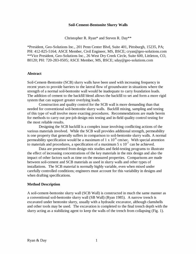
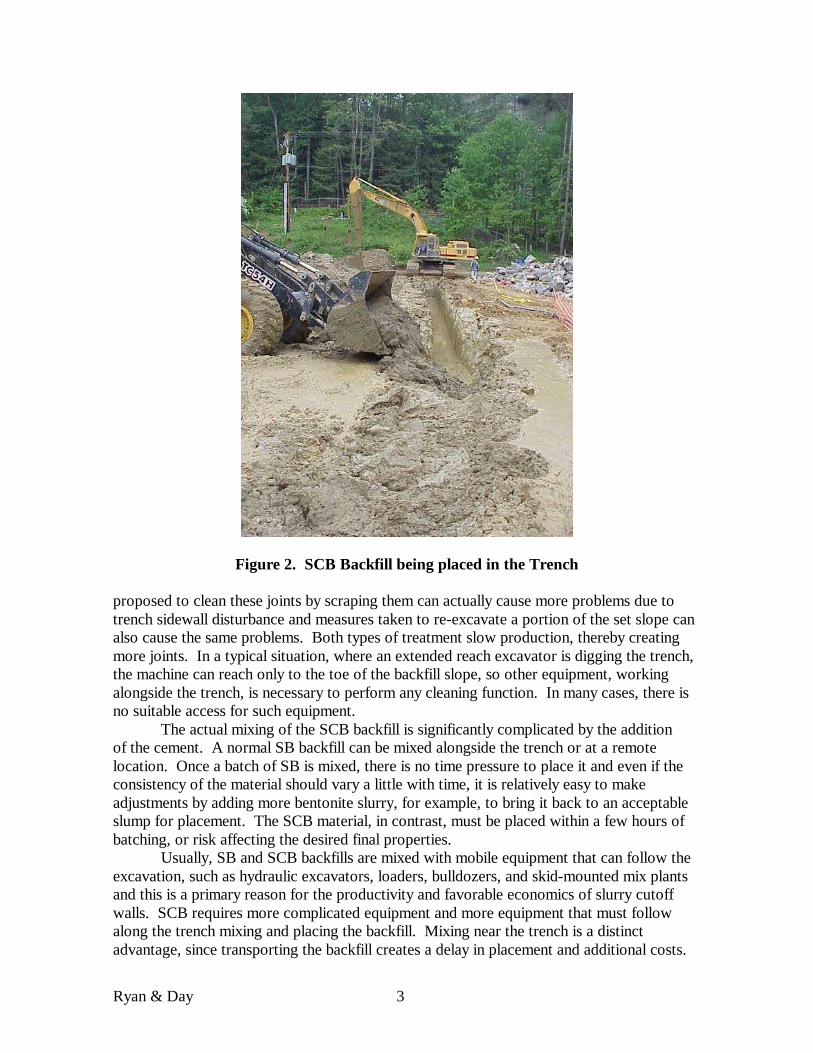
Backfill is placed in the trench after the excavation is complete by forming a slope of the mixed material that slumps down and displaces the liquid slurry forward, essentially the same operation as for an SB wall. The excavation proceeds at the same rate as backfilling, so that the distance between the excavator and the backfill placement point remains relatively constant. Since the slope of the backfill is steeper with SCB, the amount of trench open at one time is reduced, providing greater trench stability than with SB. Backfill being placed is shown in Figure 2.
Since the SCB material sets, there will be a kind of a joint between materials placed at different times. The authors do not advocate any measures to treat these joints. All of the material is relatively low strength and an angled joint with lower strength will have no significant impact on the performance in most situations. Measures that have been
Ryan & Day 3
Figure 2. SCB Backfill being placed in the Trench proposed to clean these joints by scraping them can actually cause more problems due to trench sidewall disturbance and measures taken to re-excavate a portion of the set slope can also cause the same problems. Both types of treatment slow production, thereby creating more joints. In a typical situation, where an extended reach excavator is digging the trench, the machine can reach only to the toe of the backfill slope, so other equipment, working alongside the trench, is necessary to perform any cleaning function. In many cases, there is no suitable access for such equipment.
The actual mixing of the SCB backfill is significantly complicated by the addition of the cement. A normal SB backfill can be mixed alongside the trench or at a remote location. Once a batch of SB is mixed, there is no time pressure to place it and even if the consistency of the material should vary a little with time, it is relatively easy to make adjustments by adding more bentonite slurry, for example, to bring it back to an acceptable slump for placement. The SCB material, in contrast, must be placed within a few hours of batching, or risk affecting the desired final properties.
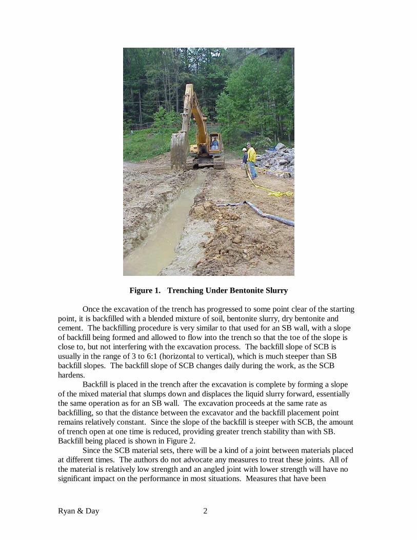
Usually, SB and SCB backfills are mixed with mobile equipment that can follow the excavation, such as hydraulic excavators, loaders, bulldozers, and skid-mounted mix plants and this is a primary reason for the productivity and favorable economics of slurry cutoff walls. SCB requires more complicated equipment and more equipment that must follow along the trench mixing and placing the backfill. Mixing near the trench is a distinct advantage, since transporting the backfill creates a delay in placement and additional costs.
Ryan & Day 4
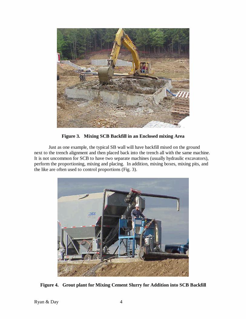
Figure 3. Mixing SCB Backfill in an Enclosed mixing Area Just as one example, the typical SB wall will have backfill mixed on the ground
next to the trench alignment and then placed back into the trench all with the same machine. It is not uncommon for SCB to have two separate machines (usually hydraulic excavators), perform the proportioning, mixing and placing. In addition, mixing boxes, mixing pits, and the like are often used to control proportions (Fig. 3).
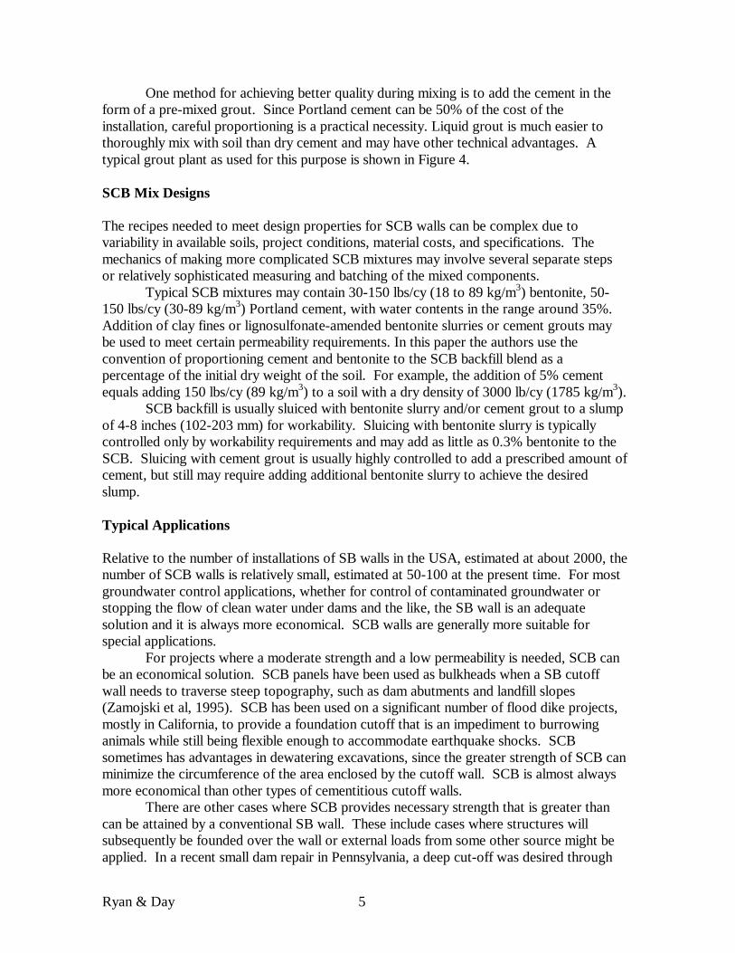
Figure 4. Grout plant for Mixing Cement Slurry for Addition into SCB Backfill
Ryan & Day 5
One method for achieving better quality during mixing is to add the cement in the form of a pre-mixed grout. Since Portland cement can be 50% of the cost of the installation, careful proportioning is a practical necessity. Liquid grout is much easier to thoroughly mix with soil than dry cement and may have other technical advantages. A typical grout plant as used for this purpose is shown in Figure 4. SCB Mix Designs The recipes needed to meet design properties for SCB walls can be complex due to variability in available soils, project conditions, material costs, and specifications. The mechanics of making more complicated SCB mixtures may involve several separate steps or relatively sophisticated measuring and batching of the mixed components.
Typical SCB mixtures may contain 30-150 lbs/cy (18 to 89 kg/m3) bentonite, 50-150 lbs/cy (30-89 kg/m3) Portland cement, with water contents in the range around 35%. Addition of clay fines or lignosulfonate-amended bentonite slurries or cement grouts may be used to meet certain permeability requirements. In this paper the authors use the convention of proportioning cement and bentonite to the SCB backfill blend as a percentage of the initial dry weight of the soil. For example, the addition of 5% cement equals adding 150 lbs/cy (89 kg/m3) to a soil with a dry density of 3000 lb/cy (1785 kg/m3).
SCB backfill is usually sluiced with bentonite slurry and/or cement grout to a slump of 4-8 inches (102-203 mm) for workability. Sluicing with bentonite slurry is typically controlled only by workability requirements and may add as little as 0.3% bentonite to the SCB. Sluicing with cement grout is usually highly controlled to add a prescribed amount of cement, but still may require adding additional bentonite slurry to achieve the desired slump. Typical Applications Relative to the number of installations of SB walls in the USA, estimated at about 2000, the number of SCB walls is relatively small, estimated at 50-100 at the present time. For most groundwater control applications, whether for control of contaminated groundwater or stopping the flow of clean water under dams and the like, the SB wall is an adequate solution and it is always more economical. SCB walls are generally more suitable for special applications.
For projects where a moderate strength and a low permeability is needed, SCB can be an economical solution. SCB panels have been used as bulkheads when a SB cutoff wall needs to traverse steep topography, such as dam abutments and landfill slopes (Zamojski et al, 1995). SCB has been used on a significant number of flood dike projects, mostly in California, to provide a foundation cutoff that is an impediment to burrowing animals while still being flexible enough to accommodate earthquake shocks. SCB sometimes has advantages in dewatering excavations, since the greater strength of SCB can minimize the circumference of the area enclosed by the cutoff wall. SCB is almost always more economical than other types of cementitious cutoff walls.
There are other cases where SCB provides necessary strength that is greater than can be attained by a conventional SB wall. These include cases where structures will subsequently be founded over the wall or external loads from some other source might be applied. In a recent small dam repair in Pennsylvania, a deep cut-off was desired through
Ryan & Day 6
an existing embankment and a concrete over-flow sill had to be founded directly on the wall. An SCB wall was used to provide the required strength.
In some cases, the SCB method is specified due to a lack of data or understanding of how a conventional SB wall “sets up” with time (i.e. consolidates and thixotropically “sets”), and might be sufficient to accomplish the desired results without the additional cost of adding cement to the backfill blend. Sampling and Testing of SCB Walls Laboratory testing that is done in advance of a project should model as closely as possible field conditions that will be expected. It is very important that laboratory protocols follow as closely as possible the order and method of work in the field. It is relatively useless to add bentonite in the laboratory as a dry material when in the field it will be added as slurry, for example. It is also essential that the consistency of the lab mixtures is workable in the field. It is not very helpful to have a lab design for a zero-slump backfill mix when most project specifications call for a 4 to 6 inch (102 to 152 mm) slump. Recommended procedures include the following:
• Take soil samples from full depth borings and blend the soil profile. A simple way to do this is to take a representative bag sample of the auger cuttings.
• Do sufficient borings to establish the outer bounds of the soil parameters, in particular fines content. This is important if it is desired to develop one mix to meet the project specifications at all locations.
• Establish cement contents as a percent of dry soil and then translate this to weight of cement per unit volume of mix. Determine if cement will be added as a grout or dry and replicate this process in the lab
• Bentonite will be added as slurry to bring the mixture to a proper slump. In addition, more bentonite may be added dry or in other cases in the form of a concentrated slurry. Again, it is important to replicate the order and process as closely as possible in the lab. Generally, it is not possible to prepare sufficient sample to run a proper slump cone test. An experienced lab can try to estimate slump by appearance or use a mini-slump cone (Evans et al, 1999).
• Sometimes, mix designs will include additives such as thinners, retarder or others to achieve certain design or construction requirements. These too should be added in the same manner as planned in the field.
• Mixes should be cast in cylinders; 2 x 4 inch (50 x 100 mm) cylinders have been shown to be adequate for typical applications. Because tests will likely be run at different time intervals and because of the natural variability of the SCB materials, it is advisable to cast a large number of samples. It is not unusual to cast 20 cylinders of each mix design.
• These mixes tend to be very sticky and difficult to get into test cylinders without air being entrained. Use tapping, vibration, rodding, or other methods to remove air voids as best as possible.
• In the field, the samples are subjected to confining pressure of the overlying material as they set. It is a current shortcoming of the testing of SCB that the samples are usually allowed to set without confining pressure. The problem is that, in a typical design mix program or in a typical field QC program, there may be
Ryan & Day 7
hundreds of samples setting at a time. It is generally impractical to try to apply confining pressure to so many samples.
• SCB test specimens are typically made and cured in accordance with ASTM D-4832 (ASTM, 2000a).
• Testing for Unconfined Compressive Strength (UCS) is typically done in accordance with ASTM Method D-4832 or D-1633. Capping of cylinder ends is usually not necessary (ASTM, 2000b).
• For permeability, the test is done in a triaxial cell according to ASTM Method D-5084. (ASTM, 2000c). Permeability testing parameters have minimal effect on test results, since the SCB is a hardened material when it is tested in the laboratory. Usually, specimens are tested after 14 days of curing at relatively low (10 psi or 69 kPa) confining pressures.
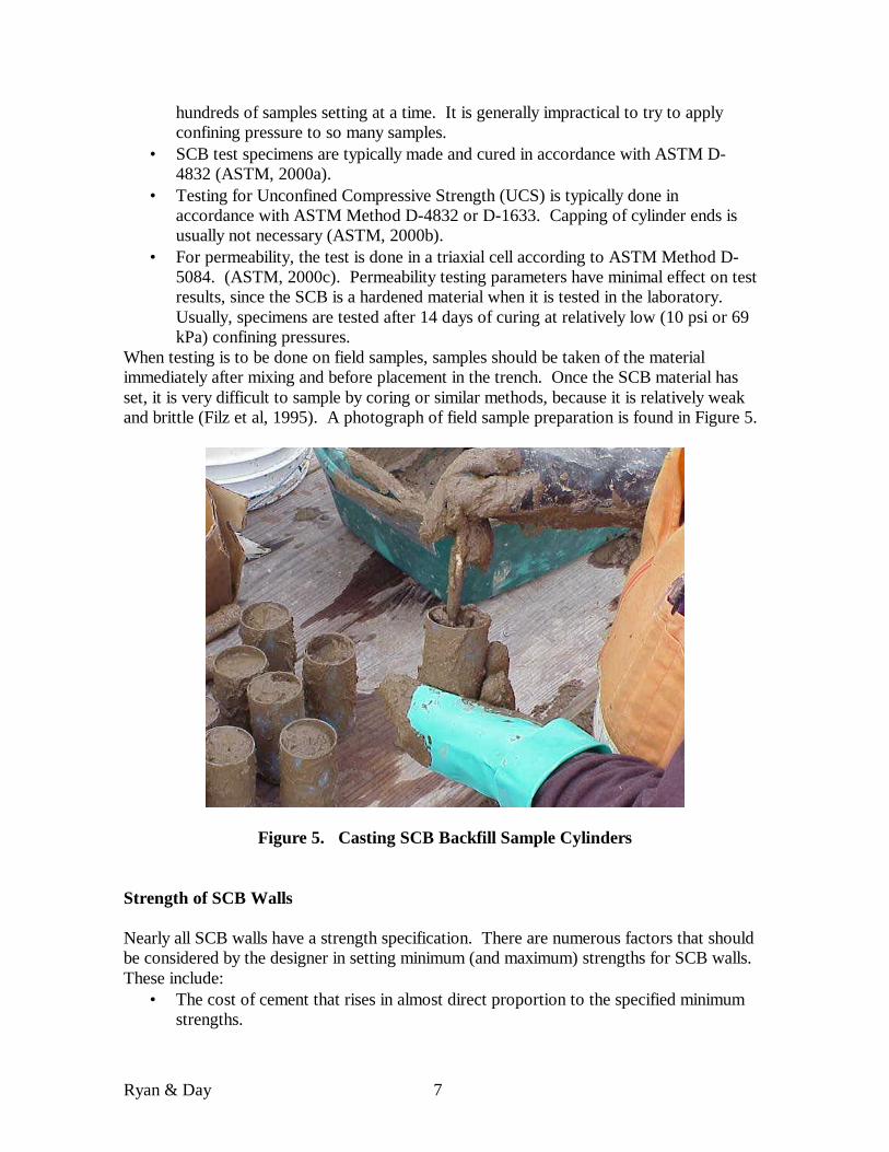
When testing is to be done on field samples, samples should be taken of the material immediately after mixing and before placement in the trench. Once the SCB material has set, it is very difficult to sample by coring or similar methods, because it is relatively weak and brittle (Filz et al, 1995). A photograph of field sample preparation is found in Figure 5.
Figure 5. Casting SCB Backfill Sample Cylinders Strength of SCB Walls Nearly all SCB walls have a strength specification. There are numerous factors that should be considered by the designer in setting minimum (and maximum) strengths for SCB walls. These include:
• The cost of cement that rises in almost direct proportion to the specified minimum strengths.
Ryan & Day 8
• The addition of excessive cement may create joints in the backfill or decrease the flexibility of the wall under load, potentially leading to cracks caused by crushing, shaking or shear type of loadings.
• The long-term potential increases in strength over time. • The negative effect that cement has on wall permeability, leading to greater flow-
through quantities than would be likely with an SB wall. • The variability of the test results and the difficulty in accurately sampling and
testing these lower strength materials. These considerations are discussed in more detail in the following paragraphs and data are provided to help guide the designer in making rational choices.
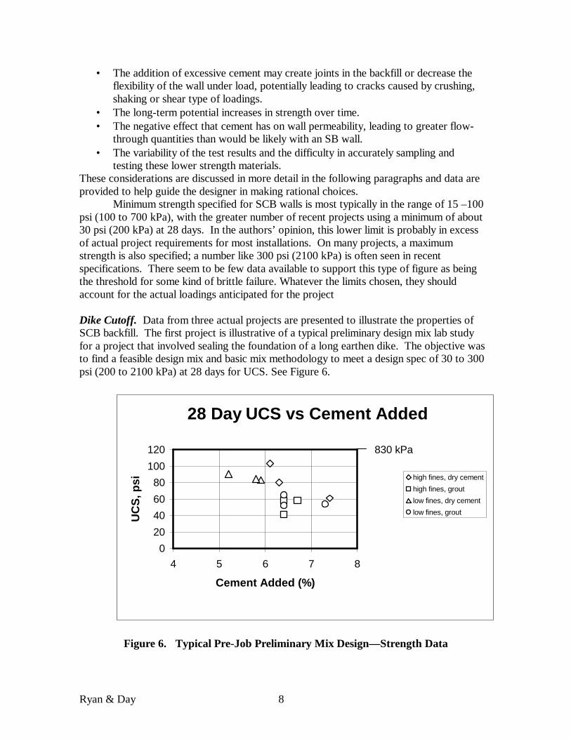
Minimum strength specified for SCB walls is most typically in the range of 15 –100 psi (100 to 700 kPa), with the greater number of recent projects using a minimum of about 30 psi (200 kPa) at 28 days. In the authors’ opinion, this lower limit is probably in excess of actual project requirements for most installations. On many projects, a maximum strength is also specified; a number like 300 psi (2100 kPa) is often seen in recent specifications. There seem to be few data available to support this type of figure as being the threshold for some kind of brittle failure. Whatever the limits chosen, they should account for the actual loadings anticipated for the project Dike Cutoff. Data from three actual projects are presented to illustrate the properties of SCB backfill. The first project is illustrative of a typical preliminary design mix lab study for a project that involved sealing the foundation of a long earthen dike. The objective was to find a feasible design mix and basic mix methodology to meet a design spec of 30 to 300 psi (200 to 2100 kPa) at 28 days for UCS. See Figure 6.
28 Day UCS vs Cement Added
020406080
100120
4 5 6 7 8
Cement Added (%)
UC
S, p
si high fines, dry cementhigh fines, groutlow fines, dry cementlow fines, grout
830 kPa
Figure 6. Typical Pre-Job Preliminary Mix Design— Strength Data
Ryan & Day 9
All of the mixes met the strength specification, although it interesting to note that, those with cement mixed in as grout generally had a lower strength than those where the cement was added dry. (Other SCB projects have shown exactly the opposite trend (Zamojsky et al, 1995)). The mixes were cast with soil from two borings, one with high fines content, 57% and the other with low fines content, 12%. There was not a significant impact on strength based on fines content.
Mine Barrier. In a second project, only one test was run pre-construction to assess the mix design. In this case there was a minimum strength requirement of 15 psi (103 kPa). The cement content selected was 3%. In this case, the SCB was selected to seal fractured rock and collapsed mine workings to stop the movement of black damp mine gas. Field results from five field samples were in the range of 15-20 psi (103-138 kPa), while the single pre-construction test gave a result of 27 psi (186 kPa).
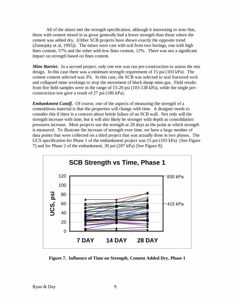
Embankment Cutoff. Of course, one of the aspects of measuring the strength of a cementitious material is that the properties will change with time. A designer needs to consider this if there is a concern about brittle failure of an SCB wall. Not only will the strength increase with time, but it will also likely be stronger with depth as consolidation pressures increase. Most projects use the strength at 28 days as the point at which strength is measured. To illustrate the increase of strength over time, we have a large number of data points that were collected on a third project that was actually done in two phases. The UCS specification for Phase 1 of the embankment project was 15 psi (103 kPa) (See Figure 7) and for Phase 2 of the embankment, 30 psi (207 kPa) (See Figure 8).
SCB Strength vs Time, Phase 1
0
20
40
60
80
100
120
7 DAY 14 DAY 28 DAY
UC
S, p
si
830 kPa
415 kPa
Figure 7. Influence of Time on Strength, Cement Added Dry, Phase 1
Ryan & Day 10
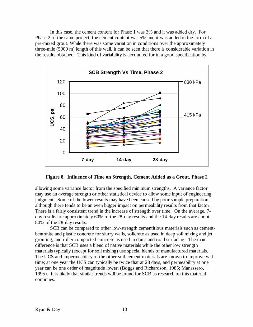
In this case, the cement content for Phase 1 was 3% and it was added dry. For Phase 2 of the same project, the cement content was 5% and it was added in the form of a pre-mixed grout. While there was some variation in conditions over the approximately three-mile (5000 m) length of this wall, it can be seen that there is considerable variation in the results obtained. This kind of variability is accounted for in a good specification by
SCB Strength Vs Time, Phase 2
0
20
40
60
80
100
120
7-day 14-day 28-day
UC
S, p
si
830 kPa
415 kPa
Figure 8. Influence of Time on Strength, Cement Added as a Grout, Phase 2 allowing some variance factor from the specified minimum strengths. A variance factor may use an average strength or other statistical device to allow some input of engineering judgment. Some of the lower results may have been caused by poor sample preparation, although there tends to be an even bigger impact on permeability results from that factor. There is a fairly consistent trend in the increase of strength over time. On the average, 7-day results are approximately 60% of the 28-day results and the 14-day results are about 80% of the 28-day results.
SCB can be compared to other low-strength cementitious materials such as cement-bentonite and plastic concrete for slurry walls, soilcrete as used in deep soil mixing and jet grouting, and roller compacted concrete as used in dams and road surfacing. The main difference is that SCB uses a blend of native materials while the other low strength materials typically (except for soil mixing) use special blends of manufactured materials. The UCS and impermeability of the other soil-cement materials are known to improve with time; at one year the UCS can typically be twice that at 28 days, and permeability at one year can be one order of magnitude lower. (Boggs and Richardson, 1985; Manassero, 1995). It is likely that similar trends will be found for SCB as research on this material continues.
Ryan & Day 11
Permeability of SCB Walls The permeability (or hydraulic conductivity) of an SCB backfill is the result of complex interactions between the various components of the mix. Clearly, Portland cement interferes with the normal ability of a soil bentonite blend to achieve very low permeability. A typical SB wall specification will require a permeability of 1 x 10⁻⁷ cm/sec, and this is a level that is relatively easily attainable on almost every project. With SCB backfill, a specification requirement of 5 x 10⁻⁷ cm/sec is typically difficult to meet and may require special construction procedures and mix components to attain. A specification of 1 x 10⁻⁶ cm/sec might be considered a normal SCB wall.
Factors that need to be considered when specifying an SCB mix or when trying to design a mix to meet specified properties are as follows:
• The addition of Portland cement to the wall has a negative effect on permeability that generally increases as the cement quantity increases. Not only does Portland cement chemically affect the ability of bentonite to “swell” and retain water, but it also requires water to be added to wet the mixture to achieve slumpable material for placement. More water leads to a less dense and more porous backfill as it sets.
• Increasing bentonite quantity will not necessarily have the same beneficial effect that it would in a normal SB backfill. Portland cement interferes with its efficiency and the additional bentonite again requires more water to wet the mix for placement.
• Additives may be helpful in reducing permeability, but they also complicate the construction process and add to the cost. Additives that have been used include lignosulfonate retarder and thinners that are used to prepare concentrated bentonite slurries for addition.
• There is some evidence that a minimum amount of fines may be beneficial in achieving optimal performance. A minimum of 10% plastic fines is recommended for a well-proportioned SCB mixture. On the other hand, excessive fines may require additional water in the form of bentonite slurry for wetting to achieve placement slump and again may be less dense.
• Adding cement in the form of a grout may provide a benefit in the form of more consistent results. Again this needs to be assessed on a project-by-project basis.
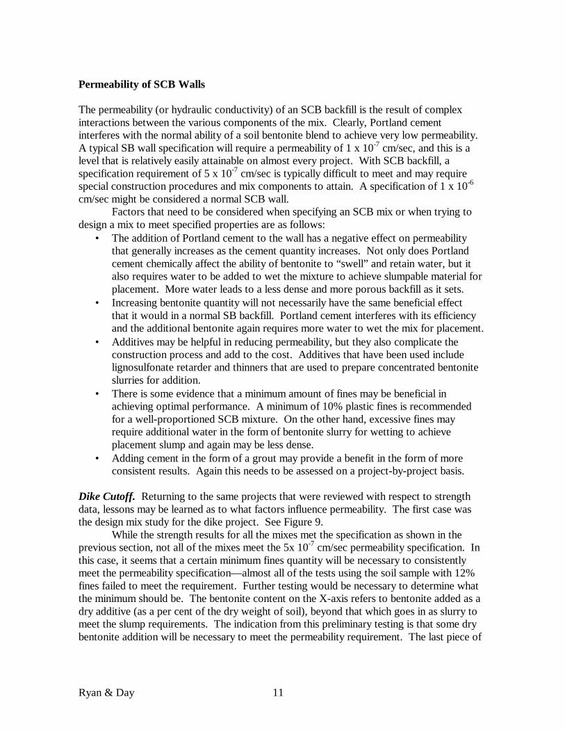
Dike Cutoff. Returning to the same projects that were reviewed with respect to strength data, lessons may be learned as to what factors influence permeability. The first case was the design mix study for the dike project. See Figure 9.
While the strength results for all the mixes met the specification as shown in the previous section, not all of the mixes meet the 5x 10⁻⁷ cm/sec permeability specification. In this case, it seems that a certain minimum fines quantity will be necessary to consistently meet the permeability specification— almost all of the tests using the soil sample with 12% fines failed to meet the requirement. Further testing would be necessary to determine what the minimum should be. The bentonite content on the X-axis refers to bentonite added as a dry additive (as a per cent of the dry weight of soil), beyond that which goes in as slurry to meet the slump requirements. The indication from this preliminary testing is that some dry bentonite addition will be necessary to meet the permeability requirement. The last piece of
Ryan & Day 12
Permeability vs Dry Bentonite Added
1.E-07
1.E-06
1.E-05
0 1 2 3
Bentonite Added, %
Per
mea
bilit
y, c
m/s
ec
high fines, dry cementhigh fines, grout
low fines, dry cementlow fines, grout
Figure 9. Influence of Additional Dry Bentonite on Permeability
information from this plot is that cement added as grout seems to provide a mix with a more consistent low permeability. This may be due to the grout being easier to mix and therefore, more homogeneous or due to the fact that pre-hydrating the cement may decrease the negative effect it has on the bentonite.
The type of testing that these data represent should be done in advance of any significant SCB project, particularly one that pushes the envelope of feasibility as the low permeability specified for this project does. Typically, these tests are done by specialty contractors, not the engineering firms writing the specifications, because the testing must model the mixing method so closely; mixing methods can vary according to contractor experience and preference. Usually, design mix tests are run by the contractors, either in preparation for the bid or perhaps more commonly by the successful contractor in preparation for the work.
Mine Barrier. The second case study, the mine gas barrier, was for a much smaller project and the specification was more liberal, 1 x 10⁻⁶ cm/sec maximum permeability. The SCB mix was helped by a relatively high fines content, 40%. For this project only one pre-job test was run and only five field samples were tested, all passing.
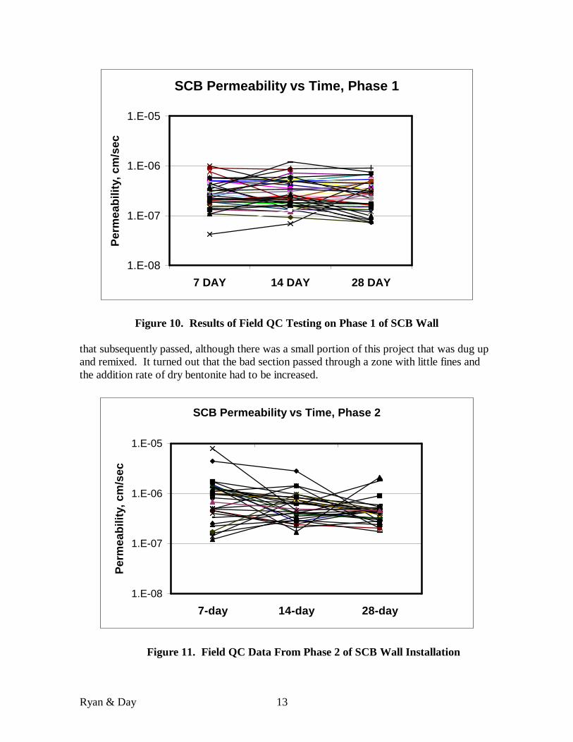
Embankment Cutoff. The last case study is again for the embankment that was done in two phases. The specification for both phases was for a maximum permeability of 5 x 10⁻⁷ cm/sec.
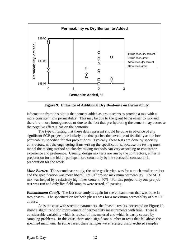
As is the case with strength parameters, the Phase 1 results, presented on Figure 10, show a slight trend for improvement of permeability measurements with time. There is considerable variability which is typical of this material and which is partly caused by sampling problems. In this case, there are a significant number of tests that fell above the specified minimum. In some cases, these samples were retested using archived samples
Ryan & Day 13
SCB Permeability vs Time, Phase 1
1.E-08
1.E-07
1.E-06
1.E-05
7 DAY 14 DAY 28 DAY
Per
mea
bilit
y, c
m/s
ec
Figure 10. Results of Field QC Testing on Phase 1 of SCB Wall that subsequently passed, although there was a small portion of this project that was dug up and remixed. It turned out that the bad section passed through a zone with little fines and the addition rate of dry bentonite had to be increased.
SCB Permeability vs Time, Phase 2
1.E-08
1.E-07
1.E-06
1.E-05
7-day 14-day 28-day
Per
mea
bilit
y, c
m/s
ec
Figure 11. Field QC Data From Phase 2 of SCB Wall Installation
Ryan & Day 14
The backfill for the first phase of the project was mixed on the ground with dry bentonite added at a 1.8% addition rate (by dry weight of soil). Portland cement was added dry and the backfill was mixed on the ground in small batches next to the trench. Backfill for the second phase had no dry bentonite (bentonite by sluicing only); cement was added in the form of a pre-mixed grout and mixing was done in a mixing box. The field QC data for this second phase, shown in Figure 11, are actually more consistent than those from the first phase.
Almost all of the data passed the specified test requirement and the points that failed were all supplemented by archived samples that passed. Since SCB properties improve with time, the archiving of samples is always important for a project of this type. Conclusions The SCB wall is a technology for constructing barriers to the lateral flow of groundwater that has seen increasing application in the last 5 years or so. While there are still far fewer of these installations compared to the more common SB walls, there have been enough to begin to assess the engineering properties of the final product. The data evaluated to date indicate that there are a number of factors that work together in a complex way to influence the principal properties of concern, strength and permeability. These include:
• Characteristics of the base soil, most importantly the average total fines and clay fines content contained in the excavated soil profile.
• The quantity of bentonite added to the final mix, including that added as slurry during the excavation process and as dry bentonite or concentrated slurry.
• The quantity of cement added and the method of adding it, whether it is dry powder or pre-mixed grout.
Strengths in the range of 15-300 psi (105-2100 kPa) are easily achievable on most projects. A permeability of 1 x 10⁻⁶ cm/sec is relatively easily achieved and a permeability less than 5 x 10⁻⁷ cm/sec is feasible using more stringent mix designs and construction procedures.
Sampling of the SCB mix, whether it is blended in the lab or taken as a part of the field QC program, is a particularly difficult task and attention must be paid to getting all air out of the samples. Taking samples of the material in its wet condition is still preferable to trying to core the set material.
Given a good understanding of the advantages and limitations of this technology, the designer will find the SCB wall a valuable addition to the range of options available for controlling groundwater. REFERENCES: API, (1990), “Recommended Practice Standard Procedures for Field Testing Water-Based Drilling Fluids”, Specification RP 13B-1, Washington, DC. ASTM, (2000a), “Preparation and Testing of Controlled Low Strength Material (CLSM) Test Cylinders”, Vol. 4.08, West Conshohocken, PA, 2000.
Ryan & Day 15
ASTM, (2000b), “Compressive Strength of Molded Soil-Cement Cylinders”, Vol. 4.08, West Conshohocken, PA, 2000. ASTM, (2000c), “Measurement of Hydraulic Conductivity of Saturated Porous Materials Using Flexible Wall Permeameter”, Vol. 4.08, West Conshohocken, PA, 2000. Boggs, Howard L, and Richardson, Alan, T. (1985), “USBR Design Considerations for Roller Compacted Concrete Dams,” Proceedings of Roller Compacted Concrete, Kenneth Hansen, Ed., American Society of Civil Engineers, Denver, CO, pp. 123-139. Davidson, R.R., Denise, G., Findlay, B., and Robertson, R.B. (1992), “Design and Construction of a Plastic Concrete Cutoff Wall for the Island Copper Mine,” Slurry Walls: Design, Construction and Quality Control, STP 1129, David B. Paul, Richard R. Davidson and Nicholas, J. Cavalli, Eds., ASTM, Philadelphia, PA, pp. 271-288. Evans, J.C., McLane, M., Conners, S., and Keister, J. (1999), “Development and Calibration of a Lab Size Slump Cone,” Unpublished, Civil Engineering Department, Bucknell, University, pp 4. Filz, G.M. and J.K Mitchell (1995), “Design, Construction, and Performance of Soil- and Cement-Based Vertical Barriers,” International Containment Technology Conference, Ralph R. Rumer and James K. Mitchell, Eds., US DoE, US EPA, and Dupont Company, Baltimore, MD, pp 63. Evans, J.C., Stahl, E.D., and Droof, E. (1987), “Plastic Concrete Cutoff Walls,” Proceedings of Geotechnical Practice for Waste Disposal, GSP No. 13, Richard Woods, Ed., ASCE, Ann Arbor, MI, pp. 462-471. Manassero, M., Fratalocchi, E., Pasqualini, E., Spanna, C., and Verga, F. (1995), “Containment with Vertical Cutoff Walls,” Proceedings of GeoEnvironment 2000, GSP No.46, Yalcin B. Acar and David E. Daniel, Eds., ASCE, New Orleans, LA, pp. 1142-1172. Ryan, C.R. (1984), “Slurry Cutoff Walls: Applications in the Control of Hazardous Wastes,” Hydraulic Barriers in Soil and Rock, STP 874, A.I. Johnson, R.K. Frobel, N.J. Cavalli, C.B. Pettersson, Eds., ASTM, Denver, CO, pp. 9-23. Zamojski, L.D., Perkins, S.W., and Reinknecht, D. (1995), “Design and Construction Evaluation of a Slurry Wall at FLR Landfill Superfund Site,” Proceedings of GeoEnvironment 2000, GSP No.46, Yalcin B. Acar and David E. Daniel, Eds., ASCE, New Orleans, LA, pp. 1192-1206.