Embed Size (px)
Citation preview

Author's Accepted Manuscript
Software defined flexible and efficient passiveoptical Networks for intra-datacenter com-munications
Rentao Gu, Yuefeng Ji, Pei Wei, Shizong Zhang
PII: S1573-4277(14)00059-9DOI: http://dx.doi.org/10.1016/j.osn.2014.05.015Reference: OSN311
To appear in: Optical Switching and Networking
Received date: 15 March 2014Revised date: 1 May 2014Accepted date: 13 May 2014
Cite this article as: Rentao Gu, Yuefeng Ji, Pei Wei, Shizong Zhang, Softwaredefined flexible and efficient passive optical Networks for intra-datacentercommunications, Optical Switching and Networking, http://dx.doi.org/10.1016/j.osn.2014.05.015
This is a PDF file of an unedited manuscript that has been accepted forpublication. As a service to our customers we are providing this early version ofthe manuscript. The manuscript will undergo copyediting, typesetting, andreview of the resulting galley proof before it is published in its final citable form.Please note that during the production process errors may be discovered whichcould affect the content, and all legal disclaimers that apply to the journalpertain.
www.elsevier.com/locate/osn
1 / 28
Software Defined Flexible and Efficient Passive Optical
Networks for Intra-datacenter Communications
Rentao Gu*1, Yuefeng Ji2, Pei Wei2, Shizong Zhang1 1Beijing Key Laboratory of Network System Architecture and Convergence,
School of Information and Communication Engineering,
Beijing University of Posts and Telecommunication,
Beijing, 100876, China.
2State Key Lab of Information Photonics and Optical Communications,
School of Information and Communication Engineering,
Beijing University of Posts and Telecommunications
Beijing, 100876, China.
Email: [email protected]*, [email protected], [email protected], [email protected]
Tel: +86-10-61198422-609,
Fax: +86-10-61198422-816.
Abstract: Facing the huge traffic challenge, optical networking shows great advantages on capacity
and energy issue. However, the efficiency and flexibility are not satisfactory to the data center
networks, especially for intra-datacenter communications. This article reviews the typical architectures
of data center networks, and suggests that TWDM-PON system can be used in the edge layer and
aggregation layer in the datacenter networks. It proposes a software defined flexible and efficient
passive optical networks, combining the software defined technology and network coding, for
intra-datacenter communications. Network coding is applied to increase the downstream bandwidth
efficiency and overcome network bottleneck, and software defined technology provides the flexibility
on wavelength assignment according to traffic statistics dynamically. To increase more efficiency, a
seamless DBA (S-DBA) scheme and an ONU grouping algorithm are proposed to fully utilize the
upstream idle time and minimize the traffic entering into the core layer of the datacenter networks.
They realize flexible scheduling and resource allocation both in time domain and wavelength domain.
The experimental simulations indicate that the proposed schemes and algorithms provide low delay,
good fairness, increased efficiency and network flexibility.
2 / 28
Keywords: Software defined networking; passive optical networks; data center
networks; ONU grouping; dynamic bandwidth allocation; network coding.
1 Introduction
As the cloud services and the big data applications emerge rapidly all over the world, the datacenters are not exclusive to huge companies only, but they are also needed by small business or even individuals. This situation makes the datacenters become more popular than ever before. However, upon the increased data processing and transmission demand, the construction and the management of datacenters have to face two emerging issues. One is the huge traffic in/between datacenters, and the other is the enormous energy consumed by datacenters.
The huge traffic: the data which has to be handled by datacenters explodes in recent years. For example, the monitoring cameras in a modern city will generate hundreds of Terabits data per hour, and a very large ecommerce website has to handle tens of Terabits data per minute at its peak time. All of these give datacenters great pressure on processing them and distributing them among different servers.
The enormous energy: except Google and Facebook that are ultra-energy-efficient, a survey of 300 North American corporations from Digital Realty indicates that the average Power Usage Effectiveness (PUE) rating—a parameter to identify how much watts power was used for the 1 watts used to run the servers—was 2.9 in 2013. And the average power load among the companies under the survey increased from 2.1 megawatts in 2011 to 2.6 megawatts in 2013. Except the energy consumed by the servers, the transmission and switching equipment occupied a large portion of power consumption.
Therefore, we need an efficient and power saving solution in the datacenter networks. Different from conventional electrical transmission and switching technology, the fiber technology provides great bandwidth potential and lower energy consumption [1]-[2]. Optical technologies will relieve the suffering of datacenters and may solve them eventually.
The communication in the datacenters contains two types of requirements: inter-datacenter and intra- datacenter. In general, inter-datacenter communication scenarios are quite similar with the carrier backbone networks, which makes the technologies for optical backbone networks, e.g. Packet Transport Networks (PTN)/ Optical Transport Networks OTN and elastic Wavelength-Division Multiplex (WDM), can be easily deployed in inter-datacenters. Also, elastic optical networks were applied in the transmission fields recently to increase the spectrum efficiency and reduce the management and operation cost. M. Jinno et al. presented the framework and the benefits on elastic optical networking [3]. G. Zhang et al. studied a novel optical grooming approach to aggregate and distribute traffic directly at the optical layer in elastic optical networks [4]. K. Christodoulopoulos et al. investigated the planning problem of an elastic OFDM optical networks [5]. K. Walkowiak et al.
3 / 28
focused on an offline problem of routing and spectrum allocation with dedicated path protection in survivable elastic optical network scenarios [6]. These results enhance the flexibility for inter-datacenter communications to a certain extent.
As for the intra-datacenter communication, one of the main tasks is data access and aggregation. Although the passive optical networks (PON) are successful in the access field and WDM-PON gains great capacity [7], it was not popular to deploy it for the intra-datacenter communications for now. The main stumbling block is that, people worry that PON cannot provide bandwidth as flexibly as Ethernet switches. The conventional tree topology limits the total throughput of the PON networks. And the fixed logical connection between optical line terminator (OLT) and optical network unit (ONU) is not suitable for timely bandwidth allocations among servers. Despite of these, many enterprises, such as Corning Inc. and IBM, provide Passive Optical LAN Solution based on PON technologies, and Francois Menard from AEPONYX used case study to suggest that PON technology can be used in the datacenters as a technology with great potential [8]. These solutions and cases indicate that PON are being considered for the intra-datacenter communications. However, the current efforts are not enough to dispel people’s misgivings on the efficiency and the flexibility of PON system.
In this article, a software defined flexible and efficient passive optical network architecture is proposed for intra-datacenter communication scenario. It is comprised of a set of OLTs, a set of ONUs and a changeable optical distribution network (ODN) which is comprised of programmable Optical Top of Rack (O-ToR) and necessary passive components. This architecture brings the inspiration of software defined network (SDN) into PON system to provide high flexibility during the data transmission process, and deploys network coding (NC) technology to increase the efficiency and total throughput of the proposed architecture. However, the conventional dynamic bandwidth allocation (DBA) algorithms cannot be applied in PON system with network coding directly. Also, the software defined technology enables the network to configure the connection between OLT and ONU dynamically, but there is no proper wavelength assignment algorithm suitable for this new architecture.
In this work, typical intra-datacenter architectures are reviewed briefly. The flexible and efficient passive optical network architecture and key issues for intra-datacenter communication is described in Section 2. To solve the key issues, Section 3 introduces the proposed seamless DBA (S-DBA) scheme to achieve the efficient scheduling and resource allocation for the time domain in a single wavelength. And Section 4 proposes an ONU grouping algorithm to achieve the optimal wavelength assignment (resource allocation in wavelength domain) so that the traffic entering into the core layer can be minimized. We conclude the whole work in Section 5.
2. Flexible and efficient passive optical networks for datacentre networks
In this section, we reviewed the features of typical datacenter architectures, and then proposed a flexible and efficient PON based networks architecture. This
4 / 28
architecture provides flexibility to coordinate the logical connection between OLTs and ONUs and supports resource allocation in both wavelength domain and time domain.
2.1. Typical Intra-datacenter Communication Architectures Intra-datacenter network is an important network infrastructure for the datacenter.
It usually connects a large number of servers and switches using high-speed links, and is the basic platform of all the applications and services those the datacenters provide. Tree topology is one of the most popular architecture, which is simple and easy-managed. But there is bandwidth bottleneck in it. As the improved architectures, Fat tree topology [9], PortLand [10], VL2 [11], Monsoon [12] are proposed to enhance the flexibility and scalability to some extent.
From the above typical datacenter networks architectures, we can find the following common points:
Aggregation: In most architectures, there is a strong aggregation demand on the traffic handling, especially in network-centric solutions, such as Fat-tree, VL2, Monsoon, and etc. Aggregation will increase the network efficiency and reduce total links and the operation cost. But it is certain that the communication between peer-servers (servers in the same layer or the same domain) should not be impacted when deploying the traffic aggregation.
Flexibility: The datacenter networks require much more flexibility to face the unpredictable traffic patterns. Most architectures try to build uniform network topology or use redundant links so that it overcomes the bottleneck and satisfies the peak traffic. But it is still lack of dynamic scheduling and resource allocation according to the time-varying traffic.
Efficiency: Most datacenters architecture use redundant links to keep high throughput. However, it results in the decline of network efficiency. It should be the best if we can use fewer physical links but keep a good throughput.
2.2. Flexible and Efficient Networks Architecture From the review of the current datacenter architecture, it is found that they pay
more attention on the traffic distribution and the connectivity among different servers. However, since they do not consider the dynamic role of the transport equipment in the bottom layer, the traffic distribution and processing policies are usually independent of the carried traffic. This leads to inefficient traffic grooming and switching during the communication among servers. Since the traffic load becomes much heavier in the datacenter than ever before, it is required to propose a new architecture which utilizes the traffic information to make the network more efficient.
A PON based software defined flexible and efficient optical networks architecture is proposed for intra-datacenter communications. As mentioned in Section 1, PON system is perfect for aggregation and access network, which usually adopts tree-like topology to reduce the links. Compared with traditional architectures, it has the advantage on reducing the installation cost and operation cost. Currently, since OLT has the ability of traffic exchange, PON system can afford almost all the
5 / 28
functions of the electrical switch networks. What we need to do is adding the intelligent function over the PON system so that the network could react according to the traffic status.
Usually, the time slot scheduling and bandwidth allocation in time domain are only applied within a single PON port. If there are multiple wavelengths transmitted in an ODN network, there is a need to coordinate wavelength assignment in different PON ports. This function is enabled by SDN technology and the controller in the network, which provides the flexible resource allocation in both wavelength and time domain.
Another important issue is that most architectures cannot achieve best traffic grooming results, because few work takes “minimize the outbound traffic” as a design goal. Since most datacenter networks have multiple layers, if the outbound traffic is minimized in lower layer, the traffic pressure to the higher layer could be much smaller. How to achieve the minimum outbound traffic also needs flexible coordination of the connections between OLT cards and ONUs. It can be supported by SDN technology and the controller, too.
It is figured out that SDN is effective in datacenter networks [13]; however, it usually works in higher layers (e.g. IP layer), and is not introduced much in the optical layer for intra-datacenter communication yet. The proposed architecture aims to provide large capacity for data communication and good flexibility on resource allocation, and to reduce the cable installation and management cost.
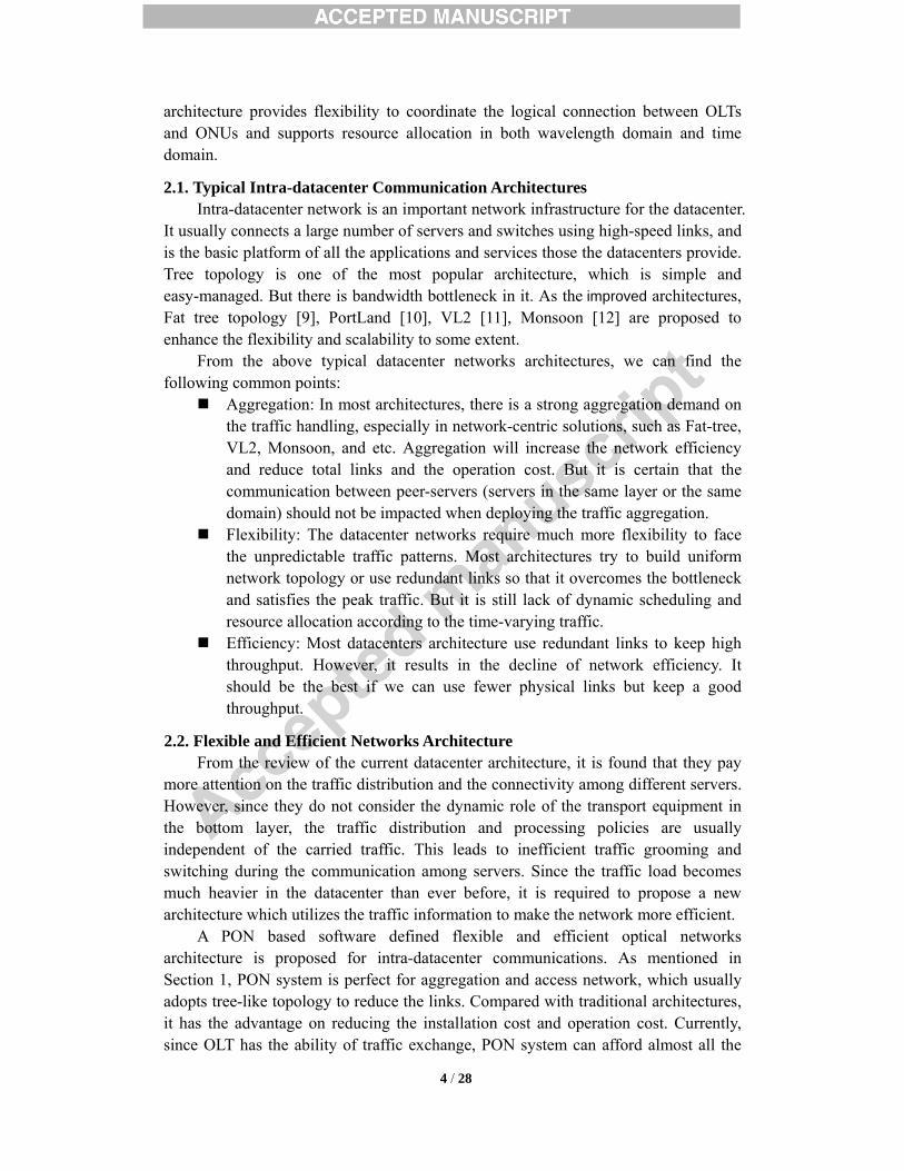
In this architecture, the intra datacenter network contains three layers, and PON system is deployed in the edge layer and aggregation layer, as shown in Fig.1. To increase the capacity of PON system and keep the fine bandwidth allocation granularity, Time- and Wavelength-Division Multiplexed Passive Optical Network (TWDM-PON) [14], a recommended technique in NG-PON2, is a good choice.
In Fig.1, the Software defined supported OLTs (SD-OLTs) generate TWDM signals to provide large capacity for tens of servers. Each SD-OLT contains several burst transceivers for different wavelengths and an interface to the controller. All the
Fig.1. Flexible and efficient passive optical networks for intra-datacenter networks.
6 / 28
wavelengths are multiplexed into a single fiber. The SD-OLTs are connected with routers in the core layer and access the traffic from ONUs through the optical top of rack devices. On one hand, the SD-OLTs can receive the command from the centralized controller and follow the instructions such as bandwidth allocation and flow control. On the other hand, the SD-OLTs should also provide network information to the controller as the foundation of all optimal solutions. Communications with the tunable ONUs can still through traditional MPCP protocol.
Flexible O-ToR device is comprised of an Arrayed Waveguide Grating (AWG) and multicast switch (MCS), responsible for scheduling the wavelengths among different servers. The WDM signals are demultiplexed into different ports by AWG, and switched to a group of ONU cards by MCS. The multicast switch is available on the market now and it has already been considered as the most economical solution of add/drop large number of wavelengths today. An M*N MCS contains M input ports and N output ports [15]. And the MCS can be managed to provide route from each input port to output ports. Considering the colorless and directionless routing feature, as well as the contentionless wavelength planning feature, it is not only deployed as a component in switching core of optical networks, but also an important component in flexible ODN scenario. In this proposed flexible architecture, we introduce MCS as a splitter to add/drop wavelengths to different ONUs. Considering the needs of colorless, directionless, and contentionless (CDC) of this architecture, the MCS may be deployed with erbium-doped fiber amplifiers (EDFA) to compensate the optical path loss, if needed. And the scale of MCS may be increased with the demand of ONU numbers, i.e. multi MCS cards will be needed. What’s more, the MCS can be integrated into an embedded board powered by the server rack and an SDN agent may be embedded to receive the southbound commend and send MCS information to the controller. The instructions form the controller can also be translated and applied on MCS by the agent. If we consider the ONUs under the same downstream wavelength as a group, the proposed architecture has the ability to add/delete any ONU to/from any ONU group. O-ToR and related fibers play the function as optical distribution networks (ODN). This architecture allows upstream wavelength reuse to double the spectrum efficiency. From this perspective, O-ToR acts as a remote node in the access network, but it does not need to convert the optical signal into electrical one.
To reduce the overhead of the data transmission, a small ONU card can be installed in the servers using PCI-E interface, instead of Ethernet network card. From the view of server side, the ONU mainly focuses on the data flow transmission, similarly with the conventional Ethernet network card. The software running on the server is able to transmit and receive data through ONU card directly. From the view of network side, basic control protocols (such as MPCP) should be supported, so that several ONU cards can share the bandwidth in both upstream and downstream and the proposed architecture keeps the compatibility to the traditional PON system. Considering that the existing protocol is sophisticated, the design of this tunable ONU is both real-time and reliable under this centralized flexible PON architecture. And as is mentioned above, each ONU can be assigned to different OLTs, the bidirectional transmission issues can be solved by deploying colorless ONUs and reusing the
7 / 28
upstream and downstream wavelength. In traditional architecture, OLT has control function within a PON port. However,
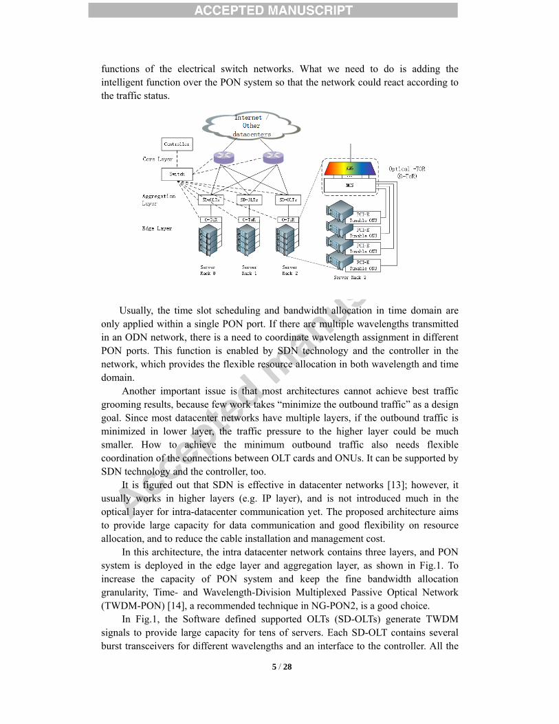
the traditional OLT is incapable for coordination resource and adjust the logical connections between different PON ports. Therefore, a controller is used here to allocate resource among multiple PON ports to achieve higher efficiency. The controller connects all the SD-OLTs and routers. It gathers network resource information and current traffic information, calculates an optimal allocation or grooming solution (such as wavelength assignment, time slot allocation scheme, network topology, and flow tables.), and configures each device to execute it. Each of the optimal solutions can run as an App on the SDN controller. The popular controller such as NOX/POX, RYU should be available under this architecture. And the communication between controller and the controlled equipment should be carried by standard southbound interface such as OpenFlow. The routers and SD-OLTs will report traffic information and statistics to the controller and process the commands from the controller. The ONUs can be monitored and controlled using standard OAM messages via SD-OLTs. By this architecture, it is feasible to assign a group of ONUs to any wavelength (SD-OLT). In each wavelength, the dynamic bandwidth allocation based on time slot is supported. Upon the controller and the flexible O-ToR, it is possible to adjust the connections between SD-OLT and ONUs so that the outbound could be reduced. As is shown in Fig.2, ONU-A and ONU-C belong to different OLTs, and the traffic between them can only be forwarded by the core router, so do ONU-B and ONU-D. Once the tunable ONUs are reassigned to proper OLTs, there is no need to exchange the data between SD-OLT1 and SD-OLT2. Under the propose PON architecture, it is possible to reach the maximal convergence ratio, i.e. the minimal traffic goes outbound. Maximal convergence ratio means lowest traffic entering into the core layer and minimize the pressure of the switch and transmission in it.
2.3. Key issues The current PON technologies could satisfy most transmission requirements of
the proposed architecture. And the SDN technology and open source controller provide flexible resource allocation and connection reassignment between OLTs and ONUs. These guarantee that the proposed architecture is feasible for the current stage.
Fig.2. Outbound traffic and ONU grouping.

8 / 28
However, there are still two key issues to be solved: a) How to minimize the outbound traffic. This architecture aims to reduce the outbound traffic in aggregation layer to
relieve the pressure of the core layer. The controller and software defined technologies can change the logical connections between OLTs and ONUs so that the amount of outbound traffic can be changed according to the description. But how to achieve the minimal outbound traffic is not mentioned in the existing research,
b) How to reduce the occupied downstream bandwidth. One of the aims is to reduce the outbound traffic. But at the same time, it will
increase the occupied downstream bandwidth, which leads to a network bottleneck sometimes. We can use network coding technologies to increases the downstream wavelength efficiency by up to 50% for the traffic between the different ONUs [16]. However, most DBA algorithms are suitable for the conventional PON system. Although a few algorithms are claimed to design for PON system with network coding, the idle time in the scheduling make them not efficient. How to deploy network coding technology and provide an efficient DBA algorithm is not solved well.
In section 3, a seamless DBA algorithm is proposed to provide an efficient DBA algorithm for the intra-datacenter networks, i.e. to solve the second issue. And an ONU grouping algorithm is described in section 4 to provide a solution for the first issue.
3. Seamless dynamic bandwidth allocation scheme (S-DBA)
Apparently, the PON system with network coding in the proposed architecture has quite different operation approaches from the conventional PON systems, both in upstream and downstream, as described in [16]-[17]. In the proposed architecture, ONUs report the destination address (e.g. destination IP address, destination MAC address) to SD-OLT using the extended MPCP REPORT frame. If any two peer ONUs has traffic sent to each other, the SD-OLT will add these two ONUs to a “network coding group” (NC group) and assign them a “group number”, which means the traffic between these two ONUs will be coded at the SD-OLT side. A hybrid algorithm to achieve effective time slot allocation for services with different QoS requirements in the network coded PON system in [18]. However, the idle time during the DBA cycle is not fully utilized, which may reduce the resource utilization ratio. In this section, we proposes seamless DBA (S-DBA) scheme, a DBA scheme to utilize the idle time and perform an efficient bandwidth allocation in time domain. Without generality, the algorithm takes EPON/10G EPON standard as example. It is easy to extend it to GPON/NG-PON standard.
Before introducing the S-DBA scheme, the following parameters are defined and explained in Table 1.
Table 1. The definitions and descriptions of the parameters Parameters Description w ONU number in a NC group. 2 is a typical value. R Upstream bit rate (bps).

9 / 28
N The total ONU number in the PON network. Tcycle The maximal DBA cycle length. Tguard The guard time between any two consecutive upstream slots. Tidle The upstream idle time. TDBAcal The calculation time for DBA. TDBAnc The DBA polling cycle length when network coding deployed.
miniB The minimal guaranteed bandwidth for ONU i(Bytes)
exkB Total excessive bandwidth granted in k-th cycle.
exdkB Total excessive bandwidth requested in k-th cycle
( )EFi kG The granted bandwidth for EF services in k-th DBA polling cycle of i-th ONU.
( )AF
i kG The granted bandwidth for AF services in k-th DBA polling cycle of i-th ONU.
( )AFi k pG The pre-granted bandwidth for AF services in k-th DBA polling cycle of i-th ONU.
( )BEi kG The granted bandwidth for BE services in k-th DBA polling cycle of i-th ONU.
( )BEi k pG The pre-granted bandwidth for BE services in k-th DBA polling cycle of i-th ONU.
EFikR
The bandwidth request of EF service in i-th ONU reported to the OLT in k-th DBA polling cycle.
AFikR
The bandwidth request of AF service in i-th ONU reported to the OLT in k-th DBA polling cycle.
BEikR
The bandwidth request of BE service in i-th ONU reported to the OLT in k-th DBA polling cycle.
exidleB The required extra bandwidth for fully utilizing the upstream idle time.
U The set of ONUs with light traffic. O The set of ONUs with heavy traffic.
estartikt The start time of EF service transmission in the kth DBA polling cycle of ith ONU.
abstartikt
The start time of AF and BE service transmission in the kth DBA polling cycle of ith ONU.
EFikA The average EF service rate for the kth prediction.
3.1. S-DBA Scheduling S-DBA contains QoS supported seamless scheduling policy, as shown in Fig. 3.
In S-DBA, the whole DBA cycle is divided into two sub-cycles: one is “uncoded sub-cycle” for services with high priority, and the other is “coded sub-cycle” for low priority services (e.g. best effort service). All the granted service with high priority is
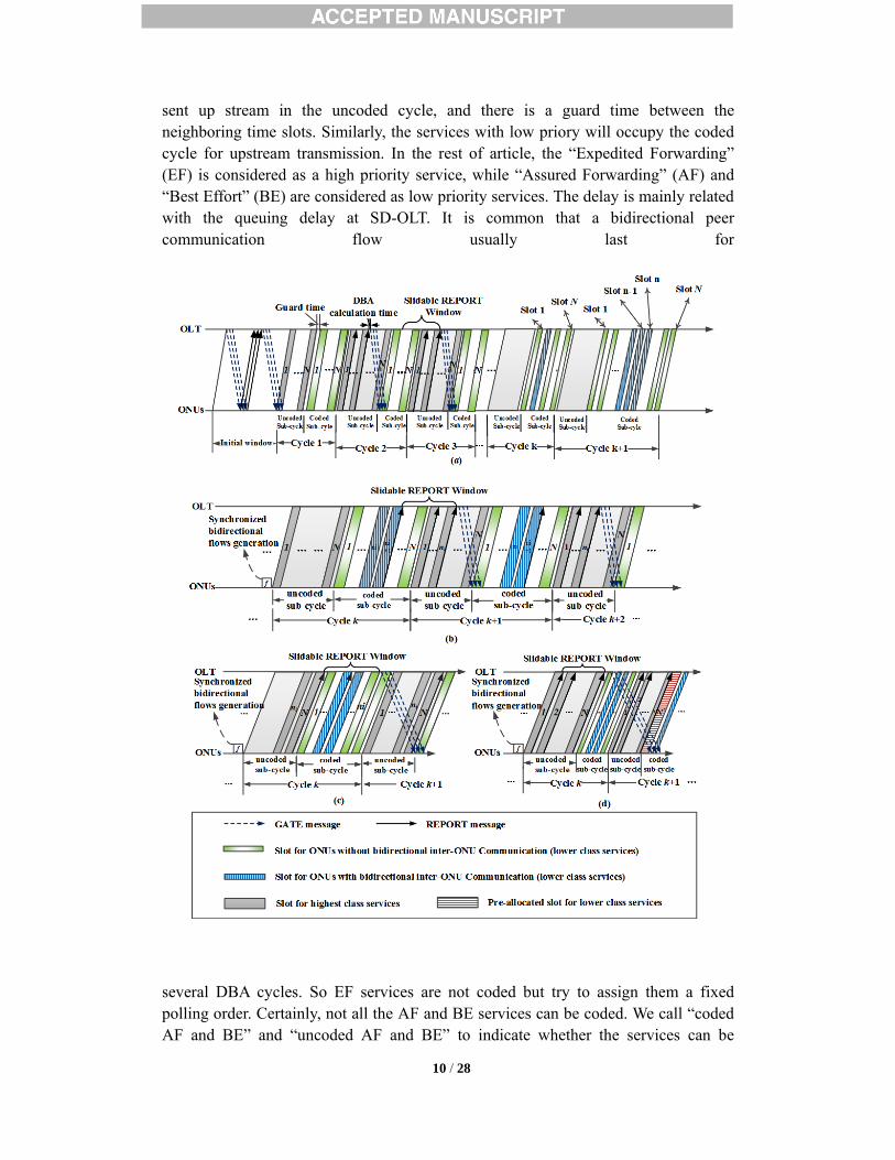
10 / 28
sent up stream in the uncoded cycle, and there is a guard time between the neighboring time slots. Similarly, the services with low priory will occupy the coded cycle for upstream transmission. In the rest of article, the “Expedited Forwarding” (EF) is considered as a high priority service, while “Assured Forwarding” (AF) and “Best Effort” (BE) are considered as low priority services. The delay is mainly related with the queuing delay at SD-OLT. It is common that a bidirectional peer communication flow usually last for
several DBA cycles. So EF services are not coded but try to assign them a fixed polling order. Certainly, not all the AF and BE services can be coded. We call “coded AF and BE” and “uncoded AF and BE” to indicate whether the services can be
Fig.3. S-DBA scheme in Software defined flexible and efficient passive optical
networks for intra- datacenter communications

11 / 28
applied “network coding” operation. As shown in Fig. 3(a), if SD-OLT gathered all the REPORT messages from
ONUs during the DBA cycle k and found that there was a “coding group” ONUs, it will assign consecutive upstream time slots for them. So that the waiting time of “coding operation” in SD-OLT can be minimized. Furthermore, we also need to determine the transmission order of “coded AF and BE” and “uncoded AF and BE”. And the latency fairness is a key factor in this decision. Suppose there are N ONUs, and there are bidirectional peer communication flow between w ONUs, the coded service should be scheduled in any w consecutive time slots in the first n time slots to grantee the best latency fairness [19], where n is determined by (1), b is the ratio of the slot interval for any of ONUs in NC group and the slot interval for any of ONUs outside NC group in the coded sub-cycle [18].
( ) ( )2 22 1 1 20.5
N b w N b w bwn
N w bw⎡ ⎤+ − − + − +
= +⎢ ⎥− +⎣ ⎦ (1)
To get the optimal scheduling results, SD-OLT need to have a global view to assign the transmission order for ONUs in and out of the NC group. Therefore, the bandwidth granted for each ONU are not computed until all the REPORT messages are received by SD-OLT. As multi-class services are carried, we need to apply different bandwidth grant polices for different services. On one hand, because of the steady bit rate and determinability, SD-OLT could predict the EF traffic precisely and apply “grant-before-report” policy [20]. It means SD-OLT is able to use GATE message to pre-grant next upstream slot and reserve enough bandwidth for EF service. On the other hand, based on the bursty nature, “grant-after-report” is still applied for AF and BE services, which means the SD-OLT grants the time slots (bandwidth) after receiving all the REPORT messages during a DBA cycle. Thus, once the coded sub-cycle for AF and BE services are granted, the following sub-cycle for EF service can also be pre-granted then. The purpose is not only for reducing the latency of EF traffic, but also is helpful to fully utilize the upstream idle time that is brought by DBA calculation and MPCP round trip time (RTT). The idle time can be calculated by
idle DBAcalT RTT T= + . (2)
Note that, for the first bandwidth allocation cycle after the initial discovery stage, the coded sub-cycle 1 and the uncoded sub-cycle 2 will be granted at the same time. This is the only special case in DBA process. Because the AF and BE services are bursty, the length of coded sub-cycle varies. It will result in the length variation of the uncoded sub-cycle. Thus, the length of the pre-granted uncoded sub-cycle could not cover the entire upstream idle time. To increase the upstream efficiency, the upstream window for REPORT messages is slideable in time domain, called “slideable REPORT window”. This window is determined under the following three cases:
a) Heavy traffic: the uncoded sub-cycle is larger than the idle time, which can be formulated as in (3).

12 / 28
( 1)1+( 1)N EF
j k guard idlejG N T T+=
+ × ≥∑ . (3)
The slideable REPORT window is determined as in Fig. 3(b). Since the uncoded sub-cycle is large enough to cover the upstream idle time, the slideable REPORT windows can go through the k-th coded sub-cycle and the (k+1)-th uncoded sub-cycle. The last (N-ni) slots in the k-th uncoded sub-cycle are assigned to utilize the upstream idle time, ni is determined by (4), where ( 1) 1dN n− ≥ ≥ .
[ ]( 1)( 1)+( 1) max
d
N EFj k d guard idle i dj n
G N n T T and n n+= +− + × ≥ =∑ , (4)
b) Light traffic: the uncoded sub-cycle is smaller than the upstream idle time, but total length of k-th coded sub-cycle and (k+1)-th uncoded sub-cycle is larger than idle time, formulated by(5):
( 1) ( 1) ( ) ( )1 1( 1) ( ) ( 1)N NEF EF AF BE
j k guard idle j k j k j k guardj jG + N T T G G G + 2N T + += =
+ × < ≤ + + + ×∑ ∑ . (5)
The slideable REPORT window is determined as in Fig. 3(c). This window could slide toward k-th coded sub-cycle, so that the total length of the last (N-ni) slots in k-th coded sub-cycle and the whole pre-granted (k+1)-th uncoded sub-cycle equals the upstream idle time. ni is determined by(6):
[ ]( ) ( ) ( 1)( 1) 1( + )+ +(2 1) max
d
N NAF BE EFj k j k j k d guard idle i dj n j
G G G N n T T and n n+= + =− + × ≥ =∑ ∑ , (6)
c) Extreme light traffic: the total length of k-th coded sub-cycle and (k+1)-th uncoded sub-cycle is still smaller than the upstream idle time, formulated by(7):
( 1) ( ) ( )1( ) (2 1)N EF AF BE
idle j k j k j k guardjT > G G G + N T +=
+ + + ×∑ . (7)
The slideable REPORT window is determined as in Fig. 3(d). In this case, there is an overlapping between the REPORT window and k-th uncoded sub-cycle. To solve this overlapping, we need to insert a small slot N’, which is assigned after the end of (k+1)-th uncoded sub-cycle. So that the total length of (k+1)-th uncoded sub-cycle, k-th coded sub-cycle and the slot N’ equals the upstream idle time. This slot is used to process the AF and BE traffic that ONU N received during the k-th uncoded cycle. In order to keep the upstream order of ONUs in NC group unchanged, slots for these ONUs in the unallocated coded sub-cycle of Cycle (k+1) will be scheduled to follow the slot N’, in case ONU N belongs to NC group.
3.2. S-DBA Resource Allocation Beside the scheduling scheme, it is also important to describe the resource
allocation policy. The scheduling scheme reflects the QoS requirement of the services. The resource allocation takes the fairness as the major aim. All the grants to ONUs are the integrated results of scheduling and resource allocation. According to the previous scheduling scheme, the GATE message contains two grants: one is for the coded sub-cycle, and the other is for the uncoded sub-cycle. To a certain ONU, the bandwidth will be granted based on the type of service. The EF service bandwidth request is satisfied first, if it is within the minimal guaranteed bandwidth of this ONU. The rest bandwidth will be assigned to the AF service that is with medium priority.
13 / 28
The BE service is allocated at the end. Firstly, to achieve the guaranteed bandwidth and allocation fairness[20], if we
assume the service level agreements (SLA) of all the ONUs are the same, the minimal guaranteed bandwidth (Bytes) for ONU i is obtained by (8):
( )min
28
cycle guardi
r T N TB
N− ×
= , (8)
Since AF and BE services have the burst characteristics, the requested bandwidth of some ONUs may be less than min
iB ,and other ONUs may request bandwidth more than min
iB . To fully use the DBA cycle, the over-granted bandwidth for the ONUs with light traffic can be reassigned to the ONUs with heavy traffic. The total excessive bandwidth granted in k-th DBA cycle ex
kB and total requested excessive bandwidth in k-th DBA cycle exd
kB are obtained by (9) and (10): min min
( ) ( 1) ( 1) ( ) ( 1) ( 1)( ) , ( : )ex EF AF BE EF AF BEk j j k j k j k j j k j k j k
j UB B G R R U B G R R− − − −
∈
= − − − > + +∑ ; (9)
min min( ) ( 1) ( 1) ( ) ( 1) ( 1)( ) , ( : )exd EF AF BE EF AF BE
k l k l k l k l l l k l k l kl O
B G R R B O B G R R− − − −∈
= + + − < + +∑ . (10)
Note that it is necessary to consider the service types and corresponding QoS requirements when allocating resources between EF, AF and BE services. According to the previous scheduling scheme, the bandwidth resource for AF and BE services in k-th coded sub-cycle is allocated before the allocation for (k+1)-th uncoded sub-cycle. When the network traffic is quite heavy, it will turn to the case (a) as shown in Fig. 3(b). In k-th coded sub-cycle, the allocation for AF and BE services in ONU i can be obtained from (11) ~ (14), where ni is determined by (4).
When in i N< ≤ ,
min( 1) ( 1) ( )
( )
( 1)min( )
( 1)
,
,
AF AF EF ex exdi k i k i i k k k
AFi k
AFi kEF ex
i i k k AFj U j k
R R B G or B B
GR
B G B otherwiseR
− −
−
∈ −
≤ − ≥
=
− +∑
⎧⎨⎩
, (11)
min( 1) ( 1) ( ) ( )
( )
( 1)min ( ) ( )
( 1)
, - ,
,
BE BE EF AF ex exdi k i k i i k i k k k
BEi k
BEi kEF AF ex
i k i k k BEj kj U
R R B G G or B B
GR
B G G B otherwiseR
− −
−
−∈
≤ − ≥
=
− − +
⎧⎨⎩
∑
. (12)
When 1 ii n≤ ≤ ,
min( ) ( ) ( )
( )
( )min( )
( )
,
,
AF AF EF ex exdi k i k i i k k k
AFi k
AFi kEF ex
i i k k AFj U j k
R R B G or B B
GR
B G B otherwiseR∈
≤ − ≥
=
− +∑
⎧⎨⎩
, (13)

14 / 28
min( ) ( ) ( ) ( )
( )
( )min ( ) ( )
( )
, - ,
,
BE BE EF AF ex exdi k i k i i k i k k k
BEi k
BEi kEF AF ex
i k i k k BEj kj U
R R B G G or B B
GR
B G G B otherwiseR
∈
≤ − ≥
=
− − +
⎧⎨⎩
∑
, (14)
If the network traffic is light, it turns to case (b), which is shown in Fig.3 (c). In k-th coded sub-cycle, the allocation for AF and BE services in ONU i can be obtained in (15) and (16):
min( 1) ( 1) ( )
( )
( 1)min( )
( 1)
,
,
AF AF EF ex exdi k i k i i k k k
AFi k
AFi kEF ex
i i k k AFj U j k
R R B G or B B
GR
B G B otherwiseR
− −
−
∈ −
≤ − ≥
=
− +∑
⎧⎨⎩
, (15)
min( 1) ( 1) ( ) ( )
( )
( 1)min ( ) ( )
( 1)
, - ,
,
BE BE EF AF ex exdi k i k i i k i k k k
BEi k
BEi kEF AF ex
i k i k k BEj kj U
R R B G G or B B
GR
B G G B otherwiseR
− −
−
−∈
≤ − ≥
=
− − +
⎧⎨⎩
∑
. (16)
Furthermore, if the allocation for AF and BE services in k-th coded sub-cycle is complete, the allocation for EF service in (k+1) uncoded sub-cycle will be computed then. Because EF service usually has a steady rate and is less bursty, the bandwidth of ONU i in the pre-granted (k+1)-th uncoded sub-cycle is used for carrying its EF service traffic, which arrives between when its last transmission ends in k-th Cycle and when the transmission starts in (k+1)-th cycle. The pre-granted bandwidth for EF
service of ONU i is determined by (17):
min( 1)( 1) min , ( )EF EF estart estart
i k iki k i ikG B A t t++⎡ ⎤= × −⎣ ⎦ , (17)
where the average EF service rate for the k-th prediction can be obtained by (18):
( 1) ( 2) ( 1)
( 1) ( 2)
EF EF EFi k i k i kEF
ik abstart abstarti k i k
R R GA
t t− − −
− −
− +=
−. (18)
At last, when the network traffic is extreme light that is case (c) and shown in Fig. 3(d), there is an upstream idle time available for carrying AF and BE services of ONU i in (k+1)-th coded sub-cycle. According to (7), the extra bandwidth provided by using
upstream idle time in (k+1)-th cycle can be calculated as follows:
( 1) ( ) ( )1( ) (2 1)Nex EF AF BE
idle idle j k j k j k guardjB T G G G N T+=
= − + + − + ×∑ . (19)
Then, the pre-granted AF bandwidth in (k+1) coded sub-cycle in ONU i is:
( )min( 1) ( 1)min , AF EF ex
N k p i N k idleG B G B+ +⎡ ⎤= −⎣ ⎦ , (20)
And the pre-granted BE bandwidth in (k+1) coded sub-cycle in ONU i is: :
15 / 28
( )( 1) ( 1)max 0, BE ex AFN k p idle N k pG B G+ +
⎡ ⎤= −⎣ ⎦ . (21)
3.3. S-DBA Performance Evaluation Evaluations are performed on different DBA schemes, including interleaved
polling with adaptive cycle time (IPACT) [21], adaptive priority scheduling (APS) [19] and S-DBA. They are conducted on 10G EPON experimental simulation platform via MATLAB and Simulink. APS algorithm does not refer any bandwidth allocation scheme for different services. To enhance the comparability and simplicity without generality, all the traffic are divided into high QoS services (EF service) and lower QoS services (AF and BE services).
Suppose a wavelength carries 16 ONUs sharing 10Gbps capacity, and the ONU uplink rate is 1Gbps. Consider that the deployment is within a datacenter, it is assume that the distance between SD-OLT and ONU is 2km in the evaluation. Based on the light propagation speed in the fiber, the RTT will be around 20μs. The maximal DBA cycle and guard time are set to 1ms and 1μs, separately. Poisson distribution are used to model the EF service, with an average packet length 70 bytes, while Pareto distribution is used to model AF and BE traffic to reflect its self-similarity with packets length from 64 to 1518 bytes. Note that these packets contains 8 bytes frame preamble, and 12 bytes minimal inter-frame gap (IPG), which is the unavoidable overhead brought by Ethernet standard. As for the traffic component, suppose 20% traffic belongs to EF service and the other 80% is distributed to AF and BE services. It is also assumed that, all the traffic is generated by all the ONUs uniformly, and all the ONUs obey the same SLA. This condition guarantees the ONUs will be treated equally during the DBA process. Table 2 summaries the major parameters in the evaluation.
Table 2. Parameters in the evaluation. Number of ONUs per wavelength 16 Upstream/downstream link capacity per wavelength 10Gbps User Network Interface (UNI) rate 1Gbps Distance between SD-OLT and ONU (uniform) 2km Round trip time (RTT) 20μs Maximum DBA cycle time 1ms Guard time 1μs
To compare the performance between different DBA schemes, we use “end-to-end delay” de as the metric. de is the delay between arriving the entrance port of ONU and leaving the SD-OLT uplink port. The evaluation illustrates the delay and fairness under different traffic load, as shown in Fig.4. It indicates that the proposed S-DBA scheme achieves the lowest delay, compared with APS and IPACT. The Fig. 4(a) illustrates the delays for all the EF service, and (b) reflects the delay performance for AF and BE services. The advantages of S-DBA are reflected in two aspects, i.e. “delay” and the “fairness between coded ONU and uncoded ONU”. As for the “delay”, Fig.4 depicts that APS and IPACT have large delay when the traffic is heavy. However, the proposed S-DBA keep the low delay for almost all the traffic condition,

16 / 28
which is one of the great advantages. This is because S-DBA pre-grants the bandwidth for EF service to reduce the waiting time, and use slideable REPORT windows to fully use the upstream idle time for transmission. So when there is heavy traffic, the S-DBA performs much more efficient than the other two. “Fairness between coded ONU and uncoded ONU” means the ONUs joining the network coding group should not obtain favored treatment during the scheduling and resource allocation. As shown in Fig.4 (a), for APS and S-DBA, there is no big delay difference between coded ONUs (the ONUs joining a network coding group) and uncoded ONUs (the ONUs those do not join any network coding group). In contrast, coded ONU have lower delay than those uncoded ONUs when deploying IPACT scheme. This phenomenon happens for AF and BE services, too, as shown in Fig.4 (b).

17 / 28
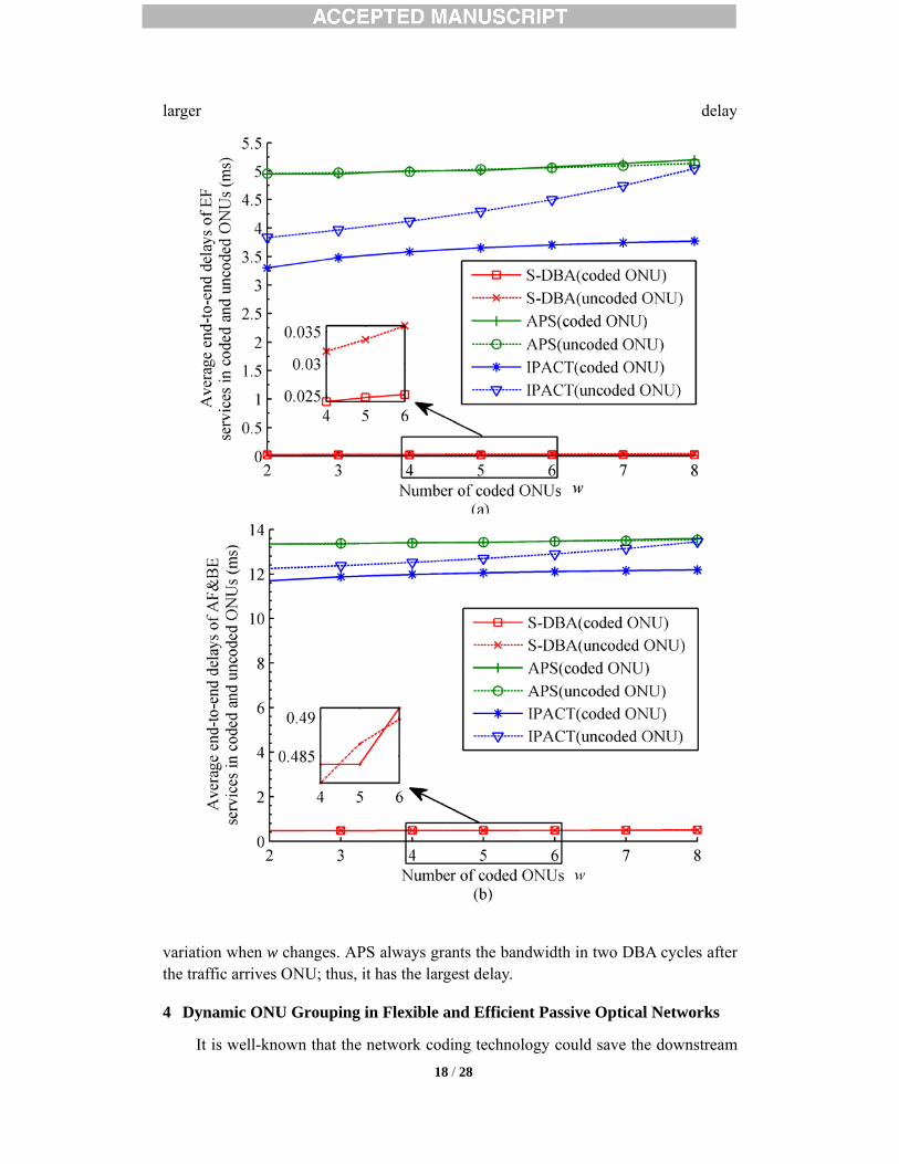
There may be peer communications among several ONUs; thus, we studied the
impact of the number of ONUs joining the network coding group. Suppose the number of coded ONUs is w, which varies from 2 to 8, and the total traffic load was set to 0.7. The end-to-end delay and fairness are evaluated in Fig.5. Compared with APS and IPACT, the average end-to-end delays of EF services in coded and uncoded ONUs in S-DBA keep the smallest when w varies, as shown in Fig. 5. The trend is identical for both EF service and AF&BE services. Similar to the above evaluation, the EF service has the lower delay than AF and BE services, but the EF service has
Fig. 4. Average end-to-end delay of services in coded and uncoded ONUs (load varies).
18 / 28
larger delay
variation when w changes. APS always grants the bandwidth in two DBA cycles after the traffic arrives ONU; thus, it has the largest delay.
4 Dynamic ONU Grouping in Flexible and Efficient Passive Optical Networks
It is well-known that the network coding technology could save the downstream
Fig. 5. Average end-to-end delay of services in coded and uncoded ONUs (w varies).
19 / 28
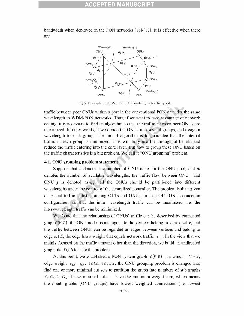
bandwidth when deployed in the PON networks [16]-[17]. It is effective when there are
traffic between peer ONUs within a port in the conventional PON or under the same wavelength in WDM-PON networks. Thus, if we want to take advantage of network coding, it is necessary to find an algorithm so that the traffic between peer ONUs are maximized. In other words, if we divide the ONUs into several groups, and assign a wavelength to each group. The aim of algorithm is to guarantee that the internal traffic in each group is minimized. This will fully use the throughput benefit and reduce the traffic entering into the core layer. But how to group these ONU based on the traffic characteristics is a big problem. We call it “ONU grouping” problem.
4.1. ONU grouping problem statement Suppose that n denotes the number of ONU nodes in the ONU pool, and m
denotes the number of available wavelengths, the traffic flow between ONU i and ONU j is denoted as jie , , all the ONUs should be partitioned into different wavelengths under the control of the centralized controller. The problem is that: given n, m, and traffic statistics among OLTs and ONUs, find an OLT-ONU connection configuration, so that the intra- wavelength traffic can be maximized, i.e. the inter-wavelength traffic can be minimized.
We found that the relationship of ONUs’ traffic can be described by connected graph ( )EVG , , the ONU nodes is analogous to the vertices belong to vertex set V, and the traffic between ONUs can be regarded as edges between vertices and belong to edge set E, the edge has a weight that equals network traffic jie , . In the view that we mainly focused on the traffic amount other than the direction, we build an undirected graph like Fig.6 to state the problem.
At this point, we established a PON system graph ( )EVG , , in which nV = , edge weight jiji ew ,, = , njni ≤≤≤≤ 1,1 , the ONU grouping problem is changed into find one or more minimal cut sets to partition the graph into numbers of sub graphs
mGGGG ...,, 321 . These minimal cut sets have the minimum weight sum, which means these sub graphs (ONU groups) have lowest weighted connections (i.e. lowest
e1, 8
e2, 3
e1, 2 e7, 8
e4, 5e3, 4
e1, 4
e2, 8
e1, 5
e4, 6
e5, 8e6, 7
e5, 6
ONU2
ONU1
ONU3
ONU4 ONU5
ONU8
ONU7
ONU6
Wavelength2
Wavelength3
Wavelength1
Fig.6. Example of 8 ONUs and 3 wavelengths traffic graph

20 / 28
inter-OLT traffic flow). According to the optimal cut sets, the ONUs are divided into groups, and each group of ONU will be connected with an OLT. For example, suppose that the cut sets { 8,1e , 8,2e , 4,1e , 5,1e , 5,2e } and { 8,7e , 8,5e , 6,4e , 5,1e , 5,4e } are minimal cut sets, which divide the ONUs into 3 groups. It means that, ONU1, ONU2 and ONU3 can be assigned to Wavelength1, and ONU5, ONU6, ONU7 can be assigned to Wavelength 3, while ONU4 and ONU8 can be assigned to Wavelength 2. Without loss of generality, the problem discussed in this article consider two wavelengths in the wavelength pools. The algorithm can be easily extended to multiple wavelength problem.
4.2. ONU grouping algorithm In order to find the minimal cut sets of undirected connected graph ( )EVG , , we
introduced an adjacency matrix C, which is a VV × symmetric matrix, that the rows and columns denote the vertices of G, respectively. Each element jiC , denote the edge weight between vertex i and j, and we formulate that 0,, == iiii wC rather than ∞ to make calculation easier.
We consider the situation that cut set Q partition G is required into two parts: sub graph ),( 111 EVG and sub graph ),( 222 EVG . Now, we need to define four terminologies:
Inner weight :For a given node K in sub graph 1G , its inner weight ( )1GIK is the weight sum of links those connect node K and all the other nodes in 1G . i.e.
( ) ∑∑∈∈
==11
1Gi
iKGj
jKK CCGI
(22)
Similarly, for any node M in sub graph 2G , there is (23)
( ) ∑∑∈∈
==22
2Gi
iMGj
jMM CCGI
(23)
Outer weight: For a given node K of sub graph 1G , its outer weight ( )1GEK is the weight sum of links those connect node K and all the nodes in the sub graph 2G , i.e.
( ) ∑∑∈∈
==22
1Gi
iKGj
jKK CCGE
(24)
Similarly, for any node M of sub graph 2G , ( ) ∑∑∈∈
==11
2Gi
iMGj
jMM CCGE
(25) Weight difference: For a given node K of sub graph 1G , the weight difference
( )1GDK equals the difference between ( )1GEK and ( )1GDK , i.e. ( ) ( ) ( )111 GIGEGD KKK −= (26)
As for node M of 2G : ( ) ( ) ( )222 GIGEGD MMM −= (27)
Cut set gain: A given graph G is divided into two sub graphs ),( 111 EVG and

21 / 28
),( 222 EVG by a cut set Q, and the vertex numbers in each sub graph are given. Q
denotes the total link weights of Q. If two nodes from different sub graphs swapped, the cut set Q is changed to Q′ and the sub graphs changed to 1G′ and 2G′ . Q′ equals the new total link weight of cut set Q′ . Then the cut set gain QQRKM ′−= , which means the reduction of new edge weight of Q′ over the old cut set Q.
Before describe the algorithm, we need to present the following three theorems. Theorem 1:Suppose the graph G is divided into two sub graphs ),( 111 EVG and
),( 222 EVG by cut set Q ; 1V and 2V are all pre-determined; and there is ( ) 01 ≤GDK
and ( ) 02 ≤GDM ( 21, GMGK ∈∈∀ ). Then the cut set Q is a minimal cut set. Proof: Assume Q is not a minimal cut set, we can interchange the vertex K in
1G and the vertex M in 2G , so that a new cut set Q′ satisfy the condition QQ <′ . Q′ divides G into two parts: 1G′ and 2G′ . For Q′
( ) ( ) ( ) ( )( ) ( )21
2221
GDGDQ
GIGIGEGEQQ
MK
MKMK
−−=
++−−=′
(28)
As addressed in Theorem 1 condition, ( ) 01 ≤GDK and ( ) 02 ≤GDM . There will be QQ ≥′ based on the expression in (7), which is contradictory with the above
hypothesis QQ <′ . Therefore, the cut set Q must be the minimal cut set. Theorem 2: Suppose the cut set Q cut the graph G into two sub graphs ),( 111 EVG
and ),( 222 EVG , if interchange the vertex K in 1G and the vertex M in 2G , we get a new cut set Q′ and the cut set gain ( ) KMMKKM CGDGDR 2)( 21 −+= .
Proof: Interchanging K and M means that interchanging the row K and row M of the adjacency matrix C, and column K and M of the adjacency matrix C, respectively. According to the Definition 4:
MK
kiGi
iKMMGj
kiGi
iMMjGj
KjKM CCCCCCR −−++−= ∑∑ ∑∑≠∈∈
≠∈∈ 112 2
(29)
In (29), ∑∑∈
≠∈
−=11 Gi
KMiM
kiGi
iM CCC , ∑∑∈
≠∈
−=11 Gi
KKiK
kiGi
iK CCC , and MKKMMMKK CCCC === ,0 ,
therefore,
( ) ( )( ) ( ) ( )( )( ) KMMK
KMMMKK
KMGi Gi
MjiMGj Gi
iKKjKM
CGDGDCGIGEGIGE
CCCCCR
2)(2
2
21
2211
1 22 1
−+=−−+−=
−⎟⎟
⎠
⎞
⎜⎜
⎝
⎛−+⎟
⎟
⎠
⎞
⎜⎜
⎝
⎛−= ∑ ∑∑ ∑
∈ ∈∈ ∈
(30)
Theorem 3: Suppose the cut set Q cut the graph G into two sub graphs ),( 111 EVG and ),( 222 EVG and interchange the vertex K in 1G and the vertex M in 2G . If the cut set gain
KMR is not more than zero 21, GMGK ∈∈∀ , the cut set Q is the minimal cut set; or if KMR is zero, both of the original cut set and the new cut set are the minimal
22 / 28
cut sets. Proof: Suppose Q is not a minimal cut set, there will be a minimal cut set Q′ so
that QQ <′ . According to Definition 4, 0>′−= QQRKM , which is inconsistent the Theorem 4 assumption 0≤KMR . Therefore, the hypothesis is wrong, and the cut set Q must be a minimal cut set. If KMR is exactly zero, then QQ =′ , we conclude that both of Q and Q′ are the minimal cut set.
Based on the above theorems, we propose an efficient “4 steps” algorithm to get a minimal cut set with constraint in undirected connected graph. It is given below:
Step 1: Suppose the initial cut set Q divides G into ),( 111 EVG and ),( 222 EVG , 1V
and 2V are given. List the adjacency matrix C. G represents the entire ONUs and traffic relationship in the pool; 1V and 2V are the ONU number assigned to Wavelength1 and Wavelength2; and C indicates the intra traffic among ONUs.
Step 2: For each vertex 1GK ∈ , 2GM ∈ , calculate vertex’s inner weight ( )1GIK , outer weight ( )1GEK and weight difference ( )1GDK . So as to ( )2GI M , ( )2GEM , ( )2GDM . If ( ) 01 ≤GDK and ( ) 02 ≤GDM , minimal cut founded, go to step 4 directly.
Step 3: Find the vertex K that has maximal ( )1GDK in 1G and the vertex M that has maximal ( )2GDM in 2G , and interchange the vertex K and the vertex M . If the cut set gain 0>KMR , go back to step 2; else, go to step 4.
Step 4: Minimal cut set found, list the vertices of current sub graphs 1G and
2G . It is very easy to use the above 4 steps’ algorithm iteratively to solve multiple
wavelengths ( )2>m scenarios, i.e. to divide graph G into more than 2 sub graphs so that the total link weight of the cut sets is minimized.
The above algorithm could runs on the controller online in the flexible PON network for datacenter networks. The O-ToR will be re-configured according to the new wavelength assignment. And SD-OLTs and ONUs will re-connected at MAC layer and physical layer then. The information exchange between the controller and OLT /O-ToR agent will go through the southbound interface. Considering the short switch time of optic switch (typically several milliseconds for MEMS and mechanical switches), the algorithm is able to support many types of services with strict QoS requirements.
4.3. Experimental evaluation and analysis In order to analyze the performance of the ONU grouping algorithm above, the
experimental simulations are conducted. Consider that a 10Gbps wavelength can be shared by around 10 servers, and WDM technology is expected to support tens or hundreds of servers. The flows among these servers may form a complex traffic graph. In this part, we use Barabasi-Albert (BA) model [22] to generate a series of random graphs which have different nodes number n and Clustering Coefficient GCC ( GCC
=0.2, 0.4, 0.6, 0.8) to simulate the intra connections among different ONUs. It is also

23 / 28
assumed that the total traffic between two ONU nodes ( jiw , ) obeys Poisson distribution with parameterλ .λ denotes average traffic intensity (Mb/s). Considering that we mainly focused on the traffic amount between two nodes (ONUs) rather than the direction of the traffic, λ is non- directional. Besides, since the connected ONU number for each wavelength is predefined, there is no capacity check during the evaluation. To show the benefits from the proposed algorithm, the evaluation process is as followed:
a) Generate a set of random graphs to represent the traffic connections among the ONUs, and assign each link a weight to represent the total traffic between each pair of ONUs.
b) Divide ONUs into several groups randomly, and calculate how much intra traffic needs to be sent outbound. The outbound traffic is corresponding to the total weight of the cut set.
c) Based on the proposed ONU grouping algorithm, an optimal cut set is obtained. Calculate how much intra traffic needs to be sent outbound for the optimal grouping. The outbound traffic is corresponding to the total weight of the cut set.
We define a metric “traffic benefit B” to evaluate the algorithm performance.
( ) ( )
( ) ( )1 1
2 2
1 1
2 2
K MK G M G
M MM G M G
B D G D G
D G D G′∈ ∈
′∈ ∈
′= −
′= −
∑ ∑
∑ ∑ (10)
B denotes the inter-wavelength traffic saving by the ONU grouping algorithm. 1G and 2G denote original random partitioned sub graphs. 1G ′ and 2G′ denote sub
graphs divided by the minimal cut set. The algorithm complexity is evaluated first. We use iterative time as a metric
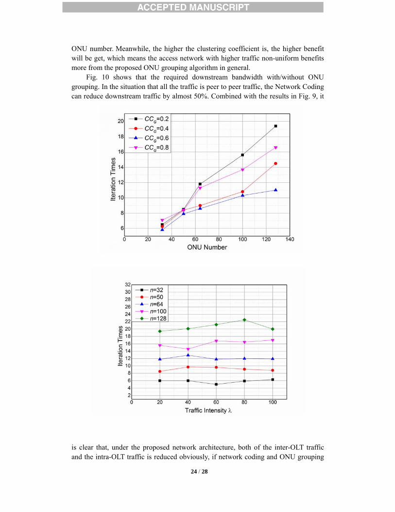
during the simulations. Fig.7 shows the iterative times of the algorithm. The result shows that the iteration time is related linearly to the number of nodes number n. Consider the total add/multiplication operations, the complexity of the algorithm should be O( 2n ).
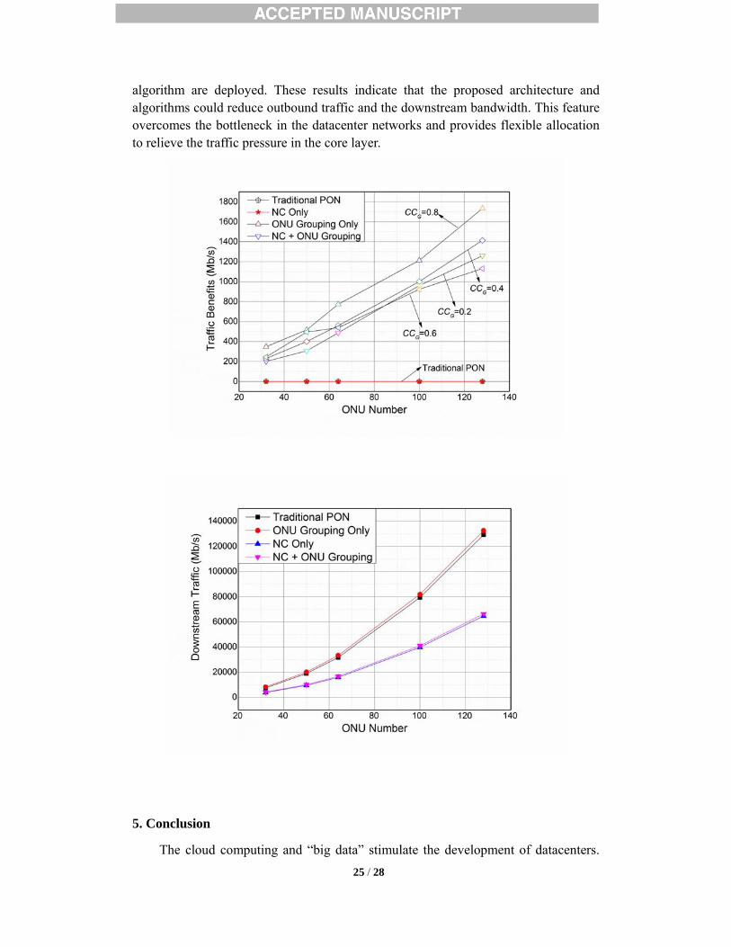
The impact of traffic amount on the time complexity is investigated in Fig.8. The results show that the time complexity will keep steady when the traffic changes. But iteration time increases with the node number n, meaning that ONU number is the major factor to influence the time consumption. In a datacenter networks, an OLT will not connect too many servers. Therefore, the proposed ONU grouping algorithm will perform well in the datacenter network scenario. We also evaluate the traffic benefit between traditional system and the flexible PON architecture with ONU grouping and Network Coding technology. As is shown in Fig.9, without ONU grouping (such as traditional PON system and PON system with Network Coding only) cannot reduce the outbound traffic, so the benefit line is always zero. However, “ONU grouping algorithm only” and “network coding+ ONU grouping” have the same decrease of the outbound traffic, which increases with the
24 / 28
ONU number. Meanwhile, the higher the clustering coefficient is, the higher benefit will be get, which means the access network with higher traffic non-uniform benefits more from the proposed ONU grouping algorithm in general.
Fig. 10 shows that the required downstream bandwidth with/without ONU grouping. In the situation that all the traffic is peer to peer traffic, the Network Coding can reduce downstream traffic by almost 50%. Combined with the results in Fig. 9, it
is clear that, under the proposed network architecture, both of the inter-OLT traffic and the intra-OLT traffic is reduced obviously, if network coding and ONU grouping
Fig.7. Iterative time vs ONU number ( λ =100, CCG: Clustering Coefficient)
Fig.8. Comparison of time under different traffic intensity (Cluster Coefficient=0.2, n: node
number)
25 / 28
algorithm are deployed. These results indicate that the proposed architecture and algorithms could reduce outbound traffic and the downstream bandwidth. This feature overcomes the bottleneck in the datacenter networks and provides flexible allocation to relieve the traffic pressure in the core layer.
5. Conclusion
The cloud computing and “big data” stimulate the development of datacenters.
Fig.9. Comparison of Traffic Benefit under different traffic intensity and PON architecture
(Cluster coefficient=0.2, 0.4, 0.6 0.8, λ =20)
Fig.10 Comparison of Downstream Traffic under different PON system (Cluster coefficient=0.8,
λ =20)

26 / 28
The huge traffic in the datacenter force us to reconsider the architecture of the intra-datacenter networks. In this article, the typical datacenters networks architectures are reviewed and analyzed. It is concluded that it is possible to deploy PON system into the edge layer and aggregation layer of datacenter networks. Then, the great capacity potential of photonics can be used to solve the bandwidth challenge in the datacenter. To overcome the conflict between burst traffic and static optical configuration, we proposed an architecture of software defined flexible and efficient passive optical networks for intra- datacenter communications, which combined the advantages of SDN and network coding.
WDM technologies are used to build up a TWDM-PON system to provide huge capacity. On each wavelength, TDM PON system with network coding is implemented. The network coding (NC) technology will increase the downstream bandwidth efficiency up to 50%. However, conventional DBA algorithms are not suitable for such a kind of PON system, and there are no proper wavelength assignment algorithms neither. This article proposed a seamless DBA scheme to realize an efficient scheduling and resource allocation in time domain and an ONU grouping algorithm to achieve an optimal resource assignment in wavelength domain. These schemes and algorithms allow the network configure the connection and adjust the policies according to the traffic status. All of these dynamic configurations rely on the centralize controller and programmable photonic device and flexible network structure. Further, the experimental simulation show that the proposed schemes and algorithms reduce the transport delay, keep good fairness, increase the efficiency and network flexibility.
Acknowledgements
This research was jointly supported by National High Technology Research and Development Program of China under Grant No. 2011AA01A104, National Natural Science Foundation of China under Grant No. 61372118, Beijing Natural Science Foundation under Grant No.4142036, and Research Fund for Doctoral Program of Higher Education of China under Grant No. 20120005130001, P. R. China.
References.
[1]. S. Aleksić, Analysis of power consumption in future high-capacity network nodes, J. Opt. Commun. Netw. 1(3) (2009) 245-258.
[2]. Y., Qiao, R. Gu, Y. Ji, Parallel optical interconnect technology: combination of higher performance and lower energy consumption, China Commun. 7(3) (2010) 99-106.
[3]. M. Jinno, H. Takara, B. Kozicki, Y. Tsukishima, Y. Sone, and S. Matsuoka, Spectrum-efficient and scalable elastic optical path network: architecture, benefits, and enabling technologies, IEEE Communications Magazine 47 (11) (2009) 66-73.
[4]. G. Zhang, M. D. Leenheer, B. Mukherjee, Optical traffic grooming in OFDM-based elastic optical networks, J. Opt. Commun. Netw. 4(11) (2012) B17-B25.
[5]. K. Christodoulopoulos, I. Tomkos, and E. A. Varvarigos, Elastic bandwidth allocation in flexible OFDM-based optical networks, J. Lightwave Technol. 29 (9) (2011) 1354-1366.
[6]. K. Walkowiak, M. Klinkowski, B. Rabiega, R. Goścień, Routing and spectrum allocation

27 / 28
algorithms for elastic optical networks with dedicated path protection, Opt. Switch. Netw. 13(July)(2014) 63-75.
[7]. A. Banerjee, Y. Park, F. Clarke, H. Song, S. Yang, Glen Kramer, K. Kim, and B. Mukherjee, Wavelength-division-multiplexed passive optical network (WDM-PON) technologies for broadband access: a review, Journal of Optical Networking, 4(11) (2005) 737-758.
[8]. F. Menard, Data center interconnect network topology optimization, in: Proceedings of Data Center World-- the premier international conference for data center and facilities managers, Orlando, Florida, Oct.2 2013, TRD 6.2.
[9]. C. E. Leiserson, Fat-trees: universal networks for hardware-efficient supercomputing, IEEE Trans. Computer, 34 (10) (1985) 892–901.
[10]. R. Niranjan Mysore, A. Pamboris, N. Farrington, N. Huang, P. Miri, S. Radhakrishnan, V. Subramanya, and A. Vahdat, PortLand: a scalable fault-tolerant layer 2 data center network fabric, in: Proceedings of ACM SIGCOMM, Barcelona, Spain, August 17-21, 2009, pp. 39–50.
[11]. A. Greenberg, J. R. Hamilton, N. Jain, S. Kandula, C. Kim, P. Lahiri, D. A. Maltz, P. Patel, and S. Sengupta, VL2: a scalable and flexible data center network, ACM SIGCOMM Comput. Comm. Rev. 39 (4) (2009) 51-62.
[12]. A. Greenberg, P. Lahiri, D. A. Maltz, P. Patel, and S. Sengupta, Towards a next generation data center architecture: scalability and commoditization, in: Proceedings of ACM workshop on Programmable Routers for Extensible Services of Tomorrow, Seattle, WA, USA, August 22, 2008, pp. 57–62.
[13]. S. Jain, A. Kumar, S. Mandal, J. Ong, L. Poutievski, A. Singh, S. Venkata et al., B4: Experience with a globally-deployed software defined WAN, ACM SIGCOMM Comput. Comm. Rev., 43 (4) (2013) 3-14.
[14]. Y. Luo, X. Zhou, F. Effenberger, X. Yan, G. Peng, Y. Qian, and Y. Ma, Time- and Wavelength-Division Multiplexed Passive Optical Network (TWDM-PON) for Next-Generation PON Stage 2 (NG-PON2), Journal of Lightwave Technology, 31(4)(2013) 587-593.
[15]. W. I. Way, Optimum Architecture for M×N Multicast Switch-Based Colorless, Directionless, Contentionless, and Flexible-Grid ROADM, in: Proceedings of National Fiber Optic Engineers Conference, March 4-8, 2012, NW3F.5.
[16]. K. Fouli, M. Maier, and M. Medard, Network coding in next-generation passive optical networks, IEEE Commun. Mag., 49 (9) (2011) 38-46.
[17]. K. Miller, T. Biermann, H. Woesner, H. Karl, Network coding in passive optical networks, in: Proceedings of IEEE International Symposium on Network Coding (NetCod), June 9-11, 2010, pp.1-6.
[18]. P. Wei, R. Gu, Y. Ji, Dynamic bandwidth allocation algorithm for next-generation time division multiplexing passive optical networks with network coding, Opt. Eng. 52(8) (2013) 86-108.
[19]. R. Kubo, M. Tadokoro, H. Nomura, H. Ujikawa, S. Nishihara, K. Suzuki, N. Yoshimoto, Bandwidth scheduling techniques in TDM-PON supporting inter-ONU communication with network coding for smart grid applications, in Proceedings of 2012 IEEE International Conference on Communications (ICC), June 10-15, 2012, pp.3206-3211.
[20]. A. Shami, X. Bai, C. M. Assi, and N. Ghani, Jitter performance in Ethernet passive optical

28 / 28
networks, IEEE/OSA J. Lightwave Technol. 23(4)(2005) 1745-1753. [21]. G. Kramer, B. Mukherjee, and G. Pesavento, IPACT: A Dynamic Protocol for an Ethernet
PON (EPON), IEEE Commun. Mag. 40(2) (2002) 74-80. [22]. A. L. Barabási, R. Albert, Emergence of scaling in random networks, Science 286(5439)
(1999) 509-512.