Embed Size (px)
Citation preview

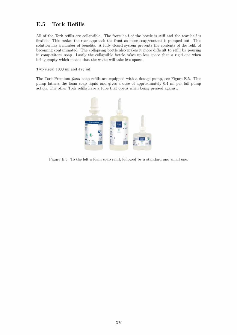
Soap Level Monitoring System Level monitoring system for the SCA Tork S4 foam soap system
Master of Science Thesis
BJOumlRN ARENDAL
JACOB CEDULF
Department of Product and Production Development
Division of Product Development
CHALMERS UNIVERSITY OF TECHNOLOGY
Gothenburg Sweden 2012
Soap Level Monitoring System
Level monitoring system for the SCA Tork S4 foam soap system
Bjoumlrn Arendal
Jacob Cedulf
Copyright copy 2012 Bjoumlrn Arendal amp Jacob Cedulf
Gothenburg Sweden 2012
Chalmers University of Technology
Department of Product and Production Development
SE-41296 Goumlteborg
Sweden
Telephone +46(0)31-772 10 00
Preface
This Master of Science thesis is the final project for us Bjorn Arendal and Jacob Cedulf in ourpostgraduate studies at the Department of Product and Production Development at ChalmersUniversity of Technology It has been carried out at SCA Hygiene Products in Gothenburgduring the spring of 2012
We would like to thank everyone who has been involved for their much appreciated help through-out the project Special thanks go to our SCA supervisors Bjorn Larsson and Gunilla Himmel-mann for all your guidance and support We would also like to thank our supervisor fromChalmers University of Technology Dr Erik Hulthen for help with academic issues Last butnot least we would like to thank our fellow thesis workers at SCA for the collaboration andmany laughs shared
Gothenburg May 2012
Bjorn ArendalJacob Cedulf
Abstract
SCA (Svenska Cellulosa Aktiebolaget) is a global hygiene and paper company Among manyother areas SCA develop products for public washrooms and the purpose of this project wasto create an inexpensive yet reliable electronic soap level measurement system that would addvalue to SCArsquos soap dispenser products All prototypes and tests in this project have beenbased on the SCA Tork S4 foam soap system
To provide the best possible hygiene the S4 soap refills are designed as a closed system Thismeans the surrounding air is kept from entering the refill also when soap is being dispensedTo achieve this the refills collapse and often in an unpredictable manner To find a levelmeasurement method for a refill that collapses unpredictably was the main challenge in thisproject
Three main methods based on capacitance mass and optical properties respectively were proto-typed and tested The rdquowinningrdquo concept measures the weight of the soap by a load cell placedso that it is subjected to the moment with which the dispenser wants to rotate around its lowerattachment points
Initial tests show a promising linear relationship between soap level and sensor readings Futurework is recommended to be aimed at increasing the systemrsquos accuracy for the 0 soap leveland at upgrading the software with features such as refill change detection and adaptive sleepduration between measurements
Sammanfattning
SCA (Svenska Cellulosa Aktiebolaget) ar ett globalt hygien- och pappersforetag Ett av mangaomraden som SCA utvecklar produkter for ar offentliga toalettutrymmen For att potentiellthoja kundvardet hos SCAs tvaldispensrar har detta projekt haft som syfte att ta fram ettelektroniskt matsystem som pa ett palitligt och billigt satt mater tvalniva Alla prototyper ochtester i det har projektet har baserats pa SCA Tork S4 skumtvalsprodukter
For att uppna basta mojliga hygien ar tvalrefillerna hos S4-serien byggda som slutna systemDetta innebar att luft forhindras fran att komma in i refillen aven nar tval pumpas ut For attuppna detta kollapsar refillerna ihop vid anvandning ofta pa ett oregelbundet vis Att hitta ettsystem som kan mata nivan i en kollapsande behallare har varit den huvudsakliga utmaningeni detta projekt
Prototyper gjordes av tre huvudsakliga losningsmetoder som baserades pa kapacitans massa ochoptiska egenskaper Efter att dessa prototyper testats kunde en rdquovinnarerdquo utses som anvandersig utav en lastcell som ersatter de tva ovre skruvarna i dispensern och mater dar kraften medvilken dispensern forsoker rotera kring sin nedre infastning
Tidiga tester visar pa ett nara linjart samband mellan tvalniva och matvarden fran lastcellenRekommendationer for framtida arbete ar bland annat att forbattra matsystemets prestandakring nollniva samt att uppgradera mjukvaran till att adaptivt justera tiden mellan matningaroch hantera refillbyten
Contents
1 Introduction 1
11 Background 1
12 Purpose 2
13 Objective 2
14 Scope 2
2 Methods and materials 3
21 Pre-study 3
22 Concept generation 4
23 Concept evaluation and selection 4
24 Concept development and testing 5
25 Materials 5
3 Dispensers and refills 6
31 The S4 dispenser 6
32 The S4 refill 8
33 System characteristics 10
34 Summary of existing products and competitors 10
4 Sensors and physics 12
41 Reaction forces 12
42 Strain gauges and load cells 13
421 Load cells used in this project 13
43 Capacitance 15
44 Proximity and distance sensors 16
441 IR distance sensor 16
442 Hall effect sensor 16
5 Concepts and prototypes 17
51 Back plate 17
511 Description 17
512 First prototype 18
513 Second prototype 18
52 Donut 19
i
521 Description 19
522 First prototype 20
523 Second prototype 20
524 Third prototype 21
53 Swing 24
54 Optical sensing 24
55 Capacitance 25
551 The RC circuit 25
56 Seal 25
6 Tests and test results 26
61 Test procedures 26
62 Back plate 26
621 First prototype 26
622 Second prototype 29
63 Donut 30
631 First prototype 30
632 Second prototype 31
633 Third prototype 32
64 Swing 34
65 Optical 35
66 Capacitance 36
661 Single plate sensing 36
662 Triple plate sensing 38
663 Tube sensing 40
664 Comments on capacitive sensing 42
7 Concept evaluation and selection 43
71 First screening Categorisation 43
72 Step two Testing 44
73 Step three After tests 44
74 Step four Evaluation of the two final concepts 46
741 Electronic back plate 46
742 Donut 46
743 Winner 46
8 Software 47
9 Discussion 49
91 Project execution 49
92 Measurements 50
921 Expensive sensors 50
ii
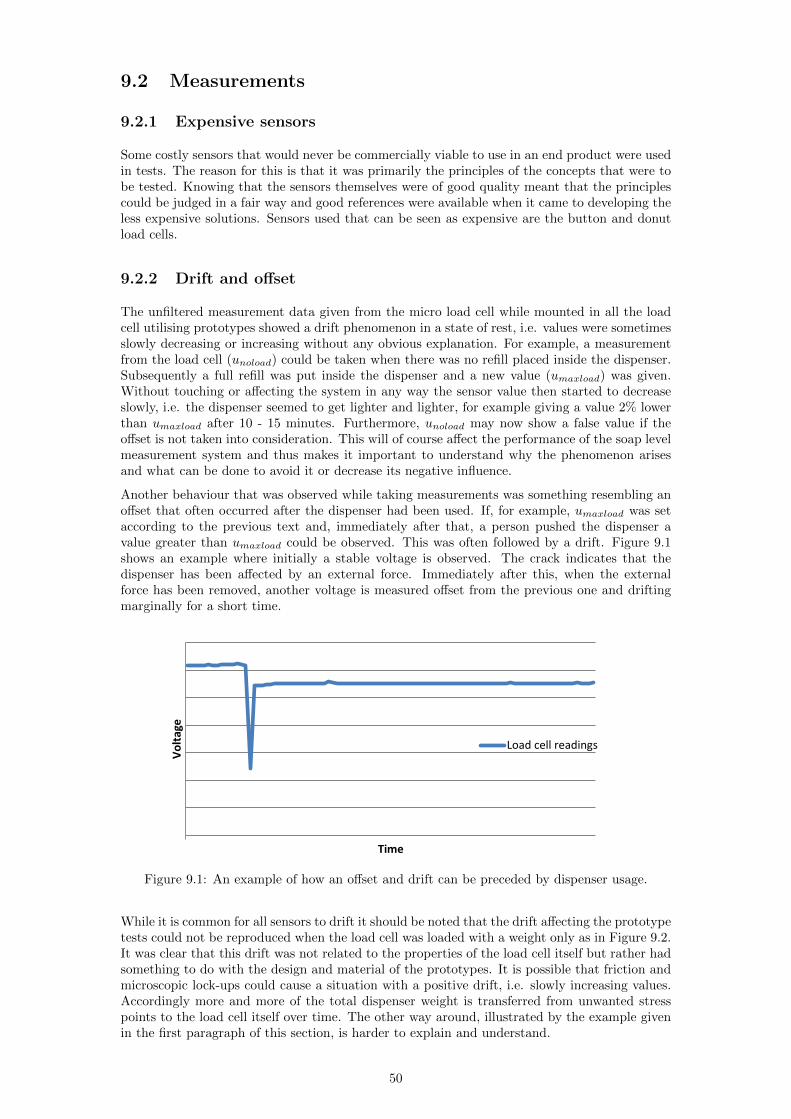
922 Drift and offset 50
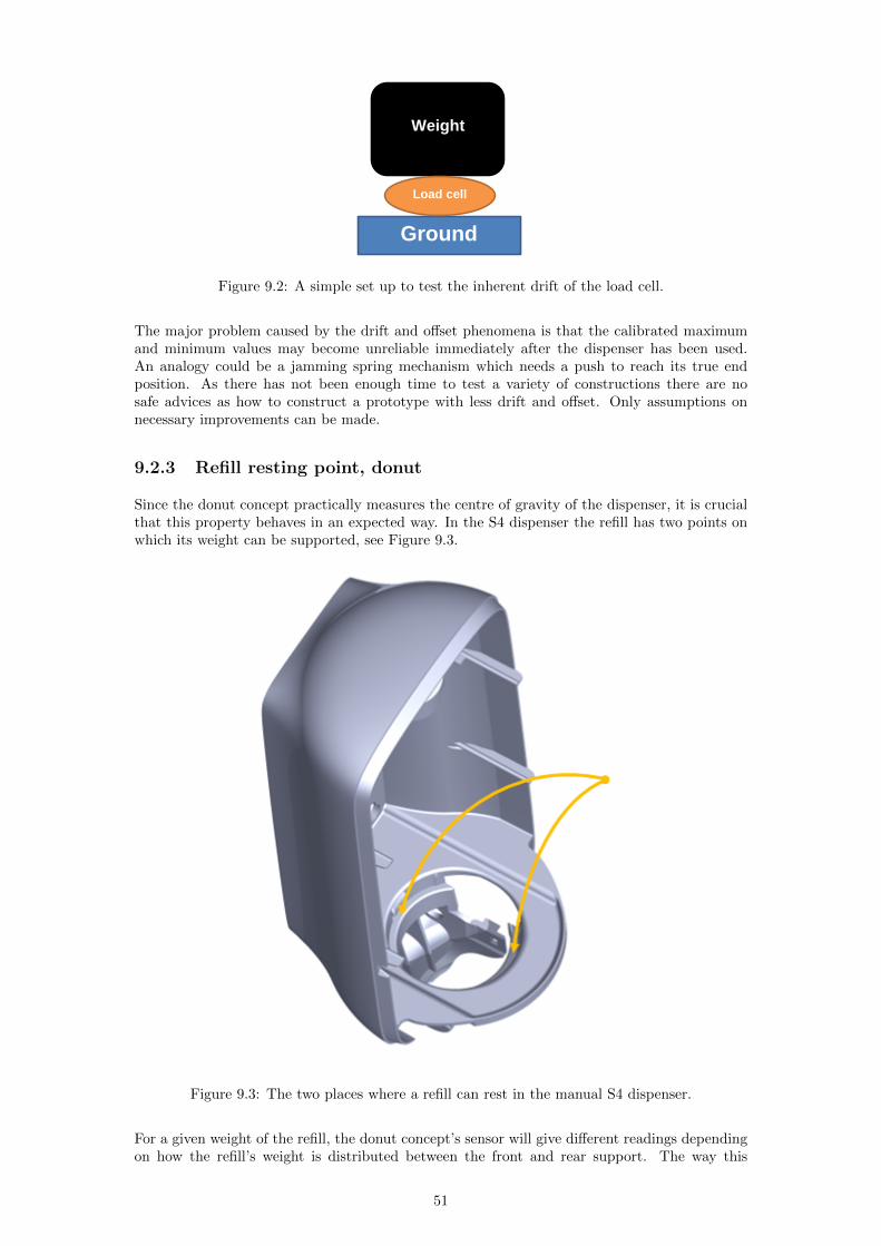
923 Refill resting point donut 51
93 Level indication 52
94 Counting in software 52
95 Other promising concepts 52
951 Capacitance 52
952 Optical 53
953 Back plate 53
96 Other product improvements 53
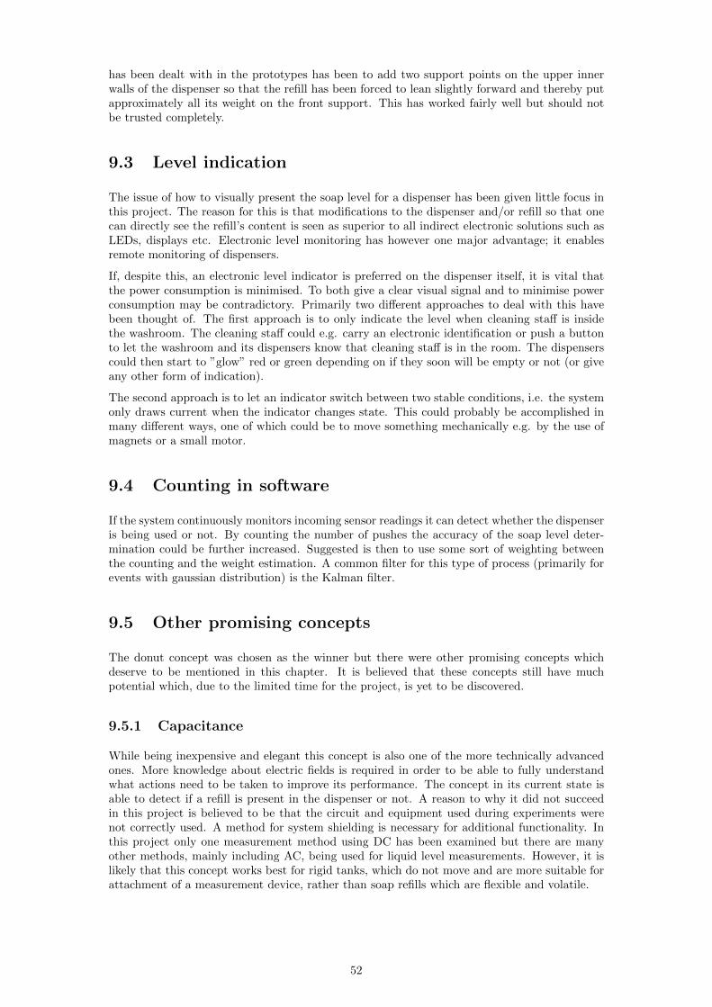
961 The refill 53
962 The dispenser 54
10 Conclusions and recommendations 55
101 Conclusions 55
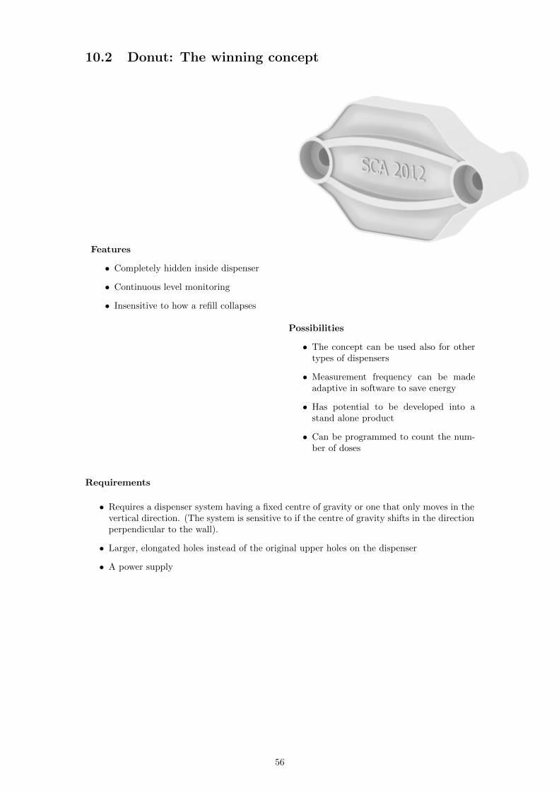
102 Donut The winning concept 56
103 The next version of the donut concept 57
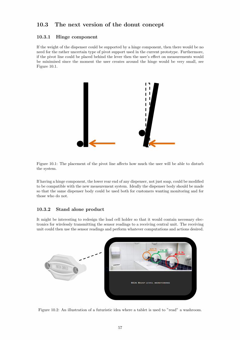
1031 Hinge component 57
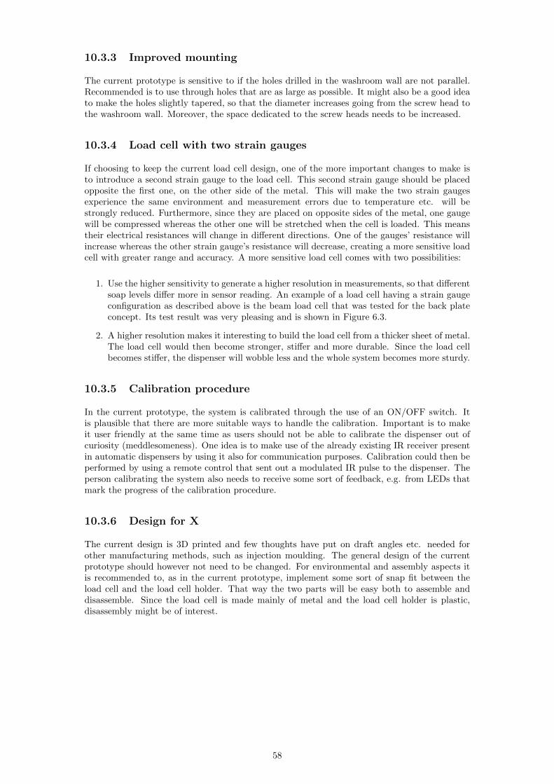
1032 Stand alone product 57
1033 Improved mounting 58
1034 Load cell with two strain gauges 58
1035 Calibration procedure 58
1036 Design for X 58
1037 Software updates 59
A Prototyping platform I
B Patents IV
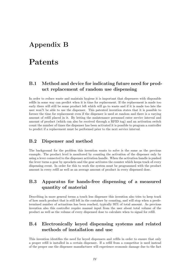
B1 Method and device for indicating future need for product replacement of randomuse dispensing IV
B2 Dispenser and method IV
B3 Apparatus for hands-free dispensing of a measured quantity of material IV
B4 Electronically keyed dispensing systems and related methods of installation anduse IV
B5 Dispensing machine V
B6 System and method for measuring monitoring and controlling washroom dis-pensers and products V
B7 Dispenser with warning device for the level of the content V
B8 A liquid receptacle of rdquobag-in-boxrdquo type V
C Specifications and criteria VI
C1 List of specifications VI
C2 First evaluation matrix criteria VII
C3 Second evaluation matrix criteria VII
iii
D Pugh matrices IX
D1 No modifications IX
D2 Dispenser modifications only X
D3 Modifications to refill or both XI
E Tork dispensers and refills XII
E1 S1 - manual liquid soap system XII
E2 S2 - manual liquid soap system small XII
E3 S3 - automatic foam soap system XII
E4 S4 - manual foam soap system XII
E5 Tork Refills XV
F Existing products and competitors XVI
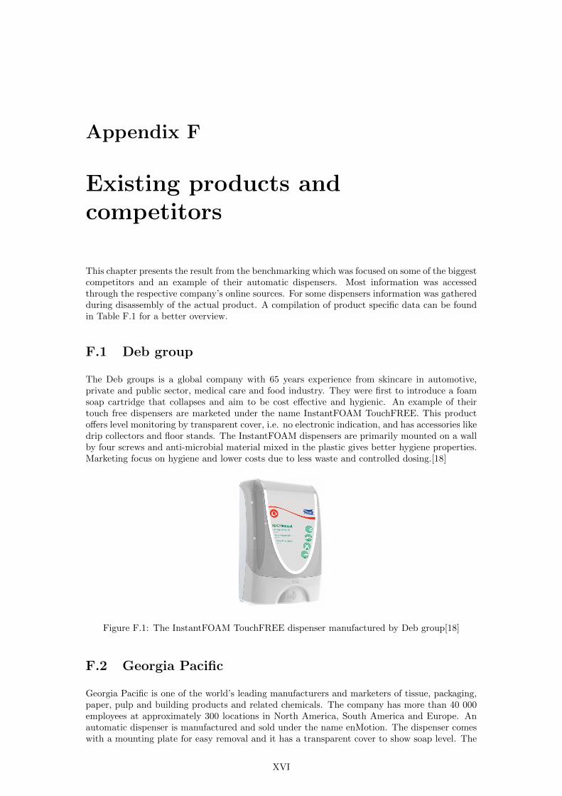
F1 Deb group XVI
F2 Georgia Pacific XVI
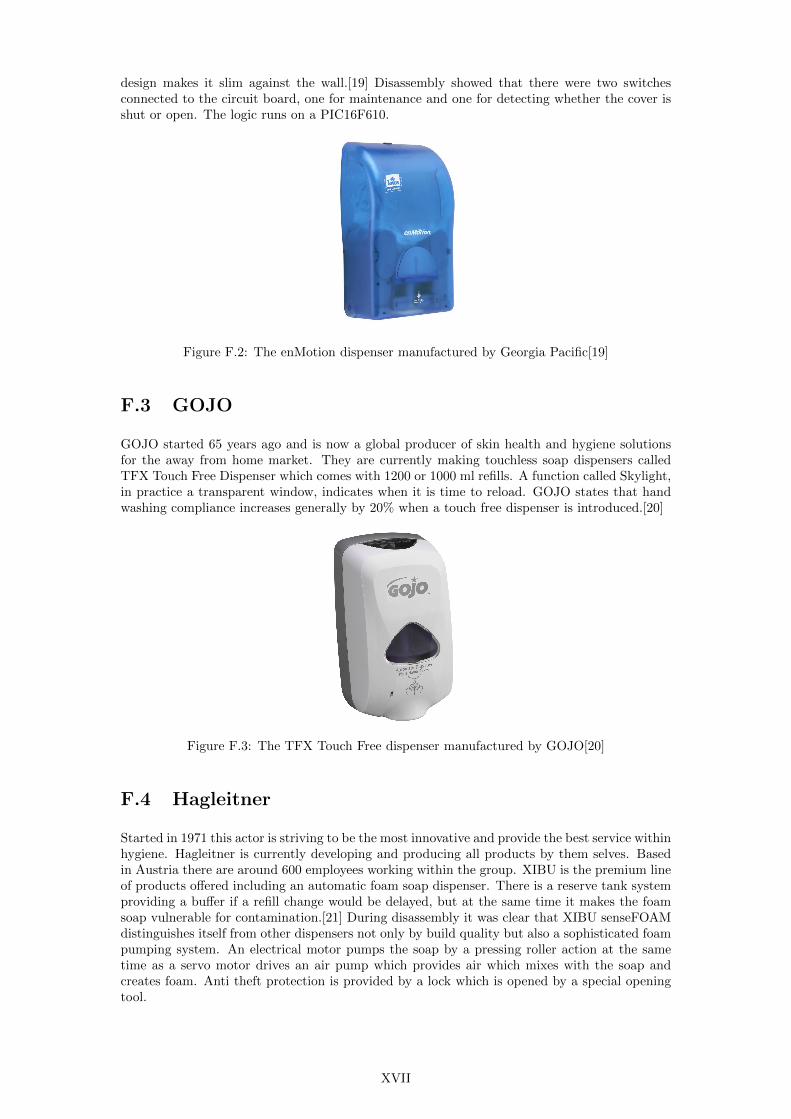
F3 GOJO XVII
F4 Hagleitner XVII
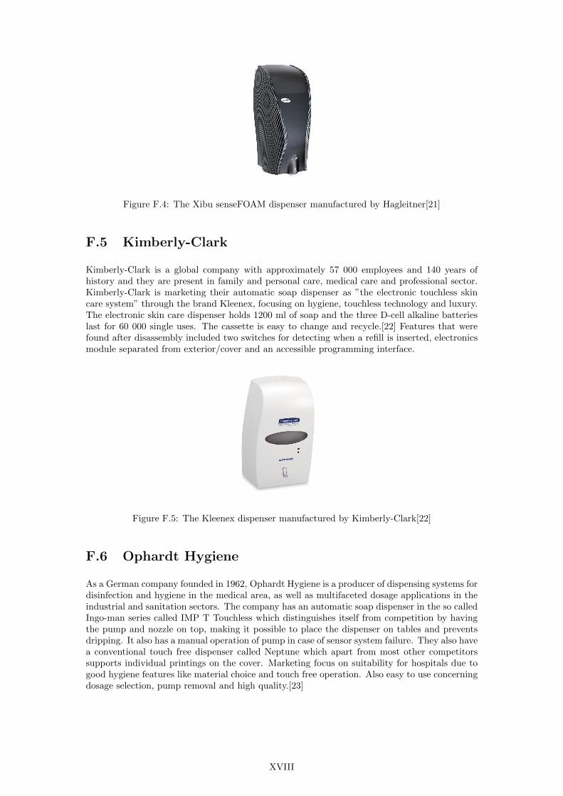
F5 Kimberly-Clark XVIII
F6 Ophardt Hygiene XVIII
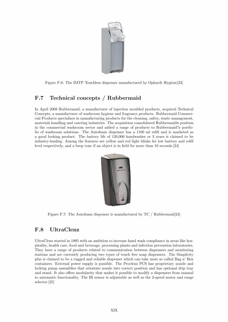
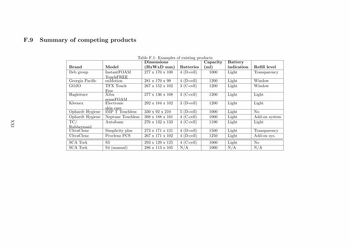
F7 Technical concepts Rubbermaid XIX
F8 UltraClenz XIX
F9 Summary of competing products XXI
G Concept sketches XXII
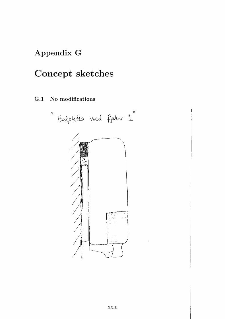
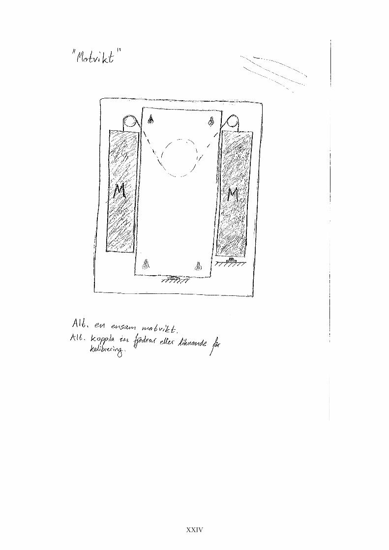
G1 No modifications XXIII
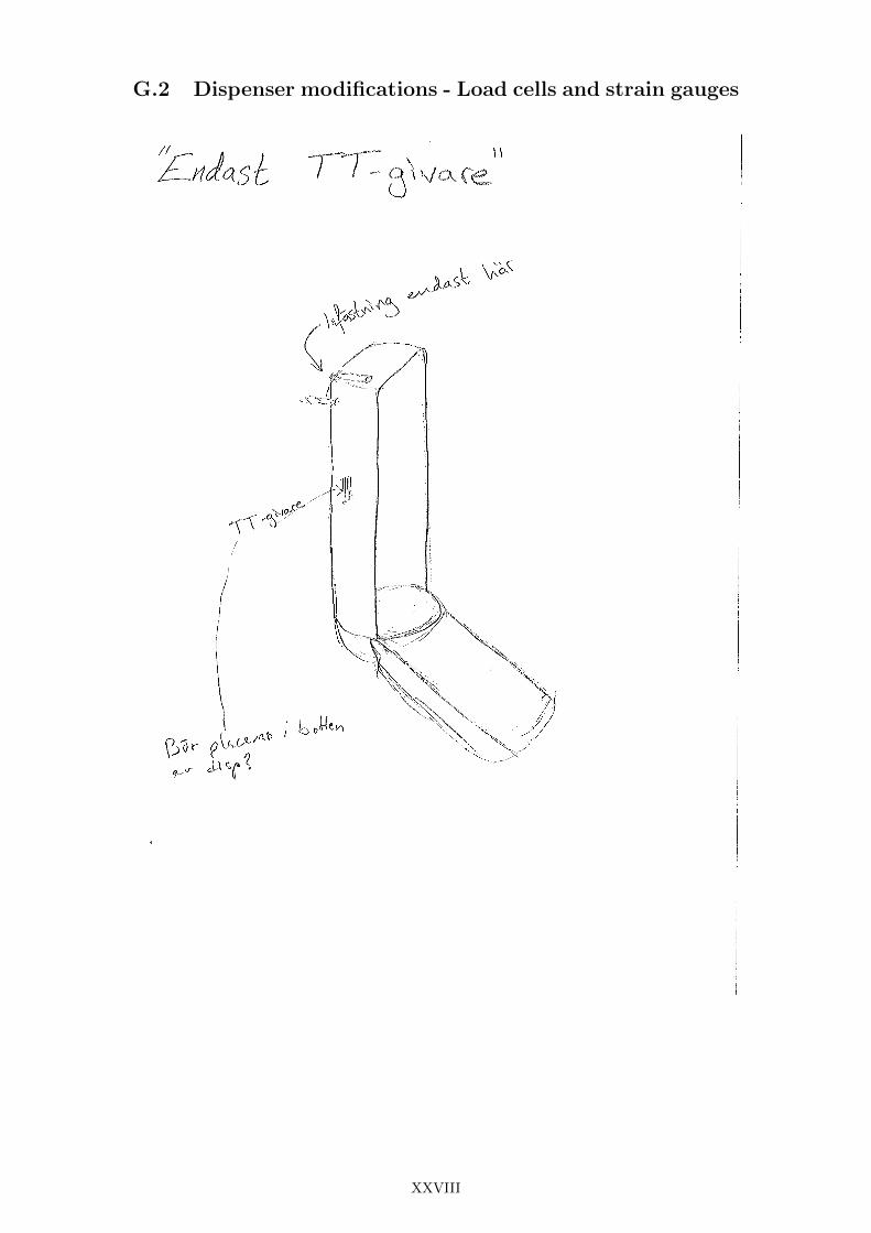
G2 Dispenser modifications - Load cells and strain gauges XXVIII
G3 Dispenser modifications - Other XXXIII
G4 Refill (and dispenser) modifications - Direct electronics XXXVIII
G5 Refill (and dispenser) modifications - Indirect electronics XLIII
G6 Features XLVIII
H Donut test results (TP4) LII
I The Water Bed concept LVII
J The Audio concept LIX
iv
Chapter 1
Introduction
11 Background
SCA (Svenska Cellulosa Aktiebolaget) is a global hygiene and paper company offering a widerange of products and brands Amongst these is the global brand Tork most common to befound on products like toilet paper paper towels napkins and soap In order to make theseproducts available to the end-user the Tork brand also offers dispensers developed specificallyfor a variety of sites and environments[1] An example is soap dispensers adapted for high trafficwashrooms like those found on airports hospitals and shopping malls (Figure 11)
Figure 11 Tork dispensers in a high traffic washroom[1]
For high traffic washrooms current trends point in the direction of better hygiene by increasedhand wash compliance and decreased risk for cross contamination To comply with these needsit is necessary to provide automatic and touch free dispensers as well as always make sure thatthe dispensers are supplied and ready to use This is where an electronic soap level measure-ment system comes into the picture The cost and acceptance of implementing the necessarytechnology have reached levels where SCA find it interesting and feasible to test it on theirautomatic soap and towel dispensers The idea is to have the dispensers indicating their levelof soap and towels respectively in order to let the responsible staff know when it is time forrefill The potential benefits generated by implementing this technology are many For examplethe usage of soap and towels could be monitored more easily and cleaning staff responsible forkeeping dispensers stuffed could rationalize their work[2]
The circumstances described above demands a reliable and inexpensive soap and towel levelmeasurement system As far as soap dispensers are concerned some of the present solutionsfor satisfying these needs implement a counting functionality This makes it possible to keeptrack of the number of doses dispensed and to compare this number with an average maximumcapacity of a refill a method which has proven to be unreliable in some cases
1
12 Purpose
The purpose is to make sure to stay ahead of competitors in the development of public washroomtechnology by providing an inexpensive and reliable solution for soap level measurement whichadds value to SCArsquos soap dispenser products This will be achieved by developing a levelmeasurement system for an electronic foam soap dispenser
13 Objective
The objective is during the time from January to June 2012 to develop an electronic soaplevel measurement system which makes it possible to present the soap level in a dispenser Theproject is to result in one or several functional prototypes
14 Scope
Current automatic dispensers already have batteries circuit board and microcontroller Becauseof this the scope of this project is restricted to the level measurement system only excludingpower supply to the system and design of the soap dispenser itself However minor modificationsof the soap dispenser can be made in order to facilitate level measurement Therefore the powersupply circuits and processor used in combination with the level measurement prototypes willnot be adapted for usage in a final product The project is based on the manual S4 soapdispenser but the resulting system shall be possible to use in future soap dispensers
2
Chapter 2
Methods and materials
This chapter presents the methods and materials that have been used to take this project frompre-study to final prototype The information given is categorised by using the different phasesof the project as sections A product development process similar to the ones presented inmany influential textbooks has been used to ensure that the methods are proven and risksminimised[3][4][5]
21 Pre-study
During the pre-study phase emphasis was put on understanding the product context and char-acteristics of the soap dispenser Efforts were also made to find existing solutions on the marketand patented measurement techniques relevant to dispenser products
Literature studies - was carried out using mainly on-line sources Reports on a variety ofsensor technologies were studied both for learning purposes ie to get familiar with limitationsand possibilities of relevant sensors and to extract ideas from previous experiments and tests
Benchmarking - Information about SCArsquos and competitorsrsquo soap dispensers was gatheredfrom on-line sources provided by each company Specifications key performance indicators andgeometrical dimensions were compiled in tables Disassembly of some competitorsrsquo dispenserswas also done to further examine the internal components and features
Patent searches - took place using the Espacenet patent database Due to the fact that thepatent database contains a very large amount of patents some sort of adapted search methodhad to be applied In this case the search was focused on certain categories where the mostinteresting patents were believed to be found The search results were compiled in a list and byusing this list some patents were chosen for further investigation The categorisation tree wasas follows
1 PHYSICS
(a) MEASURING
i MEASURING VOLUME FLOW VOLUME FLOW MASS FLOW OR LIQUIDLEVEL METERING BY VOLUME
A LEVEL INDICATORS
The hits given by these search restrictions could then be evaluated manually for further ac-tions All relevant patents which were further investigated are presented and briefly explainedin Appendix B
Interviews - took place both at Chalmers University of Technology (Chalmers) with a professorof electrical measurements and with various people at SCA A semi-structured interview methodwas used which allows for more spontaneous follow up questions and sidetracks which is suitablewhen the interviewee has a good understanding of the subject[6]
List of specifications - was established early in the project At this stage it was desirable tokeep most of the specifications general and non-quantitative There is little knowledge available
3
for this type of product and no known existing references on the market which otherwise couldhave provided an indication of performance parameters and other important criteria Instead thelist which is presented in Appendix C was based on information given by SCA A selection ofthe most important specifications was later used in the concept evaluation stage as reformulatedcriteria in the evaluation matrices
22 Concept generation
In the initial stage of the concept generation all possible ideas were desired A large amount ofideas would then be possible to decrease by excluding ideas and concepts with poor performanceie applying a development funnel
Brainstorming - was conducted in various groups and environments External input duringbrainstorming sessions was provided in the form of ideas and suggestions from SCA employeesconsultants and other experts The theme of the sessions was to come up with ideas of differentways to measure soap level
Idea provoking tools - like the TRIZ matrix were used to get a different point of view whentrying to generate new concepts TRIZ is a Russian acronym for a theory which is usually calledThe theory of inventive problem solving in English The essence of this theory has been compiledin a matrix which states several common contradictions between features and suggestions forhow to work around these contradictions[7]
Categorisation - made it possible to handle all the generated ideas in a systematic way Thecategorisation was based on concepts and ideas which shared certain features and the degree ofmodifications needed of the current dispenser and refill The categories were
bull No modifications
bull Dispenser modifications only
bull Modifications to refill or both
23 Concept evaluation and selection
In this stage of the project the aim was to start excluding poor concepts and eventually identifystrengths in certain concepts and use them to improve the weaknesses in others
Evaluation matrices - were created based on guidelines given by Ulrich amp Eppinger [3] Con-cept screening was done using Pugh matrices Evaluation criteria presented in Table C2 inAppendix C were chosen from the list of specifications and all concepts were then compared tochosen reference concept by deciding if the performance was better than worse than or sameas the reference Weaknesses in some concepts could be identified and concepts with high scorecould be further improved Furthermore poor concepts could be revised or excluded and otherswere combined to create new better ones In the final part of the evaluation and selection pro-cess several tests had been done and more knowledge had been gained This made it possible toidentify the most relevant criteria presented in Table C3 in Appendix C when selecting whichconcepts that would make it through to the last part of the concept development stage
External decisions - a number of interim meetings were held with SCA representatives tofollow up on the status of the project Feedback was given on conceptsrsquo performance andpotential based on test results and calculations In some cases decisions were made whether aconcept should be excluded
4
24 Concept development and testing
In this stage all promising concepts were refined Focus was on being able to build prototypeswhich later were to be used in tests After these tests a selection of concepts were furtherdeveloped and tested again Some concept were to be refined several times while others onlywere tested once
CAD tools - were used for everything from concept visualisation to detailed engineering Threedimensional models were created to evaluate and improve various constructions The modelswere also used to create prototypes or parts of prototypes through Selective Laser Sintering
Tests - In the beginning of the test phase there were a large number of concepts to be examinedand a restricted amount of time To test a concept by manually emptying a soap refill whichlasts for approximately 2500 doses would take too long Hence a fast and easily accessibletest was needed which could be performed many times but still be able to indicate how well acertain concept would perform in a real environment Later when some of the concepts had beenexcluded a new test was used which was allowed to take more time so as to get closer to a realusage situation The new test procedure was possible thanks to a machine which emptied therefill by pushing the dispenser automatically When only the most promising concepts were lefta manual and time consuming but realistic test could be used The aim was to simulate randompushes which the measurement system would not be subjected to in the pumping machine Thelast test was carried out in a restroom at SCArsquos office to get a genuine real environment
25 Materials
All hardware and software used in this project and their functions are listed in Table 21 Formore details about the project specific prototyping platform see Appendix A As both the microand beam load cells have been taken from commercially available kitchen scales there are nospecifications or further details about them
Table 21 A list of software and hardware usedFunction MeansPrototyping platform 1 Project specific (ATMega324PA)Prototyping platform 2 Arduino UnoComputer Aided Design Autodesk inventor 2012Patent database EspacenetCalculation and plotting 1 MatlabCalculation and plotting 2 Excel 2012AVR programming 1 AVR Studio 4AVR programming 2 IAR WorkbenchDonut load cell Futek LTH300Button load cell Honeywell FSS load sensorIR distance sensor Everlight Electronics ITR 8307Hall effect sensor Allegro A1324Micro load cell NABeam load cell NA
5
Chapter 3
Dispensers and refills
In order to better understand what design problems that have been faced and how the conceptsare supposed to work some important information about the S4 dispenser and refill is requiredThis information can be found in this chapter To get a better overview of the product contextand other dispensers more information can be found in Appendix E and Appendix F whichpresent Tork products and competitorsrsquo products respectively
31 The S4 dispenser
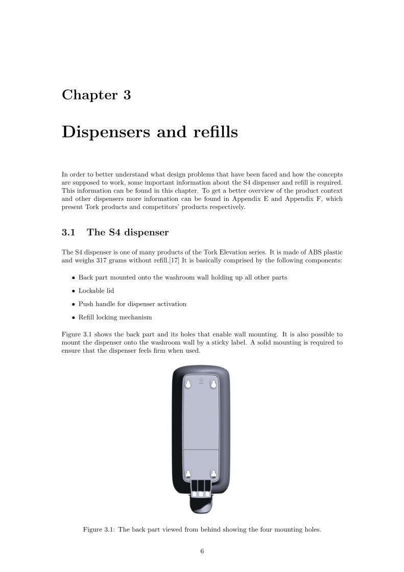
The S4 dispenser is one of many products of the Tork Elevation series It is made of ABS plasticand weighs 317 grams without refill[17] It is basically comprised by the following components
bull Back part mounted onto the washroom wall holding up all other parts
bull Lockable lid
bull Push handle for dispenser activation
bull Refill locking mechanism
Figure 31 shows the back part and its holes that enable wall mounting It is also possible tomount the dispenser onto the washroom wall by a sticky label A solid mounting is required toensure that the dispenser feels firm when used
Figure 31 The back part viewed from behind showing the four mounting holes
6
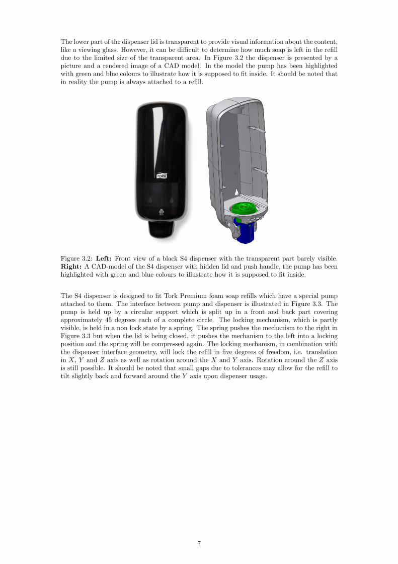
The lower part of the dispenser lid is transparent to provide visual information about the contentlike a viewing glass However it can be difficult to determine how much soap is left in the refilldue to the limited size of the transparent area In Figure 32 the dispenser is presented by apicture and a rendered image of a CAD model In the model the pump has been highlightedwith green and blue colours to illustrate how it is supposed to fit inside It should be noted thatin reality the pump is always attached to a refill
Figure 32 Left Front view of a black S4 dispenser with the transparent part barely visibleRight A CAD-model of the S4 dispenser with hidden lid and push handle the pump has beenhighlighted with green and blue colours to illustrate how it is supposed to fit inside
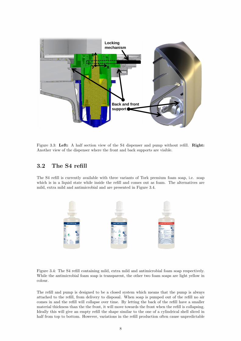
The S4 dispenser is designed to fit Tork Premium foam soap refills which have a special pumpattached to them The interface between pump and dispenser is illustrated in Figure 33 Thepump is held up by a circular support which is split up in a front and back part coveringapproximately 45 degrees each of a complete circle The locking mechanism which is partlyvisible is held in a non lock state by a spring The spring pushes the mechanism to the right inFigure 33 but when the lid is being closed it pushes the mechanism to the left into a lockingposition and the spring will be compressed again The locking mechanism in combination withthe dispenser interface geometry will lock the refill in five degrees of freedom ie translationin X Y and Z axis as well as rotation around the X and Y axis Rotation around the Z axisis still possible It should be noted that small gaps due to tolerances may allow for the refill totilt slightly back and forward around the Y axis upon dispenser usage
7
Back and front
support
Locking
mechanism
z
x y
Figure 33 Left A half section view of the S4 dispenser and pump without refill RightAnother view of the dispenser where the front and back supports are visible
32 The S4 refill
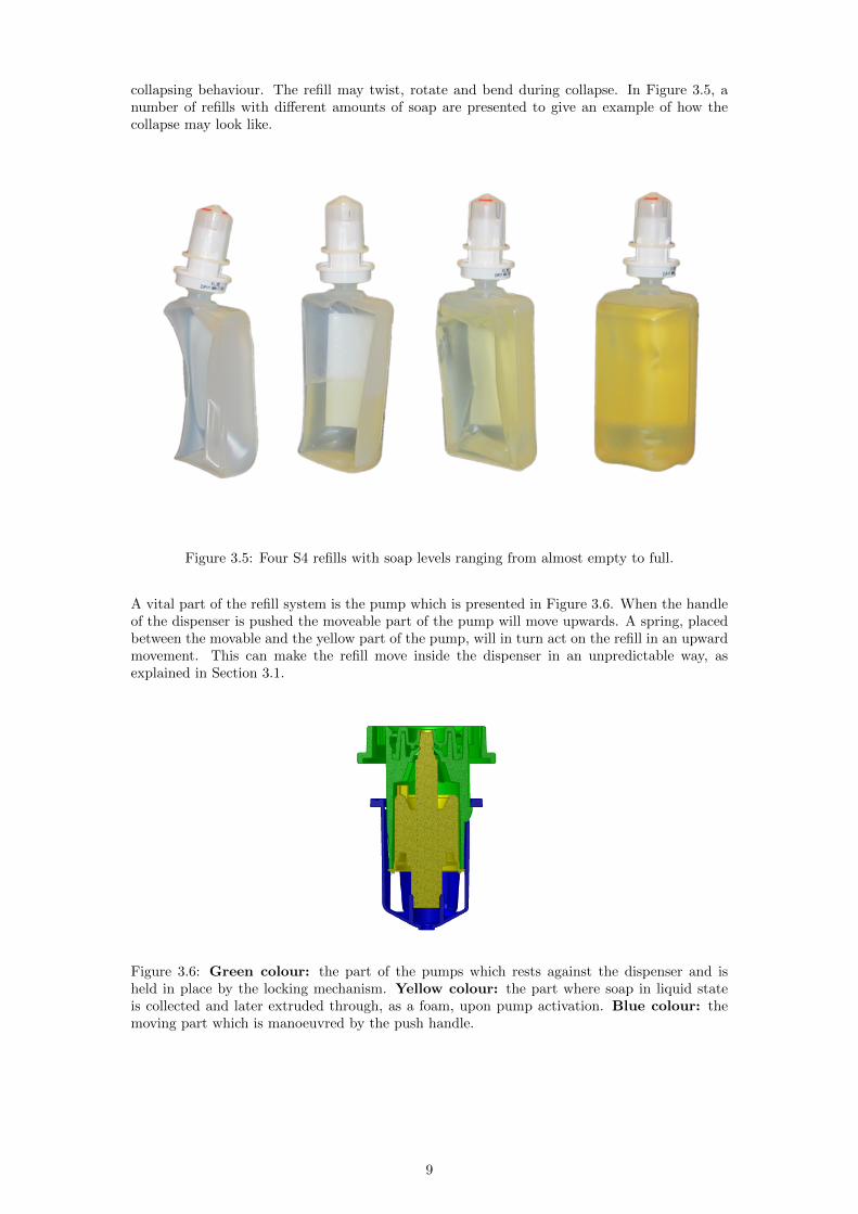
The S4 refill is currently available with three variants of Tork premium foam soap ie soapwhich is in a liquid state while inside the refill and comes out as foam The alternatives aremild extra mild and antimicrobial and are presented in Figure 34
Figure 34 The S4 refill containing mild extra mild and antimicrobial foam soap respectivelyWhile the antimicrobial foam soap is transparent the other two foam soaps are light yellow incolour
The refill and pump is designed to be a closed system which means that the pump is alwaysattached to the refill from delivery to disposal When soap is pumped out of the refill no aircomes in and the refill will collapse over time By letting the back of the refill have a smallermaterial thickness than the the front it will move towards the front when the refill is collapsingIdeally this will give an empty refill the shape similar to the one of a cylindrical shell sliced inhalf from top to bottom However variations in the refill production often cause unpredictable
8
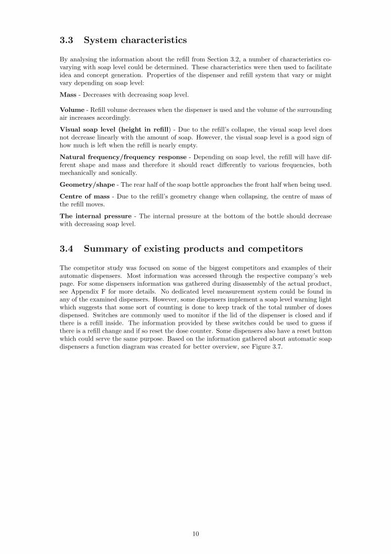
collapsing behaviour The refill may twist rotate and bend during collapse In Figure 35 anumber of refills with different amounts of soap are presented to give an example of how thecollapse may look like
Figure 35 Four S4 refills with soap levels ranging from almost empty to full
A vital part of the refill system is the pump which is presented in Figure 36 When the handleof the dispenser is pushed the moveable part of the pump will move upwards A spring placedbetween the movable and the yellow part of the pump will in turn act on the refill in an upwardmovement This can make the refill move inside the dispenser in an unpredictable way asexplained in Section 31
Figure 36 Green colour the part of the pumps which rests against the dispenser and isheld in place by the locking mechanism Yellow colour the part where soap in liquid stateis collected and later extruded through as a foam upon pump activation Blue colour themoving part which is manoeuvred by the push handle
9
33 System characteristics
By analysing the information about the refill from Section 32 a number of characteristics co-varying with soap level could be determined These characteristics were then used to facilitateidea and concept generation Properties of the dispenser and refill system that vary or mightvary depending on soap level
Mass - Decreases with decreasing soap level
Volume - Refill volume decreases when the dispenser is used and the volume of the surroundingair increases accordingly
Visual soap level (height in refill) - Due to the refillrsquos collapse the visual soap level doesnot decrease linearly with the amount of soap However the visual soap level is a good sign ofhow much is left when the refill is nearly empty
Natural frequencyfrequency response - Depending on soap level the refill will have dif-ferent shape and mass and therefore it should react differently to various frequencies bothmechanically and sonically
Geometryshape - The rear half of the soap bottle approaches the front half when being used
Centre of mass - Due to the refillrsquos geometry change when collapsing the centre of mass ofthe refill moves
The internal pressure - The internal pressure at the bottom of the bottle should decreasewith decreasing soap level
34 Summary of existing products and competitors
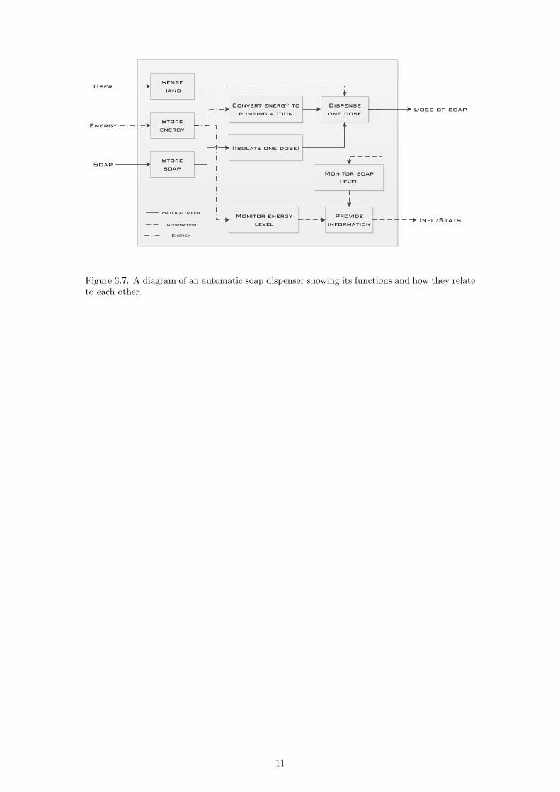
The competitor study was focused on some of the biggest competitors and examples of theirautomatic dispensers Most information was accessed through the respective companyrsquos webpage For some dispensers information was gathered during disassembly of the actual productsee Appendix F for more details No dedicated level measurement system could be found inany of the examined dispensers However some dispensers implement a soap level warning lightwhich suggests that some sort of counting is done to keep track of the total number of dosesdispensed Switches are commonly used to monitor if the lid of the dispenser is closed and ifthere is a refill inside The information provided by these switches could be used to guess ifthere is a refill change and if so reset the dose counter Some dispensers also have a reset buttonwhich could serve the same purpose Based on the information gathered about automatic soapdispensers a function diagram was created for better overview see Figure 37
10
Sense
hand
Store
energy
Store
soap
Convert energy to
pumping action
(Isolate one dose)
Monitor energy
level
Monitor soap
level
Dispense
one dose
Provide
information
User
Energy
Soap
InfoStats
Dose of soap
MaterialMech
Information
Energy
Figure 37 A diagram of an automatic soap dispenser showing its functions and how they relateto each other
11
Chapter 4
Sensors and physics
This chapter gives an introduction to the physics and sensors utilised in the most interestingconcepts and their tests The purpose is to make it easier to understand the function of theconcepts presented in Chapter 5 and the tests described in Chapter 6
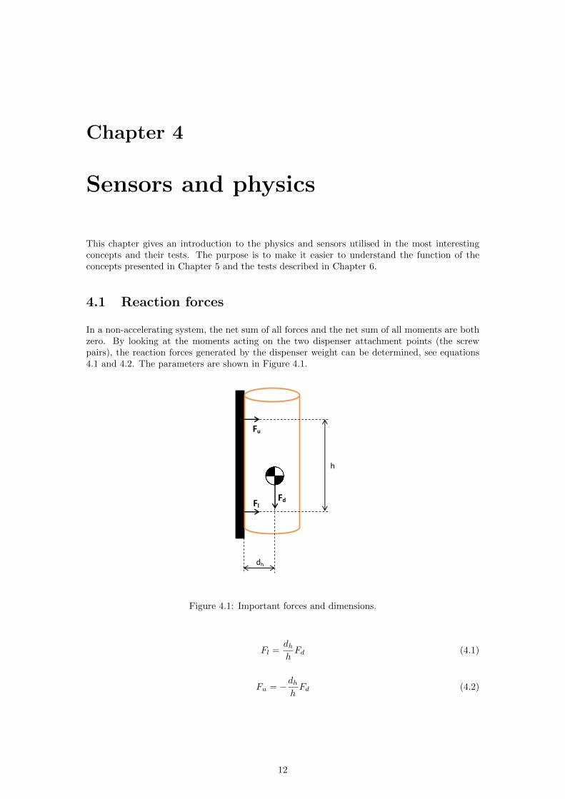
41 Reaction forces
In a non-accelerating system the net sum of all forces and the net sum of all moments are bothzero By looking at the moments acting on the two dispenser attachment points (the screwpairs) the reaction forces generated by the dispenser weight can be determined see equations41 and 42 The parameters are shown in Figure 41
h
dh
Fl
Fu
Fd
Figure 41 Important forces and dimensions
Fl =dhhFd (41)
Fu = minusdhhFd (42)
12
42 Strain gauges and load cells
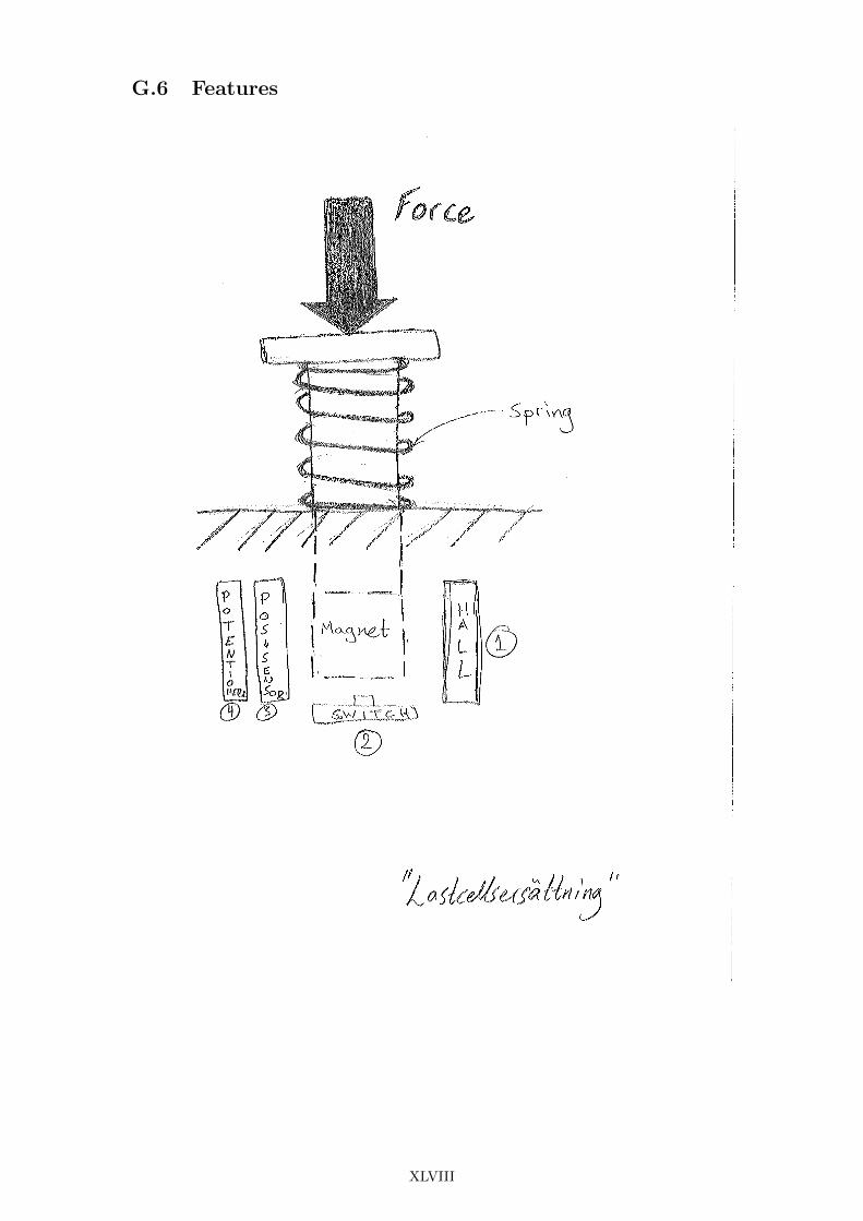
The most common way to measure strain is to use one or more strain gauges One-dimensionalstrain ε in a material is the fraction between change in length ∆L and the total (relaxed)length in that direction L
ε =∆L
L(43)
The material can be seen as a spring the more loaded the material is the longer it gets andthe greater the strain Strain gauges are constructed in such a way that their electric resistancechanges with their length They are carefully glued to the material on which the measurementswill be taken so that the strain of the material and the strain gauge will be the same [9] [10]
Strain gauges are often the sensing elements in so called load cells Load cells measure force ortorque and have built-in elastic mechanical components on which the strain gauges are mountedThe load cells are often built in such a way that the measurement is proportional to the forceapplied to them This makes them convenient to use and they are common in many types ofapplications such as kitchen and bathroom scales industrial force measurements etc [9] [10]
421 Load cells used in this project
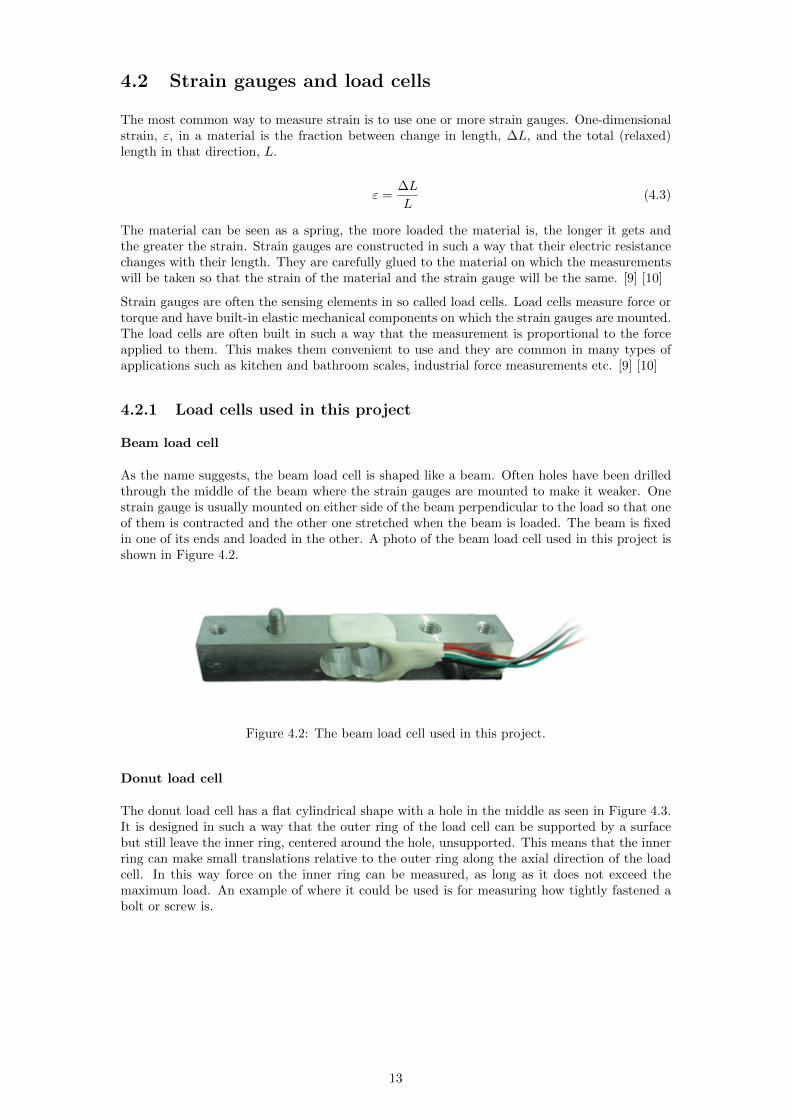
Beam load cell
As the name suggests the beam load cell is shaped like a beam Often holes have been drilledthrough the middle of the beam where the strain gauges are mounted to make it weaker Onestrain gauge is usually mounted on either side of the beam perpendicular to the load so that oneof them is contracted and the other one stretched when the beam is loaded The beam is fixedin one of its ends and loaded in the other A photo of the beam load cell used in this project isshown in Figure 42
Figure 42 The beam load cell used in this project
Donut load cell
The donut load cell has a flat cylindrical shape with a hole in the middle as seen in Figure 43It is designed in such a way that the outer ring of the load cell can be supported by a surfacebut still leave the inner ring centered around the hole unsupported This means that the innerring can make small translations relative to the outer ring along the axial direction of the loadcell In this way force on the inner ring can be measured as long as it does not exceed themaximum load An example of where it could be used is for measuring how tightly fastened abolt or screw is
13
Figure 43 The donut shaped load cell used in this project
Micro load cell
Since the micro load cellrsquos flexible component is a punched out piece of sheet steel it can bemade very flat The cell is designed in such a way that it has an outer ring that is to be heldfixed and an inner beam for bending on which one or two strain gauges are mounted In thisproject micro load cells were taken from a kitchen scale and had therefore a rather large plasticpart attached to them which had acted as one of the scalersquos feet see Figure 44
Figure 44 The micro load cell used in this project
Button load cell
The smallest type of load cell used in this project is the button load cell shown in Figure 45Its flat rear is fixed and the load is placed on the metallic rdquoballrdquo on its front
14
Figure 45 The button load cell used in this project
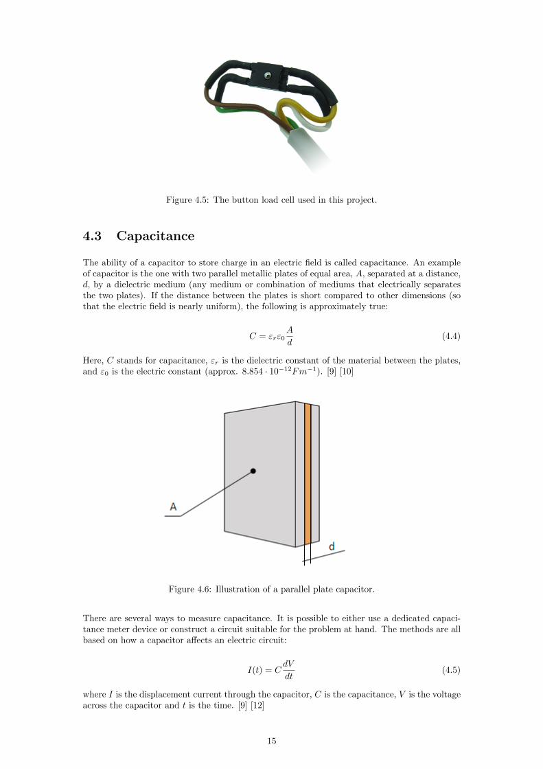
43 Capacitance
The ability of a capacitor to store charge in an electric field is called capacitance An exampleof capacitor is the one with two parallel metallic plates of equal area A separated at a distanced by a dielectric medium (any medium or combination of mediums that electrically separatesthe two plates) If the distance between the plates is short compared to other dimensions (sothat the electric field is nearly uniform) the following is approximately true
C = εrε0A
d(44)
Here C stands for capacitance εr is the dielectric constant of the material between the platesand ε0 is the electric constant (approx 8854 middot 10minus12Fmminus1) [9] [10]
Figure 46 Illustration of a parallel plate capacitor
There are several ways to measure capacitance It is possible to either use a dedicated capaci-tance meter device or construct a circuit suitable for the problem at hand The methods are allbased on how a capacitor affects an electric circuit
I(t) = CdV
dt(45)
where I is the displacement current through the capacitor C is the capacitance V is the voltageacross the capacitor and t is the time [9] [12]
15
44 Proximity and distance sensors
441 IR distance sensor
Infrared (IR) light is electromagnetic radiation with wavelength greater than that of visible lightIt can be used in electronic circuits for several purposes one of which is distance measurementAn IR distance sensor has a light emitting diode (LED) that sends out infrared light and aphototransistor that measures the strength or amount of the reflected light coming back If thesensor is analogue then the output voltage will vary with the distance to the sensed objectPlease note however that for a certain distance the output will depend also on the propertiesof the object such as its colour texture etc IR distance sensors are often one of the moreinexpensive options when it comes to distance measurements[10]
442 Hall effect sensor
Hall effect sensors respond to the flux density of a magnetic field They exist both as digital(ONOFF) and as analogue sensors If using an analogue sensor it is possible to eg determinethe distance to a magnet or detect variations in the magnetic field between the sensor and amagnet For example the flux density B at a distance x from a rectangular magnet can bedescribed as
B(x) =Br
π(atan (U(x))minus atan (V (x))) (46)
U(x) =WL
2xradic
4x2 +W 2 + L2(47)
V (x) =WL
2(x+ T )radic
4(x+ T )2 +W 2 + L2(48)
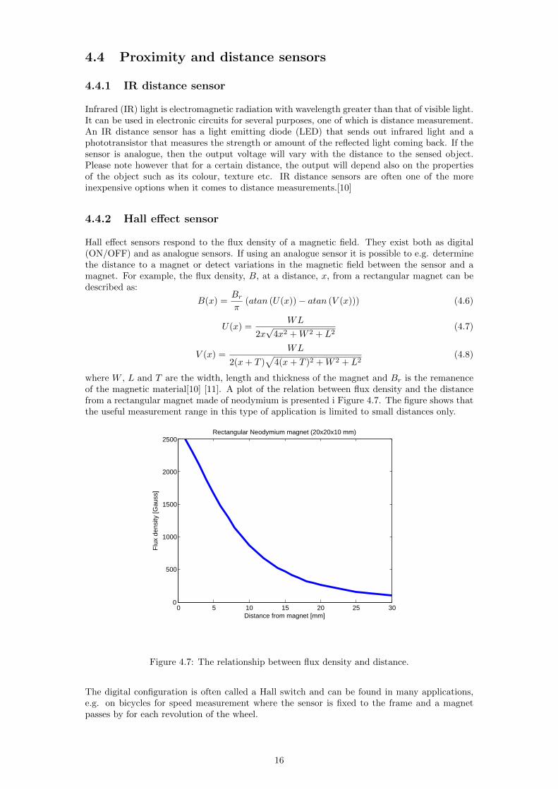
where W L and T are the width length and thickness of the magnet and Br is the remanenceof the magnetic material[10] [11] A plot of the relation between flux density and the distancefrom a rectangular magnet made of neodymium is presented i Figure 47 The figure shows thatthe useful measurement range in this type of application is limited to small distances only
0 5 10 15 20 25 300
500
1000
1500
2000
2500Rectangular Neodymium magnet (20x20x10 mm)
Flu
x de
nsity
[Gau
ss]
Distance from magnet [mm]
Figure 47 The relationship between flux density and distance
The digital configuration is often called a Hall switch and can be found in many applicationseg on bicycles for speed measurement where the sensor is fixed to the frame and a magnetpasses by for each revolution of the wheel
16
Chapter 5
Concepts and prototypes
Several measurement methods were prototyped and tested to facilitate concept evaluation Theconcepts called rdquoBack platerdquo and rdquoDonutrdquo were seen as the most interesting and they weretherefore prototyped more than once The last prototypes had a commercially more viabledesign Only the concepts that were taken all the way to testing are described in this chapterSketches of these and all other ideas are found in Appendix G1 The evaluation and selectionprocess is described in Chapter 7 Concepts involving sensors whose output need to be amplifiedhave been used together with an externally developed circuit board based on the ATmega324PAmicrocontroller Sensors that do not need amplification have been used with an Arduino Unoprototyping platform
51 Back plate
511 Description
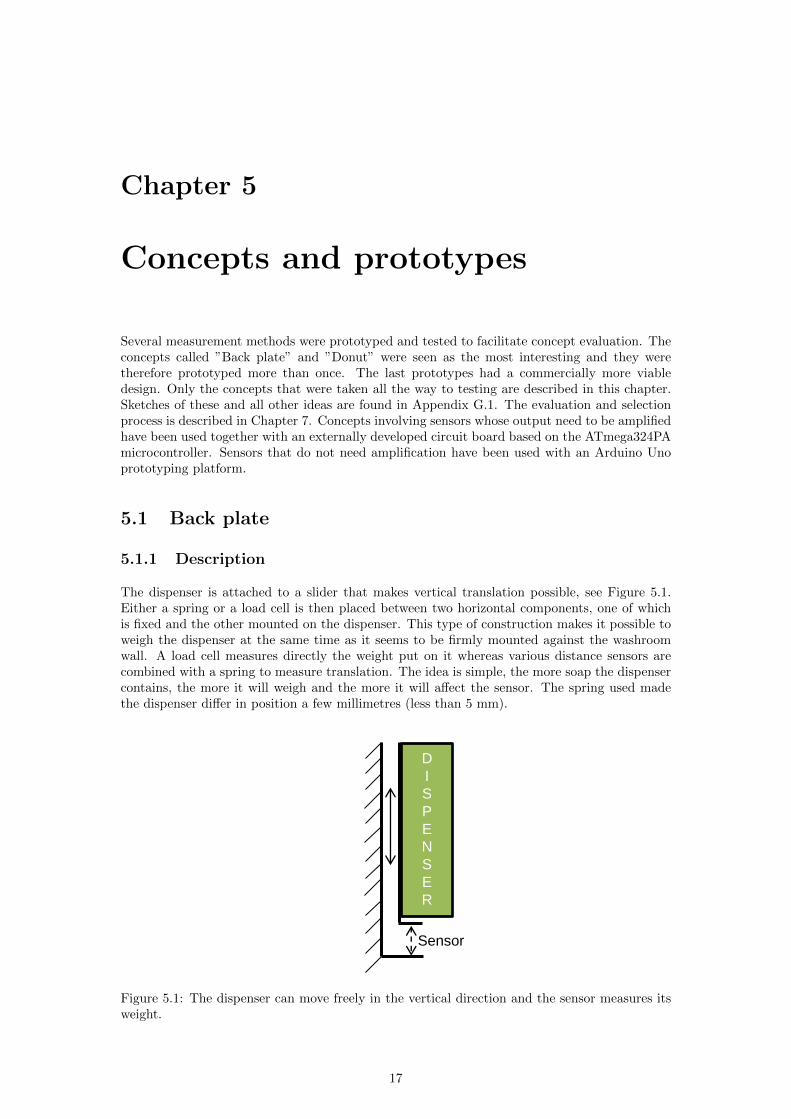
The dispenser is attached to a slider that makes vertical translation possible see Figure 51Either a spring or a load cell is then placed between two horizontal components one of whichis fixed and the other mounted on the dispenser This type of construction makes it possible toweigh the dispenser at the same time as it seems to be firmly mounted against the washroomwall A load cell measures directly the weight put on it whereas various distance sensors arecombined with a spring to measure translation The idea is simple the more soap the dispensercontains the more it will weigh and the more it will affect the sensor The spring used madethe dispenser differ in position a few millimetres (less than 5 mm)
Sensor
D
I
S
P
E
N
S
E
R
Figure 51 The dispenser can move freely in the vertical direction and the sensor measures itsweight
17
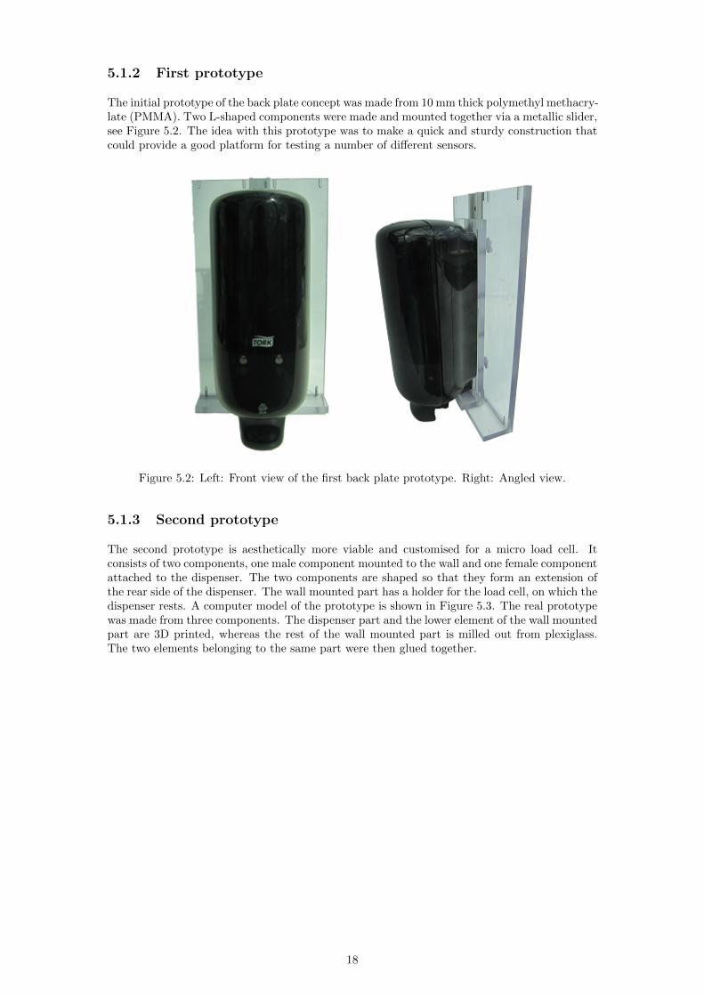
512 First prototype
The initial prototype of the back plate concept was made from 10 mm thick polymethyl methacry-late (PMMA) Two L-shaped components were made and mounted together via a metallic slidersee Figure 52 The idea with this prototype was to make a quick and sturdy construction thatcould provide a good platform for testing a number of different sensors
Figure 52 Left Front view of the first back plate prototype Right Angled view
513 Second prototype
The second prototype is aesthetically more viable and customised for a micro load cell Itconsists of two components one male component mounted to the wall and one female componentattached to the dispenser The two components are shaped so that they form an extension ofthe rear side of the dispenser The wall mounted part has a holder for the load cell on which thedispenser rests A computer model of the prototype is shown in Figure 53 The real prototypewas made from three components The dispenser part and the lower element of the wall mountedpart are 3D printed whereas the rest of the wall mounted part is milled out from plexiglassThe two elements belonging to the same part were then glued together
18
Figure 53 Left Side view of the back plate concept Right The load cell is held by a rdquoshelfrdquoon the wall mounted part
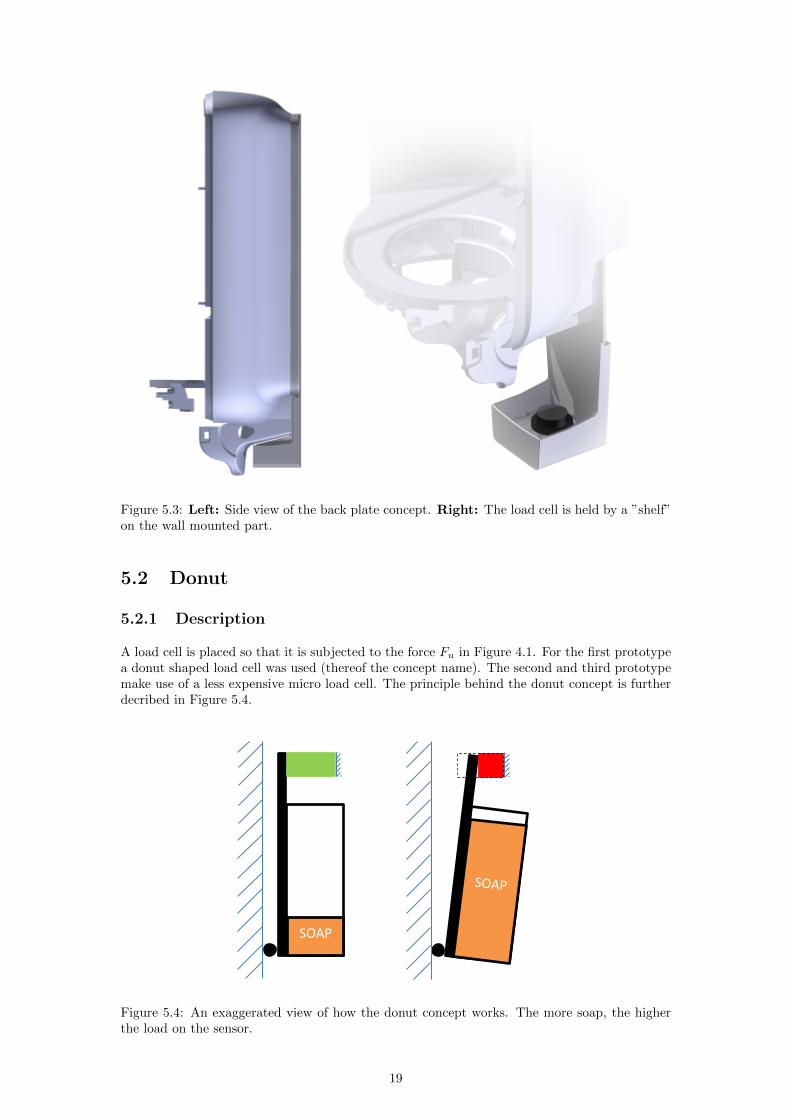
52 Donut
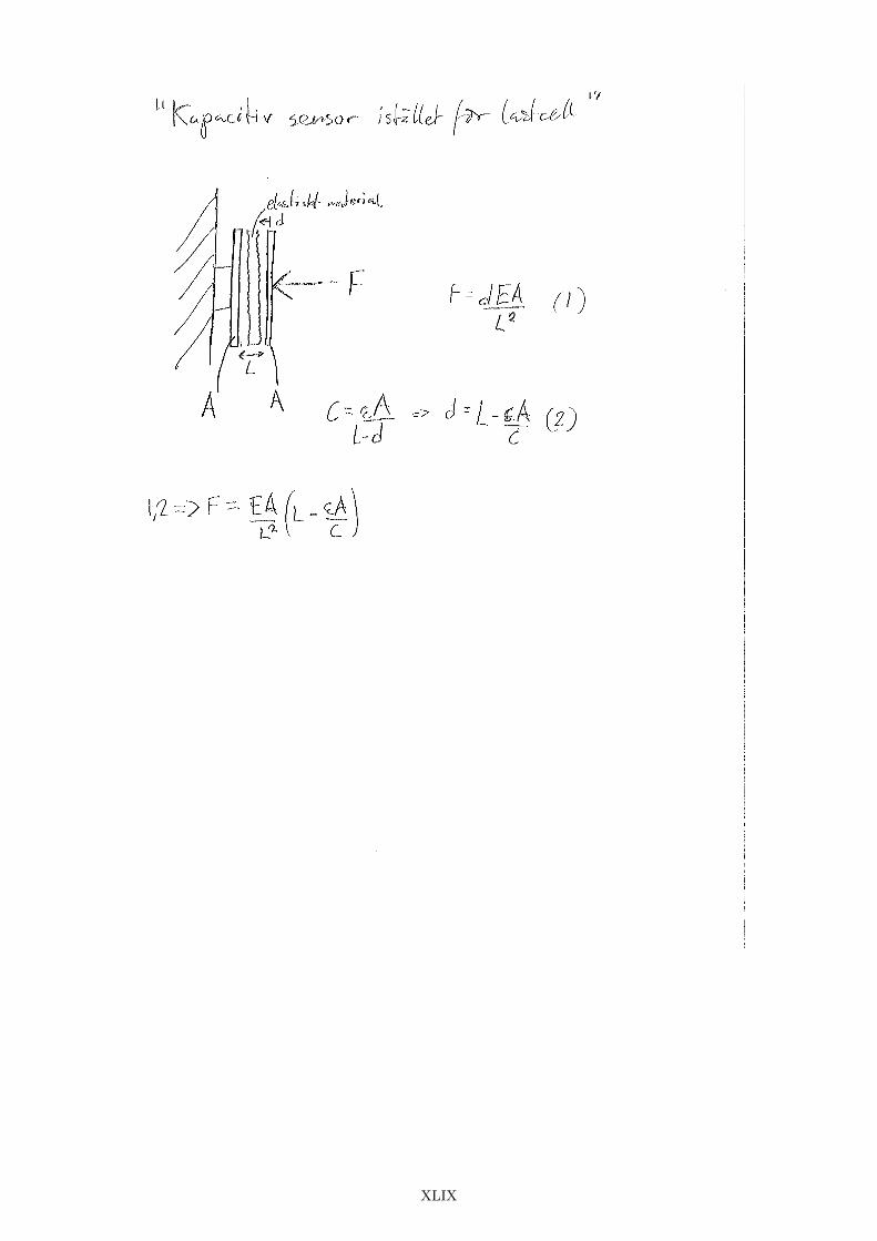
521 Description
A load cell is placed so that it is subjected to the force Fu in Figure 41 For the first prototypea donut shaped load cell was used (thereof the concept name) The second and third prototypemake use of a less expensive micro load cell The principle behind the donut concept is furtherdecribed in Figure 54
SOAP
Figure 54 An exaggerated view of how the donut concept works The more soap the higherthe load on the sensor
19
522 First prototype
The very first prototype of the donut concept was to squeeze a donut shaped load cell betweena screw head and the inner wall of the dispenser The two upper screws were replaced with onesingle screw (used for the load cell) between the two previous holes see Figure 55 To enablethe dispenser to wobble slightly a flexible plastic distance was placed between the wall and thelower part of the dispenser
Figure 55 The first prototype of the donut concept A donut shaped load cell was mountedwith a screw and washer
523 Second prototype
For the second prototype of the donut concept a micro load cell taken from a kitchen scale wasused This load cell was mounted on the inner wall of the dispenser between the two upper screwholes Before the screws were put into place they were connected by an aluminium plate whichhad the task of pushing against the load cell see Figure 56 To make sure the refill always restson its front end a support was added to both inner side walls of the dispenser forcing the refillto lean slightly forward
20
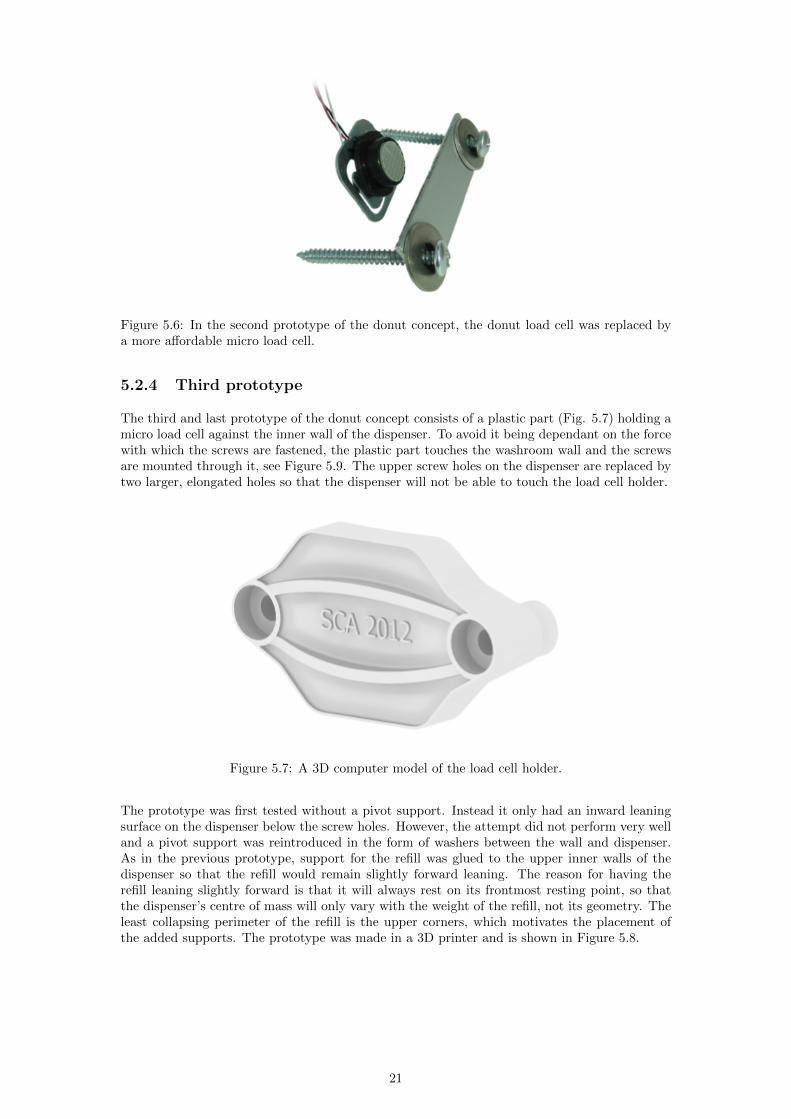
Figure 56 In the second prototype of the donut concept the donut load cell was replaced bya more affordable micro load cell
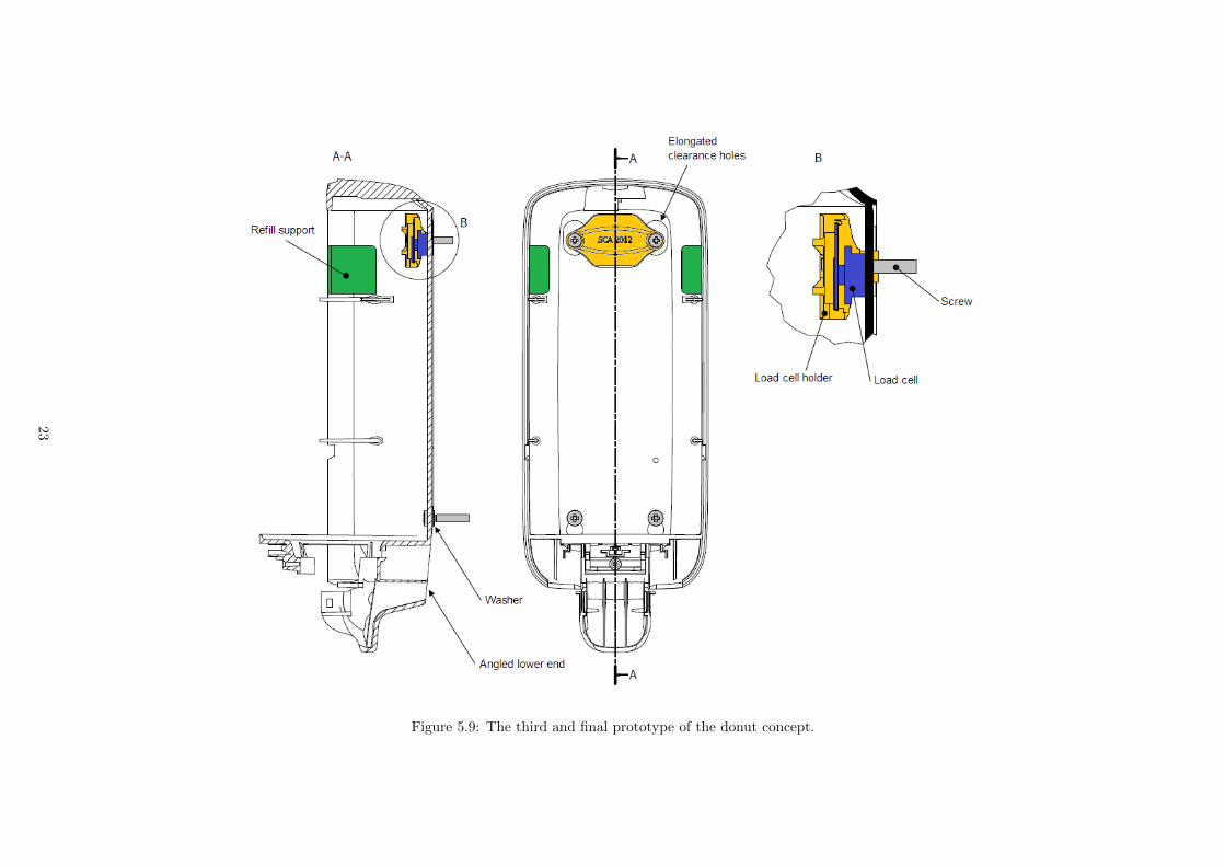
524 Third prototype
The third and last prototype of the donut concept consists of a plastic part (Fig 57) holding amicro load cell against the inner wall of the dispenser To avoid it being dependant on the forcewith which the screws are fastened the plastic part touches the washroom wall and the screwsare mounted through it see Figure 59 The upper screw holes on the dispenser are replaced bytwo larger elongated holes so that the dispenser will not be able to touch the load cell holder
Figure 57 A 3D computer model of the load cell holder
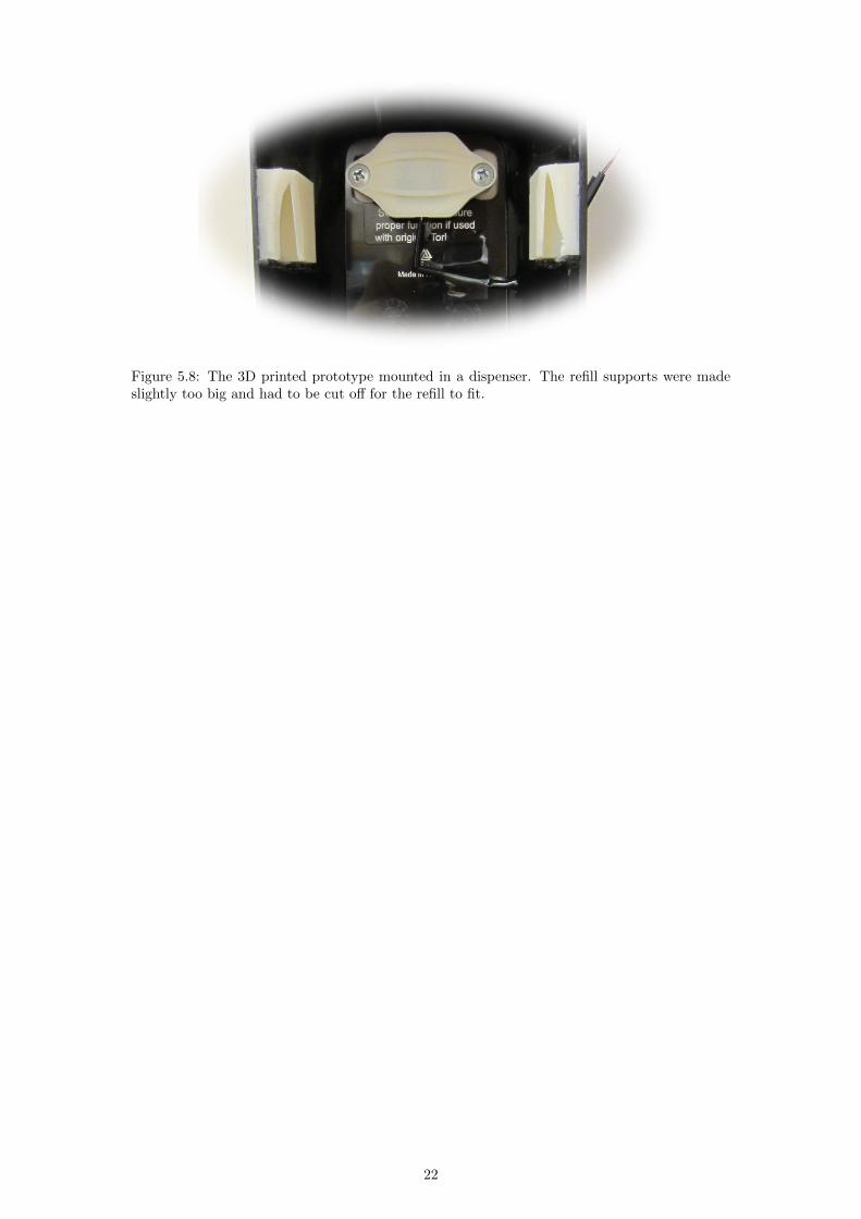
The prototype was first tested without a pivot support Instead it only had an inward leaningsurface on the dispenser below the screw holes However the attempt did not perform very welland a pivot support was reintroduced in the form of washers between the wall and dispenserAs in the previous prototype support for the refill was glued to the upper inner walls of thedispenser so that the refill would remain slightly forward leaning The reason for having therefill leaning slightly forward is that it will always rest on its frontmost resting point so thatthe dispenserrsquos centre of mass will only vary with the weight of the refill not its geometry Theleast collapsing perimeter of the refill is the upper corners which motivates the placement ofthe added supports The prototype was made in a 3D printer and is shown in Figure 58
21
Figure 58 The 3D printed prototype mounted in a dispenser The refill supports were madeslightly too big and had to be cut off for the refill to fit
22
Figure 59 The third and final prototype of the donut concept
23
53 Swing
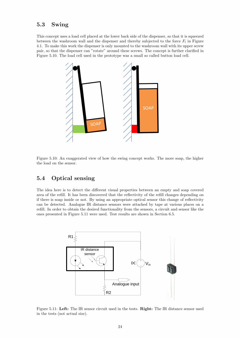
This concept uses a load cell placed at the lower back side of the dispenser so that it is squeezedbetween the washroom wall and the dispenser and thereby subjected to the force Fl in Figure41 To make this work the dispenser is only mounted to the washroom wall with its upper screwpair so that the dispenser can rdquorotaterdquo around these screws The concept is further clarified inFigure 510 The load cell used in the prototype was a small so called button load cell
Figure 510 An exaggerated view of how the swing concept works The more soap the higherthe load on the sensor
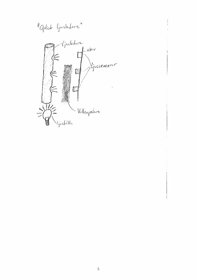
54 Optical sensing
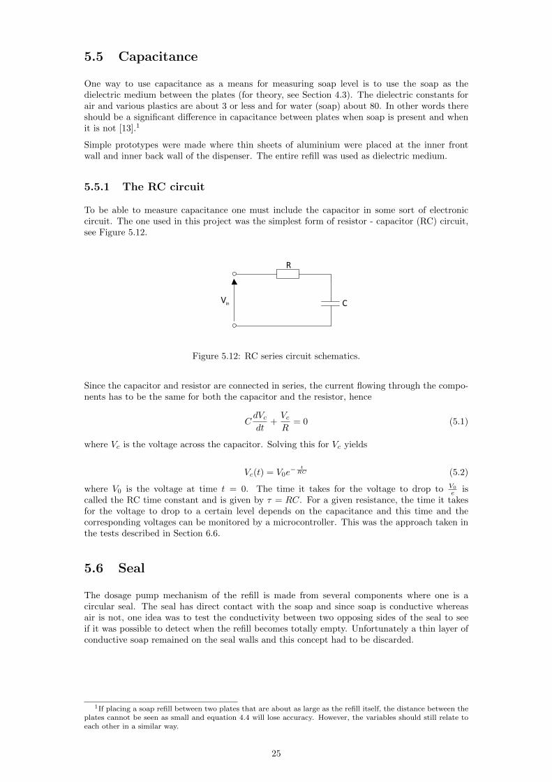
The idea here is to detect the different visual properties between an empty and soap coveredarea of the refill It has been discovered that the reflectivity of the refill changes depending onif there is soap inside or not By using an appropriate optical sensor this change of reflectivitycan be detected Analogue IR distance sensors were attached by tape at various places on arefill In order to obtain the desired functionality from the sensors a circuit and sensor like theones presented in Figure 511 were used Test results are shown in Section 65
DC
IR distance
sensor
R1
R2
Analogue input
Vin
Figure 511 Left The IR sensor circuit used in the tests Right The IR distance sensor usedin the tests (not actual size)
24
55 Capacitance
One way to use capacitance as a means for measuring soap level is to use the soap as thedielectric medium between the plates (for theory see Section 43) The dielectric constants forair and various plastics are about 3 or less and for water (soap) about 80 In other words thereshould be a significant difference in capacitance between plates when soap is present and whenit is not [13]1
Simple prototypes were made where thin sheets of aluminium were placed at the inner frontwall and inner back wall of the dispenser The entire refill was used as dielectric medium
551 The RC circuit
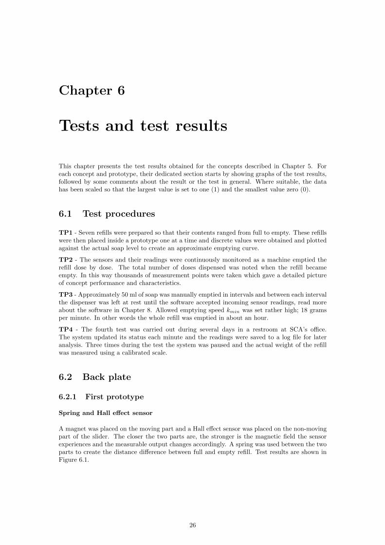
To be able to measure capacitance one must include the capacitor in some sort of electroniccircuit The one used in this project was the simplest form of resistor - capacitor (RC) circuitsee Figure 512
C
R
Vin
Figure 512 RC series circuit schematics
Since the capacitor and resistor are connected in series the current flowing through the compo-nents has to be the same for both the capacitor and the resistor hence
CdVcdt
+VcR
= 0 (51)
where Vc is the voltage across the capacitor Solving this for Vc yields
Vc(t) = V0eminus t
RC (52)
where V0 is the voltage at time t = 0 The time it takes for the voltage to drop to V0
e iscalled the RC time constant and is given by τ = RC For a given resistance the time it takesfor the voltage to drop to a certain level depends on the capacitance and this time and thecorresponding voltages can be monitored by a microcontroller This was the approach taken inthe tests described in Section 66
56 Seal
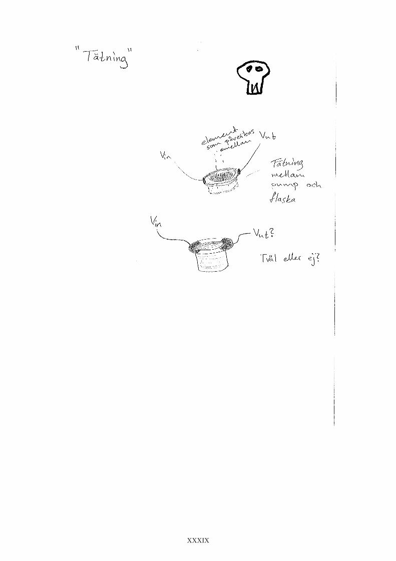
The dosage pump mechanism of the refill is made from several components where one is acircular seal The seal has direct contact with the soap and since soap is conductive whereasair is not one idea was to test the conductivity between two opposing sides of the seal to seeif it was possible to detect when the refill becomes totally empty Unfortunately a thin layer ofconductive soap remained on the seal walls and this concept had to be discarded
1If placing a soap refill between two plates that are about as large as the refill itself the distance between theplates cannot be seen as small and equation 44 will lose accuracy However the variables should still relate toeach other in a similar way
25
Chapter 6
Tests and test results
This chapter presents the test results obtained for the concepts described in Chapter 5 Foreach concept and prototype their dedicated section starts by showing graphs of the test resultsfollowed by some comments about the result or the test in general Where suitable the datahas been scaled so that the largest value is set to one (1) and the smallest value zero (0)
61 Test procedures
TP1 - Seven refills were prepared so that their contents ranged from full to empty These refillswere then placed inside a prototype one at a time and discrete values were obtained and plottedagainst the actual soap level to create an approximate emptying curve
TP2 - The sensors and their readings were continuously monitored as a machine emptied therefill dose by dose The total number of doses dispensed was noted when the refill becameempty In this way thousands of measurement points were taken which gave a detailed pictureof concept performance and characteristics
TP3 - Approximately 50 ml of soap was manually emptied in intervals and between each intervalthe dispenser was left at rest until the software accepted incoming sensor readings read moreabout the software in Chapter 8 Allowed emptying speed kmin was set rather high 18 gramsper minute In other words the whole refill was emptied in about an hour
TP4 - The fourth test was carried out during several days in a restroom at SCArsquos officeThe system updated its status each minute and the readings were saved to a log file for lateranalysis Three times during the test the system was paused and the actual weight of the refillwas measured using a calibrated scale
62 Back plate
621 First prototype
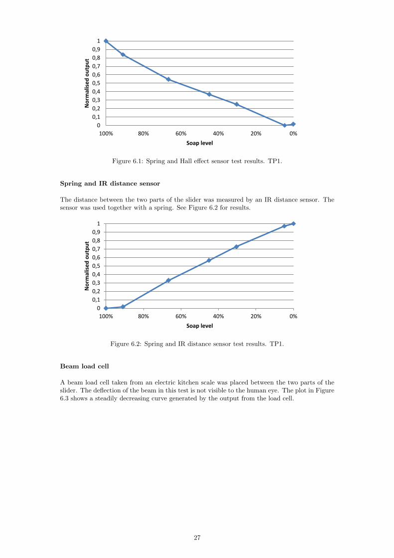
Spring and Hall effect sensor
A magnet was placed on the moving part and a Hall effect sensor was placed on the non-movingpart of the slider The closer the two parts are the stronger is the magnetic field the sensorexperiences and the measurable output changes accordingly A spring was used between the twoparts to create the distance difference between full and empty refill Test results are shown inFigure 61
26
0
01
02
03
04
05
06
07
08
09
1
020406080100
No
rmal
ise
d o
utp
ut
Soap level
Figure 61 Spring and Hall effect sensor test results TP1
Spring and IR distance sensor
The distance between the two parts of the slider was measured by an IR distance sensor Thesensor was used together with a spring See Figure 62 for results
0
01
02
03
04
05
06
07
08
09
1
020406080100
No
rmal
ise
d o
utp
ut
Soap level
Figure 62 Spring and IR distance sensor test results TP1
Beam load cell
A beam load cell taken from an electric kitchen scale was placed between the two parts of theslider The deflection of the beam in this test is not visible to the human eye The plot in Figure63 shows a steadily decreasing curve generated by the output from the load cell
27
0
01
02
03
04
05
06
07
08
09
1
020406080100
No
rmal
ise
d o
utp
ut
Soap level
Figure 63 Beam load cell test results TP1
Micro load cell
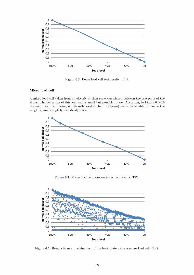
A micro load cell taken from an electric kitchen scale was placed between the two parts of theslider The deflection of this load cell is small but possible to see According to Figure 64-66the micro load cell (being significantly weaker than the beam) seems to be able to handle theweight giving a slightly less steady curve
0
01
02
03
04
05
06
07
08
09
1
020406080100
No
rmal
ise
d o
utp
ut
Soap level
Figure 64 Micro load cell non-continous test results TP1
0
01
02
03
04
05
06
07
08
09
1
020406080100
No
rmal
ise
d o
utp
ut
Soap level
Figure 65 Results from a machine test of the back plate using a micro load cell TP2
28
0
01
02
03
04
05
06
07
08
09
1
020406080100
No
rmal
ise
d o
utp
ut
Soap level
Figure 66 Median filtered results from the machine test of the micro load cell TP2
Comments
All of the back plate concepts have proven to be rather accurate at tests One problem howeverappears with the first prototype and the spring used The problem is that the system canfind more than one stable condition The dispenser can often be lifted a (tiny) bit and thenstay in that new position due to friction etc which yields a sensor reading different fromthe previous despite that the weight of the dispenser has not changed In Figure 65 severalmeasurement values are below the approximately linear level curve and some are equal to zeroThe explanation is that these values have been measured while the machine was pushing againstthe lever which lifted the dispenser marginally
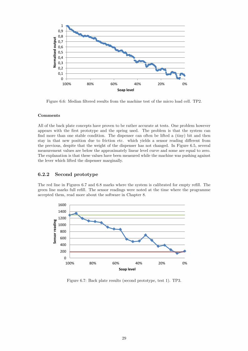
622 Second prototype
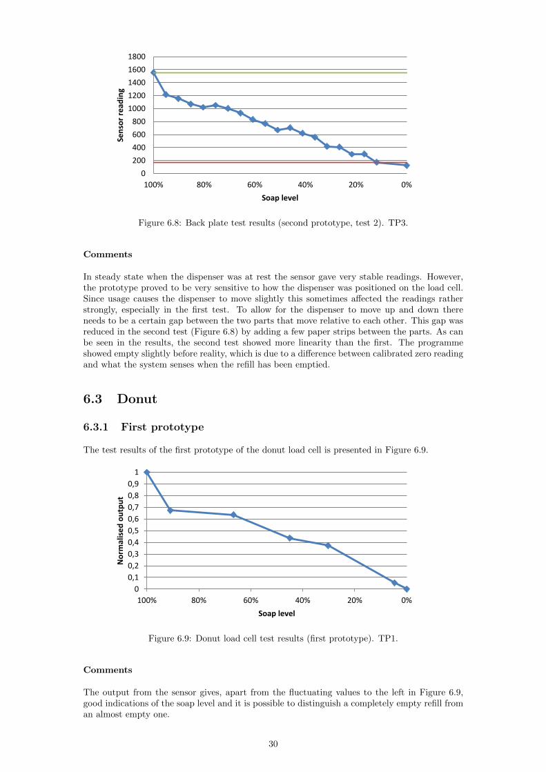
The red line in Figures 67 and 68 marks where the system is calibrated for empty refill Thegreen line marks full refill The sensor readings were noted at the time where the programmeaccepted them read more about the software in Chapter 8
0
200
400
600
800
1000
1200
1400
1600
020406080100
Sen
sor
read
ing
Soap level
Figure 67 Back plate results (second prototype test 1) TP3
29
0
200
400
600
800
1000
1200
1400
1600
1800
020406080100
Sen
sor
read
ing
Soap level
Figure 68 Back plate test results (second prototype test 2) TP3
Comments
In steady state when the dispenser was at rest the sensor gave very stable readings Howeverthe prototype proved to be very sensitive to how the dispenser was positioned on the load cellSince usage causes the dispenser to move slightly this sometimes affected the readings ratherstrongly especially in the first test To allow for the dispenser to move up and down thereneeds to be a certain gap between the two parts that move relative to each other This gap wasreduced in the second test (Figure 68) by adding a few paper strips between the parts As canbe seen in the results the second test showed more linearity than the first The programmeshowed empty slightly before reality which is due to a difference between calibrated zero readingand what the system senses when the refill has been emptied
63 Donut
631 First prototype
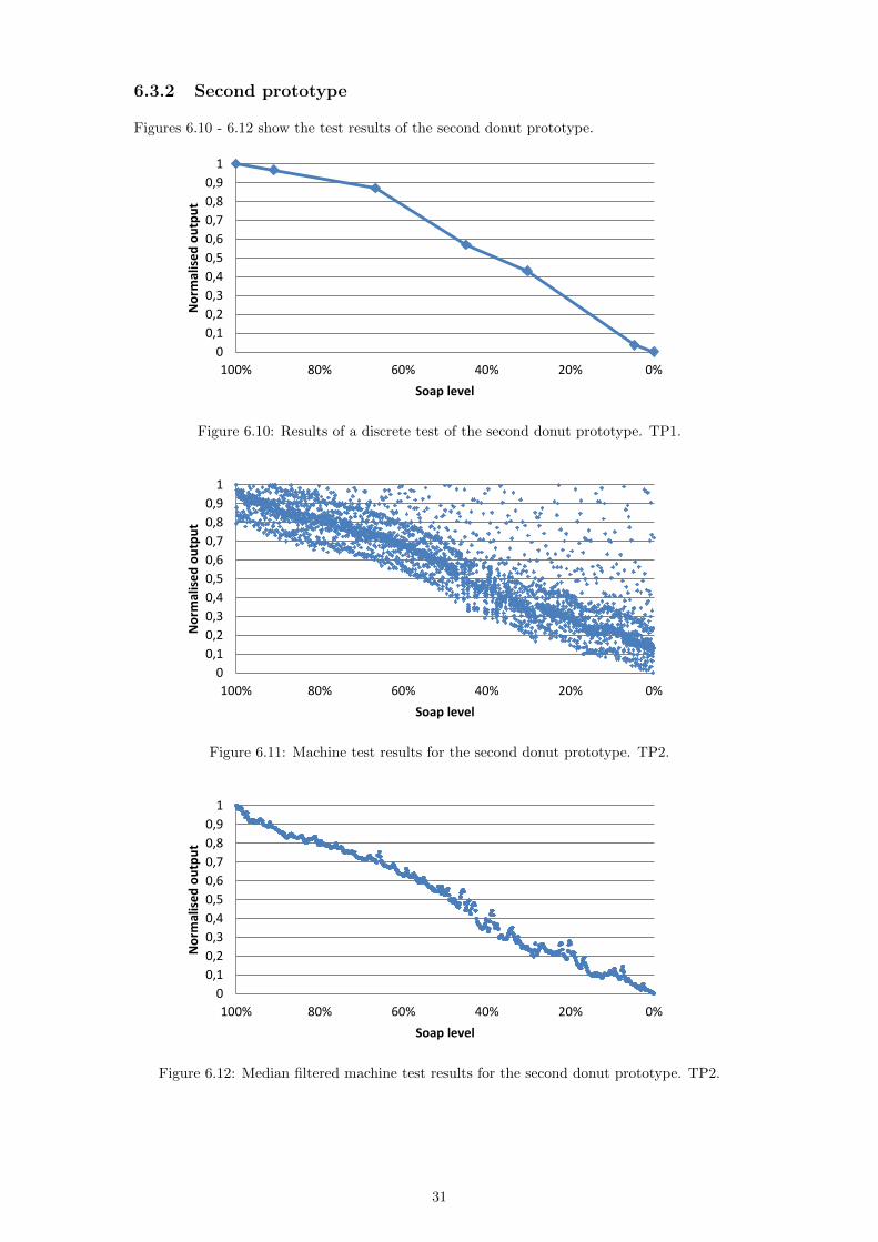
The test results of the first prototype of the donut load cell is presented in Figure 69
0
01
02
03
04
05
06
07
08
09
1
020406080100
No
rmal
ise
d o
utp
ut
Soap level
Figure 69 Donut load cell test results (first prototype) TP1
Comments
The output from the sensor gives apart from the fluctuating values to the left in Figure 69good indications of the soap level and it is possible to distinguish a completely empty refill froman almost empty one
30
632 Second prototype
Figures 610 - 612 show the test results of the second donut prototype
0
01
02
03
04
05
06
07
08
09
1
020406080100
No
rmal
ise
d o
utp
ut
Soap level
Figure 610 Results of a discrete test of the second donut prototype TP1
0
01
02
03
04
05
06
07
08
09
1
020406080100
No
rmal
ise
d o
utp
ut
Soap level
Figure 611 Machine test results for the second donut prototype TP2
0
01
02
03
04
05
06
07
08
09
1
020406080100
No
rmal
ise
d o
utp
ut
Soap level
Figure 612 Median filtered machine test results for the second donut prototype TP2
31
Comments
The second prototype showed a stable trend in readings between full and empty refill Theperhaps most interesting shown in the graphs is the three bands of readings in Figure 611 Thereason for these has not been figured out luckily outer bands had no or little effect on the filteredresult The reason why readings can be seen above the main cluster is because measurementswere sometimes taken while the machine was pushing against the lever and generated therebya spike in readings while doing so
633 Third prototype
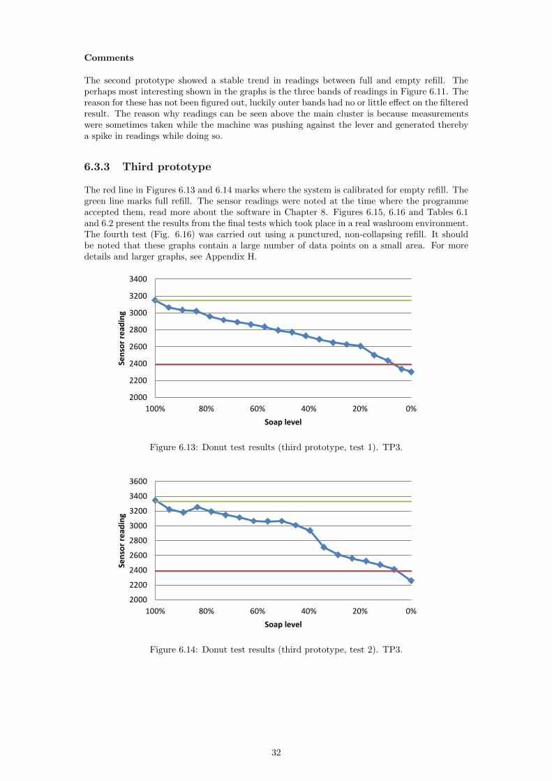
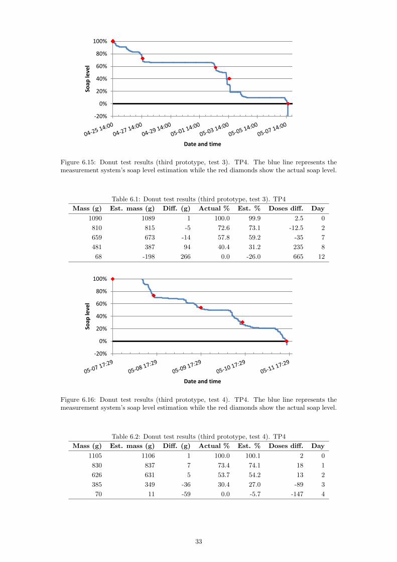
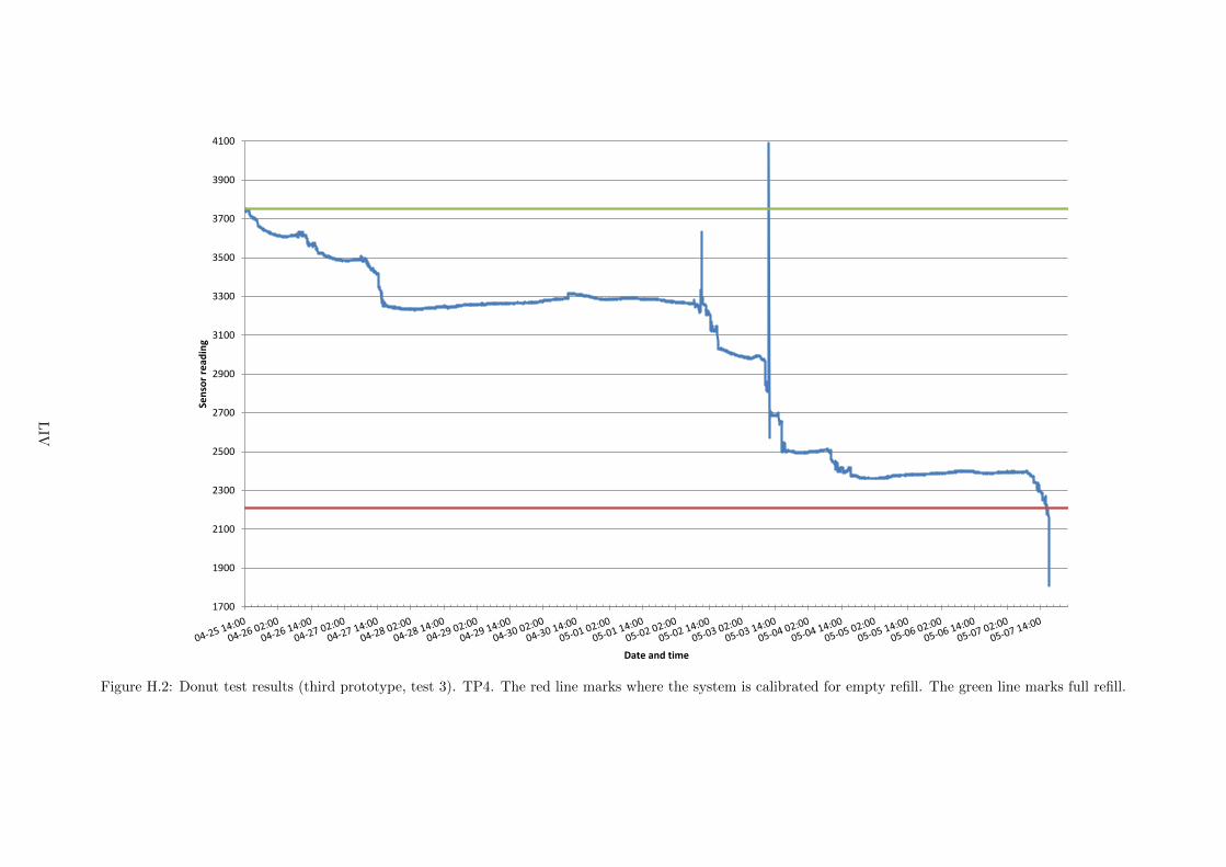
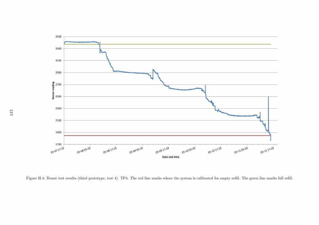
The red line in Figures 613 and 614 marks where the system is calibrated for empty refill Thegreen line marks full refill The sensor readings were noted at the time where the programmeaccepted them read more about the software in Chapter 8 Figures 615 616 and Tables 61and 62 present the results from the final tests which took place in a real washroom environmentThe fourth test (Fig 616) was carried out using a punctured non-collapsing refill It shouldbe noted that these graphs contain a large number of data points on a small area For moredetails and larger graphs see Appendix H
2000
2200
2400
2600
2800
3000
3200
3400
020406080100
Sen
sor
read
ing
Soap level
Figure 613 Donut test results (third prototype test 1) TP3
2000
2200
2400
2600
2800
3000
3200
3400
3600
020406080100
Sen
sor
read
ing
Soap level
Figure 614 Donut test results (third prototype test 2) TP3
32
-20
0
20
40
60
80
100
Soap
leve
l
Date and time
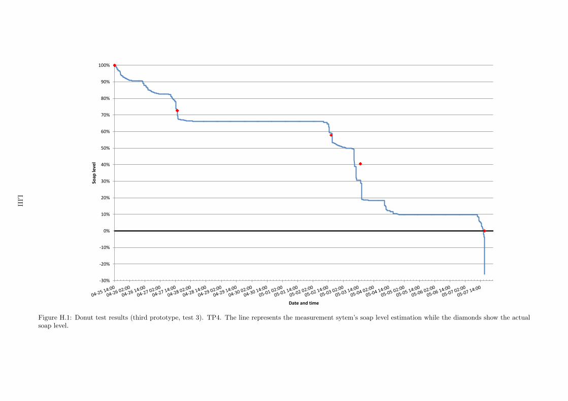
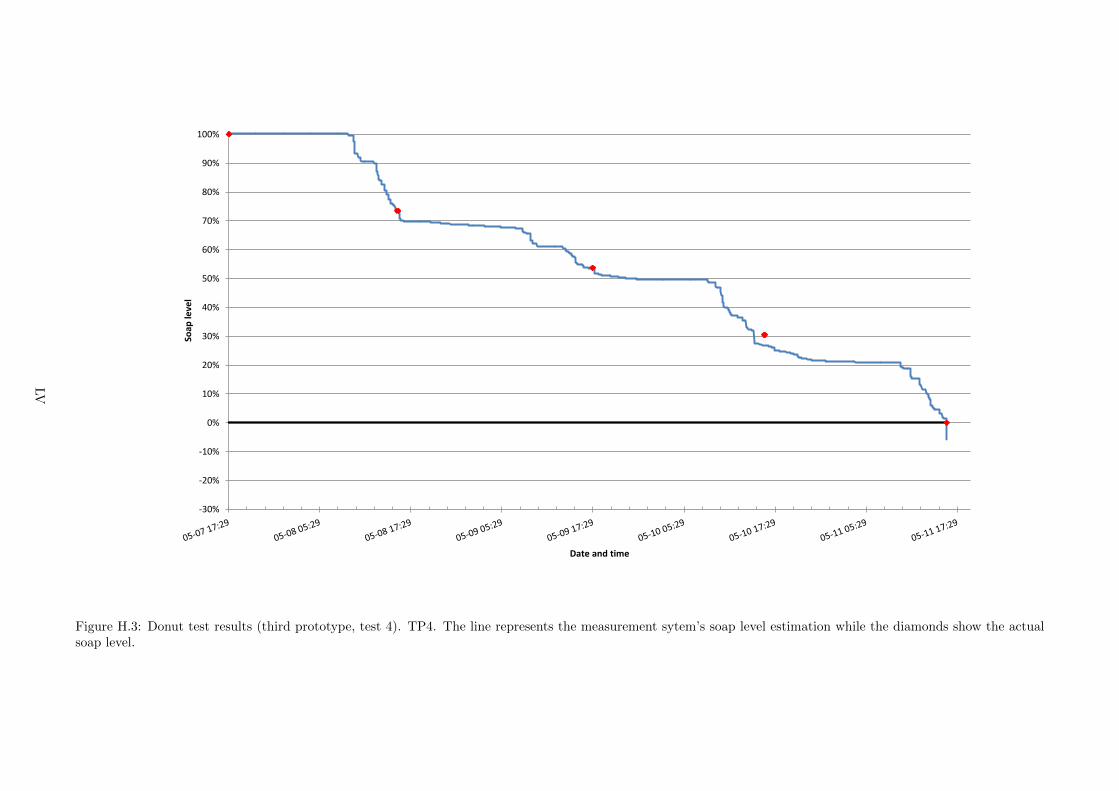
Figure 615 Donut test results (third prototype test 3) TP4 The blue line represents themeasurement systemrsquos soap level estimation while the red diamonds show the actual soap level
Table 61 Donut test results (third prototype test 3) TP4
Mass (g) Est mass (g) Diff (g) Actual Est Doses diff Day
1090 1089 1 1000 999 25 0
810 815 -5 726 731 -125 2
659 673 -14 578 592 -35 7
481 387 94 404 312 235 8
68 -198 266 00 -260 665 12
-20
0
20
40
60
80
100
Soap
leve
l
Date and time
Figure 616 Donut test results (third prototype test 4) TP4 The blue line represents themeasurement systemrsquos soap level estimation while the red diamonds show the actual soap level
Table 62 Donut test results (third prototype test 4) TP4
Mass (g) Est mass (g) Diff (g) Actual Est Doses diff Day
1105 1106 1 1000 1001 2 0
830 837 7 734 741 18 1
626 631 5 537 542 13 2
385 349 -36 304 270 -89 3
70 11 -59 00 -57 -147 4
33
Comments
The third prototype has sometimes showed tendencies of measurement offset The sensor read-ings have here seemed to for a while be too high or too low for a given soap level Within thetime span of a test the system has usually however corrected itself and returned to be in theproximity of the expected reading An example of a shifting curve is seen in Figure 614 Figure613 on the other hand shows an example of when there are few surprises and a good linearityin readings
The accuracy of the measurements seem to become worse with decreasing soap level In the endof the last test presented in Figure 615 the systemrsquos readings are far from the expected valuesand indicate a 0 soap level when there still is a considerable amount of soap left When thedispenser lid was opened after having emptied all soap one could see that the refill had twistedaway from one of the upper supports This makes it likely that the refillrsquos weight distributionhad shifted slightly from being almost entirely on the front to having put weight also on its rearresting point A shift in weight distribution between the two resting points has a very largeimpact on the measurements If the refill starts to put weight on the rear resting point thedispenserrsquos centre of mass moves closer to the wall and the moment the sensor measures dropsSince the magnitude of the readings decrease the system thinks the soap level has decreasedand this is what could have happened near the end of the third test shown in Figure 615 Aclearer larger graph is found in Appendix H
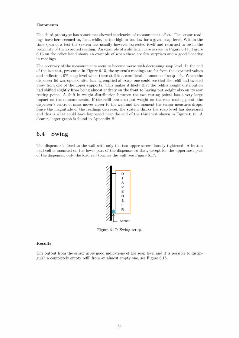
64 Swing
The dispenser is fixed to the wall with only the two upper screws loosely tightened A buttonload cell is mounted on the lower part of the dispenser so that except for the uppermost partof the dispenser only the load cell touches the wall see Figure 617
D
I
S
P
E
N
S
E
R
Sensor
Figure 617 Swing setup
Results
The output from the sensor gives good indications of the soap level and it is possible to distin-guish a completely empty refill from an almost empty one see Figure 618
34
0
01
02
03
04
05
06
07
08
09
1
020406080100
No
rmal
ise
d o
utp
ut
Soap level
Figure 618 Swing test results TP1
Comments
The swing concept and the button load cell gives good results but the problem with overloadmust be solved (the load cell must be protected against the additional forces occurring when auser pushes the lever) Moreover the dispenser cannot be loosely mounted in a real situation
65 Optical
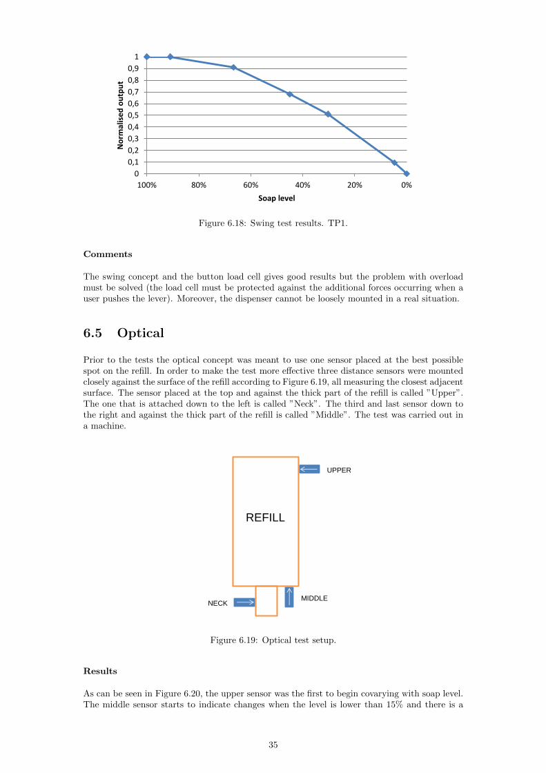
Prior to the tests the optical concept was meant to use one sensor placed at the best possiblespot on the refill In order to make the test more effective three distance sensors were mountedclosely against the surface of the refill according to Figure 619 all measuring the closest adjacentsurface The sensor placed at the top and against the thick part of the refill is called rdquoUpperrdquoThe one that is attached down to the left is called rdquoNeckrdquo The third and last sensor down tothe right and against the thick part of the refill is called rdquoMiddlerdquo The test was carried out ina machine
REFILL
UPPER
MIDDLE NECK
Figure 619 Optical test setup
Results
As can be seen in Figure 620 the upper sensor was the first to begin covarying with soap levelThe middle sensor starts to indicate changes when the level is lower than 15 and there is a
35
distinct decrease when the refill starts to become empty The neck sensor gives a steep decreasein signal when the refill is virtually empty
0
01
02
03
04
05
06
07
08
09
1
100 80 60 40 20 0
No
rmal
ise
d o
utp
ut
Soap level (approx)
Upper
Middle
Neck
Figure 620 Optical test results TP2
Comments
Optical sensing is an interesting method that seems to have potential of giving good readingsfor certain soap level intervals Important is to find a construction that makes it possible forthe sensor to come in direct contact with the soap refill One must also make sure that thisconstruction will not hinder a refill change
Another thing to keep in mind is that in this test the refill was emptied quickly so that bubblesformed inside the refill Bubbles affect a sensorrsquos output quite strongly and how the same sensorswould react in a situation where the refill is emptied much slower so that bubbles go away isdifficult to say
Preliminary tests indicate that optical sensing works with different kinds of soap including soapsthat are not transparent
66 Capacitance
661 Single plate sensing
Thin sheets of aluminium are placed on both sides of the refill inside the dispenser These twosheets form two capacitor plates one being constantly connected to ground whereas the otherplate is charged and discharged The grounded plate is placed at the back of the dispenser andthe sensing plate at the front
REFILL
Figure 621 Left Single plate sensing setup Right RC circuit used for single plate sensing
36
Measurement procedure
Charge the sensing plate rarr Turn off charging rarr Sample voltages during discharge rarr EstimateRC time constant
Results
0
01
02
03
04
05
06
07
08
09
1
020406080100
No
rmal
ise
d o
utp
ut
Soap level
Figure 622 Single plate results from continuous test in machine TP2
30
35
40
45
50
55
60
01020304050
Pro
gram
me
ou
tpu
t
C (pF)
Figure 623 Programme output for known capacitances Resistor used 680 kΩ
0
10
20
30
40
50
60
Re
lati
ve R
C t
ime
co
nst
ant
R = 680k
30
32
34
36
38
40
42
44
46
020406080100
Pro
gram
me
ou
tpu
t
Soap level
Figure 624 Programme output for various soap levels Resistor used 680 kΩ TP1
37
Comments
It seems like the capacitance changes most rapidly when the refill is nearly full From a soaplevel of around 70 down to 0 the capacitance changes only by a few picofarads Such a smallchange is very difficult to measure with the used circuit and setup
How much better other circuits are at measuring these small changes is not known Anotherquestion mark is how well the plates can be shielded from the surroundings In the tests a handplaced on the front of the dispenser made the output reach levels of the same magnitude as afull refill
All in all the single plate setup should be fairly accurate at sensing whether a refill is changed toa full one However only the simplest forms of microcontroller based capacitance measurementshave been tested in this project and more sofisticated methods might prove to be successful inthe entire usage cycle of the refill
662 Triple plate sensing
An idea is to split the sensing plate into three and thereby get three readings that combinedcould be more precise than a single reading Another possible advantage from segmenting thesensing plate is that the readings become more local to the upper mid and lower sections ofthe refill Therefore three thin sensing plates of aluminium were placed at the front of thedispenser A single plate was used as ground at the back of the dispenser see Figure 625 Thecircuit that was used is shown in Figure 626
REFILL
Figure 625 Triple plate sensing setup
Charge pin 3
Analogue input 3
R
Charge pin 2
Analogue input 2
Charge pin 1
Analogue input 1
RR
Figure 626 Circuit used for triple plate sensing
38
Measurement procedure
P1 For each plate Charge the sensing plate rarr Turn off charging rarr Sample voltages duringdischarge rarr Estimate RC time constant
P2 For each plate Charge the sensing plate rarr Turn off charging rarr Measure the time ittakes for the voltage to drop to a certain level
Results
0
01
02
03
04
05
06
07
08
09
1
020406080100
No
rmal
ise
d o
utp
ut
Soap level
Lower
Middle
Upper
Average
Figure 627 Test results for programme P1 TP1
09
092
094
096
098
1
020406080100
Normalised decay time
Soap level
Upper plate
Figure 628 Test results for the upper plate with programme P2 TP1
39
088
090
092
094
096
098
100
020406080100
Normalised decay time
Soap level
Middle plate
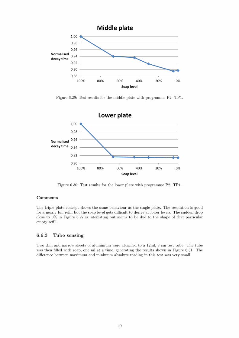
Figure 629 Test results for the middle plate with programme P2 TP1
090
092
094
096
098
100
020406080100
Normalised decay time
Soap level
Lower plate
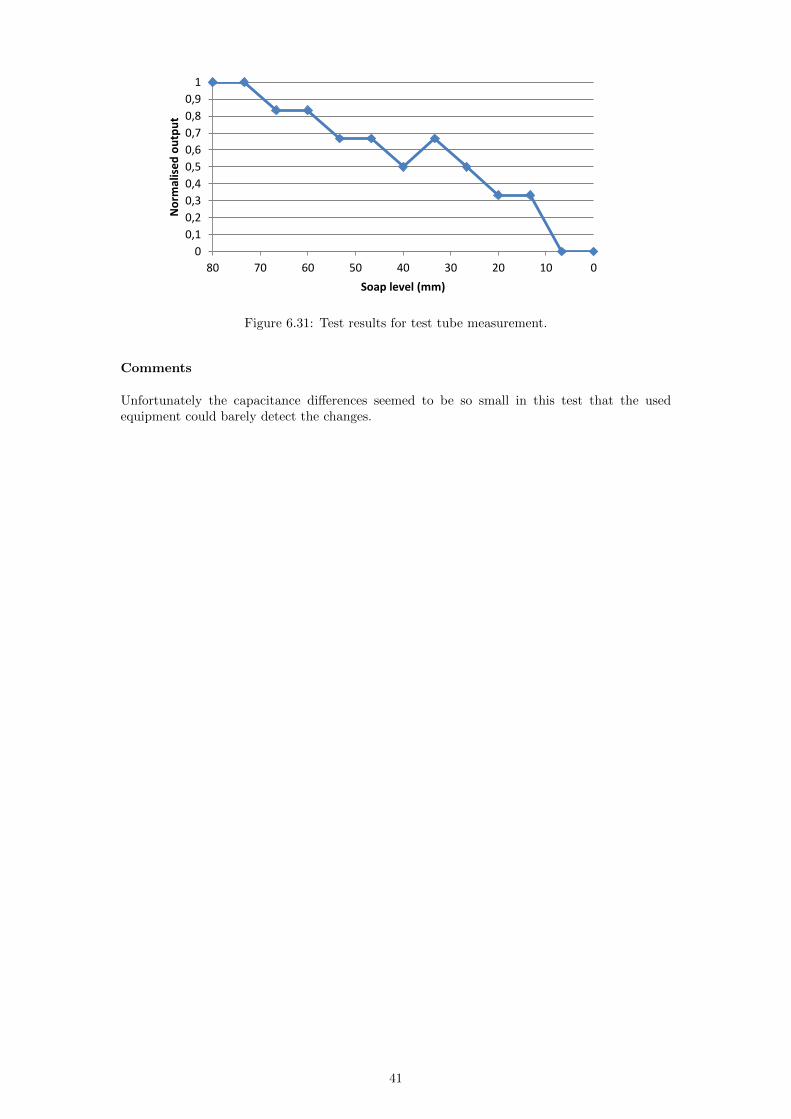
Figure 630 Test results for the lower plate with programme P2 TP1
Comments
The triple plate concept shows the same behaviour as the single plate The resolution is goodfor a nearly full refill but the soap level gets difficult to derive at lower levels The sudden dropclose to 0 in Figure 627 is interesting but seems to be due to the shape of that particularempty refill
663 Tube sensing
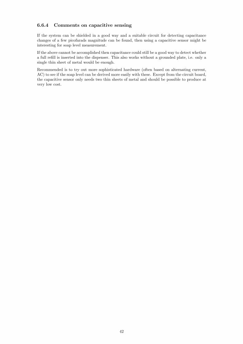
Two thin and narrow sheets of aluminium were attached to a 12ml 8 cm test tube The tubewas then filled with soap one ml at a time generating the results shown in Figure 631 Thedifference between maximum and minimum absolute reading in this test was very small
40
0
01
02
03
04
05
06
07
08
09
1
01020304050607080
No
rmal
ise
d o
utp
ut
Soap level (mm)
Figure 631 Test results for test tube measurement
Comments
Unfortunately the capacitance differences seemed to be so small in this test that the usedequipment could barely detect the changes
41
664 Comments on capacitive sensing
If the system can be shielded in a good way and a suitable circuit for detecting capacitancechanges of a few picofarads magnitude can be found then using a capacitive sensor might beinteresting for soap level measurement
If the above cannot be accomplished then capacitance could still be a good way to detect whethera full refill is inserted into the dispenser This also works without a grounded plate ie only asingle thin sheet of metal would be enough
Recommended is to try out more sophisticated hardware (often based on alternating currentAC) to see if the soap level can be derived more easily with these Except from the circuit boardthe capacitive sensor only needs two thin sheets of metal and should be possible to produce atvery low cost
42
Chapter 7
Concept evaluation and selection
After the concept generation 24 different ideas were to be funneled down to one or two rdquowinnersrdquoThe initial approach was to narrow down similar concepts and keep the best one or two of eachtype Furthermore concepts with uncertain performance that were easy to test were kept andconcepts that would be time consuming or difficult to test were eliminated unless they had anobviously higher potential than other remaining concepts All initial sketches can be found inAppendix G1
71 First screening Categorisation
The ideas were categorised according to what kind of modifications they would make to thepresent S4 system Three main categories were created The number of concepts belonging toeach category is shown in brackets
bull No modifications (5)
bull Dispenser modifications only (10)
bull Modifications to refill or both (9)
The concepts within each category were then compared to each other on a number of criteriasee Appendix C The criteria were
bull Quality of visual signal
bull Performance in measurement
bull Durability
bull Resistance against disturbances
bull rdquoFoolproof-nessrdquo
bull Energy consumption
bull Ease of manufacture
bull Generality
bull Economic potential
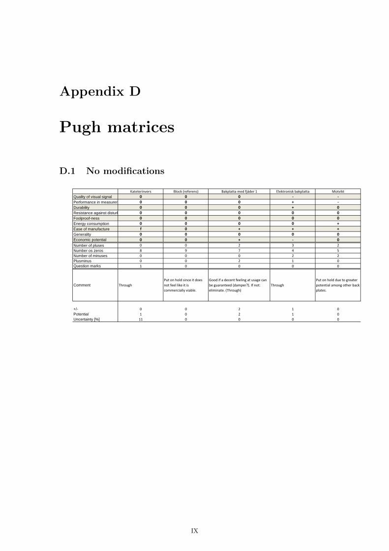
The way this was done was to put concepts belonging to the same category in a table and useone concept as reference and then for each criterion hand out pluses and minuses for all otherconcepts to denote if they were thought as being better or worse compared to the reference Alsozeros and question marks were put into the table Zeros meaning a concept was seen as equallygood as the reference at a criterion and a question mark meant that no credible estimationcould be made The pluses minuses zeros and question marks were then summed up and gavea rough idea of which concepts had a high potential which that were poor and which that wereuncertain The main result from the comparison was however not the table itself rather itwas the insight gained after discussing the criteria for each concept After these discussions atotal of 11 concepts were eliminated The tables also known as Pugh matrices can be found inAppendix D
The now remaining concepts are shown in Table 71
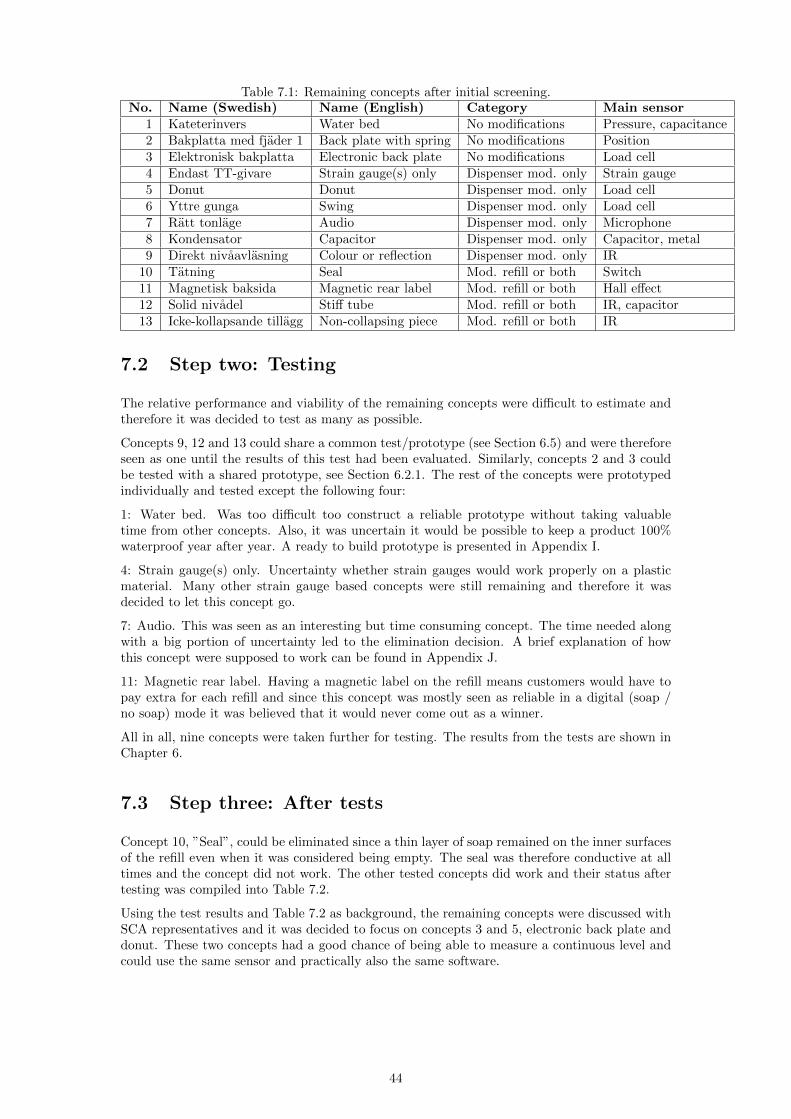
43
Table 71 Remaining concepts after initial screeningNo Name (Swedish) Name (English) Category Main sensor
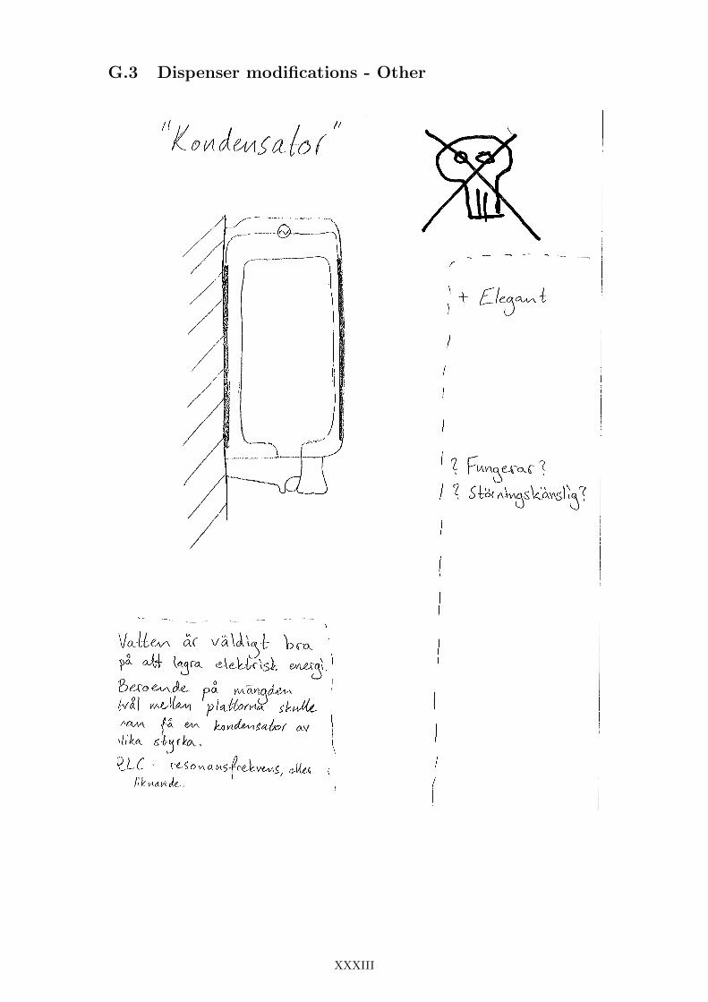
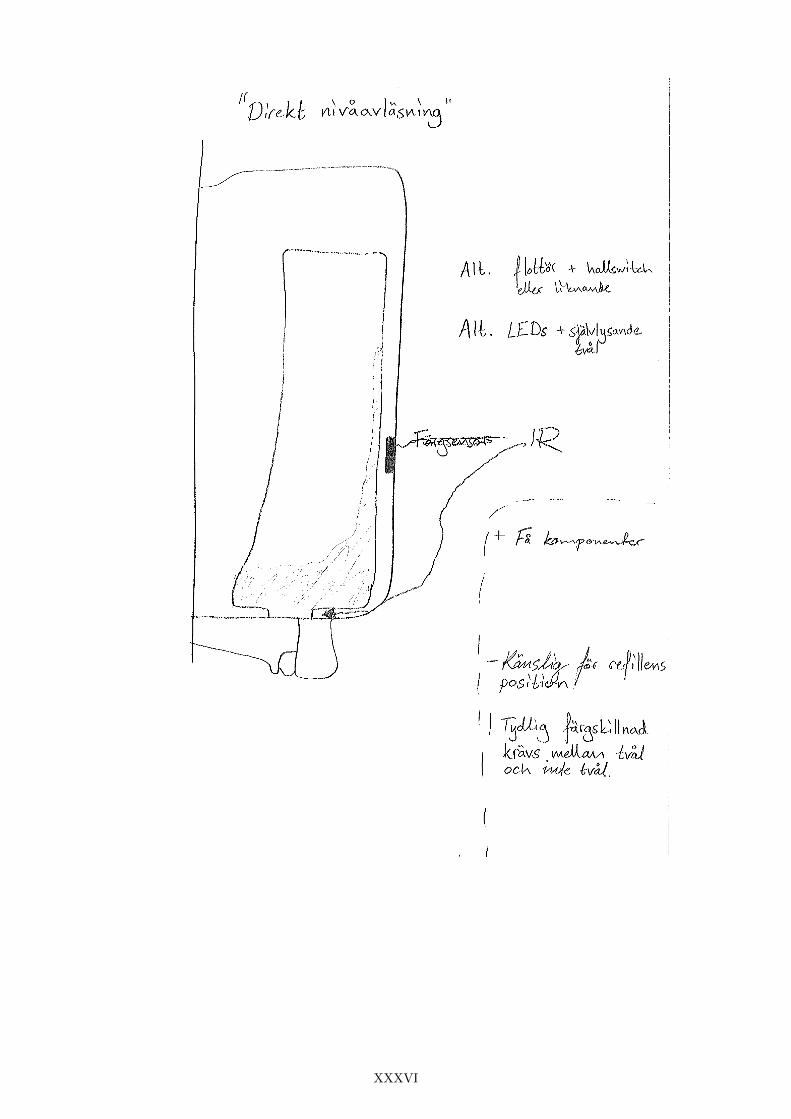
1 Kateterinvers Water bed No modifications Pressure capacitance2 Bakplatta med fjader 1 Back plate with spring No modifications Position3 Elektronisk bakplatta Electronic back plate No modifications Load cell4 Endast TT-givare Strain gauge(s) only Dispenser mod only Strain gauge5 Donut Donut Dispenser mod only Load cell6 Yttre gunga Swing Dispenser mod only Load cell7 Ratt tonlage Audio Dispenser mod only Microphone8 Kondensator Capacitor Dispenser mod only Capacitor metal9 Direkt nivaavlasning Colour or reflection Dispenser mod only IR
10 Tatning Seal Mod refill or both Switch11 Magnetisk baksida Magnetic rear label Mod refill or both Hall effect12 Solid nivadel Stiff tube Mod refill or both IR capacitor13 Icke-kollapsande tillagg Non-collapsing piece Mod refill or both IR
72 Step two Testing
The relative performance and viability of the remaining concepts were difficult to estimate andtherefore it was decided to test as many as possible
Concepts 9 12 and 13 could share a common testprototype (see Section 65) and were thereforeseen as one until the results of this test had been evaluated Similarly concepts 2 and 3 couldbe tested with a shared prototype see Section 621 The rest of the concepts were prototypedindividually and tested except the following four
1 Water bed Was too difficult too construct a reliable prototype without taking valuabletime from other concepts Also it was uncertain it would be possible to keep a product 100waterproof year after year A ready to build prototype is presented in Appendix I
4 Strain gauge(s) only Uncertainty whether strain gauges would work properly on a plasticmaterial Many other strain gauge based concepts were still remaining and therefore it wasdecided to let this concept go
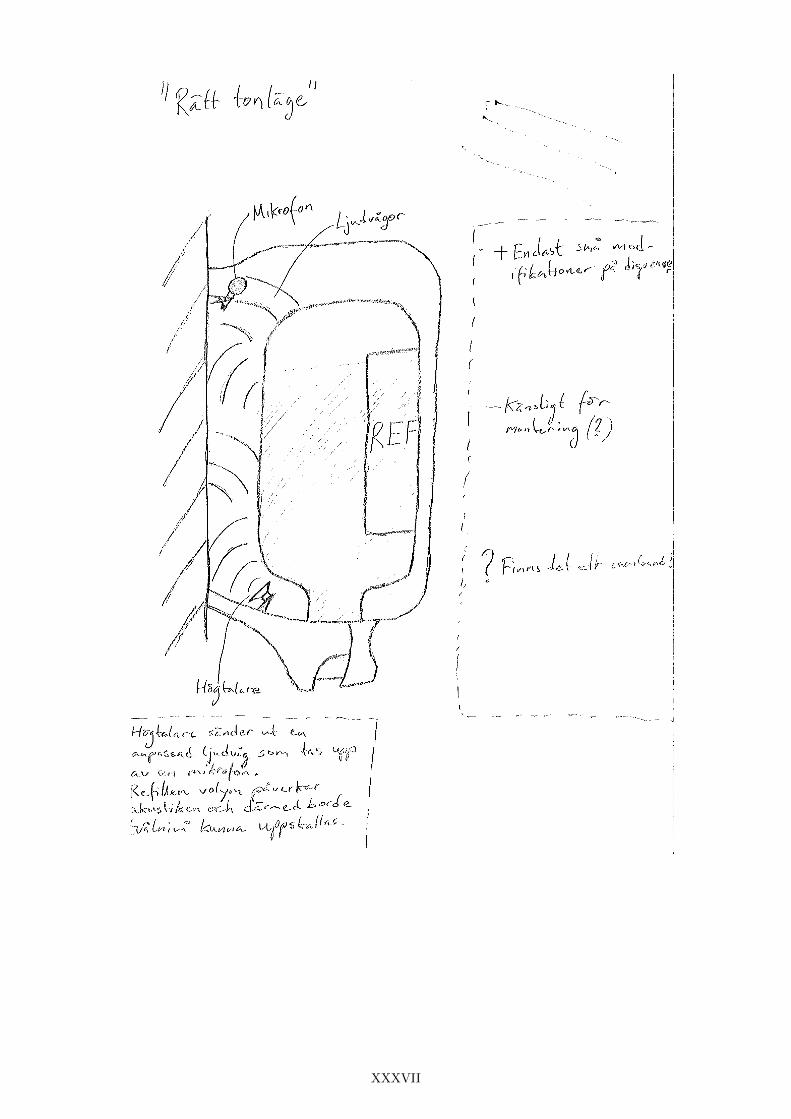
7 Audio This was seen as an interesting but time consuming concept The time needed alongwith a big portion of uncertainty led to the elimination decision A brief explanation of howthis concept were supposed to work can be found in Appendix J
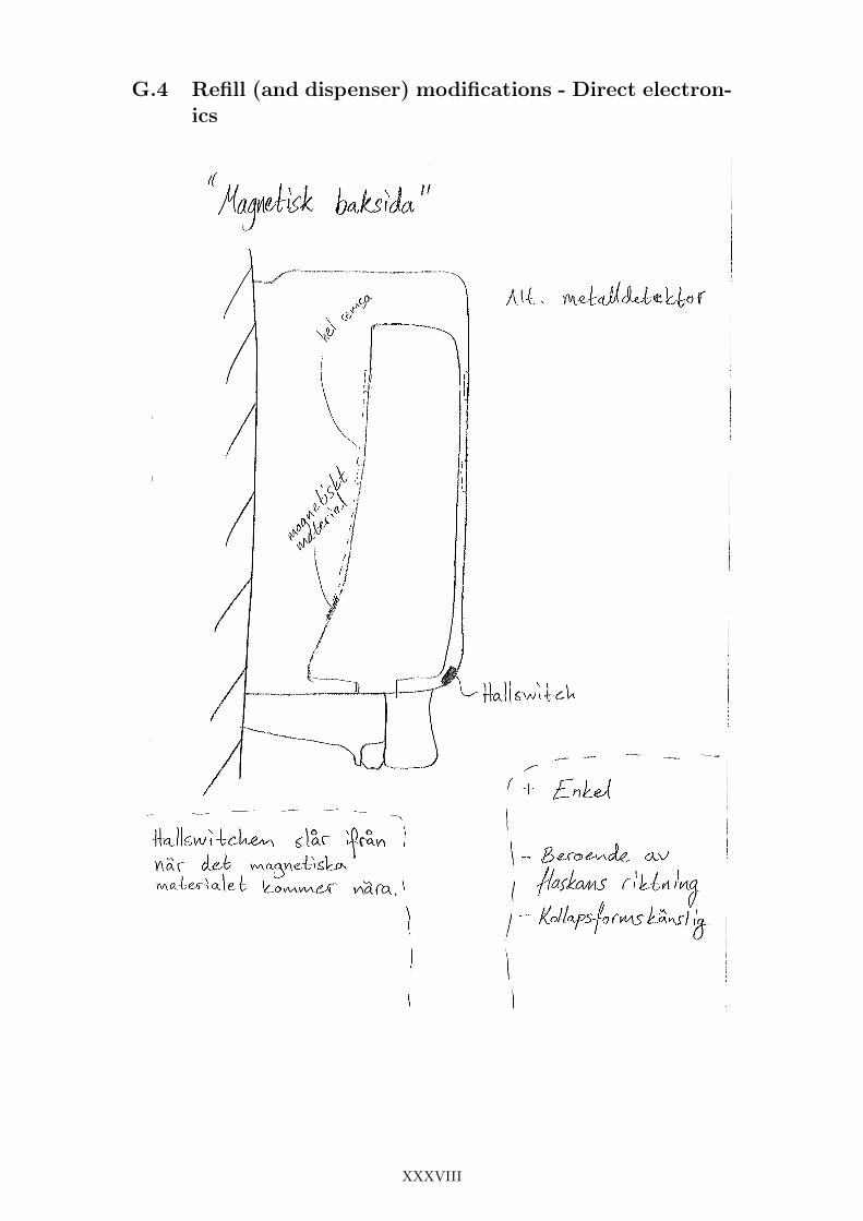
11 Magnetic rear label Having a magnetic label on the refill means customers would have topay extra for each refill and since this concept was mostly seen as reliable in a digital (soap no soap) mode it was believed that it would never come out as a winner
All in all nine concepts were taken further for testing The results from the tests are shown inChapter 6
73 Step three After tests
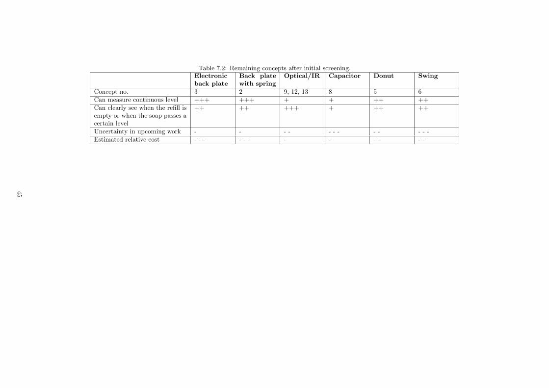
Concept 10 rdquoSealrdquo could be eliminated since a thin layer of soap remained on the inner surfacesof the refill even when it was considered being empty The seal was therefore conductive at alltimes and the concept did not work The other tested concepts did work and their status aftertesting was compiled into Table 72
Using the test results and Table 72 as background the remaining concepts were discussed withSCA representatives and it was decided to focus on concepts 3 and 5 electronic back plate anddonut These two concepts had a good chance of being able to measure a continuous level andcould use the same sensor and practically also the same software
44
Table 72 Remaining concepts after initial screeningElectronicback plate
Back platewith spring
OpticalIR Capacitor Donut Swing
Concept no 3 2 9 12 13 8 5 6Can measure continuous level +++ +++ + + ++ ++Can clearly see when the refill isempty or when the soap passes acertain level
++ ++ +++ + ++ ++
Uncertainty in upcoming work - - - - - - - - - - - -Estimated relative cost - - - - - - - - - - - -
45
74 Step four Evaluation of the two final concepts
New prototypes were made of the final two concepts The main modification to both conceptswas an improved aesthetic appearance Test results for the electronic back plate are shown inSection 622 and for the donut concept in Section 633 Evaluations of the two prototypes arefound in sections 741 and 742 below
741 Electronic back plate
For a sliding construction it was immediately noticed how sensitive the geometry was Largetolerances for the gaps between the parts would make them move quite freely but would alsomean the dispenser was not always positioned in the same way on the load cell Similarly tighttolerances would make the dispenser lie centered on the load cell at all times but could leadto friction disturbances in measurements A future prototype or product also needs to becomestiffer in rotation around the vertical axis
This prototype had low measurement drift but was prone to measurement offset One of thereasons for sudden changes in readings after dispenser usage is believed to be the possibilityfor the dispenser to move slightly in the horizontal direction This yields a situation where thedispenser does not rest equally on the load cell at all times How much of a problem this is foranother type of load cell is not known A disadvantage with the used load cell might be that ifthe dispenser moves horizontally it also bends the load cell slightly in a non-vertical directiongiving unpredictable readings
To prevent someone from lifting the whole dispenser a snap fit between the two parts could bedesigned so that one would have to open the lid before being able to dismantle the dispenser
742 Donut
The donut concept gave a more sturdy feeling when using the dispenser Another good thingabout the donut concept is that it is completely hidden inside the dispenser body The largestconcern is about mounting The current prototype is sensitive to screw holes that are not drilledperpendicularly to the wall and parallel to each other A refinement of the prototype shouldhowever be able to deal with these issues
The idea with having the load cell holder touching the wall onto which the dispenser is mountedis to make the system as insensitive as possible to how tightly the screws are fastened This hasnot worked as well as intended but a 3D printed prototype is quite soft and fragile Another thingaffecting this is the evenness of the wall onto which the dispenser is mounted Many washroomwalls are tiled and there is often a level difference between tiles and at the intersection betweentiles
The measurements from the donut concept have shown more drift than what has been observedfor the back plate However it has been less disturbed by usage and the reading drift and offsethave been approximately equally frequent above and below the true value
743 Winner
Based on the experience from the last two prototypes it was the donut prototype that performedbest and was therefore mounted in a restroom at SCA for deeper analysis Results from thistest are shown in Section 633
46
Chapter 8
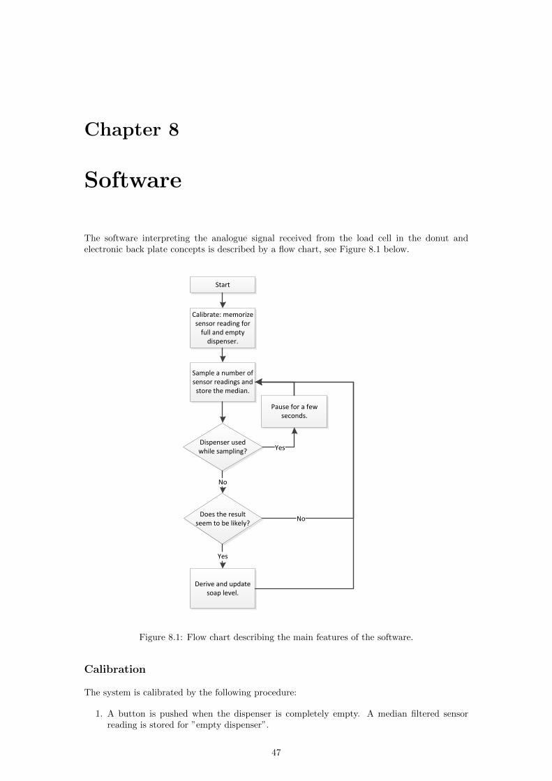
Software
The software interpreting the analogue signal received from the load cell in the donut andelectronic back plate concepts is described by a flow chart see Figure 81 below
Calibrate memorize sensor reading for
full and empty dispenser
Sample a number of sensor readings and
store the median
Dispenser used while sampling
Pause for a few seconds
Does the result seem to be likely
Derive and update soap level
No
Yes
Yes
No
Start
Figure 81 Flow chart describing the main features of the software
Calibration
The system is calibrated by the following procedure
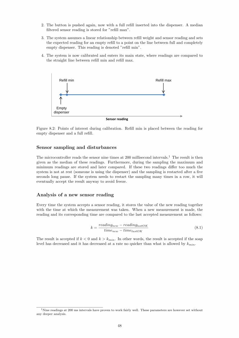
1 A button is pushed when the dispenser is completely empty A median filtered sensorreading is stored for rdquoempty dispenserrdquo
47
2 The button is pushed again now with a full refill inserted into the dispenser A medianfiltered sensor reading is stored for rdquorefill maxrdquo
3 The system assumes a linear relationship between refill weight and sensor reading and setsthe expected reading for an empty refill to a point on the line between full and completelyempty dispenser This reading is denoted rdquorefill minrdquo
4 The system is now calibrated and enters its main state where readings are compared tothe straight line between refill min and refill max
Empty dispenser
Refill min Refill max
Sensor reading
Figure 82 Points of interest during calibration Refill min is placed between the reading forempty dispenser and a full refill
Sensor sampling and disturbances
The microcontroller reads the sensor nine times at 200 millisecond intervals1 The result is thengiven as the median of these readings Furthermore during the sampling the maximum andminimum readings are stored and later compared If these two readings differ too much thesystem is not at rest (someone is using the dispenser) and the sampling is restarted after a fiveseconds long pause If the system needs to restart the sampling many times in a row it willeventually accept the result anyway to avoid freeze
Analysis of a new sensor reading
Every time the system accepts a sensor reading it stores the value of the new reading togetherwith the time at which the measurement was taken When a new measurement is made thereading and its corresponding time are compared to the last accepted measurement as follows
k =readingnew minus readinglastOK
timenew minus timelastOK(81)
The result is accepted if k lt 0 and k gt kmin In other words the result is accepted if the soaplevel has decreased and it has decreased at a rate no quicker than what is allowed by kmin
1Nine readings at 200 ms intervals have proven to work fairly well These parameters are however set withoutany deeper analysis
48
Chapter 9
Discussion
91 Project execution
This section will bring forward how some important parts of the project were executed withemphasis on what was good and what could have been done better To start up the projectwith a thorough patent search gave plenty of ideas and indications on good practises At thesame time the risk of making unintentional patent violations was reduced To be able to navigatethrough the world of patents it is necessary to have access to a well functioning database andsearch tool Furthermore a thorough investigation of competing companiesrsquo automatic soapdispensers was done which clearly showed that there was no explicit solution to the soap levelmeasurement problem
Over all the project has been focused on practical work through extensive testing and trying ofdifferent sensors and set ups A prerequisite to make this possible is to focus on componentswhich are commonly used and easily accessible This way of working resulted in further devel-opment of promising concepts which otherwise would have been excluded due to uncertaintiesand lack of time for testing
When it was time to create prototypes especially one action was taken that certainly avoidedcostly mistakes and bad prototype performance a close communication with the prototypemanufacturer was established early By doing so valuable feedback was given on constructiondetails that made it possible to further improve the performance of the prototypes An exampleof this is a decision that had to be made whether a prototype was to be produced in a workshopor by rapid prototyping In this case performance uncertainties were discussed and decided tobe too big for rapid prototyping Instead the construction could be elaborated in a workshopto ensure satisfying performance It should also be noted that as much knowledge as possiblemust be gained before ordering vital parts for the future stages of the project A certain level ofknowledge makes it possible to predict future needs that must be satisfied later on When thecircuit board and microprocessor were about to be ordered this prediction failed in some aspectsFor example there could have been better prerequisites for connection to an external displayand more space for code factors that later would limit software development and additionalfunctions
The focus during this project has been on a stand alone system which meant a lot of effort wasput into making one well functioning solution However the result could possibly have beeneven better if a combination of solutions had been pursued It is likely that some sort of synergyeffect could have been achieved if weighing the dispenser would have been combined with acounting function Maybe there also would have been more interesting concepts
49
92 Measurements
921 Expensive sensors
Some costly sensors that would never be commercially viable to use in an end product were usedin tests The reason for this is that it was primarily the principles of the concepts that were tobe tested Knowing that the sensors themselves were of good quality meant that the principlescould be judged in a fair way and good references were available when it came to developing theless expensive solutions Sensors used that can be seen as expensive are the button and donutload cells
922 Drift and offset
The unfiltered measurement data given from the micro load cell while mounted in all the loadcell utilising prototypes showed a drift phenomenon in a state of rest ie values were sometimesslowly decreasing or increasing without any obvious explanation For example a measurementfrom the load cell (unoload) could be taken when there was no refill placed inside the dispenserSubsequently a full refill was put inside the dispenser and a new value (umaxload) was givenWithout touching or affecting the system in any way the sensor value then started to decreaseslowly ie the dispenser seemed to get lighter and lighter for example giving a value 2 lowerthan umaxload after 10 - 15 minutes Furthermore unoload may now show a false value if theoffset is not taken into consideration This will of course affect the performance of the soap levelmeasurement system and thus makes it important to understand why the phenomenon arisesand what can be done to avoid it or decrease its negative influence
Another behaviour that was observed while taking measurements was something resembling anoffset that often occurred after the dispenser had been used If for example umaxload was setaccording to the previous text and immediately after that a person pushed the dispenser avalue greater than umaxload could be observed This was often followed by a drift Figure 91shows an example where initially a stable voltage is observed The crack indicates that thedispenser has been affected by an external force Immediately after this when the externalforce has been removed another voltage is measured offset from the previous one and driftingmarginally for a short time
Vo
ltag
e
Time
Load cell readings
Figure 91 An example of how an offset and drift can be preceded by dispenser usage
While it is common for all sensors to drift it should be noted that the drift affecting the prototypetests could not be reproduced when the load cell was loaded with a weight only as in Figure 92It was clear that this drift was not related to the properties of the load cell itself but rather hadsomething to do with the design and material of the prototypes It is possible that friction andmicroscopic lock-ups could cause a situation with a positive drift ie slowly increasing valuesAccordingly more and more of the total dispenser weight is transferred from unwanted stresspoints to the load cell itself over time The other way around illustrated by the example givenin the first paragraph of this section is harder to explain and understand
50
Ground
Weight
Load cell
Figure 92 A simple set up to test the inherent drift of the load cell
The major problem caused by the drift and offset phenomena is that the calibrated maximumand minimum values may become unreliable immediately after the dispenser has been usedAn analogy could be a jamming spring mechanism which needs a push to reach its true endposition As there has not been enough time to test a variety of constructions there are nosafe advices as how to construct a prototype with less drift and offset Only assumptions onnecessary improvements can be made
923 Refill resting point donut
Since the donut concept practically measures the centre of gravity of the dispenser it is crucialthat this property behaves in an expected way In the S4 dispenser the refill has two points onwhich its weight can be supported see Figure 93
Figure 93 The two places where a refill can rest in the manual S4 dispenser
For a given weight of the refill the donut conceptrsquos sensor will give different readings dependingon how the refillrsquos weight is distributed between the front and rear support The way this
51
has been dealt with in the prototypes has been to add two support points on the upper innerwalls of the dispenser so that the refill has been forced to lean slightly forward and thereby putapproximately all its weight on the front support This has worked fairly well but should notbe trusted completely
93 Level indication
The issue of how to visually present the soap level for a dispenser has been given little focus inthis project The reason for this is that modifications to the dispenser andor refill so that onecan directly see the refillrsquos content is seen as superior to all indirect electronic solutions such asLEDs displays etc Electronic level monitoring has however one major advantage it enablesremote monitoring of dispensers
If despite this an electronic level indicator is preferred on the dispenser itself it is vital thatthe power consumption is minimised To both give a clear visual signal and to minimise powerconsumption may be contradictory Primarily two different approaches to deal with this havebeen thought of The first approach is to only indicate the level when cleaning staff is insidethe washroom The cleaning staff could eg carry an electronic identification or push a buttonto let the washroom and its dispensers know that cleaning staff is in the room The dispenserscould then start to rdquoglowrdquo red or green depending on if they soon will be empty or not (or giveany other form of indication)
The second approach is to let an indicator switch between two stable conditions ie the systemonly draws current when the indicator changes state This could probably be accomplished inmany different ways one of which could be to move something mechanically eg by the use ofmagnets or a small motor
94 Counting in software
If the system continuously monitors incoming sensor readings it can detect whether the dispenseris being used or not By counting the number of pushes the accuracy of the soap level deter-mination could be further increased Suggested is then to use some sort of weighting betweenthe counting and the weight estimation A common filter for this type of process (primarily forevents with gaussian distribution) is the Kalman filter
95 Other promising concepts
The donut concept was chosen as the winner but there were other promising concepts whichdeserve to be mentioned in this chapter It is believed that these concepts still have muchpotential which due to the limited time for the project is yet to be discovered
951 Capacitance
While being inexpensive and elegant this concept is also one of the more technically advancedones More knowledge about electric fields is required in order to be able to fully understandwhat actions need to be taken to improve its performance The concept in its current state isable to detect if a refill is present in the dispenser or not A reason to why it did not succeedin this project is believed to be that the circuit and equipment used during experiments werenot correctly used A method for system shielding is necessary for additional functionality Inthis project only one measurement method using DC has been examined but there are manyother methods mainly including AC being used for liquid level measurements However it islikely that this concept works best for rigid tanks which do not move and are more suitable forattachment of a measurement device rather than soap refills which are flexible and volatile
52
952 Optical
Yet another inexpensive concept which by using IR distance sensors can indicate when the soaphas reached a certain level but lacks performance over the total soap level range More exper-iments with different sensor placements as well as different types of soap should be conductedThe concept in its current form should be suitable to combine with another solution with awider range in order to achieve increased performance A good match would be to combine thisconcept with keeping track of the number of doses dispensed
953 Back plate
As well as in the winning donut concept the weight of the refill is central for this concept Ithas been showing good results in tests but there are problems with gaps in the construction andmaterial flexibility which sometimes cause unreliable sensor readings mainly due to offset It issuggested that further development of this concept should consider the beam load cell as sensorinstead of the micro load cell By doing so it is believed that the system will be less sensitive tooffset and drift
96 Other product improvements
This section will explain some ideas of how a future dispenser and refill better adapted for soaplevel indication and measurement should be designed The ideas and suggestions are based onexperience from tests and knowledge about the soap level measurement system gathered duringthe project
961 The refill
In order to make it easier for optical soap level measurement methods the refill should be astransparent as possible This would also make it easier for a person to visually assess the soaplevel
If a collapsing refill must be used then there are some important details to keep in mind Thecollapse should be predictable and as identical as possible for each refill Furthermore manyconcepts in this project and perhaps a majority of all measurement methods would benefit froma symmetrical collapse ie if the center of gravity only changes in height and not backwardsforwards or sidewards inside the dispenser An example could be if the top of the refill wouldmove towards the bottom not only being powered by a lowered internal pressure but also gravityinstead of the back towards the front as it currently does
The refill should not only collapse symmetrically but also be symmetrical in shape and geometryThis would make it impossible to insert it into the dispenser the wrong way and if it were torotate during usage it would not change any important measurement parameter A concept ideaduring the course of this project was to add rdquoearsrdquo on the refill that would be locked in placeby the dispenser lid and be visible from outside see Figure 94 This would give a clear visualindication of the soap level and a stable refill
53
Figure 94 An illustration of how an improved refill could look in a cross section viewed fromabove The black line represents the dispenser walls and the blue line the transparent refill withsoap inside
962 The dispenser
An improved dispenser should have a larger transparent window or in the ideal case be com-pletely transparent everywhere The main challenge is to make the refill clearly visible at thesame time as the dispenser is appealing in its design Furthermore the design should commu-nicate the correct way of usage and mounting and also make these as easy as possible As faras mounting is concerned the current solution with four holes and screws may easily becomemisaligned
Some sort of reserve tank could be added in order to have a back-up during the time fromwhen the refill gets empty until it is replaced If the reserve tank is rigid it would be easier toimplement a system that signals a warning when a certain level is reached for example by usingan optical sensor Optimum would be if there was no refill at all but instead a large central tankwhich several dispensers could be supplied by concurrently through pipelines For large solidtanks there are several well-tried and accepted level measurement systems
54
Chapter 10
Conclusions andrecommendations
101 Conclusions
A soap level measurement system has been developed and prototyped The current status ofthe product is a functional prototype which has been successfully tested in real conditions Thesystem is able to monitor soap level and present this level to anyone near the soap dispenser bya display Furthermore the list of specifications is met but the system has shortcomings whichshould be improvable The current design has drift and offset problems which are believed to becaused by the current mechanical construction of the prototype These problems mainly affectthe calibration procedure
No other solution with similar functionality has been discovered in the hygiene sector during thecourse of this project This means this system could put SCA ahead of competitors if it wereto be implemented as a commercial product
More concepts other than the chosen donut concept have proven to be promising Tests haveconfirmed that concepts within areas such as optical and capacitive sensing might be interestingfor use in soap dispensers
The objective has been accomplished within time schedule and recommendations have beengiven for further development
55
102 Donut The winning concept
Features
bull Completely hidden inside dispenser
bull Continuous level monitoring
bull Insensitive to how a refill collapses
Possibilities
bull The concept can be used also for othertypes of dispensers
bull Measurement frequency can be madeadaptive in software to save energy
bull Has potential to be developed into astand alone product
bull Can be programmed to count the num-ber of doses
Requirements
bull Requires a dispenser system having a fixed centre of gravity or one that only moves in thevertical direction (The system is sensitive to if the centre of gravity shifts in the directionperpendicular to the wall)
bull Larger elongated holes instead of the original upper holes on the dispenser
bull A power supply
56
103 The next version of the donut concept
1031 Hinge component
If the weight of the dispenser could be supported by a hinge component then there would be noneed for the rather uncertain type of pivot support used in the current prototype Furthermoreif the pivot line could be placed behind the lever then the userrsquos effect on measurements wouldbe minimised since the moment the user creates around the hinge would be very small seeFigure 101
Figure 101 The placement of the pivot line affects how much the user will be able to disturbthe system
If having a hinge component the lower rear end of any dispenser not just soap could be modifiedto be compatible with the new measurement system Ideally the dispenser body should be madeso that the same dispenser body could be used both for customers wanting monitoring and forthose who do not
1032 Stand alone product
It might be interesting to redesign the load cell holder so that it would contain necessary elec-tronics for wirelessly transmitting the sensor readings to a receiving central unit The receivingunit could then use the sensor readings and perform whatever computations and actions desired
Figure 102 An illustration of a futuristic idea where a tablet is used to rdquoreadrdquo a washroom
57
1033 Improved mounting
The current prototype is sensitive to if the holes drilled in the washroom wall are not parallelRecommended is to use through holes that are as large as possible It might also be a good ideato make the holes slightly tapered so that the diameter increases going from the screw head tothe washroom wall Moreover the space dedicated to the screw heads needs to be increased
1034 Load cell with two strain gauges
If choosing to keep the current load cell design one of the more important changes to make isto introduce a second strain gauge to the load cell This second strain gauge should be placedopposite the first one on the other side of the metal This will make the two strain gaugesexperience the same environment and measurement errors due to temperature etc will bestrongly reduced Furthermore since they are placed on opposite sides of the metal one gaugewill be compressed whereas the other one will be stretched when the cell is loaded This meanstheir electrical resistances will change in different directions One of the gaugesrsquo resistance willincrease whereas the other strain gaugersquos resistance will decrease creating a more sensitive loadcell with greater range and accuracy A more sensitive load cell comes with two possibilities
1 Use the higher sensitivity to generate a higher resolution in measurements so that differentsoap levels differ more in sensor reading An example of a load cell having a strain gaugeconfiguration as described above is the beam load cell that was tested for the back plateconcept Its test result was very pleasing and is shown in Figure 63
2 A higher resolution makes it interesting to build the load cell from a thicker sheet of metalThe load cell would then become stronger stiffer and more durable Since the load cellbecomes stiffer the dispenser will wobble less and the whole system becomes more sturdy
1035 Calibration procedure
In the current prototype the system is calibrated through the use of an ONOFF switch Itis plausible that there are more suitable ways to handle the calibration Important is to makeit user friendly at the same time as users should not be able to calibrate the dispenser out ofcuriosity (meddlesomeness) One idea is to make use of the already existing IR receiver presentin automatic dispensers by using it also for communication purposes Calibration could then beperformed by using a remote control that sent out a modulated IR pulse to the dispenser Theperson calibrating the system also needs to receive some sort of feedback eg from LEDs thatmark the progress of the calibration procedure
1036 Design for X
The current design is 3D printed and few thoughts have put on draft angles etc needed forother manufacturing methods such as injection moulding The general design of the currentprototype should however not need to be changed For environmental and assembly aspects itis recommended to as in the current prototype implement some sort of snap fit between theload cell and the load cell holder That way the two parts will be easy both to assemble anddisassemble Since the load cell is made mainly of metal and the load cell holder is plasticdisassembly might be of interest
58
1037 Software updates
The current prototype is not programmed to detect when a new refill has been inserted into thedispenser This should however be a fairly straightforward task due to the clear difference insensor reading between a full and empty dispenser Some special cases that might be interestingto look at are
bull When a refill change occurs that does not go from empty to full
bull When a refill is inserted that does not contain the same type of soap as the previous refill
Ideally the system should be able to update its parameters so that it automatically handles theabove situations If that is not possible it would be advantageous if the system could at leastdetect that something has happened and notify the responsible staff
In general the system needs to be programmed in such a way that it becomes rdquoself-awarerdquoThat is the system must understand when it needs to be recalibrated or in any other formmaintained by staff
Adaptive measurement frequency
To save energy the system could enter a sleep mode between measurements It is recommendedto make the duration of this sleep adaptive to how fast the soap level is decreasing If thedispenser is used very frequently it will measure often Likewise if the dispenser is used lessfrequently it will measure more seldom and spend more time sleeping
59
References
[1] SCA and Tork company information and pictureCompany information Retrieved April 14 2012 fromhttpwwwscacomenabout_sca Picture Retrieved April 14 2012 fromhttpwwwtorkseVarfor-TorkHygienSkotselanvisningar-for-Tork-dispensrar
[2] Bjorn Larsson MSc Eng SCA Tissue AFH
[3] Ulrich amp Eppinger (2008) Product Design and Development McGraw Hill
[4] Johannesson et al (2004) Produktutveckling -effektiva metoder for konstruktion och designLiber AB
[5] Lindstedt amp Burenius (2006) The Value Model How to Master Product development andCreate Unrivalled Customer Value Nimba AB
[6] Bohgard M (2008) Arbete och teknik pa manniksans villkor Stockholm Prevent
[7] Information about TRIZRetrieved April 15 2012 fromhttpwwwtriz40com
[8] Refill information and picture Retrieved April 25 2012 fromhttpwwwtorkseProdukt520501
[9] Alciatore DG amp Histand MB (2007) Introduction to Mechatronics and MeasurementSystems Third international edition New York McGraw-Hill
[10] Setinkunt S (2007) Mechatronics Hoboken John Wiley amp Sons inc
[11] Flux density formulaRetrieved Mars 10 2012 fromhttpwwwmagneticsolutionscomaumagnet-formulahtml
[12] Ways to measure capacitanceRetrieved April 15 2012 fromhttpwwwpupmancomlistarchives1998Aprilmsg00625html
[13] Table of dielectric constantsRetrieved April 15 2012 fromhttpwwwclippercontrolscompagesDielectric-Constant-Valueshtml
[14] Tork S1 information and picturesStandard white Retrieved Jan 25 2012 fromhttpwwwtorkseProdukt560000
Black with lever Retrieved Jan 25 2012 fromhttpwwwtorkseProdukt560100
Aluminium Retrieved Jan 25 2012 fromhttpwwwtorkseProdukt452000
[15] Tork S2 information and picturesWhite Retrieved Jan 25 2012 fromhttpwwwtorkseProdukt561000
Black Retrieved Jan 25 2012 fromhttpwwwsca-torkcomproduct561008
60
[16] Tork S3 information and pictureRetrieved Jan 25 2012 fromhttpwwwtorkseProdukt453000
[17] Tork S4 information and picturesWhite Retrieved Jan 25 2012 fromhttpwwwtorkseProdukt561500
Black Retrieved Jan 25 2012 fromhttpwwwsca-torkcomproduct561508
[18] Deb groupCompany information Retrieved Jan 24 2012 fromhttpwwwdebgroupcomseabout-us
Dispenser information Retrieved Jan 24 2012 fromhttpwwwdebgroupcomsitesdefaultfilesliterature-item-filesse
proline-touchfree-dispensrar-fabpdf Dispenser picture Retrieved Jan 24 2012fromhttphygocoukstore
[19] Georgia PacificCompany information Retrieved Jan 24 2012 fromhttpwwwgpcomaboutsindexhtml
Dispenser information Retrieved Jan 24 2012 fromhttpwwwrubbermaidcommercialcomrcpproductsdetailjspcategoryCode=
skincareampsubCategoryCode=skincare_auto_foamamprcpNum=FG750411ampcategoryCode_
subCategoryCode_rcpNum=skincare_skincare_auto_foam_FG750411 Dispenser pictureRetrieved Jan 24 2012 fromhttpwwwemeagpcomuploadsModulesPhotos
[20] GOJOCompany information Retrieved Jan 24 2012 fromhttpgojocomunited-statesabout-gojocompany-informationaspx
Dispenser information Retrieved Jan 24 2012 fromhttpwwwgojocomunited-statesmarkethealthcarehealthcareproducts
aspxdisp=BB347777-6C01-44C0-819F-40CE496B82AD
Dispenser picture Retrieved Jan 24 2012 fromhttphuntindcomauimagesproduct-rangegojo-hand-cleaners
[21] HagleitnerCompany information Retrieved Feb 11 2012 fromhttpwwwhagleitnercomencompany
Dispenser information Retrieved Feb 11 2012 fromhttpwwwxibuatENGindexhtmlproductssensFOAM
Dispenser picture Retrieved Feb 11 2012 fromhttpwwwfreedom-firstcoukindexphphygienewashroomsystemshagleitner
html
[22] Kimberly-ClarkCompany information Retrieved Jan 24 2012 fromhttpwwwkimberly-clarkcomourcompanyaspx
Dispenser information Retrieved Jan 24 2012 fromhttpkcprofessionalcomaupdfsbrochureElectronic_Cassette_Skin_Care_
Systempdf
Dispenser picture Retrieved Jan 24 2012 fromhttpLINK
[23] Ophardt HygieneCompany information Retrieved Jan 24 2012 fromhttpwwwophardtcomenueber-unshtml
Dispenser information Retrieved Jan 24 2012 fromhttpwwwophardtcomeningo-man-produktuebersicht142html
Dispenser picture Retrieved Jan 24 2012 fromhttpLINK
61
[24] Technical Concepts RubbermaidCompany information Retrieved Jan 24 2012 fromhttpwwwtechnicalconceptscoukindexphpoption=com_contentamptask=
viewampid=34ampItemid=51
Dispenser information Retrieved Jan 24 2012 fromhttpwwwrubbermaidcommercialcomrcpproductsdetailjspcategoryCode=
skincareampsubCategoryCode=skincare_auto_foamamprcpNum=FG750411ampprint=true
Dispenser picture Retrieved Jan 24 2012 fromhttpLINK
[25] UltraClenzCompany information Retrieved Jan 24 2012 fromhttpwwwultraclenzcomabout_ushtml
Dispenser information Simplicity plus Retrieved Jan 24 2012 fromhttpwwwultraclenzcomsimplicity_plushtm
Dispenser information ProClenz PCS Retrieved Jan 24 2012 fromhttpwwwultraclenzcomproclenzhtm
[26] Volume measurement by speaker and microphones as done by RionCompany information Retrieved May 9 2012 fromhttpwwwrioncojp
Measurement method information Retrieved May 9 2012 fromhttpwwwrioncojpdbconpdfACM_AWM-Epdf
62
Appendix A
Prototyping platform
I
Design Drawn Date Checked Approved Date
Sheet of
Drawing no
Statement
drawingReplace
drawing
Revno Specification Account Date
A3
_C
RE
AT
OR
This
docum
ent is
our p
roperty
It m
ust not be c
opie
d a
nd its
conte
nts
must not be im
parte
d to third p
ersons w
ithout our w
ritte
n p
erm
issio
n
Infr
ingem
ent of th
e a
bove w
ill be p
rosecute
d
REF_2048 REF_2048
AN_3
AN_2VCC_5V0
VCC
VCC_5V0
VCC
VCC_5V0
VCC
VCC_11V5
VCC
VCC_11V5
VCC
AN_0R53 1K
R52 100P51
R51 0
C51
01UF
1
2
3R59
500
R68
10K
R58
2
3
1
+
-
IC52-A
OPA2337DCN
R78
10K
C56
22PF
R7
9
10K
R66 0
P55
C58
001UF
R64 0
R50 0
R63
8 4(+) (-)
IC53-C
C59
22PF
P53
C52
001UF
REF_2048
P56
P52
R77
10K
R62 100
R69
10K
AN_1R55 1K
R65
NOT MOUNTED
2
12
13
14
15
16
4
6
8
9
7
3
5
11
10
1
V+
Vo
V-
IAREF
SENSERG
RG
VREFCOM
VREFBG
VREF10
VREF5
VREF25
VREFOUT
SLEEP
VIN+
VIN-
IC50 INA125UA
R71
10K
R67
1K
2
12
13
14
15
16
4
6
8
9
7
3
5
11
10
1
V+
Vo
V-
IAREF
SENSERG
RG
VREFCOM
VREFBG
VREF10
VREF5
VREF25
VREFOUT
SLEEP
VIN+
VIN-
IC51 INA125UA
C50
01UF
R61
R74
1K
C55
001UF
R56
1
2
3R57
500
R72
NOT MOUNTED
P54
P57
C57
1000PF
8 4(+) (-)
IC52-C
R75 0
C53
001UF
R54 100
2
3
1
+
-
IC53-A
OPA2337DCN
6
5
7
+
-
IC53-B
OPA2337DCN
C54
1000PF
R70
10K
P50
6
5
7
+
-
IC52-B
OPA2337DCN
R60 100
R76
10K
R73 0
TP55TESTPOINT 12-07
TP58
TESTPOINT 12-07
TP54TESTPOINT 12-07TP60TESTPOINT 12-07
TP56TESTPOINT 12-07
TP57TESTPOINT 12-07
TP61TESTPOINT 12-07
TP62TESTPOINT 12-07
TP63TESTPOINT 12-07TP64
TESTPOINT 12-07
TP52
TESTPOINT 12-07
TP59
TESTPOINT 12-07
TP65
TESTPOINT 12-07
TP53
TESTPOINT 12-07
Typ beteckning
Circuit diagram
CREATOR
DateNN
Wiiking_DEVBOARD_ANALOG
JL JL
27592001PA
1 22012-02-23 PR
RST
REF_2048
REF_4096
Design Drawn Date Checked Approved Date
Sheet of
Drawing no
Statement
drawingReplace
drawing
Revno Specification Account Date
A3
_C
RE
AT
OR
Th
is d
ocu
me
nt
is o
ur p
ro
pe
rty
It
mu
st
no
t b
e c
op
ied
an
d its
co
nte
nts
mu
st
no
t b
e im
pa
rte
d t
o t
hird
pe
rso
ns w
ith
ou
t o
ur w
ritte
n p
erm
issio
n
Infr
ing
em
en
t o
f th
e a
bo
ve
will b
e p
ro
se
cu
ted
MOSI
MISO
TOSC1
SCK
TOSC2
TOSC2
TOSC1
SCK
MISO
RXD0
MOSI
VCC_5V0
VCC
VCC_5V0
VCC
VCC_5V0
VCC
VCC_5V0
VCC
VCC_5V0
VCC
VCC_11V5
VCC
VCC_5V0
VCC
VCC_5V0
VCC
C12
001UF
L2
600mA 1000ohm100MHz1GHz
M1
C2501UF
L3
600mA 1000ohm100MHz1GHz
C24
01UF
X1
R11 1K
R10 1K
M3
40
41
42
43
44
1
2
3
8
7
9
10
11
12
13
14
15
16
6 18 28 39 5 17 38 27
26
25
24
23
22
21
20
19
4
29
30
31
32
33
34
35
36
37
RXD0
TXD0
RST
REF_4096
AN_3
AN_2
AN_1
AN_0
PD0RXD
PD3INT1
PB4
PB0T0
PB3
XTAL1
XTAL2
PB1T1
PB5MOSI
PB2INT2
PB7SCK
PB6MISO
PD6
PD2INT0
PD1TXD
PD7
PD5
PD4
GN
D
GN
D
GN
D
GN
D
VC
C
VC
C
AV
CC
VC
C
RST
PC3
PC4
PC5
PC6
PC7
PC0
PC2
PC1
AREF
PA4ADC4
PA0ADC0
PA7ADC7
PA6ADC6
PA5ADC5
PA3ADC3
PA2ADC2
PA1ADC1
IC3 ATMEGA324-TQFP
+ C4
47UFC2
47U
6K1-F
C13
001UF
P3
2way Terminal Block
P5
1K1-A
M5
C1
01UF
1
2
12V_IN
P1
2K1-B
R8 1K
C31
1UF
C28
1UF
C2701UF
C5
470PFR4
100K
R2
100K
R16100
C20
M4
1
3
2
4
5
UREG
VoutVin
EN
GND
BYP
IC2 MIC5205YM5
C16
R15 100
R14100
R13 100
R12 100
P2
2way Terminal Block
P4
8way Terminal Block
C8
001UF
C18
01UF
1
3
2
4
5
UREG
VoutVin
EN
GND
BYP
IC1 MIC5205YM5
R112K
C2601UF
C14
22PF
C30
1UF
LED2
LED1
R9 1K
C9
001UF
L1
2A 220ohm100MHz
R3 33K
1
3
2
X2
M6
C29
1UF
F2
02A
21
D2
12V
M2
C7
470PF
+ C6
47UF
3K1-C
C23
68PF
5TXD0K1-E
R6
680
R17100
R5
100K
2
3
4
6
SLEEP
VS OUTPUT
GND
IC5
REF191GS
C10
22PF
C15
4K1-D
R7
680
C21
C17
C22C19
68PF
C3
47U
2
3
4
6
SLEEP
VS OUTPUT
GND
IC4
REF198GS
C11
22PF
TP3
TESTPOINT 12-07
Typ beteckning
Circuit diagram
2
CREATOR
DateNN
Wiiking_DEVBOARD_MCU
JL
32768 kHz
JL
115V
5V
-
+
22012-02-23
ISP-PROGRAMMING
27592001PA
DEBUG
PR
INPUT 12V
Appendix B
Patents
B1 Method and device for indicating future need for prod-uct replacement of random use dispensing
In order to reduce waste and maintain hygiene it is important that dispensers with disposablerefills in some way can predict when it is time for replacement If the replacement is made tooearly there will still be some product left which will go to waste and if it is made too late theuser wont be able to use the dispenser This patented invention states that it is possible toforesee the time for replacement even if the dispenser is used at random and there is a varyingamount of refill placed in it By letting the maintenance personnel enter service interval andamount of product (which can also be received through a RFID tag) and an activation switchcount the number of times the dispenser has been activated it is possible to program a controllerto predict if a replacement must be performed prior to the next service interval
B2 Dispenser and method
The background for the problem this invention wants to solve is the same as the previousexample The product level is monitored by counting the activation of the dispenser only byusing a lever connected to the dispenser activation handle When the activation handle is pushedthe lever turns a gear by sprockets and the gear activates the counter which keeps track of everydispensing event In order for this to work the system must be programmed with the productamount in every refill as well as an average amount of product in every dispensed dose
B3 Apparatus for hands-free dispensing of a measuredquantity of material
Describing in more general terms a touch less dispenser this invention also tries to keep trackof how much product that is still left in the container by counting and will stop when a prede-termined number of actuations has been reached typically 95 of total amount As previousinvention also this controller require manual input from the user about total volume of theproduct as well as the volume of every dispensed dose to calculate when to signal for refill
B4 Electronically keyed dispensing systems and relatedmethods of installation and use
This invention identifies the need for keyed dispensers and refills in order to ensure that onlya proper refill is installed in a certain dispenser If a refill from a competitor is used insteadof the proper one the dispenser manufacturer will experience economic damage due to the fact
IV
that dispenser often are sold at cost or less Instead the dispenser manufacturer will rely onthe refill sales to provide profit The invention for solving this problem includes communicationdevices on both the refill and the dispenser preferably using RFID tags If unauthorized use isdetected the dispenser will be disabled by a controller
B5 Dispensing machine
The inventors of this machine states that it is hard to keep track and control the amount ofcleaning products that is used in larger facilities like hotels hospitals and offices This particularmachine keeps track of and sums up the total amount weight or volume of products that hasbeen dispensed It can also prevent dispense of more products than a preset number during acertain timeframe but denying unauthorized usage
B6 System and method for measuring monitoring andcontrolling washroom dispensers and products
Patent WO2005065509 (A1)About sensing the product used with the dispenser to update the dispenserrsquos parameters accord-ingly Ways mentioned to identify the product are an RFID reader a barcode reader a printedlabel reader a magnetic strip reader a smart tag reader a hologram reader a luminescencereader andor a fluorescence reader
B7 Dispenser with warning device for the level of thecontent
Patent EP0940110 (A1) Has one fixed and one moveable partassembly of the dispenser Whenit is used the moveable part moves relative to the fixed component The dispenser counts thenumber of displacements of the movable relative to the fixed component and gives a warningsignal when the number of trips counted reaches a predetermined value
Technical solution A sensor detects every movement of the movable relative to the fixed elementand a microcontroller totals the number of trips and generates a signal when the amount ofdisplacement reaches or exceeds a predetermined threshold value
rdquoPreferably the sensor consists of a magnet and reed switch (ILS) respectively fixed to themovable and the fixed componentrdquo
rdquoFor example a short press on the handle can be an application of the user who wishesto obtain an object or one-dose product and a long press to reset the counting device whenreplacing or filling the tank by maintenance personnelrdquo
B8 A liquid receptacle of rdquobag-in-boxrdquo type
Patent WO2009064232 (A1)The idea here is to in a bag-in-box product let the bag have a stiff upper part or ceiling thatcan be seen through the outer box When the content of the bag decreases the height of thebag will also decrease and thus the position of the ceiling will change The upper partsdimensions are just slightly smaller than the outer box cross-sectional area
V
Appendix C
Specifications and criteria
C1 List of specifications
Table C1 A list of specificationsNo Requirements DemandWish
1 Monitor soap level D2 Enable soap level forecasting W3 Function without regular service D4 Resolution of at least 10 ml D5 Maximum manufacturing cost of 10 euro D6 Manufacturing cost less than 5 euro W7 Low sensitivity for external disturbance D8 Should be easy to use D9 Minimal need for user configuration W10 Automatic reset W11 Visual indication of soap level D12 Low energy consumption D13 Simple construction W
Explanations
1 The main function of the system Means that it shall be able to measure some quantitythat is proportional to the amount of soap that is left in the refill and provide an outputsignal that can be used to indicate the soap level
2 If the measurements can be used to forecast when the refill will be empty it will be regardedas an advantage
3 It will be too expensive if the system needs more attention by a technician than a soapdispenser normally would An unreliable and sensitive system is not acceptable
4 If the resolution is too bad then there is not benefit of using the system To be able to seesteps of at most 10 ml should be enough
5 The customersrsquo cost acceptance is limited and a maximum cost of 10 Euro has been set
6 A lower cost is an advantage because it makes it more likely that a customer would by theproduct
7 If it is easy to manipulated the measurements by external disturbance then there is a riskof scepticism from users and customers
8 With easy to use it is meant that one shall be able to mount and initiate the system byusing simple instructions and tools
9 This requirement is related to number seven and emphasises that for example the softwaremust be smart to avoid complicated calibrations manoeuvres
VI
10 Replacing an empty refill should not require a recalibration The system should automat-ically reset on refill change and start over with new measurements
11 Some sort of visual indication is needed in order to communicate the soap level to usersand cleaning staff
12 Minimum energy consumption must be strived for as a limited battery supply is the mostcommon power source for soap dispensers
13 If the system is easy to produce it will be cheaper and most likely more popular on themarket
C2 First evaluation matrix criteria
Table C2 Concept screening criteriaNo Criteria1 Quality of visual signal2 Performance in measurement3 Durability4 Resistance against disturbances5 rdquoFoolproof-nessrdquo6 Energy consumption7 Ease of manufacture8 Generality9 Economic potential
Explanations
1 If the system is able to provide a visual soap level signal without extra electronics it isregarded as an advantage No need for extra components to present the soap level
2 The anticipated performance of the measurements should be good enough to be used forsoap level estimation
3 It is important the system is able to handle rough usage without breaking or prolongeddecreased performance
4 Temporary disturbance for example during usage must be handled and is not allowed tomake the system useless
5 The system must be easy to set up and minimise the risk for mistakes when operated
6 The lower the consumption the better Batteries is the most common power source
7 It is an advantage if the system can be used in other dispensers regardless of its content
8 The cheaper the system is and the more value it is likely to provide the product the better
C3 Second evaluation matrix criteria
Table C3 The criteria chosen for the final concept evaluationNo Criteria1 Can measure continuous level2 Can clearly see when the refill is empty or when the soap passes a certain level3 Uncertainty in upcoming work4 Estimated relative cost
Explanations
VII
1 The system should be able to continuously follow the soap level from full to empty as itwill provide more value to the product than for example just being able to tell when it isnearly empty
2 A reliable system should be able to tell when the refill is empty with as high certainty aspossible Even if the level measurement is not exact over the full range of the soap levelit can still be an advantage if it is precise for a range close to nearly empty
3 If a concept is believed to be hard to develop further and if it is uncertain how to improvethe current status of the concept then it should be considered as a disadvantage Insteada concept that is straight forward to improve should be favoured as it will require lessdevelopment time and still provide a satisfying final result
4 The estimated cost for a concept should be as low as possible A higher cost must bemotivated by better performance
VIII
Appendix D
Pugh matrices
D1 No modifications
Kateterinvers Block (referens) Bakplatta med fjaumlder 1 Elektronisk bakplatta Motvikt
Quality of visual signal 0 0 0 - -
Performance in measurement 0 0 0 + -
Durability 0 0 0 + 0
Resistance against disturbances 0 0 0 0 0
Foolproof-ness 0 0 0 0 0
Energy consumption 0 0 0 0 +
Ease of manufacture f 0 + + +
Generality 0 0 0 0 0
Economic potential 0 0 + - 0
Number of pluses 0 0 2 3 2
Number os zeros 8 9 7 4 5
Number of minuses 0 0 0 2 2
Plusminus 0 0 2 1 0
Question marks 1 0 0 0 0
Comment Through
Put on hold since it does
not feel like it is
commercially viable
Good if a decent feeling at usage can
be guaranteed (damper) If not
eliminate (Through)
Through
Put on hold due to greater
potential among other back
plates
+- 0 0 2 1 0
Potential 1 0 2 1 0
Uncertainty [] 11 0 0 0 0
IX
D2 Dispenser modifications only
Endast TT-givare Donut-lastcell vid skruv Yttre gunga Inre gunga Balansvaringg Bra vibrationer Oumlga foumlr detaljer (REF) Raumltt tonlaumlge Kondensator Direkt nivaringavlaumlsning
Quality of visual signal 0 0 0 0 0 0 0 0 0 0
Performance in measurement + f + + f f 0 f f f
Durability 0 0 - f - - 0 0 + 0
Resistance against disturbances 0 f 0 + + f 0 - - 0
Foolproof-ness + 0 + 0 0 + 0 0 0 0
Energy consumption + + + + + 0 0 0 f 0
Ease of manufacture f + - - - 0 0 0 0 0
Generality + + + - 0 0 0 0 0 -
Economic potential - f - - - 0 0 0 - f
Number of pluses 4 3 4 3 2 1 0 0 1 0
Number os zeros 3 3 2 2 3 5 9 7 4 6
Number of minuses 1 0 3 3 3 1 0 1 2 1
Plusminus 3 3 1 0 -1 0 0 -1 -1 -1
Question marks 1 3 0 1 1 2 0 1 2 2
Comment Through Through Through
Eliminated Swing is
seen as a better
alternative This one is
similar but more
advanced
Put on hold until simpler
concepts have failed
Put on hold Too many
uncertain parameters
The valuable test time is
given to other concepts
Eliminated if not
modified to perform
better when the refill is
nearly empty
Through
Has potential but also
great uncertainty Needs
to be tested
Combine with Oumlga foumlr
detaljer to get better
performance when the
refill is rather full
+- 3 3 1 0 -1 0 0 -1 -1 -1
Potential 4 6 1 1 0 2 0 0 1 1
Uncertainty [] 11 33 0 11 11 22 0 11 22 22
X
D3 Modifications to refill or both
Sluten krets Taumltning Magnetisk baksida Faumlrgjaumlmfoumlrelse Solid nivaringdel Icke-kollapsande tillaumlgg Nivaringroumlr med koppling Vattensaumlng Fjaumldrande hals
Quality of visual signal - - 0 - + 0 0 0 -
Performance in measurement 0 f - f f f 0 f f
Durability + + 0 + + + 0 + +
Resistance against disturbances f 0 0 - 0 0 0 0 f
Foolproof-ness + + 0 0 + + 0 + +
Energy consumption 0 0 0 0 0 0 0 0 0
Ease of manufacture f + + f + + 0 0 f
Generality 0 - 0 0 0 0 0 0 0
Economic potential 0 + + 0 + + 0 0 0
Number of pluses 2 4 2 1 5 4 0 2 2
Number os zeros 4 2 6 4 3 4 9 6 3
Number of minuses 1 2 1 2 0 0 0 0 1
Plusminus 1 2 1 -1 5 4 0 2 1
Question marks 2 1 0 2 1 1 0 1 3
Comment
The other switch
conceptTaumltning is given
higher priority
Through Through
At the moment inferior to
Direkt nivaringavlaumlsning
Remember the idea of
having a reference area
Through Through
Eliminated due to its
complexity compared to
similar concepts
Eliminated as original
Through as back plate
Put on hold due to
uncertainties whether it
can be manufactured and
give accurate
measurements
+- 1 2 1 -1 5 4 0 2 1
Potential 3 3 1 1 6 5 0 3 4
Uncertainty [] 22 11 0 22 11 11 0 11 33
XI
Appendix E
Tork dispensers and refills
E1 S1 - manual liquid soap system
Material ABSDimensions 112 x 291 x 114 mm (W x H x D)Mass 350g511g (withwithout lever)
Compatible with all SCA Tork soap refills except foam soapAvailable in black white and with or without armlever Also available in a different exteriormade partly from aluminium The aluminium version has the dimensions 105 x 297 x 102 mm(W x H x D)[14] The S1 dispensers are shown in Figure E1
E2 S2 - manual liquid soap system small
Material ABSDimensions 112 x 206 x 114 mm (W x H x D)Mass 263 g
Same as S1 but smaller Available in black and in white[15] (Figure E2)
E3 S3 - automatic foam soap system
Material ABS PP and aluminiumDimensions 129 x 293 x 125 mm (W x H x D)Mass 916 g
Automatic IR sensor activated dispenser compatible with the Tork Premium Luxury FoamSoap refill It has an SCA aluminium exterior separated from an externally developed electronicdispensing module The module runs on four C-cell batteries indicates low battery and esti-mated refill level by light or sound senses whether a refill is inserted and if the lid is closed oropen When the lid is opened it assumes a new refill is inserted and then counts the number ofactivations to estimate the remaining level[16] The S3 dispenser is shown in Figure E3
E4 S4 - manual foam soap system
Material ABSDimensions 113 x 286 x 105 mm (W x H x D)Mass 371 g
This dispenser (Figure E4) is yet another product of the Tork elevation series The main
XII
difference between the S4 and the S1 is a different interface to the refill the S4 is to be usedwith the Tork Premium foam soap refills[17]
XIII
Figure E1 A White black and aluminium S1 liquid soap dispenser
Figure E2 White and black S2 liquid soap dispenser
Figure E3 S3 automatic foam soap dispenser
Figure E4 A white black and open S4 foam soap dispenser
XIV
E5 Tork Refills
All of the Tork refills are collapsible The front half of the bottle is stiff and the rear half isflexible This makes the rear approach the front as more soapcontent is pumped out Thissolution has a number of benefits A fully closed system prevents the contents of the refill ofbecoming contaminated The collapsing bottle also makes it more difficult to refill by pouringin competitorsrsquo soap Lastly the collapsible bottle takes up less space than a rigid one whenbeing empty which means that the waste will take less space
Two sizes 1000 ml and 475 ml
The Tork Premium foam soap refills are equipped with a dosage pump see Figure E5 Thispump lathers the foam soap liquid and gives a dose of approximately 04 ml per full pumpaction The other Tork refills have a tube that opens when being pressed against
Figure E5 To the left a foam soap refill followed by a standard and small one
XV
Appendix F
Existing products andcompetitors
This chapter presents the result from the benchmarking which was focused on some of the biggestcompetitors and an example of their automatic dispensers Most information was accessedthrough the respective companyrsquos online sources For some dispensers information was gatheredduring disassembly of the actual product A compilation of product specific data can be foundin Table F1 for a better overview
F1 Deb group
The Deb groups is a global company with 65 years experience from skincare in automotiveprivate and public sector medical care and food industry They were first to introduce a foamsoap cartridge that collapses and aim to be cost effective and hygienic An example of theirtouch free dispensers are marketed under the name InstantFOAM TouchFREE This productoffers level monitoring by transparent cover ie no electronic indication and has accessories likedrip collectors and floor stands The InstantFOAM dispensers are primarily mounted on a wallby four screws and anti-microbial material mixed in the plastic gives better hygiene propertiesMarketing focus on hygiene and lower costs due to less waste and controlled dosing[18]
Figure F1 The InstantFOAM TouchFREE dispenser manufactured by Deb group[18]
F2 Georgia Pacific
Georgia Pacific is one of the worldrsquos leading manufacturers and marketers of tissue packagingpaper pulp and building products and related chemicals The company has more than 40 000employees at approximately 300 locations in North America South America and Europe Anautomatic dispenser is manufactured and sold under the name enMotion The dispenser comeswith a mounting plate for easy removal and it has a transparent cover to show soap level The
XVI
design makes it slim against the wall[19] Disassembly showed that there were two switchesconnected to the circuit board one for maintenance and one for detecting whether the cover isshut or open The logic runs on a PIC16F610
Figure F2 The enMotion dispenser manufactured by Georgia Pacific[19]
F3 GOJO
GOJO started 65 years ago and is now a global producer of skin health and hygiene solutionsfor the away from home market They are currently making touchless soap dispensers calledTFX Touch Free Dispenser which comes with 1200 or 1000 ml refills A function called Skylightin practice a transparent window indicates when it is time to reload GOJO states that handwashing compliance increases generally by 20 when a touch free dispenser is introduced[20]
Figure F3 The TFX Touch Free dispenser manufactured by GOJO[20]
F4 Hagleitner
Started in 1971 this actor is striving to be the most innovative and provide the best service withinhygiene Hagleitner is currently developing and producing all products by them selves Basedin Austria there are around 600 employees working within the group XIBU is the premium lineof products offered including an automatic foam soap dispenser There is a reserve tank systemproviding a buffer if a refill change would be delayed but at the same time it makes the foamsoap vulnerable for contamination[21] During disassembly it was clear that XIBU senseFOAMdistinguishes itself from other dispensers not only by build quality but also a sophisticated foampumping system An electrical motor pumps the soap by a pressing roller action at the sametime as a servo motor drives an air pump which provides air which mixes with the soap andcreates foam Anti theft protection is provided by a lock which is opened by a special openingtool
XVII
Figure F4 The Xibu senseFOAM dispenser manufactured by Hagleitner[21]
F5 Kimberly-Clark
Kimberly-Clark is a global company with approximately 57 000 employees and 140 years ofhistory and they are present in family and personal care medical care and professional sectorKimberly-Clark is marketing their automatic soap dispenser as rdquothe electronic touchless skincare systemrdquo through the brand Kleenex focusing on hygiene touchless technology and luxuryThe electronic skin care dispenser holds 1200 ml of soap and the three D-cell alkaline batterieslast for 60 000 single uses The cassette is easy to change and recycle[22] Features that werefound after disassembly included two switches for detecting when a refill is inserted electronicsmodule separated from exteriorcover and an accessible programming interface
Figure F5 The Kleenex dispenser manufactured by Kimberly-Clark[22]
F6 Ophardt Hygiene
As a German company founded in 1962 Ophardt Hygiene is a producer of dispensing systems fordisinfection and hygiene in the medical area as well as multifaceted dosage applications in theindustrial and sanitation sectors The company has an automatic soap dispenser in the so calledIngo-man series called IMP T Touchless which distinguishes itself from competition by havingthe pump and nozzle on top making it possible to place the dispenser on tables and preventsdripping It also has a manual operation of pump in case of sensor system failure They also havea conventional touch free dispenser called Neptune which apart from most other competitorssupports individual printings on the cover Marketing focus on suitability for hospitals due togood hygiene features like material choice and touch free operation Also easy to use concerningdosage selection pump removal and high quality[23]
XVIII
Figure F6 The IMTP Touchless dispenser manufactured by Ophardt Hygiene[23]
F7 Technical concepts Rubbermaid
In April 2008 Rubbermaid a manufacturer of injection moulded products acquired TechnicalConcepts a manufacturer of washroom hygiene and fragrance products Rubbermaid Commer-cial Products specializes in manufacturing products for the cleaning safety waste managementmaterials handling and catering industries The acquisition consolidated Rubbermaidprimes positionin the commercial washroom sector and added a range of products to Rubbermaids portfo-lio of washroom solutions The Autofoam dispenser has a 1100 ml refill and is marketed asa good looking product The battery life of 120000 handwashes or 3 years is claimed to beindustry-leading Among the features are yellow and red light blinks for low battery and refilllevel respectively and a beep tone if an object is in field for more than 10 seconds[24]
Figure F7 The Autofoam dispenser is manufactured by TC Rubbermaid[24]
F8 UltraClenz
UltraClenz started in 1995 with an ambition to increase hand wash compliance in areas like hos-pitality health care food and beverage processing plants and infection prevention laboratoriesThey have a range of products related to communication between dispensers and monitoringstations and are currently producing two types of touch free soap dispensers The Simplicityplus is claimed to be a rugged and reliable dispenser which can take most so called Bag nrsquo Boxcontainers External power supply is possible The Proclenz PCS has proprietary nozzle andlocking pump assemblies that orientate nozzle into correct position and has optional drip trayand stand It also offers modularity that makes it possible to modify a dispensers from manualto automatic functionality The IR sensor is adjustable as well as the 2-speed motor and rangeselector[25]
XIX
Figure F8 The Proclenz PCS dispenser manufactured by UltraClenz[25]
XX
F9 Summary of competing products
Table F1 Examples of existing products
Brand ModelDimensions(HxWxD mm) Batteries
Capacity(ml)
Batteryindication Refill level
Deb group InstantFOAMTouchFREE
277 x 170 x 100 4 (D-cell) 1000 Light Transparency
Georgia Pacific enMotion 281 x 170 x 99 4 (D-cell) 1200 Light WindowGOJO TFX Touch
Free267 x 152 x 102 3 (C-cell) 1200 Light Window
Hagleitner XibusenseFOAM
277 x 136 x 108 3 (C-cell) 1200 Light Light
Kleenex Electronicskin care
292 x 184 x 102 3 (D-cell) 1200 Light Light
Ophardt Hygiene IMP T Touchless 330 x 92 x 210 5 (D-cell) 1000 Light NoOphardt Hygiene Neptune Touchless 398 x 188 x 101 4 (C-cell) 1000 Light Add-on systemTCRubbermaid
Autofoam 276 x 132 x 133 4 (C-cell) 1100 Light Light
UltraClenz Simplicity plus 273 x 171 x 121 4 (D-cell) 1500 Light TransparencyUltraClenz Proclenz PCS 267 x 171 x 102 4 (D-cell) 1250 Light Add-on sys
SCA Tork S3 293 x 129 x 125 4 (C-cell) 1000 Light NoSCA Tork S4 (manual) 286 x 113 x 105 NA 1000 NA NA
XX
I
XXII
Appendix G
Concept sketches
G1 No modifications
XXIII
XXIV
XX
V
XXVI
XXVII
G2 Dispenser modifications - Load cells and strain gauges
XXVIII
XXIX
XXX
XXXI
XXXII
G3 Dispenser modifications - Other
XXXIII
XXXIV
XXXV
XXXVI
XXXVII
G4 Refill (and dispenser) modifications - Direct electron-ics
XXXVIII
XXXIX
XL
XLI
XLII
G5 Refill (and dispenser) modifications - Indirect elec-tronics
XLIII
XLIV
XLV
XLVI
XLVII
G6 Features
XLVIII
XLIX
L
LI
Appendix H
Donut test results (TP4)
LII
-30
-20
-10
0
10
20
30
40
50
60
70
80
90
100
Soap
leve
l
Date and time
Figure H1 Donut test results (third prototype test 3) TP4 The line represents the measurement sytemrsquos soap level estimation while the diamonds show the actualsoap level
LIII
1700
1900
2100
2300
2500
2700
2900
3100
3300
3500
3700
3900
4100
Sen
sor
read
ing
Date and time
Figure H2 Donut test results (third prototype test 3) TP4 The red line marks where the system is calibrated for empty refill The green line marks full refill
LIV
-30
-20
-10
0
10
20
30
40
50
60
70
80
90
100
Soap
leve
l
Date and time
Figure H3 Donut test results (third prototype test 4) TP4 The line represents the measurement sytemrsquos soap level estimation while the diamonds show the actualsoap level
LV
1700
1900
2100
2300
2500
2700
2900
3100
3300
3500
Sen
sor
read
ing
Date and time
Figure H4 Donut test results (third prototype test 4) TP4 The red line marks where the system is calibrated for empty refill The green line marks full refill
LV
I
Appendix I
The Water Bed concept
The design of the planned prototype can be seen in Figures I and I The dispenser is attachedto a back plate which enables it to move slightly in the vertical direction and the weight of thedispenser is thereby put on the rdquowater bedrdquo In the planned prototype this means the weightis put on a balloon that leads the pushed away liquid into a closed-end pipe The air pressureat the top of the pipe increases until the weight of the dispenser is completely counteractedA sensor could either measure the pressure inside the liquid system or sense the height of theliquid pillar
Figure I1 A computer model of the planned Water Bed prototype
LVII
Figure I2 A close up of the thought Water Bed prototype The piston pushes against a balloonand the pushed out liquid enters a narrow pipe on the side
LVIII
Appendix J
The Audio concept
One way to know how the volume of the refill changes within the dispenser could be to measurethe acoustical properties inside the system A full refill compared to an empty refill will takeup more of the inside volume of the dispenser and thus create a certain environment for soundwaves An analogy could be an acoustic guitar where the volume of the hollow body determineshow it will sound In this case less volume will result in a tone which will ring for a shortertime and with less intensity An example of how this can work for a soap dispenser is shown inFigure J1
R
E
F
I
L
L
R
E
F
I
L
L
Figure J1 An illustration of two dispenser with different amount of soap left seen from theside Inside them there is a speaker and a microphone
Another method which could be able to measure the volume of the refill is to use one speakertwo microphones and one reference chamber This method is based on how change in pressureand volume is related in a closed chamber
∆P
P0= γ
∆V
V(J1)
Where P0 is the pressure in the chamber (preferably atmospheric pressure) V is the volumeof the chamber and γ is the ratio of specific heat The suggested measurement method is asfollows
bull Place one microphone in a reference chamber and the other one inside the dispenser
bull Assemble the reference chamber with the dispenser by an open intersection and mount thespeaker in this intersection
bull The speaker emits a sinusoidal wave signal and the ratio of the amplitude of the microphoneoutputs is measured
bull Calibrate the system using an object inside the dispenser with a known volume
For more details see the source where this idea was taken from[26]
LIX

Soap Level Monitoring System
Level monitoring system for the SCA Tork S4 foam soap system
Bjoumlrn Arendal
Jacob Cedulf
Copyright copy 2012 Bjoumlrn Arendal amp Jacob Cedulf
Gothenburg Sweden 2012
Chalmers University of Technology
Department of Product and Production Development
SE-41296 Goumlteborg
Sweden
Telephone +46(0)31-772 10 00
Preface
This Master of Science thesis is the final project for us Bjorn Arendal and Jacob Cedulf in ourpostgraduate studies at the Department of Product and Production Development at ChalmersUniversity of Technology It has been carried out at SCA Hygiene Products in Gothenburgduring the spring of 2012
We would like to thank everyone who has been involved for their much appreciated help through-out the project Special thanks go to our SCA supervisors Bjorn Larsson and Gunilla Himmel-mann for all your guidance and support We would also like to thank our supervisor fromChalmers University of Technology Dr Erik Hulthen for help with academic issues Last butnot least we would like to thank our fellow thesis workers at SCA for the collaboration andmany laughs shared
Gothenburg May 2012
Bjorn ArendalJacob Cedulf
Abstract
SCA (Svenska Cellulosa Aktiebolaget) is a global hygiene and paper company Among manyother areas SCA develop products for public washrooms and the purpose of this project wasto create an inexpensive yet reliable electronic soap level measurement system that would addvalue to SCArsquos soap dispenser products All prototypes and tests in this project have beenbased on the SCA Tork S4 foam soap system
To provide the best possible hygiene the S4 soap refills are designed as a closed system Thismeans the surrounding air is kept from entering the refill also when soap is being dispensedTo achieve this the refills collapse and often in an unpredictable manner To find a levelmeasurement method for a refill that collapses unpredictably was the main challenge in thisproject
Three main methods based on capacitance mass and optical properties respectively were proto-typed and tested The rdquowinningrdquo concept measures the weight of the soap by a load cell placedso that it is subjected to the moment with which the dispenser wants to rotate around its lowerattachment points
Initial tests show a promising linear relationship between soap level and sensor readings Futurework is recommended to be aimed at increasing the systemrsquos accuracy for the 0 soap leveland at upgrading the software with features such as refill change detection and adaptive sleepduration between measurements
Sammanfattning
SCA (Svenska Cellulosa Aktiebolaget) ar ett globalt hygien- och pappersforetag Ett av mangaomraden som SCA utvecklar produkter for ar offentliga toalettutrymmen For att potentiellthoja kundvardet hos SCAs tvaldispensrar har detta projekt haft som syfte att ta fram ettelektroniskt matsystem som pa ett palitligt och billigt satt mater tvalniva Alla prototyper ochtester i det har projektet har baserats pa SCA Tork S4 skumtvalsprodukter
For att uppna basta mojliga hygien ar tvalrefillerna hos S4-serien byggda som slutna systemDetta innebar att luft forhindras fran att komma in i refillen aven nar tval pumpas ut For attuppna detta kollapsar refillerna ihop vid anvandning ofta pa ett oregelbundet vis Att hitta ettsystem som kan mata nivan i en kollapsande behallare har varit den huvudsakliga utmaningeni detta projekt
Prototyper gjordes av tre huvudsakliga losningsmetoder som baserades pa kapacitans massa ochoptiska egenskaper Efter att dessa prototyper testats kunde en rdquovinnarerdquo utses som anvandersig utav en lastcell som ersatter de tva ovre skruvarna i dispensern och mater dar kraften medvilken dispensern forsoker rotera kring sin nedre infastning
Tidiga tester visar pa ett nara linjart samband mellan tvalniva och matvarden fran lastcellenRekommendationer for framtida arbete ar bland annat att forbattra matsystemets prestandakring nollniva samt att uppgradera mjukvaran till att adaptivt justera tiden mellan matningaroch hantera refillbyten
Contents
1 Introduction 1
11 Background 1
12 Purpose 2
13 Objective 2
14 Scope 2
2 Methods and materials 3
21 Pre-study 3
22 Concept generation 4
23 Concept evaluation and selection 4
24 Concept development and testing 5
25 Materials 5
3 Dispensers and refills 6
31 The S4 dispenser 6
32 The S4 refill 8
33 System characteristics 10
34 Summary of existing products and competitors 10
4 Sensors and physics 12
41 Reaction forces 12
42 Strain gauges and load cells 13
421 Load cells used in this project 13
43 Capacitance 15
44 Proximity and distance sensors 16
441 IR distance sensor 16
442 Hall effect sensor 16
5 Concepts and prototypes 17
51 Back plate 17
511 Description 17
512 First prototype 18
513 Second prototype 18
52 Donut 19
i
521 Description 19
522 First prototype 20
523 Second prototype 20
524 Third prototype 21
53 Swing 24
54 Optical sensing 24
55 Capacitance 25
551 The RC circuit 25
56 Seal 25
6 Tests and test results 26
61 Test procedures 26
62 Back plate 26
621 First prototype 26
622 Second prototype 29
63 Donut 30
631 First prototype 30
632 Second prototype 31
633 Third prototype 32
64 Swing 34
65 Optical 35
66 Capacitance 36
661 Single plate sensing 36
662 Triple plate sensing 38
663 Tube sensing 40
664 Comments on capacitive sensing 42
7 Concept evaluation and selection 43
71 First screening Categorisation 43
72 Step two Testing 44
73 Step three After tests 44
74 Step four Evaluation of the two final concepts 46
741 Electronic back plate 46
742 Donut 46
743 Winner 46
8 Software 47
9 Discussion 49
91 Project execution 49
92 Measurements 50
921 Expensive sensors 50
ii
922 Drift and offset 50
923 Refill resting point donut 51
93 Level indication 52
94 Counting in software 52
95 Other promising concepts 52
951 Capacitance 52
952 Optical 53
953 Back plate 53
96 Other product improvements 53
961 The refill 53
962 The dispenser 54
10 Conclusions and recommendations 55
101 Conclusions 55
102 Donut The winning concept 56
103 The next version of the donut concept 57
1031 Hinge component 57
1032 Stand alone product 57
1033 Improved mounting 58
1034 Load cell with two strain gauges 58
1035 Calibration procedure 58
1036 Design for X 58
1037 Software updates 59
A Prototyping platform I
B Patents IV
B1 Method and device for indicating future need for product replacement of randomuse dispensing IV
B2 Dispenser and method IV
B3 Apparatus for hands-free dispensing of a measured quantity of material IV
B4 Electronically keyed dispensing systems and related methods of installation anduse IV
B5 Dispensing machine V
B6 System and method for measuring monitoring and controlling washroom dis-pensers and products V
B7 Dispenser with warning device for the level of the content V
B8 A liquid receptacle of rdquobag-in-boxrdquo type V
C Specifications and criteria VI
C1 List of specifications VI
C2 First evaluation matrix criteria VII
C3 Second evaluation matrix criteria VII
iii
D Pugh matrices IX
D1 No modifications IX
D2 Dispenser modifications only X
D3 Modifications to refill or both XI
E Tork dispensers and refills XII
E1 S1 - manual liquid soap system XII
E2 S2 - manual liquid soap system small XII
E3 S3 - automatic foam soap system XII
E4 S4 - manual foam soap system XII
E5 Tork Refills XV
F Existing products and competitors XVI
F1 Deb group XVI
F2 Georgia Pacific XVI
F3 GOJO XVII
F4 Hagleitner XVII
F5 Kimberly-Clark XVIII
F6 Ophardt Hygiene XVIII
F7 Technical concepts Rubbermaid XIX
F8 UltraClenz XIX
F9 Summary of competing products XXI
G Concept sketches XXII
G1 No modifications XXIII
G2 Dispenser modifications - Load cells and strain gauges XXVIII
G3 Dispenser modifications - Other XXXIII
G4 Refill (and dispenser) modifications - Direct electronics XXXVIII
G5 Refill (and dispenser) modifications - Indirect electronics XLIII
G6 Features XLVIII
H Donut test results (TP4) LII
I The Water Bed concept LVII
J The Audio concept LIX
iv
Chapter 1
Introduction
11 Background
SCA (Svenska Cellulosa Aktiebolaget) is a global hygiene and paper company offering a widerange of products and brands Amongst these is the global brand Tork most common to befound on products like toilet paper paper towels napkins and soap In order to make theseproducts available to the end-user the Tork brand also offers dispensers developed specificallyfor a variety of sites and environments[1] An example is soap dispensers adapted for high trafficwashrooms like those found on airports hospitals and shopping malls (Figure 11)
Figure 11 Tork dispensers in a high traffic washroom[1]
For high traffic washrooms current trends point in the direction of better hygiene by increasedhand wash compliance and decreased risk for cross contamination To comply with these needsit is necessary to provide automatic and touch free dispensers as well as always make sure thatthe dispensers are supplied and ready to use This is where an electronic soap level measure-ment system comes into the picture The cost and acceptance of implementing the necessarytechnology have reached levels where SCA find it interesting and feasible to test it on theirautomatic soap and towel dispensers The idea is to have the dispensers indicating their levelof soap and towels respectively in order to let the responsible staff know when it is time forrefill The potential benefits generated by implementing this technology are many For examplethe usage of soap and towels could be monitored more easily and cleaning staff responsible forkeeping dispensers stuffed could rationalize their work[2]
The circumstances described above demands a reliable and inexpensive soap and towel levelmeasurement system As far as soap dispensers are concerned some of the present solutionsfor satisfying these needs implement a counting functionality This makes it possible to keeptrack of the number of doses dispensed and to compare this number with an average maximumcapacity of a refill a method which has proven to be unreliable in some cases
1
12 Purpose
The purpose is to make sure to stay ahead of competitors in the development of public washroomtechnology by providing an inexpensive and reliable solution for soap level measurement whichadds value to SCArsquos soap dispenser products This will be achieved by developing a levelmeasurement system for an electronic foam soap dispenser
13 Objective
The objective is during the time from January to June 2012 to develop an electronic soaplevel measurement system which makes it possible to present the soap level in a dispenser Theproject is to result in one or several functional prototypes
14 Scope
Current automatic dispensers already have batteries circuit board and microcontroller Becauseof this the scope of this project is restricted to the level measurement system only excludingpower supply to the system and design of the soap dispenser itself However minor modificationsof the soap dispenser can be made in order to facilitate level measurement Therefore the powersupply circuits and processor used in combination with the level measurement prototypes willnot be adapted for usage in a final product The project is based on the manual S4 soapdispenser but the resulting system shall be possible to use in future soap dispensers
2
Chapter 2
Methods and materials
This chapter presents the methods and materials that have been used to take this project frompre-study to final prototype The information given is categorised by using the different phasesof the project as sections A product development process similar to the ones presented inmany influential textbooks has been used to ensure that the methods are proven and risksminimised[3][4][5]
21 Pre-study
During the pre-study phase emphasis was put on understanding the product context and char-acteristics of the soap dispenser Efforts were also made to find existing solutions on the marketand patented measurement techniques relevant to dispenser products
Literature studies - was carried out using mainly on-line sources Reports on a variety ofsensor technologies were studied both for learning purposes ie to get familiar with limitationsand possibilities of relevant sensors and to extract ideas from previous experiments and tests
Benchmarking - Information about SCArsquos and competitorsrsquo soap dispensers was gatheredfrom on-line sources provided by each company Specifications key performance indicators andgeometrical dimensions were compiled in tables Disassembly of some competitorsrsquo dispenserswas also done to further examine the internal components and features
Patent searches - took place using the Espacenet patent database Due to the fact that thepatent database contains a very large amount of patents some sort of adapted search methodhad to be applied In this case the search was focused on certain categories where the mostinteresting patents were believed to be found The search results were compiled in a list and byusing this list some patents were chosen for further investigation The categorisation tree wasas follows
1 PHYSICS
(a) MEASURING
i MEASURING VOLUME FLOW VOLUME FLOW MASS FLOW OR LIQUIDLEVEL METERING BY VOLUME
A LEVEL INDICATORS
The hits given by these search restrictions could then be evaluated manually for further ac-tions All relevant patents which were further investigated are presented and briefly explainedin Appendix B
Interviews - took place both at Chalmers University of Technology (Chalmers) with a professorof electrical measurements and with various people at SCA A semi-structured interview methodwas used which allows for more spontaneous follow up questions and sidetracks which is suitablewhen the interviewee has a good understanding of the subject[6]
List of specifications - was established early in the project At this stage it was desirable tokeep most of the specifications general and non-quantitative There is little knowledge available
3
for this type of product and no known existing references on the market which otherwise couldhave provided an indication of performance parameters and other important criteria Instead thelist which is presented in Appendix C was based on information given by SCA A selection ofthe most important specifications was later used in the concept evaluation stage as reformulatedcriteria in the evaluation matrices
22 Concept generation
In the initial stage of the concept generation all possible ideas were desired A large amount ofideas would then be possible to decrease by excluding ideas and concepts with poor performanceie applying a development funnel
Brainstorming - was conducted in various groups and environments External input duringbrainstorming sessions was provided in the form of ideas and suggestions from SCA employeesconsultants and other experts The theme of the sessions was to come up with ideas of differentways to measure soap level
Idea provoking tools - like the TRIZ matrix were used to get a different point of view whentrying to generate new concepts TRIZ is a Russian acronym for a theory which is usually calledThe theory of inventive problem solving in English The essence of this theory has been compiledin a matrix which states several common contradictions between features and suggestions forhow to work around these contradictions[7]
Categorisation - made it possible to handle all the generated ideas in a systematic way Thecategorisation was based on concepts and ideas which shared certain features and the degree ofmodifications needed of the current dispenser and refill The categories were
bull No modifications
bull Dispenser modifications only
bull Modifications to refill or both
23 Concept evaluation and selection
In this stage of the project the aim was to start excluding poor concepts and eventually identifystrengths in certain concepts and use them to improve the weaknesses in others
Evaluation matrices - were created based on guidelines given by Ulrich amp Eppinger [3] Con-cept screening was done using Pugh matrices Evaluation criteria presented in Table C2 inAppendix C were chosen from the list of specifications and all concepts were then compared tochosen reference concept by deciding if the performance was better than worse than or sameas the reference Weaknesses in some concepts could be identified and concepts with high scorecould be further improved Furthermore poor concepts could be revised or excluded and otherswere combined to create new better ones In the final part of the evaluation and selection pro-cess several tests had been done and more knowledge had been gained This made it possible toidentify the most relevant criteria presented in Table C3 in Appendix C when selecting whichconcepts that would make it through to the last part of the concept development stage
External decisions - a number of interim meetings were held with SCA representatives tofollow up on the status of the project Feedback was given on conceptsrsquo performance andpotential based on test results and calculations In some cases decisions were made whether aconcept should be excluded
4
24 Concept development and testing
In this stage all promising concepts were refined Focus was on being able to build prototypeswhich later were to be used in tests After these tests a selection of concepts were furtherdeveloped and tested again Some concept were to be refined several times while others onlywere tested once
CAD tools - were used for everything from concept visualisation to detailed engineering Threedimensional models were created to evaluate and improve various constructions The modelswere also used to create prototypes or parts of prototypes through Selective Laser Sintering
Tests - In the beginning of the test phase there were a large number of concepts to be examinedand a restricted amount of time To test a concept by manually emptying a soap refill whichlasts for approximately 2500 doses would take too long Hence a fast and easily accessibletest was needed which could be performed many times but still be able to indicate how well acertain concept would perform in a real environment Later when some of the concepts had beenexcluded a new test was used which was allowed to take more time so as to get closer to a realusage situation The new test procedure was possible thanks to a machine which emptied therefill by pushing the dispenser automatically When only the most promising concepts were lefta manual and time consuming but realistic test could be used The aim was to simulate randompushes which the measurement system would not be subjected to in the pumping machine Thelast test was carried out in a restroom at SCArsquos office to get a genuine real environment
25 Materials
All hardware and software used in this project and their functions are listed in Table 21 Formore details about the project specific prototyping platform see Appendix A As both the microand beam load cells have been taken from commercially available kitchen scales there are nospecifications or further details about them
Table 21 A list of software and hardware usedFunction MeansPrototyping platform 1 Project specific (ATMega324PA)Prototyping platform 2 Arduino UnoComputer Aided Design Autodesk inventor 2012Patent database EspacenetCalculation and plotting 1 MatlabCalculation and plotting 2 Excel 2012AVR programming 1 AVR Studio 4AVR programming 2 IAR WorkbenchDonut load cell Futek LTH300Button load cell Honeywell FSS load sensorIR distance sensor Everlight Electronics ITR 8307Hall effect sensor Allegro A1324Micro load cell NABeam load cell NA
5
Chapter 3
Dispensers and refills
In order to better understand what design problems that have been faced and how the conceptsare supposed to work some important information about the S4 dispenser and refill is requiredThis information can be found in this chapter To get a better overview of the product contextand other dispensers more information can be found in Appendix E and Appendix F whichpresent Tork products and competitorsrsquo products respectively
31 The S4 dispenser
The S4 dispenser is one of many products of the Tork Elevation series It is made of ABS plasticand weighs 317 grams without refill[17] It is basically comprised by the following components
bull Back part mounted onto the washroom wall holding up all other parts
bull Lockable lid
bull Push handle for dispenser activation
bull Refill locking mechanism
Figure 31 shows the back part and its holes that enable wall mounting It is also possible tomount the dispenser onto the washroom wall by a sticky label A solid mounting is required toensure that the dispenser feels firm when used
Figure 31 The back part viewed from behind showing the four mounting holes
6
The lower part of the dispenser lid is transparent to provide visual information about the contentlike a viewing glass However it can be difficult to determine how much soap is left in the refilldue to the limited size of the transparent area In Figure 32 the dispenser is presented by apicture and a rendered image of a CAD model In the model the pump has been highlightedwith green and blue colours to illustrate how it is supposed to fit inside It should be noted thatin reality the pump is always attached to a refill
Figure 32 Left Front view of a black S4 dispenser with the transparent part barely visibleRight A CAD-model of the S4 dispenser with hidden lid and push handle the pump has beenhighlighted with green and blue colours to illustrate how it is supposed to fit inside
The S4 dispenser is designed to fit Tork Premium foam soap refills which have a special pumpattached to them The interface between pump and dispenser is illustrated in Figure 33 Thepump is held up by a circular support which is split up in a front and back part coveringapproximately 45 degrees each of a complete circle The locking mechanism which is partlyvisible is held in a non lock state by a spring The spring pushes the mechanism to the right inFigure 33 but when the lid is being closed it pushes the mechanism to the left into a lockingposition and the spring will be compressed again The locking mechanism in combination withthe dispenser interface geometry will lock the refill in five degrees of freedom ie translationin X Y and Z axis as well as rotation around the X and Y axis Rotation around the Z axisis still possible It should be noted that small gaps due to tolerances may allow for the refill totilt slightly back and forward around the Y axis upon dispenser usage
7
Back and front
support
Locking
mechanism
z
x y
Figure 33 Left A half section view of the S4 dispenser and pump without refill RightAnother view of the dispenser where the front and back supports are visible
32 The S4 refill
The S4 refill is currently available with three variants of Tork premium foam soap ie soapwhich is in a liquid state while inside the refill and comes out as foam The alternatives aremild extra mild and antimicrobial and are presented in Figure 34
Figure 34 The S4 refill containing mild extra mild and antimicrobial foam soap respectivelyWhile the antimicrobial foam soap is transparent the other two foam soaps are light yellow incolour
The refill and pump is designed to be a closed system which means that the pump is alwaysattached to the refill from delivery to disposal When soap is pumped out of the refill no aircomes in and the refill will collapse over time By letting the back of the refill have a smallermaterial thickness than the the front it will move towards the front when the refill is collapsingIdeally this will give an empty refill the shape similar to the one of a cylindrical shell sliced inhalf from top to bottom However variations in the refill production often cause unpredictable
8
collapsing behaviour The refill may twist rotate and bend during collapse In Figure 35 anumber of refills with different amounts of soap are presented to give an example of how thecollapse may look like
Figure 35 Four S4 refills with soap levels ranging from almost empty to full
A vital part of the refill system is the pump which is presented in Figure 36 When the handleof the dispenser is pushed the moveable part of the pump will move upwards A spring placedbetween the movable and the yellow part of the pump will in turn act on the refill in an upwardmovement This can make the refill move inside the dispenser in an unpredictable way asexplained in Section 31
Figure 36 Green colour the part of the pumps which rests against the dispenser and isheld in place by the locking mechanism Yellow colour the part where soap in liquid stateis collected and later extruded through as a foam upon pump activation Blue colour themoving part which is manoeuvred by the push handle
9
33 System characteristics
By analysing the information about the refill from Section 32 a number of characteristics co-varying with soap level could be determined These characteristics were then used to facilitateidea and concept generation Properties of the dispenser and refill system that vary or mightvary depending on soap level
Mass - Decreases with decreasing soap level
Volume - Refill volume decreases when the dispenser is used and the volume of the surroundingair increases accordingly
Visual soap level (height in refill) - Due to the refillrsquos collapse the visual soap level doesnot decrease linearly with the amount of soap However the visual soap level is a good sign ofhow much is left when the refill is nearly empty
Natural frequencyfrequency response - Depending on soap level the refill will have dif-ferent shape and mass and therefore it should react differently to various frequencies bothmechanically and sonically
Geometryshape - The rear half of the soap bottle approaches the front half when being used
Centre of mass - Due to the refillrsquos geometry change when collapsing the centre of mass ofthe refill moves
The internal pressure - The internal pressure at the bottom of the bottle should decreasewith decreasing soap level
34 Summary of existing products and competitors
The competitor study was focused on some of the biggest competitors and examples of theirautomatic dispensers Most information was accessed through the respective companyrsquos webpage For some dispensers information was gathered during disassembly of the actual productsee Appendix F for more details No dedicated level measurement system could be found inany of the examined dispensers However some dispensers implement a soap level warning lightwhich suggests that some sort of counting is done to keep track of the total number of dosesdispensed Switches are commonly used to monitor if the lid of the dispenser is closed and ifthere is a refill inside The information provided by these switches could be used to guess ifthere is a refill change and if so reset the dose counter Some dispensers also have a reset buttonwhich could serve the same purpose Based on the information gathered about automatic soapdispensers a function diagram was created for better overview see Figure 37
10
Sense
hand
Store
energy
Store
soap
Convert energy to
pumping action
(Isolate one dose)
Monitor energy
level
Monitor soap
level
Dispense
one dose
Provide
information
User
Energy
Soap
InfoStats
Dose of soap
MaterialMech
Information
Energy
Figure 37 A diagram of an automatic soap dispenser showing its functions and how they relateto each other
11
Chapter 4
Sensors and physics
This chapter gives an introduction to the physics and sensors utilised in the most interestingconcepts and their tests The purpose is to make it easier to understand the function of theconcepts presented in Chapter 5 and the tests described in Chapter 6
41 Reaction forces
In a non-accelerating system the net sum of all forces and the net sum of all moments are bothzero By looking at the moments acting on the two dispenser attachment points (the screwpairs) the reaction forces generated by the dispenser weight can be determined see equations41 and 42 The parameters are shown in Figure 41
h
dh
Fl
Fu
Fd
Figure 41 Important forces and dimensions
Fl =dhhFd (41)
Fu = minusdhhFd (42)
12
42 Strain gauges and load cells
The most common way to measure strain is to use one or more strain gauges One-dimensionalstrain ε in a material is the fraction between change in length ∆L and the total (relaxed)length in that direction L
ε =∆L
L(43)
The material can be seen as a spring the more loaded the material is the longer it gets andthe greater the strain Strain gauges are constructed in such a way that their electric resistancechanges with their length They are carefully glued to the material on which the measurementswill be taken so that the strain of the material and the strain gauge will be the same [9] [10]
Strain gauges are often the sensing elements in so called load cells Load cells measure force ortorque and have built-in elastic mechanical components on which the strain gauges are mountedThe load cells are often built in such a way that the measurement is proportional to the forceapplied to them This makes them convenient to use and they are common in many types ofapplications such as kitchen and bathroom scales industrial force measurements etc [9] [10]
421 Load cells used in this project
Beam load cell
As the name suggests the beam load cell is shaped like a beam Often holes have been drilledthrough the middle of the beam where the strain gauges are mounted to make it weaker Onestrain gauge is usually mounted on either side of the beam perpendicular to the load so that oneof them is contracted and the other one stretched when the beam is loaded The beam is fixedin one of its ends and loaded in the other A photo of the beam load cell used in this project isshown in Figure 42
Figure 42 The beam load cell used in this project
Donut load cell
The donut load cell has a flat cylindrical shape with a hole in the middle as seen in Figure 43It is designed in such a way that the outer ring of the load cell can be supported by a surfacebut still leave the inner ring centered around the hole unsupported This means that the innerring can make small translations relative to the outer ring along the axial direction of the loadcell In this way force on the inner ring can be measured as long as it does not exceed themaximum load An example of where it could be used is for measuring how tightly fastened abolt or screw is
13
Figure 43 The donut shaped load cell used in this project
Micro load cell
Since the micro load cellrsquos flexible component is a punched out piece of sheet steel it can bemade very flat The cell is designed in such a way that it has an outer ring that is to be heldfixed and an inner beam for bending on which one or two strain gauges are mounted In thisproject micro load cells were taken from a kitchen scale and had therefore a rather large plasticpart attached to them which had acted as one of the scalersquos feet see Figure 44
Figure 44 The micro load cell used in this project
Button load cell
The smallest type of load cell used in this project is the button load cell shown in Figure 45Its flat rear is fixed and the load is placed on the metallic rdquoballrdquo on its front
14
Figure 45 The button load cell used in this project
43 Capacitance
The ability of a capacitor to store charge in an electric field is called capacitance An exampleof capacitor is the one with two parallel metallic plates of equal area A separated at a distanced by a dielectric medium (any medium or combination of mediums that electrically separatesthe two plates) If the distance between the plates is short compared to other dimensions (sothat the electric field is nearly uniform) the following is approximately true
C = εrε0A
d(44)
Here C stands for capacitance εr is the dielectric constant of the material between the platesand ε0 is the electric constant (approx 8854 middot 10minus12Fmminus1) [9] [10]
Figure 46 Illustration of a parallel plate capacitor
There are several ways to measure capacitance It is possible to either use a dedicated capaci-tance meter device or construct a circuit suitable for the problem at hand The methods are allbased on how a capacitor affects an electric circuit
I(t) = CdV
dt(45)
where I is the displacement current through the capacitor C is the capacitance V is the voltageacross the capacitor and t is the time [9] [12]
15
44 Proximity and distance sensors
441 IR distance sensor
Infrared (IR) light is electromagnetic radiation with wavelength greater than that of visible lightIt can be used in electronic circuits for several purposes one of which is distance measurementAn IR distance sensor has a light emitting diode (LED) that sends out infrared light and aphototransistor that measures the strength or amount of the reflected light coming back If thesensor is analogue then the output voltage will vary with the distance to the sensed objectPlease note however that for a certain distance the output will depend also on the propertiesof the object such as its colour texture etc IR distance sensors are often one of the moreinexpensive options when it comes to distance measurements[10]
442 Hall effect sensor
Hall effect sensors respond to the flux density of a magnetic field They exist both as digital(ONOFF) and as analogue sensors If using an analogue sensor it is possible to eg determinethe distance to a magnet or detect variations in the magnetic field between the sensor and amagnet For example the flux density B at a distance x from a rectangular magnet can bedescribed as
B(x) =Br
π(atan (U(x))minus atan (V (x))) (46)
U(x) =WL
2xradic
4x2 +W 2 + L2(47)
V (x) =WL
2(x+ T )radic
4(x+ T )2 +W 2 + L2(48)
where W L and T are the width length and thickness of the magnet and Br is the remanenceof the magnetic material[10] [11] A plot of the relation between flux density and the distancefrom a rectangular magnet made of neodymium is presented i Figure 47 The figure shows thatthe useful measurement range in this type of application is limited to small distances only
0 5 10 15 20 25 300
500
1000
1500
2000
2500Rectangular Neodymium magnet (20x20x10 mm)
Flu
x de
nsity
[Gau
ss]
Distance from magnet [mm]
Figure 47 The relationship between flux density and distance
The digital configuration is often called a Hall switch and can be found in many applicationseg on bicycles for speed measurement where the sensor is fixed to the frame and a magnetpasses by for each revolution of the wheel
16
Chapter 5
Concepts and prototypes
Several measurement methods were prototyped and tested to facilitate concept evaluation Theconcepts called rdquoBack platerdquo and rdquoDonutrdquo were seen as the most interesting and they weretherefore prototyped more than once The last prototypes had a commercially more viabledesign Only the concepts that were taken all the way to testing are described in this chapterSketches of these and all other ideas are found in Appendix G1 The evaluation and selectionprocess is described in Chapter 7 Concepts involving sensors whose output need to be amplifiedhave been used together with an externally developed circuit board based on the ATmega324PAmicrocontroller Sensors that do not need amplification have been used with an Arduino Unoprototyping platform
51 Back plate
511 Description
The dispenser is attached to a slider that makes vertical translation possible see Figure 51Either a spring or a load cell is then placed between two horizontal components one of whichis fixed and the other mounted on the dispenser This type of construction makes it possible toweigh the dispenser at the same time as it seems to be firmly mounted against the washroomwall A load cell measures directly the weight put on it whereas various distance sensors arecombined with a spring to measure translation The idea is simple the more soap the dispensercontains the more it will weigh and the more it will affect the sensor The spring used madethe dispenser differ in position a few millimetres (less than 5 mm)
Sensor
D
I
S
P
E
N
S
E
R
Figure 51 The dispenser can move freely in the vertical direction and the sensor measures itsweight
17
512 First prototype
The initial prototype of the back plate concept was made from 10 mm thick polymethyl methacry-late (PMMA) Two L-shaped components were made and mounted together via a metallic slidersee Figure 52 The idea with this prototype was to make a quick and sturdy construction thatcould provide a good platform for testing a number of different sensors
Figure 52 Left Front view of the first back plate prototype Right Angled view
513 Second prototype
The second prototype is aesthetically more viable and customised for a micro load cell Itconsists of two components one male component mounted to the wall and one female componentattached to the dispenser The two components are shaped so that they form an extension ofthe rear side of the dispenser The wall mounted part has a holder for the load cell on which thedispenser rests A computer model of the prototype is shown in Figure 53 The real prototypewas made from three components The dispenser part and the lower element of the wall mountedpart are 3D printed whereas the rest of the wall mounted part is milled out from plexiglassThe two elements belonging to the same part were then glued together
18
Figure 53 Left Side view of the back plate concept Right The load cell is held by a rdquoshelfrdquoon the wall mounted part
52 Donut
521 Description
A load cell is placed so that it is subjected to the force Fu in Figure 41 For the first prototypea donut shaped load cell was used (thereof the concept name) The second and third prototypemake use of a less expensive micro load cell The principle behind the donut concept is furtherdecribed in Figure 54
SOAP
Figure 54 An exaggerated view of how the donut concept works The more soap the higherthe load on the sensor
19
522 First prototype
The very first prototype of the donut concept was to squeeze a donut shaped load cell betweena screw head and the inner wall of the dispenser The two upper screws were replaced with onesingle screw (used for the load cell) between the two previous holes see Figure 55 To enablethe dispenser to wobble slightly a flexible plastic distance was placed between the wall and thelower part of the dispenser
Figure 55 The first prototype of the donut concept A donut shaped load cell was mountedwith a screw and washer
523 Second prototype
For the second prototype of the donut concept a micro load cell taken from a kitchen scale wasused This load cell was mounted on the inner wall of the dispenser between the two upper screwholes Before the screws were put into place they were connected by an aluminium plate whichhad the task of pushing against the load cell see Figure 56 To make sure the refill always restson its front end a support was added to both inner side walls of the dispenser forcing the refillto lean slightly forward
20
Figure 56 In the second prototype of the donut concept the donut load cell was replaced bya more affordable micro load cell
524 Third prototype
The third and last prototype of the donut concept consists of a plastic part (Fig 57) holding amicro load cell against the inner wall of the dispenser To avoid it being dependant on the forcewith which the screws are fastened the plastic part touches the washroom wall and the screwsare mounted through it see Figure 59 The upper screw holes on the dispenser are replaced bytwo larger elongated holes so that the dispenser will not be able to touch the load cell holder
Figure 57 A 3D computer model of the load cell holder
The prototype was first tested without a pivot support Instead it only had an inward leaningsurface on the dispenser below the screw holes However the attempt did not perform very welland a pivot support was reintroduced in the form of washers between the wall and dispenserAs in the previous prototype support for the refill was glued to the upper inner walls of thedispenser so that the refill would remain slightly forward leaning The reason for having therefill leaning slightly forward is that it will always rest on its frontmost resting point so thatthe dispenserrsquos centre of mass will only vary with the weight of the refill not its geometry Theleast collapsing perimeter of the refill is the upper corners which motivates the placement ofthe added supports The prototype was made in a 3D printer and is shown in Figure 58
21
Figure 58 The 3D printed prototype mounted in a dispenser The refill supports were madeslightly too big and had to be cut off for the refill to fit
22
Figure 59 The third and final prototype of the donut concept
23
53 Swing
This concept uses a load cell placed at the lower back side of the dispenser so that it is squeezedbetween the washroom wall and the dispenser and thereby subjected to the force Fl in Figure41 To make this work the dispenser is only mounted to the washroom wall with its upper screwpair so that the dispenser can rdquorotaterdquo around these screws The concept is further clarified inFigure 510 The load cell used in the prototype was a small so called button load cell
Figure 510 An exaggerated view of how the swing concept works The more soap the higherthe load on the sensor
54 Optical sensing
The idea here is to detect the different visual properties between an empty and soap coveredarea of the refill It has been discovered that the reflectivity of the refill changes depending onif there is soap inside or not By using an appropriate optical sensor this change of reflectivitycan be detected Analogue IR distance sensors were attached by tape at various places on arefill In order to obtain the desired functionality from the sensors a circuit and sensor like theones presented in Figure 511 were used Test results are shown in Section 65
DC
IR distance
sensor
R1
R2
Analogue input
Vin
Figure 511 Left The IR sensor circuit used in the tests Right The IR distance sensor usedin the tests (not actual size)
24
55 Capacitance
One way to use capacitance as a means for measuring soap level is to use the soap as thedielectric medium between the plates (for theory see Section 43) The dielectric constants forair and various plastics are about 3 or less and for water (soap) about 80 In other words thereshould be a significant difference in capacitance between plates when soap is present and whenit is not [13]1
Simple prototypes were made where thin sheets of aluminium were placed at the inner frontwall and inner back wall of the dispenser The entire refill was used as dielectric medium
551 The RC circuit
To be able to measure capacitance one must include the capacitor in some sort of electroniccircuit The one used in this project was the simplest form of resistor - capacitor (RC) circuitsee Figure 512
C
R
Vin
Figure 512 RC series circuit schematics
Since the capacitor and resistor are connected in series the current flowing through the compo-nents has to be the same for both the capacitor and the resistor hence
CdVcdt
+VcR
= 0 (51)
where Vc is the voltage across the capacitor Solving this for Vc yields
Vc(t) = V0eminus t
RC (52)
where V0 is the voltage at time t = 0 The time it takes for the voltage to drop to V0
e iscalled the RC time constant and is given by τ = RC For a given resistance the time it takesfor the voltage to drop to a certain level depends on the capacitance and this time and thecorresponding voltages can be monitored by a microcontroller This was the approach taken inthe tests described in Section 66
56 Seal
The dosage pump mechanism of the refill is made from several components where one is acircular seal The seal has direct contact with the soap and since soap is conductive whereasair is not one idea was to test the conductivity between two opposing sides of the seal to seeif it was possible to detect when the refill becomes totally empty Unfortunately a thin layer ofconductive soap remained on the seal walls and this concept had to be discarded
1If placing a soap refill between two plates that are about as large as the refill itself the distance between theplates cannot be seen as small and equation 44 will lose accuracy However the variables should still relate toeach other in a similar way
25
Chapter 6
Tests and test results
This chapter presents the test results obtained for the concepts described in Chapter 5 Foreach concept and prototype their dedicated section starts by showing graphs of the test resultsfollowed by some comments about the result or the test in general Where suitable the datahas been scaled so that the largest value is set to one (1) and the smallest value zero (0)
61 Test procedures
TP1 - Seven refills were prepared so that their contents ranged from full to empty These refillswere then placed inside a prototype one at a time and discrete values were obtained and plottedagainst the actual soap level to create an approximate emptying curve
TP2 - The sensors and their readings were continuously monitored as a machine emptied therefill dose by dose The total number of doses dispensed was noted when the refill becameempty In this way thousands of measurement points were taken which gave a detailed pictureof concept performance and characteristics
TP3 - Approximately 50 ml of soap was manually emptied in intervals and between each intervalthe dispenser was left at rest until the software accepted incoming sensor readings read moreabout the software in Chapter 8 Allowed emptying speed kmin was set rather high 18 gramsper minute In other words the whole refill was emptied in about an hour
TP4 - The fourth test was carried out during several days in a restroom at SCArsquos officeThe system updated its status each minute and the readings were saved to a log file for lateranalysis Three times during the test the system was paused and the actual weight of the refillwas measured using a calibrated scale
62 Back plate
621 First prototype
Spring and Hall effect sensor
A magnet was placed on the moving part and a Hall effect sensor was placed on the non-movingpart of the slider The closer the two parts are the stronger is the magnetic field the sensorexperiences and the measurable output changes accordingly A spring was used between the twoparts to create the distance difference between full and empty refill Test results are shown inFigure 61
26
0
01
02
03
04
05
06
07
08
09
1
020406080100
No
rmal
ise
d o
utp
ut
Soap level
Figure 61 Spring and Hall effect sensor test results TP1
Spring and IR distance sensor
The distance between the two parts of the slider was measured by an IR distance sensor Thesensor was used together with a spring See Figure 62 for results
0
01
02
03
04
05
06
07
08
09
1
020406080100
No
rmal
ise
d o
utp
ut
Soap level
Figure 62 Spring and IR distance sensor test results TP1
Beam load cell
A beam load cell taken from an electric kitchen scale was placed between the two parts of theslider The deflection of the beam in this test is not visible to the human eye The plot in Figure63 shows a steadily decreasing curve generated by the output from the load cell
27
0
01
02
03
04
05
06
07
08
09
1
020406080100
No
rmal
ise
d o
utp
ut
Soap level
Figure 63 Beam load cell test results TP1
Micro load cell
A micro load cell taken from an electric kitchen scale was placed between the two parts of theslider The deflection of this load cell is small but possible to see According to Figure 64-66the micro load cell (being significantly weaker than the beam) seems to be able to handle theweight giving a slightly less steady curve
0
01
02
03
04
05
06
07
08
09
1
020406080100
No
rmal
ise
d o
utp
ut
Soap level
Figure 64 Micro load cell non-continous test results TP1
0
01
02
03
04
05
06
07
08
09
1
020406080100
No
rmal
ise
d o
utp
ut
Soap level
Figure 65 Results from a machine test of the back plate using a micro load cell TP2
28
0
01
02
03
04
05
06
07
08
09
1
020406080100
No
rmal
ise
d o
utp
ut
Soap level
Figure 66 Median filtered results from the machine test of the micro load cell TP2
Comments
All of the back plate concepts have proven to be rather accurate at tests One problem howeverappears with the first prototype and the spring used The problem is that the system canfind more than one stable condition The dispenser can often be lifted a (tiny) bit and thenstay in that new position due to friction etc which yields a sensor reading different fromthe previous despite that the weight of the dispenser has not changed In Figure 65 severalmeasurement values are below the approximately linear level curve and some are equal to zeroThe explanation is that these values have been measured while the machine was pushing againstthe lever which lifted the dispenser marginally
622 Second prototype
The red line in Figures 67 and 68 marks where the system is calibrated for empty refill Thegreen line marks full refill The sensor readings were noted at the time where the programmeaccepted them read more about the software in Chapter 8
0
200
400
600
800
1000
1200
1400
1600
020406080100
Sen
sor
read
ing
Soap level
Figure 67 Back plate results (second prototype test 1) TP3
29
0
200
400
600
800
1000
1200
1400
1600
1800
020406080100
Sen
sor
read
ing
Soap level
Figure 68 Back plate test results (second prototype test 2) TP3
Comments
In steady state when the dispenser was at rest the sensor gave very stable readings Howeverthe prototype proved to be very sensitive to how the dispenser was positioned on the load cellSince usage causes the dispenser to move slightly this sometimes affected the readings ratherstrongly especially in the first test To allow for the dispenser to move up and down thereneeds to be a certain gap between the two parts that move relative to each other This gap wasreduced in the second test (Figure 68) by adding a few paper strips between the parts As canbe seen in the results the second test showed more linearity than the first The programmeshowed empty slightly before reality which is due to a difference between calibrated zero readingand what the system senses when the refill has been emptied
63 Donut
631 First prototype
The test results of the first prototype of the donut load cell is presented in Figure 69
0
01
02
03
04
05
06
07
08
09
1
020406080100
No
rmal
ise
d o
utp
ut
Soap level
Figure 69 Donut load cell test results (first prototype) TP1
Comments
The output from the sensor gives apart from the fluctuating values to the left in Figure 69good indications of the soap level and it is possible to distinguish a completely empty refill froman almost empty one
30
632 Second prototype
Figures 610 - 612 show the test results of the second donut prototype
0
01
02
03
04
05
06
07
08
09
1
020406080100
No
rmal
ise
d o
utp
ut
Soap level
Figure 610 Results of a discrete test of the second donut prototype TP1
0
01
02
03
04
05
06
07
08
09
1
020406080100
No
rmal
ise
d o
utp
ut
Soap level
Figure 611 Machine test results for the second donut prototype TP2
0
01
02
03
04
05
06
07
08
09
1
020406080100
No
rmal
ise
d o
utp
ut
Soap level
Figure 612 Median filtered machine test results for the second donut prototype TP2
31
Comments
The second prototype showed a stable trend in readings between full and empty refill Theperhaps most interesting shown in the graphs is the three bands of readings in Figure 611 Thereason for these has not been figured out luckily outer bands had no or little effect on the filteredresult The reason why readings can be seen above the main cluster is because measurementswere sometimes taken while the machine was pushing against the lever and generated therebya spike in readings while doing so
633 Third prototype
The red line in Figures 613 and 614 marks where the system is calibrated for empty refill Thegreen line marks full refill The sensor readings were noted at the time where the programmeaccepted them read more about the software in Chapter 8 Figures 615 616 and Tables 61and 62 present the results from the final tests which took place in a real washroom environmentThe fourth test (Fig 616) was carried out using a punctured non-collapsing refill It shouldbe noted that these graphs contain a large number of data points on a small area For moredetails and larger graphs see Appendix H
2000
2200
2400
2600
2800
3000
3200
3400
020406080100
Sen
sor
read
ing
Soap level
Figure 613 Donut test results (third prototype test 1) TP3
2000
2200
2400
2600
2800
3000
3200
3400
3600
020406080100
Sen
sor
read
ing
Soap level
Figure 614 Donut test results (third prototype test 2) TP3
32
-20
0
20
40
60
80
100
Soap
leve
l
Date and time
Figure 615 Donut test results (third prototype test 3) TP4 The blue line represents themeasurement systemrsquos soap level estimation while the red diamonds show the actual soap level
Table 61 Donut test results (third prototype test 3) TP4
Mass (g) Est mass (g) Diff (g) Actual Est Doses diff Day
1090 1089 1 1000 999 25 0
810 815 -5 726 731 -125 2
659 673 -14 578 592 -35 7
481 387 94 404 312 235 8
68 -198 266 00 -260 665 12
-20
0
20
40
60
80
100
Soap
leve
l
Date and time
Figure 616 Donut test results (third prototype test 4) TP4 The blue line represents themeasurement systemrsquos soap level estimation while the red diamonds show the actual soap level
Table 62 Donut test results (third prototype test 4) TP4
Mass (g) Est mass (g) Diff (g) Actual Est Doses diff Day
1105 1106 1 1000 1001 2 0
830 837 7 734 741 18 1
626 631 5 537 542 13 2
385 349 -36 304 270 -89 3
70 11 -59 00 -57 -147 4
33
Comments
The third prototype has sometimes showed tendencies of measurement offset The sensor read-ings have here seemed to for a while be too high or too low for a given soap level Within thetime span of a test the system has usually however corrected itself and returned to be in theproximity of the expected reading An example of a shifting curve is seen in Figure 614 Figure613 on the other hand shows an example of when there are few surprises and a good linearityin readings
The accuracy of the measurements seem to become worse with decreasing soap level In the endof the last test presented in Figure 615 the systemrsquos readings are far from the expected valuesand indicate a 0 soap level when there still is a considerable amount of soap left When thedispenser lid was opened after having emptied all soap one could see that the refill had twistedaway from one of the upper supports This makes it likely that the refillrsquos weight distributionhad shifted slightly from being almost entirely on the front to having put weight also on its rearresting point A shift in weight distribution between the two resting points has a very largeimpact on the measurements If the refill starts to put weight on the rear resting point thedispenserrsquos centre of mass moves closer to the wall and the moment the sensor measures dropsSince the magnitude of the readings decrease the system thinks the soap level has decreasedand this is what could have happened near the end of the third test shown in Figure 615 Aclearer larger graph is found in Appendix H
64 Swing
The dispenser is fixed to the wall with only the two upper screws loosely tightened A buttonload cell is mounted on the lower part of the dispenser so that except for the uppermost partof the dispenser only the load cell touches the wall see Figure 617
D
I
S
P
E
N
S
E
R
Sensor
Figure 617 Swing setup
Results
The output from the sensor gives good indications of the soap level and it is possible to distin-guish a completely empty refill from an almost empty one see Figure 618
34
0
01
02
03
04
05
06
07
08
09
1
020406080100
No
rmal
ise
d o
utp
ut
Soap level
Figure 618 Swing test results TP1
Comments
The swing concept and the button load cell gives good results but the problem with overloadmust be solved (the load cell must be protected against the additional forces occurring when auser pushes the lever) Moreover the dispenser cannot be loosely mounted in a real situation
65 Optical
Prior to the tests the optical concept was meant to use one sensor placed at the best possiblespot on the refill In order to make the test more effective three distance sensors were mountedclosely against the surface of the refill according to Figure 619 all measuring the closest adjacentsurface The sensor placed at the top and against the thick part of the refill is called rdquoUpperrdquoThe one that is attached down to the left is called rdquoNeckrdquo The third and last sensor down tothe right and against the thick part of the refill is called rdquoMiddlerdquo The test was carried out ina machine
REFILL
UPPER
MIDDLE NECK
Figure 619 Optical test setup
Results
As can be seen in Figure 620 the upper sensor was the first to begin covarying with soap levelThe middle sensor starts to indicate changes when the level is lower than 15 and there is a
35
distinct decrease when the refill starts to become empty The neck sensor gives a steep decreasein signal when the refill is virtually empty
0
01
02
03
04
05
06
07
08
09
1
100 80 60 40 20 0
No
rmal
ise
d o
utp
ut
Soap level (approx)
Upper
Middle
Neck
Figure 620 Optical test results TP2
Comments
Optical sensing is an interesting method that seems to have potential of giving good readingsfor certain soap level intervals Important is to find a construction that makes it possible forthe sensor to come in direct contact with the soap refill One must also make sure that thisconstruction will not hinder a refill change
Another thing to keep in mind is that in this test the refill was emptied quickly so that bubblesformed inside the refill Bubbles affect a sensorrsquos output quite strongly and how the same sensorswould react in a situation where the refill is emptied much slower so that bubbles go away isdifficult to say
Preliminary tests indicate that optical sensing works with different kinds of soap including soapsthat are not transparent
66 Capacitance
661 Single plate sensing
Thin sheets of aluminium are placed on both sides of the refill inside the dispenser These twosheets form two capacitor plates one being constantly connected to ground whereas the otherplate is charged and discharged The grounded plate is placed at the back of the dispenser andthe sensing plate at the front
REFILL
Figure 621 Left Single plate sensing setup Right RC circuit used for single plate sensing
36
Measurement procedure
Charge the sensing plate rarr Turn off charging rarr Sample voltages during discharge rarr EstimateRC time constant
Results
0
01
02
03
04
05
06
07
08
09
1
020406080100
No
rmal
ise
d o
utp
ut
Soap level
Figure 622 Single plate results from continuous test in machine TP2
30
35
40
45
50
55
60
01020304050
Pro
gram
me
ou
tpu
t
C (pF)
Figure 623 Programme output for known capacitances Resistor used 680 kΩ
0
10
20
30
40
50
60
Re
lati
ve R
C t
ime
co
nst
ant
R = 680k
30
32
34
36
38
40
42
44
46
020406080100
Pro
gram
me
ou
tpu
t
Soap level
Figure 624 Programme output for various soap levels Resistor used 680 kΩ TP1
37
Comments
It seems like the capacitance changes most rapidly when the refill is nearly full From a soaplevel of around 70 down to 0 the capacitance changes only by a few picofarads Such a smallchange is very difficult to measure with the used circuit and setup
How much better other circuits are at measuring these small changes is not known Anotherquestion mark is how well the plates can be shielded from the surroundings In the tests a handplaced on the front of the dispenser made the output reach levels of the same magnitude as afull refill
All in all the single plate setup should be fairly accurate at sensing whether a refill is changed toa full one However only the simplest forms of microcontroller based capacitance measurementshave been tested in this project and more sofisticated methods might prove to be successful inthe entire usage cycle of the refill
662 Triple plate sensing
An idea is to split the sensing plate into three and thereby get three readings that combinedcould be more precise than a single reading Another possible advantage from segmenting thesensing plate is that the readings become more local to the upper mid and lower sections ofthe refill Therefore three thin sensing plates of aluminium were placed at the front of thedispenser A single plate was used as ground at the back of the dispenser see Figure 625 Thecircuit that was used is shown in Figure 626
REFILL
Figure 625 Triple plate sensing setup
Charge pin 3
Analogue input 3
R
Charge pin 2
Analogue input 2
Charge pin 1
Analogue input 1
RR
Figure 626 Circuit used for triple plate sensing
38
Measurement procedure
P1 For each plate Charge the sensing plate rarr Turn off charging rarr Sample voltages duringdischarge rarr Estimate RC time constant
P2 For each plate Charge the sensing plate rarr Turn off charging rarr Measure the time ittakes for the voltage to drop to a certain level
Results
0
01
02
03
04
05
06
07
08
09
1
020406080100
No
rmal
ise
d o
utp
ut
Soap level
Lower
Middle
Upper
Average
Figure 627 Test results for programme P1 TP1
09
092
094
096
098
1
020406080100
Normalised decay time
Soap level
Upper plate
Figure 628 Test results for the upper plate with programme P2 TP1
39
088
090
092
094
096
098
100
020406080100
Normalised decay time
Soap level
Middle plate
Figure 629 Test results for the middle plate with programme P2 TP1
090
092
094
096
098
100
020406080100
Normalised decay time
Soap level
Lower plate
Figure 630 Test results for the lower plate with programme P2 TP1
Comments
The triple plate concept shows the same behaviour as the single plate The resolution is goodfor a nearly full refill but the soap level gets difficult to derive at lower levels The sudden dropclose to 0 in Figure 627 is interesting but seems to be due to the shape of that particularempty refill
663 Tube sensing
Two thin and narrow sheets of aluminium were attached to a 12ml 8 cm test tube The tubewas then filled with soap one ml at a time generating the results shown in Figure 631 Thedifference between maximum and minimum absolute reading in this test was very small
40
0
01
02
03
04
05
06
07
08
09
1
01020304050607080
No
rmal
ise
d o
utp
ut
Soap level (mm)
Figure 631 Test results for test tube measurement
Comments
Unfortunately the capacitance differences seemed to be so small in this test that the usedequipment could barely detect the changes
41
664 Comments on capacitive sensing
If the system can be shielded in a good way and a suitable circuit for detecting capacitancechanges of a few picofarads magnitude can be found then using a capacitive sensor might beinteresting for soap level measurement
If the above cannot be accomplished then capacitance could still be a good way to detect whethera full refill is inserted into the dispenser This also works without a grounded plate ie only asingle thin sheet of metal would be enough
Recommended is to try out more sophisticated hardware (often based on alternating currentAC) to see if the soap level can be derived more easily with these Except from the circuit boardthe capacitive sensor only needs two thin sheets of metal and should be possible to produce atvery low cost
42
Chapter 7
Concept evaluation and selection
After the concept generation 24 different ideas were to be funneled down to one or two rdquowinnersrdquoThe initial approach was to narrow down similar concepts and keep the best one or two of eachtype Furthermore concepts with uncertain performance that were easy to test were kept andconcepts that would be time consuming or difficult to test were eliminated unless they had anobviously higher potential than other remaining concepts All initial sketches can be found inAppendix G1
71 First screening Categorisation
The ideas were categorised according to what kind of modifications they would make to thepresent S4 system Three main categories were created The number of concepts belonging toeach category is shown in brackets
bull No modifications (5)
bull Dispenser modifications only (10)
bull Modifications to refill or both (9)
The concepts within each category were then compared to each other on a number of criteriasee Appendix C The criteria were
bull Quality of visual signal
bull Performance in measurement
bull Durability
bull Resistance against disturbances
bull rdquoFoolproof-nessrdquo
bull Energy consumption
bull Ease of manufacture
bull Generality
bull Economic potential
The way this was done was to put concepts belonging to the same category in a table and useone concept as reference and then for each criterion hand out pluses and minuses for all otherconcepts to denote if they were thought as being better or worse compared to the reference Alsozeros and question marks were put into the table Zeros meaning a concept was seen as equallygood as the reference at a criterion and a question mark meant that no credible estimationcould be made The pluses minuses zeros and question marks were then summed up and gavea rough idea of which concepts had a high potential which that were poor and which that wereuncertain The main result from the comparison was however not the table itself rather itwas the insight gained after discussing the criteria for each concept After these discussions atotal of 11 concepts were eliminated The tables also known as Pugh matrices can be found inAppendix D
The now remaining concepts are shown in Table 71
43
Table 71 Remaining concepts after initial screeningNo Name (Swedish) Name (English) Category Main sensor
1 Kateterinvers Water bed No modifications Pressure capacitance2 Bakplatta med fjader 1 Back plate with spring No modifications Position3 Elektronisk bakplatta Electronic back plate No modifications Load cell4 Endast TT-givare Strain gauge(s) only Dispenser mod only Strain gauge5 Donut Donut Dispenser mod only Load cell6 Yttre gunga Swing Dispenser mod only Load cell7 Ratt tonlage Audio Dispenser mod only Microphone8 Kondensator Capacitor Dispenser mod only Capacitor metal9 Direkt nivaavlasning Colour or reflection Dispenser mod only IR
10 Tatning Seal Mod refill or both Switch11 Magnetisk baksida Magnetic rear label Mod refill or both Hall effect12 Solid nivadel Stiff tube Mod refill or both IR capacitor13 Icke-kollapsande tillagg Non-collapsing piece Mod refill or both IR
72 Step two Testing
The relative performance and viability of the remaining concepts were difficult to estimate andtherefore it was decided to test as many as possible
Concepts 9 12 and 13 could share a common testprototype (see Section 65) and were thereforeseen as one until the results of this test had been evaluated Similarly concepts 2 and 3 couldbe tested with a shared prototype see Section 621 The rest of the concepts were prototypedindividually and tested except the following four
1 Water bed Was too difficult too construct a reliable prototype without taking valuabletime from other concepts Also it was uncertain it would be possible to keep a product 100waterproof year after year A ready to build prototype is presented in Appendix I
4 Strain gauge(s) only Uncertainty whether strain gauges would work properly on a plasticmaterial Many other strain gauge based concepts were still remaining and therefore it wasdecided to let this concept go
7 Audio This was seen as an interesting but time consuming concept The time needed alongwith a big portion of uncertainty led to the elimination decision A brief explanation of howthis concept were supposed to work can be found in Appendix J
11 Magnetic rear label Having a magnetic label on the refill means customers would have topay extra for each refill and since this concept was mostly seen as reliable in a digital (soap no soap) mode it was believed that it would never come out as a winner
All in all nine concepts were taken further for testing The results from the tests are shown inChapter 6
73 Step three After tests
Concept 10 rdquoSealrdquo could be eliminated since a thin layer of soap remained on the inner surfacesof the refill even when it was considered being empty The seal was therefore conductive at alltimes and the concept did not work The other tested concepts did work and their status aftertesting was compiled into Table 72
Using the test results and Table 72 as background the remaining concepts were discussed withSCA representatives and it was decided to focus on concepts 3 and 5 electronic back plate anddonut These two concepts had a good chance of being able to measure a continuous level andcould use the same sensor and practically also the same software
44
Table 72 Remaining concepts after initial screeningElectronicback plate
Back platewith spring
OpticalIR Capacitor Donut Swing
Concept no 3 2 9 12 13 8 5 6Can measure continuous level +++ +++ + + ++ ++Can clearly see when the refill isempty or when the soap passes acertain level
++ ++ +++ + ++ ++
Uncertainty in upcoming work - - - - - - - - - - - -Estimated relative cost - - - - - - - - - - - -
45
74 Step four Evaluation of the two final concepts
New prototypes were made of the final two concepts The main modification to both conceptswas an improved aesthetic appearance Test results for the electronic back plate are shown inSection 622 and for the donut concept in Section 633 Evaluations of the two prototypes arefound in sections 741 and 742 below
741 Electronic back plate
For a sliding construction it was immediately noticed how sensitive the geometry was Largetolerances for the gaps between the parts would make them move quite freely but would alsomean the dispenser was not always positioned in the same way on the load cell Similarly tighttolerances would make the dispenser lie centered on the load cell at all times but could leadto friction disturbances in measurements A future prototype or product also needs to becomestiffer in rotation around the vertical axis
This prototype had low measurement drift but was prone to measurement offset One of thereasons for sudden changes in readings after dispenser usage is believed to be the possibilityfor the dispenser to move slightly in the horizontal direction This yields a situation where thedispenser does not rest equally on the load cell at all times How much of a problem this is foranother type of load cell is not known A disadvantage with the used load cell might be that ifthe dispenser moves horizontally it also bends the load cell slightly in a non-vertical directiongiving unpredictable readings
To prevent someone from lifting the whole dispenser a snap fit between the two parts could bedesigned so that one would have to open the lid before being able to dismantle the dispenser
742 Donut
The donut concept gave a more sturdy feeling when using the dispenser Another good thingabout the donut concept is that it is completely hidden inside the dispenser body The largestconcern is about mounting The current prototype is sensitive to screw holes that are not drilledperpendicularly to the wall and parallel to each other A refinement of the prototype shouldhowever be able to deal with these issues
The idea with having the load cell holder touching the wall onto which the dispenser is mountedis to make the system as insensitive as possible to how tightly the screws are fastened This hasnot worked as well as intended but a 3D printed prototype is quite soft and fragile Another thingaffecting this is the evenness of the wall onto which the dispenser is mounted Many washroomwalls are tiled and there is often a level difference between tiles and at the intersection betweentiles
The measurements from the donut concept have shown more drift than what has been observedfor the back plate However it has been less disturbed by usage and the reading drift and offsethave been approximately equally frequent above and below the true value
743 Winner
Based on the experience from the last two prototypes it was the donut prototype that performedbest and was therefore mounted in a restroom at SCA for deeper analysis Results from thistest are shown in Section 633
46
Chapter 8
Software
The software interpreting the analogue signal received from the load cell in the donut andelectronic back plate concepts is described by a flow chart see Figure 81 below
Calibrate memorize sensor reading for
full and empty dispenser
Sample a number of sensor readings and
store the median
Dispenser used while sampling
Pause for a few seconds
Does the result seem to be likely
Derive and update soap level
No
Yes
Yes
No
Start
Figure 81 Flow chart describing the main features of the software
Calibration
The system is calibrated by the following procedure
1 A button is pushed when the dispenser is completely empty A median filtered sensorreading is stored for rdquoempty dispenserrdquo
47
2 The button is pushed again now with a full refill inserted into the dispenser A medianfiltered sensor reading is stored for rdquorefill maxrdquo
3 The system assumes a linear relationship between refill weight and sensor reading and setsthe expected reading for an empty refill to a point on the line between full and completelyempty dispenser This reading is denoted rdquorefill minrdquo
4 The system is now calibrated and enters its main state where readings are compared tothe straight line between refill min and refill max
Empty dispenser
Refill min Refill max
Sensor reading
Figure 82 Points of interest during calibration Refill min is placed between the reading forempty dispenser and a full refill
Sensor sampling and disturbances
The microcontroller reads the sensor nine times at 200 millisecond intervals1 The result is thengiven as the median of these readings Furthermore during the sampling the maximum andminimum readings are stored and later compared If these two readings differ too much thesystem is not at rest (someone is using the dispenser) and the sampling is restarted after a fiveseconds long pause If the system needs to restart the sampling many times in a row it willeventually accept the result anyway to avoid freeze
Analysis of a new sensor reading
Every time the system accepts a sensor reading it stores the value of the new reading togetherwith the time at which the measurement was taken When a new measurement is made thereading and its corresponding time are compared to the last accepted measurement as follows
k =readingnew minus readinglastOK
timenew minus timelastOK(81)
The result is accepted if k lt 0 and k gt kmin In other words the result is accepted if the soaplevel has decreased and it has decreased at a rate no quicker than what is allowed by kmin
1Nine readings at 200 ms intervals have proven to work fairly well These parameters are however set withoutany deeper analysis
48
Chapter 9
Discussion
91 Project execution
This section will bring forward how some important parts of the project were executed withemphasis on what was good and what could have been done better To start up the projectwith a thorough patent search gave plenty of ideas and indications on good practises At thesame time the risk of making unintentional patent violations was reduced To be able to navigatethrough the world of patents it is necessary to have access to a well functioning database andsearch tool Furthermore a thorough investigation of competing companiesrsquo automatic soapdispensers was done which clearly showed that there was no explicit solution to the soap levelmeasurement problem
Over all the project has been focused on practical work through extensive testing and trying ofdifferent sensors and set ups A prerequisite to make this possible is to focus on componentswhich are commonly used and easily accessible This way of working resulted in further devel-opment of promising concepts which otherwise would have been excluded due to uncertaintiesand lack of time for testing
When it was time to create prototypes especially one action was taken that certainly avoidedcostly mistakes and bad prototype performance a close communication with the prototypemanufacturer was established early By doing so valuable feedback was given on constructiondetails that made it possible to further improve the performance of the prototypes An exampleof this is a decision that had to be made whether a prototype was to be produced in a workshopor by rapid prototyping In this case performance uncertainties were discussed and decided tobe too big for rapid prototyping Instead the construction could be elaborated in a workshopto ensure satisfying performance It should also be noted that as much knowledge as possiblemust be gained before ordering vital parts for the future stages of the project A certain level ofknowledge makes it possible to predict future needs that must be satisfied later on When thecircuit board and microprocessor were about to be ordered this prediction failed in some aspectsFor example there could have been better prerequisites for connection to an external displayand more space for code factors that later would limit software development and additionalfunctions
The focus during this project has been on a stand alone system which meant a lot of effort wasput into making one well functioning solution However the result could possibly have beeneven better if a combination of solutions had been pursued It is likely that some sort of synergyeffect could have been achieved if weighing the dispenser would have been combined with acounting function Maybe there also would have been more interesting concepts
49
92 Measurements
921 Expensive sensors
Some costly sensors that would never be commercially viable to use in an end product were usedin tests The reason for this is that it was primarily the principles of the concepts that were tobe tested Knowing that the sensors themselves were of good quality meant that the principlescould be judged in a fair way and good references were available when it came to developing theless expensive solutions Sensors used that can be seen as expensive are the button and donutload cells
922 Drift and offset
The unfiltered measurement data given from the micro load cell while mounted in all the loadcell utilising prototypes showed a drift phenomenon in a state of rest ie values were sometimesslowly decreasing or increasing without any obvious explanation For example a measurementfrom the load cell (unoload) could be taken when there was no refill placed inside the dispenserSubsequently a full refill was put inside the dispenser and a new value (umaxload) was givenWithout touching or affecting the system in any way the sensor value then started to decreaseslowly ie the dispenser seemed to get lighter and lighter for example giving a value 2 lowerthan umaxload after 10 - 15 minutes Furthermore unoload may now show a false value if theoffset is not taken into consideration This will of course affect the performance of the soap levelmeasurement system and thus makes it important to understand why the phenomenon arisesand what can be done to avoid it or decrease its negative influence
Another behaviour that was observed while taking measurements was something resembling anoffset that often occurred after the dispenser had been used If for example umaxload was setaccording to the previous text and immediately after that a person pushed the dispenser avalue greater than umaxload could be observed This was often followed by a drift Figure 91shows an example where initially a stable voltage is observed The crack indicates that thedispenser has been affected by an external force Immediately after this when the externalforce has been removed another voltage is measured offset from the previous one and driftingmarginally for a short time
Vo
ltag
e
Time
Load cell readings
Figure 91 An example of how an offset and drift can be preceded by dispenser usage
While it is common for all sensors to drift it should be noted that the drift affecting the prototypetests could not be reproduced when the load cell was loaded with a weight only as in Figure 92It was clear that this drift was not related to the properties of the load cell itself but rather hadsomething to do with the design and material of the prototypes It is possible that friction andmicroscopic lock-ups could cause a situation with a positive drift ie slowly increasing valuesAccordingly more and more of the total dispenser weight is transferred from unwanted stresspoints to the load cell itself over time The other way around illustrated by the example givenin the first paragraph of this section is harder to explain and understand
50
Ground
Weight
Load cell
Figure 92 A simple set up to test the inherent drift of the load cell
The major problem caused by the drift and offset phenomena is that the calibrated maximumand minimum values may become unreliable immediately after the dispenser has been usedAn analogy could be a jamming spring mechanism which needs a push to reach its true endposition As there has not been enough time to test a variety of constructions there are nosafe advices as how to construct a prototype with less drift and offset Only assumptions onnecessary improvements can be made
923 Refill resting point donut
Since the donut concept practically measures the centre of gravity of the dispenser it is crucialthat this property behaves in an expected way In the S4 dispenser the refill has two points onwhich its weight can be supported see Figure 93
Figure 93 The two places where a refill can rest in the manual S4 dispenser
For a given weight of the refill the donut conceptrsquos sensor will give different readings dependingon how the refillrsquos weight is distributed between the front and rear support The way this
51
has been dealt with in the prototypes has been to add two support points on the upper innerwalls of the dispenser so that the refill has been forced to lean slightly forward and thereby putapproximately all its weight on the front support This has worked fairly well but should notbe trusted completely
93 Level indication
The issue of how to visually present the soap level for a dispenser has been given little focus inthis project The reason for this is that modifications to the dispenser andor refill so that onecan directly see the refillrsquos content is seen as superior to all indirect electronic solutions such asLEDs displays etc Electronic level monitoring has however one major advantage it enablesremote monitoring of dispensers
If despite this an electronic level indicator is preferred on the dispenser itself it is vital thatthe power consumption is minimised To both give a clear visual signal and to minimise powerconsumption may be contradictory Primarily two different approaches to deal with this havebeen thought of The first approach is to only indicate the level when cleaning staff is insidethe washroom The cleaning staff could eg carry an electronic identification or push a buttonto let the washroom and its dispensers know that cleaning staff is in the room The dispenserscould then start to rdquoglowrdquo red or green depending on if they soon will be empty or not (or giveany other form of indication)
The second approach is to let an indicator switch between two stable conditions ie the systemonly draws current when the indicator changes state This could probably be accomplished inmany different ways one of which could be to move something mechanically eg by the use ofmagnets or a small motor
94 Counting in software
If the system continuously monitors incoming sensor readings it can detect whether the dispenseris being used or not By counting the number of pushes the accuracy of the soap level deter-mination could be further increased Suggested is then to use some sort of weighting betweenthe counting and the weight estimation A common filter for this type of process (primarily forevents with gaussian distribution) is the Kalman filter
95 Other promising concepts
The donut concept was chosen as the winner but there were other promising concepts whichdeserve to be mentioned in this chapter It is believed that these concepts still have muchpotential which due to the limited time for the project is yet to be discovered
951 Capacitance
While being inexpensive and elegant this concept is also one of the more technically advancedones More knowledge about electric fields is required in order to be able to fully understandwhat actions need to be taken to improve its performance The concept in its current state isable to detect if a refill is present in the dispenser or not A reason to why it did not succeedin this project is believed to be that the circuit and equipment used during experiments werenot correctly used A method for system shielding is necessary for additional functionality Inthis project only one measurement method using DC has been examined but there are manyother methods mainly including AC being used for liquid level measurements However it islikely that this concept works best for rigid tanks which do not move and are more suitable forattachment of a measurement device rather than soap refills which are flexible and volatile
52
952 Optical
Yet another inexpensive concept which by using IR distance sensors can indicate when the soaphas reached a certain level but lacks performance over the total soap level range More exper-iments with different sensor placements as well as different types of soap should be conductedThe concept in its current form should be suitable to combine with another solution with awider range in order to achieve increased performance A good match would be to combine thisconcept with keeping track of the number of doses dispensed
953 Back plate
As well as in the winning donut concept the weight of the refill is central for this concept Ithas been showing good results in tests but there are problems with gaps in the construction andmaterial flexibility which sometimes cause unreliable sensor readings mainly due to offset It issuggested that further development of this concept should consider the beam load cell as sensorinstead of the micro load cell By doing so it is believed that the system will be less sensitive tooffset and drift
96 Other product improvements
This section will explain some ideas of how a future dispenser and refill better adapted for soaplevel indication and measurement should be designed The ideas and suggestions are based onexperience from tests and knowledge about the soap level measurement system gathered duringthe project
961 The refill
In order to make it easier for optical soap level measurement methods the refill should be astransparent as possible This would also make it easier for a person to visually assess the soaplevel
If a collapsing refill must be used then there are some important details to keep in mind Thecollapse should be predictable and as identical as possible for each refill Furthermore manyconcepts in this project and perhaps a majority of all measurement methods would benefit froma symmetrical collapse ie if the center of gravity only changes in height and not backwardsforwards or sidewards inside the dispenser An example could be if the top of the refill wouldmove towards the bottom not only being powered by a lowered internal pressure but also gravityinstead of the back towards the front as it currently does
The refill should not only collapse symmetrically but also be symmetrical in shape and geometryThis would make it impossible to insert it into the dispenser the wrong way and if it were torotate during usage it would not change any important measurement parameter A concept ideaduring the course of this project was to add rdquoearsrdquo on the refill that would be locked in placeby the dispenser lid and be visible from outside see Figure 94 This would give a clear visualindication of the soap level and a stable refill
53
Figure 94 An illustration of how an improved refill could look in a cross section viewed fromabove The black line represents the dispenser walls and the blue line the transparent refill withsoap inside
962 The dispenser
An improved dispenser should have a larger transparent window or in the ideal case be com-pletely transparent everywhere The main challenge is to make the refill clearly visible at thesame time as the dispenser is appealing in its design Furthermore the design should commu-nicate the correct way of usage and mounting and also make these as easy as possible As faras mounting is concerned the current solution with four holes and screws may easily becomemisaligned
Some sort of reserve tank could be added in order to have a back-up during the time fromwhen the refill gets empty until it is replaced If the reserve tank is rigid it would be easier toimplement a system that signals a warning when a certain level is reached for example by usingan optical sensor Optimum would be if there was no refill at all but instead a large central tankwhich several dispensers could be supplied by concurrently through pipelines For large solidtanks there are several well-tried and accepted level measurement systems
54
Chapter 10
Conclusions andrecommendations
101 Conclusions
A soap level measurement system has been developed and prototyped The current status ofthe product is a functional prototype which has been successfully tested in real conditions Thesystem is able to monitor soap level and present this level to anyone near the soap dispenser bya display Furthermore the list of specifications is met but the system has shortcomings whichshould be improvable The current design has drift and offset problems which are believed to becaused by the current mechanical construction of the prototype These problems mainly affectthe calibration procedure
No other solution with similar functionality has been discovered in the hygiene sector during thecourse of this project This means this system could put SCA ahead of competitors if it wereto be implemented as a commercial product
More concepts other than the chosen donut concept have proven to be promising Tests haveconfirmed that concepts within areas such as optical and capacitive sensing might be interestingfor use in soap dispensers
The objective has been accomplished within time schedule and recommendations have beengiven for further development
55
102 Donut The winning concept
Features
bull Completely hidden inside dispenser
bull Continuous level monitoring
bull Insensitive to how a refill collapses
Possibilities
bull The concept can be used also for othertypes of dispensers
bull Measurement frequency can be madeadaptive in software to save energy
bull Has potential to be developed into astand alone product
bull Can be programmed to count the num-ber of doses
Requirements
bull Requires a dispenser system having a fixed centre of gravity or one that only moves in thevertical direction (The system is sensitive to if the centre of gravity shifts in the directionperpendicular to the wall)
bull Larger elongated holes instead of the original upper holes on the dispenser
bull A power supply
56
103 The next version of the donut concept
1031 Hinge component
If the weight of the dispenser could be supported by a hinge component then there would be noneed for the rather uncertain type of pivot support used in the current prototype Furthermoreif the pivot line could be placed behind the lever then the userrsquos effect on measurements wouldbe minimised since the moment the user creates around the hinge would be very small seeFigure 101
Figure 101 The placement of the pivot line affects how much the user will be able to disturbthe system
If having a hinge component the lower rear end of any dispenser not just soap could be modifiedto be compatible with the new measurement system Ideally the dispenser body should be madeso that the same dispenser body could be used both for customers wanting monitoring and forthose who do not
1032 Stand alone product
It might be interesting to redesign the load cell holder so that it would contain necessary elec-tronics for wirelessly transmitting the sensor readings to a receiving central unit The receivingunit could then use the sensor readings and perform whatever computations and actions desired
Figure 102 An illustration of a futuristic idea where a tablet is used to rdquoreadrdquo a washroom
57
1033 Improved mounting
The current prototype is sensitive to if the holes drilled in the washroom wall are not parallelRecommended is to use through holes that are as large as possible It might also be a good ideato make the holes slightly tapered so that the diameter increases going from the screw head tothe washroom wall Moreover the space dedicated to the screw heads needs to be increased
1034 Load cell with two strain gauges
If choosing to keep the current load cell design one of the more important changes to make isto introduce a second strain gauge to the load cell This second strain gauge should be placedopposite the first one on the other side of the metal This will make the two strain gaugesexperience the same environment and measurement errors due to temperature etc will bestrongly reduced Furthermore since they are placed on opposite sides of the metal one gaugewill be compressed whereas the other one will be stretched when the cell is loaded This meanstheir electrical resistances will change in different directions One of the gaugesrsquo resistance willincrease whereas the other strain gaugersquos resistance will decrease creating a more sensitive loadcell with greater range and accuracy A more sensitive load cell comes with two possibilities
1 Use the higher sensitivity to generate a higher resolution in measurements so that differentsoap levels differ more in sensor reading An example of a load cell having a strain gaugeconfiguration as described above is the beam load cell that was tested for the back plateconcept Its test result was very pleasing and is shown in Figure 63
2 A higher resolution makes it interesting to build the load cell from a thicker sheet of metalThe load cell would then become stronger stiffer and more durable Since the load cellbecomes stiffer the dispenser will wobble less and the whole system becomes more sturdy
1035 Calibration procedure
In the current prototype the system is calibrated through the use of an ONOFF switch Itis plausible that there are more suitable ways to handle the calibration Important is to makeit user friendly at the same time as users should not be able to calibrate the dispenser out ofcuriosity (meddlesomeness) One idea is to make use of the already existing IR receiver presentin automatic dispensers by using it also for communication purposes Calibration could then beperformed by using a remote control that sent out a modulated IR pulse to the dispenser Theperson calibrating the system also needs to receive some sort of feedback eg from LEDs thatmark the progress of the calibration procedure
1036 Design for X
The current design is 3D printed and few thoughts have put on draft angles etc needed forother manufacturing methods such as injection moulding The general design of the currentprototype should however not need to be changed For environmental and assembly aspects itis recommended to as in the current prototype implement some sort of snap fit between theload cell and the load cell holder That way the two parts will be easy both to assemble anddisassemble Since the load cell is made mainly of metal and the load cell holder is plasticdisassembly might be of interest
58
1037 Software updates
The current prototype is not programmed to detect when a new refill has been inserted into thedispenser This should however be a fairly straightforward task due to the clear difference insensor reading between a full and empty dispenser Some special cases that might be interestingto look at are
bull When a refill change occurs that does not go from empty to full
bull When a refill is inserted that does not contain the same type of soap as the previous refill
Ideally the system should be able to update its parameters so that it automatically handles theabove situations If that is not possible it would be advantageous if the system could at leastdetect that something has happened and notify the responsible staff
In general the system needs to be programmed in such a way that it becomes rdquoself-awarerdquoThat is the system must understand when it needs to be recalibrated or in any other formmaintained by staff
Adaptive measurement frequency
To save energy the system could enter a sleep mode between measurements It is recommendedto make the duration of this sleep adaptive to how fast the soap level is decreasing If thedispenser is used very frequently it will measure often Likewise if the dispenser is used lessfrequently it will measure more seldom and spend more time sleeping
59
References
[1] SCA and Tork company information and pictureCompany information Retrieved April 14 2012 fromhttpwwwscacomenabout_sca Picture Retrieved April 14 2012 fromhttpwwwtorkseVarfor-TorkHygienSkotselanvisningar-for-Tork-dispensrar
[2] Bjorn Larsson MSc Eng SCA Tissue AFH
[3] Ulrich amp Eppinger (2008) Product Design and Development McGraw Hill
[4] Johannesson et al (2004) Produktutveckling -effektiva metoder for konstruktion och designLiber AB
[5] Lindstedt amp Burenius (2006) The Value Model How to Master Product development andCreate Unrivalled Customer Value Nimba AB
[6] Bohgard M (2008) Arbete och teknik pa manniksans villkor Stockholm Prevent
[7] Information about TRIZRetrieved April 15 2012 fromhttpwwwtriz40com
[8] Refill information and picture Retrieved April 25 2012 fromhttpwwwtorkseProdukt520501
[9] Alciatore DG amp Histand MB (2007) Introduction to Mechatronics and MeasurementSystems Third international edition New York McGraw-Hill
[10] Setinkunt S (2007) Mechatronics Hoboken John Wiley amp Sons inc
[11] Flux density formulaRetrieved Mars 10 2012 fromhttpwwwmagneticsolutionscomaumagnet-formulahtml
[12] Ways to measure capacitanceRetrieved April 15 2012 fromhttpwwwpupmancomlistarchives1998Aprilmsg00625html
[13] Table of dielectric constantsRetrieved April 15 2012 fromhttpwwwclippercontrolscompagesDielectric-Constant-Valueshtml
[14] Tork S1 information and picturesStandard white Retrieved Jan 25 2012 fromhttpwwwtorkseProdukt560000
Black with lever Retrieved Jan 25 2012 fromhttpwwwtorkseProdukt560100
Aluminium Retrieved Jan 25 2012 fromhttpwwwtorkseProdukt452000
[15] Tork S2 information and picturesWhite Retrieved Jan 25 2012 fromhttpwwwtorkseProdukt561000
Black Retrieved Jan 25 2012 fromhttpwwwsca-torkcomproduct561008
60
[16] Tork S3 information and pictureRetrieved Jan 25 2012 fromhttpwwwtorkseProdukt453000
[17] Tork S4 information and picturesWhite Retrieved Jan 25 2012 fromhttpwwwtorkseProdukt561500
Black Retrieved Jan 25 2012 fromhttpwwwsca-torkcomproduct561508
[18] Deb groupCompany information Retrieved Jan 24 2012 fromhttpwwwdebgroupcomseabout-us
Dispenser information Retrieved Jan 24 2012 fromhttpwwwdebgroupcomsitesdefaultfilesliterature-item-filesse
proline-touchfree-dispensrar-fabpdf Dispenser picture Retrieved Jan 24 2012fromhttphygocoukstore
[19] Georgia PacificCompany information Retrieved Jan 24 2012 fromhttpwwwgpcomaboutsindexhtml
Dispenser information Retrieved Jan 24 2012 fromhttpwwwrubbermaidcommercialcomrcpproductsdetailjspcategoryCode=
skincareampsubCategoryCode=skincare_auto_foamamprcpNum=FG750411ampcategoryCode_
subCategoryCode_rcpNum=skincare_skincare_auto_foam_FG750411 Dispenser pictureRetrieved Jan 24 2012 fromhttpwwwemeagpcomuploadsModulesPhotos
[20] GOJOCompany information Retrieved Jan 24 2012 fromhttpgojocomunited-statesabout-gojocompany-informationaspx
Dispenser information Retrieved Jan 24 2012 fromhttpwwwgojocomunited-statesmarkethealthcarehealthcareproducts
aspxdisp=BB347777-6C01-44C0-819F-40CE496B82AD
Dispenser picture Retrieved Jan 24 2012 fromhttphuntindcomauimagesproduct-rangegojo-hand-cleaners
[21] HagleitnerCompany information Retrieved Feb 11 2012 fromhttpwwwhagleitnercomencompany
Dispenser information Retrieved Feb 11 2012 fromhttpwwwxibuatENGindexhtmlproductssensFOAM
Dispenser picture Retrieved Feb 11 2012 fromhttpwwwfreedom-firstcoukindexphphygienewashroomsystemshagleitner
html
[22] Kimberly-ClarkCompany information Retrieved Jan 24 2012 fromhttpwwwkimberly-clarkcomourcompanyaspx
Dispenser information Retrieved Jan 24 2012 fromhttpkcprofessionalcomaupdfsbrochureElectronic_Cassette_Skin_Care_
Systempdf
Dispenser picture Retrieved Jan 24 2012 fromhttpLINK
[23] Ophardt HygieneCompany information Retrieved Jan 24 2012 fromhttpwwwophardtcomenueber-unshtml
Dispenser information Retrieved Jan 24 2012 fromhttpwwwophardtcomeningo-man-produktuebersicht142html
Dispenser picture Retrieved Jan 24 2012 fromhttpLINK
61
[24] Technical Concepts RubbermaidCompany information Retrieved Jan 24 2012 fromhttpwwwtechnicalconceptscoukindexphpoption=com_contentamptask=
viewampid=34ampItemid=51
Dispenser information Retrieved Jan 24 2012 fromhttpwwwrubbermaidcommercialcomrcpproductsdetailjspcategoryCode=
skincareampsubCategoryCode=skincare_auto_foamamprcpNum=FG750411ampprint=true
Dispenser picture Retrieved Jan 24 2012 fromhttpLINK
[25] UltraClenzCompany information Retrieved Jan 24 2012 fromhttpwwwultraclenzcomabout_ushtml
Dispenser information Simplicity plus Retrieved Jan 24 2012 fromhttpwwwultraclenzcomsimplicity_plushtm
Dispenser information ProClenz PCS Retrieved Jan 24 2012 fromhttpwwwultraclenzcomproclenzhtm
[26] Volume measurement by speaker and microphones as done by RionCompany information Retrieved May 9 2012 fromhttpwwwrioncojp
Measurement method information Retrieved May 9 2012 fromhttpwwwrioncojpdbconpdfACM_AWM-Epdf
62
Appendix A
Prototyping platform
I
Design Drawn Date Checked Approved Date
Sheet of
Drawing no
Statement
drawingReplace
drawing
Revno Specification Account Date
A3
_C
RE
AT
OR
This
docum
ent is
our p
roperty
It m
ust not be c
opie
d a
nd its
conte
nts
must not be im
parte
d to third p
ersons w
ithout our w
ritte
n p
erm
issio
n
Infr
ingem
ent of th
e a
bove w
ill be p
rosecute
d
REF_2048 REF_2048
AN_3
AN_2VCC_5V0
VCC
VCC_5V0
VCC
VCC_5V0
VCC
VCC_11V5
VCC
VCC_11V5
VCC
AN_0R53 1K
R52 100P51
R51 0
C51
01UF
1
2
3R59
500
R68
10K
R58
2
3
1
+
-
IC52-A
OPA2337DCN
R78
10K
C56
22PF
R7
9
10K
R66 0
P55
C58
001UF
R64 0
R50 0
R63
8 4(+) (-)
IC53-C
C59
22PF
P53
C52
001UF
REF_2048
P56
P52
R77
10K
R62 100
R69
10K
AN_1R55 1K
R65
NOT MOUNTED
2
12
13
14
15
16
4
6
8
9
7
3
5
11
10
1
V+
Vo
V-
IAREF
SENSERG
RG
VREFCOM
VREFBG
VREF10
VREF5
VREF25
VREFOUT
SLEEP
VIN+
VIN-
IC50 INA125UA
R71
10K
R67
1K
2
12
13
14
15
16
4
6
8
9
7
3
5
11
10
1
V+
Vo
V-
IAREF
SENSERG
RG
VREFCOM
VREFBG
VREF10
VREF5
VREF25
VREFOUT
SLEEP
VIN+
VIN-
IC51 INA125UA
C50
01UF
R61
R74
1K
C55
001UF
R56
1
2
3R57
500
R72
NOT MOUNTED
P54
P57
C57
1000PF
8 4(+) (-)
IC52-C
R75 0
C53
001UF
R54 100
2
3
1
+
-
IC53-A
OPA2337DCN
6
5
7
+
-
IC53-B
OPA2337DCN
C54
1000PF
R70
10K
P50
6
5
7
+
-
IC52-B
OPA2337DCN
R60 100
R76
10K
R73 0
TP55TESTPOINT 12-07
TP58
TESTPOINT 12-07
TP54TESTPOINT 12-07TP60TESTPOINT 12-07
TP56TESTPOINT 12-07
TP57TESTPOINT 12-07
TP61TESTPOINT 12-07
TP62TESTPOINT 12-07
TP63TESTPOINT 12-07TP64
TESTPOINT 12-07
TP52
TESTPOINT 12-07
TP59
TESTPOINT 12-07
TP65
TESTPOINT 12-07
TP53
TESTPOINT 12-07
Typ beteckning
Circuit diagram
CREATOR
DateNN
Wiiking_DEVBOARD_ANALOG
JL JL
27592001PA
1 22012-02-23 PR
RST
REF_2048
REF_4096
Design Drawn Date Checked Approved Date
Sheet of
Drawing no
Statement
drawingReplace
drawing
Revno Specification Account Date
A3
_C
RE
AT
OR
Th
is d
ocu
me
nt
is o
ur p
ro
pe
rty
It
mu
st
no
t b
e c
op
ied
an
d its
co
nte
nts
mu
st
no
t b
e im
pa
rte
d t
o t
hird
pe
rso
ns w
ith
ou
t o
ur w
ritte
n p
erm
issio
n
Infr
ing
em
en
t o
f th
e a
bo
ve
will b
e p
ro
se
cu
ted
MOSI
MISO
TOSC1
SCK
TOSC2
TOSC2
TOSC1
SCK
MISO
RXD0
MOSI
VCC_5V0
VCC
VCC_5V0
VCC
VCC_5V0
VCC
VCC_5V0
VCC
VCC_5V0
VCC
VCC_11V5
VCC
VCC_5V0
VCC
VCC_5V0
VCC
C12
001UF
L2
600mA 1000ohm100MHz1GHz
M1
C2501UF
L3
600mA 1000ohm100MHz1GHz
C24
01UF
X1
R11 1K
R10 1K
M3
40
41
42
43
44
1
2
3
8
7
9
10
11
12
13
14
15
16
6 18 28 39 5 17 38 27
26
25
24
23
22
21
20
19
4
29
30
31
32
33
34
35
36
37
RXD0
TXD0
RST
REF_4096
AN_3
AN_2
AN_1
AN_0
PD0RXD
PD3INT1
PB4
PB0T0
PB3
XTAL1
XTAL2
PB1T1
PB5MOSI
PB2INT2
PB7SCK
PB6MISO
PD6
PD2INT0
PD1TXD
PD7
PD5
PD4
GN
D
GN
D
GN
D
GN
D
VC
C
VC
C
AV
CC
VC
C
RST
PC3
PC4
PC5
PC6
PC7
PC0
PC2
PC1
AREF
PA4ADC4
PA0ADC0
PA7ADC7
PA6ADC6
PA5ADC5
PA3ADC3
PA2ADC2
PA1ADC1
IC3 ATMEGA324-TQFP
+ C4
47UFC2
47U
6K1-F
C13
001UF
P3
2way Terminal Block
P5
1K1-A
M5
C1
01UF
1
2
12V_IN
P1
2K1-B
R8 1K
C31
1UF
C28
1UF
C2701UF
C5
470PFR4
100K
R2
100K
R16100
C20
M4
1
3
2
4
5
UREG
VoutVin
EN
GND
BYP
IC2 MIC5205YM5
C16
R15 100
R14100
R13 100
R12 100
P2
2way Terminal Block
P4
8way Terminal Block
C8
001UF
C18
01UF
1
3
2
4
5
UREG
VoutVin
EN
GND
BYP
IC1 MIC5205YM5
R112K
C2601UF
C14
22PF
C30
1UF
LED2
LED1
R9 1K
C9
001UF
L1
2A 220ohm100MHz
R3 33K
1
3
2
X2
M6
C29
1UF
F2
02A
21
D2
12V
M2
C7
470PF
+ C6
47UF
3K1-C
C23
68PF
5TXD0K1-E
R6
680
R17100
R5
100K
2
3
4
6
SLEEP
VS OUTPUT
GND
IC5
REF191GS
C10
22PF
C15
4K1-D
R7
680
C21
C17
C22C19
68PF
C3
47U
2
3
4
6
SLEEP
VS OUTPUT
GND
IC4
REF198GS
C11
22PF
TP3
TESTPOINT 12-07
Typ beteckning
Circuit diagram
2
CREATOR
DateNN
Wiiking_DEVBOARD_MCU
JL
32768 kHz
JL
115V
5V
-
+
22012-02-23
ISP-PROGRAMMING
27592001PA
DEBUG
PR
INPUT 12V
Appendix B
Patents
B1 Method and device for indicating future need for prod-uct replacement of random use dispensing
In order to reduce waste and maintain hygiene it is important that dispensers with disposablerefills in some way can predict when it is time for replacement If the replacement is made tooearly there will still be some product left which will go to waste and if it is made too late theuser wont be able to use the dispenser This patented invention states that it is possible toforesee the time for replacement even if the dispenser is used at random and there is a varyingamount of refill placed in it By letting the maintenance personnel enter service interval andamount of product (which can also be received through a RFID tag) and an activation switchcount the number of times the dispenser has been activated it is possible to program a controllerto predict if a replacement must be performed prior to the next service interval
B2 Dispenser and method
The background for the problem this invention wants to solve is the same as the previousexample The product level is monitored by counting the activation of the dispenser only byusing a lever connected to the dispenser activation handle When the activation handle is pushedthe lever turns a gear by sprockets and the gear activates the counter which keeps track of everydispensing event In order for this to work the system must be programmed with the productamount in every refill as well as an average amount of product in every dispensed dose
B3 Apparatus for hands-free dispensing of a measuredquantity of material
Describing in more general terms a touch less dispenser this invention also tries to keep trackof how much product that is still left in the container by counting and will stop when a prede-termined number of actuations has been reached typically 95 of total amount As previousinvention also this controller require manual input from the user about total volume of theproduct as well as the volume of every dispensed dose to calculate when to signal for refill
B4 Electronically keyed dispensing systems and relatedmethods of installation and use
This invention identifies the need for keyed dispensers and refills in order to ensure that onlya proper refill is installed in a certain dispenser If a refill from a competitor is used insteadof the proper one the dispenser manufacturer will experience economic damage due to the fact
IV
that dispenser often are sold at cost or less Instead the dispenser manufacturer will rely onthe refill sales to provide profit The invention for solving this problem includes communicationdevices on both the refill and the dispenser preferably using RFID tags If unauthorized use isdetected the dispenser will be disabled by a controller
B5 Dispensing machine
The inventors of this machine states that it is hard to keep track and control the amount ofcleaning products that is used in larger facilities like hotels hospitals and offices This particularmachine keeps track of and sums up the total amount weight or volume of products that hasbeen dispensed It can also prevent dispense of more products than a preset number during acertain timeframe but denying unauthorized usage
B6 System and method for measuring monitoring andcontrolling washroom dispensers and products
Patent WO2005065509 (A1)About sensing the product used with the dispenser to update the dispenserrsquos parameters accord-ingly Ways mentioned to identify the product are an RFID reader a barcode reader a printedlabel reader a magnetic strip reader a smart tag reader a hologram reader a luminescencereader andor a fluorescence reader
B7 Dispenser with warning device for the level of thecontent
Patent EP0940110 (A1) Has one fixed and one moveable partassembly of the dispenser Whenit is used the moveable part moves relative to the fixed component The dispenser counts thenumber of displacements of the movable relative to the fixed component and gives a warningsignal when the number of trips counted reaches a predetermined value
Technical solution A sensor detects every movement of the movable relative to the fixed elementand a microcontroller totals the number of trips and generates a signal when the amount ofdisplacement reaches or exceeds a predetermined threshold value
rdquoPreferably the sensor consists of a magnet and reed switch (ILS) respectively fixed to themovable and the fixed componentrdquo
rdquoFor example a short press on the handle can be an application of the user who wishesto obtain an object or one-dose product and a long press to reset the counting device whenreplacing or filling the tank by maintenance personnelrdquo
B8 A liquid receptacle of rdquobag-in-boxrdquo type
Patent WO2009064232 (A1)The idea here is to in a bag-in-box product let the bag have a stiff upper part or ceiling thatcan be seen through the outer box When the content of the bag decreases the height of thebag will also decrease and thus the position of the ceiling will change The upper partsdimensions are just slightly smaller than the outer box cross-sectional area
V
Appendix C
Specifications and criteria
C1 List of specifications
Table C1 A list of specificationsNo Requirements DemandWish
1 Monitor soap level D2 Enable soap level forecasting W3 Function without regular service D4 Resolution of at least 10 ml D5 Maximum manufacturing cost of 10 euro D6 Manufacturing cost less than 5 euro W7 Low sensitivity for external disturbance D8 Should be easy to use D9 Minimal need for user configuration W10 Automatic reset W11 Visual indication of soap level D12 Low energy consumption D13 Simple construction W
Explanations
1 The main function of the system Means that it shall be able to measure some quantitythat is proportional to the amount of soap that is left in the refill and provide an outputsignal that can be used to indicate the soap level
2 If the measurements can be used to forecast when the refill will be empty it will be regardedas an advantage
3 It will be too expensive if the system needs more attention by a technician than a soapdispenser normally would An unreliable and sensitive system is not acceptable
4 If the resolution is too bad then there is not benefit of using the system To be able to seesteps of at most 10 ml should be enough
5 The customersrsquo cost acceptance is limited and a maximum cost of 10 Euro has been set
6 A lower cost is an advantage because it makes it more likely that a customer would by theproduct
7 If it is easy to manipulated the measurements by external disturbance then there is a riskof scepticism from users and customers
8 With easy to use it is meant that one shall be able to mount and initiate the system byusing simple instructions and tools
9 This requirement is related to number seven and emphasises that for example the softwaremust be smart to avoid complicated calibrations manoeuvres
VI
10 Replacing an empty refill should not require a recalibration The system should automat-ically reset on refill change and start over with new measurements
11 Some sort of visual indication is needed in order to communicate the soap level to usersand cleaning staff
12 Minimum energy consumption must be strived for as a limited battery supply is the mostcommon power source for soap dispensers
13 If the system is easy to produce it will be cheaper and most likely more popular on themarket
C2 First evaluation matrix criteria
Table C2 Concept screening criteriaNo Criteria1 Quality of visual signal2 Performance in measurement3 Durability4 Resistance against disturbances5 rdquoFoolproof-nessrdquo6 Energy consumption7 Ease of manufacture8 Generality9 Economic potential
Explanations
1 If the system is able to provide a visual soap level signal without extra electronics it isregarded as an advantage No need for extra components to present the soap level
2 The anticipated performance of the measurements should be good enough to be used forsoap level estimation
3 It is important the system is able to handle rough usage without breaking or prolongeddecreased performance
4 Temporary disturbance for example during usage must be handled and is not allowed tomake the system useless
5 The system must be easy to set up and minimise the risk for mistakes when operated
6 The lower the consumption the better Batteries is the most common power source
7 It is an advantage if the system can be used in other dispensers regardless of its content
8 The cheaper the system is and the more value it is likely to provide the product the better
C3 Second evaluation matrix criteria
Table C3 The criteria chosen for the final concept evaluationNo Criteria1 Can measure continuous level2 Can clearly see when the refill is empty or when the soap passes a certain level3 Uncertainty in upcoming work4 Estimated relative cost
Explanations
VII
1 The system should be able to continuously follow the soap level from full to empty as itwill provide more value to the product than for example just being able to tell when it isnearly empty
2 A reliable system should be able to tell when the refill is empty with as high certainty aspossible Even if the level measurement is not exact over the full range of the soap levelit can still be an advantage if it is precise for a range close to nearly empty
3 If a concept is believed to be hard to develop further and if it is uncertain how to improvethe current status of the concept then it should be considered as a disadvantage Insteada concept that is straight forward to improve should be favoured as it will require lessdevelopment time and still provide a satisfying final result
4 The estimated cost for a concept should be as low as possible A higher cost must bemotivated by better performance
VIII
Appendix D
Pugh matrices
D1 No modifications
Kateterinvers Block (referens) Bakplatta med fjaumlder 1 Elektronisk bakplatta Motvikt
Quality of visual signal 0 0 0 - -
Performance in measurement 0 0 0 + -
Durability 0 0 0 + 0
Resistance against disturbances 0 0 0 0 0
Foolproof-ness 0 0 0 0 0
Energy consumption 0 0 0 0 +
Ease of manufacture f 0 + + +
Generality 0 0 0 0 0
Economic potential 0 0 + - 0
Number of pluses 0 0 2 3 2
Number os zeros 8 9 7 4 5
Number of minuses 0 0 0 2 2
Plusminus 0 0 2 1 0
Question marks 1 0 0 0 0
Comment Through
Put on hold since it does
not feel like it is
commercially viable
Good if a decent feeling at usage can
be guaranteed (damper) If not
eliminate (Through)
Through
Put on hold due to greater
potential among other back
plates
+- 0 0 2 1 0
Potential 1 0 2 1 0
Uncertainty [] 11 0 0 0 0
IX
D2 Dispenser modifications only
Endast TT-givare Donut-lastcell vid skruv Yttre gunga Inre gunga Balansvaringg Bra vibrationer Oumlga foumlr detaljer (REF) Raumltt tonlaumlge Kondensator Direkt nivaringavlaumlsning
Quality of visual signal 0 0 0 0 0 0 0 0 0 0
Performance in measurement + f + + f f 0 f f f
Durability 0 0 - f - - 0 0 + 0
Resistance against disturbances 0 f 0 + + f 0 - - 0
Foolproof-ness + 0 + 0 0 + 0 0 0 0
Energy consumption + + + + + 0 0 0 f 0
Ease of manufacture f + - - - 0 0 0 0 0
Generality + + + - 0 0 0 0 0 -
Economic potential - f - - - 0 0 0 - f
Number of pluses 4 3 4 3 2 1 0 0 1 0
Number os zeros 3 3 2 2 3 5 9 7 4 6
Number of minuses 1 0 3 3 3 1 0 1 2 1
Plusminus 3 3 1 0 -1 0 0 -1 -1 -1
Question marks 1 3 0 1 1 2 0 1 2 2
Comment Through Through Through
Eliminated Swing is
seen as a better
alternative This one is
similar but more
advanced
Put on hold until simpler
concepts have failed
Put on hold Too many
uncertain parameters
The valuable test time is
given to other concepts
Eliminated if not
modified to perform
better when the refill is
nearly empty
Through
Has potential but also
great uncertainty Needs
to be tested
Combine with Oumlga foumlr
detaljer to get better
performance when the
refill is rather full
+- 3 3 1 0 -1 0 0 -1 -1 -1
Potential 4 6 1 1 0 2 0 0 1 1
Uncertainty [] 11 33 0 11 11 22 0 11 22 22
X
D3 Modifications to refill or both
Sluten krets Taumltning Magnetisk baksida Faumlrgjaumlmfoumlrelse Solid nivaringdel Icke-kollapsande tillaumlgg Nivaringroumlr med koppling Vattensaumlng Fjaumldrande hals
Quality of visual signal - - 0 - + 0 0 0 -
Performance in measurement 0 f - f f f 0 f f
Durability + + 0 + + + 0 + +
Resistance against disturbances f 0 0 - 0 0 0 0 f
Foolproof-ness + + 0 0 + + 0 + +
Energy consumption 0 0 0 0 0 0 0 0 0
Ease of manufacture f + + f + + 0 0 f
Generality 0 - 0 0 0 0 0 0 0
Economic potential 0 + + 0 + + 0 0 0
Number of pluses 2 4 2 1 5 4 0 2 2
Number os zeros 4 2 6 4 3 4 9 6 3
Number of minuses 1 2 1 2 0 0 0 0 1
Plusminus 1 2 1 -1 5 4 0 2 1
Question marks 2 1 0 2 1 1 0 1 3
Comment
The other switch
conceptTaumltning is given
higher priority
Through Through
At the moment inferior to
Direkt nivaringavlaumlsning
Remember the idea of
having a reference area
Through Through
Eliminated due to its
complexity compared to
similar concepts
Eliminated as original
Through as back plate
Put on hold due to
uncertainties whether it
can be manufactured and
give accurate
measurements
+- 1 2 1 -1 5 4 0 2 1
Potential 3 3 1 1 6 5 0 3 4
Uncertainty [] 22 11 0 22 11 11 0 11 33
XI
Appendix E
Tork dispensers and refills
E1 S1 - manual liquid soap system
Material ABSDimensions 112 x 291 x 114 mm (W x H x D)Mass 350g511g (withwithout lever)
Compatible with all SCA Tork soap refills except foam soapAvailable in black white and with or without armlever Also available in a different exteriormade partly from aluminium The aluminium version has the dimensions 105 x 297 x 102 mm(W x H x D)[14] The S1 dispensers are shown in Figure E1
E2 S2 - manual liquid soap system small
Material ABSDimensions 112 x 206 x 114 mm (W x H x D)Mass 263 g
Same as S1 but smaller Available in black and in white[15] (Figure E2)
E3 S3 - automatic foam soap system
Material ABS PP and aluminiumDimensions 129 x 293 x 125 mm (W x H x D)Mass 916 g
Automatic IR sensor activated dispenser compatible with the Tork Premium Luxury FoamSoap refill It has an SCA aluminium exterior separated from an externally developed electronicdispensing module The module runs on four C-cell batteries indicates low battery and esti-mated refill level by light or sound senses whether a refill is inserted and if the lid is closed oropen When the lid is opened it assumes a new refill is inserted and then counts the number ofactivations to estimate the remaining level[16] The S3 dispenser is shown in Figure E3
E4 S4 - manual foam soap system
Material ABSDimensions 113 x 286 x 105 mm (W x H x D)Mass 371 g
This dispenser (Figure E4) is yet another product of the Tork elevation series The main
XII
difference between the S4 and the S1 is a different interface to the refill the S4 is to be usedwith the Tork Premium foam soap refills[17]
XIII
Figure E1 A White black and aluminium S1 liquid soap dispenser
Figure E2 White and black S2 liquid soap dispenser
Figure E3 S3 automatic foam soap dispenser
Figure E4 A white black and open S4 foam soap dispenser
XIV
E5 Tork Refills
All of the Tork refills are collapsible The front half of the bottle is stiff and the rear half isflexible This makes the rear approach the front as more soapcontent is pumped out Thissolution has a number of benefits A fully closed system prevents the contents of the refill ofbecoming contaminated The collapsing bottle also makes it more difficult to refill by pouringin competitorsrsquo soap Lastly the collapsible bottle takes up less space than a rigid one whenbeing empty which means that the waste will take less space
Two sizes 1000 ml and 475 ml
The Tork Premium foam soap refills are equipped with a dosage pump see Figure E5 Thispump lathers the foam soap liquid and gives a dose of approximately 04 ml per full pumpaction The other Tork refills have a tube that opens when being pressed against
Figure E5 To the left a foam soap refill followed by a standard and small one
XV
Appendix F
Existing products andcompetitors
This chapter presents the result from the benchmarking which was focused on some of the biggestcompetitors and an example of their automatic dispensers Most information was accessedthrough the respective companyrsquos online sources For some dispensers information was gatheredduring disassembly of the actual product A compilation of product specific data can be foundin Table F1 for a better overview
F1 Deb group
The Deb groups is a global company with 65 years experience from skincare in automotiveprivate and public sector medical care and food industry They were first to introduce a foamsoap cartridge that collapses and aim to be cost effective and hygienic An example of theirtouch free dispensers are marketed under the name InstantFOAM TouchFREE This productoffers level monitoring by transparent cover ie no electronic indication and has accessories likedrip collectors and floor stands The InstantFOAM dispensers are primarily mounted on a wallby four screws and anti-microbial material mixed in the plastic gives better hygiene propertiesMarketing focus on hygiene and lower costs due to less waste and controlled dosing[18]
Figure F1 The InstantFOAM TouchFREE dispenser manufactured by Deb group[18]
F2 Georgia Pacific
Georgia Pacific is one of the worldrsquos leading manufacturers and marketers of tissue packagingpaper pulp and building products and related chemicals The company has more than 40 000employees at approximately 300 locations in North America South America and Europe Anautomatic dispenser is manufactured and sold under the name enMotion The dispenser comeswith a mounting plate for easy removal and it has a transparent cover to show soap level The
XVI
design makes it slim against the wall[19] Disassembly showed that there were two switchesconnected to the circuit board one for maintenance and one for detecting whether the cover isshut or open The logic runs on a PIC16F610
Figure F2 The enMotion dispenser manufactured by Georgia Pacific[19]
F3 GOJO
GOJO started 65 years ago and is now a global producer of skin health and hygiene solutionsfor the away from home market They are currently making touchless soap dispensers calledTFX Touch Free Dispenser which comes with 1200 or 1000 ml refills A function called Skylightin practice a transparent window indicates when it is time to reload GOJO states that handwashing compliance increases generally by 20 when a touch free dispenser is introduced[20]
Figure F3 The TFX Touch Free dispenser manufactured by GOJO[20]
F4 Hagleitner
Started in 1971 this actor is striving to be the most innovative and provide the best service withinhygiene Hagleitner is currently developing and producing all products by them selves Basedin Austria there are around 600 employees working within the group XIBU is the premium lineof products offered including an automatic foam soap dispenser There is a reserve tank systemproviding a buffer if a refill change would be delayed but at the same time it makes the foamsoap vulnerable for contamination[21] During disassembly it was clear that XIBU senseFOAMdistinguishes itself from other dispensers not only by build quality but also a sophisticated foampumping system An electrical motor pumps the soap by a pressing roller action at the sametime as a servo motor drives an air pump which provides air which mixes with the soap andcreates foam Anti theft protection is provided by a lock which is opened by a special openingtool
XVII
Figure F4 The Xibu senseFOAM dispenser manufactured by Hagleitner[21]
F5 Kimberly-Clark
Kimberly-Clark is a global company with approximately 57 000 employees and 140 years ofhistory and they are present in family and personal care medical care and professional sectorKimberly-Clark is marketing their automatic soap dispenser as rdquothe electronic touchless skincare systemrdquo through the brand Kleenex focusing on hygiene touchless technology and luxuryThe electronic skin care dispenser holds 1200 ml of soap and the three D-cell alkaline batterieslast for 60 000 single uses The cassette is easy to change and recycle[22] Features that werefound after disassembly included two switches for detecting when a refill is inserted electronicsmodule separated from exteriorcover and an accessible programming interface
Figure F5 The Kleenex dispenser manufactured by Kimberly-Clark[22]
F6 Ophardt Hygiene
As a German company founded in 1962 Ophardt Hygiene is a producer of dispensing systems fordisinfection and hygiene in the medical area as well as multifaceted dosage applications in theindustrial and sanitation sectors The company has an automatic soap dispenser in the so calledIngo-man series called IMP T Touchless which distinguishes itself from competition by havingthe pump and nozzle on top making it possible to place the dispenser on tables and preventsdripping It also has a manual operation of pump in case of sensor system failure They also havea conventional touch free dispenser called Neptune which apart from most other competitorssupports individual printings on the cover Marketing focus on suitability for hospitals due togood hygiene features like material choice and touch free operation Also easy to use concerningdosage selection pump removal and high quality[23]
XVIII
Figure F6 The IMTP Touchless dispenser manufactured by Ophardt Hygiene[23]
F7 Technical concepts Rubbermaid
In April 2008 Rubbermaid a manufacturer of injection moulded products acquired TechnicalConcepts a manufacturer of washroom hygiene and fragrance products Rubbermaid Commer-cial Products specializes in manufacturing products for the cleaning safety waste managementmaterials handling and catering industries The acquisition consolidated Rubbermaidprimes positionin the commercial washroom sector and added a range of products to Rubbermaids portfo-lio of washroom solutions The Autofoam dispenser has a 1100 ml refill and is marketed asa good looking product The battery life of 120000 handwashes or 3 years is claimed to beindustry-leading Among the features are yellow and red light blinks for low battery and refilllevel respectively and a beep tone if an object is in field for more than 10 seconds[24]
Figure F7 The Autofoam dispenser is manufactured by TC Rubbermaid[24]
F8 UltraClenz
UltraClenz started in 1995 with an ambition to increase hand wash compliance in areas like hos-pitality health care food and beverage processing plants and infection prevention laboratoriesThey have a range of products related to communication between dispensers and monitoringstations and are currently producing two types of touch free soap dispensers The Simplicityplus is claimed to be a rugged and reliable dispenser which can take most so called Bag nrsquo Boxcontainers External power supply is possible The Proclenz PCS has proprietary nozzle andlocking pump assemblies that orientate nozzle into correct position and has optional drip trayand stand It also offers modularity that makes it possible to modify a dispensers from manualto automatic functionality The IR sensor is adjustable as well as the 2-speed motor and rangeselector[25]
XIX
Figure F8 The Proclenz PCS dispenser manufactured by UltraClenz[25]
XX
F9 Summary of competing products
Table F1 Examples of existing products
Brand ModelDimensions(HxWxD mm) Batteries
Capacity(ml)
Batteryindication Refill level
Deb group InstantFOAMTouchFREE
277 x 170 x 100 4 (D-cell) 1000 Light Transparency
Georgia Pacific enMotion 281 x 170 x 99 4 (D-cell) 1200 Light WindowGOJO TFX Touch
Free267 x 152 x 102 3 (C-cell) 1200 Light Window
Hagleitner XibusenseFOAM
277 x 136 x 108 3 (C-cell) 1200 Light Light
Kleenex Electronicskin care
292 x 184 x 102 3 (D-cell) 1200 Light Light
Ophardt Hygiene IMP T Touchless 330 x 92 x 210 5 (D-cell) 1000 Light NoOphardt Hygiene Neptune Touchless 398 x 188 x 101 4 (C-cell) 1000 Light Add-on systemTCRubbermaid
Autofoam 276 x 132 x 133 4 (C-cell) 1100 Light Light
UltraClenz Simplicity plus 273 x 171 x 121 4 (D-cell) 1500 Light TransparencyUltraClenz Proclenz PCS 267 x 171 x 102 4 (D-cell) 1250 Light Add-on sys
SCA Tork S3 293 x 129 x 125 4 (C-cell) 1000 Light NoSCA Tork S4 (manual) 286 x 113 x 105 NA 1000 NA NA
XX
I
XXII
Appendix G
Concept sketches
G1 No modifications
XXIII
XXIV
XX
V
XXVI
XXVII
G2 Dispenser modifications - Load cells and strain gauges
XXVIII
XXIX
XXX
XXXI
XXXII
G3 Dispenser modifications - Other
XXXIII
XXXIV
XXXV
XXXVI
XXXVII
G4 Refill (and dispenser) modifications - Direct electron-ics
XXXVIII
XXXIX
XL
XLI
XLII
G5 Refill (and dispenser) modifications - Indirect elec-tronics
XLIII
XLIV
XLV
XLVI
XLVII
G6 Features
XLVIII
XLIX
L
LI
Appendix H
Donut test results (TP4)
LII
-30
-20
-10
0
10
20
30
40
50
60
70
80
90
100
Soap
leve
l
Date and time
Figure H1 Donut test results (third prototype test 3) TP4 The line represents the measurement sytemrsquos soap level estimation while the diamonds show the actualsoap level
LIII
1700
1900
2100
2300
2500
2700
2900
3100
3300
3500
3700
3900
4100
Sen
sor
read
ing
Date and time
Figure H2 Donut test results (third prototype test 3) TP4 The red line marks where the system is calibrated for empty refill The green line marks full refill
LIV
-30
-20
-10
0
10
20
30
40
50
60
70
80
90
100
Soap
leve
l
Date and time
Figure H3 Donut test results (third prototype test 4) TP4 The line represents the measurement sytemrsquos soap level estimation while the diamonds show the actualsoap level
LV
1700
1900
2100
2300
2500
2700
2900
3100
3300
3500
Sen
sor
read
ing
Date and time
Figure H4 Donut test results (third prototype test 4) TP4 The red line marks where the system is calibrated for empty refill The green line marks full refill
LV
I
Appendix I
The Water Bed concept
The design of the planned prototype can be seen in Figures I and I The dispenser is attachedto a back plate which enables it to move slightly in the vertical direction and the weight of thedispenser is thereby put on the rdquowater bedrdquo In the planned prototype this means the weightis put on a balloon that leads the pushed away liquid into a closed-end pipe The air pressureat the top of the pipe increases until the weight of the dispenser is completely counteractedA sensor could either measure the pressure inside the liquid system or sense the height of theliquid pillar
Figure I1 A computer model of the planned Water Bed prototype
LVII
Figure I2 A close up of the thought Water Bed prototype The piston pushes against a balloonand the pushed out liquid enters a narrow pipe on the side
LVIII
Appendix J
The Audio concept
One way to know how the volume of the refill changes within the dispenser could be to measurethe acoustical properties inside the system A full refill compared to an empty refill will takeup more of the inside volume of the dispenser and thus create a certain environment for soundwaves An analogy could be an acoustic guitar where the volume of the hollow body determineshow it will sound In this case less volume will result in a tone which will ring for a shortertime and with less intensity An example of how this can work for a soap dispenser is shown inFigure J1
R
E
F
I
L
L
R
E
F
I
L
L
Figure J1 An illustration of two dispenser with different amount of soap left seen from theside Inside them there is a speaker and a microphone
Another method which could be able to measure the volume of the refill is to use one speakertwo microphones and one reference chamber This method is based on how change in pressureand volume is related in a closed chamber
∆P
P0= γ
∆V
V(J1)
Where P0 is the pressure in the chamber (preferably atmospheric pressure) V is the volumeof the chamber and γ is the ratio of specific heat The suggested measurement method is asfollows
bull Place one microphone in a reference chamber and the other one inside the dispenser
bull Assemble the reference chamber with the dispenser by an open intersection and mount thespeaker in this intersection
bull The speaker emits a sinusoidal wave signal and the ratio of the amplitude of the microphoneoutputs is measured
bull Calibrate the system using an object inside the dispenser with a known volume
For more details see the source where this idea was taken from[26]
LIX
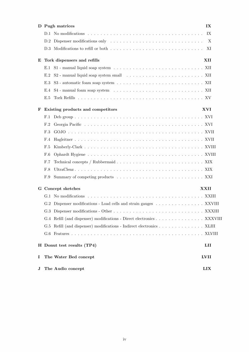