Embed Size (px)
Citation preview

Page 1
ETSI STC SMG2 #23 TDoc SMG 639/97Meeting #23Budapest, Hungary, 13th - 17th October 1997
Source : SMG2
Title :
CRs for GPRS on GSM 03.64, SMG2 WPB, Release 97, Non-Strategic
Proposed Agenda Item : 6.1Presented for : Approval
Introduction :
This document contains Phase 2+ (Release ‘97) Change Requests to support theGPRS work item, on GSM 03.64. They have been agreed by SMG2, and are proposedfor approval by SMG#23. The CRs are considered as non-strategic as they are notproposed to be presented.
The change requests are independent and can be dealt with separately.
SMG2TDOC
SPEC VERS CR Rv SUBJECT CAT STC_MEET
275/97 03.64 5.0.0 A024 1 CR 03.64-A024r1 Enhancements to dynamicallocation
C Sept 97
275/97 03.64 5.0.0 A025 1 CR to 03.64 A025 on Clarifications to DRX F Sept 97
275/97 03.64 5.0.0 A029 CR to 03.64 A029: Multiframe structure (details)(revision of SMG2 GPRS 301/97)
D Sept 97
275/97 03.64 5.0.0 A031 1 CR 03.64-A031 rev 1 Cell Re-Selection in GPRS C Sept 97
275/97 03.64 5.0.0 A032 CR 03.64-A032 on definition of PACCH D Sept 97
275/97 03.64 5.0.0 A033 1 CR 03.64 A033 rev 1 on Clarifications on Timingadvance procedure
C Sept 97
275/97 03.64 5.0.0 A035 CR to 03.64-A035 Bit order for USF coding in GPRS F Sept 97
275/97 03.64 5.0.0 A036 CR 03.64-A036 PTM-M F Sept 97
275/97 03.64 5.0.0 A037 CR 03.64-A037 Contention resolution D Sept 97
275/97 03.64 5.0.0 A039 CR 03.64-A039 Deleting parameter XHYST C Sept 97
Other Comments:
Number of pages:

Page 2
Blank page
ETSI/STC/SMG2 WPB #1 TDOC SMG2 WPB 024/97Edinburgh, Scotland Agenda 6.122- 26 September 1997 (Tdoc SMG2/3 WPA 97A220)
CHANGE REQUEST No. A024 rev1
Technical Specification GSM 03.64 version 5.0.0
Submitted to SMG for approval without presentation ("non-strategic") [ ]
with presentation ("strategic") [ ]
Status at SMG2 [ ]: Approved [ ] Rejected [ ] Postponed [ ]
Phase 1: [ ] Phase 2: [ ] Phase 2+: [Release ‘97] Work item: GPRS
Other phase(s) affected: [ ] If yes, linked CR(s):
Proposed change affects: SIM [ ] ME [ X ] Network [ X ]
Source: SMG2 WPB Date: 20-22/08/1997
Subject: Enhancements to dynamic allocation.
Category: F - Correction [ ]
A - Corresponds to a Phase 2 correction [ ]
B - Addition of Feature [ ]
C - Functional modification of Feature [X]
D - Editorial modification [ ]
Reason for change:
This Change Request introduces the modifications to GSM 03.64 required for the enhancements to thedynamic allocation scheme presented in Tdoc SMG 546/97 at SMG plenary meeting SMG#22.
Sections affected, and additional explanation of details of change (if needed):
5.4.2 Introduction of a rule for the mapping of the downlink PACCH blocks, when the MS in uplinkpacket transfer can not monitor the USF on all assigned PDCHs.
6.5.6.1 Introduction of rules allowing the MS in downlink packet transfer to perform a sufficient numberof measurements, when the downlink PDCHs assigned to the MS does not allow it to performmeasurement in each TDMA frame.
6.6.4.4.2.1 Introduction of rules for the resource allocation for uplink packet transfer, when the MS can notmonitor USF on all the assigned PDCHs.
Attached revised pages:
Page(s): 12, 24, 40.
If other core Specifications are affected, necessary (and attached) Joint CRs:
Affects (possibly): MS Test Specifications [ ] BSS Test Specifications [ ] O&M Specifications [ ]
Attached CRs?:
Cross Phase Compatibility:
Change affects operation of: Phase 1 MS in Phase 2(+) NW [ ] Phase 2(+) MS in Phase 1 NW [ ]
Change affects operation of: Phase 1 SIM in Phase 2(+) ME[ ] Phase 2(+) SIM in Phase 1 ME [ ]
Other comments:
GSM 03.64 version 5.0.0 12 TS 03 64 V5.0.0 (1997-07)
The physical channels on which the PPCH is mapped, as well as the rule that is followed on the physical channels, arederived by the MS from information broadcast on the PBCCH.
5.2.2.3 Packet Access Grant Channel (PAGCH)
The PAGCH is mapped on one or several physical channels. The exact mapping on each physical channel follows apredefined rule (see subclause 6.1.2).
The physical channels on which the PAGCH is mapped, as well as the rule that is followed on the physical channels, arederived by the MS from information broadcast on the PBCCH.
5.2.3 Packet Notification Channel (PNCH)
The PNCH is mapped on one or several blocks on PCCCH. The exact mapping follows a predefined rule. The mappingis derived by the MS from information broadcast on the PBCCH.
NOTE: Exact mapping of PNCH on PCCCH is left for phase 2 of GPRS specification.
5.3 Packet Broadcast Control Channel (PBCCH)The PBCCH shall be mapped on one or several physical channels. The exact mapping on each physical channel followsa predefined rule (see subclause 6.1.2), as it is done for the BCCH.
The existence of the PCCCH, and consequently the existence of the PBCCH, is indicated on the BCCH.
5.4 Packet Traffic Channels
5.4.1 Packet Data Traffic Channel (PDTCH)
One PDTCH is mapped onto one physical channel.
Up to eight PDTCHs, with different timeslots but with the same frequency parameters, may be allocated to one MS atthe same time.
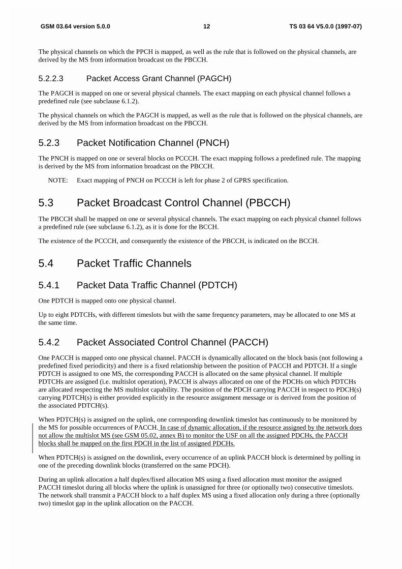
5.4.2 Packet Associated Control Channel (PACCH)
One PACCH is mapped onto one physical channel. PACCH is dynamically allocated on the block basis (not following apredefined fixed periodicity) and there is a fixed relationship between the position of PACCH and PDTCH. If a singlePDTCH is assigned to one MS, the corresponding PACCH is allocated on the same physical channel. If multiplePDTCHs are assigned (i.e. multislot operation), PACCH is always allocated on one of the PDCHs on which PDTCHsare allocated respecting the MS multislot capability. The position of the PDCH carrying PACCH in respect to PDCH(s)carrying PDTCH(s) is either provided explicitly in the resource assignment message or is derived from the position ofthe associated PDTCH(s).
When PDTCH(s) is assigned on the uplink, one corresponding downlink timeslot has continuously to be monitored bythe MS for possible occurrences of PACCH. In case of dynamic allocation, if the resource assigned by the network doesnot allow the multislot MS (see GSM 05.02, annex B) to monitor the USF on all the assigned PDCHs, the PACCHblocks shall be mapped on the first PDCH in the list of assigned PDCHs.
When PDTCH(s) is assigned on the downlink, every occurrence of an uplink PACCH block is determined by polling inone of the preceding downlink blocks (transferred on the same PDCH).
During an uplink allocation a half duplex/fixed allocation MS using a fixed allocation must monitor the assignedPACCH timeslot during all blocks where the uplink is unassigned for three (or optionally two) consecutive timeslots.The network shall transmit a PACCH block to a half duplex MS using a fixed allocation only during a three (optionallytwo) timeslot gap in the uplink allocation on the PACCH.

GSM 03.64 version 5.0.0 24 TS 03 64 V5.0.0 (1997-07)
GSM cell re-selection criteria. This provides a more general tool to make cell planning for GPRS as similar to existingplanning in GSM as possible.
The algorithm described in subclause 6.5.6.2 is only applicable if the PBCCH is allocated. If the PBCCH is notallocated, then the MS shall perform cell re-selection according to the C2 criteria. The MS shall use hysteresis when re-selecting a cell while in READY state. When the MS is in STANDBY state, a hysteresis shall be applied if the new cellis in a different routing area to that of the serving cell. The value of the hysteresis is given by the parameterCELL_RESELECTION_HYSTERESIS which is broadcast on the BCCH [FFS]. This parameter shall be broadcast onthe PBCCH if allocated.
6.5.6.1 Measurements for Cell Re-selection
The MS shall measure the received RF signal strength on the BCCH frequencies of the serving cell and the neighbourcells as indicated in the BA-GPRS list, and calculate the received level average (RLA) for each frequency, as specifiedin GSM 05.08. In addition the MS shall verify the BSIC of the cells. Only channels with the same BSIC as broadcasttogether with BA-GPRS on PBCCH shall be considered for re-selection.
In Wait state, the measurements and BSIC detection shall be made as for GSM in Idle mode as specified in 05.08 withthe following modifications:
- The MS shall make one signal measurement on each frequency in the BA list in each DRX period.
- The MS shall make one attempt to check the BSIC for each of the 6 strongest cells every 14 DRX periods.
However, the requirements shall never be more stringent than for transfer state.
In Transfer state, the measurements and BSIC detection shall be made as for GSM in circuit switched mode as specifiedin 05.08, except for a half duplex MS which shall make the measurements as for GSM in Idle mode as specified in 05.08but with the number of measurements made per second being 200, and the rate of BSIC detection shall be as for incircuit switched mode as specified in GSM 05.08. Some of the idle frames of the PDCH multiframe shall be used forBSIC detection, while the others are used for power control and timing advance procedures, see subclause 6.5.9.
When the number of downlink PDCHs assigned to certain types of multislot MS (see GSM 05.02, annex B) does notallow them to perform measurements within the TDMA frame, the network shall provide measurement windows toensure that the MS will perform a number of measurements in line with the network requirements, up to 200measurements per second. When dynamic allocation is used, the block period where the uplink acknowledgement is sentshall be used as the measurement window. During this block period, the network can only transmit on all downlinkPDCHs in the list of assigned PDCHs up to and including the PDCH carrying the PACCH, so that the MS can performmeasurements during unused PDCHs.
The network shall provide periodic intervals of inactivity during a transfer to or from a half duplex MS to allow the MSto make adjacent cell power measurements. The inactivity periods shall be distributed evenly in time in mobileterminated transfers and approximately evenly in time to mobile originated transfers. Parameters defining the inactivityperiods are signalled in the Packet Resource Request, Packet Paging Request, and Downlink Inactivity IntervalNotification messages.
The network shall provide periods of inactivity during a downlink transfer to a half duplex MS to allow the MS toperform BSIC detection. The length of the inactivity period is signalled in the Packet Ack/Nack for Downlink Transfermessage. The network shall confirm the request with a Packet Inactivity Period Notification message. The MS shallconfirm the Packet Inactivity Period Notification.
6.5.6.2 Cell Re-selection Algorithm
The following cell (re-)selection steps shall be followed ((s) and (n) denote serving cell and neighbour cell respectively).
1) Path loss criterion (C1)
GSM 03.64 version 5.0.0 40 TS 03 64 V5.0.0 (1997-07)
Optionally, the existing backoff algorithm on RACH can be used on PRACH.
On RACH, the existing backoff algorithm shall be used.
Occasionally, more Packet Channel Requests can be received than can be served. To handle this, a Packet QueuingNotification is transmitted to the sender of the Packet Channel Request. The notification includes information that thePacket Channel Request message is correctly received and Packet Immediate Assignment may be transmitted later.Packet Queuing Notification can be concatenated with the Packet Immediate Assignment to another MS in the samedownlink Radio Block. If the Timing Advance information becomes inaccurate for an MS, the Packet Polling can beused to estimate the new Timing Advance before issuing the Packet Immediate Assignment.
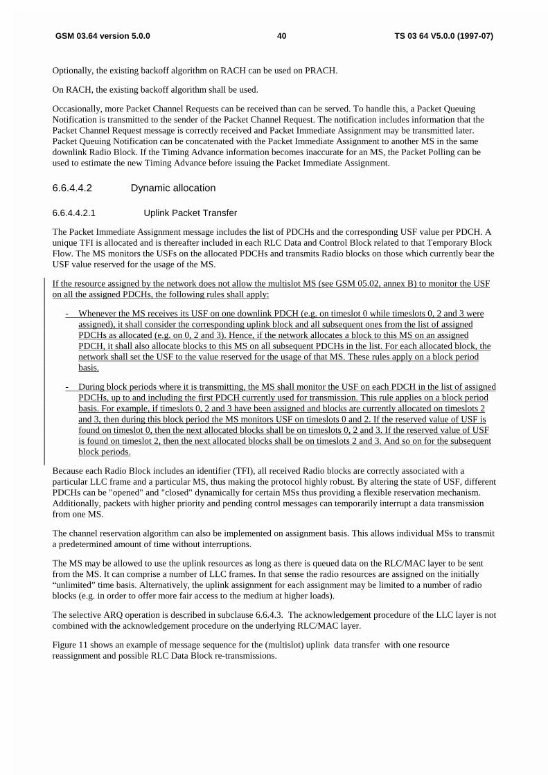
6.6.4.4.2 Dynamic allocation
6.6.4.4.2.1 Uplink Packet Transfer
The Packet Immediate Assignment message includes the list of PDCHs and the corresponding USF value per PDCH. Aunique TFI is allocated and is thereafter included in each RLC Data and Control Block related to that Temporary BlockFlow. The MS monitors the USFs on the allocated PDCHs and transmits Radio blocks on those which currently bear theUSF value reserved for the usage of the MS.
If the resource assigned by the network does not allow the multislot MS (see GSM 05.02, annex B) to monitor the USFon all the assigned PDCHs, the following rules shall apply:
- Whenever the MS receives its USF on one downlink PDCH (e.g. on timeslot 0 while timeslots 0, 2 and 3 wereassigned), it shall consider the corresponding uplink block and all subsequent ones from the list of assignedPDCHs as allocated (e.g. on 0, 2 and 3). Hence, if the network allocates a block to this MS on an assignedPDCH, it shall also allocate blocks to this MS on all subsequent PDCHs in the list. For each allocated block, thenetwork shall set the USF to the value reserved for the usage of that MS. These rules apply on a block periodbasis.
- During block periods where it is transmitting, the MS shall monitor the USF on each PDCH in the list of assignedPDCHs, up to and including the first PDCH currently used for transmission. This rule applies on a block periodbasis. For example, if timeslots 0, 2 and 3 have been assigned and blocks are currently allocated on timeslots 2and 3, then during this block period the MS monitors USF on timeslots 0 and 2. If the reserved value of USF isfound on timeslot 0, then the next allocated blocks shall be on timeslots 0, 2 and 3. If the reserved value of USFis found on timeslot 2, then the next allocated blocks shall be on timeslots 2 and 3. And so on for the subsequentblock periods.
Because each Radio Block includes an identifier (TFI), all received Radio blocks are correctly associated with aparticular LLC frame and a particular MS, thus making the protocol highly robust. By altering the state of USF, differentPDCHs can be "opened" and "closed" dynamically for certain MSs thus providing a flexible reservation mechanism.Additionally, packets with higher priority and pending control messages can temporarily interrupt a data transmissionfrom one MS.
The channel reservation algorithm can also be implemented on assignment basis. This allows individual MSs to transmita predetermined amount of time without interruptions.
The MS may be allowed to use the uplink resources as long as there is queued data on the RLC/MAC layer to be sentfrom the MS. It can comprise a number of LLC frames. In that sense the radio resources are assigned on the initially“unlimited” time basis. Alternatively, the uplink assignment for each assignment may be limited to a number of radioblocks (e.g. in order to offer more fair access to the medium at higher loads).
The selective ARQ operation is described in subclause 6.6.4.3. The acknowledgement procedure of the LLC layer is notcombined with the acknowledgement procedure on the underlying RLC/MAC layer.
Figure 11 shows an example of message sequence for the (multislot) uplink data transfer with one resourcereassignment and possible RLC Data Block re-transmissions.

ETSI/STC/SMG2 WPB #1 TDOC SMG2 WPB 019/97
Edinburgh, Scotland Agenda 6.1
22- 26 September 1997 (rev of Tdoc SMG2/3 WPA 97A130)
CHANGE REQUEST No. A025 rev 1
Technical Specification GSM 03.64 version 5.0.0
Submitted to SMG for approval without presentation ("non-strategic") [ ]
with presentation ("strategic") [ ]
Status at SMG [ ]: Approved [ ] Rejected [ ] Postponed [ ]
Phase 1: [ ] Phase 2: [ ] Phase 2+: [Release '97] Work item: GPRS
Other phase(s) affected: [ ] If yes, linked CR(s):
Proposed change affects: SIM [ ] ME [ X ] Network [ X ]
Source: SMG2 WPB Date: 03-05/09/1997
Subject: Clarifications to DRX.
Category: F - Correction [X]
A - Corresponds to a Phase 2 correction [ ]
B - Addition of Feature [ ]
C - Functional modification of Feature [ ]
D - Editorial modification [ ]
Reason for change:
This Change Request introduces a more accurate definition of the radio blocks which the MS has to monitorwhen being in the Wait state, depending on whether it is using DRX or non-DRX mode. The clarificationconsists of talking of radio blocks rather than of PAGCH or PPCH blocks, because the actual usage of suchradio blocks is only indicated by the message type of the RLC/MAC PDU, according to clause 6.1.2.
Sections affected, and additional explanation of details of change (if needed):
6.5.10 Modified as explained above.
Attached revised pages:
Page(s): 33, 34.
If other core Specifications are affected, necessary (and attached) Joint CRs:
Affects (possibly): MS Test Specifications [ ] BSS Test Specifications [ ] O&M Specifications [ ]
Attached CRs?:
Cross Phase Compatibility:
Change affects operation of: Phase 1 MS in Phase 2(+) NW [ ] Phase 2(+) MS in Phase 1 NW [ ]
Change affects operation of: Phase 1 SIM in Phase 2(+) ME[ ] Phase 2(+) SIM in Phase 1 ME [ ]
Other comments:

GSM 03.64 version 5.0.0 33 TS 03 64 V5.0.0 (1997-07)
6.5.8.4 Measurements at BSS side
A procedure shall be implemented in the BSS to monitor the uplink Rx signal level and quality on each uplink PDCH,active as well as inactive.
The BSS shall also measure the Rx signal level and the quality of a specific MS packet transfer.
6.5.9 Scheduling of idle frame activities
The MS shall use the idle frames of the PDCH multiframe for the following tasks:
- BSIC identification for cell selection (6.5.6.1)
- Continuous timing advance procedures (6.5.7.2)
- Interference measurements for power control (6.5.8.3.2)
It is not necessary to exactly specify the scheduling of these tasks.
The idle frames required for timing advance signalling is stated in 6.5.7.2.1. During the frames when the MS receivesTA-messages it can also make interference measurements. During the frames when the MS transmits access bursts itmay also be possible to make measurements on some channels.
The MS shall schedule the BSIC identification as efficiently as possible, using the remaining idle frames and alsoconsidering the requirements for interference measurements. When the MS is synchronised to a BTS, it knows thetiming of the SCH. Therefore, only a few certain idle frames are required for BSIC identification. In those frames it mayalso be possible to make measurements on some channels. When the MS shall synchronise to a new BTS, it has toprioritise that task. It may then use half of the idle frames, i.e. the same amount as available for circuit switchedconnections.
The remaining idle frames shall be used for interference measurements.
6.5.10 Discontinuous Reception (DRX)
NOTE: The text in this subclause is informative. The normative text is in GSM 05.02 [4]. Where there is aconflict between these descriptions, the normative text has precedence.
DRX (sleep mode) shall be supported when the MS is in RR Wait with Cell Update or Wait with Routing Update states.DRX is independent from MM states Ready and Standby.
Negotiation of DRX parameters is per MS. An MS may choose to use DRX or not together with some operatingparameters. The following parameters are established:
- DRX/non-DRX indicatorIt indicates whether the MS uses DRX or not.
- DRX periodA conditional parameter for MSs using DRX to determine the right paging group. The DRX period is defined bythe parameter SPLIT_PG_CYCLE according to Table 8. This results in a DRX period of about15.36/SPLIT_PG_CYCLE seconds.
- Non-DRX timerA conditional parameter for MSs using DRX to determine the time period within which the non-DRX mode iskept after leaving the Transfer state. The support for this feature is optional on the network side and theinformation about the maximum supported value for the timer in the cell is broadcast on PBCCH.
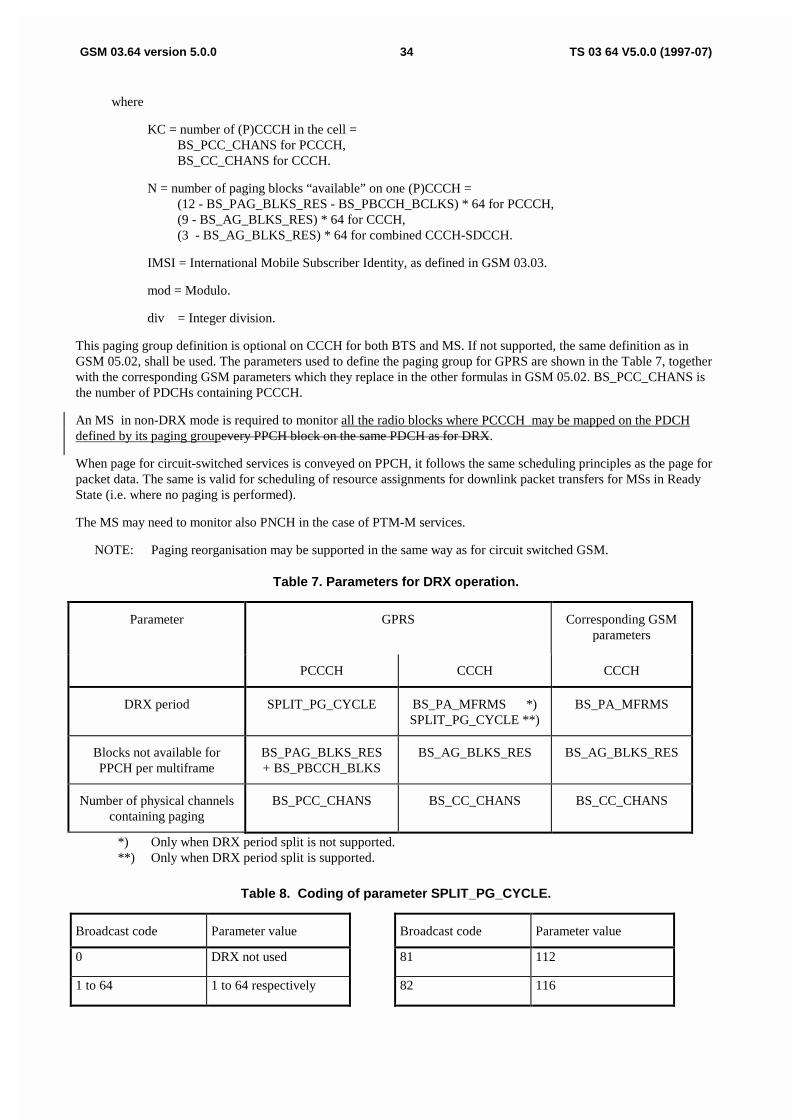
An MS in DRX mode is only required to monitor the radio blocks defined byPPCH blocks belonging to its paging groupin the same way as in GSM 05.02. The paging group for GPRS is defined as:
PAGING_GROUP (0 ... N-1) = ((IMSI mod 1000) mod (KC * N) + Max((n * N) div SPLIT_PG_CYCLE, n)) mod Nfor n = 0, ... , Min(N, SPLIT_PG_CYCLE) -1
GSM 03.64 version 5.0.0 34 TS 03 64 V5.0.0 (1997-07)
where
KC = number of (P)CCCH in the cell = BS_PCC_CHANS for PCCCH,BS_CC_CHANS for CCCH.
N = number of paging blocks “available” on one (P)CCCH = (12 - BS_PAG_BLKS_RES - BS_PBCCH_BCLKS) * 64 for PCCCH,(9 - BS_AG_BLKS_RES) * 64 for CCCH,(3 - BS_AG_BLKS_RES) * 64 for combined CCCH-SDCCH.
IMSI = International Mobile Subscriber Identity, as defined in GSM 03.03.
mod = Modulo.
div = Integer division.
This paging group definition is optional on CCCH for both BTS and MS. If not supported, the same definition as inGSM 05.02, shall be used. The parameters used to define the paging group for GPRS are shown in the Table 7, togetherwith the corresponding GSM parameters which they replace in the other formulas in GSM 05.02. BS_PCC_CHANS isthe number of PDCHs containing PCCCH.
An MS in non-DRX mode is required to monitor all the radio blocks where PCCCH may be mapped on the PDCHdefined by its paging groupevery PPCH block on the same PDCH as for DRX.
When page for circuit-switched services is conveyed on PPCH, it follows the same scheduling principles as the page forpacket data. The same is valid for scheduling of resource assignments for downlink packet transfers for MSs in ReadyState (i.e. where no paging is performed).
The MS may need to monitor also PNCH in the case of PTM-M services.
NOTE: Paging reorganisation may be supported in the same way as for circuit switched GSM.
Table 7. Parameters for DRX operation.
Parameter GPRS Corresponding GSMparameters
PCCCH CCCH CCCH
DRX period SPLIT_PG_CYCLE BS_PA_MFRMS *)SPLIT_PG_CYCLE **)
BS_PA_MFRMS
Blocks not available forPPCH per multiframe
BS_PAG_BLKS_RES+ BS_PBCCH_BLKS
BS_AG_BLKS_RES BS_AG_BLKS_RES
Number of physical channelscontaining paging
BS_PCC_CHANS BS_CC_CHANS BS_CC_CHANS
*) Only when DRX period split is not supported.**) Only when DRX period split is supported.
Table 8. Coding of parameter SPLIT_PG_CYCLE.
Broadcast code Parameter value Broadcast code Parameter value
0 DRX not used 81 112
1 to 64 1 to 64 respectively 82 116
ETSI/STC SMG2 WPB Tdoc SMG2 WPB 11/97Meeting no 1 Agenda item 6.1Edinburgh, Scotland22 - 26 September, 1997 Revision to Tdoc SMG2 GPRS 301/97
CHANGE REQUEST No. A029
Technical Specification 03.64 version 5.0.0
Submitted to SMG for approval without presentation ("non-strategic") [ ]
with presentation ("strategic") [ ]
Status at SMG [ ]: Approved [ ] Rejected [ ] Postponed [ ]
Phase 1: [ ] Phase 2: [ ] Phase 2+: [Release 97] Work item: GPRS
Other phase(s) affected: [ ] If yes, linked CR(s):
Proposed change effects: SIM [ ] ME [X] Network [X]
Source: SMG2 WPB Date: 18 September 1997
Subject: Multiframe Structure (details).
Category: F - Correction [ ]A - Corresponds to a Phase 2 correction [ ]B - Addition of Feature [ ]C - Functional modification of Feature [ ]D - Editorial modification [X]
Reason for change:
To clarify the rules for how PPCH can be allocated.
Sections affected, and additional explanations of details of change (if needed):
Section 6.1.2.
Attached revised pages:
15
If other core Specifications are affected, necessary (and attached) Joint CRs: See GSM 10.60
Affects (possibly): MS Test Specifications[ ] BSS Test Specifications[ ] O&M Specifications[ ]
Attached CRs?
Cross Phase Compatibility:
Change affects operation of:
Other comments:

Error! No text of specified style in document.15Error! No text of specified style in document.
Packet Resource Reassignment message can be used for that purpose. The network side has to send suchnotifications on PACCH(s) individually to each affected MS, PACCH(s) being possibly assigned on differenttimeslots.
- Broadcast the notification about deallocation
Simple and fast method to broadcast the notification on all the PDCHs lying on the same carrier as the PDCH tobe released. All MSs monitor the possible occurrences of PACCH on one channel and should capture suchnotification. A more efficient solution is to broadcast the notification only on PDCH(s) where the affected MSs’PACCH(s) are assigned.
In practice, a combination of all the methods can be used.
There may occur the case where an MS remains unaware of the released PDCH. In that case, such MS may cause someinterference when wrongly assuming that the decoded Uplink State Flag (see Section 6.6.4.1.) denotes the followinguplink block period reserved to it. After not getting proper response from the network, the MS would self break the RLCconnection and back-off.
0.0.1. Multiframe structure for PDCH
Note: The text in this subclause is informative. The normative text is in GSM 05.01 [3] and GSM 05.02 [4].Where there is a conflict between these descriptions, the normative text has precedence.
The mapping in time of the logical channels is defined by a multiframe structure. The multiframe structure for PDCHconsists of 52 TDMA frames, divided into 12 blocks (of 4 frames) and 4 idle frames according to Figure 1.
52 TDMA Frames
B0 B1 B2 X B3 B4 B5 X B6 B7 B8 X B9 B10 B11 X
X = Idle frameB0 - B11 = Radio blocks
Figure 1: Multiframe structure for PDCH
The mapping of logical channels onto the radio blocks is defined in the rest of this section by means of the ordered listof blocks (B0, B6, B3, B9, B1, B7, B4, B10, B2, B8, B5, B11).
One PDCH that contains PCCCH (if any) is indicated on BCCH. That PDCH is the only one that contains PBCCHblocks. On the downlink of this PDCH, the first block (B0) in the ordered list of blocks is used as PBCCH. If required,up to 3 more blocks on the same PDCH can be used as additional PBCCH. The total number of PBCCH blocks on thisPDCH is indicated in the first PBCCH block by means of the BS_PBCCH_BLKS parameter (from 1 up to 4). On thisPDCH, the first BS_PBCCH_BLKS blocks in the ordered list of blocks are reserved for PBCCH (e.g. blocks B0, B6and B3 are used if BS_PBCCH_BLKS = 3 is required).
Any additional PDCH containing PCCCH is indicated on PBCCH. On these PDCHs the BS_PBCCH_BLKS first blocksin the ordered list of blocks are used for PDTCH or PACCH in the downlink. In all cases, the actual usage of the blocksis indicated by the message type.
On any PDCH with PCCCH (with or without PBCCH), the next BS_PAG_BLKS_RES blocks in the ordered list ofblocks are used for PAGCH, PNCH, PDTCH or PACCH in the downlink. BS_PAG_BLKS_RES is a parameterbroadcast on PBCCH. Its range is from 0 up to (12 - BS_PBCCH_BLKS). The remaining blocks in the ordered list areused for PPCH, PAGCH, PNCH, PDTCH or PACCH in the downlink. In all cases, the actual usage of the blocks isindicated by the message type. PPCH shall not use any block which has a guard time of less than 2 slots to a block usedfor PBCCH (If the guard time betweeen the last burst of a PBCCH block and the first burst of a following PCCCH blockon another PDCH is less than 2 timeslot periods, that PCCCH block shall not be used for PPCH. This must be ensuredby the parameter BS_PAG_BLKS_RES).
On an uplink PDCH that contains PCCCH, all blocks in the multiframe can be used as PRACH, PDTCH or PACCH.The use as PRACH is indicated by the USF = FREE.

ETSI STC SMG2 WPB Tdoc SMG2 WPB 75 /97Edinburgh, Scotland22 - 26 September 1997
CHANGE REQUEST No. A031 rev 1
Technical Specification GSM 03.64 version 5.0.0
Submitted to SMG for approval without presentation ("non-strategic") [ ]
with presentation ("strategic") [ ]
Status at SMG2 [ ]: Approved [ ] Rejected [ ] Postponed [ ]
Phase 1: [ ] Phase 2: [ ] Phase 2+: [Release 97] Work item: GPRS
Other phase(s) affected: No
Proposed change affects: SIM [ ] ME [X] Network [X]
Source: SMG2 WPB Date: 22 September 1997
Subject: Cell re-selection in GPRS
Category: F - Correction [ ]
A - Corresponds to a Phase 2 correction [ ]
B - Addition of Feature [ ]
C - Functional modification of Feature [X]
D - Editorial modification [ ]
Reason for change:
Addition of a hysteresis parameter to be used in C32 criteria for cell re-selection when GPRS MS is inREADY state. Also a new hysteresis for change of Routing Area is introduced.
Sections affected, and additional explanation of details of change (if needed):
6.5.6.1
Attached revised pages:
Page(s): 23, 24
If other core Specifications are affected, necessary (and attached) Joint CRs:
Affects : MS Test Specifications [ ] BSS Test Specifications[ ] O&M Specifications [ ]Attached CRs?:
Cross Phase Compatibility:Change affects operation of: Phase 1 MS in Phase 2(+) NW [No] Phase 2(+) MS in Phase 1 NW [No]
Change affects operation of: Phase 1 SIM in Phase 2(+) ME[No] Phase 2(+) SIM in Phase 1 ME [No]
Other comments:

6.5.6 Cell Re-selection
NOTE: The text in this subclause is informative. The normative text is in GSM 03.22 and GSM05.02. Where there is a conflict between these descriptions, the normative text hasprecedence.
In GPRS Standby and Ready states, cell re-selection is performed by the MS, except for a class A MS whilein a circuit switched connection. The following cell re-selection criteria C31 and C32 are provided as acomplement to the current GSM cell re-selection criteria. This provides a more general tool to make cellplanning for GPRS as similar to existing planning in GSM as possible.
The algorithm described in subclause 6.5.6.2 is only applicable if the PBCCH is allocated. If the PBCCH isnot allocated, then the MS shall perform cell re-selection according to the C2 criteria. Within a Routing Area,Tthe MS shall use hysteresis when re-selecting a cell while in READY state. This hysteresis is applied to theC32 criteria (see subclause 6.5.6.2). As an option, the network operator may decide to use this hysteresis forthe C31 criteria. This shall be indicated to the MS. The value of the hysteresis is given by the parameterGPRS_CELL_RESELECTION_HYSTERESIS which shall be broadcast on the PBCCH.
When the MS is in STANDBY state, a A hysteresis shall be applied, independent of whether the MS is inREADY or STANDBY state, if the new cell is in a different rRouting aArea to that of the serving cell. Thishysteresis is given by the parameter RA_RESELECTION_HYSTERESIS and shall be broadcast on thePBCCH. If the PBCCh is not allocated, the MS shall use the CELL_RESELECTION_HYSTERESISparameter which is broadcast on the BCCH.The value of the hysteresis is given by the parameterCELL_RESELECTION_HYSTERESIS which is broadcast on the BCCH [FFS]. This parameter shall bebroadcast on the PBCCH if allocated.

ETSI/STC SMG2 WPB Tdoc SMG2 WPB 50/97Edinburgh, UK (reprint of Tdoc SMG2 GPRS 300/97)22-26 September, 1997 Agenda Item 6.1
CHANGE REQUEST No. A032
Technical Specification GSM 03.64 version 5.0.0
Submitted to SMG for approval without presentation ("non-strategic") [ ]
with presentation ("strategic") [ ]
Status at SMG [ ]: Approved [ ] Rejected [ ] Postponed [ ]
Phase 1: [ ] Phase 2: [ ] Phase 2+: [Release 97] Work item: GPRS
Other phase(s) affected: [ ] If yes, linked CR(s):
Proposed change affects: SIM [ ] ME [X] Network [X]
Source: SMG2 WPB Date: 27 August 1997
Subject: The definition for PACCH
Category: F - Correction [ ]A - Corresponds to a Phase 2 correction [ ]B - Addition of Feature [ ]C - Functional modification of Feature [ ]D - Editorial modification [x]
Reason for change:
A better explanation is needed for mapping of PACCH capturing the bidirectional nature of the channel.
Sections affected, and additional explanation of details of change (if needed):
Section 5.4.2.
Attached revised pages:
Page(s):
If other core Specifications are affected, necessary (and attached) Joint CRs:
Affects(possibly):
MS Test Specifications [ ] BSS Test Specifications [ ] O&M Specifications [ ]
Attached CRs?:
Cross Phase Compatibility:
Change affects operation of: Phase 1 MS in Phase 2(+) NW [ ] Phase 2(+) MS in Phase 1 NW [ ]
CR to 09.90 attached:
Change affects operation of: Phase 1 SIM in Phase 2(+) ME[ ]
CR to 09.91 attached:
Phase 2(+) SIM in Phase 1 ME [ ]
CR to 09.91 attached:
Other comments:

5.4.2 Packet Associated Control Channel (PACCH)
One PACCH is mapped onto one physical channel. PACCH is dynamically allocated on the block basis(not following a predefined fixed periodicity) and there is a fixed relationship between the position ofPDCH(s) carrying PACCH and PDTCH(s). If a single PDTCH is assigned to one MS, the correspondingPACCH is allocated on the same physical channel. If multiple PDTCHs are assigned (i.e. multislotoperation), PACCH is always allocated on one of the PDCHs on which PDTCHs are allocated respectingthe MS multislot capability. The position of the PDCH carrying PACCH in respect to PDCH(s) caryingPDTCH(s) is either provided explicitly in the resource assignment message or is derived from the positionof the associated PDTCH(s).
PACCH is of a bi-directional nature, i.e. it can dynamically be allocated both on the uplink and on thedownlink regardless on whether the corresponding PDTCH assignment is for uplink or downlink.
When PDTCH(s) is assigned on the uplink, one corresponding downlink timeslot has continuously to bemonitored by the MS for possible occurrences of PACCH. At the same time, the MS can use the uplinkassignment for sending PACCH blocks whenever needed.
When PDTCH(s) is assigned on the downlink, every occurence of an uplink PACCH block is determinedby polling in one of the preceding downlink blocks (transferred on the same PDCH). At the same time, thenetwork can schedule the occurrence of downlink PACCH blocks whenever needed.
ETSI/STC/SMG2 WPB #1 TDOC SMG2 WPB 085/97Edinburgh, Scotland Agenda 6.122- 26 September 1997(Tdoc SMG2/3 WPA 97A218 same as Tdoc SMG2 GPRS 326/97)
CHANGE REQUEST No. A033 Rev. 1
Technical Specification GSM 03.64 version 5.0.0
Submitted to SMG for approval without presentation ("non-strategic") [ ]with presentation ("strategic") [ ]
Status at SMG [ ]: Approved [ ] Rejected [ ] Postponed [ ]
Phase 1: [ ] Phase 2: [ ] Phase 2+: [Release 97] Work item: GPRS
Other phase(s) affected: [ ] If yes, linked CR(s):
Proposed change affects: SIM [ ] ME [X] Network [X]
Source: SMG2 Date: 25 September 1997
Subject: Clarification on timing advance procedure
Category: F - Correction [ ]A - Corresponds to a Phase 2 correction [ ]B - Addition of Feature [ ]C - Functional modification of Feature [X]D - Editorial modification [ ]
Reason for change:
Chapter 6.5.7 “Timing Advance” in GSM 03.64 v.5.0.0 is a bit confused. This CR proposes someclarifications into the timing advance procedure description.
Currently, in continuous timing advance procedure, both Uplink State Flag (USF) and Timing AdvanceIndex (TAI) are used to determine the correct uplink timeslot for special random access burst transmissionby MS. The use of two different identifiers for same purpose makes resource allocation in network side morecomplicated. Therefore, it is proposed that USF is not used for continuous timing advance purposes, but TAIis allocated also for uplink transfer instead of USF. To align with the subchannel numbering for the PTCCH,the TAI now runs from 0 to 15 instead of 1 to 16.
Sections affected, and additional explanation of details of change (if needed): see above
Attached revised pages:
Page(s):
If other core Specifications are affected, necessary (and attached) Joint CRs:
Affects (possibly): MS Test Specifications [ ] BSS Test Specifications [ ] O&M Specifications [ ]
Attached CRs?:
Cross Phase Compatibility:
Change affects operation of: Phase 1 MS in Phase 2(+) NW [ ] Phase 2(+) MS in Phase 1 NW [ ]
Change affects operation of: Phase 1 SIM in Phase 2(+) ME[ ] Phase 2(+) SIM in Phase 1 ME [ ]
Other comments:
None

2
6.5.7 Timing Advance
The timing advance procedure is used to derive the correctnecessary because a proper value for timingadvance that the MS has to be used for the uplink transmission of Rradio blocks.
The timing advance procedure comprises two parts:
- initial timing advance estimation;
- continuous timing advance updateing.
6.5.7.1 Initial timing advance estimation
The initial timing advance estimation is based onmade from the single access burst carrying the PacketChannel Request. The Packet Immediate Assignment or Packet Resource Assignment then carries theestimated timing advance value to the MS. Thatis value shouldall be used by the MS for the uplinktransmissions until the continuous timing advance updateing provides a new value (see subclause 6.5.7.2.).
Two special cases exist:
In the case when Packet Queuing Notification is used the initial estimated timing advance maybecome too old to be sent in the Packet Immediate Assignment.
when Packet Immediate Assignment is to be sent without prior paging (i.e., in the Ready state), novalid timing advance value may be available.
Then the network has three options:
Tthe Packet Polling Message can then be used to trigger the transmission of an access burst fromwhich the timing advance can be estimated.
Aalternatively Packet Immediate Assignment can be sent without timing advance information. Inthat case it is indicated to the MS that it can only start the uplink transmission after the timingadvance is obtained by the continuous timing advance update procedure.
Another possibility is that the Packet Immediate Assignment indicates that thea default timingadvance is to be used. That applies for cells with small enough radius.
In the case Packet Immediate Assignment for Downlink is sent without prior paging, no valid timingadvance value may be available. In that case the same options as described above can be used.
6.5.7.2 Continuous timing advance update
MSs in Transfer state shall use the continuous update timing advance update proceduremechanism. Thecontinuous timing advance update procedure is carried only on the PDCH which carries PACCH. Slightlydifferent mechanisms are introduced for uplink and downlink packet transfer.
For uplink packet transfer, wWithin the Packet Immediate Assignment or Packet Resource Assignment forUplink message, the MS is assigned resources on one or several uplink PDCHsone or several uplinkPDTCHs with corresponding Uplink State Flags (USF) and Timing Advance Index (TAI). For thecontinuous timing advance update procedure, the MS shall use the PDCH that contains the assignedPACCH.
For downlink packet transfer, Wwithin the Packet Resource Assignment for Downlink message, the MS isassigned resources on one or several uplink PDCHsone or several downlink PDTCHs, tTiming aAdvanceiIndex (TAI) and the PDCH used for the continuous timing advance update procedure. The TAI is 4 bitsallowing 16 different statespositions in groups of eight 52-multiframes (T10,/T21,…T165).
3
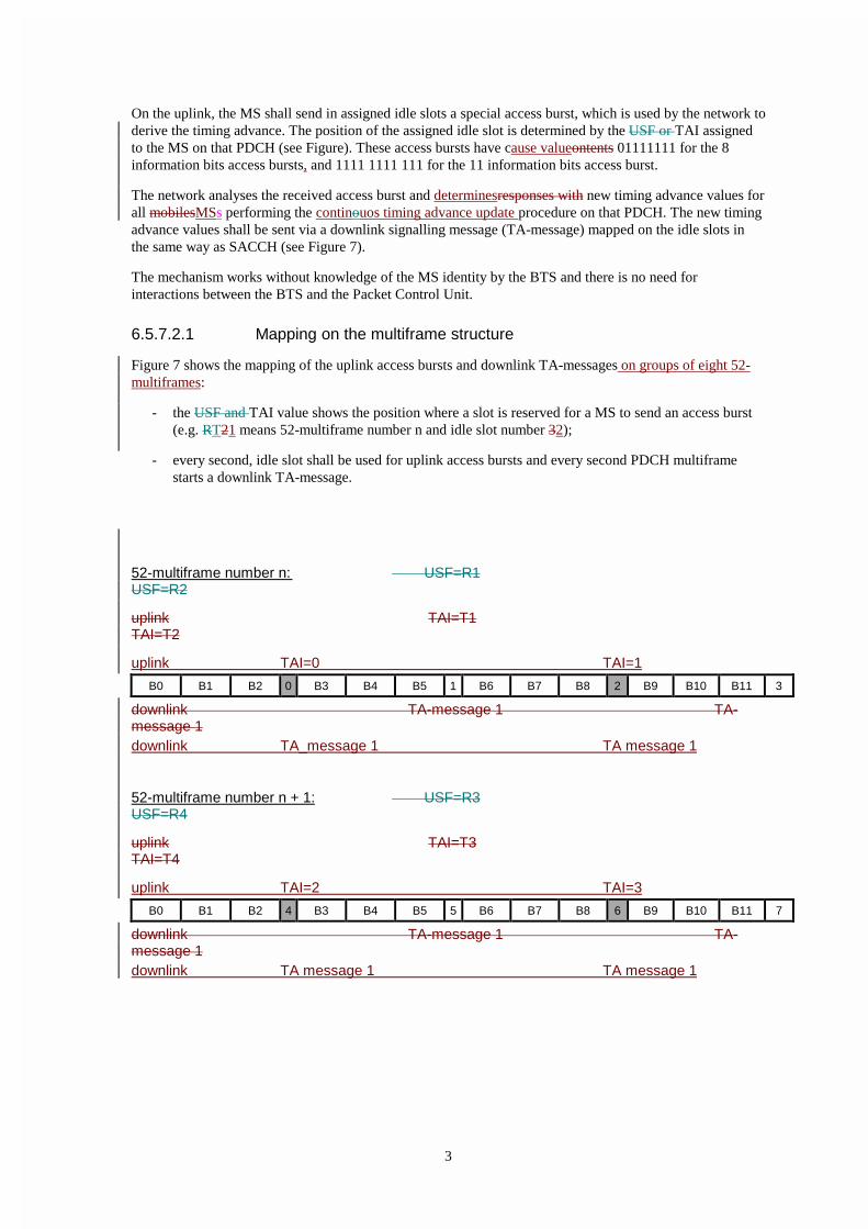
On the uplink, the MS shall send in assigned idle slots a special access burst, which is used by the network toderive the timing advance. The position of the assigned idle slot is determined by the USF or TAI assignedto the MS on that PDCH (see Figure). These access bursts have cause valueontents 01111111 for the 8information bits access bursts, and 1111 1111 111 for the 11 information bits access burst.
The network analyses the received access burst and determinesresponses with new timing advance values forall mobilesMSs performing the continouos timing advance update procedure on that PDCH. The new timingadvance values shall be sent via a downlink signalling message (TA-message) mapped on the idle slots inthe same way as SACCH (see Figure 7).
The mechanism works without knowledge of the MS identity by the BTS and there is no need forinteractions between the BTS and the Packet Control Unit.
6.5.7.2.1 Mapping on the multiframe structure
Figure 7 shows the mapping of the uplink access bursts and downlink TA-messages on groups of eight 52-multiframes:
- the USF and TAI value shows the position where a slot is reserved for a MS to send an access burst(e.g. RT21 means 52-multiframe number n and idle slot number 32);
- every second, idle slot shall be used for uplink access bursts and every second PDCH multiframestarts a downlink TA-message.
52-multiframe number n: USF=R1USF=R2
uplink TAI=T1TAI=T2
uplink TAI=0 TAI=1
B0 B1 B2 0 B3 B4 B5 1 B6 B7 B8 2 B9 B10 B11 3
downlink TA-message 1 TA-message 1downlink TA_message 1 TA message 1
52-multiframe number n + 1: USF=R3USF=R4
uplink TAI=T3 TAI=T4
uplink TAI=2 TAI=3
B0 B1 B2 4 B3 B4 B5 5 B6 B7 B8 6 B9 B10 B11 7
downlink TA-message 1 TA-message 1downlink TA message 1 TA message 1

4
52-multiframe number n + 2: USF=R5USF=R6
uplink TAI=T5 TAI=T6
uplink TAI=4 TAI=5
B0 B1 B2 8 B3 B4 B5 9 B6 B7 B8 10 B9 B10 B11 11
downlink TA-message 2 TA-message 2downlink TA message 2 TA message 2
52-multiframe number n + 3: USF=R7USF=R8
uplink TAI=T7 TAI=T8
uplink TAI=6 TAI=7
B0 B1 B2 12 B3 B4 B5 13 B6 B7 B8 14 B9 B10 B11 15
downlink TA-message 2 TA-message 2downlink TA message 2 TA message 2
52-multiframe number n + 4:
uplink TAI=T9TAI=T10
uplink TAI=8 TAI=9
B0 B1 B2 16 B3 B4 B5 17 B6 B7 B8 18 B9 B10 B11 19
downlink TA-message 3 TA-message 3downlink TA message 3 TA message 3
52-multiframe number n + 5:
uplink TAI=T11 TAI=T12
uplink TAI=10 TAI=11
B0 B1 B2 20 B3 B4 B5 21 B6 B7 B8 22 B9 B10 B11 23
downlink TA-message 3 TA-message 3downlink TA message 3 TA message 3
52-multiframe number n + 6:
uplink TAI=T13 TAI=T14
uplink TAI=12 TAI=13
B0 B1 B2 24 B3 B4 B5 25 B6 B7 B8 26 B9 B10 B11 27
downlink TA-message 4 TA-message 4

5
downlink TA message 4 TA message 4
52-multiframe number n + 7:
uplink TAI=T15TAI=T16
uplink TAI=14 TAI=15
B0 B1 B2 28 B3 B4 B5 29 B6 B7 B8 30 B9 B10 B11 31
downlink TA-message 4 TA-message 4downlink TA message 4 TA message 4
B0 - B11 = Radio blocksidle bursts are numbered from 0 to 31
Figure 7: Mapping of the uplink access bursts and downlink timing advance signalling messages
The BTS shall update the timing advance values in the next TA-message following the access burst. Toillustrate this, aAn MS that transmits an access burst in idle slots 10, 32, 54, or 76 getsreceives its updatedtiming advance value in TA message 2. This MS can also find this updated timing advance value insubsequent TA messages 3, 4, and 1, but only has to read these if TA message 2 was not receivedcorrectly.Only if TA-message 2 is incorrect, the MS has to listen to TA-message 3, 4, 1. An MS thattransmits an access burst in idle slots 9, 11, 13, 15 gets its timing advance in TA message 3. Only if TA-message 3 is incorrect, the MS has to listen to TA-message 4, 1, 2. An MS that transmits an access burst inidle slots 17, 19, 21, 23 gets its timing advance in TA message 4. Only if TA-message 4 is incorrect, the MShas to listen to TA-message 1, 2, 3. An MS that transmits an access burst in idle slots 25, 27, 29, 31 gets itstiming advance in TA message 1. Only if TA-message 1 is incorrect, the MS has to listen to TA-message 2,3, 4.
NOTE: An MS entering the Transfer state shall ignore the TA-messages until the MS has sent its firstaccess burst. This is to avoid the use of timing advance values, derived from access bursts sentby the MS that previously used the same USF or the same TAI.
ETSI/STC SMG2 WPB Tdoc SMG2 WPB 41/97Edinburgh, UK Agenda item 6.122 - 26 September, 1997
CHANGE REQUEST No. A035Technical Specification 03.64 version 5.0.0
Submitted to SMG for approval without presentation ("non-strategic") [ ]with presentation ("strategic") [ ]
Status at SMG [ ]: Approved [ ] Rejected [ ] Postponed [ ]
Phase 1: [ ] Phase 2: [ ] Phase 2+: [Release 97] Work item: GPRS
Other phase(s) affected: [ ] If yes, linked CR(s):
Proposed change effects: SIM [ ] ME [X] Network [X]
Source: SMG2 WPB Date: 19 September 1997
Subject: Bit order for USF coding in GPRS.
Category: F - Correction [X]A - Corresponds to a Phase 2 correction [ ]B - Addition of Feature [ ]C - Functional modification of Feature [ ]D - Editorial modification [ ]
Reason for change:
When table 4 was prepared a mistake was made concerning the order of transmission of the bits. It was assumed that the bitswere transmitted with the most significant bit (to the left) first. This was discussed in the last SMG2 GPRS ad hoc meeting(Tdoc SMG2 GPRS 338/97) and a correction of the RLC block format was agreed. As a consequence, the table 4 has to bechanged.
Sections affected, and additional explanations of details of change (if needed):
In section 6.5.5.1, the bit orders has been changed in all columns, so that the coding will be correct when the least significantbit (to the right) is transmitted first. As a consequence the rows has been sorted in binary order.
A corresponding change has been made to table 5.
A note has been added, clarifying that this way of showing the bit order in the fields is the opposite to the one used in 05.03,where normal coding conventions are used.
Attached revised pages:
22.
If other core Specifications are affected, necessary (and attached) Joint CRs:
Affects (possibly): MS Test Specifications[ ] BSS Test Specifications[ ] O&M Specifications[ ]
Attached CRs?
Cross Phase Compatibility:
Change affects operation of:
Other comments:
This change is not required if these details are deleted from 03.64.

GSM 03.64 version 5.0.0 TS 03 64 V5.0.0 (1997-07)22
CS-2 to CS-4 use the same 16 bit CRC for BCS. The CRC is calculated over the whole uncoded RLC Data Blockincluding MAC Header. The generator polynomial is:
G = 1+X5 + X12 + X16.
The USF has 8 states, which are represented by a binary 3 bit field in the MAC Header.
For CS-1, the whole Radio Block is convolutionally coded and USF needs to be decoded as part of the data.
All other coding schemes generate the same 12 bit code for USF, which is shaded in the figures. For these cases the USFcan be decoded either as a block code, with a minimum Hamming distance of 5, or as part of the data.
For CS-2 and CS-3, this is achieved by first mapping it into a 6 bit pre-coded value and then applying the convolutionalcode to the whole block without puncturing the first 12 coded bits, which only depends on USF.
For CS-4 the USF bits are directly mapped into the 12 bit block code.
Table 4 shows the USF coding. Note that, contrary to GSM 05.03, all binary fields are shown according to the fieldmapping convention with the bit representing the lowest order value to the right.:
Table 4: USF coding (except for CS-1).
USF flag
8 states
Binary value Pre-coded USF(for CS-2 and CS-3)
USF code word
R1 000 000 000 000 000 000 000
R25 1001 100 101 001 110100 001011
R3 010 011 010 110 001101 110110011 011 101 100
R47 0110 110 011 111001 111101101 111 100 111
R52 1001 001 011110 100 000011 011101101 110 110 000
R6 101 011 101 110 110111 010110011 010 111 011
R74 0110 011 101 110 001110 101011110 101 011 100
R8/FREE 111 111 000 111 111010 100000000 001 010 111
NOTE: The USF is not used on the uplink.
In order to simplify the decoding, the stealing bits (defined in GSM 05.03) of the block are used to indicate the actualcoding scheme. For this a backward compatible 8 bit block code with Hamming distance 5 is used. Table 5 shows thecoding:
Table 5: Code words for coding scheme indication.
Coding scheme code word
CS-1 = SDCCH 1111 1111
CS-2 0001 00111100 1000
CS-3 1000 01000010 0001
CS-4 0110 10000001 0110
All coding schemes are mandatory for MSs. Only CS-1 is mandatory for the network.

ETSI/STC SMG2 WPB Tdoc SMG2 WPB 51/97Edinburgh, UK22-26 September, 1997 Agenda Item 6.1
CHANGE REQUEST No. A036
Technical Specification GSM 03.64 version 5.0.0
Submitted to SMG for approval without presentation ("non-strategic") [ ]
with presentation ("strategic") [ ]
Status at SMG [ ]: Approved [ ] Rejected [ ] Postponed [ ]
Phase 1: [ ] Phase 2: [ ] Phase 2+: [Release 97] Work item: GPRS
Other phase(s) affected: [ ] If yes, linked CR(s):
Proposed change affects: SIM [ ] ME [X] Network [X]
Source: SMG2 WPB Date: 18 September 1997
Subject: The PTM-M service description for GPRS
Category: F - Correction [x]A - Corresponds to a Phase 2 correction [ ]B - Addition of Feature [ ]C - Functional modification of Feature [ ]D - Editorial modification [..]
Reason for change:
The weakness of the current retransmission method is that it does not allow an MS to accumulatecorrectly received RLC blocks from each transmission of an LLC frame when a cell change occursbetween transmissions. This is because TFI, which (by beeing kept the same for each transmission of theLLC frame) is used to correlate RLC blocks as belonging to the same LLC frame, is unique only within acell. Thus, this is inconsistent with the SNDCP layer where a centrally assigned “N-PDU number” togetherwith a “segment offset” in the protocol header are intended to make it possible for an MS to correctlyreceive a PTM-M N-PDU even if an inter-SGSN cell change occurs between reception of segments orretransmissions (see GSM 04.65).
Sections affected, and additional explanation of details of change (if needed):
Subclause 6.8.
Attached revised pages:
If other core Specifications are affected, necessary (and attached) Joint CRs:
Affects(possibly):
MS Test Specifications [ ] BSS Test Specifications [ ] O&M Specifications [ ]
Attached CRs?:
Cross Phase Compatibility:
Change affects operation of: Phase 1 MS in Phase 2(+) NW [ ] Phase 2(+) MS in Phase 1 NW [ ]
Change affects operation of: Phase 1 SIM in Phase 2(+) ME[ ] Phase 2(+) SIM in Phase 1 ME [ ]

6.8 PTM-M Data Transfer
Note: The stage 3 specification for PTM-M data transfer is left for phase 2 of GPRS specification.
PTM-M data, in the form of individual LLC frames, is distributed from SGSN to the BSS representing thecells that are defined by a geographical area parameter. To the cells concerned, the BSS for each PTM-MLLC frame:
− Optionally, sends a “PTM-M new message” indicator on all individual paging channels on PCCCH ifallocated, otherwise on CCCH. The indication refers to a PTM-M notification channel PNCH onPCCCH or NCH on CCCH, where a notification for the new PTM-M message can be received.
If the indicator option is not supported, or if an MS can not receive the indicator when expected, e.g.because the corresponding block in the multiframe structure is used for other purposes than paging,the MS must read the notification channel.
− Sends a PTM-M notification on PNCH or NCH. The notification has the form of a Packet ResourceAssignment for the PTM-M LLC frame. The notification includes a group identity IMGI, a unique LLCframe identifier (in the form of an N-PDU number together with a segment offset, see GSM 04.65) andan allocation of a TFI to be used in all RLC blocks of the LLC frame.
− Transmits the PTM-M LLC frame on the assigned downlink resources.
Transfer of PTM-M data is carried out without any ARQ on the RLC/MAC and LLC layers. Instead, eachLLC frame is retransmitted a specified number of timesretransmission of LLC frames is used. Retransmitsthe PTM-M LLC frame the specified number of times. For each retransmission, the above procedure isperformed. a separate The PTM-M notification (resource assignment) is sent but with includes the uniqueLLC frame identifier the same TFI as in the first transmission but a new allocation of TFI.
An MS accumulates correctly received RLC blocks from each transmission to assemble an LLC frame.
The dimensioning of PNCH shall be scaleable depending on capacity requirements.
An NCH may, if capacity allows, be used as a shared notification channel for PTM-M and AdvancedSpeech Call Items (ASCI).
An MS only interested in PTM-M needs to listen only to PNCH/NCH.

ETSI/STC SMG2 WPB Tdoc SMG2 WPB 52/97Edinburgh, UK22-26 September, 1997 Agenda Item 6.1
CHANGE REQUEST No. A037
Technical Specification GSM 03.64 version 5.0.0
Submitted to SMG for approval without presentation ("non-strategic") [ ]
with presentation ("strategic") [ ]
Status at SMG [ ]: Approved [ ] Rejected [ ] Postponed [ ]
Phase 1: [ ] Phase 2: [ ] Phase 2+: [Release 97] Work item: GPRS
Other phase(s) affected: [ ] If yes, linked CR(s):
Proposed change affects: SIM [ ] ME [X] Network [X]
Source: SMG2 WPB Date: 18 September 1997
Subject: The contention resolution in GPRS
Category: F - Correction [ ]A - Corresponds to a Phase 2 correction [ ]B - Addition of Feature [ ]C - Functional modification of Feature [ ]D - Editorial modification [x]
Reason for change:
One unnecessary and incorrect sentence is removed.
Sections affected, and additional explanation of details of change (if needed):
Subclause 6.6.4.4.3.
Attached revised pages:
Page(s):
If other core Specifications are affected, necessary (and attached) Joint CRs:
Affects(possibly):
MS Test Specifications [ ] BSS Test Specifications [ ] O&M Specifications [ ]
Attached CRs?:
Cross Phase Compatibility:
Change affects operation of: Phase 1 MS in Phase 2(+) NW [ ] Phase 2(+) MS in Phase 1 NW [ ]
Change affects operation of: Phase 1 SIM in Phase 2(+) ME[ ] Phase 2(+) SIM in Phase 1 ME [ ]
Other comments:

6.6.4.4.3 Contention Resolution
Contention resolution is an important part of RLC/MAC protocol operation, especially because onechannel allocation can be used to transfer a number of LLC frames.
There are two basic access possibilities, one phase and two phase access as defined in Subclause6.6.4.4.1.
The two phase access is inherently immune for possibility that two MSs can perceive the same channelallocation as their own. Namely the second access phase, the Packet Resource Request, uniquelyidentifies the MS by its TLLI. The same TLLI is included in the Packet Resource Assignment and nomistake is possible.
The one phase access is somewhat insecure and an efficient contention resolution mechanism has to beintroduced.
The first part of the solution is the identification of the MS. The presentation of sending MS on theRLC/MAC level is necessary not only for contention resolution but also to be able to establish RLCprotocol entity for that Temporary Block Flow on the network side. Additionally, the TLLI is necessary to beable to match simultaneous uplink and downlink packet transfers by taking into consideration multislotcapability of that MS.
In order to uniquely identify the MS when sending on uplink, the RLC Header for the first RLC Data Blockon uplink is extended to include the TLLI. The biggest disadvantage of this method is that the TLLI is alsoincluded in the LLC Frame Header so that this may seem as unnecessary overhead.
The second part of the solution is the notification from the network side about who owns the allocation.That is solved by the inclusion of the TLLI in the temporary Packet Ack/Nack. This message can be sentin an early stage, even before the receive window for RLC/MAC protocol operation is full. By doing so, thecontention is resolved after the first occurrence of Packet Ack/Nack. The possibility of RLC Data Blocksbeing captured from “wrong” MS, thus destroying the LLC frame, shall be covered for by retransmissionson the LLC layer.
ETSI STC SMG2 WPB Tdoc SMG2 WPB 57 /97Edinburgh, UK22 - 26 September 1997
CHANGE REQUEST No. A 039
Technical Specification GSM 03.64 version 5.0.0
Submitted to SMG for approval without presentation ("non-strategic") [ ]
with presentation ("strategic") [ ]
Status at SMG2 [ ]: Approved [ ] Rejected [ ] Postponed [ ]
Phase 1: [ ] Phase 2: [ ] Phase 2+: [Release 97] Work item: GPRS
Other phase(s) affected: No
Proposed change affects: SIM [ ] ME [X] Network [X]
Source: SMG2 WPB Date: 22 September 1997
Subject: Deletion of Extra Hysteresis parameter for GPRS cell re-selection
Category: F - Correction [ ]
A - Corresponds to a Phase 2 correction [ ]
B - Addition of Feature [ ]
C - Functional modification of Feature [X]
D - Editorial modification [ ]
Reason for change:
The parameter has no specific function in the sell re-selection and no foreseen application. Therefore, it isdeleted, together with a threshold parameter RXLEV_THR.
Sections affected, and additional explanation of details of change (if needed):
6.5.6.2 and 6.5.6.3
Attached revised pages:
Page(s): 24 - 26
If other core Specifications are affected, necessary (and attached) Joint CRs:
Affects (possibly): MS Test Specifications [ ] BSS Test Specifications [ ] O&M Specifications [ ]
Attached CRs?:
Cross Phase Compatibility:
Change affects operation of: Phase 1 MS in Phase 2(+) NW [No] Phase 2(+) MS in Phase 1 NW [No]
Change affects operation of: Phase 1 SIM in Phase 2(+) ME[No] Phase 2(+) SIM in Phase 1 ME [No]
Other comments:

6.5.6.2 Cell Re-selection Algorithm
The following cell (re-)selection steps shall be followed ((s) and (n) denote serving cell and neighbour cell respectively).
1) Path loss criterion (C1)The path loss criterion C1 ≥ 0, as defined in GSM 05.08, shall be used as a minimum signal strengthcriterion for cell selection for GPRS in the same way as for GSM in Idle mode.
2) Signal strength threshold criterion (C31) for hierarchical cell structures (HCS)The HCS signal strength threshold criterion (C31) shall be used to decide whether the cell is qualified forprioritised hierarchical cell re-selection.
C31(s) = RLA(s) - HCS_THR(s) ≥ 0 (serving cell)C31(n) = RLA(n) - HCS_THR(n) ≥ 0 (neighbour cell)
where HCS_THR is the signal threshold for applying HCS re-selection.
3) Cell ranking (C32)The cell ranking criterion (C32) shall be used to select cells among those with the same priority.
C32(s) = C1(s) + GPRS_RESELECT_OFFSET(s) (serving cell)C32(n) = C1(n) + GPRS_RESELECT_OFFSET(n) - GPRS_RESELECT_XHYST(n) * H(RLA(s) - RXLEV_TRH(s))
- TEMPORARY_OFFSET(n) * H(PENALTY_TIME(n) - T(n)) neighbour cell)
where
GPRS_RESELECT_OFFSET applies an offset and hysteresis value to each cell
GPRS_RESELECT_XHYST applies an additional hysteresis offset if serving cell has high signal strength
H(x) = 0 for x < 0
1 for x ≥ 0
RXLEV_TRH(s) is the signal threshold for applying additional hysteresis
TEMPORARY_OFFSET, PENALTY_TIME and T are defined in GSM 05.08.
4) Cell re-selection rulesThe MS shall select the cell having the highest C32 value among those that have the highest priority class amongthose that fulfil the criterion C31 ≥ 0.
The priority classes may correspond to different HCS layers. They may also be used for other purposes.
If no cells fulfil the criterion C31 ≥ 0, the MS shall select the cell having the highest C32 value among all cells.
It shall be possible to order an MS in Ready state to send a measurement report to the network. The measurement reportshall be regular packet transmission, addressed to the proper network entity.
It shall be possible for the network to order an individual MS in Ready state to perform cell re-selection to a cellappointed by the network, possibly in combination with a punishment parameter to prevent the MS immediate returningto the original cell. A network induces cell re-selection shall temporarily override the MS originated cell-selection.
6.5.6.3 Broadcast Information
A GPRS BA list shall be broadcast on PBCCH. It identifies the neighbour cells, including BSIC, that shall beconsidered for GPRS cell (re-)selection (not necessary the same as for GSM in Idle or circuit switched mode).
For each neighbour cell in this BA list, the parameters described below shall also be broadcast. In order to simplify thecell re-selection task for the MS, the C1 parameters, as defined in GSM 05.08, for all neighbour cells could also bebroadcast on PBCCH.

The required parameters are shown in Table 6.
Table 6: Broadcast parameters.
Parameter name Description Range Bits Channel
BA-GPRS BCCH Allocation for GPRS cell re-selection.
SeeBCCH
PBCCH
BSIC(n) Base Station Identity Code 0-63 6*n PBCCH
Priority class (s+n) [FFS] The HCS priority for the cells 0-7 3*(n+1) PBCCH
HCS_THR(s+n) HCS signal strength threshold 0-63 6*(n+1) PBCCH
GPRS_RESELECT_OFFSET(s+n) GPRS cell re-selection offset andhysteresis.
0-63 6(n+1) PBCCH
GPRS_RESELECT_XHYST(n) Additional hysteresis applied ifserving cell has high signalstrength.
0-3 2(n) PBCCH
RXLEV_THR(s) Signal threshold for applyingadditional hysteresis.
0-63 6 PBCCH
TEMPORARY_OFFSET(n) Additional offset for duration ofPENALTY_TIME.
0-7 3*n PBCCH
PENALTY_TIME(n) Duration for whichTEMPORARY_OFFSET isapplied.
0-31 5*n PBCCH
RXLEV_ACCESS_MIN(n) See GSM 05.08 0-63 6*n PBCCH
MS_TXPWR_MAX_CCH(n) See GSM 05.08 0-31 5*n PBCCH
Sum of bits BA+31*n+[11*n]+21