Embed Size (px)
Citation preview
University of Central Florida University of Central Florida
STARS STARS
Electronic Theses and Dissertations, 2004-2019
2016
Smart Grasping using Laser and Tactile Array Sensors for UCF-Smart Grasping using Laser and Tactile Array Sensors for UCF-
MANUS- An Intelligent Assistive Robotic Manipulator MANUS- An Intelligent Assistive Robotic Manipulator
Kiran Prakash University of Central Florida
Part of the Electrical and Electronics Commons
Find similar works at: https://stars.library.ucf.edu/etd
University of Central Florida Libraries http://library.ucf.edu
This Masters Thesis (Open Access) is brought to you for free and open access by STARS. It has been accepted for
inclusion in Electronic Theses and Dissertations, 2004-2019 by an authorized administrator of STARS. For more
information, please contact [email protected].
STARS Citation STARS Citation Prakash, Kiran, "Smart Grasping using Laser and Tactile Array Sensors for UCF-MANUS- An Intelligent Assistive Robotic Manipulator" (2016). Electronic Theses and Dissertations, 2004-2019. 5001. https://stars.library.ucf.edu/etd/5001
SMART GRASPING USING LASER AND TACTILE ARRAY SENSORS
FOR UCF-MANUS
-AN INTELLIGENT ASSISTIVE ROBOTIC MANIPULATOR
by
KIRAN PRAKASH
B.E. Visvesvaraya Technological University, 2012
A thesis submitted in partial fulfillment of the requirements
for the degree of Master of Science
in the Department of Electrical Engineering and Computer Science
in the College of Engineering and Computer Science
at the University of Central Florida
Orlando, Florida
Spring Term
2016
Major Professor: Aman Behal

ii
©2016 Kiran Prakash
iii
ABSTRACT
This thesis presents three improvements in the UCF MANUS Assistive Robotic Manipulator’s grasping
abilities. Firstly, the robot can now grasp objects that are deformable, heavy and have uneven contact
surfaces without undergoing slippage during robotic operations, e.g. paper cup, filled water bottle. This
is achieved by installing a high precision non-contacting Laser sensor1 that runs with an algorithm that
processes raw-input data from the sensor, registers smallest variation in the relative position of the
object with respect to the gripper. Secondly, the robot can grasp objects that are as light and small as
single cereal grain without deforming it. To achieve this a MEMS Barometer based tactile sensor array
device that can measure force that are as small as 1 gram equivalent is embedded into the gripper to
enhance pressure sensing capabilities. Thirdly, the robot gripper gloves are designed aesthetically and
conveniently to accommodate existing and newly added sensors using a 3D printing technology that
uses light weight ABS plastic as a fabrication material. The newly designed system was experimented
and found that a high degree of adaptability for different kinds of objects can be attained with a better
performance than the previous system.

iv
ACKNOWLEDGMENT
I am grateful to my advisor Dr. Aman Behal, whose understanding, expertise, generous guidance and
support made it possible for me to work on my thesis that was of great interest to me. I sincerely thank
Dr. Michael Haralambous, Assistant Professor, Department of Electrical and Computer Engineering, UCF
and Dr. Ladislau Boloni, Associate Professor, Department of Computer Science, UCF for mentoring me as
my Thesis Advisory Committee members. I also thank my research colleagues: Nicholas Alexander
Paperno and Amirhossein Jabalmeli for their sincere help and support throughout this thesis research
works.
v
TABLE OF CONTENTS
LIST OF FIGURES ......................................................................................................................................... viii
CHAPTER 1: INTRODUCTION ......................................................................................................................... 1
UCF MANUS Robotic Manipulator System ............................................................................................... 1
Problem Motivation .................................................................................................................................. 2
Objective ................................................................................................................................................... 3
Thesis Organization ................................................................................................................................... 3
CHAPTER 2: LITERATURE REVIEW ................................................................................................................. 4
Introduction .............................................................................................................................................. 4
Sensors ...................................................................................................................................................... 4
Pressure Sensing ................................................................................................................................... 5
Slip Sensing ........................................................................................................................................... 6
Discussions ................................................................................................................................................ 7
CHAPTER 3: PRESSURE SENSING USING TAKKSTRIP-2 .................................................................................. 8
Introduction .............................................................................................................................................. 8

vi
MEMS Barometer Pressure Sensor Chips ................................................................................................. 8
TakkStrip-2 .............................................................................................................................................. 10
Salient Features ...................................................................................................................................... 11
CHAPTER 4: SLIP SENSING USING HIGH PRECISION LASER SENSOR ........................................................... 13
Introduction ............................................................................................................................................ 13
High Precision Laser Sensor .................................................................................................................... 13
Salient Features ...................................................................................................................................... 15
CHAPTER 5: INSTALLATION ......................................................................................................................... 16
Introduction ............................................................................................................................................ 16
Gripper Glove Design .............................................................................................................................. 17
Newly Designed Models and their Implementation ........................................................................... 18
Interfacing Sensors.................................................................................................................................. 20
Laser Sensor ........................................................................................................................................ 20
TakkStrip-2 .......................................................................................................................................... 21
CHAPTER 6: CONTROL ALGORITHM AND DESIGN ...................................................................................... 23
Introduction ............................................................................................................................................ 23
vii
Smart Grasping using Laser Sensor and FSR ........................................................................................... 23
Gripper Force Control ......................................................................................................................... 24
Slip Detection ...................................................................................................................................... 25
Grasping using TakkStrip-2 Array Sensors .............................................................................................. 27
CHAPTER 7: EXPERIMENTAL RESULTS ......................................................................................................... 28
Introduction ............................................................................................................................................ 28
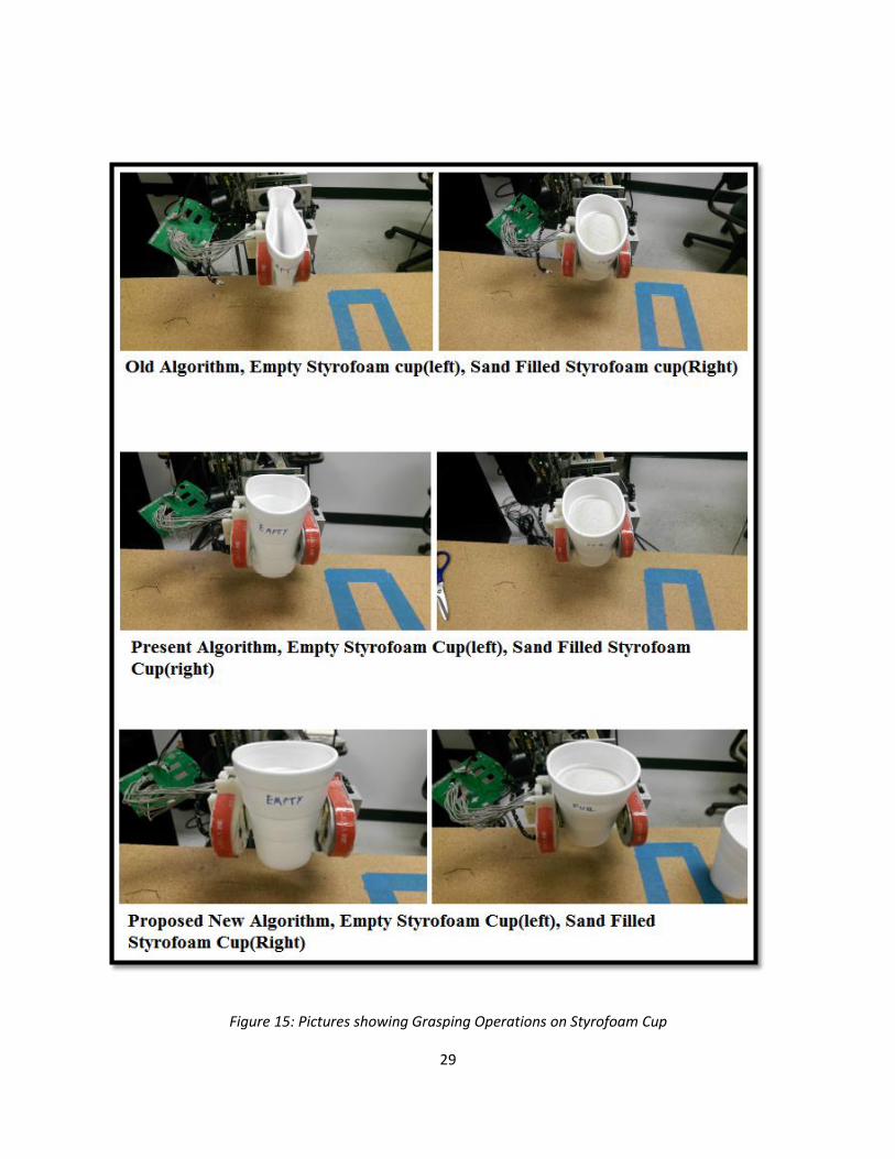
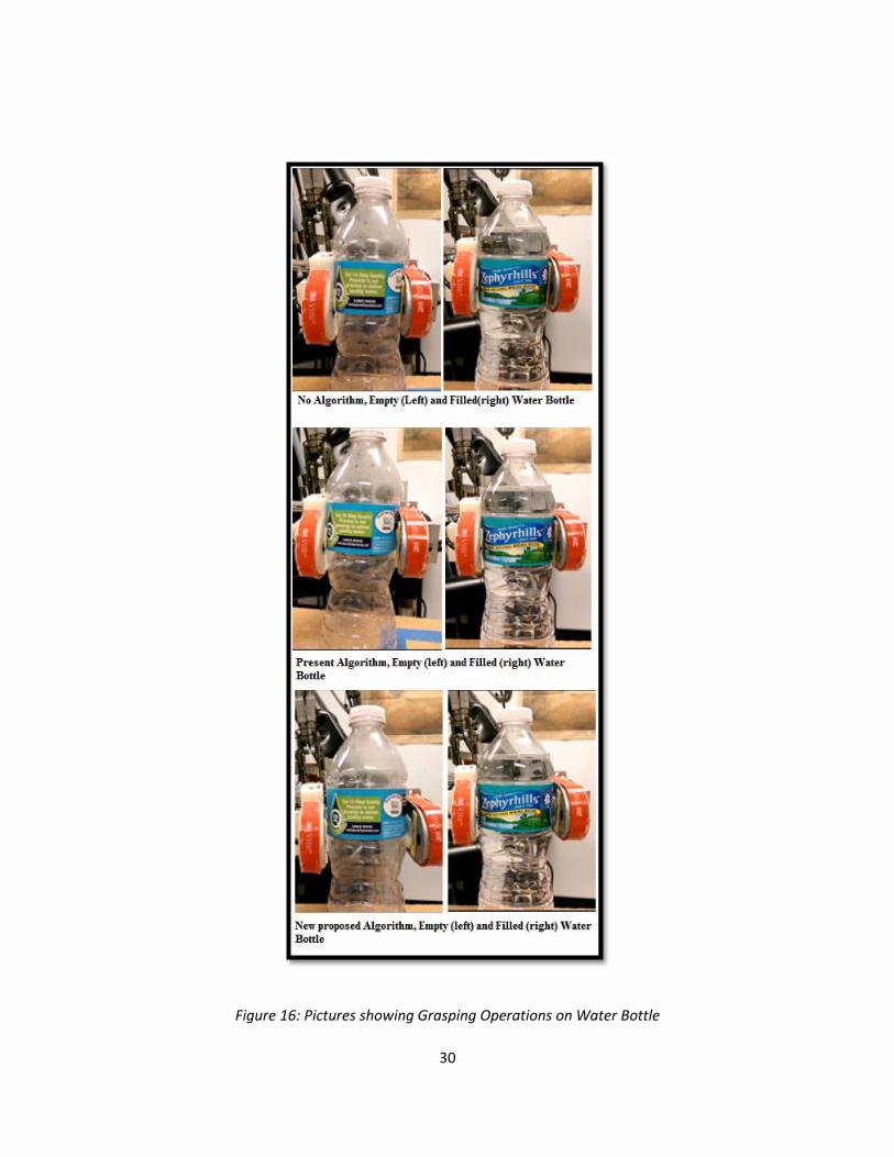
Phase-1 Experimental Set-up: Laser Sensor and FSR .............................................................................. 28
Grasping .............................................................................................................................................. 31
Slip Detection ...................................................................................................................................... 33
Phase-2 Experimental Set-up: TakkStrip-2.............................................................................................. 34
CHAPTER 8: CONCLUSION AND SCOPE FOR FUTURE RESEARCH ................................................................ 37
REFERENCES ................................................................................................................................................ 38
viii
LIST OF FIGURES
Figure 1: MEMS Barometer Chip MPL115A2 ................................................................................................ 9
Figure 2: Block Diagram and Pin Connections of MPL115A2 [33] ................................................................ 9
Figure 3: TakkStrip-2 ................................................................................................................................... 10
Figure 4: TakkStrip-2 Circuit Description .................................................................................................... 11
Figure 5: Rewired Laser Sensor Mouse Circuitry ........................................................................................ 14
Figure 6: Isometric Drawing of ADNS-9800, PixArt Imaging Inc [36] .......................................................... 14
Figure 7: Old Gripper Glove Design............................................................................................................. 17
Figure 8: Proposed Model-1 for Laser Sensor-FSR Sensors (Phase-1 Experimentation) ............................ 18
Figure 9: Implementation of Model-1 ........................................................................................................ 18
Figure 10: Proposed Model-2 for TakkStrip-2 (Phase-2 Experimentation) ................................................. 19
Figure 11: Implementation of Model-2 ...................................................................................................... 19
Figure 12: Arduino Uno Microcontroller for interfacing TakkStrip-2 to the MANUS PC ............................ 21
Figure 13: TakkStrip-2 Sensor Serial Communication Flow-Chart .............................................................. 22
Figure 14: Force Model Schematic.............................................................................................................. 24
ix
Figure 15: Pictures showing Grasping Operations on Styrofoam Cup ........................................................ 29
Figure 16: Pictures showing Grasping Operations on Water Bottle ........................................................... 30
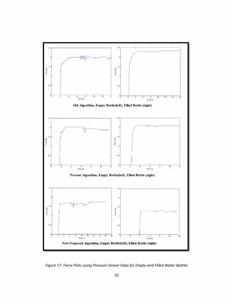
Figure 17: Force Plots using Pressure Sensor Data for Empty and Filled Water Bottles ............................ 32
Figure 18: Force, Position and Velocity Grasps during Initial Grasp and Slip. ............................................ 34
Figure 19: Grasping of Small Objects using TakkStrip-2 ............................................................................. 35

x
LIST OF TABLES
Table 1: Degree of Deformation of Various Test Objects used in ADL ....................................................... 36
1
CHAPTER 1: INTRODUCTION
UCF MANUS Robotic Manipulator System
When it comes to the designing of automation systems the advanced research focus has shifted from
production and manufacturing field towards service segments. Particularly, Assistive Robotic Systems
are one of the popular consideration in service sector. An assistive robot is a sensor based, mechatronic
system that can be reprogrammed and can perform useful works to daily human tasks e.g. Pick and
place of objects. Assistive robots may also include surgical robots, cleaning robots, rehabilitation robots,
companion robots and workstation-based robotic arm systems.
This thesis deals with a special kind of assistive robot called MANUS Hok et al. [1], a wheelchair-
mounted robotic arm(WMRA) designed by Exact Dynamics to meet the necessities of motion-impaired
persons due to neuromuscular losses like spinal cord injury, multiple sclerosis, stroke that poses
limitations to upper body extremities. The robotic arm is meant to be mounted to the side of a
wheelchair Kim et al. [2]. With two-fingered end-effector it has six degrees of freedom (DOF) and can be
directly controlled by the user using either a joystick, or a keypad controller. MANUS is upgraded to
perform a set of pre-defined tasks automatically too with built in functions. Several interface options has
been added apart from the initial robotic arm functions along with grabbing and retrieval of objects that
were based on the general automated functions Kim et al. [2].
2
Further, UCF MANUS’s performance was improved to work under complex environments and handle
more challenging tasks like grabbing objects from cabinets/boxes on shelves or underneath a table with
Fine Motion Control processes, Compensatory Gross Motion procedures and Particle Filter-Based
Tracking algorithms to ease the grasping activities which could be performed by the robot itself in
automatic mode or by the end user in the manual mode operations by Nicholas et al. [3] Kim et al. [2].
Problem Motivation
Although with these upgradation the system improved its design in terms of multimodal user interface
suitable mainly for a range of user disabilities in performing activities of daily living (ADL) but did not
involve any improvements in development of sensor components at the two fingered end-effector that
could increase effectiveness of robot’s autonomy. A human like grasping operations were limited by the
present hardware configuration of the MANUS for instituting smart grasping set points to perform ADL
on novel objects. Robotic grasping has been a principal focus in the field of robotics for decades in order
for the robots to achieve the precision of human-like grasping abilities. Due to the large variation
between the objects in the human surroundings, realizing an algorithm under such complex situations
where the robot has no prior knowledge of shape of the object and with only known noisy and partial
sensor data makes it necessary to build a system that can overcome these difficulties.
In the current system [2]-[3], grabbing of novel objects by the two-fingered end-effector relied on the
visual characteristics and force profile of the target object to estimate the gripper’s interacting force.
The visual characteristics are analyzed using the eye-in-hand camera and force sensitive resistors placed
on the robotic arm and the end-effector respectively. These methods poses a serious problem that
might lead to situation where grasping operations would not be unique to the same object at different
3
states. Lack of reliable data for certain objects may result in poor balance in forces that causes object to
slip or be deformed e.g. a soda can, empty paper cup.
Objective
To develop a system that results in a high degree of adaptability and achieve better performance than
the current system by enhancing the sensing capabilities of the robot at the end-effector for grasping
operations that involves ADL for novel objects.
Thesis Organization
With respect to the above introduction and objectives the rest of the document is organized into six
different chapters. Chapter 2 will extensively review related works in the present available sensor
technology employed in a system congruent to UCF MANUS. Chapter 3 explains the pressure sensor
device that detects the force applied between the end-effector grippers on deformable objects. Chapter
4 discusses the slip sensor device that is used for detecting the slip of grasping object. Chapter 5
documents the installation of the slip and pressure sensor on the 3D printed ABS plastic material and
interfacing of these sensors on the UCF MANUS grippers. Chapter 6 discusses the idea behind the
implementation of the proposed new smart grasping algorithm followed by analysis of the new
configuration in chapter 7 experimental results for grasping operation on various test objects. Finally,
chapter 8 discusses the important implications from the experimental results and provides necessary
improvements and scope for future research works.
4
CHAPTER 2: LITERATURE REVIEW
Introduction
A report by Nation Spinal Cord Injury (SCI) Statistical Center [39] states that an annual incidence of SCI in
US are 40 cases per million population as of 2014. At this incidence rate and with current population of
313 million people the total number of cases are estimated to be in the range 240,000- 337,000 persons
at the rate of 12,500 new cases each year. Many of these persons are confined to wheelchairs, have
moderate to minimal function in their upper extremities and need some amount of care and attention.
On an average the expenses range from 230,000 USD to 780,000 USD in the initial year and may vary
from 700,000 USD to 3 million USD for a 25 year old [40]. 2/3rd of assistive device users have difficulties
with ADL e.g. pick and place of objects.
Smart grasping of objects in ADL for robotic manipulators has been active research area in recent
period. Various force-control and slip detection methods have been published to achieve human-like
dexterous grasping that are specific to a given hardware and control algorithms, and are limited to
grasping particular category of objects only. Under such applications a versatile sensor attached to the
end-effector of the robot plays a vital role in grasping. Issues associated with the shape and mass of the
object would then become trivial, and thus can effectively overcome problem of slippage and
deformation by applying right amount of force between the grippers.
Sensors
There exists two types of robotic sensing: contacting and non-contacting. A contacting or tactile sensor
could be used in detecting the position, force, torque, etc. and on the other hand a non-contacting
5
sensor could be used to perceive proximity, displacement, etc. Resistive, elastoresistive, piezo-resistive,
tunnel effect, capacitive, optical, magnetic, piezo-electric, conductive rubber, are the different types of
contacting and non-contacting sensors available and that could be used for a specific purpose of robotic
applications. The main motivation for researchers on tactile sensing system is human skin. We often use
tactile sensation for pressure detection and slippage sensation to control and manipulate grasping
operations.
Pressure Sensing
Tactile sensors can measure force applied on the object directly on the point of contact of an object.
These sensors find applications across wide range of robotic hand manipulators. Kiyoto et al. [4]
implemented a control system on a prototyped robotic hand using a large number of tactile sensors that
closes its fingers until the tactile pressure sensors located on the finger tips came in contact with the
grasping object. Makoto et al. [5] developed a hierarchical multiprocessor controller algorithm that uses
an optical-mechanical based tactile sensors on a three fingered robotic hand prototype. In [6], a flexible
tactile sensor was fabricated for multi-fingered robotic hands that to detect shear deformation of the
grasping object. In their work, the shear forces and contact position were measured using standing piezo
resistive cantilever viscous embedded elastic sensor. Shimojo et al. [7] developed prototype of a mesh
of tactile sensors that covers entire robot structure which used pressure-conductive rubber as a flexible
sensing elements that can be mounted on arbitrary surfaces and can optimally distribute the applied
load to a 2-D surfaces. A steady response characteristics were observed in their experiments regardless
of the number, location and surface area of the sensor. Joseph et al. [8] presented a controller algorithm
by placing pressure sensing arrays at the fingertips and real time hand-mounted accelerometer on
Willow Garage PR2 robot’s two gripper parallel jaws. The designed mimicked several discrete grasping
6
controller states with the help of tactile event cues and showed how tactile feedback could be used as
primary source of sensing to achieve human like grasping.
Slip Sensing
Seiichi et al [9][10][11][12] in their extensive research on tactile sensors designed and developed a low-
profile highly sensitive slip sensor using a pressure conductive rubber as the detection element and
subsequently discussed the slip detection characteristics and the principle of the CoP Tactile Sensor. A
combined optical-mechanical tactile sensing method with high sensitivity slip detection method has
been developed by Makoto et al. [5] to enable the fine finger-force control needed for different grasping
objects on a home use manipulation system. The finger-force adjustments method for slip sensing is
studied and documented in [13]-[22] provides information on the minimum grasping force. In these
conventional sensing methods the slip sensors are mounted on the contact surface of the hand and the
slip is determined with respect to the deformation of the target object. Hamidreza et al. [23] introduces
an optical-based LED motion detection sensor used to measure the actual displacement of the grasping
objects that slips. Their system were less prone to external disturbances compared to sensors that rely
on vibration or acoustics when compared to [24] [25], where researches placed an optical-acoustic
sensor on the thumb of the prosthesis to manipulate the grasping force. The main drawbacks of these
researches are that they are practically exposed to environmental noise and external disturbances that
would sometimes lead to inaccurate grasping. Ravinder et al [26] discussed the various technology
available that uses to improve capabilities of sense of touch for robots and, with more insight on the
available trends and methodology to fabricate tactile array sensors.

7
Discussions
It is also important to keep in mind at the point of choosing suitable sensors, the structural
complications such as embedding the detecting sensor on to the UCF-MANUS’ two fingered robotic
gripper and the wiring of those sensors should be minimal. Plenty of articles could be found on sensors
that could be used for specific type of robotic hands that are not developed beyond the collaborations in
which they were designed or fabricated. Numerous research suggests that there exist a gap between
actual implementation and laboratory experimentation that are limits the progress of tactile sensors,
and the software that controls them. The prototype pressure conductive sensor discussed in [9] has
issues concerning the response time due to a difficulty imposed by the large voltage change at the point
of slippage. Although research on optical sensor [22] sounds more promising than the others, but it still
fails to detect grasping force for daily used objects such as those with transparent and reflecting
surfaces. This study hence targets in developing a slip sensor for UCF-MANUS which is simple, fast,
robust, cost-effective and, including and not limited to only prosthesis based applications rather could
be used for researches that needs to detect slippage of the object without deforming during ADL
grasping operations.
8
CHAPTER 3: PRESSURE SENSING USING TAKKSTRIP-2
Introduction
Although there are wide range of pressure sensing tactile sensors have been fabricated and
experimented, most of them were restricted only to a particular prototype for research purposes. Very
less number of tactile sensing technology have shown reliable and good performance and out of which
only few are commercially made available. Use of miniaturized tactile pressure sensor [27] that was
integrated using MEMS and CMOS in [4] demonstrated high accuracy, design flexibility for measuring
various pressure range. Lael et al. in [28], used the low-cost commercially available MEMS Barometers
tactile array sensors [29] and were successfully able to demonstrate stable adaptive grasps on i-HY
Robotic Hand [28]. The MEMS Barometric sensor chips embedded called ‘TakkStrip” fabricated by
TakkTile Inc. [30] has distinguishable merits over various commercially available tactile sensors and has
been experimented on range of robotic hands application as seen in iRobot-Harvard-Yale hand [29],
Robotiq Gripper [31] and DoraTouch [32]. In this thesis TakkStrip-2: a version of tactile array sensors
[30], were used as pressure sensors for tactile sensing.
MEMS Barometer Pressure Sensor Chips
Takkstrip-2 is nothing but an array of closely mounted MEMS Barometer Pressure sensors on a PCB chip.
MEMS Barometer Pressure chips were mainly manufactured for applications like portable and desktop
Barometry, Altimeters, Weather Stations, Air control systems, Hard-Disk Drives, etc. This miniature
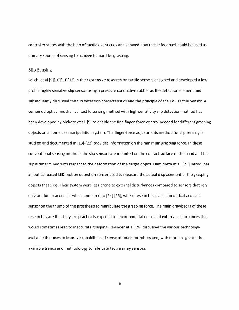
sensor chip is fabricated by Freescale Semiconductor, Houston, Texas as MPL115A2 [33] as an absolute
pressure sensing device measuring 5.0 mm x 2.0 mm x 1.2 mm. The sensor chip consists of a MEMS
9
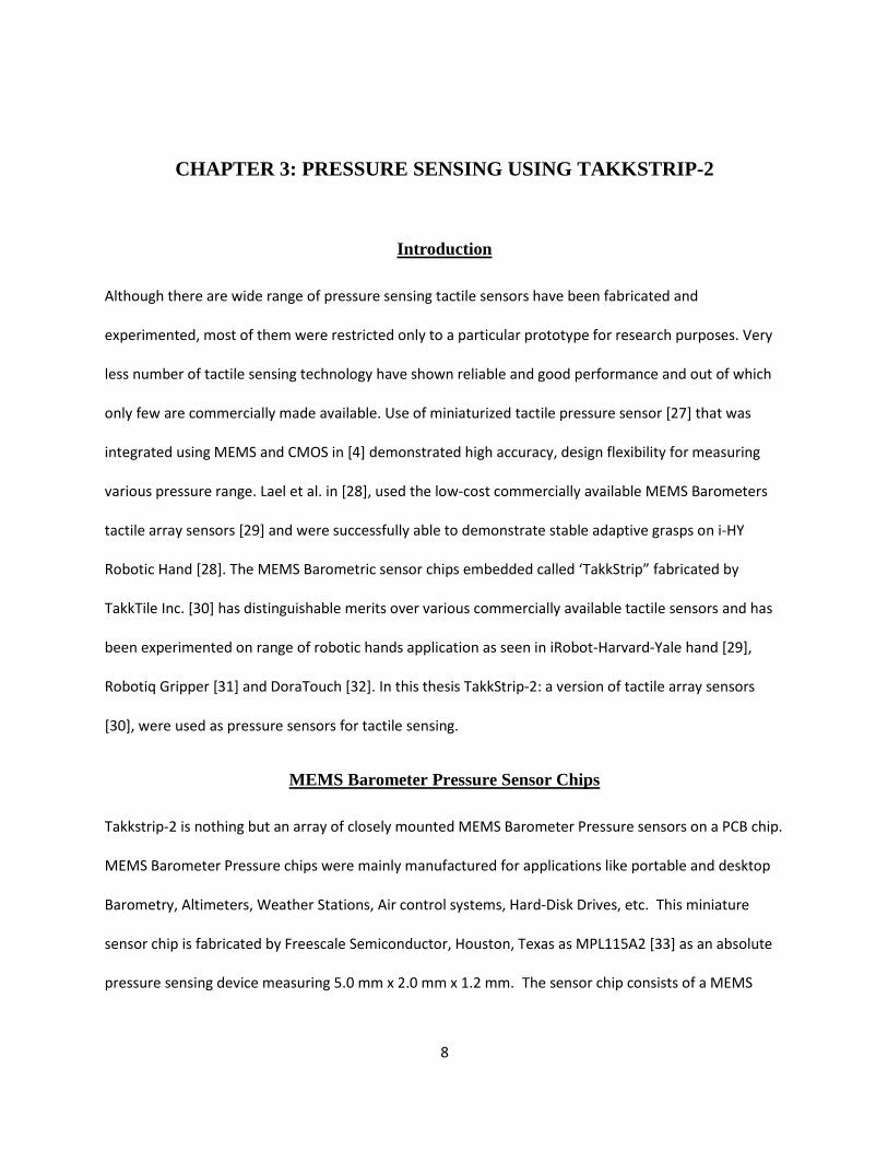
diaphragm with a Wheatstone bridge, Differential amplifier, Temperature Sensor, ADC, MUX and an I2C
interfacing for serial communication with an external microcontroller.
Figure 1: MEMS Barometer Chip MPL115A2
Figure 2: Block Diagram and Pin Connections of MPL115A2 [33]
10
TakkStrip-2
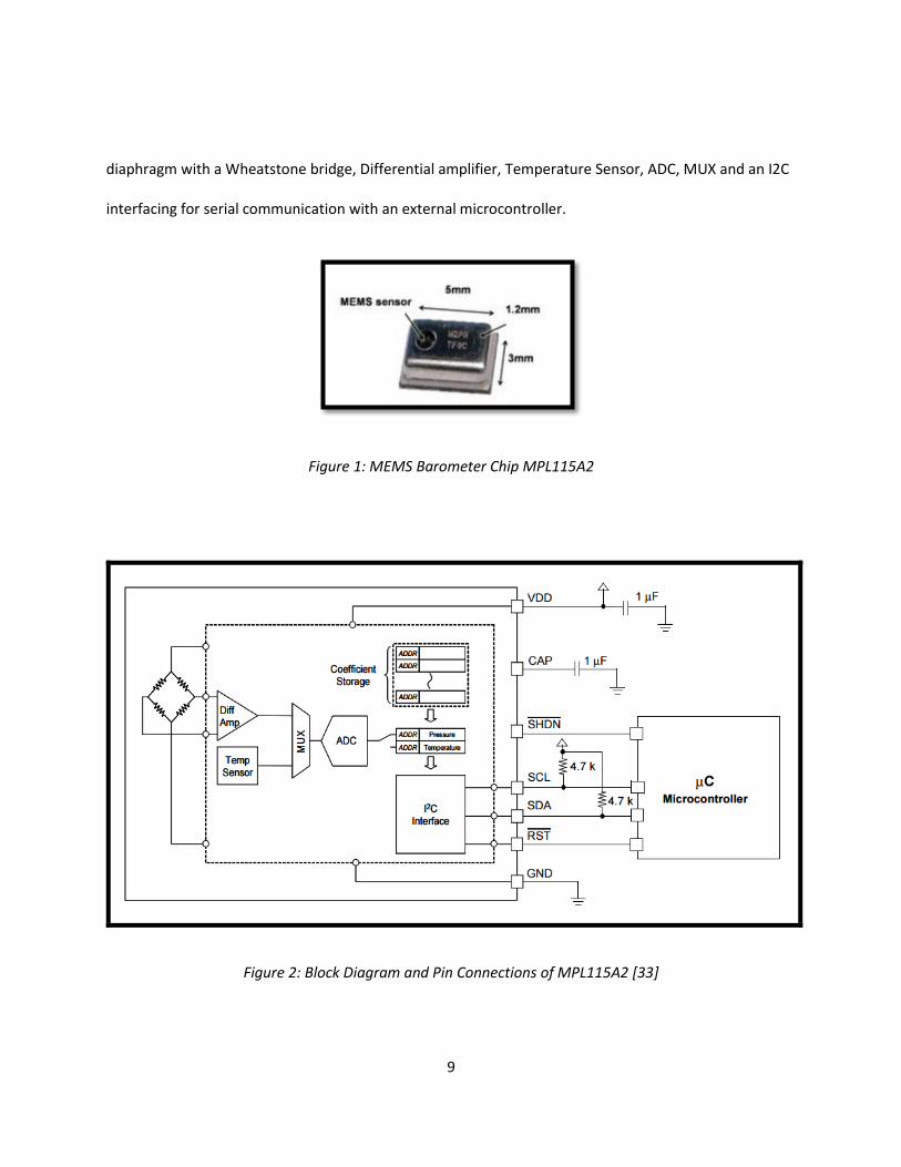
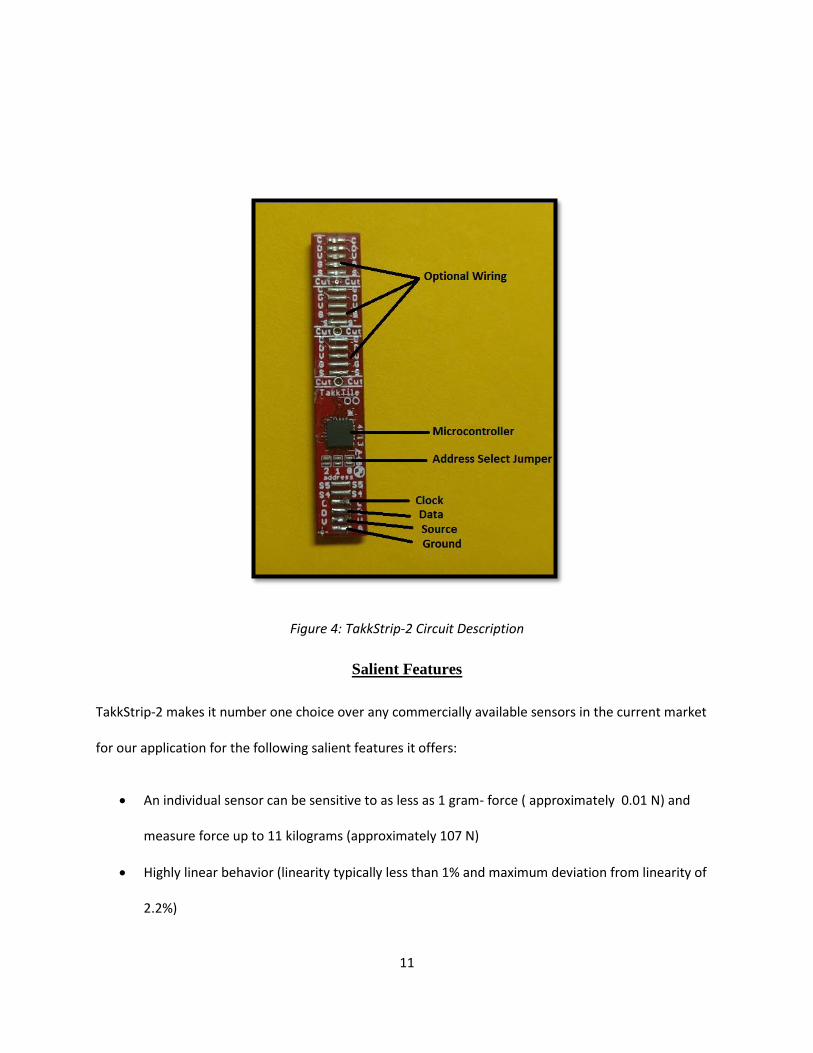
The TakkStrip-2 tactile sensor consists of 6 sensor arrays that are soldered in line with 8 mm optimally
spaced to a hard PCB (Fig-4) and are then casted in a rubber ( VytaFlex 20, Smooth Inc., USA) with
overall thickness of 4.2 mm which easily fits inside robot’s glove which shall be discussed in Chapter-5.
Figure 3: TakkStrip-2
The sensors communicate with the help of the USB-I2C bridge interface (manufactured by Cypress
Semiconductor Corp., USA). The individual sensors when cut using Dremel tool can act as an individual
taxels (individual sensor units termed by TakkTile Inc) and could be placed anywhere on the finger, as in
[28] or up to 8 different TakkStrip-2 attached to the same I2C bridge by appropriately setting the
address select jumpers at the base of the microcontroller as shown in (Fig-4).
11
Figure 4: TakkStrip-2 Circuit Description
Salient Features
TakkStrip-2 makes it number one choice over any commercially available sensors in the current market
for our application for the following salient features it offers:
An individual sensor can be sensitive to as less as 1 gram- force ( approximately 0.01 N) and
measure force up to 11 kilograms (approximately 107 N)
Highly linear behavior (linearity typically less than 1% and maximum deviation from linearity of
2.2%)

12
Readily available in an array of sensors that could be integrated with Arduino Micro
Microcontroller for interfacing with MANUS desktop workstation
TakkStrip-2 dimension closely matches the present gripper-glove configuration hence could be
easily mounted on both sides of the parallel grippers
Robust rubber cast that makes it easy to grasp wide range of object with different mass, shape
and surface properties.
13
CHAPTER 4: SLIP SENSING USING HIGH PRECISION LASER SENSOR
Introduction
There are several kinds of non-contacting sensors that are available in the current market for wide range
of robotics application. Although only few kinds of non-contacting sensors are helpful in detecting in
slippage for grasping of ADL objects. Our selection process for a non-contacting sensor was narrowed to
ADNS-3530 LED and ADNS 9800 Laser Sensor from Avago Technologies, Inc. In Hamidreza et al. [23]
clearly shows that the ADNS-3530 optical-based LED Sensor fails to detect grasping objects that are
reflective and transparent. Hence, the high performance of the Laser Sensor makes it the number one
choice in our research.
High Precision Laser Sensor
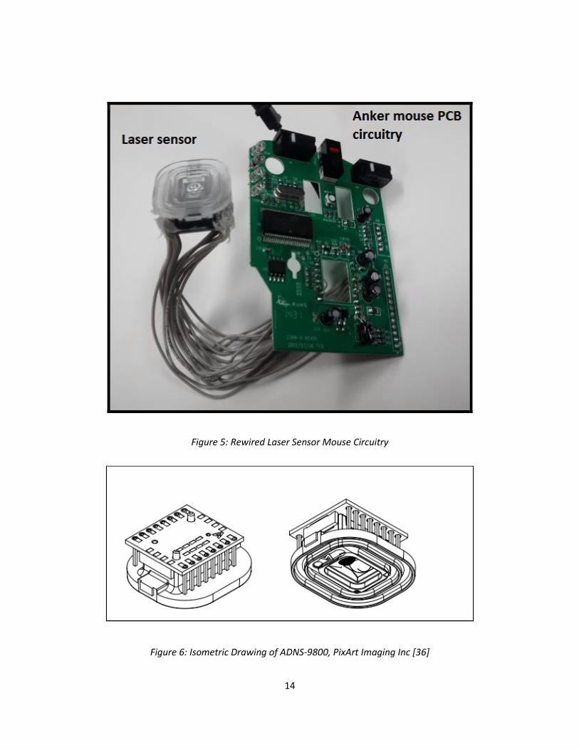
Further, we have used a high performing 8 bit RISC architecture microcontroller [34] HT46RB70 Holtek
Semiconductors Inc that supports for serial communication with the MANUS Processing Unit. This
particular device is widely used in SPI touch-panels, touch-pads, XBOX joysticks, Anker Inc Optical Mouse
for PC. It comes with a HALT feature that is intended to reduce the overall power consumption with high
Performance. The above specific ADNS-9800 Laser Slip Sensor interfaced with HT46RB70 microcontroller
were found to be available in Anker CG100 8200 DPI High Precision Programmable Laser Mouse [35] for
Personal Computers (PC).
14
Figure 5: Rewired Laser Sensor Mouse Circuitry
Figure 6: Isometric Drawing of ADNS-9800, PixArt Imaging Inc [36]
15
The LASER mouse uses an ADNS-6190-002 [36] polycarbonate round lens that delivers directed
illumination and optical imaging required for precise sensing operations by the Slip Sensor. The
dimension of the ADNS 9800 is 14.4mm x 31.5mm x 9.7mm and the assembly drawing with lens coupled
to PCB and base plate is shown in (fig-6).
Salient Features
User programmable frame rate (up to 12,000 frames per second)
Configurable sleep and wake up time (in order to optimize power consumption)
Dual power supply selections, 3 V or 5 V
16-bits motion data registers
Compliance to IEC/EN 60825-1, eye safety limit 716 𝜇W
No Laser power calibration needed
16
CHAPTER 5: INSTALLATION
Introduction
This chapter discusses in detail on the design of the gripper glove and how the two types of sensors viz.,
TakkStrip-2 and Laser sensor are mounted on it. Further, the interfacing of both types of sensors with
the MANUS Desktop workstation, the methodology of reading the sensor data and followed by the
implementation of the new adaptive control algorithms against the existing force-gripper control
algorithm is explained. The new adaptive control
17
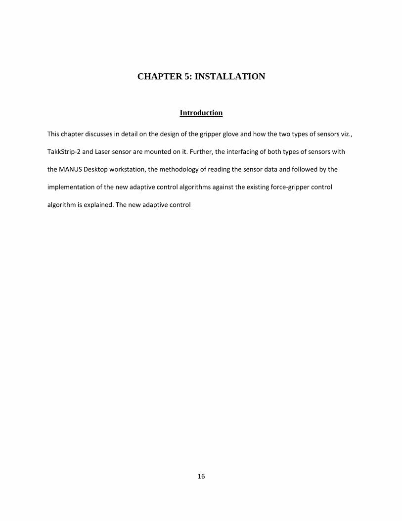
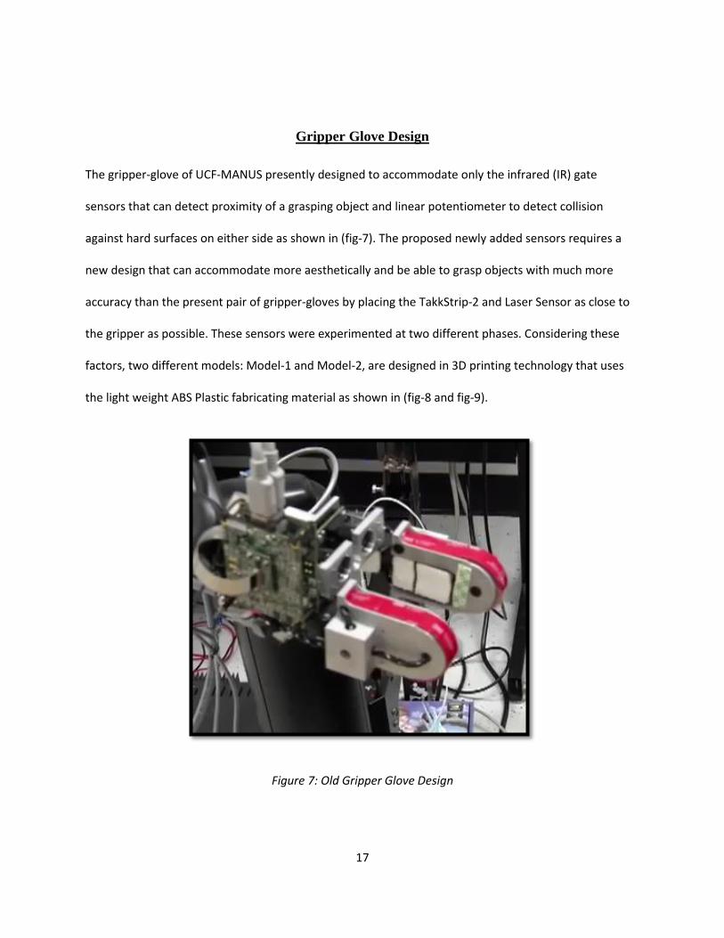
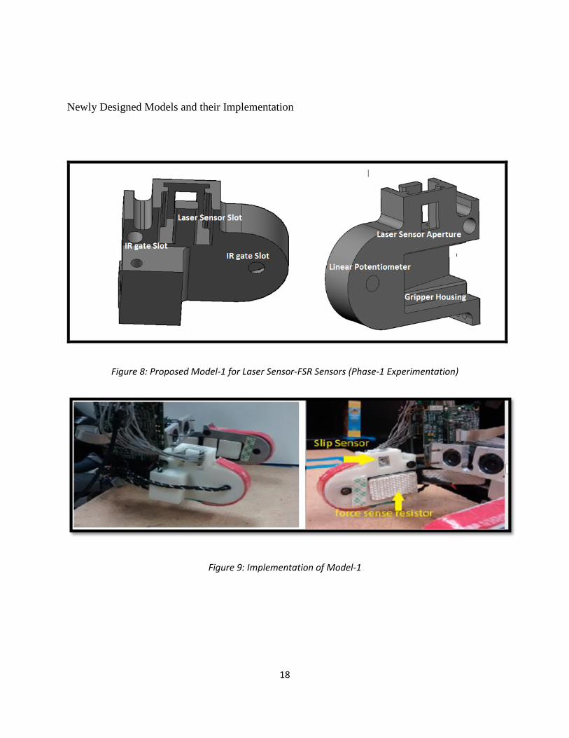
Gripper Glove Design
The gripper-glove of UCF-MANUS presently designed to accommodate only the infrared (IR) gate
sensors that can detect proximity of a grasping object and linear potentiometer to detect collision
against hard surfaces on either side as shown in (fig-7). The proposed newly added sensors requires a
new design that can accommodate more aesthetically and be able to grasp objects with much more
accuracy than the present pair of gripper-gloves by placing the TakkStrip-2 and Laser Sensor as close to
the gripper as possible. These sensors were experimented at two different phases. Considering these
factors, two different models: Model-1 and Model-2, are designed in 3D printing technology that uses
the light weight ABS Plastic fabricating material as shown in (fig-8 and fig-9).
Figure 7: Old Gripper Glove Design
18
Newly Designed Models and their Implementation
Figure 8: Proposed Model-1 for Laser Sensor-FSR Sensors (Phase-1 Experimentation)
Figure 9: Implementation of Model-1
19
Figure 10: Proposed Model-2 for TakkStrip-2 (Phase-2 Experimentation)
Figure 11: Implementation of Model-2
20
Interfacing Sensors
Laser Sensor
Laser slip sensor detects the motion changes when the object surface is within 9.95 mm from sensor
reference plane for accurate sensing as per the specification of the sensor. Hence, it is placed firmly well
inside the slot with a distance of 5mm from the point of contact between the grasping object and the
gripper. The readily available Laser Sensor is interfaced serially through any of the MANUS’s available
COM port. Since the PC of the Robotic Manipulator’s operating system works on Microsoft WINDOWS
OS data retrieval algorithm based on the standard windows desktop applications protocol available
online at Microsoft Windows Dev Center [38] has been used. There are three different ways of reading
the data from any Human Interfacing Device (HID) e.g. mouse:
WM_MOUSEMOVE
WM_INPUT
DirectInput
The WM_MOUSEMOVE protocol reads the data based on the monitor screen resolution that means that
the actual data read depends on the number of pixels the pointer has moved from its initial position.
Thus it has a serious drawbacks as there is a pointer ballistics that accelerates those data based on how
fast the grasping object moves in vicinity of the Slip Sensor. Whereas the WM_INPUT method read raw
input data from the HID stack without any additional internal ballistics application that reflect high-
definition results. By programming the Laser sensor to 8200 dpi with 1000Hz polling rate settings using
the Anker Driver Programming Software it is possible to get a resolution of 0.0031 mm/pixel. The
DirectInput on the other hand needs more thread to be handle to read the same WM_INPUT (also
21
known as Raw Input Model) data and the algorithm gets cumbersome and has no significant advantages
over the others. Also there are other advantages of using WM_INPUT Model for reading data:
It is capable of distinguishing between similar type of devices e.g. when another similar sensor is
used simultaneously
A better data traffic management from group or a specific device types compared to other two
models
This model remains same for any number of updates that would be made to currently installed
Windows Operating System on the UCF Manus work station
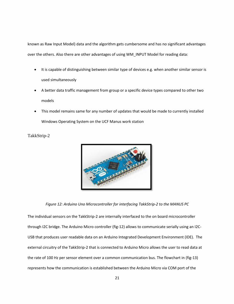
TakkStrip-2
Figure 12: Arduino Uno Microcontroller for interfacing TakkStrip-2 to the MANUS PC
The individual sensors on the TakkStrip-2 are internally interfaced to the on board microcontroller
through I2C bridge. The Arduino Micro controller (fig-12) allows to communicate serially using an I2C-
USB that produces user readable data on an Arduino Integrated Development Environment (IDE). The
external circuitry of the TakkStrip-2 that is connected to Arduino Micro allows the user to read data at
the rate of 100 Hz per sensor element over a common communication bus. The flowchart in (fig-13)
represents how the communication is established between the Arduino Micro via COM port of the
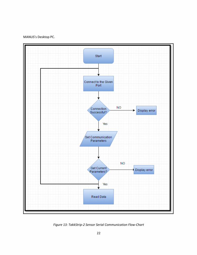
22
MANUS’s Desktop PC.
Figure 13: TakkStrip-2 Sensor Serial Communication Flow-Chart
23
CHAPTER 6: CONTROL ALGORITHM AND DESIGN
Introduction
It is at most important for a WMRAs to be able to grasp an object that are associated to the ADLs. If the
robot grasps the object too tightly or with excess force it can accidentally crush a deformable or weak
object. The robot would drop or lose the object from its grasp if the object is loosely grasped while
retrieving it to the user. With respect to the algorithm [2] that is presently implemented using the FSR
sensor in the UCF Manus the grasping mainly used the force profile of the object being grasped to
determine when the gripper stops grabbing the object. This method works for objects like cereal boxes
or any rigid structures that are used in ADLs. Issue arises when the gripper encounters less heavier, soft
and deformable objects like Styrofoam cup, paper cup, empty water bottle, etc. Completely relying on
the force sensor alone is not enough to successfully grab an object. Hence these issues are addressed in
the newly proposed algorithms.
Smart Grasping using Laser Sensor and FSR
The new algorithm seeks to rectify the stated algorithm by not depending on the force profile for its
determination on when to stop. This algorithm will utilize the already implemented force sensor in
conjunction with a Laser position displacement sensor. The Laser sensor will be used to detect when the
object is within the gripper and determine the force when to stop the grasping process. The reading
from the force sensor will then be used as minimal force necessary to successfully grab an object. If for
any reason the object was not grabbed with enough force, the Laser sensor will be utilized to detect any
24
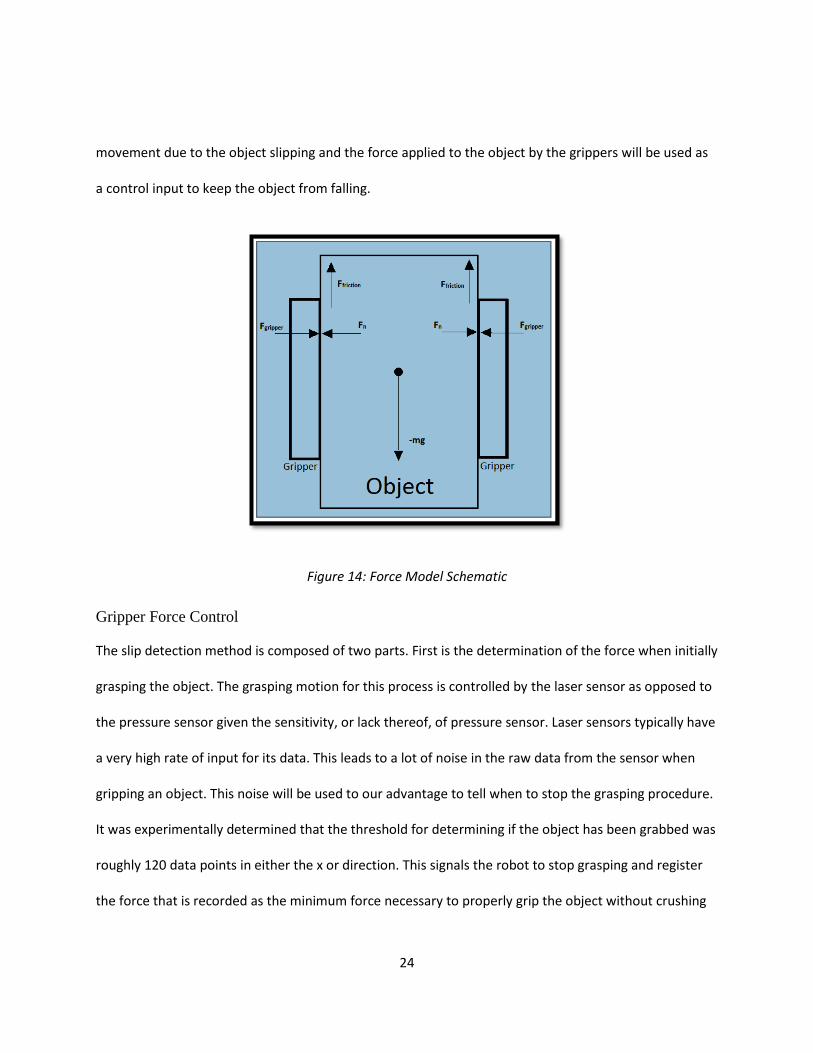
movement due to the object slipping and the force applied to the object by the grippers will be used as
a control input to keep the object from falling.
Figure 14: Force Model Schematic
Gripper Force Control
The slip detection method is composed of two parts. First is the determination of the force when initially
grasping the object. The grasping motion for this process is controlled by the laser sensor as opposed to
the pressure sensor given the sensitivity, or lack thereof, of pressure sensor. Laser sensors typically have
a very high rate of input for its data. This leads to a lot of noise in the raw data from the sensor when
gripping an object. This noise will be used to our advantage to tell when to stop the grasping procedure.
It was experimentally determined that the threshold for determining if the object has been grabbed was
roughly 120 data points in either the x or direction. This signals the robot to stop grasping and register
the force that is recorded as the minimum force necessary to properly grip the object without crushing
25
it. This registered force is then used as a starting point for determining whether or not the object is
grasped appropriately.
Slip Detection
The second part of the method involves monitoring the velocity of the object as the robot moves. This
part of the algorithm is also used to determine whether or not the object has been grasped successfully.
This is due to the fact that both events will look identical to the sensor. Because of this we can utilize
this detection method to also determine if the object was grasped too lightly to begin with. We can
express the derivative of the velocity as,
𝑚�̇� = 𝑊 − 𝜇 𝐹𝑎 ( 1 )
Where in (1), 𝑊 = 𝑚𝑔 is unknown. We can then define the applied force 𝐹𝑎 as:
𝐹𝑎 = �̂�−1(�̂� + 𝑘𝑣) ( 2 )
Where �̂� is the estimated gravitational force with �̃� = 𝑊 − �̂� being error between the estimated
and the actual, �̃� = 𝜇 − �̂� the error in the frictional co-efficient and 𝑘 is a constant. We then define the
derivative of velocity as,
𝑚�̇� = 𝑊 − 𝜇 �̂�−1(�̂� + 𝑘𝑣) ( 3 )
𝑚�̇� = 𝑊 − (�̃� + �̂�) �̂�−1(�̂� + 𝑘𝑣)
𝑚�̇� = 𝑊 − (1 + �̃� �̂�−1)(�̂� + 𝑘𝑣)
𝑚�̇� = �̃� − 𝑘𝑣 − �̃� �̂�−1 (�̂� + 𝑘𝑣) ( 4 )
For some constant 𝛾1𝑎𝑛𝑑 𝛾2 a Lyapunov-based PI controller will be used to correct the error in applied
force by controlling the velocity of the object. To do this we will first define a positive-definite Lyapunov
function 𝑉 as follows:
26
𝑉 = 1
2𝑚𝑣2 +
1
2𝛾1
−1�̃�2 +1
2𝛾2
−1�̃�2 ( 5 )
Differentiating this equation yields the derivative as:
�̇� = (�̃� − 𝑘𝑣 − �̃� �̂�−1 (�̂� + 𝑘𝑣)) 𝑣 − 𝛾1−1�̃��̇̂� − 𝛾2
−1�̃��̂� ̇ ( 6 )
From this it can be seen that for any positive value of 𝑘 the system will be globally asymptotically stable.
The newly designed controller is based on Barbalat’s Lemma such that the new co-efficient of friction is
positive.
�̇̂� = 𝛾1 𝑣 ( 7 )
�̂� ̇ = 𝛾2𝜇−1(�̂� + 𝑘𝑣)𝑣 ( 8 )
To ensure 𝜇 ̂ > 0, projection is used and hence,
�̇� = −𝑘𝑣2 ≤ 0 ( 9 )
By Barbalat’s Lemma, lim𝑡→∞
𝑣(𝑡) → 0. Signal chase to send boundedness of remaining signals or,
𝑚�̇� = �̃� − 𝜇𝜇−1(�̂� + 𝑘𝑣) ( 10 )
𝑚�̇� = �̃� − �̃� 𝜇−1 (�̂�) − 𝑘𝜇𝜇−1𝑣 ( 11 )
27
Grasping using TakkStrip-2 Array Sensors
The drawbacks associated with the FSR with regards to limited sensation of force applied between the
grippers is easily addressed by gram sensitive TakkStrip-2 array sensors that are mounted on either side
of the robot’s gripper. The TakkStrip-2 array sensors runs with algorithm [12] and equation and uses the
net force applied between the two TakkStrip-2 sensors (2). The grippers stops when the force profile
reaches to a constant value. This part of the profile represents the resistance of the object that is at its
initial state when the force is applied between the grippers. Followed shortly after this is the point
where the object’s structure yields to the grasping force. The following condition should be satisfied
when the profile reaches the constant or flattened section:
𝑔(𝑡) ≜ 𝑠𝑢𝑝𝑡 ∈[𝑡− 𝛥𝑇,𝑡]
|𝑑𝑓(𝑡)
𝑑𝑡| < 𝜖 ( 12 )
Where 𝑓(𝑡) is the net interacting force between the two TakkStrip-2 sensors, Δ𝑇 is the sliding time
window width, and 𝜖 is a numerical tolerance constant.
28
CHAPTER 7: EXPERIMENTAL RESULTS
Introduction
The UCF-MANUS platform [3] was used as the main experimental setup for this thesis. The experiments
were conducted in two different phases. In the Phase-1, grasping of objects that are heavy, deformable
and uneven contact surfaces are carried out using the Model-1 gripper-glove design. Laser and FSR are
the only two tactile sensors that are used and the gripper follows the adaptive control algorithm based
on the positive definite Lyapunov Stability criteria described in the previous chapter. In Phase-2,
grasping of small and light weight objects with different shape and size are experimented on the simple
force control algorithm as mentioned earlier. Phase-2 experimentation shows successful grasping of
objects that are as small and light as Cereal.
Phase-1 Experimental Set-up: Laser Sensor and FSR
Empty and full water bottles were used along with empty and full Styrofoam cups as test objects for the
experiments. The full water bottle was filled with water and capped and the filled Styrofoam cups were
filled with sand to prevent any water from affecting the sensors and other electronics. For all
experiments the objects are initially grabbed using the either the proposed algorithm, the previous
algorithm in [2], or using no algorithm. After the objects were grabbed, the gripper was moved upward
to test whether or not the grab was successful. A force sensing resistor (FSR) will act as the force sensor
for these experiments as it did for the previous algorithm.
29
Figure 15: Pictures showing Grasping Operations on Styrofoam Cup
30
Figure 16: Pictures showing Grasping Operations on Water Bottle
31
Grasping
The proposed algorithm succeeded in grasping the desired objects with little to no deformation and
utilizing less force than previous algorithms to obtain its goal as seen in Fig. 17. When testing on the
water bottles the proposed algorithm used 1.313 N of force to successfully grab the empty water bottle
and 1.74 N to grab the full water bottle. Both of these are less than that of the old algorithm which used
slightly less or just as much force as using no algorithm at all. The old algorithm used 2.03 N of force to
grasp the empty water bottle and 2.09 N to grasp the full one. This roughly the same as using no
algorithm to grasp the empty water bottle which used 2.07 N. This goes to show the deficits of using the
previous algorithm to grasp pliable objects. The old algorithm did perform better when grasping the full
water bottle using 0.246 N less force than when using no algorithm.
Pliable objects, such as the empty water bottle and cups, deformed significantly when grasped with the
previous algorithm and using no algorithm. The deformation of the Styrofoam cups can be seen in (fig-
15). The empty cup deforms slightly when using the proposed algorithm, but still retains most of its
original shape. The previous algorithm and use of no algorithm completely deforms the cups when being
grasped. The full cups fare better when being grasped. They suffered no deformation when grasped
using the new algorithm and only a slight deformation when using the previous one. There is
considerable deformation when using no algorithm on the full cups, but not as severe as with the empty
cups. Other rigid objects had similar results as those shown for the full Styrofoam cup.
32
Figure 17: Force Plots using Pressure Sensor Data for Empty and Filled Water Bottles
33
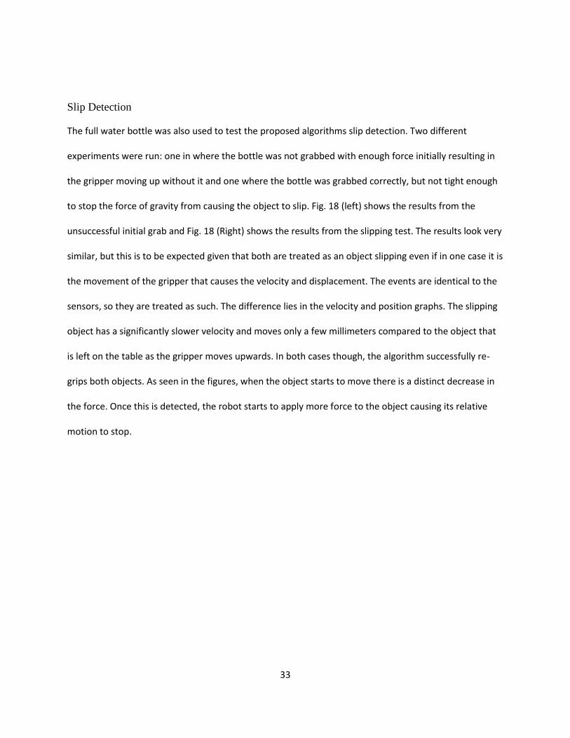
Slip Detection
The full water bottle was also used to test the proposed algorithms slip detection. Two different
experiments were run: one in where the bottle was not grabbed with enough force initially resulting in
the gripper moving up without it and one where the bottle was grabbed correctly, but not tight enough
to stop the force of gravity from causing the object to slip. Fig. 18 (left) shows the results from the
unsuccessful initial grab and Fig. 18 (Right) shows the results from the slipping test. The results look very
similar, but this is to be expected given that both are treated as an object slipping even if in one case it is
the movement of the gripper that causes the velocity and displacement. The events are identical to the
sensors, so they are treated as such. The difference lies in the velocity and position graphs. The slipping
object has a significantly slower velocity and moves only a few millimeters compared to the object that
is left on the table as the gripper moves upwards. In both cases though, the algorithm successfully re-
grips both objects. As seen in the figures, when the object starts to move there is a distinct decrease in
the force. Once this is detected, the robot starts to apply more force to the object causing its relative
motion to stop.
34
Figure 18: Force, Position and Velocity Grasps during Initial Grasp and Slip.
Phase-2 Experimental Set-up: TakkStrip-2
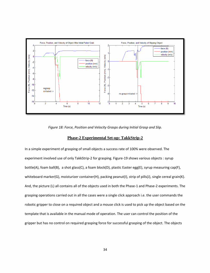
In a simple experiment of grasping of small objects a success rate of 100% were observed. The
experiment involved use of only TakkStrip-2 for grasping. Figure-19 shows various objects : syrup
bottle(A), foam ball(B), a shot glass(C), a foam block(D), plastic Easter egg(E), syrup measuring cap(F),
whiteboard marker(G), moisturizer container(H), packing peanut(I), strip of pills(J), single cereal grain(K).
And, the picture (L) all contains all of the objects used in both the Phase-1 and Phase-2 experiments. The
grasping operations carried out in all the cases were a single click approach i.e. the user commands the
robotic gripper to close on a required object and a mouse click is used to pick up the object based on the
template that is available in the manual mode of operation. The user can control the position of the
gripper but has no control on required grasping force for successful grasping of the object. The objects
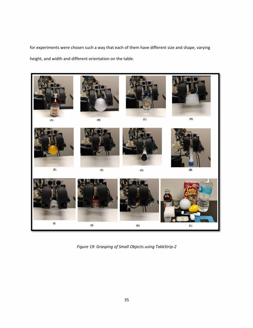
35
for experiments were chosen such a way that each of them have different size and shape, varying
height, and width and different orientation on the table.
Figure 19: Grasping of Small Objects using TakkStrip-2

36
The following table shows the summary of degree of deformation and successful rate of grasping objects
that were used in both the Phase-1 and Phase-2 experiments.
Table 1: Degree of Deformation of Various Test Objects used in ADL
Sl. No Objects Old Algorithm Present Algorithm New Proposed Algorithm
1 Empty Water Bottle Moderate Moderate NA
2 Full Water Bottle Moderate Slight NA
3 Empty Styrofoam Cup High Moderate NA
4 Full Styrofoam Cup High Moderate NA
5 Empty Paper Cup High High NA
6 Cereal Box Slight Slight None
7 Syrup Bottle Slight Slight None
8 Foam Ball High Moderate Slight
9 Shot Glass NA NA None
10 Packing Foam Block High Moderate None
11 Plastic Easter Egg High Moderate Slight
12 Plastic Measuring Cap High Moderate None
13Whiteboard Marker
PenNA NA None
14 Moisturizer Container Slight NA None
15 Packing Peanut High High Moderate
16 Pills strip NA High None
17 Single Cereal Grain NA High None
37
CHAPTER 8: CONCLUSION AND SCOPE FOR FUTURE RESEARCH
In this thesis an intelligent grasping algorithm using a Laser sensor and a force sense resistor in Phase-1
and TakkStrip-2 in the Phase-2 of the experiment that improves upon the previous grasping algorithm
that was being utilized by the UCF-MANUS system was demonstrated. There are significant
improvement over the previous algorithm that was implemented that relied on force profiles to
determine when an object was successfully grabbed. The results show that the proposed algorithm can
accomplish the same task using significantly less force than the previous one. The slip detection and
correction also succeeded in ensuring that the desired object remained grasped by the robot. This
provides a cheap and easy way to implement an intelligent grasping algorithm to improve tactile sensing
of UCF MANUS robotic grippers. Further research works may be done for replacing the force sensing
resistor by TakkStrip-2 with a new gripper-glove model and perform grasping operations on more
difficult-to-grasp objects.
38
REFERENCES
[1] H. Hok Kwee, (“Integrated Control of MANUS Manipulator and Wheelchair Enhanced by
Environmental Docking”, Robotica, 16, pp 491-498, 1998
[2] Dae-Jin Kim; Zhao Wang; Behal, A., "Motion Segmentation and Control Design for UCFMANUS—
An Intelligent Assistive Robotic Manipulator," Mechatronics, IEEE/ASME Transactions on, vol.17,
no.5, pp.936, 948, 2012
[3] Paperno, Nicholas, "Modified System Design and Implementation of an Intelligent Assistive
Robotic Manipulator". Electronic Theses and Dissertations. Paper 1291, 2015
[4] K. Ito, M. Saen, and K. Osada, “Scalable robotic-hand control system based on a hierarchical
multi-processor architecture adopting a large number of tactile sensors,” in Proc. IEEE/RSJ Int.
Conf. Intell. Robots Syst., vol. 3., pp. 100–106, 2012
[5] M. Saen, K. Ito, and K. Osada , “Action-Intention-Based Grasp Control With Fine Finger-Force
Adjustment Using Combined Optical-Mechanical Tactile Sensor”, IEEE Sensors Journal., vol. 14,
no.11, pp. 4026-4033, Nov. 2014
[6] K. Noda, K. Matsumoto, and I. Shimoyama, “Flexible tactile sensor sheet with liquid filter for
shear force detection,” in Proc. IEEE Int. Conf. MEMS, pp. 785–788, 2009
[7] M. Shimojo et al., “A high-speed mesh of tactile sensors fitting arbitrary surfaces,” in IEEE
Sensors J., vol. 10, no. 4, pp. 822–830, 2010
[8] J. Romano, K. Hsiao, and G. Niemeyer, “Humaninspired robotic grasp control with tactile
sensing,” Robotics, IEEE, vol. X, no. X, pp. 1-13, 2011.S. Teshigawara, M. Ishikawa, M. Shimojo,
39
Development of High Speed and High Sensitivity Slip Sensor, Proc. IEEE Int. conf. on Intelligent
Robots and Systems, pp.47-52, 2008
[9] S. Teshigawara, K. Tadakuma, A. Ming, M. Ishikawa, M. Shimojo, “High Sensitivity Initial Slip
Sensor for Dexterous Grasp”, Proc. IEEE Int. conf. on Robotics and Automation, pp.4867-4872,
2010
[10] S. Teshigawara, T. Tsutsumi, S. Shimizu, Y. Suzuki, A. Ming, M.Ishikawa, and M. Shimojo, “Highly
Sensitive Sensor for Detection of Initial Slip and Its Application in a Multi-fingered Robot Hand”,
Proc. IEEE Int. conf. on Robotics and Automation, pp.1097-1102, 2011
[11] S. Teshigawara, K. Tadakuma, A. Ming, M. Ishikawa, M. Shimojo, “Development of High-
Sensitivity Slip Sensor Using Special Characteristics of Pressure Conductive Rubber”, Proc. IEEE
Int. conf. on Robotics and Automation, pp.3289-3294, 2009
[12] H. Hasegawa, Y. Mizoguchi, K. Tadakuma, A. Ming, M. Ishikawa, and M. Shimojo, “Development
of intelligent robot hand using proximity, contact and slip sensing,” in Proc. IEEE Int. Conf.
Robot. Autom. pp. 777–784, 2010
[13] E. Engeberg and S. Meek, “Adaptive sliding mode control for prosthetic hands to simultaneously
prevent slip and minimize deformation of grasped objects,” IEEE/ASME Trans. Mechatronics,
vol. 18, no. 1, pp. 376–385, Feb. 2013.
[14] K. Noda, K. Matsumoto, and I. Shimoyama, “Flexible tactile sensor sheet with liquid filter for
shear force detection,” in Proc. IEEE Int. Conf. MEMS, pp. 785–788, Jan 2009
[15] D. Gunji et al., “Grasping force control of multi-fingered robot hand based on slip detection
using tactile sensor,” in Proc. IEEE Int. Conf. Robot. Autom., pp. 2605–2610, May 2008
40
[16] C. Melchiorri, “Slip detection and control using tactile and force sensors,” IEEE/ASME Trans.
Mechatronics, vol. 5, no. 3, pp. 235–243, Sep. 2000.
[17] C. Melchiorri, “Slip detection and control using tactile and force sensors,” IEEE/ASME Trans.
Mechatronics, vol. 5, no. 3, pp. 235–243, Sep. 2000.
[18] M. Tremblay and M. Cutkosky, “Estimating friction using incipient slip sensing during a
manipulation task,” in Proc. IEEE Int. Conf. Robot. Autom. pp. 429–434. May 1993
[19] Y. Yamada, H. Morita, and Y. Umetani, “Slip phase isolating: Impulsive signal generating
vibrotactile sensor and its application to real-time object regrip control,” Robotica, vol. 18, no. 1,
pp. 43–49, Jan. 2000.
[20] D. Cotton, P. Chappell, A. Cranny, N. White, and S. Beeby, “A novel thick-film piezoelectric slip
sensor for a prosthetic hand,” IEEE Sensors J., vol. 7, no. 5, pp. 752–761, May 2007.
[21] M. Ohka, H. Kobayashi, J. Takata, and Y. Mitsuya, “Sensing precision of an optical three-axis
tactile sensor for a robotic finger,” in Proc. IEEE Int. Symp. Robot Human Interact. Commun. pp.
214–219. Sep. 2006
[22] J. Ueda, A. Ikeda, and T. Ogasawara, “Grip-force control of an elastic object by vision-based slip-
margin feedback during the incipient slip,” IEEE Trans. Robot., vol. 21, no. 6, pp. 1139–1147,
Dec. 2005.
[23] H. Sani and S. Meek, “Characterizing the performance of an optical slip sensor for grip control in
a prosthesis,” in Proc. IEEE/RSJ Int. Conf. Intell. Robots Syst., pp. 1927–1932, Sep. 2011.
[24] C. Light, P. Chappell, B. Hudgins, and K. Englehart, “Intelligent multifunction myoelectric control
of hand prostheses,” J. Med. Eng. Tech., vol. 26, No. 4, p. 139-146. July/August, 2002
41
[25] A. Mingrino, A. Bucci, R. Magni, and P. Dario, “Slippage control in hand prostheses by sensing
grasping forces and sliding motion,” Proc. IEEE Int. Conf .Intell. Robot Syst., vol. 3, pp. 1803-
1809, 1994
[26] R. S. Dahiya, G. Metta, M. Valle, and G. Sandini, “Tactile Sensing - From Humans to Humanoids,”
IEEE Transactions on Robotics, vol. 26, no. 1, pp. 1–20, 2010.
[27] T. Fujimori et al., “Tiny (0.72 mm2 ) pressure sensor integrating MEMS and CMOS LSI with back-
end-of-line MEMS platform,” in Proc. Int. Conf. Solid-State Sensors, Actuators and Microsystems
(TRANSDUCERS2009), Denver, CO, pp. 1924–1927, Jun.21–25 2009.
[28] Lael U. Odhner, Leif P. Jentoft, Mark R. Claffee, Nicholas Corson, Yaroslav Tenzer, Raymond R.
Ma, Martin Buehler, Robert Kohout, Robert D. Howe, Aaron M. Dollar, ”A Compliant
Underactuated Hand for Robust Manipulation”, Art., IJRR, 2014
[29] Tenzer Y, Jentoft LP and Howe RD, “Inexpensive and easily customized tactile sensors using
MEMS barometers chips”. IEEE Robotics and Automation Magazine, 2012
[30] TakkStrip Inc. [Online], Available: http://www.takktile.com/
[31] Robotiq Gripper [Online], Available : http://www.takktile.com/projects:robotiq
[32] DoraTouch [Online], Available: http://www.takktile.com/projects:doratouch
[33] Datasheet MPL115A2, Document Number: MPL115A2 Rev. 9 02/2013, [Online], Available:
http://cache.freescale.com/files/sensors/doc/data_sheet/MPL115A2.pdf
[34] HT 46RB70 Data Sheet. Holtek Semiconductors Inc.[Online]. Available:
http://pdf1.alldatasheet.com/datasheetpdf/view/205591/HOLTEK/HT46RB70.html
[35] ADNS 9800 Data Sheet. PixArt Imaging Inc [Online]. Available:
http://www.pixart.com.tw/upload/ADNS-9800%20DS_S_V1.0_20130514144352.pdf
42
[36] ADNS-6190-002 Data Sheet. PixArt Imaging Inc. [Online]. Available:
http://www.pixart.com.tw/upload/ADNS-6190-00220DS_S_V1.0_20130514144352.pdf
[37] Raw Input Model, Programming. Microsoft Corp [Online]. Available :
https://msdn.microsoft.com
[38] Raw Input Model, Programming. Microsoft Corp [Online]. Available :
https://msdn.microsoft.com
[39] Report: National Spinal Cord Injury Statistical Center Available: https://www.nscisc.uab.edu/
[40] Dana Reeve Foundation. Available: https://www.christopherreeve.org