Embed Size (px)
Citation preview

Smart FieldCommunicator Model
STS103
Operating Guide34-ST-11-14F
4/99

ii STS103 Operating Guide 4/99
Copyright, Notices, and Trademarks
© Copyright 1995 by Honeywell Inc.
Revision F – 4/99
While this information is presented in good faith and believed to be accurate,Honeywell disclaims the implied warranties of merchantability and fitness for aparticular purpose and makes no express warranties except as may be stated in itswritten agreement with and for its customer.
In no event is Honeywell liable to anyone for any indirect, special, or consequentialdamages. The information and specifications in this document are subject tochange without notice.
This document was prepared using Information Mapping® methodologies andformatting principles.
Information Mapping® is a registered trademark of Information Mapping, Inc.
ST 3000 and SFC are U.S. registered trademarks of Honeywell Inc.
HoneywellIndustrial Automation and Control
Automation College2820 West Kelton LanePhoenix, Arizona 85023
4/99 STS103 Operating Guide iii
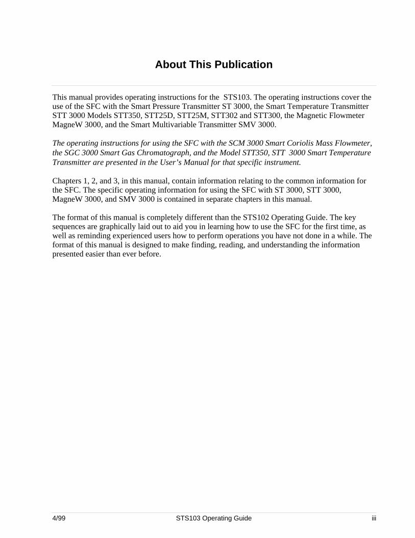
About This Publication
This manual provides operating instructions for the STS103. The operating instructions cover theuse of the SFC with the Smart Pressure Transmitter ST 3000, the Smart Temperature TransmitterSTT 3000 Models STT350, STT25D, STT25M, STT302 and STT300, the Magnetic FlowmeterMagneW 3000, and the Smart Multivariable Transmitter SMV 3000.
The operating instructions for using the SFC with the SCM 3000 Smart Coriolis Mass Flowmeter,the SGC 3000 Smart Gas Chromatograph, and the Model STT350, STT 3000 Smart TemperatureTransmitter are presented in the User’s Manual for that specific instrument.
Chapters 1, 2, and 3, in this manual, contain information relating to the common information forthe SFC. The specific operating information for using the SFC with ST 3000, STT 3000,MagneW 3000, and SMV 3000 is contained in separate chapters in this manual.
The format of this manual is completely different than the STS102 Operating Guide. The keysequences are graphically laid out to aid you in learning how to use the SFC for the first time, aswell as reminding experienced users how to perform operations you have not done in a while. Theformat of this manual is designed to make finding, reading, and understanding the informationpresented easier than ever before.

iv STS103 Operating Guide 4/99
4/99 STS103 Operating Guide v
Table of Contents
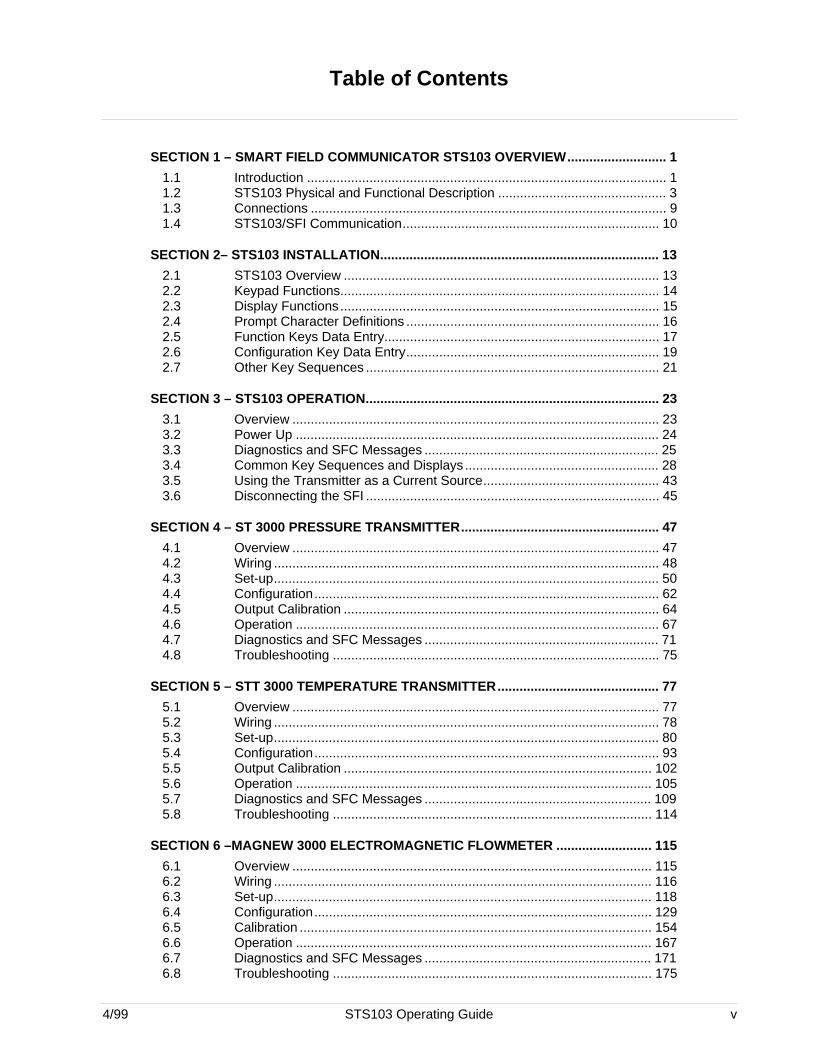
SECTION 1 – SMART FIELD COMMUNICATOR STS103 OVERVIEW........................... 1
1.1 Introduction .................................................................................................. 11.2 STS103 Physical and Functional Description .............................................. 31.3 Connections ................................................................................................. 91.4 STS103/SFI Communication...................................................................... 10
SECTION 2– STS103 INSTALLATION............................................................................ 13
2.1 STS103 Overview ...................................................................................... 132.2 Keypad Functions....................................................................................... 142.3 Display Functions....................................................................................... 152.4 Prompt Character Definitions ..................................................................... 162.5 Function Keys Data Entry........................................................................... 172.6 Configuration Key Data Entry..................................................................... 192.7 Other Key Sequences ................................................................................ 21
SECTION 3 – STS103 OPERATION................................................................................ 23
3.1 Overview .................................................................................................... 233.2 Power Up ................................................................................................... 243.3 Diagnostics and SFC Messages ................................................................ 253.4 Common Key Sequences and Displays ..................................................... 283.5 Using the Transmitter as a Current Source................................................ 433.6 Disconnecting the SFI ................................................................................ 45
SECTION 4 – ST 3000 PRESSURE TRANSMITTER...................................................... 47
4.1 Overview .................................................................................................... 474.2 Wiring ......................................................................................................... 484.3 Set-up......................................................................................................... 504.4 Configuration.............................................................................................. 624.5 Output Calibration ...................................................................................... 644.6 Operation ................................................................................................... 674.7 Diagnostics and SFC Messages ................................................................ 714.8 Troubleshooting ......................................................................................... 75
SECTION 5 – STT 3000 TEMPERATURE TRANSMITTER............................................ 77
5.1 Overview .................................................................................................... 775.2 Wiring ......................................................................................................... 785.3 Set-up......................................................................................................... 805.4 Configuration.............................................................................................. 935.5 Output Calibration .................................................................................... 1025.6 Operation ................................................................................................. 1055.7 Diagnostics and SFC Messages .............................................................. 1095.8 Troubleshooting ....................................................................................... 114
SECTION 6 –MAGNEW 3000 ELECTROMAGNETIC FLOWMETER .......................... 115
6.1 Overview .................................................................................................. 1156.2 Wiring ....................................................................................................... 1166.3 Set-up....................................................................................................... 1186.4 Configuration............................................................................................ 1296.5 Calibration ................................................................................................ 1546.6 Operation ................................................................................................. 1676.7 Diagnostics and SFC Messages .............................................................. 1716.8 Troubleshooting ....................................................................................... 175
vi STS103 Operating Guide 4/99
Table of Contents
SECTION 7 –SMV 3000 MULTIVARIABLE TRANSMITTER ........................................177
7.1 Overview...................................................................................................1777.2 Wiring........................................................................................................1787.3 Configuration ............................................................................................1807.4 Output Calibration.....................................................................................2357.5 Operation ..................................................................................................2397.6 Diagnostics and SFC Messages...............................................................2447.7 Troubleshooting ........................................................................................253
4/99 STS103 Operating Guide vii
Figures
Figure 1-1 Smart Field Communicator STS103 ......................................................... 3Figure 1-2 STS103 Keypad and LCD Display............................................................ 4Figure 1-3 STS103 Switch and Terminals.................................................................. 7Figure 1-4 STS103 Battery Pack................................................................................ 8Figure 1-5 STS103 –Junction Box ............................................................................. 9Figure 1-6 Typical Analog Data Exchange............................................................... 11Figure 1-7 Typical Digital Data Exchange ................................................................ 12Figure 2-1 STS103 Keypad Color Groups ............................................................... 14Figure 3-1 Power Up Sequence ............................................................................... 24Figure 3-2 Read Digital Database ............................................................................ 24Figure 3-3 Changing Communications Mode........................................................... 28Figure 3-4 Configuring the Elements of the DE Communications Mode
(Single PV Transmitter)........................................................................... 30Figure 3-5 Configuring the Elements of the DE Communications Mode
(Multiple PV Transmitter) ........................................................................ 31Figure 3-6 Adjusting the Damping Time Value......................................................... 33Figure 3-7 Displaying, Setting, and Calibrating the Lower Range Value.................. 34Figure 3-8 Displaying, Setting, and Calibrating the Upper Range Value.................. 35Figure 3-9 Displaying and Changing the Span......................................................... 36Figure 3-10 Displaying and Changing the Upper Range Limit ................................... 37Figure 3-11 Corrects Reset ........................................................................................ 38Figure 3-12 Displaying, Setting, and Clearing the Current Output. ............................ 39Figure 3-13 Displaying and calibrating the Current Input Value................................. 40Figure 3-14 Displaying the SFI Diagnostic Status...................................................... 41Figure 3-15 Software Version..................................................................................... 41Figure 3-16 Writing Data in Scratch Pad Area ........................................................... 42Figure 4-1 STS103 – Junction Box and IS Connection............................................ 48Figure 4-2 STS103–ST 3000 Connections .............................................................. 49Figure 4-3 Adjusting the ST 3000 Damping Time Value .......................................... 53Figure 4-4 Changing the ST 3000 Communications Mode ...................................... 55Figure 4-5 Configuring the ST 3000 DE Communications Mode ............................. 57Figure 4-6 Changing the ST 3000 Lower Range Value (LRV) ................................. 58Figure 4-7 Changing the ST 3000 Upper Range Value (URV) ................................ 59Figure 4-8 Configuring the ST 3000 Transmitter...................................................... 63Figure 4-9 ST 3000 Troubleshooting Procedure ...................................................... 75Figure 5-1 STS103 – Junction Box and IS Connection............................................ 78Figure 5-2 STS103 Connections to Model STT350 Transmitter .............................. 79Figure 5-3 STS103 Connections to Model STT25D and STT25M Transmitters ...... 79Figure 5-4 STS103 Connections to Model STT300 and STT302 Transmitters........ 80Figure 5-5 Adjusting the STT 3000 Damping Time Value........................................ 84Figure 5-6 Changing the STT 3000 Communications Mode .................................... 86Figure 5-7 Configuring the STT 3000 DE Communications Mode ........................... 88Figure 5-8 Changing the STT 3000 Lower Range Value (LRV)............................... 89Figure 5-9 Changing the STT 3000 Upper Range Value (URV) .............................. 90Figure 5-10 STT 3000 Temperature Transmitter Configuration................................. 94Figure 5-11 STT 3000 Probe Configuration ............................................................... 98Figure 5-12 Save/Restore Data.................................................................................. 99Figure 5-13 Alarm Latching/Open Input Failsafe...................................................... 100Figure 5-14 Write Protect and Password ................................................................. 101Figure 5-15 STT 3000 Troubleshooting Procedure.................................................. 114Figure 6-1 STS103 – Junction Box and IS Connection.......................................... 116Figure 6-2 STS103–MagneW Connections............................................................ 117Figure 6-3 Adjusting the MagneW 3000 Damping Time Value .............................. 122
viii STS103 Operating Guide 4/99
Figures
Figure 6-4 Selecting the MagneW 3000 Units in which to Display Values..............124Figure 6-5 Changing Communications Mode .........................................................125Figure 6-6 Configuring the MagneW 3000 DE Communications Mode ..................127Figure 6-7 Changing the MagneW 3000 Upper Range Value (Span) ....................128Figure 6-8 MagneW 3000 Prompt hierarchy...........................................................130Figure 6-9 MagneW 3000 Units Key Configuration ................................................132Figure 6-10 MagneW 3000 Range Configuration Graphic........................................137Figure 6-11 MagneW 3000 Detector Data Configuration..........................................139Figure 6-12 MagneW 3000 Alarm Setting Configuration ..........................................141Figure 6-13 MagneW 3000 Failsafe Condition Configuration ...................................143Figure 6-14 MagneW 3000 Digital Input/Output Configuration .................................145Figure 6-15 MagneW 3000 Totalizer Menu Hierarchy..............................................147Figure 6-16 MagneW 3000 Pulse Output Configuration ...........................................148Figure 6-17 MagneW 3000 Pulse Config?................................................................150Figure 6-18 MagneW 3000 Set Trip Value ...............................................................151Figure 6-19 Save/Restore Data ................................................................................152Figure 6-20 MagneW 3000 Calibration Set-up .........................................................155Figure 6-21 MagneW 3000 Calibration Menu Hierarchy...........................................161Figure 6-22 MagneW 3000 Excitation Current Check ..............................................162Figure 6-23 MagneW 3000 Excitation Current Calibration .......................................164Figure 6-24 MagneW 3000 Gain Calibration ............................................................165Figure 6-25 MagneW 3000 DI/DO Check.................................................................166Figure 6-26 MagneW 3000 Troubleshooting Procedure...........................................175Figure 7-1 STS103 – Junction Box and IS Connection ...........................................178Figure 7-2 STS103–SMV 3000 Connections ..........................................................179
4/99 STS103 Operating Guide ix
Tables
Table 1-1 Model STS103 Specifications ................................................................... 2Table 1-2 STS103 Key Functions ............................................................................. 5Table 1-3 Communication Format Description........................................................ 10Table 1-4 Typical Digital Data Exchange Sequence of Events ............................... 12Table 2-1 STS103 Key Color Group Description .................................................... 14Table 2-2 LCD Display Functions ........................................................................... 15Table 2-3 STS103 LCD Character Definitions and General Rules ......................... 16Table 2-4 Function Key Sequence.......................................................................... 18Table 2-5 Configuration Key Sequence .................................................................. 19Table 2-6 Other Key Sequences............................................................................. 21Table 3-1 Diagnostic Messages for SFC ................................................................ 26Table 3-2 DE Configuration Elements..................................................................... 29Table 3-3 Storing Data in Non-volatile memory ...................................................... 32Table 3-4 Using the SFI as a Constant Current-source .......................................... 44Table 3-5 Disconnect Check List............................................................................. 45Table 4-1 Keying–in the ST 3000 ID and Uploading the Database ........................ 50Table 4-2 Selecting the ST 3000 Units ................................................................... 54Table 4-3 The ST 3000 DE Configuration Elements............................................... 56Table 4-4 Setting the ST 3000 Lower Range Value Using Applied Pressure ......... 60Table 4-5 Setting the ST 3000 Upper Range Value Using Applied Pressure ......... 61Table 4-6 Scrolling through the ST 3000 Parameters............................................. 62Table 4-7 ST 3000 Digital to Analog Current Output Signal Calibration ................. 64Table 4-8 ST 3000 Operating Data ......................................................................... 68Table 4-9 Diagnostic Messages for SFC and ST 3000........................................... 72Table 5-1 Keying–in the STT 3000 ID and Database ............................................. 81Table 5-2 Selecting the STT 3000 Units ................................................................. 85Table 5-3 STT 3000 DE Configuration Elements.................................................... 87Table 5-4 Setting the STT 3000 Lower Range Value Using Applied Temperature. 91Table 5-5 Setting the STT 3000 Upper Range Value Using Applied Temperature. 92Table 5-6 Scrolling through the STT 3000 Parameters........................................... 93Table 5-7 STT 3000 Probe Configuration Elements ............................................... 95Table 5-8 STT 3000 Probe Types and Ranges ...................................................... 97Table 5-9 STT 3000 Digital to Analog Current Output Signal Calibration ............. 102Table 5-10 STT 3000 Operating Data..................................................................... 106Table 5-11 Diagnostic Messages for SFC and STT 3000....................................... 110Table 6-1 Keying–in the MagneW 3000 ID and Upload Database Procedure...... 118Table 6-2 List of the MagneW 3000 Units by Application...................................... 123Table 6-3 MagneW 3000 DE Configuration Elements .......................................... 126Table 6-4 Scrolling through the MagneW 3000 Parameters ................................. 131Table 6-5 MagneW 3000 Range Config? Elements.............................................. 133Table 6-6 Ranging Function Definitions ................................................................ 134Table 6-7 Function Selection Combinations.......................................................... 136Table 6-8 MagneW 3000 Detector Config? Elements........................................... 138Table 6-9 MagneW 3000 Alarm Config? Elements............................................... 140Table 6-10 MagneW 3000 Failsafe Config? Elements............................................ 142Table 6-11 MagneW 3000 Digital I/O? Elements.................................................... 144Table 6-12 MagneW 3000 Totalizer Menu Elements.............................................. 146Table 6-13 MagneW 3000 Pulse Configure? Elements .......................................... 149Table 6-14 MagneW 3000 Calibration Set-up Procedure ....................................... 156Table 6-15 Set the MagneW 3000 Units to m/sec .................................................. 157Table 6-16 Set the MagneW 3000 Span to 10.001 m/sec ...................................... 158Table 6-17 MagneW 3000 Digital to Analog Current Output Signal Calibration ..... 159Table 6-18 MagneW 3000 Operating Data ............................................................. 168Table 6-19 Diagnostic Messages for SFC and MagneW 3000 ............................... 172
x STS103 Operating Guide 4/99
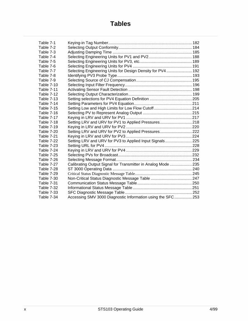
Tables
Table 7-1 Keying-in Tag Number...........................................................................182Table 7-2 Selecting Output Conformity..................................................................184Table 7-3 Adjusting Damping Time .......................................................................185Table 7-4 Selecting Engineering Units for PV1 and PV2.......................................188Table 7-5 Selecting Engineering Units for PV3, etc...............................................189Table 7-6 Selecting Engineering Units for PV4 .....................................................191Table 7-7 Selecting Engineering Units for Design Density for PV4 .......................192Table 7-8 Identifying PV3 Probe Type...................................................................193Table 7-9 Selecting Source of CJ Compensation..................................................195Table 7-10 Selecting Input Filter Frequency............................................................196Table 7-11 Activating Sensor Fault Detection .........................................................198Table 7-12 Selecting Output Characterization.........................................................199Table 7-13 Setting selections for PV4 Equation Definition ......................................205Table 7-14 Setting Parameters for PV4 Equation....................................................211Table 7-15 Setting Low and High Limits for Low Flow Cutoff ..................................214Table 7-16 Selecting PV to Represent Analog Output ............................................215Table 7-17 Keying in LRV and URV for PV1 ...........................................................217Table 7-18 Setting LRV and URV for PV1 to Applied Pressures.............................218Table 7-19 Keying in LRV and URV for PV2 ...........................................................220Table 7-20 Setting LRV and URV for PV2 to Applied Pressures.............................222Table 7-21 Keying in LRV and URV for PV3 ...........................................................224Table 7-22 Setting LRV and URV for PV3 to Applied Input Signals ........................225Table 7-23 Setting URL for PV4 ..............................................................................228Table 7-24 Keying in LRV and URV for PV4 ...........................................................229Table 7-25 Selecting PVs for Broadcast..................................................................232Table 7-26 Selecting Message Format....................................................................234Table 7-27 Calibrating Output Signal for Transmitter in Analog Mode ....................235Table 7-28 ST 3000 Operating Data .......................................................................240Table 7-29 Critical Status Diagnostic Message Table...................................................245Table 7-30 Non-Critical Status Diagnostic Message Table .....................................247Table 7-31 Communication Status Message Table.................................................250Table 7-32 Informational Status Message Table .....................................................251Table 7-33 SFC Diagnostic Message Table ............................................................252Table 7-34 Accessing SMV 3000 Diagnostic Information using the SFC................253
4/99 STS103 Operating Guide xi
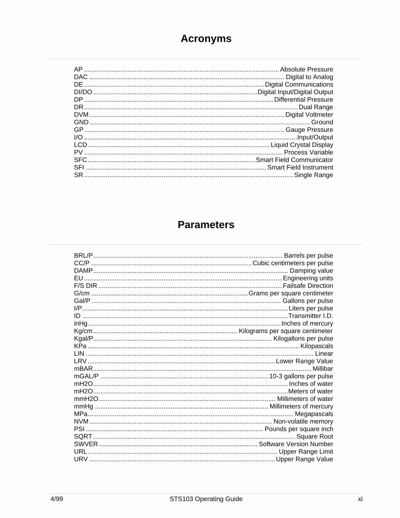
Acronyms
AP ............................................................................................................ Absolute PressureDAC ............................................................................................................ Digital to AnalogDE ....................................................................................................Digital CommunicationsDI/DO ...........................................................................................Digital Input/Digital OutputDP .........................................................................................................Differential PressureDR...................................................................................................................... Dual RangeDVM ............................................................................................................ Digital VoltmeterGND .......................................................................................................................... GroundGP............................................................................................................... Gauge PressureI/O ......................................................................................................................Input/OutputLCD.....................................................................................................Liquid Crystal DisplayPV .............................................................................................................. Process VariableSFC.............................................................................................Smart Field CommunicatorSFI .................................................................................................... Smart Field InstrumentSR ....................................................................................................................Single Range
Parameters
BRL/P......................................................................................................... Barrels per pulseCC/P .........................................................................................Cubic centimeters per pulseDAMP............................................................................................................ Damping valueEU ..............................................................................................................Engineering unitsF/S DIR ......................................................................................................Failsafe DirectionG/cm .......................................................................................Grams per square centimeterGal/P ......................................................................................................... Gallons per pulseI/P..................................................................................................................Liters per pulseID ..................................................................................................................Transmitter I.D.inHg........................................................................................................... Inches of mercuryKg/cm................................................................................ Kilograms per square centimeterKgal/P................................................................................................... Kilogallons per pulseKPa ..................................................................................................................... KilopascalsLIN .............................................................................................................................. LinearLRV ........................................................................................................Lower Range ValuemBAR......................................................................................................................... MillibarmGAL/P ............................................................................................. 10-3 gallons per pulsemH2O............................................................................................................ Inches of watermH2O............................................................................................................Meters of watermmH2O.................................................................................................. Millimeters of watermmHg ................................................................................................ Millimeters of mercuryMPa.................................................................................................................. MegapascalsNVM ..................................................................................................... Non-volatile memoryPSI .................................................................................................. Pounds per square inchSQRT ................................................................................................................ Square RootSWVER........................................................................................ Software Version NumberURL......................................................................................................... Upper Range LimitURV .......................................................................................................Upper Range Value
xii STS103 Operating Guide 4/99
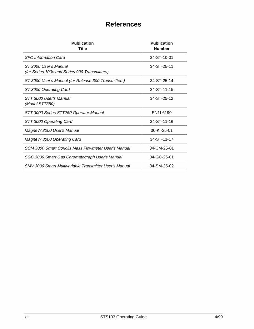
References
PublicationTitle
PublicationNumber
SFC Information Card 34-ST-10-01
ST 3000 User’s Manual(for Series 100e and Series 900 Transmitters)
34-ST-25-11
ST 3000 User’s Manual (for Release 300 Transmitters) 34-ST-25-14
ST 3000 Operating Card 34-ST-11-15
STT 3000 User’s Manual(Model STT350)
34-ST-25-12
STT 3000 Series STT250 Operator Manual EN1I-6190
STT 3000 Operating Card 34-ST-11-16
MagneW 3000 User’s Manual 36-KI-25-01
MagneW 3000 Operating Card 34-ST-11-17
SCM 3000 Smart Coriolis Mass Flowmeter User’s Manual 34-CM-25-01
SGC 3000 Smart Gas Chromatograph User’s Manual 34-GC-25-01
SMV 3000 Smart Multivariable Transmitter User’s Manual 34-SM-25-02
4/99 STS103 Operating Guide 1
Section 1 —Smart Field Communicator STS103 Overview
1.1 Introduction
Function The hand-held Smart Field Communicator(SFC), Model STS103 is abattery-powered device which establishes two-way communicationsbetween Honeywell’s Smart Field Instruments (SFIs) and an operator overthe existing SFI signal lines. The operator can send data to and receivedata from the SFI’s microprocessor, through the STS103, when connectedto the SFI’s signal lines at any accessible location from the control roomto the Smart Field Instrument.
Smart FieldInstruments (SFIs)
There are many current SFIs with which the STS103 communicates. TheSTS103 is designed for expansion and will be used with other new SFIs asthey become available. The current Honeywell smart field instrumentswith which the STS103 may be used are listed below.• Smart Pressure Transmitter ST 3000,• Smart Temperature Transmitter STT 3000,• Magnetic Mass Flowmeter MagneW 3000,• Smart Coriolis Mass Flowmeter SCM 3000,• Smart Gas Chromatograph SGC 3000, and• Smart Multivariable Transmitter SMV 3000.
ATTENTION The specific instructions for using the SFC with SCM 3000, and SGC3000 are contained in User’s Manual for that specific instrument.
Operation You can use the STS103 to• Select the Communications Mode – Command the SFI to transmit its
output signal in either an Analog (4-20 mA) mode or in the DigitalCommunications (DE) mode.
• Configure – Enter the desired operating parameters (For example:LRV, URV, Damping, Failsafe Mode, Configuration Parameters) intothe Smart Field Instrument.
• Diagnose – Access the SFI self-diagnostic capabilities to troubleshootsuspected operation or communication problems.
• Calibrate – The SFC provides a simplified procedure for calibratingSmart Field Instruments, thus maintaining excellent accuracy withsignificantly reduced maintenance requirements.
• Display – Readout all the configured operating parameters from theSFI as well as other data such as PROM Serial Number, Device ID,Scratch pad memory, Sensor Temperature, Input values in selectedEngineering Units, and others.
Continued on next page
2 STS103 Operating Guide 4/99
1.1 Introduction, Continued
Operation, continued • Checkout – Put the SFI in the Output mode and command the SFI totransmit a precise signal, selectable from 0% to 100% full scale, to assistyou in verifying loop operation, loop calibration, or troubleshooting.
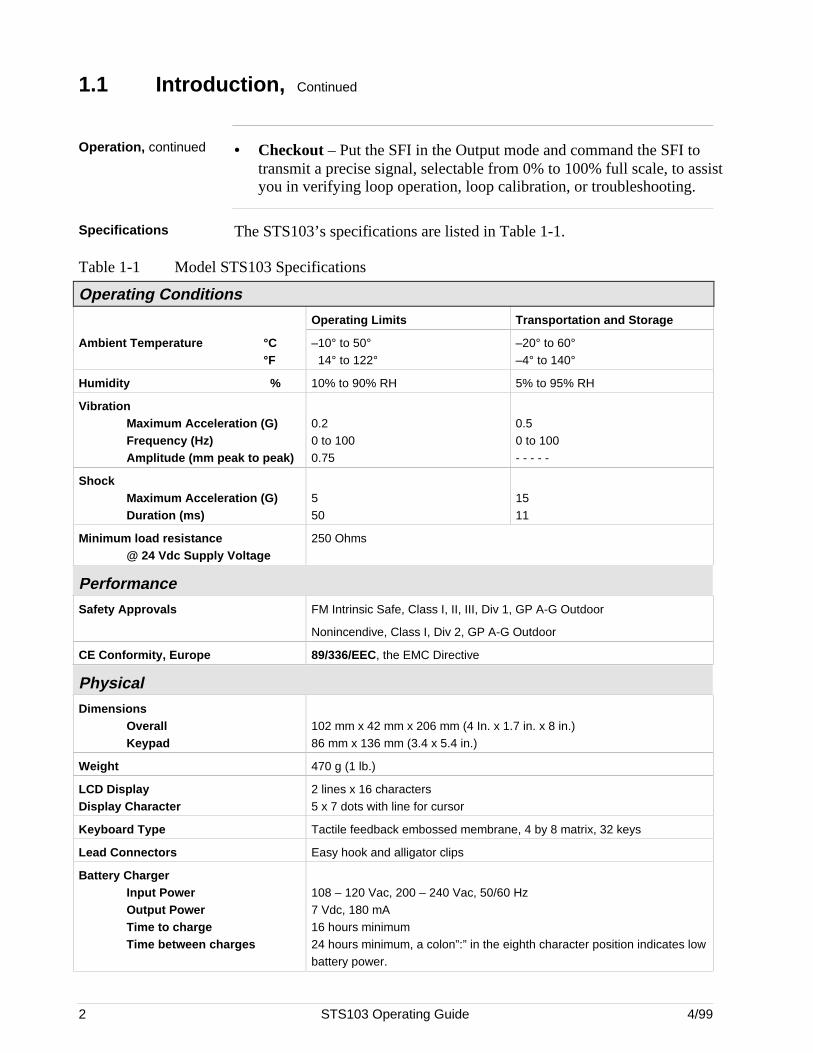
Specifications The STS103’s specifications are listed in Table 1-1.
Table 1-1 Model STS103 Specifications
Operating Conditions
Operating Limits Transportation and Storage
Ambient Temperature °C°F
–10° to 50° 14° to 122°
–20° to 60°–4° to 140°
Humidity % 10% to 90% RH 5% to 95% RH
VibrationMaximum Acceleration (G)Frequency (Hz)Amplitude (mm peak to peak)
0.20 to 1000.75
0.50 to 100- - - - -
ShockMaximum Acceleration (G)Duration (ms)
550
1511
Minimum load resistance@ 24 Vdc Supply Voltage
250 Ohms
Performance
Safety Approvals FM Intrinsic Safe, Class I, II, III, Div 1, GP A-G Outdoor
Nonincendive, Class I, Div 2, GP A-G Outdoor
CE Conformity, Europe 89/336/EEC, the EMC Directive
Physical
DimensionsOverallKeypad
102 mm x 42 mm x 206 mm (4 In. x 1.7 in. x 8 in.)86 mm x 136 mm (3.4 x 5.4 in.)
Weight 470 g (1 lb.)
LCD DisplayDisplay Character
2 lines x 16 characters5 x 7 dots with line for cursor
Keyboard Type Tactile feedback embossed membrane, 4 by 8 matrix, 32 keys
Lead Connectors Easy hook and alligator clips
Battery ChargerInput PowerOutput PowerTime to chargeTime between charges
108 – 120 Vac, 200 – 240 Vac, 50/60 Hz7 Vdc, 180 mA16 hours minimum24 hours minimum, a colon”:” in the eighth character position indicates lowbattery power.
4/99 STS103 Operating Guide 3
1.2 STS103 Physical and Functional Description
STS103 physicaldescription
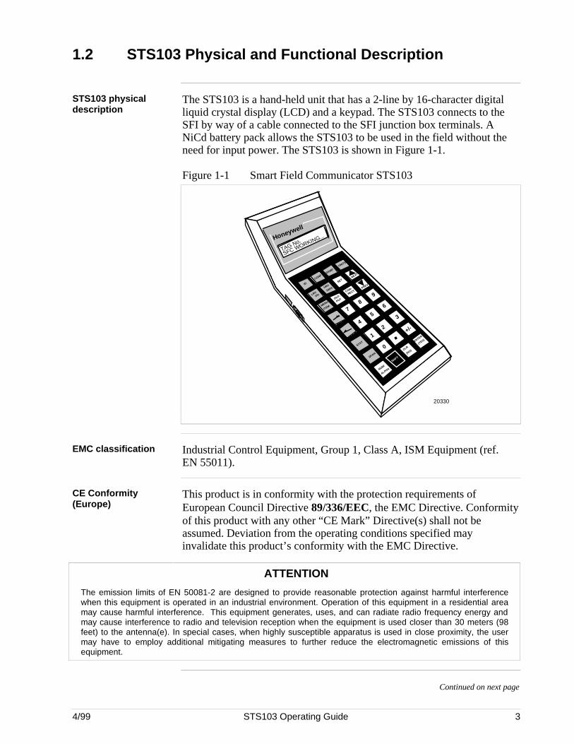
The STS103 is a hand-held unit that has a 2-line by 16-character digitalliquid crystal display (LCD) and a keypad. The STS103 connects to theSFI by way of a cable connected to the SFI junction box terminals. ANiCd battery pack allows the STS103 to be used in the field without theneed for input power. The STS103 is shown in Figure 1-1.
Figure 1-1 Smart Field Communicator STS103
TAG No.
ENTER
(YES)
CLR
(NO)
SHIFT
NUM/
ALPHA
SPAN
STAT
MENU
ITEM
LRV
0%
IDSET
DAMP
UNITS
URV
100%
OUT-
PUT
COR-
RECTPREV
NEXT
78
9
6
3
+/-
54
12
0
.
CONF
SFC WORKING...Honeywell
20330
EMC classification Industrial Control Equipment, Group 1, Class A, ISM Equipment (ref.EN 55011).
CE Conformity(Europe)
This product is in conformity with the protection requirements ofEuropean Council Directive 89/336/EEC, the EMC Directive. Conformityof this product with any other “CE Mark” Directive(s) shall not beassumed. Deviation from the operating conditions specified mayinvalidate this product’s conformity with the EMC Directive.
ATTENTION
The emission limits of EN 50081-2 are designed to provide reasonable protection against harmful interferencewhen this equipment is operated in an industrial environment. Operation of this equipment in a residential areamay cause harmful interference. This equipment generates, uses, and can radiate radio frequency energy andmay cause interference to radio and television reception when the equipment is used closer than 30 meters (98feet) to the antenna(e). In special cases, when highly susceptible apparatus is used in close proximity, the usermay have to employ additional mitigating measures to further reduce the electromagnetic emissions of thisequipment.
Continued on next page
4 STS103 Operating Guide 4/99
1.2 STS103 Physical and Functional Description, Continued
2-line by 16-characterLCD display
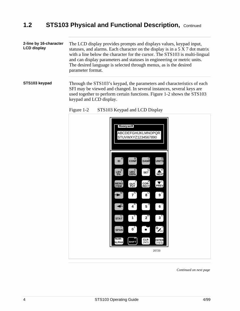
The LCD display provides prompts and displays values, keypad input,statuses, and alarms. Each character on the display is in a 5 X 7 dot matrixwith a line below the character for the cursor. The STS103 is multi-lingualand can display parameters and statuses in engineering or metric units.The desired language is selected through menus, as is the desiredparameter format.
STS103 keypad Through the STS103’s keypad, the parameters and characteristics of eachSFI may be viewed and changed. In several instances, several keys areused together to perform certain functions. Figure 1-2 shows the STS103keypad and LCD display.
Figure 1-2 STS103 Keypad and LCD Display
+–
DE READA B C D
E F G H
I J K L
M N O P
Q R S T
U V W X
Y Z
NON-VOL
ID DAMP UNITS
LRV URV SET
MENU OUT- COR-
7 8 9
5 64
1 2 3
0SPAN
STAT
NUM / ALPHA SHIFT
CLR ENTER
INPUT
URL
CONF
DE CONF RESET
A <–> DE
F/S DIR
SCR PAD
SW VER
NEXT
PREVPUT RECTITEM
(YES)(NO)
0% 100%
ABCDEFGHIJKLMNOPQRSTUVWXYZ012345
L
20720
ABCDEFGHIJKLMNOPQRSTUVWXYZ1234567890
Continued on next page
4/99 STS103 Operating Guide 5
1.2 STS103 Physical and Functional Description, Continued
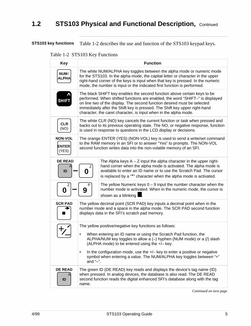
STS103 key functions Table 1-2 describes the use and function of the STS103 keypad keys.
Table 1-2 STS103 Key Functions
Key Function
NUM / ALPHA
The white NUM/ALPHA key toggles between the alpha mode or numeric modefor the STS103. In the alpha mode, the capital letter or character in the upperright-hand corner of the keys is input when that key is pressed. In the numericmode, the number is input or the indicated first function is performed.
SSSSSHHHHHIIIIIFFFFFTTTTT ^ The black SHIFT key enables the second function above certain keys to be
performed. When shifted functions are enabled, the word “SHIFT–” is displayedon line two of the display. The second function desired must be selectedimmediately after the Shift key is pressed. The Shift key upper right-handcharacter, the caret character, is input when in the alpha mode.
CLR (NO)
The white CLR (NO) key cancels the current function or task when pressed andbacks out to its previous operating state. The NO, or negative response, functionis used in response to questions in the LCD display or decisions.
NON-VOL
ENTER (YES)
The orange ENTER (YES) (NON-VOL) key is used to send a write/set commandto the RAM memory in an SFI or to answer “Yes” to prompts. The NON-VOLsecond function writes data into the non-volatile memory of an SFI.
Z
0
DE READA
ID
The Alpha keys A – Z input the alpha character in the upper right-hand corner when the alpha mode is activated. The alpha mode isavailable to enter an ID name or to use the Scratch Pad. The cursoris replaced by a “*” character when the alpha mode is activated.
Z
0P
9The yellow Numeric keys 0 – 9 input the number character when thenumber mode is activated. When in the numeric mode, the cursor is
shown as a blinking .
SCR PAD The yellow decimal point (SCR PAD) key inputs a decimal point when in thenumber mode and a space in the alpha mode. The SCR PAD second functiondisplays data in the SFI’s scratch pad memory.
+–The yellow positive/negative key functions as follows:
• When entering an ID name or using the Scratch Pad function, theALPHA/NUM key toggles to allow a (–) hyphen (NUM mode) or a (/) slash(ALPHA mode) to be entered using the +/– key.
• In the configuration mode, use the +/– key to enter a positive or negativesymbol when entering a value. The NUM/ALPHA key toggles between “+”and “–”.
DE READA
ID
The green ID (DE READ) key reads and displays the device’s tag name (ID)when pressed. In analog devices, the database is also read. The DE READsecond function reads the digital enhanced SFI’s database along with the tagname.
Continued on next page
6 STS103 Operating Guide 4/99
1.2 STS103 Physical and Functional Description, Continued
Key functions,continued
Table 1-2 STS103 Key Functions (Continued)
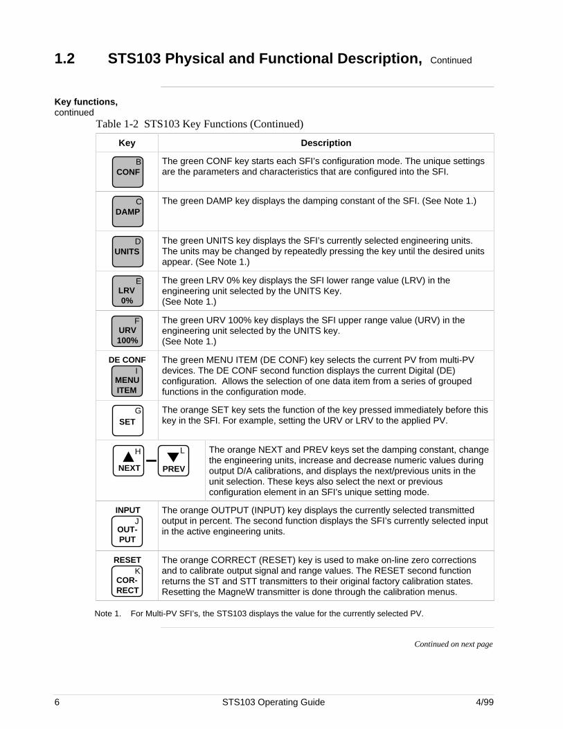
Key Description
BCONF
The green CONF key starts each SFI’s configuration mode. The unique settingsare the parameters and characteristics that are configured into the SFI.
CDAMP
The green DAMP key displays the damping constant of the SFI. (See Note 1.)
DUNITS
The green UNITS key displays the SFI’s currently selected engineering units.The units may be changed by repeatedly pressing the key until the desired unitsappear. (See Note 1.)
ELRV 0%
The green LRV 0% key displays the SFI lower range value (LRV) in theengineering unit selected by the UNITS Key.(See Note 1.)
FURV 100%
The green URV 100% key displays the SFI upper range value (URV) in theengineering unit selected by the UNITS key.(See Note 1.)
IMENU ITEM
DE CONF The green MENU ITEM (DE CONF) key selects the current PV from multi-PVdevices. The DE CONF second function displays the current Digital (DE)configuration. Allows the selection of one data item from a series of groupedfunctions in the configuration mode.
GSET
The orange SET key sets the function of the key pressed immediately before thiskey in the SFI. For example, setting the URV or LRV to the applied PV.
H
NEXT
L
PREV
The orange NEXT and PREV keys set the damping constant, changethe engineering units, increase and decrease numeric values duringoutput D/A calibrations, and displays the next/previous units in theunit selection. These keys also select the next or previousconfiguration element in an SFI’s unique setting mode.
JOUT- PUT
INPUT The orange OUTPUT (INPUT) key displays the currently selected transmittedoutput in percent. The second function displays the SFI’s currently selected inputin the active engineering units.
KCOR- RECT
RESET The orange CORRECT (RESET) key is used to make on-line zero correctionsand to calibrate output signal and range values. The RESET second functionreturns the ST and STT transmitters to their original factory calibration states.Resetting the MagneW transmitter is done through the calibration menus.
Note 1. For Multi-PV SFI’s, the STS103 displays the value for the currently selected PV.
Continued on next page
4/99 STS103 Operating Guide 7
1.2 STS103 Physical and Functional Description, Continued
Key functions,continued
Table 1-2 STS103 Key Functions (Continued)
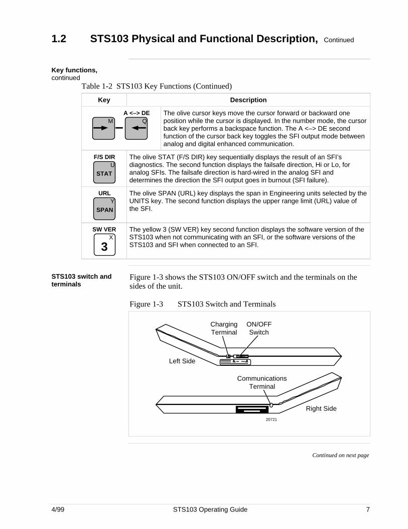
Key Description
M QA <–> DE The olive cursor keys move the cursor forward or backward one
position while the cursor is displayed. In the number mode, the cursorback key performs a backspace function. The A <–> DE secondfunction of the cursor back key toggles the SFI output mode betweenanalog and digital enhanced communication.
USTAT
F/S DIR The olive STAT (F/S DIR) key sequentially displays the result of an SFI’sdiagnostics. The second function displays the failsafe direction, Hi or Lo, foranalog SFIs. The failsafe direction is hard-wired in the analog SFI anddetermines the direction the SFI output goes in burnout (SFI failure).
YSPAN
URL The olive SPAN (URL) key displays the span in Engineering units selected by theUNITS key. The second function displays the upper range limit (URL) value ofthe SFI.
X
3
SW VER The yellow 3 (SW VER) key second function displays the software version of theSTS103 when not communicating with an SFI, or the software versions of theSTS103 and SFI when connected to an SFI.
STS103 switch andterminals
Figure 1-3 shows the STS103 ON/OFF switch and the terminals on thesides of the unit.
Figure 1-3 STS103 Switch and Terminals
Charging Terminal
ON/OFF Switch
Communications Terminal
Left Side
Right Side
20721
Continued on next page
8 STS103 Operating Guide 4/99
1.2 STS103 Physical and Functional Description, Continued
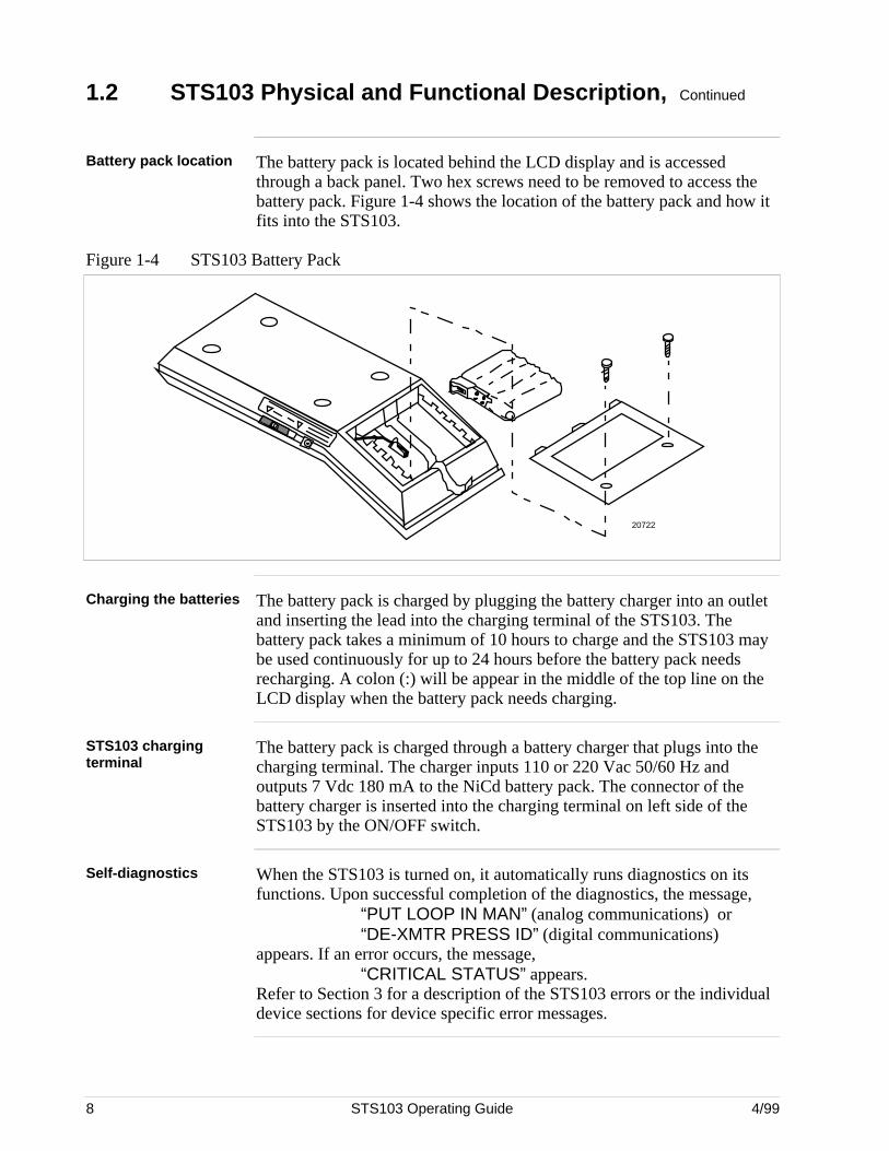
Battery pack location The battery pack is located behind the LCD display and is accessedthrough a back panel. Two hex screws need to be removed to access thebattery pack. Figure 1-4 shows the location of the battery pack and how itfits into the STS103.
Figure 1-4 STS103 Battery Pack
20722
Charging the batteries The battery pack is charged by plugging the battery charger into an outletand inserting the lead into the charging terminal of the STS103. Thebattery pack takes a minimum of 10 hours to charge and the STS103 maybe used continuously for up to 24 hours before the battery pack needsrecharging. A colon (:) will be appear in the middle of the top line on theLCD display when the battery pack needs charging.
STS103 chargingterminal
The battery pack is charged through a battery charger that plugs into thecharging terminal. The charger inputs 110 or 220 Vac 50/60 Hz andoutputs 7 Vdc 180 mA to the NiCd battery pack. The connector of thebattery charger is inserted into the charging terminal on left side of theSTS103 by the ON/OFF switch.
Self-diagnostics When the STS103 is turned on, it automatically runs diagnostics on itsfunctions. Upon successful completion of the diagnostics, the message,
“PUT LOOP IN MAN” (analog communications) or“DE-XMTR PRESS ID” (digital communications)
appears. If an error occurs, the message,“CRITICAL STATUS” appears.
Refer to Section 3 for a description of the STS103 errors or the individualdevice sections for device specific error messages.
4/99 STS103 Operating Guide 9
1.3 Connections
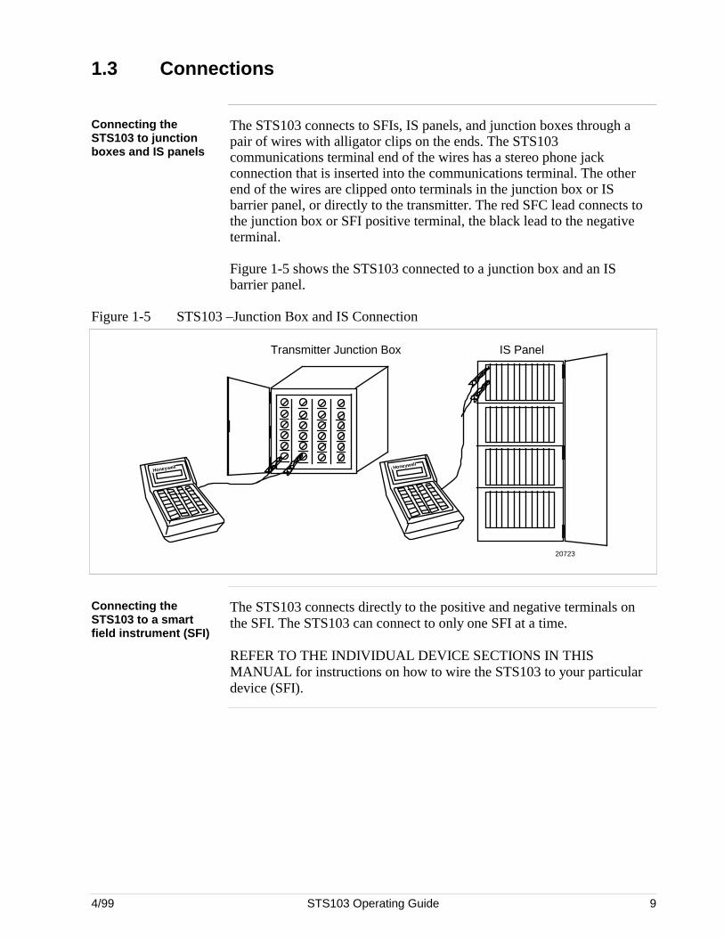
Connecting theSTS103 to junctionboxes and IS panels
The STS103 connects to SFIs, IS panels, and junction boxes through apair of wires with alligator clips on the ends. The STS103communications terminal end of the wires has a stereo phone jackconnection that is inserted into the communications terminal. The otherend of the wires are clipped onto terminals in the junction box or ISbarrier panel, or directly to the transmitter. The red SFC lead connects tothe junction box or SFI positive terminal, the black lead to the negativeterminal.
Figure 1-5 shows the STS103 connected to a junction box and an ISbarrier panel.
Figure 1-5 STS103 –Junction Box and IS Connection
Honeywell
Transmitter Junction Box IS Panel
20723
Honeywell
Connecting theSTS103 to a smartfield instrument (SFI)
The STS103 connects directly to the positive and negative terminals onthe SFI. The STS103 can connect to only one SFI at a time.
REFER TO THE INDIVIDUAL DEVICE SECTIONS IN THISMANUAL for instructions on how to wire the STS103 to your particulardevice (SFI).
10 STS103 Operating Guide 4/99
1.4 STS103/SFI Communication
How data istransferred
Sending and receiving data to and from an SFI is done over thetransmitter’s 4-20 mA wires. When the STS103 is connected to atransmitter and turned on, it automatically determines what type oftransmitter it is communicating with. When data is sent to a transmitter, arequest is sent to the transmitter and a response is sent back to theSTS103. When the STS103 and SFI are communicating, the message“SFC Working...” is displayed on the STS103.
Types ofcommunication
The message handling routines are transparent to you. The way the requestand response messages are handled depend on whether the transmitter isan analog only model or an analog/digital model, and the modeconfiguration.
Analog communications uses half duplex communication (data can besent in one direction at a time, to the transmitter or to the STS103) whilethe digital communication uses half duplex with or without broadcast (4 or6 bytes). Table 1-3 describes the communication formats used.
Table 1-3 Communication Format Description
Format Description
AnalogCommunicationMode
DE READ
AID
Analog communication uses a half-duplex , variable-lengthmessage with a wake-up pulse for on-demand requests andresponses. While the messages travel back and forth, thetransmitter’s output varies between 4-20 mA, therefore, thecontrol loop must be in manual so the data exchange doesnot interfere with the control loop.
Digital (DE)CommunicationMode
SSSSSHHHHHIIIIIFFFFFTTTTT ^
DE READ
AID
Digital communication also uses a half-duplex , variable-length message with no wake-up pulse for on-demandrequests and responses (not including data uploads). Thedata is piggybacked on the process variable data being senton the control loop.
The broadcast 4-byte format is rarely used because nodatabase protection can be performed when used in theTDC 3000 system. This mode is only used when faster PVupdate rates are required. One byte is for transmitter statusand configuration data; the other three are for process data.
The broadcast 6-byte format is used for uploading thetransmitter’s database to the STS103’s hold memory. Thebytes are similar to the 4-byte format, but it includes twoadditional bytes of transmitter database information.
Continued on next page
4/99 STS103 Operating Guide 11
1.4 STS103/SFI Communication, Continued
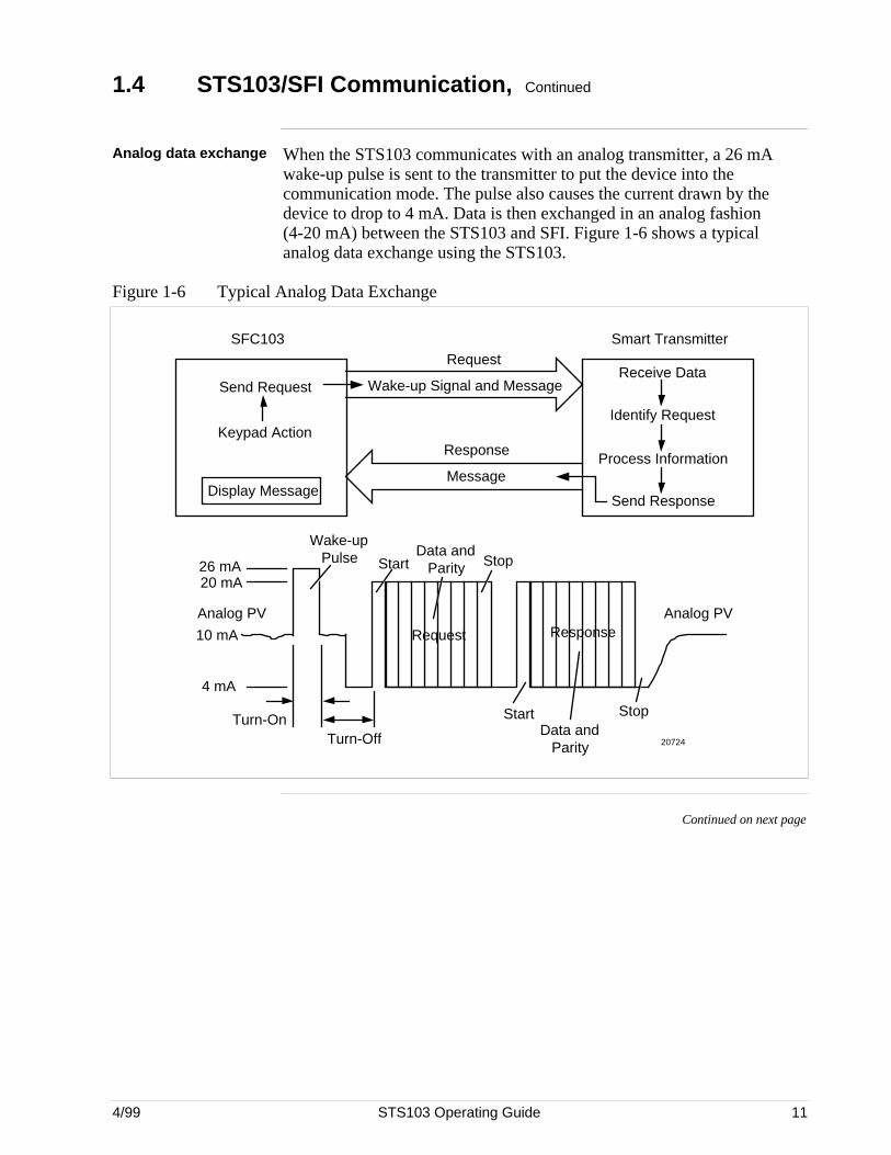
Analog data exchange When the STS103 communicates with an analog transmitter, a 26 mAwake-up pulse is sent to the transmitter to put the device into thecommunication mode. The pulse also causes the current drawn by thedevice to drop to 4 mA. Data is then exchanged in an analog fashion(4-20 mA) between the STS103 and SFI. Figure 1-6 shows a typicalanalog data exchange using the STS103.
Figure 1-6 Typical Analog Data Exchange
SFC103 Smart Transmitter
Wake-up Signal and Message
RequestReceive Data
Identify Request
Process Information
Send Response
Response
MessageDisplay Message
Send Request
Keypad Action
Request Response
26 mA20 mA
4 mA
10 mA
Wake-up Pulse Start
Data and Parity Stop
Analog PV
Turn-OnTurn-Off
Analog PV
StartData and
Parity
Stop
20724
Continued on next page
12 STS103 Operating Guide 4/99
1.4 STS103/SFI Communication, Continued
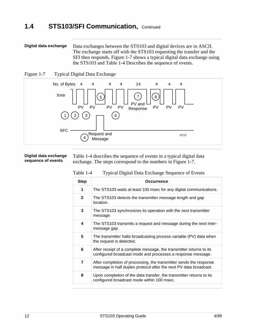
Digital data exchange Data exchanges between the STS103 and digital devices are in ASCII.The exchange starts off with the STS103 requesting the transfer and theSFI then responds. Figure 1-7 shows a typical digital data exchange usingthe STS103 and Table 1-4 Describes the sequence of events.
Figure 1-7 Typical Digital Data Exchange
Xmtr
SFC
No. of Bytes 4 4 4 4 14 4 4 4
PV PV PV PVPV and
PV PV PVResponse
Request and Message
1 2 3
4
5
6
7 8
20725
Digital data exchangesequence of events
Table 1-4 describes the sequence of events in a typical digital dataexchange. The steps correspond to the numbers in Figure 1-7.
Table 1-4 Typical Digital Data Exchange Sequence of Events
Step Occurrence
1 The STS103 waits at least 100 msec for any digital communications.
2 The STS103 detects the transmitter message length and gaplocation.
3 The STS103 synchronizes its operation with the next transmittermessage.
4 The STS103 transmits a request and message during the next inter-message gap.
5 The transmitter halts broadcasting process variable (PV) data whenthe request is detected.
6 After receipt of a complete message, the transmitter returns to itsconfigured broadcast mode and processes a response message.
7 After completion of processing, the transmitter sends the responsemessage in half duplex protocol after the next PV data broadcast.
8 Upon completion of the data transfer, the transmitter returns to itsconfigured broadcast mode within 100 msec.
4/99 STS103 Operating Guide 13
Section 2 —STS103 User Interface Guidelines
1.2 STS103 Overview
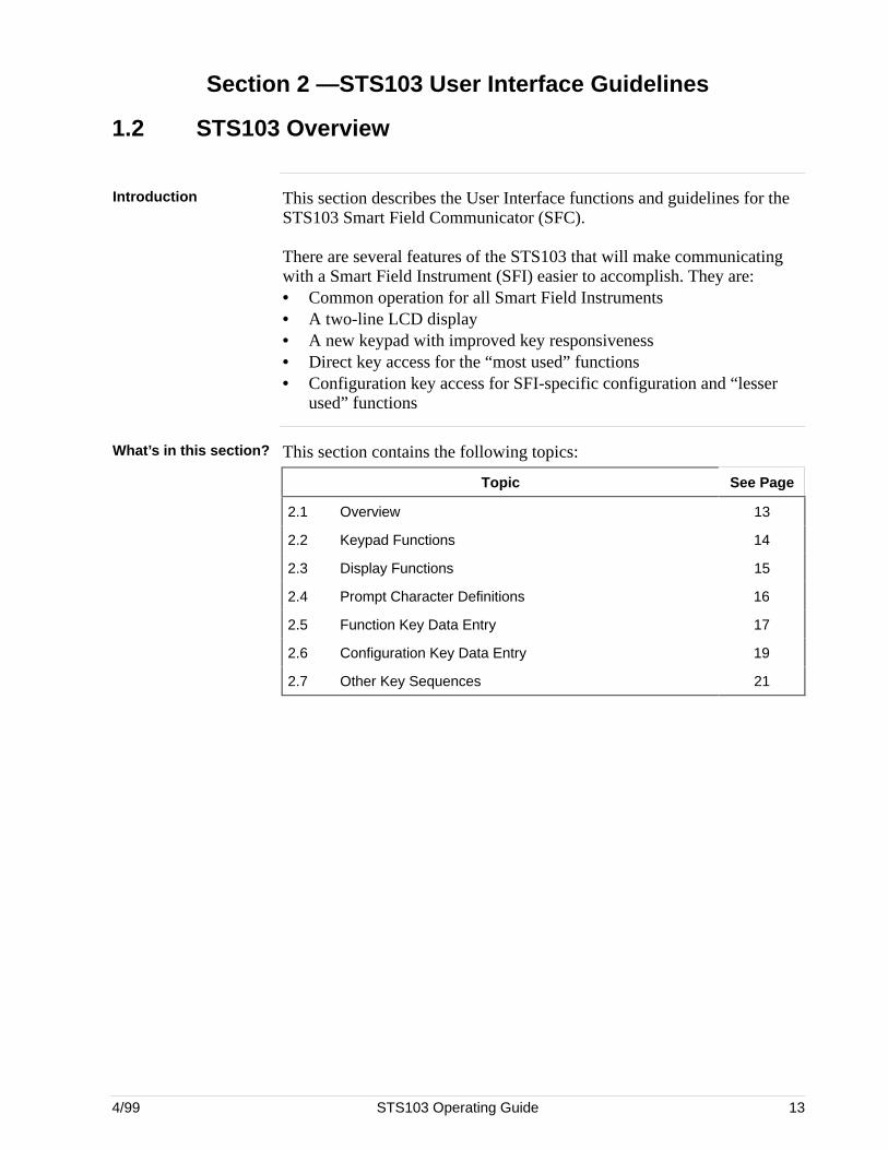
Introduction This section describes the User Interface functions and guidelines for theSTS103 Smart Field Communicator (SFC).
There are several features of the STS103 that will make communicatingwith a Smart Field Instrument (SFI) easier to accomplish. They are:• Common operation for all Smart Field Instruments• A two-line LCD display• A new keypad with improved key responsiveness• Direct key access for the “most used” functions• Configuration key access for SFI-specific configuration and “lesser
used” functions
What’s in this section? This section contains the following topics:
Topic See Page
2.1 Overview 13
2.2 Keypad Functions 14
2.3 Display Functions 15
2.4 Prompt Character Definitions 16
2.5 Function Key Data Entry 17
2.6 Configuration Key Data Entry 19
2.7 Other Key Sequences 21
14 STS103 Operating Guide 4/99
2.2 Keypad Functions
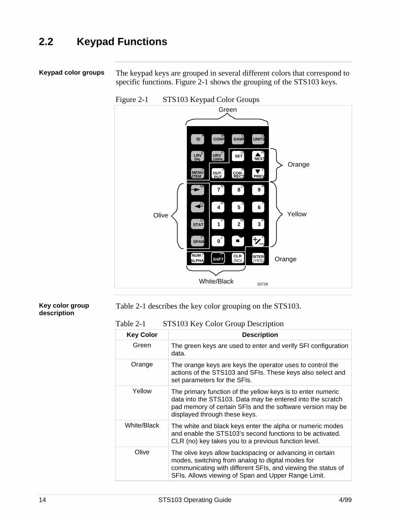
Keypad color groups The keypad keys are grouped in several different colors that correspond tospecific functions. Figure 2-1 shows the grouping of the STS103 keys.
Figure 2-1 STS103 Keypad Color Groups
+–
DE READA B C D
E F G H
I J K L
M N O P
Q R S T
U V W X
Y Z
NON-VOL
ID DAMP UNITS
LRV URV SET
MENU OUT- COR-
7 8 9
5 64
1 2 3
0SPAN
STAT
NUM / ALPHA SHIFT
CLR ENTER
INPUT
URL
CONF
DE CONF RESET
A <–> DE
F/S DIR
SCR PAD
SW VER
NEXT
PREVPUT RECTITEM
(YES)(NO)
0% 100%
Green
Orange
Yellow
White/Black
Olive
Orange
20726
Key color groupdescription
Table 2-1 describes the key color grouping on the STS103.
Table 2-1 STS103 Key Color Group DescriptionKey Color Description
Green The green keys are used to enter and verify SFI configurationdata.
Orange The orange keys are keys the operator uses to control theactions of the STS103 and SFIs. These keys also select andset parameters for the SFIs.
Yellow The primary function of the yellow keys is to enter numericdata into the STS103. Data may be entered into the scratchpad memory of certain SFIs and the software version may bedisplayed through these keys.
White/Black The white and black keys enter the alpha or numeric modesand enable the STS103’s second functions to be activated.CLR (no) key takes you to a previous function level.
Olive The olive keys allow backspacing or advancing in certainmodes, switching from analog to digital modes forcommunicating with different SFIs, and viewing the status ofSFIs. Allows viewing of Span and Upper Range Limit.
4/99 STS103 Operating Guide 15
2.3 Display Functions
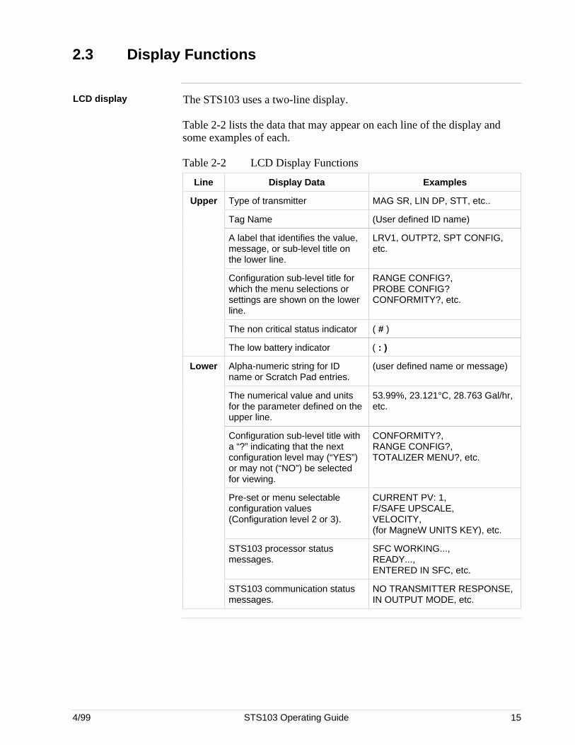
LCD display The STS103 uses a two-line display.
Table 2-2 lists the data that may appear on each line of the display andsome examples of each.
Table 2-2 LCD Display Functions
Line Display Data Examples
Upper Type of transmitter MAG SR, LIN DP, STT, etc..
Tag Name (User defined ID name)
A label that identifies the value,message, or sub-level title onthe lower line.
LRV1, OUTPT2, SPT CONFIG,etc.
Configuration sub-level title forwhich the menu selections orsettings are shown on the lowerline.
RANGE CONFIG?,PROBE CONFIG?CONFORMITY?, etc.
The non critical status indicator ( # )
The low battery indicator ( : )
Lower Alpha-numeric string for IDname or Scratch Pad entries.
(user defined name or message)
The numerical value and unitsfor the parameter defined on theupper line.
53.99%, 23.121°C, 28.763 Gal/hr,etc.
Configuration sub-level title witha “?” indicating that the nextconfiguration level may (“YES”)or may not (“NO”) be selectedfor viewing.
CONFORMITY?,RANGE CONFIG?,TOTALIZER MENU?, etc.
Pre-set or menu selectableconfiguration values(Configuration level 2 or 3).
CURRENT PV: 1,F/SAFE UPSCALE,VELOCITY,(for MagneW UNITS KEY), etc.
STS103 processor statusmessages.
SFC WORKING...,READY...,ENTERED IN SFC, etc.
STS103 communication statusmessages.
NO TRANSMITTER RESPONSE,IN OUTPUT MODE, etc.
16 STS103 Operating Guide 4/99
2.4 Prompt Character Definitions
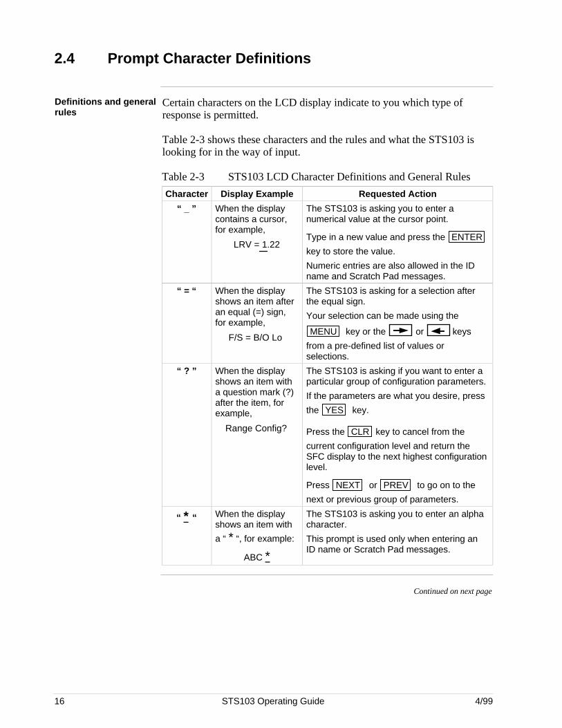
Definitions and generalrules
Certain characters on the LCD display indicate to you which type ofresponse is permitted.
Table 2-3 shows these characters and the rules and what the STS103 islooking for in the way of input.
Table 2-3 STS103 LCD Character Definitions and General Rules
Character Display Example Requested Action
“ _ ” When the displaycontains a cursor,for example,
LRV = 1.22
The STS103 is asking you to enter anumerical value at the cursor point.
Type in a new value and press the ENTER
key to store the value.
Numeric entries are also allowed in the IDname and Scratch Pad messages.
“ = “ When the displayshows an item afteran equal (=) sign,for example,
F/S = B/O Lo
The STS103 is asking for a selection afterthe equal sign.
Your selection can be made using the
MENU key or the or keys
from a pre-defined list of values orselections.
“ ? ” When the displayshows an item witha question mark (?)after the item, forexample,
Range Config?
The STS103 is asking if you want to enter aparticular group of configuration parameters.
If the parameters are what you desire, press
the YES key.
Press the CLR key to cancel from the
current configuration level and return theSFC display to the next highest configurationlevel.
Press NEXT or PREV to go on to the
next or previous group of parameters.
“ * “ When the displayshows an item with
a “ * “, for example:
ABC *
The STS103 is asking you to enter an alphacharacter.
This prompt is used only when entering anID name or Scratch Pad messages.
Continued on next page
4/99 STS103 Operating Guide 17
2.5 Function Keys Data Entry
Function keys To access the basic functions or parameters which are common to allSFIs, press any one of the labeled function keys. These common itemsare:
• ID
• SPAN/LRV/URV/URL
• INPUT/OUTPUT
• INPUT and OUTPUT CORRECTS
• LRV and URV CORRECTS and SETS
• RESET CORRECTS
• STATUS
• UNITS
• DAMPING
• FAILSAFE DIRECTION
• DE OPERATIONS
• SW VERSION
• SCRATCH PAD
Multiple processvariables
In some cases, more than one Process Variable is available. Press the
MENU key to select which PV will be referenced when the following
operating parameters are displayed:
• SPAN/LRV/URV/URL/LRL
• INPUT/OUTPUT
• DAMP
• UNITS
For example, consider an SFI that may analyze up to four components.
Each time the MENU key is pressed, the display will step through the
available Process Variables (PVs)-(CURRENT PV:1, CURRENT PV:2,CURRENT PV:3, CURRENT PV:4).
If PV:2 were selected and the SPAN key pressed, “SPAN 2” (the span
for input 2) would be displayed.
Continued on next page
18 STS103 Operating Guide 4/99
2.5 Function Keys Data Entry, Continued
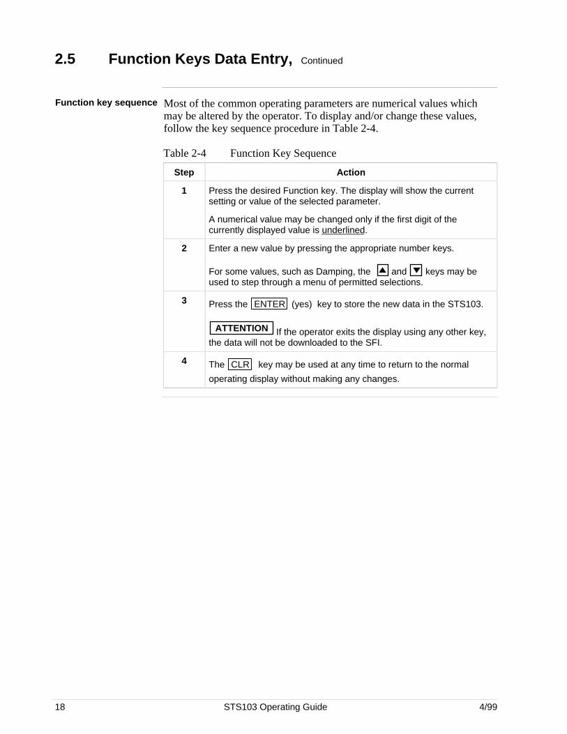
Function key sequence Most of the common operating parameters are numerical values whichmay be altered by the operator. To display and/or change these values,follow the key sequence procedure in Table 2-4.
Table 2-4 Function Key Sequence
Step Action
1 Press the desired Function key. The display will show the currentsetting or value of the selected parameter.
A numerical value may be changed only if the first digit of thecurrently displayed value is underlined.
2 Enter a new value by pressing the appropriate number keys.
For some values, such as Damping, the and keys may beused to step through a menu of permitted selections.
3 Press the ENTER (yes) key to store the new data in the STS103.
ATTENTION If the operator exits the display using any other key,the data will not be downloaded to the SFI.
4 The CLR key may be used at any time to return to the normal
operating display without making any changes.
4/99 STS103 Operating Guide 19
2.6 Configuration Key Data Entry
Configuration key Press the CONF key to access SFI-specific configuration menus. SFI
configuration is divided into two or three levels.
• Level 1 – contains a list of configuration categories which is uniqueto each SFI.
• Level 2 – contains a list of configuration parameters for each of thelevel 1 categories (two level configuration), ora sub-level of categories which pertains to the level 1categories (three level configuration).
• Level 3 – contains a list of configuration parameters for each of thelevel 2 categories.
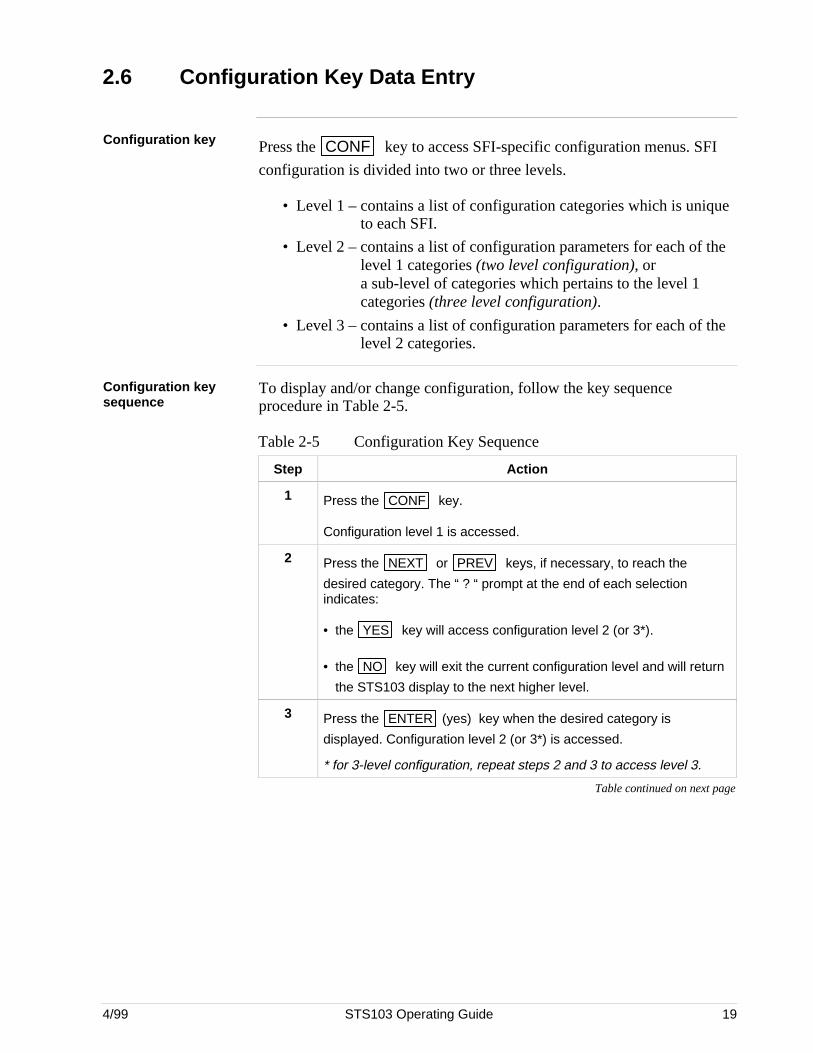
Configuration keysequence
To display and/or change configuration, follow the key sequenceprocedure in Table 2-5.
Table 2-5 Configuration Key Sequence
Step Action
1 Press the CONF key.
Configuration level 1 is accessed.
2 Press the NEXT or PREV keys, if necessary, to reach the
desired category. The “ ? “ prompt at the end of each selectionindicates:
• the YES key will access configuration level 2 (or 3*).
• the NO key will exit the current configuration level and will return
the STS103 display to the next higher level.
3 Press the ENTER (yes) key when the desired category is
displayed. Configuration level 2 (or 3*) is accessed.
* for 3-level configuration, repeat steps 2 and 3 to access level 3.
Table continued on next page
20 STS103 Operating Guide 4/99
2.6 Configuration Key Data Entry, Continued
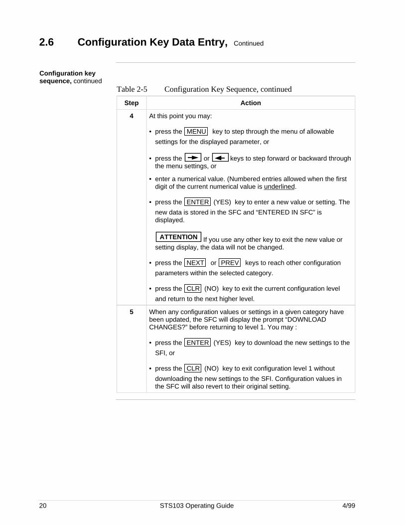
Configuration keysequence, continued
Table 2-5 Configuration Key Sequence, continued
Step Action
4 At this point you may:
• press the MENU key to step through the menu of allowable
settings for the displayed parameter, or
• press the or keys to step forward or backward throughthe menu settings, or
• enter a numerical value. (Numbered entries allowed when the firstdigit of the current numerical value is underlined.
• press the ENTER (YES) key to enter a new value or setting. The
new data is stored in the SFC and “ENTERED IN SFC” isdisplayed.
ATTENTION If you use any other key to exit the new value orsetting display, the data will not be changed.
• press the NEXT or PREV keys to reach other configuration
parameters within the selected category.
• press the CLR (NO) key to exit the current configuration level
and return to the next higher level.
5 When any configuration values or settings in a given category havebeen updated, the SFC will display the prompt “DOWNLOADCHANGES?” before returning to level 1. You may :
• press the ENTER (YES) key to download the new settings to the
SFI, or
• press the CLR (NO) key to exit configuration level 1 without
downloading the new settings to the SFI. Configuration values inthe SFC will also revert to their original setting.
4/99 STS103 Operating Guide 21
2.7 Other Key Sequences
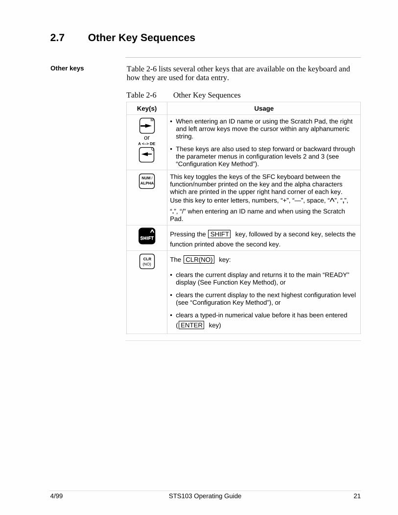
Other keys Table 2-6 lists several other keys that are available on the keyboard andhow they are used for data entry.
Table 2-6 Other Key Sequences
Key(s) Usage
M
or
QA <–> DE
• When entering an ID name or using the Scratch Pad, the rightand left arrow keys move the cursor within any alphanumericstring.
• These keys are also used to step forward or backward throughthe parameter menus in configuration levels 2 and 3 (see“Configuration Key Method”).
NUM / ALPHA
This key toggles the keys of the SFC keyboard between thefunction/number printed on the key and the alpha characterswhich are printed in the upper right hand corner of each key.Use this key to enter letters, numbers, “+”, “—”, space, “^”, “,”,
“.”, “/” when entering an ID name and when using the ScratchPad.
SSSSSHHHHHIIIIIFFFFFTTTTT ^ Pressing the SHIFT key, followed by a second key, selects the
function printed above the second key.
CLR (NO)
The CLR(NO) key:
• clears the current display and returns it to the main “READY”display (See Function Key Method), or
• clears the current display to the next highest configuration level(see “Configuration Key Method”), or
• clears a typed-in numerical value before it has been entered
( ENTER key)

22 STS103 Operating Guide 4/99
4/99 STS103 Operating Guide 23
Section 3 —STS103 Operation
3.1 Overview
This section contains all the information you will need to know in order tooperate the STS103 Smart Field Communicator with a Smart FieldInstrument.
Refer to the individual device User’s Manual for transmitter operating andinstallation information.
The STS103 operations given here are more or less the same for everySFI. See the individual device sections in this manual for operationsspecific to your particular SFI.
This section gives you the keystrokes and displays that are specific forSFC communications with the Smart Field Instruments.
What’s in this section? This section contains the following topics:
Topic See Page
3.1 Overview 23
3.2 Power up 24
3.3 Diagnostics and SFC Messages 25
3.4 Common Key Sequences and Displays 28
3.5 Using the Transmitter as a Current Source 43
3.6 Disconnecting the SFC 45
24 STS103 Operating Guide 4/99
3.2 Power Up
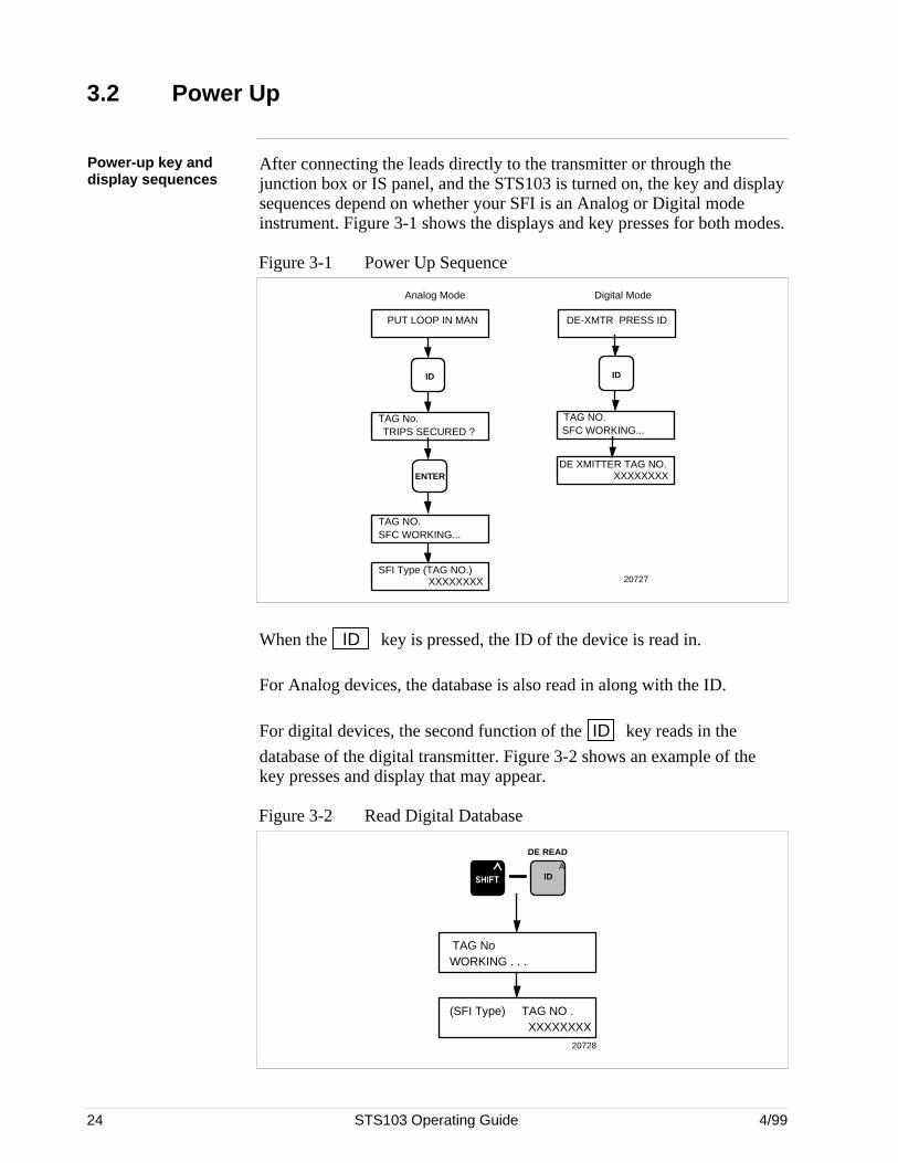
Power-up key anddisplay sequences
After connecting the leads directly to the transmitter or through thejunction box or IS panel, and the STS103 is turned on, the key and displaysequences depend on whether your SFI is an Analog or Digital modeinstrument. Figure 3-1 shows the displays and key presses for both modes.
Figure 3-1 Power Up Sequence
PUT LOOP IN MAN
Analog Mode Digital Mode
SFI Type (TAG NO.)XXXXXXXX
TAG NO.SFC WORKING...
TAG No.TRIPS SECURED ?
ID
ENTER
DE-XMTR PRESS ID
ID
TAG NO.SFC WORKING...
DE XMITTER TAG NO.XXXXXXXX
20727
When the ID key is pressed, the ID of the device is read in.
For Analog devices, the database is also read in along with the ID.
For digital devices, the second function of the ID key reads in the
database of the digital transmitter. Figure 3-2 shows an example of thekey presses and display that may appear.
Figure 3-2 Read Digital Database
DE READ
AID
(SFI Type) TAG NO .XXXXXXXX
TAG NoWORKING . . .
20728
4/99 STS103 Operating Guide 25
3.3 Diagnostics and SFC Messages
Introduction The STS103 and the SFIs both run continuous self-diagnostics.This means that they are constantly testing the communications, the loop,and themselves.
Any time you want results of these diagnostics, press the STAT key.
The SFC displays its report, in the form of messages, which identifydiagnostic conditions.Diagnostic conditions are broken down into three categories:
• an OK condition• a critical condition• a non-critical condition
OK Status An OK condition means no problem exists, and the display looks like this:
STATUS XXXXSTATUS CHECK=OK
Critical status A critical condition means that the SFI is not functioning properly. Whenthis occurs, the SFI goes into upscale burnout and maintains an output of21.8 mA, or into downscale burnout and maintains an output of less than3.9 mA. This message CRITICAL STATUS interrupts your operation andis followed by the message PRESS STATUS.
After the PRESS STATUS message, you press the STAT key to find
out what problem exists. You will receive one or more messages. Takewhatever corrective action necessary to solve the problem. Remember thatthe SFI will stay in upscale or down scale burnout until the condition iscorrected.If the SFI sends more than one message, each message will be displayedin the order of importance for about 5 seconds. If you need to see them
again, press the STAT key again.
Non-critical status A non-critical condition means that although a problem exists, the SFI isstill operating. When a non-critical condition occurs a “#” characterappears on the right side of the display, along with whatever you’redisplaying at the time.
This character means press the STAT key because some type of a
problem exists. Again, one or more messages will appear on the displayfor about five seconds each.
Low battery voltage When the battery voltage becomes low, a colon “:” will appear in themiddle of the display. It stays on the display until you either charge orreplace the batteries.
Continued on next page
26 STS103 Operating Guide 4/99
3.3 Diagnostics and SFC Messages, Continued
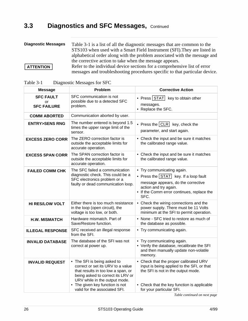
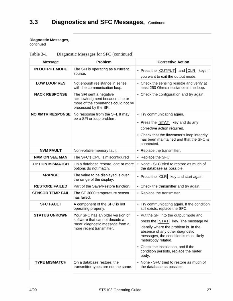
Diagnostic Messages Table 3-1 is a list of all the diagnostic messages that are common to theSTS103 when used with a Smart Field Instrument (SFI).They are listed inalphabetical order along with the problem associated with the message andthe corrective action to take when the message appears.
ATTENTION Refer to the individual device sections for a comprehensive list of errormessages and troubleshooting procedures specific to that particular device.
Table 3-1 Diagnostic Messages for SFC
Message Problem Corrective Action
SFC FAULTor
SFC FAILURE
SFC communication is notpossible due to a detected SFCproblem.
• Press STAT key to obtain other
messages.• Replace the SFC.
COMM ABORTED Communication aborted by user.
ENTRY>SENS RNG The number entered is beyond 1.5times the upper range limit of thesensor.
• Press the CLR key, check the
parameter, and start again.
EXCESS ZERO CORR The ZERO correction factor isoutside the acceptable limits foraccurate operation.
• Check the input and be sure it matchesthe calibrated range value.
EXCESS SPAN CORR The SPAN correction factor isoutside the acceptable limits foraccurate operation.
• Check the input and be sure it matchesthe calibrated range value.
FAILED COMM CHK The SFC failed a communicationdiagnostic check. This could be aSFC electronics problem or afaulty or dead communication loop.
• Try communicating again.
• Press the STAT key. If a loop fault
message appears, do the correctiveaction and try again.
• If the Comm error continues, replace theSFC.
HI RES/LOW VOLT Either there is too much resistancein the loop (open circuit), thevoltage is too low, or both.
• Check the wiring connections and thepower supply. There must be 11 Voltsminimum at the SFI to permit operation.
H.W. MISMATCH Hardware mismatch. Part ofSave/Restore function.
• None - SFC tried to restore as much ofthe database as possible.
ILLEGAL RESPONSE SFC received an illegal responsefrom the SFI.
• Try communicating again.
INVALID DATABASE The database of the SFI was notcorrect at power up.
• Try communicating again.• Verify the database, recalibrate the SFI
and then manually update non-volatilememory.
INVALID REQUEST • The SFI is being asked tocorrect or set its URV to a valuethat results in too low a span, orbeing asked to correct its LRV orURV while in the output mode.
• The given key function is notvalid for the associated SFI.
• Check that the proper calibrated URVinput is being applied to the SFI, or thatthe SFI is not in the output mode.
• Check that the key function is applicablefor your particular SFI.
Table continued on next page
4/99 STS103 Operating Guide 27
3.3 Diagnostics and SFC Messages, Continued
Diagnostic Messages,continued
Table 3-1 Diagnostic Messages for SFC (continued)
Message Problem Corrective Action
IN OUTPUT MODE The SFI is operating as a currentsource.
• Press the OUTPUT and CLR keys if
you want to exit the output mode.
LOW LOOP RES Not enough resistance in serieswith the communication loop.
• Check the sensing resistor and verify atleast 250 Ohms resistance in the loop.
NACK RESPONSE The SFI sent a negativeacknowledgment because one ormore of the commands could not beprocessed by the SFI.
• Check the configuration and try again.
NO XMTR RESPONSE No response from the SFI. It maybe a SFI or loop problem.
• Try communicating again.
• Press the STAT key and do any
corrective action required.
• Check that the flowmeter’s loop integrityhas been maintained and that the SFC isconnected.
NVM FAULT Non-volatile memory fault. • Replace the transmitter.
NVM ON SEE MAN The SFC’s CPU is misconfigured • Replace the SFC.
OPTION MISMATCH On a database restore, one or moreoptions do not match.
• None - SFC tried to restore as much ofthe database as possible.
>RANGE The value to be displayed is overthe range of the display.
• Press the CLR key and start again.
RESTORE FAILED Part of the Save/Restore function. • Check the transmitter and try again.
SENSOR TEMP FAIL The ST 3000 temperature sensorhas failed.
• Replace the transmitter.
SFC FAULT A component of the SFC is notoperating properly.
• Try communicating again. If the conditionstill exists, replace the SFC.
STATUS UNKOWN Your SFC has an older version ofsoftware that cannot decode a“new” diagnostic message from amore recent transmitter.
• Put the SFI into the output mode and
press the STAT key. The message will
identify where the problem is. In theabsence of any other diagnosticmessages, the condition is most likelymeterbody related.
• Check the installation, and if thecondition persists, replace the meterbody.
TYPE MISMATCH On a database restore, thetransmitter types are not the same.
• None - SFC tried to restore as much ofthe database as possible.
28 STS103 Operating Guide 4/99
3.4 Common Key Sequences and Displays
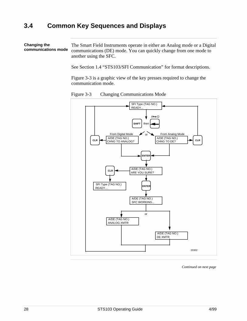
Changing thecommunications mode
The Smart Field Instruments operate in either an Analog mode or a Digitalcommunications (DE) mode. You can quickly change from one mode toanother using the SFC.
See Section 1.4 “STS103/SFI Communication” for format descriptions.
Figure 3-3 is a graphic view of the key presses required to change thecommunication mode.
Figure 3-3 Changing Communications Mode
SFI Type (TAG NO.)READY...
ENTER
From Analog Mode
SHIFT
20302
A/DE (TAG NO.)CHNG TO ANALOG?CLR
A/DE (TAG NO.)CHNG TO DE? CLR
From Digital Mode
then
A/DE (TAG NO.)ARE YOU SURE?
CLR
READY...ENTER
A D
A/DE (TAG NO.)SFC WORKING...
A/DE (TAG NO.)DE XMTR
A/DE (TAG NO.)ANALOG XMTR
or
or
SFI Type (TAG NO.)
Continued on next page
4/99 STS103 Operating Guide 29
3.4 Common Key Sequences and Displays, Continued
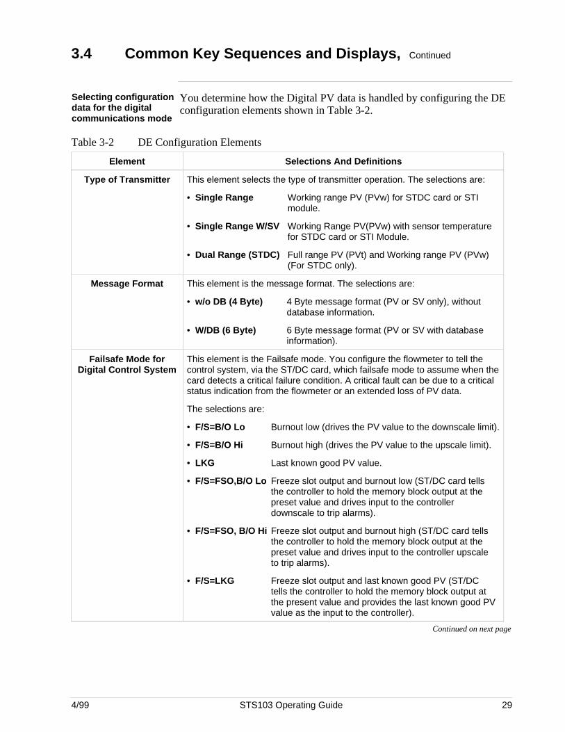
Selecting configurationdata for the digitalcommunications mode
You determine how the Digital PV data is handled by configuring the DEconfiguration elements shown in Table 3-2.
Table 3-2 DE Configuration Elements
Element Selections And Definitions
Type of Transmitter This element selects the type of transmitter operation. The selections are:
• Single Range Working range PV (PVw) for STDC card or STImodule.
• Single Range W/SV Working Range PV(PVw) with sensor temperature for STDC card or STI Module.
• Dual Range (STDC) Full range PV (PVt) and Working range PV (PVw) (For STDC only).
Message Format This element is the message format. The selections are:
• w/o DB (4 Byte) 4 Byte message format (PV or SV only), withoutdatabase information.
• W/DB (6 Byte) 6 Byte message format (PV or SV with database information).
Failsafe Mode forDigital Control System
This element is the Failsafe mode. You configure the flowmeter to tell thecontrol system, via the ST/DC card, which failsafe mode to assume when thecard detects a critical failure condition. A critical fault can be due to a criticalstatus indication from the flowmeter or an extended loss of PV data.
The selections are:
• F/S=B/O Lo Burnout low (drives the PV value to the downscale limit).
• F/S=B/O Hi Burnout high (drives the PV value to the upscale limit).
• LKG Last known good PV value.
• F/S=FSO,B/O Lo Freeze slot output and burnout low (ST/DC card tells the controller to hold the memory block output at the preset value and drives input to the controller downscale to trip alarms).
• F/S=FSO, B/O Hi Freeze slot output and burnout high (ST/DC card tells the controller to hold the memory block output at the preset value and drives input to the controller upscale to trip alarms).
• F/S=LKG Freeze slot output and last known good PV (ST/DC tells the controller to hold the memory block output at the present value and provides the last known good PV value as the input to the controller).
Continued on next page
30 STS103 Operating Guide 4/99
3.4 Common Key Sequences and Displays, Continued
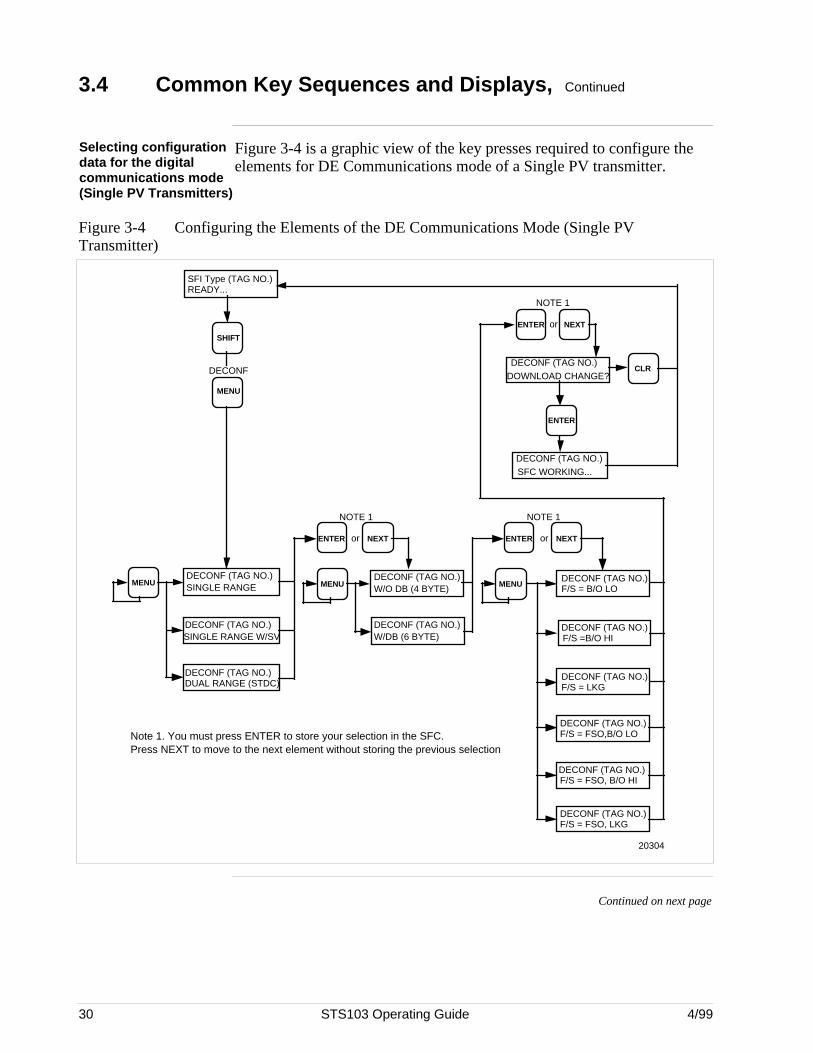
Selecting configurationdata for the digitalcommunications mode(Single PV Transmitters)
Figure 3-4 is a graphic view of the key presses required to configure theelements for DE Communications mode of a Single PV transmitter.
Figure 3-4 Configuring the Elements of the DE Communications Mode (Single PVTransmitter)
MENU
SHIFT
SFI Type (TAG NO.)READY...
DECONF
MENUDECONF (TAG NO.)SINGLE RANGE
DECONF (TAG NO.)SINGLE RANGE W/SV
DECONF (TAG NO.)DUAL RANGE (STDC)
NOTE 1
MENU
DECONF (TAG NO.)W/DB (6 BYTE)
DECONF (TAG NO.)W/O DB (4 BYTE)
ENTER or NEXT
MENUDECONF (TAG NO.)F/S = B/O LO
DECONF (TAG NO.)F/S = LKG
DECONF (TAG NO.)F/S =B/O HI
ENTER or NEXT
NOTE 1
DECONF (TAG NO.)F/S = FSO,B/O LO
DECONF (TAG NO.)F/S = FSO, LKG
DECONF (TAG NO.)F/S = FSO, B/O HI
DOWNLOAD CHANGE?DECONF (TAG NO.)
DECONF (TAG NO.)SFC WORKING...
ENTER or NEXT
NOTE 1
ENTER
CLR
20304
Note 1. You must press ENTER to store your selection in the SFC. Press NEXT to move to the next element without storing the previous selection
Continued on next page
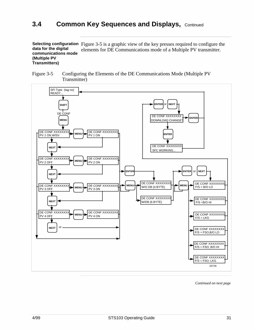
4/99 STS103 Operating Guide 31
3.4 Common Key Sequences and Displays, Continued
Selecting configurationdata for the digitalcommunications mode(Multiple PVTransmitters)
Figure 3-5 is a graphic view of the key presses required to configure theelements for DE Communications mode of a Multiple PV transmitter.
Figure 3-5 Configuring the Elements of the DE Communications Mode (Multiple PVTransmitter)
MENU
SHIFT
SFI Type (tag no)READY...
DE CONF
MENUDE CONF XXXXXXXXPV 1 ON W/SV
DOWNLOAD CHANGE?DE CONF XXXXXXXX
DE CONF XXXXXXXXSFC WORKING...
ENTER or NEXT
ENTER
ENTER
MENU
DE CONF XXXXXXXXW/DB (6 BYTE)
DE CONF XXXXXXXXW/O DB (4 BYTE)
ENTER
MENUDE CONF XXXXXXXXF/S = B/O LO
DE CONF XXXXXXXXF/S = LKG
DE CONF XXXXXXXXF/S =B/O HI
ENTER or NEXT
DE CONF XXXXXXXXF/S = FSO,B/O LO
DE CONF XXXXXXXXF/S = FSO, LKG
DE CONF XXXXXXXXF/S = FSO, B/O HI
DE CONF XXXXXXXXPV 1 ON
NEXT
MENUDE CONF XXXXXXXXPV 2 OFF
DE CONF XXXXXXXXPV 2 ON
NEXT
MENUDE CONF XXXXXXXXPV 3 OFF
DE CONF XXXXXXXXPV 3 ON
NEXT
MENUDE CONF XXXXXXXXPV 4 OFF
DE CONF XXXXXXXXPV 4 ON
NEXT or
20729
Continued on next page
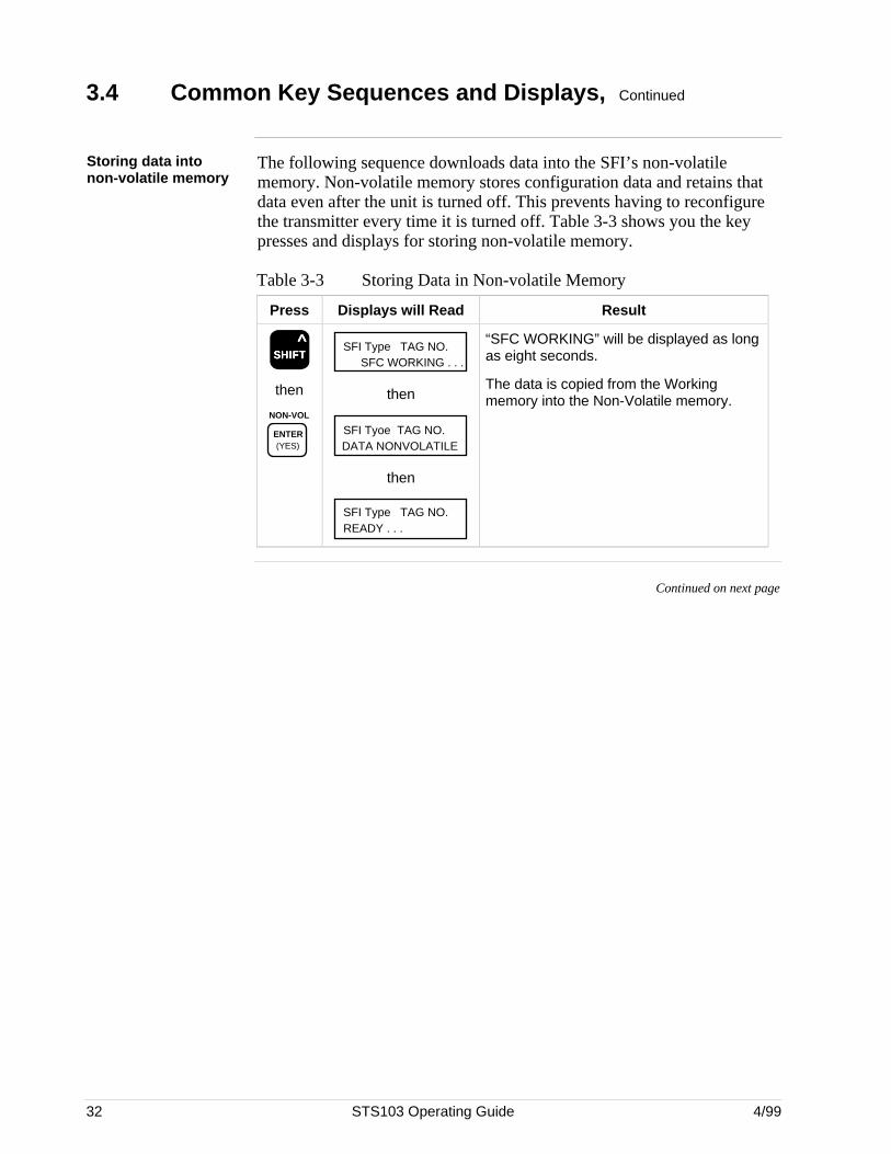
32 STS103 Operating Guide 4/99
3.4 Common Key Sequences and Displays, Continued
Storing data intonon-volatile memory
The following sequence downloads data into the SFI’s non-volatilememory. Non-volatile memory stores configuration data and retains thatdata even after the unit is turned off. This prevents having to reconfigurethe transmitter every time it is turned off. Table 3-3 shows you the keypresses and displays for storing non-volatile memory.
Table 3-3 Storing Data in Non-volatile Memory
Press Displays will Read Result
SSSSSHHHHHIIIIIFFFFFTTTTT ^
then
NON-VOL
ENTER (YES)
SFI Type TAG NO.SFC WORKING . . .
then
SFI Tyoe TAG NO.DATA NONVOLATILE
then
READY . . .SFI Type TAG NO.
“SFC WORKING” will be displayed as longas eight seconds.
The data is copied from the Workingmemory into the Non-Volatile memory.
Continued on next page
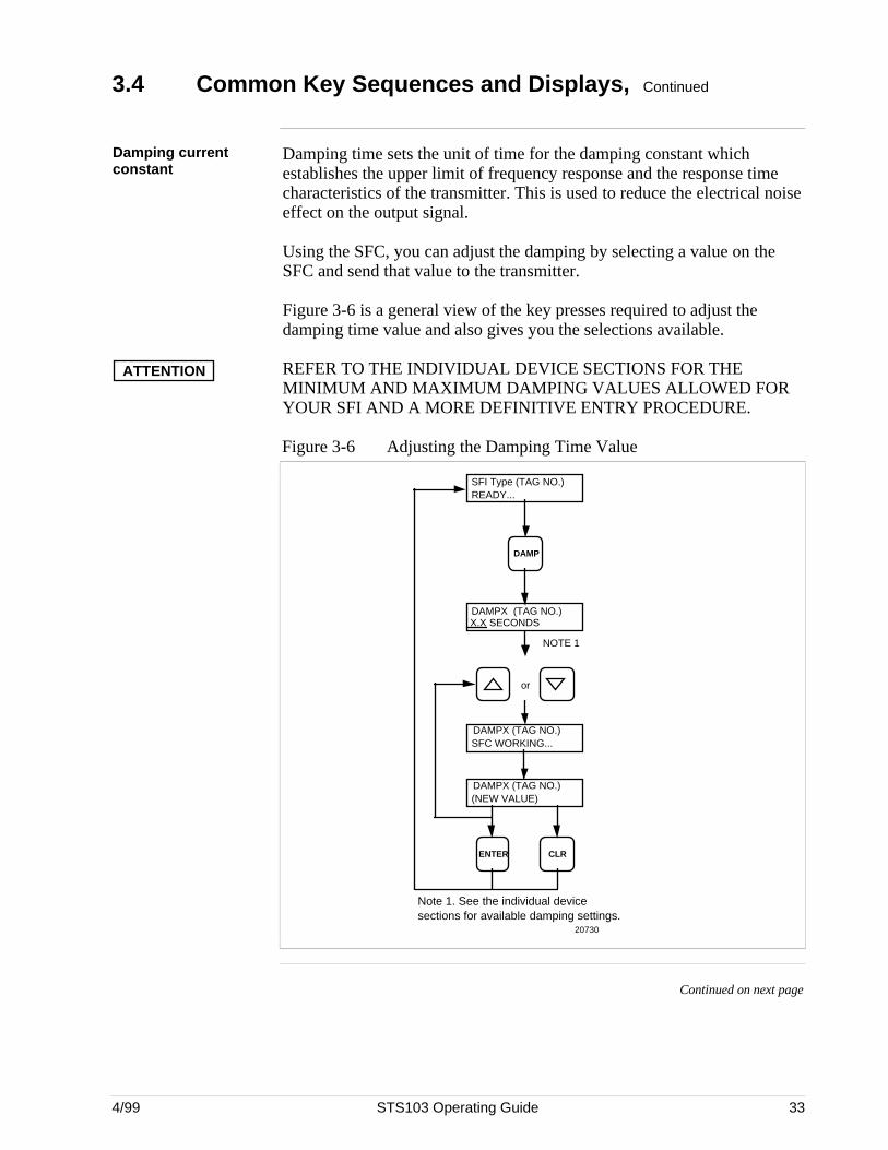
4/99 STS103 Operating Guide 33
3.4 Common Key Sequences and Displays, Continued
Damping currentconstant
Damping time sets the unit of time for the damping constant whichestablishes the upper limit of frequency response and the response timecharacteristics of the transmitter. This is used to reduce the electrical noiseeffect on the output signal.
Using the SFC, you can adjust the damping by selecting a value on theSFC and send that value to the transmitter.
Figure 3-6 is a general view of the key presses required to adjust thedamping time value and also gives you the selections available.
ATTENTION REFER TO THE INDIVIDUAL DEVICE SECTIONS FOR THEMINIMUM AND MAXIMUM DAMPING VALUES ALLOWED FORYOUR SFI AND A MORE DEFINITIVE ENTRY PROCEDURE.
Figure 3-6 Adjusting the Damping Time Value
SFI Type (TAG NO.)READY...
DAMP
DAMPX (TAG NO.)X.X SECONDS
or
DAMPX (TAG NO.)SFC WORKING...
DAMPX (TAG NO.)(NEW VALUE)
ENTER CLR
NOTE 1
Note 1. See the individual device sections for available damping settings.
20730
Continued on next page
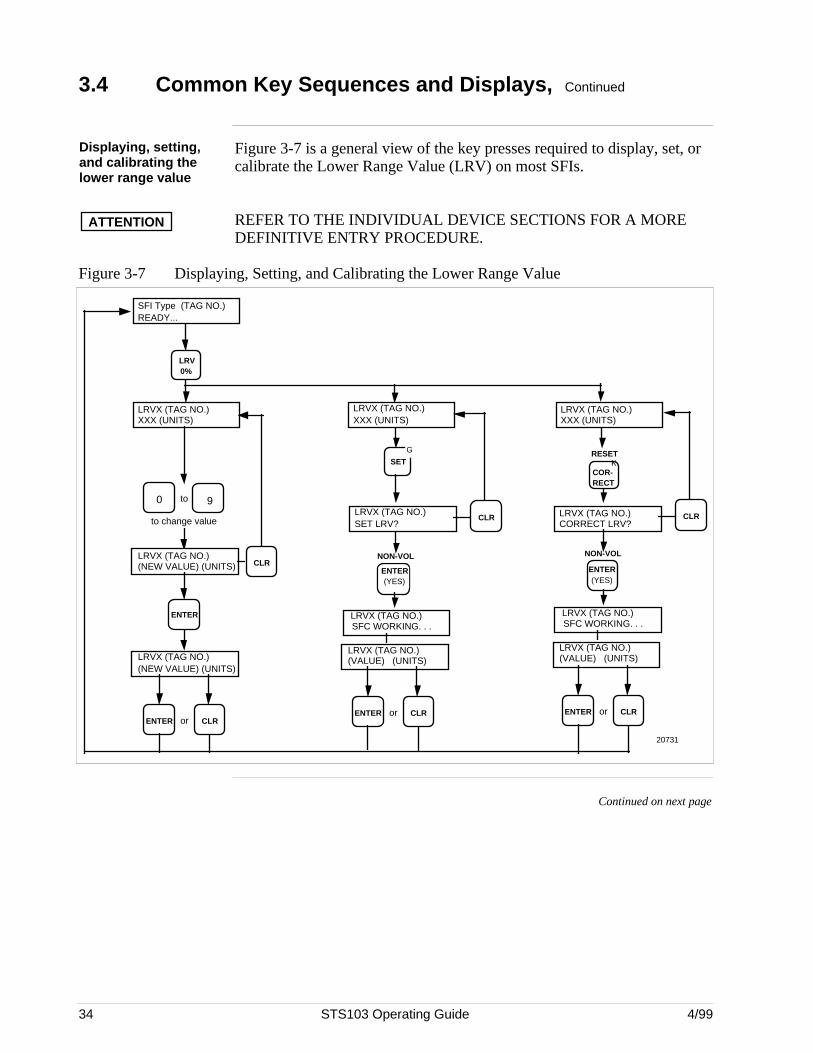
34 STS103 Operating Guide 4/99
3.4 Common Key Sequences and Displays, Continued
Displaying, setting,and calibrating thelower range value
Figure 3-7 is a general view of the key presses required to display, set, orcalibrate the Lower Range Value (LRV) on most SFIs.
ATTENTION REFER TO THE INDIVIDUAL DEVICE SECTIONS FOR A MOREDEFINITIVE ENTRY PROCEDURE.
Figure 3-7 Displaying, Setting, and Calibrating the Lower Range Value
LRVX (TAG NO.)XXX (UNITS)
to change value
LRVX (TAG NO.)(NEW VALUE) (UNITS)
CLRENTER or
ENTER
LRVX (TAG NO.)(NEW VALUE) (UNITS)
90 to
LRV 0%
SFI Type (TAG NO.)READY...
CLR
KCOR- RECT
RESETG
SET
LRVX (TAG NO.)SET LRV?
NON-VOL
ENTER (YES)
LRVX (TAG NO.)SFC WORKING. . .
LRVX (TAG NO.)(VALUE) (UNITS)
LRVX (TAG NO.)XXX (UNITS)
LRVX (TAG NO.)XXX (UNITS)
CLR LRVX (TAG NO.)CORRECT LRV?
CLR
NON-VOL
ENTER (YES)
LRVX (TAG NO.)SFC WORKING. . .
LRVX (TAG NO.)(VALUE) (UNITS)
CLRENTER or CLRENTER or
20731
Continued on next page
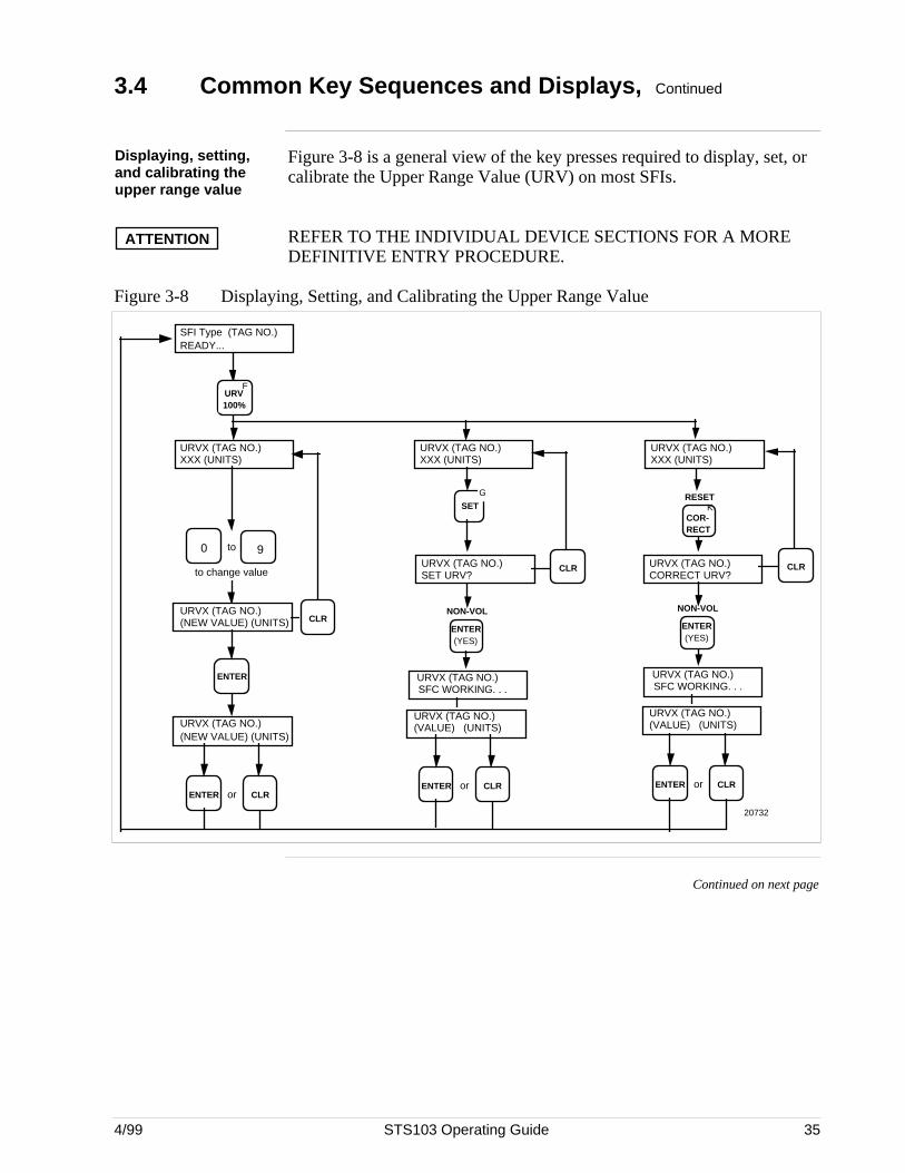
4/99 STS103 Operating Guide 35
3.4 Common Key Sequences and Displays, Continued
Displaying, setting,and calibrating theupper range value
Figure 3-8 is a general view of the key presses required to display, set, orcalibrate the Upper Range Value (URV) on most SFIs.
ATTENTION REFER TO THE INDIVIDUAL DEVICE SECTIONS FOR A MOREDEFINITIVE ENTRY PROCEDURE.
Figure 3-8 Displaying, Setting, and Calibrating the Upper Range Value
URVX (TAG NO.)XXX (UNITS)
to change value
URVX (TAG NO.)(NEW VALUE) (UNITS)
CLRENTER or
ENTER
URVX (TAG NO.)(NEW VALUE) (UNITS)
90 to
SFI Type (TAG NO.)READY...
CLR
KCOR- RECT
RESETG
SET
URVX (TAG NO.)SET URV?
NON-VOL
ENTER (YES)
URVX (TAG NO.)SFC WORKING. . .
URVX (TAG NO.)(VALUE) (UNITS)
URVX (TAG NO.)XXX (UNITS)
URVX (TAG NO.)XXX (UNITS)
CLR URVX (TAG NO.)CORRECT URV?
CLR
NON-VOL
ENTER (YES)
URVX (TAG NO.)SFC WORKING. . .
URVX (TAG NO.)(VALUE) (UNITS)
CLRENTER or CLRENTER or
FURV 100%
20732
Continued on next page
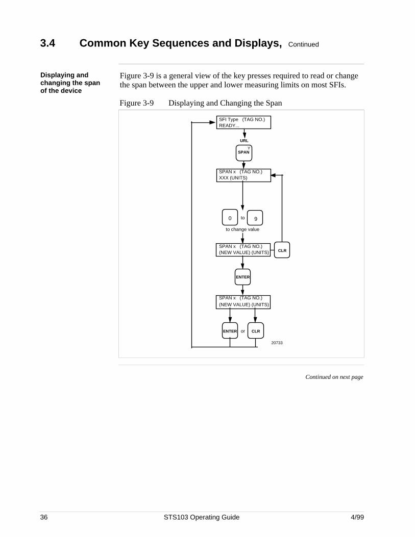
36 STS103 Operating Guide 4/99
3.4 Common Key Sequences and Displays, Continued
Displaying andchanging the spanof the device
Figure 3-9 is a general view of the key presses required to read or changethe span between the upper and lower measuring limits on most SFIs.
Figure 3-9 Displaying and Changing the Span
SPAN x (TAG NO.)XXX (UNITS)
to change value
SPAN x (TAG NO.)(NEW VALUE) (UNITS)
CLRENTER or
ENTER
SPAN x (TAG NO.)(NEW VALUE) (UNITS)
90 to
SFI Type (TAG NO.)READY...
CLR
YSPAN
URL
20733
Continued on next page
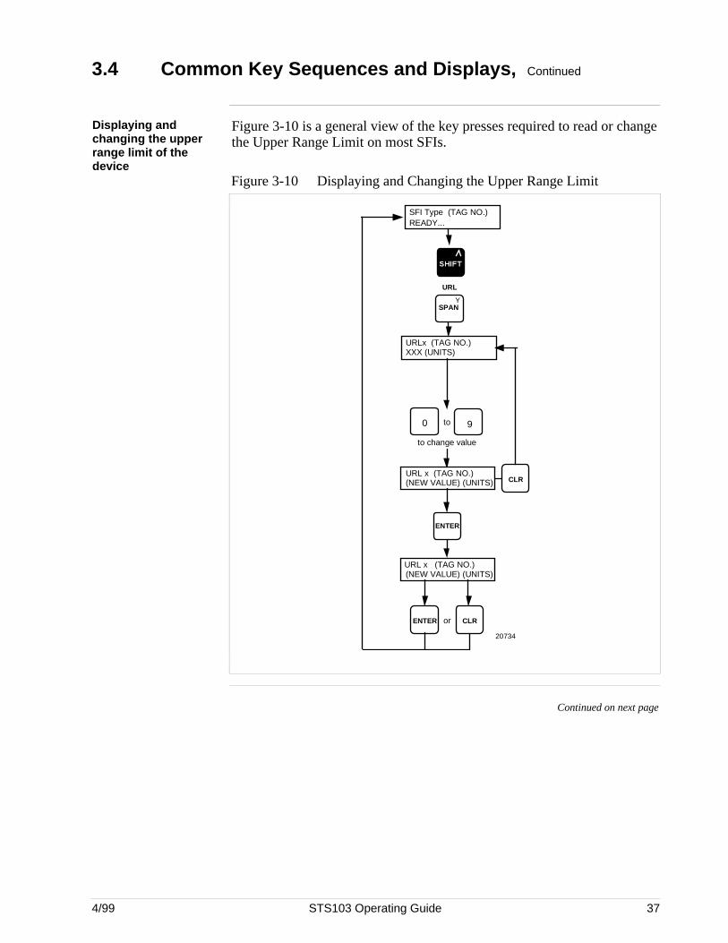
4/99 STS103 Operating Guide 37
3.4 Common Key Sequences and Displays, Continued
Displaying andchanging the upperrange limit of thedevice
Figure 3-10 is a general view of the key presses required to read or changethe Upper Range Limit on most SFIs.
Figure 3-10 Displaying and Changing the Upper Range Limit
SFI Type (TAG NO.)READY...
URLx (TAG NO.)XXX (UNITS)
to change value
URL x (TAG NO.)(NEW VALUE) (UNITS)
CLRENTER or
ENTER
URL x (TAG NO.)(NEW VALUE) (UNITS)
90 to
CLR
YSPAN
URL
20734
Continued on next page

38 STS103 Operating Guide 4/99
3.4 Common Key Sequences and Displays, Continued
Resetting the SFI The sequence below, commonly known as Corrects-Reset, shows how toreset most devices to their factory default setting. Corrects-Reset isperformed when you need to reset and recalibrate the SFI.
The MagneW 3000 default settings are in the calibration hierarchy called“shipping data.”. See the device section for the procedure.
Figure 3-11 is a general view of the key presses required to reset tofactory default settings on most SFIs.
Figure 3-11 Corrects Reset
SFI Type (TAG NO.)READY...
CLR
KCOR- RECT
RESET
(TAG NO.)SFC WORKING . . .
(TAG NO.)CORRECTS RESET?
ENTER
20735
(TAG NO.)RESET CORRECTS?
Continued on next page
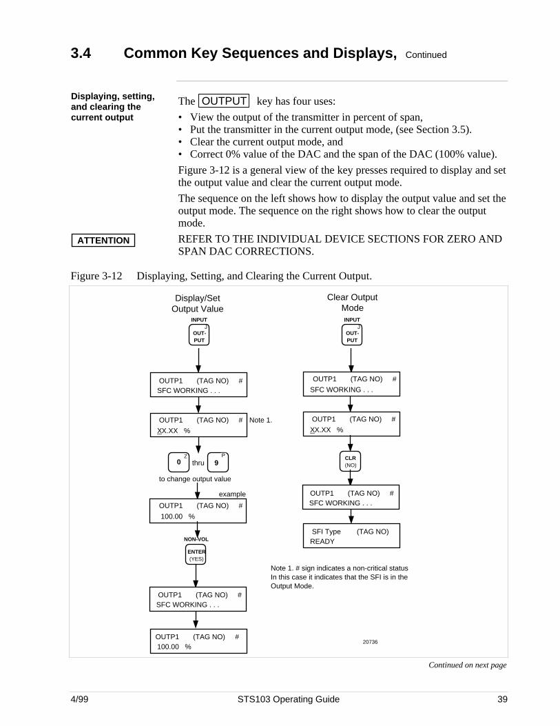
4/99 STS103 Operating Guide 39
3.4 Common Key Sequences and Displays, Continued
Displaying, setting,and clearing thecurrent output
The OUTPUT key has four uses:
• View the output of the transmitter in percent of span,• Put the transmitter in the current output mode, (see Section 3.5).• Clear the current output mode, and• Correct 0% value of the DAC and the span of the DAC (100% value).
Figure 3-12 is a general view of the key presses required to display and setthe output value and clear the current output mode.
The sequence on the left shows how to display the output value and set theoutput mode. The sequence on the right shows how to clear the outputmode.
ATTENTION REFER TO THE INDIVIDUAL DEVICE SECTIONS FOR ZERO ANDSPAN DAC CORRECTIONS.
Figure 3-12 Displaying, Setting, and Clearing the Current Output.
JOUT- PUT
INPUT
OUTP1 (TAG NO) #SFC WORKING . . .
XX.XX %
NON-VOL
ENTER (YES)
100.00 %
JOUT- PUT
INPUT
CLR (NO)
Display/Set Output Value
Clear Output Mode
Z0
P
9thru
to change output value
100.00 %
example
SFC WORKING . . .
SFC WORKING . . .
XX.XX %
SFC WORKING . . .
SFI Type (TAG NO) READY
OUTP1 (TAG NO) #
OUTP1 (TAG NO) #
OUTP1 (TAG NO) #
OUTP1 (TAG NO) #
OUTP1 (TAG NO) #
OUTP1 (TAG NO) #
OUTP1 (TAG NO) #Note 1.
Note 1. # sign indicates a non-critical status In this case it indicates that the SFI is in the Output Mode.
20736
Continued on next page
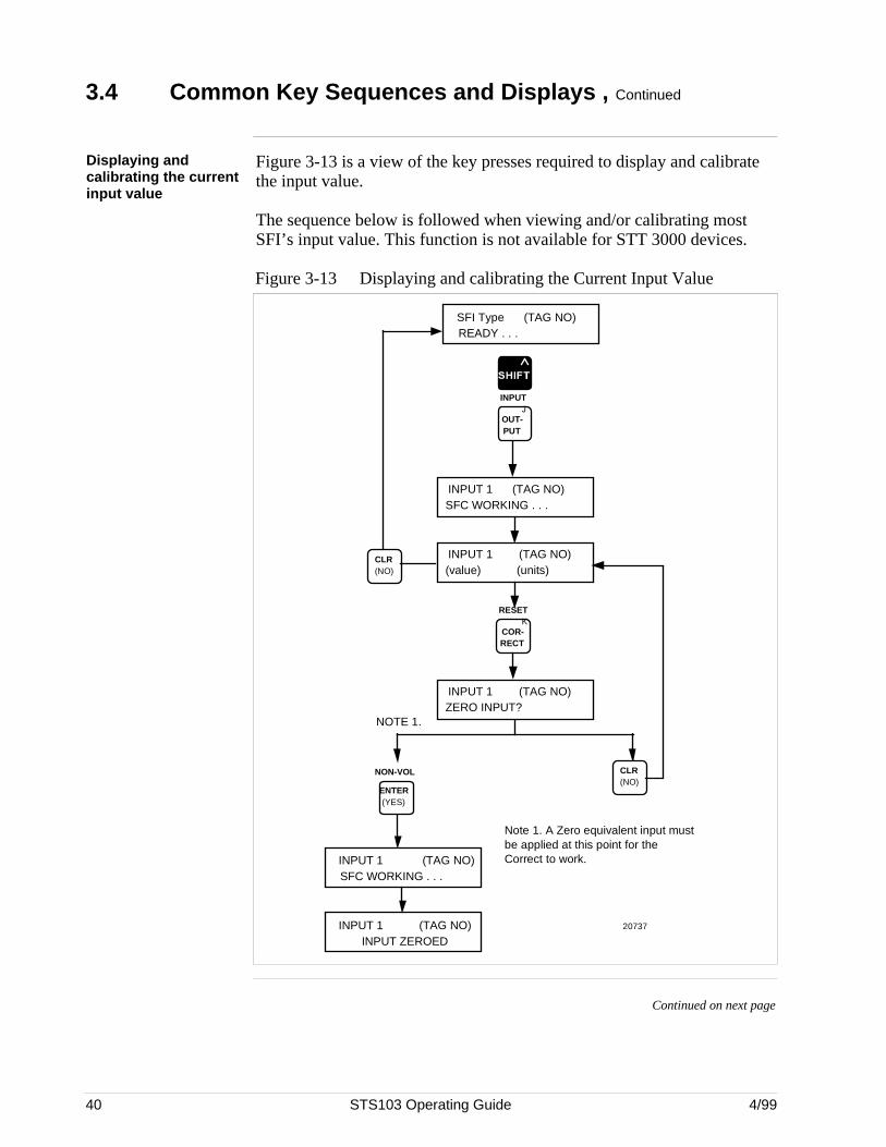
40 STS103 Operating Guide 4/99
3.4 Common Key Sequences and Displays , Continued
Displaying andcalibrating the currentinput value
Figure 3-13 is a view of the key presses required to display and calibratethe input value.
The sequence below is followed when viewing and/or calibrating mostSFI’s input value. This function is not available for STT 3000 devices.
Figure 3-13 Displaying and calibrating the Current Input Value
INPUT 1 (TAG NO) SFC WORKING . . .
(value) (units)INPUT 1 (TAG NO)
KCOR- RECT
RESET
READY . . .SFI Type (TAG NO)
CLR (NO)
NON-VOL
ENTER (YES)
SFC WORKING . . .INPUT 1 (TAG NO)
INPUT ZEROED INPUT 1 (TAG NO)
ZERO INPUT?INPUT 1 (TAG NO)
CLR (NO)
NOTE 1.
Note 1. A Zero equivalent input must be applied at this point for the Correct to work.
20737
JOUT- PUT
INPUT
Continued on next page
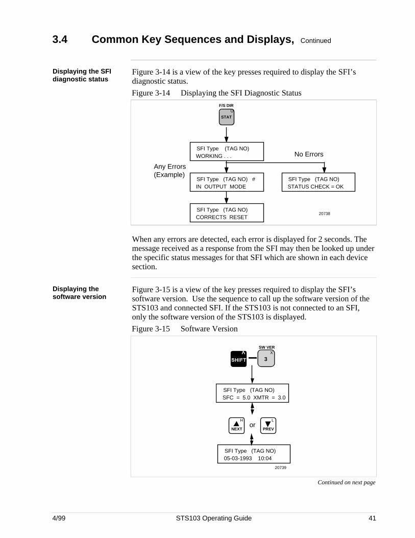
4/99 STS103 Operating Guide 41
3.4 Common Key Sequences and Displays, Continued
Displaying the SFIdiagnostic status
Figure 3-14 is a view of the key presses required to display the SFI’sdiagnostic status.
Figure 3-14 Displaying the SFI Diagnostic Status
U
STAT
F/S DIR
SFI Type (TAG NO)WORKING . . .
SFI Type (TAG NO) #IN OUTPUT MODE
SFI Type (TAG NO)STATUS CHECK = OK
No Errors
Any Errors (Example)
SFI Type (TAG NO) CORRECTS RESET
20738
When any errors are detected, each error is displayed for 2 seconds. Themessage received as a response from the SFI may then be looked up underthe specific status messages for that SFI which are shown in each devicesection.
Displaying thesoftware version
Figure 3-15 is a view of the key presses required to display the SFI’ssoftware version. Use the sequence to call up the software version of theSTS103 and connected SFI. If the STS103 is not connected to an SFI,only the software version of the STS103 is displayed.
Figure 3-15 Software Version
X
3
SW VER
SFI Type (TAG NO)SFC = 5.0 XMTR = 3.0
L
PREV
H
NEXTor
SFI Type (TAG NO)05-03-1993 10:04
20739
Continued on next page
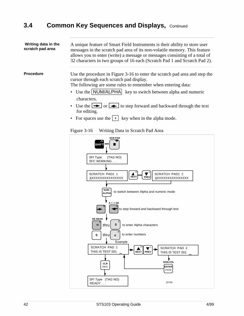
42 STS103 Operating Guide 4/99
3.4 Common Key Sequences and Displays, Continued
Writing data in thescratch pad area
A unique feature of Smart Field Instruments is their ability to store usermessages in the scratch pad area of its non-volatile memory. This featureallows you to enter (write) a message or messages consisting of a total of32 characters in two groups of 16 each (Scratch Pad 1 and Scratch Pad 2).
Procedure Use the procedure in Figure 3-16 to enter the scratch pad area and step thecursor through each scratch pad display.The following are some rules to remember when entering data:
• Use the NUM/ALPHA key to switch between alpha and numeric
characters.
• Use the or to step forward and backward through the text for editing.
• For spaces use the • key when in the alpha mode.
Figure 3-16 Writing Data in Scratch Pad Area
SFI Type (TAG NO)SFC WORKING . . .
SCR PAD
SCRATCH PAD1 1XXXXXXXXXXXXXXXX
NUM / ALPHA to switch between Alpha and numeric mode
Z0 thru
P
9
DE READA
ID to enter Alpha charactersthru
to enter numbers
SCRATCH PAD 1THIS IS TEST 001
Example
H
NEXT
L
PREVSCRATCH PAD1 2XXXXXXXXXXXXXXXX
MA <–> DE
Qto step forward and backward through text
NON-VOL
ENTER (YES)
SFI Type (TAG NO)READY . . .
L
PREV
H
NEXT
SCRATCH PAD 2THIS IS TEST 001
CLR (NO)
20740
0Z
4/99 STS103 Operating Guide 43
3.5 Using the Transmitter as a Current Source
Introduction One of the unique features of a Smart Field Instrument is its ability to beused as a constant current-source. This feature allows you to use it forcalibrating other instruments in the loop such as recorders, controllers, andpositioners.
As you know, the output of the SFI ranges from 4 to 20 milliamps where4 mA = 0% output and 20 mA = 100% output. Using the STS103, you cantell the SFI to change its output to any value between 0 and 100% andmaintain that output. Then you can use this output as a calibration inputsource to the other instruments in the loop.
Note that the current “output mode” overrides all other PV data from theSFI including the burnout data in the Digital Communications mode.
ATTENTION When you use the SFI as a current source, it no longer acts as a SFI. Makesure to clear this output mode when you are finished.
Continued on next page

44 STS103 Operating Guide 4/99
3.5 Using the Transmitter as a Current Source, Continued
Procedure Connect an ammeter to read the output of the SFI and connect the STS103Smart Field Communicator to the SFI. Follow the procedure listed inTable 3-4 to use the SFI as a constant current-source.
Table 3-4 Using the SFI as a Constant Current-source
Step Press Display Example Result or Action
1J
OUT- PUT
INPUTOUTP1 TAG NO.
SFC WORKING . . .
then
OUTP1 TAG NO. #
32.4 %
Your display will look similar to this with your outputdisplayed and it will update every 6 seconds.
Remember, when you’re ready to press the next key,to wait for the updated display.
2X
3
SW VER
Z0
NON-VOL
ENTER (YES)
OUTP1 TAG NO.SFC WORKING . . .
then
OUTP1 TAG NO. #
30.00 %
Key in the output you want. For this example, we willuse 30%.
The display will show the output with a decimal pointand two zeros. Also, the SFC adds a “#” character (anon-critical status indicator) on the right side of thedisplay to remind you that in this case you are in theoutput mode. It will stay on the display as long asyour SFI is being used as a current-source.
3 Check the output reading and see that it reads8.8 mA, which is equal to a 30% output.
If your meter shows a different reading or no “#”character appears on the display, go back to thebeginning of this procedure and start over.
Try a few different percentages and check yourmeter with the list below:
Key-in this value Your meter reads 0% 4.0 mA25% 8.0 mA50% 12.0 mA60% 13.6 mA80% 16.6 mA
100% 20.0 mA
4 CLR (NO)
OUTP1 TAG NO.SFC WORKING . . .
then
READY . . .SFI Type TAG NO.
This clears the output mode.
Notice that the “#” character disappeared.
ATTENTION If you do not press the CLR key
and press another key you will not exit the outputmode. This means that you cleared the display butare still in the output mode.
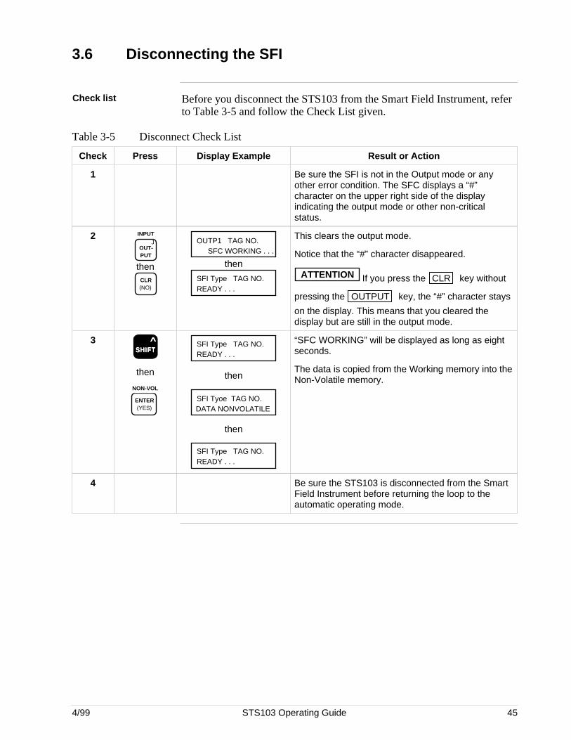
4/99 STS103 Operating Guide 45
3.6 Disconnecting the SFI
Check list Before you disconnect the STS103 from the Smart Field Instrument, referto Table 3-5 and follow the Check List given.
Table 3-5 Disconnect Check List
Check Press Display Example Result or Action
1 Be sure the SFI is not in the Output mode or anyother error condition. The SFC displays a “#”character on the upper right side of the displayindicating the output mode or other non-criticalstatus.
2J
OUT- PUT
INPUT
thenCLR (NO)
OUTP1 TAG NO.SFC WORKING . . .
then
READY . . .SFI Type TAG NO.
This clears the output mode.
Notice that the “#” character disappeared.
ATTENTION If you press the CLR key without
pressing the OUTPUT key, the “#” character stays
on the display. This means that you cleared thedisplay but are still in the output mode.
3SSSSSHHHHHIIIIIFFFFFTTTTT
^
then
NON-VOL
ENTER (YES)
READY . . .SFI Type TAG NO.
then
SFI Tyoe TAG NO.DATA NONVOLATILE
then
READY . . .SFI Type TAG NO.
“SFC WORKING” will be displayed as long as eightseconds.
The data is copied from the Working memory into theNon-Volatile memory.
4 Be sure the STS103 is disconnected from the SmartField Instrument before returning the loop to theautomatic operating mode.

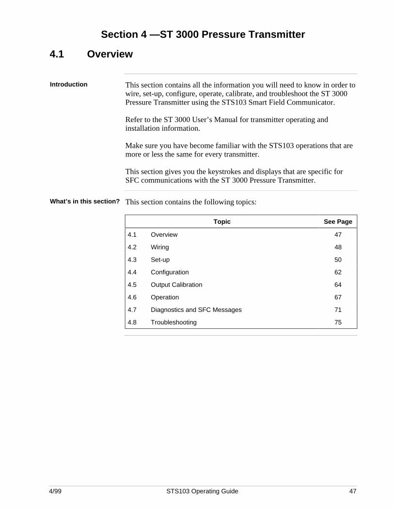
4/99 STS103 Operating Guide 47
Section 4 —ST 3000 Pressure Transmitter
4.1 Overview
Introduction This section contains all the information you will need to know in order towire, set-up, configure, operate, calibrate, and troubleshoot the ST 3000Pressure Transmitter using the STS103 Smart Field Communicator.
Refer to the ST 3000 User’s Manual for transmitter operating andinstallation information.
Make sure you have become familiar with the STS103 operations that aremore or less the same for every transmitter.
This section gives you the keystrokes and displays that are specific forSFC communications with the ST 3000 Pressure Transmitter.
What’s in this section? This section contains the following topics:
Topic See Page
4.1 Overview 47
4.2 Wiring 48
4.3 Set-up 50
4.4 Configuration 62
4.5 Output Calibration 64
4.6 Operation 67
4.7 Diagnostics and SFC Messages 71
4.8 Troubleshooting 75
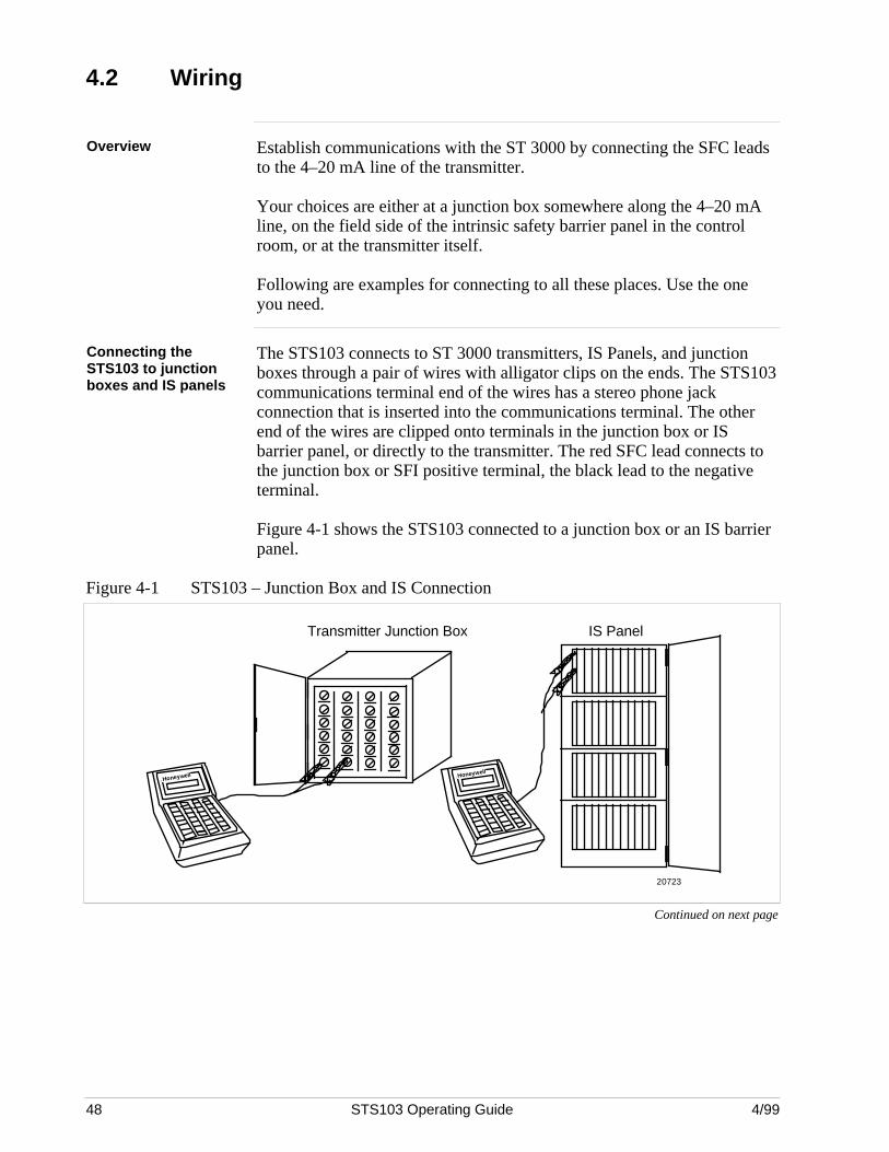
48 STS103 Operating Guide 4/99
4.2 Wiring
Overview Establish communications with the ST 3000 by connecting the SFC leadsto the 4–20 mA line of the transmitter.
Your choices are either at a junction box somewhere along the 4–20 mAline, on the field side of the intrinsic safety barrier panel in the controlroom, or at the transmitter itself.
Following are examples for connecting to all these places. Use the oneyou need.
Connecting theSTS103 to junctionboxes and IS panels
The STS103 connects to ST 3000 transmitters, IS Panels, and junctionboxes through a pair of wires with alligator clips on the ends. The STS103communications terminal end of the wires has a stereo phone jackconnection that is inserted into the communications terminal. The otherend of the wires are clipped onto terminals in the junction box or ISbarrier panel, or directly to the transmitter. The red SFC lead connects tothe junction box or SFI positive terminal, the black lead to the negativeterminal.
Figure 4-1 shows the STS103 connected to a junction box or an IS barrierpanel.
Figure 4-1 STS103 – Junction Box and IS Connection
Honeywell
Transmitter Junction Box IS Panel
20723
Honeywell
Continued on next page
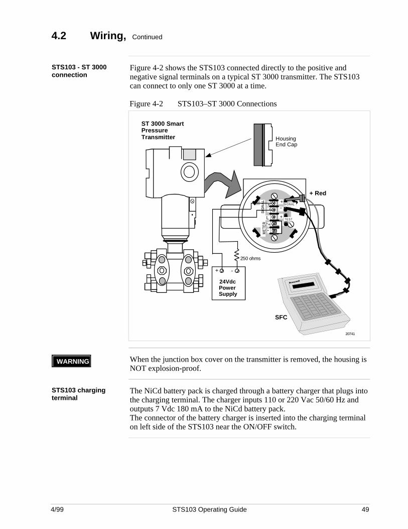
4/99 STS103 Operating Guide 49
4.2 Wiring, Continued
STS103 - ST 3000connection
Figure 4-2 shows the STS103 connected directly to the positive andnegative signal terminals on a typical ST 3000 transmitter. The STS103can connect to only one ST 3000 at a time.
Figure 4-2 STS103–ST 3000 Connections
+-
+-
+
+-
-
L-
TEST
SIGNAL
ST 3000 SmartPressureTransmitter
250 ohms
+ Red
SFC
PowerSupply
- +
24Vdc
HousingEnd Cap
20741
WARNING When the junction box cover on the transmitter is removed, the housing isNOT explosion-proof.
STS103 chargingterminal
The NiCd battery pack is charged through a battery charger that plugs intothe charging terminal. The charger inputs 110 or 220 Vac 50/60 Hz andoutputs 7 Vdc 180 mA to the NiCd battery pack.The connector of the battery charger is inserted into the charging terminalon left side of the STS103 near the ON/OFF switch.
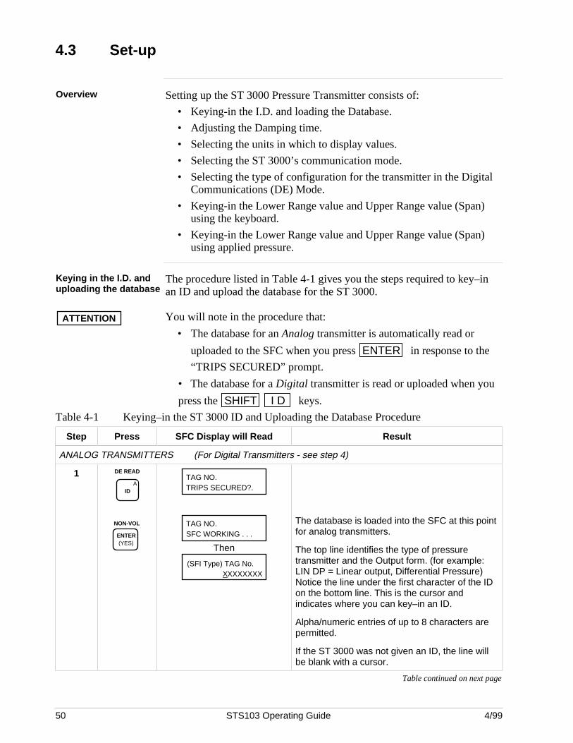
50 STS103 Operating Guide 4/99
4.3 Set-up
Overview Setting up the ST 3000 Pressure Transmitter consists of:
• Keying-in the I.D. and loading the Database.
• Adjusting the Damping time.
• Selecting the units in which to display values.
• Selecting the ST 3000’s communication mode.
• Selecting the type of configuration for the transmitter in the DigitalCommunications (DE) Mode.
• Keying-in the Lower Range value and Upper Range value (Span)using the keyboard.
• Keying-in the Lower Range value and Upper Range value (Span)using applied pressure.
Keying in the I.D. anduploading the database
The procedure listed in Table 4-1 gives you the steps required to key–inan ID and upload the database for the ST 3000.
ATTENTION You will note in the procedure that:
• The database for an Analog transmitter is automatically read or
uploaded to the SFC when you press ENTER in response to the
“TRIPS SECURED” prompt.
• The database for a Digital transmitter is read or uploaded when you
press the SHIFT I D keys.
Table 4-1 Keying–in the ST 3000 ID and Uploading the Database Procedure
Step Press SFC Display will Read Result
ANALOG TRANSMITTERS (For Digital Transmitters - see step 4)
1 DE READ
AID
NON-VOL
ENTER (YES)
TAG NO.TRIPS SECURED?.
TAG NO.SFC WORKING . . .
Then
(SFI Type) TAG No.XXXXXXXX
The database is loaded into the SFC at this pointfor analog transmitters.
The top line identifies the type of pressuretransmitter and the Output form. (for example:LIN DP = Linear output, Differential Pressure)Notice the line under the first character of the IDon the bottom line. This is the cursor andindicates where you can key–in an ID.
Alpha/numeric entries of up to 8 characters arepermitted.
If the ST 3000 was not given an ID, the line willbe blank with a cursor.
Table continued on next page
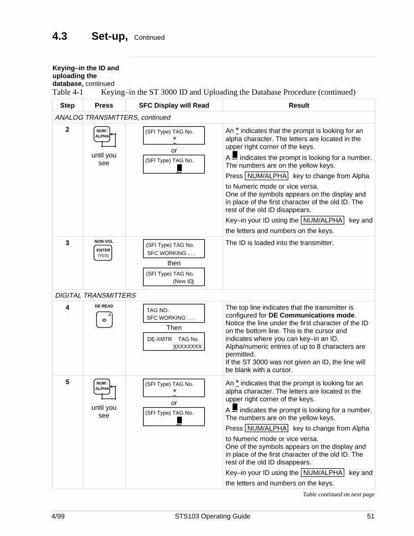
4/99 STS103 Operating Guide 51
4.3 Set-up, Continued
Keying–in the ID anduploading thedatabase, continuedTable 4-1 Keying–in the ST 3000 ID and Uploading the Database Procedure (continued)
Step Press SFC Display will Read Result
ANALOG TRANSMITTERS, continued
2 NUM / ALPHA
until yousee
*(SFI Type) TAG No.
or(SFI Type) TAG No.
An * indicates that the prompt is looking for an alpha character. The letters are located in theupper right corner of the keys.
A indicates the prompt is looking for a number.The numbers are on the yellow keys.
Press NUM/ALPHA key to change from Alpha
to Numeric mode or vice versa.One of the symbols appears on the display andin place of the first character of the old ID. Therest of the old ID disappears.
Key–in your ID using the NUM/ALPHA key and
the letters and numbers on the keys.
3 NON-VOL
ENTER (YES) SFC WORKING . . .
(SFI Type) TAG No.
then
(New ID)(SFI Type) TAG No.
The ID is loaded into the transmitter.
DIGITAL TRANSMITTERS
4 DE READ
AID
TAG NO.SFC WORKING . . .
Then
DE-XMTR TAG No.XXXXXXXX
The top line indicates that the transmitter isconfigured for DE Communications mode.Notice the line under the first character of the IDon the bottom line. This is the cursor andindicates where you can key–in an ID.Alpha/numeric entries of up to 8 characters arepermitted.If the ST 3000 was not given an ID, the line willbe blank with a cursor.
5 NUM / ALPHA
until yousee
*(SFI Type) TAG No.
or(SFI Type) TAG No.
An * indicates that the prompt is looking for an alpha character. The letters are located in theupper right corner of the keys.
A indicates the prompt is looking for a number.The numbers are on the yellow keys.
Press NUM/ALPHA key to change from Alpha
to Numeric mode or vice versa.One of the symbols appears on the display andin place of the first character of the old ID. Therest of the old ID disappears.
Key–in your ID using the NUM/ALPHA key and
the letters and numbers on the keys.
Table continued on next page
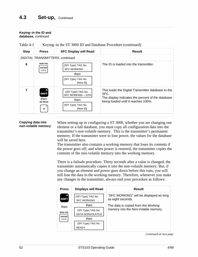
52 STS103 Operating Guide 4/99
4.3 Set-up, Continued
Keying–in the ID anddatabase, continued
Table 4-1 Keying–in the ST 3000 ID and Database Procedure (continued)
Step Press SFC Display will Read Result
DIGITAL TRANSMITTERS, continued
6 NON-VOL
ENTER (YES) SFC WORKING . . .
(SFI Type) TAG No.
then
(New ID)(SFI Type) TAG No.
The ID is loaded into the transmitter.
7SSSSSHHHHHIIIIIFFFFFTTTTT
^
thenDE READ
AID
SFC WORKING – XX%(SFI Type) TAG No.
then
(New ID)(SFI Type) TAG No.
This loads the Digital Transmitter database to theSFC.The display indicates the percent of the databasebeing loaded until it reaches 100%.
Copying data intonon-volatile memory
When setting-up or configuring a ST 3000, whether you are changing oneelement or a full database, you must copy all configuration data into thetransmitter’s non-volatile memory. This is the transmitter’s permanentmemory. If the transmitter were to lose power, the values for the databasewill be saved here.The transmitter also contains a working memory that loses its contents ifthe power goes off; and when power is restored, the transmitter copies thecontents of the non-volatile memory into the working memory.
There is a failsafe procedure. Thirty seconds after a value is changed, thetransmitter automatically copies it into the non-volatile memory. But, ifyou change an element and power goes down before this runs, you willstill lose the data in the working memory. Therefore, whenever you makeany changes in the transmitter, always end your procedure as follows:
Press Displays will Read Result
SSSSSHHHHHIIIIIFFFFFTTTTT ^
then
NON-VOL
ENTER (YES)
SFC WORKING . . .
(SFI Type) TAG No.
then
DATA NONVOLATILE
(SFI Type) TAG No.
then
READY
(SFI Type) TAG No.
“SFC WORKING” will be displayed as longas eight seconds.
The data is copied from the Workingmemory into the Non-Volatile memory.
Continued on next page
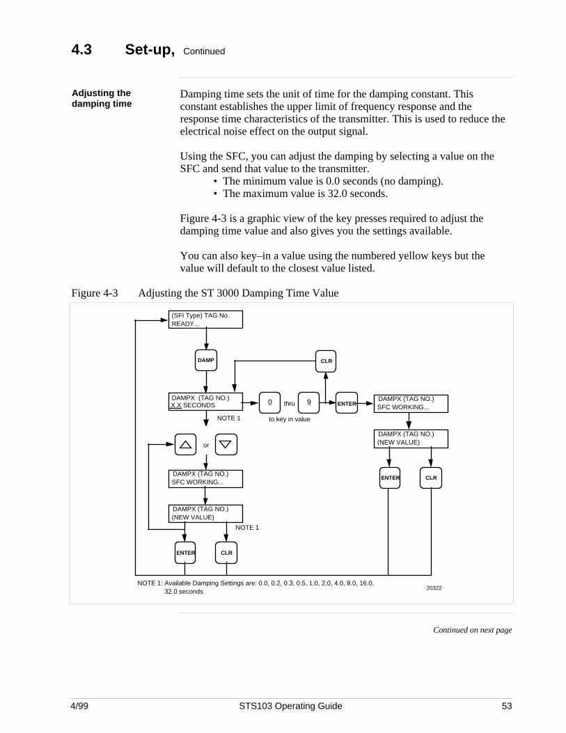
4/99 STS103 Operating Guide 53
4.3 Set-up, Continued
Adjusting thedamping time
Damping time sets the unit of time for the damping constant. Thisconstant establishes the upper limit of frequency response and theresponse time characteristics of the transmitter. This is used to reduce theelectrical noise effect on the output signal.
Using the SFC, you can adjust the damping by selecting a value on theSFC and send that value to the transmitter.
• The minimum value is 0.0 seconds (no damping).• The maximum value is 32.0 seconds.
Figure 4-3 is a graphic view of the key presses required to adjust thedamping time value and also gives you the settings available.
You can also key–in a value using the numbered yellow keys but thevalue will default to the closest value listed.
Figure 4-3 Adjusting the ST 3000 Damping Time Value
(SFI Type) TAG No.READY...
20322
DAMPX (TAG NO.)X.X SECONDS
or
DAMPX (TAG NO.)SFC WORKING...
DAMPX (TAG NO.)(NEW VALUE)
ENTER CLR
thru ENTERDAMPX (TAG NO.)SFC WORKING...
DAMPX (TAG NO.)(NEW VALUE)
ENTER CLR
CLR
NOTE 1
NOTE 1
to key in value
90
NOTE 1: Available Damping Settings are: 0.0, 0.2, 0.3, 0.5, 1.0, 2.0, 4.0, 8.0, 16.0, 32.0 seconds
DAMP
Continued on next page
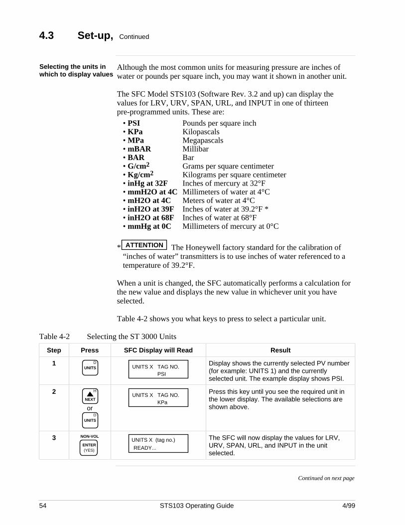
54 STS103 Operating Guide 4/99
4.3 Set-up, Continued
Selecting the units inwhich to display values
Although the most common units for measuring pressure are inches ofwater or pounds per square inch, you may want it shown in another unit.
The SFC Model STS103 (Software Rev. 3.2 and up) can display thevalues for LRV, URV, SPAN, URL, and INPUT in one of thirteenpre-programmed units. These are:
• PSI Pounds per square inch• KPa Kilopascals• MPa Megapascals• mBAR Millibar• BAR Bar• G/cm2 Grams per square centimeter• Kg/cm2 Kilograms per square centimeter• inHg at 32F Inches of mercury at 32°F• mmH2O at 4C Millimeters of water at 4°C• mH2O at 4C Meters of water at 4°C• inH2O at 39F Inches of water at 39.2°F *• inH2O at 68F Inches of water at 68°F• mmHg at 0C Millimeters of mercury at 0°C
* ATTENTION The Honeywell factory standard for the calibration of“inches of water” transmitters is to use inches of water referenced to atemperature of 39.2°F.
When a unit is changed, the SFC automatically performs a calculation forthe new value and displays the new value in whichever unit you haveselected.
Table 4-2 shows you what keys to press to select a particular unit.
Table 4-2 Selecting the ST 3000 Units
Step Press SFC Display will Read Result
1 DUNITS UNITS X TAG NO.
PSI
Display shows the currently selected PV number(for example: UNITS 1) and the currentlyselected unit. The example display shows PSI.
2 H
NEXT
orD
UNITS
UNITS X TAG NO.KPa
Press this key until you see the required unit inthe lower display. The available selections areshown above.
3 NON-VOL
ENTER (YES)
UNITS X (tag no.)
READY...
The SFC will now display the values for LRV,URV, SPAN, URL, and INPUT in the unitselected.
Continued on next page
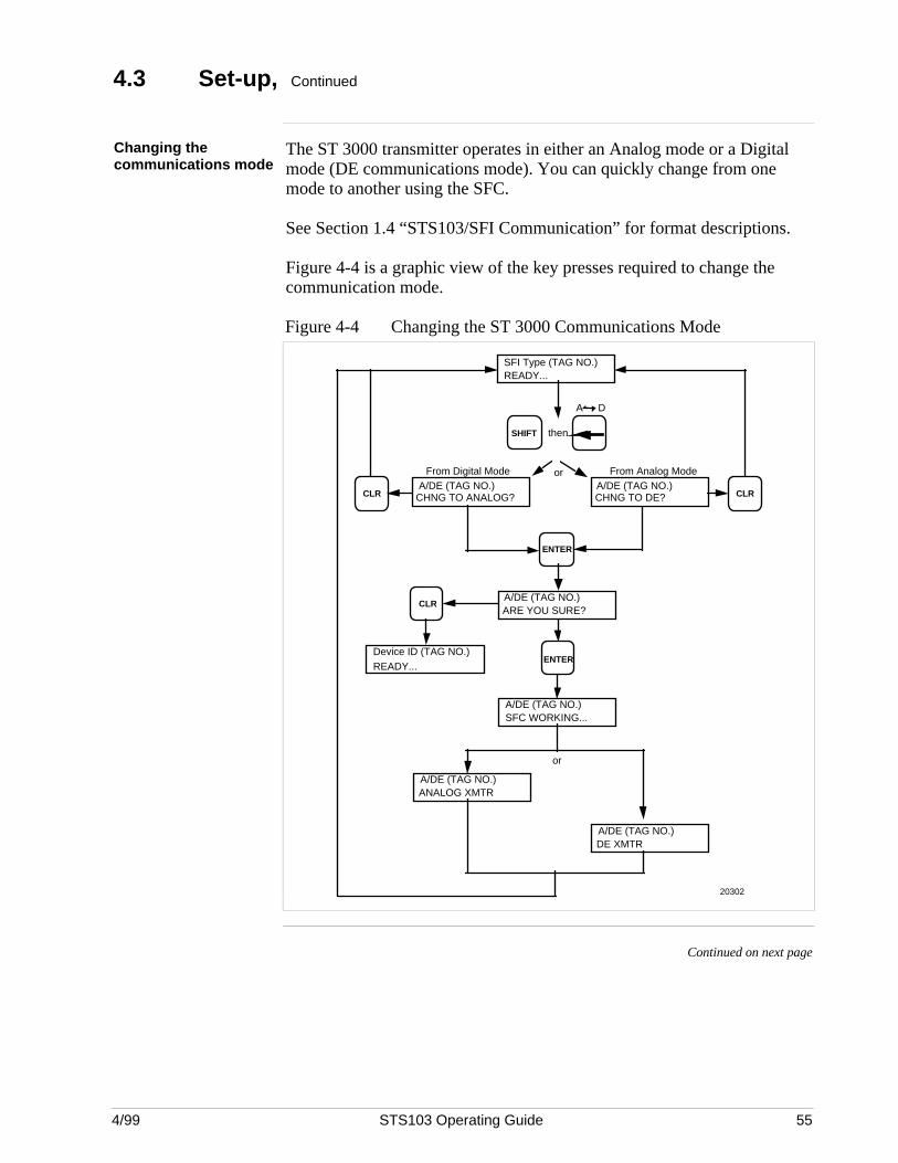
4/99 STS103 Operating Guide 55
4.3 Set-up, Continued
Changing thecommunications mode
The ST 3000 transmitter operates in either an Analog mode or a Digitalmode (DE communications mode). You can quickly change from onemode to another using the SFC.
See Section 1.4 “STS103/SFI Communication” for format descriptions.
Figure 4-4 is a graphic view of the key presses required to change thecommunication mode.
Figure 4-4 Changing the ST 3000 Communications Mode
SFI Type (TAG NO.)READY...
ENTER
From Analog Mode
SHIFT
20302
A/DE (TAG NO.)CHNG TO ANALOG?CLR
A/DE (TAG NO.)CHNG TO DE? CLR
From Digital Mode
then
A/DE (TAG NO.)ARE YOU SURE?
CLR
Device ID (TAG NO.)READY...
ENTER
A D
A/DE (TAG NO.)SFC WORKING...
A/DE (TAG NO.)DE XMTR
A/DE (TAG NO.)ANALOG XMTR
or
or
Continued on next page
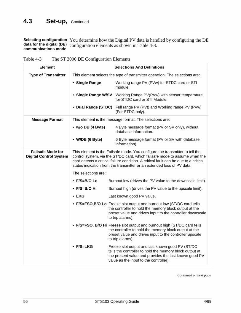
56 STS103 Operating Guide 4/99
4.3 Set-up, Continued
Selecting configurationdata for the digital (DE)communications mode
You determine how the Digital PV data is handled by configuring the DEconfiguration elements as shown in Table 4-3.
Table 4-3 The ST 3000 DE Configuration Elements
Element Selections And Definitions
Type of Transmitter This element selects the type of transmitter operation. The selections are:
• Single Range Working range PV (PVw) for STDC card or STImodule.
• Single Range W/SV Working Range PV(PVw) with sensor temperature for STDC card or STI Module.
• Dual Range (STDC) Full range PV (PVt) and Working range PV (PVw) (For STDC only).
Message Format This element is the message format. The selections are:
• w/o DB (4 Byte) 4 Byte message format (PV or SV only), withoutdatabase information.
• W/DB (6 Byte) 6 Byte message format (PV or SV with database information).
Failsafe Mode forDigital Control System
This element is the Failsafe mode. You configure the transmitter to tell thecontrol system, via the ST/DC card, which failsafe mode to assume when thecard detects a critical failure condition. A critical fault can be due to a criticalstatus indication from the transmitter or an extended loss of PV data.
The selections are:
• F/S=B/O Lo Burnout low (drives the PV value to the downscale limit).
• F/S=B/O Hi Burnout high (drives the PV value to the upscale limit).
• LKG Last known good PV value.
• F/S=FSO,B/O Lo Freeze slot output and burnout low (ST/DC card tells the controller to hold the memory block output at the preset value and drives input to the controller downscaleto trip alarms).
• F/S=FSO, B/O Hi Freeze slot output and burnout high (ST/DC card tells the controller to hold the memory block output at the preset value and drives input to the controller upscale to trip alarms).
• F/S=LKG Freeze slot output and last known good PV (ST/DC tells the controller to hold the memory block output at the present value and provides the last known good PV value as the input to the controller).
Continued on next page
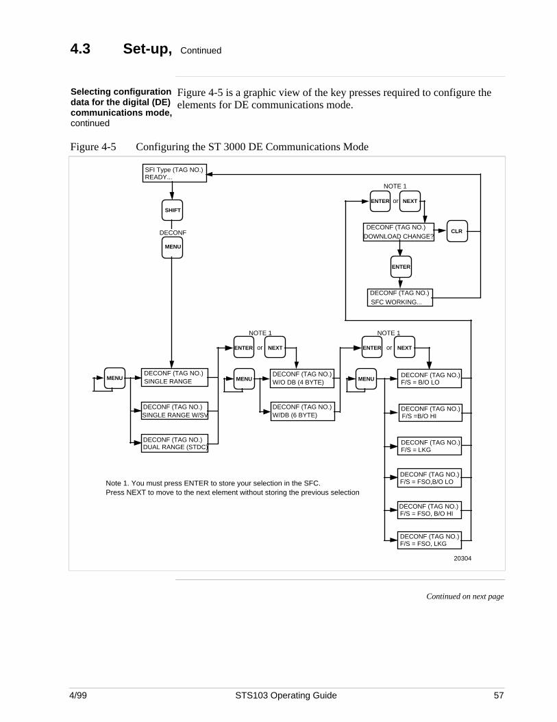
4/99 STS103 Operating Guide 57
4.3 Set-up, Continued
Selecting configurationdata for the digital (DE)communications mode,continued
Figure 4-5 is a graphic view of the key presses required to configure theelements for DE communications mode.
Figure 4-5 Configuring the ST 3000 DE Communications Mode
MENU
SHIFT
SFI Type (TAG NO.)READY...
DECONF
MENUDECONF (TAG NO.)SINGLE RANGE
DECONF (TAG NO.)SINGLE RANGE W/SV
DECONF (TAG NO.)DUAL RANGE (STDC)
NOTE 1
MENU
DECONF (TAG NO.)W/DB (6 BYTE)
DECONF (TAG NO.)W/O DB (4 BYTE)
ENTER or NEXT
MENUDECONF (TAG NO.)F/S = B/O LO
DECONF (TAG NO.)F/S = LKG
DECONF (TAG NO.)F/S =B/O HI
ENTER or NEXT
NOTE 1
DECONF (TAG NO.)F/S = FSO,B/O LO
DECONF (TAG NO.)F/S = FSO, LKG
DECONF (TAG NO.)F/S = FSO, B/O HI
DOWNLOAD CHANGE?DECONF (TAG NO.)
DECONF (TAG NO.)SFC WORKING...
ENTER or NEXT
NOTE 1
ENTER
CLR
20304
Note 1. You must press ENTER to store your selection in the SFC. Press NEXT to move to the next element without storing the previous selection
Continued on next page
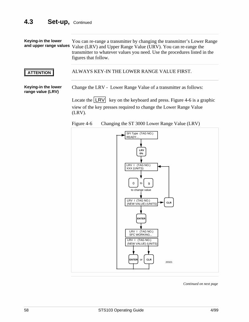
58 STS103 Operating Guide 4/99
4.3 Set-up, Continued
Keying-in the lowerand upper range values
You can re-range a transmitter by changing the transmitter’s Lower RangeValue (LRV) and Upper Range Value (URV). You can re-range thetransmitter to whatever values you need. Use the procedures listed in thefigures that follow.
ATTENTION ALWAYS KEY-IN THE LOWER RANGE VALUE FIRST.
Keying-in the lowerrange value (LRV)
Change the LRV - Lower Range Value of a transmitter as follows:
Locate the LRV key on the keyboard and press. Figure 4-6 is a graphic
view of the key presses required to change the Lower Range Value(LRV).
Figure 4-6 Changing the ST 3000 Lower Range Value (LRV)
LRV I (TAG NO.)XXX (UNITS)
to change value
LRV I (TAG NO.)(NEW VALUE) (UNITS)
CLRENTER or
ENTER
LRV I (TAG NO.)(NEW VALUE) (UNITS)
90 to
LRV 0%
SFI Type (TAG NO.)READY...
CLR
20321
LRV I (TAG NO.)SFC WORKING...
Continued on next page
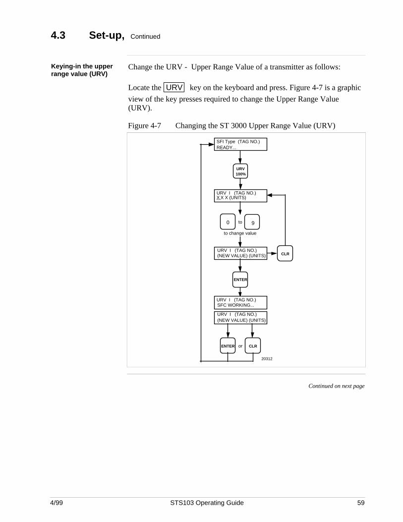
4/99 STS103 Operating Guide 59
4.3 Set-up, Continued
Keying-in the upperrange value (URV)
Change the URV - Upper Range Value of a transmitter as follows:
Locate the URV key on the keyboard and press. Figure 4-7 is a graphic
view of the key presses required to change the Upper Range Value(URV).
Figure 4-7 Changing the ST 3000 Upper Range Value (URV)
URV I (TAG NO.)X X X (UNITS)
to change value
CLRENTER or
URV I (TAG NO.)(NEW VALUE) (UNITS)
ENTER
URV I (TAG NO.)(NEW VALUE) (UNITS)
90 to
URV 100%
SFI Type (TAG NO.)READY...
CLR
URV I (TAG NO.)SFC WORKING...
20312
Continued on next page
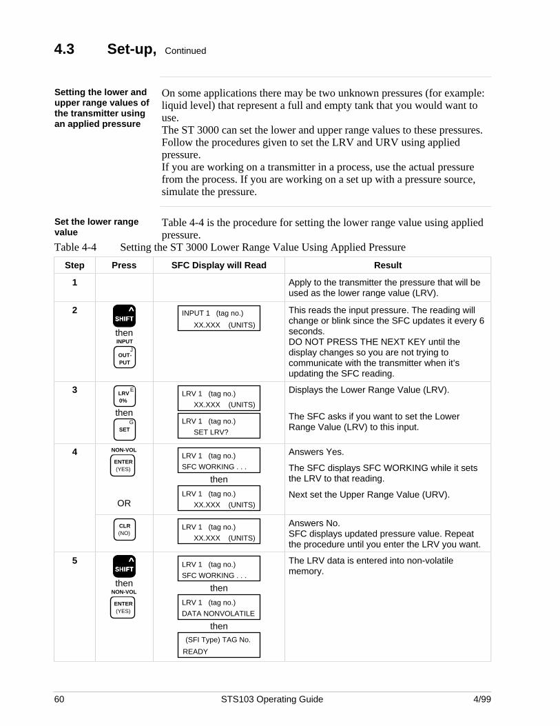
60 STS103 Operating Guide 4/99
4.3 Set-up, Continued
Setting the lower andupper range values ofthe transmitter usingan applied pressure
On some applications there may be two unknown pressures (for example:liquid level) that represent a full and empty tank that you would want touse.The ST 3000 can set the lower and upper range values to these pressures.Follow the procedures given to set the LRV and URV using appliedpressure.If you are working on a transmitter in a process, use the actual pressurefrom the process. If you are working on a set up with a pressure source,simulate the pressure.
Set the lower rangevalue
Table 4-4 is the procedure for setting the lower range value using appliedpressure.
Table 4-4 Setting the ST 3000 Lower Range Value Using Applied Pressure
Step Press SFC Display will Read Result
1 Apply to the transmitter the pressure that will beused as the lower range value (LRV).
2SSSSSHHHHHIIIIIFFFFFTTTTT
^
then
JOUT- PUT
INPUT
INPUT 1 (tag no.)
XX.XXX (UNITS)
This reads the input pressure. The reading willchange or blink since the SFC updates it every 6seconds.DO NOT PRESS THE NEXT KEY until thedisplay changes so you are not trying tocommunicate with the transmitter when it’supdating the SFC reading.
3 ELRV 0%
thenG
SET
LRV 1 (tag no.)
XX.XXX (UNITS)
LRV 1 (tag no.)
SET LRV?
Displays the Lower Range Value (LRV).
The SFC asks if you want to set the LowerRange Value (LRV) to this input.
4 NON-VOL
ENTER (YES)
OR
LRV 1 (tag no.)
SFC WORKING . . .
then
LRV 1 (tag no.)
XX.XXX (UNITS)
Answers Yes.
The SFC displays SFC WORKING while it setsthe LRV to that reading.
Next set the Upper Range Value (URV).
CLR (NO)
LRV 1 (tag no.)
XX.XXX (UNITS)
Answers No.SFC displays updated pressure value. Repeatthe procedure until you enter the LRV you want.
5SSSSSHHHHHIIIIIFFFFFTTTTT
^
thenNON-VOL
ENTER (YES)
LRV 1 (tag no.)
SFC WORKING . . .
then
LRV 1 (tag no.)
DATA NONVOLATILE
then
READY
(SFI Type) TAG No.
The LRV data is entered into non-volatilememory.
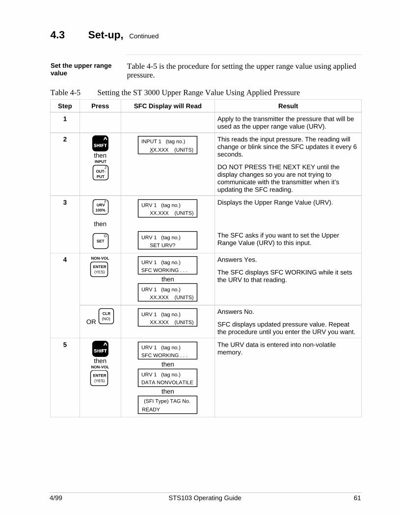
4/99 STS103 Operating Guide 61
4.3 Set-up, Continued
Set the upper rangevalue
Table 4-5 is the procedure for setting the upper range value using appliedpressure.
Table 4-5 Setting the ST 3000 Upper Range Value Using Applied Pressure
Step Press SFC Display will Read Result
1 Apply to the transmitter the pressure that will beused as the upper range value (URV).
2SSSSSHHHHHIIIIIFFFFFTTTTT
^
then
JOUT- PUT
INPUT
INPUT 1 (tag no.)
XX.XXX (UNITS)
This reads the input pressure. The reading willchange or blink since the SFC updates it every 6seconds.
DO NOT PRESS THE NEXT KEY until thedisplay changes so you are not trying tocommunicate with the transmitter when it’supdating the SFC reading.
3 FURV
100%
then
GSET
URV 1 (tag no.)
XX.XXX (UNITS)
URV 1 (tag no.)
SET URV?
Displays the Upper Range Value (URV).
The SFC asks if you want to set the UpperRange Value (URV) to this input.
4 NON-VOL
ENTER (YES)
URV 1 (tag no.)
SFC WORKING . . .
then
URV 1 (tag no.)
XX.XXX (UNITS)
Answers Yes.
The SFC displays SFC WORKING while it setsthe URV to that reading.
OR CLR (NO)
URV 1 (tag no.)
XX.XXX (UNITS)
Answers No.
SFC displays updated pressure value. Repeatthe procedure until you enter the URV you want.
5SSSSSHHHHHIIIIIFFFFFTTTTT
^
thenNON-VOL
ENTER (YES)
URV 1 (tag no.)
SFC WORKING . . .
then
URV 1 (tag no.)
DATA NONVOLATILE
then
READY
(SFI Type) TAG No.
The URV data is entered into non-volatilememory.
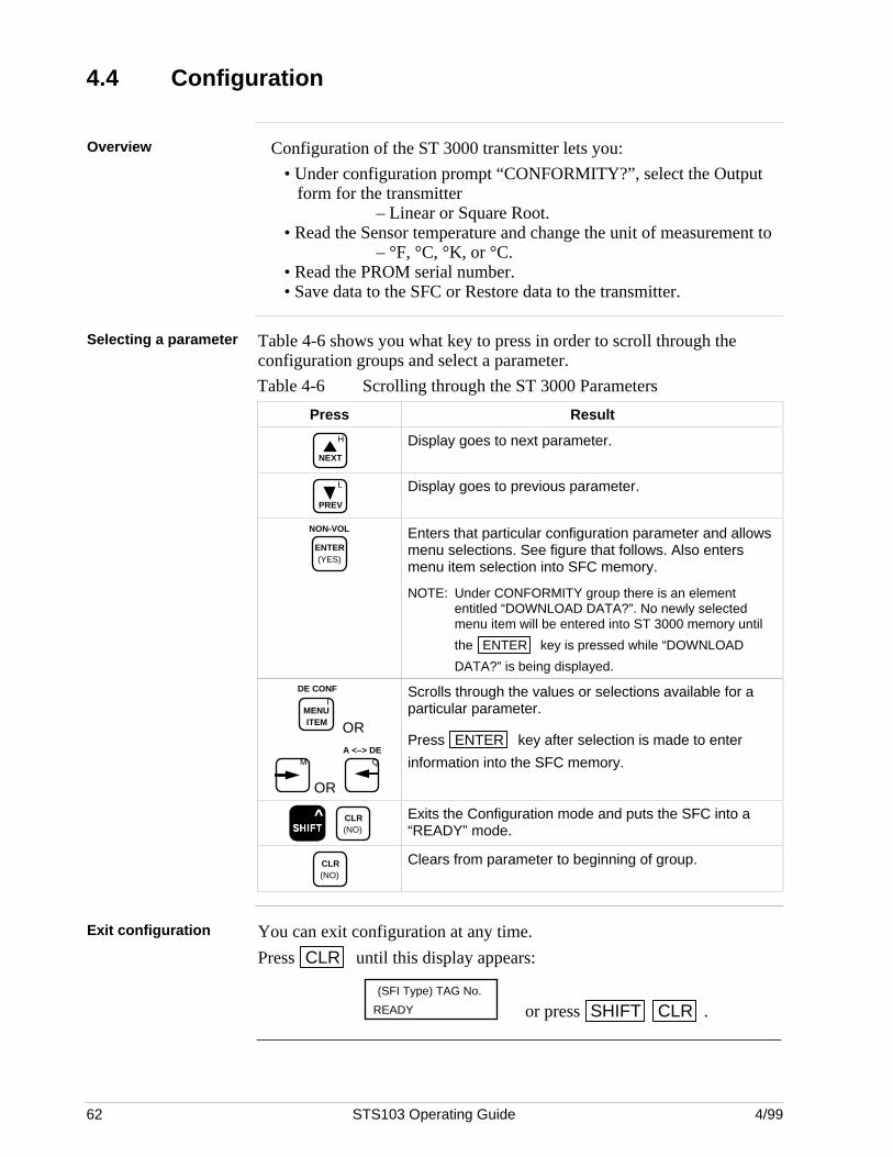
62 STS103 Operating Guide 4/99
4.4 Configuration
Overview Configuration of the ST 3000 transmitter lets you:
• Under configuration prompt “CONFORMITY?”, select the Outputform for the transmitter
– Linear or Square Root.• Read the Sensor temperature and change the unit of measurement to
– °F, °C, °K, or °C.• Read the PROM serial number.• Save data to the SFC or Restore data to the transmitter.
Selecting a parameter Table 4-6 shows you what key to press in order to scroll through theconfiguration groups and select a parameter.
Table 4-6 Scrolling through the ST 3000 Parameters
Press Result
H
NEXT
Display goes to next parameter.
L
PREV
Display goes to previous parameter.
NON-VOL
ENTER (YES)
Enters that particular configuration parameter and allowsmenu selections. See figure that follows. Also entersmenu item selection into SFC memory.
NOTE: Under CONFORMITY group there is an elemententitled “DOWNLOAD DATA?”. No newly selectedmenu item will be entered into ST 3000 memory until
the ENTER key is pressed while “DOWNLOAD
DATA?” is being displayed.
IMENU ITEM
DE CONF
OR
M
OR
QA <–> DE
Scrolls through the values or selections available for aparticular parameter.
Press ENTER key after selection is made to enter
information into the SFC memory.
SSSSSHHHHHIIIIIFFFFFTTTTT ^
CLR (NO)
Exits the Configuration mode and puts the SFC into a“READY” mode.
CLR (NO)
Clears from parameter to beginning of group.
Exit configuration You can exit configuration at any time.
Press CLR until this display appears:
READY
(SFI Type) TAG No.
or press SHIFT CLR .
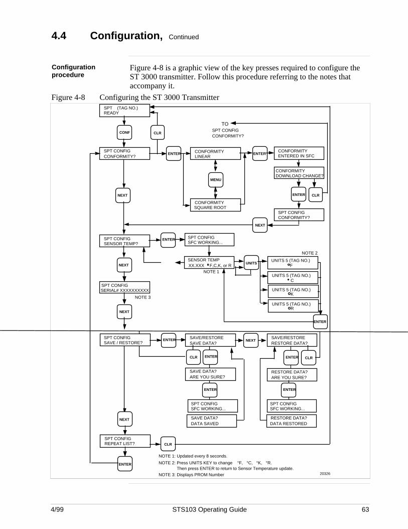
4/99 STS103 Operating Guide 63
4.4 Configuration, Continued
Configurationprocedure
Figure 4-8 is a graphic view of the key presses required to configure theST 3000 transmitter. Follow this procedure referring to the notes thataccompany it.
Figure 4-8 Configuring the ST 3000 Transmitter
NEXT
CLRCONF
SPT CONFIGCONFORMITY?
SPT (TAG NO.)READY
ENTER CONFORMITYLINEAR
MENU
CONFORMITYSQUARE ROOT
ENTERCONFORMITYENTERED IN SFC
CONFORMITYDOWNLOAD CHANGE?
ENTER
SPT CONFIGCONFORMITY?
NEXT
SPT CONFIGSENSOR TEMP?
NEXT
SPT CONFIGSERIAL# XXXXXXXXXX
ENTER SPT CONFIGSFC WORKING...
NEXT
CLR
UNITS
ENTER
NOTE 3
NOTE 1
SENSOR TEMPF,C,K, or RXX.XXX
UNITS 5 (TAG NO.)F
UNITS 5 (TAG NO.)C
UNITS 5 (TAG NO.)R
NOTE 2
CLR
20326
NEXT
SPT CONFIGREPEAT LIST?
ENTER NOTE 2: Press UNITS KEY to change °F, °C, °K, °R. Then press ENTER to return to Sensor Temperature update.
NOTE 1: Updated every 8 seconds.
NOTE 3: Displays PROM Number
UNITS 5 (TAG NO.)K
CLR
TOSPT CONFIGCONFORMITY?
SPT CONFIGSAVE / RESTORE?
ENTER SAVE/RESTORESAVE DATA?
SAVE/RESTORERESTORE DATA?
NEXT
ENTER ENTER
SAVE DATA?ARE YOU SURE?
RESTORE DATA?ARE YOU SURE?
SPT CONFIGSFC WORKING...
ENTER
SPT CONFIGSFC WORKING...
ENTER
SAVE DATA?DATA SAVED
RESTORE DATA?DATA RESTORED
CLR
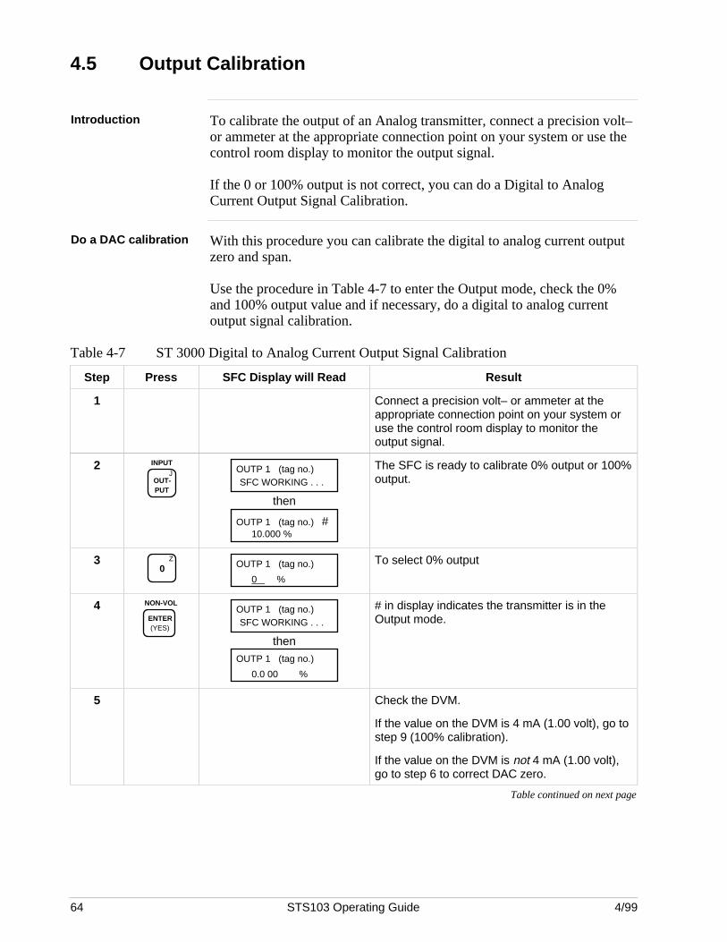
64 STS103 Operating Guide 4/99
4.5 Output Calibration
Introduction To calibrate the output of an Analog transmitter, connect a precision volt–or ammeter at the appropriate connection point on your system or use thecontrol room display to monitor the output signal.
If the 0 or 100% output is not correct, you can do a Digital to AnalogCurrent Output Signal Calibration.
Do a DAC calibration With this procedure you can calibrate the digital to analog current outputzero and span.
Use the procedure in Table 4-7 to enter the Output mode, check the 0%and 100% output value and if necessary, do a digital to analog currentoutput signal calibration.
Table 4-7 ST 3000 Digital to Analog Current Output Signal Calibration
Step Press SFC Display will Read Result
1 Connect a precision volt– or ammeter at theappropriate connection point on your system oruse the control room display to monitor theoutput signal.
2J
OUT- PUT
INPUTOUTP 1 (tag no.)SFC WORKING . . .
then
OUTP 1 (tag no.) #10.000 %
The SFC is ready to calibrate 0% output or 100%output.
3 Z
0 OUTP 1 (tag no.)
0 %
To select 0% output
4 NON-VOL
ENTER (YES)
OUTP 1 (tag no.)SFC WORKING . . .
thenOUTP 1 (tag no.)
0.0 00 %
# in display indicates the transmitter is in theOutput mode.
5 Check the DVM.
If the value on the DVM is 4 mA (1.00 volt), go tostep 9 (100% calibration).
If the value on the DVM is not 4 mA (1.00 volt),go to step 6 to correct DAC zero.
Table continued on next page
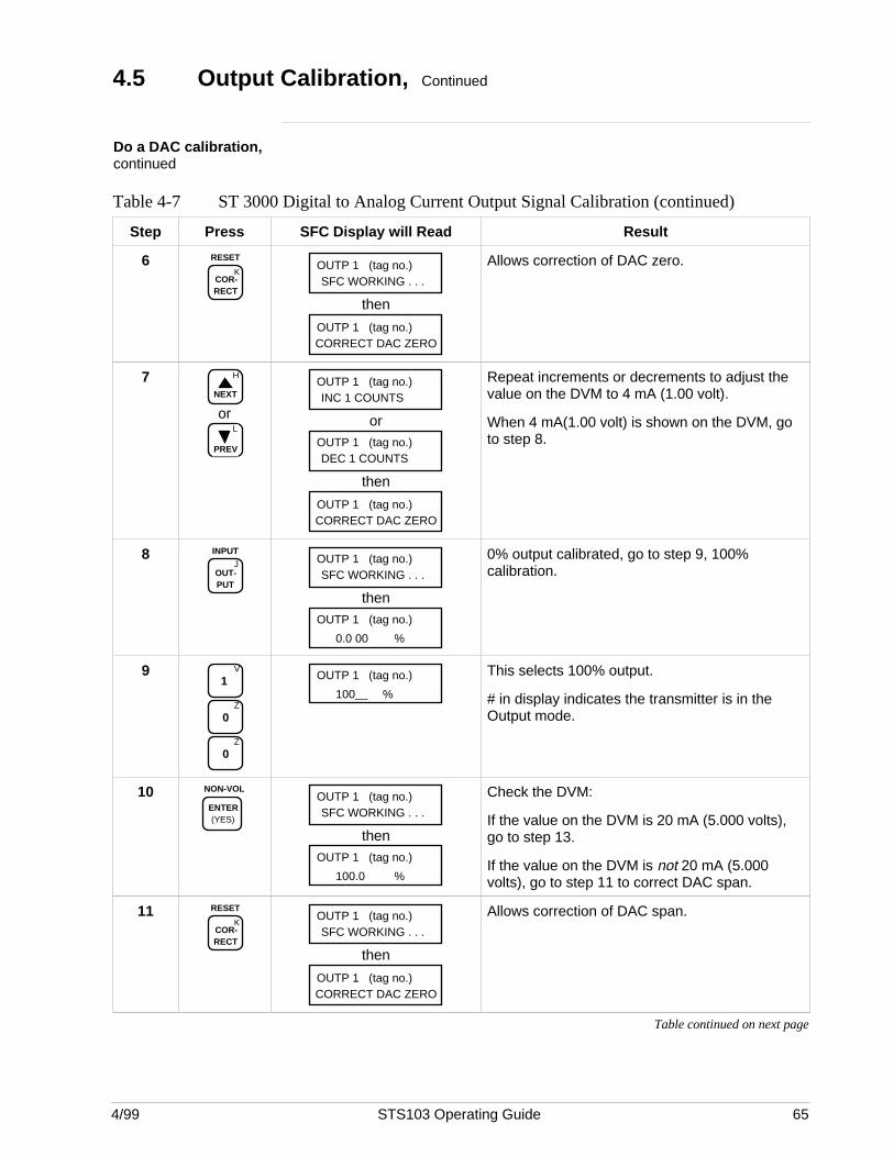
4/99 STS103 Operating Guide 65
4.5 Output Calibration, Continued
Do a DAC calibration,continued
Table 4-7 ST 3000 Digital to Analog Current Output Signal Calibration (continued)
Step Press SFC Display will Read Result
6K
COR- RECT
RESETOUTP 1 (tag no.)SFC WORKING . . .
then
OUTP 1 (tag no.)CORRECT DAC ZERO
Allows correction of DAC zero.
7 H
NEXT
orL
PREV
OUTP 1 (tag no.)INC 1 COUNTS
orOUTP 1 (tag no.)DEC 1 COUNTS
then
OUTP 1 (tag no.)CORRECT DAC ZERO
Repeat increments or decrements to adjust thevalue on the DVM to 4 mA (1.00 volt).
When 4 mA(1.00 volt) is shown on the DVM, goto step 8.
8J
OUT- PUT
INPUTOUTP 1 (tag no.)SFC WORKING . . .
thenOUTP 1 (tag no.)
0.0 00 %
0% output calibrated, go to step 9, 100%calibration.
9 V
1
Z
0
Z
0
OUTP 1 (tag no.)
100 %
This selects 100% output.
# in display indicates the transmitter is in theOutput mode.
10 NON-VOL
ENTER (YES)
OUTP 1 (tag no.)SFC WORKING . . .
thenOUTP 1 (tag no.)
100.0 %
Check the DVM:
If the value on the DVM is 20 mA (5.000 volts),go to step 13.
If the value on the DVM is not 20 mA (5.000volts), go to step 11 to correct DAC span.
11K
COR- RECT
RESETOUTP 1 (tag no.)SFC WORKING . . .
then
OUTP 1 (tag no.)CORRECT DAC ZERO
Allows correction of DAC span.
Table continued on next page

66 STS103 Operating Guide 4/99
4.5 Output Calibration, Continued
Do a DAC calibration,continued
Table 4-7 ST 3000 Digital to Analog Current Output Signal Calibration (continued)
Step Press SFC Display will Read Result
12 H
NEXT
orL
PREV
OUTP 1 (tag no.)INC 1 COUNTS
orOUTP 1 (tag no.)DEC 1 COUNTS
then
OUTP 1 (tag no.)CORRECT DAC ZERO
Repeat increments or decrements to adjust thevalue on the DVM to 20 mA (5.00 volts).
When 20 mA (5.000 volts) is shown on the DVM,go to step 13.
13J
OUT- PUT
INPUT
then
CLR (NO)
READY
(SFI Type) TAG No. Exits DAC calibration mode.
Exits OUTPUT mode.
4/99 STS103 Operating Guide 67
4.6 Operation
Overview The STS103 displays all the operating data for the ST 3000 PressureTransmitter. This data includes:
• Transmitter I.D.
• Damping value
• Lower range value
• Upper range value (span)
• Configuration elements for Digital Communications mode
• Input value
• Output Value
• Span value
• Upper range limit
• Engineering units
• Operation Status
• Software Version Number
• Failsafe Direction
• Zero Point adjustment
• Display and Keyboard Test
• Read Scratch Pad messages
Refer to Table 4-5 for Operating Data access instructions.
Continued on next page
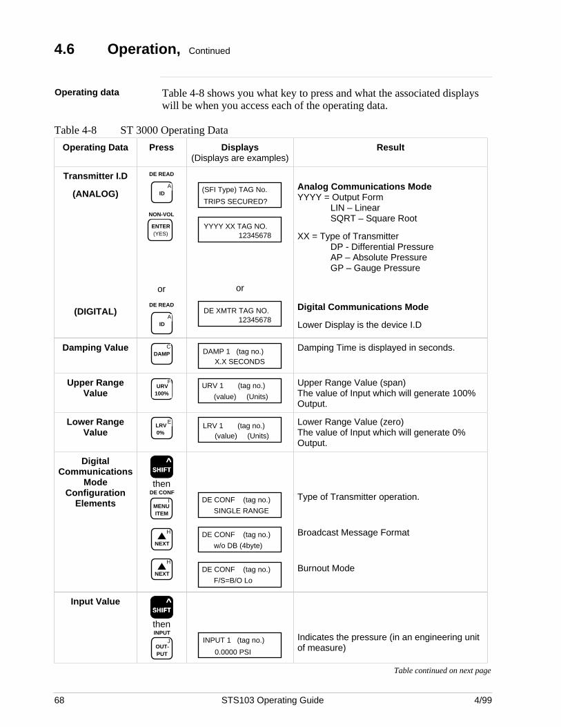
68 STS103 Operating Guide 4/99
4.6 Operation, Continued
Operating data Table 4-8 shows you what key to press and what the associated displayswill be when you access each of the operating data.
Table 4-8 ST 3000 Operating Data
Operating Data Press Displays(Displays are examples)
Result
Transmitter I.D
(ANALOG)
(DIGITAL)
DE READ
AID
NON-VOL
ENTER (YES)
or
DE READ
AID
TRIPS SECURED?
(SFI Type) TAG No.
YYYY XX TAG NO.12345678
or
DE XMTR TAG NO.12345678
Analog Communications ModeYYYY = Output Form
LIN – LinearSQRT – Square Root
XX = Type of TransmitterDP - Differential PressureAP – Absolute PressureGP – Gauge Pressure
Digital Communications Mode
Lower Display is the device I.D
Damping Value CDAMP DAMP 1 (tag no.)
X.X SECONDS
Damping Time is displayed in seconds.
Upper RangeValue
FURV
100%URV 1 (tag no.)
(value) (Units)
Upper Range Value (span)The value of Input which will generate 100%Output.
Lower RangeValue
ELRV 0%
LRV 1 (tag no.)(value) (Units)
Lower Range Value (zero)The value of Input which will generate 0%Output.
DigitalCommunications
ModeConfiguration
Elements
SSSSSHHHHHIIIIIFFFFFTTTTT ^
then
IMENU ITEM
DE CONF
H
NEXT
H
NEXT
DE CONF (tag no.)
SINGLE RANGE
DE CONF (tag no.)
w/o DB (4byte)
DE CONF (tag no.)
F/S=B/O Lo
Type of Transmitter operation.
Broadcast Message Format
Burnout Mode
Input ValueSSSSSHHHHHIIIIIFFFFFTTTTT
^
then
JOUT- PUT
INPUTINPUT 1 (tag no.)
0.0000 PSI
Indicates the pressure (in an engineering unitof measure)
Table continued on next page
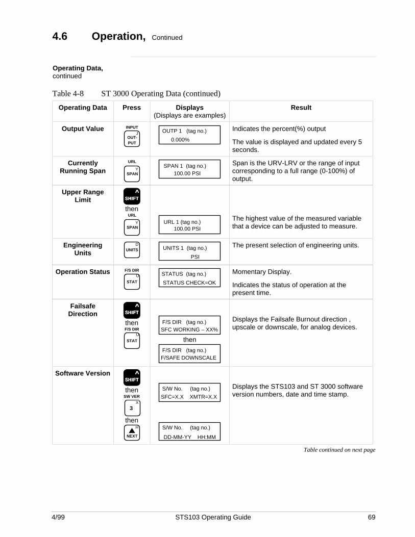
4/99 STS103 Operating Guide 69
4.6 Operation, Continued
Operating Data,continued
Table 4-8 ST 3000 Operating Data (continued)
Operating Data Press Displays(Displays are examples)
Result
Output ValueJ
OUT- PUT
INPUTOUTP 1 (tag no.)
0.000%
Indicates the percent(%) output
The value is displayed and updated every 5seconds.
CurrentlyRunning Span Y
SPAN
URLSPAN 1 (tag no.)
100.00 PSI
Span is the URV-LRV or the range of inputcorresponding to a full range (0-100%) ofoutput.
Upper RangeLimit SSSSSHHHHHIIIIIFFFFFTTTTT
^
then
YSPAN
URL
URL 1 (tag no.)100.00 PSI
The highest value of the measured variablethat a device can be adjusted to measure.
EngineeringUnits
DUNITS UNITS 1 (tag no.)
PSI
The present selection of engineering units.
Operation StatusU
STAT
F/S DIRSTATUS (tag no.)
STATUS CHECK=OK
Momentary Display.
Indicates the status of operation at thepresent time.
FailsafeDirection SSSSSHHHHHIIIIIFFFFFTTTTT
^
then
U
STAT
F/S DIR
F/S DIR (tag no.)SFC WORKING – XX%
then
F/S DIR (tag no.)F/SAFE DOWNSCALE
Displays the Failsafe Burnout direction ,upscale or downscale, for analog devices.
Software VersionSSSSSHHHHHIIIIIFFFFFTTTTT
^
then
X
3
SW VER
thenH
NEXT
S/W No. (tag no.)
SFC=X.X XMTR=X.X
S/W No. (tag no.)
DD-MM-YY HH:MM
Displays the STS103 and ST 3000 softwareversion numbers, date and time stamp.
Table continued on next page
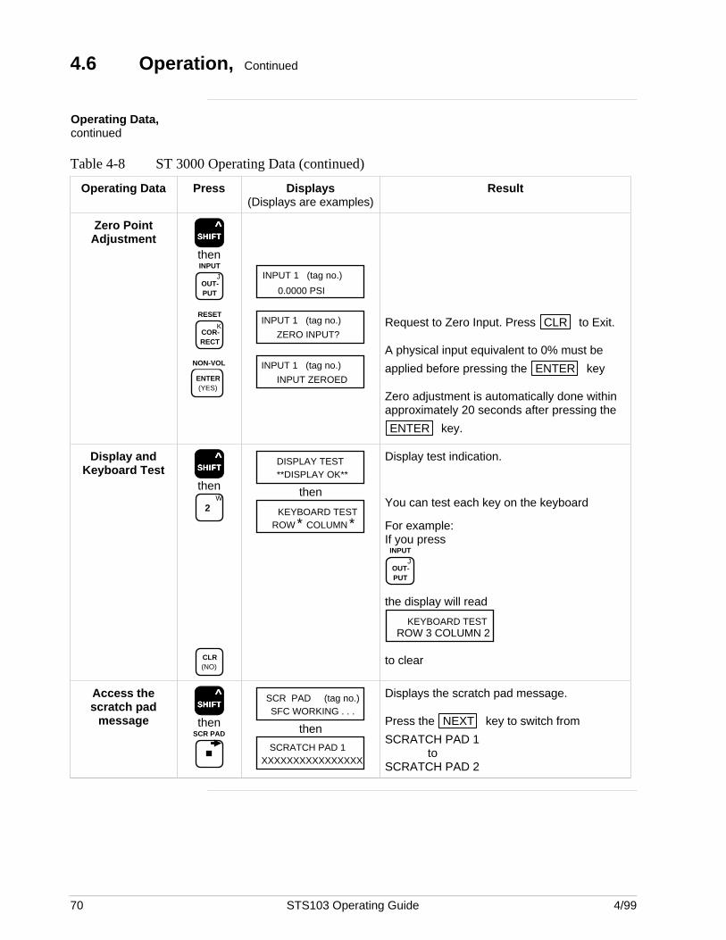
70 STS103 Operating Guide 4/99
4.6 Operation, Continued
Operating Data,continued
Table 4-8 ST 3000 Operating Data (continued)
Operating Data Press Displays(Displays are examples)
Result
Zero PointAdjustment SSSSSHHHHHIIIIIFFFFFTTTTT
^
then
JOUT- PUT
INPUT
KCOR- RECT
RESET
NON-VOL
ENTER (YES)
INPUT 1 (tag no.)
0.0000 PSI
INPUT 1 (tag no.)
ZERO INPUT?
INPUT 1 (tag no.)
INPUT ZEROED
Request to Zero Input. Press CLR to Exit.
A physical input equivalent to 0% must be
applied before pressing the ENTER key
Zero adjustment is automatically done withinapproximately 20 seconds after pressing the
ENTER key.
Display andKeyboard Test SSSSSHHHHHIIIIIFFFFFTTTTT
^
thenW
2
CLR (NO)
DISPLAY TEST**DISPLAY OK**
then
KEYBOARD TESTROW * COLUMN *
Display test indication.
You can test each key on the keyboard
For example:If you press
JOUT- PUT
INPUT
the display will read
KEYBOARD TESTROW 3 COLUMN 2
to clear
Access thescratch pad
messageSSSSSHHHHHIIIIIFFFFFTTTTT
^
thenSCR PAD
SCR PAD (tag no.)SFC WORKING . . .
then
SCRATCH PAD 1XXXXXXXXXXXXXXXX
Displays the scratch pad message.
Press the NEXT key to switch from
SCRATCH PAD 1to
SCRATCH PAD 2
4/99 STS103 Operating Guide 71
4.7 Diagnostics and SFC Messages
Introduction The ST 3000 and the STS103 both run continuous self-diagnostics.This means that they are constantly testing the communications, the loop,and themselves.
Any time you want results of these diagnostics, press the STAT key.
The SFC displays its report, in the form of messages, which identifydiagnostic conditions.Diagnostic conditions are broken down into three categories:
• OK status• critical status• a non-critical condition
OK Status An OK condition means no problem exists, and the display looks like this:
STATUS (tag no.)STATUS CHECK=OK
Critical status A critical condition means that the transmitter is not functioning properly.When this occurs, the transmitter goes into upscale burnout and maintainsan output of 21.8 mA, or into downscale burnout and maintains an outputof less than 3.9 mA. The message CRITICAL STATUS interrupts youroperation and is followed by the message PRESS STATUS.
After the PRESS STATUS message, you press the STAT key to find
out what problem exists. You will receive one or more messages. Takewhatever corrective action necessary to solve the problem. Remember thatthe transmitter will stay in upscale or down scale burnout until thecondition is corrected.If the transmitter sends more than one message, each message will bedisplayed in the order of importance for about 5 seconds. If you need to
see them again, press the STAT key again.
Non-critical status A non-critical condition means that although a problem exists, thetransmitter is still operating. When a non-critical condition occurs a “#”character appears on the right side of the display, along with whateveryou’re displaying at the time.
This character means press the STAT key because some type of a
problem exists. Again, one or more messages will appear on the displayfor about five seconds each.
Low battery voltage When the battery voltage becomes low, a colon ”:” will appear in themiddle of the display. It stays on the display until you either charge orreplace the batteries.
Continued on next page
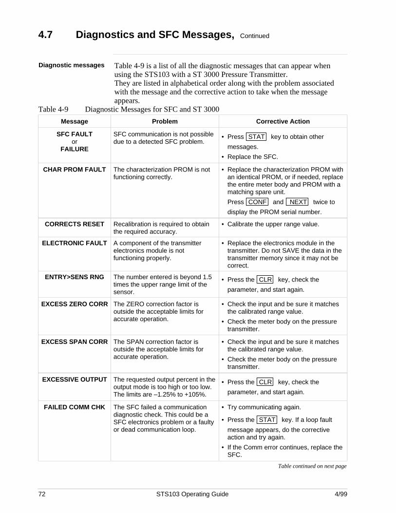
72 STS103 Operating Guide 4/99
4.7 Diagnostics and SFC Messages, Continued
Diagnostic messages Table 4-9 is a list of all the diagnostic messages that can appear whenusing the STS103 with a ST 3000 Pressure Transmitter.They are listed in alphabetical order along with the problem associatedwith the message and the corrective action to take when the messageappears.
Table 4-9 Diagnostic Messages for SFC and ST 3000
Message Problem Corrective Action
SFC FAULTor
FAILURE
SFC communication is not possibledue to a detected SFC problem.
• Press STAT key to obtain other
messages.
• Replace the SFC.
CHAR PROM FAULT The characterization PROM is notfunctioning correctly.
• Replace the characterization PROM withan identical PROM, or if needed, replacethe entire meter body and PROM with amatching spare unit.
Press CONF and NEXT twice to
display the PROM serial number.
CORRECTS RESET Recalibration is required to obtainthe required accuracy.
• Calibrate the upper range value.
ELECTRONIC FAULT A component of the transmitterelectronics module is notfunctioning properly.
• Replace the electronics module in thetransmitter. Do not SAVE the data in thetransmitter memory since it may not becorrect.
ENTRY>SENS RNG The number entered is beyond 1.5times the upper range limit of thesensor.
• Press the CLR key, check the
parameter, and start again.
EXCESS ZERO CORR The ZERO correction factor isoutside the acceptable limits foraccurate operation.
• Check the input and be sure it matchesthe calibrated range value.
• Check the meter body on the pressuretransmitter.
EXCESS SPAN CORR The SPAN correction factor isoutside the acceptable limits foraccurate operation.
• Check the input and be sure it matchesthe calibrated range value.
• Check the meter body on the pressuretransmitter.
EXCESSIVE OUTPUT The requested output percent in theoutput mode is too high or too low.The limits are –1.25% to +105%.
• Press the CLR key, check the
parameter, and start again.
FAILED COMM CHK The SFC failed a communicationdiagnostic check. This could be aSFC electronics problem or a faultyor dead communication loop.
• Try communicating again.
• Press the STAT key. If a loop fault
message appears, do the correctiveaction and try again.
• If the Comm error continues, replace theSFC.
Table continued on next page

4/99 STS103 Operating Guide 73
4.7 Diagnostics and SFC Messages, Continued
Diagnostic Messages,continued
Table 4-9 Diagnostic Messages for SFC and ST 3000 (continued)
Message Problem Corrective Action
HI RES/LOW VOLT Either there is too much resistancein the loop (open circuit), thevoltage is too low, or both.
• Check the wiring connections and thepower supply. There must be 11 Voltsminimum at the transmitter to permitoperation.
H.W. MISMATCH Hardware mismatch. Part ofSave/Restore function.
• None - SFC tried to restore as much ofthe database as possible.
ILLEGAL RESPONSE SFC received an illegal responsefrom the SFI.
• Try communicating again.
INVALID DATABASE The database of the transmitter wasnot correct at power up.
• Try communicating again.• Verify the database, re-calibrate the
transmitter and then manually update thenon-volatile memory.
INVALID REQUEST • The transmitter is being asked tocorrect or set its URV to a valuethat results in too low a span, orbeing asked to correct its LRV orURV while in the output mode.
• The given key function is not validfor the associated transmitter.
• Check that the proper calibrated URVinput is being applied to the transmitter,or that the transmitter is not in the outputmode.
• Check that the key function is applicablefor a pressure transmitter.
IN OUTPUT MODE The transmitter is operating as acurrent source.
• Press the OUTPUT and CLR keys if
you want to exit the output mode.
LOW LOOP RES Not enough resistance in serieswith the communication loop.
• Check the sensing resistor and verify atleast 250 Ohms resistance in the loop.
M B OVERLOADor
METERBODY FAULT
The pressure input is greater thantwo times the upper range limit ofthe transmitter.
• Check the process value to determine ifthe appropriate transmitter model isinstalled.
• The meterbody may have beendamaged.
• Do a complete performance check.
NACK RESPONSE The SFI sent a negativeacknowledgment because one ormore of the commands could not beprocessed by the SFI.
• Check the configuration and try again.
NO DAC TEMP COMP R-250 electronics board has beenused in a series 600 transmitter andsubsequently in a series 100transmitter. Coefficients for aspecial temperature compensationalgorithm unique to series 100/R-250 have been wiped from memory.
No corrective action possible. Effect will bea minor degradation of ambienttemperature influence specifications.
Table continued on next page
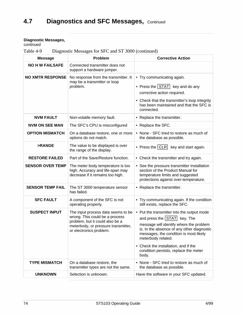
74 STS103 Operating Guide 4/99
4.7 Diagnostics and SFC Messages, Continued
Diagnostic Messages,continued
Table 4-9 Diagnostic Messages for SFC and ST 3000 (continued)
Message Problem Corrective Action
NO H W FAILSAFE Connected transmitter does notsupport a hardware jumper.
NO XMTR RESPONSE No response from the transmitter. Itmay be a transmitter or loopproblem.
• Try communicating again.
• Press the STAT key and do any
corrective action required.
• Check that the transmitter’s loop integrityhas been maintained and that the SFC isconnected.
NVM FAULT Non-volatile memory fault. • Replace the transmitter.
NVM ON SEE MAN The SFC’s CPU is misconfigured • Replace the SFC.
OPTION MISMATCH On a database restore, one or moreoptions do not match.
• None - SFC tried to restore as much ofthe database as possible.
>RANGE The value to be displayed is overthe range of the display.
• Press the CLR key and start again.
RESTORE FAILED Part of the Save/Restore function. • Check the transmitter and try again.
SENSOR OVER TEMP The meter body temperature is toohigh. Accuracy and life-span maydecrease if it remains too high.
• See the pressure transmitter Installationsection of the Product Manual fortemperature limits and suggestedprotections against over-temperature.
SENSOR TEMP FAIL The ST 3000 temperature sensorhas failed.
• Replace the transmitter.
SFC FAULT A component of the SFC is notoperating properly.
• Try communicating again. If the conditionstill exists, replace the SFC.
SUSPECT INPUT The input process data seems to bewrong. This could be a processproblem, but it could also be ameterbody, or pressure transmitter,or electronics problem.
• Put the transmitter into the output mode
and press the STAT key. The
message will identify where the problemis. In the absence of any other diagnosticmessages, the condition is most likelymeterbody related.
• Check the installation, and if thecondition persists, replace the meterbody.
TYPE MISMATCH On a database restore, thetransmitter types are not the same.
• None - SFC tried to restore as much ofthe database as possible.
UNKNOWN Selection is unknown. Have the software in your SFC updated.
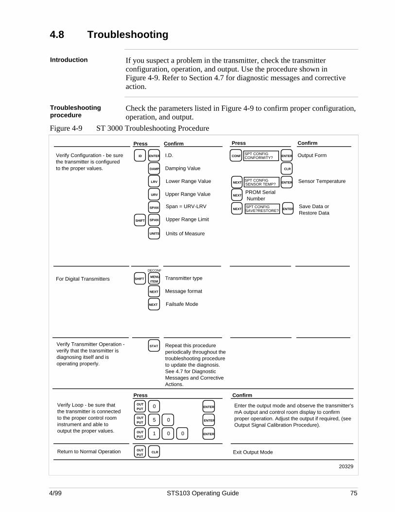
4/99 STS103 Operating Guide 75
4.8 Troubleshooting
Introduction If you suspect a problem in the transmitter, check the transmitterconfiguration, operation, and output. Use the procedure shown inFigure 4-9. Refer to Section 4.7 for diagnostic messages and correctiveaction.
Troubleshootingprocedure
Check the parameters listed in Figure 4-9 to confirm proper configuration,operation, and output.
Figure 4-9 ST 3000 Troubleshooting Procedure
ENTER
DAMP
LRV
URV
SPAN
SPAN
UNITS
NEXT
STAT
I.D.
Damping Value
Lower Range Value
Upper Range Value
Span = URV-LRV
Units of Measure
Message format
Failsafe Mode
Repeat this procedure periodically throughout the troubleshooting procedure to update the diagnosis. See 4.7 for Diagnostic Messages and Corrective Actions.
CONFSPT CONFIGCONFORMITY?
ENTER
NEXT
NEXT
Output Form
Sensor Temperature
PROM Serial Number
ID
SHIFT
MENU ITEM
Upper Range Limit
Transmitter type
Verify Configuration - be sure the transmitter is configured to the proper values.
For Digital Transmitters
Verify Transmitter Operation - verify that the transmitter is diagnosing itself and is operating properly.
Press ConfirmConfirmPress
20329
Verify Loop - be sure that the transmitter is connected to the proper control room instrument and able to output the proper values.
0OUT PUT
0
ENTER
5OUT PUT
0 ENTER
1OUT PUT
0 ENTER
Enter the output mode and observe the transmitter’s mA output and control room display to confirm proper operation. Adjust the output if required, (see Output Signal Calibration Procedure).
OUT PUT
CLRReturn to Normal Operation Exit Output Mode
ConfirmPress
DECONF
SHIFT
NEXT
CLR
SPT CONFIGSENSOR TEMP? ENTER
NEXTSPT CONFIGSAVE?RESTORE?
ENTER
Save Data or Restore Data

76 STS103 Operating Guide 4/99
4/99 STS103 Operating Guide 77
Section 5 —STT 3000 Temperature Transmitter
5.1 Overview
Introduction This section contains all the information you will need to know in order towire, set-up, configure, operate, troubleshoot, and calibrate STT 3000Smart Temperature Transmitters using the STS103 Smart FieldCommunicator.
Refer to the STT 3000 transmitter user’s manual for operating andinstallation information.
Make sure you have become familiar with the STS103 operations that aremore or less the same for every transmitter.
This section gives you the keystrokes and displays that are specific forSFC communications with the following STT 3000 Smart TemperatureTransmitter models:
• STT350• STT302• STT300• STT25D• STT25M
What’s in this section? This section contains the following topics:
Topic See Page
5.1 Overview 77
5.2 Wiring 78
5.3 Set-up 80
5.4 Configuration 93
5.5 Output Calibration 102
5.6 Operation 105
5.7 Diagnostics and SFC Messages 109
5.8 Troubleshooting 114
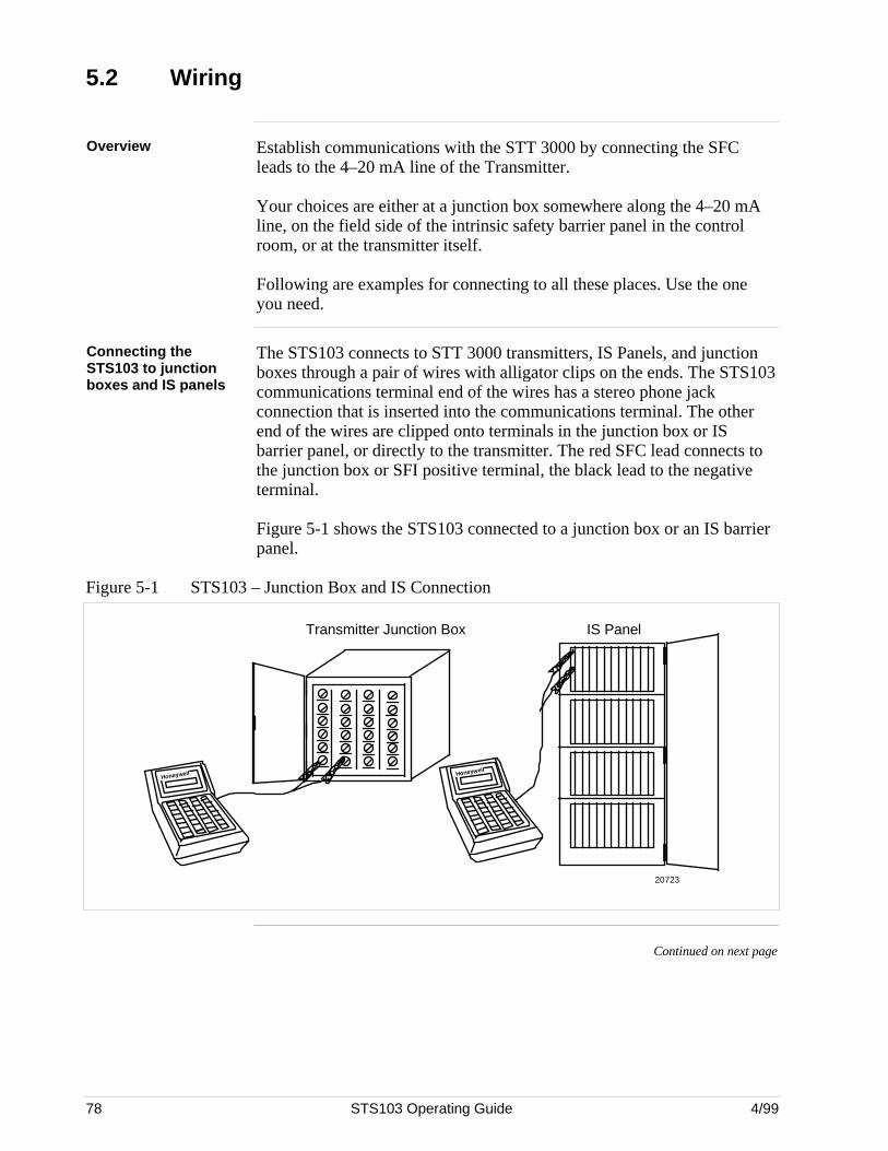
78 STS103 Operating Guide 4/99
5.2 Wiring
Overview Establish communications with the STT 3000 by connecting the SFCleads to the 4–20 mA line of the Transmitter.
Your choices are either at a junction box somewhere along the 4–20 mAline, on the field side of the intrinsic safety barrier panel in the controlroom, or at the transmitter itself.
Following are examples for connecting to all these places. Use the oneyou need.
Connecting theSTS103 to junctionboxes and IS panels
The STS103 connects to STT 3000 transmitters, IS Panels, and junctionboxes through a pair of wires with alligator clips on the ends. The STS103communications terminal end of the wires has a stereo phone jackconnection that is inserted into the communications terminal. The otherend of the wires are clipped onto terminals in the junction box or ISbarrier panel, or directly to the transmitter. The red SFC lead connects tothe junction box or SFI positive terminal, the black lead to the negativeterminal.
Figure 5-1 shows the STS103 connected to a junction box or an IS barrierpanel.
Figure 5-1 STS103 – Junction Box and IS Connection
Honeywell
Transmitter Junction Box IS Panel
20723
Honeywell
Continued on next page
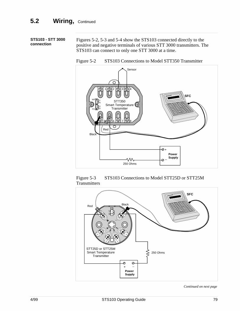
4/99 STS103 Operating Guide 79
5.2 Wiring, Continued
STS103 - STT 3000connection
Figures 5-2, 5-3 and 5-4 show the STS103 connected directly to thepositive and negative terminals of various STT 3000 transmitters. TheSTS103 can connect to only one STT 3000 at a time.
Figure 5-2 STS103 Connections to Model STT350 Transmitter
UDFS
YN
WP
1 2 3 4
5 6 7 8
SFC
Black
Red
_
250 Ohms
+PowerSupply
STT350Smart Temperature
Transmitter
Sensor
Figure 5-3 STS103 Connections to Model STT25D or STT25MTransmitters
_
UD
FS
+
14
3 2
PowerSupply
+ _
250 Ohms
SFC
STT25D or STT25MSmart Temperature
Transmitter
BlackRed
Continued on next page
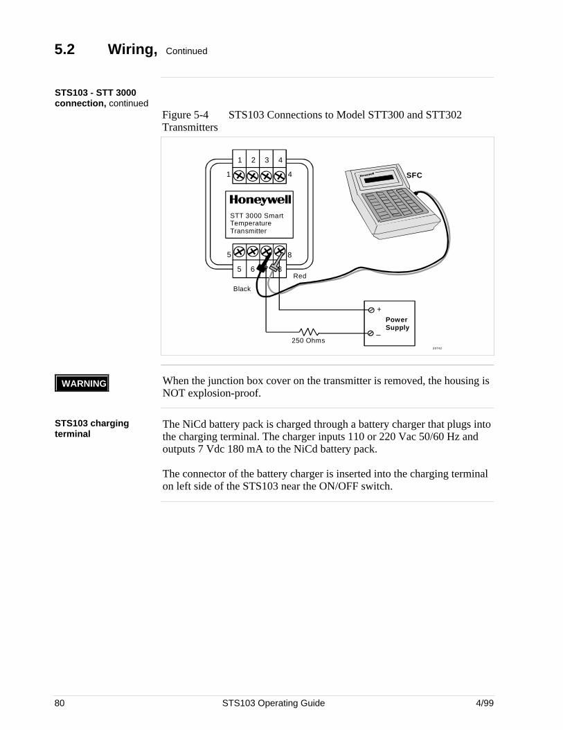
80 STS103 Operating Guide 4/99
5.2 Wiring, Continued
STS103 - STT 3000connection, continued
Figure 5-4 STS103 Connections to Model STT300 and STT302Transmitters
1 2 3 4
4 1
STT 3000 Smart Temperature Transmitter
5 8
5 6 7 8
20742
SFC
PowerSupply
+
_250 Ohms
Red
Black
WARNING When the junction box cover on the transmitter is removed, the housing isNOT explosion-proof.
STS103 chargingterminal
The NiCd battery pack is charged through a battery charger that plugs intothe charging terminal. The charger inputs 110 or 220 Vac 50/60 Hz andoutputs 7 Vdc 180 mA to the NiCd battery pack.
The connector of the battery charger is inserted into the charging terminalon left side of the STS103 near the ON/OFF switch.
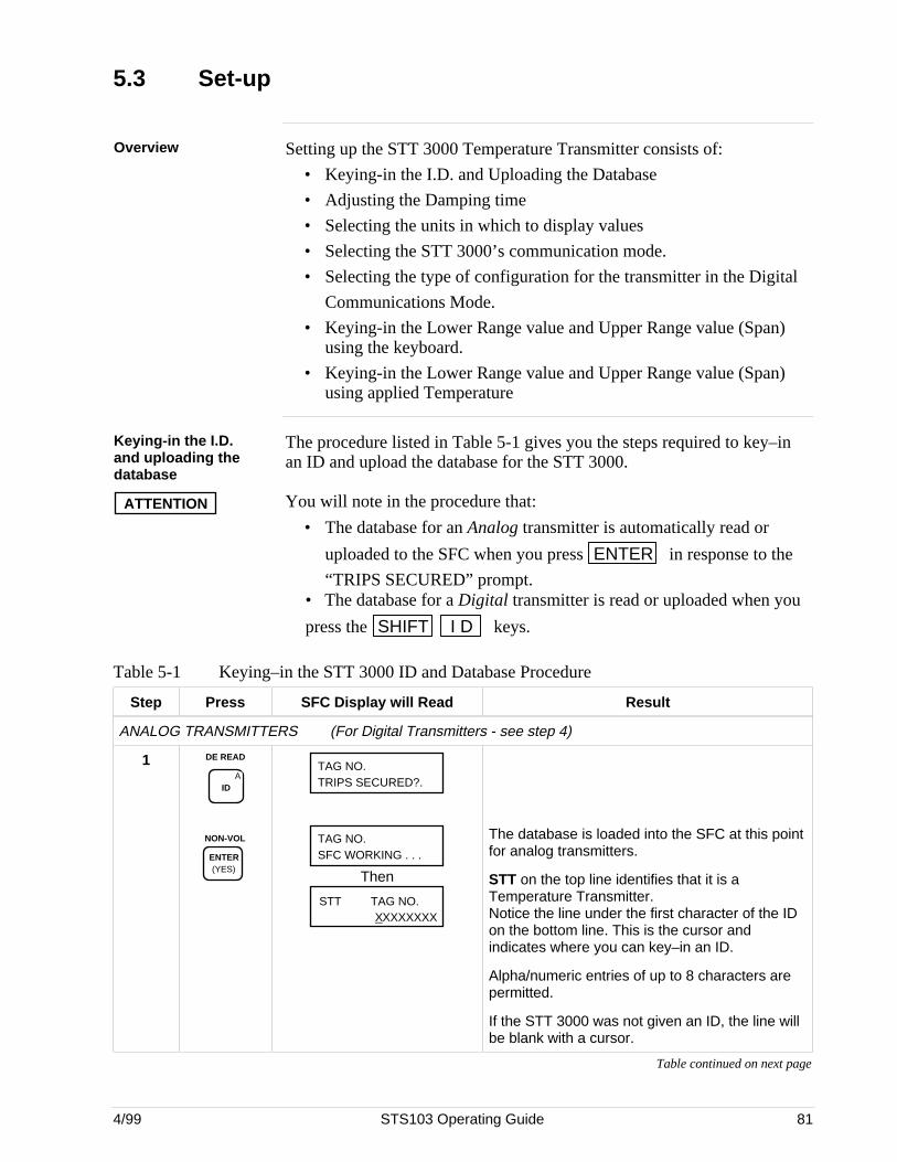
4/99 STS103 Operating Guide 81
5.3 Set-up
Overview Setting up the STT 3000 Temperature Transmitter consists of:
• Keying-in the I.D. and Uploading the Database
• Adjusting the Damping time
• Selecting the units in which to display values
• Selecting the STT 3000’s communication mode.
• Selecting the type of configuration for the transmitter in the Digital
Communications Mode.
• Keying-in the Lower Range value and Upper Range value (Span)using the keyboard.
• Keying-in the Lower Range value and Upper Range value (Span)using applied Temperature
Keying-in the I.D.and uploading thedatabase
The procedure listed in Table 5-1 gives you the steps required to key–inan ID and upload the database for the STT 3000.
ATTENTION You will note in the procedure that:
• The database for an Analog transmitter is automatically read or
uploaded to the SFC when you press ENTER in response to the
“TRIPS SECURED” prompt.• The database for a Digital transmitter is read or uploaded when you
press the SHIFT I D keys.
Table 5-1 Keying–in the STT 3000 ID and Database Procedure
Step Press SFC Display will Read Result
ANALOG TRANSMITTERS (For Digital Transmitters - see step 4)
1 DE READ
AID
NON-VOL
ENTER (YES)
TAG NO.TRIPS SECURED?.
TAG NO.SFC WORKING . . .
Then
STT TAG NO.XXXXXXXX
The database is loaded into the SFC at this pointfor analog transmitters.
STT on the top line identifies that it is aTemperature Transmitter.Notice the line under the first character of the IDon the bottom line. This is the cursor andindicates where you can key–in an ID.
Alpha/numeric entries of up to 8 characters arepermitted.
If the STT 3000 was not given an ID, the line willbe blank with a cursor.
Table continued on next page
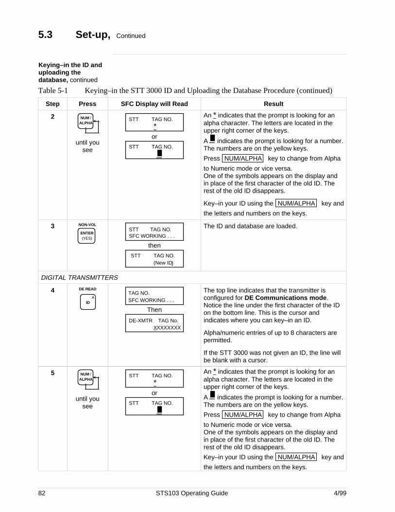
82 STS103 Operating Guide 4/99
5.3 Set-up, Continued
Keying–in the ID anduploading thedatabase, continued
Table 5-1 Keying–in the STT 3000 ID and Uploading the Database Procedure (continued)
Step Press SFC Display will Read Result
2 NUM / ALPHA
until yousee
STT TAG NO.
*or
STT TAG NO.
An * indicates that the prompt is looking for an alpha character. The letters are located in theupper right corner of the keys.
A indicates the prompt is looking for a number.The numbers are on the yellow keys.
Press NUM/ALPHA key to change from Alpha
to Numeric mode or vice versa.One of the symbols appears on the display andin place of the first character of the old ID. Therest of the old ID disappears.
Key–in your ID using the NUM/ALPHA key and
the letters and numbers on the keys.
3 NON-VOL
ENTER (YES)
STT TAG NO.SFC WORKING . . .
then
(New ID)STT TAG NO.
The ID and database are loaded.
DIGITAL TRANSMITTERS
4 DE READ
AID
TAG NO.SFC WORKING . . .
Then
DE-XMTR TAG No.XXXXXXXX
The top line indicates that the transmitter isconfigured for DE Communications mode.Notice the line under the first character of the IDon the bottom line. This is the cursor andindicates where you can key–in an ID.
Alpha/numeric entries of up to 8 characters arepermitted.
If the STT 3000 was not given an ID, the line willbe blank with a cursor.
5 NUM / ALPHA
until yousee
STT TAG NO.
*or
STT TAG NO.
An * indicates that the prompt is looking for an alpha character. The letters are located in theupper right corner of the keys.
A indicates the prompt is looking for a number.The numbers are on the yellow keys.
Press NUM/ALPHA key to change from Alpha
to Numeric mode or vice versa.One of the symbols appears on the display andin place of the first character of the old ID. Therest of the old ID disappears.
Key–in your ID using the NUM/ALPHA key and
the letters and numbers on the keys.
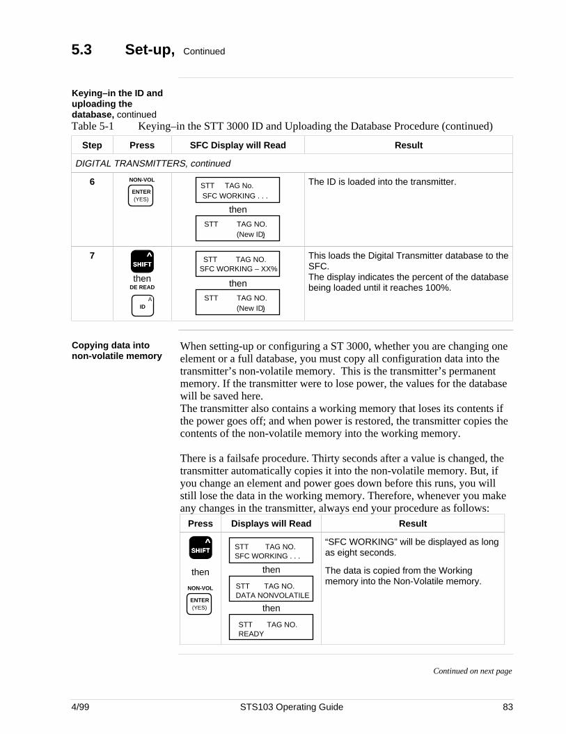
4/99 STS103 Operating Guide 83
5.3 Set-up, Continued
Keying–in the ID anduploading thedatabase, continuedTable 5-1 Keying–in the STT 3000 ID and Uploading the Database Procedure (continued)
Step Press SFC Display will Read Result
DIGITAL TRANSMITTERS, continued
6 NON-VOL
ENTER (YES) SFC WORKING . . .
STT TAG No.
then
(New ID)STT TAG NO.
The ID is loaded into the transmitter.
7SSSSSHHHHHIIIIIFFFFFTTTTT
^
thenDE READ
AID
SFC WORKING – XX%STT TAG NO.
then
(New ID)STT TAG NO.
This loads the Digital Transmitter database to theSFC.The display indicates the percent of the databasebeing loaded until it reaches 100%.
Copying data intonon-volatile memory
When setting-up or configuring a ST 3000, whether you are changing oneelement or a full database, you must copy all configuration data into thetransmitter’s non-volatile memory. This is the transmitter’s permanentmemory. If the transmitter were to lose power, the values for the databasewill be saved here.The transmitter also contains a working memory that loses its contents ifthe power goes off; and when power is restored, the transmitter copies thecontents of the non-volatile memory into the working memory.
There is a failsafe procedure. Thirty seconds after a value is changed, thetransmitter automatically copies it into the non-volatile memory. But, ifyou change an element and power goes down before this runs, you willstill lose the data in the working memory. Therefore, whenever you makeany changes in the transmitter, always end your procedure as follows:
Press Displays will Read Result
SSSSSHHHHHIIIIIFFFFFTTTTT ^
then
NON-VOL
ENTER (YES)
STT TAG NO.SFC WORKING . . .
then
STT TAG NO.DATA NONVOLATILE
then
STT TAG NO.READY
“SFC WORKING” will be displayed as longas eight seconds.
The data is copied from the Workingmemory into the Non-Volatile memory.
Continued on next page
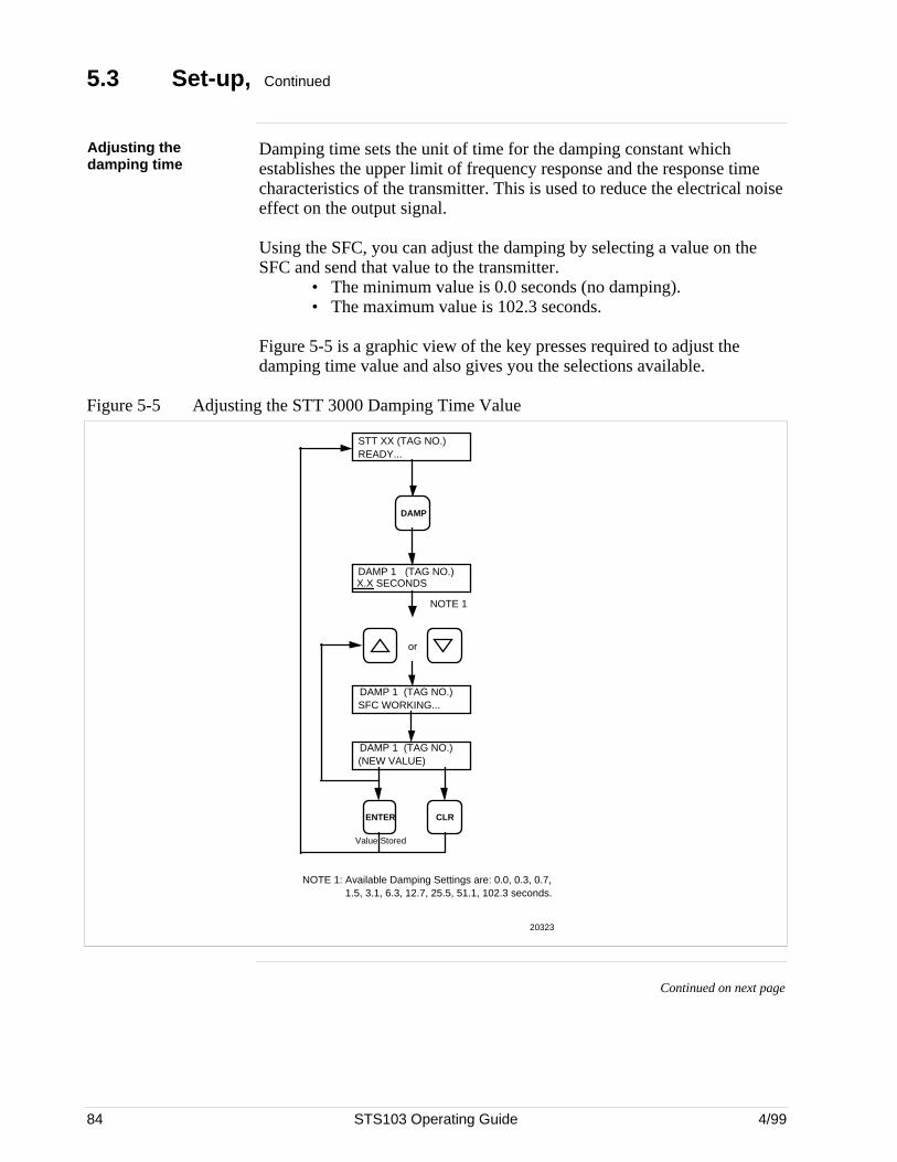
84 STS103 Operating Guide 4/99
5.3 Set-up, Continued
Adjusting thedamping time
Damping time sets the unit of time for the damping constant whichestablishes the upper limit of frequency response and the response timecharacteristics of the transmitter. This is used to reduce the electrical noiseeffect on the output signal.
Using the SFC, you can adjust the damping by selecting a value on theSFC and send that value to the transmitter.
• The minimum value is 0.0 seconds (no damping).• The maximum value is 102.3 seconds.
Figure 5-5 is a graphic view of the key presses required to adjust thedamping time value and also gives you the selections available.
Figure 5-5 Adjusting the STT 3000 Damping Time Value
STT XX (TAG NO.)READY...
DAMP
20323
DAMP 1 (TAG NO.)X.X SECONDS
or
DAMP 1 (TAG NO.)SFC WORKING...
DAMP 1 (TAG NO.)(NEW VALUE)
ENTER CLR
NOTE 1
NOTE 1: Available Damping Settings are: 0.0, 0.3, 0.7, 1.5, 3.1, 6.3, 12.7, 25.5, 51.1, 102.3 seconds.
Value Stored
Continued on next page
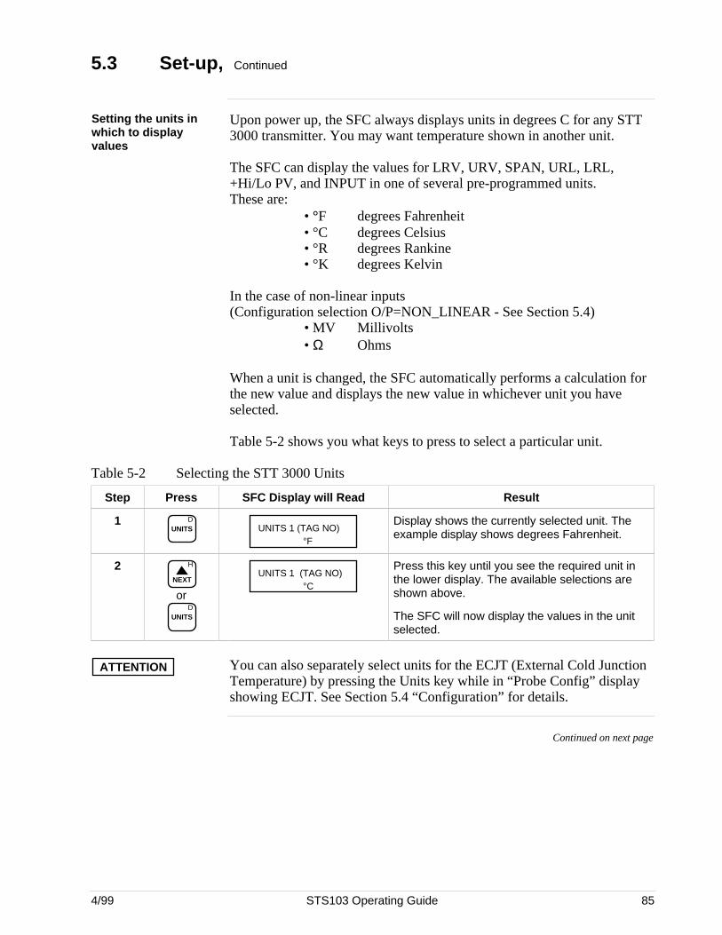
4/99 STS103 Operating Guide 85
5.3 Set-up, Continued
Setting the units inwhich to displayvalues
Upon power up, the SFC always displays units in degrees C for any STT3000 transmitter. You may want temperature shown in another unit.
The SFC can display the values for LRV, URV, SPAN, URL, LRL,+Hi/Lo PV, and INPUT in one of several pre-programmed units.These are:
• °F degrees Fahrenheit• °C degrees Celsius• °R degrees Rankine• °K degrees Kelvin
In the case of non-linear inputs(Configuration selection O/P=NON_LINEAR - See Section 5.4)
• MV Millivolts• Ω Ohms
When a unit is changed, the SFC automatically performs a calculation forthe new value and displays the new value in whichever unit you haveselected.
Table 5-2 shows you what keys to press to select a particular unit.
Table 5-2 Selecting the STT 3000 Units
Step Press SFC Display will Read Result
1 DUNITS UNITS 1 (TAG NO)
°F
Display shows the currently selected unit. Theexample display shows degrees Fahrenheit.
2 H
NEXT
orD
UNITS
UNITS 1 (TAG NO)°C
Press this key until you see the required unit inthe lower display. The available selections areshown above.
The SFC will now display the values in the unitselected.
ATTENTION You can also separately select units for the ECJT (External Cold JunctionTemperature) by pressing the Units key while in “Probe Config” displayshowing ECJT. See Section 5.4 “Configuration” for details.
Continued on next page
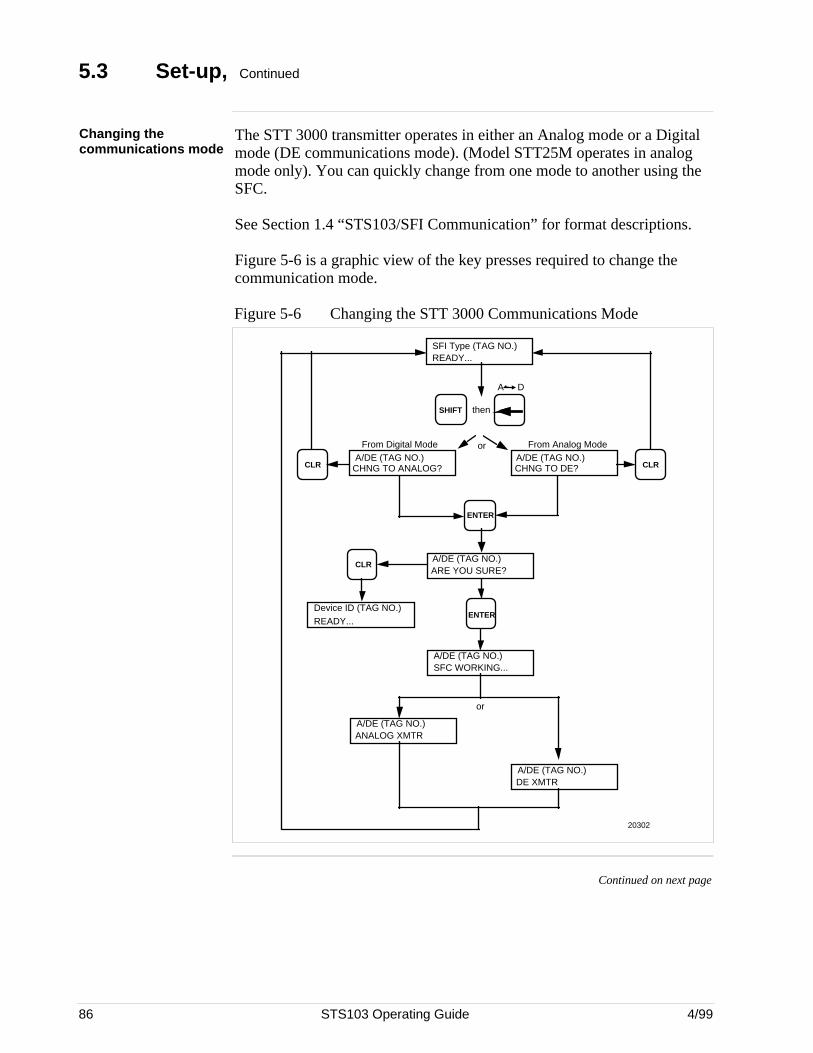
86 STS103 Operating Guide 4/99
5.3 Set-up, Continued
Changing thecommunications mode
The STT 3000 transmitter operates in either an Analog mode or a Digitalmode (DE communications mode). (Model STT25M operates in analogmode only). You can quickly change from one mode to another using theSFC.
See Section 1.4 “STS103/SFI Communication” for format descriptions.
Figure 5-6 is a graphic view of the key presses required to change thecommunication mode.
Figure 5-6 Changing the STT 3000 Communications Mode
SFI Type (TAG NO.)READY...
ENTER
From Analog Mode
SHIFT
20302
A/DE (TAG NO.)CHNG TO ANALOG?CLR
A/DE (TAG NO.)CHNG TO DE? CLR
From Digital Mode
then
A/DE (TAG NO.)ARE YOU SURE?
CLR
Device ID (TAG NO.)READY...
ENTER
A D
A/DE (TAG NO.)SFC WORKING...
A/DE (TAG NO.)DE XMTR
A/DE (TAG NO.)ANALOG XMTR
or
or
Continued on next page
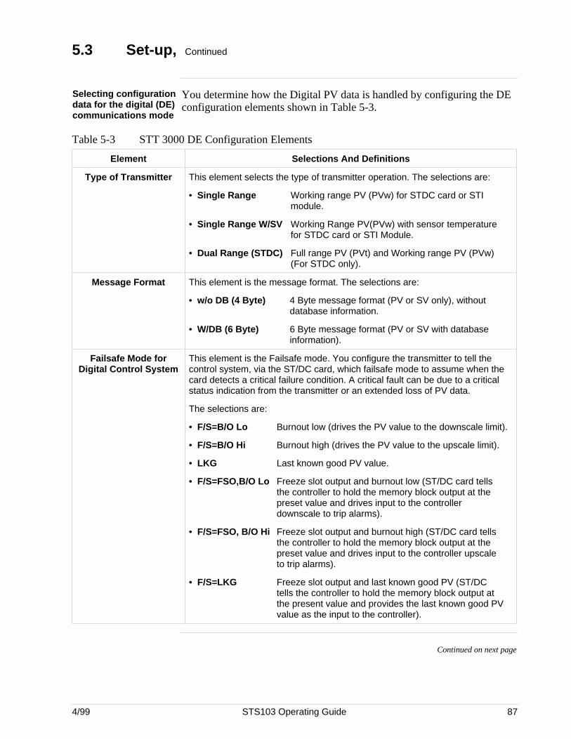
4/99 STS103 Operating Guide 87
5.3 Set-up, Continued
Selecting configurationdata for the digital (DE)communications mode
You determine how the Digital PV data is handled by configuring the DEconfiguration elements shown in Table 5-3.
Table 5-3 STT 3000 DE Configuration Elements
Element Selections And Definitions
Type of Transmitter This element selects the type of transmitter operation. The selections are:
• Single Range Working range PV (PVw) for STDC card or STImodule.
• Single Range W/SV Working Range PV(PVw) with sensor temperature for STDC card or STI Module.
• Dual Range (STDC) Full range PV (PVt) and Working range PV (PVw) (For STDC only).
Message Format This element is the message format. The selections are:
• w/o DB (4 Byte) 4 Byte message format (PV or SV only), withoutdatabase information.
• W/DB (6 Byte) 6 Byte message format (PV or SV with database information).
Failsafe Mode forDigital Control System
This element is the Failsafe mode. You configure the transmitter to tell thecontrol system, via the ST/DC card, which failsafe mode to assume when thecard detects a critical failure condition. A critical fault can be due to a criticalstatus indication from the transmitter or an extended loss of PV data.
The selections are:
• F/S=B/O Lo Burnout low (drives the PV value to the downscale limit).
• F/S=B/O Hi Burnout high (drives the PV value to the upscale limit).
• LKG Last known good PV value.
• F/S=FSO,B/O Lo Freeze slot output and burnout low (ST/DC card tells the controller to hold the memory block output at the preset value and drives input to the controller downscale to trip alarms).
• F/S=FSO, B/O Hi Freeze slot output and burnout high (ST/DC card tells the controller to hold the memory block output at the preset value and drives input to the controller upscale to trip alarms).
• F/S=LKG Freeze slot output and last known good PV (ST/DC tells the controller to hold the memory block output at the present value and provides the last known good PV value as the input to the controller).
Continued on next page
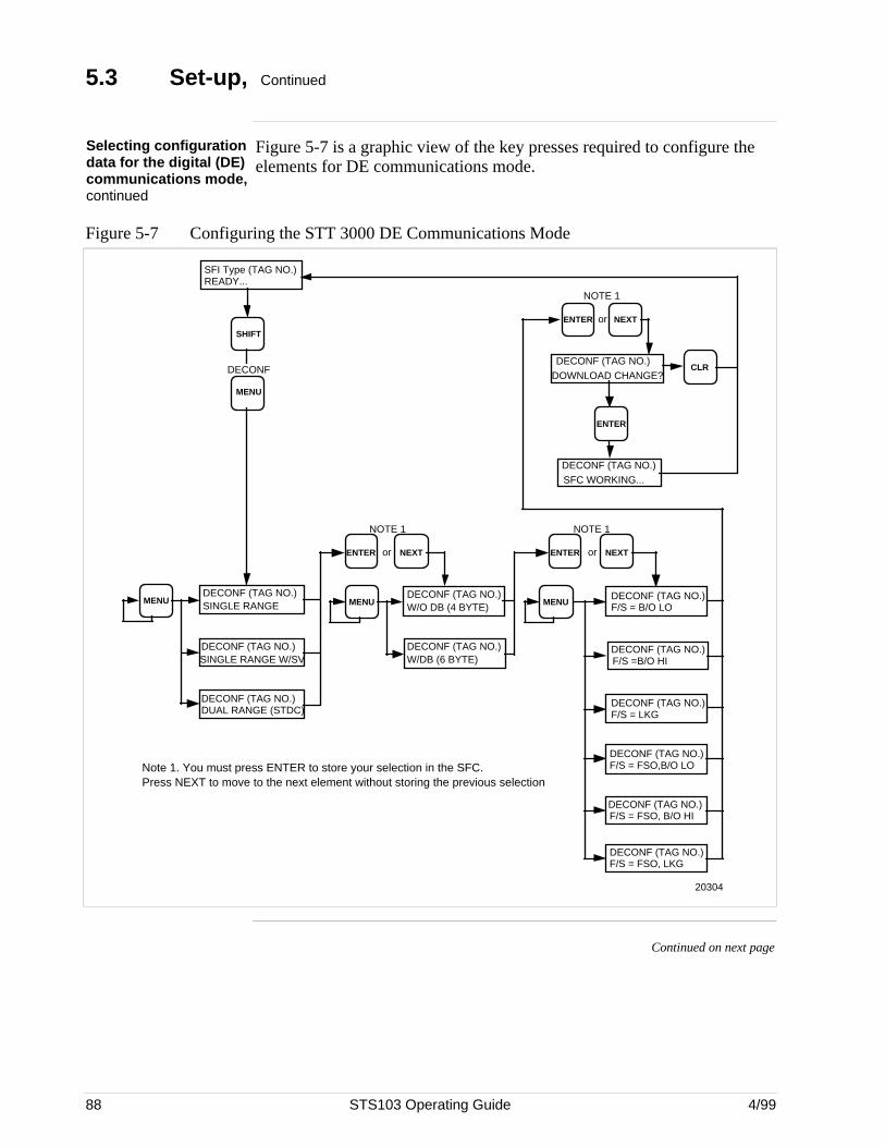
88 STS103 Operating Guide 4/99
5.3 Set-up, Continued
Selecting configurationdata for the digital (DE)communications mode,continued
Figure 5-7 is a graphic view of the key presses required to configure theelements for DE communications mode.
Figure 5-7 Configuring the STT 3000 DE Communications Mode
MENU
SHIFT
SFI Type (TAG NO.)READY...
DECONF
MENUDECONF (TAG NO.)SINGLE RANGE
DECONF (TAG NO.)SINGLE RANGE W/SV
DECONF (TAG NO.)DUAL RANGE (STDC)
NOTE 1
MENU
DECONF (TAG NO.)W/DB (6 BYTE)
DECONF (TAG NO.)W/O DB (4 BYTE)
ENTER or NEXT
MENUDECONF (TAG NO.)F/S = B/O LO
DECONF (TAG NO.)F/S = LKG
DECONF (TAG NO.)F/S =B/O HI
ENTER or NEXT
NOTE 1
DECONF (TAG NO.)F/S = FSO,B/O LO
DECONF (TAG NO.)F/S = FSO, LKG
DECONF (TAG NO.)F/S = FSO, B/O HI
DOWNLOAD CHANGE?DECONF (TAG NO.)
DECONF (TAG NO.)SFC WORKING...
ENTER or NEXT
NOTE 1
ENTER
CLR
20304
Note 1. You must press ENTER to store your selection in the SFC. Press NEXT to move to the next element without storing the previous selection
Continued on next page
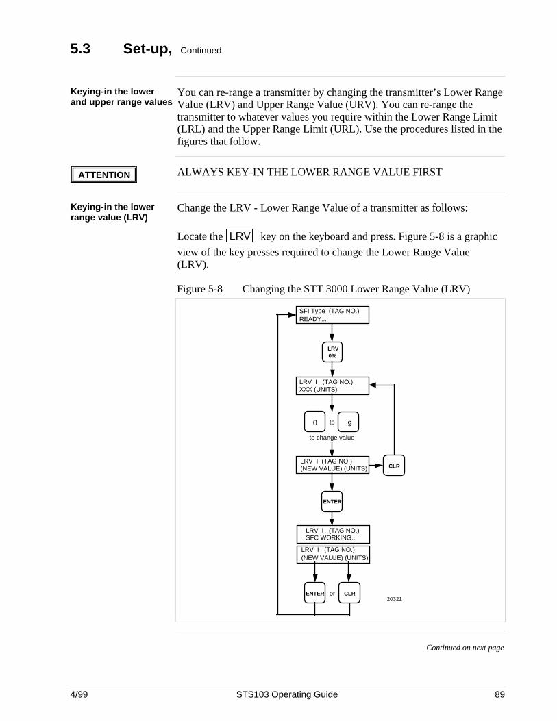
4/99 STS103 Operating Guide 89
5.3 Set-up, Continued
Keying-in the lowerand upper range values
You can re-range a transmitter by changing the transmitter’s Lower RangeValue (LRV) and Upper Range Value (URV). You can re-range thetransmitter to whatever values you require within the Lower Range Limit(LRL) and the Upper Range Limit (URL). Use the procedures listed in thefigures that follow.
ATTENTION ALWAYS KEY-IN THE LOWER RANGE VALUE FIRST
Keying-in the lowerrange value (LRV)
Change the LRV - Lower Range Value of a transmitter as follows:
Locate the LRV key on the keyboard and press. Figure 5-8 is a graphic
view of the key presses required to change the Lower Range Value(LRV).
Figure 5-8 Changing the STT 3000 Lower Range Value (LRV)
LRV I (TAG NO.)XXX (UNITS)
to change value
LRV I (TAG NO.)(NEW VALUE) (UNITS)
CLRENTER or
ENTER
LRV I (TAG NO.)(NEW VALUE) (UNITS)
90 to
LRV 0%
SFI Type (TAG NO.)READY...
CLR
20321
LRV I (TAG NO.)SFC WORKING...
Continued on next page
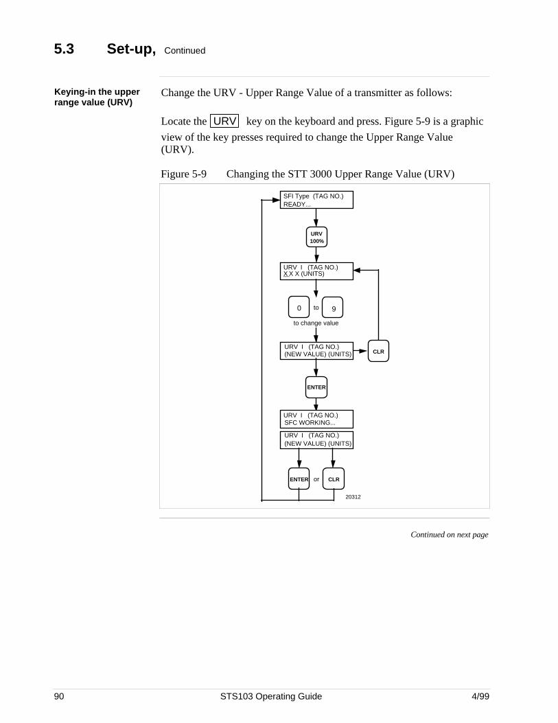
90 STS103 Operating Guide 4/99
5.3 Set-up, Continued
Keying-in the upperrange value (URV)
Change the URV - Upper Range Value of a transmitter as follows:
Locate the URV key on the keyboard and press. Figure 5-9 is a graphic
view of the key presses required to change the Upper Range Value(URV).
Figure 5-9 Changing the STT 3000 Upper Range Value (URV)
URV I (TAG NO.)X X X (UNITS)
to change value
CLRENTER or
URV I (TAG NO.)(NEW VALUE) (UNITS)
ENTER
URV I (TAG NO.)(NEW VALUE) (UNITS)
90 to
URV 100%
SFI Type (TAG NO.)READY...
CLR
URV I (TAG NO.)SFC WORKING...
20312
Continued on next page
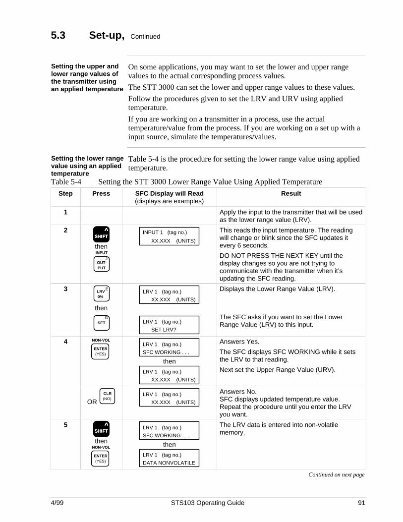
4/99 STS103 Operating Guide 91
5.3 Set-up, Continued
Setting the upper andlower range values ofthe transmitter usingan applied temperature
On some applications, you may want to set the lower and upper rangevalues to the actual corresponding process values.
The STT 3000 can set the lower and upper range values to these values.
Follow the procedures given to set the LRV and URV using appliedtemperature.
If you are working on a transmitter in a process, use the actualtemperature/value from the process. If you are working on a set up with ainput source, simulate the temperatures/values.
Setting the lower rangevalue using an appliedtemperature
Table 5-4 is the procedure for setting the lower range value using appliedtemperature.
Table 5-4 Setting the STT 3000 Lower Range Value Using Applied Temperature
Step Press SFC Display will Read(displays are examples)
Result
1 Apply the input to the transmitter that will be usedas the lower range value (LRV).
2SSSSSHHHHHIIIIIFFFFFTTTTT
^
then
JOUT- PUT
INPUT
INPUT 1 (tag no.)
XX.XXX (UNITS)
This reads the input temperature. The readingwill change or blink since the SFC updates itevery 6 seconds.
DO NOT PRESS THE NEXT KEY until thedisplay changes so you are not trying tocommunicate with the transmitter when it’supdating the SFC reading.
3 ELRV 0%
thenG
SET
LRV 1 (tag no.)
XX.XXX (UNITS)
LRV 1 (tag no.)
SET LRV?
Displays the Lower Range Value (LRV).
The SFC asks if you want to set the LowerRange Value (LRV) to this input.
4 NON-VOL
ENTER (YES)
LRV 1 (tag no.)
SFC WORKING . . .
then
LRV 1 (tag no.)
XX.XXX (UNITS)
Answers Yes.
The SFC displays SFC WORKING while it setsthe LRV to that reading.
Next set the Upper Range Value (URV).
OR CLR (NO)
LRV 1 (tag no.)
XX.XXX (UNITS)
Answers No.SFC displays updated temperature value.Repeat the procedure until you enter the LRVyou want.
5SSSSSHHHHHIIIIIFFFFFTTTTT
^
thenNON-VOL
ENTER (YES)
LRV 1 (tag no.)
SFC WORKING . . .
then
LRV 1 (tag no.)
DATA NONVOLATILE
The LRV data is entered into non-volatilememory.
Continued on next page
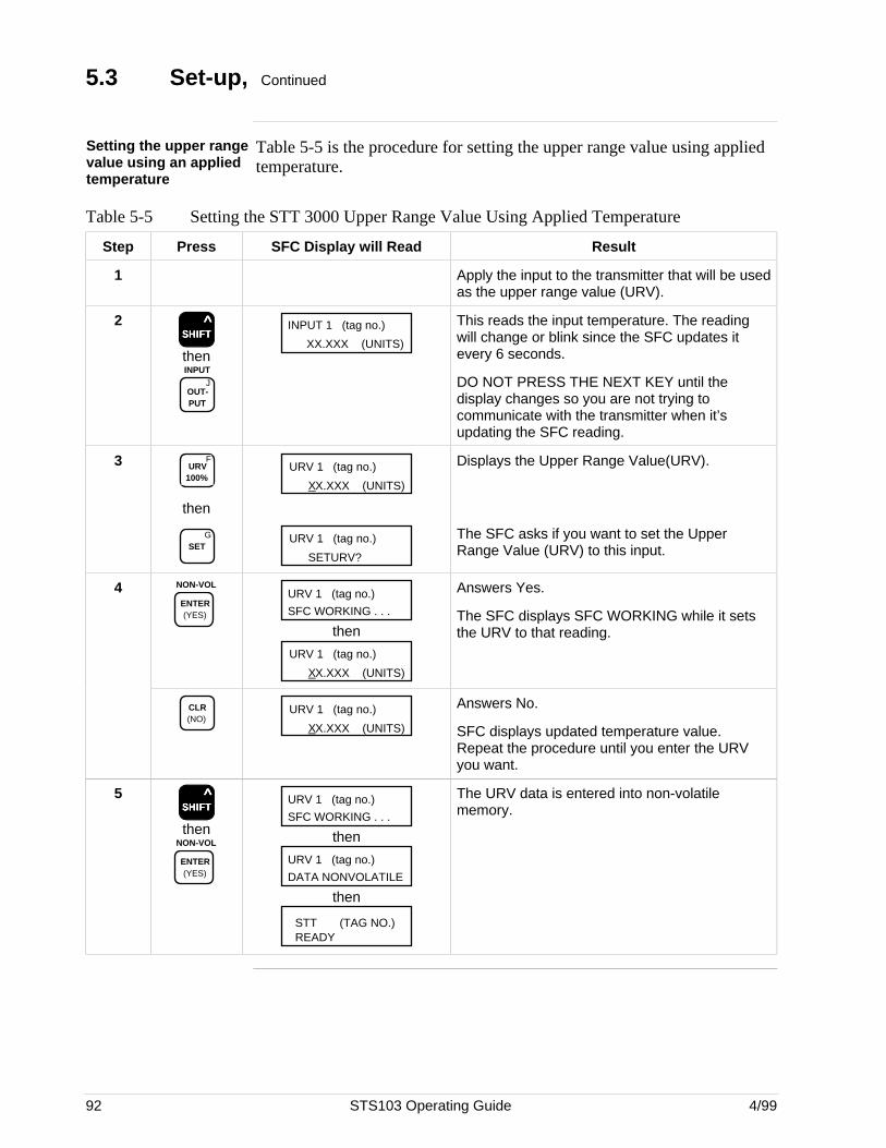
92 STS103 Operating Guide 4/99
5.3 Set-up, Continued
Setting the upper rangevalue using an appliedtemperature
Table 5-5 is the procedure for setting the upper range value using appliedtemperature.
Table 5-5 Setting the STT 3000 Upper Range Value Using Applied Temperature
Step Press SFC Display will Read Result
1 Apply the input to the transmitter that will be usedas the upper range value (URV).
2SSSSSHHHHHIIIIIFFFFFTTTTT
^
then
JOUT- PUT
INPUT
INPUT 1 (tag no.)
XX.XXX (UNITS)
This reads the input temperature. The readingwill change or blink since the SFC updates itevery 6 seconds.
DO NOT PRESS THE NEXT KEY until thedisplay changes so you are not trying tocommunicate with the transmitter when it’supdating the SFC reading.
3 FURV
100%
then
GSET
URV 1 (tag no.)
XX.XXX (UNITS)
URV 1 (tag no.)
SETURV?
Displays the Upper Range Value(URV).
The SFC asks if you want to set the UpperRange Value (URV) to this input.
4 NON-VOL
ENTER (YES)
URV 1 (tag no.)
SFC WORKING . . .
then
URV 1 (tag no.)
XX.XXX (UNITS)
Answers Yes.
The SFC displays SFC WORKING while it setsthe URV to that reading.
CLR (NO)
URV 1 (tag no.)
XX.XXX (UNITS)
Answers No.
SFC displays updated temperature value.Repeat the procedure until you enter the URVyou want.
5SSSSSHHHHHIIIIIFFFFFTTTTT
^
thenNON-VOL
ENTER (YES)
URV 1 (tag no.)
SFC WORKING . . .
then
URV 1 (tag no.)
DATA NONVOLATILE
then
STT (TAG NO.)READY
The URV data is entered into non-volatilememory.
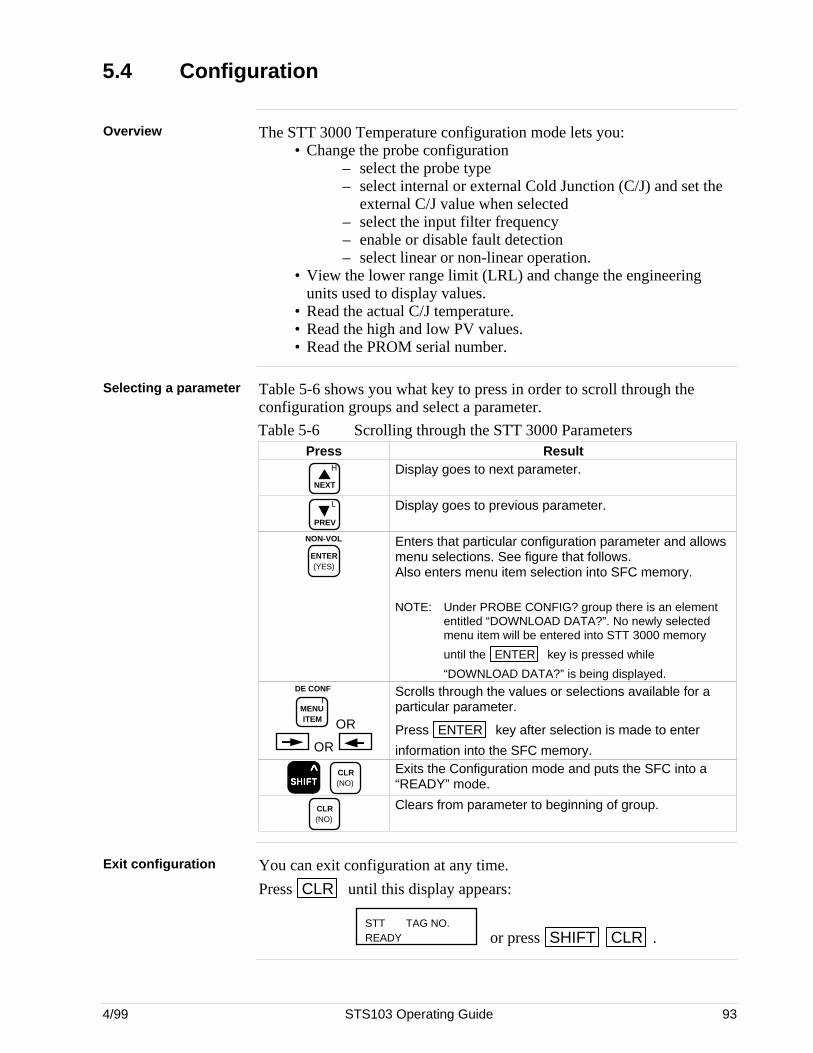
4/99 STS103 Operating Guide 93
5.4 Configuration
Overview The STT 3000 Temperature configuration mode lets you:• Change the probe configuration
– select the probe type– select internal or external Cold Junction (C/J) and set the
external C/J value when selected– select the input filter frequency– enable or disable fault detection– select linear or non-linear operation.
• View the lower range limit (LRL) and change the engineeringunits used to display values.
• Read the actual C/J temperature.• Read the high and low PV values.• Read the PROM serial number.
Selecting a parameter Table 5-6 shows you what key to press in order to scroll through theconfiguration groups and select a parameter.
Table 5-6 Scrolling through the STT 3000 ParametersPress Result
H
NEXT
Display goes to next parameter.
L
PREV
Display goes to previous parameter.
NON-VOL
ENTER (YES)
Enters that particular configuration parameter and allowsmenu selections. See figure that follows.Also enters menu item selection into SFC memory.
NOTE: Under PROBE CONFIG? group there is an elemententitled “DOWNLOAD DATA?”. No newly selectedmenu item will be entered into STT 3000 memory
until the ENTER key is pressed while
“DOWNLOAD DATA?” is being displayed.
IMENU ITEM
DE CONF
OR
OR
Scrolls through the values or selections available for aparticular parameter.
Press ENTER key after selection is made to enter
information into the SFC memory.
SSSSSHHHHHIIIIIFFFFFTTTTT ^
CLR (NO)
Exits the Configuration mode and puts the SFC into a“READY” mode.
CLR (NO)
Clears from parameter to beginning of group.
Exit configuration You can exit configuration at any time.
Press CLR until this display appears:
STT TAG NO.READY or press SHIFT CLR .
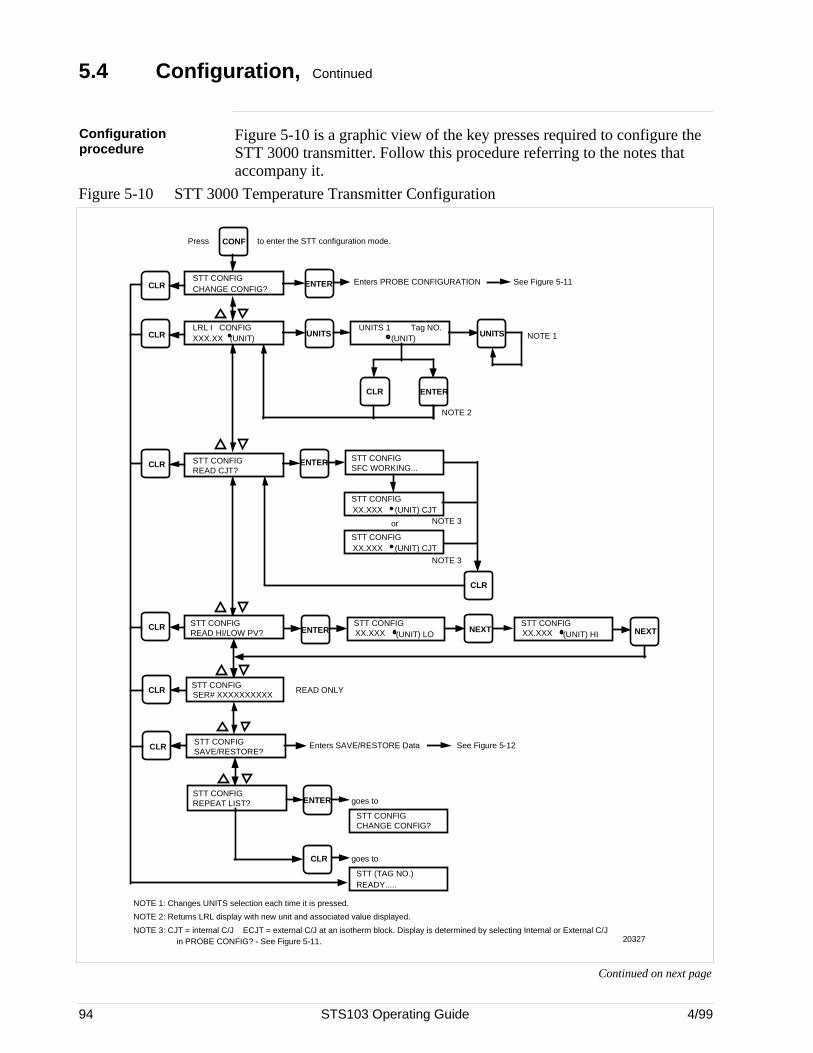
94 STS103 Operating Guide 4/99
5.4 Configuration, Continued
Configurationprocedure
Figure 5-10 is a graphic view of the key presses required to configure theSTT 3000 transmitter. Follow this procedure referring to the notes thataccompany it.
Figure 5-10 STT 3000 Temperature Transmitter Configuration
ENTER
LRL I CONFIG XXX.XX (UNIT)
UNITS
20327
NOTE 1: Changes UNITS selection each time it is pressed.
UNITS 1(UNIT)
UNITS
CONF
STT CONFIG CHANGE CONFIG?
CLR
CLR
CLR
ENTER
STT CONFIG READ CJT?
ENTER STT CONFIG SFC WORKING...
STT CONFIG SER# XXXXXXXXXX
STT CONFIG SAVE/RESTORE?
CLR
READ ONLY
STT CONFIG (UNIT) CJTXX.XXX
CLR
CLR NEXTNEXT
CLR
Enters PROBE CONFIGURATION See Figure 5-11
Tag NO.NOTE 1
NOTE 2
or NOTE 3
NOTE 3
STT CONFIG (UNIT) CJTXX.XXX
STT CONFIG (UNIT) HIXX.XXX
STT CONFIG READ HI/LOW PV? ENTER
STT CONFIG (UNIT) LOXX.XXX
STT CONFIG REPEAT LIST? ENTER
STT CONFIG CHANGE CONFIG?
CLR
goes to
STT (TAG NO.)READY.....
goes to
CLR
to enter the STT configuration mode.Press
NOTE 2: Returns LRL display with new unit and associated value displayed.
NOTE 3: CJT = internal C/J ECJT = external C/J at an isotherm block. Display is determined by selecting Internal or External C/J in PROBE CONFIG? - See Figure 5-11.
Enters SAVE/RESTORE Data See Figure 5-12
Continued on next page
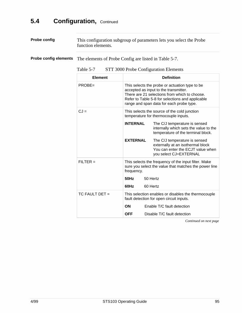
4/99 STS103 Operating Guide 95
5.4 Configuration, Continued
Probe config This configuration subgroup of parameters lets you select the Probefunction elements.
Probe config elements The elements of Probe Config are listed in Table 5-7.
Table 5-7 STT 3000 Probe Configuration Elements
Element Definition
PROBE= This selects the probe or actuation type to beaccepted as input to the transmitter.There are 21 selections from which to choose.Refer to Table 5-8 for selections and applicablerange and span data for each probe type.
CJ = This selects the source of the cold junctiontemperature for thermocouple inputs.
INTERNAL The C/J temperature is sensedinternally which sets the value to thetemperature of the terminal block.
EXTERNAL The C/J temperature is sensedexternally at an isothermal blockYou can enter the ECJT value whenyou select CJ=EXTERNAL
FILTER = This selects the frequency of the input filter. Makesure you select the value that matches the power linefrequency.
50Hz 50 Hertz
60Hz 60 Hertz
TC FAULT DET = This selection enables or disables the thermocouplefault detection for open circuit inputs.
ON Enable T/C fault detection
OFF Disable T/C fault detection
Continued on next page
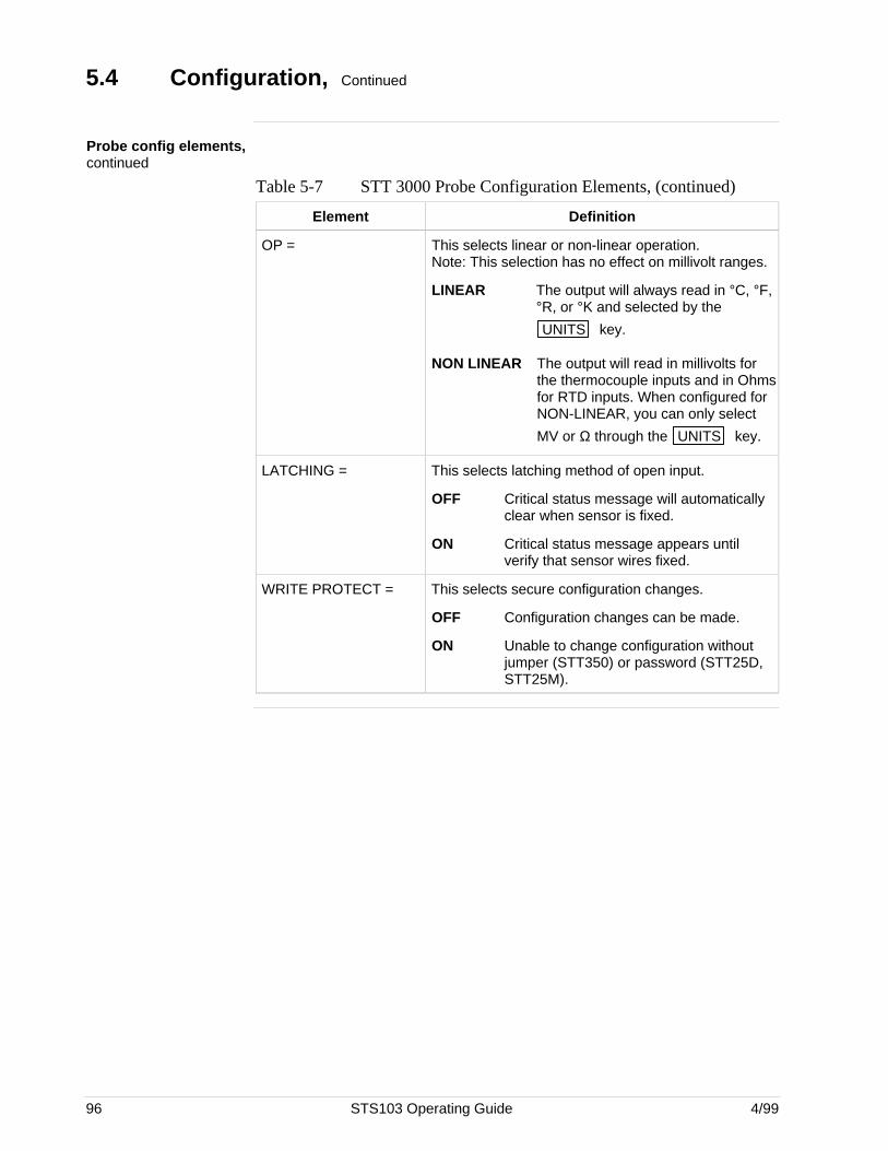
96 STS103 Operating Guide 4/99
5.4 Configuration, Continued
Probe config elements,continued
Table 5-7 STT 3000 Probe Configuration Elements, (continued)
Element Definition
OP = This selects linear or non-linear operation.Note: This selection has no effect on millivolt ranges.
LINEAR The output will always read in °C, °F,°R, or °K and selected by the
UNITS key.
NON LINEAR The output will read in millivolts forthe thermocouple inputs and in Ohmsfor RTD inputs. When configured forNON-LINEAR, you can only select
MV or Ω through the UNITS key.
LATCHING = This selects latching method of open input.
OFF Critical status message will automaticallyclear when sensor is fixed.
ON Critical status message appears untilverify that sensor wires fixed.
WRITE PROTECT = This selects secure configuration changes.
OFF Configuration changes can be made.
ON Unable to change configuration withoutjumper (STT350) or password (STT25D,STT25M).
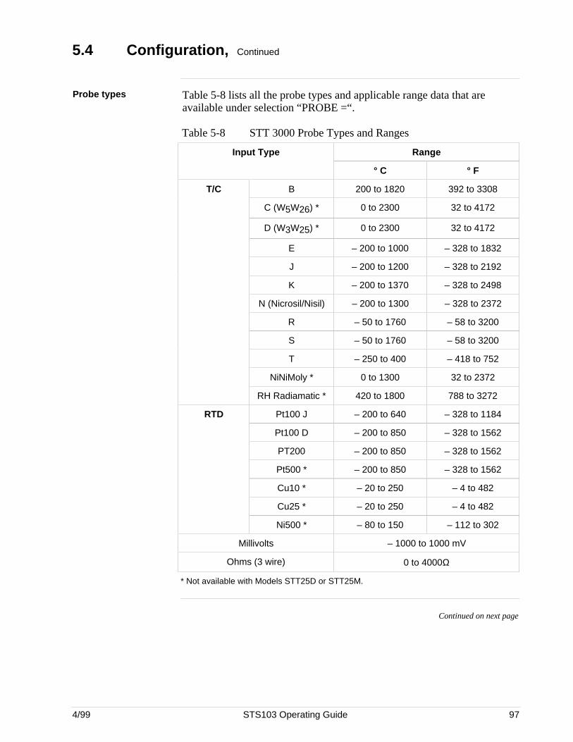
4/99 STS103 Operating Guide 97
5.4 Configuration, Continued
Probe types Table 5-8 lists all the probe types and applicable range data that areavailable under selection “PROBE =“.
Table 5-8 STT 3000 Probe Types and Ranges
Input Type Range
° C ° F
T/C B 200 to 1820 392 to 3308
C (W5W26) * 0 to 2300 32 to 4172
D (W3W25) * 0 to 2300 32 to 4172
E – 200 to 1000 – 328 to 1832
J – 200 to 1200 – 328 to 2192
K – 200 to 1370 – 328 to 2498
N (Nicrosil/Nisil) – 200 to 1300 – 328 to 2372
R – 50 to 1760 – 58 to 3200
S – 50 to 1760 – 58 to 3200
T – 250 to 400 – 418 to 752
NiNiMoly * 0 to 1300 32 to 2372
RH Radiamatic * 420 to 1800 788 to 3272
RTD Pt100 J – 200 to 640 – 328 to 1184
Pt100 D – 200 to 850 – 328 to 1562
PT200 – 200 to 850 – 328 to 1562
Pt500 * – 200 to 850 – 328 to 1562
Cu10 * – 20 to 250 – 4 to 482
Cu25 * – 20 to 250 – 4 to 482
Ni500 * – 80 to 150 – 112 to 302
Millivolts – 1000 to 1000 mV
Ohms (3 wire) 0 to 4000Ω
* Not available with Models STT25D or STT25M.
Continued on next page
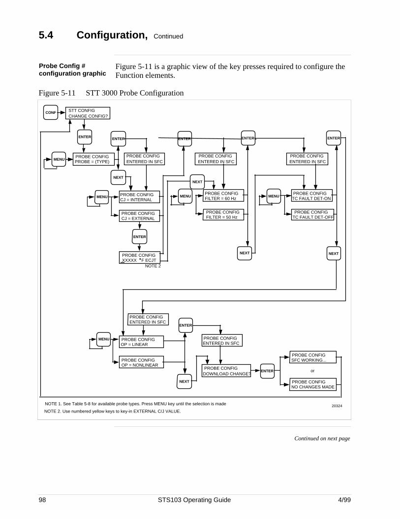
98 STS103 Operating Guide 4/99
5.4 Configuration, Continued
Probe Config #configuration graphic
Figure 5-11 is a graphic view of the key presses required to configure theFunction elements.
Figure 5-11 STT 3000 Probe Configuration
STT CONFIG CHANGE CONFIG?
MENU
ENTER
CONF
ENTER ENTER
PROBE CONFIG PROBE = (TYPE)
PROBE CONFIGENTERED IN SFC
NEXT
PROBE CONFIG CJ = INTERNAL
PROBE CONFIG CJ = EXTERNAL
PROBE CONFIG XXXXX F ECJT
MENU
ENTER
MENU
NOTE 1. See Table 5-8 for available probe types. Press MENU key until the selection is made
NOTE 2. Use numbered yellow keys to key-in EXTERNAL C/J VALUE.20324
NEXT
ENTER
PROBE CONFIG ENTERED IN SFC
PROBE CONFIG DOWNLOAD CHANGE?
ENTER
PROBE CONFIG NO CHANGES MADE
or
PROBE CONFIG SFC WORKING...
MENU
PROBE CONFIG OP = NONLINEAR
PROBE CONFIG OP = LINEAR
PROBE CONFIG ENTERED IN SFC
NEXT
ENTER
PROBE CONFIGENTERED IN SFC
PROBE CONFIG FILTER = 60 Hz
PROBE CONFIG FILTER = 50 Hz
ENTER
PROBE CONFIG ENTERED IN SFC
MENU
NEXT
PROBE CONFIG TC FAULT DET-ON
PROBE CONFIG TC FAULT DET-OFF
NOTE 2
NEXT
Continued on next page
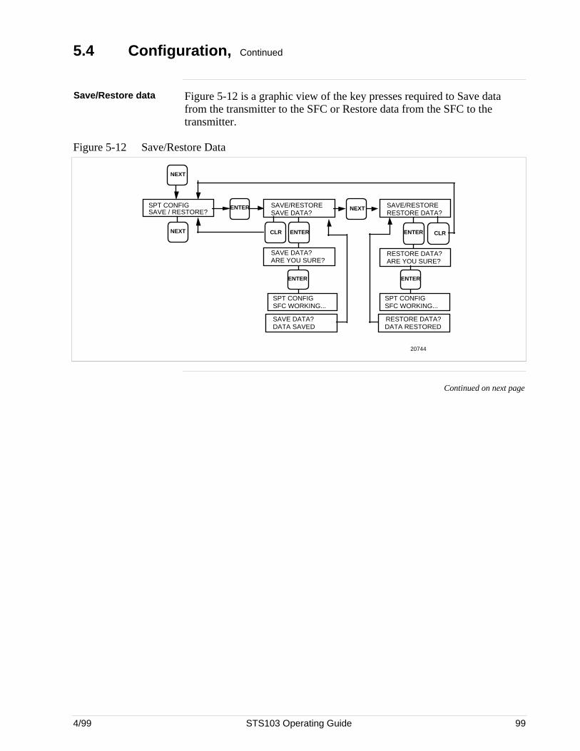
4/99 STS103 Operating Guide 99
5.4 Configuration, Continued
Save/Restore data Figure 5-12 is a graphic view of the key presses required to Save datafrom the transmitter to the SFC or Restore data from the SFC to thetransmitter.
Figure 5-12 Save/Restore Data
NEXT
CLR
20744
NEXT
SPT CONFIGSAVE / RESTORE?
ENTER SAVE/RESTORESAVE DATA?
SAVE/RESTORERESTORE DATA?
NEXT
ENTER ENTER
SAVE DATA?ARE YOU SURE?
RESTORE DATA?ARE YOU SURE?
SPT CONFIGSFC WORKING...
ENTER
SPT CONFIGSFC WORKING...
ENTER
SAVE DATA?DATA SAVED
RESTORE DATA?DATA RESTORED
CLR
Continued on next page
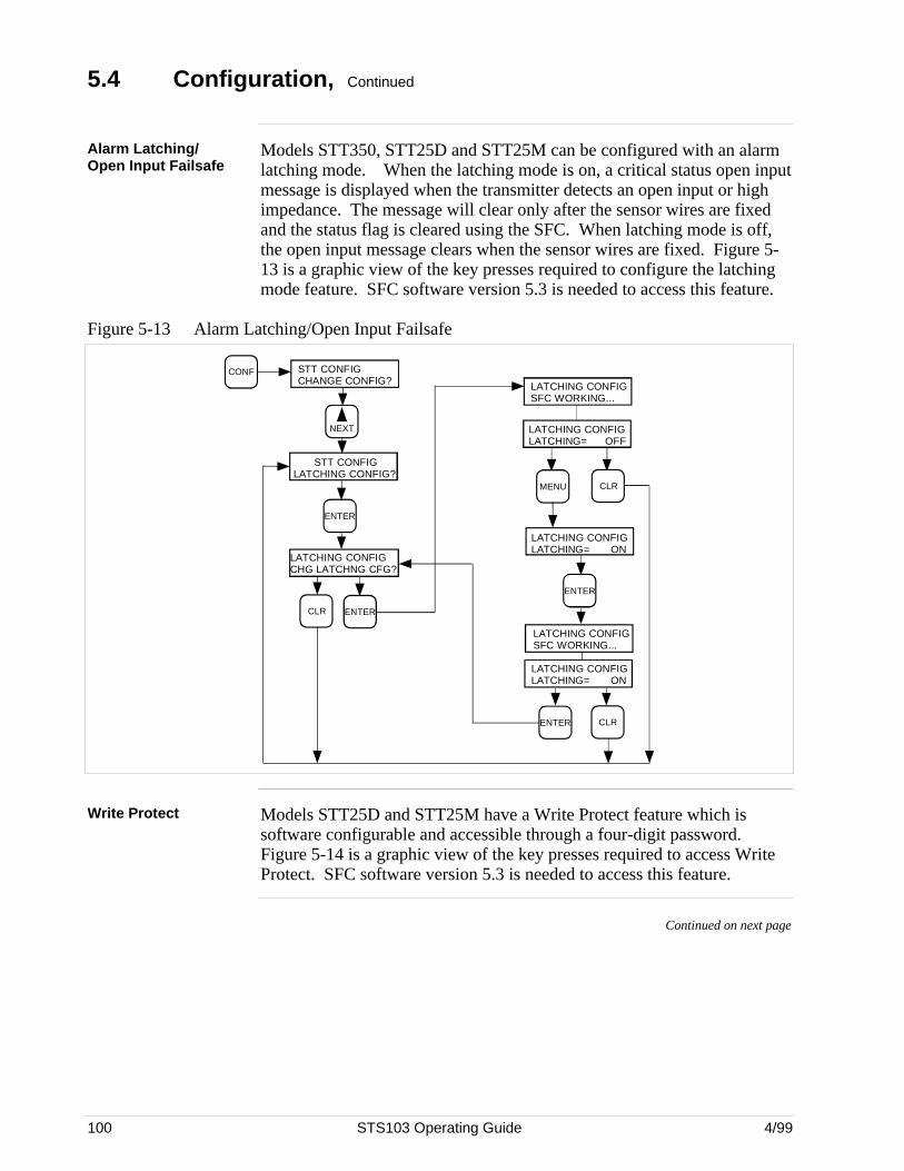
100 STS103 Operating Guide 4/99
5.4 Configuration, Continued
Alarm Latching/Open Input Failsafe
Models STT350, STT25D and STT25M can be configured with an alarmlatching mode. When the latching mode is on, a critical status open inputmessage is displayed when the transmitter detects an open input or highimpedance. The message will clear only after the sensor wires are fixedand the status flag is cleared using the SFC. When latching mode is off,the open input message clears when the sensor wires are fixed. Figure 5-13 is a graphic view of the key presses required to configure the latchingmode feature. SFC software version 5.3 is needed to access this feature.
Figure 5-13 Alarm Latching/Open Input Failsafe
CLR
NEXT
CONF STT CONFIGCHANGE CONFIG?
STT CONFIGLATCHING CONFIG?
ENTER
LATCHING CONFIGCHG LATCHNG CFG?
ENTER
LATCHING CONFIGLATCHING= OFF
MENU
LATCHING CONFIGLATCHING= ON
ENTER
LATCHING CONFIGSFC WORKING...
LATCHING CONFIGLATCHING= ON
CLR
ENTER
LATCHING CONFIGSFC WORKING...
CLR
Write Protect Models STT25D and STT25M have a Write Protect feature which issoftware configurable and accessible through a four-digit password.Figure 5-14 is a graphic view of the key presses required to access WriteProtect. SFC software version 5.3 is needed to access this feature.
Continued on next page
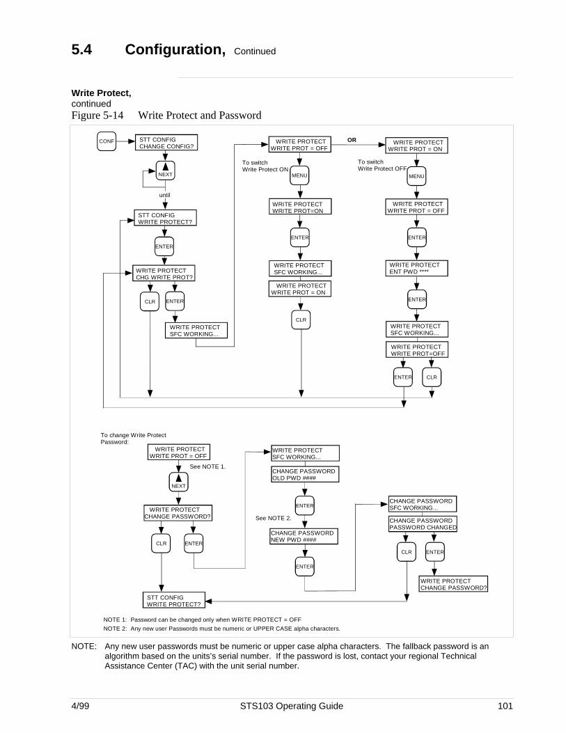
4/99 STS103 Operating Guide 101
5.4 Configuration, Continued
Write Protect,continuedFigure 5-14 Write Protect and Password
WRITE PROTECTCHANGE PASSWORD?
ENTER
CHANGE PASSWORDOLD PWD ####
ENTER
CHANGE PASSWORDNEW PWD ####
ENTER
CHANGE PASSWORDSFC WORKING...
CHANGE PASSWORDPASSWORD CHANGED
CLR CLR
ENTER
See NOTE 1.
To change Write ProtectPassword:
WRITE PROTECTWRITE PROT = OFF
NEXT
STT CONFIGWRITE PROTECT?
WRITE PROTECTSFC WORKING...
WRITE PROTECTCHANGE PASSWORD?
See NOTE 2.
NOTE 1: Password can be changed only when WRITE PROTECT = OFF
NOTE 2: Any new user Passwords must be numeric or UPPER CASE alpha characters.
WRITE PROTECTSFC WORKING...
WRITE PROTECTENT PWD ****
WRITE PROTECTWRITE PROT = OFF
CLR
NEXT
CONF STT CONFIGCHANGE CONFIG?
STT CONFIGWRITE PROTECT?
ENTER
WRITE PROTECTCHG WRITE PROT?
ENTER
MENU
WRITE PROTECTWRITE PROT=ON
ENTER
WRITE PROTECTSFC WORKING...
WRITE PROTECTWRITE PROT = ON
ENTER
ENTER
WRITE PROTECTWRITE PROT=OFF
CLR
CLR
ENTER
until
WRITE PROTECTWRITE PROT = ON
MENU
To switchWrite Protect OFF
WRITE PROTECTSFC WORKING...
OR
WRITE PROTECTWRITE PROT = OFF
To switchWrite Protect ON
NOTE: Any new user passwords must be numeric or upper case alpha characters. The fallback password is analgorithm based on the units’s serial number. If the password is lost, contact your regional TechnicalAssistance Center (TAC) with the unit serial number.

102 STS103 Operating Guide 4/99
5.5 Output Calibration
Introduction To calibrate the output of an Analog transmitter, connect a precision volt–or ammeter at the appropriate connection point on your system or use thecontrol room display to monitor the output signal.
If the 0 or 100% output is not correct, you can do a Digital to AnalogCurrent Output Signal Calibration.
Do a DAC calibration With this procedure you can calibrate the digital to analog current outputzero and span.
Use the procedure in Table 5-9 to enter the Output mode, check the 0%and 100% output values and if necessary, do a digital to analog currentoutput signal calibration.
Table 5-9 STT 3000 Digital to Analog Current Output Signal Calibration
Step Press SFC Display will Read Result
1 Connect a precision volt– or ammeter at theappropriate connection point on your system oruse the control room display to monitor theoutput signal.
2J
OUT- PUT
INPUTOUTP1 (TAG No.)SFC WORKING . . .
then
0.00 %
OUTP1 (TAG No.)
The SFC is ready to calibrate 0% output or 100%output.
3 Z
00 %
OUTP1 (TAG No.) To select 0% output
4 NON-VOL
ENTER (YES) SFC WORKING
OUTP1 (TAG No.)
then
0.00 % RNG1OUTP1 (TAG No.)
# in display indicates the transmitter is in theOutput mode.
5 Check the DVM.
If the value on the DVM is 4 mA (1.00 volt), go tostep 9 (100% calibration).
If the value on the DVM is not 4 mA (1.00 volt),go to step 6 to correct DAC zero.
Table continued on next page

4/99 STS103 Operating Guide 103
5.5 Output Calibration, Continued
Do a DAC calibration,continued
Table 5-9 STT 3000 Digital to Analog Current Output Signal Calibration (continued)
Step Press SFC Display will Read Result
6K
COR- RECT
RESETOUTP 1 (tag no.)SFC WORKING . . .
then
OUTP 1 (tag no.)CORRECT DAC ZERO
Allows correction of DAC zero.
7 H
NEXT
orL
PREV
OUTP 1 (tag no.)INC 1 COUNTS
orOUTP 1 (tag no.)DEC 1 COUNTS
then
OUTP 1 (tag no.)CORRECT DAC ZERO
Repeat increments or decrements to adjust thevalue on the DVM to 4 mA (1.00 volt).
When 4 mA (1.00 volt) is shown on the DVM, goto step 8.
8J
OUT- PUT
INPUTOUTP 1 (tag no.)SFC WORKING . . .
thenOUTP 1 (tag no.)
0.0 00 %
0% output calibrated, go to step 9, 100%calibration.
9 V
1
Z
0
Z
0
OUTP 1 (tag no.)
100 %
This selects 100% output.
# in display indicates the transmitter is in theOutput mode.
10 NON-VOL
ENTER (YES)
OUTP 1 (tag no.)SFC WORKING . . .
thenOUTP 1 (tag no.)
100.0 %
Check the DVM:
If the value on the DVM is 20 mA (5.000 volts),go to step 13.
If the value on the DVM is not 20 mA (5.000volts), go to step 11 to correct DAC span.
11K
COR- RECT
RESETOUTP 1 (tag no.)SFC WORKING . . .
then
OUTP 1 (tag no.)CORRECT DAC ZERO
Allows correction of DAC span.
Table continued on next page
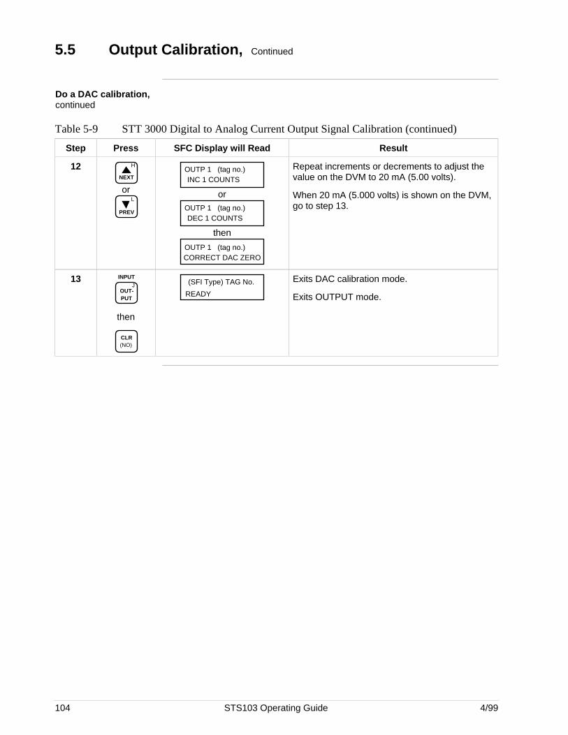
104 STS103 Operating Guide 4/99
5.5 Output Calibration, Continued
Do a DAC calibration,continued
Table 5-9 STT 3000 Digital to Analog Current Output Signal Calibration (continued)
Step Press SFC Display will Read Result
12 H
NEXT
orL
PREV
OUTP 1 (tag no.)INC 1 COUNTS
orOUTP 1 (tag no.)DEC 1 COUNTS
then
OUTP 1 (tag no.)CORRECT DAC ZERO
Repeat increments or decrements to adjust thevalue on the DVM to 20 mA (5.00 volts).
When 20 mA (5.000 volts) is shown on the DVM,go to step 13.
13J
OUT- PUT
INPUT
then
CLR (NO)
READY
(SFI Type) TAG No. Exits DAC calibration mode.
Exits OUTPUT mode.
4/99 STS103 Operating Guide 105
5.6 Operation
Overview The STS103 displays all the operating data for the STT 3000Temperature. This data includes:
• Transmitter I.D.
• Damping value
• Lower range value
• Upper range value (span)
• Configuration elements for Digital Communications mode
• Input value
• Output Value
• Span value
• Upper Range limit
• Engineering units
• Operation Status
• Software Version Number
• Failsafe Direction
• Zero Point adjustment
• Display and Keyboard Test
• Read Scratch Pad messages
• Write Protection
• Alarm Latching
Refer to Table 5-5 for Operating Data access instructions.
Continued on next page
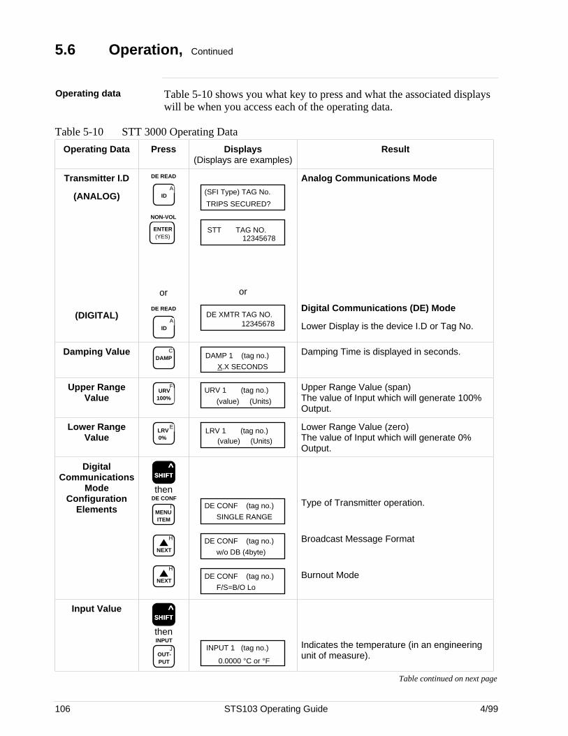
106 STS103 Operating Guide 4/99
5.6 Operation, Continued
Operating data Table 5-10 shows you what key to press and what the associated displayswill be when you access each of the operating data.
Table 5-10 STT 3000 Operating Data
Operating Data Press Displays(Displays are examples)
Result
Transmitter I.D
(ANALOG)
(DIGITAL)
DE READ
AID
NON-VOL
ENTER (YES)
or
DE READ
AID
TRIPS SECURED?
(SFI Type) TAG No.
STT TAG NO.12345678
or
DE XMTR TAG NO.12345678
Analog Communications Mode
Digital Communications (DE) Mode
Lower Display is the device I.D or Tag No.
Damping Value CDAMP DAMP 1 (tag no.)
X.X SECONDS
Damping Time is displayed in seconds.
Upper RangeValue
FURV
100%URV 1 (tag no.)
(value) (Units)
Upper Range Value (span)The value of Input which will generate 100%Output.
Lower RangeValue
ELRV 0%
LRV 1 (tag no.)(value) (Units)
Lower Range Value (zero)The value of Input which will generate 0%Output.
DigitalCommunications
ModeConfiguration
Elements
SSSSSHHHHHIIIIIFFFFFTTTTT ^
then
IMENU ITEM
DE CONF
H
NEXT
H
NEXT
DE CONF (tag no.)
SINGLE RANGE
DE CONF (tag no.)
w/o DB (4byte)
DE CONF (tag no.)
F/S=B/O Lo
Type of Transmitter operation.
Broadcast Message Format
Burnout Mode
Input ValueSSSSSHHHHHIIIIIFFFFFTTTTT
^
then
JOUT- PUT
INPUTINPUT 1 (tag no.)
0.0000 °C or °F
Indicates the temperature (in an engineeringunit of measure).
Table continued on next page
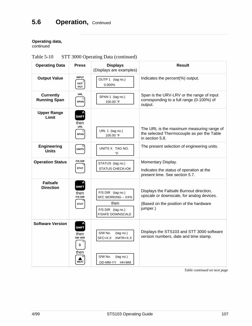
4/99 STS103 Operating Guide 107
5.6 Operation, Continued
Operating data,continued
Table 5-10 STT 3000 Operating Data (continued)
Operating Data Press Displays(Displays are examples)
Result
Output ValueJ
OUT- PUT
INPUTOUTP 1 (tag no.)
0.000%
Indicates the percent(%) output.
CurrentlyRunning Span Y
SPAN
URLSPAN 1 (tag no.)
100.00 °F
Span is the URV-LRV or the range of inputcorresponding to a full range (0-100%) ofoutput.
Upper RangeLimit SSSSSHHHHHIIIIIFFFFFTTTTT
^
then
YSPAN
URL
URL 1 (tag no.)100.00 °F
The URL is the maximum measuring range ofthe selected Thermocouple as per the Tablein section 5.8.
EngineeringUnits
DUNITS UNITS X TAG NO.
°F
The present selection of engineering units.
Operation StatusU
STAT
F/S DIRSTATUS (tag no.)
STATUS CHECK=OK
Momentary Display.
Indicates the status of operation at thepresent time. See section 5.7.
FailsafeDirection SSSSSHHHHHIIIIIFFFFFTTTTT
^
then
U
STAT
F/S DIR
F/S DIR (tag no.)SFC WORKING – XX%
then
F/S DIR (tag no.)F/SAFE DOWNSCALE
Displays the Failsafe Burnout direction,upscale or downscale, for analog devices.
(Based on the position of the hardwarejumper.)
Software VersionSSSSSHHHHHIIIIIFFFFFTTTTT
^
then
X
3
SW VER
thenH
NEXT
S/W No. (tag no.)
SFC=X.X XMTR=X.X
S/W No. (tag no.)
DD-MM-YY HH:MM
Displays the STS103 and STT 3000 softwareversion numbers, date and time stamp.
Table continued on next page
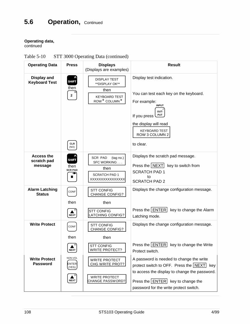
108 STS103 Operating Guide 4/99
5.6 Operation, Continued
Operating data,continued
Table 5-10 STT 3000 Operating Data (continued)
Operating Data Press Displays(Displays are examples)
Result
Display andKeyboard Test SSSSSHHHHHIIIIIFFFFFTTTTT
^
thenW
2
CLR (NO)
DISPLAY TEST**DISPLAY OK**
then
KEYBOARD TESTROW * COLUMN *
Display test indication.
You can test each key on the keyboard.
For example:
If you press
JOUT- PUT
INPUT
the display will read
KEYBOARD TESTROW 3 COLUMN 2
to clear.
Access thescratch pad
messageSSSSSHHHHHIIIIIFFFFFTTTTT
^
thenSCR PAD
SCR PAD (tag no.)SFC WORKING . . .
then
SCRATCH PAD 1XXXXXXXXXXXXXXXX
Displays the scratch pad message.
Press the NEXT key to switch from
SCRATCH PAD 1to
SCRATCH PAD 2
Alarm LatchingStatus
CONF
then
H
NEXT
STT CONFIGCHANGE CONFIG?
then
STT CONFIGLATCHING CONFIG?
Displays the change configuration message.
Press the ENTER key to change the Alarm
Latching mode.
Write ProtectCONF
then
H
NEXT
STT CONFIGCHANGE CONFIG?
then
STT CONFIGWRITE PROTECT?
Displays the change configuration message.
Press the ENTER key to change the Write
Protect switch.
Write ProtectPassword
NON-VOL
ENTER(YES)
H
NEXT
WRITE PROTECTCHG WRITE PROT?
WRITE PROTECTCHANGE PASSWORD?
A password is needed to change the write
protect switch to OFF. Press the NEXT key
to access the display to change the password.
Press the ENTER key to change the
password for the write protect switch.
4/99 STS103 Operating Guide 109
5.7 Diagnostics and SFC Messages
Introduction The STT 3000 and the STS103 both run continuous self-diagnostics.This means that they are constantly testing the communications, the loop,and themselves.
Any time you want results of these diagnostics, press the STAT key.
The SFC displays its report, in the form of messages, which identifydiagnostic conditions.Diagnostic conditions are broken down into three categories:• an OK condition• a critical condition• a non-critical condition
OK Status An OK condition means no problem exists, and the display looks like this:
STATUS (tag no.)STATUS CHECK=OK
Critical status A critical condition means that the transmitter is not functioning properly.When this occurs, the transmitter goes into upscale burnout and maintainsan output of 21.8 mA, or into downscale burnout and maintains an outputof less than 3.9 mA. The message CRITICAL STATUS interrupts youroperation and is followed by the message PRESS STATUS.
After the PRESS STATUS message, you press the STAT key to find
out what problem exists. You will receive one or more messages. Takewhatever corrective action necessary to solve the problem. Remember thatthe transmitter will stay in upscale or down scale burnout until thecondition is corrected.If the transmitter sends more than one message, each message will bedisplayed in the order of importance for about 5 seconds. If you need to
see them again, press the STAT key again.
Non-critical status A non-critical condition means that although a problem exists, thetransmitter is still operating. When a non-critical condition occurs a “#”character appears on the right side of the display, along with whateveryou’re displaying at the time.
This character means press the STAT key because some type of a
problem exists. Again, one or more messages will appear on the displayfor about five seconds each.
Low battery voltage When the battery voltage becomes low, a colon ”:” will appear in themiddle of the display. It stays on the display until you either charge orreplace the batteries.
Continued on next page
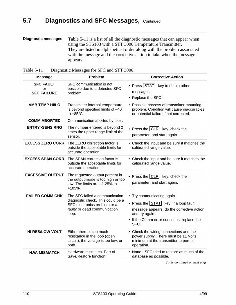
110 STS103 Operating Guide 4/99
5.7 Diagnostics and SFC Messages, Continued
Diagnostic messages Table 5-11 is a list of all the diagnostic messages that can appear whenusing the STS103 with a STT 3000 Temperature Transmitter.They are listed in alphabetical order along with the problem associatedwith the message and the corrective action to take when the messageappears.
Table 5-11 Diagnostic Messages for SFC and STT 3000
Message Problem Corrective Action
SFC FAULTor
SFC FAILURE
SFC communication is notpossible due to a detected SFCproblem.
• Press STAT key to obtain other
messages.
• Replace the SFC.
AMB TEMP HI/LO Transmitter internal temperatureis beyond specified limits of –40to +85°C.
• Possible process of transmitter mountingproblem. Condition will cause inaccuraciesor potential failure if not corrected.
COMM ABORTED Communication aborted by user.
ENTRY>SENS RNG The number entered is beyond 2times the upper range limit of thesensor.
• Press the CLR key, check the
parameter, and start again.
EXCESS ZERO CORR The ZERO correction factor isoutside the acceptable limits foraccurate operation.
• Check the input and be sure it matches thecalibrated range value.
EXCESS SPAN CORR The SPAN correction factor isoutside the acceptable limits foraccurate operation.
• Check the input and be sure it matches thecalibrated range value.
EXCESSIVE OUTPUT The requested output percent inthe output mode is too high or toolow. The limits are –1.25% to+105%.
• Press the CLR key, check the
parameter, and start again.
FAILED COMM CHK The SFC failed a communicationdiagnostic check. This could be aSFC electronics problem or afaulty or dead communicationloop.
• Try communicating again.
• Press the STAT key. If a loop fault
message appears, do the corrective actionand try again.
• If the Comm error continues, replace theSFC.
HI RES/LOW VOLT Either there is too muchresistance in the loop (opencircuit), the voltage is too low, orboth.
• Check the wiring connections and thepower supply. There must be 11 Voltsminimum at the transmitter to permitoperation.
H.W. MISMATCH Hardware mismatch. Part ofSave/Restore function.
• None - SFC tried to restore as much of thedatabase as possible.
Table continued on next page
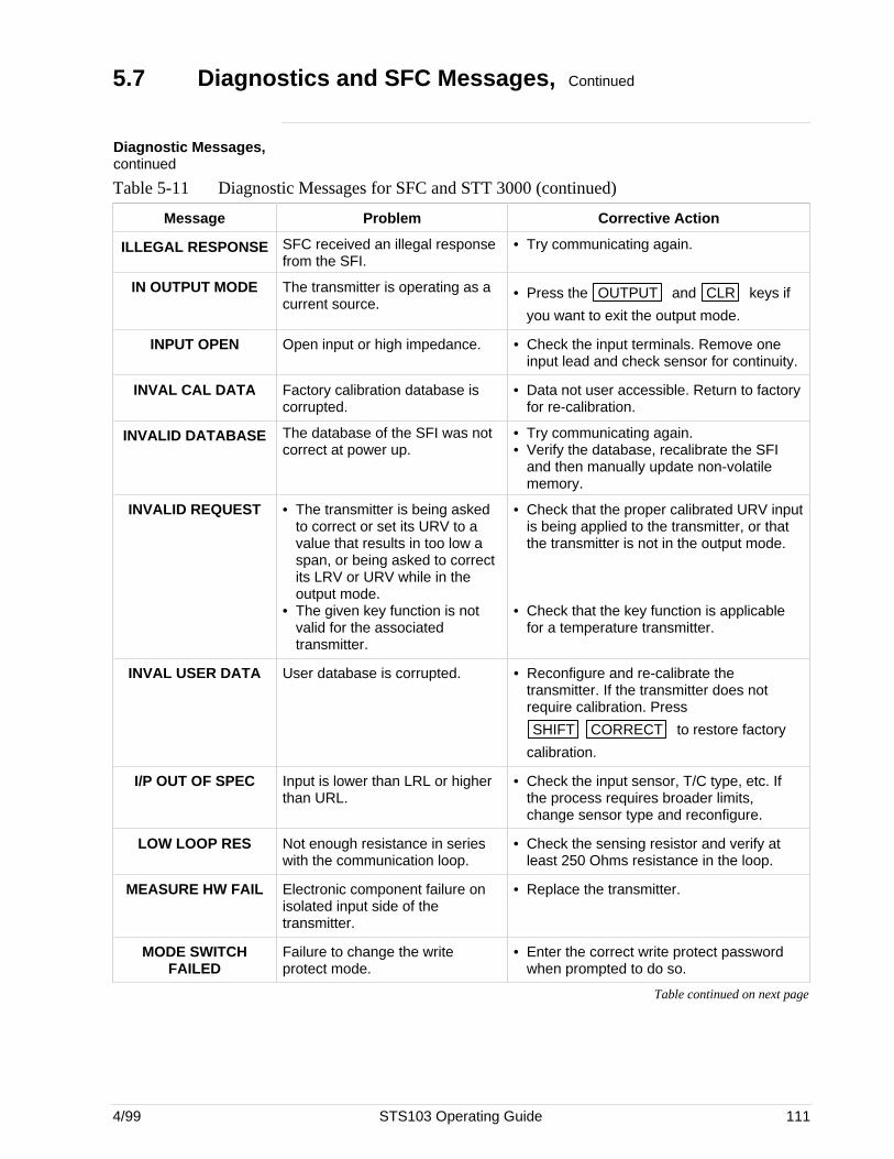
4/99 STS103 Operating Guide 111
5.7 Diagnostics and SFC Messages, Continued
Diagnostic Messages,continued
Table 5-11 Diagnostic Messages for SFC and STT 3000 (continued)
Message Problem Corrective Action
ILLEGAL RESPONSE SFC received an illegal responsefrom the SFI.
• Try communicating again.
IN OUTPUT MODE The transmitter is operating as acurrent source.
• Press the OUTPUT and CLR keys if
you want to exit the output mode.
INPUT OPEN Open input or high impedance. • Check the input terminals. Remove oneinput lead and check sensor for continuity.
INVAL CAL DATA Factory calibration database iscorrupted.
• Data not user accessible. Return to factoryfor re-calibration.
INVALID DATABASE The database of the SFI was notcorrect at power up.
• Try communicating again.• Verify the database, recalibrate the SFI
and then manually update non-volatilememory.
INVALID REQUEST • The transmitter is being askedto correct or set its URV to avalue that results in too low aspan, or being asked to correctits LRV or URV while in theoutput mode.
• The given key function is notvalid for the associatedtransmitter.
• Check that the proper calibrated URV inputis being applied to the transmitter, or thatthe transmitter is not in the output mode.
• Check that the key function is applicablefor a temperature transmitter.
INVAL USER DATA User database is corrupted. • Reconfigure and re-calibrate thetransmitter. If the transmitter does notrequire calibration. Press
SHIFT CORRECT to restore factory
calibration.
I/P OUT OF SPEC Input is lower than LRL or higherthan URL.
• Check the input sensor, T/C type, etc. Ifthe process requires broader limits,change sensor type and reconfigure.
LOW LOOP RES Not enough resistance in serieswith the communication loop.
• Check the sensing resistor and verify atleast 250 Ohms resistance in the loop.
MEASURE HW FAIL Electronic component failure onisolated input side of thetransmitter.
• Replace the transmitter.
MODE SWITCHFAILED
Failure to change the writeprotect mode.
• Enter the correct write protect passwordwhen prompted to do so.
Table continued on next page
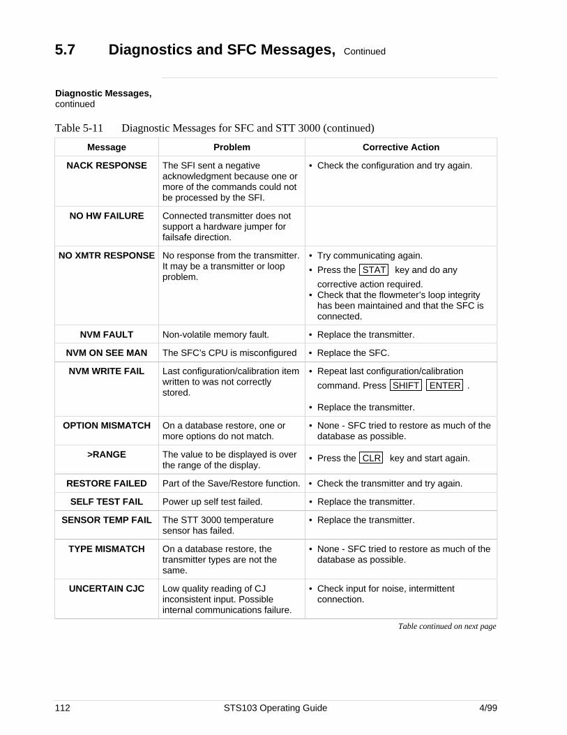
112 STS103 Operating Guide 4/99
5.7 Diagnostics and SFC Messages, Continued
Diagnostic Messages,continued
Table 5-11 Diagnostic Messages for SFC and STT 3000 (continued)
Message Problem Corrective Action
NACK RESPONSE The SFI sent a negativeacknowledgment because one ormore of the commands could notbe processed by the SFI.
• Check the configuration and try again.
NO HW FAILURE Connected transmitter does notsupport a hardware jumper forfailsafe direction.
NO XMTR RESPONSE No response from the transmitter.It may be a transmitter or loopproblem.
• Try communicating again.
• Press the STAT key and do any
corrective action required.• Check that the flowmeter’s loop integrity
has been maintained and that the SFC isconnected.
NVM FAULT Non-volatile memory fault. • Replace the transmitter.
NVM ON SEE MAN The SFC’s CPU is misconfigured • Replace the SFC.
NVM WRITE FAIL Last configuration/calibration itemwritten to was not correctlystored.
• Repeat last configuration/calibration
command. Press SHIFT ENTER .
• Replace the transmitter.
OPTION MISMATCH On a database restore, one ormore options do not match.
• None - SFC tried to restore as much of thedatabase as possible.
>RANGE The value to be displayed is overthe range of the display.
• Press the CLR key and start again.
RESTORE FAILED Part of the Save/Restore function. • Check the transmitter and try again.
SELF TEST FAIL Power up self test failed. • Replace the transmitter.
SENSOR TEMP FAIL The STT 3000 temperaturesensor has failed.
• Replace the transmitter.
TYPE MISMATCH On a database restore, thetransmitter types are not thesame.
• None - SFC tried to restore as much of thedatabase as possible.
UNCERTAIN CJC Low quality reading of CJinconsistent input. Possibleinternal communications failure.
• Check input for noise, intermittentconnection.
Table continued on next page
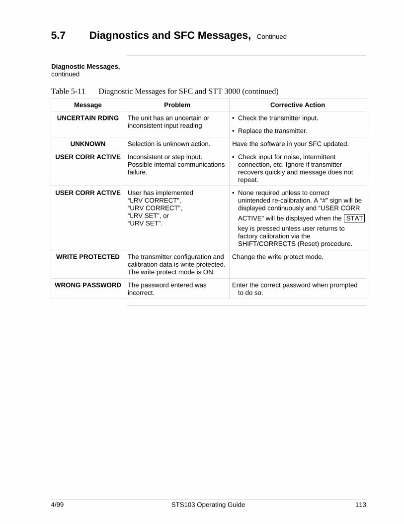
4/99 STS103 Operating Guide 113
5.7 Diagnostics and SFC Messages, Continued
Diagnostic Messages,continued
Table 5-11 Diagnostic Messages for SFC and STT 3000 (continued)
Message Problem Corrective Action
UNCERTAIN RDING The unit has an uncertain orinconsistent input reading
• Check the transmitter input.
• Replace the transmitter.
UNKNOWN Selection is unknown action. Have the software in your SFC updated.
USER CORR ACTIVE Inconsistent or step input.Possible internal communicationsfailure.
• Check input for noise, intermittentconnection, etc. Ignore if transmitterrecovers quickly and message does notrepeat.
USER CORR ACTIVE User has implemented“LRV CORRECT”,“URV CORRECT”,“LRV SET”, or“URV SET”.
• None required unless to correctunintended re-calibration. A “#” sign will bedisplayed continuously and “USER CORR
ACTIVE” will be displayed when the STAT
key is pressed unless user returns tofactory calibration via theSHIFT/CORRECTS (Reset) procedure.
WRITE PROTECTED The transmitter configuration andcalibration data is write protected.The write protect mode is ON.
Change the write protect mode.
WRONG PASSWORD The password entered wasincorrect.
Enter the correct password when promptedto do so.
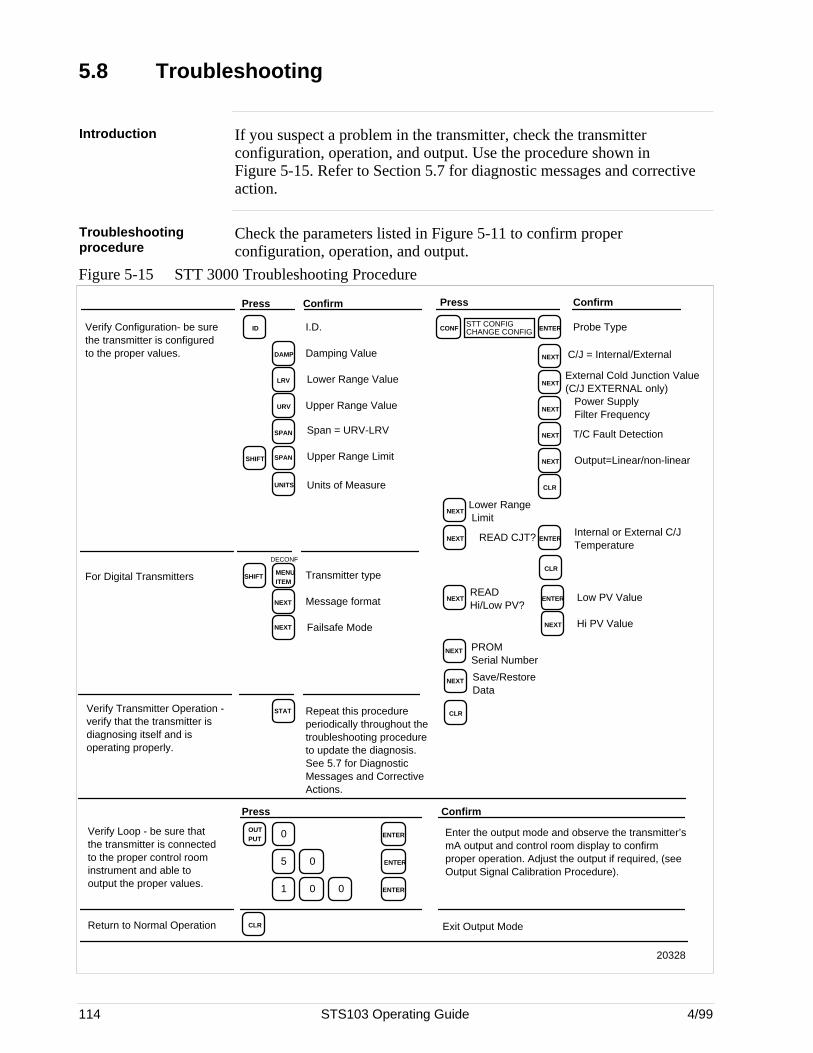
114 STS103 Operating Guide 4/99
5.8 Troubleshooting
Introduction If you suspect a problem in the transmitter, check the transmitterconfiguration, operation, and output. Use the procedure shown inFigure 5-15. Refer to Section 5.7 for diagnostic messages and correctiveaction.
Troubleshootingprocedure
Check the parameters listed in Figure 5-11 to confirm properconfiguration, operation, and output.
Figure 5-15 STT 3000 Troubleshooting Procedure
DAMP
LRV
URV
SPAN
SPAN
UNITS
NEXT
STAT
I.D.
Damping Value
Lower Range Value
Upper Range Value
Span = URV-LRV
Units of Measure
Message format
Failsafe Mode
Repeat this procedure periodically throughout the troubleshooting procedure to update the diagnosis. See 5.7 for Diagnostic Messages and Corrective Actions.
CONFSTT CONFIGCHANGE CONFIG ENTER
NEXT
NEXT
NEXT
NEXT
CLR
Probe Type
C/J = Internal/External
Power Supply Filter Frequency
T/C Fault Detection
Output=Linear/non-linear
NEXTLower Range Limit
NEXT READ CJT? ENTERInternal or External C/J Temperature
CLR
NEXTREAD Hi/Low PV?
ENTER
NEXT
Low PV Value
Hi PV Value
CLR
NEXT PROM Serial Number
ID
SHIFT
MENU ITEM
Upper Range Limit
Transmitter type
Verify Configuration- be sure the transmitter is configured to the proper values.
For Digital Transmitters
Verify Transmitter Operation - verify that the transmitter is diagnosing itself and is operating properly.
Press ConfirmConfirmPress
20328
Verify Loop - be sure that the transmitter is connected to the proper control room instrument and able to output the proper values.
0OUT PUT
0
ENTER
5 0 ENTER
1 0 ENTER
Enter the output mode and observe the transmitter’s mA output and control room display to confirm proper operation. Adjust the output if required, (see Output Signal Calibration Procedure).
CLRReturn to Normal Operation Exit Output Mode
ConfirmPress
DECONF
NEXT
SHIFT
NEXT
External Cold Junction Value (C/J EXTERNAL only)
NEXT Save/Restore Data
4/99 STS103 Operating Guide 115
Section 6 —MagneW 3000 Electromagnetic Flowmeter
6.1 Overview
Introduction This section contains all the information you will need to know in order towire, set-up, configure, operate, and calibrate the MagneW 3000 MagneticFlowmeter using the STS103 Smart Field Communicator.
Refer to the MagneW 3000 User’s Manual for Flowmeter operating andinstallation information.
Make sure you have become familiar with the STS103 operations that aremore or less the same for every transmitter.
This section gives you the keystrokes and displays that are specific forSFC communications with the MagneW 3000 Flowmeter.
What’s in this section? This section contains the following topics:
Topic See Page
6.1 Overview 115
6.2 Wiring 116
6.3 Set-up 118
6.4 Configuration 129
6.5 Calibration 154
6.6 Operation 167
6.7 Diagnostics and SFC Messages 171
6.8 Troubleshooting 175

116 STS103 Operating Guide 4/99
6.2 Wiring
Overview Establish communications with the MagneW 3000 by connecting the SFCleads to the 4–20 mA line of the flowmeter.
Your choices are either at a junction box somewhere along the 4–20 mAline, on the field side of the intrinsic safety barrier panel in the controlroom, or at the flowmeter itself.
Following are examples for connecting to all these places. Use the oneyou need.
Connecting theSTS103 to junctionboxes and IS panels
The STS103 connects to MagneW flowmeters, IS Panels, and junctionboxes through a pair of wires with alligator clips on the ends. The STS103communications terminal end of the wires has a stereo phone jackconnection that is inserted into the communications terminal. The otherend of the wires are clipped onto terminals in the junction box or ISbarrier panel, or directly to the flowmeter. The red SFC lead connects tothe junction box or SFI positive terminal, the black lead to the negativeterminal.
Figure 6-1 shows the STS103 connected to a junction box or an IS barrierpanel.
Figure 6-1 STS103 – Junction Box and IS Connection
Honeywell
Transmitter Junction Box IS Panel
20723
Honeywell
Continued on next page
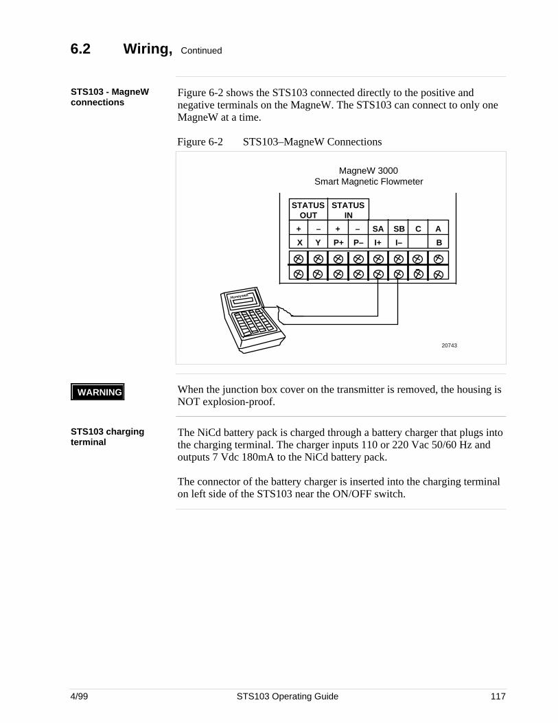
4/99 STS103 Operating Guide 117
6.2 Wiring, Continued
STS103 - MagneWconnections
Figure 6-2 shows the STS103 connected directly to the positive andnegative terminals on the MagneW. The STS103 can connect to only oneMagneW at a time.
Figure 6-2 STS103–MagneW Connections
MagneW 3000 Smart Magnetic Flowmeter
20743
X Y P+ P– I+ I– B
+ – + – SA SB C A
STATUS OUT
STATUS IN
Honeywell
WARNING When the junction box cover on the transmitter is removed, the housing isNOT explosion-proof.
STS103 chargingterminal
The NiCd battery pack is charged through a battery charger that plugs intothe charging terminal. The charger inputs 110 or 220 Vac 50/60 Hz andoutputs 7 Vdc 180mA to the NiCd battery pack.
The connector of the battery charger is inserted into the charging terminalon left side of the STS103 near the ON/OFF switch.
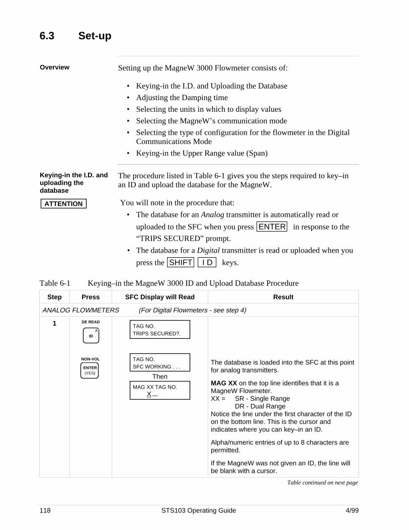
118 STS103 Operating Guide 4/99
6.3 Set-up
Overview Setting up the MagneW 3000 Flowmeter consists of:
• Keying-in the I.D. and Uploading the Database
• Adjusting the Damping time
• Selecting the units in which to display values
• Selecting the MagneW’s communication mode
• Selecting the type of configuration for the flowmeter in the DigitalCommunications Mode
• Keying-in the Upper Range value (Span)
Keying-in the I.D. anduploading thedatabase
The procedure listed in Table 6-1 gives you the steps required to key–inan ID and upload the database for the MagneW.
ATTENTION You will note in the procedure that:
• The database for an Analog transmitter is automatically read or
uploaded to the SFC when you press ENTER in response to the
“TRIPS SECURED” prompt.
• The database for a Digital transmitter is read or uploaded when you
press the SHIFT I D keys.
Table 6-1 Keying–in the MagneW 3000 ID and Upload Database Procedure
Step Press SFC Display will Read Result
ANALOG FLOWMETERS (For Digital Flowmeters - see step 4)
1 DE READ
AID
NON-VOL
ENTER (YES)
TAG NO.TRIPS SECURED?.
TAG NO.SFC WORKING . . .
Then
MAG XX TAG NO. X
The database is loaded into the SFC at this pointfor analog transmitters.
MAG XX on the top line identifies that it is aMagneW Flowmeter.XX = SR - Single Range
DR - Dual RangeNotice the line under the first character of the IDon the bottom line. This is the cursor andindicates where you can key–in an ID.
Alpha/numeric entries of up to 8 characters arepermitted.
If the MagneW was not given an ID, the line willbe blank with a cursor.
Table continued on next page
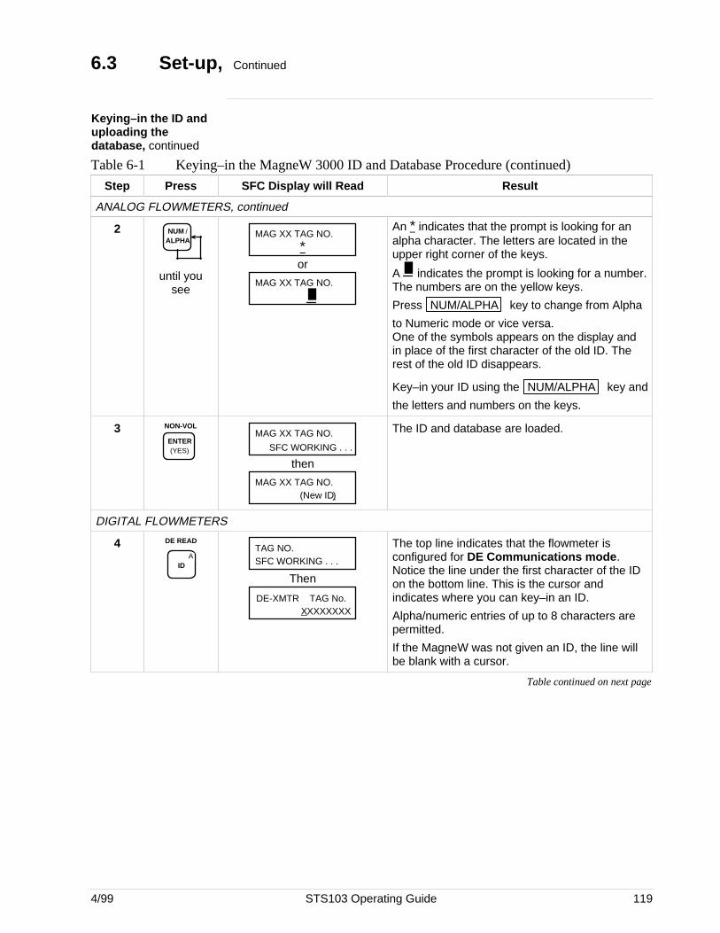
4/99 STS103 Operating Guide 119
6.3 Set-up, Continued
Keying–in the ID anduploading thedatabase, continued
Table 6-1 Keying–in the MagneW 3000 ID and Database Procedure (continued)
Step Press SFC Display will Read Result
ANALOG FLOWMETERS, continued
2 NUM / ALPHA
until yousee
MAG XX TAG NO.
*or
MAG XX TAG NO.
An * indicates that the prompt is looking for an alpha character. The letters are located in theupper right corner of the keys.
A indicates the prompt is looking for a number.The numbers are on the yellow keys.
Press NUM/ALPHA key to change from Alpha
to Numeric mode or vice versa.One of the symbols appears on the display andin place of the first character of the old ID. Therest of the old ID disappears.
Key–in your ID using the NUM/ALPHA key and
the letters and numbers on the keys.
3 NON-VOL
ENTER (YES)
MAG XX TAG NO.
SFC WORKING . . .
then
MAG XX TAG NO.(New ID)
The ID and database are loaded.
DIGITAL FLOWMETERS
4 DE READ
AID
TAG NO.SFC WORKING . . .
Then
DE-XMTR TAG No.XXXXXXXX
The top line indicates that the flowmeter isconfigured for DE Communications mode.Notice the line under the first character of the IDon the bottom line. This is the cursor andindicates where you can key–in an ID.
Alpha/numeric entries of up to 8 characters arepermitted.
If the MagneW was not given an ID, the line willbe blank with a cursor.
Table continued on next page
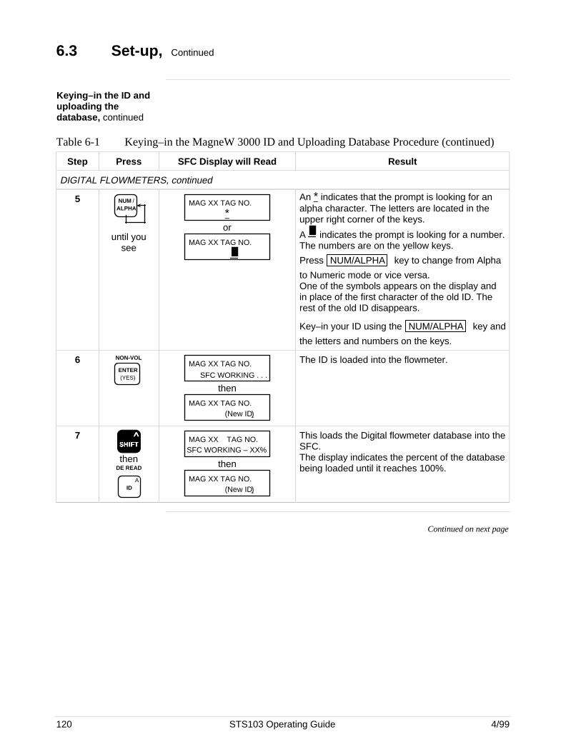
120 STS103 Operating Guide 4/99
6.3 Set-up, Continued
Keying–in the ID anduploading thedatabase, continued
Table 6-1 Keying–in the MagneW 3000 ID and Uploading Database Procedure (continued)
Step Press SFC Display will Read Result
DIGITAL FLOWMETERS, continued
5 NUM / ALPHA
until yousee
MAG XX TAG NO.
*or
MAG XX TAG NO.
An * indicates that the prompt is looking for an alpha character. The letters are located in theupper right corner of the keys.
A indicates the prompt is looking for a number.The numbers are on the yellow keys.
Press NUM/ALPHA key to change from Alpha
to Numeric mode or vice versa.One of the symbols appears on the display andin place of the first character of the old ID. Therest of the old ID disappears.
Key–in your ID using the NUM/ALPHA key and
the letters and numbers on the keys.
6 NON-VOL
ENTER (YES)
MAG XX TAG NO.
SFC WORKING . . .
then
MAG XX TAG NO.(New ID)
The ID is loaded into the flowmeter.
7SSSSSHHHHHIIIIIFFFFFTTTTT
^
thenDE READ
AID
MAG XX TAG NO.SFC WORKING – XX%
then
MAG XX TAG NO.(New ID)
This loads the Digital flowmeter database into theSFC.The display indicates the percent of the databasebeing loaded until it reaches 100%.
Continued on next page
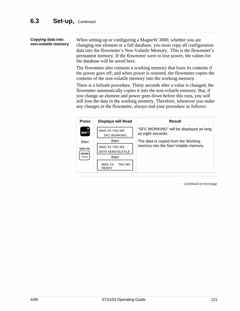
4/99 STS103 Operating Guide 121
6.3 Set-up, Continued
Copying data intonon-volatile memory
When setting-up or configuring a MagneW 3000, whether you arechanging one element or a full database, you must copy all configurationdata into the flowmeter’s Non-Volatile Memory. This is the flowmeter’spermanent memory. If the flowmeter were to lose power, the values forthe database will be saved here.
The flowmeter also contains a working memory that loses its contents ifthe power goes off; and when power is restored, the flowmeter copies thecontents of the non-volatile memory into the working memory.
There is a failsafe procedure. Thirty seconds after a value is changed, theflowmeter automatically copies it into the non-volatile memory. But, ifyou change an element and power goes down before this runs, you willstill lose the data in the working memory. Therefore, whenever you makeany changes in the flowmeter, always end your procedure as follows:
Press Displays will Read Result
SSSSSHHHHHIIIIIFFFFFTTTTT ^
then
NON-VOL
ENTER (YES)
MAG XX TAG NO.
SFC WORKING . . .
then
MAG XX TAG NO.
DATA NONVOLATILE
then
MAG XX TAG NO.READY
“SFC WORKING” will be displayed as longas eight seconds.
The data is copied from the Workingmemory into the Non-Volatile memory.
Continued on next page
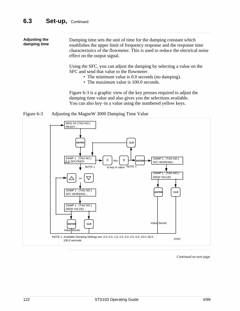
122 STS103 Operating Guide 4/99
6.3 Set-up, Continued
Adjusting thedamping time
Damping time sets the unit of time for the damping constant whichestablishes the upper limit of frequency response and the response timecharacteristics of the flowmeter. This is used to reduce the electrical noiseeffect on the output signal.
Using the SFC, you can adjust the damping by selecting a value on theSFC and send that value to the flowmeter.
• The minimum value is 0.0 seconds (no damping).• The maximum value is 100.0 seconds.
Figure 6-3 is a graphic view of the key presses required to adjust thedamping time value and also gives you the selections available.You can also key–in a value using the numbered yellow keys.
Figure 6-3 Adjusting the MagneW 3000 Damping Time Value
MAG XX (TAG NO.)READY...
ENTER
20303
DAMP 1 (TAG NO.)X.X SECONDS
or
DAMP 1 (TAG NO.)SFC WORKING...
DAMP 1 (TAG NO.)(NEW VALUE)
ENTER CLR
thru ENTERDAMP 1 (TAG NO.)SFC WORKING...
DAMP 1 (TAG NO.)(NEW VALUE)
ENTER CLR
CLR
NOTE 1 NOTE 1to key in value
90
NOTE 1: Available Damping Settings are: 0.0, 0.5, 1.0, 2.0, 3.0, 4.0, 5.0, 10.0, 50.0, 100.0 seconds
Value Stored
Value Stored
Continued on next page
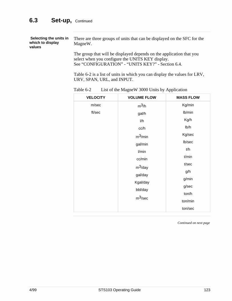
4/99 STS103 Operating Guide 123
6.3 Set-up, Continued
Selecting the units inwhich to displayvalues
There are three groups of units that can be displayed on the SFC for theMagneW.
The group that will be displayed depends on the application that youselect when you configure the UNITS KEY display.See “CONFIGURATION” - “UNITS KEY?” - Section 6.4.
Table 6-2 is a list of units in which you can display the values for LRV,URV, SPAN, URL, and INPUT.
Table 6-2 List of the MagneW 3000 Units by Application
VELOCITY VOLUME FLOW MASS FLOW
m/sec
ft/sec
m3/h
gal/h
l/h
cc/h
m3/min
gal/min
l/min
cc/min
m3/day
gal/day
Kgal/day
bbl/day
m3/sec
Kg/min
lb/min
Kg/h
lb/h
Kg/sec
lb/sec
t/h
t/min
t/sec
g/h
g/min
g/sec
ton/h
ton/min
ton/sec
Continued on next page
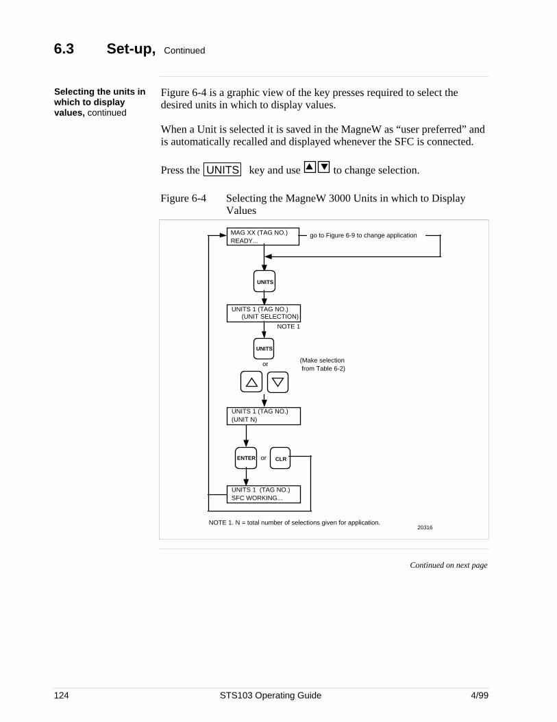
124 STS103 Operating Guide 4/99
6.3 Set-up, Continued
Selecting the units inwhich to displayvalues, continued
Figure 6-4 is a graphic view of the key presses required to select thedesired units in which to display values.
When a Unit is selected it is saved in the MagneW as “user preferred” andis automatically recalled and displayed whenever the SFC is connected.
Press the UNITS key and use to change selection.
Figure 6-4 Selecting the MagneW 3000 Units in which to DisplayValues
NOTE 1. N = total number of selections given for application.
go to Figure 6-9 to change application
UNITS 1 (TAG NO.)(UNIT SELECTION)
UNITS 1 (TAG NO.)SFC WORKING...
UNITS 1 (TAG NO.)(UNIT N)
MAG XX (TAG NO.)READY...
UNITS
NOTE 1
or
CLRENTER or
UNITS
(Make selection from Table 6-2)
20316
Continued on next page
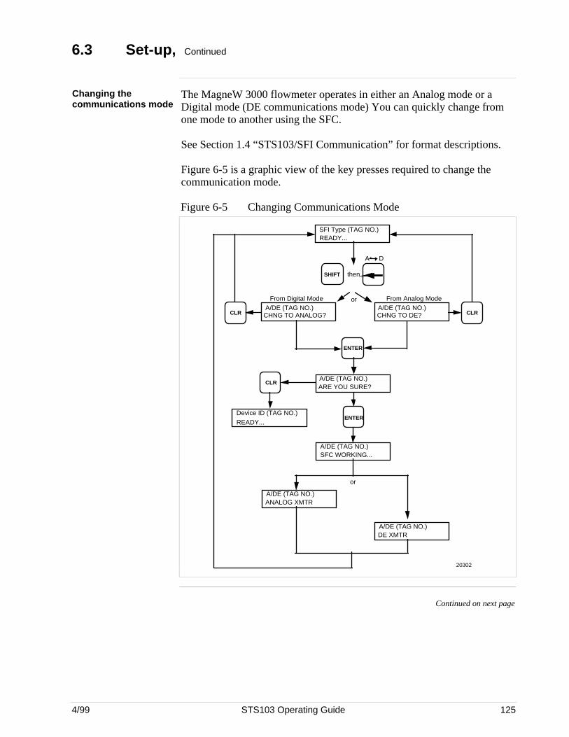
4/99 STS103 Operating Guide 125
6.3 Set-up, Continued
Changing thecommunications mode
The MagneW 3000 flowmeter operates in either an Analog mode or aDigital mode (DE communications mode) You can quickly change fromone mode to another using the SFC.
See Section 1.4 “STS103/SFI Communication” for format descriptions.
Figure 6-5 is a graphic view of the key presses required to change thecommunication mode.
Figure 6-5 Changing Communications Mode
SFI Type (TAG NO.)READY...
ENTER
From Analog Mode
SHIFT
20302
A/DE (TAG NO.)CHNG TO ANALOG?CLR
A/DE (TAG NO.)CHNG TO DE? CLR
From Digital Mode
then
A/DE (TAG NO.)ARE YOU SURE?
CLR
Device ID (TAG NO.)READY...
ENTER
A D
A/DE (TAG NO.)SFC WORKING...
A/DE (TAG NO.)DE XMTR
A/DE (TAG NO.)ANALOG XMTR
or
or
Continued on next page
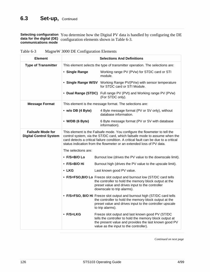
126 STS103 Operating Guide 4/99
6.3 Set-up, Continued
Selecting configurationdata for the digital (DE)communications mode
You determine how the Digital PV data is handled by configuring the DEconfiguration elements shown in Table 6-3.
Table 6-3 MagneW 3000 DE Configuration Elements
Element Selections And Definitions
Type of Transmitter This element selects the type of transmitter operation. The selections are:
• Single Range Working range PV (PVw) for STDC card or STImodule.
• Single Range W/SV Working Range PV(PVw) with sensor temperature for STDC card or STI Module.
• Dual Range (STDC) Full range PV (PVt) and Working range PV (PVw) (For STDC only).
Message Format This element is the message format. The selections are:
• w/o DB (4 Byte) 4 Byte message format (PV or SV only), withoutdatabase information.
• W/DB (6 Byte) 6 Byte message format (PV or SV with database information).
Failsafe Mode forDigital Control System
This element is the Failsafe mode. You configure the flowmeter to tell thecontrol system, via the ST/DC card, which failsafe mode to assume when thecard detects a critical failure condition. A critical fault can be due to a criticalstatus indication from the flowmeter or an extended loss of PV data.
The selections are:
• F/S=B/O Lo Burnout low (drives the PV value to the downscale limit).
• F/S=B/O Hi Burnout high (drives the PV value to the upscale limit).
• LKG Last known good PV value.
• F/S=FSO,B/O Lo Freeze slot output and burnout low (ST/DC card tells the controller to hold the memory block output at the preset value and drives input to the controller downscale to trip alarms).
• F/S=FSO, B/O Hi Freeze slot output and burnout high (ST/DC card tells the controller to hold the memory block output at the preset value and drives input to the controller upscale to trip alarms).
• F/S=LKG Freeze slot output and last known good PV (ST/DC tells the controller to hold the memory block output at the present value and provides the last known good PV value as the input to the controller).
Continued on next page
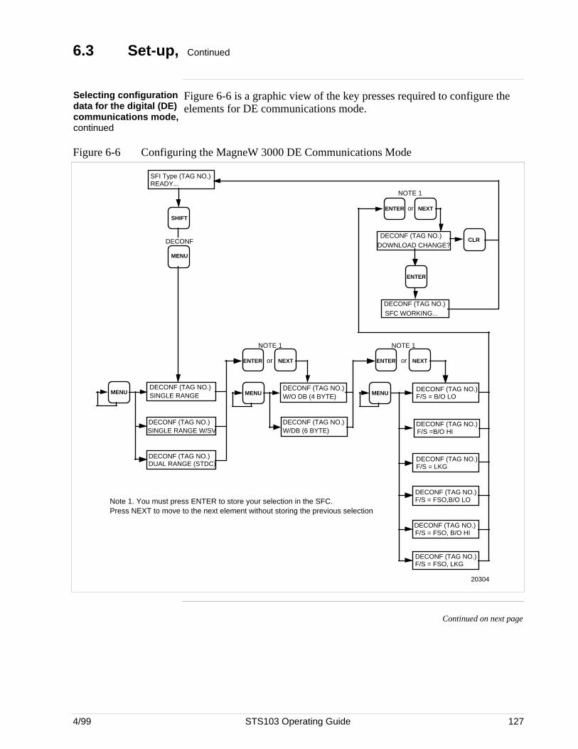
4/99 STS103 Operating Guide 127
6.3 Set-up, Continued
Selecting configurationdata for the digital (DE)communications mode,continued
Figure 6-6 is a graphic view of the key presses required to configure theelements for DE communications mode.
Figure 6-6 Configuring the MagneW 3000 DE Communications Mode
MENU
SHIFT
SFI Type (TAG NO.)READY...
DECONF
MENUDECONF (TAG NO.)SINGLE RANGE
DECONF (TAG NO.)SINGLE RANGE W/SV
DECONF (TAG NO.)DUAL RANGE (STDC)
NOTE 1
MENU
DECONF (TAG NO.)W/DB (6 BYTE)
DECONF (TAG NO.)W/O DB (4 BYTE)
ENTER or NEXT
MENUDECONF (TAG NO.)F/S = B/O LO
DECONF (TAG NO.)F/S = LKG
DECONF (TAG NO.)F/S =B/O HI
ENTER or NEXT
NOTE 1
DECONF (TAG NO.)F/S = FSO,B/O LO
DECONF (TAG NO.)F/S = FSO, LKG
DECONF (TAG NO.)F/S = FSO, B/O HI
DOWNLOAD CHANGE?DECONF (TAG NO.)
DECONF (TAG NO.)SFC WORKING...
ENTER or NEXT
NOTE 1
ENTER
CLR
20304
Note 1. You must press ENTER to store your selection in the SFC. Press NEXT to move to the next element without storing the previous selection
Continued on next page
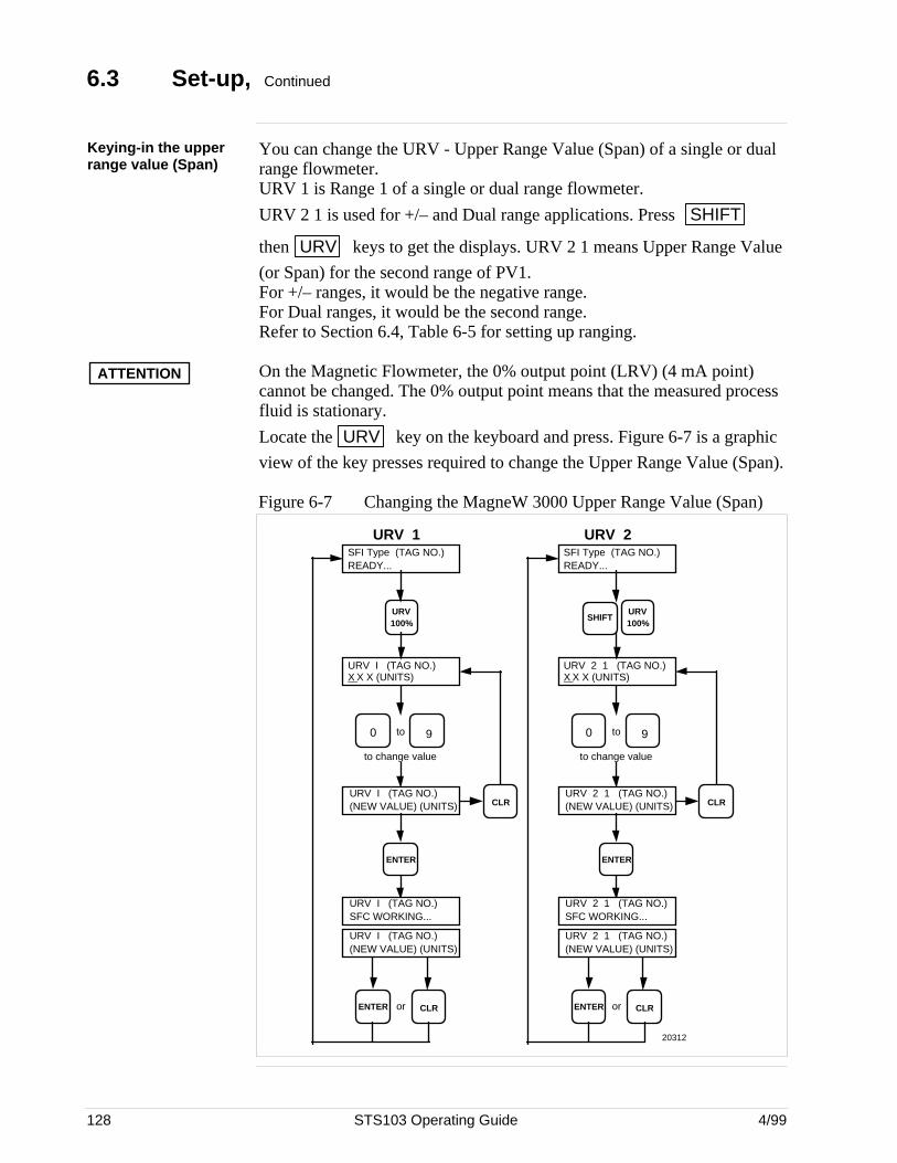
128 STS103 Operating Guide 4/99
6.3 Set-up, Continued
Keying-in the upperrange value (Span)
You can change the URV - Upper Range Value (Span) of a single or dualrange flowmeter.URV 1 is Range 1 of a single or dual range flowmeter.
URV 2 1 is used for +/– and Dual range applications. Press SHIFT
then URV keys to get the displays. URV 2 1 means Upper Range Value
(or Span) for the second range of PV1.For +/– ranges, it would be the negative range.For Dual ranges, it would be the second range.Refer to Section 6.4, Table 6-5 for setting up ranging.
ATTENTION On the Magnetic Flowmeter, the 0% output point (LRV) (4 mA point)cannot be changed. The 0% output point means that the measured processfluid is stationary.
Locate the URV key on the keyboard and press. Figure 6-7 is a graphic
view of the key presses required to change the Upper Range Value (Span).
Figure 6-7 Changing the MagneW 3000 Upper Range Value (Span)
20312
URV I (TAG NO.)X X X (UNITS)
to change value
CLRENTER or
URV I (TAG NO.)(NEW VALUE) (UNITS)
ENTER
URV I (TAG NO.)(NEW VALUE) (UNITS)
90 to
URV 100%
SFI Type (TAG NO.)READY...
CLR
URV I (TAG NO.)SFC WORKING...
URV 2 1 (TAG NO.)X X X (UNITS)
to change value
CLRENTER or
URV 2 1 (TAG NO.)(NEW VALUE) (UNITS)
ENTER
URV 2 1 (TAG NO.)(NEW VALUE) (UNITS)
90 to
URV 100%
SFI Type (TAG NO.)READY...
CLR
URV 2 1 (TAG NO.)SFC WORKING...
URV 1 URV 2
SHIFT
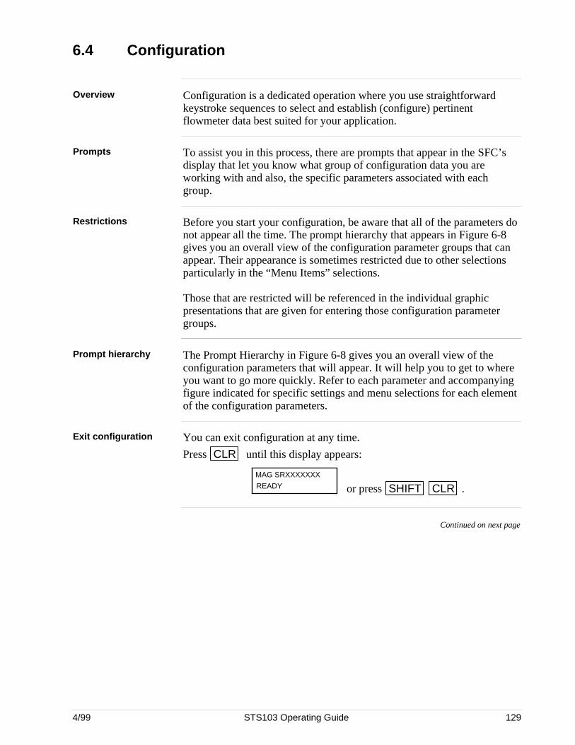
4/99 STS103 Operating Guide 129
6.4 Configuration
Overview Configuration is a dedicated operation where you use straightforwardkeystroke sequences to select and establish (configure) pertinentflowmeter data best suited for your application.
Prompts To assist you in this process, there are prompts that appear in the SFC’sdisplay that let you know what group of configuration data you areworking with and also, the specific parameters associated with eachgroup.
Restrictions Before you start your configuration, be aware that all of the parameters donot appear all the time. The prompt hierarchy that appears in Figure 6-8gives you an overall view of the configuration parameter groups that canappear. Their appearance is sometimes restricted due to other selectionsparticularly in the “Menu Items” selections.
Those that are restricted will be referenced in the individual graphicpresentations that are given for entering those configuration parametergroups.
Prompt hierarchy The Prompt Hierarchy in Figure 6-8 gives you an overall view of theconfiguration parameters that will appear. It will help you to get to whereyou want to go more quickly. Refer to each parameter and accompanyingfigure indicated for specific settings and menu selections for each elementof the configuration parameters.
Exit configuration You can exit configuration at any time.
Press CLR until this display appears:
MAG SRXXXXXXX
READY or press SHIFT CLR .
Continued on next page
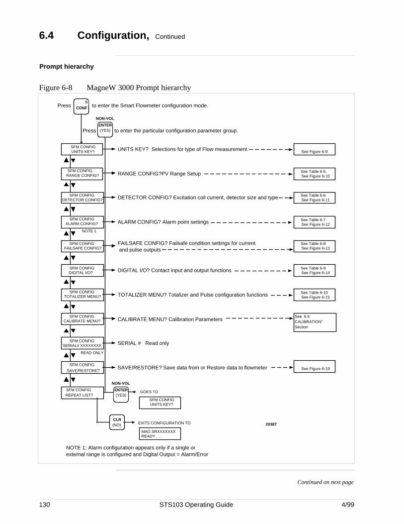
130 STS103 Operating Guide 4/99
6.4 Configuration, Continued
Prompt hierarchy
Figure 6-8 MagneW 3000 Prompt hierarchy
SFM CONFIGUNITS KEY?
B
CONF
SFM CONFIGRANGE CONFIG?
SFM CONFIGDETECTOR CONFIG?
NOTE 1.SFM CONFIG
ALARM CONFIG?
SFM CONFIGFAILSAFE CONFIG?
SFM CONFIGDIGITAL I/O?
SFM CONFIGTOTALIZER MENU?
NOTE 1: Alarm configuration appears only if a single or external range is configured and Digital Output = Alarm/Error
READ ONLY
SFM CONFIGCALIBRATE MENU?
SFM CONFIGSERIAL# XXXXXXXX
SFM CONFIG
SAVE/RESTORE?
SFM CONFIGUNITS KEY?
GOES TOSFM CONFIGREPEAT LIST?
CLR (NO) EXITS CONFIGURATION TO
MAG SRXXXXXXXREADY . . .
NOTE 1
Press to enter the Smart Flowmeter configuration mode.
Press to enter the particular configuration parameter group.
UNITS KEY? Selections for type of Flow measurement
RANGE CONFIG?PV Range Setup
DETECTOR CONFIG? Excitation coil current, detector size and type
ALARM CONFIG? Alarm point settings
FAILSAFE CONFIG? Failsafe condition settings for current and pulse outputs
DIGITAL I/O? Contact input and output functions
TOTALIZER MENU? Totalizer and Pulse configuration functions
CALIBRATE MENU? Calibration Parameters
SERIAL # Read only
SAVE/RESTORE? Save data from or Restore data to flowmeter
See Figure 6-9
See Table 6-5See Figure 6-10
See Table 6-6See Figure 6-11
See Table 6-7See Figure 6-12
See Table 6-8See Figure 6-13
See Table 6-9See Figure 6-14
See Table 6-10See Figure 6-15
See 6.5 CALIBRATION" Section
NON-VOL
ENTER (YES)
NON-VOL
ENTER (YES)
20387
See Figure 6-19
Continued on next page
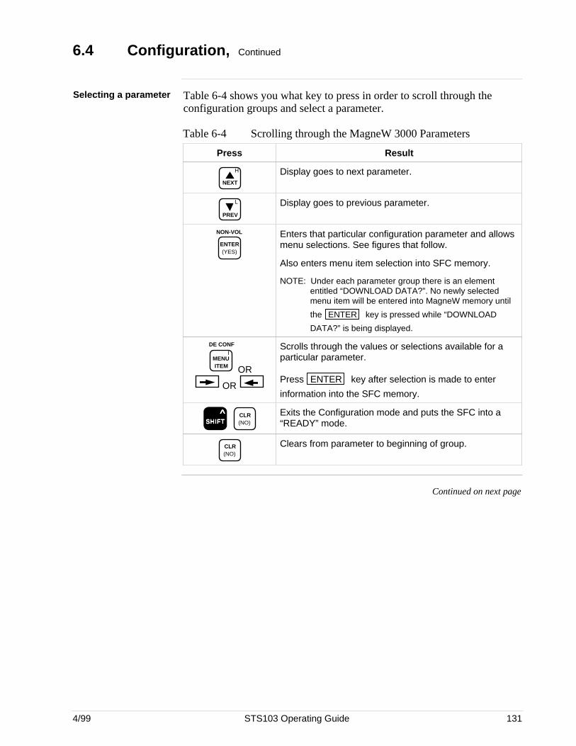
4/99 STS103 Operating Guide 131
6.4 Configuration, Continued
Selecting a parameter Table 6-4 shows you what key to press in order to scroll through theconfiguration groups and select a parameter.
Table 6-4 Scrolling through the MagneW 3000 Parameters
Press Result
H
NEXT
Display goes to next parameter.
L
PREV
Display goes to previous parameter.
NON-VOL
ENTER (YES)
Enters that particular configuration parameter and allowsmenu selections. See figures that follow.
Also enters menu item selection into SFC memory.
NOTE: Under each parameter group there is an elemententitled “DOWNLOAD DATA?”. No newly selectedmenu item will be entered into MagneW memory until
the ENTER key is pressed while “DOWNLOAD
DATA?” is being displayed.
IMENU ITEM
DE CONF
OR
OR
Scrolls through the values or selections available for aparticular parameter.
Press ENTER key after selection is made to enter
information into the SFC memory.
SSSSSHHHHHIIIIIFFFFFTTTTT ^
CLR (NO)
Exits the Configuration mode and puts the SFC into a“READY” mode.
CLR (NO)
Clears from parameter to beginning of group.
Continued on next page
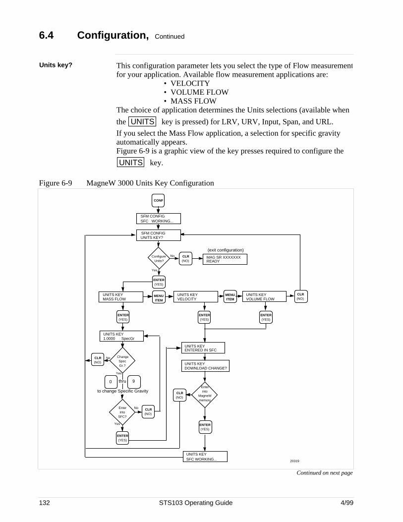
132 STS103 Operating Guide 4/99
6.4 Configuration, Continued
Units key? This configuration parameter lets you select the type of Flow measurementfor your application. Available flow measurement applications are:
• VELOCITY• VOLUME FLOW• MASS FLOW
The choice of application determines the Units selections (available when
the UNITS key is pressed) for LRV, URV, Input, Span, and URL.
If you select the Mass Flow application, a selection for specific gravityautomatically appears.Figure 6-9 is a graphic view of the key presses required to configure the
UNITS key.
Figure 6-9 MagneW 3000 Units Key Configuration
ENTER (YES)
ENTER (YES)
CLR (NO)
(exit configuration)
Yes
No MAG SR XXXXXXXREADY
Configure Units?
CONF
SFM CONFIGSFC WORKING...
SFM CONFIGUNITS KEY?
90
No
Yes
CLR (NO)
ENTER (YES)
No
Yes
CLR (NO)
UNITS KEY1.0000 SpecGr
Change Spec Gr.?
Enter into
SFC?
thru
to change Specific Gravity
MENU ITEM
UNITS KEYMASS FLOW
ENTER (YES)
ENTER (YES)
UNITS KEYENTERED IN SFC
UNITS KEYDOWNLOAD CHANGE?
UNITS KEYSFC WORKING...
CLR (NO)
MENU ITEM
UNITS KEYVELOCITY
UNITS KEYVOLUME FLOW
CLR (NO)
ENTER (YES)
Enter into
MagneW memory
20319
Continued on next page
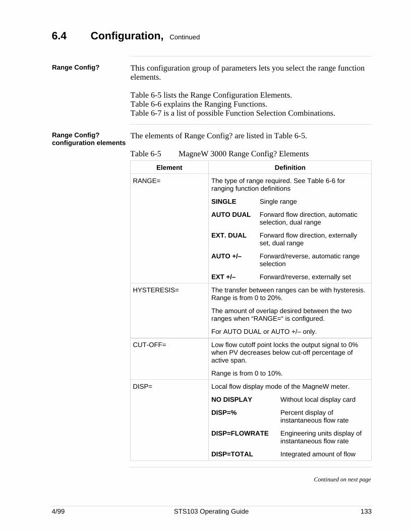
4/99 STS103 Operating Guide 133
6.4 Configuration, Continued
Range Config? This configuration group of parameters lets you select the range functionelements.
Table 6-5 lists the Range Configuration Elements.Table 6-6 explains the Ranging Functions.Table 6-7 is a list of possible Function Selection Combinations.
Range Config?configuration elements
The elements of Range Config? are listed in Table 6-5.
Table 6-5 MagneW 3000 Range Config? Elements
Element Definition
RANGE= The type of range required. See Table 6-6 forranging function definitions
SINGLE Single range
AUTO DUAL Forward flow direction, automaticselection, dual range
EXT. DUAL Forward flow direction, externallyset, dual range
AUTO +/– Forward/reverse, automatic rangeselection
EXT +/– Forward/reverse, externally set
HYSTERESIS= The transfer between ranges can be with hysteresis.Range is from 0 to 20%.
The amount of overlap desired between the tworanges when “RANGE=“ is configured.
For AUTO DUAL or AUTO +/– only.
CUT-OFF= Low flow cutoff point locks the output signal to 0%when PV decreases below cut-off percentage ofactive span.
Range is from 0 to 10%.
DISP= Local flow display mode of the MagneW meter.
NO DISPLAY Without local display card
DISP=% Percent display ofinstantaneous flow rate
DISP=FLOWRATE Engineering units display ofinstantaneous flow rate
DISP=TOTAL Integrated amount of flow
Continued on next page
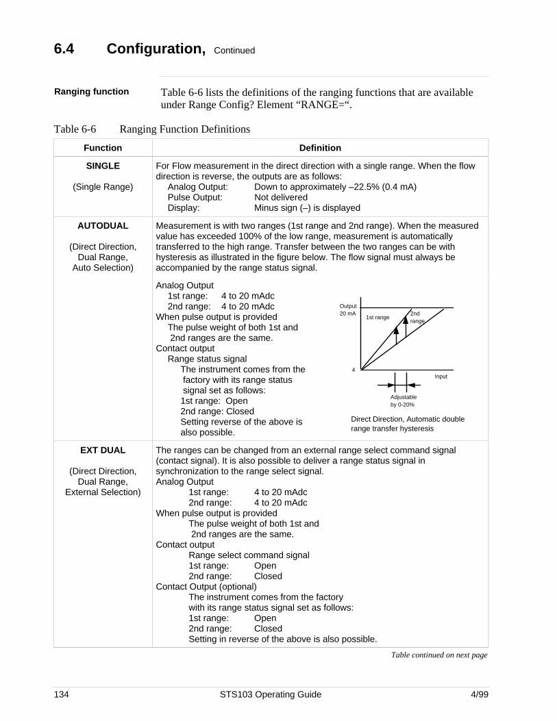
134 STS103 Operating Guide 4/99
6.4 Configuration, Continued
Ranging function Table 6-6 lists the definitions of the ranging functions that are availableunder Range Config? Element “RANGE=“.
Table 6-6 Ranging Function Definitions
Function Definition
SINGLE
(Single Range)
For Flow measurement in the direct direction with a single range. When the flowdirection is reverse, the outputs are as follows:
Analog Output: Down to approximately –22.5% (0.4 mA)Pulse Output: Not deliveredDisplay: Minus sign (–) is displayed
AUTODUAL
(Direct Direction,Dual Range,
Auto Selection)
Measurement is with two ranges (1st range and 2nd range). When the measuredvalue has exceeded 100% of the low range, measurement is automaticallytransferred to the high range. Transfer between the two ranges can be withhysteresis as illustrated in the figure below. The flow signal must always beaccompanied by the range status signal.
Analog Output1st range: 4 to 20 mAdc2nd range: 4 to 20 mAdc
When pulse output is providedThe pulse weight of both 1st and 2nd ranges are the same.
Contact outputRange status signal
The instrument comes from the factory with its range status signal set as follows:1st range: Open2nd range: ClosedSetting reverse of the above isalso possible.
Output 20 mA
1st range2nd range
4Input
Adjustable by 0-20%
Direct Direction, Automatic double range transfer hysteresis
EXT DUAL
(Direct Direction,Dual Range,
External Selection)
The ranges can be changed from an external range select command signal(contact signal). It is also possible to deliver a range status signal insynchronization to the range select signal.Analog Output
1st range: 4 to 20 mAdc2nd range: 4 to 20 mAdc
When pulse output is providedThe pulse weight of both 1st and 2nd ranges are the same.
Contact outputRange select command signal1st range: Open2nd range: Closed
Contact Output (optional)The instrument comes from the factorywith its range status signal set as follows:1st range: Open2nd range: ClosedSetting in reverse of the above is also possible.
Table continued on next page
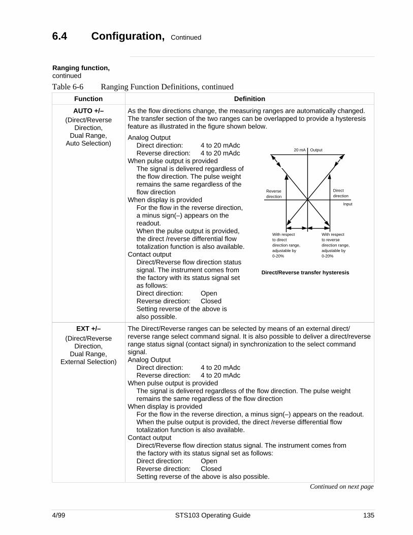
4/99 STS103 Operating Guide 135
6.4 Configuration, Continued
Ranging function,continued
Table 6-6 Ranging Function Definitions, continued
Function Definition
AUTO +/–(Direct/Reverse
Direction,
As the flow directions change, the measuring ranges are automatically changed.The transfer section of the two ranges can be overlapped to provide a hysteresisfeature as illustrated in the figure shown below.
Dual Range,Auto Selection)
Analog OutputDirect direction: 4 to 20 mAdcReverse direction: 4 to 20 mAdc
When pulse output is providedThe signal is delivered regardless ofthe flow direction. The pulse weightremains the same regardless of theflow direction
When display is providedFor the flow in the reverse direction,a minus sign(–) appears on thereadout.When the pulse output is provided,the direct /reverse differential flowtotalization function is also available.
Contact outputDirect/Reverse flow direction statussignal. The instrument comes fromthe factory with its status signal setas follows:Direct direction: OpenReverse direction: ClosedSetting reverse of the above isalso possible.
20 mA Output
Reverse direction
Direct direction
Input
With respect to direct direction range, adjustable by 0-20%
With respect to reverse direction range, adjustable by 0-20%
Direct/Reverse transfer hysteresis
EXT +/–(Direct/Reverse
Direction,Dual Range,
External Selection)
The Direct/Reverse ranges can be selected by means of an external direct/reverse range select command signal. It is also possible to deliver a direct/reverserange status signal (contact signal) in synchronization to the select commandsignal.Analog Output
Direct direction: 4 to 20 mAdcReverse direction: 4 to 20 mAdc
When pulse output is providedThe signal is delivered regardless of the flow direction. The pulse weightremains the same regardless of the flow direction
When display is providedFor the flow in the reverse direction, a minus sign(–) appears on the readout.When the pulse output is provided, the direct /reverse differential flowtotalization function is also available.
Contact outputDirect/Reverse flow direction status signal. The instrument comes fromthe factory with its status signal set as follows:Direct direction: OpenReverse direction: ClosedSetting reverse of the above is also possible.
Continued on next page
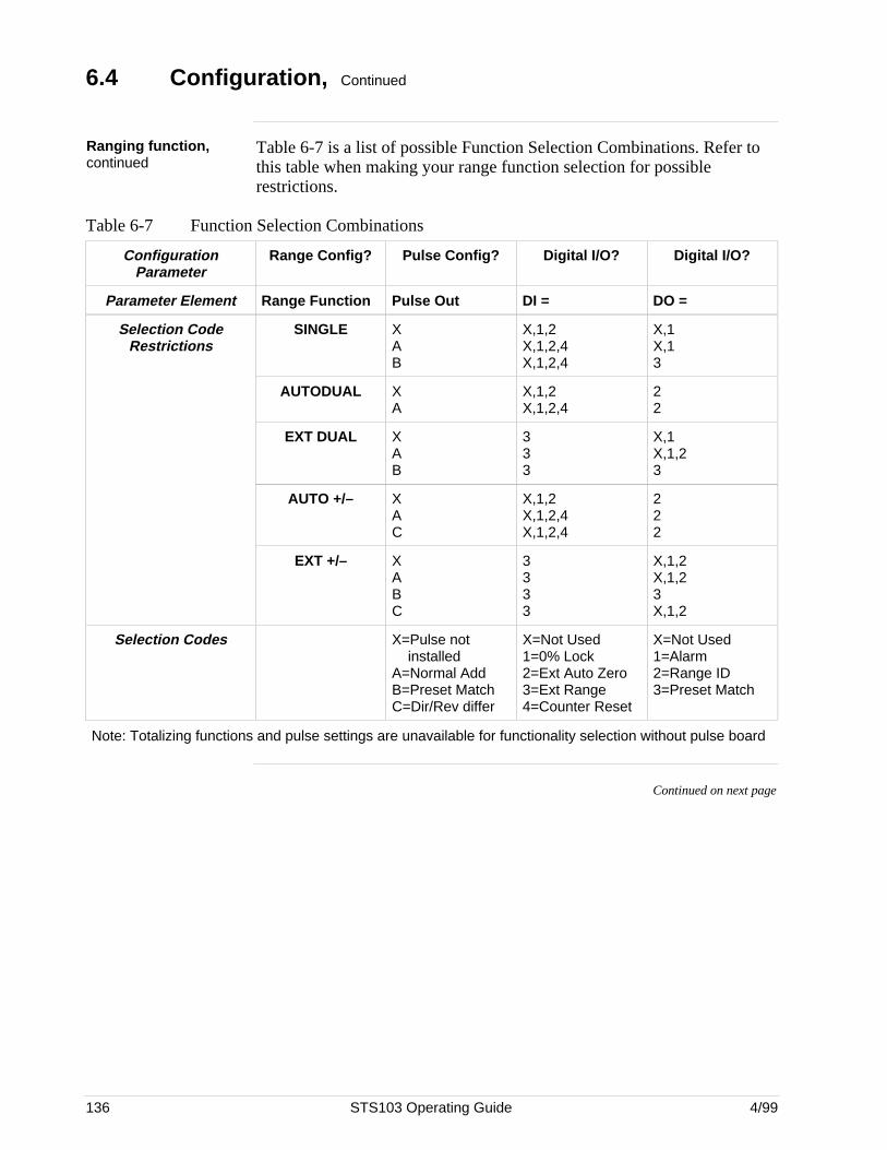
136 STS103 Operating Guide 4/99
6.4 Configuration, Continued
Ranging function,continued
Table 6-7 is a list of possible Function Selection Combinations. Refer tothis table when making your range function selection for possiblerestrictions.
Table 6-7 Function Selection Combinations
ConfigurationParameter
Range Config? Pulse Config? Digital I/O? Digital I/O?
Parameter Element Range Function Pulse Out DI = DO =
Selection CodeRestrictions
SINGLE XAB
X,1,2X,1,2,4X,1,2,4
X,1X,13
AUTODUAL XA
X,1,2X,1,2,4
22
EXT DUAL XAB
333
X,1X,1,23
AUTO +/– XAC
X,1,2X,1,2,4X,1,2,4
222
EXT +/– XABC
3333
X,1,2X,1,23X,1,2
Selection Codes X=Pulse not installedA=Normal AddB=Preset MatchC=Dir/Rev differ
X=Not Used1=0% Lock2=Ext Auto Zero3=Ext Range4=Counter Reset
X=Not Used1=Alarm2=Range ID3=Preset Match
Note: Totalizing functions and pulse settings are unavailable for functionality selection without pulse board
Continued on next page
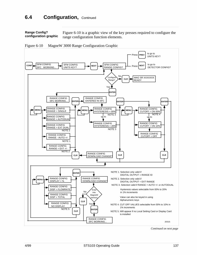
4/99 STS103 Operating Guide 137
6.4 Configuration, Continued
Range Config?configuration graphic
Figure 6-10 is a graphic view of the key presses required to configure therange configuration function elements.
Figure 6-10 MagneW 3000 Range Configuration Graphic
SFM CONFIGUNITS KEY?
NEXT SFM CONFIGRANGE CONFIG?
NEXT
PREV
CONF SFM CONFIGSFC WORKING...
Press
Press
to go to UNITS KEY?
to go to DETECTOR CONFIG?
Configure Range?
MAG SR XXXXXXXREADYCLR
ENTER
No
Yes
MENU
ENTER
CLR CLR
ENTER
MENURANGE CONFIGHYSTERESIS = 00%
MENU
NOTE 2
NOTE 3
CLR
ENTER
RANGE CONFIGSFC WORKING...
RANGE CONFIGRANGE = AUTODUAL
RANGE CONFIGRANGE = EXT DUAL
RANGE CONFIGRANGE = SINGLE
NOTE 1
NOTE 2
RANGE CONFIGRANGE - AUTO +/-
RANGE CONFIGRANGE = EXT +/-
RANGE CONFIGHYSTERESIS = 20%
NOTE 3
RANGE CONFIGCUTOFF = ON 00%
NOTE 4
RANGE CONFIGCUTOFF = OFF
up to
RANGE CONFIGCUTOFF = ON 10%
RANGE CONFIGENTERED IN SFC
RANGE CONFIGSFC WORKING...
CLR
RANGE CONFIGDOWNLOAD CHANGE?
MENU
CLR
ENTER
RANGE CONFIGDISPLAY = %
RANGE CONFIGDISP = FLOWRATE
RANGE CONFIGDISP = TOTAL
RANGE CONFIGNO DISPLAY
NOTE 5
Enter into
MagneW memory
Yes
No
ENTER
up to
NOTE 1. Selection only valid if DIGITAL OUTPUT = RANGE ID
NOTE 2. Selection only valid if DIGITAL OUTPUT = EXT RANGE
NOTE 4. CUT OFF VALUES selectable from 00% to 10% in 1% increments
NOTE 5. Will appear if no Local Setting Card or Display Card is installed
NOTE 3. Selection valid if RANGE = AUTO +/- or AUTODUAL
Hysteresis values selectable from 00% to 20% in 1% increments Value can also be keyed in using Alphanumeric keys
20315
RANGE CONFIGDOWNLOAD CHANGE?
Continued on next page
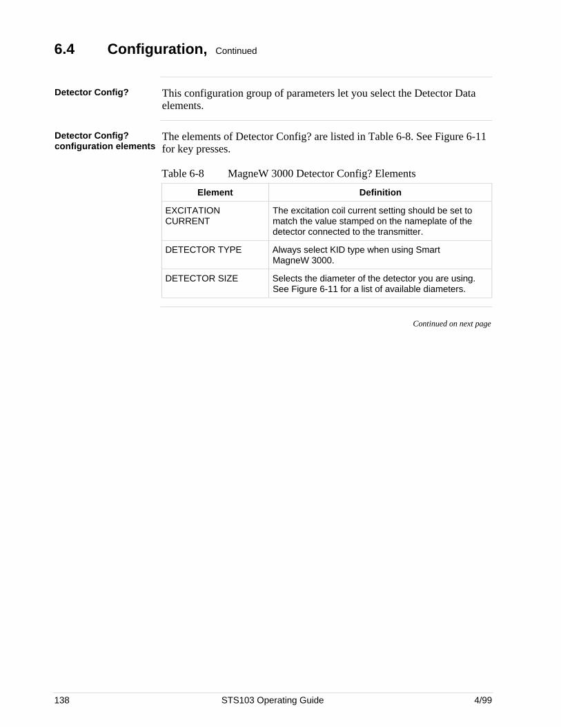
138 STS103 Operating Guide 4/99
6.4 Configuration, Continued
Detector Config? This configuration group of parameters let you select the Detector Dataelements.
Detector Config?configuration elements
The elements of Detector Config? are listed in Table 6-8. See Figure 6-11for key presses.
Table 6-8 MagneW 3000 Detector Config? Elements
Element Definition
EXCITATIONCURRENT
The excitation coil current setting should be set tomatch the value stamped on the nameplate of thedetector connected to the transmitter.
DETECTOR TYPE Always select KID type when using SmartMagneW 3000.
DETECTOR SIZE Selects the diameter of the detector you are using.See Figure 6-11 for a list of available diameters.
Continued on next page
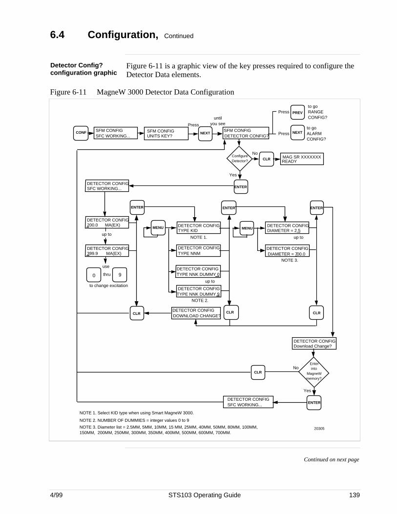
4/99 STS103 Operating Guide 139
6.4 Configuration, Continued
Detector Config?configuration graphic
Figure 6-11 is a graphic view of the key presses required to configure theDetector Data elements.
Figure 6-11 MagneW 3000 Detector Data Configuration
SFM CONFIGUNITS KEY?
NEXTSFM CONFIGDETECTOR CONFIG?
NEXT
Configure Detector?
MAG SR XXXXXXXREADYCLR
PREV
DETECTOR CONFIGSFC WORKING...
DETECTOR CONFIG200.0 MA(EX)
DETECTOR CONFIG399.9 MA(EX)
thru
to change excitation
90
CLR
ENTER
use
DETECTOR CONFIGTYPE KID
DETECTOR CONFIGTYPE NNM
MENU DETECTOR CONFIGDIAMETER = 2.5
DETECTOR CONFIGDIAMETER = 700.0
MENU
ENTER
DETECTOR CONFIGDOWNLOAD CHANGE?
CLR
ENTER
CLR
ENTER
CONF SFM CONFIGSFC WORKING...
Enter into
MagneW memory?
DETECTOR CONFIGDownload Change?
CLR
ENTER DETECTOR CONFIGSFC WORKING...
Press
until you see
Press
Press
to go RANGE CONFIG?
to go ALARM CONFIG?
up to
No
Yes
NOTE 1.
NOTE 2.
DETECTOR CONFIGTYPE NNK DUMMY 0
DETECTOR CONFIGTYPE NNK DUMMY 9
up to
NOTE 1. Select KID type when using Smart MagneW 3000.
NOTE 2. NUMBER OF DUMMIES = integer values 0 to 9
NOTE 3. Diameter list = 2.5MM, 5MM, 10MM, 15 MM, 25MM, 40MM, 50MM, 80MM, 100MM, 150MM, 200MM, 250MM, 300MM, 350MM, 400MM, 500MM, 600MM, 700MM.
NOTE 3.
up to
Yes
No
20305
Continued on next page
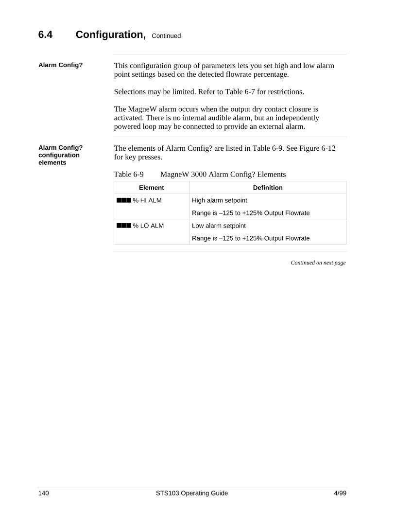
140 STS103 Operating Guide 4/99
6.4 Configuration, Continued
Alarm Config? This configuration group of parameters lets you set high and low alarmpoint settings based on the detected flowrate percentage.
Selections may be limited. Refer to Table 6-7 for restrictions.
The MagneW alarm occurs when the output dry contact closure isactivated. There is no internal audible alarm, but an independentlypowered loop may be connected to provide an external alarm.
Alarm Config?configurationelements
The elements of Alarm Config? are listed in Table 6-9. See Figure 6-12for key presses.
Table 6-9 MagneW 3000 Alarm Config? Elements
Element Definition
% HI ALM High alarm setpoint
Range is –125 to +125% Output Flowrate
% LO ALM Low alarm setpoint
Range is –125 to +125% Output Flowrate
Continued on next page

4/99 STS103 Operating Guide 141
6.4 Configuration, Continued
Alarm Config?configuration graphic
Figure 6-12 is a graphic view of the key presses required to configure thehigh and low alarm setpoints.
Figure 6-12 MagneW 3000 Alarm Setting Configuration
SFM CONFIGUNITS KEY? NEXT
SFM CONFIGALARM CONFIG?
NEXT
Configure Alarms?
MAG SR XXXXXXXREADYCLR
PREV
ENTER
ENTER
CLRCLR
ENTER
CONF SFM CONFIGSFC WORKING...
Press
until you see
Press
Press
to go to DETECTOR CONFIG?
to go to FAILSAFE CONFIG?
ALARM CONFIG?100% HI ALARM
thru
to change High Alarm Point
90
use
No
Yes
ALARM CONFIGSFC WORKING...
Enter into
MagneW memory?
ALARM CONFIGDOWNLOAD CHANGE?
ENTER
CLR Yes
Nothru
to change Low Alarm Point
90
use
ALARM CONFIG?LO ALARM25%
20300
Continued on next page
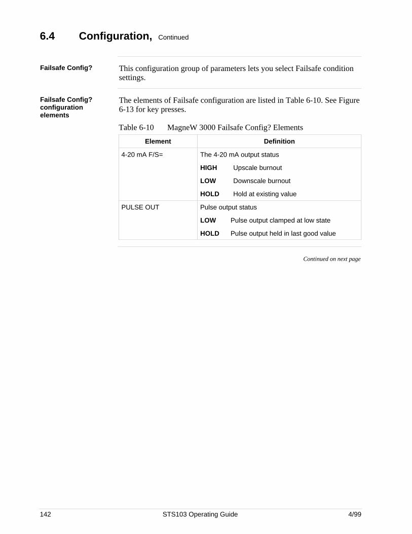
142 STS103 Operating Guide 4/99
6.4 Configuration, Continued
Failsafe Config? This configuration group of parameters lets you select Failsafe conditionsettings.
Failsafe Config?configurationelements
The elements of Failsafe configuration are listed in Table 6-10. See Figure6-13 for key presses.
Table 6-10 MagneW 3000 Failsafe Config? Elements
Element Definition
4-20 mA F/S= The 4-20 mA output status
HIGH Upscale burnout
LOW Downscale burnout
HOLD Hold at existing value
PULSE OUT Pulse output status
LOW Pulse output clamped at low state
HOLD Pulse output held in last good value
Continued on next page
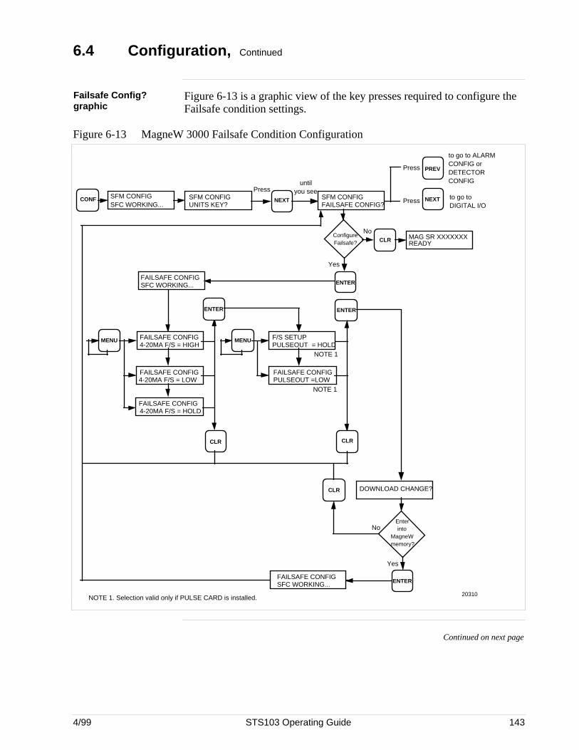
4/99 STS103 Operating Guide 143
6.4 Configuration, Continued
Failsafe Config?graphic
Figure 6-13 is a graphic view of the key presses required to configure theFailsafe condition settings.
Figure 6-13 MagneW 3000 Failsafe Condition Configuration
SFM CONFIGUNITS KEY?
NEXT
FAILSAFE CONFIGSFC WORKING...
CONF SFM CONFIGSFC WORKING...
Pressuntil
you seeto go to DIGITAL I/O
SFM CONFIGFAILSAFE CONFIG?
NEXT
Configure Failsafe?
MAG SR XXXXXXXREADYCLR
PREV
ENTER
Press
Press
to go to ALARM CONFIG or DETECTOR CONFIG
No
Yes
ENTER ENTER
F/S SETUPPULSEOUT = HOLD
FAILSAFE CONFIGPULSEOUT =LOW
MENUFAILSAFE CONFIG4-20MA F/S = HIGH
FAILSAFE CONFIG4-20MA F/S = LOW
MENU
FAILSAFE CONFIG4-20MA F/S = HOLD
NOTE 1
NOTE 1. Selection valid only if PULSE CARD is installed.
CLR CLR
DOWNLOAD CHANGE?CLR
FAILSAFE CONFIGSFC WORKING...
Enter into
MagneW memory?
ENTER
Yes
No
NOTE 1
20310
Continued on next page
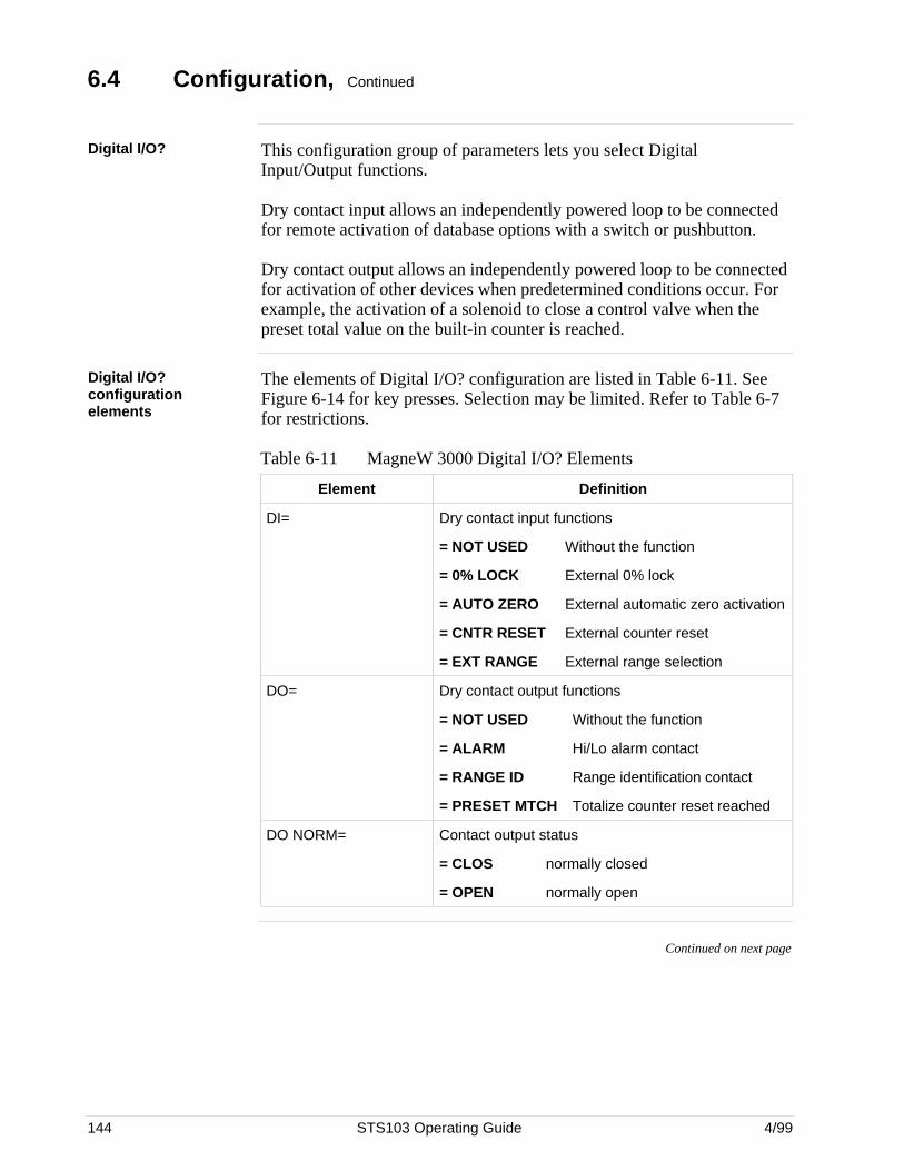
144 STS103 Operating Guide 4/99
6.4 Configuration, Continued
Digital I/O? This configuration group of parameters lets you select DigitalInput/Output functions.
Dry contact input allows an independently powered loop to be connectedfor remote activation of database options with a switch or pushbutton.
Dry contact output allows an independently powered loop to be connectedfor activation of other devices when predetermined conditions occur. Forexample, the activation of a solenoid to close a control valve when thepreset total value on the built-in counter is reached.
Digital I/O?configurationelements
The elements of Digital I/O? configuration are listed in Table 6-11. SeeFigure 6-14 for key presses. Selection may be limited. Refer to Table 6-7for restrictions.
Table 6-11 MagneW 3000 Digital I/O? Elements
Element Definition
DI= Dry contact input functions
= NOT USED Without the function
= 0% LOCK External 0% lock
= AUTO ZERO External automatic zero activation
= CNTR RESET External counter reset
= EXT RANGE External range selection
DO= Dry contact output functions
= NOT USED Without the function
= ALARM Hi/Lo alarm contact
= RANGE ID Range identification contact
= PRESET MTCH Totalize counter reset reached
DO NORM= Contact output status
= CLOS normally closed
= OPEN normally open
Continued on next page
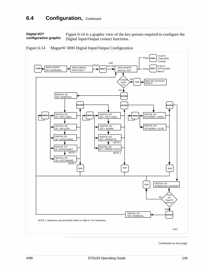
4/99 STS103 Operating Guide 145
6.4 Configuration, Continued
Digital I/O?configuration graphic
Figure 6-14 is a graphic view of the key presses required to configure theDigital Input/Output contact functions.
Figure 6-14 MagneW 3000 Digital Input/Output Configuration
SFM CONFIGUNITS KEY?
NEXT
DIGITAL I/OSFC WORKING...
CONF SFM CONFIGSFC WORKING...
Pressuntil
you see to go to TOTALIZER Menu?
SFM CONFIGDIGITAL I/O?
NEXT
Configure Digital I/O?
MAG SR XXXXXXXREADYCLR
PREV
ENTER
Press
Press
to go to FAILSAFEConfig?
No
Yes
ENTER
NOTE 1. Selections may be limited. Refer to Table 6-7 for restrictions.
MENU
ENTER
DIGITAL I/ODO = NOT USED
DIGITAL I/ODO = ALARM
MENU
NOTE 1
DIGITAL I/ODO = RANGE ID
DIGITAL I/ODO = PRESET MTCH
NOTE 1
ENTER
DIGITAL I/ODO NORM = OPEN
DIGITAL I/ODO NORM = CLOS
DIGITAL I/ODI = NOT USED
DIGITAL I/ODI = 0% LOCK
MENU
DIGITAL I/ODI = EXT RANGE
NOTE 1
DIGITAL I/ODI = AUTO-ZERO
DIGITAL I/ODI =CNTR RESET
CLR CLR CLR
DIGITAL I/ODOWNLOAD CHANGE?
CLR
DIGITAL I/OSFC WORKING...
Enter into
MagneW memory?
ENTER
Yes
No
NOTE 1
20307
Continued on next page
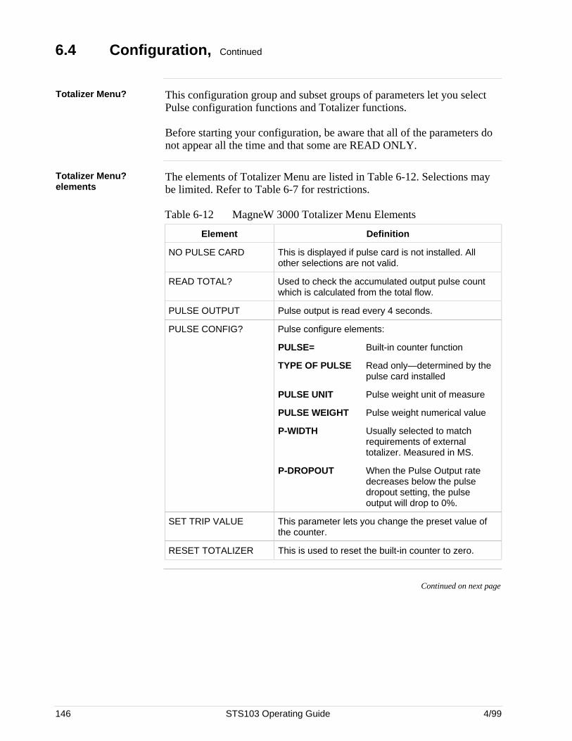
146 STS103 Operating Guide 4/99
6.4 Configuration, Continued
Totalizer Menu? This configuration group and subset groups of parameters let you selectPulse configuration functions and Totalizer functions.
Before starting your configuration, be aware that all of the parameters donot appear all the time and that some are READ ONLY.
Totalizer Menu?elements
The elements of Totalizer Menu are listed in Table 6-12. Selections maybe limited. Refer to Table 6-7 for restrictions.
Table 6-12 MagneW 3000 Totalizer Menu Elements
Element Definition
NO PULSE CARD This is displayed if pulse card is not installed. Allother selections are not valid.
READ TOTAL? Used to check the accumulated output pulse countwhich is calculated from the total flow.
PULSE OUTPUT Pulse output is read every 4 seconds.
PULSE CONFIG? Pulse configure elements:
PULSE= Built-in counter function
TYPE OF PULSE Read only—determined by thepulse card installed
PULSE UNIT Pulse weight unit of measure
PULSE WEIGHT Pulse weight numerical value
P-WIDTH Usually selected to matchrequirements of externaltotalizer. Measured in MS.
P-DROPOUT When the Pulse Output ratedecreases below the pulsedropout setting, the pulseoutput will drop to 0%.
SET TRIP VALUE This parameter lets you change the preset value ofthe counter.
RESET TOTALIZER This is used to reset the built-in counter to zero.
Continued on next page

4/99 STS103 Operating Guide 147
6.4 Configuration, Continued
Totalizer Menuhierarchy
The prompt hierarchy listed in Figure 6-15 gives you an overall view ofthe Pulse configuration parameters that will appear. It will help you get towhere you want to go more quickly.Refer to the tables and figures indicated for specific settings and menuselections for each element of the configuration parameters.
Figure 6-15 MagneW 3000 Totalizer Menu Hierarchy
SFM CONFIGUNITS KEY?
CONF SFM CONFIGSFC WORKING...
TOTALIZER MENUSFC WORKING...
TOTALIZE MENUNO PULSE CARD
TOTALIZE MENUREAD TOTAL?
NEXT SFM CONFIGTOTALIZER MENU?
NEXT
Enter Totalizer Menu?
MAG SR XXXXXXXREADYCLR
PREV
ENTER
TOTALIZE MENUPULSE OUTPUT?
TOTALIZE MENUPULSE CONFIG?
TOTALIZE MENUSET TRIP VALUE?
ENTER
ENTER
ENTER
ENTER
ENTER TOTALIZE MENURESET TOTALIZE?
RESET TOTALIZETOTAL RESET
RESET TOTALIZE112233 RESET? ENTER
CLR
TOTALIZE MENUREPEAT LIST?
ENTER
TOTALIZE MENUNO PULSE CARD
READ TOTAL000000 COUNTS
ENTER
SET TRIP VALUE? Change Preset value of counter
PULSE CONFIG? Configure Pulse Elements
PULSE OUTPUT? Read Pulse Output
CLRor
CLR
CLR
CLR
CLR
CLR
CLR
CLR
Press until you see
Press
Press
to go to DIGITAL I/O?
to go to CALIBRATE MENU?
NOTE 1:
NOTE 2:
NOTE 3:
CLR
goes to
NOTE 1: Displayed if Pulse Card not installed, other selections not valid
NOTE 2: Read Total Counts every 6 seconds
NOTE 3: Valid only if Pulse Configuration = Preset
No
20318
See Figure 6-16
See Figure 6-17
See Figure 6-18
Continued on next page
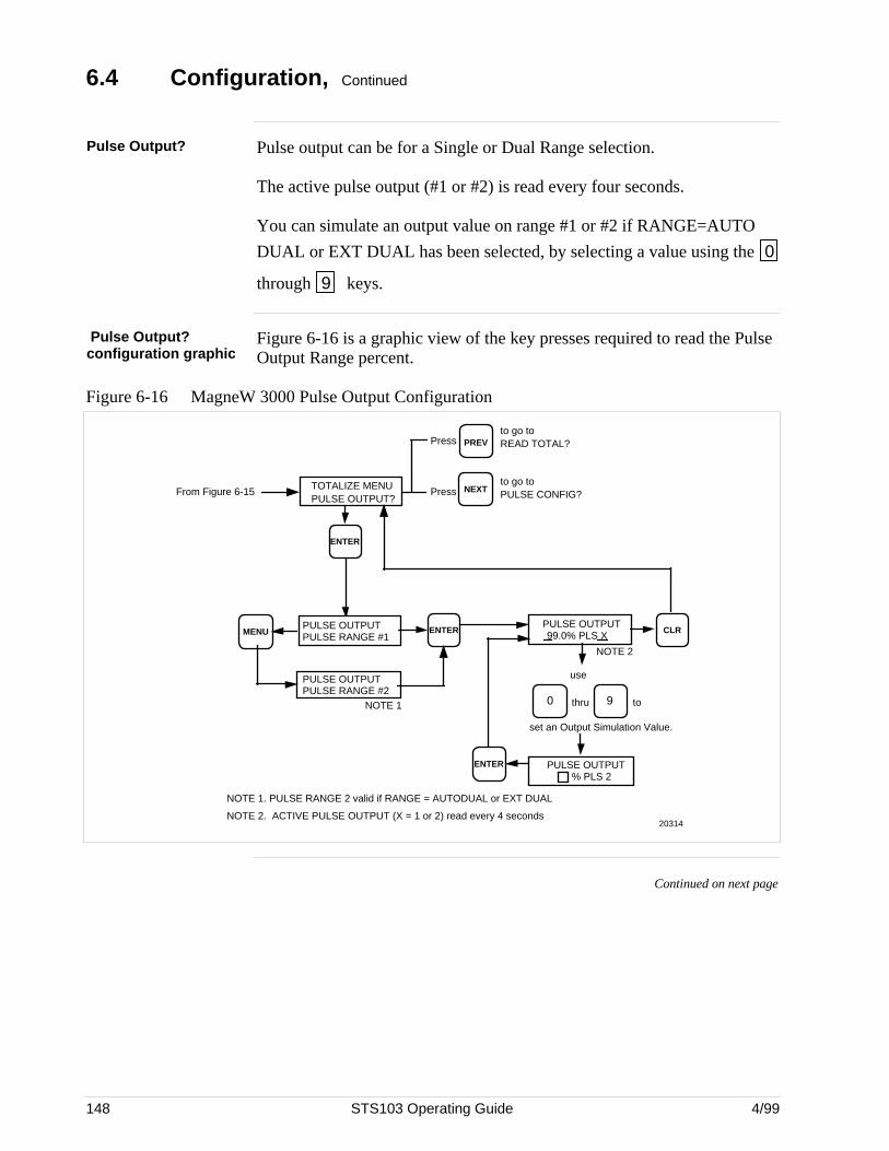
148 STS103 Operating Guide 4/99
6.4 Configuration, Continued
Pulse Output? Pulse output can be for a Single or Dual Range selection.
The active pulse output (#1 or #2) is read every four seconds.
You can simulate an output value on range #1 or #2 if RANGE=AUTO
DUAL or EXT DUAL has been selected, by selecting a value using the 0
through 9 keys.
Pulse Output?configuration graphic
Figure 6-16 is a graphic view of the key presses required to read the PulseOutput Range percent.
Figure 6-16 MagneW 3000 Pulse Output Configuration
to go to PULSE CONFIG?
TOTALIZE MENUPULSE OUTPUT?
NEXT
PREVPress
Press
to go to READ TOTAL?
NOTE 1. PULSE RANGE 2 valid if RANGE = AUTODUAL or EXT DUAL
NOTE 2. ACTIVE PULSE OUTPUT (X = 1 or 2) read every 4 seconds
ENTER
PULSE OUTPUTPULSE RANGE #1
PULSE OUTPUTPULSE RANGE #2
MENU
NOTE 1
ENTER
PULSE OUTPUT% PLS 2
CLR
NOTE 2
PULSE OUTPUT99.0% PLS X
0
use
set an Output Simulation Value.
9thru to
ENTER
From Figure 6-15
20314
Continued on next page
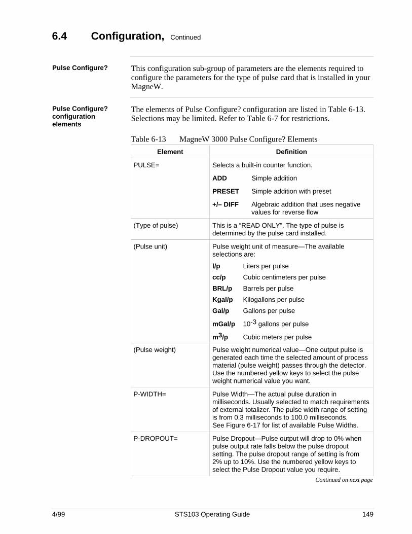
4/99 STS103 Operating Guide 149
6.4 Configuration, Continued
Pulse Configure? This configuration sub-group of parameters are the elements required toconfigure the parameters for the type of pulse card that is installed in yourMagneW.
Pulse Configure?configurationelements
The elements of Pulse Configure? configuration are listed in Table 6-13.Selections may be limited. Refer to Table 6-7 for restrictions.
Table 6-13 MagneW 3000 Pulse Configure? Elements
Element Definition
PULSE= Selects a built-in counter function.
ADD Simple addition
PRESET Simple addition with preset
+/– DIFF Algebraic addition that uses negativevalues for reverse flow
(Type of pulse) This is a “READ ONLY”. The type of pulse isdetermined by the pulse card installed.
(Pulse unit) Pulse weight unit of measure—The availableselections are:
l/p Liters per pulse
cc/p Cubic centimeters per pulse
BRL/p Barrels per pulse
Kgal/p Kilogallons per pulse
Gal/p Gallons per pulse
mGal/p 10-3 gallons per pulse
m3/p Cubic meters per pulse
(Pulse weight) Pulse weight numerical value—One output pulse isgenerated each time the selected amount of processmaterial (pulse weight) passes through the detector.Use the numbered yellow keys to select the pulseweight numerical value you want.
P-WIDTH= Pulse Width—The actual pulse duration inmilliseconds. Usually selected to match requirementsof external totalizer. The pulse width range of settingis from 0.3 milliseconds to 100.0 milliseconds.See Figure 6-17 for list of available Pulse Widths.
P-DROPOUT= Pulse Dropout—Pulse output will drop to 0% whenpulse output rate falls below the pulse dropoutsetting. The pulse dropout range of setting is from2% up to 10%. Use the numbered yellow keys toselect the Pulse Dropout value you require.
Continued on next page
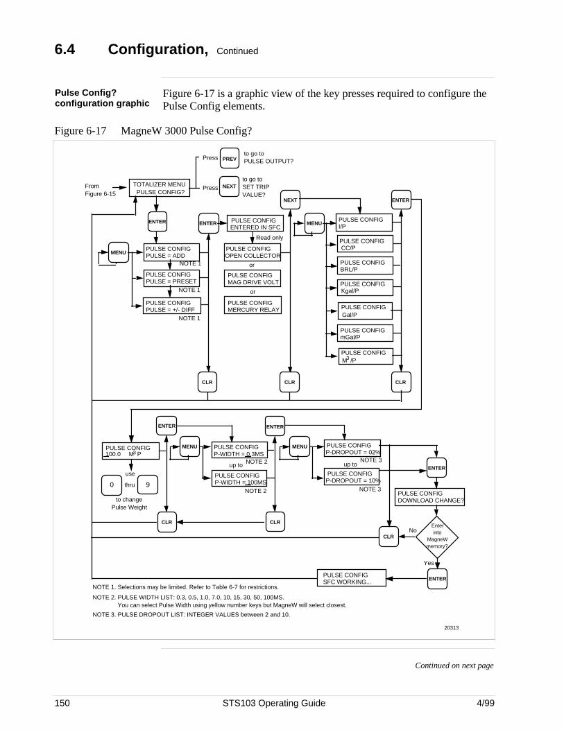
150 STS103 Operating Guide 4/99
6.4 Configuration, Continued
Pulse Config?configuration graphic
Figure 6-17 is a graphic view of the key presses required to configure thePulse Config elements.
Figure 6-17 MagneW 3000 Pulse Config?
to go to SET TRIP VALUE?
TOTALIZER MENUPULSE CONFIG?
NEXT
PREVPress
Press
to go to PULSE OUTPUT?
ENTER ENTER
MENUPULSE CONFIGPULSE = ADD
PULSE CONFIGPULSE = PRESET
NOTE 1
PULSE CONFIGPULSE = +/- DIFF
NOTE 1
NOTE 1
PULSE CONFIGENTERED IN SFC
CLRCLR CLR
ENTER
PULSE CONFIGOPEN COLLECTOR
PULSE CONFIGMAG DRIVE VOLT
PULSE CONFIGMERCURY RELAY
or
or
Read only
NEXT
MENU
PULSE CONFIGCC/P
PULSE CONFIGBRL/P
PULSE CONFIGKgal/P
PULSE CONFIGGal/P
PULSE CONFIGI/P
PULSE CONFIGmGal/P
PULSE CONFIGM /P3
From Figure 6-15
PULSE CONFIG100.0
ENTER ENTER
PULSE CONFIGDOWNLOAD CHANGE?
CLR
PULSE CONFIGSFC WORKING...
Enter into
MagneW memory?
ENTER
Yes
No
MENU PULSE CONFIGP-WIDTH = 0.3MS
PULSE CONFIGP-WIDTH = 100MS
MENU PULSE CONFIGP-DROPOUT = 02%
PULSE CONFIGP-DROPOUT = 10%
CLR CLR
NOTE 1. Selections may be limited. Refer to Table 6-7 for restrictions.
NOTE 2. PULSE WIDTH LIST: 0.3, 0.5, 1.0, 7.0, 10, 15, 30, 50, 100MS. You can select Pulse Width using yellow number keys but MagneW will select closest.
NOTE 3. PULSE DROPOUT LIST: INTEGER VALUES between 2 and 10.
NOTE 3
NOTE 3
ENTER
to change Pulse Weight
9thru0
use
M P3
NOTE 2
NOTE 2
up to up to
20313
Continued on next page
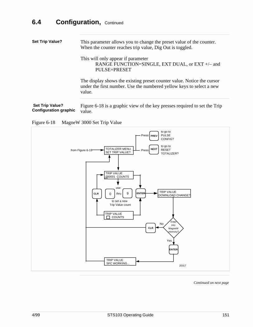
4/99 STS103 Operating Guide 151
6.4 Configuration, Continued
Set Trip Value? This parameter allows you to change the preset value of the counter.When the counter reaches trip value, Dig Out is toggled.
This will only appear if parameterRANGE FUNCTION=SINGLE, EXT DUAL, or EXT +/– andPULSE=PRESET
The display shows the existing preset counter value. Notice the cursorunder the first number. Use the numbered yellow keys to select a newvalue.
Set Trip Value?Configuration graphic
Figure 6-18 is a graphic view of the key presses required to set the Tripvalue.
Figure 6-18 MagneW 3000 Set Trip Value
TOTALIZER MENUSET TRIP VALUE?
ENTER
NEXT
PREVPress
Press
to go to PULSE CONFIG?
to go to RESET TOTALIZER?
000001TRIP VALUE
COUNTS
thru
to set a new Trip Value count
90
use
TRIP VALUESFC WORKING...
TRIP VALUEDOWNLOAD CHANGE?
CLR
NoEnter into
MagneW memory?
ENTER
Yes
20317
TRIP VALUECOUNTS
CLR
from Figure 6-15
Continued on next page
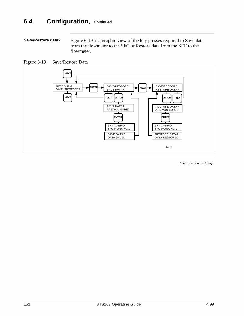
152 STS103 Operating Guide 4/99
6.4 Configuration, Continued
Save/Restore data? Figure 6-19 is a graphic view of the key presses required to Save datafrom the flowmeter to the SFC or Restore data from the SFC to theflowmeter.
Figure 6-19 Save/Restore Data
NEXT
CLR
20744
NEXT
SPT CONFIGSAVE / RESTORE?
ENTER SAVE/RESTORESAVE DATA?
SAVE/RESTORERESTORE DATA?
NEXT
ENTER ENTER
SAVE DATA?ARE YOU SURE?
RESTORE DATA?ARE YOU SURE?
SPT CONFIGSFC WORKING...
ENTER
SPT CONFIGSFC WORKING...
ENTER
SAVE DATA?DATA SAVED
RESTORE DATA?DATA RESTORED
CLR
Continued on next page
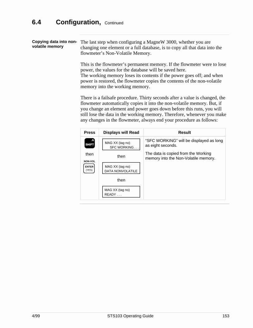
4/99 STS103 Operating Guide 153
6.4 Configuration, Continued
Copying data into non-volatile memory
The last step when configuring a MagneW 3000, whether you arechanging one element or a full database, is to copy all that data into theflowmeter’s Non-Volatile Memory.
This is the flowmeter’s permanent memory. If the flowmeter were to losepower, the values for the database will be saved here.The working memory loses its contents if the power goes off; and whenpower is restored, the flowmeter copies the contents of the non-volatilememory into the working memory.
There is a failsafe procedure. Thirty seconds after a value is changed, theflowmeter automatically copies it into the non-volatile memory. But, ifyou change an element and power goes down before this runs, you willstill lose the data in the working memory. Therefore, whenever you makeany changes in the flowmeter, always end your procedure as follows:
Press Displays will Read Result
SSSSSHHHHHIIIIIFFFFFTTTTT ^
then
NON-VOL
ENTER (YES)
MAG XX (tag no)SFC WORKING . . .
then
MAG XX (tag no)DATA NONVOLATILE
then
MAG XX (tag no)READY . . .
“SFC WORKING” will be displayed as longas eight seconds.
The data is copied from the Workingmemory into the Non-Volatile memory.
154 STS103 Operating Guide 4/99
6.5 Calibration
Introduction The calibration prompts that you will use to calibrate the MagneW are asubset of prompts under the Calibrate Menu?
There are some set-up instructions and preliminary procedures to followbefore going into the CALIBRATE MENU. These are given at thebeginning of this section.
Calibration topics The following topics are covered under “CALIBRATION”.
Topic See Page
• Equipment needed• Calibration set-up• Set units to m/s (meters per second)• Set span to 10.001 m/s (meters per second)• Do a DAC (Digital to Analog) Current output signal calibration• Calibration Menu hierarchy and procedures
Excitation current checkExcitation current calibrationGain CalibrationDI/DO check
154155157158159161162163165166
Equipment needed In order to calibrate a MagneW 3000 Magnetic Flowmeter using anSTS103 Smart Field Communicator, you will need the followingequipment:
• STS103 Smart Field Communicator
• A digital voltmeter (DVM)
• 24 Vdc power supply
• Model KIZ006 MagneW Calibrator
This calibrator is designed for the precise calibration of all models ofMagneW flowmeters. The calibrator generates a simulated flow velocitysignal which is synchronized with the excitation current of the flowmeter.The simulated signal is applied to the converter to be calibrated. Thissignal is adjustable for a flow velocity equivalent range of 0-10.00 m/sec(0-30 ft/sec) in 0.01 m/sec steps for highly accurate calibration ofindividual flow spans.
Continued on next page
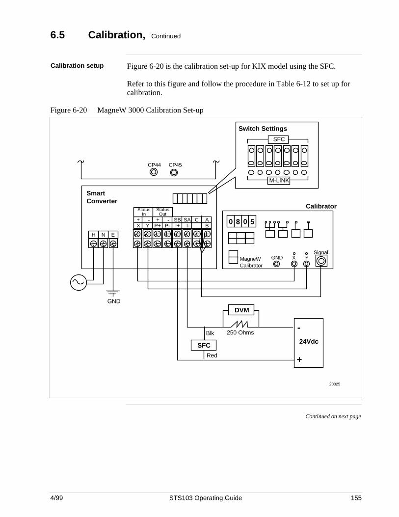
4/99 STS103 Operating Guide 155
6.5 Calibration, Continued
Calibration setup Figure 6-20 is the calibration set-up for KIX model using the SFC.
Refer to this figure and follow the procedure in Table 6-12 to set up forcalibration.
Figure 6-20 MagneW 3000 Calibration Set-up
DVM
24VdcBlk
Red
250 Ohms
MagneW Calibrator
GND
SignalX Y
0
CP45
H N E
StatusOut
StatusIn
+ + SB-- SA C AX P+ I+P-Y I- B
CP44
8 0 5
-
+
GND
SFC
Blk
Smart Converter
Calibrator
SFC
M-LINK
Switch Settings
20325
Continued on next page
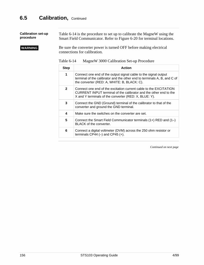
156 STS103 Operating Guide 4/99
6.5 Calibration, Continued
Calibration set-upprocedure
Table 6-14 is the procedure to set up to calibrate the MagneW using theSmart Field Communicator. Refer to Figure 6-20 for terminal locations.
WARNING Be sure the converter power is turned OFF before making electricalconnections for calibration.
Table 6-14 MagneW 3000 Calibration Set-up Procedure
Step Action
1 Connect one end of the output signal cable to the signal outputterminal of the calibrator and the other end to terminals A, B, and C ofthe converter (RED: A, WHITE: B, BLACK: C).
2 Connect one end of the excitation current cable to the EXCITATIONCURRENT INPUT terminal of the calibrator and the other end to theX and Y terminals of the converter (RED: X, BLUE: Y).
3 Connect the GND (Ground) terminal of the calibrator to that of theconverter and ground the GND terminal.
4 Make sure the switches on the converter are set.
5 Connect the Smart Field Communicator terminals (1+) RED and (1–)BLACK of the converter.
6 Connect a digital voltmeter (DVM) across the 250 ohm resistor orterminals CP44 (–) and CP45 (+).
Continued on next page
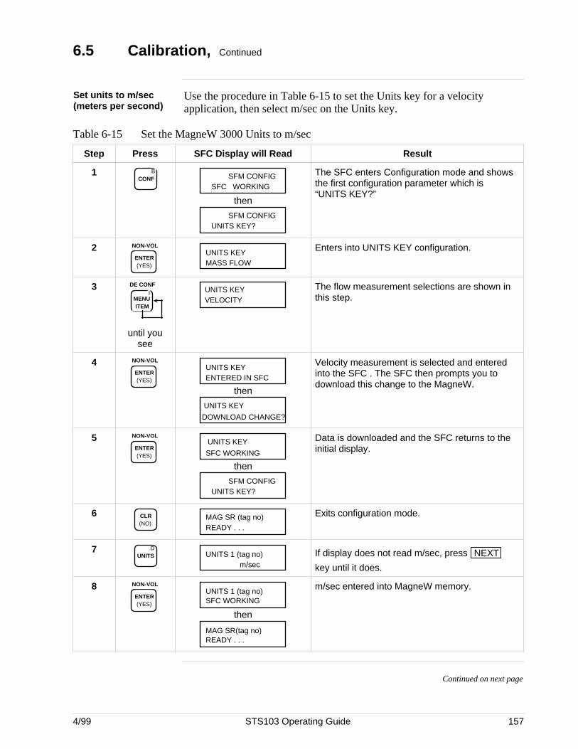
4/99 STS103 Operating Guide 157
6.5 Calibration, Continued
Set units to m/sec(meters per second)
Use the procedure in Table 6-15 to set the Units key for a velocityapplication, then select m/sec on the Units key.
Table 6-15 Set the MagneW 3000 Units to m/sec
Step Press SFC Display will Read Result
1 BCONF SFM CONFIG
SFC WORKING
then
SFM CONFIGUNITS KEY?
The SFC enters Configuration mode and showsthe first configuration parameter which is“UNITS KEY?”
2 NON-VOL
ENTER (YES) MASS FLOW
UNITS KEYEnters into UNITS KEY configuration.
3I
MENU ITEM
DE CONF
until yousee
VELOCITYUNITS KEY The flow measurement selections are shown in
this step.
4 NON-VOL
ENTER (YES) ENTERED IN SFC
UNITS KEY
then
DOWNLOAD CHANGE?
UNITS KEY
Velocity measurement is selected and enteredinto the SFC . The SFC then prompts you todownload this change to the MagneW.
5 NON-VOL
ENTER (YES) SFC WORKING
UNITS KEY
then
SFM CONFIGUNITS KEY?
Data is downloaded and the SFC returns to theinitial display.
6 CLR (NO)
MAG SR (tag no)READY . . .
Exits configuration mode.
7 DUNITS UNITS 1 (tag no)
m/sec
If display does not read m/sec, press NEXT
key until it does.
8 NON-VOL
ENTER (YES)
UNITS 1 (tag no)SFC WORKING
then
MAG SR(tag no)READY . . .
m/sec entered into MagneW memory.
Continued on next page
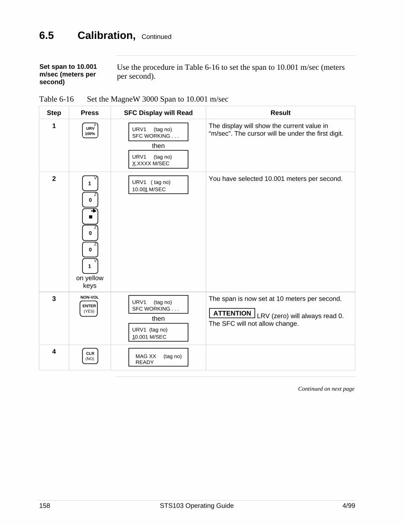
158 STS103 Operating Guide 4/99
6.5 Calibration, Continued
Set span to 10.001m/sec (meters persecond)
Use the procedure in Table 6-16 to set the span to 10.001 m/sec (metersper second).
Table 6-16 Set the MagneW 3000 Span to 10.001 m/sec
Step Press SFC Display will Read Result
1 FURV
100%URV1 (tag no)SFC WORKING . . .
then
URV1 (tag no)X.XXXX M/SEC
The display will show the current value in“m/sec”. The cursor will be under the first digit.
2 V
1
Z
0
Z
0
Z
0
V
1
on yellowkeys
URV1 ( tag no)10.001 M/SEC
You have selected 10.001 meters per second.
3 NON-VOL
ENTER (YES)
URV1 (tag no)SFC WORKING . . .
then
URV1 (tag no)10.001 M/SEC
The span is now set at 10 meters per second.
ATTENTION LRV (zero) will always read 0.The SFC will not allow change.
4 CLR (NO) MAG XX (tag no)
READY
Continued on next page
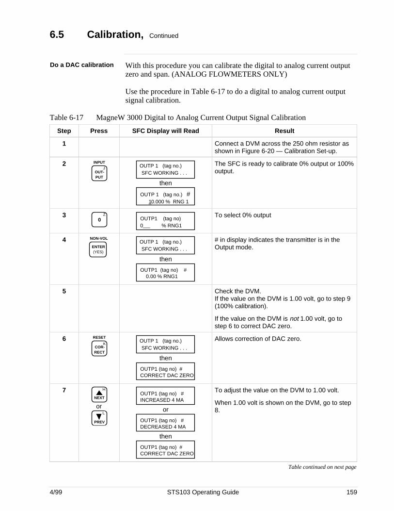
4/99 STS103 Operating Guide 159
6.5 Calibration, Continued
Do a DAC calibration With this procedure you can calibrate the digital to analog current outputzero and span. (ANALOG FLOWMETERS ONLY)
Use the procedure in Table 6-17 to do a digital to analog current outputsignal calibration.
Table 6-17 MagneW 3000 Digital to Analog Current Output Signal Calibration
Step Press SFC Display will Read Result
1 Connect a DVM across the 250 ohm resistor asshown in Figure 6-20 — Calibration Set-up.
2J
OUT- PUT
INPUTOUTP 1 (tag no.)SFC WORKING . . .
then
OUTP 1 (tag no.) #10.000 % RNG 1
The SFC is ready to calibrate 0% output or 100%output.
3 Z
0 OUTP1 (tag no)0 % RNG1
To select 0% output
4 NON-VOL
ENTER (YES)
OUTP 1 (tag no.)SFC WORKING . . .
then
OUTP1 (tag no) #0.00 % RNG1
# in display indicates the transmitter is in theOutput mode.
5 Check the DVM.If the value on the DVM is 1.00 volt, go to step 9(100% calibration).
If the value on the DVM is not 1.00 volt, go tostep 6 to correct DAC zero.
6K
COR- RECT
RESETOUTP 1 (tag no.)SFC WORKING . . .
then
OUTP1 (tag no) #CORRECT DAC ZERO
Allows correction of DAC zero.
7 H
NEXT
orL
PREV
OUTP1 (tag no) #INCREASED 4 MA
or
OUTP1 (tag no) #DECREASED 4 MA
then
OUTP1 (tag no) #CORRECT DAC ZERO
To adjust the value on the DVM to 1.00 volt.
When 1.00 volt is shown on the DVM, go to step8.
Table continued on next page
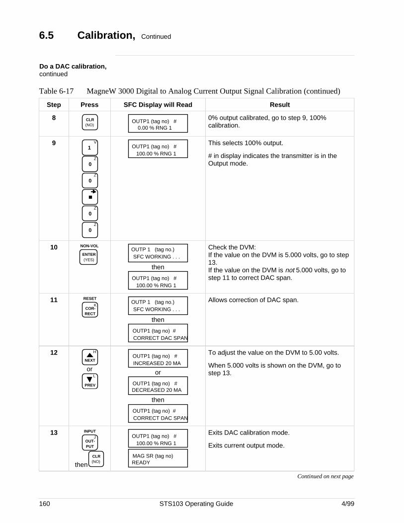
160 STS103 Operating Guide 4/99
6.5 Calibration, Continued
Do a DAC calibration,continued
Table 6-17 MagneW 3000 Digital to Analog Current Output Signal Calibration (continued)
Step Press SFC Display will Read Result
8 CLR (NO)
OUTP1 (tag no) #0.00 % RNG 1
0% output calibrated, go to step 9, 100%calibration.
9 V
1
Z
0
Z
0
Z
0
Z
0
OUTP1 (tag no) #100.00 % RNG 1
This selects 100% output.
# in display indicates the transmitter is in theOutput mode.
10 NON-VOL
ENTER (YES)
OUTP 1 (tag no.)SFC WORKING . . .
then
OUTP1 (tag no) #100.00 % RNG 1
Check the DVM:If the value on the DVM is 5.000 volts, go to step13.If the value on the DVM is not 5.000 volts, go tostep 11 to correct DAC span.
11K
COR- RECT
RESETOUTP 1 (tag no.)SFC WORKING . . .
then
OUTP1 (tag no) #CORRECT DAC SPAN
Allows correction of DAC span.
12 H
NEXT
orL
PREV
OUTP1 (tag no) #INCREASED 20 MA
or
OUTP1 (tag no) #DECREASED 20 MA
then
OUTP1 (tag no) #CORRECT DAC SPAN
To adjust the value on the DVM to 5.00 volts.
When 5.000 volts is shown on the DVM, go tostep 13.
13J
OUT- PUT
INPUT
thenCLR (NO)
OUTP1 (tag no) #100.00 % RNG 1
MAG SR (tag no)READY
Exits DAC calibration mode.
Exits current output mode.
Continued on next page
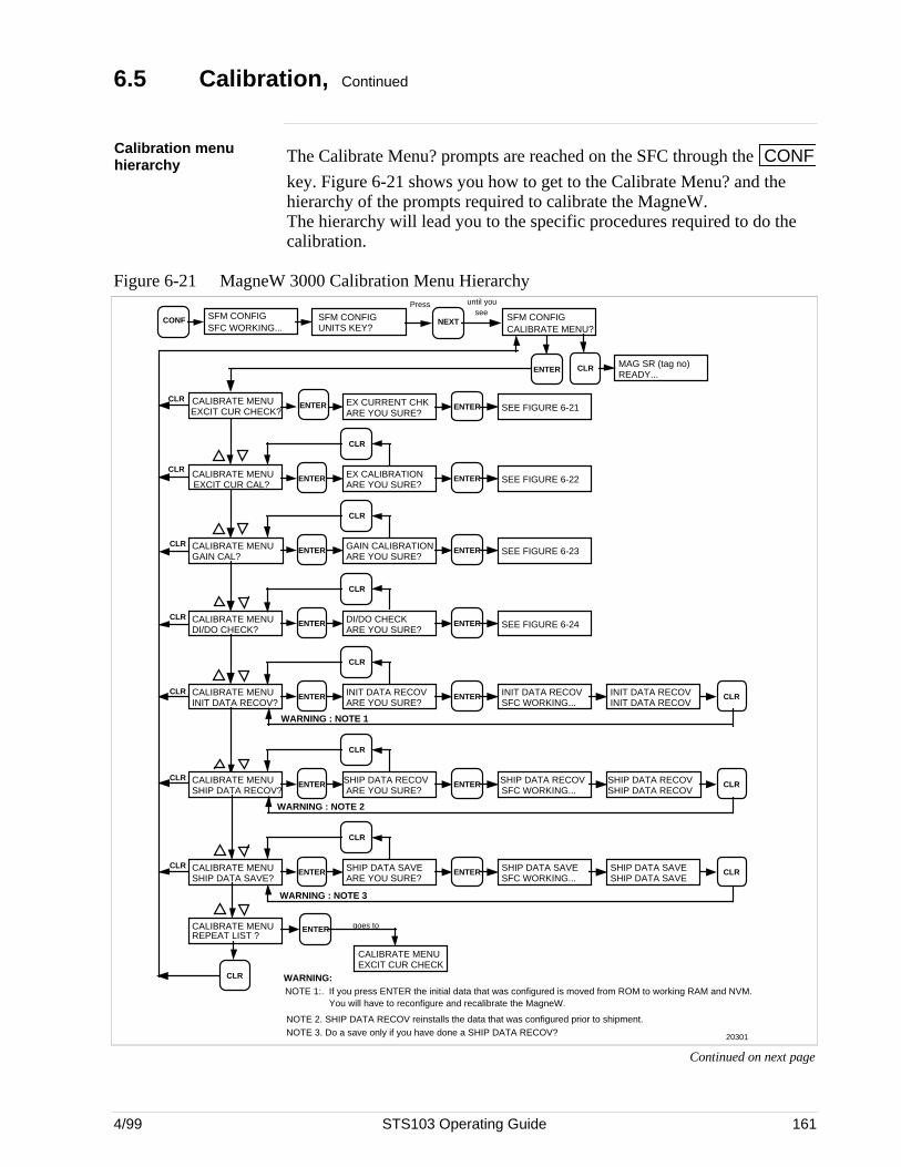
4/99 STS103 Operating Guide 161
6.5 Calibration, Continued
Calibration menuhierarchy The Calibrate Menu? prompts are reached on the SFC through the CONF
key. Figure 6-21 shows you how to get to the Calibrate Menu? and thehierarchy of the prompts required to calibrate the MagneW.The hierarchy will lead you to the specific procedures required to do thecalibration.
Figure 6-21 MagneW 3000 Calibration Menu Hierarchy
CALIBRATE MENU GAIN CAL?
CLR
SFM CONFIGUNITS KEY?
CONF SFM CONFIGSFC WORKING...
NEXT SFM CONFIGCALIBRATE MENU?
Press until you see
ENTER GAIN CALIBRATIONARE YOU SURE?
ENTER SEE FIGURE 6-23
CALIBRATE MENU DI/DO CHECK?
CLRENTER DI/DO CHECK
ARE YOU SURE?ENTER SEE FIGURE 6-24
CALIBRATE MENU INIT DATA RECOV?
CLRENTER INIT DATA RECOV
ARE YOU SURE?ENTER INIT DATA RECOV
SFC WORKING...INIT DATA RECOV INIT DATA RECOV
CLR
CALIBRATE MENU SHIP DATA RECOV?
CLRENTER SHIP DATA RECOV
ARE YOU SURE?ENTER SHIP DATA RECOV
SFC WORKING...SHIP DATA RECOV SHIP DATA RECOV
CLR
CALIBRATE MENU SHIP DATA SAVE?
CLR
CLR
CALIBRATE MENU REPEAT LIST ?
ENTER
CALIBRATE MENU EXCIT CUR CHECK
goes to
ENTER SHIP DATA SAVE ARE YOU SURE?
ENTER SHIP DATA SAVE SFC WORKING...
SHIP DATA SAVE SHIP DATA SAVE
CLR
CALIBRATE MENU EXCIT CUR CHECK?
CLRENTER EX CURRENT CHK
ARE YOU SURE?ENTER SEE FIGURE 6-21
CALIBRATE MENU EXCIT CUR CAL?
CLRENTER EX CALIBRATION
ARE YOU SURE?ENTER SEE FIGURE 6-22
MAG SR (tag no)READY...
CLR ENTER
WARNING : NOTE 1
WARNING : NOTE 2
WARNING : NOTE 3
CLR
CLR
CLR
CLR
CLR
CLR
NOTE 1:. If you press ENTER the initial data that was configured is moved from ROM to working RAM and NVM. You will have to reconfigure and recalibrate the MagneW.
NOTE 2. SHIP DATA RECOV reinstalls the data that was configured prior to shipment.NOTE 3. Do a save only if you have done a SHIP DATA RECOV?
WARNING:
20301
Continued on next page
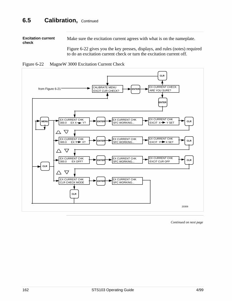
162 STS103 Operating Guide 4/99
6.5 Calibration, Continued
Excitation currentcheck
Make sure the excitation current agrees with what is on the nameplate.
Figure 6-22 gives you the key presses, displays, and rules (notes) requiredto do an excitation current check or turn the excitation current off.
Figure 6-22 MagneW 3000 Excitation Current Check
ENTER
from Figure 6-21
CLR
ENTERMENUEX CURRENT CHK
EX X Y?300.0EX CURRENT CHK EXCIT X Y SET CLR
EX CURRENT CHK EX Y X?300.0 ENTER
EX CURRENT CHK EXCIT Y X SET CLR
EX CURRENT CHK ENTER
EX CURRENT CHK EXCIT CUR OFF CLR
EX CURRENT CHK
CLR
ENTEREX CURRENT CHK SFC WORKING...
EX CURRENT CHK SFC WORKING...
EX CURRENT CHK SFC WORKING...
EX CURRENT CHK SFC WORKING...
EX CURRENT CHECK ARE YOU SURE?ENTER
CALIBRATE MENU EXCIT CUR CHECK?
CLR
CLR CHECK MODE
300.0 EX OFF?
20309
Continued on next page
4/99 STS103 Operating Guide 163
6.5 Calibration, Continued
Excitation currentcalibration
The low excitation current should read 250 mA and the high excitationcurrent should read 350 mA.
If the excitation current needs calibrating, you can select an increment ordecrement value of 0.03, 0.10, 0.50, 1.00, or 5.00 mA to use duringcalibration that will bring the excitation current to the proper value morequickly.
For example: If the high excitation current value reads 340, you can select“INC/DEC 5.00 mA” and the DVM will increase 5 mA each time youpress the key. Press twice to increase to 350.
Continued on next page
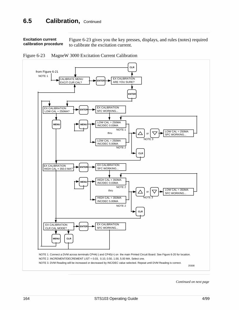
164 STS103 Operating Guide 4/99
6.5 Calibration, Continued
Excitation currentcalibration procedure
Figure 6-23 gives you the key presses, displays, and rules (notes) requiredto calibrate the excitation current.
Figure 6-23 MagneW 3000 Excitation Current Calibration
NOTE 1. Connect a DVM across terminals CP44(-) and CP45(+) on the main Printed Circuit Board. See Figure 6-20 for location.
NOTE 2. INCREMENT/DECREMENT LIST = 0.03, 0.10, 0.50, 1.00, 5.00 MA. Select one.
NOTE 3. DVM Reading will be increased or decreased by INC/DEC value selected. Repeat until DVM Reading is correct.
from Figure 6-21
CLR
CALIBRATE MENU EXCIT CUR CAL?
EX CALIBRATIONARE YOU SURE?ENTER
NOTE 1
ENTER
MENU
EX CALIBRATIONLOW CAL = 250MA?
MENU
ENTER
LOW CAL = 250MA INC/DEC 0.03MA
LOW CAL = 250MA INC/DEC 5.00MA
MENUHIGH CAL = 350MA INC/DEC 0.03MA
HIGH CAL = 350MA INC/DEC 5.00MA
EX CALIBRATIONHIGH CAL = 350.0 MA?
ENTER
EX CALIBRATIONCLR CAL MODE?
EX CALIBRATIONSFC WORKING...
ENTER
MENU CLR
EX CALIBRATIONSFC WORKING...
EX CALIBRATIONSFC WORKING...
CLR
LOW CAL = 250MA SFC WORKING...or
NOTE 3
NOTE 1
NOTE 2
thru
NOTE 2
NOTE 2thru
CLR
LOW CAL = 350MA SFC WORKING...
or
NOTE 3
20308
Continued on next page
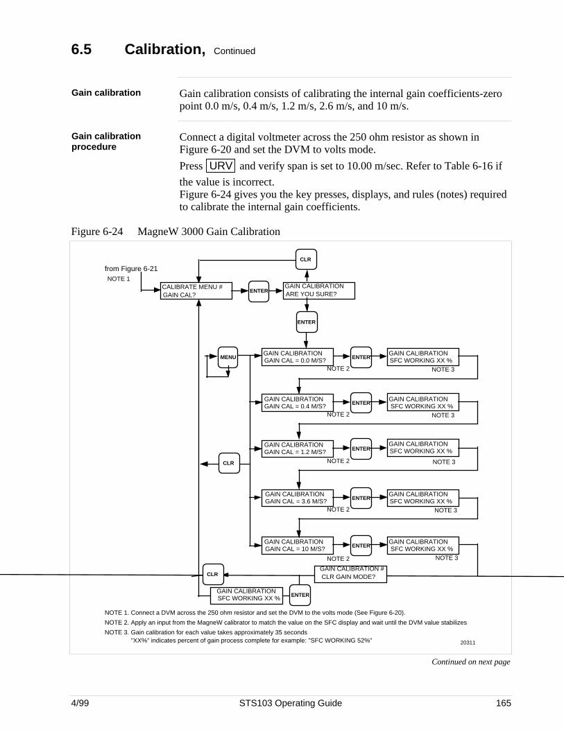
4/99 STS103 Operating Guide 165
6.5 Calibration, Continued
Gain calibration Gain calibration consists of calibrating the internal gain coefficients-zeropoint 0.0 m/s, 0.4 m/s, 1.2 m/s, 2.6 m/s, and 10 m/s.
Gain calibrationprocedure
Connect a digital voltmeter across the 250 ohm resistor as shown inFigure 6-20 and set the DVM to volts mode.
Press URV and verify span is set to 10.00 m/sec. Refer to Table 6-16 if
the value is incorrect.Figure 6-24 gives you the key presses, displays, and rules (notes) requiredto calibrate the internal gain coefficients.
Figure 6-24 MagneW 3000 Gain Calibration
ENTERMENUGAIN CALIBRATIONGAIN CAL = 0.0 M/S?
ENTER
ENTER
GAIN CALIBRATION SFC WORKING XX %
CLR
ENTER
from Figure 6-21
ENTER
CLR
GAIN CALIBRATIONARE YOU SURE?ENTER
CALIBRATE MENU #GAIN CAL?
ENTER
GAIN CALIBRATION SFC WORKING XX %
GAIN CALIBRATION SFC WORKING XX %
GAIN CALIBRATION SFC WORKING XX %
GAIN CALIBRATION SFC WORKING XX %
GAIN CALIBRATIONGAIN CAL = 0.4 M/S?
GAIN CALIBRATIONGAIN CAL = 1.2 M/S?
GAIN CALIBRATIONGAIN CAL = 3.6 M/S?
GAIN CALIBRATIONGAIN CAL = 10 M/S?
NOTE 1
NOTE 2
NOTE 2
NOTE 2
NOTE 2
NOTE 2 NOTE 3
NOTE 3
NOTE 3
NOTE 3
NOTE 3
NOTE 1. Connect a DVM across the 250 ohm resistor and set the DVM to the volts mode (See Figure 6-20).
NOTE 2. Apply an input from the MagneW calibrator to match the value on the SFC display and wait until the DVM value stabilizes
NOTE 3. Gain calibration for each value takes approximately 35 seconds "XX%" indicates percent of gain process complete for example: "SFC WORKING 52%" 20311
GAIN CALIBRATION #CLR GAIN MODE?CLR
ENTERGAIN CALIBRATION SFC WORKING XX %
Continued on next page
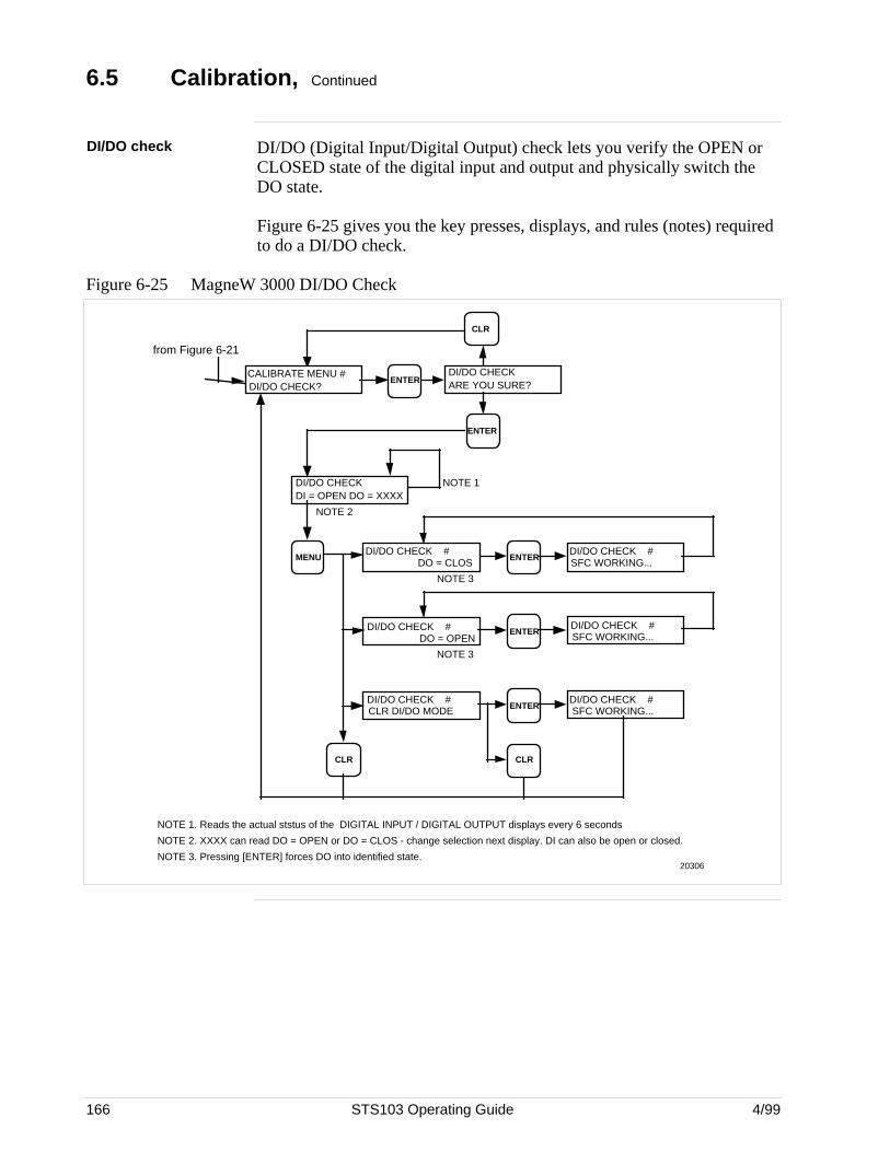
166 STS103 Operating Guide 4/99
6.5 Calibration, Continued
DI/DO check DI/DO (Digital Input/Digital Output) check lets you verify the OPEN orCLOSED state of the digital input and output and physically switch theDO state.
Figure 6-25 gives you the key presses, displays, and rules (notes) requiredto do a DI/DO check.
Figure 6-25 MagneW 3000 DI/DO Check
ENTERMENUDI/DO CHECK #
DO = CLOS
ENTER
ENTER
DI/DO CHECK #SFC WORKING...
CLR CLR
DI/DO CHECK #SFC WORKING...
DI/DO CHECK #SFC WORKING...
DI/DO CHECK #DO = OPEN
DI/DO CHECK #CLR DI/DO MODE
from Figure 6-21
ENTER
CLR
DI/DO CHECKARE YOU SURE?ENTER
CALIBRATE MENU #DI/DO CHECK?
NOTE 2
NOTE 3
NOTE 1. Reads the actual ststus of the DIGITAL INPUT / DIGITAL OUTPUT displays every 6 seconds
NOTE 2. XXXX can read DO = OPEN or DO = CLOS - change selection next display. DI can also be open or closed.
NOTE 3. Pressing [ENTER] forces DO into identified state.
DI/DO CHECKDI = OPEN DO = XXXX
NOTE 1
20306
NOTE 3
4/99 STS103 Operating Guide 167
6.6 Operation
Overview The STS103 displays all the operating data for the MagneW 3000. Thisdata includes:
• Flowmeter I.D.
• Damping value
• Upper range value (span)
• Configuration elements for Digital Communications (DE) mode
• Input value
• Output Value
• Span value
• Upper range limit
• Engineering units
• Operation Status
• Software Version Number
• Failsafe Direction
• Zero Point adjustment
• Display and Keyboard Test
• Read Scratch Pad messages
Refer to Table 6-16 for Operating Data access instructions.
Continued on next page
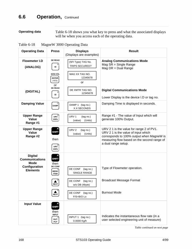
168 STS103 Operating Guide 4/99
6.6 Operation, Continued
Operating data Table 6-18 shows you what key to press and what the associated displayswill be when you access each of the operating data.
Table 6-18 MagneW 3000 Operating Data
Operating Data Press Displays(Displays are examples)
Result
Flowmeter I.D
(ANALOG)
(DIGITAL)
DE READ
AID
NON-VOL
ENTER (YES)
orDE READ
AID
TRIPS SECURED?
(SFI Type) TAG No.
MAG XX TAG NO.12345678
or
DE XMTR TAG NO.12345678
Analog Communications ModeMag SR = Single RangeMag DR = Dual Range
Digital Communications Mode
Lower Display is the device I.D or tag no.
Damping Value CDAMP DAMP 1 (tag no.)
X.X SECONDS
Damping Time is displayed in seconds.
Upper RangeValue
Range #1
FURV
100%URV 1 (tag no.)
(value) (Units)
Range #1 - The value of Input which willgenerate 100% Output.
Upper RangeValue
Range #2SSSSSHHHHHIIIIIFFFFFTTTTT
^
then
FURV
100%
URV 2 (tag no.)
(value) (Units)
URV 2 1 is the value for range 2 of PV1.URV 2 1 is the value of input whichcorresponds to 100% output when MagneW ismeasuring flow based on the second range ofa dual range setup.
DigitalCommunications
ModeConfiguration
Elements
SSSSSHHHHHIIIIIFFFFFTTTTT ^
then
IMENU ITEM
DE CONF
H
NEXT
H
NEXT
DE CONF (tag no.)
SINGLE RANGE
DE CONF (tag no.)
w/o DB (4byte)
DE CONF (tag no.)
F/S=B/O Lo
Type of Flowmeter operation.
Broadcast Message Format
Burnout Mode
Input ValueSSSSSHHHHHIIIIIFFFFFTTTTT
^
then
JOUT- PUT
INPUTINPUT 1 (tag no.)
0.0000 Kg/h
Indicates the instantaneous flow rate (in auser selected engineering unit of measure)
Table continued on next page
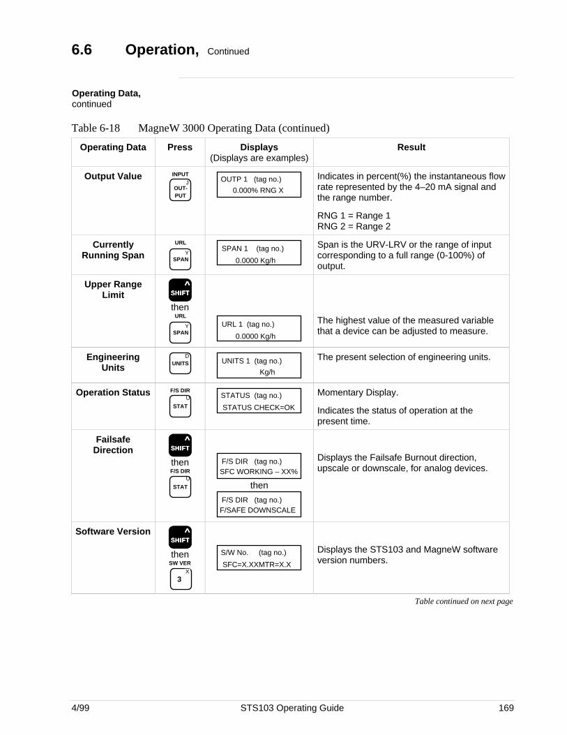
4/99 STS103 Operating Guide 169
6.6 Operation, Continued
Operating Data,continued
Table 6-18 MagneW 3000 Operating Data (continued)
Operating Data Press Displays(Displays are examples)
Result
Output ValueJ
OUT- PUT
INPUTOUTP 1 (tag no.)
0.000% RNG X
Indicates in percent(%) the instantaneous flowrate represented by the 4–20 mA signal andthe range number.
RNG 1 = Range 1RNG 2 = Range 2
CurrentlyRunning Span Y
SPAN
URLSPAN 1 (tag no.)
0.0000 Kg/h
Span is the URV-LRV or the range of inputcorresponding to a full range (0-100%) ofoutput.
Upper RangeLimit SSSSSHHHHHIIIIIFFFFFTTTTT
^
then
YSPAN
URL
URL 1 (tag no.)
0.0000 Kg/h
The highest value of the measured variablethat a device can be adjusted to measure.
EngineeringUnits
DUNITS UNITS 1 (tag no.)
Kg/h
The present selection of engineering units.
Operation StatusU
STAT
F/S DIRSTATUS (tag no.)
STATUS CHECK=OK
Momentary Display.
Indicates the status of operation at thepresent time.
FailsafeDirection SSSSSHHHHHIIIIIFFFFFTTTTT
^
then
U
STAT
F/S DIR
F/S DIR (tag no.)SFC WORKING – XX%
then
F/S DIR (tag no.)F/SAFE DOWNSCALE
Displays the Failsafe Burnout direction,upscale or downscale, for analog devices.
Software VersionSSSSSHHHHHIIIIIFFFFFTTTTT
^
then
X
3
SW VER
S/W No. (tag no.)
SFC=X.XXMTR=X.X
Displays the STS103 and MagneW softwareversion numbers.
Table continued on next page
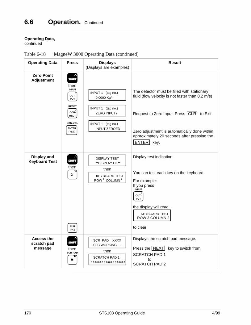
170 STS103 Operating Guide 4/99
6.6 Operation, Continued
Operating Data,continued
Table 6-18 MagneW 3000 Operating Data (continued)
Operating Data Press Displays(Displays are examples)
Result
Zero PointAdjustment SSSSSHHHHHIIIIIFFFFFTTTTT
^
then
JOUT- PUT
INPUT
KCOR- RECT
RESET
NON-VOL
ENTER (YES)
INPUT 1 (tag no.)
0.0000 Kg/h
INPUT 1 (tag no.)
ZERO INPUT?
INPUT 1 (tag no.)
INPUT ZEROED
The detector must be filled with stationaryfluid (flow velocity is not faster than 0.2 m/s)
Request to Zero Input. Press CLR to Exit.
Zero adjustment is automatically done withinapproximately 20 seconds after pressing the
ENTER key.
Display andKeyboard Test SSSSSHHHHHIIIIIFFFFFTTTTT
^
thenW
2
CLR (NO)
DISPLAY TEST**DISPLAY OK**
then
KEYBOARD TESTROW * COLUMN *
Display test indication.
You can test each key on the keyboard
For example:If you press
JOUT- PUT
INPUT
the display will read
KEYBOARD TESTROW 3 COLUMN 2
to clear
Access thescratch pad
messageSSSSSHHHHHIIIIIFFFFFTTTTT
^
thenSCR PAD
SCR PAD XXXXSFC WORKING . . .
then
SCRATCH PAD 1XXXXXXXXXXXXXXXX
Displays the scratch pad message.
Press the NEXT key to switch from
SCRATCH PAD 1to
SCRATCH PAD 2
4/99 STS103 Operating Guide 171
6.7 Diagnostics and SFC Messages
Introduction The MagneW 3000 and the STS103 both run continuous self-diagnostics.This means that they are constantly testing the communications, the loop,and themselves.
Any time you want results of these diagnostics, press the STAT key.
The SFC displays its report, in the form of messages, which identifydiagnostic conditions.Diagnostic conditions are broken down into three categories:• an OK condition• a critical condition• a non-critical condition
OK Status An OK condition means no problem exists, and the display looks like this:
STATUS (tag no.)STATUS CHECK=OK
Critical status A critical condition means that the flowmeter is not functioning properly.When this occurs, the flowmeter goes into upscale burnout and maintainsan output of 21.8 mA, or into downscale burnout and maintains an outputof less than 3.9 mA. This message CRITICAL STATUS interrupts youroperation and is followed by the message PRESS STATUS.
After the PRESS STATUS message, you press the STAT key to find
out what problem exists. You will receive one or more messages. Takewhatever corrective action necessary to solve the problem. Remember thatthe flowmeter will stay in upscale or down scale burnout until thecondition is corrected.If the flowmeter sends more than one message, each message will bedisplayed in the order of importance for about 5 seconds. If you need to
see them again, press the STAT key again.
Non-critical status A non-critical condition means that although a problem exists, theflowmeter is still operating. When a non-critical condition occurs a “#”character appears on the right side of the display, along with whateveryou’re displaying at the time.
This character means press the STAT key because some type of a
problem exists. Again, one or more messages will appear on the displayfor about five seconds each.
Low battery voltage When the battery voltage becomes low, a colon ”:” will appear in themiddle of the display. It stays on the display until you either charge orreplace the batteries.
Continued on next page
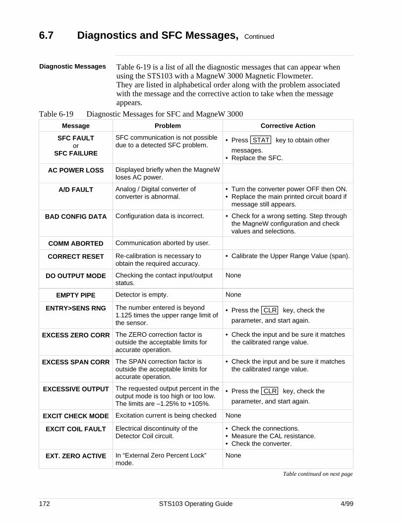
172 STS103 Operating Guide 4/99
6.7 Diagnostics and SFC Messages, Continued
Diagnostic Messages Table 6-19 is a list of all the diagnostic messages that can appear whenusing the STS103 with a MagneW 3000 Magnetic Flowmeter.They are listed in alphabetical order along with the problem associatedwith the message and the corrective action to take when the messageappears.
Table 6-19 Diagnostic Messages for SFC and MagneW 3000
Message Problem Corrective Action
SFC FAULTor
SFC FAILURE
SFC communication is not possibledue to a detected SFC problem.
• Press STAT key to obtain other
messages.• Replace the SFC.
AC POWER LOSS Displayed briefly when the MagneWloses AC power.
A/D FAULT Analog / Digital converter ofconverter is abnormal.
• Turn the converter power OFF then ON.• Replace the main printed circuit board if
message still appears.
BAD CONFIG DATA Configuration data is incorrect. • Check for a wrong setting. Step throughthe MagneW configuration and checkvalues and selections.
COMM ABORTED Communication aborted by user.
CORRECT RESET Re-calibration is necessary toobtain the required accuracy.
• Calibrate the Upper Range Value (span).
DO OUTPUT MODE Checking the contact input/outputstatus.
None
EMPTY PIPE Detector is empty. None
ENTRY>SENS RNG The number entered is beyond1.125 times the upper range limit ofthe sensor.
• Press the CLR key, check the
parameter, and start again.
EXCESS ZERO CORR The ZERO correction factor isoutside the acceptable limits foraccurate operation.
• Check the input and be sure it matchesthe calibrated range value.
EXCESS SPAN CORR The SPAN correction factor isoutside the acceptable limits foraccurate operation.
• Check the input and be sure it matchesthe calibrated range value.
EXCESSIVE OUTPUT The requested output percent in theoutput mode is too high or too low.The limits are –1.25% to +105%.
• Press the CLR key, check the
parameter, and start again.
EXCIT CHECK MODE Excitation current is being checked None
EXCIT COIL FAULT Electrical discontinuity of theDetector Coil circuit.
• Check the connections.• Measure the CAL resistance.• Check the converter.
EXT. ZERO ACTIVE In “External Zero Percent Lock”mode.
None
Table continued on next page
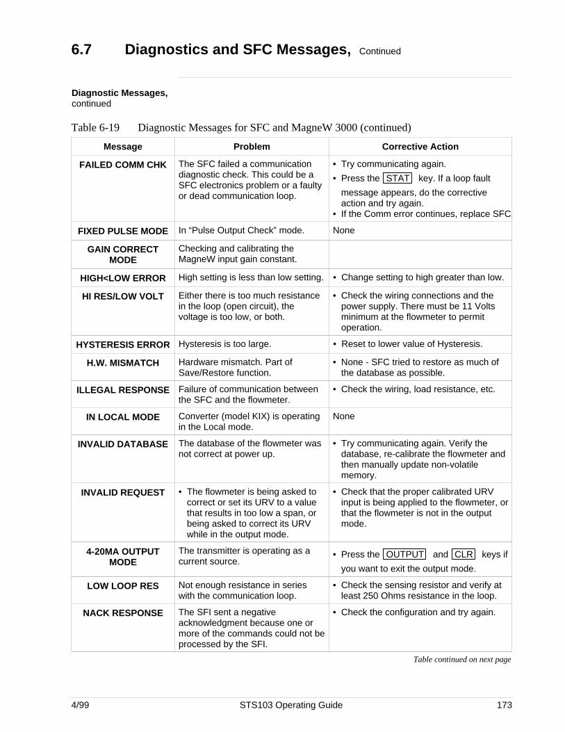
4/99 STS103 Operating Guide 173
6.7 Diagnostics and SFC Messages, Continued
Diagnostic Messages,continued
Table 6-19 Diagnostic Messages for SFC and MagneW 3000 (continued)
Message Problem Corrective Action
FAILED COMM CHK The SFC failed a communicationdiagnostic check. This could be aSFC electronics problem or a faultyor dead communication loop.
• Try communicating again.
• Press the STAT key. If a loop fault
message appears, do the correctiveaction and try again.
• If the Comm error continues, replace SFC.
FIXED PULSE MODE In “Pulse Output Check” mode. None
GAIN CORRECTMODE
Checking and calibrating theMagneW input gain constant.
HIGH<LOW ERROR High setting is less than low setting. • Change setting to high greater than low.
HI RES/LOW VOLT Either there is too much resistancein the loop (open circuit), thevoltage is too low, or both.
• Check the wiring connections and thepower supply. There must be 11 Voltsminimum at the flowmeter to permitoperation.
HYSTERESIS ERROR Hysteresis is too large. • Reset to lower value of Hysteresis.
H.W. MISMATCH Hardware mismatch. Part ofSave/Restore function.
• None - SFC tried to restore as much ofthe database as possible.
ILLEGAL RESPONSE Failure of communication betweenthe SFC and the flowmeter.
• Check the wiring, load resistance, etc.
IN LOCAL MODE Converter (model KIX) is operatingin the Local mode.
None
INVALID DATABASE The database of the flowmeter wasnot correct at power up.
• Try communicating again. Verify thedatabase, re-calibrate the flowmeter andthen manually update non-volatilememory.
INVALID REQUEST • The flowmeter is being asked tocorrect or set its URV to a valuethat results in too low a span, orbeing asked to correct its URVwhile in the output mode.
• Check that the proper calibrated URVinput is being applied to the flowmeter, orthat the flowmeter is not in the outputmode.
4-20MA OUTPUTMODE
The transmitter is operating as acurrent source.
• Press the OUTPUT and CLR keys if
you want to exit the output mode.
LOW LOOP RES Not enough resistance in serieswith the communication loop.
• Check the sensing resistor and verify atleast 250 Ohms resistance in the loop.
NACK RESPONSE The SFI sent a negativeacknowledgment because one ormore of the commands could not beprocessed by the SFI.
• Check the configuration and try again.
Table continued on next page
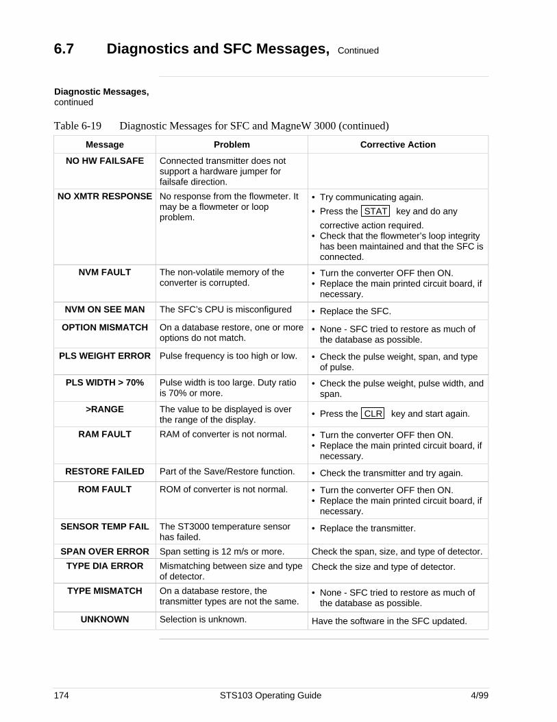
174 STS103 Operating Guide 4/99
6.7 Diagnostics and SFC Messages, Continued
Diagnostic Messages,continued
Table 6-19 Diagnostic Messages for SFC and MagneW 3000 (continued)
Message Problem Corrective Action
NO HW FAILSAFE Connected transmitter does notsupport a hardware jumper forfailsafe direction.
NO XMTR RESPONSE No response from the flowmeter. Itmay be a flowmeter or loopproblem.
• Try communicating again.
• Press the STAT key and do any
corrective action required.• Check that the flowmeter’s loop integrity
has been maintained and that the SFC isconnected.
NVM FAULT The non-volatile memory of theconverter is corrupted.
• Turn the converter OFF then ON.• Replace the main printed circuit board, if
necessary.
NVM ON SEE MAN The SFC’s CPU is misconfigured • Replace the SFC.
OPTION MISMATCH On a database restore, one or moreoptions do not match.
• None - SFC tried to restore as much ofthe database as possible.
PLS WEIGHT ERROR Pulse frequency is too high or low. • Check the pulse weight, span, and typeof pulse.
PLS WIDTH > 70% Pulse width is too large. Duty ratiois 70% or more.
• Check the pulse weight, pulse width, andspan.
>RANGE The value to be displayed is overthe range of the display.
• Press the CLR key and start again.
RAM FAULT RAM of converter is not normal. • Turn the converter OFF then ON.• Replace the main printed circuit board, if
necessary.
RESTORE FAILED Part of the Save/Restore function. • Check the transmitter and try again.
ROM FAULT ROM of converter is not normal. • Turn the converter OFF then ON.• Replace the main printed circuit board, if
necessary.
SENSOR TEMP FAIL The ST3000 temperature sensorhas failed.
• Replace the transmitter.
SPAN OVER ERROR Span setting is 12 m/s or more. Check the span, size, and type of detector.
TYPE DIA ERROR Mismatching between size and typeof detector.
Check the size and type of detector.
TYPE MISMATCH On a database restore, thetransmitter types are not the same.
• None - SFC tried to restore as much ofthe database as possible.
UNKNOWN Selection is unknown. Have the software in the SFC updated.
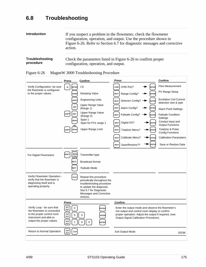
4/99 STS103 Operating Guide 175
6.8 Troubleshooting
Introduction If you suspect a problem in the flowmeter, check the flowmeterconfiguration, operation, and output. Use the procedure shown inFigure 6-26. Refer to Section 6.7 for diagnostic messages and correctiveaction.
Troubleshootingprocedure
Check the parameters listed in Figure 6-26 to confirm properconfiguration, operation, and output.
Figure 6-26 MagneW 3000 Troubleshooting Procedure
ENTER
DAMP
UNITS
URV
I.D.
Damping Value
Engineering Units
Upper Range Value (Range 1)
CONF ENTER Flow MeasurementIDVerify Configuration- be sure the flowmeter is configured to the proper values.
Press ConfirmConfirmPress
SPAN Span 1 Span for PV1 range 1
SPANSHIFT Upper Range Limit
URL
SHIFTUpper Range Value (Range 2)
Units Key?
NEXT ENTERPV Range Setup
Range Config?
NEXT ENTERExcitation Coil Current detection size & type
Detector Config?
NEXT ENTER Alarm Point SettingsAlarm Config?
NEXT ENTER Failsafe Condition Settings
Failsafe Config?
NEXT ENTERContact Input and Output Functions
Digital I/O?
NEXT ENTER Totalizer & Pulse Config Functions
Totalizer Menu?
NEXT Calibration ParametersCalibrate Menu? ENTER
URV
STAT Repeat this procedure periodically throughout the troubleshooting procedure to update the diagnosis. See 6.7 for Diagnostic Messages and Corrective Actions.
Verify Flowmeter Operation - verify that the flowmeter is diagnosing itself and is operating properly.
20336
Verify Loop - be sure that the flowmeter is connected to the proper control room instrument and able to output the proper values.
0OUT PUT
0
ENTER
5OUT PUT 0 ENTER
1OUT PUT
0 ENTER
Enter the output mode and observe the flowmeter’s mA output and control room display to confirm proper operation. Adjust the output if required, (see Output Signal Calibration Procedure).
OUT PUT
CLRReturn to Normal Operation Exit Output Mode
ConfirmPress
NEXT Broadcast format
Failsafe Mode
MENU ITEM
Transmitter typeFor Digital Flowmeters
DECONF
SHIFT
NEXT
NEXT Save/Restore?? ENTER Save or Restore Data

176 STS103 Operating Guide 4/99
4/99 STS103 Operating Guide 177
Section 7 SMV 3000 Multivariable Transmitter
7.1 Overview
Introduction This section contains all the information you will need to know in order towire, set-up, configure, operate, calibrate, and troubleshoot the SMV 3000Multivariable Transmitter using the STS103 Smart Field Communicator.*
Refer to the SMV 3000 User’s Manual (34-SM-25-02) for transmitterinstallation and additional operating information.
Make sure you have become familiar with the STS103 operations that aremore or less the same for every transmitter.
This section gives you the keystrokes and displays that are specific forSFC communications with the SMV 3000 Multivariable Transmitter.
* ATTENTION IMPORTANT: If your SMV contains Release 250 firmware or greaterand you are using the SMV 3000 for flow measurement with dynamiccompensation, you must use the SCT 3000 (software Release 150 orgreater) instead of an SFC to configure the transmitter. The SFC doesnot support the advanced configuration parameters for the SMV 3000dynamic compensation flow equations. Refer to the SMV 3000 User’sManual, document # 34-SM-25-02 for more details and also follow theSCT 3000 on-line help and on-line documentation to configure thetransmitter’s database.
What’s in this section? This section contains the following topics:
Topic See Page
7.1 Overview 177
7.2 Wiring 178
7.3 Configuration 180
7.4 Output Calibration 235
7.5 Operation 239
7.6 Diagnostics and SFC Messages 244
7.7 Troubleshooting 253
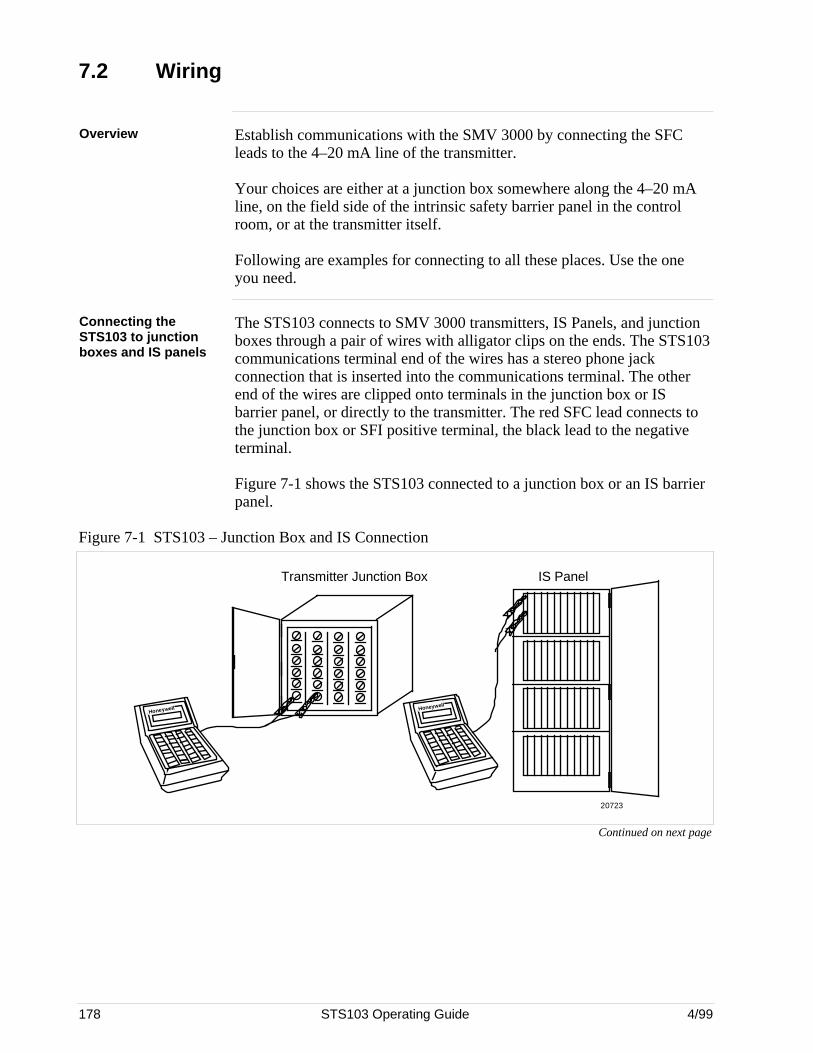
178 STS103 Operating Guide 4/99
7.2 Wiring
Overview Establish communications with the SMV 3000 by connecting the SFCleads to the 4–20 mA line of the transmitter.
Your choices are either at a junction box somewhere along the 4–20 mAline, on the field side of the intrinsic safety barrier panel in the controlroom, or at the transmitter itself.
Following are examples for connecting to all these places. Use the oneyou need.
Connecting theSTS103 to junctionboxes and IS panels
The STS103 connects to SMV 3000 transmitters, IS Panels, and junctionboxes through a pair of wires with alligator clips on the ends. The STS103communications terminal end of the wires has a stereo phone jackconnection that is inserted into the communications terminal. The otherend of the wires are clipped onto terminals in the junction box or ISbarrier panel, or directly to the transmitter. The red SFC lead connects tothe junction box or SFI positive terminal, the black lead to the negativeterminal.
Figure 7-1 shows the STS103 connected to a junction box or an IS barrierpanel.
Figure 7-1 STS103 – Junction Box and IS Connection
Honeywell
Transmitter Junction Box IS Panel
20723
Honeywell
Continued on next page
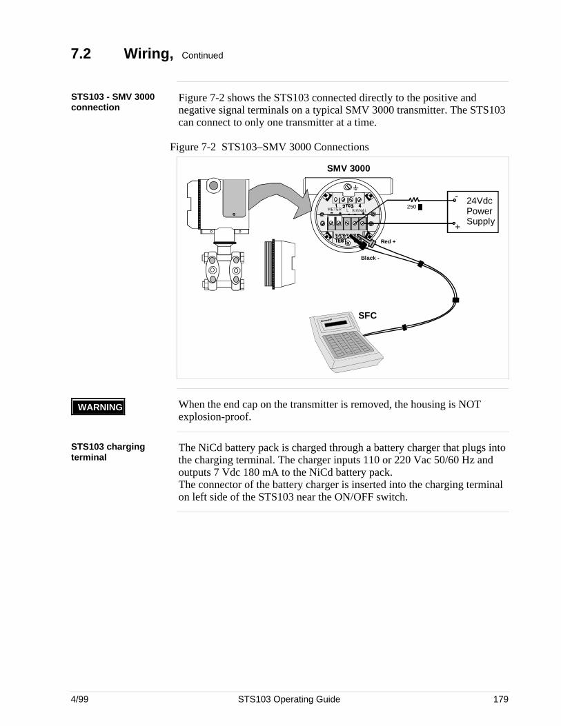
4/99 STS103 Operating Guide 179
7.2 Wiring, Continued
STS103 - SMV 3000connection
Figure 7-2 shows the STS103 connected directly to the positive andnegative signal terminals on a typical SMV 3000 transmitter. The STS103can connect to only one transmitter at a time.
Figure 7-2 STS103–SMV 3000 Connections
METER SIGNALL
Red +
Black -
24VdcPowerSupply
-
+
250
SFC
SMV 3000
WARNING When the end cap on the transmitter is removed, the housing is NOTexplosion-proof.
STS103 chargingterminal
The NiCd battery pack is charged through a battery charger that plugs intothe charging terminal. The charger inputs 110 or 220 Vac 50/60 Hz andoutputs 7 Vdc 180 mA to the NiCd battery pack.The connector of the battery charger is inserted into the charging terminalon left side of the STS103 near the ON/OFF switch.

180 STS103 Operating Guide 4/99
7.3 Configuration
Uploading the SMV 3000database
If your SMV 3000 transmitter is already configured, follow the stepsbelow to upload the database.
Please note that:• The database for a transmitter in the Analog mode is automatically
read or uploaded to the SFC when you press ENTER in response
to the “TRIPS SECURED” prompt.• The database for a transmitter in the Digital mode is read or uploaded
when you press the SHIFT I D keys.
After the database is loaded into the SFC memory, you can view thedatabase, check transmitter status, make changes to the configurationparameters (if desired) and then download the changes to the transmitter.
Configuration Overview If you need to configure the SMV 3000 transmitter, the tables in thefollowing pages provide procedures to set up the transmitter database thatcontains the configuration parameters.
Setting up the SMV 3000 Multivariable Transmitter consists of:
• Keying-in the I.D. and loading the Database.
• Selecting output conformity
• Adjusting the Damping time.
• Selecting the units in which to display values.
• Select PV3 probe type and other parameters for temperaturemeasurement
• Define PV4 flow measurement equation
• Select PV4 flow equation parameters.
• Set low flow cutoff limits for PV4 output
• Select PV output for transmitter operating in analog mode.
• Keying-in the Lower Range value and Upper Range value (Span)using the keyboard.
• Keying-in the Lower Range value and Upper Range value (Span)using applied pressure.
• Selecting the SMV 3000’s communication mode.
• Selecting the PVs for broadcast and message format for a transmitterin the Digital Communications (DE) Mode.
ATTENTION Since the SFC is compatible with other Honeywell Smartline™transmitters, be sure all configuration data applies to a multivariabletransmitter.
Continued on next page
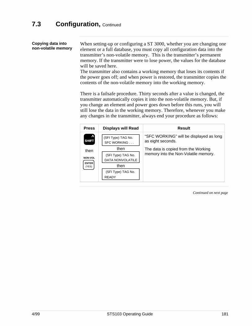
4/99 STS103 Operating Guide 181
7.3 Configuration, Continued
Copying data intonon-volatile memory
When setting-up or configuring a ST 3000, whether you are changing oneelement or a full database, you must copy all configuration data into thetransmitter’s non-volatile memory. This is the transmitter’s permanentmemory. If the transmitter were to lose power, the values for the databasewill be saved here.The transmitter also contains a working memory that loses its contents ifthe power goes off; and when power is restored, the transmitter copies thecontents of the non-volatile memory into the working memory.
There is a failsafe procedure. Thirty seconds after a value is changed, thetransmitter automatically copies it into the non-volatile memory. But, ifyou change an element and power goes down before this runs, you willstill lose the data in the working memory. Therefore, whenever you makeany changes in the transmitter, always end your procedure as follows:
Press Displays will Read Result
SSSSSHHHHHIIIIIFFFFFTTTTT ^
then
NON-VOL
ENTER (YES)
SFC WORKING . . .
(SFI Type) TAG No.
then
DATA NONVOLATILE
(SFI Type) TAG No.
then
READY
(SFI Type) TAG No.
“SFC WORKING” will be displayed as longas eight seconds.
The data is copied from the Workingmemory into the Non-Volatile memory.
Continued on next page
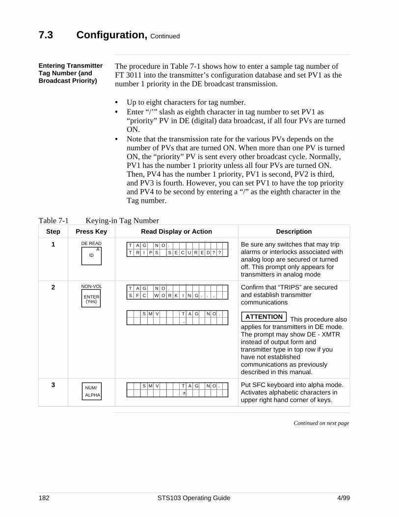
182 STS103 Operating Guide 4/99
7.3 Configuration, Continued
Entering TransmitterTag Number (andBroadcast Priority)
The procedure in Table 7-1 shows how to enter a sample tag number ofFT 3011 into the transmitter’s configuration database and set PV1 as thenumber 1 priority in the DE broadcast transmission.
• Up to eight characters for tag number.• Enter “/’” slash as eighth character in tag number to set PV1 as
“priority” PV in DE (digital) data broadcast, if all four PVs are turnedON.
• Note that the transmission rate for the various PVs depends on thenumber of PVs that are turned ON. When more than one PV is turnedON, the “priority” PV is sent every other broadcast cycle. Normally,PV1 has the number 1 priority unless all four PVs are turned ON.Then, PV4 has the number 1 priority, PV1 is second, PV2 is third,and PV3 is fourth. However, you can set PV1 to have the top priorityand PV4 to be second by entering a “/” as the eighth character in theTag number.
Table 7-1 Keying-in Tag NumberStep Press Key Read Display or Action Description
1 DE READA
ID
T A ON .G
?T R I P S S E C U R E D ?
Be sure any switches that may tripalarms or interlocks associated withanalog loop are secured or turnedoff. This prompt only appears fortransmitters in analog mode
2 NON-VOL
ENTER(Yes)
T A ON .G
S F C W O R K I N G . . .
A G N O .T_
S M V
Confirm that “TRIPS” are securedand establish transmittercommunications
ATTENTION This procedure alsoapplies for transmitters in DE mode.The prompt may show DE - XMTRinstead of output form andtransmitter type in top row if youhave not establishedcommunications as previouslydescribed in this manual.
3 NUM/
ALPHA *A G N O .T
_S M V Put SFC keyboard into alpha mode.
Activates alphabetic characters inupper right hand corner of keys.
Continued on next page
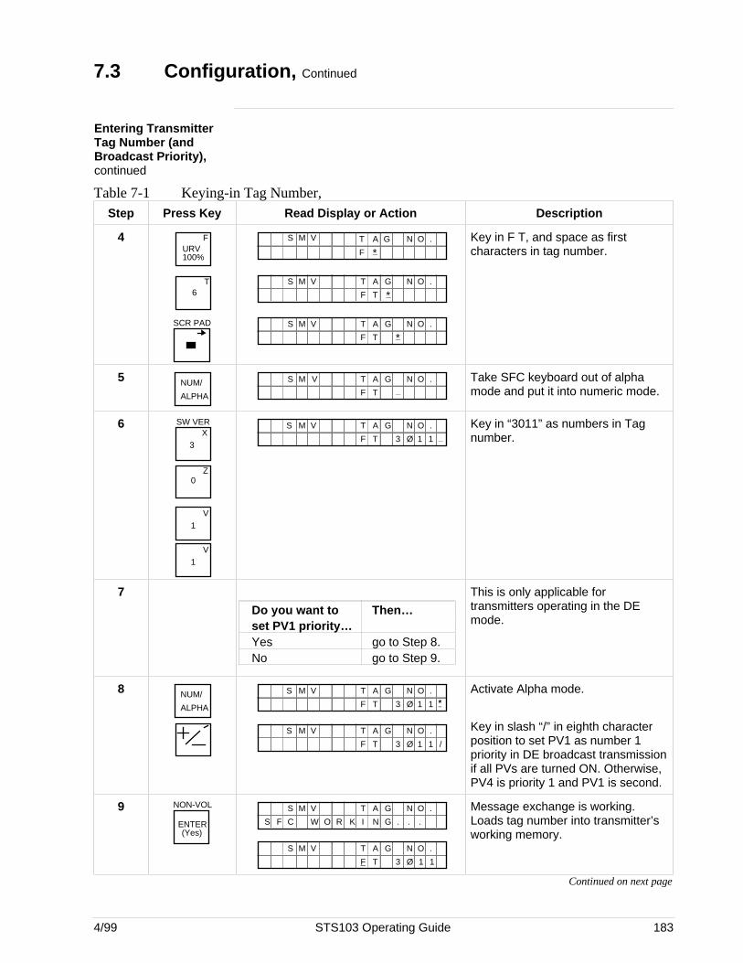
4/99 STS103 Operating Guide 183
7.3 Configuration, Continued
Entering TransmitterTag Number (andBroadcast Priority),continued
Table 7-1 Keying-in Tag Number,Step Press Key Read Display or Action Description
4URV 100%
F
6T
SCR PAD
A G N O .T_*F
S M V
A G N O .T_*F T
S M V
A G N O .T_*F T
S M V
Key in F T, and space as firstcharacters in tag number.
5 NUM/
ALPHA
A G N O .T_F T
S M V Take SFC keyboard out of alphamode and put it into numeric mode.
6X
3
SW VER
Z0
1V
1V
A G N O .T_F T 3 Ø 1 1
S M V Key in “3011” as numbers in Tagnumber.
7
Do you want to Then…set PV1 priority…Yes go to Step 8.No go to Step 9.
This is only applicable fortransmitters operating in the DEmode.
8 NUM/
ALPHA
A G N O .T*F T 3 Ø 1 1
S M V
A G N O .T
F T 3 Ø 1 1
S M V
/
Activate Alpha mode.
Key in slash “/” in eighth characterposition to set PV1 as number 1priority in DE broadcast transmissionif all PVs are turned ON. Otherwise,PV4 is priority 1 and PV1 is second.
9 NON-VOL
ENTER(Yes)
S M V A G N O .T
I N GO R KS F C W . . .
A G N O .T
F T 3 Ø 1 1
S M V
Message exchange is working.Loads tag number into transmitter’sworking memory.
Continued on next page
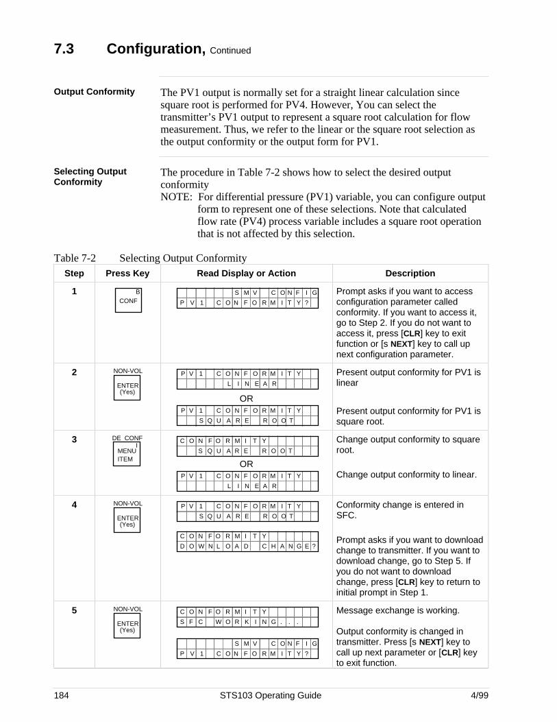
184 STS103 Operating Guide 4/99
7.3 Configuration, Continued
Output Conformity The PV1 output is normally set for a straight linear calculation sincesquare root is performed for PV4. However, You can select thetransmitter’s PV1 output to represent a square root calculation for flowmeasurement. Thus, we refer to the linear or the square root selection asthe output conformity or the output form for PV1.
Selecting OutputConformity
The procedure in Table 7-2 shows how to select the desired outputconformityNOTE: For differential pressure (PV1) variable, you can configure output
form to represent one of these selections. Note that calculatedflow rate (PV4) process variable includes a square root operationthat is not affected by this selection.
Table 7-2 Selecting Output ConformityStep Press Key Read Display or Action Description
1 BCONF I T YO R MC O N F ?
N GO IC FS M V
P V 1
Prompt asks if you want to accessconfiguration parameter calledconformity. If you want to access it,go to Step 2. If you do not want toaccess it, press [CLR] key to exitfunction or [s NEXT] key to call upnext configuration parameter.
2 NON-VOL
ENTER(Yes)
I T YO R MC O N F
L I N E A R
P V 1
ORI T YO R MC O N F
A R E R OS Q U O T
P V 1
Present output conformity for PV1 islinear
Present output conformity for PV1 issquare root.
3MENU ITEM
DE CONFI
I T YO R MC O N F
A R E R OS Q U O T
ORI T YO R MC O N F
L I N E A R
P V 1
Change output conformity to squareroot.
Change output conformity to linear.
4 NON-VOL
ENTER(Yes)
I T YO R MC O N F
A R E R OS Q U O T
P V 1
I T YO R MC O N F
O A D C HW N L NO G ED A ?
Conformity change is entered inSFC.
Prompt asks if you want to downloadchange to transmitter. If you want todownload change, go to Step 5. Ifyou do not want to downloadchange, press [CLR] key to return toinitial prompt in Step 1.
5 NON-VOL
ENTER(Yes)
I T YO R MC O N F
O R K N GC W .F .S .I
I T YO R MC O N F ?
N GO IC FS M V
P V 1
Message exchange is working.
Output conformity is changed intransmitter. Press [s NEXT] key tocall up next parameter or [CLR] keyto exit function.
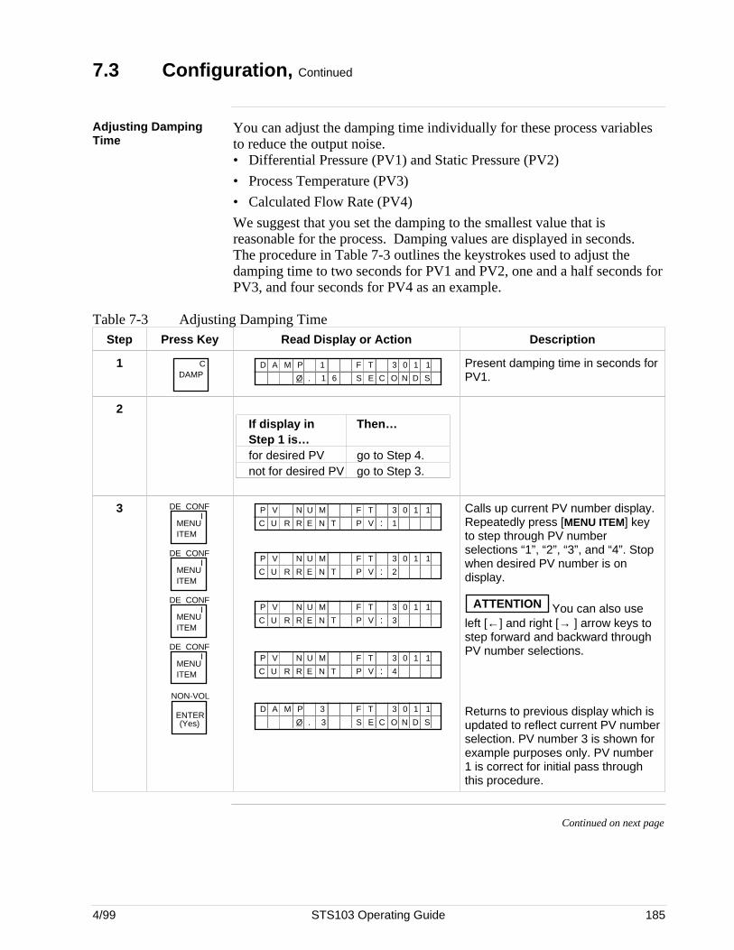
4/99 STS103 Operating Guide 185
7.3 Configuration, Continued
Adjusting DampingTime
You can adjust the damping time individually for these process variablesto reduce the output noise.• Differential Pressure (PV1) and Static Pressure (PV2)
• Process Temperature (PV3)
• Calculated Flow Rate (PV4)
We suggest that you set the damping to the smallest value that isreasonable for the process. Damping values are displayed in seconds.The procedure in Table 7-3 outlines the keystrokes used to adjust thedamping time to two seconds for PV1 and PV2, one and a half seconds forPV3, and four seconds for PV4 as an example.
Table 7-3 Adjusting Damping TimeStep Press Key Read Display or Action Description
1 CDAMP
F T1D A M P
1 E CØ . O N
3 0 1 1
S D S6
Present damping time in seconds forPV1.
2If display in Then…Step 1 is…for desired PV go to Step 4.not for desired PV go to Step 3.
3MENU ITEM
DE CONFI
MENU ITEM
DE CONFI
MENU ITEM
DE CONFI
MENU ITEM
DE CONFI
NON-VOL
ENTER(Yes)
F TMP V N 3 0 1 1
N T V :R EUC 1P
U
R
F TMP V N 3 0 1 1
N T V :R EUC 2P
U
R
F TMP V N 3 0 1 1
N T V :R EUC 3P
U
R
F TMP V N 3 0 1 1
N T V :R EUC 4P
U
R
F T3D A M P
3 E CØ . O N
3 0 1 1
S D S
Calls up current PV number display.Repeatedly press [MENU ITEM] keyto step through PV numberselections “1”, “2”, “3”, and “4”. Stopwhen desired PV number is ondisplay.
ATTENTION You can also useleft [←] and right [→ ] arrow keys tostep forward and backward throughPV number selections.
Returns to previous display which isupdated to reflect current PV numberselection. PV number 3 is shown forexample purposes only. PV number1 is correct for initial pass throughthis procedure.
Continued on next page
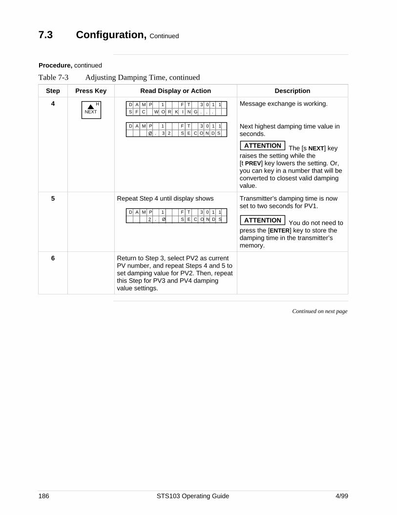
186 STS103 Operating Guide 4/99
7.3 Configuration, Continued
Procedure, continued
Table 7-3 Adjusting Damping Time, continued
Step Press Key Read Display or Action Description
4NEXT
H F T1D A M P 3 0 1 1
O R K N GC W .F .S .I
F T1D A M P
3 E CØ . O N
3 0 1 1
S D S2
Message exchange is working.
Next highest damping time value inseconds.
ATTENTION The [s NEXT] keyraises the setting while the[t PREV] key lowers the setting. Or,you can key in a number that will beconverted to closest valid dampingvalue.
5 Repeat Step 4 until display shows
F T1D A M P
Ø E C2 . O N
3 0 1 1
S D S
Transmitter’s damping time is nowset to two seconds for PV1.
ATTENTION You do not need topress the [ENTER] key to store thedamping time in the transmitter’smemory.
6 Return to Step 3, select PV2 as currentPV number, and repeat Steps 4 and 5 toset damping value for PV2. Then, repeatthis Step for PV3 and PV4 dampingvalue settings.
Continued on next page
4/99 STS103 Operating Guide 187
7.3 Configuration, Continued
Selecting Units ofMeasurement
You can choose to have the measurements for the selected process variabledisplayed in one of the preprogrammed engineering units in the SFC.
You can also choose preprogrammed engineering units for display ofdesign density value entered in equation parameters configuration. SeeSelecting Density Units in this section.
Table 7-4, Table 7-5, and Table 7-6 list the preprogrammed units for theselected process variable and show how to select them. Be sure desired PVnumber is currently selected for display when selecting applicable units.Press [MENU ITEM] to display the current PV.
IF Current PV in the SFC display … THEN …
is for the desired PV, • go to Table 7-4 to selectmeasurement units for PV1 andPV2,
• go to Table 7-5 to selectmeasurement units for PV3, or
• go to Table 7-6 to selectmeasurement units for PV4.
is not for the desired PV, press [MENU ITEM] key to call up PVNUM display and press [MENU ITEM]key to change current PV selection tomatch desired PV number.
Then, go to Table 7-4 , 7-5, or 7-6 asapplicable.
ATTENTION The engineering units shown in Table 7-4 for PV1 and PV2 are onlyavailable in an SFC with software version 4.2 or greater The selectionsare similar in earlier software versions but may not include temperaturereferences and additional engineering units of inches of water at 60 ºF(15.6 ºC) and 68ºF (20 ºC), and atmospheres. Be sure number of PV inunits display matches PV number for which units are to be selected.
Note that inches of water ranges for differential pressure input are factorycalibrated using pressure referenced to a temperature of 39.2 ºF (4 ºC).
Continued on next page
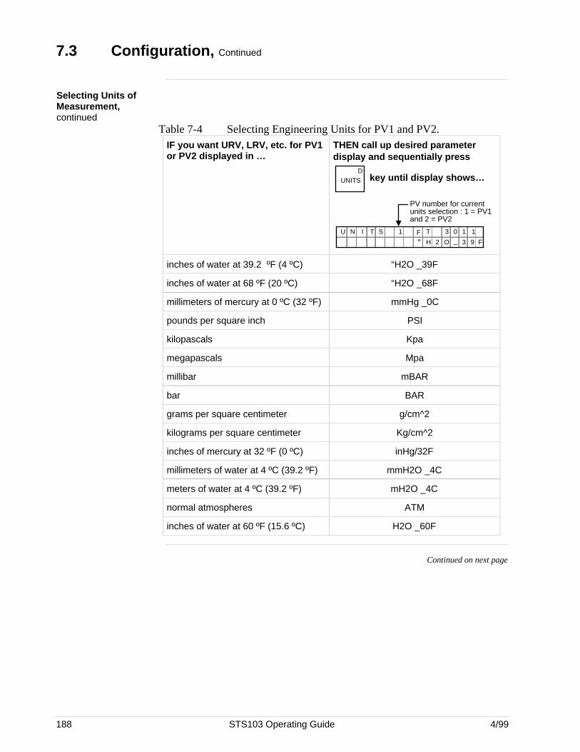
188 STS103 Operating Guide 4/99
7.3 Configuration, Continued
Selecting Units ofMeasurement,continued
Table 7-4 Selecting Engineering Units for PV1 and PV2.IF you want URV, LRV, etc. for PV1or PV2 displayed in …
THEN call up desired parameterdisplay and sequentially press
DUNITS
key until display shows…
"F T1U N I T
H 2 O
3 0 1 1S_ 3 9 F
PV number for current units selection : 1 = PV1 and 2 = PV2
inches of water at 39.2 ºF (4 ºC) “H2O _39F
inches of water at 68 ºF (20 ºC) “H2O _68F
millimeters of mercury at 0 ºC (32 ºF) mmHg _0C
pounds per square inch PSI
kilopascals Kpa
megapascals Mpa
millibar mBAR
bar BAR
grams per square centimeter g/cm^2
kilograms per square centimeter Kg/cm^2
inches of mercury at 32 ºF (0 ºC) inHg/32F
millimeters of water at 4 ºC (39.2 ºF) mmH2O _4C
meters of water at 4 ºC (39.2 ºF) mH2O _4C
normal atmospheres ATM
inches of water at 60 ºF (15.6 ºC) H2O _60F
Continued on next page
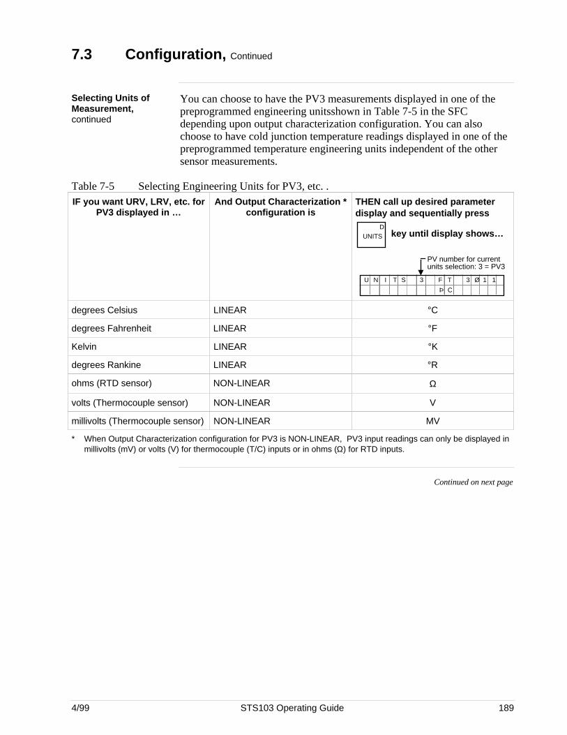
4/99 STS103 Operating Guide 189
7.3 Configuration, Continued
Selecting Units ofMeasurement,continued
You can choose to have the PV3 measurements displayed in one of thepreprogrammed engineering unitsshown in Table 7-5 in the SFCdepending upon output characterization configuration. You can alsochoose to have cold junction temperature readings displayed in one of thepreprogrammed temperature engineering units independent of the othersensor measurements.
Table 7-5 Selecting Engineering Units for PV3, etc. .IF you want URV, LRV, etc. for
PV3 displayed in …And Output Characterization *
configuration isTHEN call up desired parameterdisplay and sequentially press
DUNITS
key until display shows…
F T3U N I T
C
3 Ø 1 1
Þ
S
PV number for current units selection: 3 = PV3
degrees Celsius LINEAR °C
degrees Fahrenheit LINEAR °F
Kelvin LINEAR °K
degrees Rankine LINEAR °R
ohms (RTD sensor) NON-LINEAR Ω
volts (Thermocouple sensor) NON-LINEAR V
millivolts (Thermocouple sensor) NON-LINEAR MV
* When Output Characterization configuration for PV3 is NON-LINEAR, PV3 input readings can only be displayed inmillivolts (mV) or volts (V) for thermocouple (T/C) inputs or in ohms (Ω) for RTD inputs.
Continued on next page
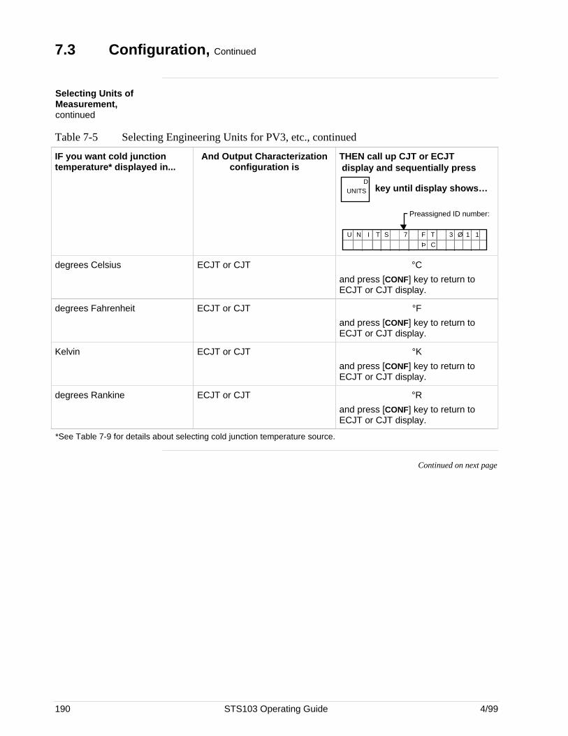
190 STS103 Operating Guide 4/99
7.3 Configuration, Continued
Selecting Units ofMeasurement,continued
Table 7-5 Selecting Engineering Units for PV3, etc., continued
IF you want cold junctiontemperature* displayed in...
And Output Characterizationconfiguration is
THEN call up CJT or ECJT display and sequentially press
DUNITS
key until display shows…
Preassigned ID number:
F T7U N I T
Þ C
3 Ø 1 1S
degrees Celsius ECJT or CJT °C
and press [CONF] key to return toECJT or CJT display.
degrees Fahrenheit ECJT or CJT °F
and press [CONF] key to return toECJT or CJT display.
Kelvin ECJT or CJT °K
and press [CONF] key to return toECJT or CJT display.
degrees Rankine ECJT or CJT °R
and press [CONF] key to return toECJT or CJT display.
*See Table 7-9 for details about selecting cold junction temperature source.
Continued on next page
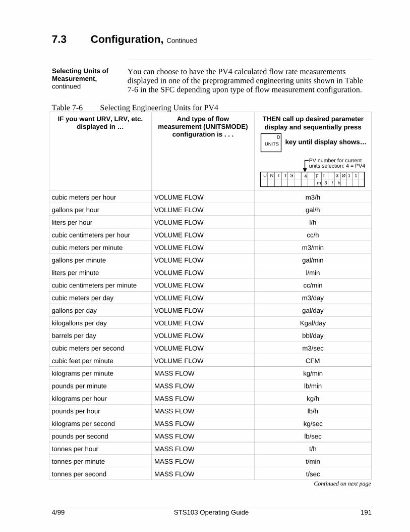
4/99 STS103 Operating Guide 191
7.3 Configuration, Continued
Selecting Units ofMeasurement,continued
You can choose to have the PV4 calculated flow rate measurementsdisplayed in one of the preprogrammed engineering units shown in Table7-6 in the SFC depending upon type of flow measurement configuration.
Table 7-6 Selecting Engineering Units for PV4IF you want URV, LRV, etc.
displayed in …And type of flow
measurement (UNITSMODE)configuration is . . .
THEN call up desired parameterdisplay and sequentially press
DUNITS
key until display shows…
4U N I T
3m
S
/ h
PV number for current units selection: 4 = PV4
F T 3 Ø 1 1
cubic meters per hour VOLUME FLOW m3/h
gallons per hour VOLUME FLOW gal/h
liters per hour VOLUME FLOW l/h
cubic centimeters per hour VOLUME FLOW cc/h
cubic meters per minute VOLUME FLOW m3/min
gallons per minute VOLUME FLOW gal/min
liters per minute VOLUME FLOW l/min
cubic centimeters per minute VOLUME FLOW cc/min
cubic meters per day VOLUME FLOW m3/day
gallons per day VOLUME FLOW gal/day
kilogallons per day VOLUME FLOW Kgal/day
barrels per day VOLUME FLOW bbl/day
cubic meters per second VOLUME FLOW m3/sec
cubic feet per minute VOLUME FLOW CFM
kilograms per minute MASS FLOW kg/min
pounds per minute MASS FLOW lb/min
kilograms per hour MASS FLOW kg/h
pounds per hour MASS FLOW lb/h
kilograms per second MASS FLOW kg/sec
pounds per second MASS FLOW lb/sec
tonnes per hour MASS FLOW t/h
tonnes per minute MASS FLOW t/min
tonnes per second MASS FLOW t/secContinued on next page
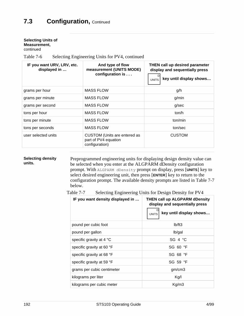
192 STS103 Operating Guide 4/99
7.3 Configuration, Continued
Selecting Units ofMeasurement,continued
Table 7-6 Selecting Engineering Units for PV4, continued
IF you want URV, LRV, etc.displayed in …
And type of flowmeasurement (UNITS MODE)
configuration is . . .
THEN call up desired parameterdisplay and sequentially press
DUNITS
key until display shows…
grams per hour MASS FLOW g/h
grams per minute MASS FLOW g/min
grams per second MASS FLOW g/sec
tons per hour MASS FLOW ton/h
tons per minute MASS FLOW ton/min
tons per seconds MASS FLOW ton/sec
user selected units CUSTOM (Units are entered aspart of PV4 equationconfiguration)
CUSTOM
Selecting densityunits.
Preprogrammed engineering units for displaying design density value canbe selected when you enter at the ALGPARM dDensity configurationprompt. With ALGPARM dDensity prompt on display, press [UNITS] key toselect desired engineering unit, then press [ENTER] key to return to theconfiguration prompt. The available density prompts are listed in Table 7-7below.
Table 7-7 Selecting Engineering Units for Design Density for PV4IF you want density displayed in … THEN call up ALGPARM dDensity
display and sequentially pressD
UNITS key until display shows…
pound per cubic foot lb/ft3
pound per gallon lb/gal
specific gravity at 4 °C SG 4 °C
specific gravity at 60 °F SG 60 °F
specific gravity at 68 °F SG 68 °F
specific gravity at 59 °F SG 59 °F
grams per cubic centimeter gm/cm3
kilograms per liter Kg/l
kilograms per cubic meter Kg/m3
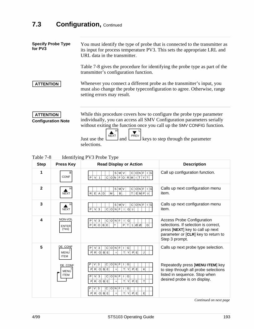
4/99 STS103 Operating Guide 193
7.3 Configuration, Continued
Specify Probe Typefor PV3
You must identify the type of probe that is connected to the transmitter asits input for process temperature PV3. This sets the appropriate LRL andURL data in the transmitter.
Table 7-8 gives the procedure for identifying the probe type as part of thetransmitter’s configuration function.
ATTENTION Whenever you connect a different probe as the transmitter’s input, youmust also change the probe typeconfiguration to agree. Otherwise, rangesetting errors may result.
ATTENTIONConfiguration Note
While this procedure covers how to configure the probe type parameterindividually, you can access all SMV Configuration parameters seriallywithout exiting the function once you call up the SMV CONFIG function.
Just use the NEXT
H
and PREV
L
keys to step through the parameterselections.
Table 7-8 Identifying PV3 Probe TypeStep Press Key Read Display or Action Description
1 BCONF I T YO R MC O N F ?
N GO IC FS M V
P V 1
Call up configuration function.
2NEXT
H
E M P. TM . B ?
N GO IC FS M V
R E A D
Calls up next configuration menuitem.
3NEXT
H
GF IC O N ?
N GO IC FS M V
P V 3
Calls up next configuration menuitem.
4 NON-VOL
ENTER(Yes)
GF IC O NP V 3
P R O B E = P T 1 Ø Ø D
Access Probe Configurationselections. If selection is correct,press [NEXT] key to call up nextparameter or [CLR] key to return toStep 3 prompt.
5MENU ITEM
DE CONFI
MENU ITEM
DE CONFI
E = TP R O B P EY J
GF IC O NP V 3
E = TP R O B P EY K
GF IC O NP V 3
E = TP R O B P EY T
GF IC O NP V 3
E = TP R O B P EY E
GF IC O NP V 3
Calls up next probe type selection.
Repeatedly press [MENU ITEM] keyto step through all probe selectionslisted in sequence. Stop whendesired probe is on display.
Continued on next page
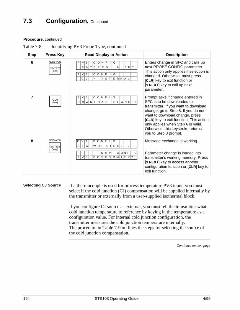
194 STS103 Operating Guide 4/99
7.3 Configuration, Continued
Procedure, continued
Table 7-8 Identifying PV3 Probe Type, continued
Step Press Key Read Display or Action Description
6 NON-VOL
ENTER(Yes)
E E IE N T N S CR D F
GF IC O NP V 3
GF IC O NP V 3
C J = I N T E R AN L
Enters change in SFC and calls upnext PROBE CONFIG parameter.This action only applies if selection ischanged. Otherwise, must press[CLR] key to exit function or[s NEXT] key to call up nextparameter.
7CLR(No) L A CO W H ND GAD N O E ?
GF IC O NP V 3 Prompt asks if change entered inSFC is to be downloaded totransmitter. If you want to downloadchange, go to Step 8. If you do notwant to download change, press[CLR] key to exit function. This actiononly applies when Step 6 is valid.Otherwise, this keystroke returnsyou to Step 3 prompt.
8 NON-VOL
ENTER(Yes)
W R NF C G .K ..S O I
GF IC O NP V 3
I T YO R MC O N F ?
N GO IC FS M V
P V 1
Message exchange is working.
Parameter change is loaded intotransmitter’s working memory. Press[s NEXT] key to access anotherconfiguration function or [CLR] key toexit function.
Selecting CJ Source If a thermocouple is used for process temperature PV3 input, you mustselect if the cold junction (CJ) compensation will be supplied internally bythe transmitter or externally from a user-supplied isothermal block.
If you configure CJ source as external, you must tell the transmitter whatcold junction temperature to reference by keying in the temperature as aconfiguration value. For internal cold junction configuration, thetransmitter measures the cold junction temperature internally.The procedure in Table 7-9 outlines the steps for selecting the source ofthe cold junction compensation.
Continued on next page
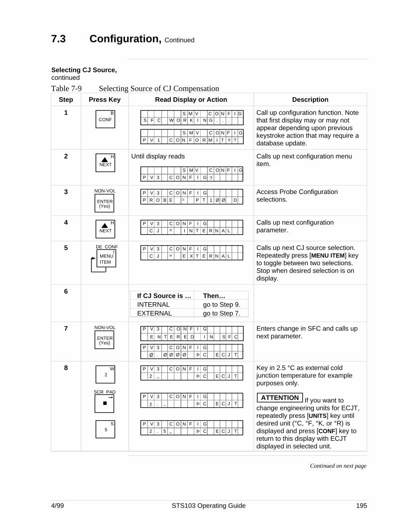
4/99 STS103 Operating Guide 195
7.3 Configuration, Continued
Selecting CJ Source,continued
Table 7-9 Selecting Source of CJ CompensationStep Press Key Read Display or Action Description
1 BCONF W R NF C G .K ..S O I
N GO IC FS M V
I T YO R MC O N F ?
N GO IC FS M V
P V 1
Call up configuration function. Notethat first display may or may notappear depending upon previouskeystroke action that may require adatabase update.
2NEXT
H Until display reads
GF IC O N ?
N GO IC FS M V
P V 3
Calls up next configuration menuitem.
3 NON-VOL
ENTER(Yes)
GF IC O NP V 3
P R O B E = P T 1 Ø Ø D
Access Probe Configurationselections.
4NEXT
H GF IC O NP V 3
C J = I N T E R AN L
Calls up next configurationparameter.
5MENU ITEM
DE CONFI
GF IC O NP V 3
C J = E X T E R AN L
Calls up next CJ source selection.Repeatedly press [MENU ITEM] keyto toggle between two selections.Stop when desired selection is ondisplay.
6If CJ Source is … Then…INTERNAL go to Step 9.EXTERNAL go to Step 7.
7 NON-VOL
ENTER(Yes)
E E IE N T N S CR D F
GF IC O NP V 3
GF IC O NP V 3
Ø Ø Ø Ø Þ C E JC T. Ø
Enters change in SFC and calls upnext parameter.
82
W
SCR PAD
5S
GF IC O NP V 3
2 _ Þ C E JC T
GF IC O NP V 3
2 Þ C E JC T. _
GF IC O NP V 3
2 Þ C E JC T. _5
Key in 2.5 °C as external coldjunction temperature for examplepurposes only.
ATTENTION If you want tochange engineering units for ECJT,repeatedly press [UNITS] key untildesired unit (°C, °F, °K, or °R) isdisplayed and press [CONF] key toreturn to this display with ECJTdisplayed in selected unit.
Continued on next page
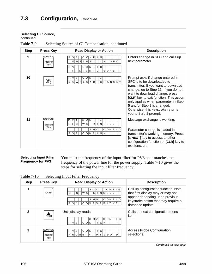
196 STS103 Operating Guide 4/99
7.3 Configuration, Continued
Selecting CJ Source,continued
Table 7-9 Selecting Source of CJ Compensation, continued
Step Press Key Read Display or Action Description
9 NON-VOL
ENTER(Yes)
E E IE N T N S CR D F
GF IC O NP V 3
GF IC O NP V 3
F I L T = H z6 ØE R
Enters change in SFC and calls upnext parameter.
10CLR(No) L A CO W H ND GAD N O E ?
GF IC O NP V 3 Prompt asks if change entered inSFC is to be downloaded totransmitter. If you want to downloadchange, go to Step 11. If you do notwant to download change, press[CLR] key to exit function. This actiononly applies when parameter in Step5 and/or Step 8 is changed.Otherwise, this keystroke returnsyou to Step 1 prompt.
11 NON-VOL
ENTER(Yes)
W R NF C G .K ..S O I
GF IC O NP V 3
GF IC O N ?
N GO IC FS M V
P V 3
Message exchange is working.
Parameter change is loaded intotransmitter’s working memory. Press[s NEXT] key to access anotherconfiguration function or [CLR] key toexit function.
Selecting Input FilterFrequency for PV3
You must the frequency of the input filter for PV3 so it matches thefrequency of the power line for the power supply. Table 7-10 gives thesteps for selecting the input filter frequency.
Table 7-10 Selecting Input Filter FrequencyStep Press Key Read Display or Action Description
1 BCONF W R NF C G .K ..S O I
N GO IC FS M V
I T YO R MC O N F ?
N GO IC FS M V
P V 1
Call up configuration function. Notethat first display may or may notappear depending upon previouskeystroke action that may require adatabase update.
2NEXT
H Until display reads
GF IC O N ?
N GO IC FS M V
P V 3
Calls up next configuration menuitem.
3 NON-VOL
ENTER(Yes)
GF IC O NP V 3
P R O B E = P T 1 Ø Ø D
Access Probe Configurationselections.
Continued on next page

4/99 STS103 Operating Guide 197
7.3 Configuration, Continued
Selecting Input FilterFrequency for PV3,continued
Table 7-10 Selecting Input Filter Frequency, Continued
Step Press Key Read Display or Action Description
4NEXT
H GF IC O NP V 3
C J = E X T E R AN L
Calls up next configurationparameter.
5NEXT
H GF IC O NP V 3
2 Þ C E JC T. Ø5 Ø Ø
Calls up next configurationparameter - ECJT only appearswhen CJ = EXTERNAL.
6NEXT
H GF IC O NP V 3
F I L T = H z6 ØE R
Calls up next configurationparameter.
7MENU ITEM
DE CONFI
GF IC O NP V 3
F I L T = H z5 ØE R
Calls up next frequency selection.Repeatedly press [MENU ITEM] keyto toggle between two selections.Stop when desired selection is ondisplay.
8 NON-VOL
ENTER(Yes)
E E IE N T N S CR D F
GF IC O NP V 3
GF IC O NP V 3
T C F A L D E T = NU T O
Enters change in SFC and calls upnext parameter.
9CLR(No) L A CO W H ND GAD N O E ?
GF IC O NP V 3 Prompt asks if change entered inSFC is to be downloaded totransmitter. If you want to downloadchange, go to Step 10. If you do notwant to download change, press[CLR] key to exit function. This actiononly applies when parameter in Step6 is changed. Otherwise, thiskeystroke returns you to Step 2prompt.
10 NON-VOL
ENTER(Yes)
W R NF C G .K ..S O I
GF IC O NP V 3
GF IC O N ?
N GO IC FS M V
P V 3
Message exchange is working.
Parameter change is loaded intotransmitter’s working memory. Press[s NEXT] key to access anotherconfiguration function or [CLR] key toexit function.
Continued on next page
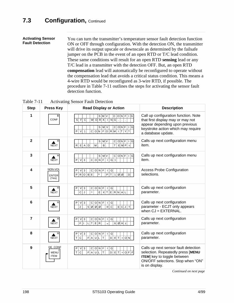
198 STS103 Operating Guide 4/99
7.3 Configuration, Continued
Activating SensorFault Detection
You can turn the transmitter’s temperature sensor fault detection functionON or OFF through configuration. With the detection ON, the transmitterwill drive its output upscale or downscale as determined by the failsafejumper on the PCB in the event of an open RTD or T/C lead condition.These same conditions will result for an open RTD sensing lead or anyT/C lead in a transmitter with the detection OFF. But, an open RTDcompensation lead will automatically be reconfigured to operate withoutthe compensation lead that avoids a critical status condition. This means a4-wire RTD would be reconfigured as 3-wire RTD, if possible. Theprocedure in Table 7-11 outlines the steps for activating the sensor faultdetection function.
Table 7-11 Activating Sensor Fault DetectionStep Press Key Read Display or Action Description
1 BCONF W R NF C G .K ..S O I
N GO IC FS M V
I T YO R MC O N F ?
N GO IC FS M V
P V 1
Call up configuration function. Notethat first display may or may notappear depending upon previouskeystroke action which may requirea database update.
2NEXT
H
E M P. TM . B ?
N GO IC FS M V
R E A D
Calls up next configuration menuitem.
3NEXT
H
GF IC O N ?
N GO IC FS M V
P V 3
Calls up next configuration menuitem.
4 NON-VOL
ENTER(Yes)
GF IC O NP V 3
P R O B E = P T 1 Ø Ø D
Access Probe Configurationselections.
5NEXT
H GF IC O NP V 3
C J = E X T E R AN L
Calls up next configurationparameter.
6NEXT
H GF IC O NP V 3
2 Þ C E JC T. Ø5 Ø Ø
Calls up next configurationparameter - ECJT only appearswhen CJ = EXTERNAL.
7NEXT
H GF IC O NP V 3
F I L T = H z6 ØE R
Calls up next configurationparameter.
8NEXT
H GF IC O NP V 3
T C F A L D E T = NU T O
Calls up next configurationparameter.
9MENU ITEM
DE CONFI
GF IC O NP V 3
T C F A L D E T = FU T O F
Calls up next sensor fault detectionselection. Repeatedly press [MENUITEM] key to toggle betweenON/OFF selections. Stop when “ON”is on display.
Continued on next page
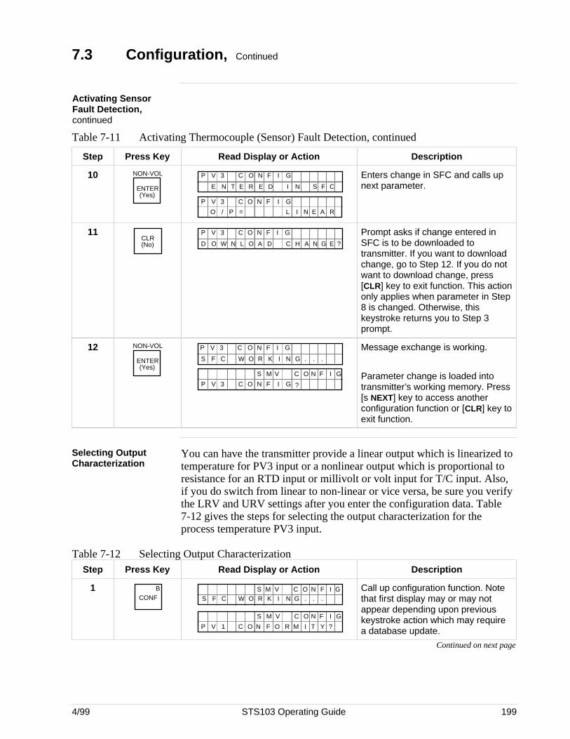
4/99 STS103 Operating Guide 199
7.3 Configuration, Continued
Activating SensorFault Detection,continued
Table 7-11 Activating Thermocouple (Sensor) Fault Detection, continued
Step Press Key Read Display or Action Description
10 NON-VOL
ENTER(Yes)
E E IE N T N S CR D F
GF IC O NP V 3
GF IC O NP V 3
O / = L N AE RP I
Enters change in SFC and calls upnext parameter.
11CLR(No) L A CO W H ND GAD N O E ?
GF IC O NP V 3 Prompt asks if change entered inSFC is to be downloaded totransmitter. If you want to downloadchange, go to Step 12. If you do notwant to download change, press[CLR] key to exit function. This actiononly applies when parameter in Step8 is changed. Otherwise, thiskeystroke returns you to Step 3prompt.
12 NON-VOL
ENTER(Yes)
W R NF C G .K ..S O I
GF IC O NP V 3
GF IC O N ?
N GO IC FS M V
P V 3
Message exchange is working.
Parameter change is loaded intotransmitter’s working memory. Press[s NEXT] key to access anotherconfiguration function or [CLR] key toexit function.
Selecting OutputCharacterization
You can have the transmitter provide a linear output which is linearized totemperature for PV3 input or a nonlinear output which is proportional toresistance for an RTD input or millivolt or volt input for T/C input. Also,if you do switch from linear to non-linear or vice versa, be sure you verifythe LRV and URV settings after you enter the configuration data. Table7-12 gives the steps for selecting the output characterization for theprocess temperature PV3 input.
Table 7-12 Selecting Output CharacterizationStep Press Key Read Display or Action Description
1 BCONF W R NF C G .K ..S O I
N GO IC FS M V
I T YO R MC O N F ?
N GO IC FS M V
P V 1
Call up configuration function. Notethat first display may or may notappear depending upon previouskeystroke action which may requirea database update.
Continued on next page
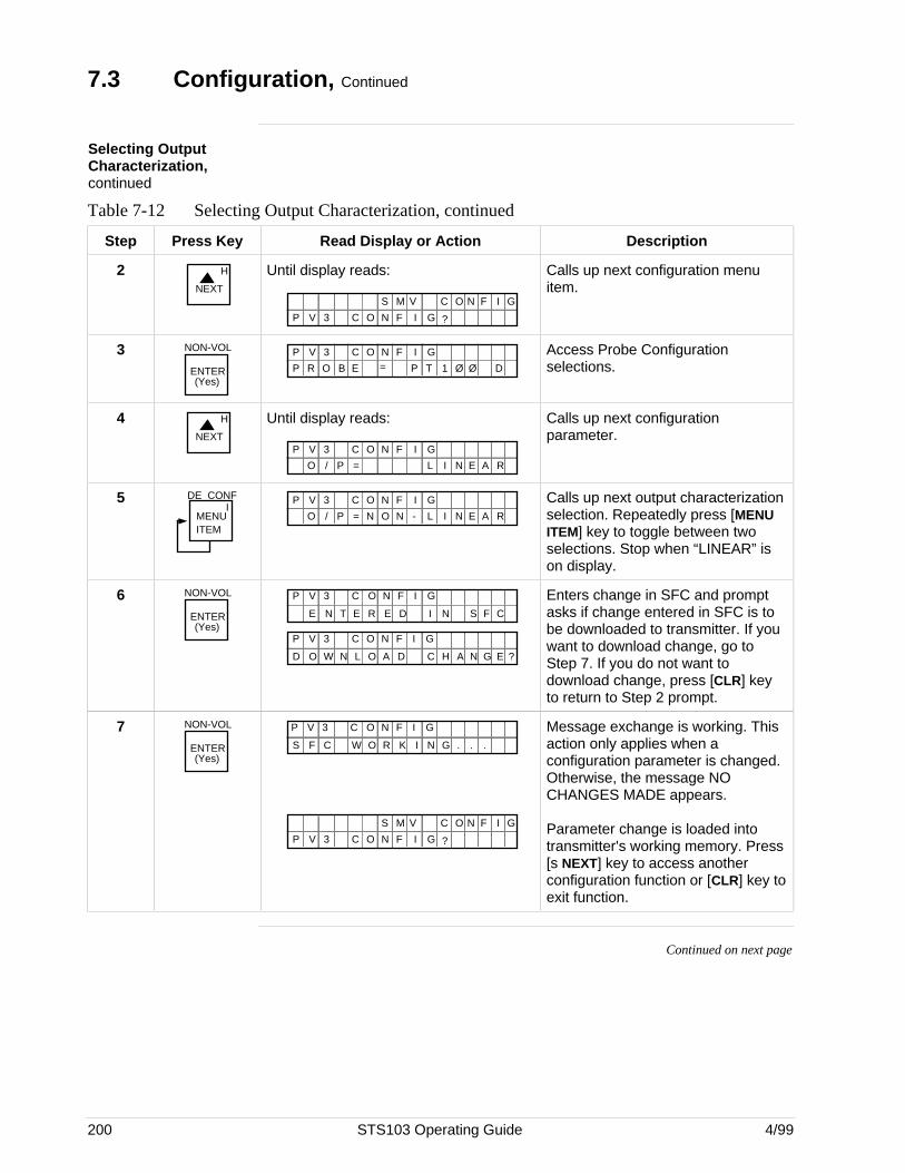
200 STS103 Operating Guide 4/99
7.3 Configuration, Continued
Selecting OutputCharacterization,continued
Table 7-12 Selecting Output Characterization, continued
Step Press Key Read Display or Action Description
2NEXT
H Until display reads:
GF IC O N ?
N GO IC FS M V
P V 3
Calls up next configuration menuitem.
3 NON-VOL
ENTER(Yes)
GF IC O NP V 3
P R O B E = P T 1 Ø Ø D
Access Probe Configurationselections.
4NEXT
H Until display reads:
GF IC O NP V 3
O / = L N AE RP I
Calls up next configurationparameter.
5MENU ITEM
DE CONFI
GF IC O NP V 3
O / = L N AE RP IN O N -
Calls up next output characterizationselection. Repeatedly press [MENUITEM] key to toggle between twoselections. Stop when “LINEAR” ison display.
6 NON-VOL
ENTER(Yes)
E E IE N T N S CR D F
GF IC O NP V 3
L A CO W H ND GAD N O E ?
GF IC O NP V 3
Enters change in SFC and promptasks if change entered in SFC is tobe downloaded to transmitter. If youwant to download change, go toStep 7. If you do not want todownload change, press [CLR] keyto return to Step 2 prompt.
7 NON-VOL
ENTER(Yes)
W R NF C G .K ..S O I
GF IC O NP V 3
GF IC O N ?
N GO IC FS M V
P V 3
Message exchange is working. Thisaction only applies when aconfiguration parameter is changed.Otherwise, the message NOCHANGES MADE appears.
Parameter change is loaded intotransmitter's working memory. Press[s NEXT] key to access anotherconfiguration function or [CLR] key toexit function.
Continued on next page

4/99 STS103 Operating Guide 201
7.3 Configuration, Continued
Defining equation forPV4 calculation
Using the SFC, you can define simple equations for measuring the flowrate of a gas or superheated steam. However, if you are using the SMV3000 for flow measurement with dynamic compensation, you must usethe SCT 3000 (software Release 150 or greater) instead of an SFC toconfigure the transmitter.
About flow calculation The SMV 3000 includes configurable simple equations for measuring theflow rate of a gas or superheated steam as it flows through an orifice platein a pipe line. It bases the gas flow rate calculation on Bernoulli’s theoremand the ideal gas law. The superheated steam equation uses themeasurements of steam pressure and temperature to determine the actualspecific volume of the flowing steam. (Note that the superheated steamequation also works for saturated steam applications.) The actual specificvolume is the reciprocal of the fluid density in steam flow calculations.
The gas flow rate can be expressed as a volumetric flow rate in fluidvolume per unit time, or as a mass flow rate in fluid mass per unit of time.
ATTENTION The mass flow rate also applies for a volumetric flow rate at standardconditions such as Standard Cubic Feet per Minute (SCFM). The steamflow rate is expressed as a mass flow rate in fluid mass per unit of time.
Dynamiccompensation flowequations
Additional configurable equations are available that provide flowmeasurement with dynamic compensation for changes due to temperatureand pressure. These equations use density, viscosity, Reynolds number,discharge coefficient, thermal expansion factor and gas expansion factorto calculate mass and volume flowrate.
ATTENTION However, due to the complexity of these flow equations, you must use theSmart Configuration Toolkit (SCT 3000) software program to configure theSMV 3000 for dynamic compensated flow measurement
Continued on next page
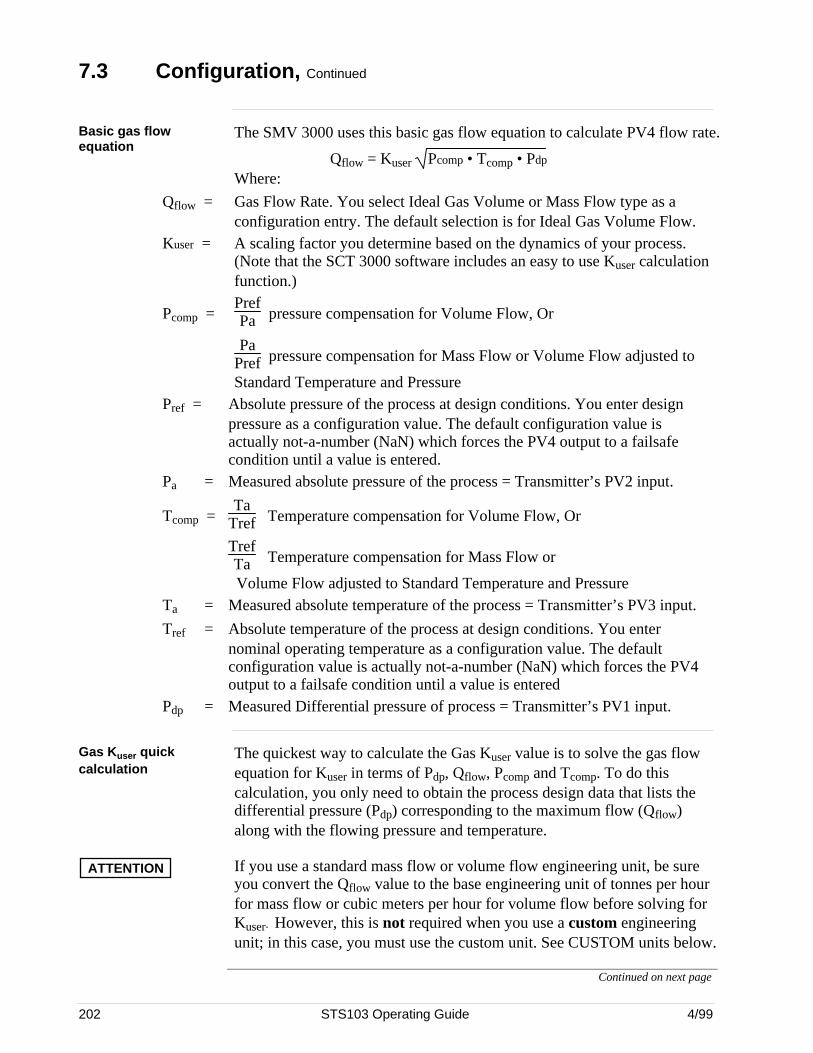
202 STS103 Operating Guide 4/99
7.3 Configuration, Continued
Basic gas flowequation
The SMV 3000 uses this basic gas flow equation to calculate PV4 flow rate.
Qflow = Kuser Pcomp • Tcomp • Pdp Where:
Qflow = Gas Flow Rate. You select Ideal Gas Volume or Mass Flow type as aconfiguration entry. The default selection is for Ideal Gas Volume Flow.
Kuser = A scaling factor you determine based on the dynamics of your process.(Note that the SCT 3000 software includes an easy to use Kuser calculationfunction.)
Pcomp =PrefPa pressure compensation for Volume Flow, Or
PaPref pressure compensation for Mass Flow or Volume Flow adjusted to
Standard Temperature and PressurePref = Absolute pressure of the process at design conditions. You enter design
pressure as a configuration value. The default configuration value isactually not-a-number (NaN) which forces the PV4 output to a failsafecondition until a value is entered.
Pa = Measured absolute pressure of the process = Transmitter’s PV2 input.
Tcomp =Ta
Tref Temperature compensation for Volume Flow, Or
TrefTa Temperature compensation for Mass Flow or
Volume Flow adjusted to Standard Temperature and PressureTa = Measured absolute temperature of the process = Transmitter’s PV3 input.
Tref = Absolute temperature of the process at design conditions. You enternominal operating temperature as a configuration value. The defaultconfiguration value is actually not-a-number (NaN) which forces the PV4output to a failsafe condition until a value is entered
Pdp = Measured Differential pressure of process = Transmitter’s PV1 input.
Gas Kuser quickcalculation
The quickest way to calculate the Gas Kuser value is to solve the gas flowequation for Kuser in terms of Pdp, Qflow, Pcomp and Tcomp. To do thiscalculation, you only need to obtain the process design data that lists thedifferential pressure (Pdp) corresponding to the maximum flow (Qflow)along with the flowing pressure and temperature.
ATTENTION If you use a standard mass flow or volume flow engineering unit, be sureyou convert the Qflow value to the base engineering unit of tonnes per hourfor mass flow or cubic meters per hour for volume flow before solving forKuser. However, this is not required when you use a custom engineeringunit; in this case, you must use the custom unit. See CUSTOM units below.
Continued on next page
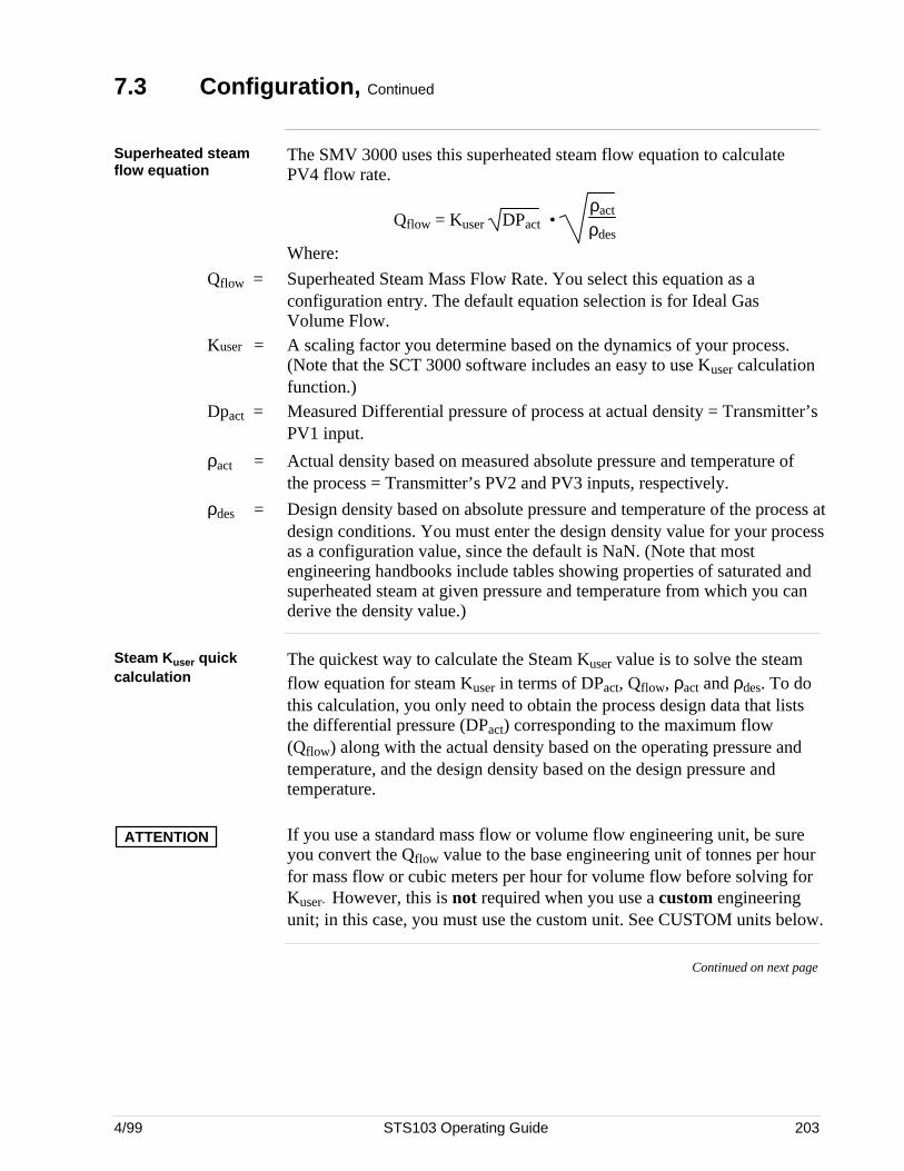
4/99 STS103 Operating Guide 203
7.3 Configuration, Continued
Superheated steamflow equation
The SMV 3000 uses this superheated steam flow equation to calculatePV4 flow rate.
Qflow = Kuser DPact • ρact
ρdes
Where:
Qflow = Superheated Steam Mass Flow Rate. You select this equation as aconfiguration entry. The default equation selection is for Ideal GasVolume Flow.
Kuser = A scaling factor you determine based on the dynamics of your process.(Note that the SCT 3000 software includes an easy to use Kuser calculationfunction.)
Dpact = Measured Differential pressure of process at actual density = Transmitter’sPV1 input.
ρact = Actual density based on measured absolute pressure and temperature ofthe process = Transmitter’s PV2 and PV3 inputs, respectively.
ρdes = Design density based on absolute pressure and temperature of the process atdesign conditions. You must enter the design density value for your processas a configuration value, since the default is NaN. (Note that mostengineering handbooks include tables showing properties of saturated andsuperheated steam at given pressure and temperature from which you canderive the density value.)
Steam Kuser quickcalculation
The quickest way to calculate the Steam Kuser value is to solve the steamflow equation for steam Kuser in terms of DPact, Qflow, ρact and ρdes. To dothis calculation, you only need to obtain the process design data that liststhe differential pressure (DPact) corresponding to the maximum flow(Qflow) along with the actual density based on the operating pressure andtemperature, and the design density based on the design pressure andtemperature.
ATTENTION If you use a standard mass flow or volume flow engineering unit, be sureyou convert the Qflow value to the base engineering unit of tonnes per hourfor mass flow or cubic meters per hour for volume flow before solving forKuser. However, this is not required when you use a custom engineeringunit; in this case, you must use the custom unit. See CUSTOM units below.
Continued on next page
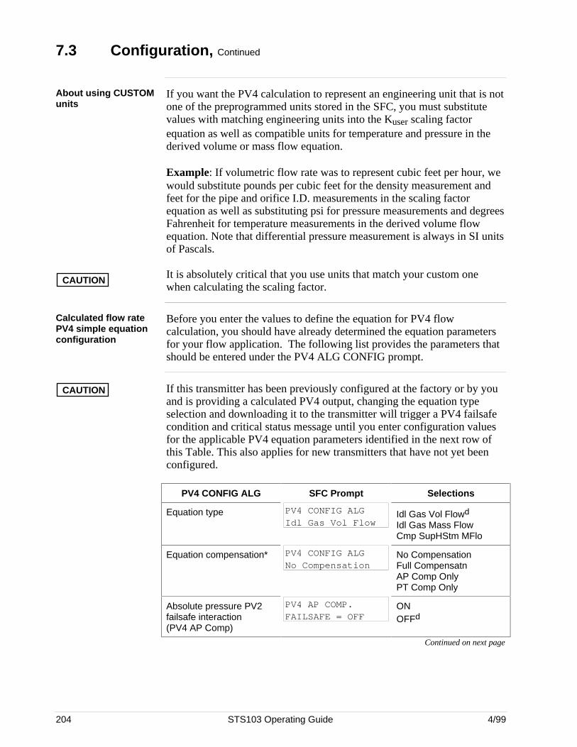
204 STS103 Operating Guide 4/99
7.3 Configuration, Continued
About using CUSTOMunits
CAUTION
If you want the PV4 calculation to represent an engineering unit that is notone of the preprogrammed units stored in the SFC, you must substitutevalues with matching engineering units into the Kuser scaling factorequation as well as compatible units for temperature and pressure in thederived volume or mass flow equation.
Example: If volumetric flow rate was to represent cubic feet per hour, wewould substitute pounds per cubic feet for the density measurement andfeet for the pipe and orifice I.D. measurements in the scaling factorequation as well as substituting psi for pressure measurements and degreesFahrenheit for temperature measurements in the derived volume flowequation. Note that differential pressure measurement is always in SI unitsof Pascals.
It is absolutely critical that you use units that match your custom onewhen calculating the scaling factor.
Calculated flow ratePV4 simple equationconfiguration
Before you enter the values to define the equation for PV4 flowcalculation, you should have already determined the equation parametersfor your flow application. The following list provides the parameters thatshould be entered under the PV4 ALG CONFIG prompt.
CAUTION If this transmitter has been previously configured at the factory or by youand is providing a calculated PV4 output, changing the equation typeselection and downloading it to the transmitter will trigger a PV4 failsafecondition and critical status message until you enter configuration valuesfor the applicable PV4 equation parameters identified in the next row ofthis Table. This also applies for new transmitters that have not yet beenconfigured.
PV4 CONFIG ALG SFC Prompt Selections
Equation type PV4 CONFIG ALGIdl Gas Vol Flow
Idl Gas Vol Flowd
Idl Gas Mass FlowCmp SupHStm MFlo
Equation compensation* PV4 CONFIG ALGNo Compensation
No CompensationFull CompensatnAP Comp OnlyPT Comp Only
Absolute pressure PV2failsafe interaction(PV4 AP Comp)
PV4 AP COMP.FAILSAFE = OFF
ONOFFd
Continued on next page
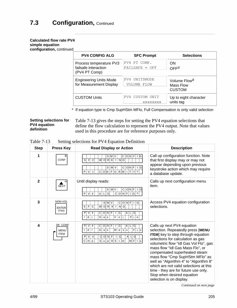
4/99 STS103 Operating Guide 205
7.3 Configuration, Continued
Calculated flow rate PV4simple equationconfiguration, continued
PV4 CONFIG ALG SFC Prompt Selections
Process temperature PV3failsafe interaction(PV4 PT Comp)
PV4 PT COMP.FAILSAFE = OFF
ONOFFd
Engineering Units Modefor Measurement Display
PV4 UNITSMODE VOLUME FLOW
Volume Flowd
Mass FlowCUSTOM
CUSTOM Units PV4 CUSTOM UNIT xxxxxxxx
Up to eight characterunits tag
* If equation type is Cmp SupHStm MFlo, Full Compensation is only valid selection
Setting selections forPV4 equationdefinition
Table 7-13 gives the steps for setting the PV4 equation selections thatdefine the flow calculation to represent the PV4 output. Note that valuesused in this procedure are for reference purposes only.
Table 7-13 Setting selections for PV4 Equation DefinitionStep Press Key Read Display or Action Description
1 BCONF W R NF C G .K ..S O I
N GO IC FS M V
I T YO R MC O N F ?
N GO IC FS M V
P V 1
Call up configuration function. Notethat first display may or may notappear depending upon previouskeystroke action which may requirea database update.
2NEXT
H Until display reads:
A L G ?
N GO IC FS M V
P V 4 C O F IN G
Calls up next configuration menuitem.
3 NON-VOL
ENTER(Yes)
W R NF C G .K ..S O IN GO IC FS M V
P V 4 LA GC O N I GF
I d l G a s V o l F l o
Access PV4 equation configurationselections.
4MENU ITEM
DE CONFI
P V 4 LA GC O N I GF
I d l G a s M a s F l os
A L GP V 4 C O F IN G
C m p S u p S tH m M F l o
Calls up next PV4 equationselection. Repeatedly press [MENUITEM] key to step through equationselections for calculation as gasvolumetric flow “Idl Gas Vol Flo”, gasmass flow “Idl Gas Mass Flo”, orcompensated superheated steammass flow “Cmp SupHStm MFlo” aswell as “Algorithm 4” to “Algorithm 8”which are not valid selections at thistime - they are for future use only.Stop when desired equationselection is on display.
Continued on next page
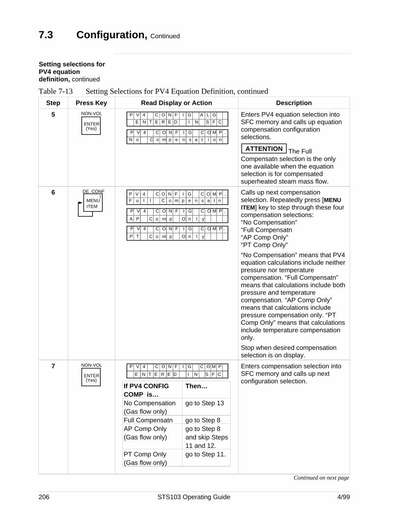
206 STS103 Operating Guide 4/99
7.3 Configuration, Continued
Setting selections forPV4 equationdefinition, continued
Table 7-13 Setting Selections for PV4 Equation Definition, continued
Step Press Key Read Display or Action Description
5 NON-VOL
ENTER(Yes)
P V 4 LA GC O N I GF
E N E R E I N S F CT D
P V 4 OC MC O N I GF
o o m p s a o nC e
P
N n t i
.
Enters PV4 equation selection intoSFC memory and calls up equationcompensation configurationselections.
ATTENTION The FullCompensatn selection is the onlyone available when the equationselection is for compensatedsuperheated steam mass flow.
6MENU ITEM
DE CONFI C O MP V 4 C O F IN G
F u l C o p e n a tP .
l m s n
P V 4 OC MC O N I GF
P o m p n lC
P
A O y
.
P V 4 OC MC O N I GF
T o m p n lC
P
P O y
.
Calls up next compensationselection. Repeatedly press [MENUITEM] key to step through these fourcompensation selections:“No Compensation”“Full Compensatn“AP Comp Only”“PT Comp Only”
“No Compensation” means that PV4equation calculations include neitherpressure nor temperaturecompensation. “Full Compensatn”means that calculations include bothpressure and temperaturecompensation. “AP Comp Only”means that calculations includepressure compensation only. “PTComp Only” means that calculationsinclude temperature compensationonly.
Stop when desired compensationselection is on display.
7 NON-VOL
ENTER(Yes)
P V 4 OC MC O N I GF P
E N E R E I N S F CT D
If PV4 CONFIG Then…COMP is…No Compensation go to Step 13(Gas flow only)Full Compensatn go to Step 8AP Comp Only go to Step 8(Gas flow only) and skip Steps
11 and 12.PT Comp Only go to Step 11.(Gas flow only)
Enters compensation selection intoSFC memory and calls up nextconfiguration selection.
Continued on next page
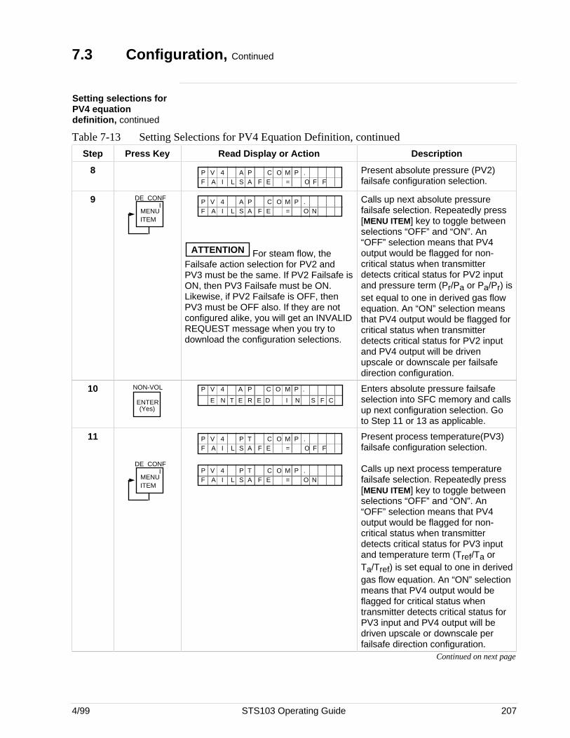
4/99 STS103 Operating Guide 207
7.3 Configuration, Continued
Setting selections forPV4 equationdefinition, continued
Table 7-13 Setting Selections for PV4 Equation Definition, continued
Step Press Key Read Display or Action Description
8 P V 4 A PF A I A F = F F
C O M P .L E OS
Present absolute pressure (PV2)failsafe configuration selection.
9MENU ITEM
DE CONFI P V 4 A P
F A I A F = NC O M P .
L E OS
ATTENTION For steam flow, theFailsafe action selection for PV2 andPV3 must be the same. If PV2 Failsafe isON, then PV3 Failsafe must be ON.Likewise, if PV2 Failsafe is OFF, thenPV3 must be OFF also. If they are notconfigured alike, you will get an INVALIDREQUEST message when you try todownload the configuration selections.
Calls up next absolute pressurefailsafe selection. Repeatedly press[MENU ITEM] key to toggle betweenselections “OFF” and “ON”. An“OFF” selection means that PV4output would be flagged for non-critical status when transmitterdetects critical status for PV2 inputand pressure term (Pr/Pa or Pa/Pr) isset equal to one in derived gas flowequation. An “ON” selection meansthat PV4 output would be flagged forcritical status when transmitterdetects critical status for PV2 inputand PV4 output will be drivenupscale or downscale per failsafedirection configuration.
10 NON-VOL
ENTER(Yes)
E N E R E I N S F CT D
P V 4 A P C O M P . Enters absolute pressure failsafeselection into SFC memory and callsup next configuration selection. Goto Step 11 or 13 as applicable.
11
MENU ITEM
DE CONFI
P V 4 P TF A I A F = F F
C O M P .L E OS
P V 4 P TF A I A F = N
C O M P .L E OS
Present process temperature(PV3)failsafe configuration selection.
Calls up next process temperaturefailsafe selection. Repeatedly press[MENU ITEM] key to toggle betweenselections “OFF” and “ON”. An“OFF” selection means that PV4output would be flagged for non-critical status when transmitterdetects critical status for PV3 inputand temperature term (Tref/Ta orTa/Tref) is set equal to one in derivedgas flow equation. An “ON” selectionmeans that PV4 output would beflagged for critical status whentransmitter detects critical status forPV3 input and PV4 output will bedriven upscale or downscale perfailsafe direction configuration.
Continued on next page
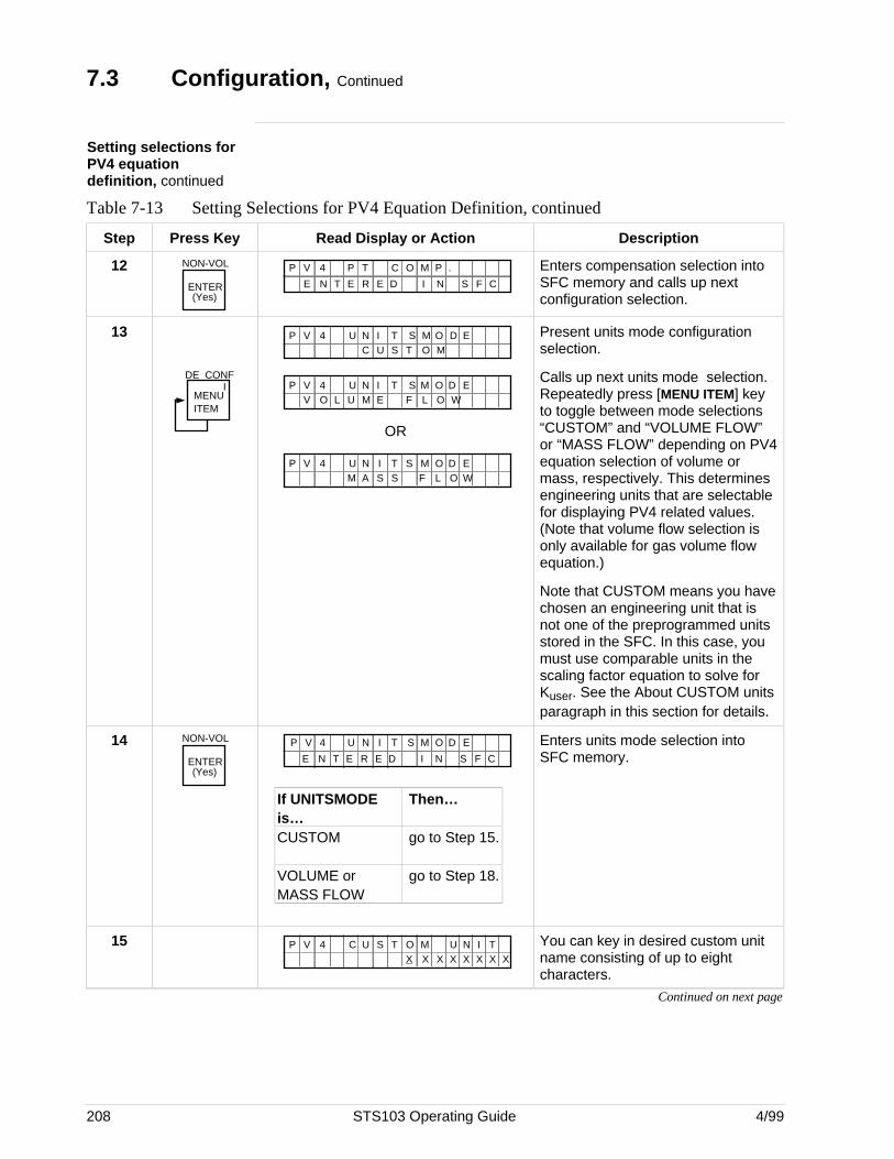
208 STS103 Operating Guide 4/99
7.3 Configuration, Continued
Setting selections forPV4 equationdefinition, continued
Table 7-13 Setting Selections for PV4 Equation Definition, continued
Step Press Key Read Display or Action Description
12 NON-VOL
ENTER(Yes)
E N E R E I N S F CT D
P V 4 P T C O M P . Enters compensation selection intoSFC memory and calls up nextconfiguration selection.
13
MENU ITEM
DE CONFI
M O DP V 4 U N T SIC O M
ETU S
M O DP V 4 U N T SIV O L E L O W
EU FM
OR
M O DP V 4 U N T SIS L O W
EM FA S
Present units mode configurationselection.
Calls up next units mode selection.Repeatedly press [MENU ITEM] keyto toggle between mode selections“CUSTOM” and “VOLUME FLOW”or “MASS FLOW” depending on PV4equation selection of volume ormass, respectively. This determinesengineering units that are selectablefor displaying PV4 related values.(Note that volume flow selection isonly available for gas volume flowequation.)
Note that CUSTOM means you havechosen an engineering unit that isnot one of the preprogrammed unitsstored in the SFC. In this case, youmust use comparable units in thescaling factor equation to solve forKuser. See the About CUSTOM unitsparagraph in this section for details.
14 NON-VOL
ENTER(Yes)
P V 4
E N E R E I N S F CT D
U N I ST OM D E
If UNITSMODE Then…is…CUSTOM go to Step 15.
VOLUME or go to Step 18.MASS FLOW
Enters units mode selection intoSFC memory.
15 M U NP V 4 C U T OSX X X
IX
TX X X X
You can key in desired custom unitname consisting of up to eightcharacters.
Continued on next page
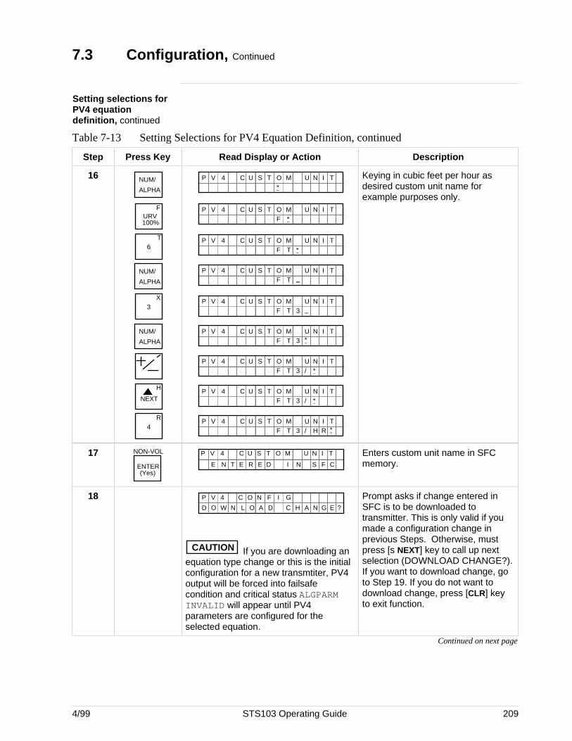
4/99 STS103 Operating Guide 209
7.3 Configuration, Continued
Setting selections forPV4 equationdefinition, continued
Table 7-13 Setting Selections for PV4 Equation Definition, continued
Step Press Key Read Display or Action Description
16 NUM/
ALPHA
URV100%
F
6T
NUM/
ALPHA
3X
NUM/
ALPHA
NEXT
H
4R
M U NP V 4 C U T OS I*
T
M U NP V 4 C U T OS IF
T*
M U NP V 4 C U T OST *
IF
T
M U NP V 4 C U T OST _
IF
T
M U NP V 4 C U T OST 3 _
IF
T
M U NP V 4 C U T OST 3 *
IF
T
M U NP V 4 C U T OST 3 /
IF
T*
M U NP V 4 C U T OST 3 /
IF
T*
M U NP V 4 C U T OST 3 /
IF
TH R *
Keying in cubic feet per hour asdesired custom unit name forexample purposes only.
17 NON-VOL
ENTER(Yes)
E N E R E I N S F CT D
M U NP V 4 C U T OS I T Enters custom unit name in SFCmemory.
18OD O W L A C N GAN D H E ?
P V 4 C O N I GF
CAUTION If you are downloading anequation type change or this is the initialconfiguration for a new transmtiter, PV4output will be forced into failsafecondition and critical status ALGPARMINVALID will appear until PV4parameters are configured for theselected equation.
Prompt asks if change entered inSFC is to be downloaded totransmitter. This is only valid if youmade a configuration change inprevious Steps. Otherwise, mustpress [s NEXT] key to call up nextselection (DOWNLOAD CHANGE?).If you want to download change, goto Step 19. If you do not want todownload change, press [CLR] keyto exit function.
Continued on next page
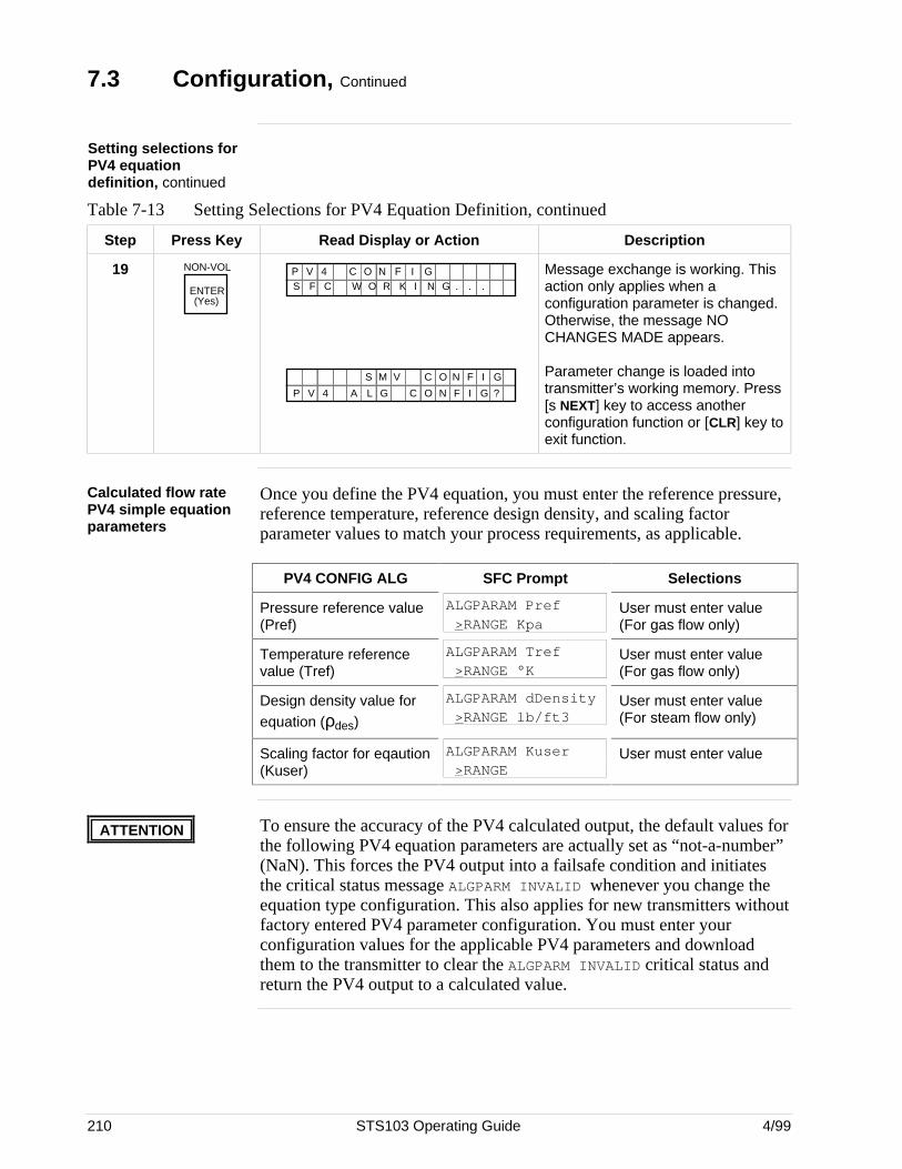
210 STS103 Operating Guide 4/99
7.3 Configuration, Continued
Setting selections forPV4 equationdefinition, continued
Table 7-13 Setting Selections for PV4 Equation Definition, continued
Step Press Key Read Display or Action Description
19 NON-VOL
ENTER(Yes)
W R NF C G .K ..S O IP V 4 C O N I GF
N GO
L
IC F
P V 4 A ?
S M V
G C O N I GF
Message exchange is working. Thisaction only applies when aconfiguration parameter is changed.Otherwise, the message NOCHANGES MADE appears.
Parameter change is loaded intotransmitter’s working memory. Press[s NEXT] key to access anotherconfiguration function or [CLR] key toexit function.
Calculated flow ratePV4 simple equationparameters
Once you define the PV4 equation, you must enter the reference pressure,reference temperature, reference design density, and scaling factorparameter values to match your process requirements, as applicable.
PV4 CONFIG ALG SFC Prompt Selections
Pressure reference value(Pref)
ALGPARAM Pref >RANGE Kpa
User must enter value(For gas flow only)
Temperature referencevalue (Tref)
ALGPARAM Tref >RANGE °K
User must enter value(For gas flow only)
Design density value forequation (ρdes)
ALGPARAM dDensity >RANGE lb/ft3
User must enter value(For steam flow only)
Scaling factor for eqaution(Kuser)
ALGPARAM Kuser >RANGE
User must enter value
ATTENTION To ensure the accuracy of the PV4 calculated output, the default values forthe following PV4 equation parameters are actually set as “not-a-number”(NaN). This forces the PV4 output into a failsafe condition and initiatesthe critical status message ALGPARM INVALID whenever you change theequation type configuration. This also applies for new transmitters withoutfactory entered PV4 parameter configuration. You must enter yourconfiguration values for the applicable PV4 parameters and downloadthem to the transmitter to clear the ALGPARM INVALID critical status andreturn the PV4 output to a calculated value.
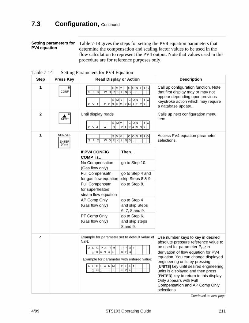
4/99 STS103 Operating Guide 211
7.3 Configuration, Continued
Setting parameters forPV4 equation
Table 7-14 gives the steps for setting the PV4 equation parameters thatdetermine the compensation and scaling factor values to be used in theflow calculation to represent the PV4 output. Note that values used in thisprocedure are for reference purposes only.
Table 7-14 Setting Parameters for PV4 EquationStep Press Key Read Display or Action Description
1 BCONF W R NF C G .K ..S O I
N GO IC FS M V
I T YO R MC O N F ?
N GO IC FS M V
P V 1
Call up configuration function. Notethat first display may or may notappear depending upon previouskeystroke action which may requirea database update.
2NEXT
H Until display reads
A L G ?
N GO IC FS M V
P V 4 P A A MR S
Calls up next configuration menuitem.
3 NON-VOL
ENTER(Yes)
W R NF C G .K ..S O IN GO IC FS M V
If PV4 CONFIG Then…COMP is…No Compensation go to Step 10.(Gas flow only)Full Compensatn go to Step 4 andfor gas flow equation skip Steps 8 & 9.Full Compensatn go to Step 8.for superheatedsteam flow equationAP Comp Only go to Step 4(Gas flow only) and skip Steps
6, 7, 8 and 9.PT Comp Only go to Step 6.(Gas flow only) and skip steps
8 and 9.
Access PV4 equation parameterselections.
4 Example for parameter set to default value ofNaN:
eA L G A R P rMK P a
P f
> GN ER A
Example for parameter with entered value:
eA L G A R P rMK P a
P f31 Ø 1 . 3
Use number keys to key in desiredabsolute pressure reference value tobe used for parameter Pref inderivation of flow equation for PV4equation. You can change displayedengineering units by pressing[UNITS] key until desired engineeringunits is displayed and then press[ENTER] key to return to this display.Only appears with FullCompensation and AP Comp Onlyselections
Continued on next page
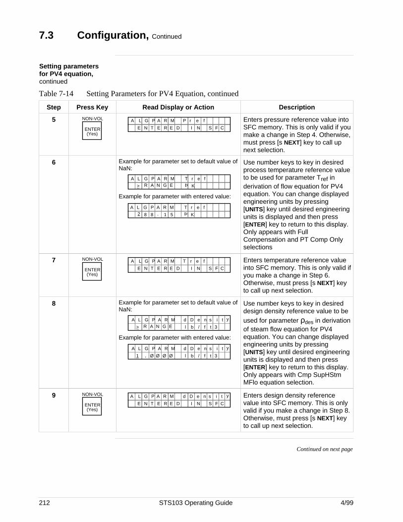
212 STS103 Operating Guide 4/99
7.3 Configuration, Continued
Setting parametersfor PV4 equation,continued
Table 7-14 Setting Parameters for PV4 Equation, continued
Step Press Key Read Display or Action Description
5 NON-VOL
ENTER(Yes)
E N E R E I N S F CT D
P r e fA L G P A R M Enters pressure reference value intoSFC memory. This is only valid if youmake a change in Step 4. Otherwise,must press [s NEXT] key to call upnext selection.
6 Example for parameter set to default value ofNaN:
eA L G A R T rMÞ K
P f
> GN ER A
Example for parameter with entered value:
eA L G A R T rM
5 Þ K
P f2 8 8 . 1
Use number keys to key in desiredprocess temperature reference valueto be used for parameter Tref inderivation of flow equation for PV4equation. You can change displayedengineering units by pressing[UNITS] key until desired engineeringunits is displayed and then press[ENTER] key to return to this display.Only appears with FullCompensation and PT Comp Onlyselections
7 NON-VOL
ENTER(Yes)
E N E R E I N S F CT D
T r e fA L G P A R M Enters temperature reference valueinto SFC memory. This is only valid ifyou make a change in Step 6.Otherwise, must press [s NEXT] keyto call up next selection.
8 Example for parameter set to default value ofNaN:
eA L G A R d DM
l b
P n s i t y
/ f t 3> GN ER A
Example for parameter with entered value:
eA L G A R d DM
l b
P n s i t y
/ f t 31 ØØ Ø. Ø
Use number keys to key in desireddesign density reference value to beused for parameter ρdes in derivationof steam flow equation for PV4equation. You can change displayedengineering units by pressing[UNITS] key until desired engineeringunits is displayed and then press[ENTER] key to return to this display.Only appears with Cmp SupHStmMFlo equation selection.
9 NON-VOL
ENTER(Yes)
E N E R E I N S F CT D
A L G P A R M ed D n s i t y Enters design density referencevalue into SFC memory. This is onlyvalid if you make a change in Step 8.Otherwise, must press [s NEXT] keyto call up next selection.
Continued on next page
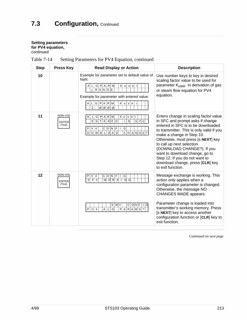
4/99 STS103 Operating Guide 213
7.3 Configuration, Continued
Setting parametersfor PV4 equation,continued
Table 7-14 Setting Parameters for PV4 Equation, continued
Step Press Key Read Display or Action Description
10 Example for parameter set to default value ofNaN:
sA L G A R K uMP e r
> GN ER A
Example for parameter with entered value:
sA L G A R K uM
Ø
P e1 . Ø Ø Ø
r
Use number keys to key in desiredscaling factor value to be used forparameter Kuser in derivation of gasor steam flow equation for PV4equation.
11 NON-VOL
ENTER(Yes)
E N E R E I N S F CT D
K u s e rA L G P A R M
OD O W L A C N GAN D H E ?
P V 4 C O N I GF
Enters change in scaling factor valuein SFC and prompt asks if changeentered in SFC is to be downloadedto transmitter. This is only valid if youmake a change in Step 10.Otherwise, must press [s NEXT] keyto call up next selection(DOWNLOAD CHANGE?). If youwant to download change, go toStep 12. If you do not want todownload change, press [CLR] keyto exit function.
12 NON-VOL
ENTER(Yes)
W R NF C G .K ..S O IP V 4 C O N I GF
A L G ?
N GO IC FS M V
P V 4 P A A MR S
Message exchange is working. Thisaction only applies when aconfiguration parameter is changed.Otherwise, the message NOCHANGES MADE appears.
Parameter change is loaded intotransmitter’s working memory. Press[s NEXT] key to access anotherconfiguration function or [CLR] key toexit function.
Continued on next page
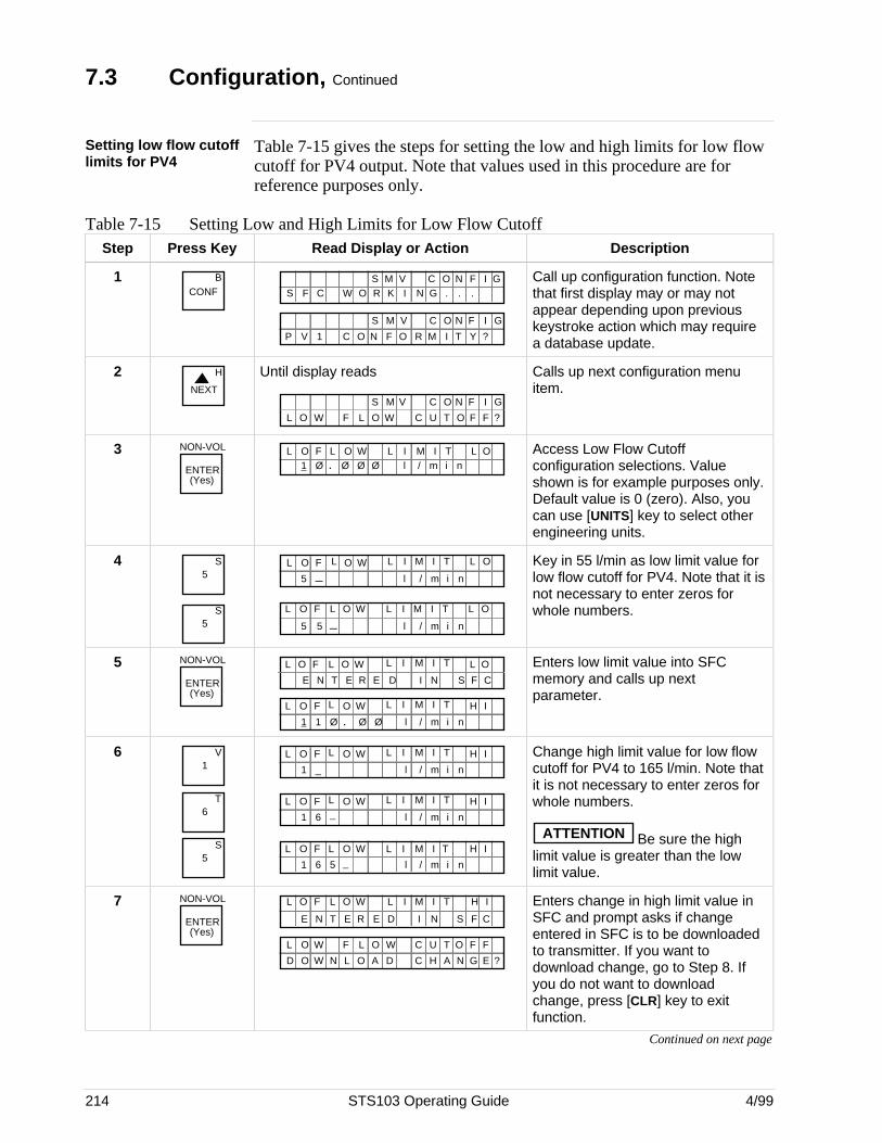
214 STS103 Operating Guide 4/99
7.3 Configuration, Continued
Setting low flow cutofflimits for PV4
Table 7-15 gives the steps for setting the low and high limits for low flowcutoff for PV4 output. Note that values used in this procedure are forreference purposes only.
Table 7-15 Setting Low and High Limits for Low Flow CutoffStep Press Key Read Display or Action Description
1 BCONF W R NF C G .K ..S O I
N GO IC FS M V
I T YO R MC O N F ?
N GO IC FS M V
P V 1
Call up configuration function. Notethat first display may or may notappear depending upon previouskeystroke action which may requirea database update.
2NEXT
H Until display reads
N GO IC FS M V
F L O ?L O W C U O FT FW
Calls up next configuration menuitem.
3 NON-VOL
ENTER(Yes)
Ø Ø.1 Ø l / m i nF L OL O W MIL I T L O
Ø
Access Low Flow Cutoffconfiguration selections. Valueshown is for example purposes only.Default value is 0 (zero). Also, youcan use [UNITS] key to select otherengineering units.
45
S
5S
5 _ l / m i n
F L OL O W MIL I T L O
5 _5 l / m i n
F L OL O W MIL I T L O
Key in 55 l/min as low limit value forlow flow cutoff for PV4. Note that it isnot necessary to enter zeros forwhole numbers.
5 NON-VOL
ENTER(Yes)
E E IE N T N S CR D F
F L OL O W MIL I T L O
Ø Ø1 .1 Ø l / m i n
F L OL O W MIL I T H I
Enters low limit value into SFCmemory and calls up nextparameter.
61
V
6T
5S
1 _ l / m i n
F L OL O W MIL I T H I
1 6 l / m i n
F L OL O W MIL I T H I_
1 6 l / m i n
F L OL O W MIL I T H I
5 _
Change high limit value for low flowcutoff for PV4 to 165 l/min. Note thatit is not necessary to enter zeros forwhole numbers.
ATTENTION Be sure the highlimit value is greater than the lowlimit value.
7 NON-VOL
ENTER(Yes)
E E IE N T N S CR D F
F L OL O W MIL I T H I
TW
O
UO C
D O W L
W F
A C N GA
L O L O
N
F F
D H E ?
Enters change in high limit value inSFC and prompt asks if changeentered in SFC is to be downloadedto transmitter. If you want todownload change, go to Step 8. Ifyou do not want to downloadchange, press [CLR] key to exitfunction.
Continued on next page
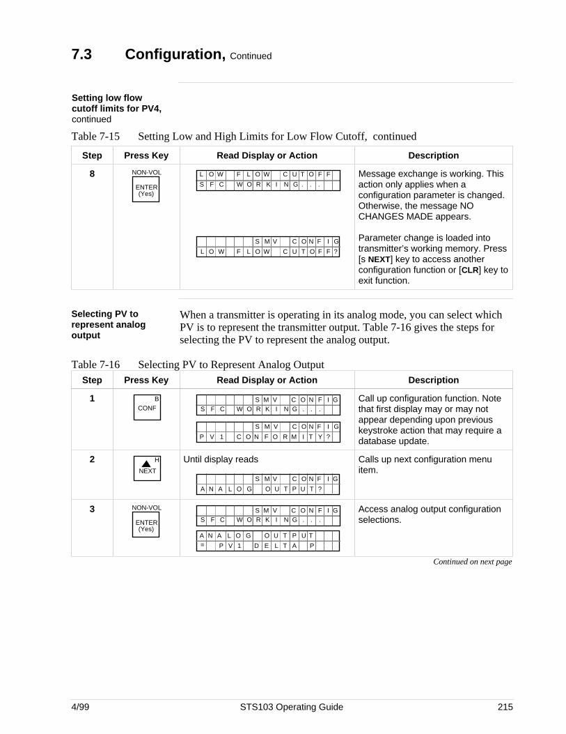
4/99 STS103 Operating Guide 215
7.3 Configuration, Continued
Setting low flowcutoff limits for PV4,continued
Table 7-15 Setting Low and High Limits for Low Flow Cutoff, continued
Step Press Key Read Display or Action Description
8 NON-VOL
ENTER(Yes)
W R NF C G .K ..S O I
TW UO CW FL O L O F F
N GO IC FS M V
F L O ?L O W C U O FT FW
Message exchange is working. Thisaction only applies when aconfiguration parameter is changed.Otherwise, the message NOCHANGES MADE appears.
Parameter change is loaded intotransmitter’s working memory. Press[s NEXT] key to access anotherconfiguration function or [CLR] key toexit function.
Selecting PV torepresent analogoutput
When a transmitter is operating in its analog mode, you can select whichPV is to represent the transmitter output. Table 7-16 gives the steps forselecting the PV to represent the analog output.
Table 7-16 Selecting PV to Represent Analog OutputStep Press Key Read Display or Action Description
1 BCONF W R NF C G .K ..S O I
N GO IC FS M V
I T YO R MC O N F ?
N GO IC FS M V
P V 1
Call up configuration function. Notethat first display may or may notappear depending upon previouskeystroke action that may require adatabase update.
2NEXT
H Until display reads
N GO IC FS M V
O GA N A ?O U P UT TL
Calls up next configuration menuitem.
3 NON-VOL
ENTER(Yes)
W R NF C G .K ..S O IN GO IC FS M V
O GA N A O U P UT TL= P V 1 D E L T A P
Access analog output configurationselections.
Continued on next page
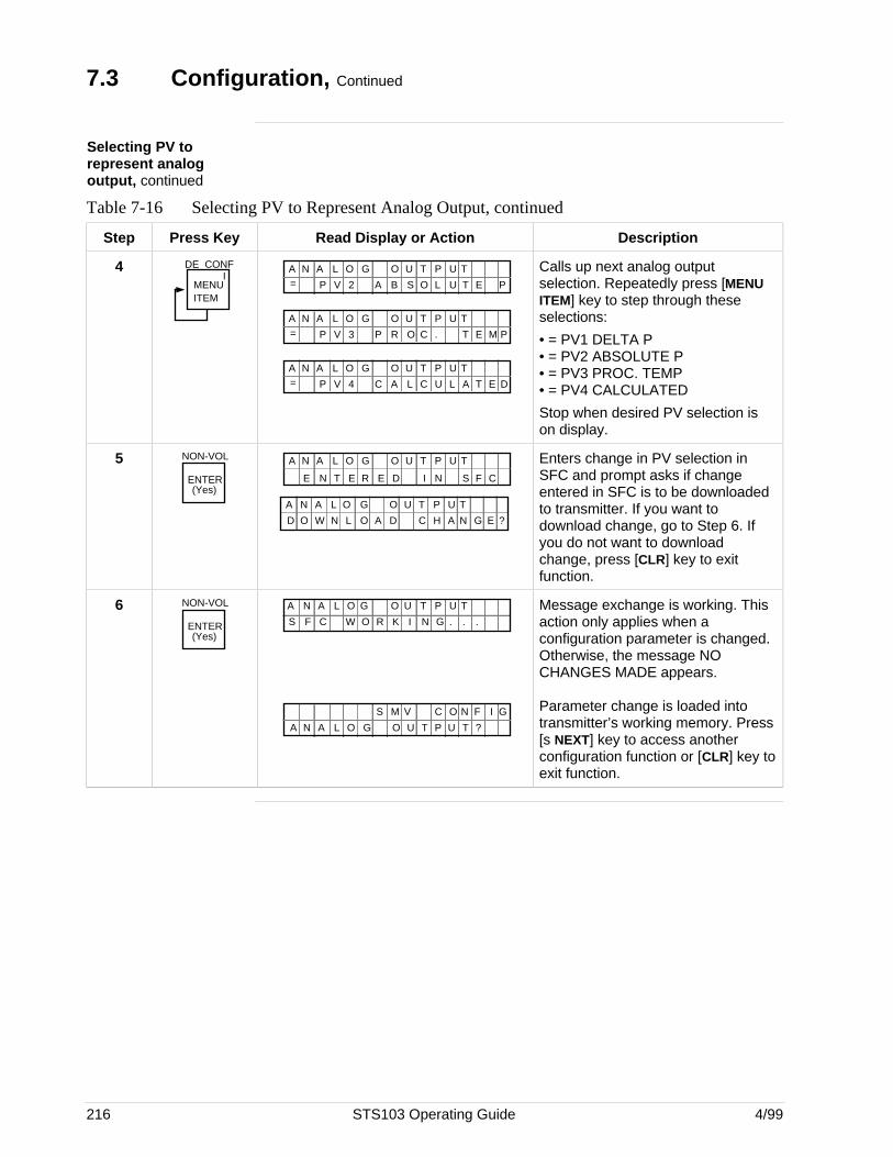
216 STS103 Operating Guide 4/99
7.3 Configuration, Continued
Selecting PV torepresent analogoutput, continued
Table 7-16 Selecting PV to Represent Analog Output, continued
Step Press Key Read Display or Action Description
4MENU ITEM
DE CONFI
O GA N A O U P UT TL= P V 2 A B S O L U T E P
O GA N A O U P UT TL= P V 3 P R O C . T E M P
O GA N A O U P UT TL= P V 4 C A L C U L A T E D
Calls up next analog outputselection. Repeatedly press [MENUITEM] key to step through theseselections:
• = PV1 DELTA P• = PV2 ABSOLUTE P• = PV3 PROC. TEMP• = PV4 CALCULATED
Stop when desired PV selection ison display.
5 NON-VOL
ENTER(Yes)
O GA N A O U P UT TL
N T E E D I N S F CE R
D CW LO N N GA HD AO E ?
O GA N A O U P UT TL
Enters change in PV selection inSFC and prompt asks if changeentered in SFC is to be downloadedto transmitter. If you want todownload change, go to Step 6. Ifyou do not want to downloadchange, press [CLR] key to exitfunction.
6 NON-VOL
ENTER(Yes)
W R NF C G .K ..S O I
O GA N A O U P UT TL
N GO IC FS M V
O GA N A ?O U P UT TL
Message exchange is working. Thisaction only applies when aconfiguration parameter is changed.Otherwise, the message NOCHANGES MADE appears.
Parameter change is loaded intotransmitter’s working memory. Press[s NEXT] key to access anotherconfiguration function or [CLR] key toexit function.
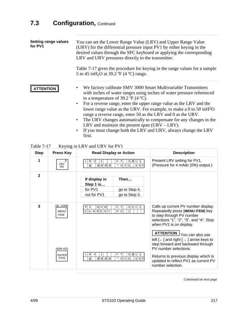
4/99 STS103 Operating Guide 217
7.3 Configuration, Continued
Setting range valuesfor PV1
You can set the Lower Range Value (LRV) and Upper Range Value(URV) for the differential pressure input PV1 by either keying in thedesired values through the SFC keyboard or applying the correspondingLRV and URV pressures directly to the transmitter.
Table 7-17 gives the procedure for keying in the range values for a sample5 to 45 inH2O at 39.2 ºF (4 ºC) range.
ATTENTION • We factory calibrate SMV 3000 Smart Multivariable Transmitterswith inches of water ranges using inches of water pressure referencedto a temperature of 39.2 ºF (4 ºC).
• For a reverse range, enter the upper range value as the LRV and thelower range value as the URV. For example, to make a 0 to 50 inH2Orange a reverse range, enter 50 as the LRV and 0 as the URV.
• The URV changes automatically to compensate for any changes in theLRV and maintain the present span (URV – LRV).
• If you must change both the LRV and URV, always change the LRVfirst.
Table 7-17 Keying in LRV and URV for PV1Step Press Key Read Display or Action Description
1 ELRV0%
F TL R V 3 Ø 1 11
Ø . Ø Ø Ø Ø " H 2 O _ 3 9 F
Present LRV setting for PV1.(Pressure for 4 mAdc (0%) output.)
2If display in Then…Step 1 is…for PV1 go to Step 4.not for PV1 go to Step 3.
3MENU ITEM
DE CONFI
NON-VOL
ENTER(Yes)
F TMP V N 3 0 1 1
N T V :R EUC 1P
U
R
F TL R V 3 Ø 1 11
Ø . Ø Ø Ø Ø " H 2 O _ 3 9 F
Calls up current PV number display.Repeatedly press [MENU ITEM] keyto step through PV numberselections “1”, “2”, “3”, and “4”. Stopwhen PV1 is on display.
ATTENTION You can also useleft [←] and right [→ ] arrow keys tostep forward and backward throughPV number selections.
Returns to previous display which isupdated to reflect PV1 as current PVnumber selection.
Continued on next page
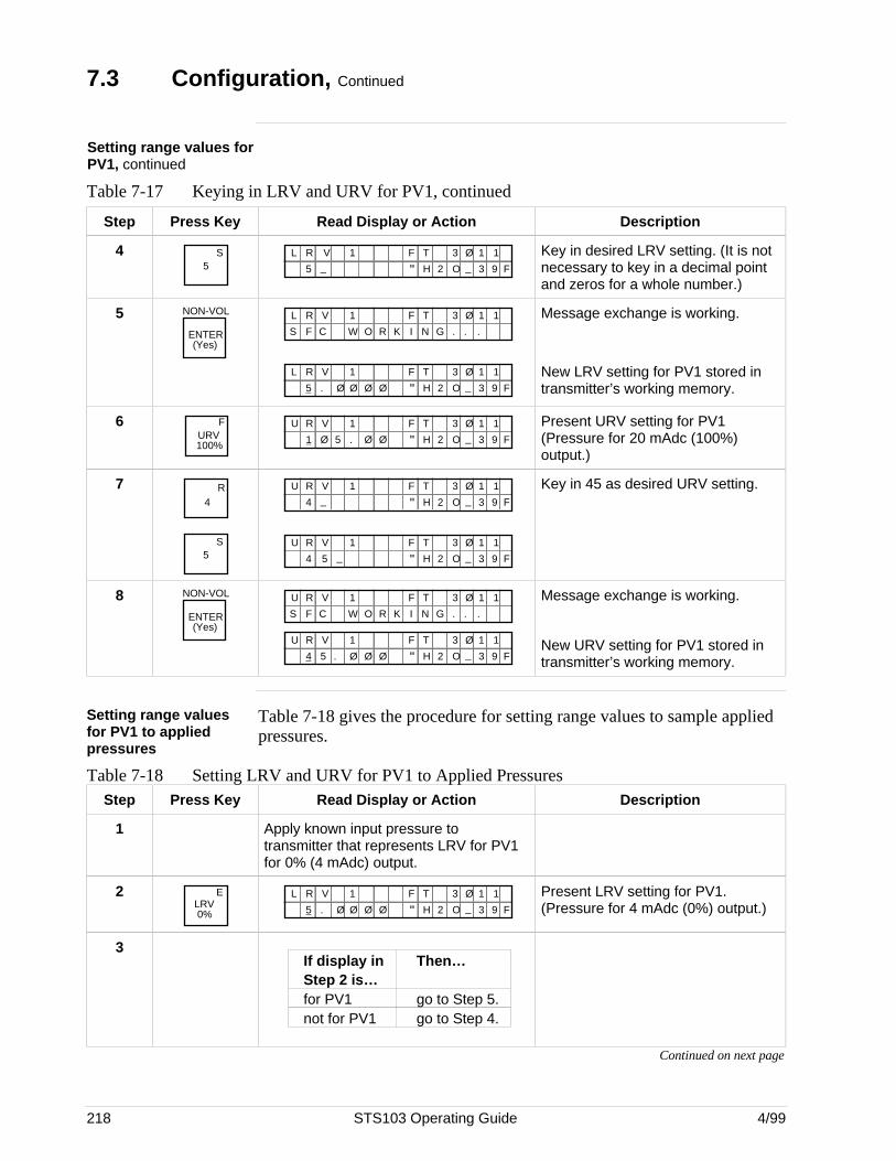
218 STS103 Operating Guide 4/99
7.3 Configuration, Continued
Setting range values forPV1, continued
Table 7-17 Keying in LRV and URV for PV1, continued
Step Press Key Read Display or Action Description
45
S F TL R V 3 Ø 1 11
5 _ " H 2 O _ 3 9 F
Key in desired LRV setting. (It is notnecessary to key in a decimal pointand zeros for a whole number.)
5 NON-VOL
ENTER(Yes)
O R K N GC W .F .S .I
F TL R V 3 Ø 1 11
F TL R V 3 Ø 1 11
5 . Ø Ø Ø Ø " H 2 O _ 3 9 F
Message exchange is working.
New LRV setting for PV1 stored intransmitter’s working memory.
6URV100%
F F TU R V 3 Ø 1 11
1 .Ø 5 Ø Ø " H 2 O _ 3 9 F
Present URV setting for PV1(Pressure for 20 mAdc (100%)output.)
7 R4
5S
F TU R V 3 Ø 1 11
4 _ " H 2 O _ 3 9 F
F TU R V 3 Ø 1 11
4 _5 " H 2 O _ 3 9 F
Key in 45 as desired URV setting.
8 NON-VOL
ENTER(Yes)
O R K N GC W .F .S .I
F TU R V 3 Ø 1 11
F TU R V 3 Ø 1 11
4 .5 Ø Ø Ø " H 2 O _ 3 9 F
Message exchange is working.
New URV setting for PV1 stored intransmitter’s working memory.
Setting range valuesfor PV1 to appliedpressures
Table 7-18 gives the procedure for setting range values to sample appliedpressures.
Table 7-18 Setting LRV and URV for PV1 to Applied PressuresStep Press Key Read Display or Action Description
1 Apply known input pressure totransmitter that represents LRV for PV1for 0% (4 mAdc) output.
2 ELRV0%
F TL R V 3 Ø 1 11
5 . Ø Ø Ø Ø " H 2 O _ 3 9 F
Present LRV setting for PV1.(Pressure for 4 mAdc (0%) output.)
3If display in Then…Step 2 is…for PV1 go to Step 5.not for PV1 go to Step 4.
Continued on next page
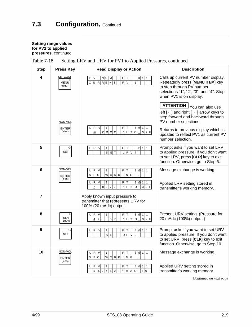
4/99 STS103 Operating Guide 219
7.3 Configuration, Continued
Setting range valuesfor PV1 to appliedpressures, continued
Table 7-18 Setting LRV and URV for PV1 to Applied Pressures, continued
Step Press Key Read Display or Action Description
4MENU ITEM
DE CONFI
NON-VOL
ENTER(Yes)
F TMP V N 3 0 1 1
N T V :R EUC 1P
U
R
F TL R V 3 Ø 1 11
Ø . Ø Ø Ø Ø " H 2 O _ 3 9 F
Calls up current PV number display.Repeatedly press [MENU ITEM] keyto step through PV numberselections “1”, “2”, “3”, and “4”. Stopwhen PV1 is on display.
ATTENTION You can also useleft [←] and right [→ ] arrow keys tostep forward and backward throughPV number selections.
Returns to previous display which isupdated to reflect PV1 as current PVnumber selection.
5SET
G F TL R V
R V
3 Ø 1 1
L
1
?S E T
Prompt asks if you want to set LRVto applied pressure. If you don’t wantto set LRV, press [CLR] key to exitfunction. Otherwise, go to Step 6.
6 NON-VOL
ENTER(Yes)
O R K N GC W .F .S .I
F TL R V 3 Ø 1 11
F TL R V 3 Ø 1 11
7 . 8 3 7 7 " H 2 O _ 3 9 F
Message exchange is working.
Applied LRV setting stored intransmitter’s working memory.
7 Apply known input pressure totransmitter that represents URV for100% (20 mAdc) output.
8URV100%
F F TU R V 3 Ø 1 11
4 .7 8 3 7 " H 2 O _ 3 9 F
Present URV setting. (Pressure for20 mAdc (100%) output.)
9SET
G F TU R V
R V
3 Ø 1 1
U
1
?S E T
Prompt asks if you want to set URVto applied pressure. If you don’t wantto set URV, press [CLR] key to exitfunction. Otherwise, go to Step 10.
10 NON-VOL
ENTER(Yes)
O R K N GC W .F .S .I
F TU R V 3 Ø 1 11
F TU R V 3 Ø 1 11
5 .5 4 8 2 " H 2 O _ 3 9 F
Message exchange is working.
Applied URV setting stored intransmitter’s working memory.
Continued on next page
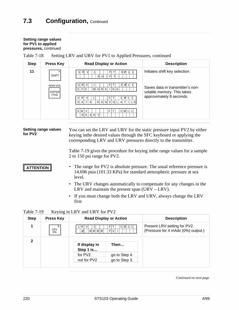
220 STS103 Operating Guide 4/99
7.3 Configuration, Continued
Setting range valuesfor PV1 to appliedpressures, continued
Table 7-18 Setting LRV and URV for PV1 to Applied Pressures, continued
Step Press Key Read Display or Action Description
11 ^SHIFT
NON-VOL
ENTER(Yes)
F TU R V 3 Ø 1 11
S H I T – . ..F
O R K N GC W .F .S .I
F TU R V 3 Ø 1 11
F TU R V 3 Ø 1 11
N O V O A TLND A T A I L E
.Y . .R E A DS M V F T 3 Ø 1 1
Initiates shift key selection.
Saves data in transmitter’s non-volatile memory. This takesapproximately 8 seconds.
Setting range valuesfor PV2
You can set the LRV and URV for the static pressure input PV2 by eitherkeying inthe desired values through the SFC keyboard or applying thecorresponding LRV and URV pressures directly to the transmitter.
Table 7-19 gives the procedure for keying inthe range values for a sample2 to 150 psi range for PV2.
ATTENTION • The range for PV2 is absolute pressure. The usual reference pressure is14.696 psia (101.33 KPa) for standard atmospheric pressure at sealevel.
• The URV changes automatically to compensate for any changes in theLRV and maintain the present span (URV – LRV).
• If you must change both the LRV and URV, always change the LRVfirst
Table 7-19 Keying in LRV and URV for PV2Step Press Key Read Display or Action Description
1 ELRV0%
F TL R V 3 Ø 1 12
Ø . Ø Ø Ø Ø P S I
Present LRV setting for PV2.(Pressure for 4 mAdc (0%) output.)
2If display in Then…Step 1 is…for PV2 go to Step 4.not for PV2 go to Step 3.
Continued on next page
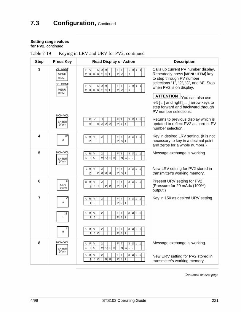
4/99 STS103 Operating Guide 221
7.3 Configuration, Continued
Setting range valuesfor PV2, continued
Table 7-19 Keying in LRV and URV for PV2, continued
Step Press Key Read Display or Action Description
3MENU ITEM
DE CONFI
MENU ITEM
DE CONFI
NON-VOL
ENTER(Yes)
F TMP V N 3 0 1 1
N T V :R EUC 1P
U
R
F TMP V N 3 0 1 1
N T V :R EUC 2P
U
R
F TL R V 3 Ø 1 12
Ø . Ø Ø Ø Ø P S I
Calls up current PV number display.Repeatedly press [MENU ITEM] keyto step through PV numberselections “1”, “2”, “3”, and “4”. Stopwhen PV2 is on display.
ATTENTION You can also useleft [←] and right [→ ] arrow keys tostep forward and backward throughPV number selections.
Returns to previous display which isupdated to reflect PV2 as current PVnumber selection.
42
W F TL R V 3 Ø 1 12
2 _ P S I
Key in desired LRV setting. (It is notnecessary to key in a decimal pointand zeros for a whole number.)
5 NON-VOL
ENTER(Yes)
O R K N GC W .F .S .I
F TL R V 3 Ø 1 12
F TL R V 3 Ø 1 12
2 . Ø Ø Ø Ø P S I
Message exchange is working.
New LRV setting for PV2 stored intransmitter’s working memory.
6URV100%
F F TU R V 3 Ø 1 12
7 .5 2 Ø Ø P S I
Present URV setting for PV2(Pressure for 20 mAdc (100%)output.)
71
V
5S
0Z
F TU R V 3 Ø 1 12
1 _ P S I
F TU R V 3 Ø 1 12
1 _5 P S I
F TU R V 3 Ø 1 12
1 _5 P S IØ
Key in 150 as desired URV setting.
8 NON-VOL
ENTER(Yes)
O R K N GC W .F .S .I
F TU R V 3 Ø 1 12
F TU R V 3 Ø 1 12
1 .5 P S IØ Ø Ø
Message exchange is working.
New URV setting for PV2 stored intransmitter’s working memory.
Continued on next page
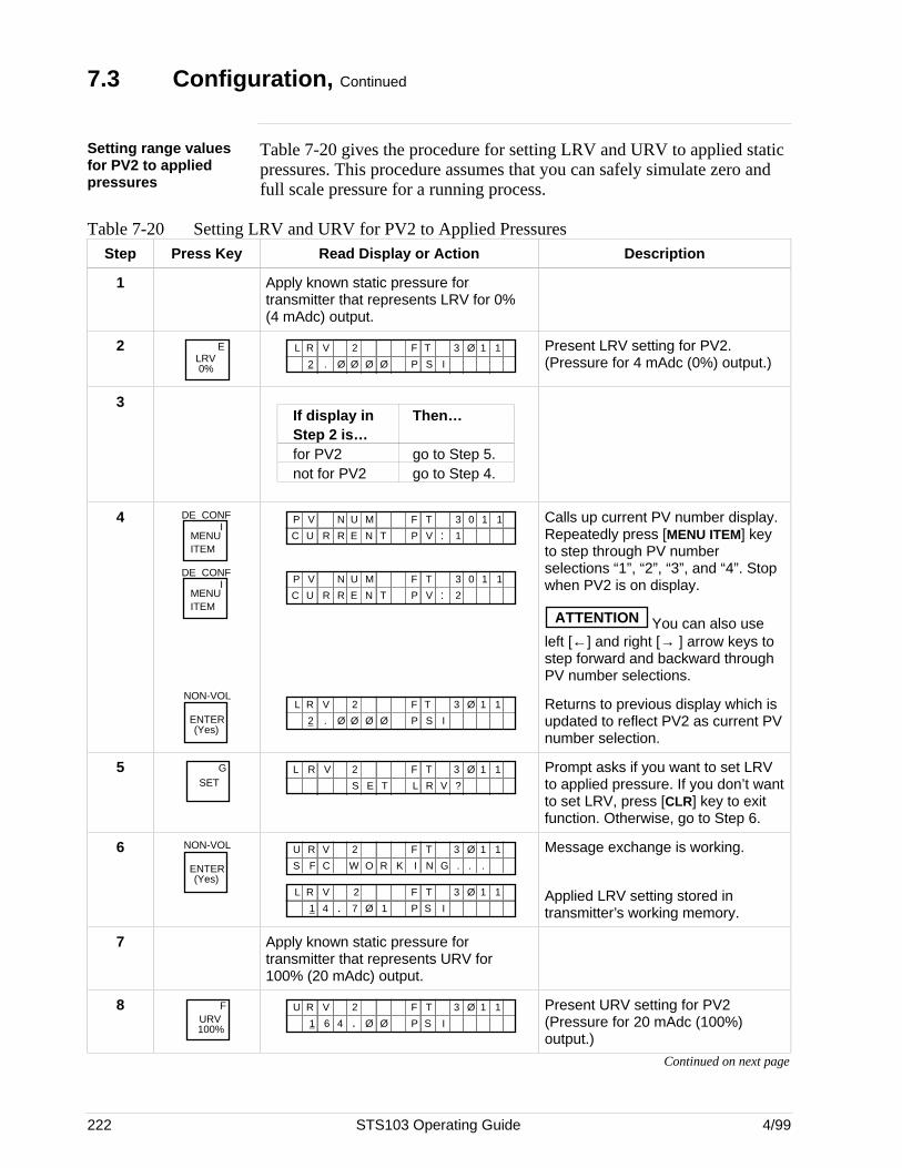
222 STS103 Operating Guide 4/99
7.3 Configuration, Continued
Setting range valuesfor PV2 to appliedpressures
Table 7-20 gives the procedure for setting LRV and URV to applied staticpressures. This procedure assumes that you can safely simulate zero andfull scale pressure for a running process.
Table 7-20 Setting LRV and URV for PV2 to Applied PressuresStep Press Key Read Display or Action Description
1 Apply known static pressure fortransmitter that represents LRV for 0%(4 mAdc) output.
2 ELRV0%
F TL R V 3 Ø 1 12
2 . Ø Ø Ø Ø P S I
Present LRV setting for PV2.(Pressure for 4 mAdc (0%) output.)
3If display in Then…Step 2 is…for PV2 go to Step 5.not for PV2 go to Step 4.
4MENU ITEM
DE CONFI
MENU ITEM
DE CONFI
NON-VOL
ENTER(Yes)
F TMP V N 3 0 1 1
N T V :R EUC 1P
U
R
F TMP V N 3 0 1 1
N T V :R EUC 2P
U
R
F TL R V 3 Ø 1 12
2 . Ø Ø Ø Ø P S I
Calls up current PV number display.Repeatedly press [MENU ITEM] keyto step through PV numberselections “1”, “2”, “3”, and “4”. Stopwhen PV2 is on display.
ATTENTION You can also useleft [←] and right [→ ] arrow keys tostep forward and backward throughPV number selections.
Returns to previous display which isupdated to reflect PV2 as current PVnumber selection.
5SET
G F TL R V
R V
3 Ø 1 1
L
2
?S E T
Prompt asks if you want to set LRVto applied pressure. If you don’t wantto set LRV, press [CLR] key to exitfunction. Otherwise, go to Step 6.
6 NON-VOL
ENTER(Yes)
O R K N GC W .F .S .I
F TU R V 3 Ø 1 12
F TL R V 3 Ø 1 12
1 4 . 7 Ø 1 P S I
Message exchange is working.
Applied LRV setting stored intransmitter’s working memory.
7 Apply known static pressure fortransmitter that represents URV for100% (20 mAdc) output.
8URV100%
F F TU R V 3 Ø 1 12
1 .6 P S I4 Ø Ø
Present URV setting for PV2(Pressure for 20 mAdc (100%)output.)
Continued on next page
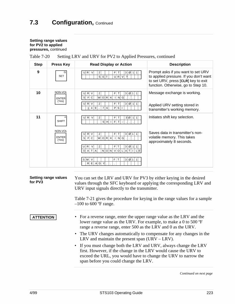
4/99 STS103 Operating Guide 223
7.3 Configuration, Continued
Setting range valuesfor PV2 to appliedpressures, continued
Table 7-20 Setting LRV and URV for PV2 to Applied Pressures, continued
Step Press Key Read Display or Action Description
9SET
G F TU R V
R V
3 Ø 1 1
U
2
?S E T
Prompt asks if you want to set URVto applied pressure. If you don’t wantto set URV, press [CLR] key to exitfunction. Otherwise, go to Step 10.
10 NON-VOL
ENTER(Yes)
O R K N GC W .F .S .I
F TU R V 3 Ø 1 12
F TU R V 3 Ø 1 12
1 94 . 7 6 P S I
Message exchange is working.
Applied URV setting stored intransmitter’s working memory.
11 ^SHIFT
NON-VOL
ENTER(Yes)
F TU R V 3 Ø 1 12
S H I T – . ..F
O R K N GC W .F .S .I
F TU R V 3 Ø 1 12
F TU R V 3 Ø 1 12
N O V O A TLND A T A I L E
.Y . .R E A DS M V F T 3 Ø 1 1
Initiates shift key selection.
Saves data in transmitter’s non-volatile memory. This takesapproximately 8 seconds.
Setting range valuesfor PV3
You can set the LRV and URV for PV3 by either keying in the desiredvalues through the SFC keyboard or applying the corresponding LRV andURV input signals directly to the transmitter.
Table 7-21 gives the procedure for keying in the range values for a sample–100 to 600 ºF range.
ATTENTION • For a reverse range, enter the upper range value as the LRV and thelower range value as the URV. For example, to make a 0 to 500 ºFrange a reverse range, enter 500 as the LRV and 0 as the URV.
• The URV changes automatically to compensate for any changes in theLRV and maintain the present span (URV – LRV).
• If you must change both the LRV and URV, always change the LRVfirst. However, if the change in the LRV would cause the URV toexceed the URL, you would have to change the URV to narrow thespan before you could change the LRV.
Continued on next page
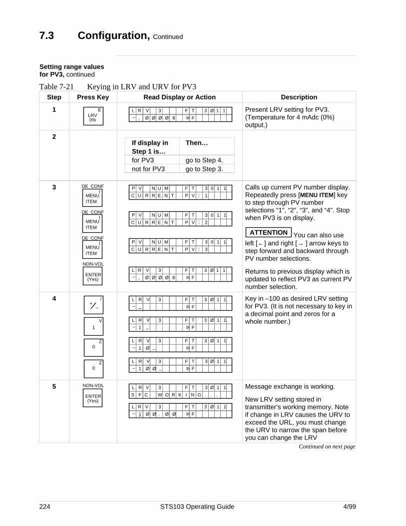
224 STS103 Operating Guide 4/99
7.3 Configuration, Continued
Setting range valuesfor PV3, continued
Table 7-21 Keying in LRV and URV for PV3Step Press Key Read Display or Action Description
1 ELRV0%
F TL R V
F
3 Ø 1 1
Þ
3
. Ø Ø Ø Ø– 8
Present LRV setting for PV3.(Temperature for 4 mAdc (0%)output.)
2If display in Then…Step 1 is…for PV3 go to Step 4.not for PV3 go to Step 3.
3MENU ITEM
DE CONFI
MENU ITEM
DE CONFI
MENU ITEM
DE CONFI
NON-VOL
ENTER(Yes)
F TMP V N 3 0 1 1
N T V :R EUC 1P
U
R
F TMP V N 3 0 1 1
N T V :R EUC 2P
U
R
F TMP V N 3 0 1 1
N T V :R EUC 3P
U
R
F TL R V
F
3 Ø 1 1
Þ
3
. Ø Ø Ø Ø– 8
Calls up current PV number display.Repeatedly press [MENU ITEM] keyto step through PV numberselections “1”, “2”, “3”, and “4”. Stopwhen PV3 is on display.
ATTENTION You can also useleft [←] and right [→ ] arrow keys tostep forward and backward throughPV number selections.
Returns to previous display which isupdated to reflect PV3 as current PVnumber selection.
4 /+
–
1V
Z0
Z0
F TL R V
F
3 Ø 1 1
Þ
3_–
F TL R V
F
3 Ø 1 1
Þ
3
1– _
F TL R V
F
3 Ø 1 1
Þ
3
1– Ø _
F TL R V
F
3 Ø 1 1
Þ
3
1– Ø Ø _
Key in –100 as desired LRV settingfor PV3. (It is not necessary to key ina decimal point and zeros for awhole number.)
5 NON-VOL
ENTER(Yes)
O R K N GC W .F .S .I
F TL R V 3 Ø 1 13
F TL R V
F
3 Ø 1 1
Þ
3
1– Ø Ø . Ø Ø
Message exchange is working.
New LRV setting stored intransmitter’s working memory. Noteif change in LRV causes the URV toexceed the URL, you must changethe URV to narrow the span beforeyou can change the LRV
Continued on next page
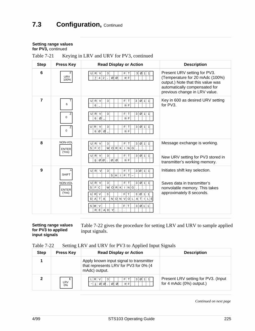
4/99 STS103 Operating Guide 225
7.3 Configuration, Continued
Setting range valuesfor PV3, continued
Table 7-21 Keying in LRV and URV for PV3, continued
Step Press Key Read Display or Action Description
6URV100%
F F TU R V
F
3 Ø 1 1
Þ
3
7 Ø4 2 . Ø
Present URV setting for PV3.(Temperature for 20 mAdc (100%)output.) Note that this value wasautomatically compensated forprevious change in LRV value.
76
T
Z0
Z0
F TU R V
F
3 Ø 1 1
Þ
3
6 _
F TU R V
F
3 Ø 1 1
Þ
3
6 _Ø
F TU R V
F
3 Ø 1 1
Þ
3
6 _Ø Ø
Key in 600 as desired URV settingfor PV3.
8 NON-VOL
ENTER(Yes)
O R K N GC W .F .S .I
F TU R V 3 Ø 1 13
F TU R V
F
3 Ø 1 1
Þ
3
6 .Ø Ø Ø Ø
Message exchange is working.
New URV setting for PV3 stored intransmitter’s working memory.
9 ^SHIFT
NON-VOL
ENTER(Yes)
F T –S H I
F TU R V 3 Ø 1 13
O R K N GC W .F .S .I
F TU R V 3 Ø 1 13
F TU R V 3 Ø 1 13
N O V O A TLND A T A I L E
.Y . .R E A DS M V F T 3 Ø 1 1
Initiates shift key selection.
Saves data in transmitter’snonvolatile memory. This takesapproximately 8 seconds.
Setting range valuesfor PV3 to appliedinput signals
Table 7-22 gives the procedure for setting LRV and URV to sample appliedinput signals.
Table 7-22 Setting LRV and URV for PV3 to Applied Input SignalsStep Press Key Read Display or Action Description
1 Apply known input signal to transmitterthat represents LRV for PV3 for 0% (4mAdc) output.
2 ELRV0%
F TL R V
F
3 Ø 1 1
Þ
3
1– Ø Ø . Ø Ø
Present LRV setting for PV3. (Inputfor 4 mAdc (0%) output.)
Continued on next page
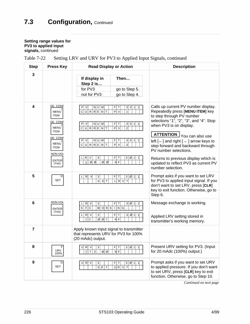
226 STS103 Operating Guide 4/99
7.3 Configuration, Continued
Setting range values forPV3 to applied inputsignals, continued
Table 7-22 Setting LRV and URV for PV3 to Applied Input Signals, continued
Step Press Key Read Display or Action Description
3If display in Then…Step 2 is…for PV3 go to Step 5.not for PV3 go to Step 4.
4MENU ITEM
DE CONFI
MENU ITEM
DE CONFI
MENU ITEM
DE CONFI
NON-VOL
ENTER(Yes)
F TMP V N 3 0 1 1
N T V :R EUC 1P
U
R
F TMP V N 3 0 1 1
N T V :R EUC 2P
U
R
F TMP V N 3 0 1 1
N T V :R EUC 3P
U
R
F TL R V
F
3 Ø 1 1
Þ
3
1– Ø Ø . Ø Ø
Calls up current PV number display.Repeatedly press [MENU ITEM] keyto step through PV numberselections “1”, “2”, “3”, and “4”. Stopwhen PV3 is on display.
ATTENTION You can also useleft [←] and right [→ ] arrow keys tostep forward and backward throughPV number selections.
Returns to previous display which isupdated to reflect PV3 as current PVnumber selection.
5SET
G F TL R V
R V
3 Ø 1 1
L
3
?S E T
Prompt asks if you want to set LRVfor PV3 to applied input signal. If youdon’t want to set LRV, press [CLR]key to exit function. Otherwise, go toStep 6.
6 NON-VOL
ENTER(Yes)
O R K N GC W .F .S .I
F TL R V 3 Ø 1 13
F TL R V
F
3 Ø 1 1
Þ
3
7 .2 Ø Ø 7
Message exchange is working.
Applied LRV setting stored intransmitter’s working memory.
7 Apply known input signal to transmitterthat represents URV for PV3 for 100%(20 mAdc) output.
8URV100%
F F TU R V
F
3 Ø 1 1
Þ
3
7 .7 2 Ø Ø
Present URV setting for PV3. (Inputfor 20 mAdc (100%) output.)
9SET
G F TU R V
R V
3 Ø 1 1
U
3
?S E T
Prompt asks if you want to set URVto applied pressure. If you don’t wantto set URV, press [CLR] key to exitfunction. Otherwise, go to Step 10.
Continued on next page
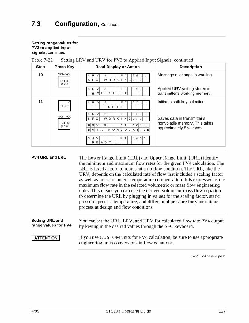
4/99 STS103 Operating Guide 227
7.3 Configuration, Continued
Setting range values forPV3 to applied inputsignals, continued
Table 7-22 Setting LRV and URV for PV3 to Applied Input Signals, continuedStep Press Key Read Display or Action Description
10 NON-VOL
ENTER(Yes)
O R K N GC W .F .S .I
F TU R V 3 Ø 1 13
F TU R V
F
3 Ø 1 1
Þ
3
6 .Ø 8 4 7
Message exchange is working.
Applied URV setting stored intransmitter’s working memory.
11 ^SHIFT
NON-VOL
ENTER(Yes)
F T –S H I
F TU R V 3 Ø 1 13
O R K N GC W .F .S .I
F TU R V 3 Ø 1 13
F TU R V 3 Ø 1 13
N O V O A TLND A T A I L E
.Y . .R E A DS M V F T 3 Ø 1 1
Initiates shift key selection.
Saves data in transmitter’snonvolatile memory. This takesapproximately 8 seconds.
PV4 URL and LRL The Lower Range Limit (LRL) and Upper Range Limit (URL) identifythe minimum and maximum flow rates for the given PV4 calculation. TheLRL is fixed at zero to represent a no flow condition. The URL, like theURV, depends on the calculated rate of flow that includes a scaling factoras well as pressure and/or temperature compensation. It is expressed as themaximum flow rate in the selected volumetric or mass flow engineeringunits. This means you can use the derived volume or mass flow equationto determine the URL by plugging in values for the scaling factor, staticpressure, process temperature, and differential pressure for your uniqueprocess at design and flow conditions.
Setting URL andrange values for PV4
You can set the URL, LRV, and URV for calculated flow rate PV4 outputby keying in the desired values through the SFC keyboard.
ATTENTION If you use CUSTOM units for PV4 calculation, be sure to use appropriateengineering units conversions in flow equations.
Continued on next page
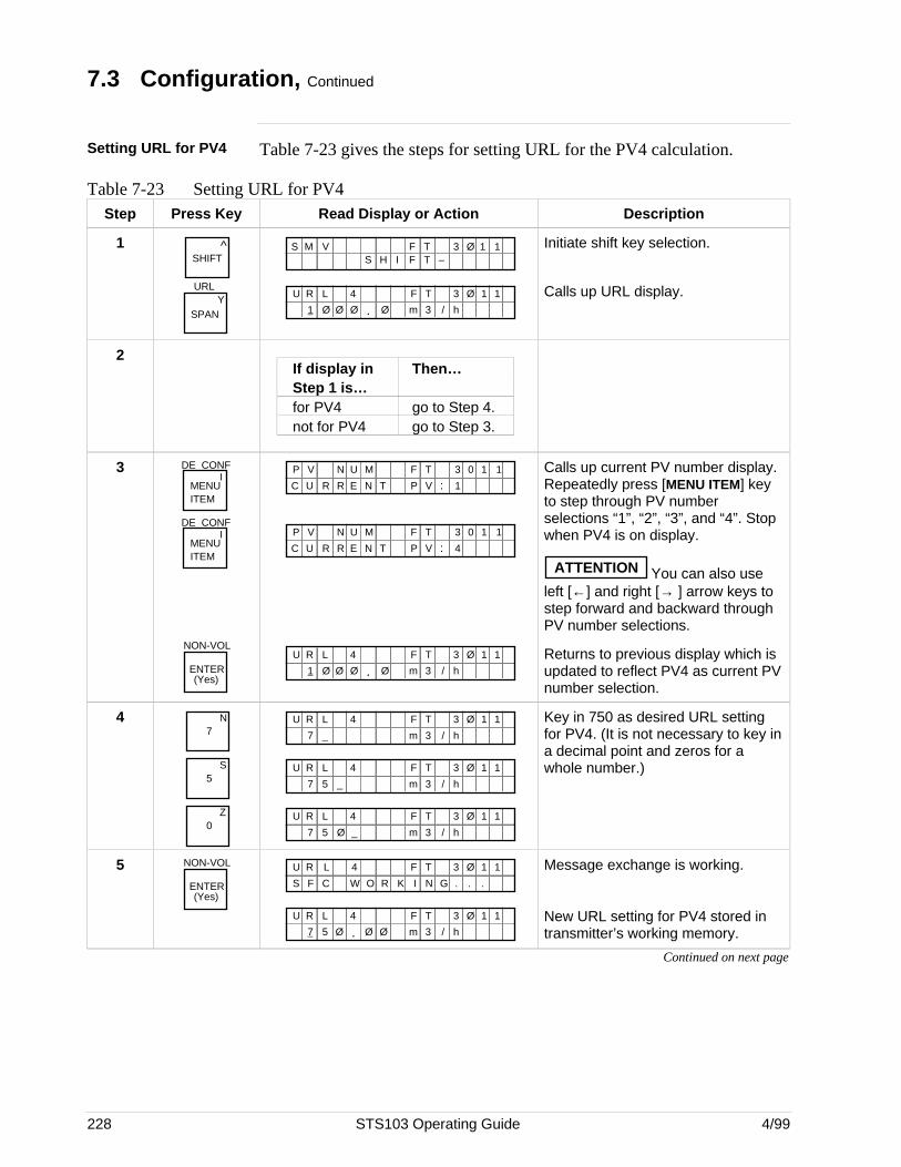
228 STS103 Operating Guide 4/99
7.3 Configuration, Continued
Setting URL for PV4 Table 7-23 gives the steps for setting URL for the PV4 calculation.
Table 7-23 Setting URL for PV4Step Press Key Read Display or Action Description
1 ^SHIFT
SPAN Y
URL
S M V F T 3 Ø 1 1F T –S H I
.1
F TU R 3 Ø 1 14
Ø Ø
L
Ø Ø m 3 / h
Initiate shift key selection.
Calls up URL display.
2If display in Then…Step 1 is…for PV4 go to Step 4.not for PV4 go to Step 3.
3MENU ITEM
DE CONFI
MENU ITEM
DE CONFI
NON-VOL
ENTER(Yes)
F TMP V N 3 0 1 1
N T V :R EUC 1P
U
R
F TMP V N 3 0 1 1
N T V :R EUC 4P
U
R
.1
F TU R 3 Ø 1 14
Ø Ø
L
Ø Ø m 3 / h
Calls up current PV number display.Repeatedly press [MENU ITEM] keyto step through PV numberselections “1”, “2”, “3”, and “4”. Stopwhen PV4 is on display.
ATTENTION You can also useleft [←] and right [→ ] arrow keys tostep forward and backward throughPV number selections.
Returns to previous display which isupdated to reflect PV4 as current PVnumber selection.
47
N
5S
0Z
7
F TU R 3 Ø 1 14L
_ m 3 / h
7
F TU R 3 Ø 1 14L
_ m 3 / h5
7
F TU R 3 Ø 1 14L
_ m 3 / h5 Ø
Key in 750 as desired URL settingfor PV4. (It is not necessary to key ina decimal point and zeros for awhole number.)
5 NON-VOL
ENTER(Yes)
F TU R 3 Ø 1 14
O R K N GC W .F .S .I
L
.7
F TU R 3 Ø 1 14
Ø Ø
L
5 Ø m 3 / h
Message exchange is working.
New URL setting for PV4 stored intransmitter’s working memory.
Continued on next page
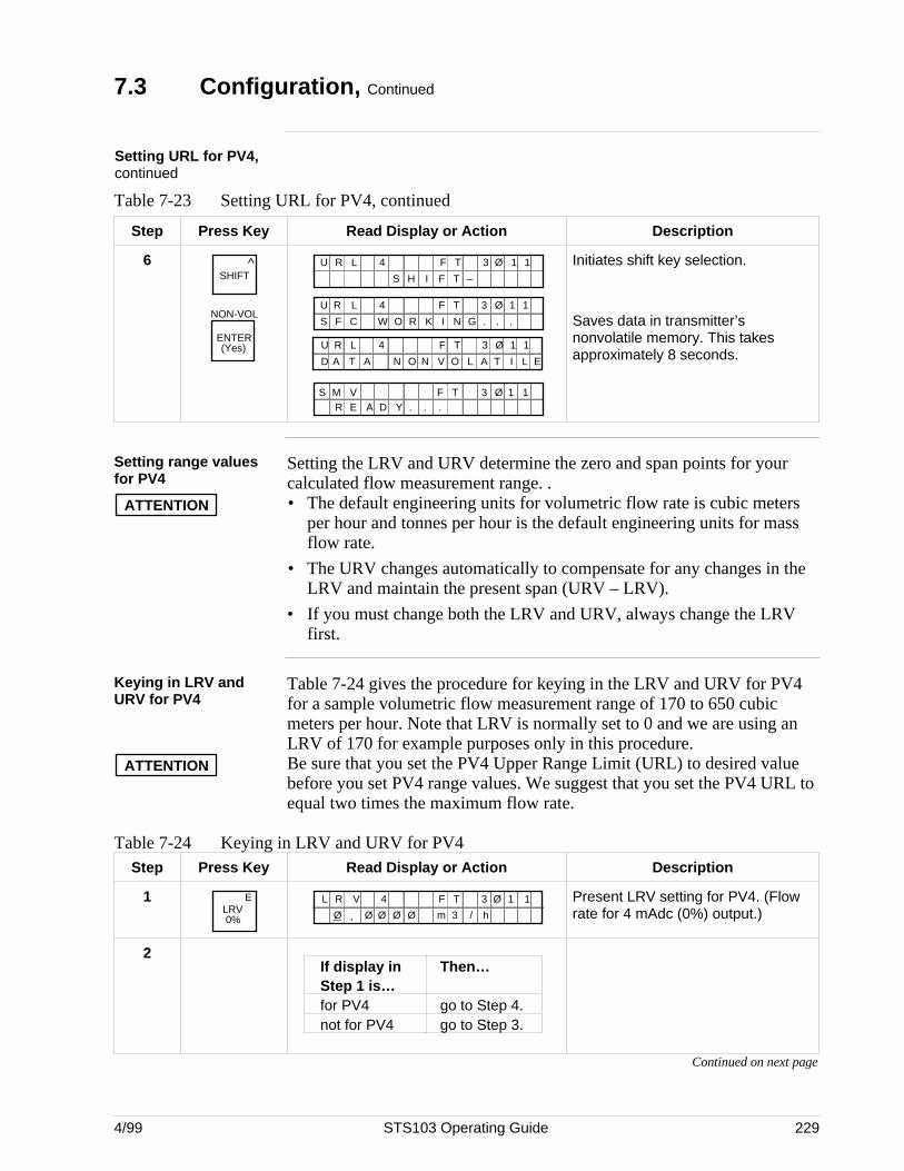
4/99 STS103 Operating Guide 229
7.3 Configuration, Continued
Setting URL for PV4,continued
Table 7-23 Setting URL for PV4, continued
Step Press Key Read Display or Action Description
6 ^SHIFT
NON-VOL
ENTER(Yes)
F T –S H I
F TU R L 3 Ø 1 14
F TU R 3 Ø 1 14
O R K N GC W .F .S .I
L
F TU R L 3 Ø 1 14
N O V O A TLND A T A I L E
.Y . .R E A DS M V F T 3 Ø 1 1
Initiates shift key selection.
Saves data in transmitter’snonvolatile memory. This takesapproximately 8 seconds.
Setting range valuesfor PV4
Setting the LRV and URV determine the zero and span points for yourcalculated flow measurement range. .
ATTENTION • The default engineering units for volumetric flow rate is cubic metersper hour and tonnes per hour is the default engineering units for massflow rate.
• The URV changes automatically to compensate for any changes in theLRV and maintain the present span (URV – LRV).
• If you must change both the LRV and URV, always change the LRVfirst.
Keying in LRV andURV for PV4
Table 7-24 gives the procedure for keying in the LRV and URV for PV4for a sample volumetric flow measurement range of 170 to 650 cubicmeters per hour. Note that LRV is normally set to 0 and we are using anLRV of 170 for example purposes only in this procedure.
ATTENTION Be sure that you set the PV4 Upper Range Limit (URL) to desired valuebefore you set PV4 range values. We suggest that you set the PV4 URL toequal two times the maximum flow rate.
Table 7-24 Keying in LRV and URV for PV4Step Press Key Read Display or Action Description
1 ELRV0%
F TL R V
3
3 Ø 1 1
m
4
.Ø Ø Ø Ø Ø / h
Present LRV setting for PV4. (Flowrate for 4 mAdc (0%) output.)
2If display in Then…Step 1 is…for PV4 go to Step 4.not for PV4 go to Step 3.
Continued on next page
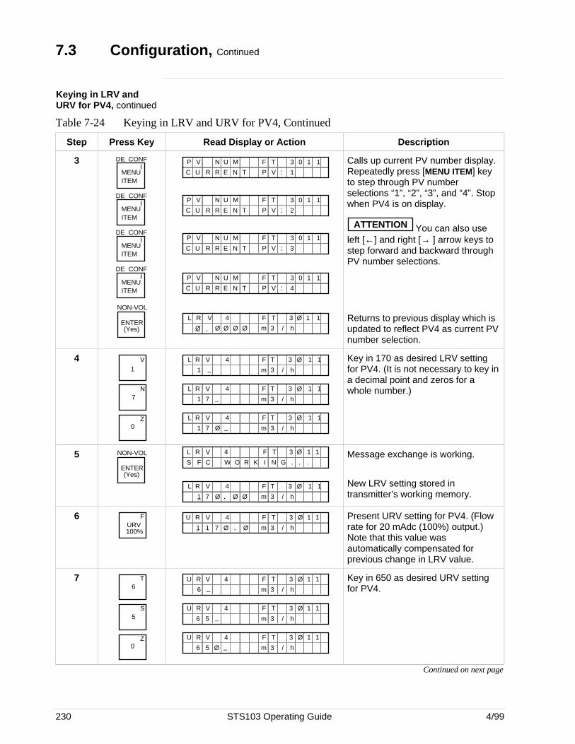
230 STS103 Operating Guide 4/99
7.3 Configuration, Continued
Keying in LRV andURV for PV4, continued
Table 7-24 Keying in LRV and URV for PV4, Continued
Step Press Key Read Display or Action Description
3MENU ITEM
DE CONFI
MENU ITEM
DE CONFI
MENU ITEM
DE CONFI
MENU ITEM
DE CONFI
NON-VOL
ENTER(Yes)
F TMP V N 3 0 1 1
N T V :R EUC 1P
U
R
F TMP V N 3 0 1 1
N T V :R EUC 2P
U
R
F TMP V N 3 0 1 1
N T V :R EUC 3P
U
R
F TMP V N 3 0 1 1
N T V :R EUC 4P
U
R
F TL R V
3
3 Ø 1 1
m
4
.Ø Ø Ø Ø Ø / h
Calls up current PV number display.Repeatedly press [MENU ITEM] keyto step through PV numberselections “1”, “2”, “3”, and “4”. Stopwhen PV4 is on display.
ATTENTION You can also useleft [←] and right [→ ] arrow keys tostep forward and backward throughPV number selections.
Returns to previous display which isupdated to reflect PV4 as current PVnumber selection.
41
V
7N
Z0
F TL R V 3 Ø 1 14
1 _ 3m / h
F TL R V 3 Ø 1 14
1 _ 3m / h7
F TL R V 3 Ø 1 14
1 _ 3m / h7 Ø
Key in 170 as desired LRV settingfor PV4. (It is not necessary to key ina decimal point and zeros for awhole number.)
5 NON-VOL
ENTER(Yes)
O R K N GC W .F .S .I
F TL R V 3 Ø 1 14
F TL R V 3 Ø 1 14
1 . 3m / h7 Ø Ø Ø
Message exchange is working.
New LRV setting stored intransmitter’s working memory.
6URV100%
F F TU R V 3 Ø 1 14
1 Ø1 7 . Ø 3m / h
Present URV setting for PV4. (Flowrate for 20 mAdc (100%) output.)Note that this value wasautomatically compensated forprevious change in LRV value.
76
T
5S
Z0
F TU R V 3 Ø 1 14
6 _ 3m / h
F TU R V 3 Ø 1 14
6 _ 3m / h5
F TU R V 3 Ø 1 14
6 _ 3m / h5 Ø
Key in 650 as desired URV settingfor PV4.
Continued on next page
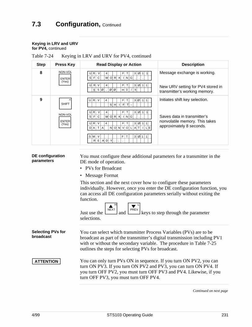
4/99 STS103 Operating Guide 231
7.3 Configuration, Continued
Keying in LRV and URVfor PV4, continued
Table 7-24 Keying in LRV and URV for PV4, continued
Step Press Key Read Display or Action Description
8 NON-VOL
ENTER(Yes)
O R K N GC W .F .S .I
F TU R V 3 Ø 1 14
F TU R V 3 Ø 1 14
6 . 3m / h5 Ø Ø Ø
Message exchange is working.
New URV setting for PV4 stored intransmitter’s working memory.
9 ^SHIFT
NON-VOL
ENTER(Yes)
F T –S H I
F TU R V 3 Ø 1 14
O R K N GC W .F .S .I
F TU R V 3 Ø 1 14
F TU R V 3 Ø 1 14
N O V O A TLND A T A I L E
.Y . .R E A DS M V F T 3 Ø 1 1
Initiates shift key selection.
Saves data in transmitter’snonvolatile memory. This takesapproximately 8 seconds.
DE configurationparameters
You must configure these additional parameters for a transmitter in theDE mode of operation.• PVs for Broadcast
• Message Format
This section and the next cover how to configure these parametersindividually. However, once you enter the DE configuration function, youcan access all DE configuration parameters serially without exiting thefunction.
Just use the NEXT
H
and PREV
L
keys to step through the parameterselections.
Selecting PVs forbroadcast
You can select which transmitter Process Variables (PVs) are to bebroadcast as part of the transmitter’s digital transmission including PV1with or without the secondary variable. The procedure in Table 7-25outlines the steps for selecting PVs for broadcast.
ATTENTION You can only turn PVs ON in sequence. If you turn ON PV2, you canturn ON PV3. If you turn ON PV2 and PV3, you can turn ON PV4. Ifyou turn OFF PV2, you must turn OFF PV3 and PV4. Likewise, if youturn OFF PV3, you must turn OFF PV4.
Continued on next page
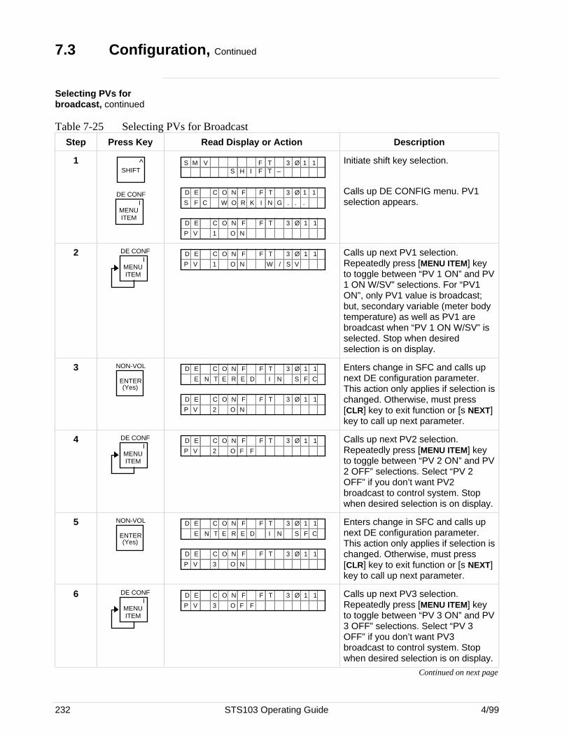
232 STS103 Operating Guide 4/99
7.3 Configuration, Continued
Selecting PVs forbroadcast, continued
Table 7-25 Selecting PVs for BroadcastStep Press Key Read Display or Action Description
1 ^SHIFT
DE CONF
MENUITEM
I
S M V F T 3 Ø 1 1F T –S H I
O R K N GC W .F .S .I
F TD E 3 Ø 1 1OC N F
OVP
F TD E 3 Ø 1 1OC N F
1 N
Initiate shift key selection.
Calls up DE CONFIG menu. PV1selection appears.
2 DE CONF
MENUITEM
IOVP
F TD E 3 Ø 1 1OC N F
1 N W / S V
Calls up next PV1 selection.Repeatedly press [MENU ITEM] keyto toggle between “PV 1 ON” and PV1 ON W/SV” selections. For “PV1ON”, only PV1 value is broadcast;but, secondary variable (meter bodytemperature) as well as PV1 arebroadcast when “PV 1 ON W/SV” isselected. Stop when desiredselection is on display.
3 NON-VOL
ENTER(Yes)
R D IN EE
F TD E 3 Ø 1 1OC N F
T S F CE N
OVP
F TD E 3 Ø 1 1OC N F
2 N
Enters change in SFC and calls upnext DE configuration parameter.This action only applies if selection ischanged. Otherwise, must press[CLR] key to exit function or [s NEXT]key to call up next parameter.
4 DE CONF
MENUITEM
IOVP
F TD E 3 Ø 1 1OC N F
2 F F
Calls up next PV2 selection.Repeatedly press [MENU ITEM] keyto toggle between “PV 2 ON” and PV2 OFF” selections. Select “PV 2OFF” if you don’t want PV2broadcast to control system. Stopwhen desired selection is on display.
5 NON-VOL
ENTER(Yes)
R D IN EE
F TD E 3 Ø 1 1OC N F
T S F CE N
OVP
F TD E 3 Ø 1 1OC N F
3 N
Enters change in SFC and calls upnext DE configuration parameter.This action only applies if selection ischanged. Otherwise, must press[CLR] key to exit function or [s NEXT]key to call up next parameter.
6 DE CONF
MENUITEM
IOVP
F TD E 3 Ø 1 1OC N F
3 F F
Calls up next PV3 selection.Repeatedly press [MENU ITEM] keyto toggle between “PV 3 ON” and PV3 OFF” selections. Select “PV 3OFF” if you don’t want PV3broadcast to control system. Stopwhen desired selection is on display.
Continued on next page
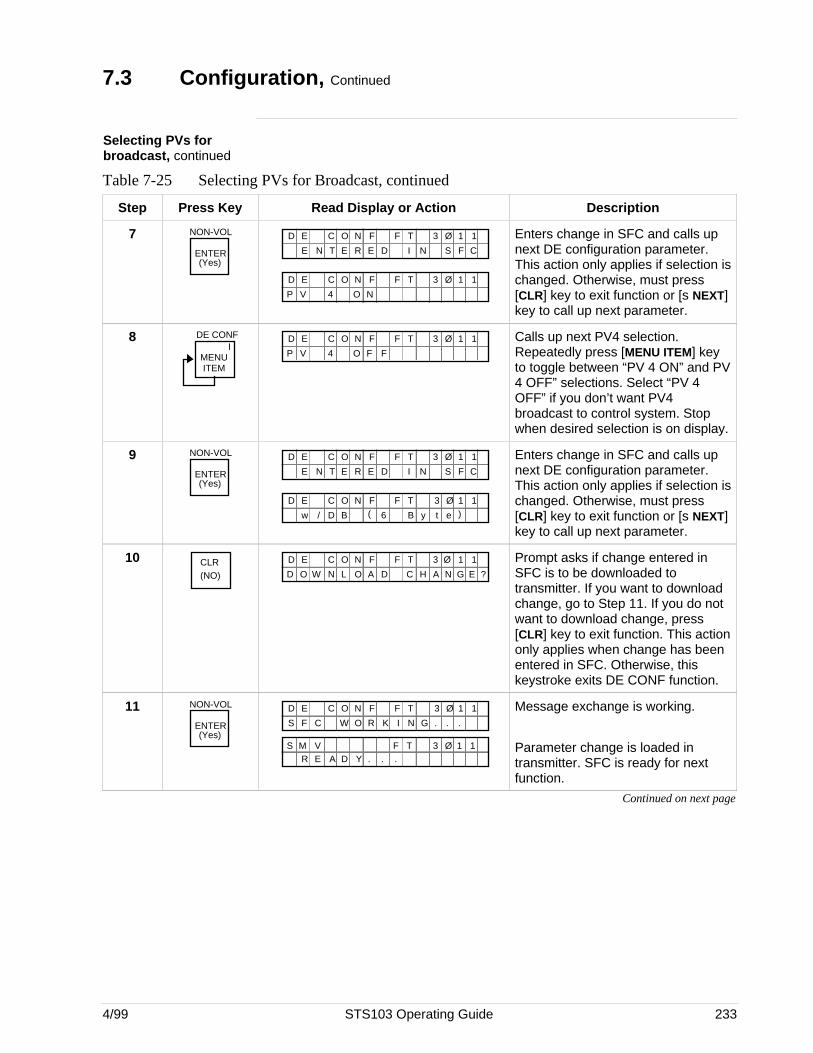
4/99 STS103 Operating Guide 233
7.3 Configuration, Continued
Selecting PVs forbroadcast, continued
Table 7-25 Selecting PVs for Broadcast, continued
Step Press Key Read Display or Action Description
7 NON-VOL
ENTER(Yes)
R D IN EE
F TD E 3 Ø 1 1OC N F
T S F CE N
OVP
F TD E 3 Ø 1 1OC N F
4 N
Enters change in SFC and calls upnext DE configuration parameter.This action only applies if selection ischanged. Otherwise, must press[CLR] key to exit function or [s NEXT]key to call up next parameter.
8 DE CONF
MENUITEM
IOVP
F TD E 3 Ø 1 1OC N F
4 F F
Calls up next PV4 selection.Repeatedly press [MENU ITEM] keyto toggle between “PV 4 ON” and PV4 OFF” selections. Select “PV 4OFF” if you don’t want PV4broadcast to control system. Stopwhen desired selection is on display.
9 NON-VOL
ENTER(Yes)
R D IN EE
F TD E 3 Ø 1 1OC N F
T S F CE N
6 B/ Bw
F TD E 3 Ø 1 1OC N F
D e )( y t
Enters change in SFC and calls upnext DE configuration parameter.This action only applies if selection ischanged. Otherwise, must press[CLR] key to exit function or [s NEXT]key to call up next parameter.
10 CLR(NO) D CW LO
F TD E 3 Ø 1 1OC N F
N N GA HD AO E ?
Prompt asks if change entered inSFC is to be downloaded totransmitter. If you want to downloadchange, go to Step 11. If you do notwant to download change, press[CLR] key to exit function. This actiononly applies when change has beenentered in SFC. Otherwise, thiskeystroke exits DE CONF function.
11 NON-VOL
ENTER(Yes)
F TD E 3 Ø 1 1OC N F
O R K N GC W .F .S .I
.Y . .R E A DS M V F T 3 Ø 1 1
Message exchange is working.
Parameter change is loaded intransmitter. SFC is ready for nextfunction.
Continued on next page
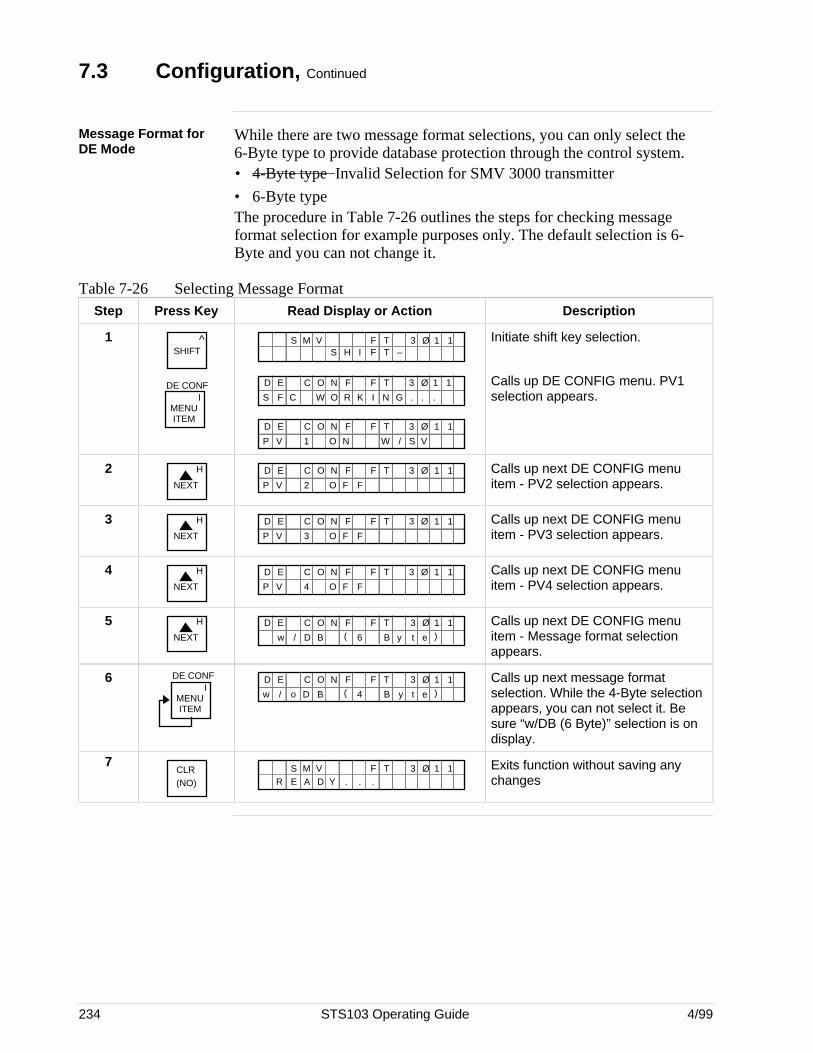
234 STS103 Operating Guide 4/99
7.3 Configuration, Continued
Message Format forDE Mode
While there are two message format selections, you can only select the6-Byte type to provide database protection through the control system.• 4-Byte type Invalid Selection for SMV 3000 transmitter
• 6-Byte typeThe procedure in Table 7-26 outlines the steps for checking messageformat selection for example purposes only. The default selection is 6-Byte and you can not change it.
Table 7-26 Selecting Message FormatStep Press Key Read Display or Action Description
1 ^SHIFT
DE CONF
MENUITEM
I
S M V F T 3 Ø 1 1F T –S H I
O R K N GC W .F .S .I
F TD E 3 Ø 1 1OC N F
OVP
F TD E 3 Ø 1 1OC N F
1 N W / S V
Initiate shift key selection.
Calls up DE CONFIG menu. PV1selection appears.
2NEXT
H
OVP
F TD E 3 Ø 1 1OC N F
2 F F
Calls up next DE CONFIG menuitem - PV2 selection appears.
3NEXT
H
OVP
F TD E 3 Ø 1 1OC N F
3 F F
Calls up next DE CONFIG menuitem - PV3 selection appears.
4NEXT
H
OVP
F TD E 3 Ø 1 1OC N F
4 F F
Calls up next DE CONFIG menuitem - PV4 selection appears.
5NEXT
H
6 B/ Bw
F TD E 3 Ø 1 1OC N F
D e )( y t
Calls up next DE CONFIG menuitem - Message format selectionappears.
6 DE CONF
MENUITEM
I4 Bo B/
F TD E 3 Ø 1 1OC N F
D e )( yw t
Calls up next message formatselection. While the 4-Byte selectionappears, you can not select it. Besure “w/DB (6 Byte)” selection is ondisplay.
7CLR(NO) .Y . .R E A D
S M V F T 3 Ø 1 1 Exits function without saving anychanges
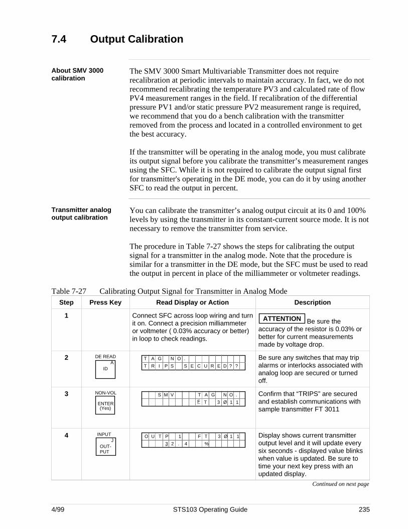
4/99 STS103 Operating Guide 235
7.4 Output Calibration
About SMV 3000calibration
The SMV 3000 Smart Multivariable Transmitter does not requirerecalibration at periodic intervals to maintain accuracy. In fact, we do notrecommend recalibrating the temperature PV3 and calculated rate of flowPV4 measurement ranges in the field. If recalibration of the differentialpressure PV1 and/or static pressure PV2 measurement range is required,we recommend that you do a bench calibration with the transmitterremoved from the process and located in a controlled environment to getthe best accuracy.
If the transmitter will be operating in the analog mode, you must calibrateits output signal before you calibrate the transmitter’s measurement rangesusing the SFC. While it is not required to calibrate the output signal firstfor transmitter's operating in the DE mode, you can do it by using anotherSFC to read the output in percent.
Transmitter analogoutput calibration
You can calibrate the transmitter’s analog output circuit at its 0 and 100%levels by using the transmitter in its constant-current source mode. It is notnecessary to remove the transmitter from service.
The procedure in Table 7-27 shows the steps for calibrating the outputsignal for a transmitter in the analog mode. Note that the procedure issimilar for a transmitter in the DE mode, but the SFC must be used to readthe output in percent in place of the milliammeter or voltmeter readings.
Table 7-27 Calibrating Output Signal for Transmitter in Analog ModeStep Press Key Read Display or Action Description
1 Connect SFC across loop wiring and turnit on. Connect a precision milliammeteror voltmeter ( 0.03% accuracy or better)in loop to check readings.
ATTENTION Be sure theaccuracy of the resistor is 0.03% orbetter for current measurementsmade by voltage drop.
2 DE READA
ID
T A ON .G
?T R I P S S E C U R E D ?
Be sure any switches that may tripalarms or interlocks associated withanalog loop are secured or turnedoff.
3 NON-VOL
ENTER(Yes)
A G N O .TF T 3 Ø 1 1
S M V Confirm that “TRIPS” are securedand establish communications withsample transmitter FT 3011
4 INPUTJ
OUT-PUT
F TO U T
%
3 Ø 1 11
3 .2 4
P Display shows current transmitteroutput level and it will update everysix seconds - displayed value blinkswhen value is updated. Be sure totime your next key press with anupdated display.
Continued on next page
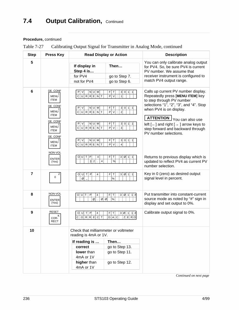
236 STS103 Operating Guide 4/99
7.4 Output Calibration, Continued
Procedure, continued
Table 7-27 Calibrating Output Signal for Transmitter in Analog Mode, continued
Step Press Key Read Display or Action Description
5If display in Then…Step 4 is…for PV4 go to Step 7.not for PV4 go to Step 6.
You can only calibrate analog outputfor PV4. So, be sure PV4 is currentPV number. We assume thatreceiver instrument is configured tomatch PV4 output range.
6MENU ITEM
DE CONFI
MENU ITEM
DE CONFI
MENU ITEM
DE CONFI
MENU ITEM
DE CONFI
NON-VOL
ENTER(Yes)
F TMP V N 3 0 1 1
N T V :R EUC 1P
U
R
F TMP V N 3 0 1 1
N T V :R EUC 2P
U
R
F TMP V N 3 0 1 1
N T V :R EUC 3P
U
R
F TMP V N 3 0 1 1
N T V :R EUC 4P
U
R
F TO U T
%
3 Ø 1 14
3 .2 4
P
Calls up current PV number display.Repeatedly press [MENU ITEM] keyto step through PV numberselections “1”, “2”, “3”, and “4”. Stopwhen PV4 is on display.
ATTENTION You can also useleft [←] and right [→ ] arrow keys tostep forward and backward throughPV number selections.
Returns to previous display which isupdated to reflect PV4 as current PVnumber selection.
7 Z0
F TO U T
%
3 Ø 1 14
Ø _P Key in 0 (zero) as desired output
signal level in percent.
8 NON-VOL
ENTER(Yes)
%.Ø
F TO U T 3 Ø 1 14P
Ø Ø
# Put transmitter into constant-currentsource mode as noted by “#” sign indisplay and set output to 0%.
9 RESETK
COR-RECT
ACE
F TO U T 3 Ø 1 14P
T
#
C O R R D C Z E R O
Calibrate output signal to 0%.
10 Check that milliammeter or voltmeterreading is 4mA or 1V.
If reading is … Then…correct go to Step 13.lower than go to Step 11.4mA or 1Vhigher than go to Step 12.4mA or 1V
Continued on next page
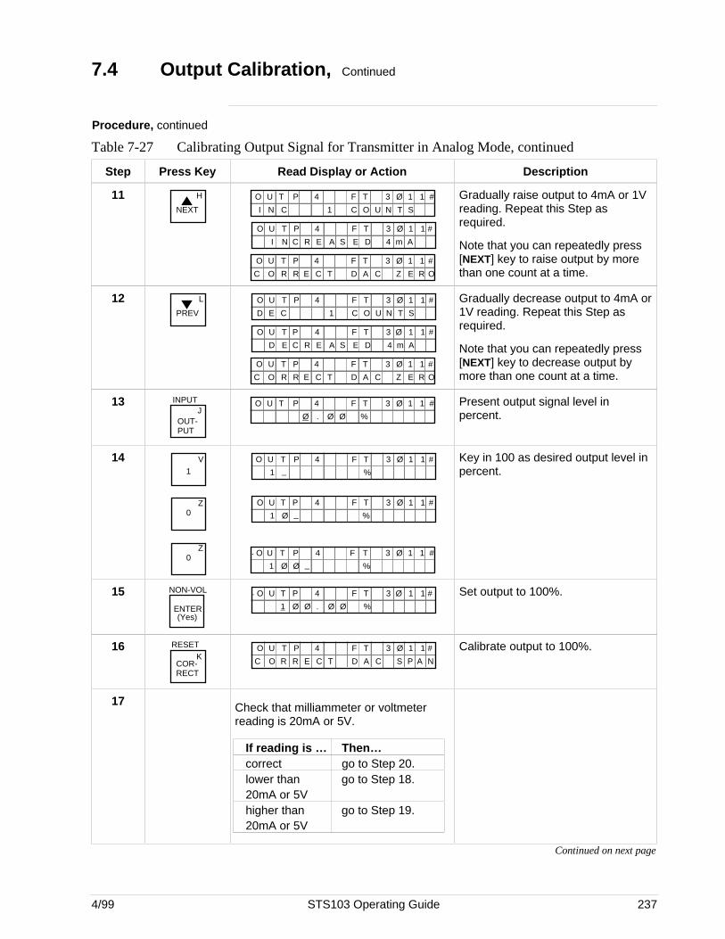
4/99 STS103 Operating Guide 237
7.4 Output Calibration, Continued
Procedure, continued
Table 7-27 Calibrating Output Signal for Transmitter in Analog Mode, continued
Step Press Key Read Display or Action Description
11NEXT
H
O
F TO U T 3 Ø 1 14P
1
#
I N C C U T SN
D
F TO U T 3 Ø 1 14P
A
#
I N E m A4C R E S
ACE
F TO U T 3 Ø 1 14P
T
#
C O R R D C Z E R O
Gradually raise output to 4mA or 1Vreading. Repeat this Step asrequired.
Note that you can repeatedly press[NEXT] key to raise output by morethan one count at a time.
12PREV
L
O
F TO U T 3 Ø 1 14P
1
#
D E C C U T SN
D
F TO U T 3 Ø 1 14P
A
#
D E E m A4C R E S
ACE
F TO U T 3 Ø 1 14P
T
#
C O R R D C Z E R O
Gradually decrease output to 4mA or1V reading. Repeat this Step asrequired.
Note that you can repeatedly press[NEXT] key to decrease output bymore than one count at a time.
13 INPUTJ
OUT-PUT
%.Ø
F TO U T 3 Ø 1 14P
Ø Ø
# Present output signal level inpercent.
141
V
Z0
Z0
F TO U T
%
3 Ø 1 14
1 _P #
F TO U T
%
3 Ø 1 14
1 Ø
P_
#
%1 Ø
. F TO U T 3 Ø 1 14P_Ø
#
Key in 100 as desired output level inpercent.
15 NON-VOL
ENTER(Yes)
%1 Ø
. F TO U T 3 Ø 1 14P
.Ø
#
Ø Ø
Set output to 100%.
16 RESETK
COR-RECT
ACE
F TO U T 3 Ø 1 14P
T
#
C O R R D C S P A N
Calibrate output to 100%.
17 Check that milliammeter or voltmeterreading is 20mA or 5V.
If reading is … Then…correct go to Step 20.lower than go to Step 18.20mA or 5Vhigher than go to Step 19.20mA or 5V
Continued on next page
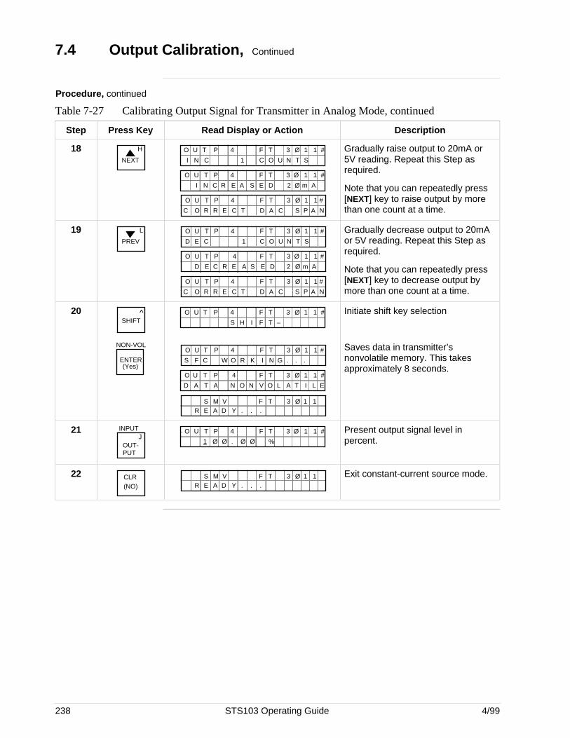
238 STS103 Operating Guide 4/99
7.4 Output Calibration, Continued
Procedure, continued
Table 7-27 Calibrating Output Signal for Transmitter in Analog Mode, continued
Step Press Key Read Display or Action Description
18NEXT
H
O
F TO U T 3 Ø 1 14P
1
#
I N C C U T SN
D
F TO U T 3 Ø 1 14P
A
#
I N E m AØC R E S 2
ACE
F TO U T 3 Ø 1 14P
T
#
C O R R D C S P A N
Gradually raise output to 20mA or5V reading. Repeat this Step asrequired.
Note that you can repeatedly press[NEXT] key to raise output by morethan one count at a time.
19PREV
L
O
F TO U T 3 Ø 1 14P
1
#
D E C C U T SN
D
F TO U T 3 Ø 1 14P
A
#
D E E m AØC R E S 2
ACE
F TO U T 3 Ø 1 14P
T
#
C O R R D C S P A N
Gradually decrease output to 20mAor 5V reading. Repeat this Step asrequired.
Note that you can repeatedly press[NEXT] key to decrease output bymore than one count at a time.
20 ^SHIFT
NON-VOL
ENTER(Yes)
F TO U T 3 Ø 1 14P
F T –S H I
#
F TO U T 3 Ø 1 14P #
F C W OS I N G .R K . .
ON
F TO U T 3 Ø 1 14P
O
#
D A T A V L T I L EN A
.Y . .R E A DS M V F T 3 Ø 1 1
Initiate shift key selection
Saves data in transmitter’snonvolatile memory. This takesapproximately 8 seconds.
21 INPUTJ
OUT-PUT
%1 Ø
. F TO U T 3 Ø 1 14P
.Ø
#
Ø Ø
Present output signal level inpercent.
22 CLR(NO) .Y . .R E A D
S M V F T 3 Ø 1 1 Exit constant-current source mode.
4/99 STS103 Operating Guide 239
7.5 Operation
Overview The STS103 displays all the operating data for the SMV 3000Multivariable Transmitter. This data includes:
• Transmitter I.D
• Current PV number selection
• Damping value
• Upper range value (span)
• Configuration elements for Digital (DE) Communications mode
• Input value
• Output Value
• Span value
• Upper range limit
• Engineering units
• Operation Status
• Failsafe Direction
• Sensor (meter body) temperature
• Cold Junction temperature
• High/Low PV
• Lower range limit
• PROM serial number
• Software Version Number
• Zero Point adjustment
• Display and Keyboard Test
• Read Scratch Pad messages
Refer to Table 4-5 for Operating Data access instructions.
Continued on next page
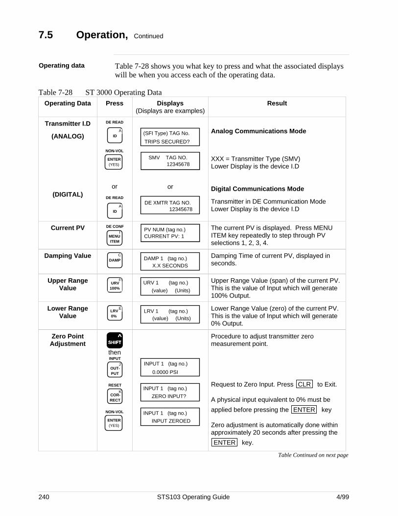
240 STS103 Operating Guide 4/99
7.5 Operation, Continued
Operating data Table 7-28 shows you what key to press and what the associated displayswill be when you access each of the operating data.
Table 7-28 ST 3000 Operating DataOperating Data Press Displays
(Displays are examples)Result
Transmitter I.D
(ANALOG)
(DIGITAL)
DE READ
AID
NON-VOL
ENTER (YES)
or
DE READ
AID
TRIPS SECURED?
(SFI Type) TAG No.
SMV TAG NO. 12345678
or
DE XMTR TAG NO.12345678
Analog Communications Mode
XXX = Transmitter Type (SMV)Lower Display is the device I.D
Digital Communications Mode
Transmitter in DE Communication ModeLower Display is the device I.D
Current PVI
MENU ITEM
DE CONFPV NUM (tag no.)CURRENT PV: 1
The current PV is displayed. Press MENUITEM key repeatedly to step through PVselections 1, 2, 3, 4.
Damping Value CDAMP DAMP 1 (tag no.)
X.X SECONDS
Damping Time of current PV, displayed inseconds.
Upper RangeValue
FURV
100%URV 1 (tag no.)
(value) (Units)
Upper Range Value (span) of the current PV.This is the value of Input which will generate100% Output.
Lower RangeValue
ELRV 0%
LRV 1 (tag no.)(value) (Units)
Lower Range Value (zero) of the current PV.This is the value of Input which will generate0% Output.
Zero PointAdjustment SSSSSHHHHHIIIIIFFFFFTTTTT
^
then
JOUT- PUT
INPUT
KCOR- RECT
RESET
NON-VOL
ENTER (YES)
INPUT 1 (tag no.)
0.0000 PSI
INPUT 1 (tag no.)
ZERO INPUT?
INPUT 1 (tag no.)
INPUT ZEROED
Procedure to adjust transmitter zeromeasurement point.
Request to Zero Input. Press CLR to Exit.
A physical input equivalent to 0% must be
applied before pressing the ENTER key
Zero adjustment is automatically done withinapproximately 20 seconds after pressing the
ENTER key.
Table Continued on next page
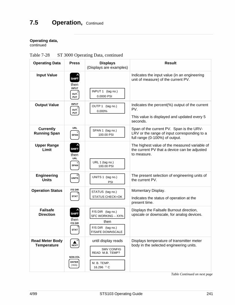
4/99 STS103 Operating Guide 241
7.5 Operation, Continued
Operating data,continued
Table 7-28 ST 3000 Operating Data, continued
Operating Data Press Displays(Displays are examples)
Result
Input ValueSSSSSHHHHHIIIIIFFFFFTTTTT
^
then
JOUT- PUT
INPUTINPUT 1 (tag no.)
0.0000 PSI
Indicates the input value (in an engineeringunit of measure) of the current PV.
Output ValueJ
OUT- PUT
INPUTOUTP 1 (tag no.)
0.000%
Indicates the percent(%) output of the currentPV.
This value is displayed and updated every 5seconds.
CurrentlyRunning Span Y
SPAN
URLSPAN 1 (tag no.)
100.00 PSI
Span of the current PV. Span is the URV-LRV or the range of input corresponding to afull range (0-100%) of output.
Upper RangeLimit SSSSSHHHHHIIIIIFFFFFTTTTT
^
then
YSPAN
URL
URL 1 (tag no.)100.00 PSI
The highest value of the measured variable ofthe current PV that a device can be adjustedto measure.
EngineeringUnits
DUNITS UNITS 1 (tag no.)
PSI
The present selection of engineering units ofthe current PV.
Operation StatusU
STAT
F/S DIRSTATUS (tag no.)
STATUS CHECK=OK
Momentary Display.
Indicates the status of operation at thepresent time.
FailsafeDirection SSSSSHHHHHIIIIIFFFFFTTTTT
^
then
U
STAT
F/S DIR
F/S DIR (tag no.)SFC WORKING – XX%
then
F/S DIR (tag no.)F/SAFE DOWNSCALE
Displays the Failsafe Burnout direction,upscale or downscale, for analog devices.
Read Meter BodyTemperature
H
NEXT
NON-VOL
ENTER (YES)
until display reads
SMV CONFIGREAD M.B. TEMP?
M. B. TEMP. 16.296 o C
Displays temperature of transmitter meterbody in the selected engineering units.
Table Continued on next page
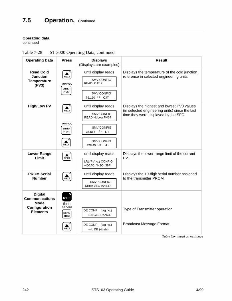
242 STS103 Operating Guide 4/99
7.5 Operation, Continued
Operating data,continued
Table 7-28 ST 3000 Operating Data, continued
Operating Data Press Displays(Displays are examples)
Result
Read ColdJunction
Temperature(PV3)
H
NEXT
NON-VOL
ENTER (YES)
until display reads
SMV CONFIGREAD CJT ?
SMV CONFIG 76.160 oF CJT
Displays the temperature of the cold junctionreference in selected engineering units.
High/Low PV H
NEXT
NON-VOL
ENTER (YES)
H
NEXT
until display reads
SMV CONFIGREAD Hi/Low PV3?
SMV CONFIG 37.564 oF L o
SMV CONFIG 428.45 oF H i
Displays the highest and lowest PV3 values(in selected engineering units) since the lasttime they were displayed by the SFC.
Lower RangeLimit
H
NEXT
until display reads
LRL(PVno.) CONFIG-400.00 "H2O_39F
Displays the lower range limit of the currentPV.
PROM SerialNumber
H
NEXT
until display reads
SMV CONFIG SER# 9317304637
Displays the 10-digit serial number assignedto the transmitter PROM.
DigitalCommunications
ModeConfiguration
Elements
SSSSSHHHHHIIIIIFFFFFTTTTT ^
then
IMENU ITEM
DE CONF
H
NEXT
DE CONF (tag no.)
SINGLE RANGE
DE CONF (tag no.)
w/o DB (4byte)
Type of Transmitter operation.
Broadcast Message Format
Table Continued on next page
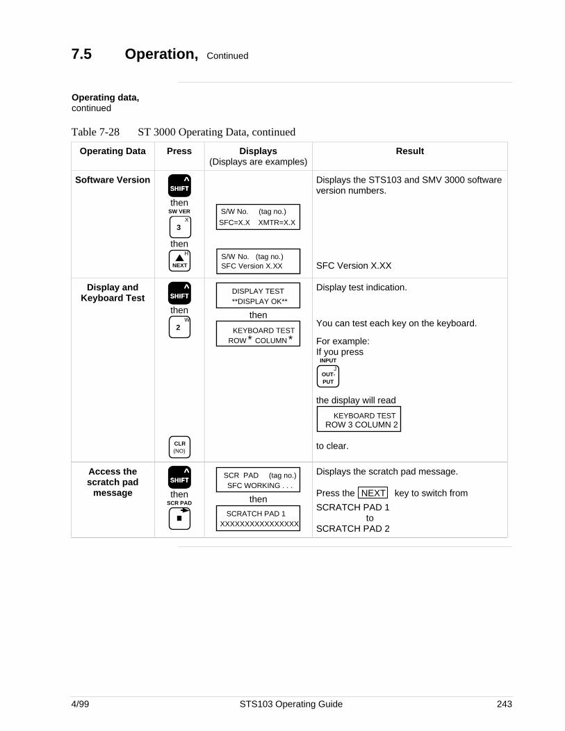
4/99 STS103 Operating Guide 243
7.5 Operation, Continued
Operating data,continued
Table 7-28 ST 3000 Operating Data, continued
Operating Data Press Displays(Displays are examples)
Result
Software VersionSSSSSHHHHHIIIIIFFFFFTTTTT
^
then
X
3
SW VER
thenH
NEXT
S/W No. (tag no.)
SFC=X.X XMTR=X.X
S/W No. (tag no.)SFC Version X.XX
Displays the STS103 and SMV 3000 softwareversion numbers.
SFC Version X.XX
Display andKeyboard Test SSSSSHHHHHIIIIIFFFFFTTTTT
^
thenW
2
CLR (NO)
DISPLAY TEST**DISPLAY OK**
then
KEYBOARD TESTROW * COLUMN *
Display test indication.
You can test each key on the keyboard.
For example:If you press
JOUT- PUT
INPUT
the display will read
KEYBOARD TESTROW 3 COLUMN 2
to clear.
Access thescratch pad
messageSSSSSHHHHHIIIIIFFFFFTTTTT
^
thenSCR PAD
SCR PAD (tag no.)SFC WORKING . . .
then
SCRATCH PAD 1XXXXXXXXXXXXXXXX
Displays the scratch pad message.
Press the NEXT key to switch from
SCRATCH PAD 1to
SCRATCH PAD 2

244 STS103 Operating Guide 4/99
7.6 Diagnostics and SFC Messages
Introduction The ST 3000 and the STS103 both run continuous self-diagnostics.This means that they are constantly testing the communications, the loop,and themselves.
Any time you want results of these diagnostics, press the STAT key.
The SFC displays its report, in the form of messages, which identifydiagnostic conditions.Diagnostic conditions are broken down into three categories:
• OK status• critical status• a non-critical condition
OK Status An OK condition means no problem exists, and the display looks like this:
STATUS (tag no.)STATUS CHECK=OK
Critical status A critical condition means that the transmitter is not functioning properly.When this occurs, the transmitter goes into upscale failsafe and maintainsan output of 21.8 mA, or into downscale failsafe and maintains an outputof less than 3.9 mA. The message CRITICAL STATUS interrupts youroperation and is followed by the message PRESS STATUS.
After the PRESS STATUS message, you press the STAT key to find
out what problem exists. You will receive one or more messages. Takewhatever corrective action necessary to solve the problem. Remember thatthe transmitter will stay in upscale or down scale failsafe until thecondition is corrected.If the transmitter sends more than one message, each message will bedisplayed in the order of importance for about 5 seconds. If you need to
see them again, press the STAT key again.
Non-critical status A non-critical condition means that although a problem exists, thetransmitter is still operating. When a non-critical condition occurs a “#”character appears on the right side of the display, along with whateveryou’re displaying at the time.
This character means press the STAT key because some type of a
problem exists. Again, one or more messages will appear on the displayfor about five seconds each.
Low battery voltage When the battery voltage becomes low, a colon ”:” will appear in themiddle of the display. It stays on the display until you either charge orreplace the batteries.
Continued on next page
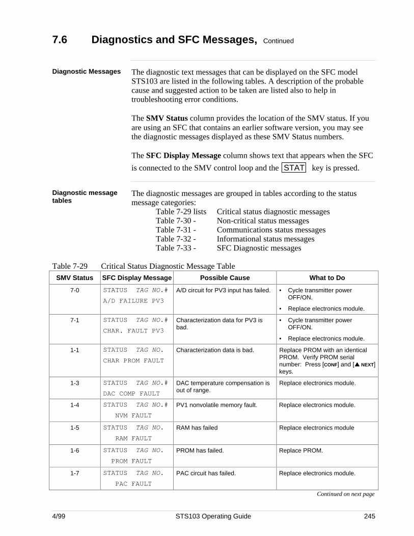
4/99 STS103 Operating Guide 245
7.6 Diagnostics and SFC Messages, Continued
Diagnostic Messages The diagnostic text messages that can be displayed on the SFC modelSTS103 are listed in the following tables. A description of the probablecause and suggested action to be taken are listed also to help introubleshooting error conditions.
The SMV Status column provides the location of the SMV status. If youare using an SFC that contains an earlier software version, you may seethe diagnostic messages displayed as these SMV Status numbers.
The SFC Display Message column shows text that appears when the SFC
is connected to the SMV control loop and the STAT key is pressed.
Diagnostic messagetables
The diagnostic messages are grouped in tables according to the statusmessage categories:
Table 7-29 lists Critical status diagnostic messagesTable 7-30 - Non-critical status messagesTable 7-31 - Communications status messagesTable 7-32 - Informational status messagesTable 7-33 - SFC Diagnostic messages
Table 7-29 Critical Status Diagnostic Message TableSMV Status SFC Display Message Possible Cause What to Do
7-0 STATUS TAG NO.#
A/D FAILURE PV3
A/D circuit for PV3 input has failed. • Cycle transmitter powerOFF/ON.
• Replace electronics module.
7-1 STATUS TAG NO.#
CHAR. FAULT PV3
Characterization data for PV3 isbad.
• Cycle transmitter powerOFF/ON.
• Replace electronics module.
1-1 STATUS TAG NO.
CHAR PROM FAULT
Characterization data is bad. Replace PROM with an identicalPROM. Verify PROM serialnumber: Press [CONF] and [ NEXT]keys.
1-3 STATUS TAG NO.#
DAC COMP FAULT
DAC temperature compensation isout of range.
Replace electronics module.
1-4 STATUS TAG NO.#
NVM FAULT
PV1 nonvolatile memory fault. Replace electronics module.
1-5 STATUS TAG NO.
RAM FAULT
RAM has failed Replace electronics module
1-6 STATUS TAG NO.
PROM FAULT
PROM has failed. Replace PROM.
1-7 STATUS TAG NO.
PAC FAULT
PAC circuit has failed. Replace electronics module.
Continued on next page
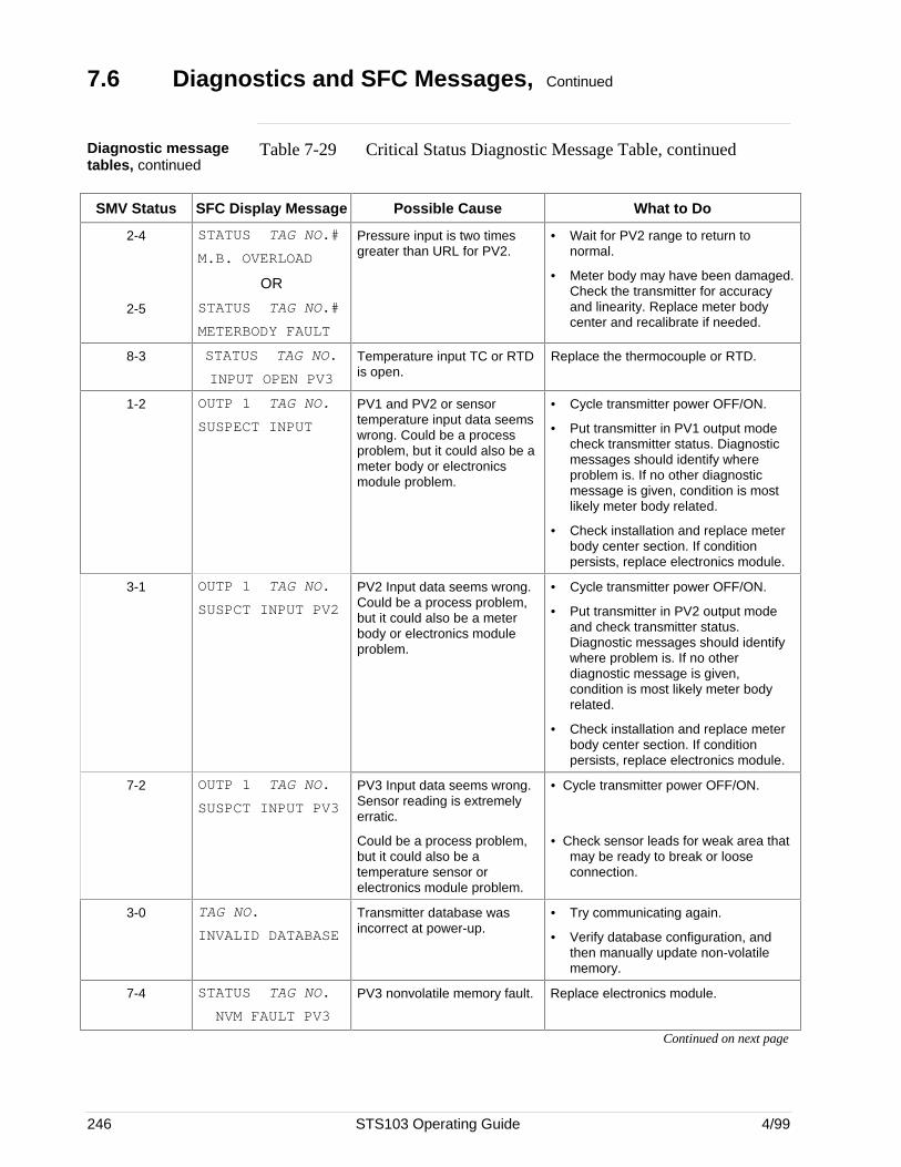
246 STS103 Operating Guide 4/99
7.6 Diagnostics and SFC Messages, Continued
Diagnostic messagetables, continued
Table 7-29 Critical Status Diagnostic Message Table, continued
SMV Status SFC Display Message Possible Cause What to Do
2-4
2-5
STATUS TAG NO.#
M.B. OVERLOAD
OR
STATUS TAG NO.#
METERBODY FAULT
Pressure input is two timesgreater than URL for PV2.
• Wait for PV2 range to return tonormal.
• Meter body may have been damaged.Check the transmitter for accuracyand linearity. Replace meter bodycenter and recalibrate if needed.
8-3 STATUS TAG NO.
INPUT OPEN PV3
Temperature input TC or RTDis open.
Replace the thermocouple or RTD.
1-2 OUTP 1 TAG NO.
SUSPECT INPUT
PV1 and PV2 or sensortemperature input data seemswrong. Could be a processproblem, but it could also be ameter body or electronicsmodule problem.
• Cycle transmitter power OFF/ON.
• Put transmitter in PV1 output modecheck transmitter status. Diagnosticmessages should identify whereproblem is. If no other diagnosticmessage is given, condition is mostlikely meter body related.
• Check installation and replace meterbody center section. If conditionpersists, replace electronics module.
3-1 OUTP 1 TAG NO.
SUSPCT INPUT PV2
PV2 Input data seems wrong.Could be a process problem,but it could also be a meterbody or electronics moduleproblem.
• Cycle transmitter power OFF/ON.
• Put transmitter in PV2 output modeand check transmitter status.Diagnostic messages should identifywhere problem is. If no otherdiagnostic message is given,condition is most likely meter bodyrelated.
• Check installation and replace meterbody center section. If conditionpersists, replace electronics module.
7-2 OUTP 1 TAG NO.
SUSPCT INPUT PV3
PV3 Input data seems wrong.Sensor reading is extremelyerratic.
Could be a process problem,but it could also be atemperature sensor orelectronics module problem.
• Cycle transmitter power OFF/ON.
• Check sensor leads for weak area thatmay be ready to break or looseconnection.
3-0 TAG NO.
INVALID DATABASE
Transmitter database wasincorrect at power-up.
• Try communicating again.
• Verify database configuration, andthen manually update non-volatilememory.
7-4 STATUS TAG NO.
NVM FAULT PV3
PV3 nonvolatile memory fault. Replace electronics module.
Continued on next page
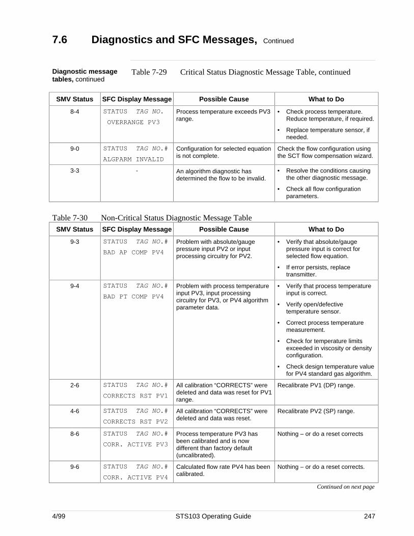
4/99 STS103 Operating Guide 247
7.6 Diagnostics and SFC Messages, Continued
Diagnostic messagetables, continued
Table 7-29 Critical Status Diagnostic Message Table, continued
SMV Status SFC Display Message Possible Cause What to Do
8-4 STATUS TAG NO.
OVERRANGE PV3
Process temperature exceeds PV3range.
• Check process temperature.Reduce temperature, if required.
• Replace temperature sensor, ifneeded.
9-0 STATUS TAG NO.#
ALGPARM INVALID
Configuration for selected equationis not complete.
Check the flow configuration usingthe SCT flow compensation wizard.
3-3 - An algorithm diagnostic hasdetermined the flow to be invalid.
• Resolve the conditions causingthe other diagnostic message.
• Check all flow configurationparameters.
Table 7-30 Non-Critical Status Diagnostic Message TableSMV Status SFC Display Message Possible Cause What to Do
9-3 STATUS TAG NO.#
BAD AP COMP PV4
Problem with absolute/gaugepressure input PV2 or inputprocessing circuitry for PV2.
• Verify that absolute/gaugepressure input is correct forselected flow equation.
• If error persists, replacetransmitter.
9-4 STATUS TAG NO.#
BAD PT COMP PV4
Problem with process temperatureinput PV3, input processingcircuitry for PV3, or PV4 algorithmparameter data.
• Verify that process temperatureinput is correct.
• Verify open/defectivetemperature sensor.
• Correct process temperaturemeasurement.
• Check for temperature limitsexceeded in viscosity or densityconfiguration.
• Check design temperature valuefor PV4 standard gas algorithm.
2-6 STATUS TAG NO.#
CORRECTS RST PV1
All calibration “CORRECTS” weredeleted and data was reset for PV1range.
Recalibrate PV1 (DP) range.
4-6 STATUS TAG NO.#
CORRECTS RST PV2
All calibration “CORRECTS” weredeleted and data was reset.
Recalibrate PV2 (SP) range.
8-6 STATUS TAG NO.#
CORR. ACTIVE PV3
Process temperature PV3 hasbeen calibrated and is nowdifferent than factory default(uncalibrated).
Nothing – or do a reset corrects
9-6 STATUS TAG NO.#
CORR. ACTIVE PV4
Calculated flow rate PV4 has beencalibrated.
Nothing – or do a reset corrects.
Continued on next page
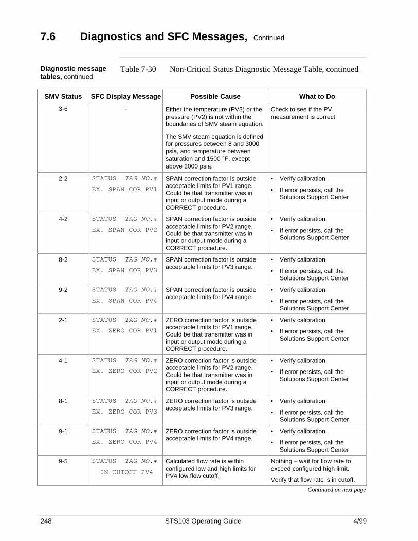
248 STS103 Operating Guide 4/99
7.6 Diagnostics and SFC Messages, Continued
Diagnostic messagetables, continued
Table 7-30 Non-Critical Status Diagnostic Message Table, continued
SMV Status SFC Display Message Possible Cause What to Do
3-6 - Either the temperature (PV3) or thepressure (PV2) is not within theboundaries of SMV steam equation.
The SMV steam equation is definedfor pressures between 8 and 3000psia, and temperature betweensaturation and 1500 °F, exceptabove 2000 psia.
Check to see if the PVmeasurement is correct.
2-2 STATUS TAG NO.#
EX. SPAN COR PV1
SPAN correction factor is outsideacceptable limits for PV1 range.Could be that transmitter was ininput or output mode during aCORRECT procedure.
• Verify calibration.
• If error persists, call theSolutions Support Center
4-2 STATUS TAG NO.#
EX. SPAN COR PV2
SPAN correction factor is outsideacceptable limits for PV2 range.Could be that transmitter was ininput or output mode during aCORRECT procedure.
• Verify calibration.
• If error persists, call theSolutions Support Center
8-2 STATUS TAG NO.#
EX. SPAN COR PV3
SPAN correction factor is outsideacceptable limits for PV3 range.
• Verify calibration.
• If error persists, call theSolutions Support Center
9-2 STATUS TAG NO.#
EX. SPAN COR PV4
SPAN correction factor is outsideacceptable limits for PV4 range.
• Verify calibration.
• If error persists, call theSolutions Support Center
2-1 STATUS TAG NO.#
EX. ZERO COR PV1
ZERO correction factor is outsideacceptable limits for PV1 range.Could be that transmitter was ininput or output mode during aCORRECT procedure.
• Verify calibration.
• If error persists, call theSolutions Support Center
4-1 STATUS TAG NO.#
EX. ZERO COR PV2
ZERO correction factor is outsideacceptable limits for PV2 range.Could be that transmitter was ininput or output mode during aCORRECT procedure.
• Verify calibration.
• If error persists, call theSolutions Support Center
8-1 STATUS TAG NO.#
EX. ZERO COR PV3
ZERO correction factor is outsideacceptable limits for PV3 range.
• Verify calibration.
• If error persists, call theSolutions Support Center
9-1 STATUS TAG NO.#
EX. ZERO COR PV4
ZERO correction factor is outsideacceptable limits for PV4 range.
• Verify calibration.
• If error persists, call theSolutions Support Center
9-5 STATUS TAG NO.#
IN CUTOFF PV4
Calculated flow rate is withinconfigured low and high limits forPV4 low flow cutoff.
Nothing – wait for flow rate toexceed configured high limit.
Verify that flow rate is in cutoff.
Continued on next page
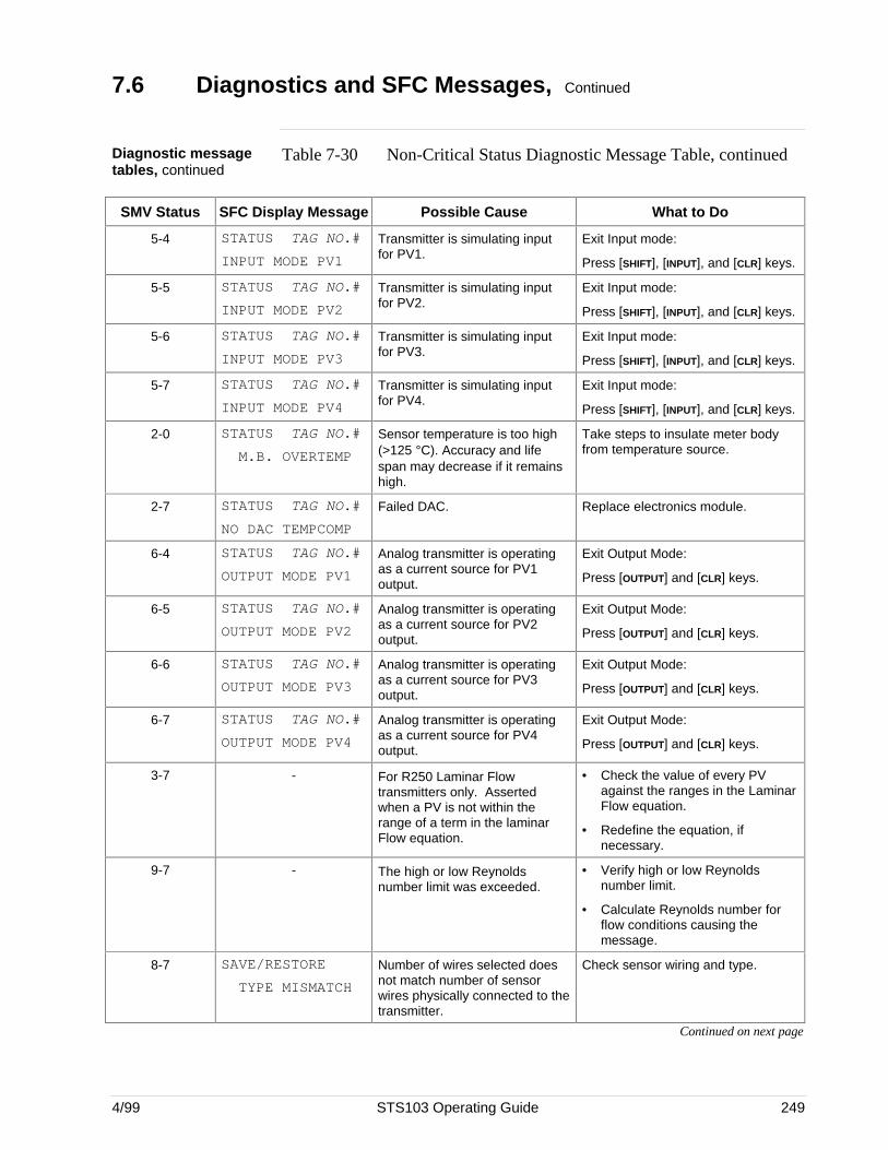
4/99 STS103 Operating Guide 249
7.6 Diagnostics and SFC Messages, Continued
Diagnostic messagetables, continued
Table 7-30 Non-Critical Status Diagnostic Message Table, continued
SMV Status SFC Display Message Possible Cause What to Do
5-4 STATUS TAG NO.#
INPUT MODE PV1
Transmitter is simulating inputfor PV1.
Exit Input mode:
Press [SHIFT], [INPUT], and [CLR] keys.
5-5 STATUS TAG NO.#
INPUT MODE PV2
Transmitter is simulating inputfor PV2.
Exit Input mode:
Press [SHIFT], [INPUT], and [CLR] keys.
5-6 STATUS TAG NO.#
INPUT MODE PV3
Transmitter is simulating inputfor PV3.
Exit Input mode:
Press [SHIFT], [INPUT], and [CLR] keys.
5-7 STATUS TAG NO.#
INPUT MODE PV4
Transmitter is simulating inputfor PV4.
Exit Input mode:
Press [SHIFT], [INPUT], and [CLR] keys.
2-0 STATUS TAG NO.#
M.B. OVERTEMP
Sensor temperature is too high(>125 °C). Accuracy and lifespan may decrease if it remainshigh.
Take steps to insulate meter bodyfrom temperature source.
2-7 STATUS TAG NO.#
NO DAC TEMPCOMP
Failed DAC. Replace electronics module.
6-4 STATUS TAG NO.#
OUTPUT MODE PV1
Analog transmitter is operatingas a current source for PV1output.
Exit Output Mode:
Press [OUTPUT] and [CLR] keys.
6-5 STATUS TAG NO.#
OUTPUT MODE PV2
Analog transmitter is operatingas a current source for PV2output.
Exit Output Mode:
Press [OUTPUT] and [CLR] keys.
6-6 STATUS TAG NO.#
OUTPUT MODE PV3
Analog transmitter is operatingas a current source for PV3output.
Exit Output Mode:
Press [OUTPUT] and [CLR] keys.
6-7 STATUS TAG NO.#
OUTPUT MODE PV4
Analog transmitter is operatingas a current source for PV4output.
Exit Output Mode:
Press [OUTPUT] and [CLR] keys.
3-7 - For R250 Laminar Flowtransmitters only. Assertedwhen a PV is not within therange of a term in the laminarFlow equation.
• Check the value of every PVagainst the ranges in the LaminarFlow equation.
• Redefine the equation, ifnecessary.
9-7 - The high or low Reynoldsnumber limit was exceeded.
• Verify high or low Reynoldsnumber limit.
• Calculate Reynolds number forflow conditions causing themessage.
8-7 SAVE/RESTORE
TYPE MISMATCH
Number of wires selected doesnot match number of sensorwires physically connected to thetransmitter.
Check sensor wiring and type.
Continued on next page
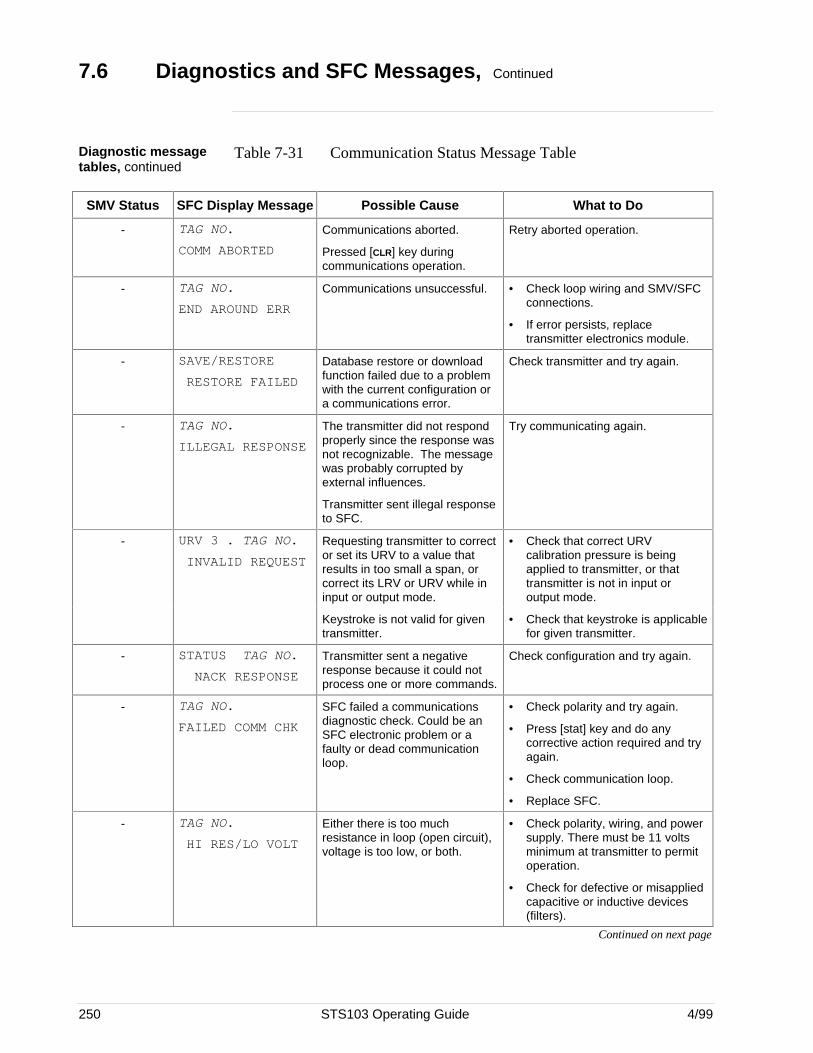
250 STS103 Operating Guide 4/99
7.6 Diagnostics and SFC Messages, Continued
Diagnostic messagetables, continued
Table 7-31 Communication Status Message Table
SMV Status SFC Display Message Possible Cause What to Do
- TAG NO.
COMM ABORTED
Communications aborted.
Pressed [CLR] key duringcommunications operation.
Retry aborted operation.
- TAG NO.
END AROUND ERR
Communications unsuccessful. • Check loop wiring and SMV/SFCconnections.
• If error persists, replacetransmitter electronics module.
- SAVE/RESTORE
RESTORE FAILED
Database restore or downloadfunction failed due to a problemwith the current configuration ora communications error.
Check transmitter and try again.
- TAG NO.
ILLEGAL RESPONSE
The transmitter did not respondproperly since the response wasnot recognizable. The messagewas probably corrupted byexternal influences.
Transmitter sent illegal responseto SFC.
Try communicating again.
- URV 3 . TAG NO.
INVALID REQUEST
Requesting transmitter to corrector set its URV to a value thatresults in too small a span, orcorrect its LRV or URV while ininput or output mode.
• Check that correct URVcalibration pressure is beingapplied to transmitter, or thattransmitter is not in input oroutput mode.
Keystroke is not valid for giventransmitter.
• Check that keystroke is applicablefor given transmitter.
- STATUS TAG NO.
NACK RESPONSE
Transmitter sent a negativeresponse because it could notprocess one or more commands.
Check configuration and try again.
- TAG NO.
FAILED COMM CHK
SFC failed a communicationsdiagnostic check. Could be anSFC electronic problem or afaulty or dead communicationloop.
• Check polarity and try again.
• Press [stat] key and do anycorrective action required and tryagain.
• Check communication loop.
• Replace SFC.
- TAG NO.
HI RES/LO VOLT
Either there is too muchresistance in loop (open circuit),voltage is too low, or both.
• Check polarity, wiring, and powersupply. There must be 11 voltsminimum at transmitter to permitoperation.
• Check for defective or misappliedcapacitive or inductive devices(filters).
Continued on next page
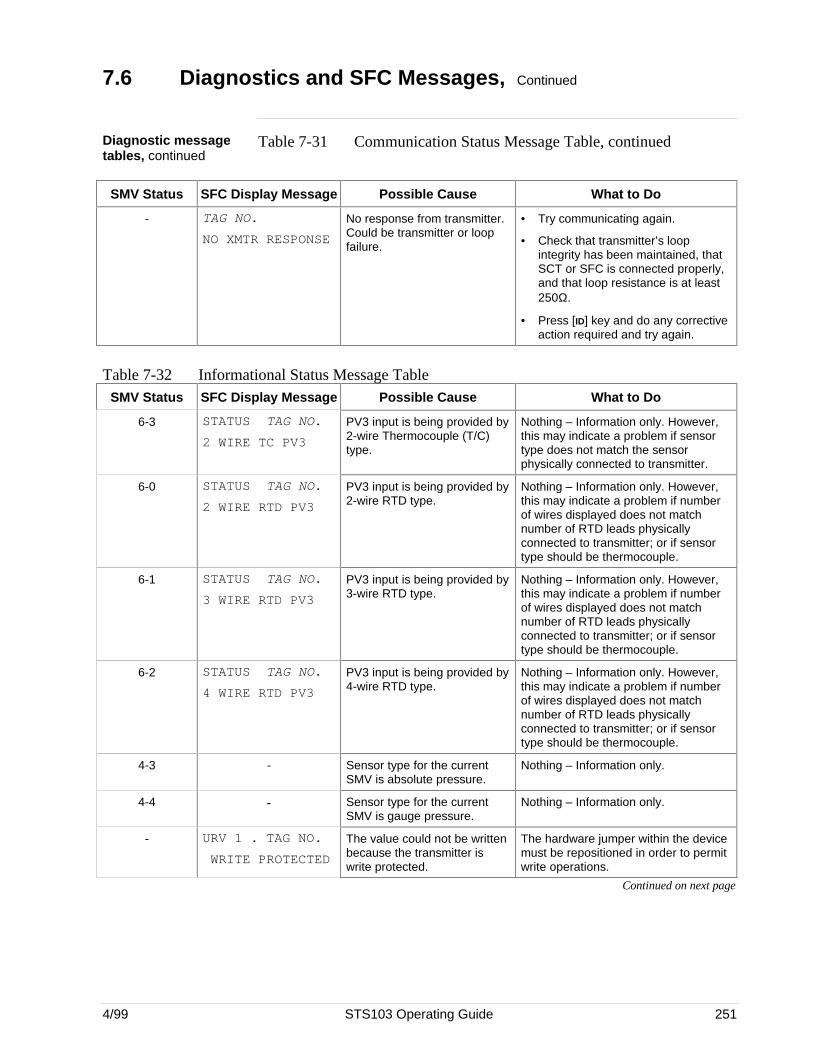
4/99 STS103 Operating Guide 251
7.6 Diagnostics and SFC Messages, Continued
Diagnostic messagetables, continued
Table 7-31 Communication Status Message Table, continued
SMV Status SFC Display Message Possible Cause What to Do
- TAG NO.
NO XMTR RESPONSE
No response from transmitter.Could be transmitter or loopfailure.
• Try communicating again.
• Check that transmitter’s loopintegrity has been maintained, thatSCT or SFC is connected properly,and that loop resistance is at least250Ω.
• Press [ID] key and do any correctiveaction required and try again.
Table 7-32 Informational Status Message TableSMV Status SFC Display Message Possible Cause What to Do
6-3 STATUS TAG NO.
2 WIRE TC PV3
PV3 input is being provided by2-wire Thermocouple (T/C)type.
Nothing – Information only. However,this may indicate a problem if sensortype does not match the sensorphysically connected to transmitter.
6-0 STATUS TAG NO.
2 WIRE RTD PV3
PV3 input is being provided by2-wire RTD type.
Nothing – Information only. However,this may indicate a problem if numberof wires displayed does not matchnumber of RTD leads physicallyconnected to transmitter; or if sensortype should be thermocouple.
6-1 STATUS TAG NO.
3 WIRE RTD PV3
PV3 input is being provided by3-wire RTD type.
Nothing – Information only. However,this may indicate a problem if numberof wires displayed does not matchnumber of RTD leads physicallyconnected to transmitter; or if sensortype should be thermocouple.
6-2 STATUS TAG NO.
4 WIRE RTD PV3
PV3 input is being provided by4-wire RTD type.
Nothing – Information only. However,this may indicate a problem if numberof wires displayed does not matchnumber of RTD leads physicallyconnected to transmitter; or if sensortype should be thermocouple.
4-3 - Sensor type for the currentSMV is absolute pressure.
Nothing – Information only.
4-4 - Sensor type for the currentSMV is gauge pressure.
Nothing – Information only.
- URV 1 . TAG NO.
WRITE PROTECTED
The value could not be writtenbecause the transmitter iswrite protected.
The hardware jumper within the devicemust be repositioned in order to permitwrite operations.
Continued on next page
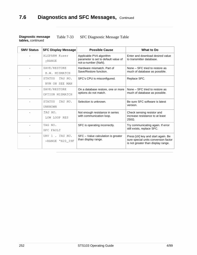
252 STS103 Operating Guide 4/99
7.6 Diagnostics and SFC Messages, Continued
Diagnostic messagetables, continued
Table 7-33 SFC Diagnostic Message Table
SMV Status SFC Display Message Possible Cause What to Do
- ALGPARM Kuser
>RANGE
Applicable PV4 algorithmparameter is set to default value ofnot-a-number (NaN).
Enter and download desired valueto transmitter database.
- SAVE/RESTORE
H.W. MISMATCH
Hardware mismatch. Part ofSave/Restore function.
None – SFC tried to restore asmuch of database as possible.
- STATUS TAG NO.
NVM ON SEE MAN
SFC’s CPU is misconfigured. Replace SFC.
- SAVE/RESTORE
OPTION MISMATCH
On a database restore, one or moreoptions do not match.
None – SFC tried to restore asmuch of database as possible.
- STATUS TAG NO.
UNKNOWN
Selection is unknown. Be sure SFC software is latestversion.
- TAG NO.
LOW LOOP RES
Not enough resistance in serieswith communication loop.
Check sensing resistor andincrease resistance to at least250Ω.
- TAG NO.
SFC FAULT
SFC is operating incorrectly. Try communicating again. If errorstill exists, replace SFC.
- URV 1 . TAG NO.
>RANGE “H20_39F
SFC – Value calculation is greaterthan display range.
Press [clr] key and start again. Besure special units conversion factoris not greater than display range.
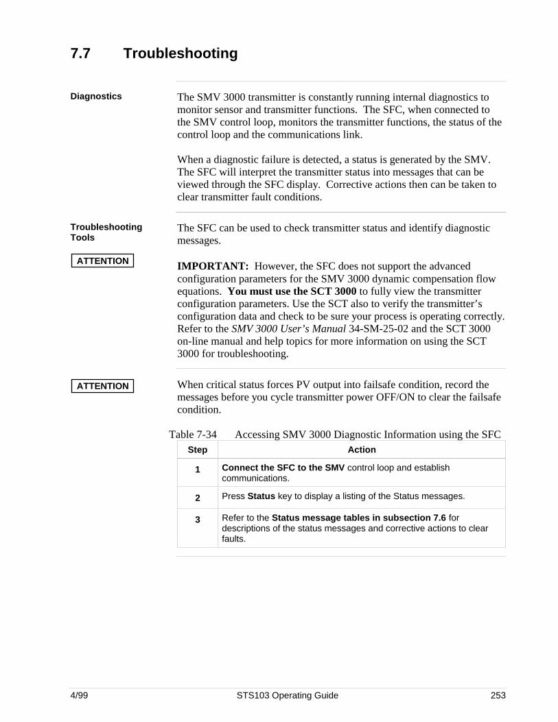
4/99 STS103 Operating Guide 253
7.7 Troubleshooting
Diagnostics The SMV 3000 transmitter is constantly running internal diagnostics tomonitor sensor and transmitter functions. The SFC, when connected tothe SMV control loop, monitors the transmitter functions, the status of thecontrol loop and the communications link.
When a diagnostic failure is detected, a status is generated by the SMV.The SFC will interpret the transmitter status into messages that can beviewed through the SFC display. Corrective actions then can be taken toclear transmitter fault conditions.
TroubleshootingTools
ATTENTION
The SFC can be used to check transmitter status and identify diagnosticmessages.
IMPORTANT: However, the SFC does not support the advancedconfiguration parameters for the SMV 3000 dynamic compensation flowequations. You must use the SCT 3000 to fully view the transmitterconfiguration parameters. Use the SCT also to verify the transmitter’sconfiguration data and check to be sure your process is operating correctly.Refer to the SMV 3000 User’s Manual 34-SM-25-02 and the SCT 3000on-line manual and help topics for more information on using the SCT3000 for troubleshooting.
ATTENTION When critical status forces PV output into failsafe condition, record themessages before you cycle transmitter power OFF/ON to clear the failsafecondition.
Table 7-34 Accessing SMV 3000 Diagnostic Information using the SFCStep Action
1 Connect the SFC to the SMV control loop and establishcommunications.
2 Press Status key to display a listing of the Status messages.
3 Refer to the Status message tables in subsection 7.6 fordescriptions of the status messages and corrective actions to clearfaults.

254 STS103 Operating Guide 4/99
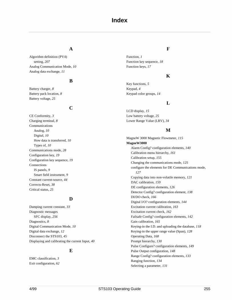
Index
4/99 STS103 Operating Guide 255
A
Algorithm definition (PV4)
setting, 207
Analog Communication Mode, 10
Analog data exchange, 11
B
Battery charger, 8
Battery pack location, 8
Battery voltage, 25
C
CE Conformity, 3
Charging terminal, 8
Communications
Analog, 10
Digital, 10
How data is transferred, 10
Types of, 10
Communications mode, 28
Configuration key, 19
Configuration key sequence, 19
Connections
IS panels, 9
Smart field instrument, 9
Constant current-source, 44
Corrects-Reset, 38
Critical status, 25
D
Damping current constant, 33
Diagnostic messages
SFC display, 256
Diagnostics, 8
Digital Communication Mode, 10
Digital data exchange, 12
Disconnect the STS103, 45
Displaying and calibrating the current Input, 40
E
EMC classification, 3
Exit configuration, 62
F
Function, 1
Function key sequence, 18
Function keys, 17
K
Key functions, 5
Keypad, 4
Keypad color groups, 14
L
LCD display, 15
Low battery voltage, 25
Lower Range Value (LRV), 34
M
MagneW 3000 Magnetic Flowmeter, 115
MagneW3000Alarm Config? configuration elements, 140
Calibration menu hierarchy, 161
Calibration setup, 155
Changing the communications mode, 125
configure the elements for DE Communications mode,
127
Copying data into non-volatile memory, 121
DAC calibration, 159
DE configuration elements, 126
Detector Config? configuration element, 138
DI/DO check, 166
Digital I/O? configuration elements, 144
Excitation current calibration, 163
Excitation current check, 162
Failsafe Config? configuration elements, 142
Gain calibration, 165
Keying-in the I.D. and uploading the database, 118
Keying-in the upper range value (Span), 128
Operating Data, 168
Prompt hierarchy, 130
Pulse Configure? configuration elements, 149
Pulse Output configuration, 148
Range Config? configuration elements, 133
Ranging function, 134
Selecting a parameter, 131
Index
256 STS103 Operating Guide 4/99
MagneW3000, cont’dSelecting the units, 123
Set Trip Value? configuration, 151
STS103 – MagneW connections, 117
Totalizer Menu elements, 146
Trouble shooting Procedure, 175
Units key?, 132
Multiple process variables, 17
N
Non-critical status, 25
O
OK Status, 25
Operation (SFC)
Changing the span of the device, 36
Changing the upper range limit, 37
Constant current-source, 43
Diagnostic Messages, 26
Displaying the SFI diagnostic status, 41
Displaying the software version, 41
Introduction, 23
Output mode (see section 3.5), 39
Resetting the SFI, 38
Self-diagnostics., 25
Software version, 41
Writing data in the scratch pad, 42
Output characterization (PV3)
Selecting, 201
output mode, 39
P
Physical description, 3
Power-up key and display sequences, 24
Probe config, 95
Probe types, 97
R
Ranging functions, 134
S
Scratch pad, 42
SMV 3000Adjusting the damping time, 186
Algorithm selection for PV4, 207
SMV 3000, cont’dDefining flow equation for PV4, 203
Output characterization for PV3, 201
PV1 priority, 183
Selecting engineering units, 188
Tag number, 183
Entering a sample tag number, 183
Thermocouple fault detection for PV3, 200
Algorithm parameters for PV4), 215
Basic gas flow equation, 204
Calculated flow rate PV4 simple equation parameters,
214
Calibrate output signal (analog mode), 245
Calibration, 245
Cold junction (CJ) compensation selection, 195
Communication Status Messages, 261
Copying data into non-volatile memory, 182
CUSTOM units, 206
DE configuration parameters, 240
Design density units for PV4, 193
Diagnostic Messages, 256
Dynamic compensation flow equations, 203
Engineering units for PV1 and PV2, 189
Engineering units for PV3, 190
Engineering units for PV4, 192
Flow calculation, 206
Gas Kuser quick calculation, 204
Input filter frequency selection for PV3, 197
Low flow cutoff limits for PV4, 219
Message Format (DE mode), 244
Operating data, 251
Output conformity, 185
Probe type identification for PV3, 194
PV4 URL and LRL, 235
PVs for broadcast (DE mode), 240
Range values (LRV and URV) for PV1, 222
Range values (LRV and URV) for PV2, 226
Range values (LRV and URV) for PV3, 229
Range values (LRV and URV) for PV4, 237
Selecting the PV for analog output:, 220
Setting range values (LRV and URV) using applied
pressure for PV1, 223
Setting range values (LRV and URV) using applied input
signals for PV3, 232
Setting range values (LRV and URV) using applied
pressure for PV2, 228
Setting range values for PV1, 222
Setting range values for PV2, 226
Index
4/99 STS103 Operating Guide 257
SMV 3000, cont’dSetting range values for PV3, 229
Setting URL and range values for PV4, 235
SFC Diagnostic Messages, 263
Span, 222, 226, 229, 237
STS103 – SMV3000 connection, 179
Superheated steam flow equation, 205
Uploading the database, 180
SMV 3000 Multivariable Transmitter, 177
Span, 36
Specifications, 2
ST3000Adjusting the damping time, 53
Changing the communications mode, 55
Configuration procedure, 63
Copying data into non-volatile memory, 52
DE configuration elements, 56
Diagnostic Messages, 72
Do a DAC calibration, 64
Keying-in the I.D. and uploading the database, 50
Lower Range Value (LRV), 58
Operating Data, 68
Selecting a parameter, 62
Selecting the units, 54
Set the lower range value, 60
Set the upper range value, 61
Setting the upper and lower range values of the
transmitter using an applied pressure, 60
STS103 – ST3000 connection, 49
Upper Range Value (URV), 58
ST3000 Pressure Transmitter, 47
Steam Kuser quick calculation, 205
Storing data, 32
STT3000Adjusting the damping time, 84
Configuration procedure, 94
DE Communications mode, 88
DE configuration elements, 87
Diagnostic Messages, 110
Keying-in the I.D. and uploading the database, 81
Keying-in the upper and lower range values, 89
lower range value (LRV), 89
Operating Data, 106
Probe config elements, 95, 96
Probe Configuration, 98
Probe types, 97
Selecting the units, 85
Set the lower range value using applied value, 91
Set the upper range value using applied value, 92
STS103 – STT3000 connection, 79, 80
Trouble shooting Procedure, 114
Upper range value (URV), 90
SFC switch and terminals, 7
U
Upper Range Limit, 37
Upper Range Value (URV), 35
User Interface functions and guidelines, 13


READER COMMENTS
Honeywell’s IAC Automation College welcomes your comments and suggestions to improve future editionsof this and other publications.
You can communicate your thoughts to us either by mail using this form, or a toll-free telephone call.
BY TELEPHONE: In the U.S.A. use our toll-free number 1*800-822-7673 (available in the48 contiguous states except Arizona; in Arizona dial 1-602-863-5558).
BY MAIL: Use this form; detach, fold, tape closed, and mail to us. We would like toacknowledge your comments; please include your complete name and address.
Title of Publication: Smart Field Communicator Model STS103 Operating Guide
Publication Number: 34-ST-11-14 Issue Date: 4/99
Writer: Dave Taunton
COMMENTS: ________________________________________________________________________
_______________________________________________________________________________
_______________________________________________________________________________
_______________________________________________________________________________
_______________________________________________________________________________
_______________________________________________________________________________
_______________________________________________________________________________
_______________________________________________________________________________
_______________________________________________________________________________
RECOMMENDATIONS:_________________________________________________________
_______________________________________________________________________________
_______________________________________________________________________________
_______________________________________________________________________________
_______________________________________________________________________________
_______________________________________________________________________________
_______________________________________________________________________________
_______________________________________________________________________________
NAME _____________________________________________________ DATE ____________
TITLE _________________________________________________________________________
COMPANY_____________________________________________________________________
ADDRESS______________________________________________________________________
CITY ______________________________ STATE_________________ ZIP________________
(If returning by mail, please tape closed; Postal regulations prohibit use of staples.)

Automation College Industrial Automation and Control Honeywell Inc. 2820 West Kelton Lane Phoenix, Arizona 85023
Communications concerning technical publications should be directed to:
FOLD FOLD
From: NO POSTAGE NECESSARY
IF MAILED IN THE USA
BUSINESS REPLY MAIL
POSTAGE WILL BE PAID BY ....
Industrial Automation and Control 2820 West Kelton Lane Phoenix, Arizona 85023
Attention: Manager, Quality
Additional Comments:
Cut
Alo
ng L
ine
FOLD FOLD
FIRST CLASS PERMIT NO. 4332 PHOENIX, ARIZONA
Honeywell


Industrial Automation and Control
Honeywell Inc.
16404 N. Black Canyon Highway
Phoenix, Arizona 85023