Embed Size (px)
Citation preview
ST 3000 Smart Transmitter Series 100 Flange Mounted Liquid Level Models Specifications 34-ST-03-63 August 2011
Introduction
In 1983, Honeywell introduced the first Smart Pressure
Transmitter― the ST 3000®. In 1989, Honeywell
launched the first all digital, bi-directional protocol for
smart field devices. Today, its ST 3000 Series 100
Flange-mount Transmitters continue to bring proven
“smart” technology to a wide spectrum of measurement
applications. Honeywell flange-mount transmitters may
be installed directly onto a tank flange and are offered
with a variety of tank connections to include ANSI flange
connections. Typical applications are high accuracy level
measurement in pressurized and un-pressurized vessels
in the chemical and hydrocarbon industries. Honeywell
flange mount transmitters demonstrate proven reliability
in hundreds on installations in a wide variety of industries
and applications. All ST 3000 transmitters can provide a
4-20 mA output, Honeywell Digitally Enhanced (DE)
output, HART® output, or Foundation™ Fieldbus output.
When digitally integrated with Honeywell’s Process
Knowledge System™, EXPERION PKS™, ST 3000
instruments provide a more accurate process variable as
well as advanced diagnostics.
Models
STF128 0 to 400 inH2O 0 to 1,000 mbar
STF132 0 to 100 psi 0 to 7bar
STF12F 0 to 400 inH2O 0 to 1,000 mbar
STF13F 0 to 100 psi 0 to 7 bar
STF14F 0 to 600 inH2O 0 to 1,500 mbar
The devices provide comprehensive self-diagnostics to
help users maintain high uptime, meet regulatory
requirements, and attain high quality standards. S100
transmitters are ideal for critical applications, such as
custody transfer of natural gas and energy and material
balances, where accuracy and stability are of the utmost
importance.
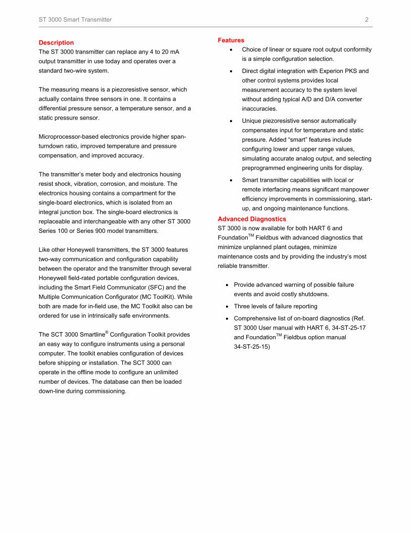
Figure 1 - On the left is Model STF12F, STF13F and STF14F. In the middle is Model STF128 and STF132 (extended
diaphragm). On the right is Model STF128 and STF132.
All these Series 100 Flange Mounted Liquid Level Pressure Transmitters feature proven piezoresistive sensor technology
Honeywell’s high-performance ST 3000 S100 transmitters
lead the industry in:
Accuracy
Stability
Reliability
Rangeability
Warranty
Includes Lifetime™ Transmitters:
ST 3000 Lifetime™ Transmitter Benefits
Total Accuracy = ±0.0375%
Stability = ±0.01% per year
Reliability = 470 years MTBF
Rangeability = 400 to 1
Lifetime Warranty = 15 years
ST 3000 Smart Transmitter 2
Description
The ST 3000 transmitter can replace any 4 to 20 mA
output transmitter in use today and operates over a
standard two-wire system.
The measuring means is a piezoresistive sensor, which
actually contains three sensors in one. It contains a
differential pressure sensor, a temperature sensor, and a
static pressure sensor.
Microprocessor-based electronics provide higher span-
turndown ratio, improved temperature and pressure
compensation, and improved accuracy.
The transmitter’s meter body and electronics housing
resist shock, vibration, corrosion, and moisture. The
electronics housing contains a compartment for the
single-board electronics, which is isolated from an
integral junction box. The single-board electronics is
replaceable and interchangeable with any other ST 3000
Series 100 or Series 900 model transmitters.
Like other Honeywell transmitters, the ST 3000 features
two-way communication and configuration capability
between the operator and the transmitter through several
Honeywell field-rated portable configuration devices,
including the Smart Field Communicator (SFC) and the
Multiple Communication Configurator (MC ToolKit). While
both are made for in-field use, the MC Toolkit also can be
ordered for use in intrinsically safe environments.
The SCT 3000 Smartline® Configuration Toolkit provides
an easy way to configure instruments using a personal
computer. The toolkit enables configuration of devices
before shipping or installation. The SCT 3000 can
operate in the offline mode to configure an unlimited
number of devices. The database can then be loaded
down-line during commissioning.
Features
Choice of linear or square root output conformity
is a simple configuration selection.
Direct digital integration with Experion PKS and
other control systems provides local
measurement accuracy to the system level
without adding typical A/D and D/A converter
inaccuracies.
Unique piezoresistive sensor automatically
compensates input for temperature and static
pressure. Added “smart” features include
configuring lower and upper range values,
simulating accurate analog output, and selecting
preprogrammed engineering units for display.
Smart transmitter capabilities with local or
remote interfacing means significant manpower
efficiency improvements in commissioning, start-
up, and ongoing maintenance functions.
Advanced Diagnostics
ST 3000 is now available for both HART 6 and
FoundationTM Fieldbus with advanced diagnostics that
minimize unplanned plant outages, minimize
maintenance costs and by providing the industry’s most
reliable transmitter.
Provide advanced warning of possible failure
events and avoid costly shutdowns.
Three levels of failure reporting
Comprehensive list of on-board diagnostics (Ref.
ST 3000 User manual with HART 6, 34-ST-25-17
and FoundationTM Fieldbus option manual
34-ST-25-15)
ST 3000 Smart Transmitter 3
Operating Conditions – All Models Parameter Reference
Condition Rated Condition Operative Limits Transportation
and Storage °C °F °C °F °C °F °C °F
Ambient Temperature All models except STF14F STF14F
25±1 25±1
77±2 77±2
-40 to 85 -40 to 85
-40 to 185 -40 to 185
-40 to 93 -40 to 85
-40 to 200 -40 to 185
-55 to 125-55 to 125
-67 to 257 -67 to 257
Meter Body Temperature All models except STF14F
STF14F
25±1 25±1
77±2 77±2
-40 to 110*-40 to 85
-40 to 230* -40 to 185
-40 to 125 -40 to 85
-40 to 257 -40 to 185
-55 to 125-55 to 125
-67 to 257 -67 to 257
Process Interface Temp.
STF128, STF132 only
25±1
77±2
-40 to 110*
-40 to 230*
-40 to 175**
-40 to 350**
-55 to 125
-67 to 257
Humidity %RH 10 to 55 0 to 100 0 to 100 0 to 100
Minimum Pressure mmHg absolute inH2O absolute
atmospheric atmospheric
25 13
2 (short term ***) 1 (short term ***)
Supply Voltage, Current, and Load Resistance
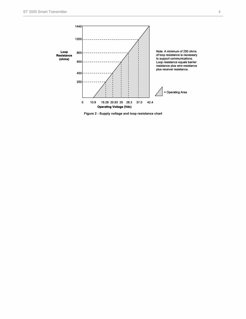
Voltage Range: 10.8 to 42.4 Vdc at terminals Current Range: 3.0 to 21.8 mA Load Resistance: 0 to 1,440 ohms (as shown in Figure 2)
* For CTFE fill fluid, the rating is –15 to 110 °C (5 to 230°F)
** For CTFE fill fluid, the maximum temperature rating is 150°C (300°F)
*** Short term equals 2 hours at 70°C (158 °F)
Maximum Allowable Working Pressure (MAWP) 3, 4
(ST 3000 products are rated to Maximum Allowable Working Pressure. MAWP depends on Approval Agency and transmitter materials of construction.)
STF 128, STF 132 Flange Material
Ambient Temperature -29 to 38°C
[-20 to 100°F]
Maximum Meterbody
Temperature 125°C [257°F]
Process Interface Temperature 175°C [350°F]
ANSI Class 150
psi [ bar]
Carbon Steel
304 S.S.
316 S.S.
285 [19.6]
275 [19.0]
275 [19.0]
245 [16.9]
218 [15.0]
225 [15.5]
215 [14.8]
198 [13.7]
205 [14.1]
ANSI Class 300
psi [bar]
Carbon Steel
304 S.S.
316 S.S.
740 [51.0]
720 [49.6]
720 [49.6]
668 [46.0]
570 [39.3]
590 [40.7]
645 [44.5]
518 [35.7]
538 [37.1]
DN PN40
psi [bar]
Carbon Steel
304 S.S.
316 S.S.
580 [40.0] 1
534 [36.8] 1
534 [36.8] 1
574 [39.6]
419 [28.9]
434 [29.9]
559 [38.5]
385 [26.5]
399 [27.5]
STF12F, STF13F, STF14F
ANSI Class 150
psi [bar]
316L Stainless Steel
230 [15.9]
185 [12.8]
No rating at this temp
1 Ambient Temperature for DN PN40 is –10 to 50°C [14 to 122 F] 3 MAWP applies for temperature range -40 to 125°C. However, Static Pressure Limit is de-rated to 3,000 psi from -26°C to -40°C.
Use of graphite o-rings de-rates transmitter to 3,625 psi. Use of adaptor with graphite o-rings de-rates transmitter to 3,000 psi. 4 Consult factory for MAWP of ST 3000 transmitters with CSA approval.
ST 3000 Smart Transmitter 4
Figure 2 - Supply voltage and loop resistance chart
Note: A minimum of 25of loop resistance is neceto support communicationLoop resistance equals bresistance plus wire resiplus receiver resistance.
= Operating Area
0 10.8 16.28 20.63 25 28.3 37.0 42.4
1440
1200
800
650
450
250
Operating Voltage (Vdc)
LoopResistance
(ohms)
0 ohms ssary s.
arrier stance
ST 3000 Smart Transmitter 5
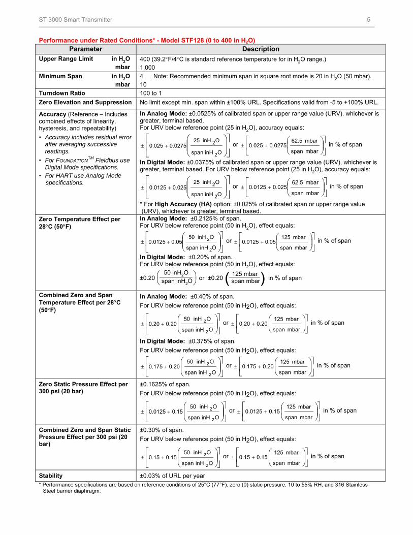
Performance under Rated Conditions* - Model STF128 (0 to 400 in H2O) Parameter Description
Upper Range Limit in H2O mbar
400 (39.2F/4C is standard reference temperature for in H2O range.) 1,000
Minimum Span in H2O mbar
4 Note: Recommended minimum span in square root mode is 20 in H2O (50 mbar). 10
Turndown Ratio 100 to 1
Zero Elevation and Suppression No limit except min. span within ±100% URL. Specifications valid from -5 to +100% URL.
Accuracy (Reference – Includes combined effects of linearity, hysteresis, and repeatability)
• Accuracy includes residual error after averaging successive readings.
• For FOUNDATIONTM Fieldbus use
Digital Mode specifications. • For HART use Analog Mode specifications.
In Analog Mode: ±0.0525% of calibrated span or upper range value (URV), whichever is greater, terminal based. For URV below reference point (25 in H2O), accuracy equals:
OinHspan
OinH250.02750.025
2
2 or
mbar span
mbar 62.50.02750.025 in % of span
In Digital Mode: ±0.0375% of calibrated span or upper range value (URV), whichever is greater, terminal based. For URV below reference point (25 in H2O), accuracy equals:
OinHspan
OinH250.0250.0125
2
2 or
mbar span
mbar 62.50.0250.0125 in % of span
* For High Accuracy (HA) option: ±0.025% of calibrated span or upper range value (URV), whichever is greater, terminal based.
Zero Temperature Effect per 28C (50F)
In Analog Mode: ±0.2125% of span. For URV below reference point (50 in H2O), effect equals:
OinHspan
OinH500.050.0125
2
2 or
mbar span
mbar 1250.050.0125 in % of span
In Digital Mode: ±0.20% of span. For URV below reference point (50 in H2O), effect equals:
±0.20
50 inH2O
span inH2O or ±0.20 ( )125 mbar
span mbar in % of span
Combined Zero and Span Temperature Effect per 28C (50F)
In Analog Mode: ±0.40% of span.
For URV below reference point (50 in H2O), effect equals:
OinHspan
OinH05 0.200.20
2
2 or
mbar span
mbar 125 0.200.20 in % of span
In Digital Mode: ±0.375% of span.
For URV below reference point (50 in H2O), effect equals:
OinHspan
OinH05 0.200.175
2
2 or
mbar span
mbar 125 0.200.175 in % of span
Zero Static Pressure Effect per 300 psi (20 bar)
±0.1625% of span.
For URV below reference point (50 in H2O), effect equals:
OinHspan
OinH05 0.150.0125
2
2 or
mbar span
mbar 125 0.150.0125 in % of span
Combined Zero and Span Static Pressure Effect per 300 psi (20 bar)
±0.30% of span.
For URV below reference point (50 in H2O), effect equals:
OinHspan
OinH05 0.150.15
2
2 or
mbar span
mbar 125 0.150.15 in % of span
Stability ±0.03% of URL per year
* Performance specifications are based on reference conditions of 25°C (77°F), zero (0) static pressure, 10 to 55% RH, and 316 Stainless Steel barrier diaphragm.
ST 3000 Smart Transmitter 6
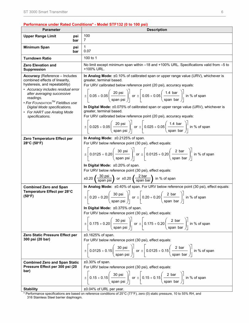
Performance under Rated Conditions* - Model STF132 (0 to 100 psi) Parameter Description
Upper Range Limit psi bar
100 7
Minimum Span psi bar
1 0.07
Turndown Ratio 100 to 1
Zero Elevation and Suppression
No limit except minimum span within –18 and +100% URL. Specifications valid from –5 to +100% URL.
Accuracy (Reference – Includes combined effects of linearity, hysteresis, and repeatability) • Accuracy includes residual error
after averaging successive readings.
• For FOUNDATIONTM Fieldbus use
Digital Mode specifications. • For HART use Analog Mode specifications.
In Analog Mode: ±0.10% of calibrated span or upper range value (URV), whichever is greater, terminal based. For URV calibrated below reference point (20 psi), accuracy equals:
sipspan
psi20 0.050.05 or
bar span
bar 1.4 0.050.05 in % of span
In Digital Mode: ±0.075% of calibrated span or upper range value (URV), whichever is greater, terminal based. For URV calibrated below reference point (20 psi), accuracy equals:
sipspan
psi20 0.050.025 or
bar span
bar 1.4 0.050.025 in % of span
Zero Temperature Effect per 28C (50F)
In Analog Mode: ±0.2125% of span. For URV below reference point (30 psi), effect equals:
sipspan
psi30 0.200.0125 or
bar span
bar 2 0.200.0125 in % of span
In Digital Mode: ±0.20% of span. For URV below reference point (30 psi), effect equals:
±0.20 ( )30 psi span psi
or ±0.20 ( )2 bar span bar in % of span
Combined Zero and Span Temperature Effect per 28C (50F)
In Analog Mode: ±0.40% of span. For URV below reference point (30 psi), effect equals:
sipspan
psi30 0.200.20 or
bar span
bar 2 0.200.20 in % of span
In Digital Mode: ±0.375% of span. For URV below reference point (30 psi), effect equals:
sipspan
psi30 0.200.175 or
bar span
bar 2 0.200.175 in % of span
Zero Static Pressure Effect per 300 psi (20 bar)
±0.1625% of span. For URV below reference point (30 psi), effect equals:
sipspan
psi30 0.150.0125 or
bar span
bar 2 0.150.0125 in % of span
Combined Zero and Span Static Pressure Effect per 300 psi (20 bar)
±0.30% of span. For URV below reference point (30 psi), effect equals:
sipspan
psi30 0.150.15 or
bar span
bar 2 0.150.15 in % of span
Stability ±0.04% of URL per year. * Performance specifications are based on reference conditions of 25°C (77°F), zero (0) static pressure, 10 to 55% RH, and 316 Stainless Steel barrier diaphragm.
ST 3000 Smart Transmitter 7
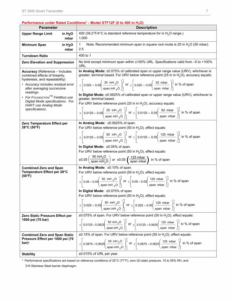
Performance under Rated Conditions* - Model STF12F (0 to 400 in H2O) Parameter Description
Upper Range Limit in H2O mbar
400 (39.2°F/4°C is standard reference temperature for in H2O range.) 1,000
Minimum Span in H2O mbar
1 Note: Recommended minimum span in square root mode is 20 in H2O (50 mbar). 2.5
Turndown Ratio 400 to 1
Zero Elevation and Suppression No limit except minimum span within ±100% URL. Specifications valid from –5 to +100% URL.
Accuracy (Reference – Includes combined effects of linearity, hysteresis, and repeatability)
• Accuracy includes residual error after averaging successive readings.
• For FOUNDATIONTM Fieldbus use
Digital Mode specifications. For HART use Analog Mode specifications.
In Analog Mode: ±0.075% of calibrated span or upper range value (URV), whichever is greater, terminal based. For URV below reference point (25 in in H2O), accuracy equals:
OinHspan
OinH520.050.025
2
2 or
mbar span
mbar 620.050.025 in % of span
In Digital Mode: ±0.0625% of calibrated span or upper range value (URV), whichever is greater, terminal based. For URV below reference point (25 in in H2O), accuracy equals:
OinHspan
OinH250.050.0125
2
2 or
mbar span
mbar 620.050.0125 in % of span
Zero Temperature Effect per 28°C (50°F)
In Analog Mode: ±0.0625% of span. For URV below reference point (50 in H2O), effect equals:
OinHspan
OinH050.050.0125
2
2 or
mbar span
mbar 1250.050.0125 in % of span
In Digital Mode: ±0.05% of span. For URV below reference point (50 in H2O), effect equals:
±0.05
50 inH2O
span inH2O or ±0.05 ( )125 mbar
span mbar in % of span
Combined Zero and Span Temperature Effect per 28°C (50°F)
In Analog Mode: ±0.10% of span. For URV below reference point (50 in H2O), effect equals:
OinHspan
OinH500.050.05
2
2 or
mbar span
mbar 1250.050.05 in % of span
In Digital Mode: ±0.075% of span. For URV below reference point (50 in H2O), effect equals:
OinHspan
OinH500.050.025
2
2 or
mbar span
mbar 1250.050.025 in % of span
Zero Static Pressure Effect per 1000 psi (70 bar)
±0.075% of span. For URV below reference point (50 in H2O), effect equals:
OinHspan
OinH500.06250.0125
2
2 or
mbar span
mbar 1250.06250.0125 in % of span
Combined Zero and Span Static Pressure Effect per 1000 psi (70 bar)•
±0.15% of span. For URV below reference point (50 in H2O), effect equals:
OinHspan
OinH500.06250.0875
2
2 or
mbar span
mbar 1250.06250.0875 in % of span
Stability ±0.015% of URL per year.
* Performance specifications are based on reference conditions of 25°C (77°F), zero (0) static pressure, 10 to 55% RH, and
316 Stainless Steel barrier diaphragm.
ST 3000 Smart Transmitter 8
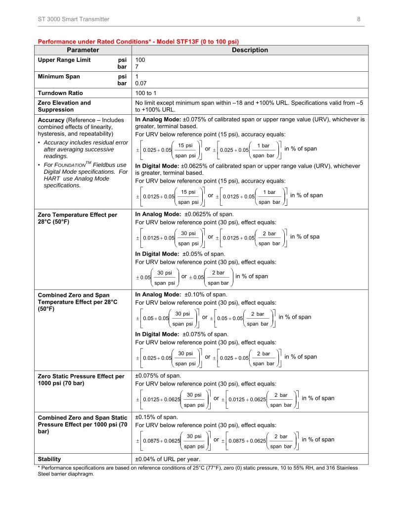
Performance under Rated Conditions* - Model STF13F (0 to 100 psi) Parameter Description
Upper Range Limit psi bar
100 7
Minimum Span psi bar
1 0.07
Turndown Ratio 100 to 1
Zero Elevation and Suppression
No limit except minimum span within –18 and +100% URL. Specifications valid from –5 to +100% URL.
Accuracy (Reference – Includes combined effects of linearity, hysteresis, and repeatability)
• Accuracy includes residual error after averaging successive readings.
• For FOUNDATIONTM Fieldbus use
Digital Mode specifications. For HART use Analog Mode specifications.
In Analog Mode: ±0.075% of calibrated span or upper range value (URV), whichever is greater, terminal based. For URV below reference point (15 psi), accuracy equals:
psispan
psi150.050.025 or
bar span
bar 10.050.025 in % of span
In Digital Mode: ±0.0625% of calibrated span or upper range value (URV), whichever is greater, terminal based. For URV below reference point (15 psi), accuracy equals:
psispan
psi150.050.0125 or
bar span
bar 10.050.0125 in % of span
Zero Temperature Effect per 28°C (50°F)
In Analog Mode: ±0.0625% of span. For URV below reference point (30 psi), effect equals:
psispan
psi300.050.0125 or
bar span
bar 20.050.0125 in % of spa
In Digital Mode: ±0.05% of span. For URV below reference point (30 psi), effect equals:
psispan
psi300.05 or
barspan
bar20.05 in % of span
Combined Zero and Span Temperature Effect per 28°C (50°F)
In Analog Mode: ±0.10% of span. For URV below reference point (30 psi), effect equals:
psispan
psi300.050.05 or
bar span
bar 20.050.05 in % of span
In Digital Mode: ±0.075% of span. For URV below reference point (30 psi), effect equals:
psispan
psi300.050.025 or
bar span
bar 20.050.025 in % of span
Zero Static Pressure Effect per 1000 psi (70 bar)
±0.075% of span. For URV below reference point (30 psi), effect equals:
psispan
psi300.06250.0125 or
bar span
bar 20.06250.0125 in % of span
Combined Zero and Span Static Pressure Effect per 1000 psi (70 bar)
±0.15% of span. For URV below reference point (30 psi), effect equals:
psispan
psi300.06250.0875 or
bar span
bar 20.06250.0875 in % of span
Stability ±0.04% of URL per year.
* Performance specifications are based on reference conditions of 25°C (77°F), zero (0) static pressure, 10 to 55% RH, and 316 Stainless Steel barrier diaphragm.
ST 3000 Smart Transmitter 9
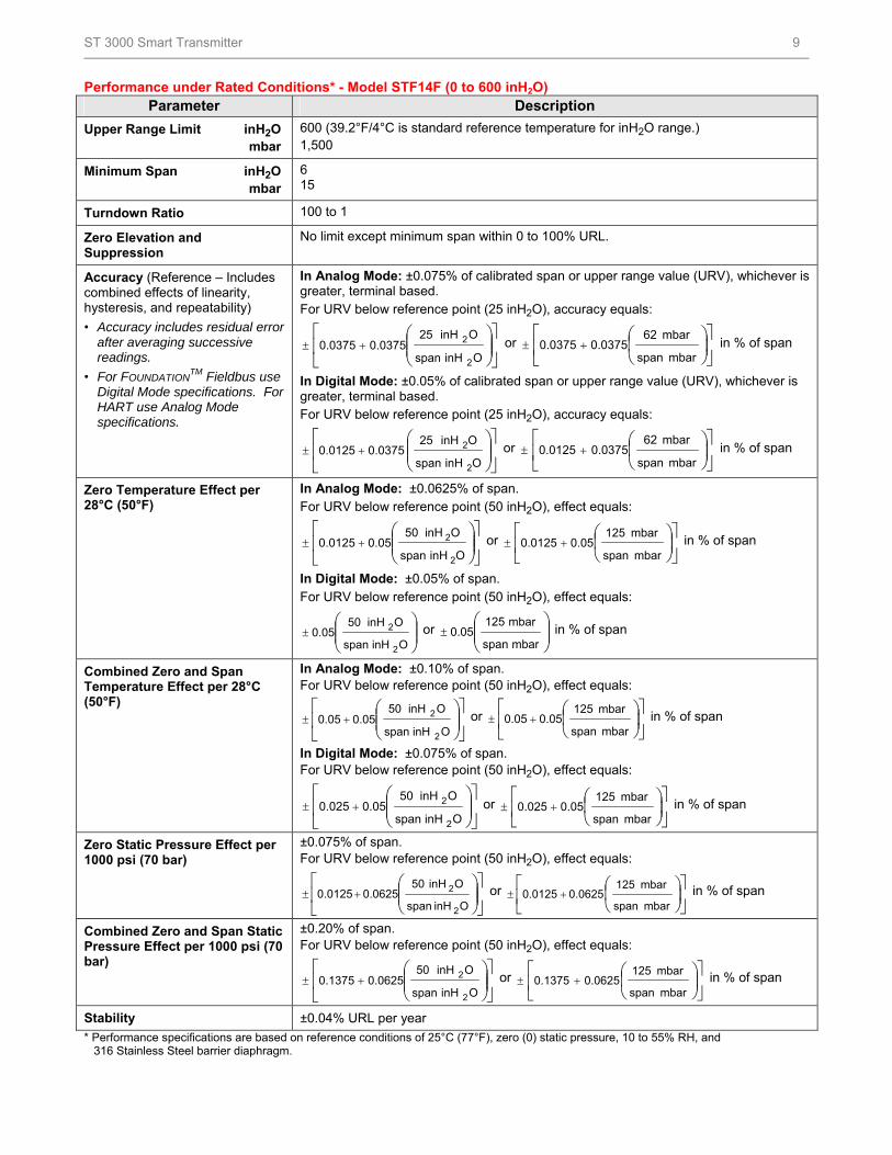
Performance under Rated Conditions* - Model STF14F (0 to 600 inH2O) Parameter Description
Upper Range Limit inH2O mbar
600 (39.2°F/4°C is standard reference temperature for inH2O range.) 1,500
Minimum Span inH2O mbar
6 15
Turndown Ratio 100 to 1
Zero Elevation and Suppression
No limit except minimum span within 0 to 100% URL.
Accuracy (Reference – Includes combined effects of linearity, hysteresis, and repeatability)
• Accuracy includes residual error after averaging successive readings.
• For FOUNDATIONTM Fieldbus use
Digital Mode specifications. For HART use Analog Mode specifications.
In Analog Mode: ±0.075% of calibrated span or upper range value (URV), whichever is greater, terminal based. For URV below reference point (25 inH2O), accuracy equals:
OinHspan
OinH250.03750.0375
2
2 or
mbar span
mbar 620.03750.0375 in % of span
In Digital Mode: ±0.05% of calibrated span or upper range value (URV), whichever is greater, terminal based. For URV below reference point (25 inH2O), accuracy equals:
OinHspan
OinH25 0.03750.0125
2
2 or
mbar span
mbar 620.03750.0125 in % of span
Zero Temperature Effect per 28°C (50°F)
In Analog Mode: ±0.0625% of span. For URV below reference point (50 inH2O), effect equals:
OinHspan
OinH500.050.0125
2
2 or
mbar span
mbar 1250.050.0125 in % of span
In Digital Mode: ±0.05% of span. For URV below reference point (50 inH2O), effect equals:
OinHspan
OinH500.05
2
2 or
mbarspan
mbar1250.05 in % of span
Combined Zero and Span Temperature Effect per 28°C (50°F)
In Analog Mode: ±0.10% of span. For URV below reference point (50 inH2O), effect equals:
OinHspan
OinH500.050.05
2
2 or
mbar span
mbar 1250.050.05 in % of span
In Digital Mode: ±0.075% of span. For URV below reference point (50 inH2O), effect equals:
OinHspan
OinH500.050.025
2
2 or
mbar span
mbar 1250.050.025 in % of span
Zero Static Pressure Effect per 1000 psi (70 bar)
±0.075% of span. For URV below reference point (50 inH2O), effect equals:
OinHspan
OinH500.06250.0125
2
2 or
mbar span
mbar 1250.06250.0125 in % of span
Combined Zero and Span Static Pressure Effect per 1000 psi (70 bar)
±0.20% of span. For URV below reference point (50 inH2O), effect equals:
OinHspan
OinH500.06250.1375
2
2 or
mbar span
mbar 1250.06250.1375 in % of span
Stability ±0.04% URL per year
* Performance specifications are based on reference conditions of 25°C (77°F), zero (0) static pressure, 10 to 55% RH, and 316 Stainless Steel barrier diaphragm.
ST 3000 Smart Transmitter 10
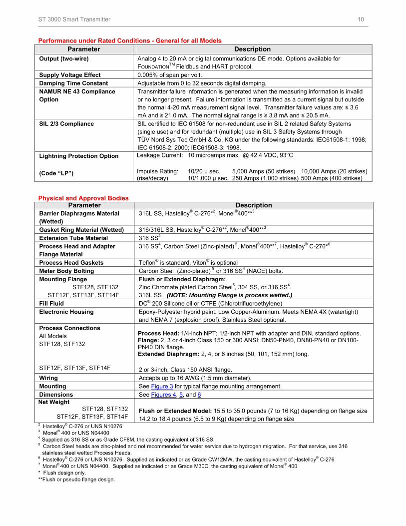
Performance under Rated Conditions - General for all Models Parameter Description
Output (two-wire) Analog 4 to 20 mA or digital communications DE mode. Options available for FOUNDATION
TM Fieldbus and HART protocol.
Supply Voltage Effect 0.005% of span per volt. Damping Time Constant Adjustable from 0 to 32 seconds digital damping. NAMUR NE 43 Compliance Option
Transmitter failure information is generated when the measuring information is invalid or no longer present. Failure information is transmitted as a current signal but outside the normal 4-20 mA measurement signal level. Transmitter failure values are: ≤ 3.6 mA and ≥ 21.0 mA. The normal signal range is ≥ 3.8 mA and ≤ 20.5 mA.
SIL 2/3 Compliance SIL certified to IEC 61508 for non-redundant use in SIL 2 related Safety Systems (single use) and for redundant (multiple) use in SIL 3 Safety Systems through TÜV Nord Sys Tec GmbH & Co. KG under the following standards: IEC61508-1: 1998; IEC 61508-2: 2000; IEC61508-3: 1998.
Lightning Protection Option
(Code “LP”)
Leakage Current: 10 microamps max. @ 42.4 VDC, 93°C
Impulse Rating: 10/20 µ sec. 5,000 Amps (50 strikes) 10,000 Amps (20 strikes)(rise/decay) 10/1,000 µ sec. 250 Amps (1,000 strikes) 500 Amps (400 strikes)
Physical and Approval Bodies Parameter Description
Barrier Diaphragms Material (Wetted)
316L SS, Hastelloy® C-276*2, Monel®400**3
Gasket Ring Material (Wetted) 316/316L SS, Hastelloy® C-276*2, Monel®400**3 Extension Tube Material 316 SS4 Process Head and Adapter Flange Material
316 SS4, Carbon Steel (Zinc-plated) 5, Monel®400**7, Hastelloy® C-276*6
Process Head Gaskets Teflon® is standard. Viton® is optional Meter Body Bolting Carbon Steel (Zinc-plated) 5 or 316 SS4 (NACE) bolts. Mounting Flange STF128, STF132 STF12F, STF13F, STF14F
Flush or Extended Diaphragm: Zinc Chromate plated Carbon Steel5, 304 SS, or 316 SS4. 316L SS (NOTE: Mounting Flange is process wetted.)
Fill Fluid DC® 200 Silicone oil or CTFE (Chlorotrifluoroethylene) Electronic Housing Epoxy-Polyester hybrid paint. Low Copper-Aluminum. Meets NEMA 4X (watertight)
and NEMA 7 (explosion proof). Stainless Steel optional. Process Connections All Models STF128, STF132 STF12F, STF13F, STF14F
Process Head: 1/4-inch NPT; 1/2-inch NPT with adapter and DIN, standard options. Flange: 2, 3 or 4-inch Class 150 or 300 ANSI; DN50-PN40, DN80-PN40 or DN100-PN40 DIN flange. Extended Diaphragm: 2, 4, or 6 inches (50, 101, 152 mm) long.
2 or 3-inch, Class 150 ANSI flange. Wiring Accepts up to 16 AWG (1.5 mm diameter). Mounting See Figure 3 for typical flange mounting arrangement. Dimensions See Figures 4, 5, and 6 Net Weight STF128, STF132 STF12F, STF13F, STF14F
Flush or Extended Model: 15.5 to 35.0 pounds (7 to 16 Kg) depending on flange size 14.2 to 18.4 pounds (6.5 to 9 Kg) depending on flange size
2 Hastelloy® C-276 or UNS N10276 3 Monel® 400 or UNS N04400 4 Supplied as 316 SS or as Grade CF8M, the casting equivalent of 316 SS. 5 Carbon Steel heads are zinc-plated and not recommended for water service due to hydrogen migration. For that service, use 316
stainless steel wetted Process Heads. 6 Hastelloy® C-276 or UNS N10276. Supplied as indicated or as Grade CW12MW, the casting equivalent of Hastelloy® C-276 7 Monel® 400 or UNS N04400. Supplied as indicated or as Grade M30C, the casting equivalent of Monel® 400 * Flush design only. **Flush or pseudo flange design.
ST 3000 Smart Transmitter 11
NOTE: Pressure transmitters that are part of safety equipment for the protection of piping (systems) or vessel(s) from
exceeding allowable pressure limits, (equipment with safety functions in accordance with Pressure Equipment Directive
97/23/EC article 1, 2.1.3), require separate examination.
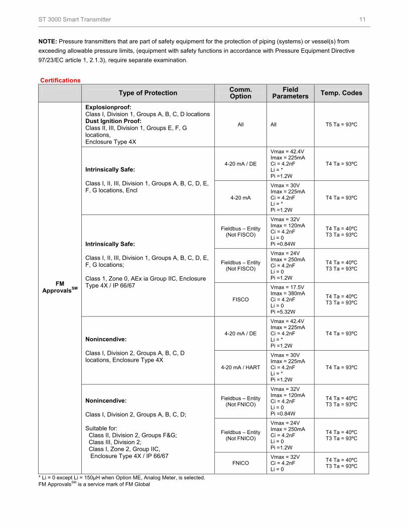
Certifications
Type of Protection Comm. Option
Field Parameters Temp. Codes
Explosionproof: Class I, Division 1, Groups A, B, C, D locations Dust Ignition Proof: Class II, III, Division 1, Groups E, F, G locations, Enclosure Type 4X
All All T5 Ta = 93ºC
4-20 mA / DE
Vmax = 42.4V Imax = 225mA Ci = 4.2nF Li = * Pi =1.2W
T4 Ta = 93ºC Intrinsically Safe: Class I, II, III, Division 1, Groups A, B, C, D, E, F, G locations, Encl
4-20 mA
Vmax = 30V Imax = 225mA Ci = 4.2nF Li = * Pi =1.2W
T4 Ta = 93ºC
Fieldbus – Entity (Not FISCO)
Vmax = 32V Imax = 120mA Ci = 4.2nF Li = 0 Pi =0.84W
T4 Ta = 40ºC T3 Ta = 93ºC
Fieldbus – Entity (Not FISCO)
Vmax = 24V Imax = 250mA Ci = 4.2nF Li = 0 Pi =1.2W
T4 Ta = 40ºC T3 Ta = 93ºC
Intrinsically Safe: Class I, II, III, Division 1, Groups A, B, C, D, E, F, G locations; Class 1, Zone 0, AEx ia Group IIC, Enclosure Type 4X / IP 66/67
FISCO
Vmax = 17.5V Imax = 380mA Ci = 4.2nF Li = 0 Pi =5.32W
T4 Ta = 40ºC T3 Ta = 93ºC
4-20 mA / DE
Vmax = 42.4V Imax = 225mA Ci = 4.2nF Li = * Pi =1.2W
T4 Ta = 93ºC Nonincendive: Class I, Division 2, Groups A, B, C, D locations, Enclosure Type 4X
4-20 mA / HART
Vmax = 30V Imax = 225mA Ci = 4.2nF Li = * Pi =1.2W
T4 Ta = 93ºC
Fieldbus – Entity (Not FNICO)
Vmax = 32V Imax = 120mA Ci = 4.2nF Li = 0 Pi =0.84W
T4 Ta = 40ºC T3 Ta = 93ºC
Fieldbus – Entity (Not FNICO)
Vmax = 24V Imax = 250mA Ci = 4.2nF Li = 0 Pi =1.2W
T4 Ta = 40ºC T3 Ta = 93ºC
FM ApprovalsSM
Nonincendive: Class I, Division 2, Groups A, B, C, D; Suitable for: Class II, Division 2, Groups F&G; Class III, Division 2; Class I, Zone 2, Group IIC, Enclosure Type 4X / IP 66/67
FNICO Vmax = 32V Ci = 4.2nF Li = 0
T4 Ta = 40ºC T3 Ta = 93ºC
* Li = 0 except Li = 150µH when Option ME, Analog Meter, is selected. FM ApprovalsSM is a service mark of FM Global
ST 3000 Smart Transmitter 12
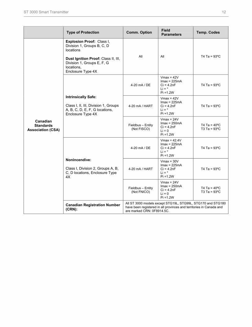
Type of Protection Comm. Option Field Parameters
Temp. Codes
Explosion Proof: Class I, Division 1, Groups B, C, D locations Dust Ignition Proof: Class II, III, Division 1, Groups E, F, G locations, Enclosure Type 4X
All All T4 Ta = 93ºC
4-20 mA / DE
Vmax = 42V Imax = 225mA Ci = 4.2nF Li = * Pi =1.2W
T4 Ta = 93ºC
4-20 mA / HART
Vmax = 42V Imax = 225mA Ci = 4.2nF Li = * Pi =1.2W
T4 Ta = 93ºC
Intrinsically Safe: Class I, II, III, Division 1, Groups A, B, C, D, E, F, G locations, Enclosure Type 4X
Fieldbus – Entity (Not FISCO)
Vmax = 24V Imax = 250mA Ci = 4.2nF Li = 0 Pi =1.2W
T4 Ta = 40ºC T3 Ta = 93ºC
4-20 mA / DE
Vmax = 42.4V Imax = 225mA Ci = 4.2nF Li = * Pi =1.2W
T4 Ta = 93ºC
4-20 mA / HART
Vmax = 30V Imax = 225mA Ci = 4.2nF Li = * Pi =1.2W
T4 Ta = 93ºC
Nonincendive: Class I, Division 2, Groups A, B, C, D locations, Enclosure Type 4X
Fieldbus – Entity (Not FNICO)
Vmax = 24V Imax = 250mA Ci = 4.2nF Li = 0 Pi =1.2W
T4 Ta = 40ºC T3 Ta = 93ºC
Canadian Standards
Association (CSA)
Canadian Registration Number (CRN):
All ST 3000 models except STG19L, STG99L, STG170 and STG180 have been registered in all provinces and territories in Canada and are marked CRN: 0F8914.5C.
ST 3000 Smart Transmitter 13
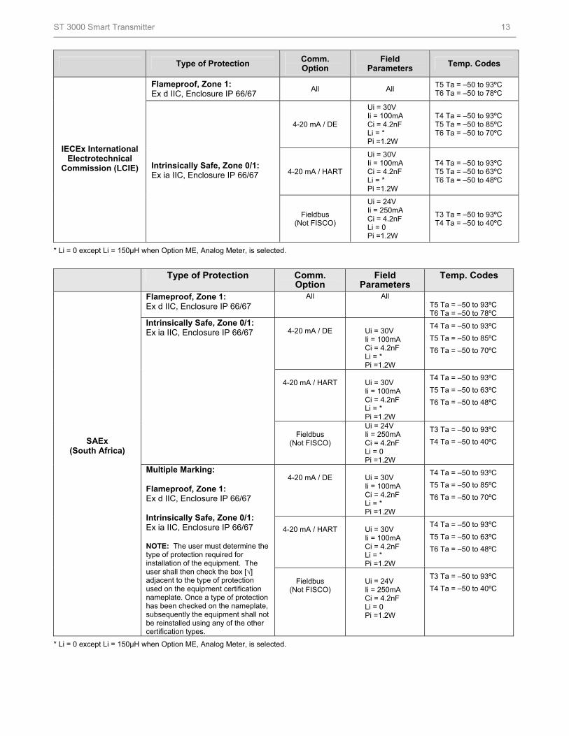
Type of Protection Comm. Option
Field Parameters
Temp. Codes
Flameproof, Zone 1: Ex d IIC, Enclosure IP 66/67
All All T5 Ta = –50 to 93ºC T6 Ta = –50 to 78ºC
4-20 mA / DE
Ui = 30V Ii = 100mA Ci = 4.2nF Li = * Pi =1.2W
T4 Ta = –50 to 93ºC T5 Ta = –50 to 85ºC T6 Ta = –50 to 70ºC
4-20 mA / HART
Ui = 30V Ii = 100mA Ci = 4.2nF Li = * Pi =1.2W
T4 Ta = –50 to 93ºC T5 Ta = –50 to 63ºC T6 Ta = –50 to 48ºC
IECEx International Electrotechnical
Commission (LCIE) Intrinsically Safe, Zone 0/1: Ex ia IIC, Enclosure IP 66/67
Fieldbus (Not FISCO)
Ui = 24V Ii = 250mA Ci = 4.2nF Li = 0 Pi =1.2W
T3 Ta = –50 to 93ºC T4 Ta = –50 to 40ºC
* Li = 0 except Li = 150µH when Option ME, Analog Meter, is selected.
Type of Protection Comm. Option
Field Parameters
Temp. Codes
Flameproof, Zone 1: Ex d IIC, Enclosure IP 66/67
All All T5 Ta = –50 to 93ºC T6 Ta = –50 to 78ºC
4-20 mA / DE
Ui = 30V Ii = 100mA Ci = 4.2nF Li = * Pi =1.2W
T4 Ta = –50 to 93ºC
T5 Ta = –50 to 85ºC
T6 Ta = –50 to 70ºC
4-20 mA / HART
Ui = 30V Ii = 100mA Ci = 4.2nF Li = * Pi =1.2W
T4 Ta = –50 to 93ºC
T5 Ta = –50 to 63ºC
T6 Ta = –50 to 48ºC
Intrinsically Safe, Zone 0/1: Ex ia IIC, Enclosure IP 66/67
Fieldbus
(Not FISCO)
Ui = 24V Ii = 250mA Ci = 4.2nF Li = 0 Pi =1.2W
T3 Ta = –50 to 93ºC
T4 Ta = –50 to 40ºC
4-20 mA / DE
Ui = 30V Ii = 100mA Ci = 4.2nF Li = * Pi =1.2W
T4 Ta = –50 to 93ºC
T5 Ta = –50 to 85ºC
T6 Ta = –50 to 70ºC
4-20 mA / HART
Ui = 30V Ii = 100mA Ci = 4.2nF Li = * Pi =1.2W
T4 Ta = –50 to 93ºC
T5 Ta = –50 to 63ºC
T6 Ta = –50 to 48ºC
SAEx (South Africa)
Multiple Marking: Flameproof, Zone 1: Ex d IIC, Enclosure IP 66/67 Intrinsically Safe, Zone 0/1: Ex ia IIC, Enclosure IP 66/67 NOTE: The user must determine the type of protection required for installation of the equipment. The user shall then check the box [√] adjacent to the type of protection used on the equipment certification nameplate. Once a type of protection has been checked on the nameplate, subsequently the equipment shall not be reinstalled using any of the other certification types.
Fieldbus
(Not FISCO)
Ui = 24V Ii = 250mA Ci = 4.2nF Li = 0 Pi =1.2W
T3 Ta = –50 to 93ºC
T4 Ta = –50 to 40ºC
* Li = 0 except Li = 150µH when Option ME, Analog Meter, is selected.
ST 3000 Smart Transmitter 14
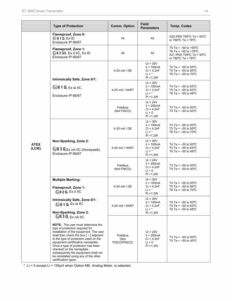
Type of Protection Comm. Option Field Parameters
Temp. Codes
Flameproof, Zone 0: , Ex tD
Enclosure IP 66/67 All All
A20 IP6X T95ºC Ta = 93ºC or T80ºC Ta = 78ºC
Flameproof, Zone 1: , Ex d IIC, Ex tD
Enclosure IP 66/67 All All
T5 Ta = –50 to +93ºC T6 Ta = –50 to +78ºC, A21 IP6X T95ºC Ta = 93ºC or T80ºC Ta = 78ºC
4-20 mA / DE
Ui = 30V Ii = 100mA Ci = 4.2nF Li = * Pi =1.2W
T4 Ta = –50 to 93ºC T5 Ta = –50 to 85ºC T6 Ta = –50 to 70ºC
4-20 mA / HART
Ui = 30V Ii = 100mA Ci = 4.2nF Li = * Pi =1.2W
T4 Ta = –50 to 93ºC T5 Ta = –50 to 63ºC T6 Ta = –50 to 48ºC
Intrinsically Safe, Zone 0/1:
, Ex ia IIC, Enclosure IP 66/67
Fieldbus (Not FISCO)
Ui = 24V Ii = 250mA Ci = 4.2nF Li = 0 Pi =1.2W
T3 Ta = –50 to 93ºC T4 Ta = –50 to 40ºC
4-20 mA / DE
Ui = 30V Ii = 100mA Ci = 4.2nF Li = * Pi =1.2W
T4 Ta = –50 to 93ºC T5 Ta = –50 to 85ºC T6 Ta = –50 to 70ºC
4-20 mA / HART
Ui = 30V Ii = 100mA Ci = 4.2nF Li = * Pi =1.2W
T4 Ta = –50 to 93ºC T5 Ta = –50 to 63ºC T6 Ta = –50 to 48ºC
Non-Sparking, Zone 2:
,Ex nA IIC (Honeywell), Enclosure IP 66/67
Fieldbus (Not FNICO)
Ui = 24V Ii = 250mA Ci = 4.2nF Li = 0 Pi =1.2W
T3 Ta = –50 to 93ºC T4 Ta = –50 to 40ºC
4-20 mA / DE
Ui = 30V Ii = 100mA Ci = 4.2nF Li = * Pi =1.2W
T4 Ta = –50 to 93ºC T5 Ta = –50 to 85ºC T6 Ta = –50 to 70ºC
4-20 mA / HART
Ui = 30V Ii = 100mA Ci = 4.2nF Li = * Pi =1.2W
T4 Ta = –50 to 93ºC T5 Ta = –50 to 63ºC T6 Ta = –50 to 48ºC
ATEX (LCIE)
Multiple Marking: Flameproof, Zone 1: , Ex d IIC Intrinsically Safe, Zone 0/1: , Ex ia IIC Non-Sparking, Zone 2: , Ex nA IIC NOTE: The user must determine the type of protection required for installation of the equipment. The user shall then check the box [ √ ] adjacent to the type of protection used on the equipment certification nameplate. Once a type of protection has been checked on the nameplate, subsequently the equipment shall not be reinstalled using any of the other certification types.
Fieldbus (Not
FISCO/FNICO)
Ui = 24V Ii = 250mA Ci = 4.2nF Li = 0 Pi =1.2W
T3 Ta = –50 to 93ºC T4 Ta = –50 to 40ºC
* Li = 0 except Li = 150µH when Option ME, Analog Meter, is selected.
ST 3000 Smart Transmitter 15
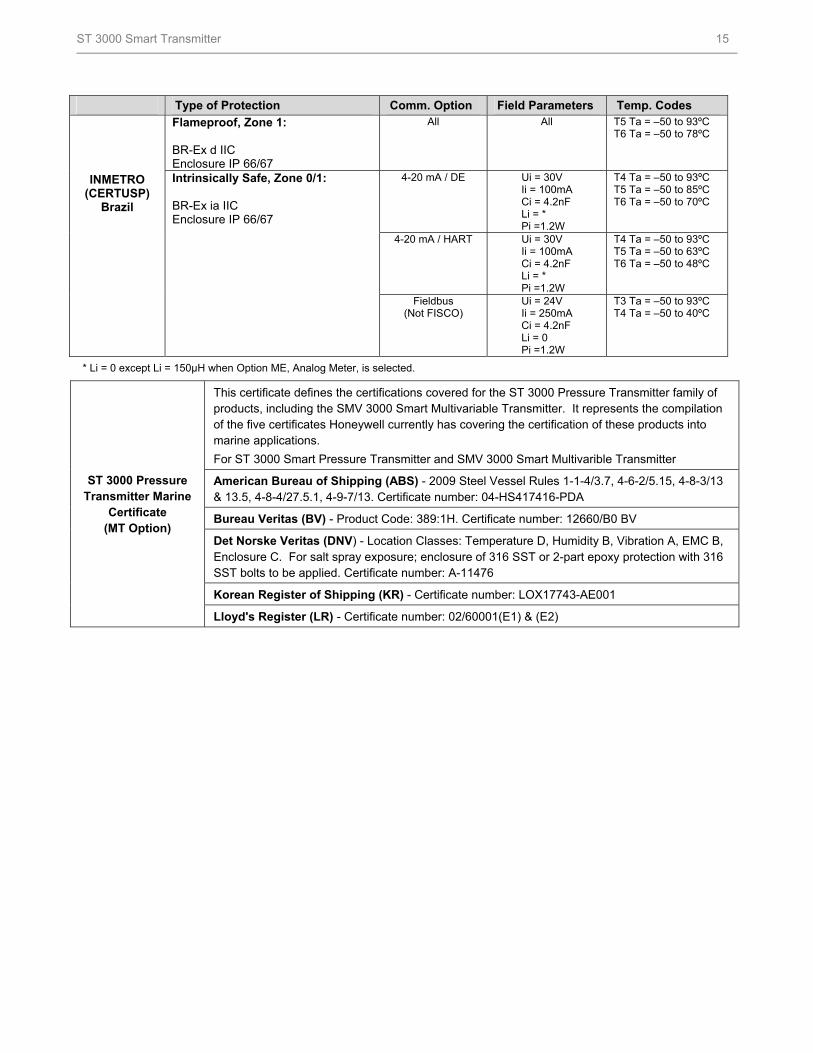
Type of Protection Comm. Option Field Parameters Temp. Codes
Flameproof, Zone 1: BR-Ex d IIC Enclosure IP 66/67
All All T5 Ta = –50 to 93ºC T6 Ta = –50 to 78ºC
4-20 mA / DE Ui = 30V Ii = 100mA Ci = 4.2nF Li = * Pi =1.2W
T4 Ta = –50 to 93ºC T5 Ta = –50 to 85ºC T6 Ta = –50 to 70ºC
4-20 mA / HART Ui = 30V Ii = 100mA Ci = 4.2nF Li = * Pi =1.2W
T4 Ta = –50 to 93ºC T5 Ta = –50 to 63ºC T6 Ta = –50 to 48ºC
INMETRO (CERTUSP)
Brazil
Intrinsically Safe, Zone 0/1: BR-Ex ia IIC Enclosure IP 66/67
Fieldbus (Not FISCO)
Ui = 24V Ii = 250mA Ci = 4.2nF Li = 0 Pi =1.2W
T3 Ta = –50 to 93ºC T4 Ta = –50 to 40ºC
* Li = 0 except Li = 150µH when Option ME, Analog Meter, is selected.
This certificate defines the certifications covered for the ST 3000 Pressure Transmitter family of products, including the SMV 3000 Smart Multivariable Transmitter. It represents the compilation of the five certificates Honeywell currently has covering the certification of these products into marine applications.
For ST 3000 Smart Pressure Transmitter and SMV 3000 Smart Multivarible Transmitter
American Bureau of Shipping (ABS) - 2009 Steel Vessel Rules 1-1-4/3.7, 4-6-2/5.15, 4-8-3/13 & 13.5, 4-8-4/27.5.1, 4-9-7/13. Certificate number: 04-HS417416-PDA
Bureau Veritas (BV) - Product Code: 389:1H. Certificate number: 12660/B0 BV
Det Norske Veritas (DNV) - Location Classes: Temperature D, Humidity B, Vibration A, EMC B, Enclosure C. For salt spray exposure; enclosure of 316 SST or 2-part epoxy protection with 316 SST bolts to be applied. Certificate number: A-11476
Korean Register of Shipping (KR) - Certificate number: LOX17743-AE001
ST 3000 Pressure Transmitter Marine
Certificate (MT Option)
Lloyd's Register (LR) - Certificate number: 02/60001(E1) & (E2)
ST 3000 Smart Transmitter 16
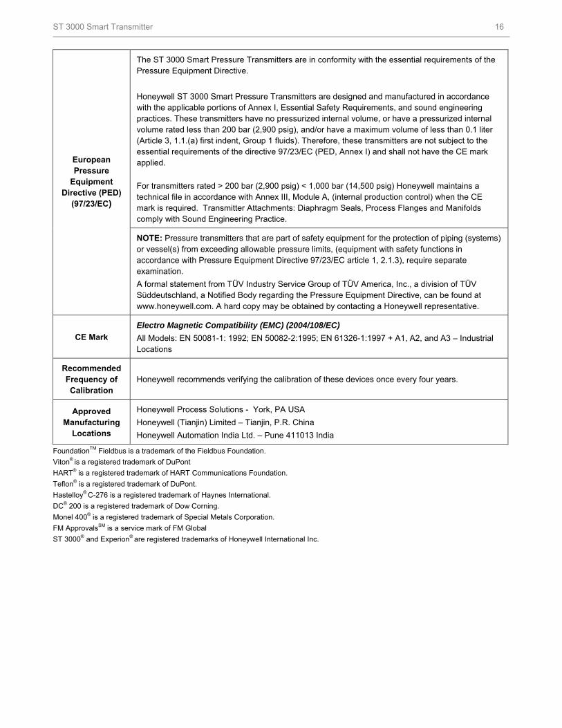
The ST 3000 Smart Pressure Transmitters are in conformity with the essential requirements of the Pressure Equipment Directive.
Honeywell ST 3000 Smart Pressure Transmitters are designed and manufactured in accordance with the applicable portions of Annex I, Essential Safety Requirements, and sound engineering practices. These transmitters have no pressurized internal volume, or have a pressurized internal volume rated less than 200 bar (2,900 psig), and/or have a maximum volume of less than 0.1 liter (Article 3, 1.1.(a) first indent, Group 1 fluids). Therefore, these transmitters are not subject to the essential requirements of the directive 97/23/EC (PED, Annex I) and shall not have the CE mark applied.
For transmitters rated > 200 bar (2,900 psig) < 1,000 bar (14,500 psig) Honeywell maintains a technical file in accordance with Annex III, Module A, (internal production control) when the CE mark is required. Transmitter Attachments: Diaphragm Seals, Process Flanges and Manifolds comply with Sound Engineering Practice.
European Pressure
Equipment Directive (PED)
(97/23/EC)
NOTE: Pressure transmitters that are part of safety equipment for the protection of piping (systems) or vessel(s) from exceeding allowable pressure limits, (equipment with safety functions in accordance with Pressure Equipment Directive 97/23/EC article 1, 2.1.3), require separate examination.
A formal statement from TÜV Industry Service Group of TÜV America, Inc., a division of TÜV Süddeutschland, a Notified Body regarding the Pressure Equipment Directive, can be found at www.honeywell.com. A hard copy may be obtained by contacting a Honeywell representative.
CE Mark
Electro Magnetic Compatibility (EMC) (2004/108/EC)
All Models: EN 50081-1: 1992; EN 50082-2:1995; EN 61326-1:1997 + A1, A2, and A3 – Industrial Locations
Recommended Frequency of Calibration
Honeywell recommends verifying the calibration of these devices once every four years.
Approved Manufacturing
Locations
Honeywell Process Solutions - York, PA USA
Honeywell (Tianjin) Limited – Tianjin, P.R. China
Honeywell Automation India Ltd. – Pune 411013 India
FoundationTM Fieldbus is a trademark of the Fieldbus Foundation.
Viton® is a registered trademark of DuPont
HART® is a registered trademark of HART Communications Foundation.
Teflon® is a registered trademark of DuPont.
Hastelloy® C-276 is a registered trademark of Haynes International.
DC® 200 is a registered trademark of Dow Corning.
Monel 400® is a registered trademark of Special Metals Corporation.
FM ApprovalsSM is a service mark of FM Global
ST 3000® and Experion® are registered trademarks of Honeywell International Inc.
ST 3000 Smart Transmitter 17
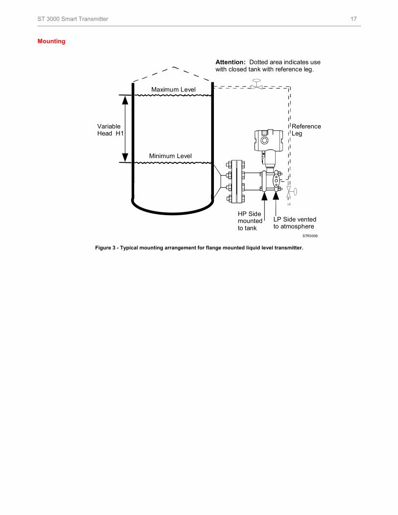
Mounting
Figure 3 - Typical mounting arrangement for flange mounted liquid level transmitter.
STR3006
VariableHead H1
ReferLeg
Attention: Dotted area indicatewith closed tank with reference l
ence
s useeg.
LP Side vento atmosph
HP Sidemountedto tank
tedere
Minimum Level
Maximum Level
ST 3000 Smart Transmitter 18
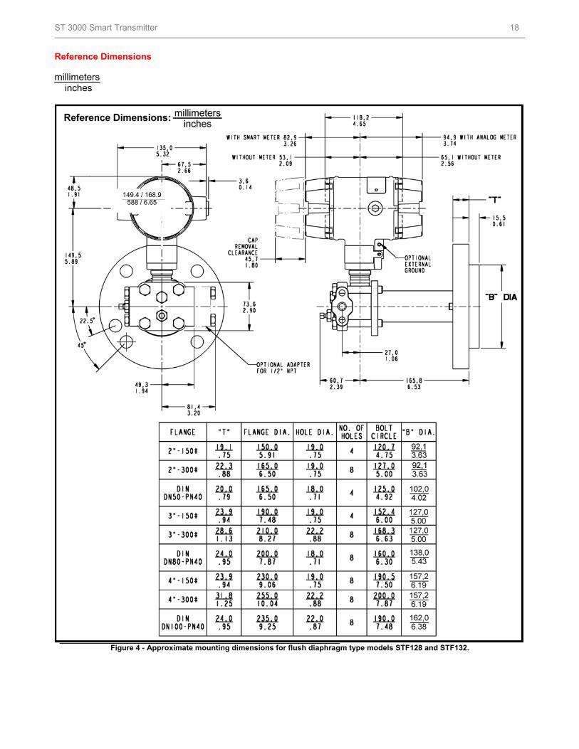
Reference Dimensions millimeters
inches
149.4 / 168.9 588 / 6.65
Figure 4 - Approximate mounting dimensions for flush diaphragm type models STF128 and STF132.
ST 3000 Smart Transmitter 19
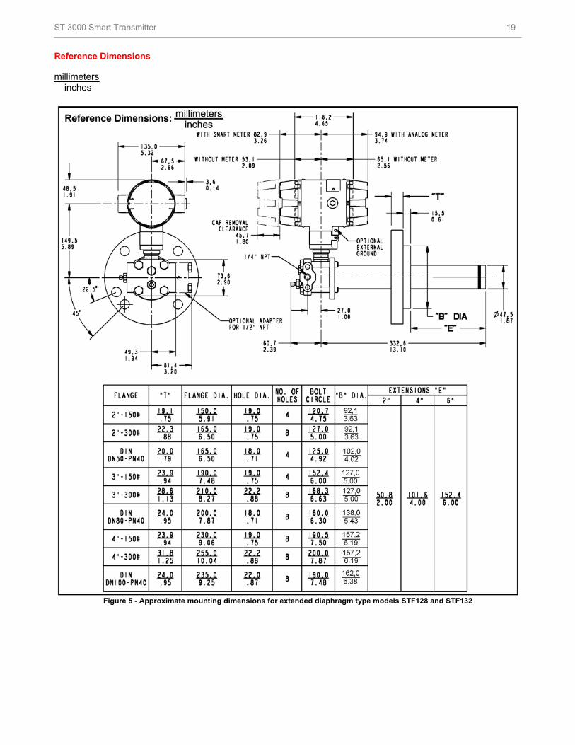
Reference Dimensions millimeters
inches
Figure 5 - Approximate mounting dimensions for extended diaphragm type models STF128 and STF132
ST 3000 Smart Transmitter 20
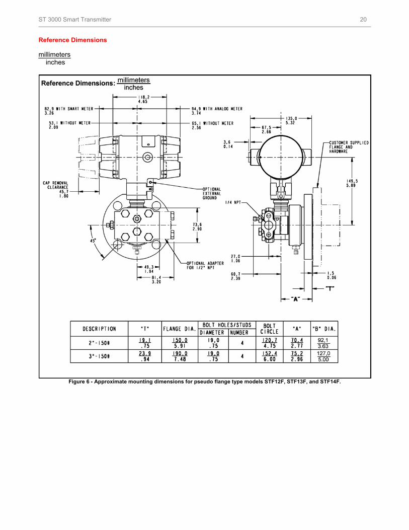
Reference Dimensions millimeters
inches
Figure 6 - Approximate mounting dimensions for pseudo flange type models STF12F, STF13F, and STF14F.
ST 3000 Smart Transmitter 21
Options
Indicating Meter (Options ME and SM)
Two integral meter options are available. An
analog meter (option ME) is available with a 0 to
100% linear scale. The Smart Meter (option SM)
provides an LCD display for both analog and
digital output and can be configured to display
pressure in pre-selected engineering units.
Lightning Protection (Option LP)
A terminal block is available with circuitry that
protects the transmitter from transient surges
induced by nearby lightning strikes.
HART® Protocol Compatibility (Options HC
and H6)
Optional electronics modules for the ST 3000
provides HART Protocol compatibility in either
HART 5.x or 6.x formats. Transmitters with a
HART Option are compatible with any HART
enabled system that provides 5.x or 6.x format
support.
Foundation Fieldbus (Option FF)
Equips transmitter with FF protocol for use in
31.25 kbit/s FF networks. See document 34-ST-
03-72 for additional information on ST 3000
Fieldbus transmitters
SIL2/SIL3 Certification (Option SL)
This ST 3000 product is available for use with
safety systems. With the SL option, we are fully
certified to SIL 2 capability for single transmitters
and SIL 3 capability for multiple transmitter use
through TÜV Nord Sys Tec GmbH & Co. KG.
We are in compliance with the following SIL
standards:
IEC 61508-1: 1998;
IEC 61508-2: 2000
IEC 61508-3: 1998
NAMUR NE43 Compliance (Option NE)
This option provides software the meets the
NAMUR NE43 requirements for failsafe
software. Transmitter failure information is
generated when the measuring information is no
longer valid. Transmitter failure values are:
≤ 3.6 mA and ≥ 21.0 mA. The normal ST 3000
ranges are ≤ 3.8 mA and ≥ 20.5 mA.
Tagging (Option TG)
Up to 30 characters can be added on the
stainless steel nameplate mounted on the
transmitter’s electronics housing at no extra
cost. Note that a separate nameplate on the
meter body contains the serial number and
body-related data. A stainless steel wired on tag
with additional data of up to 4 lines of 28
characters is also available. The number of
characters for tagging includes spaces.
Lifetime Warranty (Option WL)
Extends limited 1-year warranty policy to 15
years for ST 3000 S100 pressure transmitters.
See Honeywell Terms and Conditions.
Indicator Configuration (Option CI)
Provides custom configuration of Smart Meters
Transmitter Configuration (Option TC)
The factory can configure the transmitter
linear/square root extraction, damping time,
LRV, URV and mode (analog/digital) and enter
an ID tag of up to eight characters and
scratchpad information as specified.
Custom Calibration and ID in Memory
(Option C)
The factory can calibrate any range within the
scope of the transmitter’s range and enter an ID
tag of up to eight characters in the transmitter’s
memory.
ST 3000 Smart Transmitter 22
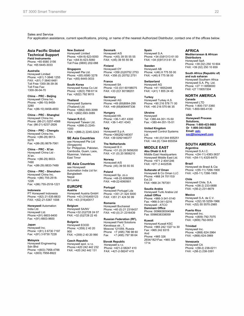
Sales and Service For application assistance, current specifications, pricing, or name of the nearest Authorized Distributor, contact one of the offices below.
Asia Pacific Global Technical Support Field Instruments Phone: +65 6580 3156 Fax: +65 6445-3033 Australia Honeywell Limited Phone: +(61) 7-3846 1255 FAX: +(61) 7-3840 6481 Toll Free 1300-36-39-36 Toll Free Fax: 1300-36-04-70 China – PRC - Beijing Honeywell China Inc. Phone: +(86-10) 8458-3280 Fax: +(86-10) 8458-4650 China – PRC - Shanghai Honeywell China Inc. Phone: (86-21) 5257-4568 Fax: (86-21) 6237-2826 China – PRC - Chengdu Honeywell China Inc. Phone: +(86-28) 6613-5078 Fax: +(86-28) 8678-7061 China – PRC - Xi’an Honeywell China Ltd - Xi’an. Phone: +(86-29) 8833-7490 Fax: +(86-29) 8833-7489 China – PRC - Shenzhen- Honeywell China Inc. Phone: +(86) 755-2518-1226 Fax: +(86) 755-2518-1221
Indonesia PT Honeywell Indonesia Phone: +(62) 21-535-8833 FAX: +(62) 21-5367 1008 Honeywell Automation India Ltd. Honeywell Ltd. Phone:+(91) 6603-9400 Fax: +(91) 6603-9600 Japan Honeywell Inc. Phone: +(81) 3 6730 7197 Fax: +(81) 3 6730 7228 Malaysia Honeywell Engineering Sdn Bhd Phone: +(603) 7958-4788 Fax: +(603) 7958-8922
New Zealand Honeywell Limited Phone: +(64-9) 623-5050 Fax: +(64-9) 623-5060 Toll Free (0800) 202-088 Singapore Honeywell Pte Ltd. Phone: +(65) 6580 3278 Fax: +(65) 6445-3033 South Korea Honeywell Korea Co Ltd Phone: +(822) 799 6114 Fax: +(822) 792 9015 Thailand Honeywell Systems (Thailand) Ltd. Phone: +(662) 693-3099 FAX: +(662) 693-3089 Taiwan R.O.C. Honeywell Taiwan Ltd. Phone: +(886-2) 2245-1000 FAX: +(886-2) 2245-3243
SE Asia Countries see Honeywell Pte Ltd (Singapore) for: Philippines, Pakistan, Cambodia, Guam, Laos, Myanmar, Vietnam, East Timor
SE Asia Countries see Honeywell Automation India Ltd for: Bangladesh Nepal Sri Lanka
EUROPE Austria Honeywell Austria GmbH Phone: +43 (316)400123 FAX: +43 (316)40017 Belgium Honeywell SA/NV Phone:+32 (0)2728 24 07 FAX: +32 (0)2728 22 45 Bulgaria Honeywell EOOD Phone: +(359) 2 40 20 900 FAX: +(359) 2 40 20 990 Czech Republic Honeywell spol. s.r.o. Phone:+420 242 442 232 FAX: +420 242 442 131
Denmark Honeywell A/S Phone: +(45) 39 55 55 55 FAX: +(45) 39 55 55 58 Finland Honeywell OY Phone: +358 (0)20752 2753 FAX: +358 (0) 20752 2751 France Honeywell SA Phone: +33 (0)1 60198075 FAX: +33 (0)1 60198201 Germany Honeywell AG Phone: +49 (69)8064-299 FAX: +49 (69)806497336 Hungary Honeywell Kft. Phone: +36-1-451 4300 FAX: +36-1-451 4343 Italy Honeywell S.p.A. Phone:+390292146307 FAX: +39 0292146377 The Netherlands Honeywell B.V. Phone: +31 (0) 20 5656200 FAX: +31 (0) 20 5656210 Norway Honeywell A/S Phone: (45) 39 55 55 55 Poland Honeywell Sp. zo.o Phone: +48-22-6060900 FAX: +48-22-6060901 Portugal Honeywell Portugal Lda Phone: +351 21 424 5000 FAX: +351 21 424 50 99 Romania Honeywell Bucharest Phone: +40 (0) 21 2316437 FAX: +40 (0) 21 2316439 Russian Federation (RF), Honeywell Field Solutions Kievskaya str., 7, Moscow 121059, Russia Phone +7 (495) 796 98 60 Fax +7 (495) 797 99 64 Slovak Republic Honeywell s.r.o. Phone: +421-2-58247 410 FAX: +421-2-58247 415
Spain Honeywell S.A. Phone: +34 (0)91313 61 00 FAX: +34 (0)91313 61 30 Sweden Honeywell AB Phone: +(46) 8 775 55 00 FAX: +(46) 8 775 56 00 Switzerland Honeywell AG Phone: +41 18552448 FAX: +(41) 1 855 24 45 Turkey Honeywell Turkey A.S. Phone: +90 216 578 71 00 FAX: +90 216 575 66 35 Ukraine Honeywell Tel: +380-44-351-15-50 Fax: +380-44-351-15-51 United Kingdom Honeywell Control Systems Ltd. Phone: +44 (0)1344 655251 FAX: +44 (0) 1344 655554
MIDDLE EAST Abu Dhabi U A E Middle East Headquarters Honeywell Middle East Ltd. Phone: +971 2 4041246 FAX: +971 2 4432536 Sultanate of Oman Honeywell & Co Oman LLC Phone: +968 24 701153/ Ext.33 FAX +968 24 787351 Saudia Arabia Honeywell Turki Arabia Ltd Jubail Office Phone: +966-3-341-0140 Fax: +966-3-341-0216 Honeywell - ATCO Dammam Office Phone: 0096638304584 Fax: 0096638338059 Kuwait Honeywell Kuwait KSC Phone: +965 242 1327 to 30 Fax: +965 242 8315 And Phone: +965 326 2934/1821Fax: +965 326 1714
AFRICA Mediterranean & African Distributors Honeywell SpA Phone: +39 (02) 250 10 604 FAX: +39 (02) 250 10 659 South Africa (Republic of) and sub saharan Honeywell Southern Africa Honeywell S.A. Pty. Ltd. Phone: +27 11 6958000 FAX +27 118051504
NORTH AMERICA Canada Honeywell LTD Phone: 1-800-737-3360 FAX: 1-800-565-4130 USA Honeywell Process Solutions, Phone: 1-800-423-9883 Or 1-800-343-0228 Email: [email protected]
SOUTH AMERICA Argentina Honeywell S.A.I.C. Phone: +(54-11) 4383-3637 FAX: +(54-11) 4325-6470 Brazil Honeywell do Brasil & Cia Phone: +(55-11) 7266-1900 FAX: +(55-11) 7266-1905 Chile Honeywell Chile, S.A. Phone: +(56-2) 233-0688 FAX: +(56-2) 231-6679 Mexico Honeywell S.A. de C.V. Phone: +(52) 55 5259-1966 FAX: +(52) 55 5570-2985 Puerto Rico Honeywell Inc. Phone: +(809) 792-7075 FAX: +(809) 792-0053 Trinidad Honeywell Inc. Phone: +(868) 624-3964 FAX: +(868) 624-3969 Venezuela Honeywell CA Phone: +(58-2) 238-0211 FAX: +(58-2) 238-3391
ST 3000 Smart Transmitter 23
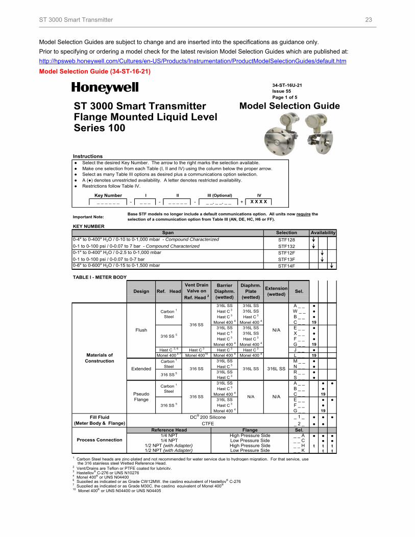
Model Selection Guides are subject to change and are inserted into the specifications as guidance only.
Prior to specifying or ordering a model check for the latest revision Model Selection Guides which are published at:
http://hpsweb.honeywell.com/Cultures/en-US/Products/Instrumentation/ProductModelSelectionGuides/default.htm
Model Selection Guide (34-ST-16-21)
34-ST-16U-21Issue 55Page 1 of 5
ST 3000 Smart Transmitter Model Selection GuideFlange Mounted Liquid LevelSeries 100
Instructions ● Select the desired Key Number. The arrow to the right marks the selection available. ● Make one selection from each Table (I, II and IV) using the column below the proper arrow. ● Select as many Table III options as desired plus a communications option selection. ● A (●) denotes unrestricted availability. A letter denotes restricted availability. ● Restrictions follow Table IV.
- - - _ _, _ _, _ _ +
Important Note:
KEY NUMBER
STF128
STF132
STF12F
STF13F
STF14F
TABLE I - METER BODY
316L SS 316L SS A _ _ ●316L SS W _ _ ●
B _ _ ●C _ _ 19
316L SS 316L SS E _ _ ●316L SS X _ _ ●
F _ _ ●G _ _ 19
J _ _ ●L _ _ 19
316L SS M _ _ ●N _ _ ●
316L SS R _ _ ●S _ _ ●
316L SS A _ _ ● ●B _ _ ●C _ _ 19
316L SS E _ _ ● ●F _ _ ●G _ _ 19
● ● ●
● ●
● ● ●● ●
t t tt t
2 Vent/Drains are Teflon or PTFE coated for lubricity.3 Hastelloy® C-276 or UNS N10276 4 Monel 400® or UNS N044006 Supplied as indicated or as Grade CW12MW, the casting equivalent of Hastelloy® C-2767 Supplied as indicated or as Grade M30C, the casting equivalent of Monel 400®
10 Monel 400® or UNS N04400 or UNS N04405
Base STF models no longer include a default communications option. All units now require the selection of a communication option from Table III (AN, DE, HC, H6 or FF).
Availability
Flush316 SS
316 SS 5
Vent DrainValve on
Ref. Head 2
_ 1 _
High Pressure Side
CTFE
1/4 NPTReference Head
_ _ C
Sel.
Hast C 3
Fill Fluid (Meter Body & Flange)
Monel 400 4
Monel 400 4
N/AN/A
_ _ H_ _ K
Process Connection 1/4 NPT
Flange
Monel 400 4
the 316 stainless steel Wetted Reference Head.
DC® 200 Silicone
316 SS
Hast C 3
Hast C 3
Span
Monel 400 4
Low Pressure Side
Low Pressure SideHigh Pressure Side
Hast C 3
Monel 400 4 7 Monel 40010
0-1 to 0-100 psi / 0-0.07 to 7 bar - Compound Characterized
Monel 400 4
Hast C 3
Hast C 3
Monel 400 4
Monel 400 4Hast C 3
1/2 NPT (with Adapter)
Selection
Barrier Diaphrm. (wetted)
Design Ref. Head
0-4" to 0-400" H2O / 0-10 to 0-1,000 mbar - Compound Characterized
Sel.Extension (wetted)
0-1 to 0-100 psi / 0-0.07 to 0-7 bar0-6" to 0-600" H2O / 0-15 to 0-1,500 mbar
0-1" to 0-400" H2O / 0-2.5 to 0-1,000 mbar
Diaphrm. Plate
(wetted)
316 SS 5
Materials of Construction Carbon 1
Steel
Hast C 3, 6
Pseudo Flange
Carbon 1
Steel
Carbon 1
Steel
316 SS 5
316 SS Hast C 3
Hast C 3
Extended
N/A
Monel 400 4
Hast C 3
Hast C 3
Hast C 3
316L SS316L SS
Hast C 3
_ _ _ _ _ _ X X X XKey Number
_ _ _
_ 2 _
_ _ A
IV
1/2 NPT (with Adapter)
1 Carbon Steel heads are zinc-plated and not recommended for water service due to hydrogen migration. For that service, use
I II
_ _ _ _ _
III (Optional)
ST 3000 Smart Transmitter 24
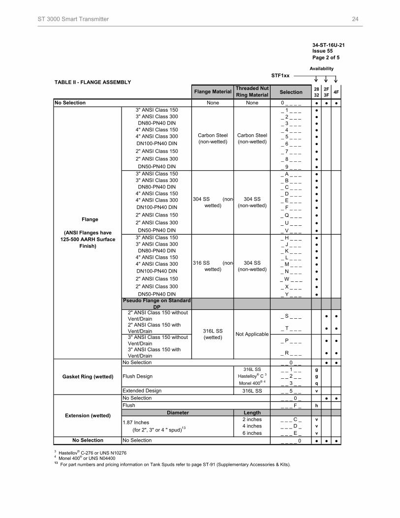
34-ST-16U-21Issue 55Page 2 of 5
Availability
STF1xxTABLE II - FLANGE ASSEMBLY
Selection28 32
2F 3F
4F
● ● ●
_ 1 _ _ _ ●_ 2 _ _ _ ●_ 3 _ _ _ ●_ 4 _ _ _ ●_ 5 _ _ _ ●
_ 6 _ _ _ ●
_ 7 _ _ _ ●
_ 8 _ _ _ ●
_ 9 _ _ _ ●
_ A _ _ _ ●_ B _ _ _ ●_ C _ _ _ ●_ D _ _ _ ●_ E _ _ _ ●
_ F _ _ _ ●
_ Q _ _ _ ●
_ U _ _ _ ●
_ V _ _ _ ●
_ H _ _ _ ●_ J _ _ _ ●_ K _ _ _ ●_ L _ _ _ ●_ M _ _ _ ●
_ N _ _ _ ●
_ W _ _ _ ●
_ X _ _ _ ●
_ Y _ _ _ ●
_ S _ _ _ ● ●
_ T _ _ _ ● ●
_ P _ _ _ ● ●
_ R _ _ _ ● ●
_ _ 0 _ _ ● ●316L SS _ _ 1 _ _ g
_ _ 2 _ _ g
_ _ 3 _ _ q
316L SS _ _ 5 _ _ v
_ _ _ 0 _ ● ●
_ _ _ F _ h
Diameter Length2 inches _ _ _ C _ v
4 inches _ _ _ D _ v
6 inches _ _ _ E _ v
_ _ _ _ 0 ● ● ●
3 Hastelloy® C-276 or UNS N102764 Monel 400® or UNS N0440013 For part numbers and pricing information on Tank Spuds refer to page ST-91 (Supplementary Accessories & Kits).
None
Threaded Nut Ring Material
DN100-PN40 DIN
2" ANSI Class 300
2" ANSI Class 150
Flange Material
No Selection None 0 _ _ _ _
2" ANSI Class 150
No Selection
Carbon Steel (non-wetted)
DN50-PN40 DIN
4" ANSI Class 300
DN100-PN40 DIN
2" ANSI Class 150
304 SS (non-wetted)
DN80-PN40 DIN3" ANSI Class 300
Carbon Steel (non-wetted)
304 SS (non-wetted)
3" ANSI Class 150
4" ANSI Class 150
DN50-PN40 DIN
Flange
(ANSI Flanges have125-500 AARH Surface
Finish)
Gasket Ring (wetted)
Extended Design
3" ANSI Class 300DN80-PN40 DIN
4" ANSI Class 150
3" ANSI Class 150 with Vent/Drain
316L SS (wetted)
2" ANSI Class 300
DN100-PN40 DIN
4" ANSI Class 300
2" ANSI Class 300
Monel 400® 4Flush Design Hastelloy® C 3
Not Applicable
No Selection
2" ANSI Class 150 with Vent/Drain3" ANSI Class 150 without Vent/Drain
No Selection
Extension (wetted)
No Selection
316 SS (non-wetted)
3" ANSI Class 150
4" ANSI Class 150
3" ANSI Class 300DN80-PN40 DIN
3" ANSI Class 150
2" ANSI Class 150 without Vent/Drain
Pseudo Flange on Standard DP
4" ANSI Class 300
304 SS (non-wetted)
Flush
1.87 Inches
(for 2", 3" or 4 " spud)13
DN50-PN40 DIN
ST 3000 Smart Transmitter 25
34-ST-16U-21
Issue 55 STF1xx
Page 3 of 528 2F
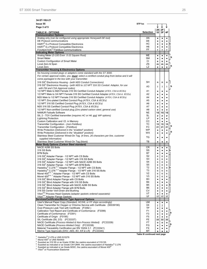
TABLE III - OPTIONS 32 3F 4F
● ● ●● ● ●● ● ●● ● ●r r r
● ● ●● ● ●e e em m mx x x
n n n
i i i
● ● ●● ● ●● ● ●● ● ●● ● ●● ● ●● ● ●15 15 15p p p
● ● ●● ● ●15 15 1521 21 21
● ● ●● ● ●
● ● ●
● ● ●
● ● ●● ● ●● ● ●c c cc c cc c cc c cc c cc c cc c cc c c● ● ●● ● ●● ● ●● ● ●● ● ●● ● ●17 17 17
● ● ●j j● ● ●● ● ●● ● ●● ● ●22 22 22
o o o● ● ●● ● ●● ● ●
Table III continued next page3 Hastelloy® C-276 or UNS N102764 Monel 400® or UNS N044005 Supplied as 316 SS or as Grade CF8M, the casting equivalent of 316 SS.6 Supplied as indicated or as Grade CW12MW, the casting equivalent of Hastelloy® C-2767 Supplied as indicated or as Grade M30C, the casting equivalent of Monel 400®
8 Viton® or Fluorocarbon Elastomer
HART® 6.x Protocol Compatible Electronics
Hastelloy® C-276 3, 6 Adapter Flange - 1/2 NPT with 316 SS Bolts Monel 400® 4, 7 Adapter Flange - 1/2 NPT with CS Bolts Monel 400® 4, 7 Adapter Flange - 1/2 NPT with 316 SS Bolts 316 SS5 Blind Adapter Flange with CS Bolts
Calibration Test Report and Certificate of Conformance (F3399)
Clean Transmitter for Oxygen or Chlorine Service with Certificate (50039190)
Services/Certificates/Marine Type Approval Options
316 SS5 Blind Adapter Flange with NACE A286 SS Bolts 316 SS5 Blind Adapter Flange with B7M Bolts 316 SS Center Vent Drain and Bushing Viton® 8 Process Head Gaskets (adapter gaskets ordered separately) Viton® 8 Adapter Flange Gaskets
User's Manual Paper Copy (Standard, HC/H6, or FF ships accordingly)
Over-Pressure Leak Test with Certificate (F3392 )
316 SS5 Adapter Flange - 1/2 NPT with B7M Bolts Hastelloy® C-276 3, 6 Adapter Flange - 1/2 NPT with CS Bolts
NACE A286 SS Bolts 316 SS Bolts B7M Bolts 316 SS5 Adapter Flange - 1/2 NPT with CS Bolts 316 SS5 Adapter Flange - 1/2 NPT with 316 SS Bolts 316 SS5 Adapter Flange - 1/2 NPT with NACE A286 SS Bolts
F5
VTVF
UM0X
CV
TPF1F3
B3B4B5B6
T2T3V2V3
S2S3S4S5
Certificate of Conformance (F3391)
NACE Certificate (Process-Wetted & Non-Process Wetted) (FC33339)
Meter Body Options (Carbon Steel standard)
316 SS5 Blind Adapter Flange with 316 SS Bolts
FEF7
CRSSB7
TG
A1A2A4
SH
A3
TB
A7A8
CCTCFCWP
SLLP
WX
SelectionCommunication Options
Indicating Meter Options
H6FF FOUNDATIONTM Fieldbus Communications
Analog only (can be configured using appropriate Honeywell DE tool) DE Protocol communications
CIZSLZ
NE
A5A6
MESM
FGFX
Marine Type Approvals (DNV, ABS, BV, KR & LR) (FC33340) MT
1/2 NPT Male to M20 Female 316 SS Certified Conduit Adapter (ATEX, CSA & IECEx)
Certificate of Origin (F0195) SIL Certificate (SIL 2/3) (FC33337)
NACE Certificate (Process-Wetted Only) (FC33338) Material Traceability Certification per EN 10204 3.1 (FC33341)
M20 316 SS Certified Conduit Plug (ATEX, CSA & IECEx) 1/2 NPT Non-certified Conduit plug (Zinc-plated carbon steel, general use) NAMUR Failsafe Software SIL 2 - TÜV Certified transmitter (requires HC or H6 and WP options)
Transmitter Housing & Electronics Options
316 SS5 Electronics Housing - (with M20 to 1/2 NPT 316 SS Conduit Adaptor, for use with FM and CSA Approval codes)
Lightning Protection Custom Calibration and I.D. in Memory Transmitter Configuration - (non-Fieldbus) Transmitter Configuration - (Fieldbus)
1/2 NPT Male to 3/4 NPT Female 316 SS Certified Conduit Adapter (ATEX, CSA & IECEx)
M20 Male to 1/2 NPT Female 316 SS Certified Conduit Adaptor (ATEX, CSA & IECEx)
1/2 NPT Zinc-plated Certified Conduit Plug (ATEX, CSA & IECEx) 1/2 NPT 316 SS Certified Conduit Plug (ATEX, CSA & IECEx)
Local Zero & Span
Write Protection (Delivered in the "enabled" position)
b
No housing conduit plugs or adaptors come standard with the ST 3000. For certain approval codes, you must select a certified conduit plug from below and it will come packaged in the box with your transmitter.
316 SS5 Electronics Housing - (with M20 Conduit Connections)
Local Zero
Analog Meter (0-100 Even 0-10 Square Root) Smart Meter Custom Configuration of Smart Meter
HART® 5.x Protocol Compatible Electronics
Write Protection (Delivered in the "disabled" position)
b
b
b
ANDEHC
Stainless Steel Customer Wired-On Tag (4 lines, 26 characters per line, customer supplied information) Stainless Steel Customer Wired-On Tag (blank)
b
b
b
b
b
b
b
ST 3000 Smart Transmitter 26
34-ST-16U-21Issue 55Page 4 of 5
Availability
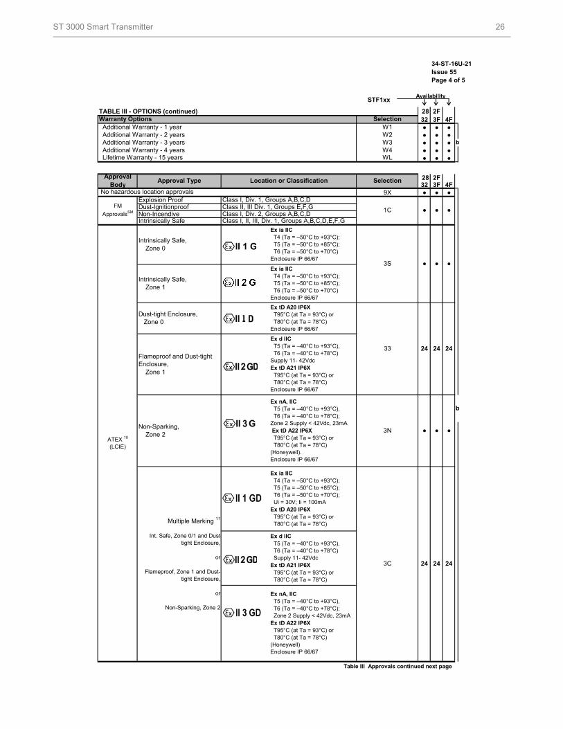
TABLE III - OPTIONS (continued) 28 2F32 3F 4F● ● ●● ● ●● ● ●● ● ●● ● ●
28 2F32 3F 4F
9X ● ● ●
Table III Approvals continued next page
W1W2W3W4
3N
3S
Additional Warranty - 1 year Additional Warranty - 2 years Additional Warranty - 3 years
Multiple Marking 11
Int. Safe, Zone 0/1 and Dust-tight Enclosure,
or
Flameproof, Zone 1 and Dust-tight Enclosure,
or
Non-Sparking, Zone 2
ATEX 10
(LCIE)
Intrinsically Safe, Zone 0
Flameproof and Dust-tight Enclosure, Zone 1
Ex d IIC T5 (Ta = –40°C to +93°C), T6 (Ta = –40°C to +78°C) Supply 11- 42VdcEx tD A21 IP6X T95°C (at Ta = 93°C) or T80°C (at Ta = 78°C)
Ex nA, IIC T5 (Ta = –40°C to +93°C), T6 (Ta = –40°C to +78°C); Zone 2 Supply < 42Vdc, 23mAEx tD A22 IP6X T95°C (at Ta = 93°C) or T80°C (at Ta = 78°C) (Honeywell) Enclosure IP 66/67
WL
Warranty Options Selection
Additional Warranty - 4 years Lifetime Warranty - 15 years
1C
Explosion Proof Class I, Div. 1, Groups A,B,C,D
● ●
24 24
STF1xx
Approval Body
No hazardous location approvals
Approval Type
Non-Incendive
24 2433
Ex d IIC T5 (Ta = –40°C to +93°C), T6 (Ta = –40°C to +78°C)Supply 11- 42VdcEx tD A21 IP6X T95°C (at Ta = 93°C) or T80°C (at Ta = 78°C)Enclosure IP 66/67
Ex ia IIC T4 (Ta = –50°C to +93°C); T5 (Ta = –50°C to +85°C); T6 (Ta = –50°C to +70°C)Enclosure IP 66/67
Ex tD A20 IP6X T95°C (at Ta = 93°C) or T80°C (at Ta = 78°C) Enclosure IP 66/67
●
Selection
Ex ia IIC T4 (Ta = –50°C to +93°C); T5 (Ta = –50°C to +85°C); T6 (Ta = –50°C to +70°C)Enclosure IP 66/67
Dust-Ignitionproof
Non-Sparking, Zone 2
24
Dust-tight Enclosure, Zone 0
Class I, II, III, Div. 1, Groups A,B,C,D,E,F,GIntrinsically Safe
Ex ia IIC T4 (Ta = –50°C to +93°C); T5 (Ta = –50°C to +85°C); T6 (Ta = –50°C to +70°C); Ui = 30V; Ii = 100mAEx tD A20 IP6X T95°C (at Ta = 93°C) or T80°C (at Ta = 78°C)
Ex nA, IIC T5 (Ta = –40°C to +93°C), T6 (Ta = –40°C to +78°C); Zone 2 Supply < 42Vdc, 23mA Ex tD A22 IP6X T95°C (at Ta = 93°C) or T80°C (at Ta = 78°C) (Honeywell).Enclosure IP 66/67
FM
ApprovalsSM
3C
Location or Classification
b
b
●
●●Class I, Div. 2, Groups A,B,C,DClass II, III Div. 1, Groups E,F,G
Intrinsically Safe, Zone 1
● ● ●
24
ST 3000 Smart Transmitter 27
34-ST-16U-21Issue 55Page 5 of 5
Availability
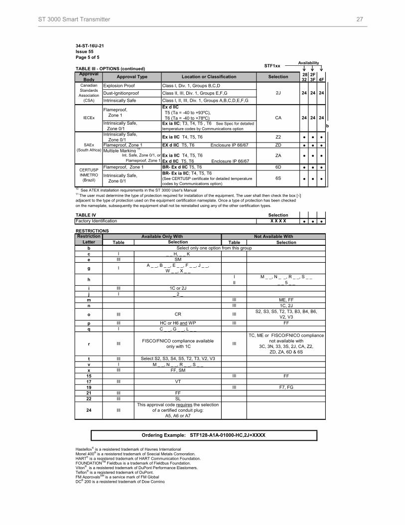
TABLE III - OPTIONS (continued)28 2F32 3F 4F
● ● ●
● ● ●
● ● ●
10 See ATEX installation requirements in the ST 3000 User's Manual
TABLE IV Selection
● ● ●
RESTRICTIONS
Table Table Selectionbc _ _ H, _ _ Ke
II _ _ 5 _ _ij _ 2 _
m ME, FFn 1C, 2J
o III
pq C _ _, G _ _, L _ _
r
t IIIv M _ _, N _ _, R _ _, S _ _x FF, SM
15 FF1719
Hastelloy® is a registered trademark of Haynes InternationalMonel 400® is a registered trademark of Special Metals Corporation.HART® is a registered trademark of HART Communication Foundation.FOUNDATIONTM Fieldbus is a trademark of Fieldbus Foundation.Viton® is a registered trademark of DuPont Performance Elastomers.Teflon® is a registered trademark of DuPont.FM ApprovalsSM is a service mark of FM GlobalDC® 200 is a registered trademark of Dow Corning
STF1xx
24 IIIThis approval code requires the selection
of a certified conduit plug: A5, A6 or A7
X X X X
on the nameplate, subsequently the equipment shall not be reinstalled using any of the other certification types.
Intrinsically Safe, Zone 0/1
BR- Ex ia IIC; T4, T5, T6 (See CERTUSP certificate for detailed temperature codes by Communications option)
g I
III
6S
CERTUSP INMETRO
(Brazil)
6D
11 The user must determine the type of protection required for installation of the equipment. The user shall then check the box [√]
BR- Ex d IIC T5, T6Flameproof, Zone 1
Int. Safe, Zone 0/1, or
Intrinsically Safe, Zone 0/1
Ex ia IIC T4, T5, T6Intrinsically Safe, Zone 0/1
Multiple Marking 11
Ex ia IIC T4, T5, T6Ex d IIC T5, T6 Enclosure IP 66/67
Flameproof, Zone 1
2J
CA
Select S2, S3, S4, S5, T2, T3, V2, V3
EX d IIC T5, T6 Enclosure IP 66/67
Flameproof, Zone 1
III
IIIIII
Approval Body
Location or Classification
b
24
24 24
24 24
h
Restriction Letter
SAEx (South Africa)
Available Only With
Factory Identification
adjacent to the type of protection used on the equipment certification nameplate. Once a type of protection has been checked
S2, S3, S5, T2, T3, B3, B4, B6, V2, V3
I
I
A _ _, B _ _, E _ _, F _ _, J _ _, W _ _, X _ _
III
FISCO/FNICO compliance available only with 1C
1C or 2JIIII
Approval Type
Select only one option from this group
SM
Class I, Div. 1, Groups B,C,D
Intrinsically Safe
Canadian Standards
Association (CSA)
Selection
IECEx
Class I, II, III, Div. 1, Groups A,B,C,D,E,F,G
Class II, III, Div. 1, Groups E,F,G
Ex ia IIC; T3, T4, T5 , T6 See Spec for detailed temperature codes by Communications option
Dust-Ignitionproof
Explosion Proof
●
Flameproof, Zone 1
ZA ●
Z2
ZD
●
III VT
24
Ex d IIC T5 (Ta = -40 to +93ºC), T6 (Ta = -40 to +78ºC)
Not Available With
M _ _, N _ _, R _ _, S _ _
III
I
III
III
IIII
IIIIII
CR
HC or H6 and WP FF
TC, ME or FISCO/FNICO compliance not available with
3C, 3N, 33, 3S, 2J, CA, Z2, ZD, ZA, 6D & 6S
FF
Ordering Example: STF128-A1A-01000-HC,2J+XXXX
2122 III SL
IIIF7, FG
●
● ●
Selection
ST 3000 Smart Transmitter 28
Specifications are subject to change without notice.
For More Information
Learn more about how Honeywell’s ST 3000 Smart
Transmitter can provide accuracy, reliability and stability in
transmitter measurement, visit our website
www.honeywell.com/ps/hfs or contact your Honeywell
account manager.
Honeywell Process Solutions
1860 West Rose Garden Lane
Phoenix, Arizona 85027
Tel: 1-800-423-9883 or 1-800-343-0228 www.honeywell.com/ps
34-ST-03-63August 2011 © 2011 Honeywell International Inc.