Embed Size (px)
Citation preview

SMV 3000 Smart Multivariable Flow Transmitter Specifications 34-SM-03-01 August 2010
Introduction The SMV 3000 combines integrated sensor and microprocessor technologies as well as dynamic flow compensation to produce the most accurate and consistent flow measurement possible, and is based on ST 3000 technology which is the most reliable in the industry. These features help improve product yield, increase process efficiency and enhance plant safety. In addition to the advantages of superior accuracy and reliability, the SMV 3000 Smart Multivariable Flow Transmitter significantly lowers your lifetime cost of ownership in several ways.
Models
SMA110 0 to 100 psia 0-1in / 25 inH2O
SMA125 0 to 750 psia 0-1in / 400 inH2O
SMG170 0 to 3,000 psi 0-1in / 400 inH2O
Installation - Wiring cost savings are achieved, as well as reduced costs of piping, manifolds, mounting, safety barriers, etc., with the SMV 3000 due to its unique ability to measure both differential and static pressure with a single sensor, and Process Temperature with an external RTD or thermocouple. By dynamically calculating the compensated mass flow, the SMV 3000 totally eliminates the need for a dedicated flow computer, or it can free your control system from performing this function.
Commissioning - The Hand-held SFC III Smart Field Communicator or SCT 3000 Smart Configuration Toolkit lets a single technician remotely configure SMV 3000 Smart Multivariable Flow Transmitters and re-range them when application requirements change. The SCT must be used to configure the advanced flow parameters
Maintenance - The SMV 3000 offers greater accuracy and stability, reducing the frequency of calibration. Self-diagnostics can automatically indicate impending problems before they affect reliability or accuracy. Also, a single technician can diagnose problems remotely, using the SFC, SCT 3000 or TPS Global User Station, saving time and reducing cost. The SMV 3000 also provides improved reliability with a single device replacing up to three transmitters.
Inventory stocking - Enhanced reliability, combined with the high turndown capability of the SMV 3000, reduces the quantity of instruments needed to stock as backups for the installed transmitters.
Figure 1 - SMV 3000 Smart Multivariable Flow Transmitter
Key Features
Unique single capsule sensor design provides highly
accurate measurements of differential pressure, absolute
or gauge pressure and meter body temperature.
3 process measurements (DP, SP and Temp.) and a flow
calculation from a single transmitter.
Flexible Electronics design allows RTD or Thermocouple
Input with standard wiring.
“Smart” features include remote communication,
calibration, configuration and diagnostics.
Flexible software allows flow calculation for liquids, gases
and steam.
Performs dynamic mass and volume flowrate
compensation for Orifice meters and Laminar Flow
Elements for highest accuracy. Standard compensation
supports other primary flow elements:
- Venturi
- Nozzle
- Averaging Pitot Tube
Digital integration with Honeywell control systems
provides local measurement accuracy to the system level

2 SMV 3000 Smart Multivariable Flow Transmitter
Description Honeywell’s SMV 3000 Smart Multivariable Flow Transmitter extends our proven “smart” technology to the measurement of three separate process variables simultaneously with the ability to calculate compensated mass or volume flow rate as a fourth process variable according to industry standard methods for air, gases, steam and liquids. It measures differential pressure and absolute or gauge pressure from a single sensor and temperature from a standard 100-ohm Resistance Temperature Detector (RTD) or thermocouple type E, J, K, or T input signals. The SMV 3000’s flow calculation may include compensation of pressure and/or temperature as well as more complex variables such as viscosity, discharge coefficient, thermal expansion factor, velocity of approach factor and gas expansion factor.
Functions
Proven Pressure Sensor Technology with characterization The SMV 3000 utilizes proven Piezoresistive sensor technology and has an ion-implanted silicon chip hermetically sealed in its meter body. This single piezoresistive capsule actually contains three sensors in one; a differential pressure sensor, an absolute or gauge pressure sensor, and a meter body temperature sensor. Process pressure applied to the transmitter’s diaphragm transfers through the fill fluid to the sensor. Voltage bridge circuits on the chip measures the differential and static pressures while a resistor in a voltage divider measures the temperature. These three input signals from the sensor coupled with the characterization data stored in the transmitter EPROM are then used by the microprocessor to calculate highly accurate pressure and temperature compensated values for the differential pressure and static pressure measurements. In this way, the SMV 3000 can provide an output signal that is stable and fully compensated for changes in process pressure and ambient temperature over a very wide range. Microprocessor-based electronics coupled with the sensor characterization provide higher span-turndown ratio, im-proved temperature and pressure compensation, and improved accuracy.
Process Temperature Measurement and Compensation Similar to the differential and static pressure measurements, the SMV 3000’s temperature electronics are characterized for ambient temperature changes so that the resistance or millivolt input from a Pt. 100 Ohm RTD or Type J, K, T or E Thermocouple is compensated for ambient temperature effects and therefore can be reported as the most accurate temperature possible. The SMV 3000’s flexibility allows the connection of either a standard 2, 3 or 4 wire 100 ohm RTD or a Type J, K, T or E thermocouple without special installation consideration. RTDs, thermocouples and thermowells can be ordered from Honeywell under this specification.
Mass Flow Measurements for Steam, Air, Gas or Liquid The SMV 3000 includes flow equations for steam, air, gas and liquids so that one model is all you need in your plant. The mass flow equation with dynamic compensation (Equation 1) is based on the ASME MFC-3M-1989 standard for orifice meters. Equation 1:
Qm = NCEvY1d2 h w f
Where,
Qm = mass flowrate N = units conversion factor C = discharge coefficient Y1 - gas expansion factor Ev = velocity of approach factor f = density at flowing conditions hw = differential pressure d = bore diameter
SMV 3000 Flow Compensation Most differential pressure transmitters utilized in steam, gas and liquid flow applications today measure the differential pressure across a primary flow element and report it to a DCS, PLC or flow computer for flow calculation. Most often, the calculation inside assumes that the density of the fluid is constant per the following equation.
Qv = K h
w
Where, Qv = volumetric flowrate hw = differential pressure K = flow factor = flowing density
In other applications, one will take the equation a step further and compensate for changes in pressure and temperature using additional pressure and temperature transmitters. For example, if a gas is being measured, the following volumetric flow equation based on multiple transmitters - the “Old” approach - applies (Figure 2). Or, in the case of Mass flowrate,
Qm = K TPh w
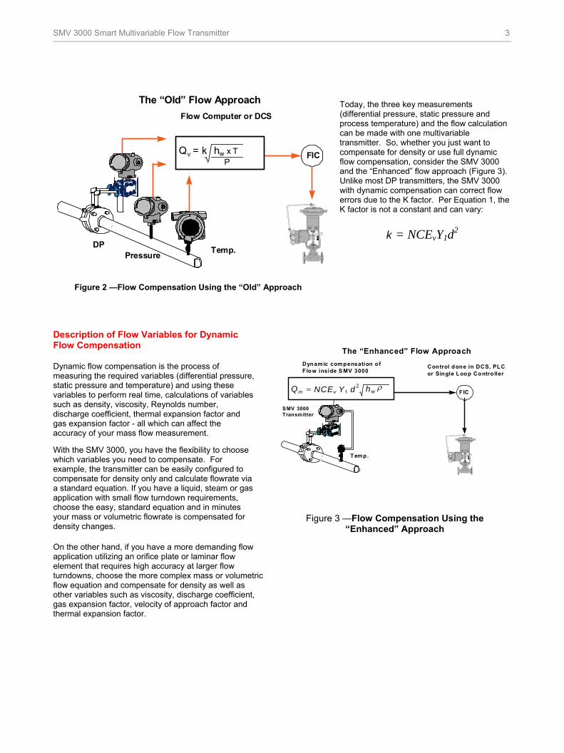
SMV 3000 Smart Multivariable Flow Transmitter 3
Today, the three key measurements (differential pressure, static pressure and process temperature) and the flow calculation can be made with one multivariable transmitter. So, whether you just want to compensate for density or use full dynamic flow compensation, consider the SMV 3000 and the “Enhanced” flow approach (Figure 3). Unlike most DP transmitters, the SMV 3000 with dynamic compensation can correct flow errors due to the K factor. Per Equation 1, the K factor is not a constant and can vary:
k = NCEvY1d2
Figure 2 —Flow Compensation Using the “Old” Approach
Description of Flow Variables for Dynamic Flow Compensation
Dynamic flow compensation is the process of measuring the required variables (differential pressure, static pressure and temperature) and using these variables to perform real time, calculations of variables such as density, viscosity, Reynolds number, discharge coefficient, thermal expansion factor and gas expansion factor - all which can affect the accuracy of your mass flow measurement.
With the SMV 3000, you have the flexibility to choose which variables you need to compensate. For example, the transmitter can be easily configured to compensate for density only and calculate flowrate via a standard equation. If you have a liquid, steam or gas application with small flow turndown requirements, choose the easy, standard equation and in minutes your mass or volumetric flowrate is compensated for density changes.
On the other hand, if you have a more demanding flow application utilizing an orifice plate or laminar flow element that requires high accuracy at larger flow turndowns, choose the more complex mass or volumetric flow equation and compensate for density as well as other variables such as viscosity, discharge coefficient, gas expansion factor, velocity of approach factor and thermal expansion factor.
SMV 3000 Transmitter
F IC
Control done in DCS, PLCor Single Loop Contro ller
Temp.
Qm NCEv Y d hw 1 2
PT
The “Enhanced” Flow Approach
Dynamic compensation o f F low inside S MV 3000
Figure 3 —Flow Compensation Using the “Enhanced” Approach
PT
FIC
Temp.DP
Pressure
PT
The “Old” Flow Approach
Flow Computer or DCS
Q v = k h w x T P

4 SMV 3000 Smart Multivariable Flow Transmitter
Discharge Coefficient Discharge coefficient is defined as the true flowrate divided by the theoretical flowrate and corrects the theoretical equation for the influence of velocity profile (Reynolds number), the assumption of no energy loss between taps, and pressure tap location. It is dependent on the primary flow element, the ratio and the Reynolds number. Reynolds number is in turn dependent on the viscosity, density and velocity of the fluid as well as the pipe diameter per the following equation:
Re = vD
where,
= velocity D = inside pipe diameter = fluid density = fluid viscosity
The SMV 3000 can be configured to dynamically compensate for discharge coefficient. This method follows the standard Stoltz equation for orifice, Venturi and nozzle primary elements to predict discharge coefficient for flowrate in the turbulent regime - Re > 4000.
C = C + b
nRe
Where,
C = Discharge coefficient at infinite Re # b = function of primary element Re = Reynolds number n = depends on the primary element
Dynamically compensating for discharge coefficient allows the SMV 3000 to obtain better flow accuracy at higher turndowns for orifice, Venturi and nozzles. Thermal Expansion Factor The material of the process pipe and primary flow element expands or contracts with changes in temperature of the fluid being measured. When a primary flow element, such as an orifice, is sized, the flowrate is calculated based on the Beta ratio (d/D) at 68 degrees F. The SMV 3000, using the thermal expansion coefficients which are dependent of the material of the pipe and flow element, calculates the change in Beta ratio per the following equations:
= d/D
D = 1 + p(Tf - 68)Dref
d = 1 + pe(Tf - 68)dref
where,
= beta ratio D = pipe diameter d = bore diameter Dref = pipe diameter at design temperature dref = bore diameter at design temperature
p = Thermal Expansion Coef. of pipe
pe = Thermal Expansion Coef. of bore
Tf = flowing temperature
As an example, a fluid at 600 degrees F could cause as much as 1% error in flow measurement using 300 series stainless steel materials. Gas Expansion Factor The gas expansion factor corrects for density differences between pressure taps due to expansion of compressible fluids. It does not apply for liquids which are essentially non-compressible and approaches unity when there are small differential pressures for gas and steam measurements. The gas expansion factor is dependent on the Beta ratio, the Isentropic exponent, the differential pressure and the static pressure of the fluid per the following equation:
1 = 1 - (0.41 + 0.354)X1/k where,
= beta ratio X1 = hw /P
k = isentropic exp. (ratio of specific heats)
The SMV 3000 dynamically compensates for gas expansion effects and provides better mass flow accuracy, especially for low static pressure applications.
Velocity of Approach Factor Ev is dependent on the Beta ratio as defined by the following equation:
Ev = 1/ 1- 4 In turn, Beta ratio is dependent on the bore diameter and pipe diameter which are functions of temperature. The SMV 3000 compensates dynamically for velocity of approach factor by calculating the true Beta ratio at flowing temperature. This ensures high flowrate accuracy at low and high temperature applications.
Density and Viscosity of Fluids Density directly effects the flowrate calculation as well as the discharge coefficient due to changes in the Reynolds number. The SMV 3000 can be configured to compensate for density of fluids due to changes in the temperature and/or pressure per the following:
Gases as a function of P and T per the Gas Law Equations.
Steam as function of P and T based on the ASME Tables.
Liquids as a function of T per a 5th Order Polynomial.
= d1 + d2TF + d3TF
2 + d4TF3 + d5TF
4
Changes in the viscosity of a fluid due to changes in temperature can also effect the Reynolds number and therefore discharge coefficient. The SMV 3000 can compensate the viscosity of liquids based on the following 5th order polynomial equation:
= v1 + v2TF + v3TF
2 + v4TF3 + v5TF

SMV 3000 Smart Multivariable Flow Transmitter 5
Support of Proprietary Flow Elements The SMV 3000 with dynamic flow compensation supports orifice meters and the Meriam Laminar Flow Elements. The SMV 3000 with density compensation supports other flow elements such as Venturi meters, nozzles, averaging pitot tubes. Averaging Pitot Tubes Averaging pitot tubes are a low differential pressure, insertion type flow element and can be used in clean steam, air, gas and liquid applications. Since averaging pitot tubes are insertion type elements, they have lower installation costs than many other primary flow elements. The SMV 3000 can be configured to compensate for density and calculate flowrate for liquids, gases and steam utilizing averaging pitot tubes (Figure 4).
Figure 4 —SMV 3000 with Averaging Pitot Tube
Meriam Laminar Flow Element Laminar Flow Elements (Figure 5) are gas volume rate of flow differential producers operating on capillary flow principles and are similar to averaging pitot tubes in that they are low differential pressure producers. They are applicable over wider flow ranges than conventional types of primary flow elements and are ideally suited for measurements of combustion air and gases such as argon, helium and nitrogen. Laminar Flow Elements behave according to the following flow formulas and can be configured for standard volumetric flowrate:
Qv = (B x hw + C x hw2) • (s/w) • (Ts/Tf) • (Pf/Ps) • (w/d)
Where,
Qv = standard volumetric flowrate B & C = calibration constants
hw = differential pressure s = standard viscosity Tf = flowing temperature Pf = flowing pressure w = wet air density d = dry air density
And for mass flowrate:
Qm = Qv • Where,
Qm = standard volumetric flowrate = density at standard conditions
The relationship between flowrate and differential pressure can be determined two ways.
The first method uses a 6th order polynomial equation that custom fits the flow element. The second method is an n-segment fit (maximum n = 5) between flow and differential pressure which also custom fits the flow element.
Figure 5 —SMV 3000 with Meriam Laminar Flow
Elements
The SMV 3000 can use either one of these methods as well as compensate for density and viscosity to increase the accuracy of the flow measurement for the Laminar Flow Element over greater flow turndowns.

6 SMV 3000 Smart Multivariable Flow Transmitter
Smart Technology Delivers Broad Benefits and Reduces Total Cost of Ownership Other Multivariable Applications Most multivariable transmitters are used in flow applications. However, there are other applications which require that multiple process variables (DP, AP and T) be transmitted to a control system - DCS or PLC. It is in the control system where a calculation such as compensated level for liquid level applications or complex calculations to infer composition in distillation columns are performed. A SMV 3000 in these applications can save substantial wiring, installation and purchase costs versus 2 or 3 separate single-variable transmitters. Whether integrating digitally to a Experion/TDC/TPS 3000 Control System or providing 4 analog 1-5 V outputs to a PLC or DCS via the MVA Multivariable Analog Card, the SMV 3000 is very cost effective in multivariable applications.
Figure 6 — Smart Field Communicator
Smart Configuration Flexibility Like other Smartline Transmitters, the SMV 3000 features two-way communication between the operator and the transmitter via the SCT 3000 Smart Configuration Toolkit or SFC - Smart Field Communicator or MC Toolkit. You connect the SFC or SCT anywhere that you can access the transmitter signal lines. These communicators provide the capabilities of transmitter adjustments and diagnostics from remote locations, such as the field installation, I/O rack or control room. The SFC and SCT3000 support other Smartline Instruments too: ST 3000, STT 3000.
Figure 7 — MC Tookit The SCT 3000 has an advantage over the SFC in that it can also be used to configure the complete SMV 3000 database and save this database for later access. The SCT 3000 is a software package and hardware interface which runs on an IBM compatible computer utilizing the Windows 95, Windows 98 or Windows NT platforms. The SCT 3000 must be used to configure the advanced flow parameters for the SMV 3000.
Figure 8 — SCT 3000

SMV 3000 Smart Multivariable Flow Transmitter 7
Digital Integration Links the SMV 3000 to
Experion and TDC/TPS 3000 for greater
process efficiency
MVA Provides Integration with Analog Systems
Digital Integration combines the functions of TDC/TPS 3000 system with the strengths of the SMV 3000 to help achieve maximum productivity, by providing:
Database security and integrity - PV Status transmission precedes the PV value, guaranteeing that a bad PV is not used in a control algorithm.
Bidirectional communication and a common database for the system and the transmitter - Data upload and download capability lowers transmitter installation costs.
Single-window diagnostics for the transmitter (electronics and meter body) and loop - Remote troubleshooting reduces maintenance effort and expedites repairs.
Automatic historization of all transmitter parameter changes - System maintenance log automatically provides audit trail of changes.
Enhanced accuracy - Elimination of D/A and A/D converters improves measurement accuracy.
Digital Integration of the SMV 3000 Smart Multivariable Flow Transmitter with Experion/TDC/TPS 3000 allows you to combine advanced transmitter technology with our state-of-the-art, process connected controllers - the Process Manager, Advanced Process Manager and High Performance Process Manager. Digital Integration of the SMV 3000 Smart Multivariable Flow Transmitter with Experion/TDC/TPS 3000 improves the integrity of the process data measurements, letting you monitor process variability with greater accuracy. Accurate and more reliable data lets you implement advanced control strategies, providing greater bottom-line profits.
The MultiVariable Analog (MVA) interface in Figure 6 provides a cost effective way to interface with analog instrumentation while utilizing all the advantages of Honeywell’s digitally enhanced (DE) communications. The MVA is fully compatible with all Honeywell Smartline™ transmitters. This includes the SMV 3000 Smart Multivariable Transmitter, ST 3000 Smart Pressure Transmitters, STT 3000 Smart Temperature Transmitter. The MVA also works in conjunction with any of Honeywell’s DE control system interfaces (STDC, STI-MV). In addition, Honeywell’s handheld communicators, SFC III and SCT 3000 and the MC Tool kit, may be used with no disturbances to the analog outputs or device status. MVA accepts the digital DE signal from any Smartline™ transmitter and outputs analog signals. Digitally integrated to the SMV 3000, the MVA can provide up to 4 analog 1-5 Volt outputs for differential pressure, static pressure, temperature and compensated flowrate. This provides an economical means of integrating SMV 3000 in analog applications when all process variables are required.
Figure 6 —MultiVariable Analog Interface MVA141 Ordered Separately under Spec. 34-MV-03-01

8 SMV 3000 Smart Multivariable Flow Transmitter
SMV 3000 Specifications Operating Conditions
Parameter Reference Condition
Rated Condition
Operative Limits
Transportation and Storage
Ambient Temperature C F
25 ±1 77 ±2
–40 to 85 –40 to 185
–40 to 93 –40 to 200
–55 to 125 –67 to 257
Meter Body Temperature C F
25 ±1 77 ±2
–40 to 110 1 –40 to 230 1
–40 to 125 1 –40 to 257 1
–55 to 125 –67 to 257
Humidity %RH 10 to 55 0 to 100 0 to 100 0 to 100
Vacuum Region - Minimum Pressure mmHg absolute inH2O absolute
Atmospheric Atmospheric
25 13
2 (short term2) 1 (short term2)
Supply Voltage, Current, and Load Resistance
Voltage Range: 10.8 to 42.4 Vdc at terminals Current Range: 3.0 to 20.8 mA Load Resistance: 0 to 1440 ohms (as shown in Figure 7).
Maximum Allowable Working Pressure (MAWP) 4
(ST 3000 products are rated to Maximum Allowable Working Pressure. MAWP depends on Approval Agency and transmitter materials of construction.)
SMA110 = 100 psi, 7 bar 3
SMA125 = 3,000 psi, 210 bar 3
SMG170 = 3,000 psi, 210 bar 3
Static Pressure Limit = Maximum Allowable Working Pressure (MAWP) = Overpressure Limit
1 For CTFE fill fluid, the rating is –15 to 110C (5 to 230F). 2 Short term equals 2 hours at 70C (158F). 3 The MAWP is intended as a pressure safety limit. Honeywell does not recommend use above the PV 2 Upper Range Limit. 4
Consult factory for MAWP of transmitters that require CSA approval (CRN)
0 10.8 16.28 20.63 25 28.3 37.0 42.4
250
450
650
800
1200
1440
Operating Voltage (Vdc)
= Operating Area
NOTE: A minimum of 250 0hms of loop resistance is necessary to support communications. Loop resistance equals barrier resistance plus wire resistance plus receiver resistance. Also 45 volt operation is permitted if not an intrinsically safe installation.
Loop Resistance
(ohms)
21012
Figure 7 —Supply Voltage and Loop Resistance Chart.

SMV 3000 Smart Multivariable Flow Transmitter 9
SMV 3000 Specifications, continued
Performance Under Rated Conditions5 - Differential Pressure Measurement - SMA110
Parameter Description
Upper Range Limit ± 25 inH2O (62.5 mbar) at 39.2F (4C) standard reference temperature for inches of water measurement range.
Turndown Ratio 25 to 1
Minimum Span ±1.0 inH2O (2.5 mbar)
Zero Elevation and Suppression No limit (except minimum span) with ±100% URL.
Accuracy (Reference – Includes combined effects of linearity, hysteresis, and repeatability)
• Applies for model with Stainless Steel barrier diaphragms
• Accuracy includes residual error after averaging successive readings.
In Analog Mode: ±0.125% of calibrated span or upper range value (URV), whichever is greater, - Terminal based.
For URV below reference point (10 inH2O), accuracy equals:
OinHspan
OinH10 0.10.025
2
2 or
mbar span
mbar 250.10.025 in % of span.
In Digital Mode: ±0.1% of calibrated span or upper range value (URV), whichever is greater, - Terminal based.
For URV below reference point (10 inH2O), accuracy equals:
± 0. 1
10 inH2O
span inH2O or ± 0. 1 ( )25 mbar
span mbar in % of span.
Zero Temperature Effect per 28C (50F)
• Applies for model with Stainless Steel barrier diaphragms
In Analog Mode: ±0.525% of calibrated span.
For URV below reference point (10 inH2O), effect equals:
OinH span
OinH10 0.500.025
2
2 or
mbar span
mbar 25 0.500.025 in % of span.
In Digital Mode: ±0.5% of calibrated span.
For URV below reference point (10 inH2O), effect equals:
±0.50
10 inH2O
span inH2O or ±0.50 ( )25 mbar
span mbar in % of span.
Combined Zero and Span Temperature Effect per 28C (50F)
• Applies for model with Stainless Steel barrier diaphragms
In Analog Mode: ±0.675% of calibrated span.
For URV below reference point (10 inH2O), effect equals:
OinHspan
OinH100.500.175
2
2 or
mbar span
mbar 250.500.175 in % of span
In Digital Mode: ±0. 625% of calibrated span.
For URV below reference point (10 inH2O), effect equals:
OinHspan
OinH100.500.125
2
2 or
mbar span
mbar 250.500.125 in % of span
Stability (At Reference Conditions) ±1.0% of URL per year.
Damping Time Constant Adjustable for 0 to 32 seconds digital damping.
5 Performance specifications are based on reference conditions of 25C (77F), zero (0) static pressure, 10 to 55% RH, and 316 Stainless Steel barrier diaphragm.
10 SMV 3000 Smart Multivariable Flow Transmitter
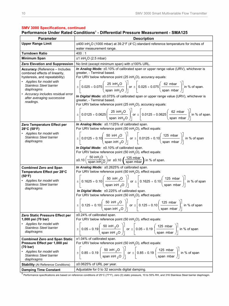
SMV 3000 Specifications, continued Performance Under Rated Conditions5 - Differential Pressure Measurement - SMA125
Parameter Description Upper Range Limit ±400 inH2O (1000 mbar) at 39.2F (4C) standard reference temperature for inches of
water measurement range.
Turndown Ratio 400 : 1
Minimum Span ±1 inH2O (2.5 mbar)
Zero Elevation and Suppression No limit (except minimum span) with ±100% URL.
Accuracy (Reference – Includes combined effects of linearity, hysteresis, and repeatability) • Applies for model with
Stainless Steel barrier diaphragms
• Accuracy includes residual error after averaging successive readings.
In Analog Mode: ±0.10% of calibrated span or upper range value (URV), whichever is greater, - Terminal based. For URV below reference point (25 inH2O), accuracy equals:
OinH span
OinH 25 0.0750.025
2
2 or
mbar span
mbar 62 0.0750.025 in % of span.
In Digital Mode: ±0.075% of calibrated span or upper range value (URV), whichever is greater, - Terminal based. For URV below reference point (25 inH2O), accuracy equals:
OinH span
OinH 25 0.06250.0125
2
2 or
mbar span
mbar 62 0.06250.0125 in % of span.
Zero Temperature Effect per 28C (50F) • Applies for model with
Stainless Steel barrier diaphragms
In Analog Mode: ±0.1125% of calibrated span. For URV below reference point (50 inH2O), effect equals:
OinHspan
OinH 500.100.0125
2
2 or
mbar span
mbar 1250.100.0125 in % of span
In Digital Mode: ±0.10% of calibrated span. For URV below reference point (50 inH2O), effect equals:
±0.10
50 inH2O
span inH2O or ±0.10 ( )125 mbar
span mbar in % of span.
Combined Zero and Span Temperature Effect per 28C (50F) • Applies for model with
Stainless Steel barrier diaphragms
In Analog Mode: ±0.2625% of calibrated span. For URV below reference point (50 inH2O), effect equals:
OinHspan
OinH 50 0.100.1625
2
2 or
mbar span
mbar 125 0.100.1625 in % of span
In Digital Mode: ±0.225% of calibrated span. For URV below reference point (50 inH2O), effect equals:
OinHspan
OinH 50 0.100.125
2
2 or
mbar span
mbar 125 0.100.125 in % of span
Zero Static Pressure Effect per 1,000 psi (70 bar) • Applies for model with
Stainless Steel barrier diaphragms
±0.24% of calibrated span. For URV below reference point (50 inH2O), effect equals:
OinHspan
OinH 50 0.190.05
2
2 or
mbar span
mbar 125 0.190.05 in % of span
Combined Zero and Span Static Pressure Effect per 1,000 psi (70 bar) • Applies for model with
Stainless Steel barrier diaphragms
±1.04% of calibrated span. For URV below reference point (50 inH2O), effect equals:
OinHspan
OinH 50 0.190.85
2
2 or
mbar span
mbar 125 0.190.85 in % of span
Stability (At Reference Conditions) ±0.0625% of URL per year.
Damping Time Constant Adjustable for 0 to 32 seconds digital damping. 5
Performance specifications are based on reference conditions of 25C (77F), zero (0) static pressure, 10 to 55% RH, and 316 Stainless Steel barrier diaphragm.

SMV 3000 Smart Multivariable Flow Transmitter 11
SMV 3000 Specifications, continued
Performance Under Rated Conditions5 - Differential Pressure Measurement - SMG170 Parameter Description
Upper Range Limit 400 inH2O (1000 mbar) at 39.2F (4C) standard reference temperature for inches of water measurement range.
Turndown Ratio 400 to 1 Minimum Span 1 inH2O (2.5 mbar)
Zero Elevation and Suppression No limit (except minimum span) with ±100% URL. Specifications valid from –5 to +100% URL.
Accuracy (Reference – Includes combined effects of linearity, hysteresis, and repeatability) • Applies for model with
Stainless Steel barrier diaphragms
• Accuracy includes residual error after averaging successive readings.
In Analog Mode: ±0.10% of calibrated span or upper range value (URV), whichever is greater, - Terminal based. For URV below reference point (50 inH2O), accuracy equals:
OinH span
OinH 50 0.0750.025
2
2 or
mbar span
mbar 125 0.0750.025 in % of span.
In Digital Mode: ±0.075% of calibrated span or upper range value (URV), whichever is greater, - Terminal based. For URV below reference point (50 inH2O), accuracy equals:
OinH span
OinH 50 0.06250.0125
2
2 or
mbar span
mbar 125 0.06250.0125 in % of span.
Zero Temperature Effect per 28C (50F) • Applies for model with
Stainless Steel barrier diaphragms
In Analog Mode: ±0.1375% of calibrated span. For URV below reference point (100 inH2O), effect equals:
OinH span
OinH 100 0.1250.0125
2
2 or
mbar span
mbar 250 0.1250.0125 in % of span.
In Digital Mode: ±0.125% of calibrated span. For URV below reference point (100 inH2O), effect equals:
±0.125
100 inH2O
span inH2O or ±0.125 ( )250 mbar
span mbar in % of span.
Combined Zero and Span Temperature Effect per 28C (50F) • Applies for model with
Stainless Steel barrier diaphragms
In Analog Mode: ±0.35% of calibrated span. For URV below reference point (100 inH2O), effect equals:
OinH span
OinH 100 0.1250.225
2
2or
mbar span
mbar 250 0.1250.225 in % of span.
In Digital Mode: ±0.325% of calibrated span. For URV below reference point (100 inH2O), effect equals:
OinH span
OinH 100 0.1250.20
2
2or
mbar span
mbar 250 0.1250.20 in % of span.
Zero Static Pressure Effect per 1,000 psi (68 bar) • Applies for model with
Stainless Steel barrier diaphragms
±0.15% of calibrated span. For URV below reference point (100 inH2O), effect equals:
OinH span
OinH 100 0.1250.025
2
2 or
mbar span
mbar 250 0.1250.025 in % of span.
Combined Zero and Span Static Pressure Effect per 1,000 psi (68 bar) • Applies for model with
Stainless Steel barrier diaphragms
±0.35% of calibrated span. For URV below reference point (100 inH2O), effect equals:
OinH span
OinH 100 0.1250.225
2
2or
mbar span
mbar 250 0.1250.225 in % of span.
Stability (At Reference Conditions) ±0.0625% of URL per year.
Damping Time Constant Adjustable for 0 to 32 seconds digital damping. 5
Performance specifications are based on reference conditions of 25C (77F), zero (0) static pressure, 10 to 55% RH, and 316 Stainless Steel barrier diaphragm.

12 SMV 3000 Smart Multivariable Flow Transmitter
SMV 3000 Specifications, continued
Performance Under Rated Conditions5 - Absolute Pressure Measurement - SMA110
Parameter Description
Upper Range Limit (URL) 100 psia (7 bara)
Turndown Ratio 20 to 1
Minimum Span 5 psia (.35 bara)
Zero Suppression No limit (except minimum span) from absolute zero to 100% URL. Specifications valid over this range.
Accuracy (Reference – Includes combined effects of linearity, hysteresis, and repeatability)
• Applies for model with Stainless Steel barrier diaphragms
• Accuracy includes residual error after averaging successive readings.
In Analog Mode: ±0.10% of calibrated span or upper range value (URV), whichever is greater - Terminal based.
For URV below reference point (20 psi), accuracy equals:
psi span
psi 20 0.0750.025 or
bar span
bar 1.4 0.0750.025 in % of span.
In Digital Mode: ±0.075% of calibrated span or upper range value (URV), whichever is greater, - Terminal based.
For URV below reference point (20 psi), accuracy equals:
psi span
psi 20 0.06250.0125 or
bar span
bar 1.4 0.06250.0125 in % of span.
Zero Temperature Effect per 28C (50F)
• Applies for model with Stainless Steel barrier diaphragms
In Analog Mode: ±0.125% of calibrated span.
For URV below reference point (50 psi), effect equals:
psi span
psi 50 0.100.025 or
bar span
bar 3.5 0.100.025 in % of span.
In Digital Mode: ±0.10% of calibrated span.
For URV below reference point (50 psi), effect equals:
±0.10 ( )50 psi span psi
or ±0.10 ( )3.5 bar span bar in % of span.
Combined Zero and Span Temperature Effect per 28C (50F)
• Applies for model with Stainless Steel barrier diaphragms
In Analog Mode: ±0.2625% of calibrated span.
For URV below reference point (50 psi), effect equals:
psi span
psi 50 0.100.1625 or
bar span
bar 3.5 0.100.1625 in % of span.
In Digital Mode: ±0.225% of calibrated span.
For URV below reference point (50 psi), effect equals:
psi span
psi 50 0.100.125 or
bar span
bar 3.5 0.100.125 in % of span.
Stability (At Reference Conditions) ±0.125% of URL per year.
Damping Time Constant Adjustable from 0 to 32 seconds digital damping.
5 Performance specifications are based on reference conditions of 25C (77F), zero (0) static pressure, 10 to 55% RH, and 316 Stainless Steel barrier diaphragm.

SMV 3000 Smart Multivariable Flow Transmitter 13
SMV 3000 Specifications, continued
Performance Under Rated Conditions5 - Absolute Pressure Measurement - SMA125
Parameter Description
Upper Range Limit (URL) 750 psia (52 bara)
Turndown Ratio 150 to 1
Minimum Span 5 psia (0.3 bara)
Zero Suppression No limit (except minimum span) from absolute zero to 100% URL. Specifications valid over this range.
Accuracy (Reference – Includes combined effects of linearity, hysteresis, and repeatability)
• Applies for model with Stainless Steel barrier diaphragms
• Accuracy includes residual error after averaging successive readings.
In Analog Mode: ±0.10% of calibrated span or upper range value (URV), whichever is greater - Terminal based.
For URV below reference point (20 psi), accuracy equals:
psi span
psi 20 0.0750.025 or
bar span
bar 1.4 0.0750.025 in % of span.
In Digital Mode: ±0.075% of calibrated span or upper range value (URV), whichever is greater, - Terminal based.
For URV below reference point (20 psi), accuracy equals:
psi span
psi 20 0.06250.0125 or
bar span
bar 1.4 0.06250.0125 in % of span.
Zero Temperature Effect per 28C (50F)
• Applies for model with Stainless Steel barrier diaphragms
In Analog Mode: ±0.1125% of calibrated span.
For URV below reference point (50 psi), effect equals:
psi span
psi 50 0.100.0125 or
bar span
bar 3.5 0.100.0125 in % of span.
In Digital Mode: ±0.10% of calibrated span.
For URV below reference point (50 psi), effect equals:
±0.10 ( )50 psi span psi
or ±0.10 ( )3.5 bar span bar in % of span.
Combined Zero and Span Temperature Effect per 28C (50F)
• Applies for model with Stainless Steel barrier diaphragms
In Analog Mode: ±0.2625% of calibrated span.
For URV below reference point (50 psi), effect equals:
psi span
psi 50 0.100.1625 or
bar span
bar 3.5 0.100.1625 in % of span.
In Digital Mode: ±0.225% of calibrated span.
psi span
psi 50 0.100.125 or
bar span
bar 3.5 0.100.125 in % of span.
Stability (At Reference Conditions) ±0.016% of URL per year.
Damping Time Constant Adjustable from 0 to 32 seconds digital damping.
5 Performance specifications are based on reference conditions of 25C (77F), zero (0) static pressure, 10 to 55% RH, and 316 Stainless Steel barrier diaphragm.

14 SMV 3000 Smart Multivariable Flow Transmitter
SMV 3000 Specifications, continued
Performance Under Rated Conditions5 - Gauge Pressure Measurement - SMG170
Parameter Description
Upper Range Limit (URL) 3,000 psig (210 barg)
Turndown Ratio 50 to 1
Minimum Span 60 psig (1.04 barg)
Zero Suppression No limit (except minimum span) from absolute zero to 100% URL. Specifications valid over this range.
Accuracy (Reference – Includes combined effects of linearity, hysteresis, and repeatability)
• Applies for model with Stainless Steel barrier diaphragms
• Accuracy includes residual error after averaging successive readings.
In Analog Mode: ±0.10% of calibrated span or upper range value (URV), whichever is greater - Terminal based.
For URV below reference point (300 psi), accuracy equals:
psi span
psi 300 0.0750.025 or
bar span
bar 21 0.0750.025 in % of span.
In Digital Mode: ±0.075% of calibrated span or upper range value (URV), whichever is greater, - Terminal based.
For URV below reference point (300 psi), accuracy equals:
psi span
psi 300 0.06250.0125 or
bar span
bar 21 0.06250.0125 in % of span.
Zero Temperature Effect per 28C (50F)
• Applies for model with Stainless Steel barrier diaphragms
In Analog Mode: ±0.1125% of calibrated span.
For URV below reference point (300 psi), effect equals:
psi span
psi 300 0.100.0125 or
bar span
bar 21 0.100.0125 in % of span.
In Digital Mode: ±0.10% of calibrated span.
For URV below reference point (300 psi), effect equals:
±0.10 ( )300 psi span psi
or ±0.10 ( )21 bar span bar in % of span.
Combined Zero and Span Temperature Effect per 28C (50F)
• Applies for model with Stainless Steel barrier diaphragms
In Analog Mode: ±0.25% of calibrated span.
For URV below reference point (300 psi), effect equals:
psi span
psi 300 0.100.15 or
bar span
bar 21 0.100.15 in % of span.
In Digital Mode: ±0.225% of calibrated span.
For URV below reference point (300 psi), effect equals:
psi span
psi 300 0.100.125 or
bar span
bar 21 0.100.125 in % of span.
Stability (At Reference Conditions) ±0.025% of URL per year.
Damping Time Constant Adjustable from 0 to 32 seconds digital damping.
5 Performance specifications are based on reference conditions of 25C (77F), zero (0) static pressure, 10 to 55% RH, and 316 Stainless Steel barrier
diaphragm.

SMV 3000 Smart Multivariable Flow Transmitter 15
SMV 3000 Specifications, continued Performance Under Rated Conditions - Process Temperature Measurement
Probe Type Digital Accuracy
(Ref.) 6
Rated Range Limits Operative Range Limits Standards
C F C F C F
RTD
Platinum 100-ohm
±0.6 ±1.0 –200 to 450 –328 to 842 –200 to 850 –328 to 1562 DIN 43760
Thermocouple
E ±1.0 ±1.8 0 to 1,000 32 to 1,832 –200 to 1,000 –328 to 1,832 IEC584.1
J ±1.0 ±1.8 0 to 1,200 32 to 2,192 –200 to 1,200 –328 to 2,192 IEC584.1
K ±1.0 ±1.8 –100 to 1,250 –148 to 2,282 –200 to 1,370 –328 to 2,498 IEC584.1
T ±1.0 ±1.8 –100 to 400 –148 to 752 –250 to 400 –418 to 752 IEC584.1
6 Add ±0.025% of calibrated span for transmitter operating in analog mode.
Parameter Description Adjustment Range Select zero and span output for any input from 0% to +100% of the upper
range limit (operative limit) shown above for each probe type. Specifications only apply to rated limit.
Output D/A Accuracy ±0.025% of span.
Minimum Span ±10C
Total Reference Accuracy • Accuracy includes residual error after
averaging successive readings.
In Analog Mode = Digital Accuracy + Output D/A Accuracy In Digital Mode = Digital Accuracy
Combined Zero and Span Temperature Effect
In Digital Mode: RTD = None Thermocouple ±0.10% of input mV per 28C (50F) ±CJ Rejection In Analog Mode: Add ±0.15% of calibrated span to calculation for digital mode above.
Cold Junction Rejection 40 to 1
Thermocouple Burnout Burnout (open lead) detection is user selectable: ON = upscale or downscale failsafe action with critical status message for any open lead.
Drift (At Reference Conditions) ±1.0C (1.8F) per year.
Damping Time Constant Adjustable from 0 to 102 seconds digital damping. Performance Under Rated Conditions - Flowrate Calculation
Mass Flowrate Accuracy
±1.0% of mass flowrate over an 8:1 flow range (64:1 DP range) for steam, air and liquids for a ASME MFC3M - ISO 1567 Orifice meter with flange taps.
Performance Under Rated Conditions - General
Parameter Description
Output (two-wire) Analog 4 to 20 mA or digital (DE protocol).
Power Supply Voltage Effect 0.005% of span per volt.

16 SMV 3000 Smart Multivariable Flow Transmitter
SMV 3000 Specifications, continued Physical
Parameter Description Barrier Diaphragms Material SMA110 SMA125 SMG170
316L SS 316L SS, Hastelloy
® C -2767, Monel
400
®8 and Tantalum 316L SS, Hastelloy
® C -2767
Process Head Material
SMA110 SMA125 SMG170
Carbon Steel (Zinc-Plated) 11 or 316L SS Carbon Steel (Zinc-Plated) 11, 316L SS, Hastelloy
® C -2769 or Monel
400
®10. Carbon Steel (Zinc-Plated) 11, 316L SS, or Hastelloy
® C -2769.
Vent/Drain Valves & Plugs 1 316 SS, Hastelloy®
C-2767, Monel 400®8
Head Gaskets Glass filled PTFE standard. Viton®
is optional
Meter Body Bolting Carbon Steel (Zinc plated) standard. Options include 316 SS, NACE A286 SS bolts and 304 SS nuts and B7M.
Optional Adapter Flange and Bolts Adapter Flange materials include 316L SS, Hastelloy®
C-2769 and Monel
400®10. Bolt material for flanges is dependent on process head bolts material
chosen. Standard adaptor o-ring material is glass-filled PTFE. Viton®
and graphite are optional.
Mounting Bracket Carbon Steel (Zinc-plated) available in angle or flat style.
Fill Fluid DC®
200 Silicone oil or CTFE (Chlorotrifluoroethylene).
Electronic Housing Epoxy-polyester hybrid paint Low Copper-Aluminum. Meets NEMA 4X (watertight) and NEMA 7 (explosion-proof).
Process Connections 1/4-inch NPT (Option 1/2-inch NPT with adapter).
Wiring Accepts up to 16 AWG (1.5 mm diameter).
Dimensions See Figure 8.
Net Weight 5.3 Kg (11.6 lb)
Mounting See Figure 9.
1 Vent/Drains are sealed with Teflon® or PTFE
7 Hastelloy® C-276 or UNS N10276
8 Monel 400® or UNS N04400
9 Hastelloy® C-276 or UNS N10276. Supplied as indicated or as Grade CW12MW, the casting equivalent of Hastelloy® C-276
10 Monel 400® or UNS N04400. Supplied as indicated or as Grade M30C, the casting equivalent of Monel 400®
11 Carbon Steel heads are zinc-plated and not recommended for water service due to hydrogen migration. For that service, use 316L stainless steel wetted
Process Heads.

SMV 3000 Smart Multivariable Flow Transmitter 17
Certifications
Type of Protection Comm. Option Field Parameters Temp. Codes
Explosionproof: Class I, Division 1, Groups A, B, C, D locations Dust Ignition Proof: Class II, III, Division 1, Groups E, F, G locations, Enclosure Type 4X
All All T5 Ta = 93ºC
4-20 mA / DE
Vmax = 42.4V Imax = 225mA Ci = 4.2nF Li = * Pi =1.2W
T4 Ta = 93ºC Intrinsically Safe: Class I, II, III, Division 1, Groups A, B, C, D, E, F, G locations, Enclosure Type 4X
4-20 mA /
Vmax = 30V Imax = 225mA Ci = 4.2nF Li = * Pi =1.2W
T4 Ta = 93ºC
Fieldbus – Entity (Not FISCO)
Vmax = 32V Imax = 120mA Ci = 4.2nF Li = 0 Pi =0.84W
T4 Ta = 40ºC T3 Ta = 93ºC
Fieldbus – Entity (Not FISCO)
Vmax = 24V Imax = 250mA Ci = 4.2nF Li = 0 Pi =1.2W
T4 Ta = 40ºC T3 Ta = 93ºC
Intrinsically Safe: Class I, II, III, Division 1, Groups A, B, C, D, E, F, G locations; Class 1, Zone 0, AEx ia Group IIC, Enclosure Type 4X / IP 66/67
FISCO
Vmax = 17.5V Imax = 380mA Ci = 4.2nF Li = 0 Pi =5.32W
T4 Ta = 40ºC T3 Ta = 93ºC
4-20 mA / DE
Vmax = 42.4V Imax = 225mA Ci = 4.2nF Li = * Pi =1.2W
T4 Ta = 93ºC Nonincendive: Class I, Division 2, Groups A, B, C, D locations, Enclosure Type 4X
4-20 mA / HART
Vmax = 30V Imax = 225mA Ci = 4.2nF Li = * Pi =1.2W
T4 Ta = 93ºC
Fieldbus – Entity (Not FNICO)
Vmax = 32V Imax = 120mA Ci = 4.2nF Li = 0 Pi =0.84W
T4 Ta = 40ºC T3 Ta = 93ºC
Fieldbus – Entity (Not FNICO)
Vmax = 24V Imax = 250mA Ci = 4.2nF Li = 0 Pi =1.2W
T4 Ta = 40ºC T3 Ta = 93ºC
FM ApprovalsSM
Nonincendive: Class I, Division 2, Groups A, B, C, D; Suitable for: Class II, Division 2, Groups F&G; Class III, Division 2; Class I, Zone 2, Group IIC, Enclosure Type 4X / IP 66/67
FNICO Vmax = 32V Ci = 4.2nF Li = 0
T4 Ta = 40ºC T3 Ta = 93ºC
Li = 0 except Li = 150µH when Option ME, Analog Meter, is selected.
FM ApprovalsSM is a service mark of FM Global

18 SMV 3000 Smart Multivariable Flow Transmitter
Type of Protection Comm. Option Field Parameters Temp. Codes
Explosion Proof: Class I, Division 1, Groups B, C, D locations Dust Ignition Proof: Class II, III, Division 1, Groups E, F, G locations, Enclosure Type 4X
All All T4 Ta = 93ºC
4-20 mA / DE
Vmax = 42V Imax = 225mA Ci = 4.2nF Li = * Pi =1.2W
T4 Ta = 93ºC
4-20 mA / HART
Vmax = 42V Imax = 225mA Ci = 4.2nF Li = * Pi =1.2W
T4 Ta = 93ºC
Intrinsically Safe: Class I, II, III, Division 1, Groups A, B, C, D, E, F, G locations, Enclosure Type 4X
Fieldbus – Entity (Not FISCO)
Vmax = 24V Imax = 250mA Ci = 4.2nF Li = 0 Pi =1.2W
T4 Ta = 40ºC T3 Ta = 93ºC
4-20 mA / DE
Vmax = 42.4V Imax = 225mA Ci = 4.2nF Li = * Pi =1.2W
T4 Ta = 93ºC
4-20 mA / HART
Vmax = 30V Imax = 225mA Ci = 4.2nF Li = * Pi =1.2W
T4 Ta = 93ºC
Nonincendive: Class I, Division 2, Groups A, B, C, D locations, Enclosure Type 4X
Fieldbus – Entity (Not FNICO)
Vmax = 24V Imax = 250mA Ci = 4.2nF Li = 0 Pi =1.2W
T4 Ta = 40ºC T3 Ta = 93ºC
Canadian Standards
Association (CSA)
Canadian Registration Number (CRN):
All ST 3000 models except STG19L, STG99L, STG170 and STG180 have been registered in all provinces and territories in Canada and are marked CRN: 0F8914.5C.
* Li = 0 except Li = 150µH when Option ME, Analog Meter, is selected.

SMV 3000 Smart Multivariable Flow Transmitter 19
Type of Protection Comm. Option Field Parameters Temp. Codes
Flameproof, Zone 1: Ex d IIC, Enclosure IP 66/67
All All T5 Ta = –50 to 93ºC T6 Ta = –50 to 78ºC
4-20 mA / DE
Ui = 30V Ii = 100mA Ci = 4.2nF Li = * Pi =1.2W
T4 Ta = –50 to 93ºC T5 Ta = –50 to 85ºC T6 Ta = –50 to 70ºC
4-20 mA / HART
Ui = 30V Ii = 100mA Ci = 4.2nF Li = * Pi =1.2W
T4 Ta = –50 to 93ºC T5 Ta = –50 to 63ºC T6 Ta = –50 to 48ºC
IECEx International
Electrotechnical Commission
(LCIE)
Intrinsically Safe, Zone 0/1: Ex ia IIC, Enclosure IP 66/67
Fieldbus (Not FISCO)
Ui = 24V Ii = 250mA Ci = 4.2nF Li = 0 Pi =1.2W
T3 Ta = –50 to 93ºC T4 Ta = –50 to 40ºC
*Li = 0 except Li = 150µH when Option ME, Analog Meter, is selected.
Type of Protection Comm. Option Field Parameters Temp. Codes
Flameproof, Zone 1: Ex d IIC, Enclosure IP 66/67
All All T5 Ta = –50 to 93ºC T6 Ta = –50 to 78ºC
4-20 mA / DE
Ui = 30V Ii = 100mA Ci = 4.2nF Li = * Pi =1.2W
T4 Ta = –50 to 93ºC T5 Ta = –50 to 85ºC T6 Ta = –50 to 70ºC
4-20 mA / HART
Ui = 30V Ii = 100mA Ci = 4.2nF Li = * Pi =1.2W
T4 Ta = –50 to 93ºC T5 Ta = –50 to 63ºC T6 Ta = –50 to 48ºC
Intrinsically Safe, Zone 0/1: Ex ia IIC, Enclosure IP 66/67
Fieldbus (Not FISCO)
Ui = 24V Ii = 250mA Ci = 4.2nF Li = 0 Pi =1.2W
T3 Ta = –50 to 93ºC T4 Ta = –50 to 40ºC
4-20 mA / DE
Ui = 30V Ii = 100mA Ci = 4.2nF Li = * Pi =1.2W
T4 Ta = –50 to 93ºC T5 Ta = –50 to 85ºC T6 Ta = –50 to 70ºC
4-20 mA / HART
Ui = 30V Ii = 100mA Ci = 4.2nF Li = * Pi =1.2W
T4 Ta = –50 to 93ºC T5 Ta = –50 to 63ºC T6 Ta = –50 to 48ºC
SAEx (South Africa)
Multiple Marking: Flameproof, Zone 1: Ex d IIC, Enclosure IP 66/67 Intrinsically Safe, Zone 0/1: Ex ia IIC, Enclosure IP 66/67 The user must determine the type of protection required for installation of the equipment. The user shall then check the box [√] adjacent to the type of protection used on the equipment certification nameplate. Once a type of protection has been checked on the nameplate, subsequently the equipment shall not be reinstalled using any of the other certification types.
Fieldbus (Not FISCO)
Ui = 24V Ii = 250mA Ci = 4.2nF Li = 0 Pi =1.2W
T3 Ta = –50 to 93ºC T4 Ta = –50 to 40ºC
*Li = 0 except Li = 150µH when Option ME, Analog Meter, is selected.

20 SMV 3000 Smart Multivariable Flow Transmitter
Type of Protection Comm. Option Field Parameters Temp. Codes
Flameproof, Zone 0: , Ex tD
Enclosure IP 66/67 All All
A20 IP6X T95ºC Ta = 93ºC or T80ºC Ta = 78ºC
Flameproof, Zone 1: , Ex d IIC, Ex tD
Enclosure IP 66/67 All All
T5 Ta = –50 to +93ºC T6 Ta = –50 to +78ºC, A21 IP6X T95ºC Ta = 93ºC or T80ºC Ta = 78ºC
4-20 mA / DE
Ui = 30V Ii = 100mA Ci = 4.2nF Li = * Pi =1.2W
T4 Ta = –50 to 93ºC T5 Ta = –50 to 85ºC T6 Ta = –50 to 70ºC
4-20 mA / HART
Ui = 30V Ii = 100mA Ci = 4.2nF Li = * Pi =1.2W
T4 Ta = –50 to 93ºC T5 Ta = –50 to 63ºC T6 Ta = –50 to 48ºC
Intrinsically Safe, Zone 0/1:
, Ex ia IIC, Enclosure IP 66/67
Fieldbus (Not FISCO)
Ui = 24V Ii = 250mA Ci = 4.2nF Li = 0 Pi =1.2W
T3 Ta = –50 to 93ºC T4 Ta = –50 to 40ºC
4-20 mA / DE
Ui = 30V Ii = 100mA Ci = 4.2nF Li = * Pi =1.2W
T4 Ta = –50 to 93ºC T5 Ta = –50 to 85ºC T6 Ta = –50 to 70ºC
4-20 mA / HART
Ui = 30V Ii = 100mA Ci = 4.2nF Li = * Pi =1.2W
T4 Ta = –50 to 93ºC T5 Ta = –50 to 63ºC T6 Ta = –50 to 48ºC
Non-Sparking, Zone 2:
,Ex nA IIC (Honeywell), Enclosure IP 66/67
Fieldbus (Not FNICO)
Ui = 24V Ii = 250mA Ci = 4.2nF Li = 0 Pi =1.2W
T3 Ta = –50 to 93ºC T4 Ta = –50 to 40ºC
4-20 mA / DE
Ui = 30V Ii = 100mA Ci = 4.2nF Li = * Pi =1.2W
T4 Ta = –50 to 93ºC T5 Ta = –50 to 85ºC T6 Ta = –50 to 70ºC
4-20 mA / HART
Ui = 30V Ii = 100mA Ci = 4.2nF Li = * Pi =1.2W
T4 Ta = –50 to 93ºC T5 Ta = –50 to 63ºC T6 Ta = –50 to 48ºC
ATEX (LCIE)
Multiple Marking: Flameproof, Zone 1: , Ex d IIC Intrinsically Safe, Zone 0/1: , Ex ia IIC Non-Sparking, Zone 2: , Ex nA IIC NOTE: The user must determine the type of protection required for installation of the equipment. The user shall then check the box [ √ ] adjacent to the type of protection used on the equipment certification nameplate. Once a type of protection has been checked on the nameplate, subsequently the equipment shall not be reinstalled using any of the other certification types.
Fieldbus (Not FISCO/FNICO)
Ui = 24V Ii = 250mA Ci = 4.2nF Li = 0 Pi =1.2W
T3 Ta = –50 to 93ºC T4 Ta = –50 to 40ºC
*Li = 0 except Li = 150µH when Option ME, Analog Meter, is selected.

SMV 3000 Smart Multivariable Flow Transmitter 21
Type of Protection Comm. Option Field Parameters Temp. Codes
Flameproof, Zone 1: BR-Ex d IIC Enclosure IP 66/67
All All T5 Ta = –50 to 93ºC T6 Ta = –50 to 78ºC
4-20 mA / DE
Ui = 30V Ii = 100mA Ci = 4.2nF Li = * Pi =1.2W
T4 Ta = –50 to 93ºC T5 Ta = –50 to 85ºC T6 Ta = –50 to 70ºC
4-20 mA / HART
Ui = 30V Ii = 100mA Ci = 4.2nF Li = * Pi =1.2W
T4 Ta = –50 to 93ºC T5 Ta = –50 to 63ºC T6 Ta = –50 to 48ºC
INMETRO (CERTUSP)
Brazil
Intrinsically Safe, Zone 0/1: BR-Ex ia IIC Enclosure IP 66/67
Fieldbus (Not FISCO)
Ui = 24V Ii = 250mA Ci = 4.2nF Li = 0 Pi =1.2W
T3 Ta = –50 to 93ºC T4 Ta = –50 to 40ºC
Li = 0 except Li = 150µH when Option ME, Analog Meter, is selected.
This certificate defines the certifications covered for the ST 3000 Pressure Transmitter family of
products, including the SMV 3000 Smart Multivariable Transmitter. It represents the compilation of
the five certificates Honeywell currently has covering the certification of these products into marine
applications.
For ST 3000 Smart Pressure Transmitter and SMV 3000 Smart Multivarible Transmitter
American Bureau of Shipping (ABS) - 2009 Steel Vessel Rules 1-1-4/3.7, 4-6-2/5.15, 4-8-3/13 &
13.5, 4-8-4/27.5.1, 4-9-7/13. Certificate number: 04-HS417416-PDA
Bureau Veritas (BV) - Product Code: 389:1H. Certificate number: 12660/B0 BV
Det Norske Veritas (DNV) - Location Classes: Temperature D, Humidity B, Vibration A, EMC B,
Enclosure C. For salt spray exposure; enclosure of 316 SST or 2-part epoxy protection with 316
SST bolts to be applied. Certificate number: A-11476
Korean Register of Shipping (KR) - Certificate number: LOX17743-AE001
ST 3000 Pressure
Transmitter Marine
Certificate
(MT Option)
Lloyd's Register (LR) - Certificate number: 02/60001(E1) & (E2)
22 SMV 3000 Smart Multivariable Flow Transmitter
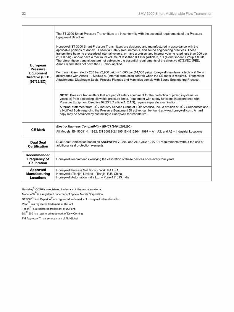
The ST 3000 Smart Pressure Transmitters are in conformity with the essential requirements of the Pressure Equipment Directive.
Honeywell ST 3000 Smart Pressure Transmitters are designed and manufactured in accordance with the applicable portions of Annex I, Essential Safety Requirements, and sound engineering practices. These transmitters have no pressurized internal volume, or have a pressurized internal volume rated less than 200 bar (2,900 psig), and/or have a maximum volume of less than 0.1 liter (Article 3, 1.1.(a) first indent, Group 1 fluids). Therefore, these transmitters are not subject to the essential requirements of the directive 97/23/EC (PED, Annex I) and shall not have the CE mark applied.
For transmitters rated > 200 bar (2,900 psig) < 1,000 bar (14,500 psig) Honeywell maintains a technical file in accordance with Annex III, Module A, (internal production control) when the CE mark is required. Transmitter Attachments: Diaphragm Seals, Process Flanges and Manifolds comply with Sound Engineering Practice.
European Pressure
Equipment Directive (PED)
(97/23/EC)
NOTE: Pressure transmitters that are part of safety equipment for the protection of piping (systems) or vessel(s) from exceeding allowable pressure limits, (equipment with safety functions in accordance with Pressure Equipment Directive 97/23/EC article 1, 2.1.3), require separate examination.
A formal statement from TÜV Industry Service Group of TÜV America, Inc., a division of TÜV Süddeutschland, a Notified Body regarding the Pressure Equipment Directive, can be found at www.honeywell.com. A hard copy may be obtained by contacting a Honeywell representative.
CE Mark Electro Magnetic Compatibility (EMC) (2004/108/EC) All Models: EN 50081-1: 1992; EN 50082-2:1995; EN 61326-1:1997 + A1, A2, and A3 – Industrial Locations
Dual Seal Certification
Dual Seal Certification based on ANSI/NFPA 70-202 and ANSI/ISA 12.27.01 requirements without the use of additional seal protection elements.
Recommended Frequency of Calibration
Honeywell recommends verifying the calibration of these devices once every four years.
Approved Manufacturing
Locations
Honeywell Process Solutions - York, PA USA Honeywell (Tianjin) Limited – Tianjin, P.R. China Honeywell Automation India Ltd. – Pune 411013 India
Hastelloy
® C-276 is a registered trademark of Haynes International.
Monel 400®
is a registered trademark of Special Metals Corporation.
ST 3000
and Experion are registered trademarks of Honeywell International Inc.
Viton®
is a registered trademark of DuPont
Teflon® is a registered trademark of DuPont.
DC®
200 is a registered trademark of Dow Corning.
FM ApprovalsSM is a service mark of FM Global

SMV 3000 Smart Multivariable Flow Transmitter 23
Mounting
190,57.5
1365.35
682.68
1154.53
1154.53
49,31.94
27,41.079
231,99.13
291.14
73,62.9
98,63.88
1084.25
1144.49
with output meter
210.83
millimetersinchesReference Dimensions:
Minimumclearance forcap removal(both ends)
OptionalAdapters
Connections at Optional Adaptersare offset from center (1, 5 mm/0.06 in.).Distance between process connectionscan be configured to:
Process heads have 1/4-inch NPT connections. Optional Adapters have 1/2-inch NPT connections.
82,53.25
Figure 8 —Approximate Mounting Dimensions for Reference Only.
OptionalIntegralMeter
OptionalFlangeAdapter
Figure 9 —Examples of Typical Mounting Positions.

24 SMV 3000 Smart Multivariable Flow Transmitter
Options
Angle Mounting Bracket – (Options MB, MX, SB, SX
and FB)
The angle mounting bracket is available in either carbon steel or stainless steel and is suitable for horizontal or vertical mounting on a two inch (50mm) pipe, as well as wall mounting. An optional flat mounting bracket is also available in carbon steel for 2 inch (50mm) pipe mounting. An option also exists for Marine approved mounting brackets used with the Marine certification options.
Indicating Meter – (Options ME and SM)
An analog or digital meter is available with 0 to 10 square root or 0 to 100% linear scale.
Adapter Flanges - (Options S2, S3, S4, S5, T2, T3,
V2, V3)
Convert standard 1/4 inch NPT connections to 1/2 inch NPT. Available in Stainless Steel, Hastelloy C and Monel with CS, 316SS, B7M or NACE A286 bolts.
Conduit Adapters - (Options A1, A2)
Converts standard 1/2 inch NPT Electrical Conduit Entry to M20 or 3/4 inch NPT. Adapters are 316 SS.
Write Protection – (Options WP, WX)
A jumper on the SMV 3000’s main board is activated so that the configuration database, as delivered from the factory, is in "read-only" and cannot be changed with WX. The WP option allows configuration changes when delivered from the factory.
Customer Tag - (Option TG)
This stainless steel tag connected to the SMV 3000 via wire allows you to specify information - 4 lines with 28 characters per line maximum.
Oxygen Cleaned Transmitter - (Option OX)
Insures that the SMV 3000 has been cleaned of hydrocarbons so that it can be used in applications such as oxygen and chlorine service.
Over-Pressure Leak Test - (Option TP)
Certificate confirming that the SMV 3000 has been leak tested to 4,500 psi.
Additional Warranty - (Options W1 - W4)
Standard warranty for the SMV 3000 is 1 year after delivery. The extended warranty options allow the SMV 3000 to be warranted for up an additional 4 years.
Laminar Flow Element - (Option LF)
Provides a SMV 3000 transmitter with specific mass flow equations supporting the Meriam Laminar Flow Element for applications such as combustion air.
Lightning Protection - (Option LP)
A terminal block with circuitry that protects the transmitter from transient surges induced by nearby lightning strikes. This does not provide protection for RTD or thermocouple wiring.
Side Vent/Drain - (Option SV)
Replaces standard End Vent/Drain plugs with side vent/drain plugs.
SS Center Vent/Drain and Bushing - (Option CV)
Allows a special bushing on side and end vent-drain plugs.
Head Gaskets - (Option VT)
Replaces standard PTFE head gaskets with Viton.
Custom Calibration - (Option CC)
Standard calibration for SMV 3000 includes: 0 - 100 inH2O for DP, 0 - 125 psia for AP and -328 to 852oF. for a Pt. 100 Ohm RTD input. Custom calibration allows you to have the factory calibrate the SMV 3000 based on your application. The CC - Custom Calibration form must be completed at time of order.
Multivariable Tx. Configuration - (Option MC)
Allows you to have the SMV 3000 configured at the factory based on your application. Includes range configuration for DP, AP, Temp. and Compensated Flowrate. The MC form must be completed at time of order.
NACE Nuts and Bolts - (Option CR)
Standard head nuts and bolts for the SMV 3000 are carbon steel. CR option supplies A286SS bolts and 302/304SS nuts for environments that are corrosive to carbon steel. 316SS bolts for adapters supplied when ordered.
Calibration Test Report - (Option F1)
Provides document stating calibration points for all measured variables.
NACE Certificate - (Options F7, FG)
Provides documentation verifying that either Process-wetted parts only (FG) or both process-wetted and non-wetted parts (F7) conform to NACE specifications.

SMV 3000 Smart Multivariable Flow Transmitter 25
Model Selection Guides are subject to change and are inserted into the specifications as guidance only. Prior to specifying or ordering a model check for the latest revision Model Selection Guides which are published at: http://hpsweb.honeywell.com/Cultures/en-US/Products/Instrumentation/ProductModelSelectionGuides/default.htm
SMV 3000 Model Selection Guide
34-ST-16U-51Issue 22Page 1 of 4
SMV 3000 Smart Multivariable Model Selection GuideFlow TransmitterDifferential Pressure, Static Pressure, Process Temperature & Flowrate
Instructions● Select the desired Key Number. The arrow to the right marks the selection available. ● Make one selection from each table, I and II, using the column below the proper arrow.● Select as many Table III options as desired (if no options are desired, specify 00).● A dot (●) denotes unrestricted availability. A letter denotes restricted availability. Restrictions follow Table IV.
_ _ _ - - _ _, _ _, _ _ -
KEY NUMBER
Pressure Range
SMA110
SMA125
SMG170
TABLE I - METER BODY
A _ _ ● ● ●B _ _ ● ●C _ _ ●D _ _ ●E _ _ ● ● ●F _ _ ● ●G _ _ ●H _ _ ●J _ _ ● ●K _ _ ●L _ _ ●_ 1 _ ● ● ●_ 2 _ ● ● ●_ _ A ● ● ●_ _ H t t t
TABLE II00000 ● ● ●
1 Carbon Steel heads are zinc-plated.2 Vent/Drains are sealed with Teflon® 9 or PTFE.3 Hastelloy® C-276 or UNS N102764 Monel 400® or UNS N044005 Supplied as 316 SS or as Grade CF8M, the casting equivalent of 316 SS.6 Supplied as indicated or as Grade CW12MW, the casting equivalent of Hastelloy® C-2767 Supplied as indicated or as Grade M30C, the casting equivalent of Monel 400®
II III (Optional)
XXXXIV
_ _ _ _ _
Selection
0-100 psia (7.0 bara)
0-750 psia (52.5 bara)
Availability
0-2.5 to 0-1,000 mbar
Selection
See 13:STT-21and 13:STT-35 for temperature probes and thermowells ordering information.
0-3,000 psig (210 barg)
Tantalum
Monel 400® 4Hastelloy® C-276 3
316L SS
CTFE
316 SS
Process Heads
Differential Pressure Range
0-1" / 25" H20
0-1" / 400" H20
0-1" / 400" H20
0-2.5 to 0-62.5 mbar
0-2.5 to 0-1,000 mbar
Fill Fluid
Materials of Construction
Barrier DiaphragmsVent/Drain Valves
and Plugs2
Carbon Steel 1
Carbon Steel 1
Carbon Steel 1
Carbon Steel 1
Hastelloy® C-276 3, 6
Hastelloy® C-276 3, 6
Monel 400® 4, 7
316 SS 5
316 SS 5
316 SS 5
316 SS 5
316 SS316 SS316 SS316 SS
Tantalum
316 SS316 SS
DC®200 Silicone
Hastelloy® C-276 3Hastelloy® C-276 3
Monel 400® 4
TantalumHastelloy® C-276 3
Monel 400® 4
316 SS
1/4" NPT
No Selection
1/2" NPT with Adapter (on 1/4" NPT Head)Process Head Configuration
Key Number I
_ _ _ _ _ _ -
Hastelloy® C-276 3316L SS
Monel 400® 4
26 SMV 3000 Smart Multivariable Flow Transmitter
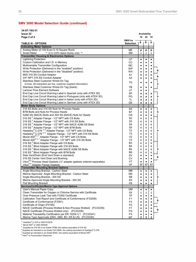
SMV 3000 Model Selection Guide (continued)
34-ST-16U-51Issue 22 Availability
Page 2 of 4 10 25 70
SMX1xx
ME p p pr r r
LP ● ● ●CC ● ● ●MC ● ● ●WP ● ● ●
● ● ●A1 n n nA2 u u u
TB ● ● ●LF ● ●SP a a aPG a a aTL a a aGE a a a
SS ● ● ●B7 ● ● ●CR ● ● ●S2 c c cS3 c c cS4 c c cS5 c c cT2 c c cT3 c c cV2 c c cV3 c c cB3 c c cB4 c c cB5 c c cB6 c c cSV ● ● ●CV ● ● ●VT ● ● ●VF 17 17 17
● ● ●● ● ●● ● ●● ● ●
FB ● ● ●
● ● ●0X j j jTP ● ● ●F1 ● ● ●F3 ● ● ●F5 ● ● ●F7 o o o
● ● ●● ● ●
MT 2 2 2
3 Hastelloy® C-276 or UNS N102764 Monel 400® or UNS N044005 Supplied as 316 SS or as Grade CF8M, the casting equivalent of 316 SS.6 Supplied as indicated or as Grade CW12MW, the casting equivalent of Hastelloy® C-2767 Supplied as indicated or as Grade M30C, the casting equivalent of Monel 400®
8 Viton® or Fluorocarbon Elastomer
b
b
b
MBMXSBSX
B7M Bolts and Nuts for Process Heads A286 SS (NACE) Bolts and 304 SS (NACE) Nuts for Heads
b
b
Marine Type Approvals (DNV, ABS, BV, KR & LR) (FC33340)
Clean Transmitter for Oxygen or Chlorine Service with Certificate Over-Pressure Leak Test with F3392 Certificate
Hastelloy® C-276 3, 6 Adapter Flange - 1/2" NPT with CS Bolts
UMServices/Certificates/Marine Type Approval Options
NACE Certificate (Process-Wetted & Non-Process Wetted) (FC33339)
Material Traceability Certification per EN 10204 3.1 (FC33341) FX
Hastelloy® C-276 3, 6 Adapter Flange - 1/2" NPT with 316 SS Bolts
316 SS 5 Blind Adapter Flange with B7M Bolts
Transmitter Mounting Bracket Options
SelectionTABLE III - OPTIONS
Write Protection (Delivered in the "disabled" position)
Smart Meter ** (0 to 100% digital display only) **
Calibration Test Report and Certificate of Conformance (F33208) Certificate of Conformance (F3391) Certificate of Origin (F0195)
User's Manual Paper Copy
Viton® 8 Process Head Gaskets (½" adapter gaskets ordered separately)
Stainless Steel Customer Wired-On Tag (blank)
Custom Calibration and I.D. in Memory Multivariable Transmitter Configuration Write Protection (Delivered in the "enabled" position)
M20 316 SS Conduit Adaptor
b
Angle Mounting Bracket - Carbon Steel
Viton® 8 Adapter Flange Gaskets
●
316 SS Center Vent Drain and Bushing
316 SS 5 Blind Adapter Flange with NACE A286 SS Bolts
Laminar Flow Element Software End Cap Live Circuit Warning Label in Spanish (only with ATEX 3D)
Stainless Steel Customer Wired-On TagTG
3/4" NPT 316 SS Conduit Adapter
(4 lines, 28 characters per line, customer supplied information)
Analog Meter (0-100 Even 0-10 Square Root)
Transmitter Housing & Electronics Options
Indicating Meter Options
Lightning Protection
WX
SM
NACE Certificate (Process-Wetted only) (FC33338) FG
End Cap Live Circuit Warning Label in Italian (only with ATEX 3D)
●
316 SS 5 Blind Adapter Flange with CS Bolts
Side Vent/Drain (End Vent Drain is standard)
Meter Body Options 316 SS Bolts and 316 SS Nuts for Process Heads
316 SS 5 Blind Adapter Flange with 316 SS Bolts
End Cap Live Circuit Warning Label in German (only with ATEX 3D)
●
End Cap Live Circuit Warning Label in Portuguse (only with ATEX 3D)
316 SS 5 Adapter Flange - 1/2" NPT with CS Bolts
Flat Mounting Bracket
Marine Approved Angle Mounting Bracket - Carbon Steel Angle Mounting Bracket - 304 SS
Monel 400® 4, 7 Adapter Flange - 1/2" NPT with CS Bolts Monel 400® 4, 7 Adapter Flange - 1/2" NPT with 316 SS Bolts
316 SS 5 Adapter Flange - 1/2" NPT with 316 SS Bolts 316 SS 5 Adapter Flange - 1/2" NPT with NACE A286 SS Bolts 316 SS 5 Adapter Flange - 1/2" NPT with B7M Bolts
Marine Approved Angle Mounting Bracket - 304 SS
b
b
b
b
b

SMV 3000 Smart Multivariable Flow Transmitter 27
SMV 3000 Model Selection Guide (continued)
Issue 22Page 3 of 4
Availability SMX1xx 10 25 70
W1 ● ● ●W2 ● ● ●W3 ● ● ●W4 ● ● ●
TABLE III - OPTIONS (continued)
● ● ●
A,B,C,D,E,F,G - - T4 at Ta < 93oC
A,B,C,D,E,F,G - T4 at Ta < 93oC
Multiple Marking11
Int. Safe, Zone 0/1, or
Flameproof, Zone 1, or
Non-Sparking, Zone 2
● ● ●
Int. Safe, Zone 0/1, orFlameproof, Zone 1
10 See ATEX installation requirements in the ST 3000 User's Manual
the nameplate, subsequently the equipment shall not be reinstalled using any of the other certification types.
IECEx
Flameproof, Zone 1Ex d IIC; T5 (Ta = -40 to +93ºC), T6 (Ta = -40 to +78ºC)
CA ● ● ●
None 9X
Canadian Standards
Association (CSA)
FM
ApprovalsSM
Explosion ProofDust Ignition Proof
3S
3D
b
Explosion ProofDust Ignition Proof
Location or ClassificationApproval Type
● ●
b
●
None
1CNon-Incendive
Class I, Div. 1, Groups A,B,C,DClass II, Div. 1, Groups E,F,GClass III, Div. 1
Intrinsically Safe
Intrinsically Safe Zone 0/1
Ex ia IIC T5
Ex d IIC T6, Enclosure IP 66/67
●
●
●
● ●
●
●
ATEX10
(LCIE)3N
3H
●
T4 at Ta = 930CT5 at Ta = 800C
Ex II 1 G Ex ia IIC T4, T5, T6Ex II 2 G Ex d IIC T5, T6
Flameproof, Zone 1
Non-Sparking Zone 2
Selection
Selection
Warranty Options
TABLE III - OPTIONS (continued)
Intrinsically Safe
Suitable for use in
Suitable for use in
Additional Warranty - 4 years
Additional Warranty - 2 years
Ex II 3 G Ex nA, IIC T6 (Honeywell) Enclosure IP 66/67
●
11 The user must determine the type of protection required for installation of the equipment. The user shall then check the box [√]adjacent to the type of protection used on the equipment certification nameplate. Once a type of protection has been checked on
ZD
Class II, III, Div. 1, Groups E,F,GClass I, II, III, Div. 2, Groups
Additional Warranty - 1 year
Additional Warranty - 3 years
Class I, Div. 2, Groups A,B,C,D
Approval Body
Class I, II, III, Div. 1, Groups
Class I, Div. 1, Groups B,C,D
2J
●
Ex ia IIC; T3, T4, T5 , T6. See Spec for detailed temperature codes by Communications option.
Class I, II, III, Div. 1, Groups
Ex nA, IIC T6Vmax = 42 Vdc
A,B,C,D,E,F,G
●
●
●
●
● ● ●
● ●
●
●
Intrinsically Safe,Zone 0/1
Ex ia IIC T4, T5, T6 Ex d IIC T5, T6 Enclosure IP 66/67
SAEx (South Africa)
T6 at Ta = 650C (Honeywell). Enclosure IP 66/67
Intrinsically Safe,Zone 0/1
Ex ia IIC T4, T5, T6
ZA
Z2
Flameproof, Zone 1 EX d IIC T5, T6 Enclosure IP 66/67Multiple Marking 11

28 SMV 3000 Smart Multivariable Flow Transmitter
SMV 3000 Model Selection Guide (continued)
34-ST-16U-51Issue 22Page 4 of 4
XXXX ● ● ●
Table Table Selection
b Select only one option from this group.
c _ _ H
j _ 2 _
no CR, S4 or B5p Functions in the analog mode only.
t S2, T2 or V2u2
17
Hastelloy® is a registered trademark of Haynes International
Monel 400® is a registered trademark of Special Metals Corporation.
HART® is a registered trademark of HART Communication Foundation.
FOUNDATIONTM Fieldbus is a registered trademark of Fieldbus Foundation.
Viton® is a registered trademark of DuPont Performance Elastomers.
FM ApprovalsSM is a service mark of FM Global
DC® 200 is a registered trademark of Dow Corning
Teflon® is a registered trademark of DuPont.
1C, 2J
III
Factory Identification
Restriction Letter
Available Only With
1C, 2J
a 3D or 3H
IIIIII VT
III
III FB, MB, SBMX, SX
Selection
Not Available With
III
III
I
III
III
Ordering Example: SMA125-E1A-00000-MB,MC,1C + XXXX
TABLE IV
RESTRICTIONS
r III
I
Display is 0-100% only. No other smart functions available with this option.

SMV 3000 Smart Multivariable Flow Transmitter 29
Ordering information
For application assistance, current specifications, pricing, or name of the nearest Authorized Distributor, contact one of the
offices below. Or, visit Honeywell on the World Wide Web at: http://www.honeywell.com.
ASIA PACIFIC Control Products Asia Pacific Headquarters Phone: +(65) 6355-2828 Fax: +(65) 6445-3033
Asia Pacific Global Technical Support Field Instruments Phone: +65 6580 3156 Fax: +65 6445-3033 Process Instruments Phone: (603) 76950 4777 Fax: (603) 7958 8922 Australia Honeywell Limited Phone: +(61) 7-3846 1255 FAX: +(61) 7-3840 6481 Toll Free 1300-36-39-36 Toll Free Fax: 1300-36-04-70 China – PRC - Beijing Honeywell China Inc. Phone: +(86-10) 8458-3280 Fax: +(86-10) 8458-4650 China – PRC - Shanghai Honeywell China Inc. Phone: (86-21) 5257-4568 Fax: (86-21) 6237-2826 China – PRC - Chengdu Honeywell China Inc. Phone: +(86-28) 8678-6348 Fax: +(86-28) 8678-7061 China – PRC - Xi’an Honeywell China Ltd - Xi’an. Phone: +(86-29) 8833-7490 Fax: +(86-29) 8833-7489 China – PRC - Shenzhen- Honeywell China Inc. Phone: +(86) 755-2518-1226 Fax: +(86) 755-2518-1221 Indonesia PT Honeywell Indonesia Phone: +(62) 21-535-8833 FAX: +(62) 21-5367 1008 India Automation India Ltd. Honeywell Ltd. Phone:+(91) 5603-9400 Fax: +(91) 5603-9600 Japan Honeywell Inc. Phone: +(81) 3 6730 7150 Fax: +(81) 3 6730 7228 Malaysia Honeywell Engineering Sdn Bhd Phone: +(60-3) 7950-4776 Fax: +(60-3) 7958-8922
New Zealand Honeywell Limited Phone: +(64-9) 623-5052 Fax: +(64-9) 623-5060 Toll Free (0800) 202-088 Philippines Honeywell Systems (Philippines) Inc. Phone: +(63-2) 633-2830-31/ 636 1661-62 Fax: +(63-2) 638-4013 Singapore Honeywell Pte Ltd. Phone: +(65) 6580 3278 Fax: +(65) 6445-3033 South Korea Honeywell Korea Co Ltd Phone: +(822) 799 6315 Fax: +(822) 792 9015 Thailand Honeywell Systems (Thailand) Ltd. Phone: +(662) 693-3099 FAX: +(662) 693-3089 Taiwan R.O.C. Honeywell Taiwan Ltd. Phone: +(886-2) 2245-1000 FAX: +(886-2) 2245-3241 SE Asia Countries see Honeywell Pte Ltd (Singapore) for: Pakistan Cambodia Guam Laos Myanmar Vietnam East Timor SE Asia Countries see Honeywell Automation India Ltd for: Bangladesh Nepal Sri Lanka
EUROPE Austria Honeywell Austria GmbH Phone: +43 (316)400123 FAX: +43 (316)40017 Belgium Honeywell SA/NV Phone: +32 (0) 2 728 24 07 FAX: +32 (0) 2 728 22 45
Bulgaria Honeywell EOOD Phone: +(359) 2 40 20 900 FAX: +(359) 2 40 20 990 Czech Republic Honeywell spol. s.r.o. Phone: +420 242 442 232 FAX: +420 242 442 131 Denmark Honeywell A/S Phone: +(45) 39 55 55 55 FAX: +(45) 39 55 55 58 Finland Honeywell OY Phone: +358 (0) 20752 2753 FAX: +358 (0) 20752 2751 France Honeywell SA Phone: +33 (0)1 60198075 FAX: +33 (0)1 60198201 Germany Honeywell AG Phone: +49 (69)8064-299 FAX: +49 (69)806497336 Hungary Honeywell Kft. Phone: +36-1-451 4300 FAX: +36-1-451 4343 Italy Honeywell S.p.A. Phone: +39 02 92146 307/ 395 FAX: +39 0292146377 The Netherlands Honeywell B.V. Phone: +31 (0) 20 5656200 FAX: +31 (0) 20 5656210 Norway Honeywell A/S Phone: (45) 39 55 55 55 Poland Honeywell Sp. zo.o Phone: +48-22-6060900 FAX: +48-22-6060901 Portugal Honeywell Portugal Lda Phone: +351 21 424 5000 FAX: +351 21 424 50 99 Romania Honeywell Bucharest Phone: +40 (0) 21 2316437 FAX: +40 (0) 21 2316439 Russian Federation (RF), ZAO "Honeywell" Phone: +7 (095) 796 98 00 FAX: +7 (495) 797 99 64
Slovak Republic Honeywell s.r.o. Phone: +421-2-58247 410 FAX: +421-2-58247 415 Spain Honeywell S.A. Phone: +34 (0)91313 61 00 FAX: +34 (0)91313 61 30 Sweden Honeywell AB Phone: +(46) 8 775 55 00 FAX: +(46) 8 775 56 00 Switzerland Honeywell AG Phone: +41 18552448 FAX: +(41) 1 855 24 45 Turkey Honeywell Turkey A.S. Phone: +90 216 578 71 00 FAX: +90 216 575 66 35 Ukraine Honeywell Tel: +380-44-201 44 74 Fax: +380-44-201-44-75 United Kingdom Honeywell Control Systems Ltd. Phone: +44 (0)1344 655251 FAX: +44 (0) 1344 655554
MIDDLE EAST Abu Dhabi U A E Middle East Headquarters Honeywell Middle East Ltd. Phone: +971 2 4041246 FAX: +971 2 4432536 Sultanate of Oman Honeywell & Co Oman LLC Phone: +968 24 701153/ Ext.33 FAX +968 24 787351 Saudia Arabia Honeywell Turki Arabia Ltd Jubail Office Phone: +966-3-341-0140 Fax: +966-3-341-0216 Honeywell - ATCO Dammam Office Phone: 0096638304584 Fax: 0096638338059 Kuwait Honeywell Kuwait KSC Phone: +965 242 1327 to 30 Fax: +965 242 8315 and Phone: +965 326 2934/1821 Fax: +965 326 1714
AFRICA Mediterranean & African Distributors Honeywell SpA Phone: +39 (02) 250 10 604 FAX: +39 (02) 250 10 659 South Africa (Republic of) and sub saharan Honeywell Southern Africa Honeywell S.A. Pty. Ltd. Phone: +27 11 6958000 FAX +27 118051504
NORTH AMERICA Canada Honeywell LTD Phone: 1-800-737-3360 FAX: 1-800-565-4130 USA Honeywell Process Solutions, Phone: 1-800-423-9883 Or 1-800-343-0228 Email: [email protected]
SOUTH AMERICA Argentina Honeywell S.A.I.C. Phone: +(54-11) 4383-3637 FAX: +(54-11) 4325-6470 Brazil Honeywell do Brasil & Cia Phone: +(55-11) 7266-1900 FAX: +(55-11) 7266-1905 Chile Honeywell Chile, S.A. Phone: +(56-2) 233-0688 FAX: +(56-2) 231-6679 Mexico Honeywell S.A. de C.V. Phone: +(52) 55 5259-1966 FAX: +(52) 55 5570-2985 Puerto Rico Honeywell Inc. Phone: +(809) 792-7075 FAX: +(809) 792-0053 Trinidad Honeywell Inc. Phone: +(868) 624-3964 FAX: +(868) 624-3969 Venezuela Honeywell CA Phone: +(58-2) 238-0211 FAX: +(58-2) 238-3391
Specifications are subject to change without notice.
30 SMV 3000 Smart Multivariable Flow Transmitter
For More Information
Learn more about how Honeywell’s SMV 3000
Smart Multivariable Flow Transmitter can increase
performance, reduce downtime and decrease
configuration costs, visit our website
www.honeywell.com/ps or contact
your Honeywell account manager.
Honeywell Process Solutions
1860 West Rose Garden Lane
512 Virginia Drive
Tel: 1-800-423-9883 or 1-800-343-0228
www.honeywell.com/ps
34-SM-03-01August 2010 © 2010 Honeywell International Inc.


![SMV [McMillan 93]](https://img.pdfslide.us/doc/110x75/5681572a550346895dc4c47a/smv-mcmillan-93.jpg)