Embed Size (px)
Citation preview

What does make water movingIn a hydraulic system (HVAC)?
A. Natural water flow in heating system dueto pressure/temperature difference
B. By pumping solutions (usuallycentrifugal pumps)
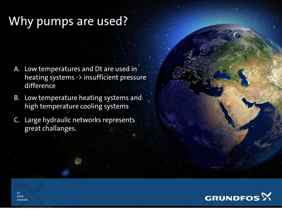
Why pumps are used?
A. Low temperatures and Dt are used in heating systems -> insufficient pressuredifference
B. Low temperature heating systems and high temperature cooling systems
C. Large hydraulic networks representsgreat challanges.

Do we need to control the pump?Do we use same flow all the time?
A. Some applications needs constant flows, therefore, a basic control (ON-OFF) is enough. Easy to ballance.
B. Sometimes constant flow equipmentsworks in cascade, each system shouldhave its constant flowrate – ballancing!
C. Most of the secondary systems areworking with variable flow, due tovariable needs.

How can we control the flow in a system? (pipe sizing is not enough)
A. By switching ON/OFF some valves(2/3 way valves)
B. By controlling a pump performances(see different control modes)
C. By using a combination of those two
D. By using alternative C + zoning thesystem + using right number of pumpsfor matching the duty.

How to control the flow of a pump?
A. Throttling valve (adding extra losses)
B. Using Bypass line C. Trimming impellerD. Using multiple pumps in paralel
operationE. Using VFD for varying
performances.

How to control the flow of a pump?Throttle valve method
A. Cheap solutionB. Commonly used – see ballancing
valves along circuits.C. Not very energy efficient,
however it is still needed in large quantities.
D. It is not always dynamic (e.g. simple throttle valves vsdifferential pressure valves)
E. Not dynamic system!

How to control the flow of a pump?Bypass valve
A. Cheap solutionB. Resulted flow over pump will be
higherC. Resulted flow in system will
match the demand (constant flow)
D. Energy consumption will be high.
E. Not dyanmic system

How to control the flow of a pump?Modifying impeller diameter
A. Cheap solution – if orderedaccordingly
B. Best solution to keep efficiencyat high rate
C. QH curve will be as close aspossible to optimal
D. Good energy consumptionE. Later changes are not really
possible (replacing impellersinvolves labour cost + newimpeller)
F. No dynamic system

How to control the flow of a pump?Multiple pump solution
A. Single speed pump systems orvariable speed pumps might be used.
B. Parallel installed pumps flow willsum (not necessary double theflow)
C. Efficiency could be highD. Could be risk in part load
conditions – cavitation couldoccur in some cases if systemcurve goes outside the pumpcurve.

How to control the flow of a pump?Variable speed pump
A. Highest investment costB. Flexible solution.C. Variable flow and adaptation to
the system demandD. Can be used with different
controlling algorythmsE. Might not be able to solve all
problems alone

LCC comparison of different pump controlInitial pump flowPump heightDesired flowDesired pressure
Reference pump4x NB40-160/149
4x NB40-160/149
P1 4 4Efficiency 0,638 0,638P1 in duty point 14,24 14,24NPSH 2,06 2,06Nr. Of pumps 4 4
Control mode Throttle valve Bypass lineTrimmed impeller
VFDMultiple pumps
Multiple pumps with
VFDImpeller diam. 159 159 134 159 149 149Resulted Flow 80,00 m3/h 134,00 m3/h 80,00 m3/h 80,00 m3/h 91,40 m3/h 80,00 m3/hResulted Pressure 32,52 25,11 19,36 18,96 24,91 18,96Pump efficiency 0,782 0,819 0,777 0,83 0,73 0,732P1 9,51 11,79 5,753 5,606 9,44 6,46NPSH Resulted 3,18 5,18 4,69 2,43 3,25 2,52
NotesThrottle valve closed partly
Bypass line opened
Impeller modified
VFD set2 pumps been
stopped2 pumps at 87%
Pump 1 954,00 EUR 1 954,00 EUR 1 954,00 EUR 1 954,00 EUR 4 200,00 EUR 4 200,00 EURVFD 0,00 EUR 0,00 EUR 0,00 EUR 1 382,00 EUR 0,00 EUR 3 100,00 EURBypass line 0,00 EUR 200,00 EUR 0,00 EUR 0,00 EUR 0,00 EUR 0,00 EURThrottle valve 250,00 EUR 0,00 EUR 0,00 EUR 0,00 EUR 0,00 EUR 0,00 EURImpeller trim. Cost 0,00 EUR 0,00 EUR 640,00 EUR 0,00 EUR 0,00 EUR 0,00 EURTotal cost of syst. 2 204,00 EUR 2 154,00 EUR 2 594,00 EUR 3 336,00 EUR 4 200,00 EUR 7 300,00 EURAnnual working hoursTotal energy consumption/yr
41083,20 kWh 50932,80 kWh 24852,96 kWh 24217,92 kWh 40780,80 kWh 27907,20 kWh
Energy Consumption 15 yr
616248,00 kWh 763992,00 kWh 372794,40 kWh 363268,80 kWh 611712,00 kWh 418608,00 kWh
Electric rateElectrical costs 61 624,80 EUR 76 399,20 EUR 37 279,44 EUR 36 326,88 EUR 61 171,20 EUR 41 860,80 EURService costs-15 yr 2 200,00 EUR 2 200,00 EUR 2 200,00 EUR 2 200,00 EUR 3 000,00 EUR 3 000,00 EURLife Cycle Cost 66 028,80 EUR 80 753,20 EUR 42 073,44 EUR 41 862,88 EUR 68 371,20 EUR 52 160,80 EUR
0,82810,543,85
19 mWS
100,00 m3/h30 mWS80 m3/h
Grundfos NB65-160/159 A-F2-A-BAQE
15
1
COST CALCULATION
4320
0,10 EUR

Larger pump or 2 smaller pumps?

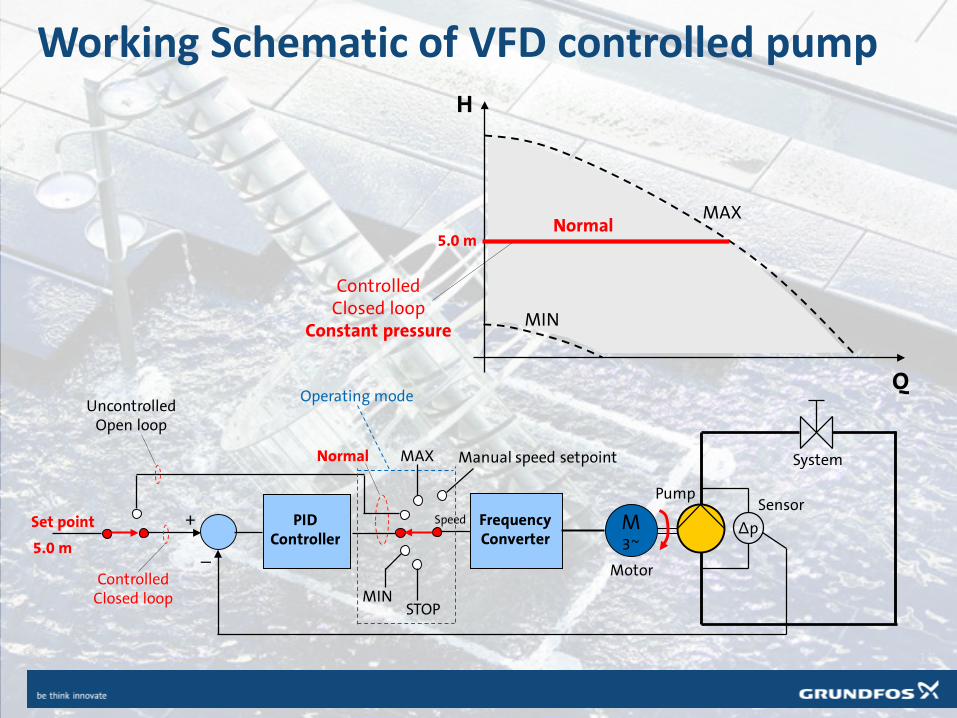
Is a VFD equipped pump enough to ensurevariable flow on system?Electronic pumps (with VFD) does not guarantee variable flow/conditions unlessthere is a feedback sensor!
Software
Frequencyconverter
Electricmotor
Sensor
Userinterface
Controller
Pump
15
Set point Δp
System
PIDController
FrequencyConverter
STOPMIN
MAXNormal
Speed M3~
Sensor
Motor
Pump
+
_
ControlledClosed loop
UncontrolledOpen loop
Q
H
MIN
MAXNormal
ControlledClosed loop
Constant pressure
5.0 m
5.0 m
Working Schematic of VFD controlled pump
Manual speed setpoint
Operating mode

Basic pump control modes.Where and when to use them?
Constant curve
Constant pressure
Proportional differential pressure (calculated)
Proportional differential pressure (measured)
Temperature control
Constant Flow

Air Con system – choosing control modes
An advanced air conditioning system consists of a number of elements, and the control mode you choose for each one is important to the overall energy consumption in the system.

System components
As an example we will look at a variable flow system with a constant flow chiller.The system consists of the elements shown below.
Buffer tank
Secondary pumps
Cooling tower Heat recovery
Fan coils
Cooling ceiling
Cooling surface
Pressure holding
Chiller
Primarypump

Control modes
Each unit in the system runs on its own pump, and for each pump you can apply one or more control modes.The control modes are listed here, and in the next slides we will look at the different control modes and explain their characteristics.
Constant curve
Constant pressure
Proportional differential pressure (calculated)
Proportional differential pressure (measured)
Temperature control
Constant Flow

Constant curve mode
• Pump is adjusted onceand for all
• Usually no need for sensors
• No need for throttle valve
• Used when there is a demand for constant flow and head
Suitable for • Primary pumps• Cooling coils• Cooling towers
Max RPM Duty point with throttle valve
Duty point without throttle valve

Constant flow mode
• Pump will keep constant flow depending on system resistancevariation
• No need for throttle valve
• Used when there is a demand for constant flow and head
Suitable in case of cascade systems• Primary pumps• Cooling coils• Cooling towers
Max RPM Duty point with throttle valve
Duty point without throttle valve

Constant pressure mode
• Pump speed provides constantpressure at the pressure sensor
• Suitable for • Pressure holding systems• Surface heating/cooling
systems• Parallel distribution systems
Max RPM

Proportional differential pressure mode (calculated)
• Head and speed are adjustedaccording to the differentialpressure setpoint
Suitable for • Secondary pumps• Mixing loop pumps for fan
coil and cooling ceilingsystems
Max RPM

Proportional differential pressure mode (measured)
• Head is dependent on a differential pressure sensor in a reference point
• Head decreases when flow is reduced
Suitable for • Secondary pumps• Mixing loop pumps for fan
coil and cooling ceilingsystems
Max RPM

Differential Temperature mode
• Here the pump speed is controlled according to a temperature in a certainreference point. For examplepre-heating water in a hot water tank
Suitable for • Heat recovery system• DHW recirculation• Boiler shunt pump• etc
Max RPM

Pump control modesThe best control modes for each pump in the air conditioning system.
Constant curve
Constant pressureProportional differential pressure (calculated)
Proportional differential pressure (measured)
Temperature control

Who is generating the different conditions?Control valves will add/cut pressure by closing or opening themselves.Valves are either controlled by thermostatic systems or BMS systems.Complex controlling system is a must in every modern building.Smart regulation can not be achieved using only mechanical equipments.

That is why we need smart pumping and controlling solutions.
Electronic solutions are not smart enough towork alone.
Many years HVAC systems was consisting onindividual equipments, where fine tuning wasmissing.
A HVAC system must be seen as a SYSTEM,together with all other elements of thebuilding
Two way communication is a must.Unist must work proactively!
My back hurts!
What?


Smart Pump Features• Self learning and Automatic adaptation
• Two way communication and with
different platforms – e.g. smartphones
• System optimisation and diagnostics
• Information instead of data!
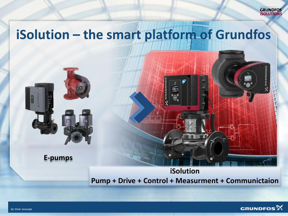
iSolution – the smart platform of Grundfos
E-pumps
iSolutionPump + Drive + Control + Measurment + Communictaion

iSolution – the smart platform of Grundfos
Sensors available for pump control

Communication interface
Standard Communciation Protocols for integration in BMS or with Cloud monitoring systems and smart phones
Online software package for design support.

Grundfos Product Center
Complete online pump selector platform Comprehensive sizing tools Replacement Tool Available on smart phones, tablets and
PC All informations at your hand –
datasheet, documents, drawings LCC Calculation Project modules Sharing information List Prices and ETA Comparison modules

Smart Communication interface –software + GPC Access
Grundfos GO
• Using Smart Phone for increased user experience
• Pump control and diagnose in wireless mode
• User Friendly
• Data Collections
• Pump sizing and search functions

Pump Setting Reports via e-mail

Circulation Pumps using iSolution platformMAGNA3 – High Efficiency Wet Runners
• Self Learning (AutoAdapt) Function and SystemDiagnose
• Built in measurement functions: Flow, Pressure, Power, Energy, Temperature, Heat Energy,
• Special Control Modes – FlowLimit and Flow Adapt
• Communication with SmartphoneWireless Cascade Communication
• Buszkommunikáció

Diagnose and Optimisation in Magna3 and TPE3
System Hydraulic
• Pressure measurement (built in sensor)Accuracy: 2% (FS)
• Flow Measurment (calculated)Accuracy: 3-5% (FS), in 90% of the curve
0
10
20
30
40
50
60
0 5 10 15 20
Rela
tív h
iba
[%]
QInd.mérő [m3/h]
Relatív hiba max. üzemmódban
1. mérés
2. mérés
3. mérés
Magna3 32-120

Diagnose and Optimisation in Magna3 and TPE3
Optimisation using trend data
Case A.
Case B.
Case A. : Q > QDesign , unballanced system, high value setpoint (Static ballan.), Low flow temperature (weather compensation control.)
Case B.: overside pump, higher pressure losses than design val. (Q < QDesign)Case C.: High value setpoint, Ballancing issues (FLOWlimit)
Shows historical data presentationover time compared to curveReal system processes!!!!
Case C.

Diagnose and Optimisation in Magna3 and TPE3
System Energy Ballance
• Heat Energy Monitor function:• Measurment accuracy +/-1% és +/-10%
varying on system conditions.• External temperature transducer (on return
pipe) directly in pump.• Very good for Energy Balance

INTELLIGENCE IN THE MAGNA3
FLOWLIMIT
• FLOWLIMIT can set maximum systemflow allowed without throtling valve.
• Usable in case of static ballancing of system (e.g. AHU bypass pump, main circulation branches).
Before After


Magna 3 – FLOWlimit functionBypass Pump ballancing in as in good old days...
Resulted annual energy consumption of pump with ballancing
𝐸𝐸𝑒𝑒𝑒𝑒𝑒𝑒𝑒𝑒𝑒𝑒𝑒𝑒𝑒𝑒𝑒𝑒𝑒𝑒𝑒𝑒𝑒𝑒= 700�8760100
= 6132 𝑘𝑘𝑘𝑘𝑘
Resulted energy loss on the pump ballancing
Ph = q ρ g h / (3.6 106) = Hydr. Power (kW)q = Volume Flow (m3/h)ρ = density (kg/m3)g = grav. acc (9.81 m/s2)h = delivered pressure(m)
Ph= 22,5 X 1000 X 9,81 X 2,5 / 3,6 X 106= 0,153 kW = 0,34 kW0,45
Annual energy losses: 0,34 X 8760 = 2978 kWh

Magna 3 – FLOWlimit funtionBypass pump ballancing using FlowLimit and no valve
Magna 3
H
Q
Chosen Pump: MAGNA3 80-40Annual Consumption : 2331 kWh/yr
Basic solution energy: 6132 kWhNew solution energy: 2331 kWhSavings: 3801 kWh = 62%

Magna 3 – FLOWlimit FunctionGas fired boilers
Q1+2+3+4=100%Q1=25% Q
H
Equalising Vessel
• Each pump does the flow of one boiler (25%)
• On partload conditions the flow foreach boiler will increase due toadaptation on the system curve.
• Larger flow will increase the returntemperature making boilerefficiency worse.

Magna 3 – FLOWlimit FunctionGas fired boilers
Q1+2+3Q1=30% Q
H
3 boilers working
• The specific flow for one boilercould be 20% higher than design flow
Q1=38% Q
H
1 boiler working• One single boiler out of 4 on
function could result 50% higherflow without flow limitation.

Magna 3 – FLOWlimit FunctionGas fired boilers
Q1+2+3+4=100%Q1=25% Q
H
• MAGNA3 / TPE3 pumps withFLOWlimit function
• Maximum flow does not exceed set value
System curve + FlowLimit


Pumps with High EfficiencyMGE motors up to 11kWTPE(3)(D), NBE, NKE, CRE, CME
• High Efficiency with PM Syncron motors upto 11kW
• Wide Application range
• Integrated Measurments and Diagnosefeatures
• Comprehensinve control solutions with no External PLC needed

50
IE motor eff. Classes until 31.12.2016

New Development– IE5 MGE motors
Állandó mágneses szinkron-reluktancia motorok beépített frekvenciaváltóval• 11 kW power• IEC 60034-30-2 only with integrated frequency drive
51
60
70
80
90
100
0,25 0,37 0,55 0,75 1,1 1,5 2,2 3 4 5,5 7,5 11 15 18,5 2260
70
80
90
100
0,25 0,37 0,55 0,75 1,1 1,5 2,2 3 4 5,5 7,5 11 15 18,5 22
IE2IE5 IE4 IE3
Power [kW]
Effic
ienc
y [%
]

Efficiency• Is it worst to use VFD up to
11kW?

100
70 68 6762
53
MG IE2 + Wall mountedVFD
MGE Model GLinear
IE4 + Wall mountedVFD
MGE Model J Linear MGE Model JQuadratic
Annual Energy Index
Comparison of external VFD vs. MGE
MG IE2 + ext. VFD
MGE Model G
Linear
IE4 + ext. VFD
MGE Model J Linear
MGE Model J
QuadratickWh: kWh: 18.528 13.055 12.680 12.395 11.447 9.890
Index: Index: 100 70 68 67 62 53
IE2 and IE4 motorswith VFD Comparedwith MGE and newMGE Motors

Inteligent solution – Complex solutions• What is beyond the pump?
Can I do more than simply moving the water?

Inteligent solution – Complex solutions• Boiler shunt pump control

GRUNDFOS COMMERCIAL BUILDINGS
BURNER
TARGETAdjust return water temperature to installationrequirements…
MEANSBoiler shunt – connectionbetween the flow and return pipe, equipped with a pumpcreating a mixing loop
BOILER SHUNT SOLUTIONSTANDARD SCENARIOCONVENTIONAL BOILER – SHUNT PUMP SOLUTION

GRUNDFOS COMMERCIAL BUILDINGS
BOILER SHUNT SOLUTIONSTANDARD SOLUTIONSHUNT PUMP INSTALLATION SETUP SOLUTION
BURNER
80oc
MAIN PUMP
FLUE GAS
CHIMNEY
30oc
>57oc
SHUNT PUMP
GRUNDFOS COMMERCIAL BUILDINGS
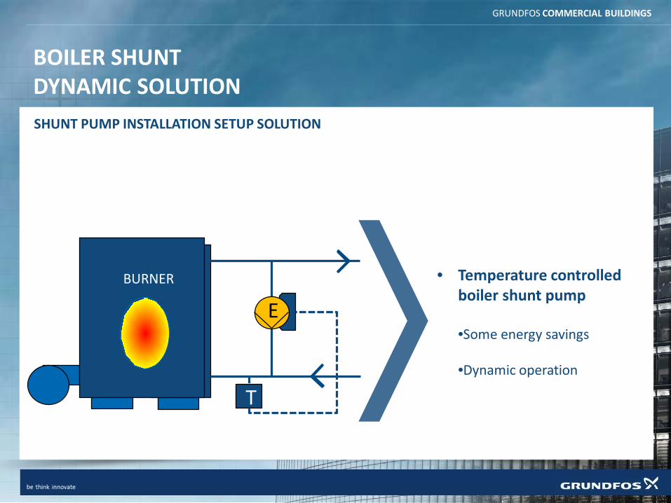
BOILER SHUNTDYNAMIC SOLUTION
BURNER
E
T
• Temperature controlledboiler shunt pump
•Some energy savings
•Dynamic operation
SHUNT PUMP INSTALLATION SETUP SOLUTION
GRUNDFOS COMMERCIAL BUILDINGS
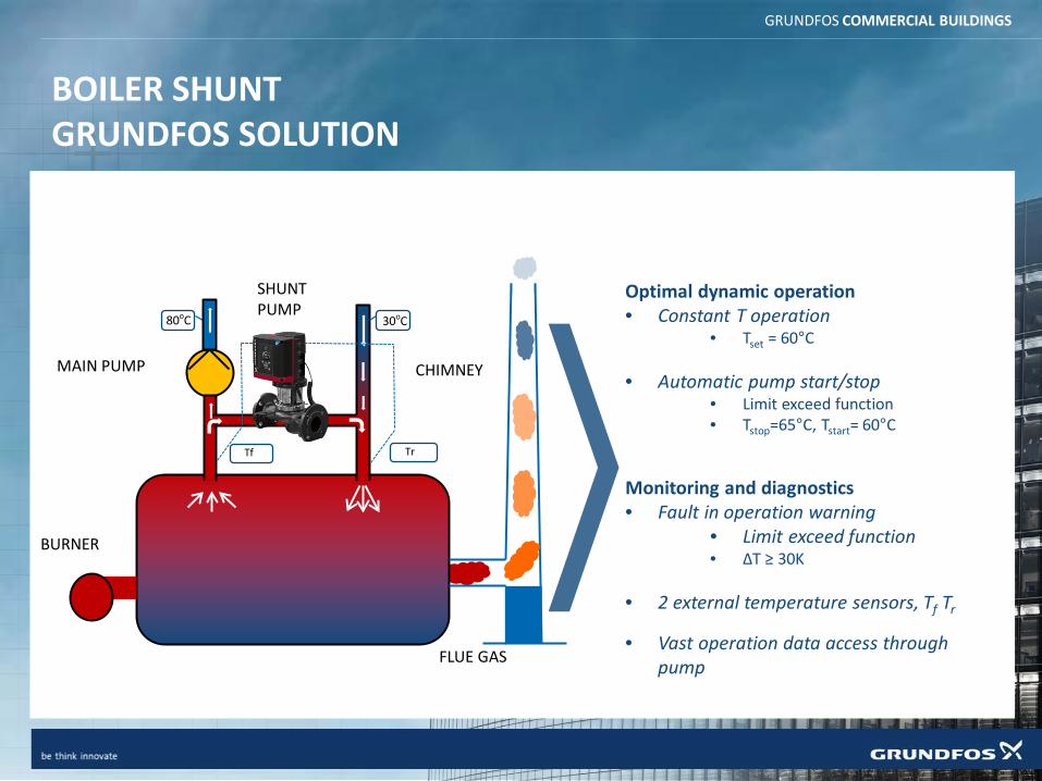
BOILER SHUNTGRUNDFOS SOLUTION
;
Optimal dynamic operation• Constant T operation
• Tset = 60°C
• Automatic pump start/stop• Limit exceed function• Tstop=65°C, Tstart= 60°C
Monitoring and diagnostics• Fault in operation warning
• Limit exceed function• ∆T ≥ 30K
• 2 external temperature sensors, Tf Tr
• Vast operation data access throughpump
BURNER
80oC
MAIN PUMP
FLUE GAS
CHIMNEY
30oC
SHUNT PUMP
Tf Tr

Inteligent solution – Complex solutions• Domestic Hot Water System

From boiler ordistrict heating
Hot water tank
Balancing valve Balancing valve
Temperature controlled TPE3
DHW system control
Riser pipes are fitted with balancing valves thatensures the right flow distribution in each riser. A temperature controlled TPE3 ensures that the overall temperature and flow in the main circulation pipe.
Temperature controlwith a single TPE3 pump
Minimum 55 °C(130 °F)
Minimum 55 °C (130 °F)
Minimum 60 °C (140 °F)
Minimum 55 °C(130 °F)
Hot waterHot water, circulationCold water
Cold water 10 °C (64 °F)

Minimum 55 °C(130 °F)
Minimum 55 °C (130 °F)
Minimum 60 °C (140 °F)
Minimum 55 °C(130 °F)
From boiler ordistrict heating
Cold water 10 °C
Hot water tank
Thermostaticcirculation valve
Thermostaticcirculation valve
Riser pipes are each fitted with a thermostatic valvethat ensures the right temperature in each riser.Here the pump will have to run in proportional pressure mode.
Temperature control with thermostatic valves
DHW system control
Proportional pressure controlled TPE3
Hot waterHot water, circulationCold water
How to make your system bad usingelectronic pumps?
• How not to do examples
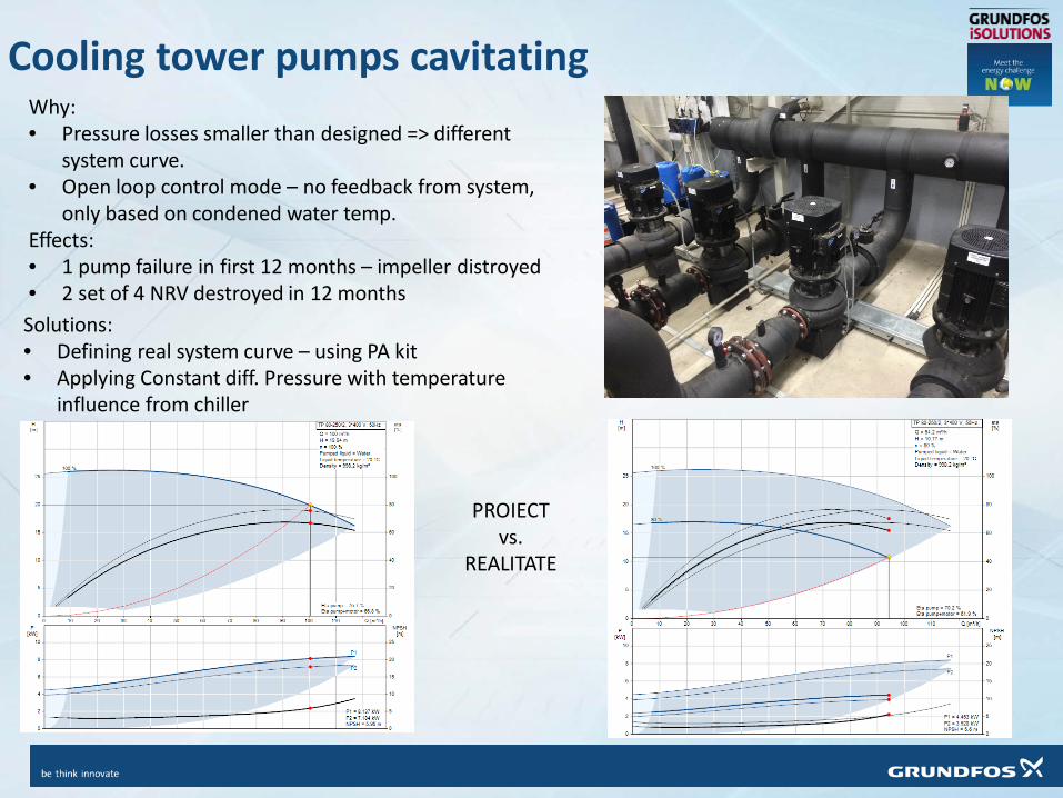
Cooling tower pumps cavitatingWhy:• Pressure losses smaller than designed => different
system curve.• Open loop control mode – no feedback from system,
only based on condened water temp.Effects:• 1 pump failure in first 12 months – impeller distroyed• 2 set of 4 NRV destroyed in 12 monthsSolutions:• Defining real system curve – using PA kit• Applying Constant diff. Pressure with temperature
influence from chiller
PROIECTvs.
REALITATE

5MW wood fired boiler – efficiency issuesWhy• Smaller system pressuredrop => different system curve• Electronic pump without pressure sensor• No balancing valvesResults:• At 80% speed pump get out of QH curve – high noise, high bearing
loads, possibly cavitation• Boiler thermal capacity decrease (bad efficiency) due to higher
water flow than designed
Solutions:• Installing DP sensors, setting correct DP to avoid pump runing
outside of range.• Hydraulic balancing must be done with existing equipments.

Recap• Using electronic pumps let us reduce electrical consumption if right control
mode is selected• Using electronic pumps will not replace balancing valves, but might reduce
their number.• Using zoning of systems will allow you to get better global efficiency• Use of added value functions will allow you to diagnose the systems weak
points and give a better feedback.• Smart solutions will let you do your job better, but it won’t do your job!• Better LCC level will lead you to more valuable buildings and systems.
Take away message:Smart Building Era is the present. Using of smart technologies is no longer just a fancy thing. It will make the difference between good solutions and best solutions!

Questions?

Thank You!