Embed Size (px)
Citation preview
SLIDING DOOR OPERATOR
INSTRUCTION MANUAL
((MMOODDEELL NNOO.. 11007711..110011 && 11007711..110022))
Please carefully keep this manual for good maintenance.

1
Caution
Be sure the door opener is far away from moisture, vibration, and corrosive gas, which
will cause fire, electric shocks and falling accidents.
Make sure the door opener is used within -20℃-+50℃ ambient temperature.
Please stick some caution mark onto the transparent door leaf to avoid possible injuries.
Please do not connect the external activating equipment with capacitance more than
DC20V, 300m A into the opener terminals.
Make sure the door leaf weight not exceeding the proposed door weight, the over weight
will cause damage or malfunction.
Use the proper power (please inquire your local distributor or management bureau).
Please do not shut the power when the opener is working.
Make sure that the operator is earthed!
Do not open or close the door crustily by hands when it is running or stopped by the
failure of power supply, which will cause danger.
The safety beam detector is highly recommended to avoid the probability of collision with
pedestrian!
Nobody should repair and change the internal electric circuit unless designated or
authorized by us. When unexpected operation happens, please contact your local
distributor or sales agent.
Do not allow children to play remote controls. If the supply cord is damaged, it must be
replaced by a special cord or assembly available from the manufacturer or its service
agent.
2
Contents 1. Product parameter………………………………………………………………………..3 1.1 Specifications……………………………………………………………………………...3 1.2 Assembly parts…………………………………………………………………………….4 1.3 Surface mounting profile………………………………………………………………….5 2. Installation………………………………………………………………………………….6 2.1 Installation schedule………………………………………………………………………6 2.2 Aluminium track …………………………………………………………………………...6 2.3 Assembly parts fixing location……………………………………………………………6 2.3.1 Motor………………………………………………………………………………………..7 2.3.2 Control device ……………………………………………………………………………..7 2.3.3 Tension wheel device……………………………………………………………………...7 2.3.4 Track stopper ………………………………………………………………………………7 2.4 Door leaf hanging………………………………………………………………………….8 2.4.1 Door height adjustment……………………………………………………………………9 2.5 Belt fixing……………………………………………………………………………………9 2.5.1 Dual-open belt……………………………………………………………………………...9 2.5.2 Single-open belt…………………………………………………………………………10 2.5.3 Belt tension adjustment…………………………………………………………………12 2.6 Connection……………………………………………………………………………….12 2.6.1 Sensor connection………………………………………………………………………12 2.6.2 Half-open connection……………………………………………………………………13 2.6.3 Battery backup connection……………………………………………………………..13 2.6.4 B group terminals connection diagram………………………………………………..13 2.6.5 C group terminals connection diagram………………………………………………. 14 2.6.6 D group terminals connection diagram………………………………………………..14 3. Debugging………………………………………………………………………………..14 3.1 Control panel……………………………………………………………………………..14 3.2 Left/ right opening switch………………………………………………………………..15 3.3 One time/ Second time induction switch…..…………………………………………..16 3.4 Opening speed & opening buffer distance…………………………………………….16 3.5 Buffering speed…………………………………………………………………………..16 3.6 Closing speed & closing buffer diatance………………………………………………16 3.7 Hold-open time…………………………………………………………………………...17 4. Operation instruction…………………………………………………………………….17 5. Trouble shooting …………………………………………………………………………17
3
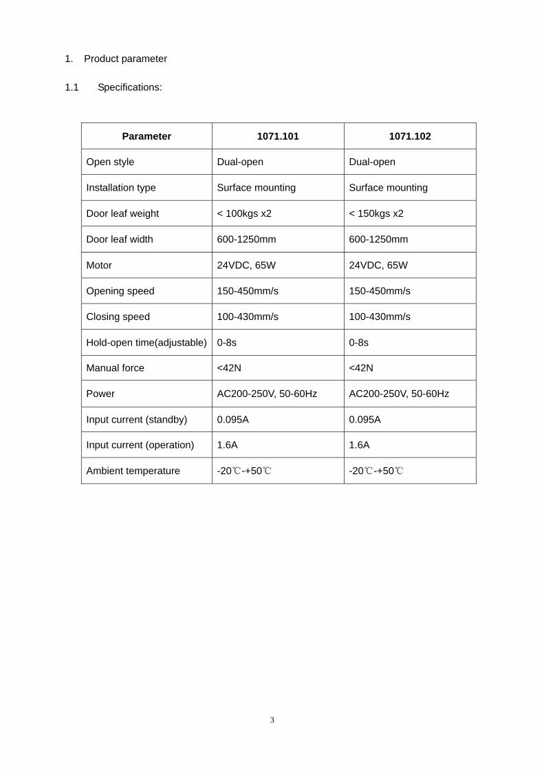
1. Product parameter 1.1 Specifications:
Parameter 1071.101 1071.102
Open style Dual-open Dual-open
Installation type Surface mounting Surface mounting
Door leaf weight < 100kgs x2 < 150kgs x2
Door leaf width 600-1250mm 600-1250mm
Motor 24VDC, 65W 24VDC, 65W
Opening speed 150-450mm/s 150-450mm/s
Closing speed 100-430mm/s 100-430mm/s
Hold-open time(adjustable) 0-8s 0-8s
Manual force <42N <42N
Power AC200-250V, 50-60Hz AC200-250V, 50-60Hz
Input current (standby) 0.095A 0.095A
Input current (operation) 1.6A 1.6A
Ambient temperature -20℃-+50℃ -20℃-+50℃
4
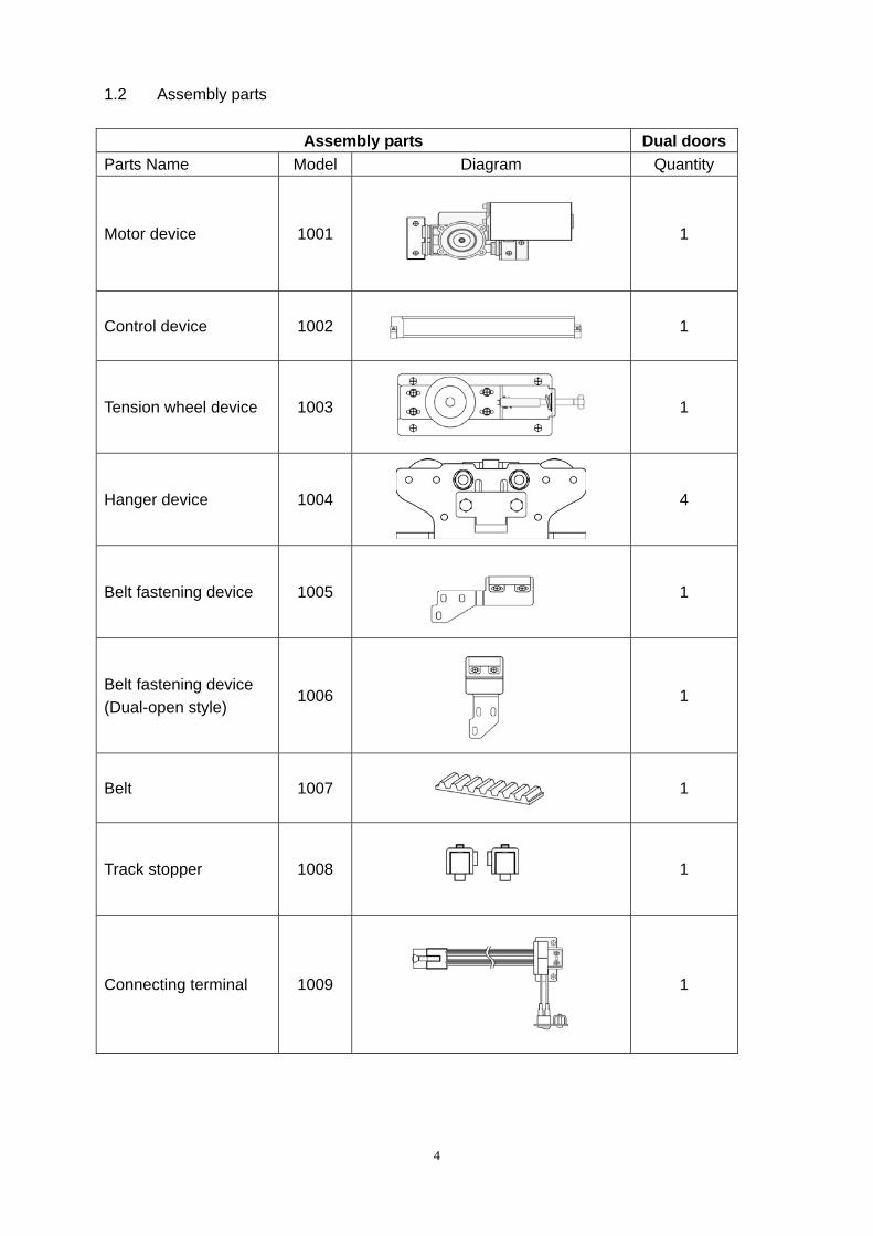
1.2 Assembly parts
Assembly parts Dual doorsParts Name Model Diagram Quantity
Motor device 1001
1
Control device 1002
1
Tension wheel device 1003
1
Hanger device 1004
4
Belt fastening device 1005
1
Belt fastening device (Dual-open style)
1006
1
Belt 1007
1
Track stopper 1008
1
Connecting terminal 1009
1
5
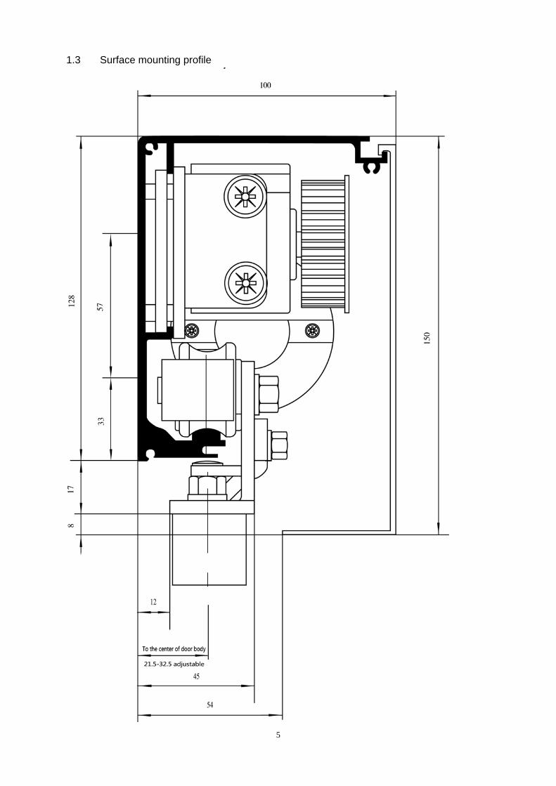
1.3 Surface mounting profile
6
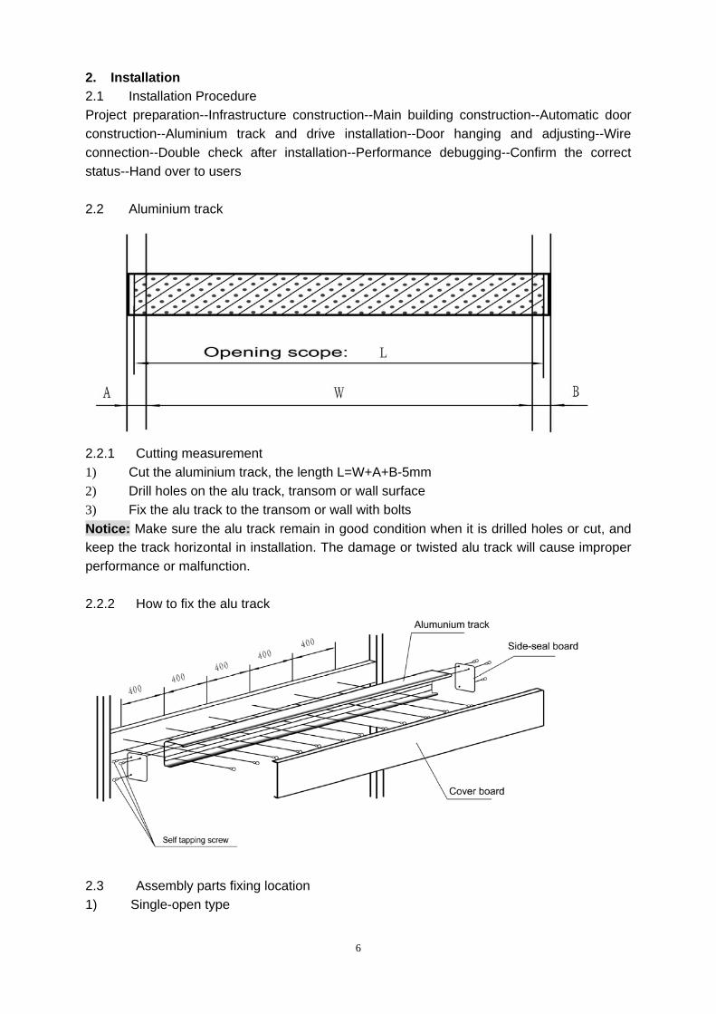
2. Installation 2.1 Installation Procedure Project preparation--Infrastructure construction--Main building construction--Automatic door construction--Aluminium track and drive installation--Door hanging and adjusting--Wire connection--Double check after installation--Performance debugging--Confirm the correct status--Hand over to users 2.2 Aluminium track
2.2.1 Cutting measurement 1) Cut the aluminium track, the length L=W+A+B-5mm 2) Drill holes on the alu track, transom or wall surface 3) Fix the alu track to the transom or wall with bolts Notice: Make sure the alu track remain in good condition when it is drilled holes or cut, and keep the track horizontal in installation. The damage or twisted alu track will cause improper performance or malfunction. 2.2.2 How to fix the alu track
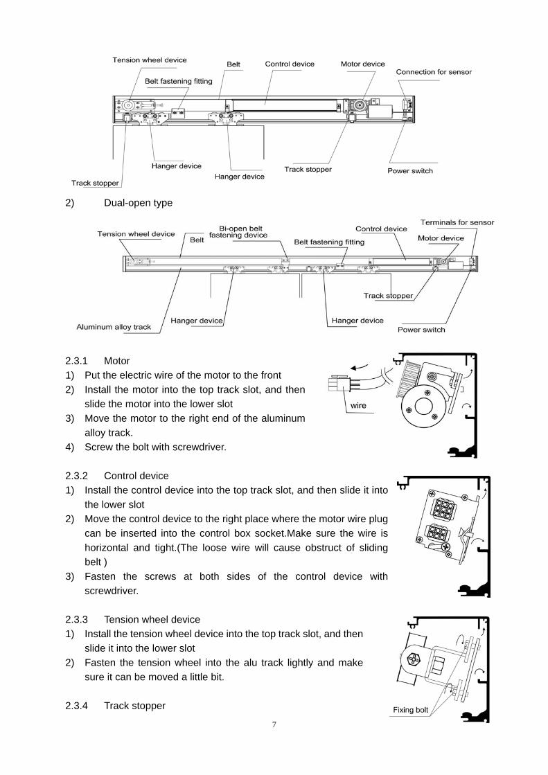
2.3 Assembly parts fixing location 1) Single-open type
7
2) Dual-open type
2.3.1 Motor 1) Put the electric wire of the motor to the front 2) Install the motor into the top track slot, and then
slide the motor into the lower slot 3) Move the motor to the right end of the aluminum
alloy track. 4) Screw the bolt with screwdriver. 2.3.2 Control device 1) Install the control device into the top track slot, and then slide it into
the lower slot 2) Move the control device to the right place where the motor wire plug
can be inserted into the control box socket.Make sure the wire is horizontal and tight.(The loose wire will cause obstruct of sliding belt )
3) Fasten the screws at both sides of the control device with screwdriver.
2.3.3 Tension wheel device 1) Install the tension wheel device into the top track slot, and then
slide it into the lower slot 2) Fasten the tension wheel into the alu track lightly and make
sure it can be moved a little bit. 2.3.4 Track stopper
8
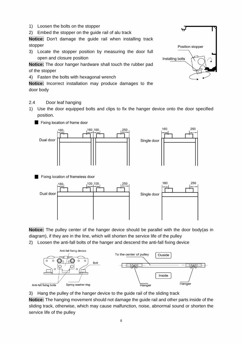
1) Loosen the bolts on the stopper 2) Embed the stopper on the guide rail of alu track Notice: Don't damage the guide rail when installing track stopper 3) Locate the stopper position by measuring the door full
open and closure position Notice: The door hanger hardware shall touch the rubber pad of the stopper 4) Fasten the bolts with hexagonal wrench Notice: Incorrect installation may produce damages to the door body 2.4 Door leaf hanging 1) Use the door equipped bolts and clips to fix the hanger device onto the door specified
position.
Notice: The pulley center of the hanger device should be parallel with the door body(as in diagram), if they are in the line, which will shorten the service life of the pulley 2) Loosen the anti-fall bolts of the hanger and descend the anti-fall fixing device
3) Hang the pulley of the hanger device to the guide rail of the sliding track Notice: The hanging movement should not damage the guide rail and other parts inside of the sliding track, otherwise, which may cause malfunction, noise, abnormal sound or shorten the service life of the pulley
9
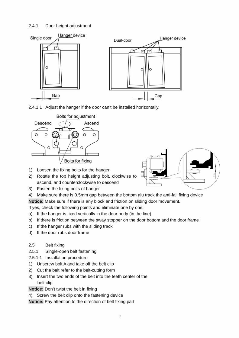
2.4.1 Door height adjustment
2.4.1.1 Adjust the hanger if the door can’t be installed horizontally.
1) Loosen the fixing bolts for the hanger. 2) Rotate the top height adjusting bolt, clockwise to
ascend, and counterclockwise to descend 3) Fasten the fixing bolts of hanger 4) Make sure there is 0.5mm gap between the bottom alu track the anti-fall fixing device Notice: Make sure if there is any block and friction on sliding door movement. If yes, check the following points and eliminate one by one: a) If the hanger is fixed vertically in the door body (in the line) b) If there is friction between the sway stopper on the door bottom and the door frame c) If the hanger rubs with the sliding track d) If the door rubs door frame 2.5 Belt fixing 2.5.1 Single-open belt fastening 2.5.1.1 Installation procedure 1) Unscrew bolt A and take off the belt clip 2) Cut the belt refer to the belt-cutting form 3) Insert the two ends of the belt into the teeth center of the belt clip
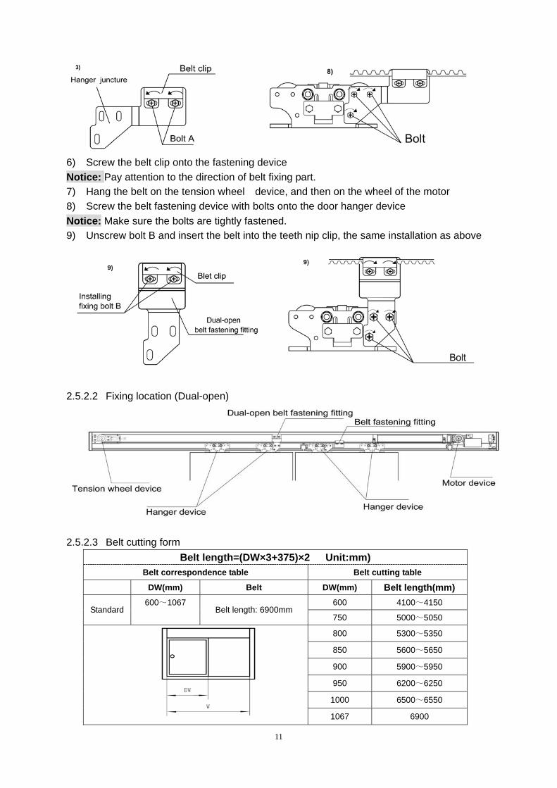
Notice: Don’t twist the belt in fixing 4) Screw the belt clip onto the fastening device Notice: Pay attention to the direction of belt fixing part
10
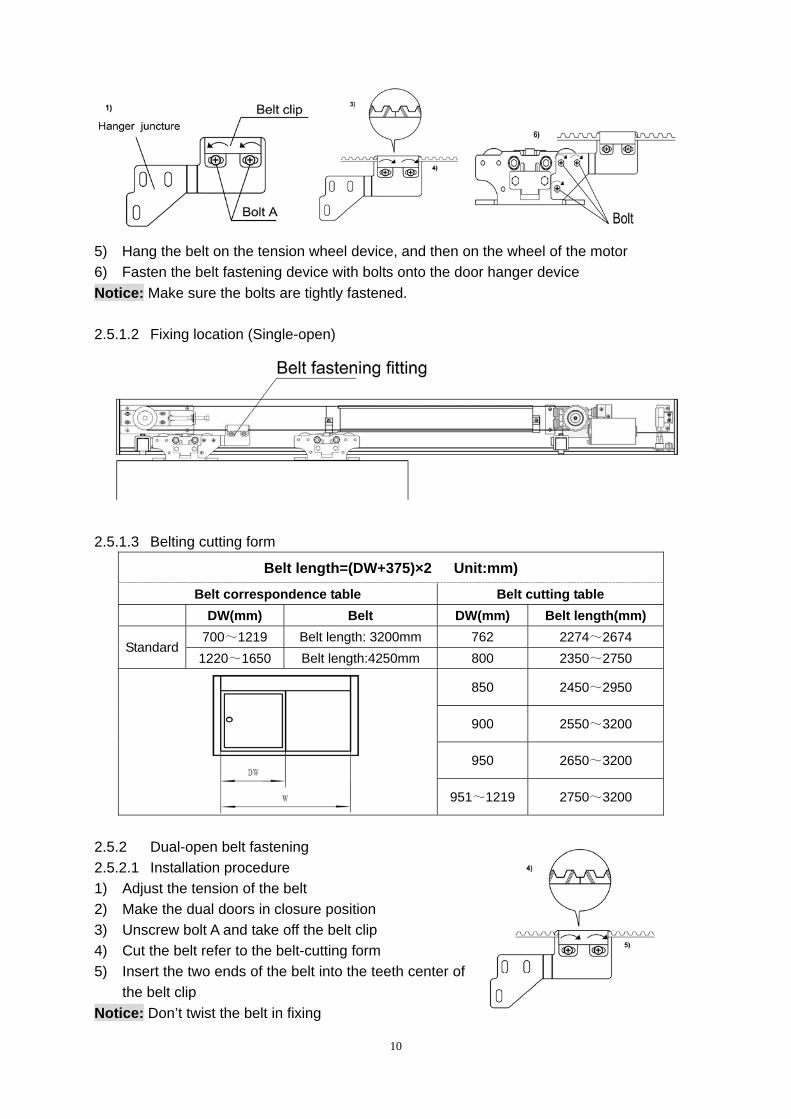
5) Hang the belt on the tension wheel device, and then on the wheel of the motor 6) Fasten the belt fastening device with bolts onto the door hanger device Notice: Make sure the bolts are tightly fastened. 2.5.1.2 Fixing location (Single-open)
2.5.1.3 Belting cutting form
Belt length=(DW+375)×2 Unit:mm)
Belt correspondence table Belt cutting table DW(mm) Belt DW(mm) Belt length(mm)
700~1219 Belt length: 3200mm 762 2274~2674 Standard
1220~1650 Belt length:4250mm 800 2350~2750
850 2450~2950
900 2550~3200
950 2650~3200
951~1219 2750~3200
2.5.2 Dual-open belt fastening 2.5.2.1 Installation procedure 1) Adjust the tension of the belt 2) Make the dual doors in closure position 3) Unscrew bolt A and take off the belt clip 4) Cut the belt refer to the belt-cutting form 5) Insert the two ends of the belt into the teeth center of
the belt clip Notice: Don’t twist the belt in fixing
11
6) Screw the belt clip onto the fastening device Notice: Pay attention to the direction of belt fixing part. 7) Hang the belt on the tension wheel device, and then on the wheel of the motor 8) Screw the belt fastening device with bolts onto the door hanger device Notice: Make sure the bolts are tightly fastened. 9) Unscrew bolt B and insert the belt into the teeth nip clip, the same installation as above
2.5.2.2 Fixing location (Dual-open)
2.5.2.3 Belt cutting form
Belt length=(DW×3+375)×2 Unit:mm) Belt correspondence table Belt cutting table
DW(mm) Belt DW(mm) Belt length(mm) 600 4100~4150
Standard 600~1067
Belt length: 6900mm 750 5000~5050
800 5300~5350
850 5600~5650
900 5900~5950
950 6200~6250
1000 6500~6550
1067 6900
12
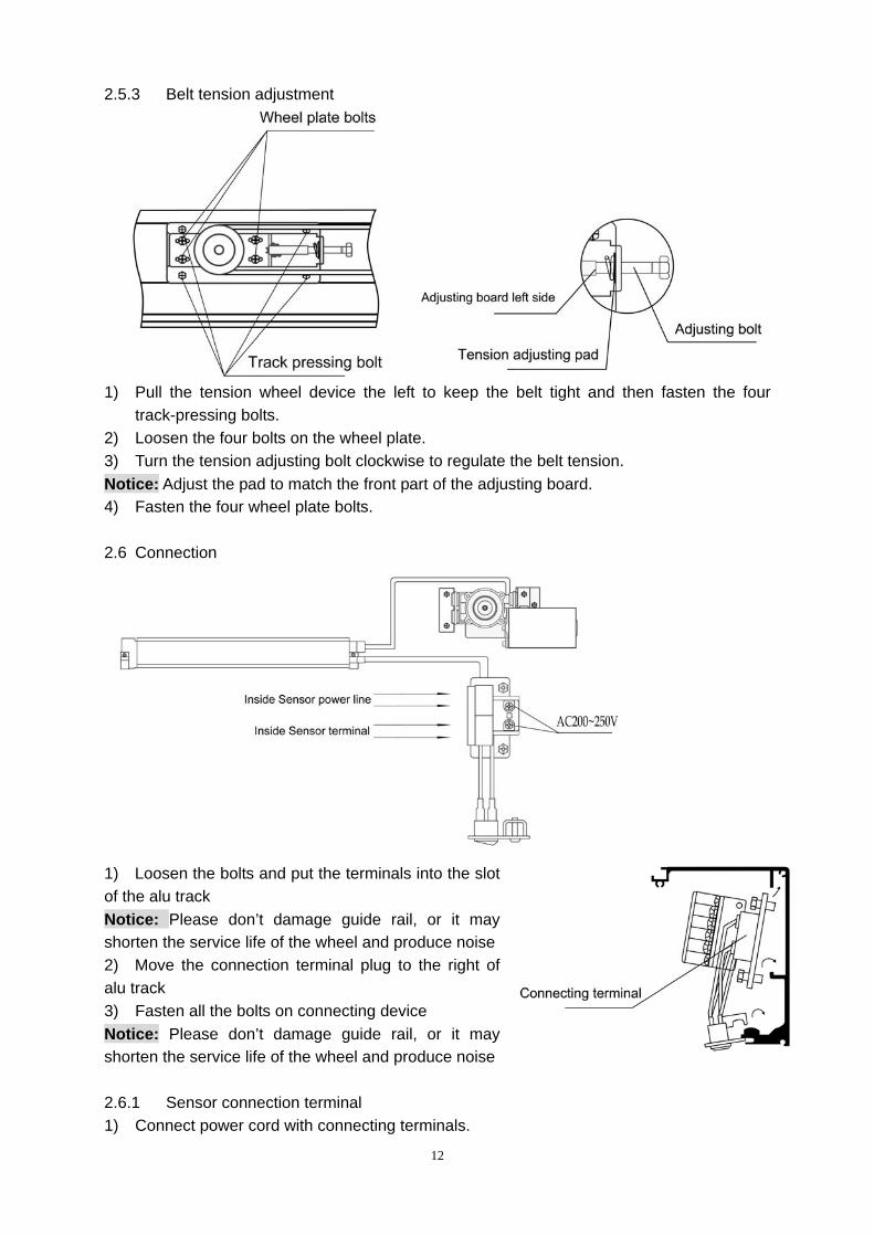
2.5.3 Belt tension adjustment
1) Pull the tension wheel device the left to keep the belt tight and then fasten the four
track-pressing bolts. 2) Loosen the four bolts on the wheel plate. 3) Turn the tension adjusting bolt clockwise to regulate the belt tension. Notice: Adjust the pad to match the front part of the adjusting board. 4) Fasten the four wheel plate bolts. 2.6 Connection
1) Loosen the bolts and put the terminals into the slot of the alu track Notice: Please don’t damage guide rail, or it may shorten the service life of the wheel and produce noise 2) Move the connection terminal plug to the right of alu track 3) Fasten all the bolts on connecting device Notice: Please don’t damage guide rail, or it may shorten the service life of the wheel and produce noise 2.6.1 Sensor connection terminal 1) Connect power cord with connecting terminals.
13
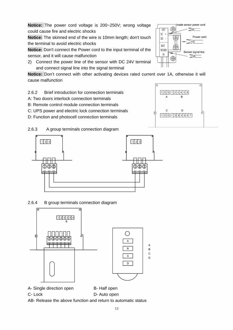
Notice: The power cord voltage is 200~250V; wrong voltage could cause fire and electric shocks Notice: The skinned end of the wire is 10mm length; don't touch the terminal to avoid electric shocks Notice: Don't connect the Power cord to the input terminal of the sensor, and it will cause malfunction 2) Connect the power line of the sensor with DC 24V terminal
and connect signal line into the signal terminal Notice: Don’t connect with other activating devices rated current over 1A, otherwise it will cause malfunction 2.6.2 Brief introduction for connection terminals A: Two doors interlock connection terminals B: Remote control module connection terminals C: UPS power and electric lock connection terminals D: Function and photocell connection terminals 2.6.3 A group terminals connection diagram
2.6.4 B group terminals connection diagram
A- Single direction open B- Half open C- Lock D- Auto open AB- Release the above function and return to automatic status
14
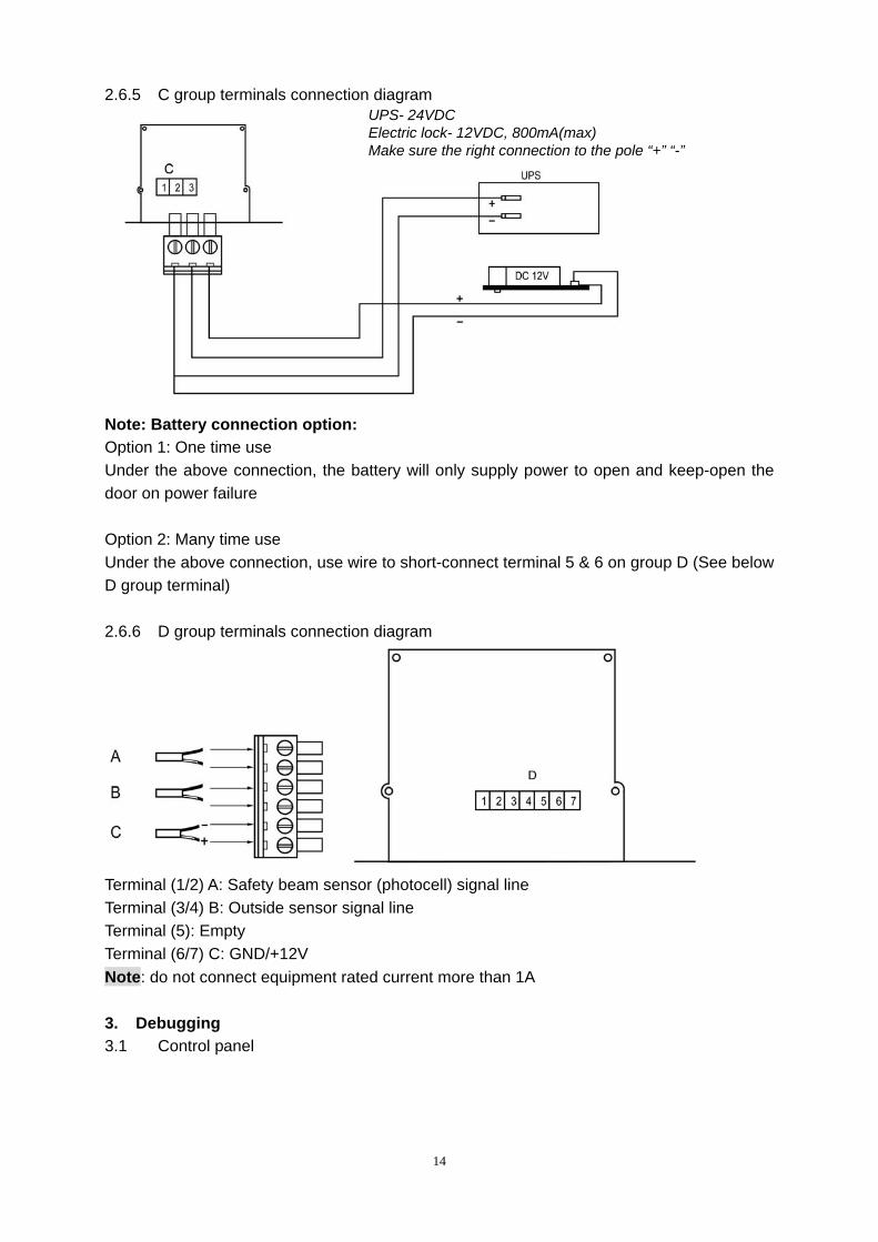
2.6.5 C group terminals connection diagram UPS- 24VDC Electric lock- 12VDC, 800mA(max) Make sure the right connection to the pole “+” “-”
Note: Battery connection option: Option 1: One time use Under the above connection, the battery will only supply power to open and keep-open the door on power failure Option 2: Many time use Under the above connection, use wire to short-connect terminal 5 & 6 on group D (See below D group terminal) 2.6.6 D group terminals connection diagram
Terminal (1/2) A: Safety beam sensor (photocell) signal line Terminal (3/4) B: Outside sensor signal line Terminal (5): Empty Terminal (6/7) C: GND/+12V Note: do not connect equipment rated current more than 1A 3. Debugging 3.1 Control panel
15
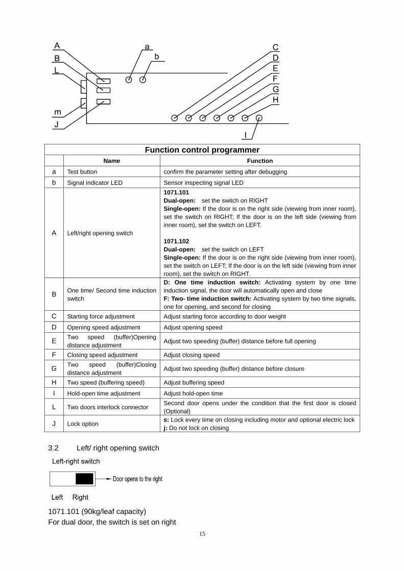
Function control programmer
Name Function
a Test button confirm the parameter setting after debugging
b Signal indicator LED Sensor inspecting signal LED
A Left/right opening switch
1071.101 Dual-open: set the switch on RIGHT Single-open: If the door is on the right side (viewing from inner room), set the switch on RIGHT; If the door is on the left side (viewing from inner room), set the switch on LEFT. 1071.102 Dual-open: set the switch on LEFT Single-open: If the door is on the right side (viewing from inner room), set the switch on LEFT; If the door is on the left side (viewing from inner room), set the switch on RIGHT.
B One time/ Second time induction switch
D: One time induction switch: Activating system by one time induction signal, the door will automatically open and close F: Two- time induction switch: Activating system by two time signals, one for opening, and second for closing
C Starting force adjustment Adjust starting force according to door weight
D Opening speed adjustment Adjust opening speed
E Two speed (buffer)Opening distance adjustment
Adjust two speeding (buffer) distance before full opening
F Closing speed adjustment Adjust closing speed
G Two speed (buffer)Closing distance adjustment
Adjust two speeding (buffer) distance before closure
H Two speed (buffering speed) Adjust buffering speed
I Hold-open time adjustment Adjust hold-open time
L Two doors interlock connector Second door opens under the condition that the first door is closed (Optional)
J Lock option s: Lock every time on closing including motor and optional electric lockj: Do not lock on closing
3.2 Left/ right opening switch
1071.101 (90kg/leaf capacity) For dual door, the switch is set on right
16
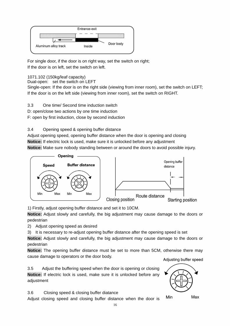
For single door, if the door is on right way, set the switch on right; If the door is on left, set the switch on left. 1071.102 (150kg/leaf capacity) Dual-open: set the switch on LEFT Single-open: If the door is on the right side (viewing from inner room), set the switch on LEFT; If the door is on the left side (viewing from inner room), set the switch on RIGHT. 3.3 One time/ Second time induction switch D: open/close two actions by one time induction F: open by first induction, close by second induction 3.4 Opening speed & opening buffer distance Adjust opening speed, opening buffer distance when the door is opening and closing Notice: If electric lock is used, make sure it is unlocked before any adjustment Notice: Make sure nobody standing between or around the doors to avoid possible injury.
1) Firstly, adjust opening buffer distance and set it to 10CM. Notice: Adjust slowly and carefully, the big adjustment may cause damage to the doors or pedestrian 2) Adjust opening speed as desired 3) It is necessary to re-adjust opening buffer distance after the opening speed is set Notice: Adjust slowly and carefully, the big adjustment may cause damage to the doors or pedestrian Notice: The opening buffer distance must be set to more than 5CM, otherwise there may cause damage to operators or the door body. 3.5 Adjust the buffering speed when the door is opening or closing Notice: If electric lock is used, make sure it is unlocked before any adjustment 3.6 Closing speed & closing buffer diatance Adjust closing speed and closing buffer distance when the door is
17
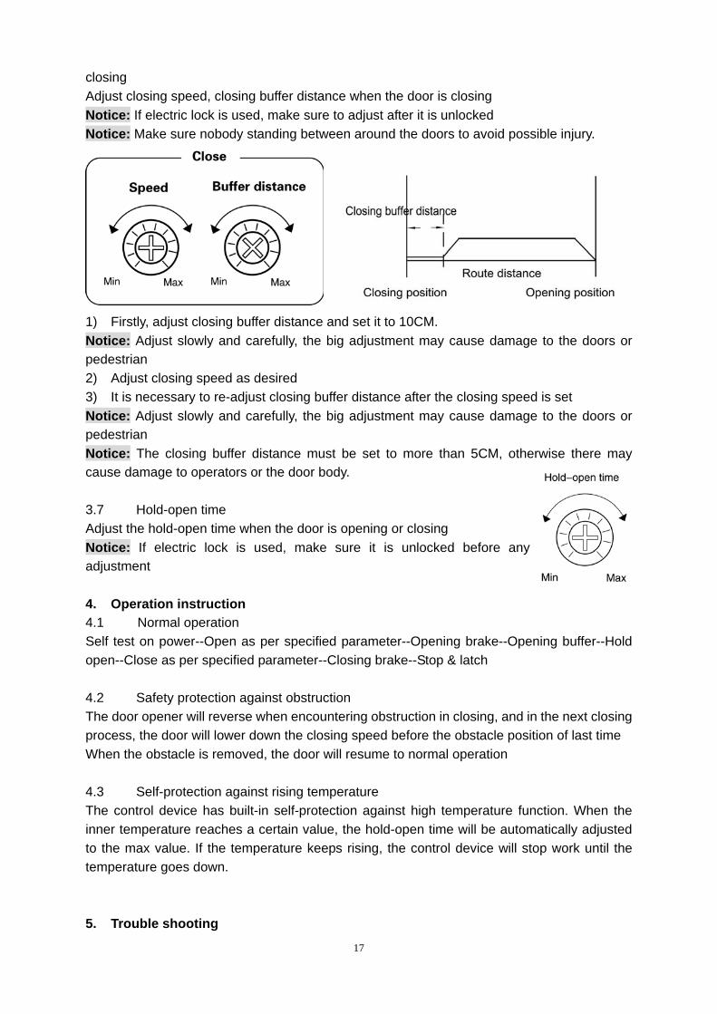
closing Adjust closing speed, closing buffer distance when the door is closing Notice: If electric lock is used, make sure to adjust after it is unlocked Notice: Make sure nobody standing between around the doors to avoid possible injury.
1) Firstly, adjust closing buffer distance and set it to 10CM. Notice: Adjust slowly and carefully, the big adjustment may cause damage to the doors or pedestrian 2) Adjust closing speed as desired 3) It is necessary to re-adjust closing buffer distance after the closing speed is set Notice: Adjust slowly and carefully, the big adjustment may cause damage to the doors or pedestrian Notice: The closing buffer distance must be set to more than 5CM, otherwise there may cause damage to operators or the door body. 3.7 Hold-open time Adjust the hold-open time when the door is opening or closing Notice: If electric lock is used, make sure it is unlocked before any adjustment 4. Operation instruction 4.1 Normal operation Self test on power--Open as per specified parameter--Opening brake--Opening buffer--Hold open--Close as per specified parameter--Closing brake--Stop & latch 4.2 Safety protection against obstruction The door opener will reverse when encountering obstruction in closing, and in the next closing process, the door will lower down the closing speed before the obstacle position of last time When the obstacle is removed, the door will resume to normal operation 4.3 Self-protection against rising temperature The control device has built-in self-protection against high temperature function. When the inner temperature reaches a certain value, the hold-open time will be automatically adjusted to the max value. If the temperature keeps rising, the control device will stop work until the temperature goes down. 5. Trouble shooting
18
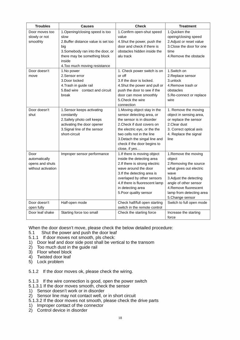
Troubles Causes Check Treatment Door moves too slowly or not smoothly
1.Opening/closing speed is too slow 2.Buffer distance value is set too big 3.Somebody ran into the door, or there may be something block inside 4.Too much moving resistance
1.Confirm open-shut speed value 4.Shut the power, push the door and check if there is obstacles hidden inside the alu track
1.Quicken the opeing/closing speed 2.Adjust or reset value 3.Close the door for one time 4.Remove the obstacle
Door doesn’t move
1.No power 2.Sensor error 3.Door locked 4.Trash in guide rail 5.Bad wire contact and circuit break
1. Check power switch is on or off 3.If the door is locked. 4.Shut the power and pull or push the door to see if the door can move smoothly 5.Check the wire connection
1.Switch on 2.Replace sensor 3.unlock 4.Remove trash or obstacles 5.Re-connect or replace wire
Door doesn’t shut
1.Sensor keeps activating constantly 2.Safety photo cell keeps activating the door opener 3.Signal line of the sensor short-circuit
1.Moving object stay in the sensor detecting area, or the sensor is in disorder 2.Check if dust covers on the electric eye, or the the two cells not in the line 3.Detach the singal line and check if the door begins to close, if yes…
1. Remove the moving object in sensing area, or replace the sensor 2.Clear dust 3. Correct optical axis 4. Replace the signal line
Door automatically opens and shuts without activation
Improper sensor performance
1.If there is moving object inside the detecting area 2.If there is strong electric wave around the door 3.If the detecting area is overlaped by other sensors4.If there is fluorescent lamp in detecting area 5.Poor quality sensor
1.Remove the moving object 2.Removing the source what gives out electric wave 3.Adjust the detecting angle of other sensor 4.Remove fluorescent lamp from detecting area5.Change sensor
Door doesn’t open fully
Half-open mode Check half/full open starting switch in the remote control
Switch to full open mode
Door leaf shake Starting force too small Check the starting force Increase the starting force
When the door doesn’t move, please check the below detailed procedure: 5.1 Shut the power and push the door leaf 5.1.1 If door moves not smooth, pls check: 1) Door leaf and door side post shall be vertical to the transom 2) Too much dust in the guide rail 3) Floor wheel block 4) Twisted door leaf 5) Lock problem 5.1.2 If the door moves ok, please check the wiring. 5.1.3 If the wire connection is good, open the power switch 5.1.3.1 If the door moves smooth, check the sensor 1) Sensor doesn’t work or in disorder 2) Sensor line may not contact well, or in short circuit 5.1.3.2 If the door moves not smooth, please check the drive parts 1) Improper contact of the connector 2) Control device in disorder