Embed Size (px)
Citation preview

AVL02 User Guide V1.5 Automatic Vehicle Location
Catalog
1 Product Overview ........................................................................................................ 3
1.1 Key Features........................................................................................................ 3 1.2 Specification......................................................................................................... 4 1.3 Outside feature .................................................................................................... 5
1.3.1 Socket and Switch ..................................................................................... 5 1.3.2 I/O ports ..................................................................................................... 6 1.3.3 LED Indicators ........................................................................................... 7 1.3.4 Detect Car ON/OFF ................................................................................... 8 1.3.5 Connect Relay to control the Car Oil/Power (Pin2) .................................... 9
2. How to use the Product ............................................................................................ 10 2.1 prophase to prepare ........................................................................................ 10 2.2 Use the command to set device by SMS....................................................... 12
2.2.1 Use the GPRS function ...................................................................... 12 2.2.2 Set the sleep mode............................................................................. 14 2.2.3 Set the parking alarm function............................................................ 15 2.2.4 Set the interval SMS........................................................................... 16 2.2.5 Other useful commands ..................................................................... 16
3 The format of the GPRS............................................................................................... 17 4. SMS instruction list...................................................................................................... 20 5. Update the firmware of the AVL................................................................................... 25 6 Worldwide APN (Access Point Name) List ................................................................... 31
1 Product Overview
AVL02 is a GPS/GSM/GPRS tracking device which is specially
developed and designed for vehicle real-time tracking and security. With
superior GPS and GPRS modules, AVL02 has good sensitivity and stable
performance. It can get accurate GPS fix even in remote places.
1.1 Key Features
Internal Polymer Lithium Ion Battery in the AVL Support mini USB port to update firmware Tracking by time interavl via GPRS or SMS Over-speed alarm Geo-fence alarm Low power alarm Support single location and continual tracking Can Real-time tracking your vehicle via map on PC GPRS function, receiving position data and alarm data on Server Anti-theft alarm, support alarm when someone tremble your car once
you park it and send an alarm report to you via SMS or GPRS data
Remotely check the status of the windows or doors close/open, through the 2 switch I/O sockets, and remotely control the status of ignition through the 1 digital I/O socket
SOS button send out exact location for immediate rescue. After user press SOS button in the AVL, AVL unit will send out the location and SOS alarm to the preset number via SMS or a server via GPRS
With 4M memory, which can store about 2000 PCS data. When GPRS is lose connection, those data will be store and send when GPRS connection is recover.
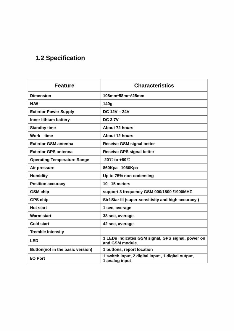
1.2 Specification
Feature Characteristics
Dimension 108mm*58mm*28mm
N.W 140g
Exterior Power Supply DC 12V – 24V
Inner lithium battery DC 3.7V
Standby time About 72 hours
Work time About 12 hours
Exterior GSM antenna Receive GSM signal better
Exterior GPS antenna Receive GPS signal better
Operating Temperature Range -20℃ to +60℃
Air pressure 860Kpa –1060Kpa
Humidity Up to 75% non-codensing
Position accuracy 10 –15 meters
GSM chip support 3 frequency GSM 900/1800 /1900MHZ
GPS chip Sirf-Star III (super-sensitivity and high accuracy )
Hot start 1 sec, average
Warm start 38 sec, average
Cold start 42 sec, average
Tremble Intensity
LED 3 LEDs indicates GSM signal, GPS signal, power on and GSM module.
Button(not in the basic version) 1 buttons, report location
I/O Port 1 switch input, 2 digital input , 1 digital output, 1 analog input
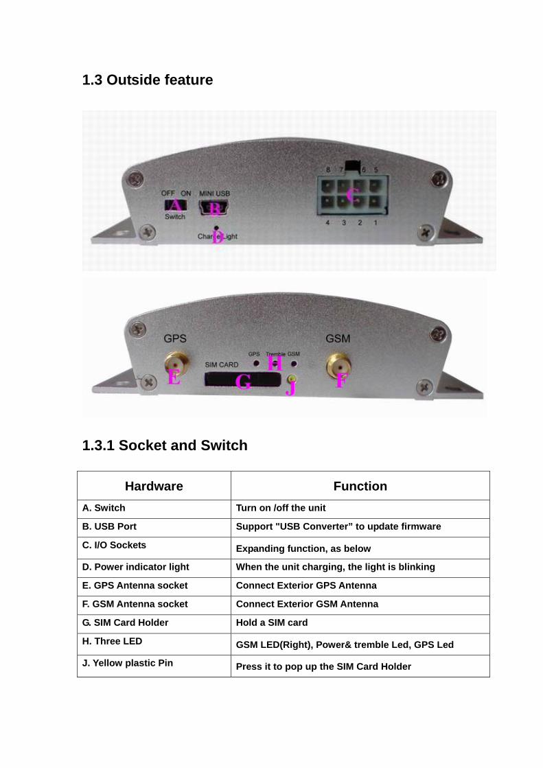
1.3 Outside feature
1.3.1 Socket and Switch
Hardware Function A. Switch Turn on /off the unit
B. USB Port Support "USB Converter” to update firmware
C. I/O Sockets Expanding function, as below
D. Power indicator light When the unit charging, the light is blinking
E. GPS Antenna socket Connect Exterior GPS Antenna
F. GSM Antenna socket Connect Exterior GSM Antenna
G. SIM Card Holder Hold a SIM card
H. Three LED GSM LED(Right), Power& tremble Led, GPS Led
J. Yellow plastic Pin Press it to pop up the SIM Card Holder
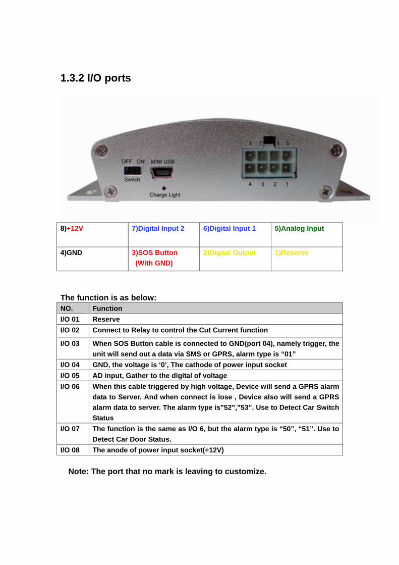
1.3.2 I/O ports
8)+12V 7)Digital Input 2 6)Digital Input 1 5)Analog Input
4)GND 3)SOS Button (With GND)
2)Digital Output 1)Reserve
The function is as below: NO. Function I/O 01 Reserve I/O 02 Connect to Relay to control the Cut Current function
I/O 03 When SOS Button cable is connected to GND(port 04), namely trigger, the unit will send out a data via SMS or GPRS, alarm type is “01”
I/O 04 GND, the voltage is ‘0’, The cathode of power input socket I/O 05 AD input, Gather to the digital of voltage I/O 06 When this cable triggered by high voltage, Device will send a GPRS alarm
data to Server. And when connect is lose , Device also will send a GPRS alarm data to server. The alarm type is”52”,”53”. Use to Detect Car Switch Status
I/O 07 The function is the same as I/O 6, but the alarm type is “50”, “51”. Use to Detect Car Door Status.
I/O 08 The anode of power input socket(+12V) Note: The port that no mark is leaving to customize.
1.3.3 LED Indicators
When AVL is in work mode, if GSM signal is in good state, the green led
will flash, similarly, if GPS signal is in good state, the blue led will flash, if
the green led is not flashing, that indicates the GSM signal is not good, if
the blue led is not flashing, then you should check if there is something
upon the GPS antenna top. Further, if you find the three leds are dark,
maybe the AVL entered into "sleep-mode" or there is no power in the AVL
unit.
LED State Description light 0.1s dark 2.9s GPS Signal Well light 1s dark 2s No GPS Signal
GPS Indicator (Blue LED)
light 0.5s dark 0.5s GPS Fault light 0.1s dark 0.1s System Initial light 1s dark 2s Low Power light 0.1s dark 2.9s Power Good
Tremble Indicator ( Red LED)
always light On Tremble light 0.1s dark 0.1s System Initial light 0.1s dark 2.9s GSM Signal Well light 1s dark 2s No GSM Signal always dark No SIM Card Or Bad SIM Cardlight 0.1s dark 0.1s (flash three times)
Call Ring
always light In A Call light 0.1s dark 0.3s (flash five times)
Send A SMS
light 0.1s dark 0.3s (flash five times)
Receive A SMS
GSM Indicator (Green LED)
light 0.1s dark 1s Connect to GPRS
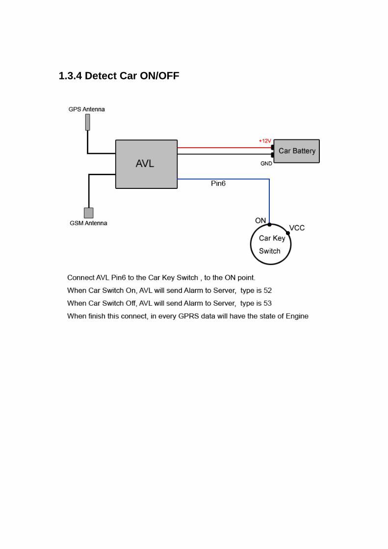
1.3.4 Detect Car ON/OFF
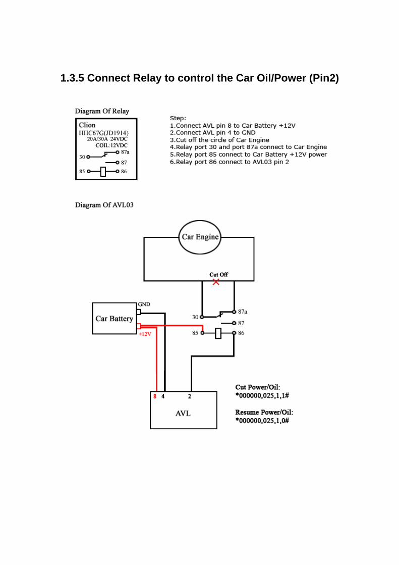
1.3.5 Connect Relay to control the Car Oil/Power (Pin2)

2. How to use the Product
2.1 prophase to prepare
Step1: Inset a SIM card. make sure the SIM card can communicate with other cards via SMS and call, and before installing the SIM card to the holder, please use a mobile phone to empty the SMS storage of the card Step2: Connect GSM Antenna and GPS Antenna to AVL unit.
(GPS antenna)
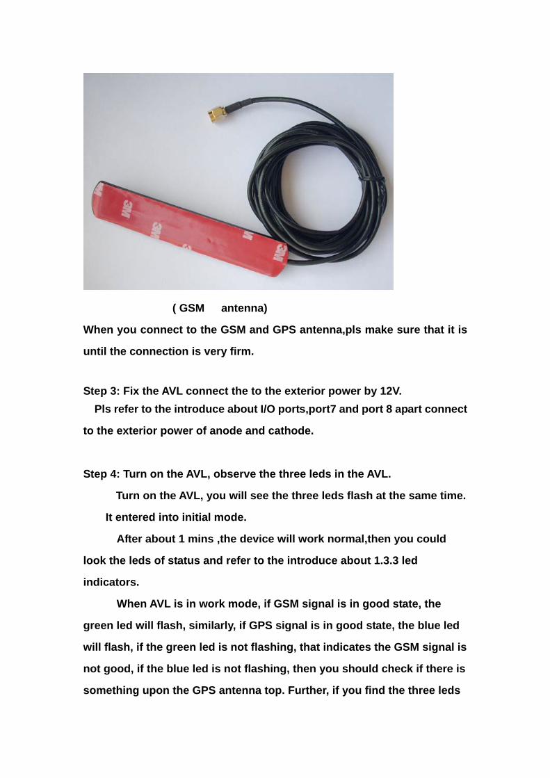
( GSM antenna)
When you connect to the GSM and GPS antenna,pls make sure that it is
until the connection is very firm.
Step 3: Fix the AVL connect the to the exterior power by 12V. Pls refer to the introduce about I/O ports,port7 and port 8 apart connect
to the exterior power of anode and cathode.
Step 4: Turn on the AVL, observe the three leds in the AVL.
Turn on the AVL, you will see the three leds flash at the same time.
It entered into initial mode.
After about 1 mins ,the device will work normal,then you could
look the leds of status and refer to the introduce about 1.3.3 led
indicators.
When AVL is in work mode, if GSM signal is in good state, the
green led will flash, similarly, if GPS signal is in good state, the blue led
will flash, if the green led is not flashing, that indicates the GSM signal is
not good, if the blue led is not flashing, then you should check if there is
something upon the GPS antenna top. Further, if you find the three leds
are dark, maybe the AVL entered into "sleep-mode" or there is no power
in the AVL unit. Notes: As everyone knows,the GPS signal is very weakly or have no GPS signal in the office .So pls put the AVL02 to the open air in order to receive the great GPS signal.
2.2 Use the command to set device by SMS
Notes: $$$$$$ is the password,and the default is:000000
If you want to modify the passwod:
The command of format:
*$$$$$$,001,@@@@@@#
Explication: $$$$$$: the old password
@@@@@@: the new password
For example: *000000,001,123456#
Afeter you send the command of SMS to device,it will reply
to your mobile phone: Receive:’001’OK
*000000,001,123456#
2.2.1 Use the GPRS function
Notes: At first of all,make sure the SIM card insert to the device and have the GPRS function. Step1: Set the APN(Access Point Name )
Different network of provider have the different APN at every country,if you don't know,pls refer to the attachment.
Format: *$$$$$$,011,APN,Username,Password#
Notes: The username and password could to be null1.
For example: *000000,011,cmnet,,#
Explication: The China Mobile’s APN is “cmnet”,and the username and
password are empty.
Afeter you send the command of SMS to device,it will reply to your
mobile phone: Receive:’011’OK
*000000,011,cmnet,,#
Step2: Set the server’s IP & PORT
Format : *$$$$$$,015,0,IP,PORT#
For example: *000000,015,0,72.167.29.18,3308#
72.167.29.18 is our server’s IP address,3308 is the port.
If client have the server by himself,pls make sure the ip and port is
correct.
Afeter you send the command of SMS to device,it will reply to your
mobile phone: Receive:’015’OK
*000000,015,0,72.167.29.18,3308#
Step3: Set Time Interval GPRS
Format: *$$$$$$,018,X,Y#
X: the time interval(unit:sec),Y: the times of the data have to send by
GPRS.
For example:*000000,018,60,999#
The device will send GPRS every 1 mins and no times limit.
Afeter you send the command of SMS to device,it will reply to your
mobile phone: Receive:’018’OK
*000000,018,60,999#
Step4: Open the GPRS fuction
Format: *$$$$$$,016,X#
X: close/open the GPRS function,
For example: *000000,016,1#
Afeter you send the command of SMS to device,it will reply to your
mobile phone: Receive:’016’OK
*000000,016,1#
2.2.2 Set the sleep mode
Step1: open the sleep mode and the tremble sensor Format: *$$$$$$,021,XY# X: close/open the sleep mode Y: close/open the tremble sensor For example: *000000,021,11# When you want to use the sleep mode of function,make sure
open the sleep mode and tremble sensor Afeter you send the command of SMS to device,it will reply to your
mobile phone: Receive:’021’OK
*000000,021,11#
Step2: set the time of no tremble into the sleep.
Format: *$$$$$$,044,X#
X: After the tremble sensor don't tremble for X second, tracker
will into sleep mode(unit:sec)
For example:*000000,044,60#
If the device don't tremble for 60 sec,the device will into the
sleep mode.
Afeter you send the command of SMS to device,it will reply to your
mobile phone: Receive:’044’OK
*000000,044,60#
Step 3: set the time of tremble to wake up the device
Format: *$$$$$$,043,X#
X: After the tremble sensor continuous tremble for X second,
device will wake up.
For example: *000000,043,30#
If the tremble sensor continuous tremble for 30 sec,device will
wake up.
Afeter you send the command of SMS to device,it will reply to your
mobile phone: Receive:’043’OK
*000000,043,30#
2.2.3 Set the parking alarm function
Step1: open the tremble sensor of switch Format : *$$$$$$,021,XY# For example: *000000,021,01# Close the sleep mode and open the tremble sensor of the above of
the set.
Of course you could open the sleep mode too.
Afeter you send the command of SMS to device,it will reply to your
mobile phone: Receive:’021’OK
*000000,021,01#
Step 2: open the parking alarm of function
Format: *$$$$$$,110,X#
X=1,open the function ,X=0 close the function
For example: *000000,110,1#
Afeter you send the command of SMS to device,it will reply to your
mobile phone: Receive:’110’OK
*000000,110,1#
Step 3: open the GPRS function
For example: *000000,016,1#
Afeter you send the command of SMS to device,it will reply to your
mobile phone: Receive:’016’OK
*000000,016,1#
2.2.4 Set the interval SMS
Step1: Set the SOS number
Format: *$$$$$$,003,0,F,CallNumber,SMS Number#
When the device send to SMS to mobile phone by interval,should
to set a SOS number which the number of the mobile phone to receive
the data.
For example: *000000,003,0,1,008613800755500, 008613800755500##
When set the SOS number,pls append the 00 and international
number as the example.86 is the international number for china.
Afeter you send the command of SMS to device,it will reply to your
mobile phone: Receive:’003’OK
*000000,003,0,1,008613800755500, 008613800755500#
Step2: Set the interval time for SMS.
Format: *$$$$$$,002,X,Y#
X: Time interval (unit:mins)
Y: the times of the data have to send by SMS
For example :*000000,002,1,999#
The device will send SMS every 1 mins and no times limit.
Afeter you send the command of SMS to device,it will reply to your
mobile phone: Receive:’002’OK
*000000,002,1,999#
2.2.5 Other useful commands
● Get current location: **$$$$$$,000#

● Get the IMEI from the device: *$$$$$$,801# ● Reboot the device by SMS: *$$$$$$,991# ● Initialization the device
*$$$$$$,990,099#
3 The format of the GPRS
The data of the device send to the server:
Format:$$(2 Bytes) + Len(2 Bytes) + IMEI(15 Bytes) + | + AlarmType(2 Bytes) + GPRMC + | + PDOP + | + HDOP + | + VDOP + | + Status(12 Bytes) + | + RTC(14 Bytes) + | + Voltage(8 Bytes) + | + ADC(8 Bytes) + | + LACCI(8 Bytes) + | + Temperature(4 Bytes) | + Serial(4 Bytes) + | + Checksum (4 Byte) + \r\n(2 Bytes)
The format of ASCII: $$A9353358019474100|AA$GPRMC,043002.000,A,2232.4289,N,11403.7343,E,0.00,,240809,,*1D|02.3|02.0|01.0|110011110000|20090824043003|14201300|00000000|25337621|0000|2280|96F7 The format in hex: 24 24 41 39 33 35 33 33 35 38 30 31 39 34 37 34 31 30 30 7C 41 41 24 47 50 52 4D 43 2C 30 34 33 30 30 32 2E 30 30 30 2C 41 2C 32 32 33 32 2E 34 32 38 39 2C 4E 2C 31 31 34 30 33 2E 37 33 34 33 2C 45 2C 30 2E 30 30 2C 2C 32 34 30 38 30 39 2C 2C 2A 31 44 7C 30 32 2E 33 7C 30 32 2E 30 7C 30 31 2E 30 7C 31 31 30 30 31 31 31 31 30 30 30 30 7C 32 30 30 39 30 38 32 34 30 34 33 30 30 33 7C 31 34 32 30 31 33 30 30 7C 30 30 30 30 30 30 30 30 7C 32 35 33 33 37 36 32 31 7C 30 30 30 30 7C 32 32 38 30 7C 39 36 46 37 0D 0A
Code Explanation
$$ 2Bytes, indicates header of command from tracker unit to call centre, in
ASCII code (hex is 0x24).
Len 2Bytes, indicates length of all command, including header and end (the
array is first high to low).
IMEI 15Bytes, at most 20 bytes.
Alarm type 2Bytes, the GPRS data trigger type.
GPRMC string DATA
PDOP
HDOP
VDOP
Status (12bytes)
RTC (14bytes)
Voltage(8bytes)
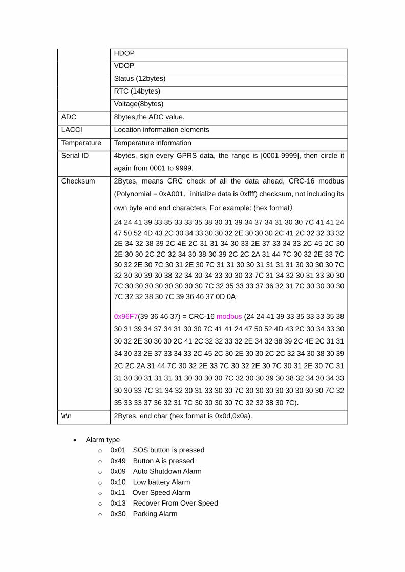
ADC 8bytes,the ADC value.
LACCI Location information elements
Temperature Temperature information
Serial ID 4bytes, sign every GPRS data, the range is [0001-9999], then circle it
again from 0001 to 9999.
Checksum 2Bytes, means CRC check of all the data ahead, CRC-16 modbus
(Polynomial = 0xA001,initialize data is 0xffff) checksum, not including its
own byte and end characters. For example: (hex format)
24 24 41 39 33 35 33 33 35 38 30 31 39 34 37 34 31 30 30 7C 41 41 24 47 50 52 4D 43 2C 30 34 33 30 30 32 2E 30 30 30 2C 41 2C 32 32 33 32 2E 34 32 38 39 2C 4E 2C 31 31 34 30 33 2E 37 33 34 33 2C 45 2C 30 2E 30 30 2C 2C 32 34 30 38 30 39 2C 2C 2A 31 44 7C 30 32 2E 33 7C 30 32 2E 30 7C 30 31 2E 30 7C 31 31 30 30 31 31 31 31 30 30 30 30 7C 32 30 30 39 30 38 32 34 30 34 33 30 30 33 7C 31 34 32 30 31 33 30 30 7C 30 30 30 30 30 30 30 30 7C 32 35 33 33 37 36 32 31 7C 30 30 30 30 7C 32 32 38 30 7C 39 36 46 37 0D 0A 0x96F7(39 36 46 37) = CRC-16 modbus (24 24 41 39 33 35 33 33 35 38
30 31 39 34 37 34 31 30 30 7C 41 41 24 47 50 52 4D 43 2C 30 34 33 30
30 32 2E 30 30 30 2C 41 2C 32 32 33 32 2E 34 32 38 39 2C 4E 2C 31 31
34 30 33 2E 37 33 34 33 2C 45 2C 30 2E 30 30 2C 2C 32 34 30 38 30 39
2C 2C 2A 31 44 7C 30 32 2E 33 7C 30 32 2E 30 7C 30 31 2E 30 7C 31
31 30 30 31 31 31 31 30 30 30 30 7C 32 30 30 39 30 38 32 34 30 34 33
30 30 33 7C 31 34 32 30 31 33 30 30 7C 30 30 30 30 30 30 30 30 7C 32
35 33 33 37 36 32 31 7C 30 30 30 30 7C 32 32 38 30 7C).
\r\n 2Bytes, end char (hex format is 0x0d,0x0a).
• Alarm type o 0x01 SOS button is pressed o 0x49 Button A is pressed o 0x09 Auto Shutdown Alarm o 0x10 Low battery Alarm o 0x11 Over Speed Alarm o 0x13 Recover From Over Speed o 0x30 Parking Alarm
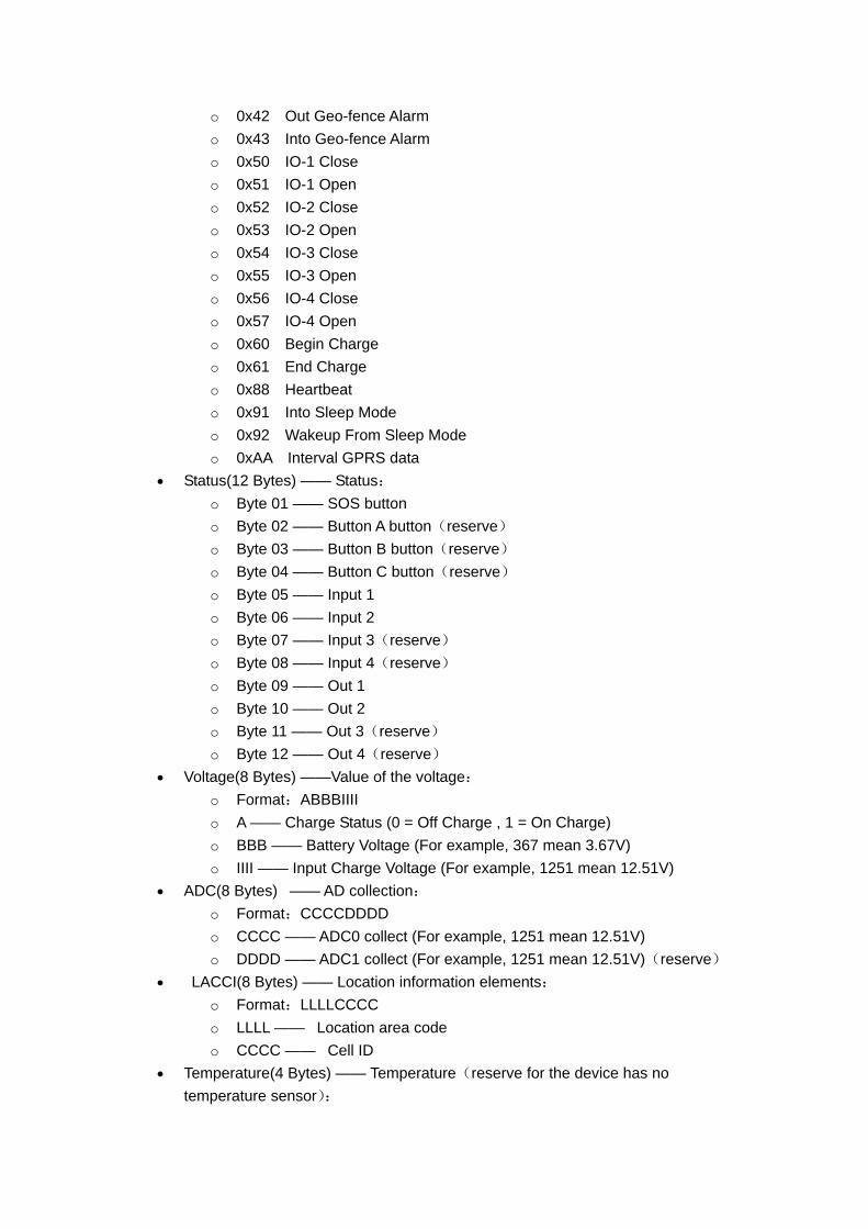
o 0x42 Out Geo-fence Alarm o 0x43 Into Geo-fence Alarm o 0x50 IO-1 Close o 0x51 IO-1 Open o 0x52 IO-2 Close o 0x53 IO-2 Open o 0x54 IO-3 Close o 0x55 IO-3 Open o 0x56 IO-4 Close o 0x57 IO-4 Open o 0x60 Begin Charge o 0x61 End Charge o 0x88 Heartbeat o 0x91 Into Sleep Mode o 0x92 Wakeup From Sleep Mode o 0xAA Interval GPRS data
• Status(12 Bytes) —— Status: o Byte 01 —— SOS button o Byte 02 —— Button A button(reserve) o Byte 03 —— Button B button(reserve) o Byte 04 —— Button C button(reserve) o Byte 05 —— Input 1 o Byte 06 —— Input 2 o Byte 07 —— Input 3(reserve) o Byte 08 —— Input 4(reserve) o Byte 09 —— Out 1 o Byte 10 —— Out 2 o Byte 11 —— Out 3(reserve) o Byte 12 —— Out 4(reserve)
• Voltage(8 Bytes) ——Value of the voltage: o Format:ABBBIIII o A —— Charge Status (0 = Off Charge , 1 = On Charge) o BBB —— Battery Voltage (For example, 367 mean 3.67V) o IIII —— Input Charge Voltage (For example, 1251 mean 12.51V)
• ADC(8 Bytes) —— AD collection: o Format:CCCCDDDD o CCCC —— ADC0 collect (For example, 1251 mean 12.51V) o DDDD —— ADC1 collect (For example, 1251 mean 12.51V)(reserve)
• LACCI(8 Bytes) —— Location information elements: o Format:LLLLCCCC o LLLL —— Location area code o CCCC —— Cell ID
• Temperature(4 Bytes) —— Temperature(reserve for the device has no temperature sensor):
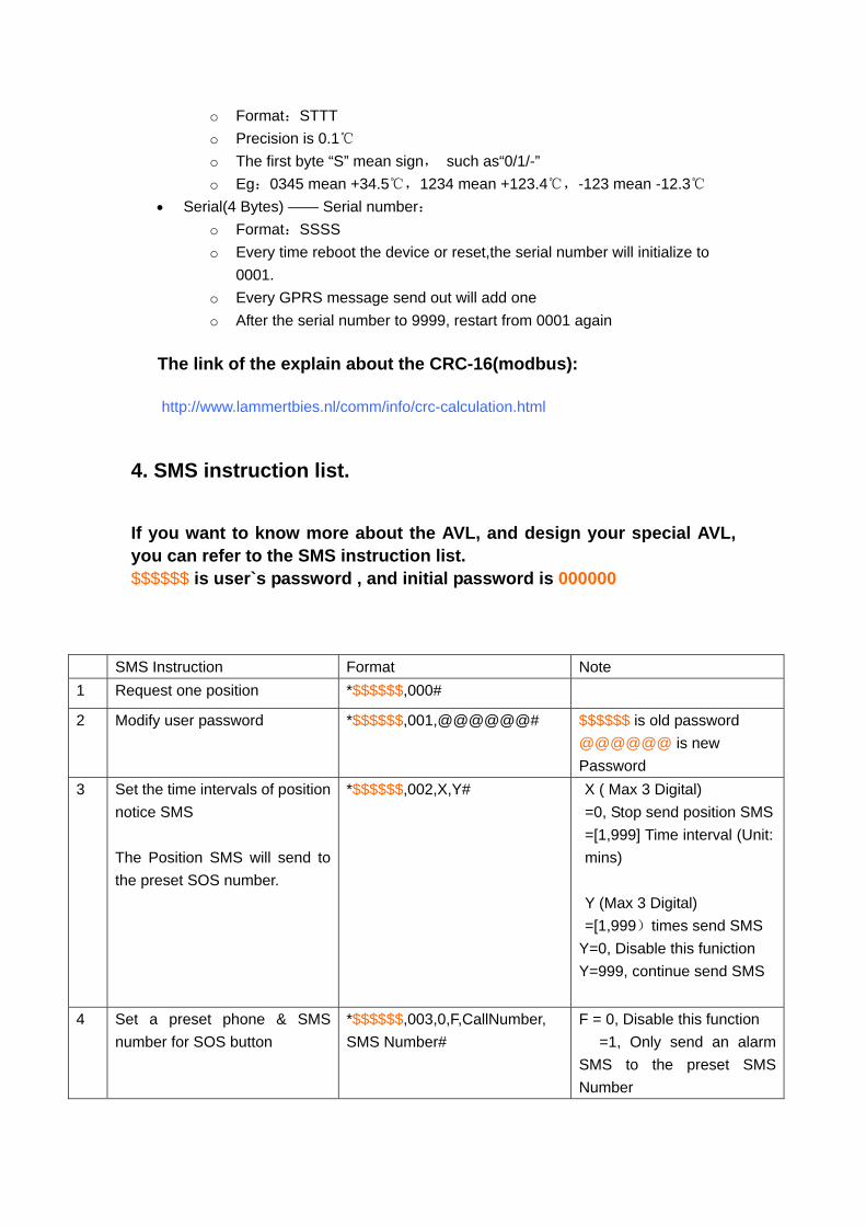
o Format:STTT o Precision is 0.1℃ o The first byte “S” mean sign, such as“0/1/-” o Eg:0345 mean +34.5℃,1234 mean +123.4℃,-123 mean -12.3℃
• Serial(4 Bytes) —— Serial number: o Format:SSSS o Every time reboot the device or reset,the serial number will initialize to
0001. o Every GPRS message send out will add one o After the serial number to 9999, restart from 0001 again
The link of the explain about the CRC-16(modbus):
http://www.lammertbies.nl/comm/info/crc-calculation.html
4. SMS instruction list.
If you want to know more about the AVL, and design your special AVL, you can refer to the SMS instruction list. $$$$$$ is user`s password , and initial password is 000000
SMS Instruction Format Note 1 Request one position *$$$$$$,000#
2 Modify user password *$$$$$$,001,@@@@@@# $$$$$$ is old password @@@@@@ is new Password
3 Set the time intervals of position notice SMS The Position SMS will send to the preset SOS number.
*$$$$$$,002,X,Y# X ( Max 3 Digital) =0, Stop send position SMS=[1,999] Time interval (Unit: mins) Y (Max 3 Digital) =[1,999)times send SMS
Y=0, Disable this funiction Y=999, continue send SMS
4 Set a preset phone & SMS number for SOS button
*$$$$$$,003,0,F,CallNumber, SMS Number#
F = 0, Disable this function =1, Only send an alarm SMS to the preset SMS Number
Notice :Tel Number and SMS Number ( must <25 digits)
5 Set low power alarm When the AVL voltage is lower than the preset value, AVL will send one lower power alarm GPRS data to the Preset Server.
*$$$$$$,004,XXX,YYY# XXX is the low power alarm voltage,eg: 3.8v,XXX=380 YYY is the auto shut down voltage,eg: 3.5v,YYY=350 For example: *$$$$$$,004,380,350#
6 Set over speed alarm When the AVL speed higher than the preset value, AVL will send one over speed alarm GPRS data to the Preset Server.
*$$$$$$,005,S,X,Y,Z# S=1 Enable speed alarm, S=0 Disable speed alarm. X=[10<XXX<250] (The speed preset value) unit is 0.1 sea mile/h Y is the times over speed [1,999] Z=[10,360],( The timeinterval to send speed alarm) unit is second.
7 Set Geo-fence alarm When the AVL move out preset scope, AVL will send one Geo-fence GPRS data to the Preset Server.
*$$$$$$,006,+lat1,+long1,+lat2,+long2,X,Y#
X=[10,360] is for time interval send alarm message. Y=0, Disable GEO-fence alarm. Y=1, Into GEO-fence alarm. Y=2, Out of GEO-fence alarm. Long1>long2&lat1>lat2
8 Set APN,Username,Password *$$$$$$,011,APN,Username,Password#
APN : APN string (Max 28 chars) User name: Your username (Max 28 chars) Password: Your password (Max 28 chars) * If haven't username or password, then left it blank. For example:
*000000,011,CMNET,,## (It haven't username and password)
9 Set IP Address & port number *$$$$$$,015,0,IP,PORT# IP : xxx.xxx.xxx.xxx PORT : [1,65535]
10 Set the time intervals of GPRS Data
*$$$$$$,018,X,Y# X (3 Digital) =0 stop send time interval GPRS
=[10,999] Time interval (Unit: sec) Y (3 Digital) =0, stop send time interval GPRS
= [1,999] After send YYY times stop. =999, continue send GPRS un-stop
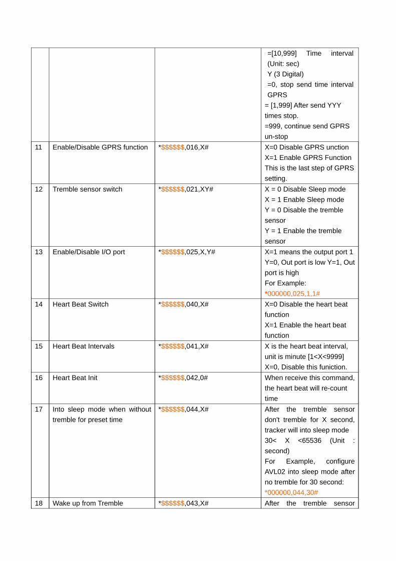
11 Enable/Disable GPRS function *$$$$$$,016,X# X=0 Disable GPRS unction X=1 Enable GPRS Function This is the last step of GPRS setting.
12 Tremble sensor switch *$$$$$$,021,XY# X = 0 Disable Sleep mode X = 1 Enable Sleep mode Y = 0 Disable the tremble sensor Y = 1 Enable the tremble sensor
13 Enable/Disable I/O port *$$$$$$,025,X,Y# X=1 means the output port 1Y=0, Out port is low Y=1, Out port is high For Example: *000000,025,1,1#
14 Heart Beat Switch *$$$$$$,040,X# X=0 Disable the heart beat function X=1 Enable the heart beat function
15 Heart Beat Intervals *$$$$$$,041,X# X is the heart beat interval, unit is minute [1<X<9999] X=0, Disable this funiction.
16 Heart Beat Init *$$$$$$,042,0# When receive this command, the heart beat will re-count time
17 Into sleep mode when without tremble for preset time
*$$$$$$,044,X# After the tremble sensor don't tremble for X second, tracker will into sleep mode 30< X <65536 (Unit : second) For Example, configure AVL02 into sleep mode after no tremble for 30 second: *000000,044,30#
18 Wake up from Tremble *$$$$$$,043,X# After the tremble sensor
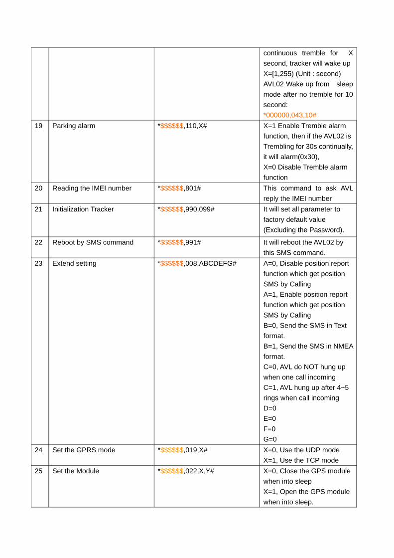
continuous tremble for X second, tracker will wake up X=[1,255) (Unit : second) AVL02 Wake up from sleep mode after no tremble for 10 second: *000000,043,10#
19 Parking alarm *$$$$$$,110,X# X=1 Enable Tremble alarm function, then if the AVL02 is Trembling for 30s continually, it will alarm(0x30), X=0 Disable Tremble alarm function
20 Reading the IMEI number *$$$$$$,801# This command to ask AVL reply the IMEI number
21 Initialization Tracker
*$$$$$$,990,099# It will set all parameter to factory default value (Excluding the Password).
22 Reboot by SMS command *$$$$$$,991# It will reboot the AVL02 by this SMS command.
23 Extend setting *$$$$$$,008,ABCDEFG# A=0, Disable position report function which get position SMS by Calling A=1, Enable position report function which get position SMS by Calling B=0, Send the SMS in Text format. B=1, Send the SMS in NMEA format. C=0, AVL do NOT hung up when one call incoming C=1, AVL hung up after 4~5 rings when call incoming D=0 E=0 F=0 G=0
24 Set the GPRS mode *$$$$$$,019,X# X=0, Use the UDP mode X=1, Use the TCP mode
25 Set the Module *$$$$$$,022,X,Y# X=0, Close the GPS module when into sleep X=1, Open the GPS module when into sleep.

Y=0, Close the GSM module when into sleep Y=1, Open the GSM module when into sleep
5. Update the firmware of the AVL
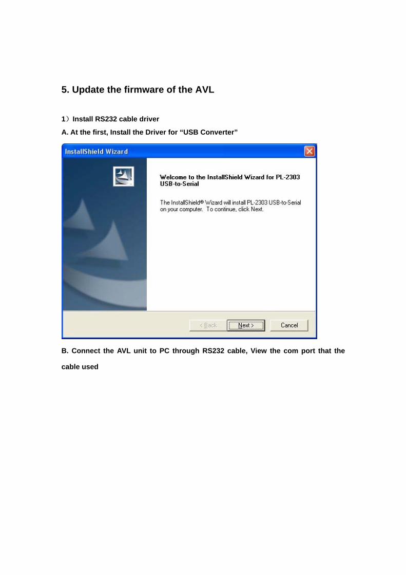
1)Install RS232 cable driver
A. At the first, Install the Driver for “USB Converter”
B. Connect the AVL unit to PC through RS232 cable, View the com port that the
cable used
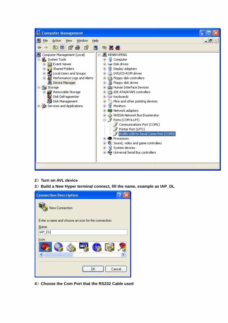
2)Turn on AVL device 3)Build a New Hyper terminal connect, fill the name, example as IAP_DL
4)Choose the Com Port that the RS232 Cable used

Setup all the option like show in the picture follow
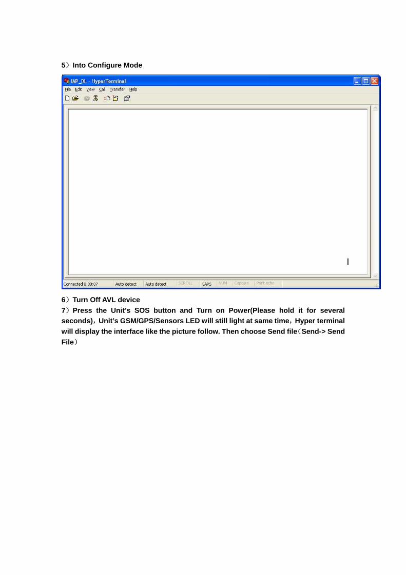
5)Into Configure Mode
6)Turn Off AVL device 7)Press the Unit’s SOS button and Turn on Power(Please hold it for several seconds),Unit’s GSM/GPS/Sensors LED will still light at same time,Hyper terminal will display the interface like the picture follow. Then choose Send file(Send-> Send File)
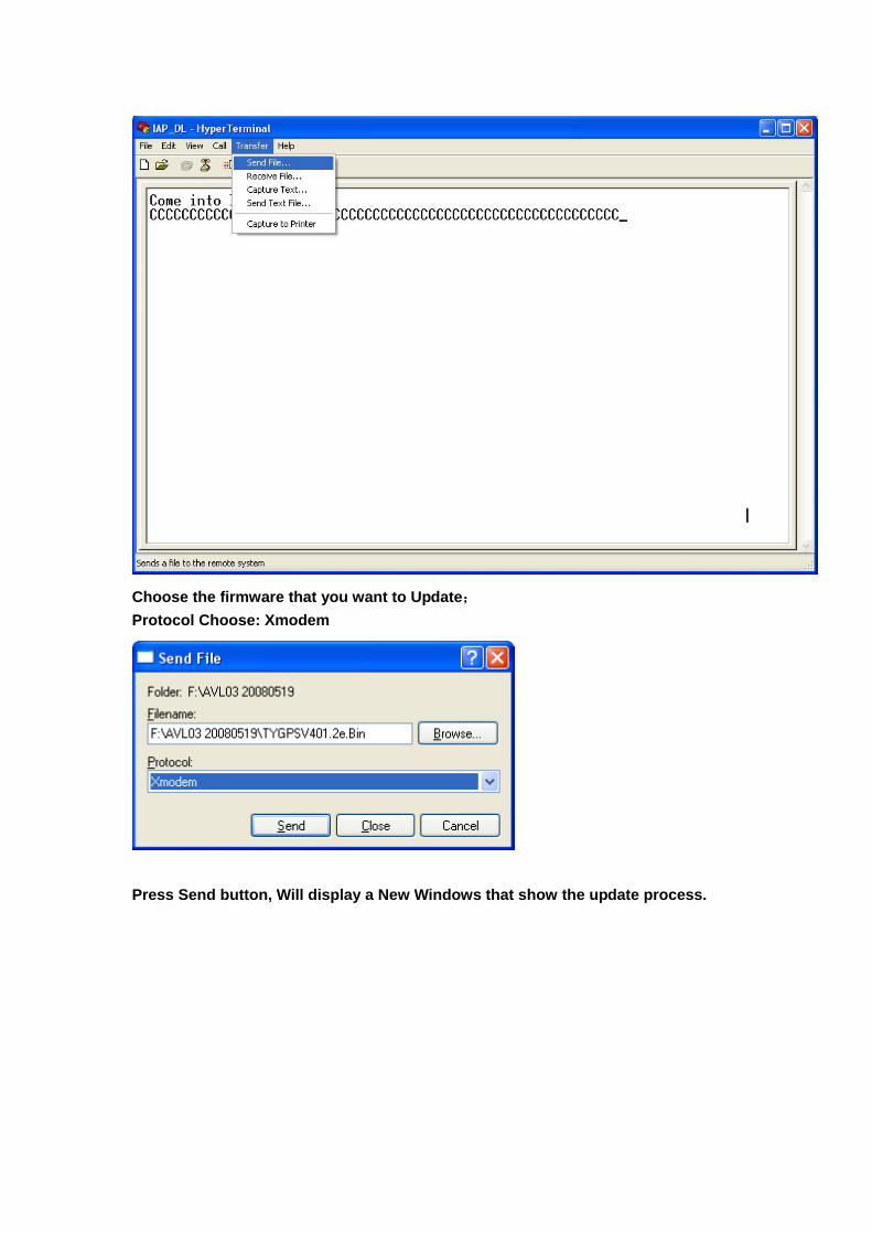
Choose the firmware that you want to Update; Protocol Choose: Xmodem
Press Send button, Will display a New Windows that show the update process.
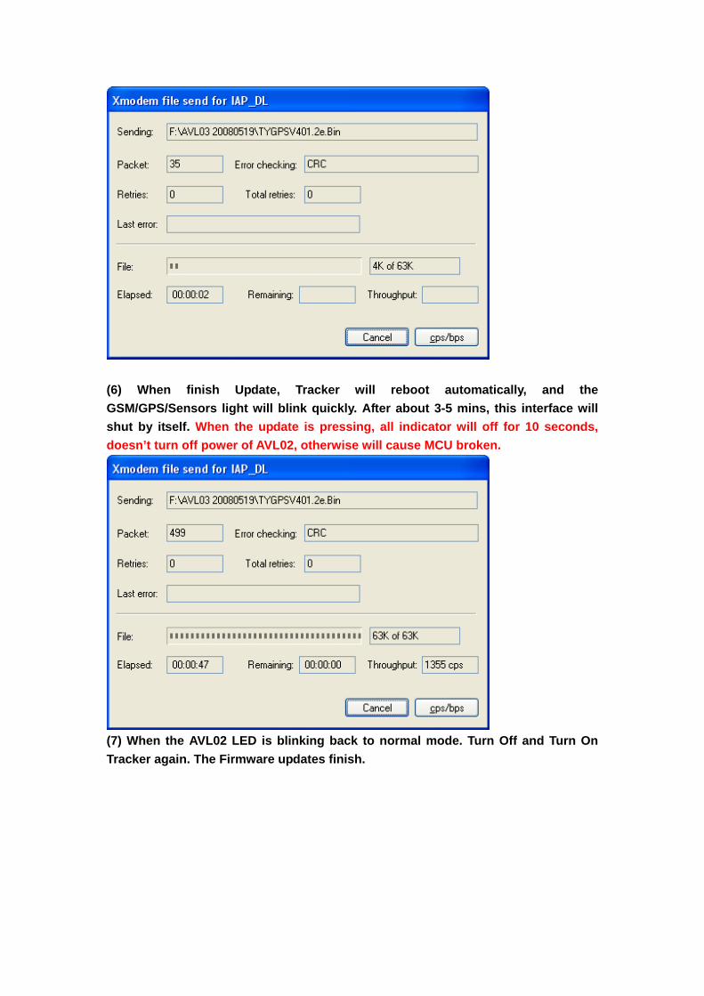
(6) When finish Update, Tracker will reboot automatically, and the GSM/GPS/Sensors light will blink quickly. After about 3-5 mins, this interface will shut by itself. When the update is pressing, all indicator will off for 10 seconds, doesn’t turn off power of AVL02, otherwise will cause MCU broken.
(7) When the AVL02 LED is blinking back to normal mode. Turn Off and Turn On Tracker again. The Firmware updates finish.

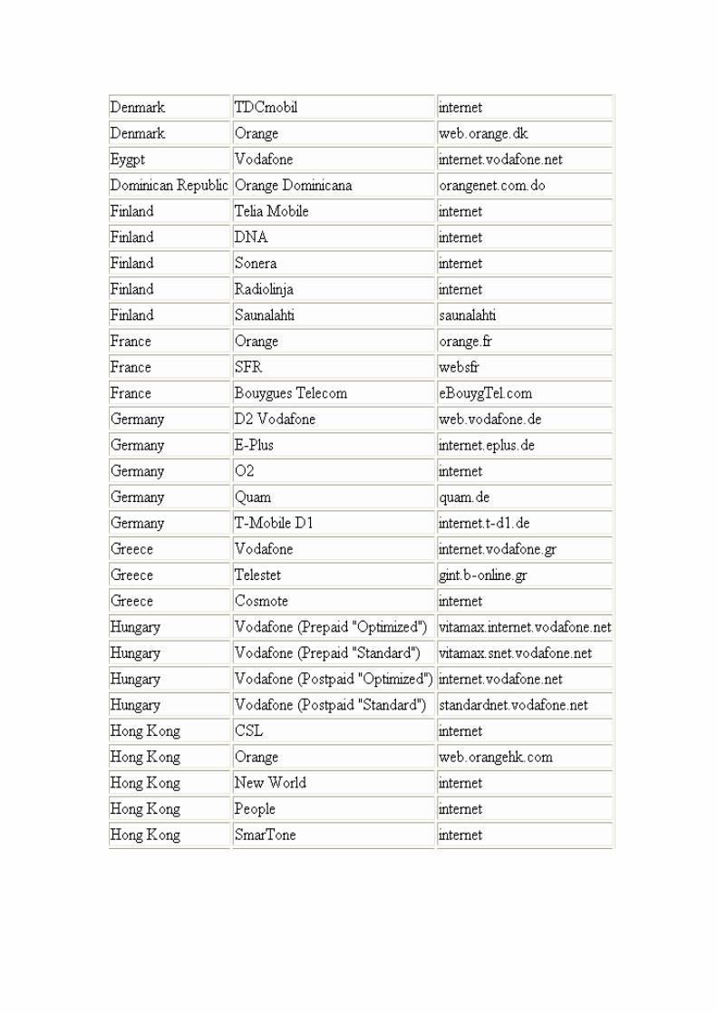
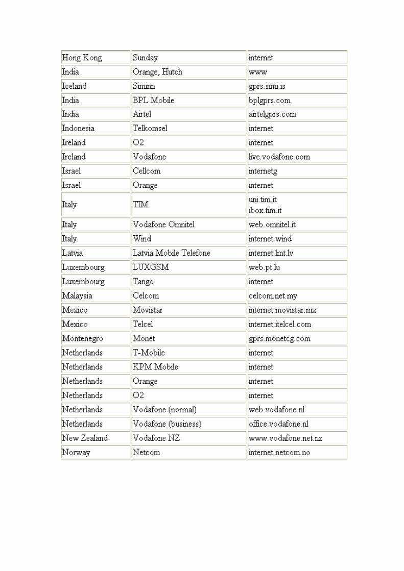
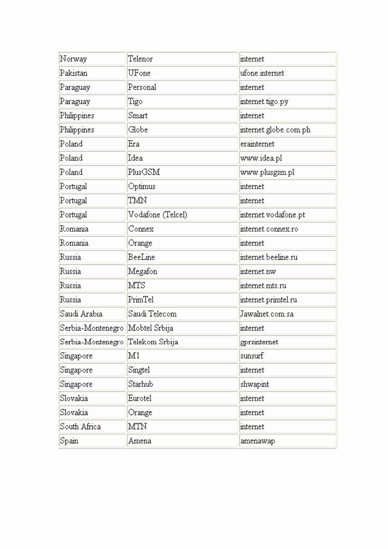
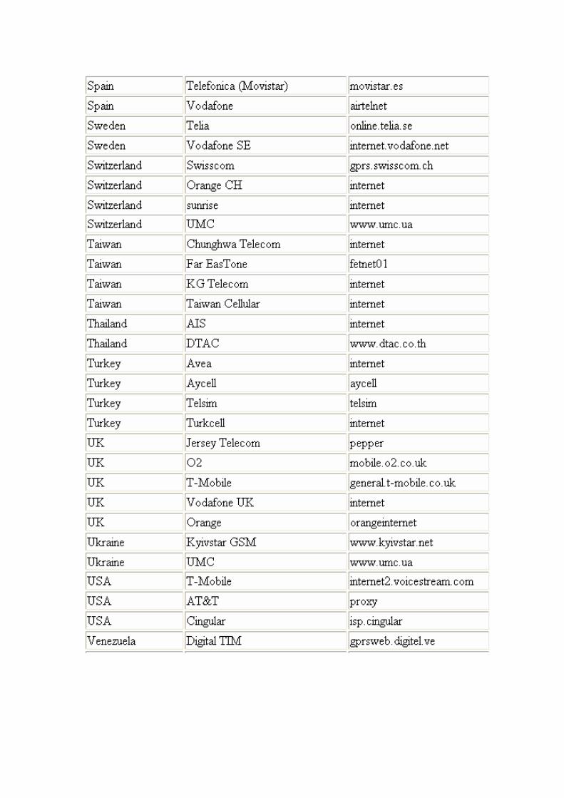
6 Worldwide APN (Access Point Name) List


![arXiv:0710.3535v1 [cs.AR] 18 Oct 2007 - Semantic Scholar · PDF file10 ETH Lab - Eurotech Group, ... the largest possible number of processing elements, ... automatic program partitioning](https://img.pdfslide.us/doc/110x75/5aa2e14a7f8b9a1f6d8dd35b/arxiv07103535v1-csar-18-oct-2007-semantic-scholar-10-eth-lab-eurotech.jpg)