Embed Size (px)
Citation preview
Slide 1Hardware Simulator Tutorial Tutorial Index
Hardware Simulator Tutorial
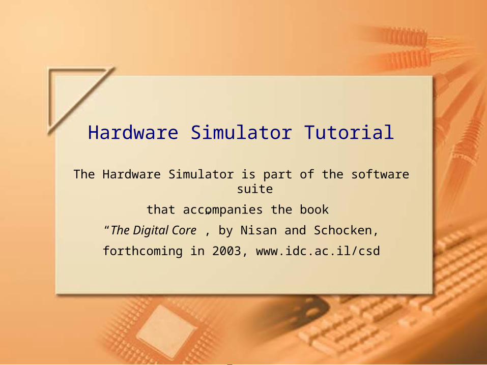
The Hardware Simulator is part of the software suite
that accompanies the book
“The Digital Core”, by Nisan and Schocken,
forthcoming in 2003, www.idc.ac.il/csd
Slide 2Hardware Simulator Tutorial Tutorial Index
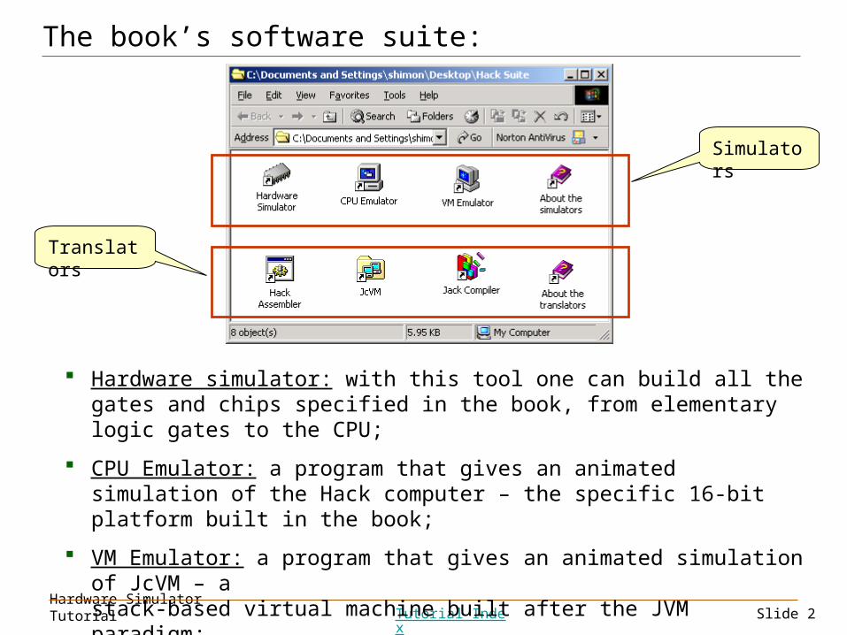
Hardware simulator: with this tool one can build all the gates and chips specified in the book, from elementary logic gates to the CPU;
CPU Emulator: a program that gives an animated simulation of the Hack computer – the specific 16-bit platform built in the book;
VM Emulator: a program that gives an animated simulation of JcVM – a stack-based virtual machine built after the JVM paradigm;
Translators: executable solutions to various programs described in the book.
Simulators
Translators
The book’s software suite:
Slide 3Hardware Simulator Tutorial Tutorial Index
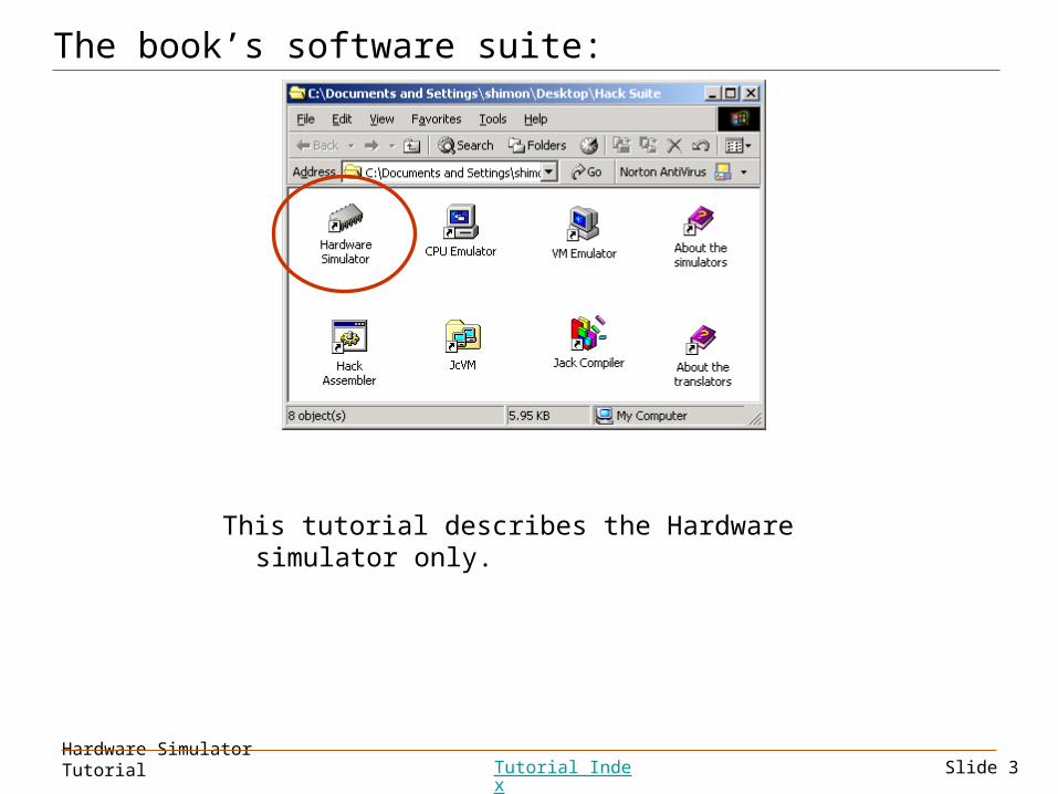
The book’s software suite:
This tutorial describes the Hardware simulator only.
Slide 4Hardware Simulator Tutorial Tutorial Index
Hardware Simulation Tutorial
Purpose: learn how to use the simulator with which all the chips specified in the book can be built
Required knowledge: Chapter 1 of the book
Recommended: Appendix A of the book.
Contents:
I. Getting started
II. Test scripts
III. Built-in chips
IV. Clocked chips
V. Debugging tools
Slide 5Hardware Simulator Tutorial Tutorial Index
Hardware Simulation Tutorial
Part I:
Getting Started
Slide 6Hardware Simulator Tutorial Tutorial Index
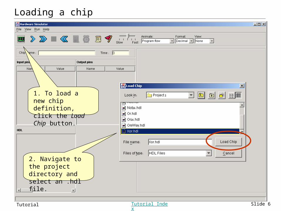
Loading a chip
1. To load a new chip definition, click the Load Chip button.
2. Navigate to the project directory and select an .hdl file.
Slide 7Hardware Simulator Tutorial Tutorial Index
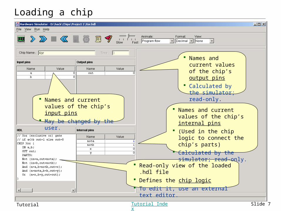
Loading a chip
Names and current values of the chip’s input pins
May be changed by the user.
Read-only view of the loaded .hdl file Defines the chip logic To edit it, use an external text editor.
Names and current values of the chip’s output pins
Calculated by the simulator; read-only.
Names and current values of the chip’s internal pins
(Used in the chip logic to connect the chip’s parts)
Calculated by the simulator; read-only.
Slide 8Hardware Simulator Tutorial Tutorial Index
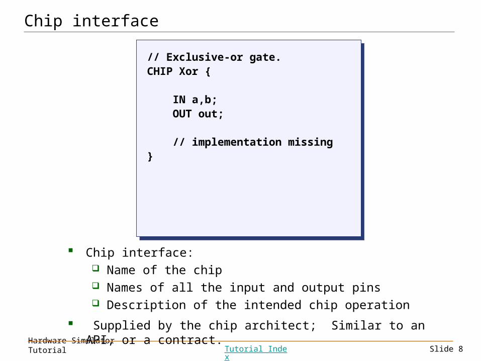
Chip interface
// Exclusive-or gate.CHIP Xor {
IN a,b; OUT out;
// implementation missing}
// Exclusive-or gate.CHIP Xor {
IN a,b; OUT out;
// implementation missing}
Chip interface: Name of the chip Names of all the input and output pins Description of the intended chip operation
Supplied by the chip architect; Similar to an API, or a contract.
Slide 9Hardware Simulator Tutorial Tutorial Index
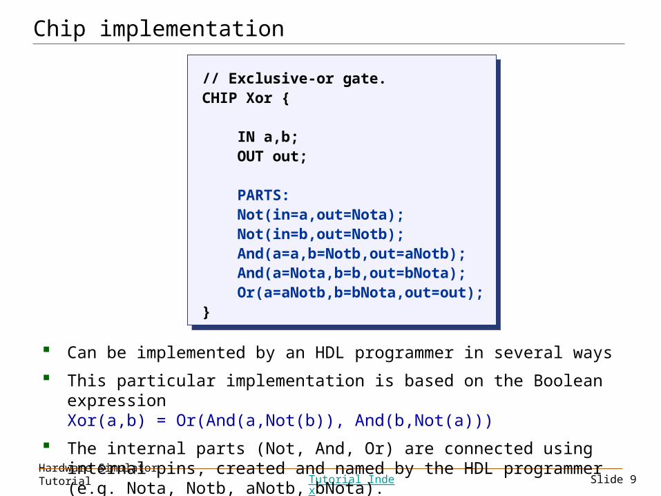
Chip implementation
// Exclusive-or gate.CHIP Xor {
IN a,b; OUT out;
PARTS: Not(in=a,out=Nota); Not(in=b,out=Notb); And(a=a,b=Notb,out=aNotb); And(a=Nota,b=b,out=bNota); Or(a=aNotb,b=bNota,out=out);}
// Exclusive-or gate.CHIP Xor {
IN a,b; OUT out;
PARTS: Not(in=a,out=Nota); Not(in=b,out=Notb); And(a=a,b=Notb,out=aNotb); And(a=Nota,b=b,out=bNota); Or(a=aNotb,b=bNota,out=out);}
Can be implemented by an HDL programmer in several ways
This particular implementation is based on the Boolean expressionXor(a,b) = Or(And(a,Not(b)), And(b,Not(a)))
The internal parts (Not, And, Or) are connected using internal pins, created and named by the HDL programmer (e.g. Nota, Notb, aNotb, bNota).
Slide 10Hardware Simulator Tutorial Tutorial Index
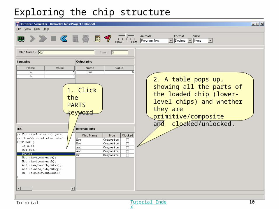
Exploring the chip structure
1. Click the PARTS keyword
2. A table pops up, showing all the parts of the loaded chip (lower-level chips) and whether they are primitive/compositeand clocked/unlocked.
Slide 11Hardware Simulator Tutorial Tutorial Index
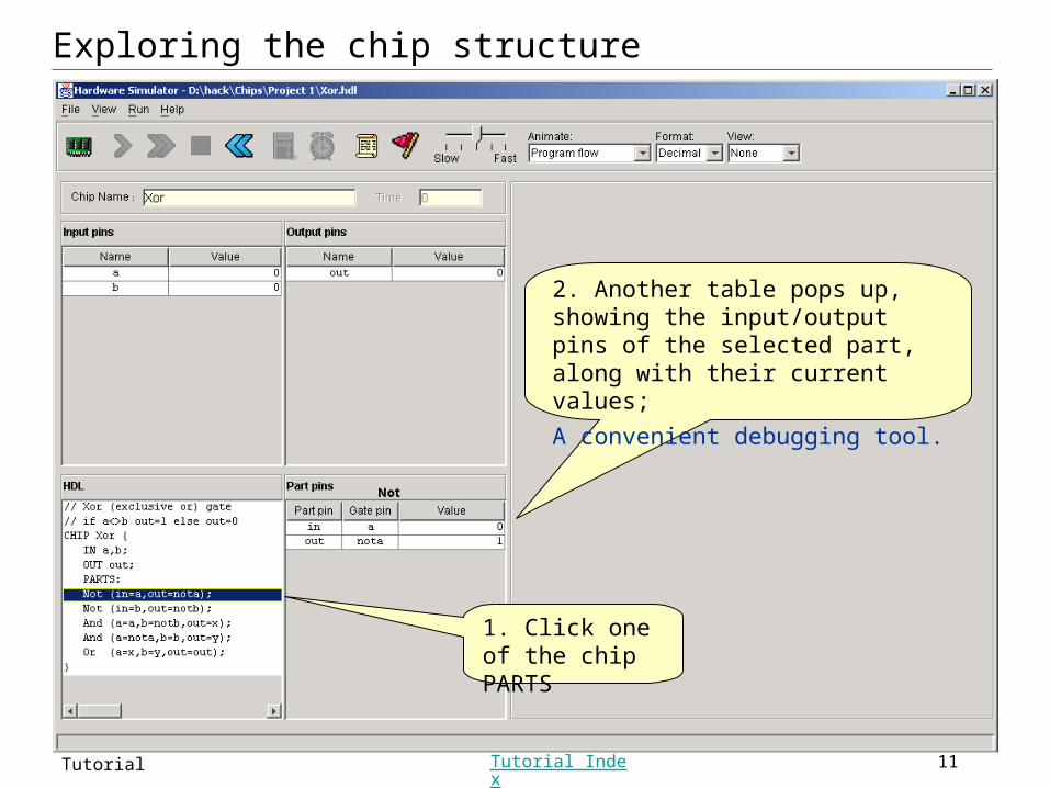
1. Click one of the chip PARTS
2. Another table pops up, showing the input/output pins of the selected part, along with their current values;
A convenient debugging tool.
Exploring the chip structure
Slide 12Hardware Simulator Tutorial Tutorial Index
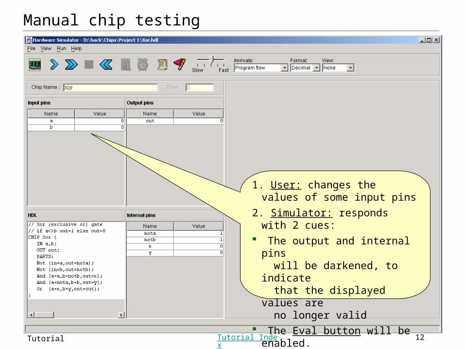
Manual chip testing
1. User: changes the values of some input pins
2. Simulator: responds with 2 cues: The output and internal pins
will be darkened, to indicate that the displayed values are no longer valid
The Eval button will be enabled.
Slide 13Hardware Simulator Tutorial Tutorial Index
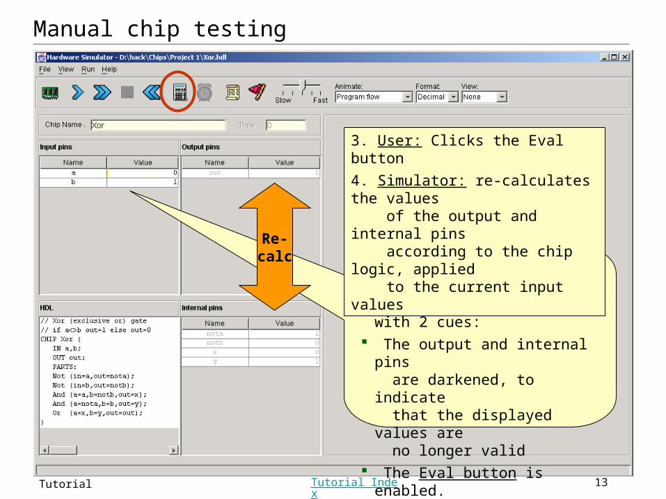
Manual chip testing
1. User: changes the values of some input pins
2. Simulator: responds with 2 cues: The output and internal pins
are darkened, to indicate that the displayed values are no longer valid
The Eval button is enabled.
Re-calc
3. User: Clicks the Eval button
4. Simulator: re-calculates the values
of the output and internal pins according to the chip logic, applied to the current input values
Slide 14Hardware Simulator Tutorial Tutorial Index
Hardware Simulation Tutorial
Part II:
Test Scripts
Slide 15Hardware Simulator Tutorial Tutorial Index
Test scripts
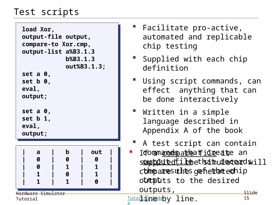
load Xor,output-file output,compare-to Xor.cmp,output-list a%B3.1.3 b%B3.1.3 out%B3.1.3;set a 0,set b 0,eval,output;
set a 0,set b 1,eval,output;
load Xor,output-file output,compare-to Xor.cmp,output-list a%B3.1.3 b%B3.1.3 out%B3.1.3;set a 0,set b 0,eval,output;
set a 0,set b 1,eval,output;
Facilitate pro-active, automated and replicable chip testing
Supplied with each chip definition
Using script commands, can effect anything that can be done interactively
Written in a simple language described in Appendix A of the book
A test script can contain commands that create an output file that records the results of the chip test
If a compare file is supplied, the simulator will compare the generated outputs to the desired outputs,line by line.
| a | b | out || 0 | 0 | 0 || 0 | 1 | 1 || 1 | 0 | 1 || 1 | 1 | 0 |
| a | b | out || 0 | 0 | 0 || 0 | 1 | 1 || 1 | 0 | 1 || 1 | 1 | 0 |
Slide 16Hardware Simulator Tutorial Tutorial Index
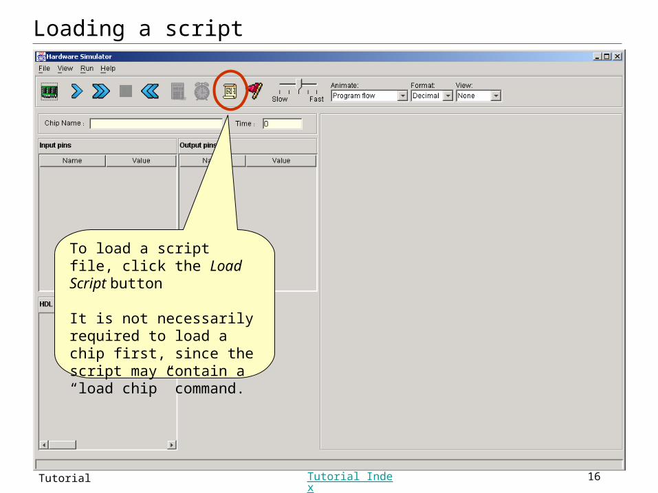
Loading a script
To load a script file, click the Load Script button
It is not necessarily required to load a chip first, since the script may contain a “load chip” command.
Slide 17Hardware Simulator Tutorial Tutorial Index
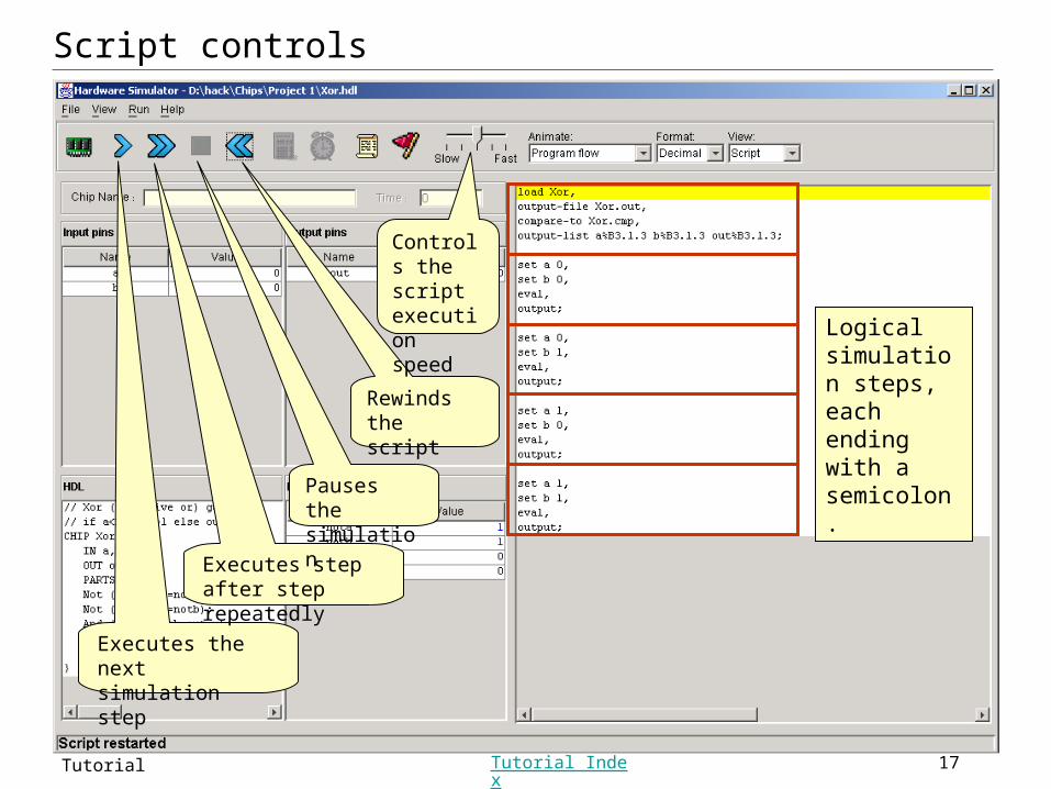
Script controls
Executes the next simulation step
Executes step after step repeatedly
Pauses the simulation
Rewindsthe script
Controls the script execution speed Logical
simulation steps, each ending with a semicolon.
Slide 18Hardware Simulator Tutorial Tutorial Index
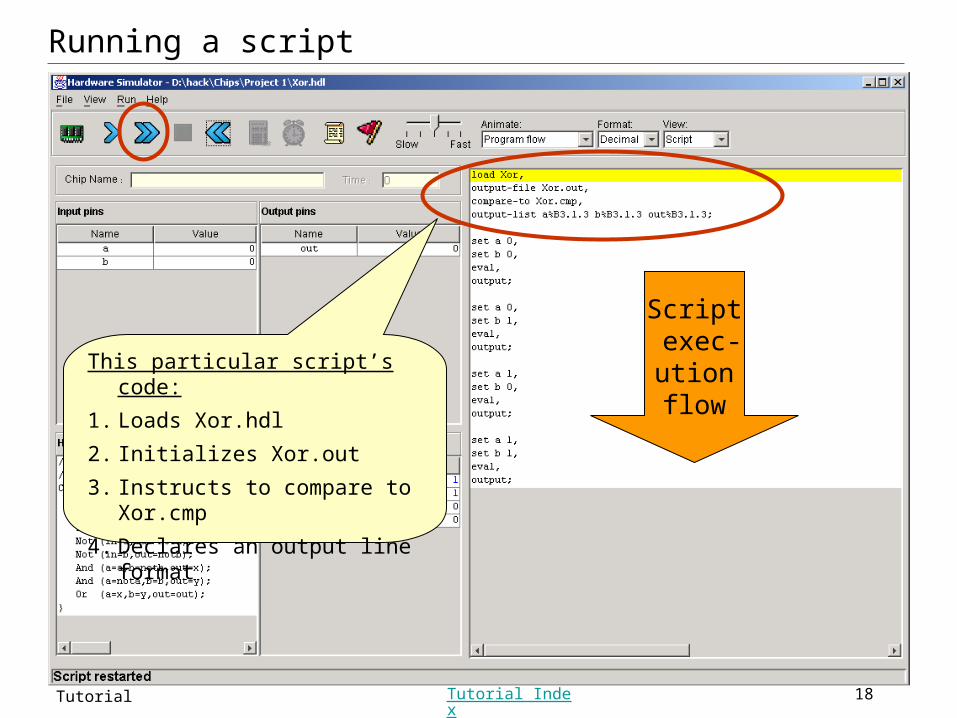
Running a script
This particular script’s code:
1. Loads Xor.hdl
2. Initializes Xor.out
3. Instructs to compare to Xor.cmp
4. Declares an output line format
Script exec-utionflow
Slide 19Hardware Simulator Tutorial Tutorial Index
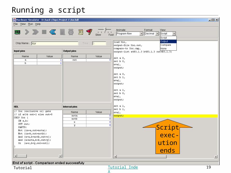
Script exec-utionends
Running a script
Slide 20Hardware Simulator Tutorial Tutorial Index
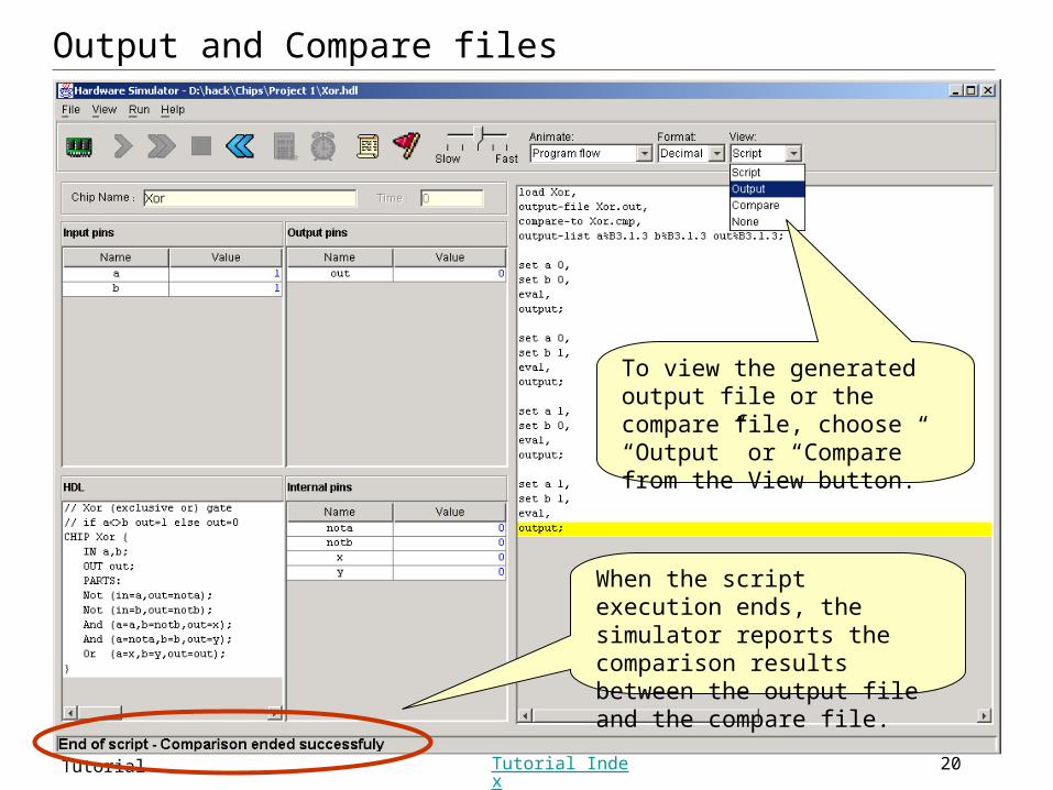
Output and Compare files
To view the generated output file or the compare file, choose “Output” or “Compare” from the View button.
When the script execution ends, the simulator reports the comparison results between the output file and the compare file.
Slide 21Hardware Simulator Tutorial Tutorial Index
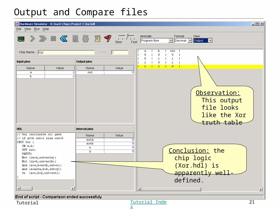
Conclusion: the chip logic (Xor.hdl) is apparently well-defined.
Output and Compare files
Observation:This output file looks like the Xor truth table
Slide 22Hardware Simulator Tutorial Tutorial Index
Hardware Simulation Tutorial
Part III:
Built-in Chips
Slide 23Hardware Simulator Tutorial Tutorial Index
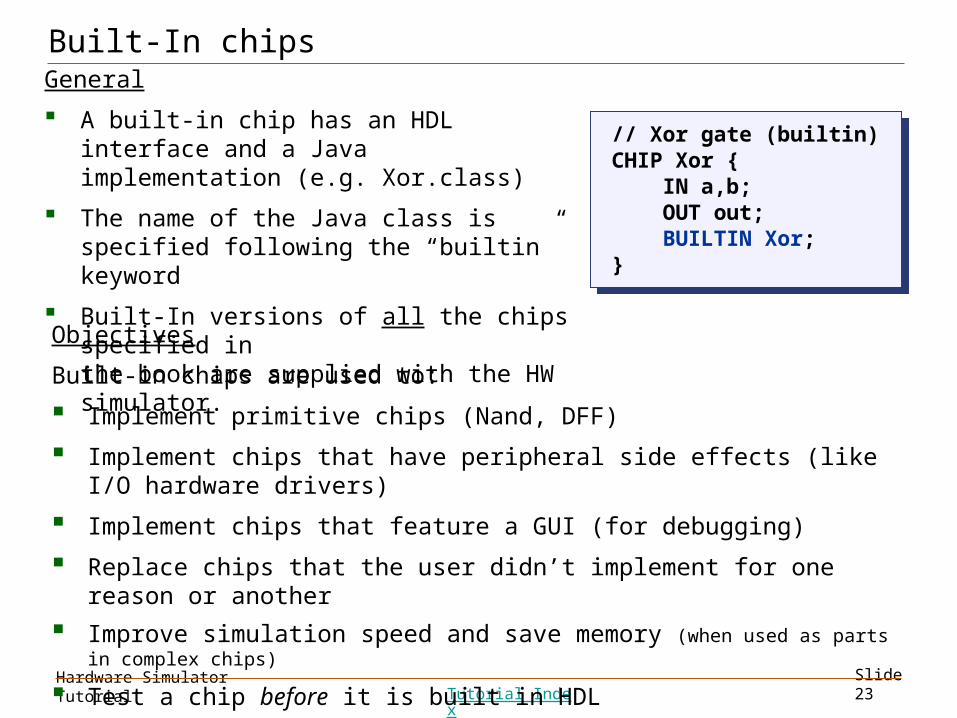
Built-In chipsGeneral
A built-in chip has an HDL interface and a Java implementation (e.g. Xor.class)
The name of the Java class is specified following the “builtin” keyword
Built-In versions of all the chips specified inthe book are supplied with the HW simulator.
// Xor gate (builtin)CHIP Xor { IN a,b; OUT out; BUILTIN Xor;}
// Xor gate (builtin)CHIP Xor { IN a,b; OUT out; BUILTIN Xor;}
Objectives
Built-in chips are used to:
Implement primitive chips (Nand, DFF)
Implement chips that have peripheral side effects (like I/O hardware drivers)
Implement chips that feature a GUI (for debugging)
Replace chips that the user didn’t implement for one reason or another
Improve simulation speed and save memory (when used as parts in complex chips)
Test a chip before it is built in HDL
Facilitate behavioral simulation of the entire hardware architecture.
Slide 24Hardware Simulator Tutorial Tutorial Index
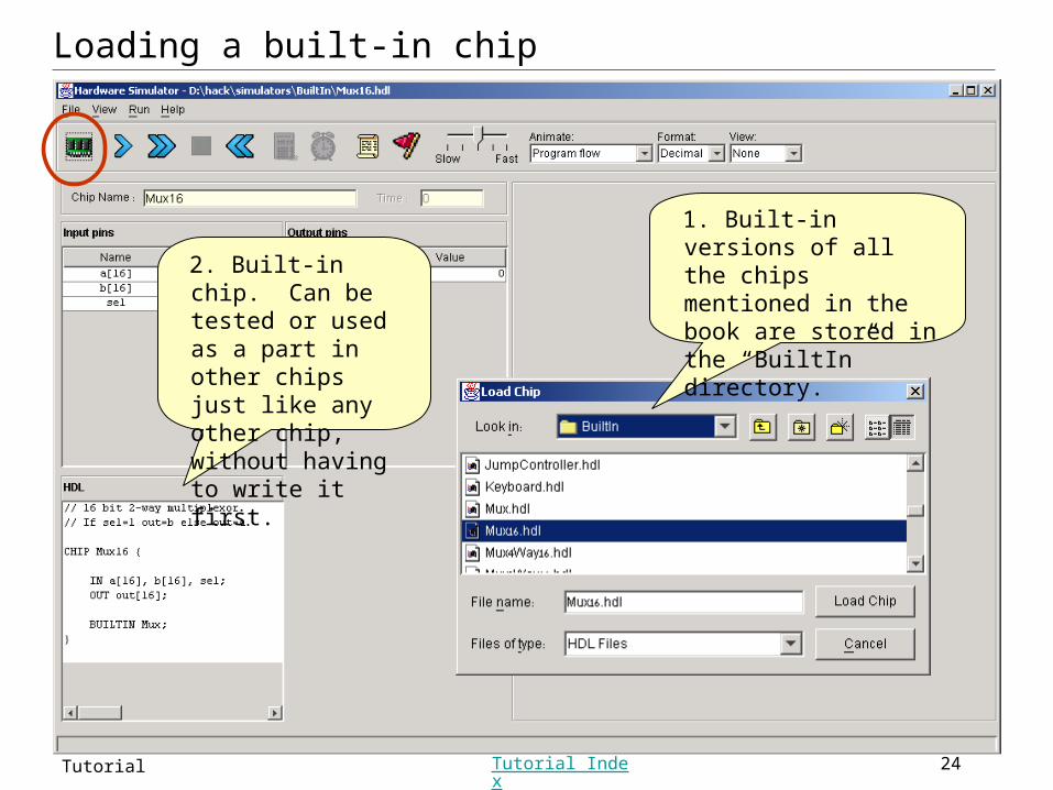
Loading a built-in chip
2. Built-in chip. Can be tested or used as a part in other chips just like any other chip, without having to write it first.
1. Built-in versions of all the chips mentioned in the book are stored in the “BuiltIn” directory.
Slide 25Hardware Simulator Tutorial Tutorial Index
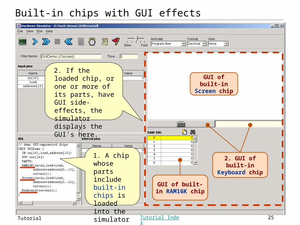
2. If the loaded chip, or one or more of its parts, have GUI side-effects, the simulator displays the GUI’s here.
Built-in chips with GUI effects
GUI of built-in Screen chip
GUI of built-in RAM16K chip
2. GUI of built-in Keyboard chip
1. A chip whose parts include built-in chips is loaded into the simulator
Slide 26Hardware Simulator Tutorial Tutorial Index
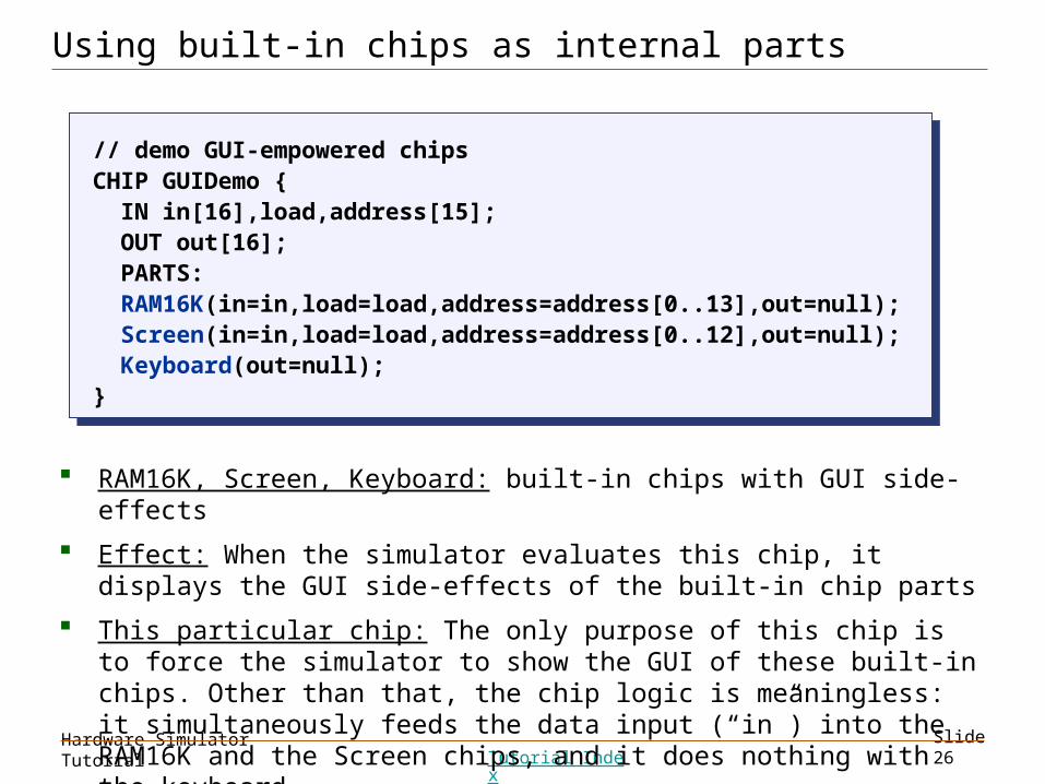
Using built-in chips as internal parts
// demo GUI-empowered chipsCHIP GUIDemo { IN in[16],load,address[15]; OUT out[16]; PARTS: RAM16K(in=in,load=load,address=address[0..13],out=null); Screen(in=in,load=load,address=address[0..12],out=null); Keyboard(out=null);}
// demo GUI-empowered chipsCHIP GUIDemo { IN in[16],load,address[15]; OUT out[16]; PARTS: RAM16K(in=in,load=load,address=address[0..13],out=null); Screen(in=in,load=load,address=address[0..12],out=null); Keyboard(out=null);}
RAM16K, Screen, Keyboard: built-in chips with GUI side-effects
Effect: When the simulator evaluates this chip, it displays the GUI side-effects of the built-in chip parts
This particular chip: The only purpose of this chip is to force the simulator to show the GUI of these built-in chips. Other than that, the chip logic is meaningless: it simultaneously feeds the data input (“in”) into the RAM16K and the Screen chips, and it does nothing with the keyboard.
Slide 27Hardware Simulator Tutorial Tutorial Index
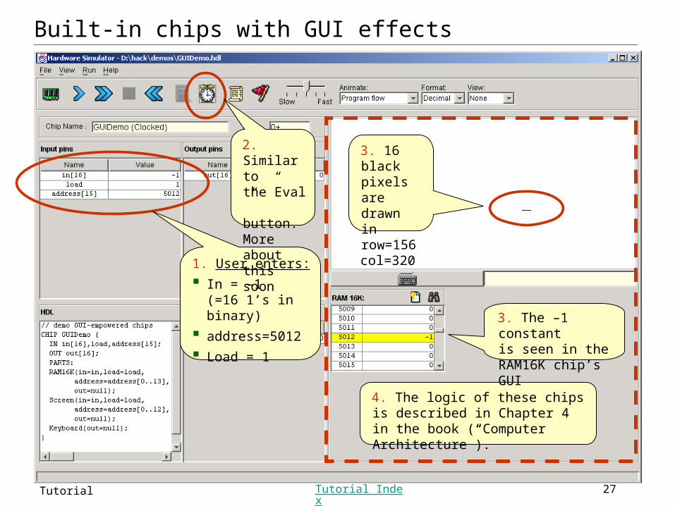
4. The logic of these chips is described in Chapter 4 in the book (“Computer Architecture”).
3. 16 black pixels are drawn in row=156col=320
3. The –1 constantis seen in the RAM16K chip’s GUI
1. User enters:
In = –1(=16 1’s in binary)
address=5012
Load = 1
2. Similar to the”Eval” button. More about this soon
Built-in chips with GUI effects
Slide 28Hardware Simulator Tutorial Tutorial Index
Hardware Simulation Tutorial
Part IV:
Clocked Chips
(Sequential Logic)
Slide 29Hardware Simulator Tutorial Tutorial Index
Clocked chips
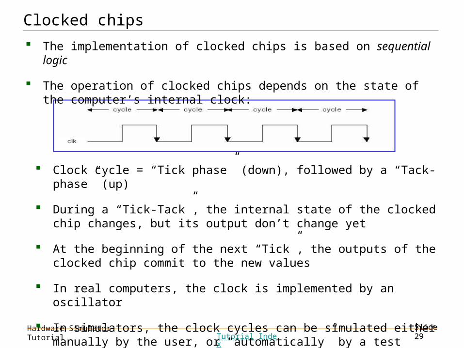
The implementation of clocked chips is based on sequential logic
The operation of clocked chips depends on the state of the computer’s internal clock:
Clock cycle = “Tick phase” (down), followed by a “Tack-phase” (up)
During a “Tick-Tack”, the internal state of the clocked chip changes, but its output don’t change yet
At the beginning of the next “Tick”, the outputs of the clocked chip commit to the new values
In real computers, the clock is implemented by an oscillator
In simulators, the clock cycles can be simulated either manually by the user, or “automatically” by a test script.
Slide 30Hardware Simulator Tutorial Tutorial Index
The D-Flip-Flop chip (DFF)
// D-Flip Flop.
CHIP DFF {
IN in; OUT out;
BUILTIN DFF;
CLOCKED in,out;}
// D-Flip Flop.
CHIP DFF {
IN in; OUT out;
BUILTIN DFF;
CLOCKED in,out;}
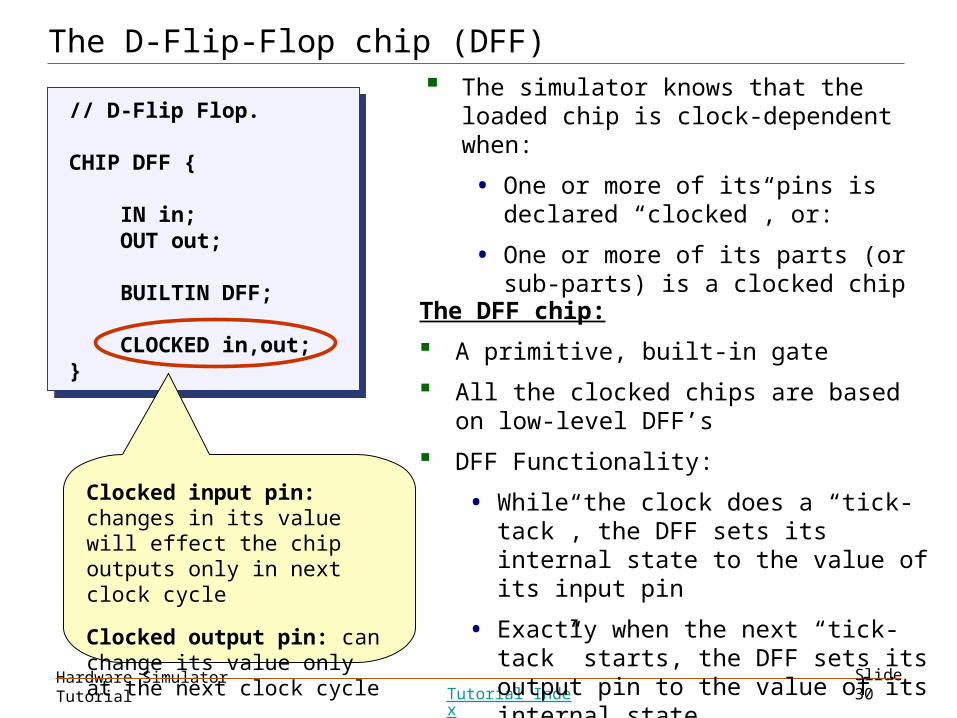
The DFF chip:
A primitive, built-in gate
All the clocked chips are based on low-level DFF’s
DFF Functionality:
• While the clock does a “tick-tack”, the DFF sets its internal state to the value of its input pin
• Exactly when the next “tick-tack” starts, the DFF sets its output pin to the value of its internal state.
Clocked input pin: changes in its value will effect the chip outputs only in next clock cycle
Clocked output pin: can change its value only at the next clock cycle
The simulator knows that the loaded chip is clock-dependent when:
• One or more of its pins is declared “clocked”, or:
• One or more of its parts (or sub-parts) is a clocked chip
Slide 31Hardware Simulator Tutorial Tutorial Index
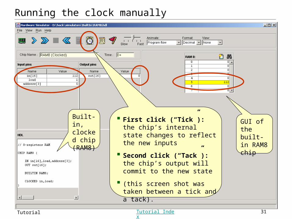
Running the clock manually
First click (“Tick”): the chip’s internal state changes to reflect the new inputs
Second click (“Tack”): the chip’s output will commit to the new state
(this screen shot was taken between a tick and a tack).
Built-in, clocked chip (RAM8)
GUI of the built-in RAM8 chip
Slide 32Hardware Simulator Tutorial Tutorial Index
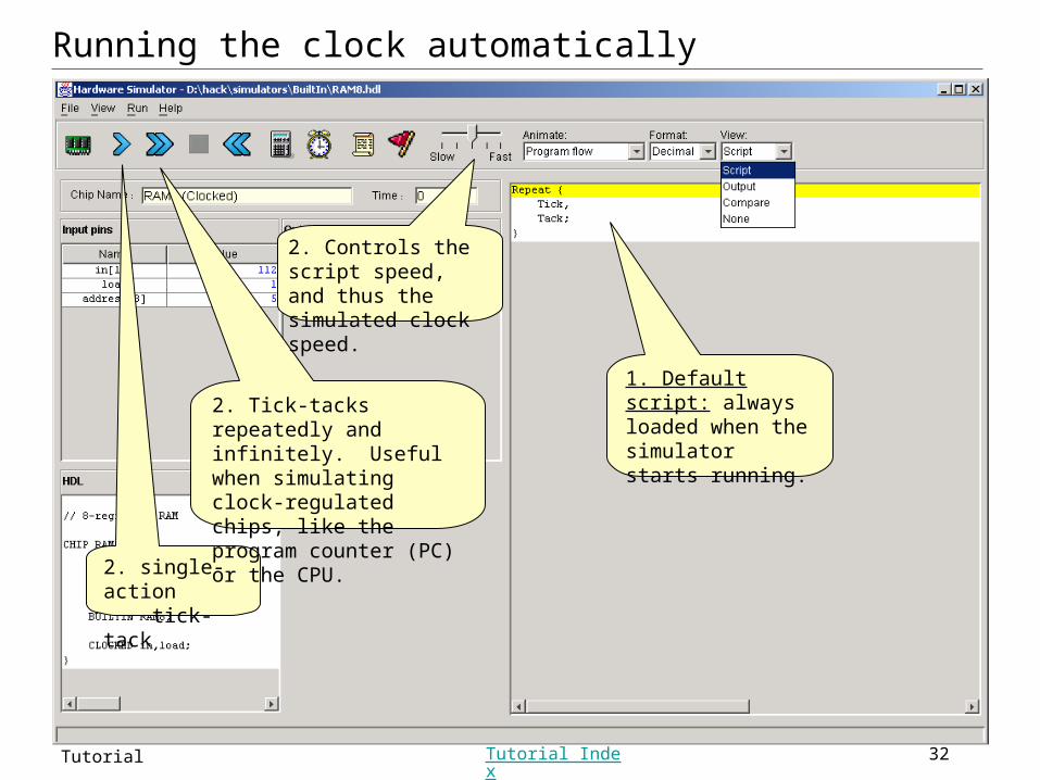
Running the clock automatically
2. single-action tick-tack
2. Tick-tacks repeatedly and infinitely. Useful when simulating clock-regulated chips, like the program counter (PC) or the CPU.
2. Controls the script speed, and thus the simulated clock speed.
1. Default script: always loaded when the simulator starts running.
Slide 33Hardware Simulator Tutorial Tutorial Index
Hardware Simulation Tutorial
Part V:
Debugging tools
Slide 34Hardware Simulator Tutorial Tutorial Index
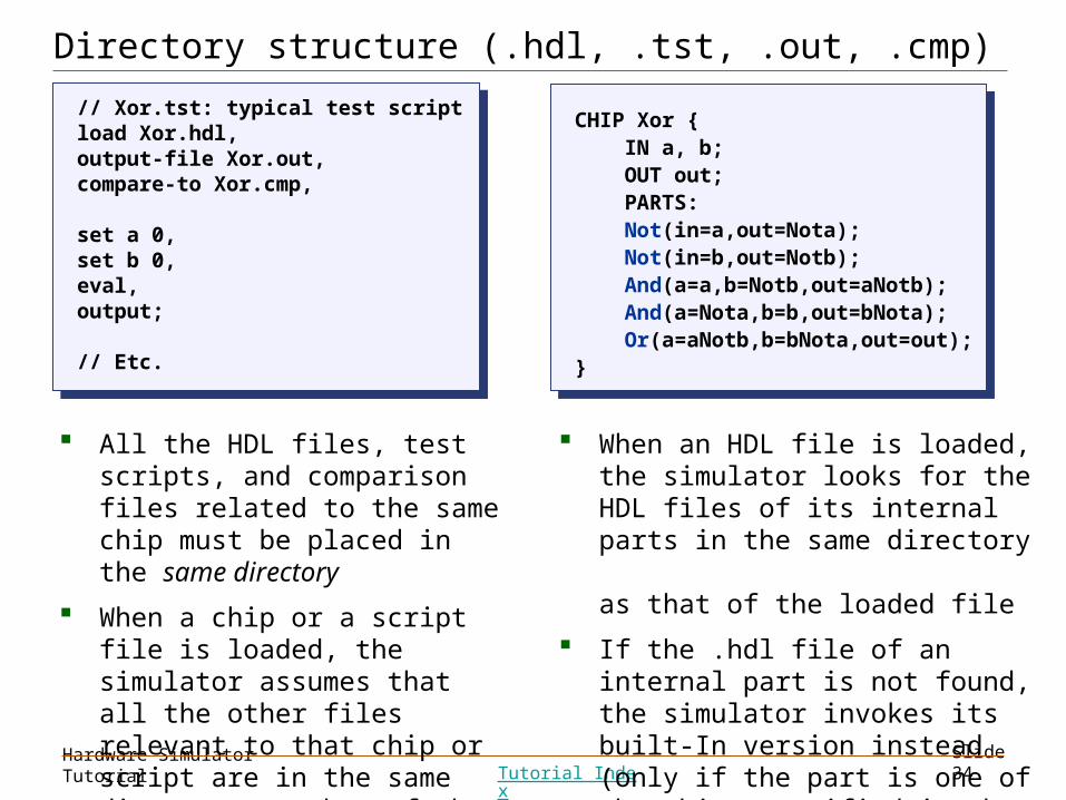
Directory structure (.hdl, .tst, .out, .cmp)
// Xor.tst: typical test script load Xor.hdl,output-file Xor.out,compare-to Xor.cmp,
set a 0,set b 0,eval,output;
// Etc.
// Xor.tst: typical test script load Xor.hdl,output-file Xor.out,compare-to Xor.cmp,
set a 0,set b 0,eval,output;
// Etc.
All the HDL files, test scripts, and comparison files related to the same chip must be placed in the same directory
When a chip or a script file is loaded, the simulator assumes that all the other files relevant to that chip or script are in the same directory as that of the loaded file.
CHIP Xor { IN a, b; OUT out; PARTS: Not(in=a,out=Nota); Not(in=b,out=Notb); And(a=a,b=Notb,out=aNotb); And(a=Nota,b=b,out=bNota); Or(a=aNotb,b=bNota,out=out);}
CHIP Xor { IN a, b; OUT out; PARTS: Not(in=a,out=Nota); Not(in=b,out=Notb); And(a=a,b=Notb,out=aNotb); And(a=Nota,b=b,out=bNota); Or(a=aNotb,b=bNota,out=out);}
When an HDL file is loaded, the simulator looks for the HDL files of its internal parts in the same directory as that of the loaded file
If the .hdl file of an internal part is not found, the simulator invokes its built-In version instead (only if the part is one of the chips specified in the book).
Slide 35Hardware Simulator Tutorial Tutorial Index
System variables
The simulator recognizes and maintains the values of the following variables:
Time: the number of time-units (clock-cycles) that elapsed since the script started running is stored in the variable time
Pins: the values of all the input, output, and internal pins of the simulated chip are accessible as variables, using their HDL names, e.g. a,b,out, Nota, Notb, etc. in the case of the Xor implementation presented earlier in this tutorial
GUI elements: the values stored in the contents of built-in chips with GUI can be accessed via variables with proper names. For example, the value of register 3 of the RAM8 chip can be accessed via RAM8[3].
These variables can be used in scripts and breakpoints, for debugging.
Slide 36Hardware Simulator Tutorial Tutorial Index
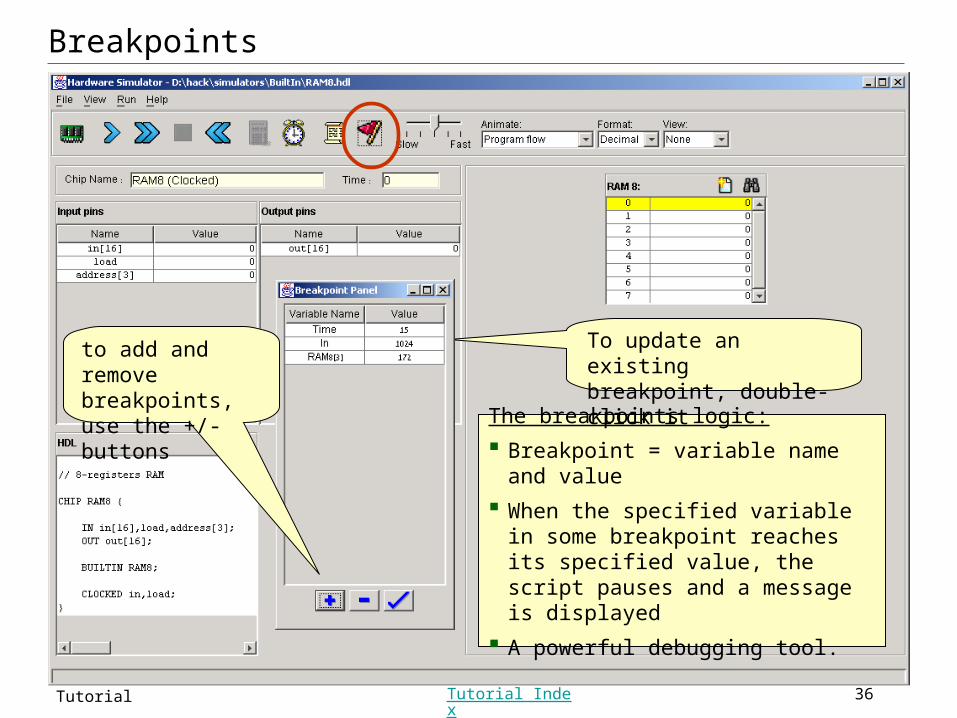
Breakpoints
The breakpoints logic:
Breakpoint = variable name and value
When the specified variable in some breakpoint reaches its specified value, the script pauses and a message is displayed
A powerful debugging tool.
To update an existing breakpoint, double-click it
to add and remove breakpoints,use the +/- buttons
Slide 37Hardware Simulator Tutorial Tutorial Index
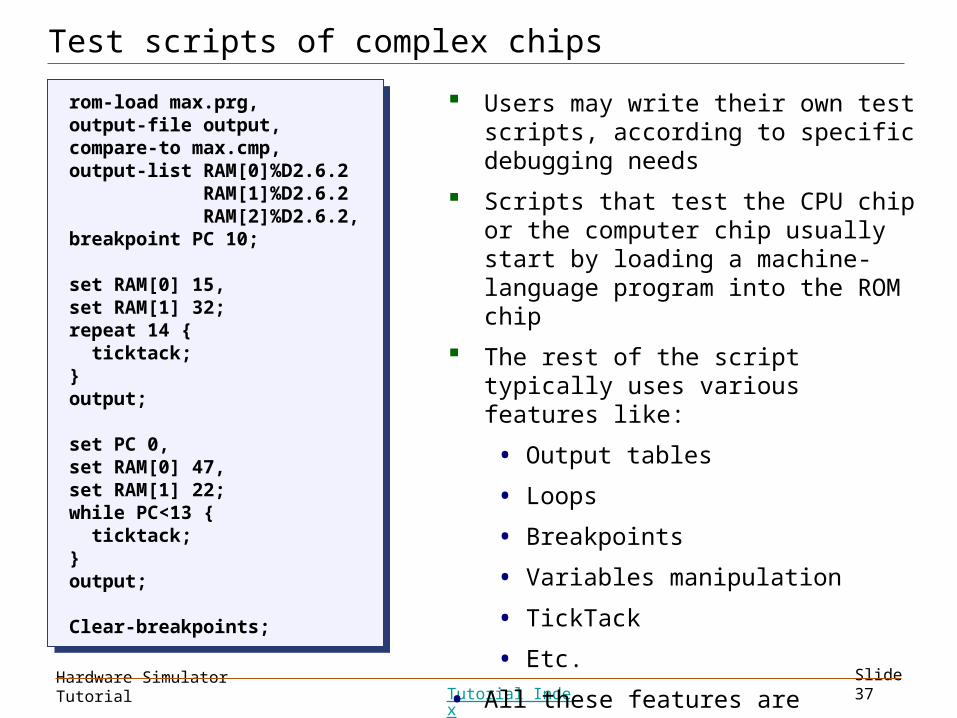
Test scripts of complex chips
rom-load max.prg,output-file output,compare-to max.cmp,output-list RAM[0]%D2.6.2 RAM[1]%D2.6.2 RAM[2]%D2.6.2,breakpoint PC 10;
set RAM[0] 15,set RAM[1] 32;repeat 14 { ticktack;}output;
set PC 0,set RAM[0] 47,set RAM[1] 22;while PC<13 { ticktack;}output;
Clear-breakpoints;
rom-load max.prg,output-file output,compare-to max.cmp,output-list RAM[0]%D2.6.2 RAM[1]%D2.6.2 RAM[2]%D2.6.2,breakpoint PC 10;
set RAM[0] 15,set RAM[1] 32;repeat 14 { ticktack;}output;
set PC 0,set RAM[0] 47,set RAM[1] 22;while PC<13 { ticktack;}output;
Clear-breakpoints;
Users may write their own test scripts, according to specific debugging needs
Scripts that test the CPU chip or the computer chip usually start by loading a machine-language program into the ROM chip
The rest of the script typically uses various features like:
• Output tables
• Loops
• Breakpoints
• Variables manipulation
• TickTack
• Etc.
• All these features are described in Appendix A of the book.
Slide 38Hardware Simulator Tutorial Tutorial Index
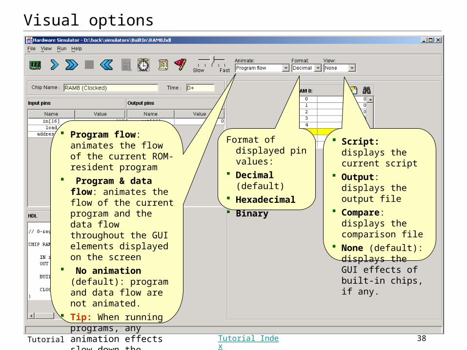
Visual options
Script: displays the current script
Output: displays the output file
Compare: displays the comparison file
None (default): displays the GUI effects of built-in chips, if any.
Program flow: animates the flow of the current ROM-resident program
Program & data flow: animates the flow of the current program and the data flow throughout the GUI elements displayed on the screen
No animation (default): program and data flow are not animated.
Tip: When running programs, any animation effects slow down the simulation considerably.
Format of displayed pin values:
Decimal (default) Hexadecimal Binary
Slide 39Hardware Simulator Tutorial Tutorial Index
Postscript: H.D. Thoreau about chips, bugs, and close observation:
I was surprised to find that the chips were covered with such combatants, that it was not a duellum, but a bellum, a war between two races of ants, the red always pitted against the black, and frequently two red ones to one black. The legions of these Myrmidons covered all the hills and vales in my wood-yard, and the ground was already strewn with the dead and dying, both red and black. It was the only battle which I have ever witnessed, the only battlefield I ever trod while the battle was raging; internecine war; the red republicans on the one hand, and the black imperialists on the other. On every side they were engaged in deadly combat, yet without any noise that I could hear, and human soldiers never fought so resolutely.... The more you think of it, the less the difference. And certainly there is not the fight recorded in Concord history, at least, if in the history of America, that will bear a moment’s comparison with this, whether for the numbers engaged in it, or for the patriotism and heroism displayed.
From “Brute Neighbors,” Walden (1854).