Embed Size (px)
Citation preview

Online Simulator
https://www.hisaka.co.jp/simulator_english/
Plate Heat ExchangerHISAKA Web-Simulator (HWS)This is the first plate heat exchanger design website opened on the Internet in the world.Access the URL below and click on the Web-Simulator icon. You can simulate the plate heat exchanger perfect for your needs, any time of the day, from anywhere.
If necessary to help for selection of Plate Heat Exchanger, please fax the form below to us.
8. Special notes Plate materials, gasket materials, etc.
Quotation Request by FAX
1. Heat duty
2. Fluid name
3. Inlet temperature
4. Outlet temperature
5. Flow rate
6. Pressure loss
7. Maximum working pressure
°C
°C
m3/h
MPa or less
MPaG
°C
°C
m3/h
MPa or less
MPaG
kW
Cold sideHot side
21.11. YMZNHE-CE000229
Osaka - FAX: +81-6-6363-0161
HISAKA provides thermal solutions based on our technologies of the plate heat exchanger toall HISAKA fans in the world.
HISAKA WORKS, LTD., Heat Exchanger Division is both ISO9001 and ISO14001 certified.HISAKA WORKS, LTD., Konoike Plant is ISO45001 certified.
Sales Department
Heat Exchanger Division
Osaka: Sonezaki, Kita-ku, Osaka-shi, Osaka, 530-0057, Japan TEL: +81-6-6363-0020 FAX: +81-6-6363-0161Tokyo: Kyobashi, Chuo-ku, Tokyo, 104-0031, Japan TEL: +81-03-5250-0760 FAX: +81-3-3562-2759Sapporo: 6-1-20, Higashisapporo 3jo, Shiroishi-ku, Sapporo City, Hokkaido 003-0003 Japan TEL: +81-11-868-8010 FAX: +81-11-868-8011Nagoya: Sakae, Naka-ku, Nagoya-shi, Aichi, 460-0008, Japan TEL: +81-52-217-2491 FAX: +81-52-217-2494Onomichi : 14-15, Nishigosyo-cho, Onomichi City, Hiroshima 722-0037 Japan Tel: +81-848-21-2750 Fax: +81-848-21-2751Customer 2-1-48, Higashi-konoike-cho,Service: Higashi-osaka-shi,Osaka, 578-0973, Japan TEL: +81-72-966-9601 FAX: +81-72-966-8923 URLhttps://www.hisaka.co.jp/english/phe/
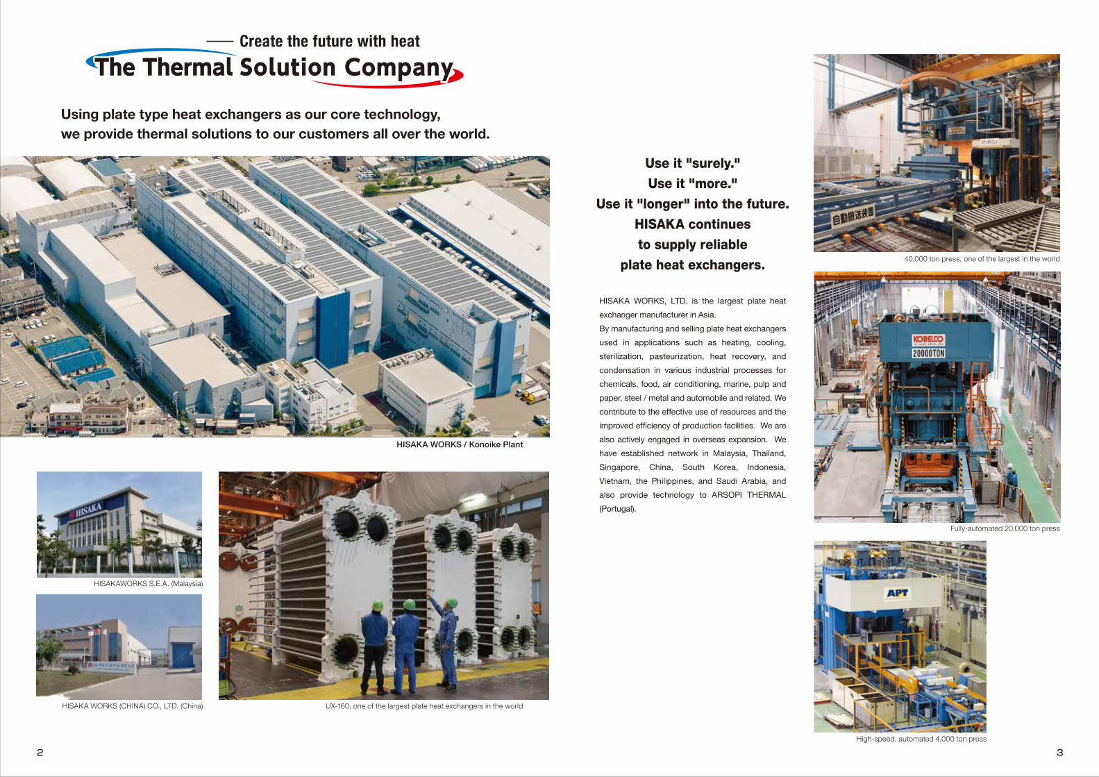
HISAKA WORKS / Konoike Plant
UX-160, one of the largest plate heat exchangers in the world
High-speed, automated 4,000 ton press
Fully-automated 20,000 ton press
40,000 ton press, one of the largest in the world
HISAKAWORKS S.E.A. (Malaysia)
HISAKA WORKS (CHINA) CO., LTD. (China)
Using plate type heat exchangers as our core technology, we provide thermal solutions to our customers all over the world.
Use it "surely."Use it "more."
Use it "longer" into the future.HISAKA continuesto supply reliable
plate heat exchangers.
HISAKA WORKS, LTD. is the largest plate heat exchanger manufacturer in Asia.By manufacturing and selling plate heat exchangers used in applications such as heating, cooling, sterilization, pasteurization, heat recovery, and condensation in various industrial processes for chemicals, food, air conditioning, marine, pulp and paper, steel / metal and automobile and related. We contribute to the effective use of resources and the improved efficiency of production facilities. We are also actively engaged in overseas expansion. We have established network in Malaysia, Thailand, Singapore, China, South Korea, Indonesia, Vietnam, the Philippines, and Saudi Arabia, and also provide technology to ARSOPI THERMAL (Portugal).
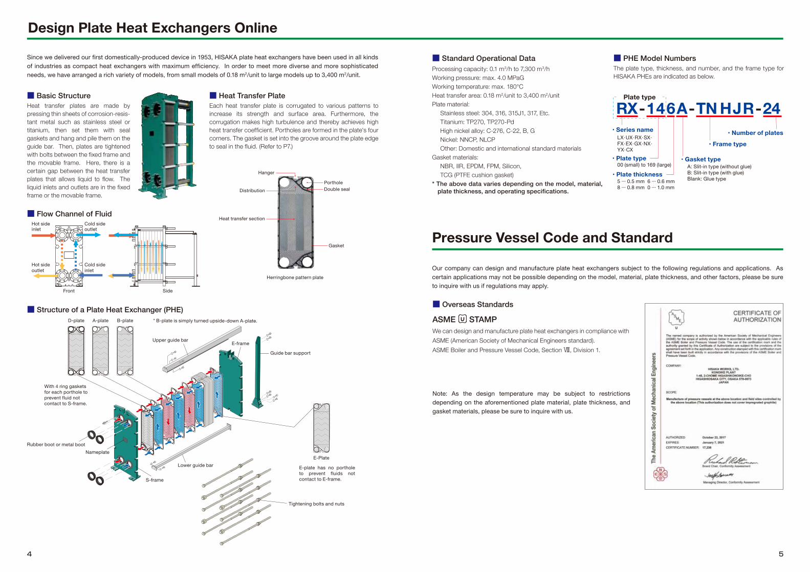
Hanger
Heat transfer section
D-plate A-plate B-plate
Tightening bolts and nuts
Gasket
PortholeDouble sealDistribution
Herringbone pattern plate
Pressure Vessel Code and Standard
Our company can design and manufacture plate heat exchangers subject to the following regulations and applications. As certain applications may not be possible depending on the model, material, plate thickness, and other factors, please be sure to inquire with us if regulations may apply.
■ Standard Operational DataProcessing capacity: 0.1 m3/h to 7,300 m3/hWorking pressure: max. 4.0 MPaGWorking temperature: max. 180°CHeat transfer area: 0.18 m2/unit to 3,400 m2/unitPlate material:
Stainless steel: 304, 316, 315J1, 317, Etc.Titanium: TP270, TP270-PdHigh nickel alloy: C-276, C-22, B, GNickel: NNCP, NLCPOther: Domestic and international standard materials
Gasket materials:NBR, IIR, EPDM, FPM, Silicon,TCG (PTFE cushion gasket)
* The above data varies depending on the model, material, plate thickness, and operating specifications.
RX-146A- -24• Number of plates
• Plate thickness
• Gasket type
• Frame type
Plate type
TN HJR
00 (small) to 169 (large)
5 ... 0.5 mm 6 ... 0.6 mm8 ... 0.8 mm 0 ... 1.0 mm
LX·UX·RX·SX·FX·EX·GX·NX·YX·CX
• Series name
• Plate typeA: Slit-in type (without glue)B: Slit-in type (with glue)Blank: Glue type
■ PHE Model NumbersThe plate type, thickness, and number, and the frame type for HISAKA PHEs are indicated as below.
Since we delivered our first domestically-produced device in 1953, HISAKA plate heat exchangers have been used in all kinds of industries as compact heat exchangers with maximum efficiency. In order to meet more diverse and more sophisticated needs, we have arranged a rich variety of models, from small models of 0.18 m2/unit to large models up to 3,400 m2/unit.
Nameplate
* B-plate is simply turned upside-down A-plate.
Rubber boot or metal boot
■ Flow Channel of Fluid
■ Structure of a Plate Heat Exchanger (PHE)
■ Basic StructureHeat transfer plates are made by pressing thin sheets of corrosion-resis-tant metal such as stainless steel or titanium, then set them with seal gaskets and hang and pile them on the guide bar. Then, plates are tightened with bolts between the fixed frame and the movable frame. Here, there is a certain gap between the heat transfer plates that allows liquid to flow. The liquid inlets and outlets are in the fixed frame or the movable frame.
■ Heat Transfer PlateEach heat transfer plate is corrugated to various patterns to increase its strength and surface area. Furthermore, the corrugation makes high turbulence and thereby achieves high heat transfer coefficient. Portholes are formed in the plate's four corners. The gasket is set into the groove around the plate edge to seal in the fluid. (Refer to P7.)
Design Plate Heat Exchangers Online
Hot sideinlet
Cold side outlet
Hot side outlet
Cold side inlet
Front Side
With 4 ring gaskets for each porthole to prevent fluid not contact to S-frame.
E-plate has no porthole to prevent fluids not contact to E-frame.
Upper guide bar
Guide bar support
E-frame
S-frame
Lower guide barE-Plate
■ Overseas Standards
ASME STAMPWe can design and manufacture plate heat exchangers in compliance with ASME (American Society of Mechanical Engineers standard).ASME Boiler and Pressure Vessel Code, Section Ⅷ, Division 1.
Note: As the design temperature may be subject to restrictions depending on the aforementioned plate material, plate thickness, and gasket materials, please be sure to inquire with us.
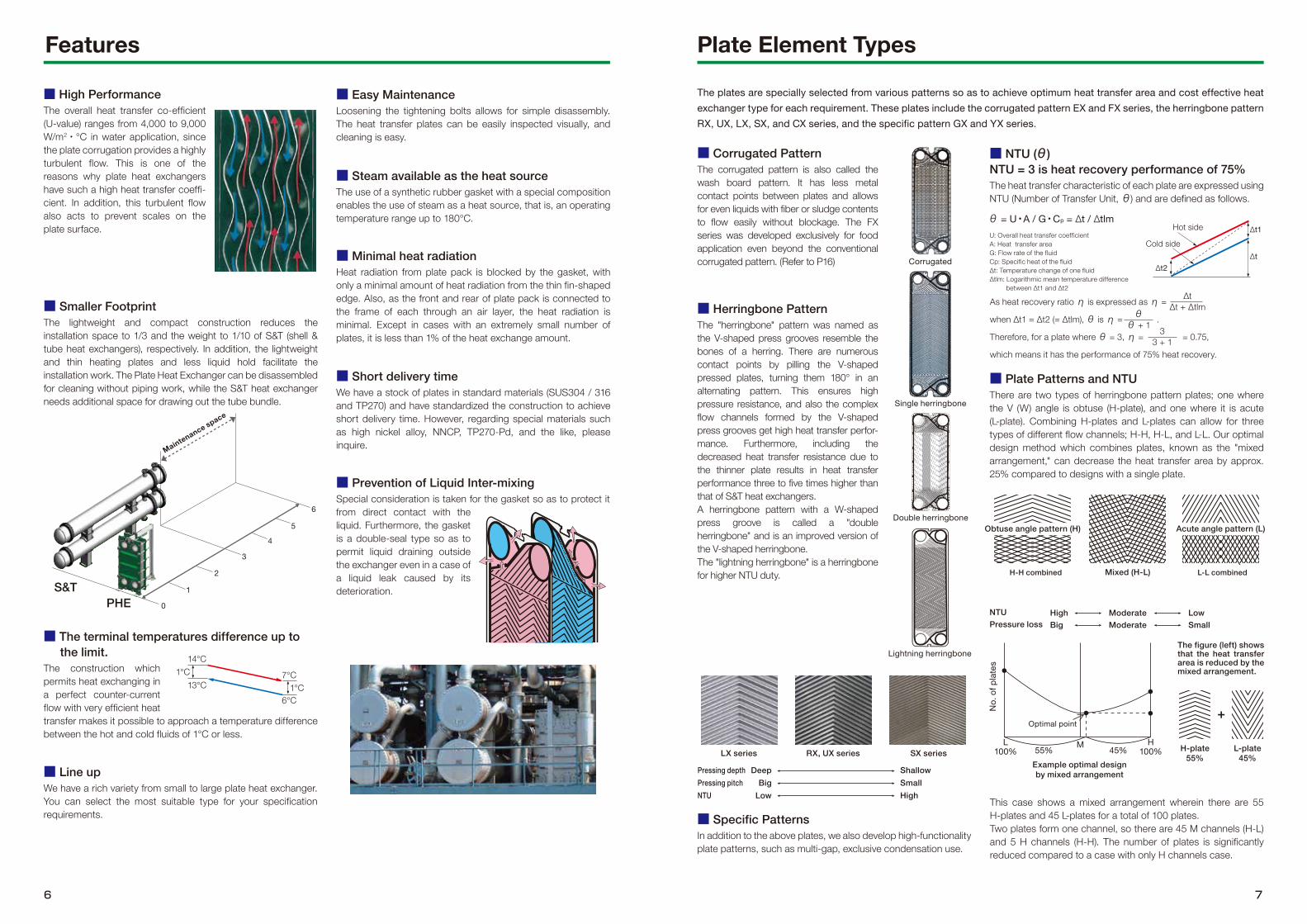
Plate Element Types
■ Corrugated PatternThe corrugated pattern is also called the wash board pattern. It has less metal contact points between plates and allows for even liquids with fiber or sludge contents to flow easily without blockage. The FX series was developed exclusively for food application even beyond the conventional corrugated pattern. (Refer to P16)
■ Herringbone PatternThe "herringbone" pattern was named as the V-shaped press grooves resemble the bones of a herring. There are numerous contact points by pilling the V-shaped pressed plates, turning them 180° in an alternating pattern. This ensures high pressure resistance, and also the complex flow channels formed by the V-shaped press grooves get high heat transfer perfor-mance. Furthermore, including the decreased heat transfer resistance due to the thinner plate results in heat transfer performance three to five times higher than that of S&T heat exchangers.A herringbone pattern with a W-shaped press groove is called a "double herringbone" and is an improved version of the V-shaped herringbone.The "lightning herringbone" is a herringbone for higher NTU duty.
■ Specific PatternsIn addition to the above plates, we also develop high-functionality plate patterns, such as multi-gap, exclusive condensation use.
The plates are specially selected from various patterns so as to achieve optimum heat transfer area and cost effective heat exchanger type for each requirement. These plates include the corrugated pattern EX and FX series, the herringbone pattern RX, UX, LX, SX, and CX series, and the specific pattern GX and YX series.
As heat recovery ratio η is expressed as η =
when Δt1 = Δt2 (= Δtlm), θ is η = .
Therefore, for a plate where θ = 3, η = = 0.75,
which means it has the performance of 75% heat recovery.
Single herringbone
Corrugated
SX seriesRX, UX seriesLX series
This case shows a mixed arrangement wherein there are 55 H-plates and 45 L-plates for a total of 100 plates.Two plates form one channel, so there are 45 M channels (H-L) and 5 H channels (H-H). The number of plates is significantly reduced compared to a case with only H channels case.
Mixed (H-L) L-L combinedH-H combined
L-plate45%
H-plate55%
+Optimal point
M H100%45%
L100% 55%
Example optimal designby mixed arrangement
The figure (left) shows that the heat transfer area is reduced by the mixed arrangement.
Double herringbone
Lightning herringbone
Features
■ High PerformanceThe overall heat transfer co-efficient (U-value) ranges from 4,000 to 9,000 W/m2 · °C in water application, since the plate corrugation provides a highly turbulent flow. This is one of the reasons why plate heat exchangers have such a high heat transfer coeffi-cient. In addition, this turbulent flow also acts to prevent scales on the plate surface.
■ Smaller FootprintThe lightweight and compact construction reduces the installation space to 1/3 and the weight to 1/10 of S&T (shell & tube heat exchangers), respectively. In addition, the lightweight and thin heating plates and less liquid hold facilitate the installation work. The Plate Heat Exchanger can be disassembled for cleaning without piping work, while the S&T heat exchanger needs additional space for drawing out the tube bundle.
■ Easy MaintenanceLoosening the tightening bolts allows for simple disassembly. The heat transfer plates can be easily inspected visually, and cleaning is easy.
■ Steam available as the heat sourceThe use of a synthetic rubber gasket with a special composition enables the use of steam as a heat source, that is, an operating temperature range up to 180°C.
■ NTU (θ)NTU = 3 is heat recovery performance of 75%The heat transfer characteristic of each plate are expressed using NTU (Number of Transfer Unit, θ) and are defined as follows.
U: Overall heat transfer coefficientA: Heat transfer areaG: Flow rate of the fluidCp: Specific heat of the fluidΔt: Temperature change of one fluidΔtlm: Logarithmic mean temperature difference
between Δt1 and Δt2
■ Minimal heat radiationHeat radiation from plate pack is blocked by the gasket, with only a minimal amount of heat radiation from the thin fin-shaped edge. Also, as the front and rear of plate pack is connected to the frame of each through an air layer, the heat radiation is minimal. Except in cases with an extremely small number of plates, it is less than 1% of the heat exchange amount.
■ Plate Patterns and NTUThere are two types of herringbone pattern plates; one where the V (W) angle is obtuse (H-plate), and one where it is acute (L-plate). Combining H-plates and L-plates can allow for three types of different flow channels; H-H, H-L, and L-L. Our optimal design method which combines plates, known as the "mixed arrangement," can decrease the heat transfer area by approx. 25% compared to designs with a single plate.
■ Short delivery timeWe have a stock of plates in standard materials (SUS304 / 316 and TP270) and have standardized the construction to achieve short delivery time. However, regarding special materials such as high nickel alloy, NNCP, TP270-Pd, and the like, please inquire.
■ Prevention of Liquid Inter-mixingSpecial consideration is taken for the gasket so as to protect it from direct contact with the liquid. Furthermore, the gasket is a double-seal type so as to permit liquid draining outside the exchanger even in a case of a liquid leak caused by its deterioration.
■ Line upWe have a rich variety from small to large plate heat exchanger. You can select the most suitable type for your specification requirements.
■ The terminal temperatures difference up to the limit.
The construction which permits heat exchanging in a perfect counter-current flow with very efficient heat transfer makes it possible to approach a temperature difference between the hot and cold fluids of 1°C or less.
13°C7°C
6°C
14°C1°C
1°C
θ = U・A / G・Cp = Δt / ΔtlmΔt1Hot side
Cold sideΔt
Δt2
ΔtΔt + Δtlm
33 + 1
θθ + 1
NTUPressure loss
HighBig
ModerateModerate
LowSmall
Pressing depthPressing pitchNTU
DeepBig
Low
ShallowSmallHigh
No.
of p
late
s
Obtuse angle pattern (H)Obtuse angle pattern (H) Acute angle pattern (L)Acute angle pattern (L)
1. Slit-in Gasket (Glue-free type)These plate gaskets do not need glue. The slit-in gasket is especially recommended for those applications where frequent replacement of the gasket is required. Further, without the glue, glue odor is reduced. The slit-in type gasket is suitable for applications such as water treatment or food processing.(D-plate gaskets and distance piece gaskets use glue. Also, some plates do not support slit-in gaskets.)
2. NEW-EPDM (N-EPDM)Usually, EPDM gasket is selected either for high temperature or aggressive fluid applications. Although EPDM gaskets are high quality, rubber gaskets lose elasticity as time passes. A cutting edge N-EPDM gasket, newly developed by Hisaka, was introduced. The N-EPDM gasket improves both the heat and chemical resistance. The life-time is two times higher than conventional EPDM. Originally invented specifically for the CO2 chemical recovery process, the N-EPDM is useful for other applications with many advantages.
3. PTFE Cushion Gaskets (TCG)Through our own development, HISAKA has pioneered PTFE Cushion Gaskets for the Plate Heat Exchanger. It is normally used in applications where conventional synthetic rubber would have limitations due to the corrosiveness of the fluid being handled. With this new development, the Plate Heat Exchangers can be applied in a wider variety of applications than before due to the chemical resistance and the durability of PTFE. Due to the elastic core of the TCG gasket, it does not require strong tightening torque during the assembly of the unit. Thus, it reduces the risks of plate deformation by over tightening. A TCG gasket can be used for one side only, if the noncorrosive f luid is running in the other side where a conventional gasket can be used.
Gaskets used in plate heat exchangers must have durability in various liquid qualities and temperature / pressure conditions.Hisaka has prepared the following gasket materials in order to support a wide variety of applications.
Standard material: NBR, EPDM (ethylene propylene rubber), IIR (butyl rubber)Special material: FPM (fluororubber), silicon, PTFE cushion gasket
Life time of NEW-EPDM and EPDM (180°C)
Structure of Fluororesin Cushion Gaskets
Installation of Slit-in Gaskets
SlitSlit
GasketGasket
SlitSlit
Fix the gasketFix the gasket
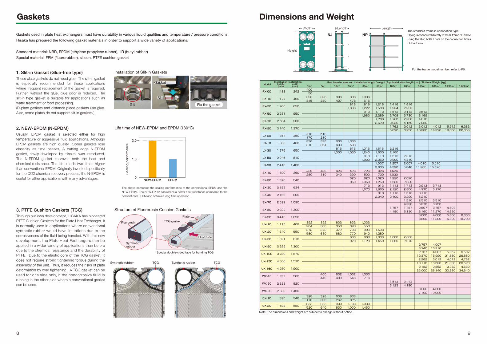
Gaskets Dimensions and Weight
Synthetic rubber TCG Synthetic rubber TCG
NJ NP
The above compares the sealing performance of the conventional EPDM and the NEW-EPDM. The NEW-EPDM can realize a better heat resistance compared to the conventional EPDM and achieves long time operation.
Seal
ing
perfo
rman
ce 2.0
1.0
0NEW-EPDM EPDM
The standard frame is connection type.Piping is connected directly to the S-frame / E-frame using the stud bolts / nuts on the connection holes of the frame.
For the frame model number, refer to P5.
Height
Note: The dimensions and weight are subject to change without notice.
Special double-sided tape for bonding TCG.
Plate
Fluid sideFluid side
TCG gasketFluororesin
Synthetic rubber
CX-10 895 346328170
328209
638267
838325
GX-20 1,593 580933520
933640
933830
1,1331,000
1,9331,460
LX-00
LX-10
LX-30
LX-50
857
1,066
1,675
2,045
350
460
650
810
2,418 1,480LX-90
418170396310
518210396364
836433816
1,000
1,336508816
1,0501,0161,240913
1,920
1,6161,6301,1132,350
2,2162,1601,5132,900
2,3134,310
WX-10
WX-50
WX-90
1,222
2,233
2,829
500
820
1,450
400449
832499
1,032546
1,333716
1,5133,123
2,4434.190
3,3007,100
4,60010,000
UX-10
UX-20
UX-30
UX-90
UX-100
UX-130
UX-160
1,115
1,540
1,891
2,929
3,780
4,300
408
550
610
1,300
1,570
1,570
4,250 1,900
392264372580
392300372630
832353372680
832398798770608970
1,032556998940808
1,120
1,5981,2801,0081,450
1,6081,880
2,6082,970
2,7578,7402,75712,3702,26213,110
4,00713,2104,00715,9903,01216,520
5,25721,8804,01221,830
6,50726,8804,76226,520
2,182 2,852 3,732 4,63223,000 26,140 30,360 34,640
RX-00
RX-10
RX-30
RX-50
RX-70
RX-90
488
1,177
1,900
2,231
2,584
3,140
242
460
650
950
900
1,370
40050396345
396380
396427
836478816
1,086
1,036615816
1,222913
1,983
1,2161,5301,1132,2891,7602,620
1,4161,9241,5132,7081,7603,0301,7625,890
1,6162,9322,1133,7302,2604,1502,0126,950
3,5136,1694,0107,8803,01210,280
4,01214,290
5,51219,000
6,26222,350
SX-20
SX-10
SX-40
SX-30
SX-70
SX-80
SX-90
1,870
2,166
2,692
2,929
3,410
540
1,590 360
805
2,683 634
1,090
1,300
1,290
620950
820500726
390426
340426
310426
280426
730926
1,0301,526
1,0501,0201,250
9132,040
1,2201,520
1,1132,400
1,7574,180
2,0202,220
713 913 1,113 1,7131,670 1,860 2,120 2,800
1,5133,2901,5104,2201,7575,130
3,1134.9702,913
6,2102,5106,2702,5078,1603,0008,800
3,510
6,1703,713
8,7503,75711,2704,00011,200
4,50714,8205,30015,300
6,30018,700
1,007 1,257 2,0073,830 4,390 5,840
4,01011,200
5,51015,870
Heat transfer area and installation length / weight (Top: Installation length (mm) / Bottom: Weight (kg))Model
Installationheight(mm)
Installationwidth(mm) 1m2 5m2 10m2 15m2 30m2 60m2 100m2 200m2 500m2 800m2 1,200m2 1,600m2
Width Length Length
1,370
180℃
180℃
180℃
180℃
213mm
791m3/h
1.25MPaG
180℃
150m2
200A
3,230m3/h
1.6MPaG
130℃
800m2
404mm
400A
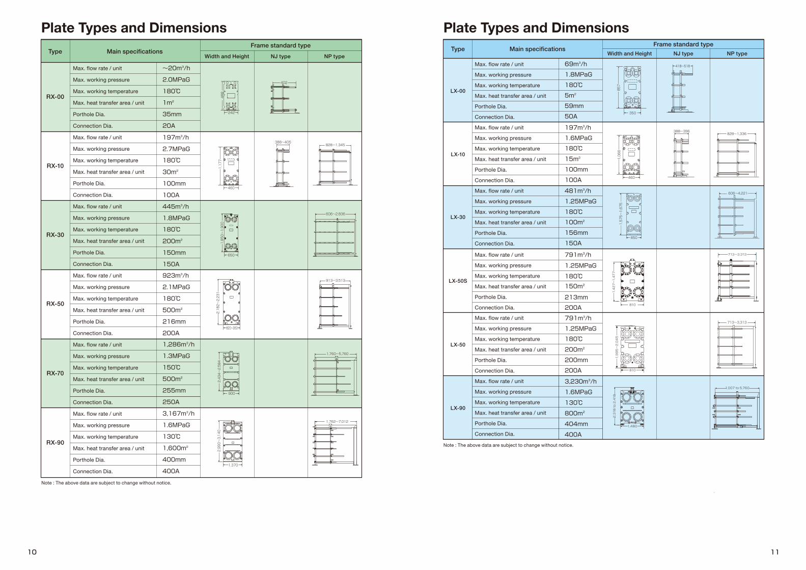
LX-90
LX-10
LX-30
LX-50
LX-50S
LX-00
Type Main specificationsFrame standard type
NJ type NP typeWidth and HeightType
RX-00
RX-10
RX-30
RX-50
RX-70
RX-90
Main specificationsFrame standard type
NJ type NP typeWidth and Height
1,480
1,007 to 5,760
713~3,313
2,318 to 2,418
Plate Types and Dimensions Plate Types and Dimensions
Max. flow rate / unit
Max. working pressure
Max. working temperature
Max. heat transfer area / unit
Porthole Dia.
Connection Dia.
Max. flow rate / unit
Max. working pressure
Max. working temperature
Max. heat transfer area / unit
Porthole Dia.
Connection Dia.
Max. flow rate / unit
Max. working pressure
Max. working temperature
Max. heat transfer area / unit
Porthole Dia.
Connection Dia.
Max. flow rate / unit
Max. working pressure
Max. working temperature
Max. heat transfer area / unit
Porthole Dia.
Connection Dia.
Max. flow rate / unit
Max. working pressure
Max. working temperature
Max. heat transfer area / unit
Porthole Dia.
Connection Dia.
Max. flow rate / unit
Max. working pressure
Max. working temperature
Max. heat transfer area / unit
Porthole Dia.
Connection Dia.
Max. flow rate / unit
Max. working pressure
Max. working temperature
Max. heat transfer area / unit
Porthole Dia.
Connection Dia.
Max. flow rate / unit
Max. working pressure
Max. working temperature
Max. heat transfer area / unit
Porthole Dia.
Connection Dia.
Max. flow rate / unit
Max. working pressure
Max. working temperature
Max. heat transfer area / unit
Porthole Dia.
Connection Dia.
Max. flow rate / unit
Max. working pressure
Max. working temperature
Max. heat transfer area / unit
Porthole Dia.
Connection Dia.
Max. flow rate / unit
Max. working pressure
Max. working temperature
Max. heat transfer area / unit
Porthole Dia.
Connection Dia.
Max. flow rate / unit
Max. working pressure
Max. working temperature
Max. heat transfer area / unit
Porthole Dia.
Connection Dia.
Note : The above data are subject to change without notice.
Note : The above data are subject to change without notice.
810
1,427~1,477
1,995~2,045
810
Up to 4,250
Up to 1,900
Up to 8,900
713 to 3,713
2,683
634
2,166
2,929 to 4,192
1,590
360
426 to 1,52680m3/h
2.0MPaG
100℃
100m2
65mm
50A
220m3/h
3.0MPaG
100℃
200m2
105mm
100A
445m3/h
3.0MPaG
100℃
600m2
150mm
150A
940m3/h
2.4MPaG
500m2
218mm
200A
1,337m3/h
3.0MPaG
100℃
800m2
260mm
250A
2,424m3/h
2.0MPaG
180℃
1,600m2
350mm
350A
2,565m3/h
2.0MPaG
130℃
1,600m2
360mm
350A
110°C(100°C for some cases)
7,300m3/h
2.3MPaG
100℃
4,300m2
600mm
600A
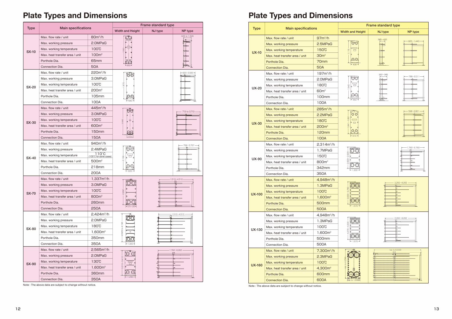
SX-40
SX-70
SX-80
SX-90
SX-20
SX-10
SX-30
UX-10
UX-20
UX-30
UX-90
UX-100
UX-130
UX-160
Type Main specificationsFrame standard type
NJ type NP typeWidth and HeightType Main specifications
Frame standard typeNJ type NP typeWidth and Height
Max. flow rate / unit
Max. working pressure
Max. working temperature
Max. heat transfer area / unit
Porthole Dia.
Connection Dia.
Max. flow rate / unit
Max. working pressure
Max. working temperature
Max. heat transfer area / unit
Porthole Dia.
Connection Dia.
Max. flow rate / unit
Max. working pressure
Max. working temperature
Max. heat transfer area / unit
Porthole Dia.
Connection Dia.
Max. flow rate / unit
Max. working pressure
Max. working temperature
Max. heat transfer area / unit
Porthole Dia.
Connection Dia.
Max. flow rate / unit
Max. working pressure
Max. working temperature
Max. heat transfer area / unit
Porthole Dia.
Connection Dia.
Max. flow rate / unit
Max. working pressure
Max. working temperature
Max. heat transfer area / unit
Porthole Dia.
Connection Dia.
Max. flow rate / unit
Max. working pressure
Max. working temperature
Max. heat transfer area / unit
Porthole Dia.
Connection Dia.
Max. flow rate / unit
Max. working pressure
Max. working temperature
Max. heat transfer area / unit
Porthole Dia.
Connection Dia.
Max. flow rate / unit
Max. working pressure
Max. working temperature
Max. heat transfer area / unit
Porthole Dia.
Connection Dia.
Max. flow rate / unit
Max. working pressure
Max. working temperature
Max. heat transfer area / unit
Porthole Dia.
Connection Dia.
Max. flow rate / unit
Max. working pressure
Max. working temperature
Max. heat transfer area / unit
Porthole Dia.
Connection Dia.
Max. flow rate / unit
Max. working pressure
Max. working temperature
Max. heat transfer area / unit
Porthole Dia.
Connection Dia.
Max. flow rate / unit
Max. working pressure
Max. working temperature
Max. heat transfer area / unit
Porthole Dia.
Connection Dia.
Max. flow rate / unit
Max. working pressure
Max. working temperature
Max. heat transfer area / unit
Porthole Dia.
Connection Dia.Note : The above data are subject to change without notice. Note : The above data are subject to change without notice.
Plate Types and Dimensions Plate Types and Dimensions

2,233
820
1,450
2,829
1,114
486
920
346
■ Characteristics❶ The heat transfer coefficient is about 2 times higher than that
of shell & tube heat exchangers. The condensing surface is always secured and the heat transfer coefficient is improved because condensate is immediately drained out.
❷ Special considerations are taken for the plate characteristics in order to achieve a much lower vapor pressure drop than conventional Plate Heat Exchangers.
❸ The cooling water consumption is about half that of S&T heat exchangers.
❹ TCG gaskets are selectively used to permit a wide range of applications.
❺ Less maintenance work, as the plates can be easily cleaned and inspected.
❻ The vapor connection sizes holes are the same for the inlets and outlets, allowing for use as a cooling condenser for vapor with inert gas.
❼ Various international Pressure Vessel Code and Standard such as ASME, JIS, CE available.
■ Applications❶ Overhead condensers for various distillation columns❷ Condensers / preheaters for evaporators❸ Condensers for gas drying / air conditioning❹ Heat recovery exchangers from exhaust steam❺ Gas coolers, etc.
■ Characteristics❶ Easy for fluids containing solids to flow between wide gap
channels (10 mm).❷ A combination of plates provides the widest channel
spacing (20 mm).❸ It provides better performance for slurry, sludge and liquid
containing crystals.❹ Electrolytic polishing selectively used for food applications.❺ Shorter maintenance time due to the slit-in gasket.
■ Applications❶ Chemicals
• Fluids containing solids: Polyvinyl chloride (polymer), various slurry fluids
• High viscosity fluids: Rubber latexes, resin latexes❷ Dyeing
• Fluids containing fibers: Waste fluid from Dyeing machine• High viscosity fluids: Viscose
❸ Food• Fluids containing solids: Sauce for grilled meat, juice with
fiber, factory waste water• Fluids containing fibers: Amazake• High viscosity fluids: Mayonnaise, various sauces, starch
saccharification liquid, syrup❹ Sugar
• Fluids containing solids: Raw juice, sugar making process such as the Steffen process, processed fluids, factory waste water
❺ Pulp and paper• Fluids containing fibers: Diluted black liquor, white liquor
❻ Other• Plating fluid containing sludge, quenching oil• High concentration sodium hypochlorite, sodium
aluminate• Heat transfer for significantly different flow rates on the hot
/ cold sides plant• Snow melting plant
GX-21 channel
Cold side slurryCold side slurry
Hot side slurryHot side slurry
GX-23 channel
Plate Heat Exchanger Lineup
YX-83 plateCooling water side Vapor side
Condenser / Gas Cooler (YX) Multi Gap Plate (GX)
GX-20(By reversing and upside-downGX-21 to GX-22.)
Cooling water side
Cross-section of Vapor Side andCooling Water Side
Vapor side
Cooling water
Condensate
Vapor
Type
WX-10
WX-50
WX-90
CX-03
Main specificationsFrame standard type
NJ type NP typeWidth and Height
Plate Types and Dimensions
Max. flow rate / unit
Max. working pressure
Max. working temperature
Max. heat transfer area / unit
Porthole Dia.
Connection Dia.
Max. flow rate / unit
Max. working pressure
Max. working temperature
Max. heat transfer area / unit
Porthole Dia.
Connection Dia.
Max. flow rate / unit
Max. working pressure
Max. working temperature
Max. heat transfer area / unit
Porthole Dia.
Connection Dia.
Max. flow rate / unit
Max. working pressure
Max. working temperature
Max. heat transfer area / unit
Porthole Dia.
Connection Dia.
Max. flow rate / unit
Max. working pressure
Max. working temperature
Max. heat transfer area / unit
Porthole Dia.
Connection Dia.
CX-23
Max. flow rate / unit
Max. working pressure
Max. working temperature
Max. heat transfer area / unit
Porthole Dia.
Connection Dia.Note : The above data are subject to change without notice.*CX-10 is both vertical and horizontal installation available.
By combination of one plate arrangement gives 3 multiple-channel configulation.
SlurrySlurry
Cooling waterCooling water
CX-10*Vertical
Horizontal
350~1,040
628~1,345
63mm
80m3/h
3.2MPaG
150℃
16m2
50A
93mm
171m3/h
1.95MPaG
150℃
30m2
100A

■ Characteristics❶ The double-gasketed line design provides a gasket line to the
outermost periphery to inhibit oxidation degradation in the inner gasket (which serves as a seal) from outside air.
❷ It prevents leakage dispersal. Should a leak occur in the inner gasket, this prevents the fluid from reaching outside.
❸ To achieve high heat-resistance, the compounding ratio of the gasket has been improved.
❹ The improved gasket groove and plate pattern increase seal pressure and ensure high pressure-resistance.
❺ It achieves a life time 5 times longer than Hisaka's conventional Plate Heat Exchangers.
❻ High heat-resistance and pressure-resistance allow for environments with high temperature of 250°C and seal pressure of 9.5Mpa or higher, which conventional PHE couldn’t use.
■ Applications❶ High temperature / High pressure fluids
High temperature, high pressure heat exchangers around boilers or the likeHeat exchangers in conventional / nuclear power applications
❷ Dangerous fluidsHeat exchangers for flammable and dangerous fluids in locations such as chemical plants
Inner gasket
Leak
Outer periphery gasketGasket for cassette interior (ring gasket)
Gasket for cassette outside
Cas
sette
out
side
Cas
sette
insid
e
Welded section
Dual Wall PlateExclusive Food ApplicationPlate (FX)
Air(gap)
Twoidenticalplates
Fluid A
Fluid B Fluid B
Fluid A
Shoulder shape anduniform distribution pattern
Liner and few contact points
Laser weldedparts
Dual Wall PlateIn case anyone of plates were to fail, the leak can be detected from outside.
Structure of a Welded Plate Heat Exchanger
The dual wall plate heat exchangers use to achieve "relief and reliance" for preventing contamination of the two fluids.
■ Characteristics❶ The dual wall design prevents any leaks from going farther
due to the air gap and the second plate. In case any one of plates were to fail, the leak can be detected from outside because of leaking through the gap of the plates.
❷ To prevent intermixing of the fluids, “Double seal gasket” (refer to P6) system is used. Any leakage of fluids across the gasket can be detected from the outside because the liquid escapes from the units.
■ Applications❶ Cooling of transformer oil, which might explode if mixed with the
cooling water❷ Cooling of lubrication or hydraulic oil, which can damage the
rotator or hydraulic equipment if mixed with the cooling water❸ Heating / cooling of food processing, where there must be no
mixing of foreign materials in the product❹ Heating / cooling of fuel oil (marine gas oil: MGO) where fatigue
breakdown due to highly frequent pulsation❺ Heating / cooling in bio-process where the process fluid may
cause environmental pollution❻ Heating / cooling between fluids where mixing can cause a
sudden chemical reaction or generate environmental pollutantsIt is normally necessary to install two heat exchangers where it is dangerous if fluid A and fluid B are mixed. However, with the dual wall plate, this is possible with just one unit.
Air blow notch removes the air in the unit and prevents contamination of bubbles, oxidation, and scorching. The drainage notch can completely drain out the fluid or the cleaning detergent in the unit.
Double-lined Gasket PlateHestia NX-50
Plate Heat Exchanger Lineup
■ Characteristics❶ The uniform distribution pattern and the shape of the shoulder
section are smoothened to create a uniformly smooth flow through the plate channels, enabling product-gently heat transfer with a uniform, and even temperature in the unit.
❷ The plate contact points have been significantly reduced to 1/4th of the conventional pattern, and the liner and few contact points arrangement has a self-cleaning effect. For that reason, long-term operation is possible, as it is less to clogs, scales and partial scorching than conventional type.
❸ The piston flow in the plate channels reduce the fluid replacement time to 1/4th of the conventional type, significantly reducing the product loss by 75%.
❹ There is also little dead space within the channels and holding volume is small, achieving a high CIP effect.
❺ The slit-in type TCG gasket also prevents rubber smells / glue smells in the product and remain scents when switching products to be produced.
FX plate: 15 seconds → 1/4th of conventional plate
Time until steady operation
Less Product Loss
Start of steady operation
Conventional plate: 60 seconds
Time / sec10 20 30 40 50 60 70 80 90
10
0.5
0
Replacementrate
Air blow notch
Drainage notch
Porthole notch
Leak detection holeLeak detectionEven if a leak from the inner gasket occurs, a leak can be detected promptly.
Double-gasketed line design
Prevention of oxidation degradationThis prevents oxidation degradation of the inner gasket due to outside air.Prevention of dispersalDispersion of fluid to outside of the unit is prevented the fluid from reaching outside.
Unified Welded Plate
20
109876543210
80 140Temperature (°C)
Hestia NX-50 (Verified performance)
Hestia NX-50 (Designed performance)
Conventional plate
Seal
pre
ssur
e (M
Pa)
200 260
Conventional model Welded model
Up to 3.0 MPaG Up to 4.0 MPaGPressure resistance
Heat resistance 150°C 180°C
■ Characteristics❶ A couple of plates are laser welded with o-ring at portholes
between the plates. One fluid flowing through the inside of the cassettes and the other fluid flowing on the outside of the cassettes.
❷ As disassembly is possible for each plate cassette, both sides of the plate cassette can be cleaned.
❸ As plate cassettes is sealed by laser welding except the portholes, this product is fit for high pressure duty, Freon refrigerants or fluids that corrode synthetic rubber.
❹ There are two types of ring gaskets; a synthetic rubber, and PTFE gasket (TCG) with outstanding chemical resistance.
■ Applications❶ Heating / cooling of fluids that corrode synthetic rubber❷ Heating / cooling of dangerous fluids such as sulfuric acid❸ Heating / cooling for the duty exceeding the heat or pressure
resistance of gasket-type plate heat exchangers❹ Heating / cooling in refrigeration cycles using refrigerant
Semi-welded Plate (WX)
■ Specification
■ High-Heat / High-Pressure Resistance
* The Hestia NX-50 was developed jointly with Hitachi-GE Nuclear Energy, Ltd.
* Patent pending
Cross-section
▲
Conventional PHEs Installation
2 sets of heat exchangersin addition to extra pumps
and piping.
Fluid A Fluid AFluid B Fluid B
Dual Wall Installation
Only one PHE isenough for the duty.
Cooling water, etc.
Process fluid
GasketLaser welding
Heat and Pressure Resistance
Two identical plates are stacked and laser-welded around the portholes.

■ Characteristics❶ Brazed plate heat exchangers are brazed stainless steel plates
by brazing filler metal such as copper or nickel.❷ It is high performance and allows for a small heat transfer area.❸ Due to the small heat transfer area and the thin material by
sturdy brazed structure, light weight, and compact design are achieved.
❹ With brazed structure, it provides a high level of sealing and outstanding heat and pressure resistance.
❺ The brazed structure reduced material to minimum is fit for mass production and is economically outstanding.
■ Applications❶ Vaporizers / condensers of refrigerant in compression
refrigeration cycles (refrigerators / heat pumps)❷ Solution heat exchangers for absorption refrigerators❸ Industrial and home water heaters❹ Heat recovery heat exchangers for cogeneration systems or
gas heat pumps❺ Oil coolers for hydraulic equipment❻ Heat exchangers for temparature control of various industrial
equipment and medical examinations
■ SpecificationDesign pressure: F.V. to 4.5 MPaDesign temperature: -100°C to 200°C
* The above mentioned varies by model. Please inquire with our company when planning.
■ Characteristics❶ The press-molded plate is molded with a special corrugation
pattern to ensure a high transfer coefficient.❷ It supports high temperatures and high pressures, showing
its performance in a wide range of fields.❸ The seal gasket consists only of the side cover, so there are
virtually no restrictions due to gasket materials.❹ As baffles can be installed to enable a multi-pass design,
heat transfer performance is close to a counter-current flow, and has a flexible flow rate.
❺ As the holding volume is small, the amount of fluid remaining in the unit is also small and only a small amount of CIP detergent can be used.
❻ Easy mechanical cleaning by the cross f low channel structure.
■ Applications❶ Heat transfer process for higher efficiency than Shell & Tube
heat exchangers❷ Heat recovery in high temperature / high pressure applications❸ Condensers❹ Vaporizers❺ Heat transfer process where a Gasketed PHE cannot be usedThey are also able to replace Shell & Tube heat exchangers in other cases as well.
Plate Heat Exchanger Lineup
PHE Total Maintenance [Full Service Package]from pickup to assemblyThe Full Service Package is a total maintenance service in HISAKA. PHE disassembly, visual checks of plates, cleaning, regasketing, frame repairs, assembly, and final inspection are all performed by service centers, for the best possible performance and a long operating life time for PHEs. We also offer the "Full Service Package" for plates only.
Cleaning In Place (CIP)Disassembly and cleaning a PHE makes it possible to remove hard scale and clogging matters and to recover performance to nearly the same level as new. However, if disassembly and cleaning are not possible, HISAKA offers CIP using "Plate-Clean" at customers' site.Before scaling, CIP with Plate-Clean can restore performance by removing scale through washing and dissolving. This is effective in prolonging the disassembly cleaning cycle of the PHE. This is effective for extending the disassembly cleaning cycle of plate heat exchangers.
Return containers that precisely fit the plates that are currently in use are provided upon customers' request.
Maintenance Menu
On-site MaintenanceHISAKA can send skilled service engineers to perform maintenance work at the customer's site. We use specialized tools, such as automatic tightening devices, to efficiently dissemble and assemble the PHE and high temperature hot water jet cleaning to remove to sticky oil residues, providing high quality maintenance service at the customer's site.
Copper (Cu)brazed
Nickel (Ni) brazed
S-frameBrazing filler metal
Heat transfer plate
E-frameOutlet / inlet nozzle
Cold side inlet
Hot side inlet
Hot side outlet
Cold side outlet
Flow channel of fluid
Hot side inletCold side outlet
Hot side outletCold side inlet
*Free Flow: Wide gap and no contact point between the heat transfer plates
■ Variety of plate gap
Max. working pressureMax. working temperatureConnection sizeMax. heat transfer areaPlate material
3.5 [MPaG]Up to 350 [°C]50A to 600AUp to 700 m2/unitStainless steel, titanium, high nickel alloy
CIP Flow Chart
Compressor (to discharge the ettluent)
Cleanerinput
Cleaning pump
Heater
Seal Flange
Seal Flange
Plate heat exchanger
Brazed Plate Heat ExchangersWelded Plate Heat Exchangers
■ Specification
* The above mentioned varies depending on the operating conditions. Please inquire with our company when planning.
Before After
Cle
anin
g ta
nk
Reco
very
tank
Return Containers for "Full Service Package" for plate only (Optional)
Plate-Clean is a special cleaner for PHEs. By circulating the cleaner inside the PHE, stubborn scale that forms on the cooling water, warm water, and steam sides can be easily removed by cleaning and dissolving withoutdisassembling the unit. Customers are no longer required to perform the hard work of removing scale.
Plate-Clean
* Each type of Plate-Clean is also sold separately.
Plate-Clean Series
Plate-Clean S
Cleaner and Target Scale
Plate-Clean C Plate-Clean FProduct Name
Cleaner
Target Scale
Plate-Clean C Calcium corbonate
Plate-Clean S Slime, mud
Plate-Clean F Iron rust
(4) Both sides dirty fluidsHXS Both side rectangular FF channel with studs.
HXS
(3) One side highly charged fluidHXE FF / Dimpled channel.
HXE
(2) One charged fluidHXC Free Flow (FF) FF corrugated / corrugated channel.
HXC FF
(1) Both sides lightly charged fluidHXC Both sides corrugated channel.
HXC
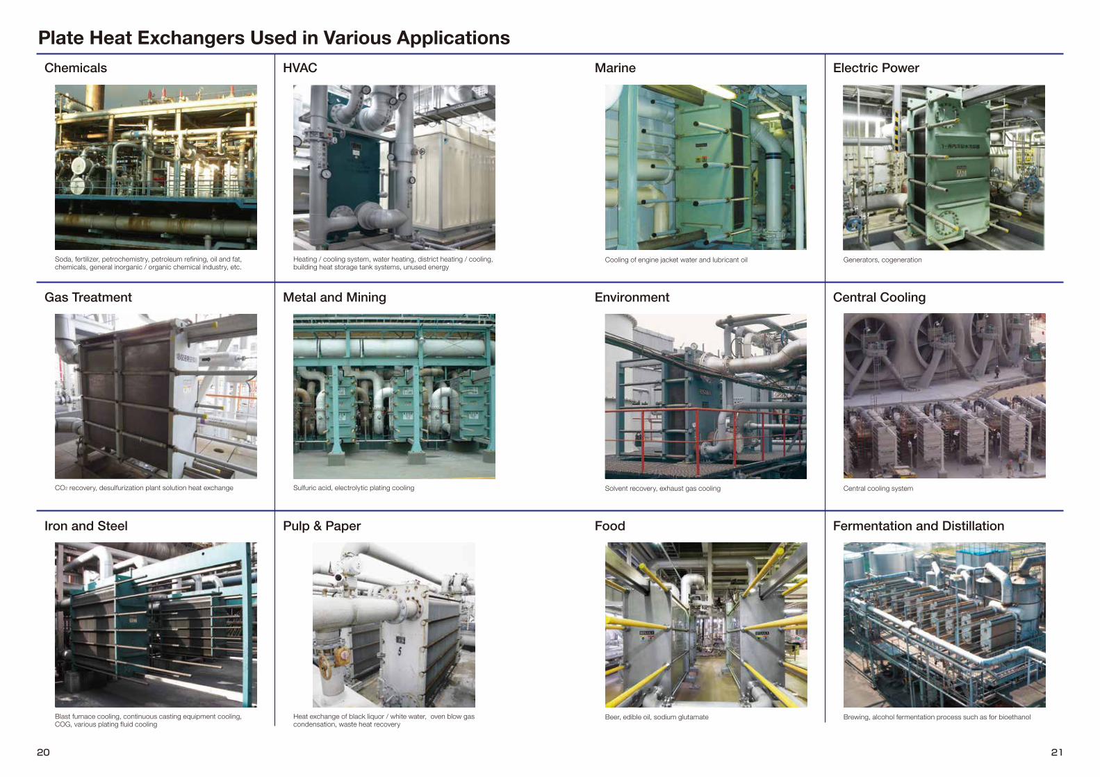
Cooling of engine jacket water and lubricant oil Generators, cogeneration
Solvent recovery, exhaust gas cooling Central cooling system
Beer, edible oil, sodium glutamate Brewing, alcohol fermentation process such as for bioethanol
Plate Heat Exchangers Used in Various Applications
Environment
Fermentation and Distillation
Gas Treatment
Chemicals HVAC Marine
Iron and Steel Pulp & Paper Food
Electric Power
Metal and Mining Central Cooling
Soda, fertilizer, petrochemistry, petroleum refining, oil and fat, chemicals, general inorganic / organic chemical industry, etc.
CO2 recovery, desulfurization plant solution heat exchange
Blast furnace cooling, continuous casting equipment cooling, COG, various plating fluid cooling
Heating / cooling system, water heating, district heating / cooling, building heat storage tank systems, unused energy
Sulfuric acid, electrolytic plating cooling
Heat exchange of black liquor / white water, oven blow gas condensation, waste heat recovery

Global Network※
22 23
● Capital alliance partnerARSOPI THERMAL S.A. (Portugal)TEL: +351-256-410-410 FAX: +351-256-410-411
YANTAI SHINWA JOINT TECHNOLOGY CO., LTD. (China)TEL: +86-535-643-3939 FAX: +86-535-643-3926
KAPP SAS (France)TEL: +33-4-78-05-68-68
● HISAKA Group■ MalaysiaHISAKAWORKS S.E.A. SDN. BHD. KUALA LUMPURTEL: +60-3-8081-4185 FAX: +60-3-8081-7185E-mail : [email protected]
JOHOR BRANCHTEL : +60-16-228-4209E-mail : [email protected]
■ ThailandHISAKA WORKS (THAILAND) CO., LTD.BANGKOKTEL: +66-2-744-3287 FAX: +66-2-744-3286E-mail : [email protected]
SATTAHIP SALES OFFICETEL: +66-3-819-9819 FAX: +66-3-819-9820E-mail : [email protected]
■ SingaporeHISAKAWORKS SINGAPORE PTE. LTD. TEL: +65-6-897-8489 FAX: +65-6-686-4579E-mail : [email protected]
■ IndonesiaPT. HISAKA WORKS INDONESIATEL: +62-21-2931-9235
■ VietnamHISAVINA Ho Chi Minh (Representative Office of HISAKAWORKS S.E.A. SDN. BHD.)TEL: +84-8-3910-7355 FAX: +84-8-3910-7356E-mail : [email protected]
■ PhilippinesHISAPINO Manila (Representative Office of HISAKAWORKS S.E.A. SDN. BHD.)TEL: +63-2-224-4129 FAX: +63-2-224-4130E-mail : [email protected]
■ South KoreaHISAKA KOREA CO., LTD. SEOULTEL: +82-2-739-8861 FAX: +82-2-739-8864E-mail : [email protected]
BUSAN BRANCHTEL: +82-51-747-0265 FAX: +82-51-747-0266
■ ChinaHIASAKA WORKS(CHINA)CO., LTDCHANGSHUTEL: +86-512-5213-3000 FAX: +86-512-5213-3008
SHANGHAI BRANCHTEL: +86-21-5211-0701 FAX: +86-21-5211-0720E-mail : [email protected]
GUANGZHOU BRANCHTEL: +86-20-3810-5515 FAX: +86-20-3847-7539
NANJING SALES OFFICEZHUHAI SALES OFFICENINGBO SALES OFFICE
■ Saudi ArabiaHISAKA MIDDLE EAST CO., LTD. DAMMAMTEL: +966-13-838-4700 FAX: +966-13-838-5800E-mail : [email protected]
● HISAKA Maintenance Network■ MalaysiaHISAKAWORKS S.E.A. SDN. BHD. No2, Jalan TP2, Taman Perindustrian SIME UEP, 47600 Subang Jaya, Selangor Darul Ehsan, MalaysiaTEL: +60-3-8081-4185 FAX: +60-3-8081-7185
XONG LIN INDUSTRIAL TRADING SDN BHD506, Jalan Perusahaan, Taman Industri Waja, 09000 Kulim, Kedah Darul Aman, MalaysiaTEL : +60-3-8081-4185
■ ThailandHISAKA WORKS (THAILAND) CO., LTD. SATTAHIP SALES OFFICE222/28, Moo.10, Eastiny Park 5 Village, Bang Saray Sattahip, Chonburi, 20250, ThailandTEL: +66-3-819-9819 FAX: +66-3-819-9820
■ SingaporeJECS SINGAPORE (PTE) LTD.26, Gul Drive, Jurong Town, Singapore 629474TEL: +65-6-861-5577 FAX: +65-6-861-4253
■ IndonesiaPT UNGGUL PRAKARSA PRISMAJl. Industri Selatan 8, Blok EE-8E, Kawasan Industri Jababeka 2, Cikarang Bekasi 17550, West JavaTEL : +62-21-8984-1348
■ VietnamHESCO TECHNOLOGY COMPANY LIMITED1391 Phan Văn Trị, Phường 10, Quận Gò Vấp, Tp.HCMTEL : +84-8-2253-0506 ■ PhilippinesJACHIN-BOAS SALES AND SERVICES CO.Laguna Belair 1, Brgy. Don Jose, Sta. Rosa, LagunaTEL : +63-4-9559-4345
■ South KoreaCLEANPIA.s187, Sunhwan-ro, Jungwon-gu, Seongnam-si, Gyeonggi-do, 13207, Republic of KoreaTEL : +82-1877-5335
■ ChinaHISAKA WORKS (CHINA) CO., LTD., Changshu PlantNo. 1 Xiangyuan Road, Changshu New & High-tech Industrial Development Zone, Changshu City, Jiangsu Province 215542, P.R. ChinaTEL : +86-512-5213-3000
■ Saudi ArabiaHISAKA MIDDLE EAST CO., LTD.P.O Box: 7102, Dammam 32435, Building No. 3861, Al Khudhariya Industrial Area, Dammam Saudi ArabiaTEL : +966-13-838-4700
■ PortugalARSOPI THERMAL S.A.P.O. Box 103, Codal 3730-901, Vale de Cambra, PortugalTEL : +351-256-410-410
France
Group Company / production base
Capital alliance partner
※Heat Exchanger Div. related
China (Nanjing)
China (Ningbo)
China (Zhuhai)