Embed Size (px)
Citation preview

Skytrak – Low Carbon Vertical
Transportation
Systems for the 21st Century
presented by
Adrian Godwin BSc DMS MCIM CEng MIET
Chairman, Lerch Bates Europe
Visit www.lerchbates.eu to learn more

Overview
Background, Changing Requirements, Needs and Wants
New Geometries, New Building Communities, New Opportunities
History of Elevators, Going Back in History
Lenz’s Law of Electrodynamics
Skytrak Design Considerations, Some Basic Physics
Skytrak – Three “Prime Movers” / Five Inventions
Linear Motor, Claw Type Double Sided
Triple Function Retarder Design
Applications of the Retarder
EGRESS, Synchrorail, Skytrak Aerial Ropeway, Skytrak Circular and Vertical
Low & High Speed Drives and Novel Transfer “Switch”
Visual Simulation

Background• Density of occupancy of all buildings is increasing
• Land becomes ever scarcer and more valuable
• Buildings have to get more efficient
• Elevator systems have to work harder!
Besides.....
• Architects want a new degree of freedom for vertical transportation systems i.e. passenger cabins that move outside the vertical plane
• New energy efficient “green” self-contained communities need to be established where people can live, work and play
• Multiple cabins need to travel in one shaft to reduce the numberof lift shafts deployed in buildings to save space
• Passenger cabins need to move people within and between buildings and facilities to remove day to day use of cars

Requirements are Changing! Why?
� Building geometry is becoming more complex
� Steel, glass and other materials can be custom cut
� Architects want unique shapes of buildings
� Transit between buildings and complexes is required
� Need to move people from major transportation hubs
� Building in city centres very constrained
� New integrated transportation solutions required
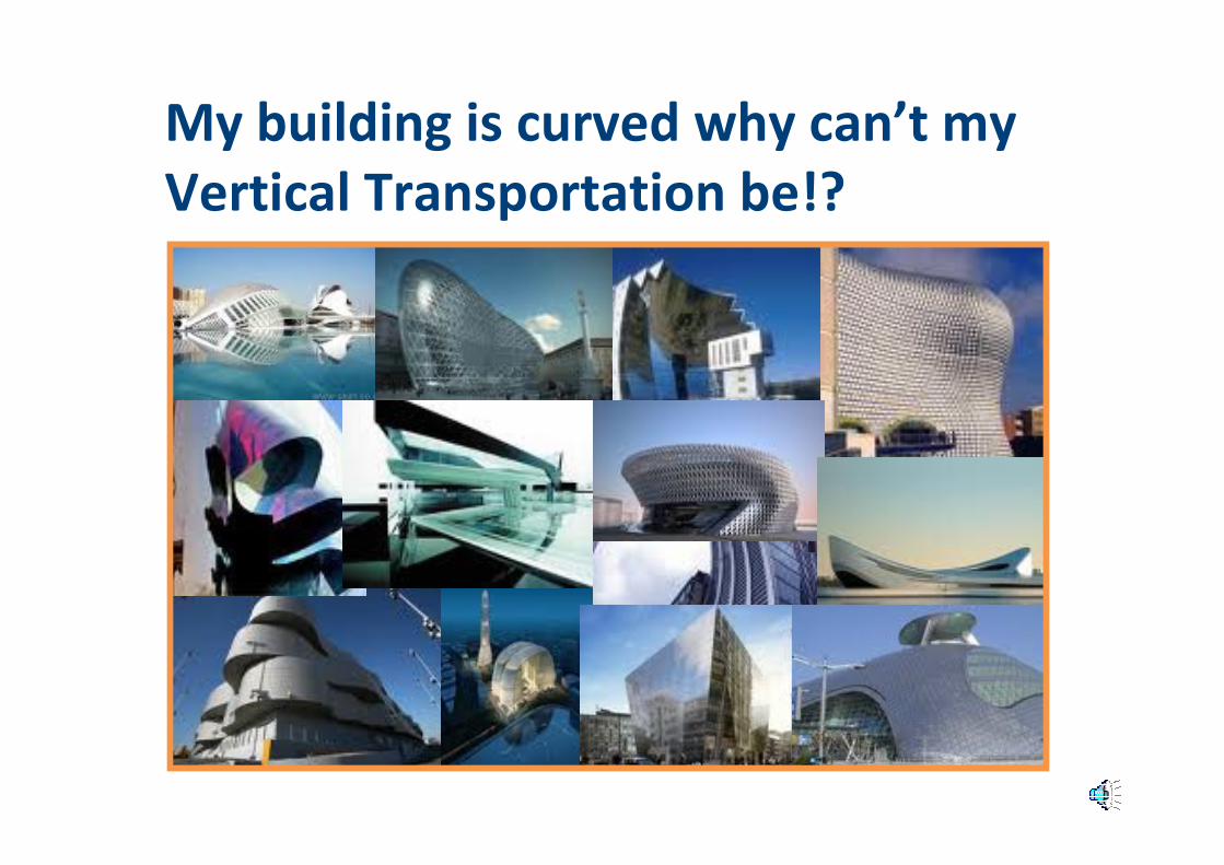
My building is curved why can’t my
Vertical Transportation be!?

Vertical Transportation needs to
respond to the architect’s wants!
July 2010
Beijing CBD
Competition
Entry

New Building Geometries ....

HOTEL
APARTMENTS
RESTAURANTS, CLUBS, VIEWING
OFFICES
SERVICED OFFICES
RETAIL
New Building Communities ...
You are just one journey away from
anything and everything in the building!

History of Elevators
• The safety gear was publicly displayed by Elisha Graves Otis in 1853 at the Crystal Palace fair in New York
• It’s now over 150 years since this landmark invention and the uttering of the words “all safe gentlemen, all safe”
• Just think how far the aviation industry has moved since the Wright brothers took off in 1903!
• Today we want to prove that a new era for vertical transportation is about to unfold with the necessary inventions and technology now, at last, in place to enable the lift industry to finally take off!

Going Back in History....
A paternoster or paternoster lift is a passenger
elevator which consists of a chain of open
compartments (each usually designed for two persons)
that move slowly in a loop up and down inside a
building without stopping. Passengers can step on or
off at any floor they like. Courtesy Wikipedia
First built in 1884 by Londoner J. E. Hall as the Cyclic Elevator, the name
paternoster ("Our Father", the first two words of the Lord's Prayer in Latin) was
originally applied to the device because the elevator is in the form of a loop and is
thus similar to rosary beads used as an aid in reciting prayers.[1]
Paternosters were popular throughout the first half of the 20th century as they
could carry more passengers than ordinary elevators. They were most common in
continental Europe, They are rather slow elevators, typically travelling at about
0.3 metres per second, thus improving the chances of jumping on and off successfully.
Today, in many countries the construction of new paternosters is no longer
allowed because of the high danger of accidents (people tripping or falling over
when trying to enter or alight). Five people were killed by paternosters from 1970 to 1993.

� How can a law of electrodynamics
established 20 years before the invention of the safety gear in 1853 hold out the prospect of
safety for passenger cabins travelling without
suspension ropes and a balance weight in the 21st century?
Lenz showed how electromagnetic circuits must
always obey Newton’s third law. Lenz's law says:
"An induced current is always in such a direction
as to oppose the motion or change causing it“
Lenz’s Law of Electrodynamics

Skytrak Design Considerations
Some basic considerations concerning the practical design
of a multicar ropeless lift system.
� Simple, efficient and quick mechanism for moving lift
cabins from UP to DN and DN to UP at terminals
� Secure wireless communication to transfer commands
from main control to moving lift cabins
� Satisfactory means of dealing with trapped passengers in
an emergency
� Failsafe brakes must now be carried on board
� Increased structural loads will be applied to support track
� Keep cars “on” a track at all times

Skytrak Design Considerations (contd.)
� Light weight materials to be used throughout
� Cabins to be kept vertical when on curved trajectory
� Ride quality like today’s best passenger lifts
� Lightest drive motor with the right characteristics
� Satisfactory control of deceleration in the UP
direction when emergency stopping occurs
� Speed consistent with meeting ATTD criteria
� Safety is paramount - all ESHR’s must be met
� Minimise overall system cost

Some Basic Physics ......
W = 1600kg W = 1600kg
L=1600kg L = 1600kg
Net Load = 800kg Net Load = 3200kg
800kg @ 2.5m/s 3200kg @ 2.5m/s
800 * 9.81 * 2.5 = 19.6 kW 3200 * 9.81 * 2.5 = 78.5kW
Probable power requirement four times conventional lift!
LW+ L
W + 1/2L
LW+
CONVENTIONAL
LIFT
ROPELESS
LIFT

Countermeasures to Power Input to
achieve Low Carbon Alternative
1.Arrange for a common d.c. power bus to feed both
UP and DN travelling lift cabins. Energy from DN
cars is fed back into the bus to feed UP travelling
cars
2.Maximum use of light weight components,
composites and alloys
3.Run system at lowest speed consistent with
acceptable time to destination
4.Ensure losses minimised, efficiency 96% plus

Skytrak – Three Types of “Prime Mover”
* Patents Pending
1. Controlled descent using a “gravity” drive
2. Low speed (up to 2.5 m/s) rotational linear motor drive3. High speed (up to 6.0 m/s) linear motor drive
Skytrak – Five Important Inventions *
1. Use of “retarder” to allow safe descent under gravity2. Passenger transportation on aerial ropeway
3. Emergency “up stopping” solution for high speed4. Gearless lantern pinion drive using rotational linear motor
5. Terminal Switching of cars from “up” to “down” shafts

Linear Motor
� Simple construction
� Double sided to maximise
output
� Single winding embraces
large number of poles
� Moving magnet weight 30kg
per metre
� Stacked as three phase
� Force output 5000 Newtons
per metre for three phases

Linear Motor (contd.)
A one metre unit length of linear motor with stator cross sectional dimensions as shown can produce 1800 Newtons of thrust

Linear Motor (contd.)
Permanent magnet arrangement with backing iron
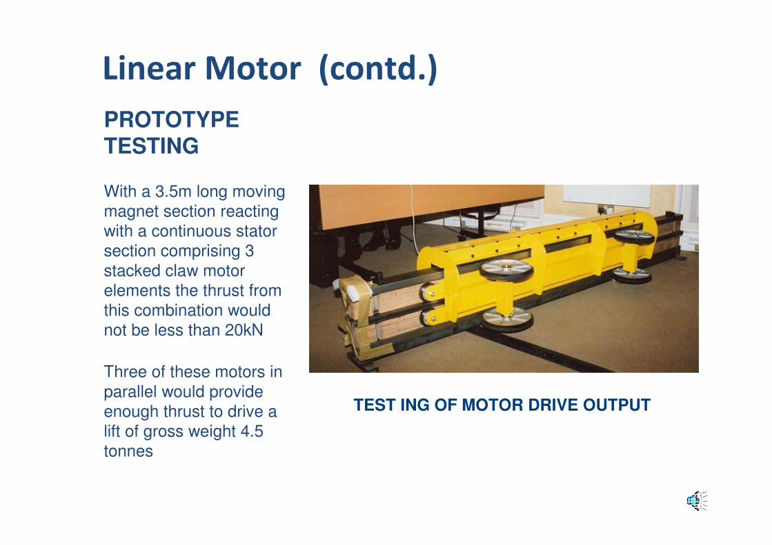
PROTOTYPE TESTING
With a 3.5m long moving
magnet section reacting
with a continuous stator
section comprising 3
stacked claw motor
elements the thrust from
this combination would
not be less than 20kN
Three of these motors in
parallel would provide
enough thrust to drive a
lift of gross weight 4.5
tonnes
TEST ING OF MOTOR DRIVE OUTPUT
Linear Motor (contd.)

Linear Motor (contd.)
� Single winding permits the
shaping of the poles to fit a
circular construction for low
speed version (discussed later)
� Labour used in manufacture is
less than conventional motor
� Automated production possible
with consequent reduction in cost
per metre
Available Product
Can be manufactured by e.g.
Phasemotion, China

Retarder (Under Test)
Triple Function
1.Act as a generator when moving to
ensure the battery pack is continuously
recharged
2.Act as a motor with sufficient force output
such that when emergency up stopping
occurs it will provide satisfactory
deceleration of the lift cabin in conjunction
with its power invertors and super capacitor
pack
3.Act as a retarder capable of supporting
the gross weight of the lift cabin and
controlling its descent at a slow speed < 1.0
m/s enabling the lift cabin to return safely to
floor level and discharge its passengers
A prototype of the “tuned generator”retarder under test is shown here

Applications of the “Retarder” Replacing
the Conventional Safety Gear
� EGRESS Personal Rapid Escape Device
� SYNCHRORAIL Horizontal Transportation
� SKYTRAK Multi-Car Aerial Ropeway System
� SKYTRAK Multi-Car Circular Transportation System
� SKYTRAK Multi-Car Vertical Transportation System

Building users take life jackets

Mullions in building cladding system contain magnet tracks
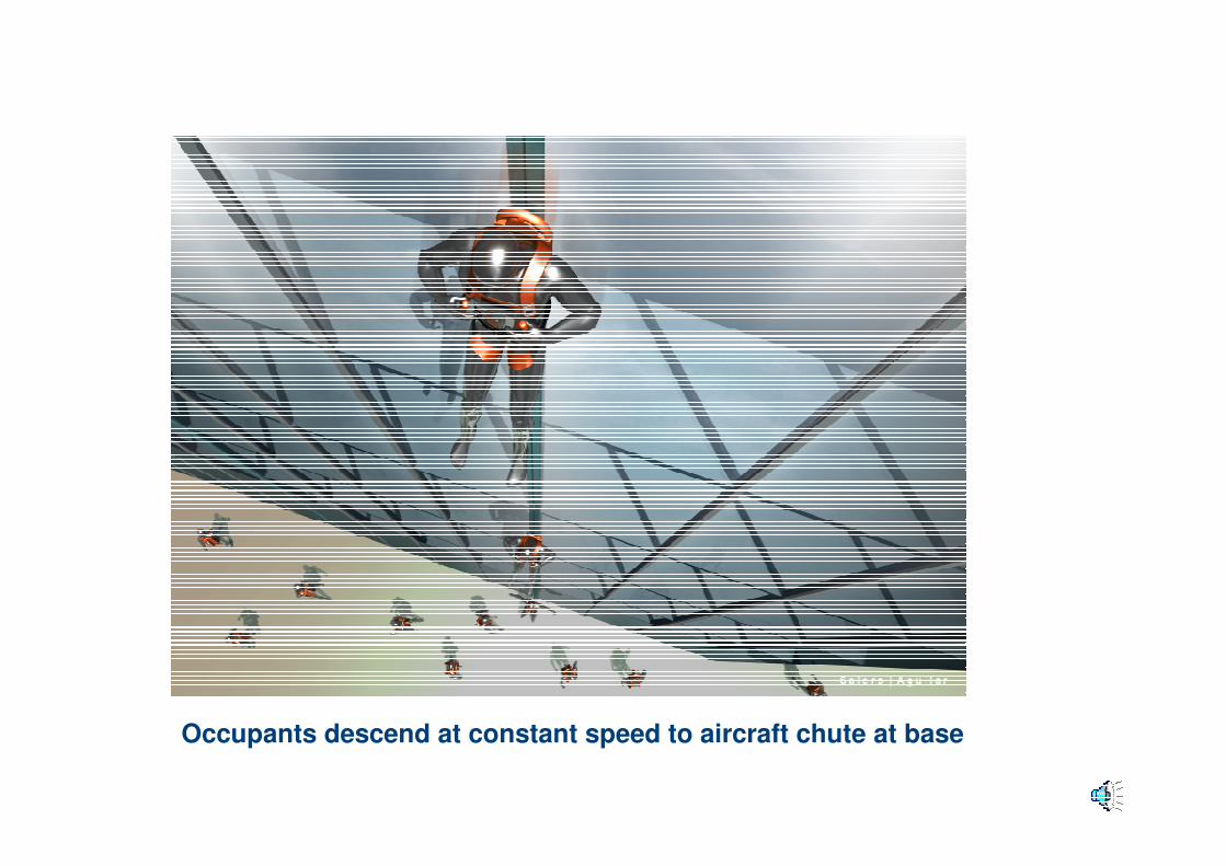
Occupants descend at constant speed to aircraft chute at base

Passenger cabins travel down a simple hanging rope under gravity using the retarder invention

A simple steel rope has extruded steel sections threaded on to it that contain the permanent magnets and the upper running surface for the suspension rollers
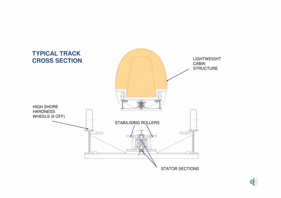
TYPICAL TRACK
CROSS SECTION
HIGH SHORE
HARDNESS
WHEELS (6 OFF)
LIGHTWEIGHT
CABIN
STRUCTURE
STATOR SECTIONS
STABILISING ROLLERS

From the passenger viewpoint, entry and exit, ride quality and transit time is very similar to that of a high quality shuttle elevator

Shuttles are lightweight and have minimum moving parts providing high reliability,
ease of maintenance and very low maintenance costs
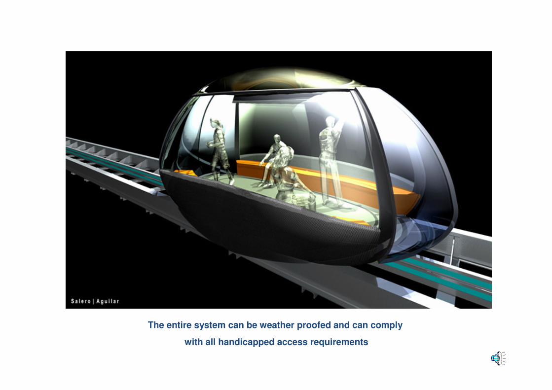
The entire system can be weather proofed and can comply
with all handicapped access requirements

Simple truss sections can be used to support the track sections at high level

Skytrak Circular Transportation

SKYTRAK...
A NEW ERA
FOR VERTICAL
TRANSPORTATION...

Prototype Test Track for
Vertical and Circular Versions

Cabin Assembly
• Composite materials
• Seating, standing
• Battery pack
• Capacitor pack
• Overspeed monitoring
• Inertia switch
• Tilt switch
• TEC air conditioning
• Slewing and slip rings
• Secure wi-fi data
• Door operator
• Load switch
• Slip ring
• Brakes
• Cabin rotational drive
with particle coupling
Design (Total weight with rated load to be < 3200kg)

Skytrak – Cabin Weight Analysis 1597kg
Cabin Main Chassis 200kg Sub Frame Assembly 50kg
Car, Doors, Floor, Seating etc
150kg
Cabin External Enclosure 50kg
Motor 523kg Retarder 132kg
Slewing Ring 30kg Slip Ring 10kg
Brakes 140kg Logic Controller 10kg
Guide Wheels 100kg Door Operator 20kg
Wireless Communication 5kg Battery 60kg
Inertia Switch 1kg Lift Position Information 1kg
Capacitor Pack & “Tuning” 85kg Normally Closed Contactors 15kg
Load Switch 5kg Up Stopping Drive 10kg

Emergency Up-Stopping Invention
Design
� Controlled deceleration when emergency stop occurs in the up direction
� Sufficient energy must be stored ”on board” and available at the instant that
any emergency stop in the up direction occurs
� The lift cabin must separate from the failsafe brake chassis in order to allow
the cabin to continue upwards decelerating at approximately 2 to 3m/s/s
� The storage element consists of a super capacitor module containing
sufficient energy to drive a 3200 kg car in the up direction for several seconds
depending on the speed
� This energy to be delivered to the “on board” retarder elements operating as
a motor using a light weight power electronic drive for a short time interval

TRACK AND MAIN DRIVE
Emergency Up-Stopping Principle

TRACK AND SUB FRAME ASSEMBLY
Emergency Up-Stopping Principle

UNDERSIDE OF SUB FRAME ASSEMBLY
Emergency Up-Stopping Principle

MAIN CHASSIS AND SUB FRAME ASSEMBLY
• Light weight structure
• 3m diameter drum –
shaped cabin
• Low centre of gravity
• Wound “retarder” stator sections
travel with car
• Passenger entrapment negated
by returning car to nearest floor
below
Emergency Up-Stopping Principle

TRACK, SUB FRAME ASSEMBLY AND BRAKES
• Brakes, normal stop
• Twin magnet tracks
• Retarders under car
• Power for car
Emergency Up-Stopping Principle

OPERATION OF BRAKE
• Stopping in down
direction
• Retarders underneath
car negate passenger
entrapment by returning
car to low level
Emergency Up-Stopping Principle

OPERATION OF BRAKE IN UPWARD DIRECTION
• Stopping in up direction
• Unlatching of car
• Stored energy gives 3s run on
for controlled deceleration
• Retarders control descent back to
main drive assembly
• Car can then return to nearest floor
Emergency Up-Stopping Principle

Track
Design
� Early high speed track
proposal
� Ride quality to acceptable standard
� Same track for low speed
and high speed
� Capable of being curved
� Use of composite materials
� Moulded to fit linear
motors/retarders

CONVENTIONAL FIRE RATED LIFT ENTRANCES
Landing Entrances

Traffic Control and Lobby
Arrangements Design
� Destination Hall Call Control� Passenger journeys planned ahead and optimised� Car speeds modulated to control headway� “Up” cars balanced with “Down” cars� Back to back redundant group control� Curved or circular tracks/shafts are parallel
with typical layout shown below

Comparison of Core Space Take (30-story plus building)
Single Deck Double Deck Skytrak
100 : 66 : 40100 : 66 : 40
Reductions of Core Space with Skytrak
Multi-Car Vertical Transportation System
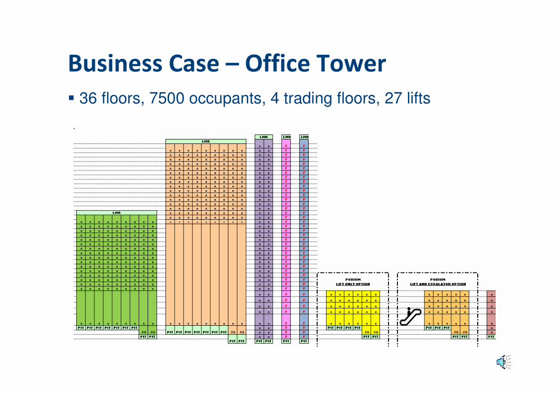
Business Case – Office Tower
� 36 floors, 7500 occupants, 4 trading floors, 27 lifts

Business Case –
Office Tower
� One lift core serves all
occupied floors
� Easy to travel around the
building as no need to transfer between lift groups
� Additional entrances required in the low rise
portion of the high rise zone

Proposed Design has eight lift shafts serving the entire building.
Floors served are levels 5 to 36 i.e. 32 levels
Building Population for purposes of traffic calculations is 12.5 sq m per person. The revised design adds back 3,680 sq m giving a roughly uniform floor plate with 159 persons per floor, total 5,088 persons
Business Case – Office Tower

Business Case – Office Tower

Summary of Business Case
� Additional Value of Space £36m
� Savings Generated £6m
� Eight high rise lifts @ £500k = £4m
� Take savings generated by not constructing the low rise
lifts and place into high rise vertical transportation solution
� £6m plus £4m = £10m (£2.5m per up/down system)
� If the new vertical transportation solution costs no more than two and a half times the cost of the high rise lifts then
the developer gets the £36m value “for free” !

Circular Linear Motor & Lantern Pinion
Slow Speed Drive (<2.5m/s)
� Three single phase linear motor
sections within a 1m diameter circle
� Direct motor drive to lantern pinion at
less than 100 RPM for 2.5 m/s
� Avoids noisy gearing
� Lightweight alloy housing
� Pinion rods or track made of
composite materials, low wear and
noise
� Two motors used to avoid any
backlash
� Combined force output on track 40000
Newtons
Patent Pending
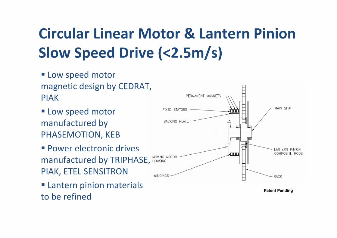
� Low speed motor
magnetic design by CEDRAT,
PIAK
� Low speed motor
manufactured by
PHASEMOTION, KEB
� Power electronic drives
manufactured by TRIPHASE,
PIAK, ETEL SENSITRON
� Lantern pinion materials
to be refined
Circular Linear Motor & Lantern Pinion
Slow Speed Drive (<2.5m/s)
Patent Pending

Skytrak – Terminal “Switches”
Patent Pending
� Minimum horizontal movement
� Minimum transfer time
� Cars remain “on” track
� Simple pivot drive arrangement
� Plan space of shafts = conventional 1600kg
capacity lifts with side counterweight
� “Through” car design utilised
� No slip rings
PLAN VIEW SECTION VIEW

Skytrak – Terminal Parking and/or
Servicing Areas
Patent Pending
SECTION AT MACHINE ROOM LEVEL SECTION AT PIT LEVEL

“Low Speed” Skytrak – Traffic Simulation