Embed Size (px)
Citation preview
SkyLiTE: End-to-End Design of Low-altitude UAV Networksfor Providing LTE Connectivity
Karthikeyan Sundaresan, Eugene Chai, Ayon Chakraborty, Sampath RangarajanNEC Labs America, Princeton, NJ 08540
Email: [email protected]
ABSTRACTUn-manned aerial vehicle (UAVs) have the potential to changethe landscape of wide-area wireless connectivity by bringingthem to areas where connectivity was sparing or non-existent(e.g. rural areas) or has been compromised due to disasters.While Google’s Project Loon and Facebook’s Project Aquilaare examples of high-altitude, long-endurance UAV-basedconnectivity efforts in this direction, the telecom operators(e.g. AT&T and Verizon) have been exploring low-altitudeUAV-based LTE solutions for on-demand deployments. Un-derstandably, these projects are in their early stages and faceformidable challenges in their realization and deployment.The goal of this document is to expose the reader to both thechallenges as well as the potential offered by these uncon-ventional connectivity solutions. We aim to explore the end-to-end design of such UAV-based connectivity networks par-ticularly in the context of low-altitude UAV networks pro-viding LTE connectivity. Specifically, we aim to highlightthe challenges that span across multiple layers (access, corenetwork, backhaul) in an inter-twined manner as well as therichness and complexity of the design space itself. To helpinterested readers navigate this complex design space to-wards a solution, we also articulate the overview of one suchend-to-end design, namely SkyLiTE– a self-organizing net-work of low-altitude UAVs that provide optimized LTE con-nectivity in a desired region.
KeywordsUAVs, LTE, RAN, EPC, backhaul, drone, localization,SDN, re-configuration, mmWave, FSO
1. VISIONToday, wireless access and connectivity is largely a
two-dimensional (terrestrial) problem, where well-plannedbase stations are statically deployed in economically vi-able areas. The growing maturity of unmanned aerialvehicle (UAV) technology aims to change that notion byadding a third spatial degree of freedom (aerial), whichhas the potential to completely change the landscape ofwireless connectivity. We now have the technical meansto deploy aerial base stations (BSs on UAVs) on thefly and provide wireless connectivity in areas where a
UAV
Satellite
Macro eNB
Control Station UE
Connectivity for C&C Out of band (macro/satellite) In band (ground station)
PoP
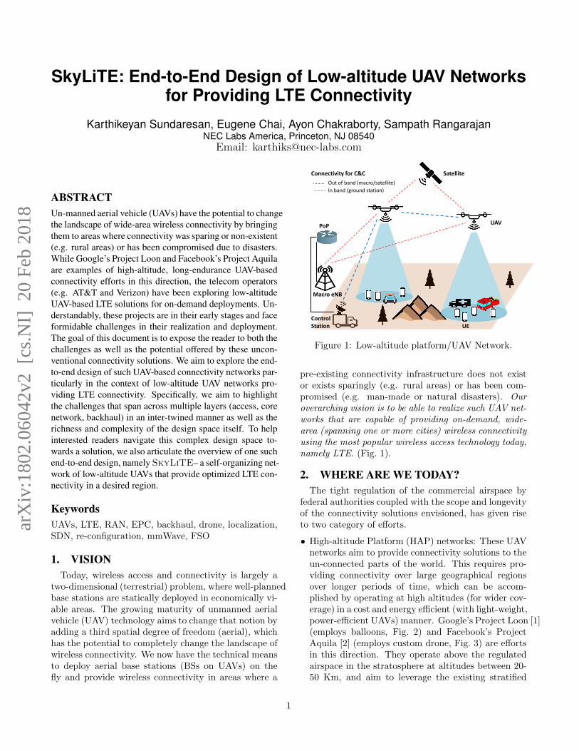
Figure 1: Low-altitude platform/UAV Network.
pre-existing connectivity infrastructure does not existor exists sparingly (e.g. rural areas) or has been com-promised (e.g. man-made or natural disasters). Ouroverarching vision is to be able to realize such UAV net-works that are capable of providing on-demand, wide-area (spanning one or more cities) wireless connectivityusing the most popular wireless access technology today,namely LTE. (Fig. 1).
2. WHERE ARE WE TODAY?The tight regulation of the commercial airspace by
federal authorities coupled with the scope and longevityof the connectivity solutions envisioned, has given riseto two category of efforts.
• High-altitude Platform (HAP) networks: These UAVnetworks aim to provide connectivity solutions to theun-connected parts of the world. This requires pro-viding connectivity over large geographical regionsover longer periods of time, which can be accom-plished by operating at high altitudes (for wider cov-erage) in a cost and energy efficient (with light-weight,power-efficient UAVs) manner. Google’s Project Loon [1](employs balloons, Fig. 2) and Facebook’s ProjectAquila [2] (employs custom drone, Fig. 3) are effortsin this direction. They operate above the regulatedairspace in the stratosphere at altitudes between 20-50 Km, and aim to leverage the existing stratified
1
arX
iv:1
802.
0604
2v2
[cs
.NI]
20
Feb
2018
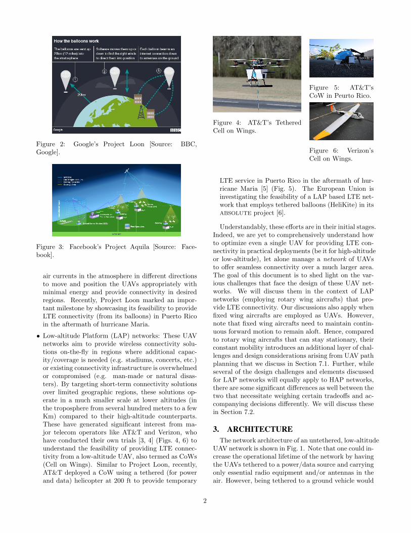
Figure 2: Google’s Project Loon [Source: BBC,Google].
Figure 3: Facebook’s Project Aquila [Source: Face-book].
air currents in the atmosphere in different directionsto move and position the UAVs appropriately withminimal energy and provide connectivity in desiredregions. Recently, Project Loon marked an impor-tant milestone by showcasing its feasibility to provideLTE connectivity (from its balloons) in Puerto Ricoin the aftermath of hurricane Maria.
• Low-altitude Platform (LAP) networks: These UAVnetworks aim to provide wireless connectivity solu-tions on-the-fly in regions where additional capac-ity/coverage is needed (e.g. stadiums, concerts, etc.)or existing connectivity infrastructure is overwhelmedor compromised (e.g. man-made or natural disas-ters). By targeting short-term connectivity solutionsover limited geographic regions, these solutions op-erate in a much smaller scale at lower altitudes (inthe troposphere from several hundred meters to a fewKm) compared to their high-altitude counterparts.These have generated significant interest from ma-jor telecom operators like AT&T and Verizon, whohave conducted their own trials [3, 4] (Figs. 4, 6) tounderstand the feasibility of providing LTE connec-tivity from a low-altitude UAV, also termed as CoWs(Cell on Wings). Similar to Project Loon, recently,AT&T deployed a CoW using a tethered (for powerand data) helicopter at 200 ft to provide temporary
Figure 4: AT&T’s TetheredCell on Wings.
Figure 5: AT&T’sCoW in Peurto Rico.
Figure 6: Verizon’sCell on Wings.
LTE service in Puerto Rico in the aftermath of hur-ricane Maria [5] (Fig. 5). The European Union isinvestigating the feasibility of a LAP based LTE net-work that employs tethered balloons (HeliKite) in itsABSOLUTE project [6].
Understandably, these efforts are in their initial stages.Indeed, we are yet to comprehensively understand howto optimize even a single UAV for providing LTE con-nectivity in practical deployments (be it for high-altitudeor low-altitude), let alone manage a network of UAVsto offer seamless connectivity over a much larger area.The goal of this document is to shed light on the var-ious challenges that face the design of these UAV net-works. We will discuss them in the context of LAPnetworks (employing rotary wing aircrafts) that pro-vide LTE connectivity. Our discussions also apply whenfixed wing aircrafts are employed as UAVs. However,note that fixed wing aircrafts need to maintain contin-uous forward motion to remain aloft. Hence, comparedto rotary wing aircrafts that can stay stationary, theirconstant mobility introduces an additional layer of chal-lenges and design considerations arising from UAV pathplanning that we discuss in Section 7.1. Further, whileseveral of the design challenges and elements discussedfor LAP networks will equally apply to HAP networks,there are some significant differences as well between thetwo that necessitate weighing certain tradeoffs and ac-companying decisions differently. We will discuss thesein Section 7.2.
3. ARCHITECTUREThe network architecture of an untethered, low-altitude
UAV network is shown in Fig. 1. Note that one could in-crease the operational lifetime of the network by havingthe UAVs tethered to a power/data source and carryingonly essential radio equipment and/or antennas in theair. However, being tethered to a ground vehicle would
2
significantly restrict its deployment flexibility to onlyaccessible areas on the ground (potentially less usefulin disasters), as well as its coverage and optimizationcapabilities. Hence, we will focus on the untetheredscenario to explore the most flexible version of UAVnetwork deployments.
The UAV carries the LTE base station (eNB) andprovides connectivity to users (UEs) on the ground.There are two potential realizations of our network vi-sion that can cater to different use cases. (i) Stand-alone: We can deploy a stand-alone LTE connectivityinfrastructure, which does not connect (backhaul) tothe Internet (i.e. an Internet point-of-presence does notexist). In cases, where no pre-existing connectivity in-frastructure is available, such a stand-alone network canbe useful in providing connectivity and communicationbetween first responders, emergency services and peoplein disaster scenarios. (ii) Internet-backhauled: When apoint-of-access (such as a ground station or macro-cell)to Internet exists, then in addition to the stand-aloneservices that can be delivered, one can also provide In-ternet access to both users in emergency scenarios aswell as those in areas of limited/no connectivity.
There are two components to wireless connectivity inthis architecture: the wireless links between the basestation on the UAV and the UEs on the ground consti-tute the radio access network (RAN), while the wire-less links between the UAVs themselves that form awireless multi-hop mesh network (in the air) constitutethe backhaul. While both these components cater todata communication between users and Internet, thereis also another wireless connectivity component that isneeded to provide command and control (C&C) for theUAVs. One could potentially leverage the RAN andbackhaul connectivity for C&C as well (in addition todata/payload). However, given the mobile and multi-hop nature of the backhaul, the latter may not “al-ways” guarantee connectivity for safety-critical opera-tions such as UAV C&C (crash avoidance, . Hence, thepreference for reliable C&C connectivity to the UAVsis typically through a static, always-reachable networknode. This can be achieved through macro cell towers(less expensive option), when one or more is availableand can reach all the UAVs, or through a satellite (moreexpensive option) as shown in Fig. 1. The latter, beingthe only viable option for C&C in high-altitude net-works, is adopted by Project Loon and Aquila.
4. LAYERED CHALLENGESThe goal of this section is to explore the design space
of our network vision by understanding the various lay-ered challenges that arise in its realization. A conven-tional LTE network consists of two main components:static base stations that provide wireless access to users(RAN - radio access network), and a wired core network
UAV
UE
P1
P2 P3
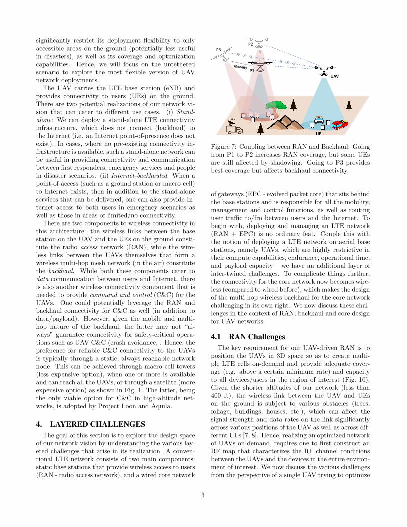
Figure 7: Coupling between RAN and Backhaul: Goingfrom P1 to P2 increases RAN coverage, but some UEsare still affected by shadowing. Going to P3 providesbest coverage but affects backhaul connectivity.
of gateways (EPC - evolved packet core) that sits behindthe base stations and is responsible for all the mobility,management and control functions, as well as routinguser traffic to/fro between users and the Internet. Tobegin with, deploying and managing an LTE network(RAN + EPC) is no ordinary feat. Couple this withthe notion of deploying a LTE network on aerial basestations, namely UAVs, which are highly restrictive intheir compute capabilities, endurance, operational time,and payload capacity – we have an additional layer ofinter-twined challenges. To complicate things further,the connectivity for the core network now becomes wire-less (compared to wired before), which makes the designof the multi-hop wireless backhaul for the core networkchallenging in its own right. We now discuss these chal-lenges in the context of RAN, backhaul and core designfor UAV networks.
4.1 RAN ChallengesThe key requirement for our UAV-driven RAN is to
position the UAVs in 3D space so as to create multi-ple LTE cells on-demand and provide adequate cover-age (e.g. above a certain minimum rate) and capacityto all devices/users in the region of interest (Fig. 10).Given the shorter altitudes of our network (less than400 ft), the wireless link between the UAV and UEson the ground is subject to various obstacles (trees,foliage, buildings, houses, etc.), which can affect thesignal strength and data rates on the link significantlyacross various positions of the UAV as well as across dif-ferent UEs [7, 8]. Hence, realizing an optimized networkof UAVs on-demand, requires one to first construct anRF map that characterizes the RF channel conditionsbetween the UAVs and the devices in the entire environ-ment of interest. We now discuss the various challengesfrom the perspective of a single UAV trying to optimize
3
0 20 40 60 80East - West (meters)
0
10
20
30
40
50
60
70
80No
rth -
Sout
h (m
eter
s)
70
75
80
85
90
95
100
105
110
Path
loss
(dB)
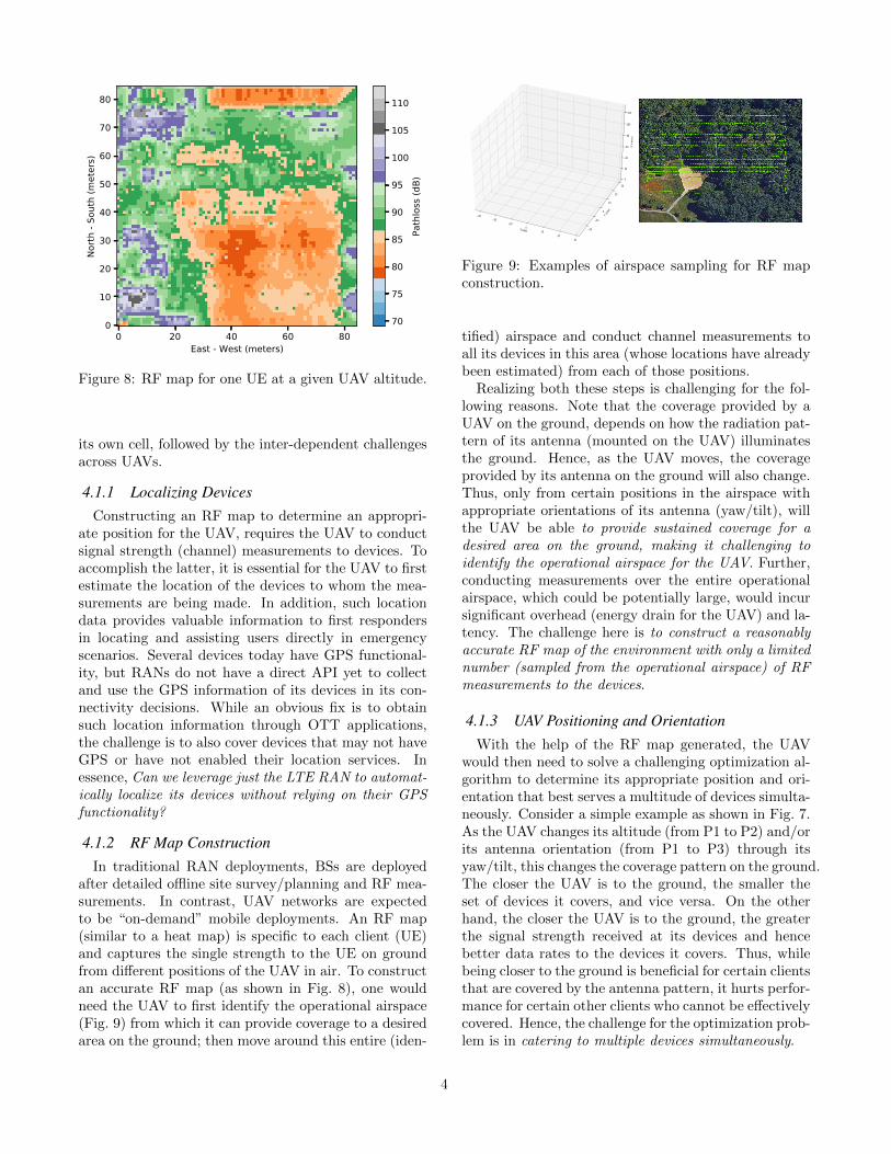
Figure 8: RF map for one UE at a given UAV altitude.
its own cell, followed by the inter-dependent challengesacross UAVs.
4.1.1 Localizing DevicesConstructing an RF map to determine an appropri-
ate position for the UAV, requires the UAV to conductsignal strength (channel) measurements to devices. Toaccomplish the latter, it is essential for the UAV to firstestimate the location of the devices to whom the mea-surements are being made. In addition, such locationdata provides valuable information to first respondersin locating and assisting users directly in emergencyscenarios. Several devices today have GPS functional-ity, but RANs do not have a direct API yet to collectand use the GPS information of its devices in its con-nectivity decisions. While an obvious fix is to obtainsuch location information through OTT applications,the challenge is to also cover devices that may not haveGPS or have not enabled their location services. Inessence, Can we leverage just the LTE RAN to automat-ically localize its devices without relying on their GPSfunctionality?
4.1.2 RF Map ConstructionIn traditional RAN deployments, BSs are deployed
after detailed offline site survey/planning and RF mea-surements. In contrast, UAV networks are expectedto be “on-demand” mobile deployments. An RF map(similar to a heat map) is specific to each client (UE)and captures the single strength to the UE on groundfrom different positions of the UAV in air. To constructan accurate RF map (as shown in Fig. 8), one wouldneed the UAV to first identify the operational airspace(Fig. 9) from which it can provide coverage to a desiredarea on the ground; then move around this entire (iden-
X Label
3020
100
1020
30
Y Lab
el
20
10
0
10
20
30
Z L
abel
0
20
40
60
80
100
120
Figure 9: Examples of airspace sampling for RF mapconstruction.
tified) airspace and conduct channel measurements toall its devices in this area (whose locations have alreadybeen estimated) from each of those positions.
Realizing both these steps is challenging for the fol-lowing reasons. Note that the coverage provided by aUAV on the ground, depends on how the radiation pat-tern of its antenna (mounted on the UAV) illuminatesthe ground. Hence, as the UAV moves, the coverageprovided by its antenna on the ground will also change.Thus, only from certain positions in the airspace withappropriate orientations of its antenna (yaw/tilt), willthe UAV be able to provide sustained coverage for adesired area on the ground, making it challenging toidentify the operational airspace for the UAV. Further,conducting measurements over the entire operationalairspace, which could be potentially large, would incursignificant overhead (energy drain for the UAV) and la-tency. The challenge here is to construct a reasonablyaccurate RF map of the environment with only a limitednumber (sampled from the operational airspace) of RFmeasurements to the devices.
4.1.3 UAV Positioning and OrientationWith the help of the RF map generated, the UAV
would then need to solve a challenging optimization al-gorithm to determine its appropriate position and ori-entation that best serves a multitude of devices simulta-neously. Consider a simple example as shown in Fig. 7.As the UAV changes its altitude (from P1 to P2) and/orits antenna orientation (from P1 to P3) through itsyaw/tilt, this changes the coverage pattern on the ground.The closer the UAV is to the ground, the smaller theset of devices it covers, and vice versa. On the otherhand, the closer the UAV is to the ground, the greaterthe signal strength received at its devices and hencebetter data rates to the devices it covers. Thus, whilebeing closer to the ground is beneficial for certain clientsthat are covered by the antenna pattern, it hurts perfor-mance for certain other clients who cannot be effectivelycovered. Hence, the challenge for the optimization prob-lem is in catering to multiple devices simultaneously.
4
UAV
Control Station UE
RAN traffic Backhaul traffic
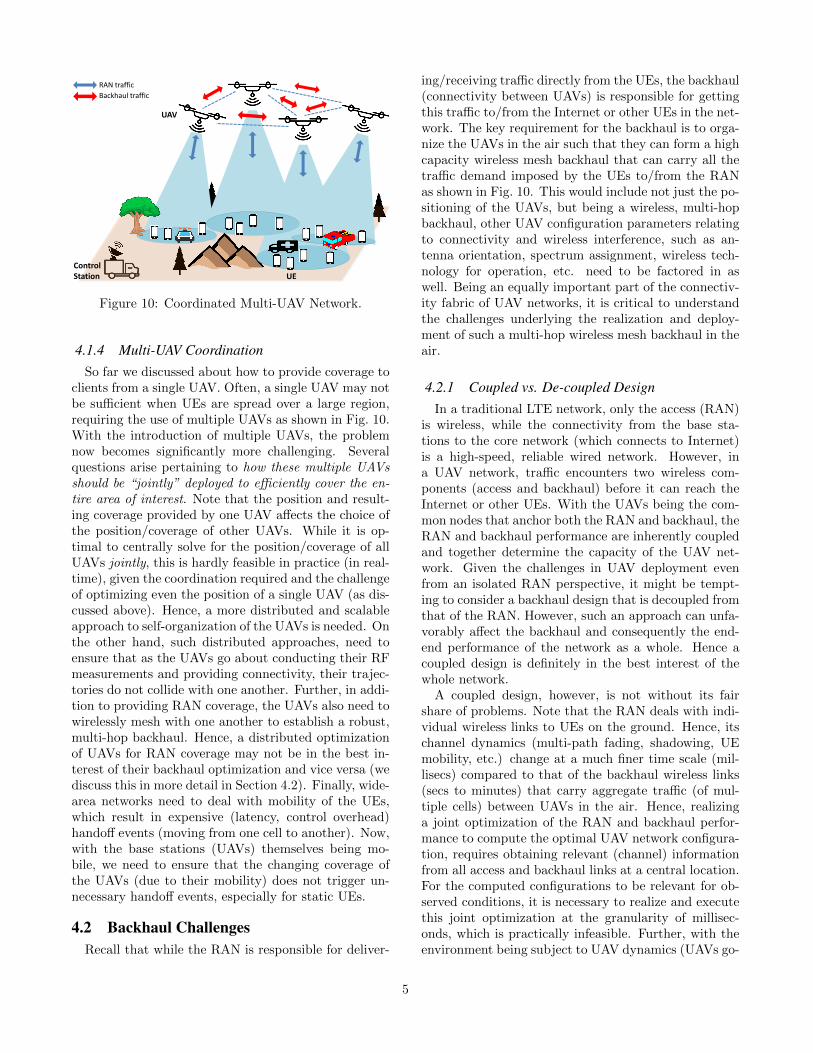
Figure 10: Coordinated Multi-UAV Network.
4.1.4 Multi-UAV CoordinationSo far we discussed about how to provide coverage to
clients from a single UAV. Often, a single UAV may notbe sufficient when UEs are spread over a large region,requiring the use of multiple UAVs as shown in Fig. 10.With the introduction of multiple UAVs, the problemnow becomes significantly more challenging. Severalquestions arise pertaining to how these multiple UAVsshould be “jointly” deployed to efficiently cover the en-tire area of interest. Note that the position and result-ing coverage provided by one UAV affects the choice ofthe position/coverage of other UAVs. While it is op-timal to centrally solve for the position/coverage of allUAVs jointly, this is hardly feasible in practice (in real-time), given the coordination required and the challengeof optimizing even the position of a single UAV (as dis-cussed above). Hence, a more distributed and scalableapproach to self-organization of the UAVs is needed. Onthe other hand, such distributed approaches, need toensure that as the UAVs go about conducting their RFmeasurements and providing connectivity, their trajec-tories do not collide with one another. Further, in addi-tion to providing RAN coverage, the UAVs also need towirelessly mesh with one another to establish a robust,multi-hop backhaul. Hence, a distributed optimizationof UAVs for RAN coverage may not be in the best in-terest of their backhaul optimization and vice versa (wediscuss this in more detail in Section 4.2). Finally, wide-area networks need to deal with mobility of the UEs,which result in expensive (latency, control overhead)handoff events (moving from one cell to another). Now,with the base stations (UAVs) themselves being mo-bile, we need to ensure that the changing coverage ofthe UAVs (due to their mobility) does not trigger un-necessary handoff events, especially for static UEs.
4.2 Backhaul ChallengesRecall that while the RAN is responsible for deliver-
ing/receiving traffic directly from the UEs, the backhaul(connectivity between UAVs) is responsible for gettingthis traffic to/from the Internet or other UEs in the net-work. The key requirement for the backhaul is to orga-nize the UAVs in the air such that they can form a highcapacity wireless mesh backhaul that can carry all thetraffic demand imposed by the UEs to/from the RANas shown in Fig. 10. This would include not just the po-sitioning of the UAVs, but being a wireless, multi-hopbackhaul, other UAV configuration parameters relatingto connectivity and wireless interference, such as an-tenna orientation, spectrum assignment, wireless tech-nology for operation, etc. need to be factored in aswell. Being an equally important part of the connectiv-ity fabric of UAV networks, it is critical to understandthe challenges underlying the realization and deploy-ment of such a multi-hop wireless mesh backhaul in theair.
4.2.1 Coupled vs. De-coupled DesignIn a traditional LTE network, only the access (RAN)
is wireless, while the connectivity from the base sta-tions to the core network (which connects to Internet)is a high-speed, reliable wired network. However, ina UAV network, traffic encounters two wireless com-ponents (access and backhaul) before it can reach theInternet or other UEs. With the UAVs being the com-mon nodes that anchor both the RAN and backhaul, theRAN and backhaul performance are inherently coupledand together determine the capacity of the UAV net-work. Given the challenges in UAV deployment evenfrom an isolated RAN perspective, it might be tempt-ing to consider a backhaul design that is decoupled fromthat of the RAN. However, such an approach can unfa-vorably affect the backhaul and consequently the end-end performance of the network as a whole. Hence acoupled design is definitely in the best interest of thewhole network.
A coupled design, however, is not without its fairshare of problems. Note that the RAN deals with indi-vidual wireless links to UEs on the ground. Hence, itschannel dynamics (multi-path fading, shadowing, UEmobility, etc.) change at a much finer time scale (mil-lisecs) compared to that of the backhaul wireless links(secs to minutes) that carry aggregate traffic (of mul-tiple cells) between UAVs in the air. Hence, realizinga joint optimization of the RAN and backhaul perfor-mance to compute the optimal UAV network configura-tion, requires obtaining relevant (channel) informationfrom all access and backhaul links at a central location.For the computed configurations to be relevant for ob-served conditions, it is necessary to realize and executethis joint optimization at the granularity of millisec-onds, which is practically infeasible. Further, with theenvironment being subject to UAV dynamics (UAVs go-
5
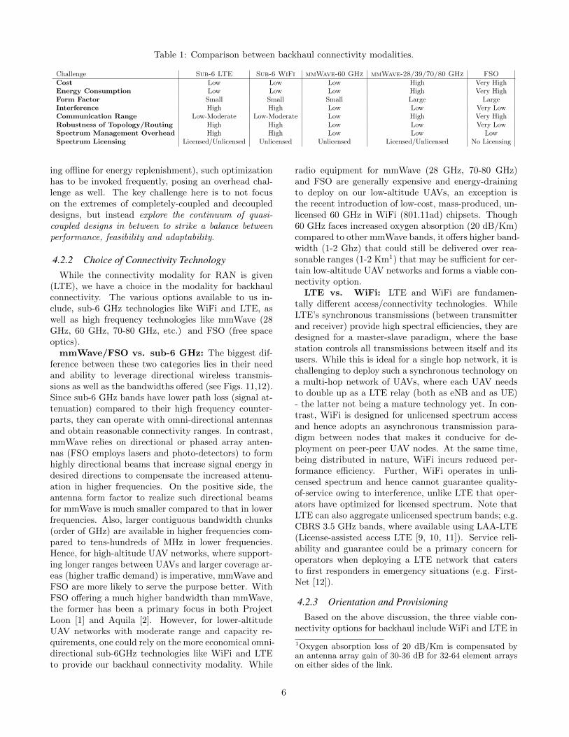
Table 1: Comparison between backhaul connectivity modalities.
Challenge Sub-6 LTE Sub-6 WiFi mmWave-60 GHz mmWave-28/39/70/80 GHz FSOCost Low Low Low High Very HighEnergy Consumption Low Low Low High Very HighForm Factor Small Small Small Large LargeInterference High High Low Low Very LowCommunication Range Low-Moderate Low-Moderate Low High Very HighRobustness of Topology/Routing High High Low Low Very LowSpectrum Management Overhead High High Low Low LowSpectrum Licensing Licensed/Unlicensed Unlicensed Unlicensed Licensed/Unlicensed No Licensing
ing offline for energy replenishment), such optimizationhas to be invoked frequently, posing an overhead chal-lenge as well. The key challenge here is to not focuson the extremes of completely-coupled and decoupleddesigns, but instead explore the continuum of quasi-coupled designs in between to strike a balance betweenperformance, feasibility and adaptability.
4.2.2 Choice of Connectivity TechnologyWhile the connectivity modality for RAN is given
(LTE), we have a choice in the modality for backhaulconnectivity. The various options available to us in-clude, sub-6 GHz technologies like WiFi and LTE, aswell as high frequency technologies like mmWave (28GHz, 60 GHz, 70-80 GHz, etc.) and FSO (free spaceoptics).
mmWave/FSO vs. sub-6 GHz: The biggest dif-ference between these two categories lies in their needand ability to leverage directional wireless transmis-sions as well as the bandwidths offered (see Figs. 11,12).Since sub-6 GHz bands have lower path loss (signal at-tenuation) compared to their high frequency counter-parts, they can operate with omni-directional antennasand obtain reasonable connectivity ranges. In contrast,mmWave relies on directional or phased array anten-nas (FSO employs lasers and photo-detectors) to formhighly directional beams that increase signal energy indesired directions to compensate the increased attenu-ation in higher frequencies. On the positive side, theantenna form factor to realize such directional beamsfor mmWave is much smaller compared to that in lowerfrequencies. Also, larger contiguous bandwidth chunks(order of GHz) are available in higher frequencies com-pared to tens-hundreds of MHz in lower frequencies.Hence, for high-altitude UAV networks, where support-ing longer ranges between UAVs and larger coverage ar-eas (higher traffic demand) is imperative, mmWave andFSO are more likely to serve the purpose better. WithFSO offering a much higher bandwidth than mmWave,the former has been a primary focus in both ProjectLoon [1] and Aquila [2]. However, for lower-altitudeUAV networks with moderate range and capacity re-quirements, one could rely on the more economical omni-directional sub-6GHz technologies like WiFi and LTEto provide our backhaul connectivity modality. While
radio equipment for mmWave (28 GHz, 70-80 GHz)and FSO are generally expensive and energy-drainingto deploy on our low-altitude UAVs, an exception isthe recent introduction of low-cost, mass-produced, un-licensed 60 GHz in WiFi (801.11ad) chipsets. Though60 GHz faces increased oxygen absorption (20 dB/Km)compared to other mmWave bands, it offers higher band-width (1-2 Ghz) that could still be delivered over rea-sonable ranges (1-2 Km1) that may be sufficient for cer-tain low-altitude UAV networks and forms a viable con-nectivity option.
LTE vs. WiFi: LTE and WiFi are fundamen-tally different access/connectivity technologies. WhileLTE’s synchronous transmissions (between transmitterand receiver) provide high spectral efficiencies, they aredesigned for a master-slave paradigm, where the basestation controls all transmissions between itself and itsusers. While this is ideal for a single hop network, it ischallenging to deploy such a synchronous technology ona multi-hop network of UAVs, where each UAV needsto double up as a LTE relay (both as eNB and as UE)- the latter not being a mature technology yet. In con-trast, WiFi is designed for unlicensed spectrum accessand hence adopts an asynchronous transmission para-digm between nodes that makes it conducive for de-ployment on peer-peer UAV nodes. At the same time,being distributed in nature, WiFi incurs reduced per-formance efficiency. Further, WiFi operates in unli-censed spectrum and hence cannot guarantee quality-of-service owing to interference, unlike LTE that oper-ators have optimized for licensed spectrum. Note thatLTE can also aggregate unlicensed spectrum bands; e.g.CBRS 3.5 GHz bands, where available using LAA-LTE(License-assisted access LTE [9, 10, 11]). Service reli-ability and guarantee could be a primary concern foroperators when deploying a LTE network that catersto first responders in emergency situations (e.g. First-Net [12]).
4.2.3 Orientation and ProvisioningBased on the above discussion, the three viable con-
nectivity options for backhaul include WiFi and LTE in
1Oxygen absorption loss of 20 dB/Km is compensated byan antenna array gain of 30-36 dB for 32-64 element arrayson either sides of the link.
6
Ch1
Ch2
Ch3
Ch1
Ch1
Ch3
Ch2
Ch3
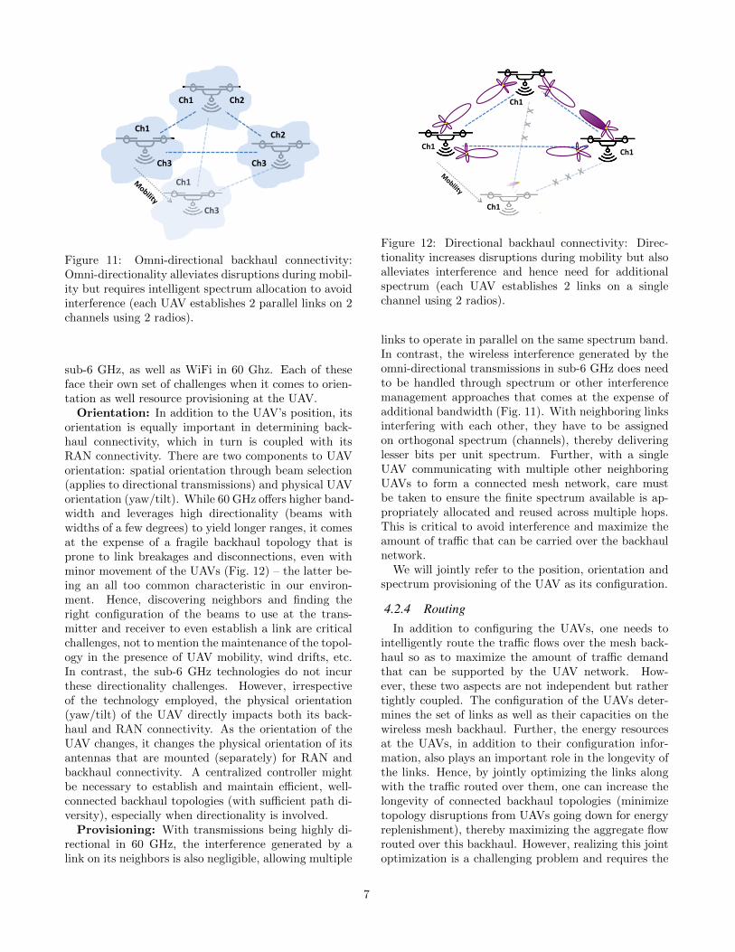
Figure 11: Omni-directional backhaul connectivity:Omni-directionality alleviates disruptions during mobil-ity but requires intelligent spectrum allocation to avoidinterference (each UAV establishes 2 parallel links on 2channels using 2 radios).
sub-6 GHz, as well as WiFi in 60 Ghz. Each of theseface their own set of challenges when it comes to orien-tation as well resource provisioning at the UAV.
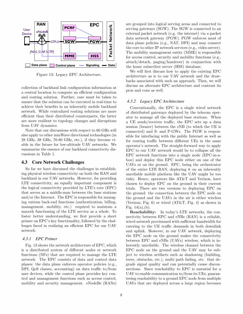
Orientation: In addition to the UAV’s position, itsorientation is equally important in determining back-haul connectivity, which in turn is coupled with itsRAN connectivity. There are two components to UAVorientation: spatial orientation through beam selection(applies to directional transmissions) and physical UAVorientation (yaw/tilt). While 60 GHz offers higher band-width and leverages high directionality (beams withwidths of a few degrees) to yield longer ranges, it comesat the expense of a fragile backhaul topology that isprone to link breakages and disconnections, even withminor movement of the UAVs (Fig. 12) – the latter be-ing an all too common characteristic in our environ-ment. Hence, discovering neighbors and finding theright configuration of the beams to use at the trans-mitter and receiver to even establish a link are criticalchallenges, not to mention the maintenance of the topol-ogy in the presence of UAV mobility, wind drifts, etc.In contrast, the sub-6 GHz technologies do not incurthese directionality challenges. However, irrespectiveof the technology employed, the physical orientation(yaw/tilt) of the UAV directly impacts both its back-haul and RAN connectivity. As the orientation of theUAV changes, it changes the physical orientation of itsantennas that are mounted (separately) for RAN andbackhaul connectivity. A centralized controller mightbe necessary to establish and maintain efficient, well-connected backhaul topologies (with sufficient path di-versity), especially when directionality is involved.
Provisioning: With transmissions being highly di-rectional in 60 GHz, the interference generated by alink on its neighbors is also negligible, allowing multiple
Ch1
Ch1
Ch1
Ch1
Figure 12: Directional backhaul connectivity: Direc-tionality increases disruptions during mobility but alsoalleviates interference and hence need for additionalspectrum (each UAV establishes 2 links on a singlechannel using 2 radios).
links to operate in parallel on the same spectrum band.In contrast, the wireless interference generated by theomni-directional transmissions in sub-6 GHz does needto be handled through spectrum or other interferencemanagement approaches that comes at the expense ofadditional bandwidth (Fig. 11). With neighboring linksinterfering with each other, they have to be assignedon orthogonal spectrum (channels), thereby deliveringlesser bits per unit spectrum. Further, with a singleUAV communicating with multiple other neighboringUAVs to form a connected mesh network, care mustbe taken to ensure the finite spectrum available is ap-propriately allocated and reused across multiple hops.This is critical to avoid interference and maximize theamount of traffic that can be carried over the backhaulnetwork.
We will jointly refer to the position, orientation andspectrum provisioning of the UAV as its configuration.
4.2.4 RoutingIn addition to configuring the UAVs, one needs to
intelligently route the traffic flows over the mesh back-haul so as to maximize the amount of traffic demandthat can be supported by the UAV network. How-ever, these two aspects are not independent but rathertightly coupled. The configuration of the UAVs deter-mines the set of links as well as their capacities on thewireless mesh backhaul. Further, the energy resourcesat the UAVs, in addition to their configuration infor-mation, also plays an important role in the longevity ofthe links. Hence, by jointly optimizing the links alongwith the traffic routed over them, one can increase thelongevity of connected backhaul topologies (minimizetopology disruptions from UAVs going down for energyreplenishment), thereby maximizing the aggregate flowrouted over this backhaul. However, realizing this jointoptimization is a challenging problem and requires the
7
PCRF
MME[NAS, S1AP, SCTP]
Pack
et N
etw
ork
PGWGTP-U
HSS
RAN EPC
SGW
Data plane Control plane Signaling Data
eNodeBUser
Device
Figure 13: Legacy EPC Architecture.
collection of backhaul link configuration information ata central location to compute an efficient configurationand routing solution. Further, care must be taken toensure that the solution can be executed in real-time toachieve their benefits in an inherently mobile backhaulnetwork. While centralized routing solutions are moreefficient than their distributed counterparts, the latterare more resilient to topology changes and disruptionsfrom UAV dynamics.
Note that our discussions with respect to 60 GHz willalso apply to other mmWave directional technologies (in28 GHz, 38 GHz, 70-80 GHz, etc.), if they become vi-able in the future for low-altitude UAV networks. Wesummarize the essence of our backhaul connectivity dis-cussions in Table 1.
4.3 Core Network ChallengesSo far we have discussed the challenges in establish-
ing physical wireless connectivity on both the RAN andbackhaul in our UAV networks. However, for providingLTE connectivity, an equally important component isthe logical connectivity provided by LTE’s core (EPC)that serves as a middle-man between the base stationsand/or the Internet. The EPC is responsible for manag-ing various back-end functions (authentication, billing,management, mobility, etc.) required to maintain asmooth functioning of the LTE service as a whole. Tofoster better understanding, we first provide a shortprimer on EPC’s key functionality, followed by the chal-lenges faced in realizing an efficient EPC for our UAVnetwork.
4.3.1 EPC PrimerFig. 13 shows the network architecture of EPC, which
is a distributed system of different nodes or networkfunctions (NFs) that are required to manage the LTEnetwork. The EPC consists of data and control dataplanes: the data plane enforces operator policies (e.g.,DPI, QoS classes, accounting) on data traffic to/fromuser devices, while the control plane provides key con-trol and management functions such as access control,mobility and security management. eNodeBs (RANs)
are grouped into logical serving areas and connected toserving gateways (SGW). The SGW is connected to anexternal packet network (e.g. the internet) via a packetdata network gateway (PGW). PGW enforces most ofdata plane policies (e.g., NAT, DPI) and may connectthe core to other IP network services (e.g., video server).The mobility management entity (MME) is responsiblefor access control, security and mobility functions (e.g.,attach/detach, paging/handover) in conjunction withthe home subscriber server (HSS) database.
We will first discuss how to apply the existing EPCarchitecture as is to our UAV network and the draw-backs associated with such an approach. Then, we willdiscuss an alternate EPC architecture and contrast itspros and cons as well.
4.3.2 Legacy EPC ArchitectureConventionally, the EPC is a single wired network
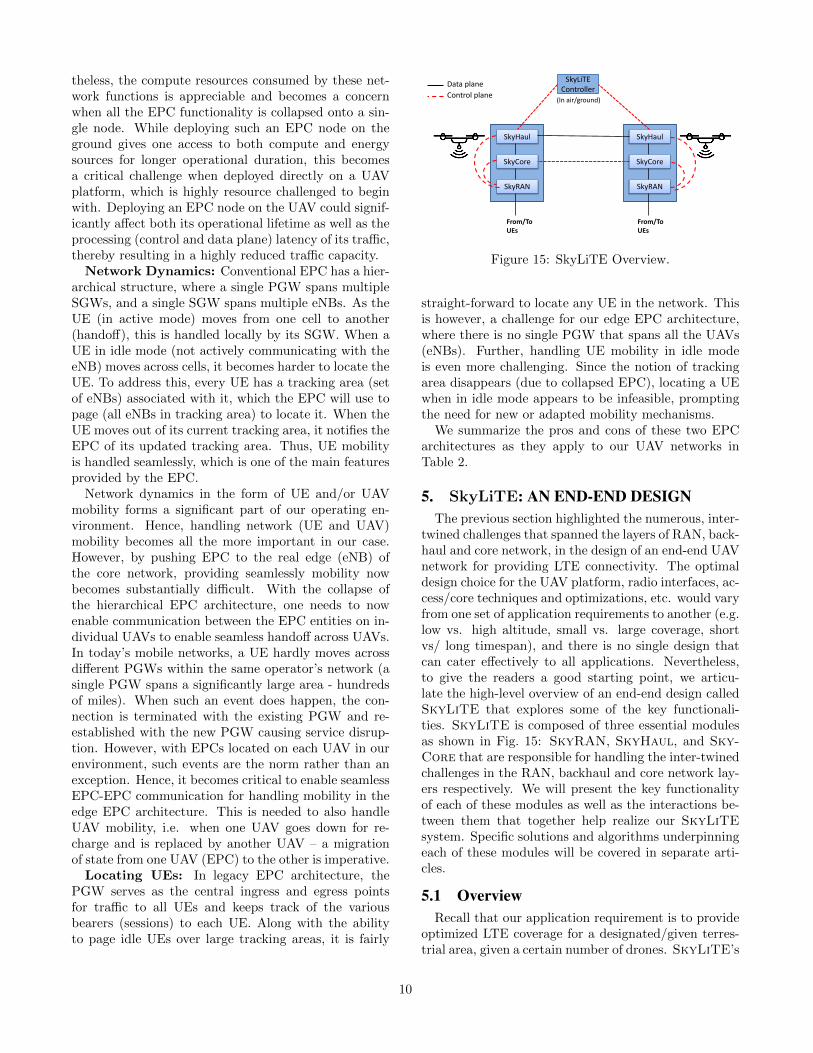
of distributed gateways deployed by the telecom oper-ator to manage all the deployed base stations. Whena UE sends/receives traffic, the EPC sets up a datasession (bearer) between the eNB (to which the UE isconnected) and S- and P-GWs. The PGW is respon-sible for interfacing with the public Internet as well asfor routing traffic between different UEs in the sameoperator’s network. The straight-forward way to applyEPC to our UAV network would be to collapse all theEPC network functions into a single node (EPC-in-a-box) and deploy this EPC node either on one of theUAVs or on the ground. EPC, being the orchestratorof the entire LTE RAN, deploying it on an inherentlyunreliable mobile platform like the UAV might be toorisky. Hence, operators like AT&T and Verizon, havechosen to deploy EPC on the ground in their currenttrials. There are two versions to deploying EPC onthe ground: the connection between the EPC node onthe ground and the UAVs in the air is either wireless(Verizon, Fig. 6) or wired (AT&T, Fig. 4) as shown inFig. 14(a),(b).
Reachability: In today’s LTE networks, the con-nectivity between EPC and eNBs (RAN) is a reliable,wired network provisioned with sufficient bandwidth forcatering to the UE traffic demands in both downlinkand uplink. However, in our UAV network, deployingthe EPC node on the ground makes the connectivitybetween EPC and eNBs (UAVs) wireless, which is in-herently unreliable. The wireless channel between theEPC node on the ground and the UAV may be sub-ject to wireless artifacts such as shadowing (building,trees, obstacles, etc.), multi path fading, etc. that de-grade signal quality and can potentially cause discon-nections. Since reachability to EPC is essential for aUAV to enable communication to/from its UEs, guaran-teeing reachability to a ground EPC node from multipleUAVs that are deployed across a large region becomes
8
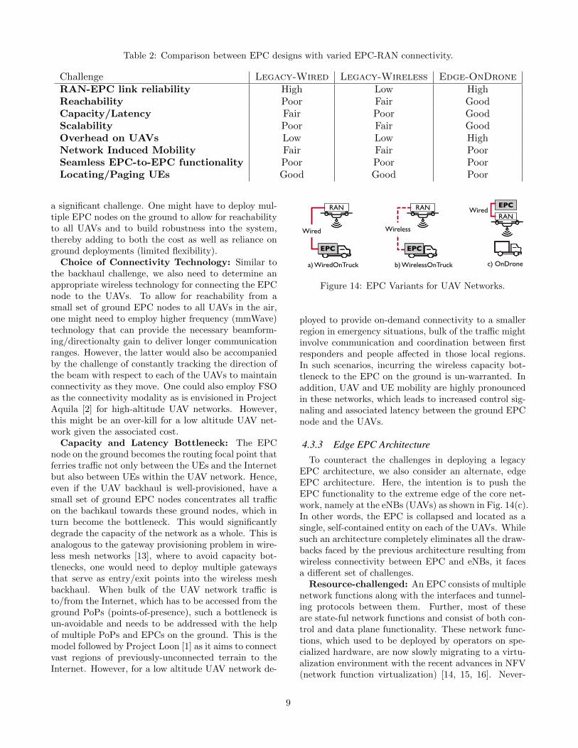
Table 2: Comparison between EPC designs with varied EPC-RAN connectivity.
Challenge Legacy-Wired Legacy-Wireless Edge-OnDroneRAN-EPC link reliability High Low HighReachability Poor Fair GoodCapacity/Latency Fair Poor GoodScalability Poor Fair GoodOverhead on UAVs Low Low HighNetwork Induced Mobility Fair Fair PoorSeamless EPC-to-EPC functionality Poor Poor PoorLocating/Paging UEs Good Good Poor
a significant challenge. One might have to deploy mul-tiple EPC nodes on the ground to allow for reachabilityto all UAVs and to build robustness into the system,thereby adding to both the cost as well as reliance onground deployments (limited flexibility).
Choice of Connectivity Technology: Similar tothe backhaul challenge, we also need to determine anappropriate wireless technology for connecting the EPCnode to the UAVs. To allow for reachability from asmall set of ground EPC nodes to all UAVs in the air,one might need to employ higher frequency (mmWave)technology that can provide the necessary beamform-ing/directionalty gain to deliver longer communicationranges. However, the latter would also be accompaniedby the challenge of constantly tracking the direction ofthe beam with respect to each of the UAVs to maintainconnectivity as they move. One could also employ FSOas the connectivity modality as is envisioned in ProjectAquila [2] for high-altitude UAV networks. However,this might be an over-kill for a low altitude UAV net-work given the associated cost.
Capacity and Latency Bottleneck: The EPCnode on the ground becomes the routing focal point thatferries traffic not only between the UEs and the Internetbut also between UEs within the UAV network. Hence,even if the UAV backhaul is well-provisioned, have asmall set of ground EPC nodes concentrates all trafficon the bachkaul towards these ground nodes, which inturn become the bottleneck. This would significantlydegrade the capacity of the network as a whole. This isanalogous to the gateway provisioning problem in wire-less mesh networks [13], where to avoid capacity bot-tlenecks, one would need to deploy multiple gatewaysthat serve as entry/exit points into the wireless meshbackhaul. When bulk of the UAV network traffic isto/from the Internet, which has to be accessed from theground PoPs (points-of-presence), such a bottleneck isun-avoidable and needs to be addressed with the helpof multiple PoPs and EPCs on the ground. This is themodel followed by Project Loon [1] as it aims to connectvast regions of previously-unconnected terrain to theInternet. However, for a low altitude UAV network de-
RAN
EPC
c) OnDronea) WiredOnTruck b) WirelessOnTruck
EPC
RAN
EPC
Wireless
EPC
RAN
Wired
Wired
Figure 14: EPC Variants for UAV Networks.
ployed to provide on-demand connectivity to a smallerregion in emergency situations, bulk of the traffic mightinvolve communication and coordination between firstresponders and people affected in those local regions.In such scenarios, incurring the wireless capacity bot-tleneck to the EPC on the ground is un-warranted. Inaddition, UAV and UE mobility are highly pronouncedin these networks, which leads to increased control sig-naling and associated latency between the ground EPCnode and the UAVs.
4.3.3 Edge EPC ArchitectureTo counteract the challenges in deploying a legacy
EPC architecture, we also consider an alternate, edgeEPC architecture. Here, the intention is to push theEPC functionality to the extreme edge of the core net-work, namely at the eNBs (UAVs) as shown in Fig. 14(c).In other words, the EPC is collapsed and located as asingle, self-contained entity on each of the UAVs. Whilesuch an architecture completely eliminates all the draw-backs faced by the previous architecture resulting fromwireless connectivity between EPC and eNBs, it facesa different set of challenges.
Resource-challenged: An EPC consists of multiplenetwork functions along with the interfaces and tunnel-ing protocols between them. Further, most of theseare state-ful network functions and consist of both con-trol and data plane functionality. These network func-tions, which used to be deployed by operators on spe-cialized hardware, are now slowly migrating to a virtu-alization environment with the recent advances in NFV(network function virtualization) [14, 15, 16]. Never-
9
theless, the compute resources consumed by these net-work functions is appreciable and becomes a concernwhen all the EPC functionality is collapsed onto a sin-gle node. While deploying such an EPC node on theground gives one access to both compute and energysources for longer operational duration, this becomesa critical challenge when deployed directly on a UAVplatform, which is highly resource challenged to beginwith. Deploying an EPC node on the UAV could signif-icantly affect both its operational lifetime as well as theprocessing (control and data plane) latency of its traffic,thereby resulting in a highly reduced traffic capacity.
Network Dynamics: Conventional EPC has a hier-archical structure, where a single PGW spans multipleSGWs, and a single SGW spans multiple eNBs. As theUE (in active mode) moves from one cell to another(handoff), this is handled locally by its SGW. When aUE in idle mode (not actively communicating with theeNB) moves across cells, it becomes harder to locate theUE. To address this, every UE has a tracking area (setof eNBs) associated with it, which the EPC will use topage (all eNBs in tracking area) to locate it. When theUE moves out of its current tracking area, it notifies theEPC of its updated tracking area. Thus, UE mobilityis handled seamlessly, which is one of the main featuresprovided by the EPC.
Network dynamics in the form of UE and/or UAVmobility forms a significant part of our operating en-vironment. Hence, handling network (UE and UAV)mobility becomes all the more important in our case.However, by pushing EPC to the real edge (eNB) ofthe core network, providing seamlessly mobility nowbecomes substantially difficult. With the collapse ofthe hierarchical EPC architecture, one needs to nowenable communication between the EPC entities on in-dividual UAVs to enable seamless handoff across UAVs.In today’s mobile networks, a UE hardly moves acrossdifferent PGWs within the same operator’s network (asingle PGW spans a significantly large area - hundredsof miles). When such an event does happen, the con-nection is terminated with the existing PGW and re-established with the new PGW causing service disrup-tion. However, with EPCs located on each UAV in ourenvironment, such events are the norm rather than anexception. Hence, it becomes critical to enable seamlessEPC-EPC communication for handling mobility in theedge EPC architecture. This is needed to also handleUAV mobility, i.e. when one UAV goes down for re-charge and is replaced by another UAV – a migrationof state from one UAV (EPC) to the other is imperative.
Locating UEs: In legacy EPC architecture, thePGW serves as the central ingress and egress pointsfor traffic to all UEs and keeps track of the variousbearers (sessions) to each UE. Along with the abilityto page idle UEs over large tracking areas, it is fairly
SkyHaul
SkyCore
SkyRAN
SkyHaul
SkyCore
SkyRAN
From/To UEs
From/To UEs
SkyLiTE Controller
Data plane Control plane
(In air/ground)
Figure 15: SkyLiTE Overview.
straight-forward to locate any UE in the network. Thisis however, a challenge for our edge EPC architecture,where there is no single PGW that spans all the UAVs(eNBs). Further, handling UE mobility in idle modeis even more challenging. Since the notion of trackingarea disappears (due to collapsed EPC), locating a UEwhen in idle mode appears to be infeasible, promptingthe need for new or adapted mobility mechanisms.
We summarize the pros and cons of these two EPCarchitectures as they apply to our UAV networks inTable 2.
5. SkyLiTE: AN END-END DESIGNThe previous section highlighted the numerous, inter-
twined challenges that spanned the layers of RAN, back-haul and core network, in the design of an end-end UAVnetwork for providing LTE connectivity. The optimaldesign choice for the UAV platform, radio interfaces, ac-cess/core techniques and optimizations, etc. would varyfrom one set of application requirements to another (e.g.low vs. high altitude, small vs. large coverage, shortvs/ long timespan), and there is no single design thatcan cater effectively to all applications. Nevertheless,to give the readers a good starting point, we articu-late the high-level overview of an end-end design calledSkyLiTE that explores some of the key functionali-ties. SkyLiTE is composed of three essential modulesas shown in Fig. 15: SkyRAN, SkyHaul, and Sky-Core that are responsible for handling the inter-twinedchallenges in the RAN, backhaul and core network lay-ers respectively. We will present the key functionalityof each of these modules as well as the interactions be-tween them that together help realize our SkyLiTEsystem. Specific solutions and algorithms underpinningeach of these modules will be covered in separate arti-cles.
5.1 OverviewRecall that our application requirement is to provide
optimized LTE coverage for a designated/given terres-trial area, given a certain number of drones. SkyLiTE’s
10
high level approach consists of two components: a boot-strapping phase and a periodic update phase. In thebootstrapping phase, SkyLiTE partitions the given areainto smaller coverage zones, where each of them will becovered by a single UAV. It then determines the config-uration of each of the UAVs to optimize both RAN aswell as backhaul connectivity and routing jointly. Here,the design targets the support of a minimum desiredtraffic demand from every UAV to every other UAV inthe backhaul during the bootstrapping phase. Also, ad-ditional UAVs may be minimally deployed to provide ahigh-capacity, reliable, mesh backhaul in the process.After the bootstrapping phase, once the location of theUEs and traffic demands between different entities inthe UAV network as well as to/from the Internet areestimated, every subsequent update phase will reconfig-ure the UAVs to cater to the spatio-temporally observednetwork and traffic conditions. Hence, based on chang-ing conditions, UAVs can also be removed from over-provisioned areas as well as added to under-provisionedareas as needed.
5.2 Hybrid DesignTo determine the UAV configuration as well as rout-
ing on the backhaul, we need to revisit our discus-sion/tradeoff on joint RAN and backhaul design – itis ideal to realize a completely joint design but im-practical to execute it in practice. SkyLiTE addressesthis tradeoff by exploring in two complementary direc-tions - hardware (a flexible UAV platform) and software(pseudo joint optimization) approaches.
Hardware: Note that the connectivity on the UAVis achieved throguh two sets of antennas, one for RANand other for backhaul. If the UAV platform can sup-port decoupled antenna mounts for RAN and backhaulconnectivity, this would weaken the strong coupling be-tween RAN and backhaul optimization – orientation ofthe RAN link will no longer affect that of the backhaullink and vice versa. Hence, the UAV can have separateRAN and backhaul configurations. The position of thedrone will still be common to these two configurations.However, a sequential optimization may be sufficientto handle this coupling, which is less stringent thanbefore. First, the UAVs will independently (locally)configure themselves for RAN optimization; then giventheir RAN configuration as well as their RAN trafficdemands, their backhaul configurations (position fixedfrom RAN configuration) as well as traffic routing overthe backhaul are determined. If the backhaul optimiza-tion requires additional backhaul-specific UAVs to bedeployed, these UAVs will also have their position de-termined as part of their configuration.
Software: Often the antenna mounts for both RANand backhaul are coupled to the UAV’s frame and hencedependent on one another. In this case, a more closely
coupled optimization is needed between the RAN andbackhaul. As before each of the UAVs will first de-termine their RAN configuration. However, instead ofpicking the most optimal RAN configuration, each UAVwill determine an acceptable set (based on some RANperformance requirements) of RAN configurations.Thengiven these feasible set of RAN configurations for eachUAV, the backhaul configuration for each UAV is jointlyselected from their respective feasible set to optimizebackhaul performance. Having a larger configurationspace for each UAV after RAN optimization allows SkyLiTEto strike a balance between RAN and backhaul perfor-mance without being biased towards the former.
Thus, SkyLiTE employs a hybrid design, where itadopts a completely decentralized RAN optimizationthat is executed locally at each of the UAVs in parallel,while it adopts a centralized backhaul optimization fordetermining the configuration of the UAVs and routingon the backhaul. A decentralized approach to RAN op-timization allows SkyLiTE to track and optimize forUE dynamics that vary at fine time scales (seconds),while being highly scalable in a large UAV network. Incontrast, with the backhaul dynamics varying at coarsetime scales (minutes), SkyLiTE leverages a centralizedapproach to realize optimal backhaul configuration androuting. Such a hybrid design allows SkyLiTE to strikean effective balance between performance and scalabil-ity.
5.3 SkyRAN
This module runs in each UAV locally and is respon-sible for determining the UAV’s configuration for op-timized RAN performance in its designated terrestrialzone. The terrestrial zone that needs to be coveredby the UAV with some performance requirements (e.g.above a certain SNR/rate for each UE in the zone)and the configuration capabilities (movement/position,transmit power, antenna pattern (tilt/yaw)) of the UAVare known. Given this, there exists a set of points inthe 3D airspace (along with appropriate UAV transmitparameters for each point) from which the UAV willbe able to deliver required coverage in the designatedzone. SkyRAN first estimates this operational airspacefor the UAV. Next, it figures out where to specificallyposition itself in this airspace so as to deliver optimizedcoverage performance for the current set of UEs in itscoverage zone. Thus, while the operational airspace isconstructed generic to the coverage zone, the eventualpositioning of the UAV is optimized for the location ofits UEs in the zone.
To accomplish the second step, SkyRAN leveragesthe LTE RAN and its synchronous transmission char-acteristics to automatically localize its devices withoutrelying on their GPS functionality. It does so by sam-pling a few locations in its operational airspace and uses
11
the LTE’s reference signal channel measurements fromthe UEs to estimate the range (from time of flight) tothe UEs from each of those points; then knowing theUAVs own location (using GPS) at the different points,employs trilateration to solve for the location of theUEs.
Once the location of the UEs is estimated, SkyRANthen constructs an RF map of its operational airspacefor each of the UEs. In essence, it creates a map thatpredicts the RF signal strength at the UE with high ac-curacy for each of UAV’s position in the operationalairspace. To create this map as quickly as possible(without exhaustively conducting measurements to UEsfrom all points in the airspace), SkyRAN leverages thelocation of all its UEs to design a hierarchical measure-ment trajectory for the UAV, whereby the UAV firstsamples different points in the airspace at a coarse level;then based on the statistics of its coarse sampling, itemploys a fine sampling of specific regions as needed toconstruct an accurate RF map for all its UEs. Notethat, with each UAV running its SkyRAN module inparallel, it is possible that the operational airspace ofmultiple UAVs overlap. In such cases, the UAVs followan implicit priority ordering to avoid collision. Here,when two UAVs are within a minimum separation range(MSR) of each other, the one with the lower prioritywill stop in its trajectory and wait for the higher prior-ity UAV to move outside the MSR, before carrying onwith its trajectory.
Finally, with the RF maps for all the UEs estimated,SkyRAN solves an optimization problem (based on de-sired coverage objective) to either determine the opti-mal configuration of operation (when RAN and back-haul are weakly coupled) or narrow down a set of effi-cient configurations (when RAN and backhaul are tightlycoupled).
5.4 SkyHaul
The SkyHaul module runs in each of the UAVs andis responsible for coordinating the optimization of back-haul connectivity. For its centralized backhaul opti-mization, SkyLiTE can leverage the same control chan-nel and associated controller that is used for the UAVnetwork’s C&C. SkyLiTE’s controller adopts an SDN(software-defined networking) approach to gather allthe relevant backhaul information (from the SkyHaulmodule in its UAVs) necessary to run its centralizedoptimization, as well as deliver the resulting computedconfigurations and traffic routing policies back to itsUAVs through their SkyHaul, which is responsible forthe execution of the routing policies.
SkyHaul periodically gathers information regardingthe incoming (to its RAN) and outgoing (from its RAN)traffic demand at the UAV, backhaul capabilities (en-ergy resources, antenna mount, number of radio inter-
faces, connectivity technology, etc.) of the UAV, as wellas the candidate UAV configurations based on RAN op-timization. The SkyHaul at each UAV then communi-cates this information to SkyLiTE’s controller, whichthen uses this information as input along with the re-maining number of UAVs available for deployment torun its backhaul optimization. The goal of the optimiza-tion is to configure the backhaul to support the observedtraffic demand from the RAN, while deploying a mini-mum number of UAVs as needed. Note that since theUAVs are locally optimized from a RAN coverage per-spective, they may not be optimally connected to eachother to form a high-capacity, reliable mesh backhaul.Hence, in such cases, the controller will automaticallydetermine the need to add or prune UAVs as needed.While the controller runs its optimization periodically,in the event of un-planned UAV dynamics (UAVs go-ing down for energy replenishment), the controller willinvoke its optimization for a backhaul reconfigurationon-demand.
In the case of sub-6 GHz backhaul connectivity, thecontroller also determines the appropriate allocation ofwireless channels at each of the UAVs so as to min-imize/avoid wireless interference between neighboringtransmitters and maximize the traffic flow that can berouted over the backhaul. On the other hand, for highfrequency directional technologies like mmWave and FSO,wireless interference is less of a concern. However, thethe controller now determines the appropriate beam ori-entations for each of the UAVs so as to create desiredhigh-gain directional, backhaul links between UAVs. Sky-Haul prefers to leverage a cost-effective, high-bandwidthmmWave technology like 60 GHz for its backhaul, whenmoderate backhaul ranges of 1-2 Km are sufficient.
5.5 SkyCore
With the challenges of reachability, capacity and la-tency in deploying legacy EPC on the ground and awayfrom the UAV network, SkyCore adopts the edge EPCarchitecture as shown in Fig. 15. SkyCore collapsesthe entire EPC and pushes it to the edge of our net-work, namely at each of the UAVs themselves, wherethe RAN also resides.
With every UAV now running its own EPC agent,even a simple eNB-eNB handoff across two UAVs nowbecomes a inter-MME (MME-MME) handoff, which needsto be accomplished across two different EPC agents.Hence, SkyCore enables a new control/data interfaceto enable EPC-EPC signaling and communication di-rectly between UAVs to handle mobility right at theedge. To reduce its compute footprint on the UAV,SkyCore adopts a software refactoring approach toeliminate distributed EPC interfaces and collapse alldistributed functionalities into a single logical entity. Itrealizes this by transforming the distributed data plane
12
functions into a series of switching flow tables and as-sociated switching actions (corresponding to networkfunctions like GTP encapsulation/decapsulation, charg-ing, etc.). It also reduces control plane signaling andlatency by pre-computing and storing (in-memory) sev-eral key attributes relating to security keys, QoS profile,etc. for the UEs that can be accessed locally and quicklyin real-time without any computation.
With the EPC being located on each UAV, the track-ing area for a UE corresponds to a single eNB (UAV) inour case (compared to a set of eNBs in legacy EPC). Toaddress the challenging problem of locating the UE dur-ing mobility, the SkyCore agent at any UAV automat-ically broadcasts the detection of a new (incoming) UE(either in active or idle mode) to the other SkyCoreagents in the UAV network. While the detection of anactive mode UE is simple, this is difficult for an idlemode UE. However, since the tracking area of the UEchanges as it moves from one UAV to another, thoughthe UE is in idle mode, it will request for a trackingarea update. Upon receiving the latter, the MME in theSkyCore agent of the new UAV, will be able to detectthis new UE’s arrival. The HSS in each SkyCore agentmaintains the location (anchoring SkyCore agent) ofall UEs in the network. Hence, when a SkyCore agentsends a UE location update, the agents in other UAVsupdate their HSS accordingly. Thus, whenever trafficneeds to be sent from a SkyCore agent to a specific UElocated at another UAV, the HSS will reveal the des-tination SkyCore agent at which the UE is anchoredand to whom the traffic has to be routed. The actualrouting path to be taken by the traffic on the meshbackhaul is then determined by the SkyHaul agent atthe UAV.
It must be noted that while SkyHaul adopts a cen-tralized approach to optimization, SkyCore follows adistributed approach similar to SkyRAN. The ratio-nale behind such a design stems from the fact thatboth SkyRAN and SkyCore deal directly with in-dividual UEs, whose time scale of dynamics warrantsa local, distributed approach. Im contrast, SkyHaulthat deals with aggregate traffic (from multiple UEs),whose coarse time scale of dynamics allows for a cen-tralized approach.
6. PROTOTYPING SkyLiTE
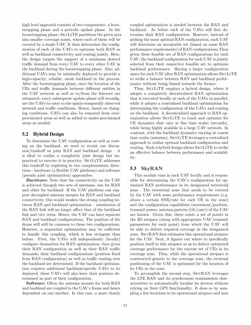
We have built an initial version of SkyLiTE withthe SkyRAN and SkyCore modules and successfullydeployed it on a DJI hexacopter (as shown in Fig. 16)that provides LTE connectivity to smartphones on theground. The SkyRAN and SkyCore modules arebuilt upon software-defined versions of RAN and Corenetwork stacks like Open Air Interface [17] and OpenEPC [18]with appropriate modifications needed to realize the de-sired features, while maintaining standards compliance.
Figure 16: SkyLiTE Prototype.
This demonstrates that with the right optimizations, itis possible to deploy and operate a self-contained mo-bile network on the UAV directly. We are in the processof testing and evaluating the performance of the indi-vidual modules in conjunction with that of the UAVplatform as well as adding the various proposed opti-mizations for each module. The results of this studywill be disseminated in subsequent articles. We willthen extend SkyLiTE to accommodate multiple UAVswith the addition of the SkyHaul module.
7. DISCUSSIONS
7.1 Additional Considerations for Fixed-WingAircrafts
The considerations for fixed wing aircrafts includethose highlighted in SkyLiTE for rotary wing aircrafts.Hence, SkyLiTE’s design elements can be leveraged inLAP networks that employ the fixed wing aircrafts asUAVs. These UAVs offer better endurance and payloadcapacity compared to their rotary wing counterparts.However, they are subject to constant mobility, whichimposes additional challenges and warrants special de-sign considerations. While mobility of the UAVs cannotbe avoided, it can be controlled and hence offers anotherdegree of freedom in the optimization of the LAP net-work through path planning of the UAVs. This creates amore involved joint optimization of RAN and backhaulconnectivity – compared to just the UAV configurationin rotary winged aircrafts, fixed wing aircrafts have toplan and control the trajectory of multiple UAVs simul-taneously, the dynamics of which, significantly impactsboth RAN and backhaul connectivity.
7.2 Applicability to HAP NetworksWhere there are several similarities in network design
between LAP and HAP networks, there are also signif-icant differences that calls for a different perspective inweighing challenges and design elements appropriately.
13
We mention some of the key differences here as well asthe applicability of SkyLiTE’s design elements.
RAN: In a LAP network, obstacles and multi pathscatterers between the UE and UAV have a substantialimpact on the LTE link performance. In contrast, ina HAP network, the large path loss (due to distance)between UAV and the UE overshadows the impact ofshadowing and fading when determining LTE link per-formance. Consequently, fine-grained RAN coverageoptimization based on the UEs is less relevant in a HAPnetwork. However, SkyRAN’s mechanisms related tolocalizing the UEs as well as coordinating multiple-UAVfor a coarse coverage optimization are still useful forHAP networks.
Backhaul: From an optimization stand-point, thisforms the most important part of the UAV network thatneeds to be intelligently and dynamically provisionedas well as maintained. In addition to the applicabilityof SkyHaul’s design components, HAP networks alsoface another challenge in their backhaul design, namelythe constant mobility of the UAVs themselves, similarto that faced in fixed wing aircrafts. Recall that theUAVs in these networks leverage the stratified air cur-rents in the atmosphere to travel and hence are prone toconstant movement. Hence, the backhaul must be ca-pable of constantly predicting the position of its UAVsto optimize the connectivity of its backhaul ahead oftime. This adds another dimension (of time) to back-haul optimization compared to that already consideredin SkyHaul. Recently, [19] articulated the notion of aspatio-temporal SDN for designing such a backhaul.
Core: Although today’s high-altitude UAV networksenvision to have their EPC on the ground, we believethe benefits of a SkyCore design for edge EPC signifi-cantly outweigh its drawbacks, and is equally applicableto a high-altitude UAV network as well.
8. CONCLUSIONUAV networks are ushering in a novel paradigm for
wireless connectivity with a host of new applicationsand services. However, leveraging them to their fullpotential requires one to first understand the variouschallenges that underline their design. This has beenthe prime focus of this work, which has tried to unravelthe various inter-twined challenges that span across thelayers of access, core network and backhaul in design-ing a low-altitude UAV network for providing LTE con-nectivity. We have also presented an end-to-end designcalled SkyLiTE that can serve as a framework or start-ing point for the design and optimization of such UAVnetworks. Through this document, we also hope to en-gage the broader research community as well as industrytowards addressing these challenges and making theseUAV networks viable in practice.
9. REFERENCES
[1] “Google x: Project loon,”https://x.company/loon/.
[2] “Facebook project aquila,” https://code.
facebook.com/posts/348442828901047/
aquila-what-s-next-for-high-altitude-connectivity-/.[3] “At&t cell on wings,” http:
//about.att.com/innovationblog/cows_fly.[4] “Verizon cell on wings,” https://newatlas.com/
verizon-drones-internet-trials/45818/.[5] “At&t’s lte-equipped flying cow in puerto rico,”
https://www.fiercewireless.com/wireless/
at-t-deploys-lte-equipped-flying-cow-drone-puerto-rico.[6] S. Chandrasekhara et. al., “Designing and
Implementing Future Aerial CommunicationNetworks,” IEEE Communications Magazine, vol.54, no. 5, pp. 26–34, May 2016.
[7] N. Ahmed, S. S. Kanhere, and S. Jha, “On theimportance of link characterization for aerialwireless sensor networks,” in IEEE WirelessCommunications Magazine, May 2016.
[8] B. V.-D. Bergh, A. Chiumento, and S. Pollin,“Lte in the sky: Trading off propagation benefitswith interference costs for aerial nodes,” in IEEEWireless Communications Magazine, May 2016.
[9] “Lte license assisted access,” Ericsson, 2015.[10] “Verizon to trial spidercloud lte-u scalable
in-building system for enterprises and venues,”http://www.spidercloud.com/news/
press-release/verizon-trial-
spidercloud-lte-u-scalable-building-
system-enterprises-and-venues, 2016, [Online;Accessed March 14 2016].
[11] “LTE in unlicensed spectrum: Harmoniouscoexistence with Wi-Fi,” Qualcomm Research,June 2014.
[12] “Firstnet: For public safety, by public safety,”https://www.firstnet.com.
[13] S. Lakshmanan, K. Sundaresan, andR. Sivakumar, “Multi-gateway Association inWireless Mesh Networks,” Ad-Hoc Networks, vol.7, no. 3, May 2009.
[14] D. King, Liebsch M., Willis P., and Ryoo J.,“Virtualisation of mobile core network use case,”http://tinyurl.com/mvveqyp.
[15] J. Kempf, B. Johansson, S. Pettersson, H. Luning,and T. Nilsson, “Moving the mobile evolvedpacket core to the cloud,” in Wireless and MobileComputing, Networking and Communications(WiMob), 2012 IEEE 8th InternationalConference on.
[16] A. Banerjee, R. Mahindra, K. Sundaresan,S. Rangarajan, and S. Kasera, “Scaling the ltecontrol plane for future mobile access,” in ACMCoNEXT, Dec 2015.
14
[17] “Open air interface: 5g software alliance fordemocraticing software alliance,”http://www.openairinterface.org.
[18] “Openepc: The open epc project,”https://www.openepc.com.
[19] B. Barritt, T. Kichkaylo, K. Mandke, A. Zalcman,and V. Lin, “Operating a uav mesh & internetbackhaul network using temporospatial sdn,” in
IEEE Aerospace Conference, June 2017.
15