Embed Size (px)
Citation preview
ETSI TR 103 593 V0.0.16 (2018-10)
System Reference Document (SRDoc);Transmission characteristics;
Technical characteristics for radiodetermination equipment for vehicular applications within the frequency range 77 GHz - 81
GHz
<<
TECHNICAL REPORT
ReferenceDTR/ERM-576
KeywordsRadio, SRDoc
ETSI
650 Route des LuciolesF-06921 Sophia Antipolis Cedex - FRANCE
Tel.: +33 4 92 94 42 00 Fax: +33 4 93 65 47 16
Siret N° 348 623 562 00017 - NAF 742 CAssociation à but non lucratif enregistrée à laSous-préfecture de Grasse (06) N° 7803/88
Important notice
The present document can be downloaded from:http://www.etsi.org/standards-search
The present document may be made available in electronic versions and/or in print. The content of any electronic and/or print versions of the present document shall not be modified without the prior written authorization of ETSI. In case of any
existing or perceived difference in contents between such versions and/or in print, the only prevailing document is the print of the Portable Document Format (PDF) version kept on a specific network drive within ETSI Secretariat.
Users of the present document should be aware that the document may be subject to revision or change of status. Information on the current status of this and other ETSI documents is available at
https://portal.etsi.org/TB/ETSIDeliverableStatus.aspx .
If you find errors in the present document, please send your comment to one of the following services:https://portal.etsi.org/People/CommiteeSupportStaff.aspx
Copyright Notification
No part may be reproduced or utilized in any form or by any means, electronic or mechanical, including photocopying and microfilm except as authorized by written permission of ETSI.
The content of the PDF version shall not be modified without the written authorization of ETSI.The copyright and the foregoing restriction extend to reproduction in all media.
© ETSI yyyy.All rights reserved.
DECTTM, PLUGTESTSTM, UMTSTM and the ETSI logo are trademarks of ETSI registered for the benefit of its Members.3GPPTM and LTE™ are trademarks of ETSI registered for the benefit of its Members and
of the 3GPP Organizational Partners.oneM2M logo is protected for the benefit of its Members.
GSM® and the GSM logo are trademarks registered and owned by the GSM Association.
ETSI
ETSI TR 103 593 V0.0.16 (2018-10)2
ContentsIntellectual Property Rights .................................................................................................................................
Foreword .............................................................................................................................................................
Modal verbs terminology ....................................................................................................................................
Executive summary .............................................................................................................................................
Introduction .........................................................................................................................................................
1 Scope .........................................................................................................................................................
2 References .................................................................................................................................................2.1 Normative references ...........................................................................................................................................2.2 Informative references .........................................................................................................................................
3 Definitions, symbols and abbreviations ....................................................................................................3.1 Definitions ...........................................................................................................................................................3.2 Symbols ...............................................................................................................................................................3.3 Abbreviations .......................................................................................................................................................
4 Comments on the System Reference Document .......................................................................................4.1 User defined subdivisions of clause(s) from here onwards .................................................................................
5 Presentation of system and technology .....................................................................................................5.1 Background ..........................................................................................................................................................5.2 Vehicle safety programmes ...............................................................................................................................5.2.1 New Car Assessment Programs (NCAP) .....................................................................................................125.2.2 Euro NCAP ..................................................................................................................................................125.2.3 US NCAP .....................................................................................................................................................135.3 Future autonomous driving vehicles ..................................................................................................................
6 Market information .................................................................................................................................6.1 Situation for current vehicles .............................................................................................................................6.2 Market penetration, autonomous driving vehicles .............................................................................................
7 Technical information .............................................................................................................................7.1 Detailed technical description ............................................................................................................................7.1.1 mm-wave technology ...................................................................................................................................197.1.2 Influence of the bumper fascia .....................................................................................................................207.1.3 Tx bandwidth and Tx power ........................................................................................................................237.2 Status of technical parameters ...........................................................................................................................7.2.1 Current ITU and European common allocations ...............................................................................................7.2.2 Sharing and compatibility studies already available .........................................................................................7.3 Information on relevant standards ....................................................................................................................
8 Radio spectrum request and justification ................................................................................................
9 Regulation ...............................................................................................................................................9.1 Current regulation ..............................................................................................................................................9.2 Proposed regulation ...........................................................................................................................................9.2.1 Proposed revisions to ECC Dec (04)03 .......................................................................................................299.2.2 Proposed revisions to EC decision 2004/545/EC ........................................................................................30
Annex A: Detailed Market information ........................................................................................................31
A1.1 General ...............................................................................................................................................................A1.2 Adaptive Light Control ......................................................................................................................................A1.3 Forward Collision Warning ...............................................................................................................................A1.3 Automatic Emergency Braking .........................................................................................................................A1.5 Automatic Cruise Control (ACC) ......................................................................................................................A1.6 Traffic Sign Recognition / Intelligent Speed Control ........................................................................................A1.7 Enhanced Blind Spot Monitoring ......................................................................................................................
ETSI
ETSI TR 103 593 V0.0.16 (2018-10)3
A1.8 Lane Keep Assist ...............................................................................................................................................A1.9 Lane Change Assist ...........................................................................................................................................A1.10 Traffic Jam Assist ..............................................................................................................................................A1.11 Rear Cross Traffic Alert ....................................................................................................................................A1.12 Rear Cross Traffic Alertsee A1.11 double entry/ clarify with Magna ........................................................A1.13 Front Junction-Intersection Assist .....................................................................................................................A1.14 Highway Chauffer clarify with Magna .......................................................................................................A1.15 Rear – Auto Emergency Braking .......................................................................................................................A1.16 Automatic Lane Change ....................................................................................................................................A1.17 Automated Parking Assist (APA) ......................................................................................................................A1.18 Home Zone Automated Parking (HZAP) ..........................................................................................................A1.19 Valet Parking .....................................................................................................................................................A1.20 Highway Pilot ....................................................................................................................................................A2.1 General ...............................................................................................................................................................A2.2 Trains (locomotive and train cars,…) ................................................................................................................A2.3 Tram/Metro ........................................................................................................................................................A2.4 Construction / farming vehicles (outdoor) .........................................................................................................A2.5 Industrial vehicles / Material handling (indoor/outdoor) ...................................................................................A2.6 Ships (boats and small vessels) .........................................................................................................................A2.7 Aircrafts via taxiing / wing tips .........................................................................................................................
Annex B: summary of Regulations in selected countries for 76-77 GHz and 77 - 81 GHz radar sensors .................................................................................................................................................53
Annex : Change History .................................................................................................................................56
History ...............................................................................................................................................................
ETSI
ETSI TR 103 593 V0.0.16 (2018-10)4
Intellectual Property RightsEssential patents
IPRs essential or potentially essential to the present document may have been declared to ETSI. The information pertaining to these essential IPRs, if any, is publicly available for ETSI members and non-members, and can be found in ETSI SR 000 314: "Intellectual Property Rights (IPRs); Essential, or potentially Essential, IPRs notified to ETSI in respect of ETSI standards", which is available from the ETSI Secretariat. Latest updates are available on the ETSI Web server (https://ipr.etsi.org).
Pursuant to the ETSI IPR Policy, no investigation, including IPR searches, has been carried out by ETSI. No guarantee can be given as to the existence of other IPRs not referenced in ETSI SR 000 314 (or the updates on the ETSI Web server) which are, or may be, or may become, essential to the present document.
Trademarks
The present document may include trademarks and/or tradenames which are asserted and/or registered by their owners. ETSI claims no ownership of these except for any which are indicated as being the property of ETSI, and conveys no right to use or reproduce any trademark and/or tradename. Mention of those trademarks in the present document does not constitute an endorsement by ETSI of products, services or organizations associated with those trademarks.
ForewordThis Technical Report (TR) has been produced by ETSI Technical Committee Electromagnetic compatibility and Radio spectrum Matters (ERM) .
Modal verbs terminologyIn the present document "should", "should not", "may", "need not", "will", "will not", "can" and "cannot" are to be interpreted as described in clause 3.2 of the ETSI Drafting Rules (Verbal forms for the expression of provisions).
"must" and "must not" are NOT allowed in ETSI deliverables except when used in direct citation.
Executive summary
Introduction
ETSI
ETSI TR 103 593 V0.0.16 (2018-10)5
1 ScopeThe present document describes radio determination equipment for vehicular applications within the frequency range 77 GHz - 81 GHz which may require a change of the present frequency designation / utilization within the EU/CEPT.
This document is limited to Ground based vehicular applications.
This document provides information on the existing and intended applications, the technical parameters, the relation to the existing spectrum regulation (ECC/DEC(04)03 and 2004/545/EC) and it reflects the WRC -2015 decision (RR footnote 5.559B and ITU-R recommendation M.2057 and ITU-R report M.2322) on automotive ground-based radar). The current regulation should be reviewed in the light of the results of WRC - 2015.
The WRC 2015 decision refers to ground-based radar applications, including automotive radars. The presentis document is limited to Ground based vehicular applications.
It includes in particular:
Market information Technical information including expected sharing and compatibility issues Regulatory issues.
2 References2.1 Normative referencesNormative references are not applicable in the present document.
2.2 Informative referencesReferences are either specific (identified by date of publication and/or edition number or version number) or non-specific. For specific references, only the cited version applies. For non-specific references, the latest version of the referenced document (including any amendments) applies.
NOTE: While any hyperlinks included in this clause were valid at the time of publication ETSI cannot guarantee their long term validity.
The following referenced documents are not necessary for the application of the present document but they assist the user with regard to a particular subject area.
[i.1] <Standard Organization acronym> <document number><version number/date of publication>: "<Title>".
[i.1] ERC/REC 70-03, Relating to the use of Short Range Devices (SRD), 22 May 2018
[i.2] Commission Implementing Decision (EU) 2017/1483 of 8 August 2017 amending Decision 2006/771/EC on harmonisation of the radio spectrum for use by short-range devices and repealing Decision 2006/804/EC
[i.3] ERC Report 003 Harmonisation of frequency bands to be designated for road transport information systems, Lisbon, February 1991
[i.4] ERC/DEC/(92)02 ERC Decision of 22 October 1992 on the frequency bands to be designated for the coordinated introduction of Road Transport Telematic Systems (ERC/DEC/(92)02)
[i.5] ECC Decision of 15 March 2002 on the frequency bands to be designated for the co-ordinated introduction of Road Transport and Traffic Telematic Systems (ECC/DEC/(02)01)
ETSI
ETSI TR 103 593 V0.0.16 (2018-10)6
[i.6] ETSI TR 101 982 V1.2.1 (2002-07), Radio equipment to be used in the 24 GHz band; System Reference Document for automotive collision warning Short Range Radar
[i.7] ECC Report 23, Compatibility of automotive collision warning Short Range Radar operating at 24 GHz with FS, EESS and Radio Astronomy, Cavtat, May 2003
[i.8] ETSI TR 102 263 V1.1.2 (2004-02), Road Transport and Traffic Telematics (RTTT); Radio equipment to be used in the 77 GHz to 81 GHz band; System Reference Document for automotive collision warning Short Range Radar
[i.9] ECC Report 56, Compatibility of automotive collision warning short range radar operating at 79 GHz with radiocommunication services, Stockholm, October 2004
[i.10] ECC/DEC(04)03, The frequency band 77-81 GHz to be designated for the use of Automotive Short Range Radars, Approved 19 March 2004, Corrected 6 March 2015
[i.11] EC Decision 2004/545/EC, Commission Decision of 8 July 2004 on the harmonisation of radio spectrum in the 79 GHz range for the use of automotive short-range radar equipment in the Community
[i.12] ECC/DEC(04)10, ECC Decision of 12 November 2004 amended 01 June 2012 on the frequency bands to be designated for the temporary introduction of Automotive Short Range Radars (SRR)
[i.13] COMMISSION IMPLEMENTING DECISION (EU) 2017/2077 of 10 November 2017 amending Decision 2005/50/EC on the harmonisation of the 24 GHz range radio spectrum band for the time-limited use by automotive short-range radar equipment in the Community
[i.14] ETSI TR 102 664 V1.2.1 (2010-04), Road Transport and Traffic Telematics (RTTT); Short range radar to be used in the 24 GHz to 27,5 GHz band; System Reference Document
[i.15] ECC Report 158, The impact of 26 GHz SRR applications using ultra-wideband (UWB) technology on radio services, Cardiff, January 2011
[i.16] ETSI EN 301 091-1 V2.1.1 (2017-01), Radar equipment operating in the 76 GHz to 77 GHz range; harmonised Standard covering the essential requirements of article 3.2 of Directive 2014/53/EU; Part 1: Ground based vehicular radar
[i.17] ETSI EN 302 264 V2.1.1 (2017-05), Short Range Radar equipment operating in the 77 GHz to 81 GHz band; Harmonised Standard covering the essential requirements of article 3.2 of Directive 2014/53/EU
[i.18] H. Meinel: Automotive Radar – History, state-of-the-art and future trends, EuRAD 2012.
[i.19] Texas Instruments: AWR1243, 76-to-81 GHz High Performance Automotive MMIC, http://www.ti.com/product/AWR1243
[i.20] F. Pfeiffer: Analyse und Optimierung von Radomen für automobile Radarsensoren, Dissertation 2009 (in German)
[i.21] ITU Radio Regulations, edition of 2016
[i.22] Recommendation ITU-R M.2057-1 (01/2018) Systems characteristics of automotive radars operating in the frequency band 76 - 81 GHz for intelligent transport systems applications
[i.23] European Commission 2018/0145[COD]: Proposal for a Regulation of the European Parliament and of the Council on type-approval requirements for motor vehicles and their trailers, and systems, components and separate technical units intended for such vehicles, as regards their general safety and the protection of vehicle occupants and vulnerable road users, amending Regulation (EU) 2018/… and repealing Regulations (EC) No 78/2009, (EC) No 79/2009 and (EC) no 661/2009 (Text with EEA relevance) {SEC(2018)270 final} – {SWD(2018) 190 final} – {SWD(2018)191 final}
[i.24] European Commission: Benefit and Feasibility of a Range of New Technologies and Unregulated Measures in the fields of Vehicle Occupant Safety and Protection of Vulnerable Road Users (March 2015)
ETSI
ETSI TR 103 593 V0.0.16 (2018-10)7
[i.25] Department Of Transportation, National Highway Traffic Safety Administration, [Docket No. NHTSA-2015-0119], New Car Assessment Program (NCAP)
[i.26] Recommendation ITU-R M.2322-0 (11/2014) Systems characteristics and compatibility of automotive radars operating in the frequency band 77.5 - 78 GHz for sharing studies.
etc.
3 Definitions, symbols and abbreviations3.1 DefinitionsFor the purposes of the present document, the [following] terms and definitions [given in ... and the following] apply:
3.2 Symbolsr Dielectric constantΧe Dielectric susceptibility: r -1
3.3 AbbreviationsFor the purposes of the present document, the [following] abbreviations [given in ... and the following] apply:
AEB Automatic Emergency BrakingNCAP New Car Assessment ProgramEuro NCAP European New Car Assessment Program US NCAP US New Car Assessment ProgramNHTSA National Highway Transportation Safety Administration (USA)FCW Forward Collision WarningLDW Lane Departure WarningLKS Lane Keeping-Assist SystemRR ITU-R Radio Regulations VRU-AEB Vulnerable Roadway User – Automatic Emergency Braking (pedestrians & bicyclists)
Short range radar Mid range radar Long range radar
4 Comments on the System Reference Document 4.1 User defined subdivisions of clause(s) from here onwards
5 Presentation of system and technology
ETSI
ETSI TR 103 593 V0.0.16 (2018-10)8
5.1 Background Radar sensors for supporting the driver of a vehicle have been under development by companies in Europe, the United States and Asia for several decades [i.18]. Early prototypes were operated in various frequency ranges such as 10 GHz, 16 GHz, 24 GHz, 35 GHz, 50 GHz or 94 GHz.
Then, in 1996, the first series busses and trucks were equipped in the United States with front and side looking collision warning radars, operating at approximately 10 GHz and 24 GHz.
A few years later, the first series cars were equipped with
- front looking radars for adaptive cruise control, operating in the band 76-77 GHz, - rear corner radars for parking support and blind spot detection, operating in the 24 GHz ultra-wideband range
rear corner radars for blind spot detection and lane change assistance, operating in the 24 GHz narrow band range.
Since then, advances in RF circuit integration, advances in microcontroller performance and advances in software algorithms helped to further improve the sensor performance, to add additional assistance functions and to reduce the sensor price so that today millions of 24 GHz (narrow band) and 76-77 GHz radar sensors per year are installed in new vehicles, ranging from small city cars up to luxury cars, thus supporting more and more drivers in safer driving.
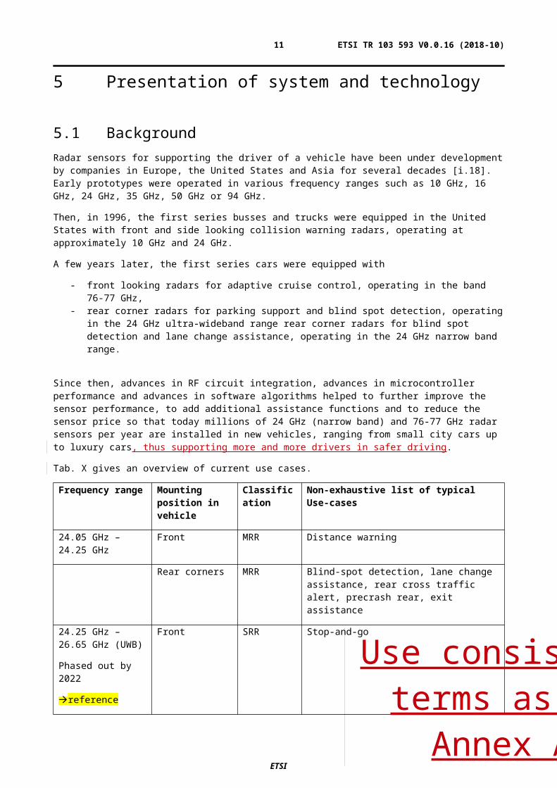
Tab. X gives an overview of current use cases.
Frequency range Mounting position in vehicle
Classification Non-exhaustive list of typical Use-cases
24.05 GHz – 24.25 GHz
Front MRR Distance warning
Rear corners MRR Blind-spot detection, lane change assistance, rear cross traffic alert, precrash rear, exit assistance
24.25 GHz – 26.65 GHz (UWB)
Phased out by 2022
reference
Front SRR Stop-and-go
Rear corners SRR Blind-spot detection, lane change assistance, rear cross traffic alert, precrash rear, exit assistance
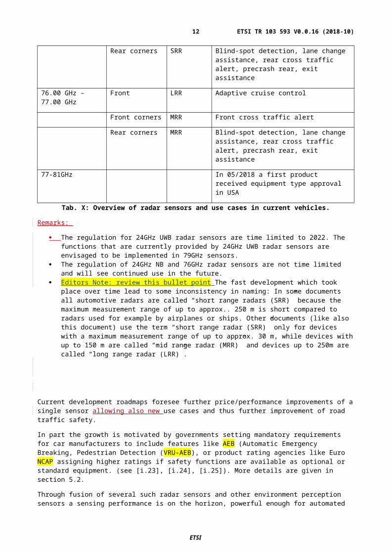
76.00 GHz – 77.00 GHz
Front LRR Adaptive cruise control
Front corners MRR Front cross traffic alert
Rear corners MRR Blind-spot detection, lane change assistance, rear cross traffic alert, precrash rear, exit assistance
77-81GHz In 05/2018 a first product received equipment type approval in USA
Tab. X: Overview of radar sensors and use cases in current vehicles.
Remarks:
The regulation for 24GHz UWB radar sensors are time limited to 2022. The functions that are currently provided by 24GHz UWB radar sensors are envisaged to be implemented in 79GHz sensors.
The regulation of 24GHz NB and 76GHz radar sensors are not time limited and will see continued use in the future.
Editors Note: review this bullet point The fast development which took place over time lead to some inconsistency in naming: In some documents all automotive radars are called “short range radars (SRR)” because the maximum measurement range of up to approx.. 250 m is short compared to radars used for
ETSI
Use consistent terms as in Annex A
ETSI TR 103 593 V0.0.16 (2018-10)9
example by airplanes or ships. Other documents (like also this document) use the term “short range radar (SRR)” only for devices with a maximum measurement range of up to approx. 30 m, while devices with up to 150 m are called “mid range radar (MRR)” and devices up to 250m are called “long range radar (LRR)”.
Current development roadmaps foresee further price/performance improvements of a single sensor allowing also new use cases and thus further improvement of road traffic safety.
In part the growth is motivated by governments setting mandatory requirements for car manufacturers to include features like AEB (Automatic Emergency Breaking, Pedestrian Detection (VRU-AEB), or product rating agencies like Euro NCAP assigning higher ratings if safety functions are available as optional or standard equipment. (see [i.23], [i.24], [i.25]). More details are given in section 5.2.
Through fusion of several such radar sensors and other environment perception sensors a sensing performance is on the horizon, powerful enough for automated driving. Highly automated [L3-L4 autonomous driving levels as described in section 5.4] and fully automated cars [L5] are expected to provide new forms and modes of transportation, changing the way mobility is provided. To ensure safety in highly automated vehicles and fully automated vehicles, multiple technologies will be required to perceive and access the driving environment. High robustness will be critical to providing safe & reliable transportation. New mobility services such as shared ownership and ride sharing will increase the actual usage time of devices included on these platforms due to higher utilization. More details are given in section 5.3.
A description of current and future use cases as considered here is provided in Annex A.1.
In parallel, over time the radio regulation for automotive radars has been developed in Europe and other regions worldwide. Starting with 24 GHz narrowband (see [i.1], [i.2], which has been available for a long time as a ISM band, followed by 76-77 GHz between 1991 and 2002 (see [i.3], [i.4], [i.5]), 24 GHz Ultra-wideband between 2002 and 2011 (see [i.6], [i.7], [i.12], [i.13], [i.14], [i.15]) and finally 79 GHz ultra-wideband in 2004 (see [i.8], [i.9], [i.10], [i.11],
The underlying regulation for automotive radars in the frequency range 77-81 GHz ([i.10], [i.11]) was developed and introduced in 2004 on the basis of non-interference/ non-protection, with accordingly very stringent limits from [i.9] to protect primary radio services (e.g. Radio astronomyie, Radiolocation):
Editors note : is possible to put full quotes from ECC Report in the document“… Decides …
2. that the 79 GHz frequency range (77-81 GHz) is designated for Short Range Radar (SRR) equipment on anon-interference and non-protected basis with a maximum mean power density of -3 dBm/MHz e.i.r.p.associated with an peak limit of 55 dBm e.i.r.p.;
3. that the maximum mean power density outside a vehicle resulting from the operation of one SRR equipmentshall not exceed -9 dBm/MHz e.i.r.p.; …”
.
It has should be noted that in the Radio Regulations (RR) there has since been for many years a primary allocations to the Radiolocation service from 76-77,5 GHz and from 78-81 GHz. At the World Radio Conference 2015, the gap 77,5-78 GHz was allocated to the Radiolocation Service on a co-primary basis including but limited to ground based vehicles radars as outlined in the RR Footnote 5.559B [i.21]:
“The use of the frequency band 77.5-78 GHz by the radiolocation service shall be limited to short-range radar for ground-based applications, including automotive radars. The technical characteristics of these radars are provided in the most recent version of Recommendation ITU-R.M.2057. The provisions of No. 4.10 do not apply.”
The frequency range 77-81 GHz plays a key role for future radar sensors because of its large available bandwidth. In 01/2018 Recommendation ITU-R M.2057-1 has beenwas published [i.22 ] providing updates for the systems characteristics of automotive radars operating in the frequency band 76 - 81 GHz for intelligent transport systems applications
ETSI
ETSI TR 103 593 V0.0.16 (2018-10)10
But for several reasons, so far up to 2018 , no automotive radar sensor for the range 77 – 81 GHz was placed on the market in Europe:
a) For many years, the RF circuit technology was not powerful enough to support that range at acceptable cost. With the introduction of SiGe and CMOS RF devices some years ago that situation now has improved. Especially the migration to CMOS based RF technologies, permit the integration of RF and processing capabilities within devices, significantly reducing the cost for radar devices. These SoC (system on Chip) reference to subsection platforms provide the ability to implement digital modulations to significantly improve the efficient and effective use of spectrum through coding schemes. Improvements in technology facilitate sophisticated technics to enhance mutual co-existence between multiple devices utilizing both transmitter and receiver interference mitigation and ejection, such as code correlation, permitting higher densities of devices to securely and safely co-exist in close proximity.
b) For many years, a regulation of that band was not available in important automotive markets outside Europe. With the decision of World Radio Conference 2015 that situation started to improve as seen for example by the recent respective new regulation in the United States and in other regions and countries. (see Annex B).
c) The European regulation was drafted in 2004 ([i.10], [i.11]) with the intention only for parking support and blind-spot detection and as such does not necessarily meet current use cases. The use cases for application of radar technology include the need for multi-mode capability – effectively the characteristics of both short range and long range devices – in a single unit to support effective solutions for safety enhancement in ground based vehicles. These needs are more general and include also functions with larger detection ranges and thus larger required transmit power.
[d)] The current regulation ([i.10], [i.11]) contains a mean power density limit of -9 dBm/MHz e.i.r.p. defined outside the vehicle which creates the difficult split responsibility with respect to ensuring sensor compliance because the sensor manufacturer does not manufacture the bumper fascia.
d)[e)] The European regulation also deviates from regulations in other regions of the world (see Annex B), increasing the development effort for sensor manufacturers and thus making such a product less attractive.
e) The use of the band 76-77 GHz is in the meanwhile permitted in Europe for a wide range of radar applications (Annex 5 of [i.1] for ground based vehicles, infrastructure systems, obstacle detection radars for rotorcraft use; Annex 4 of [i.1] for obstruction/vehicle detection at railway level crossings), which creates a more general spectrum use in this band with more potential interferers for all radars. This evolution of use in the 76-77 GHz was not foreseen when the 77-81GHz regulation was developed.
To overcome these weaknesses and to foster the further development of driver assistance systems it is proposed here to further develop the European regulation for automotive radars in the range 77 – 81 GHz as described in detail in the following sectionsclause 87.
Editors Note: Reference whether this is correct for the 77-81 GHz band. [Confirmation that automotive radars devices in this bandwidth have not been submitted for and granted FECC certification, and placed on the market needs to be confirmed ALPS sensor filing is on FCC database ].
ETSI
ETSI TR 103 593 V0.0.16 (2018-10)11
5.2 Vehicle safety programmes There are several vehicle testing organisations, which rate the available vehicles based on various defined standards. The OEMs are usually interested in fulfilling all requirements of the standards in order to get good ratings for their vehicles. The testing organisations have already developed tests to assess the safety functions that are available for the vehicles. The test organisations develop the test requirements taking into account historical accident and fatality data, the associated state of available technologies, the expected impact of improvements of enhanced driver awareness and/or controlled intervention. In many instances, features have migrated from providing driver warnings (LDW, FCW) to providing automatic reaction to known high collision risk scenarios (LKS, AEB) involving control of the vehicle’s braking or steering system.
5.2.1 New Car Assessment Programs (NCAP) NCAP is one of the most important vehicle testing programme working on several regions worldwide. In Europe, the Euro NCAP is developing feature requirements, performance & test requirements and time schedules when they will be included in the tests. These roadmaps are communicated as targeted implementation dates against which OEMs develop technology application strategies to achieve desired ratings for their vehicles. Generally, OEMs target to make available the technology to reach the maximum possible rating, while also supporting consumer choice with packages including safety technology bundled into available optional content. . [i.XX] Editors note: reference reference to the NCAP website / EU
5.2.2 Euro NCAP
Euro NCAP is a voluntary vehicle safety rating system created by the Swedish Road Administration, the Fédération Internationale de l’Automobile and International Consumer Research & Testing, and backed by the European Commission, seven European governments, as well as motoring and consumer organizations in every EU country.
The program is modelled after the New Car Assessment Program (NCAP), introduced in 1979 by the U.S. National Highway Traffic Safety Administration. Other areas with similar (but not identical) programmes include Australia and New Zealand with ANCAP, Latin America with Latin NCAP and China with C-NCAP.
Figure X gives an overview of the current timeline for the implementation of new safety related radar based functions in the Euro NCAP tests. [i.XX] Editors note: reference to the Euro NCAP website
ETSI
ETSI TR 103 593 V0.0.16 (2018-10)12
Figure X: Euro NCAP Feature Roadmap thru 2025
5.2.3 US NCAP Within the USA, the Department of Transportation’s (DOT), National Highway Traffic Safety Administration (NHTSA) administers the New Car Assessment Program (NCAP). Most recently [i.25], NHTSA has conducted requests for comment on proposals for changes to the NCAP requirements for 2018 and beyond. While the US-NCAP proposals mirror the Euro NCAP in several areas, test procedures and priorities reflect analysis of the past accidents data to affect the greatest potential benefit considering conditions in the US market. Similarly, NCAP regulations in other regions reflect the unique conditions in the market, including local supply availability, setting priorities and timetables for implementation. For global OEM’s, features supporting the global NCAP portfolio of capabilities and performance requirements are necessary. Accordingly, automotive radar technologies require regulatory modification to support the increasing demands for broader perception capabilities to achieve the safety enhancement desired cost effectively.
The relevant NCAP testing organisations publish safety reports on new cars, and award 'star ratings' based on the performance of the vehicles in a variety of crash tests, including front and side impacts, collisions with posts, and impacts with pedestrians. The top overall rating is five stars.
Testing is not mandatory, with vehicle models being independently chosen by Euro NCAP or voluntarily submitted for testing by the manufacturers.[9]
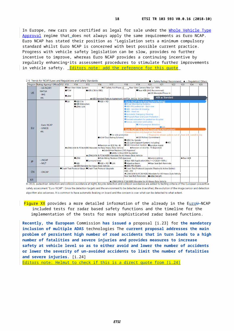
In Europe, new cars are certified as legal for sale under the Whole Vehicle Type Approval regime that does not always apply the same requirements as Euro NCAP. Euro NCAP has stated their position as “Legislation sets a minimum compulsory standard whilst Euro NCAP is concerned with best possible current practice. Progress with vehicle safety legislation can be slow, provides no further incentive to improve, whereas Euro NCAP provides a continuing incentive by regularly enhancing its assessment procedures to stimulate further improvements in vehicle safety.” Editors note: add the reference for this quote
ETSI
ETSI TR 103 593 V0.0.16 (2018-10)13
Figure XX provides a more detailed information of the already in the EuroU NCAP included tests for radar based safety functions and the timeline for the implementation of the tests for more sophisticated radar based functions.
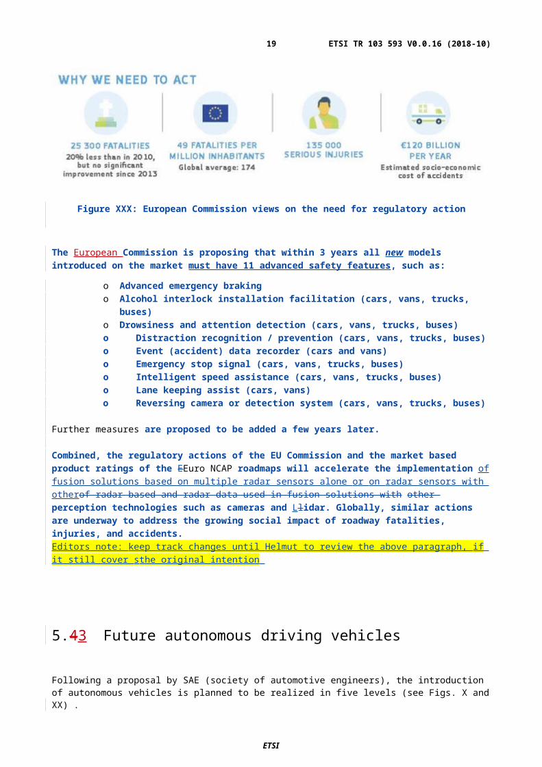
Recently, the European Commission has issued a proposal [i.23] for the mandatory inclusion of multiple ADAS technologies The current proposal addresses the main problem of persistent high number of road accidents that in turn leads to a high number of fatalities and severe injuries and provides measures to increase safety at vehicle level so as to either avoid and lower the number of accidents or lower the severity of un-avoided accidents to limit the number of fatalities and severe injuries. [i.24]Editors note: Helmut to check if this is a direct quote from [i.24]
Figure XXX: European Commission views on the need for regulatory action
The European Commission is proposing that within 3 years all new models introduced on the market must have 11 advanced safety features, such as:
o Advanced emergency braking
ETSI
ETSI TR 103 593 V0.0.16 (2018-10)14
o Alcohol interlock installation facilitation (cars, vans, trucks, buses)o Drowsiness and attention detection (cars, vans, trucks, buses)o Distraction recognition / prevention (cars, vans, trucks, buses)o Event (accident) data recorder (cars and vans)o Emergency stop signal (cars, vans, trucks, buses)o Intelligent speed assistance (cars, vans, trucks, buses)o Lane keeping assist (cars, vans)o Reversing camera or detection system (cars, vans, trucks, buses)
Further measures are proposed to be added a few years later.
Combined, the regulatory actions of the EU Commission and the market based product ratings of the EEuro NCAP roadmaps will accelerate the implementation of fusion solutions based on multiple radar sensors alone or on radar sensors with otherof radar based and radar data used in fusion solutions with other perception technologies such as cameras and Llidar. Globally, similar actions are underway to address the growing social impact of roadway fatalities, injuries, and accidents.Editors note: keep track changes until Helmut to review the above paragraph, if it still cover sthe original intention
5.43 Future autonomous driving vehicles
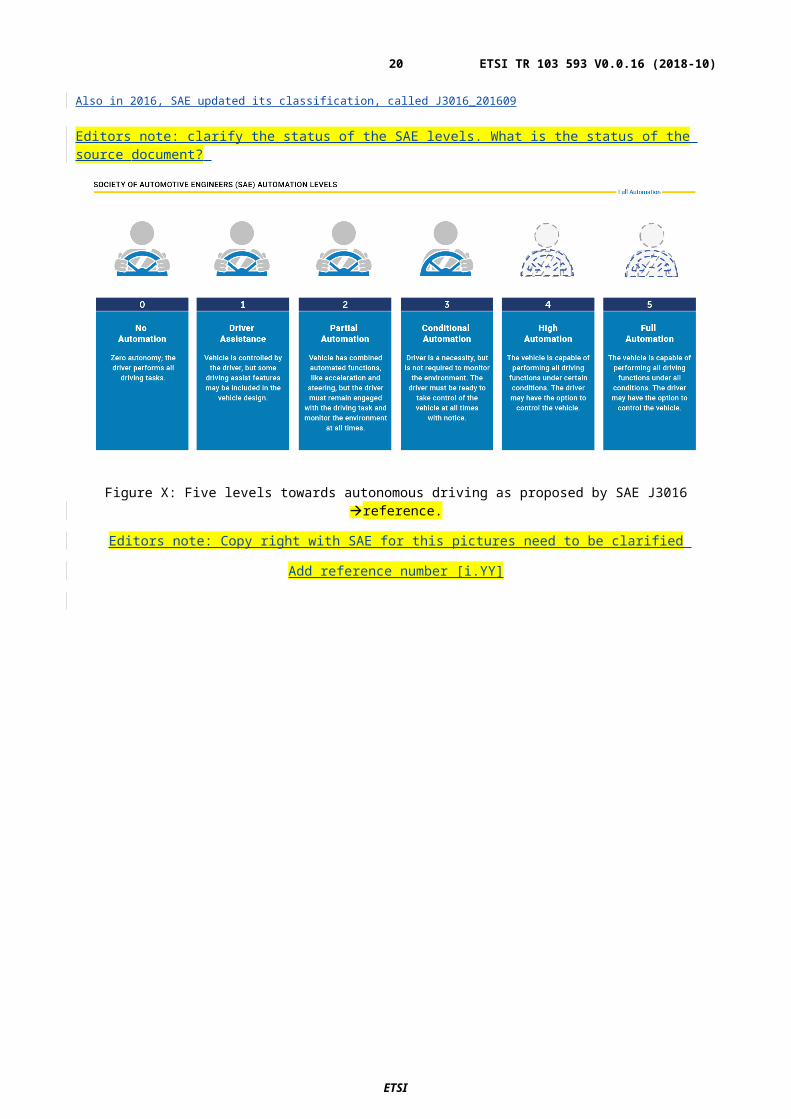
Following a proposal by SAE (society of automotive engineers), the introduction of autonomous vehicles is planned to be realized in five levels (see Figs. X and XX) .
Also in 2016, SAE updated its classification, called J3016_201609
Editors note: clarify the status of the SAE levels. What is the status of the source document?
Figure X: Five levels towards autonomous driving as proposed by SAE J3016 reference.
Editors note: Copy right with SAE for this pictures need to be clarified
Add reference number [i.YY]
ETSI
ETSI TR 103 593 V0.0.16 (2018-10)15
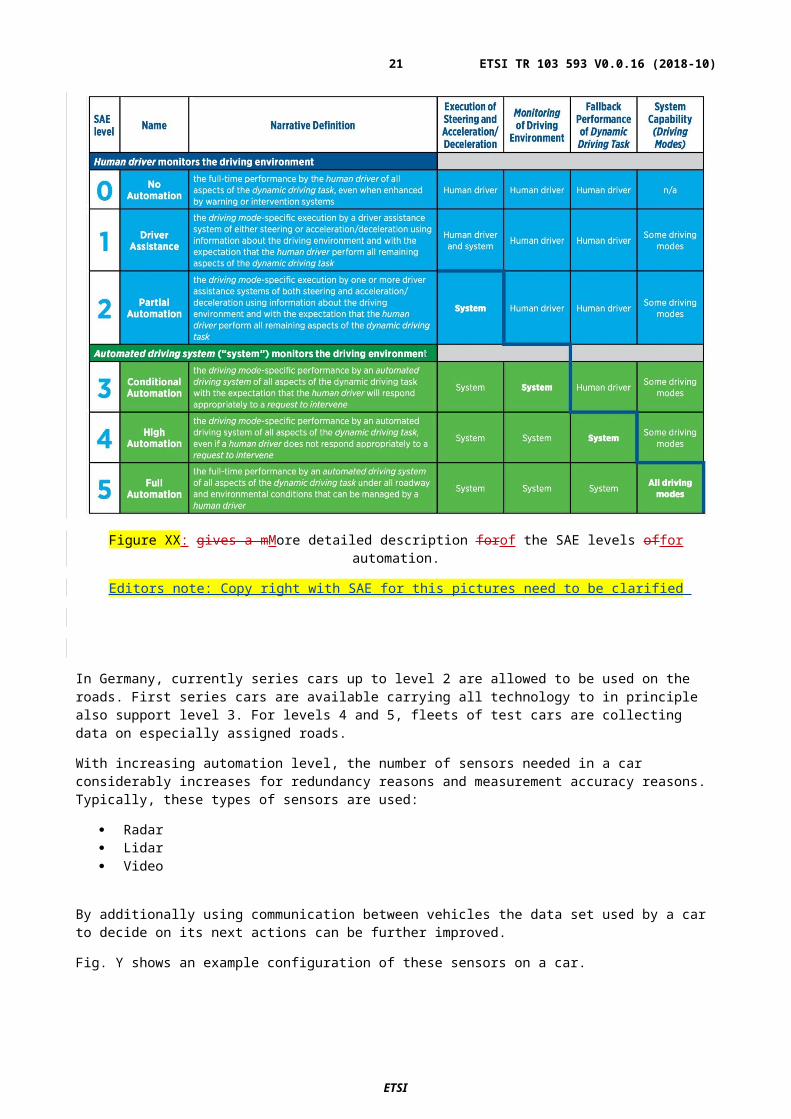
Figure XX: gives a mMore detailed description forof the SAE levels offor automation.
Editors note: Copy right with SAE for this pictures need to be clarified
In Germany, currently series cars up to level 2 are allowed to be used on the roads. First series cars are available carrying all technology to in principle also support level 3. For levels 4 and 5, fleets of test cars are collecting data on especially assigned roads.
With increasing automation level, the number of sensors needed in a car considerably increases for redundancy reasons and measurement accuracy reasons. Typically, these types of sensors are used:
Radar Lidar Video
By additionally using communication between vehicles the data set used by a car to decide on its next actions can be further improved.
Fig. Y shows an example configuration of these sensors on a car.
ETSI
ETSI TR 103 593 V0.0.16 (2018-10)16
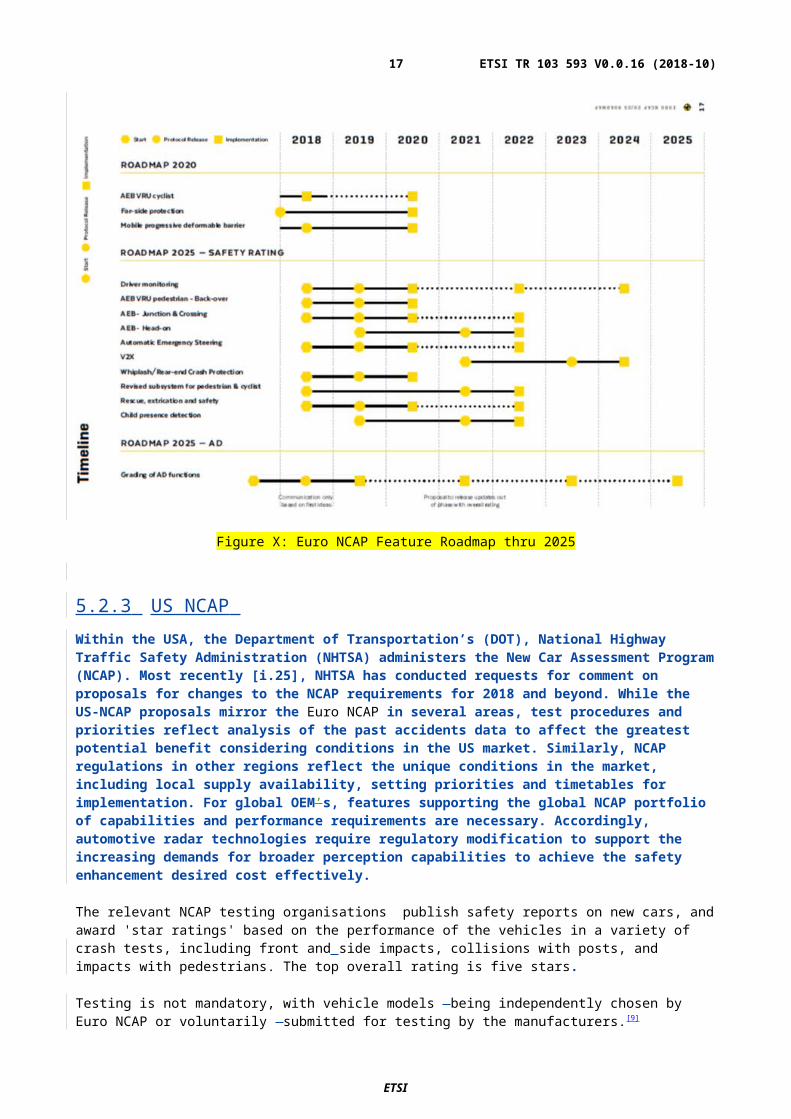
Figure Y: Example configuration of sensors on an autonomous vehicle (Level 3-4).
Editors note: figure is provided by Magna check source and reference and copyright clearance
Vehicles capable for higher levels of autonomous driving will have and use more radar sensors. Figure YY provides a time line for the different levels of automation and the expected number of radar sensors that will be deployed in such vehicles.
Figure YY: levels of autonomous driving and required number of automotive radar sensors per vehicle
With an increasing number of radar sensors on the roads, the avoidance of interference becomes more and more challenging.
ExampleTypical approaches to handling interference are:
adapting the timing of a sensor (limited by period after which the car needs an update from the sensor on the environmental situation, typically 40 – 100ms)
adapting the frequency range used by a sensor (limited by frequency regulation). repairing disturbed receive signals in processing after digitization. Random timing Coded signals
ETSI
ETSI TR 103 593 V0.0.16 (2018-10)17
To have enough frequency range available for adapting the frequency range it is important to also use MRR and LRR in the range 77 GHz – 81 GHz. (See 5.1 bullet f)
But this is only possible if the current European regulation for the range 77 GHz – 81 GHz is revised as proposed in this document.
6 Market informationContinental to elaborate on section 6
Editors note: use material from Microwave week Madrid 2018
Find material / get permission : EUMW 2018 workshop WW02 first presentation YOLE developpment ( could be used in 6.1 and 6.2: parts of the material reach up to 2030)
In total for this chapter 1-2 pages
6.1 Situation for current vehicles Market research shows, that the number of vehicles, that are equipped with assistive safety functions increased over the last X years. The assistive safety functions typically depend on different sensor technologies such as radar, camera , lidar.
German DAT report shows that …
Develop further
Volkswagen report on fitment rates?
DAT report : https://www.dat.de/fileadmin/media/download/DAT-Report/DAT-Report-2016.pdf,
Table page 10
The safety functions on today´s vehicles depend on different sensor technologies. Depending on the implementation sensor, combinations of the technologies are used in a vehicle.
More text
A current market research shows the estimated worldwide development
ETSI
ETSI TR 103 593 V0.0.16 (2018-10)18
6.2 Market penetration, autonomous driving vehicles The penetration for autonomous driving vehicles will increase over the next 15 years. One radar manufacturer provides information on their estimation of the increase of the market penetration broken down to the SAE levels of automation.
Take sources / references . ( market research reports can only be used if copyright has been cleared )
Check
VDA (ask Mr Toppel) ACEA /CLEPA OICA https://www.prnewswire.com/news-releases/automotive-radar-market---expected-to-reach-121-billion-
by-2025-300575733.html
old studies from 24GHz studies ECC Report 23 TR101982 SRDoc on 24GHz radar
ETSI
ETSI TR 103 593 V0.0.16 (2018-10)19
Add source / reference MAGNA
Subchapter: Market penetration / density
Information from ACEA/CLEPA (Frank to ask) /OESA
Commission document on digital single market
7 Technical informationGeneral overview , slide 9 from Magna contribution goes there
7.1 Detailed technical description 7.1.1 mm-wave technologyIntegrated mm-wave technology has evolved since the making available of the band in Europe in 2004.
Because of progress in semiconductor technology, active components evolved from discrete RF transistors and diodes over GaAs-based oscillator, amplifier and mixer MMICs over SiGe-based transceiver MMICs to CMOS-based radar system chips (RSCs). Today several semiconductor manufacturers, offer highly integrated RSCs covering the frequency ranges 76 GHz – 77 GHz and 77 GHz – 81 GHz with very similar fundamental RF properties, for example [i.19]:
Typical key parameters meters of such chipsets are Transmitter output power typ. 12 dBm (76 – 81 GHz) Receiver noise figure typ. 15 dB (76 - 77 GHz), typ. 16 dB (77 - 81 GHz).
Because of progress in simulation tools and materials, antennas evolved in bandwidth and general performance.
It is concluded that technically similar radar performance can be realised in the range 77 GHz – 81 GHz as is today realised in the range 76 GHz – 77 GHz.
.
ETSI
ETSI TR 103 593 V0.0.16 (2018-10)20
7.1.2 Influence of the bumper fasciaThe bumper fascia is the plastic structure attached to the front and rear of a vehicle. The fascia may or may not be painted. The presence and the design of the fascia is dictated by the vehicle manufacturer, not by the sensor manufacturer.
An advantage of radar sensors against other automotive environmental sensors is that they can be installed behind the bumper fascia, invisible from the outside. This makes it possible to install these sensors virtually everywhere on the vehicle allowing for 360 degrees detection.
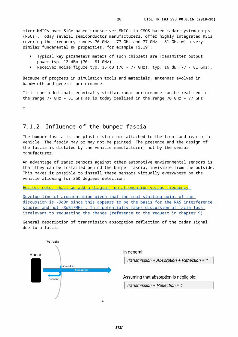
Editors note: shall we add a diagram on attenuation versus frequency
Develop line of argumentation given that the real starting point of the discussion is -9dBm since this appears to be the basis for the RAS interference studies and not -3dBm/MHz . This potentially makes discussion of facia loss irrelevant to requesting the change (reference to the request in chapter 9)
General description of transmission absorption reflection of the radar signal due to a fascia
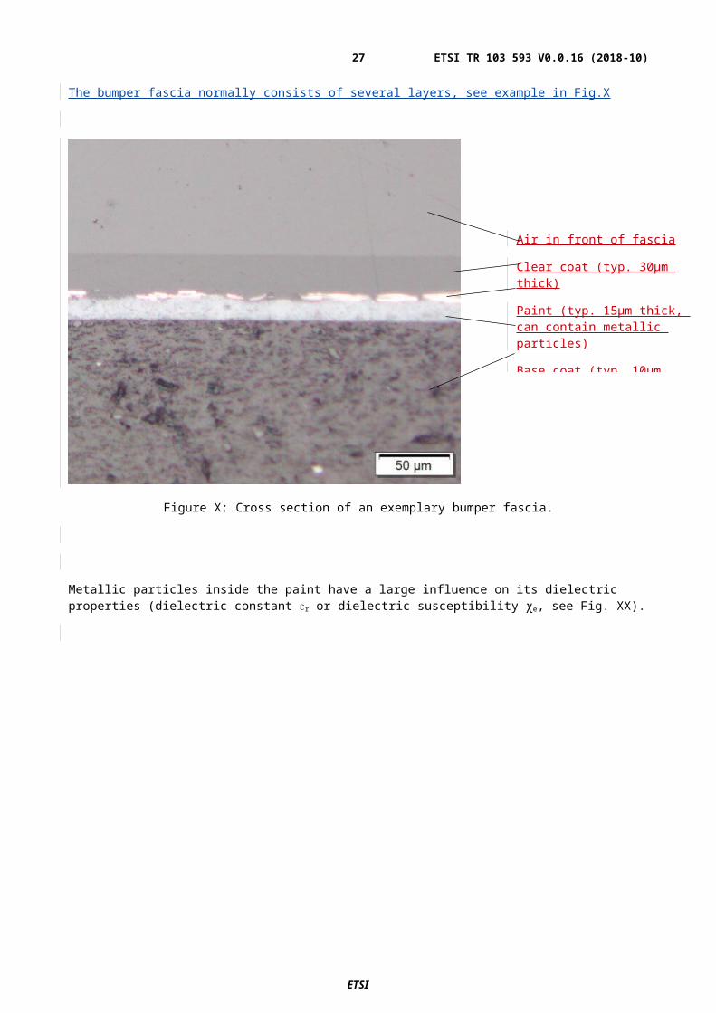
The bumper fascia normally consists of several layers, see example in Fig.X
ETSI
ETSI TR 103 593 V0.0.16 (2018-10)21
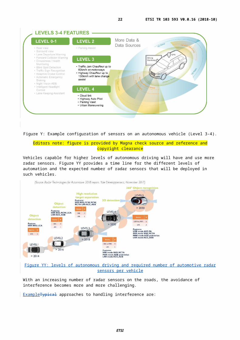
Figure X: Cross section of an exemplary bumper fascia.
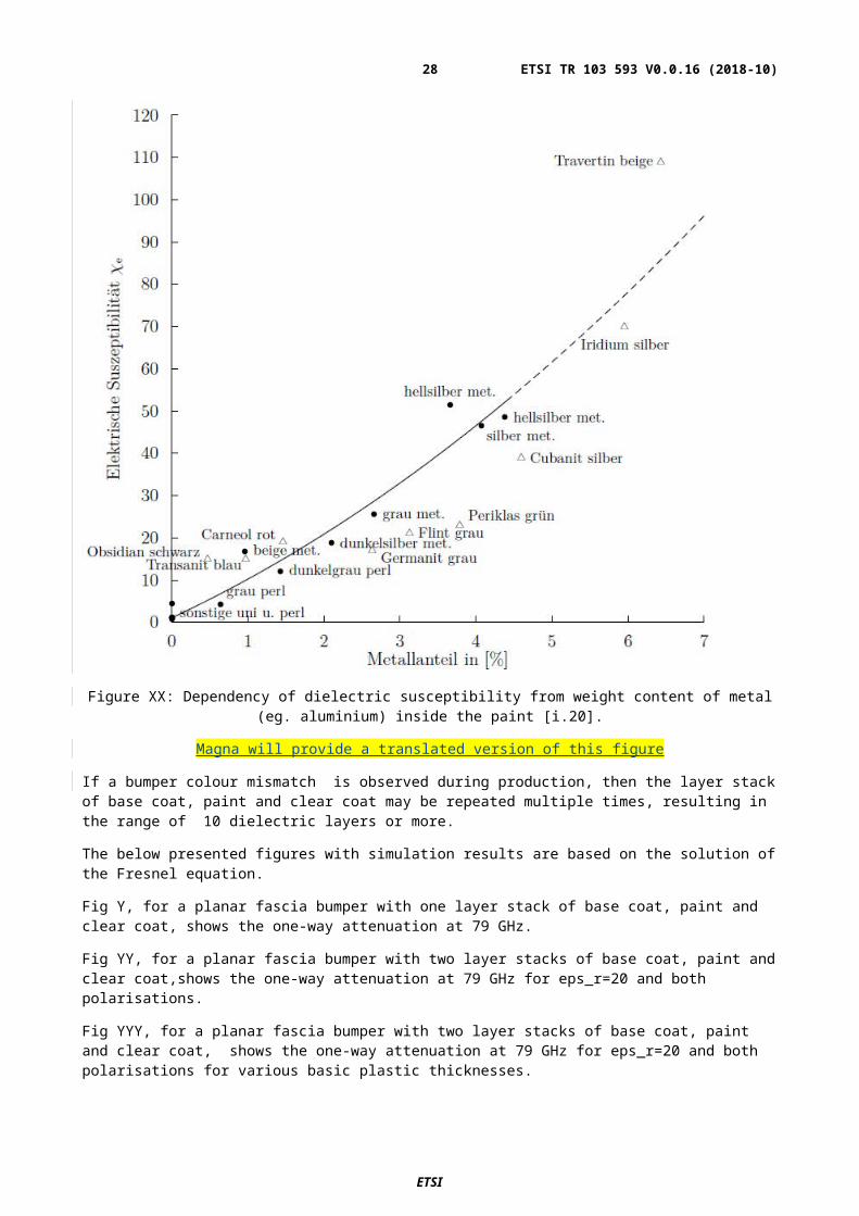
Metallic particles inside the paint have a large influence on its dielectric properties (dielectric constant r or dielectric susceptibility χe, see Fig. XX).
ETSI
Air in front of fascia
Clear coat (typ. 30µm thick)
Paint (typ. 15µm thick, can contain metallic particles)
Base coat (typ. 10µm thick)
Basic plastic (typ. 2.8mm thick)
ETSI TR 103 593 V0.0.16 (2018-10)22
Figure XX: Dependency of dielectric susceptibility from weight content of metal (eg. aluminium) inside the paint [i.20].
Magna will provide a translated version of this figure
If a bumper colour mismatch is observed during production, then the layer stack of base coat, paint and clear coat may be repeated multiple times, resulting in the range of 10 dielectric layers or more.
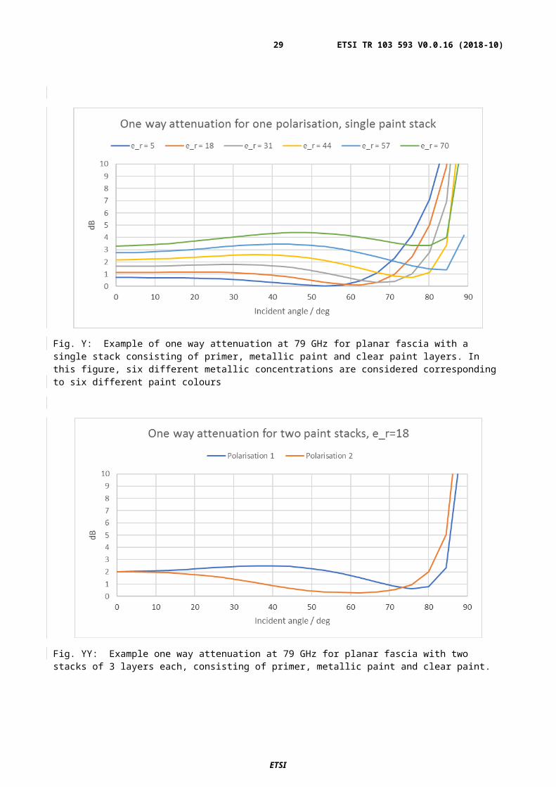
The below presented figures with simulation results are based on the solution of the Fresnel equation.
Fig Y, for a planar fascia bumper with one layer stack of base coat, paint and clear coat, shows the one-way attenuation at 79 GHz.
Fig YY, for a planar fascia bumper with two layer stacks of base coat, paint and clear coat,shows the one-way attenuation at 79 GHz for eps_r=20 and both polarisations.
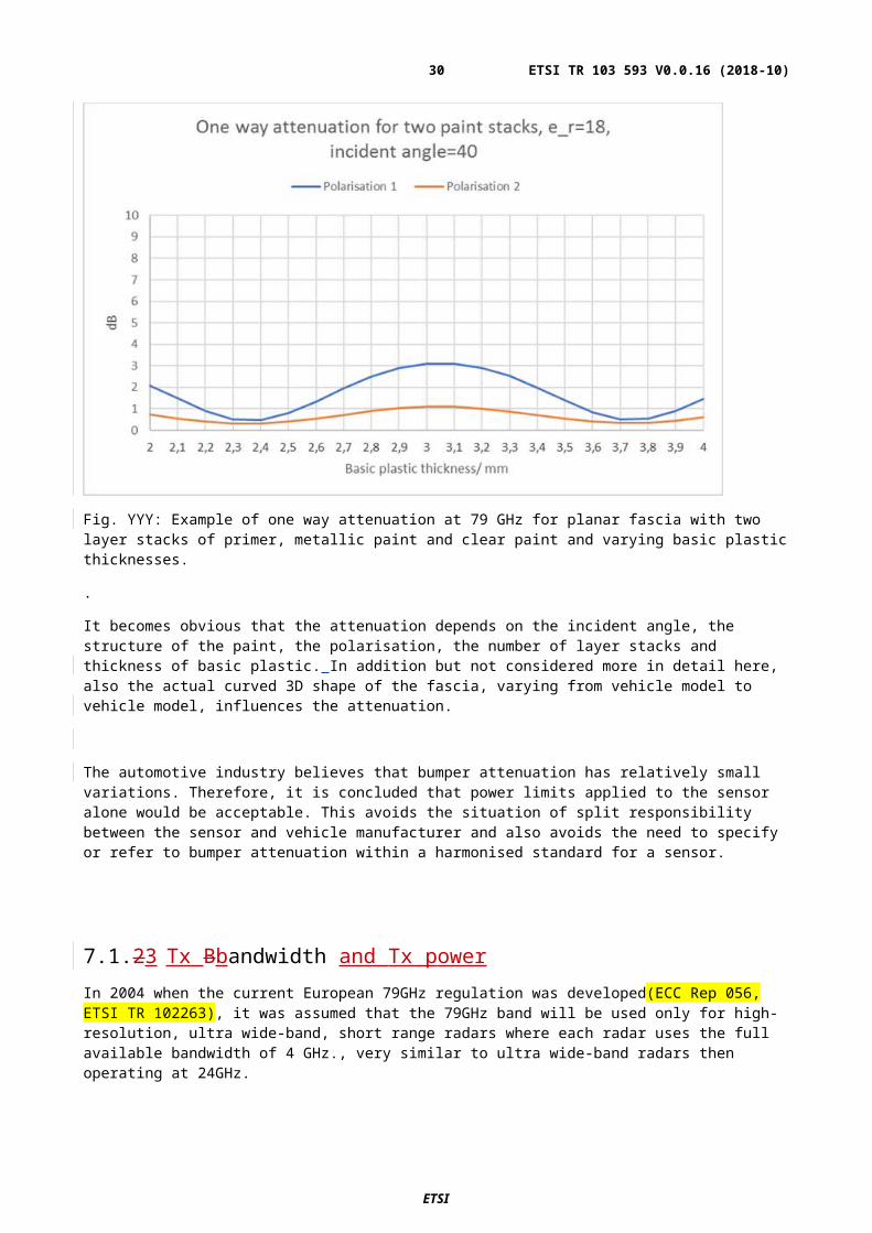
Fig YYY, for a planar fascia bumper with two layer stacks of base coat, paint and clear coat, shows the one-way attenuation at 79 GHz for eps_r=20 and both polarisations for various basic plastic thicknesses.
ETSI
ETSI TR 103 593 V0.0.16 (2018-10)23
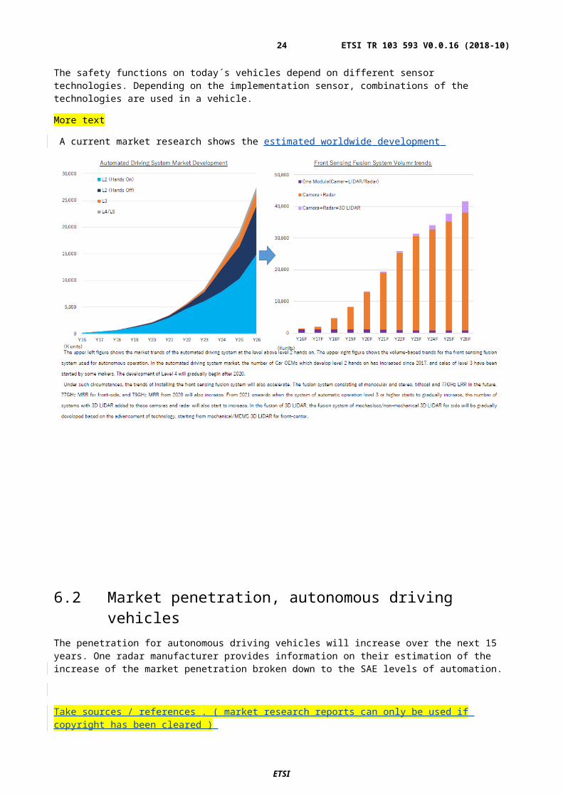
Fig. Y: Example of one way attenuation at 79 GHz for planar fascia with a single stack consisting of primer, metallic paint and clear paint layers. In this figure, six different metallic concentrations are considered corresponding to six different paint colours
Fig. YY: Example one way attenuation at 79 GHz for planar fascia with two stacks of 3 layers each, consisting of primer, metallic paint and clear paint.
ETSI
ETSI TR 103 593 V0.0.16 (2018-10)24
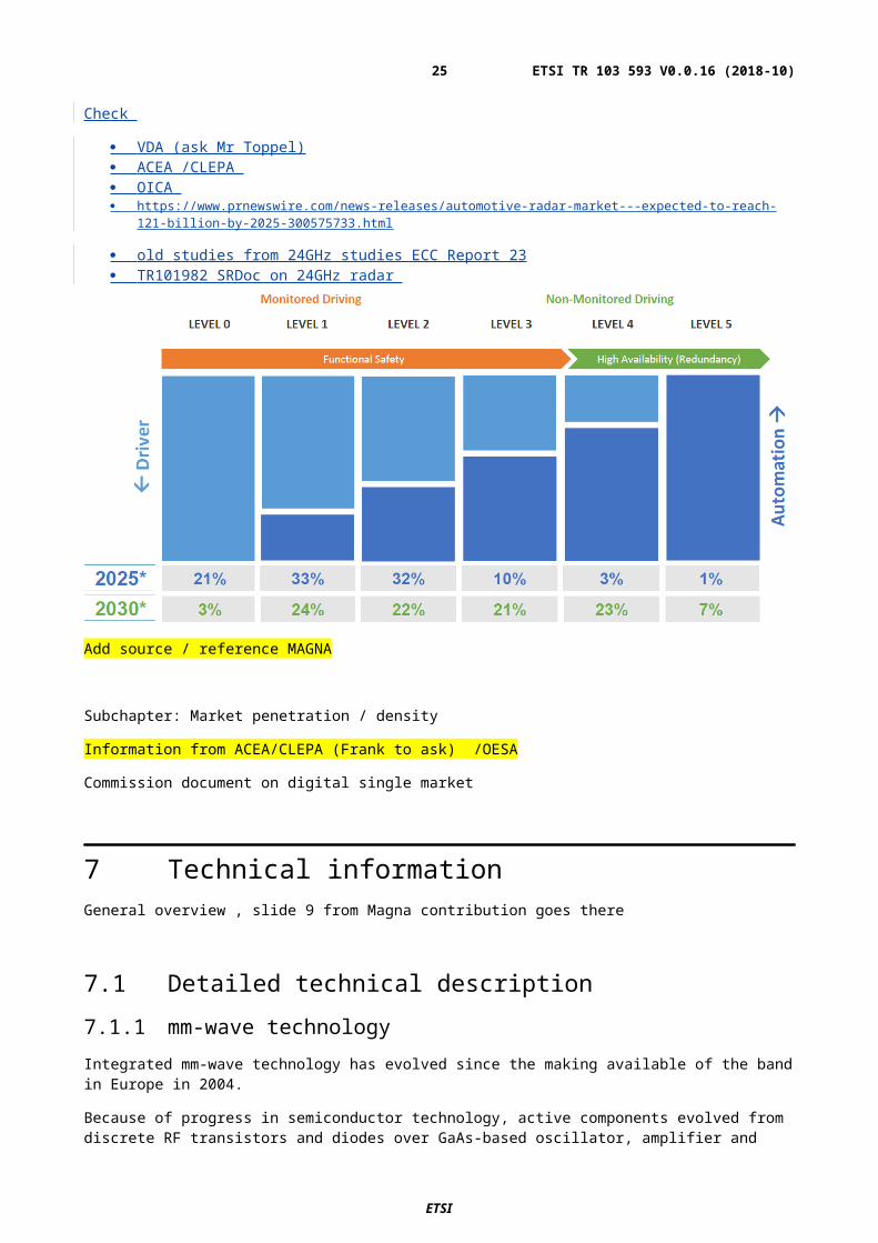
Fig. YYY: Example of one way attenuation at 79 GHz for planar fascia with two layer stacks of primer, metallic paint and clear paint and varying basic plastic thicknesses.
.
It becomes obvious that the attenuation depends on the incident angle, the structure of the paint, the polarisation, the number of layer stacks and thickness of basic plastic. In addition but not considered more in detail here, also the actual curved 3D shape of the fascia, varying from vehicle model to vehicle model, influences the attenuation.
The automotive industry believes that bumper attenuation has relatively small variations. Therefore, it is concluded that power limits applied to the sensor alone would be acceptable. This avoids the situation of split responsibility between the sensor and vehicle manufacturer and also avoids the need to specify or refer to bumper attenuation within a harmonised standard for a sensor.
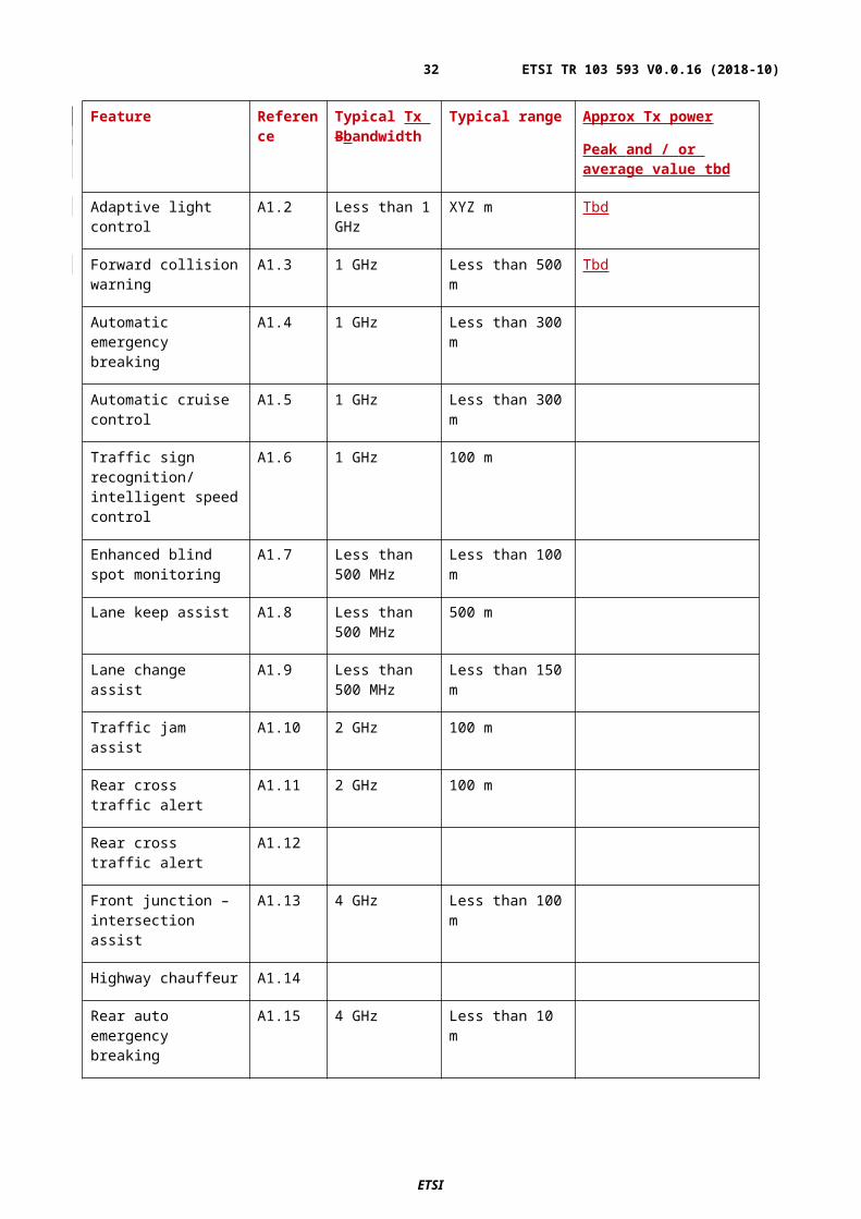
7.1.23 Tx Bbandwidth and Tx powerIn 2004 when the current European 79GHz regulation was developed(ECC Rep 056, ETSI TR 102263), it was assumed that the 79GHz band will be used only for high-resolution, ultra wide-band, short range radars where each radar uses the full available bandwidth of 4 GHz., very similar to ultra wide-band radars then operating at 24GHz.
Table Z now gives an overview of Tx bandwidth and Tx power required for the use cases as given in Annex A.1.
ETSI
ETSI TR 103 593 V0.0.16 (2018-10)25
Feature Reference
Typical Tx Bbandwidth
Typical range Approx Tx power
Peak and / or average value tbd
Adaptive light control A1.2 Less than 1 GHz XYZ m Tbd
Forward collision warning
A1.3 1 GHz Less than 500 m Tbd
Automatic emergency breaking
A1.4 1 GHz Less than 300 m
Automatic cruise control A1.5 1 GHz Less than 300 m
Traffic sign recognition/ intelligent speed control
A1.6 1 GHz 100 m
Enhanced blind spot monitoring
A1.7 Less than 500 MHz
Less than 100 m
Lane keep assist A1.8 Less than 500 MHz
500 m
Lane change assist A1.9 Less than 500 MHz
Less than 150 m
Traffic jam assist A1.10 2 GHz 100 m
Rear cross traffic alert A1.11 2 GHz 100 m
Rear cross traffic alert A1.12
Front junction – intersection assist
A1.13 4 GHz Less than 100 m
Highway chauffeur A1.14
Rear auto emergency breaking
A1.15 4 GHz Less than 10 m
Automatic lane change A1.16 2 GHz Less than 50 m
Automated parking assist (APA)
A1.17 4 GHz Less than 10 m
Home zone automated parking (HZAP)
A1.18 4 GHz Less than 10 m
Valet parking A1.19 4 GHz Less than 10 m
High way pilot A1.20 4 GHz 500 m
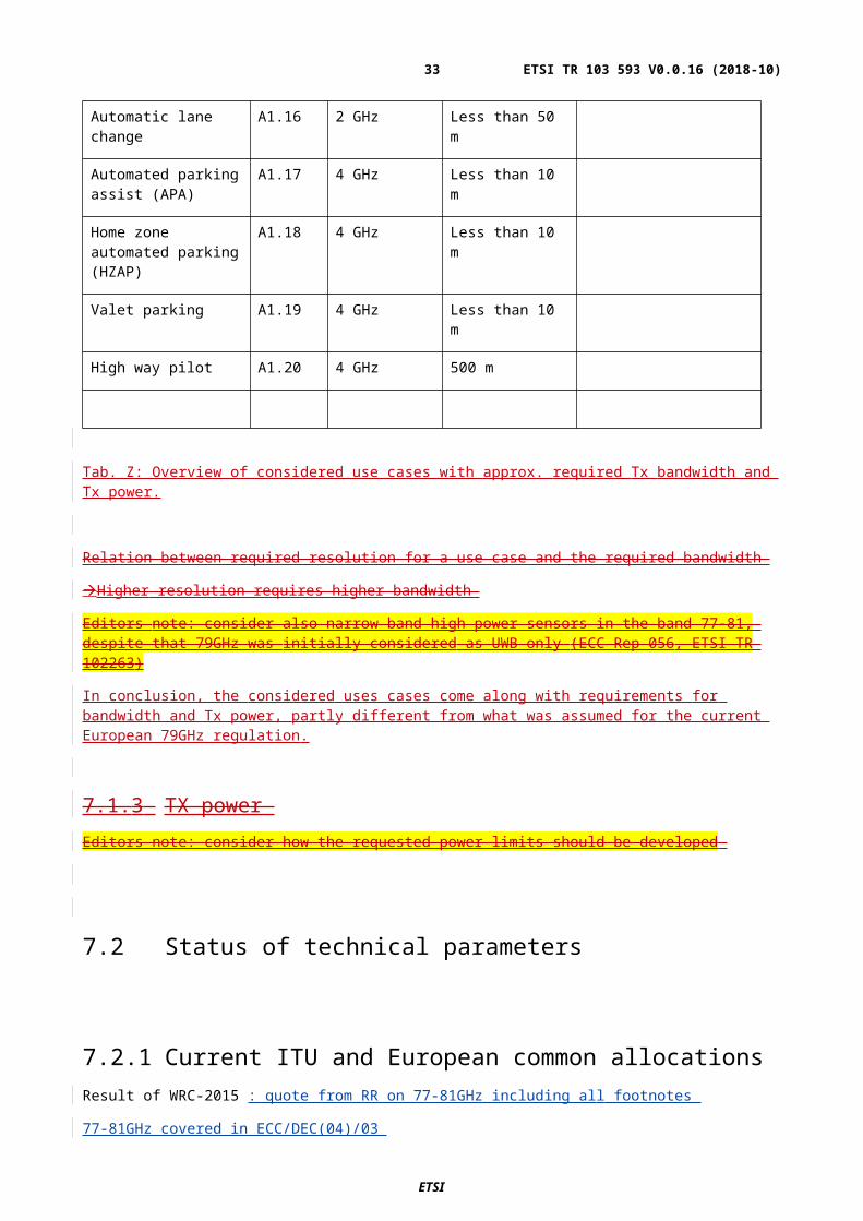
Tab. Z: Overview of considered use cases with approx. required Tx bandwidth and Tx power.
ETSI
ETSI TR 103 593 V0.0.16 (2018-10)26
Relation between required resolution for a use case and the required bandwidth
Higher resolution requires higher bandwidth
Editors note: consider also narrow band high power sensors in the band 77-81, despite that 79GHz was initially considered as UWB only (ECC Rep 056, ETSI TR 102263)
In conclusion, the considered uses cases come along with requirements for bandwidth and Tx power, partly different from what was assumed for the current European 79GHz regulation.
7.1.3 TX power Editors note: consider how the requested power limits should be developed
7.2 Status of technical parameters
7.2.1 Current ITU and European common allocationsResult of WRC-2015 : quote from RR on 77-81GHz including all footnotes
77-81GHz covered in ECC/DEC(04)/03
7.2.2 Sharing and compatibility studies already availableInitial studies on ECC Report 56 derived the PSD that are currently valid in Europe / CEPT Report 36
Kitt peak measurement exercise (2012)
IEEE paper on Japanese study (2011): contact authors of the paper to get the background and how this was reflected and further used what is the difference from this study compared to the other (old) studies on the table
M.2322 2% loss in data included? , what was the method used in M.2322
New material : Japanese Study ,
Study RA.[Coexsistence] (2018-09)protection distance/ was the 2000s and the 2% taken into account . Is this material helpful for us
Editors note:
Question: which minimum safety distance to RAS is accepted by the car industry
New Set of technical arguments
draw up a picture for Europe with a line of new technical arguments
ETSI
ETSI TR 103 593 V0.0.16 (2018-10)27
Assumed technical parameters for automotive radars in ECC Rep 56 were based on the available technology at that time. It was assumed that the 79GHz radars would use the same technology as the at that time available 24GHzt UWB radars would use.technology evolved , assumptions outdated
The most recent study was performed in preparation of WRC-2015 and resulted in report ITU-R M.2322 [i.26].
The conclusions for automotive radars with parameters as in [i.22]table ITU (see above) there were:
a) “…iInterference probability from automotive radars to amateur or amateur satellite stations is very low.”
b) “…no SRS (space-to-Earth) systems have been identified to date in the frequency range 76 GHz to 81 GHz.”
c) “Some administrations have concluded that the possibility of interference to RAS from automotive radars is sufficiently low and that the propagation characteristics of the band, translate in practice to a minimal interference potential to RAS operations. However, in some parts of the world, mitigation measures such as proper power emission limits might be needed to avoid potential interference to the radio astronomy service; some administrations permit the operation of automotive radars with specified emission power limits…. It is hoped that the radio astronomy community and the automotive radar manufacturers will continue their cooperative efforts to examine and implement mitigation techniques that can be employed to address potential interference concerns….“
But that study was only performed on the basis of power levels.
Here, it is now proposed to achieve additional mitigation by also considering the modulation of automotive radars.
Today, automotive radars typically use analogue modulation schemes:
Slow chirping FMCW, for example with 200 MHz modulation in 10 ms. Fast chirping FMCW (chirp sequencysequence), for example with 200 MHz modulation in 10 µs.
Insert figure showing frequency versus time
Newly under research for automotive radars are digital modulation schemes:
Phase-modulated CW (PMCW), for example … OFMD, for example …
Insert figure showing frequency versus time
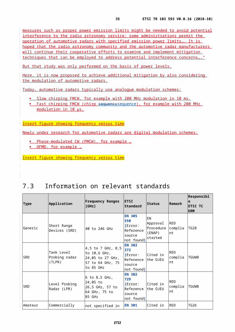
7.3 Information on relevant standards
Type Application Frequency Ranges [GHz]
ETSI Standard Status Remark
ResponsibleETSI TC ERM
Generic Short Range Devices (SRD) 40 to 246 GHz
EN 305 550 [Error: Reference source not found]
EN Approval Procedure (ENAP) started
RED compliant TG28
SRD Tank Level Probing radar (TLPR)
4,5 to 7 GHz, 8,5 to 10,6 GHz, 24,05 to 27 GHz, 57 to 64 GHz, 75 to 85 GHz
EN 302 372 [Error: Reference source not found]
Cited in the OJEU
RED compliant TGUWB
SRD Level Probing Radar (LPR)
6 to 8,5 GHz, 24,05 to 26,5 GHz, 57 to 64 GHz, 75 to 85 GHz
EN 302 729 [Error: Reference source not found]
Cited in the OJEU
RED compliant TGUWB
AmateurCommercially available amateur radio equipment
not specified in the standard
EN 301 783 [Error: Reference
Cited in the OJEU
RED compliant TG26
ETSI
ETSI TR 103 593 V0.0.16 (2018-10)28
source not found]
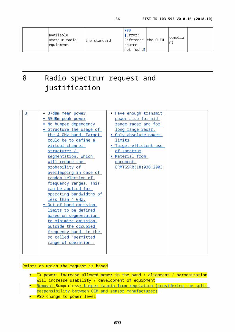
8 Radio spectrum request and justification
3 37dBm mean power 55dBm peak power No bumper dependency Structure the usage of the 4 GHz
band. Target could be to define a virtual channel structurer / segmentation, which will reduce the probability of overlapping in case of random selection of frequency ranges. This can be applied for operating bandwidths of less than 4 GHz.
Out of band emission limits to be defined based on segmentation to minimize emission outside the occupied frequency band, in the so called “permitted range of operation”.
Have enough transmit power also for mid-range radar and for long range radar.
Only absolute power limits Target efficient use of spectrum Material from document
ERMTGSRR(18)036_2003
Points on which the request is based
TX power: increase allowed power in the band / alignment / harmonization will increase usability / development of equipment
Removal Bumperloss/ bumper fascia from regulation (considering the split responsibility between OEM and sensor manufacturer)
PSD change to power level Change SRR in EC and ECC dec from automotive short range radar into high resolution automotive radar [OOB provide proposal for the studies ] Harmonization of regulation would help increase market share
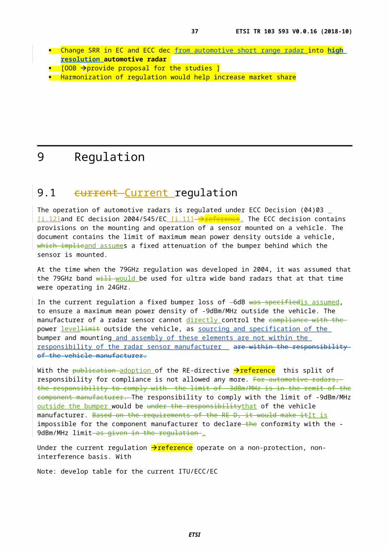
9 Regulation
9.1 current Current regulationThe operation of automotive radars is regulated under ECC Decision (04)03 [i.12]and EC decision 2004/545/EC [i.11] reference. The ECC decision contains provisions on the mounting and operation of a sensor mounted on a vehicle. The document contains the limit of maximum mean power density outside a vehicle, which implieand assumes a fixed attenuation of the bumper behind which the sensor is mounted.
ETSI
ETSI TR 103 593 V0.0.16 (2018-10)29
At the time when the 79GHz regulation was developed in 2004, it was assumed that the 79GHz band will would be used for ultra wide band radars that at that time were operating in 24GHz.
In the current regulation a fixed bumper loss of -6dB was specifiedis assumed, to ensure a maximum mean power density of -9dBm/MHz outside the vehicle. The manufacturer of a radar sensor cannot directly control the compliance with the power levellimit outside the vehicle, as sourcing and specification of the bumper and mounting and assembly of these elements are not within the responsibility of the radar sensor manufacturer are within the responsibility of the vehicle manufacturer.
With the publication adoption of the RE-directive reference this split of responsibility for compliance is not allowed any more. For automotive radars, the responsibility to comply with the limit of -3dBm/MHz is in the remit of the component manufacturer. The responsibility to comply with the limit of -9dBm/MHz outside the bumper would be under the responsibilitythat of the vehicle manufacturer. Based on the requirements of the RE-D, it would make itIt is impossible for the component manufacturer to declare the conformity with the -9dBm/MHz limit as given in the regulation .
Under the current regulation reference operate on a non-protection, non-interference basis. With
Note: develop table for the current ITU/ECC/EC
9.2 Proposed regulationIt is proposed to revise the existing ECC Decision [i.11] and EC decision [i.12] in the following pointsas summarised below.
9.2.1 Proposed revisions to ECC Dec (04)03 no Reference Proposed change Background
1 Full document Change Term
automotive short range radars
To
High resolution automotive radars
to avoid confusion between the rf coverage of the device and the implemented functions
to align the terminology with ITU
2 Considering l delete this part of the sentence
..therefore SRR must operate on a non-interference and non-protected basis in accordance with the Radio Regulations.
To reflect the decision of WRC-15 , which allocates the frequency band 77GHz - 81GHz to ground based radar applications on a co-primary status, reference to footnote 5.559B
5.559B The use of the frequency band 77.5-78 GHz by the radiolocation service shall be limited to short-range radar for ground-based applications, including automotive radars. The technical characteristics of these radars are provided in the most recent version of Recommendation ITU-R M.2057. The provisions of No. 4.10 do not apply. (WRC-15)
3 Decides 2 delete the section
on a non-interference and non-protected basis
To reflect the decision of WRC-15 on automotive radars, which allocates the frequency band 77GHz - 81GHz to ground based radar applications on a co-primary status, Reference to footnote 5.559B
5.559B The use of the frequency band 77.5-78 GHz by the radiolocation service
ETSI
ETSI TR 103 593 V0.0.16 (2018-10)30

shall be limited to short-range radar for ground-based applications, including automotive radars. The technical characteristics of these radars are provided in the most recent version of Recommendation ITU-R M.2057. The provisions of No. 4.10 do not apply. (WRC-15)
4 Decides 2 delete the section replace
maximum mean power density of -3dBm/MHz e.i.r.p.
add by
maximum mean power of 3750dBm mean e.i.r.p.
based on the technical considerations in chapter 8 and the consideration in chapter 9.1,
5 Decides 3 Delete Decides 3 completely based on the technical considerations in chapter 7,8 and the consideration in chapter 9.1,
6
9.2.2 Proposed revisions to EC decision 2004/545/EC
no Reference Proposed change Background
1 Full document Change Term
automotive short range radars
To
High resolution automotive radars
to avoid confusion between the rf coverage of the device and the implemented functions
to align the terminology with ITU
2 Article 3,
First paragraph, last sentence
Delete
..on a non-interference and non-protected basis
To reflect the decision of WRC-15 , which allocates the frequency band 77GHz - 81GHz to ground based radar applications on a co-primary status, reference to footnote 5.559B
5.559B The use of the frequency band 77.5-78 GHz by the radiolocation service shall be limited to short-range radar for ground-based applications, including automotive radars. The technical characteristics of these radars are provided in the most recent version of Recommendation ITU-R M.2057. The provisions of No. 4.10 do not apply. (WRC-15)
ETSI
ETSI TR 103 593 V0.0.16 (2018-10)31
3 Article 3,
Second paragraph
delete the section replace
maximum mean power density of -3dBm/MHz e.i.r.p.
add by
maximum mean power of 3750dBm mean e.i.r.p.
based on the technical considerations in chapter 8 and the consideration in chapter 9.1,
4 Article 3,
Third paragraph
Delete completely based on the technical considerations in chapter 7,8 and the consideration in chapter 9.1,
ETSI
ETSI TR 103 593 V0.0.16 (2018-10)32
Annex A:Detailed Market informationMarket numbers
Automotive radars are a key technology for autonomous driving vehicles .
Note: take material from Magna contribution: use case list from the TS document
A.1 Advanced Driving Assistance Systems: descriptions of features & use parameters
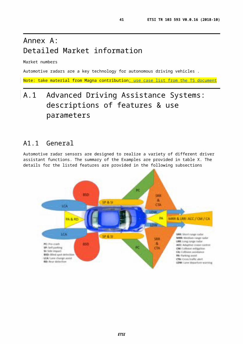
A1.1 GeneralAutomotive radar sensors are designed to realize a variety of different driver assistant functions. The summary of the Examples are provided in table X. The details for the listed features are provided in the following subsections
ETSI
ETSI TR 103 593 V0.0.16 (2018-10)33
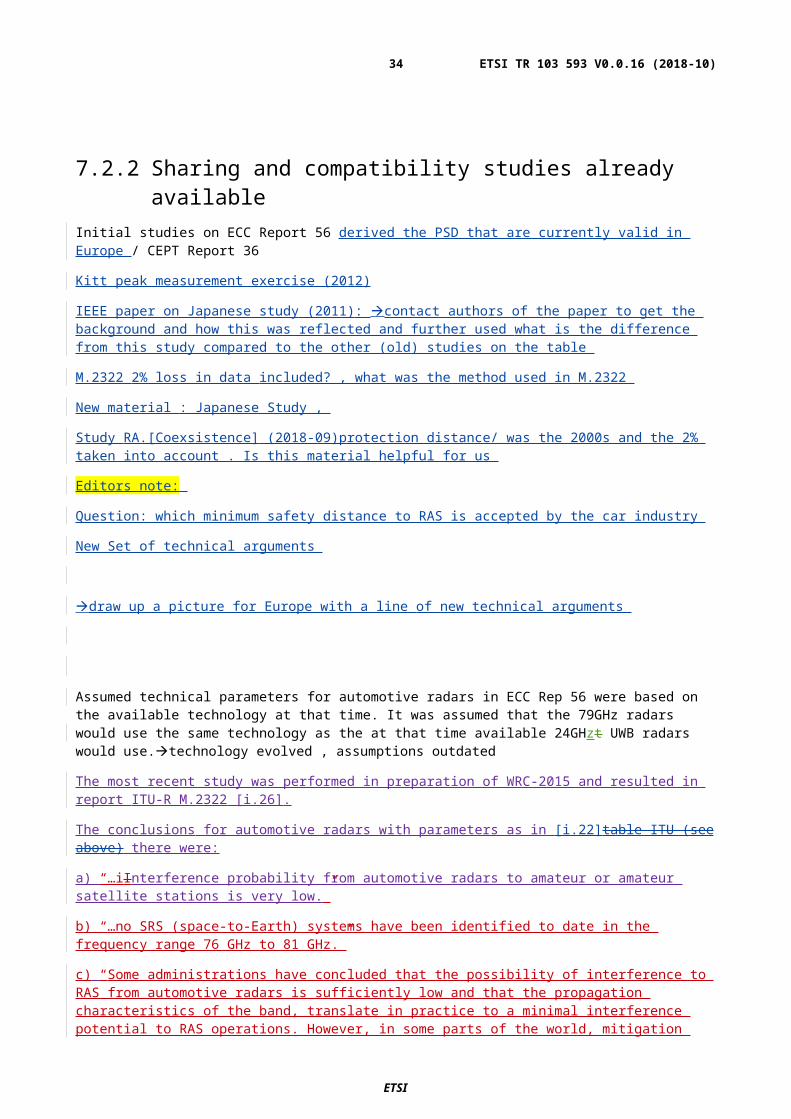
Figure A.1: tbd
Table X provides an overview of technical key parameters of features that rely on automotive radar sensors. Detailed descriptions for the features are provided in the following subchapters
Editors note for the table
What is the message / conclusion we want to convey with this info: eg only few use cases need full 4GHz BW, they have a typical range of less than 10m, others have less BW and have much larger typical range
Do we want to maintain the table in the annex or would another location better suited
Complete column for number of sensors / sensor fusion
Check with Magna colleagues the list provided is there any difference between A1.11 and A1.12
Consideration spectrum requirement for one sensor / multiple sensors (sensor fusion) per vehicle ?
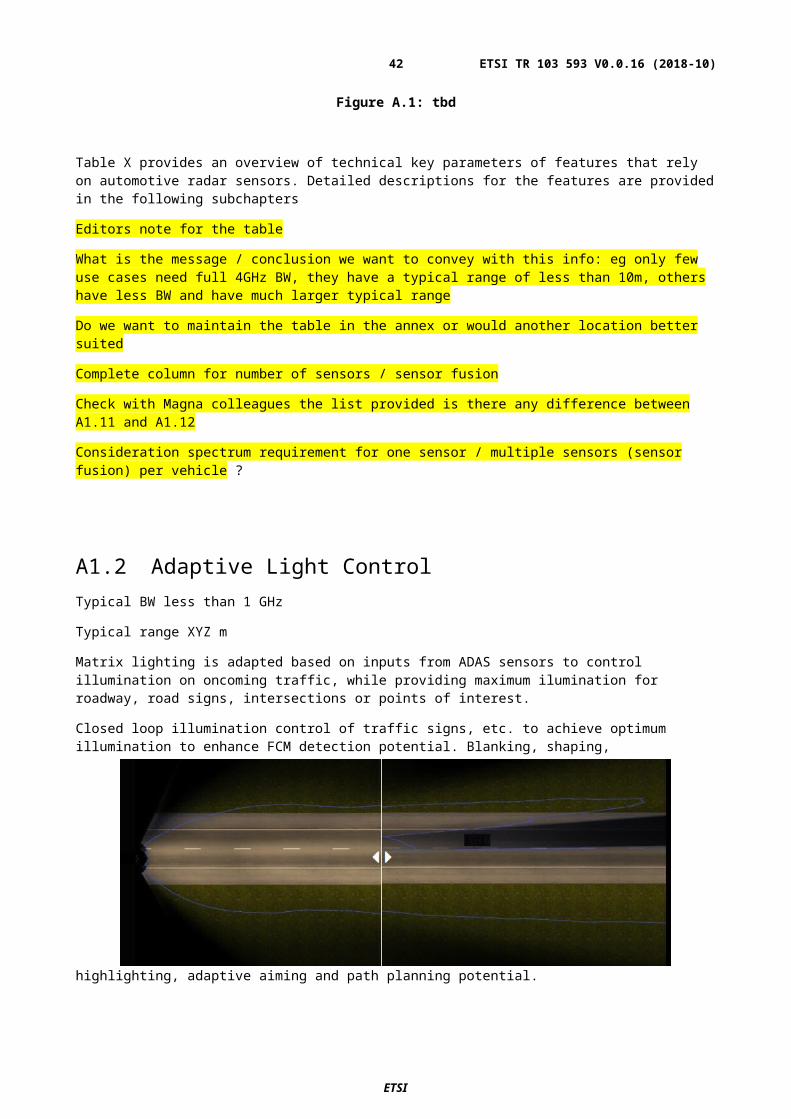
A1.2 Adaptive Light Control Typical BW less than 1 GHz
Typical range XYZ m
Matrix lighting is adapted based on inputs from ADAS sensors to control illumination on oncoming traffic, while providing maximum ilumination for roadway, road signs, intersections or points of interest.
Closed loop illumination control of traffic signs, etc. to achieve optimum illumination to enhance FCM detection potential. Blanking, shaping, highlighting, adaptive aiming and path planning potential.
Figure A.2: tbd
Key System Elements:
Matrix LED Lighting,
Radar
Camera
Localization
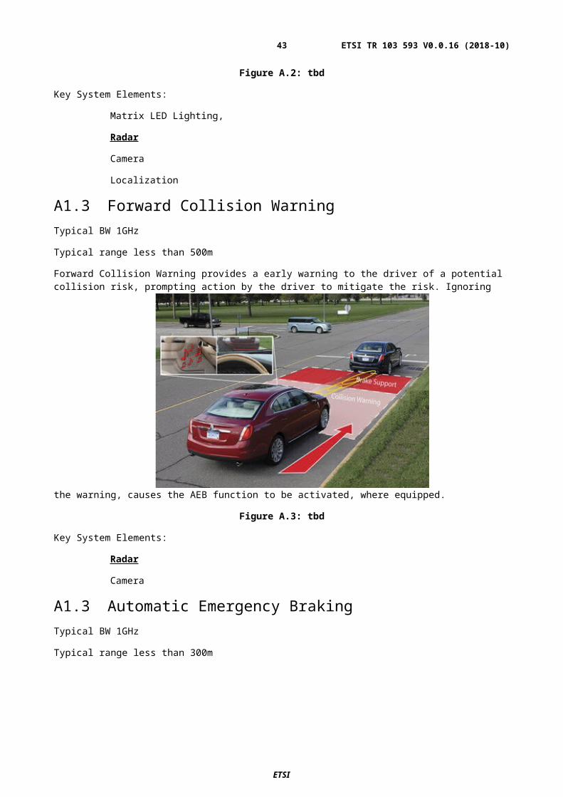
A1.3 Forward Collision WarningTypical BW 1GHz
ETSI
ETSI TR 103 593 V0.0.16 (2018-10)34
Typical range less than 500m
Forward Collision Warning provides a early warning to the driver of a potential collision risk, prompting action by the driver to mitigate the risk. Ignoring the warning, causes the AEB function to be activated, where equipped.
Figure A.3: tbd
Key System Elements:
Radar
Camera
A1.3 Automatic Emergency BrakingTypical BW 1GHz
Typical range less than 300m
AEB alerts drivers to collisions with vehicles in their path. If they do not react to the alerts, it automatically brakes to mitigate or avoid a collision. This can be demonstrated two ways: 1) camera only and 2) fusion of a camera and Radar.
Figure A.4: tbd
Key System Elements:
Radar
ETSI
ETSI TR 103 593 V0.0.16 (2018-10)35
Camera
Braking Control
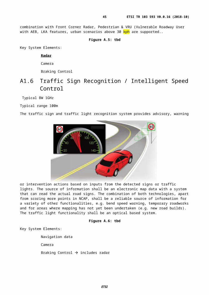
A1.5 Automatic Cruise Control (ACC) Typical BW 1GHz
Typical range 300m
ACC is normally used under highway conditions and in essence, is a system which maintains a constant distance or time to a lead vehicle when the vehicle is on highway (road where non-motorised vehicles and pedestrians are prohibited). In combination with Front Corner Radar, Pedestrian & VRU (Vulnerable Roadway User with AEB, LKA features, urban scenarios above 30 kph are supported..
Figure A.5: tbd
Key System Elements:
Radar
Camera
Braking Control
A1.6 Traffic Sign Recognition / Intelligent Speed Control Typical BW 1GHz
Typical range 100m
The traffic sign and traffic light recognition system provides advisory, warning or intervention actions based on inputs from the detected signs or traffic lights. The source of information shall be an electronic map data with a system that
ETSI
ETSI TR 103 593 V0.0.16 (2018-10)36
can read the actual road signs. The combination of both technologies, apart from scoring more points in NCAP, shall be a reliable source of information for a variety of other functionalities, e.g. bend speed warning, temporary roadworks and for areas where mapping has not yet been undertaken (e.g. new road builds). The traffic light functionality shall be an optical based system.
Figure A.6: tbd
Key System Elements:
Navigation data
Camera
Braking Control includes radar
A1.7 Enhanced Blind Spot Monitoring
Typical BW below 500MHz
Typical range below 100m
Enhanced blind spot monitoring is a convenience feature, providing the driver with a warning, typically located in the rearview mirror, for vehicles in the blind spot zone or quickly approaching the vehicle. Coverage includes merging scenarios, with the incorporation of lane marking information. Vehicles approaching in the adjacent lane are reported up to 30m behind the vehicles (10m/s closing speed maximum). Where Lane Keep Assist is included, steering counter torque will be provided to the driver, providing an indication that a lane change is not recommended. The driver always maintains control of the decision to change lanes.
ETSI
ETSI TR 103 593 V0.0.16 (2018-10)37
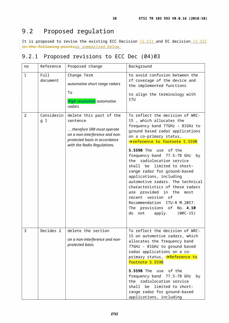
Figure A.7: tbd
Key System Elements:
Radar
Camera
A1.8 Lane Keep AssistTypical BW less than 500MHz
Typical range 500m
EYERIS® solutions for lane detection are optimized for every kind of lane marking, thus providing a reliable performance in every market and every corner of the world.
EYERIS® features either signal a warning to the driver prior to lane departure or automatically intervene with the car’s controls to deter the driver from moving out of their lane.
Figure A.8: tbd
Key System Elements:
Steering and/or Braking Control (including radar)
Camera
A1.9 Lane Change AssistTypical BW less than 500MHz
Typical range less than 150m
Lane Change Assist and cross traffic alert system extended the warning zone to support warnings at up to 70m behind the vehicle or in crossing traffic situations. Required to support high speed overtaking for European Autobahn scenarios and performance exceeding NHTSA NCAP BSD requirement.
ETSI
ETSI TR 103 593 V0.0.16 (2018-10)38
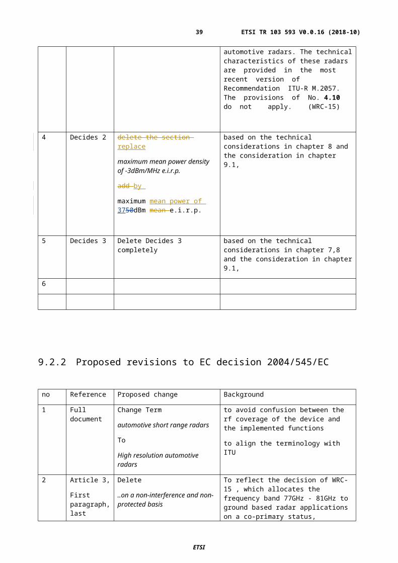
Figure A.9: tbd
Key System Elements:
Front Camera
Corner radar, see clause A1.1.
A1.10 Traffic Jam Assist
Typical BW 2GHz
Typical range 100m
ACC (see clause A1.5) is normally used under highway conditions and in essence, is a system which maintains a constant distance or time to a lead vehicle when the vehicle is on highway (road where non-motorised vehicles and pedestrians are prohibited). Traffic Jam Assist acts in combination with Front Corner Radar, LiDAR, Pedestrian & VRU (Vulnerable Roadway User) with AEB, LKA features, in urban scenarios to provide full speed range ACC capabilities including Stop & Go traffic. The system maintains the current driving lane, permitting the driver to complete lane changes.
Figure A.10: tbd
Key System Elements:
Camera
Radar
Corner Radar
Lidar
Steering &/or Braking Control
A1.11 Rear Cross Traffic AlertTypical BW 2GHz
Typical range 100m
Backing in a busy shopping mall parking lot (cars, shopping carts, pedestrians walking), the cross traffic alert system scans for traffic, pedestrians and range to surrounding objects. The driver is issued warnings via a mirror icon. In combination with Rear Pedestrian AEB, an expanded range of coverage is realized with the fusion of UPA, SVS and corner radar for enhanced security.
ETSI
ETSI TR 103 593 V0.0.16 (2018-10)39
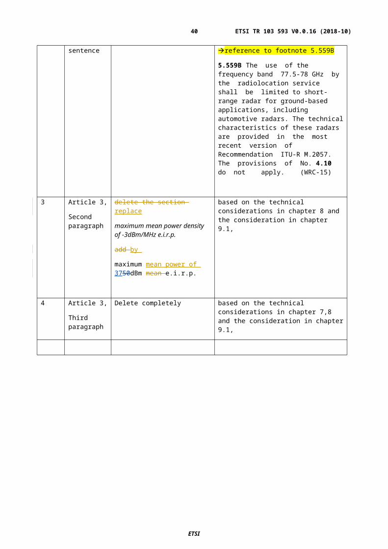
Figure A.11: tbd
Key System Elements:
Corner Radar,
Rear Camera,
UPA,
SVS,
Braking Control
A1.12 Rear Cross Traffic Alertsee A1.11 double entry/ clarify with Magna
If the vehicle is stationary, the driver attempts to pull away and the system detects one or more targets which may be at risk of collision, either within the intended lane / path of travel or which are likely to move into the lane / path of travel, the system shall provide a warning to the driver indicating location of the target at risk..
Figure A.12: tbd
Key System Elements:
ETSI
ETSI TR 103 593 V0.0.16 (2018-10)40
Front Camera,
Front Corner Radar,
UPA,
SVS,
Braking Control
A1.13 Front Junction-Intersection AssistTypical BW 4GHz
Typical range below 100m
If the vehicle is stationary and the driver attempts to initiate forward motion which causes risk of collision due to some form of cross traffic or object which is stationary ahead, the system shall inhibit the pull-away.
Figure A.13: tbd
Key System Elements:
Camera,
Corner Radar,
SVS,
UPA,
Braking Control
A1.14 Highway Chauffer clarify with Magna
Covers several cateogries that are already covered above . sensor fusion application/ multi sensor
This feature is an on-demand autonomy solution that allows the driver to enable Level 3 (SAE) driving. The driver’s readiness and ability to resume control is continuously monitored. The driver is required to monitor the driving task, and when requested to take back control, they will be given 3 seconds to do so.
ETSI
ETSI TR 103 593 V0.0.16 (2018-10)41
Highway Chauffer handles all required driving on limited access highways with driver supervision. It handles lane management, speed modulation, and path planning.
Figure A.14: tbd
Key System Elements:
Front Radar(s)
Camera,
Driver Monitoring,
Steering & Braking Control
A1.15 Rear – Auto Emergency BrakingTypical BW 4GHz
Typical range less than 10m
Ultrasonic-only or ultrasonic+camera-fusion provides obstacle detection and evaluation for Rear Automatic Emergency Braking (Rear AEB). The feature will automatically brake in case an object is in the path of the vehicle supporting NCAP requirements. Detection of the entire FMVSS 111 and NCAP reduces harsh emergency braking by providing control of rear backing speeds & comfort stops
Figure A.15: tbd
Key System Elements:
ETSI
ETSI TR 103 593 V0.0.16 (2018-10)42
UPA,
Rear Camera,
Radar,
Braking Control
A1.16 Automatic Lane ChangeTypical BW 2GHz
Typical range 50m or less
Automated Lane Change Assist supplements ACC function to autonmously initiate and execute an overtaking manuever. System anticipates the need for overtaking manuever, monitors the driving situation and available opportunities to change lanes, selects the desired opportunity, initiates turn signal, changes lanes & adjusts speed to match the traffic flow. Automatically returns to the original lane after passing the preceeding vehicle
Figure A.16: tbd
Key System Elements:
Camera
360° Radar,
Steering & Braking Control
A1.17 Automated Parking Assist (APA)Typical BW 4GHz
Typical range less than 10m
Ultrasonic-only or camera+ultrasonic-fusion automated parking systems detects obstacles in the vehicle’s path, open parking spots and performs parallel or perpendicular parking maneuvers to park the car automatically.
In combination with obstacle detection, the Rear Automatic Emergency Braking (Rear AEB) feature will automatically brake in case an object is in the path of the vehicle supporting NCAP requirements
ETSI
ETSI TR 103 593 V0.0.16 (2018-10)43
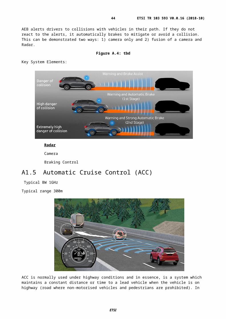
Figure A.17: tbd
Key System Elements:
UPA,
SVS
Steering Control,
Braking Control
A1.18 Home Zone Automated Parking (HZAP)Typical BW 4GHz
Typical range less that 10m
An Ultrasonic or UPA+Vision fusion system for assisting the driver by automating the repetitive tasks such as parking in/out of known (learned) parking spots. Once the desired spot and the associated approach are stored through a short learning/training session, HZAP system will maneuver the vehicle autonomously to a memorized parking spot
Figure A.18: tbd
Key System Elements:
ETSI
ETSI TR 103 593 V0.0.16 (2018-10)44
Secure Connectivity, UPA,
SVS,
Radar
Steering & Braking Control
A1.19 Valet ParkingTypical BW 4GHz
Typical range less that 10m
The driver exits the vehicle at a drop-off area and uses a remote control system, such as a fob or smart phone application, to send the vehicle away to park itself. The driver has no further interaction with the vehicle and the vehicle parks itself in a suitable parking location. The space is allocated by a carpark control system. After some time, either predefined or upon driver request the vehicle drives itself to a pickup area to meet the driver, (the summon function). The system should be capable of communicating with the driver using a remote device to allow the driver to go to the vehicle rather than summon the vehicle.
Figure A.19: tbd
Key System Elements:
Secure Connectivity,
Camera,
360° Radar,
UPA,
LiDAR
Steering & Braking Control
A1.20 Highway PilotSome sensors in this application would need
Typical BW 4GHz
Typical range 500m
Function based on sensor fusion
This feature is an on-demand autonomy solution that allows the driver to enable Level 4 (SAE) driving. If the driver is required to take back control, they will be given 10 seconds to do so. Enhanced biometric, driver monitoring required.
Highway Pilot handles all required driving on limited access highways with driver supervision. It handles lane management, speed modulation, and path planning.
ETSI
ETSI TR 103 593 V0.0.16 (2018-10)45
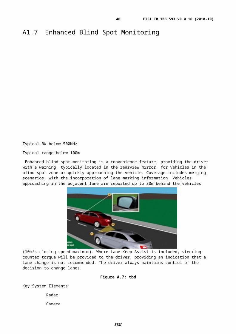
Figure A.20: tbd
Key System Elements:
Secure Connectivity
Camera,
360° Radar,
UPA,
LiDAR,
Driver Monitoring,
Steering & Braking Control
A.2 Advanced Driving Assistance Systems for other kind of ground based vehicles: descriptions of features & use parameters
A2.1 GeneralRadar sensor covered by EN 301 091-3 [i.X] are designed to realize a variety of different driver assistant functions and safety supporting functions. Based on the complexity with classes were specified to simply/generalize the RX-tests.
More details are also provided within TR 102 704 [i.X]
A2.2 Trains (locomotive and train cars,…)Short summary about use – cases and figures provided in this clause
ETSI
ETSI TR 103 593 V0.0.16 (2018-10)46
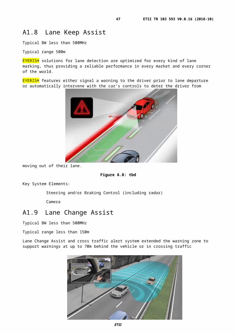
Figure A.21: tbd
Figure A.21: tbd
ETSI
ETSI TR 103 593 V0.0.16 (2018-10)47
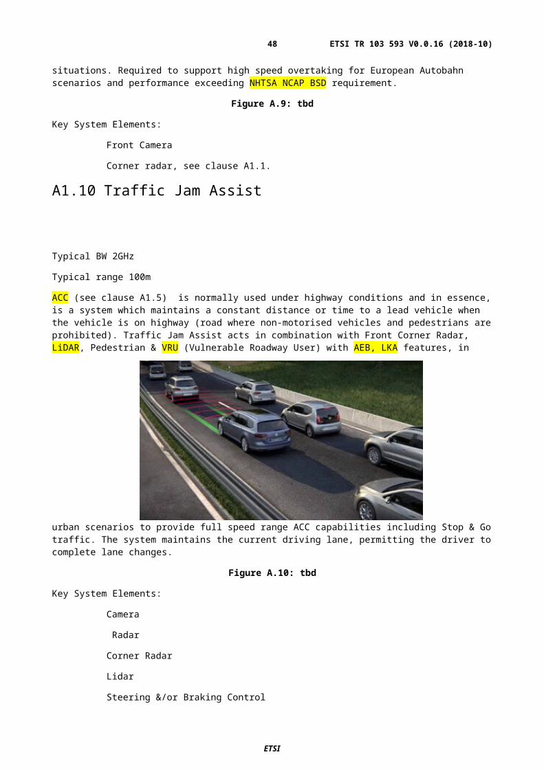
Figure A.22: Example train construction vehicles
Figure A.23: Examples catenary detection and position measurement
ETSI
ETSI TR 103 593 V0.0.16 (2018-10)48
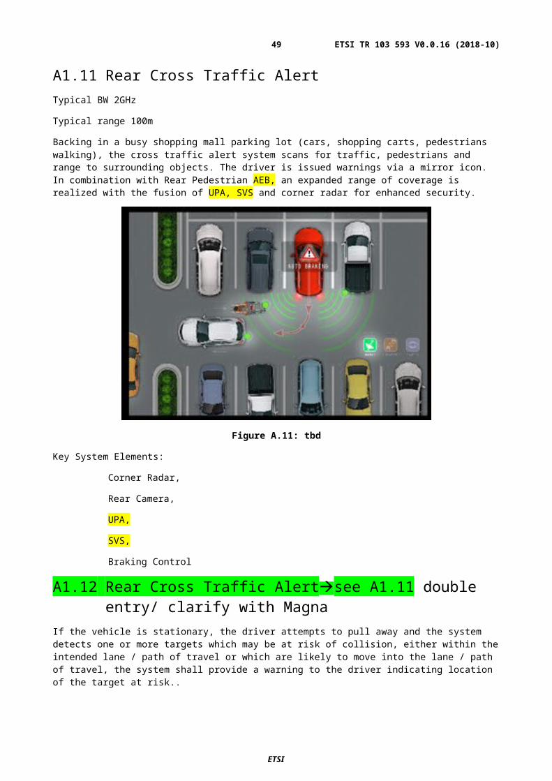
Figure A.24: Examples catenary detection and position measurement
Figure A.25: collision avoidance
A2.3 Tram/MetroUse-cases: collision warning/avoidance and speed over ground
Figures:
ETSI
ETSI TR 103 593 V0.0.16 (2018-10)49
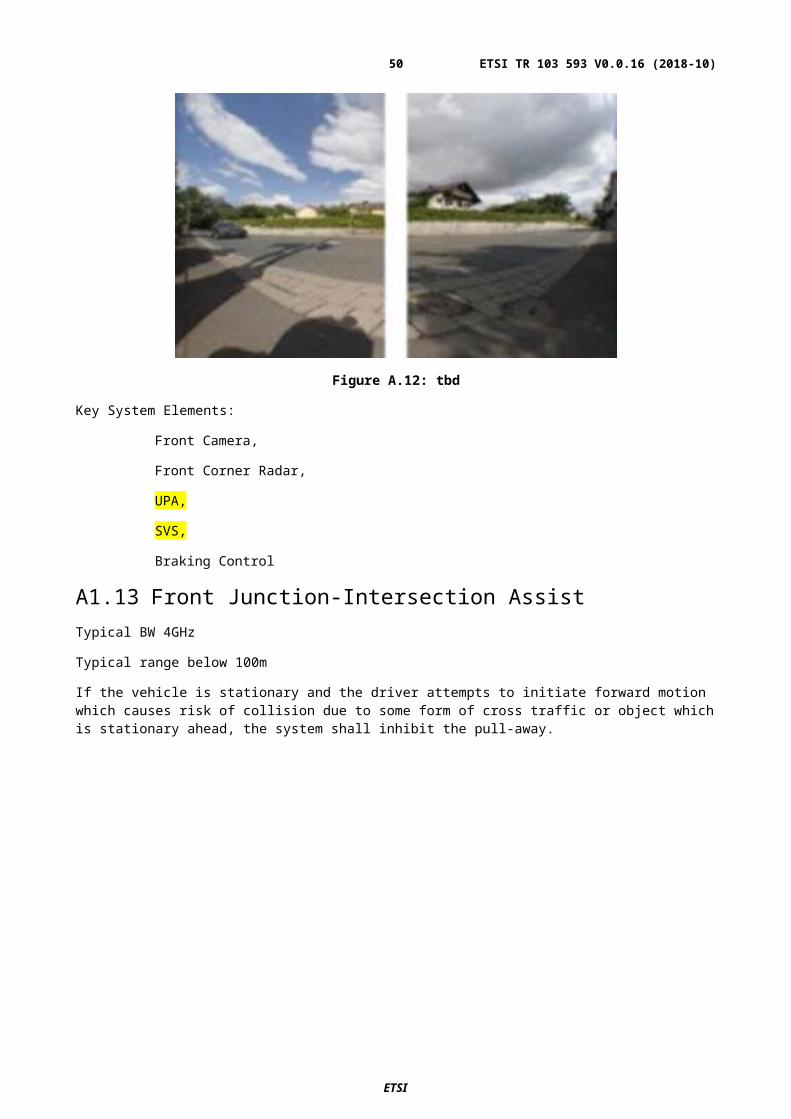
Figure A.25:
A2.4 Construction / farming vehicles (outdoor)Use- cases (very comparable with automotive use-case):
- Collision avoidance (crossing collision avoidance / back over collision avoidance / side looking (blind spot)
Huge and heavy vehicles with lot of “blind spots” increase of safety
- Autonomous devices (automatic coordinated pace)
- (correct/real) speed over ground
Figure A.26:
ETSI
ETSI TR 103 593 V0.0.16 (2018-10)50
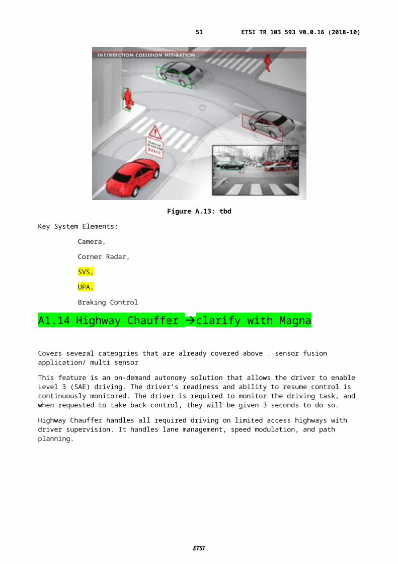
Figure A.27:
Figure A.27:
A2.5 Industrial vehicles / Material handling (indoor/outdoor)Use-cases (fork lifts, working platform):
- Collision avoidance (if people working in pulled out situation detection ground objects, blind spot detection)
- Autonomous devices
- Distance measurement (height over ground / height over headfirst)
Benefit for such sensors:
- Vehicles with lot of “blind spots” and if
- working indoor difficult to estimate the distance till the celling (headfirst), walls or obstacles on the ground increase of safety
ETSI
ETSI TR 103 593 V0.0.16 (2018-10)51
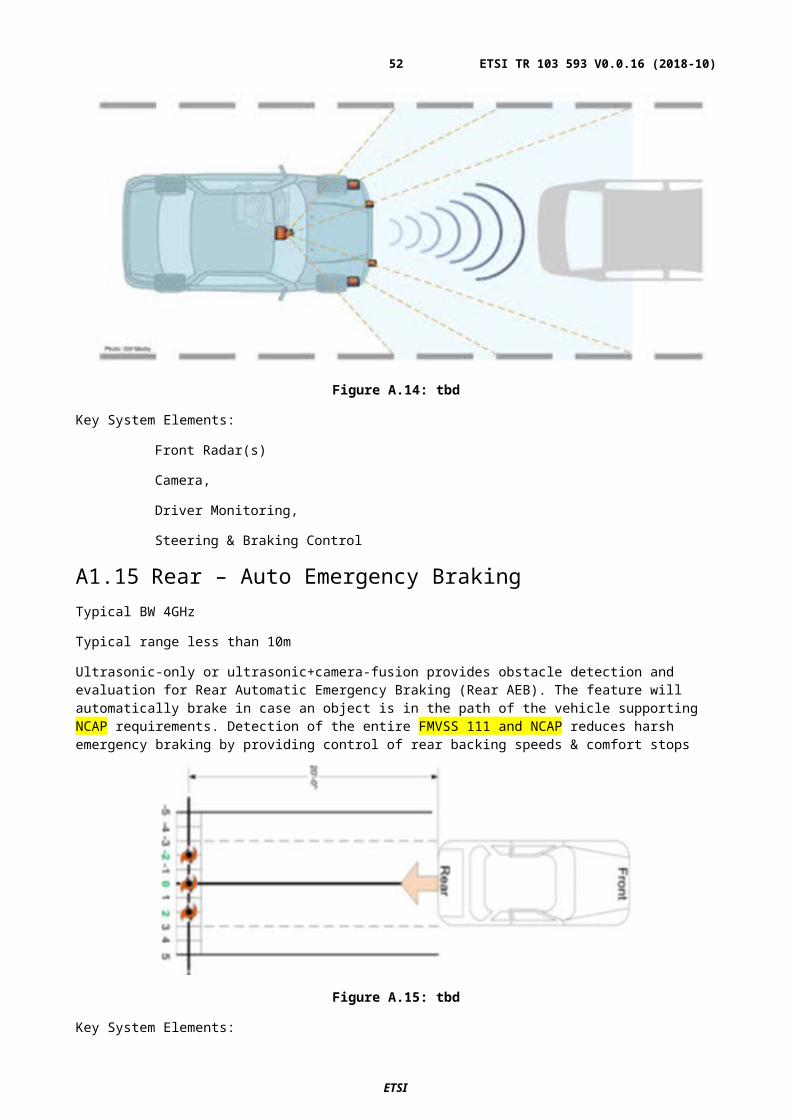
Figure A.28:
Figure A.29:
ETSI
ETSI TR 103 593 V0.0.16 (2018-10)52
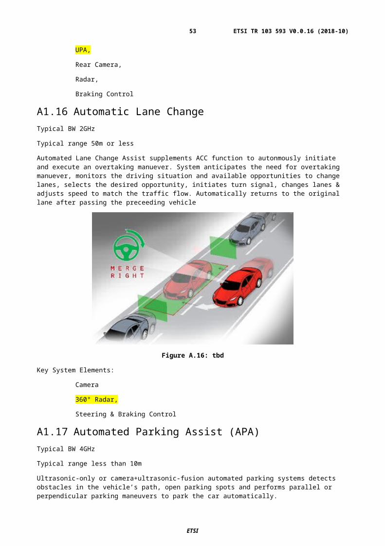
Figure A.30:
A2.6 Ships (boats and small vessels)Marine collision avoidance
watercrafts and other objects shore and infrastructure
Marine docking assistance
docking support assistance with bad visibility
Benefit for such sensors:
- Huge and slow “steering” (reaction) vehicles with “blind spots” / long breaking distances
increase of safety
A2.7 Aircrafts via taxiing / wing tips
ETSI
ETSI TR 103 593 V0.0.16 (2018-10)53
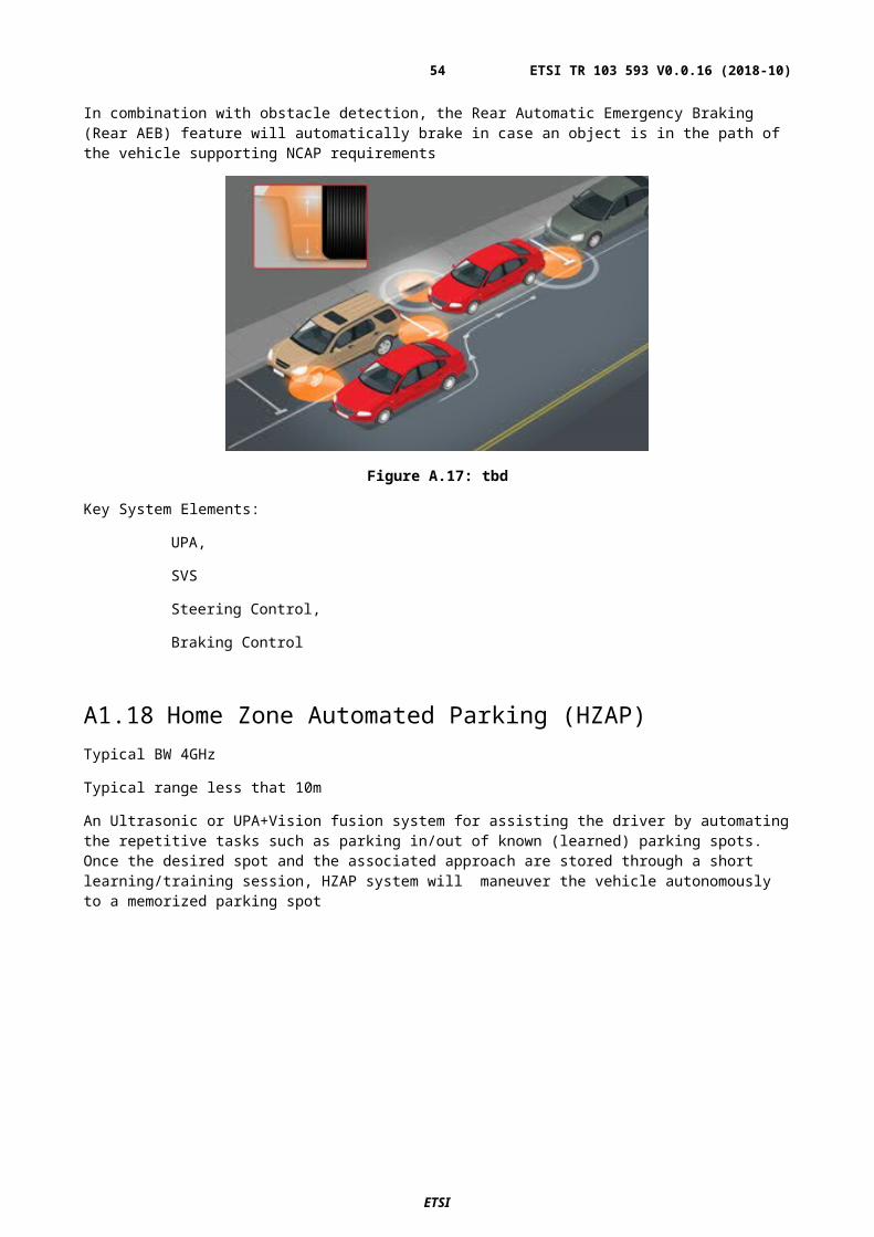
Annex B:summary of Regulations in selected countries for 76-77 GHz and 77 - 81 GHz radar sensorsThe overview provides a summary of selected market areas and countries and illustrates the radio spectrum regulations for radars operating in the frequency range 76 GHz to 81 GHz. The presented table is a snapshot of the regulation at the time when the document was developed. For reference to most recent local regulatory documents should be consulted.
For most countries the regulation and therefore approval scheme and related standard is split for the two frequency bands 76 -77 GHz and 77 – 81 GHz. In 2017 the FCC in the US has merged the frequency regulation for the whole frequency band, which is illustrated by listed frequency range.
Key parameters like power requirements and frequency band are shown.
Summary of the situation in key market countries
For 76 GHz – 77 GHz the technical requirements for acceptance are in principle homogenous and aligned over the listed countries and regions. Only a few countries deviate regarding the typical power parameters and the method applied for verification (examples: reference to conducted power).
For 77 – 81 GHz quite a number of countries do not have yet a regulation or are about to work out new regulations and standards. In addition the power requirements show big variation. Specifically the limitation of power density for dedicated usage (vehicle) or in relation to bandwidth will restrict the usage and function of related sensors.
Table1: Regulations in selected countries for 76-77 GHz and 77 - 81 GHz radar sensors
Country / Region
Regulation / Radio Standard
Power * Other**
Regulation / Radio Standard
Power * Other
76 - 77 GHz 77-81 GHz Australia Radio
communications (Low InterferencePotential Devices) Class Licence 2000Version of 27 July 2011
Peak: 44 dBm
Radio communications (Low InterferencePotential Devices) Class Licence 2000Version of 27 July 2011
Peak: 55 dBm
Freq. Range 77 - 81 GHZ
Brazil NATIONAL AGENCY FOR COMMUNICATIONSACT NO 11542 OF August 23, 2017
not moving: 200nW/cm²,front looking:60uW/cm²,side/backward looking:30uW/cm²[all at 3m]
not regulated
regulation in process?
Canada Industry CanadaRSS-251, Issue 1November 2014
50 dBmPeak: 55 dBm
regulation in processregulation is on PC
- -
ETSI
ETSI TR 103 593 V0.0.16 (2018-10)54
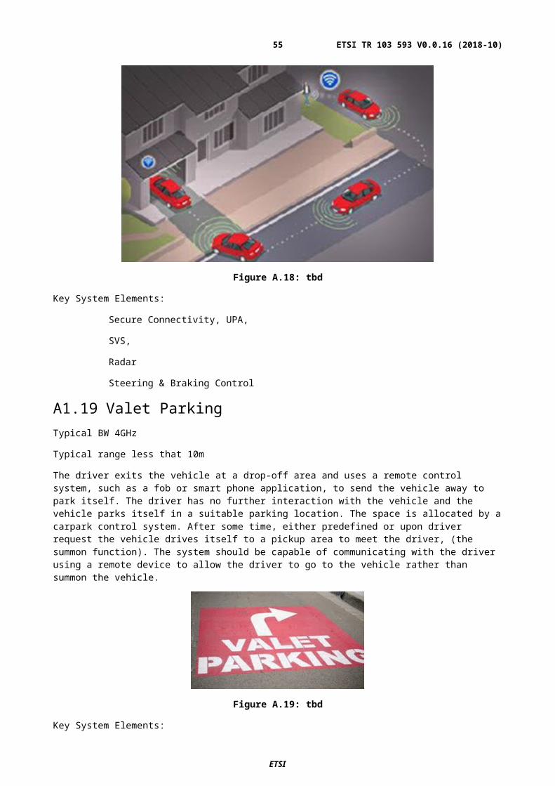
Country / Region
Regulation / Radio Standard
Power * Other**
Regulation / Radio Standard
Power * Other
76 - 77 GHz 77-81 GHz China Micropower (Short
Distance) Radio Equipments(revison of regulation in process)
Peak: 55 dBm
regulation in process
Europe EN 301 091 50 dBmPeak: 55 dBm
EN 302 264 -3 dBm / MHz(sensor)-9 dBm / MHz(car)Peak: 55 dBm
Freq. Range 77 - 81 GHZ
India - Very Low Power Radio Frequency Devices /Equipment for Short Range Radar Systems
37 dBm - not regulated
Japan ARIB STD-T48 2.210 dBm condburst power(40 dBi Gain -> 50 dBm)
ARIB STD-T111 1.1
Now full 4GHz is allowed
10 dBm condburst power(35 dBi Gain -> 45 dBm)
(When OBW is less than 2 GHz, less than 5uW/MHz)
Freq. Range 76 - 81 GHZ
South Korea
Technical Standards for Radio Equipment
(RRL Notification 2006-84 (2006.8.23))9. Automotive Radar System
10 dBm cond individual antanna(50 dBm)
Frequency band 77GHz-81GHz allocated, standard still to be released
Freq. Range 77 - 81 GHZ
Russia - Appendix 1, Resolution of State Radio Frequency Committee No. 10-09-03 of 29 October 2010"Wireless Alarm and Motion Detection Devices"
35 dBm - Appendix 1, Resolution of State Radio Frequency Committee No. 10-09-03 of 29 October 2010"Wireless Alarm and Motion Detection Devices"
-3dBm / MHz
Freq. Range 77 - 81 GHZ
Singapore - IMDA TS SRDIssue 1, 1 October 2016
37 dBmStationary: 23.5 dBm
- IDA TS UWBIssue 1 Rev 1, May 2011
-3dBm / MHzPeak: 55 dBm
Freq. Range 77 - 81 GHZ
ETSI
ETSI TR 103 593 V0.0.16 (2018-10)55
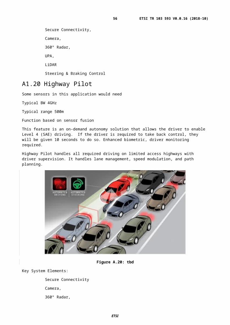
Country / Region
Regulation / Radio Standard
Power * Other**
Regulation / Radio Standard
Power * Other
76 - 77 GHz 77-81 GHz USA FCC part 95M 50 dBm
Peak: 55 dBm
Freq. Range 76 - 81 GHZ
FCC part 95M 50 dBmPeak: 55 dBm
Freq. Range 76 - 81 GHZ
* ) Power EIRP - if not otherwise stated**) Frequency range is 76GHz -77GHz - if not otherwise stated
ETSI
ETSI TR 103 593 V0.0.16 (2018-10)56
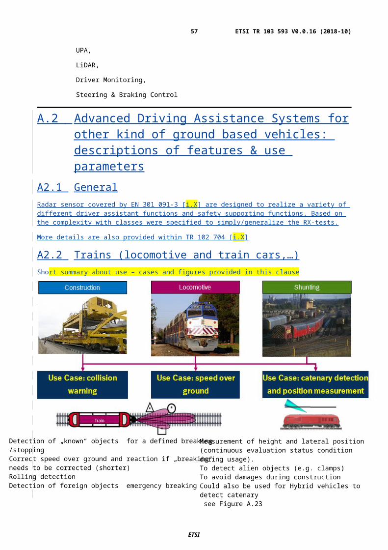
ETSI
ETSI TR 103 593 V0.0.16 (2018-10)57

Annex :Change History
Date Version Information about changes<Month year> <#> <Changes made are listed in this cell>02/2018 0.0.3 TG SRR # 32: outcome of drafting session Feb 14th,201803/2018 0.0.4 TG SRR # 32: outcome of drafting session March 14th, 201803/2018 0.0.5 TG SRR # 32: outcome of drafting session March 16th, 201804/2018 0.0.6 Outcome of drafting session April 3rd,201804/2018 0.0.7 Input document for drafting session April 25th,201804/2018 0.0.8 Output document drafting session April 25th , 201805/2018 0.0.9 Output document drafting session May 22nd , 201806/2018 0.0.10 Output document drafting session June 18th ,201806/2018 0.0.11 Output document drafting session June 28th , 201807/2018 0.0.12 Output document drafting session July 6th , 201807/2018 0.0.13 Output document drafting session July 12th , 2018 ( morning)07/2018 0.0.14 Output document drafting session July 13th , 2018 09/2018 0.0.15 Output document drafting session September 11th , 201810/2018 0.0.16 Output document drafting session October 16th , 2018
ETSI
ETSI TR 103 593 V0.0.16 (2018-10)58
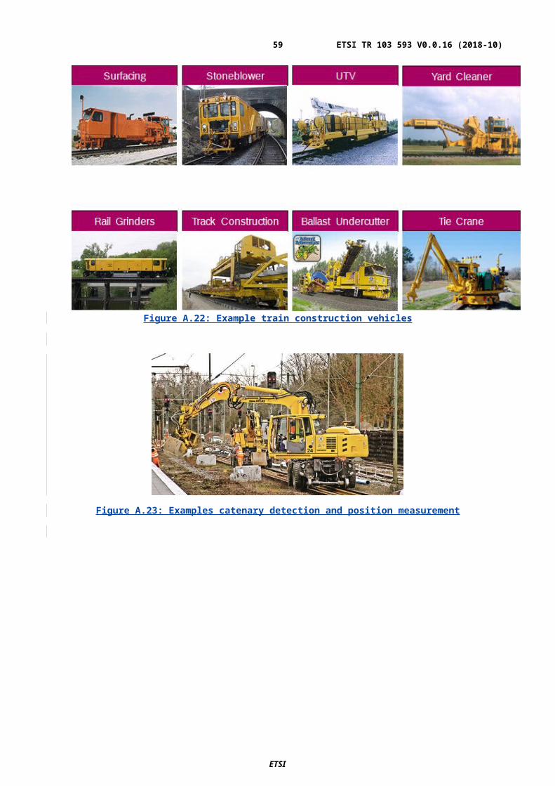
HistoryDocument history
<Version> <Date> <Milestone>
Latest changes made on 2017-07-10
ETSI
ETSI TR 103 593 V0.0.16 (2018-10)59