Embed Size (px)
Citation preview
AH1508 SJA1105 Application Board
Rev. 01.30 — 22 June 2016 User Manual
Document information
Info Content
Keywords SJA1105, SJA1105 Application Board
Abstract The SJA1105 Application Board is described in this document.
NXP Semiconductors AH1508 User Manual
AH1508 All information provided in this document is subject to legal disclaimers. © NXP Semiconductors N.V. 20164. All rights reserved.
User Manual Rev. 01.30 — 22 June 2016 2 of 27
Contact information
For more information, please visit: http://www.nxp.com
For sales office addresses, please send an email to: mailto:[email protected]
Revision history
Rev Date Description
01.30 20160622 Documentation was removed from the support package
01.21 20160301 Fixed description of default xMII mode
01.20 20160219 SJA1105 Application Board version 1.2
01.00 20151106 Initial version
NXP Semiconductors AH1508 User Manual
AH1508 All information provided in this document is subject to legal disclaimers. © NXP Semiconductors N.V. 2016. All rights reserved.
User Manual Rev. 01.30 — 22 June 2016 3 of 27
1. Introduction
The SJA1105 Application Board demonstrates the capabilities of the SJA1105 Automotive Ethernet switch in combination with four TJA1100 Automotive Ethernet PHYs.
This user manual focusses on the μC software included on this board and details the
features it provides, the control interface, and the reprogramming procedure.
2. System Overview
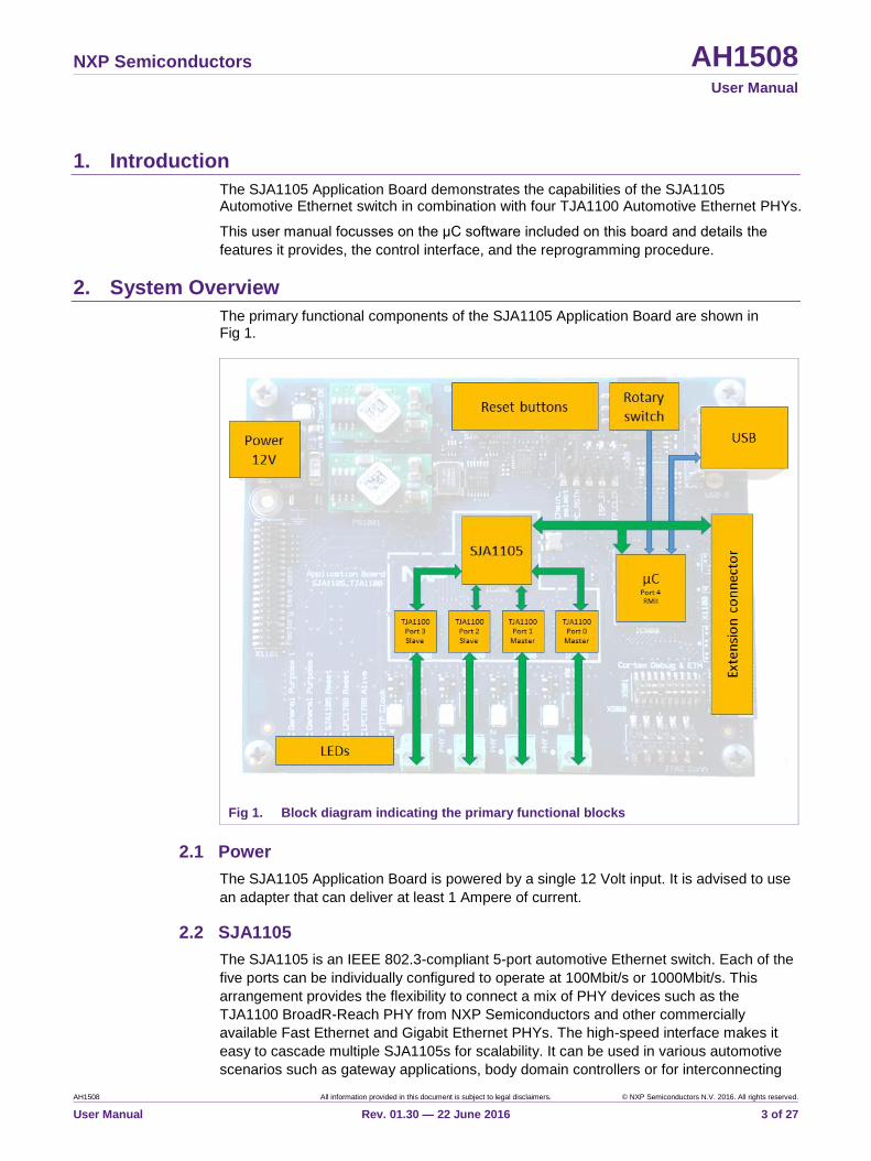
The primary functional components of the SJA1105 Application Board are shown in Fig 1.
Fig 1. Block diagram indicating the primary functional blocks
2.1 Power
The SJA1105 Application Board is powered by a single 12 Volt input. It is advised to use
an adapter that can deliver at least 1 Ampere of current.
2.2 SJA1105
The SJA1105 is an IEEE 802.3-compliant 5-port automotive Ethernet switch. Each of the
five ports can be individually configured to operate at 100Mbit/s or 1000Mbit/s. This
arrangement provides the flexibility to connect a mix of PHY devices such as the
TJA1100 BroadR-Reach PHY from NXP Semiconductors and other commercially
available Fast Ethernet and Gigabit Ethernet PHYs. The high-speed interface makes it
easy to cascade multiple SJA1105s for scalability. It can be used in various automotive
scenarios such as gateway applications, body domain controllers or for interconnecting

NXP Semiconductors AH1508 User Manual
AH1508 All information provided in this document is subject to legal disclaimers. © NXP Semiconductors N.V. 2016. All rights reserved.
User Manual Rev. 01.30 — 22 June 2016 4 of 27
multiple ECUs in a daisy chain. Full Audio Video Bridging (AVB) supports means that the
SJA1105 can be used in infotainment and driver assistance systems.
The SJA1105 comes in two variants. The SJA1105EL supports Ethernet and AVB. The
SJA1105ELT includes additional functionality to support Time-Triggered (TT) Ethernet
and Time-Sensitive Networking (TSN).
2.3 TJA1100 The TJA1100 is an OPEN Alliance BroadR-Reach compliant Ethernet PHY optimized for automotive use cases. The device provides 100Mbit/s transmit and receive capability over a single Unshielded Twisted Pair (UTP) cable, supporting a cable length of up to at least 15 m. Optimized for automotive use cases such as IP camera links, driver assistance systems and back-bone networks, the TJA1100 has been designed to minimize power consumption and system costs, while still providing the robustness required for automotive use cases. The default configuration of the TJA1100 PHYs on the SJA1105 Application Board are detailed in Table 1. The default configuration can be overruled by modifying the various CONFIGx resistors on the board or by issuing SMI commands to the PHY.
Table 1. Default TJA1100 configurations
SJA1105 port: TJA1100: SMI address: Master / Slave: MII mode:
0 IC500 4 Master RMII
1 IC600 5 Master RMII
2 IC700 6 Slave RMII
3 IC800 7 Slave RMII
2.4 μC and extension connector
The on-board μC is preprogrammed with a basic application that enables a computer to
control the SJA1105 and TJA1100 devices. In addition, it is capable of responding to
ARP and ICMP Echo requests as detailed in Table 2.
The extension connector can be used to connect other μC modules to the SJA1105
Application Board.
Table 2. Ethernet settings
Configuration setting: Value:
IPv4 address 169.254.115.1
MAC address Unique value provided by the on-board EEPROM.
Services implemented ARP
ICMP Echo (a.k.a. ping)
2.5 Rotary switch
The μC software contains a number of built-in configurations that can be selected by the
rotary switch provided on the PCB or by using the appropriate command (Section 4.3.12
or Section 5.4). A μC reset is required after the configuration has been changed.
NXP Semiconductors AH1508 User Manual
AH1508 All information provided in this document is subject to legal disclaimers. © NXP Semiconductors N.V. 2016. All rights reserved.
User Manual Rev. 01.30 — 22 June 2016 5 of 27
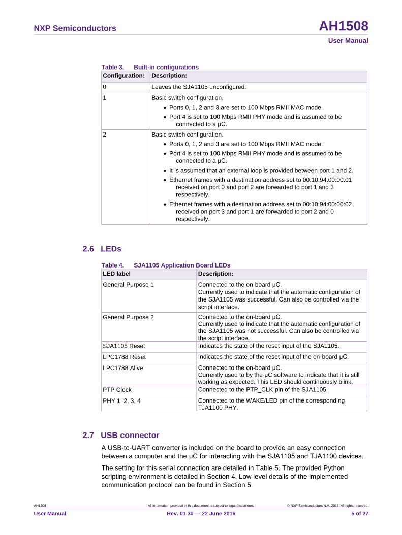
Table 3. Built-in configurations
Configuration: Description:
0 Leaves the SJA1105 unconfigured.
1 Basic switch configuration.
Ports 0, 1, 2 and 3 are set to 100 Mbps RMII MAC mode.
Port 4 is set to 100 Mbps RMII PHY mode and is assumed to be
connected to a μC.
2 Basic switch configuration.
Ports 0, 1, 2 and 3 are set to 100 Mbps RMII MAC mode.
Port 4 is set to 100 Mbps RMII PHY mode and is assumed to be
connected to a μC.
It is assumed that an external loop is provided between port 1 and 2.
Ethernet frames with a destination address set to 00:10:94:00:00:01
received on port 0 and port 2 are forwarded to port 1 and 3
respectively.
Ethernet frames with a destination address set to 00:10:94:00:00:02
received on port 3 and port 1 are forwarded to port 2 and 0
respectively.
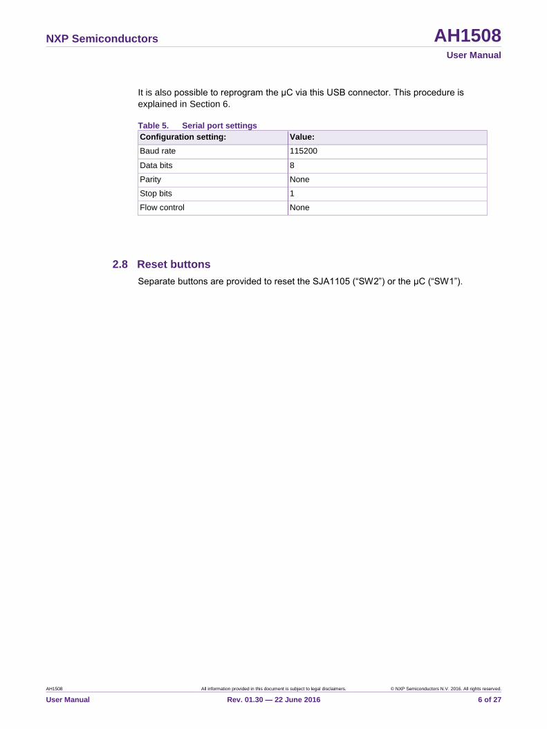
2.6 LEDs
Table 4. SJA1105 Application Board LEDs
LED label Description:
General Purpose 1 Connected to the on-board μC.
Currently used to indicate that the automatic configuration of
the SJA1105 was successful. Can also be controlled via the
script interface.
General Purpose 2 Connected to the on-board μC. Currently used to indicate that the automatic configuration of the SJA1105 was not successful. Can also be controlled via the script interface.
SJA1105 Reset Indicates the state of the reset input of the SJA1105.
LPC1788 Reset Indicates the state of the reset input of the on-board μC.
LPC1788 Alive Connected to the on-board μC. Currently used to by the μC software to indicate that it is still working as expected. This LED should continuously blink.
PTP Clock Connected to the PTP_CLK pin of the SJA1105.
PHY 1, 2, 3, 4 Connected to the WAKE/LED pin of the corresponding TJA1100 PHY.
2.7 USB connector
A USB-to-UART converter is included on the board to provide an easy connection
between a computer and the μC for interacting with the SJA1105 and TJA1100 devices.
The setting for this serial connection are detailed in Table 5. The provided Python
scripting environment is detailed in Section 4. Low level details of the implemented
communication protocol can be found in Section 5.
NXP Semiconductors AH1508 User Manual
AH1508 All information provided in this document is subject to legal disclaimers. © NXP Semiconductors N.V. 2016. All rights reserved.
User Manual Rev. 01.30 — 22 June 2016 6 of 27
It is also possible to reprogram the μC via this USB connector. This procedure is
explained in Section 6.
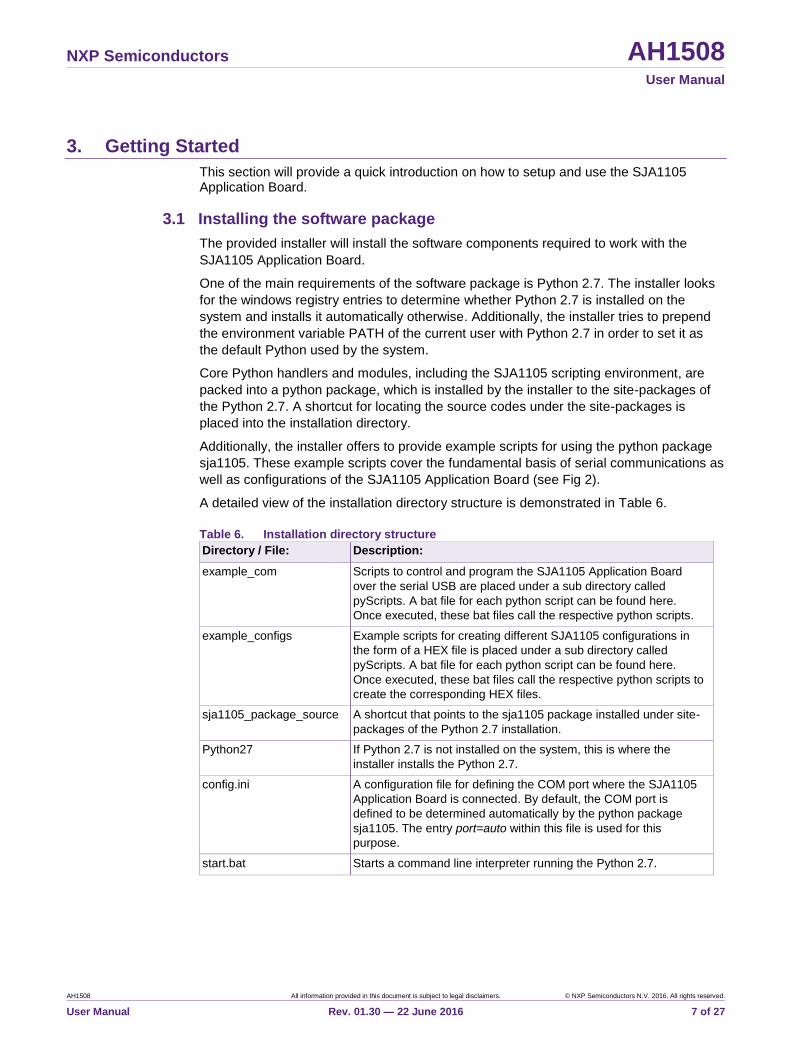
Table 5. Serial port settings
Configuration setting: Value:
Baud rate 115200
Data bits 8
Parity None
Stop bits 1
Flow control None
2.8 Reset buttons
Separate buttons are provided to reset the SJA1105 (“SW2”) or the μC (“SW1”).
NXP Semiconductors AH1508 User Manual
AH1508 All information provided in this document is subject to legal disclaimers. © NXP Semiconductors N.V. 2016. All rights reserved.
User Manual Rev. 01.30 — 22 June 2016 7 of 27
3. Getting Started
This section will provide a quick introduction on how to setup and use the SJA1105 Application Board.
3.1 Installing the software package
The provided installer will install the software components required to work with the
SJA1105 Application Board.
One of the main requirements of the software package is Python 2.7. The installer looks
for the windows registry entries to determine whether Python 2.7 is installed on the
system and installs it automatically otherwise. Additionally, the installer tries to prepend
the environment variable PATH of the current user with Python 2.7 in order to set it as
the default Python used by the system.
Core Python handlers and modules, including the SJA1105 scripting environment, are
packed into a python package, which is installed by the installer to the site-packages of
the Python 2.7. A shortcut for locating the source codes under the site-packages is
placed into the installation directory.
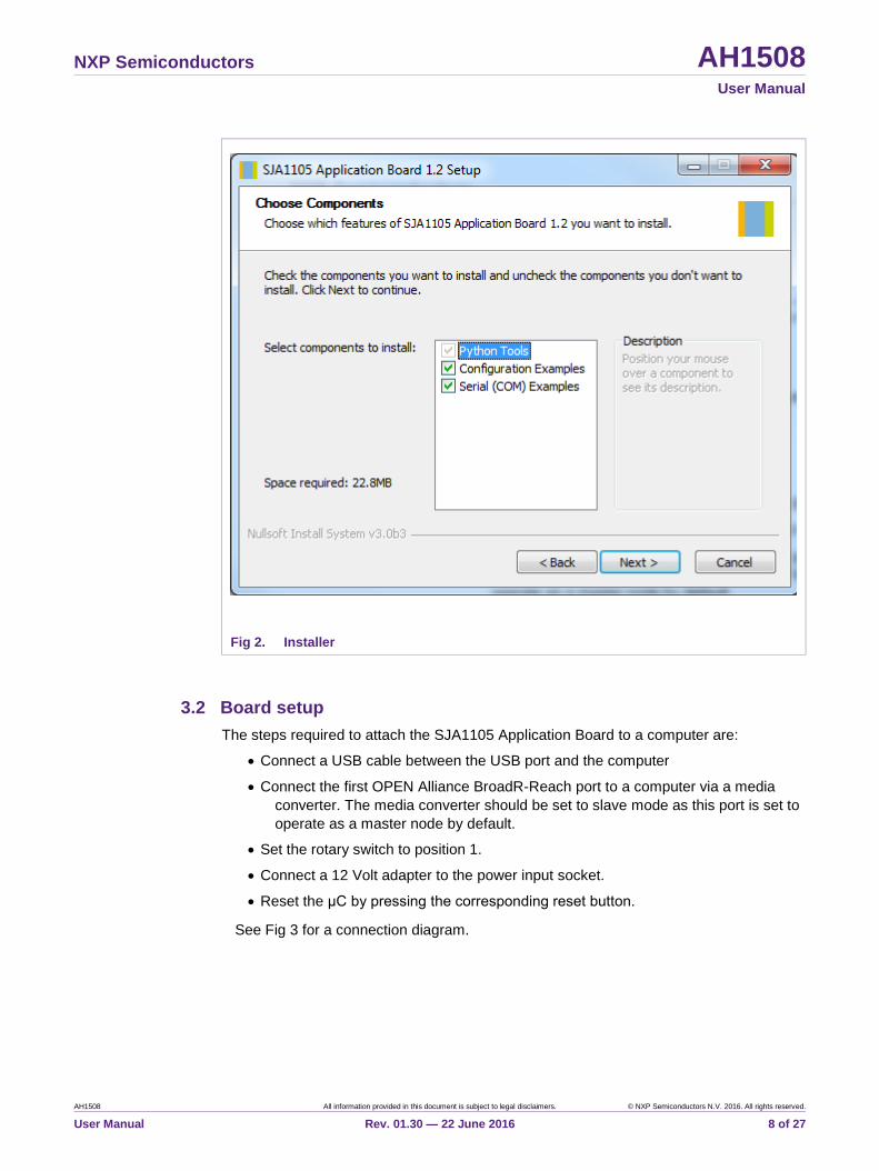
Additionally, the installer offers to provide example scripts for using the python package
sja1105. These example scripts cover the fundamental basis of serial communications as
well as configurations of the SJA1105 Application Board (see Fig 2).
A detailed view of the installation directory structure is demonstrated in Table 6.
Table 6. Installation directory structure
Directory / File: Description:
example_com Scripts to control and program the SJA1105 Application Board
over the serial USB are placed under a sub directory called
pyScripts. A bat file for each python script can be found here.
Once executed, these bat files call the respective python scripts.
example_configs Example scripts for creating different SJA1105 configurations in
the form of a HEX file is placed under a sub directory called
pyScripts. A bat file for each python script can be found here.
Once executed, these bat files call the respective python scripts to
create the corresponding HEX files.
sja1105_package_source A shortcut that points to the sja1105 package installed under site-
packages of the Python 2.7 installation.
Python27 If Python 2.7 is not installed on the system, this is where the
installer installs the Python 2.7.
config.ini A configuration file for defining the COM port where the SJA1105
Application Board is connected. By default, the COM port is
defined to be determined automatically by the python package
sja1105. The entry port=auto within this file is used for this
purpose.
start.bat Starts a command line interpreter running the Python 2.7.
NXP Semiconductors AH1508 User Manual
AH1508 All information provided in this document is subject to legal disclaimers. © NXP Semiconductors N.V. 2016. All rights reserved.
User Manual Rev. 01.30 — 22 June 2016 8 of 27
Fig 2. Installer
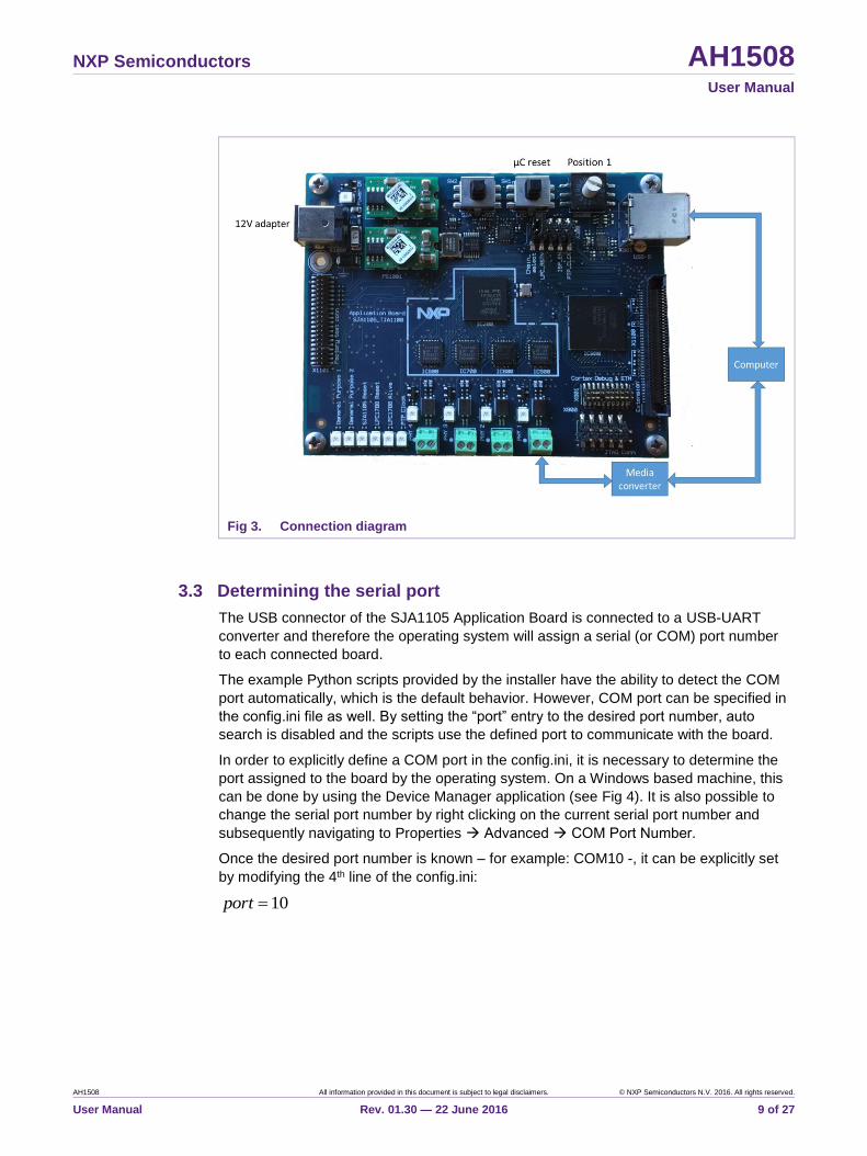
3.2 Board setup
The steps required to attach the SJA1105 Application Board to a computer are:
Connect a USB cable between the USB port and the computer
Connect the first OPEN Alliance BroadR-Reach port to a computer via a media
converter. The media converter should be set to slave mode as this port is set to
operate as a master node by default.
Set the rotary switch to position 1.
Connect a 12 Volt adapter to the power input socket.
Reset the μC by pressing the corresponding reset button.
See Fig 3 for a connection diagram.
NXP Semiconductors AH1508 User Manual
AH1508 All information provided in this document is subject to legal disclaimers. © NXP Semiconductors N.V. 2016. All rights reserved.
User Manual Rev. 01.30 — 22 June 2016 9 of 27
Fig 3. Connection diagram
3.3 Determining the serial port
The USB connector of the SJA1105 Application Board is connected to a USB-UART
converter and therefore the operating system will assign a serial (or COM) port number
to each connected board.
The example Python scripts provided by the installer have the ability to detect the COM
port automatically, which is the default behavior. However, COM port can be specified in
the config.ini file as well. By setting the “port” entry to the desired port number, auto
search is disabled and the scripts use the defined port to communicate with the board.
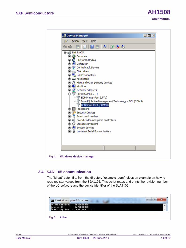
In order to explicitly define a COM port in the config.ini, it is necessary to determine the
port assigned to the board by the operating system. On a Windows based machine, this
can be done by using the Device Manager application (see Fig 4). It is also possible to
change the serial port number by right clicking on the current serial port number and
subsequently navigating to Properties Advanced COM Port Number.
Once the desired port number is known – for example: COM10 -, it can be explicitly set
by modifying the 4th line of the config.ini:
10port
NXP Semiconductors AH1508 User Manual
AH1508 All information provided in this document is subject to legal disclaimers. © NXP Semiconductors N.V. 2016. All rights reserved.
User Manual Rev. 01.30 — 22 June 2016 10 of 27
Fig 4. Windows device manager
3.4 SJA1105 communication
The “id.bat” batch file, from the directory “example_com”, gives an example on how to
read register values from the SJA1105. This script reads and prints the revision number
of the μC software and the device identifier of the SJA1105.
Fig 5. id.bat
NXP Semiconductors AH1508 User Manual
AH1508 All information provided in this document is subject to legal disclaimers. © NXP Semiconductors N.V. 2016. All rights reserved.
User Manual Rev. 01.30 — 22 June 2016 11 of 27
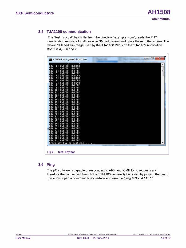
3.5 TJA1100 communication
The “test_phy.bat” batch file, from the directory “example_com”, reads the PHY
identification registers for all possible SMI addresses and prints these to the screen. The
default SMI address range used by the TJA1100 PHYs on the SJA1105 Application
Board is 4, 5, 6 and 7.
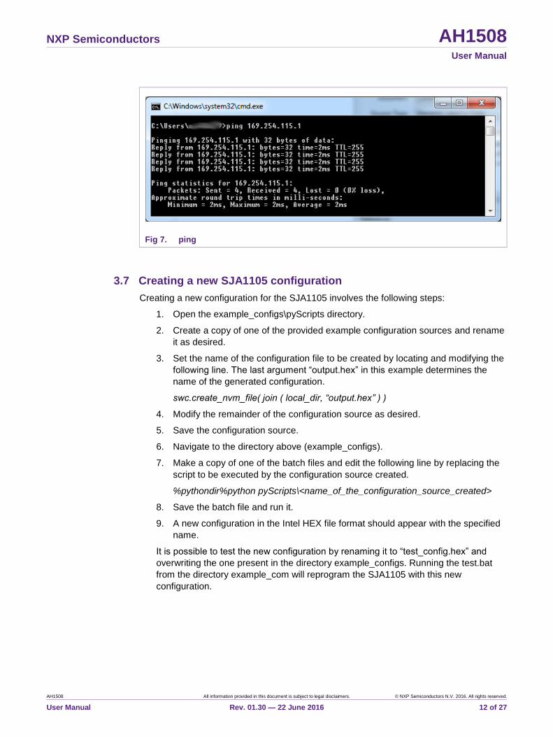
3.6 Ping
The μC software is capable of responding to ARP and ICMP Echo requests and
therefore the connection through the TJA1100 can easily be tested by pinging the board.
To do this, open a command line interface and execute “ping 169.254.115.1”.
Fig 6. test_phy.bat
NXP Semiconductors AH1508 User Manual
AH1508 All information provided in this document is subject to legal disclaimers. © NXP Semiconductors N.V. 2016. All rights reserved.
User Manual Rev. 01.30 — 22 June 2016 12 of 27
Fig 7. ping
3.7 Creating a new SJA1105 configuration
Creating a new configuration for the SJA1105 involves the following steps:
1. Open the example_configs\pyScripts directory.
2. Create a copy of one of the provided example configuration sources and rename
it as desired.
3. Set the name of the configuration file to be created by locating and modifying the
following line. The last argument “output.hex” in this example determines the
name of the generated configuration.
swc.create_nvm_file( join ( local_dir, “output.hex” ) )
4. Modify the remainder of the configuration source as desired.
5. Save the configuration source.
6. Navigate to the directory above (example_configs).
7. Make a copy of one of the batch files and edit the following line by replacing the
script to be executed by the configuration source created.
%pythondir%python pyScripts\<name_of_the_configuration_source_created>
8. Save the batch file and run it.
9. A new configuration in the Intel HEX file format should appear with the specified
name.
It is possible to test the new configuration by renaming it to “test_config.hex” and
overwriting the one present in the directory example_configs. Running the test.bat
from the directory example_com will reprogram the SJA1105 with this new
configuration.
NXP Semiconductors AH1508 User Manual
AH1508 All information provided in this document is subject to legal disclaimers. © NXP Semiconductors N.V. 2016. All rights reserved.
User Manual Rev. 01.30 — 22 June 2016 13 of 27
4. Python scripting
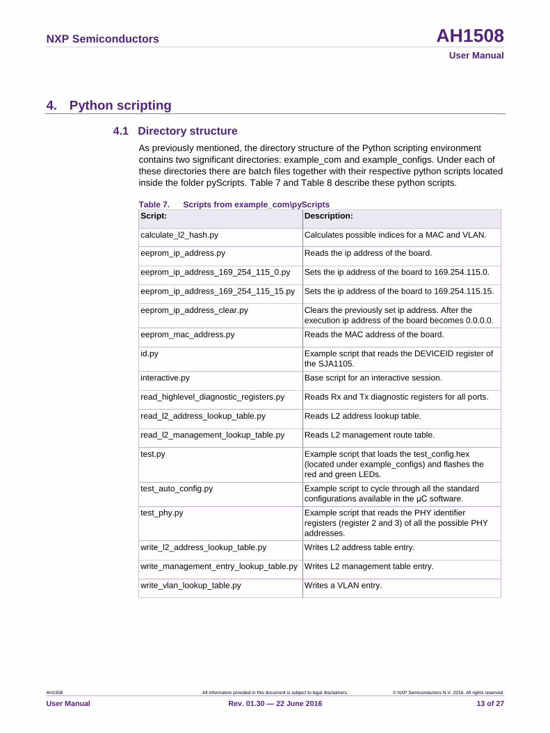
4.1 Directory structure
As previously mentioned, the directory structure of the Python scripting environment
contains two significant directories: example_com and example_configs. Under each of
these directories there are batch files together with their respective python scripts located
inside the folder pyScripts. Table 7 and Table 8 describe these python scripts.
Table 7. Scripts from example_com\pyScripts
Script: Description:
calculate_l2_hash.py Calculates possible indices for a MAC and VLAN.
eeprom_ip_address.py Reads the ip address of the board.
eeprom_ip_address_169_254_115_0.py Sets the ip address of the board to 169.254.115.0.
eeprom_ip_address_169_254_115_15.py Sets the ip address of the board to 169.254.115.15.
eeprom_ip_address_clear.py Clears the previously set ip address. After the
execution ip address of the board becomes 0.0.0.0.
eeprom_mac_address.py Reads the MAC address of the board.
id.py Example script that reads the DEVICEID register of
the SJA1105.
interactive.py Base script for an interactive session.
read_highlevel_diagnostic_registers.py Reads Rx and Tx diagnostic registers for all ports.
read_l2_address_lookup_table.py Reads L2 address lookup table.
read_l2_management_lookup_table.py Reads L2 management route table.
test.py Example script that loads the test_config.hex
(located under example_configs) and flashes the
red and green LEDs.
test_auto_config.py Example script to cycle through all the standard
configurations available in the μC software.
test_phy.py Example script that reads the PHY identifier
registers (register 2 and 3) of all the possible PHY
addresses.
write_l2_address_lookup_table.py Writes L2 address table entry.
write_management_entry_lookup_table.py Writes L2 management table entry.
write_vlan_lookup_table.py Writes a VLAN entry.
NXP Semiconductors AH1508 User Manual
AH1508 All information provided in this document is subject to legal disclaimers. © NXP Semiconductors N.V. 2016. All rights reserved.
User Manual Rev. 01.30 — 22 June 2016 14 of 27
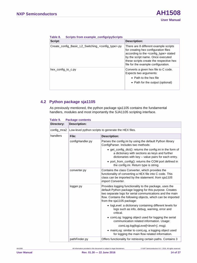
Table 8. Scripts from example_configs\pyScripts
Script: Description:
Create_config_Basic_L2_Switching_<config_type>.py There are 8 different example scripts
for creating hex configuration files
according to the <config_type> stated
by the script name. Once executed
these scripts create the respective hex
file for the example configuration.
hex_config_to_c.py Converts a given hex file to C code.
Expects two arguments:
Path to the hex file
Path for the output (optional)
4.2 Python package sja1105
As previously mentioned, the python package sja1105 contains the fundamental
handlers, modules and most importantly the SJA1105 scripting interface.
Table 9. Package contents
Directory: Description:
config_mra2 Low-level python scripts to generate the HEX files.
handlers File: Description:
configHandler.py Parses the config.ini by using the default Python library
ConfigParser. Includes two methods:
get_config_dict(): returns the config.ini in the form of
a dictionary with sections as keys and further
dictionaries with key – value pairs for each entry.
port_from_config(): returns the COM port defined in
the config.ini. Return type is string.
converter.py Contains the class Converter, which provides the
functionality of converting a HEX file into C code. This
class can be imported by the statement: from sja1105
import Converter.
logger.py Provides logging functionality to the package, uses the
default Python package logging for this purpose. Creates
two separate logs for serial communications and the main
flow. Contains the following objects, which can be imported
from the sja1105 package:
logLevel: a dictionary containing different levels for
logs such as info, debug, warning, error and
critical.
comLog: logging object used for logging the serial
communication related information. Usage:
comLog.log(logLevel[<level>], msg).
mainLog: similar to comLog, a logging object used
for logging the main flow related information.
pathFinder.py Offers functionality for retrieving certain paths. Contains 3
NXP Semiconductors AH1508 User Manual
AH1508 All information provided in this document is subject to legal disclaimers. © NXP Semiconductors N.V. 2016. All rights reserved.
User Manual Rev. 01.30 — 22 June 2016 15 of 27
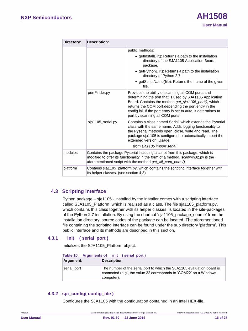
Directory: Description:
public methods:
getInstallDir(): Returns a path to the installation
directory of the SJA1105 Application Board
package.
getPythonDir(): Returns a path to the installation
directory of Python 2.7.
getScriptName(file): Returns the name of the given
file.
portFinder.py Provides the ability of scanning all COM ports and
determining the port that is used by SJA1105 Application
Board. Contains the method get_sja1105_port(), which
returns the COM port depending the port entry in the
config.ini. If the port entry is set to auto, it determines to
port by scanning all COM ports.
sja1105_serial.py Contains a class named Serial, which extends the Pyserial
class with the same name. Adds logging functionality to
the Pyserial methods open, close, write and read. The
package sja1105 is configured to automatically import the
extended version. Usage:
from sja1105 import serial
modules Contains the package Pyserial including a script from this package, which is
modified to offer its functionality in the form of a method. scanwin32.py is the
aforementioned script with the method get_all_com_ports().
platform Contains sja1105_platform.py, which contains the scripting interface together with
its helper classes. (see section 4.3)
4.3 Scripting interface
Python package – sja1105 - installed by the installer comes with a scripting interface
called SJA1105_Platform, which is realized as a class. The file sja1105_platform.py,
which contains this class together with its helper classes, is located in the site-packages
of the Python 2.7 installation. By using the shortcut ‘sja1105_package_source’ from the
installation directory, source codes of the package can be located. The aforementioned
file containing the scripting interface can be found under the sub directory ‘platform’. This
public interface and its methods are described in this section.
4.3.1 __init__( serial_port )
Initializes the SJA1105_Platform object.
Table 10. Arguments of __init__( serial_port )
Argument: Description
serial_port The number of the serial port to which the SJA1105 evaluation board is
connected (e.g., the value 22 corresponds to ‘COM22’ on a Windows
computer).
4.3.2 spi_config( config_file )
Configures the SJA1105 with the configuration contained in an Intel HEX-file.

NXP Semiconductors AH1508 User Manual
AH1508 All information provided in this document is subject to legal disclaimers. © NXP Semiconductors N.V. 2016. All rights reserved.
User Manual Rev. 01.30 — 22 June 2016 16 of 27
Table 11. Arguments of spi_config( config_file )
Argument: Description:
config_file The path to the aforementioned Intel HEX-file containing the desired
configuration for the SJA1105.
4.3.3 spi_write( address, data )
Writes a value to a SJA1105 register defined by the argument address.
Table 12. Arguments of spi_write( address, data )
Argument: Description:
address The address of the register to write to. The range of valid addresses is
0x0000_0000 to 0x001F_FFFF.
data The unsigned 32-bit integer data value to write to the register.
4.3.4 spi_read ( address )
Returns the value of a SJA1105 register (unsigned 32-bit integer) with the given address.
Table 13. Arguments of spi_read( address )
Argument: Description:
address The address of the register to read from. The range of valid addresses is
0x0000_0000 to 0x001F_FFFF.
4.3.5 spi_read_print( address )
Reads the value of a SJA1105 register defined by the address and prints this value to the
standard output as a formatted string.
Table 14. Arguments of spi_read_print( address )
Argument: Description:
address The address of the register to read from. The range of valid addresses is
0x0000_0000 to 0x001F_FFFF.
4.3.6 smi_write( phy, address, data )
Writes to an SMI register inside one of the PHYs,
Table 15. Arguments of smi_write( phy, address, data )
Argument: Description:
phy The address of the PHY. The range of valid PHY addresses is 0 to 31.
address The address of the register to write to. The range of valid addresses is 0
to 31.
data The unsigned 16-bit integer data value to write to the register.

NXP Semiconductors AH1508 User Manual
AH1508 All information provided in this document is subject to legal disclaimers. © NXP Semiconductors N.V. 2016. All rights reserved.
User Manual Rev. 01.30 — 22 June 2016 17 of 27
4.3.7 smi_read( phy, address )
Reads from an SMI register inside one of the PHYs and returns this value (unsigned 16-
bit integer).
Table 16. Arguments of smi_read( phy, address )
Argument: Description:
phy The address of the PHY. The range of valid addresses is 0 to 31.
address The address of the register to write to. The range of valid addresses is 0
to 31.
4.3.8 smi_read_print( phy, address )
Reads from an SMI register inside one of the PHYs and prints this value to the standard
output as a formatted string.
Table 17. Arguments of smi_read_print( phy, address )
Argument: Description:
phy The address of the PHY. The range of valid PHY addresses is 0 to 31.
address The address of the register to write to. The range of valid addresses is 0
to 31.
4.3.9 reset()
Resets the SJA1105.
4.3.10 get_version()
Returns the μC software revision number (unsigned 32-bit integer).
4.3.11 set_leds( red=False, green=False)
Turns the red and green LEDs on or off.
Table 18. Arguments of set_leds( red=False, green=False)
Argument: Description>
red Turns the red LED on (True) or off (False).
green Turns the green LED on (True) or off (False).
4.3.12 auto_configure( config_number )
Uses a configuration stored in the μC to configure the SJA1105. A boolean value is
returned to indicate whether the configuration procedure was successful (True) or not
(False).
Table 19. Arguments of auto_configure( config_number )
Argument: Description:
config_number The configuration to use (unsigned 8-bit integer).
NXP Semiconductors AH1508 User Manual
AH1508 All information provided in this document is subject to legal disclaimers. © NXP Semiconductors N.V. 2016. All rights reserved.
User Manual Rev. 01.30 — 22 June 2016 18 of 27
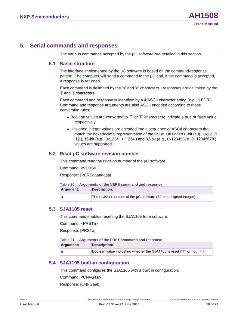
5. Serial commands and responses
The various commands accepted by the μC software are detailed in this section.
5.1 Basic structure
The interface implemented by the μC software is based on the command-response
pattern. The computer will send a command to the μC and, if the command is accepted,
a response is returned.
Each command is delimited by the ‘<’ and ‘>’ characters. Responses are delimited by the
‘[‘ and ‘]’ characters.
Each command and response is identified by a 4 ASCII character string (e.g., ‘LEDR’).
Command and response arguments are also ASCII encoded according to these
conversion rules:
Boolean values are converted to ‘T’ or ‘F’ character to indicate a true or false value
respectively.
Unsigned integer values are encoded into a sequence of ASCII characters that
match the hexadecimal representation of the value. Unsigned 8-bit (e.g., 0x12
‘12’), 16-bit (e.g., 0x1234 ‘1234’) and 32-bit (e.g., 0x12345678 ‘12345678’)
values are supported.
5.2 Read μC software revision number
This command read the revision number of the μC software.
Command: <VERS>
Response: [VERSaaaaaaaa]
Table 20. Arguments of the VERS command and response
Argument: Description:
a The revision number of the μC software (32-bit unsigned integer).
5.3 SJA1105 reset
This command enables resetting the SJA1105 from software.
Command: <PRSTa>
Response: [PRSTa]
Table 21. Arguments of the PRST command and response
Argument: Description:
a Boolean value indicating whether the SJA1105 is reset (‘T’) or not (‘F’).
5.4 SJA1105 built-in configuration
This command configures the SJA1105 with a built in configuration.
Command: <CNFGaa>
Response: [CNFGaab]

NXP Semiconductors AH1508 User Manual
AH1508 All information provided in this document is subject to legal disclaimers. © NXP Semiconductors N.V. 2016. All rights reserved.
User Manual Rev. 01.30 — 22 June 2016 19 of 27
Table 22. Arguments of the CNFG command and response
Argument: Description:
a The configuration to set (8-bit unsigned integer).
b Indicates whether the configuration was successful (‘T’) or not (‘F’).
Notes:
This command is available starting with revision 7.
5.5 SJA1105 register write
This command writes to a register inside the SJA1105.
Command: <SPIWaaaaaaaabbbbbbbb>
Response: [SPIWaaaaaaaabbbbbbbb]
Table 23. Arguments of the SPIW command and response
Argument: Description:
a The register to write to (32-bit unsigned integer).
b The value to write (32-bit unsigned integer).
5.6 SJA1105 register read
This command reads from a register inside the SJA1105.
Command: <SPIWaaaaaaaa>
Response: [SPIWaaaaaaaabbbbbbbb]
Table 24. Arguments of the SPIR command and response
Argument: Description:
a The register to read from (32-bit unsigned integer).
b The value read (32-bit unsigned integer).
5.7 SJA1105 low level SPI access
This command implements a low-level interface to the SJA1105. Its primary use is for
writing configurations in a more efficient way.
Command: <SPIX(aaaa)+>
Response: [SPIX(aaaa)+]
Table 25. Arguments of the SPIX command and response
Argument: Description:
(aaaa)+ One or more 16-bit unsigned integer values to transfer on the SPI
interface.
5.8 PHY register write
This command writes to a register inside an Ethernet PHY.
Command: <SMIWaabbcccc>
Response: [SMIWaabbcccc]
NXP Semiconductors AH1508 User Manual
AH1508 All information provided in this document is subject to legal disclaimers. © NXP Semiconductors N.V. 2016. All rights reserved.
User Manual Rev. 01.30 — 22 June 2016 20 of 27
Table 26. Arguments of the SMIW command and response
Argument: Description:
a The SMI address of the PHY (8-bit unsigned integer, range 0 to 31).
b The register to write to (8-bit unsigned integer, range 0 to 31).
c The value to write (16-bit unsigned integer).
5.9 PHY register read
This command reads from a register inside an Ethernet PHY.
Command: <SMIRaabb>
Response: [SMIRaabbcccc]
Table 27. Arguments of the SMIR command and response
Argument: Description:
a The SMI address of the PHY (8-bit unsigned integer, range 0 to 31).
b The register to read from (8-bit unsigned integer, range 0 to 31).
c The value read (16-bit unsigned integer).
5.10 IPv4 address write
This command writes a new IPv4 address to the EEPROM. This value will be ignored by
the μC software if it is equal to 0x00000000 or 0xFFFFFFFF. A reset is required before
this value is used by the μC software.
Command: <IP4Waaaaaaaa>
Response: [IP4Waaaaaaaa]
Table 28. Arguments of the IP4W command and response
Argument: Description:
a The new IPv4 address to store in the EEPROM. For example, the
address 169.254.115.1 would be encoded as 0xA9FE7301.
5.11 IPv4 address read
This command reads the IPv4 address stored in the EEPROM. This value will be ignored
by the μC software it is equal to 0x00000000 or 0xFFFFFFFF.
Command: <IP4R>
Response: [IP4Raaaaaaaa]
Table 29. Arguments of the IP4W command and response
Argument: Description:
a The new IPv4 address to store in the EEPROM. For example, the
address 169.254.115.1 would be encoded as 0xA9FE7301
NXP Semiconductors AH1508 User Manual
AH1508 All information provided in this document is subject to legal disclaimers. © NXP Semiconductors N.V. 2016. All rights reserved.
User Manual Rev. 01.30 — 22 June 2016 21 of 27
6. In-system programming
The μC software can be reprogrammed via the serial port.
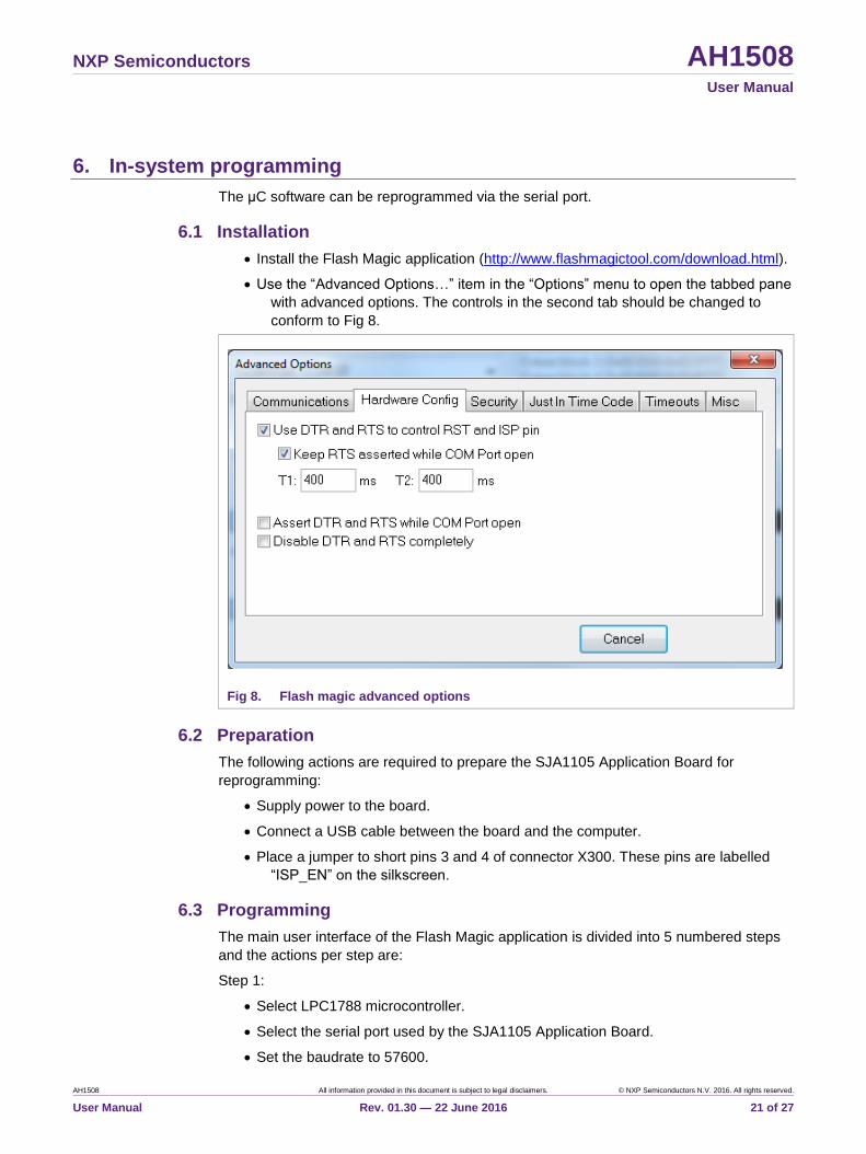
6.1 Installation
Install the Flash Magic application (http://www.flashmagictool.com/download.html).
Use the “Advanced Options…” item in the “Options” menu to open the tabbed pane
with advanced options. The controls in the second tab should be changed to
conform to Fig 8.
Fig 8. Flash magic advanced options
6.2 Preparation
The following actions are required to prepare the SJA1105 Application Board for
reprogramming:
Supply power to the board.
Connect a USB cable between the board and the computer.
Place a jumper to short pins 3 and 4 of connector X300. These pins are labelled
“ISP_EN” on the silkscreen.
6.3 Programming
The main user interface of the Flash Magic application is divided into 5 numbered steps
and the actions per step are:
Step 1:
Select LPC1788 microcontroller.
Select the serial port used by the SJA1105 Application Board.
Set the baudrate to 57600.

NXP Semiconductors AH1508 User Manual
AH1508 All information provided in this document is subject to legal disclaimers. © NXP Semiconductors N.V. 2016. All rights reserved.
User Manual Rev. 01.30 — 22 June 2016 22 of 27
Set interface to “None (ISP)”.
Set the oscillator to 12 MHz.
Step 2:
Select “Erase blocks used by Hex File”.
Step 3:
Select the Intel Hex file to program.
Step 4:
Optionally select “Verify after programming”.
Step 5:
Click the Start button.
NXP Semiconductors AH1508 User Manual
AH1508 All information provided in this document is subject to legal disclaimers. © NXP Semiconductors N.V. 2016. All rights reserved.
User Manual Rev. 01.30 — 22 June 2016 23 of 27
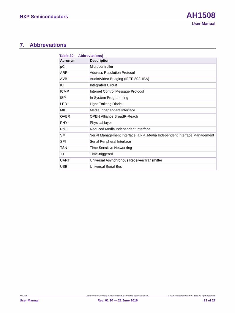
7. Abbreviations
Table 30. Abbreviations)
Acronym Description
μC Microcontroller
ARP Address Resolution Protocol
AVB Audio/Video Bridging (IEEE 802.1BA)
IC Integrated Circuit
ICMP Internet Control Message Protocol
ISP In-System Programming
LED Light Emitting Diode
MII Media Independent Interface
OABR OPEN Alliance BroadR-Reach
PHY Physical layer
RMII Reduced Media Independent Interface
SMI Serial Management Interface, a.k.a. Media Independent Interface Management
SPI Serial Peripheral Interface
TSN Time Sensitive Networking
TT Time-triggered
UART Universal Asynchronous Receiver/Transmitter
USB Universal Serial Bus

Erro
r!
Unkn
ow
n
do
cu
me
nt
pro
pe
rty
na
me
.
Erro
r! Unkno
wn d
ocum
ent p
roperty
nam
e.
Erro
r! Un
kn
ow
n d
ocu
me
nt p
rop
erty
na
me
.
NXP Semiconductors AH1508 User Manual
AH1508 All information provided in this document is subject to legal disclaimers. © NXP Semiconductors N.V. 20164. All rights reserved.
User Manual Rev. 01.30 — 22 June 2016 24 of 27
8. Legal information
8.1 Definitions Draft — The document is a draft version only. The content is still under
internal review and subject to formal approval, which may result in
modifications or additions. NXP Semiconductors does not give any
representations or warranties as to the accuracy or completeness of
information included herein and shall have no liability for the consequences
of use of such information.
8.2 Disclaimers Limited warranty and liability — Information in this document is believed to
be accurate and reliable. However, NXP Semiconductors does not give any
representations or warranties, expressed or implied, as to the accuracy or
completeness of such information and shall have no liability for the
consequences of use of such information. NXP Semiconductors takes no
responsibility for the content in this document if provided by an information
source outside of NXP Semiconductors.
In no event shall NXP Semiconductors be liable for any indirect, incidental,
punitive, special or consequential damages (including - without limitation -
lost profits, lost savings, business interruption, costs related to the removal or
replacement of any products or rework charges) whether or not such
damages are based on tort (including negligence), warranty, breach of
contract or any other legal theory.
Notwithstanding any damages that customer might incur for any reason
whatsoever, NXP Semiconductors’ aggregate and cumulative liability
towards customer for the products described herein shall be limited in
accordance with the Terms and conditions of commercial sale of NXP
Semiconductors.
Right to make changes — NXP Semiconductors reserves the right to make
changes to information published in this document, including without
limitation specifications and product descriptions, at any time and without
notice. This document supersedes and replaces all information supplied prior
to the publication hereof.
Suitability for use — NXP Semiconductors products are not designed,
authorized or warranted to be suitable for use in life support, life-critical or
safety-critical systems or equipment, nor in applications where failure or
malfunction of an NXP Semiconductors product can reasonably be expected
to result in personal injury, death or severe property or environmental
damage. NXP Semiconductors and its suppliers accept no liability for
inclusion and/or use of NXP Semiconductors products in such equipment or
applications and therefore such inclusion and/or use is at the customer’s own
risk.
Applications — Applications that are described herein for any of these
products are for illustrative purposes only. NXP Semiconductors makes no
representation or warranty that such applications will be suitable for the
specified use without further testing or modification.
Customers are responsible for the design and operation of their applications
and products using NXP Semiconductors products, and NXP
Semiconductors accepts no liability for any assistance with applications or
customer product design. It is customer’s sole responsibility to determine
whether the NXP Semiconductors product is suitable and fit for the
customer’s applications and products planned, as well as for the planned
application and use of customer’s third party customer(s). Customers should
provide appropriate design and operating safeguards to minimize the risks
associated with their applications and products.
NXP Semiconductors does not accept any liability related to any default,
damage, costs or problem which is based on any weakness or default in the
customer’s applications or products, or the application or use by customer’s
third party customer(s). Customer is responsible for doing all necessary
testing for the customer’s applications and products using NXP
Semiconductors products in order to avoid a default of the applications and
the products or of the application or use by customer’s third party
customer(s). NXP does not accept any liability in this respect.
Export control — This document as well as the item(s) described herein
may be subject to export control regulations. Export might require a prior
authorization from competent authorities.
Translations — A non-English (translated) version of a document is for
reference only. The English version shall prevail in case of any discrepancy
between the translated and English versions.
Evaluation products — This product is provided on an “as is” and “with all
faults” basis for evaluation purposes only. NXP Semiconductors, its affiliates
and their suppliers expressly disclaim all warranties, whether express,
implied or statutory, including but not limited to the implied warranties of non-
infringement, merchantability and fitness for a particular purpose. The entire
risk as to the quality, or arising out of the use or performance, of this product
remains with customer.
In no event shall NXP Semiconductors, its affiliates or their suppliers be
liable to customer for any special, indirect, consequential, punitive or
incidental damages (including without limitation damages for loss of
business, business interruption, loss of use, loss of data or information, and
the like) arising out the use of or inability to use the product, whether or not
based on tort (including negligence), strict liability, breach of contract, breach
of warranty or any other theory, even if advised of the possibility of such
damages.
Notwithstanding any damages that customer might incur for any reason
whatsoever (including without limitation, all damages referenced above and
all direct or general damages), the entire liability of NXP Semiconductors, its
affiliates and their suppliers and customer’s exclusive remedy for all of the
foregoing shall be limited to actual damages incurred by customer based on
reasonable reliance up to the greater of the amount actually paid by
customer for the product or five dollars (US$5.00). The foregoing limitations,
exclusions and disclaimers shall apply to the maximum extent permitted by
applicable law, even if any remedy fails of its essential purpose.
8.3 Licenses
Purchase of NXP <xxx> components
<License statement text>
8.4 Patents Notice is herewith given that the subject device uses one or more of the
following patents and that each of these patents may have corresponding
patents in other jurisdictions.
<Patent ID> — owned by <Company name>
8.5 Trademarks Notice: All referenced brands, product names, service names and
trademarks are property of their respective owners.
<Name> — is a trademark of NXP Semiconductors N.V.
NXP Semiconductors AH1508 User Manual
AH1508 All information provided in this document is subject to legal disclaimers. © NXP Semiconductors N.V. 2016. All rights reserved.
User Manual Rev. 01.30 — 22 June 2016 25 of 27
9. List of figures
Fig 1. Block diagram indicating the primary functional
blocks ................................................................ 3 Fig 2. Installer ............................................................. 8 Fig 3. Connection diagram .......................................... 9 Fig 4. Windows device manager ............................... 10 Fig 5. id.bat ............................................................... 10 Fig 6. test_phy.bat .................................................... 11 Fig 7. ping ................................................................. 12 Fig 8. Flash magic advanced options ........................ 21
NXP Semiconductors AH1508 User Manual
AH1508 All information provided in this document is subject to legal disclaimers. © NXP Semiconductors N.V. 2016. All rights reserved.
User Manual Rev. 01.30 — 22 June 2016 26 of 27
10. List of tables
Table 1. Default TJA1100 configurations ........................ 4 Table 2. Ethernet settings ............................................... 4 Table 3. Built-in configurations ........................................ 5 Table 4. SJA1105 Application Board LEDs ..................... 5 Table 5. Serial port settings ............................................ 6 Table 6. Installation directory structure ........................... 7 Table 7. Scripts from example_com\pyScripts .............. 13 Table 8. Scripts from example_configs\pyScripts ......... 14 Table 9. Package contents ........................................... 14 Table 10. Arguments of __init__( serial_port ) ................ 15 Table 11. Arguments of spi_config( config_file ) ............. 16 Table 12. Arguments of spi_write( address, data ) ......... 16 Table 13. Arguments of spi_read( address ) ................... 16 Table 14. Arguments of spi_read_print( address ) .......... 16 Table 15. Arguments of smi_write( phy, address, data ) . 16 Table 16. Arguments of smi_read( phy, address ) .......... 17 Table 17. Arguments of smi_read_print( phy, address ) . 17 Table 18. Arguments of set_leds( red=False,
green=False) ................................................... 17 Table 19. Arguments of auto_configure( config_number )
........................................................................ 17 Table 20. Arguments of the VERS command and
response ......................................................... 18 Table 21. Arguments of the PRST command and
response ......................................................... 18 Table 22. Arguments of the CNFG command and
response ......................................................... 19 Table 23. Arguments of the SPIW command and response
........................................................................ 19 Table 24. Arguments of the SPIR command and response
........................................................................ 19 Table 25. Arguments of the SPIX command and response
........................................................................ 19 Table 26. Arguments of the SMIW command and
response ......................................................... 20 Table 27. Arguments of the SMIR command and response
........................................................................ 20 Table 28. Arguments of the IP4W command and response
........................................................................ 20 Table 29. Arguments of the IP4W command and response
........................................................................ 20 Table 30. Abbreviations) ................................................. 23
NXP Semiconductors AH1508 User Manual
AH1508 All information provided in this document is subject to legal disclaimers. © NXP Semiconductors N.V. 2016. All rights reserved.
User Manual Rev. 01.30 — 22 June 2016 27 of 27
11. Contents
1. Introduction ......................................................... 3 2. System Overview ................................................. 3 2.1 Power ................................................................. 3 2.2 SJA1105............................................................. 3 2.3 TJA1100 ............................................................. 4 2.4 μC and extension connector .............................. 4 2.5 Rotary switch ...................................................... 4 2.6 LEDs .................................................................. 5 2.7 USB connector ................................................... 5 2.8 Reset buttons ..................................................... 6 3. Getting Started .................................................... 7 3.1 Installing the software package .......................... 7 3.2 Board setup ........................................................ 8 3.3 Determining the serial port ................................. 9 3.4 SJA1105 communication ................................. 10 3.5 TJA1100 communication .................................. 11 3.6 Ping .................................................................. 11 3.7 Creating a new SJA1105 configuration ............ 12 4. Python scripting ................................................ 13 4.1 Directory structure ............................................ 13 4.2 Python package sja1105 .................................. 14 4.3 Scripting interface ............................................ 15 4.3.1 __init__( serial_port ) ....................................... 15 4.3.2 spi_config( config_file ) .................................... 15 4.3.3 spi_write( address, data ) ................................. 16 4.3.4 spi_read ( address ) ......................................... 16 4.3.5 spi_read_print( address ) ................................. 16 4.3.6 smi_write( phy, address, data ) ........................ 16 4.3.7 smi_read( phy, address ) ................................. 17 4.3.8 smi_read_print( phy, address ) ......................... 17 4.3.9 reset() ............................................................... 17 4.3.10 get_version() .................................................... 17 4.3.11 set_leds( red=False, green=False) .................. 17 4.3.12 auto_configure( config_number ) ..................... 17 5. Serial commands and responses .................... 18 5.1 Basic structure ................................................. 18 5.2 Read μC software revision number .................. 18 5.3 SJA1105 reset .................................................. 18 5.4 SJA1105 built-in configuration.......................... 18 5.5 SJA1105 register write ..................................... 19 5.6 SJA1105 register read ..................................... 19 5.7 SJA1105 low level SPI access ......................... 19 5.8 PHY register write ............................................ 19 5.9 PHY register read ............................................. 20 5.10 IPv4 address write ............................................ 20
5.11 IPv4 address read ............................................ 20 6. In-system programming .................................... 21 6.1 Installation ........................................................ 21 6.2 Preparation ....................................................... 21 6.3 Programming .................................................... 21 7. Abbreviations ..................................................... 23 8. Legal information .............................................. 24 8.1 Definitions ......................................................... 24 8.2 Disclaimers ....................................................... 24 8.3 Licenses ........................................................... 24 8.4 Patents ............................................................. 24 8.5 Trademarks ...................................................... 24 9. List of figures ..................................................... 25 10. List of tables ...................................................... 26 11. Contents ............................................................. 27

Mouser Electronics
Authorized Distributor
Click to View Pricing, Inventory, Delivery & Lifecycle Information: NXP:
OM14510/SJA1105TJP


![Board Member Application - NEW[2]](https://img.pdfslide.us/doc/110x75/616f37b38824e243230ad937/board-member-application-new2.jpg)


![[MoC] Entity Control Board Chair Application](https://img.pdfslide.us/doc/110x75/559afa151a28ab82458b485b/moc-entity-control-board-chair-application.jpg)