Embed Size (px)
Citation preview
Component s fo r Ra i l on Boa rd App l i ca t i on
ContactorsDisconnectorsDC High Speed Circuit BreakersResistorsHigh Voltage Transducers
Brochure_Rail_Ok.qxd:Layout 1 25-09-2009 19:12 Pagina 1
2
Traction innovation
For over 50 years, Microelettrica
Scientifica products have
accompanied and often anticipated
the evolution of rail transport all
over the world. Today, Microelettrica
Scientifica contactors, disconnectors,
power resistors and high voltage
transducers, together with EMC
Traction DC high speed circuit
breakers have become the standard
of reference for a growing number of
highly qualified rail vehicle
customers all over the world.
Know how in continuous evolution
The frontiers of power generation,
transmission and distribution
are changing continuously and
Microelettrica Scientifica is evolving
with them through continuous
innovation of products and
technologies.
All the steps of our processes, from
product conception to product
validation, from choice of materials
to final routine tests, are accurately
controlled to guarantee total safety
of equipment, persons and lines, as
well as full customers satisfaction,
but more than that to constantly
find innovative solutions that improve
the cost/performance/features
balance of our products.
Applications
Locomotives
High Speed Trains
Electric Multiple Units
Metros
Trams/LRV
Passenger Cars
Trolleybuses
Brochure_Rail_Ok.qxd:Layout 1 25-09-2009 19:12 Pagina 2
3
Components for Rai l on Board Appl icat ion
Wework together with our customers
Our industrial philosophy is to
manage the evolution of our
products in full coordination and
collaboration with our customers.
Since the first contacts, we are
pleased to foster relations with
them. In this way we can help in
selecting the product from our
wide range which better fits the
requirements. And, in case of special
requirements, we are always eager
to develop custom-designed
products: our company is well
prepared to manage the most
challenging projects and our
factories will easily realize them.
Made in Microelettrica Scientifica
To achieve the best results,
Microelettrica Scientifica develops
and produces the entire range
of products in its own facilities in
Rozzano and Lacchiarella, as well as
the EMC Traction facility in
Vimodrone, all very near to Milano.
But we also run operations in USA,
South Africa, France, India and
China. Wherever in the world
customers know they can always
count on quality, excellence and
accuracy in the realization of each
single product and component,
but also get supported locally.
Products
ContactorsDisconnectors
DC High Speed Circuit Breakers
Braking ResistorsResistors for Traction Control
High Voltage Transducers
Brochure_Rail_Ok.qxd:Layout 1 25-09-2009 19:12 Pagina 3
4 Contac to r s
Applications
Line contactor
Power or auxiliary converter input
Filter pre-charging
Traction motors on-load disconnection
Electromagnetic brakes
Heating/Air conditioning systems
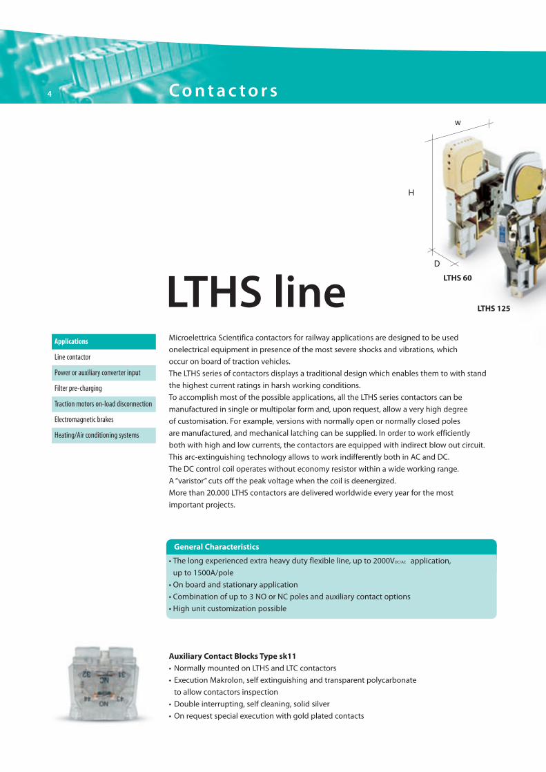
Microelettrica Scientifica contactors for railway applications are designed to be used
onelectrical equipment in presence of the most severe shocks and vibrations, which
occur on board of traction vehicles.
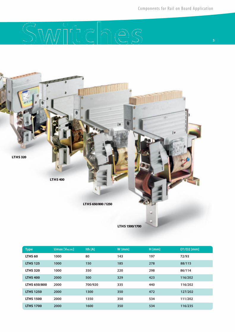
The LTHS series of contactors displays a traditional design which enables them to with stand
the highest current ratings in harsh working conditions.
To accomplish most of the possible applications, all the LTHS series contactors can be
manufactured in single or multipolar form and, upon request, allow a very high degree
of customisation. For example, versions with normally open or normally closed poles
are manufactured, and mechanical latching can be supplied. In order to work efficiently
both with high and low currents, the contactors are equipped with indirect blow out circuit.
This arc-extinguishing technology allows to work indifferently both in AC and DC.
The DC control coil operates without economy resistor within a wide working range.
A “varistor” cuts off the peak voltage when the coil is deenergized.
More than 20.000 LTHS contactors are delivered worldwide every year for the most
important projects.
Auxiliary Contact Blocks Type sk11
• Normally mounted on LTHS and LTC contactors
• Execution Makrolon, self extinguishing and transparent polycarbonate
to allow contactors inspection
• Double interrupting, self cleaning, solid silver
• On request special execution with gold plated contacts
• The long experienced extra heavy duty flexible line, up to 2000VDC/AC application,
up to 1500A/pole
• On board and stationary application
• Combination of up to 3 NO or NC poles and auxiliary contact options
• High unit customization possible
LTHS line
H
D
w
LTHS 125
LTHS 60
General Characteristics
Brochure_Rail_Ok.qxd:Layout 1 25-09-2009 19:12 Pagina 4
Components for Rai l on Board Appl icat ion
5
Umax [VAC/DC] Ith [A] W (mm] H [mm] D1/D2 [mm]
LTHS 60
Type
143 197 72/93
LTHS 125 1000 150 185 278 88/115
LTHS 320 1000 350 220 298 86/114
LTHS 400 2000 500 329 423 116/202
LTHS 650/800 2000 700/920 335 440 116/202
LTHS 1250 2000 1300 350 472 127/202
LTHS 1500 2000 1350 350 534 111/202
LTHS 1700 2000 1600 350 534 116/235
1000
LTHS 320
LTHS 400
LTHS 1500/1700
LTHS 650/800 /1250
80
Brochure_Rail_Ok.qxd:Layout 1 25-09-2009 19:12 Pagina 5
LTC 100
LTC 100 NC
LTCS 250
Auxiliary Contact Blocks Type rk11
• Contacts based on Reed relay technology
• Sealed tips, not affected by harsh environmental conditions
• Shielding case from external magnetic fields
• Same mechanical interface of standard SK11auxiliary blocks
• Power rating 10 VA
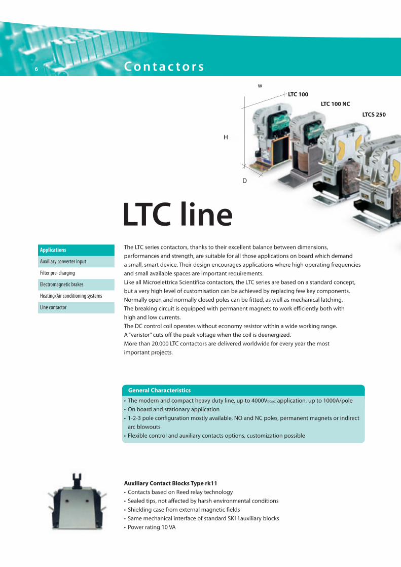
LTC lineApplications
Auxiliary converter input
Filter pre-charging
Electromagnetic brakes
Heating/Air conditioning systems
Line contactor
The LTC series contactors, thanks to their excellent balance between dimensions,
performances and strength, are suitable for all those applications on board which demand
a small, smart device. Their design encourages applications where high operating frequencies
and small available spaces are important requirements.
Like all Microelettrica Scientifica contactors, the LTC series are based on a standard concept,
but a very high level of customisation can be achieved by replacing few key components.
Normally open and normally closed poles can be fitted, as well as mechanical latching.
The breaking circuit is equipped with permanent magnets to work efficiently both with
high and low currents.
The DC control coil operates without economy resistor within a wide working range.
A “varistor” cuts off the peak voltage when the coil is deenergized.
More than 20.000 LTC contactors are delivered worldwide for every year the most
important projects.
H
D
w
• The modern and compact heavy duty line, up to 4000VDC/AC application, up to 1000A/pole
• On board and stationary application
• 1-2-3 pole configuration mostly available, NO and NC poles, permanent magnets or indirect
arc blowouts
• Flexible control and auxiliary contacts options, customization possible
General Characteristics
6 Contac to r s
Brochure_Rail_Ok.qxd:Layout 1 25-09-2009 19:12 Pagina 6
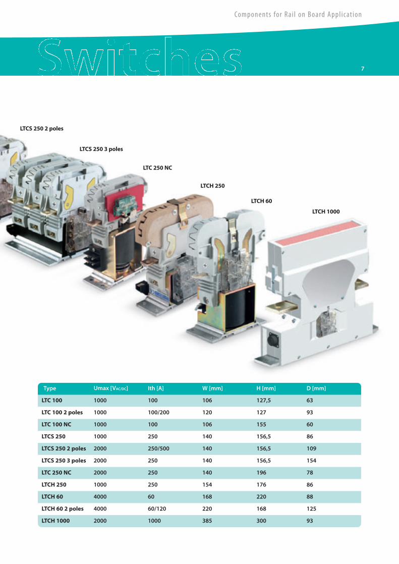
LTCS 250 2 poles
LTC 250 NC
LTCH 250
LTCH 60
LTCH 1000
LTCS 250 3 poles
Umax [VAC/DC] Ith [A] W [mm] H [mm] D [mm]
LTC 100
Type
100 106 127,5 63
LTC 100 2 poles 1000 100/200 120 127 93
LTC 100 NC 1000 100 106 155 60
LTCS 250 1000 250 140 156,5 86
LTCS 250 2 poles 2000 250/500 140 156,5 109
LTCS 250 3 poles 2000 250 140 156,5 154
LTC 250 NC 2000 250 140 196 78
LTCH 250 1000 250 154 176 86
LTCH 60 4000 60 168 220 88
LTCH 60 2 poles 4000 60/120 220 168 125
LTCH 1000 2000 1000 385 300 93
1000
7
Components for Rai l on Board Appl icat ion
Brochure_Rail_Ok.qxd:Layout 1 25-09-2009 19:12 Pagina 7
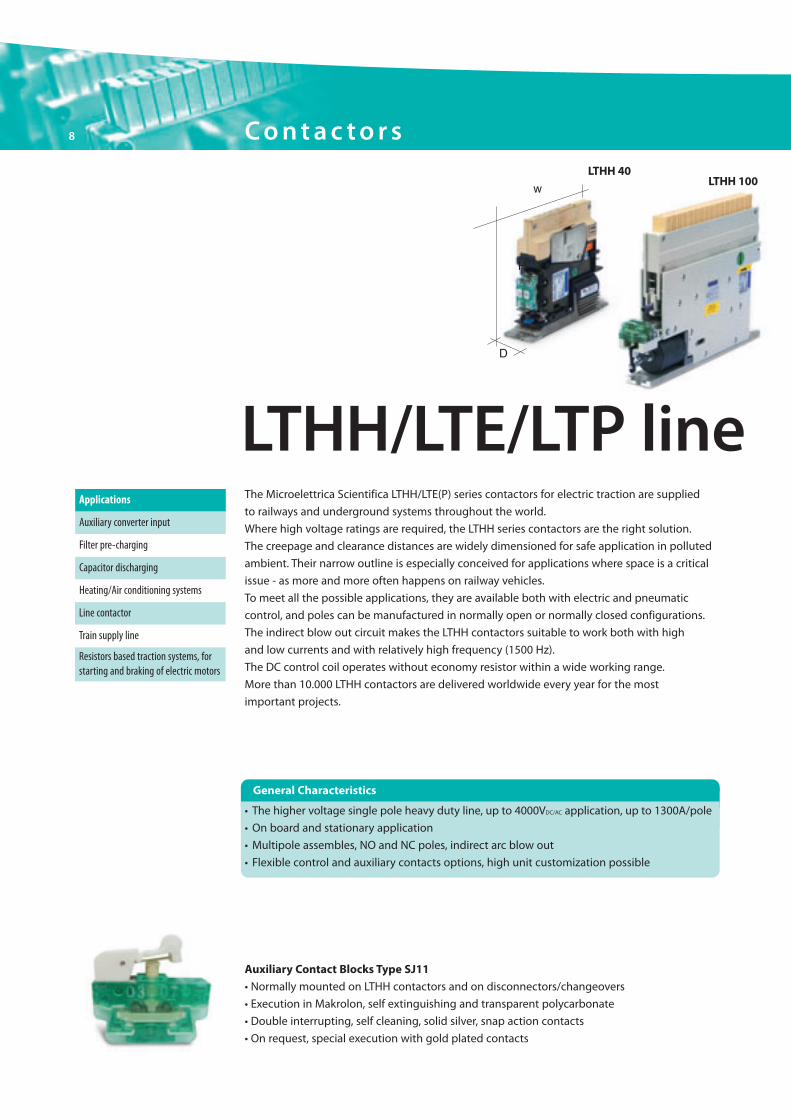
The Microelettrica Scientifica LTHH/LTE(P) series contactors for electric traction are supplied
to railways and underground systems throughout the world.
Where high voltage ratings are required, the LTHH series contactors are the right solution.
The creepage and clearance distances are widely dimensioned for safe application in polluted
ambient. Their narrow outline is especially conceived for applications where space is a critical
issue - as more and more often happens on railway vehicles.
To meet all the possible applications, they are available both with electric and pneumatic
control, and poles can be manufactured in normally open or normally closed configurations.
The indirect blow out circuit makes the LTHH contactors suitable to work both with high
and low currents and with relatively high frequency (1500 Hz).
The DC control coil operates without economy resistor within a wide working range.
More than 10.000 LTHH contactors are delivered worldwide every year for the most
important projects.
Applications
Auxiliary converter input
Filter pre-charging
Capacitor discharging
Heating/Air conditioning systems
Line contactor
Train supply line
Resistors based traction systems, forstarting and braking of electric motors
Auxiliary Contact Blocks Type SJ11
• Normally mounted on LTHH contactors and on disconnectors/changeovers
• Execution in Makrolon, self extinguishing and transparent polycarbonate
• Double interrupting, self cleaning, solid silver, snap action contacts
• On request, special execution with gold plated contacts
LTHH/LTE/LTP line
LTHH 100LTHH 40
H
D
w
• The higher voltage single pole heavy duty line, up to 4000VDC/AC application, up to 1300A/pole
• On board and stationary application
• Multipole assembles, NO and NC poles, indirect arc blow out
• Flexible control and auxiliary contacts options, high unit customization possible
General Characteristics
8 Contac to r s
Brochure_Rail_Ok.qxd:Layout 1 25-09-2009 19:12 Pagina 8
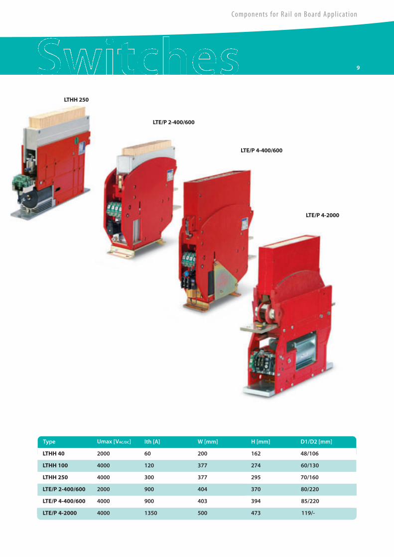
Umax [VAC/DC] Ith [A] W [mm] H [mm] D1/D2 [mm]
LTHH 40
Type
200 162 48/106
LTHH 100 4000 120 377 274 60/130
LTHH 250 4000 300 377 295 70/160
LTE/P 2-400/600 2000 900 404 370 80/220
LTE/P 4-400/600 4000 900 403 394 85/220
LTE/P 4-2000 4000 1350 500 473 119/-
2000
LTHH 250
LTE/P 2-400/600
LTE/P 4-400/600
LTE/P 4-2000
60
9
Components for Rai l on Board Appl icat ion
Brochure_Rail_Ok.qxd:Layout 1 25-09-2009 19:12 Pagina 9
10 D i s connec to r s
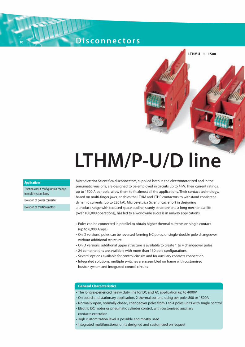
Microelettrica Scientifica disconnectors, supplied both in the electromotorized and in the
pneumatic versions, are designed to be employed in circuits up to 4 kV. Their current ratings,
up to 1500 A per pole, allow them to fit almost all the applications. Their contact technology,
based on multi-finger jaws, enables the LTHM and LTHP contactors to withstand consistent
dynamic currents (up to 220 kA). Microelettrica Scientifica’s effort in designing
a product range with reduced space outline, sturdy structure and a long mechanical life
(over 100,000 operations), has led to a worldwide success in railway applications.
• Poles can be connected in parallel to obtain higher thermal currents on single contact
(up to 6,000 Amps)
• On D versions, poles can be reversed forming NC poles, or single-double pole changeover
without additional structure
• On D versions, additional upper structure is available to create 1 to 4 changeover poles
• 24 combinations are available with more than 130 pole configurations
• Several options available for control circuits and for auxiliary contacts connection
• Integrated solutions: multiple switches are assembled on frame with customised
busbar system and integrated control circuits
LTHM/P-U/D lineApplications
Isolation of traction motors
Traction circuit configuration changein multi-system locos
Isolation of power converter
LTHMU - 1 - 1500
• The long experienced heavy duty line for DC and AC application up to 4000V
• On board and stationary application, 2 thermal current rating per pole: 800 or 1500A
• Normally open, normally closed, changeover poles from 1 to 4 poles units with single control
• Electric DC motor or pneumatic cylinder control, with customized auxiliary
contacts execution
• High customization level is possible and mostly used
• Integrated multifunctional units designed and customized on request
General Characteristics
Brochure_Rail_Ok.qxd:Layout 1 25-09-2009 19:12 Pagina 10
11
Components for Rai l on Board Appl icat ion
Auxiliary Connections
• To meet all customer requirements, special connections and cabling can be supplied both
on the high voltage and on the low voltage circuits. On the HV side, poles can be connected
in series or parallel. Terminals can be shaped according to customers’ requirements
• LV circuits can be cabled to perform different logical functions. Any kind of connector
available in commerce can be fitted to these circuits
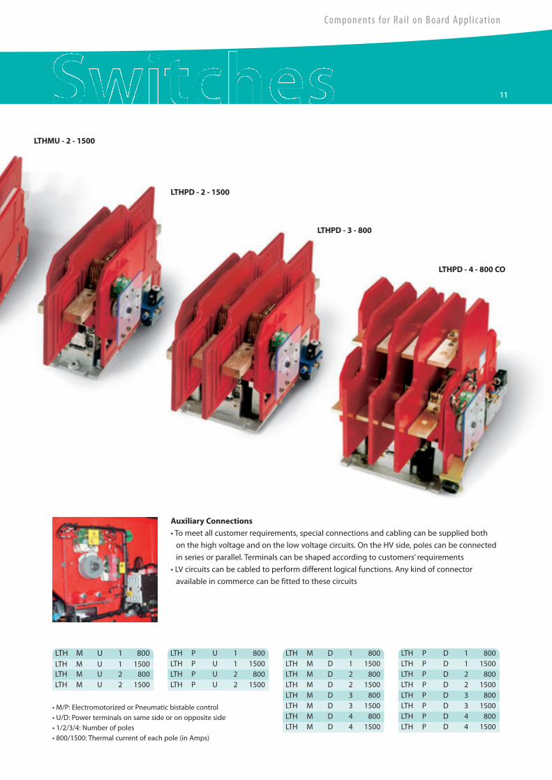
• M/P: Electromotorized or Pneumatic bistable control• U/D: Power terminals on same side or on opposite side• 1/2/3/4: Number of poles• 800/1500: Thermal current of each pole (in Amps)
LTH P D 1 800LTH M U 1 1500 LTH P D 1 1500LTH M U 2 800 LTH P D 2 800LTH M U 2 1500 LTH P D 2 1500
LTH P D 3 800LTH P D 3 1500LTH P D 4 800LTH P D 4 1500
LTHMU - 2 - 1500
LTHPD - 2 - 1500
LTHPD - 3 - 800
LTHPD - 4 - 800 CO
LTH M U 1 800 LTH P U 1 800LTH P U 1 1500LTH P U 2 800LTH P U 2 1500
LTH M D 1 800LTH M D 1 1500LTH M D 2 800LTH M D 2 1500LTH M D 3 800LTH M D 3 1500LTH M D 4 800LTH M D 4 1500
Brochure_Rail_Ok.qxd:Layout 1 25-09-2009 19:12 Pagina 11
12 D i s connec to r s
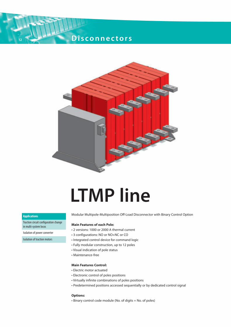
Modular Multipole-Multiposition Off-Load Disconnector with Binary Control Option
Main Features of each Pole:
• 2 versions: 1000 or 2000 A thermal current
• 3 configurations: NO or NO+NC or CO
• Integrated control device for command logic
• Fully modular construction, up to 12 poles
• Visual indication of pole status
• Maintenance-free
Main Features Control:
• Electric motor actuated
• Electronic control of poles positions
• Virtually infinite combinations of poles positions
• Predetermined positions accessed sequentially or by dedicated control signal
Options:
• Binary control code module (No. of digits = No. of poles)
LTMP lineApplications
Isolation of traction motors
Traction circuit configuration changein multi-system locos
Isolation of power converter
Brochure_Rail_Ok.qxd:Layout 1 25-09-2009 19:12 Pagina 12
Components for Rai l on Board Appl icat ion
13
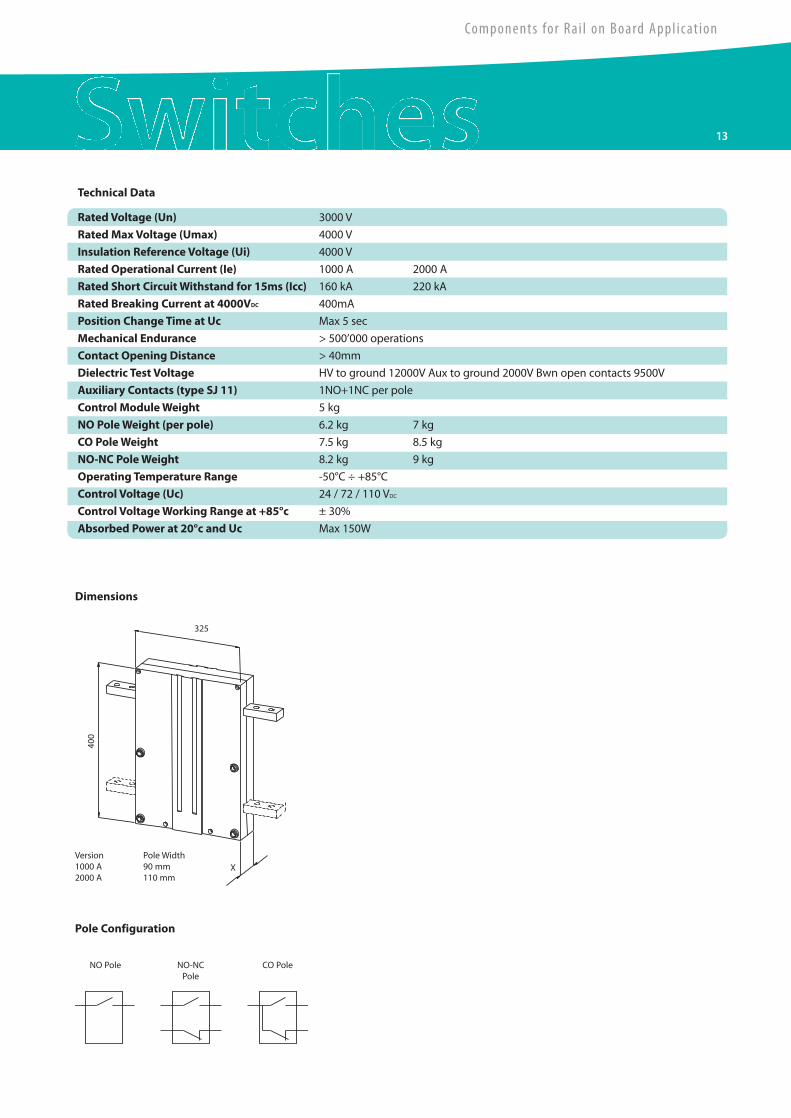
RatedVoltage (Un) 3000 V
Rated MaxVoltage (Umax) 4000 V
Insulation Reference Voltage (Ui) 4000 V
Rated Operational Current (Ie) 1000 A 2000 A
Rated Short CircuitWithstand for 15ms (Icc) 160 kA 220 kA
Rated Breaking Current at 4000VDC 400mA
Position Change Time at Uc Max 5 sec
Mechanical Endurance > 500’000 operations
Contact Opening Distance > 40mm
Dielectric Test Voltage HV to ground 12000V Aux to ground 2000V Bwn open contacts 9500V
Auxiliary Contacts (type SJ 11) 1NO+1NC per pole
Control ModuleWeight 5 kg
NO PoleWeight (per pole) 6.2 kg 7 kg
CO PoleWeight 7.5 kg 8.5 kg
NO-NC PoleWeight 8.2 kg 9 kg
Operating Temperature Range -50°C ÷ +85°C
Control Voltage (Uc) 24 / 72 / 110 VDC
Control VoltageWorking Range at +85°c ± 30%
Absorbed Power at 20°c and Uc Max 150W
Technical Data
Dimensions
Version1000 A2000 A
Pole Width90 mm110 mm
400
325
X
Pole Configuration
NO Pole NO-NCPole
CO Pole
Brochure_Rail_Ok.qxd:Layout 1 25-09-2009 19:12 Pagina 13
14
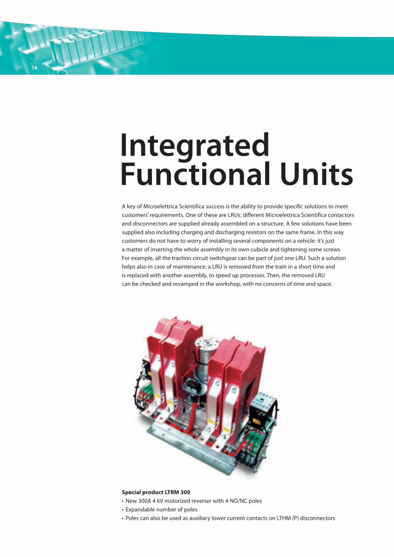
A key of Microelettrica Scientifica success is the ability to provide specific solutions to meet
customers’ requirements. One of these are LRUs: different Microelettrica Scientifica contactors
and disconnectors are supplied already assembled on a structure. A few solutions have been
supplied also including charging and discharging resistors on the same frame. In this way
customers do not have to worry of installing several components on a vehicle: it’s just
a matter of inserting the whole assembly in its own cubicle and tightening some screws.
For example, all the traction circuit switchgear can be part of just one LRU. Such a solution
helps also in case of maintenance: a LRU is removed from the train in a short time and
is replaced with another assembly, to speed up processes. Then, the removed LRU
can be checked and revamped in the workshop, with no concerns of time and space.
IntegratedFunctional Units
Special product LTRM 300
• New 300A 4 kV motorized reverser with 4 NO/NC poles
• Expandable number of poles
• Poles can also be used as auxiliary lower current contacts on LTHM (P) disconnectors
Brochure_Rail_Ok.qxd:Layout 1 25-09-2009 19:12 Pagina 14

15
Components for Rai l on Board Appl icat ion
4 QS
4 QS
15kV 16,6Hz/25kV 50Hz
Precharging contactor
Transformer tappingchange overdisconnector
Main power contactor
Brochure_Rail_Ok.qxd:Layout 1 25-09-2009 19:12 Pagina 15
16 DC H igh Speed C i rcu i t B reake r s
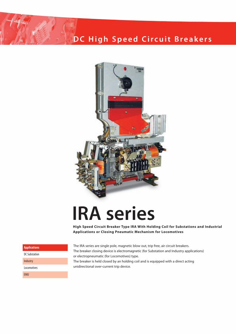
The IRA series are single pole, magnetic blow out, trip free, air circuit breakers.
The breaker closing device is electromagnetic (for Substation and Industry applications)
or electropneumatic (for Locomotives) type.
The breaker is held closed by an holding coil and is equipped with a direct acting
unidirectional over-current trip device.
Applications
DC Substation
Industry
EMU
Locomotives
IRA seriesHigh Speed Circuit Breaker Type IRA With Holding Coil for Substations and Industrial
Applications or Closing Pneumatic Mechanism for Locomotives
Brochure_Rail_Ok.qxd:Layout 1 25-09-2009 19:12 Pagina 16
17
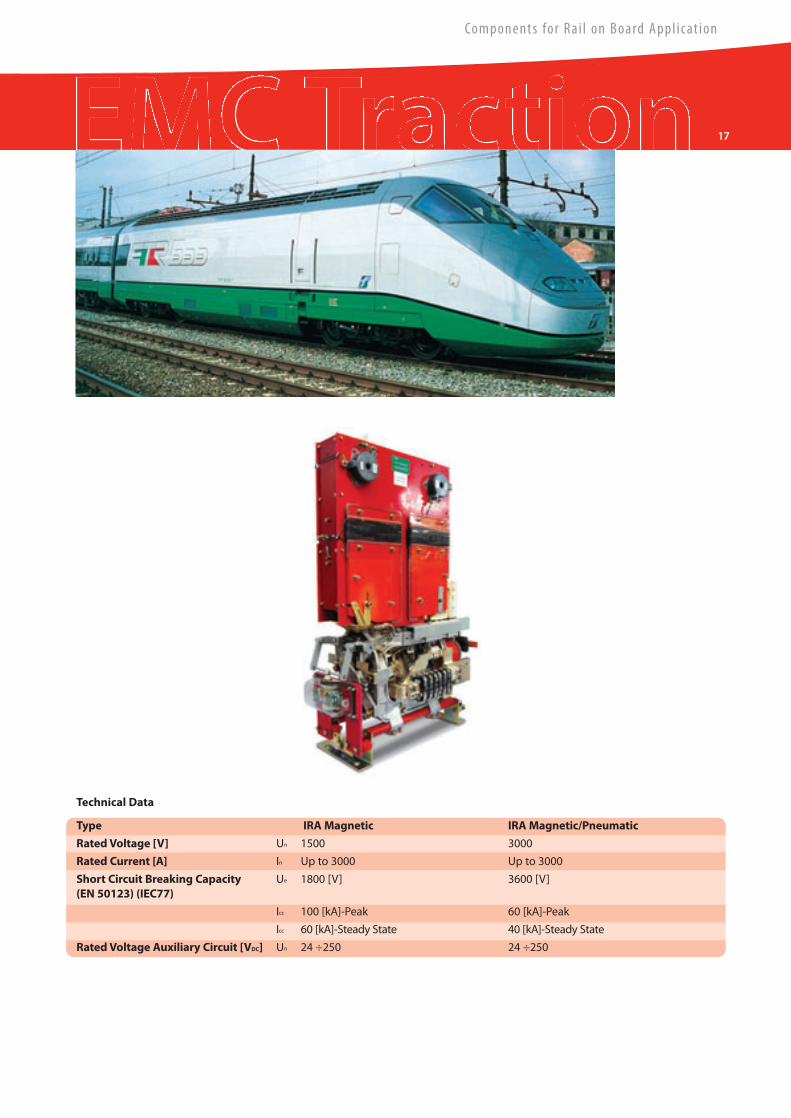
Type IRAMagnetic IRAMagnetic/Pneumatic
RatedVoltage [V] Un 1500 3000
Rated Current [A] In Up to 3000 Up to 3000
Short Circuit Breaking Capacity Ue 1800 [V] 3600 [V](EN 50123) (IEC77)
Icc 100 [kA]-Peak 60 [kA]-Peak
Icc 60 [kA]-Steady State 40 [kA]-Steady State
RatedVoltage Auxiliary Circuit [VDC] Un 24 ÷250 24 ÷250
Technical Data
Components for Rai l on Board Appl icat ion
Brochure_Rail_Ok.qxd:Layout 1 25-09-2009 19:12 Pagina 17
18 DC H igh Speed C i rcu i t B reake r s
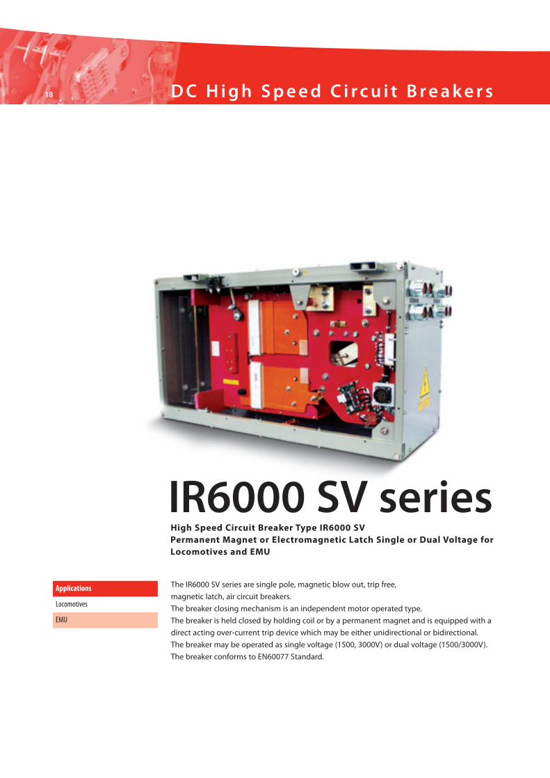
The IR6000 SV series are single pole, magnetic blow out, trip free,
magnetic latch, air circuit breakers.
The breaker closing mechanism is an independent motor operated type.
The breaker is held closed by holding coil or by a permanent magnet and is equipped with a
direct acting over-current trip device which may be either unidirectional or bidirectional.
The breaker may be operated as single voltage (1500, 3000V) or dual voltage (1500/3000V).
The breaker conforms to EN60077 Standard.
Applications
Locomotives
EMU
IR6000 SV seriesHigh Speed Circuit Breaker Type IR6000 SVPermanent Magnet or Electromagnetic Latch Single or Dual Voltage forLocomotives and EMU
Brochure_Rail_Ok.qxd:Layout 1 25-09-2009 19:12 Pagina 18
19
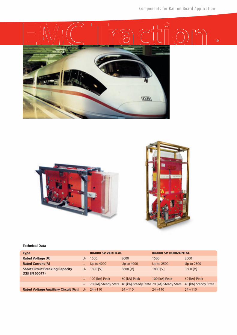
Type IR6000 SVVERTICAL IR6000 SV HORIZONTAL
RatedVoltage [V] Un 1500 3000 1500 3000
Rated Current [A] In Up to 4000 Up to 4000 Up to 2500 Up to 2500
Short Circuit Breaking Capacity Ue 1800 [V] 3600 [V] 1800 [V] 3600 [V](CEI EN 60077)
Icc 100 [kA]-Peak 60 [kA]-Peak 100 [kA]-Peak 60 [kA]-Peak
Icc 70 [kA]-Steady State 40 [kA]-Steady State 70 [kA]-Steady State 40 [kA]-Steady State
RatedVoltage Auxiliary Circuit [VDC] Un 24 ÷110 24 ÷110 24 ÷110 24 ÷110
Technical Data
Components for Rai l on Board Appl icat ion
Brochure_Rail_Ok.qxd:Layout 1 25-09-2009 19:12 Pagina 19
20 DC H igh Speed C i rcu i t B reake r s
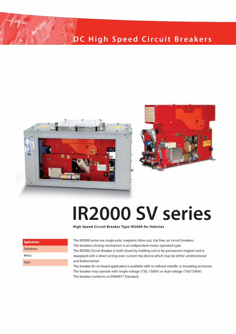
The IR2000 series are single pole, magnetic blow out, trip free, air circuit breakers.
The breakers closing mechanism is an indipendent motor operated type.
The IR2000 Circuit Breaker is held closed by holding coil or by permanent magnet and is
equipped with a direct acting over-current trip device which may be either unidirectional
and bidirectional.
This breaker for on-board application is available with or without metallic or insulating enclosure.
The breaker may operate with single voltage (750, 1500V) or dual voltage (750/1500V).
The breaker conforms to EN60077 Standard.
Applications
Trolleybuses
Metros
Trams
IR2000 SV seriesHigh Speed Circuit Breaker Type IR2000 for Vehicles
Brochure_Rail_Ok.qxd:Layout 1 25-09-2009 19:12 Pagina 20
21
Components for Rai l on Board Appl icat ion
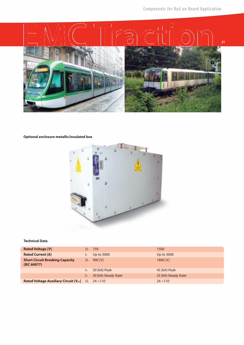
Optional enclosure metallic/insulated box
RatedVoltage [V] Un 750 1500
Rated Current [A] In Up to 3000 Up to 3000
Short Circuit Breaking Capacity Ue 900 [V] 1800 [V](IEC 60077)
Icc 50 [kA]-Peak 45 [kA]-Peak
Icc 30 [kA]-Steady State 25 [kA]-Steady State
RatedVoltage Auxiliary Circuit [VDC] Un 24 ÷110 24 ÷110
Technical Data
Brochure_Rail_Ok.qxd:Layout 1 25-09-2009 19:12 Pagina 21
22 On Boa rd
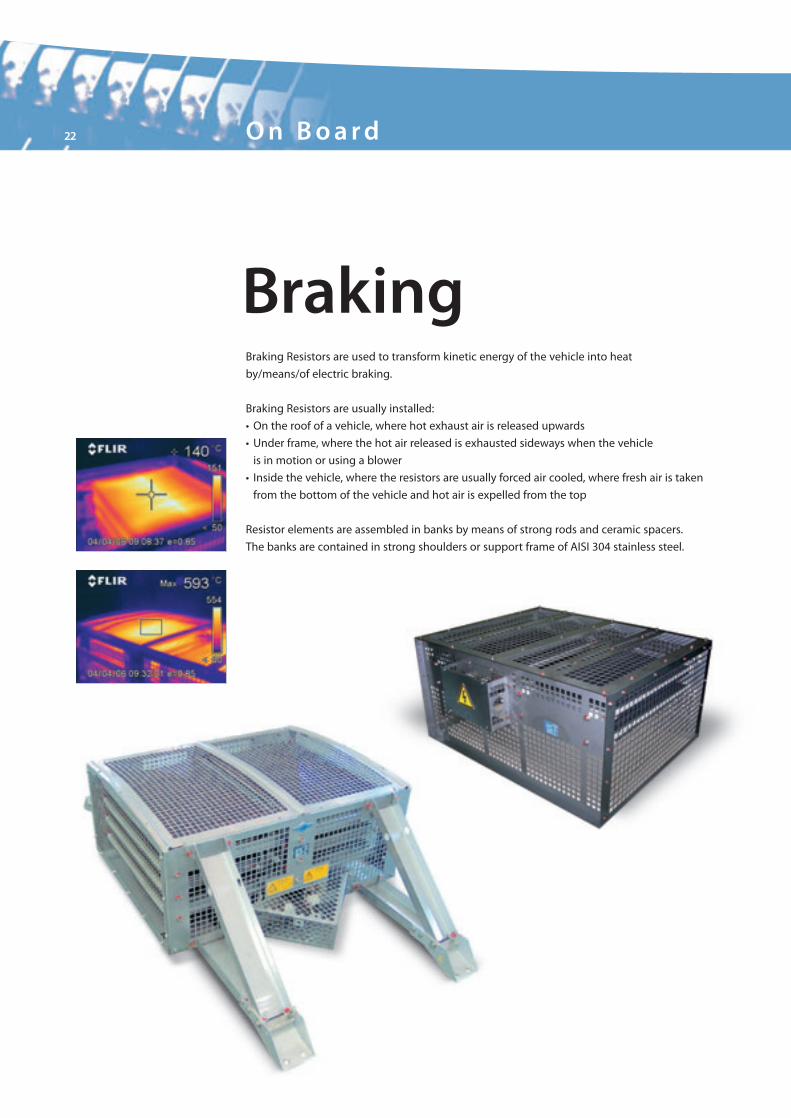
BrakingBraking Resistors are used to transform kinetic energy of the vehicle into heat
by/means/of electric braking.
Braking Resistors are usually installed:
• On the roof of a vehicle, where hot exhaust air is released upwards
• Under frame, where the hot air released is exhausted sideways when the vehicle
is in motion or using a blower
• Inside the vehicle, where the resistors are usually forced air cooled, where fresh air is taken
from the bottom of the vehicle and hot air is expelled from the top
Resistor elements are assembled in banks by means of strong rods and ceramic spacers.
The banks are contained in strong shoulders or support frame of AISI 304 stainless steel.
Brochure_Rail_Ok.qxd:Layout 1 25-09-2009 19:12 Pagina 22
23
Components for Rai l on Board Appl icat ion
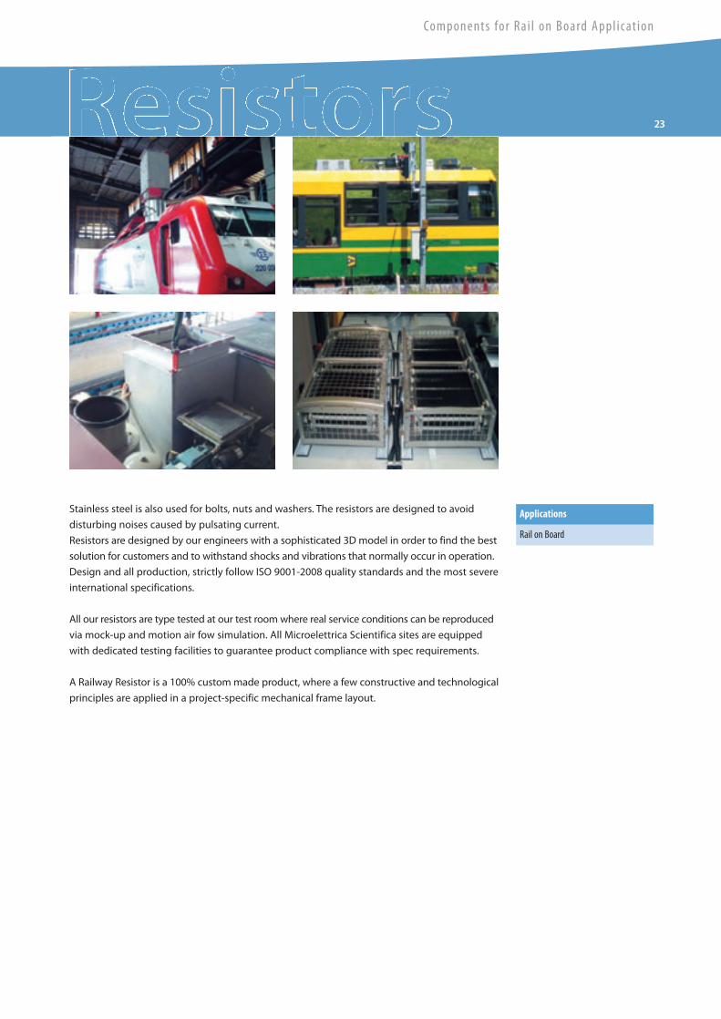
Stainless steel is also used for bolts, nuts and washers. The resistors are designed to avoid
disturbing noises caused by pulsating current.
Resistors are designed by our engineers with a sophisticated 3D model in order to find the best
solution for customers and to withstand shocks and vibrations that normally occur in operation.
Design and all production, strictly follow ISO 9001-2008 quality standards and the most severe
international specifications.
All our resistors are type tested at our test roomwhere real service conditions can be reproduced
via mock-up and motion air fow simulation. All Microelettrica Scientifica sites are equipped
with dedicated testing facilities to guarantee product compliance with spec requirements.
A Railway Resistor is a 100% custommade product, where a few constructive and technological
principles are applied in a project-specific mechanical frame layout.
Applications
Rail on Board
Brochure_Rail_Ok.qxd:Layout 1 25-09-2009 19:12 Pagina 23
24 On Boa rd
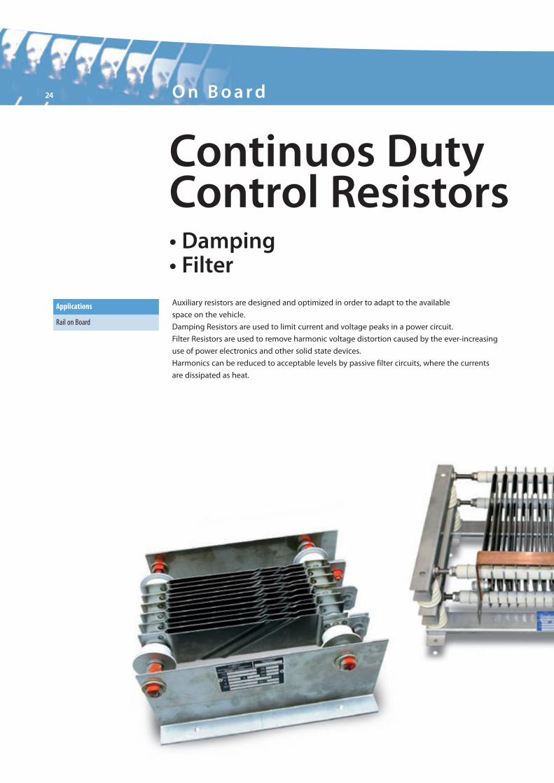
Continuos DutyControl Resistors• Damping• FilterAuxiliary resistors are designed and optimized in order to adapt to the available
space on the vehicle.
Damping Resistors are used to limit current and voltage peaks in a power circuit.
Filter Resistors are used to remove harmonic voltage distortion caused by the ever-increasing
use of power electronics and other solid state devices.
Harmonics can be reduced to acceptable levels by passive filter circuits, where the currents
are dissipated as heat.
Applications
Rail on Board
Brochure_Rail_Ok.qxd:Layout 1 25-09-2009 19:13 Pagina 24
Components for Rai l on Board Appl icat ion
25
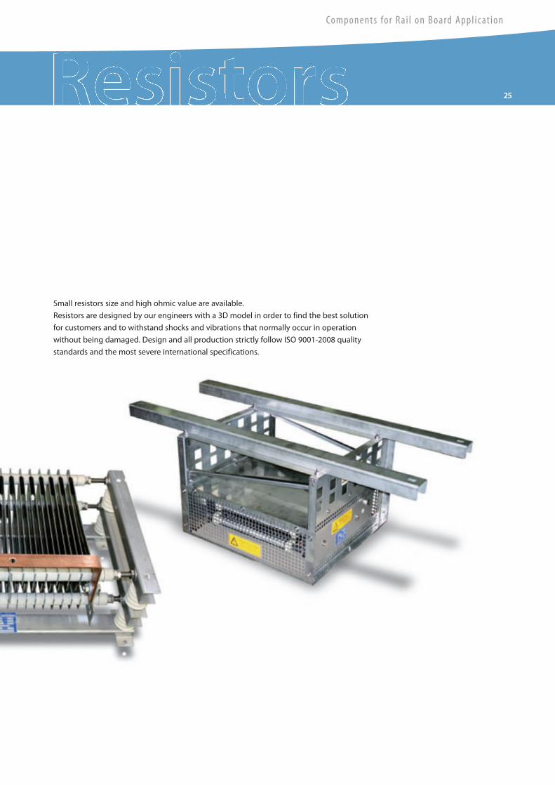
Small resistors size and high ohmic value are available.
Resistors are designed by our engineers with a 3D model in order to find the best solution
for customers and to withstand shocks and vibrations that normally occur in operation
without being damaged. Design and all production strictly follow ISO 9001-2008 quality
standards and the most severe international specifications.
Brochure_Rail_Ok.qxd:Layout 1 25-09-2009 19:13 Pagina 25
26 On Boa rd
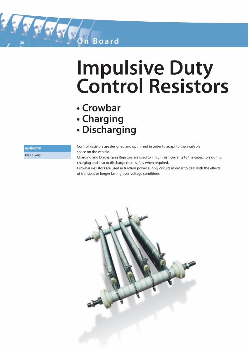
Impulsive DutyControl Resistors• Crowbar• Charging• DischargingControl Resistors are designed and optimized in order to adapt to the available
space on the vehicle.
Charging and Discharging Resistors are used to limit inrush currents to the capacitors during
charging and also to discharge them safely when required.
Crowbar Resistors are used in traction power supply circuits in order to deal with the effects
of transient or longer lasting over-voltage conditions.
Applications
Rail on Board
Brochure_Rail_Ok.qxd:Layout 1 25-09-2009 19:13 Pagina 26
Components for Rai l on Board Appl icat ion
27
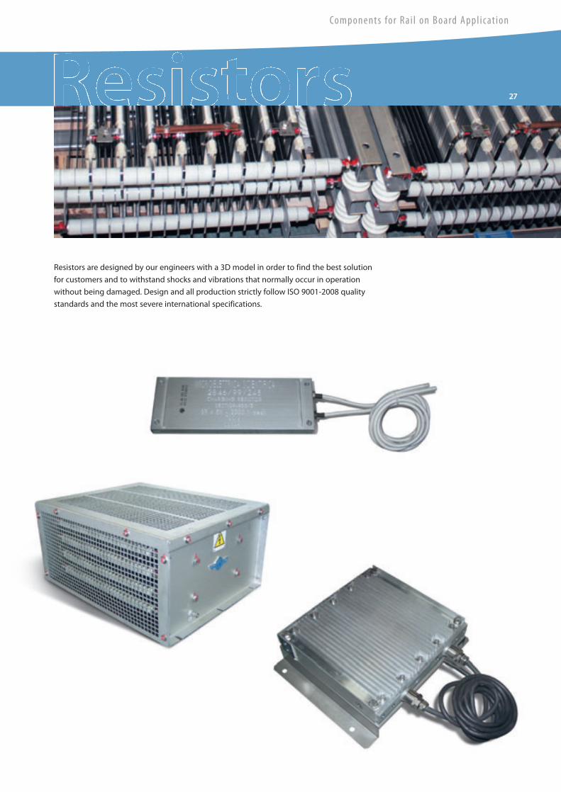
Resistors are designed by our engineers with a 3D model in order to find the best solution
for customers and to withstand shocks and vibrations that normally occur in operation
without being damaged. Design and all production strictly follow ISO 9001-2008 quality
standards and the most severe international specifications.
Brochure_Rail_Ok.qxd:Layout 1 25-09-2009 19:13 Pagina 27
28 Transduce r s
Eurometer
Maximum Speed of the rolling stock (on which the device is installed) 350 km/h
Storage temperature from -45°C to +80°C
Class of air temperature (EN50125-1) TX (from -45°C to +75°C)
Class of altitude range (EN50125-1) A1 (up to 1400m)
Relative humidity at 40°C 95%
Maximum solar radiation (EN50125-1) 1120W/m2
Protection level for terminal box (EN60529) IP 66 (RTL); IP 54 (IRTL)
Transvers acceleration (EN50125-1) GT1
Longitudinal acceleration GL1
Shock and vibrations EN 61373
Contamining fluids (60721-3-5) 5F3
Lateral wind withstand up to 25m/s, gusts up to 40 m/s 1s
Weight 18kg (RTL) + 7.5kg (IRTL)
Electrical Performances
The EUROMETER operates under the following four different power supply systems
(EN 50163 - Railway Systems Supply Voltages).
Electrification System/Nominal Voltage Working Range
DC 1.5 kV 900 ÷ 2.200 VDC
DC 3kV 2.000 ÷ 4.000 VDC
AC 15kV 16 2/3 Hz 10.000 ÷ 19.000 VAC
AC 25kV 50 Hz 17.000 ÷ 30.000 VAC
General Characteristics
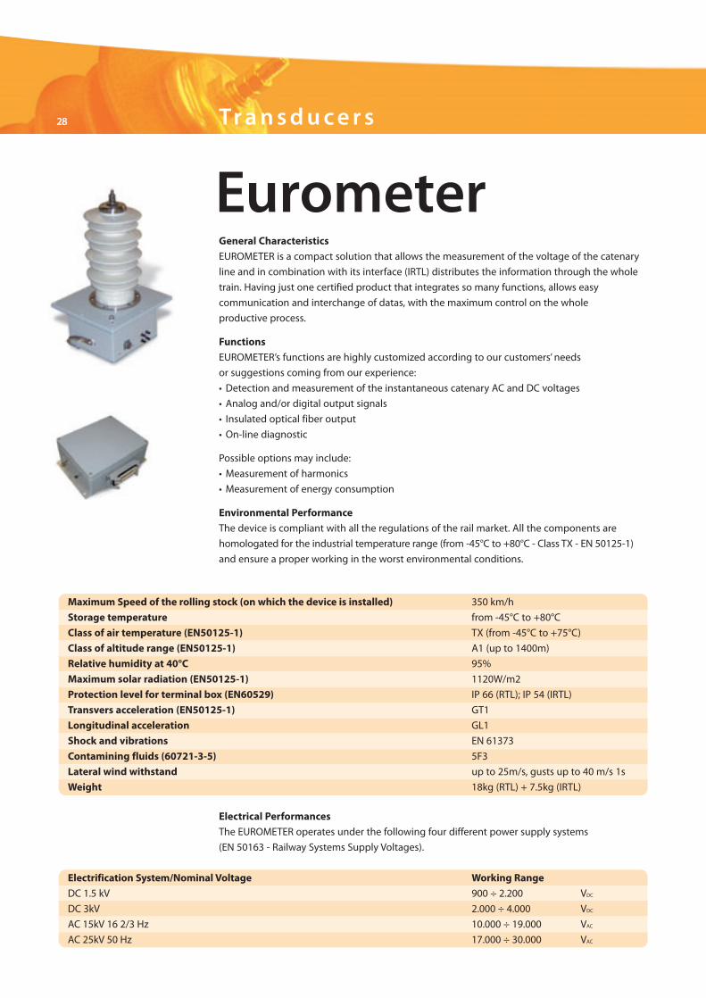
EUROMETER is a compact solution that allows the measurement of the voltage of the catenary
line and in combination with its interface (IRTL) distributes the information through the whole
train. Having just one certified product that integrates so many functions, allows easy
communication and interchange of datas, with the maximum control on the whole
productive process.
Functions
EUROMETER’s functions are highly customized according to our customers’ needs
or suggestions coming from our experience:
• Detection and measurement of the instantaneous catenary AC and DC voltages
• Analog and/or digital output signals
• Insulated optical fiber output
• On-line diagnostic
Possible options may include:
• Measurement of harmonics
• Measurement of energy consumption
Environmental Performance
The device is compliant with all the regulations of the rail market. All the components are
homologated for the industrial temperature range (from -45°C to +80°C - Class TX - EN 50125-1)
and ensure a proper working in the worst environmental conditions.
Brochure_Rail_Ok.qxd:Layout 1 25-09-2009 19:13 Pagina 28
Components for Rai l on Board Appl icat ion
29
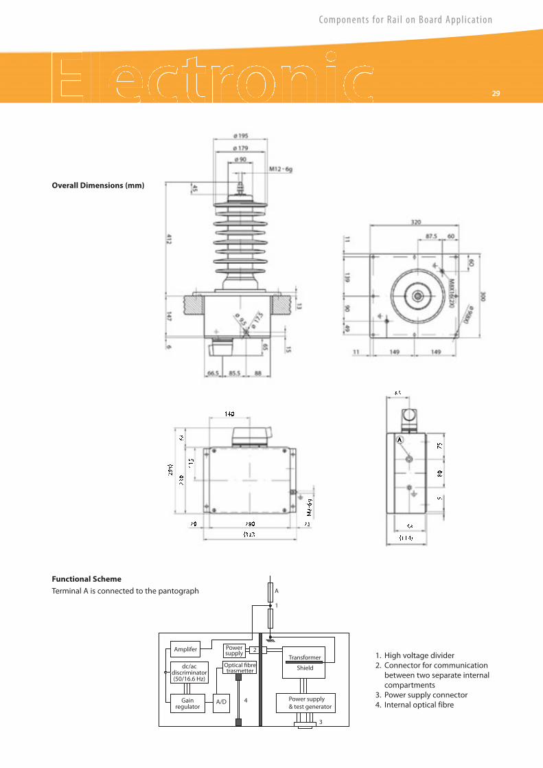
Overall Dimensions (mm)
AmpliferTransformer
Power supply& test generator
Shielddc/acdiscriminator(50/16.6 Hz)
Gainregulator
Optical fibretrasmetter
Powersupply
A/D
2
4
3
1
A
Functional Scheme
Terminal A is connected to the pantograph
1. High voltage divider2. Connector for communicationbetween two separate internalcompartments
3. Power supply connector4. Internal optical fibre
Brochure_Rail_Ok.qxd:Layout 1 25-09-2009 19:13 Pagina 29
30 Transduce r s
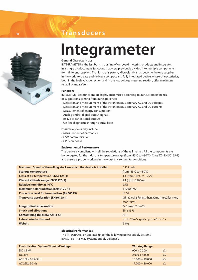
Integrameter
Maximum Speed of the rolling stock on which the device is installed 350 km/h
Storage temperature from -45°C to +80°C
Class of air temperature (EN50125-1) TX (from -45°C to +75°C)
Class of altitude range (EN50125-1) A1 (up to 1400m)
Relative humidity at 40°C 95%
Maximum solar radiation (EN50125-1) 1120W/m2
Protection level for terminal box (EN60529) IP 66
Transverse acceleration (EN50125-1) GT1 (2m/s2 for less than 50ms, 1m/s2 formore
than 50ms)
Longitudinal acceleration GL1 (max 2 m/s2)
Shock and vibrations EN 61373
Contamining fluids (60721-3-5) 5F3
Lateral wind withstand up to 25m/s, gusts up to 40 m/s 1s
Weight 58kg
Electrical PerformancesThe INTEGRAMETER operates under the following power supply systems(EN 50163 – Railway Systems Supply Voltages).
Electrification System/Nominal Voltage Working Range
DC 1.5 kV 900 ÷ 2.200 VDC
DC 3kV 2.000 ÷ 4.000 VDC
AC 15kV 16 2/3 Hz 10.000 ÷ 19.000 VAC
AC 25kV 50 Hz 17.000 ÷ 30.000 VAC
General CharacteristicsINTEGRAMETER is the last born in our line of on-board metering products and integratesin a single product many functions that were previously divided into multiple componentsfrom different suppliers. Thanks to this patent, Microelettrica has become the one supplierin the world to create and deliver a compact and fully integrated device whose characteristics,both in the high voltage section and in the low voltage metering section, offer maximumreliability and safety.
FunctionsINTEGRAMETER’s functions are highly customized according to our customers’ needsor suggestions coming from our experience:• Detection and measurement of the instantaneous catenary AC and DC voltages• Detection and measurement of the instantaneous catenary AC and DC currents• Measurement of energy consumption• Analog and/or digital output signals• RS422 or RS485 serial outputs• On-line diagnostic through optical fibre
Possible options may include:• Measurement of harmonics• GSM communication• GPRS on board
Environmental PerformanceThe device is compliant with all the regulations of the rail market. All the components arehomologated for the industrial temperature range (from -45°C to +80°C - Class TX - EN 50125-1)and ensure a proper working in the worst environmental conditions.
Brochure_Rail_Ok.qxd:Layout 1 25-09-2009 19:13 Pagina 30
Components for Rai l on Board Appl icat ion
31
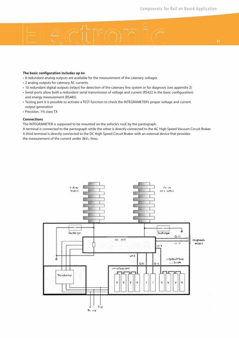
The basic configuration includes up to:• 8 redundant analog outputs are available for the measurement of the catenary voltages• 2 analog outputs for catenary AC currents• 10 redundant digital outputs (relays) for detection of the catenary line system or for diagnosis (see appendix 2)• Serial ports allow both a redundant serial transmission of voltage and current (RS422 in the basic configuration)and energy measurement (RS485)• Testing port it is possible to activate a TEST function to check the INTEGRAMETER’s proper voltage and currentoutput generation• Precision. 1% class TX
ConnectionsThe INTEGRAMETER is supposed to be mounted on the vehicle’s roof, by the pantograph.A terminal is connected to the pantograph while the other is directly connected to the AC High Speed Vacuum Circuit Braker.A third terminal is directly connected to the DC High Speed Circuit Braker with an external device that providesthe measurement of the current under 3kVDC lines.
Brochure_Rail_Ok.qxd:Layout 1 25-09-2009 19:13 Pagina 31
AutomaticDoorSystems
5070
710-
INB
-Sep
t200
9-BT
SAdv
.Tor
ino-
Prin
ted
byGR
AFAR
T
Official Microelettrica Scientifica dealer
E M C Tr a c t i o n S . r. l .
DC High SpeedCircuit BreakersIR2000IR6000IR6000MPIR6000MLIRAIR2000SVIR6000SV
DC SwitchgearsDIACLAD
Stationary ResistorsNeutral GroundingHarmonic FilterLoad BanksStarting/Braking/DischargeLine Test
On Board ResistorsBrakingContinuous Duty ControlImpulsive Duty Control
Res i s to r s
C o m p o n e n t s f o r D C S u b s t a t i o n A p p l i c a t i o n
RelaysA lineM lineMC lineN-DIN lineUltra line
SoftwareMSCom2
TransducersMHCO lineMHIT lineEurometerIntegrameter
E lec t ron i cSw i t ches
ContactorsLTHS lineLTC lineLTHH/LTE/LTP lineLTNS lineN line
DisconnectorsLTHM/P-U/D lineLTMP line
For information on salesnetwork and products please visit
www.microelettrica.com
C o m p o n e n t s f o r E n e r g y A p p l i c a t i o n
C o m p o n e n t s f o r I n d u s t r y A p p l i c a t i o n
Brochure_Rail_Ok.qxd:Layout 1 25-09-2009 19:45 Pagina 1