Embed Size (px)
Citation preview
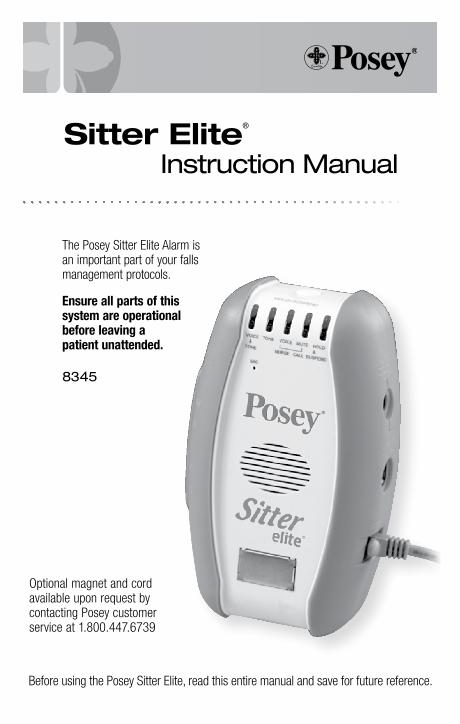
Optional magnet and cord available upon request by contacting Posey customer service at 1.800.447.6739
Sitter Elite®
Instruction Manual
Before using the Posey Sitter Elite, read this entire manual and save for future reference.
The Posey Sitter Elite Alarm is an important part of your falls management protocols.
Ensure all parts of this system are operational before leaving a patient unattended.
8345
www.posey.com 1.800.447.6739 Sitter Elite2
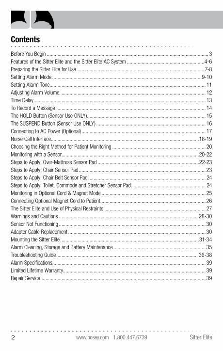
Contents
Before You Begin ......................................................................................................................... 3Features of the Sitter Elite and the Sitter Elite AC System ..........................................................4-6Preparing the Sitter Elite for Use ................................................................................................7-8Setting Alarm Mode ................................................................................................................9-10Setting Alarm Tone. .................................................................................................................... 11Adjusting Alarm Volume. ............................................................................................................ 12Time Delay ................................................................................................................................. 13To Record a Message ................................................................................................................ 14The HOLD Button (Sensor Use ONLY)......................................................................................... 15The SUSPEND Button (Sensor Use ONLY) .................................................................................. 16Connecting to AC Power (Optional) ............................................................................................. 17Nurse Call Interface...............................................................................................................18-19Choosing the Right Method for Patient Monitoring ...................................................................... 20Monitoring with a Sensor.......................................................................................................20-22Steps to Apply: Over-Mattress Sensor Pad ............................................................................22-23Steps to Apply: Chair Sensor Pad ............................................................................................... 23Steps to Apply: Chair Belt Sensor Pad ........................................................................................ 24Steps to Apply: Toilet, Commode and Stretcher Sensor Pad ........................................................ 24Monitoring in Optional Cord & Magnet Mode .............................................................................. 25Connecting Optional Magnet Cord to Patient ............................................................................... 26The Sitter Elite and Use of Physical Restraints ............................................................................ 27Warnings and Cautions ........................................................................................................ 28-30Sensor Not Functioning ..............................................................................................................30Adapter Cable Replacement .......................................................................................................30Mounting the Sitter Elite ........................................................................................................31-34Alarm Cleaning, Storage and Battery Maintenance .....................................................................35Troubleshooting Guide .......................................................................................................... 36-38Alarm Specifications................................................................................................................... 39Limited Lifetime Warranty........................................................................................................... 39Repair Service ............................................................................................................................ 39
www.posey.com 1.800.447.6739Sitter Elite 3
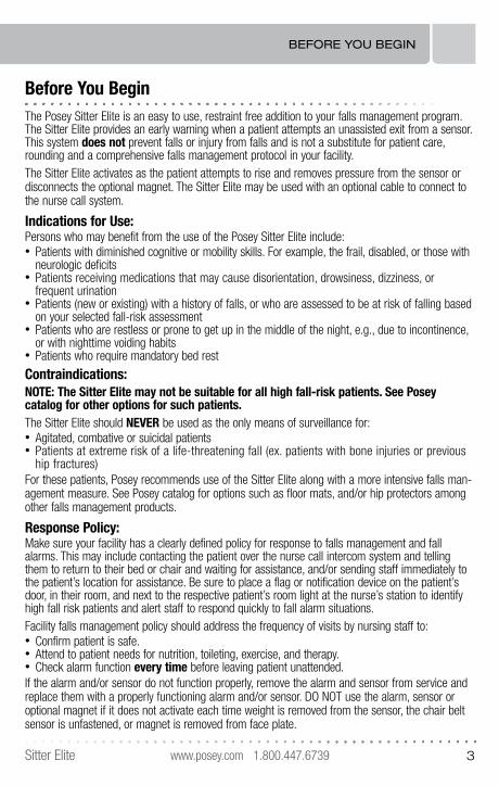
Before You BeginThe Posey Sitter Elite is an easy to use, restraint free addition to your falls management program. The Sitter Elite provides an early warning when a patient attempts an unassisted exit from a sensor. This system does not prevent falls or injury from falls and is not a substitute for patient care, rounding and a comprehensive falls management protocol in your facility.The Sitter Elite activates as the patient attempts to rise and removes pressure from the sensor or disconnects the optional magnet. The Sitter Elite may be used with an optional cable to connect to the nurse call system.
Indications for Use:Persons who may benefit from the use of the Posey Sitter Elite include:• Patients with diminished cognitive or mobility skills. For example, the frail, disabled, or those with
neurologic deficits• Patients receiving medications that may cause disorientation, drowsiness, dizziness, or
f requent urination• Patients (new or existing) with a history of falls, or who are assessed to be at risk of falling based
on your selected fall-risk assessment• Patients who are restless or prone to get up in the middle of the night, e.g., due to incontinence,
or with nighttime voiding habits• Patients who require mandatory bed rest
Contraindications:NOTE: The Sitter Elite may not be suitable for all high fall-risk patients. See Posey catalog for other options for such patients.The Sitter Elite should NEVER be used as the only means of surveillance for: • Agitated, combative or suicidal patients• Patients at extreme risk of a life-threatening fall (ex. patients with bone injuries or previous
hip fractures)For these patients, Posey recommends use of the Sitter Elite along with a more intensive falls man-agement measure. See Posey catalog for options such as floor mats, and/or hip protectors among other falls management products.
Response Policy:Make sure your facility has a clearly defined policy for response to falls management and fall alarms. This may include contacting the patient over the nurse call intercom system and telling them to return to their bed or chair and waiting for assistance, and/or sending staff immediately to the patient’s location for assistance. Be sure to place a flag or notification device on the patient’s door, in their room, and next to the respective patient’s room light at the nurse’s station to identify high fall risk patients and alert staff to respond quickly to fall alarm situations.Facility falls management policy should address the frequency of visits by nursing staff to: • Confirm patient is safe.• Attend to patient needs for nutrition, toileting, exercise, and therapy.• Check alarm function every time before leaving patient unattended.If the alarm and/or sensor do not function properly, remove the alarm and sensor from service and replace them with a properly functioning alarm and/or sensor. DO NOT use the alarm, sensor or optional magnet if it does not activate each time weight is removed from the sensor, the chair belt sensor is unfastened, or magnet is removed from face plate.
BEFORE YOU BEGIN
www.posey.com 1.800.447.6739 Sitter Elite4
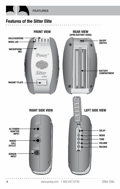
Features of the Sitter Elite
HOLD/SUSPEND
®
Sitter™
NURSECALL
SENSOR
9V
TONE
0
1
2
OFFON
DELAY
MODE
TONE
VOLUME
RECORD
AC POWER ADAPTER
INPUT
NURSECALL
OUTLET
SENSORINPUT
MODE LEDHOLD/SUSPEND
ON/OFFSWITCH
BATTERYCOMPARTMENT
MICROPHONEMIC
MAGNET PLATE
FRONT VIEW
RIGHT SIDE VIEW LEFT SIDE VIEW
REAR VIEW (OPEN BATTERY DOOR)
FEATURES
www.posey.com 1.800.447.6739Sitter Elite 5
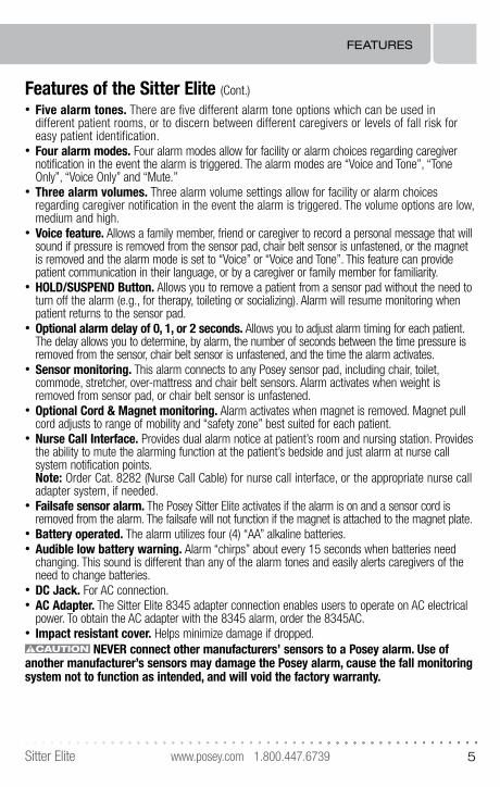
Features of the Sitter Elite (Cont.)• Five alarm tones. There are five different alarm tone options which can be used in
different patient rooms, or to discern between different caregivers or levels of fall risk for easy patient identification.
• Four alarm modes. Four alarm modes allow for facility or alarm choices regarding caregiver notification in the event the alarm is triggered. The alarm modes are “Voice and Tone”, “Tone Only”, “Voice Only” and “Mute.”
• Three alarm volumes. Three alarm volume settings allow for facility or alarm choices regarding caregiver notification in the event the alarm is triggered. The volume options are low, medium and high.
• Voice feature. Allows a family member, friend or caregiver to record a personal message that will sound if pressure is removed from the sensor pad, chair belt sensor is unfastened, or the magnet is removed and the alarm mode is set to “Voice” or “Voice and Tone”. This feature can provide patient communication in their language, or by a caregiver or family member for familiarity.
• HOLD/SUSPEND Button. Allows you to remove a patient from a sensor pad without the need to turn off the alarm (e.g., for therapy, toileting or socializing). Alarm will resume monitoring when patient returns to the sensor pad.
• Optional alarm delay of 0, 1, or 2 seconds. Allows you to adjust alarm timing for each patient. The delay allows you to determine, by alarm, the number of seconds between the time pressure is removed from the sensor, chair belt sensor is unfastened, and the time the alarm activates.
• Sensor monitoring. This alarm connects to any Posey sensor pad, including chair, toilet, commode, stretcher, over-mattress and chair belt sensors. Alarm activates when weight is removed from sensor pad, or chair belt sensor is unfastened.
• Optional Cord & Magnet monitoring. Alarm activates when magnet is removed. Magnet pull cord adjusts to range of mobility and “safety zone” best suited for each patient.
• Nurse Call Interface. Provides dual alarm notice at patient’s room and nursing station. Provides the ability to mute the alarming function at the patient’s bedside and just alarm at nurse call system notification points. Note: Order Cat. 8282 (Nurse Call Cable) for nurse call interface, or the appropriate nurse call adapter system, if needed.
• Failsafe sensor alarm. The Posey Sitter Elite activates if the alarm is on and a sensor cord is removed from the alarm. The failsafe will not function if the magnet is attached to the magnet plate.
• Battery operated. The alarm utilizes four (4) “AA” alkaline batteries. • Audible low battery warning. Alarm “chirps” about every 15 seconds when batteries need
changing. This sound is different than any of the alarm tones and easily alerts caregivers of the need to change batteries.
• DC Jack. For AC connection.• AC Adapter. The Sitter Elite 8345 adapter connection enables users to operate on AC electrical
power. To obtain the AC adapter with the 8345 alarm, order the 8345AC.• Impact resistant cover. Helps minimize damage if dropped.
NEVER connect other manufacturers’ sensors to a Posey alarm. Use of another manufacturer’s sensors may damage the Posey alarm, cause the fall monitoring system not to function as intended, and will void the factory warranty.
FEATURES
www.posey.com 1.800.447.6739 Sitter Elite6
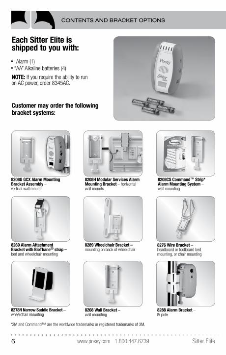
Each Sitter Elite is shipped to you with:• Alarm (1)• “AA” Alkaline batteries (4)
NOTE: If you require the ability to run on AC power, order 8345AC.
Customer may order the following bracket systems:
8208G GCX Alarm Mounting Bracket Assembly – vertical wall mounts
8269 Alarm Attachment Bracket with BioThane® strap – bed and wheelchair mounting
8278N Narrow Saddle Bracket – wheelchair mounting
8208 Wall Bracket – wall mounting
8288 Alarm Bracket – IV pole
8289 Wheelchair Bracket –mounting on back of wheelchair
8276 Wire Bracket – headboard or footboard bed mounting, or chair mounting
8208H Modular Services Alarm Mounting Bracket – horizontal wall mounts
8208CS Command™ Strip* Alarm Mounting System – wall mounting
*3M and Command™ are the worldwide trademarks or registered trademarks of 3M.
CONTENTS AND BRACKET OPTIONS
www.posey.com 1.800.447.6739Sitter Elite 7
Preparing the Sitter Elite for Use
Battery Installation:The battery-operated Sitter Elite is portable and long lasting. Fresh alkaline batteries have an estimated life of 30 days of daily use. Actual life depends on alarm mode, tone and volume you select.
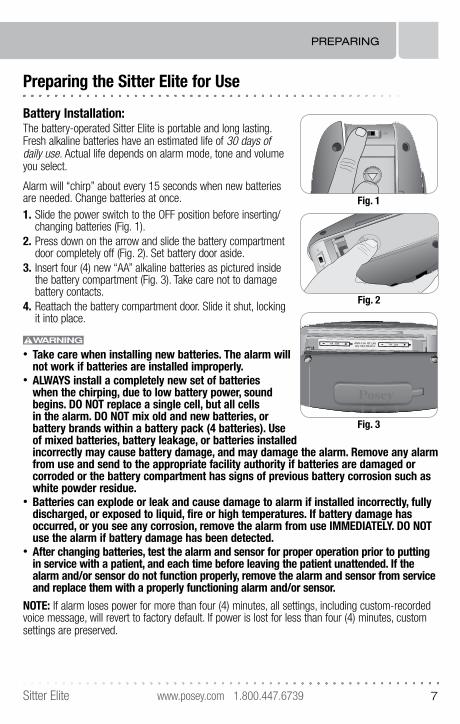
Alarm will “chirp” about every 15 seconds when new batteries are needed. Change batteries at once. 1. Slide the power switch to the OFF position before inserting/
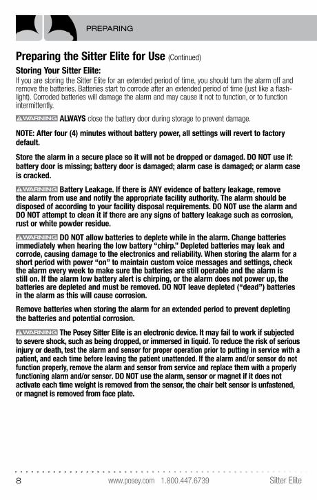
changing batteries (Fig. 1).2. Press down on the arrow and slide the battery compartment
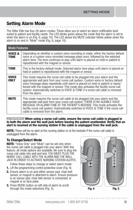
door completely off (Fig. 2). Set battery door aside.3. Insert four (4) new “AA” alkaline batteries as pictured inside
the battery compartment (Fig. 3). Take care not to damage battery contacts.
4. Reattach the battery compartment door. Slide it shut, locking it into place.
• Take care when installing new batteries. The alarm will not work if batteries are installed improperly.
• ALWAYS install a completely new set of batteries when the chirping, due to low battery power, sound begins. DO NOT replace a single cell, but all cells in the alarm. DO NOT mix old and new batteries, or battery brands within a battery pack (4 batteries). Use of mixed batteries, battery leakage, or batteries installed incorrectly may cause battery damage, and may damage the alarm. Remove any alarm from use and send to the appropriate facility authority if batteries are damaged or corroded or the battery compartment has signs of previous battery corrosion such as white powder residue.
• Batteries can explode or leak and cause damage to alarm if installed incorrectly, fully discharged, or exposed to liquid, fire or high temperatures. If battery damage has occurred, or you see any corrosion, remove the alarm from use IMMEDIATELY. DO NOT use the alarm if battery damage has been detected.
• After changing batteries, test the alarm and sensor for proper operation prior to putting in service with a patient, and each time before leaving the patient unattended. If the alarm and/or sensor do not function properly, remove the alarm and sensor from service and replace them with a properly functioning alarm and/or sensor.
NOTE: If alarm loses power for more than four (4) minutes, all settings, including custom-recorded voice message, will revert to factory default. If power is lost for less than four (4) minutes, custom settings are preserved.
ON
OFF
Fig. 2
AA
SIZ
E
AA
SIZ
EA
A S
IZE
AA
SIZ
EQ
ty 4A
A A
lkalin
e
ANSI-15AIEC-LRO
OFF
PRESS
Fig. 1
AA SIZE AA SIZE
OFFON
ANSI-15A IEC-LR6Qty 4AA Alkaline
DELAY
MODE
TONE
VOLUM
RECOR
Fig. 3
PREPARING
www.posey.com 1.800.447.6739 Sitter Elite8
Preparing the Sitter Elite for Use (Continued)
Storing Your Sitter Elite:If you are storing the Sitter Elite for an extended period of time, you should turn the alarm off and remove the batteries. Batteries start to corrode after an extended period of time (just like a flash-light). Corroded batteries will damage the alarm and may cause it not to function, or to function intermittently.
ALWAYS close the battery door during storage to prevent damage.
NOTE: After four (4) minutes without battery power, all settings will revert to factory default.
Store the alarm in a secure place so it will not be dropped or damaged. DO NOT use if: battery door is missing; battery door is damaged; alarm case is damaged; or alarm case is cracked.
Battery Leakage. If there is ANY evidence of battery leakage, remove the alarm from use and notify the appropriate facility authority. The alarm should be disposed of according to your facility disposal requirements. DO NOT use the alarm and DO NOT attempt to clean it if there are any signs of battery leakage such as corrosion, rust or white powder residue.
DO NOT allow batteries to deplete while in the alarm. Change batteries immediately when hearing the low battery “chirp.” Depleted batteries may leak and corrode, causing damage to the electronics and reliability. When storing the alarm for a short period with power “on” to maintain custom voice messages and settings, check the alarm every week to make sure the batteries are still operable and the alarm is still on. If the alarm low battery alert is chirping, or the alarm does not power up, the batteries are depleted and must be removed. DO NOT leave depleted (“dead”) batteries in the alarm as this will cause corrosion.
Remove batteries when storing the alarm for an extended period to prevent depleting the batteries and potential corrosion.
The Posey Sitter Elite is an electronic device. It may fail to work if subjected to severe shock, such as being dropped, or immersed in liquid. To reduce the risk of serious injury or death, test the alarm and sensor for proper operation prior to putting in service with a patient, and each time before leaving the patient unattended. If the alarm and/or sensor do not function properly, remove the alarm and sensor from service and replace them with a properly functioning alarm and/or sensor. DO NOT use the alarm, sensor or magnet if it does not activate each time weight is removed from the sensor, the chair belt sensor is unfastened, or magnet is removed from face plate.
PREPARING
www.posey.com 1.800.447.6739Sitter Elite 9
Setting Alarm Mode
The Sitter Elite has four (4) alarm modes. These allow you to select an alarm notification best suited to patient and facility needs. The LED blinks green above the mode that the alarm is set to when the alarm is on (Fig. 6, page 10). The LED above the MUTE indicator blinks yellow when the alarm is on and in “Mute” mode (Fig. 6, page 10).
Mode Features
VOICE & TONE
Depending on whether a custom voice recording is made, either the factory default voice or a custom voice recorded message plays once, followed by the selected alarm tone. The tone continues to play until alarm is placed on hold or patient is repositioned with the magnet or sensor.
TONE This is the factory default mode. Selected alarm tone plays until alarm is placed on hold or patient is repositioned with the magnet or sensor.
VOICE ONLY
This mode requires the nurse call cable to be plugged into your alarm and the appropriate wall jack from your nurse call system. Custom voice or factory default voice message plays repeatedly until alarm is placed on hold or patient is reposi-tioned with the magnet or sensor. This mode also activates the facility nurse call system. Automatically switches to VOICE & TONE if a nurse call cable is removed from the alarm.
MUTE This mode requires the nurse call cable to be plugged into your alarm and the appropriate wall jack from your nurse call system. THERE IS NO AUDIBLE VOICE MESSAGE OR ALARM TONE AT THE PATIENT’S BEDSIDE. This mode activates the facility nurse call system. Automatically switches to VOICE & TONE if the nurse call cable is removed from the alarm.
When using a nurse call cable, ensure the nurse call cable is plugged in to both the alarm and the wall jack before leaving the patient unattended. Verify that an alert is received at the nursing station if the cable is unplugged from the wall jack.
NOTE: There will be no alert at the nursing station or at the bedside if the nurse call cable is unplugged from the alarm.
To Change/Select ModeNOTE: “Voice Only” and “Mute” can be set only when the nurse call cable is plugged into your alarm. With this feature, all mode options are available. Be sure to plug the nurse call cable into wall and test. YOU MUST PLUG THE NURSE CALL CABLE INTO THE ALARM AND THE WALL JACK IN ORDER TO ACTIVATE NURSING STATION ALERTS.
Follow these steps to change or select alarm mode:1. Lift the programming control protective cover (Fig. 4).2. Ensure alarm is on and either sensor pad, chair belt
sensor, or magnet is attached to alarm. Ensure pressure is on sensor pad, chair belt sensor is connected, or magnet is on face plate.
3. Press MODE button on left side of alarm to scroll through the mode selections (Fig. 5).
TONE
Fig. 4
TONE
0
1
2
Fig. 5
SETTING MODE
www.posey.com 1.800.447.6739 Sitter Elite10
SETTING MODE
Setting Alarm Mode (Continued)
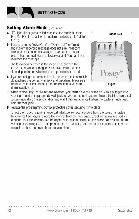
4. LED light blinks green to indicate selected mode is in use (Fig. 6). LED blinks yellow if the alarm mode is set to “Mute” (Fig. 6).
5. If alarm is set to “Voice Only” or “Voice and Tone” mode and custom recorded message does not play, re-record message. If this does not work, remove batteries for at least 1 hour to reset alarm to factory default. You can then re-record the message.The last option selected is the mode utilized when the sensor is activated or magnet is removed from the face plate, depending on which monitoring mode is selected.
6. If you are using the nurse call cable, check to make sure it is plugged into the correct wall jack and the alarm. Make sure the mode you select alerts at the nurse’s station when the alarm is activated.
7. When “Voice Only” or “Mute” are selected, you must have the nurse call cable plugged into your alarm and the appropriate wall jack for your nurse call system. Ensure that the nurse call system indicators (nursing station and wall light) are activated when the cable is unplugged from the wall jack.
8. Replace the programming control protective cover, securing it into place.To test the modes requiring nurse call interface, remove pressure from the sensor, unfasten the chair belt sensor, or remove the magnet from the face plate. Check at the nurse’s station to ensure that the indicator for the appropriate patient alarms on the nurse call system and the wall light, indicating there is no pressure on the sensor, chair belt sensor is unfastened, or the magnet has been removed from the face plate.
HOLD/SUSPEND
®
Sitter™
Mode LED
Fig. 6
www.posey.com 1.800.447.6739Sitter Elite 11
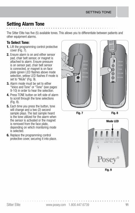
Setting Alarm Tone
The Sitter Elite has five (5) available tones. This allows you to differentiate between patients and other equipment alarms.
To Select Tone:1. Lift the programming control protective
cover (Fig. 7). 2. Ensure alarm is on and either sensor
pad, chair belt sensor, or magnet is attached to alarm. Ensure pressure is on sensor pad, chair belt sensor is connected, or magnet is on face plate (green LED flashes above mode selection, yellow LED flashes if mode is set to “Mute” (Fig. 9).
3. Alarm mode must be set to either “Voice and Tone” or “Tone” (see pages 9-10) in order to hear the selection.
4. Press TONE button on left side of alarm to scroll through the tone selections (Fig. 8).
5. Each time you press the button, tone will change and a two (2) second sample plays. The last sample heard is the tone utilized for the alarm when the sensor is activated or the magnet is removed from the face plate, depending on which monitoring mode is selected.
6. Replace the programming control protective cover, securing it into place.
TONE
Fig. 7
TONE
0
1
2
Fig. 8
HOLD/SUSPEND
®
Sitter™
Mode LED
Fig. 9
SETTING TONE
www.posey.com 1.800.447.6739 Sitter Elite12
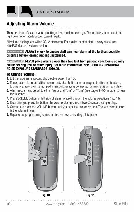
Adjusting Alarm Volume
There are three (3) alarm volume settings: low, medium and high. These allow you to select the right volume for facility and/or patient needs.
All volume settings are within OSHA standards. For maximum staff alert in noisy areas, use HIGHEST (loudest) volume setting.
ALWAYS check to ensure staff can hear alarm at the furthest possible distance before leaving patient unattended.
NEVER place alarm closer than two feet from patient’s ear. Doing so may cause hearing loss or other injury. For more information, see: OSHA OCCUPATIONAL NOISE EXPOSURE STANDARDS 1910.95.
To Change Volume:1. Lift the programming control protective cover (Fig. 10).2. Ensure alarm is on and either sensor pad, chair belt sensor, or magnet is attached to alarm.
Ensure pressure is on sensor pad, chair belt sensor is connected, or magnet is on face plate.3. Alarm mode must be set to either “Voice and Tone” or “Tone” (see pages 9-10) in order to hear
the selection.4. Press VOLUME button on left side of alarm to scroll through the volume selections (Fig. 11).5. Each time you press the button, the volume changes and a two (2) second sample plays.6. Continue to press the VOLUME button until you hear the desired volume. The last sample heard
is the volume in use.7. Replace the programming control protective cover, securing it into place.
TONE
Fig. 10
TONE
0
1
2
Fig. 11
ADJUSTING VOLUME
www.posey.com 1.800.447.6739Sitter Elite 13
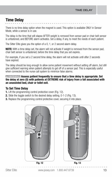
Time Delay
There is no time delay option when the magnet is used. This option is available ONLY in Sensor Mode, while a sensor is in use.
The delay is the time that will elapse AFTER weight is removed from sensor pad or chair belt sensor is unfastened, and BEFORE alarm activates. Set a delay, if any, to meet the needs of each patient.
The Sitter Elite gives you the option of a 0, 1, or 2 second alarm delay.
NOTE: With a time delay set, the alarm will not activate if weight is removed from the sensor pad, chair belt sensor is unfastened, before the time delay that you set expires.
For example, if you set a 2 second time delay, the alarm will not activate until after 2 seconds have expired.
The delay should be long enough to allow some patient movement without setting off alarm, but still give sufficient warning when patient attempts to get off of a sensor pad. This is especially useful when connected to the nurse call system to minimize false alarms.
Assess patient frequently to ensure that a time delay is appropriate. Set the delay at zero (0) with patients at EXTREME risk of injury from a fall associated with an unassisted bed, chair or toilet exit.
To Set Time Delay1. Lift the programming control protective cover (Fig. 12).2. Slide the toggle switch to the desired delay setting, 0-1-2 (Fig. 13).3. Replace the programming control protective cover, securing it into place.
TONE
Fig. 12
TONE
0
1
2
Fig. 13
TIME DELAY
www.posey.com 1.800.447.6739 Sitter Elite14
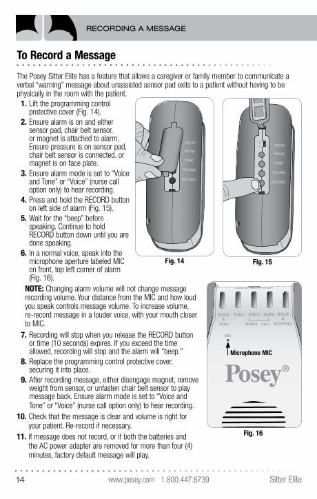
To Record a Message
The Posey Sitter Elite has a feature that allows a caregiver or family member to communicate a verbal “warning” message about unassisted sensor pad exits to a patient without having to be physically in the room with the patient.
1. Lift the programming control protective cover (Fig. 14).
2. Ensure alarm is on and either sensor pad, chair belt sensor, or magnet is attached to alarm. Ensure pressure is on sensor pad, chair belt sensor is connected, or magnet is on face plate.
3. Ensure alarm mode is set to “Voice and Tone” or “Voice” (nurse call option only) to hear recording.
4. Press and hold the RECORD button on left side of alarm (Fig. 15).
5. Wait for the “beep” before speaking. Continue to hold RECORD button down until you are done speaking.
6. In a normal voice, speak into the microphone aperture labeled MIC on front, top left corner of alarm (Fig. 16).
NOTE: Changing alarm volume will not change message recording volume. Your distance from the MIC and how loud you speak controls message volume. To increase volume, re-record message in a louder voice, with your mouth closer to MIC.
7. Recording will stop when you release the RECORD button or time (10 seconds) expires. If you exceed the time allowed, recording will stop and the alarm will “beep.”
8. Replace the programming control protective cover, securing it into place.
9. After recording message, either disengage magnet, remove weight from sensor, or unfasten chair belt sensor to play message back. Ensure alarm mode is set to “Voice and Tone” or “Voice” (nurse call option only) to hear recording.
10. Check that the message is clear and volume is right for your patient. Re-record if necessary.
11. If message does not record, or if both the batteries and the AC power adapter are removed for more than four (4) minutes, factory default message will play.
TONE
Fig. 14
TONE
0
1
2
Fig. 15
HOLD/SUSPEND
®
Sitter™
Fig. 16
Microphone MIC
RECORDING A MESSAGE
www.posey.com 1.800.447.6739Sitter Elite 15
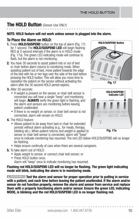
The HOLD Button (Sensor Use ONLY)
NOTE: HOLD feature will not work unless sensor is plugged into the alarm.
To Place the Alarm on HOLD:1. Press HOLD/SUSPEND button on the top of alarm (Fig. 17)
for 1 second. The HOLD/SUSPEND LED will begin flashing RED at 3-second intervals if the alarm is in HOLD mode (Fig. 17a). The green LED indicating mode will continue to flash, but the alarm is not monitoring.
2. You have 30 seconds to assist patient into or out of bed or chair before alarm returns to monitoring mode. When assisting patient out of bed, move patient towards the edge of the bed with his or her legs over the side of the bed before pressing the HOLD button. This will allow you more time to reposition the patient on the sensor without activating the alarm after the 30 second HOLD period expires.
3. After 30 seconds:• If weight is present on the sensor, or chair belt sensor is
connected you will hear a single “beep” and monitoring will begin. ALWAYS verify the green light is flashing, and the alarm and sensors are monitoring before leaving patient unattended.
• If there is no weight on sensor, or chair belt sensor is not connected, alarm will remain on HOLD.
4. The HOLD feature:• Allows patient to be away from bed or chair for extended
periods without alarm activating (e.g., for meals, therapy, toileting etc.). When patient returns and weight is applied to sensor or chair belt sensor is connected, alarm will “beep” once to indicate monitoring has resumed. The red LED below HOLD/SUSPEND will no longer be flashing.
• Helps ensure continuity of care when there are several caregivers.5. To take alarm out of HOLD:
• Apply weight to sensor, or connect chair belt sensor; or• Press HOLD button once.
Alarm will “beep” once to indicate monitoring has resumed. Flashing red HOLD/SUSPEND LED will no longer be flashing. The green light indicating mode will blink, indicating the alarm is in monitoring mode.
Test the alarm and sensor for proper operation prior to putting in service with a patient, and each time before leaving the patient unattended. If the alarm and/or sensor do not function properly, remove the alarm and sensor from service and replace them with a properly functioning alarm and/or sensor. Ensure the green LED, indicating MODE, is blinking and the red HOLD/SUSPEND LED is no longer flashing red.
VOICE&
TONE
TONEMUTE
VOICENURSE CALLMIC
HOLD&
SUSPEND
HOLD/SUSPEND
HOLD/SUSPEND Button
Fig. 17
HOLD/SUSPEND
®
Sitter™
HOLD/SUSPENDIndicator LED
Fig. 17a
THE HOLD BUTTON
www.posey.com 1.800.447.6739 Sitter Elite16
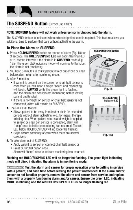
The SUSPEND Button (Sensor Use ONLY)
NOTE: SUSPEND feature will not work unless sensor is plugged into the alarm.
The SUSPEND feature is indicated when extended patient care is required. This feature allows you additional time to perform that care without activating the alarm.
To Place the Alarm on SUSPEND:1. Press HOLD/SUSPEND button on the top of alarm (Fig. 18) for
3 seconds. The HOLD/SUSPEND LED will begin flashing RED at ½-second intervals if the alarm is in SUSPEND mode (Fig. 18a). The green LED indicating mode will continue to flash, but the alarm is not monitoring.
2. You have 5 minutes to assist patient into or out of bed or chair before alarm returns to monitoring mode.
3. After 5 minutes:• If weight is present on the sensor, or chair belt sensor is
connected you will hear a single “beep” and monitoring will begin. ALWAYS verify the green light is flashing, and the alarm and sensors are monitoring before leaving patient unattended.
• If there is no weight on sensor, or chair belt sensor is not connected, alarm will remain on SUSPEND.
4. The SUSPEND feature:• Allows patient to be away from bed or chair for extended
periods without alarm activating (e.g., for meals, therapy, toileting etc.). When patient returns and weight is applied to sensor, or chair belt sensor is connected, alarm will “beep” once to indicate monitoring has resumed. The red LED below HOLD/SUSPEND will no longer be flashing.
• Helps ensure continuity of care when there are several caregivers.
5. To take alarm out of SUSPEND:• Apply weight to sensor, or connect chair belt sensor, or• Press SUSPEND button once.
Alarm will “beep” once to indicate monitoring has resumed.
Flashing red HOLD/SUSPEND LED will no longer be flashing. The green light indicating mode will blink, indicating the alarm is in monitoring mode.
Test the alarm and sensor for proper operation prior to putting in service with a patient, and each time before leaving the patient unattended. If the alarm and/or sensor do not function properly, remove the alarm and sensor from service and replace them with a properly functioning alarm and/or sensor. Ensure the green LED, indicating MODE, is blinking and the red HOLD/SUSPEND LED is no longer flashing red.
VOICE&
TONE
TONEMUTE
VOICENURSE CALLMIC
HOLD&
SUSPEND
HOLD/SUSPEND
HOLD/SUSPEND Button
Fig. 18
HOLD/SUSPEND
®
Sitter™
HOLD/SUSPENDIndicator LED
Fig. 18a
THE SUSPEND BUTTON
www.posey.com 1.800.447.6739Sitter Elite 17
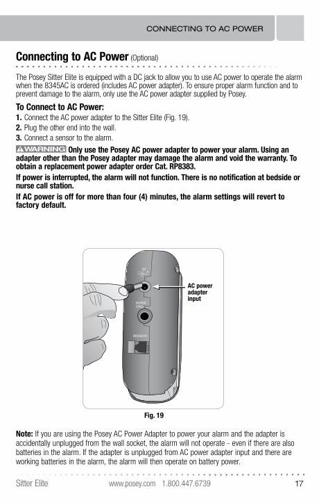
Connecting to AC Power (Optional)
The Posey Sitter Elite is equipped with a DC jack to allow you to use AC power to operate the alarm when the 8345AC is ordered (includes AC power adapter). To ensure proper alarm function and to prevent damage to the alarm, only use the AC power adapter supplied by Posey.
To Connect to AC Power:1. Connect the AC power adapter to the Sitter Elite (Fig. 19).2. Plug the other end into the wall.3. Connect a sensor to the alarm.
Only use the Posey AC power adapter to power your alarm. Using an adapter other than the Posey adapter may damage the alarm and void the warranty. To obtain a replacement power adapter order Cat. RP8383.If power is interrupted, the alarm will not function. There is no notification at bedside or nurse call station.If AC power is off for more than four (4) minutes, the alarm settings will revert to factory default.
NURSECALL
SENSOR
9V
AC power adapterinput
Fig. 19
Note: If you are using the Posey AC Power Adapter to power your alarm and the adapter is accidentally unplugged from the wall socket, the alarm will not operate - even if there are also batteries in the alarm. If the adapter is unplugged from AC power adapter input and there are working batteries in the alarm, the alarm will then operate on battery power.
CONNECTING TO AC POWER
www.posey.com 1.800.447.6739 Sitter Elite18
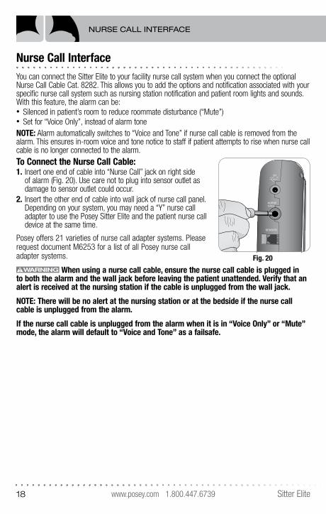
Nurse Call InterfaceYou can connect the Sitter Elite to your facility nurse call system when you connect the optional Nurse Call Cable Cat. 8282. This allows you to add the options and notification associated with your specific nurse call system such as nursing station notification and patient room lights and sounds. With this feature, the alarm can be:• Silenced in patient’s room to reduce roommate disturbance (“Mute”)• Set for “Voice Only”, instead of alarm toneNOTE: Alarm automatically switches to “Voice and Tone” if nurse call cable is removed from the alarm. This ensures in-room voice and tone notice to staff if patient attempts to rise when nurse call cable is no longer connected to the alarm.To Connect the Nurse Call Cable:1. Insert one end of cable into “Nurse Call” jack on right side
of alarm (Fig. 20). Use care not to plug into sensor outlet as damage to sensor outlet could occur.
2. Insert the other end of cable into wall jack of nurse call panel. Depending on your system, you may need a “Y” nurse call adapter to use the Posey Sitter Elite and the patient nurse call device at the same time.
Posey offers 21 varieties of nurse call adapter systems. Please request document M6253 for a list of all Posey nurse call adapter systems.
When using a nurse call cable, ensure the nurse call cable is plugged in to both the alarm and the wall jack before leaving the patient unattended. Verify that an alert is received at the nursing station if the cable is unplugged from the wall jack.
NOTE: There will be no alert at the nursing station or at the bedside if the nurse call cable is unplugged from the alarm.
If the nurse call cable is unplugged from the alarm when it is in “Voice Only” or “Mute” mode, the alarm will default to “Voice and Tone” as a failsafe.
NURSECALL
SENSOR
9V
Fig. 20
NURSE CALL INTERFACE
www.posey.com 1.800.447.6739Sitter Elite 19
Nurse Call Interface (Continued)
FOR SAFE USE WITH NURSE CALL CABLE:• DO NOT stretch or strain cable to avoid possible damage and possible malfunction.• DO NOT attach cable to moving parts of the bed or chair that will cause strain or
damage if the bed or chair is repositioned.• ALWAYS position the cable so that moving parts (side rails, wheels, etc.) will not cause
strain or damage the cable.• DO NOT run over the cable with carts or equipment.• DO NOT wrap the cable tightly during storage.• ALWAYS remove the cable by pulling on the plug. DO NOT pull on the cable.• ALWAYS secure the cable out of the way so it will not be a tripping hazard.• ALWAYS test alarm and nurse call function prior to leaving the patient unattended.
Activate the alarm (remove pressure from sensor, unfasten chair belt sensor, or remove magnet from face plate) and make sure the nurse call light for the proper bed and room activate in the hall and at the nurse’s station.
• DO NOT use the alarm, sensor or magnet if it does not activate each time weight is removed from the sensor, the chair belt sensor is unfastened, or magnet is removed from face plate. Replace alarm and sensor with working units and retest before leaving the patient unattended.
NURSE CALL INTERFACE
www.posey.com 1.800.447.6739 Sitter Elite20
Choosing the Right Method for Patient Monitoring
The Sitter Elite allows you to monitor a patient in sensor mode or optional cord & magnet mode. NOTE: Both methods CANNOT be used at the same time. Select the mode best suited to patient needs and risk assessment. This will vary for each patient based on:
• Activity level• Dexterity • Nighttime toileting habits• Cognition• and other possible factors
Consult a qualified medical authority if you have questions about the right option for your patient.
The Posey Sitter Elite is an electronic device. It may fail to work if subjected to severe shock, such as being dropped, or immersed in liquid. To reduce the risk of serious injury or death, test the alarm and sensor for proper operation prior to putting in service with a patient, and each time before leaving the patient unattended. If the alarm and/or sensor do not function properly, remove the alarm and sensor from service and replace them with a properly functioning alarm and/or sensor. DO NOT use the alarm, sensor or magnet if it does not activate each time weight is removed from the sensor, the chair belt sensor is unfastened, or magnet is removed from face plate (see pages 20-22).
Monitoring with a Sensor
Magnet and Sensor Modes CANNOT be used at the same time. A connected sensor will ALWAYS override the magnet. If you are using a sensor pad for monitoring with the alarm, ALWAYS remove the magnet and store it in a safe place while the sensor is being used.
IF YOU ARE MONITORING WITH THE SENSOR FEATURE AND THE MAGNET IS ATTACHED, THE ALARM WILL NOT ACTIVATE AS A FAILSAFE IF THE SENSOR CORD IS REMOVED.
The following instructions will help you set up and safely use the Sitter Elite with a sensor.
TIPS TO PROTECT SENSORS FROM DAMAGETo avoid inconvenience to staff and patients, and to protect sensors from damage, you should follow these steps:
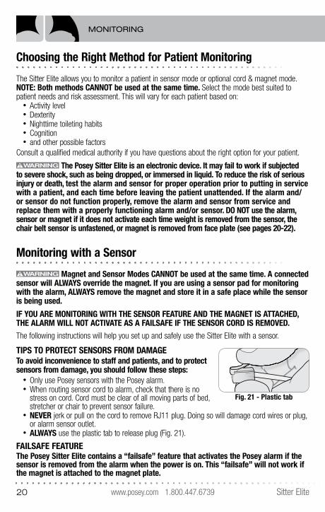
• Only use Posey sensors with the Posey alarm.• When routing sensor cord to alarm, check that there is no
stress on cord. Cord must be clear of all moving parts of bed, stretcher or chair to prevent sensor failure.
• NEVER jerk or pull on the cord to remove RJ11 plug. Doing so will damage cord wires or plug, or alarm sensor outlet.
• ALWAYS use the plastic tab to release plug (Fig. 21).
FAILSAFE FEATUREThe Posey Sitter Elite contains a “failsafe” feature that activates the Posey alarm if the sensor is removed from the alarm when the power is on. This “failsafe” will not work if the magnet is attached to the magnet plate.
Fig. 21 - Plastic tab
MONITORING
www.posey.com 1.800.447.6739Sitter Elite 21
Monitoring with a Sensor (Continued) FOR SAFE USE IN ALL SENSOR MODES:
To reduce the risk of serious injury or death, ALWAYS follow these steps after putting the sensor in place and before leaving patient unattended (see instructions below). DO NOT use any alarm or sensor that does not alarm each time it is tested.
1. Remove and store magnet when a sensor is in use. If magnet is on the alarm face plate, the alarm will NOT activate if sensor is disconnected. Store magnet in a safe place, out of the patient’s reach.
2. Make sure alarm is ON and in monitoring mode (LED Mode light flashing green or yellow (“Mute” mode only).
3. Check that the RJ11 plug on the sensor cable is not damaged (plug broken, or wires disconnected) and is securely connected to the alarm.
4. Disconnecting the sensor from the alarm will cause the alarm to activate. This is called a “failsafe” mode. Disconnect the sensor to make sure the failsafe mode works. DO NOT use the alarm if the alarm does not sound when the sensor is disconnected.
5. When connecting the alarm to the nurse call system, check that the nurse call cable is securely connected to the alarm and the nurse call panel. ALWAYS test alarm and nurse call function if nurse call cable is plugged into the alarm and wall jack. Activate the alarm (remove pressure from sensor, unfasten chair belt sensor, and make sure the nurse call light for the proper bed and room activate in the appropriate nurse’s station location). Remove the cable from the wall jack and make sure the visual or audible alert at the nurse’s station immediately activates.
6. Inspect sensor cord and nurse call cable (if in use) to ensure they are out of the footpath and DO NOT pose a tripping hazard.
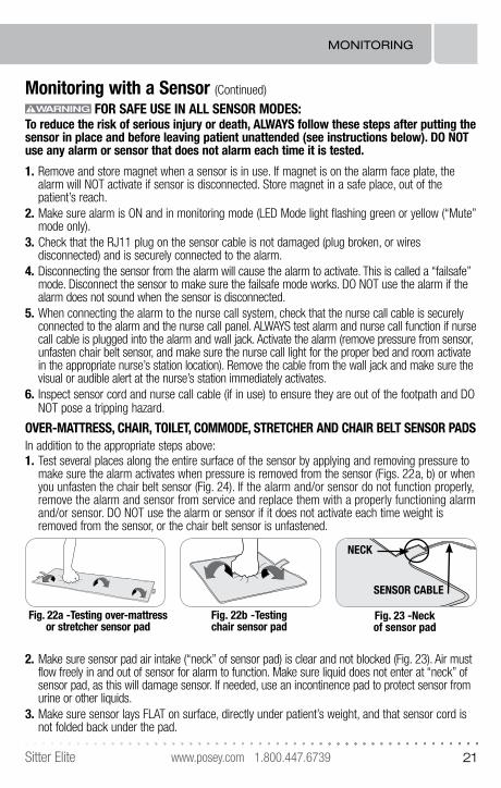
OVER-MATTRESS, CHAIR, TOILET, COMMODE, STRETCHER AND CHAIR BELT SENSOR PADS In addition to the appropriate steps above:1. Test several places along the entire surface of the sensor by applying and removing pressure to
make sure the alarm activates when pressure is removed from the sensor (Figs. 22a, b) or when you unfasten the chair belt sensor (Fig. 24). If the alarm and/or sensor do not function properly, remove the alarm and sensor from service and replace them with a properly functioning alarm and/or sensor. DO NOT use the alarm or sensor if it does not activate each time weight is removed from the sensor, or the chair belt sensor is unfastened.
2. Make sure sensor pad air intake (“neck” of sensor pad) is clear and not blocked (Fig. 23). Air must flow freely in and out of sensor for alarm to function. Make sure liquid does not enter at “neck” of sensor pad, as this will damage sensor. If needed, use an incontinence pad to protect sensor from urine or other liquids.
3. Make sure sensor lays FLAT on surface, directly under patient’s weight, and that sensor cord is not folded back under the pad.
Fig. 23 -Neck of sensor pad
NECK
SENSOR CABLE
Fig. 22b -Testing chair sensor pad
Fig. 22a -Testing over-mattress or stretcher sensor pad
MONITORING
www.posey.com 1.800.447.6739 Sitter Elite22
Monitoring with a Sensor (Continued)
4. Check that there is no risk that chair sensor pad will be trapped in a “hammocking” chair seat. To reduce this risk, place a foundation cushion on seat under sensor.
5. Make sure mattress continues to make contact with the sensor and will activate the alarm when pressure is removed, even if the head or foot of the bed is articulated.
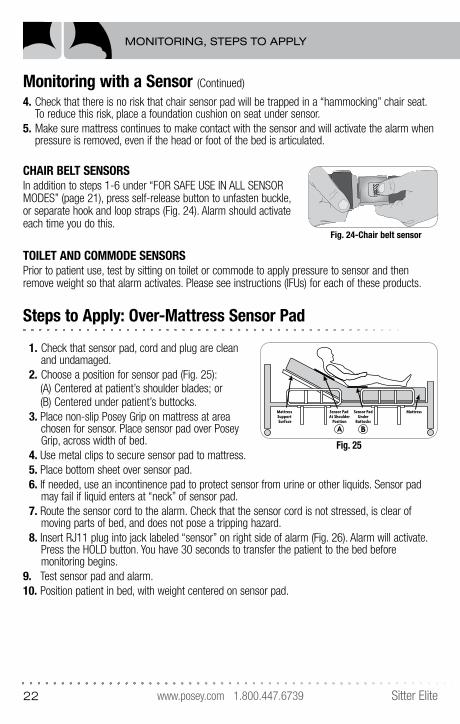
CHAIR BELT SENSORS In addition to steps 1-6 under “FOR SAFE USE IN ALL SENSOR MODES” (page 21), press self-release button to unfasten buckle, or separate hook and loop straps (Fig. 24). Alarm should activate each time you do this.
TOILET AND COMMODE SENSORS Prior to patient use, test by sitting on toilet or commode to apply pressure to sensor and then remove weight so that alarm activates. Please see instructions (IFUs) for each of these products.
Steps to Apply: Over-Mattress Sensor Pad
1. Check that sensor pad, cord and plug are clean and undamaged.
2. Choose a position for sensor pad (Fig. 25): (A) Centered at patient’s shoulder blades; or (B) Centered under patient’s buttocks. 3. Place non-slip Posey Grip on mattress at area
chosen for sensor. Place sensor pad over Posey Grip, across width of bed.
4. Use metal clips to secure sensor pad to mattress.5. Place bottom sheet over sensor pad.6. If needed, use an incontinence pad to protect sensor from urine or other liquids. Sensor pad
may fail if liquid enters at “neck” of sensor pad.7. Route the sensor cord to the alarm. Check that the sensor cord is not stressed, is clear of
moving parts of bed, and does not pose a tripping hazard.8. Insert RJ11 plug into jack labeled “sensor” on right side of alarm (Fig. 26). Alarm will activate.
Press the HOLD button. You have 30 seconds to transfer the patient to the bed before monitoring begins.
9. Test sensor pad and alarm.10. Position patient in bed, with weight centered on sensor pad.
Sensor Pad At Shoulder
Position
Sensor PadUnder
Buttocks
MattressMattress Support Surface
A B
Fig. 25
MONITORING, STEPS TO APPLY
PRESS
Fig. 24-Chair belt sensor
www.posey.com 1.800.447.6739Sitter Elite 23
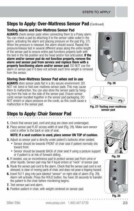
Steps to Apply: Over-Mattress Sensor Pad (Continued)
Testing Alarm and Over-Mattress Sensor PadALWAYS check sensor pads when connecting them to a Posey alarm. You can check a pad by attaching it to the sensor cable outlet in the alarm, activating the alarm and placing pressure on the pad (Fig. 27). When the pressure is released, the alarm should sound. Repeat this pressure/release test in several different areas along the entire length of the sensor pad to ensure entire pad functions properly both with the bed in the flat position and the head and/or foot articulated. If the alarm and/or sensor pad do not function properly, remove the alarm and sensor pad from service and replace them with a properly functioning alarm and/or sensor pad. DO NOT use the alarm or sensor pad if it does not activate each time weight is removed from the sensor.
Storing Over-Mattress Sensor Pad when not in useALWAYS store sensor pads flat in a dry secure environment. DO NOT roll, bend or fold over mattress sensor pads. This may cause them to malfunction. You can also store the sensor pads by hang-ing from the hole on the side of the sensor pad. Ensure sensor cords remain bundled together in the sensor pad packaging. DO NOT stretch or place pressure on the cords, as this could cause a malfunction in the sensor pad.
Steps to Apply: Chair Sensor Pad
1. Check that sensor pad, cord and plug are clean and undamaged.2. Place sensor pad FLAT across width of seat (Fig. 28). Make sure sensor
cord is either to the back or side of seat.NOTE: If a seat cushion is used, place sensor ON TOP of cushion.
3. Adjust so sensor pad is directly under patient’s buttocks when seated.• Sensor should be towards FRONT of chair seat if patient normally sits
toward front.• Sensor should be towards BACK of chair seat if using a posture support
or if patient is at risk of forward sliding.4. If needed, use an incontinence pad to protect sensor pad from urine or
other liquids. Sensor pad may fail if liquid enters at “neck” of sensor pad.5. Route the sensor pad cord to the alarm. Check that the sensor pad cord is not
stressed, is clear of moving parts of chair, and does not pose a tripping hazard.6. Insert RJ11 plug into jack labeled “sensor” on right side of alarm (Fig. 29).
Alarm will activate. Press the HOLD button. You have 30 seconds to transfer the patient to the chair before monitoring begins.
7. Test sensor pad and alarm.8. Position patient in chair, with weight centered on sensor pad.
Fig. 27-Testing over-mattress sensor pad
Fig. 26
NURSECALL
SENSOR
9V
STEPS TO APPLY
Fig. 28
Fig. 29
NURSECALL
SENSOR
9V
www.posey.com 1.800.447.6739 Sitter Elite24
STEPS TO APPLY
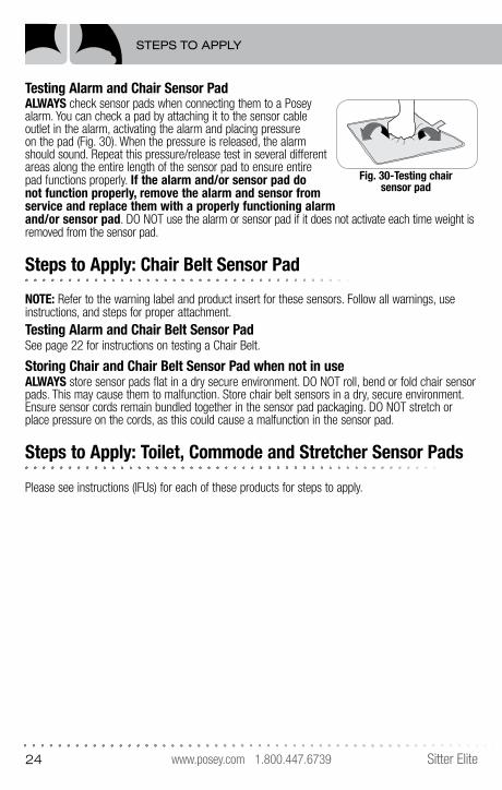
Testing Alarm and Chair Sensor PadALWAYS check sensor pads when connecting them to a Posey alarm. You can check a pad by attaching it to the sensor cable outlet in the alarm, activating the alarm and placing pressure on the pad (Fig. 30). When the pressure is released, the alarm should sound. Repeat this pressure/release test in several different areas along the entire length of the sensor pad to ensure entire pad functions properly. If the alarm and/or sensor pad do not function properly, remove the alarm and sensor from service and replace them with a properly functioning alarm and/or sensor pad. DO NOT use the alarm or sensor pad if it does not activate each time weight is removed from the sensor pad.
Steps to Apply: Chair Belt Sensor Pad
NOTE: Refer to the warning label and product insert for these sensors. Follow all warnings, use instructions, and steps for proper attachment. Testing Alarm and Chair Belt Sensor PadSee page 22 for instructions on testing a Chair Belt.
Storing Chair and Chair Belt Sensor Pad when not in useALWAYS store sensor pads flat in a dry secure environment. DO NOT roll, bend or fold chair sensor pads. This may cause them to malfunction. Store chair belt sensors in a dry, secure environment. Ensure sensor cords remain bundled together in the sensor pad packaging. DO NOT stretch or place pressure on the cords, as this could cause a malfunction in the sensor pad.
Steps to Apply: Toilet, Commode and Stretcher Sensor Pads
Please see instructions (IFUs) for each of these products for steps to apply.
Fig. 30-Testing chair sensor pad
www.posey.com 1.800.447.6739Sitter Elite 25
Monitoring in Optional Cord & Magnet Mode
Magnet and Sensor Modes CANNOT be used at the same time. A con-nected sensor will ALWAYS override the magnet. If you are using a sensor cord for monitoring with the alarm, ALWAYS remove the magnet and store it in a safe place while the sensor is being used.
If you are monitoring with the sensor feature and the magnet is attached, the alarm will not activate as a failsafe if the sensor cord is removed.
A “false alarm” may occur if cord is too short and minimal patient movement disconnects clip from patient or magnet too quickly. If cord is too long, patient may be able to move out of the “safety zone” without alarm activating.
The Cord & Magnet Mode can be used to monitor patient in bed, or on a chair or toilet. An adjustable slider lets you choose the cord length best suited to each patient. Cord length selection will vary depending on patient needs, bed, or chair mount position, and other factors. It is the caregiver’s duty to determine the acceptable range of movement (“safety zone”) for each patient. Consider the following when choosing proper cord length:
Bed Use• Cord should allow enough movement to enhance sleep comfort, but be short enough to alert staff
if patient moves out of the “safety zone”.• Consider the extra distance from head of bed to wall if monitor is wall mounted. • Cord should be in DIRECT LINE from patient to magnet on face of alarm. • Adjust cord length EACH TIME you raise or lower the bed or the mattress head section to account
for this movement. • Make sure cord is not impeded by pillows or bedding, and is not entangled in side rails or in the
head or footboard.
Chair Use• For use with an adjustable chair, lengthen or shorten cord to account for any change in distance
when chair is adjusted. • Make sure cord is not impeded by chair cushions and is not
entangled in chair parts.
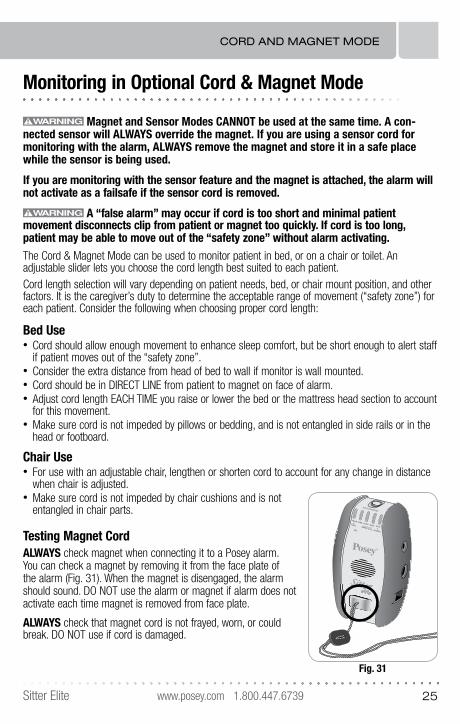
Testing Magnet CordALWAYS check magnet when connecting it to a Posey alarm. You can check a magnet by removing it from the face plate of the alarm (Fig. 31). When the magnet is disengaged, the alarm should sound. DO NOT use the alarm or magnet if alarm does not activate each time magnet is removed from face plate.
ALWAYS check that magnet cord is not frayed, worn, or could break. DO NOT use if cord is damaged.
Fig. 31
VOICE&
TONE
TONEMUTE
VOICENURSE CALLMIC
HOLD&
SUSPEND
HOLD/SUSPEND
CORD AND MAGNET MODE
www.posey.com 1.800.447.6739 Sitter Elite26
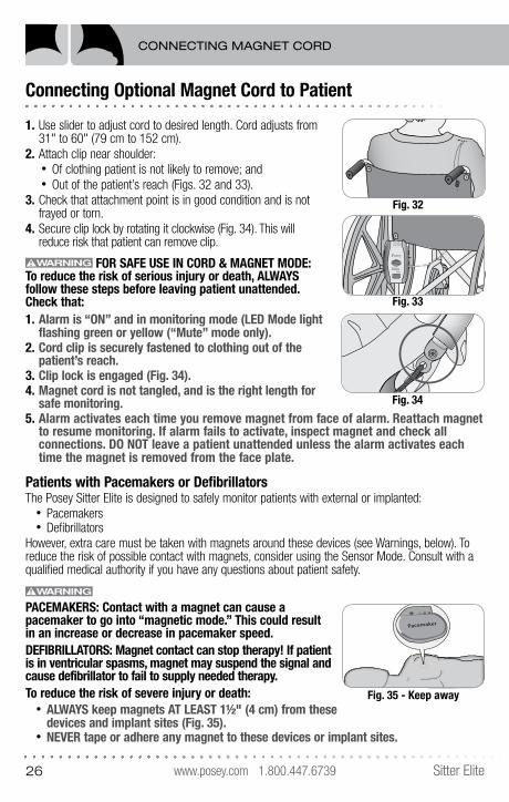
Connecting Optional Magnet Cord to Patient
1. Use slider to adjust cord to desired length. Cord adjusts from 31" to 60" (79 cm to 152 cm).
2. Attach clip near shoulder: • Of clothing patient is not likely to remove; and• Out of the patient’s reach (Figs. 32 and 33).
3. Check that attachment point is in good condition and is not frayed or torn.
4. Secure clip lock by rotating it clockwise (Fig. 34). This will reduce risk that patient can remove clip.
FOR SAFE USE IN CORD & MAGNET MODE:To reduce the risk of serious injury or death, ALWAYS follow these steps before leaving patient unattended. Check that: 1. Alarm is “ON” and in monitoring mode (LED Mode light
flashing green or yellow (“Mute” mode only).2. Cord clip is securely fastened to clothing out of the
patient’s reach.3. Clip lock is engaged (Fig. 34).4. Magnet cord is not tangled, and is the right length for
safe monitoring.5. Alarm activates each time you remove magnet from face of alarm. Reattach magnet
to resume monitoring. If alarm fails to activate, inspect magnet and check all connections. DO NOT leave a patient unattended unless the alarm activates each time the magnet is removed from the face plate.
Patients with Pacemakers or Defibrillators The Posey Sitter Elite is designed to safely monitor patients with external or implanted:
• Pacemakers• Defibrillators
However, extra care must be taken with magnets around these devices (see Warnings, below). To reduce the risk of possible contact with magnets, consider using the Sensor Mode. Consult with a qualified medical authority if you have any questions about patient safety.
PACEMAKERS: Contact with a magnet can cause a pacemaker to go into “magnetic mode.” This could result in an increase or decrease in pacemaker speed.DEFIBRILLATORS: Magnet contact can stop therapy! If patient is in ventricular spasms, magnet may suspend the signal and cause defibrillator to fail to supply needed therapy.To reduce the risk of severe injury or death:
• ALWAYS keep magnets AT LEAST 1½" (4 cm) from these devices and implant sites (Fig. 35).
• NEVER tape or adhere any magnet to these devices or implant sites.
HOLD/SUSPEND
Fig. 32
Sitter
HOLD/SUSPEND
VOICE
&
TONE
HOLD
&
SUSPEND
TONE
MIC
VOICE
NURSE CALL
MUTE
Fig. 33
Fig. 34
Pacemaker
Fig. 35 - Keep away
CONNECTING MAGNET CORD
www.posey.com 1.800.447.6739Sitter Elite 27
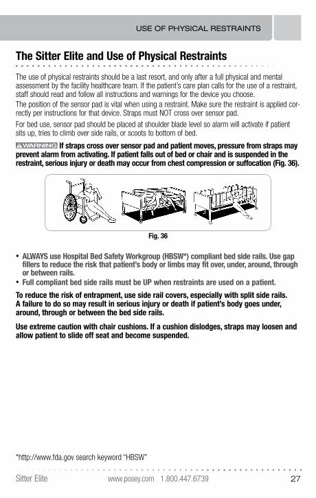
The Sitter Elite and Use of Physical Restraints
The use of physical restraints should be a last resort, and only after a full physical and mental assessment by the facility healthcare team. If the patient’s care plan calls for the use of a restraint, staff should read and follow all instructions and warnings for the device you choose.The position of the sensor pad is vital when using a restraint. Make sure the restraint is applied cor-rectly per instructions for that device. Straps must NOT cross over sensor pad.For bed use, sensor pad should be placed at shoulder blade level so alarm will activate if patient sits up, tries to climb over side rails, or scoots to bottom of bed.
If straps cross over sensor pad and patient moves, pressure from straps may prevent alarm from activating. If patient falls out of bed or chair and is suspended in the restraint, serious injury or death may occur from chest compression or suffocation (Fig. 36).
• ALWAYS use Hospital Bed Safety Workgroup (HBSW*) compliant bed side rails. Use gap fillers to reduce the risk that patient’s body or limbs may fit over, under, around, through or between rails.
• Full compliant bed side rails must be UP when restraints are used on a patient.
To reduce the risk of entrapment, use side rail covers, especially with split side rails. A failure to do so may result in serious injury or death if patient’s body goes under, around, through or between the bed side rails.
Use extreme caution with chair cushions. If a cushion dislodges, straps may loosen and allow patient to slide off seat and become suspended.
Fig. 36
*http://www.fda.gov search keyword “HBSW”
USE OF PHYSICAL RESTRAINTS
www.posey.com 1.800.447.6739 Sitter Elite28
Warnings and Cautions
• NEVER connect a Posey alarm to other manufacturers’ sensors.• NEVER connect a Posey sensor to other manufacturers’ alarm.• Make sure it is safe to drill and there are no pipes or electrical wires that could be damaged
when using screws to attach the wall mount bracket.• NEVER place alarm closer than two feet from patient’s ear. Doing so may cause hearing loss or
other injury. For more information, see: OSHA OCCUPATIONAL NOISE EXPOSURE STANDARDS 1910.95.
• ALWAYS check to ensure staff can hear alarm at the furthest possible distance before leaving patient unattended.
• Magnet and Sensor Modes CANNOT be used at the same time. A connected sensor will ALWAYS override the magnet. If you are using a sensor cord for monitoring with the alarm, ALWAYS remove the magnet and store it in a safe place while the sensor is being used. If you are monitoring with the sensor feature and the magnet is attached, the alarm will not activate as a failsafe if the sensor cord is removed.
• Check that there is no stress on the nurse call cable. Make sure cable is clear of all moving parts of bed or chair, and does not pose a tripping hazard.
• Check that both ends of cable are securely plugged in and the nurse call system has an alert warning if the cable is disconnected from the wall jack.
• Test alarm and nurse call functions by activating alarm and removing pressure from the sensor pad, or unfastening chair belt sensor EACH TIME before leaving patient unattended.
• When monitoring with cord and magnet:– A “false alarm” may occur if cord is too short.– If cord is too long, patient may be able to move out of the “safety zone” without alarm activating.
• Assess patient frequently to ensure that a time delay is appropriate. Set the delay at zero (0) with patients at EXTREME risk of injury from a fall associated with an unassisted bed, chair or toilet exit.
• Before each use, check that: – Alarm is securely mounted out of the patient’s reach and functions properly by activating alarm.– Indicator lights are in clear view of staff.
• DO NOT mix old and new batteries or battery brands. This may cause rupture or leakage and damage alarm.
• DO NOT allow batteries to deplete while in the alarm. Change batteries immediately when hearing the low battery “chirp.” Depleted batteries may leak and corrode, causing damage. When storing the alarm for a short period with power “on” to maintain custom voice messages and settings, check the alarm every week to make sure the batteries are still operable and the alarm is still on. If the alarm low battery alert is chirping, or the alarm does not power up, the batteries are depleted and must be removed. DO NOT leave depleted (“dead”) batteries in the alarm to avoid corrosion.
• Remove batteries when storing the alarm for an extended period to prevent depleting the batteries and potential corrosion.
• The Posey Sitter Elite is an electronic device. It may fail to work if subjected to severe shock, such as being dropped, or immersed in liquid. To reduce the risk of serious injury or death, test the alarm and sensor for proper operation prior to putting in service with a patient, and each time
WARNINGS AND CAUTIONS
www.posey.com 1.800.447.6739Sitter Elite 29
Warnings and Cautions (Continued)
before leaving the patient unattended. If the alarm and/or sensor do not function properly, remove the alarm and sensor from service and replace them with a properly functioning alarm and/or sensor. DO NOT use the alarm, sensor or magnet if it does not activate each time weight is removed from the sensor, the chair belt sensor is unfastened, or magnet is removed from face plate.
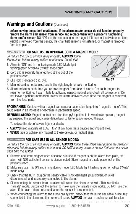
FOR SAFE USE IN OPTIONAL CORD & MAGNET MODE:To reduce the risk of serious injury or death, ALWAYS follow these steps before leaving patient unattended. Check that: 1. Alarm is “ON” and in monitoring mode (LED Mode light
flashing green or yellow (“Mute” mode only).2. Cord clip is securely fastened to clothing out of the
patient’s reach.3. Clip lock is engaged (Fig. 37). 4. Magnet cord is not tangled, and is the right length for safe monitoring.5. Alarm activates each time you remove magnet from face of alarm. Reattach magnet to
resume monitoring. If alarm fails to activate, inspect magnet and check all connections. Do not leave a patient unattended unless the alarm activates each time the magnet is removed from the face plate.
PACEMAKERS: Contact with a magnet can cause a pacemaker to go into “magnetic mode”. This could result in an increase or decrease in pacemaker speed.DEFIBRILLATORS: Magnet contact can stop therapy! If patient is in ventricular spasms, magnet may suspend the signal and cause defibrillator to fail to supply needed therapy.
To reduce the risk of severe injury or death:• ALWAYS keep magnets AT LEAST 1½" (4 cm) from these devices and implant sites.• NEVER tape or adhere any magnet to these devices or implant sites.
FOR SAFE USE IN ALL SENSOR MODES:To reduce the risk of serious injury or death, ALWAYS follow these steps after putting the sensor in place and before leaving patient unattended. DO NOT use any alarm or sensor that does not alarm each time it is tested.1. Remove and store magnet when a sensor is in use. If magnet is on the alarm face plate, the
alarm will NOT activate if sensor is disconnected. Store magnet in a safe place, out of the patient’s reach.
2. Make sure alarm is ON and in monitoring mode (LED Mode light flashing green or yellow (“Mute” mode only).
3. Check that the RJ11 plug on the sensor cable is not damaged (plug broken, or wires disconnected) and is securely connected to the alarm.
4. Disconnecting the sensor from the alarm will cause the alarm to activate. This is called a “failsafe” mode. Disconnect the sensor to make sure the failsafe mode works. DO NOT use the alarm if the alarm does not sound when the sensor is disconnected.
5. When connecting the alarm to the nurse call system, check that the nurse call cable is securely connected to the alarm and the nurse call panel. ALWAYS test alarm and nurse call function
Fig. 37
WARNINGS AND CAUTIONS
www.posey.com 1.800.447.6739 Sitter Elite30
Warnings and Cautions (Continued)
if nurse call cable is plugged into the alarm and wall jack. Activate the alarm (remove pressure from sensor, unfasten chair belt sensor) and make sure the nurse call light for the proper bed and room activate in the appropriate nurse’s station location. Remove the cable from the wall jack and make sure the visual or audible alert at the nurse’s station immediately activates.
6. Inspect sensor cord and nurse call cable (if in use) to ensure they are out of the footpath and DO NOT pose a tripping hazard.
OVER-MATTRESS, CHAIR AND STRETCHER SENSOR PADS 1. Test several places along the entire surface of the sensor by applying and removing pressure
to make sure the alarm activates when pressure is removed from the sensor/mattress, or when you unfasten the chair belt sensor. If the alarm and/or sensor do not function properly, remove the alarm and sensor from service and replace them with a properly functioning alarm and/or sensor. DO NOT use the alarm or sensor if it does not activate each time weight is removed from the sensor, or the chair belt sensor is unfastened.
2. Make sure sensor pad air intake (“neck” of over mattress or chair sensor pad) is clear and not blocked. Air must flow freely in and out of sensor for alarm to function. Make sure liquid does not enter at “neck” of sensor pad, as this will damage sensor. If needed, use an incontinence pad to protect sensor from urine or other liquids.
3. Make sure sensor lays FLAT on chair or bed surface, directly under patient’s weight, and that sensor cord is not folded back under the pad.
4. Check that there is no risk that chair sensor pad will be trapped in a “hammocking” chair seat. To reduce this risk, place a foundation cushion on seat under sensor.
5. Make sure mattress continues to make contact with the sensor and will activate the alarm when pressure is removed, even if the head or foot of the bed is articulated.
CHAIR BELT SENSORSIn addition to steps 1-6 under “FOR SAFE USE IN ALL SENSOR MODES,” see page 22 for instruc-tions on how to properly test a Chair Belt Sensor.
TOILET / COMMODEPlease see instructions (IFUs) for each of these products for warnings.
Sensor Not Functioning
If the alarm and/or sensor do not function properly, remove the alarm and sensor from service and replace them with a properly functioning alarm and/or sensor. DO NOT use the alarm or sensor if it does not activate each time weight is removed from the sensor, the chair belt sensor is unfastened.
Adapter Cable Replacement
Contact Posey Customer Service for nurse call cable adapters available for various nurse call systems. Posey offers 21 varieties of nurse call adapter sysems. Please request document M6253 for a list of all nurse call adapter systems.
WARNINGS AND CAUTIONS
www.posey.com 1.800.447.6739Sitter Elite 31
OFF
ON
PULL LEVERSLIDE OUT
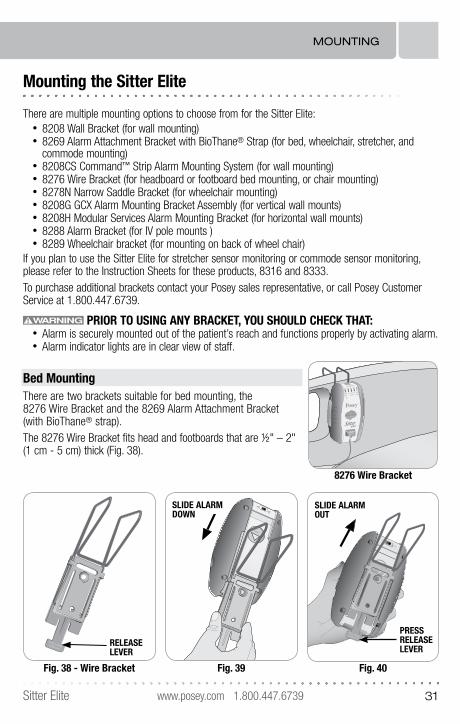
Mounting the Sitter Elite
There are multiple mounting options to choose from for the Sitter Elite:• 8208 Wall Bracket (for wall mounting)• 8269 Alarm Attachment Bracket with BioThane® Strap (for bed, wheelchair, stretcher, and
commode mounting) • 8208CS Command™ Strip Alarm Mounting System (for wall mounting)• 8276 Wire Bracket (for headboard or footboard bed mounting, or chair mounting)• 8278N Narrow Saddle Bracket (for wheelchair mounting)• 8208G GCX Alarm Mounting Bracket Assembly (for vertical wall mounts)• 8208H Modular Services Alarm Mounting Bracket (for horizontal wall mounts)• 8288 Alarm Bracket (for IV pole mounts )• 8289 Wheelchair bracket (for mounting on back of wheel chair)
If you plan to use the Sitter Elite for stretcher sensor monitoring or commode sensor monitoring, please refer to the Instruction Sheets for these products, 8316 and 8333.To purchase additional brackets contact your Posey sales representative, or call Posey Customer Service at 1.800.447.6739.
PRIOR TO USING ANY BRACKET, YOU SHOULD CHECK THAT:• Alarm is securely mounted out of the patient’s reach and functions properly by activating alarm.• Alarm indicator lights are in clear view of staff.
Bed MountingThere are two brackets suitable for bed mounting, the 8276 Wire Bracket and the 8269 Alarm Attachment Bracket (with BioThane® strap).The 8276 Wire Bracket fits head and footboards that are ½" – 2" (1 cm - 5 cm) thick (Fig. 38).
8276 Wire Bracket
DELAY
MODE
TONE
VOLUME
RECORD
VOICE&
TONE
TONE
MIC
VOICE MUTE HOLD&
SUSPEND
HOLD/SUSPEND
NURSE CALL
PRESSRELEASELEVER
Fig. 38 - Wire Bracket
PULL LEVERSLIDE OUTRELEASELEVER
Fig. 39
PRESS
ON
OFF
SLIDE ALARMDOWN
Fig. 40
SLIDE ALARM OUT
MOUNTING
www.posey.com 1.800.447.6739 Sitter Elite32
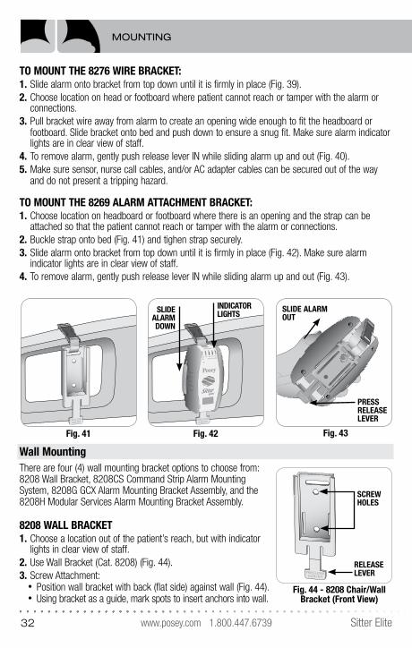
TO MOUNT THE 8276 WIRE BRACKET: 1. Slide alarm onto bracket from top down until it is firmly in place (Fig. 39).2. Choose location on head or footboard where patient cannot reach or tamper with the alarm or
connections.3. Pull bracket wire away from alarm to create an opening wide enough to fit the headboard or
footboard. Slide bracket onto bed and push down to ensure a snug fit. Make sure alarm indicator lights are in clear view of staff.
4. To remove alarm, gently push release lever IN while sliding alarm up and out (Fig. 40).5. Make sure sensor, nurse call cables, and/or AC adapter cables can be secured out of the way
and do not present a tripping hazard.
TO MOUNT THE 8269 ALARM ATTACHMENT BRACKET:1. Choose location on headboard or footboard where there is an opening and the strap can be
attached so that the patient cannot reach or tamper with the alarm or connections.2. Buckle strap onto bed (Fig. 41) and tighen strap securely.3. Slide alarm onto bracket from top down until it is firmly in place (Fig. 42). Make sure alarm
indicator lights are in clear view of staff.4. To remove alarm, gently push release lever IN while sliding alarm up and out (Fig. 43).
Wall MountingThere are four (4) wall mounting bracket options to choose from: 8208 Wall Bracket, 8208CS Command Strip Alarm Mounting System, 8208G GCX Alarm Mounting Bracket Assembly, and the 8208H Modular Services Alarm Mounting Bracket Assembly.
8208 WALL BRACKET1. Choose a location out of the patient’s reach, but with indicator
lights in clear view of staff.2. Use Wall Bracket (Cat. 8208) (Fig. 44).3. Screw Attachment:
• Position wall bracket with back (flat side) against wall (Fig. 44).• Using bracket as a guide, mark spots to insert anchors into wall.
Fig. 44 - 8208 Chair/Wall Bracket (Front View)
PRESS LEVERSLIDE OUT
RELEASELEVER
SCREWHOLES
MOUNTING
Fig. 41
PRESS LEVERSLIDE OUT
OFF
ON
PULL LEVER
SLIDE OUT PRESSRELEASELEVER
Fig. 43
SLIDE ALARM OUT
Fig. 42
PRESS LEVERSLIDE OUT
DELAY
MODE
TONE
VOLUME
RECORD
VOICE&
TONE
TONE
MIC
VOICE MUTE HOLD&
SUSPEND
HOLD/SUSPEND
NURSE CALL
SLIDE ALARMDOWN
INDICATOR LIGHTS
www.posey.com 1.800.447.6739Sitter Elite 33
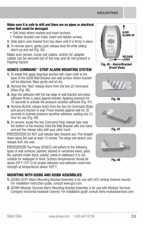
Make sure it is safe to drill and there are no pipes or electrical wires that could be damaged.
• Drill holes where marked and insert anchors.• Position bracket over holes. Insert and tighten screws.
1. Slide alarm onto bracket from top down until it is firmly in place.2. To remove alarm, gently push release lever IN while sliding
alarm up and out (Fig. 45).Make sure sensor, nurse call cables, and/or AC adapter cables can be secured out of the way and do not present a tripping hazard.
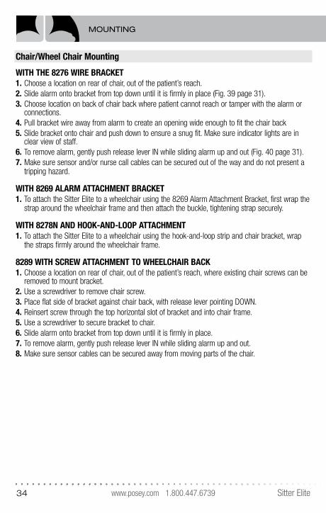
8208CS COMMAND™ STRIP ALARM MOUNTING SYSTEM1. To install first apply isopropyl alcohol with clean cloth to the
back of the 8208 Wall Bracket and wall surface where bracket will be attached. Wipe gently and let dry.
2. Remove the “Red” release liners from the two (2) Command Strips (Fig. 46).
3. Align the adhesive with the top edge of wall bracket and press adhesive firmly in place against bracket. Applying pressure for 10 seconds to activate the pressure sensitive adhesive (Fig. 47).
4. Remove BLACK release liners from the two (2) Command Strips and secure bracket to wall. Press bracket against wall for 30 seconds to activate pressure sensitive adhesive, waiting one (1) hour for use (Fig. 48).
5. To remove, locate the two Command Strip release tabs near the bottom of the bracket. Hold the Wall Bracket with one hand and pull the release tabs with your other hand.
DO NOT pull release tabs towards you. Pull straight down along the wall at least 15 inches. The strips will stretch and release from the wall.
The Posey 8208CS will adhere to the following types of wall surfaces: painted, stained or varnished wood, glass tile, painted cinder block, plaster, metal or wallboard. It is not suitable for wallpaper or brick. Surface temperatures should be above 50º F (10º C) for proper adhesion and adhesion could lose strength at temperatures above 105º F.
MOUNTING WITH 8208G AND 8208H ASSEMBLIES1. 8208G GCX® Alarm Mounting Bracket Assembly is for use with GCX vertical channel mounts.
For installation instruction guide, consult www.gcx.com.2. 8208H Modular Services Alarm Mounting Bracket Assembly is for use with Modular Services
Company horizontal headwall channel. For installation guide consult www.modularservices.com.
MOUNTING
Fig. 45 - Alarm/Bracket (Front View)
PRESS LEVERSLIDE OUT
HOLD/SUSPEND
®
Sitter™
SLIDE ALARM UP
RELEASELEVER
Fig. 47
Fig. 46
Fig. 48
www.posey.com 1.800.447.6739 Sitter Elite34
Chair/Wheel Chair Mounting
WITH THE 8276 WIRE BRACKET 1. Choose a location on rear of chair, out of the patient’s reach. 2. Slide alarm onto bracket from top down until it is firmly in place (Fig. 39 page 31).3. Choose location on back of chair back where patient cannot reach or tamper with the alarm or
connections.4. Pull bracket wire away from alarm to create an opening wide enough to fit the chair back5. Slide bracket onto chair and push down to ensure a snug fit. Make sure indicator lights are in
clear view of staff.6. To remove alarm, gently push release lever IN while sliding alarm up and out (Fig. 40 page 31).7. Make sure sensor and/or nurse call cables can be secured out of the way and do not present a
tripping hazard.
WITH 8269 ALARM ATTACHMENT BRACKET1. To attach the Sitter Elite to a wheelchair using the 8269 Alarm Attachment Bracket, first wrap the
strap around the wheelchair frame and then attach the buckle, tightening strap securely.
WITH 8278N AND HOOK-AND-LOOP ATTACHMENT 1. To attach the Sitter Elite to a wheelchair using the hook-and-loop strip and chair bracket, wrap
the straps firmly around the wheelchair frame.
8289 WITH SCREW ATTACHMENT TO WHEELCHAIR BACK 1. Choose a location on rear of chair, out of the patient’s reach, where existing chair screws can be
removed to mount bracket. 2. Use a screwdriver to remove chair screw. 3. Place flat side of bracket against chair back, with release lever pointing DOWN. 4. Reinsert screw through the top horizontal slot of bracket and into chair frame. 5. Use a screwdriver to secure bracket to chair. 6. Slide alarm onto bracket from top down until it is firmly in place. 7. To remove alarm, gently push release lever IN while sliding alarm up and out. 8. Make sure sensor cables can be secured away from moving parts of the chair.
MOUNTING
www.posey.com 1.800.447.6739Sitter Elite 35
Alarm Cleaning, Storage and Battery Maintenance
Cleaning: Sensor, Cables and Alarm Housing (exterior ONLY)Dampen (but DO NOT soak) a clean cloth with disinfectant. Wipe alarm clean, using care not to get disinfectant inside speaker grill and connector ports.
To reduce the risk of damage, NEVER:• use any cleaning substance that contains Phenol• immerse in liquid • sterilize with heat
Always use a clean, DRY cloth to dry all parts.
Storage • This device is designed for use in normal indoor environments.• This device may be stored in ambient warehouse temperatures at normal humidity levels (10 to 50%).
Avoid excess moisture or high humidity that may damage product materials (greater than 90%).• Store pad sensors flat or hang in a dry secure environment. DO NOT fold or roll sensors, as it
may damage internal electronic parts and cause a malfunction.
Disposal Dispose of per facility policy. Be sure to follow all laws that apply.
Battery Compartment Battery Leakage. If there is ANY evidence of battery leakage, remove
the alarm from use and notify the appropriate facility authority. The alarm should be disposed of according to your facility disposal requirements. DO NOT use the alarm and DO NOT attempt to clean it if there are any signs of battery leakage such as corrosion, rust or white powder residue.
DO NOT allow batteries to deplete while in the alarm. Change batteries immediately when hearing the low battery “chirp.” Depleted batteries may leak and corrode, causing damage to the electronics and reliability. When storing the alarm for a short period with power “on” to maintain custom voice messages and settings, check the alarm every week to make sure the batteries are still operable and the alarm is still on. If the alarm low battery alert is chirping, or the alarm does not power up, the batteries are depleted and must be removed. DO NOT leave depleted (“dead”) batteries in the alarm to avoid corrosion.
Remove batteries when storing the alarm for an extended period to prevent depleting the batteries and potential corrosion.
CLEANING, STORAGE, MAINTENANCE
www.posey.com 1.800.447.6739 Sitter Elite36
Troubleshooting Guide
PROBLEM: Continuous alarm with patient in bed or chair.SOLUTION: Magnet and Cord Mode• Check that magnet is connected to plate on face of alarm.
SOLUTION: Chair Sensor Pad• Check that sensor pad cord and RJ11 plug are clean and undamaged. Check plug connection
to alarm.• Check sensor pad for creases or damage to vinyl cover. • Check “neck” of chair sensor pad for signs that urine or other liquids have leaked into pad.• Check that sensor pad is directly under patient’s weight.
– Pad should be towards front of chair seat if patient normally sits toward front.– Pad should be towards back of chair seat if posture support is in use or if patient is at risk of
forward sliding.• Check seating/positioning aids such as wheelchair cushions or wedge cushions. Weight from
these may activate alarm, or prevent sensor from activating.• Check sensor pad expiration date. A continuous alarm may indicate sensor pad is “worn-out” and
should be replaced.
SOLUTION: Over-Mattress Sensor Pad• Check that sensor cord and RJ11 plug are clean and undamaged. Check plug connection to alarm.• Check sensor pad for creases or damage to vinyl cover.• Check “neck” of over mattress sensor pad for signs that urine or other liquids have leaked into pad.• Patient may not be heavy enough to activate sensor.
– Shoulder Placement: Adjust sensor pad so it is centered at shoulder blade area and patient makes contact with pad.
– Try a different sensor pad location. Most patient weight is normally under buttocks.– Buttocks Placement: Check that sensor pad is directly under patient’s weight. Shoulder
placement may be needed for a very small individual or restless sleeper.• A foam pad on top of mattress may diffuse patient’s weight so sensor pad does not activate.
– Reposition over-mattress sensor pad above foam pad.• Mattress may not bend easily when head or knee sections are raised or lowered. Some
mattresses are very stiff and may form an air pocket between mattress and frame when bed is adjusted. This may prevent weight from touching sensor pad. Try a different sensor pad location.
• Check sensor pad expiration date. A continuous alarm may indicate sensor pad is “worn-out” and should be replaced.
SOLUTION: Chair Belt Sensor• Check that sensor cord and RJ11 plug are clean and undamaged. Check plug connection to alarm.• Check that buckle is securely fastened and there are no loose wires.
SOLUTION: Exit Alarm Mat• Check that there is no weight on sensor.• Check that sensor cord and RJ11 plug are clean and undamaged. Check plug connection to alarm.
TROUBLESHOOTING GUIDE
www.posey.com 1.800.447.6739Sitter Elite 37
Troubleshooting Guide (Continued)
PROBLEM: Intermittent Alarm while the patient is in a bed or chair.SOLUTION: • Check that sensor cord and RJ11 plug are clean and undamaged. Check plug connection to alarm.• Check sensor pad for creases or damage to vinyl cover. • Check that sensor pad is directly under patient’s weight.• Is the sensor getting caught in “hammocking” wheelchair seat? If so, place a foundation cushion
on seat, under sensor.• Make sure sensor cord is not folded back under pad.• Make sure sensor pad air intake (“neck” of over mattress or chair sensor pad) is clear and not
blocked. Air must flow freely in and out of sensor.• Try a new sensor if intermittent alarm can not be fixed.• Make sure mattress continues to make contact with the sensor and will activate the alarm when
pressure is removed, even if the head or foot of the bed is articulated.• Apply pressure to sensor in several areas to check that alarm activates.• Ensure batteries are not corroded.
PROBLEM: No Alarm when patient exits bed or chair.SOLUTION: • Make sure alarm is ON (LED Mode light flashing green or yellow (“Mute” mode only).• Check batteries. If needed, insert four (4) new “AA” alkaline batteries. DO NOT mix old and new
batteries, or different brands of batteries.SOLUTION: Voice and Tone or Voice Only• Remove batteries from alarm for at least 1 hour to allow alarm to reset. Re-record message.SOLUTION: Magnet and Cord Mode• Check to make sure a sensor is not connected to the alarm. Sensor will “turn off” magnet activation.SOLUTION: Chair Sensor Pad• Make sure sensor pad cord is not folded back under pad.• Make sure sensor pad air intake (“neck” of chair sensor pad) is clear and not blocked. Air must
flow freely in and out of the sensor pad.• Check that there is no weight in the chair such as a box, bag or book.• Check seating/positioning aides. A heavy wheelchair cushion may prevent alarm from alarming.
Try a different position for the sensor pad, such as on top of the cushion.• Is the sensor pad getting caught in “hammocking” wheelchair seat? If so, place a foundation
cushion on seat, under sensor pad.• Try a new sensor pad if alarm does not sound.
SOLUTION: Over-Mattress Sensor Pads• Check that all connections are tight and properly plugged into the alarm. • Check the “DELAY” setting. • Check that there is no weight on the mattress such as a box, bag or book.• Check that the correct side of the bed sensor pad is “UP” under the mattress.
TROUBLESHOOTING GUIDE
www.posey.com 1.800.447.6739 Sitter Elite38
Troubleshooting Guide (Continued)
SOLUTION: Over Mattress Sensor Pads (Continued)• When the patient lies down they may not be making contact with the sensor to activate monitoring.
Try a different position for the sensor pad. Most patient weight is normally under buttocks.
SOLUTION: Chair Belt Sensor• Check that all connections are tight and properly plugged into the alarm. • Check the “DELAY” setting.
PROBLEM: Alarm volume is too low or too loud.
SOLUTION: • Press the VOLUME button on the side of alarm to change volume setting. Continue tapping the
button to scroll through the selections. The last sample heard is the volume in use.
PROBLEM: Cannot access the “Voice Only” or “Mute” mode settings.SOLUTION: • The “Voice Only” and “Mute” modes are available ONLY while nurse call interface is in use.
Check that nurse call cable is properly connected to alarm and nurse call panel jacks.
PROBLEM: In “Voice and Tone” or “Voice Only” modes, custom voice messagedoes not play.SOLUTION: • Remove batteries from alarm for at least 1 hour to allow alarm to reset. Replace batteries as
needed and check that battery contacts are clean. Re-record message.
PROBLEM: Alarm “chirps.”SOLUTION: • A “chirp” sound indicates a low battery. Insert four (4) new “AA” alkaline batteries. DO NOT mix
old and new batteries, or different brands of batteries.
PROBLEM: Sensors slide around when the head of the bed is raised or loweredon beds with foam overlays.SOLUTION: • Anchor the sensor(s) on top of the mattress, under the foam overlay with the Posey Grip and
clips provided.
PROBLEM: In-room alarm activates, but nurse call station does not activate.SOLUTION: • Check that all connections are tight and the nurse call cable is connected to the alarm and
properly plugged into the facility’s nurse call system. The connections should snap tightly together.• Check for worn or damaged wires.• Verify use of proper adapter for the system.
TROUBLESHOOTING GUIDE

www.posey.com 1.800.447.6739Sitter Elite 39
Alarm Specifications:
Size 3.6”W x 6”L x 2.2”D (9 cm x 15 cm x 5.6 cm)
Weight 10.2 oz (13.7 oz with batteries), 0.29 kgs. (0.39 kgs with batteries)
Power Supply Four (4) “AA” alkaline batteries. Optional AC power adapter (8345AC) 9 VDC.
Battery Life Expectancy
Approximately 30 days of daily use; may vary
Current Drain Non-alarmed monitoring mode 0.45 mA, maximum alarm volume 132 mA
Alarm Maximum Volume
100 ± 5dB
Voltage Range 4.6-6.3 VDC
Low Battery Warning
Audible, low battery “chirp” about every 15 seconds when batteries need changing
Limited Lifetime Warranty
The Posey Company is committed to manufacturing the best quality products. Posey warrants to the original purchaser that the Posey Sitter Elite is defect-free in materials and workmanship. If the prod-uct is found to be defective in workmanship or materials, we will replace or repair it without charge. This warranty does not cover accidental damage, water immersion, improper care, alteration or misuse, and excludes claims for loss or theft. Service under this warranty is available by contacting the Posey Customer Service hotline (1.800.447.6739) for a return authorization, and by forwarding the product in clean condition, freight pre-paid, with dated proof of purchase. This warranty gives you specific legal rights, and you may also have other rights, which vary from state to state.
Repair Service
Return all alarms for repair to: Posey Company – Sitter Elite Repairs, 5635 Peck Road • Arcadia, CA 91006Insure for $500.00. For additional information or questions, call the Posey Company: 1.800.447.6739.
SPECIFICATIONS, WARRANTY, REPAIR

M6223 REV G 013015 © 2015 Posey Company. All rights reserved.
Posey Company • 5635 Peck Road, Arcadia, CA 91006-0020 USAPhone: 1.800.447.6739 • Fax: 1.800.767.3933 • www.posey.com
Sitter Elite®
Instruction Manual