Embed Size (px)
Citation preview

Siemens FI 01 · 2009 US Edition
2/2 Product overview
2/4 Transmitters for gage, absolute and differential pressure
2/4 Z series for gage and absolute pressure2/10 SITRANS P250 for differential pressure2/15 ZD series for gage and absolute pressure
2/19 Transmitters for food, pharma-ceuticals and biotechnology
2/19 SITRANS P Compact for gage and absolute pressure
2/26 SITRANS P300 for gage and absolute pressure
2/45 Transmitters for gage pressure for paper industrySITRANS P300 and DS III series with PMC connection
2/45 Technical descriptionTechnical specifications, ordering data, dimensional drawings
2/50 - DS III series with PMC connection2/56 - SITRANS P300 with PMC connection
2/61 Transmitters for gage, absolute and differential pressure, flow and levelDS III, DS III PA and DS III FF series
2/61 Technical descriptionTechnical specifications, ordering data, dimensional drawings
2/68 - for gage pressure2/77 - for gage and absolute pressure with
front-flush diaphragm2/87 - for absolute pressure
(gage construction)2/96 - for absolute pressure
(differential construction)2/105 - for differential pressure and flow2/122 - for level
2/132 SITRANS P Accessories2/132 Supplementary electronics for 4-wire
connection2/134 Accessories/spare parts for SITRANS P,
P300 and DS III series2/140 Factory-mounting of valve manifolds on
SITRANS P transmitters
2/144 Transmitters for hydrostatic level2/144 MPS series (submersible sensor)
2/148 Remote seals for transmitters and pressure gauges
2/148 Introduction2/154 Pancake type diaphragm seal with flexi-
ble capillary tube2/155 Flange-type diaphragm seal directly
connected2/158 Diaphragm seal "flanged off-line
low-pressure type", directly connected2/159 Flange-type diaphragm seal with
flexible capillary tube2/161 Diaphragm seal "flanged off-line type"2/163 Diaphragm seal "flanged off-line
low-pressure type"2/165 Flushing rings2/167 Diaphragm seal with quick connection2/170 Inline diaphragm seal with quick con-
nection2/172 Diaphragm seal "threaded design"2/173 Diaphragm seal "threaded, low-pressure
design"2/175 Inline diaphragm seal, wafer for pressure2/177 Diaphragm seal, saddle2/179 Measuring setups2/180 - with remote seals2/182 - without remote seals2/184 Questionnaire
2/186 Fittings2/186 Technical description, Selection aid2/187 Double shut-off valves2/189 2-, 3- and 5-spindle valve manifolds
DN 52/192 Oval flange
You can download all instructions, cata-logs and certificates for SITRANS P free of charge at the following Internet ad-dress:www.siemens.com/sitransp
SITRANS Pmeasuring instruments for pressure
© Siemens AG 2008

SITRANS P measuring instruments for pressureProduct overview
2/2 Siemens FI 01 · 2009 US Edition
2
■ Overview
Application Description Page Software for Parameterization
SITRANS P – measuring instruments for pressure, absolute pressure, differential pressure, flow and level
Two- or three-wire transmitters for measuring gage and abso-lute pressure
SITRANS P, Z seriesCompact single-range transmitters Analog electronicsAvailable ex stock
2/4 –
Two- or three-wire transmitters for measuring differential pres-sure
SITRANS P250Compact single-range transmitters Analog electronicsAvailable ex stock
2/10 –
Two- or three-wire transmitters for measuring gage and abso-lute pressure
SITRANS P, ZD series5:1 Turn downDigital displayAvailable ex stock
2/15 –
Transmitters for gage and abso-lute pressure for food, pharma-ceuticals and biotechnology
SITRANS P Compact Single-range transmitters in 2-wire systemSanitary design with various aseptic connections according to EHEDG, FDA and GMP recommenda-tions.
2/19 –
Two-wire transmitters for mea-suring gage and absolute pres-sure
SITRANS P300• Sanitary design according to EHEDG, FDA and
GMP• Parameterization over 3 buttons or communication
over HART, PROFIBUS PA or FOUNDATION Fieldbus
• Standard process connection G½, ½-NPT and flush-mounted process connections available
• 100:1 Turn down
2/26 SIMATIC PDM
Two-wire transmitters for mea-suring gage pressure
SITRANS P300 and DS III series with PMC connection for the paper industry• 100:1 Turn down• Process connections for the paper industry• Parameter assignment over 3 buttons and HART,
PROFIBUS PA or FOUNDATION Fieldbus
2/45 SIMATIC PDM
Two-wire transmitters for mea-suring:• Gage pressure,• Absolute pressure• Differential pressure and • Flow or• Level
SITRANS P, DS III seriesSITRANS P, DS III PA seriesSITRANS P, DS III FF series100:1 Turn downParameterization using:• 3 pushbuttons and HART for DS III series• 3 pushbuttons and PROFIBUS-PA for DS III PA se-
ries• 3 buttons and FOUNDATION Fieldbus for DS III FF
series• Available ex stock
2/61 SIMATIC PDMSIMATIC PDM
Supplementary electronics for adaptation of two-wire transmit-ters for four-wire connections
Output: 0 or 4 to 20 mAPower supply: 24 V AC/DC, 230 V AC
2/132 –
© Siemens AG 2008

SITRANS P measuring instruments for pressureProduct overview
2/3Siemens FI 01 · 2009 US Edition
2
2-wire transmitter for measuing hydrostatic levels
SITRANS P, MPS series (submersible sensor)For measuring liquid levels in wells, tanks, channels, dams etc.
2/144 –
Remote seals for measuring viscous, corrosive or fibrous media (as well as media at extreme temperatures)
Remote seals in pancake and flange designsQuick-release remote seals for the food industryWide range of diaphragm materials and filling liq-uids available
2/148 –
Shutting off the lines for the medium and differential pres-sureMounting of transmitter on valve manifold or shut-off fitting
Shut-off fittings and valve manifolds available in steel, brass or stainless steelValve manifolds available for the various process connections of the SITRANS P transmitters
2/186 –
Application Description Page Software for Parameterization
© Siemens AG 2008
SITRANS P measuring instruments for pressureTransmitters for gage, absolute and differential pressure
Z series for gage and absolute pressure
2/4 Siemens FI 01 · 2009 US Edition
2
■ Overview
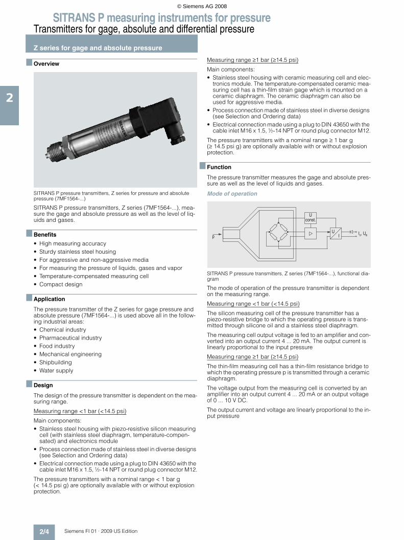
SITRANS P pressure transmitters, Z series for pressure and absolute pressure (7MF1564-...)
SITRANS P pressure transmitters, Z series (7MF1564-...), mea-sure the gage and absolute pressure as well as the level of liq-uids and gases.
■ Benefits
• High measuring accuracy• Sturdy stainless steel housing• For aggressive and non-aggressive media• For measuring the pressure of liquids, gases and vapor• Temperature-compensated measuring cell• Compact design
■ Application
The pressure transmitter of the Z series for gage pressure and absolute pressure (7MF1564-...) is used above all in the follow-ing industrial areas:• Chemical industry• Pharmaceutical industry• Food industry• Mechanical engineering• Shipbuilding • Water supply
■ Design
The design of the pressure transmitter is dependent on the mea-suring range.
Measuring range <1 bar (<14.5 psi)
Main components:• Stainless steel housing with piezo-resistive silicon measuring
cell (with stainless steel diaphragm, temperature-compen-sated) and electronics module
• Process connection made of stainless steel in diverse designs (see Selection and Ordering data)
• Electrical connection made using a plug to DIN 43650 with the cable inlet M16 x 1.5, ½-14 NPT or round plug connector M12.
The pressure transmitters with a nominal range < 1 bar g (< 14.5 psi g) are optionally available with or without explosion protection.
Measuring range ≥1 bar (≥14.5 psi)
Main components:• Stainless steel housing with ceramic measuring cell and elec-
tronics module. The temperature-compensated ceramic mea-suring cell has a thin-film strain gage which is mounted on a ceramic diaphragm. The ceramic diaphragm can also be used for aggressive media.
• Process connection made of stainless steel in diverse designs (see Selection and Ordering data)
• Electrical connection made using a plug to DIN 43650 with the cable inlet M16 x 1.5, ½-14 NPT or round plug connector M12.
The pressure transmitters with a nominal range ≥ 1 bar g (≥ 14.5 psi g) are optionally available with or without explosion protection.
■ Function
The pressure transmitter measures the gage and absolute pres-sure as well as the level of liquids and gases.
Mode of operation
SITRANS P pressure transmitters, Z series (7MF1564-...), functional dia-gram
The mode of operation of the pressure transmitter is dependent on the measuring range.
Measuring range <1 bar (<14.5 psi)
The silicon measuring cell of the pressure transmitter has a piezo-resistive bridge to which the operating pressure is trans-mitted through silicone oil and a stainless steel diaphragm.
The measuring cell output voltage is fed to an amplifier and con-verted into an output current 4 ... 20 mA. The output current is linearly proportional to the input pressure
Measuring range ≥1 bar (≥14.5 psi)
The thin-film measuring cell has a thin-film resistance bridge to which the operating pressure p is transmitted through a ceramic diaphragm.
The voltage output from the measuring cell is converted by an amplifier into an output current 4 ... 20 mA or an output voltage of 0 ... 10 V DC.
The output current and voltage are linearly proportional to the in-put pressure
�������
��� �
��
© Siemens AG 2008

SITRANS P measuring instruments for pressureTransmitters for gage, absolute and differential pressure
Z series for gage and absolute pressure
2/5Siemens FI 01 · 2009 US Edition
2
■ Technical specifications
■ Dimensional drawings
Pressure transmitter 7MF1564-... with process connection G½" male, dimensions in mm (inch)
Pressure transmitter 7MF1564-... with process connection G¼" male, dimensions in mm (inch)
SITRANS P pressure transmitters, Z series for gage pressure, abso-lute pressure and level
Mode of operation
• Measuring range <1 bar (<14.5 psi)
Piezo-resistive
• Measuring range ≥1 bar (≥14.5 psi)
Thin-film strain gage
Input
Measured variable Gage and absolute pressure
Measured range
• Pressure
- Metric 0 ... 400 bar g (0 ... 5802 psi g)
- US measuring range 0 ... 6000 psi g
• Absolute pressure
- Metric 0 ... 16 bar a (0 ... 232 psi a)
- US measuring range 0 ... 300 psi a
Output
Output signal
• Current output signal 4 ... 20 mA
• Voltage output signal (only mea-suring range ≥ 1 bar (14.5 psi))
0 ... 10 V DC
Accuracy To EN 60770-1
Error in measurement (at 25 °C (77 °F), including conformity error, hysteresis and repeatability)
0.25% of full-scale value – typical
Response time T99 < 0.1 s
Long-term drift
• Start of scale 0.25% of full scale value/year
• Full-scale value 0.25% of full scale value/year
Influence of ambient temperature
• Start of scale 0.25%/10 K (0.25%/10 K) of full-scale value
• Full-scale value 0.25%/10 K (0.25%/10 K) of full-scale value
Rated operating conditions
Process temperature -30 ... +120 °C (-22 … +248 °F)
Ambient temperature -25 ... +85 °C (-13 … +185 °F)
Storage temperature -50 ... +100 °C (-58 … +212 °F)
Degree of protection to EN 60529 IP65
Design
Weight ≈ 0.25 kg (≈ 0.55 lb)
Wetted parts materials
• Measuring cell
- Measuring range <1 bar (<14.5 psi)
Stainless steel, 1.4571/316Ti
- Measuring range ≥1 bar (≥14.5 psi)
Al2O3 – 96%
• Process connection Stainless steel, mat. No. 1.4571/316Ti
• Gasket Viton
Process connection See Selection and Ordering data
Power supply UH
Terminal voltage on pressure trans-mitter
• For current output 10 ... 36 V DC
• For voltage output signal (only measuring range ≥ 1 bar (14.5 psi))
15 ... 36 V DC
Certificate and approvals
Classification according to pressure equipment directive (DRGL 97/23/EC)
For gases of fluid group 1 and liq-uids of fluid 1; complies with requirements of article 3, para-graph 3 (sound engineering prac-tice)
Explosion protection
• Intrinsic safety "i" (only with current output)
TÜV 02 ATEX 1953X
- Identification Ex II 1/2G EEx ia IIC T4
• Intrinsic safety "T.I.I.S." (only with current output)
applied
Lloyds Register of Shipping Certificate No. 03/30003
27
132 (5.2) without Ex protection1)
141 (5.6) with Ex protection
(dia
m. 1
.1)
M16x1,5or½-14 NPT
1) Length on version for voltage output 0 ... 10 V: 106 (4.2)2) Inner diameter 3 (0.12)
Ø
50
G½
B2)
20
(1.9
7)
SW27
(0.8)5
(0.2)
122 (4.8) without Ex protection1)
131 (5.15) with Ex protection
(dia
m. 1
.1)
M16x1,5or½-14 NPT
1) Length on version for voltage output 0 ... 10 V: 96 (3.8)2) Inner diameter 3 (0.12)
Ø27
50
G¼
B2)
16(1
.97)
SW27
(0.63)
© Siemens AG 2008

SITRANS P measuring instruments for pressureTransmitters for gage, absolute and differential pressure
Z series for gage and absolute pressure
2/6 Siemens FI 01 · 2009 US Edition
2
Pressure transmitter 7MF1564-... with process connection 7/16-20 UNF male, dimensions in mm (inch)
Pressure transmitter 7MF1564-... with process connection ¼"-18 NPT male, dimensions in mm (inch)
Pressure transmitter 7MF1564-... with process connection ¼"-18 NPT female, dimensions in mm (inch)
Pressure transmitter 7MF1564-... with process connection G1“ male,dimensions in mm (inch)
Pressure transmitter 7MF1564-... with process connection ½"-14 NPT male, dimensions in mm (inch)
Pressure transmitter 7MF1564-... with process connection ½"-14 NPT female, dimensions in mm (inch)
■ Schematics
SITRANS P pressure transmitters, Z series (7MF1564-...), connectiondiagram, with current output (top) and voltage output (bottom)
Ø27
(dia
m. 1
.1)
1) Length on version for voltage output 0 ... 10 V: 98 (3.9)
124 (4.88) without Ex protection1)
133 (5.23) with Ex protection
M16x1.5or½-14 NPT
50
28
(1.9
7)
SW27
(1.1)
¼-1
8 N
PT
129 (5.2) without Ex protection1)
138 (5.6) with Ex protection
(dia
m. 1
.1)
M16x1,5or½-14 NPT
1) Length on version for voltage output 0 ... 10 V: 103 (4.1)
21
50
Ø27
G1
(1.9
7)
SW39
(0.8)
��
���
������ ��
����
�������� �� ������ �������������� ������!"��� ���#��$���%��$���%
��
&��
��������
��
��
��
������ �� �'� ����������������� ������!"��� ���#��$���%��$���%&�$��%
© Siemens AG 2008
SITRANS P measuring instruments for pressureTransmitters for gage, absolute and differential pressure
Z series for gage and absolute pressure
2/7Siemens FI 01 · 2009 US Edition
2
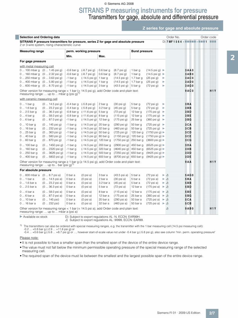
Please note:• It is not possible to have a smaller span than the smallest span of the device of the entire device range.• The value must not fall below the minimum permissible operating pressure of the special measuring range of the selected
measuring cell.• The required span of the device must lie between the smallest and the largest possible span of the entire device range.
■ Selection and Ordering data Order No. Order code
SITRANS P pressure transmitters for pressure, series Z for gage and absolute pressure2 or 3-wire system, rising characteristic curve
D) 7 MF 1 5 6 4 - 77777 - 777 1 777
Measuring range perm. working pressure Burst pressure
Min. Max.
For gage pressure
with metal measuring cell0 ... 100 mbar g (0 ... 1.45 psi g) -0.6 bar g (-8.7 psi g) 0.6 bar g (8.7 psi g) 1 bar g (14.5 psi g) } 3 A A 00 ... 160 mbar g (0 ... 2.32 psi g) -0.6 bar g (-8.7 psi g) 0.6 bar g (8.7 psi g) 1 bar g (14.5 psi g) } 3 A B 00 ... 250 mbar g (0 ... 3.63 psi g) -1 bar g (-14.5 psi g) 1 bar g (14.5 psi g) 1.7 bar g (25 psi g) } 3 A C 00 ... 400 mbar g (0 ... 5.80 psi g) -1 bar g (-14.5 psi g) 1 bar g (14.5 psi g) 1.7 bar g (25 psi g) } 3 A D 00 ... 600 mbar g (0 ... 8.70 psi g) -1 bar g (-14.5 psi g) 3 bar g (43.5 psi g) 5 bar g (72 psi g) } 3 A G 0
Other version for measuring range < 1 bar (< 14.5 psi g), add Order code and plain text: measuring range: ... up to ... mbar g (psi g)1)
9 A C 0 H 1 Y
with ceramic measuring cell
0 ... 1 bar g (0 ... 14.5 psi g) -0.4 bar g (-5.8 psi g) 2 bar g (30 psi g) 5 bar g (72 psi g) } 3 B A0 ... 1.6 bar g (0 ... 23.2 psi g) -0.4 bar g (-5.8 psi g) 3.2 bar g (45 psi g) 5 bar g (72 psi g) } 3 B B0 ... 2.5 bar g (0 ... 36.3 psi g) -0.8 bar g (-11.6 psi g) 5 bar g (72 psi g) 12 bar g (175 psi g) } 3 B D0 ... 4 bar g (0 ... 58.0 psi g) -0.8 bar g (-11.6 psi g) 8 bar g (115 psi g) 12 bar g (175 psi g) } 3 B E0 ... 6 bar g (0 ... 87.0 psi g) -1 bar g (-14.5 psi g) 12 bar g (175 psi g) 25 bar g (360 psi g) } 3 B G
0 ... 10 bar g (0 ... 145 psi g) -1 bar g (-14.5 psi g) 20 bar g (290 psi g) 50 bar g (725 psi g) } 3 C A0 ... 16 bar g (0 ... 232 psi g) -1 bar g (-14.5 psi g) 32 bar g (460 psi g) 50 bar g (725 psi g) } 3 C B0 ... 25 bar g (0 ... 363 psi g) -1 bar g (-14.5 psi g) 50 bar g (725 psi g) 120 bar g (1750 psi g) } 3 C D0 ... 40 bar g (0 ... 580 psi g) -1 bar g (-14.5 psi g) 80 bar g (1150 psi g) 120 bar g (1750 psi g) } 3 C E0 ... 60 bar g (0 ... 870 psi g) -1 bar g (-14.5 psi g) 120 bar g (1750 psi g) 250 bar g (3600 psi g) } 3 C G
0 ... 100 bar g (0 ... 1450 psi g) -1 bar g (-14.5 psi g) 200 bar g (2900 psi g) 450 bar g (6525 psi g) } 3 D A0 ... 160 bar g (0 ... 2320 psi g) -1 bar g (-14.5 psi g) 320 bar g (4640 psi g) 450 bar g (6525 psi g) } 3 D B0 ... 250 bar g (0 ... 3626 psi g) -1 bar g (-14.5 psi g) 500 bar g (7250 psi g) 650 bar g (9425 psi g) } 3 D D0 ... 400 bar g (0 ... 5802 psi g) -1 bar g (-14.5 psi g) 600 bar g (8700 psi g) 650 bar g (9425 psi g) } 3 D E
Other version for measuring range ≥ 1 bar g (≥ 14.5 psi g), add Order code and plain text: measuring range: ... up to... bar (psi g)1)
9 A A H 1 Y
For absolute pressure
0 ... 600 mbar a (0 ... 8.7 psi a) 0 bar a (0 psi a) 3 bar a (43.5 psi a) 5 bar a (72 psi a) } J) 5 A G 00 ... 1 bar a (0 ... 14.5 psi a) 0 bar a (0 psi a) 2 bar a (30 psi a) 5 bar a (72 psi a) } J) 5 B A0 ... 1.6 bar a (0 ... 23.2 psi a) 0 bar a (0 psi a) 3.2 bar a (45 psi a) 5 bar a (72 psi a) } J) 5 B B0 ... 2.5 bar a (0 ... 36.3 psi a) 0 bar a (0 psi a) 5 bar a (72 psi a) 12 bar a (175 psi a) } J) 5 B D
0 ... 4 bar a (0 ... 58.0 psi a) 0 bar a (0 psi a) 8 bar a (115 psi a) 12 bar a (175 psi a) } J) 5 B E0 ... 6 bar a (0 ... 87.0 psi a) 0 bar a (0 psi a) 12 bar a (175 psi a) 25 bar a (360 psi a) } J) 5 B G0 ... 10 bar a (0 ... 145 psi) 0 bar a (0 psi a) 20 bar a (290 psi a) 50 bar a (725 psi a) } J) 5 C A0 ... 16 bar a (0 ... 232 psi) 0 bar a (0 psi a) 32 bar a (460 psi a) 50 bar a (725 psi a) } J) 5 C B
Other version for measuring range < 1 bar (< 14.5 psi a), add Order code and plain text: measuring range: ... up to ... mbar a (psi a)
J) 9 A B 0 H 1 Y
} Available ex stock D) Subject to export regulations AL: N, ECCN: EAR99H.J) Subject to export regulations AL: 9I999, ECCN: EAR99.
1) The transmitters can also be ordered with special measuring ranges, e.g. the transmitter with the 1 bar measuring cell (14.5 psi measuring cell): -0.2 ... +0.8 bar g (-2.9 ... +11.6 psi g) or-0.4 ... +0.6 bar g (-5.8 ... +8.7 psi g) or ..., however start-of-scale value not under -0.4 bar g (-5.8 psi g), also see column "min. perm. operating pressure"
© Siemens AG 2008

SITRANS P measuring instruments for pressureTransmitters for gage, absolute and differential pressure
Z series for gage and absolute pressure
2/8 Siemens FI 01 · 2009 US Edition
2
■ Selection and Ordering data Order No. Order code
SITRANS P pressure transmitters for pressure, series Z for pressure and absolute pressure2 or 3-wire system, rising characteristic curve
D) 7 MF 1 5 6 4 - 77777 - 777 1 777
Measuring range Perm. working pressure Burst pressure
min. max.
Measuring ranges for gage pressure (only for US market)
(0 ... 10 psi g) (-3 psi g) (20 psi g) (60 psi g) 4 B A(0 ... 15 psi g) (-6 psi g) (30 psi g) (72 psi g) 4 B B(3 ... 15 psi g) (-6 psi g) (30 psi g) (72 psi g) 4 B C(0 ... 20 psi g) (-6 psi g) (40 psi g) (72 psi g) 4 B D(0 ... 30 psi g) (-6 psi g) (60 psi g) (72 psi g) 4 B E
(0 ... 60 psi g) (-11.5 psi g) (120 psi g) (175 psi g) 4 B F(0 ... 100 psi g) (-14.5 psi g) (200 psi g) (360 psi g) 4 B G(0 ... 150 psi g) (-14.5 psi g) (300 psi g) (725 psi g) 4 C A(0 ... 200 psi g) (-14.5 psi g) (400 psi g) (725 psi g) 4 C B(0 ... 300 psi g) (-14.5 psi g) (600 psi g) (1750 psi g) 4 C D
(0 ... 500 psi g) (-14.5 psi g) (1000 psi g) (1750 psi g) 4 C E(0 ... 750 psi g) (-14.5 psi g) (1500 psi g) (3600 psi g) 4 C F(0 ... 1000 psi g) (-14.5 psi g) (2000 psi g) (3600 psi g) 4 C G(0 ... 1500 psi g) (-14.5 psi g) (3000 psi g) (6525 psi g) 4 D A(0 ... 2000 psi g) (-14.5 psi g) (4000 psi g) (6525 psi g) 4 D B
(0 ... 3000 psi g) (-14.5 psi g) (6000 psi g) (9425 psi g) 4 D D(0 ... 5000 psi g) (-14.5 psi g) (8700 psi g) (9425 psi g) 4 D E(0 ... 6000 psi g) (-14.5 psi g) (8700 psi g) (9425 psi g) 4 D F
Other version, add Order code and plain text: Measuring range: ... up to ... psi g 9 B A H 1 Y
Measuring ranges for absolute pressure (only for US market)
(0 ... 10 psi a) (0 psi a) (20 psi a) (60 psi a) J) 6 A G(0 ... 15 psi a) (0 psi a) (30 psi a) (72 psi a) J) 6 B A(0 ... 20 psi a) (0 psi a) (40 psi a) (72 psi a) J) 6 B B(0 ... 30 psi a) (0 psi a) (60 psi a) (72 psi a) J) 6 B D(0 ... 60 psi a) (0 psi a) (120 psi a) (175 psi a) J) 6 B E
(0 ... 100 psi a) (0 psi a) (200 psi a) (360 psi a) J) 6 B G(0 ... 150 psi a) (0 psi a) (300 psi a) (725 psi a) J) 6 C A(0 ... 200 psi a) (0 psi a) (400 psi a) (725 psi a) J) 6 C B(0 ... 300 psi a) (0 psi a) (600 psi a) (1725 psi a) J) 6 C C
Other version, add Order code and plain text: Measuring range: ... up to ... psi a J) 9 B B H 1 Y
Output signal
4 ... 20 mA;C 2-wire system; power supply 10 ... 36 V DC } 00 ... 10 V; 3-wire system; power supply 15 ... 36 V DC 1 0
Explosion protection
Without } 0With explosion protection Ex II 1/2 G EEx ia IIC T4 (only for version 4 ... 20 mA; 2-wire system; power supply 10 ... 30 V DC)
1
With explosion protection "Intrinsic safety T.I.I.S." (available soon) 2
Electrical connection
Plug to DIN 43650, Form A, cable inlet M16 x 1.5 } 1Round connector M12, IP67 2Plug to DIN 43650, cable inlet ½-14 NPT 3Plug to DIN 43650, cable inlet Pg11 4Cable gland Pg11 with 2 m PE cable, IP68 6Special version (specify Order code and plain text) 9 N 1 Y
} Available ex stock D) Subject to export regulations AL: N, ECCN: EAR99H.J) Subject to export regulations AL: 9I999, ECCN: EAR99.
© Siemens AG 2008

SITRANS P measuring instruments for pressureTransmitters for gage, absolute and differential pressure
Z series for gage and absolute pressure
2/9Siemens FI 01 · 2009 US Edition
2
■ Selection and Ordering data Order No. Order code
SITRANS P pressure transmitters for pressure, series Z for pressure and absolute pressure2 or 3-wire system, rising characteristic curve
D) 7 MF 1 5 6 4 - 77777 - 777 1 777
Process connection
G½" male to EN 837-1 (½" BSP male) (standard for metric pressure ranges mbar, bar) } AG½" male thread and G1/8" female thread BG¼“ male to EN837-1 (¼“ BSP male) C7/16"-20 UNF male D¼"-18 NPT male (standard for pressure ranges psi) E
¼"-18 NPT female F½"-14 NPT male G½"-14 NPT female HRC ½" male to JIS B 7505 KG1" male (only for measuring ranges ≥ 1 bar g (14.5 psi g)) and max. permissible working pressure100 bar g (1450 psi g)
M
Special version (specify Order code and plain text) Z P 1 Y
Sealing material between sensor and housing
Viton (standard) } ANeoprene BPerbunan CSpecial version (specify Order code and plain text) Z Q 1 Y
Further designs Order code / Order No.
Quality inspection certificate (Factory calibration) to IEC 60770-2,add "-Z" to Order No. and Order code.
C11
Oxygen version, oil and grease-free cleaning (only if the sealing material between sensor and housing is Viton and only for measuring ranges ≥ 1 bar g (≥ 14.5 psi g)and ≥ 1 bar a (≥ 14.5 psi a)
E10
Accessories Order No.
Quality inspection certificate (Factory calibration) to IEC 60770-2 supplied later,specify factory no. of transmitter.
D) 7MF1564-8CC11
} Available ex stock D) Subject to export regulations AL: N, ECCN: EAR99H.
© Siemens AG 2008

SITRANS P measuring instruments for pressureTransmitters for gage, absolute and differential pressure
SITRANS P250 for differential pressure
2/10 Siemens FI 01 · 2009 US Edition
2
■ Overview
SITRANS P250 transmitter for differential pressure
The SITRANS P250 transmitter measures the differential pres-sure of liquids and gases.
■ Benefits
• High measuring accuracy• Sturdy stainless steel enclosure• For aggressive and non-aggressive media • For the measurement of the differential pressure of liquids and
gases• Temperature-compensated measuring cell• Compact design
■ Application
The SITRANS P250 transmitter for differential pressure is prima-rily used in the following industries:• Chemical industry• Pharmaceutical industry• Food industry• Mechanical engineering• Shipbuilding• Water supply
■ Design
Main components:• Stainless steel enclosure with piezo-resistive ceramic measur-
ing cell and (temperature-compensated) electronics module.• Process connection made of stainless steel in diverse designs
(see Selection and ordering data)• Electrical connection through connectors acc. to EN 175301-
803-A and round connectors M12, as well as with permanently fixed cable
■ Function
The pressure transmitter measures the differential pressure of liquids and gases.
Mode of operation
SITRANS P250 pressure transmitter, function diagram
The piezo-resistive ceramic measuring cell (membrane) has a Wheatstone bridge circuit, on which the operating pressure P1 and P2 of the media acts at both ends.
The voltage output from the measuring cell is converted by an amplifier into an output current of 4 to 20 mA or an output voltage of 0 to 5 or 10 V DC.
The output current and voltage are linearly proportional to the in-put pressure.
■ Technische Daten
SITRANS P250 differential pressure transmitter
Application
Differential pressure transmitter Liquids and neutral gases
Mode of operation
Measuring principle Piezo-resistive measuring cell (ceramic diaphragm)
Input
Measured variable Differential pressure
Measuring range 0 ... 0.1 to 0 ... 25 bar(0 ... 1.45 to 0 ... 363 psi)
Operating pressure ≤ 25 bar (363 psi) at a differential pressure range < 6 bar (87 psi)≤ 50 bar (725 psi) at a differential pressure range > 10 bar (145 psi)
Burst pressure 1.5 x operating pressure
Output
Output signal
• Current output signal 4 ... 20 mA
• Voltage output signal 0 ... 5 V and 0 ... 10 V DC
Load
3-wire > 10 kΩ
2-wire ≤ (UH - 11 V) / 0.02 A
Measuring accuracy
Dynamic behavior (at 25°C (77°F), including conformity error, hystere-sis and repeatability)
≤ 1 % of typical full-scale value, see "Measuring range" table
Long-term drift acc. to IEC 60770 ≤ 0.5 % of full-scale value/year
Influence of ambient temperature
• Start of scale ≤ 0.6 %/10 K of full-scale value (≤ 1.2 %/10 K for measuring cell 0 ... 0.1 bar (1.45 psi))
• Full-scale value ≤ 0.22 %/10 K of full-scale value (≤ 0.37 %/10 K for measuring cell 0 ... 0.1 bar (1.45 psi))
Dynamic behavior Suitable for static and dynamic measurements
Response time T99 < 5 ms
Load variation < 50 Hz
p1 p2
Uconst.
UI I0, UB
© Siemens AG 2008
SITRANS P measuring instruments for pressureTransmitters for gage, absolute and differential pressure
SITRANS P250 for differential pressure
2/11Siemens FI 01 · 2009 US Edition
2
■ Schematics
Connection with current output 4 ... 20 mA and plug to EN 175301-803-A
Connection with current output 4 ... 20 mA and round connector
Connection with current output 4 ... 20 mA and permanently fixed cable
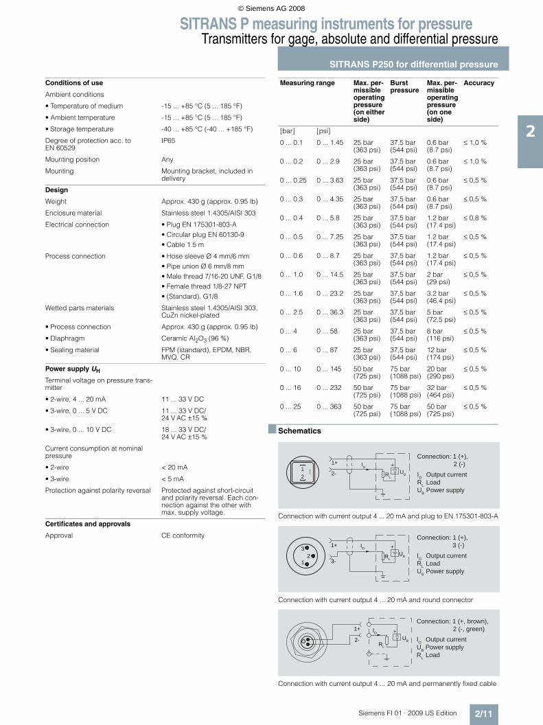
Conditions of use
Ambient conditions
• Temperature of medium -15 ... +85 °C (5 ... 185 °F)
• Ambient temperature -15 ... +85 °C (5 ... 185 °F)
• Storage temperature -40 ... +85 °C (-40 ... +185 °F)
Degree of protection acc. to EN 60529
IP65
Mounting position Any
Mounting Mounting bracket, included in delivery
Design
Weight Approx. 430 g (approx. 0.95 lb)
Enclosure material Stainless steel 1.4305/AISI 303
Electrical connection • Plug EN 175301-803-A• Circular plug EN 60130-9• Cable 1.5 m
Process connection • Hose sleeve Ø 4 mm/6 mm• Pipe union Ø 6 mm/8 mm• Male thread 7/16-20 UNF, G1/8• Female thread 1/8-27 NPT • (Standard), G1/8
Wetted parts materials Stainless steel 1.4305/AISI 303, CuZn nickel-plated
• Process connection Approx. 430 g (approx. 0.95 lb)
• Diaphragm Ceramic Al2O3 (96 %)
• Sealing material FPM (standard), EPDM, NBR, MVQ, CR
Power supply UH
Terminal voltage on pressure trans-mitter
• 2-wire, 4 ... 20 mA 11 ... 33 V DC
• 3-wire, 0 ... 5 V DC 11 ... 33 V DC/24 V AC ±15 %
• 3-wire, 0 ... 10 V DC 18 ... 33 V DC/24 V AC ±15 %
Current consumption at nominal pressure
• 2-wire < 20 mA
• 3-wire < 5 mA
Protection against polarity reversal Protected against short-circuit and polarity reversal. Each con-nection against the other with max. supply voltage.
Certificates and approvals
Approval CE conformity
Measuring range Max. per-missible operating pressure (on either side)
Burst pressure
Max. per-missible operating pressure (on one side)
Accuracy
[bar] [psi]
0 ... 0.1 0 ... 1.45 25 bar (363 psi)
37,5 bar(544 psi)
0.6 bar (8.7 psi)
≤ 1,0 %
0 ... 0.2 0 ... 2.9 25 bar (363 psi)
37,5 bar(544 psi)
0.6 bar (8.7 psi)
≤ 1,0 %
0 ... 0.25 0 ... 3.63 25 bar (363 psi)
37,5 bar(544 psi)
0.6 bar (8.7 psi)
≤ 0,5 %
0 ... 0.3 0 ... 4.35 25 bar (363 psi)
37,5 bar(544 psi)
0.6 bar (8.7 psi)
≤ 0,5 %
0 ... 0.4 0 ... 5.8 25 bar (363 psi)
37,5 bar(544 psi)
1.2 bar (17.4 psi)
≤ 0,8 %
0 ... 0.5 0 ... 7.25 25 bar (363 psi)
37,5 bar(544 psi)
1.2 bar (17.4 psi)
≤ 0,5 %
0 ... 0.6 0 ... 8.7 25 bar (363 psi)
37,5 bar(544 psi)
1.2 bar (17.4 psi)
≤ 0,5 %
0 ... 1.0 0 ... 14.5 25 bar (363 psi)
37,5 bar(544 psi)
2 bar (29 psi)
≤ 0,5 %
0 ... 1.6 0 ... 23.2 25 bar (363 psi)
37,5 bar(544 psi)
3.2 bar (46.4 psi)
≤ 0,5 %
0 ... 2.5 0 ... 36.3 25 bar (363 psi)
37,5 bar(544 psi)
5 bar (72.5 psi)
≤ 0,5 %
0 ... 4 0 ... 58 25 bar (363 psi)
37,5 bar(544 psi)
8 bar (116 psi)
≤ 0,5 %
0 ... 6 0 ... 87 25 bar (363 psi)
37,5 bar(544 psi)
12 bar (174 psi)
≤ 0,5 %
0 ... 10 0 ... 145 50 bar (725 psi)
75 bar(1088 psi)
20 bar (290 psi)
≤ 0,5 %
0 ... 16 0 ... 232 50 bar (725 psi)
75 bar(1088 psi)
32 bar (464 psi)
≤ 0,5 %
0 ... 25 0 ... 363 50 bar (725 psi)
75 bar(1088 psi)
50 bar (725 psi)
≤ 0,5 %
UB Power supplyRL LoadIO Output current
Connection: 1 (+), 2 (-)IO
UBRL
1+ +2-
12
+Connection: 1 (+), 3 (-)IO Output currentRL LoadUB Power supply
UBRL
IO
3-
1+
12
3
Connection: 1 (+, brown), 2 (-, green)IO Output currentUB Power supplyRL Load
UBRL
IO
2-
1+ +
© Siemens AG 2008

SITRANS P measuring instruments for pressureTransmitters for gage, absolute and differential pressure
SITRANS P250 for differential pressure
2/12 Siemens FI 01 · 2009 US Edition
2Connection with voltage output 0 ... 5 V DC (0 ... 10 V DC) and plug to EN 175301-803-A
Connection with voltage output 0 ... 5 V DC (0 ... 10 V DC) and round con-nector
Connection with voltage output 0 ... 5 V DC (0 ... 10 V DC) and perma-nently fixed cable
■ Dimensional drawings
SITRANS P250 differential pressure transmitter with socket outlet to EN 175301-803-A, dimensions in mm (inch)
SITRANS P250 differential pressure transmitter with round connector to EN 60130-9, dimensions in mm (inch)
SITRANS P250 differential pressure transmitter with cable, dimensions in mm (inch)
+Connection: 1 (+UB), 2 (-), 3 (+U0)UO Output voltageRL LoadUB Power supply
UBRLUO
1+
3-
123 2+
+
Connection: 1 (+UB, brown), 2 (+U0, green), 3 (-, white)UO Output voltageUB Power supplyRL Load
UBRL
UO
1
2
3
12
3
Connection: 1 (+UB), 2 (-), 3 (+U0)Uo Output voltageUB Power supplyRL Load
+UO
UBRL
1+
2-
3+
Stainless
(mou
nted
)
Socket outletEN 175301-803-A
20 (0.79)
P1
P2
Ø 2
5(0
.98)
M 4
44 (1.7)X
~ 13
6 (5
.4)
15 ±
0,5
21 ±
0,8
5 (0
.2)
102
(4.0
2)
Round connectorEN 60130-9
(mou
nted
)~1
58 (6
.2)
~108
(4.3
)Cable
~95
(3.7
)
~138
(5.4
)
© Siemens AG 2008

SITRANS P measuring instruments for pressureTransmitters for gage, absolute and differential pressure
SITRANS P250 for differential pressure
2/13Siemens FI 01 · 2009 US Edition
2
Process connections Ø Width across flats
L X
[mm] [inch] [mm] [inch] [mm] [inch]
Pipe union with screw-in nipple for outer pipe (stainless steel 1.4305/AISI 303)
6 a = 10b = 12
24 65
8 a = 12b = 14
26 67
Female thread G1/8(stainless steel 1.4305/AISI 303)
- a = 14 12 53
Pipe union with screw-in nipple for outer pipe (CuZn nickel-plated)
6 a = 10b = 12
24 65
8 a = 12b = 14
25 66
Hose connection for hose (CuZn nickel-plated, stainless steel 1.4571/AISI 316TI)
4 a = 10 20 61
6 a = 10 25 66
Male thread G1/8(CuZn nickel-plated)
- a = 10b = 12
20 61
Male thread G1/87/16-20 UNF (CuZn nickel-plated)
- a = 14 18 59
L
a b
1/8-
27 N
PT
L
a
1/8-
27 N
PTG1/8
a b
L
1/8-
27 N
PT
a
L
1/8-
27 N
PT
L
ba
1/8-
27 N
PT
a
L
1/8-
27 N
PT
7/16
-20
UN
F
© Siemens AG 2008

SITRANS P measuring instruments for pressureTransmitters for gage, absolute and differential pressure
SITRANS P250 for differential pressure
2/14 Siemens FI 01 · 2009 US Edition
2
■ Selection and ordering data Order No. Order code
SITRANS P 250 pressure transmitter for differential pressureAccuracy ≤ 1 %, wetted parts ceramic/stainless steel 1.4301, scope of delivery: transmitter, mounting bracket and instruction manual, without explosion protection
7 M F 1 6 4 1 - 7777 0 - 777 0 777
Measuring range0 ... 0.1 bar (0 ... 1.45 psi) } 3 A A0 ... 0.2 bar (0 ... 2.90 psi) } 3 A C0 ... 0.25 bar (0 ... 3.63 psi) } 3 A D0 ... 0.3 bar (0 ... 5.35 ps) } 3 A E0 ... 0.4 bar (0 ... 5.80 psi) } 3 A F0 ... 0.5 bar (0 ... 7.25 psi) } 3 A G0 ... 0.6 bar (0 ... 8.70 psi) } 3 A H0 ... 1.0 bar (0 ... 14.5 psi) } 3 B A0 ... 1.6 bar (0 ... 23.2 psi) } 3 B B0 ... 2.5 bar (0 ... 36.3 psi) } 3 B D0 ... 4.0 bar (0 ... 58.0psi) } 3 B E0 ... 6.0 bar (0 ... 87.0 psi) } 3 B G0 ... 10.0 bar (0 ... 145 psi) } 3 C A0 ... 16.0 bar (0 ... 232 psi) } 3 C B0 ... 25.0 bar (0 ... 363 psi) } 3 C D
Output signal4 ... 20 mA } 00 ... 5 V DC 10 ... 10 V DC 2
Electrical connection• Plug acc. to EN 175 301-803-A (suitable coupling included in scope of delivery) } 1• Round connector acc. to EN 60139-9 2• Cable 1.5 m with cable gland 3
Process connection• Without connections, female thread 1/8-27 NPT } A• Hose connection
- CuZn nickel-plated, for hose ∅ 4 mm B- CuZn nickel-plated, for hose ∅ 6 mm C- PVDF, for hose ∅ 6 mm D
• Pipe union- CuZn nickel-plated, for pipe ∅ 6 mm E- Stainless steel 1.4304, for pipe ∅ 6 mm F- CuZn nickel-plated, for pipe ∅ 8 mm G- Stainless steel 1.4304, for pipe ∅ 8 mm H
• Male thread, 7/16-20 UNF (CuZn nickel-plated) L• Adapter
- Inner, G1/8 (stainless steel), for pipe ∅ 6 mm M- Outer, with union nut, for pipe ∅ 6 mm N
sealing material• Fluoro rubber (Viton/FPM) } A• Ethylene propylene diene monomer rubber (EPDM) B• Nitrile butadiene rubber (NBR) C• Silicone rubber (MVQ) D• Neoprene (CR) E
Weitere Ausführungen Kurzangabe
Please add "-Z" to Order No. and specify Order code(s).
Quality inspection certificate (Factory calibration) to IEC 60770-2 supplied C11
} Available ex stock
© Siemens AG 2008
SITRANS P measuring instruments for pressureTransmitters for gage, absolute and differential pressure
ZD series for gage and absolute pressure
2/15Siemens FI 01 · 2009 US Edition
2
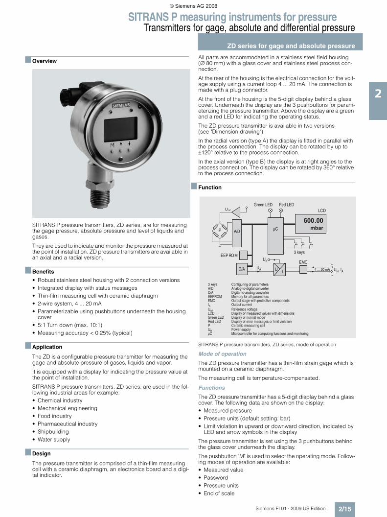
■ Overview
SITRANS P pressure transmitters, ZD series, are for measuring the gage pressure, absolute pressure and level of liquids and gases.
They are used to indicate and monitor the pressure measured at the point of installation. ZD pressure transmitters are available in an axial and a radial version.
■ Benefits
• Robust stainless steel housing with 2 connection versions• Integrated display with status messages• Thin-film measuring cell with ceramic diaphragm• 2-wire system, 4 ... 20 mA• Parameterizable using pushbuttons underneath the housing
cover• 5:1 Turn down (max. 10:1)• Measuring accuracy < 0.25% (typical)
■ Application
The ZD is a configurable pressure transmitter for measuring the gage and absolute pressure of gases, liquids and vapor.
It is equipped with a display for indicating the pressure value at the point of installation.
SITRANS P pressure transmitters, ZD series, are used in the fol-lowing industrial areas for example:• Chemical industry• Mechanical engineering• Food industry• Pharmaceutical industry• Shipbuilding • Water supply
■ Design
The pressure transmitter is comprised of a thin-film measuring cell with a ceramic diaphragm, an electronics board and a digi-tal indicator.
All parts are accommodated in a stainless steel field housing (∅ 80 mm) with a glass cover and stainless steel process con-nection.
At the rear of the housing is the electrical connection for the volt-age supply using a current loop 4 ... 20 mA. The connection is made with a plug connector.
At the front of the housing is the 5-digit display behind a glass cover. Underneath the display are the 3 pushbuttons for param-eterizing the pressure transmitter. Above the display are a green and a red LED for indicating the operating status.
The ZD pressure transmitter is available in two versions (see "Dimension drawing"):
In the radial version (type A) the display is fitted in parallel with the process connection. The display can be rotated by up to ±120° relative to the process connection.
In the axial version (type B) the display is at right angles to the process connection. The display can be rotated by 360° relative to the process connection.
■ Function
SITRANS P pressure transmitters, ZD series, mode of operation
Mode of operation
The ZD pressure transmitter has a thin-film strain gage which is mounted on a ceramic diaphragm.
The measuring cell is temperature-compensated.
Functions
The ZD pressure transmitter has a 5-digit display behind a glass cover. The following data are shown on the display:• Measured pressure• Pressure units (default setting: bar)• Limit violation in upward or downward direction, indicated by
LED and arrow symbols in the display
The pressure transmitter is set using the 3 pushbuttons behind the glass cover underneath the display.
The pushbutton "M" is used to select the operating mode. Follow-ing modes of operation are available:• Measured value• Password• Pressure units• End of scale
������
����
� ���
���
�����
�
�
���� �����������
��
��
�� � �
��
����������� ������
����
������ � �!"#$�"�#� !�%&�&��'������ ��&( #)' ) "#"'&(�* �+��'����� �"#"'&()' )&�&( #�* �+��'������� �� ���! ��&((�%&�&��'����� �$'%$'��'&#��,"'-�%� '�*'"+��* �% ���'��� �$'%$'�*$����'���! ��!����*��+ ('&#��� �"�%(&�� !���&�$�� �+&($���,"'-� "����" ���������� �"�%(&�� !�� ��&(�� ��� ��� �"�%(&�� !���� ������&#��� ��("�"'�+" (&'" �� ���&�"*���&�$�"�#�*�((�� � ,����$%%(��� "*� * �'� ((���! ��* �%$'"�#�!$�*'" ���&� �� �"' �"�#
������
© Siemens AG 2008

SITRANS P measuring instruments for pressureTransmitters for gage, absolute and differential pressure
ZD series for gage and absolute pressure
2/16 Siemens FI 01 · 2009 US Edition
2
• Upper and lower limit value• Zero adjustment• Upper and lower current saturation limit• Electrical damping
The other two pushbuttons are used to set the values in the indi-vidual operating modes.
Two LED indicators are fitted above the display to monitor the set range and the status.
The green LED signals that the measured pressure lies within the set limits. The red LED lights up when the measured pressure lies outside the set limits and when there is an error.
■ Technical specifications
SITRANS P pressure transmitters, ZD series
Mode of operation
Measuring principle Thin-film strain gage
Input
Measured variable Gage and absolute pressure
Measured range Resolution
0 ... 2 bar (0 ... 29 psi) 0.6 mbar (0.008 psi)
0 ... 10 bar (0 ... 145 psi) 3 mbar (0.044 psi)
0 ... 50 bar (0 ... 725 psi) 15 mbar (0.218 psi)
0 ... 200 bar (0 ... 2900 psi) 60 mbar (0.9 psi)
0 ... 400 bar (0 ... 5802 psi) 120 mbar (1.8 psi)
Measured range Overload limit
0 ... 2 bar (0 ... 29 psi) 5 bar (72.5 psi)
0 ... 10 bar (0 ... 145 psi) 25 bar (363 psi)
0 ... 50 bar (0 ... 725 psi) 120 bar (1740 psi)
0 ... 200 bar (0 ... 2900 psi) 500 bar (7250 psi)
0 ... 400 bar (0 ... 5802 psi) 600 bar (8700 psi)
Turn down 5:1
Output
Output signal 4 ... 20 mA
Lower current limit min. 3.6 mA
Upper current limit max. 23 mA
Output protected against Reversed polarity, overvoltage and short-circuiting
Max. load R B = (UH - 12 V) / 0.023 A
Voltage measurement Linear rising
Measuring accuracy To EN 60770-1
Error in measurement (including non-linearity, hysteresis and repeat-ability, at 25 °C (77 °F))
< 0.25% of full-scale value (typi-cal), max. 0.5%
Adjustment time < 100 ms
Long-term drift 0.25% of full scale value/year
Influence of ambient temperature < ±0.25%/10 K (< ±0.25%/10 K) of full-scale value
Vibration influence 0.05%/g to 500 Hz in all directions (to IEC 68-2-64)
Power supply effect < ±0.01%/V of full-scale value
Rated conditions
Ambient conditions
• Ambient temperature -25 ... +85 °C (-13 ... +185 °F)
• Storage temperature -40 ... +85 °C (-40 ... +185 °F)
Medium conditions
• Process temperature -30 ... +100 °C (-22 ... +212 °F)
Degree of protection IP65 to EN 60529
Electromagnetic compatibility
• Emitted interference and interfer-ence immunity
To EN 61326/A1 appendix A (1998)
Displays and controls
Display LCD, max. 5 digits, digit height 9 mm
Decimal point Freely parameterizable
Limit values Freely parameterizable
Limit violation display Red LED and message on LCD (↑ symbol /↓ symbol in case of limit violation in upward / down-ward direction)
Parameterization With 3 pushbuttons
Units mA or % or physical variable (default setting: bar)Other dimensions: mbar, kPa, MPa, mmH2O, mH2O, psi, inH2O, mmHg, kg/cm², torr, atm
Damping Between 0.1 and 100 s (increment: 0.1 s) freely parame-terizable
Design
Weight ≈0.6 kg (≈1.32 lb)
Electrical connection Using 2-pole plug connector with M16x1.5-Cable inlet to EN 175301-803A, plastic
Process connection • Male thread G½B and female thread G1/8B
• G½B to EN 837-1• Female thread: ½-14 NPT
Version of housing/process connec-tion
• Radial (type A), can be swiveled by max. ±120° (α)
• Axial (type B), can be swiveled by max. ±360°
Material
Non-wetted parts materials
• Field housing Ø 80 mm (3.15 inch), stainless steel mat. No. 1.4016
• Cover Stainless steel, mat. No. 1.4016 with glass
Wetted parts materials
• Measuring cell Al2O3
• Gasket Viton
• Process connection Stainless steel, mat. No. 1.4571/316Ti
Power supply
Terminal voltage on pressure trans-mitter (UH)
12 ... 30 V DC
Certificate and approvals
Classification according to pressure equipment directive 97/23/EC
For gases of fluid group 1 and liq-uids of fluid 1; complies with requirements of article 3, para-graph 3 (sound engineering prac-tice)
© Siemens AG 2008

SITRANS P measuring instruments for pressureTransmitters for gage, absolute and differential pressure
ZD series for gage and absolute pressure
2/17Siemens FI 01 · 2009 US Edition
2
■ Dimensional drawings
SITRANS P pressure transmitters, ZD series, dimensional drawing, dimensions in mm (inch)
■ Schematics
SITRANS P pressure transmitters, ZD series, connection diagram
�
�
.�/��0����1
�23
45��6
�/�7�08�981
�7�08�661
87��07�9/1
.�/��0����1
�/�7�08
�981
�7�08
�661
2)8��:�; �23
8<=8�7 �2):�;
�8�/3
.�/��0����1
�:�/�6)8
������ ������
8<=8�7 �2):�;
�
����
���
�
��
��
�
�� ������������� ���� � �������������
© Siemens AG 2008

SITRANS P measuring instruments for pressureTransmitters for gage, absolute and differential pressure
ZD series for gage and absolute pressure
2/18 Siemens FI 01 · 2009 US Edition
2
F) Subject to export regulations AL: 9I999, ECCN: N.
Selection and Ordering data Order No. Ord. Code
SITRANS P pressure transmitters, ZD series for gage and absolute pressure
7M F 1 5 8 0 -
Conformity error 0.25%, 5:1 turn down (max. 10:1), housing and process connection made of stainless steel membrane made of ceramic, 2-wire system, output 4 ... 20 mA
7777 0 777
Input variableGage pressure } 1
Absolute pressure }
F)2
Measured range Span0 ... 2 bar (0 ... 29 psi)
0 ... 0.4 / 2 bar(0 ... 5.8 / 29 psi)
} D
0 ... 10 bar (0 ... 145 psi)
0 ... 2 / 10 bar(0 ... 5.8 / 145 psi)
} E
0 ... 50 bar (0 ... 725 psi)
0 ... 10 / 50 bar(0 ... 145 / 725 psi)
} F
0 ... 200 bar (0 ... 2900 psi)
0 ... 40 / 200 bar(0 ... 580 / 2900 psi)
} G
0 ... 400 bar (0 ... 5802 psi)
0 ... 80 / 400 bar(0 ... 1160 / 5802 psi)
} H
Other version (on request)add Order Code and plain text: Process connection: ............
Z J 1 Y
Process connectionG½B male thread and G1/8B female thread } AG½B to EN 837-1 F) BFemale thread ½-14 NPT F) CG 1“ male thread F) M
DesignProcess connection vertically downwards, thread in connector M16x1.5
} 1
Process connection horizontally to rear, thread in connector M16x1.5
2
Process connection vertically downwards, thread in connector ½"-14 NPT
} 3
Process connection horizontally to rear, thread in connector ½"-14 NPT
4
Selection and Ordering data Order Code
Further designs
Please add "Z" to Order No. and specify Order code(s) and plain text.
Quality inspection certificate (Factory cali-bration) to IEC 60770-2 supplied
C1 1
Factory certificateto EN 10204-2.2 supplied
C1 4
Oxygen cleaning application, oil and grease-free cleaned(only in conjunction with the sealing material Viton between sensor and enclosure and only in conjunction with measuring ranges >= 1 bar g and 1 bar abs)
E1 0
Sealing material FEP between sensor and housing, instead of Vitonmax. operating pressure 15 bar (218 psi), max. measuring temperature -10 ... +50 °C
E2 0
Additional data
Please add "Z" to Order No. and specify Order code(s) and plain text.
Measuring range to be set,specify in plain text:Y01: ... up to ... mbar, bar, kPa, MPa, psi
Y0 1
TAG number made of stainless steel Y1 5
Accessories Order No.
Quality inspection certificate (Factory calibration) to IEC 60770-2 supplied later,specify factory of transmitter.
7MF1564-8CC11
} Available ex stock
© Siemens AG 2008

SITRANS P measuring instruments for pressureTransmitters for food, pharmaceuticals and biotechnology
SITRANS P Compactfor gage and absolute pressure
2/19Siemens FI 01 · 2009 US Edition
2
■ Overview
The SITRANS P Compact pressure transmitter is designed for the special requirements of the food, pharmaceutical and bio-technology industries.
The use of high-grade materials guarantees compliance with sanitary regulations.
Particular value has been placed on a high surface quality. It is therefore possible, for example, to guarantee roughness values down to Ra = 0.4 μm (1.57 ⋅ 10-5 inch) in the wetted area (welded seam area Ra < 0.8 μm (3.15 ⋅ 10-5 inch)). The system can be electropolished in addition.
A further important feature is the sanitary design of the process connection by means of various aseptic connections.
The completely welded stainless steel housing can be designed up to degree of protection IP67.
Using appropriate thermal decouplers, the SITRANS P Compact pressure transmitter can be used for process temperatures up to 200 °C (392 °F).
■ Benefits
• Measuring ranges from 0 to 160 mbar (0 to 2.32 psi) to 0 to 40 bar (0 to 580 psi)
• Linearity error including hysteresis < +0.2% of full-scale value• Piezo-resistive measurement system, vacuum-proof and over-
load-proof• Sanitary design according to EHEDG, FDA and GMP recom-
mendations• Material and surface quality according to sanitary require-
ments• Wetted parts made of stainless steel; completely welded• Signal output 4 to 20 mA (0 to 20 mA as option)• Stainless steel housing with degree of protection IP65 (IP67 as
option)• Process temperature up to 200 °C (392 °F)• Explosion protection II 2G EEx [ib] IIC T6 to ATEX• Easy and safe to clean
■ Application
The SITRANS P Compact pressure transmitter is designed for the special requirements of the food, pharmaceutical and bio-technology industries.
The use of high-grade materials guarantees compliance with sanitary regulations.
The SITRANS P Compact pressure transmitter is available in many versions. Exact adaptation of the pressure transmitter to conditions at the place of use is thus possible
■ Design
The electronics is potted to protect it against moisture, corrosive atmospheres and vibration.
Notes on operating the pressure transmitter
Compensation of internal atmospheric pressure
Compensation of the internal atmospheric pressure of the SITRANS P Compact pressure transmitters is performed as fol-lows:• in the plug versions by means of the screwed gland (IP65)• in the field housings by means of an integral sintered filter
(IP65) or a vented cable (IP67)• in versions with cable outlet by means of a vented cable (IP67)
In the absolute pressure range there is no need for compensa-tion with respect to atmospheric pressure.
Note: These degrees of protection are only achieved under the following conditions:• if the pressure transmitter is installed correctly• if the screwed glands are securely tightened• if the cable diameters agree with the nominal diameters of the
gaskets in the housing
Note: The integral EMC measures are only effective if the earth connection is made correctly.
CE marking
The CE marking of the pressure transmitter certifies compliance with the guidelines of the European Council (9/336/EC), the EMC law (13.11.1992), as well as the applicable generic standards.
Interference-free operation in systems and plants is achieved only if the specifications for shielding, earthing, cable routing and electrical isolation are observed during installation and as-sembly.
Hazardous areas
Note: Electrical equipment in hazardous areas must only be in-stalled and operated by trained personnel.
Modifications to units and connections result in cancellation of the explosion protection and guarantee.
With intrinsically-safe circuits, make sure that equipotential bonding exists throughout the complete cabling inside and out-side of the hazardous area. The limits specified in the ATEX ap-proval must be observed.
© Siemens AG 2008

SITRANS P measuring instruments for pressureTransmitters for food, pharmaceuticals and biotechnologySITRANS P Compactfor gage and absolute pressure
2/20 Siemens FI 01 · 2009 US Edition
2
■ Function
The process pressure acts on a piezo-resistive semiconductor measuring bridge through a remote seal and a transmission liq-uid. The pressure transmitter converts the pressure values into a load-independent current.
A compensation network makes the output signal largely inde-pendent of the ambient temperature. As a result of a specially adapted remote seal connection with minimized volume, the in-fluence of the process temperature on the output signal is greatly reduced compared to a conventional screw connection.
The pressure transmitters can be powered with a non-regulated DC voltage of 10 to 30 V. Output signals common to measuring technology are available.
■ Technical specifications
Pressure transmitters for food, pharmaceuticals and biotechnology
Mode of operation
Measuring principle Piezo-resistive
Input
Measured variable Gage or absolute pressure
Measured range 0 ... 160 mbar (0 ... 2.32 psi)... 0 ... 40 bar (0 ... 580 psi)
Output
Output signal
• Two-wire system 4 ... 20 mA
• Three-wire system 0 ... 20 mA
Measuring accuracy To EN 60770-1
Linearity error including hysteresis (reference point adjustment)
≤ 0.2% of full-scale value
Adjustment accuracy ≤ ± 0.2% of full-scale value
Adjustment time < 20 ms
Influence of ambient temperature
On th enclosure
• Zero < 0.2%/10 K of full-scale value
• Measured span < 0.2%/10 K of full-scale value
On the process connection (remote seal)
Zero error (depends on design)
• Flange remote seal
- DN 25 / 1" 4.8 mbar/10 K (0.070 psi/10 K)
- DN 32 / 1¼” 2.3 mbar/10 K (0.033 psi/10 K)
- DN 40 / 1½” 1.6 mbar/10 K (0.023 psi/10 K)
- DN 50 / 2" 0.6 mbar/10 K (0.009 psi/10 K)
• Clamp-on seal
- DN 25 / 1" 9.5 mbar/10 K (0.138 psi/10 K)
- DN 32 / 1¼” 4.1 mbar/10 K (0.060 psi/10 K)
- DN 40 / 1½” 3.9 mbar/10 K (0.057 psi/10 K)
- DN 50 / 2" 3.9 mbar/10 K (0.057 psi/10 K)
The zero error specified for the process connection should be consid-ered as a guideline for a standard design. We will produce a detailed system calculation on request. Systems with reduced remote seal errors are available on request.
Rated conditions
Installation conditions
• Mounting position Any, vertical as standard
Ambient conditions
• Ambient temperature -10 ... +70 °C (14 ... 158 °F)
• Storage temperature -10 ... +90 °C (14 ... 194 °F)
• Process temperature Max. 200 °C (392 °F), depends on design
• Degree of protection (to EN 60529) IP65, optional IP67
• Electromagnetic compatibility
- Emitted interference To EN 50081 Part 1, issue 1993 (residential and industrial areas). The unit has no own emissions.
- Interference immunity to EN 50082 Part 2, issue March 1995 (industrial areas)
Design
Weight (without remote seal)
• Field housing ≈ 460 g (≈ 1.01 lb)
• Housing with plug ≈ 200 g (≈ 0.44 lb)
Housing
• Designs • Field housing IP65 or IP67, with screwed gland
• Angled plug DIN 43650, IP65• Cable connection, IP67• Round plug connector M12,
IP65
• Material Stainless steel, mat. No. 1.4404/1.4305
Material of union nut Polyamide (with electrical con-nection using plug or cable)Electronics unit potted with sili-coneInternal ventilation for measuring ranges < 16 bar (< 232 psi), through housing thread or con-nection cable depending on design
Process connection
• Versions See Ordering data
• Material of coupling Stainless steel, mat. No. 1.4404/316L
Power supply
Terminal voltage on transmitter 10 ... 30 V DC
Rated voltage 24 V DC
Certificate and approvals
Classification according to pressure equipment directive (DRGL 97/23/EC)
For gases of fluid group 1 and liq-uids of fluid group 1; complies with the requirements of article 3, paragraph 1 (appendix 1); assigned to category III, confor-mity evaluation module H by the TÜV Nord
Explosion protection
• Intrinsic safety "i" TÜV 03 ATEX 2099 X
- Identification Ex II 2G EEx ib IIC T6
© Siemens AG 2008

SITRANS P measuring instruments for pressureTransmitters for food, pharmaceuticals and biotechnology
SITRANS P Compactfor gage and absolute pressure
2/21Siemens FI 01 · 2009 US Edition
2
Selection and Ordering data Order No. Ord. code
SITRANS P Compact pressure trans-mitters for pressure and absolute pressure with diaphragm flush at front
7 M F 8 0 1 0 -
2-wire systemProcess temperature up to 140 °C (284 °F)Accuracy: 0.2% of full-scale valueOutput 4 ... 20 mA
1 7777 - 7777 777
Diaphragm sealwith quick-release clampMilk pipe union to DIN 11851 with slotted union nut• DN 25 A D• DN 32 A E• DN 40 A F• DN 50 A G• DN 65 A HMilk pipe union to DIN 11851 with threaded socket• DN 25 B D• DN 32 B E• DN 40 B F• DN 50 B G• DN 65 B HClamp connection to DIN 32676• DN 25 C D• DN 40 C F• DN 50 C GClamp connection to ISO 2852• 1 inch D M• 1½ inch D N• 2 inch D P• 2½ inch D QIDF standard with slotted union nut• 1 inch E M• 1½ inch E N• 2 inch E PIDF standard with threaded socket• 1 inch F M• 1½ inch F N• 2 inch F PSMS standard with slotted union nut• 1 inch GM• 1½ inch G N• 2 inch G PSMS standard with threaded socket• 1 inch H M• 1½ inch H N• 2 inch H PDRD flange, without welding-type flange• DN 50, PN 40 J HVarivent connection (Tuchenhagen)• D = 50, for Varivent housing DN 25 and
1 inchK F
• D = 68, for Varivent housing DN 40 ... DN 125 and 1½ ... 6 inch
K L
Special version(add Order code and plain text)
Z A J 1 Y
Filling liquidVegetable oil 1
medicinal white oil 2
Food oil, FDA-listed 3
Special version(add Order code and plain text)
9 L 1 Y
Output signal4 ... 20 mA 1
Special version(add Order code and plain text)
9 M 1 Y
Selection and Ordering data Order No. Ord. code
SITRANS P Compact pressure trans-mitters for pressure and absolute pressure with diaphragm flush at front
7 M F 8 0 1 0 -
2-wire systemProcess temperature up to 140 °C (284 °F)Accuracy: 0.2% of full-scale valueOutput 4 ... 20 mA
1 7777 - 7777 777
Diaphragm sealwith aseptic connection Aseptic screwed gland to DIN 11864-1, form A, with slotted union nut• 1 inch P M• 1½ inch P N• 2 inch P P• 2½ inch P QAseptic screwed gland toDIN 11864-1, form Awith threaded socket• 1 inch QM• 1½ inch Q N• 2 inch Q P• 2½ inch QQAseptic screwed NEUMOwith slotted union nut1)
1) Please specify as well:Connections for pipes: R01, R02 or R03, see table "Further designs" on next page
• DN 25 R D• DN 32 R E• DN 40 R F• DN 50 R GAseptic screwed NEUMOwith threaded socket1)
• DN 25 S D• DN 32 S E• DN 40 S F• DN 50 S GAseptic screwed NEUMOwith clamp connection, form R1)
• DN 25 T D• DN 32 T E• DN 40 T F• DN 50 T GAseptic screwed NEUMOwith clamp connection, form V1)
• DN 25 U D• DN 32 U E• DN 40 U F• DN 50 U GSpecial version(add Order code and plain text)
Z A J 1 Y
Filling liquidVegetable oil 1
medicinal white oil 2
Food oil, FDA-listed 3
Special version(add Order code and plain text)
9 L 1 Y
Output signal4 ... 20 mA 1
Special version(add Order code and plain text)
9 M 1 Y
© Siemens AG 2008

SITRANS P measuring instruments for pressureTransmitters for food, pharmaceuticals and biotechnologySITRANS P Compactfor gage and absolute pressure
2/22 Siemens FI 01 · 2009 US Edition
2
F) Subject to export regulations AL: 9I999, ECCN: N.
Selection and Ordering data Order No. Ord. code
SITRANS P Compact pressure trans-mitters for pressure and absolute pressure with diaphragm flush at front
7 M F 8 0 1 0 -
2-wire systemProcess temperature up to 140 °C (284 °F)Accuracy: 0.2% of full-scale valueOutput 4 ... 20 mA
1 7777 - 7777 777
Housing design (stainless steel mat. No. 1.4404/316L) / electr. connectionHousing with angled plug to DIN 43650, IP65
1
Housing with round plug M12, IP65, union nut made of polyamide
2
Housing with round plug M12, IP65, union nut made of stainless steel
3
Stainless steel field housing (small) with cable gland, IP65
4
Stainless steel field housing (small) with cable gland, IP67Internal ventilation for measuring ranges < 10 bar (< 145 psi)
5
Measured range Overload pressure0 ... 160 mbar g(0 ... 2.32 psi g)
2 bar g(29 psi g)
B B
0 ... 250 mbar g(0 ... 3.63 psi g)
2 bar g(29 psi g)
B C
0 ... 400 mbar g(0 ... 5.8 psi g)
6 bar g(87 psi g)
B D
0 ... 600 mbar g(0 ... 8.7 psi g)
6 bar g(87 psi g)
B E
0 ... 1 bar g(0 ... 14.5 psi g)
10 bar g(145 psi g)
C A
0 ... 1.6 bar g(0 ... 23.2 psi g)
10 bar g(145 psi g)
C B
0 ... 2.5 bar g(0 ... 36.3 psi g)
16 bar g(232 psi g)
C C
0 ... 4 bar g(0 ... 58 psi g)
16 bar g(232 psi g)
C D
0 ... 6 bar g(0 ... 87 psi g)
30 bar g(435 psi g)
C E
0 ... 10 bar g(0 ... 145 psi g)
30 bar g(435 psi g)
D A
0 ... 16 bar g(0 ... 232 psi g)
50 bar g(725 psi g)
D B
0 ... 25 bar g(0 ... 363 psi g)
50 bar g(725 psi g)
D C
0 ... 40 bar g(0 ... 580 psi g)
70 bar g(1015 psi g)
D D
-160 ... 0 mbar g(-2.32 ... 0 psi g)
2 bar g(29 psi g)
E B
-250 ... 0 bar g(-3.73 ... 0 psi g)
2 bar g(29 psi g)
E C
-400 ... 0 bar g(-5.8 ... 0 psi g)
6 bar g(87 psi g)
E D
-600 ... 0 bar g(-8.7 ... 0 psi g)
6 bar g(87 psi g)
E E
-1 ... 0 bar g(-14.5 ... 0 psi g)
10 bar g(145 psi g)
F A
-1 ... 0.6 bar g(-14.5 ... 8.7 psi g)
10 bar g(145 psi g)
F B
-1 ... 1.5 bar g(-14.5 ... 21.8 psi g)
16 bar g(232 psi g)
F C
-1 ... 3 bar g(-14.5 ... 43.5 psi g)
16 bar g(232 psi g)
F D
-1 ... 5 bar g(-14.5 ... 72.5 psi g)
30 bar g(435 psi g)
F E
Selection and Ordering data Order No. Ord. code
SITRANS P Compact pressure trans-mitters for pressure and absolute pressure with diaphragm flush at front
7 M F 8 0 1 0 -
2-wire systemProcess temperature up to 140 °C (284 °F)Accuracy: 0.2% of full-scale valueOutput 4 ... 20 mA
1 7777 - 7777 777
Measured range Overload pres-sure
(continued)
-1 ... 9 bar g(-14.5 ... 130.5 psi g)
30 bar g(435 psi g)
G A
-1 ... 15 bar g(-14.5 ... 217.6 psi g)
50 bar g(725 psi g)
G B
0 ... 1 bar a(0 ... 14.5 psi a)
10 bar a(145 psi a)
F) H A
0 ... 1.6 bar a(0 ... 23.2 psi a)
10 bar a(145 psi a)
F) H B
0 ... 2.5 bar a(0 ... 36.3 psi a)
16 bar a(232 psi a)
F) H C
0 ... 4 bar a(0 ... 58 psi a)
16 bar a(232 psi a)
F) H D
0 ... 6 bar a(0 ... 87 psi a)
30 bar a(435 psi a)
F) H E
0 ... 10 bar a(0 ... 145 psi a)
30 bar a(435 psi a)
F) J A
Special version(add Order code and plain text)
F) Z A P 1 Y
Explosion protectionwithout 1with, to ATEX 100a, II 2 G, EEx ib IIC T6 2
Further designs Order code
Please add "-Z" to Order No. and specify Order code
Sanitary version P01Roughness of process connection: Foil Ra < 0.8 µm (3.15·10-8 inch); Welded seams Ra < 1.5 µm (5.9·10-8 inch)
Integral cooling element K01Process temperature max. 200 °C (392 °F) instead of 140 °C (284 °F)
Connections for pipePipes to DIN 11850 R01ISO pipes to DIN 2463 R02Pipes to O. D. Tubing "BS 4825 Part 1" R03
CertificatesQuality inspection certificate (Factory calibration) to IEC 60770-2
C11
Acceptance test certificate to EN 10204-3.1
C12
Use of FDA-listed remote seal filling liq-uids certified by factory certificate to EN 10204-2.2
C17
Roughness depth measurement Ra certified by factory certificate to EN 10204-3.1
C18
Certification to EHEDG for clamp-on seals with aseptic screwed gland to DIN 11864
C19
© Siemens AG 2008

SITRANS P measuring instruments for pressureTransmitters for food, pharmaceuticals and biotechnology
SITRANS P Compactfor gage and absolute pressure
2/23Siemens FI 01 · 2009 US Edition
2
Selection and Ordering data Order No. Ord. code
SITRANS P Compact pressure trans-mitters for pressure and absolute pressure with clamp-on remote seal
7 M F 8 0 1 0 -
2-wire systemProcess temperature up to 140 °C (284 °F)Accuracy: 0.2% of full-scale valueOutput 4 ... 20 mA
2 7777 - 7777 777
Clamp-on remote seal (screwed gland at both ends) with quick-release clampsMilk pipe union to DIN 11851 with threaded socket• DN 25 A D• DN 32 A E• DN 40 A F• DN 50 A G• DN 65 A HClamp connection to DIN 32676• DN 25 C D• DN 32 C E• DN 40 C F• DN 50 C G• DN 65 C HClamp connection to ISO 28521)
1) Please note the internal diameter of the pipe. Please specify pipe classes (see "Further designs")
• 1 inch DM• 1½ inch D N• 2 inch D P• 2½ inch D QSpecial version(add Order code and plain text)
Z A J 1 Y
Filling liquidVegetable oil 1
Medicinal white oil 2
Food oil, FDA-listed 3
Special version(add Order code and plain text)
9 L 1 Y
Output signal4 ... 20 mA 1
Special version(add Order code and plain text)
9 M 1 Y
Selection and Ordering data Order No. Ord. code
SITRANS P Compact pressure trans-mitters for pressure and absolute pressure with clamp-on remote seal
7 M F 8 0 1 0 -
2-wire systemProcess temperature up to 140 °C (284 °F)Accuracy: 0.2% of full-scale valueOutput 4 ... 20 mA
2 7777 - 7777 777
Clamp-on sealwith aseptic connection Aseptic screwed gland toDIN 11864-1, form Awith threaded socket• 1 inch QM• 1½ inch Q N• 2 inch Q PAseptic screwed NEUMOwith threaded socket1)
1) Please specify as well:Connections for pipes: R01, R02 or R03, see table "Further designs" on next page
• DN 25 S D• DN 32 S E• DN 40 S F• DN 50 S G• DN 65 S HAseptic screwed NEUMOwith clamp connection, form R1)
• DN 25 T D• DN 32 T E• DN 40 T F• DN 50 T GAseptic screwed gland SÜDMOwith threaded socket W 501• 1 inch V M• 1½ inch V N• 2 inch V PAseptic screwed gland SÜDMOwith clamp connection W 601• 1 inch WM• 1½ inch WN• 2 inch WPSpecial version(add Order code and plain text)
Z A J 1 Y
Filling liquidVegetable oil 1
medicinal white oil 2
Food oil, FDA-listed 3
Special version(add Order code and plain text)
9 L 1 Y
Output signal4 ... 20 mA 1
Special version(add Order code and plain text)
9 M 1 Y
© Siemens AG 2008

SITRANS P measuring instruments for pressureTransmitters for food, pharmaceuticals and biotechnologySITRANS P Compactfor gage and absolute pressure
2/24 Siemens FI 01 · 2009 US Edition
2
F) Subject to export regulations AL: 9I999, ECCN: N.
Selection and Ordering data Order No. Ord. code
SITRANS P Compact pressure trans-mitters for pressure and absolute pressure with clamp-on remote seal
7 M F 8 0 1 0 -
2-wire systemProcess temperature up to 140 °C (284 °F)Accuracy: 0.2% of full-scale valueOutput 4 ... 20 mA
2 7777 - 7777 777
Housing design (stainless steel mat. No. 1.4404/316L) / electr. connectionHousing with angled plug to DIN 43650, IP65, union nut made of polyamide
1
Housing with round plug M12, IP65, union nut made of polyamide
2
Housing with round plug M12, IP65, union nut made of stainless steel
3
Stainless steel field housing (small) with cable gland, IP65
4
Stainless steel field housing (small) with cable gland, IP67Internal ventilation for measuring ranges < 10 bar (< 145 psi)
5
Measured range Overload pressure0 ... 160 mbar g(0 ... 2.32 psi g)
2 bar g(29 psi g)
B B
0 ... 250 mbar g(0 ... 3.63 psi g)
2 bar g(29 psi g)
B C
0 ... 400 mbar g(0 ... 5.8 psi g)
6 bar g(87 psi g)
B D
0 ... 600 mbar g(0 ... 8.7 psi g)
6 bar g(87 psi g)
B E
0 ... 1 bar g(0 ... 14.5 psi g)
10 bar g(145 psi g)
C A
0 ... 1.6 bar g(0 ... 23.2 psi g)
10 bar g(145 psi g)
C B
0 ... 2.5 bar g(0 ... 36.3 psi g)
16 bar g(232 psi g)
C C
0 ... 4 bar g(0 ... 58 psi g)
16 bar g(232 psi g)
C D
0 ... 6 bar g(0 ... 87 psi g)
30 bar g(435 psi g)
C E
0 ... 10 bar g(0 ... 145 psi g)
30 bar g(435 psi g)
D A
0 ... 16 bar g(0 ... 232 psi g)
50 bar g(725 psi g)
D B
0 ... 25 bar g(0 ... 363 psi g)
50 bar g(725 psi g)
D C
0 ... 40 bar g(0 ... 580 psi g)
70 bar g(1015 psi g)
D D
-160 ... 0 mbar g(-2.32 ... 0 psi g)
2 bar g(29 psi g)
E B
-250 ... 0 bar g(-3.73 ... 0 psi g)
2 bar g(29 psi g)
E C
-400 ... 0 bar g(-5.8 ... 0 psi g)
6 bar g(87 psi g)
E D
-600 ... 0 bar g(-8.7 ... 0 psi g)
6 bar g(87 psi g)
E E
-1 ... 0 bar g(-14.5 ... 0 psi g)
10 bar g(145 psi g)
F A
-1 ... 0.6 bar g(-14.5 ... 8.7 psi g)
10 bar g(145 psi g)
F B
-1 ... 1.5 bar g(-14.5 ... 21.8 psi g)
16 bar g(232 psi g)
F C
-1 ... 3 bar g(-14.5 ... 43.5 psi g)
16 bar g(232 psi g)
F D
-1 ... 5 bar g(-14.5 ... 72.5 psi g)
30 bar g(435 psi g)
F E
Selection and Ordering data Order No. Ord. code
SITRANS P Compact pressure trans-mitters for pressure and absolute pressure with clamp-on remote seal
7 M F 8 0 1 0 -
2-wire systemProcess temperature up to 140 °C (284 °F)Accuracy: 0.2% of full-scale valueOutput 4 ... 20 mA
2 7777 - 7777 777
Measured range Overload pressure(continued)
-1 ... 9 bar g(-14.5 ... 130.5 psi g)
30 bar g(435 psi g)
G A
-1 ... 15 bar g(-14.5 ... 217.6 psi g)
50 bar g(725 psi g)
G B
0 ... 1 bar a(0 ... 14.5 psi a)
10 bar a(145 psi a)
F) H A
0 ... 1.6 bar a(0 ... 23.2 psi a)
10 bar a(145 psi a)
F) H B
0 ... 2.5 bar a(0 ... 36.3 psi a)
16 bar a(232 psi a)
F) H C
0 ... 4 bar a(0 ... 58 psi a)
16 bar a(232 psi a)
F) H D
0 ... 6 bar a(0 ... 87 psi a)
30 bar a(435 psi a)
F) H E
0 ... 10 bar a(0 ... 145 psi a)
30 bar a(435 psi a)
F) J A
Special version(add Order code and plain text)
F) Z A P 1 Y
Explosion protectionwithout 1with, to ATEX 100a, II 2 G, EEx ib IIC T6 2
Further designs Order code
Please add "-Z" to Order No. and specify Order code
Sanitary version P01Roughness of process connection: Foil Ra < 0.8 µm (3.15·10-8 inch); Welded seams Ra < 1.5 µm (5.9·10-8 inch)
Integral cooling element K01Process temperature max. 200 °C (392 °F) instead of 140 °C (284 °F)
Connections for pipePipes to DIN 11850 R01ISO pipes to ISO 2463 R02Pipes to O. D. Tubing "BS 4825 Part 1" R03
CertificatesQuality inspection certificate (Factory calibration) to IEC 60770-2
C11
Acceptance test certificate to EN 10204-3.1
C12
Use of FDA-listed remote seal filling liq-uids certified by factory certificate to EN 10204-2.2
C17
Roughness depth measurement Ra certified by factory certificate to EN 10204-3.1
C18
Certification to EHEDG for clamp-on seals with aseptic screwed gland to DIN 11864
C19
© Siemens AG 2008

SITRANS P measuring instruments for pressureTransmitters for food, pharmaceuticals and biotechnology
SITRANS P Compactfor gage and absolute pressure
2/25Siemens FI 01 · 2009 US Edition
2
■ Dimensional drawings
SITRANS P, dimensions in mm (inch)
■ Schematics
SITRANS P Compact, connection diagram
�� ��
������������� ����������
����� �
�"%��*(&�%�* ���*'" �' ���:����<6<�:��7�����8��' ��4���/7�8>������2>
�"%�)�*��,� �#(&� 0! 1� $� �'-��& ' ���:�88�/78�:��7�����<7
? ��*��,� �#(&� ��" ���$'' ���:�88�/78�:��7�����<7
���%'"*��*��,� �#(&� � $� �'-��& :�$� ��4@ � ���$'-��:�88�/<�)8�:��7�����<78>������>
�(&�%�* ���*'" �:�$� ��4@ � ���$'-�:��7�����7�8>������>
�"%���*��,� �#(&� �0&��%'"*1� $� �'-��& ��:�88�/<�)8:�$� ��4@ � ���$'-�:��7�����<78>������>
�"%��*(&�%�* ���*'" �:�$� ��4@ � ���$'-�:��7�����<78>������>
;-���&(� �* $%(��! ��%� *����'��%��&'$��$%�' �����A��0�9��A?1
���08
�8/1
�(&�%�* ���*'" �' ���:����<6<�4���/7��:��7�����<78>������2>
?"�( - $�"�#�'&"�(�����'��(��#���� !�%� '�*'" ����<7��<6�&��&('���&'"+�
B�7�0 "&���8�961
? ��*&C(�� "&����7�����8��0��8/��������91
��7�
�08�961
6��7�0�
�9�1 8���7�0��91
��#(� �%($#�' ��:����<7���#���� !�%� '�*'" ����<7
�9�08�7�1 ? ��*&C(�� "&��������8��0��8/��������91
6��7�0�
�9�1
��8�
��07��1�/
�7�08
�7�1
��/�0���1
�&C(��* ���*'" ���#���� !�%� '�*'" ����<60*&C(��+��'"(&'" �1
6��7�0�
�9�1 8�6�7�0����1
���7
0��91
� $� �%($#�,"'-�*��,�* ���*'" ��8���#���� !�%� '�*'" ����<7
6��7�0�
�9�1
9��0�
�61
9�0���71
(���!�)�����
��*
�+�*
,����!�����
��*
�+�*
"�-������ ��
-��� ���������
���!�����
+�-��.
��-��� ���)� �
/�������� � �0
© Siemens AG 2008

SITRANS P measuring instruments for pressureTransmitters for food, pharmaceuticals and biotechnology
SITRANS P300 for gage and absolute pressure
2/26 Siemens FI 01 · 2009 US Edition
2
■ Overview
The SITRANS P300 is a digital pressure transmitter for gage and absolute pressure. All conventional thread versions are available as process connections. In addition, various sanitary connec-tions and flange connections with front-flush diaphragms meet the requirements of a dead space free process connection.
The output signal is a load-independent direct current from 4 to 20 mA or a PROFIBUS PA signal, which is linearly proportional to the input pressure. Communication is over HART protocol or over PROFIBUS PA interface. Convenient buttons for easy local operation of the basic settings of the pressure transmitter.
The SITRANS P300 has a single-chamber stainless steel casing. The pressure transmitter is approved with "intrinsically safe" type of protection It can be used in zone 1 or zone 0.
■ Benefits
• High quality and long life• High reliability even under extreme chemical and mechanical
loads• Extensive diagnosis and simulation functions• Small long-term drift• Wetted parts made of high-grade materials (such as stainless
steel, Hastelloy)• Measuring range 0.1 psi to 5800 psi (0.008 bar to 400 bar)• High measuring accuracy• Parameterization via pushbuttons and HART communication
or PROFIBUS PA communication
■ Application
The pressure transmitter is available in versions for gage pres-sure and for absolute pressure. The output signal is always a load-independent direct current from 4 to 20 mA or a PROFIBUS PA signal, which is linearly proportional to the input pressure. The pressure transmitter measures aggressive, non-aggressive and hazardous gases, as well as vapors and liquids.
It can be used for the following measurement types:• Gage pressure• Absolute pressure
With appropriate parameter settings, it can also be used for the following additional measurement types:• Level• Volume• Mass
The "intrinsically-safe" EEx version of the transmitter can be in-stalled in hazardous areas (zone 1). The transmitters are pro-vided with an EC type examination certificate and comply with the respective harmonized European standards of ATEX.
Gage pressure
This variant measures aggressive, non-aggressive and hazard-ous gases, vapors and liquids.
The smallest measuring span is 0.15 psi g, the largest 5800 psi g (0.01 bar g, the largest 400 bar g).
Level
With appropriate parameter settings, the gage pressure model measures the level of aggressive, non-aggressive and hazard-ous liquids.
For measuring the level in an open tank you require a gage transmitter.
Absolute pressure
This model measures the absolute pressure of aggressive, non-aggressive and hazardous gases, vapors and liquids.
The smallest measuring span is 0.1 psi a, the largest 435 psi a (0.008 bar a, the largest 30 bar a).
© Siemens AG 2008

SITRANS P measuring instruments for pressureTransmitters for food, pharmaceuticals and biotechnology
SITRANS P300 for gage and absolute pressure
2/27Siemens FI 01 · 2009 US Edition
2
■ Design
The device comprises:• Electronics• Housing• Measuring cell
Perspective view of the SITRANS P300
The housing has a screw-on cover (3), with or without an inspec-tion window depending on the version. The electrical terminal housing, the buttons for operation of the device and, depending on the version, the digital display are located under this cover. The connections for the auxiliary power UH and the shield are in the terminal housing. The cable gland is mounted on the side of the housing. The measuring cell with the process connection (5) is located on the underside of the housing. Depending on the version of the device, the measuring cell with the process con-nection may differ from the one shown in the diagram.
■ Function
Operation of the electronics with HART communication
Function diagram of electronics
The input pressure is converted into an electrical signal by the sensor (1). This signal is amplified by the measuring amplifier (2) and digitalized in an analog to digital converter (3). The digital signal is analyzed in a microcontroller (4) and corrected with re-gard to linearity and thermal characteristics. In a digital to ana-log converter (5) it is then converted into the output current of 4 to 20 mA. A diode circuit provides reverse voltage protection. You can make an uninterrupted current measurement with a low-ohm ammeter at the connection (10). The data specific to the measuring cell, the electronic data and parameter settings are stored in two non-volatile memories (6). The first memory is linked with the measuring cell, the second with the electronics.
The buttons (8) can be used to call up individual functions, so-called modes. If you have a device with a digital display (9), you can use this to track mode settings and other messages. The ba-sic mode settings can be changed with a computer via the HART modem (7).
������
�
�
�
�
��
�
���
��
�
� � �� �� �
�
8 �&�$�"�#�*�((����� �� ���'�$���'�&�%("!"��� ��&( #)' ) "#"'&(�* �+��'��� "*� * �'� ((��7 �"#"'&()' )&�&( #�* �+��'��< ����� �)+ (&'"(����� ����&*-�"��'-����&�$�"�#�*�((�&� ��(�*'� �"*�6 ���;�"�'��!&*�/ ;-����"�%$'������0( *&(� %��&'" �19 �"#"'&(� "�%(&�8� �" ��*"�*$"'�&� �* ���*'" ��! ���='���&(�&���'���� �$'%$'�*$����'�� � ,����$%%(��� ��%$'�+&�"&C(�
4��� �
����
�
�����
���;�"�'��!&*�
�(�*'� �"*�
�&�$�"�#�*�((
© Siemens AG 2008

SITRANS P measuring instruments for pressureTransmitters for food, pharmaceuticals and biotechnology
SITRANS P300 for gage and absolute pressure
2/28 Siemens FI 01 · 2009 US Edition
2
Operation of the electronics with PROFIBUS PA communica-tion
Function diagram of electronics
The input pressure is converted into an electrical signal by the sensor (1). This signal is amplified by the measuring amplifier (2) and digitalized in an analog to digital converter (3). The digital signal is analyzed in a microcontroller (4) and corrected with re-gard to linearity and thermal characteristics. It is then made available at the PROFIBUS PA over an electrically isolated PROFIBUS PA interface (7). The data specific to the measuring cell, the electronic data and parameter settings are stored in two non-volatile memories (6). The first memory is linked with the measuring cell, the second with the electronics.
The buttons (8) can be used to call up individual functions, so-called modes. If you have a device with a digital display (9), you can use this to track mode settings and other messages. The ba-sic mode settings can be changed with a computer over the bus master (12).
Mode of operation of the FOUNDATION Fieldbuselectronics
Function diagram of electronics
The bridge output voltage created by the sensor (1, Figure "Function diagram of electronics") is amplified by the instrument amplifier (2) and digitized in the analog-to-digital converter (3). The digital information is evaluated in the microcontroller, its lin-earity and temperature response corrected, and provided on the FOUNDATION Fieldbus through an electrically isolated FOUNDATION Fieldbus Interface (7).
The data specific to the measuring cell, the electronics data, and the parameter data are stored in the two non-volatile memories (6). The one memory is coupled to the measuring cell, the other to the electronics. As the result of this modular design, the elec-tronics and the measuring cell can be replaced separately from each other.
Using the three pushbuttons (8) you can parameterize the pres-sure transmitter directly at the point of measurement. The push-buttons can also be used to control the view of the results, the error messages and the operating modes on the digital display (9).
The results with status values and diagnostic values are trans-ferred by cyclic data transmission on the FOUNDATION Fieldbus. Parameterization data and error messages are trans-ferred by acyclic data transmission. Special software such as National Instruments Configurator is required for this.
Mode of operation of the measuring cells
The process connections available include the following:• G½• ½-14 NPT• Front-flush diaphragm:
- Flanges to EN- Flanges to ASME- NuG and pharmaceutical connections
�
�
��
�
�
��
�� �� �� �
����
�
�����
�
�
� � �
�!
��
��
8 �&�$�"�#�*�((����� �� ���'�$���'�&�%("!"��� ��&( #)' ) "#"'&(�* �+��'��� "*� * �'� ((��7 �(�*'�"*&(�"� (&'" �< ����� �)+ (&'"(����� ��
�&*-�"��'-����&�$�"�#�*�((&� ��(�*'� �"*�
6 ���?�3�4)���"�'��!&*�
4��� �
�(�*'� �"*�
�&�$�"�#�*�((
��"�'��!&*�
3$�)&�'��
� ,���$%%(�$�"'� $%)����(��
� ,�����$%%(�
���?�3�
4)��
���?�3�
4)��
/ ;-����"�%$'�����0( *&(� %��&'" �1
9 �"#"'&(� "�%(&�8� � ,����$%%(�88 ������* $%(��� ��("��8� 3$���&�'��
�� ��%$'�+&�"&C(�
�
�
��
�
�
��
�� �� �� �
����
�
�����
�
�
� � �
�!
8 �&�$�"�#�*�((����� �� ���'�$���'�&�%("!"��� ��&( #)' ) "#"'&(�* �+��'��� "*� * �'� ((��7 �(�*'�"*&(�"� (&'" �< ����� �)+ (&'"(����� ��
�&*-�"��'-����&�$�"�#�*�((&� ��(�*'� �"*�
6 ??�"�'��!&*�
4��� �
�(�*'� �"*�
�&�$�"�#�*�((
??"�'��!&*�
� ,���$%%(�$�"'� $%)����(��
� ,�����$%%(�
/ ;-����"�%$'�����0( *&(� %��&'" �1
9 �"#"'&(� "�%(&�8� � ,����$%%(�
�� ��%$'�+&�"&C(�
© Siemens AG 2008

SITRANS P measuring instruments for pressureTransmitters for food, pharmaceuticals and biotechnology
SITRANS P300 for gage and absolute pressure
2/29Siemens FI 01 · 2009 US Edition
2
Measuring cell for gage pressure
Measuring cell for gage pressure, function chart
The input pressure (pe) is transferred to the gage pressure sen-sor (6) via the barrier diaphragm (4) and the fill fluid (5), displac-ing its measuring diaphragm. The displacement changes the re-sistance value of the four piezo resistors in the measuring diaphragm in a bridge circuit. The change in the resistance causes a bridge output voltage proportional to the input pres-sure.
The transmitters with spans ≤ 926.1 psi (≤ 63 bar) measure the input pressure against atmosphere, those with spans ≥ 2352 psi (≥ 160 bar) against vacuum.
Measuring cell for absolute pressure
Measuring cell for absolute pressure, function chart
The input pressure (pe) is transferred to the absolute pressure sensor (5) via the barrier diaphragm (3) and the fill fluid (4), dis-placing its measuring diaphragm. The displacement changes the resistance value of the four piezo resistors in the measuring diaphragm in a bridge circuit. The change in the resistance causes a bridge output voltage proportional to the input pres-sure.
Measuring cell for gage pressure, front-flush diaphragm
Measuring cell for gage pressure, front-flush diaphragm, function chart
The input pressure (pe) is transferred to the gage pressure sen-sor (6) via the barrier diaphragm (4) and the fill fluid (5), displac-ing its measuring diaphragm. The displacement changes the re-sistance value of the four piezo resistors in the measuring diaphragm in a bridge circuit. The change in the resistance causes a bridge output voltage proportional to the input pres-sure.
The transmitters with spans ≤ 926.1 psi (≤ 63 bar) measure the input pressure against atmosphere, those with spans ≥ 2352 psi (≥ 160 bar) against vacuum.
Measuring cell for absolute pressure, front-flush diaphragm
Measuring cell for absolute pressure, front-flush diaphragm, function chart
1
2
3
4
5
6
1 Reference pressure2 Measuring cell3 Process connection4 Barrier diaphragm5 Fill fluid6 Gage pressure sensorpe Pressure as input variablepe
1
2
3
4
5
1 Measuring cell2 Process connection3 Barrier diaphragm4 Fill fluid5 Absolute pressure sensorpe Pressure as input variablepe
1 Reference pressure2 Measuring cell3 Barrier diaphragm4 Fill fluid5 Gage pressure sensorpe Pressure as input variable
5
4
3
2
1
1 Measuring cell2 Barrier diaphragm3 Fill fluid4 Absolute pressure sensorpe Pressure as input variable
4
3
2
1
© Siemens AG 2008

SITRANS P measuring instruments for pressureTransmitters for food, pharmaceuticals and biotechnology
SITRANS P300 for gage and absolute pressure
2/30 Siemens FI 01 · 2009 US Edition
2
The input pressure (pe) is transferred to the absolute pressure sensor (5) via the barrier diaphragm (3) and the fill fluid (4), dis-placing its measuring diaphragm. The displacement changes the resistance value of the four piezo resistors in the measuring diaphragm in a bridge circuit. The change in the resistance causes a bridge output voltage proportional to the input pres-sure.
Parameterization of SITRANS P300
Depending on the version, there are a range of options for pa-rameterizing the pressure transmitter and for setting or scanning the parameters.
Parameterization using the pushbuttons (local operation)
With the pushbuttons you can easily set the most important pa-rameters without any additional equipment.
Parameterization using HART communication
Parameterization using HART communication is performed with a HART communicator or a PC.
Communication between a HART communicator and a pressure transmit-ter
When parameterizing with the HART communicator, the connec-tion is made directly to the 2-wire system.
HART communication between a PC communicator and a pressure transmitter
When parameterizing with a PC, the connection is made through a HART modem.
The signals needed for communication in conformity with the HART 5.x or 6.x protocols are superimposed on the output cur-rent using the Frequency Shift Keying (FSK) method.
Adjustable parameters on SITRANS P300 with HART communi-cation
Diagnostic functions for SITRANS P300 with HART communica-tion• Zero correction for position• Event counter• Transmitter Output Alarms• Saturation alarm• Min/Max registers• Simulation functions• Maintenance timer
Available physical units of display for SITRANS P300 with HART communication
D
���;* ��$�"*&' �
���������88����'�&���"''��4�;��:4�� � ,����$%%(�
'�&���"''��4�;��:4�� � ,����$%%(�
���;� ��
��� �(&%' %
�4����
���������7����
Parameters Pushbuttons HART com-munication
Start of scale x x
Full-scale value x x
Electrical damping x x
Start-of-scale value without application of a pressure ("Blind setting")
x x
Full-scale value without application of a pressure ("Blind setting")
x x
Zero adjustment x x
Current transmitter x x
Fault current x x
Disabling of keys, write protection x x1)
1) Cancel apart from write protection
Linear or square root output x x
Characterizer setup x
Freely-programmable LCD x
Diagnostics functions x
Physical variable Physical dimensions
Pressure (setting can also be made in the factory)
Pa, MPa, kPa, bar, mbar, torr, atm, psi, g/cm2, kg/cm2, inH2O, inH2O (4 °C), mmH2O, ftH2O (20 °C), inHg, mmHg
Level (height data) m, cm, mm, ft, in
Volume m3, dm3, hl, yd3, ft3, in3, US gal-lon, lmp. gallon, bushel, barrel, barrel liquid
Mass g, kg, t, lb, Ston, Lton, oz
Temperature K, °C, °F, °R
Miscellaneous %, mA
© Siemens AG 2008

SITRANS P measuring instruments for pressureTransmitters for food, pharmaceuticals and biotechnology
SITRANS P300 for gage and absolute pressure
2/31Siemens FI 01 · 2009 US Edition
2
Parameterization through PROFIBUS PA interface
Fully digital communication through PROFIBUS PA, profile 3.0, is particularly user-friendly. The PROFIBUS puts the DS III PA is in connection with a process control system, e.g. SIMATIC PSC 7. Communication is possible even in a potentially explosive envi-ronment.
For parameterization through PROFIBUS you need suitable soft-ware, e.g. SIMATIC PDM (Process Device Manager).
Parameterization through FOUNDATION Fieldbus Interface
Fully digital communication through FOUNDATION Fieldbus is particularly user-friendly. Through the FOUNDATION Fieldbus the P300 FF is connected to a process control system. Commu-nication is possible even in a potentially explosive environment.
For parameterization through the FOUNDATION Fieldbus you need suitable software, e.g. National Instruments Configurator.
Adjustable parameters for P300 PA and FF
Diagnostic functions for P300 PA and FF• Event counter• Min/Max registers• Maintenance timer• Simulation functions• Zero correction for position• Transmitter Output Alarms• Saturation alarm
Physical dimensions available for the display
Sanitary version
In the case of the SITRANS P300 with 7MF812.-... front-flush di-aphragm, selected connections comply with the requirements of the EHEDG or 3A. You will find further details in the order form. Please note in particular that the seal materials used must com-ply with the requirements of 3A. Similarly, the filling liquids used must be FDA-compliant.
Parameters Pushbuttons (DS III HART)
PROFIBUS PA and FOUNDATION Fieldbus interface
Electrical damping x x
Zero adjustment (correction of position)
x x
Key and/or function disabling x x
Source of measured-value dis-play
x x
Physical dimension of display x x
Position of decimal point x x
Bus address x x
Linear or square root output x
Characterizer setup x
Freely-programmable LCD x
Diagnostics functions x
Physical variable Physical dimensions
Pressure (setting can also be made in the factory)
MPa, kPa, Pa, bar, mbar, torr, atm, psi, g/cm2, kg/cm2, mmH2O, mmH2O (4 °C), inH2O, inH20 (4 °C), ftH2O (20 °C), mmHg, inHg
Level (height data) m, cm, mm, ft, in, yd
Volume m3, dm3, hl, yd3, ft3, in3, US gallon, lmp. gallon, bushel, barrel, barrel liquid
Volume flow m3/s, m3/min, m3/h, m3/d, l/s, l/min, l/h, l/ d, Ml/d, ft3/s, ft3/min, ft3/h, ft3/d, US gal-lon/s, US gallon/min, US gallon/h, US gal-lon/d, bbl/s, bbl/min, bbl/h, bbl/d
Mass flow g/s, g/min, g/h, g/d, kg/s, kg/min, kg/h, kg/d, t/s, t/min, t/h, /t/d, lb/s, lb/min, lb/h, lb/d, STon/s, STon/min, STon/h, STon/d, LTon/s, LTon/min, LTon/h, LTon/d
Total mass flow t, kg, g, lb, oz, LTon, STon
Temperature K, °C, °F, °R
Miscellaneous %
© Siemens AG 2008
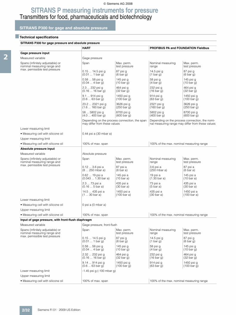
SITRANS P measuring instruments for pressureTransmitters for food, pharmaceuticals and biotechnology
SITRANS P300 for gage and absolute pressure
2/32 Siemens FI 01 · 2009 US Edition
2
■ Technical specifications F
SITRANS P300 for gage pressure and absolute pressure
HART PROFIBUS PA and FOUNDATION Fieldbus
Gage pressure input
Measured variable Gage pressure
Spans (infinitely adjustable) ornominal measuring range andmax. pemissible test pressure
Span Max. perm. test pressure
Nominal measuring range
Max. perm. test pressure
0.15 ... 14.5 psi g(0.01 ... 1 bar g)
87 psi g(6 bar g)
14.5 psi g(1 bar g)
87 psi g(6 bar g)
0.58 ... 58 psi g(0.04 ... 4 bar g)
145 psi g(10 bar g)
58 psi g(4 bar g)
145 psi g(10 bar g)
2.3 ... 232 psi g(0.16 ... 16 bar g)
464 psi g(32 bar g)
232 psi g(16 bar g)
464 psi g(32 bar g)
9.1 ... 914 psi g(0.6 ... 63 bar g)
1450 psi g(100 bar g)
914 psi g(63 bar g)
1450 psi g(100 bar g)
23.2 ... 2321 psi g(1.6 ... 160 bar g)
3626 psi g(250 bar g)
2321 psi g(160 bar g)
3626 psi g(250 bar g)
58 ... 5802 psi g(4.0 ... 400 bar g)
8700 psi g(600 bar g)
5802 psi g(400 bar g)
8700 psi g(600 bar g)
Depending on the process connection, the span may differ from these values
Depending on the process connection, the nomi-nal measuring range may differ from these values
Lower measuring limit
• Measuring cell with silicone oil 0.44 psi a (30 mbar a)
Upper measuring limit
• Measuring cell with silicone oil 100% of max. span 100% of the max. nominal measuring range
Absolute pressure input
Measured variable Absolute pressure
Spans (infinitely adjustable) ornominal measuring range andmax. pemissible test pressure
Span Max. perm. test pressure
Nominal measuring range
Max. perm. test pressure
0.12 ... 3.6 psi a (8 ... 250 mbar a)
87 psi a (6 bar a)
3.6 psi a (250 mbar a)
87 psi a (6 bar a)
0.62 ... 19 psi a (0.043 ... 1.30 bar a)
145 psi a (10 bar a)
19 psi a (1.30 bar a)
145 psi a (10 bar a)
2.3 ... 73 psi a (0.16 ... 5 bar a)
435 psi a (30 bar a)
73 psi a (5 bar a)
435 psi a (30 bar a)
14.5 ... 435 psi a (1 ... 30 bar a)
1450 psi a (100 bar a)
435 psi a (30 bar a)
1450 psi a (100 bar a)
Lower measuring limit
• Measuring cell with silicone oil 0 psi a (0 mbar a)
Upper measuring limit
• Measuring cell with silicone oil 100% of max. span 100% of the max. nominal measuring range
Input of gage pressure, with front-flush diaphragm
Measured variable Gage pressure, front-flush
Spans (infinitely adjustable) or nominal measuring range and max. pemissible test pressure
Span Max. perm. test pressure
Nominal measuring range
Max. perm. test pressure
0.15 ... 14.5 psi g (0.01 ... 1 bar g)
87 psi g (6 bar g)
14.5 psi g (1 bar g)
87 psi g (6 bar g)
0.58 ... 58 psi g (0.04 ... 4 bar g)
145 psi g (10 bar g)
58 psi g (4 bar g)
145 psi g (10 bar g)
2.32 ... 232 psi g (0.16 ... 16 bar g)
464 psi g (32 bar g)
232 psi g (16 bar g)
464 psi g (32 bar g)
9.14 ... 914 psi g (0.6 ... 63 bar g)
1450 psi g (100 bar g)
914 psi g (63 bar g)
1450 psi g (100 bar g)
Lower measuring limit -1.45 psi g (-100 mbar g)
Upper measuring limit
• Measuring cell with silicone oil 100% of max. span 100% of the max. nominal measuring range
© Siemens AG 2008

SITRANS P measuring instruments for pressureTransmitters for food, pharmaceuticals and biotechnology
SITRANS P300 for gage and absolute pressure
2/33Siemens FI 01 · 2009 US Edition
2
Input of absolute pressure, with front-flush diaphragm
Measured variable Absolute pressure (front-flush)
Spans (infinitely adjustable) ornominal measuring range andmax. pemissible test pressure
Span Max. perm. test pressure
Nominal measuring range
Max. perm. test pressure
0.62 ... 18.9 psi a (43 ... 1300 mbar a)
145 psi a (10 bar a)
18.9 psi a (1300 mbar a)
145 psi a (10 bar a)
2.32 ... 72.5 psi a (0.16 ... 5 bar a)
435 psi a (30 bar a)
72,5 psi a (5 bar a)
435 psi a (30 bar a)
14.5 ... 435 psi a (1 ... 30 bar a)
1450 psi a (100 bar a)
435 psi a (30 bar a)
1450 psi a (100 bar a)
Depending on the process connection, the span may differ from these values
Depending on the process connection, the nomi-nal measuring range may differ from these values
Lower measuring limit 0 psi a (0 bar a)
Upper measuring limit
• Measuring cell with silicone oil 100% der max. Messspanne 100% des max. Nennmessbereichs
Output
Output signal 4 ... 20 mA Digital PROFIBUS PA signal
Physical bus - IEC 61158-2
With polarity reversal protection No Yes
Electrical damping T63 (step width 0.1 s) Set to 0.1 s (0 ... 100 s)
Accuracy To EN 60770-1
Reference conditions(All error data refer always refer to the set span)
Increasing characteristic, start-of-scale value 0 bar, stainless steel seal diaphragm, measuring cell with silicone oil, room temperature 25 °C (77 °F), span ratio (r = max. span / set span)
Measurement deviation with cut-off point set-ting, including hysteresis and repeatability.
Gage pressure Absolute pressure
(Absolute pressure, front-flushed)
Gage pressure Absolute pressure
(Absolute pressure, front-flushed)
Linear characteristic curve ≤ 0.075% ≤ 0.1% ≤ 0.2%
• r ≤ 10 ≤ (0.0029 ⋅ r + 0.071)% ≤ 0.1% ≤ 0.2%
• 10 < r ≤ 30 ≤ (0.0045 ⋅ r + 0.071)% ≤ 0.2% ≤ 0.4%
• 30 < r ≤ 100 ≤ (0.005 ⋅ r + 0.05)% - -
Settling time T63 without electrical damping Approx. 0.2 s
Long-term drift at ± 30 °C (± 54 °F) ≤ (0.25 ⋅ r)%/5 years ≤ (0.1 ⋅ r)%/year ≤ 0.25%/5 years ≤ 0.1%/year
Influence of ambient temperature
• at -10 ... +60 °C (14 ... 140 °F) ≤ (0.1 ⋅ r +0.2)% ≤ (0.2 ⋅ r +0.3)%
≤ 0.3% ≤ 0.5%
• at -40 ... -10 °C and +60 ... +85 °C(-40 ... 14 °F and 140 ... 185 °F)
≤ (0.1 ⋅ r + 0.15)% / 10 K ≤ (0.2 ⋅ r + 0.3)%/10 K
≤ 0.25%/10 K ≤ 0.5%/10 K
Influence of the medium temperature (only with front-flush diaphragm)
• Temperature difference between medium temperature and ambient temperature
3 mbar/10 K (0.04 psi/10 K)
SITRANS P300 for gage pressure and absolute pressure
HART PROFIBUS PA and FOUNDATION Fieldbus
© Siemens AG 2008

SITRANS P measuring instruments for pressureTransmitters for food, pharmaceuticals and biotechnology
SITRANS P300 for gage and absolute pressure
2/34 Siemens FI 01 · 2009 US Edition
2
Rated operating conditions
Installation conditions
Ambient temperature Observe the temperature class in areas subject to explosion hazard.
• Measuring cell with silicone oil -40 ... +85 °C (-40 ... +185 °F)
• Measuring cell with Neobee oil (with front-flush diaphragm)
-10 ... +85 °C (14 ... +185 °F)
• Measuring cell with inert liquid (not with front-flush diaphragm)
-20 ... +85 °C (-4 ... +185 °F)
• Digital display -30 ... +85 °C (-22 ... +185 °F)
• Storage temperature -50 ... +85 °C (-58 ... +185 °F)(with Neobee: -20 ... +85 °C (-4 ... +185 °F)
Climatic class
Condensation Permissible
Degree of protection to EN 60529 IP65, IP68, NEMA X, enclosure cleaning, resistant to lyes, steam to 150° C (302 °F)
Electromagnetic compatibility
• Emitted interference and interference immunity To EN 61326 and NAMUR NE 21
Medium conditions
Process temperature
• Measuring cell with silicone oil -40 ... +100 °C (-40 ... +212 °F)
• Measuring cell with silicone oil (with front-flush diaphragm)
-40 ... +150 °C (-40 ... +302 °F)
• Measuring cell with Neobee oil (with front-flush diaphragm)
-40 ... +150 °C (-40 ... +302 °F)
• Measuring cell with silicone oil, with temper-ature isolator (only with front-flush dia-phragm)
-40 ... +200 °C (-40 ... +392 °F)
• Measuring cell with inert liquid -20 ... +100 °C (-4 ... +212 °F)
• Measuring cell with high temperature oil -10 ... +250 °C (14 ... +482 °F)
Design (standard version)
Weight (without options) Approx. 800 g (1.8 lb)
Housing material Stainless steel, mat. No. 1.4301/304
Material of parts in contact with the medium
• Connection shank Stainless steel, mat. No. 1.4404/316L or Hastelloy C276, mat. No. 2.4819
• Oval flange Stainless steel, mat. No. 1.4404/316L
• Seal diaphragm Stainless steel, mat. No. 1.4404/316L or Hastelloy C276, mat. No. 2.4819
• Measuring cell filling • Silicone oil• Inert filling liquid
Process connection • G½B to DIN EN 837-1• Female thread ½-14 NPT• Oval flange PN 160 (MWP 2320 psi) with fastening thread:
- 7/16-20 UNF to IEC 61518- M10 as per DIN 19213
Design (version with front-flush dia-phragm)
Weight (without options) Approx. 1 ... 13 kg (2.2 ... 29 lb)
Housing material Stainless steel, mat. No. 1.4301/304
Material of parts in contact with the medium
• Process connection Stainless steel, mat. No. 1.4404/316L
• Seal diaphragm Stainless steel, mat. No. 1.4404/316L
• Measuring cell filling • Silicone oil• Inert filling liquid• FDA compliant fill fluid (Neobee oil)
Process connection • Flanges as per EN and ASME• F&B and pharmaceutical flanges
SITRANS P300 for gage pressure and absolute pressure
HART PROFIBUS PA and FOUNDATION Fieldbus
© Siemens AG 2008

SITRANS P measuring instruments for pressureTransmitters for food, pharmaceuticals and biotechnology
SITRANS P300 for gage and absolute pressure
2/35Siemens FI 01 · 2009 US Edition
2
Power supply UH
Terminal voltage on transmitter 10.5 ... 42 V DCfor intrinsically safe operation: 10.5 ... 30 V DC
Supplied through bus
Separate power supply - Not necessary
Bus voltage
• Without EEx - 9 ... 32 V
• For intrinsically-safe operation - 9 ... 24 V
Current consumption
• Max. basic current - 12.5 mA
• Startup current ≤ basic current - Yes
• Max. fault current in the event of a fault - 15.5 mA
Fault disconnection electronics (FDE) - Available
Certificate and approvals
Classification according to pressure equip-ment directive (DRGL 97/23/EC)
For gases of fluid group 1 and liquids of fluid group 1; complies with requirements of Article 3, para-graph 3 (sound engineering practice)
Water, waste water Available soon
Explosion protection
Intrinsic safety "i" PTB 05 ATEX 2048
Identification Ex II 1/2 G EEx ia/ib IIB/IIC T4, T5, T6
Permissible ambient temperature
• Temperature class T4 -40 ... +85 °C (-40 ... +185 °F)
• Temperature class T5 -40 ... +70 °C (-40 ... +158 °F)
• Temperature class T6 -40 ... +60 °C (-40 ... +140 °F)
Connection To certified intrinsically-safe circuits with maxi-mum values:Ui = 30 V, Ii = 100 mA, Pi = 750 mW, Ri = 300 Ω
To certified intrinsically-safe circuits with maxi-mum values:FISCO supply unit: Ui = 17.5 V, Ii = 380 mA, Pi = 5.32 WLinear barrier: Ui = 24 V, Ii = 250 mA, Pi = 1.2 W
Effective inner capacitance: Ci = 6 nF Ci = 1.1 nF
Effective inner inductance: Li = 0.4 mH Li ≤ 7 μH
Explosion protection to FM for USA and Canada (cFMUS)
• Identification (DIP) or (IS); (NI) Certificate of Compliance 3025099
CL I, DIV 1, GP ABCD T4 ... T6; CL II, DIV 1, GP EFG; CL III; CL I, ZN 0/1 AEx ia IIC T4 ... T6;CL I, DIV 2, GP ABCD T4 ... T6; CL II, DIV 2, GP FG; CL III
• Identification (DIP) or (IS) Certificate of Compliance 3025099C
CL I, DIV 1, GP ABCD T4 ... T6; CL II, DIV 1, GP EFG; CL III; Ex ia IIC 4 ... T6;CL I, DIV 2, GP ABCD T4 ... T6; CL II, DIV 2, GP FG; CL III
SITRANS P300 for gage pressure and absolute pressure
HART PROFIBUS PA and FOUNDATION Fieldbus
© Siemens AG 2008

SITRANS P measuring instruments for pressureTransmitters for food, pharmaceuticals and biotechnology
SITRANS P300 for gage and absolute pressure
2/36 Siemens FI 01 · 2009 US Edition
2
HART communication
HART communication 230 ... 1100 Ω
Protocol HART Version 5.x
Software for computer SIMATIC PDM
PROFIBUS PA communication
Simultaneous communication with master class 2 (max.)
4
The address can be set using Configuration tool or local opera-tion (standard setting address 126)
Cyclic data usage
• Output byte 5 (one measuring value) or10 (two measuring values)
• Input byte 0, 1, or 2 (register operating mode and reset function for metering)
Internal preprocessing
Device profile PROFIBUS PA Profile for Process Control Devices Version 3.0, Class B
Function blocks 2
• Analog input
- Adaptation to customer-specif-ic process variables
Yes, linearly rising or falling char-acteristic
- Electrical damping T63 , adjustable
0 ... 100 s
- Simulation function Input /Output
- Failure mode Can be parameterized (last good value, substitute value, incorrect value)
- Limit monitoring Yes, one upper and lower warning limit and one alarm limit respec-tively
• Register (totalizer) Can be reset, preset, optional direction of counting, simulation function of register output
- Failure mode Can be parameterized (summation with last good value, continuous summation, summation with incor-rect value)
- Limit monitoring One upper and lower warning limit and one alarm limit respectively
• Physical block 1
Transducer blocks 2
• Pressure transducer block
- Can be calibrated by applying two pressures
Yes
- Monitoring of sensor limits Yes
- Characterizer Max. 30 points
- Transfer function linear
- Simulation function available
- Square-rooted characteristic for flow measurement
Yes
- Gradual volume suppression and implementation point of square-root extraction
Parameterizable
- Simulation function for mea-sured pressure value and sen-sor temperature
Constant value or over parameter-izable ramp function
Communication FOUNDATION Fieldbus
Function blocks 3 function blocks analog input, 1 function block PID
• Analog input
- Adaptation to customer-specif-ic process variables
Yes, linearly rising or falling char-acteristic
- Electrical damping T63 , adjust-able
0 ... 100 s
- Simulation function Output/input (can be locked within the device with a bridge)
- Failure mode Can be parameterized (last good value, substitute value, incorrect value)
- Limit monitoring Yes, one upper and lower warning limit and one alarm limit respec-tively
- Square-rooted characteristic for flow measurement
Yes
• PID Standard FF function block
• Physical block 1 Resource block
Transducer blocks 1 transducer block Pressure with calibration, 1 transducer block LCD
• Pressure transducer block
- Can be calibrated by applying two pressures
Yes
- Monitoring of sensor limits Yes
- Simulation function: Measured pressure value, sensor temper-ature and electronics tempera-ture
Constant value or over parameter-izable ramp function
© Siemens AG 2008

SITRANS P measuring instruments for pressureTransmitters for food, pharmaceuticals and biotechnology
SITRANS P300 for gage and absolute pressure
2/37Siemens FI 01 · 2009 US Edition
2
F) Subject to export regulations AL: 9I999, ECCN: N.
Selection and Ordering data Order No.
SITRANS P300 pressure transmitters for gage and absolute pressure, single-chamber measur-ing housing, rating plate inscription in English
4 ... 20 mA/HART 7 M F 8 0 2 3 -
PROFIBUS PA 7 M F 8 0 2 4 -
FOUNDATION Fieldbus (FF) 7 M F 8 0 2 5 -
77777 - 7777
Measuring cell filling Measuring cell cleaningSilicone oil Standard 1Inert liquid Cleanliness level 2 to
DIN 254103
max. span 0.15 ... 14.5 psi g (0.01 ... 1 bar g) B0.58 ... 58 psi g (0.04 ... 4 bar g) C2.32 ... 232 psi g (0.16 ...16 bar g) D9.14 ... 914 psi g (0.63 ... 63 bar g) E23.2 ... 2320 psi g (1.6 ... 160 bar g) F58 ... 5802 psi g (4 ... 400 bar g) G
0.036 ... 3.63 psi a (2.5 ... 25 mbar a) F) Q0.19 ... 18.9 psi a (13 ... 1300 mbar a) F) S0.7 ... 72.5 psi a (0.05 ... 5 bar a) F) T4.35 ... 435 psi a (0.3 ... 30 bar a) F) U
Wetted parts materialsSeal diaphragm Measuring cell
Stainless steel Stainless steel AHastelloy Stainless steel F) BHastelloy Hastelloy F) C
Version for diaphragm seal1) 2) Y
Process connection• G½B to EN 837-1 0• ½-14 NPT 1• Oval flange made of stainless steel
- Mounting thread 7/16-20 UNF to EN 61518 2- Mounting thread M10 to DIN 19213 3- Mounting thread M12 to DIN 19213 4
• Male thread M20 x 1,5 5• Male thread ½ -14 NPT 6
Non-wetted parts materials• St. steel, deep-drawn and electrolytically polished 4
Version• Standard version 1
Explosion protection• Without A• With ATEX, Type of protection:
- "Intrinsic safety (EEx ia)" B• Zone 20/21/223) C• Ex nA/nL (zone 2)4) E• With FM „Intrinsic safe“ (cFMUS) M
Electrical connection / cable entry• Screwed gland M20x1.5 (Polyamide)5) A• Screwed gland M20x1.5 (metal) B• Screwed gland M20x1.5 (stainless steel) C• M12 connector (metal, without cable socket) F• M12 connector (stainless steel, without cable socket) G• ½-14 NPT thread, metal6) H• ½-14 NPT thread, stainless steel6) J
Display• Without display, with pushbuttons, closed lid5) 1• With display and pushbuttons, closed lid 2• With display and pushbuttons, lid with macrolon
washer (setting on HART devices: mA, on PROFIBUS PA and FOUNDATION Fieldbus devices: pressure units)
4
• With display (setting acc. to specifications, Order code "Y21" or "Y22" required), lid with macrolon washer
5
• With display and pushbuttons, lid with glass pane (setting on HART devices: mA, on PROFIBUS and FOUNDATION Fieldbus devices: pressure units)
6
• With display (setting acc. to specifications, Order code "Y21" or "Y22" required), lid with glass pane
7
Power supply units see "SITRANS I power supply units and isol. amplifiers".
Factory-mounting of shut-off valves and valve manifolds see page 2/140.
Included in delivery of the device:• Brief instructions (Leporello)• CD-ROM with detailed documentation
1) When the manufacture’s certificate M (calibration certificate) has to be ordered for transmitters with diaphragm seals, it is recommended only to order this certificate exclusively with the diaphragm seals. The measuring accuracy of the total combination is certified here.
2) Whe the acceptance test certificate 3.1 for transmitters with direct-con-nected diaphragm seals is ordered, this certificate must also be ordered with the corresponding seals.
3) Can only be ordered in conjunction with electrical connection Option A.4) Can only be ordered in conjunction with electrical connection Option B, C,
F or G.5) Only together with HART electronics.6) Without cable gland.
Selection and Ordering data Order No.
SITRANS P300 pressure transmitters for gage and absolute pressure, single-chamber measur-ing housing, rating plate inscription in English
4 ... 20 mA/HART 7 M F 8 0 2 3 -
PROFIBUS PA 7 M F 8 0 2 4 -
FOUNDATION Fieldbus (FF) 7 M F 8 0 2 5 -
77777 - 7777
© Siemens AG 2008

SITRANS P measuring instruments for pressureTransmitters for food, pharmaceuticals and biotechnology
SITRANS P300 for gage and absolute pressure
2/38 Siemens FI 01 · 2009 US Edition
2
F) Subject to export regulations AL: 9I999, ECCN: N.
Selection and Ordering data Order No.
SITRANS P300 pressure transmitters for gage and absolute pressure with front-flush membrane, single-chamber measuring housing, rating plate inscription in English
4 ... 20 mA/HART F) 7 M F 8 1 2 3 -
PROFIBUS PA F) 7 M F 8 1 2 4 -
FOUNDATION Fieldbus (FF) F) 7 M F 8 1 2 5 -
77777 - 7777
Measuring cell filling Measuring cell cleaningSilicone oil Standard 1Inert liquid Cleanliness level 2 to
DIN 254103
FDA compliant fill fluid• Neobee oil Standard 4
max. span 0.15 ... 14.5 psi g (0.01 ... 1 bar g) B0.58 ... 58 psi g (0.04 ... 4 bar g) C2.32 ... 232 psi g (0.16 ... 16 bar g) D9.14 ... 914 psi g (0.63 ... 63 bar g) E
0.19 ... 18.9 psi a1) (13 ... 1300 mbar a)1) S0.7 ... 72.5 psi a1) (0.05 ... 5 bar a)1) T4.35 ... 435 psi a1) (0.03 ... 30 bar a)1) U
Wetted parts materials Seal diaphragm Measuring cell
Stainless steel Stainless steel A
Process connection• Flange version with Order code M.., N.., R.. or Q..
(see "Further designs")7
Non-wetted parts materials• Stainless steel, deep-drawn and electrolytically
polished4
Version• Standard version 1
Explosion protection• Without A• With ATEX, Type of protection:
- "Intrinsic safety (EEx ia)" B• Zone 20/21/222) C• Ex nA/nL (zone 2)3) E• With FM „Intrinsic safe“ (cFMUS) M
Electrical connection / cable entry• Screwed gland M20x1.5 (Polyamide)4) A• Screwed gland M20x1.5 (metal) B• Screwed gland M20x1.5 (stainless steel) C• M12 connector (without cable socket) F• M12 connector (stainless steel, without cable socket) G• ½-14 NPT thread, metal5) H• ½-14 NPT thread, stainless steel5) J
Display• Without display, with pushbuttons, closed lid4) 1• With display and pushbuttons, closed lid 2• With display and pushbuttons, lid with macrolon
washer (setting on HART devices: mA, on PROFIBUS PA and FOUNDATION Fieldbus devices: pressure units)
4
• With display (setting acc. to specifications, Order code "Y21" or "Y22" required), lid with macrolon washer
5
• With display and pushbuttons, lid with glass pane (setting on HART devices: mA, on PROFIBUS PA and FOUNDATION Fieldbus devices: pressure units)
6
• With display (setting acc. to specifications, Order code "Y21" or "Y22" required), lid with glass pane
7
Power supply units see "SITRANS I power supply units and isol. amplifiers".
Included in delivery of the device:• Brief instructions (Leporello)• CD-ROM with detailed documentation
1) Not with temperature decoupler P00 and P10, not for process connections R02, R04, R10 and R11, and can only be ordered in conjunction with sili-cone oil.
2) Can only be ordered in conjunction with electrical connection Option A.3) Can only be ordered in conjunction with electrical connection Option B, C,
F or G.4) Only together with HART electronics.5) Without cable gland.
Selection and Ordering data Order No.
SITRANS P300 pressure transmitters for gage and absolute pressure with front-flush membrane, single-chamber measuring housing, rating plate inscription in English
4 ... 20 mA/HART F) 7 M F 8 1 2 3 -
PROFIBUS PA F) 7 M F 8 1 2 4 -
FOUNDATION Fieldbus (FF) F) 7 M F 8 1 2 5 -
77777 - 7777
© Siemens AG 2008

SITRANS P measuring instruments for pressureTransmitters for food, pharmaceuticals and biotechnology
SITRANS P300 for gage and absolute pressure
2/39Siemens FI 01 · 2009 US Edition
2
Selection and Ordering data Order code
Further designsAdd "-Z" to Order No. and specify Order code.
HART PA FF
Mounting bracketmade completely of stainless steel, for wall or pipe mounting
A02
Cable socket for M12 plug• Metal A50• Stainless steel A51
Rating plate inscription(instead of English)• German B10• French B12• Spanish B13• Italian B14
English rating plate B21Pressure units in inH20 or psi
Quality inspection certificate (Factory cali-bration) to IEC 60770-21)
C11
to IEC 60770-2
Acceptance test certificate2) C12to EN 10204-3.1
Factory certificate C14to EN 10204-2.2
Type of protection IP68 D12
Only for SITRANS P300 with front-flush diaphragm (7MF81..-...)
Flange to EN 1092-1, form B1• DN 25, PN 403) M11• DN 25, PN 1003) M21• DN 40, PN 40 M13• DN 40, PN 100 M23• DN 50, PN 16 M04• DN 50, PN 40 M14• DN 80, PN 25 M06• DN 80, PN 40 M16
Flanges to ASME B16.5• 1", class 1503) M40• 1½", class 150 M41• 2", class 150 M42• 3", class 150 M43• 4", class 150 M44• 1", class 3003) M45• 1½", class 300 M46• 2", class 300 M47• 3", class 300 M48
Threaded connection acc. to DIN 3852-2, Form A• G ¾“-A, flush-mounted4) R01• G 1“-A, flush-mounted4) R02• G 2“-A, flush-mounted4) R04
Tank connection5)
Sealing is included in delivery• TG 52/50, PN 40 R10• TG 52/150, PN 40 R11
Sanitary process connection according DIN 11851 (Dairy connection)certified to 3A6)
• DN 50, PN 25 N04• DN 80, PN 25 N06
Tri-Clamp connection according DIN 32676/ISO 2852certified to 3A6)
• DN 50/2“, PN 16 N14• DN 65/3“, PN 10 N15
Varivent connectioncertified to 3A and EHEDG3)
• Type N = 68 for Varivent housingDN 40 ... 125 and 1½" ... 6", PN 40
N28
Temperature decoupler up to 200 °C7)
for version with front-flush diaphragmP00
Temperature decoupler up to 250 °CMeasuring cell filling: High-temperature oil, only in conjunction with measuring cell filling silicone oil
P10
Bio-Control (Neumo) sanitary connectioncertified to 3A and EHEDG3)
• DN 50, PN 16 Q53• DN 65, PN 16 Q54
Sanitary process connection to DRD• 65 mm, PN 40 M32
SMS socket with union nut• 2“ M67• 2½“ M68• 3“ M69
SMS threaded socket• 2“ M73• 2½“ M74• 3“ M75
IDF socket with union nut ISO 2853• 2“ M82• 2½“ M83• 3“ M84
IDF threaded socket ISO 2853• 2“ M92• 2½“ M93• 3“ M94
Sanitary process connection to NEUMO Bio-Connect screw connectioncertified to 3A and EHEDG3)
• DN 50, PN 16 Q05• DN 65, PN 16 Q06• DN 80, PN 16 Q07• DN 100, PN 16 Q08• DN 2“, PN 16 Q13• DN 2½“, PN 16 Q14• DN 3“, PN 16 Q15• DN 4“, PN 16 Q16
Sanitary process connection to NEUMO Bio-Connect flange connectioncertified to 3A and EHEDG3)
• DN 50, PN 16 Q23• DN 65, PN 16 Q24• DN 80, PN 16 Q25• DN 100, PN 16 Q26• DN 2“, PN 16 Q31• DN 2½“, PN 16 Q32• DN 3“, PN 16 Q33• DN 4“, PN 16 Q34
Sanitary process connection to NEUMO Bio-Connect clamp connectioncertified to 3A and EHEDG3)
• DN 50, PN 16 Q39• DN 65, PN 10 Q40• DN 80, PN 10 Q41• DN 100, PN 10 Q42• DN 2½“, PN 16 Q48• DN 3“, PN 10 Q49• DN 4“, PN 10 Q50
Selection and Ordering data Order code
Further designsAdd "-Z" to Order No. and specify Order code.
HART PA FF
© Siemens AG 2008

SITRANS P measuring instruments for pressureTransmitters for food, pharmaceuticals and biotechnology
SITRANS P300 for gage and absolute pressure
2/40 Siemens FI 01 · 2009 US Edition
2Sanitary process connection to NEUMO Connect S flange connectioncertified to 3A and EHEDG• DN 50, PN 16 Q63• DN 65, PN 10 Q64• DN 80, PN 10 Q65• DN 100, PN 10 Q66• DN 2“, PN 16 Q72• DN 2½“, PN 10 Q73• DN 3“, PN 10 Q74• DN 4“, PN 10 Q75
Aseptic threaded socket to DIN 11864-1 Form A• DN 50, PN 25 N33• DN 65, PN 25 N34• DN 80, PN 25 N35• DN 100, PN 25 N36
Aseptic flange with notch to DIN 11864-2 Form A• DN 50, PN 16 N43• DN 65, PN 16 N44• DN 80, PN 16 N45• DN 100, PN 16 N46
Aseptic flange with groove to DIN 11864-2 Form A• DN 50, PN 16 N43 +
P11• DN 65, PN 16 N44 +
P11• DN 80, PN 16 N45 +
P11• DN 100, PN 16 N46 +
P11
Aseptic clamp with groove to DIN 11864-3 Form A• DN 50, PN 25 N53• DN 65, PN 25 N54• DN 80, PN 16 N55• DN 100, PN 16 N56
1) When the manufacture’s certificate M (calibration certificate) has to be ordered for transmitters with diaphragm seals, it is recommended only to order this certificate exclusively with the diaphragm seals. The measuring accuracy of the total combination is certified here.
2) Whe the acceptance test certificate 3.1 for transmitters with direct-con-nected diaphragm seals is ordered, this certificate must also be ordered with the corresponding seals.
3) Special Viton seal included in delivery.4) Lower measuring limit 1.45 psi g (-100 mbar g).5) The weldable socket can be ordered under accessories6) Certified to 3A.
The maximum temperatures of the medium depend on the respective cell fillings.
7) 3A certification only if used in conjunction with 3A-compliant sealing rings.
Selection and Ordering data Order code
Further designsAdd "-Z" to Order No. and specify Order code.
HART PA FF
Selection and Ordering data Order code
Additional dataAdd "-Z" to Order No. and specify Order code.
HART PA FF
Measuring range to be set Y01Specify in plain text V (max. 5 digits):Y01: ... up to ... mbar, bar, kPa, MPa, psi
Measuring point number (TAG No.) Y15Max. 16 characters, specify in plain text:Y15: ...........................................
Measuring point text Y16Max. 27 characters, specify in plain text:Y16: ...........................................
Entry of HART TAG Y17Max. 8 characters, specify in plain text:Y17: ...........................................
Setting of pressure indication in pressure units
Y21
Specify in plain text (standard setting: mA): Y21: mbar, bar, kPa, MPa, psi, ...Note:The following pressure units can be selected:bar, mbar, mm H2O*), inH2O*), ftH2O*), mmHG, inHG, psi, Pa, kPa, MPa, g/cm2, kg/cm2, Torr, ATM or % *) ref. temperature 20 °C
Setting of pressure indicator in non-pressure units
Y22 + Y01
Specify in plain text:Y22: ..... up to ..... l, m3, m, USg, ...(specification of measuring range in pressure units "Y01" is essential, unit with max. 5 char-acters)
Preset bus address Y25possible between 1 ... 126)Specify in plain text:Y25: .....................
Only "Y01" and "Y21" can be factory preset
= available
Ordering exampleItem line: 7MF8023-1DB24-1AB7-ZB line: A02 + Y01 + Y21C line: Y01: 0 to 14.5 psi (0 to 1 bar)C line: Y21: psi (bar)
© Siemens AG 2008

SITRANS P measuring instruments for pressureTransmitters for food, pharmaceuticals and biotechnology
SITRANS P300 for gage and absolute pressure
2/41Siemens FI 01 · 2009 US Edition
2
■ Dimensional drawings
SITRANS P300, with oval flange, dimensions in mm (inch)
SITRANS P300, process connection M20 x 1,5; with mounted mounting bracket, dimensions in mm (inch)
© Siemens AG 2008

SITRANS P measuring instruments for pressureTransmitters for food, pharmaceuticals and biotechnology
SITRANS P300 for gage and absolute pressure
2/42 Siemens FI 01 · 2009 US Edition
2
SITRANS P300, front-flush, dimensions in mm (inch)
The diagram shows a SITRANS P300 with an example of a flange. In this drawing the height is subdivided into H1 and H2.
H1 = Height of the SITRANS P300 up to a defined cross-section
H2 = Height of the flange up to this defined cross-section
Only the height H2 is indicated in the dimensions of the flanges.
© Siemens AG 2008

SITRANS P measuring instruments for pressureTransmitters for food, pharmaceuticals and biotechnology
SITRANS P300 for gage and absolute pressure
2/43Siemens FI 01 · 2009 US Edition
2
Flanges to EN and ASME
Flanges to EN
Flanges to ASME
NuG and pharmaceutical connectionsConnections to DIN
Other connections
EN 1092-1
DN PN ∅D H2
25 40 115 mm (4.5“) Approx.52 mm (2“)25 100 140 mm (5.5“)
40 40 150 mm (5.9“)40 100 170 mm (6.7“)50 16 165 mm (6.5“)50 40 165 mm (6.5“)80 16 200 mm (7.9“)80 40 200 mm (7.9“)
ASME B16.5
DN class ∅D H2
1“ 150 110 mm (4.3“) Approx.52 mm (2“)1“ 300 125 mm (4.9“)
1½“ 150 130 mm (5.1“)1½“ 300 155 mm (6.1“)2“ 150 150 mm (5.9“)2“ 300 165 mm (6.5“)3“ 150 190 mm (7.5“)3“ 300 210 mm (8.1“)4“ 150 230 mm (9.1“)4“ 300 255 mm (10.0“)
DIN 11851 (Dairy connection)
DN PN ∅D H2
50 25 92 mm (3.6“) Approx.52 mm (2“)
80 25 127 mm (5.0“)
Tri-Clamp according DIN 32676
DN PN ∅D H2
50 16 64 mm (2.5“) Approx. 52 mm (2“)
65 16 91 mm (3.6“)
Varivent connection
DN PN ∅D H2
40 ... 125 40 84 mm (3.3“)
Approx.52 mm (2“)
Bio-Control connection
DN PN ∅D H2
50 16 90 mm (3.5“) Approx.52 mm (2“)
65 16 120 mm (4.7“)
Sanitary process connection to DRD
DN PN ∅D H2
50 40 105 mm (4.1“) Approx. 52 mm (2“)
Sanitary process screw connection to NEUMO Bio-Connect
DN PN ∅D H2
50 16 82 mm (3.2“) Approx. 52 mm (2“)
65 16 105 mm (4.1“)
80 16 115 mm (4.5“)
100 16 145 mm (5.7“)
2“ 16 82 mm (3.2“)
2½“ 16 105 mm (4.1“)
3“ 16 105 mm (4.1“)
4“ 16 145 mm (5.7“)
Sanitary connection to NEUMO Bio-Connectflange connection
DN PN ∅D H2
50 16 110 mm (4.3“) Approx. 52 mm (2“)
65 16 140 mm (5.5“)
80 16 150 mm (5.9“)
100 16 175 mm (6.9“)
2“ 16 100 mm (3.9“)
2½“ 16 110 mm (4.3“)
3“ 16 140 mm (5.5“)
4“ 16 175 mm (6.9“)
Sanitary connection to NEUMO Bio-Connectclamp connection
DN PN ∅D H2
50 16 77.4 mm (3.0“) Approx. 52 mm (2“)
65 10 90.9 mm (3.6“)
80 10 106 mm (4.2“)
100 10 119 mm (4.7“)
2“ 16 64 mm (2.5“)
2½“ 16 77.4 mm (3.0“)
3“ 10 90.9 mm (3.6“)
4“ 10 119 mm (4.7“)
Sanitary connection to NEUMO Bio-Connect Sflange connection
DN PN ∅D H2
50 16 125 mm (4.9“) Approx. 52 mm (2“)
65 10 145 mm (5.7“)
80 10 155 mm (6.1“)
100 10 180 mm (7.1“)
2“ 16 125 mm (4.9“)
2½“ 10 135 mm (5.3“)
3“ 10 145 mm (5.7“)
4“ 10 180 mm (7.1“)
© Siemens AG 2008

SITRANS P measuring instruments for pressureTransmitters for food, pharmaceuticals and biotechnology
SITRANS P300 for gage and absolute pressure
2/44 Siemens FI 01 · 2009 US Edition
2
Thread connection G¾“, G1“ and G2“ to DIN 3852
DN PN ∅D H2
¾“ 63 37 mm (1.5“) Approx. 45 mm (1.8“)
1“ 63 48 mm (1.9“) Approx. 47 mm (1.9“)
2“ 63 78 mm (3.1“) Approx. 52 mm (2“)
Tank connection TG52/50 und TG52/150
DN PN ∅D H2
25 40 63 mm (2.5“) Approx. 63 mm (2.5“)
25 40 63 mm (2.5“) Approx.170mm (6.7“)
SMS socket with union nut
DN PN ∅D H2
2“ 25 84 mm (3.3“) Approx. 52 mm (2.1“)2½“ 25 100 mm (3.9“)
3“ 25 114 mm (4.5“)
SMS threaded socket
DN PN ∅D H2
2“ 25 70 x 1/6 mm Approx. 52 mm (2.1“)2½“ 25 85 x 1/6 mm
3“ 25 98 x 1/6 mm
IDF socket with union nut
DN PN ∅D H2
2“ 25 77 mm (3“) Approx. 52 mm (2.1“)2½“ 25 91 mm (3.6“)
3“ 25 106 mm (4.2“)
IDF threaded socket
DN PN ∅D H2
2“ 25 64 mm (2.5“) Approx. 52 mm (2.1“)2½“ 25 77.5 mm (3.1“)
3“ 25 91 mm (3.6“)
Aseptic threaded socket to DIN 11864-1 Form A
DN PN ∅D H2
50 25 78 x 1/6“ Approx. 52 mm (2.1“)65 25 95 x 1/6“
80 25 110 x ¼“
100 25 130 x ¼“
Aseptic flange with notch to DIN 11864-2 Form A
DN PN ∅D H2
50 16 94 Approx. 52 mm (2.1“)65 16 113
80 16 133
100 16 159
Aseptic flange with groove to DIN 11864-2 Form A
DN PN ∅D H2
50 16 94 Approx. 52 mm (2.1“)65 16 113
80 16 133
100 16 159
Aseptic clamp with groove to DIN 11864-3 Form A
DN PN ∅D H2
50 25 77.5 Approx. 52 mm (2.1“)65 25 91
80 16 106
100 16 130
© Siemens AG 2008

SITRANS P measuring instruments for pressureTransmitters for gage pressure for the paper industry
SITRANS P300 and DS III serieswith PMC connection – Technical description
2/45Siemens FI 01 · 2009 US Edition
2
■ Overview
The SITRANS P300 and DS III pressure transmitters have been fitted with special process connections for the paper industry. With the two process connection threads 1½" and 1" flush at the front, the SITRANS P300 and DS III transmitters can be used for all processes in the paper industry.
SITRANS P300 and DS III series pressure transmitters are digital pressure transmitters featuring extensive user-friendliness and high accuracy. The parameterization is performed using push-buttons, over HART communication, PROFIBUS PA or FOUNDATION Fieldbus interface (DS III only).
Extensive functionality enables the pressure transmitter to be precisely adapted to the plant’s requirements. Operation is very simple in spite of the numerous setting options.
Transmitters with type of protection "Intrinsic safety" and "Explo-sion-proof" may be installed within potentially explosive atmo-spheres (zone 1) or in zone 0. The transmitters are provided with an EC type examination certificate and comply with the corre-sponding harmonized European standards (ATEX).
Various versions of the pressure transmitters are available for measuring:• Gage pressure• Filling level• Volume level• Mass level
■ Benefits
• High quality and long life• High reliability even under extreme chemical and mechanical
loads, e.g. abrasion.• For aggressive and non-aggressive gases, vapors and liquids• Extensive diagnosis and simulation functions• Minimum conformity error
• Small long-term drift• Wetted parts made of Hastelloy• Infinitely adjustable spans from 0.15 psi g to 232 psi g
(0.03 bar g to 16 bar g) for DS III with HART interface• Nominal measuring range from 14.5 psi g to 232 psi g
(1 bar g to 16 bar g) for DS III with PROFIBUS PA and FOUNDATION Fieldbus interface
• Infinitely adjustable spans from 0.15 psi g to 0.3 psi g (0.03 bar g to 16 bar g) for SITRANS P300 with HART inter-face
• Nominal measuring range from 14.5 psi g to 232 psi g (1 bar g to 16 bar g) for SITRANS P300 with PROFIBUS PA in-terface
• High measuring accuracy• Parameterization over pushbuttons and HART communica-
tion, or over PROFIBUS PA or FOUNDATION Fieldbus inter-face (DS III only).
■ Application
The pressure transmitters of the DS III series, can be used in in-dustrial areas with extreme chemical and mechanical loads. Electromagnetic compatibility in the range 10 kHz ... 1 GHz makes the DS III pressure transmitters suitable for locations with high electromagnetic emissions.
Pressure transmitters with type of protection "Intrinsic safety" and "Explosion-proof" may be installed within potentially explosive at-mospheres (zone 1) or in zone 0. The pressure transmitters are provided with an EC type examination certificate and comply with the corresponding harmonized European standards (ATEX).
Pressure transmitters with the type of protection "Intrinsic safety" for use in zone 0 may be operated with power supply units of cat-egory "ia" and "ib".
The transmitters can be equipped with various designs of re-mote seals for special applications such as the measurement of highly viscous substances.
The pressure transmitter can be operated locally over 3 push-buttons or programmed externally over HART communication or over PROFIBUS PA or FOUNDATION Fieldbus interface (only DS III).
SITRANS P, DS III series
Measured variable: Gage pressure of aggressive and non-aggressive gases, vapors and liquids.
Span (infinitely adjustable)
For DS III HART: 0.43 ... 232 psi g (0.03 ... 16 bar g)
Nominal measuring range
For DS III PA and FF: 14.5 ... 232 psi g (1 ... 16 bar g)
SITRANS P300
Span (infinitely adjustable)
For DS III HART: 0.43 ... 232 psi g (0.03 ... 16 bar g)
Nominal measuring range
For DS III PA: 14.5 ... 232 psi g (1 ... 16 bar g)
© Siemens AG 2008

SITRANS P measuring instruments for pressureTransmitters for gage pressure for the paper industrySITRANS P300 and DS III serieswith PMC connection – Technical description
2/46 Siemens FI 01 · 2009 US Edition
2
■ Design
SITRANS P, DS III series
Device front view, SITRANS P DS III
The transmitter comprises a range of different components, de-pending on the order specifications. The various options are listed in the ordering information. The components described below are the same for all transmitters.
The rating plate (3, Figure "Front view") with the Order No. is lo-cated on the side of the housing. The specified number together with the ordering information provide details on the optional de-sign details and on the possible measuring range (physical properties of built-in sensor element).
The approval label is located on the opposite side.
The housing is made of die-cast aluminium or stainless steel pre-cision casting. A round cover is screwed on at the front and rear of the housing. The front cover (6) can be fitted with a viewing pane so that the measured values can be read directly on the digital display. The inlet (4) for the electrical connection is lo-cated either on the left or right side. The unused opening on the opposite side is sealed by a blanking plug. The protective earth connection is located on the rear of the housing.
The electrical connections for the power supply and screen are accessible by unscrewing the rear cover. The bottom part of the housing contains the measuring cell with process connection (1). The measuring cell is prevented from rotating by a locking screw (8). As the result of this modular design, the measuring cell and the electronics can be replaced separately from each other. The set parameter data are retained.
At the top of the housing is a plastic cover (5), which hides the pushbuttons.
SITRANS P300
The device comprises:• Electronics• Housing• Measuring cell
Perspective view of the SITRANS P300
The housing has a screwable cover (3), with or without an in-spection window depending on the version. The electrical termi-nal housing, the buttons for operation of the device and, de-pending on the version, the digital display are located under this cover. The connections for the auxiliary power UH and the shield are in the terminal housing. The cable gland is on the side of the housing. The measuring cell with the process connection (5) is located on the underside of the housing. Depending on the ver-sion of the device, the measuring cell with the process connec-tion may differ from the one shown in the diagram.
© Siemens AG 2008

SITRANS P measuring instruments for pressureTransmitters for gage pressure for the paper industry
SITRANS P300 and DS III serieswith PMC connection – Technical description
2/47Siemens FI 01 · 2009 US Edition
2
■ Function
Operation of the electronics with PROFIBUS PA communica-tion
Function diagram of electronics
The bridge output voltage created by the sensor (1, Figure "Function diagram of electronics") is amplified by the instrument amplifier (2) and digitized in the analog-to-digital converter (3). The digital information is evaluated in a microcontroller, its linear-ity and temperature response corrected, and converted in a dig-ital-to-analog converter (5) into an output current of 4 to 20 mA.
The diode circuit (10) protects against incorrect polarity.
The data specific to the measuring cell, the electronics data, and the parameter data are stored in the two non-volatile memories (6). The one memory is coupled to the measuring cell, the other to the electronics. As the result of this modular design, the elec-tronics and the measuring cell can be replaced separately from each other.
Using the 3 pushbuttons (8) you can parameterize the pressure transmitter directly at the point of measurement. The pushbut-tons can also be used to control the view of the results, the error messages and the operating modes on the digital display (9).
The HART modem (7) permits parameterization using a protocol according to the HART specification.
The pressure transmitters with spans ≤ 914 psi g (≤ 63 bar g)measure the input pressure compared to atmosphere, transmit-ters with spans ≥ 2321 psi g (≥ 160 bar g) compared to vacuum.
Operation of the electronics with PROFIBUS PA communica-tion
Function diagram of electronics
The bridge output voltage created by the sensor (1, Figure "Function diagram of electronics") is amplified by the instrument amplifier (2) and digitized in the analog-to-digital converter (3). The digital information is evaluated in the microcontroller, its lin-earity and temperature response corrected, and provided on the PROFIBUS PA through an electrically isolated PA interface (7).
The data specific to the measuring cell, the electronics data, and the parameter data are stored in the two non-volatile memories (6). The first memory is linked with the measuring cell, the sec-ond with the electronics. This modular design means that the electronics and the measuring cell can be replaced separately from one another.
Using the three pushbuttons (8) you can parameterize the pres-sure transmitter directly at the point of measurement. The push-buttons can also be used to control the view of the results, the error messages and the operating modes on the digital display (9).
The results with status values and diagnostic values are trans-ferred by cyclic data transmission on the PROFIBUS PA. Param-eterization data and error messages are transferred by acyclic data transmission. Special software such as SIMATIC PDM is re-quired for this.
������
�
�
�
�
��
�
���
��
�
� � �� �� �
�
8 �&�$�"�#�*�((����� �� ���'�$���'�&�%("!"��� ��&( #)' ) "#"'&(�* �+��'��� "*� * �'� ((��7 �"#"'&()' )&�&( #�* �+��'��< ����� �)+ (&'"(����� ����&*-�"��'-����&�$�"�#�*�((�&� ��(�*'� �"*�6 ���;�"�'��!&*�/ ;-����"�%$'������0( *&(� %��&'" �19 �"#"'&(� "�%(&�8� �" ��*"�*$"'�&� �* ���*'" ��! ���='���&(�&���'���� �$'%$'�*$����'�� � ,����$%%(��� ��%$'�+&�"&C(�
4��� �
����
�
�����
���;�"�'��!&*�
�(�*'� �"*�
�&�$�"�#�*�((
�
�
��
�
�
��
�� �� �� �
����
�
�����
�
�
� � �
�!
��
��
8 �&�$�"�#�*�((����� �� ���'�$���'�&�%("!"��� ��&( #)' ) "#"'&(�* �+��'��� "*� * �'� ((��7 �(�*'�"*&(�"� (&'" �< ����� �)+ (&'"(����� ��
�&*-�"��'-����&�$�"�#�*�((&� ��(�*'� �"*�
6 ���?�3�4)���"�'��!&*�
4��� �
�(�*'� �"*�
�&�$�"�#�*�((
��"�'��!&*�
3$�)&�'��
� ,���$%%(�$�"'� $%)����(��
� ,�����$%%(�
���?�3�
4)��
���?�3�
4)��
/ ;-����"�%$'�����0( *&(� %��&'" �1
9 �"#"'&(� "�%(&�8� � ,����$%%(�88 ������* $%(��� ��("��8� 3$���&�'��
�� ��%$'�+&�"&C(�
© Siemens AG 2008

SITRANS P measuring instruments for pressureTransmitters for gage pressure for the paper industrySITRANS P300 and DS III serieswith PMC connection – Technical description
2/48 Siemens FI 01 · 2009 US Edition
2
Mode of operation of the FOUNDATION Fieldbus electronics
Function diagram of electronics
The bridge output voltage created by the sensor (1, Figure "Function diagram of electronics") is amplified by the instrument amplifier (2) and digitized in the analog-to-digital converter (3). The digital information is evaluated in the microcontroller, its lin-earity and temperature response corrected, and provided on the FOUNDATION Fieldbus through an electrically isolated FOUNDATION Fieldbus Interface (7).
The data specific to the measuring cell, the electronics data, and the parameter data are stored in the two non-volatile memories (6). The one memory is coupled to the measuring cell, the other to the electronics. As the result of this modular design, the elec-tronics and the measuring cell can be replaced separately from each other.
Using the three pushbuttons (8) you can parameterize the pres-sure transmitter directly at the point of measurement. The push-buttons can also be used to control the view of the results, the error messages and the operating modes on the digital display (9).
The results with status values and diagnostic values are trans-ferred by cyclic data transmission on the FOUNDATION Fieldbus. Parameterization data and error messages are trans-ferred by acyclic data transmission. Special software such as National Instruments Configurator is required for this.
Mode of operation of the measuring cell
Measuring cell for gage pressure with front-flush diaphragm
Measuring cell for gage pressure, with front-flush diaphragm, function diagram
The pressure pe is applied through the process connection (2, Figure "Measuring cell for gage pressure, with front-flush di-aphragm for paper industry, function diagram") to the measuring cell (1). This pressure is subsequently transmitted further through the seal diaphragm (3) and the filling liquid (4) to the sil-icon pressure sensor (5) whose measuring diaphragm is then flexed. This changes the resistance of the four piezo-resistors fit-ted in the diaphragm in a bridge circuit. This change in resis-tance results in a bridge output voltage proportional to the input pressure.
Parameterization
Depending on the version, there are a range of options for pa-rameterizing the pressure transmitter and for setting or scanning the parameters.
Parameterization using the pushbuttons (local operation)
With the pushbuttons you can easily set the most important pa-rameters without any additional equipment.
Parameterization using HART communication
Parameterization using HART communication is performed with a HART communicator or a PC.
Communication between a HART communicator and a pressure transmitter
When parameterizing with the HART communicator, the connec-tion is made directly to the 2-wire system.
�
�
��
�
�
��
�� �� �� �
����
�
�����
�
�
� � �
�!
8 �&�$�"�#�*�((����� �� ���'�$���'�&�%("!"��� ��&( #)' ) "#"'&(�* �+��'��� "*� * �'� ((��7 �(�*'�"*&(�"� (&'" �< ����� �)+ (&'"(����� ��
�&*-�"��'-����&�$�"�#�*�((&� ��(�*'� �"*�
6 ??�"�'��!&*�
4��� �
�(�*'� �"*�
�&�$�"�#�*�((
??"�'��!&*�
� ,���$%%(�$�"'� $%)����(��
� ,�����$%%(�
/ ;-����"�%$'�����0( *&(� %��&'" �1
9 �"#"'&(� "�%(&�8� � ,����$%%(�
�� ��%$'�+&�"&C(�
�
�
�
�
�
�
�
8 �&�$�"�#�*�((� �� *����* ���*'" �� 4�&(� "&%-�&#�� ?"(("�#�("E$" 7 4"("* ��%����$������� �%� �����$���&��"�%$'�+&�"&C(�
D
���;* ��$�"*&' �
���������88����'�&���"''��4�;��:4�� � ,����$%%(�
© Siemens AG 2008

SITRANS P measuring instruments for pressureTransmitters for gage pressure for the paper industry
SITRANS P300 and DS III serieswith PMC connection – Technical description
2/49Siemens FI 01 · 2009 US Edition
2
HART communication between a PC communicator and a pressure transmitter
When parameterizing with a PC, the connection is made through a HART modem.
The signals needed for communication in conformity with the HART 5.x or 6.x protocols are superimposed on the output cur-rent using the Frequency Shift Keying (FSK) method.
Adjustable parameter DS III HART and P300 HART
Diagnostic functions for DS III HART and P300 HART • Zero correction for position• Event counter• Transmitter Output Alarms• Saturation alarm• Min/Max registers• Simulation functions• Maintenance timer
Available physical units of display for DS III HART and P300 HART
Parameterization through PROFIBUS PA interface
Fully digital communication through PROFIBUS PA, profile 3.0, is particularly user-friendly. The PROFIBUS puts the DS III PA is in connection with a process control system, e.g. SIMATIC PSC 7. Communication is possible even in a potentially explosive envi-ronment.
For parameterization through PROFIBUS you need suitable soft-ware, e.g. SIMATIC PDM (Process Device Manager).
Parameterization through FOUNDATION Fieldbus Interface
Fully digital communication through FOUNDATION Fieldbus is particularly user-friendly. Through the FOUNDATION Fieldbus the DS III FF is connected to a process control system. Commu-nication is possible even in a potentially explosive environment.
For parameterization through the FOUNDATION Fieldbus you need suitable software, e.g. National Instruments Configurator.
Adjustable parameters for DS III PA and FF and P300 PA and FF
Diagnostic functions for DS III PA and FF and P300 PA and FF• Event counter• Min/Max registers• Maintenance timer• Simulation functions• Zero correction for position• Transmitter Output Alarms• Saturation alarm
Physical dimensions available for the display
Parameters Pushbuttons HART com-munication
Start of scale x x
Full-scale value x x
Electrical damping x x
Start-of-scale value without application of a pressure ("Blind setting")
x x
Full-scale value without application of a pressure ("Blind setting")
x x
Zero adjustment x x
Current transmitter x x
Fault current x x
Disabling of keys, write protection x x1)
1) Cancel apart from write protection
Type of dimension and actual dimension x x
Linear or square root output x x
Characterizer setup x
Freely-programmable LCD x
Diagnostics functions x
Physical variable Physical dimensions
Pressure (setting can also be made in the factory)
Pa, MPa, kPa, bar, mbar, torr, atm, psi, g/cm2, kg/cm2, inH2O, inH2O (4 °C), mmH2O, ftH2O (20 °C), inHg, mmHg
Level (height data) m, cm, mm, ft, in
Volume m3, dm3, hl, yd3, ft3, in3, US gallon, lmp, gallon, bushel, barrel, barrel liquid
Mass g, kg, t, lb, Ston, Lton, oz
Temperature K, °C, °F, °R
Miscellaneous %, mA
'�&���"''��4�;��:4�� � ,����$%%(�
���;� ��
��� �(&%' %
�4����
���������7����
Adjustable parameters Pushbuttons PROFIBUS PA and FOUNDATION Fieldbus interface
Electrical damping x x
Zero adjustment (correction of position)
x x
Key and/or function disabling x x
Source of measured-value dis-play
x x
Physical dimension of display x x
Position of decimal point x x
Bus address x x
Linear or square root output x
Characterizer setup x
Freely-programmable LCD x
Diagnostic functions x
Physical variable Physical dimensions
Pressure (setting can also be made in the factory)
MPa, kPa, Pa, bar, mbar, torr, atm, psi, g/cm2, kg/cm2, mmH2O, mmH2O (4 °C), inH2O, inH20 (4 °C), ftH2O (20 °C), mmHg, inHg
Level (height data) m, cm, mm, ft, in, yd
Mass g, kg, t, lb, Ston, Lton, oz
Volume m3, dm3, hl, yd3, ft3, in3, US gallon, lmp, gallon, bushel, barrel, barrel liquid
Temperature K, °C, °F, °R
Miscellaneous %
© Siemens AG 2008

SITRANS P measuring instruments for pressureTransmitters for gage pressure for the paper industry
DS III series with PMC connection
2/50 Siemens FI 01 · 2009 US Edition
2
■ Technical specifications
SITRANS P, DS III series for gage pressure with PMC connection for the paper industry
HART PROFIBUS PA or FOUNDATION Fieldbus
Input
Measured variable Gage pressure
Spans (infinitely adjustable) or nominal measuring range and max. permissible test pressure
Span Max. perm. test pres-sure
Nominal measuring range
Max. perm. test pres-sure
0.15 ... 14.5 psi g (0.01 ... 1 bar g)
87 psi g (6 bar g)
14.5 psi g (1 bar g)
87 psi g (6 bar g)
0.58 ... 58 psi g (0.04 ... 4 bar g)
145 psi g (10 bar g)
58 psi g (4 bar g)
145 psi g (10 bar g)
2.32 ... 232 psi g (0.16 ... 16 bar g)
464 psi g (32 bar g)
232 psi g (16 bar g)
464 psi g (32 bar g)
Lower measuring limit
• Measuring cell with silicone oil filling 1.45 psi a (100 mbar a)
Upper measuring limit 100% of max. span
Output
Output signal 4 ... 20 mA Digital PROFIBUS PA or FOUNDATION Fieldbus signal
• Lower limit (infinitely adjustable) 3.55 mA, factory preset to 3.84 mA -
• Upper limit (infinitely adjustable) 23 mA, factory preset to 20.5 mA or optionally set to 22.0 mA
-
Load
• Without HART communication RB ≤ (UH - 10.5 V)/0.023 A in Ω,UH : Power supply in V
-
• With HART communication RB = 230 ... 500 Ω (SIMATIC PDM) orRB = 230 ... 1100 Ω (HART Communicator)
-
Physical bus - IEC 61158-2
With polarity reversal protection - Yes
Accuracy To EN 60770-1
Reference conditions(All error data refer always refer to the set span)
Increasing characteristic, start-of-scale value 0 bar, stainless steel seal diaphragm, silicone oil filling, room temperature 25 °C (77 °F) r: Span ratio (r = max. span/set span)
Error in measurement and fixed-point setting (including hysteresis and repeatability)
• Linear characteristic ≤ 0.075%
- r ≤ 10 ≤ (0.0029 ⋅ r + 0.071)%
- 10 < r ≤ 30 ≤ (0.0045 ⋅ r + 0.071)%
- 30 < r ≤ 100 ≤ (0.005 ⋅ r + 0.05)%
Long-term drift (temperature change ± 30 °C (± 54 °F))
≤ (0.25 ⋅ r)% every 5 years ≤ 0.25% every 5 years
Influence of ambient temperature
• at -10 ... +60 °C (14 ... 140 °F) ≤ (0.08 ⋅ r + 0.1)% ≤ 0.3%
• at -40 ... -10 °C and +60 ... +85 °C(-40 ... +14 °F and 140 ... 185 °F)
≤ (0.1 ⋅ r + 0.15)%/10 K ≤ 0.25%/10 K
Influence of medium temperature
• Temperature difference between medium temperature and ambient temperature
0.04 psi/10 K (3 mbar/10 K)
Influence of mounting position 0.00145 psi g (≤ 0.1 mbar g) per 10° inclination
Measured Value Resolution - 3 ⋅ 10-5 of nominal measuring range
© Siemens AG 2008

SITRANS P measuring instruments for pressureTransmitters for gage pressure for the paper industry
DS III series with PMC connection
2/51Siemens FI 01 · 2009 US Edition
2
Rated operating conditions
Degree of protection (to EN 60529) IP65, IP68, NEMA X, enclosure cleaning, resistant to lyes, steam to 150° C (302 °F)
Process temperature -20 ... +100 °C (-4 ... +212 °F)
Ambient conditions
• Ambient temperature -20 ... +85 °C (-4 ... +185 °F)
• Storage temperature -50 ... +85 °C (-58 ... +185 °F)
• Climatic class
- Condensation Permissible
• Electromagnetic compatibility
- Emitted interference and interference im-munity
To EN 61326 and NAMUR NE 21
Design
Weight (without options) ≈ 1.5 kg (≈ 3.3 lb)
Housing material Low copper die-cast aluminium, GD-AlSi12 or stainless steel precision casting, mat. No. 1.4408
Wetted parts materials Stainless steel
• Gasket (standard) PTFE flat gasket
• O-ring (minibolt) FPM (Viton) or optionally: FFPM or NBR
Measuring cell filling Silicone oil or inert filling liquid
Process connection (standard) Front-flush, 1½", PMC Standard design
Process connection (minibolt) Front-flush, 1", minibolt design
Power supply UH Supplied through bus
Terminal voltage on transmitter 10.5 ... 45 V DC10.5 ... 30 V DC in intrinsically-safe mode
-
Separate 24 V power supply necessary - No
Bus voltage
• Not Ex - 9 ... 32 V
• With intrinsically-safe operation - 9 ... 24 V
Current consumption
• Basic current (max.) - 12.5 mA
• Startup current ≤ basic current - Yes
• Max. current in event of fault - 15.5 mA
Fault disconnection electronics (FDE) avail-able
- Yes
Certificate and approvals
Classification according to pressure equip-ment directive (DRGL 97/23/EC)
For gases of fluid group 1 and liquids of fluid group 1; complies with requirements of Article 3, para-graph 3 (sound engineering practice)
SITRANS P, DS III series for gage pressure with PMC connection for the paper industry
HART PROFIBUS PA or FOUNDATION Fieldbus
© Siemens AG 2008

SITRANS P measuring instruments for pressureTransmitters for gage pressure for the paper industry
DS III series with PMC connection
2/52 Siemens FI 01 · 2009 US Edition
2
SITRANS P, DS III series for gage pressure with PMC connection for the paper industry
HART communication
HART communication 230 ... 1100 Ω
Protocol HART Version 5.x
Software for computer SIMATIC PDM
PROFIBUS PA communication
Simultaneous communication with master class 2 (max.)
4
The address can be set using Configuration tool or local opera-tion (standard setting address 126)
Cyclic data usage
• Output byte 5 (one measuring value) or10 (two measuring values)
• Input byte 0, 1, or 2 (register operating mode and reset function for metering)
Internal preprocessing
Device profile PROFIBUS PA Profile for Process Control Devices Version 3.0, Class B
Function blocks 2
• Analog input
- Adaptation to customer-specif-ic process variables
Yes, linearly rising or falling char-acteristic
- Electrical damping T63 , adjust-able
0 ... 100 s
- Simulation function Input /Output
- Failure mode Can be parameterized (last good value, substitute value, incorrect value)
- Limit monitoring Yes, one upper and lower warning limit and one alarm limit respec-tively
• Register (totalizer) Can be reset, preset, optional direction of counting, simulation function of register output
- Failure mode Can be parameterized (summation with last good value, continuous summation, summation with incor-rect value)
- Limit monitoring One upper and lower warning limit and one alarm limit respectively
• Physical block 1
Transducer blocks 2
• Pressure transducer block
- Can be calibrated by applying two pressures
Yes
- Monitoring of sensor limits Yes
- Characterizer Max. 30 points
- Simulation function for mea-sured pressure value and sen-sor temperature
Constant value or over parameter-izable ramp function
Communication FOUNDATION Fieldbus
Function blocks 3 function blocks analog input, 1 function block PID
• Analog input
- Adaptation to customer-specif-ic process variables
Yes, linearly rising or falling char-acteristic
- Electrical damping T63 , adjust-able
0 ... 100 s
- Simulation function Output/input (can be locked within the device with a bridge)
- Failure mode Can be parameterized (last good value, substitute value, incorrect value)
- Limit monitoring Yes, one upper and lower warning limit and one alarm limit respec-tively
- Square-rooted characteristic for flow measurement
Yes
• PID Standard FF function block
• Physical block 1 Resource block
Transducer blocks 1 transducer block Pressure with calibration, 1 transducer block LCD
• Pressure transducer block
- Can be calibrated by applying two pressures
Yes
- Monitoring of sensor limits Yes
- Simulation function: Measured pressure value, sensor temper-ature and electronics tempera-ture
Constant value or over parameter-izable ramp function
© Siemens AG 2008

SITRANS P measuring instruments for pressureTransmitters for gage pressure for the paper industry
DS III series with PMC connection
2/53Siemens FI 01 · 2009 US Edition
2
Selection and Ordering data Order No.
SITRANS P pressure transmitters for gage pressure, with PMC connection series DS III HART
7 M F 4 1 3 3 -
77777 - 7777
Measuring cell filling Measuring cell cleaning
Silicone oil Standard 1Inert liquid Grease-free 3
Span0.15 ... 14.5 psi g1)
1) Only with "PMC Style Standard" process connection
(0.01 ... 1 bar g)1) B0.58 ... 58 psi g (0.04 ... 4 bar g) C2.32 ... 232 psi g (0.16 ... 16 bar g) D
Wetted parts materialsSeal diaphragm Connection shank
Hastelloy Stainless steel B
Process connection• PMC Style Standard: Thread 1½" 2• PMC Style Mini bolt: 1" front-flush (min. span:
7.25 psi (500 mbar), can not be ordered with mit 14.5 psi (1-bar) measuring cell (Option B))
3
Non-wetted parts materials• Housing made of die-cast aluminum 0• Housing stainless steel precision casting 3
Version• Standard version 1• International version, English label inscriptions,
documentation in 5 languages on CD2
Explosion protection• None A• FM/CSA Explosion proof N
Electrical connection / cable entry• Female thread M20x1.5 B• Female thread ½-14 NPT C• M12 connectors (metal) F
Display• Without indicator 0• Without visible digital indicator (digital indicator
hidden, setting: mA)} 1
• With visible digital indication, setting: mA 6• With customer-specific digital indication (setting
as specified, Order code "Y21" or "Y22" required)
7
Power supply units see "SITRANS I power supply units and isolation amplifiers".
Included in delivery of the device:• Brief instructions (Leporello)• CD-ROM with detailed documentation• Sealing ring
Selection and Ordering data Order No.
SITRANS P pressure transmitter for gage pressure, with PMC connection
DS III PA (PROFIBUS PA) series 7 M F 4 1 3 4 -
DS III FF series (FOUNDATION Fieldbus) 7 M F 4 1 3 5 -
77777 - 7777
Measuring cell filling Measuring cell cleaning
Silicone oil Standard 1Inert liquid Grease-free 3
Nominal measuring range14.5 psi g1)
1) Only with "PMC Style Standard" process connection
(1 bar g)1) B58 psi g (4 bar g) C232 psi g (16 bar g) D
Wetted parts materialsSeal diaphragm Connection shank
Hastelloy Stainless steel B
Process connection• PMC Style Standard: front-flush 1½" 2• PMC Style Mini bolt: front-flush 1"
(min. span: 7.25 psi (500 mbar), can not be or-dered with 14.5 psi (1-bar) measuring cell (Op-tion B))
3
Non-wetted parts materials• Housing made of die-cast aluminum 0• Housing stainless steel precision casting 3
Version• Standard version 1• International version, English label inscriptions,
documentation in 5 languages on CD2
Explosion protection• None A• FM/CSA Explosion proof N
Electrical connection / cable inlet• Screwed gland M20x1.5 B• Screwed gland ½-14 NPT C• M12 connectors (metal) F
Display• Without indicator 0• Without visible digital indicator (digital indicator
hidden, setting: mA)} 1
• With visible digital display 6• With customer-specific digital display (setting as
specified, Order code "Y21" or required)7
Included in delivery of the device:• Brief instructions (Leporello)• CD-ROM with detailed documentation• Sealing ring
© Siemens AG 2008

SITRANS P measuring instruments for pressureTransmitters for gage pressure for the paper industry
DS III series with PMC connection
2/54 Siemens FI 01 · 2009 US Edition
2
Selection and Ordering data Order code
Further designs HART PA FF
Add "-Z" to Order No. and specify Order code.
M12 cable sockets (metal) A50
Rating plate inscription(instead of German)
• English B11• French B12• Spanish B13• Italian B14
English rating plate B21Pressure units in inH20 or psi
Quality inspection certificate (Factory cali-bration) to IEC 60770-2
C11
Acceptance test certificate C12To EN 10204-3.1
Factory certificate C14To EN 10204-2.2
Output signal can be set to upper limit of 22.0 mA
D05
Mounting• Weldable sockets for standard 1½" threaded
connectionP01
• Weldable socket for mini bolt connection 1" (incl. screw 5/16-18 UNC-2B and washer)
P02
Selection and Ordering data Order code
Additional data HART PA FF
Add "-Z" to Order No. and specify Order code.
Measuring range to be set Y01Specify in plain text (max. 5 digits):Y01: ... up to ... mbar, bar, kPa, MPa, psi
Measuring point number (TAG No.) Y15Max. 16 characters, specify in plain text:Y15: ...........................................
Measuring point text Y16Max. 27 characters, specify in plain text:Y16: ...........................................
Entry of HART address (TAG) Y17Max. 8 characters, specify in plain text:Y17: ...........................................
Setting of pressure indication in pressure units
Y21
Specify in plain text (standard setting: mA): Y21: mbar, bar, kPa, MPa, psi, ...Note:The following pressure units can be selected:bar, mbar, mm H2O*), inH2O*), ftH2O*), mmHG, inHG, psi, Pa, kPa, MPa, g/cm2, kg/cm2, Torr, ATM or % *) ref. temperature 20 °C
Setting of pressure indication in non-pressure units
Y22 + Y01
Specify in plain text:Y22: ..... up to ..... l, m3, m, USg, ...(specification of measuring range in pressure units "Y01" is essential, unit with max. 5 characters)
Preset bus address Y25Max. 8 characters, specify in plain text:Y25: ...........
Only "Y01" and "Y21" can be factory preset
= available
Ordering exampleItem line: 7MF4133-1DB20-1AB7-ZB line: A22 + Y01 + Y21C line: Y01: 14.5 ... 145 psi (1 ... 10 bar)C line: Y21: psi (bar)
© Siemens AG 2008

SITRANS P measuring instruments for pressureTransmitters for gage pressure for the paper industry
DS III series with PMC connection
2/55Siemens FI 01 · 2009 US Edition
2
■ Dimensional drawings
SITRANS P DS III pressure transmitters for gage pressure, with PMC connection, dimensions in mm (inch)
The diagram shows a SITRANS P DS III with an example of a flange. In this drawing the height is subdivided into H1 and H2.
H1 = Height of the SITRANS P DS III up to a defined cross-sec-tion
H2 = Height of the flange up to this defined cross-section
Only the height H2 is indicated in the dimensions of the flanges.
PMC Style standard (left) and PMC Style minibolt (right) weldable sock-ets, dimensions in mm (inch)
Material: Stainless steel, mat. No. 1.4404 / 316L
�
<&%%� =�����08�8/1
6��0��91 �
781
� 81
4%&*��! ��� '&'" �
!�- $
�"�#
6
8���07<61870��<1
780���1
�� 0��/1
7�08�961
.�/�
0��871
9��0��<1�1
8���0��9�1
8
� 8�F�&%%
� =��8��
�07�8�1
� �
8 �� *����* ���*'" �G�����'&� &� � 3(&��"�#�%($#� �(�*'�"*&(�* ���*'" �G
)��*��,� �#(&� ���=8�7)��*��,� �#(&� �2)8��:�;
� ;���"�&(��" �7 �(�*'� �"*���" ��� "#"'&(� "�%(&��0( �#��� +��&((�(��#'-�! ��* +���,"'-�,"� ,1< �� '�*'"+��* +��� +�������6 4*��,�* +����&!�'��C�&*��'�0 �(��! ���=%( �" �)%� !���*( �$���
� '��- ,��"��'-�� �&,"�#1
81 �(( ,�&%%� =��������0��69�"�*-1�'-��& �(��#'-�"��& "'" ��1 9�����0��<�"�*-1�! ���"�"�$�� "�'&�*��' �%���"'�� '&'" ��,"'-�"� "*&' �
PMC Style standard
DN PN ∅D H2
40.9 mm (1.6") Approx. 36.8 mm (1.4’’)
PMC Style minibolt
DN PN ∅D H2
26.3 mm (1.0") Approx. 33.1 mm (1.3’’)
© Siemens AG 2008

SITRANS P measuring instruments for pressureTransmitters for gage pressure for the paper industry
SITRANS P300 with PMC connection
2/56 Siemens FI 01 · 2009 US Edition
2
■ Technical specifications
SITRANS P300 for gage pressure with PMC connection for the paper industry
HART PROFIBUS PA
Input
Measured variable Gage pressure (flush-mounted)
Spans (infinitely adjustable) ornominal measuring range andmax. permissible test pressure
Span Max. perm. test pressure
Nominal measuring range
Max. perm. test pressure
0.15 ... 14.5 psi g (0.01 ... 1 bar g)
87 psi g (6 bar g)
14.5 psi g (1 bar g)
87 psi g (6 bar g)
0.58 ... 58 psi g (0.04 ... 4 bar g)
145 psi g (10 bar g)
58 psi g (4 bar g)
145 psi g (10 bar g)
2.3 ... 232 psi g(0.16 ... 16 bar g)
464 psi g (32 bar g)
232 psi g (16 bar g)
464 psi g (32 bar g)
Depending on the process connection, the span may differ from these values
Depending on the process connection, the nomi-nal measuring range may differ from these values
Lower measuring limit
• Measuring cell with silicone oil 1.45 psi a (100 mbar a)
Upper measuring limit
• Measuring cell with silicone oil 100% of max. span 100% of the max. nominal measuring range
Output
Output signal 4 ... 20 mA Digital PROFIBUS PA signal
Physical bus - IEC 61158-2
With polarity reversal protection No Yes
Electrical damping T63 (step width 0.1 s) Set to 0.1 s (0 ... 100 s)
Accuracy To EN 60770-1
Reference conditions(All error data refer always refer to the set span)
Increasing characteristic, start-of-scale value 0 bar, stainless steel seal diaphragm, measuring cell with silicone oil, room temperature 25 °C (77 °F), span ratio (r = max. span/set span)
Measurement deviation with cut-off point set-ting, including hysteresis and repeatability.
Linear characteristic curve ≤ 0.075%
• r ≤ 10 ≤ (0.0029 ⋅ r + 0.071)%
• 10 < r ≤ 30 ≤ (0.0045 ⋅ r + 0.071)%
• 30 < r ≤ 100 ≤ (0.005 ⋅ r + 0.05)%
Settling time T63 without electrical damping Approx. 0.2 s
Long-term drift at ±30 °C (±54 °F) ≤ (0.25 ⋅ r)%/5 years ≤ 0.25%/5 years
Influence of ambient temperature
• at -10 ... +60 °C (14 ... 140 °F) ≤ (0.1 ⋅ r + 0.2)% ≤ 0.3%
• at -40 ... -10 °C and +60 ... +85 °C(-40 ... 14 °F and 140 ... 185 °F)
≤ (0.1 ⋅ r + 0.15)%/10 K ≤ 0.25%/10 K
Influence of the medium temperature (only with front-flush diaphragm)
• Temperature difference between medium temperature and ambient temperature
0.04 psi/10 K (3 mbar/10 K)
Rated operating conditions
Installation conditions
Ambient temperature Observe the temperature class in areas subject to explosion hazard.
• Measuring cell with silicone oil -40 ... +85 °C (-40 ... +185 °F)
• Digital display -30 ... +85 °C (-22 ... +185 °F)
• Storage temperature -50 ... +85 °C (-58 ... +185 °F)
Climatic class
Condensation Permissible
Degree of protection to EN 60529 IP65, IP68, NEMA X, enclosure cleaning, resistant to lyes, steam to 150° C (302 °F)
Electromagnetic compatibility
• Emitted interference and interfer. immunity To EN 61326 and NAMUR NE 21
© Siemens AG 2008

SITRANS P measuring instruments for pressureTransmitters for gage pressure for the paper industry
SITRANS P300 with PMC connection
2/57Siemens FI 01 · 2009 US Edition
2
Medium conditions
Process temperature
• Measuring cell with silicone oil -40 ... +100 °C (-40 ... +212 °F)
Design
Weight (without options) Approx. 1 kg (2.2 lb)
Housing material Stainless steel, mat. No. 1.4301/304
Material of parts in contact with the medium
• Seal diaphragm Hastelloy C276, mat. No. 2.4819
• Measuring cell filling Silicone oil
Power supply UH
Terminal voltage on transmitter 10.5 ... 42 V DCfor intrinsically safe operation: 10.5 ... 30 V DC
Supplied through bus
Separate power supply - Not necessary
Bus voltage
• Without EEx - 9 ... 32 V
• For intrinsically-safe operation - 9 ... 24 V
Current consumption
• Max. basic current - 12.5 mA
• Startup current ≤ basic current - Yes
• Max. fault current in the event of a fault - 15.5 mA
Fault disconnection electronics (FDE) - Available
Certificate and approvals
Classification according to pressure equip-ment directive (DRGL 97/23/EC)
For gases of fluid group 1 and liquids of fluid group 1; complies with requirements of Article 3, para-graph 3 (sound engineering practice)
Explosion protection
Intrinsic safety "i" PTB 05 ATEX 2048
Identification Ex II 1/2 G EEx ia/ib IIB/IIC T4, T5, T6
Permissible ambient temperature
• Temperature class T4 -40 ... +85 °C (-40 ... +185 °F)
• Temperature class T5 -40 ... +70 °C (-40 ... +158 °F)
• Temperature class T6 -40 ... +60 °C (-40 ... +140 °F)
Connection To certified intrinsically-safe circuits with maxi-mum values:Ui = 30 V, Ii = 100 mA, Pi = 750 mW, Ri = 300 Ω
To certified intrinsically-safe circuits with maxi-mum values:FISCO supply unit: Ui = 17.5 V, Ii = 380 mA, Pi = 5.32 WLinear barrier: Ui = 24 V, Ii = 250 mA, Pi = 1.2 W
Effective inner capacitance: Ci = 6 nF Ci = 1.1 nF
Effective inner inductance: Li = 0.4 mH Li ≤ 7 μH
Explosion protection to FM for USA and Canada (cFMUS)
• Identification (DIP) or (IS); (NI) Certificate of Compliance 3025099
CL I, DIV 1, GP ABCD T4 ... T6; CL II, DIV 1, GP EFG; CL III; CL I, ZN 0/1 AEx ia IIC T4 ... T6;CL I, DIV 2, GP ABCD T4 ... T6; CL II, DIV 2, GP FG; CL III
• Identification (DIP) or (IS) Certificate of Compliance 3025099C
CL I, DIV 1, GP ABCD T4 ... T6; CL II, DIV 1, GP EFG; CL III; Ex ia IIC 4 ... T6;CL I, DIV 2, GP ABCD T4 ... T6; CL II, DIV 2, GP FG; CL III
SITRANS P300 for gage pressure with PMC connection for the paper industry
HART PROFIBUS PA
© Siemens AG 2008
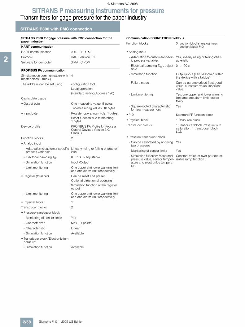
SITRANS P measuring instruments for pressureTransmitters for gage pressure for the paper industry
SITRANS P300 with PMC connection
2/58 Siemens FI 01 · 2009 US Edition
2
SITRANS P300 for gage pressure with PMC connection for the paper industry
HART communication
HART communication 230 ... 1100 Ω
Protocol HART Version 5.x
Software for computer SIMATIC PDM
PROFIBUS PA communication
Simultaneous communication with master class 2 (max.)
4
The address can be set using configuration toolLocal operation(standard setting Address 126)
Cyclic data usage
• Output byte One measuring value: 5 bytesTwo measuring values: 10 bytes
• Input byte Register operating mode: 1 bytesReset function due to metering. 1 bytes
Device profile PROFIBUS PA Profile for Process Control Devices Version 3.0, Class B
Function blocks 2
• Analog input
- Adaptation to customer-specific process variables
Linearly rising or falling character-istic
- Electrical damping T63 0 ... 100 s adjustable
- Simulation function Input /Output
- Limit monitoring One upper and lower warning limit and one alarm limit respectively
• Register (totalizer) Can be reset and presetOptional direction of countingSimulation function of the register output
- Limit monitoring One upper and lower warning limit and one alarm limit respectively
• Physical block 1
Transducer blocks 2
• Pressure transducer block
- Monitoring of sensor limits Yes
- Characterizer Max. 31 points
- Characteristic Linear
- Simulation function Available
• Transducer block "Electronic tem-perature"
- Simulation function Available
Communication FOUNDATION Fieldbus
Function blocks 3 function blocks analog input, 1 function block PID
• Analog input
- Adaptation to customer-specif-ic process variables
Yes, linearly rising or falling char-acteristic
- Electrical damping T63 , adjust-able
0 ... 100 s
- Simulation function Output/input (can be locked within the device with a bridge)
- Failure mode Can be parameterized (last good value, substitute value, incorrect value)
- Limit monitoring Yes, one upper and lower warning limit and one alarm limit respec-tively
- Square-rooted characteristic for flow measurement
Yes
• PID Standard FF function block
• Physical block 1 Resource block
Transducer blocks 1 transducer block Pressure with calibration, 1 transducer block LCD
• Pressure transducer block
- Can be calibrated by applying two pressures
Yes
- Monitoring of sensor limits Yes
- Simulation function: Measured pressure value, sensor temper-ature and electronics tempera-ture
Constant value or over parameter-izable ramp function
© Siemens AG 2008

SITRANS P measuring instruments for pressureTransmitters for gage pressure for the paper industry
SITRANS P300 with PMC connection
2/59Siemens FI 01 · 2009 US Edition
2
F) Subject to export regulations AL: 9I999, ECCN: N.
Selection and Ordering data Order No.
SITRANS P300 pressure transmitters with PMC connection, single-chamber measuring housing, rating plate inscription in English
4 ... 20 mA/HART F) 7 M F 8 1 2 3 -
PROFIBUS PA F) 7 M F 8 1 2 4 -
FOUNDATION Fieldbus (FF) F) 7 M F 8 1 2 5 -
77777 - 7777
Measuring cell filling Measuring cell cleaningSilicone oil Standard 1Inert liquid Cleanliness level 2 to
DIN 254103
Span14.5 psi g (1 bar g) B58 psi g (4 bar g) C232 psi g (16 bar g) D
Wetted parts materialsSeal diaphragm Measuring cell
Hastelloy Stainless steel B
Process connection• PMC Style Standard: Thread 1½" 2• PMC Style Mini bolt: 1" front-flush (min. span: 7.25
psi (500 mbar), can not be ordered with 14.5 psi (1-bar) measuring cell (Option B))
3
Non-wetted parts materials• Stainless steel, deep-drawn and electrolytically
polished4
Version• Standard version 1
Explosion protection• None A• With ATEX, Type of protection:
- "Intrinsic safety (EEx ia)" B• Zone 20/21/221)
1) Can only be ordered in conjunction with electrical connection Option A.
C• Ex nA/nL (zone 2)2)
2) Can only be ordered in conjunction with electrical connection Option B, C, F or G.
E• With FM + CSA, Type of protection:
- "Intrinsic Safe (is)" (planned) M
Electrical connection / cable entry• Screwed gland M20x1.5 (Polyamide)3)
3) Only together with HART electronics.
A• Screwed gland M20x1.5 (metal) B• Screwed gland M20x1.5 (stainless steel) C• M12 connector (without cable socket) F• M12 connector (stainless steel, without cable socket) G• ½-14 NPT thread, metal4)
4) Without cable gland.
H• ½-14 NPT thread, stainless steel4) J
Display• Without display, with pushbuttons, closed lid3) 1
• With display and pushbuttons, closed lid 2
• With display and pushbuttons, lid with glass pane (setting on HART devices: mA, on PROFIBUS PA and FOUNDATION Fieldbus devices: pressure unit)
6
• With display (setting acc. to specifications, Order code "Y21" or "Y22" required), lid with glass pane
7
Power supply units see "SITRANS I power supply units and isolation amplifiers".
Included in delivery of the device:• Brief instructions (Leporello)• CD-ROM with detailed documentation• Sealing ring
Selection and Ordering data Order code
Further designs HART PA FF
Add "-Z" to Order No. and specify Order code.
Cable socket for M12 plug• Metal A50• Stainless steel A51
Rating plate inscription(instead of English)
• German B10• French B12• Spanish B13• Italian B14
English rating plate B21Pressure units in inH2O or psi
Quality inspection certificate (Factory cali-bration) to IEC 60770-2
C11
Acceptance test certificate C12To EN 10204-3.1
Factory certificate C14To EN 10204-2.2
Set output signal to upper limit of 22.0 mA D05
Type of protection IP68 D12
Mounting• Weldable sockets for standard 1½" threaded
connectionP01
• Weldable socket for mini bolt connection 1" (incl. screw 5/16-18 UNC-2B and washer)
P02
Additional data
Add "-Z" to Order No. and specify Order code.
Measuring range to be set Y01Specify in plain text (max. 5 digits):Y01: ... up to ... mbar, bar, kPa, MPa, psi
Measuring point number (TAG No.) Y15Max. 16 characters, specify in plain text: Y15: ......
Measuring point text Y16Max. 27 characters, specify in plain text: Y16: ......
Entry of HART address (TAG) Y17Max. 8 characters, specify in plain text:Y17: ...........................................
Setting of pressure indication in pressure units
Y21
Specify in plain text (standard setting: mA): Y21: mbar, bar, kPa, MPa, psi, ...Note: The following pressure units can be selected:bar, mbar, mm H2O*), inH2O*), ftH2O*), mmHG, inHG, psi, Pa, kPa, MPa, g/cm2, kg/cm2, Torr, ATM or % *) ref. temperature 20 °C
Setting of pressure indication in non-pres-sure units
Y22 + Y01
Specify in plain text:Y22: ..... up to ..... l, m3, m, USg, ...(specification of measuring range in pressure units "Y01" is essential, unit with max. 5 char-acters)
Preset bus address Y25Specify in plain text:Y25: .....................
Only "Y01" and "Y21" can be factory preset
= available
© Siemens AG 2008

SITRANS P measuring instruments for pressureTransmitters for gage pressure for the paper industry
SITRANS P300 with PMC connection
2/60 Siemens FI 01 · 2009 US Edition
2
■ Dimensional drawings
SITRANS P300 pressure transmitters for gage pressure, with PMC connection, dimensions in mm (inch)
The diagram shows a SITRANS P300 with an example of a flange. In this drawing the height is subdivided into H1 and H2.
H1 = Height of the SITRANS P300 up to a defined cross-section
H2 = Height of the flange up to this defined cross-section
Only the height H2 is indicated in the dimensions of the flanges.
PMC Style Standard (left) and PMC Style Minibolt (right) weldable sock-ets, dimensions in mm (inch)
Material: Stainless steel, mat. No. 1.4404 / 316L
PMC Style Standard
DN PN ∅D H2
40.4 mm (1.6") Approx. 36.8 mm (1.4’’)
PMC Style Minibolt
DN PN ∅D H2
26.3 mm (1.0") Approx. 33.1 mm (1.3’’)
© Siemens AG 2008
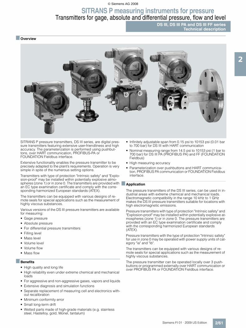
SITRANS P measuring instruments for pressureTransmitters for gage, absolute and differential pressure, flow and level
DS III, DS III PA and DS III FF seriesTechnical description
2/61Siemens FI 01 · 2009 US Edition
2
■ Overview
SITRANS P pressure transmitters, DS III series, are digital pres-sure transmitters featuring extensive user-friendliness and high accuracy. The parameterization is performed using pushbut-tons, over HART communication, PROFIBUS-PA or FOUNDATION Fieldbus interface.
Extensive functionality enables the pressure transmitter to be precisely adapted to the plant’s requirements. Operation is very simple in spite of the numerous setting options.
Transmitters with type of protection "Intrinsic safety" and "Explo-sion-proof" may be installed within potentially explosive atmo-spheres (zone 1) or in zone 0. The transmitters are provided with an EC type examination certificate and comply with the corre-sponding harmonized European standards (ATEX).
The transmitters can be equipped with various designs of re-mote seals for special applications such as the measurement of highly viscous substances.
Various versions of the DS III pressure transmitters are available for measuring:• Gage pressure• Absolute pressure• For differential pressure transmitters • Filling level• Mass level• Volume level• Volume flow• Mass flow
■ Benefits
• High quality and long life• High reliability even under extreme chemical and mechanical
loads• For aggressive and non-aggressive gases, vapors and liquids• Extensive diagnosis and simulation functions• Separate replacement of measuring cell and electronics with-
out recalibration• Minimum conformity error• Small long-term drift• Wetted parts made of high-grade materials (e.g. stainless
steel, Hastelloy, gold, Monel, tantalum)
• Infinitely adjustable span from 0.15 psi to 10153 psi (0.01 bar to 700 bar) for DS III with HART communication
• Nominal measuring range from 14.5 psi to 10153 psi (1 bar to 700 bar) for DS III PA (PROFIBUS PA) and FF (FOUNDATION Fieldbus)
• High measuring accuracy• Parameterization over pushbuttons and HART communica-
tion, PROFIBUS PA communication or FOUNDATION Fieldbus interface.
■ Application
The pressure transmitters of the DS III series, can be used in in-dustrial areas with extreme chemical and mechanical loads. Electromagnetic compatibility in the range 10 kHz to 1 GHz makes the DS III pressure transmitters suitable for locations with high electromagnetic emissions.
Pressure transmitters with type of protection "Intrinsic safety" and "Explosion-proof" may be installed within potentially explosive at-mospheres (zone 1) or in zone 0. The pressure transmitters are provided with an EC type examination certificate and comply with the corresponding harmonized European standards (ATEX).
Pressure transmitters with the type of protection "Intrinsic safety" for use in zone 0 may be operated with power supply units of cat-egory "ia" and "ib".
The transmitters can be equipped with various designs of re-mote seals for special applications such as the measurement of highly viscous substances.
The pressure transmitter can be operated locally over 3 push-buttons or programmed externally over HART communication or over PROFIBUS PA or FOUNDATION Fieldbus interface.
© Siemens AG 2008

SITRANS P measuring instruments for pressureTransmitters for gage, absolute and differential pressure, flow and levelDS III, DS III PA and DS III FF seriesTechnical description
2/62 Siemens FI 01 · 2009 US Edition
2
Pressure transmitter for gage pressure• Measured variable: Gage pressure of aggressive and non-ag-
gressive gases, vapors and liquids.• Span (infinitely adjustable)
for DS III HART: 0.15 psi to 10153 psi (0.01 bar to 700 bar)• Nominal measuring range
for DS III PA and FF: 14.5 psi to 10153 psi (1 bar to 700 bar)
Pressure transmitters for absolute pressure • Measured variable: Absolute pressure of aggressive and non-
aggressive gases, vapors and liquids.• Span (infinitely adjustable)
for DS III HART: 0.12 ... 1450 psi a (8.3 mbar a ... 100 bar a)• Nominal measuring range
for DS III PA and FF: 3.63...1450 psi a (250 mbar a...100 bar a)• There are two series:
- gage construction- differential construction
Pressure transmitters for differential pressure and flow• Measured variables:
- Differential pressure- Small positive or negative pressure- Flow q ~ √Δp (together with a primary differential pressure
device (see Chapter "Flow Meters"))• Span (infinitely adjustable)
for DS III HART: 0.0145 ... 435 psi (1 mbar ... 30 bar)• Nominal measuring range
for DS III PA and FF: 0.29 ... 435 psi (20 mbar ... 30 bar)
Pressure transmitters for level• Measured variable: Level of aggressive and non-aggressive
liquids in open and closed vessels.• Span (infinitely adjustable)
for DS III HART: 0.363 ... 72.5 psi (25 mbar ... 5 bar)• Nominal measuring range
for DS III PA and FF: 3.63 ... 72.5 psi (250 mbar ... 5 bar)• Nominal diameter of the mounting flange
- DN 80 or DN 100- 3 inch or 4 inch
In the case of level measurements in open containers, the low-pressure connection of the measuring cell remains open (mea-surement "compared to atmospheric").
In the case of measurements in closed containers, the lower-pressure connection has to be connected to the container in or-der to compensate the static pressure.
The wetted parts are made from a variety of materials, depend-ing on the degree of corrosion resistance required.
■ Design
Front view
The transmitter consists of various components depending on the order. The possible versions are listed in the ordering infor-mation. The components described below are the same for all transmitters.
The rating plate (3, Figure "Front view") with the Order No. is lo-cated on the side of the housing. The specified number together with the ordering information provide details on the optional de-sign details and on the possible measuring range (physical properties of built-in sensor element).
The approval label is located on the opposite side.
The housing is made of die-cast aluminium or stainless steel pre-cision casting. A round cover is screwed on at the front and rear of the housing. The front cover (6) can be fitted with a viewing pane so that the measured values can be read directly on the digital display. The inlet (4) for the electrical connection is lo-cated either on the left or right side. The unused opening on the opposite side is sealed by a blanking plug. The protective earth connection is located on the rear of the housing.
The electrical connections for the power supply and screen are accessible by unscrewing the rear cover. The bottom part of the housing contains the measuring cell with process connection (1). The measuring cell is prevented from rotating by a locking screw (8). As the result of this modular design, the measuring cell and the electronics can be replaced separately from each other. The set parameter data are retained.
At the top of the housing is a plastic cover (5), which hides the pushbuttons.
© Siemens AG 2008

SITRANS P measuring instruments for pressureTransmitters for gage, absolute and differential pressure, flow and level
DS III, DS III PA and DS III FF seriesTechnical description
2/63Siemens FI 01 · 2009 US Edition
2
■ Function
Operation of the electronics with HART communication
Function diagram of the electronics
The bridge output voltage created by the sensor (1, Figure "Function diagram of the electronics") is amplified by the instru-ment amplifier (2) and digitized in the analog-to-digital converter (3). The digital information is evaluated in a microcontroller, its linearity and temperature response corrected, and converted in a digital-to-analog converter (5) into an output current of 4 to 20 mA.
The diode circuit (10) protects against incorrect polarity.
The data specific to the measuring cell, the electronics data, and the parameter data are stored in the two non-volatile memories (6). The one memory is coupled to the measuring cell, the other to the electronics. As the result of this modular design, the elec-tronics and the measuring cell can be replaced separately from each other.
Using the 3 pushbuttons (8) you can parameterize the pressure transmitter directly at the point of measurement. The pushbut-tons can also be used to control the view of the results, the error messages and the operating modes on the digital display (9).
The HART modem (7) permits parameterization using a protocol according to the HART specification.
The pressure transmitters with spans ≤ 914 psi g (≤ 63 bar) mea-sure the input pressure compared to atmosphere, transmitters with spans ≥ 2321 psi g (≤ 160 bar) compared to vacuum.
Operation of the electronics with PROFIBUS PA communica-tion
Function diagram of the electronics
The bridge output voltage created by the sensor (1, Figure "Function diagram of the electronics") is amplified by the instru-ment amplifier (2) and digitized in the analog-to-digital converter (3). The digital information is evaluated in the microcontroller, its linearity and temperature response corrected, and provided on the PROFIBUS PA through an electrically isolated PA interface (7).
The data specific to the measuring cell, the electronics data, and the parameter data are stored in the two non-volatile memories (6). The first memory is linked with the measuring cell, the sec-ond with the electronics. This modular design means that the electronics and the measuring cell can be replaced separately from one another.
Using the three pushbuttons (8) you can parameterize the pres-sure transmitter directly at the point of measurement. The push-buttons can also be used to control the view of the results, the error messages and the operating modes on the digital display (9).
The results with status values and diagnostic values are trans-ferred by cyclic data transmission on the PROFIBUS PA. Param-eterization data and error messages are transferred by acyclic data transmission. Special software such as SIMATIC PDM is re-quired for this.
������
�
�
�
�
��
�
���
��
�
� � �� �� �
�
8 �&�$�"�#�*�((����� �� ���'�$���'�&�%("!"��� ��&( #)' ) "#"'&(�* �+��'��� "*� * �'� ((��7 �"#"'&()' )&�&( #�* �+��'��< ����� �)+ (&'"(����� ����&*-�"��'-����&�$�"�#�*�((�&� ��(�*'� �"*�6 ���;�"�'��!&*�/ ;-����"�%$'������0( *&(� %��&'" �19 �"#"'&(� "�%(&�8� �" ��*"�*$"'�&� �* ���*'" ��! ���='���&(�&���'���� �$'%$'�*$����'�� � ,����$%%(��� ��%$'�+&�"&C(�
4��� �
����
�
�����
���;�"�'��!&*�
�(�*'� �"*�
�&�$�"�#�*�((
�
�
��
�
�
��
�� �� �� �
����
�
�����
�
�
� � �
�!
��
��
8 �&�$�"�#�*�((����� �� ���'�$���'�&�%("!"��� ��&( #)' ) "#"'&(�* �+��'��� "*� * �'� ((��7 �(�*'�"*&(�"� (&'" �< ����� �)+ (&'"(����� ��
�&*-�"��'-����&�$�"�#�*�((&� ��(�*'� �"*�
6 ���?�3�4)���"�'��!&*�
4��� �
�(�*'� �"*�
�&�$�"�#�*�((
��"�'��!&*�
3$�)&�'��
� ,���$%%(�$�"'� $%)����(��
� ,�����$%%(�
���?�3�
4)��
���?�3�
4)��
/ ;-����"�%$'�����0( *&(� %��&'" �1
9 �"#"'&(� "�%(&�8� � ,����$%%(�88 ������* $%(��� ��("��8� 3$���&�'��
�� ��%$'�+&�"&C(�
© Siemens AG 2008

SITRANS P measuring instruments for pressureTransmitters for gage, absolute and differential pressure, flow and levelDS III, DS III PA and DS III FF seriesTechnical description
2/64 Siemens FI 01 · 2009 US Edition
2
Mode of operation of the FOUNDATION Fieldbus electronics
Function diagram of the electronics
The bridge output voltage created by the sensor (1, Figure "Function diagram of the electronics") is amplified by the instru-ment amplifier (2) and digitized in the analog-to-digital converter (3). The digital information is evaluated in the microcontroller, its linearity and temperature response corrected, and provided on the FOUNDATION Fieldbus through an electrically isolated FOUNDATION Fieldbus Interface (7).
The data specific to the measuring cell, the electronics data, and the parameter data are stored in the two non-volatile memories (6). The one memory is coupled to the measuring cell, the other to the electronics. As the result of this modular design, the elec-tronics and the measuring cell can be replaced separately from each other.
Using the three pushbuttons (8) you can parameterize the pres-sure transmitter directly at the point of measurement. The push-buttons can also be used to control the view of the results, the error messages and the operating modes on the digital display (9).
The results with status values and diagnostic values are trans-ferred by cyclic data transmission on the FOUNDATION Fieldbus. Parameterization data and error messages are trans-ferred by acyclic data transmission. Special software such as National Instruments Configurator is required for this.
Mode of operation of the measuring cells
Measuring cell for gage pressure
Measuring cell for gage pressure, function diagram
The pressure pe is applied through the process connection (2, Figure "Measuring cell for gage pressure, function diagram) to the measuring cell (1). This pressure is subsequently transmitted further through the seal diaphragm (3) and the filling liquid (4) to the silicon pressure sensor (5) whose measuring diaphragm is then flexed. This changes the resistance of the four piezo-resis-tors fitted in the diaphragm in a bridge circuit. This change in re-sistance results in a bridge output voltage proportional to the in-put pressure.
Measuring cell for gage pressure, with front-flush diaphragm for paper industry
Measuring cell for gage pressure, with front-flush diaphragm for paper in-dustry, function diagram
The pressure pe is applied through the process connection (2, Figure "Measuring cell for gage pressure, with front-flush dia-phragm for paper industry, function diagram") to the measuring cell (1). This pressure is subsequently transmitted further through the seal diaphragm (3) and the filling liquid (4) to the sil-icon pressure sensor (5) whose measuring diaphragm is then flexed. This changes the resistance of the four piezo-resistors fit-ted in the diaphragm in a bridge circuit. This change in resis-tance results in a bridge output voltage proportional to the input pressure.
�
�
��
�
�
��
�� �� �� �
����
�
�����
�
�
� � �
�!
8 �&�$�"�#�*�((����� �� ���'�$���'�&�%("!"��� ��&( #)' ) "#"'&(�* �+��'��� "*� * �'� ((��7 �(�*'�"*&(�"� (&'" �< ����� �)+ (&'"(����� ��
�&*-�"��'-����&�$�"�#�*�((&� ��(�*'� �"*�
6 ??�"�'��!&*�
4��� �
�(�*'� �"*�
�&�$�"�#�*�((
??"�'��!&*�
� ,���$%%(�$�"'� $%)����(��
� ,�����$%%(�
/ ;-����"�%$'�����0( *&(� %��&'" �1
9 �"#"'&(� "�%(&�8� � ,����$%%(�
�� ��%$'�+&�"&C(�
�
�
�
�
�
�
�
8 �&�$�"�#�*�((� �� *����* ���*'" �� 4�&(� "&%-�&#�� ?"(("�#�("E$" 7 4"("* ��%����$������� ��� �����$���&��"�%$'�+&�"&C(�
�
�
�
�
�
�
�
8 �&�$�"�#�*�((� �� *����* ���*'" �� 4�&(� "&%-�&#�� ?"(("�#�("E$" 7 4"("* ��%����$������� �%� �����$���&��"�%$'�+&�"&C(�
© Siemens AG 2008

SITRANS P measuring instruments for pressureTransmitters for gage, absolute and differential pressure, flow and level
DS III, DS III PA and DS III FF seriesTechnical description
2/65Siemens FI 01 · 2009 US Edition
2
Measuring cell for absolute pressure from gage construction
Measuring cell for absolute pressure from gage construction, function diagram
The absolute pressure pe is transmitted through the seal dia-phragm (3, Figure "Measuring cell for absolute pressure from gage construction, function diagram") and the filling liquid (4) to the silicon absolute pressure sensor (5) whose measuring dia-phragm is then flexed. This changes the resistance of the four pi-ezo-resistors fitted in the diaphragm in a bridge circuit. This change in resistance results in a bridge output voltage propor-tional to the input pressure.
Measuring cell for absolute pressure from differential construction
Measuring cell for absolute pressure from differential construction, function diagram
The input pressure pe is transmitted through the seal diaphragm (6, Figure "Measuring cell for absolute pressure from differential construction, function diagram") and the filling liquid (8) to the silicon pressure sensor (3).
The difference in pressure between the input pressure pe and the reference vacuum (1) on the low-pressure side of the mea-suring cell flexes the measuring diaphragm. The resistance of the four piezo-resistors fitted in the diaphragm in a bridge circuit thus changes. This change in resistance results in a bridge out-put voltage proportional to the absolute pressure.
An overload diaphragm is installed to provide protection from overloads. If the measuring limits are exceeded, the overload di-aphragm (2) is flexed until the seal diaphragm rests on the body of the measuring cell (7), thus protecting the silicon pressure sensor from overloads.
Measuring cell for differential pressure and flow
Measuring cell for differential pressure and flow, function diagram
The differential pressure is transmitted through the seal dia-phragms (1, Figure "Measuring cell for differential pressure and flow, function diagram") and the filling liquid (7) to the silicon pressure sensor (4). The measuring diaphragm is flexed by the applied differential pressure. This changes the resistance of the four piezo-resistors fitted in the diaphragm in a bridge circuit. This change in resis-tance results in a bridge output voltage proportional to the abso-lute pressure.An overload diaphragm is installed to provide protection from overloads. If the measuring limits are exceeded, the overload di-aphragm (2) is flexed until the seal diaphragm rests on the body of the measuring cell (7), thus protecting the silicon pressure sensor from overloads.
Measuring cell for level
Measuring cell for level, function diagram
The input pressure (hydrostatic pressure) acts hydraulically on the measuring cell through the seal diaphragm on the mounting flange (2, Figure "Measuring cell for level, function diagram"). This differential pressure is subsequently transmitted further through the measuring cell (3) and the filling liquid (9) to the sil-icon pressure sensor (6) whose measuring diaphragm is then flexed. This changes the resistance of the four piezo-resistors fitted in the diaphragm in a bridge circuit. This change in resistance results in a bridge output voltage pro-portional to the differential pressure.An overload diaphragm is installed to provide protection from overloads. If the measuring limits are exceeded, the overload di-aphragm (2) is flexed until the seal diaphragm rests on the body of the measuring cell (7), thus protecting the silicon pressure sensor from overloads.
���
7
�
�
88 �&�$�"�#�*�((� �� *����* ���*'" �� 4�&(� "&%-�&#�� ?"(("�#�("E$" 7 4"("* ��&C� ($'��%����$������� ��� �C� ($'��%����$���&��"�%$'�+&�"&C(�
�
� � �
�
���
�
8 ��!����*��+&*$$�� �+��( & � "&%-�&#�� 4"("* ��%����$������� �� �)�"�#7 �� *����!(&�#�< 4�&(� "&%-�&#�6 3 �� !���&�$�"�#�*�((/ ?"(("�#�("E$" �� �C� ($'��%����$���&�
"�%$'�+&�"&C(�
�
�
���
�
��
�
�
� �����!���)���0� ������& �'����!�!���)���0+ ��������������������1 ������2�����3 �! �2�0������������4 (���������5��!
� �
�
� � �
�
�
�
��
3 ��������������������4 ������6 ������2�����7 (���������5��!�� "������� ��� )�2���������5��!
2�0�� ����2�����
� (�������� )� �-�� �����!���)���0��
0�� ����2�����& �����!���)���0+ �! �2�0������������1 �'����!�!���)���0
© Siemens AG 2008

SITRANS P measuring instruments for pressureTransmitters for gage, absolute and differential pressure, flow and levelDS III, DS III PA and DS III FF seriesTechnical description
2/66 Siemens FI 01 · 2009 US Edition
2
Parameterization DS III
Depending on the version, there are a range of options for pa-rameterizing the pressure transmitter and for setting or scanning the parameters.
Parameterization using the pushbuttons (local operation)
With the pushbuttons you can easily set the most important pa-rameters without any additional equipment.
Parameterization using HART communication
Parameterization using HART communication is performed with a HART communicator or a PC.
Communication between a HART communicator and a pressure transm.
When parameterizing with the HART communicator, the connec-tion is made directly to the 2-wire system.
HART communication between a PC communicator and a pressure transmitter
When parameterizing with a PC, the connection is made through a HART modem.
The signals needed for communication in conformity with the HART 5.x or 6.x protocols are superimposed on the output cur-rent using the Frequency Shift Keying (FSK) method.
Adjustable parameters, DS III HART
Diagnostic functions for DS III HART• Zero correction for position• Event counter• Transmitter alarms• Saturation alarm• Min/Max registers• Simulation functions• Maintenance timer
Available physical units of display for DS III HART
Table style: Technical specifications 2
Parameterization through PROFIBUS PA interface
Fully digital communication through PROFIBUS PA, profile 3.0, is particularly user-friendly. The PROFIBUS puts the DS III PA is in connection with a process control system, e.g. SIMATIC PSC 7. Communication is possible even in a potentially explosive envi-ronment.
For parameterization through PROFIBUS you need suitable soft-ware, e.g. SIMATIC PDM (Process Device Manager).
Parameterization through FOUNDATION Fieldbus Interface
Fully digital communication through FOUNDATION Fieldbus is particularly user-friendly. Through the FOUNDATION Fieldbus the DS III FF is connected to a process control system. Commu-nication is possible even in a potentially explosive environment.
For parameterization through the FOUNDATION Fieldbus you need suitable software, e.g. National Instruments Configurator.
Adjustable parameters for DS III PA and FF
Parameters Pushbuttons (DS III HART)
HART com-munication
Start of scale x x
Full-scale value x x
Electrical damping x x
Start-of-scale value without application of a pressure ("Blind setting")
x x
Full-scale value without application of a pressure ("Blind setting")
x x
Zero adjustment x x
Current transmitter x x
Fault current x x
Disabling of keys, write protection x x1)
1) Cancel apart from write protection
Type of dimension and actual dimension x x
Linear or square root output x2)
2) Only differential pressure
x2)
Characterizer setup x
Freely-programmable LCD x
Diagnostics functions x
D
���;* ��$�"*&' �
���������88����'�&���"''��4�;��:4�� � ,����$%%(�
'�&���"''��4�;��:4�� � ,����$%%(�
���;� ��
��� �(&%' %
�4����
���������7����
Physical variable Physical dimensions
Pressure (setting can also be made in the factory)
Pa, MPa, kPa, bar, mbar, torr, atm, psi, g/cm2, kg/cm2, inH2O, inH2O (4 °C), mmH2O, ftH2O (20 °C), inHg, mmHg
Level (height data) m, cm, mm, ft, in
Volume m3, dm3, hl, yd3, ft3, in3, US gallon, lmp. gallon, bushel, barrel, barrel liquid
Mass g, kg, t, lb, Ston, Lton, oz
Volume flow m3/d, m3/h, m3/s, l/min, l/s, ft3/d, ft3/min, ft3/s, US gallon/min, US gallon/s
Mass flow t/d, t/h, t/min, kg/d, kg/h, kg/min, kg/s, g/d, g/h, g/min, g/s, lb/d, lb/h, lb/min, lb/s, LTon/d, LTon/h, STon/d, STon/h, STon/min
Temperature K, °C, °F, °R
Miscellaneous %, mA
Parameters Pushbuttons (DS III HART)
PROFIBUS PA and FOUNDATION Fieldbus interface
Electrical damping x x
Zero adjustment (correction of position)
x x
Key and/or function disabling x x
Source of measured-value dis-play
x x
Physical dimension of display x x
Position of decimal point x x
Bus address x x
Linear or square root output x
Input of characterizer setup x
Freely-programmable LCD x
Diagnostics functions x
© Siemens AG 2008

SITRANS P measuring instruments for pressureTransmitters for gage, absolute and differential pressure, flow and level
DS III, DS III PA and DS III FF seriesTechnical description
2/67Siemens FI 01 · 2009 US Edition
2
Diagnostic functions for DS III PA and FF• Event counter• Min/Max registers• Maintenance timer• Simulation functions• Zero correction for position• Transmitter alarms• Saturation alarm
Physical dimensions available for the display
Physical variable Physical dimensions
Pressure (setting can also be made in the factory)
MPa, kPa, Pa, bar, mbar, torr, atm, psi, g/cm2, kg/cm2, mmH2O, mmH2O (4 °C), inH2O, inH20 (4 °C), ftH2O (20 °C), mmHg, inHg
Level (height data) m, cm, mm, ft, in, yd
Volume m3, dm3, hl, yd3, ft3, in3, US gallon, lmp. gallon, bushel, barrel, barrel liquid
Volume flow m3/s, m3/min, m3/h, m3/d, l/s, l/min, l/h, l/ d, Ml/d, ft3/s, ft3/min, ft3/h, ft3/d, US gal-lon/s, US gallon/min, US gallon/h, US gal-lon/d, bbl/s, bbl/min, bbl/h, bbl/d
Mass flow g/s, g/min, g/h, g/d, kg/s, kg/min, kg/h, kg/d, t/s, t/min, t/h, /t/d, lb/s, lb/min, lb/h, lb/d, STon/s, STon/min, STon/h, STon/d, LTon/s, LTon/min, LTon/h, LTon/d
Total mass flow t, kg, g, lb, oz, LTon, STon
Temperature K, °C, °F, °R
Miscellaneous %
© Siemens AG 2008
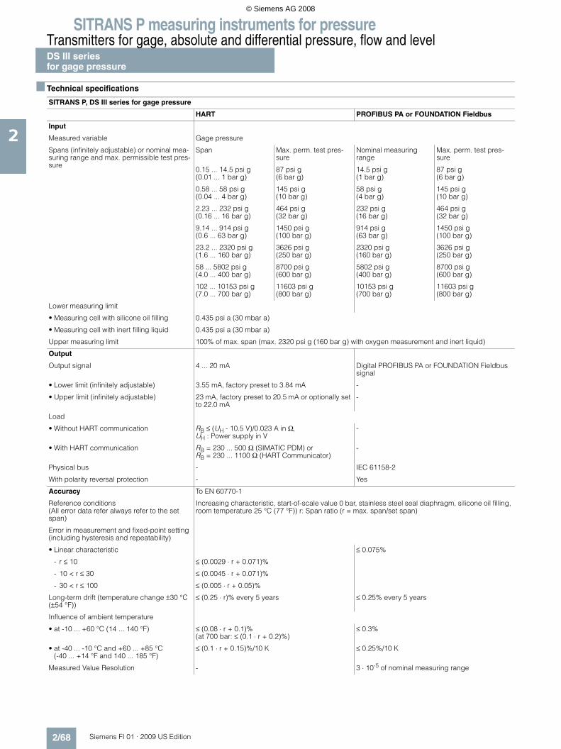
SITRANS P measuring instruments for pressureTransmitters for gage, absolute and differential pressure, flow and levelDS III seriesfor gage pressure
2/68 Siemens FI 01 · 2009 US Edition
2
■ Technical specifications
SITRANS P, DS III series for gage pressure
HART PROFIBUS PA or FOUNDATION Fieldbus
Input
Measured variable Gage pressure
Spans (infinitely adjustable) or nominal mea-suring range and max. permissible test pres-sure
Span Max. perm. test pres-sure
Nominal measuring range
Max. perm. test pres-sure
0.15 ... 14.5 psi g (0.01 ... 1 bar g)
87 psi g (6 bar g)
14.5 psi g (1 bar g)
87 psi g (6 bar g)
0.58 ... 58 psi g (0.04 ... 4 bar g)
145 psi g (10 bar g)
58 psi g (4 bar g)
145 psi g (10 bar g)
2.23 ... 232 psi g (0.16 ... 16 bar g)
464 psi g (32 bar g)
232 psi g (16 bar g)
464 psi g (32 bar g)
9.14 ... 914 psi g (0.6 ... 63 bar g)
1450 psi g (100 bar g)
914 psi g (63 bar g)
1450 psi g (100 bar g)
23.2 ... 2320 psi g (1.6 ... 160 bar g)
3626 psi g (250 bar g)
2320 psi g (160 bar g)
3626 psi g (250 bar g)
58 ... 5802 psi g (4.0 ... 400 bar g)
8700 psi g (600 bar g)
5802 psi g (400 bar g)
8700 psi g (600 bar g)
102 ... 10153 psi g (7.0 ... 700 bar g)
11603 psi g (800 bar g)
10153 psi g (700 bar g)
11603 psi g (800 bar g)
Lower measuring limit
• Measuring cell with silicone oil filling 0.435 psi a (30 mbar a)
• Measuring cell with inert filling liquid 0.435 psi a (30 mbar a)
Upper measuring limit 100% of max. span (max. 2320 psi g (160 bar g) with oxygen measurement and inert liquid)
Output
Output signal 4 ... 20 mA Digital PROFIBUS PA or FOUNDATION Fieldbus signal
• Lower limit (infinitely adjustable) 3.55 mA, factory preset to 3.84 mA -
• Upper limit (infinitely adjustable) 23 mA, factory preset to 20.5 mA or optionally set to 22.0 mA
-
Load
• Without HART communication RB ≤ (UH - 10.5 V)/0.023 A in Ω,UH : Power supply in V
-
• With HART communication RB = 230 ... 500 Ω (SIMATIC PDM) orRB = 230 ... 1100 Ω (HART Communicator)
-
Physical bus - IEC 61158-2
With polarity reversal protection - Yes
Accuracy To EN 60770-1
Reference conditions(All error data refer always refer to the set span)
Increasing characteristic, start-of-scale value 0 bar, stainless steel seal diaphragm, silicone oil filling, room temperature 25 °C (77 °F)) r: Span ratio (r = max. span/set span)
Error in measurement and fixed-point setting (including hysteresis and repeatability)
• Linear characteristic ≤ 0.075%
- r ≤ 10 ≤ (0.0029 ⋅ r + 0.071)%
- 10 < r ≤ 30 ≤ (0.0045 ⋅ r + 0.071)%
- 30 < r ≤ 100 ≤ (0.005 ⋅ r + 0.05)%
Long-term drift (temperature change ±30 °C (±54 °F))
≤ (0.25 ⋅ r)% every 5 years ≤ 0.25% every 5 years
Influence of ambient temperature
• at -10 ... +60 °C (14 ... 140 °F) ≤ (0.08 ⋅ r + 0.1)%(at 700 bar: ≤ (0.1 ⋅ r + 0.2)%)
≤ 0.3%
• at -40 ... -10 °C and +60 ... +85 °C(-40 ... +14 °F and 140 ... 185 °F)
≤ (0.1 ⋅ r + 0.15)%/10 K ≤ 0.25%/10 K
Measured Value Resolution - 3 ⋅ 10-5 of nominal measuring range
© Siemens AG 2008

SITRANS P measuring instruments for pressureTransmitters for gage, absolute and differential pressure, flow and level
DS III seriesfor gage pressure
2/69Siemens FI 01 · 2009 US Edition
2
Rated operating conditions
Degree of protection (to EN 60529) IP65
Process temperature
• Measuring cell with silicone oil filling -40 ... +100 °C (-40 ... +212 °F)
• Measuring cell with inert filling liquid -20 ... +100 °C (-4 ... +212 °F)
• In conjunction with dust explosion protec-tion
-20 ... +60 °C (-4 ... +140 °F)
Ambient conditions
• Ambient temperature
- Digital indicators -30 ... +85 °C (-22 ... +185 °F)
• Storage temperature -50 ... +85 °C (-58 ... +185 °F)
• Climatic class
- Condensation Permissible
• Electromagnetic compatibility
- Emitted interference and interference immunity
To EN 61326 and NAMUR NE 21
Design
Weight (without options) ≈ 1.5 kg (≈ 3.3 lb)
Housing material Low copper die-cast aluminium, GD-AlSi12 or stainless steel precision casting, mat. No. 1.4408
Wetted parts materials
• Connection shank Stainless steel, mat. No. 1.4404/316L or Hastelloy C4, mat. No. 2.4610
• Oval flange Stainless steel, mat. No. 1.4404/316L
• Seal diaphragm Stainless steel, mat. No. 1.4404/316L or Hastelloy C276, mat. No. 2.4819
Measuring cell filling Silicone oil or inert filling liquid (max. 160 bar (2320 psi g) with oxygen measurement)
Process connection Connection shank G½A to DIN EN 837-1, female thread ½ -14 NPT or oval flange (PN 160 (MWP 2320 psi g)) to DIN 19213 with mounting thread M10 or 7/16-20 UNF to EN 61518
Material of the mounting bracket
• Steel Sheet steel, Mat. No. 1.0330, chrome-plated
• Stainless steel Stainless steel, Mat. No. 1.4301 (SS304)
Power supply UH Supplied through bus
Terminal voltage on transmitter 10.5 ... 45 V DC10.5 ... 30 V DC in intrinsically-safe mode
-
Separate 24 V power supply necessary - No
Bus voltage
• Not Ex - 9 ...32 V
• With intrinsically-safe operation - 9 ...24 V
Current consumption
• Basic current (max.) - 12.5 mA
• Startup current ≤ basic current - Yes
• Max. current in event of fault - 15.5 mA
Fault disconnection electronics (FDE) avail-able
- Yes
SITRANS P, DS III series for gage pressure
HART PROFIBUS PA or FOUNDATION Fieldbus
© Siemens AG 2008

SITRANS P measuring instruments for pressureTransmitters for gage, absolute and differential pressure, flow and levelDS III seriesfor gage pressure
2/70 Siemens FI 01 · 2009 US Edition
2
Certificate and approvals
Classification according to pressure equip-ment directive (DRGL 97/23/EC)
For gases of fluid group 1 and liquids of fluid group 1; complies with requirements of Article 3, para-graph 3 (sound engineering practice)
Explosion protection
• Intrinsic safety "i" PTB 99 ATEX 2122
- Identification Ex II 1/2 G EEx ia/ib IIB/IIC T6
- Permissible ambient temperature -40 ... +85 °C (-40 ... +185 °F) temperature class T4;-40 ... +70 °C (-40 ... +158 °F) temperature class T5;-40 ... +60 °C (-40 ... +140 °F) temperature class T6
- Connection To certified intrinsically-safe circuits with maxi-mum values: Ui = 30 V, Ii = 100 mA, Pi = 750 mW; Ri = 300 Ω
FISCO supply unit: Uo = 17.5 V, Io = 380 mA, Po = 5.32 WLinear barrier: Uo = 24 V, Io = 250 mA, Po = 1.2 W
- Effective internal inductance/capacitance L i = 0.4 mH, Ci = 6 nF L i = 7 μH, Ci = 1.1 nF
• Explosion-proof "d" PTB 99 ATEX 1160
- Identification Ex II 1/2 G EEx d IIC T4/T6
- Permissible ambient temperature -40 ... +85 °C (-40 ... +185 °F) temperature class T4;-40 ... +60 °C (-40 ... +140 °F) temperature class T6
- Connection To circuits with values: UH = 10.5 ... 45 V DC To circuits with values: UH = 9 ... 32 V DC
• Dust explosion protection for zone 20 PTB 01 ATEX 2055
- Identification Ex II 1 D IP65 T 120 °CEx II 1/2 D IP65 T 120 °C
- Permissible ambient temperature -40 ... +85 °C (-40 ... +185 °F)
- Max.surface temperature 120 °C (248 °F)
- Connection To certified intrinsically-safe circuits with maxi-mum values: Ui = 30 V, Ii = 100 mA, Pi = 750 mW, Ri = 300 Ω
FISCO supply unit: Uo = 17.5 V, Io = 380 mA, Po = 5.32 WLinear barrier: Uo = 24 V, Io = 250 mA, Po = 1.2 W
- Effective internal inductance/capacitance L i = 0.4 mH, Ci = 6 nF L i = 7 μH, Ci = 1.1 nF
• Dust explosion protection for zone 21/22 PTB 01 ATEX 2055
- Identification Ex II 2 D IP65 T 120 °C
- Connection To circuits with values: UH = 10.5 ... 45 V DC; Pmax = 1.2 W
To circuits with values: UH = 9 ... 32 V DC; Pmax = 1.2 W
• Type of protection "n" (zone 2) TÜV 01 ATEX 1696 X Planned
- Identification Ex II 3 G EEx nA L IIC T4/T5/T6 -
• Explosion protection to FM Certificate of Compliance 3008490
- Identification (XP/DIP) or (IS); (NI) CL I, DIV 1, GP ABCD T4...T6; CL II, DIV 1, GP EFG; CL III; CL I, ZN 0/1 AEx ia IIC T4...T6; CL I, DIV 2, GP ABCD T4...T6; CL II, DIV 2, GP FG; CL III
• Explosion protection to CSA Certificate of Compliance 1153651
- Identification (XP/DIP) or (IS) CL I, DIV 1, GP ABCD T4...T6; CL II, DIV 1, GP EFG; CL III; Ex ia IIC T4...T6; CL I, DIV 2, GP ABCD T4...T6; CL II, DIV 2, GP FG; CL III
SITRANS P, DS III series for gage pressure
HART PROFIBUS PA or FOUNDATION Fieldbus
© Siemens AG 2008

SITRANS P measuring instruments for pressureTransmitters for gage, absolute and differential pressure, flow and level
DS III seriesfor gage pressure
2/71Siemens FI 01 · 2009 US Edition
2
HART communication
HART communication 230 ... 1100 Ω
Protocol HART Version 5.x
Software for computer SIMATIC PDM
PROFIBUS PA communication
Simultaneous communication with master class 2 (max.)
4
The address can be set using Configuration tool or local opera-tion (standard setting address 126)
Cyclic data usage
• Output byte 5 (one measuring value) or10 (two measuring values)
• Input byte 0, 1, or 2 (register operating mode and reset function for metering)
Internal preprocessing
Device profile PROFIBUS PA Profile for Process Control Devices Version 3.0, Class B
Function blocks 2
• Analog input
- Adaptation to customer-specif-ic process variables
Yes, linearly rising or falling char-acteristic
- Electrical damping T63 , adjust-able
0 ... 100 s
- Simulation function Input /Output
- Failure mode Can be parameterized (last good value, substitute value, incorrect value)
- Limit monitoring Yes, one upper and lower warning limit and one alarm limit respec-tively
• Register (totalizer) Can be reset, preset, optional direction of counting, simulation function of register output
- Failure mode Can be parameterized (summation with last good value, continuous summation, summation with incor-rect value)
- Limit monitoring One upper and lower warning limit and one alarm limit respectively
• Physical block 1
Transducer blocks 2
• Pressure transducer block
- Can be calibrated by applying two pressures
Yes
- Monitoring of sensor limits Yes
- Characterizer Max. 30 points
- Square-rooted characteristic for flow measurement
Yes
- Gradual volume suppression and implementation point of square-root extraction
Parameterizable
- Simulation function for mea-sured pressure value and sen-sor temperature
Constant value or over parameter-izable ramp function
Communication FOUNDATION Fieldbus
Function blocks 3 function blocks analog input, 1 function block PID
• Analog input
- Adaptation to customer-specif-ic process variables
Yes, linearly rising or falling char-acteristic
- Electrical damping T63 , adjust-able
0 ... 100 s
- Simulation function Output/input (can be locked within the device with a bridge)
- Failure mode Can be parameterized (last good value, substitute value, incorrect value)
- Limit monitoring Yes, one upper and lower warning limit and one alarm limit respec-tively
- Square-rooted characteristic for flow measurement
Yes
• PID Standard FF function block
• Physical block 1 Resource block
Transducer blocks 1 transducer block Pressure with calibration, 1 transducer block LCD
• Pressure transducer block
- Can be calibrated by applying two pressures
Yes
- Monitoring of sensor limits Yes
- Simulation function: Measured pressure value, sensor temper-ature and electronics tempera-ture
Constant value or over parameter-izable ramp function
© Siemens AG 2008

SITRANS P measuring instruments for pressureTransmitters for gage, absolute and differential pressure, flow and levelDS III seriesfor gage pressure
2/72 Siemens FI 01 · 2009 US Edition
2
Selection and Ordering data Order No.
SITRANS P pressure transmitters for gage pressure, series DS III HART
7 M F 4 0 3 3 -
77777 - 7777
Measuring cell filling Measuring cell cleaning
Silicone oil Standard } 1Inert liquid1) Grease-free 3
Span0.15 ... 14.5 psi g (0.01 ... 1 bar g) } B0.58 ... 58 psi g (0.04 ... 4 bar g) } C2.32 ... 232 psi g (0.16 ... 16 bar g) } D9.14 ... 914 psi g (0.63 ... 63 bar g) } E23.2 ... 2320 psi g (1.6 ... 160 bar g) } F58.0 ... 5802 psi g (4.0 ... 400 bar g) } G102.0 ...10153 psi g (7.0 ... 700 bar g) } J
Wetted parts materialsSeal diaphragm Process connection
Stainless steel Stainless steel } AHastelloy Stainless steel BHastelloy Hastelloy CVersion as diaphragm seal2) 3) Y
Process connection• Connection shank G½B to EN 837-1 } 0• Female thread ½-14 NPT 1• Oval flange made of stainless steel
- Mounting thread 7/16-20 UNF to EN 61518 2- Mounting thread M10 to DIN 19213 3- Mounting thread M12 to DIN 19213 4
• Male thread M20 x 1,5 5• Male thread ½-14 NPT 6
Non-wetted parts materials• Housing made of die-cast aluminium } 0• Housing stainless steel precision casting4) 3
Version• Standard version 1• International version, English label inscriptions,
documentation in 5 languages on CD} 2
Explosion protection• Without A• With ATEX, Type of protection:
- "Intrinsic safety (EEx ia)" B- "Explosion-proof (EEx d)"5) D- "Intrinsic safety and explosion-proof enclosure
(EEx ia + EEx d)"6)P
- "Ex nA/nL (zone 2)" E- "Intrinsic safety, explosion-proof enclosure and
dust explosion protection (EEx ia + EEx d + Zone 1D/2D)"6)
} R
• With FM + CSA, Type of protection:- "Intrinsic safety and explosion-proof
(is + xp)"5)N C
Electrical connection / cable entry• Screwed gland Pg 13.5 (adapter)7) A• Screwed gland M20x1.5 } B• Screwed gland ½-14 NPT C• Han 7D plug (plastic housing) incl. mating
connector7)D
• M12 connector (metal)8) F
Display• Without indicator 0• Without visible digital indicator (digital indicator
hidden, setting: mA)} 1
• With visible digital indicator, setting: mA 6• With customer-specific digital indicator
(setting as specified, Order code "Y21" or "Y22" required)
7
}Available ex stock
Power supply units see "SITRANS I power supply units and isolation amplifiers".
Factory-mounting of shut-off valves and valve manifolds see page 2/140.
Included in delivery of the device:• Brief instructions (Leporello)• CD-ROM with detailed documentation
1) For oxygen cleaning application, add Order code E10.2) When the manufacture’s certificate M (calibration certificate) has to be
ordered for transmitters with diaphragm seals, it is recommended only to order this certificate exclusively with the diaphragm seals. The measuring accuracy of the total combination is certified here.
3) Whe the acceptance test certificate 3.1 for transmitters with direct-con-nected diaphragm seals is ordered, this certificate must also be ordered with the corresponding seals.
4) Not together with Electrical connection „Screwed gland Pg 13.5“ and „Han7D plug“.
5) Without cable gland, with blanking plug6) With enclosed cable gland EEx ia and blanking plug7) Not together with type of protection "Explosion-proof" and type of protection
"Ex nA".8) Cannot be used together with the following types of protection:
"Explosion-proof" and "Intrinsic safety and explosion-proof"
Selection and Ordering data Order No.
SITRANS P pressure transmitters for gage pressure, series DS III HART
7 M F 4 0 3 3 -
77777 - 7777
© Siemens AG 2008

SITRANS P measuring instruments for pressureTransmitters for gage, absolute and differential pressure, flow and level
DS III seriesfor gage pressure
2/73Siemens FI 01 · 2009 US Edition
2
Selection and Ordering data Order No.
SITRANS P pressure transmitters for gage pressure
DS III PA (PROFIBUS PA) series 7 M F 4 0 3 4 -
DS III FF series (FOUNDATION Fieldbus) 7 M F 4 0 3 5 -
77777 - 7777
Measuring cell filling Measuring cell cleaning
Silicone oil Standard 1Inert liquid1) Grease-free 3
Nominal measuring range14.5 psi g (1 bar g) B58 psi g (4 bar g) C232 psi g (16 bar g) D914 psi g (63 bar g) E2320 psi g (160 bar g) F5802 psi g (400 bar g) G10153 psi g (700 bar g) J
Wetted parts materialsSeal diaphragm Process connection
Stainless steel Stainless steel AHastelloy Stainless steel BHastelloy Hastelloy CVersion as diaphragm seal2) 3) Y
Process connection• Connection shank G½A to EN 837-1 0• Female thread ½-14 NPT 1• Oval flange made of stainless steel
- Mounting thread 7/16-20 UNF to EN 61518 2- Mounting thread M10 to DIN 19213 3- Mounting thread M12 nach DIN 19213 4
• Male thread M20 x 1,5 5• Male thread ½-14 NPT 6
Non-wetted parts materials• Housing made of die-cast aluminium 0• Housing stainless steel precision casting 3
Version• Standard version 1• International version, English label inscriptions,
documentation in 5 languages on CD2
Explosion protection• Without A• With ATEX, Type of protection:
- "Intrinsic safety (EEx ia)" B- "Explosion-proof (EEx d)"4) D- "Intrinsic safety and explosion-proof enclosure
(EEx ia + EEx d)"5)P
- "Ex nA/nL (zone 2)" E- "Intrinsic safety, explosion-proof enclosure and
dust explosion protection (EEx ia + EEx d + Zone 1D/2D)"6) (not for DS III FF)
R
• With FM + CSA, Type of protection:- "Intrinsic safety and explosion-proof
(is + xp)"5)N C
Electrical connection / cable entry• Screwed gland M20x1.5 B• Screwed gland ½-14 NPT C• Plug M12 (metal)6) F
Display• Without indicator 0• Without visible digital indicator (digital indicator
hidden, setting: mA)} 1
• With visible digital indicator 6• With customer-specific digital indicator (setting
as specified, Order code "Y21" or required)7
Factory-mounting of shut-off valves and valve manifolds see page 2/140.The device is delivered together with brief instructions (Leporello) and a CD-ROM containing detailed documentation.
1) For oxygen cleaning application, add Order code E10.2) When the manufacture’s certificate M (calibration certificate) has to be
ordered for transmitters with diaphragm seals, it is recommended only to order this certificate exclusively with the diaphragm seals. The measuring accuracy of the total combination is certified here.
3) Whe the acceptance test certificate 3.1 for transmitters with direct-con-nected diaphragm seals is ordered, this certificate must also be ordered with the corresponding seals.
4) Without cable gland, with blanking plug.5) With enclosed cable gland EEx ia and blanking plug.6) Cannot be used together with the following types of protection:
"Explosion-proof" and "Intrinsic safety and explosion-proof"
Selection and Ordering data Order No.
SITRANS P pressure transmitters for gage pressure
DS III PA (PROFIBUS PA) series 7 M F 4 0 3 4 -
DS III FF series (FOUNDATION Fieldbus) 7 M F 4 0 3 5 -
77777 - 7777
© Siemens AG 2008

SITRANS P measuring instruments for pressureTransmitters for gage, absolute and differential pressure, flow and levelDS III seriesfor gage pressure
2/74 Siemens FI 01 · 2009 US Edition
2
Selection and Ordering data Order code
Further designsAdd "-Z" to Order No. and specify Order code.
HART PA FF
Pressure transmitter with mounting bracket made of: • Steel A01• Stainless steel A02
Plug• Han 7D (metal, gray) A30• Han 8U (instead of Han 7D) A31
Cable sockets for M12 connectors (metal) A50
Rating plate inscription(instead of German)• English B11• French B12• Spanish B13• Italian B14
English rating plate B21Pressure units in inH2O or psi
Quality inspection certificate (Factory cali-bration) to IEC 60770-21)
1) When the manufacture’s certificate M (calibration certificate) has to be ordered for transmitters with diaphragm seals, it is recommended only to order this certificate exclusively with the diaphragm seals. The measuring accuracy of the total combination is certified here.
C11
Acceptance test certificate2)
2) Whe the acceptance test certificate 3.1 for transmitters with direct-con-nected diaphragm seals is ordered, this certificate must also be ordered with the corresponding seals.
C12To EN 10204-3.1
Factory certificate C14To EN 10204-2.2
"Functional Safety (SIL)" certificate C20
"PROFIsafe“ certificate and protocol C21
Setting of upper limit of output signal to 22.0 mA
D05
Manufacturer's declaration acc. to NACE D07
Type of protection IP68 D12(not together with 7D/Han 8U plug, cable gland Pg 13.5)
Digital indicator alongside the pushbuttons D27(only together with the devices 7MF4033-....0-.A.6 or -.A.7-Z, Y21 or Y22 + Y01)
Supplied with oval flange D37(1 item), PTFE packing and screws in thread of oval flange
Use in or on zone 1D/2D E01(only together with type of protection "Intrinsic safety (EEx ia)")
Use on zone 0 E02(only together with type of protection "Intrinsic safety (EEx ia)")
Oxygen cleaning application E10(max. 120 bar g (1740 psi g) at 60°C (140 °F) for oxygen measurement and inert liquid)
Explosion-proof "Intrinsic safety" to INMETRO (Brazil)
E25
(only for transmitter 7MF4...-.....-.B..)
Explosion-proof "Intrinsic safety" to NEPSI (China)
E55
(only for transmitter 7MF4...-.....-.B..)
Explosion protection "Explosion-proof" to NEPSI (China)
E56
(only for transmitter 7MF4...-.....-.D..)
Explosion-proof "Zone 2" to NEPSI (China) E57(only for transmitter 7MF4...-.....-.E..)
Selection and Ordering data Order code
Additional dataAdd "-Z" to Order No. and specify Order code.
HART PA FF
Measuring range to be set Y01Specify in plain text (max. 5 digits):Y01: ... up to ... mbar, bar, kPa, MPa, psi
Measuring point number (TAG No.) Y15Max. 16 characters, specify in plain text:Y15: ...........................................
Measuring point text Y16Max. 27 characters, specify in plain text:Y16: ...........................................
Entry of HART address (TAG) Y17Max. 8 characters, specify in plain text:Y17: ...........................................
Setting of pressure indication in pressure units
Y21
Specify in plain text (standard setting: mA): Y21: mbar, bar, kPa, MPa, psi, ...Note:The following pressure units can be selected:bar, mbar, mm H2O*), inH2O*), ftH2O*), mmHG, inHG, psi, Pa, kPa, MPa, g/cm2, kg/cm2, Torr, ATM oder % *) ref. temperature 20 °C
Setting of pressure indication in non-pressure units
Y22 + Y01
Specify in plain text:Y22: ..... up to ..... l/min, m3/h, m, USgpm, ...(specification of measuring range in pressure units "Y01" is essential, unit with max. 5 characters)
Preset bus address Y25(possible between 1 and 126)Specify in plain text:Y25: .....................
Only "Y01", "Y21", "Y22", "Y25" and "D05" can be factory preset
= available
Ordering exampleItem line: 7MF4033-1EA00-1AA7-ZB line: A01 + Y01 + Y21C line: Y01: 145 ... 290 psi (10 ... 20 bar)C line: Y21: psi (bar)
© Siemens AG 2008

SITRANS P measuring instruments for pressureTransmitters for gage, absolute and differential pressure, flow and level
DS III seriesfor gage pressure
2/75Siemens FI 01 · 2009 US Edition
2
■ Dimensional drawings
SITRANS P pressure transmitters, DS III HART series for gage pressure, dimensions in mm (inch)
1 Process connection: - ½-14 NPT, - connection shank G½B or - oval flange2 Blanking plug3 Electrical connection: - screwed gland M20x1,5 4), - screwed gland ½-14 NPT or - PROFIBUS-Stecker M12 3) 4)
4 Terminal side5 Electronic side, digital display (longer overall length for cover with window)6 Protective cover over keys7 Mounting bracket (option)8 Screw cover - safety bracket (only for type of protection "Explosion-proof enclosure", not shown in the drawing)
1) Allow approx. 20 mm (0.79 inch) thread length in addition2) Minimum distance for rotating3) Not with type of protection "Explosion-proof enclosure"4) Not with type of protection "FM + CSA"
approx 30 (1.2)15
(0.6)144 (5.67) 55
(2.2)51
(2.0)74
(2.9)
4) 100 (3.94)
237
(9.3
)17
1 (6
.7)
36,5
(1,4
4)
min. 90 (3.6)
ø 50 ... 60(1.97 ... 2.36)
ø80
(3.1
5)
72 (2
.8)
123 (4.8)
20 (0.8
)
50 (1.9
7)11
7 (4
.6)
68 (2
.7)
5)
5 4
1
3
26
1)1) 8
120
(4.7
)105 (4.1)
7
28(1.1)
© Siemens AG 2008

SITRANS P measuring instruments for pressureTransmitters for gage, absolute and differential pressure, flow and levelDS III seriesfor gage pressure
2/76 Siemens FI 01 · 2009 US Edition
2
SITRANS P pressure transmitters, DS III PA and FF series for gage pressure, dimensions in mm (inch)
1 Process connection: - ½-14 NPT, - onnection shankG½B or - oval flange2 Blanking plug3 Electrical connection: - screwed gland Pg 13,5 (adapter)2) 3), - screwed gland M20x1,5 3), - screwed gland ½-14 NPT or - Han 7D/ Han 8U 2) 3) plug4 Terminal side5 Electronic side, digital display (longer overall length for cover with window)6 Protective cover over keys7 Mounting bracket (option)8 Screw cover - safety bracket (only for type of protection "Explosion-proof enclosure", not shown in the drawing)
1) Allow approx. 20 mm (0.79 inch) thread length to permit unscrewing2) Not with type of protection "Explosion-proof enclosure"3) Not with type of protection "FM + CSA" [is + xp]"4) For Pg 13,5 with adapter approx. 45 mm (1.77 inch)5) Minimum distance for rotating
ca. 30 (1.2)ca. 96 (3.78)
15(0.6)
144 (5.67) 55(2.2)
51(2.0)
74(2.9)
4) 100 (3.94)
237
(9.3
)17
1 (6
.7)
36,5
(1,4
4)
min. 90 (3.6)
ø 50 ... 60(1.97 ... 2.36)
ø80
(3.1
5)
72 (2
.8)
123 (4.8)
20 (0.8
)
50 (1.9
7)11
7 (4
.6)
68 (2
.7)
5)
5 4
1
33
26
1)1) 8
120
(4.7
)
105 (4.1)
7
28(1.1)
© Siemens AG 2008
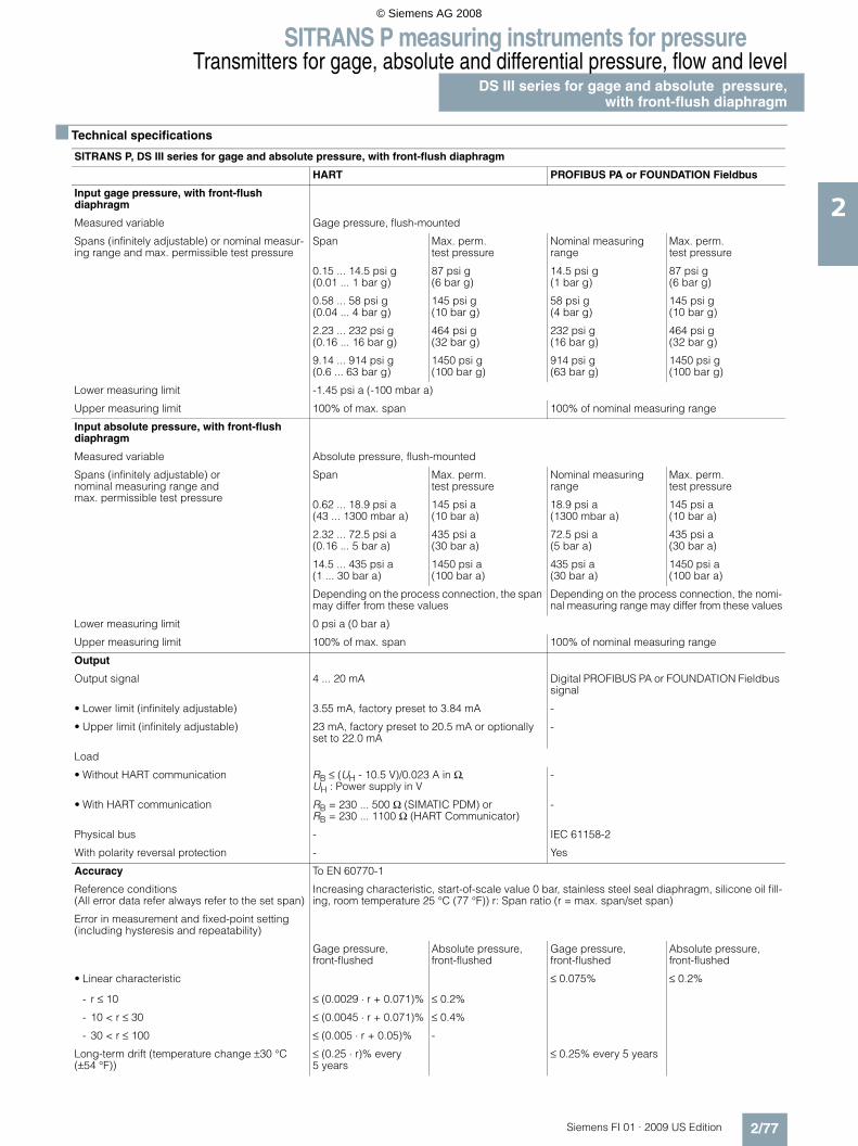
SITRANS P measuring instruments for pressureTransmitters for gage, absolute and differential pressure, flow and level
DS III series for gage and absolute pressure,with front-flush diaphragm
2/77Siemens FI 01 · 2009 US Edition
2
■ Technical specifications
SITRANS P, DS III series for gage and absolute pressure, with front-flush diaphragm
HART PROFIBUS PA or FOUNDATION Fieldbus
Input gage pressure, with front-flush diaphragm
Measured variable Gage pressure, flush-mounted
Spans (infinitely adjustable) or nominal measur-ing range and max. permissible test pressure
Span Max. perm. test pressure
Nominal measuring range
Max. perm. test pressure
0.15 ... 14.5 psi g (0.01 ... 1 bar g)
87 psi g (6 bar g)
14.5 psi g (1 bar g)
87 psi g (6 bar g)
0.58 ... 58 psi g (0.04 ... 4 bar g)
145 psi g (10 bar g)
58 psi g (4 bar g)
145 psi g (10 bar g)
2.23 ... 232 psi g (0.16 ... 16 bar g)
464 psi g (32 bar g)
232 psi g (16 bar g)
464 psi g (32 bar g)
9.14 ... 914 psi g (0.6 ... 63 bar g)
1450 psi g(100 bar g)
914 psi g (63 bar g)
1450 psi g (100 bar g)
Lower measuring limit -1.45 psi a (-100 mbar a)
Upper measuring limit 100% of max. span 100% of nominal measuring range
Input absolute pressure, with front-flush diaphragm
Measured variable Absolute pressure, flush-mounted
Spans (infinitely adjustable) ornominal measuring range andmax. permissible test pressure
Span Max. perm. test pressure
Nominal measuring range
Max. perm. test pressure
0.62 ... 18.9 psi a (43 ... 1300 mbar a)
145 psi a (10 bar a)
18.9 psi a (1300 mbar a)
145 psi a (10 bar a)
2.32 ... 72.5 psi a (0.16 ... 5 bar a)
435 psi a (30 bar a)
72.5 psi a (5 bar a)
435 psi a (30 bar a)
14.5 ... 435 psi a (1 ... 30 bar a)
1450 psi a (100 bar a)
435 psi a (30 bar a)
1450 psi a (100 bar a)
Depending on the process connection, the span may differ from these values
Depending on the process connection, the nomi-nal measuring range may differ from these values
Lower measuring limit 0 psi a (0 bar a)
Upper measuring limit 100% of max. span 100% of nominal measuring range
Output
Output signal 4 ... 20 mA Digital PROFIBUS PA or FOUNDATION Fieldbus signal
• Lower limit (infinitely adjustable) 3.55 mA, factory preset to 3.84 mA -
• Upper limit (infinitely adjustable) 23 mA, factory preset to 20.5 mA or optionally set to 22.0 mA
-
Load
• Without HART communication RB ≤ (UH - 10.5 V)/0.023 A in Ω,UH : Power supply in V
-
• With HART communication RB = 230 ... 500 Ω (SIMATIC PDM) orRB = 230 ... 1100 Ω (HART Communicator)
-
Physical bus - IEC 61158-2
With polarity reversal protection - Yes
Accuracy To EN 60770-1
Reference conditions(All error data refer always refer to the set span)
Increasing characteristic, start-of-scale value 0 bar, stainless steel seal diaphragm, silicone oil fill-ing, room temperature 25 °C (77 °F)) r: Span ratio (r = max. span/set span)
Error in measurement and fixed-point setting (including hysteresis and repeatability)
Gage pressure, front-flushed
Absolute pressure, front-flushed
Gage pressure, front-flushed
Absolute pressure, front-flushed
• Linear characteristic ≤ 0.075% ≤ 0.2%
- r ≤ 10 ≤ (0.0029 ⋅ r + 0.071)% ≤ 0.2%
- 10 < r ≤ 30 ≤ (0.0045 ⋅ r + 0.071)% ≤ 0.4%
- 30 < r ≤ 100 ≤ (0.005 ⋅ r + 0.05)% -
Long-term drift (temperature change ±30 °C (±54 °F))
≤ (0.25 ⋅ r)% every 5 years
≤ 0.25% every 5 years
© Siemens AG 2008
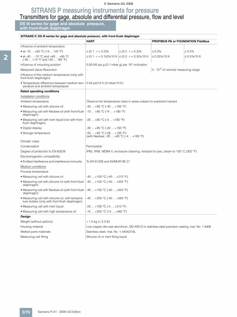
SITRANS P measuring instruments for pressureTransmitters for gage, absolute and differential pressure, flow and levelDS III series for gage and absolute pressure,with front-flush diaphragm
2/78 Siemens FI 01 · 2009 US Edition
2
Influence of ambient temperature
• at -10 ... +60 °C (14 ... 140 °F) ≤ (0.1 ⋅ r + 0.2)% ≤ (0.2 ⋅ r + 0.3)% ≤ 0.3% ≤ 0.5%
• at -40 ... -10 °C and +60 ... +85 °C(-40 ... +14 °F and 140 ... 185 °F)
≤ (0.1 ⋅ r + 0.15)%/10 K ≤ (0.2 ⋅ r + 0.3)%/10 K ≤ 0.25%/10 K ≤ 0.5%/10 K
Influence of mounting position 0.00145 psi g (0.1 mbar g) per 10° inclination
Measured Value Resolution - 3 ⋅ 10-5 of nominal measuring range
Influence of the medium temperature (only with front-flush diaphragm)
• Temperature difference between medium tem-perature and ambient temperature
0.04 psi/10 K (3 mbar/10 K)
Rated operating conditions
Installation conditions
Ambient temperature Observe the temperature class in areas subject to explosion hazard.
• Measuring cell with silicone oil -40 ... +85 °C (-40 ... +185 °F)
• Measuring cell with Neobee oil (with front-flush diaphragm)
-10 ... +85 °C (14 ... +185 °F)
• Measuring cell with inert liquid (not with front-flush diaphragm)
-20 ... +85 °C (-4 ... +185 °F)
• Digital display -30 ... +85 °C (-22 ... +185 °F)
• Storage temperature -50 ... +85 °C (-58 ... +185 °F)(with Neobee: -20 ... +85 °C (-4 ... +185 °F)
Climatic class
Condensation Permissible
Degree of protection to EN 60529 IP65, IP68, NEMA X, enclosure cleaning, resistant to lyes, steam to 150° C (302 °F)
Electromagnetic compatibility
• Emitted interference and interference immunity To EN 61326 and NAMUR NE 21
Medium conditions
Process temperature
• Measuring cell with silicone oil -40 ... +100 °C (-40 ... +212 °F)
• Measuring cell with silicone oil (with front-flush diaphragm)
-40 ... +150 °C (-40 ... +302 °F)
• Measuring cell with Neobee oil (with front-flush diaphragm)
-40 ... +150 °C (-40 ... +302 °F)
• Measuring cell with silicone oil, with tempera-ture isolator (only with front-flush diaphragm)
-40 ... +200 °C (-40 ... +392 °F)
• Measuring cell with inert liquid -20 ... +100 °C (-4 ... +212 °F)
• Measuring cell with high temperature oil -10 ... +250 °C (14 ... +482 °F)
Design
Weight (without options) ≈ 1.5 kg (≈ 3.3 lb)
Housing material Low copper die-cast aluminium, GD-AlSi12 or stainless steel precision casting, mat. No. 1.4408
Wetted parts materials Stainless steel, mat. No. 1.4404/316L
Measuring cell filling Silicone oil or inert filling liquid
SITRANS P, DS III series for gage and absolute pressure, with front-flush diaphragm
HART PROFIBUS PA or FOUNDATION Fieldbus
© Siemens AG 2008

SITRANS P measuring instruments for pressureTransmitters for gage, absolute and differential pressure, flow and level
DS III series for gage and absolute pressure,with front-flush diaphragm
2/79Siemens FI 01 · 2009 US Edition
2
Sanitary version
In the case of SITRANS P DSIII with 7MF413x front-flush dia-phragm, selected connections comply with the requirements of EHEDG.
Power supply UH Supplied through bus
Terminal voltage on transmitter 10.5 ... 45 V DC10.5 ... 30 V DC in intrinsically-safe mode
-
Separate 24 V power supply necessary - No
Bus voltage
• Not Ex - 9 ...32 V
• With intrinsically-safe operation - 9 ...24 V
Current consumption
• Basic current (max.) - 12.5 mA
• Startup current ≤ basic current - Yes
• Max. current in event of fault - 15.5 mA
Fault disconnection electronics (FDE) available - Yes
Certificate and approvals
Classification according to pressure equipment directive (DRGL 97/23/EC)
For gases of fluid group 1 and liquids of fluid group 1; complies with requirements of Article 3, paragraph 3 (sound engineering practice)
Explosion protection
• Intrinsic safety "i" PTB 99 ATEX 2122
- Identification Ex II 1/2 G EEx ia/ib IIB/IIC T6
- Permissible ambient temperature -40 ... +85 °C (-40 ... +185 °F) temperature class T4;-40 ... +70 °C (-40 ... +158 °F) temperature class T5;-40 ... +60 °C (-40 ... +140 °F) temperature class T6
- Connection To certified intrinsically-safe circuits with maxi-mum values: Ui = 30 V, Ii = 100 mA, Pi = 750 mW; Ri = 300 Ω
FISCO supply unit: Uo = 17.5 V, Io = 380 mA, Po = 5.32 WLinear barrier: Uo = 24 V, Io = 250 mA, Po = 1.2 W
- Effective internal inductance/capacitance L i = 0.4 mH, Ci = 6 nF L i = 7 μH, Ci = 1.1 nF
• Explosion-proof "d" PTB 99 ATEX 1160
- Identification Ex II 1/2 G EEx d IIC T4/T6
- Permissible ambient temperature -40 ... +85 °C (-40 ... +185 °F) temperature class T4;-40 ... +60 °C (-40 ... +140 °F) temperature class T6
- Connection To circuits with values: UH = 10.5 ... 45 V DC To circuits with values: UH = 9 ... 32 V DC
• Dust explosion protection for zone 20 PTB 01 ATEX 2055
- Identification Ex II 1 D IP65 T 120 °CEx II 1/2 D IP65 T 120 °C
- Permissible ambient temperature -40 ... +85 °C (-40 ... +185 °F)
- Max.surface temperature 120 °C (248 °F)
- Connection To certified intrinsically-safe circuits with maxi-mum values: Ui = 30 V, Ii = 100 mA, Pi = 750 mW, Ri = 300 Ω
FISCO supply unit: Uo = 17.5 V, Io = 380 mA, Po = 5.32 WLinear barrier: Uo = 24 V, Io = 250 mA, Po = 1.2 W
- Effective internal inductance/capacitance L i = 0.4 mH, Ci = 6 nF L i = 7 μH, Ci = 1.1 nF
• Dust explosion protection for zone 21/22 PTB 01 ATEX 2055
- Identification Ex II 2 D IP65 T 120 °C
- Connection To circuits with values: UH = 10.5 ... 45 V DC; Pmax = 1.2 W
To circuits with values: UH = 9 ... 32 V DC; Pmax = 1.2 W
• Type of protection "n" (zone 2) TÜV 01 ATEX 1696 X Planned
- Identification Ex II 3 G EEx nA L IIC T4/T5/T6 -
• Explosion protection to FM Certificate of Compliance 3008490
- Identification (XP/DIP) or (IS); (NI) CL I, DIV 1, GP ABCD T4...T6; CL II, DIV 1, GP EFG; CL III; CL I, ZN 0/1 AEx ia IIC T4...T6; CL I, DIV 2, GP ABCD T4...T6; CL II, DIV 2, GP FG; CL III
• Explosion protection to CSA Certificate of Compliance 1153651
- Identification (XP/DIP) or (IS) CL I, DIV 1, GP ABCD T4...T6; CL II, DIV 1, GP EFG; CL III; Ex ia IIC T4...T6; CL I, DIV 2, GP ABCD T4...T6; CL II, DIV 2, GP FG; CL III
SITRANS P, DS III series for gage and absolute pressure, with front-flush diaphragm
HART PROFIBUS PA or FOUNDATION Fieldbus
© Siemens AG 2008

SITRANS P measuring instruments for pressureTransmitters for gage, absolute and differential pressure, flow and levelDS III series for gage and absolute pressure,with front-flush diaphragm
2/80 Siemens FI 01 · 2009 US Edition
2
HART communication
HART communication 230 ... 1100 Ω
Protocol HART Version 5.x
Software for computer SIMATIC PDM
PROFIBUS PA communication
Simultaneous communication with master class 2 (max.)
4
The address can be set using Configuration tool or local opera-tion (standard setting address 126)
Cyclic data usage
• Output byte 5 (one measuring value) or10 (two measuring values)
• Input byte 0, 1, or 2 (register operating mode and reset function for metering)
Internal preprocessing
Device profile PROFIBUS PA Profile for Process Control Devices Version 3.0, Class B
Function blocks 2
• Analog input
- Adaptation to customer-specif-ic process variables
Yes, linearly rising or falling char-acteristic
- Electrical damping T63 , adjust-able
0 ... 100 s
- Simulation function Input /Output
- Failure mode Can be parameterized (last good value, substitute value, incorrect value)
- Limit monitoring Yes, one upper and lower warning limit and one alarm limit respec-tively
• Register (totalizer) Can be reset, preset, optional direction of counting, simulation function of register output
- Failure mode Can be parameterized (summation with last good value, continuous summation, summation with incor-rect value)
- Limit monitoring One upper and lower warning limit and one alarm limit respectively
• Physical block 1
Transducer blocks 2
• Pressure transducer block
- Can be calibrated by applying two pressures
Yes
- Monitoring of sensor limits Yes
- Characterizer Max. 30 points
- Square-rooted characteristic for flow measurement
Yes
- Gradual volume suppression and implementation point of square-root extraction
Parameterizable
- Simulation function for mea-sured pressure value and sen-sor temperature
Constant value or over parameter-izable ramp function
Communication FOUNDATION Fieldbus
Function blocks 3 function blocks analog input, 1 function block PID
• Analog input
- Adaptation to customer-specif-ic process variables
Yes, linearly rising or falling char-acteristic
- Electrical damping T63 , adjust-able
0 ... 100 s
- Simulation function Output/input (can be locked within the device with a bridge)
- Failure mode Can be parameterized (last good value, substitute value, incorrect value)
- Limit monitoring Yes, one upper and lower warning limit and one alarm limit respec-tively
- Square-rooted characteristic for flow measurement
Yes
• PID Standard FF function block
• Physical block 1 Resource block
Transducer blocks 1 transducer block Pressure with calibration, 1 transducer block LCD
• Pressure transducer block
- Can be calibrated by applying two pressures
Yes
- Monitoring of sensor limits Yes
- Simulation function: Measured pressure value, sensor temper-ature and electronics tempera-ture
Constant value or over parameter-izable ramp function
© Siemens AG 2008
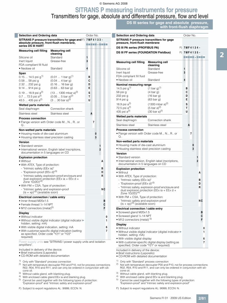
SITRANS P measuring instruments for pressureTransmitters for gage, absolute and differential pressure, flow and level
DS III series for gage and absolute pressure,with front-flush diaphragm
2/81Siemens FI 01 · 2009 US Edition
2
F) Subject to export regulations AL: 9I999, ECCN: N. F) Subject to export regulations AL: 9I999, ECCN: N.
Selection and Ordering data Order No.
SITRANS P pressure transmitters for gage and absolute pressure, front-flush membrane, series DS III HART
F) 7 M F 4 1 3 3 -
77777 - 7777
Measuring cell filling Measuring cell cleaning
Silicone oil Standard 1Inert liquid Grease-free 3FDA compliant fill fluid• Neobee oil Standard 4
Span0.15 ... 14.5 psi g1)
1) Only with "Standard" process connection
(0.01 ... 1 bar g)1) B0.58 ... 58 psi g (0.04 ... 4 bar g) C2.32 ... 232 psi g (0.16 ... 16 bar g) D9.14 ... 914 psi g (0.63 ... 63 bar g) E
0.19 ... 18.9 psi a2)
2) Not with temperature decoupler P00 and P10, not for process connections R02, R04, R10 and R11, and can only be ordered in conjunction with sili-cone oil.
(13 ... 1300 mbar a)2) S0.7 ... 72.5 psi a2) (0.05 ... 5 bar a)2) T43.5 ... 435 psi a2) (3 ... 30 bar a)2) U
Wetted parts materialsSeal diaphragm Connection shank
Stainless steel Stainless steel A
Process connection• Flange version with Order code M.., N.., R.. or
Q..7
Non-wetted parts materials• Housing made of die-cast aluminium 0• Housing stainless steel precision casting 3
Version• Standard version 1• International version, English label inscriptions,
documentation in 5 languages on CD2
Explosion protection• Without A• With ATEX, Type of protection:
- "Intrinsic safety (EEx ia)" B- "Explosion-proof (EEx d)"3)
3) Without cable gland, with blanking plug.
D- "Intrinsic safety, explosion-proof enclosure and
dust explosion protection (EEx ia + EEx d + Zone 1D/2D)"4)
4) With enclosed cable gland EEx ia and blanking plug.
R
• With FM + CSA, Type of protection:- "Intrinsic safety and explosion-proof
(is + xp)"3) (available soon)N C
Electrical connection / cable entry• Inner thread M20x1.5 B• Female thread ½-14 NPT C• M12 connectors (metal)5)
5) Cannot be used together with the following types of protection: "Explosion-proof" and "Intrinsic safety and explosion-proof"
F
Display• Without indicator 0• Without visible digital indicator (digital indicator
hidden, setting: mA)} 1
• With visible digital indication, setting: mA 6• With customer-specific digital indication (setting
as specified, Order code "Y21" or "Y22" required)
7
Power supply units see "SITRANS I power supply units and isolation amplifiers".
Included in delivery of the device:• Brief instructions (Leporello)• CD-ROM with detailed documentation
Selection and Ordering data Order No.
SITRANS P pressure transmitters for gage pressure, front-flush membrane
DS III PA series (PROFIBUS PA) F) 7 M F 4 1 3 4 -
DS III FF series (FOUNDATION Fieldbus) F) 7 M F 4 1 3 5 -
77777 - 7777
Measuring cell filling Measuring cell cleaning
Silicone oil Standard 1Inert liquid Grease-free 3FDA compliant fill fluid• Neobee oil Standard 4
Nominal measuring range14.5 psi g1)
1) Only with "Standard" process connection
(1 bar g)1) B58 psi g (4 bar g) C232 psi g (16 bar g) D914 psi g (63 bar g) E
18.9 psi a2)
2) Not with temperature decoupler P00 and P10, not for process connections R02, R04, R10 and R11, and can only be ordered in conjunction with sili-cone oil.
(1300 mbar a)2) S72.5 psi a2) (5 bar a)2) T435 psi a2) (30 bar a)2) U
Wetted parts materialsSeal diaphragm Connection shank
Stainless steel Stainless steel A
Process connection• Flange version with Order code M.., N.., R.. or
Q..7
Non-wetted parts materials• Housing made of die-cast aluminium 0• Housing stainless steel precision casting 3
Version• Standard version 1• International version, English label inscriptions,
documentation in 5 languages on CD2
Explosion protection• Without A• With ATEX, Type of protection:
- "Intrinsic safety (EEx ia)" B- "Explosion-proof (EEx d)"3)
3) Without cable gland, with blanking plug.
D- "Intrinsic safety, explosion-proof enclosure and
dust explosion protection (EEx ia + EEx d + Zone 1D/2D)"4)
4) With enclosed cable gland EEx ia and blanking plug.
R
• With FM + CSA, Type of protection:- "Intrinsic safety and explosion-proof
(is + xp)"3) (available soon)N C
Electrical connection / cable entry• Screwed gland M20x1.5 B• Screwed gland ½-14 NPT C• M12 connectors (metal) 5)
5) Cannot be used together with the following types of protection: "Explosion-proof" and "Intrinsic safety and explosion-proof"
F
Display• Without indicator 0• Without visible digital indicator (digital indicator
hidden, setting: mA)} 1
• With visible digital display 6• With customer-specific digital display (setting as
specified, Order code "Y21" or required)7
Included in delivery of the device:• Brief instructions (Leporello)• CD-ROM with detailed documentation
© Siemens AG 2008

SITRANS P measuring instruments for pressureTransmitters for gage, absolute and differential pressure, flow and levelDS III series for gage and absolute pressure,with front-flush diaphragm
2/82 Siemens FI 01 · 2009 US Edition
2
Selection and Ordering data Order code
Further designs HART PA FF
Add "-Z" to Order No. and specify Order code.
Cable sockets for M12 connectors (metal) A50
Rating plate inscription(instead of German)
• English B11• French B12• Spanish B13• Italian B14
English rating plate B21Pressure units in inH2O or psi
Quality inspection certificate (Factory cali-bration) to IEC 60770-2
C11
Acceptance test certificate C12To EN 10204-3.1
Factory certificate C14To EN 10204-2.2
"PROFIsafe" certificate and protocol C21
Flanges to EN 1092-1• DN 25, PN 401) M11• DN 25, PN 1001) M21• DN 40, PN 40 M13• DN 40, PN 100 M23• DN 50, PN 16 M04• DN 50, PN 40 M14• DN 80, PN 16 M06• DN 80, PN 40 M16
Flanges to ASME B16.5• Stainless steel flange 1" class 1501) M40• Stainless steel flange 1½" class 150 M41• Stainless steel flange 2" class 150 M42• Stainless steel flange 3" class 150 M43• Stainless steel flange 4" class 150 M44• Stainless steel flange 1" class 3001) M45• Stainless steel flange 1½" class 300 M46• Stainless steel flange 2" class 300 M47• Stainless steel flange 3" class 300 M48• Stainless steel flange 4" class 300 M49
Threaded connection acc. to DIN 3852-2, Form A• G ¾“, flush-mounted2) R01• G 1“, flush-mounted2) R02• G 2“, flush-mounted2) R04
Tank connection3)
Sealing is included in delivery• TG 52/50, PN 40 R10• TG 52/150, PN 40 R11
Sanitary process connection according DIN 11851 (Dairy connection)• DN 50, PN 25 N04• DN 80, PN 25 N06
Tri-Clamp connection according DIN 32676/ISO 2852• DN 50/2“, PN 16 N14• DN 65/3“, PN 10 N15
Varivent connectioncertified to EHEDG• Type N = 68 for Varivent housing
DN 40 ... 125 and 1½" ... 6", PN 40N28
Temperature decoupler up to 200 °C4)
for version with front-flush diaphragmP00
Temperature decoupler up to 250 °CMeasuring cell filling: High-temperature oil,only in conjunction with measuring cell filling silicone oil
P10
Bio-Control (Neumo) sanitary connectioncertified to EHEDG• DN 50, PN 16 Q53• DN 65, PN 16 Q54
Sanitary process connection to DRD• 65 mm, PN 40 M32
SMS socket with union nut• 2“ M67• 2½“ M68• 3“ M69
SMS threaded socket• 2“ M73• 2½“ M74• 3“ M75
IDF socket with union nut ISO 2853• 2“ M82• 2½“ M83• 3“ M84
IDF threaded socket ISO 2853• 2“ M92• 2½“ M93• 3“ M94
Sanitary process connection to NEUMO Bio-Connect screw connectioncertified to EHEDG• DN 50, PN 16 Q05• DN 65, PN 16 Q06• DN 80, PN 16 Q07• DN 100, PN 16 Q08• DN 2“, PN 16 Q13• DN 2½“, PN 16 Q14• DN 3“, PN 16 Q15• DN 4“, PN 16 Q16Sanitary process connection to NEUMO Bio-Connect flange connectioncertified to EHEDG• DN 50, PN 16 Q23• DN 65, PN 16 Q24• DN 80, PN 16 Q25• DN 100, PN 16 Q26• DN 2“, PN 16 Q31• DN 2½“, PN 16 Q32• DN 3“, PN 16 Q33• DN 4“, PN 16 Q34
Sanitary process connection to NEUMO Bio-Connect clamp connectioncertified to EHEDG• DN 50, PN 16 Q39• DN 65, PN 10 Q40• DN 80, PN 10 Q41• DN 100, PN 10 Q42• DN 2½“, PN 16 Q48• DN 3“, PN 10 Q49• DN 4“, PN 10 Q50
Selection and Ordering data Order code
Further designs HART PA FF
Add "-Z" to Order No. and specify Order code.
© Siemens AG 2008

SITRANS P measuring instruments for pressureTransmitters for gage, absolute and differential pressure, flow and level
DS III series for gage and absolute pressure,with front-flush diaphragm
2/83Siemens FI 01 · 2009 US Edition
2Sanitary process connection to NEUMO Connect S flange connectioncertified to EHEDG• DN 50, PN 16 Q63• DN 65, PN 10 Q64• DN 80, PN 10 Q65• DN 100, PN 10 Q66• DN 2“, PN 16 Q72• DN 2½“, PN 10 Q73• DN 3“, PN 10 Q74• DN 4“, PN 10 Q75
Aseptic threaded socket to DIN 11864-1 Form A• DN 50, PN 25 N33• DN 65, PN 25 N34• DN 80, PN 25 N35• DN 100, PN 25 N36
Aseptic flange with notch to DIN 11864-2 Form A• DN 50, PN 16 N43• DN 65, PN 16 N44• DN 80, PN 16 N45• DN 100, PN 16 N46
Aseptic flange with groove to DIN 11864-2 Form A• DN 50, PN 16 N43 +
P11• DN 65, PN 16 N44 +
P11• DN 80, PN 16 N45 +
P11• DN 100, PN 16 N46 +
P11
Aseptic clamp with groove to DIN 11864-3 Form A• DN 50, PN 25 N53• DN 65, PN 25 N54• DN 80, PN 16 N55• DN 100, PN 16 N56
1) Special Viton seal included in delivery.2) Lower measuring limit -100 mbar g (1.45 psi g).3) The weldable socket can be ordered under accessories4) The maximum temperatures of the medium depend on the respective cell
fillings.
Selection and Ordering data Order code
Further designs HART PA FF
Add "-Z" to Order No. and specify Order code.
Selection and Ordering data Order code
Additional data HART PA FF
Add "-Z" to Order No. and specify Order code.
Measuring range to be set Y01Specify in plain text (max. 5 digits):Y01: ... up to ... mbar, bar, kPa, MPa, psi
Measuring point number (TAG No.) Y15Max. 16 characters, specify in plain text:Y15: ...........................................
Measuring point text Y16Max. 27 characters, specify in plain text:Y16: ...........................................
Setting of pressure indicator in pressure units
Y21
Specify in plain text (standard setting: mA): Y21: mbar, bar, kPa, MPa, psi, ...Note:The following pressure units can be selected:bar, mbar, mm H2O*), inH2O*), ftH2O*), mmHG, inHG, psi, Pa, kPa, MPa, g/cm2, kg/cm2, Torr, ATM oder % *) ref. temperature 20 °C
Preset bus address Y25(possible between 1 and 126)Specify in plain text:Y25: .....................
Only "Y01" and "Y21" can be factory preset
= available
Ordering exampleItem line: 7MF4133-1DB20-1AB7-ZB line: A22 + Y01 + Y21C line: Y01: 14.5 ... 145 psi (1 ... 10 bar)C line: Y21: psi (bar)
© Siemens AG 2008

SITRANS P measuring instruments for pressureTransmitters for gage, absolute and differential pressure, flow and levelDS III series for gage and absolute pressure,with front-flush diaphragm
2/84 Siemens FI 01 · 2009 US Edition
2
■ Dimensional drawings
SITRANS P pressure transmitters, DS III series for gage pressure, with front-flush diaphragm, dimensions in mm (inch)
The diagram shows a SITRANS P DS III with an example of a flange. In this drawing the height is subdivided into H1 and H2.
H1 = Height of the SITRANS DS III up to a defined cross-section
H2 = Height of the flange up to this defined cross-section
Only the height H2 is indicated in the dimensions of the flanges.
Flanges to EN and ASME
Flanges to EN
Flanges to ASME
NuG and pharmaceutical connectionsConnections to DIN
Other connections
90 (3.6)
EN 1092-1
DN PN ∅D H2
25 40 115 mm (4.5“) Approx.52 mm (2“)25 100 140 mm (5.5“)
40 40 150 mm (5.9“)40 100 170 mm (6.7“)50 16 165 mm (6.5“)50 40 165 mm (6.5“)80 16 200 mm (7.9“)80 40 200 mm (7.9“)
ASME B16.5
DN class ∅D H2
1“ 150 110 mm (4.3“) Approx.52 mm (2“)1“ 300 125 mm (4.9“)
1½“ 150 130 mm (5.1“)1½“ 300 155 mm (6.1“)2“ 150 150 mm (5.9“)2“ 300 165 mm (6.5“)3“ 150 190 mm (7.5“)3“ 300 210 mm (8.1“)4“ 150 230 mm (9.1“)4“ 300 255 mm (10.0“)
DIN 11851 (Dairy connection)
DN PN ∅D H2
50 25 92 mm (3.6“) Approx.52 mm (2“)
80 25 127 mm (5.0“)
Tri-Clamp according DIN 32676
DN PN ∅D H2
50 16 64 mm (2.5“) Approx. 52 mm (2“)
65 16 91 mm (3.6“)
Varivent connection
DN PN ∅D H2
40 ... 125 40 84 mm (3.3“)
Approx.52 mm (2“)
Bio-Control connection
DN PN ∅D H2
50 16 90 mm (3.5“) Approx.52 mm (2“)
65 16 120 mm (4.7“)
© Siemens AG 2008

SITRANS P measuring instruments for pressureTransmitters for gage, absolute and differential pressure, flow and level
DS III series for gage and absolute pressure,with front-flush diaphragm
2/85Siemens FI 01 · 2009 US Edition
2
Sanitary process connection to DRD
DN PN ∅D H2
50 40 105 mm (4.1“) Approx. 52 mm (2“)
Sanitary process screw connection to NEUMO Bio-Connect
DN PN ∅D H2
50 16 82 mm (3.2“) Approx. 52 mm (2“)
65 16 105 mm (4.1“)
80 16 115 mm (4.5“)
100 16 145 mm (5.7“)
2“ 16 82 mm (3.2“)
2½“ 16 105 mm (4.1“)
3“ 16 105 mm (4.1“)
4“ 16 145 mm (5.7“)
Sanitary connection to NEUMO Bio-Connectflange connection
DN PN ∅D H2
50 16 110 mm (4.3“) Approx. 52 mm (2“)
65 16 140 mm (5.5“)
80 16 150 mm (5.9“)
100 16 175 mm (6.9“)
2“ 16 100 mm (3.9“)
2½“ 16 110 mm (4.3“)
3“ 16 140 mm (5.5“)
4“ 16 175 mm (6.9“)
Sanitary connection to NEUMO Bio-Connectclamp connection
DN PN ∅D H2
50 16 77.4 mm (3.0“) Approx. 52 mm (2“)
65 10 90.9 mm (3.6“)
80 10 106 mm (4.2“)
100 10 119 mm (4.7“)
2“ 16 64 mm (2.5“)
2½“ 16 77.4 mm (3.0“)
3“ 10 90.9 mm (3.6“)
4“ 10 119 mm (4.7“)
Sanitary connection to NEUMO Bio-Connect Sflange connection
DN PN ∅D H2
50 16 125 mm (4.9“) Approx. 52 mm (2“)
65 10 145 mm (5.7“)
80 10 155 mm (6.1“)
100 10 180 mm (7.1“)
2“ 16 125 mm (4.9“)
2½“ 10 135 mm (5.3“)
3“ 10 145 mm (5.7“)
4“ 10 180 mm (7.1“)
Thread connection G¾“, G1“ and G2“ to DIN 3852
DN PN ∅D H2
¾“ 63 37 mm (1.5“) Approx. 45 mm (1.8“)
1“ 63 48 mm (1.9“) Approx. 47 mm (1.9“)
2“ 63 78 mm (3.1“) Approx. 52 mm (2“)
Tank connection TG52/50 and TG52/150
DN PN ∅D H2
25 40 63 mm (2.5“) Approx. 63 mm (2.5“)
25 40 63 mm (2.5“) Approx. 170 mm (6.7“)
SMS socket with union nut
DN PN ∅D H2
2“ 25 84 mm (3.3“) Approx. 52 mm (2.1“)2½“ 25 100 mm (3.9“)
3“ 25 114 mm (4.5“)
SMS threaded socket
DN PN ∅D H2
2“ 25 70 x 1/6 mm Approx. 52 mm (2.1“)2½“ 25 85 x 1/6 mm
3“ 25 98 x 1/6 mm
IDF socket with union nut
DN PN ∅D H2
2“ 25 77 mm (3“) Approx. 52 mm (2.1“)2½“ 25 91 mm (3.6“)
3“ 25 106 mm (4.2“)
IDF threaded socket
DN PN ∅D H2
2“ 25 64 mm (2.5“) Approx. 52 mm (2.1“)2½“ 25 77.5 mm (3.1“)
3“ 25 91 mm (3.6“)
© Siemens AG 2008

SITRANS P measuring instruments for pressureTransmitters for gage, absolute and differential pressure, flow and levelDS III series for gage and absolute pressure,with front-flush diaphragm
2/86 Siemens FI 01 · 2009 US Edition
2
Aseptic threaded socket to DIN 11864-1 Form A
DN PN ∅D H2
50 25 78 x 1/6“ Approx. 52 mm (2.1“)
65 25 95 x 1/6“
80 25 110 x ¼“
100 25 130 x ¼“
Aseptic flange with notch to DIN 11864-2 Form A
DN PN ∅D H2
50 16 94 Approx. 52 mm (2.1“)
65 16 113
80 16 133
100 16 159
Aseptic flange with groove to DIN 11864-2 Form A
DN PN ∅D H2
50 16 94 Approx. 52 mm (2.1“)
65 16 113
80 16 133
100 16 159
Aseptic clamp with groove to DIN 11864-3 Form A
DN PN ∅D H2
50 25 77.5 Approx. 52 mm (2.1“)
65 25 91
80 16 106
100 16 130
© Siemens AG 2008

SITRANS P measuring instruments for pressureTransmitters for gage, absolute and differential pressure, flow and level
DS III series for absolute pressure(gage construction)
2/87Siemens FI 01 · 2009 US Edition
2
■ Technical specifications
SITRANS P, DS III series for absolute pressure (gage construction)
HART PROFIBUS PA or FOUNDATION Fieldbus
Input
Measured variable Absolute pressure
Spans (infinitely adjustable) ornominal measuring range andmax. permissible test pressure
Span Max. perm. test pressure
Nominal measuring range
Max. perm. test pressure
0.12 ... 3.6 psi a (8.3 ... 250 mbar a)
87 psi a (6 bar a)
3.6 psi a (250 mbar a)
87 psi a (6 bar a)
0.62 ... 18.9 psi a (43 ... 1300 mbar a)
145 psi a (10 bar a)
18.9 psi a (1300 mbar a)
145 psi a (10 bar a)
2.32 ... 72.5 psi a (160 ... 5000 mbar a)
435 psi a (30 bar a)
72.5 psi a (5 bar a)
435 psi a (30 bar a)
14.5 ... 435 psi a (1 ... 30 bar a)
1450 psi a (100 bar a)
435 psi a (30 bar a)
1450 psi a (100 bar a)
Lower measuring limit
• Measuring cell with silicone oil filling 0 psi a (0 mbar a)
Upper measuring limit 100% of max. span
Output
Output signal 4 ... 20 mA Digital PROFIBUS PA or FOUNDATION Fieldbus signal
• Lower limit (infinitely adjustable) 3.55 mA, factory preset to 3.84 mA -
• Upper limit (infinitely adjustable) 23 mA, factory preset to 20.5 mA or optionally set to 22.0 mA
-
Load
• Without HART communication RB ≤ (UH - 10.5 V)/0.023 A in Ω,UH : Power supply in V
-
• With HART communication RB = 230 ... 500 Ω (SIMATIC PDM) orRB = 230 ... 1100 Ω (HART Communicator)
-
Physical bus - IEC 61158-2
With polarity reversal protection - Yes
Accuracy To EN 60770-1
Reference conditions(All error data refer always refer to the set span)
Increasing characteristic, start-of-scale value 0 bar, stainless steel seal diaphragm, silicone oil filling, room temperature 25 °C (77 °F)) r: Span ratio (r = max. span / set span)
Error in measurement and fixed-point setting (including hysteresis and repeatability)
• Linear characteristic ≤ 0.1%
- r ≤ 10 ≤ 0.1%
- 10 < r ≤ 30 ≤ 0.2%
Long-term drift (temperature change ±30 °C (±54 °F))
≤ (0.1 ⋅ r)%/year ≤ 0.1%/year
Influence of ambient temperature
• at -10 ... +60 °C (14 ... 140 °F) ≤ (0.1 ⋅ r +0.2)% ≤ 0.3%
• at -40 ... -10 °C and +60 ... +85 °C(-40 ... +14 °F and 140 ... 185 °F)
≤ (0.1 ⋅ r + 0.15)%/10 K ≤ 0.25%/10 K
Measured Value Resolution - 3 ⋅ 10-5 of nominal measuring range
© Siemens AG 2008

SITRANS P measuring instruments for pressureTransmitters for gage, absolute and differential pressure, flow and levelDS III series for absolute pressure(gage construction)
2/88 Siemens FI 01 · 2009 US Edition
2
Rated operating conditions
Degree of protection (to EN 60529) IP65
Process temperature
• Measuring cell with silicone oil filling -40 ... +100 °C (-40 ... +212 °F)
• Measuring cell with inert filling liquid -20 ... +100 °C (-4 ... +212 °F)
• In conjunction with dust explosion protec-tion
-20 ... +60 °C (-4 ... +140 °F)
Ambient conditions
• Ambient temperature
- Digital indicators -30 ... +85 °C (-22 ... +185 °F)
• Storage temperature -50 ... +85 °C (-58 ... +185 °F)
• Climatic class
- Condensation Permissible
• Electromagnetic compatibility
- Emitted interference and interference im-munity
To EN 61326 and NAMUR NE 21
Design
Weight (without options) ≈ 1.5 kg (≈ 3.3 lb)
Housing material Low copper die-cast aluminium, GD-AlSi12 or stainless steel precision casting, mat. No. 1.4408
Wetted parts materials
• Connection shank Stainless steel, mat. No. 1.4404/316L or Hastelloy C4, mat. No. 2.4610
• Oval flange Stainless steel, mat. No. 1.4404/316L
• Seal diaphragm Stainless steel, mat. No. 1.4404/316L or Hastelloy C276, mat. No. 2.4819
Measuring cell filling Silicone oil or inert filling liquid (max. 160 bar a (2320 psi a) with oxygen measurement)
Process connection Connection shank G½A to DIN EN 837-1, female thread ½ -14 NPT or oval flange (PN 160 (MWP 2320 psi a)) to DIN 19213 with mounting thread M10 or 7/16-20 UNF to EN 61518
Material of the mounting bracket
• Steel Sheet steel, Mat. No. 1.0330, chrome-plated
• Stainless steel Stainless steel, Mat. No. 1.4301 (SS304)
Power supply UH Supplied through bus
Terminal voltage on transmitter 10.5 ... 45 V DC10.5 ... 30 V DC in intrinsically-safe mode
-
Separate 24 V power supply necessary - No
Bus voltage
• Not Ex - 9 ... 32 V
• With intrinsically-safe operation - 9 ... 24 V
Current consumption
• Basic current (max.) - 12.5 mA
• Startup current ≤ basic current - Yes
• Max. current in event of fault - 15.5 mA
Fault disconnection electronics (FDE) avail-able
- Yes
SITRANS P, DS III series for absolute pressure (gage construction)
HART PROFIBUS PA or FOUNDATION Fieldbus
© Siemens AG 2008

SITRANS P measuring instruments for pressureTransmitters for gage, absolute and differential pressure, flow and level
DS III series for absolute pressure(gage construction)
2/89Siemens FI 01 · 2009 US Edition
2
Certificate and approvals
Classification according to pressure equip-ment directive (DRGL 97/23/EC)
For gases of fluid group 1 and liquids of fluid group 1; complies with requirements of Article 3, para-graph 3 (sound engineering practice)
Explosion protection
• Intrinsic safety "i" PTB 99 ATEX 2122
- Identification Ex II 1/2 G EEx ia/ib IIB/IIC T6
- Permissible ambient temperature -40 ... +85 °C (-40 ... +185 °F) temperature class T4;-40 ... +70 °C (-40 ... +158 °F) temperature class T5;-40 ... +60 °C (-40 ... +140 °F) temperature class T6
- Connection To certified intrinsically-safe circuits with maxi-mum values: Ui = 30 V, Ii = 100 mA, Pi = 750 mW; Ri = 300 Ω
FISCO supply unit: Uo = 17.5 V, Io = 380 mA, Po = 5.32 WLinear barrier: Uo = 24 V, Io = 250 mA, Po = 1.2 W
- Effective internal inductance/capacitance L i = 0.4 mH, Ci = 6 nF L i = 7 μH, Ci = 1.1 nF
• Explosion-proof "d" PTB 99 ATEX 1160
- Identification Ex II 1/2 G EEx d IIC T4/T6
- Permissible ambient temperature -40 ... +85 °C (-40 ... +185 °F) temperature class T4;-40 ... +60 °C (-40 ... +140 °F) temperature class T6
- Connection To circuits with values: UH = 10.5 ... 45 V DC To circuits with values: UH = 9 ... 32 V DC
• Dust explosion protection for zone 20 PTB 01 ATEX 2055
- Identification Ex II 1 D IP65 T 120 °CEx II 1/2 D IP65 T 120 °C
- Permissible ambient temperature -40 ... +85 °C (-40 ... +185 °F)
- Max.surface temperature 120 °C (248 °F)
- Connection To certified intrinsically-safe circuits with maxi-mum values: Ui = 30 V, Ii = 100 mA, Pi = 750 mW, Ri = 300 Ω
FISCO supply unit: Uo = 17.5 V, Io = 380 mA, Po = 5.32 WLinear barrier: Uo = 24 V, Io = 250 mA, Po = 1.2 W
- Effective internal inductance/capacitance L i = 0.4 mH, Ci = 6 nF L i = 7 μH, Ci = 1.1 nF
• Dust explosion protection for zone 21/22 PTB 01 ATEX 2055
- Identification Ex II 2 D IP65 T 120 °C
- Connection To circuits with values: UH = 10.5 ... 45 V DC; Pmax = 1.2 W
To circuits with values: UH = 9 ... 32 V DC; Pmax = 1.2 W
• Type of protection "n" (zone 2) TÜV 01 ATEX 1696 X Planned
- Identification Ex II 3 G EEx nA L IIC T4/T5/T6 -
• Explosion protection to FM Certificate of Compliance 3008490
- Identification (XP/DIP) or (IS); (NI) CL I, DIV 1, GP ABCD T4...T6; CL II, DIV 1, GP EFG; CL III; CL I, ZN 0/1 AEx ia IIC T4...T6; CL I, DIV 2, GP ABCD T4...T6; CL II, DIV 2, GP FG; CL III
• Explosion protection to CSA Certificate of Compliance 1153651
- Identification (XP/DIP) or (IS) CL I, DIV 1, GP ABCD T4...T6; CL II, DIV 1, GP EFG; CL III; Ex ia IIC T4...T6; CL I, DIV 2, GP ABCD T4...T6; CL II, DIV 2, GP FG; CL III
SITRANS P, DS III series for absolute pressure (gage construction)
HART PROFIBUS PA or FOUNDATION Fieldbus
© Siemens AG 2008

SITRANS P measuring instruments for pressureTransmitters for gage, absolute and differential pressure, flow and levelDS III series for absolute pressure(gage construction)
2/90 Siemens FI 01 · 2009 US Edition
2
HART communication
HART communication 230 ... 1100 Ω
Protocol HART Version 5.x
Software for computer SIMATIC PDM
PROFIBUS PA communication
Simultaneous communication with master class 2 (max.)
4
The address can be set using Configuration tool or local opera-tion (standard setting address 126)
Cyclic data usage
• Output byte 5 (one measuring value) or10 (two measuring values)
• Input byte 0, 1, or 2 (register operating mode and reset function for metering)
Internal preprocessing
Device profile PROFIBUS PA Profile for Process Control Devices Version 3.0, Class B
Function blocks 2
• Analog input
- Adaptation to customer-specif-ic process variables
Yes, linearly rising or falling char-acteristic
- Electrical damping T63 , adjust-able
0 ... 100 s
- Simulation function Input /Output
- Failure mode Can be parameterized (last good value, substitute value, incorrect value)
- Limit monitoring Yes, one upper and lower warning limit and one alarm limit respec-tively
• Register (totalizer) Can be reset, preset, optional direction of counting, simulation function of register output
- Failure mode Can be parameterized (summation with last good value, continuous summation, summation with incor-rect value)
- Limit monitoring One upper and lower warning limit and one alarm limit respectively
• Physical block 1
Transducer blocks 2
• Pressure transducer block
- Can be calibrated by applying two pressures
Yes
- Monitoring of sensor limits Yes
- Characterizer Max. 30 points
- Square-rooted characteristic for flow measurement
Yes
- Gradual volume suppression and implementation point of square-root extraction
Parameterizable
- Simulation function for mea-sured pressure value and sen-sor temperature
Constant value or over parameter-izable ramp function
Communication FOUNDATION Fieldbus
Function blocks 3 function blocks analog input, 1 function block PID
• Analog input
- Adaptation to customer-specif-ic process variables
Yes, linearly rising or falling char-acteristic
- Electrical damping T63 , adjust-able
0 ... 100 s
- Simulation function Output/input (can be locked within the device with a bridge)
- Failure mode Can be parameterized (last good value, substitute value, incorrect value)
- Limit monitoring Yes, one upper and lower warning limit and one alarm limit respec-tively
- Square-rooted characteristic for flow measurement
Yes
• PID Standard FF function block
• Physical block 1 Resource block
Transducer blocks 1 transducer block Pressure with calibration, 1 transducer block LCD
• Pressure transducer block
- Can be calibrated by applying two pressures
Yes
- Monitoring of sensor limits Yes
- Simulation function: Measured pressure value, sensor temper-ature and electronics tempera-ture
Constant value or over parameter-izable ramp function
© Siemens AG 2008
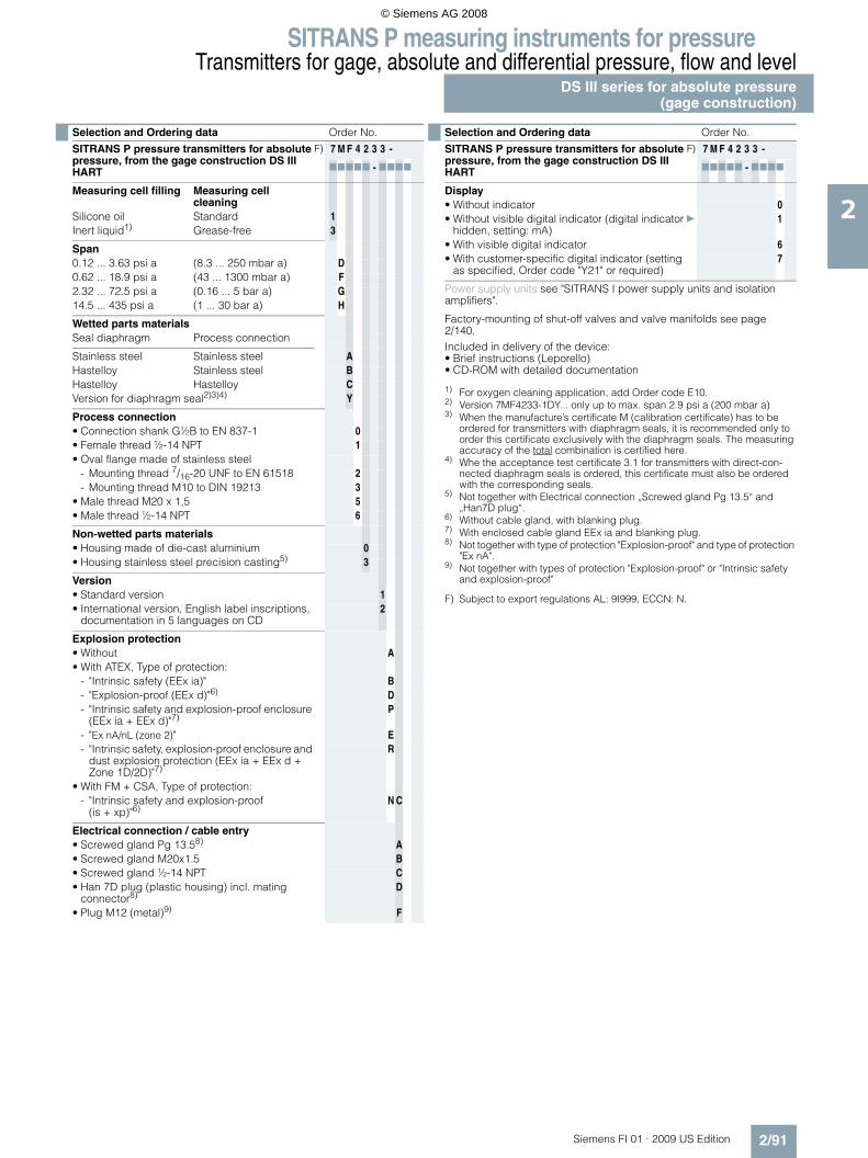
SITRANS P measuring instruments for pressureTransmitters for gage, absolute and differential pressure, flow and level
DS III series for absolute pressure(gage construction)
2/91Siemens FI 01 · 2009 US Edition
2
F) Subject to export regulations AL: 9I999, ECCN: N.
Selection and Ordering data Order No.
SITRANS P pressure transmitters for absolute pressure, from the gage construction DS III HART
F) 7 M F 4 2 3 3 -
77777 - 7777
Measuring cell filling Measuring cell cleaning
Silicone oil Standard 1Inert liquid1) Grease-free 3
Span0.12 ... 3.63 psi a (8.3 ... 250 mbar a) D0.62 ... 18.9 psi a (43 ... 1300 mbar a) F2.32 ... 72.5 psi a (0.16 ... 5 bar a) G14.5 ... 435 psi a (1 ... 30 bar a) H
Wetted parts materialsSeal diaphragm Process connection
Stainless steel Stainless steel AHastelloy Stainless steel BHastelloy Hastelloy CVersion for diaphragm seal2)3)4) Y
Process connection• Connection shank G½B to EN 837-1 0• Female thread ½-14 NPT 1• Oval flange made of stainless steel
- Mounting thread 7/16-20 UNF to EN 61518 2- Mounting thread M10 to DIN 19213 3
• Male thread M20 x 1,5 5• Male thread ½-14 NPT 6
Non-wetted parts materials• Housing made of die-cast aluminium 0• Housing stainless steel precision casting5) 3
Version• Standard version 1• International version, English label inscriptions,
documentation in 5 languages on CD2
Explosion protection• Without A• With ATEX, Type of protection:
- "Intrinsic safety (EEx ia)" B- "Explosion-proof (EEx d)"6) D- "Intrinsic safety and explosion-proof enclosure
(EEx ia + EEx d)"7)P
- "Ex nA/nL (zone 2)" E- "Intrinsic safety, explosion-proof enclosure and
dust explosion protection (EEx ia + EEx d + Zone 1D/2D)"7)
R
• With FM + CSA, Type of protection:- "Intrinsic safety and explosion-proof
(is + xp)"6)N C
Electrical connection / cable entry• Screwed gland Pg 13.58) A• Screwed gland M20x1.5 B• Screwed gland ½-14 NPT C• Han 7D plug (plastic housing) incl. mating
connector8)D
• Plug M12 (metal)9) F
Display• Without indicator 0• Without visible digital indicator (digital indicator
hidden, setting: mA)} 1
• With visible digital indicator 6• With customer-specific digital indicator (setting
as specified, Order code "Y21" or required)7
Power supply units see "SITRANS I power supply units and isolation amplifiers".
Factory-mounting of shut-off valves and valve manifolds see page 2/140.Included in delivery of the device:• Brief instructions (Leporello)• CD-ROM with detailed documentation
1) For oxygen cleaning application, add Order code E10.2) Version 7MF4233-1DY... only up to max. span 2.9 psi a (200 mbar a)3) When the manufacture’s certificate M (calibration certificate) has to be
ordered for transmitters with diaphragm seals, it is recommended only to order this certificate exclusively with the diaphragm seals. The measuring accuracy of the total combination is certified here.
4) Whe the acceptance test certificate 3.1 for transmitters with direct-con-nected diaphragm seals is ordered, this certificate must also be ordered with the corresponding seals.
5) Not together with Electrical connection „Screwed gland Pg 13.5“ and „Han7D plug“.
6) Without cable gland, with blanking plug.7) With enclosed cable gland EEx ia and blanking plug.8) Not together with type of protection "Explosion-proof" and type of protection
"Ex nA".9) Not together with types of protection "Explosion-proof" or "Intrinsic safety
and explosion-proof"
Selection and Ordering data Order No.
SITRANS P pressure transmitters for absolute pressure, from the gage construction DS III HART
F) 7 M F 4 2 3 3 -
77777 - 7777
© Siemens AG 2008

SITRANS P measuring instruments for pressureTransmitters for gage, absolute and differential pressure, flow and levelDS III series for absolute pressure(gage construction)
2/92 Siemens FI 01 · 2009 US Edition
2
F) Subject to export regulations AL: 9I999, ECCN: N.
Selection and Ordering data Order No.
SITRANS P pressure transmitters for absolute pressure (gage construction)
DS III PA series (PROFIBUS PA) F) 7 M F 4 2 3 4 -
DS III FF series (FOUNDATION Fieldbus) F) 7 M F 4 2 3 5 -
77777 - 7777
Measuring cell filling Measuring cell cleaning
Silicone oil Standard 1Inert liquid1) Grease-free 3
Nominal measuring range3.63 psi a (250 mbar a) D18.9 psi a (1300 mbar a) F72.5 psi a (5 bar a) G435 psi a (30 bar a) H
Wetted parts materialsSeal diaphragm Process connection
Stainless steel Stainless steel AHastelloy Stainless steel BHastelloy Hastelloy CVersion as diaphragm seal2)3)4) Y
Process connection• Connection shank G½B to EN 837-1 0• Female thread ½-14 NPT 1• Oval flange made of stainless steel
- Mounting thread 7/16-20 UNF to EN 61518 2- Mounting thread M10 to DIN 19213 3
• Male thread M20 x 1,5 5• Male thread ½-14 NPT 6
Non-wetted parts materials• Housing made of die-cast aluminium 0• Housing stainless steel precision casting 3
Version• Standard version 1• International version, English label inscriptions,
documentation in 5 languages on CD2
Explosion protection• Without A• With ATEX, Type of protection:
- "Intrinsic safety (EEx ia)" B- "Explosion-proof (EEx d)"5) D- "Intrinsic safety and explosion-proof enclosure
(EEx ia + EEx d)"6)P
- "Ex nA/nL (zone 2)" E- "Intrinsic safety, explosion-proof enclosure and
dust explosion protection (EEx ia + EEx d + Zone 1D/2D)"6) (not for DS III FF)
R
• With FM + CSA, Type of protection:- "Intrinsic safety and explosion-proof
(is + xp)"5)N C
Electrical connection / cable entry• Screwed gland M20x1.5 B• Screwed gland ½-14 NPT C• Plug M12 incl. mating connector7) F
Display• Without indicator 0• Without visible digital indicator (digital indicator
hidden, setting: mA)} 1
• With visible digital indicator 6• With customer-specific digital indicator (setting
as specified, Order code "Y21" or required)7
Factory-mounting of shut-off valves and valve manifolds see page 2/140.Included in delivery of the device:• Brief instructions (Leporello)• CD-ROM with detailed documentation
1) For oxygen cleaning application, add Order code E10.2) Version 7MF4233-1DY... only up to max. span 2.9 psi a (200 mbar a).3) When the manufacture’s certificate M (calibration certificate) has to be
ordered for transmitters with diaphragm seals, it is recommended only to order this certificate exclusively with the diaphragm seals. The measuring accuracy of the total combination is certified here.
4) Whe the acceptance test certificate 3.1 for transmitters with direct-con-nected diaphragm seals is ordered, this certificate must also be ordered with the corresponding seals.
5) Without cable gland, with blanking plug.6) With enclosed cable gland EEx ia and blanking plug.7) Not together with types of protection "Explosion-proof" or "Intrinsic safety
and explosion-proof"
Selection and Ordering data Order No.
SITRANS P pressure transmitters for absolute pressure (gage construction)
DS III PA series (PROFIBUS PA) F) 7 M F 4 2 3 4 -
DS III FF series (FOUNDATION Fieldbus) F) 7 M F 4 2 3 5 -
77777 - 7777
© Siemens AG 2008

SITRANS P measuring instruments for pressureTransmitters for gage, absolute and differential pressure, flow and level
DS III series for absolute pressure(gage construction)
2/93Siemens FI 01 · 2009 US Edition
2
Selection and Ordering data Order code
Further designs HART PA FF
Add "-Z" to Order No. and specify Order code.
Pressure transmitter with mounting bracket made of: • Steel A01• Stainless steel A02
Plug• Han 7D (metal, gray) A30• Han 8U (instead of Han 7D) A31
Cable sockets for M12 connectors (metal) A50
Rating plate inscription(instead of German)• English B11• French B12• Spanish B13• Italian B14
English rating plate B21Pressure units in H2O or psi
Quality inspection certificate (Factory cali-bration) to IEC 60770-2 1)
C11
Acceptance test certificate2) C12To EN 10204-3.1
Factory certificate C14To EN 10204-2.2
"Functional Safety (SIL)" certificate C20
"PROFIsafe" certificate and protocol C21
Setting of upper limit of output signal to 22.0 mA
D05
Manufacturer's declaration acc. to NACE D07
Type of protection IP68 D12(not together with Han 7D / Han 8U plug, Pg 13.5 screwed gland)
Digital indicator alongside the pushbut-tons
D27
(only together with the devices 7MF4233-....0-.A.6 or -.A.7-Z, Y21 or Y22 + Y01).
Supplied with oval flange D37(1 item), PTFE packing and screws in thread of oval flange
Use in or on zone 1D/2D E01(only together with type of protection "Intrinsic safety (EEx ia)")
Use on zone 0 E02(only together with type of protection "Intrinsic safety (EEx ia)")
Oxygen cleaning application E10(max. 120 bar a (1740 psi a) at 60 °C (140 °F) with oxygen measurement and inert liquid)
Explosion-proof "Intrinsic safety" to INMETRO (Brazil)
E25
(only for transmitter 7MF4...-.....-.B..)
Explosion-proof "Intrinsic safety" to NEPSI (China)
E55
(only for transmitter 7MF4...-.....-.B..)
Explosion protection "Explosion-proof" to NEPSI (China)
E56
(only for transmitter 7MF4...-.....-.D..)
Explosion-proof "Zone 2" to NEPSI (China) E57(only for transmitter 7MF4...-.....-.E..)
Additional data HART PA FF
Add "-Z" to Order No. and specify Order code.
Measuring range to be set Y01Specify in plain text (max. 5 digits): Y01: ... up to ... mbar, bar, kPa, MPa, psi
Measuring point number (TAG No.) Y15Max. 16 characters, specify in plain text:Y15: ...........................................
Measuring point text Y16Max. 27 characters, specify in plain text:Y16: ...........................................
Entry of HART address (TAG) Y17Max. 8 characters, specify in plain text:Y17: ...........................................
Setting of pressure indication in pressure units
Y21
Specify in plain text (standard setting: mA):Y21: mbar, bar, kPa, MPa, psi, ...Note:The following pressure units can be selected:bar, mbar, mm H2O*), inH2O*), ftH2O*), mmHG, inHG, psi, Pa, kPa, MPa, g/cm2, kg/cm2, Torr, ATM oder % *) ref. temperature 20 °C
Setting of pressure indication in non-pressure units
Y22 + Y01
Specify in plain text:Y22: ..... up to ..... l/min, m3/h, m, USgpm, ...(specification of measuring range in pressure units "Y01" is essential, unit with max. 5 characters)
Preset bus address Y25(possible between 1 and 126)Specify in plain text:Y25: .....................
Only "Y01", "Y21", "Y22", "Y25" and "D05" can be factory preset
= available
1) When the manufacture’s certificate M (calibration certificate) has to be ordered for transmitters with diaphragm seals, it is recommended only to order this certificate exclusively with the diaphragm seals. The measuring accuracy of the total combination is certified here.
2) Whe the acceptance test certificate 3.1 for transmitters with direct-con-nected diaphragm seals is ordered, this certificate must also be ordered with the corresponding seals.
Selection and Ordering data Order code
© Siemens AG 2008
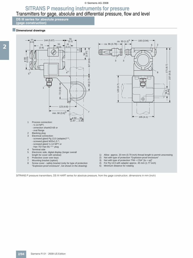
SITRANS P measuring instruments for pressureTransmitters for gage, absolute and differential pressure, flow and levelDS III series for absolute pressure(gage construction)
2/94 Siemens FI 01 · 2009 US Edition
2
■ Dimensional drawings
SITRANS P pressure transmitters, DS III HART series for absolute pressure, from the gage construction, dimensions in mm (inch)
1 Process connection: - ½-14 NPT, - onnection shankG½B or - oval flange2 Blanking plug3 Electrical connection: - screwed gland Pg 13,5 (adapter)2) 3), - screwed gland M20x1,5 3), - screwed gland ½-14 NPT or - Han 7D/ Han 8U 2) 3) plug4 Terminal side5 Electronic side, digital display (longer overall length for cover with window)6 Protective cover over keys7 Mounting bracket (option)8 Screw cover - safety bracket (only for type of protection "Explosion-proof enclosure", not shown in the drawing)
1) Allow approx. 20 mm (0.79 inch) thread length to permit unscrewing2) Not with type of protection "Explosion-proof enclosure"3) Not with type of protection "FM + CSA" [is + xp]"4) For Pg 13,5 with adapter approx. 45 mm (1.77 inch)5) Minimum distance for rotating
ca. 30 (1.2)ca. 96 (3.78)
15(0.6)
144 (5.67) 55(2.2)
51(2.0)
74(2.9)
4) 100 (3.94)
237
(9.3
)17
1 (6
.7)
36,5
(1,4
4)
min. 90 (3.6)
ø 50 ... 60(1.97 ... 2.36)
ø80
(3.1
5)
72 (2
.8)
123 (4.8)
20 (0.8
)
50 (1.9
7)11
7 (4
.6)
68 (2
.7)
5)
5 4
1
33
26
1)1) 8
120
(4.7
)105 (4.1)
7
28(1.1)
© Siemens AG 2008
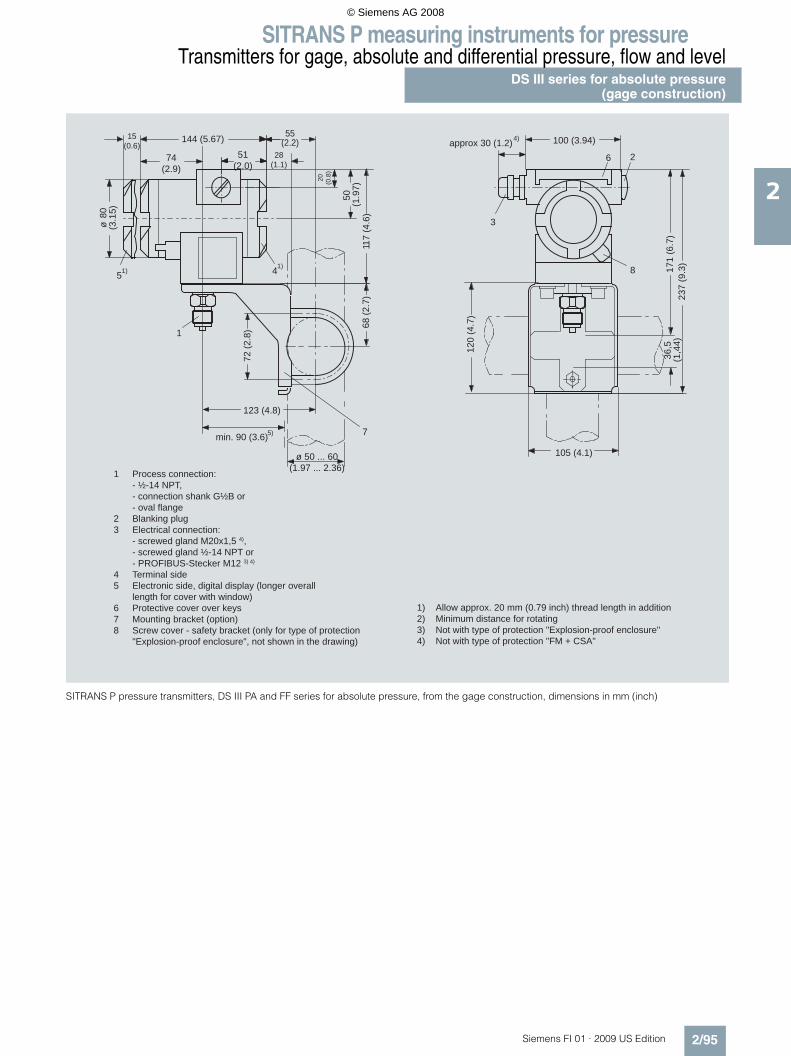
SITRANS P measuring instruments for pressureTransmitters for gage, absolute and differential pressure, flow and level
DS III series for absolute pressure(gage construction)
2/95Siemens FI 01 · 2009 US Edition
2
SITRANS P pressure transmitters, DS III PA and FF series for absolute pressure, from the gage construction, dimensions in mm (inch)
1 Process connection: - ½-14 NPT, - connection shank G½B or - oval flange2 Blanking plug3 Electrical connection: - screwed gland M20x1,5 4), - screwed gland ½-14 NPT or - PROFIBUS-Stecker M12 3) 4)
4 Terminal side5 Electronic side, digital display (longer overall length for cover with window)6 Protective cover over keys7 Mounting bracket (option)8 Screw cover - safety bracket (only for type of protection "Explosion-proof enclosure", not shown in the drawing)
1) Allow approx. 20 mm (0.79 inch) thread length in addition2) Minimum distance for rotating3) Not with type of protection "Explosion-proof enclosure"4) Not with type of protection "FM + CSA"
approx 30 (1.2)15
(0.6)144 (5.67) 55
(2.2)51
(2.0)74
(2.9)
4) 100 (3.94)
237
(9.3
)17
1 (6
.7)
36,5
(1,4
4)
min. 90 (3.6)
ø 50 ... 60(1.97 ... 2.36)
ø80
(3.1
5)
72 (2
.8)
123 (4.8)
20 (0.8
)
50 (1.9
7)11
7 (4
.6)
68 (2
.7)
5)
5 4
1
3
26
1)1) 8
120
(4.7
)
105 (4.1)
7
28(1.1)
© Siemens AG 2008

SITRANS P measuring instruments for pressureTransmitters for gage, absolute and differential pressure, flow and levelDS III series for absolute pressure(differential construction)
2/96 Siemens FI 01 · 2009 US Edition
2
■ Technical specifications
SITRANS P, DS III series for absolute pressure (differential construction)
HART PROFIBUS PA or FOUNDATION Fieldbus
Input
Measured variable Absolute pressure pressure
Spans (infinitely adjustable) ornominal measuring range andmax. permissible working pressure
Span Maximum working pres-sure
Nominal measuring range
Maximum working pres-sure
0.12 ... 3.6 psi a (8.3 ... 250 mbar a)
464 psi a (32 bar a)
3.6 psi a (250 mbar a)
464 psi a (32 bar a)
0.62 ... 18.9 psi a (43 ... 1300 mbar a)
464 psi a (32 bar a)
18.9 psi a (1300 bar a)
464 psi a (32 bar a)
2.32 ... 72.5 psi a (160 ... 5000 mbar a)
464 psi a (32 bar a)
72.5 psi a (5 bar a)
464 psi a (32 bar a)
14.5 ... 435 psi a (1 ... 30 bar a)
2320 psi a (160 bar a)
435 psi a (30 bar a)
2320 psi a (160 bar a)
77 ... 1450 psi a (5.3 ... 100 bar a)
2320 psi a (160 bar a)(for connection thread M10 and 7/16-20 UNF in the process flanges)
1450 psi a (100 bar a)
2320 psi a (160 bar a)(for connection thread M10 and 7/16-20 UNF in the process flanges)
Lower measuring limit
• Measuring cell with silicone oil filling 0 psi a (0 mbar a)
Upper measuring limit 100% of max. span
Output
Output signal 4 ... 20 mA Digital PROFIBUS PA or FOUNDATION Fieldbus signal
• Lower limit (infinitely adjustable) 3.55 mA, factory preset to 3.84 mA -
• Upper limit (infinitely adjustable) 23 mA, factory preset to 20.5 mA or optionally set to 22.0 mA
-
Load
• Without HART communication RB ≤ (UH - 10.5 V)/0.023 A in Ω,UH : Power supply in V
-
• With HART communication RB = 230 ... 500 Ω (SIMATIC PDM) orRB = 230 ... 1100 Ω (HART Communicator)
-
Physical bus - IEC 61158-2
With polarity reversal protection - Yes
Accuracy To EN 60770-1
Reference conditions(All error data refer always refer to the set span)
Increasing characteristic, start-of-scale value 0 bar, stainless steel seal diaphragm, silicone oil filling, room temperature 25 °C (77 °F)) r: Span ratio (r = max. span / set span)
Error in measurement and fixed-point setting (including hysteresis and repeatability)
• Linear characteristic ≤ 0.1%
- r ≤ 10 ≤ 0.1%
- 10 < r ≤ 30 ≤ 0.2%
Long-term drift (temperature change ± 30 °C (± 54 °F))
≤ (0.1 ⋅ r)%/year ≤ 0.1%/year
Influence of ambient temperature
• at -10 ... +60 °C (14 ... 140 °F) ≤ (0.1 ⋅ r +0.2)% ≤ 0.3%
• at -40 ... -10 °C and +60 ... +85 °C (-40 ... +14 °F and 140 ... 185 °F)
≤ (0.1 ⋅ r + 0.15)%/10 K ≤ 0.25%/10 K
Measured Value Resolution - 3 ⋅ 10-5 of nominal measuring range
© Siemens AG 2008

SITRANS P measuring instruments for pressureTransmitters for gage, absolute and differential pressure, flow and level
DS III series for absolute pressure(differential construction)
2/97Siemens FI 01 · 2009 US Edition
2
Rated operating conditions
Degree of protection (to EN 60529) IP65
Process temperature
• Measuring cell with silicone oil filling -40 ... +100 °C (-40 ... +212 °F)
• Measuring cell with inert filling liquid -20 ... +100 °C (-4 ... +212 °F)
• In conjunction with dust explosion protec-tion
-20 ... +60 °C (-4 ... +140 °F)
Ambient conditions
• Ambient temperature
- Digital indicators -30 ... +85 °C (-22 ... +185 °F)
• Storage temperature -50 ... +85 °C (-58 ... +185 °F)
• Climatic class
- Condensation Permissible
• Electromagnetic compatibility
- Emitted interference and interference im-munity
To EN 61326 and NAMUR NE 21
Design
Weight (without options) ≈ 4.5 kg (≈ 9.9 lb)
Housing material Low copper die-cast aluminium, GD-AlSi12 or stainless steel precision casting, mat. No. 1.4408
Wetted parts materials
• Seal diaphragm Stainless steel, mat. No. 1.4404/316L or Hastelloy C276, mat. No. 2.4819, Monel, mat. No. 2.4360, tantalum or gold
• Process flanges and sealing screw Stainless steel, mat. No. 1.4408, Hastelloy C4, mat. No. 2.4610 or Monel, mat. No. 2.4360
• O-Ring FPM (Viton) or optionally: PTFE, FEP, FEPM and NBR
Measuring cell filling Silicone oil or inert filling liquid (max. 160 bar (2320 psi a) with oxygen measurement)
Process connection ¼-18 NPT and flange connection to DIN 19213 with mounting thread M10 to DIN 19213 or 7/16-20 UNF to EN 61518
Material of the mounting bracket
• Steel Sheet steel, Mat. No. 1.0330, chrome-plated
• Stainless steel Stainless steel, Mat. No. 1.4301 (SS304)
Power supply UH Supplied through bus
Terminal voltage on transmitter 10.5 ... 45 V DC10.5 ... 30 V DC in intrinsically-safe mode
-
Separate 24 V power supply necessary - No
Bus voltage
• Not Ex - 9 ... 32 V
• With intrinsically-safe operation - 9 ... 24 V
Current consumption
• Basic current (max.) - 12.5 mA
• Startup current ≤ basic current - Yes
• Max. current in event of fault - 15.5 mA
Fault disconnection electronics (FDE) avail-able
- Yes
SITRANS P, DS III series for absolute pressure (differential construction)
HART PROFIBUS PA or FOUNDATION Fieldbus
© Siemens AG 2008

SITRANS P measuring instruments for pressureTransmitters for gage, absolute and differential pressure, flow and levelDS III series for absolute pressure(differential construction)
2/98 Siemens FI 01 · 2009 US Edition
2
Certificate and approvals
Classification according to pressure equip-ment directive (DRGL 97/23/EC)
For gases of fluid group 1 and liquids of fluid group 1; complies with requirements of Article 3, para-graph 3 (sound engineering practice)
Explosion protection
• Intrinsic safety "i" PTB 99 ATEX 2122
- Identification Ex II 1/2 G EEx ia/ib IIB/IIC T6
- Permissible ambient temperature -40 ... +85 °C (-40 ... +185 °F) temperature class T4;-40 ... +70 °C (-40 ... +158 °F) temperature class T5;-40 ... +60 °C (-40 ... +140 °F) temperature class T6
- Connection To certified intrinsically-safe circuits with maxi-mum values: Ui = 30 V, Ii = 100 mA, Pi = 750 mW; Ri = 300 Ω
FISCO supply unit: Uo = 17.5 V, Io = 380 mA, Po = 5.32 WLinear barrier: Uo = 24 V, Io = 250 mA, Po = 1.2 W
- Effective internal inductance/capacitance L i = 0.4 mH, Ci = 6 nF L i = 7 μH, Ci = 1.1 nF
• Explosion-proof "d" PTB 99 ATEX 1160
- Identification Ex II 1/2 G EEx d IIC T4/T6
- Permissible ambient temperature -40 ... +85 °C (-40 ... +185 °F) temperature class T4;-40 ... +60 °C (-40 ... +140 °F) temperature class T6
- Connection To circuits with values: UH = 10.5 ... 45 V DC To circuits with values: UH = 9 ... 32 V DC
• Dust explosion protection for zone 20 PTB 01 ATEX 2055
- Identification Ex II 1 D IP65 T 120 °CEx II 1/2 D IP65 T 120 °C
- Permissible ambient temperature -40 ... +85 °C (-40 ... +185 °F)
- Max.surface temperature 120 °C (248 °F)
- Connection To certified intrinsically-safe circuits with maxi-mum values: Ui = 30 V, Ii = 100 mA, Pi = 750 mW, Ri = 300 Ω
FISCO supply unit: Uo = 17.5 V, Io = 380 mA, Po = 5.32 WLinear barrier: Uo = 24 V, Io = 250 mA, Po = 1.2 W
- Effective internal inductance/capacitance L i = 0.4 mH, Ci = 6 nF L i = 7 μH, Ci = 1.1 nF
• Dust explosion protection for zone 21/22 PTB 01 ATEX 2055
- Identification Ex II 2 D IP65 T 120 °C
- Connection To circuits with values: UH = 10.5 ... 45 V DC; Pmax = 1.2 W
To circuits with values: UH = 9 ... 32 V DC; Pmax = 1.2 W
• Type of protection "n" (zone 2) TÜV 01 ATEX 1696 X Planned
- Identification Ex II 3 G EEx nA L IIC T4/T5/T6 -
• Explosion protection to FM Certificate of Compliance 3008490
- Identification (XP/DIP) or (IS); (NI) CL I, DIV 1, GP ABCD T4...T6; CL II, DIV 1, GP EFG; CL III; CL I, ZN 0/1 AEx ia IIC T4...T6; CL I, DIV 2, GP ABCD T4...T6; CL II, DIV 2, GP FG; CL III
• Explosion protection to CSA Certificate of Compliance 1153651
- Identification (XP/DIP) or (IS) CL I, DIV 1, GP ABCD T4...T6; CL II, DIV 1, GP EFG; CL III; Ex ia IIC T4...T6; CL I, DIV 2, GP ABCD T4...T6; CL II, DIV 2, GP FG; CL III
SITRANS P, DS III series for absolute pressure (differential construction)
HART PROFIBUS PA or FOUNDATION Fieldbus
© Siemens AG 2008

SITRANS P measuring instruments for pressureTransmitters for gage, absolute and differential pressure, flow and level
DS III series for absolute pressure(differential construction)
2/99Siemens FI 01 · 2009 US Edition
2
HART communication
HART communication 230 ... 1100 Ω
Protocol HART Version 5.x
Software for computer SIMATIC PDM
PROFIBUS PA communication
Simultaneous communication with master class 2 (max.)
4
The address can be set using Configuration tool or local opera-tion (standard setting address 126)
Cyclic data usage
• Output byte 5 (one measuring value) or10 (two measuring values)
• Input byte 0, 1, or 2 (register operating mode and reset function for metering)
Internal preprocessing
Device profile PROFIBUS PA Profile for Process Control Devices Version 3.0, Class B
Function blocks 2
• Analog input
- Adaptation to customer-specif-ic process variables
Yes, linearly rising or falling char-acteristic
- Electrical damping T63 , adjust-able
0 ... 100 s
- Simulation function Input /Output
- Failure mode Can be parameterized (last good value, substitute value, incorrect value)
- Limit monitoring Yes, one upper and lower warning limit and one alarm limit respec-tively
• Register (totalizer) Can be reset, preset, optional direction of counting, simulation function of register output
- Failure mode Can be parameterized (summation with last good value, continuous summation, summation with incor-rect value)
- Limit monitoring One upper and lower warning limit and one alarm limit respectively
• Physical block 1
Transducer blocks 2
• Pressure transducer block
- Can be calibrated by applying two pressures
Yes
- Monitoring of sensor limits Yes
- Characterizer Max. 30 points
- Square-rooted characteristic for flow measurement
Yes
- Gradual volume suppression and implementation point of square-root extraction
Parameterizable
- Simulation function for mea-sured pressure value and sen-sor temperature
Constant value or over parameter-izable ramp function
Communication FOUNDATION Fieldbus
Function blocks 3 function blocks analog input, 1 function block PID
• Analog input
- Adaptation to customer-specif-ic process variables
Yes, linearly rising or falling char-acteristic
- Electrical damping T63 , adjust-able
0 ... 100 s
- Simulation function Output/input (can be locked within the device with a bridge)
- Failure mode Can be parameterized (last good value, substitute value, incorrect value)
- Limit monitoring Yes, one upper and lower warning limit and one alarm limit respec-tively
- Square-rooted characteristic for flow measurement
Yes
• PID Standard FF function block
• Physical block 1 Resource block
Transducer blocks 1 transducer block Pressure with calibration, 1 transducer block LCD
• Pressure transducer block
- Can be calibrated by applying two pressures
Yes
- Monitoring of sensor limits Yes
- Simulation function: Measured pressure value, sensor temper-ature and electronics tempera-ture
Constant value or over parameter-izable ramp function
© Siemens AG 2008
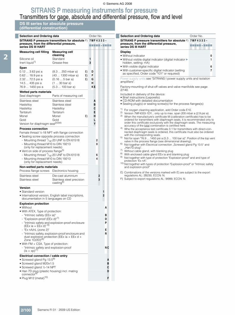
SITRANS P measuring instruments for pressureTransmitters for gage, absolute and differential pressure, flow and levelDS III series for absolute pressure(differential construction)
2/100 Siemens FI 01 · 2009 US Edition
2
E) Combinations of the versions marked with E) are subject to the exportregulations AL: 2B230, ECCN: N.
F) Subject to export regulations AL: 9I999, ECCN: N.
Selection and Ordering data Order No.
SITRANS P pressure transmitters for absolute pressure, from the differential pressure, series DS III HART
F) 7 M F 4 3 3 3 -
77777 - 7777
Measuring cell filling Measuring cell cleaning
Silicone oil Standard 1Inert liquid1) Grease-free 3
Span0.12 ... 3.63 psi a (8.3 ... 250 mbar a) E) D0.62 ... 18.9 psi a (43 ... 1300 mbar a) E) F2.32 ... 72.5 psi a (0.16 ... 5 bar a) E) G14.5 ... 435 psi a (1 ... 30 bar a) H76.9 ... 1450 psi a (5.3 ... 100 bar a) K E
Wetted parts materialsSeal diaphragm Parts of measuring cell
Stainless steel Stainless steel AHastelloy Stainless steel BHastelloy Hastelloy CTantalum Tantalum EMonel Monel E) HGold Gold LVersion for diaphragm seal2)3)4) Y
Process connectionFemale thread ¼-18 NPT with flange connection• Sealing screw opposite process connection
- Mounting thread 7/16-20 UNF to EN 61518 2- Mounting thread M10 to DIN 19213
(only for replacement needs)0
• Vent on side of process flange5)
- Mounting thread 7/16-20 UNF to EN 61518 6- Mounting thread M10 to DIN 19213
(only for replacement needs)4
Non-wetted parts materialsProcess flange screws Electronics housing
Stainless steel Die-cast aluminium 2Stainless steel Stainless steel precision
casting6)3
Version• Standard version 1• International version, English label inscriptions,
documentation in 5 languages on CD2
Explosion protection• Without A• With ATEX, Type of protection:
- "Intrinsic safety (EEx ia)" B- "Explosion-proof (EEx d)"7) D- "Intrinsic safety and explosion-proof enclosure
(EEx ia + EEx d)" 8)P
- "Ex nA/nL (zone 2)" E- "Intrinsic safety, explosion-proof enclosure and
dust explosion protection (EEx ia + EEx d + Zone 1D/2D)"8)
R
• With FM + CSA, Type of protection:- "Intrinsic safety and explosion-proof
(is + xp)"7)N C
Electrical connection / cable entry• Screwed gland Pg 13.59) A• Screwed gland M20x1.5 B• Screwed gland ½-14 NPT C• Han 7D plug (plastic housing) incl. mating
connector9)D
• Plug M12 (metal)10) F
Display• Without indicator 0• Without visible digital indicator (digital indicator
hidden, setting: mA)} 1
• With visible digital indicator 6• With customer-specific digital indicator (setting
as specified, Order code "Y21" or required)7
Power supply units see "SITRANS I power supply units and isolation amplifiers".
Factory-mounting of shut-off valves and valve manifolds see page 2/140.Included in delivery of the device:• Brief instructions (Leporello)• CD-ROM with detailed documentation• Sealing plug(s) or sealing screw(s) for the process flanges(s)
1) For oxygen cleaning application, add Order code E10.2) Version 7MF4333-1DY... only up to max. span 200 mbar a (2.9 psi a).3) When the manufacture’s certificate M (calibration certificate) has to be
ordered for transmitters with diaphragm seals, it is recommended only to order this certificate exclusively with the diaphragm seals. The measuring accuracy of the total combination is certified here.
4) Whe the acceptance test certificate 3.1 for transmitters with direct-con-nected diaphragm seals is ordered, this certificate must also be ordered with the corresponding seals.
5) Not for span "76.9 ... 1450 psi a (5.3 ... 100 bar a)". Position of the top vent valve in the process flange (see dimensional drawing).
6) Not together with Electrical connection „Screwed gland Pg 13.5“ and „Han7D plug“.
7) Without cable gland, with blanking plug8) With enclosed cable gland EEx ia and blanking plug9) Not together with type of protection "Explosion-proof" and and type of
protection "Ex nA".10) Not together with types of protection "Explosion-proof" or "Intrinsic safety
and explosion-proof"
Selection and Ordering data Order No.
SITRANS P pressure transmitters for absolute pressure, from the differential pressure, series DS III HART
F) 7 M F 4 3 3 3 -
77777 - 7777
© Siemens AG 2008

SITRANS P measuring instruments for pressureTransmitters for gage, absolute and differential pressure, flow and level
DS III series for absolute pressure(differential construction)
2/101Siemens FI 01 · 2009 US Edition
2
E) Combinations of the versions marked with E) are subject to the export regulations AL: 2B230, ECCN: N.
F) Subject to export regulations AL: 9I999, ECCN: N.
Selection and Ordering data Order No.
SITRANS P pressure transmitters for absolute pressure (from the differential construction)
DS III PA series (PROFIBUS PA) F) 7 M F 4 3 3 4 -
DS III FF series (FOUNDATION Fieldbus) F) 7 M F 4 3 3 5 -
77777 - 7777
Measuring cell filling Measuring cell cleaning
Silicone oil Standard 1Inert liquid1) Grease-free 3
Nominal measuring range3.63 psi a (250 mbar a) E) D18.9 psi a (1300 mbar a) E) F72.5 psi a (5 bar a) E) G435 psi a (30 bar a) H1450 psi a (100 bar a) K E
Wetted parts materialsSeal diaphragm Parts of measuring cell
Stainless steel Stainless steel AHastelloy Stainless steel BHastelloy Hastelloy CTantalum Tantalum EMonel Monel E) HGold Gold LVersion as diaphragm seal2)3)4) Y
Process connectionFemale thread ¼-18 NPT with flange connection• Sealing screw opposite process connection
- Mounting thread 7/16-20 UNF to EN 61518 2- Mounting thread M10 to DIN 19213
(only for replacement needs)0
• Vent on side of process flange5)
- Mounting thread 7/16-20 UNF to EN 61518 6- Mounting thread M10 to DIN 19213
(only for replacement needs)4
Non-wetted parts materialsProcess flange screws Electronics housing
Stainless steel Die-cast aluminium 2Stainless steel Stainless steel precision
casting3
Version• Standard version 1• International version, English label inscriptions,
documentation in 5 languages on CD2
Explosion protection• Without A• With ATEX, Type of protection:
- "Intrinsic safety (EEx ia)" B
- "Explosion-proof (EEx d)"6) D
- "Intrinsic safety and explosion-proof enclosure (EEx ia + EEx d)"7)
P
- "Ex nA/nL (zone 2)" E- "Intrinsic safety, explosion-proof enclosure and
dust explosion protection (EEx ia + EEx d + Zone 1D/2D)"7) (not for DS III FF)
R
• With FM + CSA, Type of protection:- "Intrinsic safety and explosion-proof
(is + xp)"6)N C
Electrical connection / cable entry• Screwed gland M20x1.5 B• Screwed gland ½-14 NPT C• M12 Connector (metall)8) F
Display• Without indicator 0• Without visible digital indicator (digital indicator
hidden, setting: mA)} 1
• With visible digital indicator 6• With customer-specific digital indicator (setting
as specified, Order code "Y21" or required)7
Factory-mounting of shut-off valves and valve manifolds see page 2/140.Included in delivery of the device:• Brief instructions (Leporello)• CD-ROM with detailed documentation• Sealing plug(s) or sealing screw(s) for the process flanges(s)
1) For oxygen cleaning application, add Order code E10.2) Version 7MF4334-1DY... only up to max. span 2.9 psi a (200 mbar a).3) When the manufacture’s certificate M (calibration certificate) has to be
ordered for transmitters with diaphragm seals, it is recommended only to order this certificate exclusively with the diaphragm seals. The measuring accuracy of the total combination is certified here.
4) Whe the acceptance test certificate 3.1 for transmitters with direct-con-nected diaphragm seals is ordered, this certificate must also be ordered with the corresponding seals.
5) Not for nominal measuring range 1450 psi a (100 bar a). Position of the top vent valve in the process flange (see dimensional drawing).
6) Without cable gland, with blanking plug7) With enclosed cable gland EEx ia and blanking plug8) Cannot be used together with the following types of protection:
"Explosion-proof" and "Intrinsic safety and explosion-proof".
Selection and Ordering data Order No.
SITRANS P pressure transmitters for absolute pressure (from the differential construction)
DS III PA series (PROFIBUS PA) F) 7 M F 4 3 3 4 -
DS III FF series (FOUNDATION Fieldbus) F) 7 M F 4 3 3 5 -
77777 - 7777
© Siemens AG 2008
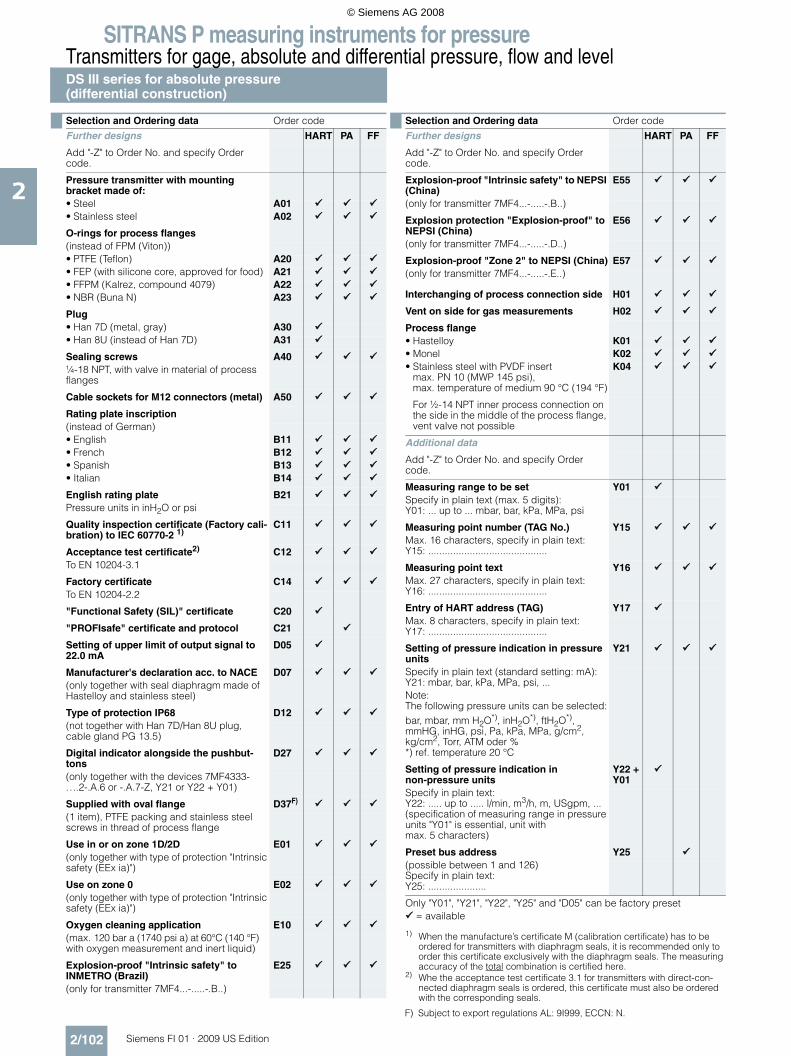
SITRANS P measuring instruments for pressureTransmitters for gage, absolute and differential pressure, flow and levelDS III series for absolute pressure(differential construction)
2/102 Siemens FI 01 · 2009 US Edition
2
Selection and Ordering data Order code
Further designs HART PA FF
Add "-Z" to Order No. and specify Order code.
Pressure transmitter with mounting bracket made of: • Steel A01• Stainless steel A02
O-rings for process flanges(instead of FPM (Viton))• PTFE (Teflon) A20• FEP (with silicone core, approved for food) A21• FFPM (Kalrez, compound 4079) A22• NBR (Buna N) A23
Plug• Han 7D (metal, gray) A30• Han 8U (instead of Han 7D) A31
Sealing screws A40¼-18 NPT, with valve in material of process flanges
Cable sockets for M12 connectors (metal) A50
Rating plate inscription(instead of German)• English B11• French B12• Spanish B13• Italian B14
English rating plate B21Pressure units in inH2O or psi
Quality inspection certificate (Factory cali-bration) to IEC 60770-2 1)
C11
Acceptance test certificate2) C12To EN 10204-3.1
Factory certificate C14To EN 10204-2.2
"Functional Safety (SIL)" certificate C20
"PROFIsafe" certificate and protocol C21
Setting of upper limit of output signal to 22.0 mA
D05
Manufacturer's declaration acc. to NACE D07(only together with seal diaphragm made of Hastelloy and stainless steel)
Type of protection IP68 D12(not together with Han 7D/Han 8U plug, cable gland PG 13.5)
Digital indicator alongside the pushbut-tons
D27
(only together with the devices 7MF4333-....2-.A.6 or -.A.7-Z, Y21 or Y22 + Y01)
Supplied with oval flange D37F)
(1 item), PTFE packing and stainless steel screws in thread of process flange
Use in or on zone 1D/2D E01(only together with type of protection "Intrinsic safety (EEx ia)")
Use on zone 0 E02(only together with type of protection "Intrinsic safety (EEx ia)")
Oxygen cleaning application E10(max. 120 bar a (1740 psi a) at 60°C (140 °F) with oxygen measurement and inert liquid)
Explosion-proof "Intrinsic safety" to INMETRO (Brazil)
E25
(only for transmitter 7MF4...-.....-.B..)
Explosion-proof "Intrinsic safety" to NEPSI (China)
E55
(only for transmitter 7MF4...-.....-.B..)
Explosion protection "Explosion-proof" to NEPSI (China)
E56
(only for transmitter 7MF4...-.....-.D..)
Explosion-proof "Zone 2" to NEPSI (China) E57(only for transmitter 7MF4...-.....-.E..)
Interchanging of process connection side H01
Vent on side for gas measurements H02
Process flange• Hastelloy K01• Monel K02• Stainless steel with PVDF insert
max. PN 10 (MWP 145 psi),max. temperature of medium 90 °C (194 °F)
K04
For ½-14 NPT inner process connection on the side in the middle of the process flange, vent valve not possible
Additional data
Add "-Z" to Order No. and specify Order code.
Measuring range to be set Y01Specify in plain text (max. 5 digits):Y01: ... up to ... mbar, bar, kPa, MPa, psi
Measuring point number (TAG No.) Y15Max. 16 characters, specify in plain text:Y15: ...........................................
Measuring point text Y16Max. 27 characters, specify in plain text:Y16: ...........................................
Entry of HART address (TAG) Y17Max. 8 characters, specify in plain text:Y17: ...........................................
Setting of pressure indication in pressure units
Y21
Specify in plain text (standard setting: mA):Y21: mbar, bar, kPa, MPa, psi, ...Note:The following pressure units can be selected:bar, mbar, mm H2O*), inH2O*), ftH2O*), mmHG, inHG, psi, Pa, kPa, MPa, g/cm2, kg/cm2, Torr, ATM oder % *) ref. temperature 20 °C
Setting of pressure indication in non-pressure units
Y22 + Y01
Specify in plain text:Y22: ..... up to ..... l/min, m3/h, m, USgpm, ...(specification of measuring range in pressure units "Y01" is essential, unit with max. 5 characters)
Preset bus address Y25(possible between 1 and 126)Specify in plain text:Y25: .....................
Only "Y01", "Y21", "Y22", "Y25" and "D05" can be factory preset = available
1) When the manufacture’s certificate M (calibration certificate) has to be ordered for transmitters with diaphragm seals, it is recommended only to order this certificate exclusively with the diaphragm seals. The measuring accuracy of the total combination is certified here.
2) Whe the acceptance test certificate 3.1 for transmitters with direct-con-nected diaphragm seals is ordered, this certificate must also be ordered with the corresponding seals.
Selection and Ordering data Order code
Further designs HART PA FF
Add "-Z" to Order No. and specify Order code.
F) Subject to export regulations AL: 9I999, ECCN: N.
© Siemens AG 2008

SITRANS P measuring instruments for pressureTransmitters for gage, absolute and differential pressure, flow and level
DS III series for absolute pressure(differential construction)
2/103Siemens FI 01 · 2009 US Edition
2
■ Dimensional drawings
SITRANS P pressure transmitters, DS III HART series for absolute pressure, from the differential construction, dimensions in mm (inch)
7
8
&%%� =���
<8�08
���1
�
�
�<
89/�06�/1
�
/
8���07��61
</�0��616��0��/�1
6
8���0��61
9<�0�
�/1
7��0���71
9��0��<1�"4%
&*��! ��� '&'" �
!�- $
�"�#
�"<9�0��61
�" 9
&%%� =��9<�0��6/1
&%%� =�����08��1�71 8���0��9�1870��<1 8���07�<61
�� 0��/1
780���1
.�/�
0��871
886�0��<1
7�08�961
8�7�0��81
D
8�
88
8 �� *����* ���*'" �G�H)8/�:�;�0�:�<878/1� 3(&��"�#�%($#� �(�*'�"*&(�* ���*'" �G
)��*��,� �#(&� ��#�8��7�0& &%'��1��1��1�)��*��,� �#(&� ���=8�7��1�)��*��,� �#(&� �2)8��:�;� �)��&��6����&��/��%($#��1��1
� ;���"�&(��" �7 �(�*'� �"*���" ��� "#"'&(� "�%(&��0( �#��� +��&((�(��#'-�! ��* +���,"'-�,"� ,1< �� '�*'"+��* +��� +�������6 $�'"�#�C�&*��'�0 %'" �1/ 4�&("�#��*��,�,"'-�+&(+��0 %'" �19 4*��,�* +���)��&!�'��C�&*��'�0 �(��! ��'�%�� !�%� '�*'" �
I�=%( �" �)%� !���*( �$��I��� '��- ,��"��'-�� �&,"�#18� &'��&(�+��'"�#�! ��("E$" ���&�$�����'�04'&� &� 188 &'��&(�+��'"�#�! ��#&����&�$�����'�0�$!!"=����1
81 �(( ,�&%%� =��������0��69�"�*-1�'-��& �(��#'-�' �%���"'�$��*��,"�#�1 : '�,"'-�'�%�� !�%� '�*'" ��I�=%( �" �)%� !���*( �$��I�1 : '�,"'-�'�%�� !�%� '�*'" ��I?�D��4��J"��D�=%KI�1 9�����0��<��"�*-1�! ���"�"�$�� "�'&�*��' �%���"'�� '&'" ��,"'-�"� "*&' �71 �7����08�/�"�*-1�! ���#�8��7�,"'-�& &%'��
B�7������<�
08�96��������<1
© Siemens AG 2008

SITRANS P measuring instruments for pressureTransmitters for gage, absolute and differential pressure, flow and levelDS III series for absolute pressure(differential construction)
2/104 Siemens FI 01 · 2009 US Edition
2
SITRANS P pressure transmitters, DS III PA and FF series for absolute pressure, from the differential construction, dimensions in mm (inch)
7
8
&%%� =���
<8�08
���1
�
�<
89/�06�/1
�
/
8���07��61
</�0��616��0��/�1
6
8���0��61
9<�0�
�/1
7��0���71
9��0��<1�"
4%&*��! ��� '&'" �
!�- $
�"�#
�"<9�0��61
�" 9
&%%� =�����08��1 8���0��9�1870��<1 8���07�<61
�� 0��/1
780���1
.�/�
0��871
886�0��<1
7�08�961
8�7�0��81
D
8 �� *����* ���*'" �G�H)8/�:�;�0�:�<878/1� 3(&��"�#�%($#� �(�*'�"*&(�* ���*'" �G
)��*��,� �#(&� ���=8�7��1�)��*��,� �#(&� �2)8��:�;� �)����?�3�4�%($#�8���1��1
� ;���"�&(��" �7 �(�*'� �"*��" ��� "#"'&(� "�%(&��0( �#��� +��&((�(��#'-�! ��* +���,"'-�,"� ,1< �� '�*'"+��* +��� +�������6 $�'"�#�C�&*��'�0 %'" �1/ 4�&("�#��*��,�,"'-�+&(+��0 %'" �19 4*��,�* +���L��&!�'��C�&*��'�0 �(��! ���=%( �" �)%� !���*( �$���
� '��- ,��"��'-�� �&,"�#18� &'��&(�+��'"�#�! ��("E$" ���&�$�����'�04'&� &� 188 &'��&(�+��'"�#�! ��#&����&�$�����'�0�$!!"=����1
81 �(( ,�&%%� =��������0��69�"�*-1�'-��& �(��#'-�"��& "'" ��1 9�����0��<��"�*-1�! ���"�"�$�� "�'&�*��' �%���"'�� '&'" ��,"'-�"� "*&' ��1 : '�,"'-�'�%�� !�%� '�*'" ��I�=%( �" �)%� !���*( �$��I�1 : '�,"'-�'�%�� !�%� '�*'" ��I?�D��4�I
8�
88
B�7������<�
08�96��������<1
© Siemens AG 2008

SITRANS P measuring instruments for pressureTransmitters for gage, absolute and differential pressure, flow and level
DS III seriesfor differential pressure and flow
2/105Siemens FI 01 · 2009 US Edition
2
■ Technical specifications
SITRANS P, DS III series, for differential pressure and flow
HART PROFIBUS PA or FOUNDATION Fieldbus
Input
Measured variable Differential pressure and flow
Spans (infinitely adjustable) or nominal mea-suring range and max. permissible working pressure
Span Maximum working pressure
Nominal measuring range
Maximum working pressure
0.4 ... 8 inH2O (1 ... 20 mbar)
464 psi (32 bar)
8 inH2O (20 mbar g)
464 psi (32 bar)
0.4 ... 24 inH2O (1 ... 60 mbar)
2320 psi (160 bar)
24 inH2O (60 mbar)
2320 psi (160 bar)
1 ... 100 inH2O (2.5 ... 250 mbar)
100 inH2O (250 mbar)
2.4 ... 240 inH2O (6 ... 600 mbar)
240 inH2O (600 mbar)
6.4 ... 642 inH2O (16 ... 1600 mbar)
642 inH2O (1600 mbar)
20 ... 2000 inH2O (50 ... 5000 mbar)
2000 inH2O (5 bar)
4.35 ... 435 psi (0.3 ... 30 bar)
435 psi (30 bar)
1 ... 100 inH2O (2.5 ... 250 mbar)
6091 psi (420 bar)
100 inH2O (250 mbar)
6091 psi (420 bar)
2.4 ... 240 inH2O (6 ... 600 mbar)
240 inH2O (600 mbar)
6.4 ... 642 inH2O (16 ... 1600 mbar)
642 inH2O (1600 mbar)
20 ... 2000 inH2O (50 ... 5000 mbar)
2000 inH2O (5 bar)
4.35 ... 435 psi (0.3 ... 30 bar)
435 psi (30 bar)
Lower measuring limit
• Measuring cell with silicone oil filling -100% of max. span (-33% with 435 psi (30 bar) measuring cell or 0.44 psi (30 mbar a))
Upper measuring limit 100% of max. span (for oxygen version and inert filling liquid; max. 2320 psi g (160 bar g))
Output
Output signal 4 ... 20 mA Digital PROFIBUS PA or FOUNDATION Fieldbus signal
• Lower limit (infinitely adjustable) 3.55 mA, factory preset to 3.84 mA -
• Upper limit (infinitely adjustable) 23 mA, factory preset to 20.5 mA or optionally set to 22.0 mA
-
Load
• Without HART communication RB ≤ (UH - 10.5 V)/0.023 A in Ω,UH : Power supply in V
-
• With HART communication RB = 230 ... 500 Ω (SIMATIC PDM) orRB = 230 ... 1100 Ω (HART Communicator)
-
Physical bus - IEC 61158-2
With polarity reversal protection - Yes
Accuracy To EN 60770-1
Reference conditions(All error data refer always refer to the set span)
Increasing characteristic, start-of-scale value 0 bar, stainless steel seal diaphragm, silicone oil filling, room temperature 25 °C (77 °F)) r: Span ratio (r = max. span / set span)
Error in measurement and fixed-point setting (including hysteresis and repeatability)
• Linear characteristic ≤ 0.075%
- r ≤ 10 ≤ (0.0029 ⋅ r + 0.071)%
- 10 < r ≤ 30 ≤ (0.0045 ⋅ r + 0.071)%
- 30 < r ≤ 100 ≤ (0.005 ⋅ r + 0.05)%
• Square-root characteristic (flow > 50%) ≤ 0.1%
- r ≤ 10 ≤ 0.1%
- 10 < r ≤ 30 ≤ 0.2%
© Siemens AG 2008

SITRANS P measuring instruments for pressureTransmitters for gage, absolute and differential pressure, flow and levelDS III seriesfor differential pressure and flow
2/106 Siemens FI 01 · 2009 US Edition
2
• Square-root characteristic (flow 25 ... 50%) ≤ 0.2
- r ≤ 10 ≤ 0.2% -
- 10 < r ≤ 30 ≤ 0.4% -
Long-term drift (temperature change ± 30 °C (± 54 °F))
≤ (0.25 ⋅ r)% every 5 yearsstatic pressure max. 1015 psi g (70 bar g)
≤ (0.25% every 5 yearsstatic pressure max. 1015 psi g (70 bar g)
• 20 mbar (0.29 psi)-measuring cell ≤ (0.2 ⋅ r) per year ≤ 0.2 per year
Influence of ambient temperature
• at -10 ... +60 °C (14 ... 140 °F) ≤ (0.08 ⋅ r + 0.1)% ≤ 0.3%
• at -40 ... -10 °C and +60 ... +85 °C(-40 ... +14 °F and 140 ... 185 °F)
≤ (0.1 ⋅ r + 0.15)%/10 K(Twice the value with 0.29 psi (20-mbar) measuring cell)
≤ 0.25%/10 K
Influence of static pressure
• on the zero point ≤ (0.15 ⋅ r)% per 1450 psi (100 bar) ≤ 0.15% per 1450 psi (100 bar)- 0.29 psi (20 mbar)-measuring cell ≤ (0.15 ⋅ r)% per 464 psi (32 bar) ≤ 0.15% per 464 psi (32 bar)
• on the span ≤ 0.2% per 1450 psi (100 bar) -- 0.29 psi (20 mbar)-measuring cell ≤ 0.2% per 464 psi (32 bar) -
Measured Value Resolution - 3 ⋅ 10-5 of nominal measuring range
Rated operating conditions
Degree of protection (to EN 60529) IP65
Process temperature
• Measuring cell with silicone oil filling -40 ... +100 °C (-40 ... +212 °F)
• Measuring cell with inert filling liquid -20 ... +100 °C (-4 ... +212 °F)
• In conjunction with dust explosion protec-tion
-20 ... +60 °C (-4 ... +140 °F)
Ambient conditions
• Ambient temperature
- Digital indicators -30 ... +85 °C (-22 ... +185 °F)
• Storage temperature -50 ... +85 °C (-58 ... +185 °F)
• Climatic class
- Condensation Permissible
• Electromagnetic compatibility
- Emitted interference and interference immunity
To EN 61326 and NAMUR NE 21
Material of the mounting bracket
• Steel Sheet steel, Mat. No. 1.0330, chrome-plated
• Stainless steel Stainless steel, Mat. No. 1.4301 (SS304)
Design
Weight (without options) ≈ 4.5 kg (≈ 9.9 lb)
Housing material Low copper die-cast aluminium, GD-AlSi12 or stainless steel precision casting, mat. No. 1.4408
Wetted parts materials
• Seal diaphragm Stainless steel, mat. No. 1.4404/316L or Hastelloy C276, mat. No. 2.4819, Monel, mat. No. 2.4360, tantalum or gold
Measuring cell filling Silicone oil or inert filling liquid (max. 2320 psi g (160 bar) with oxygen measurement)
Process connection Female thread ¼-18 NPT and flange connection with mounting thread M10 to DIN 19213 or 7/16-20 UNF to EN 61518
SITRANS P, DS III series, for differential pressure and flow
HART PROFIBUS PA or FOUNDATION Fieldbus
© Siemens AG 2008

SITRANS P measuring instruments for pressureTransmitters for gage, absolute and differential pressure, flow and level
DS III seriesfor differential pressure and flow
2/107Siemens FI 01 · 2009 US Edition
2
Power supply UH Supplied through bus
Terminal voltage on transmitter 10.5 ... 45 V DC10.5 ... 30 V DC in intrinsically-safe mode
-
Separate 24 V power supply necessary - No
Bus voltage
• Not Ex - 9 ...32 V
• With intrinsically-safe operation - 9 ...24 V
Current consumption
• Basic current (max.) - 12.5 mA
• Startup current ≤ basic current - Yes
• Max. current in event of fault - 15.5 mA
Fault disconnection electronics (FDE) avail. - Yes
SITRANS P, DS III series, for differential pressure and flow
HART PROFIBUS PA or FOUNDATION Fieldbus
© Siemens AG 2008

SITRANS P measuring instruments for pressureTransmitters for gage, absolute and differential pressure, flow and levelDS III seriesfor differential pressure and flow
2/108 Siemens FI 01 · 2009 US Edition
2
Certificate and approvals
Classification according to pressure equip-ment directive (DRGL 97/23/EC)
PN 32/160 (MWP 464/2320 psi) For gases of fluid group 1 and liquids of fluid group 1; complies with requirements of Article 3, para-graph 3 (sound engineering practice)
PN 420 (MWP 6092 psi) For gases of fluid group 1 and liquids of fluid group 1; complies with basic safety requirements of Article 3, paragraph 1 (appendix 1); assigned to category III, conformity evaluation module H by the TÜV Nord.
Explosion protection
• Intrinsic safety "i" PTB 99 ATEX 2122
- Identification Ex II 1/2 G EEx ia/ib IIB/IIC T6
- Permissible ambient temperature -40 ... +85 °C (-40 ... +185 °F) temperature class T4;-40 ... +70 °C (-40 ... +158 °F) temperature class T5;-40 ... +60 °C (-40 ... +140 °F) temperature class T6
- Connection To certified intrinsically-safe circuits with maxi-mum values: Ui = 30 V, Ii = 100 mA, Pi = 750 mW; Ri = 300 Ω
FISCO supply unit: Uo = 17.5 V, Io = 380 mA, Po = 5.32 WLinear barrier: Uo = 24 V, Io = 250 mA, Po = 1.2 W
- Effective internal inductance/capacitance L i = 0.4 mH, Ci = 6 nF L i = 7 μH, Ci = 1.1 nF
• Explosion-proof "d" PTB 99 ATEX 1160
- Identification Ex II 1/2 G EEx d IIC T4/T6
- Permissible ambient temperature -40 ... +85 °C (-40 ... +185 °F) temperature class T4;-40 ... +60 °C (-40 ... +140 °F) temperature class T6
- Connection To circuits with values: UH = 10.5 ... 45 V DC To circuits with values: UH = 9 ... 32 V DC
• Dust explosion protection for zone 20 PTB 01 ATEX 2055
- Identification Ex II 1 D IP65 T 120 °CEx II 1/2 D IP65 T 120 °C
- Permissible ambient temperature -40 ... +85 °C (-40 ... +185 °F)
- Max.surface temperature 120 °C (248 °F)
- Connection To certified intrinsically-safe circuits with maxi-mum values: Ui = 30 V, Ii = 100 mA, Pi = 750 mW, Ri = 300 Ω
FISCO supply unit: Uo = 17.5 V, Io = 380 mA, Po = 5.32 WLinear barrier: Uo = 24 V, Io = 250 mA, Po = 1.2 W
- Effective internal inductance/capacitance L i = 0.4 mH, Ci = 6 nF L i = 7 μH, Ci = 1.1 nF
• Dust explosion protection for zone 21/22 PTB 01 ATEX 2055
- Identification Ex II 2 D IP65 T 120 °C
- Connection To circuits with values: UH = 10.5 ... 45 V DC; Pmax = 1.2 W
To circuits with values: UH = 9 ... 32 V DC; Pmax = 1.2 W
• Type of protection "n" (zone 2) TÜV 01 ATEX 1696 X Planned
- Identification Ex II 3 G EEx nA L IIC T4/T5/T6 -
• Explosion protection to FM Certificate of Compliance 3008490
- Identification (XP/DIP) or (IS); (NI) CL I, DIV 1, GP ABCD T4...T6; CL II, DIV 1, GP EFG; CL III; CL I, ZN 0/1 AEx ia IIC T4...T6; CL I, DIV 2, GP ABCD T4...T6; CL II, DIV 2, GP FG; CL III
• Explosion protection to CSA Certificate of Compliance 1153651
- Identification (XP/DIP) or (IS) CL I, DIV 1, GP ABCD T4...T6; CL II, DIV 1, GP EFG; CL III; Ex ia IIC T4...T6; CL I, DIV 2, GP ABCD T4...T6; CL II, DIV 2, GP FG; CL III
SITRANS P, DS III series, for differential pressure and flow
HART PROFIBUS PA or FOUNDATION Fieldbus
© Siemens AG 2008

SITRANS P measuring instruments for pressureTransmitters for gage, absolute and differential pressure, flow and level
DS III seriesfor differential pressure and flow
2/109Siemens FI 01 · 2009 US Edition
2
HART communication
HART communication 230 ... 1100 Ω
Protocol HART Version 5.x
Software for computer SIMATIC PDM
PROFIBUS PA communication
Simultaneous communication with master class 2 (max.)
4
The address can be set using Configuration tool or local opera-tion (standard setting address 126)
Cyclic data usage
• Output byte 5 (one measuring value) or10 (two measuring values)
• Input byte 0, 1, or 2 (register operating mode and reset function for metering)
Internal preprocessing
Device profile PROFIBUS PA Profile for Process Control Devices Version 3.0, Class B
Function blocks 2
• Analog input
- Adaptation to customer-specif-ic process variables
Yes, linearly rising or falling char-acteristic
- Electrical damping T63 , adjust-able
0 ... 100 s
- Simulation function Input /Output
- Failure mode Can be parameterized (last good value, substitute value, incorrect value)
- Limit monitoring Yes, one upper and lower warning limit and one alarm limit respec-tively
• Register (totalizer) Can be reset, preset, optional direction of counting, simulation function of register output
- Failure mode Can be parameterized (summation with last good value, continuous summation, summation with incor-rect value)
- Limit monitoring One upper and lower warning limit and one alarm limit respectively
• Physical block 1
Transducer blocks 2
• Pressure transducer block
- Can be calibrated by applying two pressures
Yes
- Monitoring of sensor limits Yes
- Characterizer Max. 30 points
- Square-rooted characteristic for flow measurement
Yes
- Gradual volume suppression and implementation point of square-root extraction
Parameterizable
- Simulation function for mea-sured pressure value and sen-sor temperature
Constant value or over parameter-izable ramp function
Communication FOUNDATION Fieldbus
Function blocks 3 function blocks analog input, 1 function block PID
• Analog input
- Adaptation to customer-specif-ic process variables
Yes, linearly rising or falling char-acteristic
- Electrical damping T63 , adjust-able
0 ... 100 s
- Simulation function Output/input (can be locked within the device with a bridge)
- Failure mode Can be parameterized (last good value, substitute value, incorrect value)
- Limit monitoring Yes, one upper and lower warning limit and one alarm limit respec-tively
- Square-rooted characteristic for flow measurement
Yes
• PID Standard FF function block
• Physical block 1 Resource block
Transducer blocks 1 transducer block Pressure with calibration, 1 transducer block LCD
• Pressure transducer block
- Can be calibrated by applying two pressures
Yes
- Monitoring of sensor limits Yes
- Simulation function: Measured pressure value, sensor temper-ature and electronics tempera-ture
Constant value or over parameter-izable ramp function
© Siemens AG 2008

SITRANS P measuring instruments for pressureTransmitters for gage, absolute and differential pressure, flow and levelDS III seriesfor differential pressure and flow
2/110 Siemens FI 01 · 2009 US Edition
2
Selection and Ordering data Order No.
SITRANS P pressure transmitters for differen-tial pressure and flow, Series DS III HARTMWP 464/2320 psi (PN 32/160)
7 M F 4 4 3 3 -
77777 - 7777
Measuring cell filling Measuring cell cleaning
Silicone oil Standard } 1Inert liquid1) Grease-free 3
SpanMWP 464 psi (PN 32)0.4015 ... 8.03 inH2O2) (1 ... 20 mbar)2)
} B
MWP 2320 psi (PN 160)0.4015 ... 24.09 inH2O (1 ... 60 mbar) } C1.004 ... 100.4 inH2O (2.5 ... 250 mbar) } D2.409 ... 240.9 inH2O (6 ... 600 mbar) } E6.424 ... 642.4 inH2O (16 ... 1600 mbar) } F20.08 ... 2008 inH2O (50 ... 5000 mbar) } G4.35 ... 435 psi (0.3 ... 30 bar) } H
Wetted parts materials(stainless steel process flanges)Seal diaphragm Parts of measuring cell
Stainless steel Stainless steel } AHastelloy Stainless steel BHastelloy Hastelloy CTantalum3) Tantalum EMonel3) Monel HGold3) Gold LVersion for diaphragm seal4) 5) Y
Process connectionFemale thread ¼-18 NPT with flange connection• Sealing screw opposite process connection
- Mounting thread 7/16-20 UNF to EN 61518 2- Mounting thread M10 to DIN 19213
(only for replacement needs)} 0
• Vent on side of process flange2)
- Mounting thread 7/16-20 UNF to EN 61518 6- Mounting thread M10 to DIN 19213
(only for replacement needs)4
Non-wetted parts materialsProcess flange screws Electronics housing
Stainless steel Die-cast aluminium } 2Stainless steel Stainless steel precision
casting6)3
Version• Standard version 1• International version, English label inscriptions,
documentation in 5 languages on CD} 2
Explosion protection• Without A• With ATEX, Type of protection:
- "Intrinsic safety (EEx ia)" B- "Explosion-proof (EEx d)"7) D- "Intrinsic safety and explosion-proof
enclosure (EEx ia + EEx d)"8)P
- "Ex nA/nL (zone 2)" E- "Intrinsic safety, explosion-proof enclosure
and dust explosion protection(EEx ia + EEx d + Zone 1D/2D)"8)
} R
• With FM + CSA, Type of protection:- "Intrinsic safety and explosion-proof
(is + xp)"7)N C
Electrical connection / cable entry• Screwed gland Pg 13.59) A• Screwed gland M20x1.5 } B• Screwed gland ½-14 NPT C• Han 7D plug (plastic housing) incl. mating
connector10)D
• M12 connectors (metal)10) F
Display• Without indicator 0• Without visible digital indicator (digital indicator
hidden, setting: mA)} 1
• With visible digital indication 6• With customer-specific digital indication (setting
as specified, Order code "Y21" or required)7
} Available ex stock
Power supply units see "SITRANS I power supply units and isolation amplifiers".
Factory-mounting of shut-off valves and valve manifolds see page 2/140.Included in delivery of the device:• Brief instructions (Leporello)• CD-ROM with detailed documentation• Sealing plug(s) or sealing screw(s) for the process flanges(s)
1) For oxygen cleaning application, add Order code E10.2) Not suitable for connection of remote seal. Position of the top vent valve in
the process flanges (see dimensional drawing).3) Only together with max. spans 100.4, 240.9, 2008 inH2O and 435 psi (250,
1600, 5000 and 30000 mbar).4) When the manufacture’s certificate M (calibration certificate) has to be
ordered for transmitters with diaphragm seals, it is recommended only to order this certificate exclusively with the diaphragm seals. The measuring accuracy of the total combination is certified here.
5) Whe the acceptance test certificate 3.1 for transmitters with direct-con-nected diaphragm seals is ordered, this certificate must also be ordered with the corresponding seals.
6) Not together with Electrical connection „Screwed gland Pg 13.5“ and „Han7D plug“.
7) Without cable gland, with blanking plug8) With enclosed cable gland EEx ia and blanking plug9) Not together with type of protection "Explosion-proof" and and type of
protection "Ex nA".10) Cannot be used together with the following types of protection:
"Explosion-proof" and "Intrinsic safety and explosion-proof"
Selection and Ordering data Order No.
SITRANS P pressure transmitters for differen-tial pressure and flow, Series DS III HARTMWP 464/2320 psi (PN 32/160)
7 M F 4 4 3 3 -
77777 - 7777
© Siemens AG 2008
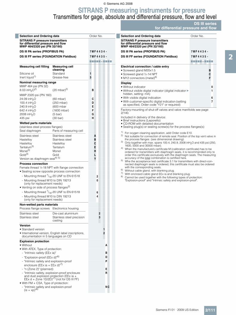
SITRANS P measuring instruments for pressureTransmitters for gage, absolute and differential pressure, flow and level
DS III seriesfor differential pressure and flow
2/111Siemens FI 01 · 2009 US Edition
2
Selection and Ordering data Order No.
SITRANS P pressure transmitters for differential pressure and flowMWP 464/2320 psi (PN 32/160)
DS III PA series (PROFIBUS PA) 7 M F 4 4 3 4 -
DS III FF series (FOUNDATION Fieldbus) 7 M F 4 4 3 5 -
77777 - 7777
Measuring cell filling Measuring cell cleaning
Silicone oil Standard 1Inert liquid1) Grease-free 3
Nominal measuring rangeMWP 464 psi (PN 32)8.03 inH2O2) (20 mbar)2) B
MWP 2320 psi (PN 160)24.09 inH2O (60 mbar) C100.4 inH2O (250 mbar) D240.9 inH2O (600 mbar E642.4 inH2O (1600 mbar) F2008 inH2O (5 bar) G435 psi (30 bar) H
Wetted parts materials(stainless steel process flanges)Seal diaphragm Parts of measuring cell
Stainless steel Stainless steel AHastelloy Stainless steel BHastelloy Hastelloy CTantalum3) Tantalum EMonel3) Monel HGold3) Gold LVersion as diaphragm seal4) 5) Y
Process connectionFemale thread ¼-18 NPT with flange connection• Sealing screw opposite process connection
- Mounting thread 7/16-20 UNF to EN 61518 2- Mounting thread M10 to DIN 19213
(only for replacement needs)0
• Venting on side of process flanges2)
- Mounting thread 7/16-20 UNF to EN 61518 6- Mounting thread M10 to DIN 19213
(only for replacement needs)4
Non-wetted parts materialsProcess flange screws Electronics housing
Stainless steel Die-cast aluminium 2Stainless steel Stainless steel precision
casting3
Version• Standard version 1• International version, English label inscriptions,
documentation in 5 languages on CD2
Explosion protection• Without A• With ATEX, Type of protection:
- "Intrinsic safety (EEx ia)" B
- "Explosion-proof (EEx d)"6) D- "Intrinsic safety and explosion-proof
enclosure (EEx ia + EEx d)"7)P
- "n (Zone 2)" (planned) E- "Intrinsic safety, explosion-proof enclosure
and dust explosion protection (EEx ia + EEx d + Zone 1D/2D)"7) (not for DS III FF)
R
• With FM + CSA, Type of protection:- "Intrinsic safety and explosion-proof
(is + xp)"6)N C
Electrical connection / cable entry• Screwed gland M20x1.5 B• Screwed gland ½-14 NPT C• M12 connectors (metal)8) F
Display• Without indicator 0• Without visible digital indicator (digital indicator
hidden, setting: mA)} 1
• With visible digital indication 6• With customer-specific digital indication (setting
as specified, Order code "Y21" or required)7
Factory-mounting of shut-off valves and valve manifolds see page 2/140.Included in delivery of the device:• Brief instructions (Leporello)• CD-ROM with detailed documentation• Sealing plug(s) or sealing screw(s) for the process flanges(s)
1) For oxygen cleaning application, add Order code E10.2) Not suitable for connection of remote seal. Position of the top vent valve in
the process flanges (see dimensional drawing).3) Only together with max. spans 100.4, 240.9, 2008 inH2O and 435 psi (250,
1600, 5000 and 30000 mbar).4) When the manufacture’s certificate M (calibration certificate) has to be
ordered for transmitters with diaphragm seals, it is recommended only to order this certificate exclusively with the diaphragm seals. The measuring accuracy of the total combination is certified here.
5) Whe the acceptance test certificate 3.1 for transmitters with direct-con-nected diaphragm seals is ordered, this certificate must also be ordered with the corresponding seals.
6) Without cable gland, with blanking plug.7) With enclosed cable gland EEx ia and blanking plug.8) Cannot be used together with the following types of protection:
"Explosion-proof" and "Intrinsic safety and explosion-proof".
Selection and Ordering data Order No.
SITRANS P pressure transmitters for differential pressure and flowMWP 464/2320 psi (PN 32/160)
DS III PA series (PROFIBUS PA) 7 M F 4 4 3 4 -
DS III FF series (FOUNDATION Fieldbus) 7 M F 4 4 3 5 -
77777 - 7777
© Siemens AG 2008

SITRANS P measuring instruments for pressureTransmitters for gage, absolute and differential pressure, flow and levelDS III seriesfor differential pressure and flow
2/112 Siemens FI 01 · 2009 US Edition
2
Selection and Ordering data Order code
Further designsAdd "-Z" to Order No. and specify Order code.
HART PA FF
Pressure transmitter with mounting bracket made of: • Steel A01• Stainless steel A02
O-rings for process flanges(instead of FPM (Viton))• PTFE (Teflon) A20• FEP (with silicone core, approved for food) A21• FFPM (Kalrez, compound 4079) A22• NBR (Buna N) A23
Plug• Han 7D (metal, gray) A30• Han 8U (instead of Han 7D) A31
Sealing screws¼-18 NPT, with valve in mat. of process flanges
A40
Cable sockets for M12 connectors (metal) A50
Rating plate inscription (instead of German)• English B11• French B12• Spanish B13• Italian B14
English rating plate (calibration certificate) B21Pressure units in inH2O or psi
Quality inspection certificate (Factory cali-bration) to IEC 60770-2 1)
C11
Acceptance test certificate2)
To EN 10 204-3.1C12
Factory certificateTo EN 10 204-2.2
C14
"Functional Safety (SIL)" certificate C20
"PROFIsafe" certificate and protocol C21
Setting of upper limit of output signal to 22.0 mA
D05
Manufacturer's declaration acc. to NACE D07(only together with seal diaphragm made of Hastelloy and stainless steel)
Type of protection IP68(not together with 7D/Han 8U plug, cable gland Pg 13.5)
D12
Digital indicator alongside the pushbut-tons
D27
(only together with the devices 7MF4433-....2-.A.6 or -.A.7-Z, Y21 or Y22 + Y01)
Process flange screws made of Monel(max. nominal pressure PN20)
D34
Supplied with oval flange set D37(2 items), PTFE packings and stainles steel screws in thread of process flanges
Use in or on zone 1D/2D E01(only together with type of protection "Intrinsic safety (EEx ia)")
Use on zone 0 E02(only together with type of protection "Intrinsic safety (EEx ia)")
TÜV approval to AD/TRD E06(only together with type of protection "Intrinsic safety (EEx ia)")
Overfilling safety device for flammable and non-flammable liquids(max. PN 32 (MVWP 464 psi), basic device with type of protection "Intrinsic safety (EEx ia)", to WHG and VbF, not together with measuring cell filling "inert liquid")
E08
Oxygen cleaning application E10(max. 120 bar (1740 psi) at 60°C (140 °F) with oxygen measurement and inert liquid)
Explosion-proof "Intrinsic safety" to INMETRO (Brazil)
E25
(only for transmitter 7MF4...-.....-.B..)
Explosion-proof "Intrinsic safety" to NEPSI (China)
E55
(only for transmitter 7MF4...-.....-.B..)
Explosion protection "Explosion-proof" to NEPSI (China)(only for transmitter 7MF4...-.....-.D..)
E56
Explosion-proof "Zone 2" to NEPSI (China) E57(only for transmitter 7MF4...-.....-.E..)
Interchanging of process connection side H01
Vent on side for gas measurements H02
Stainless steel process flanges for vertical differential pressure lines(not together with K01, K02 and K04)3)
H03
Process flange• Hastelloy K01• Monel K02• Stainless steel with PVDF insert
max. PN 10 (MWP 145 psi),max. temperature of medium 90 °C (194 °F)
K04
For ½-14 NPT inner process connection on the side in the middle of the process flange, vent valve not possible
= available
1) When the manufacture’s certificate M (calibration certificate) has to be ordered for transmitters with diaphragm seals, it is recommended only to order this certificate exclusively with the diaphragm seals. The measuring accuracy of the total combination is certified here.
2) Whe the acceptance test certificate 3.1 for transmitters with direct-con-nected diaphragm seals is ordered, this certificate must also be ordered with the corresponding seals.
3) Not suitable for connection of remote seal
Selection and Ordering data Order code
Further designsAdd "-Z" to Order No. and specify Order code.
HART PA FF
© Siemens AG 2008
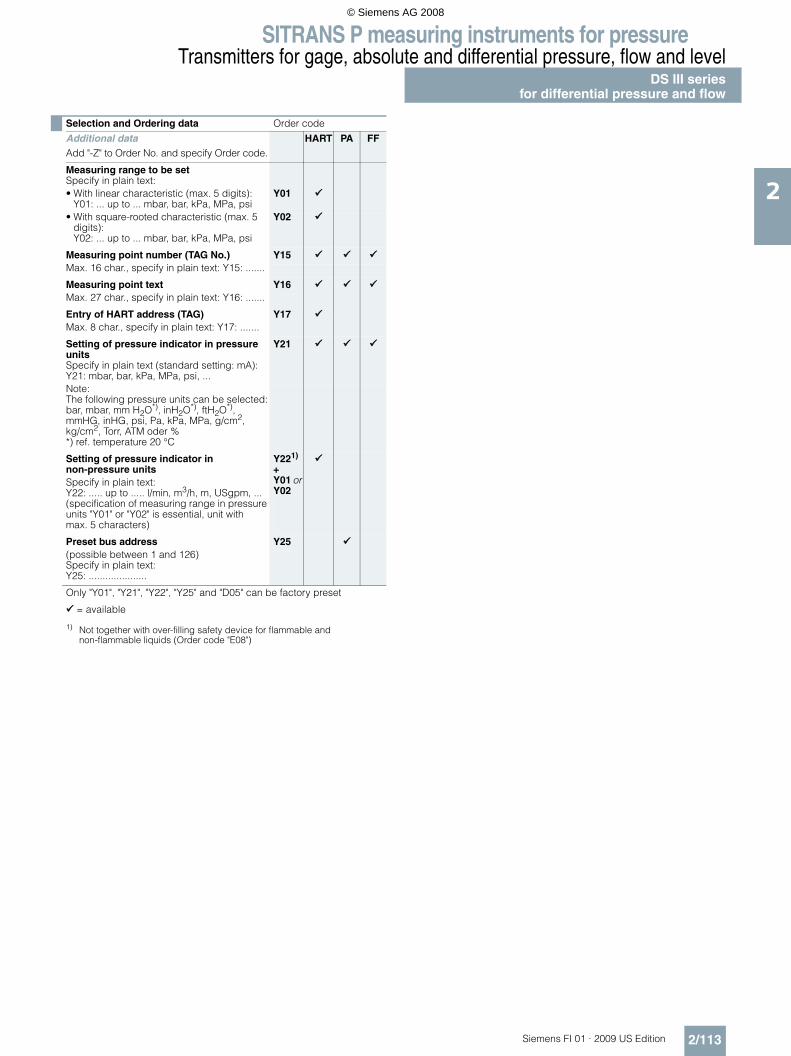
SITRANS P measuring instruments for pressureTransmitters for gage, absolute and differential pressure, flow and level
DS III seriesfor differential pressure and flow
2/113Siemens FI 01 · 2009 US Edition
2
Selection and Ordering data Order code
Additional dataAdd "-Z" to Order No. and specify Order code.
HART PA FF
Measuring range to be setSpecify in plain text:• With linear characteristic (max. 5 digits):
Y01: ... up to ... mbar, bar, kPa, MPa, psiY01
• With square-rooted characteristic (max. 5 digits):Y02: ... up to ... mbar, bar, kPa, MPa, psi
Y02
Measuring point number (TAG No.) Y15Max. 16 char., specify in plain text: Y15: .......
Measuring point text Y16Max. 27 char., specify in plain text: Y16: .......
Entry of HART address (TAG) Y17Max. 8 char., specify in plain text: Y17: .......
Setting of pressure indicator in pressure unitsSpecify in plain text (standard setting: mA): Y21: mbar, bar, kPa, MPa, psi, ...
Y21
Note:The following pressure units can be selected:bar, mbar, mm H2O*), inH2O*), ftH2O*), mmHG, inHG, psi, Pa, kPa, MPa, g/cm2, kg/cm2, Torr, ATM oder % *) ref. temperature 20 °C
Setting of pressure indicator in non-pressure units
Y221)
+ Y01 or Y02
1) Not together with over-filling safety device for flammable and non-flammable liquids (Order code "E08")
Specify in plain text:Y22: ..... up to ..... l/min, m3/h, m, USgpm, ...(specification of measuring range in pressure units "Y01" or "Y02" is essential, unit with max. 5 characters)
Preset bus address Y25(possible between 1 and 126)Specify in plain text:Y25: .....................
Only "Y01", "Y21", "Y22", "Y25" and "D05" can be factory preset
= available
© Siemens AG 2008

SITRANS P measuring instruments for pressureTransmitters for gage, absolute and differential pressure, flow and levelDS III seriesfor differential pressure and flow
2/114 Siemens FI 01 · 2009 US Edition
2
Selection and Ordering data Order No.
SITRANS P pressure transmitters for differen-tial pressure and flow, Series DS III HARTMWP 6092 psi (PN 420)
7 M F 4 5 3 3 -
77777 - 7777
Measuring cell filling Measuring cell cleaning
Silicone oil Standard 1
Span1.004 ... 100.4 inH2O (2.5 ... 250 mbar) D2.409 ... 240.9 inH2O (6 ... 600 mbar) E6.424 ... 642.4 inH2O (16 ... 1600 mbar) F20.08 ... 2008 inH2O (50 ... 5000 mbar) G4.35 ... 435 psi (0.3 ... 30 bar) H
Wetted parts materials(stainless steel process flanges)Seal diaphragm Parts of measuring cell
Stainless steel Stainless steel AHastelloy Stainless steel BGold1) Gold L
Process connectionFemale thread ¼-18 NPT with flange connection• Sealing screw opposite process connection
- Mounting thread 7/16-20 UNF to EN 61518 3- Mounting thread M12 to DIN 19213
(only for replacement needs)1
• Venting on side of process flanges. Position of the top vent valve in the process flanges (see dimensional drawing).- Mounting thread 7/16-20 UNF to EN 61518 7- Mounting thread M12 to DIN 19213
(only for replacement needs)5
Non-wetted parts materialsProcess flange screws Electronics housing
Stainless steel Die-cast aluminium 2Stainless steel Stainless steel precision
casting2)3
Version• Standard version 1• International version, English label inscriptions,
documentation in 5 languages on CD2
Explosion protection• Without A• With ATEX, Type of protection:
- "Intrinsic safety (EEx ia)" B
- "Explosion-proof (EEx d)"3) D
- "Intrinsic safety and explosion-proof enclosure (EEx ia + EEx d)"4)
P
- "Ex nA/nL (zone 2)" E- "Intrinsic safety, explosion-proof enclosure
and dust explosion protection (EEx ia + EEx d + Zone 1D/2D)"4)
R
• With FM + CSA, Type of protection:- "Intrinsic safety and explosion-proof
(is + xp)"3), max PN 360N C
Electrical connection / cable entry• Screwed gland Pg 13.55) A• Screwed gland M20x1.5 B• Screwed gland ½-14 NPT C• Han 7D plug (plastic housing) incl. mating
connector5)D
• M12 connectors (metal)6) F
Display• Without indicator 0• Without visible digital indicator (digital indicator
hidden, setting: mA)} 1
• With visible digital indication 6• With customer-specific digital indication (setting
as specified, Order code "Y21" or required)7
Power supply units see "SITRANS I power supply units and isolation amplifiers".
Factory-mounting of shut-off valves and valve manifolds see page 2/140.Scope of delivery: Pressure transmitter as ordered (Instruction Manual is extra ordering item)
1) Not together with max. span 240.9 inH2O (600 mbar)2) Not together with Electrical connection „Screwed gland Pg 13.5“ and
„Han7D plug“.3) Without cable gland, with blanking plug4) With enclosed cable gland EEx ia and blanking plug5) Not together with type of protection "Explosion-proof" and and type of
protection "Ex nA".6) Cannot be used together with the following types of protection:
"Explosion-proof" and "Intrinsic safety and explosion-proof".
Selection and Ordering data Order No.
SITRANS P pressure transmitters for differen-tial pressure and flow, Series DS III HARTMWP 6092 psi (PN 420)
7 M F 4 5 3 3 -
77777 - 7777
© Siemens AG 2008

SITRANS P measuring instruments for pressureTransmitters for gage, absolute and differential pressure, flow and level
DS III seriesfor differential pressure and flow
2/115Siemens FI 01 · 2009 US Edition
2
Selection and Ordering data Order No.
SITRANS P pressure transmitters for differen-tial pressure and flow, Series DS III HARTMWP 6092 psi (PN 420)
DS III PA (PROFIBUS PA) series 7 M F 4 5 3 4 -
DS III FF series (FOUNDATION Fieldbus) 7 M F 4 5 3 5 -
1 7777 - 7777
Nominal measuring range100.4 inH2O (250 mbar) D240.9 inH2O (600 mbar) E642.4 inH2O (1600 mbar) F2008 inH2O (5 bar) G435 psi30 bar (30 bar) H
Wetted parts materials(stainless steel process flanges)Seal diaphragm Parts of measuring cell
Stainless steel Stainless steel AHastelloy Stainless steel BGold1) Gold L
Process connectionFemale thread ¼-18 NPT with flange connection• Sealing screw opposite process connection
- Mounting thread 7/16-20 UNF to EN 61518 3- Mounting thread M12 to DIN 19213
(only for replacement needs)1
• Venting on side of process flanges. Position of the top vent valve in the process flanges (see dimensional drawing).- Mounting thread 7/16-20 UNF to EN 61518 7- Mounting thread M12 to DIN 19213
(only for replacement needs)5
Non-wetted parts materialsProcess flange screws Electronics housing
Stainless steel Die-cast aluminium 2Stainless steel Stainless steel precision
casting3
Version• Standard version 1• International version, English label inscriptions,
documentation in 5 languages on CD2
Explosion protection• Without A• With ATEX, Type of protection:
- "Intrinsic safety (EEx ia)" B- "Explosion-proof (EEx d)"2) D- "Intrinsic safety and explosion-proof
enclosure (EEx ia + EEx d)"3)P
- "Ex nA/nL (zone 2)" E- "Intrinsic safety, explosion-proof enclosure
and dust explosion protection (EEx ia + EEx d + Zone 1D/2D)"3) (not for DS III FF)
R
• With FM + CSA, Type of protection:- "Intrinsic safety and explosion-proof
(is + xp)"2), max PN 360N C
Electrical connection / cable entry• Screwed gland M20x1.5 B• Screwed gland ½-14 NPT C• Plug M12 incl. mating connector4) F
Display• Without indicator 0• Without visible digital indicator (digital indicator
hidden, setting: mA)} 1
• With visible digital indicator 6• With customer-specific digital indicator (setting
as specified, Order code "Y21" or required)7
Factory-mounting of shut-off valves and valve manifolds see page 2/140.Included in delivery of the device:• Brief instructions (Leporello)• CD-ROM with detailed documentation• Sealing plug(s) or sealing screw(s) for the process flanges(s)
1) Not together with max. span 240.9 inH2O (600 mbar)2) Without cable gland, with blanking plug.3) With enclosed cable gland EEx ia and blanking plug.4) Not together with types of protection "Explosion-proof" and "Intrinsic safety
and explosion-proof"
Selection and Ordering data Order No.
SITRANS P pressure transmitters for differen-tial pressure and flow, Series DS III HARTMWP 6092 psi (PN 420)
DS III PA (PROFIBUS PA) series 7 M F 4 5 3 4 -
DS III FF series (FOUNDATION Fieldbus) 7 M F 4 5 3 5 -
1 7777 - 7777
© Siemens AG 2008
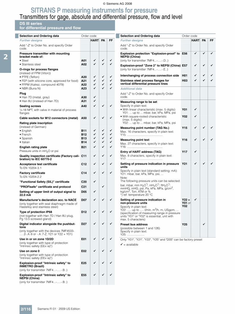
SITRANS P measuring instruments for pressureTransmitters for gage, absolute and differential pressure, flow and levelDS III seriesfor differential pressure and flow
2/116 Siemens FI 01 · 2009 US Edition
2
Selection and Ordering data Order code
Further designs HART PA FF
Add "-Z" to Order No. and specify Order code.
Pressure transmitter with mounting bracket made of: • Steel A01• Stainless steel A02
O-rings for process flanges(instead of FPM (Viton))• PTFE (Teflon) A20• FEP (with silicone core, approved for food) A21• FFPM (Kalrez, compound 4079) A22• NBR (Buna N) A23
Plug• Han 7D (metal, gray) A30• Han 8U (instead of Han 7D) A31
Sealing screws A40¼-18 NPT, with valve in material of process flanges
Cable sockets for M12 connectors (metal) A50
Rating plate inscription(instead of German)• English B11• French B12• Spanish B13• Italian B14
English rating plate B21Pressure units in inH2O or psi
Quality inspection certificate (Factory cali-bration) to IEC 60770-2
C11
Acceptance test certificate C12To EN 10204-3.1
Factory certificate C14To EN 10204-2.2
"Functional Safety (SIL)" certificate C20
"PROFIsafe" certificate and protocol C21
Setting of upper limit of output signal to 22.0 mA
D05
Manufacturer's declaration acc. to NACE D07(only together with seal diaphragm made of Hastelloy and stainless steel)
Type of protection IP68 D12(not together with Han 7D / Han 8U plug, Pg 13.5 screwed gland)
Digital indicator alongside the pushbut-tons
D27
(only together with the devices 7MF4533-....2-.A.6 or -.A.7-Z, Y21 or Y22 + Y01)
Use in or on zone 1D/2D E01(only together with type of protection "Intrinsic safety (EEx ia)")
Use on zone 0 E02(only together with type of protection "Intrinsic safety (EEx ia)")
Explosion-proof "Intrinsic safety" to INMETRO (Brazil)
E25
(only for transmitter 7MF4...-.....-.B..)
Explosion-proof "Intrinsic safety" to NEPSI (China)
E55
(only for transmitter 7MF4...-.....-.B..)
Explosion protection "Explosion-proof" to NEPSI (China)
E56
(only for transmitter 7MF4...-.....-.D..)
Explosion-proof "Zone 2" to NEPSI (China) E57(only for transmitter 7MF4...-.....-.E..)
Interchanging of process connection side H01
Stainless steel process flanges for vertical differential pressure lines
H03
Additional data
Add "-Z" to Order No. and specify Order code.
Measuring range to be setSpecify in plain text:• With linear characteristic (max. 5 digits):
Y01: ... up to ... mbar, bar, kPa, MPa, psiY01
• With square-rooted characteristic (max. 5 digits):Y02: ... up to ... mbar, bar, kPa, MPa, psi
Y02
Measuring point number (TAG No.) Y15Max. 16 characters, specify in plain text:Y15: ...........................................
Measuring point text Y16Max. 27 characters, specify in plain text:Y16: ...........................................
Entry of HART address (TAG) Y17Max. 8 characters, specify in plain text:Y17: ...........................................
Setting of pressure indication in pressure units
Y21
Specify in plain text (standard setting: mA):Y21: mbar, bar, kPa, MPa, psi, ...Note:The following pressure units can be selected:bar, mbar, mm H2O*), inH2O*), ftH2O*), mmHG, inHG, psi, Pa, kPa, MPa, g/cm2, kg/cm2, Torr, ATM or % *) ref. temperature 20 °C
Setting of pressure indication in non-pressure units
Y22 + Y01 or Y02Specify in plain text:
Y22: ..... up to ..... l/min, m3/h, m, USgpm, ...(specification of measuring range in pressure units "Y01" or "Y02" is essential, unit with max. 5 characters)
Preset bus address Y25(possible between 1 and 126)Specify in plain text:Y25: .....................
Only "Y01", "Y21", "Y22", "Y25" and "D05" can be factory preset
= available
Selection and Ordering data Order code
Further designs HART PA FF
Add "-Z" to Order No. and specify Order code.
© Siemens AG 2008

SITRANS P measuring instruments for pressureTransmitters for gage, absolute and differential pressure, flow and level
DS III seriesfor differential pressure and flow
2/117Siemens FI 01 · 2009 US Edition
2
■ Dimensional drawings
SITRANS P pressure transmitters, DS III HART series for differential pressure and flow, dimensions in mm (inch)
7
8
&%%� =���
<8�08
���1
�
�
�<
89/�06�/1
�
/
8���07��61
</�0��616��0��/�1
6
8���0��61
9<�0�
�/1
7��0���71
9��0��<1�"4%
&*��! ��� '&'" �
!�- $
�"�#
�"<9�0��61
�" 9
&%%� =��9<�0��6/1
&%%� =�����08��1�71 8���0��9�1870��<1 8���07�<61
�� 0��/1
780���1
.�/�
0��871
886�0��<1
7�08�961
8�7�0��81
D
8�
88
8 �� *����* ���*'" �G�H)8/�:�;�0�:�<878/1� 3(&��"�#�%($#� �(�*'�"*&(�* ���*'" �G
)��*��,� �#(&� ��#�8��7�0& &%'��1��1��1�)��*��,� �#(&� ���=8�7��1�)��*��,� �#(&� �2)8��:�;� �)��&��6����&��/��%($#��1��1
� ;���"�&(��" �7 �(�*'� �"*���" ��� "#"'&(� "�%(&��0( �#��� +��&((�(��#'-�! ��* +���,"'-�,"� ,1< �� '�*'"+��* +��� +�������6 $�'"�#�C�&*��'�0 %'" �1/ 4�&("�#��*��,�,"'-�+&(+��0 %'" �19 4*��,�* +���)��&!�'��C�&*��'�0 �(��! ��'�%�� !�%� '�*'" �
I�=%( �" �)%� !���*( �$��I��� '��- ,��"��'-�� �&,"�#18� &'��&(�+��'"�#�! ��("E$" ���&�$�����'�04'&� &� 188 &'��&(�+��'"�#�! ��#&����&�$�����'�0�$!!"=����1
81 �(( ,�&%%� =��������0��69�"�*-1�'-��& �(��#'-�' �%���"'�$��*��,"�#�1 : '�,"'-�'�%�� !�%� '�*'" ��I�=%( �" �)%� !���*( �$��I�1 : '�,"'-�'�%�� !�%� '�*'" ��I?�D��4��J"��D�=%KI�1 9�����0��<��"�*-1�! ���"�"�$�� "�'&�*��' �%���"'�� '&'" ��,"'-�"� "*&' �71 �7����08�/�"�*-1�! ���#�8��7�,"'-�& &%'��
B�7������<�
08�96��������<1
© Siemens AG 2008
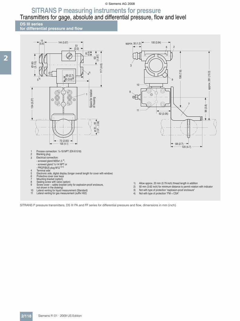
SITRANS P measuring instruments for pressureTransmitters for gage, absolute and differential pressure, flow and levelDS III seriesfor differential pressure and flow
2/118 Siemens FI 01 · 2009 US Edition
2
SITRANS P pressure transmitters, DS III PA and FF series for differential pressure and flow, dimensions in mm (inch)
7
8
&%%� =���
<8�08
���1
�
�<
89/�06�/1
�
/
8���07��61
</�0��616��0��/�1
6
8���0��61
9<�0�
�/1
7��0���71
9��0��<1�"
4%&*��! ��� '&'" �
!�- $
�"�#
�"<9�0��61
�" 9
&%%� =�����08��1 8���0��9�1870��<1 8���07�<61
�� 0��/1
780���1
.�/�
0��871
886�0��<1
7�08�961
8�7�0��81
D
8 �� *����* ���*'" �G�H)8/�:�;�0�:�<878/1� 3(&��"�#�%($#� �(�*'�"*&(�* ���*'" �G
)��*��,� �#(&� ���=8�7��1�)��*��,� �#(&� �2)8��:�;� �)����?�3�4�%($#�8���1��1
� ;���"�&(��" �7 �(�*'� �"*��" ��� "#"'&(� "�%(&��0( �#��� +��&((�(��#'-�! ��* +���,"'-�,"� ,1< �� '�*'"+��* +��� +�������6 $�'"�#�C�&*��'�0 %'" �1/ 4�&("�#��*��,�,"'-�+&(+��0 %'" �19 4*��,�* +���L��&!�'��C�&*��'�0 �(��! ���=%( �" �)%� !���*( �$���
� '��- ,��"��'-�� �&,"�#18� &'��&(�+��'"�#�! ��("E$" ���&�$�����'�04'&� &� 188 &'��&(�+��'"�#�! ��#&����&�$�����'�0�$!!"=����1
81 �(( ,�&%%� =��������0��69�"�*-1�'-��& �(��#'-�"��& "'" ��1 9�����0��<��"�*-1�! ���"�"�$�� "�'&�*��' �%���"'�� '&'" ��,"'-�"� "*&' ��1 : '�,"'-�'�%�� !�%� '�*'" ��I�=%( �" �)%� !���*( �$��I�1 : '�,"'-�'�%�� !�%� '�*'" ��I?�D��4�I
8�
88
B�7������<�
08�96��������<1
© Siemens AG 2008

SITRANS P measuring instruments for pressureTransmitters for gage, absolute and differential pressure, flow and level
DS III seriesfor differential pressure and flow
2/119Siemens FI 01 · 2009 US Edition
2
SITRANS P pressure transmitters, DS III HART series for differential pressure and flow, with process covers for vertical differential pressure lines, option „H03“, dimensions in mm (inch)
�
<&%%� =�����08�8/1/1
6��0��91 �
781
/ /
&%%� =��/��<�0����1
&%%� =��/
70���71
<1
�� 81
<6�0��<�171
4%&*��! ��� '&'" �
!�- $
�"�#
&%%� =���
86�0/
�7�1
61
9
8
8���07�<61870��<1
780���1
�� 0��/1
7�08�961
.�/�
0��871
9��0��<1�1
&%%� =��9<�0��6/18���0��9�1
D
8 �� *����* ���*'" �G�H)8/�:�;�0�:�<878/1� 3(&��"�#�%($#� �(�*'�"*&(�* ���*'" �G
)��*��,� �#(&� ��#�8��7�0& &%'��1��1��1�)��*��,� �#(&� ���=8�7��1�)��*��,� �#(&� �2)8��:�;� �)��&��6����&��/��%($#��1��1
� ;���"�&(��" �7 �(�*'� �"*���" ��� "#"'&(� "�%(&��0( �#��� +��&((�(��#'-�! ��* +���,"'-�,"� ,1< �� '�*'"+��* +��� +�������6 $�'"�#�C�&*��'�0 %'" �1/ 4�&("�#��*��,�,"'-�+&(+��0 %'" �19 4*��,�* +���)��&!�'��C�&*��'�0 �(��! ��'�%�� !�%� '�*'" �
I�=%( �" �)%� !���*( �$��I��� '��- ,��"��'-�� �&,"�#1
81 �(( ,�&%%� =��������0��69�"�*-1�'-��& �(��#'-�' �%���"'�$��*��,"�#�1 : '�,"'-�'�%�� !�%� '�*'" ��I�=%( �" �)%� !���*( �$��I�1 : '�,"'-�'�%�� !�%� '�*'" ��I?�D��4��J"��D�=%KI�1 9�����0��<�"�*-1�! ���"�"�$�� "�'&�*��' �%���"'�� '&'" ��,"'-�"� "*&' �71 6�����0��9�"�*-1�! ���:�������05�����<�9��%�"1<1 98����0��<�"�*-1�! ���:�������05�����<�9��%�"161 �89����0/�<��"�*-1�! ���:�������05�����<�9��%�"1/1 �7����08�/�"�*-1�! ���#�8��7�,"'-�& &%'��
© Siemens AG 2008

SITRANS P measuring instruments for pressureTransmitters for gage, absolute and differential pressure, flow and levelDS III seriesfor differential pressure and flow
2/120 Siemens FI 01 · 2009 US Edition
2
SITRANS P pressure transmitters, DS III PA and FF series for differential pressure and flow, with process covers for vertical differential pressure lines, option „H03“, dimensions in mm (inch)
SITRANS P pressure transmitters, DS III series for differential pressure and flow, with process covers for vertical differential pressure lines
�
<&%%� =����08�8/1<1
6��0��91 �
781
/ /
&%%� =�/��<�0����1
&%%� =�
/7�0�
��71
<1
� 81
<6�0��<�171
4%&*��! ��� '&'" �
!�- $
�"�#
&%%� =���
86�0/
�7�1
61
9
8
8���07�<61870��<1
780���1
�� 0��/1
7�08�961
"&�
��/�
�0��87
1
9��0��<1�1
8���0��9�1
D
8 �� *����* ���*'" ��H)8/�:�;�0�:�<8�78/1� 3(&��"�#�%($#� �(�*'�"*&(�* ���*'" �G
�*��,� �#(&� ���=8�7��1��*��,� �#(&� �2)8��:�;� ����?�3�4�%($#�8���1��1
� ;���"�&(��" �7 �(�*'� �"*���" ��� "#"'&(� "�%(&��0( �#��� +��&((�(��#'-�! ��* +���,"'-�,"� ,1< �� '�*'"+��* +��� +�������6 $�'"�#�C�&*��'�0 %'" �1/ 4�&("�#��*��,�,"'-�+&(+��0 %'" �19 4*��,�* +����&!�'��C�&*��'�0 �(��! ���=%( �" �)%� !���*( �$���
� '��- ,��"��'-�� �&,"�#1
81 �(( ,�&%%� =��������0��69�"�*-1�'-��& �(��#'-�"��& "'" ��1 : '�,"'-�'�%��%� '�*'" ��I�=%( �" �)%� !���*( �$��I�1 : '�,"'-�'�%��%� '�*'" ��I?�D��4��J"��D�=%KI�1 9�����0��<�"�*-1�! ���"�"�$�� "�'&�*��' �%���"'�� '&'" �
,"'- $'�"� "*&' �71 6�����0��9�"�*-1�! ���:�������05�����<�9��%�"1<1 98����0��<�"�*-1�! ���:�������05�����<�9��%�"161 �89����0/�<��"�*-1�! ���:�������05�����<�9��%�"1
© Siemens AG 2008

SITRANS P measuring instruments for pressureTransmitters for gage, absolute and differential pressure, flow and level
DS III seriesfor differential pressure and flow
2/121Siemens FI 01 · 2009 US Edition
2
SITRANS P pressure transmitters, DS III FF series for differential pressure and flow, with digital indicator beside pushbuttons, for vertical differential pressure lines, option „D27“, dimensions in mm (inch)
SITRANS P pressure transmitters, DS III series for differential pressure and flow, with digital indicator beside pushbuttons
90(3.6)
© Siemens AG 2008

SITRANS P measuring instruments for pressureTransmitters for gage, absolute and differential pressure, flow and levelDS III seriesfor level
2/122 Siemens FI 01 · 2009 US Edition
2
■ Technical specifications
SITRANS P, DS III series for level
HART PROFIBUS PA or FOUNDATION Fieldbus
Input
Measured variable Level
Spans (infinitely adjustable) ornominal measuring range andmax. permissible working pressure
Span Maximum working pressure
Nominal measuring range
Maximum working pressure
0.36 ... 3.63 psi g (25 ... 250 mbar g)
See "Mounting flange" 3.63 psi g (250 mbar g)
See "Mounting flange"
0.36 ... 8.7 psi g (25 ... 600 mbar g)
See "Mounting flange" 8.7 psi g (600 mbar g)
See "Mounting flange"
0.77 ... 23.2 psi g (53 ... 1600 mbar g)
See "Mounting flange" 23.2 psi g (1600 mbar g)
See "Mounting flange"
2.32 ... 72.5 psi g (160 ... 5000 mbar g)
See "Mounting flange" 72.5 psi g (5000 mbar g)
See "Mounting flange"
Lower measuring limit
• Measuring cell with silicone oil filling -100% of max. span or 0.435 psi a (30 mbar), depending on mounting flange
Upper measuring limit 100% of max. span 100% of the max. nominal measuring range
Output
Output signal 4 ... 20 mA Digital PROFIBUS PA or FOUNDATION Fieldbus signal
• Lower limit (infinitely adjustable) 3.55 mA, factory preset to 3.84 mA -
• Upper limit (infinitely adjustable) 23 mA, factory preset to 20.5 mA or optionally set to 22.0 mA
-
Load
• Without HART communication RB ≤ (UH - 10.5 V)/0.023 A in Ω,UH : Power supply in V
-
• With HART communication RB = 230 ... 500 Ω (SIMATIC PDM) orRB = 230 ... 1100 Ω (HART Communicator)
-
Physical bus - IEC 61158-2
With polarity reversal protection - Yes
Accuracy To EN 60770-1
Reference conditions(All error data refer always refer to the set span)
Increasing characteristic, start-of-scale value 0 bar, stainless steel seal diaphragm, silicone oil fill-ing, room temperature 25 °C (77 °F)) r: Span ratio (r = max. span / set span)
Error in measurement and fixed-point setting (including hysteresis and repeatability)
• Linear characteristic ≤ 0.075%
- r ≤ 10 ≤ 0.15%
- 10 < r ≤ 30 ≤ 0.3%
- 30 < r ≤ 100 ≤ (0.0075 ⋅ r + 0.075)%
Long-term drift (temperature change ±30 °C (±54 °F))
≤ (0.25 ⋅ r)% every 5 yearsstatic pressure max. 1015 psi g (70 bar g)
≤ (0.25% every 5 yearsstatic pressure max. 1015 psi g (70 bar g)
Influence of ambient temperature
• at -10 ... +60 °C (14 ... 140 °F)
- 3.63 psi (250 mbar)measuring cell ≤ (0.5 ⋅ r + 0.2)% (0.4 instead of 0.2 with 10 < r ≤ 30)
≤ 0.7%
- 8.7 psi (600 mbar) measuring cell ≤ (0.3 ⋅ r + 0.2)% (0.4 instead of 0.2 with 10 < r ≤ 30)
≤ 0.5%
- 23.2 and 72.5 psi (1600 and 5000 mbar) measuring cells
≤ (0.25 ⋅ r + 0.2)% (0.4 instead of 0.2 with 10 < r ≤ 30)
≤ 0.45%
• at -40 ... -10 °C and +60 ... +85 °C(-40 ... +14 °F and 140 ... 185 °F)
- 3.63 psi (250 mbar) measuring cell ≤ (0.25 ⋅ r +0.15)%/10 K double values with 10 < r ≤ 30
≤ 0.4%/10 K
- 8.7 psi (600 mbar) measuring cell ≤ (0.15 ⋅ r +0.15)%/10 K double values with 10 < r ≤ 30
≤ 0.3%/10 K
- 23.2 and 72.5 psi (1600 and 5000 mbar) measuring cells
≤ (0.12 ⋅ r +0.15)%/10 K double values with 10 < r ≤ 30
≤ 0.27%/10 K
© Siemens AG 2008

SITRANS P measuring instruments for pressureTransmitters for gage, absolute and differential pressure, flow and level
DS III seriesfor level
2/123Siemens FI 01 · 2009 US Edition
2
Influence of static pressure
• on the zero point
- 3.63 psi (250 mbar) measuring cell ≤ (0.3 ⋅ r)% per nominal pressure ≤ 0.3% per nominal pressure
- 8.7 psi (600 mbar) measuring cell ≤ (0.15 ⋅ r)% per nominal pressure ≤ 0.15% per nominal pressure
- 23.2 and 72.5 psi (1600 and 5000 mbar) measuring cells
≤ (0.1 ⋅ r)% per nominal pressure ≤ 0.1% per nominal pressure
• on the span ≤ (0.1 ⋅ r)% per nominal pressure ≤ 0.1% per nominal pressure
Measured Value Resolution - 3 ⋅ 10-5 of nominal measuring range
Rated operating conditions
Degree of protection (to EN 60529) IP65
Process temperature Note: Always take into account assignment of max. permissible working temperature to max. per-missible working pressure of the respective flange connection!
• Measuring cell with silicone oil filling -40 ... +100 °C (-40 ... +212 °F)
- High-pressure side pabs ≥ 1bar: -40 ... +175 °C (-40 ... +347 °F)pabs ≥ 1bar: -40 ... +80 °C (-40 ... +176 °F)
- Low-pressure side -40 ... +100 °C (-40 ... +212 °F)-20 ... +60 °C (-4 ... +140 °F) in conjunction with dust explosion protection
Ambient conditions
• Ambient temperature
- Digital indicators -30 ... +85 °C (-22 ... +185 °F)
• Storage temperature -50 ... +85 °C (-58 ... +185 °F)
• Climatic class
- Condensation Permissible
• Electromagnetic compatibility
- Emitted interference and interference immu-nity
To EN 61326 and NAMUR NE 21
Design
Weight (without options)
• To EN (pressure transmitter with mounting flange, without tube)
≈ 11 ... 13 kg (≈ 24.2 ... 28.7 lb)
• To ASME (pressure transmitter with mounting flange, without tube)
≈ 11 ... 18 kg (≈ 24.2 ... 39.7 lb)
Wetted parts materials Low copper die-cast aluminium, GD-AlSi12 or stainless steel precision casting, mat. No. 1.4408
Housing material
High-pressure side
• Seal diaphragm of mounting flange Stainless steel, mat. No. 1.4404/316L, Monel, mat. No. 2.4360, Hastelloy B2, mat. No. 2.4617, Hastelloy C276, mat. No. 2.4819, Hastelloy C4, mat. No. 2.4610, tantalum, PTFE, ECTFE
Measuring cell filling Silicone oil
Process connection
• High-pressure side Flange to EN and ASME
• Low-pressure side Female thread ¼-18 NPT and flange connection with mounting thread M10 to DIN 19213 or 7/16-20 UNF to EN 61518
Power supply UH Supplied through bus
Terminal voltage on transmitter 10.5 ... 45 V DC10.5 ... 30 V DC in intrinsically-safe mode
-
Separate 24 V power supply necessary - No
Bus voltage
• Not Ex - 9 ... 32 V
• With intrinsically-safe operation - 9 ... 24 V
Current consumption
• Basic current (max.) - 12.5 mA
• Startup current ≤ basic current - Yes
• Max. current in event of fault - 15.5 mA
Fault disconnection electronics (FDE) available - Yes
SITRANS P, DS III series for level
HART PROFIBUS PA or FOUNDATION Fieldbus
© Siemens AG 2008

SITRANS P measuring instruments for pressureTransmitters for gage, absolute and differential pressure, flow and levelDS III seriesfor level
2/124 Siemens FI 01 · 2009 US Edition
2
Certificate and approvals
Classification according to pressure equipment directive (DRGL 97/23/EC)
For gases of fluid group 1 and liquids of fluid group 1; complies with requirements of Article 3, paragraph 3 (sound engineering practice)
Explosion protection
• Intrinsic safety "i" PTB 99 ATEX 2122
- Identification Ex II 1/2 G EEx ia/ib IIB/IIC T6
- Permissible ambient temperature -40 ... +85 °C (-40 ... +185 °F) temperature class T4;-40 ... +70 °C (-40 ... +158 °F) temperature class T5;-40 ... +60 °C (-40 ... +140 °F) temperature class T6
- Connection To certified intrinsically-safe circuits with maxi-mum values: Ui = 30 V, Ii = 100 mA, Pi = 750 mW; Ri = 300 Ω
FISCO supply unit: Uo = 17.5 V, Io = 380 mA, Po = 5.32 WLinear barrier: Uo = 24 V, Io = 250 mA, Po = 1.2 W
- Effective internal inductance/capacitance L i = 0.4 mH, Ci = 6 nF L i = 7 μH, Ci = 1.1 nF
• Explosion-proof "d" PTB 99 ATEX 1160
- Identification Ex II 1/2 G EEx d IIC T4/T6
- Permissible ambient temperature -40 ... +85 °C (-40 ... +185 °F) temperature class T4;-40 ... +60 °C (-40 ... +140 °F) temperature class T6
- Connection To circuits with values: UH = 10.5 ... 45 V DC To circuits with values: UH = 9 ... 32 V DC
• Dust explosion protection for zone 20 PTB 01 ATEX 2055
- Identification Ex II 1 D IP65 T 120 °CEx II 1/2 D IP65 T 120 °C
- Permissible ambient temperature -40 ... +85 °C (-40 ... +185 °F)
- Max.surface temperature 120 °C (248 °F)
- Connection To certified intrinsically-safe circuits with maxi-mum values: Ui = 30 V, Ii = 100 mA, Pi = 750 mW, Ri = 300 Ω
FISCO supply unit: Uo = 17.5 V, Io = 380 mA, Po = 5.32 WLinear barrier: Uo = 24 V, Io = 250 mA, Po = 1.2 W
- Effective internal inductance/capacitance L i = 0.4 mH, Ci = 6 nF L i = 7 μH, Ci = 1.1 nF
• Dust explosion protection for zone 21/22 PTB 01 ATEX 2055
- Identification Ex II 2 D IP65 T 120 °C
- Connection To circuits with values: UH = 10.5 ... 45 V DC; Pmax = 1.2 W
To circuits with values: UH = 9 ... 32 V DC; Pmax = 1.2 W
• Type of protection "n" (zone 2) TÜV 01 ATEX 1696 X Planned
- Identification Ex II 3 G EEx nA L IIC T4/T5/T6 -
• Explosion protection to FM Certificate of Compliance 3008490
- Identification (XP/DIP) or (IS); (NI) CL I, DIV 1, GP ABCD T4...T6; CL II, DIV 1, GP EFG; CL III; CL I, ZN 0/1 AEx ia IIC T4...T6; CL I, DIV 2, GP ABCD T4...T6; CL II, DIV 2, GP FG; CL III
• Explosion protection to CSA Certificate of Compliance 1153651
- Identification (XP/DIP) or (IS) CL I, DIV 1, GP ABCD T4...T6; CL II, DIV 1, GP EFG; CL III; Ex ia IIC T4...T6; CL I, DIV 2, GP ABCD T4...T6; CL II, DIV 2, GP FG; CL III
SITRANS P, DS III series for level
HART PROFIBUS PA or FOUNDATION Fieldbus
© Siemens AG 2008

SITRANS P measuring instruments for pressureTransmitters for gage, absolute and differential pressure, flow and level
DS III seriesfor level
2/125Siemens FI 01 · 2009 US Edition
2
HART communication
HART communication 230 ... 1100 Ω
Protocol HART Version 5.x
Software for computer SIMATIC PDM
PROFIBUS PA communication
Simultaneous communication with master class 2 (max.)
4
The address can be set using Configuration tool or local opera-tion (standard setting address 126)
Cyclic data usage
• Output byte 5 (one measuring value) or10 (two measuring values)
• Input byte 0, 1, or 2 (register operating mode and reset function for metering)
Internal preprocessing
Device profile PROFIBUS PA Profile for Process Control Devices Version 3.0, Class B
Function blocks 2
• Analog input
- Adaptation to customer-specif-ic process variables
Yes, linearly rising or falling char-acteristic
- Electrical damping T63 , adjust-able
0 ... 100 s
- Simulation function Input /Output
- Failure mode Can be parameterized (last good value, substitute value, incorrect value)
- Limit monitoring Yes, one upper and lower warning limit and one alarm limit respec-tively
• Register (totalizer) Can be reset, preset, optional direction of counting, simulation function of register output
- Failure mode Can be parameterized (summation with last good value, continuous summation, summation with incor-rect value)
- Limit monitoring One upper and lower warning limit and one alarm limit respectively
• Physical block 1
Transducer blocks 2
• Pressure transducer block
- Can be calibrated by applying two pressures
Yes
- Monitoring of sensor limits Yes
- Characterizer Max. 30 points
- Square-rooted characteristic for flow measurement
Yes
- Gradual volume suppression and implementation point of square-root extraction
Parameterizable
- Simulation function for mea-sured pressure value and sen-sor temperature
Constant value or over parameter-izable ramp function
Communication FOUNDATION Fieldbus
Function blocks 3 function blocks analog input, 1 function block PID
• Analog input
- Adaptation to customer-specif-ic process variables
Yes, linearly rising or falling char-acteristic
- Electrical damping T63 , adjust-able
0 ... 100 s
- Simulation function Output/input (can be locked within the device with a bridge)
- Failure mode Can be parameterized (last good value, substitute value, incorrect value)
- Limit monitoring Yes, one upper and lower warning limit and one alarm limit respec-tively
- Square-rooted characteristic for flow measurement
Yes
• PID Standard FF function block
• Physical block 1 Resource block
Transducer blocks 1 transducer block Pressure with calibration, 1 transducer block LCD
• Pressure transducer block
- Can be calibrated by applying two pressures
Yes
- Monitoring of sensor limits Yes
- Simulation function: Measured pressure value, sensor temper-ature and electronics tempera-ture
Constant value or over parameter-izable ramp function
Mounting flange
Nom. diam. Nom. press.
• To EN 1092-1
- DN 80 PN 40
- DN 100 PN16, PN40
• To ASME B16.5
- 3 inch Class 150, class 300
- 4 inch Class 150, class 300
© Siemens AG 2008

SITRANS P measuring instruments for pressureTransmitters for gage, absolute and differential pressure, flow and levelDS III seriesfor level
2/126 Siemens FI 01 · 2009 US Edition
2
Selection and Ordering data Order No.
SITRANS P pressure transmitters for level series DS III HART
7 M F 4 6 3 3 -
77 Y77 - 7777
Measuring cell filling Measuring cell cleaning
Silicone oil Standard 1
Span10 ... 100 inH2O (25 ... 250 mbar) D10 ... 240 inH2O (25 ... 600 mbar) E22 ... 640 inH2O (53 ... 1600 mbar) F64 ... 2 000 inH2O (0.16 ... 5 bar) G
Process connection of low-pressure sideFemale thread ¼-18 NPT with flange connection• Mounting thread 7/16-20 UNF to EN 61518 2• Mounting thread M10 to DIN 19213
(only for replacement needs)0
Non-wetted parts materialsProcess flange screws Electronics housing
Stainless steel Die-cast aluminium 2Stainless steel Stainless steel precision
casting1)3
Version• Standard version 1• International version, English label inscriptions,
documentation in 5 languages on CD2
Explosion protection• Without A• With ATEX, Type of protection:
- "Intrinsic safety (EEx ia)" B- "Explosion-proof (EEx d)"2) D- "Intrinsic safety and explosion-proof
enclosure (EEx ia + EEx d)"3)P
- "Ex nA/nL (zone 2)" E- "Intrinsic safety, explosion-proof enclosure
and dust explosion protection (EEx ia + EEx d + Zone 1D/2D)"3)
R
• With FM + CSA, Type of protection:- "Intrinsic safety and explosion-proof
(is + xp)"1)N C
Electrical connection / cable entry• Screwed gland Pg 13.54) A• Screwed gland M20x1.5 B• Screwed gland ½-14 NPT C• Han 7D plug (plastic housing) incl. mating
connector4)D
• M12 connectors (metal)5) F
Display• Without indicator 0• Without visible digital indicator (digital indicator
hidden, setting: mA)} 1
• With visible digital indication 6• With customer-specific digital indication (setting
as specified, Order code "Y21" or required)7
Ordering information: 1st order item: Pressure transmitter 7MF4633-...2nd order item: Mounting flange 7MF4912-3...
Ordering example:Item line 1: 7MF4633-1DY22-1AC1-ZB line: Y01C line: Y01: 32 to 58 inH2O (80 to 143 mbar)Item line 2: 7MF4812-3QA01
Power supply units see "SITRANS I power supply units and isolation amplifiers".
Included in delivery of the device:• Brief instructions (Leporello)• CD-ROM with detailed documentation• Sealing plug(s) or sealing screw(s) for the process flanges(s)
1) Not together with Electrical connection „Screwed gland Pg 13.5“ and „Han7D plug“.
2) Without cable gland, with blanking plug.3) With enclosed cable gland EEx ia and blanking plug.4) Not together with type of protection "Explosion-proof" and type of protection
"Ex nA".5) Not together with types of protection "Explosion-proof" or "Intrinsic safety
and explosion-proof"
© Siemens AG 2008
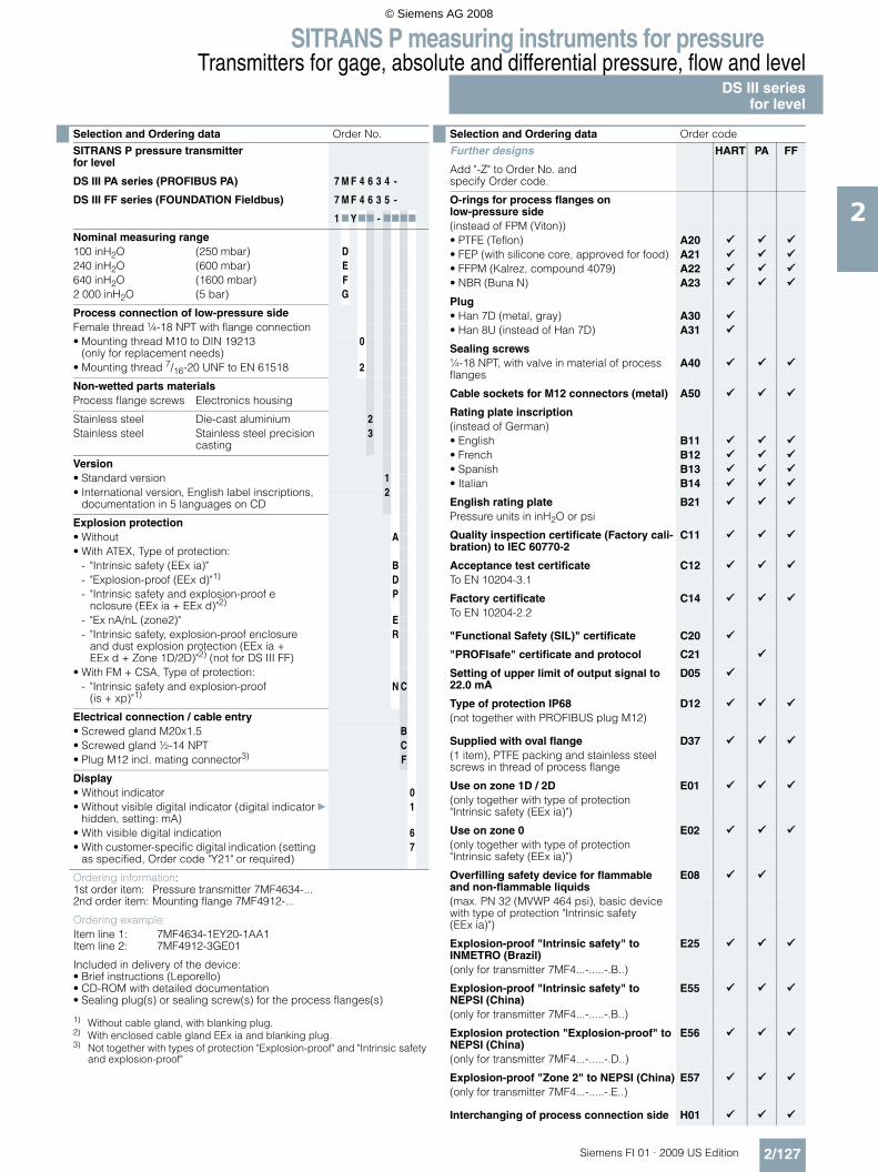
SITRANS P measuring instruments for pressureTransmitters for gage, absolute and differential pressure, flow and level
DS III seriesfor level
2/127Siemens FI 01 · 2009 US Edition
2
Selection and Ordering data Order No.
SITRANS P pressure transmitter for level
DS III PA series (PROFIBUS PA) 7 M F 4 6 3 4 -
DS III FF series (FOUNDATION Fieldbus) 7 M F 4 6 3 5 -
1 7 Y77 - 7777
Nominal measuring range100 inH2O (250 mbar) D240 inH2O (600 mbar) E640 inH2O (1600 mbar) F2 000 inH2O (5 bar) G
Process connection of low-pressure sideFemale thread ¼-18 NPT with flange connection• Mounting thread M10 to DIN 19213
(only for replacement needs)0
• Mounting thread 7/16-20 UNF to EN 61518 2
Non-wetted parts materialsProcess flange screws Electronics housing
Stainless steel Die-cast aluminium 2Stainless steel Stainless steel precision
casting3
Version• Standard version 1• International version, English label inscriptions,
documentation in 5 languages on CD2
Explosion protection• Without A• With ATEX, Type of protection:
- "Intrinsic safety (EEx ia)" B- "Explosion-proof (EEx d)"1)
1) Without cable gland, with blanking plug.
D- "Intrinsic safety and explosion-proof e
nclosure (EEx ia + EEx d)"2)
2) With enclosed cable gland EEx ia and blanking plug.
P
- "Ex nA/nL (zone2)" E- "Intrinsic safety, explosion-proof enclosure
and dust explosion protection (EEx ia + EEx d + Zone 1D/2D)"2) (not for DS III FF)
R
• With FM + CSA, Type of protection:- "Intrinsic safety and explosion-proof
(is + xp)"1)N C
Electrical connection / cable entry• Screwed gland M20x1.5 B• Screwed gland ½-14 NPT C• Plug M12 incl. mating connector3)
3) Not together with types of protection "Explosion-proof" and "Intrinsic safety and explosion-proof"
F
Display• Without indicator 0• Without visible digital indicator (digital indicator
hidden, setting: mA)} 1
• With visible digital indication 6• With customer-specific digital indication (setting
as specified, Order code "Y21" or required)7
Ordering information: 1st order item: Pressure transmitter 7MF4634-...2nd order item: Mounting flange 7MF4912-...
Ordering example:Item line 1: 7MF4634-1EY20-1AA1Item line 2: 7MF4912-3GE01
Included in delivery of the device:• Brief instructions (Leporello)• CD-ROM with detailed documentation• Sealing plug(s) or sealing screw(s) for the process flanges(s)
Selection and Ordering data Order code
Further designs HART PA FF
Add "-Z" to Order No. and specify Order code.
O-rings for process flanges on low-pressure side(instead of FPM (Viton))• PTFE (Teflon) A20• FEP (with silicone core, approved for food) A21• FFPM (Kalrez, compound 4079) A22• NBR (Buna N) A23
Plug• Han 7D (metal, gray) A30• Han 8U (instead of Han 7D) A31
Sealing screws¼-18 NPT, with valve in material of process flanges
A40
Cable sockets for M12 connectors (metal) A50
Rating plate inscription(instead of German)• English B11• French B12• Spanish B13• Italian B14
English rating plate B21Pressure units in inH2O or psi
Quality inspection certificate (Factory cali-bration) to IEC 60770-2
C11
Acceptance test certificate C12To EN 10204-3.1
Factory certificate C14To EN 10204-2.2
"Functional Safety (SIL)" certificate C20
"PROFIsafe" certificate and protocol C21
Setting of upper limit of output signal to 22.0 mA
D05
Type of protection IP68 D12(not together with PROFIBUS plug M12)
Supplied with oval flange D37(1 item), PTFE packing and stainless steel screws in thread of process flange
Use on zone 1D / 2D E01(only together with type of protection "Intrinsic safety (EEx ia)")
Use on zone 0 E02(only together with type of protection "Intrinsic safety (EEx ia)")
Overfilling safety device for flammable and non-flammable liquids
E08
(max. PN 32 (MVWP 464 psi), basic device with type of protection "Intrinsic safety (EEx ia)")
Explosion-proof "Intrinsic safety" to INMETRO (Brazil)
E25
(only for transmitter 7MF4...-.....-.B..)
Explosion-proof "Intrinsic safety" to NEPSI (China)
E55
(only for transmitter 7MF4...-.....-.B..)
Explosion protection "Explosion-proof" to NEPSI (China)
E56
(only for transmitter 7MF4...-.....-.D..)
Explosion-proof "Zone 2" to NEPSI (China) E57(only for transmitter 7MF4...-.....-.E..)
Interchanging of process connection side H01
© Siemens AG 2008

SITRANS P measuring instruments for pressureTransmitters for gage, absolute and differential pressure, flow and levelDS III seriesfor level
2/128 Siemens FI 01 · 2009 US Edition
2
Additional data HART PA FF
Add "-Z" to Order No. and specify Order code.
Measuring range to be set Y01Specify in plain text (max. 5 digits):Y01: ... up to ... mbar, bar, kPa, MPa, psi
Measuring point number (TAG No.) Y15Max. 16 characters, specify in plain text:Y15: ...........................................
Measuring point text Y16Max. 27 characters, specify in plain text:Y16: ...........................................
Entry of HART address (TAG) Y17Max. 8 characters, specify in plain text:Y17: ...........................................
Setting of pressure indicator in pressure units
Y21
Specify in plain text (standard setting: mA):Y21: mbar, bar, kPa, MPa, psi, ...Note:The following pressure units can be selected:bar, mbar, mm H2O*), inH2O*), ftH2O*), mmHG, inHG, psi, Pa, kPa, MPa, g/cm2, kg/cm2, Torr, ATM or % *) ref. temperature 20 °C
Setting of pressure indicator in non-pressure units
Y221)
+ Y01Specify in plain text:Y22: ..... up to ..... l/min, m3/h, m, USgpm, ...(specification of measuring range in pressure units "Y01" is essential, unit with max. 5 characters)
Preset bus address Y25(possible between 1 and 126)Specify in plain text:Y25: .....................
Only "Y01", "Y21", "Y22", "Y25" and "D05" can be factory preset
= available
1) Not together with over-filling safety device for flammable and non-flammable liquids (Order code "E08")
Selection and Ordering data Order code Selection and Ordering data Order No.Ord. code
Mounting flange 7 M F 4 8 1 2 -
Directly mounted on the SITRANS P pressure transmitter (converter part) for level, for DS III series
3 7777 777
Connection acc. to EN 1092-1Nom. diam. Nom. press.DN 80 PN 40 DDN 100 PN 16 G
PN 40 H
Connection acc. to ASME B16.5Nom. diam. Nom. press.3 inch Class 150 Q
Class 300 R4 inch Class 150 T
Class 300 UOther version, addOrder code and plain text:Nominal diameter: ...; Nominal pressure: ...
Z J 1 Y
Wetted parts materials• Stainless steel 316L A
- Coated with PFA D- Coated with PTFE E 0- Coated with ECTFE1)
1) For vacuum on request
F
• Monel 400, mat. No. 2.4360 G• Hastelloy B2, mat. No. 2.4617 H• Hastelloy C276, mat. No. 2.4819 J• Hastelloy C4, mat. No. 2.4610 U• Tantalum K
Other version, addOrder code and plain text:material of parts in contact with the medium: ...Sealing face, see "Technical specifications"
Z K 1 Y
Tube length• Without 0• 50 mm (1.97 inch) 1• 100 mm (3.94 inch) 2• 150 mm (5.90 inch) 3• 200 mm (7.87 inch) 4Other version: addOrder code and plain text:Tube length: ...
9 L 1 Y
Filling liquid• Silicone oil M5 1• Silicone oil M50 2• High-temperature oil 3• Halocarbon oil (for O2 measurements) 4• Glycerin / water2)
2) Not suitable for use in low-pressure range
6• Food oil (FDA-listed) 7
Other version, addOrder code and plain text:filling liquid: ...
9 M 1 Y
© Siemens AG 2008
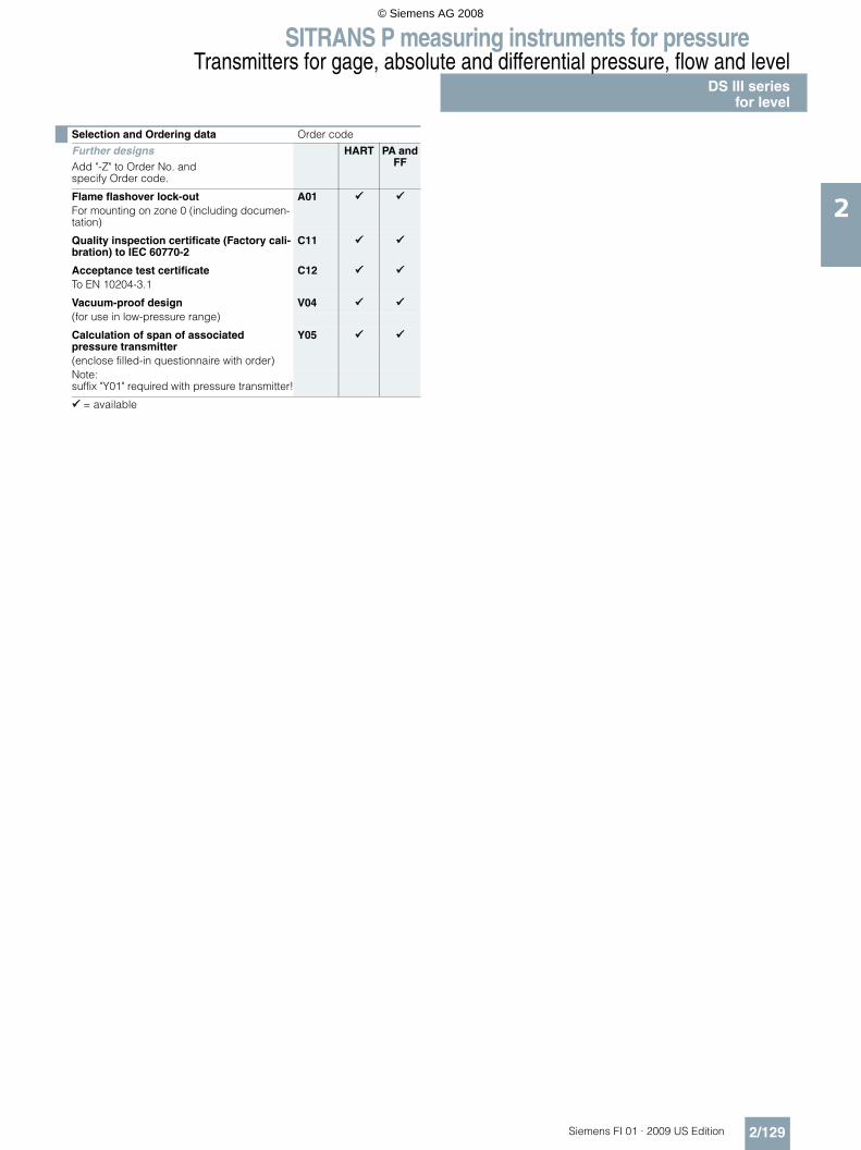
SITRANS P measuring instruments for pressureTransmitters for gage, absolute and differential pressure, flow and level
DS III seriesfor level
2/129Siemens FI 01 · 2009 US Edition
2
Selection and Ordering data Order code
Further designsAdd "-Z" to Order No. and specify Order code.
HART PA and FF
Flame flashover lock-out A01For mounting on zone 0 (including documen-tation)
Quality inspection certificate (Factory cali-bration) to IEC 60770-2
C11
Acceptance test certificate C12To EN 10204-3.1
Vacuum-proof design V04(for use in low-pressure range)
Calculation of span of associated pressure transmitter
Y05
(enclose filled-in questionnaire with order)Note:suffix "Y01" required with pressure transmitter!
= available
© Siemens AG 2008

SITRANS P measuring instruments for pressureTransmitters for gage, absolute and differential pressure, flow and levelDS III seriesfor level
2/130 Siemens FI 01 · 2009 US Edition
2
■ Dimensional drawings
SITRANS P pressure transmitters, DS III HART series for level, including mounting flange, dimensions in mm (inch)
Connection to EN 1092-1
Connection to ASME B16.5
d: Internal diameter of gasket to DIN 2690dM: Effective diaphragm diameter
1) 89 mm = 3½ inch with tube length L = 0.
8/7
<
�
7��0��81
��
!
C
�
8�/�0���71
�
78
�
��=�
/
781�81
<
8<7�0<�71
�
9
781
4%&*��! ��� '&'" � !�- $�"�#
&%%� =� ����08�8/171
8���0��9�1
&%%� =��9<�0��6/1
8���07�<61780���1 6��0��91
870��<1
9��0��<1�1
8 �� *����* ���*'" �� !�( ,�%����$����" ��H)8/�:�;�0�:�<8�78/1� 3(&��"�#�%($#� �(�*'�"*&(�* ���*'" �G
�*��,� �#(&� ��#�8��7�0& &%'��1��1��1��*��,� �#(&� ���=8�7���*��,� �#(&� �2)8��:�;� ��&��6����&��/��%($#��1��1
� ;���"�&(��" �7 �(�*'� �"*���" ��� "#"'&(� "�%(&��0( �#��� +��&((�(��#'-�! ��* +���,"'-�,"� ,1< �� '�*'"+��* +��� +�������/ 4�&("�#��*��,�,"'-�+&(+��0 %'" �19 4*��,�* +����&!�'��C�&*��'�0 �(��! ��'�%�� !�%� '�*'" ��I�=%( �" �)%� !���*( �$��I�
� '��- ,��"��'-�� �&,"�#1
81 �(( ,�&%%� =��������0��69�"�*-1�'-��& �(��#'-�"��& "'" ��1 : '�,"'-�'�%�� !�%� '�*'" ��I�=%( �" �)%� !���*( �$��I�1 : '�,"'-�'�%�� !�%� '�*'" ��I?�D��4��J"��D�=%KI�1 9�����0��<��"�*-1�! ���"�"�$�� "�'&�*��' �%���"'�� '&'" ��,"'- $'�"� "*&' �71 �%%� =���7����08�66�"�*-1�! ���#�8��7�,"'-�& &%'��
Nom. diam. Nom. press. b D d d2 d4 d5 dM f k n L
mm mm mm mm mm mm mm mm mm mm mm
DN 80 PN 40 24 200 90 18 138 76 721) 2 160 8 0, 50, 100, 150 or 200DN 100 PN 40 20 220 115 18 158 94 89 2 180 8
PN 40 24 235 115 22 162 94 89 2 190 8
Nom. diam. Nom. press. b D d2 d4 d5 dM f k n L
lb/sq.in. inch inch inch inch inch inch inch inch inch
(mm) (mm) (mm) (mm) (mm) (mm) (mm) (mm) (mm)
3 inch 150 0.94(23.8)
7.5(190.5)
0.75(19.0)
5(127)
3(76)
2.811)
(72)0.06(1.6)
6(152.4)
4 0, 2, 3.94, 5.94 or 7.87(0, 50, 100, 150 or 200)
300 1.12(28.6)
8.25(209.5)
0.87(22.2)
5(127)
3(76)
2.811)
(72)0.06(1.6)
6.69(168.3)
8
4 inch 150 0.94(23.8)
9(228.5)
0.75(19.0)
6.19(157.2)
3.69(94)
3.5(89)
0.06(1.6)
7.5(190.5)
8
300 1.25(31.7)
10(254)
0.87(22.2)
6.19(157.2)
3.69(94)
3.5(89)
0.06(1.6)
7.88(200)
8
© Siemens AG 2008

SITRANS P measuring instruments for pressureTransmitters for gage, absolute and differential pressure, flow and level
DS III seriesfor level
2/131Siemens FI 01 · 2009 US Edition
2
SITRANS P pressure transmitters, DS III PA and FF series for level, including mounting flange, dimensions in mm (inch)
Connection to EN 1092-1
Connection to ASME B16.5
d: Internal diameter of gasket to DIN 2690dM: Effective diaphragm diameter
1) 89 mm = 3½ inch with tube length L = 0.
8/7
<
�
7��0��81
��
!
C
�
8�/�0���71
�
7
8
�
��=�
/
781�81
<
8<7�0<�71
9
781
4%&*��! ��� '&'" � !�- $�"�#
&%%� =�����08�8/1
8���0��9�1 8���07�<61780���1 6��0��91
870��<1
9��0��<1�1
8 �� *����* ���*'" �� !�( ,�%����$����" ��H)8/�:�;�0�:�<878/1� 3(&��"�#�%($#� �(�*'�"*&(�* ���*'" �G
)��*��,� �* ���*'" ����=8�7��1�)��*��,� �* ���*'" ��2)8��:�;� �)����?�3�4�%($#�8���1��1
� ;���"�&(��" �7 �(�*'� �"*���" ��� "#"'&(� "�%(&��0( �#��� +��&((�(��#'-�! ��* +���,"'-�,"� ,1< �� '�*'"+��* +��� +�������/ 4�&("�#��*��,�,"'-�+&(+��0 %'" �19 4*��,�* +����&!�'��C�&*��'�0 �(��! ��I�=%( �" �)%� !���*( �$��I�
� '��- ,��"��'-�� �&,"�#1
81 �(( ,�&%%� =��������0��69�"�*-1�'-��& �(��#'-�"��& "'" ��1 : '�,"'-�'�%�� !�%� '�*'" ��I�=%( �" �)%� !���*( �$��I�1 : '�,"'-�'�%�� !�%� '�*'" ��I?�D��4��J"��D�=%KI�1 9�����0��<��"�*-1�! ���"�"�$�� "�'&�*��' �%���"'�� '&'" ��,"'-�"� "*&' �
Nom. diam. Nom. press. b D d d2 d4 d5 dM f k n L
mm mm mm mm mm mm mm mm mm mm mm
DN 80 PN 40 24 200 90 18 138 76 721) 2 160 8 0, 50, 100, 150 or 200
DN 100 PN 40 20 220 115 18 158 94 89 2 180 8
PN 40 24 235 115 22 162 94 89 2 190 8
Nom. diam. Nom. press. b D d2 d4 d5 dM f k n L
lb/sq.in. inch inch inch inch inch inch inch inch inch
(mm) (mm) (mm) (mm) (mm) (mm) (mm) (mm) (mm)
3 inch 150 0.94(23.8)
7.5(190.5)
0.75(19.0)
5(127)
3(76)
2.811)
(72)0.06(1.6)
6(152.4)
4 0, 2, 3.94, 5.94 or 7.87(0, 50, 100, 150 or 200)
300 1.12(28.6)
8.25(209.5)
0.87(22.2)
5(127)
3(76)
2.811)
(72)0.06(1.6)
6.69(168.3)
8
4 inch 150 0.94(23.8)
9(228.5)
0.75(19.0)
6.19(157.2)
3.69(94)
3.5(89)
0.06(1.6)
7.5(190.5)
8
300 1.25(31.7)
10(254)
0.87(22.2)
6.19(157.2)
3.69(94)
3.5(89)
0.06(1.6)
7.88(200)
8
© Siemens AG 2008

SITRANS P measuring instruments for pressureSITRANS P Accessories
Supplementary electronics for 4-wire connection
2/132 Siemens FI 01 · 2009 US Edition
2
■ Overview
SITRANS P pressure transmitter with supplementary electronics for 4-wire connection
Direct connection of the supplementary electronics to a SITRANS P pressure transmitter from the DS III HART series pro-duces a transmitter for four-wire connection.
The supplementary electronics cannot be attached to explosion-protected pressure transmitters. The supplementary electronics is fitted in a light metal housing which is mounted on the left side of the pressure transmitter.
Note on ordering:
The supplementary electronics has to be be ordered through the supplementary options of the pressure transmitter in question.
■ Technical specifications
■ Dimensional drawings
SITRANS P pressure transmitters with supplementary electronics for four-wire connection, dimension drawing, dimensions in mm (inch)
■ Schematics
Supplementary electronics for 4-wire connection, connection diagram
SITRANS P, supplementary electronics for 4-wire connection
Output
Output signal 0 ... 20 mA or 4 ... 20 mA
Load Max. 750 Ω
Voltage measurement Linear (square-rooting in transmit-ter if necessary)
Electrical isolation Between power supply and input/ output
Measuring accuracy To EN 60770-1
Conformity error (in addition to transmitter)
≤ 0.15% of set span
Influence of ambient temperature ≤ 0.1% per 10 K
Power supply effect ≤ 0.1% per 10% change in volt-age or frequency
Load effect ≤ 0.1% per 100% change
Rated conditions
Ambient temperature -20 ... +80 °C (-4 ... +176 °F)
Storage temperature -50 ... +85 °C (-58 ... +185 °F)
Degree of protection IP54 to EN 60529
Electromagnetic compatibility (EMC)
EN 50081, EN 50082
Design
Dimensions (W x H x D) in mm (inch)
80 x 120 x 60 (3.15 x 4.72 x 2.36)
Electrical connection Screw terminals (Pg 13.5 cable inlet) or Han 7D / Han 8U plug
Power supply
Supply voltage 230 V AC (-10 ... +6%, 47 ... 63 Hz, approx. 6 VA) or 24 V AC/DC (24 V AC ± 10%, 47 ... 63 Hz, approx. 3 VA)
Permissible ripple (within the speci-fied limits)
Approx. 2.5 Vpp
� �
&+
1
3 4
� �
&+
1
3 4 ��
�
��
� & + 1 3
��
� �
&+
1
3 4 ��
� �
�� � �8
�� � 8
��
�8
�/��0�����
��8,9�6�:4;�����
�������
,"��&��*�"��+�*
8���4;8���4;
8���4;8���6�
�� �� �� ������ �� �� � �'����� )��!� � �8 ����������
© Siemens AG 2008

SITRANS P measuring instruments for pressureSITRANS P Accessories
Supplementary electronics for 4-wire connection
2/133Siemens FI 01 · 2009 US Edition
2
Selection and Ordering data Order code
Supplementary electronics for 4-wire connection
V77
Order No. of the transmitter7MF4.33-.....-1AB. add "-Z" and Order code.
Power supply Electrical connection24 V AC/DC Terminals; 2 Pg screwed
glands, to left1
2 Han 7D/Han 8U plugs incl. mating connector, to left
3
1 Han 7D plug incl. mating connector, angled
5
Terminals; 1 Pg screwed gland, downwards
6
1 Han 8U plug incl. mating connector, downwards (observe arrangement of plug and differential pressure line)
9
230 V AC Terminals; 2 Pg screwed glands, to left
7
2 Han 7D plugs incl. mating connector, to left
8
Output current0 ... 20 mA 04 ... 20 mA 1
Selection and Ordering data Order No.
Accessories
Instruction ManualGerman/English
E86060-K6017-A131-A3
© Siemens AG 2008

SITRANS P measuring instruments for pressureSITRANS P AccessoriesAccessories / spare parts for SITRANS PP300 and DS III series
2/134 Siemens FI 01 · 2009 US Edition
2
F) Subject to export regulations AL: 9I999, ECCN: N.
Selection and Ordering data Order No.
Replacement measuring cell for pressurefor SITRANS P, DS III, DS III PA and DS III FF series
7 M F 4 9 9 0 -
7777 0 - 0 D C 0
Measuring cell filling Measuring cell cleaningSilicone oil Standard 1Inert liquid Grease-free 3
Measured span0.15 ... 14.5 psi g (0.01 ... 1 bar g) B0.6 ... 58 psi g (0.04 ... 4 bar g) C2.32 ... 232 psi g (0.16 ... 16 bar g) D9.14 ... 914 psi g (0.63 ... 63 bar g) E23.2 ... 2320 psi g (1.6 ... 160 bar g) F58.0 ... 5802 psi g (4.0 ... 400 bar g) G
Wetted parts materialsSeal diaphragm Process connection
Stainless steel Stainless steel AHastelloy Stainless steel BHastelloy Hastelloy C
Process connection• Connection shank G½B to EN 837-1 0• Female thread ½-14 NPT 1• Oval flange made of stainless steel,
max. span 160 bar (2320 psi)- Mounting thread 7/16-20 UNF to EN 61518 2- Mounting thread M10 to DIN 19213 3
Further designs Order code
Please add "-Z" to Order No. and specify Order code.
Acceptance test certificate C12to EN 10204-3.1
Selection and Ordering data Order No.
Replacement measuring cell for absolute pressure (from the pressure series)for SITRANS P, DS III, DS III PA and DS III FF series
F) 7 M F 4 9 9 2 -
7777 0 - 0 D C 0
Measuring cell filling Measuring cell cleaningSilicone oil Standard 1Inert liquid Grease-free 3
Measured span0.12 ... 3.63 psi a (8.3 ... 250 mbar a) D0.62 ... 18.9 psi a (43 ... 1300 mbar a) F2.32 ... 72.5 psi a (0.16 ... 5 bar a) G14.5 ... 435 psi a (1 ... 30 bar a) H
Wetted parts materialsSeal diaphragm Process connection
Stainless steel Stainless steel AHastelloy Stainless steel BHastelloy Hastelloy C
Process connection• Connection shank G½B to EN 837-1 0• Female thread ½-14 NPT 1• Oval flange made of stainless steel,
max. span 160 bar (2320 psi)- Mounting thread 7/16-20 UNF to EN 61518 2- Mounting thread M10 to DIN 19213 3
Further designs Order code
Please add "-Z" to Order No. and specify Order code.
Acceptance test certificate C12to EN 10204-3.1
© Siemens AG 2008

SITRANS P measuring instruments for pressureSITRANS P Accessories
Accessories / spare parts for SITRANS PP300 and DS III series
2/135Siemens FI 01 · 2009 US Edition
2
E) Combinations of the versions marked with E) are subject to the export regulations AL: 2B230, ECCN: N.
F) Subject to export regulations AL: 9I999, ECCN: N.
Selection and Ordering data Order No.
Spare parts / Accessories
Replacement measuring cell for absolute pres-sure (from the differential construction) for SITRANS P, DS III, DS III PA and DS III FF series
F) 7 M F 4 9 9 3 -
77777 - 0 D C 0
Measuring cell filling Measuring cell cleaningSilicone oil Standard 1Inert liquid Grease-free 3
Measured span0.12 ... 3.63 psi a (8.3 ... 250 mbar a) E) D0.62 ... 18.9 psi a (43 ... 1300 mbar a) E) F2.32 ... 72.5 psi a (0.16 ... 5 bar a) E) G14.5 ... 435 psi a (1 ... 30 bar a) H76.9 ... 1450 psi a (5.3 ... 100 bar a) K E
Wetted parts materialsSeal diaphragm Parts of measuring cell
Stainless steel Stainless steel AHastelloy Stainless steel BHastelloy Hastelloy CTantalum Tantalum EMonel Monel E) HGold Gold L
Process connectionFemale thread ¼-18 NPT with flange connection• Sealing screw opposite process connection
- Mounting thread M10 to DIN 19213 0- Mounting thread 7/16-20 UNF to EN 61518 2
• Vent on side of process flange1)
1) Not for span "76.9 ... 1450 psi (5.3 ... 100 bar)"
- Mounting thread M10 to DIN 19213 4- Mounting thread 7/16-20 UNF to EN 61518 6
Non-wetted parts materials• Stainless steel process flange screws 2
Further designsPlease add "-Z" to Order No. and specify Order code.
Order code
O-rings for process flanges(instead of FPM (Viton))• PTFE (Teflon) A20• FEP (with silicone core, approved for food) A21• FFPM (Kalrez, compound 4079) A22• NBR (Buna N) A23
Acceptance test certificate C12to EN 10204-3.1
Process connection G½A D16
Remote seal flanges D20(not together with K01, K02 and K04)
Vent on side for gas measurements H02
Process flanges• without K00• with process flange made of
- Hastelloy K01- Monel K02- Stainless steel with PVDF insert
max. PN 10 (MWP 145 psi)max. temperature of medium 90 °C (194 °F)
K04
Selection and Ordering data Order No.
Spare parts / Accessories
Replacement measuring cell for differential pressure and MWP 464/2320 psi (PN 32/160) for SITRANS P, DS III, DS III PA and DS III FF series
7 M F 4 9 9 4 -
77777 - 0 D C 0
Measuring cell filling Measuring cell cleaningSilicone oil Standard 1Inert liquid Grease-free 3
Measured spanMWP 464 psi (PN 32)0.4 ... 8 inH2O1)
1) Not suitable for connection of remote seal
(1 ... 20 mbar) B
MWP 2320 psi (PN 160)0.4 ... 24 inH2O (1 ... 60 mbar) C1 ... 100 inH2O (2.5 ... 250 mbar) D2.4 ... 240 inH2O (6 ... 600 mbar) E16.4 ... 642 inH2O (6 ... 1600 mbar) F20 ... 2000 inH2O (50 ... 5000 mbar) G4.35 ... 435 psi (0.3 ... 30 bar) H
Wetted parts materials(stainless steel process flanges)
Seal diaphragm Parts of measuring cell
Stainless steel Stainless steel AHastelloy Stainless steel BHastelloy Hastelloy CTantalum2)
2) Only together with max. spans 3.63, 23.2, 72.5 and 435 psi (250, 1600, 5000 and 30000 mbar).
Tantalum EMonel2) Monel HGold2) Gold L
Process connectionFemale thread ¼-18 NPT with flange connection• Sealing screw opposite process connection
- Mounting thread M10 to DIN 19213 0- Mounting thread 7/16-20 UNF to EN 61518 2
• Vent on side of process flange- Mounting thread M10 to DIN 19213 4- Mounting thread 7/16-20 UNF to EN 61518 6
Non-wetted parts materialsStainless steel process flange screws 2
Further designsPlease add "-Z" to Order No. and specify Order code.
Order code
O-rings for process flanges(instead of FPM (Viton))• PTFE (Teflon) A20• FEP (with silicone core, approved for food) A21• FFPM (Kalrez, compound 4079) A22• NBR (Buna N) A23
Acceptance test certificate C12to EN 10204-3.1
Remote seal flanges D20(not together with K01, K02 and K04)
Vent on side for gas measurements H02
Stainless steel process flanges for vertical differential pressure lines
H03
(not together with K01, K02 and K04)
Process flanges• without K00• with process flange made of
- Hastelloy K01- Monel K02- Stainless steel with PVDF insert
max. PN 10 (MWP 145 psi)max. temperature of medium 90 °C (194 °F)
K04
© Siemens AG 2008

SITRANS P measuring instruments for pressureSITRANS P AccessoriesAccessories / spare parts for SITRANS PP300 and DS III series
2/136 Siemens FI 01 · 2009 US Edition
2
Selection and Ordering data Order No.
Spare parts / Accessories
Replacement measuring cell for differential pressure and MWP 6092 psi (PN 420) for SITRANS P, DS III, DS III PA and DS III FF series
7 M F 4 9 9 5 -
77777 - 0 D C 0
Measuring cell filling Measuring cell cleaningSilicone oil Standard 1
Measured span1 ... 100 inH2O (2.5 ... 250 mbar) D2.4 ... 240 inH2O (6 ... 600 mbar) E6.4 ... 642 inH2O (16 ... 1600 mbar) F20 ... 2000 inH2O (50 ... 5000 mbar) G4.35 ... 435 psi (0.3 ... 30 bar) H
Wetted parts materials(stainless steel process flanges)
Seal diaphragm Parts of measuring cell
Stainless steel Stainless steel AHastelloy Stainless steel BGold1)
1) Not together with max. span 240.9 inH2O (600 mbar)
Gold L
Process connectionFemale thread ¼-18 NPT with flange connection• Sealing screw opposite process connection
- Mounting thread M12 to DIN 19213 1
- Mounting thread 7/16-20 UNF to EN 61518 3
• Vent on side of process flange- Mounting thread M12 to DIN 19213 5
- Mounting thread 7/16-20 UNF to EN 61518 7
Non-wetted parts materials• Stainless steel process flange screws 2
Further designs Order code
Please add "-Z" to Order No. and specify Order code.
O-rings for process flanges(instead of FPM (Viton))• PTFE (Teflon) A20• FEP (with silicone core, approved for food) A21• FFPM (Kalrez, compound 4079) A22• NBR (Buna N) A23
Acceptance test certificate C12to EN 10204-3.1
Stainless steel process flanges for vertical dif-ferential pressure lines
H03
without process flanges K00
Selection and Ordering data Order No.
Spare parts / Accessories
Replacement measuring cell for levelfor SITRANS P, DS III, DS III PA and DS III FF series
7 M F 4 9 9 6 -
77777 - 0 D C 0
Measuring cell filling Measuring cell cleaningSilicone oil Standard 1
Rated measuring range3.63 psi (250 mbar) D8.70 psi (600 mbar) E23.2 psi (1600 mbar) F72.5 psi (5 bar) G
Wetted parts materials(stainless steel process flanges)
Seal diaphragm Parts of measuring cell
Stainless steel Stainless steel A
Process connection of low-pressure sideFemale thread ¼-18 NPT with flange connection• Sealing screw opposite process connection
- Mounting thread M10 to DIN 19213 0
- Mounting thread 7/16-20 UNF to EN 61518 2
Non-wetted parts materials• Stainless steel process flange screws 2
Further designs Order code
Please add "-Z" to Order No. and specify Order code.
O-rings for process flanges(instead of FPM (Viton))• PTFE (Teflon) A20• FEP (with silicone core, approved for food) A21• FFPM (Kalrez, compound 4079) A22• NBR (Buna N) A23
Acceptance test certificate C12to EN 10204-3.1
without process flanges K00
© Siemens AG 2008

SITRANS P measuring instruments for pressureSITRANS P Accessories
Accessories / spare parts for SITRANS PP300 and DS III series
2/137Siemens FI 01 · 2009 US Edition
2
F) Subject to export regulations AL: 9I999, ECCN: N.
Selection and Ordering data Order No.
Spare parts / Accessories
Mounting bracket and mounting partsfor pressure transmittersDS III, DS III PA and DS III FF series(7MF403.-.....-..C.)for absolute pressure transmittersDS III, DS III PA and DS III FF series(7MF423.-.....-..C.)• made of steel 7MF4997-1AB• made of stainless steel 7MF4997-1AH
Mounting bracket and mounting partsfor pressure transmittersDS III, DS III PA and DS III FF series(7MF403.-.... .-..A., -..B. and -..D.)for absolute pressure transmittersDS III, DS III PA and DS III FF series(7MF423.-.... .-..A., -..B. and -..D.)• Made of steel 7MF4997-1AC• Made of stainless steel } 7MF4997-1AJ
Mounting bracket and mounting partsfor differential pressure transmitters with flange thread M10DS III, DS III PA and DS III FF series(7MF433.-... and 7MF443.-...)• made of steel 7MF4997-1AD• made of stainless steel } 7MF4997-1AK
Mounting bracket and mounting partsfor differential pressure transmitters with flange thread M12DS III, DS III PA and DS III FF series(7MF453.-...)• made of steel 7MF4997-1AE• made of stainless steel 7MF4997-1AL
Mounting bracket and mounting partsfor differential and absolute pressure trans-mitters with flange thread 7/16-20 UNFDS III, DS III PA and DS III FF series(7MF433.-..., 7MF443.-... and 7MF453.-...)• made of steel 7MF4997-1AF• made of stainless steel 7MF4997-1AM
CoverMade of die-cast aluminium, including gasket, for DS III, DS III PA and DS III FF series • without window F) 7MF4997-1BB• with window }
F)7MF4997-1BE
CoverMade of stainless steel, including gasket, for DS III, DS III PA and DS III FF series • without window F) 7MF4997-1BC• with window F) 7MF4997-1BF
Digital indicatorIncluding mounting materialfor DS III, DS III PA and DS III FF series
7MF4997-1BR
Measuring-point label• without inscription (5 off) 7MF4997-1CA• with inscription (1 off)
Data according to Y01 or Y02, Y15 and Y16 (see "SITRANS P pressure transmitters")
7MF4997-1CB-ZY..: ................
Mounting screws 7MF4997-1CDfor measuring-point label, earthing and con-nection terminals or for digital indicator (50 off)
Sealing screws(1 set = 2 off) for process flange• made of stainless steel 7MF4997-1CG• made of Hastelloy F) 7MF4997-1CH
Screw plug with valve (1 set = 2 off)• made of stainless steel } 7MF4997-1CP• made of Hastelloy F) 7MF4997-1CQ
Electronics• for DS III series 7MF4997-1DK• for DS III PA series 7MF4997-1DL• for DS III FF series 7MF4997-1DM
Connection board• for DS III series 7MF4997-1DN• for DS III PA and DS III FF series 7MF4997-1DP
O-rings for process flanges made of• FPM (Viton) F) 7MF4997-2DA• PTFE (Teflon) F) 7MF4997-2DB• FEP (with silicone core, approved for food) F) 7MF4997-2DC• FFPM (Kalrez, compound 4079) F) 7MF4997-2DD• NBR (Buna N) F) 7MF4997-2DE
Weldable sockets for PMC connectionfor DS III and P300 series• PMC Style Standard: Thread 1½“ 7MF4997-2HA• PMC Style Mini bolt: front-flush 1“ F) 7MF4997-2HB
Sealing rings for PMC connection(packing unit: 5 pcs)• Sealing ring made of PTFE for PMC Style
Standard: Thread 1½"F) 7MF4997-2HC
• Sealing ring made of Viton for PMC Style Minibolt: front-flush 1“
F) 7MF4997-2HD
Weldable socket for TG 52/50 and TG 52/150 connectionfor DS III and P300 series• TG 52/50 connection 7MF4997-2HE• TG 52/150 connection 7MF4997-2HF
Seals for TG 52/50 and TG 52/150 made of silicone
7MF4997-2HG
Seals for flange connection with flush-mounted diaphragmMaterial FPM (Viton), 10 units• DN 25, PN 40 (M11) F) 7MF4997-2HH• DN 25, PN 100 (M21) F) 7MF4997-2HJ• 1", class 150 (M40) F) 7MF4997-2HK• 1", class 300 (M45) F) 7MF4997-2HL
Mounting bracket and mounting parts for P300• Made of stainless steel 7MF8997-1AA
Lid without window for P300• Gasket not included 7MF8997-1BA
Lid with glass window for P300• Gasket not included 7MF8997-1BD
NBR housing gasket for P300 7MF8997-1BG
Measuring point label for P300• Unlabeled 7MF8997-1CA
Cable gland for P300• Metal 7MF8997-1EA• Plastic (blue) 7MF8997-1EB
} Available ex stock
Selection and Ordering data Order No.
© Siemens AG 2008

SITRANS P measuring instruments for pressureSITRANS P AccessoriesAccessories / spare parts for SITRANS PP300 and DS III series
2/138 Siemens FI 01 · 2009 US Edition
2
D) Subject to export regulations AL: N, ECCN: EAR99H.G) Subject to export regulations AL: N, ECCN: 5D992B1.
Selection and Ordering data Order No.
Instruction Manual1)
1) You can download the Instruction Manuals free-of-charge from the Internet site www.siemens.com/sitransp.
• for P300 series with HART communication- German A5E00359580- English A5E00359579- French A5E00359578- Spanish A5E00359576- Italian A5E00359577- Leporello German/English A5E00359581
• for P300 series with PROFIBUS PA communi-cation- German A5E00414587- English A5E00414588- French A5E00414589- Spanish A5E00414590- Italian A5E00414591- Leporello German/English A5E00414592
• for DS III series- German A5E00047090- English A5E00047092- French A5E00053218- Spanish A5E00053219- Italian A5E00053220
• for DS III PA series- German A5E00053275- English A5E00053276- French A5E00053277- Spanish A5E00053278- Italian A5E00053279
• for DS III FF series- German A5E00279627- English A5E00279629- French (planned) A5E00279630- Spanish (planned) A5E00279632- Italian (planned) A5E00279631
Brief instructions (Leporello)• for DS III series, German, English A5E00047093• for DS III PA series, German, English A5E00053274• for DS III FF series, German, English A5E00282355
CD with documentation G) A5E00090345for P300, DS III, DS III PA and DS III FF seriesGerman, English, French, Italian, Spanish
Instruction Manualfor replacement of electronics, measuring cell and connection board• German/English A5E00078060
HART modem• with RS232 interface }
D)7MF4997-1DA
• with USB interface }
D)7MF4997-1DB
Supplementary electronics for 4-wire connec-tion
see page 2/132
} Available ex stock
Power supply units see "SITRANS I power supply units and input isola-tors".
© Siemens AG 2008

SITRANS P measuring instruments for pressureSITRANS P Accessories
Accessories / spare parts for SITRANS PP300 and DS III series
2/139Siemens FI 01 · 2009 US Edition
2
■ Dimensional drawings
Mounting bracket for SITRANS P gage and absolute pressure transmitter, DS III seriesMaterial of mounting bracket: Sheet-steel Mat. No. 1.0330, chrome-plated, or stainless steel Mat. No. 1.4301 (304)
Mounting bracket for SITRANS P differential pressure transmitter, DS III series,Material of mounting bracket: Sheet-steel Mat. No. 1.0330, chrome-plated, or stainless steel Mat. No. 1.4301 (304)
© Siemens AG 2008

SITRANS P measuring instruments for pressureSITRANS P AccessoriesFactory-mounting of valve manifolds onSITRANS P transmitters
2/140 Siemens FI 01 · 2009 US Edition
2
■ Overview
SITRANS P transmitters• P300 for relative and absolute pressure,• DS III for relative and absolute pressure (both designs) and• DS III for differential pressure
can be delivered factory-fitted with the following valve manifolds:• 7MF9011-4EA and 7MF9011-4FA valve manifolds for relative
pressure and absolute pressure transmitters• 7MF9411-5BA and 7MF9411-5CA valve manifolds for abso-
lute pressure and differential pressure transmitters
■ Design
The 7MF9011-4EA valve manifolds are sealed with gaskets made of PTFE between transmitter and the valve manifold as standard. Soft iron, stainless steel and copper gaskets are also available for sealing purposes if preferred.
The 7MF9011-4FA valve manifolds are sealed with PTFE sealing tape between the transmitter and the valve manifold.
The 7MF9411-5BA and 7MF9411-5CA valve manifolds are sealed with PTFE sealing rings between the transmitter and the valve manifold.
Once installed, the complete unit is checked under pressure for leaks and is certified leak-proof with a factory certificate to EN 10204 - 2.2.
All valve manifolds should preferably be secured with the re-spective mounting brackets. The transmitters are mounted on the valve manifold and not on the unit itself.
If you order a mounting bracket when choosing the option "Fac-tory mounting of valve manifolds", you will receive a mounting bracket for the valve manifold instead of a bracket for mounting the transmitter.
If you order an acceptance test certificate 3.1 to EN10204 when choosing the option "Factory mounting of valve manifolds", a separate certificate is provided for the transmitters and the valve manifolds respectively.
■ Selection and Ordering data
7MF9011-4FA valve block on relative and absolute pressure transmitters
Add -Z to the Order No. of the transmitter and add order codes.
Order code
SITRANS P DSIII 7MF403.-...1.-..., 7MF423.-...1.-... andSITRANS P300 7MF802.-...1.-...With process connection female thread ½-14 NPT in-sealed with PTFE sealing stripDelivery incl. high-pressure test certified by factory certificate to EN10204-2.2
T03
7MF9011-4EA valve block on relative and absolute pressure transmitters
Add -Z to the Order No. of the transmitter and add order codes.
Order code
SITRANS P DSIII 7MF403.-...0.-..., 7MF423.-...0.-... andSITRANS P300 7MF802.-...0.-...
T02
with process connection collar G1/2 A to EN837-1 with gasket made of PTFE between valve manifold and transmitter
Alternative sealing material:
• soft iron A70
• stainless steel, Mat. No. 14571 A71
• copper A72
Delivery incl. high-pressure test certified by factory certificate to EN10204-2.2
Further designs:
Delivery includes mounting brackets and mounting clips made of stainless steel (instead of the mounting bracket sup-plied with the transmitter)
A02
Supplied acceptance test certificate to EN 10204- 3.1 for transmitters and mounted valve manifold
C12
Oil and grease-free cleaning for oxygen operation
E10
7MF9411-5BA valve manifold on absolute and differential pressure transmitters
Add -Z to the Order No. of the transmitter and add order codes.
Order code
SITRANS P DSIII 7MF433.-…, 7MF443.-… and 7MF453.-…1)
mounted with gaskets made of PTFE and screws made of
• chromized steel U01
• stainless steel U02
Delivery incl. high-pressure test certified by factory certificate to EN10204-2.2
7MF9411-5CA valve manifold on differential pressure transmitters
Add -Z to the Order No. of the transmitter and add order codes.
Order code
SITRANS P DSIII 7MF443.-... und 7MF453.-…1)
mounted with gaskets made of PTFE and screws made of
• chromized steel U03
• stainless steel U04
Delivery incl. high-pressure test certified by factory certificate to EN10204-2.2
Further designs:
Delivery includes mounting bracket and mounting clips made of
• steel A01
• stainless steel A02
(instead of the mounting bracket sup-plied with the transmitter)
Supplied acceptance test certificate to EN10204-3.1 for transmitters and mounted valve manifold
C12
Oil and grease-free cleaning for oxygen operation
E10
1) For 7MF453.-... transmitters, you require a 7/10-20 UNF connection thread in the process flange.
© Siemens AG 2008
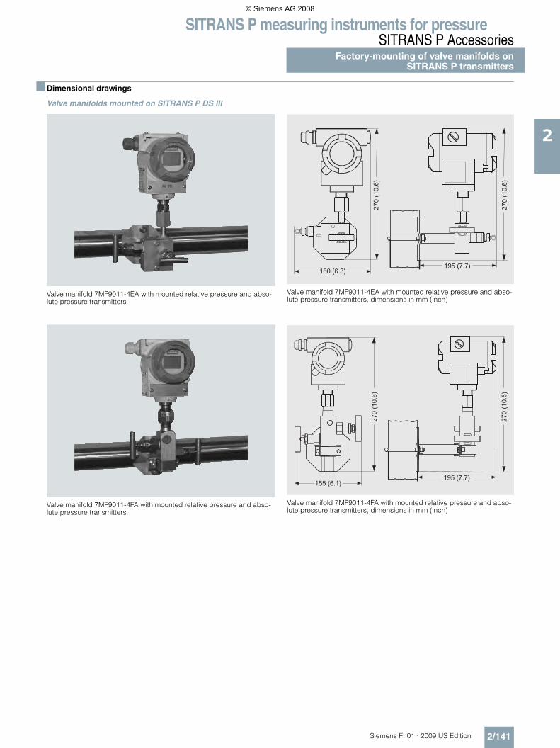
SITRANS P measuring instruments for pressureSITRANS P Accessories
Factory-mounting of valve manifolds onSITRANS P transmitters
2/141Siemens FI 01 · 2009 US Edition
2
■ Dimensional drawings
Valve manifolds mounted on SITRANS P DS III
Valve manifold 7MF9011-4EA with mounted relative pressure and abso-lute pressure transmitters
Valve manifold 7MF9011-4EA with mounted relative pressure and abso-lute pressure transmitters, dimensions in mm (inch)
Valve manifold 7MF9011-4FA with mounted relative pressure and abso-lute pressure transmitters
Valve manifold 7MF9011-4FA with mounted relative pressure and abso-lute pressure transmitters, dimensions in mm (inch)
© Siemens AG 2008

SITRANS P measuring instruments for pressureSITRANS P AccessoriesFactory-mounting of valve manifolds onSITRANS P transmitters
2/142 Siemens FI 01 · 2009 US Edition
2
Valve manifold 7MF9411-5BA with mounted differential pressure trans-mitter
Valve manifold 7MF9411-5CA with mounted differential pressure trans-mitter
Valve manifold 7MF9411-5BA with mounted differential pressure transmitter, dimensions in mm (inch)
Valve manifold 7MF9411-5CA with mounted differential pressure transmitter, dimensions in mm (inch)
© Siemens AG 2008

SITRANS P measuring instruments for pressureSITRANS P Accessories
Factory-mounting of valve manifolds onSITRANS P transmitters
2/143Siemens FI 01 · 2009 US Edition
2
Valve manifolds mounted on SITRANS P300
Valve manifold 7MF9011-4EA with mounted relative pressure and abso-lute pressure transmitters
Valve manifold 7MF9011-4EA with mounted relative pressure and abso-lute pressure transmitters, dimensions in mm (inch)
Valve manifold 7MF9011-4FA with mounted relative pressure and abso-lute pressure transmitters
Valve manifold 7MF9011-4FA with mounted relative pressure and abso-lute pressure transmitters, dimensions in mm
© Siemens AG 2008

SITRANS P measuring instruments for pressureTransmitters for hydrostatic level
MPS series (submersible sensor)
2/144 Siemens FI 01 · 2009 US Edition
2
■ Overview
SITRANS P pressure transmitters, MPS series (submersible sensor)
SITRANS P pressure transmitters, MPS series, are submersible sensors for hydrostatic level measurements.
The pressure transmitters of the MPS series are available for var-ious measuring ranges and with explosion protection as an op-tion.
A junction box and a cable hanger are available as accessories for simple installation.
■ Benefits
• Compact design• Simple installation• Small error in measurement (0.3%)• Degree of protection IP68
■ Application
SITRANS P pressure transmitters, MPS series, are used in the following branches for example:• Oil and gas industries• Shipbuilding• Water supply
■ Design
SITRANS P pressure transmitters, MPS series, have a flush-mounted piezo-resistive sensor with stainless steel diaphragm.
These pressure transmitters are equipped with an electronic cir-cuit fitted together with the sensor in a stainless steel housing. The cable also contains a strength cord and vent pipe.
The diaphragm is protected against external influences by a protective cap.
The sensor, electronic circuit and cable are sealed in a common housing of small dimensions.
The pressure transmitter is temperature-compensated for a wide temperature range.
■ Function
SITRANS P pressure transmitters, MPS series, are for measuring the liquid levels in wells, tanks, channels and dams.
SITRANS P pressure transmitters, MPS series, mode of operation and wiring diagram
On one side of the sensor, the diaphragm is exposed to the hy-drostatic pressure which is proportional to the submersion depth. This pressure is compared with atmospheric pressure. Pressure compensation is carried out using the vent pipe in the connection cable.
The hydrostatic pressure of the liquid column acts on the sensor diaphragm, and transmits the pressure to the piezo-resistive bridge in the sensor.
The output voltage of the sensor is applied to the electronic cir-cuit where it is converted into an output current of 4 to 20 mA.
The cable of the 7MF1570 transmitter must always be connected in the supplied junction box. The junction box has to be installed near the measuring point.
If the medium is anything other than water, it is also necessary to check compatibility with the specified materials of the transmit-ter.
■ Integration
Junction box 7MF1570-8AA, opened
�������
��� �
�� <= ���$-���%
����$-���%
*�� ����������
;���)���0
�����
© Siemens AG 2008

SITRANS P measuring instruments for pressureTransmitters for hydrostatic level
MPS series (submersible sensor)
2/145Siemens FI 01 · 2009 US Edition
2
Measuring point setup, in principle
■ Technical specifications
SITRANS P pressure transmitters, MPS series (submersible sensor)
Mode of operation
Measuring principle Piezo-resistive
Input
Measured variable Hydrostatic level
Measuring range Maximum working pressure
• 0 ... 6 ftH2O (0 ... 2 mH2O) • 20.3 psi (1.4 bar) (corresponds to 42 ftH2O (14 mH2O))
• 0 ... 12 ftH2O (0 ... 4 mH2O) • 20.3 psi (1.4 bar) (corresponds to 42 ftH2O (14 mH2O))
• 0 ... 15 ftH2O (0 ... 5 mH2O) • 20.3 psi (1.4 bar) (corresponds to 42 ftH2O (14 mH2O))
• 0 ... 18 ftH2O (0 ... 6 mH2O) • 43.5 psi (3.0 bar) (corresponds to 90 ftH2O (30 mH2O))
• 0 ... 30 ftH2O (0 ... 10 mH2O) • 43.5 psi (3.0 bar) (corresponds to 90 ftH2O (30 mH2O))
• 0 ... 60 ftH2O (0 ... 20 mH2O) • 87.0 psi (6.0 bar) (corresponds to 180 ftH2O (60 mH2O))
Output
Output signal 4 ... 20 mA
Accuracy To EN 60770-1
Error in measurement (including non-linearity, hysteresis and repeat-ability, at 25 °C (77 °F))
0.3% of full-scale value (typical)
Influence of ambient temperature
Zero and span
• 3 ... 18 ftH2O (1 ... 6 mH2O) 0.45%/10 K of full-scale value
• ≥ 18 ftH2O (≥ 6 mH2O) 0.3%/10 K of full-scale value
Long-term stability
Zero and span
• 1 ... 6 mH2O (3 ... 18 ftH2O) 0.25% of full-scale value/year
• ≥ 6 mH2O (≥ 18 ftH2O) 0.2% of full-scale value/year
Rated operating conditions
Ambient conditions
• Process temperature -10 ... +80 °C (+14 ... +176 °F)
• Storage temperature -40 ... +100 °C (-40 ... +212 °F)
Degree of protection to DIN EN 60529
IP68
Design
Weight
• Pressure transmitters ≈ 0.4 kg (≈ 0.88 lb)
• Cable 0.08 kg/m (≈ 0.054 lb/ft)
Electrical connection Cable with 2 conductors with screen and vent pipe, strength cord (max. 300 N (67.44 lbf)
Material
• Seal diaphragm Stainless steel, mat. No. 1.4571/316 Ti
• Casing Stainless steel, mat. No. 1.4571/316 Ti
• Gasket Viton
• Connecting cable OptionallyPE/HFFR sheath (non-halogen) orFEP sheath
Power supply
Terminal voltage on pressure trans-mitter (UB)
10 ... 36 V DC
Certificate and approvals
The transmitter is not subject to the pressure equipment directive (DGRL 97/23/EC)
Explosion protection
• Intrinsic safety "i" TÜV 03 ATEX 2004X
- Identification Ex II 1 G EEx ia IIC T4
Junction box
Application For connecting the transmitter cable
Design
Weight 0.2 kg (0.44 lb)
Electrical connection 2 x 3-way (28 ... 18 AWG)
Cable entry 2 x M20x1.5
Enclosure material Polycarbonate
Vent pipe for atmospheric pressure
Screw for cable strength cord
Rated operating conditions
Degree of protection to DIN EN 60529
IP54
Cable hanger
Application For mounting the transmitter
Design
Weight 0.16 kg (0.35 lb)
Material Galvanized steel, polyamide
© Siemens AG 2008

SITRANS P measuring instruments for pressureTransmitters for hydrostatic level
MPS series (submersible sensor)
2/146 Siemens FI 01 · 2009 US Edition
2
C) Subject to export regulations AL: N, ECCN: EAR99.D) Subject to export regulations AL: N, ECCN: EAR99H.
■ Dimensional drawings
SITRANS P pressure transmitters, MPS series, dimensions in mm (inch)
Junction box, dimensions in mm (inch)
Cable hanger, dimensions in mm (inch)
Selection and Ordering data Order No.
SITRANS P pressure transmittersfor pressure, MPS series (submers-ible sensor)
C) 7 M F 1 5 7 0 - 77A 0 7 777
2-wire system
Note: Junction box and cable hanger included in delivery
Cable materialPE } 1FEP 5
Measuring range Cable length L0 ... 2 mH2O 10 m } C0 ... 4 mH2O 10 m } D0 ... 5 mH2O 25 m } B0 ... 6 mH2O 25 m } E0 ... 10 mH2O 25 m } F0 ... 20 mH2O 25 m } G
0 ... 6 ftH2O 32 ft K0 ... 12 ftH2O 32 ft L0 ... 18 ftH2O 82 ft M0 ... 30 ftH2O 82 ft N0 ... 60 ftH2O 82 ft P
Special measuring range/Special cablelength1)
Specify measuring range and cable length in plain text
1) Special measuring ranges between 0 ... 3 ftH2O (0 ... 1 mH2O)and 0 ... 656 ftH2O (0 ... 200 mH2O) and special cable lengths up to 3281ft (1000 m) are possible. With Ex versions the max.special cable length is 150 ft (50 m). The length of free-hanging cable should not exceed 1230ft (375 m).
Z J 1 Y
Explosion protection
• without }1
• with, type of protection "Intrinsic safe-ty" (Ex II 1 G EEx ia IIC T4)
} 2
• With approval for drinking water to WRAS and ACS
}
D)6
Further designs Order code
Quality inspection certificate (Factory calibration) to IEC 60770-2, add "-Z" to Order No. and Order code.
C11
Order No.
Quality inspection certificate (Factory calibration) to IEC 60770-2 supplied later, specify factory no. of transmitter for this porpose.
7MF1564-8CC11
Accessories (as spare parts)
Junction box 7MF1570-8AAfor connecting the transmitter cable
Cable hanger 7MF1570-8ABfor mounting the pressure transmitter
} Available ex stockPower supply units see "SITRANS I power supply units and input isola-tors".
��$-���%
��$-���%
�����
*�� �����
�� � �'����
�16�$3��% �
>��4
$���
!��0
�%
"�-����)�� )�6�&�$��&&%�!��0��$-��.���-������<:8((�%(��?�-����-����� )���1�00���$�����46���)�%������� ��*�� ��������$���+%�!��0��$������!��0� ��%�� � �'������� )�+�?�&�!��0��$+�?������!��0�%�)����$-��.���,%
"�-����)�� )
� ���� )�!�$�)� �%
Ventingvalve
57 (2.25)
Mountinghole
50 (1.97)
79 (3
.1)
30 (1.2
)
94 (3
.7)
65 (2.56)
M20x1.5
22(0.87)
M20x1.5
22(0.87)
30 (1.2
)
© Siemens AG 2008

SITRANS P measuring instruments for pressureTransmitters for hydrostatic level
MPS series (submersible sensor)
2/147Siemens FI 01 · 2009 US Edition
2
■ More information
Determination of the measuring range in case of media with a density ≠ 1000 kg/m3 (medium ≠ water)
Calculation of the measuring range:
p = ρ x g x H
with:
ρ = density of medium
g = local acceleration due to gravity
H = maximum level
Example:
Medium: Diesel fuel = 850 kg/m3
Acceleration due to gravity: 9.81 m/s2
Start-of-scale : 0 m
Maximum level: 6.2 m
Calculation:
p = 850 kg/m3 x 9.81 m/s2 x 6.2 m
p = 51698.7 N/m2
p = 517 mbar
Transmitter to be ordered:
7MF1570-5ZA02-Z
J1Y: 0 ... 517 mbar; able length e.g. 8 m
ρ
© Siemens AG 2008

SITRANS P measuring instruments for pressureRemote seals for transmitters and pressure gauges
Introduction
2/148 Siemens FI 01 · 2009 US Edition
2
■ Application
The remote seals 7MF48.. can be fitted to SITRANS P transmit-ters for• pressure (7MF4033 and 7MF4034),• absolute pressure (7MF4233, 7MF4234, 7MF4333,
7MF4334) and• differential pressure and flow (7MF4433 and 7MF4434).
■ Design and mode of operation
A remote seal system consists of a transmitter, one or two remote seals, an appropriate transmission liquid, and a connection be-tween the transmitter and remote seal (direct mounting or capil-lary).
The volume in contact with the measured medium is defined by an flexible diaphragm. The volume between this diaphragm and the pressure transmitter is completely filled with a transmission fluid. If a pressure is now applied to the remote seal, this is trans-mitted via the flexible diaphragm and the fill fluid to the pressure transmitter.
In many cases, a capillary is located between the remote seal and the pressure transmitter in order e.g. to minimize tempera-ture effects from the hot medium on the latter. However, the cap-illary line influences the response time and the temperature re-sponse of the complete remote seal system. When fitting remote seals to differential pressure transmitters, two capillaries of the same length must always be used.
■ Fields of use
Remote seal systems should be used if a separation between the measured medium and the measuring instrument is appro-priate or essential for the following reasons:• The temperature of the medium is outside the limits speci-
fied for the transmitter.• The medium is corrosive and requires diaphragm materials in
the transmitter which are not available.• The medium is highly viscous or contains solids which
would block the measuring chambers of the transmitter.• The medium may freeze in the measuring chambers or
impulse line.• The medium is heterogeneous and fibrous. • The medium tends towards polymerization or crystallization.• The process requires quick-release remote seals, as neces-
sary e.g. in the food industry for fast cleaning.• The process requires cleaning of the measuring site, e.g. in a
batch process.
■ Constructional designs
A differentiation is made between diaphragm seals and inline seals.
With the diaphragm seals, the pressure is measured via a flat convoluted diaphragm welded to a convoluted backup.
With the inline seals, the pressure is measured via a cylindrical diaphragm positioned in a pipe, and transmitted to the transmit-ter via the filling liquid.
The inline seal is a special design for flowing media. It consists of a cylindrical pipe in which a cylindrical diaphragm is embed-ded. Since it is completely integrated in the process pipe, no tur-bulences, dead volumes or other obstructions to the flow occur.
Diaphragm seal of pancake design, and also with extended diaphragm (extension)
Diaphragm seal of flush flange design, and also with extended diaphragm (extension)
Tri-Clamp sanitary remote seal
Diaphragm seals
The following types of diaphragm seals exist:• Pancake design, and pancake design with extended dia-
phragm (extension) to DIN or ANSI which are secured using a backup blind flange.
• Flush flange design, and flange design with extended dia-phragm (extension) to DIN or ANSI which are installed by us-ing holes in the flange.
• Sanitary remote seals, e.g. to DIN 11851, Cherry Burrell, APC connection, Tri-clamp connection, etc.
The sanitary remote seals are common designs in the food in-dustry. Their design means that the measured medium cannot accumulate in dead volumes. The sanitary clamp present on the remote seal means that quick dismounting is possible for clean-ing.• Button diaphragm seal with male thread for screwing into
tapped holes.• Remote seals with customer-specific process connections.
© Siemens AG 2008

SITRANS P measuring instruments for pressureRemote seals for transmitters and pressure gauges
Introduction
2/149Siemens FI 01 · 2009 US Edition
2
Clamp-on seals
The following types of clamp-on seals exist:• Sanitary inline seals, e.g. to DIN 11851, Cherry Burrell, tri-
clamp connection etc. The sanitary facility enables the seal to be removed quickly for cleaning purposes.
• Inline seals for positioning between DIN or ANSI flanges.• Inline seals with customer-specific process connections.
■ Transmission response
Temperature errors occur if the fill fluid in the remote seal and in the capillaries expands or contracts as a result of temperature effects. The temperature error depends on the diaphragm charateristic, the influence of the fill fluid, and the influence of the fill fluid under the process flanges or in the flanges on the trans-mitter (volume minimized for remote seals).
Diaphragm characteristicThe charateristic of the remote seal is of great importance. The larger the diaphragm diameter, the softer it is. In comparison to a smaller diaphragm, this means that it can respond far easier to temperature-based expansions of the filling liquid.The result is that low measuring ranges are only possible withlarge diaphragm diameters. In addition, the diaphragm thick-ness, its material, and any coatings which may be present mustalso be considered.
Fill fluidAll fill fluids expand or contract when the temperature varies. Temperature-independent errors can be minimized by selecting a suitable filling liquid, but it must also be ensured that the filling liquid is appropriate for the temperature limits and operating pressure. For food and beverage as well as pharmaceutical ap-plications see reference for FDA approved fill fluids.
Since the fill fluid is present under the remote seal diaphragm, in the capillaries and under the process flanges of the transmitter, the temperature error must be calculated separately for each combination.
Response timeThe response time depends on the internal diameter of the cap-illaries, the viscosity of the filling liquid, the capillary extension length, and the pressure in the measuring system:
Internal diameter:The response time decreases as the internal diameter increases, but the temperature error increases due to increased oil volume.
Viscosity:The response time increases as the viscosity increases.
Capillary length:The capillary length has a proportional effect on the response time and the temperature error.
Measuring system pressure:The response time decreases as the pressure in the measuring system increases.
■ Recommendations
The following should be observed to obtain an optimum combi-nation of transmitter and remote seal:• The remote seal diameter, and thus the effective diameter of
the diaphragm, should be selected as large as possible in or-der to keep the temperature-dependents errors as low as pos-sible.
• The capillaries should be selected as short as possible in or-der to keep the response time and the temperature-depen-dent errors as low as possible.
Button diaphragm seal with diaphragm flush with front
Sanitary tri-clamp seal and for flange pancake mounting
• A filling liquid should be selected which has the lowest viscos-ity and the lowest coefficient of expansion, and which simulta-neously fulfills the process requirements with respect to pres-sure/vacuum and temperature. The filling liquid must also be compatible with the process medium.
• When installing the equipment for vacuum applications, the transmitter must always be located below the lowest tap.
• It should also be noted that some of the filling liquids are very limited with respect to the permissible temperature of the me-dium for vacuum applications.
• When operating permanently at a vacuum, the remote seal must be designed in the version resistant to those vacuum ap-plicaton.
• Recommendations on the minimum span can be found in the tables on pages 2/150 and 2/151.
■ Note
The remote seals listed in this catalog are a selection of the most common designs. As a result of the large variety of process con-nections, it may nevertheless be the case that certain remote seals which are not listed in the catalog are still available.
Other versions could be:• Other process connections, standards• Aseptic or sterile connections• Other sizes• Other nominal pressures• Special diaphragm materials, including coatings• Other sealing faces• Other fill fluids• Other capillary lengths• Sheathing of capillaries with protective coat• Calibration at higher/lower temperatures etc.
Please contact your Siemens Regional Office for more information.
© Siemens AG 2008
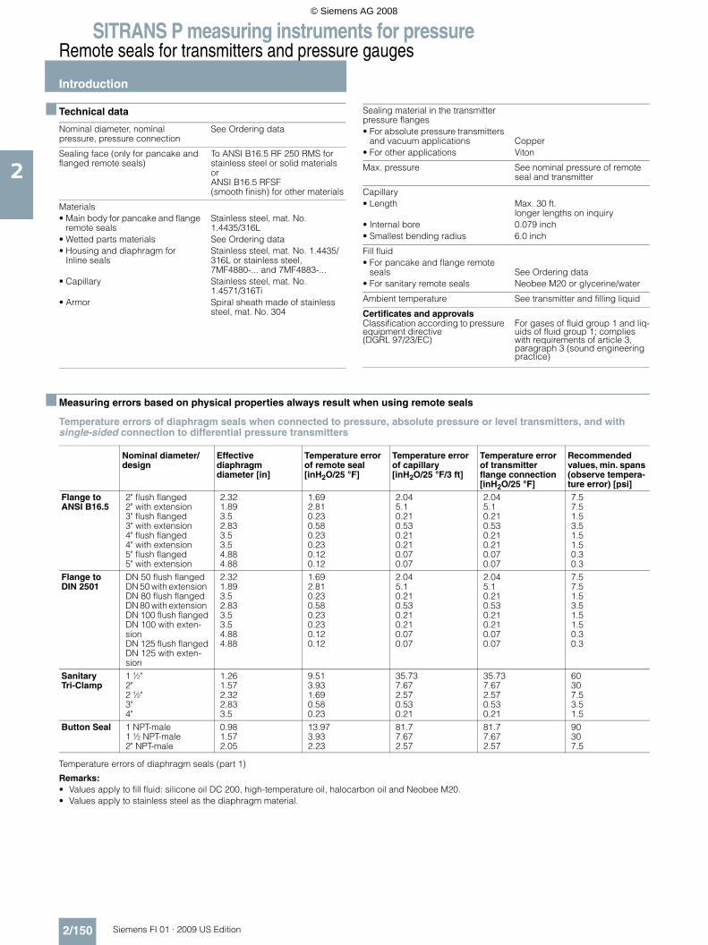
SITRANS P measuring instruments for pressureRemote seals for transmitters and pressure gauges
Introduction
2/150 Siemens FI 01 · 2009 US Edition
2
■ Technical data
■ Measuring errors based on physical properties always result when using remote seals
Temperature errors of diaphragm seals when connected to pressure, absolute pressure or level transmitters, and with single-sided connection to differential pressure transmitters
Temperature errors of diaphragm seals (part 1)
Remarks:• Values apply to fill fluid: silicone oil DC 200, high-temperature oil, halocarbon oil and Neobee M20.• Values apply to stainless steel as the diaphragm material.
Nominal diameter, nominal pressure, pressure connection
See Ordering data
Sealing face (only for pancake and flanged remote seals)
To ANSI B16.5 RF 250 RMS for stainless steel or solid materials or ANSI B16.5 RFSF(smooth finish) for other materials
Materials• Main body for pancake and flange
remote sealsStainless steel, mat. No. 1.4435/316L
• Wetted parts materials See Ordering data • Housing and diaphragm for
Inline sealsStainless steel, mat. No. 1.4435/316L or stainless steel,7MF4880-... and 7MF4883-...
• Capillary Stainless steel, mat. No. 1.4571/316Ti
• Armor Spiral sheath made of stainlesssteel, mat. No. 304
Sealing material in the transmitterpressure flanges• For absolute pressure transmitters
and vacuum applications Copper• For other applications Viton
Max. pressure See nominal pressure of remote seal and transmitter
Capillary• Length Max. 30 ft.
longer lengths on inquiry• Internal bore 0.079 inch• Smallest bending radius 6.0 inch
Fill fluid• For pancake and flange remote
seals See Ordering data • For sanitary remote seals Neobee M20 or glycerine/water
Ambient temperature See transmitter and filling liquid
Certificates and approvalsClassification according to pressure equipment directive(DGRL 97/23/EC)
For gases of fluid group 1 and liq-uids of fluid group 1; complies with requirements of article 3, paragraph 3 (sound engineering practice)
Nominal diameter/design
Effective diaphragm diameter [in]
Temperature error of remote seal [inH2O/25 °F]
Temperature error of capillary [inH2O/25 °F/3 ft]
Temperature error of transmitter flange connection [inH2O/25 °F]
Recommended values, min. spans (observe tempera-ture error) [psi]
Flange to ANSI B16.5
2" flush flanged2" with extension3" flush flanged3" with extension4" flush flanged4" with extension5" flush flanged5" with extension
2.321.893.52.833.53.54.884.88
1.692.810.230.580.230.230.120.12
2.045.10.210.530.210.210.070.07
2.045.10.210.530.210.210.070.07
7.57.51.53.51.51.50.30.3
Flange to DIN 2501
DN 50 flush flangedDN 50 with extension DN 80 flush flangedDN 80 with extension DN 100 flush flangedDN 100 with exten-sion DN 125 flush flangedDN 125 with exten-sion
2.321.893.52.833.53.54.884.88
1.692.810.230.580.230.230.120.12
2.045.10.210.530.210.210.070.07
2.045.10.210.530.210.210.070.07
7.57.51.53.51.51.50.30.3
SanitaryTri-Clamp
1 ½"2"2 ½"3"4"
1.261.572.322.833.5
9.513.931.690.580.23
35.737.672.570.530.21
35.737.672.570.530.21
60307.53.51.5
Button Seal 1 NPT-male1 ½ NPT-male2" NPT-male
0.981.572.05
13.973.932.23
81.77.672.57
81.77.672.57
90307.5
© Siemens AG 2008

SITRANS P measuring instruments for pressureRemote seals for transmitters and pressure gauges
Introduction
2/151Siemens FI 01 · 2009 US Edition
2
Temperature errors of diaphragm seals with double-sided connection to differential pressure transmitters
Temperature errors of diaphragm seals (part 2)
Remarks:• Values apply to fill fluids: silicone oil DC 200, high-temperature oil, halocarbon oil and Neobee M20.• Values apply to stainless steel as the diaphragm material.
Temperature errors of clamp-on seals when connected to pressure or absolute pressure transmitters, and with single-sided connection to differential pressure transmitters
Temperature errors of clamp-on seals with double-sided connection to differential pressure transmitters
Temperature errors of clamp-on seals
Remarks:• Values apply to fill fluids: silicone oil DC 200, high-temperature oil, halocarbon oil and Neobee M20.• Values apply to stainless steel as the diaphragm material.• Diaphragm thickness: 1" & 1 ½" & 2":0.002 inch
3" & 4": 0.004 inch
Nominal diameter/design
Effective diaphragm diameter [in]
Temperature error of remote seal [inH2O/25 °F]
Temperature error of capillary [inH2O/25 °F/3 ft]
Temperature error of transmitter flange connection [inH2O/25 °F]
Recommended values, min. spans (observe tempera-ture error) [psi]
Flange to ANSI B16.5
2" flush flanged2" with extension3" flush flanged3" with extension4" flush flanged4" with extension5" flush flanged5" with extension
2.321.893.52.833.53.54.884.88
0.3840.6920.0770.1540.0770.0770.0380.038
0.421.0510.0420.1260.0420.0420.0170.017
0.421.0510.0420.1260.0420.0420.0170.017
3.53.511.5110.30.3
Flange to DIN 2501
DN 50 flush flangedDN 50 with extension DN 80 flush flangedDN 80 with extension DN 100 flush flangedDN 100 with exten-sion DN 125 flush flangedDN 125 with exten-sion
2.321.893.52.833.53.54.884.88
0.3840.6920.0770.1540.0770.0770.0380.038
0.421.0510.0420.1260.0420.0420.0170.017
0.421.0510.0420.1260.0420.0420.0170.017
3.53.511.5110.30.3
SanitaryTri-Clamp
2"2 ½"3"4"
1.572.322.833.5
0.9610.3840.1540.077
1.8490.420.1260.042
1.8490.420.1260.042
303.51.51
Nominal diameter/design Temperature error of remote seal [inH2O/25 °F]
Temperature error of capillary [inH2O/25 °F/3 ft]
Temperature error of transmitter flange connection [inH2O/25 °F]
Recommended values, min. spans (observe tempera-ture error) [psi]
1 inch1 ½ inch2 inch3 inch4 inch
3.3452.4992.235.3050.461
5.172.7321.8493.0681.849
5.172.7321.8493.0681.849
14.53.51.51.51.5
Nominal diameter/design Temperature error of remote seal [inH2O/25 °F]
Temperature error of capillary [inH2O/25 °F/3 ft]
Temperature error of transmitter flange connection [inH2O/25 °F]
Recommended values, min. spans (observe tempera-ture error) [psi]
1 inch1 ½ inch2 inch3 inch4 inch
1.2690.4610.1541.6920.577
1.0930.1680.0840.2940.084
1.0930.1680.0840.2940.084
14.53.51.51.51.5
© Siemens AG 2008
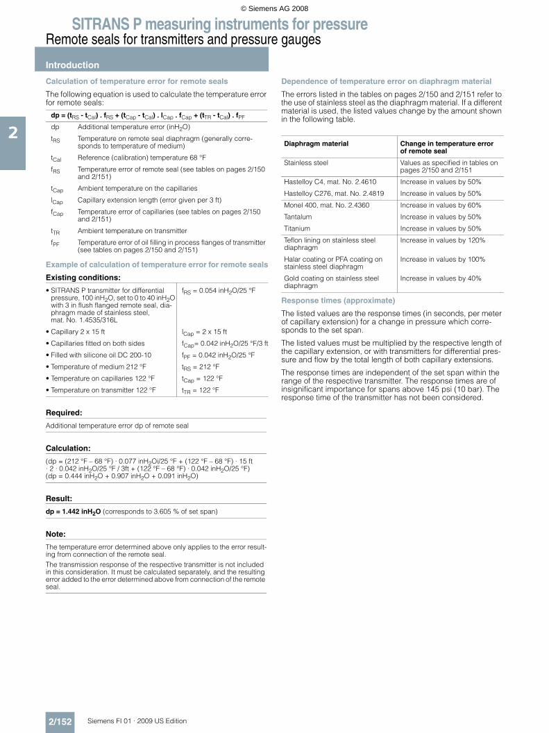
SITRANS P measuring instruments for pressureRemote seals for transmitters and pressure gauges
Introduction
2/152 Siemens FI 01 · 2009 US Edition
2
Calculation of temperature error for remote seals
The following equation is used to calculate the temperature error for remote seals:
Example of calculation of temperature error for remote seals
Existing conditions:
Required:
Calculation:
Result:
Note:
Dependence of temperature error on diaphragm material
The errors listed in the tables on pages 2/150 and 2/151 refer to the use of stainless steel as the diaphragm material. If a different material is used, the listed values change by the amount shown in the following table.
Response times (approximate)
The listed values are the response times (in seconds, per meter of capillary extension) for a change in pressure which corre-sponds to the set span.
The listed values must be multiplied by the respective length of the capillary extension, or with transmitters for differential pres-sure and flow by the total length of both capillary extensions.
The response times are independent of the set span within the range of the respective transmitter. The response times are of insignificant importance for spans above 145 psi (10 bar). The response time of the transmitter has not been considered.
dp = (tRS - tCal) . fRS + (tCap - tCal) . lCap . fCap + (tTR - tCal) . fPF
dp Additional temperature error (inH2O)
tRS Temperature on remote seal diaphragm (generally corre-sponds to temperature of medium)
tCal Reference (calibration) temperature 68 °F
fRS Temperature error of remote seal (see tables on pages 2/150 and 2/151)
tCap Ambient temperature on the capillaries
lCap Capillary extension length (error given per 3 ft)
fCap Temperature error of capillaries (see tables on pages 2/150 and 2/151)
tTR Ambient temperature on transmitter
fPF Temperature error of oil filling in process flanges of transmitter (see tables on pages 2/150 and 2/151)
• SITRANS P transmitter for differential pressure, 100 inH2O, set to 0 to 40 inH2O with 3 in flush flanged remote seal, dia-phragm made of stainless steel, mat. No. 1.4535/316L
fRS = 0.054 inH2O/25 °F
• Capillary 2 x 15 ft lCap = 2 x 15 ft
• Capillaries fitted on both sides fCap= 0.042 inH2O/25 °F/3 ft
• Filled with silicone oil DC 200-10 fPF = 0.042 inH2O/25 °F
• Temperature of medium 212 °F tRS = 212 °F
• Temperature on capillaries 122 °F tCap = 122 °F
• Temperature on transmitter 122 °F tTR = 122 °F
Additional temperature error dp of remote seal
(dp = (212 °F – 68 °F) · 0.077 inH2Oi/25 °F + (122 °F – 68 °F) · 15 ft· 2 · 0.042 inH2O/25 °F / 3ft + (122 °F – 68 °F) · 0.042 inH2O/25 °F)(dp = 0.444 inH2O + 0.907 inH2O + 0.091 inH2O)
dp = 1.442 inH2O (corresponds to 3.605 % of set span)
The temperature error determined above only applies to the error result-ing from connection of the remote seal.The transmission response of the respective transmitter is not included in this consideration. It must be calculated separately, and the resulting error added to the error determined above from connection of the remote seal.
Diaphragm material Change in temperature error of remote seal
Stainless steel Values as specified in tables on pages 2/150 and 2/151
Hastelloy C4, mat. No. 2.4610 Increase in values by 50%
Hastelloy C276, mat. No. 2.4819 Increase in values by 50%
Monel 400, mat. No. 2.4360 Increase in values by 60%
Tantalum Increase in values by 50%
Titanium Increase in values by 50%
Teflon lining on stainless steel diaphragm
Increase in values by 120%
Halar coating or PFA coating on stainless steel diaphragm
Increase in values by 100%
Gold coating on stainless steel diaphragm
Increase in values by 40%
© Siemens AG 2008

SITRANS P measuring instruments for pressureRemote seals for transmitters and pressure gauges
Introduction
2/153Siemens FI 01 · 2009 US Edition
2
■ Technical data of filling liquid
When selecting the filling liquid, check that it is suitable with respect to the permissible temperature of the medium and the process pressure. Also check the compatibility with the mea-sured medium. For example, only food grade filling liquids may be used in the food industry. A special case are oxygen and chlorine as the measured media; the fill fluid must not react with them, otherwise an explosion or fire may occur if there is a leak in the remote seal.
■ Maximum temperature of medium
The following maximum temperatures of the medium apply depending on the wetted parts materials:0
■ Maximum capillary length (guidance values for diaphragm seals and inline seals)
Filling liquid Density Temperature on capillary Response time in s/m (s/ft) with max. span of transmitter
kg/dm3 (lb/in3) °C (°F) 250 mbar (3.63 psi) 600 mbar (8.7 psi) 1600 mbar (23.2 psi)
Silicone oil DC 200-10
0.934 (0.033) +60+20- 20
(140)(68)(-4)
0.060.110.3
(0.018)(0.034)(0.091)
0.020.020.12
(0.006)(0.006)(0.037)
0.010.020.05
(0.003)(0.006)(0.015)
Silicone oilDC 200-50
0.966 (0.035) +60+20- 20
(140)(68)(-4)
0.60.611.69
(0.183)(0.186)(0.515)
0.250.260.71
(0.076)(0.079)(0.216)
0.090.10.27
(0.027)(0.030)(0.082)
Syltherm 800 0.935 (0.034) +60+20- 20
(140)(68)(-4)
0.060.110.3
(0.018)(0.034)(0.091)
0.020.020.12
(0.006)(0.006)(0.37)
0.010.020.05
(0.003)(0.006)(0.015)
High-temperature oil
1.07 (0.039) +60+20-10
(140)(68)(14)
0.140.653.96
(0.043)(0.198)(1.207)
0.060.271.65
(0.018)(0.082)(0.503)
0.020.10.62
(0.006)(0.030)(0.189)
Halocarbon oil 1.968 (0.071) +60+20- 20
(140)(68)(68)
0.070.292.88
(0.021)(0.088)(0.878)
0.030.121.2
(0.009)(0.037)(0.366)
0.010.050.45
(0.003)(0.015)(0.137)
Fluorolube 1.866 (0.068) +60+20- 20
(140)(68)(68)
0.070.292.88
(0.021)(0.088)(0.878)
0.030.121.2
(0.009)(0.037)(0.366)
0.010.050.45
(0.003)(0.015)(0.137)
Neobee M20 0.917 (0.033) +60+20- 20
(140)(68)(68)
0.180.431.19
(0.055)(0.131)(0.363)
0.080.180.5
(0.024)(0.055)(0.152)
0.030.070.18
(0.009)(0.021)(0.055)
Glycerine/water 1.22 (0.044) +60+20
0
(140)(68)(32)
0.130.769.72
(0.040)(0.232)(2.963)
0.050.324.05
(0.015)(0.098)(12.34)
0.020.121.51
(0.006)(0.037)(0.460)
Filling liquid Permissible temperature of medium Density at 20 °C (68 °F)
Viscosity at 20 °C (68 °F)
Expansion coefficient
pabs<1 bar (pabs<14.5 psi) pabs>1 bar (pabs>14.5 psi) kg/dm3 (lb/in3) m2/s·106 (ft2/s·106) 1/°C (1/°F)
°C (°F) °C (°F)
Silicone oilDC200-10
-40 to +121 (-40 to +248) -40 to +200 (-40 to +392) 0.934 (0.03) 10 (107.6) 0.00108 (0.00060)
Silicone oil DC 200-50
-20 to +150 (-4 to +302) -20 to +250 (-4 to +482) 0.96 (0.03) 50 (538) 0.00104 (0.00058)
Syltherm 800 -40 to +121 (-40 to +250) -40 to +205 (-40 to +400) 0.935 (0.034) 10.03 (107.9) 0.00109 (0.00061)
High-tempera-ture oil
-10 to +200 (+14 to +392) -10 to +350 (+14 to +662) 1.07 (0.04) 39 (420) 0.0008 (0.00044)
Halocarbon oil -40 to +80 (-40 to +176) -40 to +175 (-40 to +347) 1.968 (0.07) 14 (151) 0.00086 (0.00048)
Fluorolube Not possible Not possible -40 to +175 (-40 to +347) 1.866 (0.068) 15.5 (167) 0.000864 (0.00048)
Neobee M20 10 to +90 (+14 to +195) -10 to +200 (+14 to +392) 0.917 (0.03) 9.8 (105) 0.00082 (0.00045)
Glycerine/water Not possible Not possible -10 to +120 (+14 to +248) 1.22 (0.04) 88 (947) 0.0005 (0.00028)
Material pabs < 1 bar (14.5 psi)
pabs > 1 bar (14.5 psi)
°C (°F) °C (°F)
Stainless steel, mat. No. 1.4571/316Ti 200 (392) 350 (662)PTFE coating 100 (212) 150 (302)ECTFE/PFA coating 100 (212) 150 (302)Hastelloy C4, mat. No. 2.4610 200 (392) 350 (662)Hastelloy C276, mat. No. 2.4819 200 (392) 350 (662)Monel 400, mat. No. 2.4360 200 (392) 350 (662)Tantalum 200 (392) 300 (572)
Nominal diameter Max. length of capillary
Diaphragm seal Inline seal
DN 25 (1 inch) 2.5 m (8.2 ft) 2.5 m (8.2 ft)
DN 32 (1¼ inch) 2.5 m (4.9 ft) 2.5 m (8.2 ft)
DN 40 (1½ inch) 4 m (13.1 ft) 6 m (19.7 ft)
DN 50 (2 inch) 6 m (19.7 ft) 10 m (32.8 ft)
DN 65 (2½ inch) 8 m (26.2 ft) 10 m (32.8 ft)
DN 80 (3 inch) 10 m (32.8 ft) 10 m (32.8 ft)
Size 4 inch (30.0 ft) –
Size 5 inch (30.0 ft) – –
© Siemens AG 2008

SITRANS P measuring instruments for pressureRemote seals for transmitters and pressure gaugesPancake type diaphragm sealwith flexible capillary tube
2/154 Siemens FI 01 · 2009 US Edition
2
Pancake type diaphragm seal
■ Dimensions (Connection to ASME B16.5)
Pancake type diaphragm seal, dimensions
C) Subject to export regulations AL: N, ECCN: EAR99.
Size Class D DM F A [in2]
2"
150 - 2500
3.94 2.32 0.79 12.2
3" 5.28 3.50 0.79 21.9
4" 6.22 3.50 0.79 30.4
5" 7.32 4.80 0.87 42.1
Size = Nominal pipe sizeDM = Effective diaphragm diameterClass = Flange rating per ASME B16.5All dimensions in inches unless otherwise noted
Selection and Ordering data Order No. Order code
Pancake type diaphragm sealwith flexible capillary extension, connected to a SITRANS P transmitter (order separately)
for pressure 7MF40 7 7 or 7MF42 7 7 C) 7 M F 4 8 0 0 -
for absolute pressure 7MF43 7 7 C) 7 M F 4 8 0 1 -
for differential pressure 7MF44 7 7
• dual seals for DPC) 7 M F 4 8 0 3 -
1 7777 - 7B 777
Size and class• 2 inch• 3 inch• 4 inch• 5 inch
class 150 ... 2500class 150 ... 2500class 150 ... 2500class 150 ... 2500
EHLN
Special design, customer information to be supplied
Z J 1 Y
Materials and wetted parts• SST 316L• SST 316L with carbon pigmented Teflon lined
diaphragm (good upto 500 °F)• Monel 400, mat. No. 2.4360• Hastelloy C276, mat. No. 2.4819• Tantal
AE
GJK
0
Special design, customer information to be supplied
Z K 1 J
Extension length (316SS standard)Without extension (standard version) 0Special design, customer information to be supplied for extension
9 L 1 Y
System fill• Silicone oil DC 200-10• Silicone oil DC 200-50• High temperature oil• Halocarbon (for O2-application)• Silicone oil M5• Syltherm 800• DC704 silicone oil• Fluorolube
12345678
Special design, customer inform. to be supplied 9 M 1 Y
Length of capillary• 3 ft• 5 ft• 10 ft• 15 ft• 20 ft• 25 ft• 30 ft
2345678
Special design, customer inform. to be supplied 9 N 1 Y
Further designsPlease add „-Z“ to Order No. and specifiy Order code
for 7MF4800Integrated flame path restriction A 0 1Certificate of calibration N.I.S.T. (20% steps) C 1 1Material conformance certificate C 1 2Vacuum service (must be specified with HT oil) V 0 1Calculation of span of transmitter (completed questionnaire to be attached)
Y 0 5
for 7MF4801
Integrated flame path restriction A 0 1Certificate of calibration N.I.S.T. (20% steps) C 1 1Material conformance certificate C 1 2Calculation of span of transmitter (completed questionnaire to be attached)
Y 0 5
for 7MF4803
Integrated flame path restriction A 0 2Certificate of calibration N.I.S.T. (20% steps) C 1 1Material conformance certificate C 1 2Vacuum service (must be specified with HT oil) V 0 3Calculation of span of transmitter (completed questionnaire to be attached)
Y 0 5
© Siemens AG 2008

SITRANS P measuring instruments for pressureRemote seals for transmitters and pressure gauges
Flange-type diaphragm sealdirectly connected
2/155Siemens FI 01 · 2009 US Edition
2
Flange-type diaphragm seal, without extension
■ Dimensions (connection to ASME B16.5)
Flange-type diaphragm seal without extension for flanges ≤ 1"
Flange-type diaphragm seal without extension for flanges ≥ 1.5"
Flange-type diaphragm seal, without extension, dimensions
Optional instrumentWelded capillaryconnection1/4” NPT1/2“ NPT
Optional instrumentconnectionswelded capillaryconnection1/4” NPT1/2“ NPT
Size Class A B C DM E F G X Weight
DN lbs
½"150 3.50 2.38 1.38 1.3 0.85 0.06 0.62 4 2.2
300 3.75 2.62 1.38 1.6 0.85 0.06 0.62 4 2.2
¾"150 3.88 2.75 1.69 1.6 0.85 0.06 0.62 4 2.4
300 4.62 3.25 1.69 1.6 0.85 0.06 0.75 4 3.5
1"150 4.25 3.12 2.00 2.1 0.85 0.06 0.62 4 3.1
300 4.88 3.50 2.00 2.1 0.85 0.06 0.75 4 3.7
1.5"
150 5.00 3.55 2.88 1.9 0.69 0.06 0.62 4 3.5
300 6.12 4.50 2.88 1.9 0.81 0.06 0.88 4 5.5
600 6.12 4.50 2.88 1.9 1.13 0.25 0.88 4 7.3
1500 7.00 4.88 2.88 1.9 1.50 0.25 1.12 4 13.0
2500 8.00 5.75 2.88 1.9 2.00 0.25 1.25 4 22.9
2"
150 6.00 4.75 3.62 2.4 0.75 0.06 0.75 4 5.9
300 6.50 5.00 3.62 2.4 0.88 0.06 0.75 8 8.1
600 6.50 5.00 3.62 2.4 1.25 0.25 0.75 8 12.5
1500 8.50 6.50 3.62 2.4 1.75 0.25 1.00 8 29.0
2500 9.25 6.75 3.62 2.4 2.25 0.25 1.12 8 43.6
3"
150 7.50 6.00 5.00 3.5 0.94 0.06 0.75 4 11.7
300 8.25 6.62 5.00 3.5 1.12 0.06 0.88 8 17.2
600 8.25 6.62 5.00 3.5 1.50 0.25 0.88 8 24.2
900 9.50 7.50 5.00 3.5 1.75 0.25 1.00 8 36.7
1500 10.53 8.00 5.00 3.5 2.13 0.25 1.25 8 53.9
2500 12.01 9.00 5.00 3.5 2.87 0.25 1.38 8 93.9
4"
150 9.00 7.50 6.19 3.5 0.94 0.06 0.75 8 16.9
300 10.04 7.88 6.19 3.5 1.25 0.06 0.88 8 27.9
400 10.4 7.88 6.19 3.5 1.63 0.25 1.00 8 38.3
600 10.83 8.50 6.19 3.5 1.75 0.25 1.00 8 47.3
900 11.51 9.25 6.19 3.5 2.00 0.25 1.25 8 60.9
1500 12.30 9.50 6.19 3.5 2.37 0.25 1.38 8 81.4
2500 14.00 10.75 6.19 3.5 3.25 0.25 1.62 8 144.5
DN = Nominal pipe sizeDM = Effective diaphragm diameterClass = Flange rating per ASME B16.5X = Number of bolt holesAll dimensions in inches unless otherwise noted
© Siemens AG 2008

SITRANS P measuring instruments for pressureRemote seals for transmitters and pressure gaugesFlange-type diaphragm sealdirectly connected
2/156 Siemens FI 01 · 2009 US Edition
2
Flange-type diaphragm seal, with extension
■ Dimensions
Flange-type diaphragm seal, with extension, dimensions
C) Subject to export regulations AL: N, ECCN: EAR99.
Size Class A B C DM E1) F G H X L
DN
2" 150 6.00 4.753.62 1.8 1.90
0.75
0.06
0.75 4
2.0 3.0 4.0 6.0
300 6.50 5.00 0.88 0.75 8
3" 150 7.50 6.005.00 2.8 2.99
0.94 0.75 4
300 8.25 6.62 1.12 0.88 8
4" 150 9.00 7.506.19 3.5 3.70
0.94 0.75 8
300 10.04 7.88 1.25 0.88 81) based on schedule 40DN = Nominal pipe sizeDM = Effective diaphragm diameterClass = Flange rating per ASME B16.5X = Number of bolt holesAll dimensions in inches unless otherwise noted
Instrument connectionOptionsWelded capillary connection1/4” NPT1/2“ NPT
Selection and Ordering data Order No. Order code
Flange-type diaphragm seal
directly connected to a SITRANS P 7MF40 7 7 or 7MF42 7 7(order separately)
C) 7 M F 4 8 1 0 -
77777 777
Process connectionvertical (transmitter upright)horizontal
02
Size and class• 2 inch• 2 inch• 2 inch• 2 inch• 3 inch• 3 inch• 3 inch• 4 inch• 4 inch• 4 inch
class 150class 300class 600class 1500class 150class 300class 600class 150class 300class 400
LMNP
QRS
TUV
Special design, customer information to be supplied
Z J 1 Y
Materials and wetted parts• SST 316L• SST 316L with carbon pigmented Teflon lined
diaphragm (good upto 500 °F)• Monel 400, mat. No. 2.4360• Hastelloy C276, mat. No. 2.4819• Tantal
AE
GJK
0
Special design, customer information to be supplied
Z K 1 Y
Extension length (316SS standard)Without extension (standard version)2"4"6"8"
01234
Special design, customer information to be supplied for extension
9 L 1 Y
System fill• Silicone oil DC 200-10• Silicone oil DC 200-50• High temperature oil• Halocarbon (for O2-application)• Silicone oil M5• Syltherm 800• DC704 silicone oil• Fluorolube
12345678
Special design, customer information to be supplied
9 M 1 Y
Further designsPlease add „-Z“ to Order No. and specifiy Order code
Integrated flame path restrictionRotatable FlangeCertification of calibration N.I.S.T. (20% steps)Material conformance certificateVacuum service (must be specified with HT oil)Calculation of span of transmitter (completed questionnaire to be attached)
A
B
C
C
V
Y
0
0
1
1
0
0
1
1
1
2
1
5
© Siemens AG 2008
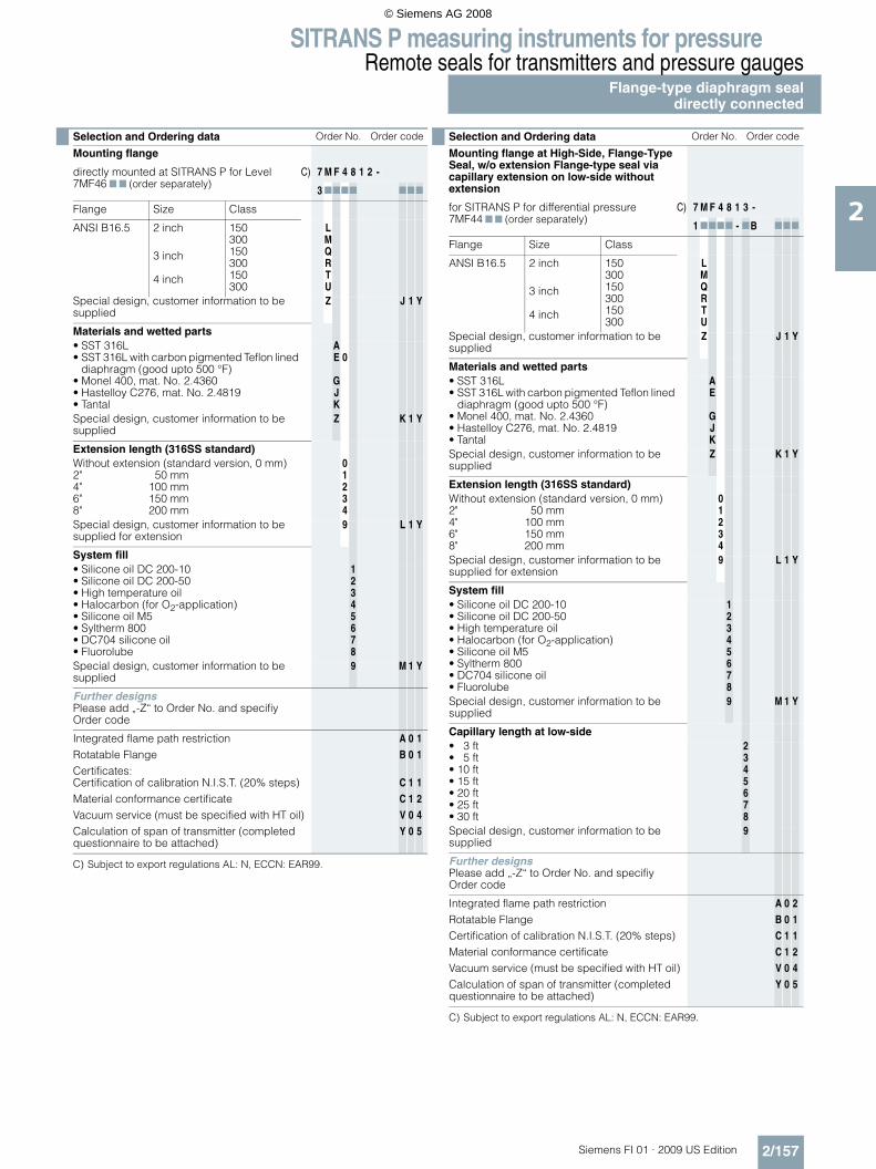
SITRANS P measuring instruments for pressureRemote seals for transmitters and pressure gauges
Flange-type diaphragm sealdirectly connected
2/157Siemens FI 01 · 2009 US Edition
2
C) Subject to export regulations AL: N, ECCN: EAR99.
C) Subject to export regulations AL: N, ECCN: EAR99.
Selection and Ordering data Order No. Order code
Mounting flange
directly mounted at SITRANS P for Level 7MF46 7 7 (order separately)
C) 7 M F 4 8 1 2 -
3 7777 777
Flange Size Class
ANSI B16.5 2 inch
3 inch
4 inch
150300150300150300
LMQRTU
Special design, customer information to be supplied
Z J 1 Y
Materials and wetted parts• SST 316L• SST 316L with carbon pigmented Teflon lined
diaphragm (good upto 500 °F)• Monel 400, mat. No. 2.4360• Hastelloy C276, mat. No. 2.4819• Tantal
AE
GJK
0
Special design, customer information to be supplied
Z K 1 Y
Extension length (316SS standard)Without extension (standard version, 0 mm)2" 50 mm4" 100 mm6" 150 mm8" 200 mm
01234
Special design, customer information to be supplied for extension
9 L 1 Y
System fill• Silicone oil DC 200-10• Silicone oil DC 200-50• High temperature oil• Halocarbon (for O2-application)• Silicone oil M5• Syltherm 800• DC704 silicone oil• Fluorolube
12345678
Special design, customer information to be supplied
9 M 1 Y
Further designsPlease add „-Z“ to Order No. and specifiy Order code
Integrated flame path restrictionRotatable FlangeCertificates:Certification of calibration N.I.S.T. (20% steps)Material conformance certificateVacuum service (must be specified with HT oil)Calculation of span of transmitter (completed questionnaire to be attached)
A
B
C
C
V
Y
0
0
1
1
0
0
1
1
1
2
4
5
Selection and Ordering data Order No. Order code
Mounting flange at High-Side, Flange-Type Seal, w/o extension Flange-type seal via capillary extension on low-side without extension
for SITRANS P for differential pressure 7MF44 7 7 (order separately)
C) 7 M F 4 8 1 3 -
1 7777 - 7B 777
Flange Size Class
ANSI B16.5 2 inch
3 inch
4 inch
150300150300150300
LMQRTU
Special design, customer information to be supplied
Z J 1 Y
Materials and wetted parts• SST 316L• SST 316L with carbon pigmented Teflon lined
diaphragm (good upto 500 °F)• Monel 400, mat. No. 2.4360• Hastelloy C276, mat. No. 2.4819• Tantal
AE
GJK
Special design, customer information to be supplied
Z K 1 Y
Extension length (316SS standard)Without extension (standard version, 0 mm)2" 50 mm4" 100 mm6" 150 mm8" 200 mm
01234
Special design, customer information to be supplied for extension
9 L 1 Y
System fill• Silicone oil DC 200-10• Silicone oil DC 200-50• High temperature oil• Halocarbon (for O2-application)• Silicone oil M5• Syltherm 800• DC704 silicone oil• Fluorolube
12345678
Special design, customer information to be supplied
9 M 1 Y
Capillary length at low-side• 3 ft• 5 ft• 10 ft• 15 ft• 20 ft• 25 ft• 30 ft
2345678
Special design, customer information to be supplied
9
Further designsPlease add „-Z“ to Order No. and specifiy Order code
Integrated flame path restrictionRotatable FlangeCertification of calibration N.I.S.T. (20% steps)Material conformance certificateVacuum service (must be specified with HT oil)Calculation of span of transmitter (completed questionnaire to be attached)
A
B
C
C
V
Y
0
0
1
1
0
0
2
1
1
2
4
5
© Siemens AG 2008

SITRANS P measuring instruments for pressureRemote seals for transmitters and pressure gaugesDiaphragm seal "flanged off-linelow-pressure type", directly connected
2/158 Siemens FI 01 · 2009 US Edition
2
Diaphragm seal "flanges off-line low-pressure type"
■ Dimensions (Connection to ASME B16.5)
C) Subject to export regulations AL: N, ECCN: EAR99.
G2 G3 X A B C DM ESize Class½" 150# ½"-13UNC 4 5.91
5.91
0.06
3.5
2.36½" 300# ½"-13UNC 4 5.91 0.06 2.36½" 600# ½"-13UNC 4 5.91 0.25 2.55¾" 150# ½"-13UNC 4 5.91 0.06 2.36¾" 300# 5/8"-11UNC 4 5.91 0.06 2.36¾" 600# 5/8"-11UNC 4 5.91 0.25 2.551" 150# ½"-13UNC 4 5.91 0.06 2.361" 300# 5/8"-11UNC 4 5.91 0.06 2.361" 600# 5/8"-11UNC 4 5.91 0.25 2.55
1 ½" 150# ½"-13UNC 4 5.91 0.06 2.361 ½" 300# ¾"-10UNC 4 6.12 0.06 2.461 ½" 600# ¾"-10UNC 4 6.12 0.25 2.65
2" 150# 5/8"-11UNC 4 6.00 0.06 2.362" 300# 5/8"-11UNC 8 6.50 0.06 2.362" 600# 5/8"-11UNC 8 6.50 0.25 2.55
Instrument connection optionswelded capillary connection1/4” NPT1/2“ NPT
DM = Effective diaphragm diameterG1 = Instrument connectionG2 = Process connectionG3 = Threaded bolt holeX = Number of bolt holesClass = Flange rating per ASME B16.5Size = Nominal pipe sizeAll dimensions in inches unless otherwise noted
Selection and Ordering data Order No. Order code
Diaphragm seal "flanged off-line low-pres-sure type"
direct mount to transmitter, 316 stainless steel upper housing SITRANS P for 7MF44 7 7 or 7MF46 7 7 (order separately)
C) 7 M F 4 8 1 4 -
3 7777 777
Size and class• ½ inch• ½ inch• ½ inch• ¾ inch• ¾ inch• ¾ inch• 1 inch• 1 inch• 1 inch• 1 ½ inch• 1 ½ inch• 1 ½ inch• 2 inch• 2 inch• 2 inch
class 150#RFclass 300#RFclass 600#RFclass 150#RFclass 300#RFclass 600#RFclass 150#RFclass 300#RFclass 600#RFclass 150#RFclass 300#RFclass 600#RFclass 150#RFclass 300#RFclass 600#RF
ABCEFGJKLNPQSTU
Special design, customer information to be supplied
Z J 1 Y
Materials and wetted parts• SST 316L• SST 316L with carbon pigmented Teflon lined
diaphragm (good upto 500 °F)• Monel 400, mat. No. 2.4360• Hastelloy C276, mat. No. 2.4819• Tantal
AE
GJK
Special design, customer information to be supplied
Z K 1 Y
Flushing port(s)None1 x ¼"NPT-female (available w/ SS, HC or MO)2 x ¼"NPT-female (available w/ SS, HC or MO)
024
Special design, customer information to be supplied
9 L 1 Y
System fill• Silicone oil DC 200-10• Silicone oil DC 200-50• High temperature oil• Halocarbon (for O2-application)• Silicone oil M5• Syltherm 800• DC704 silicone oil• Fluorolube
12345678
Special design, customer information to be supplied
9 M 1 Y
Further designsPlease add „-Z“ to Order No. and specifiy Order code
Integrated flame path restriction A 0 1Certification of calibration N.I.S.T. (20 % steps) C 1 1Material conformance certificate C 1 2Vacuum service (must be specified with HT oil) V 0 1Calculation of span of transmitter (completed questionnaire to be attached)
Y 0 5
© Siemens AG 2008

SITRANS P measuring instruments for pressureRemote seals for transmitters and pressure gauges
Flange-type diaphragm sealwith flexible capillary tube
2/159Siemens FI 01 · 2009 US Edition
2
Flange-type diaphragm seal with flexible capillary extension
■ Dimensions (Connection to ASME B16.5)
Flange-type diaphragm seal for flanges ≤ 1"
Flange-type diaphragm seal for flanges ≥ 1.5"
■ Connection to ASME B16.5
Optional instrumentWelded capillaryconnection1/4” NPT1/2” NPT
Optional instrumentconnectionswelded capillaryconnection1/4” NPT1/2” NPT
Systemfill port
Size Class A B C DM E F G X Weight
DN lbs
½"150 3.50 2.38 1.38 1.3 0.85 0.06 0.62 4 2.2
300 3.75 2.62 1.38 1.6 0.85 0.06 0.62 4 2.2
¾"150 3.88 2.75 1.69 1.6 0.85 0.06 0.62 4 2.4
300 4.62 3.25 1.69 1.6 0.85 0.06 0.75 4 3.5
1"150 4.25 3.12 2.00 2.1 0.85 0.06 0.62 4 3.1
300 4.88 3.50 2.00 2.1 0.85 0.06 0.75 4 3.7
1.5"
150 5.00 3.55 2.88 1.9 0.69 0.06 0.62 4 3.5
300 6.12 4.50 2.88 1.9 0.81 0.06 0.88 4 5.5
600 6.12 4.50 2.88 1.9 1.13 0.25 0.88 4 7.3
1500 7.00 4.88 2.88 1.9 1.50 0.25 1.12 4 13.0
2500 8.00 5.75 2.88 1.9 2.00 0.25 1.25 4 22.9
2"
150 6.00 4.75 3.62 2.4 0.75 0.06 0.75 4 5.9
300 6.50 5.00 3.62 2.4 0.88 0.06 0.75 8 8.1
600 6.50 5.00 3.62 2.4 1.25 0.25 0.75 8 12.5
1500 8.50 6.50 3.62 2.4 1.75 0.25 1.00 8 29.0
2500 9.25 6.75 3.62 2.4 2.25 0.25 1.12 8 43.6
3"
150 7.50 6.00 5.00 3.5 0.94 0.06 0.75 4 11.7
300 8.25 6.62 5.00 3.5 1.12 0.06 0.88 8 17.2
600 8.25 6.62 5.00 3.5 1.50 0.25 0.88 8 24.2
900 9.50 7.50 5.00 3.5 1.75 0.25 1.00 8 36.7
1500 10.53 8.00 5.00 3.5 2.13 0.25 1.25 8 53.9
2500 12.01 9.00 5.00 3.5 2.87 0.25 1.38 8 93.9
4"
150 9.00 7.50 6.19 3.5 0.94 0.06 0.75 8 16.9
300 10.04 7.88 6.19 3.5 1.25 0.06 0.88 8 27.9
400 10.4 7.88 6.19 3.5 1.63 0.25 1.00 8 38.3
600 10.83 8.50 6.19 3.5 1.75 0.25 1.00 8 47.3
900 11.51 9.25 6.19 3.5 2.00 0.25 1.25 8 60.9
1500 12.30 9.50 6.19 3.5 2.37 0.25 1.38 8 81.4
2500 14.00 10.75 6.19 3.5 3.25 0.25 1.62 8 144.5
DN = Nominal pipe sizeDM = Effective diaphragm diameterClass = Flange rating per ASME B16.5X = Number of bolt holesAll dimensions in inches unless otherwise noted
© Siemens AG 2008

SITRANS P measuring instruments for pressureRemote seals for transmitters and pressure gaugesFlange-type diaphragm sealwith flexible capillary tube
2/160 Siemens FI 01 · 2009 US Edition
2
C) Subject to export regulations AL: N, ECCN: EAR99.
Selection and Ordering data Order No. Order code
Flange-type diaphragm seal
with flexible capillary extension, connected to a SITRANS P transmitter (order separately)
for pressure 7MF40 7 7 or 7MF42 7 7 C) 7 M F 4 8 2 0 -
for absolute pressure 7MF43 7 7 C) 7 M F 4 8 2 1 -
for differential pressure 7MF44 7 7
• dual seals for DPC) 7 M F 4 8 2 3 -
1 7777 - 7B 777
Size and class• 2 inch• 2 inch• 2 inch• 2 inch• 3 inch• 3 inch• 3 inch• 4 inch• 4 inch• 4 inch• 5 inch• 5 inch• 5 inch
class 150class 300class 600class 1500class 150class 300class 600class 150class 300class 400class 150class 300class 400
LMNPQRSTUVWXY
Special design, customer information to be supplied
Z J 1 Y
Materials and wetted parts• SST 316L• SST 316L with carbon pigmented Teflon lined
diaphragm (good upto 500 °F)• Monel 400, mat. No. 2.4360• Hastelloy C276, mat. No. 2.4819• Tantal
AE
GJK
0
Special design, customer information to be supplied
Z K 1 Y
Extension length (316SS standard)Without extension (standard version) 0Special design, customer information to be supplied for extension
9 L 1 Y
System fill• Silicone oil DC 200-10• Silicone oil DC 200-50• High temperature oil• Halocarbon (for O2-application)• Silicone oil M5• Syltherm 800• DC704 silicone oil• Fluorolube
12345678
Special design, customer information to be supplied
9 M 1 Y
Length of capillary• 3 ft• 5 ft• 10 ft• 15 ft• 20 ft• 25 ft• 30 ft
2345678
Special design, customer information to be supplied
9 N 1 Y
Selection and Ordering data Order code
Further designsPlease add „-Z“ to Order No. and specifiy Order code
for 7MF4820Integrated flame path restriction A 0 1Rotatable Flange B 0 1DP "H" flange service B 0 2Certificate of calibration N.I.S.T. (20% steps) C 1 1Material conformance certificate C 1 2Vacuum service (must be specified with HT oil) V 0 1Calculation of span of transmitter (completed questionnaire to be attached)
Y 0 5
for 7MF4821Integrated flame path restriction A 0 1Rotatable Flange B 0 1Certificate of calibration N.I.S.T. (20% steps) C 1 1Material conformance certificate C 1 2Calculation of span of transmitter (completed questionnaire to be attached)
Y 0 5
for 7MF4823Integrated flame path restriction A 0 2Rotatable Flange B 0 1Certificate of calibration N.I.S.T. (20% steps) C 1 1Material conformance certificate C 1 2Vacuum service (must be specified with HT oil) V 0 3Calculation of span of transmitter (completed questionnaire to be attached)
Y 0 5
© Siemens AG 2008

SITRANS P measuring instruments for pressureRemote seals for transmitters and pressure gauges
Diaphragm seal "flanged off-line type"
2/161Siemens FI 01 · 2009 US Edition
2
Diaphragm seal "flanged off-line type"
■ Dimensions (Connection to ASME B16.5)
Diaphragm seal "flanged off-line type", dimensionsInstrumentconnection
Instrumentconnection
Systemfill port
Optional1/8” NPTor 1/4” NPTflushingconnection
Systemfill port
G1 G2 G3 A B C DM E
¼"-NPTor
½"-NPT
½" 150# 4 x ½"-13UNC 3.75 2.381.38
2.1 3.74
½" 300# 4 x ½"-13UNC 3.75 2.62½" 600# 4 x ½"-13UNC 3.75 2.621" 150# 4 x ½"-13UNC 4.25 3.12
2.001" 300# 4 x 5/8"-11UNC 4.88 3.501" 600# 4 x 5/8"-11UNC 4.88 3.50
1 ½" 150# 4 x ½"-13UNC 5.00 3.882.881 ½" 300# 4 x ¾"-10UNC 6.12 4.50
1 ½" 600# 4 x ¾"-10UNC 6.12 4.502" 150# 4 x 5/8"-11UNC 6.00 4.75
3.622" 300# 8 x 0.75 6.50 5.002" 600# 8 x 0.75 6.50 5.00
G1 G2 G3 F H J Weightlbs
¼"-NPTor
½"-NPT
½" 150# 4 x ½"-13UNC 1.10 0.06 2.20 4.3½" 300# 4 x ½"-13UNC 1.10 0.06 2.20 4.3½" 600# 4 x ½"-13UNC 1.26 0.25 2.36 4.41" 150# 4 x ½"-13UNC 0.87 0.06 1.97 4.41" 300# 4 x 5/8"-11UNC 0.87 0.06 1.97 8.51" 600# 4 x 5/8"-11UNC 1.26 0.25 2.36 8.5
1 ½" 150# 4 x ½"-13UNC 0.87 0.06 1.97 5.01 ½" 300# 4 x ¾"-10UNC 0.87 0.06 1.97 6.61 ½" 600# 4 x ¾"-10UNC 1.26 0.25 2.36 9.1
2" 150# 4 x 5/8"-11UNC 0.87 0.06 1.97 6.12" 300# 8 x 0.75 0.89 0.06 1.99 8.52" 600# 8 x 0.75 1.28 0.25 2.38 10.0
DM = Effective diaphragm diameterG1 = Instrument connectionG2 = Process connectionG3 = Threaded bolt holeAll dimensions in inches unless otherwise noted
© Siemens AG 2008

SITRANS P measuring instruments for pressureRemote seals for transmitters and pressure gauges
Diaphragm seal "flanged off-line type"
2/162 Siemens FI 01 · 2009 US Edition
2
C) Subject to export regulations AL: N, ECCN: EAR99.
Selection and Ordering data Order No. Order code
Diaphragm seal "flanged off-line type" MWP depends on flange
with flexible armored capillary, 316 stainless steel upper housing SITRANS P for 7MF40 7 7 and 7MF42 7 7 (order separately)
C) 7 M F 4 8 2 6 -
77777 - 7B 777
Seal designStud mountAll-welded stud mountThrough-hole flange mount
123
Size and class• ½ inch• ½ inch• ½ inch• ¾ inch• ¾ inch• ¾ inch• 1 inch• 1 inch• 1 inch• 1 ½ inch• 1 ½ inch• 1 ½ inch• 2 inch• 2 inch• 2 inch
class 150#RFclass 300#RFclass 600#RFclass 150#RFclass 300#RFclass 600#RFclass 150#RFclass 300#RFclass 600#RFclass 150#RFclass 300#RFclass 600#RFclass 150#RFclass 300#RFclass 600#RF
ABCEFGJKLNPQSTU
Special design, customer information to be supplied
Z J 1 Y
Materials and wetted parts• SST 316L• SST 316L with carbon pigmented Teflon lined
diaphragm (good upto 500 °F)• Monel 400, mat. No. 2.4360• Hastelloy C276, mat. No. 2.4819• Tantal
AE
GJK
Special design, customer information to be supplied
Z K 1 Y
Flushing port(s)None1 x ¼"NPT-female (available w/ SS, HC or MO)2 x ¼"NPT-female (available w/ SS, HC or MO)
024
Special design, customer information to be supplied
9 L 1 Y
System fill• Silicone oil DC 200-10• Silicone oil DC 200-50• High temperature oil (comes with metal gas-
ket and stronger bolts)• Halocarbon (for O2-application)• Silicone oil M5• Syltherm 800• DC704 silicone oil• Fluorolube
123
45678
Special design, customer information to be supplied
9 M 1 Y
Length of capillary• Direct mount • 3 ft• 5 ft• 10 ft• 15 ft• 20 ft• 25 ft• 30 ft
02345678
Special design, customer information to be supplied
9 N 1 Y
Further designsPlease add „-Z“ to Order No. and specifiy Order code
Integrated flame path restrictionDP "H" flange serviceCertification of calibration N.I.S.T. (20 % steps)Material conformance certificateVacuum service (must be specified with HT oil)Calculation of span of transmitter (completed questionnaire to be attached)
A
B
C
C
V
Y
0
0
1
1
0
0
1
2
1
2
1
5
Selection and Ordering data Order No. Order code
© Siemens AG 2008

SITRANS P measuring instruments for pressureRemote seals for transmitters and pressure gauges
Diaphragm seal "flanged off-linelow-pressure type"
2/163Siemens FI 01 · 2009 US Edition
2
Diaphragm seal "flanged off-line low-pressure type"
■ Dimensions (Connection to ASME B16.5)
Diaphragm seal "flanged off-line low-pressure type", dimensions
Instrument connection optionswelded capillary connection1/4” NPT1/2“ NPT
G2 G3 X A B C DM ESize Class½" 150# ½"-13UNC 4 5.91
5.91
0.06
3.5
2.36½" 300# ½"-13UNC 4 5.91 0.06 2.36½" 600# ½"-13UNC 4 5.91 0.25 2.55¾" 150# ½"-13UNC 4 5.91 0.06 2.36¾" 300# 5/8"-11UNC 4 5.91 0.06 2.36¾" 600# 5/8"-11UNC 4 5.91 0.25 2.551" 150# ½"-13UNC 4 5.91 0.06 2.361" 300# 5/8"-11UNC 4 5.91 0.06 2.361" 600# 5/8"-11UNC 4 5.91 0.25 2.55
1 ½" 150# ½"-13UNC 4 5.91 0.06 2.361 ½" 300# ¾"-10UNC 4 6.12 0.06 2.461 ½" 600# ¾"-10UNC 4 6.12 0.25 2.65
2" 150# 5/8"-11UNC 4 6.00 0.06 2.362" 300# 5/8"-11UNC 8 6.50 0.06 2.362" 600# 5/8"-11UNC 8 6.50 0.25 2.55
DM = Effective diaphragm diameterG2 = Process connectionG3 = Threaded bolt holeX = Number of bolt holesClass = Flange rating per ASME B16.5Size = Nominal pipe sizeAll dimensions in inches unless otherwise noted
© Siemens AG 2008

SITRANS P measuring instruments for pressureRemote seals for transmitters and pressure gaugesDiaphragm seal "flanged off-linelow-pressure type"
2/164 Siemens FI 01 · 2009 US Edition
2
C) Subject to export regulations AL: N, ECCN: EAR99.
C) Subject to export regulations AL: N, ECCN: EAR99.
Selection and Ordering data Order No. Order code
Diaphragm seal "flanged off-line low-pressure type"
with flexible armored capillary, 316 stainless steel upper housing SITRANS P for 7MF407 7 and 7MF42 7 7 (order separately)
C) 7 M F 4 8 2 7 -
1 7777 - 7B 777
Size and class• ½ inch• ½ inch• ½ inch• ¾ inch• ¾ inch• ¾ inch• 1 inch• 1 inch• 1 inch• 1 ½ inch• 1 ½ inch• 1 ½ inch• 2 inch• 2 inch• 2 inch
class 150#RFclass 300#RFclass 600#RFclass 150#RFclass 300#RFclass 600#RFclass 150#RFclass 300#RFclass 600#RFclass 150#RFclass 300#RFclass 600#RFclass 150#RFclass 300#RFclass 600#RF
ABCEFGJKLNPQSTU
Special design, customer information to be supplied
Z J 1 Y
Materials and wetted parts• SST 316L• SST 316L with carbon pigmented Teflon lined
diaphragm (good upto 500 °F)• Monel 400, mat. No. 2.4360• Hastelloy C276, mat. No. 2.4819• Tantal
AE
GJK
Special design, customer information to be supplied
Z K 1 Y
Flushing port(s)None1 x ¼"NPT-female (available w/ SS, HC or MO)2 x ¼"NPT-female (available w/ SS, HC or MO)
024
Special design, customer information to be supplied
9 L 1 Y
System fill• Silicone oil DC 200-10• Silicone oil DC 200-50• High temperature oil 2)• Halocarbon (for O2-application)• Silicone oil M5• Syltherm 800• DC704 silicone oil• Fluorolube
12345678
Special design, customer information to be supplied
9 M 1 Y
Length of capillary• Direct mount • 3 ft• 5 ft• 10 ft• 15 ft• 20 ft• 25 ft• 30 ft
02345678
Special design, customer information to be supplied
9 N 1 Y
Further designsPlease add „-Z“ to Order No. and specifiy Order code
Integrated flame path restrictionDP "H" flange serviceCertification of calibration N.I.S.T. (20 % steps)Material conformance certificateVacuum service (must be specified with HT oil)Calculation of span of transmitter (completed questionnaire to be attached)
A
B
C
C
V
Y
0
0
1
1
0
0
1
2
1
2
1
5
Selection and Ordering data Order No. Order code
Diaphragm seal "flanged off-line low-pressure type"
with flexible armored capillary, 316 stainless steel upper housing SITRANS P for 7MF44 7 7 (order separately)
C) 7 M F 4 8 2 8 -
1 7777 - 7B 777
Size and class• ½ inch• ½ inch• ½ inch• ¾ inch• ¾ inch• ¾ inch• 1 inch• 1 inch• 1 inch• 1 ½ inch• 1 ½ inch• 1 ½ inch• 2 inch• 2 inch• 2 inch
class 150#RFclass 300#RFclass 600#RFclass 150#RFclass 300#RFclass 600#RFclass 150#RFclass 300#RFclass 600#RFclass 150#RFclass 300#RFclass 600#RFclass 150#RFclass 300#RFclass 600#RF
ABCEFGJKLNPQSTU
Special design, customer information to be supplied
Z J 1 Y
Materials and wetted parts• SST 316L• SST 316L with carbon pigmented Teflon lined
diaphragm (good upto 500 °F)• Monel 400, mat. No. 2.4360• Hastelloy C276, mat. No. 2.4819• Tantal
AE
GJK
Special design, customer information to be supplied
Z K 1 Y
Flushing port(s)None1 x ¼"NPT-female (available w/ SS, HC or MO)2 x ¼"NPT-female (available w/ SS, HC or MO)
024
Special design, customer information to be supplied
9 L 1 Y
System fill• Silicone oil DC 200-10• Silicone oil DC 200-50• High temperature oil 2)• Halocarbon (for O2-application)• Silicone oil M5• Syltherm 800• DC704 silicone oil• Fluorolube
12345678
Special design, customer information to be supplied
9 M 1 Y
Length of capillary• 3 ft• 5 ft• 10 ft• 15 ft• 20 ft• 25 ft• 30 ft
2345678
Special design, customer information to be supplied
9 N 1 Y
Further designsPlease add „-Z“ to Order No. and specifiy Order code
Integrated flame path restrictionCertification of calibration N.I.S.T. (20 % steps)Material conformance certificateVacuum service (must be specified with HT oil)Calculation of span of transmitter (completed questionnaire to be attached)
A
C
C
V
Y
0
1
1
0
0
2
1
2
1
5
© Siemens AG 2008

SITRANS P measuring instruments for pressureRemote seals for transmitters and pressure gauges
Flushing rings
2/165Siemens FI 01 · 2009 US Edition
2
■ Overview
Flushing ring
Flushing rings are required for flange-mounted and pancake type remote seals (Order No. 7MF4800 ... 7MF4823) if the dan-ger exists that the process conditions and the geometry of the connection could cause the process to form deposits or block-ages.
The flushing ring is clamped between the process flange and the remote seal.
Deposits can be flushed away from the diaphragm through the holes in the side, or the pressure volume can be vented. Different nominal diameters and forms permit adaptation to the respec-tive process flange.
Process connection
For flanges to EN and ASME:DN 50, 80, 100, 125; PN 16 ... 100 orDN 2 inch, 3 inch, 4 inch, 5 inch; Class 150 ... 600
Standard design
Material: CrNi-Stahl, mat. No. 1.4404/316LSealing faces and flushing holes: See Ordering data
■ Design
Installation example
■ Technical specifications
■ Dimensional drawings
Connection to EN 1092-1
Connection to ASME B 16.5
Flushing ring, dimension drawing
;�) ���
��@�����
=����������� �2�����
(���)����� ��
��0 �������2�����
A��.�
(���)��������
(���)��������
Flushing ring for remote seals of pancake and flange design
Nom. diam. Nom. press.• DN 50 PN 16 ... PN 100• DN 80 PN 16 ... PN 100• DN 100 PN 16 ... PN 100• DN 125 PN 16 ... PN 100
• 2 inch Class 150 ... class 600• 3 inch Class 150 ... class 600• 4 inch Class 150 ... class 600• 5 inch Class 150 ... class 600
Sealing face
• To EN 1092-1 Form B1Form B2Form D/Form DForm C/Form CForm C/Form CForm EForm F
• To ASME B16.5 RF 125 ... 250 AA RFSFRJT ring groove
Flushing holes (2 off), female thread:
• G¼• G½
• ¼-18 NPT
• ½-14 NPT
Material Stainless steel 1.4404/316L
DN PN d4 di h Weight
(mm) (bar) (mm) (mm) (mm) (kg)
50 16 ... 100 102 62 30 1.10
80 16 ... 100 138 92 30 1.90
100 16 ... 100 162 92 30 3.15
125 16 ... 100 188 126 30 3.50
DN Class d4 di h Weight
inch mm (inch) mm (inch) mm (inch) kg (lb)
2 150 ... 600 92 (3.62) 62 (2.44) 30 (1.18) 0.60 (1.32)
3 150 ... 600 127 (5) 92 (3.62) 30 (1.18) 1.05 (2.31)
4 150 ... 600 157 (6.18) 92 (3.62) 30 (1.18) 2.85 (6.28)
5 150 ... 600 185.5 (7.3) 126 (4.96) 30 (1.18) 3.30 (7.28)
!�
)
!+
/)���!
© Siemens AG 2008

SITRANS P measuring instruments for pressureRemote seals for transmitters and pressure gauges
Flushing rings
2/166 Siemens FI 01 · 2009 US Edition
2
Selection and Ordering data Order No. Ord. code
Flushing ring 7 M F 4 8 2 5 -
for remote seals 7MF4900 to 7MF4923 1 7777 777
Nom. diam. Nom. press.• 2 inch Class 150 ... 600 G• 3 inch Class 150 ... 600 H• 4 inch Class 150 ... 600 J• 5 inch Class 150 ... 600 K
Other versionAdd Order code and plain text:Nominal diameter: ...; Nominal pressure: ...
Z J 1 Y
Sealing face• ASME B16.5
- RF 125 ... 250 AA M- RFSF Q- RJT ring groove R
Other versionAdd Order code and plain text:Sealing face: ...
Z K 1 Y
Flushing holes (2 off)• Female thread G¼ 1• Female thread G½ 2• Female thread ¼-18 NPT 3• Female thread ½-14 NPT 4
Material• Stainless steel 316L 0Other versionAdd Order code and plain text:Material: ...
9 M 1 y
Further designsPlease add „-Z“ to Order No. and specifiy Order code
Acceptance test certificate Bto EN 10204, section 3.1.B C 1 2
© Siemens AG 2008

SITRANS P measuring instruments for pressureRemote seals for transmitters and pressure gauges
Diaphragm seal with quick connection
2/167Siemens FI 01 · 2009 US Edition
2
Diaphragm seal with quick connection, with slotted union nut
■ Dimensions (connection to ASME B16.5)
Diaphragm seal with quick connection, with slotted union nut
Diaphragm seal with quick connection, with male thread, dimensions
Diaphragm seal with quick connection, Tri-Clamp connection
■ Dimensions (connection to ASME B16.5)
Diaphragm seal with quick connection, Tri-Clamp connection, dimen-sions
DN[mm]
MWP[psi]
A[mm]
B C DM E G1 Weight[lbs]
25 600 Rd 52 x 1/6 2.48 0.83 1.0 2.36¼"-NPT
or½"-NPT female
1.332 600 Rd 58 x 1/6 2.76 0.83 1.3 2.72 1.640 600 Rd 65 x 1/6 3.07 0.83 1.6 2.17 2.550 360 Rd 78 x 1/6 3.62 0.87 2.1 2.32 2.8
DN[mm]
MWP[psi]
A[mm]
B C DM E G1 Weight[lbs]
40 600 Rd 65 x 1/6 3.07 1.12 1.6 2.17 ¼"-NPTor
½"-NPT female
2.850 360 Rd 78 x 1/6 3.62 1.42 2.1 2.24 3.0
DM = Effective diaphragm diameterMWP = Maximum Working Pressure @ 250 °FG1 = Instrument connectionDN = Nominal pipe sizeAll dimensions in inches unless otherwise noted
Type 7MF4840with union nut
Type 7MF4840with malethread
Size[in]
MWP[psi]
A B C DM E G1 Weight[lbs]
1.5 600 1.50 1.97 1.71 1.0
1.38
¼"-NPTor
½"-NPT female
1.32 550 1.50 2.52 2.22 1.6 1.7
2.5 450 2.52 3.05 2.78 2.0 2.03 350 2.31 3.58 3.28 2.8 2.44 250 2.31 4.68 4.34 3.5 2.7
DM = Effective diaphragm diameterMWP = Maximum Working Pressure @ 250 °F, higher rating with appro-priate clamping deviceG1 = Instrument connectionSize = Nominal pipe sizeAll dimensions in inches unless otherwise noted
© Siemens AG 2008

SITRANS P measuring instruments for pressureRemote seals for transmitters and pressure gauges
Diaphragm seal with quick connection
2/168 Siemens FI 01 · 2009 US Edition
2
Diaphragm seal with quick connection, "i"-line (Cherry Burrel - male)
■ Dimensions (connection to ASME B16.5)
Diaphragm seal with quick connection, "i"-line (Cherry Burrel - male), dimensions
C) Subject to export regulations AL: N, ECCN: EAR99.
Size[in]
MWP[psi]
A B C DM E F G1 Weight[lbs]
1.5 500
1.42
1.18 2.00 1.3 1.74 1.38 ¼"-NPTor
½"-NPT female
1.32 450 1.18 2.64 1.8 2.24 1.44 1.73 350 1.30 3.87 2.8 3.30 1.59 2.4
DM = Effective diaphragm diameterMWP = Maximum Working Pressure @ 250 °F, higher rating with appro-priate clamping deviceG1 = Instrument connectionSize = Nominal pipe sizeAll dimensions in inches unless otherwise noted
Selection and Ordering data Order No. Order code
Diaphragm seal
with quick connection for gage pressure transmitter SITRANS P 7MF40 7 7 and 7MF42 7 7 (order separately)made of 316 SS
C) 7 M F 4 8 4 0 -
77A 0 7 - 7B 777
Process connectionDIN 11 851 with slotted union nutDN 25/PN 40DN 32/PN 40DN 40/PN 40DN 50/PN 25DN 65/PN 25DN 80/PN 25DIN 11 851 with screw necksDN 25/PN 40DN 32/PN 40DN 40/PN 40DN 50/PN 25DN 65/PN 25DN 80/PN 25Tri-Clamp Connection1 ½" 600 psi2" 550 psi2 ½" 450 psi3" 350 psiVarivent (Tuchenhagen)Size 25132Size 40150Sanitary (4" Tank Spud)2" extension6" extension"I"-Line (Cherry Burrell - male)1 ½" 500 psi2" 450 psi3" 350 psi
111111
222222
4444
55
66
555
BCDEFG
BCDEFG
LMNP
CE
BD
UVW
Special design, customer information to be supplied
9 Z+
HJ
11
YY
System fill• Vegetable oil• Glycerin/Water 86.5/13.5 %• Neobee M20• Mineral oil
1234
Special design, customer information to be supplied
9 M 1 Y
Length of capillary• Direct Mount• 3 ft• 5 ft• 10 ft• 15 ft• 20 ft• 25 ft• 30 ft
02345678
Special design, customer information to be supplied
9 N 1 Y
Further designsPlease add „-Z“ to Order No. and specifiy Order code
Certification of calibration N.I.S.T. (20 % steps)Material conformance certificateVacuum service (must be specified with vege-table oil)Calculation of span of transmitter (completed questionnaire to be attached)
C
C
V
Y
1
1
0
0
1
2
1
5
Tank Spud accessories
Sanitary Tank Spud Clamp (1 pc.) P 1 0Sanitary Tank Spud O-ring (1 pc.) P 1 1Sanitary Tank Spud Weldolet 2" extension (1 pc.)
P 1 2
Sanitary Tank Spud Weldolet 6" extension (1 pc.)
P 1 3
© Siemens AG 2008

SITRANS P measuring instruments for pressureRemote seals for transmitters and pressure gauges
Diaphragm seal with quick connection
2/169Siemens FI 01 · 2009 US Edition
2
C) Subject to export regulations AL: N, ECCN: EAR99.
Selection and Ordering data Order No. Order code
Diaphragm seal
with quick connection for differential trans-mitter SITRANS P 7MF44 7 7 (order separately) made of 316 SS
C) 7 M F 4 8 4 3 -
77A 0 7 - 7B 777
Process connectionDIN 11 851 with slotted union nutDN 50/PN 25DN 65/PN 25DN 80/PN 25DIN 11 851 with screw necksDN 50/PN 25DN 65/PN 25DN 80/PN 25Tri-Clamp Connection2" 550 psi2 ½" 450 psi3" 350 psi4" 250 psi"I"-Line (Cherry Burrell - male)3" 350 psi4" 200 psiSanitary (4" Tank Spud)2" extension6" extension
111
222
4444
55
66
EFG
EFG
MNPQ
WX
BD
Special design, customer information to be supplied
9 Z+
HJ
11
YY
System fill• Vegetable oil• Glycerin/Water 86.5/13.5 %• Neobee M20• Mineral oil
1234
Special design, customer information to be supplied
9 M 1 Y
Length of capillary• 3 ft• 5 ft• 10 ft• 15 ft• 20 ft• 25 ft• 30 ft
2345678
Special design, customer information to be supplied
9 N 1 Y
Further designsPlease add „-Z“ to Order No. and specifiy Order code
Certification of calibration N.I.S.T. (20 % steps)Material conformance certificateVacuum service (must be specified with vege-table oil)Calculation of span of transmitter (completed questionnaire to be attached)
C
C
V
Y
1
1
0
0
1
2
3
5
Tank Spud accessoriesSanitary Tank Spud Clamp (1 pc., two required) P 1 0
Sanitary Tank Spud O-ring (1 pc., two required) P 1 1
Sanitary Tank Spud Weldolet 2" extension (1 pc., two required)
P 1 2
Sanitary Tank Spud Weldolet 6" extension (1 pc., two required)
P 1 3
© Siemens AG 2008
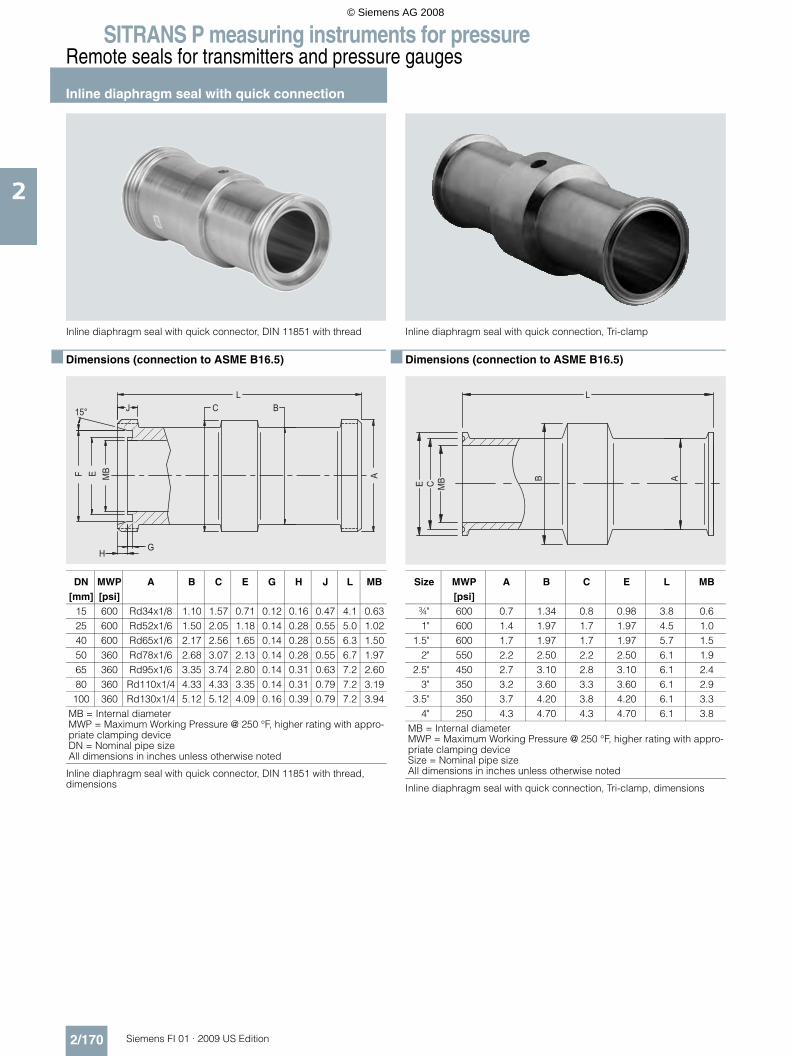
SITRANS P measuring instruments for pressureRemote seals for transmitters and pressure gauges
Inline diaphragm seal with quick connection
2/170 Siemens FI 01 · 2009 US Edition
2
Inline diaphragm seal with quick connector, DIN 11851 with thread
■ Dimensions (connection to ASME B16.5)
Inline diaphragm seal with quick connector, DIN 11851 with thread, dimensions
Inline diaphragm seal with quick connection, Tri-clamp
■ Dimensions (connection to ASME B16.5)
Inline diaphragm seal with quick connection, Tri-clamp, dimensions
DN[mm]
MWP[psi]
A B C E G H J L MB
15 600 Rd34x1/8 1.10 1.57 0.71 0.12 0.16 0.47 4.1 0.6325 600 Rd52x1/6 1.50 2.05 1.18 0.14 0.28 0.55 5.0 1.0240 600 Rd65x1/6 2.17 2.56 1.65 0.14 0.28 0.55 6.3 1.5050 360 Rd78x1/6 2.68 3.07 2.13 0.14 0.28 0.55 6.7 1.9765 360 Rd95x1/6 3.35 3.74 2.80 0.14 0.31 0.63 7.2 2.6080 360 Rd110x1/4 4.33 4.33 3.35 0.14 0.31 0.79 7.2 3.19
100 360 Rd130x1/4 5.12 5.12 4.09 0.16 0.39 0.79 7.2 3.94MB = Internal diameterMWP = Maximum Working Pressure @ 250 °F, higher rating with appro-priate clamping deviceDN = Nominal pipe sizeAll dimensions in inches unless otherwise noted
Size MWP[psi]
A B C E L MB
¾" 600 0.7 1.34 0.8 0.98 3.8 0.61" 600 1.4 1.97 1.7 1.97 4.5 1.0
1.5" 600 1.7 1.97 1.7 1.97 5.7 1.52" 550 2.2 2.50 2.2 2.50 6.1 1.9
2.5" 450 2.7 3.10 2.8 3.10 6.1 2.43" 350 3.2 3.60 3.3 3.60 6.1 2.9
3.5" 350 3.7 4.20 3.8 4.20 6.1 3.34" 250 4.3 4.70 4.3 4.70 6.1 3.8
MB = Internal diameterMWP = Maximum Working Pressure @ 250 °F, higher rating with appro-priate clamping deviceSize = Nominal pipe sizeAll dimensions in inches unless otherwise noted
© Siemens AG 2008
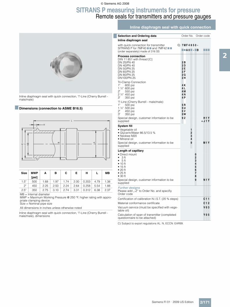
SITRANS P measuring instruments for pressureRemote seals for transmitters and pressure gauges
Inline diaphragm seal with quick connection
2/171Siemens FI 01 · 2009 US Edition
2
Inline diaphragm seal with quick connection, "i"-Line (Cherry Burrell - male/male)
■ Dimensions (connection to ASME B16.5)
Inline diaphragm seal with quick connection, "i"-Line (Cherry Burrell - male/male), dimensions
C) Subject to export regulations AL: N, ECCN: EAR99.
Size MWP[psi]
A B C E H L MB
1.5" 500 1.68 1.97 1.74 2.00 0.203 4.79 1.382" 450 2.25 2.50 2.24 2.64 0.258 5.54 1.88
2.5" 350 2.75 3.10 2.74 3.31 0.312 6.38 2.37MB = Internal diameterMWP = Maximum Working Pressure @ 250 °F, higher rating with appro-priate clamping deviceSize = Nominal pipe sizeAll dimensions in inches unless otherwise noted
Selection and Ordering data Order No. Order code
Inline diaphragm seal
with quick connection for transmitter SITRANS P for 7MF40 7 7 and 7MF42 7 7(order separately) made of 316 SS
C) 7 M F 4 8 5 0 -
77A 0 7 - 7B 777
Process connectionDIN 11 851 with thread [C]DN 25/PN 40DN 40/PN 40DN 50/PN 25DN 65/PN 25DN 80/PN 25DN100/PN 25Tri-Clamp Connection1" 600 psi1 ½" 600 psi2" 550 psi2 ½" 450 psi3" 350 psi"I"-Line (Cherry Burrell - male/male)1" 500 psi1 ½" 500 psi2" 450 psi3" 350 psi
222222
44444
5555
BDEFGH
KLMNP
RUVW
Special design, customer information to be supplied
9 Z+
HJ
11
YY
System fill• Vegetable oil• Glycerin/Water 86.5/13.5 %• Neobee M20• Mineral oil
1234
Special design, customer information to be supplied
9 M 1 Y
Length of capillary• Direct mount• 3 ft• 5 ft• 10 ft• 15 ft• 20 ft• 25 ft• 30 ft
02345678
Special design, customer information to be supplied
9 N 1 Y
Further designsPlease add „-Z“ to Order No. and specifiy Order code
Certification of calibration N.I.S.T. (20 % steps)Material conformance certificateVacuum service (must be specified with vege-table oil)Calculation of span of transmitter (completed questionnaire to be attached)
C
C
V
Y
1
1
0
0
1
2
3
5
© Siemens AG 2008

SITRANS P measuring instruments for pressureRemote seals for transmitters and pressure gauges
Diaphragm seal "threaded design"
2/172 Siemens FI 01 · 2009 US Edition
2
Diaphragm seal "threaded design"
■ Dimensions (Connection to ASME B16.5)
Diaphragm seal "threaded design"
C) Subject to export regulations AL: N, ECCN: EAR99.
Instrumentconnection
Instrumentconnection
Processconnection
Processconnection
Systemfill port
Systemfill port
Optional 1/8” NPT or1/4” NPT flushing
connection
G1 G2 A B DM E F Weight[lbs]
¼"-NPTor
½"-NPT
¼"-NPT or½"-NPT
3.741.18 2.1 2.20 0.63 3.0
¾"-NPT 1.41 2.1 2.36 0.79 3.41"-NPT 1.77 2.1 3.46 1.89 3.6
G1 = Instrument connection, G2 = Process connectionDM = Effective diaphragm diameterAll dimensions in inches unless otherwise noted
Selection and Ordering data Order No. Order code
Diaphragm seal "threaded design" MWP 3675 psiwith flexible armored capillary, 316 stainless steel upper housing SITRANS P for 7MF407 7 and 7MF42 7 7 pressure (order separately)
C) 7 M F 4 8 6 1 -
1 7777 - 7B 777
Size and class• ¼"NPT-female• ½"NPT-female• ¾"NPT-female• 1"NPT-female
ABCD
Special design, customer information to be supplied
Z J 1 Y
Materials and wetted parts• SST 316L• SST 316L with carbon pigmented Teflon lined
diaphragm (good upto 500 °F)• SST 316L with Hastelloy C276 diaphragm• SST 316L with PFA coated diaphragm (good
upto 500 °F)• Monel 400, mat. No. 2.4360• Hastelloy C276, mat. No. 2.4819• Hastelloy C276 lower housing with Tantalum
diaphragm
AE
FD
GJK
Special design, customer information to be supplied
Z K 1 Y
Flushing port(s)None1 x ¼"NPT-female2 x ¼"NPT-female
024
Special design, customer inform. to be supplied 9 L 1 Y
System fill• Silicone oil DC 200-10• Silicone oil DC 200-50• High temperature oil (comes with metal gas-
ket and stronger bolts)• Halocarbon (for O2-application)• Silicone oil M5• Syltherm 800• DC704 silicone oil• Fluorolube
123
45678
Special design, customer inform. to be supplied 9 M 1 Y
Length of capillary• Direct mount• 3 ft• 5 ft• 10 ft• 15 ft• 20 ft• 25 ft• 30 ft
02345678
Special design, customer information to be supplied
9 N 1 Y
Further designsPlease add „-Z“ to Order No. and specify Ord. code
Integrated flame path restrictionDP "H" flange serviceCertification of calibration N.I.S.T. (20 % steps)Material conformance certificateVacuum service (must be specified with HT oil)Calculation of span of transmitter (completed questionnaire to be attached)
ABCCVY
001100
121215
© Siemens AG 2008

SITRANS P measuring instruments for pressureRemote seals for transmitters and pressure gauges
Diaphragm seal "threaded, low-pressure design"
2/173Siemens FI 01 · 2009 US Edition
2
Diaphragm seal "threaded, low-pressure design"
■ Dimensions (Connection to ASME B16.5)
Diaphragm seal "threaded, low-pressure design, dimensions
C) Subject to export regulations AL: N, ECCN: EAR99.
G1 G2 A B C DM E F Weight[lbs]
¼"-NPTor
½"-NPT
¼"-NPT
5.91 4.92
1.25
3.5
3.00 0.90 14.0½"-NPT 1.25 3.00 0.90 14.0¾"-NPT 1.38 3.20 1.10 14.21"-NPT 1.75 3.50 1.40 14.5
G1 = Instrument connectionG2 = Process connectionDM = Effective diaphragm diameterAll dimensions in inches unless otherwise noted
Selection and Ordering data Order No. Order code
Diaphragm seal "threaded, low-pressure design" MWP 1,500 psi
with flexible armored capillary, 316 stainless steel upper housing SITRANS P for 7MF407 7 and 7MF42 7 7 pressure (order separately)
C) 7 M F 4 8 6 2 -
1 7777 - 7B 777
Size and class• ¼"NPT-female• ½"NPT-female• ¾"NPT-female• 1"NPT-female
ABCD
Special design, customer information to be supplied
Z J 1 Y
Materials and wetted parts• SST 316L• SST 316L with carbon pigmented Teflon lined
diaphragm1)
• SST 316L with Hastelloy C276 diaphragm• SST 316L with PFA coated diaphragm1)
• Monel 400, mat. No. 2.4360• Hastelloy C276, mat. No. 2.4819• Hastelloy C276 lower housing with Tantalum
diaphragm
AE
FDGJK
Special design, customer information to be supplied
Z K 1 Y
Flushing port(s)None1 x ¼"NPT-female2 x ¼"NPT-female
024
Special design, customer information to be supplied
9 L 1 Y
System fill• Silicone oil DC 200-10• Silicone oil DC 200-50• High temperature oil (comes with metal gas-
ket and stronger bolts)• Halocarbon (for O2-application)• Silicone oil M5• Syltherm 800• DC704 silicone oil• Fluorolube
123
45678
Special design, customer information to be supplied
9 M 1 Y
Length of capillary• Direct mount• 3 ft• 5 ft• 10 ft• 15 ft• 20 ft• 25 ft• 30 ft
02345678
Special design, customer information to be supplied
9 N 1 Y
Further designsPlease add „-Z“ to Order No. and specifiy Order code
Integrated flame path restrictionCertification of calibration N.I.S.T. (20 % steps)Material conformance certificateVacuum service (must be specified with HT oil)Calculation of span of transmitter (completed questionnaire to be attached)
A
C
C
V
Y
0
1
1
0
0
1
1
2
1
5
© Siemens AG 2008

SITRANS P measuring instruments for pressureRemote seals for transmitters and pressure gauges
Diaphragm seal "threaded, low-pressure design"
2/174 Siemens FI 01 · 2009 US Edition
2
C) Subject to export regulations AL: N, ECCN: EAR99.
Selection and Ordering data Order No. Order code
Diaphragm seal "threaded, low-pressure design" MWP 1,500 psi
with flexible armored capillary, 316 stainless steel upper housing SITRANS P for 7MF44 7 7 (order separately)
C) 7 M F 4 8 6 3 -
1 7777 - 7B 777
Size and class• ¼"NPT-female• ½"NPT-female• ¾"NPT-female• 1"NPT-female
ABCD
Special design, customer information to be supplied
Z J 1 Y
Materials and wetted parts• SST 316L• SST 316L with carbon pigmented Teflon lined
diaphragm (good upto 500 °F)• SST 316L with Hastelloy C276 diaphragm• SST 316L with PFA coated diaphragm (good
upto 500 °F)• Monel 400, mat. No. 2.4360• Hastelloy C276, mat. No. 2.4819• Hastelloy C276 lower housing with Tantalum
diaphragm
AE
FD
GJK
Special design, customer information to be supplied
Z K 1 Y
Flushing port(s)None1 x ¼"NPT-female2 x ¼"NPT-female
024
Special design, customer information to be supplied
9 L 1 Y
System fill• Silicone oil DC 200-10• Silicone oil DC 200-50• High temperature oil (comes with metal gas-
ket and stronger bolts)• Halocarbon (for O2-application)• Silicone oil M5• Syltherm 800• DC704 silicone oil• Fluorolube
123
45678
Special design, customer information to be supplied
9 M 1 Y
Length of capillary• 3 ft• 5 ft• 10 ft• 15 ft• 20 ft• 25 ft• 30 ft
2345678
Special design, customer information to be supplied
9 N 1 Y
Further designsPlease add „-Z“ to Order No. and specifiy Order code
Integrated flame path restrictionCertification of calibration N.I.S.T. (20 % steps)Material conformance certificateVacuum service (must be specified with HT oil)Calculation of span of transmitter (completed questionnaire to be attached)
A
C
C
V
Y
0
1
1
0
0
2
1
2
3
5
© Siemens AG 2008

SITRANS P measuring instruments for pressureRemote seals for transmitters and pressure gauges
Inline diaphragm seal, wafer for pressure
2/175Siemens FI 01 · 2009 US Edition
2
Inline diaphragm seal, wafer for pressure
■ Dimensions (Connection to ASME B16.5)
Inline diaphragm seal, wafer for pressure, dimensions
C) Subject to export regulations AL: N, ECCN: EAR99.
Size Class A MB L Weight[lbs]
1"
150# - 2500#
2.4 1.12
2.36
3.11.5" 3.3 1.69 4.8
2" 3.7 2.15 5.53" 5.1 3.25 8.84" 5.9 4.21 10.35" 7.3 5.20 15.06" 8.5 6.26 20.9
MB = Effective internal diameterClass = Flange rating per ASME B16.5Size = Nominal pipe sizeAll dimensions in inches unless otherwise noted
Optional instruments connectionswelded capillary connection1/4” NPT1/2” NPT
Selection and Ordering data Order No. Order code
Inline diaphragm seals wafer assembled to
SITRANS P for 7MF40 7 7 and 7MF42 7 7 (order separately)
C) 7 M F 4 8 8 0 -
1 77 0 7 - 7B 777
Size and class• 1 inch• 1 ½ inch• 2 inch• 3 inch• 4 inch
class 150 to 2500class 150 to 2500class 150 to 2500class 150 to 2500class 150 to 2500
LMNPQ
Special design, customer information to be supplied
Z J 1 Y
Materials and wetted parts• SST 316L• SST 316L with PFA-Coating (good upto
500 °F)• Monel 400, mat. No. 2.4360• Hastelloy C276, mat. No. 2.4819• Tantal
AD
GJK
Special design, customer information to be supplied
Z K 1 Y
System fill• Silicone oil DC 200-10• Silicone oil DC 200-50• High temperature oil• Halocarbon (for O2-application)• Silicone oil M5• DC704 silicone oil• Fluorolube
1234578
Special design, customer information to be supplied
9 M 1 Y
Length of capillary• Direct mount• 3 ft• 5 ft• 10 ft• 15 ft• 20 ft• 25 ft• 30 ft
02345678
Special design, customer information to be supplied
9 N 1 Y
Further designsPlease add „-Z“ to Order No. and specifiy Order code
Integrated flame path restrictionCertification of calibration N.I.S.T. (20% steps)Material conformance certificateVacuum service (must be specified with HT oil)Calculation of span of transmitter (completed questionnaire to be attached)
A
C
C
V
Y
0
1
1
0
0
1
1
2
1
5
© Siemens AG 2008

SITRANS P measuring instruments for pressureRemote seals for transmitters and pressure gauges
Inline diaphragm seal, wafer for pressure
2/176 Siemens FI 01 · 2009 US Edition
2
C) Subject to export regulations AL: N, ECCN: EAR99.
Selection and Ordering data Order No. Order code
Inline diaphragm seals wafer assembled to
SITRANS P for 7MF44 7 7 (order separately) C) 7 M F 4 8 8 3 -
1 77 0 7 - 7B 777
Size and class• 1 inch• 1 ½ inch• 2 inch• 3 inch• 4 inch
class 150 to 2500class 150 to 2500class 150 to 2500class 150 to 2500class 150 to 2500
LMNPQ
Special design, customer information to be supplied
Z J 1 Y
Materials and wetted parts• SST 316L• SST 316L with PFA-Coating (good upto
500 °F)• Monel 400, mat. No. 2.4360• Hastelloy C276, mat. No. 2.4819• Tantal
ADGJK
Special design, customer information to be supplied
Z K 1 Y
System fill• Silicone oil DC 200-10• Silicone oil DC 200-50• High temperature oil• Halocarbon (for O2-application)• Silicone oil M5• DC704 silicone oil• Fluorolube
1234578
Special design, customer information to be supplied
9 M 1 Y
Length of capillary• 3 ft• 5 ft• 10 ft• 15 ft• 20 ft• 25 ft• 30 ft
2345678
Special design, customer information to be supplied
9 N 1 Y
Further designsPlease add „-Z“ to Order No. and specifiy Order code
Integrated flame path restrictionCertification of calibration N.I.S.T. (20% steps)Material conformance certificateVacuum service (must be specified with HT oil)Calculation of span of transmitter (completed questionnaire to be attached)
A
C
C
V
Y
0
1
1
0
0
2
1
2
3
5
© Siemens AG 2008

SITRANS P measuring instruments for pressureRemote seals for transmitters and pressure gauges
Diaphragm seal, saddle
2/177Siemens FI 01 · 2009 US Edition
2
Diaphragm seal, saddle
■ Dimensions (Connection to ASME B16.5)
Diaphragm seal, saddle, dimensions
Radius To fit Pipe G1R Pipe size O.D.
1.49 2.5 3.00
¼"-NPTor
½"-NPT female
1.77 3.0 3.502.24 4.0 4.502.76 5.0 5.503.35 6.0 6.63
4.311 8.0 8.6255.374 10.0 10.756.378 12.0 12.75
7.0 14.0 14.75G1 = Instrument connectionAll dimensions in inches unless otherwise noted
Clamp ring
Spacer ring Upper housing
Adapter
GTAW
Saddle flange
© Siemens AG 2008

SITRANS P measuring instruments for pressureRemote seals for transmitters and pressure gauges
Diaphragm seal, saddle
2/178 Siemens FI 01 · 2009 US Edition
2
C) Subject to export regulations AL: N, ECCN: EAR99.
Selection and Ordering data Order No. Order code
Diaphragm seal, saddle, MWP 1,500 psi
with flexible armored capillary or direct mount, 316 stainless steel upper housing and assem-ply hardware SITRANS P for 7MF40 7 7 or 7MF42 7 7 (order separately)
C) 7 M F 4 8 9 0 -
1 7777 - 7B 777
Nominal pipe size• Not applicable
(Retrofit for existing 7MF48 7 7)• 2.5"• 3"• 4"• 5"• 6"• 8"• Retrofit 3" Conoflow (6 bolt pattern)• Retrofit 3" M&G style (8 bolt pattern)• Retrofit 4" Conoflow (6 bolt pattern)• Retrofit 4" M&G style (8 bolt pattern)
N
ABCDEGPQRS
Special design, customer information to be supplied
Z J 1 Y
Diaphragm material• SST 316L• SST 316L with carbon pigmented Teflon lined
diaphragm (good upto 500 °F)• SST 316L with PFA coated diaphragm (good
upto 500 °F)• Monel 400, mat. No. 2.4360• Hastelloy C276, mat. No. 2.4819• Tantal
AE
D
GJK
Special design, customer information to be supplied
Z K 1 Y
Saddle MaterialNone (Retrofit order)Carbon steel, Ni platedSST 316LHastelloy C276, mat. No. 2.4819
0124
Special design, customer information to be supplied
9 L 1 Y
System fill• Silicone oil DC 200-10• Silicone oil DC 200-50• High temperature oil (comes with metal gas-
ket and stronger bolts)• Halocarbon (for O2-application)• Silicone oil M5• DC704 silicone oil• Fluorolube
123
4578
Special design, customer information to be supplied
9 M 1 Y
Length of capillary• Direct mount• 3 ft• 5 ft• 10 ft• 15 ft• 20 ft• 25 ft• 30 ft
02345678
Special design, customer information to be supplied
9 N 1 Y
Further designsPlease add „-Z“ to Order No. and specifiy Order code
Integrated flame path restrictionCertification of calibration N.I.S.T. (20 % steps)Material conformance certificateVacuum service (must be specified with HT oil)Calculation of span of transmitter (completed questionnaire to be attached)
A
C
C
V
Y
0
1
1
0
0
1
1
2
1
5
© Siemens AG 2008

SITRANS P measuring instruments for pressureRemote seals for transmitters and pressure gauges
Measuring setups
2/179Siemens FI 01 · 2009 US Edition
2
■ Measuring setups
The following pages show examples of typical measuring setups for use of SITRANS P transmitters with and without remote seals, such as:• Setups for transmitters with connection of remote seals, with
associated equations for calculation.• Questionnaires
Checking of combination between transmitter and remote seal• Setups for transmitters without remote seals, with associated
equations for calculation• Questionnaires
For hydrostatic level measurements
■ Installation
Remote seals of pancake design are fitted between the connec-tion flange of the measuring point and a blind flange. Remote seals of flanged design are fitted directly on the connection flange of the measuring point. The respective pressure rating of the blind flange or the flanged remote seal must be observed. The transmitter should always be installed below the connection flange, and below the lower connection flange in the case of dif-ferential pressure transmitters. When measuring at pressures above atmospheric, the transmitter can also be installed above the connection flange. When measuring at pressures below at-mospheric, the transmitter must always be installed below the connection flange, and below the lower connection flange in the case of differential pressure transmitters.
■ Offset of measuring range
If there is a difference in height between the two connection flanges when measuring with two remote seals, an additional dif-ferential pressure results from the oil filling of the remote seal capillaries. This results in an offset of the actual measuring range and must be taken into account when adjusting the transmitter. An offset in the measuring range also occurs when combining a remote seal with a transmitter if the latter is not installed at the same height as the former.
■ Transmitter output
If the level, separation layer or density increase in closed ves-sels, the differential pressure and the output signal of the trans-mitter also increase. If an inverted relationship is desired be-tween the differential pressure and the output signal, the start-of-scale and full-scale values of the SITRANS P must be inter-changed.
With open vessels, an increasing pressure is usually assigned to an increasing level, separation layer or density.
■ Influence of ambient temperature
The capillaries between the remote seal and the transmitter should be kept as short as possible to obtain the good transmis-sion response. Temperature differences between the individual capillaries or between the individual remote seals should be avoided.
If the complete setup is exposed to temperature variations, er-rors result from the thermal expansion of the filling liquid in the capillaries, in the remote seals and in the connection units of the transmitters.
■ Notes
• When measuring separation layers, ensure that the layer is po-sitioned between the two spigots. Also ensure that the level in the vessel is always above the top spigot.
• When measuring density, make sure that the level of the me-dium remains constant. The level is usually above the top spigot.
■ Possible combinations of transmitter and remote seal
Installation type Transmitter Remote seal
A/B 7MF4033 and7MF4034
7MF4800,7MF4810,7MF4820,7MF4826,7MF4827,7MF4840,7MF4850,7MF4861,7MF4862,7MF4880 and7MF4890
C1/C2 7MF4233 and7MF4234
7MF4800,7MF4810,7MF4820,7MF4826,7MF4827,7MF4840,7MF4850,7MF4861,7MF4862,7MF4880 and7MF4890
(vac
uum
-pro
of d
esig
n re
qui
red
)
7MF4333 and7MF4334
7MF4801 and7MF4821
D 7MF4433 and7MF4434
7MF4803,7MF4823,7MF4828,7MF4843,7MF4863 and7MF4883
E 7MF4433 and7MF4434
7MF4813
G/H/J 7MF4433 and7MF4434
7MF4803,7MF4823,7MF4828,7MF4843,7MF4863 and7MF4883
© Siemens AG 2008

SITRANS P measuring instruments for pressureRemote seals for transmitters and pressure gauges
Measuring setups with remote seals
2/180 Siemens FI 01 · 2009 US Edition
2
■ Schematics
Types of installation for pressure and level measurements (open vessels)
Types of installation for absolute level measurements (closed vessels)
Type of installation for differential pressure and flow measurements
��
��
��
��
��
��
��
��
#����$$�� ��������
4'&�') !)�*&(�G %��F�?�M�#�M������"(��M�#�M��8
?$(()�*&(�G %��F�?�M�#�M������"(�M�#�M��8
#����$$�� ��������
4'&�') !)�*&(�G %��F�?�M�#�M�������"(�M�#�M��8
?$(()�*&(�G %��F�?�M�#�M�������"(�M�#�M��8
%�����%� 4'&�') !)�*&(��+&($��' �C����'%� ?$(()�*&(��+&($��' �C����'? ����"'�� !��� "$��"��+����(�"( ����"'�� !�!"(("�#� "(�"��'-��*&%"((&���'
'-����� '����&(# *&(�&**�(��&'" �� $��' �#�&+"'��� 4'&�') !)�*&(��+&($��� ?$(()�*&(��+&($��8 �"�'&�*��C�',����+����(�!(&�#��&� �%����$���'�&���
�����$���'�&���"''��&C +��'-����&�$�"�#�% "�'
�����$���'�&���"''��C�( ,�'-����&�$�"�#�% "�'
�8���6���0���!'1��,"'-�-&( *&�C �� "(�&��!"(("�#�("E$" � �(���8�������08��8�!'1
#����$$�� �������� #����$$�� ��������
#����$$�� �������&������&�
4'&�') !)�*&(�G %��F�%4;��;����"(��M�#�M��8
?$(()�*&(�G %��F�%�:�����"(�M�#�M��8
%�����%� 4'&�') !)�*&(��+&($��' �C����'%� ?$(()�*&(��+&($��' �C����'%4;��; 4'&�') !)�*&(��+&($�%�:� ?$(()�*&(��+&($��"( ����"'�� !�!"(("�#� "(�"��'-��*&%"((&���'
'-����� '����&(# *&(�&**�(��&'" �� $��' �#�&+"'��8 �"�'&�*��C�',����+����(�!(&�#��&� �%����$���'�&����
8
�8
%&C�
%&C�
�����$���'�&���"''���! ��&C� ($'��%����$���&(,&���C�( ,�'-����&�$�"�#�% "�'G��8����������06�9�"�*-1
#����$$�� �������&� #����$$�� �������&�
��
�N
�8
#����$$�� �������'
4'&�') !)�*&(�G %��F�%4;��;���"(��M�#�M��N
?$(()�*&(�G %��F�%�:����"(�M�#�M��N
%�����%� 4'&�') !)�*&(��+&($��' �C����'%� ?$(()�*&(��+&($��' �C����'%4;��; 4'&�') !)�*&(��+&($�%�:� ?$(()�*&(��+&($��"( ����"'�� !�!"(("�#� "(�"��'-��*&%"((&���'
'-����� '����&(# *&(�&**�(��&'" �� $��' �#�&+"'��N �"�'&�*��C�',����'-����&�$�"�#�% "�'��0�%"# '�1
#����$$�� �������' ?"('���� �"' �"�#
© Siemens AG 2008

SITRANS P measuring instruments for pressureRemote seals for transmitters and pressure gauges
Measuring setups with remote seals
2/181Siemens FI 01 · 2009 US Edition
2
Types of installation for level measurements (closed vessels)
��
�N
#����$$�� �������(
4'&�') !)�*&(�G %��F�?�M�#�M������"(��M�#�M��N
?$(()�*&(�G %��F�?�M�#�M������"(�M�#�M��N
%�����%� 4'&�') !)�*&(��+&($��' �C����'%� ?$(()�*&(��+&($��' �C����'? ����"'�� !��� "$��"��+����(�"( ����"'�� !�!"(("�#� "(�"��'-��*&%"((&���'
'-����� '����&(# *&(�&**�(��&'" �� $��' �#�&+"'��� 4'&�') !)�*&(��+&($��� ?$(()�*&(��+&($��N �"�'&�*��C�',����'-����&�$�"�#�% "�'��0�%"# '�1
#����$$�� �������(
��
��
��
��
��
�N
��
�8
#����$$�� �������)*������+
4'&�') !)�*&(�G %��F�?�M�#�M������"(��M�#�M��N
?$(()�*&(�G %��F�?�M�#�M������"(�M�#�M��N
%�����%� 4'&�') !)�*&(��+&($��' �C����'%� ?$(()�*&(��+&($��' �C����'? ����"'�� !��� "$��"��+����(�"( ����"'�� !�!"(("�#� "(�"��'-��*&%"((&���'
'-����� '����&(
# *&(�&**�(��&'" �� $��' �#�&+"'��� 4'&�') !)�*&(��+&($��� ?$(()�*&(��+&($��N �"�'&�*��C�',����'-����&�$�"�#�% "�'��0�%"# '�1
�8
��
#����$$�� �������+
C�',����'-����&�$�"�#�% "�'���� �+&*$$�
�����6���0���!'1��,"'-�-&( *&�C �� "(�&�!"(("�#�("E$" � �(�����������08��8�!'1
�8
��
#����$$�� �������
C�( ,�'-��( ,�����&�$�"�#�% "�'
#����$$�� �������)
�����$���'�&���"''���! �� "!!����'"&(�%����$��&C +��'-��$%%�����&�$�"�#�% "�'��� �+&*$$�
�8���6���0���!'1��,"'-�-&( *&�C �� "(�&�!"(("�#�("E$" � �(���8�������08��8�!'1
© Siemens AG 2008

SITRANS P measuring instruments for pressureRemote seals for transmitters and pressure gauges
Measuring setups without remote seals
2/182 Siemens FI 01 · 2009 US Edition
2
■ Overview
Notes• For the separation layer measurement, the separation layer
has to be positioned between the two spigots.
Also you must make sure that the level in the container is al-ways above the top spigot.
• When measuring density, make sure that the level of the me-dium remains constant. The level should be above the top spigot
■ Schematics
Pressure transmitters for differential pressure, for flanging
Measuring setups for open containers
D
�
�$
%�,�$�-������-���
4'&�') !)�*&(�G %��F��M�#�M���
?$(()�*&(�G %��F��M�#�M���
%�����%� 4'&�') !)�*&(��+&($��' �C����'%� ?$(()�*&(��+&($��' �C����' ����"'�� !��� "$��"��+����(# *&(�&**�(��&'" �� $��' �#�&+"'��� 4'&�') !)�*&(��+&($��� ?$(()�*&(��+&($�
?$(()�*&(��+&($�
4'&�') !)�*&(��+&($�
�$
�
8�
D
������� ��$�����-������-���
4'&�') !)�*&(�G %��F�#�M�0���M�8���0������1�M��1
?$(()�*&(�G %��F�8�M�#�M���
%�����%� 4'&�') !)�*&(��+&($��' �C����'%� ?$(()�*&(��+&($��' �C����'8 ����"'�� !�-�&+"���("E$" � ����"'�� !�("#-'���("E$" # *&(�&**�(��&'" �� $��' �#�&+"'��� 4'&�') !)�*&(��+&($��� ?$(()�*&(��+&($�
� ��'&�'�(�+�(F�!$(()�*&(��+&($�
4'&�') !)�*&(��+&($�
4�%&�&'" ��(&���
�
D
'��� ���-������-���
4'&�') !)�*&(�G %��F��:�M�#�M���
?$(()�*&(�G %��F��O�M�#�M���
%������%� 4'&�') !)�*&(��+&($��' �C����'%� ?$(()�*&(��+&($��' �C����'�: "�"�$�� ���"'�� !��� "$��"��+����(�O &="�$�� ���"'�� !��� "$��"��+����(# *&(�&**�(��&'" �� $��' �#�&+"'��� ?$(()�*&(��+&($��"���
� ��'&�'�(�+�(
© Siemens AG 2008

SITRANS P measuring instruments for pressureRemote seals for transmitters and pressure gauges
Measuring setups without remote seals
2/183Siemens FI 01 · 2009 US Edition
2
Measuring setups for closed containers
�
�$
%�,�$�-������-���*�.��� ���
4'&�') !)�*&(�G �%��F��M�#�M���
?$(()�*&(�G �%��F��M�#�M���
%������%� 4'&�') !)�*&(��+&($��' �C����'�%� ?$(()�*&(��+&($��' �C����' ����"'�� !��� "$��"��+����(# *&(�&**�(��&'" �� $��' �#�&+"'��� 4'&�') !)�*&(��+&($��� ?$(()�*&(��+&($�
&="�$��(�+�(
4'&�') !)�*&(��+&($�
?$(()�*&(��+&($�
;�&���"''����!����*��("��
4'&'"*%����$�� �&�)!"((� ���#&'"+�
%����$���("��
Maximum level
�
P � +
�$
��
8
������� ��$�����-������-���
4'&�') !)�*&(�G �%��F�#�M�0���M�8���0������1�M�����N�M�P�1
?$(()�*&(�G �%��F�#�M�0���M�8���N�M�P�1
%������%� 4'&�') !)�*&(��+&($��' �C����'�%� ?$(()�*&(��+&($��' �C����'8 ����"'�� !�-�&+"���("E$" �,"'-���%&�&'" ��(&���
"��+����(� ����"'�� !�("#-'���("E$" �,"'-���%&�&'" ��(&���P� ����"'�� !�("E$" �"��'-����#&'"+��%����$���("��
0* ����% � "�#�' �'-��'��%��&'$����="�'"�#�'-���1# *&(�&**�(��&'" �� $��' �#�&+"'��� 4'&�') !)�*&(��+&($��� ?$(()�*&(��+&($��N �"�'&�*��C�',����'-����&�$�"�#�% "�'�
0�%"# '�1
&=����%&�&'" ��(&���
4'&�') !)�*&(��+&($�
?$(()�*&(��+&($�
4'&'"*%����$��
� ��'&�'�(�+�(
4'&'"*%����$��
;�&���"''����!����*��("��
© Siemens AG 2008

2/184 Siemens FI 01 · 2009 US Edition
2
s Questionnaire (suitable for US market)
for hydrostatic level measurements
s
Order date: _______________________________________________
Processing date: __________________________________________
Ordering code (customer): _________________________________
Ordering code (supplier): __________________________________
Customer reference:_______________________________________
Measuring point: __________________________________________
Position:__________________________________________________
Dimensions: ______________________________________________
Pressure: psi
Temperature: K °F
Measuring range: inch ft(please mark with cross)
Order No. of transmitter 1):
Y01
The different pressures and tem-peratures (densities) in the vessel and in the reference column result in an offset in the start-of-scale and full-scale values.The calibration data are deter-mined in addition.It is also checked whether – as a result of the range offset – the ordered transmitter is suitable for this measurement.
Please supply the following characteristic data so that we can calculate the measuring range, start-of-scale value, full-scale value and calibration data:
1) Reference line filled with condensation! Falling differential pressure with increasing level.2) Reference line without gas or filled with gas (air). Rising differential pressure with increasing level.3) If not specified otherwise, this value is assumed as the calculation pressure of the level meter.
The input signal (differential pressure) depends on the density (pressure and temperature). The influence is practically negligible for a lowest liquid level of 20 to 30% of the distance between the measuring points.
4) If a pressure correction of the level is required, the measuring range must be the same as the distance between the measuring points, and the transmitter is designed for the calculation pressure of 1 bar (absolute).Pressure correction means: the static pressure and the temperature are measured separately and calculated by a correction computer or measured-value computer.
7 M F 4 – –Z–
Please mark type of boiler with a cross: Closed 1)
Open or not under pressure 2)
Medium ____________________
Licensed boiler pressure (absolute) _______________ psi
Operating pressure (absolute) Lowest _______________ psi
Normal 3) _______________ psi
Highest _______________ psi
Temperature of reference column (cold) _______________ °F
Distance between measuring points (dimension according to sketch) HV = _________ ft
Measuring range 4) = start-of-scale value to full-scale value
Start-of-scale value HU =___________ ft
Full-scale value HO =___________ ft
Position of equalizing vessel above bottom measuringpoint if different from HV _______________ ft
Please mark pressure correction of level with a cross: No
Yes 4)
© Siemens AG 2008

2/185Siemens FI 01 · 2009 US Edition
2
s Questionnaire (suitable for US market)
Checking of transmitter/remote seal combinations
s
* Customer:___________________ Tag. No.: _____________________* Plant: ___________________ Item No.: _____________________* Ordering code:________________ Person responsible: ___________* Ordering department: _____ Phone: _____________________* Transmitter Order No.: 7MF 4 –1 –1
Order No. of transmitter known?
* Order No. of remote seal:* 7MF 4 8 – – –Z
Suffixes _______________________Suffixes _______________________
* Or without Order No.: Process connection* Standard: ________________________* Nominal diameter: ________________________* Nominal pressure: ________________________* Constructional design: Pancake-type rem. seal
Flanged remote seal Quick-release remote seal Clamp-on seal Other.: ______________
* Connection: Direct connection Capillary on one side; connection to: + side – side Capillaries on both sides; Capillary length: ___ ft
* Vacuum-proof design Yes No* Wetted parts materials: ________________________* Tube: No Yes, __inch long* Filling liquid ________________________* Miscellaneous ________________________
Calculation of measuring range necessary?
* Medium ____________________________* Density of medium: _______ kg/m3
* Temperature of medium: Normal ________ °FMinimum ________ °FMaximum ________ °F
* Ambient temperature on capillaries: Normal ________ °FMinimum ________ °FMaximum ________ °F
* Ambient temperature on transmitter: Normal ________ °FMinimum ________ °FMaximum ________ °F
* Operating pressure referred to absolute zero: ____ psiabs* Does a vacuum occur during startup? No Yes
If yes, associated temperature of medium: ________ °F* Installation type, see pages 2/180 and 2/181
* Measuring: With install. types A, B, C1, C2 and D: from ___ to ___ psi range With install. types A, B, G, H and J: HU = ___ inch; HO = ___ inch* Dimensions: With install. types A, B, C1 and C2: H1 = ___ inch
With install. types D, G, H and J: HV = ___ inch* Start-of-scale value following calculation: _________ psi ( 4 mA)* Full-scale value following calculation: _________ psi (20 mA)* Associated span: _________ psi* Error to be expected: _________ of set span per 18 °F
_________ change in temperature
A B C2C1
E JHG
D
< , %
NoYes
* Range to be set:* (without calculation)
Start-of-scale:_________ psi ( 4 mA)Full-scale: _________ psi (20 mA)
* Required measuring accuracy:Error: _________ of set span per: _________ 18 °F change in : _________ temperature
< . %
*) Values must be entered here!
Please fill in this questionnaireand enclose with every order!
No Yes
Checked: Name:Department:Date:
© Siemens AG 2008

SITRANS P measuring instruments for pressureFittings
Technical description, Selection aid
2/186 Siemens FI 01 · 2009 US Edition
2
■ Overview
All 21-off fittings can be secured onto walls, racks (72 mm grid) and vertical and horizontal pipes.
This offers the advantage when assembling a plant that the shut-off fittings can be secured first and the lines for the medium and differential pressure connected to them. It is then possible to check all connections for leaks and to blow out or flush the pipes in order to remove dirt (welding residues, shavings etc.).
The measuring instruments can be screwed onto the shut-off fit-tings right at the end when all piping has been completed.
If an instrument has to be removed for maintenance, the fittings and pipes remain as they are. It is only necessary to close the valves – the instrument can then be removed, and refitted follow-ing maintenance.
Material acceptance test certificate to EN 10204-3.1
If a material acceptance test certificate to EN 10204-3.1 is re-quired when ordering valve manifolds or shut-off fittings, please note that a single certificate is sufficient for each ordered item type. This means that you will only be charged for one certificate in the cost calculations.
■ Selection of available shut-off valves
Transmitters Shut-off valves for general applications
Page Shut-off valves for special applications
Page
Relative and absolute pres-sure transmitters with process connection G½" male threade.g.• SITRANS P, Z series
7MF1564-.....-.A..• SITRANS P300
7MF802.-...0.-....• SITRANS P DS III series
7MF403.-...0.-.... and7MF423.-...0.-....
Double shut-off valve DN 5 for crossover ½-NPT-F to G½ nipple connection7MF9011-4EA
2/187
Relative and absolute pres-sure transmitter with G½"-14 NPT female thread• e.g.• SITRANS P Z series
7MF1564-.....-.H..• SITRANS P300
7MF802.-...1.-....• SITRANS P DS III series
7MF403.-...1.-.... and 7MF423.-...1.-....
Double shut-off valve DN 57MF9011-4FA and 7MF9011-4GA
2/187 Double shut-off valve DN 5 for process connection ½-NPT7MF9011-4DA
2/187
Absolute pressure transmitter with process connection to IEC 61518e.g.• SITRANS P DS III series
7MF433.-...
2-spindle valve manifold DN 57MF9411-5A.
2/189
Differential pressure transmit-ter with process connection to IEC 61518e.g.• SITRANS P DS III series
7MF443.-... and 7MF453.-...
For 3/5-spindle valve manifold DN 57MF9411-5B. and 7MF9411-5C.
2/189
© Siemens AG 2008

SITRANS P measuring instruments for pressureFittings
Double shut-off valves
2/187Siemens FI 01 · 2009 US Edition
2
■ Overview
The double shut-off valves DN 5 are suitable for pressure gages and pressure transmitters and available in 4 versions:• Sleeve-collar• Sleeve-sleeve• Sleeve-nipple• Collar-collar
■ Characteristic curves
Permissible operating pressure as a function of the permissible operating temperature
■ Dimensional drawings
Double shut-off valve DN 5 (sleeve-sleeve) 7MF9011-4DA, dimensions in mm
Double shut-off valve DN 5 (sleeve-nipple) 7MF9011-4EA, dimensions in mm
Double shut-off valve DN 5 (sleeve-collar) 7MF9011-4FA, dimensions in mm
Double shut-off valve DN 5 (collar-collar) 7MF9011-4GA, dimensions in mm
Selection and Ordering data Order No.
Double shut-off valves DN 5
Material: X 6 CrNiMoTi 17 13 2 (mat. No. 1.4404/316L), max. permissible working pressure 420 bar;
• Sleeve-sleeve 7MF9011-4DA
• Sleeve-nipple connection 7MF9011-4EA
• Sleeve-collar 7MF9011-4FA
• Collar-collar 7MF9011-4GA
Accessories
Factory test certificate EN 10204–2.2 7MF9000-8AB
Material acceptance test certificate EN 10204-3.1
7MF9000-8AD
�
8��
���
���
���C&�
A�� 8�� ��� ��� ���
�%��&'"�#�%����$��
�%��&'"�#�'��%��&'$��
����C&��&'�8���A��7��C&��&'�����A�
86�
�&
�7�7
8� �8<�
<��7
��
�8�67
6
7�
&%%� =��88/
&%%� =��9�
"&���<��
� � ���*'" �� �� �+"*���" �G�2)8��:�;3 � ���*'" �� ����&�$�����'��" �G�2)8��:�;� N��'�&� �'��'�* ���*'" �G�H)8/�:�;
�8�67<��8
8�
&�
�7�7
��
�
8/
<
<��7 8�
��7
8/�7
867�
6
&%%� =��9�&%%� =��88/
"&��<��
"&���6&%%� =����7/
� � ���*'" �� �� �+"*���" �G��"%%(��' ���:�8<��/����2��45��63 � ���*'" �� ����&�$�����'��" �G�2)8��:�;� N��'�&� �'��'�* ���*'" �G�H)8/�:�;
� � ���*'" �� �� �+"*���" �G�2)8��:�;3 � ���*'" �� ����&�$�����'��" �G�2)8��:�;� N��'�&� �'��'�* ���*'" �G�H)8/�:�;
88�
2)8��:�;
H)8/�:�
;
2)8��:�;
�
�
&
B
C
A
A Connection on device side : ½-14 NPTB Connection on measurement side: ½-14 NPTC Vent and test connection: ¼-18 NPT
© Siemens AG 2008

SITRANS P measuring instruments for pressureFittings
Double shut-off valves
2/188 Siemens FI 01 · 2009 US Edition
2
■ Overview
The mounting set is suitable for the double shut-off valves 7MF9011-4.A and for wall, rack and pipe mounting.
■ Dimensional drawings
Mounting bracket (7MF9011-8AB) for shut-off valves 7MF9011-4DA and 7MF9011-4EA for wall, rack or pipe mounting, dimensions in mm
Mounting bracket (7MF9011-8AC) for shut-off valves 7MF9011-4FA and 7MF9011-4GA for wall, rack or pipe mounting, dimensions in mm
Selection and Ordering data Order No.
Mounting set for shut-off valves
• 7MF9011-4DA und -4EAmade of stainless steel, scope of delivery:1x mounting bracket, 2x hexagon screws M6x40, 1x mounting clip, 2x washers 8.4 to DIN 125;2x hexagon nuts 8.4 to DIN EN 24032
7MF9011-8AB
• 7MF9011-4FA und -4GAmade of stainless steel, scope of delivery:1x mounting bracket, 2x hexagon screws M6x10, 1x mounting clip, 2x washers 8.4 to DIN 125;2x hexagon nuts 8.4 to DIN EN 24032
7MF9011-8AC
hex. 10
65
4
R30
6.5
Ø60.3
85
100
25
115072
9072
90
SW10
© Siemens AG 2008
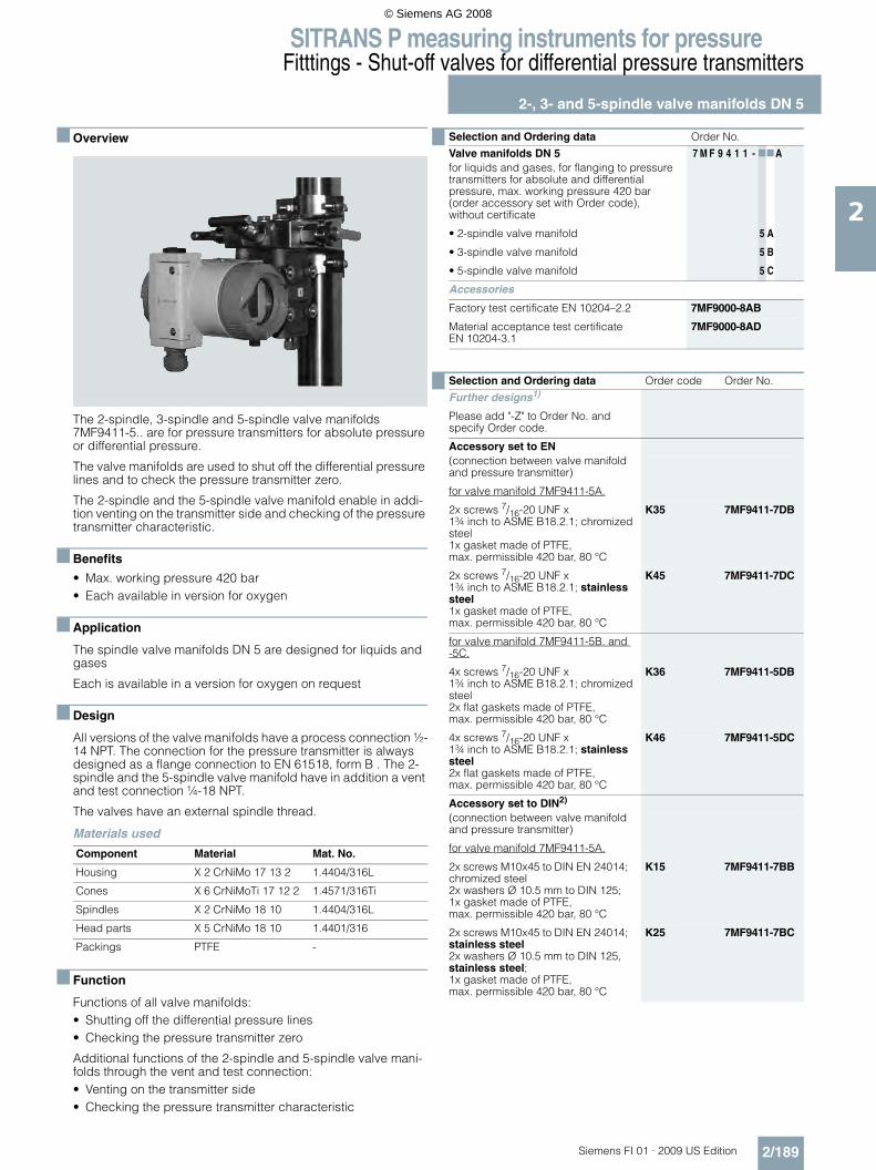
SITRANS P measuring instruments for pressureFitttings - Shut-off valves for differential pressure transmitters
2-, 3- and 5-spindle valve manifolds DN 5
2/189Siemens FI 01 · 2009 US Edition
2
■ Overview
The 2-spindle, 3-spindle and 5-spindle valve manifolds 7MF9411-5.. are for pressure transmitters for absolute pressure or differential pressure.
The valve manifolds are used to shut off the differential pressure lines and to check the pressure transmitter zero.
The 2-spindle and the 5-spindle valve manifold enable in addi-tion venting on the transmitter side and checking of the pressure transmitter characteristic.
■ Benefits
• Max. working pressure 420 bar• Each available in version for oxygen
■ Application
The spindle valve manifolds DN 5 are designed for liquids and gases
Each is available in a version for oxygen on request
■ Design
All versions of the valve manifolds have a process connection ½-14 NPT. The connection for the pressure transmitter is always designed as a flange connection to EN 61518, form B . The 2-spindle and the 5-spindle valve manifold have in addition a vent and test connection ¼-18 NPT.
The valves have an external spindle thread.
Materials used
■ Function
Functions of all valve manifolds:• Shutting off the differential pressure lines• Checking the pressure transmitter zero
Additional functions of the 2-spindle and 5-spindle valve mani-folds through the vent and test connection:• Venting on the transmitter side• Checking the pressure transmitter characteristic
Component Material Mat. No.
Housing X 2 CrNiMo 17 13 2 1.4404/316L
Cones X 6 CrNiMoTi 17 12 2 1.4571/316Ti
Spindles X 2 CrNiMo 18 10 1.4404/316L
Head parts X 5 CrNiMo 18 10 1.4401/316
Packings PTFE -
Selection and Ordering data Order No.
Valve manifolds DN 5 7 M F 9 4 1 1 - 77Afor liquids and gases, for flanging to pressure transmitters for absolute and differential pressure, max. working pressure 420 bar (order accessory set with Order code),without certificate
• 2-spindle valve manifold 5 A
• 3-spindle valve manifold 5 B
• 5-spindle valve manifold 5 C
Accessories
Factory test certificate EN 10204–2.2 7MF9000-8AB
Material acceptance test certificate EN 10204-3.1
7MF9000-8AD
Selection and Ordering data Order code Order No.
Further designs1)
Please add "-Z" to Order No. and specify Order code.
Accessory set to EN(connection between valve manifold and pressure transmitter)
for valve manifold 7MF9411-5A.
2x screws 7/16-20 UNF x 1¾ inch to ASME B18.2.1; chromized steel1x gasket made of PTFE, max. permissible 420 bar, 80 °C
K35 7MF9411-7DB
2x screws 7/16-20 UNF x 1¾ inch to ASME B18.2.1; stainless steel1x gasket made of PTFE, max. permissible 420 bar, 80 °C
K45 7MF9411-7DC
for valve manifold 7MF9411-5B. and -5C.
4x screws 7/16-20 UNF x 1¾ inch to ASME B18.2.1; chromized steel2x flat gaskets made of PTFE, max. permissible 420 bar, 80 °C
K36 7MF9411-5DB
4x screws 7/16-20 UNF x 1¾ inch to ASME B18.2.1; stainless steel2x flat gaskets made of PTFE, max. permissible 420 bar, 80 °C
K46 7MF9411-5DC
Accessory set to DIN2)
(connection between valve manifold and pressure transmitter)
for valve manifold 7MF9411-5A.
2x screws M10x45 to DIN EN 24014; chromized steel2x washers Ø 10.5 mm to DIN 125;1x gasket made of PTFE, max. permissible 420 bar, 80 °C
K15 7MF9411-7BB
2x screws M10x45 to DIN EN 24014; stainless steel2x washers Ø 10.5 mm to DIN 125, stainless steel;1x gasket made of PTFE, max. permissible 420 bar, 80 °C
K25 7MF9411-7BC
© Siemens AG 2008

SITRANS P measuring instruments for pressureFitttings - Shut-off valves for differential pressure transmitters
2-, 3- and 5-spindle valve manifolds DN 5
2/190 Siemens FI 01 · 2009 US Edition
2
■ Accessories
Accessory set for 2-, 3- and 5-spindle valve manifolds
2-spindle valve manifold DN 5 • K35: 2 screws 7/16-20 UNF x 1¾ inch to ASME B18.2.1,
1 flat gasket• K15: 2 screws M10x45 to DIN EN 24014, 2 washers,
1 flat gasket
3-spindle and 5-way valve manifold DN 5 • K36: 4 screws 7/16-20 UNF x 1¾ inch to ASME B18.2.1,
2 flat gaskets• K16: 4 screws M10x45 to DIN EN 24014, 4 washers,
2 flat gaskets
Washers Ø 10.5 to DIN 125
Flat gaskets made of PTFE, max. 420 bar, 80 °C
Note: Flange connection with M10 screws only permissible up to PN 160!
Mounting plate
Made of electrogalvanized sheet-steel• M11: For wall mounting or for securing on rack (72 mm grid)
Scope of delivery: - 1 mounting plate with bolts for mounting on valve manifold
• M12: For pipe mountingScope of delivery: - 1 mounting plate M11- 2 pipe brackets with nuts and washers for pipes with max.
Ø 60.3 mm
Valve manifold 100 bar, suitable for oxygen• S12: For 2-way valve manifold• S13: For 3-way valve manifold• S13: For 5-way valve manifold
■ Characteristic curves
Valve manifolds PN 5 (7MF9411-5..), permissible working pressure as a function of the permissible working temperature
for valve manifolds 7MF9411-5B. and -5C.
4x screws M10x45 to DIN EN 24014; chromized steel4x washers Ø 10.5 mm to DIN 125;2x flat gaskets made of PTFE, max. permissible 420 bar, 80 °CFlange connection with M10 screws only permissible up to PN 160.
K16 7MF9411-6BB
4x screws M10x45 to DIN EN 24014; stainless steel4x washers Ø 10.5 mm to DIN 125, stainless steel;2x flat gaskets made of PTFE, max. permissible 420 bar, 80 °CFlange connection with M10 screws only permissible up to PN 160.
K26 7MF9411-6BC
Mounting plate
• for valve manifold, made of electrogalvanized sheet-steel- for wall mounting or for securing
on rack (72 mm grid), weight 0.5 kgScope of delivery:1 mounting plate with bolts for mounting on valve manifold
M11 7MF9006-6EA
- for pipe mounting, weight 0.7 kgScope of delivery:1x mounting plate M11, 2x pipe brackets with nuts and washers (for pipe with max. Ø 60.3 mm)
M12 7MF9006-6GA
• for valve manifold, made of stainless steel- for wall mounting or for securing
on rack (72 mm grid), weight 0.5 kgScope of delivery:1 mounting plate with bolts for mounting on valve manifold
M21 7MF9006-6EC
- for pipe mounting, weight 0.7 kgScope of delivery:1x mounting plate M11, 2x pipe brackets with nuts and washers (for pipe with max. Ø 60.3 mm)
M22 7MF9006-6GC
Valve manifold 100 barSuitable for oxygen• for 7MF9411-5A. S12• for 7MF9411-5B. S13• for 7MF9411-5C. S14
1) When ordering accessory set or mounting together with the valve manifolds, please use Order code; otherwise use Order No.
2) Flange connections to DIN 19213 only permissible up to 160!
Selection and Ordering data Order code Order No.
Further designs1)
Please add "-Z" to Order No. and specify Order code.
�
���
���
&��
+��-��
B"� ��� ��� &�� +��
���
�� ��
������
����
����� ���� �0���� ���
© Siemens AG 2008
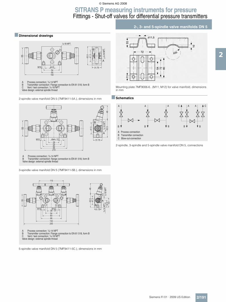
SITRANS P measuring instruments for pressureFitttings - Shut-off valves for differential pressure transmitters
2-, 3- and 5-spindle valve manifolds DN 5
2/191Siemens FI 01 · 2009 US Edition
2
■ Dimensional drawings
2-spindle valve manifold DN 5 (7MF9411-5A.), dimensions in mm
3-spindle valve manifold DN 5 (7MF9411-5B.), dimensions in mm
5-spindle valve manifold DN 5 (7MF9411-5C.), dimensions in mm
Mounting plate 7MF9006-6.. (M11, M12) for valve manifold, dimensions in mm
■ Schematics
2-spindle, 3-spindle and 5-spindle valve manifold DN 5, connections
� �� *����* ���*'" �G�2)8��:�;3� ;�&���"''���* ���*'" �G�?(&�#��* ���*'" ��' ��:�<8�78/��! ���3� N��'���'��'�* ���*'" �G�H)8/�:�;N&(+�� ��"#�G��='���&(��%"� (��'-��&
�������
��� ��������
���
����
�������
����
�
��
����
�������
��
���
����������������������
���
�
�
� �� *����* ���*'" �G�2)8��:�;3 ;�&���"''���* ���*'" �G�!(&�#��* ���*'" ��' ��:�<8�78/��! ���3N&(+�� ��"#�G��='���&(��%"� (��'-��&
���������
�
���
��
����
���
��
��� ��
�������
�������
����
���
�
�
�
� �� *����* ���*'" �G�2)8��:�;3 ;�&���"''���* ���*'" �G�?(&�#��* ���*'" ��' ��:�<8�78/��! ���3� N��'���'��'�* ���*'" �G�H)8/�:�;N&(+�� ��"#�G��='���&(��%"� (��'-��&
�
,
�
,
�
,
�
," "
�
,
,������������ ������/����0� ������ ��"�������� ���� ��
© Siemens AG 2008

SITRANS P measuring instruments for pressureFittings - Accessories
Oval flange
2/192 Siemens FI 01 · 2009 US Edition
2
■ Overview
The oval flange 7MF9408-2C. for pressure transmitters for abso-lute pressure and differential pressure has a ½-14 NPT female thread and is designed for max. operating pressure 400 bar.
■ Accessories
• E34: 2 screws 7/16-20 UNF x 1½ inch to ASME B18.3, 1 O-ring (FPM 90)
• E13: 2 screws M10x40 to DIN EN 4762, 2 washers, 1 O-ring (FPM 90)
• E36: 2 screws 7/16-20 UNF x 1½ inch to ASME B18.2.1, 1 flat gasket
• E16: 2 screws M10x40 to DIN EN ISO 4762, 2 washers, 1 flat gasket
Washers Ø 10.5 to DIN 125
Flat gaskets made of PTFE, max. 420 bar, 80 °C
O-ring to DIN 3771, 20 x 2.65 – S – FPM90, max. 420 bar, 120 °C
Note: M10 screws only permissible up to PN 160!
■ Dimensional drawings
Oval flange 7MF9408-2C, dimensions in mm
7
Selection and Ordering data Order No.
Oval flangewith female thread ½-14 NPT, max. working pressure 420 bar, flange connection to DIN EN 61518, form A
Material
P250GH, mat. No.: 1.0460 7MF9408-2CE
X 2 CrNiMo 17 13 2, mat. No. 1.4404/316L 7MF9408-2CL
Selection and Ordering data Order code Order No.
Further designs
Please add "-Z" to Order No. and specify Order code.
Accessory set to EN1)
2x screws 7/16-20 UNF x 1½ inch to ASME B 18.2.3; chromized steel1x flat gasket made of PTFE, max. permissible 420 bar, 80 °C
E36 7MF9408-5DA
2x screws 7/16-20 UNF x 1½ inch to ASME B 18.2.3; chromized steel1x O-ring to DIN 3771, 20 x 2.65 - S - FPM90, max. permissble 420 bar, 120 °C
E34 7MF9408-5CA
Accessory set to DIN1)
1) When ordering accessory set together with the oval flange, pleaseuse Order code; otherwise use Order No.
2x screws M10x40 to DIN EN ISO 4762; chromized steel2x washers Ø 10.5 mm to DIN 125;1x O-ring to DIN 3771, 20 x 2.65 - S - FPM90, max. permissble 420 bar, 120 °C2)
2) Flange connections with M10 screws only permissible up to PN 160!
E13 7MF9408-6AA
2x screws M10x40 to DIN EN ISO 4762; chromized steel2x washers Ø 10.5 mm to DIN 125;1x flat gasket made of PTFE, max. permissible 420 bar, 80 °C2)
E16 7MF9408-6BA
© Siemens AG 2008