Embed Size (px)
Citation preview
SITRANS P measuring instruments for pressureRemote seals for transmitters and pressure gauges
Technical description
2/111Siemens FI 01 · 2005
2■ Overview
In many cases the pressure transmitter and the measured me-dium have to be physically separated. It is then necessary to use a remote seal.
The remote seals can be used with the following SITRANS P pressure transmitter series:• Pressure (MK II, MS, DS III, DS III PA, DS III FF)• Absolute pressure (DS III, DS III PA, DS III FF)• Differential pressure and flow (DS III, DS III PA, DS III FF)
Note
When configuring your remote seal, be sure to read the informa-tion about transmission response, temperature error and re-sponse time to be found in the sections "Function" and "Technical data". Only then will the remote seal work to optimum effect.
■ Benefits
• No direct contact between the pressure transmitter and the medium
• Individual configuration of the pressure transmitter for perfect adaptation to the operating conditions
• Available in many versions• Specially designed for difficult operating conditions• Quick-release versions available for the food industry
■ Application
Remote seal systems should be used if a separation between the measured medium and the measuring instrument is essential or appropriate.
Examples of such cases:• The temperature of the medium is outside the limits specified
for the pressure transmitter.• The medium is corrosive and requires diaphragm materials
which are not available for the pressure transmitter.• The medium is highly viscous or contains solids which would
block the measuring chambers of the pressure transmitter.• The medium may freeze in the measuring chambers or pulse
line.• The medium is heterogeneous or fibrous.• The medium tends towards polymerization or crystallization.• The process requires quick-release remote seals, as neces-
sary e.g. in the food industry for fast cleaning.• The process requires cleaning of the measuring point, e.g. in
a batch process.
■ Design
A remote seal system consists of the following components.• Pressure transmitter• One or two remote seals• Filling liquid• Connection between pressure transmitter and remote seal (di-
rect mounting or by means of capillary)
The volume in contact with the measured medium is terminated by a flat elastic diaphragm lying in a bed. Between the dia-phragm and the pressure transmitter is the filling liquid.
In many cases, a capillary has to be connected between the re-mote seal and the pressure transmitter in order e.g. to minimize temperature effects on the latter when hot media are involved.
However, the capillary influences the response time and the tem-perature response of the complete remote seal system. Two ca-pillaries of equal length must always be used to connect a re-mote seal to a pressure transmitter for differential pressure.
The remote seal can be optionally equipped with a projecting di-aphragm (tube).
Remote seals of sandwich design are fitted with a dummy flange.
Designs
Diaphragm seal
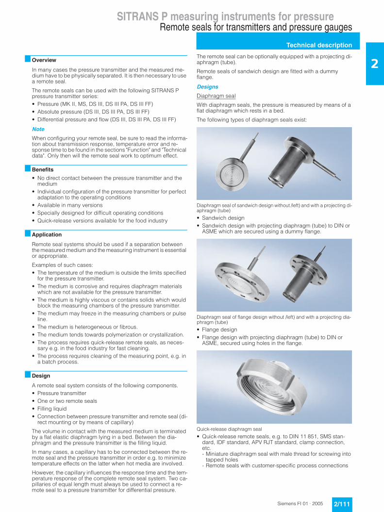
With diaphragm seals, the pressure is measured by means of a flat diaphragm which rests in a bed.
The following types of diaphragm seals exist:
Diaphragm seal of sandwich design without /left) and with a projecting di-aphragm (tube)
• Sandwich design• Sandwich design with projecting diaphragm (tube) to DIN or
ASME which are secured using a dummy flange.
Diaphragm seal of flange design without /left) and with a projecting dia-phragm (tube)
• Flange design• Flange design with projecting diaphragm (tube) to DIN or
ASME, secured using holes in the flange.
Quick-release diaphragm seal
• Quick-release remote seals, e.g. to DIN 11 851, SMS stan-dard, IDF standard, APV RJT standard, clamp connection, etc. - Miniature diaphragm seal with male thread for screwing into
tapped holes- Remote seals with customer-specific process connections

SITRANS P measuring instruments for pressureRemote seals for transmitters and pressure gauges
Technical description
2/112 Siemens FI 01 · 2005
2
Miniature diaphragm seal with diaphragm flush with front
• Miniature diaphragm seals
The quick-release remote seals are used above all in the food in-dustry. Their design means that the measured medium cannot accumulate in dead volumes. The quick-release clamp present on the remote seal means that quick dismounting is possible for cleaning.
Clamp-on seal
Clamp-on seal with quick-release design (left) and for flange mounting
With clamp-on seals, the pressure is first measured using a cy-lindrical diaphragm positioned in a pipe, and then transmitted to the pressure transmitter by means of the filling liquid.
The clamp-on seal is a special design for flowing media. It con-sists of a cylindrical pipe in which a cylindrical diaphragm is em-bedded. Since it is completely integrated in the process pipe, no turbulences, dead volumes or other obstructions to the flow oc-cur. Furthermore, the clamp-on seal can be cleaned by a pig.
The following types of clamp-on seals exist:• Quick-release clamp-on seals, e.g. to DIN 11 851, SMS stan-
dard, IDF standard, APV/RJT standard, clamp connection etc. The quick-release facility attached to the remote seal enables the seal to be removed quickly for cleaning purposes.
• Clamp-on seals for flanging to EN or ASME.• Clamp-on seals with customer-specific process connections.
■ Function
The measured pressure is transferred from the diaphragm to the filling liquid and passes through the capillary to the measuring chamber of the pressure transmitter. The interior of the dia-phragm seal and of the capillary, as well as the measuring cham-ber of the transmitter, are filled gas-free by the filling liquid.
Transmission response
The transmission response of a remote seal is characterized by the following variables:• Temperature error• Adjustment time
Temperature error
Temperature errors are caused by the change of volume of the filling liquid due to temperature variations. To select the right re-mote seal you must calculate the temperature error.
Below you will find an overview of the factors which influence the size of the temperature error, as well as information on how to calculate the temperature error.
The temperature error is dependent on the following variables:• Rigidity of the diaphragm used• Filling liquid used• Influence of the filling liquid underneath the process flanges or
in the connection shank of the pressure transmitter• Internal diameter of the capillary: The bigger the internal dia-
meter, the bigger the temperature error• Length of the capillary: The longer the capillary, the bigger the
temperature error
Diaphragm rigidity
The rigidity of the diaphragm is of decisive importance. The big-ger the diameter of the diaphragm, the softer the diaphragm and the more sensitively it reacts to temperature-induced changes in volume of the filling liquid.
The result is that small measuring ranges are only possible with large diaphragm diameters.
Other factors apart from diaphragm rigidity which also play a role:• Diaphragm thickness• Diaphragm material• Coatings if present
Filling liquid
Every filling liquid reacts to temperature variations with a change of volume. Temperature errors can be minimized by selecting a suitable filling liquid, but the filling liquid must also be appropri-ate for the temperature limits and operating pressure. Further-more, the filling liquid must also be physiologically harmless.
Since the filling liquid is present under the diaphragm, in the ca-pillary and under the process flange of the pressure transmitter (or in the connection shank), the temperature error must be cal-culated separately for each combination.
Note:
When operating in the low-pressure range, also during commis-sioning, it is recommended to use a vacuum-proof remote seal (see Selection and Ordering data).
An example of a temperature error calculation can be found in the section "Technical Specifications".

SITRANS P measuring instruments for pressureRemote seals for transmitters and pressure gauges
Technical description
2/113Siemens FI 01 · 2005
2Response time
The response time is dependent on the following factors:• Internal diameter of the capillary: The bigger the internal dia-
meter, the shorter the response time• Viscosity of the filling liquid The greater the viscosity, the lon-
ger the response time• Length of the capillary: The longer the capillary, the longer the
response time• Pressure in the pressure measuring system: The higher the
pressure, the shorter the response time
Recommendations
The following should be observed to obtain an optimum combi-nation of transmitter and remote seal:• Choose the biggest possible diameter for the remote seal. The
effective diameter of the seal diaphragm is then bigger and the temperature error smaller.
• Choose the shortest possible capillary. The response time is then shorter and the temperature error smaller
• Choose the filling liquid with the least viscosity and the smal-lest coefficient of expansion. Make sure, however, that the fil-ling liquid meets the process requirements with regard to pressure, vacuum and temperature. And ensure that the filling liquid and the medium are compatible with one another.
• Note the following points for use in the vacuum range: - The pressure transmitter must always be positioned below
the lowest spigot.- The operating range of some filling liquids is very limited with
regard to the permissible temperature of the medium.- A vacuum-proof seal is necessary for continuous operation
in the low-pressure range.• Recommendations for the minimum span can be found in the
section "Technical data".
Note
The remote seals listed here are a selection of the most common designs. On account of the large variety of process connections, certain remote seals which are not listed here may be available nevertheless.
Other versions can be:• Other process connections, standards• Aseptic or sterile connections• Other dimensions• Other nominal pressures• Special diaphragm materials, including coatings• Other sealing faces• Other filling liquids• Other capillary lengths• Sheathing of capillaries with protective hose• Calibration at higher/lower temperatures etc.
Please contact your Siemens Regional Office for more infor-mation.

SITRANS P measuring instruments for pressureRemote seals for transmitters and pressure gauges
Technical description
2/114 Siemens FI 01 · 2005
2 ■ Technical specificationsTemperature error Diaphragm sealsTemperature errors of diaphragm seals when connected to pressure transmitters for pressure, absolute pressure, differential pres-sure (single-sided) and level
Remarks: • Step diaphragm available only for flanged remote seals without tube in the diaphragm materials 316L, Hastelloy C276 and tanta-
lum, and not in vacuum-proof version (V01 and V04 as options)• Values apply for the filling liquids silicone oil M5, silicone oil M50, high-temperature oil, halocarbon oil and vegetable oil.• Half the values apply to glycerin/water mixture as the filling liquid.• Values apply to stainless steel as the diaphragm material.
Nominal diame-ter/design
Diaphragm diameter
Temperature error of remote seal
Temperature error of capil-lary
Temperature error of process flange/connec-tion spigot
Recommended min. spans (guidance values, observe temp. error)
mm (inch) mbar/10 K
(psi/18 °F)
mbar/(10 K ⋅ mKap)
(psi/(18 °F ⋅ mKap))
mbar/10 K
(psi/18 °F)
mbar (psi)
Sandwich design or with flange to EN 1092-1
DN 50 without tube, with sinusoidal diaphragm
59 (2.32) 3 (0.044) 4 (0.058) 4 (0.058) 500 (7.25)
DN 50 without tube, with step diaphragm
59 (2.32) 0.6 (0.009) 0.8 (0.012) 0.8 (0.012) 100 (1.45)
DN 50 with tube 48 (1.89) 5 (0.073) 10 (0.145) 10 (0.145) 500 (7.25)
DN 80 without tube, with sinusoidal diaphragm
89 (3.50) 0.4 (0.006) 0.4 (0.006) 0.4 (0.006) 100 (1.45)
DN 80 without tube, with step diaphragm
89 (3.50) 0.08 (0.0012) 0.08 (0.0012) 0.08 (0.0012) 50 (0.73)
DN 80 with tube 72 (2.83) 1 (0.015) 1 (1.015) 1 (1.015) 250 (3.63)
DN 100 without tube 89 (3.50) 0.4 (0.006) 0.4 (0.006) 0.4 (0.006) 100 (1.45)
DN 100 with tube 89 (3.50) 0.4 (0.006) 0.4 (0.006) 0.4 (0.006) 100 (1.45)
DN 125 without tube 124 (4.88) 0.2 (0.003) 0.1 (0.002) 0.1 (0.002) 20 (0.29)
DN 125 with tube 124 (4.88) 0.2 (0.003) 0.1 (0.002) 0.1 (0.002) 20 (0.29)
Sandwich design or with flange to ASME B16.5
2 inch without tube, with sinusoidal diaphragm
59 (2.32) 3 (0.044) 4 (0.058) 4 (0.058) 500 (7.25)
2 inch without tube, with step diaphragm
59 (2.32) 0.6 (0.009) 0.8 (0.012) 0.8 (0.012) 100 (1.45)
2 inch with tube 48 (1.89) 5 (0.073) 10 (0.145) 10 (0.145) 500 (7.25)
3 inch without tube, with sinusoidal diaphragm
89 (3.50) 0.4 (0.006) 0.4 (0.006) 0.4 (0.006) 100 (1.45)
3 inch without tube, with step diaphragm
89 (3.50) 0.08 (0.0012) 0.08 (0.0012) 0.08 (0.0012) 50 (0.73)
3 inch with tube 72 (2.83) 1 (0.015) 1 (1.015) 1 (1.015) 250 (3.63)
4 inch without tube 89 (3.50) 0.4 (0.006) 0.4 (0.006) 0.4 (0.006) 100 (1.45)
4 inch with tube 89 (3.50) 0.4 (0.006) 0.4 (0.006) 0.4 (0.006) 100 (1.45)
5 inch without tube 124 (4.88) 0.2 (0.003) 0.1 (0.002) 0.1 (0.002) 20 (0.29)
5 inch with tube 124 (4.88) 0.2 (0.003) 0.1 (0.002) 0.1 (0.002) 20 (0.29)
Remote seal with union nut to DIN 11851
DN 25 25 (0.98) 25 (0.363) 160 (2.321) 160 (2.321) 6000 (87)
DN 32 32 (1.26) 17 (0.247) 70 (1.015) 70 (1.015) 4000 (58)
DN 40 40 (1.57) 7 (0.102) 15 (0.218) 15 (0.218) 2000 (29)
DN 50 52 (2.05) 4 (0.058) 5 (0.073) 5 (0.073) 500 (7.25)
DN 65 59 (2.32) 3 (0.044) 4 (0.058) 4 (0.058) 500 (7.25)
DN 80 72 (2.83) 1 (0.015) 1 (0.015) 1 (0.015) 250 (3.63)
Remote seal with threaded socket to DIN 11851
DN 25 25 (0.98) 25 (0.363) 160 (2.321) 160 (2.321) 6000 (87)
DN 32 32 (1.26) 17 (0.247) 70 (1.015) 70 (1.015) 4000 (58)
DN 40 40 (1.57) 7 (0.102) 15 (0.218) 15 (0.218) 2000 (29)
DN 50 52 (2.05) 4 (0.058) 5 (0.073) 5 (0.073) 500 (7.25)
DN 65 59 (2.32) 3 (0.044) 4 (0.058) 4 (0.058) 500 (7.25)
DN 80 72 (2.83) 1 (0.015) 1 (0.015) 1 (0.015) 250 (3.63)
Clamp connec-tion
1½ inch 32 (1.26) 17 (0.247) 70 (1.015) 70 (1.015) 4000 (58)
2 inch 40 (1.57) 7 (0.102) 15 (0.218) 15 (0.218) 2000 (29)
2½ inch 59 (2.32) 3 (0.044) 5 (0.073) 5 (0.073) 500 (7.25)
3 inch 72 (2.83) 1 (0.015) 1 (0.015) 1 (0.015) 250 (3.63)
Miniature dia-phragm seal
G1B 25 (0.98) 25 (0.363) 160 (2.321) 160 (2.321) 6000 (87)
G1½B 40 (1.57) 7 (0.102) 15 (0.218) 15 (0.218) 2000 (29)
G2B 52 (2.05) 4 (0.058) 5 (0.073) 5 (0.073) 500 (7.25)
SITRANS P measuring instruments for pressureRemote seals for transmitters and pressure gauges
Technical description
2/115Siemens FI 01 · 2005
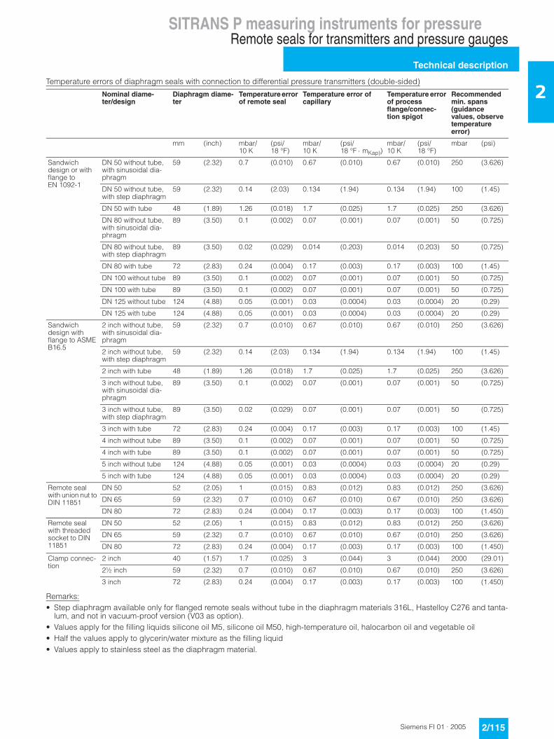
2Temperature errors of diaphragm seals with connection to differential pressure transmitters (double-sided)
Remarks: • Step diaphragm available only for flanged remote seals without tube in the diaphragm materials 316L, Hastelloy C276 and tanta-
lum, and not in vacuum-proof version (V03 as option).• Values apply for the filling liquids silicone oil M5, silicone oil M50, high-temperature oil, halocarbon oil and vegetable oil• Half the values apply to glycerin/water mixture as the filling liquid• Values apply to stainless steel as the diaphragm material.
Nominal diame-ter/design
Diaphragm diame-ter
Temperature error of remote seal
Temperature error of capillary
Temperature error of process flange/connec-tion spigot
Recommended min. spans (guidance values, observe temperature error)
mm (inch) mbar/10 K
(psi/18 °F)
mbar/10 K
(psi/18 °F ⋅ mKap))
mbar/10 K
(psi/18 °F)
mbar (psi)
Sandwich design or with flange to EN 1092-1
DN 50 without tube, with sinusoidal dia-phragm
59 (2.32) 0.7 (0.010) 0.67 (0.010) 0.67 (0.010) 250 (3.626)
DN 50 without tube, with step diaphragm
59 (2.32) 0.14 (2.03) 0.134 (1.94) 0.134 (1.94) 100 (1.45)
DN 50 with tube 48 (1.89) 1.26 (0.018) 1.7 (0.025) 1.7 (0.025) 250 (3.626)
DN 80 without tube, with sinusoidal dia-phragm
89 (3.50) 0.1 (0.002) 0.07 (0.001) 0.07 (0.001) 50 (0.725)
DN 80 without tube, with step diaphragm
89 (3.50) 0.02 (0.029) 0.014 (0.203) 0.014 (0.203) 50 (0.725)
DN 80 with tube 72 (2.83) 0.24 (0.004) 0.17 (0.003) 0.17 (0.003) 100 (1.45)
DN 100 without tube 89 (3.50) 0.1 (0.002) 0.07 (0.001) 0.07 (0.001) 50 (0.725)
DN 100 with tube 89 (3.50) 0.1 (0.002) 0.07 (0.001) 0.07 (0.001) 50 (0.725)
DN 125 without tube 124 (4.88) 0.05 (0.001) 0.03 (0.0004) 0.03 (0.0004) 20 (0.29)
DN 125 with tube 124 (4.88) 0,05 (0.001) 0.03 (0.0004) 0.03 (0.0004) 20 (0.29)
Sandwich design with flange to ASME B16.5
2 inch without tube, with sinusoidal dia-phragm
59 (2.32) 0.7 (0.010) 0.67 (0.010) 0.67 (0.010) 250 (3.626)
2 inch without tube, with step diaphragm
59 (2.32) 0.14 (2.03) 0.134 (1.94) 0.134 (1.94) 100 (1.45)
2 inch with tube 48 (1.89) 1.26 (0.018) 1.7 (0.025) 1.7 (0.025) 250 (3.626)
3 inch without tube, with sinusoidal dia-phragm
89 (3.50) 0.1 (0.002) 0.07 (0.001) 0.07 (0.001) 50 (0.725)
3 inch without tube, with step diaphragm
89 (3.50) 0.02 (0.029) 0.07 (0.001) 0.07 (0.001) 50 (0.725)
3 inch with tube 72 (2.83) 0.24 (0.004) 0.17 (0.003) 0.17 (0.003) 100 (1.45)
4 inch without tube 89 (3.50) 0.1 (0.002) 0.07 (0.001) 0.07 (0.001) 50 (0.725)
4 inch with tube 89 (3.50) 0.1 (0.002) 0.07 (0.001) 0.07 (0.001) 50 (0.725)
5 inch without tube 124 (4.88) 0.05 (0.001) 0.03 (0.0004) 0.03 (0.0004) 20 (0.29)
5 inch with tube 124 (4.88) 0.05 (0.001) 0.03 (0.0004) 0.03 (0.0004) 20 (0.29)
Remote seal with union nut to DIN 11851
DN 50 52 (2.05) 1 (0.015) 0.83 (0.012) 0.83 (0.012) 250 (3.626)
DN 65 59 (2.32) 0.7 (0.010) 0.67 (0.010) 0.67 (0.010) 250 (3.626)
DN 80 72 (2.83) 0.24 (0.004) 0.17 (0.003) 0.17 (0.003) 100 (1.450)
Remote seal with threaded socket to DIN 11851
DN 50 52 (2.05) 1 (0.015) 0.83 (0.012) 0.83 (0.012) 250 (3.626)
DN 65 59 (2.32) 0.7 (0.010) 0.67 (0.010) 0.67 (0.010) 250 (3.626)
DN 80 72 (2.83) 0.24 (0.004) 0.17 (0.003) 0.17 (0.003) 100 (1.450)
Clamp connec-tion
2 inch 40 (1.57) 1.7 (0.025) 3 (0.044) 3 (0.044) 2000 (29.01)
2½ inch 59 (2.32) 0.7 (0.010) 0.67 (0.010) 0.67 (0.010) 250 (3.626)
3 inch 72 (2.83) 0.24 (0.004) 0.17 (0.003) 0.17 (0.003) 100 (1.450)
SITRANS P measuring instruments for pressureRemote seals for transmitters and pressure gauges
Technical description
2/116 Siemens FI 01 · 2005
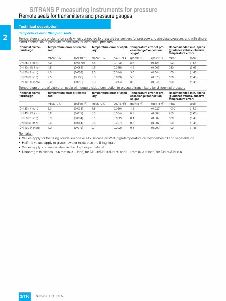
2Temperature error Clamp-on seals
Temperature errors of clamp-on seals when connected to pressure transmitters for pressure and absolute pressure, and with single-sided connection to pressure transmitters for differential pressure
Temperature errors of clamp-on seals with double-sided connection to pressure transmitters for differential pressure
Remarks: • Values apply for the filling liquids silicone oil M5, silicone oil M50, high-temperature oil, halocarbon oil and vegetable oil.• Half the values apply to glycerin/water mixture as the filling liquid.• Values apply to stainless steel as the diaphragm material.• Diaphragm thickness 0.05 mm (0.002 inch) for DN 25/DN 40/DN 50 and 0.1 mm (0.004 inch) for DN 80/DN 100
Nominal diame-ter/design
Temperature error of remote seal
Temperature error of capil-lary
Temperature error of pro-cess flange/connection spigot
Recommended min. spans (guidance values, observe temperature error)
mbar/10 K (psi/18 °F) mbar/10 K (psi/18 °F) (psi/18 °F) (psi/18 °F) mbar (psi)
DN 25 (1 inch) 6.0 (0.0870) 8.5 (0.123) 8.5 (0.123) 1000 (14.5)
DN 40 (1½ inch) 4.5 (0.065) 4.5 (0.065) 4.5 (0.065) 250 (3.63)
DN 50 (2 inch) 4.0 (0.058) 3.0 (0.044) 3.0 (0.044) 100 (1.45)
DN 80 (3 inch) 9.5 (0.138) 5.0 (0.073) 5.0 (0.073) 100 (1.45)
DN 100 (4 inch) 8.0 (0.012) 3.0 (0.044) 3.0 (0.044) 100 (1.45)
Nominal diame-ter/design
Temperature error of remote seal
Temperature error of capil-lary
Temperature error of pro-cess flange/connection spigot
Recommended min. spans (guidance values, observe temperature error)
mbar/10 K (psi/18 °F) mbar/10 K (psi/18 °F) (psi/18 °F) (psi/18 °F) mbar (psi)
DN 25 (1 inch) 2.3 (0.033) 1.8 (0.026) 1.8 (0.026) 1000 (14.5)
DN 40 (1½ inch) 0.8 (0.012) 0.3 (0.004) 0.3 (0.004) 250 (3.63)
DN 50 (2 inch) 0.3 (0.004) 0.1 (0.002) 0.1 (0.002) 100 (1.45)
DN 80 (3 inch) 3.0 (0.044) 0.5 (0.007) 0.5 (0.007) 100 (1.45)
DN 100 (4 inch) 1.0 (0.015) 0.1 (0.002) 0.1 (0.002) 100 (1.45)
SITRANS P measuring instruments for pressureRemote seals for transmitters and pressure gauges
Technical description
2/117Siemens FI 01 · 2005
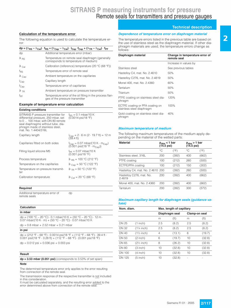
2Calculation of the temperature error
The following equation is used to calculate the temperature er-ror:
Example of temperature error calculation
Dependence of temperature error on diaphragm material
The temperature errors listed in the previous table are based on the use of stainless steel as the diaphragm material. If other dia-phragm materials are used, the temperature errors change as follows:
Maximum temperature of medium
The following maximum temperatures of the medium apply de-pending on the material of the wetted parts:
Maximum capillary length for diaphragm seals (guidance va-lues)
dp = (ϑRS – ϑCal) ⋅ fRS + (ϑCap – ϑCal) ⋅ lCap ⋅fCap + (ϑTR – ϑCal) ⋅ fPF
dp Additional temperature error (mbar)
ϑ RS Temperature on remote seal diaphragm (generally corresponds to temperature of medium)
ϑ Cal Calibration (reference) temperature (20 °C (68 °F))
fRS Temperature error of remote seal
ϑ Cap Ambient temperature on the capillaries
lCap Capillary length
fCap Temperature error of capillaries
ϑ TR Ambient temperature on pressure transmitter
fPF Temperature error of the oil filling in the process flan-ges of the pressure transmitter
Existing conditions
SITRANS P pressure transmitter for differential pressure, 250 mbar, set to 0 ... 100 mbar, with DN 80 remote seal diaphragms without tube, dia-phragm made of stainless steel, mat. No. 1.4404/316L
fRS = 0.1 mbar/10 K (0.0014 psi/18 °F)
Capillary length lCap = 2 ⋅ 6 m (2 ⋅ 19.7 ft) = 12 m (39.4 ft)
Capillaries fitted on both sides fCap = 0.07 mbar/(10 K ⋅ mCap) (0.001 psi/(18 °F ⋅ mCap))
Filling liquid silicone M5 fPF = 0.07 mbar/10 K (0.001 psi/18 °F)
Process temperature ϑ RS = 100 °C (212 °F)
Temperature on the capillaries ϑ Cap = 50 °C (122 °F)
Temperature on pressure transmit-ter
ϑ TR = 50 °C (122 °F)
Calibration temperature ϑ Cal = 20 °C (68 °F)
Required
Additional temperature error of remote seals
dp
Calculation
in mbar
dp = (100 °C – 20 °C) ⋅ 0.1 mbar/10 K + (50 °C – 20 °C) ⋅ 12 m ⋅ 0.07 mbar/(10 K ⋅ m) + (50 °C – 20 °C) ⋅ 0.07 mbar/10 K
dp = 0.8 mbar + 2.52 mbar + 0.21 mbar
in psi
dp = (212 °F – 68 °F) ⋅ 0.0014 psi/18 °F + (112 °F – 68 °F) ⋅ 39.4 ft ⋅ 0.001 psi/(18 °F ⋅ 3.28 ft) + (112 °F – 68 °F) ⋅ (0.001 psi/18 °F)
dp = 0.012 psi + 0.036 psi + 0.003 psi
Result
dp = 3.53 mbar (0.051 psi) (corresponds to 3.53% of set span)
Note
The determined temperature error only applies to the error resulting from connection of the remote seal.The transmission response of the respective transmitter is not included in this consideration. It must be calculated separately, and the resulting error added to the error determined above from connection of the remote seal.
Diaphragm material Change in temperature error of remote seal
Increase in values by
Stainless steel See previous tables
Hastelloy C4, mat. No. 2.4610 50%
Hastelloy C276, mat. No. 2.4819 50%
Monel 400, mat. No. 2.4360 60%
Tantalum 50%
Titanium 50%
PTFE coating on stainless steel dia-phragm
120%
ECTFE coating or PFA coating on stainless steel diaphragm
100%
Gold coating on stainless steel dia-phragm
40%
Material pabs < 1 bar (14.5 psi)
pabs > 1 bar (14.5 psi)
°C (°F) °C (°F)
Stainless steel, 316L 200 (392) 400 (662)
PTFE coating 100 (212) 260 (500)
ECTFE/PFA coating 100 (212) 150 (302)
Hastelloy C4, mat. No. 2.4610 200 (392) 260 (500)
Hastelloy C276, mat. No. 2.4819
200 (392) 400 (662)
Monel 400, mat. No. 2.4360 200 (392) 400 (662)
Tantalum 200 (392) 300 (572)
Nom. diam. Max. length of capillary
Diaphragm seal Clamp-on seal
m (ft) m (ft)
DN 25 (1 inch) 2.5 (8.2) 2.5 (8.2)
DN 32 (1¼ inch) 2.5 (8.2) 2.5 (8.2)
DN 40 (1½ inch) 4 (13.1) 6 (19.7)
DN 50 (2 inch) 6 (19.7) 10 (32.8)
DN 65 (2½ inch) 8 (26.2) 10 (32.8)
DN 80 (3 inch) 10 (32.8) 10 (32.8)
DN 100 (4 inch) 10 (32.8) 10 (32.8)
DN 125 (5 inch) 10 (32.8) - -

SITRANS P measuring instruments for pressureRemote seals for transmitters and pressure gauges
Technical description
2/118 Siemens FI 01 · 2005
2Response times
The values listed in the following table are the response times (in seconds per meter of capillary) for a change in pressure which corresponds to the set span.
The listed values must be multiplied by the respective length of the capillary, or with transmitters for differential pressure and flow by the total length of both capillaries.
The response times are independent of the set span within the range of the respective transmitter. The response times are of in-significant importance for spans above 10 bar (145 psi). The re-sponse times of the pressure transmitters are not considered in the table.
Technical data of filling liquids
When selecting the filling liquid, check that it is suitable with re-spect to the permissible temperature of the medium and the pro-cess pressure.
Also check the compatibility of the filling liquid with the measu-red medium. For example, only physiologically harmless filling li-quids may be used in the food industry.
Oxygen and chlorine are special cases of measured medium. The liquid must not react with either of these two media or a lea-king remote seal may lead to an explosion or fire
Filling liquid Density Temperature on capillary
Response time in s/m (s/ft) with max. span of pressure transmitter
kg/dm3 lb/in3 °C (°F) 250 mbar (3.63 psi) 600 mbar (8.7 psi) 1600 mbar (23.2 psi)
Silicone oil M5 0,914 (0.033) +60 (140) 0.06 (0.018) 0,02 (0.006) 0.01 (0.003)
+20 (68) 0.11 (0.034) 0.02 (0.006) 0.02 (0.006)
- 20 (-4) 0.3 (0.091) 0.12 (0.037) 0.05 (0.015)
Silicone oil M50 0.966 (0.035) +60 (140) 0.6 (0.183) 0.25 (0.076) 0.09 (0.027)
+20 (68) 0.61 (0.186) 0.26 (0.079) 0.1 (0.030)
- 20 (-4) 1,69 (0.515) 0.71 (0.216) 0.27 (0.082)
High-temperature oil 1.070 (0.039) +60 (140) 0.14 (0.043) 0.06 (0.018) 0.02 (0.006)
+20 (68) 0.65 (0.198) 0.27 (0.082) 0.1 (0.030)
-10 (14) 3.96 (1.207) 1.65 (0.503) 0.62 (0.189)
Halocarbon oil 1.968 (0.071) +60 (140) 0.07 (0.021) 0.03 (0.009) 0.01 (0.003)
+20 (68) 0.29 (0.088) 0.12 (0.037) 0.05 (0.015)
- 20 (-4) 2.88 (0.878) 1.2 (0.366) 0.45 (0.137)
Vegetable oil 0.940 (0.034) +60 (140) 0.18 (0.055) 0.08 (0.024) 0.03 (0.009)
+20 (68) 0.43 (0.131) 0.18 (0.055) 0.07 (0.021)
- 20 (-4) 1.19 (0.363) 0.5 (0.152) 0.18 (0.055)
Glycerin/water 1.220 (0.044) +60 (140) 0.13 (0.040) 0.05 (0.015) 0.02 (0.006)
+20 (68) 0.76 (0.232) 0.32 (0.098) 0.12 (0.037)
0 (32) 9.72 (2.963) 4.05 (1.234) 1.51 (0.460)
Filling liquid Digit in Order No.
Permissible temperature of medium Density at 20 °C (68 °F)
Viscosity at 20 °C (68 °F)
Coefficient of expan-sion
pabs < 1 bar (pabs < 14.5 psi)
pabs > 1 bar
(pabs > 14.5 psi)
°C (°F) °C (°F) kg/dm3 (lb/in3) m2/s⋅106 (ft2/s⋅106) 1/°C (1/°F)
Silicone oil M5 1 -60 ... +80 (-76 ... +176) -90 ... +180 (-130 ... +356) 0.914 (0.03) 4 43 0.00108 (0.00060)
Silicone oil M50 2 -40 ... +150 (-40 ... +302) -40 ... +250 (-40 ... +482) 0,96 (0.03) 50 538 0.00104 (0.00058)
High-tempera-ture oil
3 -10 ... +200 (+14 ... +392) -10 ... +350 (+14 ... +662) 1.07 (0.04) 39 420 0.00080 (0.00044)
Halocarbon oil 4 -40 ... +80 (-40 ... +176) -40 ... +175 (-40 ... +347) 1.968 (0.07) 14 151 0.00086 (0.00048)
Vegetable oil 5 -10 ... +200 (+14 ... +392) -10 ... +250 (+14 ... +392) 0.94 (0.03) 66 710 0.00082 (0.00045)
Glycerin/water 6 Not pos-sible
Not possible -10 ... +120 (+14 ... +248) 1.22 (0.04) 88 (947) 0.00050 (0.00028)

SITRANS P measuring instruments for pressureDiaphragm seal of sandwich design
For pressure, absolute pressure, diff. pressureand flow, with flexible capillary
2/119Siemens FI 01 · 2005
2■ Overview
Diaphragm seals of sandwich design
■ Technical specifications
Diaphragm seals of sandwich design
• DN 50 PN 16 ... PN 100
• DN 80 PN 16 ... PN 100
• DN 100 PN 16 ... PN 100
• DN 125 PN 16 ... PN 100
• 2 inch Class 150 ... class 2500
• 3 inch Class 150 ... class 2500
• 4 inch Class 150 ... class 2500
• 5 inch Class 150 ... class 2500
Sealing face
• For stainless steel, mat. No. 1.4404/216L
To EN 1092-1, form B1 or ASME B16.5 RF 125 ... 250 AA
• For the other materials To EN 1092-1, form B2 or ASME B16.5 RFSF
Materials
• Main body Stainless steel 316L
• Wetted parts Stainless steel 316L
• Without foil
• PTFE (for vacuum on request)
• ECTFE (for vacuum on request)
• PFA (for vacuum on request)
Monel 400, mat. No. 2.4360
Hastelloy C276, mat. No. 2.4819
Hastelloy C4, mat. No. 2.4610
Tantalum
• Capillary Stainless steel, mat. No. 1.4571/316Ti
• Sheath Spiral hose made of stainless steel, mat. No. 1.4301/316
Sealing material in the process flan-ges
• For pressure transmitters, absolute pressure transmitters and low-pressure applications
Copper
• For other applications Viton
Maximum pressure See above and the technical data of the pressure transmitters
Tube length Without tube as standard (tube available on request)
Capillary
• Length Max. 10 m (32.8 ft), longer lengths on request
• Internal diameter 2 mm (0.079 inch)
• Minimum bending radius 150 mm (5.9 inch)
Filling liquid Silicone oil M5
Silicone oil M50
High-temperature oil
Halocarbon oil (for measuring O2)
Vegetable oil
Glycerine/water (not suitable for use in low-pressure range)
Permissible ambient temperature Dependent on the pressure trans-mitter and the filling liquid of the remote sealMore information can be found in the technical data of the pressure transmitters and in the section "Technical data of filling liquid" in the Technical description to the remote seals
Weight Approx. 4 kg (8.82 lb)
Certificate and approvals
Classification according to pressure equipment directive (DRGL 97/23/EC)
For gases of fluid group 1 and liquids of fluid group 1; complies with requirements of article 3, paragraph 3 (sound engineering practice)
SITRANS P measuring instruments for pressureDiaphragm seal of sandwich designFor pressure, absolute pressure, diff. pressure and flow, with flexible capillary
2/120 Siemens FI 01 · 2005
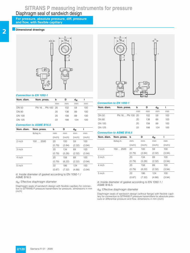
2 ■ Dimensional drawings
Connection to EN 1092-1
Connection to ASME B16.5
d: Inside diameter of gasket according to EN 1092-1 / ASME B16.5
dM: Effective diaphragm diameter
Diaphragm seals of sandwich design with flexible capillary for connec-tion to SITRANS P pressure transmitters for pressure, dimensions in mm (inch)
Connection to EN 1092-1
Connection to ASME B16.5
d: Inside diameter of gasket according to EN 1092-1 / ASME B16.5
dM: Effective diaphragm diameter
Diaphragm seals of sandwich design (without flange) with flexible capil-lary for connection to SITRANS P pressure transmitters for absolute pres-sure or differential pressure and flow, dimensions in mm (inch)
Nom. diam. Nom. press. b D dM l
mm mm mm mm
DN 50 PN 16 ... PN 100 20 102 59 100
DN 80 20 138 89 100
DN 100 20 158 89 100
DN 125 22 188 124 100
Nom. diam. Nom. press. b D dM I
lb/sq.in. mm mm mm mm
(inch) (inch) (inch) (inch)
2 inch 150 .... 2500 20 100 59 100
(0.79) (3.94) (2.32) (3.94)
3 inch 20 134 89 100
(0.79) (5.28) (2.32) (3.94)
4 inch 20 158 89 100
(0.79) (6.22) (2.32) (3.94)
5 inch 22 186 124 100
(0.87) (7.32) (4.88) (3.94)
)
�
+ (
�����
.�#. =$
Nom. diam. Nom. press. b D dM l
mm mm mm mm
DN 50 PN 16 ... PN 100 20 102 59 100
DN 80 20 138 89 100
DN 100 20 158 89 100
DN 125 22 188 124 100
Nom. diam. Nom. press. b D dM I
lb/sq.in. mm mm mm mm
(inch) (inch) (inch) (inch)
2 inch 150 ... 2500 20 100 59 100
(0.79) (3.94) (2.32) (3.94)
3 inch 20 134 89 100
(0.79) (5.28) (2.32) (3.94)
4 inch 20 158 89 100
(0.79) (6.22) (2.32) (3.94)
5 inch 22 186 124 100
(0.87) (7.32) (4.88) (3.94)
$�&
A
�I
�����
9� 9+
:!
SITRANS P measuring instruments for pressureDiaphragm seal of sandwich design
For pressure, absolute pressure, diff. pressureand flow, with flexible capillary
2/121Siemens FI 01 · 2005
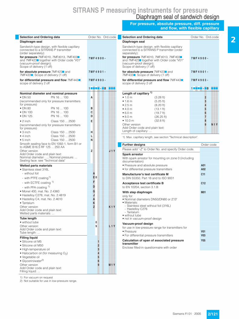
2Selection and Ordering data Order No. Ord.code
Diaphragm seal
Sandwich-type design, with flexible capillary connected to a SITRANS P transmitter (order separately):for pressure 7MF4010, 7MF4013, 7MF4037 and 7MF4237 together with Order code "V01" (vacuum-proof design); Scope of delivery (1 off)
7 M F 4 9 0 0 -
for absolute pressure 7MF4237 and 7MF4337; Scope of delivery (1 off)
7 M F 4 9 0 1 -
for differential pressure and flow 7MF4437; scope of delivery 2 off
7 M F 4 9 0 3 -
1 7777 - 7B 777
Nominal diameter and nominal pressure• DN 50 PN 16 ... 100 A(recommended only for pressure transmitters for pressure)• DN 80 PN 16 ... 100 B• DN 100 PN 16 ... 100 C• DN 125 PN 16 ... 100 D
• 2 inch Class 150 ... 2500 E(recommended only for pressure transmitters for pressure)• 3 inch Class 150 ... 2500 H• 4 inch Class 150 ... 2500 L• 5 inch Class 150 ... 2500 NSmooth sealing face to EN 1092-1, form B1 or to ASME B16.5 RF 125 ... 250 AAOther versionAdd Order code and plain text:Nominal diameter: ...; Nominal pressure: ...Sealing face: see "Technical data"
Z J 1 Y
Wetted parts materials• Stainless steel 316L
- without foil A
- with PTFE coating1)
1) For vacuum on request
E 0
- with ECTFE coating 1) F
- with PFA coating 1) D
• Monel 400, mat. No. 2.4360 G• Hastelloy C276, mat. No. 2.4819 J• Hastelloy C4, mat. No. 2.4610 A• Tantalum KOther versionAdd Order code and plain text:Wetted parts materials: ...
Z K 1 Y
Tube length• without tube 0Other version:Add Order code and plain text:Tube length: ...
9 L 1 Y
Filling liquid• Silicone oil M5 1• Silicone oil M50 2• High-temperature oil 3• Halocarbon oil (for measuring O2) 4• Vegetable oil 5• Glycerin/water2)
2) Not suitable for use in low-pressure range.
6Other versionAdd Order code and plain text:Filling liquid: ...
9 M 1 Y
Selection and Ordering data Order No. Ord.code
Diaphragm seal
Sandwich-type design, with flexible capillary connected to a SITRANS P transmitter (order separately):for pressure 7MF4010, 7MF4013, 7MF4037 and 7MF4237 together with Order code "V01" (vacuum-proof design); Scope of delivery (1 off)
7 M F 4 9 0 0 -
for absolute pressure 7MF4237 and 7MF4337; Scope of delivery (1 off)
7 M F 4 9 0 1 -
for differential pressure and flow 7MF4437; scope of delivery 2 off
7 M F 4 9 0 3 -
1 7777 - 7B 777
Length of capillary 1)
1) Max. capillary length, see section "Technical description".
• 1.0 m (3.28 ft) 2• 1.6 m (5.25 ft) 3• 2.5 m (8.20 ft) 4• 4.0 m (13.1 ft) 5• 6.0 m (19.7 ft) 6• 8.0 m (26.25 ft) 7• 10.0 m (32.8 ft) 8Other versionAdd Order code and plain text:Length of capillary: ...
9 N 1 Y
Further designs Order code
Please add "-Z" to Order No. and specify Order code.
Spark arrestorWith spark arrestor for mounting on zone 0 (including documentation)• Pressure and absolute pressure A01• for differential pressure transmitters A02
Manufacturer's test certificate M C11to DIN 55350, Part 18 and to ISO 9001
Acceptance test certificate B C12to EN 10204, section 3.1.B
With step diaphragm M01only for:• Nominal diameters DN50/DN80 or 2"/3"• Materials:
- Stainless steel without foil (316L)- Hastelloy C276- Tantalum
• without tube• not in vacuum-proof design
Vacuum-proof designfor use in low-pressure range for transmitters for • Pressure V01• For differential pressure transmitters V03
Calculation of span of associated pressure transmitter
Y05
Enclose filled-in questionnaire with order
SITRANS P measuring instruments for pressureDiaphragm seal of flange designFor pressure, absolute pressure, diff. pressure and flow, with flexible capillary
2/122 Siemens FI 01 · 2005
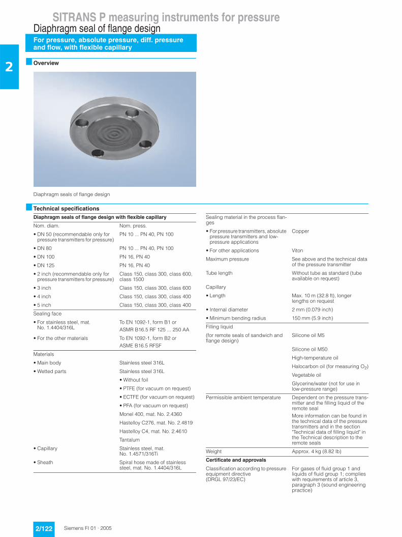
2 ■ Overview
Diaphragm seals of flange design
■ Technical specifications
Diaphragm seals of flange design with flexible capillary
Nom. diam. Nom. press.
• DN 50 (recommendable only for pressure transmitters for pressure)
PN 10 ... PN 40, PN 100
• DN 80 PN 10 ... PN 40, PN 100
• DN 100 PN 16, PN 40
• DN 125 PN 16, PN 40
• 2 inch (recommendable only for pressure transmitters for pressure)
Class 150, class 300, class 600, class 1500
• 3 inch Class 150, class 300, class 600
• 4 inch Class 150, class 300, class 400
• 5 inch Class 150, class 300, class 400
Sealing face
• For stainless steel, mat. No. 1.4404/316L
To EN 1092-1, form B1 or ASMR B16.5 RF 125 ... 250 AA
• For the other materials To EN 1092-1, form B2 or ASME B16.5 RFSF
Materials
• Main body Stainless steel 316L
• Wetted parts Stainless steel 316L
• Without foil
• PTFE (for vacuum on request)
• ECTFE (for vacuum on request)
• PFA (for vacuum on request)
Monel 400, mat. No. 2.4360
Hastelloy C276, mat. No. 2.4819
Hastelloy C4, mat. No. 2.4610
Tantalum
• Capillary Stainless steel, mat. No. 1.4571/316Ti
• Sheath Spiral hose made of stainless steel, mat. No. 1.4404/316L
Sealing material in the process flan-ges
• For pressure transmitters, absolute pressure transmitters and low-pressure applications
Copper
• For other applications Viton
Maximum pressure See above and the technical data of the pressure transmitter
Tube length Without tube as standard (tube available on request)
Capillary
• Length Max. 10 m (32.8 ft), longer lengths on request
• Internal diameter 2 mm (0.079 inch)
• Minimum bending radius 150 mm (5.9 inch)
Filling liquid
(for remote seals of sandwich and flange design)
Silicone oil M5
Silicone oil M50
High-temperature oil
Halocarbon oil (for measuring O2)
Vegetable oil
Glycerine/water (not for use in low-pressure range)
Permissible ambient temperature Dependent on the pressure trans-mitter and the filling liquid of the remote sealMore information can be found in the technical data of the pressure transmitters and in the section "Technical data of filling liquid" in the Technical description to the remote seals
Weight Approx. 4 kg (8.82 lb)
Certificate and approvals
Classification according to pressure equipment directive (DRGL 97/23/EC)
For gases of fluid group 1 and liquids of fluid group 1; complies with requirements of article 3, paragraph 3 (sound engineering practice)
SITRANS P measuring instruments for pressureDiaphragm seal of flange design
For pressure, absolute pressure, diff. pressureand flow, with flexible capillary
2/123Siemens FI 01 · 2005
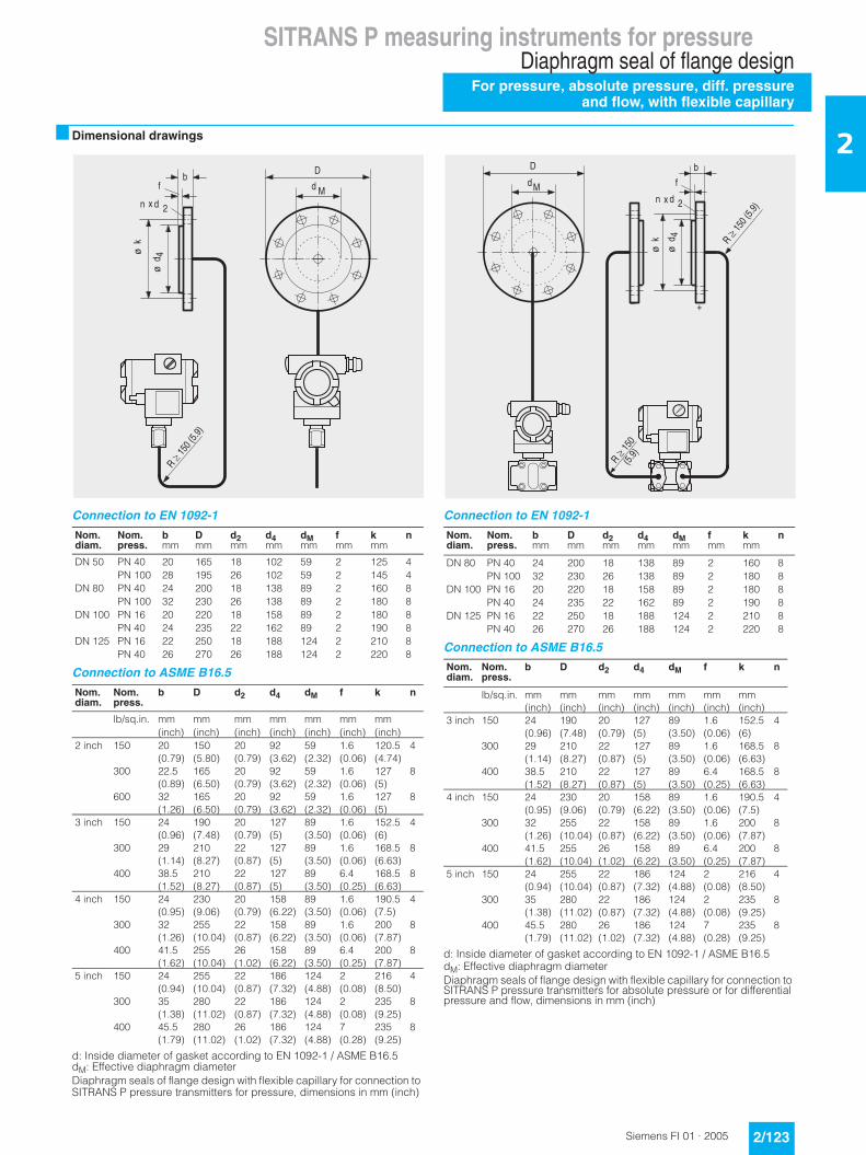
2■ Dimensional drawings
Connection to EN 1092-1
Connection to ASME B16.5
d: Inside diameter of gasket according to EN 1092-1 / ASME B16.5dM: Effective diaphragm diameterDiaphragm seals of flange design with flexible capillary for connection to SITRANS P pressure transmitters for pressure, dimensions in mm (inch)
Connection to EN 1092-1
Connection to ASME B16.5
d: Inside diameter of gasket according to EN 1092-1 / ASME B16.5dM: Effective diaphragm diameterDiaphragm seals of flange design with flexible capillary for connection to SITRANS P pressure transmitters for absolute pressure or for differential pressure and flow, dimensions in mm (inch)
Nom. diam.
Nom. press.
bmm
Dmm
d2mm
d4mm
dMmm
fmm
kmm
n
DN 50 PN 40 20 165 18 102 59 2 125 4PN 100 28 195 26 102 59 2 145 4
DN 80 PN 40 24 200 18 138 89 2 160 8PN 100 32 230 26 138 89 2 180 8
DN 100 PN 16 20 220 18 158 89 2 180 8PN 40 24 235 22 162 89 2 190 8
DN 125 PN 16 22 250 18 188 124 2 210 8PN 40 26 270 26 188 124 2 220 8
Nom. diam.
Nom. press.
b D d2 d4 dM f k n
lb/sq.in. mm mm mm mm mm mm mm(inch) (inch) (inch) (inch) (inch) (inch) (inch)
2 inch 150 20 150 20 92 59 1.6 120.5 4(0.79) (5.80) (0.79) (3.62) (2.32) (0.06) (4.74)
300 22.5 165 20 92 59 1.6 127 8(0.89) (6.50) (0.79) (3.62) (2.32) (0.06) (5)
600 32 165 20 92 59 1.6 127 8(1.26) (6.50) (0.79) (3.62) (2.32) (0.06) (5)
3 inch 150 24 190 20 127 89 1.6 152.5 4(0.96) (7.48) (0.79) (5) (3.50) (0.06) (6)
300 29 210 22 127 89 1.6 168.5 8(1.14) (8.27) (0.87) (5) (3.50) (0.06) (6.63)
400 38.5 210 22 127 89 6.4 168.5 8(1.52) (8.27) (0.87) (5) (3.50) (0.25) (6.63)
4 inch 150 24 230 20 158 89 1.6 190.5 4(0.95) (9.06) (0.79) (6.22) (3.50) (0.06) (7.5)
300 32 255 22 158 89 1.6 200 8(1.26) (10.04) (0.87) (6.22) (3.50) (0.06) (7.87)
400 41.5 255 26 158 89 6.4 200 8(1.62) (10.04) (1.02) (6.22) (3.50) (0.25) (7.87)
5 inch 150 24 255 22 186 124 2 216 4(0.94) (10.04) (0.87) (7.32) (4.88) (0.08) (8.50)
300 35 280 22 186 124 2 235 8(1.38) (11.02) (0.87) (7.32) (4.88) (0.08) (9.25)
400 45.5 280 26 186 124 7 235 8(1.79) (11.02) (1.02) (7.32) (4.88) (0.28) (9.25)
);
���� �7
+
A��3
A��
8
(
�����
.��#. =$
Nom. diam.
Nom. press.
bmm
Dmm
d2mm
d4mm
dMmm
fmm
kmm
n
DN 80 PN 40 24 200 18 138 89 2 160 8PN 100 32 230 26 138 89 2 180 8
DN 100 PN 16 20 220 18 158 89 2 180 8PN 40 24 235 22 162 89 2 190 8
DN 125 PN 16 22 250 18 188 124 2 210 8PN 40 26 270 26 188 124 2 220 8
Nom. diam.
Nom. press.
b D d2 d4 dM f k n
lb/sq.in. mm mm mm mm mm mm mm(inch) (inch) (inch) (inch) (inch) (inch) (inch)
3 inch 150 24 190 20 127 89 1.6 152.5 4(0.96) (7.48) (0.79) (5) (3.50) (0.06) (6)
300 29 210 22 127 89 1.6 168.5 8(1.14) (8.27) (0.87) (5) (3.50) (0.06) (6.63)
400 38.5 210 22 127 89 6.4 168.5 8(1.52) (8.27) (0.87) (5) (3.50) (0.25) (6.63)
4 inch 150 24 230 20 158 89 1.6 190.5 4(0.95) (9.06) (0.79) (6.22) (3.50) (0.06) (7.5)
300 32 255 22 158 89 1.6 200 8(1.26) (10.04) (0.87) (6.22) (3.50) (0.06) (7.87)
400 41.5 255 26 158 89 6.4 200 8(1.62) (10.04) (1.02) (6.22) (3.50) (0.25) (7.87)
5 inch 150 24 255 22 186 124 2 216 4(0.94) (10.04) (0.87) (7.32) (4.88) (0.08) (8.50)
300 35 280 22 186 124 2 235 8(1.38) (11.02) (0.87) (7.32) (4.88) (0.08) (9.25)
400 45.5 280 26 186 124 7 235 8(1.79) (11.02) (1.02) (7.32) (4.88) (0.28) (9.25)
$
�I
A1
������ �>
@��0
&�
@���
*
�����
9�� 9
+:!
�����
9� 9+
:!

SITRANS P measuring instruments for pressureDiaphragm seal of flange designFor pressure, absolute pressure, diff. pressure and flow, with flexible capillary
2/124 Siemens FI 01 · 2005
2Selection and Ordering data Order No. Ord. code
Diaphragm seal
Flange design, with flexible capillary, connected to a pressure transmitterSITRANS P (order separately):
for pressure 7MF4010, 7MF4013, 7MF4037 and 7MF4237 together with Order code "V01" (vacuum-proof design); scope of delivery: 1 off
7 M F 4 9 2 0 -
for absolute pressure 7MF4237 and 7MF4337; scope of delivery: 1 off
7 M F 4 9 2 1 -
for differential pressure and flow 7MF4437; scope of delivery: 2 off
7 M F 4 9 2 3 -
1 7777 - 7B 777
Nominal diameter and nominal pressure• DN 50 PN 10 ... 40 A
PN 100 B(DN 50 recommended only for pressure transmitters for pressure)
• DN 80 PN 10 ... 40 DPN 100 E
• DN 100 PN 16 GPN 40 H
• DN 125 PN 16 JPN 40 K
• 2 inch Class 150 LClass 300 MClass 600 NClass 1500 P
(2 inch recommended only for pressure transmitters for pressure)• 3 inch Class 150 Q
Class 300 RClass 600 S
• 4 inch Class 150 TClass 300 UClass 400 V
• 5 inch Class 150 WClass 300 XClass 400 Y
Smooth sealing face to EN 1092-1, form B1 or to ASME B16.5 RF 125 ... 250 AA
Other versionAdd Order code and plain text:Nominal diameter: ...; Nominal pressure: ...Sealing face: See "Technical data"
Z J 1 Y
Wetted parts materials• Stainless steel 316L
- without foil A
- with PTFE coating1) E 0
- with ECTFE coating 1) F
- with PFA coating 1) D
• Monel 400, mat. No. 2.4360 G• Hastelloy C276, mat. No. 2.4819 J• Hastelloy C4, mat. No. 2.4610 U• Tantalum KOther versionAdd Order code and plain text:Wetted parts materials: ...
Z K 1 Y
Tube length• without tube 0Other version:Add Order code and plain text:Tube length: ...
9 L 1 Y
Filling liquid• Silicone oil M5 1• Silicone oil M50 2• High-temperature oil 3• Halocarbon oil (for measuring O2) 4• Vegetable oil 5• Glycerin/water2) 6Other versionAdd Order code and plain text:Filling liquid: ...
9 M 1 Y
Length of capillary 3)
• 1.0 m (3.28 ft) 2• 1.6 m (5.25 ft) 3• 2.5 m (8.20 ft) 4• 4.0 m (13.1 ft) 5• 6.0 m (19.7 ft) 6• 8.0 m (26.25 ft) 7• 10.0 m (32.8 ft) 8Other versionAdd Order code and plain text:Length of capillary: ...
9 N 1 Y
1) For vacuum on request.2) Not suitable for use in low-pressure range.3) Max. capillary length, see section "Technical description".
Further designs Order code
Please add "-Z" to Order No. and specify Order code.
Spark arrestorWith spark arrestor for mounting on zone 0 (including documentation) for transmitters for• pressure and absolute pressure A01• differential pressure A02
Manufacturer's test certificate M C11to DIN 55350, Part 18 and to ISO 9001
Acceptance test certificate B C12to EN 10204, section 3.1.B
with step diaphragm M01only for:• Nominal diameters DN50/DN80 or 2"/3"• Pressure ratings PN 40 or class 150/300• Materials:
- Stainless steel without foil (316L)- Hastelloy C276- Tantalum
• without tube• not in vacuum-proof design
Vacuum-proof designfor use in low-pressure range for transmitters for• pressure V01• differential pressure V03
Calculation of span of associated pressure transmitter
Y05
Enclose filled-in questionnaire with order
Selection and Ordering data Order No. Ord. code
Diaphragm seal
Flange design, with flexible capillary, connected to a pressure transmitterSITRANS P (order separately):
for pressure 7MF4010, 7MF4013, 7MF4037 and 7MF4237 together with Order code "V01" (vacuum-proof design); scope of delivery: 1 off
7 M F 4 9 2 0 -
for absolute pressure 7MF4237 and 7MF4337; scope of delivery: 1 off
7 M F 4 9 2 1 -
for differential pressure and flow 7MF4437; scope of delivery: 2 off
7 M F 4 9 2 3 -
1 7777 - 7B 777
SITRANS P measuring instruments for pressureDiaphragm seal of flange design
For pressure and absolute pressure,directly fitted on transmitter
2/125Siemens FI 01 · 2005
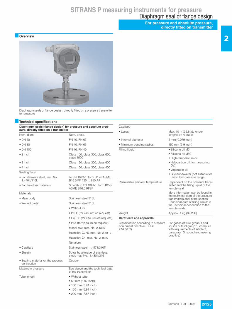
2■ Overview
Diaphragm seals of flange design, directly fitted on a pressure transmitter for pressure
■ Technical specifications
Diaphragm seals (flange design) for pressure and absolute pres-sure, directly fitted on a transmitter
Nom. diam. Nom. press.
• DN 50 PN 40, PN 63
• DN 80 PN 40, PN 63
• DN 100 PN 16, PN 40
• 2 inch Class 150, class 300, class 600, class 1500
• 3 inch Class 150, class 300, class 600
• 4 inch Class 150, class 300, class 400
Sealing face
• For stainless steel, mat. No. 1.4404/316L
To EN 1092-1, form B1 or ASME B16.5 RF 125 ... 250 AA
• For the other materials Smooth to EN 1092-1, form B2 or ASME B16.5 RFSF
Materials
• Main body Stainless steel 316L
• Wetted parts Stainless steel 316L
• Without foil
• PTFE (for vacuum on request)
• ECTFE (for vacuum on request)
• PFA (for vacuum on request)
Monel 400, mat. No. 2.4360
Hastelloy C276, mat. No. 2.4819
Hastelloy C4, mat. No. 2.4610
Tantalum
• Capillary Stainless steel, 1.4571/316Ti
• Sheath Spiral hose made of stainless steel, mat. No. 1.4301/316
• Sealing material on the process connection
Copper
Maximum pressure See above and the technical data of the transmitter
Tube length • Without tube• 50 mm (1.97 inch)• 100 mm (3.94 inch)• 150 mm (5.91 inch)• 200 mm (7.87 inch)
Capillary
• Length Max. 10 m (32.8 ft), longer lengths on request
• Internal diameter 2 mm (0.079 inch)
• Minimum bending radius 150 mm (5.9 inch)
Filling liquid • Silicone oil M5• Silicone oil M50• High-temperature oil• Halocarbon oil (for measuring
O2)• Vegetable oil• Glycerine/water (not suitable for
use in low-pressure range)
Permissible ambient temperature Dependent on the pressure trans-mitter and the filling liquid of the remote seal.More information can be found in the technical data of the pressure transmitters and in the section "Technical data of filling liquid" in the Technical description to the remote seals.
Weight Approx. 4 kg (8.82 lb)
Certificate and approvals
Classification according to pressure equipment directive (DRGL 97/23/EC)
For gases of fluid group 1 and liquids of fluid group 1; complies with requirements of article 3, paragraph 3 (sound engineering practice)
SITRANS P measuring instruments for pressureDiaphragm seal of flange designFor pressure and absolute pressure, directly fitted on transmitter
2/126 Siemens FI 01 · 2005
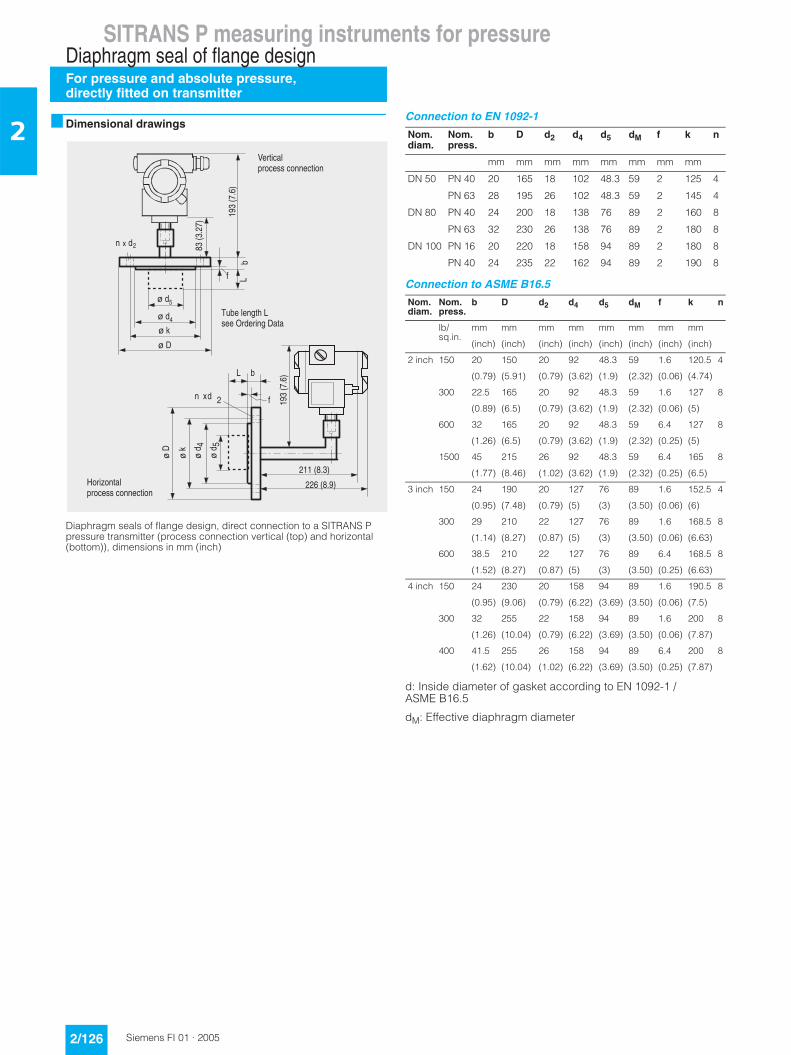
2 ■ Dimensional drawings
Diaphragm seals of flange design, direct connection to a SITRANS P pressure transmitter (process connection vertical (top) and horizontal (bottom)), dimensions in mm (inch)
Connection to EN 1092-1
Connection to ASME B16.5
d: Inside diameter of gasket according to EN 1092-1 / ASME B16.5
dM: Effective diaphragm diameter
�=%�#2 0$
/%�#%
�2$
)
;�=%�#2 0$
����#/ %$
��0�#/ =$
)
;
���� �7
���� �7
A� 8A�3
A�+
A�+
A�3
A� 8
�
A� .
A� .
�
*�������������������
5��>���������������
?�)������,�������� �����+���
Nom. diam.
Nom. press.
b D d2 d4 d5 dM f k n
mm mm mm mm mm mm mm mm
DN 50 PN 40 20 165 18 102 48.3 59 2 125 4
PN 63 28 195 26 102 48.3 59 2 145 4
DN 80 PN 40 24 200 18 138 76 89 2 160 8
PN 63 32 230 26 138 76 89 2 180 8
DN 100 PN 16 20 220 18 158 94 89 2 180 8
PN 40 24 235 22 162 94 89 2 190 8
Nom. diam.
Nom. press.
b D d2 d4 d5 dM f k n
lb/sq.in.
mm mm mm mm mm mm mm mm
(inch) (inch) (inch) (inch) (inch) (inch) (inch) (inch)
2 inch 150 20 150 20 92 48.3 59 1.6 120.5 4
(0.79) (5.91) (0.79) (3.62) (1.9) (2.32) (0.06) (4.74)
300 22.5 165 20 92 48.3 59 1.6 127 8
(0.89) (6.5) (0.79) (3.62) (1.9) (2.32) (0.06) (5)
600 32 165 20 92 48.3 59 6.4 127 8
(1.26) (6.5) (0.79) (3.62) (1.9) (2.32) (0.25) (5)
1500 45 215 26 92 48.3 59 6.4 165 8
(1.77) (8.46) (1.02) (3.62) (1.9) (2.32) (0.25) (6.5)
3 inch 150 24 190 20 127 76 89 1.6 152.5 4
(0.95) (7.48) (0.79) (5) (3) (3.50) (0.06) (6)
300 29 210 22 127 76 89 1.6 168.5 8
(1.14) (8.27) (0.87) (5) (3) (3.50) (0.06) (6.63)
600 38.5 210 22 127 76 89 6.4 168.5 8
(1.52) (8.27) (0.87) (5) (3) (3.50) (0.25) (6.63)
4 inch 150 24 230 20 158 94 89 1.6 190.5 8
(0.95) (9.06) (0.79) (6.22) (3.69) (3.50) (0.06) (7.5)
300 32 255 22 158 94 89 1.6 200 8
(1.26) (10.04) (0.79) (6.22) (3.69) (3.50) (0.06) (7.87)
400 41.5 255 26 158 94 89 6.4 200 8
(1.62) (10.04) (1.02) (6.22) (3.69) (3.50) (0.25) (7.87)

SITRANS P measuring instruments for pressureDiaphragm seal of flange design
For pressure and absolute pressure,directly fitted on transmitter
2/127Siemens FI 01 · 2005
2Selection and Ordering data Order No. Ord.code
Diaphragm seal 7 M F 4 9 1 0 -
Directly fitted to a pressure transmitterSITRANS P for pressure 7MF4010, 7MF4013 and 7MF4037 and 7MF4237 together with Order code "V01" (vacuum-proof design); must be ordered separately
77777 777
Process connection• Vertical (pressure transmitter upright) 0
• Horizontal 2
Nominal diameter and nominal pressure• DN 50 PN 40 A
PN 100 B
• DN 80 PN 40 DPN 100 E
• DN 100 PN 16 GPN 40 H
• 2 inch Class 150 LClass 300 M
Class 600 N
Class 1500 P
• 3 inch Class 150 QClass 300 R
Class 600 S
• 4 inch Class 150 TClass 300 U
Class 400 V
Smooth sealing face to DIN 1092-01, form B1 or B2, or to ASME B16.5 125 ... 250 AA or RFSF
Other versionAdd Order code and plain text:Nominal diameter: ...; Nominal pressure: ...
Z J 1 Y
Wetted parts materials• Stainless steel 316L
- without foil A
- with PTFE coating1) E 0
- with ECTFE coating 1) F
- with PFA coating 1) D
• Monel 400, mat. No. 2.4360 G
• Hastelloy C276, mat. No. 2.4819 J
• Hastelloy C4, mat. No. 2.4610 U
• Tantalum K
Other versionAdd Order code and plain text:Wetted parts materials: ...
Z K 1 Y
Tube length• Without tube 0
• 50 mm (1.97 inch) 1
• 100 mm (3.94 inch) 2
• 150 mm (5.90 inch) 3
• 200 mm (7.87 inch) 4
Other version:Add Order code and plain text:Tube length: ...
9 L 1 Y
Filling liquid• Silicone oil M5 1
• Silicone oil M50 2
• High-temperature oil 3
• Halocarbon oil (for measuring O2) 4
• Vegetable oil 5
• Glycerin/water2) 6
Other versionAdd Order code and plain text:Filling liquid: ...
9 M 1 Y
1) For vacuum on request.2) Not suitable for use in low-pressure range.
Further designs Order code
Please add "-Z" to Order No. and specify Order code.
Spark arrestor A01With spark arrestor for mounting on zone 0 (including documentation) for transmitters for pressure and abso-lute pressure
Manufacturer's test certificate M C11to DIN 55350, Part 18 and to ISO 9001
Acceptance test certificate B C12to EN 10204, section 3.1.B
with step diaphragm M01only for:• Nominal diameters DN50/DN80 or 2"/3"• Pressure ratings PN 40 or class 150/300• Materials:
- Stainless steel without foil (316L)- Hastelloy C276- Tantalum
• without tube• not in vacuum-proof design
Vacuum-proof design V01for use in low-pressure range for transmitters for pressure
Calculation of span of associated pressure transmitter
Y05
Enclose filled-in questionnaire with order
Selection and Ordering data Order No. Ord.code
Diaphragm seal 7 M F 4 9 1 0 -
Directly fitted to a pressure transmitterSITRANS P for pressure 7MF4010, 7MF4013 and 7MF4037 and 7MF4237 together with Order code "V01" (vacuum-proof design); must be ordered separately
77777 777

SITRANS P measuring instruments for pressureDiaphragm seal of flange designFor differential pressure,fixed connection and with capillary
2/128 Siemens FI 01 · 2005
2 ■ Overview
Diaphragm seals of flange design for pressure transmitters for differential pressure, fixed connection and with flexible capillary
■ Technical specifications
Diaphragm seals of flange design for pressure transmitters for dif-ferential pressure, fixed connection and with flexible capillary
Nom. diam. Nom. press.
• DN 80 PN 40
• DN 100 PN 16, PN 40
• 3 inch Class 150, class 300
• 4 inch Class 150, class 300
Sealing face
• For stainless steel, mat. No. 1.4404/316L
To EN 1092-1, form B1 or ASME B16.5 RF 125 ... 250 AA
• For the other materials To EN 1092-1, form B2 or ASME B16.5 RFSF
Materials
• Main body Stainless steel 316L
• Wetted parts Stainless steel 316L
• Without foil
• PTFE (for vacuum on request)
• ECTFE (for vacuum on request)
• PFA (for vacuum on request)
Monel 400, mat. No. 2.4360
Hastelloy C276, mat. No. 2.4819
Hastelloy C4, mat. No. 2.4610
Tantalum
• Capillary Stainless steel, mat. No. 1.4571/316Ti
• Sheath Spiral hose made of stainless steel, mat. No. 1.4301/316
Sealing material in the process flan-ges
• For pressure transmitters, absolute pressure transmitters and low-pressure applications
Copper
• For other applications Viton
Maximum pressure See above and the technical data of the pressure transmitter
Tube length Without tube
50 mm (1.97 inch)
100 mm (3.94 inch)
150 mm (5.91 inch)
200 mm (7.87 inch)
Capillary
• Length Max. 10 m (32.8 ft), longer lengths on request
• Internal diameter 2 mm (0.079 inch)
• Minimum bending radius 150 mm (5.9 inch)
Filling liquid Silicone oil M5
Silicone oil M50
High-temperature oil
Halocarbon oil (for measuring O2)
Vegetable oil
Glycerine/water (not suitable for use in low-pressure range)
Permissible ambient temperature Dependent on the pressure trans-mitter and the filling liquid of the remote sealMore information can be found in the technical data of the pressure transmitters and in the section "Technical data of filling liquid" in the Technical description to the remote seals
Weight Approx. 4 kg (8.82 lb)
Certificate and approvals
Classification according to pressure equipment directive (DRGL 97/23/EC)
For gases of fluid group 1 and liquids of fluid group 1; complies with requirements of article 3, paragraph 3 (sound engineering practice)
SITRANS P measuring instruments for pressureDiaphragm seal of flange design
For differential pressure,fixed connection and with capillary
2/129Siemens FI 01 · 2005
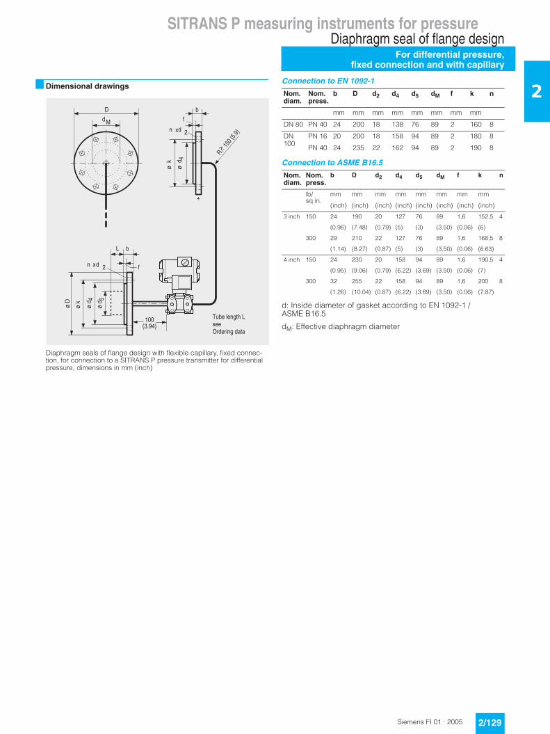
2■ Dimensional drawings
Diaphragm seals of flange design with flexible capillary, fixed connec-tion, for connection to a SITRANS P pressure transmitter for differential pressure, dimensions in mm (inch)
Connection to EN 1092-1
Connection to ASME B16.5
d: Inside diameter of gasket according to EN 1092-1 / ASME B16.5
dM: Effective diaphragm diameter
+
�
);
���� �7
A��3
(
A�� 8
������.��#. =$
BC
���#% =8$
)
;���� �7
A�+
A�3
A� 8
A� .
�
?�)������,������� ����� ���
Nom. diam.
Nom. press.
b D d2 d4 d5 dM f k n
mm mm mm mm mm mm mm mm
DN 80 PN 40 24 200 18 138 76 89 2 160 8
DN 100
PN 16 20 200 18 158 94 89 2 180 8
PN 40 24 235 22 162 94 89 2 190 8
Nom. diam.
Nom. press.
b D d2 d4 d5 dM f k n
lb/sq.in.
mm mm mm mm mm mm mm mm
(inch) (inch) (inch) (inch) (inch) (inch) (inch) (inch)
3 inch 150 24 190 20 127 76 89 1,6 152,5 4
(0.96) (7.48) (0.79) (5) (3) (3.50) (0.06) (6)
300 29 210 22 127 76 89 1,6 168,5 8
(1.14) (8.27) (0.87) (5) (3) (3.50) (0.06) (6.63)
4 inch 150 24 230 20 158 94 89 1,6 190,5 4
(0.95) (9.06) (0.79) (6.22) (3.69) (3.50) (0.06) (7)
300 32 255 22 158 94 89 1,6 200 8
(1.26) (10.04) (0.87) (6.22) (3.69) (3.50) (0.06) (7.87)
SITRANS P measuring instruments for pressureDiaphragm seal of flange designFor differential pressure,fixed connection and with capillary
2/130 Siemens FI 01 · 2005
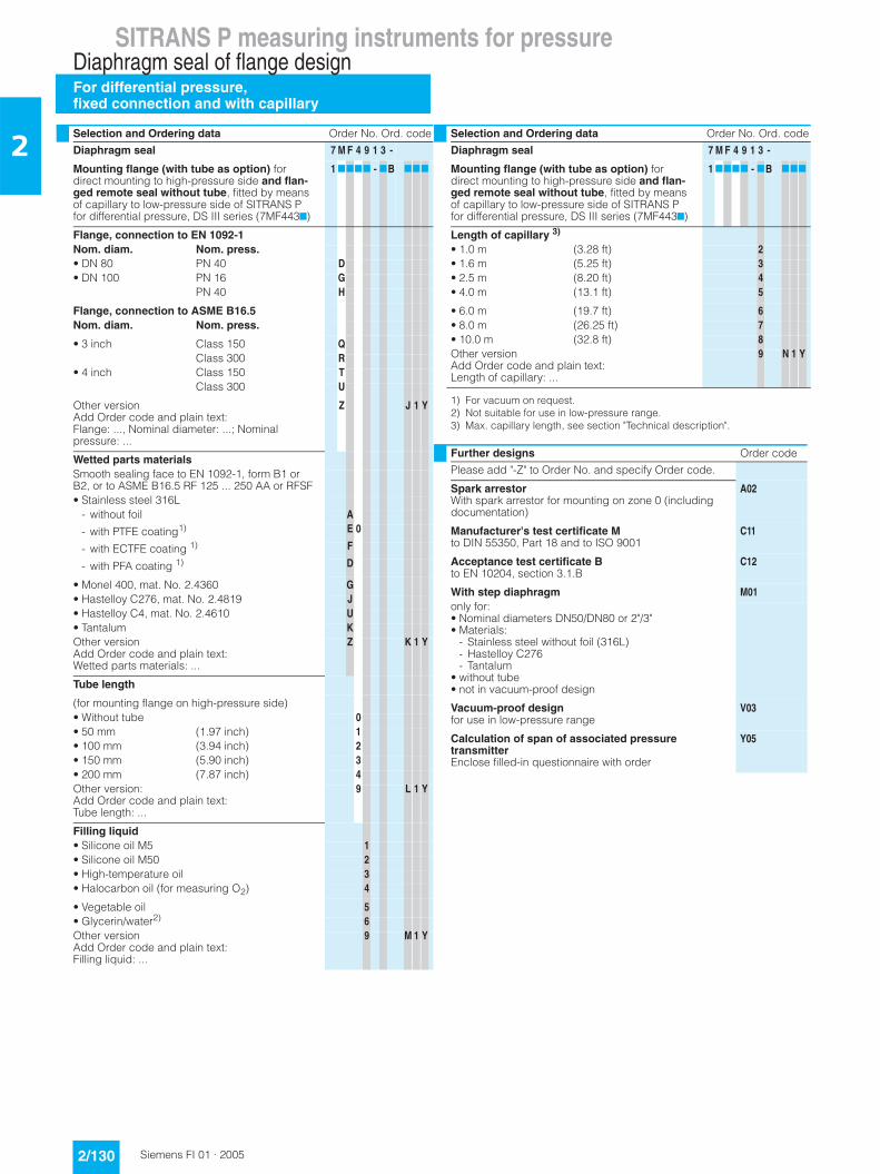
2Selection and Ordering data Order No. Ord. code
Diaphragm seal 7 M F 4 9 1 3 -
Mounting flange (with tube as option) for direct mounting to high-pressure side and flan-ged remote seal without tube, fitted by means of capillary to low-pressure side of SITRANS P for differential pressure, DS III series (7MF4437)
1 7777 - 7B 777
Flange, connection to EN 1092-1Nom. diam. Nom. press.• DN 80 PN 40 D• DN 100 PN 16 G
PN 40 H
Flange, connection to ASME B16.5Nom. diam. Nom. press.
• 3 inch Class 150 QClass 300 R
• 4 inch Class 150 TClass 300 U
Other versionAdd Order code and plain text:Flange: ..., Nominal diameter: ...; Nominal pressure: ...
Z J 1 Y
Wetted parts materialsSmooth sealing face to EN 1092-1, form B1 or B2, or to ASME B16.5 RF 125 ... 250 AA or RFSF• Stainless steel 316L
- without foil A
- with PTFE coating1) E 0
- with ECTFE coating 1) F
- with PFA coating 1) D
• Monel 400, mat. No. 2.4360 G• Hastelloy C276, mat. No. 2.4819 J• Hastelloy C4, mat. No. 2.4610 U• Tantalum KOther versionAdd Order code and plain text:Wetted parts materials: ...
Z K 1 Y
Tube length
(for mounting flange on high-pressure side)• Without tube 0• 50 mm (1.97 inch) 1• 100 mm (3.94 inch) 2• 150 mm (5.90 inch) 3• 200 mm (7.87 inch) 4Other version:Add Order code and plain text:Tube length: ...
9 L 1 Y
Filling liquid• Silicone oil M5 1• Silicone oil M50 2• High-temperature oil 3• Halocarbon oil (for measuring O2) 4
• Vegetable oil 5• Glycerin/water2) 6Other versionAdd Order code and plain text:Filling liquid: ...
9 M 1 Y
Length of capillary 3)
• 1.0 m (3.28 ft) 2• 1.6 m (5.25 ft) 3• 2.5 m (8.20 ft) 4• 4.0 m (13.1 ft) 5
• 6.0 m (19.7 ft) 6• 8.0 m (26.25 ft) 7• 10.0 m (32.8 ft) 8Other versionAdd Order code and plain text:Length of capillary: ...
9 N 1 Y
1) For vacuum on request.2) Not suitable for use in low-pressure range.3) Max. capillary length, see section "Technical description".
Further designs Order code
Please add "-Z" to Order No. and specify Order code.
Spark arrestorWith spark arrestor for mounting on zone 0 (including documentation)
A02
Manufacturer's test certificate Mto DIN 55350, Part 18 and to ISO 9001
C11
Acceptance test certificate Bto EN 10204, section 3.1.B
C12
With step diaphragm M01only for:• Nominal diameters DN50/DN80 or 2"/3"• Materials:
- Stainless steel without foil (316L)- Hastelloy C276- Tantalum
• without tube• not in vacuum-proof design
Vacuum-proof designfor use in low-pressure range
V03
Calculation of span of associated pressure transmitterEnclose filled-in questionnaire with order
Y05
Selection and Ordering data Order No. Ord. code
Diaphragm seal 7 M F 4 9 1 3 -
Mounting flange (with tube as option) for direct mounting to high-pressure side and flan-ged remote seal without tube, fitted by means of capillary to low-pressure side of SITRANS P for differential pressure, DS III series (7MF4437)
1 7777 - 7B 777
SITRANS P measuring instruments for pressureQuick-release diaphragm seals
For pressure, absolute pressure and diff. pressure
2/131Siemens FI 01 · 2005
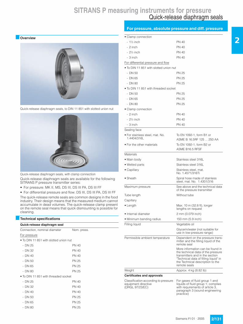
2■ Overview
Quick-release diaphragm seals, to DIN 11 851 with slotted union nut
Quick-release diaphragm seals, with clamp connection
Quick-release diaphragm seals are available for the following SITRANS P pressure transmitter series:• For pressure: MK II, MS, DS III, DS III PA, DS III FF• For differential pressure and flow: DS III, DS III PA, DS III FFThe quick-release remote seals are common designs in the food industry. Their design means that the measured medium cannot accumulate in dead volumes. The quick-release clamp present on the remote seal means that quick dismounting is possible for cleaning.
■ Technical specifications
Quick-release diaphragm seal
Connection, nominal diameter Nom. press.
For pressure
• To DIN 11 851 with slotted union nut
- DN 25 PN 40
- DN 32 PN 40
- DN 40 PN 40
- DN 50 PN 25
- DN 65 PN 25
- DN 80 PN 25
• To DIN 11 851 with threaded socket
- DN 25 PN 40
- DN 32 PN 40
- DN 40 PN 40
- DN 50 PN 25
- DN 65 PN 25
- DN 80 PN 25
• Clamp connection
- 1½ inch PN 40
- 2 inch PN 40
- 2½ inch PN 40
- 3 inch PN 40
For differential pressure and flow
• To DIN 11 851 with slotted union nut
- DN 50 PN 25
- DN 65 PN 25
- DN 80 PN 25
• To DIN 11 851 with threaded socket
- DN 50 PN 25
- DN 65 PN 25
- DN 80 PN 25
• Clamp connection
- 2 inch PN 40
- 2½ inch PN 40
- 3 inch PN 40
Sealing face
• For stainless steel, mat. No. 1.4404/316L
To EN 1092-1, form B1 or ASME B 16.5RF 125 ... 250 AA
• For the other materials To EN 1092-1, form B2 or ASME B16.5 RFSF
Materials
• Main body Stainless steel 316L
• Wetted parts Stainless steel 316L
• Capillary Stainless steel, mat. No. 1.4571/316Ti
• Sheath Spiral hose made of stainless steel, mat. No. 1.4301/316
Maximum pressure See above and the technical data of the pressure transmitter
Tube length Without tube
Capillary
• Length Max. 10 m (32.8 ft), longer lengths on request
• Internal diameter 2 mm (0.079 inch)
• Minimum bending radius 150 mm (5.9 inch)
Filling liquid Vegetable oil
Glycerin/water (not suitable for use in low-pressure range)
Permissible ambient temperature Dependent on the pressure trans-mitter and the filling liquid of the remote sealMore information can be found in the technical data of the pressure transmitters and in the section "Technical data of filling liquid" in the Technical description to the remote seals
Weight Approx. 4 kg (8.82 lb)
Certificates and approvals
Classification according to pressure equipment directive (DRGL 97/23/EC)
For gases of fluid group 1 and liquids of fluid group 1; complies with requirements of article 3, paragraph 3 (sound engineering practice)
SITRANS P measuring instruments for pressureQuick-release diaphragm seals
For pressure, absolute pressure and diff. pressure
2/132 Siemens FI 01 · 2005
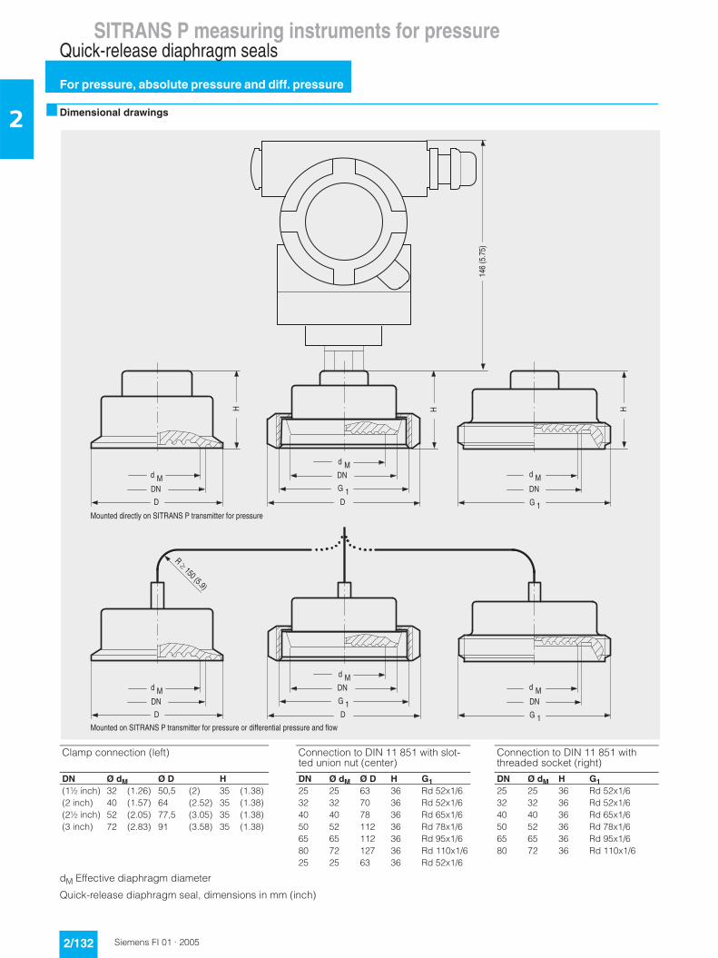
2 ■ Dimensional drawings
dM Effective diaphragm diameter
Quick-release diaphragm seal, dimensions in mm (inch)
�80�#. 2.$
55 5
(
�D
+
(
+
+@
(
�D
+@
+@
(
�D
+
(
+
+@
+@
�����.��#. =$
(
�D
+@
(��� � �����������?�9@��������-������;����������
(��� ����?�9@��������-������;������������� �;;������������������ �;��
Clamp connection (left) Connection to DIN 11 851 with slot-ted union nut (center)
Connection to DIN 11 851 with threaded socket (right)
DN Ø dM Ø D H DN Ø dM Ø D H G1 DN Ø dM H G1(1½ inch) 32 (1.26) 50,5 (2) 35 (1.38) 25 25 63 36 Rd 52x1/6 25 25 36 Rd 52x1/6(2 inch) 40 (1.57) 64 (2.52) 35 (1.38) 32 32 70 36 Rd 52x1/6 32 32 36 Rd 52x1/6(2½ inch) 52 (2.05) 77,5 (3.05) 35 (1.38) 40 40 78 36 Rd 65x1/6 40 40 36 Rd 65x1/6(3 inch) 72 (2.83) 91 (3.58) 35 (1.38) 50 52 112 36 Rd 78x1/6 50 52 36 Rd 78x1/6
65 65 112 36 Rd 95x1/6 65 65 36 Rd 95x1/680 72 127 36 Rd 110x1/6 80 72 36 Rd 110x1/625 25 63 36 Rd 52x1/6
SITRANS P measuring instruments for pressureQuick-release diaphragm seals
For pressure, absolute pressure and diff. pressure
2/133Siemens FI 01 · 2005
2Selection and Ordering data Order No. Ord. code
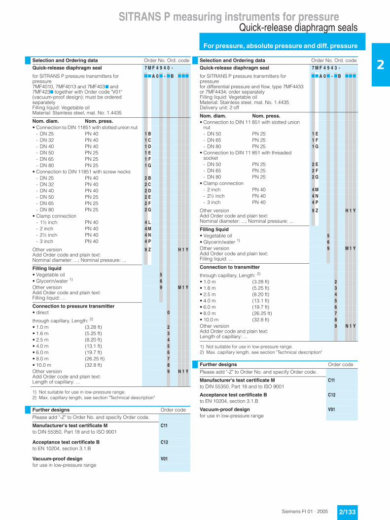
Quick-release diaphragm seal 7 M F 4 9 4 0 -
for SITRANS P pressure transmitters for pressure7MF4010, 7MF4013 and 7MF4037 and 7MF4237 together with Order code "V01" (vacuum-proof design); must be ordered separatelyFilling liquid: Vegetable oilMaterial: Stainless steel, mat. No. 1.4435
77 A 0 7 - 7B 777
Nom. diam. Nom. press.• Connection to DIN 11851 with slotted union nut
- DN 25 PN 40 1 B- DN 32 PN 40 1 C- DN 40 PN 40 1 D- DN 50 PN 25 1 E- DN 65 PN 25 1 F- DN 80 PN 25 1 G
• Connection to DIN 11851 with screw necks- DN 25 PN 40 2 B- DN 32 PN 40 2 C- DN 40 PN 40 2 D- DN 50 PN 25 2 E- DN 65 PN 25 2 F- DN 80 PN 25 2 G
• Clamp connection- 1½ inch PN 40 4 L- 2 inch PN 40 4 M- 2½ inch PN 40 4 N- 3 inch PN 40 4 P
Other versionAdd Order code and plain text:Nominal diameter: ...; Nominal pressure: ...
9 Z H 1 Y
Filling liquid• Vegetable oil 5• Glycerin/water 1)
1) Not suitable for use in low-pressure range.
6Other versionAdd Order code and plain text:Filling liquid: ...
9 M 1 Y
Connection to pressure transmitter• direct 0
through capillary, Length: 2)
2) Max. capillary length, see section "Technical description"
• 1.0 m (3.28 ft) 2• 1.6 m (5.25 ft) 3• 2.5 m (8.20 ft) 4• 4.0 m (13.1 ft) 5• 6.0 m (19.7 ft) 6• 8.0 m (26.25 ft) 7• 10.0 m (32.8 ft) 8Other versionAdd Order code and plain text:Length of capillary: ...
9 N 1 Y
Further designs Order code
Please add "-Z" to Order No. and specify Order code.
Manufacturer's test certificate M C11to DIN 55350, Part 18 and to ISO 9001
Acceptance test certificate B C12to EN 10204, section 3.1.B
Vacuum-proof design V01for use in low-pressure range
Selection and Ordering data Order No. Ord. code
Quick-release diaphragm seal 7 M F 4 9 4 3 -
for SITRANS P pressure transmitters for pressurefor differential pressure and flow, type 7MF4433 or 7MF4434; order separatelyFilling liquid: Vegetable oilMaterial: Stainless steel, mat. No. 1.4435Delivery unit: 2 off
77 A 0 7 - 7B 777
Nom. diam. Nom. press.• Connection to DIN 11 851 with slotted union
nut- DN 50 PN 25 1 E- DN 65 PN 25 1 F- DN 80 PN 25 1 G
• Connection to DIN 11 851 with threaded socket - DN 50 PN 25 2 E- DN 65 PN 25 2 F- DN 80 PN 25 2 G
• Clamp connection- 2 inch PN 40 4 M- 2½ inch PN 40 4 N- 3 inch PN 40 4 P
Other versionAdd Order code and plain text:Nominal diameter: ...; Nominal pressure: ...
9 Z H 1 Y
Filling liquid• Vegetable oil 5• Glycerin/water 1)
1) Not suitable for use in low-pressure range.
6Other versionAdd Order code and plain text:Filling liquid: ...
9 M 1 Y
Connection to transmitter
through capillary, Length: 2)
2) Max. capillary length, see section "Technical description"
• 1.0 m (3.28 ft) 2• 1.6 m (5.25 ft) 3• 2.5 m (8.20 ft) 4• 4.0 m (13.1 ft) 5• 6.0 m (19.7 ft) 6• 8.0 m (26.25 ft) 7• 10.0 m (32.8 ft) 8Other versionAdd Order code and plain text:Length of capillary: ...
9 N 1 Y
Further designs Order code
Please add "-Z" to Order No. and specify Order code.
Manufacturer's test certificate M C11to DIN 55350, Part 18 and to ISO 9001
Acceptance test certificate B C12to EN 10204, section 3.1.B
Vacuum-proof design V01for use in low-pressure range
SITRANS P measuring instruments for pressureMiniature diaphragm seal
For pressure and absolute pressure
2/134 Siemens FI 01 · 2005
2 ■ Overview
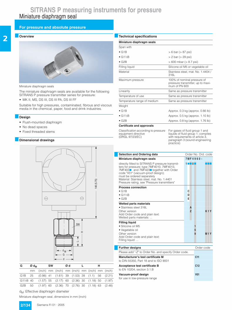
Miniature diaphragm seals
The miniature diaphragm seals are available for the following SITRANS P pressure transmitter series for pressure:• MK II, MS, DS III, DS III PA, DS III FF
Suitable for high pressures, contaminated, fibrous and viscous media in the chemical, paper, food and drink industries.
■ Design
• Flush-mounted diaphragm• No dead spaces• Fixed threaded stems
■ Dimensional drawings
dM: Effective diaphragm diameter
Miniature diaphragm seal, dimensions in mm (inch)
■ Technical specifications
G Ø dM SW Ø d L H
mm (inch) mm (inch) mm (inch) mm (inch) mm (inch)
G1B 25 (0.98) 41 (1.61) 39 (1.53) 28 (1.1) 56 (2.21)
G1½B 40 (1.57) 55 (2.17) 60 (2.36) 30 (1.18) 50 (1.97)
G2B 50 (1.97) 60 (2.36) 70 (2.76) 30 (1.18) 63 (2.48)
�80�#. 2.$
D
�
5
�E
(
Miniature diaphragm seals
Span with
• G1B > 6 bar (> 87 psi)
• G1½B > 2 bar (> 29 psi)
• G2B > 600 mbar (> 8.7 psi)
Filling liquid Silicone oil M5 or vegetable oil
Material Stainless steel, mat. No. 1.4404 / 316L
Maximum pressure 100% of nominal pressure of pressure transmitter, up to maxi-mum of PN 600
Linearity Same as pressure transmitter
Temperature of use Same as pressure transmitter
Temperature range of medium Same as pressure transmitter
Weight
• G1B Approx. 0.3 kg (approx. 0.66 lb)
• G1½B Approx. 0.5 kg (approx. 1.10 lb)
• G2B Approx. 0.8 kg (approx. 1.76 lb)
Certificate and approvals
Classification according to pressure equipment directive (DRGL 97/23/EC)
For gases of fluid group 1 and liquids of fluid group 1; complies with requirements of article 3, paragraph 3 (sound engineering practice)
Selection and Ordering data Order No. Ord. code
Miniature diaphragm seals 7 M F 4 9 6 0 -
directly fitted to SITRANS P pressure transmit-ters for pressure; type 7MF4010, 7MF4013, 7MF4037 and 7MF4237 together with Order code "V01" (vacuum-proof design); must be ordered separatelyMaterial: Stainless steel, mat. No. 1.4401Pressure rating, see "Pressure transmitters"
1 77 0 7 777
Process connection• G1B C• G1½B D• G2B E
Wetted parts materials• Stainless steel 316L AOther versionAdd Order code and plain text:Wetted parts materials: ...
Z K 1 Y
Filling liquid• Silicone oil M5 1• Vegetable oil 5Other versionAdd Order code and plain text:Filling liquid: ...
9 M 1 Y
Further designs Order code
Please add "-Z" to Order No. and specify Order code.
Manufacturer's test certificate M C11to DIN 55350, Part 18 and to ISO 9001
Acceptance test certificate B C12to EN 10204, section 3.1.B
Vacuum-proof design V01for use in low-pressure range
SITRANS P measuring instruments for pressureAccessories for diaphragm seal
Flushing rings
2/135Siemens FI 01 · 2005
2■ Overview
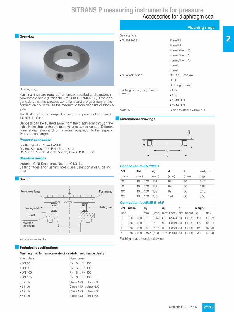
Flushing ring
Flushing rings are required for flange-mounted and sandwich-type remote seals (Order No. 7MF4900 ... 7MF4923) if the dan-ger exists that the process conditions and the geometry of the connection could cause the medium to form deposits or blocka-ges.
The flushing ring is clamped between the process flange and the remote seal.
Deposits can be flushed away from the diaphragm through the holes in the side, or the pressure volume can be vented. Different nominal diameters and forms permit adaptation to the respec-tive process flange.
Process connection
For flanges to EN and ASME:DN 50, 80, 100, 125; PN 16 ... 100 orDN 2 inch, 3 inch, 4 inch, 5 inch; Class 150 ... 600
Standard design
Material: CrNi-Stahl, mat. No. 1.4404/316LSealing faces and flushing holes: See Selection and Ordering data
■ Design
Installation example
■ Technical specifications
■ Dimensional drawings
Connection to EN 1092-1
Connection to ASME B 16.5
Flushing ring, dimension drawing
Flushing ring for remote seals of sandwich and flange design
Nom. diam. Nom. press.
• DN 50 PN 16 ... PN 100
• DN 80 PN 16 ... PN 100
• DN 100 PN 16 ... PN 100
• DN 125 PN 16 ... PN 100
• 2 inch Class 150 ... class 600
• 3 inch Class 150 ... class 600
• 4 inch Class 150 ... class 600
• 5 inch Class 150 ... class 600
+��,���
��F����
(�����������;����
6���,��������
��-��������;����
D��3��
6���,�������
6���,������
Sealing face
• To EN 1092-1 Form B1
Form B2
Form D/Form D
Form C/Form C
Form C/Form C
Form E
Form F
• To ASME B16.5 RF 125 ... 250 AA
RFSF
RJT ring groove
Flushing holes (2 off), female thread:
• G¼
• G½
• ¼-18 NPT
• ½-14 NPT
Material Stainless steel 1.4404/316L
DN PN d4 di h Weight
(mm) (bar) (mm) (mm) (mm) (kg)
50 16 ... 100 102 62 30 1.10
80 16 ... 100 138 92 30 1.90
100 16 ... 100 162 92 30 3.15
125 16 ... 100 188 126 30 3.50
DN Class d4 di h Weight
inch mm (inch) mm (inch) mm (inch) kg (lb)
2 150 ... 600 92 (3.62) 62 (2.44) 30 (1.18) 0.60 (1.32)
3 150 ... 600 127 (5) 92 (3.62) 30 (1.18) 1.05 (2.31)
4 150 ... 600 157 (6.18) 92 (3.62) 30 (1.18) 2.85 (6.28)
5 150 ... 600 185.5 (7.3) 126 (4.96) 30 (1.18) 3.30 (7.28)
�
,
8
?,���

SITRANS P measuring instruments for pressureAccessories for diaphragm seal
Flushing rings
2/136 Siemens FI 01 · 2005
2 Selection and Ordering data Order No. Ord. code
Flushing ring 7 M F 4 9 2 5 -
for remote seals 7MF4900 to 7MF4923 1 7777 777
Nom. diam. Nom. press.• DN 50 PN 16 ... PN 100 A• DN 80 PN 16 ... PN 100 B• DN 100 PN 16 ... PN 100 C• DN 125 PN 16 ... PN 100 D
• 2 inch Class 150 ... 600 G• 3 inch Class 150 ... 600 H• 4 inch Class 150 ... 600 J• 5 inch Class 150 ... 600 K
Other versionAdd Order code and plain text:Nominal diameter: ...; Nominal pressure: ...
Z J 1 Y
Sealing face• To EN 1092-1
- Form B1 A- Form B2 C
- Form C / Form C D- Form D / Form C E- Form D / Form D F
- Form E G- Form F H
• ASME B16.5- RF 125 ... 250 AA M- RFSF Q- RJT ring groove R
Other versionAdd Order code and plain text:Sealing face: ...
Z K 1 Y
Flushing holes (2 off)• Female thread G¼ 1• Female thread G½ 2• Female thread ¼-18 NPT 3• Female thread ½-14 NPT 4
Material• Stainless steel 316L 0Other versionAdd Order code and plain text:Material: ...
9 M 1 Y
Further designs Order code
Please add "-Z" to Order No. and specify Order code.
Acceptance test certificate B C12to EN 10204, section 3.1.B

SITRANS P measuring instruments for pressureClamp-on seals of flange design
For pressure, differential pressure and flow
2/137Siemens FI 01 · 2005
2■ Overview
Clamp-on seals for flange-mounting
The clamp-on seal is completely integrated in the process line. It is particularly suitable for flowing and highly viscous media.
The clamp-on remote seal consists of a cylindrical jacket into which a thin-walled pipe is welded. It is clamped directly bet-ween two flanges in the pipeline.
■ Design
• Clamp-on seals for flange-mounting (flange design) to EN/ASME for SITRANS P pressure transmitters - For pressure: MK II, MS, DS III, DS III PA and DS III FF series- For differential pressure and flow: DS III, DS III PA and
DS III FF• Sealing face to EN 1092-1 or ASME B16.5• Connection to the transmitter directly or by means of a flexible
capillary (max. 10 m long)• See Technical data for details of materials used for the wetted
parts• Material used for the capillary, the guard sleeve, the seal’s
main body and the measuring cell: Stainless steel, mat.-No. 1.4571
• Filling liquid: Silicone oil, high-temperature oil, halocarbon oil, vegetable oil or glycerin/water (not suitable for uses in low-pressure range)
■ Function
The measured pressure is transferred from the diaphragm to the filling liquid and passes either directly or through the capillary to the measuring chamber of the pressure transmitter. The interior of the diaphragm seal and of the capillary, as well as the measu-ring chamber of the pressure transmitter, are filled gas-free by the filling liquid.
Note:
When operating in the low-pressure range, also during commis-sioning, it is recommended to use a vacuum-proof remote seal (see Selection and Ordering data).
■ Technical specifications
Clamp-on seals for flange-mounting
Nom. diam. Nom. press.
• DN 25 PN 6 ... PN 100
• DN 40 PN 6 ... PN 100
• DN 50 PN 6 ... PN 100
• DN 80 PN 6 ... PN 100
• DN 100 PN 6 ... PN 100
• 1 inch Class 150 ... class 2500
• 1½ inch Class 150 ... class 2500
• 2 inch Class 150 ... class 2500
• 3 inch Class 150 ... class 2500
• 4 inch Class 150 ... class 2500
Process connection Flange to EN 1092-1 or ASME B 16.5
Sealing face To EN 1092-1, form B1 or to ASME B16.5 RF 125 ... 250 A or RFSF
Materials
• Main body Stainless steel 1.4404/316L
• Diaphragm Stainless steel 1.4404/316L
• Wetted parts Stainless steel 1.4404/316L
• Without foil
• ECTFE coating
• PFA coating (for vacuum on re-quest)
Monel 400, mat. No. 2.4360
Hastelloy C276, mat. No. 2.4819
Hastelloy C4, mat. No. 2.4610
Tantalum
• Capillary Stainless steel, mat. No. 1.4571/316Ti
• Sheath Spiral hose made of stainless steel, mat. No. 1.4301/316
Capillary
• Length Max. 10 m (32.8 ft)
• Internal diameter 2 mm (0.079 inch)
• Minimum bending radius 150 mm (5.9 inch)
Filling liquid Silicone oil M5
Silicone oil M50
High-temperature oil
Halocarbon oil
Vegetable oil
Glycerin/water (not suitable for uses in low-pressure range)
Permissible ambient temperature See pressure transmitters, see fil-ling liquid
Weight Approx. 4 kg (8.82 lb)
Certificates and approvals
Classification according to pressure equipment directive (DRGL 97/23/EC)
For gases of fluid group 1 and liquids of fluid group 1; complies with the requirements of article 3, paragraph 1 (appendix 1); assig-ned to category III, conformity evaluation module H by the TÜV Nord
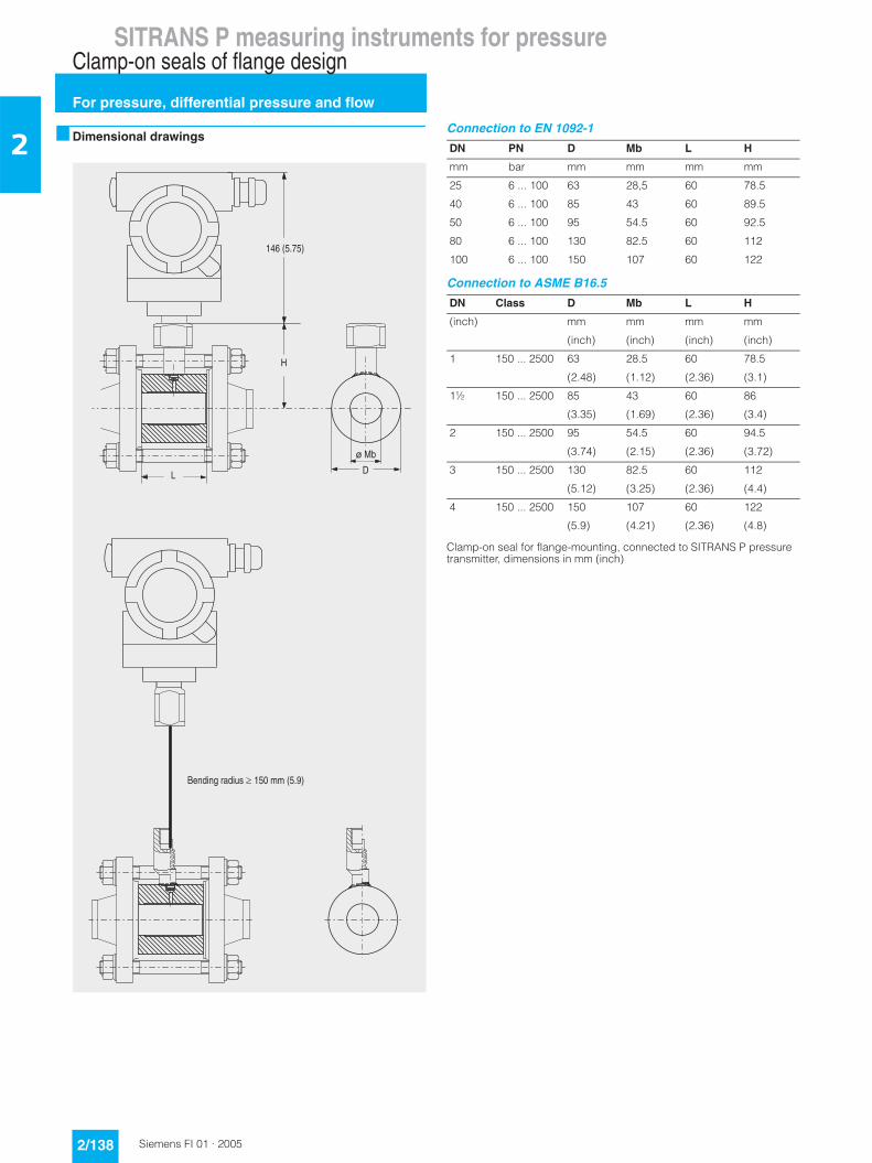
SITRANS P measuring instruments for pressureClamp-on seals of flange design
For pressure, differential pressure and flow
2/138 Siemens FI 01 · 2005
2 ■ Dimensional drawings
Connection to EN 1092-1
Connection to ASME B16.5
Clamp-on seal for flange-mounting, connected to SITRANS P pressure transmitter, dimensions in mm (inch)
+
A�()
�
5
�80�#. 2.$
�� ����� �������.��--�#. =$
DN PN D Mb L H
mm bar mm mm mm mm
25 6 ... 100 63 28,5 60 78.5
40 6 ... 100 85 43 60 89.5
50 6 ... 100 95 54.5 60 92.5
80 6 ... 100 130 82.5 60 112
100 6 ... 100 150 107 60 122
DN Class D Mb L H
(inch) mm mm mm mm
(inch) (inch) (inch) (inch)
1 150 ... 2500 63 28.5 60 78.5
(2.48) (1.12) (2.36) (3.1)
1½ 150 ... 2500 85 43 60 86
(3.35) (1.69) (2.36) (3.4)
2 150 ... 2500 95 54.5 60 94.5
(3.74) (2.15) (2.36) (3.72)
3 150 ... 2500 130 82.5 60 112
(5.12) (3.25) (2.36) (4.4)
4 150 ... 2500 150 107 60 122
(5.9) (4.21) (2.36) (4.8)
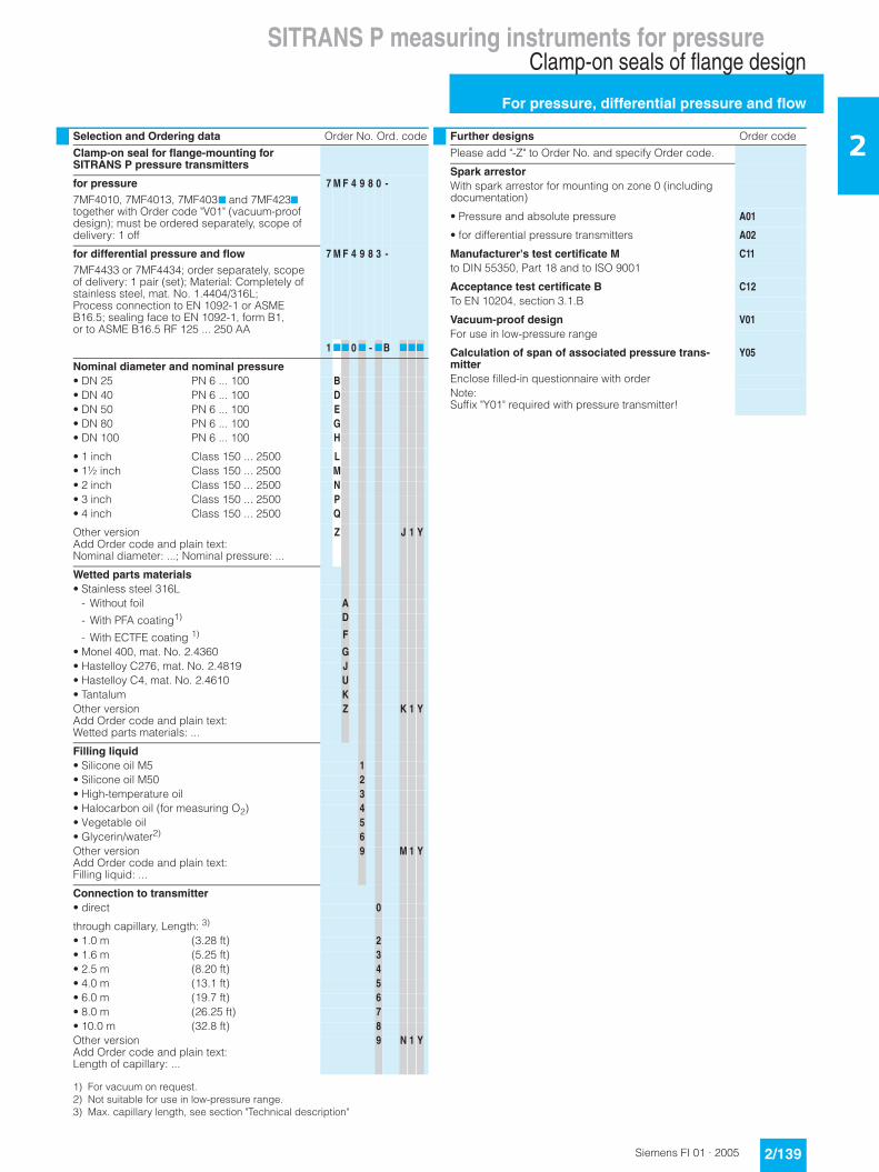
SITRANS P measuring instruments for pressureClamp-on seals of flange design
For pressure, differential pressure and flow
2/139Siemens FI 01 · 2005
2Selection and Ordering data Order No. Ord. code
Clamp-on seal for flange-mounting for SITRANS P pressure transmitters
for pressure7MF4010, 7MF4013, 7MF4037 and 7MF4237 together with Order code "V01" (vacuum-proof design); must be ordered separately, scope of delivery: 1 off
7 M F 4 9 8 0 -
for differential pressure and flow7MF4433 or 7MF4434; order separately, scope of delivery: 1 pair (set); Material: Completely of stainless steel, mat. No. 1.4404/316L;Process connection to EN 1092-1 or ASME B16.5; sealing face to EN 1092-1, form B1, or to ASME B16.5 RF 125 ... 250 AA
7 M F 4 9 8 3 -
1 77 0 7 - 7B 777
Nominal diameter and nominal pressure• DN 25 PN 6 ... 100 B• DN 40 PN 6 ... 100 D• DN 50 PN 6 ... 100 E• DN 80 PN 6 ... 100 G• DN 100 PN 6 ... 100 H
• 1 inch Class 150 ... 2500 L• 1½ inch Class 150 ... 2500 M• 2 inch Class 150 ... 2500 N• 3 inch Class 150 ... 2500 P• 4 inch Class 150 ... 2500 Q
Other versionAdd Order code and plain text:Nominal diameter: ...; Nominal pressure: ...
Z J 1 Y
Wetted parts materials• Stainless steel 316L
- Without foil A
- With PFA coating1)
1) For vacuum on request.
D
- With ECTFE coating 1) F
• Monel 400, mat. No. 2.4360 G• Hastelloy C276, mat. No. 2.4819 J• Hastelloy C4, mat. No. 2.4610 U• Tantalum KOther versionAdd Order code and plain text:Wetted parts materials: ...
Z K 1 Y
Filling liquid• Silicone oil M5 1• Silicone oil M50 2• High-temperature oil 3• Halocarbon oil (for measuring O2) 4• Vegetable oil 5• Glycerin/water2)
2) Not suitable for use in low-pressure range.
6Other versionAdd Order code and plain text:Filling liquid: ...
9 M 1 Y
Connection to transmitter• direct 0
through capillary, Length: 3)
3) Max. capillary length, see section "Technical description"
• 1.0 m (3.28 ft) 2• 1.6 m (5.25 ft) 3• 2.5 m (8.20 ft) 4• 4.0 m (13.1 ft) 5• 6.0 m (19.7 ft) 6• 8.0 m (26.25 ft) 7• 10.0 m (32.8 ft) 8Other versionAdd Order code and plain text:Length of capillary: ...
9 N 1 Y
Further designs Order code
Please add "-Z" to Order No. and specify Order code.
Spark arrestorWith spark arrestor for mounting on zone 0 (including documentation)
• Pressure and absolute pressure A01
• for differential pressure transmitters A02
Manufacturer's test certificate M C11to DIN 55350, Part 18 and to ISO 9001
Acceptance test certificate B C12To EN 10204, section 3.1.B
Vacuum-proof design V01For use in low-pressure range
Calculation of span of associated pressure trans-mitter
Y05
Enclose filled-in questionnaire with orderNote:Suffix "Y01" required with pressure transmitter!
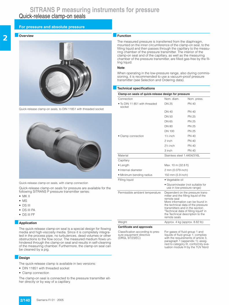
SITRANS P measuring instruments for pressureQuick-release clamp-on seals
For pressure and absolute pressure
2/140 Siemens FI 01 · 2005
2 ■ Overview
Quick-release clamp-on seals, to DIN 11851 with threaded socket
Quick-release clamp-on seals, with clamp connection
Quick-release clamp-on seals for pressure are available for the following SITRANS P pressure transmitter series:• MK II• MS• DS III• DS III PA• DS III FF
■ Application
The quick-release clamp-on seal is a special design for flowing media and high-viscosity media. Since it is completely integra-ted in the process pipe, no turbulences, dead volumes or other obstructions to the flow occur. The measured medium flows un-hindered through the clamp-on seal and results in self-cleaning of the measuring chamber. Furthermore, the clamp-on seal can be cleaned by a pig.
■ Design
The quick-release clamp is available in two versions:• DIN 11851 with threaded socket• Clamp connection
The clamp-on seal is connected to the pressure transmitter eit-her directly or by way of a capillary.
■ Function
The measured pressure is transferred from the diaphragm, mounted on the inner circumference of the clamp-on seal, to the filling liquid and then passes through the capillary to the measu-ring chamber of the pressure transmitter. The interior of the clamp-on seal and of the capillary, as well as the measuring chamber of the pressure transmitter, are filled gas-free by the fil-ling liquid.
Note:
When operating in the low-pressure range, also during commis-sioning, it is recommended to use a vacuum-proof pressure transmitter (see Selection and Ordering data).
■ Technical specifications
Clamp-on seals of quick-release design for pressure
Connection Nom. diam. Nom. press.
• To DIN 11 851 with threadedsocket
DN 25 PN 40
DN 40 PN 40
DN 50 PN 25
DN 65 PN 25
DN 80 PN 25
DN 100 PN 25
• Clamp connection 1½ inch PN 40
2 inch PN 40
2½ inch PN 40
3 inch PN 40
Material Stainless steel 1.4404/316L
Capillary
• Length Max. 10 m (32.8 ft)
• Internal diameter 2 mm (0.079 inch)
• Minimum bending radius 150 mm (5.9 inch)
Filling liquid • Vegetable oil
• Glycerin/water (not suitable for use in low-pressure range)
Permissible ambient temperature Dependent on the pressure trans-mitter and the filling liquid of the remote sealMore information can be found in the technical data of the pressure transmitters and in the section "Technical data of filling liquid" in the Technical description to the remote seals
Weight Approx. 4 kg (approx. 8.82 lb)
Certificate and approvals
Classification according to pres-sure equipment directive (DRGL 97/23/EC)
For gases of fluid group 1 and liquids of fluid group 1; complies with the requirements of article 3, paragraph 1 (appendix 1); assig-ned to category III, conformity eva-luation module H by the TÜV Nord

SITRANS P measuring instruments for pressureQuick-release clamp-on seals
For pressure and absolute pressure
2/141Siemens FI 01 · 2005
2■ Dimensional drawings
Quick-release clamp-on seal, dimensions in mm (inch)
�
$; '
-
�
�*=�
9+:
!
�
�
-
$�
$�
$�
$�
�
$; '�
�
�
$�
$�
$�
$�
�����9
�� 9+:
!
$$
&��������������������<�";��������,������1�����������
&������������<�";��������,������1�����������������11�������������������1��
Connection to DIN 11851 with screw necks Clamp connection for pipes to BS 4825/3 and o.D. tubes
DN Ø D1 Ø D2 H L G1 d Ø D1 Ø D2 H L D
25 38 52 68 128 Rd 52x1/6 mm (inch) mm (inch) mm (inch) mm (inch) mm (inch) mm (inch)
40 55 65 74,5 160 Rd 65x1/6 22,2 (1) 38 (1.5) 50 (1.97) 67 (2.64) 114 (4.49) 50,5 (1.98)
50 68 78 81 170 Rd 78x1/6 34,9 (1½) 43 (1.69) 65 (2.56) 74,5 (2.93) 146 (5.75) 50,5 (1.98)
65 85 95 89,5 182 Rd 95x1/6 47,6 (2) 56 (2.2) 75 (2.95) 79,5 (3.13) 156 (6.14) 64 (2.52)
80 110 110 97 182 Rd 110x1/4 60,3 (2½) 68 (2.68) 77 (3.03) 80,5 (3.17) 156 (6.14) 77,5 (3.05)
100 130 130 107 182 Rd 110x1/4 73,0 (3) 82 (3.23) 91 (3.58) 87,5 (3.44) 156 (6.14) 91 (3.58)
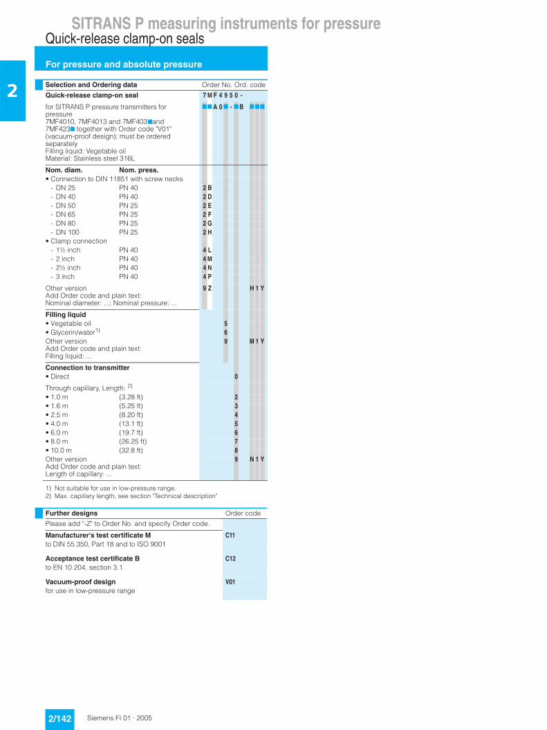
SITRANS P measuring instruments for pressureQuick-release clamp-on seals
For pressure and absolute pressure
2/142 Siemens FI 01 · 2005
2 Selection and Ordering data Order No. Ord. code
Quick-release clamp-on seal 7 M F 4 9 5 0 -
for SITRANS P pressure transmitters for pressure7MF4010, 7MF4013 and 7MF4037and 7MF4237 together with Order code "V01" (vacuum-proof design); must be ordered separatelyFilling liquid: Vegetable oilMaterial: Stainless steel 316L
77 A 0 7 - 7B 777
Nom. diam. Nom. press.• Connection to DIN 11851 with screw necks
- DN 25 PN 40 2 B- DN 40 PN 40 2 D- DN 50 PN 25 2 E- DN 65 PN 25 2 F- DN 80 PN 25 2 G- DN 100 PN 25 2 H
• Clamp connection- 1½ inch PN 40 4 L- 2 inch PN 40 4 M- 2½ inch PN 40 4 N- 3 inch PN 40 4 P
Other versionAdd Order code and plain text:Nominal diameter: ...; Nominal pressure: ...
9 Z H 1 Y
Filling liquid• Vegetable oil 5• Glycerin/water1)
1) Not suitable for use in low-pressure range.
6Other versionAdd Order code and plain text:Filling liquid: ...
9 M 1 Y
Connection to transmitter• Direct 0
Through capillary, Length: 2)
2) Max. capillary length, see section "Technical description"
• 1.0 m (3.28 ft) 2• 1.6 m (5.25 ft) 3• 2.5 m (8.20 ft) 4• 4.0 m (13.1 ft) 5• 6.0 m (19.7 ft) 6• 8.0 m (26.25 ft) 7• 10.0 m (32.8 ft) 8Other versionAdd Order code and plain text:Length of capillary: ...
9 N 1 Y
Further designs Order code
Please add "-Z" to Order No. and specify Order code.
Manufacturer's test certificate M C11to DIN 55.350, Part 18 and to ISO 9001
Acceptance test certificate B C12to EN 10 204, section 3.1
Vacuum-proof design V01for use in low-pressure range
SITRANS P measuring instruments for pressureRemote seals
Measuring setups
2/143Siemens FI 01 · 2005
2■ Overview
This section shows examples of typical measuring setups for using SITRANS P pressure transmitters with and without remote seals.
Equations for calculating start of scale and full scale are provi-ded for each example.
Questionnaires are included to help you select the right combi-nation of remote seal and pressure transmitter.
Installation
Remote seals of sandwich design are fitted between the con-nection flange of the measuring point and a dummy flange. Re-mote seals of flange design are fitted directly on the connection flange of the measuring point. The respective pressure rating of the dummy flange or the flanged remote seal must be observed.
The pressure transmitter should be installed below the connec-tion flange (and below the lower connection flange in the case of differential pressure transmitters). This arrangement must be used in the low-pressure range.
When measuring at pressures above atmospheric, the pressure transmitter can also be installed above the connection flange.
The capillaries between the remote seal and the pressure trans-mitter should be as short as possible to obtain a good transmis-sion response.
Offset of measuring range
If there is a difference in height between the two connection flan-ges when measuring with two remote seals, an additional diffe-rential pressure will result from the oil filling of the remote seal ca-pillaries. This results in a measuring range offset which has to be taken into account when you set the pressure transmitter.
An offset in the measuring range also occurs when combining a remote seal with a transmitter if the latter is not installed at the same height as the former.
Pressure transmitter output
If the level, separation layer or density increase in closed ves-sels, the differential pressure and hence the output signal of the pressure transmitter also increase.
For an inverted relationship between the differential pressure and the output signal, the start-of-scale and full-scale values of the SITRANS P must be interchanged.
With open vessels, a rising pressure is usually assigned to an in-creasing level, separation layer or density.
Influence of ambient temperature
Temperature differences between the individual capillaries and between the individual remote seals should be avoided.
Temperature variations in the area of the measuring setup cause a change in volume of the filling liquid and hence measuring er-rors.
Notes• For the separation layer measurement, the separation layer
has to be positioned between the two spigots. Also you must make sure that the level in the container is always above the top spigot.
• When measuring density, make sure that the level of the me-dium remains constant. The level should be above the top spi-got
Possible combinations of pressure transmitters and remote seals
Type of installation Pressure transmit-ters
Remote seals
A/B 7MF40107MF40137MF40337MF40347MF4035
7MF49007MF49107MF4920
C1 and C2 7MF42337MF42347MF4235
7MF49007MF49107MF4920(vacuum-proof design in each case)
7MF43337MF43347MF4335
7MF49017MF4921
D 7MF44337MF44347MF4435
7MF49037MF4923
E 7MF44337MF44347MF4435
7MF4913
G, H and J 7MF44337MF44347MF4435
7MF49037MF4923
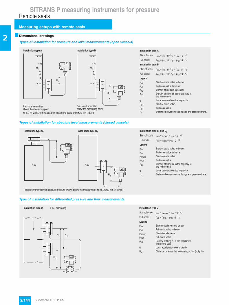
SITRANS P measuring instruments for pressureRemote seals
Measuring setups with remote seals
2/144 Siemens FI 01 · 2005
2 ■ Dimensional drawings
Types of installation for pressure and level measurements (open vessels)
Types of installation for absolute level measurements (closed vessels)
Type of installation for differential pressure and flow measurements
�
�
�
�
�
�
�
�
�������������������
������1����� �&"�J��C��K���K�- �������K���K�-�
C������ �&%�J��C��K���K�-�������K���K�-�
�������������������
������1����� �&"�J��C��K���K�- ������K���K�-�
C������ �&%�J��C��K���K�-�������K���K�-�
�������&" ������1�����2������A������&% C������2������A������C� $��������1�,����,����2������� $��������1�1������������3����������
�3����,������� �����������������������2���- ������1�����2��-� C������2��-� $�������A�������2�����1��������������������+
�������������,�����A�2���3��,�������������
�������������,�����A�����3��,�������������
-����8�,� �/�1�!.����3�3���A��������1������F��������-����*�,� �/+��1�!
������������������� �������������������
��������������������������������1����� �&"�J���<"�<�������K���K�-�
C������ �&%�J��%;$������K���K�-�
�������&" ������1�����2������A������&% C������2������A�������<"�< ������1�����2���%;$ C������2����� $��������1�1������������3����������
�3����,������� �����������������������2���-� $�������A�������2�����1��������������������+-
�
-�
�A�
�A�
�������������,������1���A�������������������A�����3��,���������������-��������,,� 8+:����3!
������������������� ��������������������
-�
-?
-�
�������������������
������1����� �&"�J���<"�<�������K���K�-?
C������ �&%�J��%;$������K���K�-?
�������&" ������1�����2������A������&% C������2������A�������<"�< ������1�����2���%;$ C������2����� $��������1�1������������3����������
�3����,������� �����������������������2���-? $�������A��������3��,��������������� �������!
������������������� C�����,���������
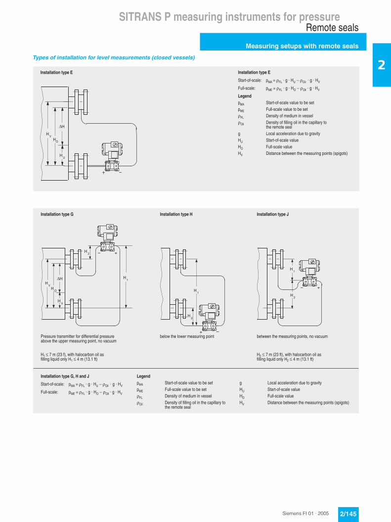
SITRANS P measuring instruments for pressureRemote seals
Measuring setups with remote seals
2/145Siemens FI 01 · 2005
2Types of installation for level measurements (closed vessels)
-�
-?
������������������
������1����� �&"�J��C��K���K�- �������K���K�-?
C������ �&%�J��C��K���K�-�������K���K�-?
�������&" ������1�����2������A������&% C������2������A������C� $��������1�,����,����2������� $��������1�1������������3����������
�3����,������� �����������������������2���- ������1�����2��-� C������2��-? $�������A��������3��,��������������� �������!
������������������
�-
-
-
�-
-�
-?
-�
-�
������������������!"�#�����$
������1����� �&"�J��C��K���K�- �������K���K�-?
C������ �&%�J��C��K���K�-�������K���K�-?
�������&" ������1�����2������A������&% C������2������A������C� $��������1�,����,����2������� $��������1�1������������3����������
�3����,������
� �����������������������2���- ������1�����2��-� C������2��-? $�������A��������3��,��������������� �������!
-�
-�
������������������$
A��������3��,��������������.����2���,
-����8�,� �/�1�!.����3�3���A�������1������F��������-����*�,� �/+��1�!
-�
-�
������������������#
A�����3�������,�������������
������������������!
�������������,������1�����11���������������A�2���3��������,�������������.����2���,
-����8�,� �/�1!.����3�3���A�������1������F��������-����*�,� �/+��1�!

SITRANS P measuring instruments for pressureRemote seals
Measuring setups without remote seals
2/146 Siemens FI 01 · 2005
2 ■ Overview
Notes• For the separation layer measurement, the separation layer
has to be positioned between the two spigots. Also you must make sure that the level in the container is always above the top spigot.
• When measuring density, make sure that the level of the me-dium remains constant. The level should be above the top spi-got
■ Dimensional drawings
Pressure transmitters for differential pressure, for flanging
Measuring setups for open containers
�
�
-�
-�
��%���&���'(�&���
������1����� �&"�J���K���K�-
C������ �&%�J���K���K�-�
�������&" ������1�����2������A������&% C������2������A������ $��������1�,����,����2����� �����������������������2���- ������1�����2��-� C������2��
C������2��
������1�����2��
�
�
-�
�
�-�
�
)���(����������(�&���'(�&���
������1����� �&"�J���K� - �K����� -���- !�K���!
C������ �&%�J����K���K�-�
�������&" ������1�����2������A������&% C������2������A������� $��������1�3�2�����F����� $��������1���3�����F���� �����������������������2���- ������1�����2��-� C������2��
���������2�J�1������2��
������1�����2��
������������
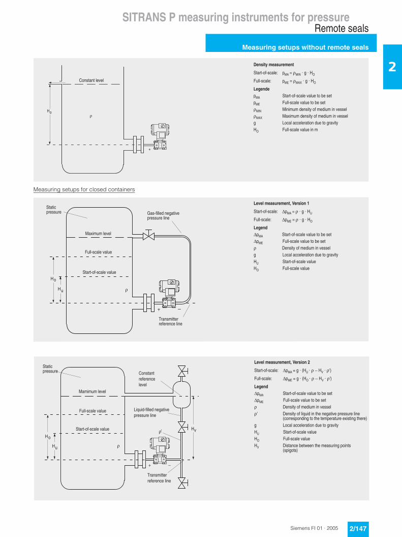
SITRANS P measuring instruments for pressureRemote seals
Measuring setups without remote seals
2/147Siemens FI 01 · 2005
2
Measuring setups for closed containers
-�
�
�
��������&���'(�&���
������1����� �&"�J��&�;�K���K�-�
C������ �&%�J��&"L�K���K�-�
��������&" ������1�����2������A������&% C������2������A������&�; &���,�,����������1�,����,����2�����&"L &>�,�,����������1�,����,����2����� �����������������������2���-� C������2������,
���������2�
�
-�
-�
��%���&���'(�&���"�*�(�����
������1����� ��&"�J���K���K�-
C������ ��&%�J���K���K�-�
��������&" ������1�����2������A�������&% C������2������A������ $��������1�,����,����2����� �����������������������2���- ������1�����2��-� C������2��
&>�,�,��2�
������1�����2��
C������2��
<���,�������1����������
������������� '��1���������2�
������������
�M-�
-�
-2
�
��%���&���'(�&���"�*�(������
������1����� ��&"�J���K� - �K����-?�K��M!
C������ ��&%�J���K� -��K����-?�K��M!
��������&" ������1�����2������A�������&% C������2������A������ $��������1�,����,����2�����M $��������1��F��������3�������2��������������
������������������3����,���������>��������3���!� �����������������������2���- ������1�����2��-� C������2��-? $�������A��������3��,��������������
�������!
&,�,�,��2�
������1�����2��
C������2��
�������������
��F����1���������2�������������
���������1�������2�
<���,�������1����������
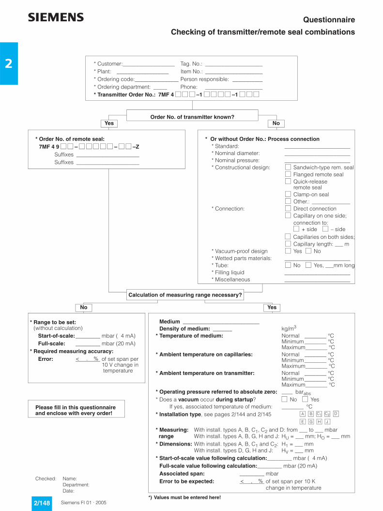
2/148 Siemens FI 01 · 2005
2
Questionnaire
Checking of transmitter/remote seal combinations
s
* Customer:___________________ Tag. No.: _____________________* Plant: ___________________ Item No.: _____________________* Ordering code:________________ Person responsible: ___________* Ordering department: _____ Phone: _____________________* Transmitter Order No.: 7MF 4 –1 –1
Order No. of transmitter known?
* Order No. of remote seal:* 7MF 4 9 – – –Z
Suffixes _______________________Suffixes _______________________
* Or without Order No.: Process connection* Standard: ________________________* Nominal diameter: ________________________* Nominal pressure: ________________________* Constructional design: Sandwich-type rem. seal
Flanged remote seal Quick-release remote seal Clamp-on seal Other.: ______________
* Connection: Direct connection Capillary on one side; connection to: + side – side Capillaries on both sides; Capillary length: ___ m
* Vacuum-proof design Yes No* Wetted parts materials: ________________________* Tube: No Yes, ___mm long* Filling liquid ________________________* Miscellaneous ________________________
Calculation of measuring range necessary?
* Medium ____________________________* Density of medium: _______ kg/m3
* Temperature of medium: Normal ________ °CMinimum________ °CMaximum________ °C
* Ambient temperature on capillaries: Normal ________ °CMinimum________ °CMaximum________ °C
* Ambient temperature on transmitter: Normal ________ °CMinimum________ °CMaximum________ °C
* Operating pressure referred to absolute zero: ____ barabs* Does a vacuum occur during startup? No Yes
If yes, associated temperature of medium: ________ °C* Installation type, see pages 2/144 and 2/145
* Measuring: With install. types A, B, C1, C2 and D: from ___ to ___ mbar range With install. types A, B, G, H and J: HU = ___ mm; HO = ___ mm* Dimensions: With install. types A, B, C1 and C2: H1 = ___ mm
With install. types D, G, H and J: HV = ___ mm* Start-of-scale value following calculation:_________ mbar ( 4 mA)* Full-scale value following calculation:_________ mbar (20 mA)* Associated span: _________ mbar* Error to be expected: _________ of set span per 10 K
_________ change in temperature
A B C2C1
E JHG
D
< , %
NoYes
* Range to be set:* (without calculation)
Start-of-scale:_________ mbar ( 4 mA)Full-scale: _________ mbar (20 mA)
* Required measuring accuracy:Error: _________ of set span per: _________ 10 V change in : _________ temperature
< . %
*) Values must be entered here!
Please fill in this questionnaireand enclose with every order!
No Yes
Checked: Name:Department:Date:

2/149Siemens FI 01 · 2005
2
s Questionnaire
for hydrostatic level measurements
s
Order date: _______________________________________________
Processing date: __________________________________________
Ordering code (customer): _________________________________
Ordering code (supplier): __________________________________
Customer reference:_______________________________________
Measuring point: __________________________________________
Position:__________________________________________________
Dimensions: ______________________________________________
Pressure: bar
Temperature: K °C
Measuring range: cm m(please mark with cross)
Order No. of transmitter 1):
Y01
The different pressures and tem-peratures (densities) in the vessel and in the reference column result in an offset in the start-of-scale and full-scale values.The calibration data are deter-mined in addition.It is also checked whether – as a result of the range offset – the ordered transmitter is suitable for this measurement.
Please supply the following characteristic data so that we can calculate the measuring range, start-of-scale value, full-scale value and calibration data:
1) Reference line filled with condensation! Falling differential pressure with increasing level.2) Reference line without gas or filled with gas (air). Rising differential pressure with increasing level.3) If not specified otherwise, this value is assumed as the calculation pressure of the level meter.
The input signal (differential pressure) depends on the density (pressure and temperature). The influence is practically negligible for a lowest liquid level of 20 to 30% of the distance between the measuring points.
4) If a pressure correction of the level is required, the measuring range must be the same as the distance between the measuring points, and the transmitter is designed for the calculation pressure of 1 bar (absolute).Pressure correction means: the static pressure and the temperature are measured separately and calculated by a correction computer or measured-value computer.
7 M F 4 – –Z–
Please mark type of boiler with a cross: Closed 1)
Open or not under pressure 2)
Medium ____________________
Licensed boiler pressure (absolute) _______________ bar
Operating pressure (absolute) Lowest _______________ bar
Normal 3) _______________ bar
Highest _______________ bar
Temperature of reference column (cold) _______________ K
Distance between measuring points (dimension according to sketch) HV = _________ m
Measuring range 4) = start-of-scale value to full-scale value
Start-of-scale value HU =___________ m
Full-scale value HO =___________ m
Position of equalizing vessel above bottom measuringpoint if different from HV _______________ m
Please mark pressure correction of level with a cross: No
Yes 4)
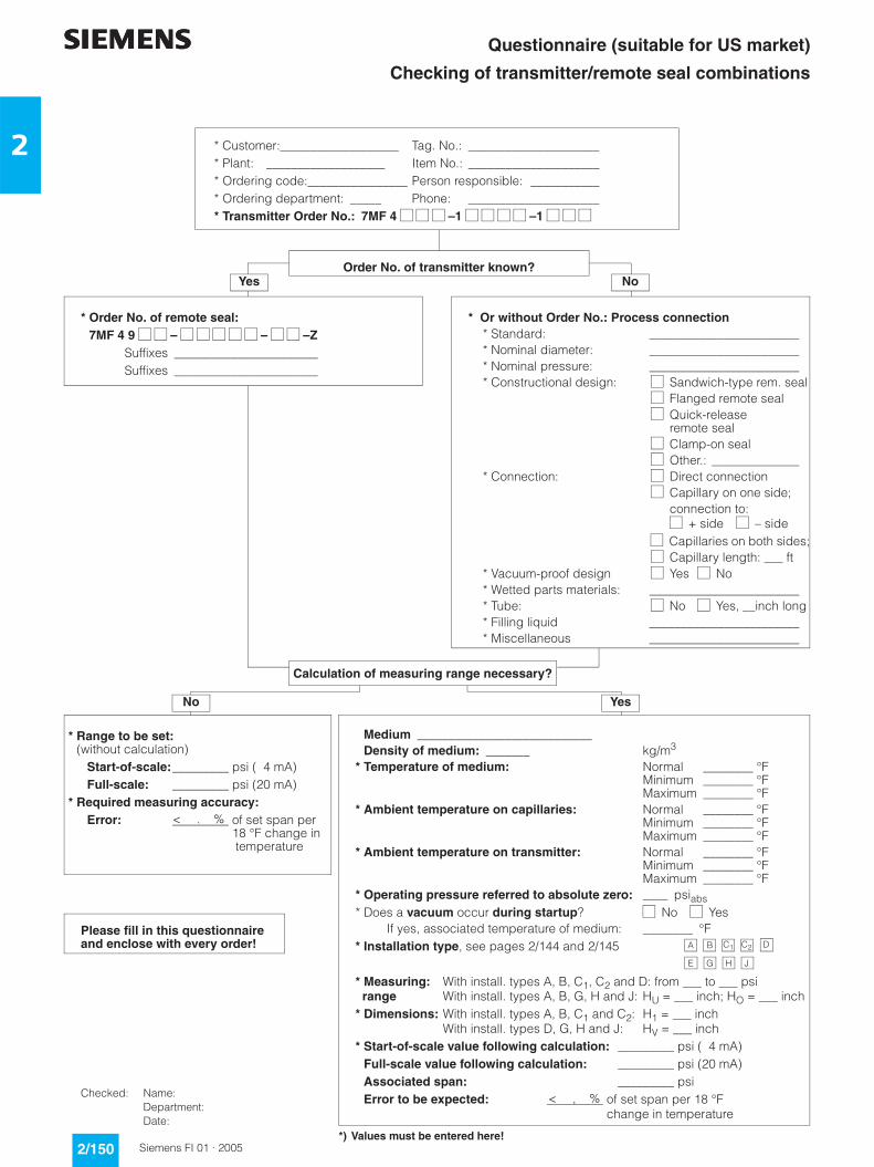
2/150 Siemens FI 01 · 2005
2
s Questionnaire (suitable for US market)
Checking of transmitter/remote seal combinations
s
* Customer:___________________ Tag. No.: _____________________* Plant: ___________________ Item No.: _____________________* Ordering code:________________ Person responsible: ___________* Ordering department: _____ Phone: _____________________* Transmitter Order No.: 7MF 4 –1 –1
Order No. of transmitter known?
* Order No. of remote seal:* 7MF 4 9 – – –Z
Suffixes _______________________Suffixes _______________________
* Or without Order No.: Process connection* Standard: ________________________* Nominal diameter: ________________________* Nominal pressure: ________________________* Constructional design: Sandwich-type rem. seal
Flanged remote seal Quick-release remote seal Clamp-on seal Other.: ______________
* Connection: Direct connection Capillary on one side; connection to: + side – side Capillaries on both sides; Capillary length: ___ ft
* Vacuum-proof design Yes No* Wetted parts materials: ________________________* Tube: No Yes, __inch long* Filling liquid ________________________* Miscellaneous ________________________
Calculation of measuring range necessary?
* Medium ____________________________* Density of medium: _______ kg/m3
* Temperature of medium: Normal ________ °FMinimum ________ °FMaximum ________ °F
* Ambient temperature on capillaries: Normal ________ °FMinimum ________ °FMaximum ________ °F
* Ambient temperature on transmitter: Normal ________ °FMinimum ________ °FMaximum ________ °F
* Operating pressure referred to absolute zero: ____ psiabs* Does a vacuum occur during startup? No Yes
If yes, associated temperature of medium: ________ °F* Installation type, see pages 2/144 and 2/145
* Measuring: With install. types A, B, C1, C2 and D: from ___ to ___ psi range With install. types A, B, G, H and J: HU = ___ inch; HO = ___ inch* Dimensions: With install. types A, B, C1 and C2: H1 = ___ inch
With install. types D, G, H and J: HV = ___ inch* Start-of-scale value following calculation: _________ psi ( 4 mA)* Full-scale value following calculation: _________ psi (20 mA)* Associated span: _________ psi* Error to be expected: _________ of set span per 18 °F
_________ change in temperature
A B C2C1
E JHG
D
< , %
NoYes
* Range to be set:* (without calculation)
Start-of-scale:_________ psi ( 4 mA)Full-scale: _________ psi (20 mA)
* Required measuring accuracy:Error: _________ of set span per: _________ 18 °F change in : _________ temperature
< . %
*) Values must be entered here!
Please fill in this questionnaireand enclose with every order!
No Yes
Checked: Name:Department:Date: