Embed Size (px)
Citation preview

SITRANS P measuring instruments for pressureTransmitters for gage and absolute pressure
SITRANS P300
2/25Siemens FI 01 · 2008
2 Overview
The SITRANS P300 is a digital pressure transmitter for gage and absolute pressure. All conventional thread versions are available as process connections. In addition, various hygiene-based connections and flange connections with front-flush diaphragms meet the requirements of a dead space free process connec-tion.
The output signal is a load-independent direct current from 4 to 20 mA or a PROFIBUS PA signal, which is linearly proportional to the input pressure. Communication is over HART protocol or over PROFIBUS PA interface. Convenient buttons for easy local operation of the basic settings of the pressure transmitter.
The SITRANS P300 has a single-chamber stainless steel casing. The pressure transmitter is approved with "intrinsically safe" type of protection It can be used in zone 1 or zone 0.
Benefits
• High quality and long life• High reliability even under extreme chemical and mechanical
loads• Extensive diagnosis and simulation functions• Minimum conformity error• Small long-term drift• Wetted parts made of high-grade materials (such as stainless
steel, Hastelloy)• Measuring range 8 mbar to 400 bar• High measuring accuracy• Parameterization over control keys and HART communication
or PROFIBUS PA communication
Application
The pressure transmitter is available in versions for gage pres-sure and for absolute pressure. The output signal is always a load-independent direct current from 4 to 20 mA or a PROFIBUS PA signal, which is linearly proportional to the input pressure. The pressure transmitter measures aggressive, non-aggressive and hazardous gases, as well as vapors and liquids.
It can be used for the following measurement types:• Gage pressure• Absolute pressure
With appropriate parameter settings, it can also be used for the following additional measurement types:• Level• Volume• Mass
The "intrinsically-safe" EEx version of the transmitter can be in-stalled in hazardous areas (zone 1). The transmitters are pro-vided with an EC type examination certificate and comply with the respective harmonized European standards of ATEX.
Gage pressure
This variant measures aggressive, non-aggressive and hazard-ous gases, vapors and liquids.
The smallest measuring span is 10 mbar g, the largest 400 bar g.
Level
With appropriate parameter settings, the gage pressure variant measures the level of aggressive, non-aggressive and hazard-ous liquids.
For measuring the level in an open container you require one de-vice; for measuring the level in a closed container, you require two devices and a process control system.
Absolute pressure
This variant measures the absolute pressure of aggressive, non-aggressive and hazardous gases, vapors and liquids.
The smallest measuring span is 8 mbar a, the largest 30 bar a.
© Siemens AG 2007
SITRANS P measuring instruments for pressureTransmitters for gage and absolute pressure
SITRANS P300
2/26 Siemens FI 01 · 2008
2 Design
The device comprises:• Electronics• Housing• Measuring cell
Perspective view of the SITRANS P300
The housing has a screw-on cover (3), with or without an inspec-tion window depending on the version. The electrical terminal housing, the buttons for operation of the device and, depending on the version, the digital display are located under this cover. The connections for the auxiliary power UH and the shield are in the terminal housing. The cable gland is on the side of the hous-ing. The measuring cell with the process connection (5) is lo-cated on the underside of the housing. Depending on the ver-sion of the device, the measuring cell with the process connection may differ from the one shown in the diagram.
Function
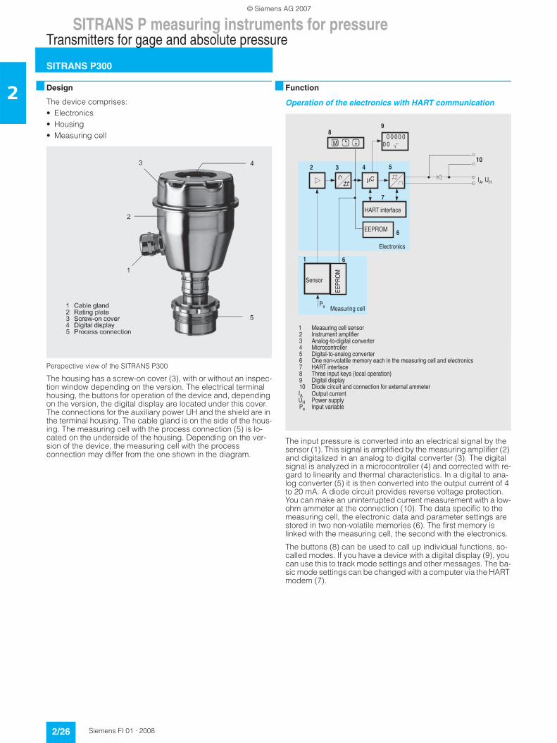
Operation of the electronics with HART communication
The input pressure is converted into an electrical signal by the sensor (1). This signal is amplified by the measuring amplifier (2) and digitalized in an analog to digital converter (3). The digital signal is analyzed in a microcontroller (4) and corrected with re-gard to linearity and thermal characteristics. In a digital to ana-log converter (5) it is then converted into the output current of 4 to 20 mA. A diode circuit provides reverse voltage protection. You can make an uninterrupted current measurement with a low-ohm ammeter at the connection (10). The data specific to the measuring cell, the electronic data and parameter settings are stored in two non-volatile memories (6). The first memory is linked with the measuring cell, the second with the electronics.
The buttons (8) can be used to call up individual functions, so-called modes. If you have a device with a digital display (9), you can use this to track mode settings and other messages. The ba-sic mode settings can be changed with a computer via the HART modem (7).
+0
!
1
1 //2% + &* 13 4&5 &//((/ 6 0+.27 .(-#$8 4 4 29//+ 0 &,
::
1
::1
0+.2
:
1
© Siemens AG 2007

SITRANS P measuring instruments for pressureTransmitters for gage and absolute pressure
SITRANS P300
2/27Siemens FI 01 · 2008
2Operation of the electronics with PROFIBUS PA communica-tion
The input pressure is converted into an electrical signal by the sensor (1). This signal is amplified by the measuring amplifier (2) and digitalized in an analog to digital converter (3). The digital signal is analyzed in a microcontroller (4) and corrected with re-gard to linearity and thermal characteristics. It is then made available at the PROFIBUS PA over an electrically isolated PROFIBUS PA interface (7). The data specific to the measuring cell, the electronic data and parameter settings are stored in two non-volatile memories (6). The first memory is linked with the measuring cell, the second with the electronics.
The buttons (8) can be used to call up individual functions, so-called modes. If you have a device with a digital display (9), you can use this to track mode settings and other messages. The ba-sic mode settings can be changed with a computer over the bus master (12).
Mode of operation of the measuring cells
The process connections available include the following:• G½• ½-14 NPT• Front-flush diaphragm:
- Flanges to EN- Flanges to ASME- NuG and pharmaceutical connections
Measuring cell for gage pressure
Measuring cell for gage pressure, function chart
The input pressure (pe) is transferred to the gage pressure sen-sor (6) via the seal diaphragm (4) and the filling liquid (5), dis-placing its measuring diaphragm. The displacement changes the resistance value of the four piezo resistors in the measuring diaphragm in a bridge circuit. The change in the resistance causes a bridge output voltage proportional to the input pres-sure.
The transmitters with spans ≤ 63 bar measure the input pressure against atmosphere, those with spans ≥ 160 bar against vacuum.
Measuring cell for absolute pressure
Measuring cell for absolute pressure, function chart
The input pressure (pe) is transferred to the absolute pressure sensor (5) via the seal diaphragm (3) and the filling liquid (4), displacing its measuring diaphragm. The displacement changes the resistance value of the four piezo resistors in the measuring diaphragm in a bridge circuit. The change in the re-sistance causes a bridge output voltage proportional to the input pressure.
&
%%
&
%%&
!
& ,,1/ "2* &9 %= 2,,
33,
8 @ "1
%
&
"1
&
@
$
@
"
5 <30 !
: $ $#"0 ,
2D
1
2
3
4
5
6
1 Reference pressure2 Measuring cell3 Process connection4 Seal diaphragm5 Filling liquid6 Relative pressure sensorpe Pressure as input variablepe
1
2
3
4
5
1 Measuring cell2 Process connection3 Seal diaphragm4 Filling liquid5 Absolute pressure sensorpe Pressure as input variablepe
© Siemens AG 2007

SITRANS P measuring instruments for pressureTransmitters for gage and absolute pressure
SITRANS P300
2/28 Siemens FI 01 · 2008
2Measuring cell for gage pressure, front-flush diaphragm
Measuring cell for gage pressure, front-flush diaphragm, function chart
The input pressure (pe) is transferred to the gage pressure sen-sor (6) via the seal diaphragm (4) and the filling liquid (5), dis-placing its measuring diaphragm. The displacement changes the resistance value of the four piezo resistors in the measuring diaphragm in a bridge circuit. The change in the resistance causes a bridge output voltage proportional to the input pres-sure.
The transmitters with spans ≤ 63 bar measure the input pressure against atmosphere, those with spans ≥ 160 bar against vacuum.
Measuring cell for absolute pressure, front-flush diaphragm
Measuring cell for absolute pressure, front-flush diaphragm, function chart
The input pressure (pe) is transferred to the absolute pressure sensor (5) via the seal diaphragm (3) and the filling liquid (4), displacing its measuring diaphragm. The displacement changes the resistance value of the four piezo resistors in the measuring diaphragm in a bridge circuit. The change in the re-sistance causes a bridge output voltage proportional to the input pressure.
Parameterization of SITRANS P300
Depending on the version, there are a range of options for pa-rameterizing the pressure transmitter and for setting or scanning the parameters.
Parameterization using the input keys (local operation)
With the input keys you can easily set the most important param-eters without any additional equipment.
Parameterization using HART communication
Parameterization using HART communication is performed with a HART communicator or a PC.
Communication between a HART communicator and a pressure transmit-ter
When parameterizing with the HART communicator, the connec-tion is made directly to the 2-wire system.
HART communication between a PC communicator and a pressure transmitter
When parameterizing with a PC, the connection is made through a HART modem.
The signals needed for communication in conformity with the HART 5.x or 6.x protocols are superimposed on the output cur-rent using the Frequency Shift Keying (FSK) method.
1 Reference pressure2 Measuring cell3 Seal diaphragm4 Filling liquid5 Relative pressure sensorpe Pressure as input variable
5
4
3
2
1
1 Measuring cell2 Seal diaphragm3 Filling liquid4 Absolute pressure sensorpe Pressure as input variable
4
3
2
1
-"<,,
/+++,<";
,<";
-"<,,
/
/+++9
© Siemens AG 2007

SITRANS P measuring instruments for pressureTransmitters for gage and absolute pressure
SITRANS P300
2/29Siemens FI 01 · 2008
2Adjustable parameters on SITRANS P300 with HART communi-cation
Diagnostic functions for SITRANS P300 with HART communica-tion• Zero correction display• Event counter• Limit transmitter• Saturation alarm• Slave pointer• Simulation functions• Maintenance timer
Available physical units of display for SITRANS P300 with HART communication
Parameterization through PROFIBUS PA interface
Fully digital communication through PROFIBUS PA, profile 3.0, is particularly user-friendly. The PROFIBUS puts the DS III PA is in connection with a process control system, e.g. SIMATIC PSC 7. Communication is possible even in a potentially explosive envi-ronment.
For parameterization through PROFIBUS you need suitable soft-ware, e.g. SIMATIC PDM (Process Device Manager).
Parameterization through FOUNDATION Fieldbus Interface
Fully digital communication through FOUNDATION Fieldbus is particularly user-friendly. Through the FOUNDATION Fieldbus the DS III FF is connected to a process control system. Commu-nication is possible even in a potentially explosive environment.
For parameterization through the FOUNDATION Fieldbus you need suitable software, e.g. National Instruments Configurator.
Adjustable parameters for P300 PA and FF
Diagnostic functions for P300 PA and FF• Event counter• Slave pointer• Maintenance timer• Simulation functions• Display of zero correction• Limit transmitter• Saturation alarm
Physical dimensions available for the display
Hygiene version
In the case of the SITRANS P300 with 7MF812.-... front-flush di-aphragm, selected connections comply with the requirements of the EHEDG or 3A. You will find further details in the order form. Please note in particular that the seal materials used must com-ply with the requirements of 3A. Similarly, the filling liquids used must be FDA-compliant.
Parameters Input keys HART com-munication
Start of scale x x
Full-scale value x x
Electrical damping x x
Start-of-scale value without application of a pressure ("Blind setting")
x x
Full-scale value without application of a pressure ("Blind setting")
x x
Zero adjustment x x
Current transmitter x x
Fault current x x
Disabling of keys, write protection x x1)
1) Cancel apart from write protection
Type of dimension and actual dimension x x
Input of characteristic x
Freely-programmable LCD x
Diagnostics functions x
Physical variable Physical dimensions
Pressure (setting can also be made in the factory)
Pa, MPa, kPa, bar, mbar, torr, atm, psi, g/cm2, kg/cm2, inH2O, inH2O (4 °C), mmH2O, ftH2O (20 °C), inHg, mmHg
Level (height data) m, cm, mm, ft, in
Volume m3, dm3, hl, yd3, ft3, in3, US gal-lon, lmp. gallon, bushel, barrel, barrel liquid
Mass g, kg, t, lb, Ston, Lton, oz
Temperature K, °C, °F, °R
Miscellaneous %, mA
Parameters Input keys (DS III HART)
PROFIBUS PA and FOUNDATION Fieldbus interface
Electrical damping x x
Zero adjustment (correction of position)
x x
Key and/or function disabling x x
Source of measured-value dis-play
x x
Physical dimension of display x x
Position of decimal point x x
Bus address x x
Adjustment of characteristic x x
Input of characteristic x
Freely-programmable LCD x
Diagnostics functions x
Physical variable Physical dimensions
Pressure (setting can also be made in the factory)
MPa, kPa, Pa, bar, mbar, torr, atm, psi, g/cm2, kg/cm2, mmH2O, mmH2O (4 °C), inH2O, inH20 (4 °C), ftH2O (20 °C), mmHg, inHg
Level (height data) m, cm, mm, ft, in, yd
Volume m3, dm3, hl, yd3, ft3, in3, US gallon, lmp. gallon, bushel, barrel, barrel liquid
Volume flow m3/s, m3/min, m3/h, m3/d, l/s, l/min, l/h, l/ d, Ml/d, ft3/s, ft3/min, ft3/h, ft3/d, US gal-lon/s, US gallon/min, US gallon/h, US gal-lon/d, bbl/s, bbl/min, bbl/h, bbl/d
Mass flow g/s, g/min, g/h, g/d, kg/s, kg/min, kg/h, kg/d, t/s, t/min, t/h, /t/d, lb/s, lb/min, lb/h, lb/d, STon/s, STon/min, STon/h, STon/d, LTon/s, LTon/min, LTon/h, LTon/d
Total mass flow t, kg, g, lb, oz, LTon, STon
Temperature K, °C, °F, °R
Miscellaneous %
© Siemens AG 2007

SITRANS P measuring instruments for pressureTransmitters for gage and absolute pressure
SITRANS P300
2/30 Siemens FI 01 · 2008
2 Technical specifications F
SITRANS P300 for gage pressure and absolute pressure
HART PROFIBUS PA and FOUNDATION Fieldbus
Gage pressure input
Measured variable Gage pressure (flush-mounted)
Spans (infinitely adjustable) ornominal measuring range andmax. pemissible test pressure
Span Max. perm. test pres-sure
Nominal measuring range
Max. perm. test pres-sure
0.01 ... 1 bar g(0.15 ... 14.5 psi g)
6 bar g(87 psi g)
1 bar g(14.5 psi g)
6 bar g(87 psi g)
0.04 ... 4 bar g(0.58 ... 58 psi g)
10 bar g(145 psi g)
4 bar g(58 psi g)
10 bar g(145 psi g)
0.16 ... 16 bar g(2.3 ... 232 psi g)
32 bar g(464 psi g)
16 bar g(232 psi g)
32 bar g(464 psi g)
0.6 ... 63 bar g(9.1 ... 914 psi g)
100 bar g(1450 psi g)
63 bar g(914 psi g)
100 bar g(1450 psi g)
1.6 ... 160 bar g(23.2 ... 2321 psi g)
250 bar g(3626 psi g)
160 bar g(2321 psi g)
250 bar g(3626 psi g)
4.0 ... 400 bar g(58 ... 5802 psi g)
600 bar g(8700 psi g)
400 bar g(5802 psi g)
600 bar g(8700 psi g)
Depending on the process connection, the span may differ from these values
Lower measuring limit
• Measuring cell with silicone oil 30 mbar a (0.44 psi a)
Upper measuring limit
• Measuring cell with silicone oil 100% of max. span 100% of the max. nominal measuring range
Absolute pressure input
Measured variable Absolute pressure
Spans (infinitely adjustable) ornominal measuring range andmax. pemissible test pressure
Span Max. perm. test pres-sure
Nominal measuring range
Max. perm. test pres-sure
8 ... 250 mbar a(0.12 ... 3.6 psi a)
6 bar a(87 psi a)
250 mbar a(3.6 psi a)
6 bar a(87 psi a)
0.043 ... 1.30 bar a(0.62 ... 19 psi a)
10 bar a(145 psi a)
1.30 bar a(19 psi a)
10 bar a(145 psi a)
0.16 ... 5 bar a(2.3 ... 73 psi a)
30 bar a(435 psi a)
5 bar a(73 psi a)
30 bar a(435 psi a)
1 ... 30 bar a(14.5 ... 435 psi a)
100 bar a(1450 psi a)
30 bar a(435 psi a)
100 bar a(1450 psi a)
Lower measuring limit
• Measuring cell with silicone oil 0 mbar a (0 psi a)
Upper measuring limit
• Measuring cell with silicone oil 100% of max. span 100% of the max. nominal measuring range
Input of gage pressure, with front-flush diaphragm
Measured variable Gage pressure
Spans (infinitely adjustable) ornominal measuring range andmax. pemissible test pressure
Span Max. perm. test pres-sure
Nominal measuring range
Max. perm. test pres-sure
8 ... 250 mbar g(0.12 ... 3.6 psi g)
6 bar g(87 psi g)
250 mbar g(3.6 psi g)
6 bar g(87 psi g)
0.01 ... 1 bar g(0.15 ... 14.5 psi g)
6 bar g(87 psi g)
1 bar g(14.5 psi g)
6 bar g(87 psi g)
0.04 ... 4 bar g(0.58 ... 58 psi g)
10 bar g(145 psi g)
4 bar g(58 psi g)
10 bar g(145 psi g)
0.16 ... 16 bar g(2.3 ... 232 psi g)
32 bar g(464 psi g)
16 bar g(232 psi g)
32 bar g(464 psi g)
0.6 ... 63 bar g(9.1 ... 914 psi g)
100 bar g(1450 psi g)
63 bar g(914 psi g)
100 bar g(1450 psi g)
Depending on the process connection, the span may differ from these values
© Siemens AG 2007

SITRANS P measuring instruments for pressureTransmitters for gage and absolute pressure
SITRANS P300
2/31Siemens FI 01 · 2008
2Lower measuring limit
• Measuring cell with silicone oil 100 mbar a (1.45 psi a)
Upper measuring limit
• Measuring cell with silicone oil 100% of max. span 100% of the max. nominal measuring range
Output
Output signal 4 ... 20 mA Digital PROFIBUS PA signal
Physical bus - IEC 61158-2
With polarity reversal protection No Yes
Electrical damping T63 (step width 0.1 s) Set to 0.1 s (0 ... 100 s)
Accuracy To EN 60770-1
Reference conditions Increasing characteristic, start-of-scale value 0 bar, stainless steel seal diaphragm, measuring cell with silicone oil, room temperature 25 °C (77 °F), span ratio (r = max. span / set span)
Measurement deviation with cut-off point set-ting, including hysteresis and repeatability.
Gage pressure Absolute pressure Gage pressure Absolute pressure
Linear characteristic curve ≤ 0,075% ≤ 0,075%
• r ≤ 10 ≤ (0.0029 ⋅ r + 0.071)% ≤ 0,1%
• 10 < r ≤ 30 ≤ (0.0045 ⋅ r + 0.071)% ≤ 0,2%
• 30 < r ≤ 100 ≤ (0.005 ⋅ r + 0.05)% -
Settling time T63 without electrical damping Approx. 0.2 s
Long-term drift at ± 30 °C (± 54 °F) ≤ (0.25 ⋅ r)%/5 years ≤ (0.1 ⋅ r)%/year ≤ 0.25%/5 years ≤ 0.1%/year
Influence of ambient temperature
• at -10 ... +60 °C (14 ... 140 °F) ≤ (0.1 ⋅ r +0.2)% ≤ 0,3%
• at -40 ... -10 °C and +60 ... +85 °C(-40 ... 14 °F and 140 ... 185 °F)
≤ (0.1 ⋅ r + 0.15)% / 10 K ≤ 0.25%/ 10 K
Influence of the medium temperature (only with front-flush diaphragm)
• Temperature difference between medium temperature and ambient temperature
3 mbar/10 K (0.04 psi/10 K)
Rated operating conditions
Installation conditions
Ambient temperature Observe the temperature class in areas subject to explosion hazard.
• Measuring cell with silicone oil -40 ... +85 °C (-40 ... +185 °F)
• Measuring cell with medical whiteoil and Neobee oil (with front-flush diaphragm)
-10 ... +85 °C (14 ... +185 °F)
• Measuring cell with inert liquid (not with front-flush diaphragm)
-20 ... +85 °C (-4 ... +185 °F)
• Digital display -30 ... +85 °C (-22 ... +185 °F)
• Storage temperature -50 ... +85 °C (-58 ... +185 °F)
Climatic class
Condensation Permissible
Degree of protection to EN 60529 IP65, IP68, NEMA X, enclosure cleaning, resistant to lyes, steam to 150° C (302 °F)
Electromagnetic compatibility
• Emitted interference and interference immu-nity
To EN 61326 and NAMUR NE 21
Medium conditions
Process temperature
• Measuring cell with silicone oil -40 ... +100 °C (-40 ... +212 °F)
• Measuring cell with silicone oil (with front-flush diaphragm)
-25 ... +150 °C (-13 ... +302 °F)
• Measuring cell with medical whiteoil and Neobee oil (with front-flush diaphragm)
-40 ... +150 °C (-40 ... +302 °F)
• Measuring cell with silicone oil, with temper-ature isolator (only with front-flush dia-phragm)
-25 ... +200 °C (-13 ... +392 °F)
• Measuring cell with inert liquid -20 ... +100 °C (-4 ... +212 °F)
SITRANS P300 for gage pressure and absolute pressure
HART PROFIBUS PA and FOUNDATION Fieldbus
© Siemens AG 2007

SITRANS P measuring instruments for pressureTransmitters for gage and absolute pressure
SITRANS P300
2/32 Siemens FI 01 · 2008
2Design (standard version)
Weight (without options) Approx. 800 g (1.8 lb)
Housing material Stainless steel, mat. No. 1.4301/304
Material of parts in contact with the medium
• Connection shank Stainless steel, mat. No. 1.4404/316L or Hastelloy C276, mat. No. 2.4819
• Oval flange Stainless steel, mat. No. 1.4404/316L
• Seal diaphragm Stainless steel, mat. No. 1.4404/316L or Hastelloy C276, mat. No. 2.4819
• Measuring cell filling • Silicone oil• Inert filling liquid
Process connection • G½A to DIN EN 837-1• Female thread ½-14 NPT• Oval flange PN 160 (MWP 2320 psi) with fastening thread:
- 7/16-20 UNF to IEC 61518- M10 as per DIN 19213
Design (version with front-flush dia-phragm)
Weight (without options) Approx. 1 ... 13 kg (2.2 ... 29 lb)
Housing material Stainless steel, mat. No. 1.4301/304
Material of parts in contact with the medium
• Process connection Stainless steel, mat. No. 1.4404/316L
• Seal diaphragm Stainless steel, mat. No. 1.4404/316L
• Measuring cell filling • Silicone oil• Inert filling liquid• FDA compliant fill fluid
Process connection • Flanges as per EN and ASME• F&B and pharmaceutical flanges
Power supply UH
Terminal voltage on transmitter 10.5 ... 42 V DCfor intrinsically safe operation: 10.5 ... 30 V DC
Supplied through bus
Separate power supply - Not necessary
Bus voltage
• Without EEx - 9 ... 32 V
• For intrinsically-safe operation - 9 ... 24 V
Current consumption
• Max. basic current - 12.5 mA
• Startup current ≤ basic current - Yes
• Max. fault current in the event of a fault - 15.5 mA
Fault disconnection electronics (FDE) - Available
SITRANS P300 for gage pressure and absolute pressure
HART PROFIBUS PA and FOUNDATION Fieldbus
© Siemens AG 2007

SITRANS P measuring instruments for pressureTransmitters for gage and absolute pressure
SITRANS P300
2/33Siemens FI 01 · 2008
2Certificate and approvals
Classification according to pressure equip-ment directive (DRGL 97/23/EC)
For gases of fluid group 1 and liquids of fluid group 1; complies with requirements of Article 3, para-graph 3 (sound engineering practice)
Water, waste water Available soon
Explosion protection
Intrinsic safety "i" PTB 05 ATEX 2048
Identification Ex II 1/2 G EEx ia/ib IIB/IIC T4, T5, T6
Permissible ambient temperature
• Temperature class T4 -40 ... +85 °C (-40 ... +185 °F)
• Temperature class T5 -40 ... +70 °C (-40 ... +158 °F)
• Temperature class T6 -40 ... +60 °C (-40 ... +140 °F)
Connection To certified intrinsically-safe circuits with maxi-mum values:Ui = 30 V, Ii = 100 mA, Pi = 750 mW, Ri = 300 Ω
To certified intrinsically-safe circuits with maxi-mum values:FISCO supply unit: Ui = 17.5 V, Ii = 380 mA, Pi = 5.32 WLinear barrier: Ui = 24 V, Ii = 250 mA, Pi = 1.2 W
Effective inner capacitance: Ci = 6 nF Ci = 1.1 nF
Effective inner inductance: Li = 0.4 mH Li ≤ 7 µH
Explosion protection to FM for USA and Canada (cFMUS)
• Identification (DIP) or (IS); (NI) Certificate of Compliance 3025099
CL I, DIV 1, GP ABCD T4 ... T6; CL II, DIV 1, GP EFG; CL III; CL I, ZN 0/1 AEx ia IIC T4 ... T6;CL I, DIV 2, GP ABCD T4 ... T6; CL II, DIV 2, GP FG; CL III
• Identification (DIP) or (IS) Certificate of Compliance 3025099C
CL I, DIV 1, GP ABCD T4 ... T6; CL II, DIV 1, GP EFG; CL III; Ex ia IIC 4 ... T6;CL I, DIV 2, GP ABCD T4 ... T6; CL II, DIV 2, GP FG; CL III
SITRANS P300 for gage pressure and absolute pressure
HART PROFIBUS PA and FOUNDATION Fieldbus
© Siemens AG 2007

SITRANS P measuring instruments for pressureTransmitters for gage and absolute pressure
SITRANS P300
2/34 Siemens FI 01 · 2008
2
HART communication
HART communication 230 ... 1100 Ω
Protocol HART Version 5.x
Software for computer SIMATIC PDM
PROFIBUS PA communication
Simultaneous communication with master class 2 (max.)
4
The address can be set using Configuration tool or local opera-tion (standard setting address 126)
Cyclic data usage
• Output byte 5 (one measuring value) or10 (two measuring values)
• Input byte 0, 1, or 2 (register operating mode and reset function for metering)
Internal preprocessing
Device profile PROFIBUS PA Profile for Process Control Devices Version 3.0, Class B
Function blocks 2
• Analog input
- Adaptation to customer-specif-ic process variables
Yes, linearly rising or falling char-acteristic
- Electrical damping T63 , adjust-able
0 ... 100 s
- Simulation function Input /Output
- Failure mode Can be parameterized (last good value, substitute value, incorrect value)
- Limit monitoring Yes, one upper and lower warning limit and one alarm limit respec-tively
• Register (totalizer) Can be reset, preset, optional direction of counting, simulation function of register output
- Failure mode Can be parameterized (summation with last good value, continuous summation, summation with incor-rect value)
- Limit monitoring One upper and lower warning limit and one alarm limit respectively
• Physical block 1
Transducer blocks 2
• Pressure transducer block
- Can be calibrated by applying two pressures
Yes
- Monitoring of sensor limits Yes
- Specification of a container characteristic with
Max. 30 nodes
- Square-rooted characteristic for flow measurement
Yes
- Gradual volume suppression and implementation point of square-root extraction
Parameterizable
- Simulation function for mea-sured pressure value and sen-sor temperature
Constant value or over parameter-izable ramp function
Communication FOUNDATION Fieldbus
Function blocks 3 function blocks analog input, 1 function block PID
• Analog input
- Adaptation to customer-specif-ic process variables
Yes, linearly rising or falling char-acteristic
- Electrical damping T63 , adjust-able
0 ... 100 s
- Simulation function Output/input (can be locked within the device with a bridge)
- Failure mode Can be parameterized (last good value, substitute value, incorrect value)
- Limit monitoring Yes, one upper and lower warning limit and one alarm limit respec-tively
- Square-rooted characteristic for flow measurement
Yes
• PID Standard FF function block
• Physical block 1 Resource block
Transducer blocks 1 transducer block Pressure with calibration, 1 transducer block LCD
• Pressure transducer block
- Can be calibrated by applying two pressures
Yes
- Monitoring of sensor limits Yes
- Simulation function: Measured pressure value, sensor temper-ature and electronics tempera-ture
Constant value or over parameter-izable ramp function
© Siemens AG 2007

SITRANS P measuring instruments for pressureTransmitters for gage and absolute pressure
SITRANS P300
2/35Siemens FI 01 · 2008
2
F) Subject to export regulations AL: 9I999, ECCN: N.
Selection and Ordering data Order No.
SITRANS P300 pressure transmitters for gage and absolute pressure, single-chamber measur-ing housing, rating plate inscription in English
4 ... 20 mA/HART 7 M F 8 0 2 3 -
PROFIBUS PA 7 M F 8 0 2 4 -
FOUNDATION Fieldbus (FF) 7 M F 8 0 2 5 -
77777 - 7777
Measuring cell filling Measuring cell cleaningSilicone oil Standard 1Inert liquid Cleanliness level 2 to
DIN 254103
max. span 1 bar g (14.5 psi g) B4 bar g (58 psi g) C16 bar g (232 psi g) D63 bar g (914 psi g) E160 bar g (2320 psi g) F400 bar g (5800 psi g) G0.25 bar a (3.63 psi a) F) Q1.3 bar a (18.9 psi a) F) S5 bar a (72.5 psi a) F) T30 bar a (435 psi a) F) U
Wetted parts materialsSeal diaphragm Measuring cell
Stainless steel Stainless steel AHastelloy Stainless steel F) BHastelloy Hastelloy F) C
Version for diaphragm seal 1) 2) Y
Process connection• G½A to EN 837-1 0• ½-14 NPT 1• Oval flange made of stainless steel
- Mounting thread 7/16-20 UNF to EN 61518 2- Mounting thread M10 to DIN 19213 3- Mounting thread M12 to DIN 19213 4
• Male thread M20 x 1,5 5• Male thread ½ -14 NPT 6
Non-wetted parts materials• St. steel, deep-drawn and electrolytically polished 4
Version• Standard version 1
Explosion protection• Without A• With ATEX, Type of protection:
- "Intrinsic safety (EEx ia)" B• With FM „Intrinsic safe“ (cFMUS) M
Electrical connection / cable entry• Screwed gland M20x1.5 (Polyamide) 3) A• Screwed gland M20x1.5 (metal) B• Screwed gland M20x1.5 (stainless steel) C• M12 connector (metal, without cable socket) F• M12 connector (stainless steel, without cable socket) G• ½-14 NPT thread, metal 4) H• ½-14 NPT thread, stainless steel4) J
Display• Without display, with keys, closed lid 3) 1• With display and keys, closed lid 2• With display and keys, lid with glass pane
(setting on HART devices: mA, on PROFIBUS devices: pressure units)
6
• With display (setting acc. to specifications, Order code "Y21" or "Y22" required), lid with glass pane
7
Power supply units see "SITRANS I power supply units and isol. amplifiers".
Factory-mounting of shut-off valves and valve manifolds see page 2/133.
Included in delivery of the device:• Brief instructions (Leporello)• CD-ROM with detailed documentation
1) When the manufacture’s certificate M (calibration certificate) has to be ordered for transmitters with diaphragm seals, it is recommended only to order this certificate exclusively with the diaphragm seals. The measuring accuracy of the total combination is certified here.
2) Whe the acceptance test certificate 3.1 for transmitters with direct-con-nected diaphragm seals is ordered, this certificate must also be ordered with the corresponding seals.
3) Only together with HART electronics.4) Without cable gland.
Selection and Ordering data Order No.
SITRANS P300 pressure transmitters for gage and absolute pressure, single-chamber measur-ing housing, rating plate inscription in English
4 ... 20 mA/HART 7 M F 8 0 2 3 -
PROFIBUS PA 7 M F 8 0 2 4 -
FOUNDATION Fieldbus (FF) 7 M F 8 0 2 5 -
77777 - 7777
© Siemens AG 2007

SITRANS P measuring instruments for pressureTransmitters for gage and absolute pressure
SITRANS P300
2/36 Siemens FI 01 · 2008
2
F) Subject to export regulations AL: 9I999, ECCN: N.
Selection and Ordering data Order No.
SITRANS P300 pressure transmitters for gage pressure with front-flush membrane, single-chamber measuring housing, rating plate inscription in English
4 ... 20 mA/HART F) 7 M F 8 1 2 3 -
PROFIBUS PA F) 7 M F 8 1 2 4 -
FOUNDATION Fieldbus (FF) F) 7 M F 8 1 2 5 -
77777 - 7777
Measuring cell filling Measuring cell cleaningSilicone oil Standard 1Inert liquid Cleanliness level 2 to
DIN 254103
FDA compliant fill fluid• Neobee oil Standard 4
max. span 1 bar g (14.5 psi g) B4 bar g (58 psi g) C16 bar g (232 psi g) D63 bar g (914 psi g) E
Wetted parts materials Seal diaphragm Measuring cell
Stainless steel Stainless steel A
Process connection• Flange version with Order code M.., N.., R.. or Q..
(see "Further designs")7
Non-wetted parts materials• Stainless steel, deep-drawn and electrolytically
polished4
Version• Standard version 1
Explosion protection• Without A• With ATEX, Type of protection:
- "Intrinsic safety (EEx ia)" B• With FM „Intrinsic safe“ (cFMUS) M
Electrical connection / cable entry• Screwed gland M20x1.5 (Polyamide)1)
1) Only together with HART electronics.
A• Screwed gland M20x1.5 (metal) B• Screwed gland M20x1.5 (stainless steel) C• M12 connector (without cable socket) F• M12 connector (stainless steel, without cable socket) G• ½-14 NPT thread, metal2)
2) Without cable gland.
H• ½-14 NPT thread, stainless steel2) J
Display• Without display, with keys, closed lid1) 1• With display and keys, closed lid 2• With display and keys, lid with macrolon washer
(setting on HART devices: mA, on PROFIBUS PA and FOUNDATION Fieldbus devices: pressure units)
4
• With display (setting acc. to specifications, Order code "Y21" or "Y22" required), lid with macrolon washer
5
• With display and keys, lid with glass pane (setting on HART devices: mA, on PROFIBUS PA and FOUNDATION Fieldbus devices: pressure units)
6
• With display (setting acc. to specifications, Order code "Y21" or "Y22" required), lid with glass pane
7
Power supply units see "SITRANS I power supply units and isol. amplifiers".
Included in delivery of the device:• Brief instructions (Leporello)• CD-ROM with detailed documentation
© Siemens AG 2007

SITRANS P measuring instruments for pressureTransmitters for gage and absolute pressure
SITRANS P300
2/37Siemens FI 01 · 2008
2Selection and Ordering data Order code
Further designsAdd "-Z" to Order No. and specify Order code.
HART PA FF
Mounting bracketmade completely of stainless steel, for wall or pipe mounting
A02
Cable socket for M12 plug• Metal A50• Stainless steel A51
Rating plate inscription(instead of English)• German B10• French B12• Spanish B13• Italian B14
English rating plate B21Pressure units in inH20 or psi
Manufacturer's test certificate M1)
(calibration certificate)C11
to DIN 55350, Part 18 and to ISO 8402
Acceptance test certificate2) C12to EN 10204-3.1
Factory certificate C14to EN 10204-2.2
Type of protection IP68 D12
Only for SITRANS P300 with front-flush diaphragm (7MF81..-...)
Flange to EN 1092-1• DN 25, PN 40 M11• DN 25, PN 100 M21• DN 40, PN 40 M13• DN 40, PN 100 M23• DN 50, PN 16 M04• DN 50, PN 40 M14• DN 80, PN 25 M06• DN 80, PN 40 M16
Flanges to ASME B16.5• 1", class 150 M40• 1½", class 150 M41• 2", class 150 M42• 3", class 150 M43• 4", class 150 M44• 1", class 300 M45• 1½", class 300 M46• 2", class 300 M47• 3", class 300 M48
Threaded connection• G 2“, flush-mounted R04
Tank connection• TG 52/50, PN 40 R10
Tri-Clamp connection according DIN 32676/ISO 2852certified to 3A3)
• DN 50/2“, PN 16 N14• DN 65/3“, PN 10 N15
Varivent connectioncertified to 3A and EHEDG3)
• Type N = 68 for Varivent housingDN 40 ... 125 and 1½" ... 6", PN 40
N28
Temperature decoupler up to 200 °C3)
for version with front-flush diaphragmP00
Bio-Control (Neumo) sanitary connectioncertified to 3A and EHEDG3)
• DN 50, PN 16 Q53• DN 65, PN 16 Q54
Sanitary process connection to DRD• 50 mm, PN 40 M32
Sanitary process connection to NEUMO Bio-Connect screw connectioncertified to 3A and EHEDG3)
• DN 40, PN 16 Q04• DN 50, PN 16 Q05• DN 65, PN 16 Q06• DN 80, PN 16 Q07• DN 100, PN 16 Q08• DN 2“, PN 16 Q13• DN 2½“, PN 16 Q14• DN 3“, PN 16 Q15• DN 4“, PN 16 Q16
Sanitary process connection to NEUMO Bio-Connect flange connectioncertified to 3A and EHEDG3)
• DN 50, PN 16 Q23• DN 65, PN 16 Q24• DN 80, PN 16 Q25• DN 100, PN 16 Q26• DN 2“, PN 16 Q31• DN 2½“, PN 16 Q32• DN 3“, PN 16 Q33• DN 4“, PN 16 Q34
Sanitary process connection to NEUMO Bio-Connect clamp connectioncertified to 3A and EHEDG3)
• DN 50, PN 16 Q39• DN 65, PN 10 Q40• DN 80, PN 10 Q41• DN 100, PN 10 Q42• DN 2½“, PN 16 Q48• DN 3“, PN 10 Q49• DN 4“, PN 10 Q50
Sanitary process connection to NEUMO Connect S flange connectioncertified to 3A and EHEDG• DN 50, PN 16 Q63• DN 65, PN 10 Q64• DN 80, PN 10 Q65• DN 100, PN 10 Q66• DN 2“, PN 16 Q72• DN 2½“, PN 10 Q73• DN 3“, PN 10 Q74• DN 4“, PN 10 Q75
1) When the manufacture’s certificate M (calibration certificate) has to be ordered for transmitters with diaphragm seals, it is recommended only to order this certificate exclusively with the diaphragm seals. The measuring accuracy of the total combination is certified here.
2) Whe the acceptance test certificate 3.1 for transmitters with direct-con-nected diaphragm seals is ordered, this certificate must also be ordered with the corresponding seals.
3) Certified to 3A.The maximum temperatures of the medium depend on the respective cell fillings.
Selection and Ordering data Order code
Further designsAdd "-Z" to Order No. and specify Order code.
HART PA FF
© Siemens AG 2007

SITRANS P measuring instruments for pressureTransmitters for gage and absolute pressure
SITRANS P300
2/38 Siemens FI 01 · 2008
2
Dimensional drawings
SITRANS P300, with oval flange, dimensions in mm (inch)
Selection and Ordering data Order code
Additional dataAdd "-Z" to Order No. and specify Order code.
HART PA FF
Measuring range to be set Y01Specify in plain text V (max. 5 digits):Y01: ... up to ... mbar, bar, kPa, MPa, psi
Measuring point number (TAG No.) Y15Max. 16 characters, specify in plain text:Y15: ...........................................
Measuring point text Y16Max. 27 characters, specify in plain text:Y16: ...........................................
Entry of HART TAG Y17Max. 8 characters, specify in plain text:Y17: ...........................................
Setting of pressure indication in pressure units
Y21
Specify in plain text (standard setting: mA): Y21: mbar, bar, kPa, MPa, psi, ...Note:The following pressure units can be selected:bar, mbar, mm H2O*), inH2O*), ftH2O*), mmHG, inHG, psi, Pa, kPa, MPa, g/cm2, kg/cm2, Torr, ATM or % *) ref. temperature 20 °C
HART PA FF
Setting of pressure indicator in non-pressure units
Y22 + Y01
Specify in plain text:Y22: ..... up to ..... l, m3, m, USg, ...(specification of measuring range in pressure units "Y01" is essential, unit with max. 5 char-acters)
Preset bus address Y25Specify in plain text:Y25: .....................
Only "Y01" and "Y21" can be factory preset
= available
Ordering exampleItem line: 7MF8023-1DB24-1AB7-ZB line: A02 + Y01 + Y21C line: Y01: 1 ... 10 bar (14.5 ... 145 psi)C line: Y21: bar (psi)
Selection and Ordering data Order code
© Siemens AG 2007

SITRANS P measuring instruments for pressureTransmitters for gage and absolute pressure
SITRANS P300
2/39Siemens FI 01 · 2008
2
SITRANS P300 with mounted mounting bracket, dimensions in mm (inch)
SITRANS P300, front-flush, dimensions in mm (inch)
The diagram shows a SITRANS P300 with an example of a flange. In this drawing the height is subdivided into H1 and H2.
H1 = Height of the SITRANS P300 up to a defined cross-section
H2 = Height of the flange up to this defined cross-section
Only the height H2 is indicated in the dimensions of the flanges.
© Siemens AG 2007

SITRANS P measuring instruments for pressureTransmitters for gage and absolute pressure
SITRANS P300
2/40 Siemens FI 01 · 2008
2Flanges to EN and ASME
Flanges to EN
Flanges to ASME
NuG and pharmaceutical connectionsConnections to DIN
Other connections
EN 1092-1
DN PN ∅D H2
25 40 115 mm (4.5“) Approx.52 mm (2“)25 100 140 mm (5.5“)
40 40 150 mm (5.9“)40 100 170 mm (6.7“)50 16 165 mm (6.5“)50 40 165 mm (6.5“)80 16 200 mm (7.9“)80 40 200 mm (7.9“)
ASME B16.5
DN class ∅D H2
1“ 150 110 mm (4.3“) Approx.52 mm (2“)1“ 300 125 mm (4.9“)
1½“ 150 130 mm (5.1“)1½“ 300 155 mm (6.1“)2“ 150 150 mm (5.9“)2“ 300 165 mm (6.5“)3“ 150 190 mm (7.5“)3“ 300 210 mm (8.1“)4“ 150 230 mm (9.1“)4“ 300 255 mm (10.0“)
DIN 11851 (Dairy connection)
DN PN ∅D H2
50 25 92 mm (3.6“) Approx.52 mm (2“)
80 25 127 mm (5.0“)
Tri-Clamp according DIN 32676
DN PN ∅D H2
50 16 64 mm (2.5“) Approx. 52 mm (2“)
65 16 91 mm (3.6“)
Varivent connection
DN PN ∅D H2
40 ... 125 40 84 mm (3.3“)
Approx.52 mm (2“)
Bio-Control connection
DN PN ∅D H2
50 16 90 mm (3.5“) Approx.52 mm (2“)
65 16 120 mm (4.7“)
Sanitary process connection to DRD
DN PN ∅D H2
50 40 105 mm (4.1“) Approx. 52 mm (2“)
Sanitary process screw connection to NEUMO Bio-Connect
DN PN ∅D H2
50 16 82 mm (3.2“) Approx. 52 mm (2“)
65 16 105 mm (4.1“)
80 16 115 mm (4.5“)
100 16 145 mm (5.7“)
2“ 16 82 mm (3.2“)
2½“ 16 105 mm (4.1“)
3“ 16 105 mm (4.1“)
4“ 16 145 mm (5.7“)
Sanitary connection to NEUMO Bio-Connectflange connection
DN PN ∅D H2
50 16 110 mm (4.3“) Approx. 52 mm (2“)
65 16 140 mm (5.5“)
80 16 150 mm (5.9“)
100 16 175 mm (6.9“)
2“ 16 100 mm (3.9“)
2½“ 16 110 mm (4.3“)
3“ 16 140 mm (5.5“)
4“ 16 175 mm (6.9“)
Sanitary connection to NEUMO Bio-Connectclamp connection
DN PN ∅D H2
50 16 77,4 mm (3.0“) Approx. 52 mm (2“)
65 10 90,9 mm (3.6“)
80 10 106 mm (4.2“)
100 10 119 mm (4.7“)
2“ 16 64 mm (2.5“)
2½“ 16 77,4 mm (3.0“)
3“ 10 90,9 mm (3.6“)
4“ 10 119 mm (4.7“)
Sanitary connection to NEUMO Bio-Connect Sflange connection
DN PN ∅D H2
50 16 125 mm (4.9“) Approx. 52 mm (2“)
65 10 145 mm (5.7“)
80 10 155 mm (6.1“)
100 10 180 mm (7.1“)
2“ 16 125 mm (4.9“)
2½“ 10 135 mm (5.3“)
3“ 10 145 mm (5.7“)
4“ 10 180 mm (7.1“)
© Siemens AG 2007

SITRANS P measuring instruments for pressureTransmitters for gage and absolute pressure
SITRANS P300
2/41Siemens FI 01 · 2008
2
Thread connection G2“ to DIN 3852
DN PN ∅D H2
2“ 63 78 mm (3.1“) Approx. 52 mm (2“)
Tank connection TG 52/50
DN PN ∅D H2
25 40 63 mm (2.5“) Approx.63 mm (2.5“)
© Siemens AG 2007

北京迪妙声科技有限公司 BEJING DELLSONICS SCIENCE & TECHNOLOGY LTD.
地址:北京海淀区魏公村街 1号韦伯豪家园 3-3-702 (100081) http://www.dellsonics.com
DELLSONICS
公 司 简 介
北京迪妙声科技有限公司(原名北京妙声力科技有限公司),位于北京市海淀区中关村
南大街,是与西门子公司德国总部正式签约的西门子过程仪表及分析仪器核心合作伙伴,
也是西门子北方区域规模最大、实力最强的优秀代理商。
公司主营:
一、西门子-妙声力(Milltronics)系列物位产品:超声波物位计、超声波液位差计、超声波泥水界
面计、超声波明渠流量计、雷达物位计、射频导纳物位计、射频导纳油水界面计、;射频导纳物位开关、
音叉式物位开关、阻旋式物位开关;皮带称、固体质量流量计、冲板流量计等。
二、西门子过程仪表产品:电磁流量计、质量流量计、超声波流量计、 温度变送器、压力变送器、
阀门定位器、气体分析仪等。
三、德国 UWT 公司的阻旋式料位开关、音叉式料位开关、重锤式料位计等产品。
四、自行研发生产超声波液位计、温度变送器、压力变送器、数显表及油田专用仪器等产品。
成立于 1954 年的西门子-妙声力公司(Milltronics)是世界公认的超声波物位测量领域
的领导者,全球最大的超声波物位仪表生产厂家,在超声波、雷达、电容技术领域拥有超过 60
项专利,超声波产品的综合性能指标经美国《控制》杂志评比,其综合性能名列全球第一!
作为西门子公司长期稳定的代理商,我公司有着 10 余年产品的销售和服务经验,无论
从专业技术水平、现货及备件库存量、售后服务质量、仪表维护以及故障产品国内维修能力
等方面,都具备显著的优势。尤其是我公司一流的技术支持和高效率高品质的服务体系,在
业界具有很高的知名度。
如果您需要相关的产品,需要咨询技术问题,需要值得信赖的合作伙伴,敬请来电垂询!
商务部总机电话:010-88579530/31/32/33,88579597,88571841,81968099(小灵通)
传真:总机转 50
谢谢您的合作与支持!
电话:010-88579530/31/32/33,88579597,88571841 传真:总机转 50 E-mail:[email protected]