Embed Size (px)
Citation preview
SITRANS F flowmetersSITRANS F M
System information SITRANS F Melectromagnetic flowmeters
4/21Siemens FI 01 · 2010
4
Function
All electromagnetic flowmeters are based on Faraday’s law of in-duction:
UM = B ⋅ v ⋅ d ⋅ k
UM = Measured voltage induced in the medium perpendicular to the magnetic field and the flow direction. The voltage is tapped at two point electrodes.
B = Magnetic flux density which permeates the flowing medium perpendicular to the flow direction.
v = flow velocity of medium
d = internal diameter of metering tube
k = proportionality factor or sensor constant
Function and measuring principle of electromagnetic measurement
An electromagnetic flowmeter generally consists of a magneti-cally non-conducting metering tube with an internal electrically non-conducting surface, magnet coils connected in series and mounted diametrically on the tube, and at least two electrodes which are inserted through the pipe wall and are in contact with the measured medium. The magnet field coils through which the current passes generate a pulsed electromagnetic field with the magnetic flux density B perpendicular to the pipe axis.
This magnetic field penetrates the magnetically non-conducting metering tube and the medium flowing through it, which must have a minimum electrical conductivity.
According to Faraday’s law of induction, a voltage UM is gener-ated in an electrically conducting medium, and is proportional to the flow velocity v of the medium, the magnetic flux density B, and the distance between the electrodes d (internal diameter of pipe).
The signal voltage UM is tapped by the electrodes which are in contact with the medium, and passed through the insulating pipe wall. The signal voltage UM which is proportional to the flow velocity is converted by an associated transmitter into appropri-ate standard signals such as 4 to 20 mA.
SITRANS F M diagnostics
The diagnostic functions are all internal tools in the meter:• Identification in clear text and error log • Error categories: function; warning; permanent and fatal
errors• Transmitter self-check including all outputs and the accuracy• Sensor check: coil and electrode circuit test• Overflow• Empty pipe: partial filling; low conductivity; electrode fouling
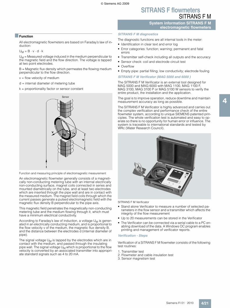
SITRANS F M Verificator (MAG 5000 and 6000 )
The SITRANS F M Verificator is an external tool designed for MAG 5000 and MAG 6000 with MAG 1100, MAG 1100 F, MAG 3100, MAG 3100 P or MAG 5100 W sensors to verify the entire product, the installation and the application.
The goal is to improve operation, reduce downtime and maintain measurement accuracy as long as possible.
The SITRANS F M Verificator is highly advanced and carries out the complex verification and performance check of the entire flowmeter system, according to unique SIEMENS patented prin-ciples. The whole verification test is automated and easy to op-erate so there is no opportunity for human error or influence. The system is traceable to international standards and tested by WRc (Water Research Council).
SITRANS F M Verificator
• Stand alone Verificator to measure a number of selected pa-rameters in the flow sensor and a transmitter which affects the integrity of the flow measurement
• Up to 20 measurements can be stored in the Verificator • The Verificator can be connected via a serial cable to a PC en-
abling download of the data. A Windows OC program enables printing and management of verificator reports.
Verification - Steps
Verification of a SITRANS F M flowmeter consists of the following test routines:
1. Transmitter test2. Flowmeter and cable insulation test3. Sensor magnetism test
© Siemens AG 2009
SITRANS F flowmetersSITRANS F MSystem information SITRANS F Melectromagnetic flowmeters
4/22 Siemens FI 01 · 2010
4
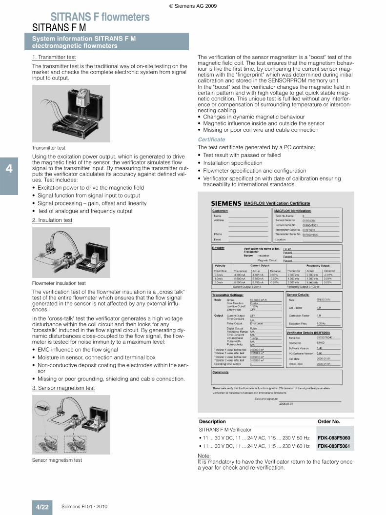
1. Transmitter test
The transmitter test is the traditional way of on-site testing on the market and checks the complete electronic system from signal input to output.
Transmitter test
Using the excitation power output, which is generated to drive the magnetic field of the sensor, the verificator simulates flow signal to the transmitter input. By measuring the transmitter out-puts the verificator calculates its accuracy against defined val-ues. Test includes:• Excitation power to drive the magnetic field• Signal function from signal input to output• Signal processing – gain, offset and linearity• Test of analogue and frequency output
2. Insulation test
Flowmeter insulation test
The verification test of the flowmeter insulation is a „cross talk“ test of the entire flowmeter which ensures that the flow signal generated in the sensor is not affected by any external influ-ences.
In the "cross-talk" test the verificator generates a high voltage disturbance within the coil circuit and then looks for any "crosstalk" induced in the flow signal circuit. By generating dy-namic disturbances close-coupled to the flow signal, the flow-meter is tested for noise immunity to a maximum level:• EMC influence on the flow signal• Moisture in sensor, connection and terminal box• Non-conductive deposit coating the electrodes within the sen-
sor• Missing or poor grounding, shielding and cable connection.
3. Sensor magnetism test
Sensor magnetism test
The verification of the sensor magnetism is a "boost" test of the magnetic field coil. The test ensures that the magnetism behav-iour is like the first time, by comparing the current sensor mag-netism with the "fingerprint" which was determined during initial calibration and stored in the SENSORPROM memory unit.In the "boost" test the verificator changes the magnetic field in certain pattern and with high voltage to get quick stable mag-netic condition. This unique test is fulfilled without any interfer-ence or compensation of surrounding temperature or intercon-necting cabling. • Changes in dynamic magnetic behaviour• Magnetic influence inside and outside the sensor• Missing or poor coil wire and cable connection
CertificateThe test certificate generated by a PC contains: • Test result with passed or failed • Installation specification• Flowmeter specification and configuration• Verificator specification with date of calibration ensuring
traceability to international standards.
Note:It is mandatory to have the Verificator return to the factory once a year for check and re-verification.
Description Order No.
SITRANS F M Verificator
• 11 ... 30 V DC, 11 ... 24 V AC, 115 ... 230 V, 50 Hz FDK-083F5060
• 11 ... 30 V DC, 11 ... 24 V AC, 115 ... 230 V, 60 Hz FDK-083F5061
© Siemens AG 2009
SITRANS F flowmetersSITRANS F M
System information SITRANS F Melectromagnetic flowmeters
4/23Siemens FI 01 · 2010
4
Technical specifications
Flowmeter Calibration and traceability
To ensure continuous accurate measurement, flowmeters must be calibrated. All measuring instrumentation, used in the calibra-tion of the flowmeters, has either been calibrated by a UKAS or DANAK accedited laboratory or has been calibrated against certified master sensors. This provides an unbroken chain of measurement-traceability to national standards.
Siemens Flow Instruments can provide accredited calibration in the flow range from 0.0001 m3/h to 4350 m3/h.
The accreditation bodies DANAK and UKAS have signed the ILAC MRA agreement (International Laboratory Accreditation Corporation - Mutual Recognition Arrangement). Therefore the accreditation ensures international traceability and recognition of the test results in 39 countries world wide, including the US (NIST traceability).
A calibration certificate is shipped with every sensor and cali-bration data are stored in the SENSORPROM memory unit.
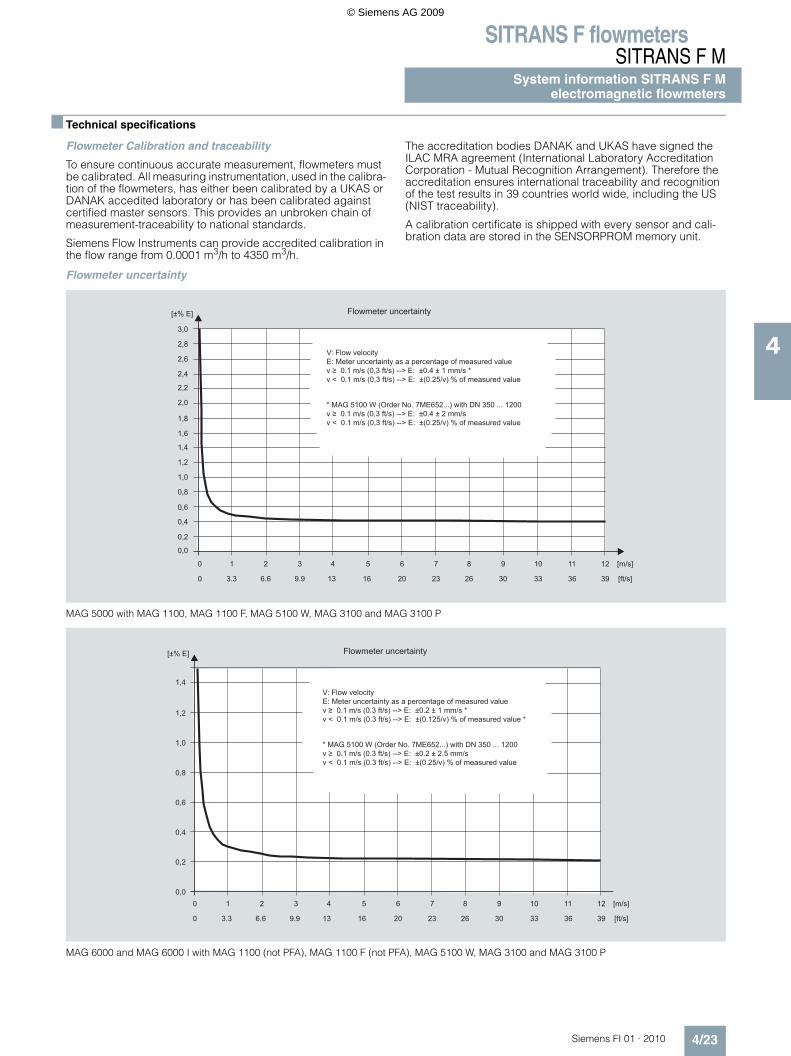
Flowmeter uncertainty
MAG 5000 with MAG 1100, MAG 1100 F, MAG 5100 W, MAG 3100 and MAG 3100 P
MAG 6000 and MAG 6000 I with MAG 1100 (not PFA), MAG 1100 F (not PFA), MAG 5100 W, MAG 3100 and MAG 3100 P
V: Flow velocityE: Meter uncertainty as a percentage of measured valuev ≥ 0.1 m/s (0,3 ft/s) --> E: ±0.4 ± 1 mm/s *v < 0.1 m/s (0,3 ft/s) --> E: ±(0.25/v) % of measured value
* MAG 5100 W (Order No. 7ME652...) with DN 350 ... 1200 v ≥ 0.1 m/s (0,3 ft/s) --> E: ±0.4 ± 2 mm/sv < 0.1 m/s (0,3 ft/s) --> E: ±(0.25/v) % of measured value
Flowmeter uncertainty
10
0,2
0,0
0,6
0,4
1,0
0,8
1,4
1,2
1,8
1,6
2,2
2,0
2,6
2,4
3,0
2,8
2 3 4 5 6 7 8 9 10 11 12
3.30 6.6 9.9 13 16 20 23 26 30 33 36 39
[m/s]
[ft/s]
[±% E]
Flowmeter uncertainty
V: Flow velocityE: Meter uncertainty as a percentage of measured valuev ≥ 0.1 m/s (0.3 ft/s) --> E: ±0.2 ± 1 mm/s *v < 0.1 m/s (0.3 ft/s) --> E: ±(0.125/v) % of measured value *
* MAG 5100 W (Order No. 7ME652...) with DN 350 ... 1200 v ≥ 0.1 m/s (0.3 ft/s) --> E: ±0.2 ± 2.5 mm/sv < 0.1 m/s (0.3 ft/s) --> E: ±(0.25/v) % of measured value
10 2 3 4 5 6 7 8 9 10 11 12 [m/s]
[ft/s]
[±% E]
0,0
0,2
0,4
0,6
0,8
1,0
1,2
1,4
3.30 6.6 9.9 13 16 20 23 26 30 33 36 39
© Siemens AG 2009
SITRANS F flowmetersSITRANS F MSystem information SITRANS F Melectromagnetic flowmeters
4/24 Siemens FI 01 · 2010
4
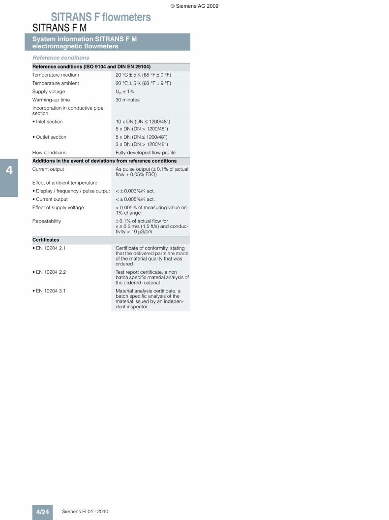
Reference conditions
Reference conditions (ISO 9104 and DIN EN 29104)
Temperature medium 20 °C ± 5 K (68 °F ± 9 °F)
Temperature ambient 20 °C ± 5 K (68 °F ± 9 °F)
Supply voltage Un ± 1%
Warming-up time 30 minutes
Incorporation in conductive pipe section
• Inlet section 10 x DN (DN ≤ 1200/48”)5 x DN (DN > 1200/48“)
• Outlet section 5 x DN (DN ≤ 1200/48”)3 x DN (DN > 1200/48“)
Flow conditions Fully developed flow profile
Additions in the event of deviations from reference conditions
Current output As pulse output (± 0.1% of actual flow + 0.05% FSO)
Effect of ambient temperature
• Display / frequency / pulse output < ± 0.003%/K act.
• Current output < ± 0.005%/K act.
Effect of supply voltage < 0.005% of measuring value on 1% change
Repeatability ± 0.1% of actual flow for v ≥ 0.5 m/s (1.5 ft/s) and conduc-tivity > 10 µS/cm
Certificates
• EN 10204 2.1 Certificate of conformity, stating that the delivered parts are made of the material quality that was ordered
• EN 10204 2.2 Test report certificate, a non batch specific material analysis of the ordered material
• EN 10204 3.1 Material analysis certificate, a batch specific analysis of the material issued by an indepen-dent inspector
© Siemens AG 2009
SITRANS F flowmetersSITRANS F M
System information SITRANS F Melectromagnetic flowmeters
4/25Siemens FI 01 · 2010
4
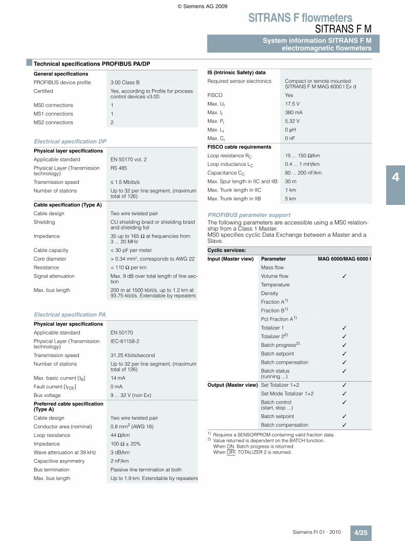
Technical specifications PROFIBUS PA/DP
Electrical specification DP
Electrical specification PA
PROFIBUS parameter supportThe following parameters are accessible using a MS0 relation-ship from a Class 1 Master.MS0 specifies cyclic Data Exchange between a Master and a Slave.
1) Requires a SENSORPROM containing valid fraction data.2) Value returned is dependent on the BATCH function.
When ON, Batch progress is returned.When OFF, TOTALIZER 2 is returned.
General specifications
PROFIBUS device profile 3.00 Class B
Certified Yes, according to Profile for process control devices v3.00.
MS0 connections 1
MS1 connections 1
MS2 connections 2
Physical layer specifications
Applicable standard EN 50170 vol. 2
Physical Layer (Transmission technology)
RS 485
Transmission speed ≤ 1.5 Mbits/s
Number of stations Up to 32 per line segment, (maximum total of 126)
Cable specification (Type A)
Cable design Two wire twisted pair
Shielding CU shielding braid or shielding braid and shielding foil
Impedance 35 up to 165 Ω at frequencies from 3 ... 20 MHz
Cable capacity < 30 pF per meter
Core diameter > 0.34 mm², corresponds to AWG 22
Resistance < 110 Ω per km
Signal attenuation Max. 9 dB over total length of line sec-tion
Max. bus length 200 m at 1500 kbit/s, up to 1.2 km at 93.75 kbit/s. Extendable by repeaters
Physical layer specifications
Applicable standard EN 50170
Physical Layer (Transmission technology)
IEC-61158-2
Transmission speed 31.25 Kbits/second
Number of stations Up to 32 per line segment, (maximum total of 126)
Max. basic current [IB] 14 mA
Fault current [IFDE] 0 mA
Bus voltage 9 ... 32 V (non Ex)
Preferred cable specification (Type A)
Cable design Two wire twisted pair
Conductor area (nominal) 0.8 mm2 (AWG 18)
Loop resistance 44 Ω/km
Impedance 100 Ω ± 20%
Wave attenuation at 39 kHz 3 dB/km
Capacitive asymmetry 2 nF/km
Bus termination Passive line termination at both
Max. bus length Up to 1.9 km. Extendable by repeaters
IS (Intrinsic Safety) data
Required sensor electronics Compact or remote mounted SITRANS F M MAG 6000 I Ex d
FISCO Yes
Max. UI 17.5 V
Max. II 380 mA
Max. PI 5.32 V
Max. LI 0 µH
Max. CI 0 nF
FISCO cable requirements
Loop resistance RC 15 ... 150 Ω/km
Loop inductance LC 0.4 ... 1 mH/km
Capacitance CC 80 ... 200 nF/km
Max. Spur length in IIC and IIB 30 m
Max. Trunk length in IIC 1 km
Max. Trunk length in IIB 5 km
Cyclic services:
Input (Master view) Parameter MAG 6000/MAG 6000 I
Mass flow
Volume flow
Temperature
Density
Fraction A1)
Fraction B1)
Pct Fraction A1)
Totalizer 1
Totalizer 22)
Batch progress2)
Batch setpoint
Batch compensation
Batch status (running ...)
Output (Master view) Set Totalizer 1+2
Set Mode Totalizer 1+2
Batch control (start, stop ...)
Batch setpoint
Batch compensation
© Siemens AG 2009
SITRANS F flowmetersSITRANS F MSystem information SITRANS F Melectromagnetic flowmeters
4/26 Siemens FI 01 · 2010
4
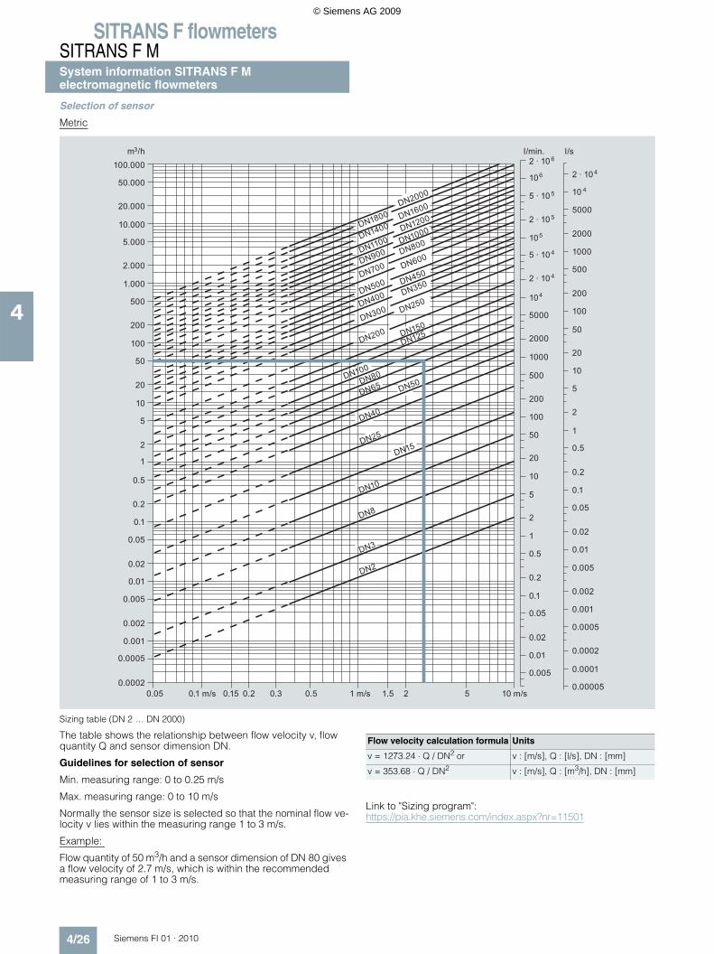
Selection of sensor
Metric
Sizing table (DN 2 … DN 2000)
The table shows the relationship between flow velocity v, flow quantity Q and sensor dimension DN.
Guidelines for selection of sensor
Min. measuring range: 0 to 0.25 m/s
Max. measuring range: 0 to 10 m/s
Normally the sensor size is selected so that the nominal flow ve-locity v lies within the measuring range 1 to 3 m/s.
Example:
Flow quantity of 50 m3/h and a sensor dimension of DN 80 gives a flow velocity of 2.7 m/s, which is within the recommended measuring range of 1 to 3 m/s.
Link to "Sizing program": https://pia.khe.siemens.com/index.aspx?nr=11501
100.000
50.000
m /h3
10.000
20.000
5.000
2.000
1.000
500
200
100
50
20
10
5
2
1
0.5
0.2
0.1
0.05
0.02
0.01
0.005
0.002
0.001
0.0005
0.0002
I/min.
DN1800DN2000
DN1600
DN1400 DN1200
DN1100 DN1000
DN800
DN900
DN700 DN600
DN500
DN400
DN300
DN200
DN100
DN450
DN350
DN250
DN150
DN125
DN80
DN65 DN50
DN40
DN25
DN15
DN10
DN8
DN3
DN2
0.05 0.1 m/s 0.15 0.2 0.3 1 m/s0.5 1.5 2 50.00005
0.0001
0.0002
0.0005
0.001
0.005
0.01
0.02
0.05
0.002
0.005
0.01
0.02
0.05
0.1
0.1
0.2
0.5
0.2
0.5
1
1
2
5
10
20
50
10
5
2
20
50
100
100
500
200
200
500
1000
2000
5000
2000
5000
10
2 · 10
10
I/s
5
104
4
4
2 · 10 6
5 · 10 5
2 · 10 5
5 · 10 4
2 · 10 4
1000
10 m/s
106
Flow velocity calculation formula Units
v = 1273.24 ⋅ Q / DN2 or v : [m/s], Q : [l/s], DN : [mm]
v = 353.68 ⋅ Q / DN2 v : [m/s], Q : [m3/h], DN : [mm]
© Siemens AG 2009
SITRANS F flowmetersSITRANS F M
System information SITRANS F Melectromagnetic flowmeters
4/27Siemens FI 01 · 2010
4
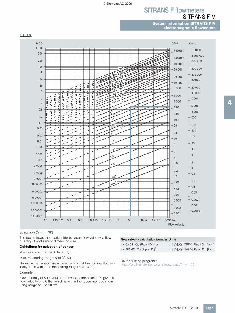
Imperial
Sizing table (1/12” … 78”)
The table shows the relationship between flow velocity v, flow quantity Q and sensor dimension size.
Guidelines for selection of sensor
Min. measuring range: 0 to 0.8 ft/s
Max. measuring range: 0 to 33 ft/s
Normally the sensor size is selected so that the nominal flow ve-locity v lies within the measuring range 3 to 10 ft/s.
Example:
Flow quantity of 500 GPM and a sensor dimension of 6" gives a flow velocity of 5.6 ft/s, which is within the recommended meas-uring range of 3 to 10 ft/s.
Link to "Sizing program": https://pia.khe.siemens.com/index.aspx?nr=11501
Flow velocity
MGD
0.000001
1/12"
0.1 0.15 0.2 0.3 1 f/s0.5 1.5 15 202 5
0.0005
0.001
0.005
0.01
0.02
0.001
0.002
0.05
0.002
0.05
0.1
0.2
0.50.1
0.2
0.5
1
1
2
5
10
20
50
10
5
2
20
50
100
100
500
200
500 000
I/min.
0.8 3 10 f/s 3033 f/s
1/8"
3/8"
1/4"
1/2"
1½"
2½"
1"
0.000002
0.000005
0.00001
0.00002
0.00005
0.0001
0.0002
0.0005
0.001
0.002
0.005
0.01
0.02
0.05
0.1
0.2
0.5
1
2
5
10
20
50
100
200
500
1,000GPM
200 000
100 000
50 000
20 000
10 000
5 000
2 000
1 000
500
200
500 000
200 000
100 000
50 000
20 000
10 000
5 000
2 000
1 000
1 000 000
2 000 000
78"
72" 66"
60" 54"
48" 44"
2"
3"4"5"
6"8"
10"12"
40"/42" 36"
32" 30"
28" 24"
20" 18"
16" 14"
Flow velocity calculation formula Units
v = 0.408 ⋅ Q / (Pipe I.D.)2 or v : [ft/s], Q : [GPM], Pipe I.D. : [inch]
v = 283.67 ⋅ Q / (Pipe I.D.)2 v : [ft/s], Q : [MGD], Pipe I.D. : [inch]
© Siemens AG 2009
SITRANS F flowmetersSITRANS F MSystem information SITRANS F Melectromagnetic flowmeters
4/28 Siemens FI 01 · 2010
4
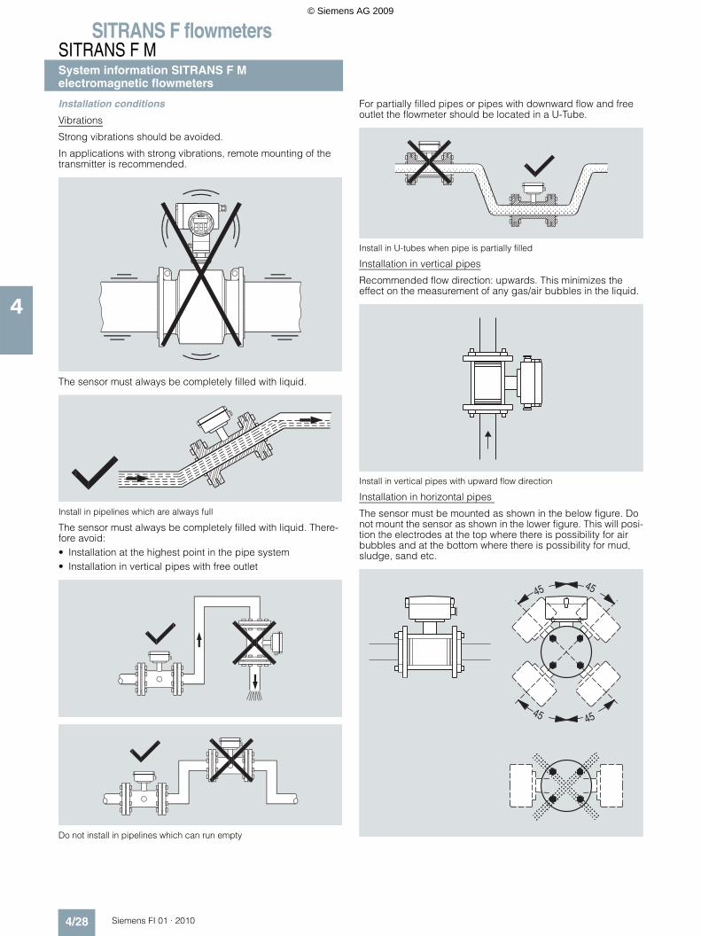
Installation conditions
Vibrations
Strong vibrations should be avoided.
In applications with strong vibrations, remote mounting of the transmitter is recommended.
The sensor must always be completely filled with liquid.
Install in pipelines which are always full
The sensor must always be completely filled with liquid. There-fore avoid:• Installation at the highest point in the pipe system• Installation in vertical pipes with free outlet
Do not install in pipelines which can run empty
For partially filled pipes or pipes with downward flow and free outlet the flowmeter should be located in a U-Tube.
Install in U-tubes when pipe is partially filled
Installation in vertical pipes
Recommended flow direction: upwards. This minimizes theeffect on the measurement of any gas/air bubbles in the liquid.
Install in vertical pipes with upward flow direction
Installation in horizontal pipes
The sensor must be mounted as shown in the below figure. Do not mount the sensor as shown in the lower figure. This will posi-tion the electrodes at the top where there is possibility for air bubbles and at the bottom where there is possibility for mud, sludge, sand etc.
© Siemens AG 2009
SITRANS F flowmetersSITRANS F M
System information SITRANS F Melectromagnetic flowmeters
4/29Siemens FI 01 · 2010
4
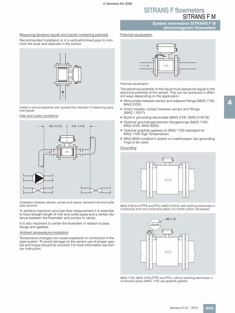
Measuring abrasive liquids and liquids containing particles
Recommended installation is in a vertical/inclined pipe to mini-mize the wear and deposits in the sensor.
Install in vertical pipelines with upward flow direction if measuring abra-sive liquids
Inlet and outlet conditions
Installation between elbows, pumps and valves: standard inlet and outlet pipe sections
To achieve maximum accurate flow measurement it is essential to have straight length of inlet and outlet pipes and a certain dis-tance between the flowmeter and pumps or valves.
It is also important to center the flowmeter in relation to pipe flange and gaskets.
Ambient temperature-Installation
Temperature changes can cause expansion or contraction in the pipe system. To avoid damage on the sensor use of proper gas-ket and torque should be ensured. For more information see sen-sor instruction.
Potential equalization
Potential equalization
The electrical potential of the liquid must always be equal to the electrical potential of the sensor. This can be achieved in differ-ent ways depending on the application:• Wire jumper between sensor and adjacent flange (MAG 1100,
MAG 3100)• Direct metallic contact between sensor and fittings
(MAG 1100 F)• Build-in grounding electrodes (MAG 3100, MAG 5100 W)• Optional grounding/protection flanges/rings (MAG 1100,
MAG 3100, MAG 8000)• Optional graphite gaskets on MAG 1100 (standard for
MAG 1100 High Temperature)• MAG 8000 installed in plastic or coated pipes: two grounding
rings to be used.
Grounding
MAG 3100 (not PTFE and PFA), MAG 5100 W: with earthing electrodes in conductive and non-conductive pipes (no further action necessary)
MAG 1100, MAG 3100 (PTFE and PFA): without earthing electrodes in conductive pipes (MAG 1100 use graphite gasket)
min. 5 x Di min. 3 x Di
M6 x 16
© Siemens AG 2009
SITRANS F flowmetersSITRANS F MSystem information SITRANS F Melectromagnetic flowmeters
4/30 Siemens FI 01 · 2010
4
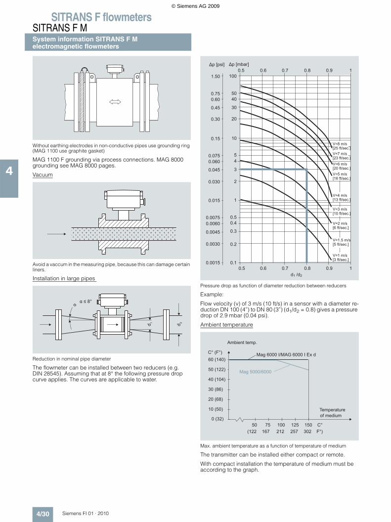
Without earthing electrodes in non-conductive pipes use grounding ring (MAG 1100 use graphite gasket)
MAG 1100 F grounding via process connections. MAG 8000 grounding see MAG 8000 pages.
Vacuum
Avoid a vaccum in the measuring pipe, because this can damage certain liners.
Installation in large pipes
Reduction in nominal pipe diameter
The flowmeter can be installed between two reducers (e.g. DIN 28545). Assuming that at 8° the following pressure drop curve applies. The curves are applicable to water.
Pressure drop as function of diameter reduction between reducers
Example:
Flow velocity (v) of 3 m/s (10 ft/s) in a sensor with a diameter re-duction DN 100 (4”) to DN 80 (3”) (d1/d2 = 0.8) gives a pressure drop of 2.9 mbar (0.04 psi).
Ambient temperature
Max. ambient temperature as a function of temperature of medium
The transmitter can be installed either compact or remote.
With compact installation the temperature of medium must be according to the graph.
α ≤ 8° α
d 2d 1
Δp [mbar]Δp [psi]
1.50
0.75
0.45
0.30
0.15
0.0750.060
0.030
0.045
0.60
0.015
0.0045
0.00600.0075
0.0030
0.0015
V=8 m/s [25 ft/sec.]V=7 m/s [23 ft/sec.]
10.90.80.70.5 0.6100
0.50.4
0.2
0.5 0.6
50
30
40
20
5
10
4
3
0.8 0.9d1 /d2
1
0.3
0.11
2
0.7
V=1 m/s [3 ft/sec.]
V=1.5 m/s [5 ft/sec.]
V=2 m/s [6 ft/sec.]
V=3 m/s [10 ft/sec.]
V=4 m/s [13 ft/sec.]
V=5 m/s [16 ft/sec.]
V=6 m/s [20 ft/sec.]
of mediumTemperature
Ambient temp.
Mag 6000 I/MAG 6000 I Ex d
Mag 5000/6000
0 (32)
C° (F°)
40 (104)
50 (122)
30 (86)
10 (50)
20 (68)
60 (140)
75 150 C°10050 125 167 302 F°) 212(122 257
© Siemens AG 2009
SITRANS F flowmetersSITRANS F M
System information SITRANS F Melectromagnetic flowmeters
4/31Siemens FI 01 · 2010
4
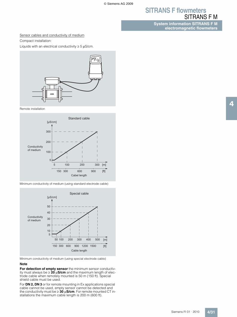
Sensor cables and conductivity of medium
Compact installation:
Liquids with an electrical conductivity ≥ 5 µS/cm.
Remote installation
Minimum conductivity of medium (using standard electrode cable)
Minimum conductivity of medium (using special electrode cable)
Note For detection of empty sensor the minimum sensor conductiv-ity must always be ≥ 20 µS/cm and the maximum length of elec-trode cable when remotely mounted is 50 m (150 ft). Special shield cable must be used. For DN 2, DN 3 or for remote mounting in Ex applications special cable cannot be used, empty sensor cannot be detected and the conductivity must be ≥ 30 µS/cm. For remote mounted CT in-stallations the maximum cable length is 200 m (600 ft).
Standard cable
Cabel length
Conductivityof medium
[µS/cm]
[m]3002001005
300
200
100
5
150 600 900 [ft]300
Conductivityof medium
Special cable
Cable length
[µS/cm]
50
40
20
5
30
10
50 300 400 500 [m]100 200
[ft]15001200900150 300 600
© Siemens AG 2009


![SITRANS F flowmeters SITRANS F X - … · A = cross-section area [m2] V = flow velocity [m/s] 1 2 d Q ... Process connections Flange norm EN 1092-1 form B1/B2 or ASME ... temperature](https://img.pdfslide.us/doc/110x75/5b2569d07f8b9a517c8b477e/sitrans-f-flowmeters-sitrans-f-x-a-cross-section-area-m2-v-flow-velocity.jpg)