Embed Size (px)
Citation preview
SITRANS F flowmetersSITRANS F RRotary-piston metersIntroduction
4/378 Siemens FI 01 · 2010
4
Overview
Mechanical registers, automatic batchmeters and digital registers with current and pulse output
Rotary-piston meter DN 15 (½“) with single-pointer dial type 01 without acceccories
Rotary-piston meter DN 25 (1“) with single-pointer dial type 01
Rotary piston meter with electric flow register in compact form
Acid resistant rotary-piston meter DN 25 (1“) with single-pointer dial type 01 without acceccories
Rotary-piston meter DN 50 (2") with mech. Single-pointer dial type 01, with accessories (here: cooling attachment and pulser)
Automatic batch meter DN 50 (2“), with rotary-piston meter, quantity pre-set register and shut-off valve
© Siemens AG 2009
SITRANS F flowmetersSITRANS F R
Rotary-piston metersIntroduction
4/379Siemens FI 01 · 2010
4
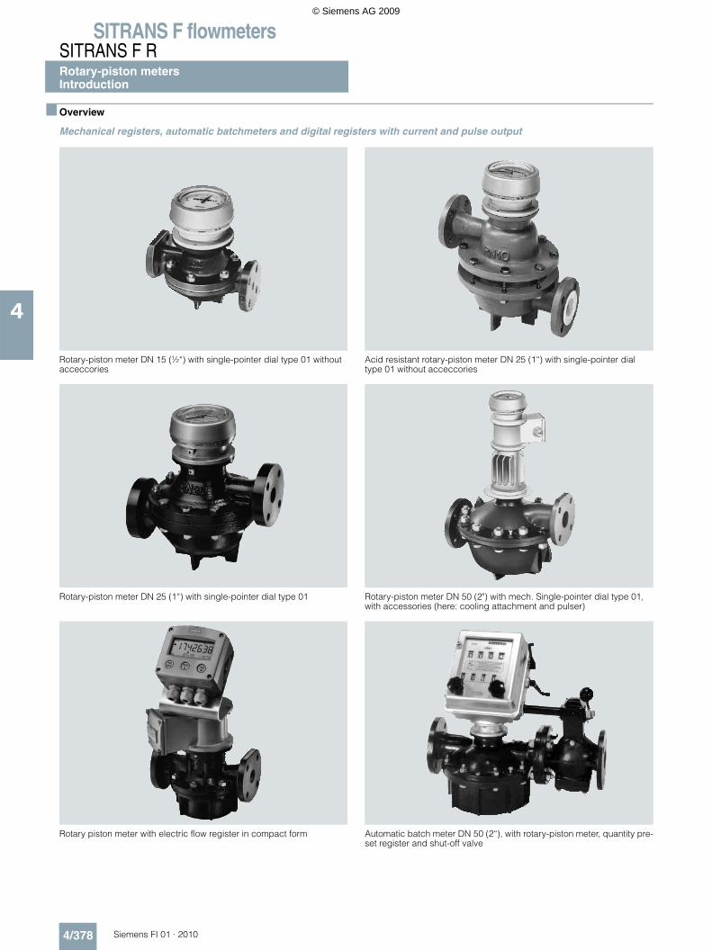
Selection overview, rotary piston meters
Version Rotary piston meters Acid meters
Nominal diameter DN 15 DN 25 DN 50 DN 80 DN 25
Order No. 7MR10..-... 7MR11..-... 7MR14..-... 7MR16..-... 7MR111-...
Nominal pressure
PN 6
PN 10
PN 16
PN 25
PN 40
PN 63
Flow variables
Max. 20 l/min
Max. 100 l/min
Max. 500 l/min
Max. 1 000 l/min
Flange standards
Drilled acc. to EN
Drilled acc. to ASME
With raised faces
Approvals
Custody transfer
Material acceptance test EN 10204-3.1
ATEX in preparation
Piston material
Carbon
Cast iron
Ni-resist
Hard rubber
PTFE 40 °C
PTFE 90 °C
CrNiMo steel with carbon contact surface
CrNiMo steel with PTFE contact surface
PCTFE
Designs
Mechanical singe-pointer dial
Mechanical double-pointer dial
As automatic batchmeter (incl. shut-off valve)
With electronic flow register
Remote or compact installation
© Siemens AG 2009
SITRANS F flowmetersSITRANS F RRotary-piston meters - IntroductionApplication
4/380 Siemens FI 01 · 2010
4
Benefits• High measuring accuracy (approved for custody transfer)• Suitable for flow rates up to 1000 l/min (264 USgpm)• Wide flow rate range• Low dependence on viscosity• Low pressure drop• Simple compact design• High reliability• Advantages with extremely high viscosity since pressure
drops up to 3 bar (43.5 psi) permissible• Advantages with very low viscosity (e.g. liquefied gas) since
only low pressure drops occur because of the light-weight mechanism with good running characteristics
• Wide range of available materials, e.g. plastic lining for partic-ularly corrosive liquids
• Easy service as a result of simple design• Liquid temperatures up to 300 °C• Also available with external heater• Metering and dispensing without a power supply• No inlet or outlet pipe sections required• Independent of flow profile, conductivity and damping
Rotary-piston meters are characterized by:• Accuracy• Reliability• Robust design
Application
For use in closed liquid circuits at pressures up to PN 63 (MWP914 psi) and liquid temperatures up to 300 °C (572 °F).• For all liquids ranging from lubricating oils up to corrosive ac-
ids, viscosity ≤ 0.2 mPa s (cp) and for pasty, viscous liquids (e.g. colors for offset printing with 350 000 mPa s (cp))
• For measurements requiring an accuracy associated with custody transfer.
A prerequisite for exact measurements is that the liquid is homo-geneous without coarse solid impurities or gas inclusions.Rotary-piston meters are mainly used in the petroleum industry, the raw material industries, the chemical industry, the foodstuffs and beverage industries and in power stations and district heat-ing stations:In the basic version (meter mechanism and register) for meter-ing in the production, distribution and consumption of liquids.• With quantity preset register and mechanical shut-off valve as
an automatic batchmeter without a power supply• With accessories (pulser etc.) for flow rate measurement, re-
mote metering and digital data processing
They complement one another with respect to the flow rate ranges but have particular advantages for specific applications.
Rotary-piston meters are approved for custody transfer in the European Union and in many other countries.
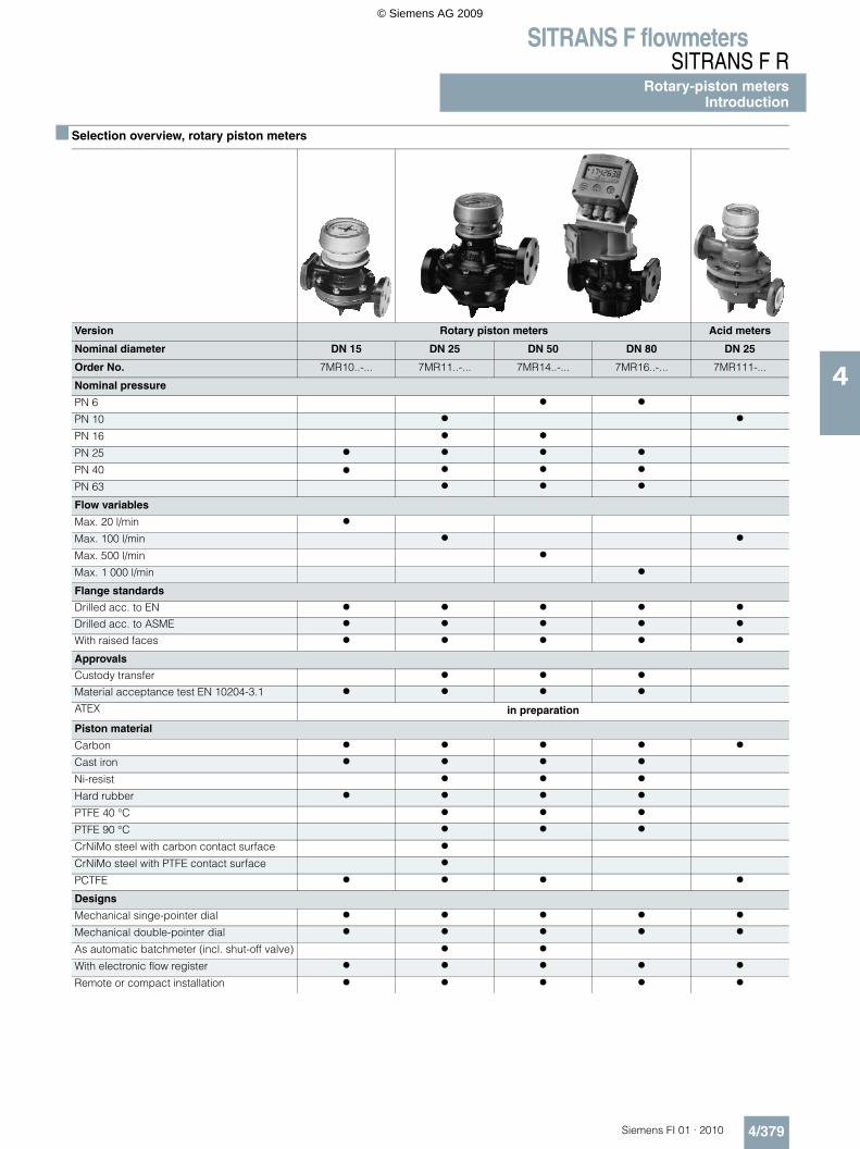
Rotary-piston meter Automatic batchmeter
Industrial designDN 25 (1“) ... DN 80 (3“)PN 4, 6, 10, 16
Industrial designDN 15 (½“) ... DN 80 (3“)PN 25, 40, 63
Acid-resistant modelDN 25 (1“), PN 10
Rotary-piston meter with mechani-cal shut-off valve and quantity pre-set registerDN 25 (1“), PN 10DN 25 (2“), PN 6
For industrial liquids such as: Alco-hols, bitumen, dispersions, paints, greases, liquid gases, adhesives, lacquers, alkalis, solvents, mineral oils, acids etc.
For industrial liquids such as: Alco-hols, bitumen, dispersions, paints, greases, liquid gases, adhesives, lacquers, alkalis, solvents, mineral oils, acids etc.
For particularly corrosive liquids such as: Phosphoric acid, hydro-chloric acid, dilute sulfuric acid, etc.
For industrial liquids such as: Alco-hols, bitumen, dispersions, paints, greases, liquid gases, adhesives, lacquers, alkalis, solvents, mineral oils, acids etc.
Rated flow
Rated size DN
Order No. Page Rated flow
Rated size DN
Order No. Page Rated flow
Rated size DN
Order No.
Page Rated flow
Rated size DN
Order No.
Page
l/min (USgpm)
mm (inch)
l/min (USgpm)
mm (inch)
l/min (USgpm)
mm (inch)
l/min (USgpm)
mm (inch)
20 (5.3) 15 (½“)
7MR1020 7MR1030
4/394
100 (26.4)
25 (1“)
7MR1110 4/396 100 (26.4)
25 (1“) 7MR1120 7MR1130 7MR1140
4/396 100 (26) 25 (1) 7MR1111 4/402 100 (26) 25 (1) 7MR1112 7MR1113
4/404
500 (132)
50 (2“)
7MR1410 4/398 500 (132) 50 (2“) 7MR1420 7MR1430 7MR1440
4/398 500 (132)
50 (2) 7MR1412 7MR1413
4/405
1000 (264)
80 (3“)
7MR1610 4/400 1000 (264)
80 (3“) 7MR1620 7MR1630 7MR1640
4/400
© Siemens AG 2009
SITRANS F flowmetersSITRANS F R
Rotary-piston meters - IntroductionFunction and Design
4/381Siemens FI 01 · 2010
4
Function
Measuring principle
When metering flowing liquids, either the volume V is recorded over a given time t or the momentary flow rate q is determined.
The relationship between these variables is V = q ⋅ t.
In accordance with these two measuring principles, a differenti-ation is made between:• direct volumetric meters, also referred to as positive displace-
ment meters. These include rotary-piston meters.• indirect volumetric meters such as velocity meters, where the
flow velocity v represents a direct measure of the flow rate q at a given cross-section F according to the relationship q = v ⋅ A. Examples include electromagnetic flowmeters and flowmeters operating according to the differential pressure principle.
Rotary-piston meters are direct volumetric meters: They operate according to the positive displacement principle. Their operation is based on the continuous limitation of defined portions of the volumetric flow in the mechanism by continuous filling and emp-tying of the measurement space. This consists of the walls of the measuring chamber and the moving part, i.e. the rotary-piston.
The rotary-piston is driven by the pressure difference in the me-tered liquid between the inlet and outlet. The meters are basi-cally purely mechanical devices operating without a power sup-ply.
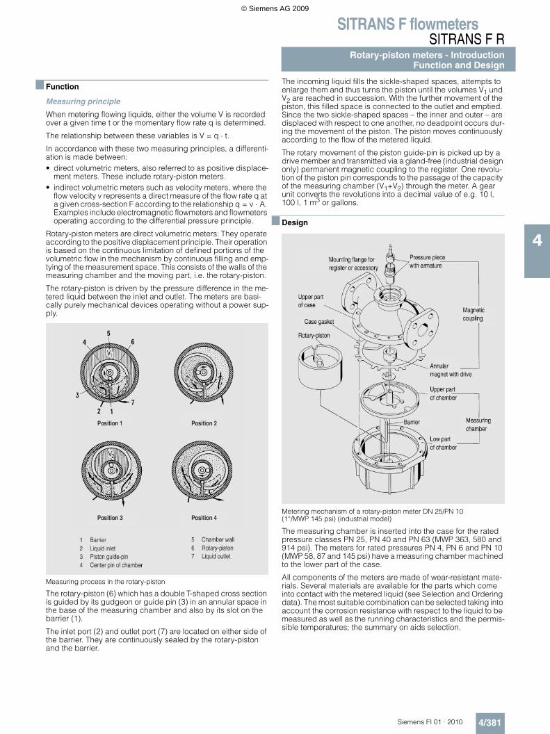
Measuring process in the rotary-piston
The rotary-piston (6) which has a double T-shaped cross section is guided by its gudgeon or guide pin (3) in an annular space in the base of the measuring chamber and also by its slot on the barrier (1).
The inlet port (2) and outlet port (7) are located on either side of the barrier. They are continuously sealed by the rotary-piston and the barrier.
The incoming liquid fills the sickle-shaped spaces, attempts to enlarge them and thus turns the piston until the volumes V1 und V2 are reached in succession. With the further movement of the piston, this filled space is connected to the outlet and emptied. Since the two sickle-shaped spaces – the inner and outer – are displaced with respect to one another, no deadpoint occurs dur-ing the movement of the piston. The piston moves continuously according to the flow of the metered liquid.
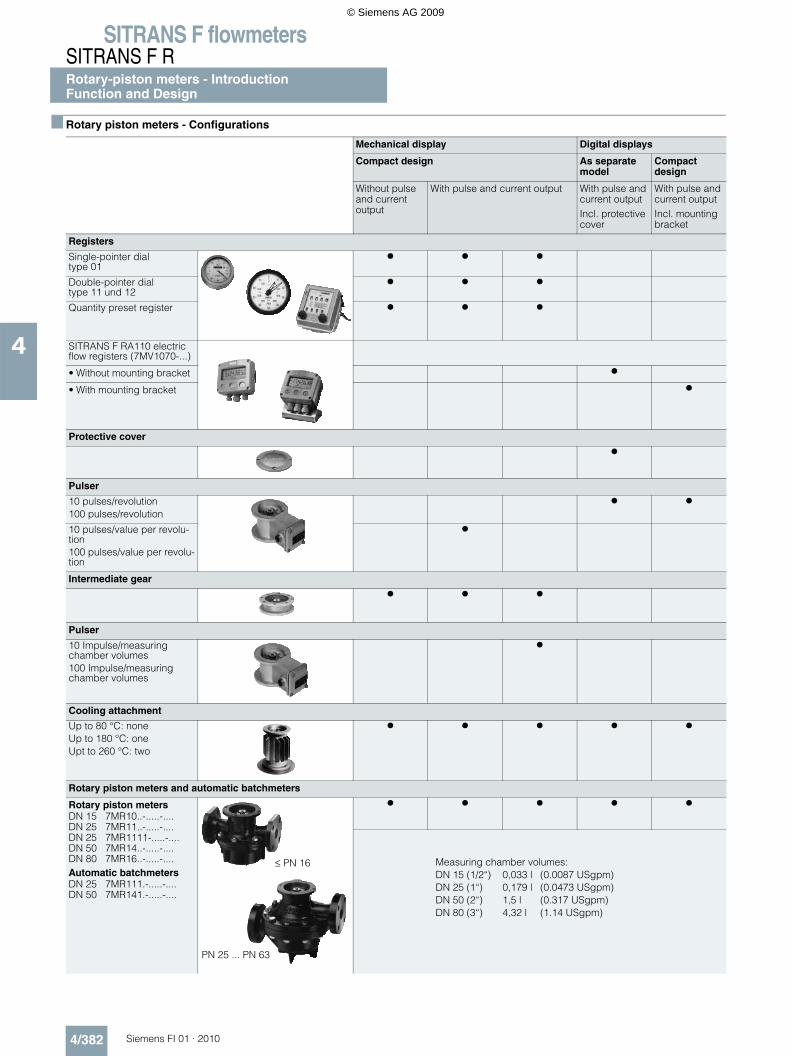
The rotary movement of the piston guide-pin is picked up by a drive member and transmitted via a gland-free (industrial design only) permanent magnetic coupling to the register. One revolu-tion of the piston pin corresponds to the passage of the capacity of the measuring chamber (V1+V2) through the meter. A gear unit converts the revolutions into a decimal value of e.g. 10 l, 100 l, 1 m3 or gallons.
Design
Metering mechanism of a rotary-piston meter DN 25/PN 10 (1“/MWP 145 psi) (industrial model)
The measuring chamber is inserted into the case for the rated pressure classes PN 25, PN 40 and PN 63 (MWP 363, 580 and 914 psi). The meters for rated pressures PN 4, PN 6 and PN 10 (MWP 58, 87 and 145 psi) have a measuring chamber machined to the lower part of the case.
All components of the meters are made of wear-resistant mate-rials. Several materials are available for the parts which come into contact with the metered liquid (see Selection and Ordering data). The most suitable combination can be selected taking into account the corrosion resistance with respect to the liquid to be measured as well as the running characteristics and the permis-sible temperatures; the summary on aids selection.
© Siemens AG 2009
SITRANS F flowmetersSITRANS F RRotary-piston meters - IntroductionFunction and Design
4/382 Siemens FI 01 · 2010
4
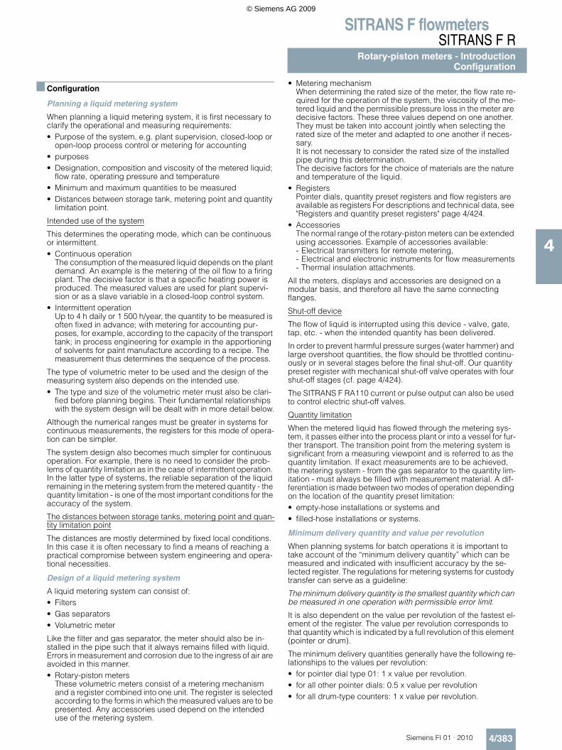
Rotary piston meters - Configurations
Mechanical display Digital displays
Compact design As separate model
Compact design
Without pulse and current output
With pulse and current output With pulse and current outputIncl. protective cover
With pulse and current outputIncl. mounting bracket
Registers
Single-pointer dialtype 01
Double-pointer dialtype 11 und 12
Quantity preset register
SITRANS F RA110 electric flow registers (7MV1070-...)
• Without mounting bracket
• With mounting bracket
Protective cover
Pulser
10 pulses/revolution100 pulses/revolution
10 pulses/value per revolu-tion100 pulses/value per revolu-tion
Intermediate gear
Pulser
10 Impulse/measuring chamber volumes100 Impulse/measuring chamber volumes
Cooling attachment
Up to 80 °C: noneUp to 180 °C: oneUpt to 260 °C: two
Rotary piston meters and automatic batchmeters
Rotary piston metersDN 15 7MR10..-.....-....DN 25 7MR11..-.....-....DN 25 7MR1111-.....-....DN 50 7MR14..-.....-....DN 80 7MR16..-.....-....Automatic batchmetersDN 25 7MR111.-.....-....DN 50 7MR141.-.....-....
≤ PN 16
PN 25 ... PN 63
Measuring chamber volumes:DN 15 (1/2“) 0,033 l (0.0087 USgpm)DN 25 (1“) 0,179 l (0.0473 USgpm)DN 50 (2“) 1,5 l (0.317 USgpm)DN 80 (3“) 4,32 l (1.14 USgpm)
© Siemens AG 2009
SITRANS F flowmetersSITRANS F R
Rotary-piston meters - IntroductionConfiguration
4/383Siemens FI 01 · 2010
4
Configuration
Planning a liquid metering system
When planning a liquid metering system, it is first necessary to clarify the operational and measuring requirements:• Purpose of the system, e.g. plant supervision, closed-loop or
open-loop process control or metering for accounting • purposes• Designation, composition and viscosity of the metered liquid;
flow rate, operating pressure and temperature• Minimum and maximum quantities to be measured• Distances between storage tank, metering point and quantity
limitation point.
Intended use of the system
This determines the operating mode, which can be continuous or intermittent.• Continuous operation
The consumption of the measured liquid depends on the plant demand. An example is the metering of the oil flow to a firing plant. The decisive factor is that a specific heating power is produced. The measured values are used for plant supervi-sion or as a slave variable in a closed-loop control system.
• Intermittent operationUp to 4 h daily or 1 500 h/year, the quantity to be measured is often fixed in advance; with metering for accounting pur-poses, for example, according to the capacity of the transport tank; in process engineering for example in the apportioning of solvents for paint manufacture according to a recipe. The measurement thus determines the sequence of the process.
The type of volumetric meter to be used and the design of the measuring system also depends on the intended use.• The type and size of the volumetric meter must also be clari-
fied before planning begins. Their fundamental relationships with the system design will be dealt with in more detail below.
Although the numerical ranges must be greater in systems for continuous measurements, the registers for this mode of opera-tion can be simpler.
The system design also becomes much simpler for continuous operation. For example, there is no need to consider the prob-lems of quantity limitation as in the case of intermittent operation. In the latter type of systems, the reliable separation of the liquid remaining in the metering system from the metered quantity - the quantity limitation - is one of the most important conditions for the accuracy of the system.
The distances between storage tanks, metering point and quan-tity limitation point
The distances are mostly determined by fixed local conditions. In this case it is often necessary to find a means of reaching a practical compromise between system engineering and opera-tional necessities.
Design of a liquid metering system
A liquid metering system can consist of:• Filters• Gas separators• Volumetric meter
Like the filter and gas separator, the meter should also be in-stalled in the pipe such that it always remains filled with liquid. Errors in measurement and corrosion due to the ingress of air are avoided in this manner.• Rotary-piston meters
These volumetric meters consist of a metering mechanism and a register combined into one unit. The register is selected according to the forms in which the measured values are to be presented. Any accessories used depend on the intended use of the metering system.
• Metering mechanismWhen determining the rated size of the meter, the flow rate re-quired for the operation of the system, the viscosity of the me-tered liquid and the permissible pressure loss in the meter are decisive factors. These three values depend on one another. They must be taken into account jointly when selecting the rated size of the meter and adapted to one another if neces-sary.It is not necessary to consider the rated size of the installed pipe during this determination.The decisive factors for the choice of materials are the nature and temperature of the liquid.
• RegistersPointer dials, quantity preset registers and flow registers are available as registers For descriptions and technical data, see "Registers and quantity preset registers" page 4/424.
• AccessoriesThe normal range of the rotary-piston meters can be extended using accessories. Example of accessories available: - Electrical transmitters for remote metering,- Electrical and electronic instruments for flow measurements- Thermal insulation attachments.
All the meters, displays and accessories are designed on a modular basis, and therefore all have the same connecting flanges.
Shut-off device
The flow of liquid is interrupted using this device - valve, gate, tap, etc. - when the intended quantity has been delivered.
In order to prevent harmful pressure surges (water hammer) and large overshoot quantities, the flow should be throttled continu-ously or in several stages before the final shut-off. Our quantity preset register with mechanical shut-off valve operates with four shut-off stages (cf. page 4/424).
The SITRANS F RA110 current or pulse output can also be used to control electric shut-off valves.
Quantity limitation
When the metered liquid has flowed through the metering sys-tem, it passes either into the process plant or into a vessel for fur-ther transport. The transition point from the metering system is significant from a measuring viewpoint and is referred to as the quantity limitation. If exact measurements are to be achieved, the metering system - from the gas separator to the quantity lim-itation - must always be filled with measurement material. A dif-ferentiation is made between two modes of operation depending on the location of the quantity preset limitation:• empty-hose installations or systems and • filled-hose installations or systems.
Minimum delivery quantity and value per revolution
When planning systems for batch operations it is important to take account of the “minimum delivery quantity” which can be measured and indicated with insufficient accuracy by the se-lected register. The regulations for metering systems for custody transfer can serve as a guideline:
The minimum delivery quantity is the smallest quantity which can be measured in one operation with permissible error limit.
It is also dependent on the value per revolution of the fastest el-ement of the register. The value per revolution corresponds to that quantity which is indicated by a full revolution of this element (pointer or drum).
The minimum delivery quantities generally have the following re-lationships to the values per revolution:• for pointer dial type 01: 1 x value per revolution.• for all other pointer dials: 0.5 x value per revolution• for all drum-type counters: 1 x value per revolution.
© Siemens AG 2009
SITRANS F flowmetersSITRANS F RRotary-piston meters - IntroductionConfiguration
4/384 Siemens FI 01 · 2010
4
Certain values per revolution or certain values of the minimum delivery quantity are assigned to each rated size of the individ-ual meter types. These values have been selected such that they almost always represent the best solutions to the metering prob-lems. Should it be found during the planning of a system that the minimum delivery quantity attainable with the value per revolu-tion stated in the catalogue does not correspond to the opera-tional requirements, please contact us.
Viscosity, density
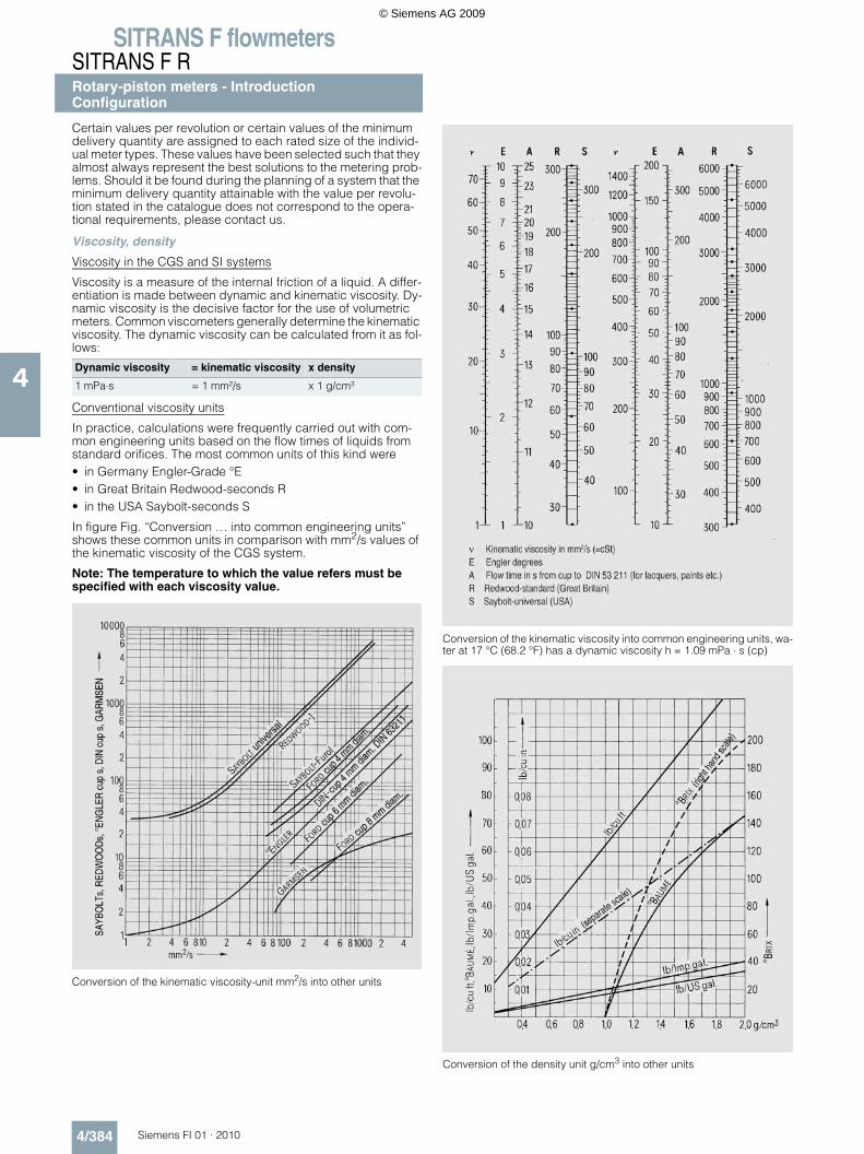
Viscosity in the CGS and SI systems
Viscosity is a measure of the internal friction of a liquid. A differ-entiation is made between dynamic and kinematic viscosity. Dy-namic viscosity is the decisive factor for the use of volumetric meters. Common viscometers generally determine the kinematic viscosity. The dynamic viscosity can be calculated from it as fol-lows:
Conventional viscosity units
In practice, calculations were frequently carried out with com-mon engineering units based on the flow times of liquids from standard orifices. The most common units of this kind were• in Germany Engler-Grade °E• in Great Britain Redwood-seconds R• in the USA Saybolt-seconds S
In figure Fig. “Conversion … into common engineering units” shows these common units in comparison with mm2/s values of the kinematic viscosity of the CGS system.
Note: The temperature to which the value refers must be specified with each viscosity value.
Conversion of the kinematic viscosity-unit mm2/s into other units
Conversion of the kinematic viscosity into common engineering units, wa-ter at 17 °C (68.2 °F) has a dynamic viscosity h = 1.09 mPa ⋅ s (cp)
Conversion of the density unit g/cm3 into other units
Dynamic viscosity = kinematic viscosity x density
1 mPa⋅s = 1 mm²/s x 1 g/cm³
© Siemens AG 2009
SITRANS F flowmetersSITRANS F R
Rotary-piston meters - IntroductionConfiguration - Recommended materials
4/385Siemens FI 01 · 2010
4
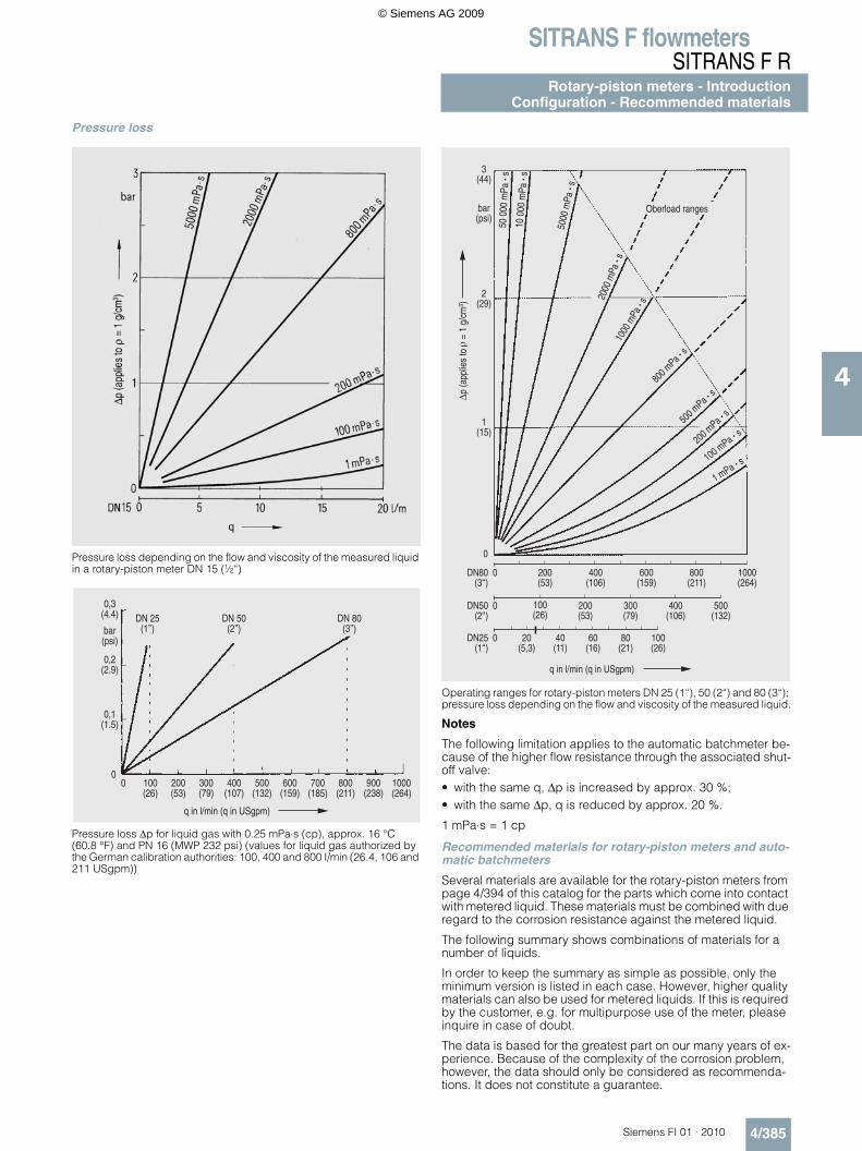
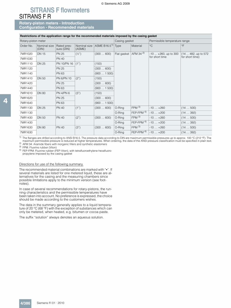
Pressure loss
Pressure loss depending on the flow and viscosity of the measured liquid in a rotary-piston meter DN 15 (½“)
Pressure loss ∆p for liquid gas with 0.25 mPa⋅s (cp), approx. 16 °C (60.8 °F) and PN 16 (MWP 232 psi) (values for liquid gas authorized by the German calibration authorities: 100, 400 and 800 I/min (26.4, 106 and 211 USgpm))
Operating ranges for rotary-piston meters DN 25 (1“), 50 (2“) and 80 (3“); pressure loss depending on the flow and viscosity of the measured liquid.
Notes
The following limitation applies to the automatic batchmeter be-cause of the higher flow resistance through the associated shut-off valve:• with the same q, ∆p is increased by approx. 30 %;• with the same ∆p, q is reduced by approx. 20 %.
1 mPa⋅s = 1 cp
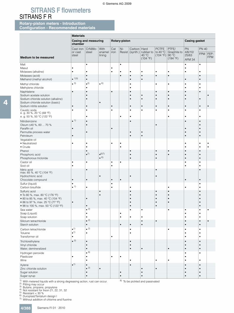
Recommended materials for rotary-piston meters and auto-matic batchmeters
Several materials are available for the rotary-piston meters from page 4/394 of this catalog for the parts which come into contact with metered liquid. These materials must be combined with due regard to the corrosion resistance against the metered liquid.
The following summary shows combinations of materials for a number of liquids.
In order to keep the summary as simple as possible, only the minimum version is listed in each case. However, higher quality materials can also be used for metered liquids. If this is required by the customer, e.g. for multipurpose use of the meter, please inquire in case of doubt.
The data is based for the greatest part on our many years of ex-perience. Because of the complexity of the corrosion problem, however, the data should only be considered as recommenda-tions. It does not constitute a guarantee.
© Siemens AG 2009
SITRANS F flowmetersSITRANS F RRotary-piston meters - IntroductionConfiguration - Recommended materials
4/386 Siemens FI 01 · 2010
4
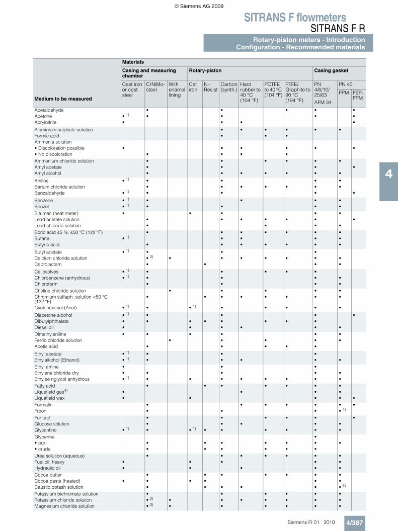
1) The flanges are drilled according to ANSI B16.5. The pressure data according to DIN are maximum permissible pressures up to approx. 100 °C (212 °F). The maximum permissible pressure is reduced at higher temperatures. When ordering, the data of the ANSI pressure classification must be specified in plain text.
2) AFM 34: Aramide fibers with inorganic fillers and synthetic elastomers3) FPM: Fluorine rubber (Viton)4) FEP-FPM: Fluorine rubber (FEP-Viton), with tetrafluoroethylene-hexafluoro-
propylene imposed by the casing gasket
Directions for use of the following summary.
The recommended material combinations are marked with “•”. If several materials are listed for one metered liquid, these are al-ternatives for the casing and the measuring chambers since possible limitations apply to the minimum version (see foot-notes).
In case of several recommendations for rotary-pistons, the run-ning characteristics and the permissible temperatures have been taken into account. No preference is expressed, the choice should be made according to the customers wishes.
The data in the summary generally applies to a liquid tempera-ture of 20 °C (68 °F) with the exception of substances which can only be metered, when heated, e.g. bitumen or cocoa paste.
The suffix “solution” always denotes an aqueous solution.
Restrictions of the application range for the recommended materials imposed by the casing gasket
Rotary-piston meter Casing gasket Permissible temperature range
Order No. Nominal size (DIN)
Rated pres-sure (DIN)
Nominal size (ASME)
ASME B16.51) Type Material °C °F
7MR1020 DN 15 PN 25 (½”) (300 … 600) Flat gasket AFM 34 2) -10 ... +260, up to 300 for short time
(14 ... 482, up to 572 for short time)
7MR1030 PN 40
7MR1110 DN 25 PN 10/PN 16 (1”) (150)
7MR1120 PN 25 (300 … 600)
7MR1140 PN 63 (900 … 1 500)
7MR1410 DN 50 PN 6/PN 10 (2”) (150)
7MR1420 PN 25 (300 … 600)
7MR1440 PN 63 (900 … 1 500)
7MR1610 DN 80 PN 4/PN 6 (3”) (150)
7MR1620 PN 25 (300 … 600)
7MR1640 PN 63 (900 … 1 500)
7MR1130 DN 25 PN 40 (1”) (300 … 600) O-Ring FPM 3) -10 … +260 (14 … 500)
7MR1130 O-Ring FEP-FPM 4) -10 … +200 (14 … 392)
7MR1430 DN 50 PN 40 (2”) (300 … 600) O-Ring FPM 3) -10 … +260 (14 … 500)
7MR1430 O-Ring FEP-FPM 4) -10 … +200 (14 … 392)
7MR1630 DN 80 PN 40 (3”) (300 … 600) O-Ring FPM 3) -10 … +260 (14 … 500)
7MR1630 O-Ring FEP-FPM 4) -10 … +200 (14 … 392)
© Siemens AG 2009
SITRANS F flowmetersSITRANS F R
Rotary-piston meters - IntroductionConfiguration - Recommended materials
4/387Siemens FI 01 · 2010
4
Medium to be measured
Materials
Casing and measuring chamber
Rotary-piston Casing gasket
Cast iron or cast steel
CrNiMo-steel
With enamel lining
Cat iron
Ni-Resist
Carbon(synth.)
Hard rubber to 40 °C (104 °F)
PCTFEto 40 °C (104 °F)
PTFE/Graphite to 90 °C (194 °F)
PN 4/6/10/25/63AFM 34
PN 40
FPM FEP-FPM
Acetaldehyde • • • • •Acetone • 1) • • • •Acrylnitrile • • • •
Aluminium sulphate solution • • • • • •Formic acid • • •Ammonia solution• Discoloration possible • • • • • •• No discoloration • • • •Ammonium chloride solution • • • • • •Amyl acetate • • • •Amyl alcohol • • • • • • •
Aniline • 1) • • • •Barium chloride solution • • • • • • •Benzaldehyde • 1) • • • •
Benzene • 1) • • • •Benzol • 1) • • • •Bitumen (heat meter) • • • • •Lead acetate solution • • • • • • •Lead chloride solution • • • •Boric acid ≤5 %, ≤50 °C (122 °F) • • • • • • •Butane • 1) • • • •Butyric acid • • • • • • •
Butyl acetate • 1) • • •Calcium chloride solution • 2) • • • • • • •Caprolactam • • • •
Cellosolves • 1) • • • • •Chlorbenzene (anhydrous) • 1) • • • •Chloroform • • • •Choline chloride solution • • • • •Chromium sulfaph. solution <50 °C (122 °F)
• • • • • • • •
Cyclohexanol (Anol) • 1) • • 1) • • • • •
Diacetone alcohol • 1) • • • •Dibutylphthalate • • • • • • • •Diesel oil • • • • • •Dimethylaniline • • • • • •Ferric chloride solution • • • • •Acetis acid • • • • •
Ethyl acetate • 1) • • •Ethylalkohol (Ethanol) • 1) • • • • •Ethyl amine • • •Ethylene chloride dry • • • • •Ethylee nglycol anhydrous • 1) • • • • • • • •Fatty acid • • • • • • •Liquefield gas4) • • • •Liquefield wax • • • • •Formalin • • • • • • •Freon • • • • 4)
Furfurol • • • • • •Glucose solution • • • • •Glysantine • 1) • • 1) • • • • • •Glycerine •• pur • • • • • • •• crude • • • • • •Urea solution (aqueous) • • • • • • •Fuel oil, heavy • • • • •Hydraulic oil • • • • •Cocoa butter • • • • • • •Cocoa paste (heated) • • • • • •Caustic potash solution • • • • • • 5)
Potassium bichromate solution • • • • • •Potassium chloride solution • 2) • • • • • • •Magnesium chloride solution • 2) • • • • • •
© Siemens AG 2009
SITRANS F flowmetersSITRANS F RRotary-piston meters - IntroductionConfiguration - Recommended materials
4/388 Siemens FI 01 · 2010
4
1) With metered liquids with a strong degreasing action, rust can occur.2) Pitting may occur3) Butane, propane, propylene4) Not resistant for freon 21, 22, 31, 325) Resistant < 30 %6) Duroplast/Tantalum design l7) Without addition of chlorine and fluorine
8) To be pickled and passivated
Malt • • • •Masut • • •Molasses (alkaline) • • • • • • • • • •Molasses (acid) • • • • • • •Methanol (methyl alcohol) • 1)3) • • • • •
Methyl chloride • 3) •3) • 6) • • • • •Methylene chloride • • • •Naphtalene • • • • • • • •Sodium acetate solution • • • • • • •Sodium chloride solution (alkaline) • • • • • • •Sodium chloride solution (basic) •Sodium nitrite solution • • • • • • • • • •Caustic sodae. g. 30 %, 20 °C (68 °F)
• • • • • • • • •
e. g. 50 %, 50 °C (122 °F) • • • • • •
Nitrobenzene • 1) • • • •Oleum ≤40 %, 60 ... 70 % • • •Paraffin oil • • • •Permutite process water • • • • •Petroleum • • • • •Vegatable oil• Neutralized • • • • • • •• Crude • • • • •Phenol • • • • • •Phosphoric acid •7) •6)7) • • • • •Phosphorous tricloride • 6) • • • •Castor oil • • • • • •Soot oil • • • •Nitric acidmax. 65 %, 40 °C (104 °F)
• • •
Hydrochloric acid • • •Chocolate compound • • • • • •Sulfur (liquid) • • •Carbon bisulfide • 1) • • • • • •Sulfuric acid • • • • •• To 80 %, max. 80 °C (176 °F) • • • • •• 80 to 85 %, max. 40 °C (104 °F) • • • • •• 86 to 97 %, max. 25 °C (77 °F) • • • • •• 98 to 100 %, max. 50 °C (122 °F) • • • •Sea water • 2) • • • • • •Soap (Liquid) • • • •Soap solution • • • • • •Silicium tetrachloride • 2) • • • • •Starch solution • • • • • •
Carbon tetrachloride •1) • 2) • • • •Toluene •1) • • • •Transformer oil • • • •
Trichlorethylene • 2) • • • •Vinyl chloride • • • •Water, demineralized • • • • • •
Hydrogen peroxide • 8) • •Plasticizer • • • • •Wine • • • • • •
Xylene •1) • • • •Zinc chloride solution • 2) • • • • •Sugar solution • • • • •Sugar syrup • • • • •
Medium to be measured
Materials
Casing and measuring chamber
Rotary-piston Casing gasket
Cast iron or cast steel
CrNiMo-steel
With enamel lining
Cat iron
Ni-Resist
Carbon(synth.)
Hard rubber to 40 °C (104 °F)
PCTFEto 40 °C (104 °F)
PTFE/Graphite to 90 °C (194 °F)
PN 4/6/10/25/63AFM 34
PN 40
FPM FEP-FPM
© Siemens AG 2009
SITRANS F flowmetersSITRANS F R
Rotary-piston meters - IntroductionConfiguration - Recommended materials
4/389Siemens FI 01 · 2010
4
Definitions
Flow rate
qmin is the smallest flow rate which must be present if readings within the stated tolerance are to be obtained under the given operating conditions. The qmin value primarily depends on the viscosity of the liquid.
Attention must also be paid to the weight and material running characteristics of the moving parts of the metering mechanism. Data on qmin as a function of the above mentioned factors are listed in the technical specifications of the respective mecha-nism.
qmax is limited by• The maximum permissible speed which can be expected of
the moving parts of the mechanism (rotary piston) without the life (long-term accuracy) of the meter being shortened to an unacceptable extent. For this reason, the permissible qmax value for continuous operation is restricted to approx. half of the qmax for batch operation (approx. 1 500 h/year).
• The pressure loss, i.e. the pressure difference occurring in the mechanism through hydraulic losses. A maximum value of 3 bar (43.5 psi) is permissible. This value is only reached with very high viscosities and large flow rates. The meter size and the viscosity of the liquid are decisive factors for the actual pressure loss which occurs.
Values for qmax cont. and qmax batch (dependent on viscosity) are listed in the technical specifications.
Theory of the error curve for volumetric meters
On the basis of the German Standards and Weights and Mea-sures Regulations (also EC and OIML recommendations), the measuring error in volumetric meters, i.e. the difference between the registered quantity (A, actual reading) and the actual quan-tity (N, correct value) is defined as follows: a positive error means an indication which is too large, a negative error an indi-cation which is too small, compared to the actual quantity (N). To calculate the percentage error, the following applies:
f = (A - N)/N ⋅ 100 in % of the correct value
The primary cause of measuring errors is the gap loss which cannot be completely avoided despite the highest manufactur-ing precision for the parts of the mechanism - a flow which does not produce a corresponding rotary movement in the mecha-nism and is thus not recorded.
Diagram to illustrate the theory of the error curve for volumetric meters
If it is assumed that other external influences, e.g. gas inclusions in the liquid to be measured, are eliminated by appropriate mea-sures, the following simplified statement can be made on the form of the error curve:
Gap losses always lead to negative errors (positive delivery error corresponds to a negative indication error).
The total gap loss is made up of two components:• A component with a hyperbolic function which results from the
varying influence of mechanical friction (this influence de-creases with increasing flow rate after the friction at rest has been overcome) and
• A loss component which increases linearly with the flow rate and is due to the increasing flow resistance and thus the higher pressure difference in the mechanism.
The total curve can be formed from these two effects. It is char-acteristic for all positive displacement meters. The illustration “Error curves of volumetric meters” is greatly enlarged to simplify understanding.
Error curves of rotary-piston meters
The shape of the error curve is also affected by the viscosity of the metered liquid. The error in measurement increases with de-creasing viscosity, especially at the beginning and towards the end of the flow rate range.
By appropriate regulation, i.e. changing a pair of gear-wheels between the meter mechanism and the register, the position of the error curve can be displaced parallel to the zero line and thus the meter can be optimally calibrated. The appropriate pair of replacement gears can be read off from a table or determined with the aid of a calculating disk.
The illustration “Error curves of volumetric meters” shows error curves without any regulation having been carried out.
Error curves of volumetric meters dependent in shape and location on the flow rate and the viscosity of the liquid
Note: 1 mPa⋅s = 1 cp
Measuring accuracy
The rotary-piston meters are approved in the European Commu-nity and in many other countries for the custody transfer.
The following error limits apply between 0.2 % and 0.5 % of the correct value (depending on the liquid, the measuring range and the relevant calibration specifications).
The stated error limits in % of the correct value apply to the whole flow rate and for any delivery quantity greater than the smallest permissible quantity.
This is an important difference compared to other measuring in-struments whose errors are related to the full-scale value and thus only reach the stated accuracy at one point - full-scale de-flection. The minimum flow rate should not fall below 10% of the maximum flow rate in order to remain within the stated accuracy limit. This explains why the usual flow rate range for volumetric meters is 1:10.
!
"#
"#
!
"#
"#
"#
$!
%&'()*
+) ),'(-./+).),
0&1&)
1(2.)
0*)&3&(4$(&)()/
© Siemens AG 2009
SITRANS F flowmetersSITRANS F RRotary-piston meters - IntroductionConfiguration - Recommended materials
4/390 Siemens FI 01 · 2010
4
Note: The measuring system of the rotary-piston meter must al-ways be filled with the liquid to be measured in order to achieve a high measuring accuracy.
Service life (long-term accuracy)
The service life of a volumetric meter, i.e. the operating time until an overhaul or recalibration becomes necessary, is determined by the mechanical abrasion of the moving parts of the mecha-nisms which occurs because of forces from the metered liquid.
As well as the nature of the materials used (running characteris-tics), the service life is dependent on the lubricating properties of the metered liquid, the service is dependent on the lubricating properties of the metered liquid, the daily operating time and the cube of the flow rate (speed of rotation). The last factor is one of the reasons why only half of the maximum flow rate specified for the batch operation is permissible for continuous operation.
Since the above factors can hardly be determined exactly with industrial use of the meter, unequivocal statements on the ser-vice life (long-term accuracy) are not possible.
Recalibration is required every two years by law (in Germany) for meters used for custody transfer. On the basis of this regulation, it is recommended that meters which are not used for custody transfer be checked and recalibrated if necessary, at intervals of two to three years. Even this recommendation is based on aver-age, “normal” operating conditions. A period of three years is too short, for example, for a meter used for the batch dispensing of lubricating oil, it will still work within the stated error limits even after five years or more
© Siemens AG 2009
SITRANS F flowmetersSITRANS F R
Rotary-piston meters - IntroductionTechnical specifications
4/391Siemens FI 01 · 2010
4
Technical specifications
1) For metal rotary-pistons: increase by a factor of 2, for PCTFE and PTFE/graphite filling rotary-pistons: increase by a factor of 3.2) Continuous operation: over 8 hours a day.3) For metal pistons: reduce by a factor ≈0.8 to extend service life.4) Intermittent operation: up to 8 hours a day5) Note: When using pistons made of carbon, there is danger of break in the
case of liquid hammers
6) When using pistons made of carbon.7) Flow rates for higher viscosities on request; we have experience of up to
350 000 mPa⋅s (cp).8) Values in brackets apply to casing in CrNiMo steel.9) Max. permissible viscosity for exact closing of the shut-off valve and for
exact dispensing: viscosities up to 4 000 mPa⋅s (cp) possible.
Note:In order to extend the service life of the pulse sensor, rotary-piston meters with current and/or pulse output (without intermediate gear) should only be operated at max. 60% of the permissible flow.
Meter sizes (DN), pressure stages (PN) and permissible flow rates (q) for rotary-piston meters and automatic batchmeters
Design DN PN Rated flow rate Permissible flow rate
With vis-cosity
Min.1) with continu-ous2) operation
Max. with intermittent3)4)
operationMax. with con-tinuousoperation
mm (inch) bar (psi) l/min (USgpm) mPa⋅s(cp)
l/min (USgpm) l/min (USgpm) l/min (USgpm)
Rotaty-piston meter for industrial use
15 5) (½)5) 2540
(363)(580)
20 (5.3) ≤ 1< 58002 0005 00010 0007)
1.51.00.20.20.20.2
(0.26)(0.2)(0.05)(0.03)(0.03)(0.03)
10 6)
20201041
(5.3)(5.3)(5.3)(1.3)(0.53)(0.26)
101010521
(2.6)(2.6)(2.6)(1.3)(0.53)(0.26)
25 (1) 1016254063
(145)(232)(363)(580)(914)
100 (26.4) 0.30.6158005 00010 00020 0007)
126531111
(3.2)(1.6)(1.3)(0.8)(0.26)(0.26)(0.26)(0.26)
100100100100100807050
(26)(26)(26)(26)(26)(13)(5.3)(2.6)
8080808080605030
(13)(13)(13)(13)(13)(13)(5.3)(2.6)
50 (2) 610254063
(87)(145)8)
(363)(580)(914)
500 (132) 0.30.6158005 00010 00020 000
402018102222
(11)(5.3)(4.8)(2.6)(0.53)(0.53)(0.53)(0.53)
500500500500500350300150
(106)(132)(132)(132)(106)(53)(21)(11)
350350350350350250180100
(44)(44)(44)(44)(44)(44)(21)(11)
80 (3) 6254063
(58)(87)8)
(363)(580)(914)
1 000 (264) 0.30.6158005 00010 00020 0007)
603525105555
(16)(9.3)(6.6)(2.6)(1.3)(1.3)(1.3)(1.3)
1 0001 0001 0001 0001 000700600300
(211)(264)(264)(264)(211)(93)(40)(20)
700700700700500350250150
(93)(93)(93)(93)(93)(93)(40)(20)
Rotary-piston meter acid-resistant mode
25 (1) 10 (145) 100 (26.4) 0.615
1084
(2.6)(2.1)(1.0)
100100100
(26)(26)(26)
505050
(13)(13)(13)
Automatic batchmeter (Rotary-piston meter with quantity preset register and mechanical shut-off valve)
25 (1) 10 (145) 100 (26.4) 0.30.6158009)
126531
(3.2)(1.6)(1.3)(0.8)(0.26)
100100100100100
(26)(26)(26)(26)(26)
– –
50 (2) 610
(87)(145)8)
500 132 0.30.6158009)
402018102
(11)(5.3)(4.8)(2.6)(0.53)
500500500500400
(106)(132)(132)(132)(106)
– –
© Siemens AG 2009
SITRANS F flowmetersSITRANS F RRotary-piston meters - IntroductionTechnical specifications
4/392 Siemens FI 01 · 2010
4
Piston materials
1) For 120 min max. 65 °C (149 °F); for 20 min max. 90 °C (194 °F), e. g. for cleaning procedures2) Error limit max. 1%; at 90°C (194 °F) max. 2%
Note
The material combinations which can be supplied are listed in the Selection and Ordering data.The maximum permissible liquid temperature is determined by the “weakest link” in the particular combination (the PCTFE ro-tary-piston, for example, in a meter made of Cranium steel).
Automatic batchmeter
With this meter, the maximum permissible liquid temperature is also limited by the operation and design of the shut-off valve.
The following temperatures are permissible for valves with main-tenance free• Gland seal: -10 ... +200 °C (14 ... 392 °F)• Bellows seals: -10 ... + 40 °C, max. 3 bar (14 ... 104 °F, max.
43.5 psi)
Models for higher liquid temperatures on request. The installa-tion of cooling attachments also necessitates a corresponding increase in length of the mechanical shut-off valve.
The following restriction applies to the automatic batchmeters because of the higher flow resistance through the associated shut-off valve:• with the same value q, ∆p is increased by approx. 30 %• with the same value ∆p, q is reduced by approx. 20 %
In case of a dynamic viscosity 60 mPa⋅s (cp), constructional de-tails of the shut-off valve cone must be changed.
Furthermore, installation of a filter is omitted for 800 mPa⋅s (cp) and above.
Piston material Design Permissible liquid temperature Max. perm. dyn. viscosity
Order No. code.
°C °F mPa⋅s (cp)
Carbon -10 ... 300 14 ... 572 25 K
Cast iron (mat. No. GG 25)Cast iron (mat. No. GG 25) with slotting
-10 ... 300-10 ... 300
14 ... 57214 ... 572
EB
Ni-Resist (mat. No. 0.6660)Ni-Resist (mat. No. 0.6660) with slotting
-10 ... 300-10 ... 300
14 ... 57214 ... 572
NC
Hard rubberHard rubber with slotting
-10 ... 401)
-10 ... 401)14 ... 1041)
14 ... 1041)5050
GD
PTFE/graphite fillingPTFE/ graphite fillingPTFE/ graphite fillingPTFE/ graphite filling
with slotting
with slotting
0 ... 40 2)
0 ... 40 2)
0 ... 90 2)
0 ... 90 2)
32 ... 1042)
32 ... 1042)
32 ... 1942)
32 ... 1942)
120120120120
FLRM
PCTFEPCTFE with slotting
-10 ... +40 2)
-10 ... +40 2)14 ... 1042)
14 ... 1042)120120
HJ
Gni steel with carbon contact surface (DN 25 (1“) only)Gni steel with PTFE contact surface (DN 25 (1“) only)
Collar piston -10 ... +200-10 ... +40
14 ... 39214 ... 104
> 10> 10
ST
Further technical specifications
Materials and max. permissible liquid temperatures
Housing (also lining with acid resis-tant meters) and measuring cham-ber
Temperature range
• Cast iron, spheroidal graphite, cast steel, Cranium steel
-30 ... +300 °C (-22 ... +572 °F)
• Cast iron/enamel, Duroplast mea-suring chamber
-20 ... +80 °C (-4 ... +176 °F)
General data
Error limits Between 0.2 % and 0.5 % of the correct value (depending on the metered fluid, the measuring range and the relevant calibra-tion regulations) except for rotary-piston meters DN 15 (½“) and acid-resistant meters with PCTFE pistons; where 1% of the actual value applies.
Reproducibility Within 0.05 %
Adjustment In steps from 0.01 %
Pressure drop Max. permissible 3 bar (43.5 psi), max. 0.5 bar (7.25 psi) for acid resistant meters
Transmission from wet to dry space Gland-free, via permanent mag-net coupling
Installation position (axis of meter mechanism)
• Rotary-piston meter for industrial use
- Acid-resistant model Any
- Automatic batchmeter Vertical
• Special designs
- Rotary-piston meter for oil fuels Any
- Rotary-piston meter for liquid gas Meter axis vertical
Special inlet and outlet pipe sec-tions
Not necessary
Pipe connection Flanges drilled to DIN 2501, DIN 2547 (PN 63 only)
Filter size (mesh width) 0.8 mm (0.031 inch) for rotary-piston meter
© Siemens AG 2009
SITRANS F flowmetersSITRANS F R
Rotary-piston metersOrdering example
4/393Siemens FI 01 · 2010
4
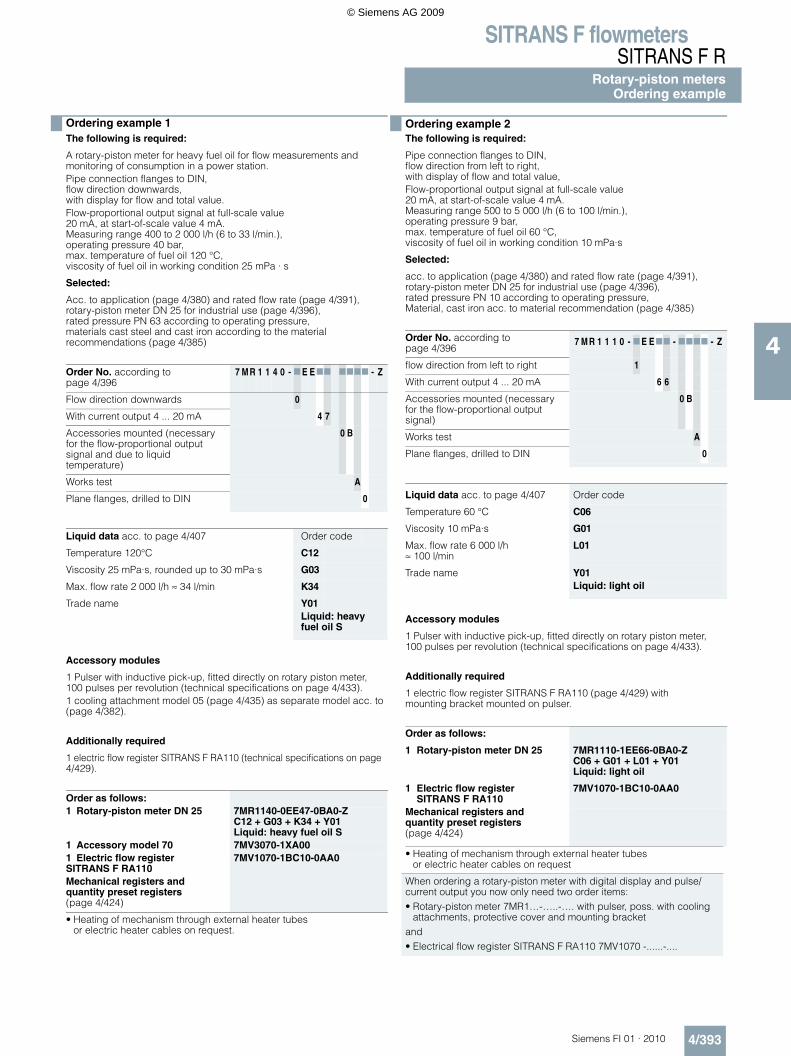
Ordering example 1The following is required:
A rotary-piston meter for heavy fuel oil for flow measurements and monitoring of consumption in a power station.Pipe connection flanges to DIN,flow direction downwards,with display for flow and total value.Flow-proportional output signal at full-scale value20 mA, at start-of-scale value 4 mA.Measuring range 400 to 2 000 l/h (6 to 33 l/min.),operating pressure 40 bar,max. temperature of fuel oil 120 °C,viscosity of fuel oil in working condition 25 mPa · s
Selected:
Acc. to application (page 4/380) and rated flow rate (page 4/391),rotary-piston meter DN 25 for industrial use (page 4/396),rated pressure PN 63 according to operating pressure,materials cast steel and cast iron according to the material recommendations (page 4/385)
Order No. according to page 4/396
7 M R 1 1 4 0 - 7 E E77 7777 - Z
Flow direction downwards 0
With current output 4 ... 20 mA 4 7
Accessories mounted (necessary for the flow-proportional output signal and due to liquid temperature)
0 B
Works test A
Plane flanges, drilled to DIN 0
Liquid data acc. to page 4/407 Order code
Temperature 120°C C12
Viscosity 25 mPa·s, rounded up to 30 mPa·s G03
Max. flow rate 2 000 l/h ≈ 34 l/min K34
Trade name Y01Liquid: heavy fuel oil S
Accessory modules
1 Pulser with inductive pick-up, fitted directly on rotary piston meter, 100 pulses per revolution (technical specifications on page 4/433).1 cooling attachment model 05 (page 4/435) as separate model acc. to(page 4/382).
Additionally required
1 electric flow register SITRANS F RA110 (technical specifications on page 4/429).
Order as follows:1 Rotary-piston meter DN 25 7MR1140-0EE47-0BA0-Z
C12 + G03 + K34 + Y01Liquid: heavy fuel oil S
1 Accessory model 70 7MV3070-1XA001 Electric flow register SITRANS F RA110
7MV1070-1BC10-0AA0
Mechanical registers and quantity preset registers (page 4/424)
• Heating of mechanism through external heater tubes or electric heater cables on request.
Ordering example 2The following is required:
Pipe connection flanges to DIN,flow direction from left to right,with display of flow and total value,Flow-proportional output signal at full-scale value20 mA, at start-of-scale value 4 mA.Measuring range 500 to 5 000 l/h (6 to 100 l/min.),operating pressure 9 bar,max. temperature of fuel oil 60 °C,viscosity of fuel oil in working condition 10 mPa·s
Selected:
acc. to application (page 4/380) and rated flow rate (page 4/391),rotary-piston meter DN 25 for industrial use (page 4/396),rated pressure PN 10 according to operating pressure,Material, cast iron acc. to material recommendation (page 4/385)
Order No. according to page 4/396
7 M R 1 1 1 0 - 7 E E77 - 7777 - Z
flow direction from left to right 1
With current output 4 ... 20 mA 6 6
Accessories mounted (necessary for the flow-proportional output signal)
0 B
Works test A
Plane flanges, drilled to DIN 0
Liquid data acc. to page 4/407 Order code
Temperature 60 °C C06
Viscosity 10 mPa·s G01
Max. flow rate 6 000 l/h ≈ 100 l/min
L01
Trade name Y01Liquid: light oil
Accessory modules
1 Pulser with inductive pick-up, fitted directly on rotary piston meter, 100 pulses per revolution (technical specifications on page 4/433).
Additionally required
1 electric flow register SITRANS F RA110 (page 4/429) with mounting bracket mounted on pulser.
Order as follows:
1 Rotary-piston meter DN 25 7MR1110-1EE66-0BA0-ZC06 + G01 + L01 + Y01Liquid: light oil
1 Electric flow register SITRANS F RA110
7MV1070-1BC10-0AA0
Mechanical registers and quantity preset registers (page 4/424)
• Heating of mechanism through external heater tubes or electric heater cables on request
When ordering a rotary-piston meter with digital display and pulse/current output you now only need two order items:• Rotary-piston meter 7MR1…-…..-…. with pulser, poss. with cooling
attachments, protective cover and mounting bracket and• Electrical flow register SITRANS F RA110 7MV1070 -......-....
© Siemens AG 2009
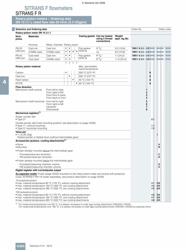
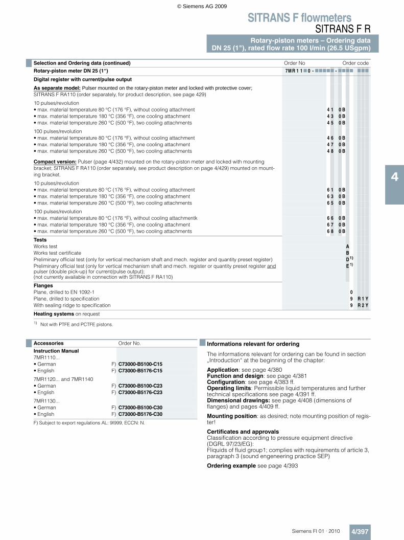
SITRANS F flowmetersSITRANS F RRotary-piston meters – Ordering dataDN 15 (½"), rated flow rate 20 l/min (5.3 USgpm)
4/394 Siemens FI 01 · 2010
4
Selection and Ordering data Order No. Order code
Rotary-piston meter DN 15 (½“)
Nom. press.
Materials Casing gasket Can be heated using 2 thread connections
Weight appr. kg (lb)
Housing Meas. chamber Rotary piston
PN 25 (363 psi)
Cast iron Cast iron • • Flat gasket AFM 34
R 3/4“ 9.0 (19.8) 7M R 1 0 2 0 - 7 E777 7777 777
CrNiMo steel CrNiMo steel • • • • no 9.0 (19.8) 7M R 1 0 2 0 - 7 S777 7777 777
PN 40 (580 psi)
Cast steel Cast iron • • Flat gasket AFM 34
R 3/8“ 11 (24.2) 7M R 1 0 3 0 - 7 E777 7777 777
Cast steel CrNiMo steel • • R 3/8“ 11.5 (25.4) 7M R 1 0 3 0 - 7D777 7777 777
↓ ↓ ↓ ↓
Rotary piston material Max. permissibleliquid temperature
Carbon • 300 °C (572 °F) K
Cast iron • 300 °C (572 °F) E
Hard rubber • 40 °C (104 °F) G
PCTFE • 40 °C (104 °F) H
Flow directionMechanism shaft vertical From left to right 1
From right to left 2From front to back 3From back to front 4
Mechanism shaft horizontal From left to right 5From right to left 6Upwards 7Downwards 0
Mechanical registers1)
Single- pointer dial • Type 01 0 1
Double-pointer dial (note mounting position! see description on page 4/426) • Type 11, vertical mounting 1 1• Type12, horizontal mounting 1 2
Value per• 1 l (0.26 USg)
Fastest pointer or fastest drum (without intermediate gear)1
Accessories (pulsers, cooling attachments)1)
• None A• Mounted B
• Pulser already mounted above the intermediate gear:
- 10 pulses/value per revolution C- 100 pulses/value per revolution D
• Pulser already mounted below the intermediate gear:
- 10 pulses/measuring chamber volume G- 100 pulses/measuring chamber volume H
Digital register with current/pulse output
As separate model: Pulser (page 4/432) mounted on the rotary-piston meter and locked with protective cover; SITRANS F RA110 (order separately, see product description on page 4/429)
10 pulses/revolution• max. material temperature 80 °C (176 °F), without cooling attachment 4 1 0 B• max. material temperature 180 °C (356 °F), one cooling attachment 4 3 0 B• max. material temperature 260 °C (500 °F), two cooling attachments 4 5 0 B
100 pulses/revolution• max. material temperature 80 °C (176 °F), without cooling attachment 4 6 0 B• max. material temperature 180 °C (356 °F), one cooling attachment 4 7 0 B• max. material temperature 260 °C (500 °F), two cooling attachments 4 8 0 B1) For measuring temperatures over 80 °C, it is always necessary to order one cooling attachment (7MV3001-1XX00).
For measuring temperatures over 180 °C, it is always necessary to order two cooling attachments (7MV3001-2XX00) as separate items.
© Siemens AG 2009
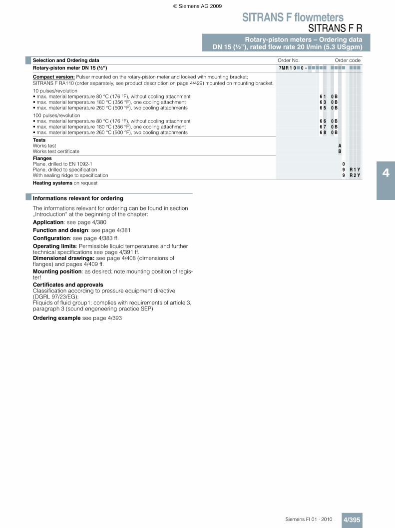
SITRANS F flowmetersSITRANS F R
Rotary-piston meters – Ordering dataDN 15 (½"), rated flow rate 20 l/min (5.3 USgpm)
4/395Siemens FI 01 · 2010
4
Informations relevant for ordering
The informations relevant for ordering can be found in section „Introduction“ at the beginning of the chapter:Application: see page 4/380Function and design: see page 4/381Configuration: see page 4/383 ff.Operating limits: Permissible liquid temperatures and further technical specifications see page 4/391 ff.Dimensional drawings: see page 4/408 (dimensions of flanges) and pages 4/409 ff.Mounting position: as desired; note mounting position of regis-ter!Certificates and approvalsClassification according to pressure equipment directive (DGRL 97/23/EG): Fliquids of fluid group1; complies with requirements of article 3, paragraph 3 (sound engeneering practice SEP)
Ordering example see page 4/393
Rotary-piston meter DN 15 (½“) 7M R 1 0 7 0 - 77777 7777 777
Compact version: Pulser mounted on the rotary-piston meter and locked with mounting bracket; SITRANS F RA110 (order separately, see product description on page 4/429) mounted on mounting bracket.
10 pulses/revolution• max. material temperature 80 °C (176 °F), without cooling attachment 6 1 0 B• max. material temperature 180 °C (356 °F), one cooling attachment 6 3 0 B• max. material temperature 260 °C (500 °F), two cooling attachments 6 5 0 B
100 pulses/revolution• max. material temperature 80 °C (176 °F), without cooling attachment 6 6 0 B• max. material temperature 180 °C (356 °F), one cooling attachment 6 7 0 B• max. material temperature 260 °C (500 °F), two cooling attachments 6 8 0 B
TestsWorks test AWorks test certificate BFlangesPlane, drilled to EN 1092-1 0Plane, drilled to specification 9 R 1 YWith sealing ridge to specification 9 R 2 Y
Heating systems on request
Selection and Ordering data Order No. Order code
© Siemens AG 2009
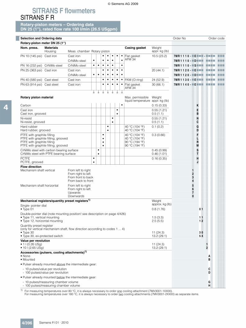
SITRANS F flowmetersSITRANS F RRotary-piston meters – Ordering dataDN 25 (1"), rated flow rate 100 l/min (26.5 USgpm)
4/396 Siemens FI 01 · 2010
4
Selection and Ordering data Order No Order code
Rotary-piston meter DN 25 (1“)
Nom. press. Materials Casing gasket Weight appr. kg (lb)Housing Meas. chamber Rotary piston
PN 10 (145 psi) Cast iron Cast iron • • • • • Flat gasket AFM 34
10.5 (23.2) 7M R 1 1 1 0 - 7 E777 - 7777 777
CrNiMo steel • • • • • 7M R 1 1 1 0 - 7D777 7777 777
PN 16 (232 psi) CrNiMo steel CrNiMo steel • • • • • • 7M R 1 1 1 0 - 7 S777 7777 777
PN 25 (363 psi) Cast iron Cast iron • • • • • 20 (44.1) 7M R 1 1 2 0 - 7 E777 7777 777
CrNiMo steel • • • • • • • 7M R 1 1 2 0 - 7D777 7777 777
PN 40 (580 psi) Cast steel Cast iron • • • • • FKM (O-ring) 24 (52.9) 7M R 1 1 3 0 - 7 E777 7777 777
PN 63 (914 psi) Cast steel Cast iron • • • • • Flat gasket AFM 34
30 (66.1) 7M R 1 1 4 0 - 7 E777 7777 777
↓ ↓ ↓ ↓ ↓ ↓ ↓
Rotary piston material Max. permissible liquid temperature
Weight appr. kg (lb)
Carbon • 0.15 (0.33) K
Cast iron • 0.55 (1.21) ECast iron, grooved • 0.5 (1.1) B
Ni-resist • 0.55 (1.21) NNi-resist, grooved • 0.5 (1.1) C
Hard rubber • 40 °C (104 °F) 0.1 (0.2) GHard rubber, grooved • 40 °C (104 °F) D
PTFE with graphite filling • 40 °C (104 °F) 0.3 (0.66) FPTFE with graphite filling, grooved • 40 °C (104 °F) LPTFE with graphite filling • 90 °C (194 °F) RPTFE with graphite filling, grooved • 90 °C (194 °F) M
CrNiMo steel with carbon bearing surface • 0.45 (0.99) SCrNiMo steel with PTFE bearing surface • 0.46 (1.01) T
PCTFE • 0.16 (0.35) HPCTFE, grooved • J
Flow directionMechanism shaft vertical From left to right 1
From right to left 2From front to back 3From back to front 4
Mechanism shaft horizontal From left to right 5From right to left 6Upwards 7Downwards 0
Mechanical registers/quantity preset registers1) Weight approx. kg (lb)Single- pointer dial
• Type 01 0.8 (1.76) 0 1
Double-pointer dial (note mounting position! see description on page 4/426) • Type 11, vertical mounting 1.5 (3.3) 1 1• Type 12, horizontal mounting 2.5 (5.5) 1 2
Quantity preset register (only for vertical mechanism shaft, flow direction according to codes 1 ... 4)• Type 30 11 (24.3) 3 0• Type 30, ex-protected switch 13.2 (29.1) 5 4
Value per revolution• 1 l (0.26 USg) 11 (24.3) 1• 10 l (2.65 USg) 13.2 (29.1) 2
Accessories (pulsers, cooling attachments)1)
• None A• Mounted B
• Pulser already mounted above the intermediate gear:
- 10 pulses/value per revolution C- 100 pulses/value per revolution D
• Pulser already mounted below the intermediate gear:
- 10 pulses/measuring chamber volume G- 100 pulses/measuring chamber volume H
1) For measuring temperatures over 80 °C, it is always necessary to order one cooling attachment (7MV3001-1XX00).For measuring temperatures over 180 °C, it is always necessary to order two cooling attachments (7MV3001-2XX00) as separate items.
© Siemens AG 2009
SITRANS F flowmetersSITRANS F R
Rotary-piston meters – Ordering dataDN 25 (1"), rated flow rate 100 l/min (26.5 USgpm)
4/397Siemens FI 01 · 2010
4
Informations relevant for ordering
The informations relevant for ordering can be found in section „Introduction“ at the beginning of the chapter:
Application: see page 4/380Function and design: see page 4/381Configuration: see page 4/383 ff.Operating limits: Permissible liquid temperatures and further technical specifications see page 4/391 ff.Dimensional drawings: see page 4/408 (dimensions of flanges) and pages 4/409 ff.
Mounting position: as desired; note mounting position of regis-ter!
Certificates and approvalsClassification according to pressure equipment directive (DGRL 97/23/EG): Fliquids of fluid group1; complies with requirements of article 3, paragraph 3 (sound engeneering practice SEP)
Ordering example see page 4/393
Selection and Ordering data (continued) Order No Order code
Rotary-piston meter DN 25 (1“) 7M R 1 1 7 0 - 77777 - 7777 777
Digital register with current/pulse output
As separate model: Pulser mounted on the rotary-piston meter and locked with protective cover;SITRANS F RA110 (order separately, for product description, see page 429)
10 pulses/revolution• max. material temperature 80 °C (176 °F), without cooling attachment 4 1 0 B• max. material temperature 180 °C (356 °F), one cooling attachment 4 3 0 B• max. material temperature 260 °C (500 °F), two cooling attachments 4 5 0 B
100 pulses/revolution• max. material temperature 80 °C (176 °F), without cooling attachment 4 6 0 B• max. material temperature 180 °C (356 °F), one cooling attachment 4 7 0 B• max. material temperature 260 °C (500 °F), two cooling attachments 4 8 0 B
Compact version: Pulser (page 4/432) mounted on the rotary-piston meter and locked with mounting bracket; SITRANS F RA110 (order separately, see product description on page 4/429) mounted on mount-ing bracket.
10 pulses/revolution• max. material temperature 80 °C (176 °F), without cooling attachment 6 1 0 B• max. material temperature 180 °C (356 °F), one cooling attachment 6 3 0 B• max. material temperature 260 °C (500 °F), two cooling attachments 6 5 0 B
100 pulses/revolution• max. material temperature 80 °C (176 °F), without cooling attachmentk 6 6 0 B• max. material temperature 180 °C (356 °F), one cooling attachment 6 7 0 B• max. material temperature 260 °C (500 °F), two cooling attachments 6 8 0 B
TestsWorks test AWorks test certificate BPreliminary official test (only for vertical mechanism shaft and mech. register and quantity preset register) D1)
1) Not with PTFE and PCTFE pistons.
Preliminary official test (only for vertical mechanism shaft and mech. register or quantity preset register and pulser (double pick-up) for current/pulse output);(not currently available in connection with SITRANS F RA110)
E 1)
FlangesPlane, drilled to EN 1092-1 0Plane, drilled to specification 9 R 1 YWith sealing ridge to specification 9 R 2 Y
Heating systems on request
Accessories Order No.
Instruction Manual7MR1110...• German F) C73000-B5100-C15• English F) C73000-B5176-C15
7MR1120... and 7MR1140• German F) C73000-B5100-C23• English F) C73000-B5176-C23
7MR1130...• German F) C73000-B5100-C30• English F) C73000-B5176-C30
F) Subject to export regulations AL: 9I999, ECCN: N.
© Siemens AG 2009
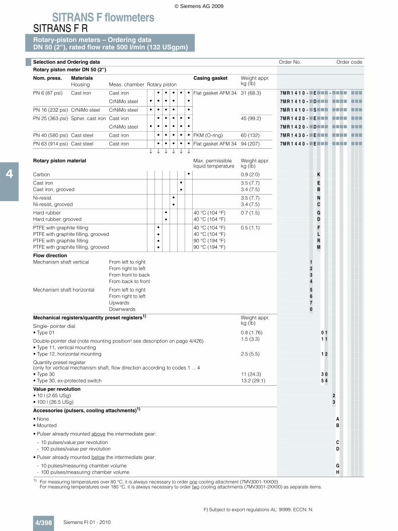
SITRANS F flowmetersSITRANS F RRotary-piston meters – Ordering dataDN 50 (2"), rated flow rate 500 l/min (132 USgpm)
4/398 Siemens FI 01 · 2010
4
Selection and Ordering data Order No. Order code
Rotary piston meter DN 50 (2“)
Nom. press. Materials Casing gasket Weight appr. kg (lb)Housing Meas. chamber Rotary piston
PN 6 (87 psi) Cast iron Cast iron • • • • • Flat gasket AFM 34 31 (68.3) 7M R 1 4 1 0 - 7 E777 - 7777 777
CrNiMo steel • • • • • 7M R 1 4 1 0 - 7D777 7777 777
PN 16 (232 psi) CrNiMo steel CrNiMo steel • • • • • 7M R 1 4 1 0 - 7 S777 7777 777
PN 25 (363 psi) Spher. cast iron Cast iron • • • • • 45 (99.2) 7M R 1 4 2 0 - 7 E777 7777 777
CrNiMo steel • • • • • • 7M R 1 4 2 0 - 7D777 7777 777
PN 40 (580 psi) Cast steel Cast iron • • • • • FKM (O-ring) 60 (132) 7M R 1 4 3 0 - 7 E777 7777 777
PN 63 (914 psi) Cast steel Cast iron • • • • • Flat gasket AFM 34 94 (207) 7M R 1 4 4 0 - 7 E777 7777 777
↓ ↓ ↓ ↓ ↓ ↓
Rotary piston material Max. permissible liquid temperature
Weight appr. kg (lb)
Carbon • 0.9 (2.0) K
Cast iron • 3.5 (7.7) ECast iron, grooved • 3.4 (7.5) B
Ni-resist • 3.5 (7.7) NNi-resist, grooved • 3.4 (7.5) C
Hard rubber • 40 °C (104 °F) 0.7 (1.5) GHard rubber, grooved • 40 °C (104 °F) D
PTFE with graphite filling • 40 °C (104 °F) 0.5 (1.1) FPTFE with graphite filling, grooved • 40 °C (104 °F) LPTFE with graphite filling • 90 °C (194 °F) RPTFE with graphite filling, grooved • 90 °C (194 °F) M
Flow directionMechanism shaft vertical From left to right 1
From right to left 2From front to back 3From back to front 4
Mechanism shaft horizontal From left to right 5From right to left 6Upwards 7Downwards 0
Mechanical registers/quantity preset registers1) Weight appr. kg (lb)
Single- pointer dial• Type 01 0.8 (1.76) 0 1
Double-pointer dial (note mounting position! see description on page 4/426) 1.5 (3.3) 1 1
• Type 11, vertical mounting• Type 12, horizontal mounting 2.5 (5.5) 1 2
Quantity preset register (only for vertical mechanism shaft, flow direction according to codes 1 ... 4• Type 30 11 (24.3) 3 0• Type 30, ex-protected switch 13.2 (29.1) 5 4
Value per revolution• 10 l (2.65 USg) 2• 100 l (26.5 USg) 3
Accessories (pulsers, cooling attachments)1)
• None A• Mounted B
• Pulser already mounted above the intermediate gear:
- 10 pulses/value per revolution C- 100 pulses/value per revolution D
• Pulser already mounted below the intermediate gear:
- 10 pulses/measuring chamber volume G- 100 pulses/measuring chamber volume H
1) For measuring temperatures over 80 °C, it is always necessary to order one cooling attachment (7MV3001-1XX00).For measuring temperatures over 180 °C, it is always necessary to order two cooling attachments (7MV3001-2XX00) as separate items.
F) Subject to export regulations AL: 9I999, ECCN: N.
© Siemens AG 2009
SITRANS F flowmetersSITRANS F R
Rotary-piston meters – Ordering dataDN 50 (2"), rated flow rate 500 l/min (132 USgpm)
4/399Siemens FI 01 · 2010
4
Informations relevant for ordering
The informations relevant for ordering can be found in section „Introduction“ at the beginning of the chapter:
Application: see page 4/380Function and design: see page 4/381Configuration: see page 4/383 ff.Operating limits: Permissible liquid temperatures and further technical specifications see page 4/391 ff.Dimensional drawings: see page 4/408 (dimensions of flanges) and pages 4/409 ff.
Mounting position: as desired; note mounting position of register!
Certificates and approvalsClassification according to pressure equipment directive (DGRL 97/23/EG): • 7MR1410 and 7MR1420: for liquids of group 1; complies with
requirements of article 3, paragraph 3 (sound engeneering practice SEP)
• 7MR1430 and 7MR1440: for liquids of group 2; complies with requirements of article 3, paragraph 3 (sound engeneering practice SEP);For liquids of fluid group 1 on request.
Ordering example see page 4/393
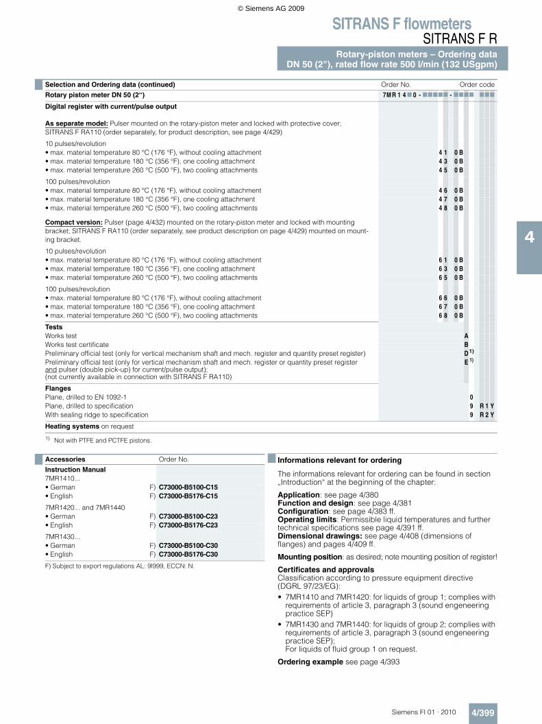
Selection and Ordering data (continued) Order No. Order code
Rotary piston meter DN 50 (2“) 7M R 1 4 7 0 - 77777 - 7777 777
Digital register with current/pulse output
As separate model: Pulser mounted on the rotary-piston meter and locked with protective cover;SITRANS F RA110 (order separately, for product description, see page 4/429)
10 pulses/revolution• max. material temperature 80 °C (176 °F), without cooling attachment 4 1 0 B• max. material temperature 180 °C (356 °F), one cooling attachment 4 3 0 B• max. material temperature 260 °C (500 °F), two cooling attachments 4 5 0 B
100 pulses/revolution• max. material temperature 80 °C (176 °F), without cooling attachment 4 6 0 B• max. material temperature 180 °C (356 °F), one cooling attachment 4 7 0 B• max. material temperature 260 °C (500 °F), two cooling attachments 4 8 0 B
Compact version: Pulser (page 4/432) mounted on the rotary-piston meter and locked with mounting bracket; SITRANS F RA110 (order separately, see product description on page 4/429) mounted on mount-ing bracket.
10 pulses/revolution• max. material temperature 80 °C (176 °F), without cooling attachment 6 1 0 B• max. material temperature 180 °C (356 °F), one cooling attachment 6 3 0 B• max. material temperature 260 °C (500 °F), two cooling attachments 6 5 0 B
100 pulses/revolution• max. material temperature 80 °C (176 °F), without cooling attachment 6 6 0 B• max. material temperature 180 °C (356 °F), one cooling attachment 6 7 0 B• max. material temperature 260 °C (500 °F), two cooling attachments 6 8 0 B
TestsWorks test AWorks test certificate BPreliminary official test (only for vertical mechanism shaft and mech. register and quantity preset register) D1)
Preliminary official test (only for vertical mechanism shaft and mech. register or quantity preset registerand pulser (double pick-up) for current/pulse output);(not currently available in connection with SITRANS F RA110)
E 1)
FlangesPlane, drilled to EN 1092-1 0Plane, drilled to specification 9 R 1 YWith sealing ridge to specification 9 R 2 Y
Heating systems on request
1) Not with PTFE and PCTFE pistons.
Accessories Order No.
Instruction Manual7MR1410...• German F) C73000-B5100-C15• English F) C73000-B5176-C15
7MR1420... and 7MR1440• German F) C73000-B5100-C23• English F) C73000-B5176-C23
7MR1430...• German F) C73000-B5100-C30• English F) C73000-B5176-C30
F) Subject to export regulations AL: 9I999, ECCN: N.
© Siemens AG 2009
SITRANS F flowmetersSITRANS F RRotary-piston meters – Ordering dataDN 80 (3"), rated flow rate 1000 l/min (264 USgpm)
4/400 Siemens FI 01 · 2010
4
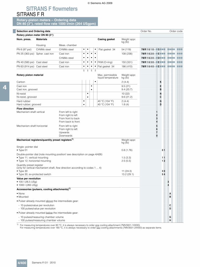
Selection and Ordering data Order No. Order code
Rotary piston meter DN 80 (3“)
Nom. press. Materials Casing gasket Weight appr. kg (lb)
Housing Meas. chamber
PN 6 (87 psi) CrNiMo steel CrNiMo steel • • • Flat gasket 34 54 (119) 7M R 1 6 1 0 - 7 S777 7777 777
PN 25 (363 psi) Spher. cast iron Cast iron • • • • 108 (238) 7M R 1 6 2 0 - 7 E777 7777 777
CrNiMo steel • • • • 7M R 1 6 2 0 - 7D777 7777 777
PN 40 (580 psi) Cast steel Cast iron • • • • FKM (O-ring) 150 (331) 7M R 1 6 3 0 - 7 E777 7777 777
PN 63 (914 psi) Cast steel Cast iron • • • • Flat gasket 34 186 (410) 7M R 1 6 4 0 - 7 E777 7777 777
↓ ↓ ↓ ↓
Rotary piston material Max. permissible liquid temperature
Weight appr. kg (lb)
Carbon • 2 (4.4) K
Cast iron • 9.5 (21) ECast iron, grooved • 9.4 (20.7) B
Ni-resist • 10 (22) NNi-resist, grooved • 9.6 (21.2) C
Hard rubber • 40 °C (104 °F) 2 (4.4) GHard rubber, grooved • 40 °C (104 °F) 1.8 (4) D
Flow directionMechanism shaft vertical From left to right 1
From right to left 2From front to back 3From back to front 4
Mechanism shaft horizontal From left to right 5From right to left 6Upwards 7Downwards 0
Mechanical registers/quantity preset registers1) Weight appr. kg (lb)
Single- pointer dial• Type 01 0.8 (1.76) 0 1
Double-pointer dial (note mounting position! see description on page 4/426)• Type 11, vertical mounting 1.5 (3.3) 1 1• Type 12, horizontal mounting 2.5 (5.5) 1 2
Quantity preset register (only for vertical mechanism shaft, flow direction according to codes 1 ... 4)• Type 30 11 (24.3) 3 0• Type 30, ex-protected switch 13.2 (29.1) 5 4
Value per revolution• 100 l (26.5 USg) 3• 1000 l (265 USg) 4
Accessories (pulsers, cooling attachments)1)
• None A• Mounted B
• Pulser already mounted above the intermediate gear:
- 10 pulses/value per revolution C- 100 pulses/value per revolution D
• Pulser already mounted below the intermediate gear:
- 10 pulses/measuring chamber volume G- 100 pulses/measuring chamber volume H
1) For measuring temperatures over 80 °C, it is always necessary to order one cooling attachment (7MV3001-1XX00).For measuring temperatures over 180 °C, it is always necessary to order two cooling attachments (7MV3001-2XX00) as separate items.
© Siemens AG 2009
SITRANS F flowmetersSITRANS F R
Rotary-piston meters – Ordering dataDN 80 (3"), rated flow rate 1000 l/min (264 USgpm)
4/401Siemens FI 01 · 2010
4
F) Subject to export regulations AL: 9I999, ECCN: N.
Informations relevant for ordering
The informations relevant for ordering can be found in section „Introduction“ at the beginning of the chapter:
Application: see page 4/380Function and design: see page 4/381Configuration: see page 4/383 ff.Operating limits: Permissible liquid temperatures and further technical specifications see page 4/391 ff.Dimensional drawings: see page 4/408 (dimensions of flanges) and pages 4/408 ff.
Mounting position: as desired; note mounting position of regis-ter!
Certificates and approvalsClassification according to pressure equipment directive (DGRL 97/23/EG): • 7MR1610-7 E 7 7 7 and 7MR1610-7 D 7 7 7, cast iron hous-
ing: for liquids of fluid group 2; complies with requirements of article 3, para. 3 (sound engineering practice SEP)
• 7MR1610-7 S 7 7 7, stainless steel housing: for liquids of fluid group 1; complies with requirements of article 3, para. 3 ( SEP)
• 7MR1620, 7MR1630 and 7MR1640: for liquids of fluid group 2; complies with requirements of article 3, para. 3 (SEP)
Ordering example see page 4/393
Selection and Ordering data (continued) Order No. Order code
Rotary piston meter DN 80 (3“) 7M R 1 6 7 0 - 77777 - 7777 7 7 7
Digital register with current/pulse output
As separate model: Pulser mounted on the rotary-piston meter and locked with protective cover;SITRANS F RA110 (order separately, for product description, see page 4/429)
10 pulses/revolution• max. material temperature 80 °C (176 °F), without cooling attachment 4 1 0 B• max. material temperature 180 °C (356 °F), one cooling attachment 4 3 0 B• max. material temperature 260 °C (500 °F), two cooling attachments 4 5 0 B
100 pulses/revolution• max. material temperature 80 °C (176 °F), without cooling attachment 4 6 0 B• max. material temperature 180 °C (356 °F), one cooling attachment 4 7 0 B• max. material temperature 260 °C (500 °F), two cooling attachments 4 8 0 B
Compact version: Pulser (page 4/432) mounted on the rotary-piston meter and locked with mountingbracket; SITRANS F RA110 (order separately, see product description on page 4/429) mounted on mount-ing bracket.
10 pulses/revolution• max. material temperature 80 °C (176 °F), without cooling attachment 6 1 0 B• max. material temperature 180 °C (356 °F), one cooling attachment 6 3 0 B• max. material temperature 260 °C (500 °F), two cooling attachments 6 5 0 B
100 pulses/revolution• max. material temperature 80 °C (176 °F), without cooling attachment 6 6 0 B• max. material temperature 180 °C (356 °F), one cooling attachment 6 7 0 B• max. material temperature 260 °C (500 °F), two cooling attachments 6 8 0 B
TestsWorks test AWorks test certificate BPreliminary official test (only for vertical mechanism shaft and mech. register and quantity preset register) D1)
Preliminary official test (only for vertical mechanism shaft and mech. Register or quantity preset registerand pulser (double pick-up) for current/pulse output);(not currently available in connection with SITRANS F RA110
E 1)
FlangesPlane, drilled to EN 1092-1 0Plane, drilled to specification 9 R 1 YWith sealing ridge to specification 9 R 2 Y
Heating systems on request
1) Not with PTFE and PCTFE pistons.
Accessories Order No.
Instruction Manual7MR1610...• German F) C73000-B5100-C15• English F) C73000-B5176-C15
7MR1620... and 7MR1640• German F) C73000-B5100-C23• English F) C73000-B5176-C23
7MR1630...• German F) C73000-B5100-C30• English F) C73000-B5176-C30
© Siemens AG 2009
SITRANS F flowmetersSITRANS F RRotary-piston meters – Ordering data – DN 25 (1"),acid-resistant, rated fl. rate 100 l/min (26.5 USgpm)
4/402 Siemens FI 01 · 2010
4
Selection and Ordering data Order No.
Rotary-piston meter DN 25 (1“), acid-resistant
Nom. press. MaterialsMeasuring chamber1)
1) In order to avoid the measurement chamber components becoming misshapen, the pressure loss should not exceed 0.5 bar (7.25 psi).
Max. permissible liquid temperature
Weight approx. kg (lb)
Housing Rotary piston
PN 10 (145 psi) Cast iron Duroplast Carbon 80 °C (176 °F) 28 (61.7) 7M R 1 1 1 1 - 7 P K77 - 7777 - Z
PCTFE 40 °C (104 °F) 7M R 1 1 1 1 - 7 P H77 7777 - Z
Flow directionMechanism shaft vertical From left to right 1
From right to left 2From front to back 3From back to front 4
Register2)
2) For measuring temperatures over 80 °C, it is always necessary to order one cooling attachment (7MV3001-1XX00).For measuring temperatures over 180 °C, it is always necessary to order two cooling attachments (7MV3001-2XX00) as separate items.
Weight approx. kg (lb)Single pointer dial
• Type 01 0.8 (1.76) 0 1Double pointer dial (note mounting position! Description on page 4/426)• Type 11 1.5 (3.3) 1 1• Type 12 2.5 (5.5) 1 2
Quantity preset register(only for vertical mechanism shaft, flow direction according to codes 1 ... 4)
Value per revolution1 l (0.26 USg) 110 l (2.65 USg)3)
3) Not possible with rotary-piston meters with quantity preset register!
2Pastest pointer or fastest drum
Accessories (pulsers, cooling attachments)2)
For measuring temperatures over 80 °C, it is always necessary to order one cooling attachment (7MV3001-1XX00).For measuring temperatures over 180 °C, it is always necessary to order two cooling attachments (7MV3001-1XX00) as separate items.
• None A• Mounted B
• Pulser already mounted above the intermediate gear:
- 10 pulses/value per revolution C- 100 pulses/value per revolution D
• Pulser already mounted below the intermediate gear:
- 10 pulses/measuring chamber volume G- 100 pulses/measuring chamber volume H
TestsWorks test AWorks test certificate B
GasketViton4)
4) Consider durability of Viton!
1Kalrez 2
Accessories Order No.
Instruction Manual7MR1111...• German F) C73000-B5100-C23• English F) C73000-B5176-C23
F) Subject to export regulations AL: 9I999, ECCN: N.
© Siemens AG 2009
SITRANS F flowmetersSITRANS F R
Rotary-piston meters – Ordering data – DN 25 (1"),acid-resistant, rated fl. rate 100 l/min (26.5 USgpm)
4/403Siemens FI 01 · 2010
4
Informations relevant for ordering
The informations relevant for ordering can be found in section „Introduction“ at the beginning of the chapter:
Application: see page 4/380Function and design: see page 4/381Configuration: see page 4/383 ff.Operating limits: Permissible liquid temperatures and further technical specifications see page 4/391 ff.Dimensional drawings: see page 4/408 (dimensions of flanges) and pages 4/408 ff.
Mounting position: as desired; note mounting position of register!
Certificates and approvalsClassification according to pressure equipment directive (DGRL 97/23/EG): Fliquids of fluid group1; complies with requirements of article 3, paragraph 3 (sound engeneering practice SEP)
Ordering example see page 4/393
© Siemens AG 2009
SITRANS F flowmetersSITRANS F RRotary-piston meters - Ordering dataAutomatic batchmeter DN 25 (1")
4/404 Siemens FI 01 · 2010
4
F) Subject to export regulations AL: 9I999, ECCN: N.
Informations relevant for orderingsee page 4/406
Selection and Ordering data Order No. Order code
Automatic batchmeter DN 25 (1“)With mechanical shut-off valve downstream of metering mechanism (upstream of metering mechanism see page 4/407)
Nom. press. Materials Weight appr. kg (lb)Housing Meas. chamber Rotary piston
PN 10 (145 psi) Cast iron Cast iron • • • • • 38 (83.8) 7M R 1 1 1 7 - 7 E777 - 7777 777
CrNiMo steel • • • • • • 7M R 1 1 1 7 - 7D777 7777 777
CrNiMo steel CrNiMo steel • • • • • • 7M R 1 1 1 7 - 7 S777 7777 777
↓ ↓ ↓ ↓ ↓ ↓ ↓
Rotary piston material Max. permissible liquid temperature
Weight appr.kg (lb)
Carbon • 0.15 (0.3) K
Cast iron • 0.55 (1.2) ECast iron, grooved • 0.5 (1.1) B
Ni-resist • 0.55 (1.2) NNi-resist, grooved • 0.5 (1.1) C
Hard rubber • 40 °C (104 °F) 0.1 (0.2) GHard rubber, grooved • 40 °C (104 °F) D
PTFE with graphite filling • 40 °C (104 °F) 0.3 (0.7) FPTFE with graphite filling, grooved • 40 °C (104 °F) LPTFE with graphite filling • 90 °C (194 °F) RPTFE with graphite filling, grooved • 90 °C (194 °F) M
PCTFE • 40 °C (104 °F) 0.16 (0.4) HPCTFE, grooved • 40 °C (104 °F) J
CrNiMo with carbon contact surface • 0.4 (0.9) SCrNiMo with PTFE contact surface • T
Tappet bushing• With maintenance-free sealed bushing 2• With bellows 1)
1) Restricted operating conditions (max. 40 °C (104 °F), max. 3 bar (43.5 psi))
3
Flow directionMechanism shaft always vertical • From left to right, valve right 1
• From right to left, valve left 2
Quantity preset register(description on page 4/426) • Type 30 3 0
• Type 30, ex-protected switch 5 4
Value per revolution and adjustment step1 l/0,1 : 0,1 l 110 l/1 : 1 l 2
Accessories (description on page 4/431)Without AMounted (separate Order No. required, see Selection and Ordering data table on page 4/406) B
TestsWorks test AWorks test certificate BPreliminary official test up to 50 l/min (13.2 USgpm) C2)
2) Not with PTFE and PCTFE pistons.
FlangesPlane, drilled to EN 1092-1 0Plane, drilled to specification 9 R 1 YWith sealing ridge to specification 9 R 2 Y
Note: If pressure impacts are likely, the valve should be before the automatic batchmeter in the direction of flow. (See supplement A04, page 4/407)
Accessories Order No.
Instruction Manual7MR111...• German F) C73000-B5100-C20• English F) C73000-B5176-C20
© Siemens AG 2009
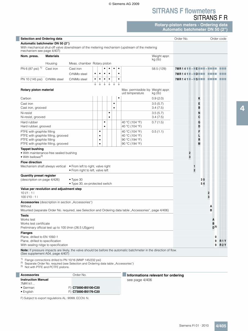
SITRANS F flowmetersSITRANS F R
Rotary-piston meters - Ordering dataAutomatic batchmeter DN 50 (2")
4/405Siemens FI 01 · 2010
4
F) Subject to export regulations AL: 9I999, ECCN: N.
Informations relevant for orderingsee page 4/406
Selection and Ordering data Order No. Order code
Automatic batchmeter DN 50 (2“)With mechanical shut-off valve downstream of the metering mechanism (upstream of the meteringmechanism see page 4/407)
Nom. press. Materials Weight appr.kg (lb)
Housing Meas. chamber Rotary piston
PN 6 (87 psi) 1)
1) Flange connections drilled to PN 10/16 (MWP 145/232 psi)
Cast iron Cast iron • • • • 58.5 (129) 7M R 1 4 1 7 - 7 E777 - 7777 777
CrNiMo steel • • • • • 7M R 1 4 1 7 - 7D777 7777 777
PN 10 (145 psi) CrNiMo steel CrNiMo steel • • • • • 7M R 1 4 1 7 - 7 S777 7777 777
↓ ↓ ↓ ↓ ↓ ↓
Rotary piston material Max. permissible liq-uid temperature
Weight appr.kg (lb)
Carbon • 0.9 (2.0) K
Cast iron • 3.5 (5.7) ECast iron, grooved • 3.4 (7.5) B
Ni-resist • 3.5 (5.7) NNi-resist, grooved • 3.4 (7.5) C
Hard rubber • 40 °C (104 °F) 0.7 (1.5) GHard rubber, grooved • 40 °C (104 °F) D
PTFE with graphite filling • 40 °C (104 °F) 0.5 (1.1) FPTFE with graphite filling, grooved • 40 °C (104 °F) LPTFE with graphite filling • 90 °C (194 °F) RPTFE with graphite filling, grooved • 90 °C (194 °F) M
Tappet bushing• With maintenance-free sealed bushing 2• With bellows2)
2) Separate Order No. required (see Selection and Ordering data table „Accessories“)
3
Flow directionMechanism shaft always vertical • From left to right, valve right 1
• From right to left, valve left 2
Quantity preset register(description on page 4/426) • Type 30 3 0
• Type 30, ex-protected switch 5 4
Value per revolution and adjustment step10 l/1 : 1 l 2100 l/10 : 1 l 3
Accessories (description in section „Accessories“)Without AMounted (separate Order No. required, see Selection and Ordering data table „Accessories“, page 4/406) B
TestsWorks test AWorks test certificate BPreliminary official test up to 100 l/min (26.5 USgpm) D3)
3) Not with PTFE and PCTFE pistons.
FlangesPlane, drilled to EN 1092-1 0Plane, drilled to specification 9 R 1 YWith sealing ridge to specification 9 R 2 Y
Note: If pressure impacts are likely, the valve should be before the automatic batchmeter in the direction of flow. (See supplement A04, page 4/407)
Accessories Order No.
Instruction Manual7MR141...• German F) C73000-B5100-C20• English F) C73000-B5176-C20
© Siemens AG 2009
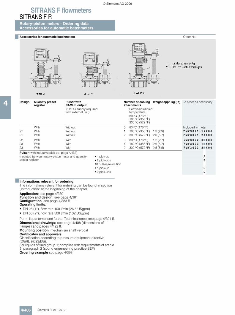
SITRANS F flowmetersSITRANS F RRotary-piston meters - Ordering dataAccessories for automatic batchmeters
4/406 Siemens FI 01 · 2010
4
Informations relevant for orderingThe informations relevant for ordering can be found in section „Introduction“ at the beginning of the chapter:Application: see page 4/380Function and design: see page 4/381Configuration: see page 4/383 ff.Operating limits: • DN 25 (1“), flow rate 100 l/min (26.5 USgpm)• DN 50 (2“), flow rate 500 l/min (132 USgpm)
Perm. liquid temp. and further Technical spec. see page 4/391 ff.Dimensional drawings: see page 4/408 (dimensions of flanges) and pages 4/422 ff.Mounting position: mechanism shaft verticalCertificates and approvalsClassification according to pressure equipment directive (DGRL 97/23/EG): For liquids of fluid group 1; complies with requirements of article 3, paragraph 3 (sound engeneering practice SEP)Ordering example see page 4/393
Accessories for automatic batchmeters Order No.
Design Quantity preset register
Pulser with NAMUR output
Number of cooling attachments
Weight appr. kg (lb) To order as accessory
(8 V DC supply required from external unit)
Permissible liquid temperature80 °C (176 °F)180 °C (356 °F)300 °C (572 °F)
With Without 0 80 °C (176 °F) Included in meter21 With Without 1 180 °C (356 °F) 1.3 (2.9) 7 M V 3 0 2 1 - 1 X X 0 021 With Without 2 300 °C (572 °F) 2.6 (5.7) 7 M V 3 0 2 1 - 2 X X 0 0
22 With With 0 80 °C (176 °F) 1.2 (2.7) 7M V 3 0 2 2 - 0 7 X 0 023 With With 1 180 °C (356 °F) 2.6 (5.7) 7 M V 3 0 2 3 - 1 7 X 0 023 With With 2 300 °C (572 °F) 2.5 (5.5) 7 M V 3 0 2 3 - 2 7 X 0 0
Pulser (with inductive pick-up, page 4/432)mounted between rotary-piston meter and quantity preset register
• 1 pick-up A• 2 pick-ups B10 pulses/revolution• 1 pick-up C• 2 pick-ups D
© Siemens AG 2009
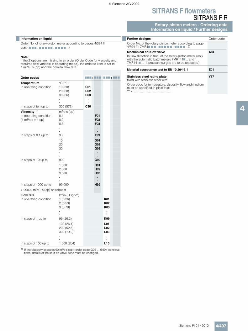
SITRANS F flowmetersSITRANS F R
Rotary-piston meters - Ordering dataInformation on liquid / Further designs
4/407Siemens FI 01 · 2010
4
Information on liquid
Order No. of rotary-piston meter according to pages 4/394 ff.7MR17 7 7 - 7 7 7 7 7 - 7 7 7 7 - Z
Note:If the Z options are missing in an order (Order Code for viscosity and required flow variable in operating mode), the ordered item is set to 1 mPa · s (cp) and the nominal flow rate.
Order codes 777 + 777 + 777 + 777
Temperature °C (°F)In operating condition 10 (50) C01
20 (68) C0230 (86) C03··
··
In steps of ten up to 300 (572) C30
Viscosity 1)
1) If the viscosity exceeds 60 mPa.s (cp) (order code G06 ... G99), construc-tional details of the shut-off valve cone must be changed.
mPa·s (cp)In operating condition 0.1 F01(1 mPa·s = 1 cp) 0.2 F02
0.3 F03··
··
In steps of 0.1 up to 9.9 F99
10 G0120 G0230 G03··
··
In steps of 10 up to 990 G99
1 000 H012 000 H023 000 H03··
··
In steps of 1000 up to 99 000 H99
> 99000 mPa · s (cp) on request
Flow rate l/min (USgpm)In operating condition 1 (0.26) K01
2 (0.53) K023 (0.79) K03··
··
In steps of 1 up to 99 (26.2) K99
100 (26.4) L01200 (52.8) L02300 (79.2) L03··
··
In steps of 100 up to 1 000 (264) L10
Further designs Order code
Order No. of the rotary-piston meter according to page 4/394 ff.; 7MR17 7 7 - 7 7 7 7 7 - 7 7 7 7 - Z
Mechanical shut-off valve A04In flow direction in front of the rotary-piston meter (only with the automatic batchmeters 7MR1117... and 7MR1417..., if pressure surges are to be expected)
Material acceptance test to EN 10 204-3.1 E01
Stainless steel rating platefixed with stainless steel wireOrder code for temperature, viscosity, flow and medium must be specified in plain text: Y17: ...........................................
Y17
© Siemens AG 2009
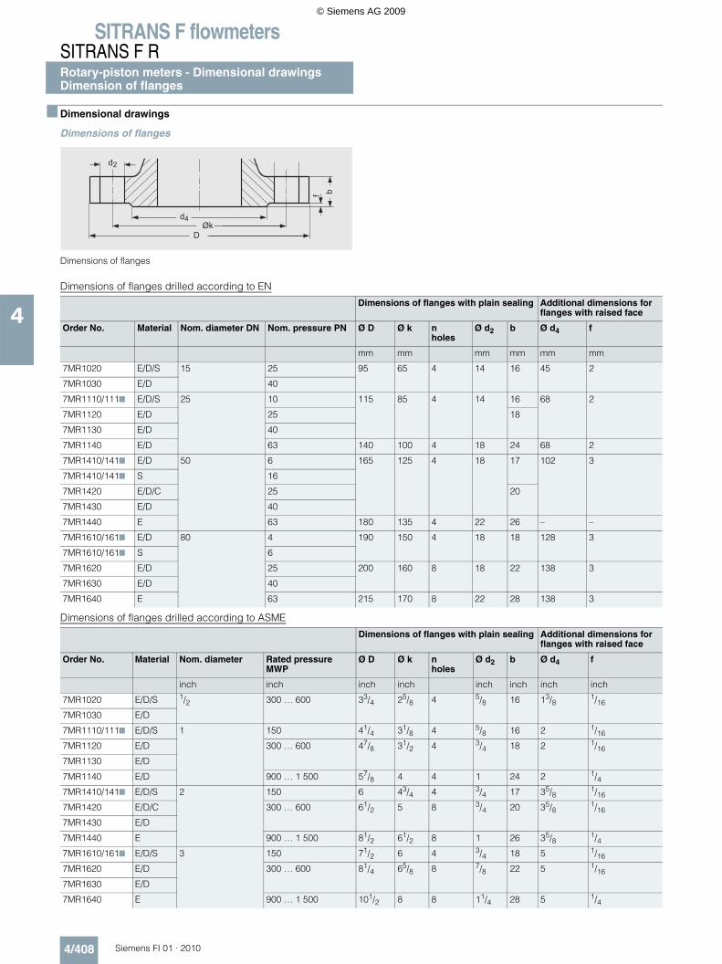
SITRANS F flowmetersSITRANS F RRotary-piston meters - Dimensional drawingsDimension of flanges
4/408 Siemens FI 01 · 2010
4
Dimensional drawings
Dimensions of flanges
Dimensions of flanges
Dimensions of flanges drilled according to EN
Dimensions of flanges drilled according to ASME
Dimensions of flanges with plain sealing Additional dimensions for flanges with raised face
Order No. Material Nom. diameter DN Nom. pressure PN Ø D Ø k nholes
Ø d2 b Ø d4 f
mm mm mm mm mm mm
7MR1020 E/D/S 15 25 95 65 4 14 16 45 2
7MR1030 E/D 40
7MR1110/1117 E/D/S 25 10 115 85 4 14 16 68 2
7MR1120 E/D 25 18
7MR1130 E/D 40
7MR1140 E/D 63 140 100 4 18 24 68 2
7MR1410/1417 E/D 50 6 165 125 4 18 17 102 3
7MR1410/1417 S 16
7MR1420 E/D/C 25 20
7MR1430 E/D 40
7MR1440 E 63 180 135 4 22 26 – –
7MR1610/1617 E/D 80 4 190 150 4 18 18 128 3
7MR1610/1617 S 6
7MR1620 E/D 25 200 160 8 18 22 138 3
7MR1630 E/D 40
7MR1640 E 63 215 170 8 22 28 138 3
Dimensions of flanges with plain sealing Additional dimensions for flanges with raised face
Order No. Material Nom. diameter Rated pressure MWP
Ø D Ø k nholes
Ø d2 b Ø d4 f
inch inch inch inch inch inch inch inch
7MR1020 E/D/S 1/2 300 … 600 33/4 25/8 4 5/8 16 13/81/16
7MR1030 E/D
7MR1110/1117 E/D/S 1 150 41/4 31/8 4 5/8 16 2 1/16
7MR1120 E/D 300 … 600 47/8 31/2 4 3/4 18 2 1/16
7MR1130 E/D
7MR1140 E/D 900 … 1 500 57/8 4 4 1 24 2 1/47MR1410/1417 E/D/S 2 150 6 43/4 4 3/4 17 35/8
1/16
7MR1420 E/D/C 300 … 600 61/2 5 8 3/4 20 35/81/16
7MR1430 E/D
7MR1440 E 900 … 1 500 81/2 61/2 8 1 26 35/81/4
7MR1610/1617 E/D/S 3 150 71/2 6 4 3/4 18 5 1/16
7MR1620 E/D 300 … 600 81/4 65/8 8 7/8 22 5 1/16
7MR1630 E/D
7MR1640 E 900 … 1 500 101/2 8 8 11/4 28 5 1/4
© Siemens AG 2009
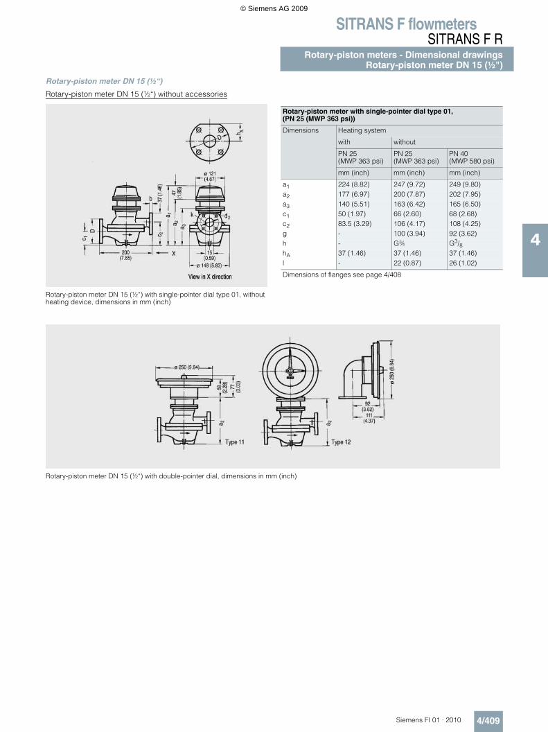
SITRANS F flowmetersSITRANS F R
Rotary-piston meters - Dimensional drawingsRotary-piston meter DN 15 (½")
4/409Siemens FI 01 · 2010
4
Rotary-piston meter DN 15 (½“)
Rotary-piston meter DN 15 (½“) without accessories
Rotary-piston meter DN 15 (½“) with single-pointer dial type 01, without heating device, dimensions in mm (inch)
Rotary-piston meter DN 15 (½“) with double-pointer dial, dimensions in mm (inch)
Rotary-piston meter with single-pointer dial type 01, (PN 25 (MWP 363 psi))
Dimensions Heating system
with without
PN 25 (MWP 363 psi)
PN 25 (MWP 363 psi)
PN 40 (MWP 580 psi)
mm (inch) mm (inch) mm (inch)
a1 224 (8.82) 247 (9.72) 249 (9.80)a2 177 (6.97) 200 (7.87) 202 (7.95)a3 140 (5.51) 163 (6.42) 165 (6.50)c1 50 (1.97) 66 (2.60) 68 (2.68)c2 83.5 (3.29) 106 (4.17) 108 (4.25)g - 100 (3.94) 92 (3.62)h - G¾ G3/8hA 37 (1.46) 37 (1.46) 37 (1.46)l - 22 (0.87) 26 (1.02)
Dimensions of flanges see page 4/408
© Siemens AG 2009
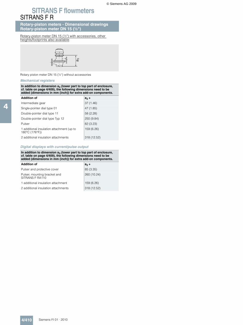
SITRANS F flowmetersSITRANS F RRotary-piston meters - Dimensional drawingsRotary-piston meter DN 15 (½")
4/410 Siemens FI 01 · 2010
4
Rotary-piston meter DN 15 (½") with accessories, other heights/footprints also available
Rotary piston meter DN 15 (½“) without accessories
Mechanical registers
Digital displays with current/pulse output
In addition to dimension a3 (lower part to top part of enclosure, cf. table on page 4/409), the following dimensions need to be added (dimensions in mm (inch)) for extra add-on components.
Addition of a3 +
Intermediate gear 37 (1.46)
Single-pointer dial type 01 47 (1.85)
Double-pointer dial type 11 58 (2.28)
Double-pointer dial type Typ 12 250 (9.84)
Pulser 82 (3.23)
1 additional insulation attachment (up to 180°C (176°F))
159 (6.26)
2 additional insulation attachments 318 (12.52)
In addition to dimension a3 (lower part to top part of enclosure, cf. table on page 4/409), the following dimensions need to be added (dimensions in mm (inch)) for extra add-on components.
Addition of a3 +
Pulser and protective cover 85 (3.35)
Pulser, mounting bracket and SITRANS F RA110
260 (10.24)
1 additional insulation attachment 159 (6.26)
2 additional insulation attachments 318 (12.52)
a 3
© Siemens AG 2009
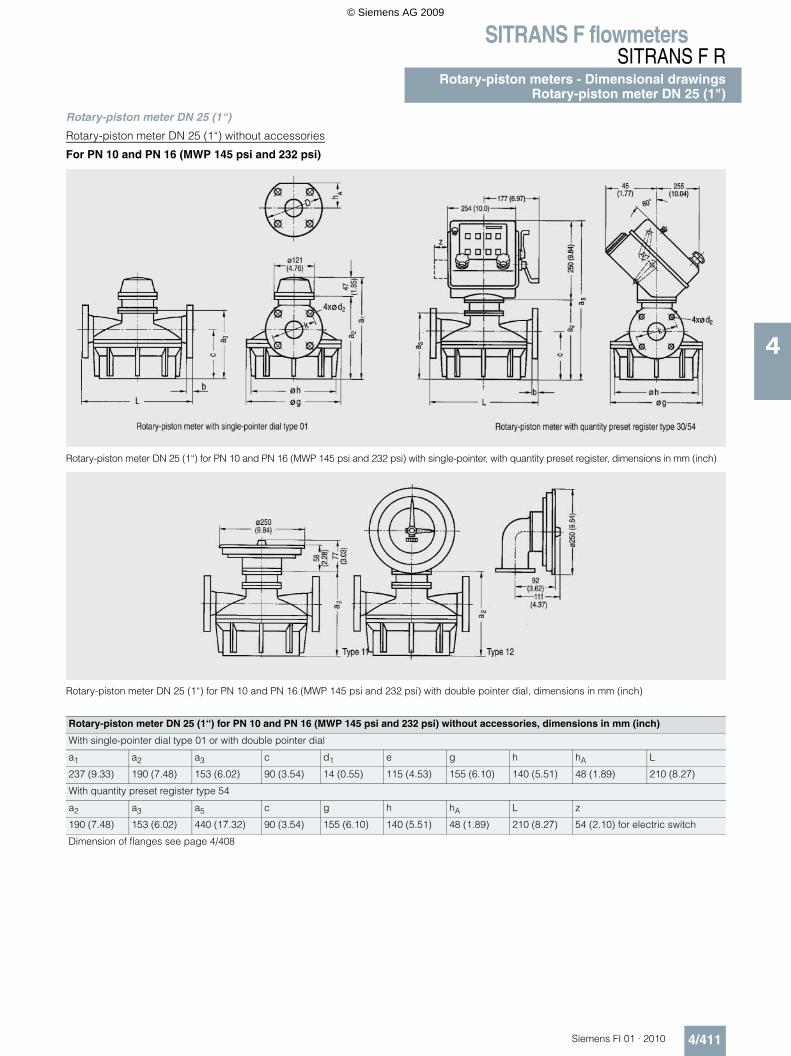
SITRANS F flowmetersSITRANS F R
Rotary-piston meters - Dimensional drawingsRotary-piston meter DN 25 (1")
4/411Siemens FI 01 · 2010
4
Rotary-piston meter DN 25 (1“)
Rotary-piston meter DN 25 (1“) without accessories
For PN 10 and PN 16 (MWP 145 psi and 232 psi)
Rotary-piston meter DN 25 (1“) for PN 10 and PN 16 (MWP 145 psi and 232 psi) with single-pointer, with quantity preset register, dimensions in mm (inch)
Rotary-piston meter DN 25 (1“) for PN 10 and PN 16 (MWP 145 psi and 232 psi) with double pointer dial, dimensions in mm (inch)
Rotary-piston meter DN 25 (1“) for PN 10 and PN 16 (MWP 145 psi and 232 psi) without accessories, dimensions in mm (inch)
With single-pointer dial type 01 or with double pointer dial
a1 a2 a3 c d1 e g h hA L
237 (9.33) 190 (7.48) 153 (6.02) 90 (3.54) 14 (0.55) 115 (4.53) 155 (6.10) 140 (5.51) 48 (1.89) 210 (8.27)
With quantity preset register type 54
a2 a3 a5 c g h hA L z
190 (7.48) 153 (6.02) 440 (17.32) 90 (3.54) 155 (6.10) 140 (5.51) 48 (1.89) 210 (8.27) 54 (2.10) for electric switch
Dimension of flanges see page 4/408
© Siemens AG 2009
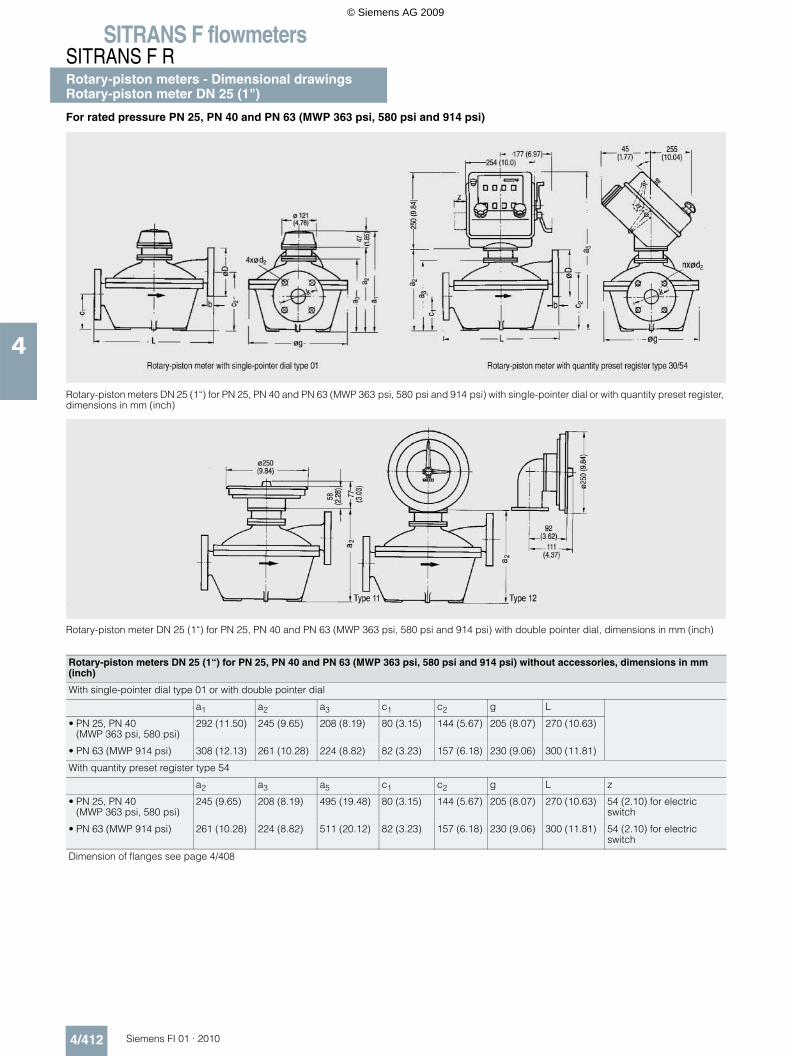
SITRANS F flowmetersSITRANS F RRotary-piston meters - Dimensional drawingsRotary-piston meter DN 25 (1")
4/412 Siemens FI 01 · 2010
4
For rated pressure PN 25, PN 40 and PN 63 (MWP 363 psi, 580 psi and 914 psi)
Rotary-piston meters DN 25 (1“) for PN 25, PN 40 and PN 63 (MWP 363 psi, 580 psi and 914 psi) with single-pointer dial or with quantity preset register, dimensions in mm (inch)
Rotary-piston meter DN 25 (1“) for PN 25, PN 40 and PN 63 (MWP 363 psi, 580 psi and 914 psi) with double pointer dial, dimensions in mm (inch)
Rotary-piston meters DN 25 (1“) for PN 25, PN 40 and PN 63 (MWP 363 psi, 580 psi and 914 psi) without accessories, dimensions in mm (inch)
With single-pointer dial type 01 or with double pointer dial
a1 a2 a3 c1 c2 g L
• PN 25, PN 40 (MWP 363 psi, 580 psi)
292 (11.50) 245 (9.65) 208 (8.19) 80 (3.15) 144 (5.67) 205 (8.07) 270 (10.63)
• PN 63 (MWP 914 psi) 308 (12.13) 261 (10.28) 224 (8.82) 82 (3.23) 157 (6.18) 230 (9.06) 300 (11.81)
With quantity preset register type 54
a2 a3 a5 c1 c2 g L z
• PN 25, PN 40 (MWP 363 psi, 580 psi)
245 (9.65) 208 (8.19) 495 (19.48) 80 (3.15) 144 (5.67) 205 (8.07) 270 (10.63) 54 (2.10) for electric switch
• PN 63 (MWP 914 psi) 261 (10.28) 224 (8.82) 511 (20.12) 82 (3.23) 157 (6.18) 230 (9.06) 300 (11.81) 54 (2.10) for electric switch
Dimension of flanges see page 4/408
© Siemens AG 2009
SITRANS F flowmetersSITRANS F R
Rotary-piston meters - Dimensional drawingsRotary-piston meter DN 25 (1")
4/413Siemens FI 01 · 2010
4
Rotary-piston meter DN 25 (1") with accessories, other heights/footprints also available
For rated pressure PN 10 and PN 16 (MWP 145 psi and 232 psi)
Rotary piston meter DN 25 (1“) without accessories
Mechanical registers
Digital displays with current/pulse output
For rated pressure PN 25, PN 40 and PN 63 (MWP 363 psi, 580 psi and 914 psi)
Rotary piston meter DN 25 (1“) without accessories
Mechanical registers
Digital displays with current/pulse output
In addition to dimension a3 (lower part to top part of enclosure, cf. table on page 4/411), the following dimensions need to be added (dimensions in mm (inch)) for extra add-on components.
Addition of a3 +
Intermediate gear 37 (1.46)
Single-pointer dial type 01 47 (1.85)
Double-pointer dial type 11 58 (2.28)
Double-pointer dial type Typ 12 250 (9.84)
Pulser 82 (3.23)
1 additional insulation attachment (up to 180°C (176°F))
159 (6.26)
2 additional insulation attachments 318 (12.52)
Intermediate gear 287 (11.30)
In addition to dimension a3 (lower part to top part of enclosure, cf. table on page 4/411), the following dimensions need to be added (dimensions in mm (inch)) for extra add-on components.
Addition of a3 +
Pulser and protective cover 85 (3.35)
Pulser, mounting bracket and SITRANS F RA110
260 (10.24)
1 additional insulation attachment 159 (6.26)
2 additional insulation attachments 318 (12.52)
a 3
In addition to dimension a3 (lower part to top part of enclosure, cf. table on page 4/412), the following dimensions need to be added (dimensions in mm (inch)) for extra add-on components.
Addition of a3 +
Intermediate gear 37 (1.46)
Single-pointer dial type 01 47 (1.85)
Double-pointer dial type 11 58 (2.28)
Double-pointer dial type Typ 12 250 (9.84)
Pulser 82 (3.23)
1 additional insulation attachment (up to 180°C (176°F))
159 (6.26)
2 additional insulation attachments 318 (12.52)
Intermediate gear 287 (11.30)
In addition to dimension a3 (lower part to top part of enclosure, cf. table on page 4/412), the following dimensions need to be added (dimensions in mm (inch)) for extra add-on components.
Addition of a3 +
Pulser and protective cover 85 (3.35)
Pulser, mounting bracket and SITRANS F RA110
260 (10.24)
1 additional insulation attachment 159 (6.26)
2 additional insulation attachments 318 (12.52)
a 3
© Siemens AG 2009
SITRANS F flowmetersSITRANS F RRotary-piston meters - Dimensional drawingsRotary-piston meter DN 50 (2")
4/414 Siemens FI 01 · 2010
4
Rotary-piston meter DN 50 (2“)
Rotary-piston meter DN 50 (2“) without accessories
For rated pressure PN 6 and PN 16 (MWP 87 psi and 232 psi)
Rotary-piston meter DN 50 (2“) for PN 6 and PN 16 (MWP 87 psi and 232 psi) with single-pointer dial bzw. with quantity preset register, dimensions in mm (inch)
Rotary-piston meter DN 50 (2“) for PN 6 and PN 16 (MWP 87 psi and 232 psi) with double-pointer dial, dimensions in mm (inch)
Rotary-piston meter DN 50 (2“) for PN 6 and PN 16 (MWP 87 psi and 232 psi) without accessories, dimensions in mm (inch)
with single-pointer dial Typ 01 bzw. with double-pointer dial
a1 a2 a3 c d1 e g h hA L
289 (11.38) 242 (9.53) 205 (8.07) 147 (5.79) 18 (0.71) 165 (6.50) 275 (10.83) 250 (9.84) 75 (2.95) 325 (12.80)
with quantity preset register Typ 54
a2 a3 a5 c g h hA L z
242 (9.53) 205 (8.07) 492 (19.37) 147 (5.79) 275 (10.83) 250 (9.84) 75 (2.95) 325 (12.80) 54 (2.10) for electric switch
Dimension of flanges see page 4/408
© Siemens AG 2009
SITRANS F flowmetersSITRANS F R
Rotary-piston meters - Dimensional drawingsRotary-piston meter DN 50 (2")
4/415Siemens FI 01 · 2010
4
For rated pressure PN 25, PN 40 and PN 63 (MWP 363 psi, 580 psi and 914 psi)
Rotary-piston meter DN 50 (2“) for PN 25, PN 40 and PN 63 (MWP 363 psi, 580 psi and 914 psi) with single-pointer dial bzw. with quantity preset register, dimensions in mm (inch)
Rotary-piston meter DN 50 (2“) for PN 25, PN 40 and PN 63 (MWP 363 psi, 580 psi and 914 psi) with double-pointer dial, dimensions in mm (inch)
Rotary-piston meter DN 50 (2“) for PN 25, PN 40 and PN 63 (MWP 363 psi, 580 psi and 914 psi) without accessories, dimensions in mm (inch)
with single-pointer dial Typ 01 bzw. with double-pointer dial
a1 a2 a3 c1 c2 g L
• PN 25, PN 40 (MWP 363 psi, 580 psi)
347 (13.66) 300 (11.81) 263 (10.35) 120 (4.7) 205 (8.1) 330 (12.99) 400 (15.75)
• PN 63 (MWP 914 psi) 369 (14.53) 322 (12.68) 285 (11.22) 120 (4.7) 230 (9.1) 385 (15.16) 470 (18.50)
with quantity preset register Typ 54
a2 a3 a5 c1 c2 g L z
• PN 25, PN 40 (MWP 363 psi, 580 psi)
300 (11.8) 263 (10.4) 550 (21.7) 120 (4.7) 205 (8.1) 330 (12.99) 400 (15.75) 54 (2.10) for electric switch
• PN 63 (MWP 914 psi) 332 (12.7) 285 (11.2) 572 (22.5) 120 (4.7) 230 (9.1) 385 (15.2) 470 (18.50) 54 (2.10) for electric switch
Dimension of flanges see page 4/408
© Siemens AG 2009
SITRANS F flowmetersSITRANS F RRotary-piston meters - Dimensional drawingsRotary-piston meter DN 50 (2")
4/416 Siemens FI 01 · 2010
4
Rotary-piston meter DN 50 (2") with accessories, other heights/footprints also available
For rated pressure PN 6 and PN 16 (MWP 87 psi and 232 psi)
Rotary piston meter DN 50 (2“) without accessories
Mechanical registers
Digital displays with current/pulse output
For rated pressure PN 25, PN 40 and PN 63 (MWP 363 psi, 580 psi and 914 psi)
Rotary piston meter DN 50 (2“) without accessories
Mechanical registers
Digital displays with current/pulse output
In addition to dimension a3 (lower part to top part of enclosure, cf. table on page 4/414), the following dimensions need to be added (dimensions in mm (inch)) for extra add-on components.
Addition of a3 +
Intermediate gear 37 (1.46)
Single-pointer dial type 01 47 (1.85)
Double-pointer dial type 11 58 (2.28)
Double-pointer dial type Typ 12 250 (9.84)
Pulser 82 (3.23)
1 additional insulation attachment (up to 180°C (176°F))
159 (6.26)
2 additional insulation attachments 318 (12.52)
Intermediate gear 287 (11.30)
In addition to dimension a3 (lower part to top part of enclosure, cf. table on page 4/414), the following dimensions need to be added (dimensions in mm (inch)) for extra add-on components.
Addition of a3 +
Pulser and protective cover 85 (3.35)
Pulser, mounting bracket and SITRANS F RA110
260 (10.24)
1 additional insulation attachment 159 (6.26)
2 additional insulation attachments 318 (12.52)
a 3
In addition to dimension a3 (lower part to top part of enclosure, cf. table on page 4/415), the following dimensions need to be added (dimensions in mm (inch)) for extra add-on components.
Addition of a3 +
Intermediate gear 37 (1.46)
Single-pointer dial type 01 47 (1.85)
Double-pointer dial type 11 58 (2.28)
Double-pointer dial type Typ 12 250 (9.84)
Pulser 82 (3.23)
1 additional insulation attachment (up to 180°C (176°F))
159 (6.26)
2 additional insulation attachments 318 (12.52)
Intermediate gear 287 (11.30)
In addition to dimension a3 (lower part to top part of enclosure, cf. table on page 4/415), the following dimensions need to be added (dimensions in mm (inch)) for extra add-on components.
Addition of a3 +
Pulser and protective cover 85 (3.35)
Pulser, mounting bracket and SITRANS F RA110
260 (10.24)
1 additional insulation attachment 159 (6.26)
2 additional insulation attachments 318 (12.52)
a 3
© Siemens AG 2009
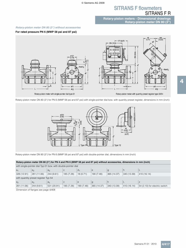
SITRANS F flowmetersSITRANS F R
Rotary-piston meters - Dimensional drawingsRotary-piston meter DN 80 (3")
4/417Siemens FI 01 · 2010
4
Rotary-piston meter DN 80 (3“) without accessories
For rated pressure PN 6 (MWP 58 psi and 87 psi)
Rotary-piston meter DN 80 (3“) for PN 6 (MWP 58 psi and 87 psi) with single-pointer dial bzw. with quantity preset register, dimensions in mm (inch)
Rotary-piston meter DN 80 (3“) for PN 6 (MWP 58 psi and 87 psi) with double-pointer dial, dimensions in mm (inch)
Rotary-piston meter DN 80 (3“) for PN 4 and PN 6 (MWP 58 psi and 87 psi) without accessories, dimensions in mm (inch)
with single-pointer dial Typ 01 bzw. with double-pointer dial
a1 a2 a3 c d1 e g h L
328 (12.91) 281 (11.06) 244 (9.61) 185 (7.28) 18 (0.71) 190 (7.48) 365 (14.37) 340 (13.39) 410 (16.14)
with quantity preset register Typ 54
a2 a3 a5 c e g h L z
281 (11.06) 244 (9.61) 531 (20.91) 185 (7.28) 190 (7.48) 365 (14.37) 340 (13.39) 410 (16.14) 54 (2.10) for electric switch
Dimension of flanges see page 4/408
© Siemens AG 2009
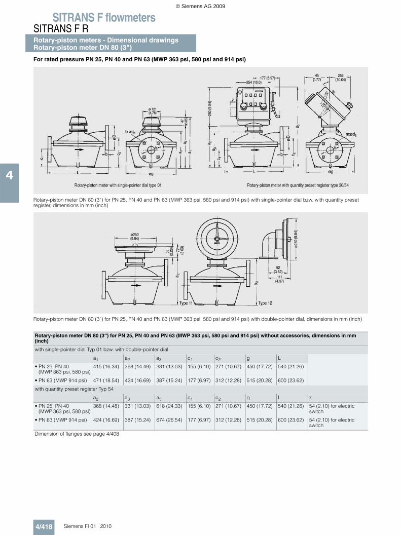
SITRANS F flowmetersSITRANS F RRotary-piston meters - Dimensional drawingsRotary-piston meter DN 80 (3")
4/418 Siemens FI 01 · 2010
4
For rated pressure PN 25, PN 40 and PN 63 (MWP 363 psi, 580 psi and 914 psi)
Rotary-piston meter DN 80 (3“) for PN 25, PN 40 and PN 63 (MWP 363 psi, 580 psi and 914 psi) with single-pointer dial bzw. with quantity preset register, dimensions in mm (inch)
Rotary-piston meter DN 80 (3“) for PN 25, PN 40 and PN 63 (MWP 363 psi, 580 psi and 914 psi) with double-pointer dial, dimensions in mm (inch)
Rotary-piston meter DN 80 (3“) for PN 25, PN 40 and PN 63 (MWP 363 psi, 580 psi and 914 psi) without accessories, dimensions in mm (inch)
with single-pointer dial Typ 01 bzw. with double-pointer dial
a1 a2 a3 c1 c2 g L
• PN 25, PN 40 (MWP 363 psi, 580 psi)
415 (16.34) 368 (14.49) 331 (13.03) 155 (6.10) 271 (10.67) 450 (17.72) 540 (21.26)
• PN 63 (MWP 914 psi) 471 (18.54) 424 (16.69) 387 (15.24) 177 (6.97) 312 (12.28) 515 (20.28) 600 (23.62)
with quantity preset register Typ 54
a2 a3 a5 c1 c2 g L z
• PN 25, PN 40 (MWP 363 psi, 580 psi)
368 (14.48) 331 (13.03) 618 (24.33) 155 (6.10) 271 (10.67) 450 (17.72) 540 (21.26) 54 (2.10) for electric switch
• PN 63 (MWP 914 psi) 424 (16.69) 387 (15.24) 674 (26.54) 177 (6.97) 312 (12.28) 515 (20.28) 600 (23.62) 54 (2.10) for electric switch
Dimension of flanges see page 4/408
© Siemens AG 2009
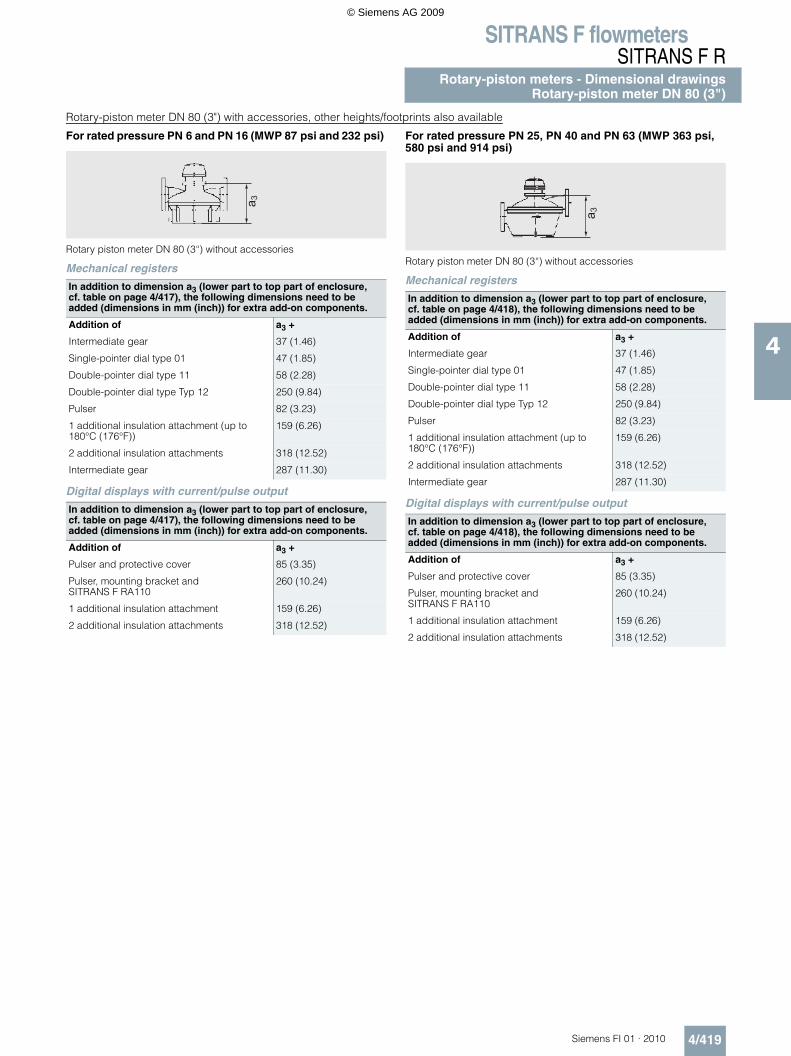
SITRANS F flowmetersSITRANS F R
Rotary-piston meters - Dimensional drawingsRotary-piston meter DN 80 (3")
4/419Siemens FI 01 · 2010
4
Rotary-piston meter DN 80 (3") with accessories, other heights/footprints also available
For rated pressure PN 6 and PN 16 (MWP 87 psi and 232 psi)
Rotary piston meter DN 80 (3“) without accessories
Mechanical registers
Digital displays with current/pulse output
For rated pressure PN 25, PN 40 and PN 63 (MWP 363 psi, 580 psi and 914 psi)
Rotary piston meter DN 80 (3“) without accessories
Mechanical registers
Digital displays with current/pulse output
In addition to dimension a3 (lower part to top part of enclosure, cf. table on page 4/417), the following dimensions need to be added (dimensions in mm (inch)) for extra add-on components.
Addition of a3 +
Intermediate gear 37 (1.46)
Single-pointer dial type 01 47 (1.85)
Double-pointer dial type 11 58 (2.28)
Double-pointer dial type Typ 12 250 (9.84)
Pulser 82 (3.23)
1 additional insulation attachment (up to 180°C (176°F))
159 (6.26)
2 additional insulation attachments 318 (12.52)
Intermediate gear 287 (11.30)
In addition to dimension a3 (lower part to top part of enclosure, cf. table on page 4/417), the following dimensions need to be added (dimensions in mm (inch)) for extra add-on components.
Addition of a3 +
Pulser and protective cover 85 (3.35)
Pulser, mounting bracket and SITRANS F RA110
260 (10.24)
1 additional insulation attachment 159 (6.26)
2 additional insulation attachments 318 (12.52)
a 3
In addition to dimension a3 (lower part to top part of enclosure, cf. table on page 4/418), the following dimensions need to be added (dimensions in mm (inch)) for extra add-on components.
Addition of a3 +
Intermediate gear 37 (1.46)
Single-pointer dial type 01 47 (1.85)
Double-pointer dial type 11 58 (2.28)
Double-pointer dial type Typ 12 250 (9.84)
Pulser 82 (3.23)
1 additional insulation attachment (up to 180°C (176°F))
159 (6.26)
2 additional insulation attachments 318 (12.52)
Intermediate gear 287 (11.30)
In addition to dimension a3 (lower part to top part of enclosure, cf. table on page 4/418), the following dimensions need to be added (dimensions in mm (inch)) for extra add-on components.
Addition of a3 +
Pulser and protective cover 85 (3.35)
Pulser, mounting bracket and SITRANS F RA110
260 (10.24)
1 additional insulation attachment 159 (6.26)
2 additional insulation attachments 318 (12.52)
a 3
© Siemens AG 2009
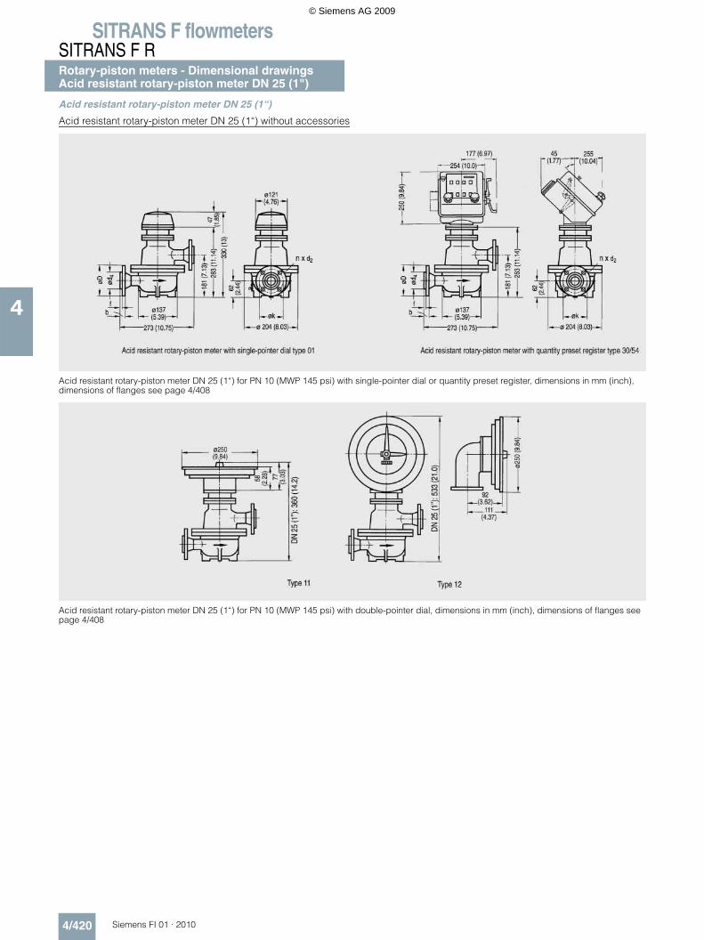
SITRANS F flowmetersSITRANS F RRotary-piston meters - Dimensional drawingsAcid resistant rotary-piston meter DN 25 (1")
4/420 Siemens FI 01 · 2010
4
Acid resistant rotary-piston meter DN 25 (1“)
Acid resistant rotary-piston meter DN 25 (1“) without accessories
Acid resistant rotary-piston meter DN 25 (1“) for PN 10 (MWP 145 psi) with single-pointer dial or quantity preset register, dimensions in mm (inch), dimensions of flanges see page 4/408
Acid resistant rotary-piston meter DN 25 (1“) for PN 10 (MWP 145 psi) with double-pointer dial, dimensions in mm (inch), dimensions of flanges see page 4/408
© Siemens AG 2009
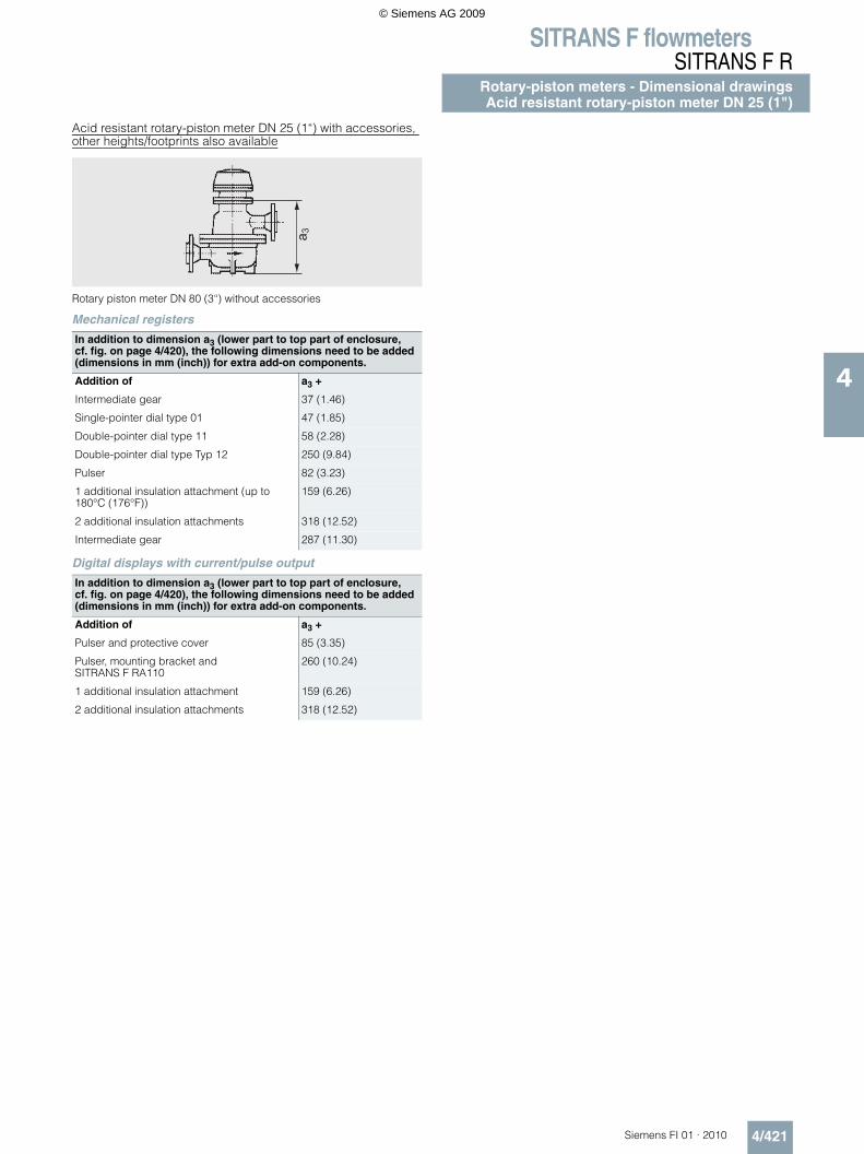
SITRANS F flowmetersSITRANS F R
Rotary-piston meters - Dimensional drawingsAcid resistant rotary-piston meter DN 25 (1")
4/421Siemens FI 01 · 2010
4
Acid resistant rotary-piston meter DN 25 (1“) with accessories, other heights/footprints also available
Rotary piston meter DN 80 (3“) without accessories
Mechanical registers
Digital displays with current/pulse output
In addition to dimension a3 (lower part to top part of enclosure, cf. fig. on page 4/420), the following dimensions need to be added (dimensions in mm (inch)) for extra add-on components.
Addition of a3 +
Intermediate gear 37 (1.46)
Single-pointer dial type 01 47 (1.85)
Double-pointer dial type 11 58 (2.28)
Double-pointer dial type Typ 12 250 (9.84)
Pulser 82 (3.23)
1 additional insulation attachment (up to 180°C (176°F))
159 (6.26)
2 additional insulation attachments 318 (12.52)
Intermediate gear 287 (11.30)
In addition to dimension a3 (lower part to top part of enclosure, cf. fig. on page 4/420), the following dimensions need to be added (dimensions in mm (inch)) for extra add-on components.
Addition of a3 +
Pulser and protective cover 85 (3.35)
Pulser, mounting bracket and SITRANS F RA110
260 (10.24)
1 additional insulation attachment 159 (6.26)
2 additional insulation attachments 318 (12.52)
a 3
© Siemens AG 2009

SITRANS F flowmetersSITRANS F RRotary-piston meters - Dimensional drawingsAutomatic batchmeter DN 25 (1")
4/422 Siemens FI 01 · 2010
4
Automatic batchmeter DN 25 (1“)
Automatic batchmeter DN 25 (1“) for PN 10 (MWP 145 psi) with quantity preset register, dimensions in mm (inch)
Automatic batchmeter DN 25 (1“) for PN 10 (MWP 145 psi) with quantity preset register type 30, without accessories, dimensions in mm (inch)
c g h hA h1 L m p z
90 (3.54) 155 (6.10) 140 (5.51) 48 (1.89) 440 (17.32) 210 (8.27) 241 (9.49) 345 (13.58) 54 (2.1) for electric switch
See page 4/408 for flange dimensions
Automatic batchmeter DN 25 (1") with accessories; dimensions in mm (inch)
Model 21 Model 22 Model 23
Dimension a for automatic batchmeter with 1 heat insulation attachment
599 (23.58) 522 (20.55) 681 (26.81)
Dimension a for automatic batchmeter with 2 heat insulation attachments
758 (29.84) - 840 (33.07)
© Siemens AG 2009
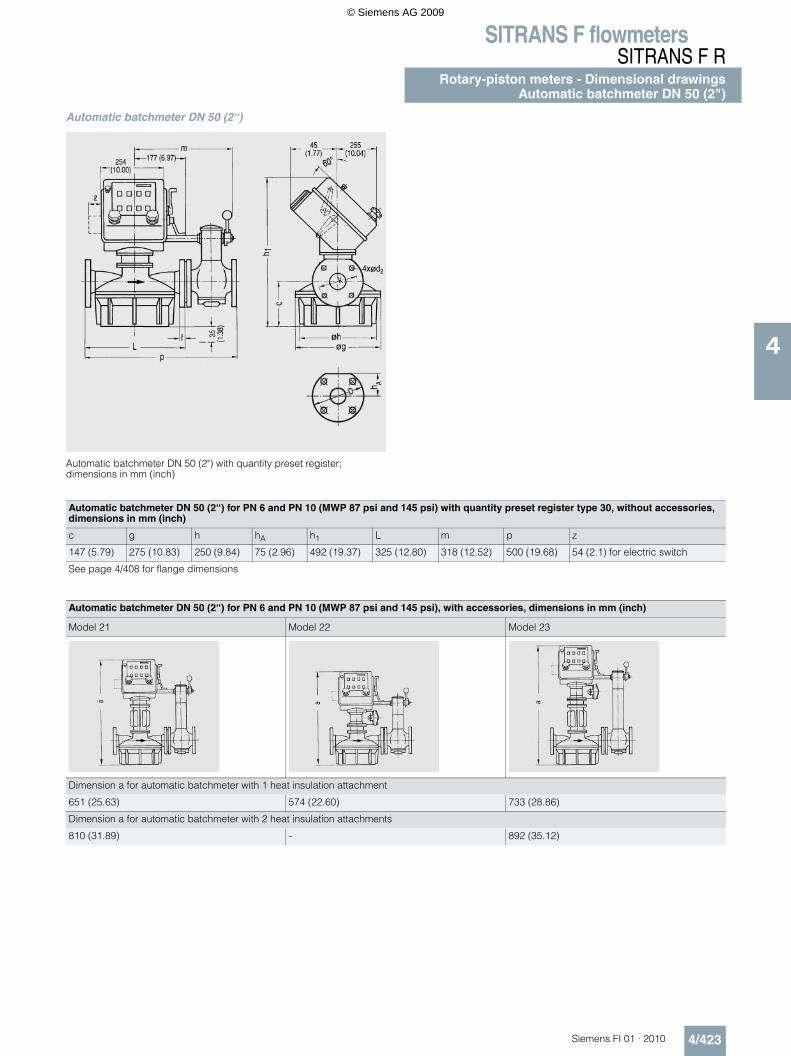
SITRANS F flowmetersSITRANS F R
Rotary-piston meters - Dimensional drawingsAutomatic batchmeter DN 50 (2")
4/423Siemens FI 01 · 2010
4
Automatic batchmeter DN 50 (2“)
Automatic batchmeter DN 50 (2") with quantity preset register; dimensions in mm (inch)
Automatic batchmeter DN 50 (2“) for PN 6 and PN 10 (MWP 87 psi and 145 psi) with quantity preset register type 30, without accessories, dimensions in mm (inch)
c g h hA h1 L m p z
147 (5.79) 275 (10.83) 250 (9.84) 75 (2.96) 492 (19.37) 325 (12.80) 318 (12.52) 500 (19.68) 54 (2.1) for electric switch
See page 4/408 for flange dimensions
Automatic batchmeter DN 50 (2“) for PN 6 and PN 10 (MWP 87 psi and 145 psi), with accessories, dimensions in mm (inch)
Model 21 Model 22 Model 23
Dimension a for automatic batchmeter with 1 heat insulation attachment
651 (25.63) 574 (22.60) 733 (28.86)
Dimension a for automatic batchmeter with 2 heat insulation attachments
810 (31.89) - 892 (35.12)
© Siemens AG 2009
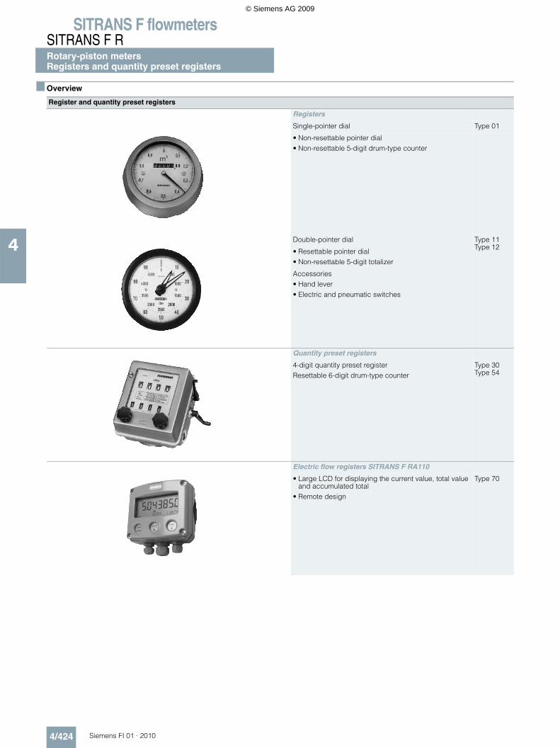
SITRANS F flowmetersSITRANS F RRotary-piston metersRegisters and quantity preset registers
4/424 Siemens FI 01 · 2010
4
Overview
Register and quantity preset registers
Registers
Single-pointer dial Type 01
• Non-resettable pointer dial• Non-resettable 5-digit drum-type counter
Double-pointer dial Type 11Type 12
• Resettable pointer dial• Non-resettable 5-digit totalizer
Accessories• Hand lever• Electric and pneumatic switches
Quantity preset registers
4-digit quantity preset registerResettable 6-digit drum-type counter
Type 30Type 54
Electric flow registers SITRANS F RA110
• Large LCD for displaying the current value, total value and accumulated total
• Remote design
Type 70
© Siemens AG 2009
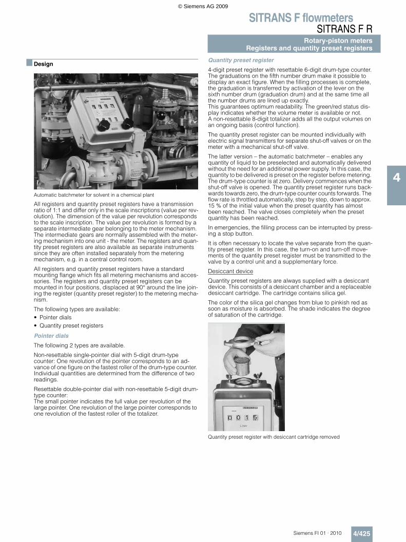
SITRANS F flowmetersSITRANS F R
Rotary-piston metersRegisters and quantity preset registers
4/425Siemens FI 01 · 2010
4
Design
Automatic batchmeter for solvent in a chemical plant
All registers and quantity preset registers have a transmission ratio of 1:1 and differ only in the scale inscriptions (value per rev-olution). The dimension of the value per revolution corresponds to the scale inscription. The value per revolution is formed by a separate intermediate gear belonging to the meter mechanism. The intermediate gears are normally assembled with the meter-ing mechanism into one unit - the meter. The registers and quan-tity preset registers are also available as separate instruments since they are often installed separately from the metering mechanism, e.g. in a central control room.
All registers and quantity preset registers have a standard mounting flange which fits all metering mechanisms and acces-sories. The registers and quantity preset registers can be mounted in four positions, displaced at 90° around the line join-ing the register (quantity preset register) to the metering mecha-nism.
The following types are available:• Pointer dials• Quantity preset registers
Pointer dials
The following 2 types are available.
Non-resettable single-pointer dial with 5-digit drum-type counter: One revolution of the pointer corresponds to an ad-vance of one figure on the fastest roller of the drum-type counter. Individual quantities are determined from the difference of two readings.
Resettable double-pointer dial with non-resettable 5-digit drum-type counter:The small pointer indicates the full value per revolution of the large pointer. One revolution of the large pointer corresponds to one revolution of the fastest roller of the totalizer.
Quantity preset register
4-digit preset register with resettable 6-digit drum-type counter.The graduations on the fifth number drum make it possible to display an exact figure. When the filling processes is complete, the graduation is transferred by activation of the lever on the sixth number drum (graduation drum) and at the same time all the number drums are lined up exactly.This guarantees optimum readability. The green/red status dis-play indicates whether the volume meter is available or not.A non-resettable 8-digit totalizer adds all the output volumes on an ongoing basis (control function).
The quantity preset register can be mounted individually with electric signal transmitters for separate shut-off valves or on the meter with a mechanical shut-off valve.
The latter version – the automatic batchmeter – enables any quantity of liquid to be preselected and automatically delivered without the need for an additional power supply. In this case, the quantity to be delivered is preset on the register before metering. The drum-type counter is at zero. Delivery commences when the shut-off valve is opened. The quantity preset register runs back-wards towards zero, the drum-type counter counts forwards. The flow rate is throttled automatically, step by step, down to approx. 15 % of the initial value when the preset quantity has almost been reached. The valve closes completely when the preset quantity has been reached.
In emergencies, the filling process can be interrupted by press-ing a stop button.
It is often necessary to locate the valve separate from the quan-tity preset register. In this case, the turn-on and turn-off move-ments of the quantity preset register must be transmitted to the valve by a control unit and a supplementary force.
Desiccant device
Quantity preset registers are always supplied with a desiccant device. This consists of a desiccant chamber and a replaceable desiccant cartridge. The cartridge contains silica gel.
The color of the silica gel changes from blue to pinkish red as soon as moisture is absorbed. The shade indicates the degree of saturation of the cartridge.
Quantity preset register with desiccant cartridge removed
© Siemens AG 2009
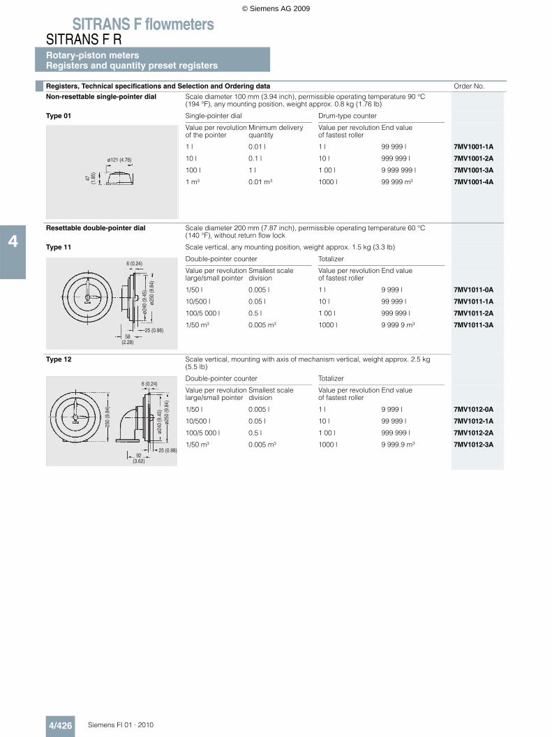
SITRANS F flowmetersSITRANS F RRotary-piston metersRegisters and quantity preset registers
4/426 Siemens FI 01 · 2010
4
Registers, Technical specifications and Selection and Ordering data Order No.
Non-resettable single-pointer dial Scale diameter 100 mm (3.94 inch), permissible operating temperature 90 °C (194 °F), any mounting position, weight approx. 0.8 kg (1.76 lb)
Type 01 Single-pointer dial Drum-type counter
Value per revolutionof the pointer
Minimum delivery quantity
Value per revolution of fastest roller
End value
1 l 0.01 l 1 l 99 999 l 7MV1001-1A
10 l 0.1 l 10 l 999 999 l 7MV1001-2A
100 l 1 l 1 00 l 9 999 999 l 7MV1001-3A
1 m³ 0.01 m³ 1000 l 99 999 m³ 7MV1001-4A
Resettable double-pointer dial Scale diameter 200 mm (7.87 inch), permissible operating temperature 60 °C (140 °F), without return flow lock
Type 11 Scale vertical, any mounting position, weight approx. 1.5 kg (3.3 lb)
Double-pointer counter Totalizer
Value per revolution large/small pointer
Smallest scale division
Value per revolution of fastest roller
End value
1/50 l 0.005 l 1 l 9 999 l 7MV1011-0A
10/500 l 0.05 l 10 l 99 999 l 7MV1011-1A
100/5 000 l 0.5 l 1 00 l 999 999 l 7MV1011-2A
1/50 m³ 0.005 m³ 1000 l 9 999 9 m³ 7MV1011-3A
Type 12 Scale vertical, mounting with axis of mechanism vertical, weight approx. 2.5 kg (5.5 lb)
Double-pointer counter Totalizer
Value per revolution large/small pointer
Smallest scale division
Value per revolution of fastest roller
End value
1/50 l 0.005 l 1 l 9 999 l 7MV1012-0A
10/500 l 0.05 l 10 l 99 999 l 7MV1012-1A
100/5 000 l 0.5 l 1 00 l 999 999 l 7MV1012-2A
1/50 m³ 0.005 m³ 1000 l 9 999.9 m³ 7MV1012-3A
47(1
.85)
ø121 (4.76)
47(1
.85)
ø121 (4.76)
5
5
5
5
© Siemens AG 2009
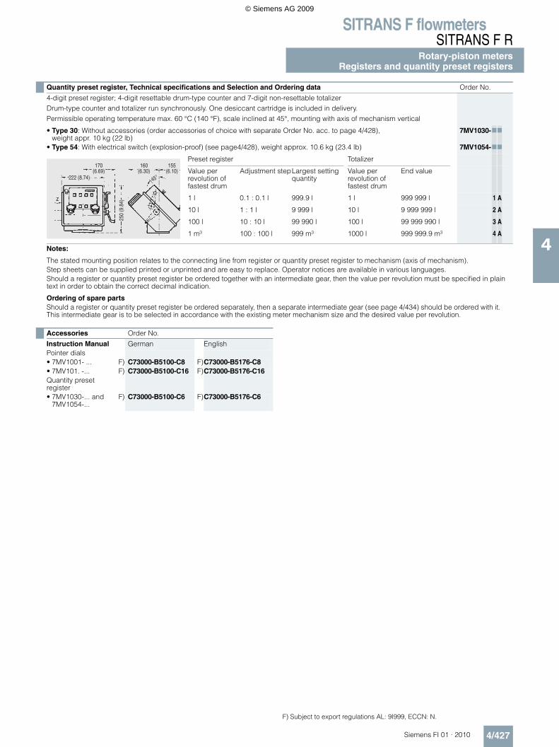
SITRANS F flowmetersSITRANS F R
Rotary-piston metersRegisters and quantity preset registers
4/427Siemens FI 01 · 2010
4
Quantity preset register, Technical specifications and Selection and Ordering data Order No.
4-digit preset register; 4-digit resettable drum-type counter and 7-digit non-resettable totalizerDrum-type counter and totalizer run synchronously. One desiccant cartridge is included in delivery.Permissible operating temperature max. 60 °C (140 °F), scale inclined at 45°, mounting with axis of mechanism vertical
• Type 30: Without accessories (order accessories of choice with separate Order No. acc. to page 4/428),weight appr. 10 kg (22 lb)
7MV1030-77
• Type 54: With electrical switch (explosion-proof) (see page4/428), weight approx. 10.6 kg (23.4 lb) 7MV1054-77
Preset register Totalizer
Value per revolution of fastest drum
Adjustment stepLargest setting quantity
Value per revolution of fastest drum
End value
1 l 0.1 : 0.1 l 999.9 l 1 l 999 999 l 1 A
10 l 1 : 1 l 9 999 l 10 l 9 999 999 l 2 A
100 l 10 : 10 l 99 990 l 100 l 99 999 990 l 3 A
1 m³ 100 : 100 l 999 m³ 1000 l 999 999.9 m³ 4 A
Notes:
The stated mounting position relates to the connecting line from register or quantity preset register to mechanism (axis of mechanism).Step sheets can be supplied printed or unprinted and are easy to replace. Operator notices are available in various languages.Should a register or quantity preset register be ordered together with an intermediate gear, then the value per revolution must be specified in plain text in order to obtain the correct decimal indication.
Ordering of spare partsShould a register or quantity preset register be ordered separately, then a separate intermediate gear (see page 4/434) should be ordered with it. This intermediate gear is to be selected in accordance with the existing meter mechanism size and the desired value per revolution.
Accessories Order No.
Instruction Manual German EnglishPointer dials• 7MV1001- ... F) C73000-B5100-C8 F)C73000-B5176-C8• 7MV101. -... F) C73000-B5100-C16 F)C73000-B5176-C16Quantity preset register• 7MV1030-... and
7MV1054-...F) C73000-B5100-C6 F)C73000-B5176-C6
F) Subject to export regulations AL: 9I999, ECCN: N.
© Siemens AG 2009
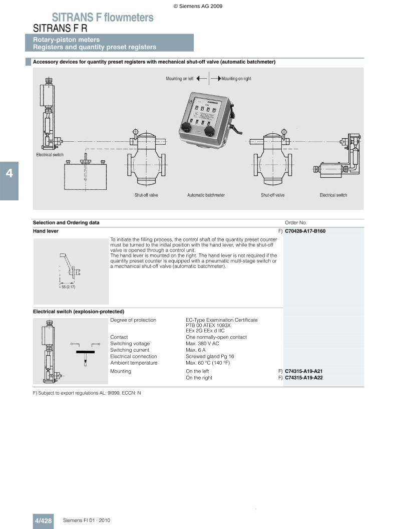
SITRANS F flowmetersSITRANS F RRotary-piston metersRegisters and quantity preset registers
4/428 Siemens FI 01 · 2010
4
F) Subject to export regulations AL: 9I999, ECCN: N
Accessory devices for quantity preset registers with mechanical shut-off valve (automatic batchmeter)
Selection and Ordering data Order No.
Hand lever F) C70428-A17-B160
To initiate the filling process, the control shaft of the quantity preset counter must be turned to the initial position with the hand lever, while the shut-off valve is opened through a control unit.The hand lever is mounted on the right. The hand lever is not required if the quantity preset counter is equipped with a pneumatic multi-stage switch or a mechanical shut-off valve (automatic batchmeter).
Electrical switch (explosion-protected)
Degree of protection EC-Type Examination CertificatePTB 00 ATEX 1093XEEx 2G EEx d IIC
Contact One normally-open contactSwitching voltage Max. 380 V ACSwitching current Max. 6 AElectrical connection Screwed gland Pg 16Ambient temperature Max. 60 °C (140 °F)
Mounting On the left F) C74315-A19-A21On the right F) C74315-A19-A22
.
© Siemens AG 2009
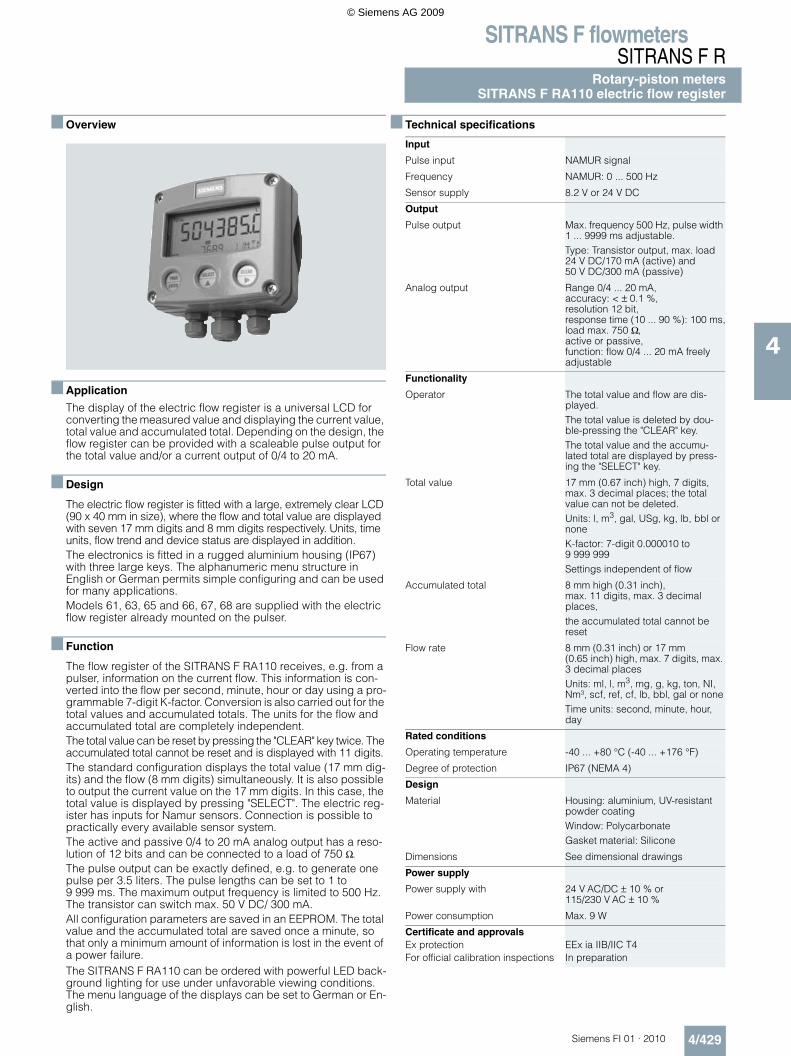
SITRANS F flowmetersSITRANS F R
Rotary-piston metersSITRANS F RA110 electric flow register
4/429Siemens FI 01 · 2010
4
Overview
Application
The display of the electric flow register is a universal LCD for converting the measured value and displaying the current value, total value and accumulated total. Depending on the design, the flow register can be provided with a scaleable pulse output for the total value and/or a current output of 0/4 to 20 mA.
Design
The electric flow register is fitted with a large, extremely clear LCD (90 x 40 mm in size), where the flow and total value are displayed with seven 17 mm digits and 8 mm digits respectively. Units, time units, flow trend and device status are displayed in addition.The electronics is fitted in a rugged aluminium housing (IP67) with three large keys. The alphanumeric menu structure in English or German permits simple configuring and can be used for many applications.Models 61, 63, 65 and 66, 67, 68 are supplied with the electric flow register already mounted on the pulser.
Function
The flow register of the SITRANS F RA110 receives, e.g. from a pulser, information on the current flow. This information is con-verted into the flow per second, minute, hour or day using a pro-grammable 7-digit K-factor. Conversion is also carried out for the total values and accumulated totals. The units for the flow and accumulated total are completely independent.The total value can be reset by pressing the "CLEAR" key twice. The accumulated total cannot be reset and is displayed with 11 digits.The standard configuration displays the total value (17 mm dig-its) and the flow (8 mm digits) simultaneously. It is also possible to output the current value on the 17 mm digits. In this case, the total value is displayed by pressing "SELECT". The electric reg-ister has inputs for Namur sensors. Connection is possible to practically every available sensor system. The active and passive 0/4 to 20 mA analog output has a reso-lution of 12 bits and can be connected to a load of 750 Ω. The pulse output can be exactly defined, e.g. to generate one pulse per 3.5 liters. The pulse lengths can be set to 1 to 9 999 ms. The maximum output frequency is limited to 500 Hz. The transistor can switch max. 50 V DC/ 300 mA.All configuration parameters are saved in an EEPROM. The total value and the accumulated total are saved once a minute, so that only a minimum amount of information is lost in the event of a power failure.The SITRANS F RA110 can be ordered with powerful LED back-ground lighting for use under unfavorable viewing conditions. The menu language of the displays can be set to German or En-glish.
Technical specifications
Input
Pulse input NAMUR signal
Frequency NAMUR: 0 ... 500 Hz
Sensor supply 8.2 V or 24 V DC
Output
Pulse output Max. frequency 500 Hz, pulse width 1 ... 9999 ms adjustable.Type: Transistor output, max. load 24 V DC/170 mA (active) and 50 V DC/300 mA (passive)
Analog output Range 0/4 ... 20 mA, accuracy: < ± 0.1 %, resolution 12 bit, response time (10 ... 90 %): 100 ms,load max. 750 Ω, active or passive, function: flow 0/4 ... 20 mA freely adjustable
Functionality
Operator The total value and flow are dis-played.The total value is deleted by dou-ble-pressing the "CLEAR" key.The total value and the accumu-lated total are displayed by press-ing the "SELECT" key.
Total value 17 mm (0.67 inch) high, 7 digits, max. 3 decimal places; the total value can not be deleted.Units: l, m3, gal, USg, kg, lb, bbl or noneK-factor: 7-digit 0.000010 to 9 999 999Settings independent of flow
Accumulated total 8 mm high (0.31 inch), max. 11 digits, max. 3 decimal places,the accumulated total cannot be reset
Flow rate 8 mm (0.31 inch) or 17 mm (0.65 inch) high, max. 7 digits, max. 3 decimal placesUnits: ml, l, m3, mg, g, kg, ton, NI, Nm³, scf, ref, cf, lb, bbl, gal or noneTime units: second, minute, hour, day
Rated conditions
Operating temperature -40 ... +80 °C (-40 ... +176 °F)
Degree of protection IP67 (NEMA 4)
Design
Material Housing: aluminium, UV-resistant powder coatingWindow: PolycarbonateGasket material: Silicone
Dimensions See dimensional drawings
Power supply
Power supply with 24 V AC/DC ± 10 % or 115/230 V AC ± 10 %
Power consumption Max. 9 W
Certificate and approvalsEx protection EEx ia IIB/IIC T4For official calibration inspections In preparation
© Siemens AG 2009
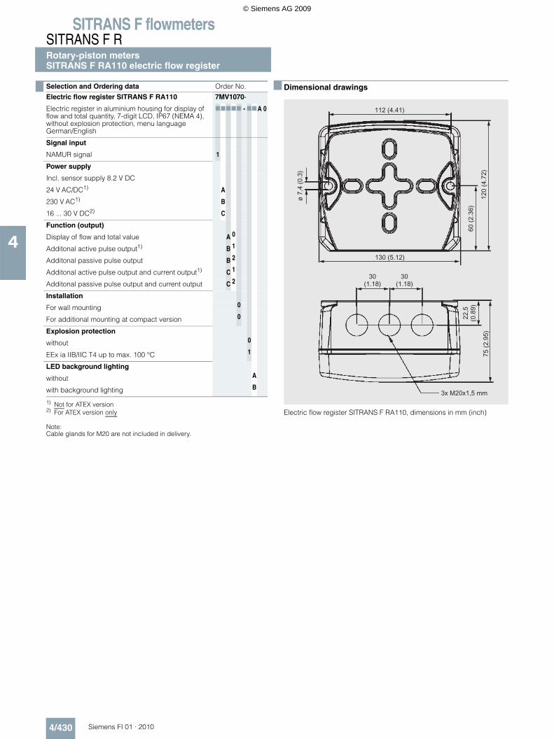
SITRANS F flowmetersSITRANS F RRotary-piston metersSITRANS F RA110 electric flow register
4/430 Siemens FI 01 · 2010
4
Note:Cable glands for M20 are not included in delivery.
Dimensional drawings
Electric flow register SITRANS F RA110, dimensions in mm (inch)
Selection and Ordering data Order No.
Electric flow register SITRANS F RA110 7MV1070-
Electric register in aluminium housing for display of flow and total quantity, 7-digit LCD, IP67 (NEMA 4), without explosion protection, menu language German/English
77777 - 77A 0
Signal input
NAMUR signal 1
Power supply
Incl. sensor supply 8.2 V DC
24 V AC/DC1)
1) Not for ATEX version
A
230 V AC1) B
16 ... 30 V DC2)
2) For ATEX version only
C
Function (output)
Display of flow and total value A 0
Additonal active pulse output1) B 1
Additonal passive pulse output B 2
Additonal active pulse output and current output1) C 1
Additonal passive pulse output and current output C 2
Installation
For wall mounting 0
For additional mounting at compact version 0
Explosion protection
without 0
EEx ia IIB/IIC T4 up to max. 100 °C 1
LED background lighting
without A
with background lighting B
© Siemens AG 2009
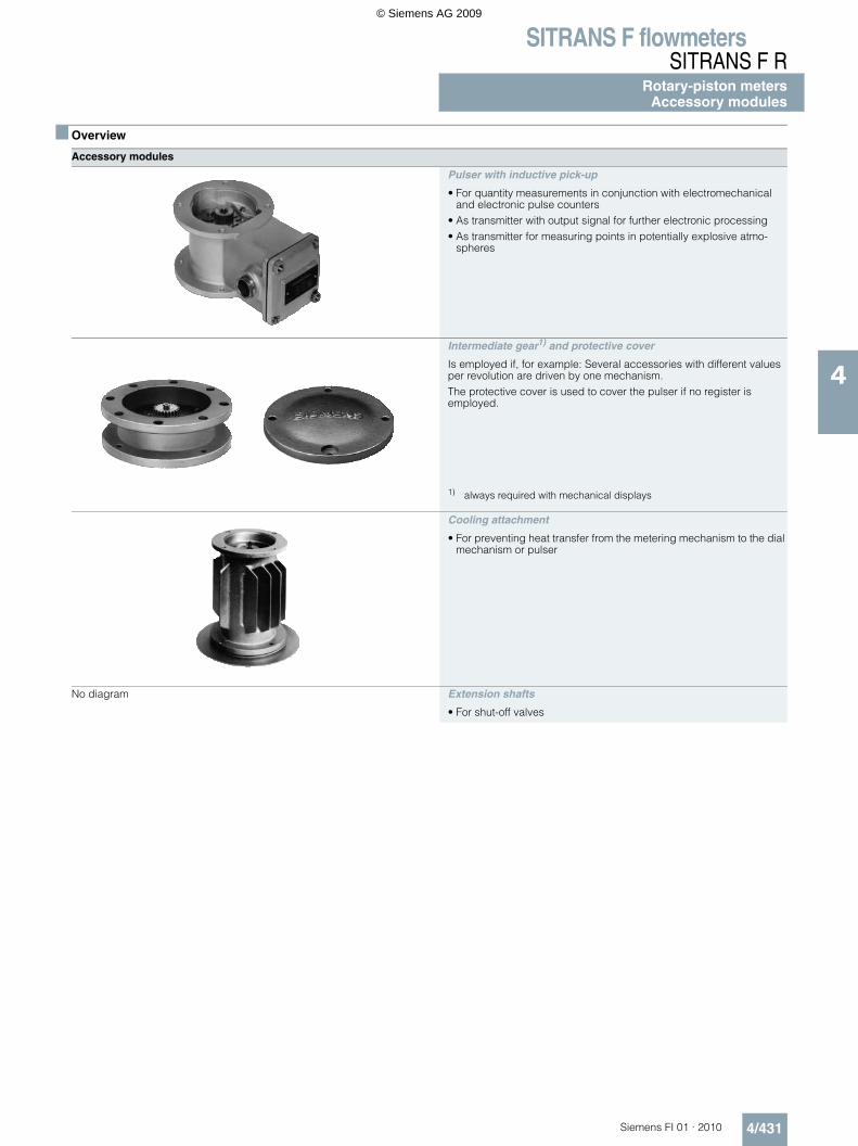
SITRANS F flowmetersSITRANS F R
Rotary-piston metersAccessory modules
4/431Siemens FI 01 · 2010
4
Overview
Accessory modules
Pulser with inductive pick-up
• For quantity measurements in conjunction with electromechanical and electronic pulse counters
• As transmitter with output signal for further electronic processing• As transmitter for measuring points in potentially explosive atmo-
spheres
Intermediate gear1) and protective cover
Is employed if, for example: Several accessories with different values per revolution are driven by one mechanism.The protective cover is used to cover the pulser if no register is employed.
1) always required with mechanical displays
Cooling attachment
• For preventing heat transfer from the metering mechanism to the dial mechanism or pulser
No diagram Extension shafts
• For shut-off valves
© Siemens AG 2009
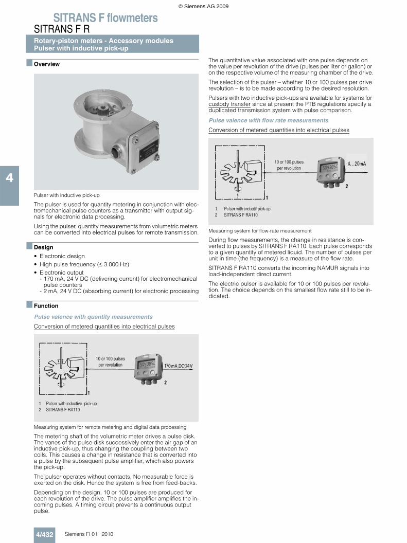
SITRANS F flowmetersSITRANS F RRotary-piston meters - Accessory modulesPulser with inductive pick-up
4/432 Siemens FI 01 · 2010
4
Overview
Pulser with inductive pick-up
The pulser is used for quantity metering in conjunction with elec-tromechanical pulse counters as a transmitter with output sig-nals for electronic data processing.
Using the pulser, quantity measurements from volumetric meters can be converted into electrical pulses for remote transmission.
Design
• Electronic design• High pulse frequency (≤ 3 000 Hz)• Electronic output
- 170 mA, 24 V DC (delivering current) for electromechanical pulse counters
- 2 mA, 24 V DC (absorbing current) for electronic processing
Function
Pulse valence with quantity measurements
Conversion of metered quantities into electrical pulses
Measuring system for remote metering and digital data processing
The metering shaft of the volumetric meter drives a pulse disk. The vanes of the pulse disk successively enter the air gap of an inductive pick-up, thus changing the coupling between two coils. This causes a change in resistance that is converted into a pulse by the subsequent pulse amplifier, which also powers the pick-up.
The pulser operates without contacts. No measurable force is exerted on the disk. Hence the system is free from feed-backs.
Depending on the design, 10 or 100 pulses are produced for each revolution of the drive. The pulse amplifier amplifies the in-coming pulses. A timing circuit prevents a continuous output pulse.
The quantitative value associated with one pulse depends on the value per revolution of the drive (pulses per liter or gallon) or on the respective volume of the measuring chamber of the drive.
The selection of the pulser – whether 10 or 100 pulses per drive revolution – is to be made according to the desired resolution.
Pulsers with two inductive pick-ups are available for systems for custody transfer since at present the PTB regulations specify a duplicated transmission system with pulse comparison.
Pulse valence with flow rate measurements
Conversion of metered quantities into electrical pulses
Measuring system for flow-rate measurement
During flow measurements, the change in resistance is con-verted to pulses by SITRANS F RA110. Each pulse corresponds to a given quantity of metered liquid. The number of pulses per unit in time (the frequency) is a measure of the flow rate.
SITRANS F RA110 converts the incoming NAMUR signals into load-independent direct current.
The electric pulser is available for 10 or 100 pulses per revolu-tion. The choice depends on the smallest flow rate still to be in-dicated.
© Siemens AG 2009
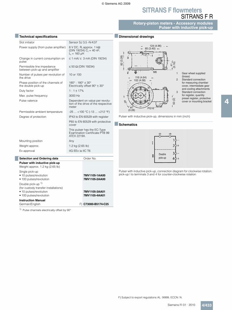
SITRANS F flowmetersSITRANS F R
Rotary-piston meters - Accessory modulesPulser with inductive pick-up
4/433Siemens FI 01 · 2010
4
Technical specifications
Dimensional drawings
Pulser with inductive pick-up, dimensions in mm (inch)
Schematics
Pulser with inductive pick-up, connection diagram for clockwise rotation; pick-up l to terminals 3 and 4 for counter-clockwise rotation
Slot initiator Sensor SJ 3,5 -N-K37
Power supply (from pulse amplifier) 8 V DC, Ri approx. 1 kΩ (DIN 19234) Ci = 40 nF; Li = 160 µH
Change in current consumption on pulse
≤ 1 mA/ ≤ 3 mA (DIN 19234)
Permissible line impedance between pick-up and amplifier
≤ 50 Ω (DIN 19234)
Number of pulses per revolution of the drive
10 or 100
Phase position of the channels of the double pick-up
180° : 180° ± 30°Electrically offset 90° ± 30°
Duty factor 1 : 1 ± 17%
Max. pulse frequency 3000 Hz
Pulse valence Dependent on value per revolu-tion of the drive of the respective meter
Permissible ambient temperature -25 ... +100 °C (-13 ... +212 °F)
Degree of protection IP43 to EN 60529 with register
P65 to EN 60529 with protective cover
This pulser has the EC-Type Examination Certificate PTB 99 ATEX 2219X.
Mounting position Any
Weight approx. 1.2 kg (2.65 lb)
Ex approval IIG EEx ia IIC T6
Selection and Ordering data Order No.
Pulser with inductive pick-upWeight approx. 1.2 kg (2.65 lb)
Single pick-up • 10 pulses/revolution 7MV1105-1AA00• 100 pulses/revolution 7MV1105-2AA00
Double pick-up 1)
1) Pulse channels electrically offset by 90°
(for custody transfer installations)• 10 pulses/revolution 7MV1105-3AA01• 100 pulses/revolution 7MV1105-4AA01
Instruction ManualGerman/English F) C73000-B5174-C25
+
65
"7
7)'-)).)/
(//1&)1(&3&).1-)1&2)())/())/1&&((1-)(
(//1&)1(&3&)().((4))()()&()1(2)1&2)&&.(18)(
F) Subject to export regulations AL: 9I999, ECCN: N.
© Siemens AG 2009
SITRANS F flowmetersSITRANS F RRotary-piston meters - Accessory modulesIntermediate gear and protective cover
4/434 Siemens FI 01 · 2010
4
Overview
Intermediate gear
The capacity of the measuring chamber, which differs according to the meter size, can be adapted to the decimal values per rev-olution using the intermediate gear. The intermediate gear is in-cluded in the delivery of the meter mechanism.
The intermediate gear is also suitable for the installation of other ratios, e.g. factor X : 1, kg indication, etc.
Separate ordering is necessary• if a register is ordered as a spare part or• if accessories (pulsers) are subsequently ordered to extend
the system and the meter mechanism does not yet have a separate modular intermediate gear.
Dimensional drawings
Intermediate gear, dimensions in mm (inch)
F) Subject to export regulations AL: 9I999, ECCN: N
Overview
Protective cover for pulser without register
The protective cover can be used to cover a pulser when no register is used.
Selection and Ordering data Order No.
Intermediate gear for rotary-piston meterWeight approx. 0.6 kg (1.32 lb)Power supply Value per revolution
(output drive intermediate gear)
DN 15 (½“) 1 l (0.26 USg) 7MV1211-1B
DN 25 (1“) 1 l (0.26 USg) 7MV1211-2B10 l (2.6 USg) 7MV1211-3B
DN 50 (2“) 10 l (2.6 USg) 7MV1211-4B100 l/0.1 m³ (26.4 USg) 7MV1211-5B
DN 80 (3“) 100 l/0.1 m³ (26.4 USg) 7MV1211-6B1 m³ (264 USg) 7MV1211-7B
69
5
6
5 +
5
(//1&)1(&3&).1-)1&2) (//1&)1(&3&.)1&&((1-)(
)()&.((4))()()
Selection and Ordering data Order No.
Protective cover F) C70401-A26-C18
.
© Siemens AG 2009
SITRANS F flowmetersSITRANS F R
Rotary-piston meters - Accessory modulesCooling attachment
4/435Siemens FI 01 · 2010
4
Overview
Cooling attachment
When liquids are metered at high temperatures, the transmission of heat from the meter mechanism to the register or accessory can be reduced by the cooling attachment and thus the operat-ing temperature of these units can be kept within the permissible limits.
The housing is comprised of cast light alloy with cooling fins. The lower flange is equipped with a projecting disk for protection against radiant heat.
If an existing meter has to be modified at a later date, the re-placeable gearwheel of the meter mechanism must be replaced by the coupling disk supplied and mounted at the top of the shaft of the insulation attachment.
Technical specifications
Dimensional drawings
Cooling attachment, dimensions in mm (inch)
Attached accessory or register Max. permissible liquid temperatureCooling attachment
Without 1 2
Pulser with inductive pick-up, all regis-ters except type 01
80 °C (176 °F)
180 °C (356 °F)
300 °C (572 °F)
Single-pointer dial type 01 90 °C (194 °F)
250 °C (482 °F)
300 °C (572 °F)
The above limits only apply if the meter mechanism is insulated (lagged) for liquid temperatures ≥ 150 °C (302 °F) (this applies to an ambient temperature up to 40 °C (104 °F).
Weight approx. 1.3 kg (2.9 lb)
Selection and Ordering data Order No.
Cooling attachment 7MV3001-1XX00
© Siemens AG 2009
SITRANS F flowmetersSITRANS F RRotary-piston meters - Accessory modulesExtension shaft for shut-off valves
4/436 Siemens FI 01 · 2010
4
Overview
For extending the actuator linkage of the mechanical shut-off valve on the automatic batchmeter, which is directly connected to the quantity preset register. The extension is always needed when accessories such as a cooling attachment or pulser are in-stalled between the quantity preset register and the metering mechanism.
Dimensional drawings
Extension for mechanical shut-off valve DN 25 (1“) and DN 50 (2“), dimensions in mm (inch)
F) Subject to export regulations AL: 9I999, ECCN: N.
7
Selection and Ordering data Order No.
Extension for shut-off valveDN 25 (1“) and DN 50 (2“)Overall height „a“ in mm (inch)
Weight approx. in kg (lb)
• 82 (3.2) 1.0 (2.2) F) C70144-A336-A35• 159 (6.3) 1.4 (3.1) F) C70144-A336-A37
7 (0.28)M24x1,5(0.06)
13 (0
.51)
M6
50(1.97)
a
62 (2.44)
a62
(2.4
4)
95 (3.74)
© Siemens AG 2009