Embed Size (px)
Citation preview
SITRANS F flowmetersSITRANS F M
Transmitter MAG 5000/6000
4/32 Siemens FI 01 · 2010
4
Overview
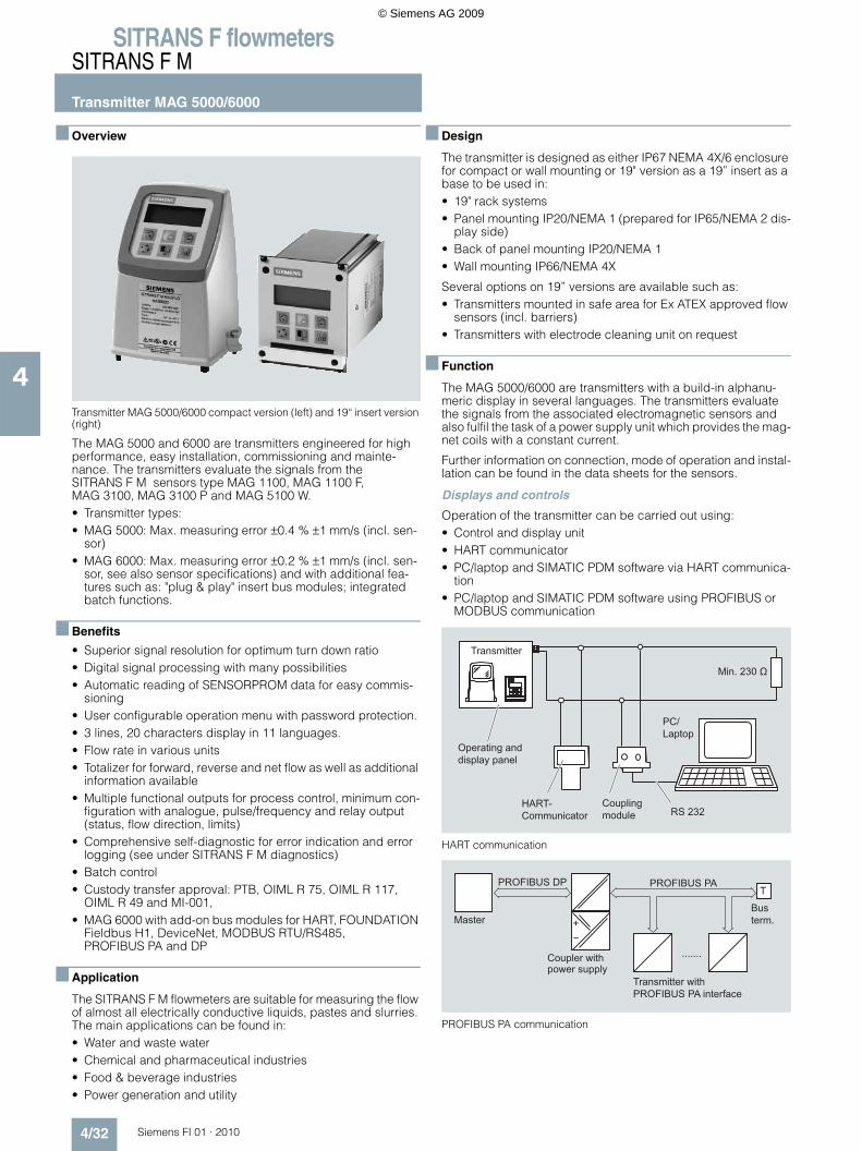
Transmitter MAG 5000/6000 compact version (left) and 19“ insert version (right)
The MAG 5000 and 6000 are transmitters engineered for high performance, easy installation, commissioning and mainte-nance. The transmitters evaluate the signals from the SITRANS F M sensors type MAG 1100, MAG 1100 F, MAG 3100, MAG 3100 P and MAG 5100 W.• Transmitter types:• MAG 5000: Max. measuring error ±0.4 % ±1 mm/s (incl. sen-
sor)• MAG 6000: Max. measuring error ±0.2 % ±1 mm/s (incl. sen-
sor, see also sensor specifications) and with additional fea-tures such as: "plug & play" insert bus modules; integrated batch functions.
Benefits
• Superior signal resolution for optimum turn down ratio• Digital signal processing with many possibilities• Automatic reading of SENSORPROM data for easy commis-
sioning• User configurable operation menu with password protection. • 3 lines, 20 characters display in 11 languages.• Flow rate in various units• Totalizer for forward, reverse and net flow as well as additional
information available• Multiple functional outputs for process control, minimum con-
figuration with analogue, pulse/frequency and relay output (status, flow direction, limits)
• Comprehensive self-diagnostic for error indication and error logging (see under SITRANS F M diagnostics)
• Batch control• Custody transfer approval: PTB, OIML R 75, OIML R 117,
OIML R 49 and MI-001,• MAG 6000 with add-on bus modules for HART, FOUNDATION
Fieldbus H1, DeviceNet, MODBUS RTU/RS485, PROFIBUS PA and DP
Application
The SITRANS F M flowmeters are suitable for measuring the flow of almost all electrically conductive liquids, pastes and slurries. The main applications can be found in:• Water and waste water• Chemical and pharmaceutical industries• Food & beverage industries• Power generation and utility
Design
The transmitter is designed as either IP67 NEMA 4X/6 enclosure for compact or wall mounting or 19" version as a 19” insert as a base to be used in:• 19" rack systems• Panel mounting IP20/NEMA 1 (prepared for IP65/NEMA 2 dis-
play side)• Back of panel mounting IP20/NEMA 1• Wall mounting IP66/NEMA 4X
Several options on 19” versions are available such as:• Transmitters mounted in safe area for Ex ATEX approved flow
sensors (incl. barriers)• Transmitters with electrode cleaning unit on request
Function
The MAG 5000/6000 are transmitters with a build-in alphanu-meric display in several languages. The transmitters evaluate the signals from the associated electromagnetic sensors and also fulfil the task of a power supply unit which provides the mag-net coils with a constant current.
Further information on connection, mode of operation and instal-lation can be found in the data sheets for the sensors.
Displays and controls
Operation of the transmitter can be carried out using:• Control and display unit• HART communicator• PC/laptop and SIMATIC PDM software via HART communica-
tion• PC/laptop and SIMATIC PDM software using PROFIBUS or
MODBUS communication
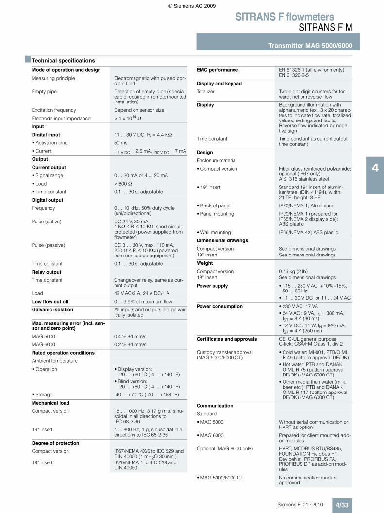
HART communication
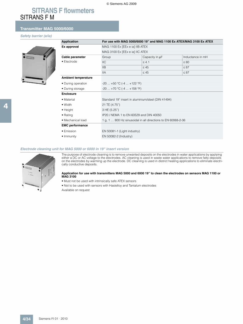
PROFIBUS PA communication
Operating and display panel
PC/ Laptop
Coupling module
HART- Communicator
Transmitter
RS 232
Min. 230 Ω
Transmitter withPROFIBUS PA interface
Coupler withpower supply
Bus term.Master
PROFIBUS DP PROFIBUS PA
.......
T
+
© Siemens AG 2009
SITRANS F flowmetersSITRANS F M
Transmitter MAG 5000/6000
4/33Siemens FI 01 · 2010
4
Technical specifications
Mode of operation and design
Measuring principle Electromagnetic with pulsed con-stant field
Empty pipe Detection of empty pipe (special cable required in remote mounted installation)
Excitation frequency Depend on sensor size
Electrode input impedance > 1 x 10¹⁴ Ω
Input
Digital input 11 ... 30 V DC, Ri = 4.4 KΩ
• Activation time 50 ms
• Current I11 V DC = 2.5 mA, I30 V DC = 7 mA
Output
Current output
• Signal range 0 ... 20 mA or 4 ... 20 mA
• Load < 800 Ω
• Time constant 0.1 … 30 s, adjustable
Digital output
Frequency 0 ... 10 kHz, 50% duty cycle (uni/bidirectional)
Pulse (active) DC 24 V, 30 mA, 1 KΩ ≤ Ri ≤ 10 KΩ, short-circuit-protected (power supplied from flowmeter)
Pulse (passive) DC 3 … 30 V, max. 110 mA, 200 Ω ≤ Ri ≤ 10 KΩ (powered from connected equipment)
Time constant 0.1 … 30 s, adjustable
Relay output
Time constant Changeover relay, same as cur-rent output
Load 42 V AC/2 A, 24 V DC/1 A
Low flow cut off 0 ... 9.9% of maximum flow
Galvanic isolation All inputs and outputs are galvan-ically isolated
Max. measuring error (incl. sen-sor and zero point)
MAG 5000 0.4 % ±1 mm/s
MAG 6000 0.2 % ±1 mm/s
Rated operation conditions
Ambient temperature
• Operation • Display version:-20 ... +60 °C (-4 ... +140 °F)
• Blind version:-20 ... +60 °C (-4 ... +140 °F)
• Storage -40 ... +70 °C (-40 ... +158 °F)
Mechanical load
Compact version 18 ... 1000 Hz, 3,17 g rms, sinu-soidal in all directions to IEC 68-2-36
19“ insert 1 ... 800 Hz, 1 g, sinusoidal in all directions to IEC 68-2-36
Degree of protection
Compact version IP67/NEMA 4X/6 to IEC 529 and DIN 40050 (1 mH2O 30 min.)
19“ insert IP20/NEMA 1 to IEC 529 and DIN 40050
EMC performance EN 61326-1 (all environments)EN 61326-2-5
Display and keypad
Totalizer Two eight-digit counters for for-ward, net or reverse flow
Display Background illumination with alphanumeric text, 3 x 20 charac-ters to indicate flow rate, totalized values, settings and faults; Reverse flow indicated by nega-tive sign
Time constant Time constant as current output time constant
Design
Enclosure material
• Compact version Fiber glass reinforced polyamide; optional (IP67 only): AISI 316 stainless steel
• 19" insert Standard 19“ insert of alumin-ium/steel (DIN 41494), width: 21 TE, height: 3 HE
• Back of panel IP20/NEMA 1; Aluminium
• Panel mounting IP20/NEMA 1 (prepared for IP65/NEMA 2 display side); ABS plastic
• Wall mounting IP66/NEMA 4X; ABS plastic
Dimensional drawings
Compact version See dimensional drawings19“ insert See dimensional drawings
Weight
Compact version 0.75 kg (2 lb)19“ insert See dimensional drawings
Power supply • 115 ... 230 V AC +10% -15%, 50 ... 60 Hz
• 11 ... 30 V DC or 11 ... 24 V AC
Power consumption • 230 V AC: 17 VA• 24 V AC : 9 VA, IN = 380 mA,
IST = 8 A (30 ms)• 12 V DC : 11 W, IN = 920 mA,
IST = 4 A (250 ms)
Certificates and approvals CE, C-UL general purpose, C-tick; CSA/FM Class 1, div 2
Custody transfer approval (MAG 5000/6000 CT)
• Cold water: MI-001, PTB/OIML R 49 (pattern approval DE/DK)
• Hot water: PTB and DANAK OIML R 75 (pattern approval DE/DK) (MAG 6000 CT)
• Other media than water (milk, beer etc.): PTB and DANAK OIML R 117 (pattern approval DE/DK) (MAG 6000 CT)
Communication
Standard
• MAG 5000 Without serial communication or HART as option
• MAG 6000 Prepared for client mounted add-on modules
Optional (MAG 6000 only) HART, MODBUS RTU/RS485, FOUNDATION Fieldbus H1, DeviceNet, PROFIBUS PA, PROFIBUS DP as add-on mod-ules
• MAG 5000/6000 CT No communication moduls approved
© Siemens AG 2009
SITRANS F flowmetersSITRANS F M
Transmitter MAG 5000/6000
4/34 Siemens FI 01 · 2010
4
Safety barrier (e/ia)
Electrode cleaning unit for MAG 5000 or 6000 in 19" insert version
Application For use with MAG 5000/6000 19” and MAG 1100 Ex ATEX/MAG 3100 Ex ATEX
Ex approval MAG 1100 Ex [EEx e ia] IIB ATEX
MAG 3100 Ex [EEx e ia] IIC ATEX
Cable parameter• Electrode
Group Capacity in µF Inductance in mH
IIC ≤ 4.1 ≤ 80
IIB ≤ 45 ≤ 87
IIA ≤ 45 ≤ 87
Ambient temperature
• During operation -20 ... +50 °C (-4 ... +122 °F)
• During storage -20 ... +70 °C (-4 ... +158 °F)
Enclosure
• Material Standard 19” insert in aluminium/steel (DIN 41494)
• Width 21 TE (4.75”)
• Height 3 HE (5.25”)
• Rating IP20 / NEMA 1 to EN 60529 and DIN 40050
• Mechanical load 1 g, 1 … 800 Hz sinusoidal in all directions to EN 60068-2-36
EMC performance
• Emission EN 50081-1 (Light industry)
• Immunity EN 50082-2 (Industry)
The purpose of electrode cleaning is to remove unwanted deposits on the electrodes in water applications by applying either a DC or AC voltage to the electrodes. AC cleaning is used in waste water applications to remove fatty deposits on the electrodes by warming up the electrode. DC cleaning is used in district heating applications to eliminate electri-cally conductive deposits.
Application for use with transmitters MAG 5000 and 6000 19” to clean the electrodes on sensors MAG 1100 or MAG 3100• Must not be used with intrinsically safe ATEX sensors• Not to be used with sensors with Hastelloy and Tantalum electrodesAvailable on request
© Siemens AG 2009
SITRANS F flowmetersSITRANS F M
Transmitter MAG 5000/6000
4/35Siemens FI 01 · 2010
4
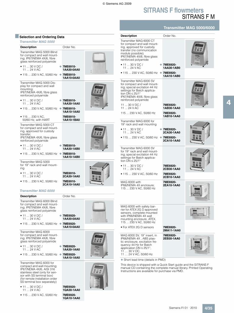
Selection and Ordering DataTransmitter MAG 5000
Transmitter MAG 6000
Description Order No.
Transmitter MAG 5000 Blindfor compact and wall mount-ing; IP67/NEMA 4X/6, fibre glass reinforced polyamide
• 11 ... 30 V DC / 11 ... 24 V AC
7ME6910-1AA30-0AA0
• 115 ... 230 V AC, 50/60 Hz 7ME6910-1AA10-0AA0
Transmitter MAG 5000 Dis-play for compact and wall mounting;IP67/NEMA 4X/6, fibre glass reinforced polyamide
• 11 ... 30 V DC / 11 ... 24 V AC
7ME6910-1AA30-1AA0
• 115 ... 230 V AC, 50/60 Hz 7ME6910-1AA10-1AA0
• 115 ... 230 V AC, 50/60 Hz, with HART
7ME6910-1AA10-1BA0
Transmitter MAG 5000 CTfor compact and wall mount-ing, approved for custody transfer;IP67/NEMA 4X/6, fibre glass reinforced polyamide
• 11 ... 30 V DC / 11 ... 24 V AC
7ME6910-1AA30-1AB0
• 115 ... 230 V AC, 50/60 Hz 7ME6910-1AA10-1AB0
Transmitter MAG 5000 for 19” rack and wall mount-ing
• 11 ... 30 V DC / 11 ... 24 V AC
7ME6910-2CA30-1AA0
• 115 ... 230 V AC, 50/60 Hz 7ME6910-2CA10-1AA0
Description Order No.
Transmitter MAG 6000 Blindfor compact and wall mount-ing; IP67/NEMA 4X/6, fibre glass reinforced polyamide
• 11 ... 30 V DC / 11 ... 24 V AC
7ME6920-1AA30-0AA0
• 115 ... 230 V AC, 50/60 Hz 7ME6920-1AA10-0AA0
Transmitter MAG 6000 for compact and wall mount-ing; IP67/NEMA 4X/6, fibre glass reinforced polyamide
• 11 ... 30 V DC / 11 ... 24 V AC
7ME6920-1AA30-1AA0
• 115 ... 230 V AC, 50/60 Hz 7ME6920-1AA10-1AA0
Transmitter MAG 6000 for compact and wall mounting; IP67/NEMA 4X/6, AISI 316 stainless steel (only for sen-sor with SS terminal box) (for remote installation order SS terminal box separately)
• 11 ... 30 V DC / 11 ... 24 V AC
7ME6920-1QA30-1AA0
• 115 ... 230 V AC, 50/60 Hz 7ME6920-1QA10-1AA0
Transmitter MAG 6000 CTfor compact and wall mount-ing, approved for custody transfer (no communication moduls possible); IP67/NEMA 4X/6, fibre glass reinforced polyamide
• 11 ... 30 V DC / 11 ... 24 V AC
7ME6920-1AA30-1AB0
• 115 ... 230 V AC, 50/60 Hz 7ME6920-1AA10-1AB0
Transmitter MAG 6000 SVfor compact and wall mount-ing; special excitation 44 Hz settings for Batch applica-tion DN ≤ 25/1“IP67/NEMA 4X/6, fibre glass reinforced polyamide
11 ... 30 V DC / 11 ... 24 V AC
7ME6920-1AB30-1AA0
115 ... 230 V AC, 50/60 Hz 7ME6920-1AB10-1AA0
Transmitter MAG 6000 for 19“ rack and wall mounting
• 11 ... 30 V DC / 11 ... 24 V AC
7ME6920-2CA30-1AA0
• 115 ... 230 V AC, 50/60 Hz 7ME6920-2CA10-1AA0
Transmitter MAG 6000 SVfor 19“ rack and wall mount-ing; special excitation 44 Hz settings for Batch applica-tion DN ≤ 25/1“
• 11 ... 30 V DC / 11 ... 24 V AC
7ME6920-2CB30-1AA0
• 115 ... 230 V AC, 50/60 Hz 7ME6920-2CB10-1AA0
MAG 6000 with IP66/NEMA 4X enclosure;115 ... 230 V AC, 50/60 Hz
7ME6920-2EA10-1AA0
MAG 6000 with safety bar-rier for ATEX 2G D approved sensors, complete mounted with IP66/NEMA 4X wall mounting enclosure, ATEX,115 ... 230 V AC, 50/60 Hz
• For ATEX 2G D sensors 7ME6920-2MA11-1AA0
MAG 6000 SV, 19” insert, in IP66/NEMA 4X , ABS plas-tic enclosure, excitation fre-quency 44 Hz for Batch application DN ≤ 25/1“,11 … 30 V DC, 11 … 24 V AC, 50/60 Hz
7ME6920-2EB30-1AA0
Short lead time (details in PMD)
This device is shipped with a Quick Start guide and the SITRANS F manual CD containing the complete manual library. Printed Operating Instructions are available for purchase via PMD.
Description Order No.
© Siemens AG 2009
SITRANS F flowmetersSITRANS F M
Transmitter MAG 5000/6000
4/36 Siemens FI 01 · 2010
4
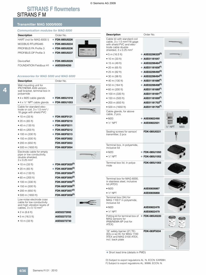
Communication modules for MAG 6000
Accessories for MAG 5000 and MAG 6000
Description Order No.
HART (not for MAG 6000 I) FDK-085U0226
MODBUS RTU/RS485 FDK-085U0234
PROFIBUS PA Profile 3 FDK-085U0236
PROFIBUS DP Profile 3 FDK-085U0237
DeviceNet FDK-085U0229
FOUNDATION Fieldbus H1 A5E02054250
Description Order No.
Wall mounting unit for IP67/NEMA 4X/6 version, wall bracket, terminal box in polyamide
• 4 x M20 cable glands FDK-085U1018
• 4 x ½“ NPT cable glands FDK-085U1053
Cable for standard elec-trode or coil, 3 x 1.5 mm² / 18 gage with shield PVC
• 10 m (33 ft) FDK-083F0121
• 20 m (65 ft) FDK-083F0210
• 40 m (130 ft) FDK-083F0211
• 60 m (200 ft) FDK-083F0212
• 100 m (330 ft) FDK-083F0213
• 150 m (500 ft) FDK-083F3052
• 200 m (650 ft) FDK-083F3053
• 500 m (1650 ft) FDK-083F3054
Electrode cable for empty pipe or low conductivity, double shielded, 3 x 0.25 mm²
• 10 m (33 ft) FDK-083F3020D)
• 20 m (65 ft) FDK-083F3095D)
• 40 m (130 ft) FDK-083F3094D)
• 60 m (200 ft) FDK-083F3093D)
• 100 m (330 ft) FDK-083F3092D)
• 150 m (500 ft) FDK-083F3056D)
• 200 m (650 ft) FDK-083F3057D)
• 500 m (1650 ft) FDK-083F3058D)
Low-noise electrode coax cable for low conductivity and high vibration levels of cables, 3 x 0.13 mm2
• 2 m (6.6 ft) A5E02272692
• 5 m (16.5 ft) A5E02272723
• 10 m (33 ft) A5E02272730
Cable kit with standard coil cable, 3 x 1.5 mm²/18 gage with shield PVC and elec-trode cable double shielded, 3 x 0.25 mm²
• 5 m (16.5 ft) A5E02296329D)
• 10 m (33 ft) A5E01181647
• 15 m (49 ft) A5E02296464D)
• 20 m (65 ft) A5E01181656F)
• 25 m (82 ft) A5E02296490D)
• 30 m (98 ft) A5E02296494D)
• 40 m (130 ft) A5E01181686F)
• 50 m (164 ft) A5E02296498D)
• 60 m (200 ft) A5E01181689F)
• 100 m (330 ft) A5E01181691F)
• 150 m (500 ft) A5E01181699F)
• 200 m (650 ft) A5E01181703F)
• 500 m (1650 ft) A5E01181705F)
Cable glands, for above cable, 2 pcs.
• M20 A5E00822490
• ½“ NPT A5E00822501
Sealing screws for sensor/ transmitter, 2 pcs
FDK-085U0221
Terminal box, in polyamide, inclusive lid
• M20 FDK-085U1050
• ½" NPT FDK-085U1052
Terminal box lid, in polya-mide
FDK-085U1003
Terminal box for MAG 6000, in stainless steel, inclusive lid (ATEX)
• M20 A5E00836867
• ½" NPT A5E00836868
Terminal box (3A) for MAG 1100 F in polyamide, inclusive lid
• M20 A5E00822478
• ½" NPT A5E00822479
Potting kit for terminal box of MAG sensors for IP68/NEMA 6P (not for ATEX)
FDK-085U0220
19“ safety barrier (21 TE) [EEx e ia] IIC for MAG 1100 ATEX and MAG 3100 ATEX, incl. back plate
FDK-083F5034
Short lead time (details in PMD)
Description Order No.
M20½“ NPT
D) Subject to export regulations AL: N, ECCN: EAR99H.F) Subject to export regulations AL: 9I999, ECCN: N.
© Siemens AG 2009
SITRANS F flowmetersSITRANS F M
Transmitter MAG 5000/6000
4/37Siemens FI 01 · 2010
4
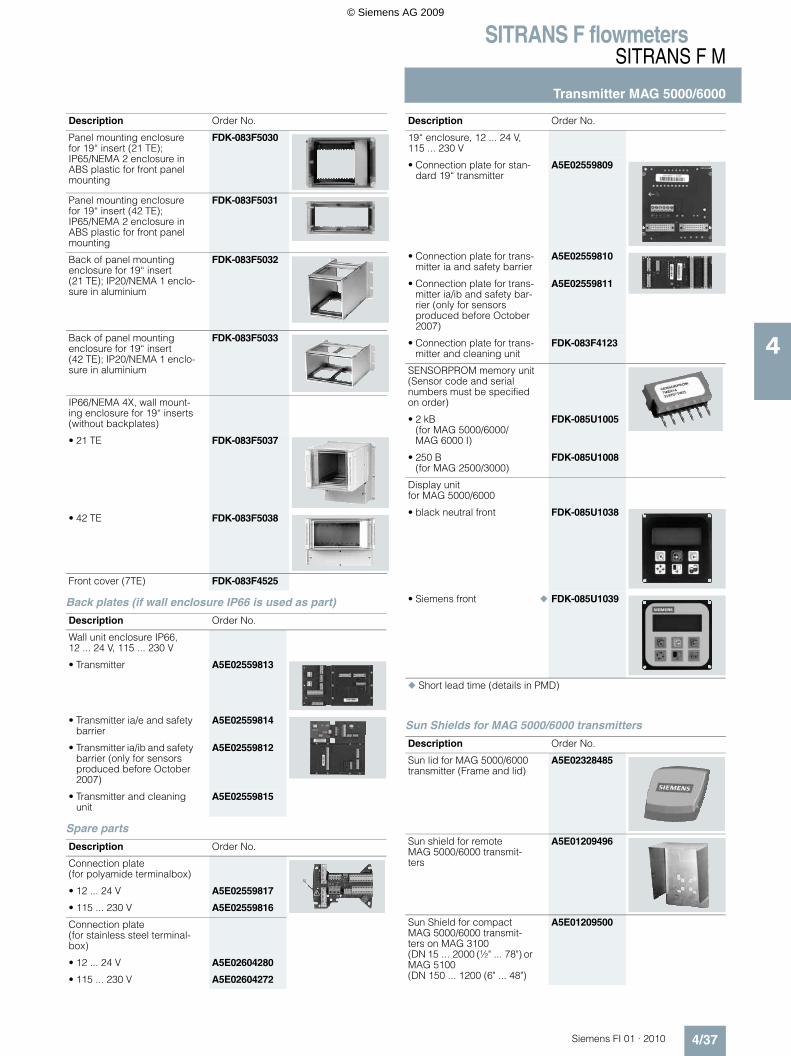
Back plates (if wall enclosure IP66 is used as part)
Spare parts
Sun Shields for MAG 5000/6000 transmitters
Panel mounting enclosure for 19“ insert (21 TE); IP65/NEMA 2 enclosure in ABS plastic for front panel mounting
FDK-083F5030
Panel mounting enclosure for 19“ insert (42 TE); IP65/NEMA 2 enclosure in ABS plastic for front panel mounting
FDK-083F5031
Back of panel mounting enclosure for 19“ insert (21 TE); IP20/NEMA 1 enclo-sure in aluminium
FDK-083F5032
Back of panel mounting enclosure for 19“ insert (42 TE); IP20/NEMA 1 enclo-sure in aluminium
FDK-083F5033
IP66/NEMA 4X, wall mount-ing enclosure for 19“ inserts(without backplates)
• 21 TE FDK-083F5037
• 42 TE FDK-083F5038
Front cover (7TE) FDK-083F4525
Description Order No.
Wall unit enclosure IP66, 12 ... 24 V, 115 ... 230 V
• Transmitter A5E02559813
• Transmitter ia/e and safety barrier
A5E02559814
• Transmitter ia/ib and safety barrier (only for sensors produced before October 2007)
A5E02559812
• Transmitter and cleaning unit
A5E02559815
Description Order No.
Connection plate(for polyamide terminalbox)
• 12 ... 24 V A5E02559817
• 115 ... 230 V A5E02559816
Connection plate(for stainless steel terminal-box)
• 12 ... 24 V A5E02604280
• 115 ... 230 V A5E02604272
Description Order No.
19“ enclosure, 12 ... 24 V, 115 ... 230 V
• Connection plate for stan-dard 19“ transmitter
A5E02559809
• Connection plate for trans-mitter ia and safety barrier
A5E02559810
• Connection plate for trans-mitter ia/ib and safety bar-rier (only for sensors produced before October 2007)
A5E02559811
• Connection plate for trans-mitter and cleaning unit
FDK-083F4123
SENSORPROM memory unit(Sensor code and serial numbers must be specified on order)
• 2 kB (for MAG 5000/6000/ MAG 6000 I)
FDK-085U1005
• 250 B (for MAG 2500/3000)
FDK-085U1008
Display unit for MAG 5000/6000
• black neutral front FDK-085U1038
• Siemens front FDK-085U1039
Short lead time (details in PMD)
Description Order No.
Sun lid for MAG 5000/6000 transmitter (Frame and lid)
A5E02328485
Sun shield for remote MAG 5000/6000 transmit-ters
A5E01209496
Sun Shield for compact MAG 5000/6000 transmit-ters on MAG 3100 (DN 15 ... 2000 (½" ... 78") or MAG 5100 (DN 150 ... 1200 (6" ... 48")
A5E01209500
Description Order No.
© Siemens AG 2009
SITRANS F flowmetersSITRANS F M
Transmitter MAG 5000/6000
4/38 Siemens FI 01 · 2010
4
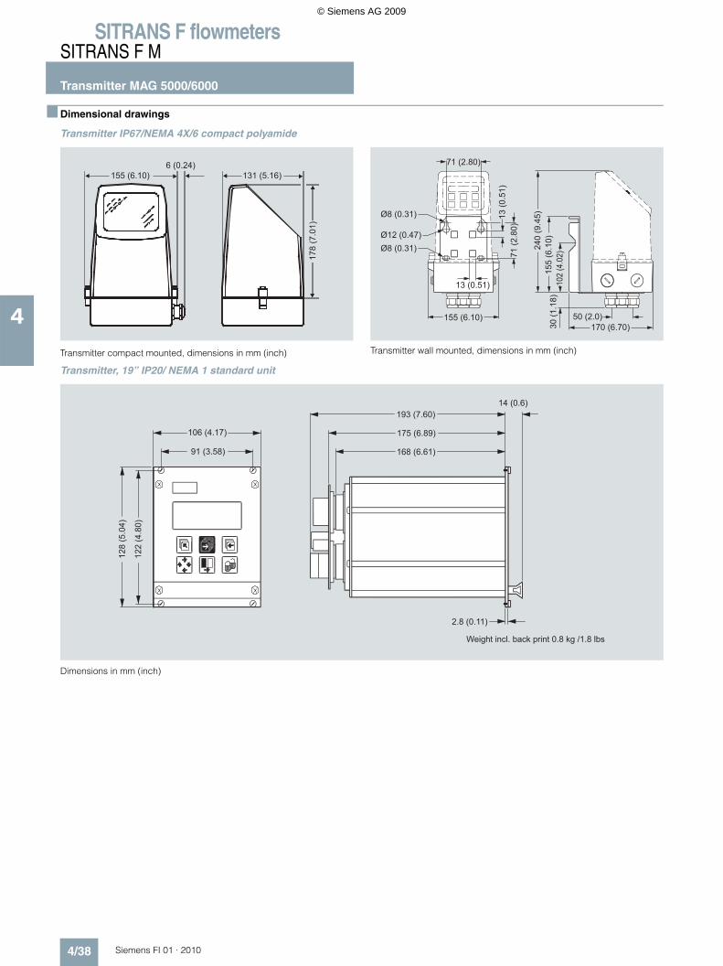
Dimensional drawings
Transmitter IP67/NEMA 4X/6 compact polyamide
Transmitter compact mounted, dimensions in mm (inch)
Transmitter wall mounted, dimensions in mm (inch)
Transmitter, 19” IP20/ NEMA 1 standard unit
Dimensions in mm (inch)
155 (6.10)6 (0.24)
131 (5.16)
178
(7.0
1)
Ø12 (0.47)
13 (0
.51)
71 (2
.80)
Ø8 (0.31)
Ø8 (0.31)
71 (2.80)
155 (6.10)
13 (0.51)
240
(9.4
5)15
5 (6
.10)
102
(4.0
2)
170 (6.70)50 (2.0)
30 (1
.18)
Weight incl. back print 0.8 kg /1.8 lbs
2.8 (0.11)
14 (0.6)
168 (6.61)
175 (6.89)
193 (7.60)
122
(4.8
0)
128
(5.0
4)
91 (3.58)
106 (4.17)
© Siemens AG 2009
SITRANS F flowmetersSITRANS F M
Transmitter MAG 5000/6000
4/39Siemens FI 01 · 2010
4
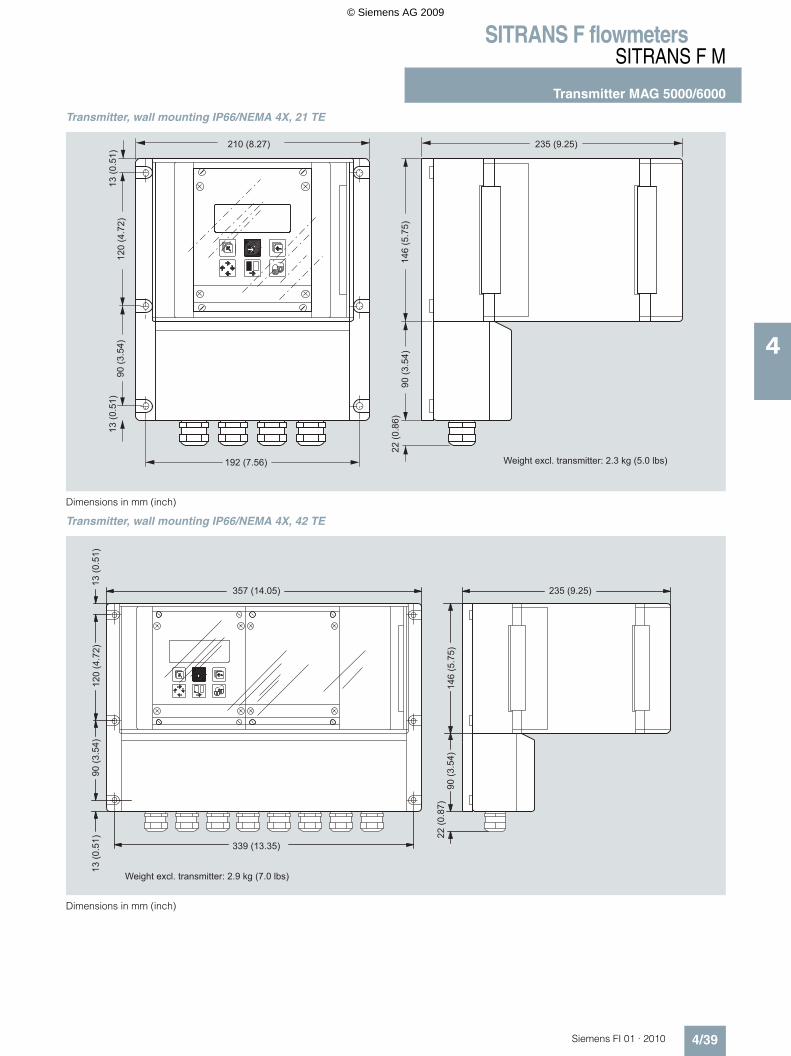
Transmitter, wall mounting IP66/NEMA 4X, 21 TE
Dimensions in mm (inch)
Transmitter, wall mounting IP66/NEMA 4X, 42 TE
Dimensions in mm (inch)
Weight excl. transmitter: 2.3 kg (5.0 lbs)
235 (9.25)210 (8.27)
192 (7.56)
13 (0
.51)
22 (0
.86)
90 (3
.54)
90 (3
.54)
120
(4.7
2)
146
(5.7
5)
13 (0
.51)
Weight excl. transmitter: 2.9 kg (7.0 lbs)
13 (0
.51)
120
(4.7
2)
339 (13.35)
357 (14.05)
22 (0
.87)
90 (3
.54)
146
(5.7
5)
235 (9.25)
90 (3
.54)
13 (0
.51)
© Siemens AG 2009
SITRANS F flowmetersSITRANS F M
Transmitter MAG 5000/6000
4/40 Siemens FI 01 · 2010
4
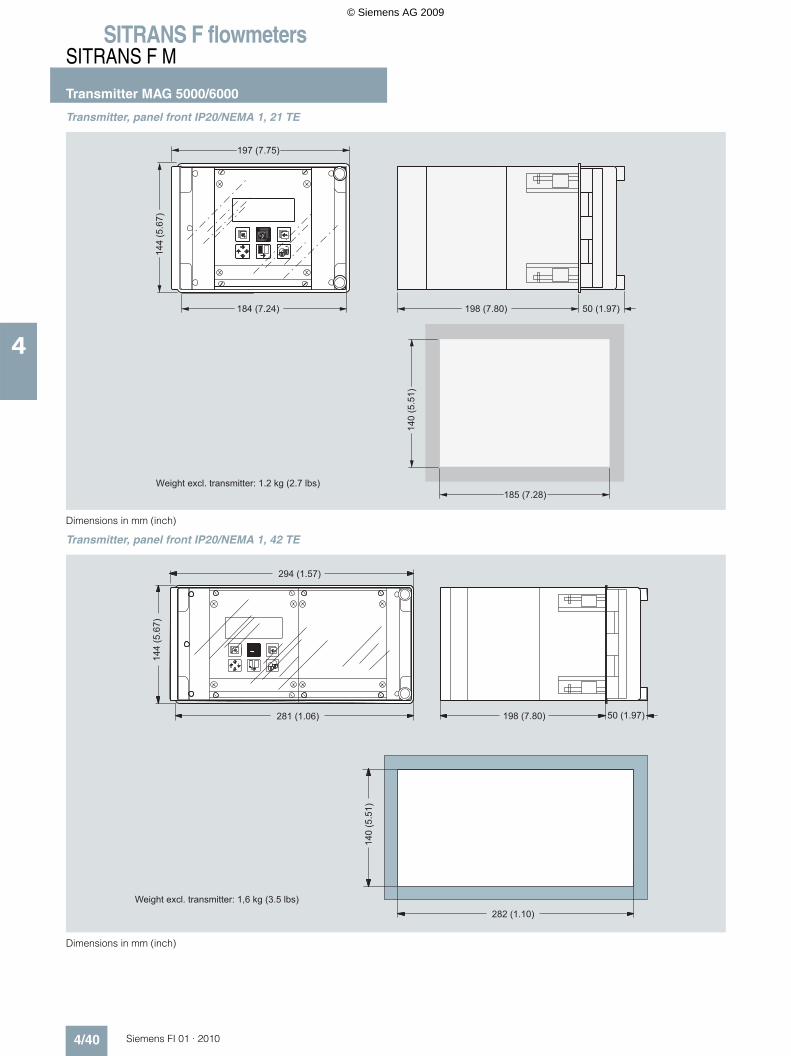
Transmitter, panel front IP20/NEMA 1, 21 TE
Dimensions in mm (inch)
Transmitter, panel front IP20/NEMA 1, 42 TE
Dimensions in mm (inch)
Weight excl. transmitter: 1.2 kg (2.7 lbs)
197 (7.75)
184 (7.24) 198 (7.80) 50 (1.97)
185 (7.28)
140
(5.5
1)
144
(5.6
7)
Weight excl. transmitter: 1,6 kg (3.5 lbs)
144
(5.6
7)
294 (1.57)
281 (1.06)
140
(5.5
1)
282 (1.10)
198 (7.80) 50 (1.97)
© Siemens AG 2009
SITRANS F flowmetersSITRANS F M
Transmitter MAG 5000/6000
4/41Siemens FI 01 · 2010
4
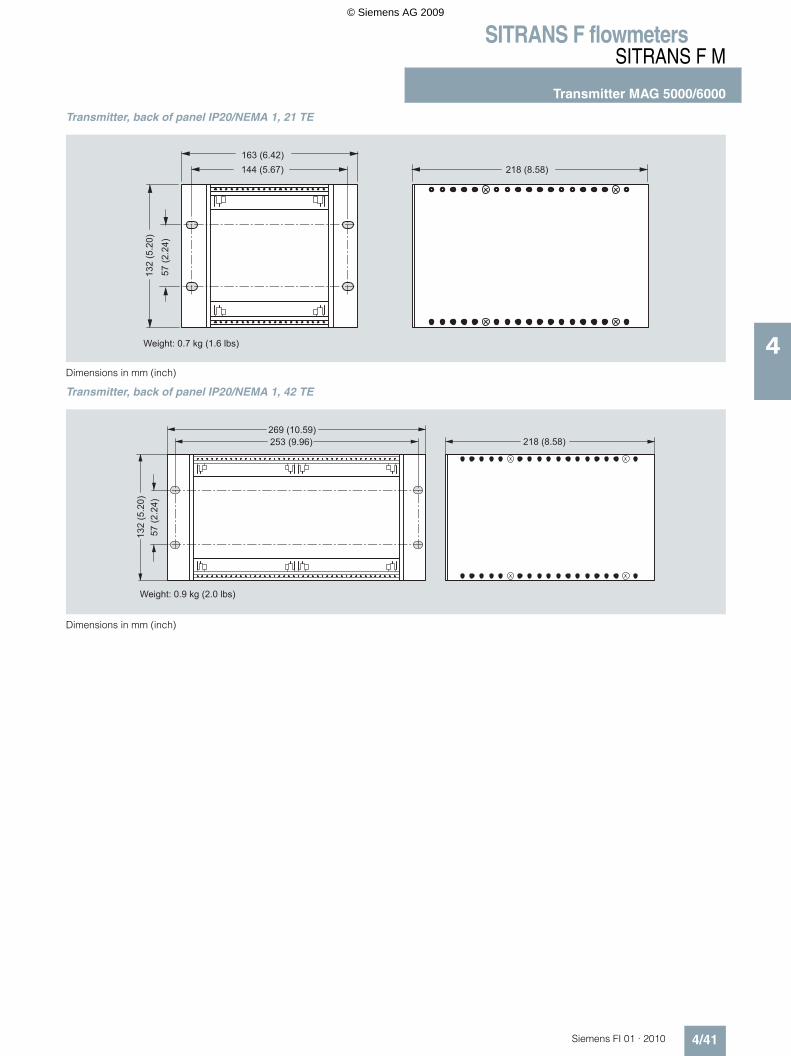
Transmitter, back of panel IP20/NEMA 1, 21 TE
Dimensions in mm (inch)
Transmitter, back of panel IP20/NEMA 1, 42 TE
Dimensions in mm (inch)
Weight: 0.7 kg (1.6 lbs)
163 (6.42)144 (5.67) 218 (8.58)
57 (2
.24)
132
(5.2
0)
Weight: 0.9 kg (2.0 lbs)
269 (10.59)253 (9.96) 218 (8.58)
57 (2
.24)
132
(5.2
0)
© Siemens AG 2009
SITRANS F flowmetersSITRANS F M
Transmitter MAG 5000/6000
4/42 Siemens FI 01 · 2010
4
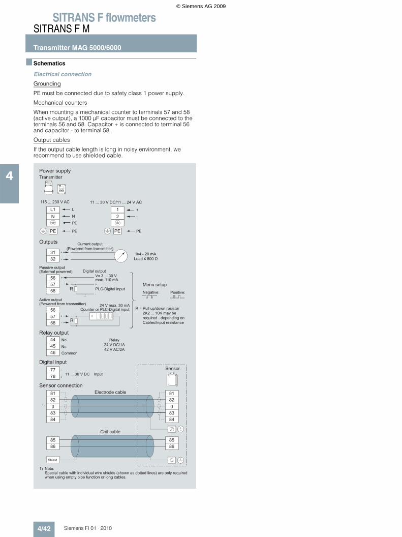
Schematics
Electrical connection
Grounding
PE must be connected due to safety class 1 power supply.
Mechanical counters
When mounting a mechanical counter to terminals 57 and 58 (active output), a 1000 µF capacitor must be connected to the terminals 56 and 58. Capacitor + is connected to terminal 56 and capacitor - to terminal 58.
Output cables
If the output cable length is long in noisy environment, we recommend to use shielded cable.
Note:Special cable with individual wire shields (shown as dotted lines) are only required when using empty pipe function or long cables.
1)
24 V max. 30 mA
Vx 3 ... 30 V max. 110 mA
0/4 - 20 mALoad ≤ 800 Ω
Sensor
Positive:Negative:
Counter or PLC-Digital input
Menu setup
Outputs
PLC-Digital input
PE
Coil cable
Sensor connectionElectrode cable
Relay output
Digital input
11 ... 30 V DC
Relay24 V DC/1A42 V AC/2A
Nc
Shield
Common
No
Digital output
Current output(Powered from transmitter)
Power supply
115 ... 230 V AC
Passive output(External powered)
Active output(Powered from transmitter)
Input
R =
Transmitter
Pull up/down resister 2K2... 10K may be required - depending on Cables/Input resistance
11 ... 30 V DC/11 ... 24 V AC
R
R
1)
L1N
12
85
78
0
77
86
8483
8281
4546
44
5758
56
3132
5758
56
PEPE
85
0
86
8483
8281
PE
PE
N
L
© Siemens AG 2009