Embed Size (px)
Citation preview
SINGLE ZONE ART COOL PREMIER WALL MOUNTED
INSTALLATION MANUAL
1-1/4, 1-1/2 and 2 TonsLA150HYV3, LA180HYV3, LA240HYV3
3/4 and 1 TonsLA090HYV3, LA120HYV3

The instructions included in this manual must be followed to prevent product malfunction, property damage, injury, or death to the user or other people. Incorrect operation due to ignoring any instructions will cause harm or damage. The level of seriousness is classified by the symbols described below.
Do not throw away, destroy, or lose this manual. Please read carefully and store in a safe place for future reference.
Content familiarity required for proper installation.
A summary list of safety precautions begins on page 3.
For more technical materials such as submittals, engineering databooks, and catalogs, visit www.lghvac.com.
For continual product development, LG Electronics U.S.A., Inc., reserves the right to change specifications without notice. ©LG Electronics U.S.A., Inc.
This document, as well as all reports, illustrations, data, information, and other materials are the property of LG Electronics U.S.A., Inc.
PROPRIETARY DATA NOTICEThis document, as well as all reports, illustrations, data, information, and
other materials are the property of LG Electronics U.S.A., Inc., and are disclosed by LG Electronics U.S.A., Inc., only in confidence.
This document is for design purposes only.
3
Safety Instructions
Due to our policy of continuous product innovation, some specifications may change without notification. ©LG Electronics U.S.A., Inc., Englewood Cliffs, NJ. All rights reserved. “LG” is a registered trademark of LG Corp.
SAFETY INSTRUCTIONS
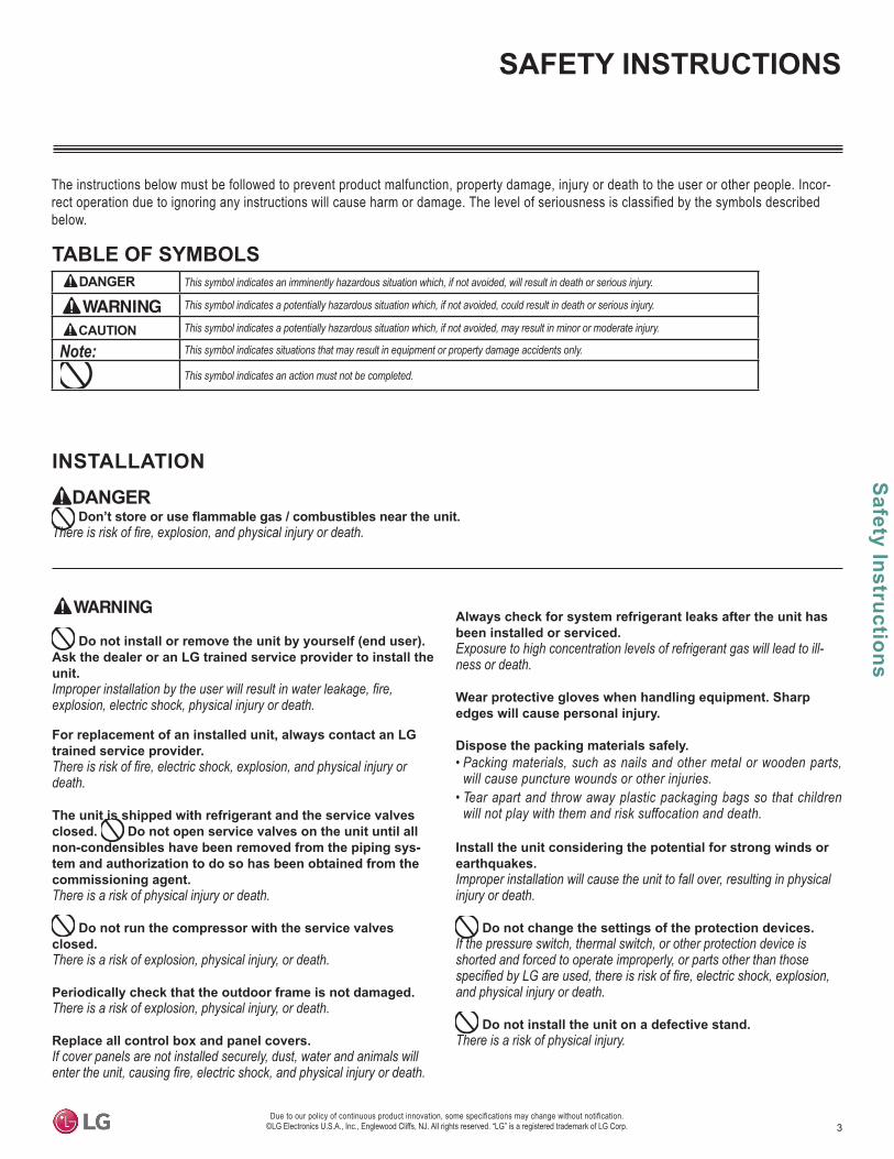
The instructions below must be followed to prevent product malfunction, property damage, injury or death to the user or other people. Incor-rect operation due to ignoring any instructions will cause harm or damage. The level of seriousness is classified by the symbols described below.
TABLE OF SYMBOLS
Do not install or remove the unit by yourself (end user). Ask the dealer or an LG trained service provider to install the unit.
explosion, electric shock, physical injury or death.
For replacement of an installed unit, always contact an LG trained service provider.
death.
The unit is shipped with refrigerant and the service valves closed. Do not open service valves on the unit until all non-condensibles have been removed from the piping sys-tem and authorization to do so has been obtained from the commissioning agent.There is a risk of physical injury or death.
Do not run the compressor with the service valves closed. There is a risk of explosion, physical injury, or death.
Periodically check that the outdoor frame is not damaged. There is a risk of explosion, physical injury, or death.
Replace all control box and panel covers.If cover panels are not installed securely, dust, water and animals will
Always check for system refrigerant leaks after the unit has been installed or serviced.Exposure to high concentration levels of refrigerant gas will lead to ill-ness or death.
Wear protective gloves when handling equipment. Sharp edges will cause personal injury.
Dispose the packing materials safely.• Packing materials, such as nails and other metal or wooden parts,
will cause puncture wounds or other injuries.• Tear apart and throw away plastic packaging bags so that children
will not play with them and risk suffocation and death.
Install the unit considering the potential for strong winds or earthquakes.Improper installation will cause the unit to fall over, resulting in physical injury or death.
Do not change the settings of the protection devices.If the pressure switch, thermal switch, or other protection device is shorted and forced to operate improperly, or parts other than those
and physical injury or death.
Do not install the unit on a defective stand. There is a risk of physical injury.
INSTALLATION
This symbol indicates an imminently hazardous situation which, if not avoided, will result in death or serious injury.
This symbol indicates a potentially hazardous situation which, if not avoided, could result in death or serious injury.
This symbol indicates a potentially hazardous situation which, if not avoided, may result in minor or moderate injury.
This symbol indicates situations that may result in equipment or property damage accidents only.
This symbol indicates an action must not be completed.
DANGER
CAUTION
4
Sing
le Z
one
Art
Coo
l Pre
mie
r Wal
l Mou
nted
Inst
alla
tion
Man
ual
Due to our policy of continuous product innovation, some specifications may change without notification. ©LG Electronics U.S.A., Inc., Englewood Cliffs, NJ. All rights reserved. “LG” is a registered trademark of LG Corp.
SAFETY INSTRUCTIONS
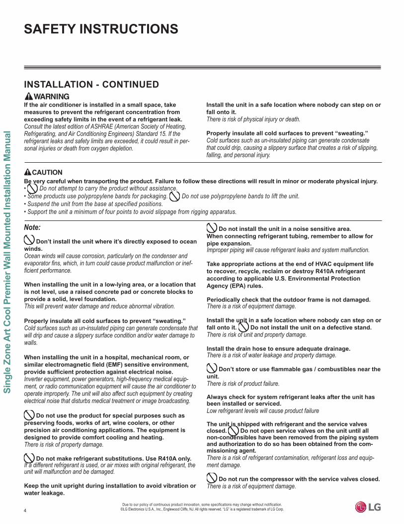
INSTALLATION - CONTINUED
Don’t install the unit where it’s directly exposed to ocean winds.Ocean winds will cause corrosion, particularly on the condenser and
-
When installing the unit in a low-lying area, or a location that is not level, use a raised concrete pad or concrete blocks to provide a solid, level foundation. This will prevent water damage and reduce abnormal vibration.
Properly insulate all cold surfaces to prevent “sweating.” Cold surfaces such as un-insulated piping can generate condensate that will drip and cause a slippery surface condition and/or water damage to walls.
When installing the unit in a hospital, mechanical room, or
Inverter equipment, power generators, high-frequency medical equip-ment, or radio communication equipment will cause the air conditioner to operate improperly. The unit will also affect such equipment by creating electrical noise that disturbs medical treatment or image broadcasting.
Do not use the product for special purposes such as preserving foods, works of art, wine coolers, or other precision air conditioning applications. The equipment is designed to provide comfort cooling and heating.There is risk of property damage.
Do not make refrigerant substitutions. Use R410A only.If a different refrigerant is used, or air mixes with original refrigerant, the unit will malfunction and be damaged.
Keep the unit upright during installation to avoid vibration or water leakage.
Do not install the unit in a noise sensitive area.When connecting refrigerant tubing, remember to allow for pipe expansion.Improper piping will cause refrigerant leaks and system malfunction.
Take appropriate actions at the end of HVAC equipment life to recover, recycle, reclaim or destroy R410A refrigerant according to applicable U.S. Environmental Protection Agency (EPA) rules.
Periodically check that the outdoor frame is not damaged. There is a risk of equipment damage.
Install the unit in a safe location where nobody can step on or fall onto it. Do not install the unit on a defective stand.There is risk of unit and property damage.
Install the drain hose to ensure adequate drainage.There is a risk of water leakage and property damage.
unit.There is risk of product failure.
Always check for system refrigerant leaks after the unit has been installed or serviced.Low refrigerant levels will cause product failure
The unit is shipped with refrigerant and the service valves closed. Do not open service valves on the unit until all non-condensibles have been removed from the piping system and authorization to do so has been obtained from the com-missioning agent.There is a risk of refrigerant contamination, refrigerant loss and equip-ment damage.
Do not run the compressor with the service valves closed. There is a risk of equipment damage.
CAUTIONBe very careful when transporting the product. Failure to follow these directions will result in minor or moderate physical injury.• Do not attempt to carry the product without assistance.• Some products use polypropylene bands for packaging. Do not use polypropylene bands to lift the unit. • Suspend the unit from the base at specified positions.• Support the unit a minimum of four points to avoid slippage from rigging apparatus.
If the air conditioner is installed in a small space, take measures to prevent the refrigerant concentration from exceeding safety limits in the event of a refrigerant leak.Consult the latest edition of ASHRAE (American Society of Heating, Refrigerating, and Air Conditioning Engineers) Standard 15. If the refrigerant leaks and safety limits are exceeded, it could result in per-sonal injuries or death from oxygen depletion.
Install the unit in a safe location where nobody can step on or fall onto it.There is risk of physical injury or death.
Properly insulate all cold surfaces to prevent “sweating.” Cold surfaces such as un-insulated piping can generate condensate that could drip, causing a slippery surface that creates a risk of slipping, falling, and personal injury.
5
Safety Instructions
Due to our policy of continuous product innovation, some specifications may change without notification. ©LG Electronics U.S.A., Inc., Englewood Cliffs, NJ. All rights reserved. “LG” is a registered trademark of LG Corp.
SAFETY INSTRUCTIONS
High voltage electricity is required to operate this system. Adhere to the National Electrical Codes and these instructions when wiring. Improper connections and inadequate grounding can cause accidental injury or death.Always ground the unit following local, state, and National Electrical Codes.
Turn the power off at the nearest disconnect before servicing the equipment.Electrical shock can cause physical injury or death.
Properly size all circuit breakers or fuses.
WIRING
The information contained in this manual is intended for use
familiar with the U.S. National Electric Code (NEC) who is equipped with the proper tools and test instruments.Failure to carefully read and follow all instructions in this manual can result in personal injury or death.
All electric work must be performed by a licensed electrician and conform to local building codes or, in the absence of local codes, with the National Electrical Code, and the instructions given in this manual. If the power source capacity is inadequate or the electric work is not
death.
Refer to local, state, and federal codes, and use power wires
strain relief.Improperly securing wires will create undue stress on equipment power
-cal injury or death.
-iar with the U.S. National Electric Code (NEC) who is equipped with the proper tools and test instruments.Failure to carefully read and follow all instructions in this manual can result in equipment malfunction and property damage.
6
Sing
le Z
one
Art
Coo
l Pre
mie
r Wal
l Mou
nted
Inst
alla
tion
Man
ual
Due to our policy of continuous product innovation, some specifications may change without notification. ©LG Electronics U.S.A., Inc., Englewood Cliffs, NJ. All rights reserved. “LG” is a registered trademark of LG Corp.
SAFETY INSTRUCTIONS
that no metal scraps, screws, or bits of wiring have been left inside or surrounding the unit.
Do not use this equipment in mission critical or special- purpose applications such as preserving foods, works of art, wine coolers or refrigeration. The equipment is designed to provide comfort cooling and heating.
Do not block the inlet or outlet.Unit will malfunction.
Securely attach the electrical part cover to the indoor unit and the service panel to the outdoor unit.Non-secured covers can result in malfunction due to dust or water in the service panel.
Periodically verify the equipment mounts have not deteriorated.If the base collapses, the unit could fall and cause property damage or product failure.
Do not allow water, dirt, or animals to enter the unit.There is risk of unit failure.
OPERATION
Do not provide power to or operate the unit if it is
Use a dedicated power source for this product.
Do not operate the disconnect switch with wet hands.
Periodically verify the equipment mounts have not deteriorated.If the unit falls from its installed location, it can cause physical injury or death.
If gas leaks out, ventilate the area before operating the unit.If the unit is mounted in an enclosed, low-lying, or poorly ventilated area,
shock, explosion, physical injury or death.
CAUTIONTo avoid physical injury, use caution when cleaning or servicing the air conditioner.
Do not allow water, dirt, or animals to enter the unit.
Avoid excessive cooling, and periodically perform venti-lation to the unit.Inadequate ventilation is a health hazard.
Do not touch the refrigerant piping during or after operation.It can cause burns or frostbite.
Do not operate the unit with the panel(s) or protective
moving parts.The rotating, hot, cold, and high-voltage parts of the unit can cause physical injury or death.
Periodically verify the equipment mounts have not deteriorated.If the base collapses, the unit can fall and cause physical injury or death.
Periodically check power cord and plug for damage.Cord must be replaced by the manufacturer, its service agent, or similar
Do not open the inlet grille of the unit during operation. Do not operate the unit with the panels or guards re-
moved. Do not insert hands or other objects through the inlet or outlet when the unit is plugged in. Do not touch
The unit contains sharp, rotating, hot, and high voltage parts that can cause personal injury and/or electric shock.
Securely attach the electrical part cover to the indoor unit and the service panel to the outdoor unit.Non-secured covers can result in burns or electric shock due to dust or water in the service panel.
7Due to our policy of continuous product innovation, some specifications may change without notification.
©LG Electronics U.S.A., Inc., Englewood Cliffs, NJ. All rights reserved. “LG” is a registered trademark of LG Corp.
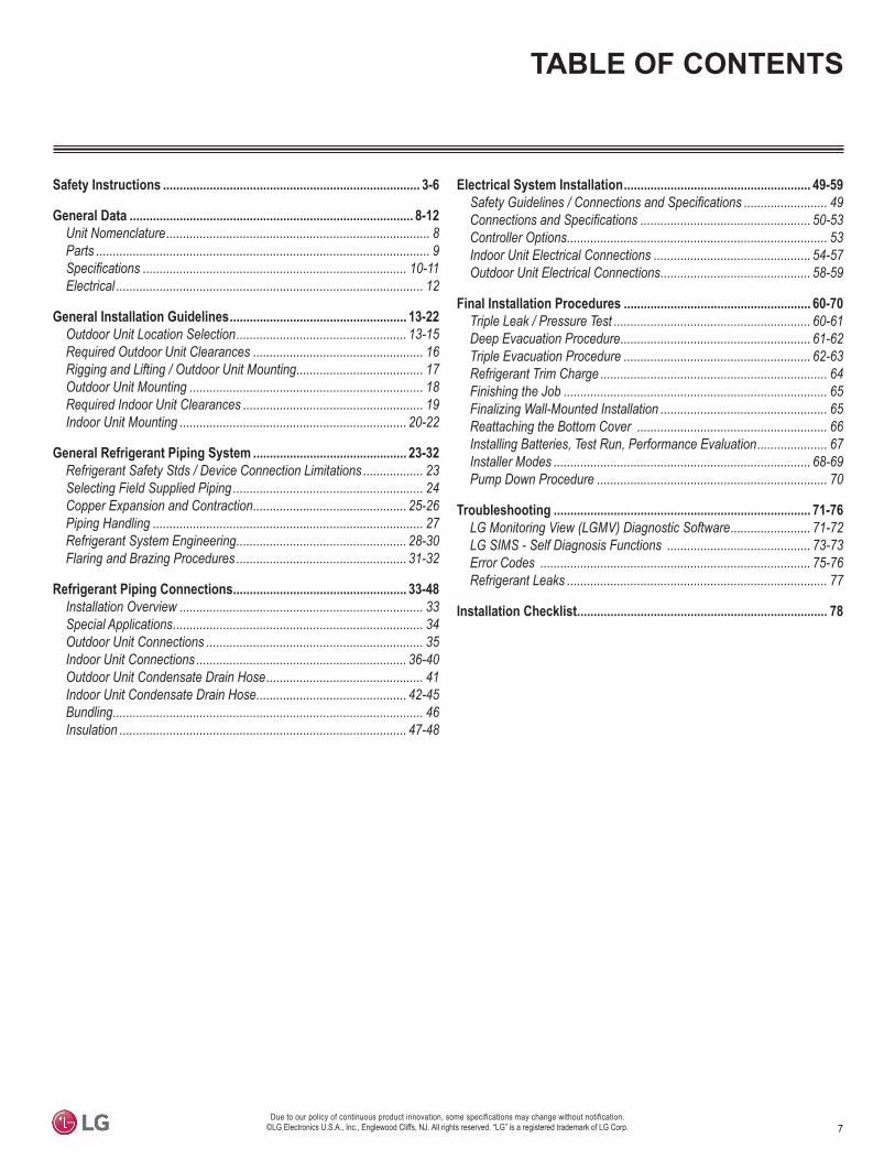
TABLE OF CONTENTS
Safety Instructions ............................................................................. 3-6
General Data ..................................................................................... 8-12Unit Nomenclature ............................................................................... 8Parts .................................................................................................... 9
............................................................................... 10-11Electrical ............................................................................................ 12
General Installation Guidelines ..................................................... 13-22Outdoor Unit Location Selection ................................................... 13-15Required Outdoor Unit Clearances ................................................... 16Rigging and Lifting / Outdoor Unit Mounting ...................................... 17Outdoor Unit Mounting ...................................................................... 18Required Indoor Unit Clearances ...................................................... 19Indoor Unit Mounting .................................................................... 20-22
General Refrigerant Piping System .............................................. 23-32Refrigerant Safety Stds / Device Connection Limitations .................. 23Selecting Field Supplied Piping ......................................................... 24Copper Expansion and Contraction .............................................. 25-26Piping Handling ................................................................................. 27Refrigerant System Engineering ................................................... 28-30Flaring and Brazing Procedures ................................................... 31-32
Refrigerant Piping Connections .................................................... 33-48Installation Overview ......................................................................... 33Special Applications ........................................................................... 34Outdoor Unit Connections ................................................................. 35Indoor Unit Connections ............................................................... 36-40Outdoor Unit Condensate Drain Hose ............................................... 41Indoor Unit Condensate Drain Hose ............................................. 42-45Bundling ............................................................................................. 46Insulation ...................................................................................... 47-48
Electrical System Installation ........................................................ 49-59 ......................... 49
................................................... 50-53Controller Options .............................................................................. 53Indoor Unit Electrical Connections ............................................... 54-57Outdoor Unit Electrical Connections ............................................. 58-59
Final Installation Procedures ........................................................ 60-70Triple Leak / Pressure Test ........................................................... 60-61Deep Evacuation Procedure ......................................................... 61-62Triple Evacuation Procedure ........................................................ 62-63Refrigerant Trim Charge .................................................................... 64Finishing the Job ............................................................................... 65Finalizing Wall-Mounted Installation .................................................. 65Reattaching the Bottom Cover ......................................................... 66Installing Batteries, Test Run, Performance Evaluation ..................... 67Installer Modes ............................................................................. 68-69Pump Down Procedure ..................................................................... 70
Troubleshooting ............................................................................. 71-76LG Monitoring View (LGMV) Diagnostic Software ........................ 71-72LG SIMS - Self Diagnosis Functions ........................................... 73-73Error Codes ................................................................................. 75-76Refrigerant Leaks .............................................................................. 77
Installation Checklist ........................................................................... 78
8
Sing
le Z
one
Art
Coo
l Pre
mie
r Wal
l Mou
nted
Inst
alla
tion
Man
ual
Due to our policy of continuous product innovation, some specifications may change without notification. ©LG Electronics U.S.A., Inc., Englewood Cliffs, NJ. All rights reserved. “LG” is a registered trademark of LG Corp.
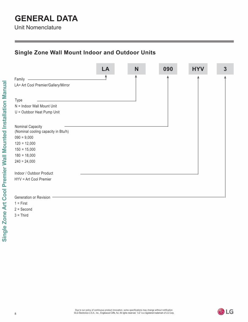
GENERAL DATAUnit Nomenclature
Single Zone Wall Mount Indoor and Outdoor Units
LA N 090 HYV 3
Generation or Revision1 = First2 = Second3 = Third
Indoor / Outdoor ProductHYV = Art Cool Premier
Nominal Capacity (Nominal cooling capacity in Btu/h)090 = 9,000 120 = 12,000 150 = 15,000180 = 18,000240 = 24,000
TypeN = Indoor Wall Mount UnitU = Outdoor Heat Pump Unit
FamilyLA= Art Cool Premier/Gallery/Mirror
9
Product Data
Due to our policy of continuous product innovation, some specifications may change without notification. ©LG Electronics U.S.A., Inc., Englewood Cliffs, NJ. All rights reserved. “LG” is a registered trademark of LG Corp.
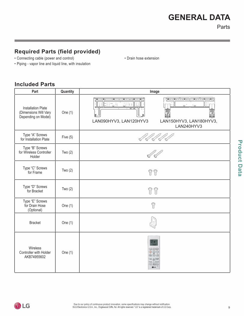
GENERAL DATAParts
• Connecting cable (power and control)• Piping - vapor line and liquid line, with insulation
• Drain hose extensionRequired Parts (field provided)
Included PartsPart Quantity Image
Installation Plate(Dimensions Will VaryDepending on Model)
One (1)
LAN090HYV3, LAN120HYV3 LAN150HYV3, LAN180HYV3, LAN240HYV3
Type “A” Screwsfor Installation Plate Five (5)
Type “B” Screwsfor Wireless Controller
HolderTwo (2)
Type “C” Screwsfor Frame Two (2)
Type “D” Screws for Bracket Two (2)
Type “E” Screws for Drain Hose
(Optional)One (1)
Bracket One (1)
Wireless Controller with Holder
AKB74955602One (1)
10
Sing
le Z
one
Art
Coo
l Pre
mie
r Wal
l Mou
nted
Inst
alla
tion
Man
ual
Due to our policy of continuous product innovation, some specifications may change without notification. ©LG Electronics U.S.A., Inc., Englewood Cliffs, NJ. All rights reserved. “LG” is a registered trademark of LG Corp.
GENERAL DATA
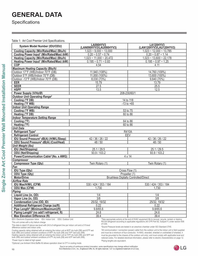
Table 1: System Model Number (IDU/ODU) LA090HYV3
(LAN090HYV3/LAU090HYV3)LA120HYV3
(LAN120HYV3/LAU120HYV3)Cooling Capacity (Min/Rated/Max) (Btu/h) 1,023 ~ 9,000 ~ 13,000 1,023 ~ 12,000 ~ 13,785Cooling Power Input1 (Min/Rated/Max) (kW) 0.20 ~ 0.57 ~ 0.74 0.20 ~ 0.87 ~ 1.14Heating Capacity (Min/Rated/Max) (Btu/h) 1,023 ~ 11,000 ~ 20,472 1,023 ~ 13,600 ~ 22,178Heating Power Input1 (Min/Rated/Max) (kW) 0.195 ~ 0.71 ~ 0.93 0.195 ~ 0.97 ~ 1.25COP 4.54 4.11
Maximum Heating Capacity (Btu/h)Outdoor 17°F (WB)/Indoor 70°F (DB) 11,940 (108%) 14,760 (109%)Outdoor 5°F (WB)/Indoor 70°F (DB) 11,000 (100%) 13,600 (100%)Outdoor -13°F (WB)/Indoor 70°F (DB) 8,030 (73%) 9,640 (70%)EER 15.79 13.79SEER 27.5 25.5HSPF 13.5 12.5Power Supply (V/Hz/Ø) 208-230/60/1
Outdoor Unit Operating Range2
Cooling (°F DB) 14 to 118Heating (°F WB) -13 to +65
Indoor Unit Operating RangeCooling (°F WB) 53 to 75Heating (°F DB) 60 to 86
Indoor Temperature Setting RangeCooling (°F) 64 to 86Heating (°F) 60 to 86
Unit DataRefrigerant Type3 R410ARefrigerant Control EEVIDU Sound Pressure4 dB(A) (H/M/L/Sleep) 42 / 36 / 26 / 22 42 / 36 / 26 / 22ODU Sound Pressure4 dB(A) (Cool/Heat) 48 / 50 48 / 50
Unit Weight (lbs)IDU (Net/Shipping) 25.1 / 29.5 25.1 / 29.5ODU (Net/Shipping) 93.9 / 103.2 93.9 / 103.2Power/Communication Cable5 (No. x AWG) 4 x 14
CompressorCompressor Type (Qty) Twin Rotary (1) Twin Rotary (1)
FanIDU Type (Qty) Cross Flow (1)ODU Type (Qty) Propeller (1)Motor/Drive Brushless Digitally Controlled/Direct
Airflow RateIDU Max/H/M/L (CFM) 530 / 424 / 353 / 184 530 / 424 / 353 / 184ODU Max (CFM) 1,730 1,730
PipingLiquid Line (in, OD) 1/4 1/4Vapor Line (in, OD) 3/8 3/8Condensation Line (OD, ID) 25/32, 19/32 25/32, 19/32Additional Refrigerant Charge (oz/ft) 0.22 0.22Pipe Length6 (Minimum/Maximum)(ft) 9.8/65.6 9.8/65.6Piping Length6 (no add’l refrigerant, ft) 24.6 24.6Max Elevation Difference (ft) 39.4 39.4
EEV: Electronic Expansion Valve IDU: Indoor Unit ODU: Outdoor UnitThis unit comes with a dry helium charge.This data is rated 0 ft above sea level with 24.6 of refrigerant line per indoor unit and a 0 ft level difference outdoor and indoor units.Cooling capacity rating obtained with air entering the indoor unit at 80ºF dry bulb (DB) and 67ºF wet bulb (WB) and outdoor ambient conditions of 95ºF dry bulb (DB) and 75ºF wet bulb (WB). Heating capacity rating obtained with air entering the indoor unit at 70ºF dry bulb (DB) and 59ºF wet bulb (WB) and outdoor ambient conditions of 47ºF dry bulb (DB) and 43ºF wet bulb (WB).1Power Input is rated at high speed.2Optional Low Ambient Wind Baffle Kit allows operation down to 0°F in cooling mode.
3Take appropriate actions at the end of HVAC equipment life to recover, recycle, reclaim or destroy R410A refrigerant according to applicable regulations (40 CFR Part 82, Subpart F) under section 608 of CAA.4Sound Pressure levels are tested in an anechoic chamber under ISO Standard 3745.5All communication / connection (power) cable from the outdoor unit to the indoor unit is field supplied and must be a minimum of four-conductor, 14 AWG, stranded, shielded or unshielded (if shielded, it must be grounded to the chassis of the outdoor unit only), and must comply with applicable local and national codes. For detailed electrical information, please refer to electric characteristics on page 12.6Piping lengths are equivalent.
11
Product Data
Due to our policy of continuous product innovation, some specifications may change without notification. ©LG Electronics U.S.A., Inc., Englewood Cliffs, NJ. All rights reserved. “LG” is a registered trademark of LG Corp.
GENERAL DATA
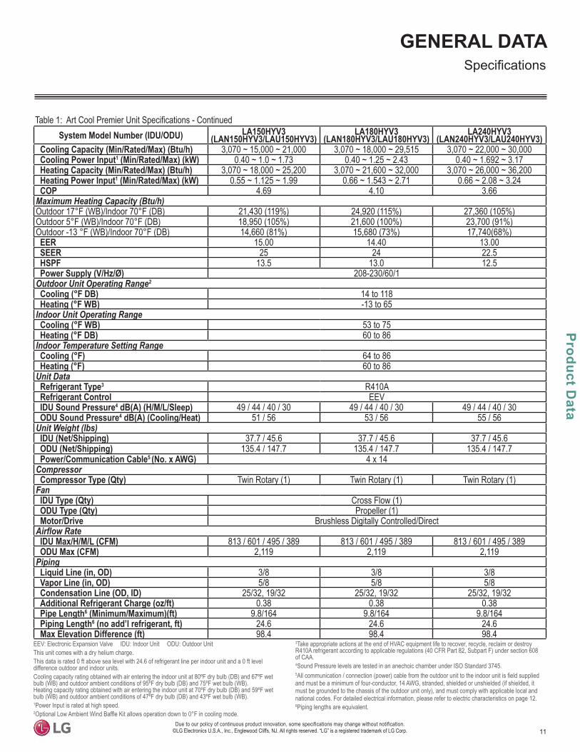
System Model Number (IDU/ODU) LA150HYV3 (LAN150HYV3/LAU150HYV3)
LA180HYV3 (LAN180HYV3/LAU180HYV3)
LA240HYV3 (LAN240HYV3/LAU240HYV3)
Cooling Capacity (Min/Rated/Max) (Btu/h) 3,070 ~ 15,000 ~ 21,000 3,070 ~ 18,000 ~ 29,515 3,070 ~ 22,000 ~ 30,000Cooling Power Input1 (Min/Rated/Max) (kW) 0.40 ~ 1.0 ~ 1.73 0.40 ~ 1.25 ~ 2.43 0.40 ~ 1.692 ~ 3.17Heating Capacity (Min/Rated/Max) (Btu/h) 3,070 ~ 18,000 ~ 25,200 3,070 ~ 21,600 ~ 32,000 3,070 ~ 26,000 ~ 36,200Heating Power Input1 (Min/Rated/Max) (kW) 0.55 ~ 1.125 ~ 1.99 0.66 ~ 1.543 ~ 2.71 0.66 ~ 2.08 ~ 3.24COP 4.69 4.10 3.66
Maximum Heating Capacity (Btu/h)Outdoor 17°F (WB)/Indoor 70°F (DB) 21,430 (119%) 24,920 (115%) 27,360 (105%)Outdoor 5°F (WB)/Indoor 70°F (DB) 18,950 (105%) 21,600 (100%) 23,700 (91%)Outdoor -13 °F (WB)/Indoor 70°F (DB) 14,660 (81%) 15,680 (73%) 17,740(68%)EER 15.00 14.40 13.00SEER 25 24 22.5HSPF 13.5 13.0 12.5Power Supply (V/Hz/Ø) 208-230/60/1
Outdoor Unit Operating Range2
Cooling (°F DB) 14 to 118Heating (°F WB) -13 to 65
Indoor Unit Operating RangeCooling (°F WB) 53 to 75Heating (°F DB) 60 to 86
Indoor Temperature Setting RangeCooling (°F) 64 to 86Heating (°F) 60 to 86
Unit DataRefrigerant Type3 R410ARefrigerant Control EEVIDU Sound Pressure4 dB(A) (H/M/L/Sleep) 49 / 44 / 40 / 30 49 / 44 / 40 / 30 49 / 44 / 40 / 30ODU Sound Pressure4 dB(A) (Cooling/Heat) 51 / 56 53 / 56 55 / 56
Unit Weight (lbs)IDU (Net/Shipping) 37.7 / 45.6 37.7 / 45.6 37.7 / 45.6ODU (Net/Shipping) 135.4 / 147.7 135.4 / 147.7 135.4 / 147.7Power/Communication Cable5 (No. x AWG) 4 x 14
CompressorCompressor Type (Qty) Twin Rotary (1) Twin Rotary (1) Twin Rotary (1)
FanIDU Type (Qty) Cross Flow (1)ODU Type (Qty) Propeller (1)Motor/Drive Brushless Digitally Controlled/Direct
Airflow RateIDU Max/H/M/L (CFM) 813 / 601 / 495 / 389 813 / 601 / 495 / 389 813 / 601 / 495 / 389ODU Max (CFM) 2,119 2,119 2,119
PipingLiquid Line (in, OD) 3/8 3/8 3/8Vapor Line (in, OD) 5/8 5/8 5/8Condensation Line (OD, ID) 25/32, 19/32 25/32, 19/32 25/32, 19/32Additional Refrigerant Charge (oz/ft) 0.38 0.38 0.38Pipe Length6 (Minimum/Maximum)(ft) 9.8/164 9.8/164 9.8/164Piping Length6 (no add’l refrigerant, ft) 24.6 24.6 24.6Max Elevation Difference (ft) 98.4 98.4 98.4
EEV: Electronic Expansion Valve IDU: Indoor Unit ODU: Outdoor UnitThis unit comes with a dry helium charge.This data is rated 0 ft above sea level with 24.6 of refrigerant line per indoor unit and a 0 ft level difference outdoor and indoor units.Cooling capacity rating obtained with air entering the indoor unit at 80ºF dry bulb (DB) and 67ºF wet bulb (WB) and outdoor ambient conditions of 95ºF dry bulb (DB) and 75ºF wet bulb (WB). Heating capacity rating obtained with air entering the indoor unit at 70ºF dry bulb (DB) and 59ºF wet bulb (WB) and outdoor ambient conditions of 47ºF dry bulb (DB) and 43ºF wet bulb (WB).1Power Input is rated at high speed.2Optional Low Ambient Wind Baffle Kit allows operation down to 0°F in cooling mode.
3Take appropriate actions at the end of HVAC equipment life to recover, recycle, reclaim or destroy R410A refrigerant according to applicable regulations (40 CFR Part 82, Subpart F) under section 608 of CAA.4Sound Pressure levels are tested in an anechoic chamber under ISO Standard 3745.5All communication / connection (power) cable from the outdoor unit to the indoor unit is field supplied and must be a minimum of four-conductor, 14 AWG, stranded, shielded or unshielded (if shielded, it must be grounded to the chassis of the outdoor unit only), and must comply with applicable local and national codes. For detailed electrical information, please refer to electric characteristics on page 12.6Piping lengths are equivalent.

12
Sing
le Z
one
Art
Coo
l Pre
mie
r Wal
l Mou
nted
Inst
alla
tion
Man
ual
Due to our policy of continuous product innovation, some specifications may change without notification. ©LG Electronics U.S.A., Inc., Englewood Cliffs, NJ. All rights reserved. “LG” is a registered trademark of LG Corp.
GENERAL DATAElectrical
Nominal Tons
Unit Model Number Hertz Voltage Voltage Range
(Min. to Max.) MCA MOP Compressor Qty.
Compressor Motor RLA
Outdoor Fan Motor
Indoor Fan Motor
Cooling Heating W FLA W FLA
3/4 LA090HYV3
60 208 -230 187 - 253
11.2 15 1 8.3 8.3 85 0.4 58 0.4
1 LA120HYV3 11.2 15 1 8.3 8.3 85 0.4 58 0.4
1-1/4 LA150HYV3 19.0 30 1 14.41 14.41 124 0.4 58 0.5
1-1/2 LA180HYV3 19.0 30 1 14.41 14.41 124 0.4 58 0.5
2 LA240HYV3 19.0 30 1 14.41 14.41 124 0.4 58 0.5
Table 2: Art Cool Premier Electrical Data
Voltage tolerance is ±10%.Maximum allowable voltage unbalance is 2%.MCA = Minimum Circuit Ampacity.
Maximum Overcurrent Protection (MOP) is calculated as follows: (Largest motor FLA x 2.25) + (Sum of other motor FLA) rounded down to the nearest standard fuse size. RLA = Rated Load Amps.FLA = Full Load Amps.
13
General Installation G
uidelines
Due to our policy of continuous product innovation, some specifications may change without notification. ©LG Electronics U.S.A., Inc., Englewood Cliffs, NJ. All rights reserved. “LG” is a registered trademark of LG Corp.
GENERAL INSTALLATION GUIDELINES
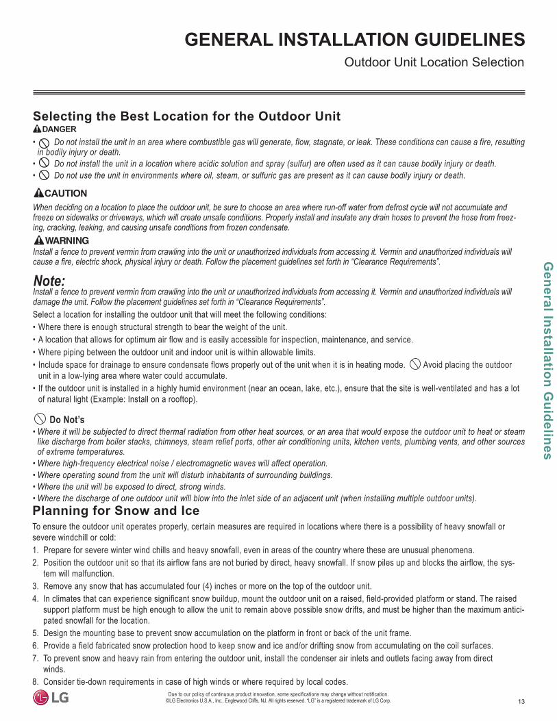
Selecting the Best Location for the Outdoor UnitDANGER
• Do not install the unit in an area where combustible gas will generate, flow, stagnate, or leak. These conditions can cause a fire, resulting in bodily injury or death.
• Do not install the unit in a location where acidic solution and spray (sulfur) are often used as it can cause bodily injury or death.• Do not use the unit in environments where oil, steam, or sulfuric gas are present as it can cause bodily injury or death.
When deciding on a location to place the outdoor unit, be sure to choose an area where run-off water from defrost cycle will not accumulate and freeze on sidewalks or driveways, which will create unsafe conditions. Properly install and insulate any drain hoses to prevent the hose from freez-ing, cracking, leaking, and causing unsafe conditions from frozen condensate.
Install a fence to prevent vermin from crawling into the unit or unauthorized individuals from accessing it. Vermin and unauthorized individuals will
Install a fence to prevent vermin from crawling into the unit or unauthorized individuals from accessing it. Vermin and unauthorized individuals will
Select a location for installing the outdoor unit that will meet the following conditions:• Where there is enough structural strength to bear the weight of the unit.• A location that allows for optimum air flow and is easily accessible for inspection, maintenance, and service.• Where piping between the outdoor unit and indoor unit is within allowable limits.• Include space for drainage to ensure condensate flows properly out of the unit when it is in heating mode. Avoid placing the outdoor
unit in a low-lying area where water could accumulate.• If the outdoor unit is installed in a highly humid environment (near an ocean, lake, etc.), ensure that the site is well-ventilated and has a lot
of natural light (Example: Install on a rooftop).
Do Not’s• Where it will be subjected to direct thermal radiation from other heat sources, or an area that would expose the outdoor unit to heat or steam
like discharge from boiler stacks, chimneys, steam relief ports, other air conditioning units, kitchen vents, plumbing vents, and other sources of extreme temperatures.
• • Where operating sound from the unit will disturb inhabitants of surrounding buildings.• Where the unit will be exposed to direct, strong winds.• Where the discharge of one outdoor unit will blow into the inlet side of an adjacent unit (when installing multiple outdoor units).Planning for Snow and IceTo ensure the outdoor unit operates properly, certain measures are required in locations where there is a possibility of heavy snowfall or severe windchill or cold:1. Prepare for severe winter wind chills and heavy snowfall, even in areas of the country where these are unusual phenomena.2. Position the outdoor unit so that its airflow fans are not buried by direct, heavy snowfall. If snow piles up and blocks the airflow, the sys-
tem will malfunction.3. Remove any snow that has accumulated four (4) inches or more on the top of the outdoor unit.4. In climates that can experience significant snow buildup, mount the outdoor unit on a raised, field-provided platform or stand. The raised
support platform must be high enough to allow the unit to remain above possible snow drifts, and must be higher than the maximum antici-pated snowfall for the location.
5. Design the mounting base to prevent snow accumulation on the platform in front or back of the unit frame.6. Provide a field fabricated snow protection hood to keep snow and ice and/or drifting snow from accumulating on the coil surfaces.7. To prevent snow and heavy rain from entering the outdoor unit, install the condenser air inlets and outlets facing away from direct
winds.8. Consider tie-down requirements in case of high winds or where required by local codes.
Outdoor Unit Location Selection
14
Sing
le Z
one
Art
Coo
l Pre
mie
r Wal
l Mou
nted
Inst
alla
tion
Man
ual
Due to our policy of continuous product innovation, some specifications may change without notification. ©LG Electronics U.S.A., Inc., Englewood Cliffs, NJ. All rights reserved. “LG” is a registered trademark of LG Corp.
GENERAL INSTALLATION GUIDELINES
Planning for Snow and Ice, continued.
The indoor unit will take longer to provide heat, or heating performance will be reduced in winter if the unit is installed:
drain hoses to prevent the hose from freezing, cracking, leaking, and damaging the outdoor unit.
1. In a narrow, shady location.2. Near a location that has a lot of ground moisture.
3. In a highly humid environment.4. In an area in which condensate does not drain properly.
Outdoor Unit Location Selection
When deciding on a location to place the outdoor unit, be sure to choose an area where run-off water from defrost cycle will not accumulate and freeze on sidewalks or driveways, which will create unsafe conditions. Properly install and insulate any drain hoses to prevent the hose from freez-ing, cracking, leaking, and causing unsafe conditions from frozen condensate.
Tie-Downs and Lightning ProtectionTie-Downs• The strength of the roof must be checked before installing the
outdoor units. • If the installation site is prone to high winds or earthquakes, when
installing on the wall or roof, securely anchor the mounting base using a field-provided tie-down configuration approved by a local professional engineer.
• The overall tie-down configuration must be approved by a local professional engineer.
Always refer to local code when using a wind restraint system.
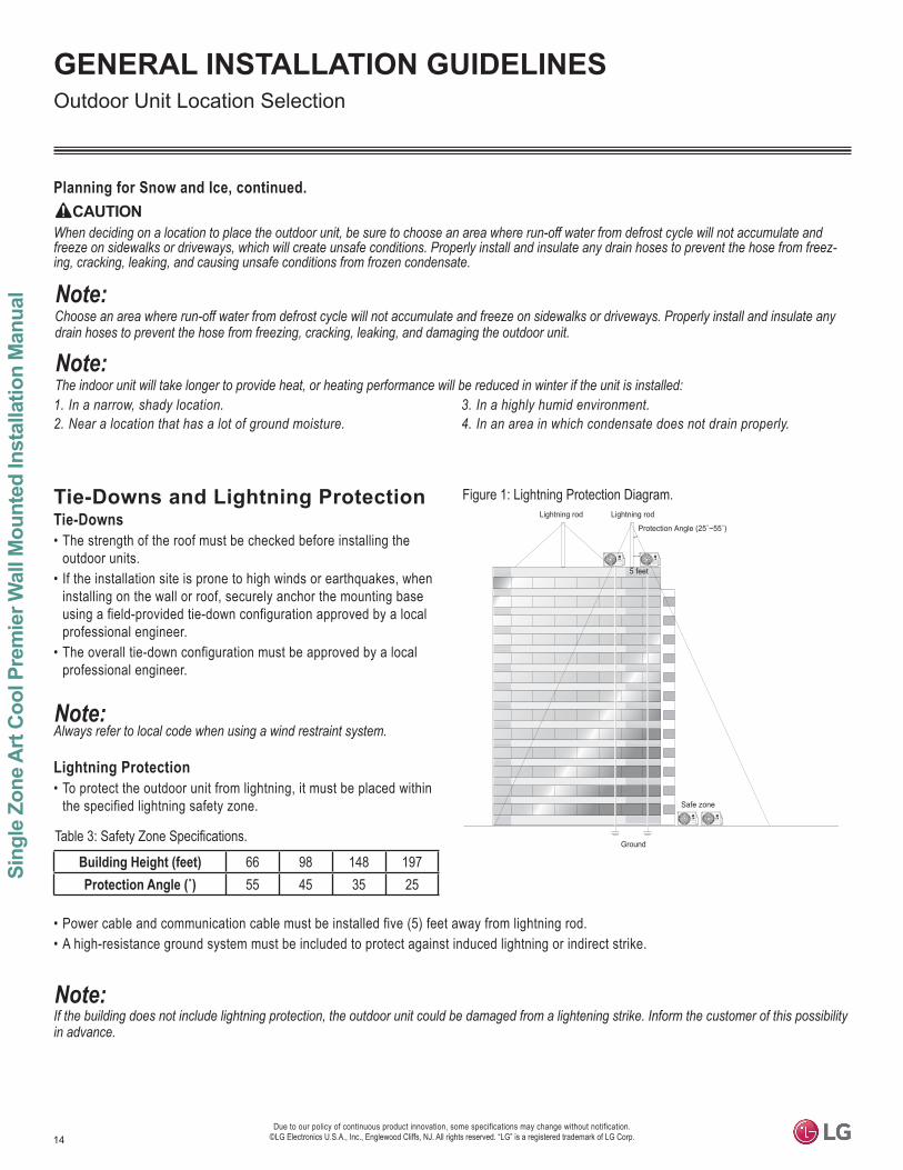
Lightning Protection• To protect the outdoor unit from lightning, it must be placed within
the specified lightning safety zone.
• Power cable and communication cable must be installed five (5) feet away from lightning rod. • A high-resistance ground system must be included to protect against induced lightning or indirect strike.
Building Height (feet) 66 98 148 19755 45 35 25
If the building does not include lightning protection, the outdoor unit could be damaged from a lightening strike. Inform the customer of this possibility in advance.
Ground
Safe zone
Lightning rod
5 feet
Lightning rod
Figure 1: Lightning Protection Diagram.
Table 3: Safety Zone Specifications.
15
General Installation G
uidelines
Due to our policy of continuous product innovation, some specifications may change without notification. ©LG Electronics U.S.A., Inc., Englewood Cliffs, NJ. All rights reserved. “LG” is a registered trademark of LG Corp.
GENERAL INSTALLATION GUIDELINES
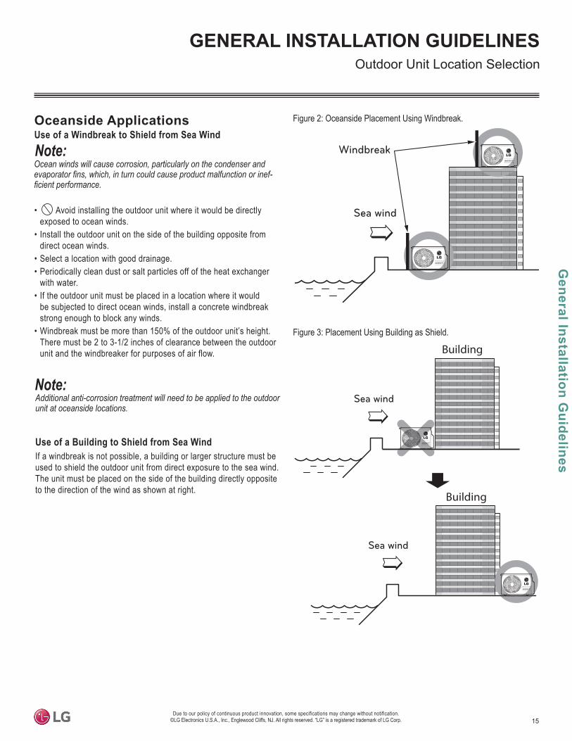
• Avoid installing the outdoor unit where it would be directly exposed to ocean winds.
• Install the outdoor unit on the side of the building opposite from direct ocean winds.
• Select a location with good drainage.• Periodically clean dust or salt particles off of the heat exchanger
with water. • If the outdoor unit must be placed in a location where it would
be subjected to direct ocean winds, install a concrete windbreak strong enough to block any winds.
• Windbreak must be more than 150% of the outdoor unit’s height. There must be 2 to 3-1/2 inches of clearance between the outdoor unit and the windbreaker for purposes of air flow.
Additional anti-corrosion treatment will need to be applied to the outdoor unit at oceanside locations.
Ocean winds will cause corrosion, particularly on the condenser and -
Oceanside ApplicationsUse of a Windbreak to Shield from Sea Wind
Use of a Building to Shield from Sea WindIf a windbreak is not possible, a building or larger structure must be used to shield the outdoor unit from direct exposure to the sea wind. The unit must be placed on the side of the building directly opposite to the direction of the wind as shown at right.
Figure 2: Oceanside Placement Using Windbreak.
Figure 3: Placement Using Building as Shield.
Sea wind
Windbreak
Sea wind
Sea wind
Building
Building
Outdoor Unit Location Selection
16
Sing
le Z
one
Art
Coo
l Pre
mie
r Wal
l Mou
nted
Inst
alla
tion
Man
ual
Due to our policy of continuous product innovation, some specifications may change without notification. ©LG Electronics U.S.A., Inc., Englewood Cliffs, NJ. All rights reserved. “LG” is a registered trademark of LG Corp.
GENERAL INSTALLATION GUIDELINES
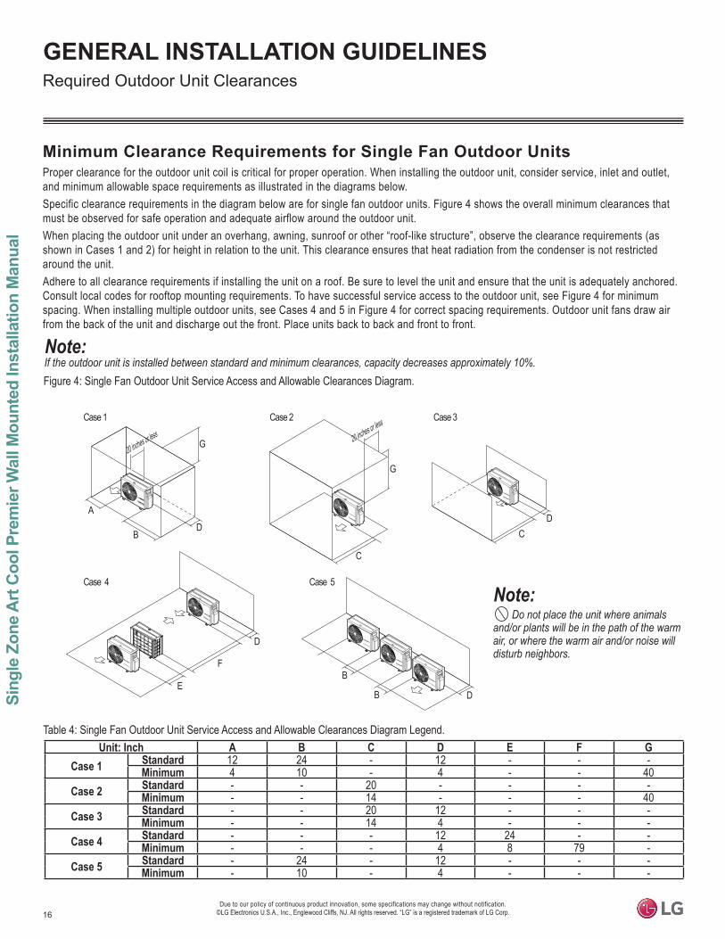
Figure 4: Single Fan Outdoor Unit Service Access and Allowable Clearances Diagram.
Unit: Inch A B C D E F GCase 1 Standard 12 24 - 12 - - -
Minimum 4 10 - 4 - - 40Case 2 Standard - - 20 - - - -
Minimum - - 14 - - - 40Case 3 Standard - - 20 12 - - -
Minimum - - 14 4 - - -Case 4 Standard - - - 12 24 - -
Minimum - - - 4 8 79 -Case 5 Standard - 24 - 12 - - -
Minimum - 10 - 4 - - -
Table 4: Single Fan Outdoor Unit Service Access and Allowable Clearances Diagram Legend.
Do not place the unit where animals
disturb neighbors.
If the outdoor unit is installed between standard and minimum clearances, capacity decreases approximately 10%.
Minimum Clearance Requirements for Single Fan Outdoor UnitsProper clearance for the outdoor unit coil is critical for proper operation. When installing the outdoor unit, consider service, inlet and outlet, and minimum allowable space requirements as illustrated in the diagrams below.Specific clearance requirements in the diagram below are for single fan outdoor units. Figure 4 shows the overall minimum clearances that must be observed for safe operation and adequate airflow around the outdoor unit.When placing the outdoor unit under an overhang, awning, sunroof or other “roof-like structure”, observe the clearance requirements (as shown in Cases 1 and 2) for height in relation to the unit. This clearance ensures that heat radiation from the condenser is not restricted around the unit. Adhere to all clearance requirements if installing the unit on a roof. Be sure to level the unit and ensure that the unit is adequately anchored. Consult local codes for rooftop mounting requirements. To have successful service access to the outdoor unit, see Figure 4 for minimum spacing. When installing multiple outdoor units, see Cases 4 and 5 in Figure 4 for correct spacing requirements. Outdoor unit fans draw air from the back of the unit and discharge out the front. Place units back to back and front to front.
A
BD
G
C
G
CD
E
D
DB
BF
1/16 inch
20 inches or less Case 1
Case 4
Case 2 Case 3
Case 5
20 inches or less
Required Outdoor Unit Clearances
17
General Installation G
uidelines
Due to our policy of continuous product innovation, some specifications may change without notification. ©LG Electronics U.S.A., Inc., Englewood Cliffs, NJ. All rights reserved. “LG” is a registered trademark of LG Corp.
GENERAL INSTALLATION GUIDELINESRigging and Lifting / Outdoor Unit Mounting
Rigging and Lifting Instructions
Wear protective gloves and safety goggles when handling equipment. Sharp edges will cause personal injury.
Dispose of the packing materials safely.• Packing materials, such as nails and other metal or wooden parts, will cause puncture wounds or other injuries.• Tear apart and throw away plastic packaging bags so that children will not play with them and risk suffocation and death.
• Be very careful when transporting the product. There is a risk of the product falling and causing physical injury.• • Some products use polypropylene bands for packaging. Do not use polypropylene bands to lift the unit.• Support the outdoor unit at a minimum of four points to avoid slippage from rigging apparatus.
• Make sure the outdoor unit is in its original packaging to avoid damage during local transport.•
immediately.• Handle the outdoor unit with care. Keep the outdoor unit upright to avoid damaging inside components.• If a forklift is to transport the outdoor unit, the forklift arms must pass through the openings at the bottom.•
the unit. Pass the rope through the two (2) forklift slots each at the front and rear of the outdoor unit.• • Always include padding to protect the outdoor unit from rope damage, and take into consideration the outdoor unit’s center of gravity.
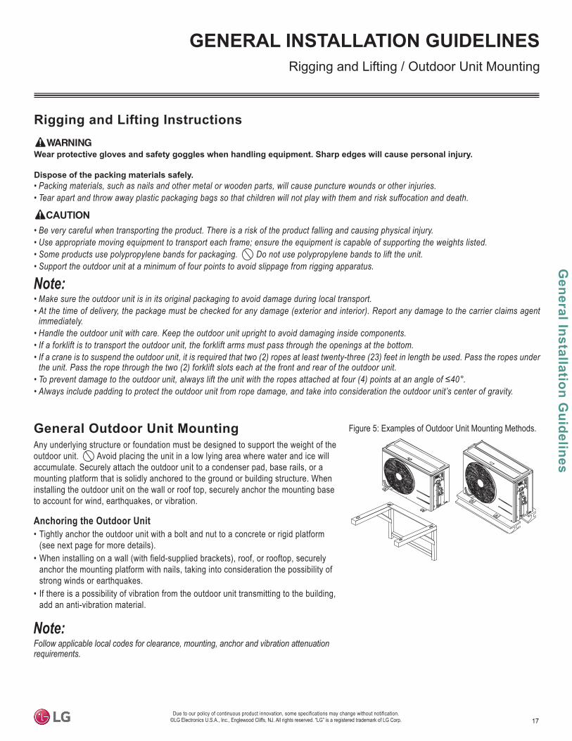
General Outdoor Unit MountingAny underlying structure or foundation must be designed to support the weight of the outdoor unit. Avoid placing the unit in a low lying area where water and ice will accumulate. Securely attach the outdoor unit to a condenser pad, base rails, or a mounting platform that is solidly anchored to the ground or building structure. When installing the outdoor unit on the wall or roof top, securely anchor the mounting base to account for wind, earthquakes, or vibration.
Anchoring the Outdoor Unit• Tightly anchor the outdoor unit with a bolt and nut to a concrete or rigid platform
(see next page for more details). • When installing on a wall (with field-supplied brackets), roof, or rooftop, securely
anchor the mounting platform with nails, taking into consideration the possibility of strong winds or earthquakes.
• If there is a possibility of vibration from the outdoor unit transmitting to the building, add an anti-vibration material.
Figure 5: Examples of Outdoor Unit Mounting Methods.
18
Sing
le Z
one
Art
Coo
l Pre
mie
r Wal
l Mou
nted
Inst
alla
tion
Man
ual
Due to our policy of continuous product innovation, some specifications may change without notification. ©LG Electronics U.S.A., Inc., Englewood Cliffs, NJ. All rights reserved. “LG” is a registered trademark of LG Corp.
GENERAL INSTALLATION GUIDELINES
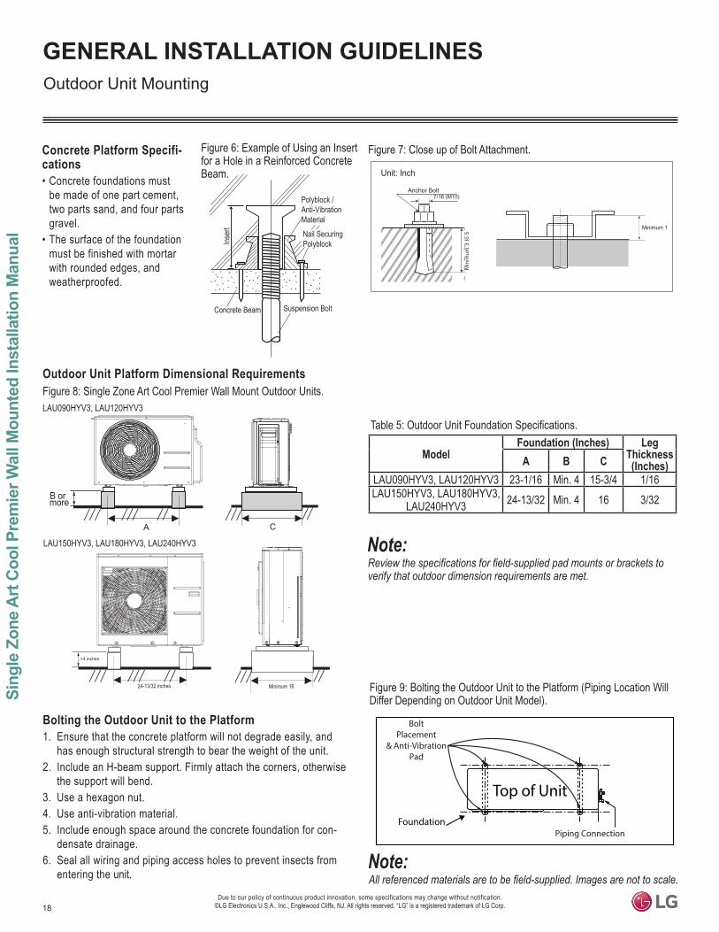
ModelFoundation (Inches) Leg
Thickness (Inches)A B C
LAU090HYV3, LAU120HYV3 23-1/16 Min. 4 15-3/4 1/16LAU150HYV3, LAU180HYV3,
LAU240HYV3 24-13/32 Min. 4 16 3/32
Concrete Platform Specifi-cations• Concrete foundations must
be made of one part cement, two parts sand, and four parts gravel.
• The surface of the foundation must be finished with mortar with rounded edges, and weatherproofed.
7/16 (M10)Anchor Bolt
Min
imum
3 to
5
Minimum 1
Unit: Inch
BoltPlacement
& Anti-VibrationPad
Piping Connection
Top of Unit
Foundation
Bolting the Outdoor Unit to the Platform1. Ensure that the concrete platform will not degrade easily, and
has enough structural strength to bear the weight of the unit.2. Include an H-beam support. Firmly attach the corners, otherwise
the support will bend.3. Use a hexagon nut.4. Use anti-vibration material.5. Include enough space around the concrete foundation for con-
densate drainage.6. Seal all wiring and piping access holes to prevent insects from
entering the unit.
Figure 6: Example of Using an Insert for a Hole in a Reinforced Concrete Beam.
Outdoor Unit Platform Dimensional Requirements
Figure 7: Close up of Bolt Attachment.
Figure 8: Single Zone Art Cool Premier Wall Mount Outdoor Units.
Table 5:
Figure 9: Bolting the Outdoor Unit to the Platform (Piping Location Will Differ Depending on Outdoor Unit Model).
Concrete Beam
Inser
t
Suspension Bolt
Polyblock / Anti-Vibration MaterialNail SecuringPolyblock
Outdoor Unit Mounting
B or more
A C
24-13/32 inches Minimum 16
>4 inches
LAU090HYV3, LAU120HYV3
LAU150HYV3, LAU180HYV3, LAU240HYV3
19
General Installation G
uidelines
Due to our policy of continuous product innovation, some specifications may change without notification. ©LG Electronics U.S.A., Inc., Englewood Cliffs, NJ. All rights reserved. “LG” is a registered trademark of LG Corp.
GENERAL INSTALLATION GUIDELINESRequired Indoor Unit Clearances
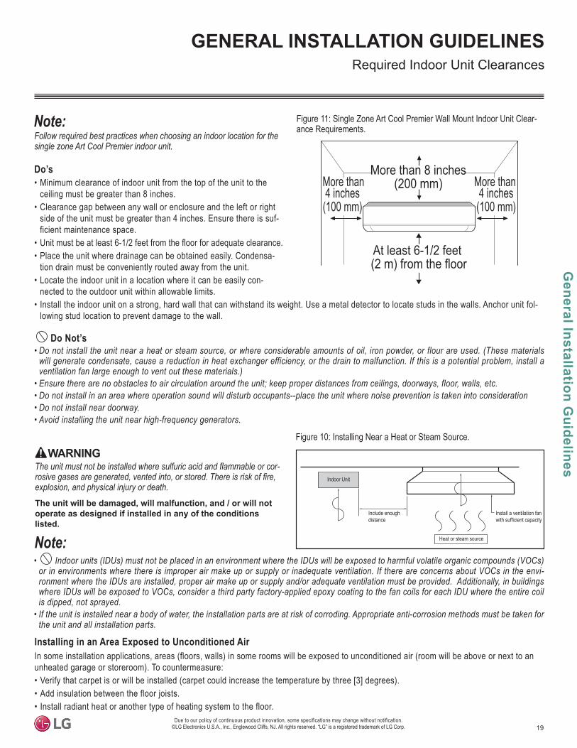
Do’s• Minimum clearance of indoor unit from the top of the unit to the
ceiling must be greater than 8 inches.• Clearance gap between any wall or enclosure and the left or right
side of the unit must be greater than 4 inches. Ensure there is suf-ficient maintenance space.
• • Place the unit where drainage can be obtained easily. Condensa-
tion drain must be conveniently routed away from the unit.• Locate the indoor unit in a location where it can be easily con-
nected to the outdoor unit within allowable limits.• Install the indoor unit on a strong, hard wall that can withstand its weight. Use a metal detector to locate studs in the walls. Anchor unit fol-
lowing stud location to prevent damage to the wall.
Do Not’s• Do not install the unit near a heat or steam source, or where considerable amounts of oil, iron powder, or flour are used. (These materials
will generate condensate, cause a reduction in heat exchanger efficiency, or the drain to malfunction. If this is a potential problem, install a ventilation fan large enough to vent out these materials.)
• • Do not install in an area where operation sound will disturb occupants--place the unit where noise prevention is taken into consideration• Do not install near doorway.•
-
explosion, and physical injury or death.
WARNING
The unit will be damaged, will malfunction, and / or will not operate as designed if installed in any of the conditions listed.
• -
is dipped, not sprayed.• If the unit is installed near a body of water, the installation parts are at risk of corroding. Appropriate anti-corrosion methods must be taken for
the unit and all installation parts.
Installing in an Area Exposed to Unconditioned AirIn some installation applications, areas (floors, walls) in some rooms will be exposed to unconditioned air (room will be above or next to an unheated garage or storeroom). To countermeasure: • Verify that carpet is or will be installed (carpet could increase the temperature by three [3] degrees).• Add insulation between the floor joists. • Install radiant heat or another type of heating system to the floor.
Install a ventilation fanwith sufficient capacity
Heat or steam source
Include enough distance
Indoor Unit
Figure 10: Installing Near a Heat or Steam Source.
Figure 11: Single Zone Art Cool Premier Wall Mount Indoor Unit Clear-ance Requirements.
More than 8 inches(200 mm)More than
4 inches(100 mm)
More than4 inches(100 mm)
At least 6-1/2 feet (2 m) from the floor

20
Sing
le Z
one
Art
Coo
l Pre
mie
r Wal
l Mou
nted
Inst
alla
tion
Man
ual
Due to our policy of continuous product innovation, some specifications may change without notification. ©LG Electronics U.S.A., Inc., Englewood Cliffs, NJ. All rights reserved. “LG” is a registered trademark of LG Corp.
GENERAL INSTALLATION GUIDELINESIndoor Unit Mounting
1. The wall mounted indoor unit is shipped with the installation plate attached to its back. To remove, Unscrew all screw / screws that hold the installation plate to the back of the indoor unit. Number of screws depends on the indoor unit model.
2. Confirm the location where the installation plate will be placed. (Install the indoor unit on a strong, hard wall that can withstand its weight.)
3. Align the centerline using a leveling tool. Measure the wall and mark the centerline.
4. Attach the installation plate to the wall following the measure-ments and marks. Use the type “A” screws that are factory-sup-plied with the plate. • Insert a screw into the center hole of the installation plate, and
tighten. • Verify the installation plate is horizontal using a leveling tool.• Tighten the remaining screws into the holes indicated on the
installation plate.
If the installation plate is not level, any condensate will not drain away
5. Observe all rear piping clearances when drilling into the wall.
tile, plywood, or similar materials without proper anchors. Indoor units must be securely, and
tile, plywood, or similar materials without proper anchors. Indoor units must be securely and prop-
Anchor
Anchor Screw15/64 x 1-3/16 in.
(6 x 30 mm)5/32 x 1-31/32 in.
(4 x 50 mm)
Table 6: Anchor / Screw Sizes.
Figure 12: Art Cool Premier Wall Mount LAN090HYV3 / LAN120HYV3 Indoor Unit Installation Plate Dimensions.
Figure 13: Art Cool Premier Wall Mount LAN150HYV3 / LAN180HYV3 / LAN240HYV3 Indoor Unit Installation Plate Dimensions.
Mounting the Installation Plate to the WallFollow the procedure below and general best practices when mounting the indoor unit’s installation plate to a wall.
wiring can cause serious bodily injury or death.Use caution when drilling holes through the walls for the purposes of piping connections. Power wiring can cause serious bodily injury or death.
Select location carefully. Unit must be anchored to a strong wall to prevent unnecessary vibration.
Figure 14: Installation Plate Screw Locations (Will Vary Depending on Indoor Unit Model).
Figure 15: Example of an Anchor.
Installation Plate
41-23/32 (1060)14-29/32 (379) 7-27/32 (199)
8-7/16 (214)
6-5/16 (160)
2 (51
)
9-1/32 (229)
Ø2-9/16 (65)
2-3/4 (7
0)14
-23/32
(374
)
2-3/4
(70)
2-3/4
(70)
12-1/
8 (30
8)
2 (51)
4-11/32 (110)
3-3/8 (86)5-25/32 (147)
Ø2-9/16 (65)
Unit Bottom LineUnit Outline
Fixing the Installation Plate, Drilling Hole
5-3/16 (132)5-3/16 (132)
2-3/4
(70)
39-9/32 (998)
2-23/3
2 (69)14-11/16 (373) 5-13/32 (137)
2-3/32
(53)
13-19
/32 (3
45)
Ø2-9/16 (65)
3-9/32 (83)
1-1/16
(27)
Unit Outline 5-29/32 (150)
4-17/32 (115)
Ø2-9/16 (65)
3-9/32 (83)5-9/32 (134)
1-1/16
(27)
2-3/32
(53)
11-13
/16 (3
00)
5-29/32 (150)5-29/32 (150) 7-13/32 (188)7-13/32 (188)
Installation Plate

21
General Installation G
uidelines
Due to our policy of continuous product innovation, some specifications may change without notification. ©LG Electronics U.S.A., Inc., Englewood Cliffs, NJ. All rights reserved. “LG” is a registered trademark of LG Corp.
GENERAL INSTALLATION GUIDELINES
Figure 16: Position of the Bot-tom Panel Connection Points.
Figure 17: Releasing the Back of the Bottom Panel.
Figure 18: Releasing the Sides of the Bot-tom Panel.
Drilling the Access Hole in the Wall A hole needs to be drilled into the wall to connect the power wiring / communication cable and refrigerant piping (and drain piping) from the indoor unit to the outdoor unit. Follow all piping and wiring clearance requirements.1. Confirm the location of the indoor unit, and where the piping hole will be placed. HYV3 Art Cool Premier indoor units have a choice of left
or right piping.
2. Measure the distance from the installation plate (see previous page Refer to the measure indicated on the installation plate.
3. Using a 2-9/16 inch (65 mm) hole core drill bit, drill a hole at either the right or left side of the wall mounting, pre-chosen following installa-tion guidelines and application needs.
• The slant of the hole must be 3/16” to 5/16” from level with the slant being upward on the indoor unit side and downward on the outdoor unit side.
4. Finish off the newly drilled hole as shown with bushing and sleeve covering to prevent damage to the insulation and piping.
(3/1
6"~
5/1
6")
Indoor
WALL
Outdoor
Bushing
Core Drill
Sleeve
Figure 19: Drilling Piping Hole.
Indoor Unit Mounting
Preparing the Piping and Power Wiring / Communication (Connection) CableAfter the length between the indoor unit and the outdoor unit has been measured, cut the piping and the power wiring / communication (connection) cable to the proper length: • Cut the piping slightly longer than the measurement.• Cut the power wiring / communication (connection) cable 4.9 ft (1.5
m) longer than that of the piping.
Removing the Indoor Unit Bottom PanelTo access the indoor unit piping port connections, and to make the indoor unit installation procedure easier, open the front panel, and remove the bottom panel first. 1. Fully open the front panel. 2. The bottom panel has plastic clips that attach to the indoor unit at
several connection points. The number and position of the con-nections vary depending on the model of indoor unit.
3. Hold the center of the bottom panel, and pull it towards to disen-gage the pins, releasing them from the connection points.
4. Pull both sides of the bottom panel out to release the clips from the connections, being careful not to damage the bottom panel or scratch the main horizontal vane. Set aside the bottom panel to re-install after all procedures are complete.
22
Sing
le Z
one
Art
Coo
l Pre
mie
r Wal
l Mou
nted
Inst
alla
tion
Man
ual
Due to our policy of continuous product innovation, some specifications may change without notification. ©LG Electronics U.S.A., Inc., Englewood Cliffs, NJ. All rights reserved. “LG” is a registered trademark of LG Corp.
GENERAL INSTALLATION GUIDELINES
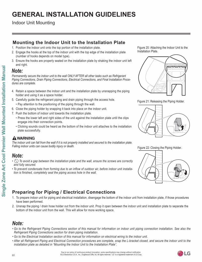
1. Position the indoor unit onto the top portion of the installation plate.2. Engage the hooks at the top of the indoor unit with the top edge of the installation plate
(number of hooks depends on model type).3. Ensure the hooks are properly seated on the installation plate by shaking the indoor unit left
and right.
-dures are complete.
4. Retain a space between the indoor unit and the installation plate by unsnapping the piping holder and using it as a space holder.
5. Carefully guide the refrigerant piping and drain piping through the access hole.• Pay attention to the positioning of the piping through the wall.
6. Close the piping holder by snapping it back into place on the indoor unit.7. Push the bottom of indoor unit towards the installation plate.
• Press the lower left and right sides of the unit against the installation plate until the clips engage into their connection points.
• Clicking sounds could be heard as the bottom of the indoor unit attaches to the installation plate successfully.
Figure 20: Attaching the Indoor Unit to the Installation Plate.
Figure 21: Releasing the Piping Holder.
Mounting the Indoor Unit to the Installation Plate
The indoor unit can fall from the wall if it is not properly installed and secured to the installation plate.
• To avoid a gap between the installation plate and the wall, ensure the screws are correctly and fully secured.
• To prevent condensate from forming due to an inflow of outdoor air, before indoor unit installa-tion is finished, completely seal the piping access hole in the wall.
Indoor Unit Mounting
Preparing for Piping / Electrical Connections1. To prepare indoor unit for piping and electrical installation, disengage the bottom of the indoor unit from installation plate, if those procedures
have been performed.2. Unsnap the piping / drain hose holder out from the indoor unit. Prop it open between the indoor unit and installation plate to separate the
bottom of the indoor unit from the wall. This will allow for more working space.
•
• •
Figure 22: Closing the Piping Holder.
23
General R
efrigerant Piping System Inform
ation
©
Refrigerant Safety StandardsASHRAE Standards 15-2010 and 34-2010 address refrigerant safety and the maximum allowable concentration of refrigerant in an occupied space. Refrigerant will dissipate into the atmosphere, but a certain volume of air is required to safely dissipate the refrigerant. For R410A refrigerant, the maximum allowable concentration of refrigerant is 26 lbs./1,000 cubic feet (Addendum L modified the RCL to 26) of occupied spaces. Buildings with 24-hour occupancy are allowed half of that concentration.If a single zone system develops a refrigerant leak, the entire refrigerant charge of the system will dump into the area where the leak occurs. To meet ASHRAE Standards 15 and 34, the smallest room volume on the system must be calculated and compared to the maximum allow-able concentration. Also consult state and local codes in regards to refrigerant safety.
REFRIGERANT SAFETY STANDARDS / DEVICE CONNECTION LIMITATIONS
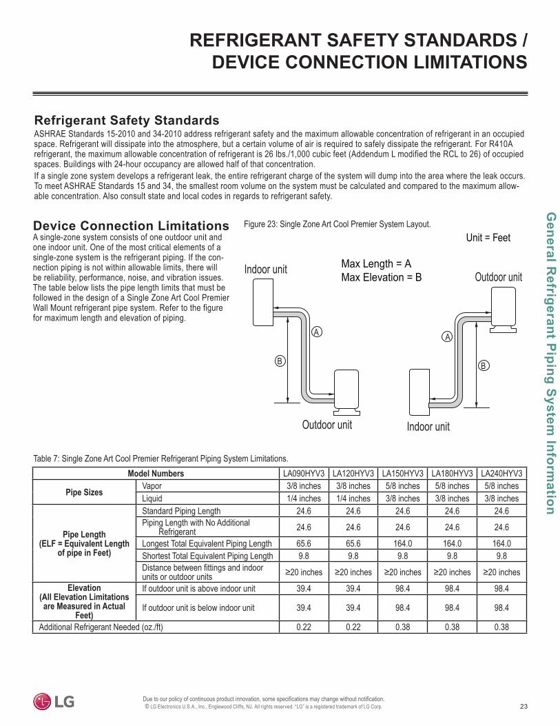
Device Connection LimitationsA single-zone system consists of one outdoor unit and one indoor unit. One of the most critical elements of a single-zone system is the refrigerant piping. If the con-nection piping is not within allowable limits, there will be reliability, performance, noise, and vibration issues. The table below lists the pipe length limits that must be followed in the design of a Single Zone Art Cool Premier Wall Mount refrigerant pipe system. Refer to the figure for maximum length and elevation of piping.
Figure 23: Single Zone Art Cool Premier System Layout.
Outdoor unit
Indoor unit
A
B
Outdoor unit
Indoor unit
A
B
Max Length = AMax Elevation = B
Unit = Feet
Table 7: Single Zone Art Cool Premier Refrigerant Piping System Limitations.Model Numbers LA090HYV3 LA120HYV3 LA150HYV3 LA180HYV3 LA240HYV3
Pipe Sizes Vapor 3/8 inches 3/8 inches 5/8 inches 5/8 inches 5/8 inchesLiquid 1/4 inches 1/4 inches 3/8 inches 3/8 inches 3/8 inches
Pipe Length(ELF = Equivalent Length
of pipe in Feet)
Standard Piping Length 24.6 24.6 24.6 24.6 24.6Piping Length with No Additional
Refrigerant 24.6 24.6 24.6 24.6 24.6
Longest Total Equivalent Piping Length 65.6 65.6 164.0 164.0 164.0Shortest Total Equivalent Piping Length 9.8 9.8 9.8 9.8 9.8Distance between fittings and indoor units or outdoor units
Elevation (All Elevation Limitations are Measured in Actual
Feet)
If outdoor unit is above indoor unit 39.4 39.4 98.4 98.4 98.4
If outdoor unit is below indoor unit 39.4 39.4 98.4 98.4 98.4
Additional Refrigerant Needed (oz./ft) 0.22 0.22 0.38 0.38 0.38
24
Sing
le Z
one
Art
Cool
Pre
mie
r Wal
l Mou
nted
Eng
inee
ring
Man
ual
©
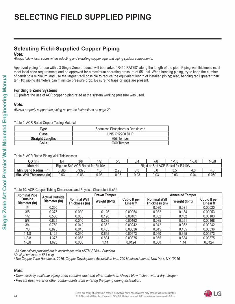
Selecting Field-Supplied Copper PipingAlways follow local codes when selecting and installing copper pipe and piping system components.
Approved piping for use with LG Single Zone products will be marked “R410 RATED” along the length of the pipe. Piping wall thickness must meet local code requirements and be approved for a maximum operating pressure of 551 psi. When bending piping, try to keep the number of bends to a minimum, and use the largest radii possible to reduce the equivalent length of installed piping; also, bending radii greater than ten (10) piping diameters can minimize pressure drop. Be sure no traps or sags are present.
For Single Zone SystemsLG prefers the use of ACR copper piping rated at the system working pressure was used.
Always properly support the piping as per the instructions on page 29.
Table 8: ACR Rated Piping Wall Thicknesses.
Type Seamless Phosphorous DeoxidizedClass UNS C12200 DHP
Straight Lengths H58 TemperCoils O60 Temper
Table 9: ACR Rated Copper Tubing Material.
OD (in) 1/4 3/8 1/2 5/8 3/4 7/8 1-1/8 1-3/8 1-5/8Material Rigid or Soft ACR Rated for R410A Rigid or Soft ACR Rated for R410A
Min. Bend Radius (in) 0.563 0.9375 1.5 2.25 3.0 3.0 3.5 4.0 4.5Min. Wall Thickness (in) 0.03 0.03 0.03 0.03 0.03 0.03 0.03 0.04 0.050
Table 10: ACR Copper Tubing Dimensions and Physical Characteristics1-3.Nominal Pipe
Outside Diameter (in)
Actual Outside Diameter (in)
Drawn Temper Annealed TemperNominal Wall Thickness (in) Weight (lb/ft) Cubic ft per
Linear ftNominal Wall Thickness (in) Weight (lb/ft) Cubic ft per
Linear ft1/4 0.250 -- -- -- 0.030 0.081 0.000203/8 0.375 0.030 0.126 0.00054 0.032 0.134 0.000531/2 0.500 0.035 0.198 0.00101 0.032 0.182 0.001035/8 0.625 0.040 0.285 0.00162 0.035 0.251 0.001683/4 0.750 0.042 0.362 0.00242 0.042 0.362 0.002427/8 0.875 0.045 0.455 0.00336 0.045 0.455 0.00336
1-1/8 1.125 0.050 0.655 0.00573 0.050 0.655 0.005731-3/8 1.375 0.055 0.884 0.00875 0.055 0.884 0.008751-5/8 1.625 0.060 1.14 0.0124 0.060 1.14 0.0124
1All dimensions provided are in accordance with ASTM B280 – Standard..2Design pressure = 551 psig.3The Copper Tube Handbook, 2016, Copper Development Association Inc., 260 Madison Avenue, New York, NY 10016.
• Commercially available piping often contains dust and other materials. Always blow it clean with a dry nitrogen.• Prevent dust, water or other contaminants from entering the piping during installation.
SELECTING FIELD SUPPLIED PIPING
25
General R
efrigerant Piping System Inform
ation
©
Copper Expansion and Contraction
See table on next page for precalculated anticipated expansion for various pipe sizes and lengths of refrigerant tubing.To find the anticipated expansion value:1. From the table on the next page, find the row corresponding with the actual feet of the straight pipe segment.2. Estimate the minimum and maximum temperature of the pipe.3. In the column showing the minimum pipe temperature, look up the anticipated expansion distance corresponding to the segment length.
Do the same for the maximum pipe temperature.4. Calculate the difference in the two expansion distance values. The result will be the change in pipe length.
COPPER EXPANSION AND CONTRACTION
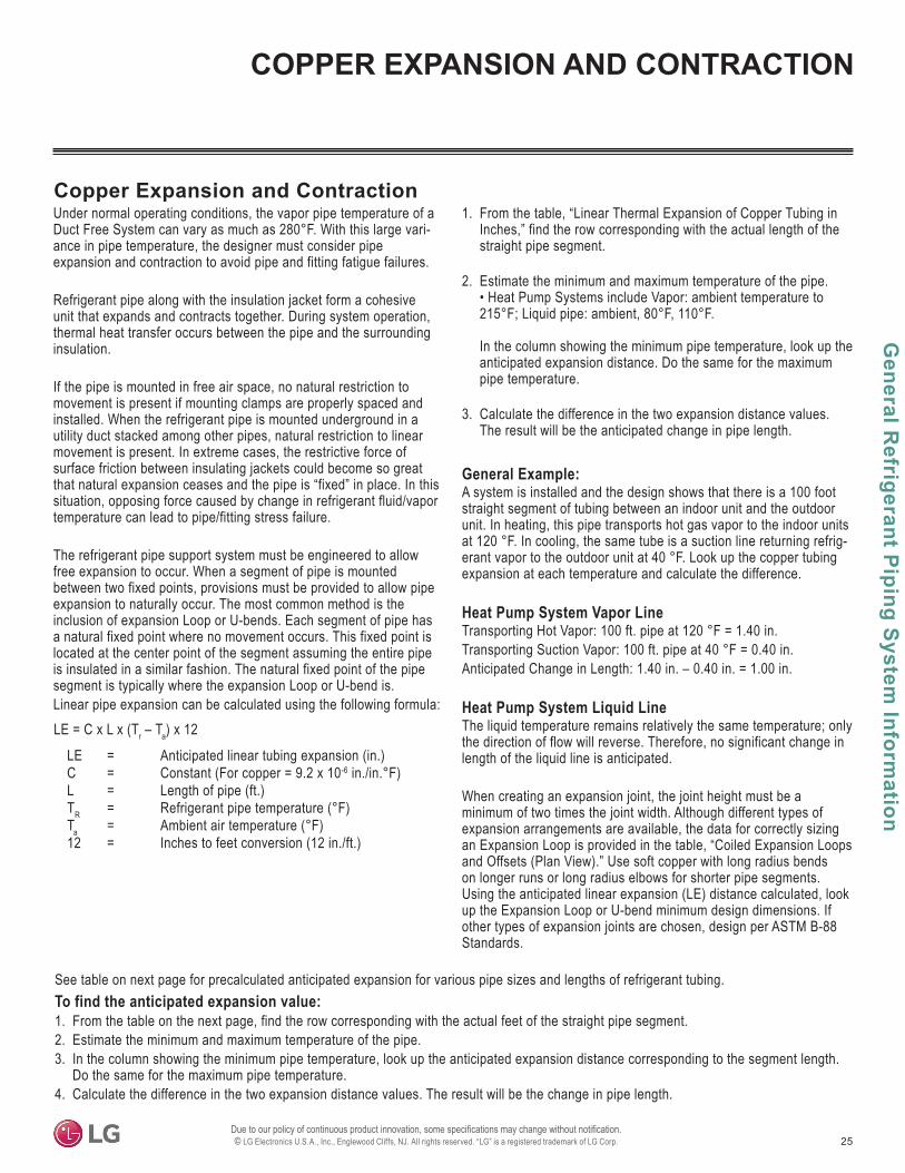
Under normal operating conditions, the vapor pipe temperature of a Duct Free System can vary as much as 280°F. With this large vari-ance in pipe temperature, the designer must consider pipe expansion and contraction to avoid pipe and fitting fatigue failures.
Refrigerant pipe along with the insulation jacket form a cohesive unit that expands and contracts together. During system operation, thermal heat transfer occurs between the pipe and the surrounding insulation.
If the pipe is mounted in free air space, no natural restriction to movement is present if mounting clamps are properly spaced and installed. When the refrigerant pipe is mounted underground in a utility duct stacked among other pipes, natural restriction to linear movement is present. In extreme cases, the restrictive force of surface friction between insulating jackets could become so great that natural expansion ceases and the pipe is “fixed” in place. In this situation, opposing force caused by change in refrigerant fluid/vapor temperature can lead to pipe/fitting stress failure.
The refrigerant pipe support system must be engineered to allow free expansion to occur. When a segment of pipe is mounted between two fixed points, provisions must be provided to allow pipe expansion to naturally occur. The most common method is the inclusion of expansion Loop or U-bends. Each segment of pipe has a natural fixed point where no movement occurs. This fixed point is located at the center point of the segment assuming the entire pipe is insulated in a similar fashion. The natural fixed point of the pipe segment is typically where the expansion Loop or U-bend is. Linear pipe expansion can be calculated using the following formula:
1. From the table, “Linear Thermal Expansion of Copper Tubing in Inches,” find the row corresponding with the actual length of the straight pipe segment.
2. Estimate the minimum and maximum temperature of the pipe. • Heat Pump Systems include Vapor: ambient temperature to 215°F; Liquid pipe: ambient, 80°F, 110°F.
In the column showing the minimum pipe temperature, look up the anticipated expansion distance. Do the same for the maximum pipe temperature.
3. Calculate the difference in the two expansion distance values. The result will be the anticipated change in pipe length.
General Example:A system is installed and the design shows that there is a 100 foot straight segment of tubing between an indoor unit and the outdoor unit. In heating, this pipe transports hot gas vapor to the indoor units at 120 °F. In cooling, the same tube is a suction line returning refrig-erant vapor to the outdoor unit at 40 °F. Look up the copper tubing expansion at each temperature and calculate the difference.
Heat Pump System Vapor LineTransporting Hot Vapor: 100 ft. pipe at 120 °F = 1.40 in.Transporting Suction Vapor: 100 ft. pipe at 40 °F = 0.40 in.Anticipated Change in Length: 1.40 in. – 0.40 in. = 1.00 in.
Heat Pump System Liquid LineThe liquid temperature remains relatively the same temperature; only the direction of flow will reverse. Therefore, no significant change in length of the liquid line is anticipated.
When creating an expansion joint, the joint height must be a minimum of two times the joint width. Although different types of expansion arrangements are available, the data for correctly sizing an Expansion Loop is provided in the table, “Coiled Expansion Loops and Offsets (Plan View).” Use soft copper with long radius bends on longer runs or long radius elbows for shorter pipe segments. Using the anticipated linear expansion (LE) distance calculated, look up the Expansion Loop or U-bend minimum design dimensions. If other types of expansion joints are chosen, design per ASTM B-88 Standards.
LE = C x L x (Tr – Ta) x 12
LE = Anticipated linear tubing expansion (in.)C = Constant (For copper = 9.2 x 10⁻⁶ in./in.°F)L = Length of pipe (ft.)TR = Refrigerant pipe temperature (°F)Ta = Ambient air temperature (°F)12 = Inches to feet conversion (12 in./ft.)

26
Sing
le Z
one
Art
Cool
Pre
mie
r Wal
l Mou
nted
Eng
inee
ring
Man
ual
©
Pipe Length1
Fluid Temperature °F35° 40° 45° 50° 55° 60° 65° 70° 75° 80° 85° 90° 95° 100° 105° 110° 115° 120° 125° 130°
10 0.04 0.04 0.05 0.06 0.06 0.07 0.08 0.08 0.09 0.09 0.10 0.10 0.11 0.11 0.11 0.12 0.13 0.14 0.15 0.1520 0.08 0.08 0.10 0.12 0.13 0.14 0.15 0.16 0.17 0.18 0.19 0.20 0.21 0.22 0.22 0.23 0.26 0.28 0.29 0.3030 0.12 0.12 0.15 0.18 0.20 0.21 0.23 0.24 0.26 0.27 0.29 0.30 0.32 0.33 0.32 0.35 0.39 0.42 0.44 0.4540 0.16 0.16 0.20 0.24 0.26 0.28 0.30 0.32 0.34 0.36 0.38 0.40 0.42 0.44 0.43 0.46 0.52 0.56 0.58 0.6050 0.20 0.20 0.25 0.30 0.33 0.35 0.38 0.40 0.43 0.45 0.48 0.50 0.53 0.55 0.54 0.58 0.65 0.70 0.73 0.7560 0.24 0.24 0.30 0.36 0.39 0.42 0.45 0.48 0.51 0.54 0.57 0.60 0.63 0.66 0.65 0.69 0.78 0.84 0.87 0.9070 0.28 0.28 0.35 0.42 0.46 0.49 0.53 0.56 0.60 0.63 0.67 0.70 0.74 0.77 0.76 0.81 0.91 0.98 1.02 1.0580 0.32 0.32 0.40 0.48 0.52 0.56 0.60 0.64 0.68 0.72 0.76 0.80 0.84 0.88 0.86 0.92 1.04 1.12 1.16 1.2090 0.36 0.36 0.45 0.54 0.59 0.63 0.68 0.72 0.77 0.81 0.86 0.90 0.95 0.99 0.97 1.04 1.17 1.26 1.31 1.35100 0.40 0.40 0.50 0.60 0.65 0.70 0.75 0.80 0.85 0.90 0.95 1.00 1.05 1.10 1.08 1.15 1.30 1.40 1.45 1.50120 0.48 0.48 0.60 0.72 0.78 0.84 0.90 0.96 1.02 1.08 1.14 1.20 1.26 1.32 1.30 1.38 1.56 1.68 1.74 1.80140 0.56 0.56 0.70 0.84 0.91 0.98 1.05 1.12 1.19 1.26 1.33 1.40 1.47 1.54 1.51 1.61 1.82 1.96 2.03 2.10160 0.64 0.64 0.80 0.96 1.04 1.12 1.20 1.28 1.36 1.44 1.52 1.60 1.68 1.76 1.73 1.84 2.08 2.24 2.32 2.40180 0.72 0.72 0.90 1.08 1.17 1.26 1.35 1.44 1.53 1.62 1.71 1.80 1.89 1.98 1.94 2.07 2.34 2.52 2.61 2.70
Table 11: Linear Thermal Expansion of Copper Tubing in Inches.
1Pipe length baseline temperature = 0°F. "Expansion of Carbon, Copper and Stainless Steel Pipe," The Engineers' Toolbox, www.engineeringtoolbox.com.
Anticipated Linear Expansion (LE) (inches)
Nominal Tube Size (OD) inches1/4 3/8 1/2 3/4
1/2 R1 6 7 8 9L2 38 44 50 59
1 R1 9 10 11 13L2 54 63 70 83
1-1/2 R1 11 12 14 16L2 66 77 86 101
2 R1 12 14 16 19L2 77 89 99 117
2-1/2 R1 14 16 18 21L2 86 99 111 131
3 R1 15 17 19 23L2 94 109 122 143
3-1/2 R1 16 19 21 25L2 102 117 131 155
4 R1 17 20 22 26L2 109 126 140 166
Table 12: Radii of Coiled Expansion Loops and Developed Lengths of Expansion Offsets.
Figure 24: Coiled Expansion Loops and Offsets (Plan View).
Large Tubing U-bend (>3/4 in.) Loop Small Tubing U-bend (<3/4 in.)
R
LR
LL
1R = Centerline Length of Pipe. 2L = Centerline Minimum Radius (inches).
All expansion loops and offsets must be installed in the horizontal plane to prevent the possibility of trapping oil. Loops and offsets in vertical risers must also be installed in a horizontal plane.
COPPER EXPANSION AND CONTRACTION
27
General R
efrigerant Piping System Inform
ation
©
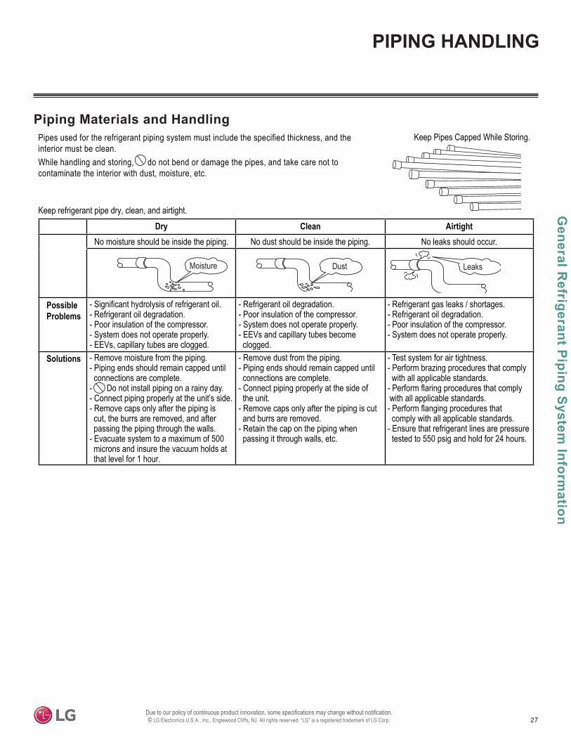
Piping Materials and HandlingPipes used for the refrigerant piping system must include the specified thickness, and the interior must be clean. While handling and storing, do not bend or damage the pipes, and take care not to contaminate the interior with dust, moisture, etc.
Clean AirtightNo moisture should be inside the piping. No dust should be inside the piping. No leaks should occur.
PossibleProblems
- Significant hydrolysis of refrigerant oil.- Refrigerant oil degradation.- Poor insulation of the compressor.- System does not operate properly.- EEVs, capillary tubes are clogged.
- Refrigerant oil degradation.- Poor insulation of the compressor.- System does not operate properly.- EEVs and capillary tubes become clogged.
- Refrigerant gas leaks / shortages.- Refrigerant oil degradation.- Poor insulation of the compressor.- System does not operate properly.
Solutions - Remove moisture from the piping.- Piping ends should remain capped until connections are complete.- Do not install piping on a rainy day.- Connect piping properly at the unit’s side.- Remove caps only after the piping is cut, the burrs are removed, and after passing the piping through the walls.- Evacuate system to a maximum of 500 microns and insure the vacuum holds at that level for 1 hour.
- Remove dust from the piping.- Piping ends should remain capped until connections are complete.- Connect piping properly at the side of the unit.- Remove caps only after the piping is cut and burrs are removed.- Retain the cap on the piping when passing it through walls, etc.
- Test system for air tightness.- Perform brazing procedures that comply with all applicable standards.- Perform flaring procedures that comply with all applicable standards.- Perform flanging procedures that comply with all applicable standards. - Ensure that refrigerant lines are pressure tested to 550 psig and hold for 24 hours.
Moisture Dust Leaks
Keep Pipes Capped While Storing.
Keep refrigerant pipe dry, clean, and airtight.
PIPING HANDLING
28
Sing
le Z
one
Art
Cool
Pre
mie
r Wal
l Mou
nted
Eng
inee
ring
Man
ual
©
REFRIGERANT SYSTEM ENGINEERING
No Pipe Size SubstitutionsUse only the pipe size selected by the information in this manual. Using a different size is prohibited and will result in a system malfunction or failure to work at all.
No In-line Refrigeration ComponentsComponents such as oil traps, solenoid valves, filter-driers, sight glasses, tee fittings, and other after-market accessories are not permitted on the refrigerant piping system between the outdoor units and the indoor units. LG Single Zone systems are provided with redun-dant systems that make sure oil is properly returned to the compressor. Sight-glasses and solenoid valves will cause vapor to form in the liquid stream. Over time, driers will deteriorate and introduce debris into the system. The designer and installer must verify the refrigerant pip-ing system is free of traps, sagging pipes, sight glasses, filter driers, etc.
Field-Provided Isolation Ball ValvesLG maintains a neutral position on using isolation valves in LG HVAC refrigerant piping systems. LG does not endorse any manufacturer of isolation valves. It is recognized that installing isolation valves will simplify future maintenance requirements, and, if used, considerations must be taken including, but not limited to, the following:
• Pressure drops for any component used, including isolation valves, must be known in equivalent pipe length and calculated into the total and segment equivalent piping lengths and compared to product design limitations.
• In all cases, materials must be suitable for the application and any applicable codes, including, but not limited to, diameter and wall thick-ness continuity per ACR standards.
Failure to do so will cause significant performance degradation. Proper leak checks must be performed. Using isolation valves does not automatically void any LG product warranty, however, a limited warranty will be voided in whole or part if any field supplied accessory fail in any way that causes product failure.
Proper system operation depends on the installer using utmost care while assembling the piping system. The following pages are an over-view of best practices when installing the refrigerant piping system.
LG Electronics U.S.A.,Inc., is not responsible for any piping calculations, refrigerant leaks, degradation of performance, any other potential problems or damages caused by the interconnecting piping, their joint connections, isolation valves, or introduced debris inside the piping system.
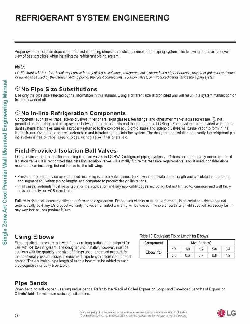
Component Size (Inches)
Elbow (ft.)1/4 3/8 1/2 5/8 3/40.5 0.6 0.7 0.8 1.2
Table 13: Equivalent Piping Length for Elbows.Using ElbowsField-supplied elbows are allowed if they are long radius and designed for use with R410A refrigerant. The designer and installer, however, must be cautious with the quantity and size of fittings used, and must account for the additional pressure losses in equivalent pipe length calculation for each branch. The equivalent pipe length of each elbow must be added to each pipe segment manually (see table).
Pipe BendsWhen bending soft copper, use long radius bends. Refer to the “Radii of Coiled Expansion Loops and Developed Lengths of Expansion Offsets” table for minimum radius specifications.
29
General R
efrigerant Piping System Inform
ation
©
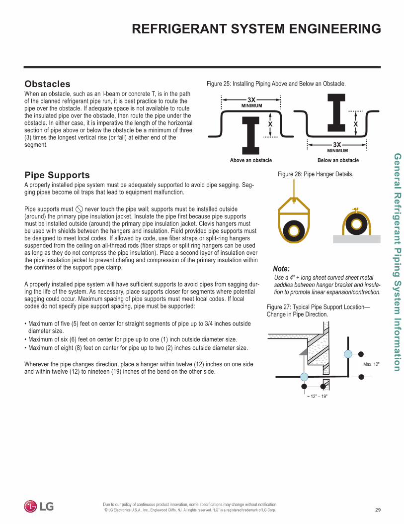
Figure 25: Installing Piping Above and Below an Obstacle.ObstaclesWhen an obstacle, such as an I-beam or concrete T, is in the path of the planned refrigerant pipe run, it is best practice to route the pipe over the obstacle. If adequate space is not available to route the insulated pipe over the obstacle, then route the pipe under the obstacle. In either case, it is imperative the length of the horizontal section of pipe above or below the obstacle be a minimum of three (3) times the longest vertical rise (or fall) at either end of the segment.
MINIMUM
Above an obstacleMINIMUM
Below an obstacle
3X
X
3X
X
Pipe SupportsA properly installed pipe system must be adequately supported to avoid pipe sagging. Sag-ging pipes become oil traps that lead to equipment malfunction.
Pipe supports must never touch the pipe wall; supports must be installed outside (around) the primary pipe insulation jacket. Insulate the pipe first because pipe supports must be installed outside (around) the primary pipe insulation jacket. Clevis hangers must be used with shields between the hangers and insulation. Field provided pipe supports must be designed to meet local codes. If allowed by code, use fiber straps or split-ring hangers suspended from the ceiling on all-thread rods (fiber straps or split ring hangers can be used as long as they do not compress the pipe insulation). Place a second layer of insulation over the pipe insulation jacket to prevent chafing and compression of the primary insulation within the confines of the support pipe clamp.
A properly installed pipe system will have sufficient supports to avoid pipes from sagging dur-ing the life of the system. As necessary, place supports closer for segments where potential sagging could occur. Maximum spacing of pipe supports must meet local codes. If local codes do not specify pipe support spacing, pipe must be supported:
• Maximum of five (5) feet on center for straight segments of pipe up to 3/4 inches outside diameter size.
• Maximum of six (6) feet on center for pipe up to one (1) inch outside diameter size.• Maximum of eight (8) feet on center for pipe up to two (2) inches outside diameter size.
Wherever the pipe changes direction, place a hanger within twelve (12) inches on one side and within twelve (12) to nineteen (19) inches of the bend on the other side.
Figure 26: Pipe Hanger Details.
Use a 4" + long sheet curved sheet metal saddles between hanger bracket and insula-tion to promote linear expansion/contraction.
Figure 27: Typical Pipe Support Location—Change in Pipe Direction.
Max. 12"
~ 12" – 19"
REFRIGERANT SYSTEM ENGINEERING
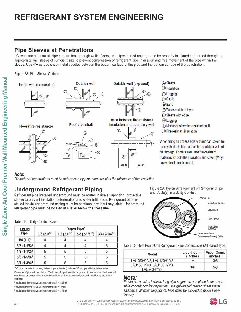
30
Sing
le Z
one
Art
Cool
Pre
mie
r Wal
l Mou
nted
Eng
inee
ring
Man
ual
©
REFRIGERANT SYSTEM ENGINEERING
Model Liquid Conn. (inches)
Vapor Conn. (inches)
LAU090HYV3, LAU120HYV3 1/4 3/8LAU150HYV3, LAU180HYV3,
LAU240HYV3 3/8 5/8
Pipe Sleeves at PenetrationsLG recommends that all pipe penetrations through walls, floors, and pipes buried underground be properly insulated and routed through an appropriate wall sleeve of sufficient size to prevent compression of refrigerant pipe insulation and free movement of the pipe within the sleeve. Use 4”+ curved sheet metal saddles between the bottom surface of the pipe and the bottom surface of the penetration.
Figure 28: Pipe Sleeve Options.
Diameter of penetrations must be determined by pipe diameter plus the thickness of the insulation.
Underground Refrigerant PipingRefrigerant pipe installed underground must be routed inside a vapor tight protective sleeve to prevent insulation deterioration and water infiltration. Refrigerant pipe in-stalled inside underground casing must be continuous without any joints. Underground refrigerant pipe must be located at a level below the frost line.
Table 14: Utility Conduit Sizes.
1OD pipe diameter in inches; Values in parenthesis () indicate OD of pipe with insulation jacket.2Diameter of pipe with insulation. Thickness of pipe insulation is typical. Actual required thickness will vary based on surrounding ambient conditions and must be calculated and specified by the design engineer.3Insulation thickness (value in parenthesis) = 3/8 inch.4Insulation thickness (value in parenthesis) = 1 inch.5Insulation thickness (value in parenthesis) = 3/4 inch.
Liquid Pipe1
Vapor Pipe1
3/8 (2.02,5) 1/2 (2.02,5) 5/8 (2-1/82,5) 3/4 (2-1/42,5)1/4 (1.0)3 4 4 4 4
3/8 (1-1/8)3 4 4 4 51/2 (1-1/2)4 5 5 5 55/8 (1-5/8)4 5 5 5 53/4 (1-3/4)4 5 5 5 5
Figure 29: Typical Arrangement of Refrigerant Pipe and Cable(s) in a Utility Conduit.
Table 15: Heat Pump Unit Refrigerant Pipe Connections (All Flared Type).
Provide expansion joints in long pipe segments and place in an acces-sible conduit box for inspection. Use galvanized curved sheet metal saddles at all mounting points. Pipe must be allowed to move freely linearly.
Vapor Line
Liquid Line
Communication / Connection (Power) Cable
Pipe Sleeve
Insulation Material
InsulationMaterial
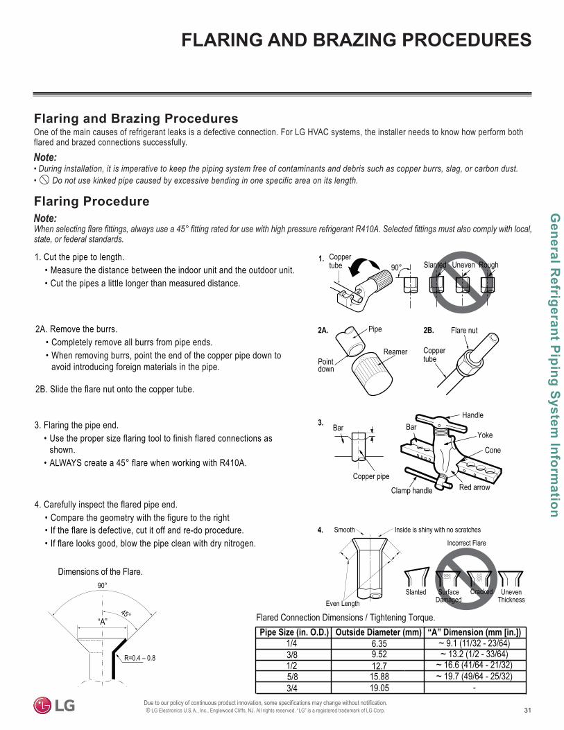
31
General R
efrigerant Piping System Inform
ation
©
Flaring Procedure
Flaring and Brazing ProceduresOne of the main causes of refrigerant leaks is a defective connection. For LG HVAC systems, the installer needs to know how perform both flared and brazed connections successfully.
state, or federal standards.
• During installation, it is imperative to keep the piping system free of contaminants and debris such as copper burrs, slag, or carbon dust.• Do not use kinked pipe caused by excessive bending in one specific area on its length.
3. Flaring the pipe end.• Use the proper size flaring tool to finish flared connections as
shown.• ALWAYS create a 45° flare when working with R410A.
1. Cut the pipe to length.• Measure the distance between the indoor unit and the outdoor unit.• Cut the pipes a little longer than measured distance.
2A. Remove the burrs.• Completely remove all burrs from pipe ends.• When removing burrs, point the end of the copper pipe down to
avoid introducing foreign materials in the pipe.
2B. Slide the flare nut onto the copper tube.
90° Slanted Uneven Rough
Pipe
ReamerPointdown
Flare nut
Coppertube
Bar
Copper pipe
Clamp handle Red arrow
Cone
Bar
Slanted
Smooth
UnevenThickness
1.
2A. 2B.
3.
4.
4. Carefully inspect the flared pipe end.• Compare the geometry with the figure to the right • If the flare is defective, cut it off and re-do procedure.• If flare looks good, blow the pipe clean with dry nitrogen.
90°
45°“A”
R=0.4 – 0.8
Dimensions of the Flare.
Pipe Size (in. O.D.) “A” Dimension (mm [in.])
1/2
1/4
5/8
3/8
3/4
Flared Connection Dimensions / Tightening Torque.
Handle
Incorrect Flare
Even LengthCracked
Yoke
Inside is shiny with no scratches
SurfaceDamaged
Coppertube
Outside Diameter (mm)6.359.5212.715.8819.05
~ 9.1 (11/32 - 23/64)~ 13.2 (1/2 - 33/64)
~ 16.6 (41/64 - 21/32)~ 19.7 (49/64 - 25/32)
-
FLARING AND BRAZING PROCEDURES
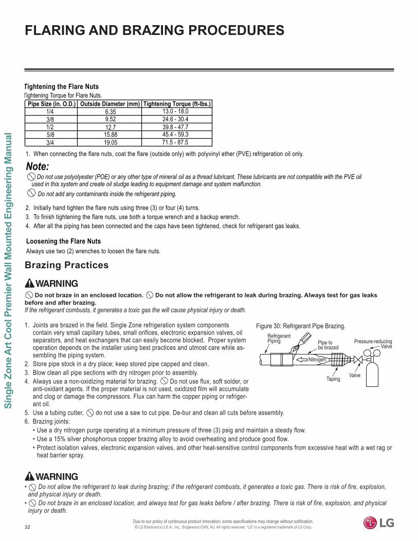
32
Sing
le Z
one
Art
Cool
Pre
mie
r Wal
l Mou
nted
Eng
inee
ring
Man
ual
©
13.0 - 18.024.6 - 30.439.8 - 47.7
Tightening Torque for Flare Nuts.Tightening the Flare Nuts
1. When connecting the flare nuts, coat the flare (outside only) with polyvinyl ether (PVE) refrigeration oil only.
2. Initially hand tighten the flare nuts using three (3) or four (4) turns.3. To finish tightening the flare nuts, use both a torque wrench and a backup wrench.4. After all the piping has been connected and the caps have been tightened, check for refrigerant gas leaks.
Loosening the Flare NutsAlways use two (2) wrenches to loosen the flare nuts.
Do not use polyolyester (POE) or any other type of mineral oil as a thread lubricant. These lubricants are not compatible with the PVE oil used in this system and create oil sludge leading to equipment damage and system malfunction.
Pipe Size (in. O.D.) Tightening Torque (ft-lbs.)
1/2
1/4
5/8
3/8
3/4
Outside Diameter (mm)6.359.5212.715.8819.05
45.4 - 59.371.5 - 87.5
Do not add any contaminants inside the refrigerant piping.
Figure 30: Refrigerant Pipe Brazing.
Pressure-reducingValve
ValveTaping
Nitrogen
Pipe tobe brazed
RefrigerantPiping
Brazing Practices
1. Joints are brazed in the field. Single Zone refrigeration system components contain very small capillary tubes, small orifices, electronic expansion valves, oil separators, and heat exchangers that can easily become blocked. Proper system operation depends on the installer using best practices and utmost care while as-sembling the piping system.
2. Store pipe stock in a dry place; keep stored pipe capped and clean.3. Blow clean all pipe sections with dry nitrogen prior to assembly. 4. Always use a non-oxidizing material for brazing. Do not use flux, soft solder, or
anti-oxidant agents. If the proper material is not used, oxidized film will accumulate and clog or damage the compressors. Flux can harm the copper piping or refriger-ant oil.
5. Use a tubing cutter, do not use a saw to cut pipe. De-bur and clean all cuts before assembly.6. Brazing joints:
• Use a dry nitrogen purge operating at a minimum pressure of three (3) psig and maintain a steady flow.• Use a 15% silver phosphorous copper brazing alloy to avoid overheating and produce good flow.• Protect isolation valves, electronic expansion valves, and other heat-sensitive control components from excessive heat with a wet rag or
heat barrier spray.
Do not braze in an enclosed location. Do not allow the refrigerant to leak during brazing. Always test for gas leaks before and after brazing. If the refrigerant combusts, it generates a toxic gas the will cause physical injury or death.
• Do not allow the refrigerant to leak during brazing; if the refrigerant combusts, it generates a toxic gas. There is risk of fire, explosion, and physical injury or death.
• Do not braze in an enclosed location, and always test for gas leaks before / after brazing. There is risk of fire, explosion, and physical injury or death.
FLARING AND BRAZING PROCEDURES
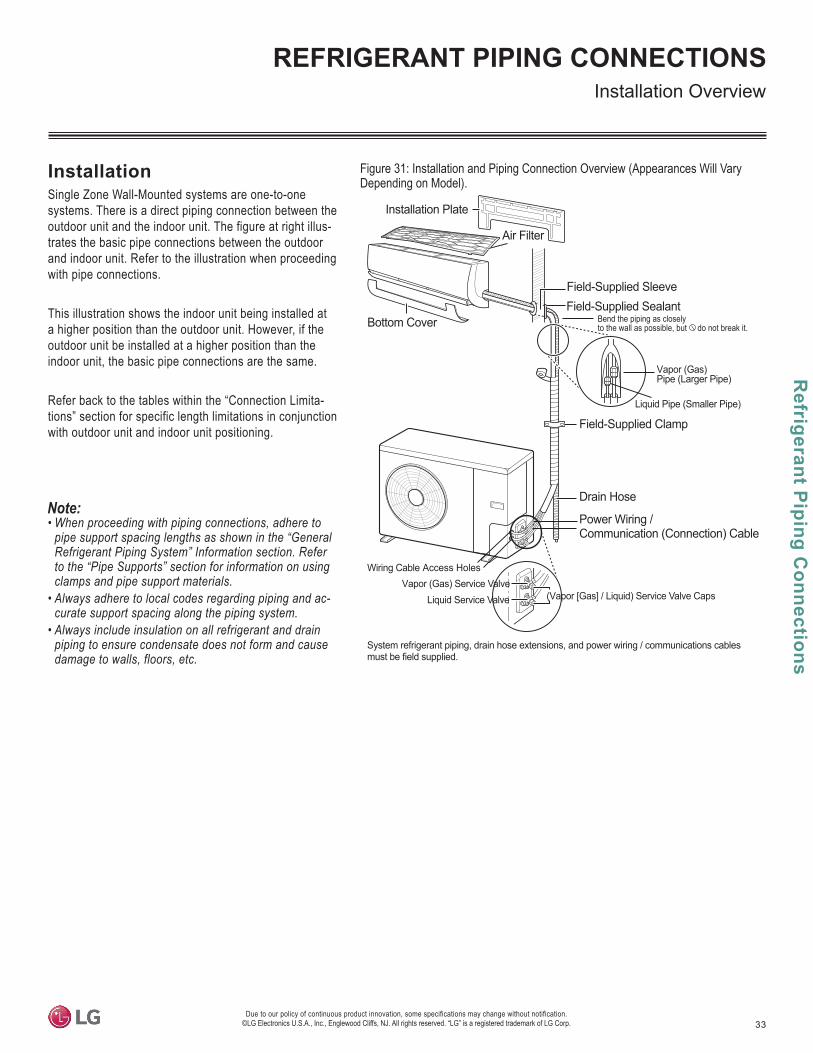
33
Refrigerant P
iping Connections
Due to our policy of continuous product innovation, some specifications may change without notification. ©LG Electronics U.S.A., Inc., Englewood Cliffs, NJ. All rights reserved. “LG” is a registered trademark of LG Corp.
REFRIGERANT PIPING CONNECTIONSInstallation Overview
Figure 31: Installation and Piping Connection Overview (Appearances Will Vary Depending on Model).
InstallationSingle Zone Wall-Mounted systems are one-to-one systems. There is a direct piping connection between the outdoor unit and the indoor unit. The figure at right illus-trates the basic pipe connections between the outdoor and indoor unit. Refer to the illustration when proceeding with pipe connections.
This illustration shows the indoor unit being installed at a higher position than the outdoor unit. However, if the outdoor unit be installed at a higher position than the indoor unit, the basic pipe connections are the same.
Refer back to the tables within the “Connection Limita-tions” section for specific length limitations in conjunction with outdoor unit and indoor unit positioning.
• When proceeding with piping connections, adhere to pipe support spacing lengths as shown in the “General Refrigerant Piping System” Information section. Refer to the “Pipe Supports” section for information on using clamps and pipe support materials.
• Always adhere to local codes regarding piping and ac-curate support spacing along the piping system.
• Always include insulation on all refrigerant and drain piping to ensure condensate does not form and cause damage to walls, floors, etc.
Bend the piping as closely to the wall as possible, but do not break it.
Installation Plate
Air Filter
Bottom Cover
Vapor (Gas)Pipe (Larger Pipe)
Liquid Pipe (Smaller Pipe)
Drain Hose
Power Wiring /Communication (Connection) Cable
Vapor (Gas) Service ValveLiquid Service Valve (Vapor [Gas] / Liquid) Service Valve Caps
System refrigerant piping, drain hose extensions, and power wiring / communications cablesmust be field supplied.
Field-Supplied SleeveField-Supplied Sealant
Field-Supplied Clamp
Wiring Cable Access Holes
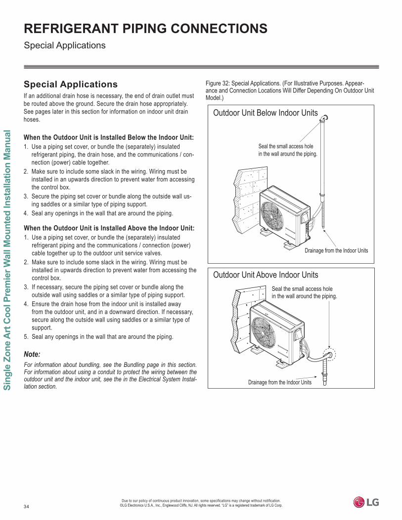
34
Sing
le Z
one
Art
Coo
l Pre
mie
r Wal
l Mou
nted
Inst
alla
tion
Man
ual
Due to our policy of continuous product innovation, some specifications may change without notification. ©LG Electronics U.S.A., Inc., Englewood Cliffs, NJ. All rights reserved. “LG” is a registered trademark of LG Corp.
REFRIGERANT PIPING CONNECTIONS
Special ApplicationsIf an additional drain hose is necessary, the end of drain outlet must be routed above the ground. Secure the drain hose appropriately. See pages later in this section for information on indoor unit drain hoses.
When the Outdoor Unit is Installed Below the Indoor Unit:1. Use a piping set cover, or bundle the (separately) insulated
refrigerant piping, the drain hose, and the communications / con-nection (power) cable together.
2. Make sure to include some slack in the wiring. Wiring must be installed in an upwards direction to prevent water from accessing the control box.
3. Secure the piping set cover or bundle along the outside wall us-ing saddles or a similar type of piping support.
4. Seal any openings in the wall that are around the piping.
When the Outdoor Unit is Installed Above the Indoor Unit:1. Use a piping set cover, or bundle the (separately) insulated
refrigerant piping and the communications / connection (power) cable together up to the outdoor unit service valves.
2. Make sure to include some slack in the wiring. Wiring must be installed in upwards direction to prevent water from accessing the control box.
3. If necessary, secure the piping set cover or bundle along the outside wall using saddles or a similar type of piping support.
4. Ensure the drain hose from the indoor unit is installed away from the outdoor unit, and in a downward direction. If necessary, secure along the outside wall using saddles or a similar type of support.
5. Seal any openings in the wall that are around the piping.
Special Applications
Figure 32: Special Applications. (For Illustrative Purposes. Appear-ance and Connection Locations Will Differ Depending On Outdoor Unit Model.)
For information about bundling, see the Bundling page in this section. For information about using a conduit to protect the wiring between the outdoor unit and the indoor unit, see the in the Electrical System Instal-lation section.
Seal the small access holein the wall around the piping.
Outdoor Unit Below Indoor Units
Outdoor Unit Above Indoor UnitsSeal the small access hole in the wall around the piping.
Drainage from the Indoor Units
Drainage from the Indoor Units
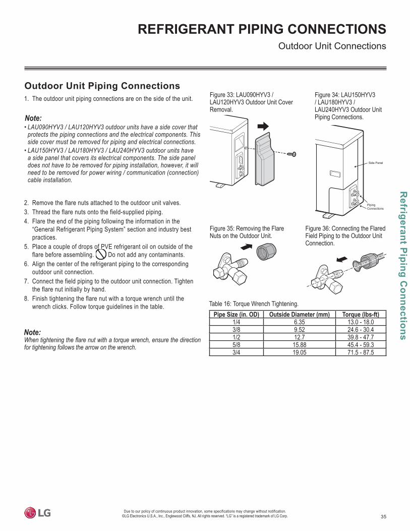
35
Refrigerant P
iping Connections
Due to our policy of continuous product innovation, some specifications may change without notification. ©LG Electronics U.S.A., Inc., Englewood Cliffs, NJ. All rights reserved. “LG” is a registered trademark of LG Corp.
REFRIGERANT PIPING CONNECTIONSOutdoor Unit Connections
Outdoor Unit Piping Connections1. The outdoor unit piping connections are on the side of the unit.
for tightening follows the arrow on the wrench.
Table 16: Torque Wrench Tightening.Pipe Size (in. OD) Outside Diameter (mm) Torque (lbs-ft)
1/4 6.35 13.0 - 18.03/8 9.52 24.6 - 30.41/2 12.7 39.8 - 47.75/8 15.88 45.4 - 59.33/4 19.05 71.5 - 87.5
Figure 33: LAU090HYV3 / LAU120HYV3 Outdoor Unit Cover Removal.
Figure 34: LAU150HYV3 / LAU180HYV3 / LAU240HYV3 Outdoor Unit Piping Connections.
Piping Connections
Side Panel
Figure 35: Removing the Flare Nuts on the Outdoor Unit.
• LAU090HYV3 / LAU120HYV3 outdoor units have a side cover that protects the piping connections and the electrical components. This side cover must be removed for piping and electrical connections.
• LAU150HYV3 / LAU180HYV3 / LAU240HYV3 outdoor units have a side panel that covers its electrical components. The side panel does not have to be removed for piping installation, however, it will need to be removed for power wiring / communication (connection) cable installation.
2. Remove the flare nuts attached to the outdoor unit valves.3. Thread the flare nuts onto the field-supplied piping. 4. Flare the end of the piping following the information in the
“General Refrigerant Piping System” section and industry best practices.
5. Place a couple of drops of PVE refrigerant oil on outside of the flare before assembling. Do not add any contaminants.
6. Align the center of the refrigerant piping to the corresponding outdoor unit connection.
7. Connect the field piping to the outdoor unit connection. Tighten the flare nut initially by hand.
8. Finish tightening the flare nut with a torque wrench until the wrench clicks. Follow torque guidelines in the table.
Figure 36: Connecting the Flared Field Piping to the Outdoor Unit Connection.
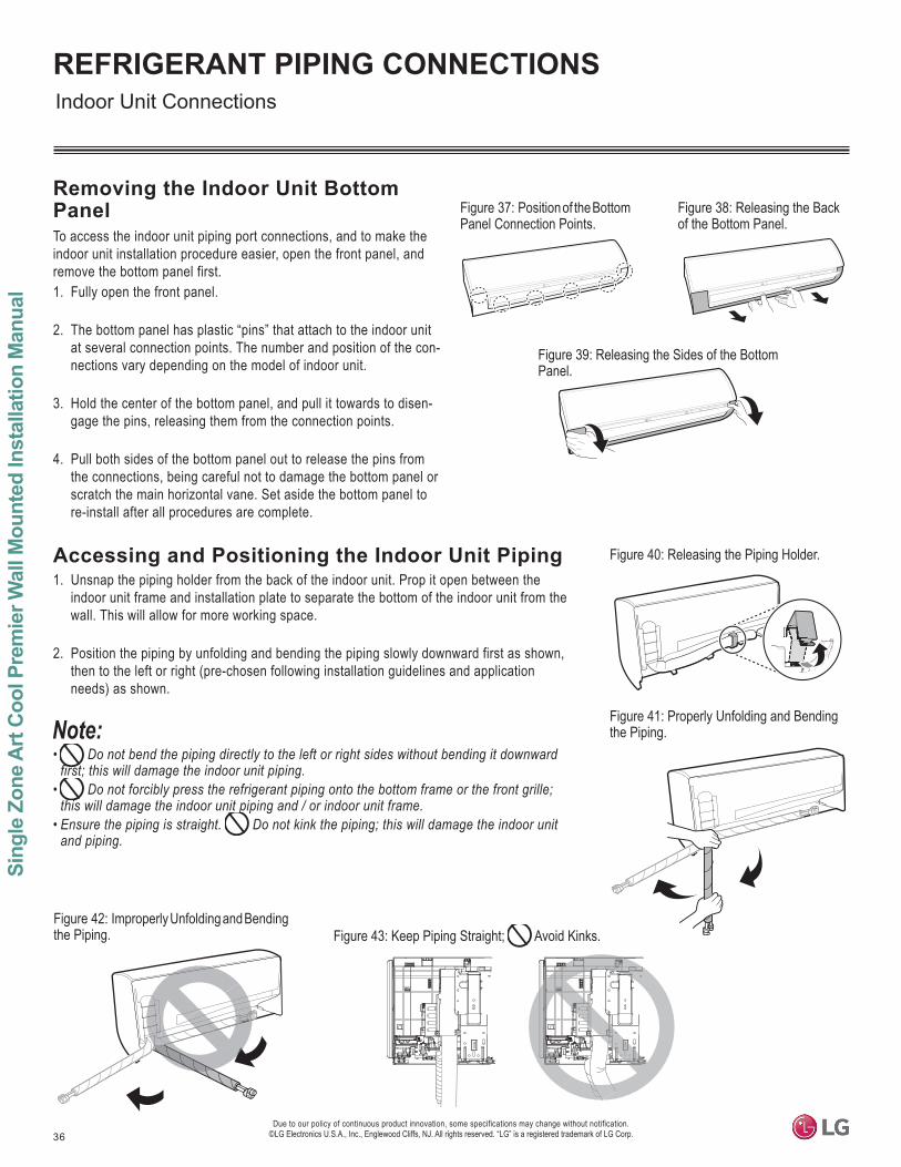
36
Sing
le Z
one
Art
Coo
l Pre
mie
r Wal
l Mou
nted
Inst
alla
tion
Man
ual
Due to our policy of continuous product innovation, some specifications may change without notification. ©LG Electronics U.S.A., Inc., Englewood Cliffs, NJ. All rights reserved. “LG” is a registered trademark of LG Corp.
REFRIGERANT PIPING CONNECTIONS
Accessing and Positioning the Indoor Unit Piping1. Unsnap the piping holder from the back of the indoor unit. Prop it open between the
indoor unit frame and installation plate to separate the bottom of the indoor unit from the wall. This will allow for more working space.
2. Position the piping by unfolding and bending the piping slowly downward first as shown, then to the left or right (pre-chosen following installation guidelines and application needs) as shown.
Removing the Indoor Unit Bottom PanelTo access the indoor unit piping port connections, and to make the indoor unit installation procedure easier, open the front panel, and remove the bottom panel first. 1. Fully open the front panel.
2. The bottom panel has plastic “pins” that attach to the indoor unit at several connection points. The number and position of the con-nections vary depending on the model of indoor unit.
3. Hold the center of the bottom panel, and pull it towards to disen-gage the pins, releasing them from the connection points.
4. Pull both sides of the bottom panel out to release the pins from the connections, being careful not to damage the bottom panel or scratch the main horizontal vane. Set aside the bottom panel to re-install after all procedures are complete.
Figure 37: Position of the Bottom Panel Connection Points.
Figure 38: Releasing the Back of the Bottom Panel.
Figure 39: Releasing the Sides of the Bottom Panel.
Figure 40: Releasing the Piping Holder.
• Do not bend the piping directly to the left or right sides without bending it downward first; this will damage the indoor unit piping.
• Do not forcibly press the refrigerant piping onto the bottom frame or the front grille; this will damage the indoor unit piping and / or indoor unit frame.
• Ensure the piping is straight. Do not kink the piping; this will damage the indoor unit and piping.
Indoor Unit Connections
Figure 41: Properly Unfolding and Bending the Piping.
Figure 42: Improperly Unfolding and Bending the Piping. Figure 43: Keep Piping Straight; Avoid Kinks.
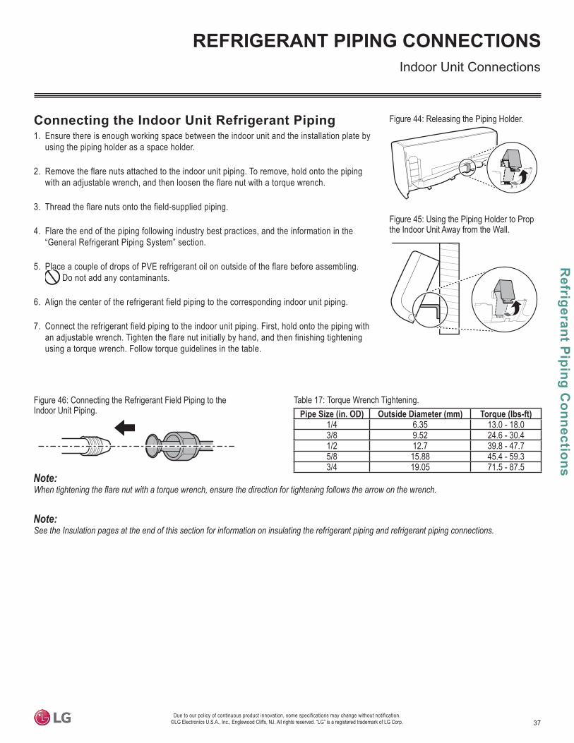
37
Refrigerant P
iping Connections
Due to our policy of continuous product innovation, some specifications may change without notification. ©LG Electronics U.S.A., Inc., Englewood Cliffs, NJ. All rights reserved. “LG” is a registered trademark of LG Corp.
REFRIGERANT PIPING CONNECTIONS
Table 17: Torque Wrench Tightening.Pipe Size (in. OD) Outside Diameter (mm) Torque (lbs-ft)
1/4 6.35 13.0 - 18.03/8 9.52 24.6 - 30.41/2 12.7 39.8 - 47.75/8 15.88 45.4 - 59.33/4 19.05 71.5 - 87.5
Connecting the Indoor Unit Refrigerant Piping1. Ensure there is enough working space between the indoor unit and the installation plate by
using the piping holder as a space holder.
2. Remove the flare nuts attached to the indoor unit piping. To remove, hold onto the piping with an adjustable wrench, and then loosen the flare nut with a torque wrench.
3. Thread the flare nuts onto the field-supplied piping.
4. Flare the end of the piping following industry best practices, and the information in the “General Refrigerant Piping System” section.
5. Place a couple of drops of PVE refrigerant oil on outside of the flare before assembling. Do not add any contaminants.
6. Align the center of the refrigerant field piping to the corresponding indoor unit piping.
7. Connect the refrigerant field piping to the indoor unit piping. First, hold onto the piping with an adjustable wrench. Tighten the flare nut initially by hand, and then finishing tightening using a torque wrench. Follow torque guidelines in the table.
Figure 44: Releasing the Piping Holder.
Figure 45: Using the Piping Holder to Prop the Indoor Unit Away from the Wall.
Figure 46: Connecting the Refrigerant Field Piping to the Indoor Unit Piping.
Indoor Unit Connections
See the Insulation pages at the end of this section for information on insulating the refrigerant piping and refrigerant piping connections.

38
Sing
le Z
one
Art
Coo
l Pre
mie
r Wal
l Mou
nted
Inst
alla
tion
Man
ual
Due to our policy of continuous product innovation, some specifications may change without notification. ©LG Electronics U.S.A., Inc., Englewood Cliffs, NJ. All rights reserved. “LG” is a registered trademark of LG Corp.
REFRIGERANT PIPING CONNECTIONS
Using a Conduit for Indoor Unit Wiring / Cable Installation
• -nection (power) cable. The conduit can be positioned in the desired direction.
• Before permanently positioning the refrigerant piping and drain hose at the back of the indoor unit, install the conduit first.
1. Indoor unit includes a conduit bracket that can be found in the accessory kit. Assemble the conduit and bracket with a grommet and washer (field-supplied or included with the elbow con-nector) as shown.
2. Guide the power wiring / communication cable into the conduit / bracket assembly.
3. Attach the conduit / bracket assembly to the back of the indoor unit using the black Type D screws found in the accessory kit.
• Check local, state, and federal codes when choosing a conduit size. • For systems with wiring greater than 130 feet, see the “Communication / Connection (Power)
Cable Specifications from Outdoor Unit to Indoor Unit” in the Electrical System Installation section for information.
4. Close the piping holder, and, if all wiring and piping installation is complete, reassemble the indoor unit properly onto the installation plate.
5. To protect the piping, condensate drain, and conduit from the elements, add a lineset cover from the indoor access hole to the outdoor unit.
Figure 47: Liquidtight 3/4 Inch Elbow Connector Attached to Flexible Conduit.
Figure 48: Indoor Unit Conduit / Bracket Assembly.
Figure 49: Attaching the Conduit / Bracket Assembly to the Back of the Indoor Unit.
If a conduit is not used, see pages in the “Refrigerant Piping Connections” for refrigerant piping, condensate drain, power wiring / communication cable bundling information.
Indoor Unit Connections
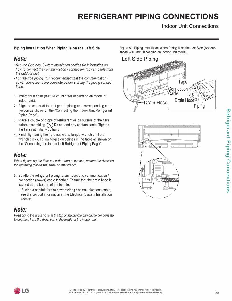
39
Refrigerant P
iping Connections
Due to our policy of continuous product innovation, some specifications may change without notification. ©LG Electronics U.S.A., Inc., Englewood Cliffs, NJ. All rights reserved. “LG” is a registered trademark of LG Corp.
REFRIGERANT PIPING CONNECTIONS
Piping Installation When Piping is on the Left Side
• See the Electrical System Installation section for information on how to connect the communication / connection (power) cable from the outdoor unit.
• For left-side piping, it is recommended that the communication / power connections are complete before starting the piping connec-tions.
1. Insert drain hose (feature could differ depending on model of indoor unit).
2. Align the center of the refrigerant piping and corresponding con-nection as shown on the “Connecting the Indoor Unit Refrigerant Piping Page”.
3. Place a couple of drops of refrigerant oil on outside of the flare before assembling. Do not add any contaminants. Tighten the flare nut initially by hand.
4. Finish tightening the flare nut with a torque wrench until the wrench clicks. Follow torque guidelines in the table as shown on the “Connecting the Indoor Unit Refrigerant Piping Page”.
for tightening follows the arrow on the wrench.
5. Bundle the refrigerant piping, drain hose, and communication / connection (power) cable together. Ensure that the drain hose is located at the bottom of the bundle.• If using a conduit for the power wiring / communications cable,
see the conduit information in the Electrical System Installation section.
Positioning the drain hose at the top of the bundle can cause condensate
Left Side Piping
Drain Hose Piping
Connection Cable
Tape
Drain Hose
Figure 50: Piping Installation When Piping is on the Left Side (Appear-ances Will Vary Depending on Indoor Unit Model).
Indoor Unit Connections
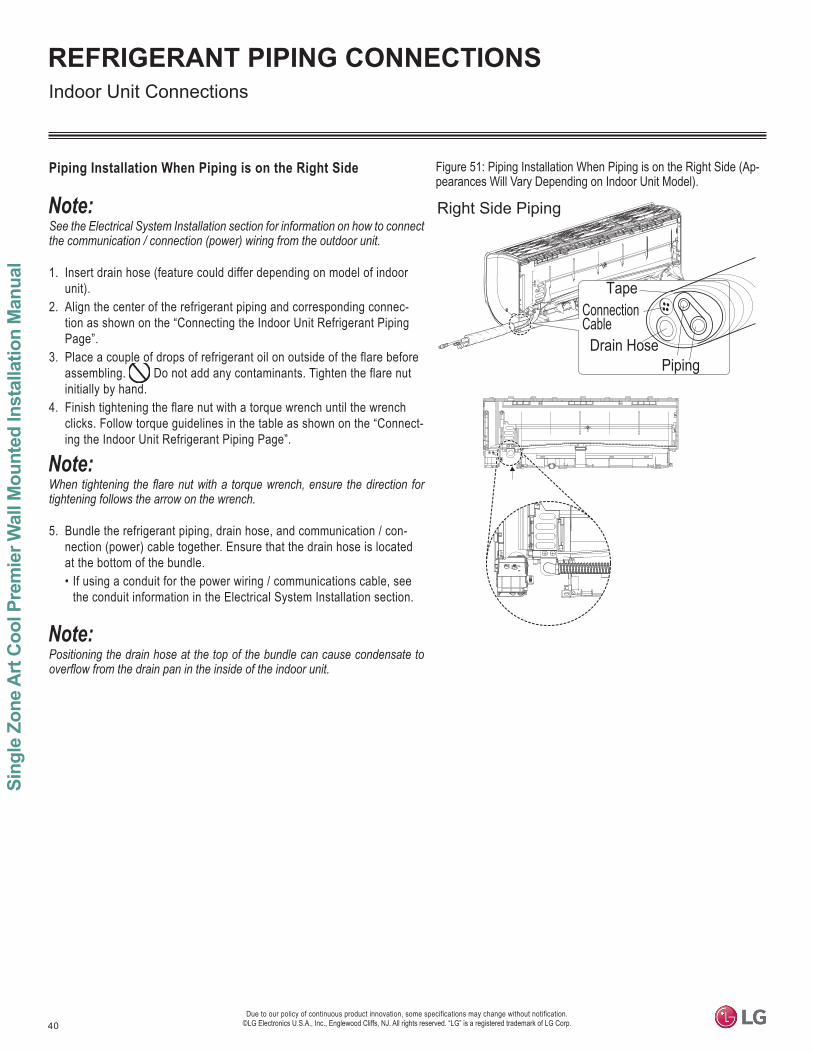
40
Sing
le Z
one
Art
Coo
l Pre
mie
r Wal
l Mou
nted
Inst
alla
tion
Man
ual
Due to our policy of continuous product innovation, some specifications may change without notification. ©LG Electronics U.S.A., Inc., Englewood Cliffs, NJ. All rights reserved. “LG” is a registered trademark of LG Corp.
REFRIGERANT PIPING CONNECTIONS
Piping Installation When Piping is on the Right Side
See the Electrical System Installation section for information on how to connect the communication / connection (power) wiring from the outdoor unit.
1. Insert drain hose (feature could differ depending on model of indoor unit).
2. Align the center of the refrigerant piping and corresponding connec-tion as shown on the “Connecting the Indoor Unit Refrigerant Piping Page”.
3. Place a couple of drops of refrigerant oil on outside of the flare before assembling. Do not add any contaminants. Tighten the flare nut initially by hand.
4. Finish tightening the flare nut with a torque wrench until the wrench clicks. Follow torque guidelines in the table as shown on the “Connect-ing the Indoor Unit Refrigerant Piping Page”.
tightening follows the arrow on the wrench.
5. Bundle the refrigerant piping, drain hose, and communication / con-nection (power) cable together. Ensure that the drain hose is located at the bottom of the bundle.• If using a conduit for the power wiring / communications cable, see
the conduit information in the Electrical System Installation section.
Positioning the drain hose at the top of the bundle can cause condensate to
Right Side Piping
Piping
Connection Cable
Tape
Drain Hose
Figure 51: Piping Installation When Piping is on the Right Side (Ap-pearances Will Vary Depending on Indoor Unit Model).
Indoor Unit Connections
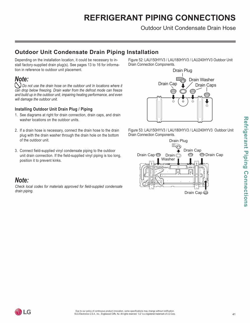
41
Refrigerant P
iping Connections
Due to our policy of continuous product innovation, some specifications may change without notification. ©LG Electronics U.S.A., Inc., Englewood Cliffs, NJ. All rights reserved. “LG” is a registered trademark of LG Corp.
REFRIGERANT PIPING CONNECTIONS
Depending on the installation location, it could be necessary to in-stall factory-supplied drain plug(s). See pages 13 to 16 for informa-tion in reference to outdoor unit placement.
Do not use the drain hose on the outdoor unit In locations where it can drop below freezing. Drain water from the defrost mode can freeze and build up in the outdoor unit, impairing heating performance, and even will damage the outdoor unit.
Installing Outdoor Unit Drain Plug / Piping1. See diagrams at right for drain connection, drain caps, and drain
washer locations on the outdoor units.
2. If a drain hose is necessary, connect the drain hose to the drain plug with the drain washer through the drain hole on the bottom of the outdoor unit.
3. Connect field-supplied vinyl condensate piping to the outdoor unit drain connection. If the field-supplied vinyl piping is too long, position it to prevent kinks.
Outdoor Unit Condensate Drain Piping Installation
drain piping.
Figure 52: LAU150HYV3 / LAU180HYV3 / LAU240HYV3 Outdoor Unit Drain Connection Components.
Drain Plug
DrainWasher
Drain Cap
Drain CapDrain Cap
Drain Cap
Outdoor Unit Condensate Drain Hose
Figure 53: LAU150HYV3 / LAU180HYV3 / LAU240HYV3 Outdoor Unit Drain Connection Components.
Drain Plug
Drain CapDrain Washer
Drain Caps
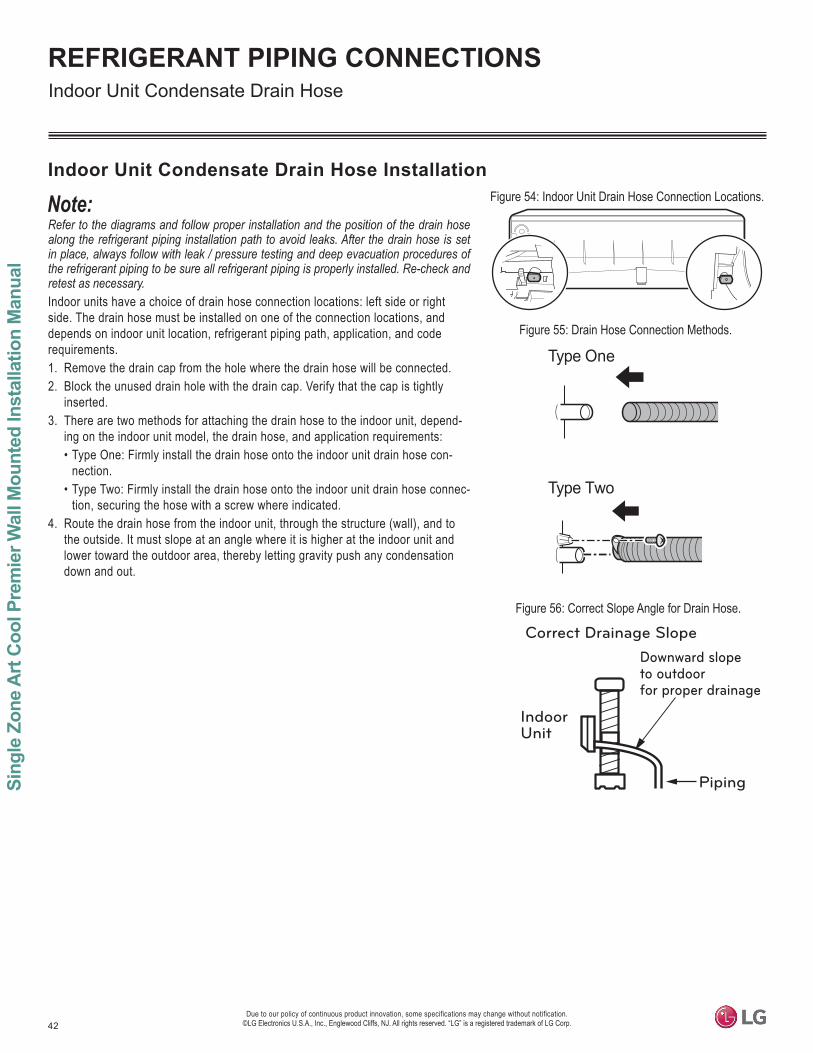
42
Sing
le Z
one
Art
Coo
l Pre
mie
r Wal
l Mou
nted
Inst
alla
tion
Man
ual
Due to our policy of continuous product innovation, some specifications may change without notification. ©LG Electronics U.S.A., Inc., Englewood Cliffs, NJ. All rights reserved. “LG” is a registered trademark of LG Corp.
REFRIGERANT PIPING CONNECTIONS
Refer to the diagrams and follow proper installation and the position of the drain hose along the refrigerant piping installation path to avoid leaks. After the drain hose is set in place, always follow with leak / pressure testing and deep evacuation procedures of the refrigerant piping to be sure all refrigerant piping is properly installed. Re-check and retest as necessary.Indoor units have a choice of drain hose connection locations: left side or right side. The drain hose must be installed on one of the connection locations, and depends on indoor unit location, refrigerant piping path, application, and code requirements. 1. Remove the drain cap from the hole where the drain hose will be connected. 2. Block the unused drain hole with the drain cap. Verify that the cap is tightly
inserted.3. There are two methods for attaching the drain hose to the indoor unit, depend-
ing on the indoor unit model, the drain hose, and application requirements: • Type One: Firmly install the drain hose onto the indoor unit drain hose con-
nection. • Type Two: Firmly install the drain hose onto the indoor unit drain hose connec-
tion, securing the hose with a screw where indicated.4. Route the drain hose from the indoor unit, through the structure (wall), and to
the outside. It must slope at an angle where it is higher at the indoor unit and lower toward the outdoor area, thereby letting gravity push any condensation down and out.
Type One
Type Two
Figure 54: Indoor Unit Drain Hose Connection Locations.
Figure 55: Drain Hose Connection Methods.
Downward slopeto outdoorfor proper drainage
Indoor Unit
Piping
Correct Drainage Slope
Indoor Unit Condensate Drain Hose Installation
Figure 56: Correct Slope Angle for Drain Hose.
Indoor Unit Condensate Drain Hose
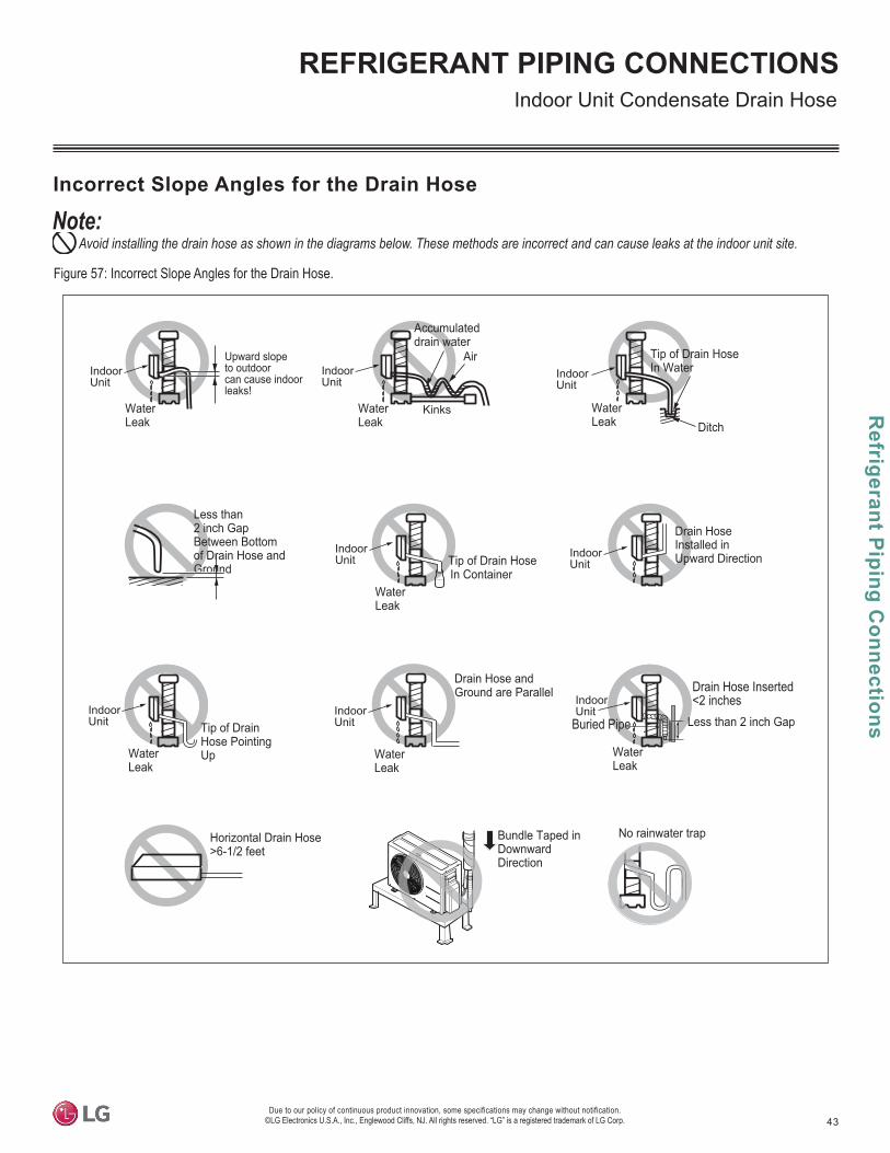
43
Refrigerant P
iping Connections
Due to our policy of continuous product innovation, some specifications may change without notification. ©LG Electronics U.S.A., Inc., Englewood Cliffs, NJ. All rights reserved. “LG” is a registered trademark of LG Corp.
REFRIGERANT PIPING CONNECTIONS
Accumulateddrain water
Tip of Drain Hose In Container
Tip of Drain Hose PointingUp
Tip of Drain Hose In Water
Air
KinksWaterLeak
WaterLeak Ditch
Less than 2 inch GapBetween Bottomof Drain Hose andGround
WaterLeak
No rainwater trap
Drain Hose and Ground are Parallel
Horizontal Drain Hose>6-1/2 feet
Drain Hose Inserted <2 inches
Bundle Taped inDownwardDirection
Less than 2 inch GapBuried Pipe
Upward slopeto outdoorcan cause indoorleaks!
IndoorUnit
IndoorUnit
IndoorUnit
IndoorUnit
WaterLeak
IndoorUnit
IndoorUnit
WaterLeak
IndoorUnit
WaterLeak
IndoorUnit
WaterLeak
Drain HoseInstalled in Upward Direction
Figure 57: Incorrect Slope Angles for the Drain Hose.
Indoor Unit Condensate Drain Hose
Avoid installing the drain hose as shown in the diagrams below. These methods are incorrect and can cause leaks at the indoor unit site.
Incorrect Slope Angles for the Drain Hose

44
Sing
le Z
one
Art
Coo
l Pre
mie
r Wal
l Mou
nted
Inst
alla
tion
Man
ual
Due to our policy of continuous product innovation, some specifications may change without notification. ©LG Electronics U.S.A., Inc., Englewood Cliffs, NJ. All rights reserved. “LG” is a registered trademark of LG Corp.
REFRIGERANT PIPING CONNECTIONS
two (2) inches so it won’t pull out.
Insert the drainhose >2 inchesso it won’t be pulledout of the field-supplied drain pipe.
>2 inches Drain Hose
Interior Wall
Vinyl ChlorideDrain Pipe
Exterior Wall
Extending the Indoor Unit Drain Hose
Depending on the location of the indoor unit, and its accessibility to the outside, It could be necessary to extend the drain hose so that condensate will be properly routed away.
1. Insert the field-supplied drain extension hose into the indoor unit drain hose joint.
2. Securely wrap the connection between the field-supplied drain hose and the indoor unit drain hose with vinyl tape.
3. All drain hoses and hose connections must be properly insulated to ensure any conden-sation will not damage walls, floors, furniture, etc. Extension connection insulation is to be more than 12 inches in length, and more than 1/4 inches thick (follow all local, state, and federal codes for the proper insulation materials and installation procedures).
2 inches(50 mm)
Outside WallInside Wall
Vinyl Chloride Drain PipeSystem
Indoor Outdoor
Indoor UnitDrain Hose
Indoor UnitDrain Hose
Insulation(More than 12 inches long and 1/4 inches thick)
Drain HoseExtension
Figure 58: Connecting the Extension Drain Hose to the Indoor Unit Drain Hose.
Figure 59: Securing the Extension Drain Hose to the Indoor Unit Drain Hose.
Figure 60: Insulating the Indoor Unit to Extension Drain Hose Connection.
Indoor Unit Condensate Drain Hose
Precautions for Drain Hose Installation in a Wall-Embedded Drain Pipe System
Follow all local, state, and federal guidelines when working with a wall-embedded drain pipe system.
Figure 61: Inserting the Drain Hose More Than Two (2) inches Into the Wall-Embedded Drain Pipe System (Overview).
Figure 62: Inserting the Drain Hose More Than Two (2) inches Into the Wall-Embedded Drain Pipe System (Close Up View).

45
Refrigerant P
iping Connections
Due to our policy of continuous product innovation, some specifications may change without notification. ©LG Electronics U.S.A., Inc., Englewood Cliffs, NJ. All rights reserved. “LG” is a registered trademark of LG Corp.
REFRIGERANT PIPING CONNECTIONS
Checking the Indoor Unit Drain Hose for Leaks 1. Remove the indoor unit filter by pulling it up and out towards you.
physical injury.
2. Pour a glass of water on the back of the evaporator.
3. Verify that the water flows appropriately through and out of the indoor unit and drain hose without any leaks. Check all connection areas for leaks: the drain hose connection to the in-door unit, the connection from the indoor unit drain hose to the field-suppled drain extension hose, drain hose insert into wall-embedded drain system.
4. Verify that the water is flowing out and through the drain hose. If leaks are not present, but water is not flowing out and through the drain hose, pour more water on the back of the evaporator.
5. When satisfied that the drain system is leak-free, re-insert the filter.
Figure 63: Removing the Indoor Unit Filter.
Indoor Unit Condensate Drain Hose
Figure 64: Adding Water to the Evaporator.
Figure 65: Checking for Leaks at the Con-nection Areas.
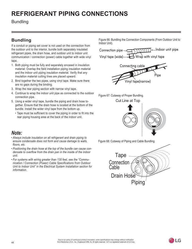
46Due to our policy of continuous product innovation, some specifications may change without notification.
©LG Electronics U.S.A., Inc., Englewood Cliffs, NJ. All rights reserved. “LG” is a registered trademark of LG Corp.
REFRIGERANT PIPING CONNECTIONS
• Always include insulation on all refrigerant and drain piping to ensure condensate does not form and cause damage to walls, floors, etc.
• Positioning the drain hose at the top of the bundle can cause con-densate to overflow from the drain pan in the inside of the indoor unit.
• For systems with wiring greater than 130 feet, see the “Commu-nication / Connection (Power) Cable Specifications from Outdoor Unit to Indoor Unit” in the Electrical System Installation section for information.
BundlingIf a conduit or piping set cover is not used on the connection from the outdoor unit to the interior, bundle both separately insulated refrigerant pipes, the drain hose, and outdoor unit to indoor unit communication / connection (power) cable together with wide vinyl tape. 1. Both piping must be fully and separately encased in insulation
material: Overlap the field installation piping insulation material and the indoor unit piping insulation material. Verify that any insulation material cutting lines are placed upward.
2. Bind together the two pipes, using vinyl tape. Make sure there are no gaps during the binding.
3. Wrap the rear piping section with narrow vinyl tape.4. Continue to wrap the indoor unit pipe as connected to the outdoor
connection pipe.5. Using a wider vinyl tape, bundle the piping and drain hose to-
gether. Ensure that the drain hose is located at the bottom of the bundle. Install the wider vinyl tape from the bottom up.• Tape must be sufficient to cover the piping in order to fit into the
rear piping housing area at the back of the indoor unit.
Figure 66: Bundling the Connection Components (From Outdoor Unit to Indoor Unit).
Figure 67: Cutaway of Proper Bundling.
Vinyl tape(narrow)
Connection pipe
Connecting cable
Vinyl tape (wide) Wrap with vinyl tape
Indoor unit pipe
Pipe
Cut Line at Top
Figure 68: Cutaway of Piping and Cable Bundling.
Bundling
Piping
ConnectionCable
Tape
Drain Hose

47
Insulation
Due to our policy of continuous product innovation, some specifications may change without notification. ©LG Electronics U.S.A., Inc., Englewood Cliffs, NJ. All rights reserved. “LG” is a registered trademark of LG Corp.
INSULATION
Figure 69: Typical Insulation Butt-Joint at Indoor Unit Casing.
Figure 70: Typical Refrigerant Flare Fitting Insulation Detail.
Refrigerant Piping System InsulationFor information regarding insulation for underground or penetration situations, see the “General Refrigerant Piping System Information” section.
All refrigerant piping from the outdoor unit to the indoor units must be insulated correctly for safety and usage. Refrigerant piping, field-pro-vided isolation ball valves (if present), service valves, and elbows must be properly and completely insulated using closed cell pipe insulation (up to the indoor unit piping connections). To prevent heat loss / heat gain through the refrigerant piping, all refrigerant piping including liquid lines and vapor lines must be insulated separately. Insulation must be a minimum 1/2 inches thick, and thickness may need to be increased based on ambient conditions and local codes. Table on next page lists minimum wall thickness requirements for Ethylene Propylene Diene Methylene (EPDM) insulation.
Inside the outdoor unit, maximum pipe temperature is 248°F and minimum pipe temperature is -40°F. For field insulation of refrigerant piping between outdoor units and indoor units, consider the following pipe temperature ranges for an operating heat pump system:
• Heating mode refrigerant temperature ranges: Liquid = 75-118°F; High Pressure Vapor = 95-220°F• Cooling mode refrigerant temperature ranges: Liquid = 75-118°F; Low Pressure Vapor = 40-90°F
All insulation joints must be glued with no air gaps. Insulation material must fit snugly against the refrigeration pipe with no air space between it and the pipe. Do not allow insulation passing through pipe hangers, inside conduit, and/or sleeves to be compressed. Protect insulation inside hangers and supports with a second layer. All pipe insulation exposed to the sun and outdoor elements must be properly protected with PVC, aluminum vapor barrier, or alternatively placed in a weather-resistant enclosure such as a pipe rack with a top cover; and meet local codes.
Surface of Indoor Unit Casing
Field-Provided Pipe Insulation
Figure 71: Insulating the Shut Off / Isolation Ball Valve (If Present).
Indoor Unit
Insulation (Field Supplied)
Cable Tie, etc.(Field Supplied)
Refrigerant Piping

48
Sing
le Z
one
Art
Coo
l Pre
mie
r Wal
l Mou
nted
Inst
alla
tion
Man
ual
Due to our policy of continuous product innovation, some specifications may change without notification. ©LG Electronics U.S.A., Inc., Englewood Cliffs, NJ. All rights reserved. “LG” is a registered trademark of LG Corp.
INSULATION
1. Typical Conditioned LocationA building plenum or space that contains conditioned air that does not exceed 80°F DB.
2. Special Conditioned Location1. When the location is air conditioned, but there is severe temperature/humidity difference due to high ceilings.
• Church, auditorium, theater, lobby, etc.2. When the location is air conditioned, but internal temperature/humidity are high.
• Bathroom, swimming pool, locker room, etc.
3. Typical Unconditioned LocationAn unconditioned space inside a building.
Minimum Refrigerant Pipe Ethylene Propylene Diene Methylene (EPDM) Insulation Wall Thickness Requirements
4. Special Unconditioned Location: If conditions 1 and 2 below are present.1. An unconditioned space or plenum of a building.2. An area where there is an elevated humidity level.
Air-conditioned location Non-air conditioned location1. Typical Conditioned
Location2. Special Conditioned
Location3. Typical Unconditioned
Location4. Special Unconditioned
Location
Liquid pipeø1/4 inch >1/2 inches >1/2 inches >1/2 inches >1/2 inchesø3/8 inch
>1/2 inches >1/2 inches >1/2 inches >1/2 inches
Vapor pipe
ø3/8 inch
>1/2 inches >3/4 inches >3/4 inches
>1 inch
ø1/2 inchø5/8 inchø3/4 inchø7/8 inchø1 inch
ø1-1/8 inches
>3/4 inchesø1-1/4 inches
>1 inch >1 inchø1-3/8 inchesø1-1/2 inchesø1-3/4 inches
Table 18: Minimum Refrigerant Pipe EPDM Insulation Wall Thickness Requirements.1
• • Always properly insulate the piping. Insufficient insulation will result in condensation, reduced heating/cooling performance, etc. Also, if the
pipes aren’t insulated properly, condensation could potentially cause damage to building finishes. Pay special attention to insulating the pipes installed in the ceiling plenum.
• Fully insulate the piping connections.• Follow locals codes and the designer’s instructions when selecting ethylene propylene diene methylene (EPDM) insulation wall thickness.
1The thickness of the above insulation material is based on heat conductivity of 0.61 Btu/in/h/ft2/°F.
5. Additional Insulation for Indoor Units May be Required in Humid Environments.The air conditioner factory insulation has been tested according to “ISO Conditions with Mist,” and it satisfies the requirements. If the system has been operating for a long time in a high humidity environment (dew point temperature: more than 73°F), condensate is likely to form. If this happens, install 3/8 inch thick EPDM insulation that is plenum-rated with a heat-resistance factor of more than 248°F.

49
Electrical System Installation
Due to our policy of continuous product innovation, some specifications may change without notification. ©LG Electronics U.S.A., Inc., Englewood Cliffs, NJ. All rights reserved. “LG” is a registered trademark of LG Corp.
ELECTRICAL SYSTEM INSTALLATION
• All power wiring and communication cable installation must be performed by trained service providers working in accordance with local, state, and National Electrical Code (NEC) / UL / CSA federal regulations related to electrical equipment and wiring, and following the manufacturer product diagrams, requirements, and instructions in this manual. Failure to do so will lead to electric shock which can cause physical injury or death.
• Verify that main power to the unit is completely off before proceeding. Follow all safety and warning information outlined at the beginning of this manual. Failure to do so will cause electric shock and bodily injury or death.
• Familiarize yourself with the location of the circuit breaker. Be sure that a circuit breaker or some other emergency power cutoff device is in place before any power wiring is done to the system. Failure to do so will cause bodily injury or death.
• Never touch any power lines or live cables before all power is cutoff to the system. To do so will cause bodily injury or death.• Undersized wiring will lead to unacceptable voltage at the unit and will cause a fire, which will cause bodily injury or death.• Properly ground the Single Zone outdoor and indoor units. Ground wiring is required to prevent accidental electrical shock, bodily injury, and
death during current leakage.• Ground wiring must always be installed by a trained technician. • Install appropriately sized breakers / fuses / overcurrent protection switches and wiring in accordance with local, state, and NEC regulations
related to electrical equipment and wiring, and following the instructions in this manual. Using an oversized breaker or fuse will result in electric shock, physical injury or death.
• Do not connect ground wire to refrigerant, gas, or water piping; to lightning rods; to telephone ground wiring; or to the building plumbing system. Failure to properly provide a NEC-approved earth ground can result in electric shock, fire, physical injury or death.
• Consider ambient conditions (temperature, direct sunlight, inclement weather, etc.) when selecting, installing, and connecting the power wir-ing.
• Properly ground the Single Zone outdoor and indoor unit. Improperly connected ground wire can cause communication problems from electri-cal noise, and motor current leakage. Ground wiring must always be installed by a trained technician.
• Install appropriately sized breakers / fuses / overcurrent protection switches and wiring in accordance with local, state, and NEC regulations related to electrical equipment and wiring, and following the instructions in this manual. Using an oversized breaker or fuse will result in equip-ment malfunction and property damage.
• Do not connect ground wire to refrigerant, gas, or water piping; to lightning rods; to telephone ground wiring; or to the building plumbing system. Failure to properly provide a NEC-approved earth ground can result in property damage and equipment malfunction.
• Do not operate the air conditioning system until the refrigerant piping installation is complete. Operating the system before refrigerant piping is finalized will damage the compressor.
Figure 72: Close up of a Typical Ring Terminal.Power Wiring / Communication Cable ConnectionsBest practice dictates using solderless ring or fork terminals at all power wiring and com-munication cable terminations. Use copper bearing ring or fork terminals; do not use galvanized or nickel plate over steel. Use appropriate crimping tool to attach the ring or fork terminals at all power wiring and control cable terminations.
To Install a Ring or Fork Terminal:1. Trim the wiring with wire cutters or pliers, then strip the insulation to expose the strand
wiring to about 3/8 inches.2. Using a ring terminal fastener or pliers, securely clamp a ring terminal to each stripped
wire end.
Ring TerminalPower Wiring
Figure 73: Distance Between the Terminal Connections.
>1/4inches
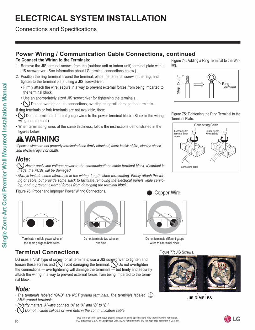
50
Sing
le Z
one
Art
Coo
l Pre
mie
r Wal
l Mou
nted
Inst
alla
tion
Man
ual
Due to our policy of continuous product innovation, some specifications may change without notification. ©LG Electronics U.S.A., Inc., Englewood Cliffs, NJ. All rights reserved. “LG” is a registered trademark of LG Corp.
ELECTRICAL SYSTEM INSTALLATION
Strip
to
3/8"
RingTerminal
Connecting Cable
Connecting cable
Loosening theterminal blockscrew
Fastening the wiring tightly
Figure 74: Adding a Ring Terminal to the Wir-ing.
To Connect the Wiring to the Terminals:1. Remove the JIS terminal screws from the (outdoor unit or indoor unit) terminal plate with a
JIS screwdriver. (See information about LG terminal connections below.)2. Position the ring terminal around the terminal, place the terminal screw in the ring, and
tighten to the terminal plate using a JIS screwdriver. • Firmly attach the wire; secure in a way to prevent external forces from being imparted to
the terminal block.• Use an appropriately sized JIS screwdriver for tightening the terminals. • Do not overtighten the connections; overtightening will damage the terminals.
If ring terminals or fork terminals are not available, then:• Do not terminate different gauge wires to the power terminal block. (Slack in the wiring
will generate heat.)• When terminating wires of the same thickness, follow the instructions demonstrated in the
figures below.
• Never apply line voltage power to the communications cable terminal block. If contact is made, the PCBs will be damaged.
• Always include some allowance in the wiring length when terminating. Firmly attach the wir-ing or cable, but provide some slack to facilitate removing the electrical panels while servic-ing, and to prevent external forces from damaging the terminal block.
:Copper Wire
Terminate multiple power wires of the same gauge to both sides.
Do not terminate two wires on one side.
Do not terminate different gauge wires to a terminal block.
and physical injury or death.
Figure 75: Tightening the Ring Terminal to the Terminal Plate.
Figure 76: Proper and Improper Power Wiring Connections.
Power Wiring / Communication Cable Connections, continued
Terminal ConnectionsLG uses a “JIS” type of screw for all terminals; use a JIS screwdriver to tighten and loosen these screws and avoid damaging the terminal. Do not overtighten the connections — overtightening will damage the terminals — but firmly and securely attach the wiring in a way to prevent external forces from being imparted to the termi-nal block.
• The terminals labeled “GND” are NOT ground terminals. The terminals labeled ARE ground terminals.
• Polarity matters. Always connect “A” to “A” and “B” to “B.”• Do not include splices or wire nuts in the communication cable.
Figure 77: JIS Screws.
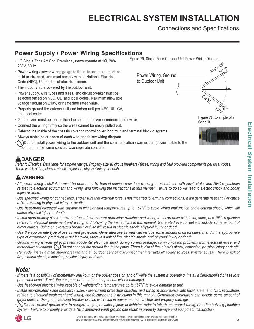
51
Electrical System Installation
Due to our policy of continuous product innovation, some specifications may change without notification. ©LG Electronics U.S.A., Inc., Englewood Cliffs, NJ. All rights reserved. “LG” is a registered trademark of LG Corp.
ELECTRICAL SYSTEM INSTALLATION
• LG Single Zone Art Cool Premier systems operate at 1Ø, 208-230V, 60Hz.
• Power wiring / power wiring gauge to the outdoor unit(s) must be solid or stranded, and must comply with all National Electrical Code (NEC), UL, and local electrical codes.
• The indoor unit is powered by the outdoor unit.• Power supply, wire types and sizes, and circuit breaker must be
selected based on NEC, UL, and local codes. Maximum allowable voltage fluctuation ±10% or nameplate rated value.
• Properly ground the outdoor unit and indoor unit per NEC, UL, CA, and local codes.
• Ground wire must be longer than the common power / communication wires.• Connect the wiring firmly so the wires cannot be easily pulled out.• Refer to the inside of the chassis cover or control cover for circuit and terminal block diagrams.• Always match color codes of each wire and follow wiring diagram.• Do not install power wiring to the outdoor unit and the communication / connection (power) cable to the
indoor unit in the same conduit. Use separate conduits.
Figure 78: Example of a Conduit.
Figure 79: Single Zone Outdoor Unit Power Wiring Diagram.
7/16" ± 1/8"
13/16"
GN/YL
Power Wiring, Groundto Outdoor Unit
Power Supply / Power Wiring Specifications
• All power wiring installation must be performed by trained service providers working in accordance with local, state, and NEC regulations related to electrical equipment and wiring, and following the instructions in this manual. Failure to do so will lead to electric shock and bodily injury or death.
• Use specified wiring for connections, and ensure that external force is not imparted to terminal connections. It will generate heat and / or cause a fire, resulting in physical injury or death.
• Use heat-proof electrical wire capable of withstanding temperatures up to 167°F to avoid wiring malfunction and electrical shock, which will cause physical injury or death.
• Install appropriately sized breakers / fuses / overcurrent protection switches and wiring in accordance with local, state, and NEC regulation related to electrical equipment and wiring, and following the instructions in this manual. Generated overcurrent will include some amount of direct current. Using an oversized breaker or fuse will result in electric shock, physical injury or death.
• Use the appropriate type of overcurrent protection. Generated overcurrent can include some amount of direct current, and if the appropriate type of overcurrent protection is not installed, there is a risk of fire, electric shock, and physical injury or death.
• Ground wiring is required to prevent accidental electrical shock during current leakage, communication problems from electrical noise, and motor current leakage. Do not connect the ground line to the pipes. There is risk of fire, electric shock, explosion, physical injury or death.
• Per code, install a main indoor breaker, and an outdoor service disconnect that interrupts all power sources simultaneously. There is risk of fire, electric shock, explosion, physical injury or death.
• If there is a possibility of momentary blackout, or the power goes on and off while the system is operating, install a field-supplied phase loss protection circuit. If not, the compressor and other components will be damaged.
• Use heat-proof electrical wire capable of withstanding temperatures up to 167°F to avoid damage to unit.• Install appropriately sized breakers / fuses / overcurrent protection switches and wiring in accordance with local, state, and NEC regulations
related to electrical equipment and wiring, and following the instructions in this manual. Generated overcurrent can include some amount of direct current. Using an oversized breaker or fuse will result in equipment malfunction and property damage.
• Do not connect ground wire to refrigerant, gas, or water piping; to lightning rods; to telephone ground wiring; or to the building plumbing system. Failure to properly provide a NEC approved earth ground can result in property damage and equipment malfunction.

52
Sing
le Z
one
Art
Coo
l Pre
mie
r Wal
l Mou
nted
Inst
alla
tion
Man
ual
Due to our policy of continuous product innovation, some specifications may change without notification. ©LG Electronics U.S.A., Inc., Englewood Cliffs, NJ. All rights reserved. “LG” is a registered trademark of LG Corp.
ELECTRICAL SYSTEM INSTALLATION
Communication / Connection (Power) Cable Specifications from Outdoor Unit to Indoor Unit Figure 80: Typical Single Zone Outdoor Unit to Indoor Unit Wiring and
Communications Cable Diagram For Wiring Lengths Up to 130 Feet.
Communication / Connection(Power), Ground Cable From Outdoor UnitTo Indoor Unit
13/16"
GN/YL
GN/YL = (Ground, Yellow)
7/16" ± 1/8"• For communication / connection (power) wires between the Single
Zone outdoor unit and the indoor unit for lengths up to 130 feet, use a minimum 14 gauge, four (4) conductor, stranded, shielded or unshielded wire. If shielded, the wire must be grounded to the chassis at the outdoor unit only.• When the communication / connection (power) wire between the
indoor unit and outdoor unit is GREATER THAN 130 feet, use:• A two (2) conductor wire for power.• A two (2) conductor wire for communication / ground. • Separate the power AT LEAST two (2) inches away from the
communication / ground wire. • All wiring is still minimum 14 gauge, stranded, shielded, or
unshielded as cited above.• Insulation material as required by local code.• Firmly attach the cable; provide slack but secure in a way to pre-
vent external forces from being imparted on the terminal block.• Wiring must be completed without splices.
• Always verify the communication cable is connected to a communications terminal on the Single Zone Art Cool Premier unit. Never apply line voltage power to the communication cable connection. If contact is made, the PCBs will be damaged.
• The shield of the communications cable connecting the outdoor unit to the indoor unit must be grounded only to the outdoor unit frame. • Tie the shield of each cable segment together using a wire nut at the indoor unit. Maintain polarity throughout the communication network.• Position the incoming power to the outdoor unit away from the power / communications cables from the outdoor unit to the indoor unit. • Never use a common multiple-core communications cable.
All power wiring and communication cable installation must be per-formed by trained service providers working in accordance with local, state, and National Electrical Code (NEC) / UL / ETL federal regulations related to electrical equipment and wiring, and following the manufac-turer product diagrams, requirements, and instructions in this manual. Failure to do so will lead to electric shock which can cause physical injury or death.
Figure 81: Single Zone Outdoor Unit to Indoor Unit Wiring and Com-munications Cable Diagram For Wiring Lengths GREATER THAN 130 Feet.
Figure 82: Typical HYV3 Power / Communication System Diagram For Wiring Lengths Up to 130 Feet.
Two-Conductor Power Cable
GN/YL
GN/YL = (Ground, Yellow)
Two-Conductor Communication /Ground Cable
Separate At Least Two (2) Inches
13/16"
7/16" ± 1/8"
1(L1)
2(L2)
13/16"
7/16" ± 1/8"
3
Figure 83: HYV3 Power / Communication System Diagram For Wiring Lengths GREATER THAN 130 Feet.
Indoor Unit Terminal
Power Supply1 Phase, 208-230V
Con
nect
ing
Cab
le
Gro
undi
ng L
ine
Gro
undi
ng L
ine
Outdoor Unit Terminal
If 3-pole disconnect is required by local code, install here. Indoor Unit
Terminal
Power Supply1 Phase, 208-230V
Con
nect
ing
Cab
le
Gro
undi
ng L
ine
Gro
undi
ng L
ine
Outdoor Unit Terminal
If 3-pole disconnect is required by local code, install here.
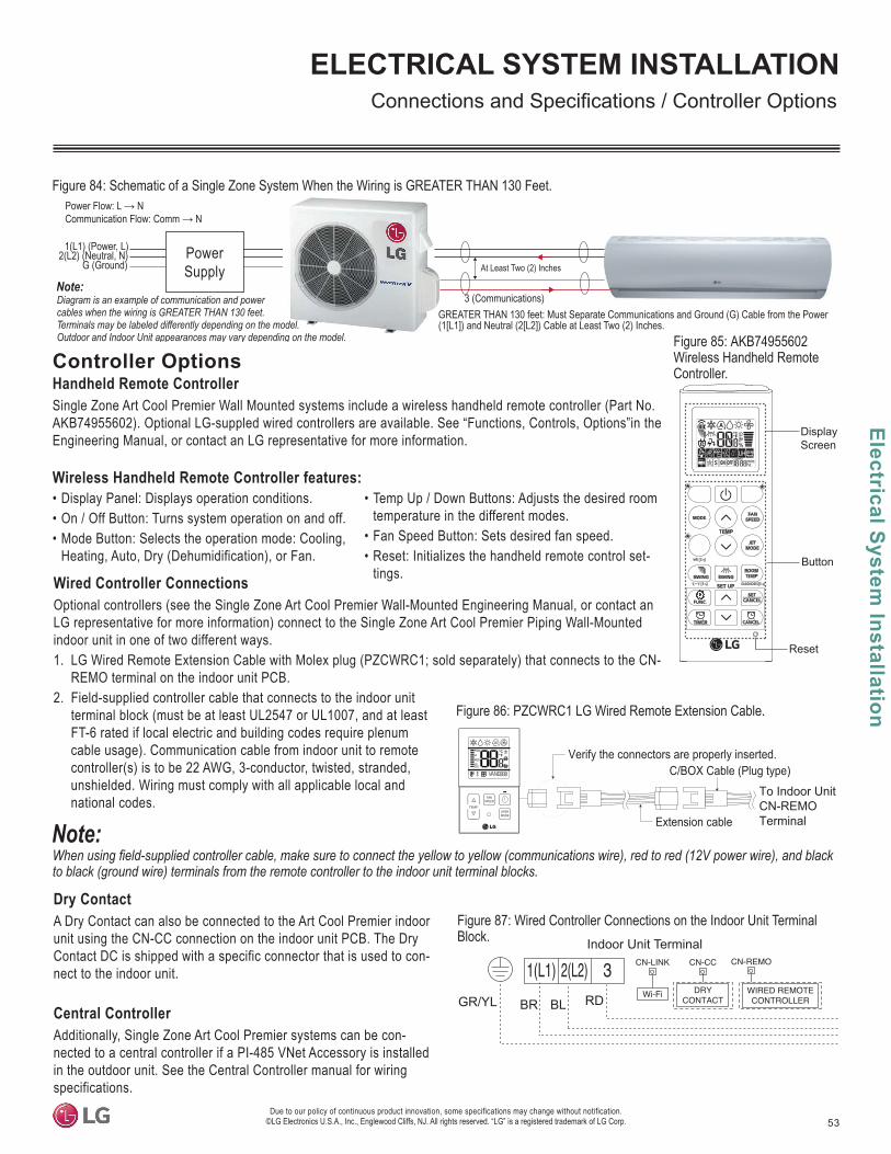
53
Electrical System Installation
Due to our policy of continuous product innovation, some specifications may change without notification. ©LG Electronics U.S.A., Inc., Englewood Cliffs, NJ. All rights reserved. “LG” is a registered trademark of LG Corp.
ELECTRICAL SYSTEM INSTALLATION
Controller OptionsHandheld Remote ControllerSingle Zone Art Cool Premier Wall Mounted systems include a wireless handheld remote controller (Part No. AKB74955602). Optional LG-suppled wired controllers are available. See “Functions, Controls, Options”in the Engineering Manual, or contact an LG representative for more information.
Wireless Handheld Remote Controller features: • Display Panel: Displays operation conditions.• On / Off Button: Turns system operation on and off.• Mode Button: Selects the operation mode: Cooling,
Heating, Auto, Dry (Dehumidification), or Fan.
• Temp Up / Down Buttons: Adjusts the desired room temperature in the different modes.
• Fan Speed Button: Sets desired fan speed.• Reset: Initializes the handheld remote control set-
tings.
Dry Contact A Dry Contact can also be connected to the Art Cool Premier indoor unit using the CN-CC connection on the indoor unit PCB. The Dry Contact DC is shipped with a specific connector that is used to con-nect to the indoor unit.
Central ControllerAdditionally, Single Zone Art Cool Premier systems can be con-nected to a central controller if a PI-485 VNet Accessory is installed in the outdoor unit. See the Central Controller manual for wiring specifications.
Figure 84: Schematic of a Single Zone System When the Wiring is GREATER THAN 130 Feet.
Wired Controller Connections Optional controllers (see the Single Zone Art Cool Premier Wall-Mounted Engineering Manual, or contact an LG representative for more information) connect to the Single Zone Art Cool Premier Piping Wall-Mounted indoor unit in one of two different ways.1. LG Wired Remote Extension Cable with Molex plug (PZCWRC1; sold separately) that connects to the CN-
REMO terminal on the indoor unit PCB. 2. Field-supplied controller cable that connects to the indoor unit
terminal block (must be at least UL2547 or UL1007, and at least FT-6 rated if local electric and building codes require plenum cable usage). Communication cable from indoor unit to remote controller(s) is to be 22 AWG, 3-conductor, twisted, stranded, unshielded. Wiring must comply with all applicable local and national codes.
Figure 85: AKB74955602 Wireless Handheld Remote Controller.
to black (ground wire) terminals from the remote controller to the indoor unit terminal blocks.
Verify the connectors are properly inserted.C/BOX Cable (Plug type)
Extension cable
To Indoor UnitCN-REMO Terminal
TEMP
FANSPEED
OPERMODE
Figure 86: PZCWRC1 LG Wired Remote Extension Cable.
Figure 87: Wired Controller Connections on the Indoor Unit Terminal Block.
Power Supply
1(L1) (Power, L)2(L2) (Neutral, N)
G (Ground)
Power Flow: L N
Diagram is an example of communication and power cables when the wiring is GREATER THAN 130 feet. Terminals may be labeled differently depending on the model.Outdoor and Indoor Unit appearances may vary depending on the model.
Communication Flow: Comm N
3 (Communications)GREATER THAN 130 feet: Must Separate Communications and Ground (G) Cable from the Power (1[L1]) and Neutral (2[L2]) Cable at Least Two (2) Inches.
At Least Two (2) Inches
Display
Button
Screen
*
*
*
Reset
Indoor Unit Terminal
BR BL RDGR/YL
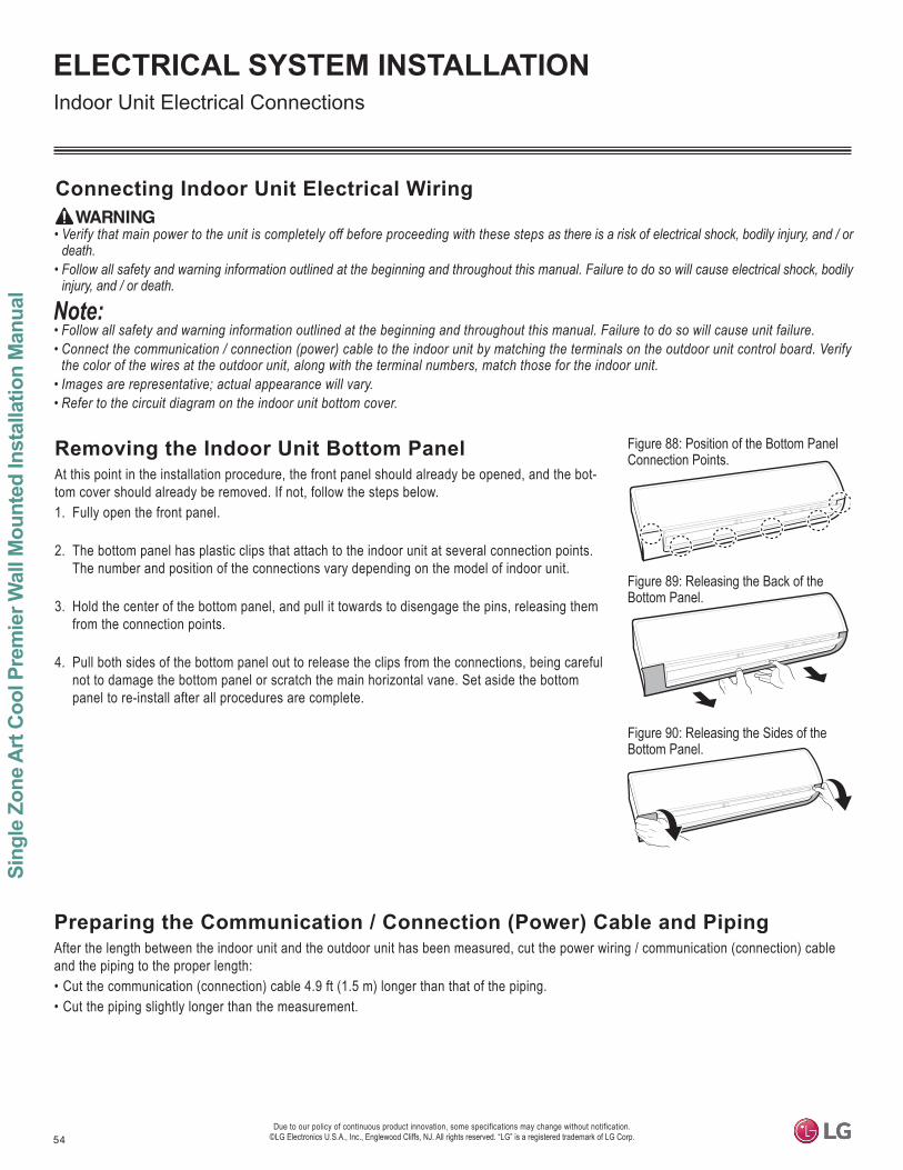
54
Sing
le Z
one
Art
Coo
l Pre
mie
r Wal
l Mou
nted
Inst
alla
tion
Man
ual
Due to our policy of continuous product innovation, some specifications may change without notification. ©LG Electronics U.S.A., Inc., Englewood Cliffs, NJ. All rights reserved. “LG” is a registered trademark of LG Corp.
ELECTRICAL SYSTEM INSTALLATION
Connecting Indoor Unit Electrical Wiring
• Verify that main power to the unit is completely off before proceeding with these steps as there is a risk of electrical shock, bodily injury, and / or death.
• Follow all safety and warning information outlined at the beginning and throughout this manual. Failure to do so will cause electrical shock, bodily injury, and / or death.
• Follow all safety and warning information outlined at the beginning and throughout this manual. Failure to do so will cause unit failure.• Connect the communication / connection (power) cable to the indoor unit by matching the terminals on the outdoor unit control board. Verify
the color of the wires at the outdoor unit, along with the terminal numbers, match those for the indoor unit.• Images are representative; actual appearance will vary.• Refer to the circuit diagram on the indoor unit bottom cover.
Removing the Indoor Unit Bottom PanelAt this point in the installation procedure, the front panel should already be opened, and the bot-tom cover should already be removed. If not, follow the steps below.1. Fully open the front panel.
2. The bottom panel has plastic clips that attach to the indoor unit at several connection points. The number and position of the connections vary depending on the model of indoor unit.
3. Hold the center of the bottom panel, and pull it towards to disengage the pins, releasing them from the connection points.
4. Pull both sides of the bottom panel out to release the clips from the connections, being careful not to damage the bottom panel or scratch the main horizontal vane. Set aside the bottom panel to re-install after all procedures are complete.
Figure 88: Position of the Bottom Panel Connection Points.
Figure 89: Releasing the Back of the Bottom Panel.
Figure 90: Releasing the Sides of the Bottom Panel.
Preparing the Communication / Connection (Power) Cable and PipingAfter the length between the indoor unit and the outdoor unit has been measured, cut the power wiring / communication (connection) cable and the piping to the proper length: • Cut the communication (connection) cable 4.9 ft (1.5 m) longer than that of the piping.• Cut the piping slightly longer than the measurement.
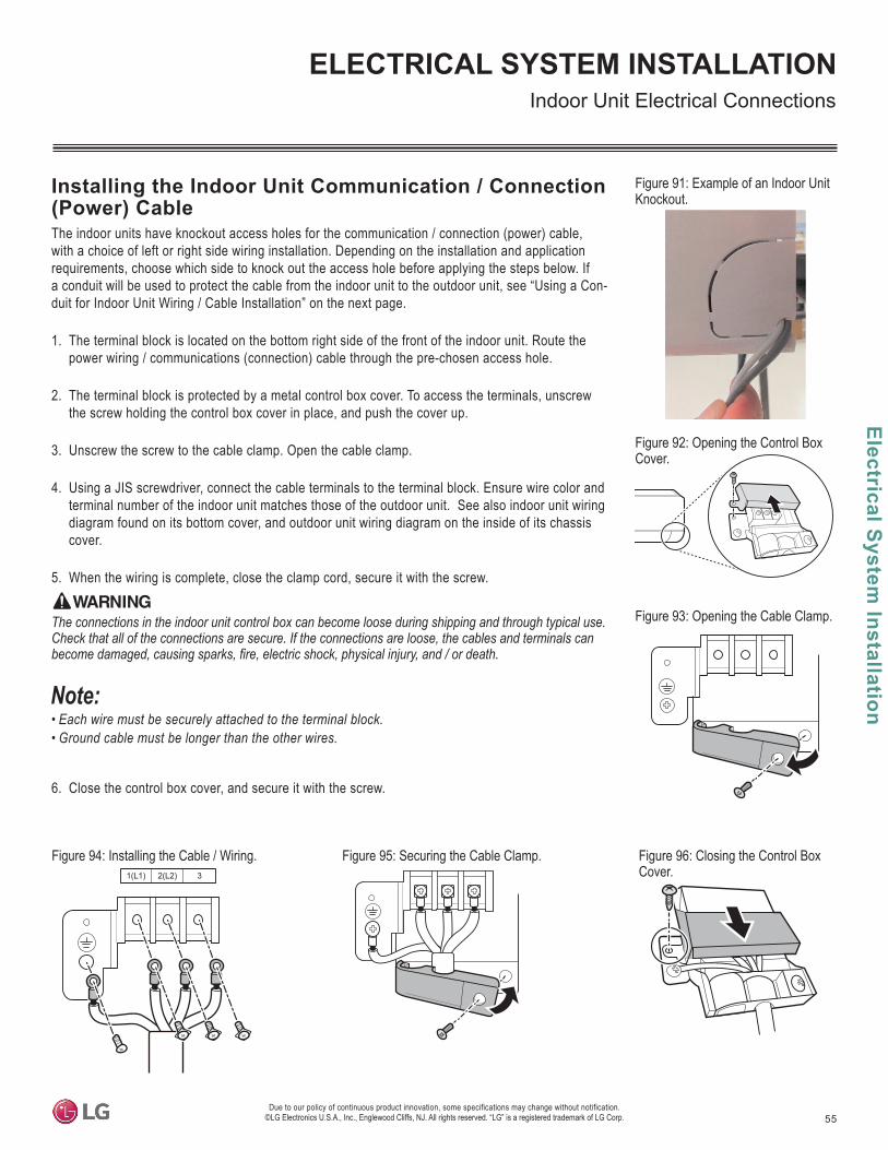
55
Electrical System Installation
Due to our policy of continuous product innovation, some specifications may change without notification. ©LG Electronics U.S.A., Inc., Englewood Cliffs, NJ. All rights reserved. “LG” is a registered trademark of LG Corp.
ELECTRICAL SYSTEM INSTALLATION
Figure 91: Example of an Indoor Unit Knockout.
1(L1) 2(L2) 3
Installing the Indoor Unit Communication / Connection (Power) CableThe indoor units have knockout access holes for the communication / connection (power) cable, with a choice of left or right side wiring installation. Depending on the installation and application requirements, choose which side to knock out the access hole before applying the steps below. If a conduit will be used to protect the cable from the indoor unit to the outdoor unit, see “Using a Con-duit for Indoor Unit Wiring / Cable Installation” on the next page.
1. The terminal block is located on the bottom right side of the front of the indoor unit. Route the power wiring / communications (connection) cable through the pre-chosen access hole.
2. The terminal block is protected by a metal control box cover. To access the terminals, unscrew the screw holding the control box cover in place, and push the cover up.
3. Unscrew the screw to the cable clamp. Open the cable clamp.
4. Using a JIS screwdriver, connect the cable terminals to the terminal block. Ensure wire color and terminal number of the indoor unit matches those of the outdoor unit. See also indoor unit wiring diagram found on its bottom cover, and outdoor unit wiring diagram on the inside of its chassis cover.
5. When the wiring is complete, close the clamp cord, secure it with the screw.
Figure 92: Opening the Control Box Cover.
Figure 93: Opening the Cable Clamp.
6. Close the control box cover, and secure it with the screw.
The connections in the indoor unit control box can become loose during shipping and through typical use. Check that all of the connections are secure. If the connections are loose, the cables and terminals can
• Each wire must be securely attached to the terminal block.• Ground cable must be longer than the other wires.
Figure 94: Installing the Cable / Wiring. Figure 95: Securing the Cable Clamp. Figure 96: Closing the Control Box Cover.
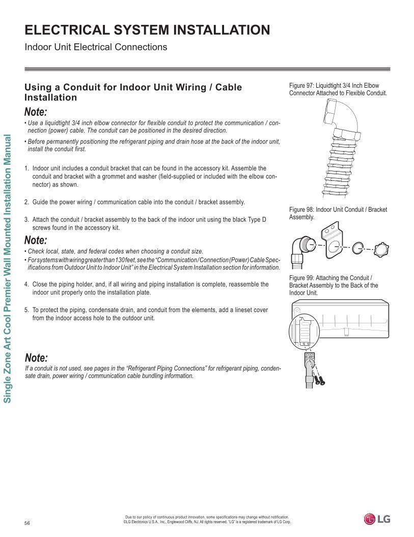
56
Sing
le Z
one
Art
Coo
l Pre
mie
r Wal
l Mou
nted
Inst
alla
tion
Man
ual
Due to our policy of continuous product innovation, some specifications may change without notification. ©LG Electronics U.S.A., Inc., Englewood Cliffs, NJ. All rights reserved. “LG” is a registered trademark of LG Corp.
ELECTRICAL SYSTEM INSTALLATION
Using a Conduit for Indoor Unit Wiring / Cable Installation
• Use a liquidtight 3/4 inch elbow connector for flexible conduit to protect the communication / con-nection (power) cable. The conduit can be positioned in the desired direction.
• Before permanently positioning the refrigerant piping and drain hose at the back of the indoor unit, install the conduit first.
1. Indoor unit includes a conduit bracket that can be found in the accessory kit. Assemble the conduit and bracket with a grommet and washer (field-supplied or included with the elbow con-nector) as shown.
2. Guide the power wiring / communication cable into the conduit / bracket assembly.
3. Attach the conduit / bracket assembly to the back of the indoor unit using the black Type D screws found in the accessory kit.
• Check local, state, and federal codes when choosing a conduit size. • For systems with wiring greater than 130 feet, see the “Communication / Connection (Power) Cable Spec-
ifications from Outdoor Unit to Indoor Unit” in the Electrical System Installation section for information.
4. Close the piping holder, and, if all wiring and piping installation is complete, reassemble the indoor unit properly onto the installation plate.
5. To protect the piping, condensate drain, and conduit from the elements, add a lineset cover from the indoor access hole to the outdoor unit.
Figure 97: Liquidtight 3/4 Inch Elbow Connector Attached to Flexible Conduit.
Figure 98: Indoor Unit Conduit / Bracket Assembly.
Figure 99: Attaching the Conduit / Bracket Assembly to the Back of the Indoor Unit.
If a conduit is not used, see pages in the “Refrigerant Piping Connections” for refrigerant piping, conden-sate drain, power wiring / communication cable bundling information.
57
Electrical System Installation
Due to our policy of continuous product innovation, some specifications may change without notification. ©LG Electronics U.S.A., Inc., Englewood Cliffs, NJ. All rights reserved. “LG” is a registered trademark of LG Corp.
ELECTRICAL SYSTEM INSTALLATION
Cable Installation When Piping is on the Left Side1. Insert the communication / connection (power) cable through the left access hole, and through the inside of the indoor unit to the terminal
block.2. Connect the communication / connection (power) cable terminals to the terminal block as detailed in “Installing the Indoor Unit Communi-
cation / Connection (Power) Cable” on the previous pages.3. Secure the refrigerant piping, drain hose, and communication / connection (power) cable together using cable ties, or by the bundling
method.
• Position the drain hose at the bottom. Positioning the drain hose at the top of the bundle can cause condensate to overflow from the drain pan in the inside of the indoor unit.
• If a conduit is not used, see this section or in the “Refrigerant Piping Connections” for refrigerant piping, condensate drain, power wiring / communication cable bundling information.
Cable Installation When Piping is on the Right Side • Insert the communication / connection (power) cable through the right access hole, and through the indoor unit to the terminal block.• Connect the communication / connection (power) cable terminals to the terminal block as detailed in “Installing the Indoor Unit Communica-
tion / Connection (Power) Cable” on the previous pages.• Secure the refrigerant piping, drain hose, and communication / connection (power) cable together using cable ties, or by the bundling
method.
• Position the drain hose at the bottom. Positioning the drain hose at the top of the bundle can cause condensate to overflow from the drain pan in the inside of the indoor unit.
• If a conduit is not used, see this section or in the “Refrigerant Piping Connections” for refrigerant piping, condensate drain, power wiring / communication cable bundling information.
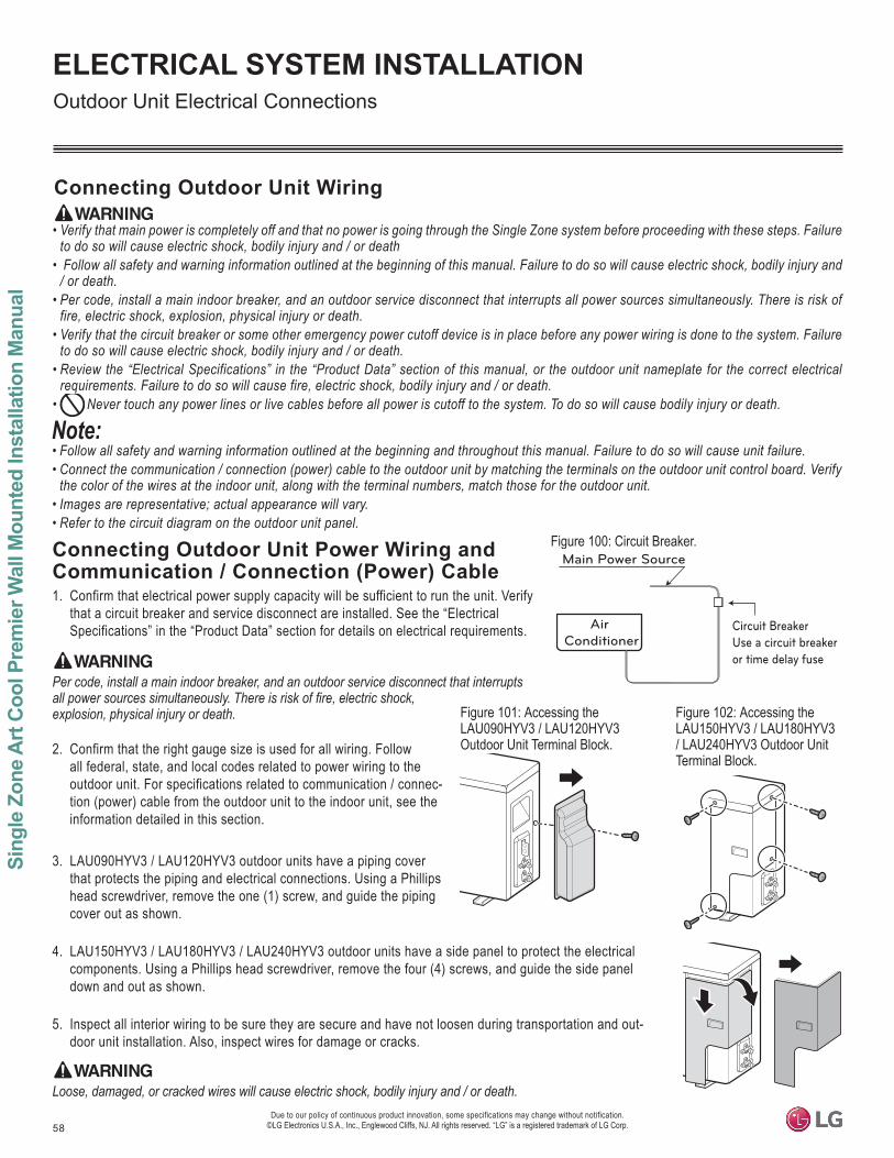
58
Sing
le Z
one
Art
Coo
l Pre
mie
r Wal
l Mou
nted
Inst
alla
tion
Man
ual
Due to our policy of continuous product innovation, some specifications may change without notification. ©LG Electronics U.S.A., Inc., Englewood Cliffs, NJ. All rights reserved. “LG” is a registered trademark of LG Corp.
ELECTRICAL SYSTEM INSTALLATION
Connecting Outdoor Unit Wiring
• Verify that main power is completely off and that no power is going through the Single Zone system before proceeding with these steps. Failure to do so will cause electric shock, bodily injury and / or death
• Follow all safety and warning information outlined at the beginning of this manual. Failure to do so will cause electric shock, bodily injury and / or death.
• Per code, install a main indoor breaker, and an outdoor service disconnect that interrupts all power sources simultaneously. There is risk of fire, electric shock, explosion, physical injury or death.
• Verify that the circuit breaker or some other emergency power cutoff device is in place before any power wiring is done to the system. Failure to do so will cause electric shock, bodily injury and / or death.
• Review the “Electrical Specifications” in the “Product Data” section of this manual, or the outdoor unit nameplate for the correct electrical requirements. Failure to do so will cause fire, electric shock, bodily injury and / or death.
• Never touch any power lines or live cables before all power is cutoff to the system. To do so will cause bodily injury or death.
Figure 100: Circuit Breaker.
Air Conditioner
Main Power Source
Circuit BreakerUse a circuit breakeror time delay fuse
• Follow all safety and warning information outlined at the beginning and throughout this manual. Failure to do so will cause unit failure.• Connect the communication / connection (power) cable to the outdoor unit by matching the terminals on the outdoor unit control board. Verify
the color of the wires at the indoor unit, along with the terminal numbers, match those for the outdoor unit.• Images are representative; actual appearance will vary.• Refer to the circuit diagram on the outdoor unit panel.
Connecting Outdoor Unit Power Wiring and Communication / Connection (Power) Cable1. Confirm that electrical power supply capacity will be sufficient to run the unit. Verify
that a circuit breaker and service disconnect are installed. See the “Electrical Specifications” in the “Product Data” section for details on electrical requirements.
Per code, install a main indoor breaker, and an outdoor service disconnect that interrupts
explosion, physical injury or death.
2. Confirm that the right gauge size is used for all wiring. Follow all federal, state, and local codes related to power wiring to the outdoor unit. For specifications related to communication / connec-tion (power) cable from the outdoor unit to the indoor unit, see the information detailed in this section.
3. LAU090HYV3 / LAU120HYV3 outdoor units have a piping cover that protects the piping and electrical connections. Using a Phillips head screwdriver, remove the one (1) screw, and guide the piping cover out as shown.
4. LAU150HYV3 / LAU180HYV3 / LAU240HYV3 outdoor units have a side panel to protect the electrical components. Using a Phillips head screwdriver, remove the four (4) screws, and guide the side panel down and out as shown.
5. Inspect all interior wiring to be sure they are secure and have not loosen during transportation and out-door unit installation. Also, inspect wires for damage or cracks.
Loose, damaged, or cracked wires will cause electric shock, bodily injury and / or death.
Figure 102: Accessing the LAU150HYV3 / LAU180HYV3 / LAU240HYV3 Outdoor Unit Terminal Block.
Figure 101: Accessing the LAU090HYV3 / LAU120HYV3 Outdoor Unit Terminal Block.
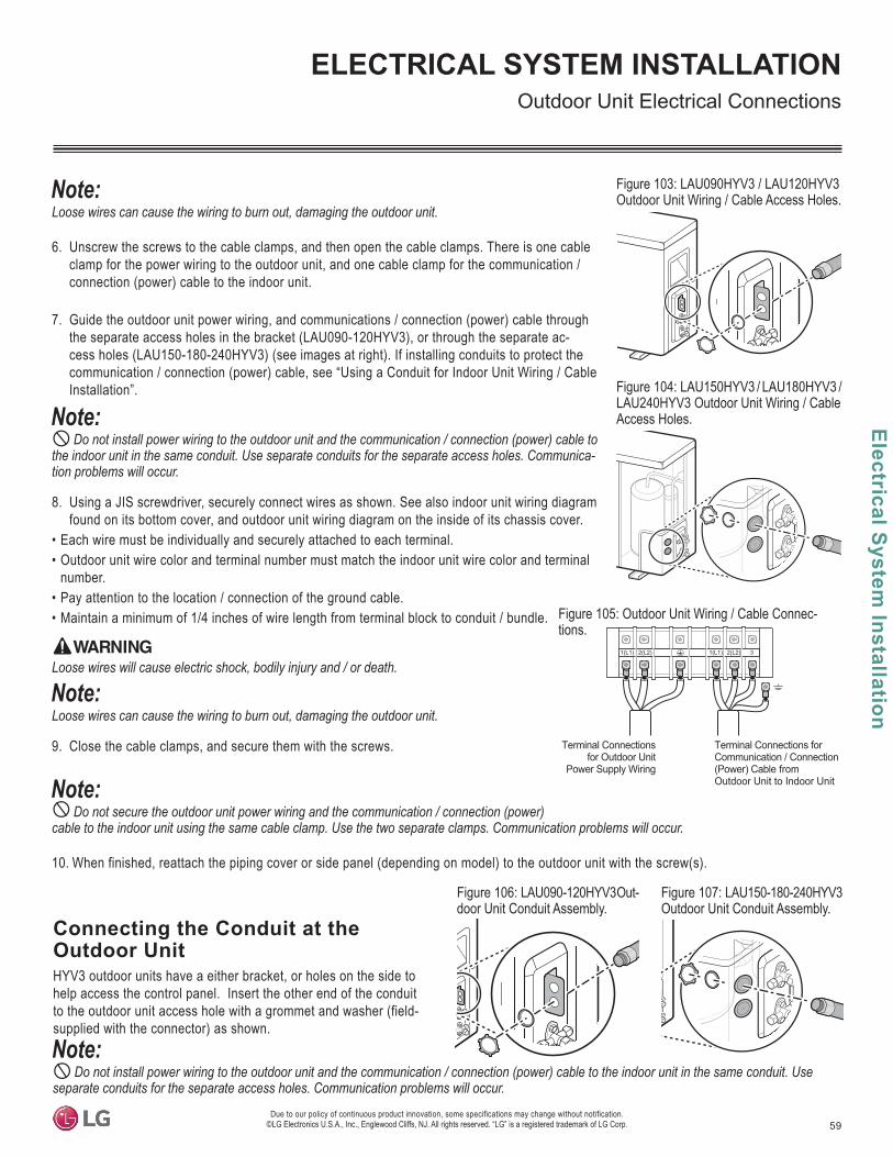
59
Electrical System Installation
Due to our policy of continuous product innovation, some specifications may change without notification. ©LG Electronics U.S.A., Inc., Englewood Cliffs, NJ. All rights reserved. “LG” is a registered trademark of LG Corp.
ELECTRICAL SYSTEM INSTALLATION
Connecting the Conduit at the Outdoor UnitHYV3 outdoor units have a either bracket, or holes on the side to help access the control panel. Insert the other end of the conduit to the outdoor unit access hole with a grommet and washer (field-supplied with the connector) as shown.
Do not install power wiring to the outdoor unit and the communication / connection (power) cable to the indoor unit in the same conduit. Use separate conduits for the separate access holes. Communication problems will occur.
Loose wires can cause the wiring to burn out, damaging the outdoor unit.
6. Unscrew the screws to the cable clamps, and then open the cable clamps. There is one cable clamp for the power wiring to the outdoor unit, and one cable clamp for the communication / connection (power) cable to the indoor unit.
7. Guide the outdoor unit power wiring, and communications / connection (power) cable through the separate access holes in the bracket (LAU090-120HYV3), or through the separate ac-cess holes (LAU150-180-240HYV3) (see images at right). If installing conduits to protect the communication / connection (power) cable, see “Using a Conduit for Indoor Unit Wiring / Cable Installation”.
Do not install power wiring to the outdoor unit and the communication / connection (power) cable to the indoor unit in the same conduit. Use separate conduits for the separate access holes. Communica-tion problems will occur.
8. Using a JIS screwdriver, securely connect wires as shown. See also indoor unit wiring diagram found on its bottom cover, and outdoor unit wiring diagram on the inside of its chassis cover.
• Each wire must be individually and securely attached to each terminal.• Outdoor unit wire color and terminal number must match the indoor unit wire color and terminal
number. • Pay attention to the location / connection of the ground cable.• Maintain a minimum of 1/4 inches of wire length from terminal block to conduit / bundle.
Loose wires will cause electric shock, bodily injury and / or death.
Loose wires can cause the wiring to burn out, damaging the outdoor unit.
9. Close the cable clamps, and secure them with the screws.
Do not secure the outdoor unit power wiring and the communication / connection (power) cable to the indoor unit using the same cable clamp. Use the two separate clamps. Communication problems will occur.
10. When finished, reattach the piping cover or side panel (depending on model) to the outdoor unit with the screw(s).
Figure 103: LAU090HYV3 / LAU120HYV3 Outdoor Unit Wiring / Cable Access Holes.
Figure 104: LAU150HYV3 / LAU180HYV3 / LAU240HYV3 Outdoor Unit Wiring / Cable Access Holes.
Terminal Connections for Outdoor Unit
Power Supply Wiring
Terminal Connections for Communication / Connection(Power) Cable from Outdoor Unit to Indoor Unit
1(L1) 2(L2) 1(L1) 2(L2) 3
Figure 105: Outdoor Unit Wiring / Cable Connec-tions.
Figure 106: LAU090-120HYV3 Out-door Unit Conduit Assembly.
Figure 107: LAU150-180-240HYV3 Outdoor Unit Conduit Assembly.
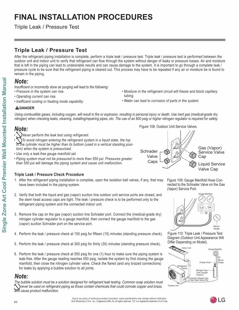
60
Sing
le Z
one
Art
Coo
l Pre
mie
r Wal
l Mou
nted
Inst
alla
tion
Man
ual
Due to our policy of continuous product innovation, some specifications may change without notification. ©LG Electronics U.S.A., Inc., Englewood Cliffs, NJ. All rights reserved. “LG” is a registered trademark of LG Corp.
FINAL INSTALLATION PROCEDURES
Triple Leak / Pressure TestAfter the refrigerant piping installation is complete, perform a triple leak / pressure test. Triple leak / pressure test is performed between the outdoor unit and indoor unit to verify that refrigerant can flow through the system without danger of leaks or pressure losses. Air and moisture that is left in the piping can lead to undesirable results and can cause damage to the system. It is important to go through a complete leak / pressure cycle to be sure that the refrigerant piping is cleared out. This process may have to be repeated if any air or moisture be is found to remain in the piping.
• Pressure in the system can rise.• Operating current can rise.• Inefficient cooling or heating mode capability.
• Moisture in the refrigerant circuit will freeze and block capillary tubing.
• Water can lead to corrosion of parts in the system.
Figure 108: Outdoor Unit Service Valves.
DANGER
nitrogen) when checking leaks, cleaning, installing/repairing pipes, etc. The use of an 800 psig or higher nitrogen regulator is required for safety.
• Never perform the leak test using refrigerant.• To avoid nitrogen entering the refrigerant system in a liquid state, the top
tion) when the system is pressurized.• • Piping system must not be pressured to more than 550 psi. Pressures greater
than 550 psi will damage the piping system and cause unit malfunction.
Triple Leak / Pressure Check Procedure1. After the refrigerant piping installation is complete, open the isolation ball valves, if any, that may
have been included in the piping system.
2. Verify that both the liquid and gas (vapor) suction line outdoor unit service ports are closed, and the stem head access caps are tight. The leak / pressure check is to be performed only to the refrigerant piping system and the connected indoor unit.
3. Remove the cap on the gas (vapor) suction line Schrader port. Connect the (medical-grade dry) nitrogen cylinder regulator to a gauge manifold, then connect the gauge manifold to the gas (vapor) suction Schrader port on the service port.
4. Perform the leak / pressure check at 150 psig for fifteen (15) minutes (standing pressure check).
5. Perform the leak / pressure check at 300 psig for thirty (30) minutes (standing pressure check).
6. Perform the leak / pressure check at 550 psig for one (1) hour to make sure the piping system is leak-free. After the gauge reading reaches 550 psig, isolate the system by first closing the gauge manifold, then close the nitrogen cylinder valve. Check the flared (and any brazed connections) for leaks by applying a bubble solution to all joints.
The bubble solution must be a solution designed for refrigerant leak testing. Common soap solution must never be used on refrigerant piping as those contain chemicals that could corrode copper and brass,
and cause product malfunction.
Triple Leak / Pressure Test
Figure 109: Gauge Manifold Hose Con-nected to the Schrader Valve on the Gas (Vapor) Service Port.
Indoor Unit
Outdoor Unit
Gauge Manifold
Charge Hose
Nitrogen GasTank (UprightPosition)
RefrigerantPiping
MicronGauge
Connected to Shrader Valveon Gas (Vapor) Service Port
Gas (Vapor) Service ValveCap
Liquid ServiceValve Cap
SchraderValveCaps
Figure 110: Triple Leak / Pressure Test Diagram (Outdoor Unit Appearance Will Differ Depending on Model).
Gauge Manifold
MicronGauge
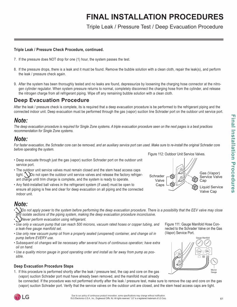
61
Final Installation Procedures
Due to our policy of continuous product innovation, some specifications may change without notification. ©LG Electronics U.S.A., Inc., Englewood Cliffs, NJ. All rights reserved. “LG” is a registered trademark of LG Corp.
FINAL INSTALLATION PROCEDURES
Deep Evacuation ProcedureAfter the leak / pressure check is complete, its is required that a deep evacuation procedure is be performed to the refrigerant piping and the connected indoor unit. Deep evacuation must be performed through the gas (vapor) suction line Schrader port on the outdoor unit service port.
The deep evacuation procedure is required for Single Zone systems. A triple evacuation procedure seen on the next pages is a best practices recommendation for Single Zone systems.
before operating the system.
• Deep evacuate through just the gas (vapor) suction Schrader port on the outdoor unit service port.
• The outdoor unit service valves must remain closed and the stem head access caps tight. Do not open the outdoor unit service valves and release the factory refriger-ant charge until trim charge is complete, and the system is ready to operate.
• Any field-installed ball valves in the refrigerant system (if used) must be open to ensure all piping is free and clear for deep evacuation on all piping and the connected indoor unit.
• Do not apply power to the system before performing the deep evacuation procedure. There is a possibility that the EEV valve may close and isolate sections of the piping system, making the deep evacuation procedure inconclusive.
• Never perform evacuation using refrigerant.• Use only a vacuum pump that can reach 500 microns, vacuum rated hoses or copper tubing, and
• pump before EVERY use.
• Subsequent oil changes will be necessary after several hours of continuous operation; have extra oil on hand.
• Use a quality micron gauge in good operating order and install as far away from pump as possible.
Deep Evacuation Procedure Steps1. If this procedure is performed shortly after the leak / pressure test, the cap and core on the gas
(vapor) suction Schrader port must have already been removed, and the manifold must already be connected. If the procedure was not performed shortly after the leak / pressure test, make sure to remove the cap and core on the gas (vapor) suction Schrader port. Verify that the service valves on the outdoor unit are closed, and the stem head access caps are tight.
Triple Leak / Pressure Test / Deep Evacuation Procedure
Figure 111: Gauge Manifold Hose Con-nected to the Schrader Valve on the Gas (Vapor) Service Port.
Gauge Manifold
MicronGauge
Figure 112: Outdoor Unit Service Valves.
Gas (Vapor) Service ValveCap
Liquid ServiceValve Cap
SchraderValveCaps
Triple Leak / Pressure Check Procedure, continued.
7. If the pressure does NOT drop for one (1) hour, the system passes the test.
8. If the pressure drops, there is a leak and it must be found. Remove the bubble solution with a clean cloth, repair the leak(s), and perform the leak / pressure check again.
9. After the system has been thoroughly tested and no leaks are found, depressurize by loosening the charging hose connector at the nitro-gen cylinder regulator. When system pressure returns to normal, completely disconnect the charging hose from the cylinder, and release the nitrogen charge from all refrigerant piping. Wipe off any remaining bubble solution with a clean cloth.
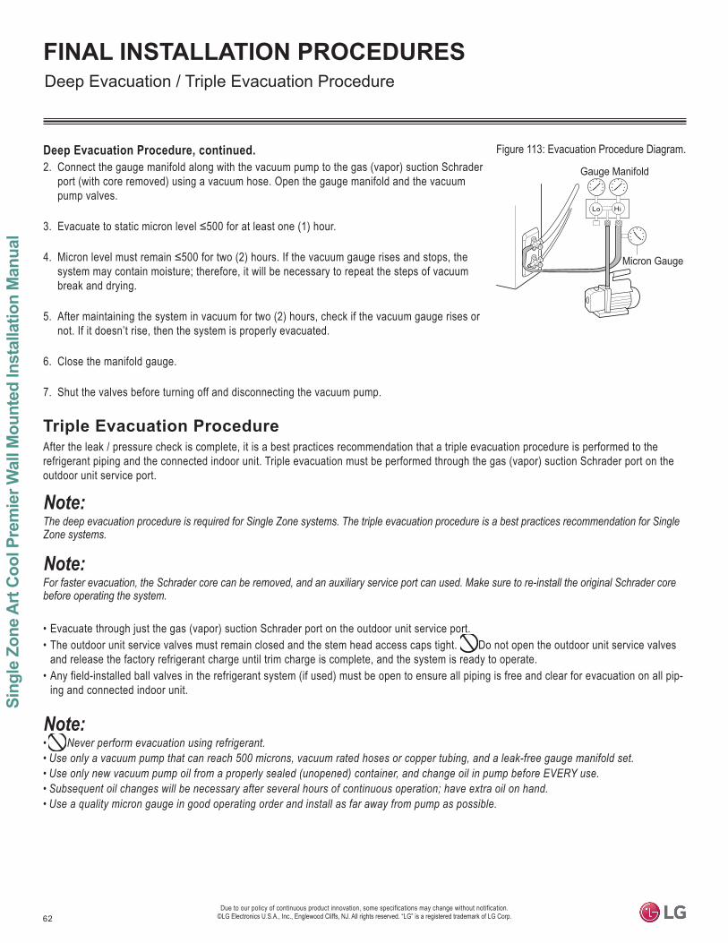
62
Sing
le Z
one
Art
Coo
l Pre
mie
r Wal
l Mou
nted
Inst
alla
tion
Man
ual
Due to our policy of continuous product innovation, some specifications may change without notification. ©LG Electronics U.S.A., Inc., Englewood Cliffs, NJ. All rights reserved. “LG” is a registered trademark of LG Corp.
FINAL INSTALLATION PROCEDURES
Triple Evacuation ProcedureAfter the leak / pressure check is complete, it is a best practices recommendation that a triple evacuation procedure is performed to the refrigerant piping and the connected indoor unit. Triple evacuation must be performed through the gas (vapor) suction Schrader port on the outdoor unit service port.
The deep evacuation procedure is required for Single Zone systems. The triple evacuation procedure is a best practices recommendation for Single Zone systems.
before operating the system.
• Evacuate through just the gas (vapor) suction Schrader port on the outdoor unit service port. • The outdoor unit service valves must remain closed and the stem head access caps tight. Do not open the outdoor unit service valves
and release the factory refrigerant charge until trim charge is complete, and the system is ready to operate.• Any field-installed ball valves in the refrigerant system (if used) must be open to ensure all piping is free and clear for evacuation on all pip-
ing and connected indoor unit.
• Never perform evacuation using refrigerant.• • • Subsequent oil changes will be necessary after several hours of continuous operation; have extra oil on hand.• Use a quality micron gauge in good operating order and install as far away from pump as possible.
Deep Evacuation Procedure, continued.2. Connect the gauge manifold along with the vacuum pump to the gas (vapor) suction Schrader
port (with core removed) using a vacuum hose. Open the gauge manifold and the vacuum pump valves.
3.
4. system may contain moisture; therefore, it will be necessary to repeat the steps of vacuum break and drying.
5. After maintaining the system in vacuum for two (2) hours, check if the vacuum gauge rises or not. If it doesn’t rise, then the system is properly evacuated.
6. Close the manifold gauge.
7. Shut the valves before turning off and disconnecting the vacuum pump.
Deep Evacuation / Triple Evacuation Procedure
Figure 113: Evacuation Procedure Diagram.
Gauge Manifold
Micron Gauge
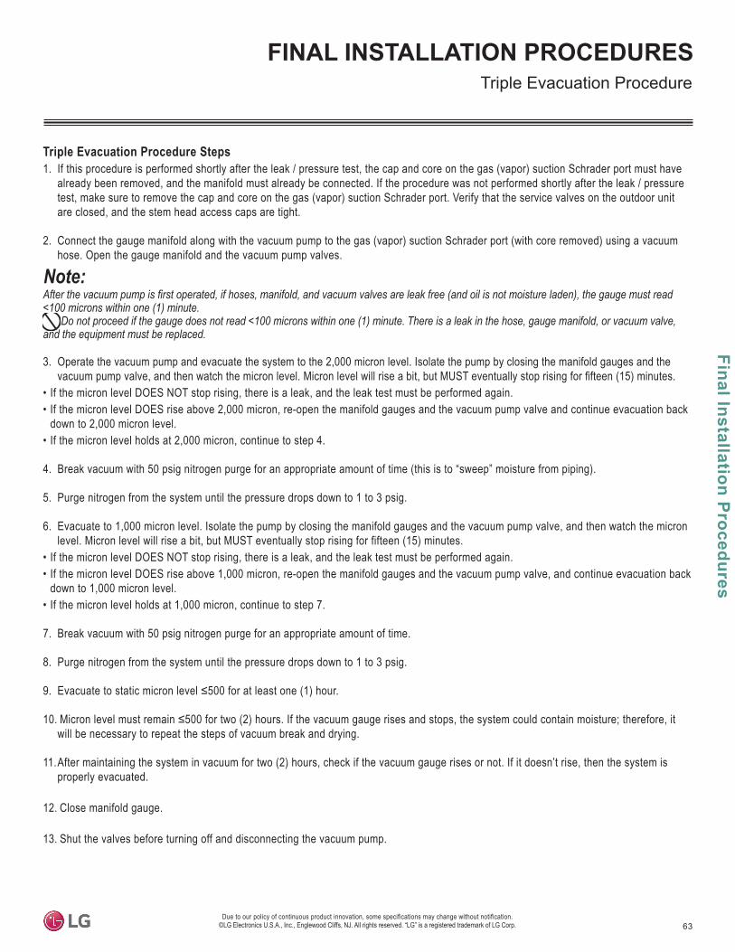
63
Final Installation Procedures
Due to our policy of continuous product innovation, some specifications may change without notification. ©LG Electronics U.S.A., Inc., Englewood Cliffs, NJ. All rights reserved. “LG” is a registered trademark of LG Corp.
FINAL INSTALLATION PROCEDURESTriple Evacuation Procedure
Triple Evacuation Procedure Steps1. If this procedure is performed shortly after the leak / pressure test, the cap and core on the gas (vapor) suction Schrader port must have
already been removed, and the manifold must already be connected. If the procedure was not performed shortly after the leak / pressure test, make sure to remove the cap and core on the gas (vapor) suction Schrader port. Verify that the service valves on the outdoor unit are closed, and the stem head access caps are tight.
2. Connect the gauge manifold along with the vacuum pump to the gas (vapor) suction Schrader port (with core removed) using a vacuum hose. Open the gauge manifold and the vacuum pump valves.
and the equipment must be replaced.
3. Operate the vacuum pump and evacuate the system to the 2,000 micron level. Isolate the pump by closing the manifold gauges and the
• If the micron level DOES NOT stop rising, there is a leak, and the leak test must be performed again.• If the micron level DOES rise above 2,000 micron, re-open the manifold gauges and the vacuum pump valve and continue evacuation back
down to 2,000 micron level.• If the micron level holds at 2,000 micron, continue to step 4.
4. Break vacuum with 50 psig nitrogen purge for an appropriate amount of time (this is to “sweep” moisture from piping).
5. Purge nitrogen from the system until the pressure drops down to 1 to 3 psig.
6. Evacuate to 1,000 micron level. Isolate the pump by closing the manifold gauges and the vacuum pump valve, and then watch the micron level. Micron level will rise a bit, but MUST eventually stop rising for fifteen (15) minutes.
• If the micron level DOES NOT stop rising, there is a leak, and the leak test must be performed again.• If the micron level DOES rise above 1,000 micron, re-open the manifold gauges and the vacuum pump valve, and continue evacuation back
down to 1,000 micron level.• If the micron level holds at 1,000 micron, continue to step 7.
7. Break vacuum with 50 psig nitrogen purge for an appropriate amount of time.
8. Purge nitrogen from the system until the pressure drops down to 1 to 3 psig.
9.
10. will be necessary to repeat the steps of vacuum break and drying.
11. After maintaining the system in vacuum for two (2) hours, check if the vacuum gauge rises or not. If it doesn’t rise, then the system is properly evacuated.
12. Close manifold gauge.
13. Shut the valves before turning off and disconnecting the vacuum pump.
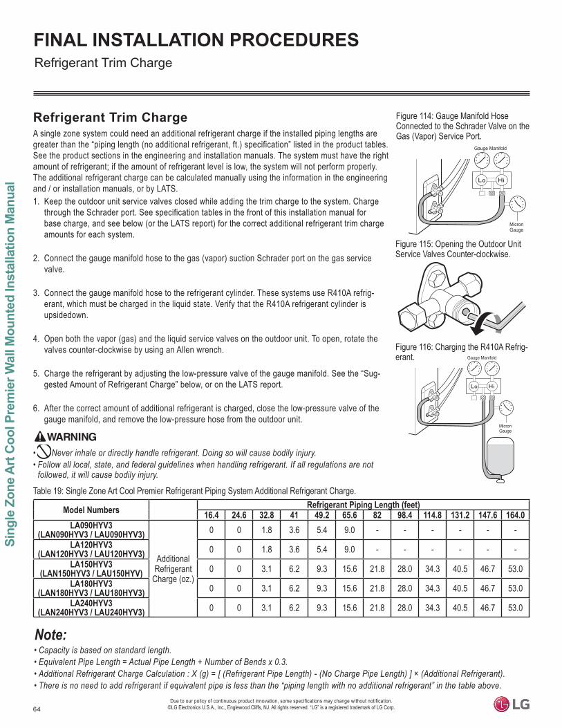
64
Sing
le Z
one
Art
Coo
l Pre
mie
r Wal
l Mou
nted
Inst
alla
tion
Man
ual
Due to our policy of continuous product innovation, some specifications may change without notification. ©LG Electronics U.S.A., Inc., Englewood Cliffs, NJ. All rights reserved. “LG” is a registered trademark of LG Corp.
FINAL INSTALLATION PROCEDURESRefrigerant Trim Charge
Refrigerant Trim ChargeA single zone system could need an additional refrigerant charge if the installed piping lengths are greater than the “piping length (no additional refrigerant, ft.) specification” listed in the product tables. See the product sections in the engineering and installation manuals. The system must have the right amount of refrigerant; if the amount of refrigerant level is low, the system will not perform properly. The additional refrigerant charge can be calculated manually using the information in the engineering and / or installation manuals, or by LATS.1. Keep the outdoor unit service valves closed while adding the trim charge to the system. Charge
through the Schrader port. See specification tables in the front of this installation manual for base charge, and see below (or the LATS report) for the correct additional refrigerant trim charge amounts for each system.
2. Connect the gauge manifold hose to the gas (vapor) suction Schrader port on the gas service valve.
3. Connect the gauge manifold hose to the refrigerant cylinder. These systems use R410A refrig-erant, which must be charged in the liquid state. Verify that the R410A refrigerant cylinder is upsidedown.
4. Open both the vapor (gas) and the liquid service valves on the outdoor unit. To open, rotate the valves counter-clockwise by using an Allen wrench.
5. Charge the refrigerant by adjusting the low-pressure valve of the gauge manifold. See the “Sug-gested Amount of Refrigerant Charge” below, or on the LATS report.
6. After the correct amount of additional refrigerant is charged, close the low-pressure valve of the gauge manifold, and remove the low-pressure hose from the outdoor unit.
• • Follow all local, state, and federal guidelines when handling refrigerant. If all regulations are not
• Capacity is based on standard length.• Equivalent Pipe Length = Actual Pipe Length + Number of Bends x 0.3.• • There is no need to add refrigerant if equivalent pipe is less than the “piping length with no additional refrigerant” in the table above.
Table 19: Single Zone Art Cool Premier Refrigerant Piping System Additional Refrigerant Charge.
Model Numbers Refrigerant Piping Length (feet)16.4 24.6 32.8 41 49.2 65.6 82 98.4 114.8 131.2 147.6 164.0
LA090HYV3(LAN090HYV3 / LAU090HYV3)
AdditionalRefrigerant
Charge (oz.)
0 0 1.8 3.6 5.4 9.0 - - - - - -LA120HYV3
(LAN120HYV3 / LAU120HYV3) 0 0 1.8 3.6 5.4 9.0 - - - - - -LA150HYV3
(LAN150HYV3 / LAU150HYV) 0 0 3.1 6.2 9.3 15.6 21.8 28.0 34.3 40.5 46.7 53.0LA180HYV3
(LAN180HYV3 / LAU180HYV3) 0 0 3.1 6.2 9.3 15.6 21.8 28.0 34.3 40.5 46.7 53.0LA240HYV3
(LAN240HYV3 / LAU240HYV3) 0 0 3.1 6.2 9.3 15.6 21.8 28.0 34.3 40.5 46.7 53.0
Gauge Manifold
MicronGauge
Figure 114: Gauge Manifold Hose Connected to the Schrader Valve on the Gas (Vapor) Service Port.
Figure 115: Opening the Outdoor Unit Service Valves Counter-clockwise.
Figure 116: Charging the R410A Refrig-erant.
Gauge Manifold
MicronGauge
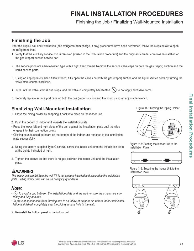
65
Final Installation Procedures
Due to our policy of continuous product innovation, some specifications may change without notification. ©LG Electronics U.S.A., Inc., Englewood Cliffs, NJ. All rights reserved. “LG” is a registered trademark of LG Corp.
FINAL INSTALLATION PROCEDURESFinishing the Job / Finalizing Wall-Mounted Installation
Finishing the JobAfter the Triple Leak and Evacuation (and refrigerant trim charge, if any) procedures have been performed, follow the steps below to open the refrigerant lines.1. Verify that the auxiliary service port is removed (if used in the Evacuation procedure) and the original Schrader core was re-installed on
the gas (vapor) suction service port.
2. The service ports are a back-seated type with a right hand thread. Remove the service valve caps on both the gas (vapor) suction and the liquid service ports.
3. Using an appropriately sized Allen wrench, fully open the valves on both the gas (vapor) suction and the liquid service ports by turning the valve stem counterclockwise.
4. Turn until the valve stem is out, stops, and the valve is completely backseated. Do not apply excessive force.
5. Securely replace service port caps on both the gas (vapor) suction and the liquid using an adjustable wrench.
Finalizing Wall-Mounted Installation1. Close the piping holder by snapping it back into place on the indoor unit.
2. Push the bottom of indoor unit towards the installation plate.• Press the lower left and right sides of the unit against the installation plate until the clips
engage into their connection points• Clicking sounds could be heard as the bottom of the indoor unit attaches to the installation
plate successfully.
3. Using the factory-supplied Type C screws, screw the indoor unit onto the installation plate at the points indicated at right.
4. Tighten the screws so that there is no gap between the indoor unit and the installation plate.
The indoor unit can fall from the wall if it is not properly installed and secured to the installation
• To avoid a gap between the installation plate and the wall, ensure the screws are correctly and fully secured.
• To prevent condensate from forming due to an inflow of outdoor air, before indoor unit installation is finished, completely seal the piping access hole in the wall.
5. Re-install the bottom panel to the indoor unit.
Figure 117: Closing the Piping Holder.
Figure 118: Seating the Indoor Unit to the Installation Plate.
Figure 119: Securing the Indoor Unit to the Installation Plate.
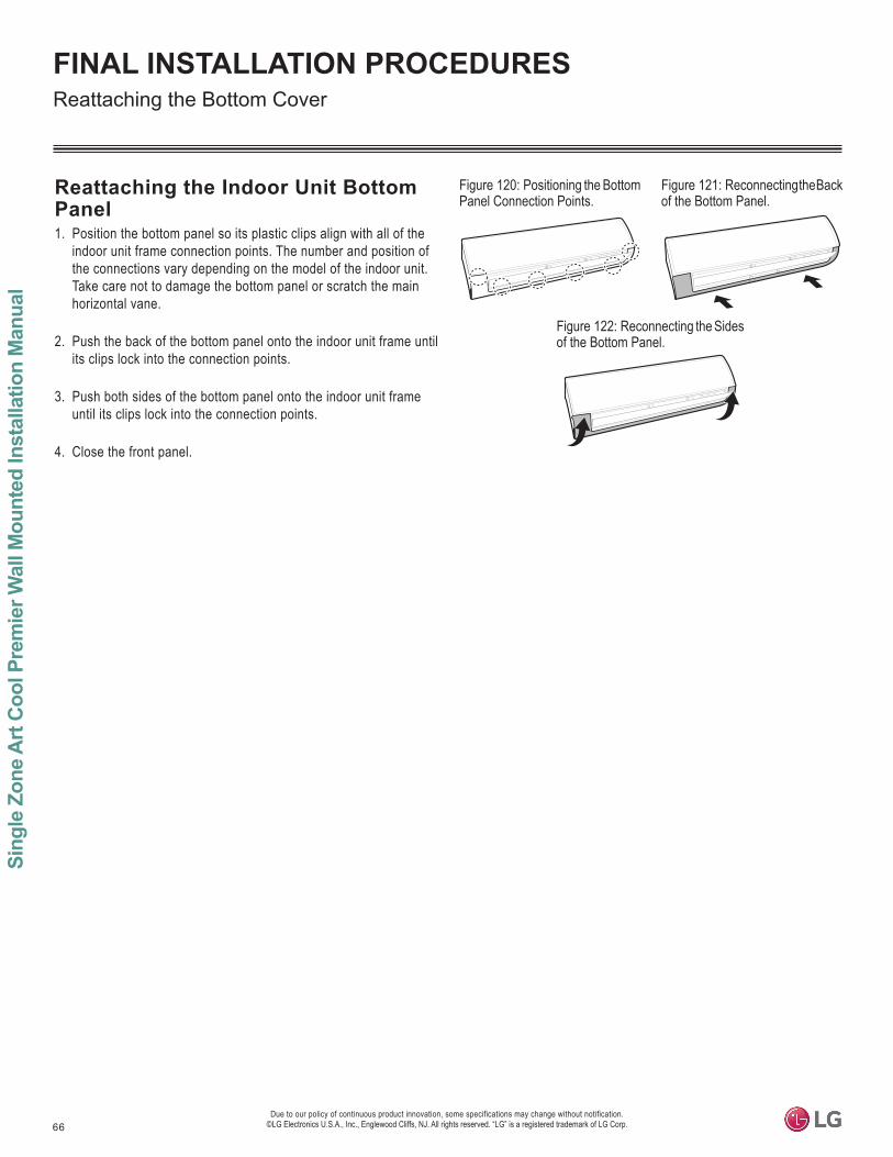
66
Sing
le Z
one
Art
Coo
l Pre
mie
r Wal
l Mou
nted
Inst
alla
tion
Man
ual
Due to our policy of continuous product innovation, some specifications may change without notification. ©LG Electronics U.S.A., Inc., Englewood Cliffs, NJ. All rights reserved. “LG” is a registered trademark of LG Corp.
FINAL INSTALLATION PROCEDURES
Reattaching the Indoor Unit Bottom Panel1. Position the bottom panel so its plastic clips align with all of the
indoor unit frame connection points. The number and position of the connections vary depending on the model of the indoor unit. Take care not to damage the bottom panel or scratch the main horizontal vane.
2. Push the back of the bottom panel onto the indoor unit frame until its clips lock into the connection points.
3. Push both sides of the bottom panel onto the indoor unit frame until its clips lock into the connection points.
4. Close the front panel.
Figure 120: Positioning the Bottom Panel Connection Points.
Figure 121: Reconnecting the Back of the Bottom Panel.
Figure 122: Reconnecting the Sides of the Bottom Panel.
Reattaching the Bottom Cover
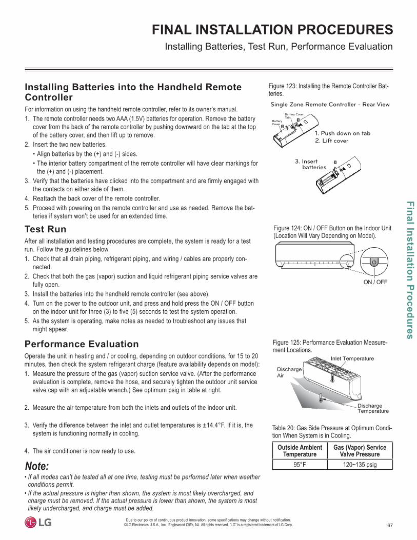
67
Final Installation Procedures
Due to our policy of continuous product innovation, some specifications may change without notification. ©LG Electronics U.S.A., Inc., Englewood Cliffs, NJ. All rights reserved. “LG” is a registered trademark of LG Corp.
FINAL INSTALLATION PROCEDURES
Test RunAfter all installation and testing procedures are complete, the system is ready for a test run. Follow the guidelines below.1. Check that all drain piping, refrigerant piping, and wiring / cables are properly con-
nected.2. Check that both the gas (vapor) suction and liquid refrigerant piping service valves are
fully open.3. Install the batteries into the handheld remote controller (see above).4. Turn on the power to the outdoor unit, and press and hold press the ON / OFF button
on the indoor unit for three (3) to five (5) seconds to test the system operation.5. As the system is operating, make notes as needed to troubleshoot any issues that
might appear.
Installing Batteries into the Handheld Remote ControllerFor information on using the handheld remote controller, refer to its owner’s manual.1. The remote controller needs two AAA (1.5V) batteries for operation. Remove the battery
cover from the back of the remote controller by pushing downward on the tab at the top of the battery cover, and then lift up to remove.
2. Insert the two new batteries.• Align batteries by the (+) and (-) sides.• The interior battery compartment of the remote controller will have clear markings for
the (+) and (-) placement.3. Verify that the batteries have clicked into the compartment and are firmly engaged with
the contacts on either side of them.4. Reattach the back cover of the remote controller.5. Proceed with powering on the remote controller and use as needed. Remove the bat-
teries if system won’t be used for an extended time.
1. Push down on tab2. Lift cover
3. Insert 3
batteries
Single Zone Remote Controller - Rear ViewBattery CoverTab
BatteryCover
Figure 123: Installing the Remote Controller Bat-teries.
Performance EvaluationOperate the unit in heating and / or cooling, depending on outdoor conditions, for 15 to 20 minutes, then check the system refrigerant charge (feature availability depends on model):1. Measure the pressure of the gas (vapor) suction service valve. (After the performance
evaluation is complete, remove the hose, and securely tighten the outdoor unit service valve cap with an adjustable wrench.) See optimum psig in table at right.
2. Measure the air temperature from both the inlets and outlets of the indoor unit.
3. Verify the difference between the inlet and outlet temperatures is ±14.4°F. If it is, the system is functioning normally in cooling.
4. The air conditioner is now ready to use. Outside Ambient Temperature
Gas (Vapor) Service Valve Pressure
95°F 120~135 psig
• If all modes can’t be tested all at one time, testing must be performed later when weather conditions permit.
• If the actual pressure is higher than shown, the system is most likely overcharged, and charge must be removed. If the actual pressure is lower than shown, the system is most likely undercharged, and charge must be added.
Table 20: Gas Side Pressure at Optimum Condi-tion When System is in Cooling.
Discharge Temperature
DischargeAir
Inlet Temperature
Figure 124: ON / OFF Button on the Indoor Unit (Location Will Vary Depending on Model).
Installing Batteries, Test Run, Performance Evaluation
Figure 125: Performance Evaluation Measure-ment Locations.
ON / OFF
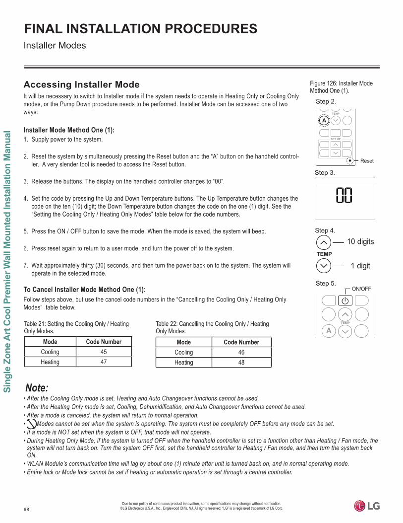
68
Sing
le Z
one
Art
Coo
l Pre
mie
r Wal
l Mou
nted
Inst
alla
tion
Man
ual
Due to our policy of continuous product innovation, some specifications may change without notification. ©LG Electronics U.S.A., Inc., Englewood Cliffs, NJ. All rights reserved. “LG” is a registered trademark of LG Corp.
FINAL INSTALLATION PROCEDURES
Accessing Installer ModeIt will be necessary to switch to Installer mode if the system needs to operate in Heating Only or Cooling Only modes, or the Pump Down procedure needs to be performed. Installer Mode can be accessed one of two ways:
Installer Mode Method One (1): 1. Supply power to the system.
2. Reset the system by simultaneously pressing the Reset button and the “A” button on the handheld control-ler. A very slender tool is needed to access the Reset button.
3. Release the buttons. The display on the handheld controller changes to “00”.
4. Set the code by pressing the Up and Down Temperature buttons. The Up Temperature button changes the code on the ten (10) digit; the Down Temperature button changes the code on the one (1) digit. See the “Setting the Cooling Only / Heating Only Modes” table below for the code numbers.
5. Press the ON / OFF button to save the mode. When the mode is saved, the system will beep.
6. Press reset again to return to a user mode, and turn the power off to the system.
7. Wait approximately thirty (30) seconds, and then turn the power back on to the system. The system will operate in the selected mode.
To Cancel Installer Mode Method One (1): Follow steps above, but use the cancel code numbers in the “Cancelling the Cooling Only / Heating Only Modes” table below.
Figure 126: Installer Mode Method One (1).
Installer Modes
Mode Code NumberCooling 45Heating 47
Table 21: Setting the Cooling Only / Heating Only Modes.
Table 22: Cancelling the Cooling Only / Heating Only Modes.
SET UP
TEMP
A
Reset
TEMP
10 digits
1 digit
A
ON/OFF
Step 2.
Step 3.
Step 4.
Step 5.
Mode Code NumberCooling 46Heating 48
• After the Cooling Only mode is set, Heating and Auto Changeover functions cannot be used.• After the Heating Only mode is set, Cooling, Dehumidification, and Auto Changeover functions cannot be used.• After a mode is canceled, the system will return to normal operation. • Modes cannot be set when the system is operating. The system must be completely OFF before any mode can be set.• If a mode is NOT set when the system is OFF, that mode will not operate.• During Heating Only Mode, if the system is turned OFF when the handheld controller is set to a function other than Heating / Fan mode, the
system will not turn back on. Turn the system OFF first, set the handheld controller to Heating / Fan mode, and then turn the system back ON.
• • Entire lock or Mode lock cannot be set if heating or automatic operation is set through a central controller.

69
Final Installation Procedures
Due to our policy of continuous product innovation, some specifications may change without notification. ©LG Electronics U.S.A., Inc., Englewood Cliffs, NJ. All rights reserved. “LG” is a registered trademark of LG Corp.
FINAL INSTALLATION PROCEDURESInstaller Modes
Installer Mode Method Two (2): 1. Supply power to the system.
2. Insert a battery (or the batteries) into the handheld controller while simultaneously pressing the “A” button.
3. Release the “A” button. The display on the handheld controller changes to “00”.
4. Set the code by pressing the Up and Down Temperature buttons. The Up Temperature button changes the code on the ten (10) digit; the Down Temperature button changes the code on the one (1) digit. See the “Setting the Cooling Only / Heating Only Modes” table below for the code numbers.
5. Press the ON / OFF button to save the mode. When the mode is saved, the system will beep.
6. Remove a battery, re-insert the battery, and turn the power off to the system.
7. Wait approximately thirty (30) seconds, and then turn the power back on to the system. The system will operate in the selected mode.
To Cancel Installer Mode Method Two (2): Follow steps above, but use the cancel code numbers in the “Cancelling the Cooling Only / Heating Only Modes” table below.
Mode Code NumberCooling 45Heating 47
Table 23: Setting the Cooling Only / Heating Only Modes.
Table 24: Cancelling the Cooling Only / Heating Only Modes.
Mode Code NumberCooling 46Heating 48
Figure 127: Installer Mode Method Two (2).
TEMP
10 digits
1 digit
A
ON/OFF
Step 3.
Step 4.
Step 5.
TEMP
A
Step 2.
• After the Cooling Only mode is set, Heating and Auto Changeover functions cannot be used.• After the Heating Only mode is set, Cooling, Dehumidification, and Auto Changeover functions cannot be used.• After a mode is canceled, the system will return to normal operation. • Modes cannot be set when the system is operating. The system must be completely OFF before any mode can be set.• If a mode is NOT set when the system is OFF, that mode will not operate.• During Heating Only Mode, if the system is turned OFF when the handheld controller is set to a function other than Heating / Fan mode, the
system will not turn back on. Turn the system OFF first, set the handheld controller to Heating / Fan mode, and then turn the system back ON.
• • Entire lock or Mode lock cannot be set if heating or automatic operation is set through a central controller.

70
Sing
le Z
one
Art
Coo
l Pre
mie
r Wal
l Mou
nted
Inst
alla
tion
Man
ual
Due to our policy of continuous product innovation, some specifications may change without notification. ©LG Electronics U.S.A., Inc., Englewood Cliffs, NJ. All rights reserved. “LG” is a registered trademark of LG Corp.
FINAL INSTALLATION PROCEDURESPump Down Procedure
Pump Down ProcedureUse Pump Down Procedure when the refrigerant piping system needs to be serviced. Pumping down collects all the refrigerant in the system and pipes it to the outdoor unit without losing any charge. Always adhere to and be familiar with local codes regarding the handling of refrigerant.The system must operate in Cooling Only mode to proceed with the pump down procedure. If needed, refer to the previous sections for proper steps to place the unit into Cooling Only mode.1. Turn off the power to the system.
2. Remove the cap from the vapor (gas) service valve. Connect the gauge manifold hose to the gas (vapor) suction Schrader port on the gas service valve.
3. Open the gas (vapor) suction Schrader port on the gas service valve halfway, and purge the air in the manifold hose.
4. Turn the power on. Operate the system in Cooling Only Mode for at least ten (10) minutes; verify that the compressor is operating properly.
5. Fully close the liquid piping service valve to the outdoor unit by rotating the valve clockwise with an Allen wrench.
6. Observe the pressure gauge reading. When it changes to 14.2 to 7.1 psig, fully close the gas (vapor) service valve, and then immediately turn the unit off. Pump down procedure is complete and all refrigerant will be collected into the outdoor unit.
Do not operate the unit in Pump Down for an extended period. It will damage the compressor.
7. Disconnect the gauge manifold hose to the gas (vapor) suction Schrader port on the gas service valve.
8. If necessary for service, disconnect the pipe to the outdoor unit. To protect the outdoor unit from air, vapor, and debris, block the outdoor valve by installing a flare nut through the pipe after brazing the end of the disconnected pipe.
9. Re-attach the cap to the vapor (gas) service valve, using a torque wrench to firmly tighten.
Always perform Pump Down procedure in the Cooling Only mode.
• • After pump down, power must be turned OFF before the pipe is removed. If the system is operated without the pipe connected, air inside
Figure 128: Connecting the Manifold Hose.
Figure 129: Closing the Outdoor Unit Liquid Piping Service Valve.
Gauge Manifold
MicronGauge
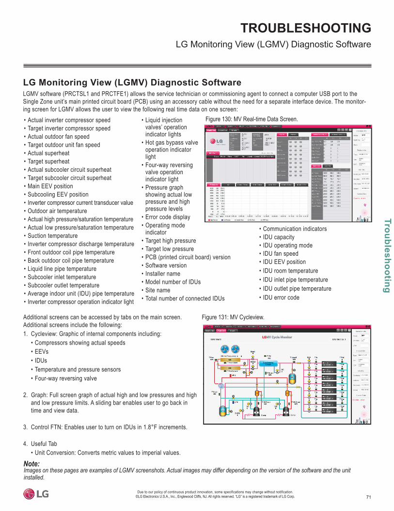
71
Troubleshooting
TROUBLESHOOTING
Due to our policy of continuous product innovation, some specifications may change without notification. ©LG Electronics U.S.A., Inc., Englewood Cliffs, NJ. All rights reserved. “LG” is a registered trademark of LG Corp.
Additional screens can be accessed by tabs on the main screen. Additional screens include the following: 1. Cycleview: Graphic of internal components including:
• Compressors showing actual speeds• EEVs• IDUs• Temperature and pressure sensors• Four-way reversing valve
2. Graph: Full screen graph of actual high and low pressures and high and low pressure limits. A sliding bar enables user to go back in time and view data.
3. Control FTN: Enables user to turn on IDUs in 1.8°F increments.
4. Useful Tab• Unit Conversion: Converts metric values to imperial values.
• Actual inverter compressor speed• Target inverter compressor speed• Actual outdoor fan speed• Target outdoor unit fan speed• Actual superheat• Target superheat • Actual subcooler circuit superheat • Target subcooler circuit superheat • Main EEV position• Subcooling EEV position• Inverter compressor current transducer value• Outdoor air temperature• Actual high pressure/saturation temperature• Actual low pressure/saturation temperature• Suction temperature• Inverter compressor discharge temperature• Front outdoor coil pipe temperature• Back outdoor coil pipe temperature• Liquid line pipe temperature• Subcooler inlet temperature• Subcooler outlet temperature• Average indoor unit (IDU) pipe temperature• Inverter compressor operation indicator light
• Liquid injection valves’ operation indicator lights
• Hot gas bypass valve operation indicator light
• Four-way reversing valve operation indicator light
• Pressure graph showing actual low pressure and high pressure levels
• Error code display• Operating mode
indicator• Target high pressure• Target low pressure• PCB (printed circuit board) version• Software version• Installer name• Model number of IDUs• Site name• Total number of connected IDUs
• Communication indicators• IDU capacity• IDU operating mode• IDU fan speed• IDU EEV position• IDU room temperature• IDU inlet pipe temperature• IDU outlet pipe temperature• IDU error code
LG Monitoring View (LGMV) Diagnostic SoftwareLGMV software (PRCTSL1 and PRCTFE1) allows the service technician or commissioning agent to connect a computer USB port to the Single Zone unit’s main printed circuit board (PCB) using an accessory cable without the need for a separate interface device. The monitor-ing screen for LGMV allows the user to view the following real time data on one screen:
Figure 130: MV Real-time Data Screen.
Figure 131: MV Cycleview.
Images on these pages are examples of LGMV screenshots. Actual images may differ depending on the version of the software and the unit installed.
LG Monitoring View (LGMV) Diagnostic Software
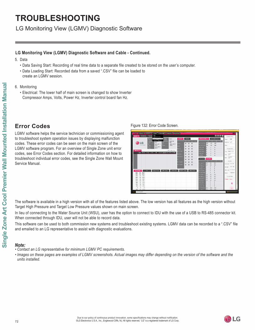
72
Sing
le Z
one
Art
Coo
l Pre
mie
r Wal
l Mou
nted
Inst
alla
tion
Man
ual
Due to our policy of continuous product innovation, some specifications may change without notification. ©LG Electronics U.S.A., Inc., Englewood Cliffs, NJ. All rights reserved. “LG” is a registered trademark of LG Corp.
TROUBLESHOOTING
5. Data• Data Saving Start: Recording of real time data to a separate file created to be stored on the user’s computer.• Data Loading Start: Recorded data from a saved “.CSV” file can be loaded to
create an LGMV session.
6. Monitoring• Electrical: The lower half of main screen is changed to show Inverter
Compressor Amps, Volts, Power Hz, Inverter control board fan Hz.
The software is available in a high version with all of the features listed above. The low version has all features as the high version without Target High Pressure and Target Low Pressure values shown on main screen. In lieu of connecting to the Water Source Unit (WSU), user has the option to connect to IDU with the use of a USB to RS-485 connector kit. When connected through IDU, user will not be able to record data.This software can be used to both commission new systems and troubleshoot existing systems. LGMV data can be recorded to a “.CSV” file and emailed to an LG representative to assist with diagnostic evaluations.
Error CodesLGMV software helps the service technician or commissioning agent to troubleshoot system operation issues by displaying malfunction codes. These error codes can be seen on the main screen of the LGMV software program. For an overview of Single Zone unit error codes, see Error Codes section. For detailed information on how to troubleshoot individual error codes, see the Single Zone Wall Mount Service Manual.
Figure 132: Error Code Screen.
• Contact an LG representative for minimum LGMV PC requirements.• Images on these pages are examples of LGMV screenshots. Actual images may differ depending on the version of the software and the
units installed.
LG Monitoring View (LGMV) Diagnostic Software and Cable - Continued.
LG Monitoring View (LGMV) Diagnostic Software
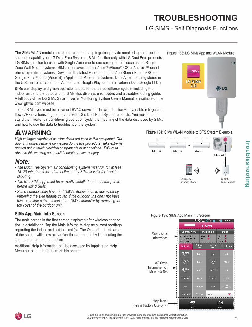
73
Troubleshooting
TROUBLESHOOTING
Due to our policy of continuous product innovation, some specifications may change without notification. ©LG Electronics U.S.A., Inc., Englewood Cliffs, NJ. All rights reserved. “LG” is a registered trademark of LG Corp.
LG SIMS - Self Diagnosis Functions
The SIMs WLAN module and the smart phone app together provide monitoring and trouble-shooting capability for LG Duct Free Systems. SIMs function only with LG Duct Free products. LG SIMs can also be used with Single Zone one-to-one configurations such as the Single Zone Wall Mount systems. SIMs app is available for Apple® iPhone® iOS or Android™ smart phone operating systems. Download the latest version from the App Store (iPhone iOS) or Google Play™ store (Android). (Apple and iPhone are trademarks of Apple Inc., registered in the U.S. and other countries. Android and Google Play store are trademarks of Google LLC.) SIMs can display and graph operational data for the air conditioner system including the indoor unit and the outdoor unit. SIMs also displays error codes and a troubleshooting guide. A full copy of the LG SIMs Smart Inverter Monitoring System User’s Manual is available on the www.lghvac.com website. To use SIMs, you must be a trained HVAC service technician familiar with variable refrigerant flow (VRF) systems in general, and with LG’s Duct Free System products. You must under-stand the inverter air conditioning operation cycle, the meaning of the data displayed by SIMs, and how to use the data to troubleshoot the system.
• The Duct Free System air conditioning system must run for at least 15–20 minutes before data collected by SIMs is valid for troubleshooting.
• The free SIMs app must be correctly installed on the smart phone before using SIMs.
• Some outdoor units have an LGMV extension cable accessed by removing the side handle cover. If the outdoor unit does not have this extension cable, access the LGMV connector by removing the top cover of the outdoor unit.
High voltages capable of causing death are used in this equipment. Outdoor unit power remains connected during this procedure. Take extreme caution not to touch electrical components or connections. Failure to
Figure 133: LG SIMs App and WLAN Module.
Figure 134: SIMs WLAN Module to DFS System Example.
Figure 135: SIMs App Main Info ScreenSIMs App Main Info ScreenThe main screen is the first screen displayed after wireless connec-tion is established. Tap the Main Info tab to display current readings regarding the indoor and outdoor unit(s). The Operational Info area of the screen will show active functions or modes by illuminating the light to the right of the function. Additional Help information can be accessed by tapping the Help Menu buttons at the bottom of this screen.
OperationalInformation
AC CycleInformation onMain Info Tab
Help Menu(File is Factory Use Only)
LG SIMsWLAN Module
LG SIMs Appon Smart Phone
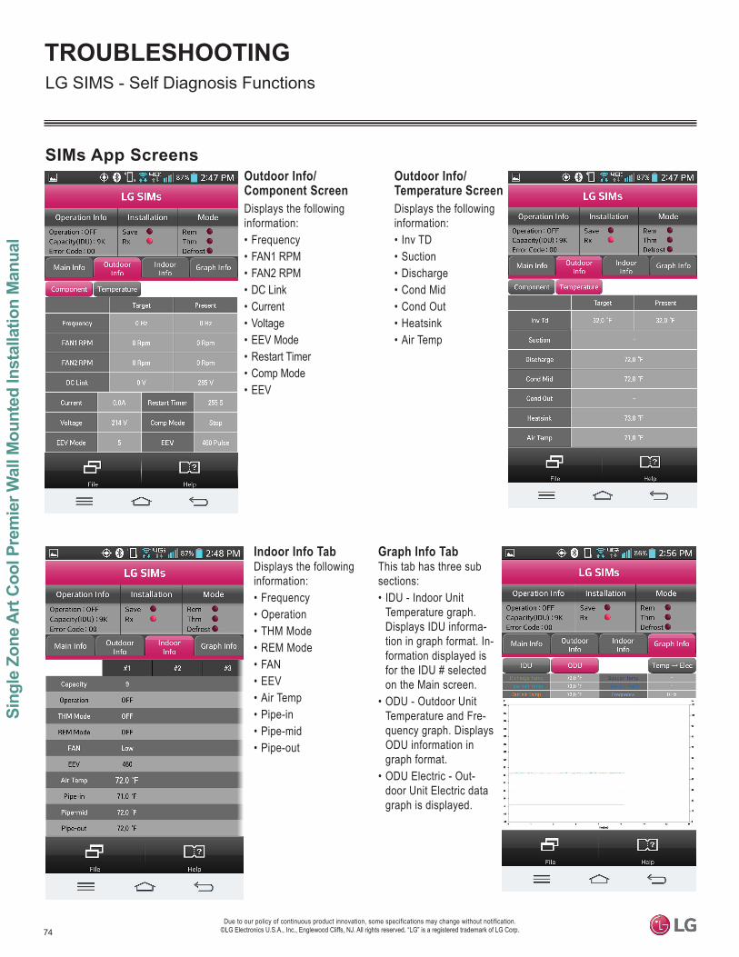
74
Sing
le Z
one
Art
Coo
l Pre
mie
r Wal
l Mou
nted
Inst
alla
tion
Man
ual
Due to our policy of continuous product innovation, some specifications may change without notification. ©LG Electronics U.S.A., Inc., Englewood Cliffs, NJ. All rights reserved. “LG” is a registered trademark of LG Corp.
TROUBLESHOOTINGLG SIMS - Self Diagnosis Functions
SIMs App ScreensOutdoor Info/ Component ScreenDisplays the following information:• Frequency• FAN1 RPM• FAN2 RPM • DC Link • Current• Voltage• EEV Mode• Restart Timer• Comp Mode• EEV
Indoor Info Tab Displays the following information:• Frequency• Operation• THM Mode• REM Mode• FAN• EEV• Air Temp• Pipe-in• Pipe-mid• Pipe-out
Graph Info Tab This tab has three sub sections:• IDU - Indoor Unit
Temperature graph. Displays IDU informa-tion in graph format. In-formation displayed is for the IDU # selected on the Main screen.
• ODU - Outdoor Unit Temperature and Fre-quency graph. Displays ODU information in graph format.
• ODU Electric - Out-door Unit Electric data graph is displayed.
Outdoor Info/ Temperature ScreenDisplays the following information:• Inv TD• Suction• Discharge• Cond Mid• Cond Out• Heatsink• Air Temp
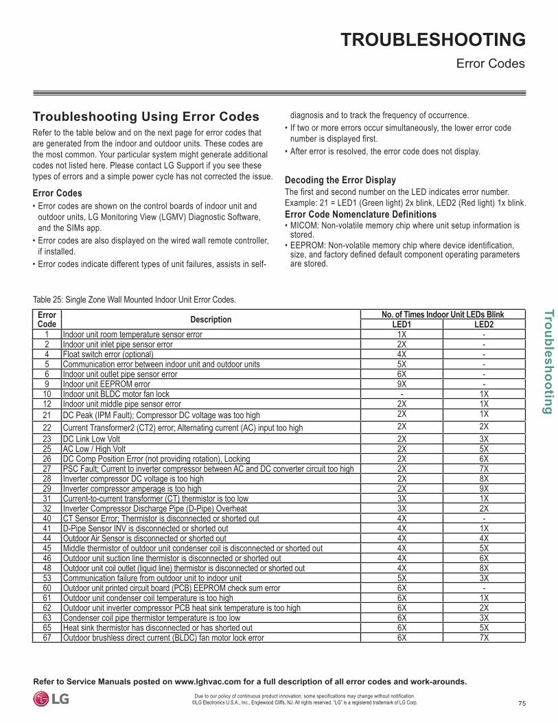
75
Troubleshooting
TROUBLESHOOTING
Due to our policy of continuous product innovation, some specifications may change without notification. ©LG Electronics U.S.A., Inc., Englewood Cliffs, NJ. All rights reserved. “LG” is a registered trademark of LG Corp.
Troubleshooting Using Error CodesRefer to the table below and on the next page for error codes that are generated from the indoor and outdoor units. These codes are the most common. Your particular system might generate additional codes not listed here. Please contact LG Support if you see these types of errors and a simple power cycle has not corrected the issue.
Error Codes• Error codes are shown on the control boards of indoor unit and
outdoor units, LG Monitoring View (LGMV) Diagnostic Software, and the SIMs app.
• Error codes are also displayed on the wired wall remote controller, if installed.
• Error codes indicate different types of unit failures, assists in self-
diagnosis and to track the frequency of occurrence.• If two or more errors occur simultaneously, the lower error code
number is displayed first.• After error is resolved, the error code does not display.
Decoding the Error DisplayThe first and second number on the LED indicates error number. Example: 21 = LED1 (Green light) 2x blink, LED2 (Red light) 1x blink. Error Code Nomenclature Definitions• MICOM: Non-volatile memory chip where unit setup information is
stored.• EEPROM: Non-volatile memory chip where device identification,
size, and factory defined default component operating parameters are stored.
Error Codes
Error Code Description No. of Times Indoor Unit LEDs Blink
LED1 LED21 Indoor unit room temperature sensor error 1X -2 Indoor unit inlet pipe sensor error 2X -4 Float switch error (optional) 4X -5 Communication error between indoor unit and outdoor units 5X -6 Indoor unit outlet pipe sensor error 6X -9 Indoor unit EEPROM error 9X -10 Indoor unit BLDC motor fan lock - 1X12 Indoor unit middle pipe sensor error 2X 1X21 DC Peak (IPM Fault); Compressor DC voltage was too high 2X 1X22 Current Transformer2 (CT2) error; Alternating current (AC) input too high 2X 2X23 DC Link Low Volt 2X 3X25 AC Low / High Volt 2X 5X26 DC Comp Position Error (not providing rotation), Locking 2X 6X27 PSC Fault; Current to inverter compressor between AC and DC converter circuit too high 2X 7X28 Inverter compressor DC voltage is too high 2X 8X29 Inverter compressor amperage is too high 2X 9X31 Current-to-current transformer (CT) thermistor is too low 3X 1X32 Inverter Compressor Discharge Pipe (D-Pipe) Overheat 3X 2X40 CT Sensor Error; Thermistor is disconnected or shorted out 4X -41 D-Pipe Sensor INV is disconnected or shorted out 4X 1X44 Outdoor Air Sensor is disconnected or shorted out 4X 4X45 Middle thermistor of outdoor unit condenser coil is disconnected or shorted out 4X 5X46 Outdoor unit suction line thermistor is disconnected or shorted out 4X 6X48 Outdoor unit coil outlet (liquid line) thermistor is disconnected or shorted out 4X 8X53 Communication failure from outdoor unit to indoor unit 5X 3X60 Outdoor unit printed circuit board (PCB) EEPROM check sum error 6X -61 Outdoor unit condenser coil temperature is too high 6X 1X62 Outdoor unit inverter compressor PCB heat sink temperature is too high 6X 2X63 Condenser coil pipe thermistor temperature is too low 6X 3X65 Heat sink thermistor has disconnected or has shorted out 6X 5X67 Outdoor brushless direct current (BLDC) fan motor lock error 6X 7X
Table 25: Single Zone Wall Mounted Indoor Unit Error Codes.
Refer to Service Manuals posted on www.lghvac.com for a full description of all error codes and work-arounds.
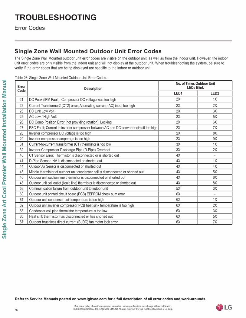
76
Sing
le Z
one
Art
Coo
l Pre
mie
r Wal
l Mou
nted
Inst
alla
tion
Man
ual
Due to our policy of continuous product innovation, some specifications may change without notification. ©LG Electronics U.S.A., Inc., Englewood Cliffs, NJ. All rights reserved. “LG” is a registered trademark of LG Corp.
TROUBLESHOOTINGError Codes
Table 26: Single Zone Wall Mounted Outdoor Unit Error Codes.
Error Code Description
No. of Times Outdoor Unit LEDs Blink
LED1 LED221 DC Peak (IPM Fault); Compressor DC voltage was too high 2X 1X22 Current Transformer2 (CT2) error; Alternating current (AC) input too high 2X 2X23 DC Link Low Volt 2X 3X25 AC Low / High Volt 2X 5X26 DC Comp Position Error (not providing rotation), Locking 2X 6X27 PSC Fault; Current to inverter compressor between AC and DC converter circuit too high 2X 7X28 Inverter compressor DC voltage is too high 2X 8X29 Inverter compressor amperage is too high 2X 9X31 Current-to-current transformer (CT) thermistor is too low 3X 1X32 Inverter Compressor Discharge Pipe (D-Pipe) Overheat 3X 2X40 CT Sensor Error; Thermistor is disconnected or is shorted out 4X -41 D-Pipe Sensor INV is disconnected or shorted out 4X 1X44 Outdoor Air Sensor is disconnected or shorted out 4X 4X45 Middle thermistor of outdoor unit condenser coil is disconnected or shorted out 4X 5X46 Outdoor unit suction line thermistor is disconnected or shorted out 4X 6X48 Outdoor unit coil outlet (liquid line) thermistor is disconnected or shorted out 4X 8X53 Communication failure from outdoor unit to indoor unit 5X 3X60 Outdoor unit printed circuit board (PCB) EEPROM check sum error 6X -61 Outdoor unit condenser coil temperature is too high 6X 1X62 Outdoor unit inverter compressor PCB heat sink temperature is too high 6X 2X63 Condenser coil pipe thermistor temperature is too low 6X 3X65 Heat sink thermistor has disconnected or has shorted out 6X 5X67 Outdoor brushless direct current (BLDC) fan motor lock error 6X 7X
Single Zone Wall Mounted Outdoor Unit Error CodesThe Single Zone Wall Mounted outdoor unit error codes are visible on the outdoor unit, as well as from the indoor unit. However, the indoor unit error codes are only visible from the indoor unit and will not display at the outdoor unit. When troubleshooting the system, be sure to verify if the error codes that are being displayed are specific to the indoor or outdoor unit.
Refer to Service Manuals posted on www.lghvac.com for a full description of all error codes and work-arounds.
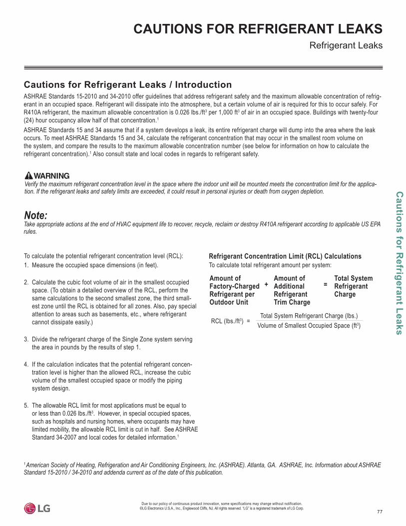
77
Cautions for R
efrigerant Leaks
CAUTIONS FOR REFRIGERANT LEAKS
Due to our policy of continuous product innovation, some specifications may change without notification. ©LG Electronics U.S.A., Inc., Englewood Cliffs, NJ. All rights reserved. “LG” is a registered trademark of LG Corp.
Amount of Factory-Charged Refrigerant per Outdoor Unit
Amount of Additional Refrigerant Trim Charge
Refrigerant Concentration Limit (RCL) CalculationsTo calculate total refrigerant amount per system:
Cautions for Refrigerant Leaks / IntroductionASHRAE Standards 15-2010 and 34-2010 offer guidelines that address refrigerant safety and the maximum allowable concentration of refrig-erant in an occupied space. Refrigerant will dissipate into the atmosphere, but a certain volume of air is required for this to occur safely. For R410A refrigerant, the maximum allowable concentration is 0.026 lbs./ft3 per 1,000 ft3 of air in an occupied space. Buildings with twenty-four (24) hour occupancy allow half of that concentration.1
ASHRAE Standards 15 and 34 assume that if a system develops a leak, its entire refrigerant charge will dump into the area where the leak occurs. To meet ASHRAE Standards 15 and 34, calculate the refrigerant concentration that may occur in the smallest room volume on the system, and compare the results to the maximum allowable concentration number (see below for information on how to calculate the refrigerant concentration).1 Also consult state and local codes in regards to refrigerant safety.
1
rules.
Total System Refrigerant Charge
+ =
To calculate the potential refrigerant concentration level (RCL):1. Measure the occupied space dimensions (in feet).
2. Calculate the cubic foot volume of air in the smallest occupied space. (To obtain a detailed overview of the RCL, perform the same calculations to the second smallest zone, the third small-est zone until the RCL is obtained for all zones. Also, pay special attention to areas such as basements, etc., where refrigerant cannot dissipate easily.)
3. Divide the refrigerant charge of the Single Zone system serving the area in pounds by the results of step 1.
4. If the calculation indicates that the potential refrigerant concen-tration level is higher than the allowed RCL, increase the cubic volume of the smallest occupied space or modify the piping system design.
5. The allowable RCL limit for most applications must be equal to or less than 0.026 lbs./ft3. However, in special occupied spaces, such as hospitals and nursing homes, where occupants may have limited mobility, the allowable RCL limit is cut in half. See ASHRAE Standard 34-2007 and local codes for detailed information.1
RCL (lbs./ft3) = Total System Refrigerant Charge (lbs.)
Volume of Smallest Occupied Space (ft3)
Refrigerant Leaks
Verify the maximum refrigerant concentration level in the space where the indoor unit will be mounted meets the concentration limit for the applica
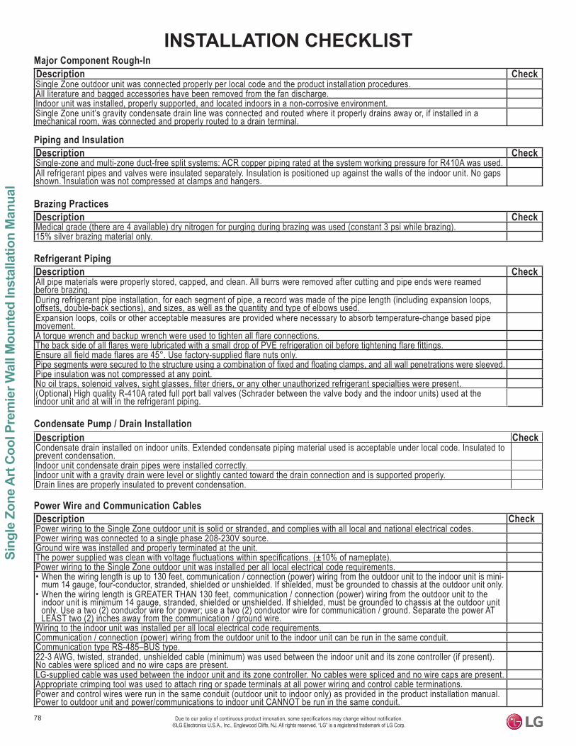
Due to our policy of continuous product innovation, some specifications may change without notification. ©LG Electronics U.S.A., Inc., Englewood Cliffs, NJ. All rights reserved. “LG” is a registered trademark of LG Corp.
78
Sing
le Z
one
Art C
ool P
rem
ier W
all M
ount
ed In
stal
latio
n M
anua
l
INSTALLATION CHECKLISTMajor Component Rough-In Description CheckSingle Zone outdoor unit was connected properly per local code and the product installation procedures.All literature and bagged accessories have been removed from the fan discharge.Indoor unit was installed, properly supported, and located indoors in a non-corrosive environment.Single Zone unit’s gravity condensate drain line was connected and routed where it properly drains away or, if installed in a mechanical room, was connected and properly routed to a drain terminal.
Piping and Insulation Description CheckSingle-zone and multi-zone duct-free split systems: ACR copper piping rated at the system working pressure for R410A was used.All refrigerant pipes and valves were insulated separately. Insulation is positioned up against the walls of the indoor unit. No gaps shown. Insulation was not compressed at clamps and hangers.
Brazing Practices Description CheckMedical grade (there are 4 available) dry nitrogen for purging during brazing was used (constant 3 psi while brazing).15% silver brazing material only.
Refrigerant Piping Description CheckAll pipe materials were properly stored, capped, and clean. All burrs were removed after cutting and pipe ends were reamed before brazing.During refrigerant pipe installation, for each segment of pipe, a record was made of the pipe length (including expansion loops, offsets, double-back sections), and sizes, as well as the quantity and type of elbows used.Expansion loops, coils or other acceptable measures are provided where necessary to absorb temperature-change based pipe movement.A torque wrench and backup wrench were used to tighten all flare connections.The back side of all flares were lubricated with a small drop of PVE refrigeration oil before tightening flare fittings.Ensure all field made flares are 45°. Use factory-supplied flare nuts only.
Pipe insulation was not compressed at any point.No oil traps, solenoid valves, sight glasses, filter driers, or any other unauthorized refrigerant specialties were present.(Optional) High quality R-410A rated full port ball valves (Schrader between the valve body and the indoor units) used at the indoor unit and at will in the refrigerant piping.
Condensate Pump / Drain InstallationDescription CheckCondensate drain installed on indoor units. Extended condensate piping material used is acceptable under local code. Insulated to prevent condensation.Indoor unit condensate drain pipes were installed correctly.Indoor unit with a gravity drain were level or slightly canted toward the drain connection and is supported properly.Drain lines are properly insulated to prevent condensation.
Power Wire and Communication Cables Description CheckPower wiring to the Single Zone outdoor unit is solid or stranded, and complies with all local and national electrical codes. Power wiring was connected to a single phase 208-230V source. Ground wire was installed and properly terminated at the unit.The power supplied was clean with voltage fluctuations within specifications. (±10% of nameplate).Power wiring to the Single Zone outdoor unit was installed per all local electrical code requirements.• When the wiring length is up to 130 feet, communication / connection (power) wiring from the outdoor unit to the indoor unit is mini-
mum 14 gauge, four-conductor, stranded, shielded or unshielded. If shielded, must be grounded to chassis at the outdoor unit only.• When the wiring length is GREATER THAN 130 feet, communication / connection (power) wiring from the outdoor unit to the
indoor unit is minimum 14 gauge, stranded, shielded or unshielded. If shielded, must be grounded to chassis at the outdoor unit only. Use a two (2) conductor wire for power; use a two (2) conductor wire for communication / ground. Separate the power AT LEAST two (2) inches away from the communication / ground wire.
Wiring to the indoor unit was installed per all local electrical code requirements.Communication / connection (power) wiring from the outdoor unit to the indoor unit can be run in the same conduit.Communication type RS-485–BUS type.22-3 AWG, twisted, stranded, unshielded cable (minimum) was used between the indoor unit and its zone controller (if present). No cables were spliced and no wire caps are present.LG-supplied cable was used between the indoor unit and its zone controller. No cables were spliced and no wire caps are present.Appropriate crimping tool was used to attach ring or spade terminals at all power wiring and control cable terminations.Power and control wires were run in the same conduit (outdoor unit to indoor only) as provided in the product installation manual. Power to outdoor unit and power/communications to indoor unit CANNOT be run in the same conduit.
For further technical materials such as submittals, engineering manuals, service manuals, and catalogs, visit www.lghvac.com.
IM_SZ_ArtCoolPremier_HYV3_8_20Supersedes: IM_SZ_ArtCoolPremier_HYV3_3_20
IM_SZ_ArtCoolPremier_HYV1_4_16IM_SZ_ArtCoolPremier_HYV1_6_15
LG Electronics, U.S.A., Inc.Air Conditioning Technologies4300 North Point ParkwayAlpharetta, Georgia 30022www.lghvac.com
20001747 ISO 9001: 2008
LG ELECTRONICS INC.