Embed Size (px)
Citation preview
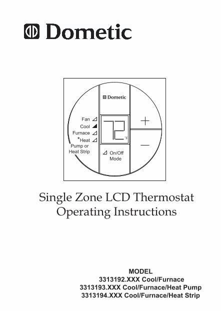
Single Zone LCD ThermostatOperating Instructions
MODEL 3313192.XXX Cool/Furnace
3313193.XXX Cool/Furnace/Heat Pump3313194.XXX Cool/Furnace/Heat Strip
On/OffMode
FanCool
Furnace*Heat
Pump or Heat Strip
˚F
2
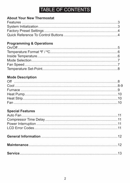
TABLE OF CONTENTS
About Your New ThermostatFeatures ..................................................................................................3System Initialization .................................................................................3Factory Preset Settings ...........................................................................4Quick Reference To Control Buttons .......................................................4
Programming & OperationsOn/Off ......................................................................................................5Temperature Format ºF / ºC.....................................................................6Inside Temperature ..................................................................................6Mode Selection ........................................................................................7Fan Speed ...............................................................................................7Temperature Set-Point.............................................................................8
Mode DescriptionOff ..........................................................................................................8Cool .........................................................................................................8-9Furnace ...................................................................................................9Heat Pump...............................................................................................10Heat Strip.................................................................................................10Fan ..........................................................................................................10
Special FeaturesAuto Fan ..................................................................................................11Compressor Time Delay ..........................................................................11Power Interruption ...................................................................................11LCD Error Codes .....................................................................................11
General Information ..............................................................................12
Maintenance ...........................................................................................12
Service ....................................................................................................13
3
Congratulations! Your recreational vehicle manufacturer has equipped your RV with the most advanced RV thermostat. Your Dometic Single Zone LCD thermostat has been designed for ease of operation and for many years of reliable service.
Features• LiquidCrystalDisplayandGreenLEDModeIndicators• AutoFan• IndoorTemperatureDisplay• °F/°CDisplay
To help familiarize yourself with the operation of the Single Zone LCD thermostat, review the following diagrams and accompanying text that explain the functional characteristics of this system.
Your Single Zone LCD thermostat is equipped with both a liquid crys-taldisplay (LCD) that identifies the temperatureset-point, fanspeed(Auto, Low, High), and F/C and green LEDs that indicate the mode of operation (Off, Fan, Cool, Furnace, Heat Pump or Heat Strip*). The modes of operation available will vary depending on the system in-stalled in your RV.
* Select models.
System InitializationA system initialization will need to be performed by the installer after the system is installed. • MakesuretheSingleZoneLCDthermostatisintheOffcondi-
tion. See page 4, “Quick Reference To Control Buttons”. • Pressthe“+” button and, while holding it, also press and hold
the On/Off Mode button for three seconds. LCD will show ― ― . Press the On/Off Mode button again to turn system off.
This completes the initialization.The furnace On/Off temperature differential should be set at this time. See “Mode Description - Furnace” on page 9 for further information on furnace mode differential setting.
About Your New Thermostat
4
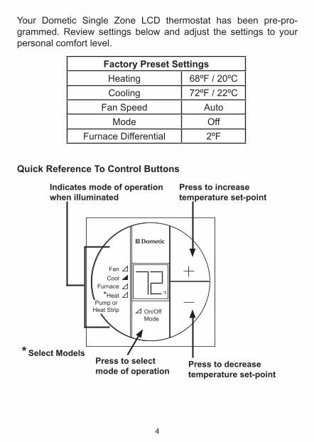
Factory Preset SettingsHeating 68ºF / 20ºCCooling 72ºF / 22ºC
Fan Speed AutoMode Off
Furnace Differential 2ºF
Your Dometic Single Zone LCD thermostat has been pre-pro-grammed. Review settings below and adjust the settings to your personal comfort level.
* Select Models
On/OffMode
FanCool
Furnace*Heat
Pump or Heat Strip
˚F
Press to decreasetemperature set-point
Press to increase temperature set-point
Indicates mode of operation when illuminated
Press to select mode of operation
Quick Reference To Control Buttons
5
On/Off
To turn On the Single Zone LCD thermostat, press the On/Off Mode button. The LCD will be activated. To turn Off the Single Zone LCD thermostat press the On/Off Mode button and toggle through the modes until the On/Off green LED is on. The LCD will go out and the green LED will remain on for approximately 15 seconds, then go out.
Programming & Operations
6
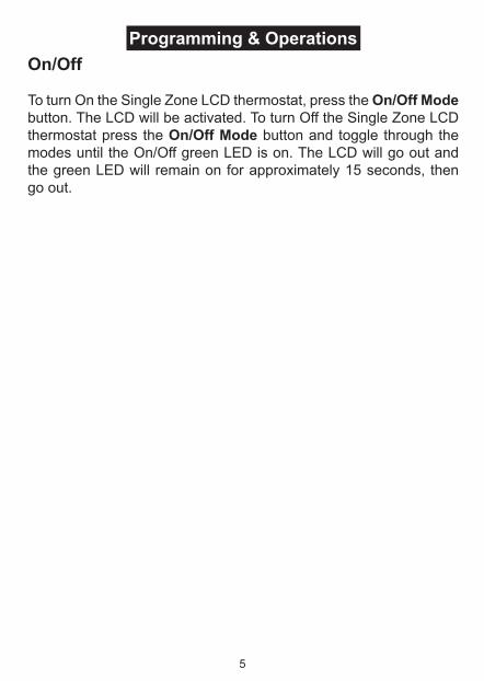
Inside Temperature
To display the Inside Temperature, the Single Zone LCD thermostat mustbeintheOffMode.Presseitherthe“+”or“―” button to display the Inside Temperature.
On/OffMode
FanCool
Furnace˚F
Temperature Format ºF / ºC
Simultaneously press the “+” and “―“ buttons to toggle between Fahrenheit and Centigrade format. ºF indicates Fahrenheit and ºC indicates Centigrade.
On/OffMode
FanCool
Furnace*Heat
Pump or Heat Strip
˚F
7
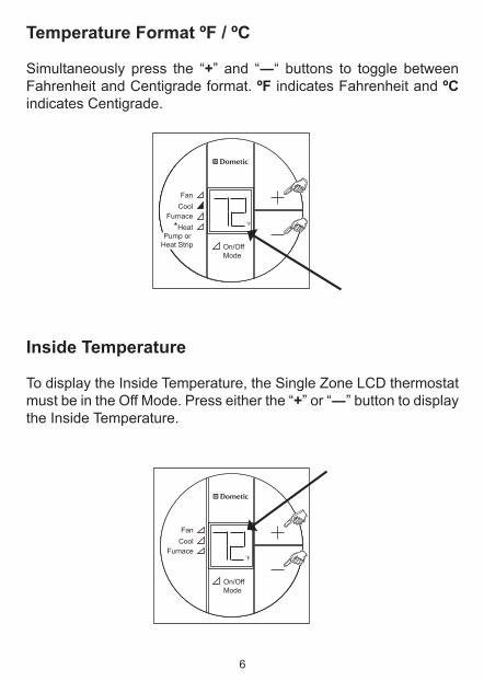
Fan Speed
Press the On/Off Mode button until the fan green LED is lit. The LCDwillshow“Lo”(Low),“Hi”(High)or“Au”(Auto).Pressthe“+” or “―” button to select the desired fan speed. See “Special Features” on page 11 for more information on Auto Fan.
Mode Selection
Press the On/Off Mode button to advance through the available modes. Each successive press will advance to the next available mode. The green LED will indicate the mode selected. Depending on the systems installed, your choices will be Off, Fan, Cool, Fur-nace, Heat Pump or Heat Strip. See “Mode Description” on pages 8-10 for more information on modes.
On/OffMode
FanCool
Furnace
On/OffMode
FanCool
Furnace˚F
8
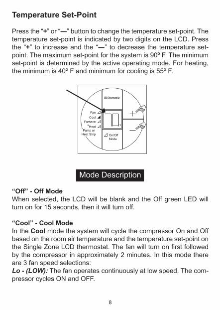
Temperature Set-Point
Pressthe“+”or“―” button to change the temperature set-point. The temperature set-point is indicated by two digits on the LCD. Press the “+” to increaseand the “―” to decrease the temperature set-point. The maximum set-point for the system is 90º F. The minimum set-point is determined by the active operating mode. For heating, the minimum is 40º F and minimum for cooling is 55º F.
On/OffMode
FanCool
Furnace*Heat
Pump or Heat Strip
˚F
Mode Description
“Off” - Off ModeWhen selected, the LCD will be blank and the Off green LED will turn on for 15 seconds, then it will turn off.
“Cool” - Cool Mode In the Cool mode the system will cycle the compressor On and Off based on the room air temperature and the temperature set-point on theSingleZoneLCDthermostat.Thefanwillturnonfirstfollowedby the compressor in approximately 2 minutes. In this mode there are 3 fan speed selections:Lo - (LOW): The fan operates continuously at low speed. The com-pressor cycles ON and OFF.
9
Hi - (HIGH): The fan operates continuously at high speed. The com-pressor cycles ON and OFF.Au - (AUTO): When auto fan is selected the fan speed will vary depending on the difference between the temperature set-point and the room air temperature. In auto fan the compressor and the fan will cycle On and Off with the thermostat. See “Special Features” on page 11 for information on auto fan.
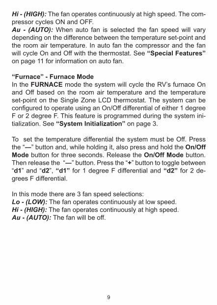
“Furnace” - Furnace Mode In the FURNACE mode the system will cycle the RV’s furnace On and Off based on the room air temperature and the temperature set-point on the Single Zone LCD thermostat. The system can be configuredtooperateusinganOn/Offdifferentialofeither1degreeF or 2 degree F. This feature is programmed during the system ini-tialization. See “System Initialization” on page 3.
To set the temperature differential the system must be Off. Press the“―” button and, while holding it, also press and hold the On/Off Mode button for three seconds. Release the On/Off Mode button. Then release the “―”button.Pressthe“+” button to toggle between “d1”and“d2”, “d1” for 1 degree F differential and “d2” for 2 de-grees F differential.
In this mode there are 3 fan speed selections:Lo - (LOW): The fan operates continuously at low speed.Hi - (HIGH): The fan operates continuously at high speed.Au - (AUTO): The fan will be off.
10
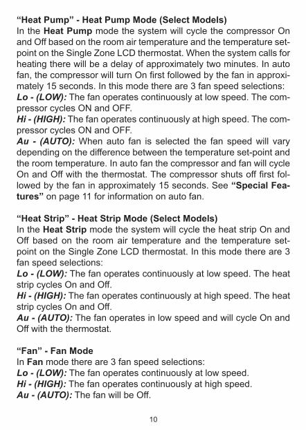
“Heat Pump” - Heat Pump Mode (Select Models)In the Heat Pump mode the system will cycle the compressor On and Off based on the room air temperature and the temperature set-point on the Single Zone LCD thermostat. When the system calls for heating there will be a delay of approximately two minutes. In auto fan,thecompressorwillturnOnfirstfollowedbythefaninapproxi-mately 15 seconds. In this mode there are 3 fan speed selections:Lo - (LOW): The fan operates continuously at low speed. The com-pressor cycles ON and OFF.Hi - (HIGH): The fan operates continuously at high speed. The com-pressor cycles ON and OFF.Au - (AUTO): When auto fan is selected the fan speed will vary depending on the difference between the temperature set-point and the room temperature. In auto fan the compressor and fan will cycle OnandOffwiththethermostat.Thecompressorshutsofffirstfol-lowed by the fan in approximately 15 seconds. See “Special Fea-tures” on page 11 for information on auto fan.
“Heat Strip” - Heat Strip Mode (Select Models)In the Heat Strip mode the system will cycle the heat strip On and Off based on the room air temperature and the temperature set-point on the Single Zone LCD thermostat. In this mode there are 3 fan speed selections:Lo - (LOW): The fan operates continuously at low speed. The heat strip cycles On and Off.Hi - (HIGH): The fan operates continuously at high speed. The heat strip cycles On and Off.Au - (AUTO): The fan operates in low speed and will cycle On and Off with the thermostat.
“Fan” - Fan ModeIn Fan mode there are 3 fan speed selections:Lo - (LOW): The fan operates continuously at low speed.Hi - (HIGH): The fan operates continuously at high speed.Au - (AUTO): The fan will be Off.
11
Special Features
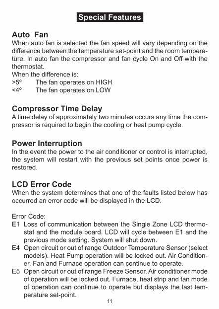
Auto FanWhen auto fan is selected the fan speed will vary depending on the difference between the temperature set-point and the room tempera-ture. In auto fan the compressor and fan cycle On and Off with the thermostat.When the difference is:>5º ThefanoperatesonHIGH<4º The fan operates on LOW
Compressor Time DelayA time delay of approximately two minutes occurs any time the com-pressor is required to begin the cooling or heat pump cycle.
Power InterruptionIn the event the power to the air conditioner or control is interrupted, the system will restart with the previous set points once power is restored.
LCD Error CodeWhen the system determines that one of the faults listed below has occurred an error code will be displayed in the LCD.
Error Code:E1 Loss of communication between the Single Zone LCD thermo-
stat and the module board. LCD will cycle between E1 and the previous mode setting. System will shut down.
E4 Open circuit or out of range Outdoor Temperature Sensor (select models). Heat Pump operation will be locked out. Air Condition-er, Fan and Furnace operation can continue to operate.
E5 Open circuit or out of range Freeze Sensor. Air conditioner mode of operation will be locked out. Furnace, heat strip and fan mode of operation can continue to operate but displays the last tem-perature set-point.
12
General Information
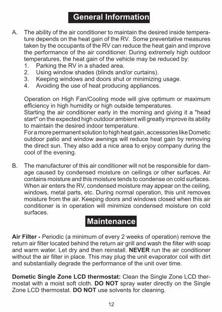
A. The ability of the air conditioner to maintain the desired inside tempera-ture depends on the heat gain of the RV. Some preventative measures taken by the occupants of the RV can reduce the heat gain and improve the performance of the air conditioner. During extremely high outdoor temperatures, the heat gain of the vehicle may be reduced by:1. Parking the RV in a shaded area.2. Using window shades (blinds and/or curtains).3. Keeping windows and doors shut or minimizing usage. 4. Avoiding the use of heat producing appliances.
Operation on High Fan/Cooling mode will give optimum or maximum efficiencyinhighhumidityorhighoutsidetemperatures.
Starting the air conditioner early in the morning and giving it a "head start" on the expected high outdoor ambient will greatly improve its ability to maintain the desired indoor temperature.
For a more permanent solution to high heat gain, accessories like Dometic outdoor patio and window awnings will reduce heat gain by removing the direct sun. They also add a nice area to enjoy company during the cool of the evening.
B. The manufacturer of this air conditioner will not be responsible for dam-
age caused by condensed moisture on ceilings or other surfaces. Air contains moisture and this moisture tends to condense on cold surfaces. When air enters the RV, condensed moisture may appear on the ceiling, windows, metal parts, etc. During normal operation, this unit removes moisture from the air. Keeping doors and windows closed when this air conditioner is in operation will minimize condensed moisture on cold surfaces.
Maintenance
Air Filter - Periodic (a minimum of every 2 weeks of operation) remove the returnairfilterlocatedbehindthereturnairgrillandwashthefilterwithsoapand warm water. Let dry and then reinstall. NEVER run the air conditioner withouttheairfilterinplace.Thismayplugtheunitevaporatorcoilwithdirtand substantially degrade the performance of the unit over time.
Dometic Single Zone LCD thermostat: Clean the Single Zone LCD ther-mostat with a moist soft cloth. DO NOT spray water directly on the Single Zone LCD thermostat. DO NOT use solvents for cleaning.
13
REVISIONForm No. 3313327.011 6/10(French 3313345.013) ©2010 Dometic, LLCLagrange, IN 46761
USASERVICE OFFICEDometic, LLC2320 Industrial ParkwayElkhart, IN 46516574-294-2511
Service
In the unlikely event the unit fails to operate or operates improperly, check the following before calling your service center.
1. If your RV is connected to a motor generator, check to be sure the motor generator is running and producing power.
2. If the RV is connected to a power supply by a land line, check to be sure the line is sized properly to run air conditioner load and it is plugged into the power supply.
3. Check your 120 VAC fuse or circuit breaker to see if it is open.4. Check your 12 VDC fuse or circuit breaker to see if it is open.5. After the above checks, call your local service center for further
help.Thisunitmustbeservicedbyqualifiedservicepersonnelonly.
When calling for service, always give the following:
1. Air conditioner/heat pump Model Number and Serial Number foundon Identification Label located on theBasePanof theunit. It is necessary to remove the return air cover to expose the rating plate.
2. Electronic Control Kit Part Number and Serial Number found onIdentificationLabellocatedonthesideoftheKit.Thiskitismounted in the return air cavity and can be exposed by remov-ing the return air cover.
CANADADometic, LLC46 Zatonski, Unit 3Brantford, ON N3T 5L8CANADA519-720-9578
For Service CenterAssistance Call:800-544-4881