Embed Size (px)
Citation preview
Single Temperature Sensor Based Evaporator Filling Control UsingExcitation Signal Harmonics
Kasper Vinther, Henrik Rasmussen, Roozbeh Izadi-Zamanabadi and Jakob Stoustrup
Abstract— An important aspect of efficient and safe operationof refrigeration and air conditioning systems is superheatcontrol for evaporators. This is conventionally controlled with apressure sensor, a temperature sensor, an expansion valve andProportional-Integral (PI) controllers or more advanced modelbased control. In this paper we show that superheat can becontrolled without a pressure sensor and without a model ofthe system. This is achieved by continuous excitation of thesystem and by applying Fourier analysis, which gives an errorsignal that can be used together with standard PI control.The proposed method works for systems with ”S” shapedinput/output maps that satisfy sigmoid function properties andsuch behavior has been identified in both an air conditioningand a refrigeration system. Tests on these systems show that thesuperheat can be controlled to a low level over a large operatingrange with only one sensor. It is believed that the method ingeneral is applicable to a wide variety of nonlinear systems forwhich the desired operating points are close to points of zeromean curvature of system nonlinearities.
I. INTRODUCTION
Maximization of two-phase refrigerant flow in evaporatorsis an important aspect of efficient operation of refrigerationand air conditioning systems, because liquid refrigerant ac-counts for the majority of cooling. At the same time it isimportant that all refrigerant is vaporized before it enters thecompressor to avoid the risk of compressor damage. Controlof the evaporator filling level is also known as superheatcontrol, where superheat is the difference between the evap-oration temperature and the temperature of the vapor leavingthe evaporator. Superheat control is generally achieved usingan expansion valve and the most commonly used devices arethe Thermostatic Expansion Valve (TXV) and the ElectronicExpansion Valve (EEV).
The significant nonlinear response from the opening de-gree (OD) of the expansion valve to the evaporator superheatposes as a control challenge. TXV’s operate well within acertain operating range, but are limited by a constant controlgain, which is problematic, since changes in operating con-ditions for the nonlinear system can cause unstable behaviorand actuator hunting [1], [2]. The EEV allows for muchgreater freedom in expansion valve control and introducesthe possibility of using PID control, which is used in themajority of EEV superheat control setups seen today [2].However, there is still a need for adaption of the controllerto changes in operating conditions, which is often solvedusing some variant of gain scheduling, see e.g. [3].
K. Vinther, H. Rasmussen and J. Stoustrup are with the Section ofAutomation and Control, Department of Electronic Systems, Aalborg Uni-versity, 9220, Denmark {kv,hr,jakob}@es.aau.dk
R. Izadi-Zamanabadi is with the Department of Electronic Controllersand Services, Danfoss A/S, 6430, Denmark [email protected]
There are also alternatives to gain scheduling. In [4]nonlinearity compensation in the valve to superheat responseis achieved using a cascaded feedback loop, [5] uses feed-back linearization to compensate for nonlinearities and thebackstepping design method is used in [6] to find a nonlinearsuperheat controller that works for a wide range of operatingpoints. Another alternative is to use the compressor, insteadof the valve, to control the superheat as done in [7]. Thereare many possibilities, however, a problem with advancedmethods is that they often require a good model of thesystem, which can be difficult to produce and furthermoreeach system is often composed of components from manydifferent manufactures making most systems unique. Thedesire for cheap systems in the industry also means lesssensors and thus a need for even more accurate models.
We will in this paper show that the evaporator superheatcan actually be controlled over a wide range of operatingconditions using only a single temperature measurement atthe outlet of the evaporator, thus saving a pressure sensor.Furthermore, this is achieved without using a model of thesystem and very little a priori system knowledge. Qualitativeknowledge about the evaporator nonlinearity from valveinput to evaporator outlet temperature is used instead ofquantitative knowledge to control the filling of the evapo-rator. This is possible for Input/Output (I/O) relationshipsthat have sigmoid function properties (”S” shaped I/O map).
The proposed method has taken inspiration from excitationsignal based extremum- and slope-seeking control, whichare gradient descent non-model based methods (this subjectis well covered in e.g. [8]). Extremum-seeking control hase.g. been used in [9] for optimization of condenser watertemperature in chilled water cooling plants resulting in aminimization of the total sum of chiller and cooling towerpower consumption and in [10] for optimization of air-sideeconomizers in HVAC systems. However, the more generalslope-seeking control is better suited for superheat control,since the nonlinear I/O map is ”S” shaped and the optimalsuperheat will be at a certain slope rather than where theslope is zero. A reasonable sub-optimal choice in generalis where the slope is largest, since this gives an evaporatoroutlet temperature that lies between the surrounding tem-perature and evaporation temperature. However, finding anappropriate reference slope can be very difficult, since thischanges with operating conditions and load.
While still using an excitation signal, as in slope-seekingcontrol, we instead propose to use Fourier analysis to cal-culate an error signal for feedback. We have called thismethod harmonic control and it is presented in [11]. This is
another approach for single sensor superheat control than thevariance based method we presented in [12] and the benefitof harmonic control is that it does not require a systemmodel, it works for a wide operating range, and it does notrequire any reference set points, which together means thatit has a high degree of Plug and Play.
The structure of this paper is as follows. Two differenttest systems are first introduced in Section II followed by adescription of the harmonic control method and simulationresults in Section III. Then safety logic is added to the controlconcept in Section IV and the controller is tested on thetwo systems with results presented in Section V. Finally,conclusions are drawn in Section VI.
II. SYSTEM DESCRIPTIONS
The proposed harmonic controller is designed for systemswith steady state I/O maps that exhibit sigmoid functionproperties and such qualitative behavior has been identifiedin the relation between the OD of an EEV and the outlettemperature To of evaporators in two different refrigerationsystems located at Aalborg University (www.es.aau.dk/projects/refrigeration/). This behavior is utilizedfor evaporator filling (superheat) control and the physicallayout of the two systems are therefore described in thetwo following subsections, along with presentation of thequalitative behavior of the evaporator outlet temperature.
A. Air Conditioning System
A simplified schematic of the air conditioning systemis presented in Fig. 1. This air conditioning system uses
CompressorEvaporator
Ecoflow valve
Condenser
Fan
fconOD
fcpTc,i
Tc,o
To PcPe Tc,a
Fan
Manualcontrol
Ta
Fan fhvac
Cold room Hot room
Outside
Heat load
Fig. 1. Simplified schematic of the air conditioning system. T , P and f areindicators for temperature sensors, pressure sensors and frequency control.
refrigerant type R410a and has a finned-tube evaporator withfour channels and a cooling capacity of 11 kW. The refrig-erant flow is controllable with a Danfoss EcoflowTMvalve.It is possible to control the OD of the valve and thedistribution of flow into the individual pipes, however, thedistribution is kept constant in this setup. Furthermore, itis possible to control the frequency of both the evaporatorand condenser fans, and also the frequency of the fansbetween the cold room, the hot room and the outside. Thescroll compressor frequency is also controllable and sensorsmeasure temperature and pressure at the indicated locationswith a sampling interval of 1 second.
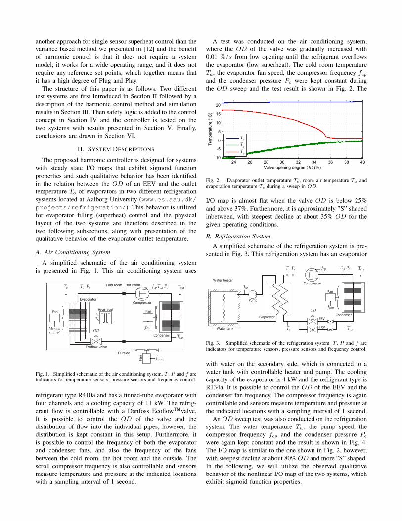
A test was conducted on the air conditioning system,where the OD of the valve was gradually increased with0.01 %/s from low opening until the refrigerant overflowsthe evaporator (low superheat). The cold room temperatureTa, the evaporator fan speed, the compressor frequency fcpand the condenser pressure Pc were kept constant duringthe OD sweep and the test result is shown in Fig. 2. The
24 26 28 30 32 34 36 38 40-10
-5
0
5
10
15
20
Valve opening degree OD (%)
Tem
pera
ture
(°C
)
TaTeTo
Fig. 2. Evaporator outlet temperature To, room air temperature Ta andevaporation temperature Te during a sweep in OD.
I/O map is almost flat when the valve OD is below 25%and above 37%. Furthermore, it is approximately ”S” shapedinbetween, with steepest decline at about 35% OD for thegiven operating conditions.
B. Refrigeration System
A simplified schematic of the refrigeration system is pre-sented in Fig. 3. This refrigeration system has an evaporator
Compressor
Evaporator EEV
Pump
Water heater
Condenser
Fan
Water tank
fconOD
fcp Tc,i
Tc,o
To
Te
Tw
PcPe Tc,a
TXV
Fig. 3. Simplified schematic of the refrigeration system. T , P and f areindicators for temperature sensors, pressure sensors and frequency control.
with water on the secondary side, which is connected to awater tank with controllable heater and pump. The coolingcapacity of the evaporator is 4 kW and the refrigerant type isR134a. It is possible to control the OD of the EEV and thecondenser fan frequency. The compressor frequency is againcontrollable and sensors measure temperature and pressure atthe indicated locations with a sampling interval of 1 second.
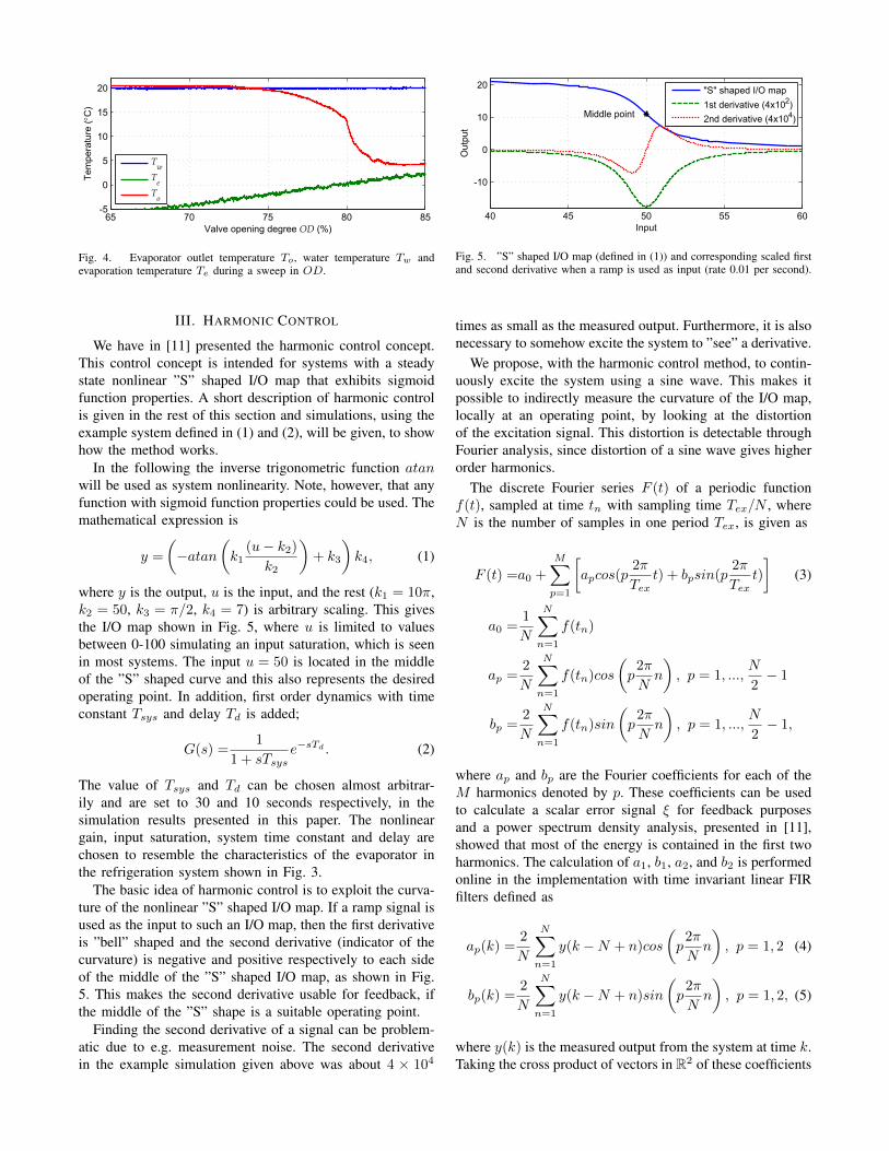
An OD sweep test was also conducted on the refrigerationsystem. The water temperature Tw, the pump speed, thecompressor frequency fcp and the condenser pressure Pc
were again kept constant and the result is shown in Fig. 4.The I/O map is similar to the one shown in Fig. 2, however,with steepest decline at about 80% OD and more ”S” shaped.In the following, we will utilize the observed qualitativebehavior of the nonlinear I/O map of the two systems, whichexhibit sigmoid function properties.
65 70 75 80 85-5
0
5
10
15
20
Valve opening degree OD (%)
Tem
pera
ture
(°C
)
TwTeTo
Fig. 4. Evaporator outlet temperature To, water temperature Tw andevaporation temperature Te during a sweep in OD.
III. HARMONIC CONTROL
We have in [11] presented the harmonic control concept.This control concept is intended for systems with a steadystate nonlinear ”S” shaped I/O map that exhibits sigmoidfunction properties. A short description of harmonic controlis given in the rest of this section and simulations, using theexample system defined in (1) and (2), will be given, to showhow the method works.
In the following the inverse trigonometric function atanwill be used as system nonlinearity. Note, however, that anyfunction with sigmoid function properties could be used. Themathematical expression is
y =
(−atan
(k1
(u− k2)k2
)+ k3
)k4, (1)
where y is the output, u is the input, and the rest (k1 = 10π,k2 = 50, k3 = π/2, k4 = 7) is arbitrary scaling. This givesthe I/O map shown in Fig. 5, where u is limited to valuesbetween 0-100 simulating an input saturation, which is seenin most systems. The input u = 50 is located in the middleof the ”S” shaped curve and this also represents the desiredoperating point. In addition, first order dynamics with timeconstant Tsys and delay Td is added;
G(s) =1
1 + sTsyse−sTd . (2)
The value of Tsys and Td can be chosen almost arbitrar-ily and are set to 30 and 10 seconds respectively, in thesimulation results presented in this paper. The nonlineargain, input saturation, system time constant and delay arechosen to resemble the characteristics of the evaporator inthe refrigeration system shown in Fig. 3.
The basic idea of harmonic control is to exploit the curva-ture of the nonlinear ”S” shaped I/O map. If a ramp signal isused as the input to such an I/O map, then the first derivativeis ”bell” shaped and the second derivative (indicator of thecurvature) is negative and positive respectively to each sideof the middle of the ”S” shaped I/O map, as shown in Fig.5. This makes the second derivative usable for feedback, ifthe middle of the ”S” shape is a suitable operating point.
Finding the second derivative of a signal can be problem-atic due to e.g. measurement noise. The second derivativein the example simulation given above was about 4 × 10⁴
40 45 50 55 60
-10
0
10
20
Out
put
Input
Middle point
"S" shaped I/O map1st derivative (4x10²)2nd derivative (4x10⁴)
Fig. 5. ”S” shaped I/O map (defined in (1)) and corresponding scaled firstand second derivative when a ramp is used as input (rate 0.01 per second).
times as small as the measured output. Furthermore, it is alsonecessary to somehow excite the system to ”see” a derivative.
We propose, with the harmonic control method, to contin-uously excite the system using a sine wave. This makes itpossible to indirectly measure the curvature of the I/O map,locally at an operating point, by looking at the distortionof the excitation signal. This distortion is detectable throughFourier analysis, since distortion of a sine wave gives higherorder harmonics.
The discrete Fourier series F (t) of a periodic functionf(t), sampled at time tn with sampling time Tex/N , whereN is the number of samples in one period Tex, is given as
F (t) =a0 +
M∑p=1
[apcos(p
2π
Text) + bpsin(p
2π
Text)
](3)
a0 =1
N
N∑n=1
f(tn)
ap =2
N
N∑n=1
f(tn)cos
(p2π
Nn
), p = 1, ...,
N
2− 1
bp =2
N
N∑n=1
f(tn)sin
(p2π
Nn
), p = 1, ...,
N
2− 1,
where ap and bp are the Fourier coefficients for each of theM harmonics denoted by p. These coefficients can be usedto calculate a scalar error signal ξ for feedback purposesand a power spectrum density analysis, presented in [11],showed that most of the energy is contained in the first twoharmonics. The calculation of a1, b1, a2, and b2 is performedonline in the implementation with time invariant linear FIRfilters defined as
ap(k) =2
N
N∑n=1
y(k −N + n)cos
(p2π
Nn
), p = 1, 2 (4)
bp(k) =2
N
N∑n=1
y(k −N + n)sin
(p2π
Nn
), p = 1, 2, (5)
where y(k) is the measured output from the system at time k.Taking the cross product of vectors in R2 of these coefficients
gives an error signal defined as
ξ =
[a1b1
]×[a2b2
]=a1b2 − a2b1 = |H1||H2|sin(φ) (6)
|H1| =√a21 + b21
|H2| =√a22 + b22,
where |H1| and |H2| are the amplitudes of the two firstharmonics and φ is the angle from the first harmonic to thesecond harmonic. The cross product is a normal vector andit is positive if the operating point is located to the right ofthe middle point of the ”S” shaped nonlinearity and negativeto the other side.
It can be a good idea to normalize the error signal ξ,since the amplitude of the excitation signal at the outputis dependent on the operating point dependent gain in thesystem. In (7), the error signal is normalized with the cubedamplitude of the first harmonic, which gives an almost linearfeedback signal.
ξn =a1b2 − a2b1√a21 + b21
3 =a1b2 − a2b1(a21 + b21)
1.5 . (7)
Other normalizations can be used as well and some of themare shown in Fig. 6. The first three normalized error signals
-1
0
1
Nor
mal
ized
Erro
r ξn 1
|H1|
|H1|2
|H1|3
0 20 40 60 80 1000
2
4
6
Am
plitu
de
Input uc
Input sineOutput |H1|
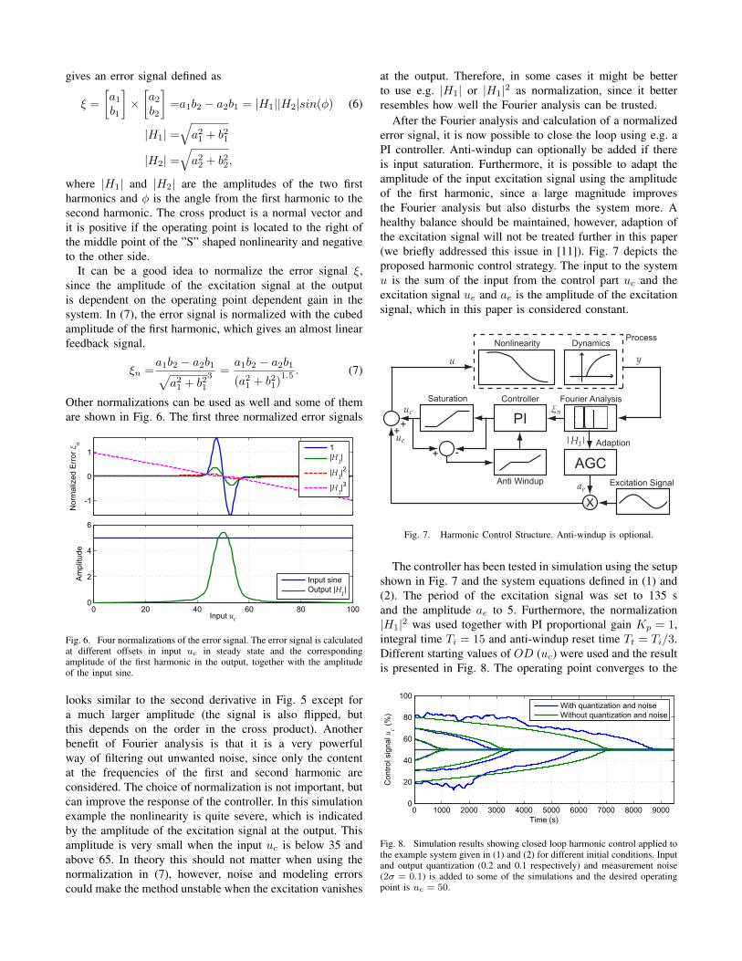
Fig. 6. Four normalizations of the error signal. The error signal is calculatedat different offsets in input uc in steady state and the correspondingamplitude of the first harmonic in the output, together with the amplitudeof the input sine.
looks similar to the second derivative in Fig. 5 except fora much larger amplitude (the signal is also flipped, butthis depends on the order in the cross product). Anotherbenefit of Fourier analysis is that it is a very powerfulway of filtering out unwanted noise, since only the contentat the frequencies of the first and second harmonic areconsidered. The choice of normalization is not important, butcan improve the response of the controller. In this simulationexample the nonlinearity is quite severe, which is indicatedby the amplitude of the excitation signal at the output. Thisamplitude is very small when the input uc is below 35 andabove 65. In theory this should not matter when using thenormalization in (7), however, noise and modeling errorscould make the method unstable when the excitation vanishes
at the output. Therefore, in some cases it might be betterto use e.g. |H1| or |H1|2 as normalization, since it betterresembles how well the Fourier analysis can be trusted.
After the Fourier analysis and calculation of a normalizederror signal, it is now possible to close the loop using e.g. aPI controller. Anti-windup can optionally be added if thereis input saturation. Furthermore, it is possible to adapt theamplitude of the input excitation signal using the amplitudeof the first harmonic, since a large magnitude improvesthe Fourier analysis but also disturbs the system more. Ahealthy balance should be maintained, however, adaption ofthe excitation signal will not be treated further in this paper(we briefly addressed this issue in [11]). Fig. 7 depicts theproposed harmonic control strategy. The input to the systemu is the sum of the input from the control part uc and theexcitation signal ue and ae is the amplitude of the excitationsignal, which in this paper is considered constant.
Nonlinearity Dynamics
Fourier Analysis
Excitation Signal
Saturation Controller
X
Anti Windup
++
+ -
PI
yu
ae
ξnu
u
c
e
Process
|H |1
AGCAdaption
Fig. 7. Harmonic Control Structure. Anti-windup is optional.
The controller has been tested in simulation using the setupshown in Fig. 7 and the system equations defined in (1) and(2). The period of the excitation signal was set to 135 sand the amplitude ae to 5. Furthermore, the normalization|H1|2 was used together with PI proportional gain Kp = 1,integral time Ti = 15 and anti-windup reset time Tt = Ti/3.Different starting values of OD (uc) were used and the resultis presented in Fig. 8. The operating point converges to the
0 1000 2000 3000 4000 5000 6000 7000 8000 90000
20
40
60
80
100
Con
trol s
igna
l uc (%
)
Time (s)
With quantization and noiseWithout quantization and noise
Fig. 8. Simulation results showing closed loop harmonic control applied tothe example system given in (1) and (2) for different initial conditions. Inputand output quantization (0.2 and 0.1 respectively) and measurement noise(2σ = 0.1) is added to some of the simulations and the desired operatingpoint is uc = 50.
desired value of uc = 50 in all the simulations, however,the response is more uncertain when noise and quantizationis added. This is not surprising, since the amplitude of theharmonics are very small compared to the noise, when thevalve OD is below 35% and above 65%, see Fig. 6.
Note that slope-seeking control could not have stabilizedthe system to the same operating point, because the slopedecreases on both sides of the operating point. If slope-seeking control is used, one would have to choose a referenceslope that deviates from the middle of the ”S” shaped curve,well aware that this slope will be mirrored around themiddle of the curve, giving only local stability. Furthermore,choosing a suitable reference can be difficult in itself, sincethe slope changes when the operating conditions and hencethe system nonlinearity changes in the time varying system,giving an unpredictable operating point.
The PI control part of the harmonic controller has beentuned manually in the simulations and tests presented in thispaper. However, automatic tuning of the controller will bepursued in future research. When tuning it is important toremember that the Fourier analysis is meant for periodicsignals, which means that the controller should not betuned too aggressively. However, slow variations will onlygive frequency content in the lower spectrum, which alsoindicates that the frequency of the excitation should be high.Simulations have also shown that the period of the excitationTex should approximately be at least twice as large as thecombined system time constant Tsys and delay Td.
IV. SAFETY LOGIC
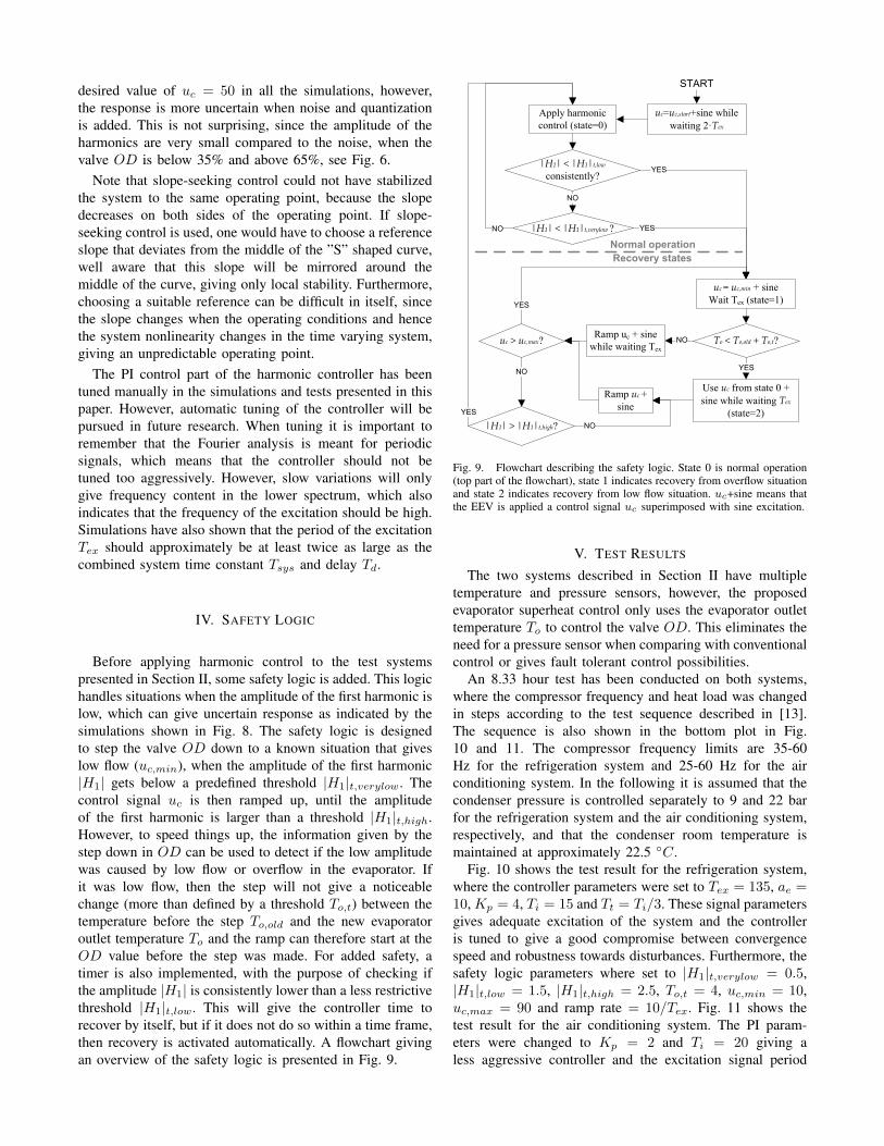
Before applying harmonic control to the test systemspresented in Section II, some safety logic is added. This logichandles situations when the amplitude of the first harmonic islow, which can give uncertain response as indicated by thesimulations shown in Fig. 8. The safety logic is designedto step the valve OD down to a known situation that giveslow flow (uc,min), when the amplitude of the first harmonic|H1| gets below a predefined threshold |H1|t,verylow. Thecontrol signal uc is then ramped up, until the amplitudeof the first harmonic is larger than a threshold |H1|t,high.However, to speed things up, the information given by thestep down in OD can be used to detect if the low amplitudewas caused by low flow or overflow in the evaporator. Ifit was low flow, then the step will not give a noticeablechange (more than defined by a threshold To,t) between thetemperature before the step To,old and the new evaporatoroutlet temperature To and the ramp can therefore start at theOD value before the step was made. For added safety, atimer is also implemented, with the purpose of checking ifthe amplitude |H1| is consistently lower than a less restrictivethreshold |H1|t,low. This will give the controller time torecover by itself, but if it does not do so within a time frame,then recovery is activated automatically. A flowchart givingan overview of the safety logic is presented in Fig. 9.
|H1| < |H1|t,low
consistently?
Apply harmonic control (state=0)
uc = uc,min + sineWait Tex (state=1)
Ramp uc +sine
To < To,old + To,t?Ramp uc + sine while waiting Tex
uc=uc,start+sine while waiting 2·Tex
NO
Use uc from state 0 + sine while waiting Tex
(state=2)
YES
YES
NOuc > uc,max?
YES
|H1| > |H1|t,high?
NO
YES
NO
Normal operationRecovery states
START
|H1| < |H1|t,verylow ? YESNO
Fig. 9. Flowchart describing the safety logic. State 0 is normal operation(top part of the flowchart), state 1 indicates recovery from overflow situationand state 2 indicates recovery from low flow situation. uc+sine means thatthe EEV is applied a control signal uc superimposed with sine excitation.
V. TEST RESULTS
The two systems described in Section II have multipletemperature and pressure sensors, however, the proposedevaporator superheat control only uses the evaporator outlettemperature To to control the valve OD. This eliminates theneed for a pressure sensor when comparing with conventionalcontrol or gives fault tolerant control possibilities.
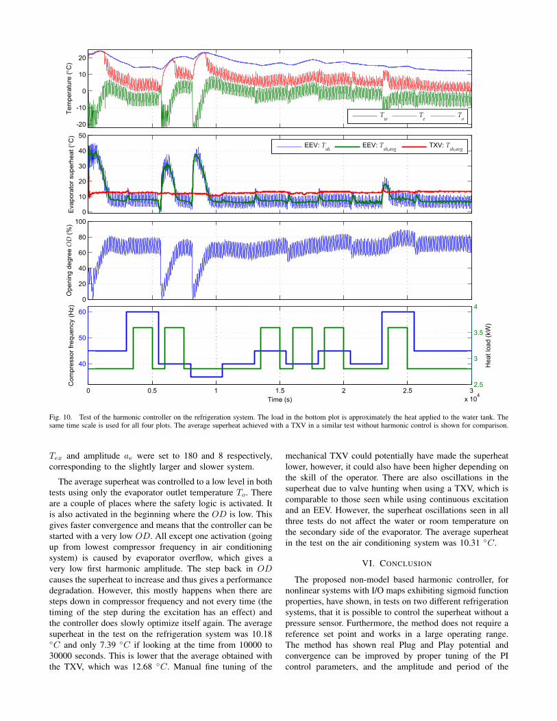
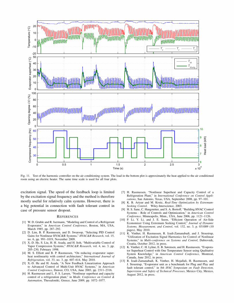
An 8.33 hour test has been conducted on both systems,where the compressor frequency and heat load was changedin steps according to the test sequence described in [13].The sequence is also shown in the bottom plot in Fig.10 and 11. The compressor frequency limits are 35-60Hz for the refrigeration system and 25-60 Hz for the airconditioning system. In the following it is assumed that thecondenser pressure is controlled separately to 9 and 22 barfor the refrigeration system and the air conditioning system,respectively, and that the condenser room temperature ismaintained at approximately 22.5 ◦C.
Fig. 10 shows the test result for the refrigeration system,where the controller parameters were set to Tex = 135, ae =10, Kp = 4, Ti = 15 and Tt = Ti/3. These signal parametersgives adequate excitation of the system and the controlleris tuned to give a good compromise between convergencespeed and robustness towards disturbances. Furthermore, thesafety logic parameters where set to |H1|t,verylow = 0.5,|H1|t,low = 1.5, |H1|t,high = 2.5, To,t = 4, uc,min = 10,uc,max = 90 and ramp rate = 10/Tex. Fig. 11 shows thetest result for the air conditioning system. The PI param-eters were changed to Kp = 2 and Ti = 20 giving aless aggressive controller and the excitation signal period
-20
-10
0
10
20Te
mpe
ratu
re (°
C)
Tw Te To
0
10
20
30
40
50
Eva
pora
tor s
uper
heat
(°C
)
EEV: Tsh EEV: Tsh,avg TXV: Tsh,avg
0
20
40
60
80
100
Ope
ning
deg
ree
OD
(%)
0 0.5 1 1.5 2 2.5 3x 10
4
40
50
60
Time (s)
Com
pres
sor f
requ
ency
(Hz)
2.5
3
3.5
4
Hea
t loa
d (k
W)
Fig. 10. Test of the harmonic controller on the refrigeration system. The load in the bottom plot is approximately the heat applied to the water tank. Thesame time scale is used for all four plots. The average superheat achieved with a TXV in a similar test without harmonic control is shown for comparison.
Tex and amplitude ae were set to 180 and 8 respectively,corresponding to the slightly larger and slower system.
The average superheat was controlled to a low level in bothtests using only the evaporator outlet temperature To. Thereare a couple of places where the safety logic is activated. Itis also activated in the beginning where the OD is low. Thisgives faster convergence and means that the controller can bestarted with a very low OD. All except one activation (goingup from lowest compressor frequency in air conditioningsystem) is caused by evaporator overflow, which gives avery low first harmonic amplitude. The step back in ODcauses the superheat to increase and thus gives a performancedegradation. However, this mostly happens when there aresteps down in compressor frequency and not every time (thetiming of the step during the excitation has an effect) andthe controller does slowly optimize itself again. The averagesuperheat in the test on the refrigeration system was 10.18◦C and only 7.39 ◦C if looking at the time from 10000 to30000 seconds. This is lower that the average obtained withthe TXV, which was 12.68 ◦C. Manual fine tuning of the
mechanical TXV could potentially have made the superheatlower, however, it could also have been higher depending onthe skill of the operator. There are also oscillations in thesuperheat due to valve hunting when using a TXV, which iscomparable to those seen while using continuous excitationand an EEV. However, the superheat oscillations seen in allthree tests do not affect the water or room temperature onthe secondary side of the evaporator. The average superheatin the test on the air conditioning system was 10.31 ◦C.
VI. CONCLUSION
The proposed non-model based harmonic controller, fornonlinear systems with I/O maps exhibiting sigmoid functionproperties, have shown, in tests on two different refrigerationsystems, that it is possible to control the superheat without apressure sensor. Furthermore, the method does not require areference set point and works in a large operating range.The method has shown real Plug and Play potential andconvergence can be improved by proper tuning of the PIcontrol parameters, and the amplitude and period of the
-20
-10
0
10
20Te
mpe
ratu
re (°
C)
Ta Te To
0
10
20
30
40
50
Eva
pora
tor s
uper
heat
(°C
)
TshTsh,avg
0
20
40
60
80
100
Ope
ning
deg
ree
OD
(%)
0 0.5 1 1.5 2 2.5 3x 10
4
30
40
50
60
Time (s)
Com
pres
sor f
requ
ency
(Hz)
6
7
8
9
10
Hea
t loa
d (k
W)
Fig. 11. Test of the harmonic controller on the air conditioning system. The load in the bottom plot is approximately the heat applied to the air conditionedroom using an electric heater. The same time scale is used for all four plots.
excitation signal. The speed of the feedback loop is limitedby the excitation signal frequency and the method is thereforemostly useful for relatively calm systems. However, there isa big potential in connection with fault tolerant control incase of pressure sensor dropout.
REFERENCES
[1] W. D. Gruhle and R. Isermann, “Modeling and Control of a RefrigerantEvaporator,” in American Control Conference, Boston, MA, USA,March 1985, pp. 287–292.
[2] D. Lim, B. P. Rasmussen, and D. Swaroop, “Selecting PID ControlGains for Nonlinear HVAC&R Systems,” HVAC&R Research, vol. 15,no. 6, pp. 991–1019, November 2009.
[3] X.-D. He, S. Liu, H. H. Asada, and H. Itoh, “Multivariable Control ofVapor Compression Systems,” HVAC&R Research, vol. 4, no. 3, pp.205–230, February 1998.
[4] M. S. Elliott and B. P. Rasmussen, “On reducing evaporator super-heat nonlinearity with control architecture,” International Journal ofRefrigeration, vol. 33, no. 3, pp. 607–614, May 2010.
[5] X.-D. He and H. Asada, “A New Feedback Linearization Approachto Advanced Control of Multi-Unit HVAC Systems,” in AmericanControl Conference, Denver, CO, USA, June 2003, pp. 2311–2316.
[6] H. Rasmussen and L. F. S. Larsen, “Nonlinear superheat and capacitycontrol of a refrigeration plant,” in Medit. Conference on Control &Automation, Thessaloniki, Greece, June 2009, pp. 1072–1077.
[7] H. Rasmussen, “Nonlinear Superheat and Capacity Control of aRefrigeration Plant,” in International Conference on Control Appli-cations, San Antonio, Texas, USA, September 2008, pp. 97–101.
[8] K. B. Ariyur and M. Krstic, Real-Time Optimization by Extremum-Seeking Control. Wiley-Interscience, 2003.
[9] H. S. Sane, C. Haugstetter, and S. A. Bortoff, “Building HVAC ControlSystems - Role of Controls and Optimization,” in American ControlConference, Minneapolis, Minn., USA, June 2006, pp. 1121–1126.
[10] P. Li, Y. Li, and J. E. Seem, “Efficient Operation of Air-SideEconomizer Using Extremum Seeking Control,” Journal of DynamicSystems, Measurement, and Control, vol. 132, no. 3, p. 031009 (10pages), May 2010.
[11] K. Vinther, H. Rasmussen, R. Izadi-Zamanabadi, and J. Stoustrup,“Utilization of Excitation Signal Harmonics for Control of NonlinearSystems,” in Multi-conference on Systems and Control, Dubrovnik,Croatia, October 2012, in press.
[12] K. Vinther, C. H. Lyhne, E. B. Sørensen, and H. Rasmussen, “Evapora-tor Superheat Control with One Temperature Sensor using QualitativeSystem Knowledge,” in American Control Conference, Montreal,Canada, June 2012, in press.
[13] R. Izadi-Zamanabadi, K. Vinther, H. Mojallali, H. Rasmussen, andJ. Stoustrup, “Evaporator unit as a benchmark for Plug and Play andfault tolerant control,” in 8th IFAC Symposium on Fault Detection,Supervision and Safety of Technical Processes, Mexico City, Mexico,August 2012, in press.