Embed Size (px)
Citation preview

Environmentally sealed for corrosive areas.
®
®
AustralianStandard
Certi
fied
Prod
uct
The Proximity Mark Series is a line of position indicators with a selection of var-ious output options. Four model styles make up the Mark series to cover almostany application. Standard models in the Mark Series have visual position indi-cators and are weatherproof, explosion-proof, and submersible. A large varietyof outputs are available to fit specific applications. There is a choice of 1 to 6switch outputs of 16 varieties including inductive sensors, high temperatureswitches, gold contact switches, hermetically sealed switches, and high currentswitches. Besides the switch outputs the Series offers potentiometer outputsand 4 to 20 mA transmitters. The units are purchased for either direct driveapplications, such as rotary valves, or lever drive applications, such as linearvalves. Adjustable visual indicator is standard on direct drive units that dis-plays OPEN / CLOSED status and degrees.
A patented magnetic drive that completely seals the switch compartment fromthe atmosphere for maximum leak protection is utilized in the Mark 1. TheMark 3 uses the same magnetic drive of the Mark 1, but it can be used for multi-turn applications with 1 to 25 revolutions, such as gate valves. A through shaftdrive is incorporated in the Mark 4 making the unit a lower cost alternative tothe Mark 1 for applications that are not as demanding. Also featured in theMark 6 is a patented magnetic design that completely seals the switch cavity.The Mark 6 offers hermetically sealed reed switches that are perfect for highcycle rate applications and low current uses such as computer and PLC controlsystems.
• Features a patented magnetic coupling that isolates the switch compartment, completely sealing the unit from the surrounding atmosphere for maximum haz-ard and leak protection.
• EZset cams on switch models provide simple set point adjustment.• Flexible design allows multiple switches and transmitter options.• Ideal for corrosive environments.
• Features a patented magnetic coupling that isolates the switch compartment, completely sealing the unit from the surrounding atmosphere for maximum hazard and leak protection.
• Multi-Turn models that can provide switch signals between 1 and 25 revolutions, and transmitter models for up to 10 revolutions without gear reduction.
• Flexible design allows multiple switches and transmitter options.• Ideal for corrosive environments.
• Thru-Shaft design that features a 1˝ bushing for long life and o-rings to seal the switch compartment for hazard, corrosion, and leak protection.
• EZset cams on switch models provide simple set point adjustment.• Flexible design allows multiple switches and transmitter options.• A lower cost alternative to the Mark 1 Series for less demanding applications.
Mark 1 Magnetic Coupling
Mark 3 Multi-Turn
Mark 4 Thru Shaft
Mark 1 – Stainless Steel
Mark 1 – Polyester Coated
Aluminum
Mark Series Position Indicators/Switches/Transmitters
PROXIMITY Controls, A Division of Dwyer Instruments, Inc.,1431 State Hwy 210 E, Fergus Falls, MN 56537/Phone 218 739-3364/219 879-8000/Fax 218 739-2734/219 872-90571
PROXIMITY Controls, A Division of Dwyer Instruments, Inc.,1431 State Hwy 210 E, Fergus Falls, MN 56537/Phone 218 739-3364/219 879-8000/Fax 218 739-2734/219 872-9057 2
Complete factory assembled packages combine visual indication, solenoids,switches and transmitter in a single convenient UL, CSA, ATEX, or SAA cer-tified assembly which saves labor and reduces cost. The simple package isshipped ready for installation, complete with a custom designed mounting kitfor your specific application. Many options are available such as painted alu-minum, epoxy coated aluminum or stainless steel housings including a stan-dard 3/4˝ NPT conduit entrance and choice of 1 or 2 additional 1/2˝ NPT con-duit entrances. The optional conduit entrances are drilled and tapped in thebase of the position indicator housing and solenoid valves are screwed into theentrances. 22 to 16 AWG wire leads from solenoids, switches and optionaltransmitter are terminated in prelabeled, easy-access terminal strips protect-ed inside the housing. Note: UL, CSA, ATEX, or SAA approval requires com-plete package assembly by Proximity. Consult the factory for recommendedUL, CSA, ATEX, or SAA approved solenoid valve options.
Eliminate the possibility of conduit contamination and the need for seal fittings withProximity’s factory sealed (potted) leads. This seal has been UL tested to 6000 psi(413 bar) and listed for Class I, Groups A, B, C, D; Div. 1 & 2 atmospheres. Groupsmay vary depending on the switch model. Standard leads are 18 AWG and 36˝ (91.44 cm) long.
• AS-Interface allowing networking of up to 31 devices over a 2-wire network
• Option for Mark 1 Magnetic Drive and Mark 4 Thru-Shaft ValvePosition Indicators
• Available with 1 or 2 incorporated solenoid valves
• Features a patented magnetic coupling that isolates the switch compartment, completely sealing the unit from the surrounding atmosphere for maximum hazard and leak protection.
• Magnetic actuated reed switches that eliminate moving parts such as cams and shafts.
• Protective circuitry prevents damage to contacts due to capacitive discharge or voltage surges.
• Optional “Jumbo” LED indication of switch status.• Perfect for computer control systems and PLC’s.
Mark 6 Magnetic Actuated Reed
Junction Package
Factory Sealed Leads
AS-Interface
Mark Series Position Indicators/Switches/Transmitters

PROXIMITY Controls, A Division of Dwyer Instruments, Inc.,1431 State Hwy 210 E, Fergus Falls, MN 56537/Phone 218 739-3364/219 879-8000/Fax 218 739-2734/219 872-90573
Construction
OutputType
SwitchType
&Rating
DrivingMethod
Enclosure
EnclosureOptions
Mark 1, Magnetic CouplingMark 3, Multi-TurnMark 4, Thru-ShaftMark 6, Protected Reed Switch
1346
123323531032045678
OA
BC
DGHILMP
QRSTV
W
DL
1AAAAAAAAAAAAAA
AA
AAAA-A-
-AAAA
A
AA
AAA
AAAAAAA
A
3-AAAAAAAAA--AA
-A
-A---A-
---AA
A
AA
AAA
AAA--AA
A
4AAAAAAAAAAAAAA
AA
AAAA-A-
-AAAA
A
AA
AAA
AAAAAAA
A
6AA------------
--
----A-A
A----
-
AA
AA-
AAA--AA
-
Available Options “A” signifies available with
correspondingconstruction style.
Mark
1 Switch2 SwitchesPotentiometer, 1K Ohm. Available with Switch Types* B, C, I, O, R, S, V, W.Potentiometer, 2K Ohm. Available with Switch Types* B, C, I, O, R, S, V, W.Potentiometer, 5K Ohm. Available with Switch Types* B, C, I, O, R, S, V, W.Potentiometer, 10K Ohm. Available with Switch Types* B, C, I, O, R, S, V, W.Potentiometer, 20K Ohm. Available with Switch Types* B, C, I, O, R, S, V, W.4 SwitchesTransmitter, 4 to 20mA. Available with Switch Types* B, C, I, O, R, S, V, W.6 Switches. Available with Switch Types B, C, I, R, V, W.AS-interface and 1 Switch. Available with Switch Types B, I, R, W.AS-interface and 2 Switches. Available with Switch Types B, I, R, W.No SwitchesSPDT Snap, Rated: 15A @ 125/250/480 VAC (~); 1/8 hp @ 125 VAC (~),1/4 hp @ 250 VAC (~), 1/2A @ 125 VDC ( ), 1/4A @ 250 VDC ( ).Inductive Sensor. 10 to 30 VDC ( ). Load: 0.1A.SPDT High Temperature Snap, 350°F (176°C) for 600 hours, Rated:15.1A @ 125/250/277 VAC (~).DPDT Snap, Rated: 10A @ 125/250 VAC (~), 0.3A @ 125 VDC ( ), 0.15A @ 250 VDC ( ).SPDT Gold Contact Snap, Rated: 1A @ 125 VAC (~).SPDT Hermetically Sealed Snap, Rated: 1A @ 125 VAC (~).NAMUR Inductive Sensor. 15 mA max @ 5-25 VDC ( ).SPST Hermetically Sealed Reed with LED, Rated: 0.02A @ 125 VAC (~).SPDT Magnetic Blow-Out, Rated: 10A @ 125 VAC (~)/VDC ( ), 1/4 hp @ 125 VAC (~)/VDC ( ).SPST Hermetically Sealed Reed, Rated: 0.15A @ 125 VAC (~), 0.15A @30 VDC ( ); 125 VAC (~) 10W (Lamp).SPDT Hermetically Sealed Reed, Rated: 0.15A @ 125 VAC (~), 0.15A @ 30 VDC ( ).SPDT Hermetically Sealed Reed, Rated: 2A @ 125 VAC (~), 2A @ 24 VDC ( ).SPDT Snap, Rated: 4A @ 125/250 VAC (~).SPDT High Temperature Snap, 250°F (121°C) Continuous, Rated: 5A @ 125/250/480 VAC (~).SPDT Snap, Rated: 11A @ 125/250 VAC (~), 1/3 hp @ 125/250 VAC (~),1/2A @ 125 VDC ( ), 1/4A @ 250 VDC ( ), 4A @ 125 VAC (~) (tungsten).SPDT Gold Contact Snap, Rated 0.1A @ 125 VAC (~).
* Mark 1 and 4 potentiometer and transmitter outputs will have no switches when ordered with switch type O; 2 switches if ordered with switch types B, C, I, R, V, or W; and 4 switches if ordered with switch type S. Mark 3 potentiometer and transmitter outputs will have no switches when ordered with switch type O, and 2 switches if ordered with switch types A, D, G, or M.
J1J2S
SV1SV2MTB
IS
Direct Drive (Yoke) with Stainless Steel Visual Indicator.Lever Drive (Shaft), No Visual Indicator.
Junction Package with One 1/2˝ NPT Female Conduit Connection and Terminal Strip.Junction Package with Two 1/2˝ NPT Female Conduit Connection and Terminal Strip.SAA Listed Flameproof1 Attached Solenoid Valve (Must be ordered with J1 option).2 Attached Solenoid Valves (Must be ordered with J2 option).Metric Threaded Conduit Connection, M25 (M20 for optional J1 and J2 connections).Directive 94/9/EC, KEMA 03 ATEX 2391, II 2 G EEx d IIC T6 (-20°C ≤ Tamb ≤ 70°C)(T5 (-20°C ≤ Tamb ≤ 80°C) optional wording).Directive 94/9/EC, KEMA 03 ATEX 1392 x, II 1 G EEx ia IIC T4 (-20°C ≤ Tamb ≤ 40°C).
016
Aluminum, Painted Black (other colors available, consult factory)Aluminum, Painted White Epoxy with SS trimCast 316 Stainless Steel
Mark Series Model Chart

PROXIMITY Controls, A Division of Dwyer Instruments, Inc.,1431 State Hwy 210 E, Fergus Falls, MN 56537/Phone 218 739-3364/219 879-8000/Fax 218 739-2734/219 872-9057 4
Mounting kits with drive yoke (see drawing), or slotted lever arm, bracket, fasteners and other zinc plated orstainless steel hardware fit over 2000 popular valves and actuators. A high strength spring tempered stainless steeldrive yoke/coupling is tailored to fit securely to a specific valve or actuator stem. There is no slippage or binding. Nospecial alignment fixtures are required due to switch offset design and yoke to stem engagement that makes instal-lation a “snap”. Each kit is specially designed for a particular valve or actuator, making field mounting simple withstandard tools. Please specify make and model of valve or actuator on order.
Mounting kits can be used interchangeably with all models since external mounting features are identical. Rotaryvalves utilize direct drive couplings and a slotted lever drive is used with linear valves. Lever drives convert linearmotion to rotary. Stainless steel visual indicators are standard for direct drive, automated quarter-turn valve appli-cations.
Position Indicators/Switches/TransmittersMarkSeries
SWITCH
VISUAL INDICATOR
DRIVE YOKE
MOUNTING KIT
SPECIFICATIONSGeneralProduct Ratings:Weatherproof and flameproof. NEMA 1, 2, 3, 3R, 3S, 4, 4X, 6, 7, 9, 12,13.
UL rated: Class I, Div. 1 & 2, Groups B, C, D (Some units available forGroup A, consult factory); Class II, Div. 1 & 2, Groups E, F, and G.
CSA rated: Class I, Div. 1 & 2, Groups A, B, C, D; Class II, Div. 1 & 2,Groups E, F, and G; Submersible to 50 feet.
SAA rated: -S suffix, Certified Ex d IIC T6 IP68 (15 meters).
ATEX Compliant: -B suffix, directive 94/9/EC, KEMA 03 ATEX 2391, II 2 G EEx d IIC T6 for -20°C ≤ Tamb ≤70°C and T5 for -20°C ≤ Tamb ≤ 80°C optionalwording. –IS suffix directive 94/9/EC KEMA 03 ATEX 1392X, II 1 G EEx ia IIC T4 -20°C ≤ Tamb≤40°C.(Switch type C is not available with ATEX; Switch type B is not availablewith ATEX intrinsically safe, -IS suffix).
Electrical Connections: Screw terminal. Optional factory sealed leadsthat are 36˝ (914.4 mm) of 18 AWG.Conduit Connection: 3/4˝ female NPT standard. Optional one or two1/2” female NPT. M25 and M20 optional (Standard on SAA certifiedproducts).Mounting Orientation: Not position sensitive.Weight: 4 to 6 lb (1.5 to 3.0 kg).Operational Life: over 10,000,000 cycles.Maximum Altitude: 2000 meters.Patents: US 4214133, 4647733, 4831350, 5357067, and other patentspending.
Mark 1, 3, 4, and 6 with Switch OutputsTemperature Limits: -65 to 180°F (-54 to 82°C). Switch Type C ratedto 350°F (176°C) for 600 hours, Switch Type T rated to 250°F (121°C)continuous. (ATEX flameproof, -B suffix, rated -20°C (-4°F) to 80°C(176°F); ATEX intrinsically safe, -IS suffix, rated -20°C (-4°F) to 40°C(104°F)).
Switch Type: See model chart on previous page.Electrical Rating: See model chart on previous page.Set Point Adjustment: Mark 1 and 4: 5 to 360°. Mark 3: 1 to 25 revo-lutions. Mark 6: 45 to 180°.
Mark 1, 3, and 4 with PotentiometerAccuracy: ± 0.5% of full span. Optional ± 0.25% of full span.Temperature Limits: -40 to 180°F (-40 to 82°C).(ATEX flameproof, -Bsuffix, rated -20°C (-4°F) to 80°C (176°F); ATEX intrinsically safe, -IS suf-fix, rated -20°C (-4°F) to 40°C (104°F)).Power Rating: 1.5 Watt maximum. Output Signal: 1000 Ohm standard. Optional 2000, 5000, 10000, or20000 Ohms.Zero and Span Adjustments: Span trim pot with 2000 Ohm adjust-ment. No zero adjustment.Rotational Travel: Mark 1 and 4: Minimum: 0°, Maximum: 340°. Mark3: 0 to 10 revolutions.
Mark 1, 3, and 4 with TransmitterAccuracy: ± 0.5% of full span. Optional ± 0.25% of full span.Temperature Limits: -40 to 180°F (-40 to 82°C). (ATEX flameproof, -Bsuffix, rated -20°C (-4°F) to 80°C (176°F); ATEX intrinsically safe, -IS suf-fix, rated -20°C (-4°F) to 40°C (104°F)).Power Requirements: 5 to 30 VDC.Current Consumption: 50 mA. Output Signal: 4 to 20 mA.Zero and Span Adjustments: Trim pots for adjusting both. Mark 1 and4: Span is adjustable from 50 to 300°. Mark 3: Span is adjustable from1.5 to 8.5 revolutions. Conduit Connection: 3/4˝ female NPT standard. Optional one or two1/2˝ female NPT. M25 and M20 optional (Standard on SAA models).Rotational Travel: Mark 1 and 4: Minimum: 50°, Maximum: 300°. Mark3: Minimum: 1.5 revolutions, Maximum: 8.5 revolutions.

PROXIMITY Controls, A Division of Dwyer Instruments, Inc., 1431 State Hwy 210 E, Fergus Falls, MN 56537/Phone 218 739-3364/219 879-8000/Fax 218 739-2734/219 872-90575
Rotary Position IndicatorMagnetically Coupled Switches and TransmittersIdeal for Corrosive Environments
MARK1
BENEFITS• The switch compartment is completely isolated from atmos-
phere.
• A magnetic coupling completely seals the switch compart-ment for maximum hazard and leak protection, (IP68 andsubmersible to 50 feet indefinitely).
• Set screw cams provide infinite adjustment, and user-friendly manual cams provide single-step rotationaladjustment and locking set screw.
• Flexible design allows multiple mechanical or proximityswitches and transmitter option(s).
• Adjustable stainless steel visual indicator with scale is stan-dard for quarter turn direct drive applications.
• Housing options include 1, 2 or 3 conduit entrances, junc-tion package, terminal strip and solenoid valve option(s).
• Mounting hardware is available in plated or stainless steelmaterial for your specific requirements, including rotary,linear and Namur mounting hardware.
APPLICATIONS• Rotary valve actuators and dampers
• Linear valve actuators and cylinders
• Manual valves
• Gear operators
• Positioners
SPECIFICATIONSMinimum Rotational Travel: 5°.Maximum Rotational Travel: 360°.Operational Life: 1,000,000 cycles.Temperature Limits: -65 to 180°F (-54 to 82°C).Weight: 3 lb (1.5 k) to 6 lb (3.0 k).Maximum Altitude: 2000 m (6560 ft).
See page 4 for other specifications.
Suggested SpecificationPosition indicators shall be magnetically coupled Proximity model1XXXXXX. The (indicator)(transmitter)(potentiometer) shall include0(1)(2)(4)(6) switch(es). The switch(es) shall beSPDT(DPDT)(Namur)(Magnetic Blow-out) mechanical (proximity)rated at amps. The coupling shall be direct (lever) drive. Thehousing shall be painted aluminum (epoxy coated) (stainless steel)with a screw-on cover. The housing shall include one 3/4˝ NPT con-duit entrance, (0)(1)(2) 1/2˝ NPT conduit entrance(s) and a terminalstrip. It shall be NEMA 4, 4X, 7, 9, UL/CSA certified Class I GroupsA, B, C, D(B,C,D), Divisions 1 and 2 (ATEX Flameproof) (ATEXIntrinsically Safe-IS) (SAA Flameproof). See reverse side for com-plete specifications and ordering information. The Proximity indica-tor part number shall be: 1XXXXXX.
1[25.40]
CLEARANCE REQUIREDFOR COVER REMOVAL LEVER DRIVE
DIRECT DRIVE
4-1/4[107.95]
3[76.20]
1-1/6[26.99]
5/16[7.94].249 ± .001
[6.32 ± .03]
2-3/8[60.33]
1-1/4[31.75]
5-5/16[150.81] *4-9/16
[115.89]
#6-32 UNC THREADX 1/4 [6.35] DEEP
4-7/8[123.83]
2-3/8[60.33]
1-9/16[39.69]
3/4 NPTCONDUIT
CONNECTIONOR OPTIONAL
M25
118° Ø4-7/16[112.71]
1/4[6.35]TYP
Ø1/8 [3.18] PINTYP 2 PLACES
1/2 NPT CONDUIT CONNECTION (OPTIONAL)OR OPTIONAL M20 2 PLACES
1/4-20 UNC THREAD X 7/16 [11.11] DPTYP 2 PLACES
*FOR MODELS 11, 12, 41, 42, 61 & 62
1-1/2[38.10]
Cutaway View Model 12VD0J2 Shown
U.S. Patent No. 4,214,133
®
®
AustralianStandard
Certi
fied
Prod
uct

PROXIMITY Controls, A Division of Dwyer Instruments, Inc.,1431 State Hwy 210 E, Fergus Falls, MN 56537/Phone 218 739-3364/219 879-8000/Fax 218 739-2734/219 872-9057 6
1 Mark 1, Magnetic Coupling
FUNCTION DATA
1 1 Switch*2 2 Switches*3 Potentiometer, 1K Ohm. Available with Switch Types B, C, I, O, R, S, V, W*†32 Potentiometer, 2K Ohm. Available with Switch Types B, C, I, O, R, S, V, W*†35 Potentiometer, 5K Ohm. Available with Switch Types B, C, I, O, R, S, V, W*†310 Potentiometer, 10K Ohm. Available with Switch Types B, C, I, O, R, S, V, W*†320 Potentiometer, 20K Ohm. Available with Switch Types B, C, I, O, R, S, V, W*†4 4 Switches*5 Transmitter, 4 to 20 mA. Available with Switch Types B, C, I , O, R, S, V, W*†6 6 Switches. Available with Switch Types B, C, I, R, V, W7 AS-interface and 1 Switch. Available with Switch Types B, I, R, W*8 AS-interface and 2 Switches. Available with Switch Types B, I, R, W*
SWITCH DATAO No Switches*A SPDT Snap, Rated: 15A @ 125/250/480 VAC (~): 1/8 hp @ 125 VAC (~),
1/4 hp @ 250 VAC (~). 1/2A @ 125 VDC ( ), 1/4A @ 250 VDC ( ).B Inductive sensor. 10 to 30 VDC ( ) Load: 0.1A*C SPDT High Temperature Snap, 350°F (176°C) for 600 hours. Rated:,
15.1A @ 125/250/277 VAC (~).*D DPDT Snap, Rated: 10A @ 125/250 VAC (~) 0.3A @ 125 VDC ( ), 0.15A @ 250 VDC ( ).G SPDT Gold Contact Snap, Rated: 1A @ 125 VAC (~).H SPDT Hermetically Sealed Snap. Rated: 1A @ 125 VAC (~).I NAMUR Inductive Sensor. 15 mA max @ 5-25 VDC ( )*.M SPDT Magnetic Blow Out, Rated: 10A @ 125 VAC (~)/VDC ( ), 1/4 hp @ 125 vac (~)/VDC ( ).R SPDT Hermetically Sealed Reed, Rated: 2A @ 125 VAC (~), 2A @ 24 VDC ( )*.S SPDT Snap, Rated: 4A @ 125/250 VAC (~).T SPDT High Temperature Snap, 250°F (121°C) Continuous, Rated: 5A @ 125/250/480 VAC (~).V SPDT Snap, Rated: 11A @ 125/250 VAC (~), 1/3 hp @ 125/250 VAC (~),
1/2 A @ 125 VDC ( ). 1/4A @ 250 VDC ( ), 4A @ 125 VAC (~) (tungsten)*W SPDT Gold Contract Snap, Rated: 0.1A @ 125 VAC (~)*
DRIVING METHOD
D Direct Drive, Stainless Steel Visual Indicator Standard*L Lever Drive, Shaft Output*
HOUSING MATERIAL AND FINISH
0 Aluminum, Painted Black.* (Other colors available, consult factory)1 Aluminum, Painted White Epoxy with SS trim.*6 Cast 316 Stainless Steel*
SPECIAL ENCLOSURE FEATURES
J1 Junction Package with One 1/2˝ NPT Female Conduit Connection and Terminal Strip.*J2 Junction Package with Two 1/2˝ NPT Female Conduit Connection and Terminal Strip.*S SAA Listed Flameproof*SV1 1 Attached Solenoid Valve (Must be ordered with J1 option)*SV2 2 Attached Solenoid Valve (Must be ordered with J2 option)*MT Metric Threaded Conduit Connection, M25 (M20 for optional J1 and J2 connections).*B Directive 94/9/EC, KEMA 03 ATEX 2391, II 2 G EEx d IIC T6 (-20°C≤ Tamb ≤70°C)
(T5 (-20°C≤Tamb≤80°C) optional wording).*IS Directive 94/9/EC, KEMA 03 ATEX 1392 X II 1 G EEx Ia IIC T4 (-20°C≤ Tamb ≤40°C).
1 2 A D 0 Example of Popular Model Number
Specifications and Ordering Information
Class I, Groups B,C,DClass II, Groups E,F,G,Divisions 1 & 2(Models 11---, 12---, 14--- Group A also)
Class I, Groups A,B,C,D,Class II, Groups E,F,G,Divisions 1 & 2Submersible to 50 feet
NOTE: When ordering mounting kits, please supplymake and model number of your actuator or valve.
Designed to meet type 1,2,3,3R,3S,4,4X,6,7,9,12,13
II 2 G EEx d IIC T6 or T5 (Flameproof – B; Special Enclosure Features)II 1 G EEx ia IIC T4 (Intrinsically Safe – IS; Special Enclosure Features)Ingress Protection Certified IP68
Certified Ex d IIC T6 IP68 (15 meters)
®
®
AustralianStandard
Certi
fied
Prod
uct
SPECIFICATIONS SUBJECT TO CHANGE WITHOUT NOTICE.
*Junction Package available. Consult factory for solenoid valves.
† Potentiometer and transmitter outputs will have no switches when ordered with switch type O, 2 switches if ordered with switch types B, C, I, R,V, or W, and 4 switches if ordered with switch type S. No other switch types are available.

PROXIMITY Controls, A Division of Dwyer Instruments, Inc., 1431 State Hwy 210 E, Fergus Falls, MN 56537/Phone 218 739-3364/219 879-8000/Fax 218 739-2734/219 872-90577
Rotary Position IndicatorMulti-Turn Switches and TransmittersIdeal for Corrosive Environments
BENEFITS
• The switch compartment is completely isolated fromatmosphere.
• A magnetic coupling completely seals the switch compart-ment for maximum hazard and leak protection, (IP68 and submersible to 50 feet indefinitely).
• Switch signals are provided between 1 and 25 revolu-tions. Transmitter output is available up to 10 revolutionswithout gear reduction.
• Flexible design allows multiple mechanical switch andtransmitter option(s).
• Housing options include 1, 2 or 3 conduit entrances, forjunction package with solenoid valve option(s).
• Mounting hardware available in plated or stainless steelfor your specific requirements includes rotary, linear andNamur mounting hardware.
APPLICATIONS• Multi-turn rotary valves and actuators • Linear valve actuators and cylinders• Multi-turn manual valves• Gear operators• Positioners
SPECIFICATIONSMinimum Rotational Travel: One revolution.
Maximum Rotational Travel: 25 revolutions.
Operational Life: Over 1,000,000 cycles.
Temperature Limits: -65 to 180°F (-54 to 82°C).
Weight: 4 lb (1.5 k) to 6 lb (3.0 k).
Maximum Altitude: 2000 m (6560 ft).
See page 4 for other specifications.
Suggested SpecificationPosition indicators shall be magnetically coupled Proximity Model3XXXXXX. The indicator (transmitter) (potentiometer) shall include0(1)(2)(4)(6) switch(es). The switch(es) shall be SPDT (DPDT)(Namur) (Magnetic Blow-out) mechanical rated amps. Thecoupling shall be direct (lever) drive. The housing shall be paintedaluminum(epoxy coated)(stainless steel) with screw-on cover. Thehousing shall include one 3/4˝ NPT conduit entrance and 0(1)(2) 1/2˝NPT conduit entrance(s) and be NEMA 4,4X,7,9, UL/CSA certifiedClass I Groups A, B, C, D (B, C, D), Divisions 1 and 2 (ATEXFlameproof) (ATEX Intrinsically Safe) (SAA Flameproof). Seereverse side for detailed specifications and ordering information. TheProximity part number shall be 3XXXXXX.
Mark3
Cutaway View Model 36VD0 Shown
U.S. Patents 4,214,133, & 4,647,733
1[25.40]
CLEARANCE REQUIREDFOR COVER REMOVAL LEVER DRIVE
DIRECT DRIVE
4-1/4[107.95]
3[76.20]
1-1/6[26.99]
5/16[7.94].249 ± .001
[6.32 ± .03]
2-3/8[60.33]
5-5/16[150.81] *4-9/16
[115.89]
#6-32 UNC THREADX 1/4 [6.35] DEEP
4-7/8[123.83]
2-3/8[60.33]
1-9/16[39.69]
3/4 NPTCONDUIT
CONNECTIONOR OPTIONAL
M25
118° Ø4-7/16[112.71]
1/4[6.35]TYP
Ø1/8 [3.18] PINTYP 2 PLACES
1/2 NPT CONDUIT CONNECTION (OPTIONAL)OR OPTIONAL M20 2 PLACES
1/4-20 UNC THREAD X 7/16 [11.11] DPTYP 2 PLACES
*FOR MODELS 11, 12, 41, 42, 61 & 62
1-1/2[38.10]
®
®
AustralianStandard
Certi
fied
Prod
uct

PROXIMITY Controls, A Division of Dwyer Instruments, Inc., 1431 State Hwy 210 E, Fergus Falls, MN 56537/Phone 218 739-3364/219 879-8000/Fax 218 739-2734/219 872-9057 8
3 Mark 3, Multi-Turn (1-10 Revolutions)
FUNCTION DATA
1 1 Switch*2 2 Switches*3 Potentiometer, 1K Ohm Available with Switch Types A, D, G, M or T†32 Potentiometer, 2K Ohm Available with Switch Types A, D, G, M or T†35 Potentiometer, 5K Ohm Available with Switch Types A, D, G, M or T†310 Potentiometer, 10K Ohm Available with Switch Types A, D, G, M or T†320 Potentiometer, 20K Ohm Available with Switch Types A, D, G, M or T†4 4 Switches*5 Transmitter, 4 to 20 mA. Available with Switch Types A, D, G, M or T†6 6 Switches, Available with Switch Types C, V, W
SWITCH DATAO No Switches*A SPDT, Snap, Rated: 15A @ 125/250/480 VAC (~); 1/8 hp @ 125 VAC (~),
1/4 hp @ 250 VAC (~), 1/2A @ 125 VDC ( ), 1/4A @ 250 VDC ( ).*C SPDT High temperature Snap. 350°F (176°C) for 500 hours. Rated: 15.1A @ 125/250/277 VAC (~).*D DPDT Snap, Rated: 10A @ 125/250 VAC (~), 0.3A @ 125 VDC ( ), 0.15A @ 250 VDC ( ).*G SPDT Gold Contact Snap, Rated: 1A @ 125 VAC (~).*M SPDT, Magnetic Blow-Out, Rated: 10A @ 125 VAC (~)/VDC ( ), 1/4 hp @ 125 VAC (~)/VDC ( ).*
T SPDT, Gold Contacts, 1 amp 125 VAC; 1 amp 24 VDC*V SPDT Snap, Rated: 11A @ 125/250 VAC (~); 1/3 hp @ 125/250 VAC (~);
1/2A @ 125 VDC ( ), 1/4A @ 250 VDC ( ), 4A @ 125 VAC (~) (tungsten).*W SPDT Gold Contact Snap, Rated 0.1A @ 125 VAC (~).*
DRIVING METHOD
D Direct Drive*L Lever Drive, Shaft Output*
HOUSING MATERIAL AND FINISH
0 Aluminum, Painted Black* (Other colors available, consult factory)1 Aluminum, Painted White Epoxy with SS trim.*6 Cast 316 Stainless Steel*
SPECIAL ENCLOSURE FEATURES
J1 Junction Package with One 1/2˝ Female NPT Conduit Connection (No Terminal Strip).*J2 Junction Package with Two 1/2˝ Female NPT Conduit Connection (No Terminal Strip).*S SAA Listed Flameproof*SV1 1 Attached Solenoid Valve (Must be ordered with J1 option)*SV2 2 Attached Solenoid Valve (Must be ordered with J2 option)*MT Metric Threaded Conduit Connection, M25 (M20 for optional J1 and J2 connections).*B Directive 94/9/EC, KEMA 03 ATEX 2391, II 2 G EEx d IIC T6 (-20°C≤ Tamb ≤70°C)
(T5 (-20°C≤Tamb≤80°C) optional wording).*IS Directive 94/9/EC, KEMA 03 ATEX 1392 X II 1 G EEx Ia IIC T4 (-20°C≤ Tamb ≤40°C)
3 5 O D 0 EXAMPLE OF POPULAR MODEL NUMBER
† Potentiometer and transmitter outputs will have no switches when ordered with switch type O, and 2 switches if ordered with switch types A, D, G, or M.
*Junction package available. Consult factory for solenoid valve packages.
SPECIFICATIONS SUBJECT TO CHANGE WITHOUT NOTICE.
Specifications and Ordering Information
Designed to meet type 1,2,3,3R,3S,4,4X,6,7,9,12,13
II 2 G EEx d IIC T6 or T5 (Flameproof – B; Special Enclosure Features)II 1 G EEx ia IIC T4 (Intrinsically Safe – IS; Special Enclosure Features)Ingress Protection Certified IP68
Certified Ex d IIC T6 IP68 (15 meters)
NOTE: When ordering mounting kits, please supply make and model number of your actuator or valve.
®
®
Class I, Groups B,C,D, Class II, Groups E,F,GDivisions 1 and 2(Models 31, 32, 34, Group A also)
Class I, Groups A,B,C,D,Class II, Groups E,F,G,Divisions 1 and 2 Australian
Standard
Certi
fied
Prod
uct

PROXIMITY Controls, A Division of Dwyer Instruments, Inc., 1431 State Hwy 210 E, Fergus Falls, MN 56537/Phone 218 739-3364/219 879-8000/Fax 218 739-2734/219 872-90579
Rotary Position IndicatorThru-Shaft Switches and TransmittersExplosion Proof and General Purpose
Mark4
BENEFITS• A shaft through a 1˝ bushing and O-ring seals the switch
compartment for hazard, corrosion and leak protection, (IP 68 submersible).
• Set screw cams provide infinite adjustment, and user-friend-ly manual cams provide single-step rotational adjustmentand locking set screw.
• Flexible design allows multiple mechanical or proximityswitch and transmitter option(s).
• Adjustable stainless steel visual indicator with scale isstandard for quarter turn direct drive applications.
• Housing options include 1, 2 or 3 conduit entrances, junctionpackage, terminal strip and solenoid valve(s).
• Mounting hardware available in plated or stainless steel foryour specific requirements includes rotary, linear andNamur mounting hardware.
• High temperature to 600°F for limited duration consult fac-tory for available options.
APPLICATIONS• Rotary valve actuators and dampers• Linear valve actuators and cylinders• Manual valves•Gear operators• Positioners
SPECIFICATIONSMinimum Rotational Travel: 5°.
Maximum Rotational Travel: 360°.
Operational Life: 1,000,000 cycles.
Operating Temperature: -65 to 180°F (-54 to 82°C).
Weight: 3 lb (1.5 k) to 6 lb (3.0 k).
Maximum Altitude: 2000 m (6560 ft).
(Consult Factory for Pneumatic Indicator Data)
See page 4 for other specifications.
Suggested SpecificationPosition indicators shall be Proximity Model 4XXXXXX. The indicator(transmitter)(potentiometer) shall include 0(1)(2) (4)(6)switch(es). The switch(es) shall be SPDT (DPDT) (Namur)(MagneticBlow-out) mechanical (proximity) rated at
amps. The coupling shall be direct(lever) drive. The housingshall be painted aluminum (epoxy coated) with a screw-on metal(clearplastic) cover. The housing shall include one 3/4˝ NPT conduitentrance and 0(1)(2) 1/2˝ NPT conduit entrance(s) (and terminalstrip). It shall be NEMA 4,4X,7,9, UL/CSA certified Class I GroupsC, D Divisions 1 and 2 (ATEX Flameproof) (ATEX Intrinsically Safe- IS) (SAA Flameproof). See reverse side for complete specificationsand ordering information. The part number is 4XXXXXX.
Cutaway View Model 42RD0J2 Shown
1[25.40]
CLEARANCE REQUIREDFOR COVER REMOVAL LEVER DRIVE
DIRECT DRIVE
4-1/4[107.95]
3[76.20]
1-1/6[26.99]
5/16[7.94].249 ± .001
[6.32 ± .03]
2-3/8[60.33]
1-1/4[31.75]
5-5/16[150.81] *4-9/16
[115.89]
#6-32 UNC THREADX 1/4 [6.35] DEEP
4-7/8[123.83]
2-3/8[60.33]
1-9/16[39.69]
3/4 NPTCONDUIT
CONNECTIONOR OPTIONAL
M25
118° Ø4-7/16[112.71]
1/4[6.35]TYP
Ø1/8 [3.18] PINTYP 2 PLACES
1/2 NPT CONDUIT CONNECTION (OPTIONAL)OR OPTIONAL M20 2 PLACES
1/4-20 UNC THREAD X 7/16 [11.11] DPTYP 2 PLACES
*FOR MODELS 11, 12, 41, 42, 61 & 62
1-1/2[38.10]
®
®
AustralianStandard
Certi
fied
Prod
uct

PROXIMITY Controls, A Division of Dwyer Instruments, Inc., 1431 State Hwy 210 E, Fergus Falls, MN 56537/Phone 218 739-3364/219 879-8000/Fax 218 739-2734/219 872-9057 10
4 Mark 4, Thru-Shaft
FUNCTION DATA
1 1 Switch*2 2 Switches*3 Potentiometer, 1K Ohm. Available with Switch Types B, C, I, O, R, S, V, W*†32 Potentiometer, 2K Ohm. Available with Switch Types B, C, I, O, R, S, V, W*†35 Potentiometer, 5K Ohm. Available with Switch Types B, C, I, O, R, S, V, W*†310 Potentiometer, 10K Ohm. Available with Switch Types B, C, I, O, R, S, V, W*†320 Potentiometer, 20K Ohm. Available with Switch Types B, C, I, O, R, S, V, W*†4 4 Switches*5 Transmitter, 4 to 20 mA. Available with Switch Types B, C, I , O, R, S, V, W*†6 6 Switches. Available with Switch Types B, C, I, R, V, W7 AS-interface and 1 Switch. Available with Switch Types B, I, R, W*8 AS-interface and 2 Switches. Available with Switch Types B, I, R, W*
SWITCH DATA
O No Switches*A SPDT Snap, Rated: 15A @ 125/250/480 VAC (~): 1/8 hp @ 125 VAC (~),
1/4 hp @ 250 VAC (~). 1/2A @ 125 VDC ( ), 1/4A @ 250 VDC ( ).B Inductive sensor. 10 to 30 VDC ( ) Load: 0.1A*C SPDT High Temperature Snap, 350°F (176°C) for 600 hours. Rated:,
15.1A @ 125/250/277 vac (~).*D DPDT Snap, Rated: 10A @ 125/250 VAC (~) 0.3A @ 125 VDC ( ), 0.15A @ 250 VDC ( ).G SPDT Gold Contact Snap, Rated: 1A @ 125 VAC (~).H SPDT Hermetically Sealed Snap. Rated: 1A @ 125 VAC (~).I NAMUR Inductive Sensor. 15 mA max @ 5-25 VDC ( ).*M SPDT Magnetic Blow Out, Rated: 10A @ 125 VAC (~)/VDC ( ), 1/4 hp @ 125 VAC (~)/VDC ( ).R SPDT Hermetically Sealed Reed, Rated: 2A @ 125 VAC (~), 2A @ 24 VDC ( ).*S SPDT Snap, Rated: 4A @ 125/250 VAC (~).T SPDT High Temperature Snap, 250°F (121°C) Continuous, Rated: 5A @ 125/250/480 VAC (~).V SPDT Snap, Rated: 11A @ 125/250 VAC (~), 1/3 hp @ 125/250 VAC (~),
1/2 A @ 125 VDC ( ). 1/4A @ 250 VDC ( ), 4A @ 125 VAC (~) (tungsten)*W SPDT Gold Contract Snap, Rated: 0.1A @ 125 VAC (~)*
DRIVING METHOD
D Direct Drive, Stainless Steel Visual Indicator Standard*L Lever Drive, Shaft Output*
HOUSING MATERIAL AND FINISH
0 Aluminum, Painted Black.* (Other colors available, consult factory)1 Aluminum, Painted White Epoxy with SS trim.*6 Cast 316 Stainless Steel*
SPECIAL ENCLOSURE FEATURES
J1 Junction Package with One 1/2˝ Female NPT Conduit Connection and Terminal Strip.*J2 Junction Package with Two 1/2˝ Female NPT Conduit Connection and Terminal Strip.*S SAA Listed Flameproof*SV1 1 Attached Solenoid Valve (Must be ordered with J1 option)*SV2 2 Attached Solenoid Valve (Must be ordered with J2 option)*MT Metric Threaded Conduit Connection, M25 (M20 for optional J1 and J2 connections).*B Directive 94/9/EC, KEMA 03 ATEX 2391, II 2 G EEx d IIC T6 (-20°C≤ Tamb ≤70°C)
(T5 (-20°C≤Tamb≤80°C) optional wording).*IS Directive 94/9/EC, KEMA 03 ATEX 1392 X II 1 G EEx Ia IIC T4 (-20°C≤ Tamb ≤40°C)
4 2 A D 0 EXAMPLE OF POPULAR MODEL NUMBER
*Junction package available. Consult factory for solenoid valve packages and pneumatic indicator option.
SPECIFICATIONS SUBJECT TO CHANGE WITHOUT NOTICE.
Specifications and Ordering Information
Class I, Groups C,D, Class II, Groups E,F,G,Divisions 1 and 2
Class I, Groups C,D,Class II, Groups E,F,G,Divisions 1 and 2
Designed to meet type 1,2,3,3R,3S,4,4X,6,7,9,12,13
II 2 G EEx d IIC T6 or T5(Flameproof – B; Special Enclosure Features)II 1 G EEx ia IIC T4 (Intrinsically Safe – IS; Special Enclosure Features)Ingress Protection Certified IP68
Certified Ex d IIC T6 IP68 (15 meters)
NOTE: When ordering mounting kits, please supply make and model number of your actuator or valve.
®
®
AustralianStandard
Certi
fied
Prod
uct
† Potentiometer and transmitter outputs will have no switches when ordered with switch type O, 2 switches if ordered with switch types B, C, I, R,V, or W, and 4 switches if ordered with switch type S. No other switch types are available.
PROXIMITY Controls, A Division of Dwyer Instruments, Inc., 1431 State Hwy 210 E, Fergus Falls, MN 56537/Phone 218 739-3364/219 879-8000/Fax 218 739-2734/219 872-905711
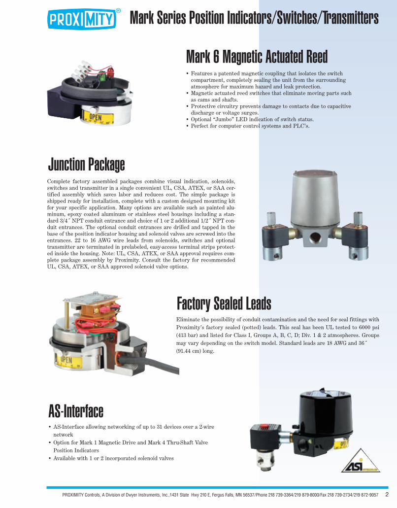
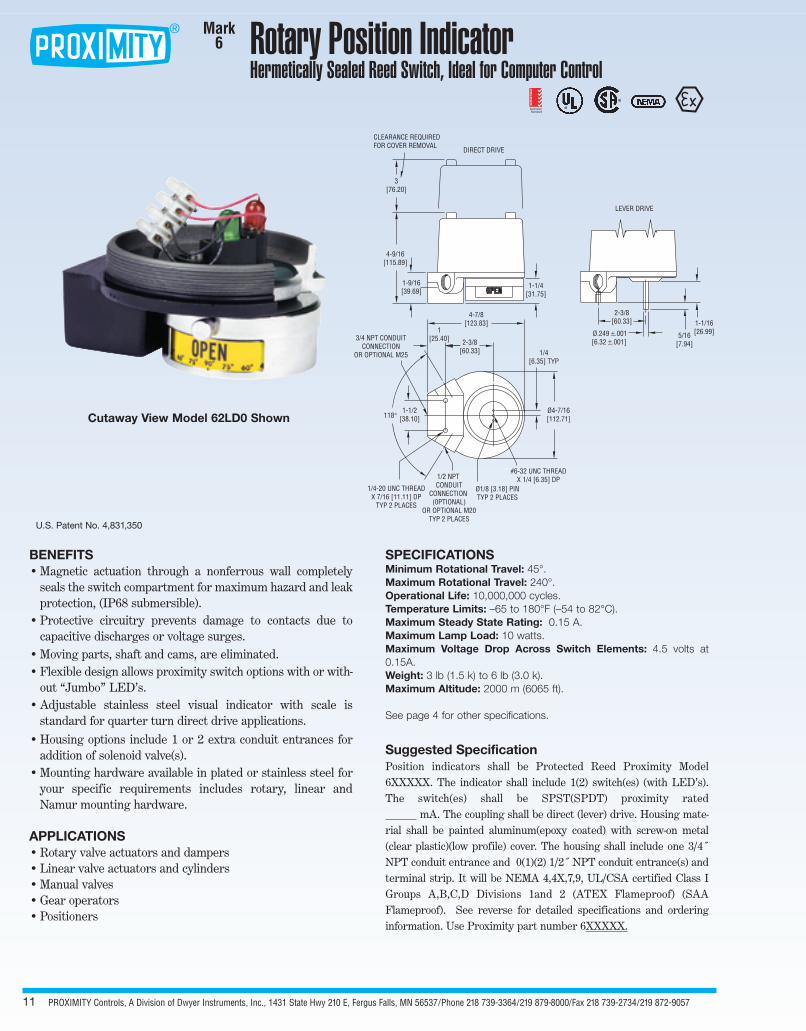
Rotary Position IndicatorHermetically Sealed Reed Switch, Ideal for Computer Control
Mark6
BENEFITS• Magnetic actuation through a nonferrous wall completely
seals the switch compartment for maximum hazard and leakprotection, (IP68 submersible).
• Protective circuitry prevents damage to contacts due tocapacitive discharges or voltage surges.
• Moving parts, shaft and cams, are eliminated.• Flexible design allows proximity switch options with or with-
out “Jumbo” LED’s.• Adjustable stainless steel visual indicator with scale is
standard for quarter turn direct drive applications.• Housing options include 1 or 2 extra conduit entrances for
addition of solenoid valve(s).• Mounting hardware available in plated or stainless steel for
your specific requirements includes rotary, linear andNamur mounting hardware.
APPLICATIONS• Rotary valve actuators and dampers• Linear valve actuators and cylinders• Manual valves• Gear operators• Positioners
SPECIFICATIONSMinimum Rotational Travel: 45°.Maximum Rotational Travel: 240°.Operational Life: 10,000,000 cycles.Temperature Limits: –65 to 180°F (–54 to 82°C).Maximum Steady State Rating: 0.15 A.Maximum Lamp Load: 10 watts.Maximum Voltage Drop Across Switch Elements: 4.5 volts at0.15A. Weight: 3 lb (1.5 k) to 6 lb (3.0 k).Maximum Altitude: 2000 m (6065 ft).
See page 4 for other specifications.
Suggested SpecificationPosition indicators shall be Protected Reed Proximity Model6XXXXX. The indicator shall include 1(2) switch(es) (with LED’s).The switch(es) shall be SPST(SPDT) proximity rated
mA. The coupling shall be direct (lever) drive. Housing mate-rial shall be painted aluminum(epoxy coated) with screw-on metal(clear plastic)(low profile) cover. The housing shall include one 3/4˝NPT conduit entrance and 0(1)(2) 1/2˝ NPT conduit entrance(s) andterminal strip. It will be NEMA 4,4X,7,9, UL/CSA certified Class IGroups A,B,C,D Divisions 1and 2 (ATEX Flameproof) (SAAFlameproof). See reverse for detailed specifications and orderinginformation. Use Proximity part number 6XXXXX.
U.S. Patent No. 4,831,350
CLEARANCE REQUIREDFOR COVER REMOVAL
3[76.20]
4-9/16[115.89]
1-9/16[39.69]
1-1/4[31.75]
3/4 NPT CONDUITCONNECTION
OR OPTIONAL M25
4-7/8[123.83]
1/4[6.35] TYP
2-3/8[60.33]
1[25.40]
Ø4-7/16[112.71]118°
1-1/2[38.10]
#6-32 UNC THREADX 1/4 [6.35] DP
Ø1/8 [3.18] PINTYP 2 PLACES
1/2 NPT CONDUIT
CONNECTION(0PTIONAL)
OR OPTIONAL M20TYP 2 PLACES
1/4-20 UNC THREADX 7/16 [11.11] DP
TYP 2 PLACES
2-3/8[60.33] 1-1/16
[26.99]5/16[7.94]
Ø.249 ±.001[6.32 ±.001]
LEVER DRIVE
DIRECT DRIVE
®
®
AustralianStandard
Certi
fied
Prod
uct
Cutaway View Model 62LD0 Shown

PROXIMITY Controls, A Division of Dwyer Instruments, Inc., 1431 State Hwy 210 E, Fergus Falls, MN 56537/Phone 218 739-3364/219 879-8000/Fax 218 739-2734/219 872-9057 12
Specifications and Ordering Information
6 Mark 6, Protected Reed
FUNCTION DATA
1 1 Reed Switch Element with Protective Circuit*
2 2 Reed Switch Elements with Protective Circuits*
SWITCH DATA
L SPST Hermetically Sealed Reed with LED, Rated: 0.02A @ 125 VAC (~); 0.02A @ 30 VDC ( ) (NEMA 4, 4X Only)*
P SPST Hermetically Sealed Reed, Rated: 0.15A @ 125 VAC (~), 0.15A @ 30 VDC ( ), 125 VAC (~) 10W (Lamp)*
Q SPDT Hermetically Sealed Reed, Rated: 0.15A @ 125 VAC (~), 0.15A @ 30 VDC ( )*
DRIVING METHOD
D Direct Drive, Stainless Steel Visual Indicator Standard*
L Lever Drive, Shaft Output*
HOUSING MATERIAL AND FINISH
0 Aluminum, Painted Black*
1 Aluminum, Painted & White Epoxy with SS Trim*
SPECIAL ENCLOSURE FEATURES
J1 Junction Package with One 1/2˝ Female NPT Conduit Connection and Terminal Strip*
J2 Junction Package with Two 1/2˝ Female NPT Conduit Connection and Terminal Strip*
S SAA Listed Flameproof*
SV1 1Attached Solenoid Valve (Must be ordered with J1 option)*
SV2 2 Attached Solenoid Valves ( Must be ordered with J2 option)*
MT Metric Threaded Conduit, M25 (M20 for optional J1 and J2 Connection)*
B Directive 94/9/EC, KEMA 03 ATEX 2391, II 2 G EEx d IIC T6 (-20°C≤ Tamb ≤70°C)(T5 (-20°C ≤ Tamb ≤ 80°C) optional wording)*
6 2 Q D 0 EXAMPLE OF POPULAR MODEL NUMBER
*Junction package available. Consult factory for solenoid valve packages.
SPECIFICATIONS SUBJECT TO CHANGE WITHOUT NOTICE.
Class I, Groups A,B,C,D, Class II, Groups E,F,G,Divisions 1 and 2
Class I, Groups A,B,C,D,Class II, Groups E,F,G,Divisions 1 and 2
Designed to meet type 1,2,3,3R,3S,4,4X,6,7,9,12,13
II 2 G EEx d IIC T6 or T5 (Flameproof - B; Special EnclosureFeatures) Ingress Protection Certified IP68
Certified EX d IIC T6 IP68 (15 meters)
NOTE: When ordering mounting kits, please supply make and model number of your actuator or valve.
®
®
AustralianStandard
Certi
fied
Prod
uct
PROXIMITY Controls, A Division of Dwyer Instruments, Inc., 1431 State Hwy 210 E, Fergus Falls, MN 56537/Phone 218 739-3364/219 879-8000/Fax 218 739-2734/219 872-905713
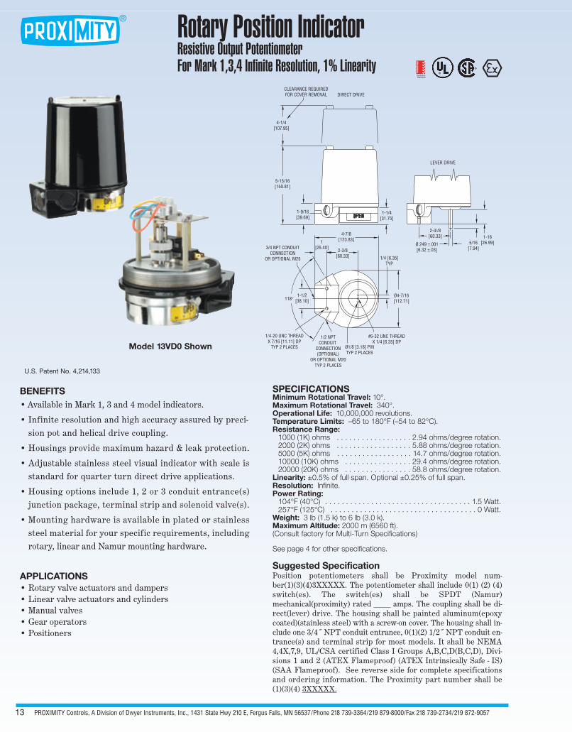
Rotary Position IndicatorResistive Output PotentiometerFor Mark 1,3,4 Infinite Resolution, 1% Linearity
BENEFITS• Available in Mark 1, 3 and 4 model indicators.
• Infinite resolution and high accuracy assured by preci-sion pot and helical drive coupling.
• Housings provide maximum hazard & leak protection.
• Adjustable stainless steel visual indicator with scale isstandard for quarter turn direct drive applications.
• Housing options include 1, 2 or 3 conduit entrance(s)junction package, terminal strip and solenoid valve(s).
• Mounting hardware is available in plated or stainlesssteel material for your specific requirements, includingrotary, linear and Namur mounting hardware.
APPLICATIONS• Rotary valve actuators and dampers• Linear valve actuators and cylinders• Manual valves• Gear operators• Positioners
SPECIFICATIONSMinimum Rotational Travel: 10°.Maximum Rotational Travel: 340°.Operational Life: 10,000,000 revolutions.Temperature Limits: –65 to 180°F (–54 to 82°C).Resistance Range:
1000 (1K) ohms . . . . . . . . . . . . . . . . . . 2.94 ohms/degree rotation.2000 (2K) ohms . . . . . . . . . . . . . . . . . . 5.88 ohms/degree rotation.5000 (5K) ohms . . . . . . . . . . . . . . . . . . 14.7 ohms/degree rotation.10000 (10K) ohms . . . . . . . . . . . . . . . . 29.4 ohms/degree rotation.20000 (20K) ohms . . . . . . . . . . . . . . . . 58.8 ohms/degree rotation.
Linearity: ±0.5% of full span. Optional ±0.25% of full span.Resolution: Infinite.Power Rating:
104°F (40°C) . . . . . . . . . . . . . . . . . . . . . . . . . . . . . . . . . . . 1.5 Watt.257°F (125°C) . . . . . . . . . . . . . . . . . . . . . . . . . . . . . . . . . . . 0 Watt.
Weight: 3 lb (1.5 k) to 6 lb (3.0 k).Maximum Altitude: 2000 m (6560 ft).(Consult factory for Multi-Turn Specifications)
See page 4 for other specifications.
Suggested SpecificationPosition potentiometers shall be Proximity model num-ber(1)(3)(4)3XXXXX. The potentiometer shall include 0(1) (2) (4)switch(es). The switch(es) shall be SPDT (Namur)mechanical(proximity) rated amps. The coupling shall be di-rect(lever) drive. The housing shall be painted aluminum(epoxycoated)(stainless steel) with a screw-on cover. The housing shall in-clude one 3/4˝ NPT conduit entrance, 0(1)(2) 1/2˝ NPT conduit en-trance(s) and terminal strip for most models. It shall be NEMA4,4X,7,9, UL/CSA certified Class I Groups A,B,C,D(B,C,D), Divi-sions 1 and 2 (ATEX Flameproof) (ATEX Intrinsically Safe - IS)(SAA Flameproof). See reverse side for complete specificationsand ordering information. The Proximity part number shall be(1)(3)(4) 3XXXXX.
Model 13VD0 Shown
U.S. Patent No. 4,214,133
LEVER DRIVE
2-3//8[60.33]
Ø.249 ±.001[6.32 ±.03]
5/16[7.94]
1-16[26.99]
CLEARANCE REQUIREDFOR COVER REMOVAL
4-1/4[107.95]
5-15/16[150.81]
1-9/16[39.69]
1-1/4[31.75]
1/4 [6.35]TYP
4-7/8[123.83]
2-3/8[60.33]
1[25.40]3/4 NPT CONDUIT
CONNECTIONOR OPTIONAL M25
1-1/2[38.10]118°
1/4-20 UNC THREADX 7/16 [11.11] DP
TYP 2 PLACES
Ø4-7/16[112.71]
#6-32 UNC THREADX 1/4 [6.35] DP
Ø1/8 [3.18] PINTYP 2 PLACES
1/2 NPTCONDUIT
CONNECTION(OPTIONAL)
OR OPTIONAL M20TYP 2 PLACES
DIRECT DRIVE
®
®
AustralianStandard
Certi
fied
Prod
uct

PROXIMITY Controls, A Division of Dwyer Instruments, Inc., 1431 State Hwy 210 E, Fergus Falls, MN 56537/Phone 218 739-3364/219 879-8000/Fax 218 739-2734/219 872-9057 14
Specifications and Ordering Information
1 Mark 1, Magnetic Coupling3 Mark 3, Multi-Turn, (1-10 Revolutions)4 Mark 4, Thru-Shaft
FUNCTION DATA
3 Potentiometer, 1K Ohm.†32 Potentiometer, 2K Ohm.†35 Potentiometer, 5K Ohm.†310 Potentiometer, 10K Ohm.†320 Potentiometer, 20K Ohm.†
SWITCH DATAO No SwitchesA SPDT Snap, Rated: 15A @ 125/250/480 VAC (~): 1/8 hp @ 125 VAC (~), (Mark 3 Only)
1/4 hp @ 250 VAC (~), 1/2A @ 125 VDC ( ), 1/4A @ 250 VDC ( )B Inductive Sensor 10 to 30 VDC ( ), Load: 0.1A (Mark 1 & 4 Only)C SPDT High Temperature Snap, 350°F (176°C) for 600 hours, Rated: 15.1A @ 125/250/277 VAC (~)D DPDT Snap, Rated: 10A @ 125/250 VAC (~), 0.3A @ 125 VDC ( ), 0.15A @ 250 VDC ( ), (Mark 3 Only)G SPDT Gold Contact Snap, Rated: 1A @ 125 VAC (~), (Mark 3 Only)I NAMUR Inductive Sensor, 15 mA max @ 5-25 VDC ( ). (Mark 1 & 4 Only)M SPDT Magnetic Blow-Out, Rated: 10A @ 125 VAC (~) /VDC ( ), 1/4 hp @ 125 VAC (~)/VDC ( ) (Mark 3 Only)R SPDT Hermetically Sealed Reed, Rated: 2A @ 125 VAC (~) , 2A @ 24 VDC ( ). (Mark 1 & 4 Only)S SPDT Snap, Rated: 4A @ 125/250 VAC (~). (Mark 1& 4 Only)T SPDT High Temperature Snap, 250°F (121°C) Continuous, Rated: 5A @ 125/250/480 VAC (~) (Mark 3 Only)V SPDT Snap, Rated: 11A @ 125/250 VAC (~), 1/3 hp @ 125/250 VAC (~),
1/2A @ 125 VDC ( ), 1/4A @ 250 VDC ( ), 4A @ 125/250 VAC (~) (Tungsten)W SPDT Gold Contact Snap, Rated: 0.1A @ 125 VAC (~)
DRIVING METHODD Direct Drive, Stainless Steel Visual Indicator StandardL Lever Drive, Shaft Output
HOUSING MATERIAL AND FINISH0 Aluminum, Painted Black (Other colors available, consult factory)1 Aluminum, Painted White Epoxy with SS Trim6 Cast 316 Stainless Steel
SPECIAL ENCLOSURE FEATURESJ1 Junction Package with One 1/2˝ Female NPT Conduit Connection and Terminal Strip, except Mark 3J2 Junction Package with Two 1/2˝ Female NPT Conduit Connection and Terminal Strip, except Mark 3S SAA Listed FlameproofSV1 1 Attached Solenoid Valve (Must be ordered with J1 option)SV2 2 Attached Solenoid Valves (Must be ordered with J2 option)MT Metric Threaded Conduit Connection, M25 (M20 for optional J1 and J2 connections)B Directive 94/9/EC, KEMA 03 ATEX 2391, II 2 G EEx d IIC T6 (-20°C≤ Tamb ≤70°C)
(T5 (-20°C ≤ Tamb ≤ 80°C) optional wording)IS Directive 94/9/EC, KEMA 03 ATEX 1392 x, II 1 G EEx ia IIC T4 (-20°C≤ Tamb ≤40°C)
4 3 V D 0 EXAMPLE OF POPULAR MODEL NUMBER
† Mark 1 and 4 potentiometer and transmitter outputs will have no switches when ordered with switch type O; 2 switches if orderedwith switch types B, C, I, R, V, or W; and 4 switches if ordered with switch type S. Mark 3 potentiometer and transmitter outputswill have no switches when ordered with switch type O, and 2 switches if ordered with switch types A, D, G, or M.
Consult factory for solenoid valve packages.
SPECIFICATIONS SUBJECT TO CHANGE WITHOUT NOTICE.
See individual products for UL, CSA, ATEX, and SAA approvals by Basic Design (Mark 1, 3, 4).
NOTE: When ordering mounting kits, please supply make and model number of your actuator or valve.
PROXIMITY Controls, A Division of Dwyer Instruments, Inc., 1431 State Hwy 210 E, Fergus Falls, MN 56537/Phone 218 739-3364/219 879-8000/Fax 218 739-2734/219 872-905715
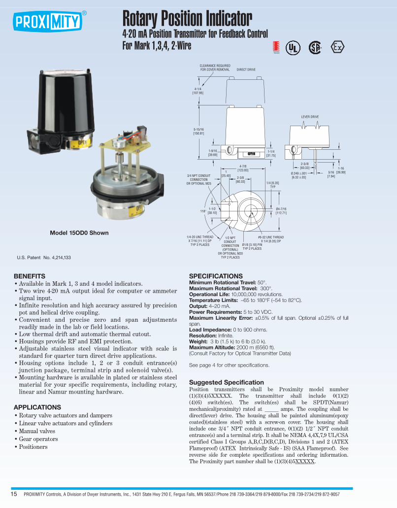
Rotary Position Indicator4-20 mA Position Transmitter for Feedback ControlFor Mark 1,3,4, 2-Wire
BENEFITS• Available in Mark 1, 3 and 4 model indicators. • Two wire 4-20 mA output ideal for computer or ammeter
signal input.• Infinite resolution and high accuracy assured by precision
pot and helical drive coupling. • Convenient and precise zero and span adjustments
readily made in the lab or field locations.• Low thermal drift and automatic thermal cutout.• Housings provide RF and EMI protection.• Adjustable stainless steel visual indicator with scale is
standard for quarter turn direct drive applications.• Housing options include 1, 2 or 3 conduit entrance(s)
junction package, terminal strip and solenoid valve(s). • Mounting hardware is available in plated or stainless steel
material for your specific requirements, including rotary,linear and Namur mounting hardware.
APPLICATIONS• Rotary valve actuators and dampers• Linear valve actuators and cylinders• Manual valves• Gear operators• Positioners
SPECIFICATIONSMinimum Rotational Travel: 50°.Maximum Rotational Travel: 300°.Operational Life: 10,000,000 revolutions.Temperature Limits: –65 to 180°F (–54 to 82°C).Output: 4–20 mA.Power Requirements: 5 to 30 VDC.Maximum Linearity Error: ±0.5% of full span. Optional ±0.25% of fullspan.Load Impedance: 0 to 900 ohms.Resolution: Infinite.Weight: 3 lb (1.5 k) to 6 lb (3.0 k).Maximum Altitude: 2000 m (6560 ft).(Consult Factory for Optical Transmitter Data)
See page 4 for other specifications.
Suggested SpecificationPosition transmitters shall be Proximity model number(1)(3)(4)5XXXXX. The transmitter shall include 0(1)(2)(4)(6) switch(es). The switch(es) shall be SPDT(Namur) mechanical(proximity) rated at amps. The coupling shall bedirect(lever) drive. The housing shall be painted aluminum(epoxycoated)(stainless steel) with a screw-on cover. The housing shallinclude one 3/4˝ NPT conduit entrance, 0(1)(2) 1/2˝ NPT conduitentrance(s) and a terminal strip. It shall be NEMA 4,4X,7,9 UL/CSAcertified Class I Groups A,B,C,D(B,C,D), Divisions 1 and 2 (ATEXFlameproof) (ATEX Intrinsically Safe - IS) (SAA Flameproof). Seereverse side for complete specifications and ordering information.The Proximity part number shall be (1)(3)(4)5XXXXX.
Model 15OD0 Shown
U.S. Patent No. 4,214,133
LEVER DRIVE
2-3//8[60.33]
Ø.249 ±.001[6.32 ±.03]
5/16[7.94]
1-16[26.99]
CLEARANCE REQUIREDFOR COVER REMOVAL
4-1/4[107.95]
5-15/16[150.81]
1-9/16[39.69]
1-1/4[31.75]
1/4 [6.35]TYP
4-7/8[123.83]
2-3/8[60.33]
1[25.40]3/4 NPT CONDUIT
CONNECTIONOR OPTIONAL M25
1-1/2[38.10]118°
1/4-20 UNC THREADX 7/16 [11.11] DP
TYP 2 PLACES
Ø4-7/16[112.71]
#6-32 UNC THREADX 1/4 [6.35] DP
Ø1/8 [3.18] PINTYP 2 PLACES
1/2 NPTCONDUIT
CONNECTION(OPTIONAL)
OR OPTIONAL M20TYP 2 PLACES
DIRECT DRIVE
®
®
AustralianStandard
Certi
fied
Prod
uct

PROXIMITY Controls, A Division of Dwyer Instruments, Inc., 1431 State Hwy 210 E, Fergus Falls, MN 56537/Phone 218 739-3364/219 879-8000/Fax 218 739-2734/219 872-9057 16
1 Mark 1, Magnetic Coupling3 Mark 3, Multi-Turn (1-10 Revolutions)4 Mark 4, Thru-Shaft
FUNCTION DATA5 4-20 mA Position Transmitter & 2 Switch Elements†
4-20 mA Position Transmitter & 4 Switch Elements†4-20 mA Position Transmitter without Switches†
SWITCH DATAO No SwitchesA SPDT Snap, Rated: 15A @ 125/250/480 VAC (~); 1/8 HP @ 125 VAC (~)
1/4 hp @ 250 VAC (~), 1/2A @ 125 VDC ( ). 1/4A @ 250 VDC ( ) (Mark 3 Only)B Inductive Sensor, 10 to 30 VDC ( ). Load: 0.1A (Mark 1& 4 Only)C SPDT High Temperature Snap, 350°F (176°C) for 600 hours. Rated: 15.1A @ 125/250/277 VAC (~)D DPDT Snap, Rated: 10A @ 125/250 VAC (~), 0.3A @ 125 VDC ( ), 0.15A @ 250 VDC ( ) (Mark 3 Only)G SPDT Gold Contact Snap, Rated: 1A @ 125 VAC (~) (Mark 3 Only)I NAMUR Inductive Sensor, 15 mA max @ 5-25 VDC ( ) (Mark 1 & 4 Only)M SPDT Magnetic Blow-Out, Rated: 10A @ 125 VAC (~)/VDC ( ), 1/4 hp @ 125 VAC (~)/VDC ( ) (Mark 3 Only)R SPDT Hermetically Sealed Reed, Rated: 2A @125 VAC (~), 2A @ 24 VDC ( ) (Mark 1 & 4 Only)S SPDT Snap, Rated: 4A @ 125/250 VAC (~) (Mark 1/4 Only)T SPDT High Temperature Snap, 250°F (121°C) Continuous, Rated: 5A @ 125/250/480 VAC (~) (Mark 3 Only)V SPDT Snap, Rated: 11A @ 125/250 VAC (~), 1/3 hp @ 125/250 VAC (~), 1/2A @ 125 VDC ( ), 1/4A @ 250 VDC ( ),
4A @ 125 VAC (~) (tungsten).W SPDT Gold Contact Snap, Rated: 0.1A @ 125 VAC (~)
DRIVING METHODD Direct Drive, Stainless Steel Visual Indicator StandardL Lever Drive, Shaft Output
HOUSING MATERIAL AND FINISH0 Aluminum, Painted Black (Other colors available, consult factory)1 Aluminum, Painted White Epoxy with SS Trim6 Cast 316 Stainless Steel
SPECIAL ENCLOSURE FEATURESJ1 Junction Package with One 1/2˝ Female NPT Conduit Connection and Terminal Strip, except Mark 3J2 Junction Package with Two 1/2˝ Female NPT Conduit Connection and Terminal Strip, except Mark 3S SAA Listed FlameproofSV1 1 Attached Solenoid Valve (Must be ordered with J1 option)SV2 2 Attached Solenoid Valves (Must be ordered with J2 option)MT Metric Threaded Conduit Connection, M25 (M20 for optional J1 and J2 connections)B Directive 94/9/EC, KEMA 03 ATEX 2391, II 2 G EEx d IIC T6 (-20°C≤ Tamb ≤70°C)
(T5 (-20°C ≤ Tamb ≤ 80°C) optional wording)IS Directive 94/9/EC, KEMA 03 ATEX 1392 x, II 1 G EEx ia IIC T4 (-20°C≤ Tamb ≤40°C)
1 5 V D 0 EXAMPLE OF POPULAR MODEL NUMBER
† Mark 1 and 4 potentiometer and transmitter outputs will have no switches when ordered with switch type O; 2 switches if ordered with switch types B, C, I, R, V, or W; and 4 switches if ordered with switch type S. Mark 3 potentiometer and transmitter outputswill have no switches when ordered with switch type O, and 2 switches if ordered with switch types A, D, G, or M.
Consult factory for solenoid valve packages.
SPECIFICATIONS SUBJECT TO CHANGE WITHOUT NOTICE.
Specifications and Ordering Information
See individual products for UL, CSA, ATEX and SAA approvals by Basic Design (Mark 1, 3, 4).
NOTE: When ordering mounting kits, please supply make and model number of your actuator or valve.