Embed Size (px)
DESCRIPTION
VANET, WiMAX
Citation preview
National Institute of Technology Rourkela
Simulation Of Vehicular Movement in
VANET
by
Amrit Ekka [109cs0021]
A thesis submitted in partial fulfillment of the requirement for the
degree of Bachelor in Technology
Under the supervision of
Dr. A. K. Turuk
Department of Computer Science and Engineering
June 2013
Computer Science and EngineeringNational Institute of Technology RourkelaRourkela-769 008, India. www.nitrkl.ac.in
Dr. Ashok Kumar TurukHead Of The Department,
Department of Computer Science & Engineering,
NIT Rourkela.
June 07, 2013
Certificate
This is to certify that the work in the thesis entitled Simulation Of Vehicular
Movement in VANET by Amrit Ekka, bearing roll number 109cs0021, is a record
of an authentic work carried out by him under my supervision and guidance in
partial fulfillment of the requirements for the award of the degree of Bachelor of
Technology in Computer Science and Engineering at National Institute of Tech-
nology Rourkela.
Dr. Ashok Kumar Turuk
Acknowledgements
I would like to articulate my profound gratitude and indebtedness to those persons who
helped us in the project. First of all, I would like to express my obligation to my project
guide Prof. Ashok Kumar Turuk for his motivation, help and supportiveness. I am
sincerely thankful to him for his guidance and helping effort in improving our knowledge
on the subject. He has been always helpful to us in all aspects and I thank him from
the deepest of my heart. An assemblage of this nature could never have been attempted
without reference to and inspiration from the works of others whose details are men-
tioned in reference section. I acknowledge my indebtedness to all of them. At the last,
my sincere thanks to all my friends who have patiently extended all sorts of helps for
accomplishing this assignment.. . .
(Amrit Ekka)
ii
Abstract
In the recent years research in the field of vehicular ad-hoc network(VANET) is
done extensively. VANET consist of large number of dynamically nodes which
are vehicles over a area. Different types of technology and applications are being
developed for the VANET . So this VANET technology and applications should be
thoroughly checked before deployment in the real world environment. But to test
technologies and applications in real world environment is not feasible it involves
lot of danger and safety issues, different reports of the testing cant also be gener-
ated so to overcome these limitation we need to carry out simulation of VANET
in the computer environment i.e. we should do a computer simulation. Computer
simulation is risk and danger free, we can generate different scenario (rural, ur-
ban, collision of vehicles) of the VANET using this. So computer simulation is
very important in VANET research.Simulation of VANET is divided into two part
a. Traffic simulation: Generation of traffic movement, Defining the mobility model
for vehicle and creating traffic movement.
b. Network simulation: Generating Inter communicating vehicle , Defining com-
munication protocols.
And both the simulation are connected in bi-directional coupling. . . .
Keywords: VANET, SUMO, MANET, Network simulation, Traffic simulation
Contents
Acknowledgements ii
List of Figures vi
List of Tables vii
Abbreviations viii
1 Introduction 1
1.1 MANET . . . . . . . . . . . . . . . . . . . . . . . . . . . . . . . . . . . . . 1
1.1.1 Application of MANET . . . . . . . . . . . . . . . . . . . . . . . . 2
1.2 VANET . . . . . . . . . . . . . . . . . . . . . . . . . . . . . . . . . . . . . 3
1.2.1 Specific Characteristics of VANET . . . . . . . . . . . . . . . . . . 4
1.2.2 Applications Of VANET . . . . . . . . . . . . . . . . . . . . . . . 5
1.2.3 Challenges faced by VANET . . . . . . . . . . . . . . . . . . . . . 6
1.2.3.1 Technical Challenges . . . . . . . . . . . . . . . . . . . . . 6
1.2.3.2 Business Challenges . . . . . . . . . . . . . . . . . . . . . 7
2 Simulation Theory 8
2.1 Challenges for realistic VANET simulation . . . . . . . . . . . . . . . . . . 8
2.2 Mobility Modeling . . . . . . . . . . . . . . . . . . . . . . . . . . . . . . . 10
2.2.1 Random Node Movement . . . . . . . . . . . . . . . . . . . . . . . 12
2.2.2 Real-world Mobility Traces . . . . . . . . . . . . . . . . . . . . . . 12
2.2.3 Artificial Mobility Traces . . . . . . . . . . . . . . . . . . . . . . . 12
2.2.4 Bi-directionally Coupled Simulators . . . . . . . . . . . . . . . . . 13
2.3 Routing Protocols . . . . . . . . . . . . . . . . . . . . . . . . . . . . . . . 13
2.3.1 Topology Based routing protocols . . . . . . . . . . . . . . . . . . 14
2.3.1.1 Proactive routing protocols . . . . . . . . . . . . . . . . . 14
2.3.1.2 Reactive routing protocols . . . . . . . . . . . . . . . . . 14
2.3.2 position based routing protocol . . . . . . . . . . . . . . . . . . . 15
2.3.2.1 Position Based Greedy V2V Protocols . . . . . . . . . . . 15
2.3.3 Broadcast Routing . . . . . . . . . . . . . . . . . . . . . . . . . . . 16
2.3.3.1 BROADCOMM Routing Protocol . . . . . . . . . . . . . 16
2.3.4 Geo-cast Routing . . . . . . . . . . . . . . . . . . . . . . . . . . . . 17
3 18
iv
Contents v
3.1 Traffic Simulation . . . . . . . . . . . . . . . . . . . . . . . . . . . . . . . . 18
3.1.1 SUMO (Simulation of Urban Mobility) . . . . . . . . . . . . . . . . 18
3.1.2 Importing map . . . . . . . . . . . . . . . . . . . . . . . . . . . . . 19
3.1.3 Generation of Network file . . . . . . . . . . . . . . . . . . . . . . . 20
3.1.4 Network file . . . . . . . . . . . . . . . . . . . . . . . . . . . . . . . 20
3.1.5 Trip file . . . . . . . . . . . . . . . . . . . . . . . . . . . . . . . . . 21
3.1.6 Route file . . . . . . . . . . . . . . . . . . . . . . . . . . . . . . . . 22
3.1.7 Configuration file . . . . . . . . . . . . . . . . . . . . . . . . . . . . 22
3.2 Network simulation . . . . . . . . . . . . . . . . . . . . . . . . . . . . . . . 23
3.2.1 OMNeT++ . . . . . . . . . . . . . . . . . . . . . . . . . . . . . . . 23
3.2.2 Veins . . . . . . . . . . . . . . . . . . . . . . . . . . . . . . . . . . 24
3.2.3 simulation . . . . . . . . . . . . . . . . . . . . . . . . . . . . . . . . 24
3.3 Combining Both network . . . . . . . . . . . . . . . . . . . . . . . . . . . 25
3.3.1 Final Simulation . . . . . . . . . . . . . . . . . . . . . . . . . . . . 27
4 Conclusion 28
Bibliography 29
List of Figures
1.1 Mobile Ad-hoc Network [15] . . . . . . . . . . . . . . . . . . . . . . . . . . 2
1.2 Vehicular Ad-hoc Network [16] . . . . . . . . . . . . . . . . . . . . . . . . 3
2.1 Evolution of mobility modeling strategies and techniques in VANET re-search [12] . . . . . . . . . . . . . . . . . . . . . . . . . . . . . . . . . . . 10
2.2 Mobility modeling techniques for simulation of VANET protocols andapplications [12] . . . . . . . . . . . . . . . . . . . . . . . . . . . . . . . . 11
3.1 Network file created manually (a) Grid network (b) and (c) Spider Net-works [17] . . . . . . . . . . . . . . . . . . . . . . . . . . . . . . . . . . . . 19
3.2 Map form open street Org . . . . . . . . . . . . . . . . . . . . . . . . . . . 19
3.3 OSM file to Network file (a) OSM file JOSM editor (b) Network filerunning in SUMO . . . . . . . . . . . . . . . . . . . . . . . . . . . . . . . 20
3.4 Network file snapshot . . . . . . . . . . . . . . . . . . . . . . . . . . . . . 21
3.5 Trip file snapshot . . . . . . . . . . . . . . . . . . . . . . . . . . . . . . . . 21
3.6 Route file snapshot . . . . . . . . . . . . . . . . . . . . . . . . . . . . . . . 22
3.7 Movement of vehicle in sumo(Traffic simulation) . . . . . . . . . . . . . . 22
3.8 Veins Architechture [19] . . . . . . . . . . . . . . . . . . . . . . . . . . . . 24
3.9 launchd file snapshot . . . . . . . . . . . . . . . . . . . . . . . . . . . . . . 24
3.10 Network Simulator OMNeT++ coupled with Traffic simulator SUMO us-ing TraCI [19] . . . . . . . . . . . . . . . . . . . . . . . . . . . . . . . . . . 26
3.11 Opening port for communication between traffic and network simulation . 26
3.12 Network simulation using omnet++ . . . . . . . . . . . . . . . . . . . . . 27
vi
List of Tables
2.1 OVERVIEW OF MOBILITY MODELS, THEIR LEVEL OF SUPPORTIN SIMULATION FRAMEWORKS, AND THEIR PARTICULAR AD-VANTAGES AND DRAWBACKS [12] . . . . . . . . . . . . . . . . . . . . 11
2.2 Comparison of Various Protocols [14] . . . . . . . . . . . . . . . . . . . . . 16
vii
Abbreviations
MANET Mobile Adhoc NEtwork
VANET Vhicular Adhoc NEtwork
PAN Personal Area Network
RSU Road Side Unit
OBU On Board Unit
WAVE Wireless Access for Vehicular Network
SUMO Simulation of Urban Mobility
VEINS VEhicle In Network Simulation
viii
Chapter 1
Introduction
Wireless Ad-hoc network is defined as a network which doesnt have a preexisting com-
munication infrastructure. Network is created by some nodes which are available. In
this type of network determination of which nodes to transfer data to which node is
done dynamically, depending upon the connectivity of both devices. Ad-hoc network
can use flooding data transfer. In Ad-hoc network all devices are treated equally all
have same status. The main use of wireless ad-hoc network is done by Mobile Ad-hoc
Network (MANET). In MANET different participating node moves randomly in the
created wireless Ad-hoc network.
1.1 MANET
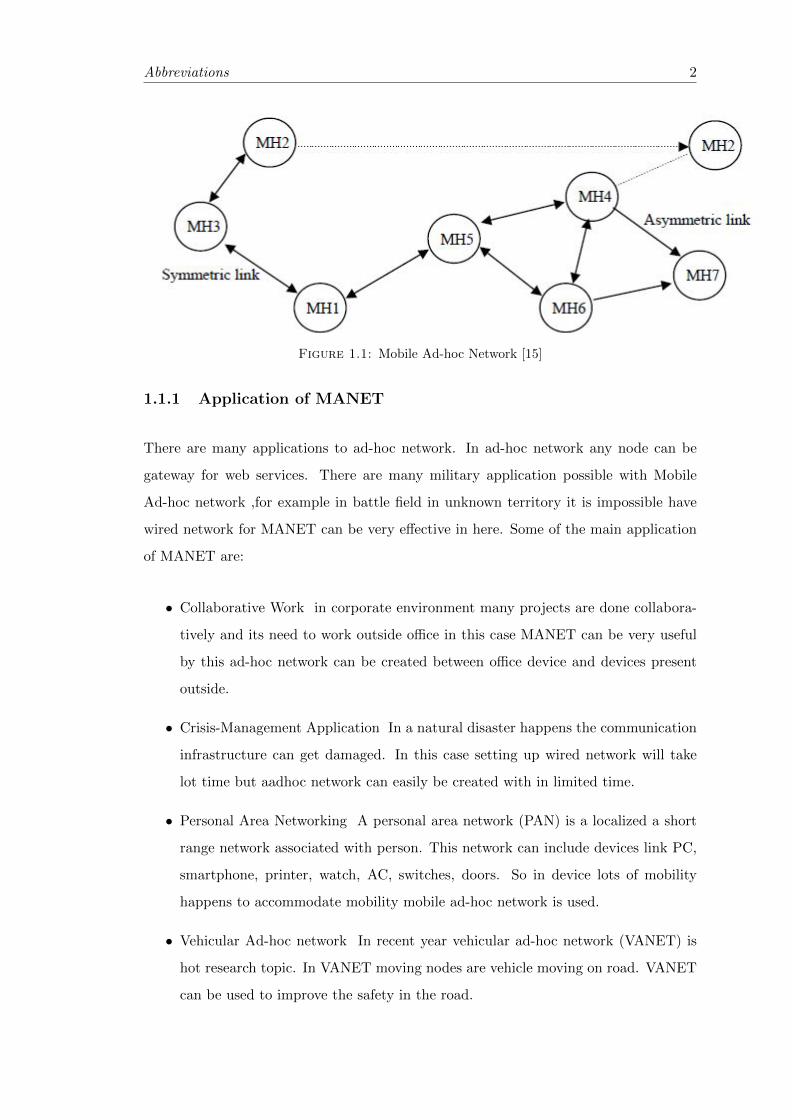
We know that in MANET nodes moves randomly in the wireless Ad-hic network. Since
here devices moves dynamically in the network so the connecting link between two de-
vices changes frequently it makes building MANET very challenging. The main challenge
of building MANET is to manage continuous change of route traffic.
The figure1.1 [15 ]shows how data is forwared form souce to destination detecting con-
nectivity between two device.
1
Abbreviations 2
Figure 1.1: Mobile Ad-hoc Network [15]
1.1.1 Application of MANET
There are many applications to ad-hoc network. In ad-hoc network any node can be
gateway for web services. There are many military application possible with Mobile
Ad-hoc network ,for example in battle field in unknown territory it is impossible have
wired network for MANET can be very effective in here. Some of the main application
of MANET are:
• Collaborative Work in corporate environment many projects are done collabora-
tively and its need to work outside office in this case MANET can be very useful
by this ad-hoc network can be created between office device and devices present
outside.
• Crisis-Management Application In a natural disaster happens the communication
infrastructure can get damaged. In this case setting up wired network will take
lot time but aadhoc network can easily be created with in limited time.
• Personal Area Networking A personal area network (PAN) is a localized a short
range network associated with person. This network can include devices link PC,
smartphone, printer, watch, AC, switches, doors. So in device lots of mobility
happens to accommodate mobility mobile ad-hoc network is used.
• Vehicular Ad-hoc network In recent year vehicular ad-hoc network (VANET) is
hot research topic. In VANET moving nodes are vehicle moving on road. VANET
can be used to improve the safety in the road.
Abbreviations 3
Among the different type of MANET the most popular is Vehicular ad-hoc network
(VANET) it used for communication between different vehicles running on traffic and
road side infrastructure .We can also say that VANET are Subset of MANET where
communication nodes are mainly vehicles.
1.2 VANET
Now a days most modern car have intra vehicular network which allows wireless com-
munication between vehicle and electronic gadets like smart phone ,Global Positioning
System (GPS) ,Bluetooth media players. But the Inter vehicular communication net-
work is still not available. So to provide inter vehicular communication VANET i.e.
Vehicular ad-hoc Network technologies are emerging.
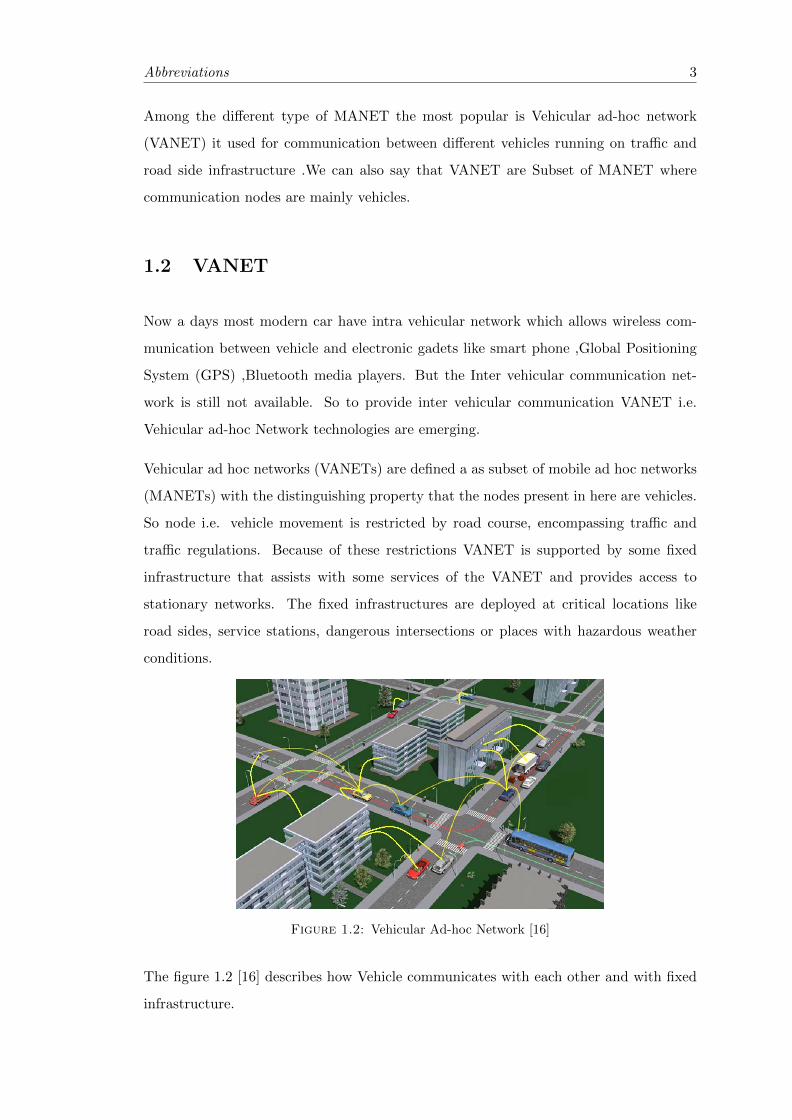
Vehicular ad hoc networks (VANETs) are defined a as subset of mobile ad hoc networks
(MANETs) with the distinguishing property that the nodes present in here are vehicles.
So node i.e. vehicle movement is restricted by road course, encompassing traffic and
traffic regulations. Because of these restrictions VANET is supported by some fixed
infrastructure that assists with some services of the VANET and provides access to
stationary networks. The fixed infrastructures are deployed at critical locations like
road sides, service stations, dangerous intersections or places with hazardous weather
conditions.
Figure 1.2: Vehicular Ad-hoc Network [16]
The figure 1.2 [16] describes how Vehicle communicates with each other and with fixed
infrastructure.
Abbreviations 4
1.2.1 Specific Characteristics of VANET
High Dynamic Topology : VANET have very high dynamic topology .The commu-
nication links between node changes very rapidly. Communication between two nodes
remains for very less time. For example if two vehicles moving away from each other
with a speed of 25m/sec and if the transmission range is about 250m, then the link will
only last for only 5 seconds ( 250m/ 50ms-1). So this how highly dynamic topology is
present in VANET
Frequent disconnected Network : From the above characteristic we can see that
connection between two or more vehicle remains for 5 second or so. To maintain the
continuous connectivity vehicles needs another connection nearby immediately. But if
failure occurs vehicles can connect with Road Side Unit (RSU). Frequent disconnected
network mainly occurs where vehicle density is very low like rural area.
Mobility Modelling and Prediction : The above two features for connectivity
needs the knowledge of positions of vehicles and their movements but this is very difficult
to predict since vehicle can move randomly and it doesnt have a pattern. So mobility
models node prediction which based on the study of predefined road roadway model and
vehicle speeds are use.
Communication Environment : The mobility model highly varies in different en-
vironment form rural area to urban area, from highways to that of city environment. So
mobility modelling and vehicle movement prediction and routing algorithm should adapt
to these changes. For highways mobility models are very simple because vehicle move-
ment is one dimensional. But in case of city environment lots of vehicle present different
obstacle like building are present it makes communication application very complex in
VANET.
Hard Delay Constraints : Safety aspect like accident, sudden break and emergency
call of VANET application depends upon the deliver time of data. It cannot compro-
mise for data delay in this type of application. Therefore hard delay constrain is more
important in VANET than high data rate.
Interaction with on-board sensors : The on-bard sensor are present in the vehicle.
These sensors are used to find vehicle location, vehicle speed and vehicle movement these
informations are then used for effective communication between vehicles.
Abbreviations 5
1.2.2 Applications Of VANET
The primary goals of VANETs are to improve safety on the road. To achieve this,
the vehicles act as sensors and exchange messages to different vehicles this messages
include information like speed of vehicle, condition of road, Traffic density. This enables
the drivers and authorities to react early to any dangerous situations like accidents
and traffic jams. But the recent research in the field of VANET have discovered many
applications and technologies.
Type-1:Application Assistance for Safe Navigation
This applications manages different critical aspects of traffic safety. Several services can
be offered, among them are the following:
• Application for avoiding collision through distance calculation between two vehicle
it can use sudden braking system.
• Application for detection of hazardous and dangerous driving conditions. This
conditions can be damaged road, blocked road, if road is covered with snow or
mud.
• Application for emergency call services after an accident occurs here the vehicle
can automatically call to authority if an accident occurs.
• Applications for detecting rogue drivers which are disobeying traffic rules like
crossing speed limit, talking in phone while driving, driving in the wrong side
of the road.
Type-2:Application for Traffic Regulation and Internet Connectivity
The second types of applications are the following:
• Application forAdvanced Navigation Assistance (ANA) such a car park formation,
real time vehicle congestion information, expected weather condition for driving ,
etc.,
• Internet connection services can be provided to vehicle added for travel comfort
and improved productivity. This be done by data transfer between vehicle and
road side unit.
Abbreviations 6
• Chatting services between users of the same root, This can improve driving safety
one driver can send immediate warning message to other driver, and
• Application for advertisement of local/nearest service stations, nearest hotel, shops,
mall.
1.2.3 Challenges faced by VANET
There are many challenges which are faced by VANET. These challenges are technical
challenges as well as business challenges. Now we will see what these challenges are
in following paragraph and in next chapter how we can overcome this challenges using
simulation.
1.2.3.1 Technical Challenges
There is no particular transport protocol created for vehicular networks so far, and it is
very complex to design new protocols or to adapt existing protocols by modifications.
The transport of messages between noses should be completely error free because their
will most likely be no time to retransmit the message, especially in emergency situations
like accident. Tis messages are very critical to transmission of message should happen
with in an instant so transport of message should be error free and read with time. Most
often, transport messages must be error free because a message will not be able to be
retransmitted in the case where two cars are passing each other while going in opposite
directions that can after some time two cars will be out of connection range.
VANET will have to enhance its transport layer protocols from currently used protocols
in ad hoc network transport technologies. We have to use a specialized protocol designed
for VANET other than TCP. The current challenges that are needed to be overcome to
create a successful transport protocol are because of long round trip times, high packet
loss rates, high probability of packet reordering, and short connection durations are
present in current ad hoc networks. Vehicular ad-hoc networks add to the complexity
due to the fact that the nodes are travelling at high rates of speed.
Overall, VANETs must work in all type of traffic i.e. high and low vehicle density envi-
ronments in urban and rural environment respectively. This creates a challenge for the
Abbreviations 7
hardware design for VANETs. Because for example in low density vehicle environment
the number of vehicle will be less so some vehicles will be out of rang for communication.
In high density vehicle environment sharing of bandwidth is a challenge for VANET.
1.2.3.2 Business Challenges
The main business challenge for VANET is to create of a new market. Also, all potential
of VENET may not be realised by customer, so proper advertisement and awareness must
be spread.
One other business challenge for VANET is there will be old vehicles in road which are
not equipped with VANET, only newer vehicles will be equipped with the VANET.
Chapter 2
Simulation Theory
In the previous chapter we have seen many challenges faced by VANET, many ap-
plication and technologies are being developed to overcome this challenges. So these
applications should be thoroughly checked before deployment in the real world environ-
ment. But to test this application in real world environment it is not possible, because
this testing involves many safety issues and possess danger. So to test this applications
Computer simulation is used. It is very feasible, cost much less, possess no danger and
we can also automatically generate reports of different aspect of application.
VANET simulation is different from MANET (Mobile Ad Hoc Networks) simulation
because, in VANETs, the vehicular environment has new challenges and requirements
when compared to MANET environment, in VANET simulation we have to include
factors like road topology, roadside obstacle, varying speed and mobility of vehicle,
driver behavior, traffic light, and traffic congestion.
In this chapter we present some challenges faced for VANET simulation, existing mobility
models which represent the realistic behaviour of vehicle, we also review the VANET
standards, and study and compare different software available for VANET simulation.
2.1 Challenges for realistic VANET simulation
Simulation of VANET involves large number of node when compared to the MANET.
Here in this section we represent some challenges which are faced by VANET.
8
Abbreviations 9
• Accurate and realistic topology of maps: VANET have to include accurate topol-
ogy for the simulation. These street topologies should manage different densities
of intersections, contain multiple lanes information, different categories of streets
and speed limitations.
• Obstacles: VANET have to face many obstacle obstacles this obstacle includes
hurdles in vehicular movement and vehicular communication. For example when
wireless signal passes through specific environment such as building or mountain
signal may get disrupt.
• Vehicles characteristics: In realistic environment each category of vehicle has its
own characteristics of driving, So VANET simulation have to correctly represent
this characteristics. For example trucks are not allowed in some particular times,
Buses have to move in some predefined lane. Moreover speed capabilities of a car
or a bus or a trucks are different from each other. So VANET simulator has to
take all these characteristics in account.
• Trip motion: Trip is defined as a path form source to destination. There may
be may trip available for same source and destination. The trip selection changes
according to the interest of drive. So VANET simulation have to take drivers
interest in account.
• Path motion: A path is defined as the set of road segments taken by a car on
its trip between an initial and a destination point. Drivers choose their paths
according to a set of constraints such as time of the day, speed limitations, road
congestion, distance, and even the drivers’ personal habits.
• Smooth deceleration and acceleration: vehicles do not abruptly break and acceler-
ate and crosses the speed limit. Models for decelerations and accelerations should
consequently be considered according to type of vehicle.
• Human driving patterns: drivers give response to their environments, not only
with respect to static obstacles such as buildings , but also to dynamic obstacles,
such as neighbouring cars and pedestrians. So mobility of models of simulator
have to behave according these properties.
• Intersection Management: Intersection management in one of the challenges for
the VANET simulation there are many ways to control the intersection vehicle have
Abbreviations 10
to look at traffic density or look at traffic light. Simulation have to differentiate
between all of them.
• Time patterns: Traffic density re different during different time of the day. Simula-
tion have to differentiate between rush hour and normal hour, occasion of specific
event. This constrain can change the trip and path selection of a vehicle.
• External Influence: VANET have to take external influences in to account. These
external influences can be temporary road works, blockage due to accident, Com-
munication networks are used to find the external influence.
So for more realistic VANET simulation model should include more building parameter.
More parameter will provide more realistic simulation. Major parameters are topology
maps, driver behaviour.
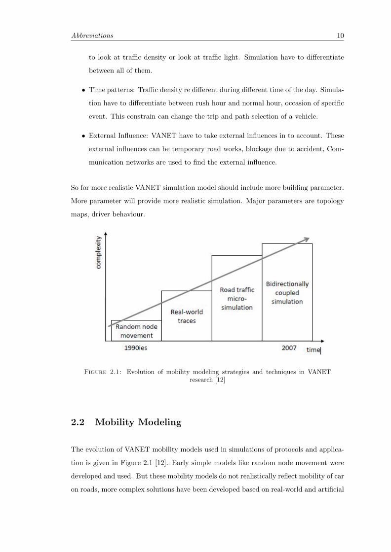
Figure 2.1: Evolution of mobility modeling strategies and techniques in VANETresearch [12]
2.2 Mobility Modeling
The evolution of VANET mobility models used in simulations of protocols and applica-
tion is given in Figure 2.1 [12]. Early simple models like random node movement were
developed and used. But these mobility models do not realistically reflect mobility of car
on roads, more complex solutions have been developed based on real-world and artificial
Abbreviations 11
traces of car movements up to recent advances based on tightly coupled road traffic
micro-simulation and network simulation, Traffic simulation and network simulation are
described in next chapter.
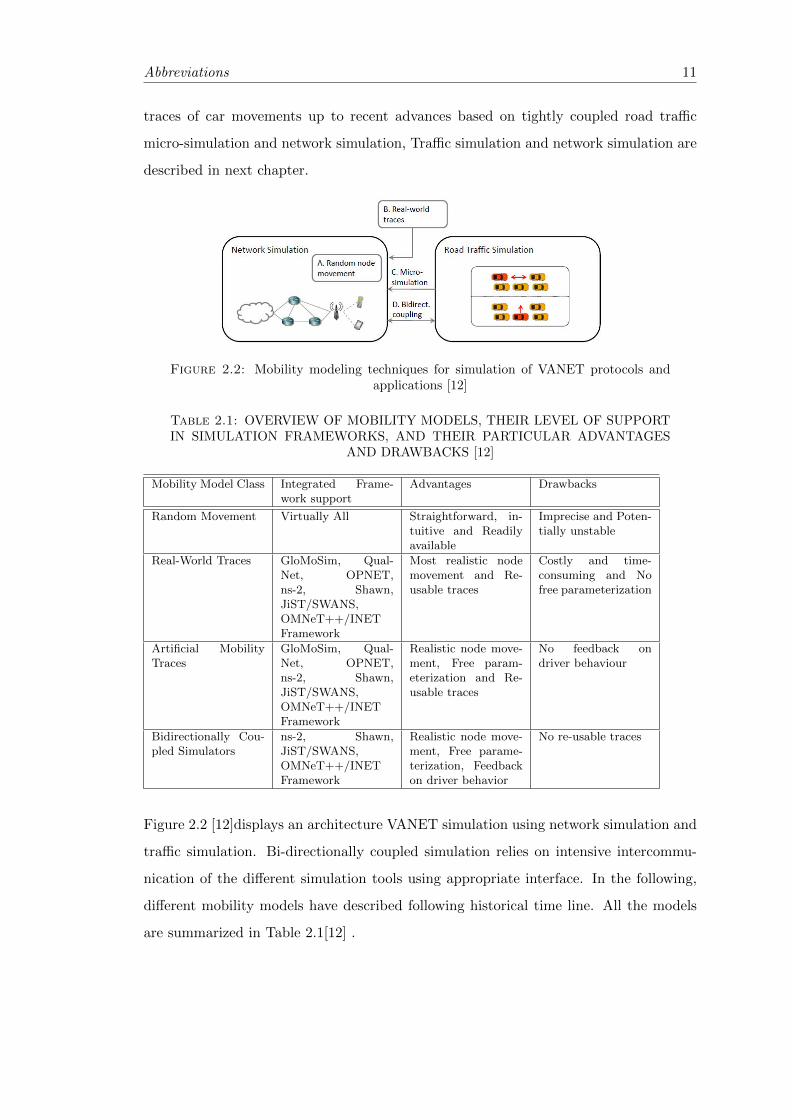
Figure 2.2: Mobility modeling techniques for simulation of VANET protocols andapplications [12]
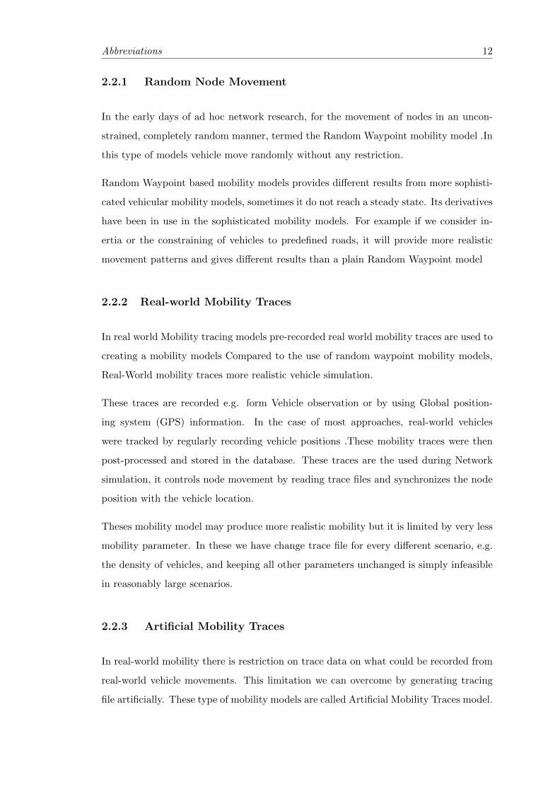
Table 2.1: OVERVIEW OF MOBILITY MODELS, THEIR LEVEL OF SUPPORTIN SIMULATION FRAMEWORKS, AND THEIR PARTICULAR ADVANTAGES
AND DRAWBACKS [12]
Mobility Model Class Integrated Frame-work support
Advantages Drawbacks
Random Movement Virtually All Straightforward, in-tuitive and Readilyavailable
Imprecise and Poten-tially unstable
Real-World Traces GloMoSim, Qual-Net, OPNET,ns-2, Shawn,JiST/SWANS,OMNeT++/INETFramework
Most realistic nodemovement and Re-usable traces
Costly and time-consuming and Nofree parameterization
Artificial MobilityTraces
GloMoSim, Qual-Net, OPNET,ns-2, Shawn,JiST/SWANS,OMNeT++/INETFramework
Realistic node move-ment, Free param-eterization and Re-usable traces
No feedback ondriver behaviour
Bidirectionally Cou-pled Simulators
ns-2, Shawn,JiST/SWANS,OMNeT++/INETFramework
Realistic node move-ment, Free parame-terization, Feedbackon driver behavior
No re-usable traces
Figure 2.2 [12]displays an architecture VANET simulation using network simulation and
traffic simulation. Bi-directionally coupled simulation relies on intensive intercommu-
nication of the different simulation tools using appropriate interface. In the following,
different mobility models have described following historical time line. All the models
are summarized in Table 2.1[12] .
Abbreviations 12
2.2.1 Random Node Movement
In the early days of ad hoc network research, for the movement of nodes in an uncon-
strained, completely random manner, termed the Random Waypoint mobility model .In
this type of models vehicle move randomly without any restriction.
Random Waypoint based mobility models provides different results from more sophisti-
cated vehicular mobility models, sometimes it do not reach a steady state. Its derivatives
have been in use in the sophisticated mobility models. For example if we consider in-
ertia or the constraining of vehicles to predefined roads, it will provide more realistic
movement patterns and gives different results than a plain Random Waypoint model
2.2.2 Real-world Mobility Traces
In real world Mobility tracing models pre-recorded real world mobility traces are used to
creating a mobility models Compared to the use of random waypoint mobility models,
Real-World mobility traces more realistic vehicle simulation.
These traces are recorded e.g. form Vehicle observation or by using Global position-
ing system (GPS) information. In the case of most approaches, real-world vehicles
were tracked by regularly recording vehicle positions .These mobility traces were then
post-processed and stored in the database. These traces are the used during Network
simulation, it controls node movement by reading trace files and synchronizes the node
position with the vehicle location.
Theses mobility model may produce more realistic mobility but it is limited by very less
mobility parameter. In these we have change trace file for every different scenario, e.g.
the density of vehicles, and keeping all other parameters unchanged is simply infeasible
in reasonably large scenarios.
2.2.3 Artificial Mobility Traces
In real-world mobility there is restriction on trace data on what could be recorded from
real-world vehicle movements. This limitation we can overcome by generating tracing
file artificially. These type of mobility models are called Artificial Mobility Traces model.
Abbreviations 13
Artificial mobility models have the advantage of providing simulations with very realistic
mobility traces while freely adjusting the mobility parameters at same time so that
influence of parameter can be examine on output.
2.2.4 Bi-directionally Coupled Simulators
In any case of communication in VANET for example accident information, road block-
age information, hazard condition warning require loop between traffic simulation and
network simulation to be closed. For this purpose intensive cooperation happens be-
tween different simulation, So this type of simulator are called bi-directional simulator.
These type of simulator have recently been developed.
In these simulations, two processes runs concurrently that are process of the network
simulator and the road traffic simulator. Both processes exchange information like po-
sition and speed of simulated vehicles, Data like radio state are present in network
simulator where as planned route is present in the road traffic simulator. In formation
exchange takes place in regular interval.
2.3 Routing Protocols
Now different leading car manufactures collaborated with USA government agency to
develop communication protocol specially dedicated for the Vehicular communication.
Outcome of this collaboration is a wireless access called Wireless Access for Vehicular
Environment (WAVE) dedicated for to vehicle to Roadside and vehicle to vehicle com-
munication. It major objective is to improve the safety on the road but also takes care
of traffic management as well as on-board entertainment application. When vehicles are
equipped with WAVE communication device it is called as VANET.
We know that VANET are subset of MANET, there are plenty of routing protocols
developed for MANET but these usually do not apply for the VANET because it has
very high mobility and network gets frequently disconnected.
Routing protocols manages how information exchange happens between two communi-
cation entities, this management is done by establishing a route, decision in forwarding
data, maintaining the route and recovery of failed route.
Abbreviations 14
In VANET, the routing protocols are classified into five categories[14]: Topology based,
Position based, Cluster based, Geo-cast and Broadcast. Table2.2 [14] present compari-
sion of various protocols.
2.3.1 Topology Based routing protocols
Topology based routing protocols gets the information of the route the topology of the
network. We can further divide this protocol into two category.
1. Proactive
2. Reactive
2.3.1.1 Proactive routing protocols
The main distinction of proactive routing protocols is that irrespective of communi-
cation request, the routing information like next forwarding hop is maintained in the
background. The data packets are constantly flooded into different node to maintain
the path and then using these information a table is created which contains data about
next hop to reach a certain destination. The main advantage of proactive routing is that
we do not have do a route discovery route information can be directly derived from the
table.
One example of proactive routing protocol is given below:
Fisheye state routing (FSR):
In Fisheye state routing every nodes creates a topology table(TT) based on the informa-
tion which are given by neighbour and it also share information if TT whit its neighbour.
Routing tables are different for different destination. The problem with FSR in if the
size of network increases the size of table will also increase so it will be very complex to
maintain tables. If mobility increate the accuracy of route between node to destination
will decrease.
2.3.1.2 Reactive routing protocols
Unlike proactive routing protocols here route opens only when it necessary for commu-
nication between two nodes. So this type of protocols are also called as On Demand

Abbreviations 15
routing protocols. It maintains routs which are in use, So burden on large network de-
creases. Here very large networks are also easily maintainable. Reactive protocols have
a phase of searching route, this usually done by flooding, this phase ends when the route
found. One example of proactive routing protocol is given below:
Temporal Ordered Routing Algorithm(TORA) :
TORA is link reversal routing algorithm it builds a directed cyclic graph according to
which it directs the flow of packets and ensures its reaches to all nodes. To construct a
directed node broadcasts query packets. If an receive query packet, if node has a link
to destination it will again broadcast a reply packet; which acknowledges the link . It
constantly updates graph information in regular interval.
2.3.2 position based routing protocol
In position based routing protocols the determination of route is done by information of
geographical position of different nodes. Here source inters the information of destination
in the node of the packet. The source sends the packet to next hop which is closest to the
destination. The main advantage of these protocols is that we do not have to maintain
information about route from a source to destination. These protocols are mainly dived
into two category:
1. Position based greedy V2V protocols
2. Delay Tolerant Protocols
2.3.2.1 Position Based Greedy V2V Protocols
In greedy algorithm the source and intermediate nodes sends, the packets to the farthest
node in the direction of destination. The main aim of these protocols is to decrease
the time to for packet transmission, and so are called as Min delay routing proto-
cols. Various types of Position based greedy V2V protocols are GSR, GPSR, CAR,
GPCR, STBR, ASTAR, CBF, SAR, DIR and ROMSGP. One example is given below:
Geographic Source Routing (GSR) :
The GSR are imported from MANET use to VANET use by incorporating in to it greedy
Abbreviations 16
forwarding of messages toward the destination. It uses a specific mode called Perimeter
Mode for recovery if next hop node is not found. It uses static street map and location
information about each node, because it do not consider vehicle density in road so this
not a efficient method.
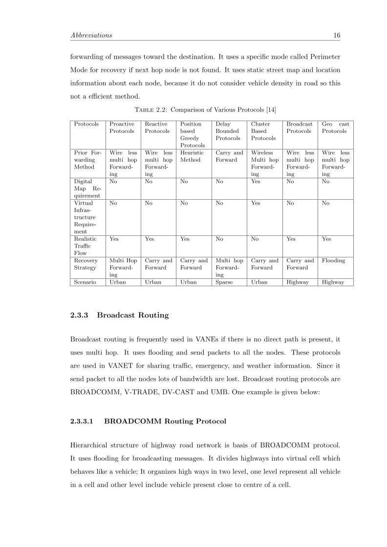
Table 2.2: Comparison of Various Protocols [14]
Protocols ProactiveProtocols
ReactiveProtocols
PositionbasedGreedyProtocols
DelayBoundedProtocols
ClusterBasedProtocols
BroadcastProtocols
Geo castProtocols
Prior For-wardingMethod
Wire lessmulti hopForward-ing
Wire lessmulti hopForward-ing
HeuristicMethod
Carry andForward
WirelessMulti hopForward-ing
Wire lessmulti hopForward-ing
Wire lessmulti hopForward-ing
DigitalMap Re-quirement
No No No No Yes No No
VirtualInfras-tructureRequire-ment
No No No No Yes No No
RealisticTrafficFlow
Yes Yes Yes No No Yes Yes
RecoveryStrategy
Multi HopForward-ing
Carry andForward
Carry andForward
Multi hopForward-ing
Carry andForward
Carry andForward
Flooding
Scenario Urban Urban Urban Sparse Urban Highway Highway
2.3.3 Broadcast Routing
Broadcast routing is frequently used in VANEs if there is no direct path is present, it
uses multi hop. It uses flooding and send packets to all the nodes. These protocols
are used in VANET for sharing traffic, emergency, and weather information. Since it
send packet to all the nodes lots of bandwidth are lost. Broadcast routing protocols are
BROADCOMM, V-TRADE, DV-CAST and UMB. One example is given below:
2.3.3.1 BROADCOMM Routing Protocol
Hierarchical structure of highway road network is basis of BROADCOMM protocol.
It uses flooding for broadcasting messages. It divides highways into virtual cell which
behaves like a vehicle; It organizes high ways in two level, one level represent all vehicle
in a cell and other level include vehicle present close to centre of a cell.

Abbreviations 17
2.3.4 Geo-cast Routing
It is a type of multi cast routing which is based in geographical location. It delivers
packet to all nodes which are present in a geographical region. The vehicles which are
not present inside certain geographical region does not gets the warning messages. It
floods the message to node defined by forwarding zone. Its main disadvantage is that it
is unfavourable to the neighbour. The various Geo-cast routing are DRG, DG-CASTOR
and IVG.
Chapter 3
In this chapter we describe how simulation is done and what the results of the simulation
are. The simulation is done in 2 phases and two different simulator have been used One
is SUMO(Simulation of Urban Mobility) for road traffic simulation and Veins(Vehicular
environment in Network Simulation) for network simulation.
3.1 Traffic Simulation
For simulation of Road traffic simulator used is SUMO (Simulator for Urban Mobility).
Lets see about sumo.
3.1.1 SUMO (Simulation of Urban Mobility)
SUMO is open source and highly portable road traffic simulator, it can handle very
large network. It uses microscopic and continuous mobility model. It was developed by
Institute of Transportation Systems at the German Aerospace Center [13].
Since SUMO uses microscopic traffic simulation, each vehicle have explicitly defined,
each having unique path an indentification. Each vehicle can be further defined by
Origin destination metrics (O/D matrics) this matrics contains information about source
and destination. Trip file can be generated from o/d matrics usind od2trips.
For simulation SUMO need network file to the road network.
Now we will discuss how network file is created. Network files define the road map ion
which the vehicle runs. Network file generation have following phase.
18

Abbreviations 19
3.1.2 Importing map
Although we can manually generate network file by writing route, but this networks are
very primitive and it is very difficult to create complex networks. Fig 3.1 [17] shows
some manually created networks.
Figure 3.1: Network file created manually (a) Grid network (b) and (c) Spider Net-works [17]
(a) (b) (c)
But for the realistic simulation we have to create network file which are present in the
real world for that purpose SUMO incorporate by which we can download real world
road map Form the openstreetmap.org fig3.2 show map from openstreet.org
Figure 3.2: Map form open street Org
The map are downloaded are OSM file, after downloading map from the website the
OSM file edited using JOSM Java OpenStreetMap Editor . IN this process all the
unwanted route and path are removed to simplify the network file.
Abbreviations 20
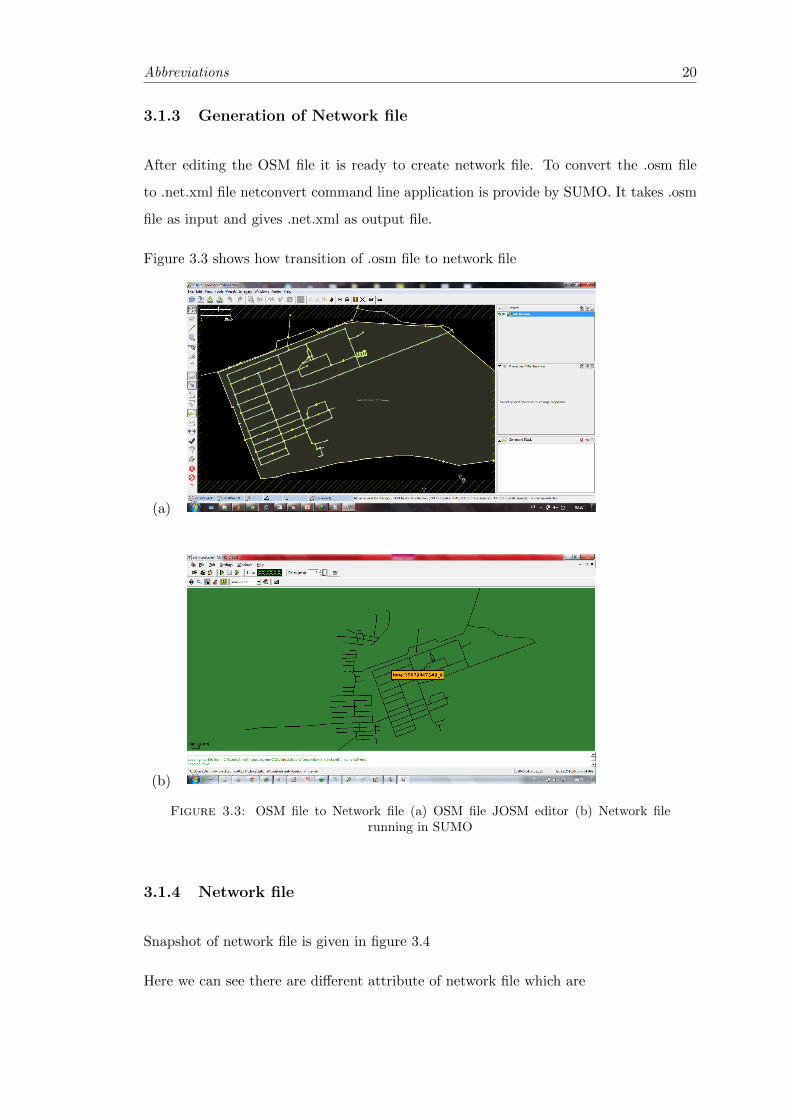
3.1.3 Generation of Network file
After editing the OSM file it is ready to create network file. To convert the .osm file
to .net.xml file netconvert command line application is provide by SUMO. It takes .osm
file as input and gives .net.xml as output file.
Figure 3.3 shows how transition of .osm file to network file
(a)
(b)
Figure 3.3: OSM file to Network file (a) OSM file JOSM editor (b) Network filerunning in SUMO
3.1.4 Network file
Snapshot of network file is given in figure 3.4
Here we can see there are different attribute of network file which are
Abbreviations 21
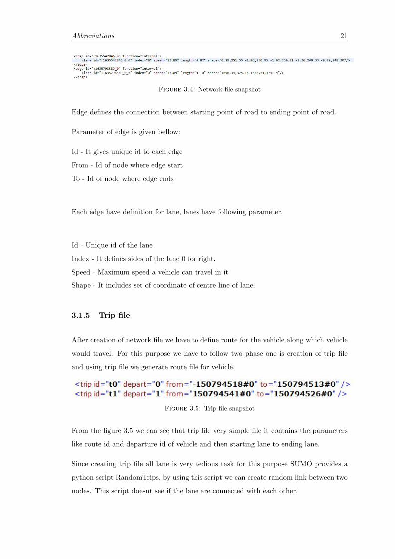
Figure 3.4: Network file snapshot
Edge defines the connection between starting point of road to ending point of road.
Parameter of edge is given bellow:
Id - It gives unique id to each edge
From - Id of node where edge start
To - Id of node where edge ends
Each edge have definition for lane, lanes have following parameter.
Id - Unique id of the lane
Index - It defines sides of the lane 0 for right.
Speed - Maximum speed a vehicle can travel in it
Shape - It includes set of coordinate of centre line of lane.
3.1.5 Trip file
After creation of network file we have to define route for the vehicle along which vehicle
would travel. For this purpose we have to follow two phase one is creation of trip file
and using trip file we generate route file for vehicle.
Figure 3.5: Trip file snapshot
From the figure 3.5 we can see that trip file very simple file it contains the parameters
like route id and departure id of vehicle and then starting lane to ending lane.
Since creating trip file all lane is very tedious task for this purpose SUMO provides a
python script RandomTrips, by using this script we can create random link between two
nodes. This script doesnt see if the lane are connected with each other.
Abbreviations 22
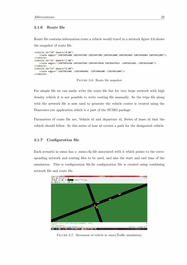
3.1.6 Route file
Route file contains information route a vehicle would travel in a network figure 3.6 shows
the snapshot of route file.
Figure 3.6: Route file snapshot
For simple file we can easily write the route file but for very large network with high
density vehicle it is not possible to write routing file manually. So the trips file along
with the network file is now used to generate the vehicle routes is created using the
Duarouter.exe application which is a part of the SUMO package.
Parameters of route file are, Vehicle id and departure id, Series of lanes id that the
vehicle should follow. So this series of lane id creates a path for the designated vehicle.
3.1.7 Configuration file
Each scenario in sumo has a .sumo.cfg file associated with it which points to the corre-
sponding network and routing files to be used, and also the start and end time of the
simulation. This is configuration file.So configuration file is created using combining
network file and route file.
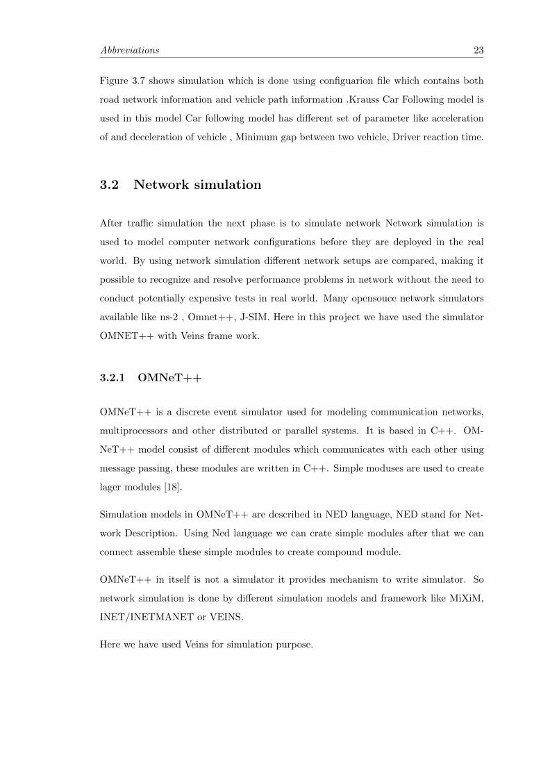
Figure 3.7: Movement of vehicle in sumo(Traffic simulation)
Abbreviations 23
Figure 3.7 shows simulation which is done using configuarion file which contains both
road network information and vehicle path information .Krauss Car Following model is
used in this model Car following model has different set of parameter like acceleration
of and deceleration of vehicle , Minimum gap between two vehicle, Driver reaction time.
3.2 Network simulation
After traffic simulation the next phase is to simulate network Network simulation is
used to model computer network configurations before they are deployed in the real
world. By using network simulation different network setups are compared, making it
possible to recognize and resolve performance problems in network without the need to
conduct potentially expensive tests in real world. Many opensouce network simulators
available like ns-2 , Omnet++, J-SIM. Here in this project we have used the simulator
OMNET++ with Veins frame work.
3.2.1 OMNeT++
OMNeT++ is a discrete event simulator used for modeling communication networks,
multiprocessors and other distributed or parallel systems. It is based in C++. OM-
NeT++ model consist of different modules which communicates with each other using
message passing, these modules are written in C++. Simple moduses are used to create
lager modules [18].
Simulation models in OMNeT++ are described in NED language, NED stand for Net-
work Description. Using Ned language we can crate simple modules after that we can
connect assemble these simple modules to create compound module.
OMNeT++ in itself is not a simulator it provides mechanism to write simulator. So
network simulation is done by different simulation models and framework like MiXiM,
INET/INETMANET or VEINS.
Here we have used Veins for simulation purpose.
Abbreviations 24
3.2.2 Veins
Veins module is avilabe in MiXiM frame work here MixiM provides communication
module and protocol . Veins stand for Vehicle in Network Simulation. Veins is an
open source Inter-Vehicular Communication (IVC) simulation framework composed of
an network simulator and a road traffic microsimulation model.
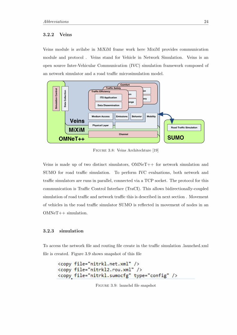
Figure 3.8: Veins Architechture [19]
Veins is made up of two distinct simulators, OMNeT++ for network simulation and
SUMO for road traffic simulation. To perform IVC evaluations, both network and
traffic simulators are runs in parallel, connected via a TCP socket. The protocol for this
communication is Traffic Control Interface (TraCI). This allows bidirectionally-coupled
simulation of road traffic and network traffic this is described in next section . Movement
of vehicles in the road traffic simulator SUMO is reflected in movement of nodes in an
OMNeT++ simulation.
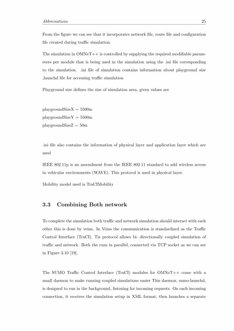
3.2.3 simulation
To access the network file and routing file create in the traffic simulation .launched.xml
file is created. Figure 3.9 shows snapshot of this file
Figure 3.9: launchd file snapshot
Abbreviations 25
From the figure we can see that it incorporates network file, route file and configuration
file created during traffic simulation.
The simulation in OMNeT++ is controlled by supplying the required modifiable param-
eters per module that is being used in the simulation using the .ini file corresponding
to the simulation. .ini file of simulation contains information about playground size
,launchd file for accessing traffic simulation
Playground size defines the size of simulation area, given values are
playgroundSizeX = 5500m
playgroundSizeY = 5500m
playgroundSizeZ = 50m
.ini file also contains the information of physical layer and application layer which are
used
IEEE 802.11p is an amendment from the IEEE 802.11 standard to add wireless access
in vehicular environments (WAVE). This protocol is used in physical layer.
Mobility model used is TraCIMobility
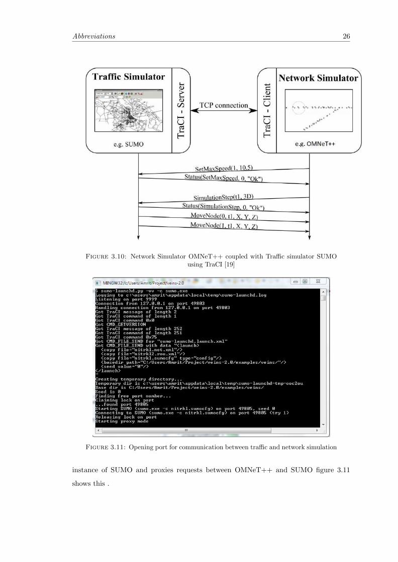
3.3 Combining Both network
To complete the simulation both traffic and network simulation should interact with each
other this is done by veins. In Veins the communication is standardized as the Traffic
Control Interface (TraCI). Tis protocol allows bi- directionally coupled simulation of
traffic and network. Both the runs in parallel, connected via TCP socket as we can see
in Figure 3.10 [19].
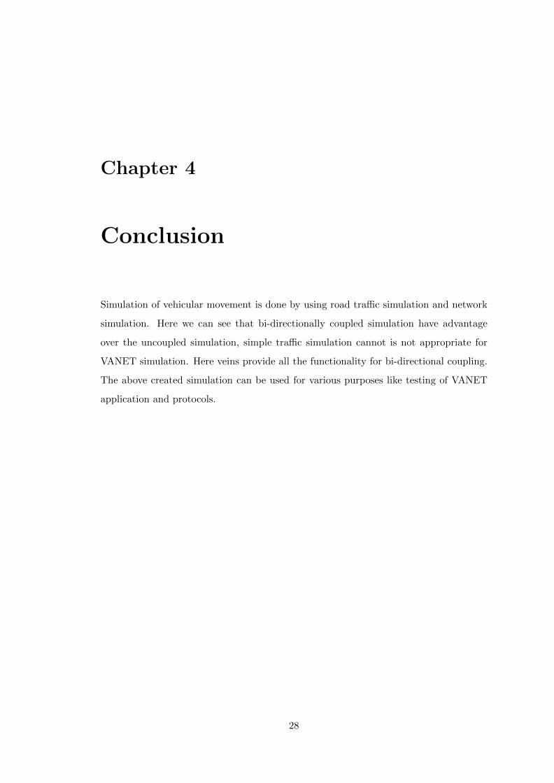
The SUMO Traffic Control Interface (TraCI) modules for OMNeT++ come with a
small daemon to make running coupled simulations easier This daemon, sumo-launchd,
is designed to run in the background, listening for incoming requests. On each incoming
connection, it receives the simulation setup in XML format, then launches a separate
Abbreviations 26
Figure 3.10: Network Simulator OMNeT++ coupled with Traffic simulator SUMOusing TraCI [19]
Figure 3.11: Opening port for communication between traffic and network simulation
instance of SUMO and proxies requests between OMNeT++ and SUMO figure 3.11
shows this .

Abbreviations 27
3.3.1 Final Simulation
After completing all the above mentioned steps now we can run the simulation in om-
net++ The node movement in the network simulation is governed by network file of
traffic simulation. Figure 3.12 represents this.
Figure 3.12: Network simulation using omnet++
All the information of the communication between vehicle are stored in a trace file.
Chapter 4
Conclusion
Simulation of vehicular movement is done by using road traffic simulation and network
simulation. Here we can see that bi-directionally coupled simulation have advantage
over the uncoupled simulation, simple traffic simulation cannot is not appropriate for
VANET simulation. Here veins provide all the functionality for bi-directional coupling.
The above created simulation can be used for various purposes like testing of VANET
application and protocols.
28
Bibliography[1]Li Zhiyuan,Hu Jinhong.Framework of Real VANET Simulation Research.2011 Third
International Conference on Multimedia Information Networking and Security.
[2]Vehicular Mobility Simulation for VANETs Marco Fiore Politecnico di Torino Corso
Duca degli Abruzzi 24 10129 Torino, Italy Jerome Harri, Fethi Filali, Christian Bon-
net Institut Eurecom y Department of Mobile Communications 06904 Sophia-Antipolis,
France
[3] VEHICLE-TO-VEHICLE AND ROAD-SIDE SENSOR COMMUNICATION FOR
ENHANCED ROAD SAFETY Andreas Festag, Alban Hessler, Roberto Baldessari, Long
Le, Wenhui Zhang, Dirk Westhoff NEC Laboratories Europe.
[4] VEHICLE-TO-VEHICLE AND ROAD-SIDE SENSOR COMMUNICATION FOR
ENHANCED ROAD SAFETY Andreas Festag, Alban Hessler, Roberto Baldessari, Long
Le, Wenhui Zhang, Dirk Westhoff NEC Laboratories Europe.
[5] Fan Li and Yu Wang; Routing in Vehicular Ad Hoc Networks: A Survey, IEEE
Vehicular Technology Magazine, Volume 2, Issue 2, June 2007; Pages: 12-22.
[6]Survey of Routing Protocols in Vehicular Ad Hoc Networks Kevin C. Lee, UCLA,
USA Uichin Lee, UCLA, USA Mario Gerla, UCLA, USA
[7]Development of a Hybrid Simulation and Emulation Testbed For VANETs R. Costa,
S. Sargento, R. Aguiar, Instituto de Telecomunicac oes, Aveiro (Portugal) and W.Zhang,
NEC Network Laboratories, Heidelberg (Germany).
[8] A comprehensive survey on vehicular Ad Hoc network Saif Al-Sultan n, Moath M.
Al-Doori, Ali H. Al-Bayatti, Hussien Zedan Software Technology Research Laboratory,
De Montfort University, Bede Island Building, Western Boulevard, Leicester LE2 7EW,
UK.
29
Bibliography 30
[9] Urban Mobility Models for VANETs Atulya Mahajan, Niranjan Potnis, Kartik
Gopalan and An-I A. Wang Computer Science, Florida State University.
[10] A. Varga, The OMNeT++ Discrete Event Simulation System, Proc. European
Simulation Multiconf. (ESM 01), June 2001.
[11] Bidirectionally Coupled Network and Road Traffic Simulation for Improved IVC
Analysis Christoph Sommer, Student Member, IEEE, Reinhard German, and Falko
Dressler, Senior Member, IEEE. IEEE TRANSACTIONS ON MOBILE COMPUTING,
VOL. 10, NO. 1, JANUARY 2011
[12] Progressing Toward Realistic Mobility Models in VANET Simulations Christoph
Sommer Student Member, IEEE and Falko Dressler Senior Member, IEEE Computer
Networks and Communication Systems Dept. of Computer Sciences University of Elargen-
Nuremberg, Germany
[13] SUMO - Simulation of Urban MObility: An Overview In: SIMUL 2011, The Third
International Conference on Advances in System Simulation, 2011.
[14] A comparative study of Routing Protocols in VANET Sandhaya Kohli1, Bandanjot
Kaur2, Sabina Bindra2 1Dept. of CSE, RIMT-IMT, 2Dept. of CSE, RIMT-IET
[15] Mobile Ad hoc networking carlos de morais cordeiro and Dharma P. Agrawal, OBR
Research center for distributed and mobile computing, ECECS, University of Cincinnati,
Cincinnati
[16] http://www.car-to-car.org/index.php?id=137
[17] SUMO network Generation http://sumo.sourceforge.net/
[18]THE OMNET++ DISCRETE EVENT SIMULATION SYSTEM Andrs Varga De-
partment of Telecommunications Budapest University of Technology and Economics
Pzmny Pter stny 1/d. 1117 Budapest, Hungary
[19] http://veins.car2x.org/documentation/
![VANET Routing on City Roads Using Real-Time Vehicular ...celio/classes/cmovel/slides/vanet-rbvt09.pdf · dynamic source routing (DSR) [9], ... The RBVT routing protocols leverage](https://img.pdfslide.us/doc/110x75/5aeb05fe7f8b9a90318c6bcb/vanet-routing-on-city-roads-using-real-time-vehicular-celioclassescmovelslidesvanet-.jpg)