Embed Size (px)
Citation preview
J. Cent. South Univ. (2018) 25: 662−670 DOI: https://doi.org/10.1007/s11771-018-3769-9
Simulation and analysis of humid air turbine cycle based on aeroderivative three-shaft gas turbine
HUANG Di(黄地)1, 2, CHEN Jin-wei(陈金伟)1, ZHOU Deng-ji(周登极)1, ZHANG Hui-sheng(张会生)1, SU Ming(苏明)1
1. The Key Laboratory of Power Machinery and Engineering (Ministry of Education),
Shanghai Jiao Tong University, Shanghai 200240, China; 2. State Grid Jiangsu Electric Power Research Institute, Nanjing 211103, China
© Central South University Press and Springer-Verlag GmbH Germany, part of Springer Nature 2018
Abstract: Due to the fact that the turbine outlet temperature of aeroderivative three-shaft gas turbine is low, the conventional combined cycle is not suitable for three-shaft gas turbines. However, the humid air turbine (HAT) cycle provides a new choice for aeroderivative gas turbine because the humidification process does not require high temperature. Existing HAT cycle plants are all based on single-shaft gas turbines due to their simple structures, therefore converting aeroderivative three-shaft gas turbine into HAT cycle still lacks sufficient research. This paper proposes a HAT cycle model on a basis of an aeroderivative three-shaft gas turbine. Detailed HAT cycle modelling of saturator, gas turbine and heat exchanger are carried out based on the modular modeling method. The models are verified by simulations on the aeroderivative three-shaft gas turbine. Simulation results show that the studied gas turbine with original size and characteristics could not reach the original turbine inlet temperature because of the introduction of water. However, the efficiency still increases by 0.16% when the HAT cycle runs at the designed power of the simple cycle. Furthermore, simulations considering turbine modifications show that the efficiency could be significantly improved. The results obtained in the paper can provide reference for design and analysis of HAT cycle based on multi-shaft gas turbine especially the aeroderivative gas turbine. Key words: humid air turbine; aeroderivative gas turbine; saturator; simulation Cite this article as: HUANG Di, CHEN Jin-wei, ZHOU Deng-ji, ZHANG Hui-sheng, SU Ming. Simulation and analysis of humid air turbine cycle based on aeroderivative three-shaft gas turbine [J]. Journal of Central South University, 2018, 25(3): 662–670. DOI: https://doi.org/10.1007/s11771-018-3769-9.
1 Introduction
The humid air turbine (HAT) cycle proposed by RAO [1] is one of the most advanced gas turbine cycles that is known for its high efficiency and low emission, as well as for its competitive cost, particularly in small and medium-capacity gas turbines [2]. Different from traditional gas turbine cycles such as the regenerative cycle and the combined cycle, the HAT cycle changes the flow
rate inside the components of gas turbine [3]. That is to say, the gas turbine designed for simple cycle might not suit HAT cycle. The main reason is that the flow rate leaving the saturator increases during the humidification process in the saturator. The saturator, which acts as a pressurized humidification tower, permits the introduction of water under boiling point into the compressed air stream with minimal exergy losses [4].
The three-shaft gas turbine was originally designed for aeroengine. The simple cycle of
Foundation item: Project(2017YFB0903300) supported by the National Key R&D Program of China; Project(2016M601593) supported
by the China Postdoctoral Science Foundation Received date: 2016−07−12; Accepted date: 2017−12−20 Corresponding author: ZHANG Hui-sheng, PhD, Professor; Tel: +86–13818875114; E-mail: [email protected]; ORCID: 0000-0002-
4771-3986
J. Cent. South Univ. (2018) 25: 662–670
663
three-shaft gas turbine already has very high efficiency due to its high pressure ratio and low turbine outlet temperature (TOT). Therefore, the aeroderivative gas turbine provides a new choice for power generation. The simple cycle however is not commonly used in power generation thus converting the aeroderivative gas turbine into advanced gas turbine cycles needs to be studied in depth. Nevertheless, the potential of the efficiency improvement is limited due to the low TOT [5, 6]. This is because that the majority of the gas turbine cycles require high TOT to heat the working mediums. The HAT cycle is such a suitable cycle for aeroderivative gas turbine because it does not require high temperature working mediums. The liquid water needed in the saturator can be generated by the low temperature exhaust gas of aeroderivative gas turbine.
There is only limited number of HAT plants and most of them are still at testing stage. Thus the modeling and simulation play a significant role in the development of HAT cycle. ÅGREN et al [7] introduced the first experiments on a HAT cycle plant which is based on the Volvo VT600 gas turbine. HATAMIYA et al [8], KUROKI et al [9] and TAKEDA et al [10] showed three different periods of Japanese advanced HAT (AHAT) cycle plant based on Hitachi H-50 gas turbine, respectively. DE PAEPE et al [11] discussed the performance of converting the Turbec T100 micro gas turbine into micro HAT (mHAT) cycle. It can be seen that most of existing HAT cycle plants are based on single-shaft gas turbines. The main reason is that the structure of single-shaft gas turbine is simple thus converting it into HAT cycle is more feasible. Although the saturator changes the flow rate inside the gas turbine, the HAT cycle based on the single-shaft gas turbine can achieve a new mass balance while the extra flow rate becomes output power. Therefore, the existing simulations for HAT cycles are mostly based on single-shaft gas turbines. ZHANG et al [12] and WAN et al [13] did the steady-state simulation of HAT cycle while OUYANG et al [14] and CARRERO et al [15] discussed the dynamic simulation, which are all based on single-shaft gas turbine. NYBERG et al [16] simulated and analyzed the components of HAT cycle but only focused on cycle simulation without considering any existing gas turbine. Therefore, the HAT cycle based on multi-shaft gas
turbine still lacks sufficient research and has a great demand for system simulation and design analysis.
In this work, the modeling and simulation of HAT cycle based on an aeroderivative three-shaft gas turbine is done by the software IPSEpro. The different layouts and humidification parameters are discussed to analyze the possibility and performance of converting the aeroderivative three-shaft gas turbines into the HAT cycle. This paper first discusses the HAT cycle based on areoderivative gas turbine and can provide reference for design and analysis of HAT cycle based on multi-shaft gas turbine especially the aeroderivative gas turbine. 2 Aeroderivative three-shaft gas turbine
and HAT cycle
An aeroderivative three-shaft gas turbine is taken as the simulation object. The gas turbine contains two compressors (the low-pressure and the high-pressure compressors) and three turbines (high-pressure, low-pressure and power turbines). It is widely known that only power turbine can provide output power through the connected power shaft, while the other four components achieve power balance through high-pressure shaft and low-pressure shaft. This complicated structure makes the areoderivative gas turbine difficult to be converted into HAT cycle.
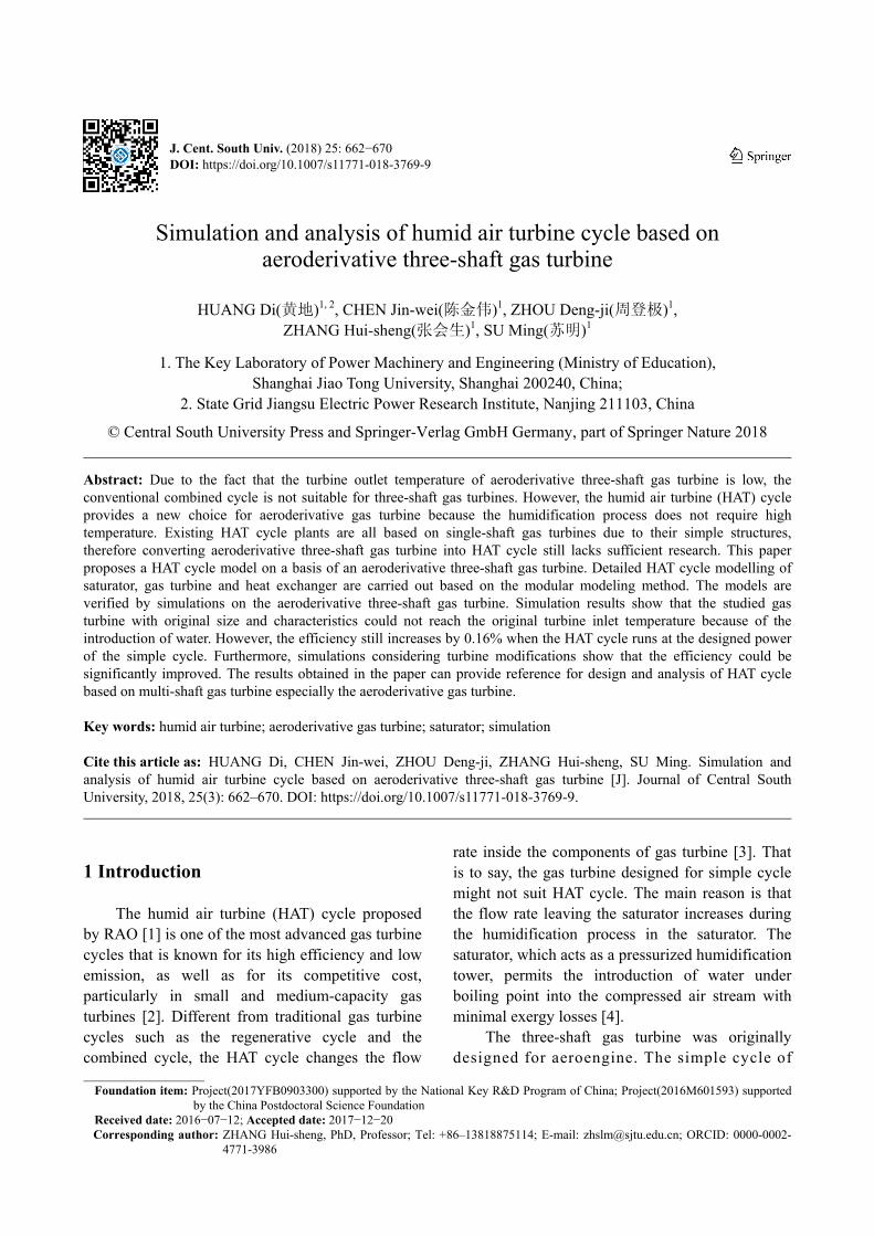
In addition, an intercooler is placed between the low-pressure compressor and the core engine. Moreover, the extraction air from an inside stage and the output of high pressure compressor is sent to four positions to cool the turbines. The structure diagram of the aeroderivative gas turbine is shown in Figure 1 and the main designed parameters are listed in Table 1.
Various layouts of HAT cycle will be simulated in this paper. The saturator is always put on the output of high pressure compressor, after the extraction air leaving the mainstream air. The benefits from introduction of aftercooler and transformation of intercooler is the main object to be discussed in this paper. The HAT cycle based on the original size of aeroderivative gas turbine is considered first, which means that the gas turbine will run at off-design conditions and the performance will be limited by the characteristics of its components due to the air humidification. Then
J. Cent. South Univ. (2018) 25: 662–670
664
Figure 1 Structure diagram of aeroderivative gas turbine
Table 1 Main designed parameters of aeroderivative gas
turbine
Item Amount
Power/MW 40
Efficiency/% 42
Total pressure ratio 40.76
Intercooler outlet temperature/°C 40
Turbine outlet temperature/°C 391
the gas turbine modification is proposed to redesign the three turbines. The simulation results will be compared with those based on the original size. 3 Modeling of HAT cycle
The modeling of HAT cycle is based on the modular modeling method. Thus the system model is divided into several components, for example, saturator, compressor, turbine etc. The modeling method of each component is shown in the following text. 3.1 Saturator
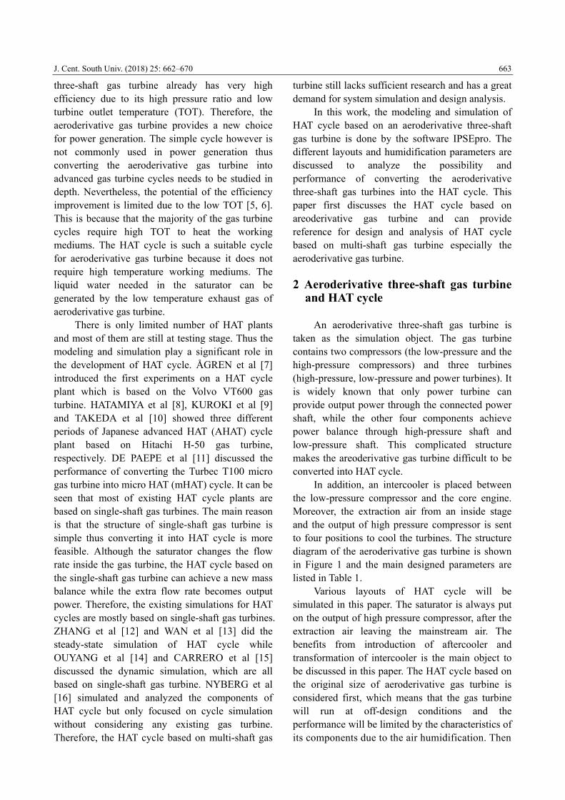
The saturator model is based on the cooling tower method [4]. It is assumed that the air stream is fully saturated at the outlet for the saturator. Two lines are often used to describe the humidification process in the saturator. One is the saturation curve (a solid line shown in Figure 2), which stands for the enthalpy of saturated humid air at the temperature of water. The other is the operating line (a solid line also shown in Figure 2), representing the real enthalpy of the humid air in the saturator.
The gradient of the saturation curve equals the slope of the saturator operating line at the narrowest section between the two (see Figure 2). Note that this is not true if the pinch point occurs at the bottom of the saturator [16]. Based on the above theory, the temperature difference of pinch point is utilized to describe the saturator model.
Figure 2 Saturation curve and operating lines in a
saturator
3.2 Gas turbine
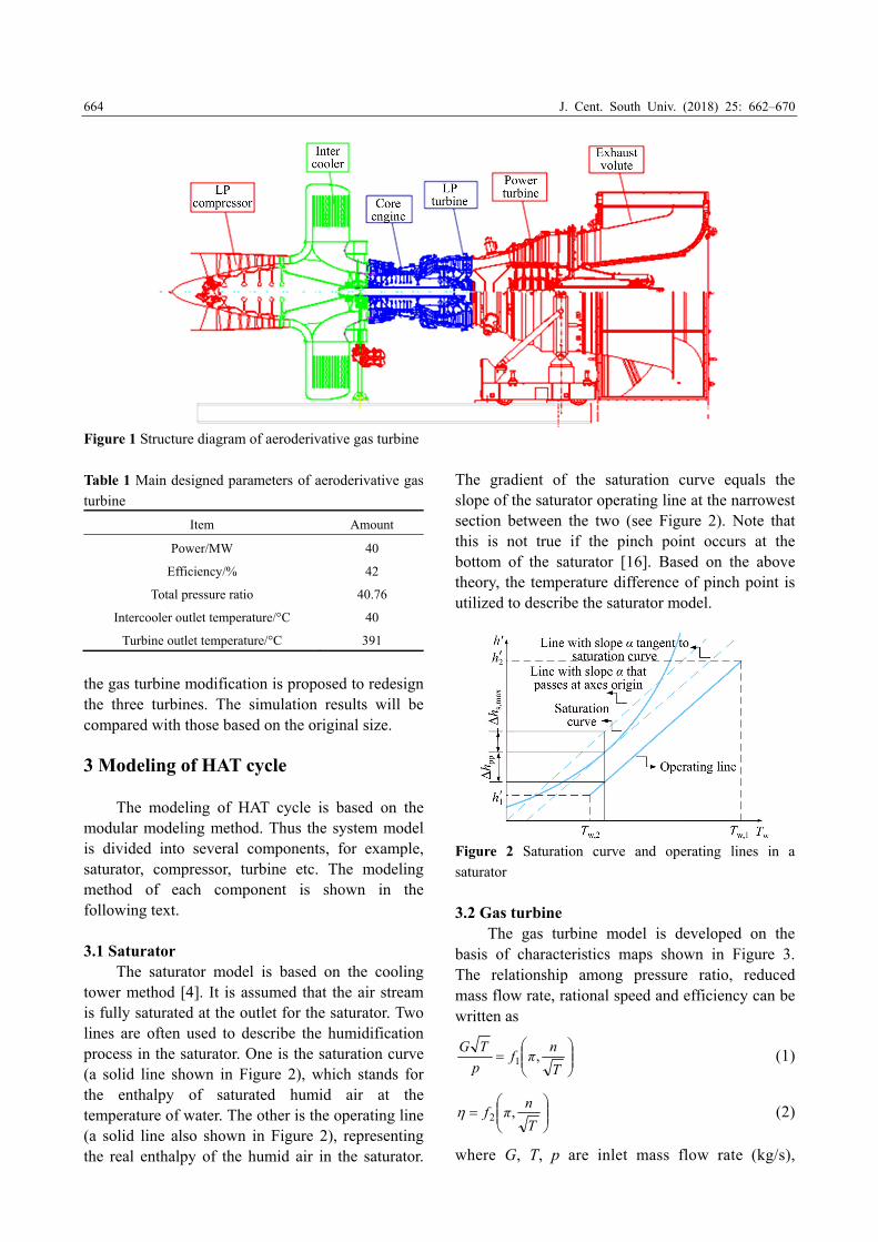
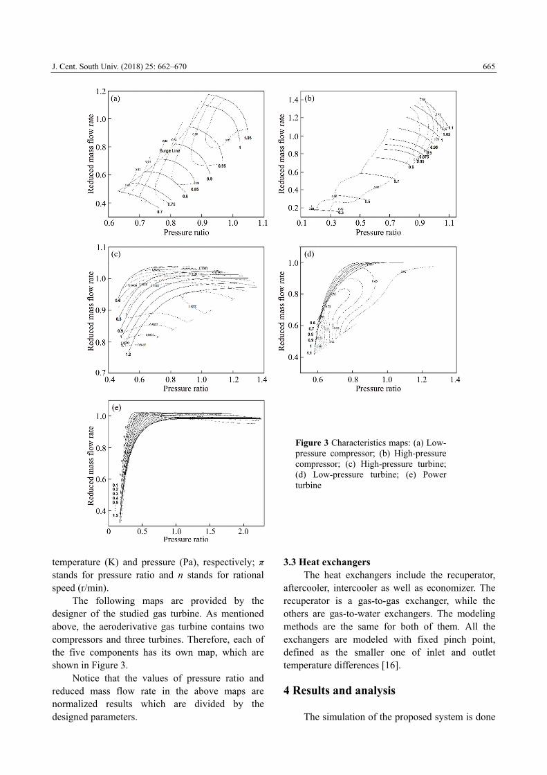
The gas turbine model is developed on the basis of characteristics maps shown in Figure 3. The relationship among pressure ratio, reduced mass flow rate, rational speed and efficiency can be written as
T
nπf
p
TG,1 (1)
T
nπf ,2 (2)
where G, T, p are inlet mass flow rate (kg/s),
J. Cent. South Univ. (2018) 25: 662–670
665
temperature (K) and pressure (Pa), respectively; π stands for pressure ratio and n stands for rational speed (r/min).
The following maps are provided by the designer of the studied gas turbine. As mentioned above, the aeroderivative gas turbine contains two compressors and three turbines. Therefore, each of the five components has its own map, which are shown in Figure 3.
Notice that the values of pressure ratio and reduced mass flow rate in the above maps are normalized results which are divided by the designed parameters.
3.3 Heat exchangers The heat exchangers include the recuperator,
aftercooler, intercooler as well as economizer. The recuperator is a gas-to-gas exchanger, while the others are gas-to-water exchangers. The modeling methods are the same for both of them. All the exchangers are modeled with fixed pinch point, defined as the smaller one of inlet and outlet temperature differences [16]. 4 Results and analysis
The simulation of the proposed system is done
Figure 3 Characteristics maps: (a) Low- pressure compressor; (b) High-pressure compressor; (c) High-pressure turbine; (d) Low-pressure turbine; (e) Power turbine
J. Cent. South Univ. (2018) 25: 662–670
666
by IPSEpro, which is developed by SimTech Company. IPSEpro is a highly flexible software environment for calculating heat balances and simulating processes, which can be used in various fields of application like power plant engineering, chemical engineering and other related areas [17].
The simple cycle is first simulated and the results are compared with the designed parameter to validate the modeling method. Then the simulations of three different HAT cycle layouts with the same saturator condition are done to show the performance of converting the aeroderivative gas turbine into HAT cycle. 4.1 Simple cycle simulation
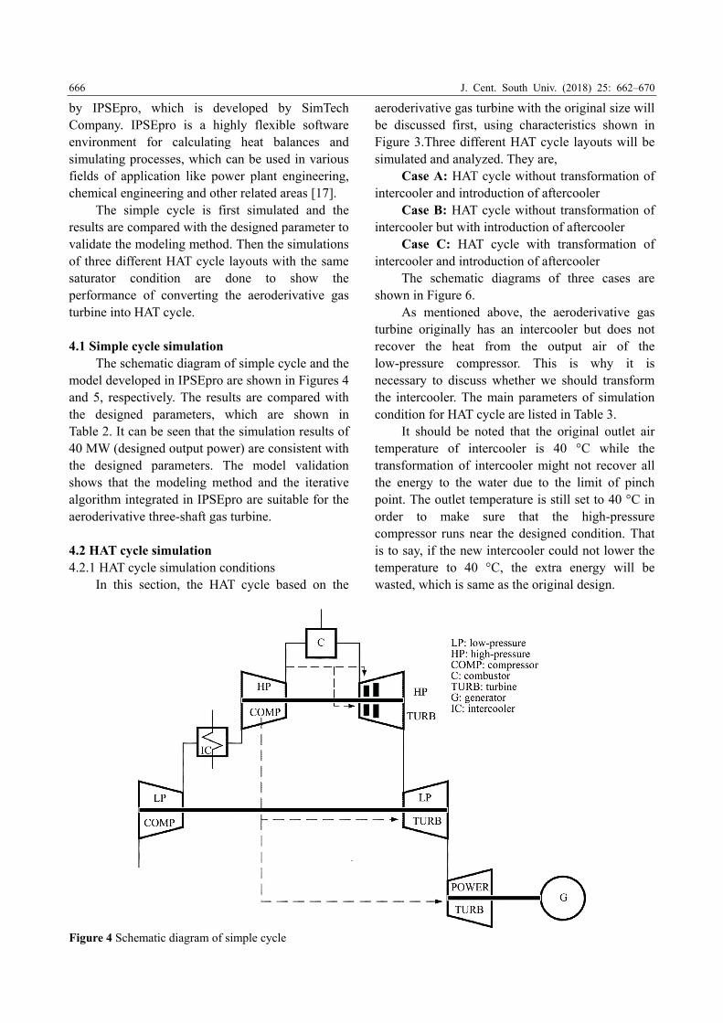
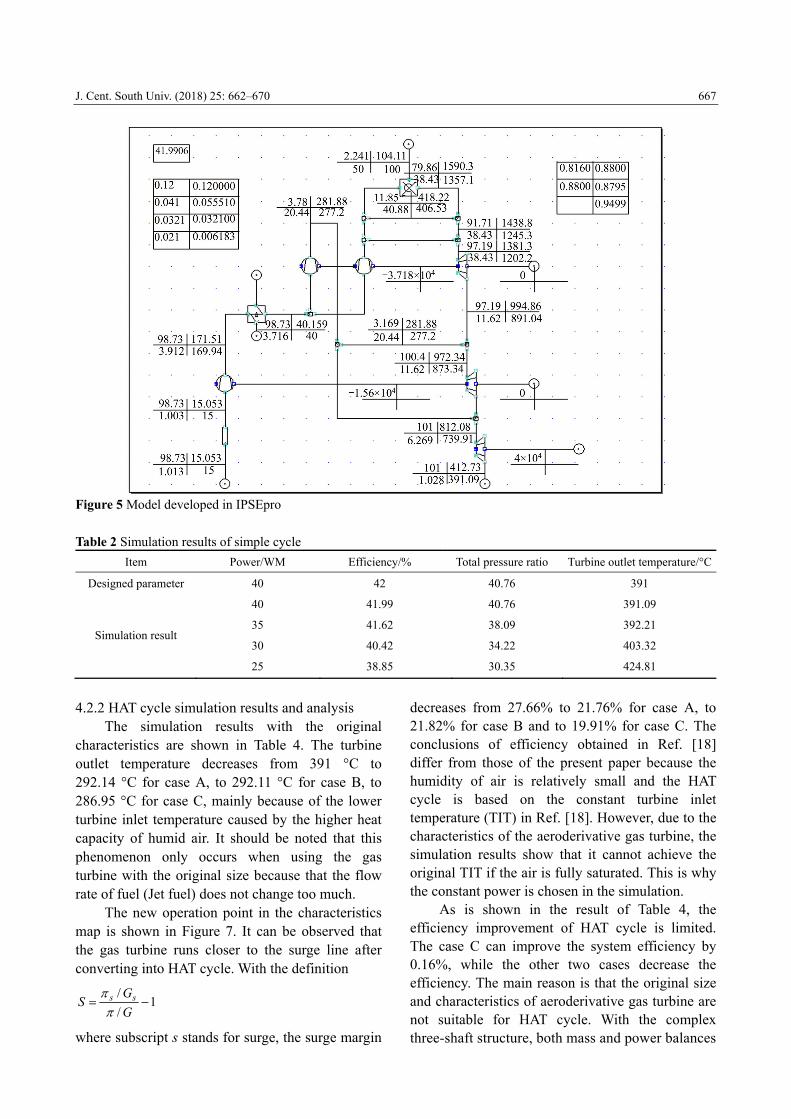
The schematic diagram of simple cycle and the model developed in IPSEpro are shown in Figures 4 and 5, respectively. The results are compared with the designed parameters, which are shown in Table 2. It can be seen that the simulation results of 40 MW (designed output power) are consistent with the designed parameters. The model validation shows that the modeling method and the iterative algorithm integrated in IPSEpro are suitable for the aeroderivative three-shaft gas turbine.
4.2 HAT cycle simulation 4.2.1 HAT cycle simulation conditions
In this section, the HAT cycle based on the
aeroderivative gas turbine with the original size will be discussed first, using characteristics shown in Figure 3.Three different HAT cycle layouts will be simulated and analyzed. They are,
Case A: HAT cycle without transformation of intercooler and introduction of aftercooler
Case B: HAT cycle without transformation of intercooler but with introduction of aftercooler
Case C: HAT cycle with transformation of intercooler and introduction of aftercooler
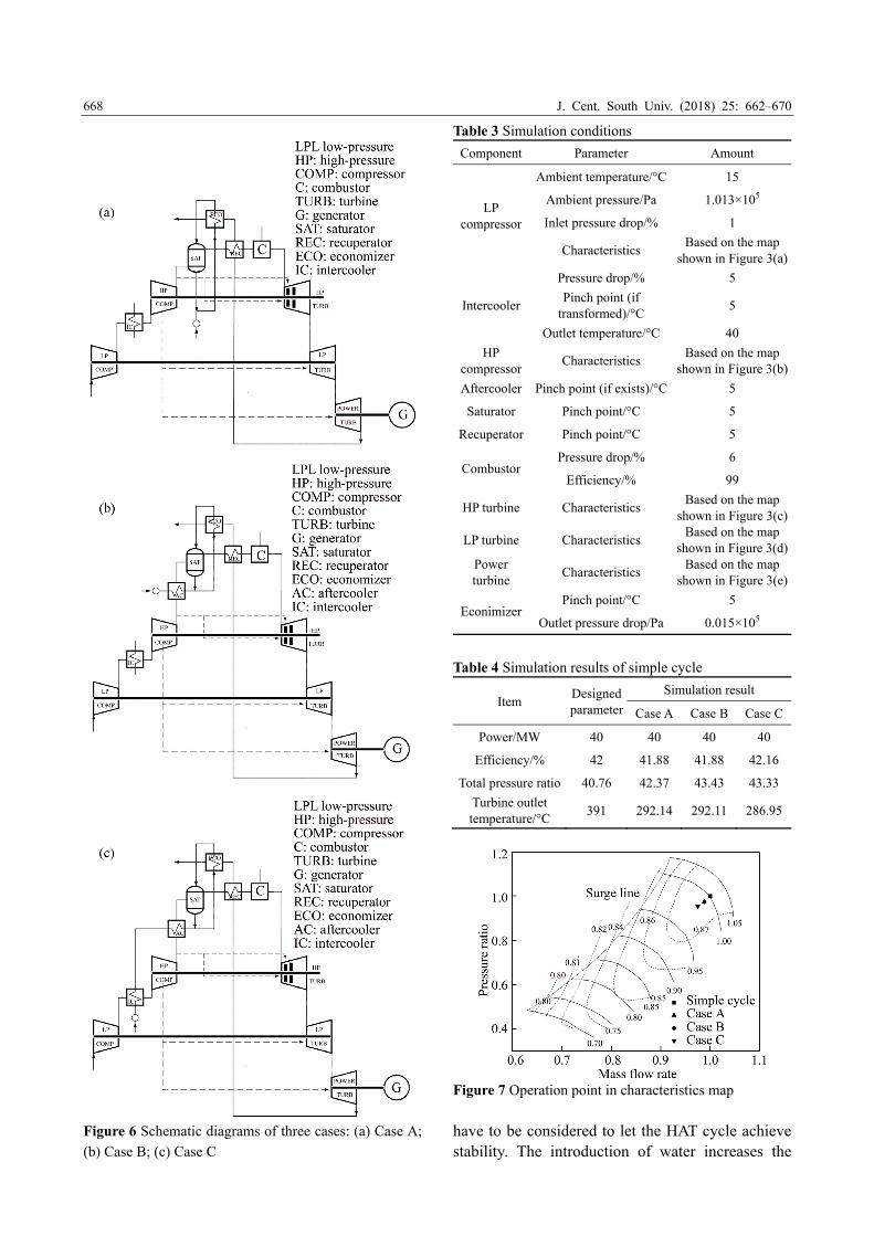
The schematic diagrams of three cases are shown in Figure 6.
As mentioned above, the aeroderivative gas turbine originally has an intercooler but does not recover the heat from the output air of the low-pressure compressor. This is why it is necessary to discuss whether we should transform the intercooler. The main parameters of simulation condition for HAT cycle are listed in Table 3.
It should be noted that the original outlet air temperature of intercooler is 40 °C while the transformation of intercooler might not recover all the energy to the water due to the limit of pinch point. The outlet temperature is still set to 40 °C in order to make sure that the high-pressure compressor runs near the designed condition. That is to say, if the new intercooler could not lower the temperature to 40 °C, the extra energy will be wasted, which is same as the original design.
Figure 4 Schematic diagram of simple cycle
J. Cent. South Univ. (2018) 25: 662–670
667
Figure 5 Model developed in IPSEpro
Table 2 Simulation results of simple cycle
Item Power/WM Efficiency/% Total pressure ratio Turbine outlet temperature/°C
Designed parameter 40 42 40.76 391
Simulation result
40 41.99 40.76 391.09
35 41.62 38.09 392.21
30 40.42 34.22 403.32
25 38.85 30.35 424.81
4.2.2 HAT cycle simulation results and analysis
The simulation results with the original characteristics are shown in Table 4. The turbine outlet temperature decreases from 391 °C to 292.14 °C for case A, to 292.11 °C for case B, to 286.95 °C for case C, mainly because of the lower turbine inlet temperature caused by the higher heat capacity of humid air. It should be noted that this phenomenon only occurs when using the gas turbine with the original size because that the flow rate of fuel (Jet fuel) does not change too much.
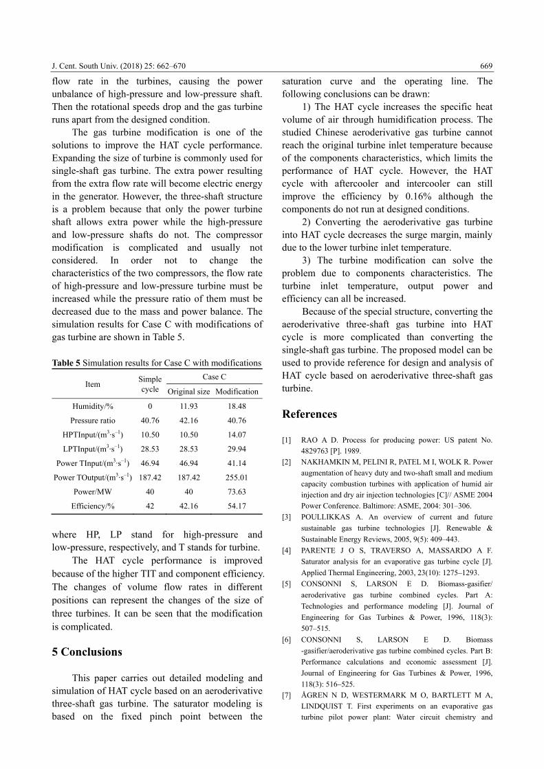
The new operation point in the characteristics map is shown in Figure 7. It can be observed that the gas turbine runs closer to the surge line after converting into HAT cycle. With the definition
1/
/
G
GS ss
where subscript s stands for surge, the surge margin
decreases from 27.66% to 21.76% for case A, to 21.82% for case B and to 19.91% for case C. The conclusions of efficiency obtained in Ref. [18] differ from those of the present paper because the humidity of air is relatively small and the HAT cycle is based on the constant turbine inlet temperature (TIT) in Ref. [18]. However, due to the characteristics of the aeroderivative gas turbine, the simulation results show that it cannot achieve the original TIT if the air is fully saturated. This is why the constant power is chosen in the simulation.
As is shown in the result of Table 4, the efficiency improvement of HAT cycle is limited. The case C can improve the system efficiency by 0.16%, while the other two cases decrease the efficiency. The main reason is that the original size and characteristics of aeroderivative gas turbine are not suitable for HAT cycle. With the complex three-shaft structure, both mass and power balances
J. Cent. South Univ. (2018) 25: 662–670
668
Figure 6 Schematic diagrams of three cases: (a) Case A;
(b) Case B; (c) Case C
Table 3 Simulation conditions
Component Parameter Amount
LP compressor
Ambient temperature/°C 15
Ambient pressure/Pa 1.013×10⁵
Inlet pressure drop/% 1
Characteristics Based on the map
shown in Figure 3(a)
Intercooler
Pressure drop/% 5
Pinch point (if transformed)/°C
5
Outlet temperature/°C 40
HP compressor
Characteristics Based on the map
shown in Figure 3(b)
Aftercooler Pinch point (if exists)/°C 5
Saturator Pinch point/°C 5
Recuperator Pinch point/°C 5
CombustorPressure drop/% 6
Efficiency/% 99
HP turbine Characteristics Based on the map
shown in Figure 3(c)
LP turbine Characteristics Based on the map
shown in Figure 3(d)Power turbine
Characteristics Based on the map
shown in Figure 3(e)
EconimizerPinch point/°C 5
Outlet pressure drop/Pa 0.015×10⁵
Table 4 Simulation results of simple cycle
Item Designed parameter
Simulation result
Case A Case B Case C
Power/MW 40 40 40 40
Efficiency/% 42 41.88 41.88 42.16
Total pressure ratio 40.76 42.37 43.43 43.33
Turbine outlet temperature/°C
391 292.14 292.11 286.95
Figure 7 Operation point in characteristics map
have to be considered to let the HAT cycle achieve stability. The introduction of water increases the
J. Cent. South Univ. (2018) 25: 662–670
669
flow rate in the turbines, causing the power unbalance of high-pressure and low-pressure shaft. Then the rotational speeds drop and the gas turbine runs apart from the designed condition.
The gas turbine modification is one of the solutions to improve the HAT cycle performance. Expanding the size of turbine is commonly used for single-shaft gas turbine. The extra power resulting from the extra flow rate will become electric energy in the generator. However, the three-shaft structure is a problem because that only the power turbine shaft allows extra power while the high-pressure and low-pressure shafts do not. The compressor modification is complicated and usually not considered. In order not to change the characteristics of the two compressors, the flow rate of high-pressure and low-pressure turbine must be increased while the pressure ratio of them must be decreased due to the mass and power balance. The simulation results for Case C with modifications of gas turbine are shown in Table 5. Table 5 Simulation results for Case C with modifications
Item Simple cycle
Case C
Original size Modification
Humidity/% 0 11.93 18.48
Pressure ratio 40.76 42.16 40.76
HPTInput/(m3·s–1) 10.50 10.50 14.07
LPTInput/(m3·s–1) 28.53 28.53 29.94
Power TInput/(m3·s–1) 46.94 46.94 41.14
Power TOutput/(m3·s–1) 187.42 187.42 255.01
Power/MW 40 40 73.63
Efficiency/% 42 42.16 54.17
where HP, LP stand for high-pressure and low-pressure, respectively, and T stands for turbine.
The HAT cycle performance is improved because of the higher TIT and component efficiency. The changes of volume flow rates in different positions can represent the changes of the size of three turbines. It can be seen that the modification is complicated. 5 Conclusions
This paper carries out detailed modeling and simulation of HAT cycle based on an aeroderivative three-shaft gas turbine. The saturator modeling is based on the fixed pinch point between the
saturation curve and the operating line. The following conclusions can be drawn:
1) The HAT cycle increases the specific heat volume of air through humidification process. The studied Chinese aeroderivative gas turbine cannot reach the original turbine inlet temperature because of the components characteristics, which limits the performance of HAT cycle. However, the HAT cycle with aftercooler and intercooler can still improve the efficiency by 0.16% although the components do not run at designed conditions.
2) Converting the aeroderivative gas turbine into HAT cycle decreases the surge margin, mainly due to the lower turbine inlet temperature.
3) The turbine modification can solve the problem due to components characteristics. The turbine inlet temperature, output power and efficiency can all be increased.
Because of the special structure, converting the aeroderivative three-shaft gas turbine into HAT cycle is more complicated than converting the single-shaft gas turbine. The proposed model can be used to provide reference for design and analysis of HAT cycle based on aeroderivative three-shaft gas turbine.
References [1] RAO A D. Process for producing power: US patent No.
4829763 [P]. 1989.
[2] NAKHAMKIN M, PELINI R, PATEL M I, WOLK R. Power
augmentation of heavy duty and two-shaft small and medium
capacity combustion turbines with application of humid air
injection and dry air injection technologies [C]// ASME 2004
Power Conference. Baltimore: ASME, 2004: 301–306.
[3] POULLIKKAS A. An overview of current and future
sustainable gas turbine technologies [J]. Renewable &
Sustainable Energy Reviews, 2005, 9(5): 409–443.
[4] PARENTE J O S, TRAVERSO A, MASSARDO A F.
Saturator analysis for an evaporative gas turbine cycle [J].
Applied Thermal Engineering, 2003, 23(10): 1275–1293.
[5] CONSONNI S, LARSON E D. Biomass-gasifier/
aeroderivative gas turbine combined cycles. Part A:
Technologies and performance modeling [J]. Journal of
Engineering for Gas Turbines & Power, 1996, 118(3):
507–515.
[6] CONSONNI S, LARSON E D. Biomass
-gasifier/aeroderivative gas turbine combined cycles. Part B:
Performance calculations and economic assessment [J].
Journal of Engineering for Gas Turbines & Power, 1996,
118(3): 516–525.
[7] ÅGREN N D, WESTERMARK M O, BARTLETT M A,
LINDQUIST T. First experiments on an evaporative gas
turbine pilot power plant: Water circuit chemistry and
J. Cent. South Univ. (2018) 25: 662–670
670
humidification evaluation [J]. Journal of Engineering for Gas
Turbines and Power-Transactions of the ASME, 2002, 124(1):
96–102.
[8] HATAMIYA S, ARAKI H, HIGUCHI S. An evaluation of
advanced humid air turbine system with water recovery [C]//
ASME Turbo Expo 2004: Power for Land, Sea, and Air.
Vienna, 2004, 7: 585–591.
[9] KUROKI H, HATAMIYA S, SHIBATA T, KOGANEZAWA
T, KIZUKA N, HATAMIYA S, MARUSHIMA S.
Development of elemental technologies for advanced humid
air turbine system [J]. Journal of Engineering for Gas
Turbines and Power-Transactions of the ASME, 2008, 130(3):
031701.
[10] TAKEDA T, ARAKI H, IWAI Y, MORISAKI T, SATO K.
Test Results of 40MW-class advanced humid air turbine and
exhaust gas water recovery system [C]// ASME Turbo Expo
2014: Turbine Technical Conference and Exposition.
Düsseldorf: ASME, 2014: GT2014-27281.
[11] DE PAEPE W, CARRERO M M, BRAM S, CONTINO F.
T100 micro gas turbine converted to full humid air operation:
test rig evaluation [C]// ASME Turbo Expo 2014: Turbine
Technical Conference and Exposition. Düsseldorf: ASME,
2014, GT2014-26123.
[12] ZHANG Shi-jie, XIAO Yun-han. Steady-state off-design
thermodynamic performance analysis of a humid air turbine
based on a micro turbine [C]// ASME Turbo Expo 2006:
Power for Land, Sea, and Air. Barcelona: ASME, 2006:
287–296.
[13] WAN Kui-fang, ZHANG Shi-jie, WANG Jing, XIAO
Yun-han. Performance of humid air turbine with exhaust gas
expanded to below ambient pressure based on microturbine
[J]. Energy Conversion & Management, 2010, 51(11):
2127–2133.
[14] OUYANG Yan-yan, ZHANG Shi-jie, XU Zhen, WANG Bo,
XIAO Yun-han. Dynamic modeling and simulation of a
micro humid air turbine [J]. Gas Turbine Technology, 2012,
25(3): 21–27. (in Chinese)
[15] CARRERO M M, FERRARI M L, de PAEPE W, PARENTE
A, BRAM S, CONTINO F. Transient simulations of a T100
micro gas turbine converted into a micro humid air turbine
[C]// ASME Turbo Expo 2015: Turbine Technical
Conference and Exposition. Montreal: ASME, 2015:
GT2015-43277.
[16] NYBERG B, THERN M. Thermodynamic studies of a HAT
cycle and its components [J]. Applied Energy, 2012, 89(1):
315–321.
[17] SIMTECH. IPSEpro Design Suite [EB/OL].
http://www.simtechnology.com/CMS/index.php/ipsepro/syst
em-description/ipsepro-design-suite.
[18] WEI Chen-yu, ZANG Shu-sheng. Experimental
investigation on the off-design performance of a small-sized
humid air turbine cycle [J]. Applied Thermal Engineering,
2013, 51(51): 166–176.
(Edited by HE Yun-bin)
中文导读
基于航改三轴燃气轮机的湿空气透平循环建模与分析 摘要:由于航改三轴燃气轮的排气温度很低,传统的联合循环技术并不适用于三轴燃气轮机。湿空气
透平(HAT)循环不需要高温余热,因此,为航改燃气轮机提供了一种新的选择。然而由于单轴燃气
轮机结构更加简单,现有的 HAT 循环试验电站都是基于单轴燃气轮机设计的,而将航改燃气轮机改
造为 HAT 循环依然缺乏充分的研究。本文提出了一种基于航改燃气轮机的 HAT 循环模型,详细介绍
了基于模块化建模的饱和器、燃气轮机和换热器的建模方法,并通过对国产某航改三轴燃气轮机的仿
真验证了该方法的准确性。仿真结果表明,在不改变燃气轮机尺寸和运行特性的前提下,直接转变为
HAT 循环后,由于注入水的缘故,系统无法达到原有的额定透平进口温度。但是,当 HAT 循环运行
在额定功率时,系统效率依然可以提高 0.16%。此外,仿真结果还表明,当考虑燃气轮机改型后,HAT循环效率的提升非常显著。文章结果对基于多轴燃气轮机,特别是航改燃气轮机的 HAT 循环设计与
分析提供了参考。 关键词:湿空气透平;航改燃气轮机;饱和器;仿真