Embed Size (px)
Citation preview
© 2010 Test Systems Strategies, Inc. All Right Reserved .Page 1 of 17
TSSI Test Development Series (TDS)
Product Tutorial
Simple Conversion Flows
January 2010 Rev 2
Test Systems Strategies, Inc.
www.tessi.com
© 2010 Test Systems Strategies, Inc. All Right Reserved .Page 2 of 17
Setup Information This tutorial assumes you have an existing TDS installation and it has been properly licensed. If that‟s not
the case, please contact your local TSSI representative, or email [email protected], to arrange for an
evaluation package. Furthermore, you should have access to the TDS User Manual (comes with the TDS
installation) for reference.
Minimum System Requirements:
- Processor: All x86 (32-bit) and x86-64 (64-bit) processors from Intel and AMD are supported.
Recommended: 3 GHz speed
- Operating System: Linux Redhat 5.x or openSUSE 11.x
- Memory: 2GB (recommend 8GB)
- Diskspace: 100GB
Test case:
- copy tds.training.product.tgz to your working directory (eg, /home/mywork)
- cd /home/mywork
- tar xvfz tds.training.product.tgz
This creates a directory named “tds.training” with all the files referenced in this document.
Introduction
The main component of TDS is the ATE-neutral database called WDB (Waveform Database), which is a
binary representation of WGL (Waveform Generation Language) created by TSSI in the 1980‟s. It serves
as a single standard format that all TDS tools work on, as opposed to point-to-point conversions where
many similar conversions are duplicated and hence, presents chances for inconsistency.
TDS pattern conversion methodology consists of two major steps:
1. In-Conversion: Convert all EDA formats to a WDB.
2. Out-Conversion: From WDB, apply writers (or Bridges) to output target ATE format, and design
files for re-simulation.
When ready, go to your working directory (cd /home/mywork/tds.training) and launch TDS:
$TDSDIR/wavemaker_mt &
And follow a flow of your choice below.
© 2010 Test Systems Strategies, Inc. All Right Reserved .Page 3 of 17
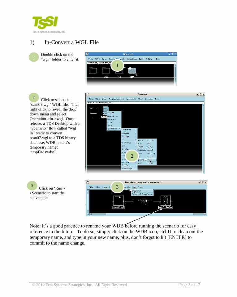
1) In-Convert a WGL File
Double click on the
“wgl” folder to enter it.
Click to select the
„scan07.wgl‟ WGL file. Then
right click to reveal the drop
down menu and select
Operation->in->wgl. Once
release, a TDS Desktop with a
“Scenario” flow called “wgl
in” ready to convert
scan07.wgl to a TDS binary
database, WDB, and it‟s
temporary named
“tmpf1tdswdst”.
Click on „Run‟-
>Scenario to start the
conversion
Note: It‟s a good practice to rename your WDB before running the scenario for easy
reference in the future. To do so, simply click on the WDB icon, ctrl-U to clean out the
temporary name, and type in your new name, plus, don‟t forget to hit [ENTER] to
commit to the name change.
1
2
3
1
2
3
© 2010 Test Systems Strategies, Inc. All Right Reserved .Page 4 of 17
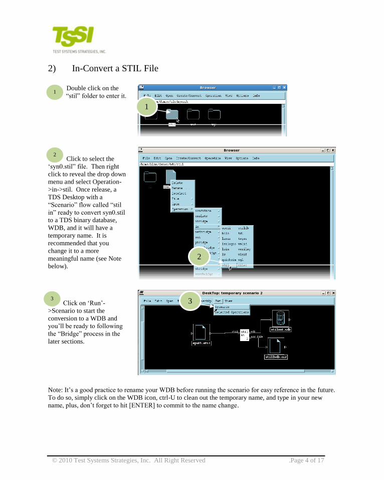
2) In-Convert a STIL File
Double click on the
“stil” folder to enter it.
Click to select the
„syn0.stil” file. Then right
click to reveal the drop down
menu and select Operation-
>in->stil. Once release, a
TDS Desktop with a
“Scenario” flow called “stil
in” ready to convert syn0.stil
to a TDS binary database,
WDB, and it will have a
temporary name. It is
recommended that you
change it to a more
meaningful name (see Note
below).
Click on „Run‟-
>Scenario to start the
conversion to a WDB and
you‟ll be ready to following
the “Bridge” process in the
later sections.
Note: It‟s a good practice to rename your WDB before running the scenario for easy reference in the future.
To do so, simply click on the WDB icon, ctrl-U to clean out the temporary name, and type in your new
name, plus, don‟t forget to hit [ENTER] to commit to the name change.
1
2
3
1
2
3
© 2010 Test Systems Strategies, Inc. All Right Reserved .Page 5 of 17
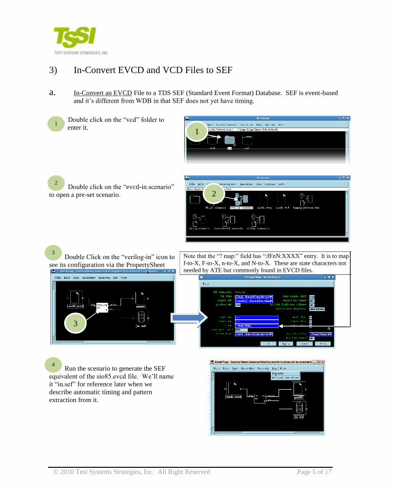
3) In-Convert EVCD and VCD Files to SEF
a. In-Convert an EVCD File to a TDS SEF (Standard Event Format) Database. SEF is event-based
and it‟s different from WDB in that SEF does not yet have timing.
Double click on the “vcd” folder to
enter it.
Double click on the “evcd-in.scenario”
to open a pre-set scenario.
Double Click on the “verilog-in” icon to
see its configuration via the PropertySheet
Note that the “? map:” field has “:fFnN:XXXX” entry. It is to map
f-to-X, F-to-X, n-to-X, and N-to-X. These are state characters not
needed by ATE but commonly found in EVCD files.
Run the scenario to generate the SEF
equivalent of the sio85.evcd file. We‟ll name
it “in.sef” for reference later when we
describe automatic timing and pattern
extraction from it.
1
2
3
1
2
3
4

© 2010 Test Systems Strategies, Inc. All Right Reserved .Page 6 of 17
b. In-Convert a VCD File to a TDS SEF Database. Because in VCD, signals have no direction, users
will have to specify their own signal directions and bidirectional change controls.
Double click on the
“vcd” folder to enter
it.
Click to select the
„sio85.vcd” file. Then right
click to reveal the drop down
menu and select Operation-
>in->verilog. Once release,
a TDS Desktop with a
“Scenario” flow called
“verilog in” ready to convert
sio85.vcd to a TDS
uncyclized binary database,
SEF (Standard Event Format
Database).
Double click on the “verilog in” icon to
open its PropertySheet:
Change “make signal defn?” to YES to tell TDS to
generate the Signal Definition File automatically.
1
2
1
2
3
3
4
4
© 2010 Test Systems Strategies, Inc. All Right Reserved .Page 7 of 17
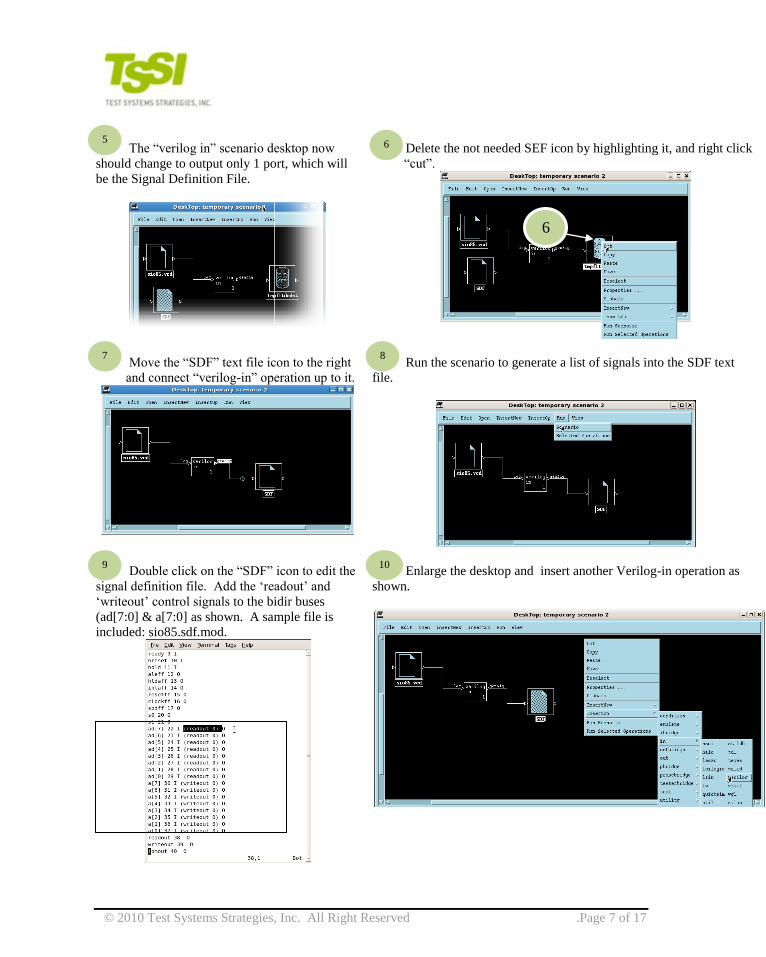
The “verilog in” scenario desktop now
should change to output only 1 port, which will
be the Signal Definition File.
Delete the not needed SEF icon by highlighting it, and right click
“cut”.
Move the “SDF” text file icon to the right
and connect “verilog-in” operation up to it.
Run the scenario to generate a list of signals into the SDF text
file.
Double click on the “SDF” icon to edit the
signal definition file. Add the „readout‟ and
„writeout‟ control signals to the bidir buses
(ad[7:0] & a[7:0] as shown. A sample file is
included: sio85.sdf.mod.
Enlarge the desktop and insert another Verilog-in operation as
shown.
5 6
6
7 8
9 10
© 2010 Test Systems Strategies, Inc. All Right Reserved .Page 8 of 17
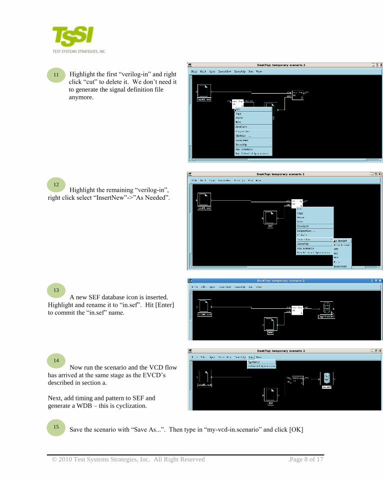
Highlight the first “verilog-in” and right
click “cut” to delete it. We don‟t need it
to generate the signal definition file
anymore.
Highlight the remaining “verilog-in”,
right click select “InsertNew”->”As Needed”.
A new SEF database icon is inserted.
Highlight and rename it to “in.sef”. Hit [Enter]
to commit the “in.sef” name.
Now run the scenario and the VCD flow
has arrived at the same stage as the EVCD‟s
described in section a.
Next, add timing and pattern to SEF and
generate a WDB – this is cyclization.
Save the scenario with “Save As...”. Then type in “my-vcd-in.scenario” and click [OK]
11
12
13
14
15
© 2010 Test Systems Strategies, Inc. All Right Reserved .Page 9 of 17
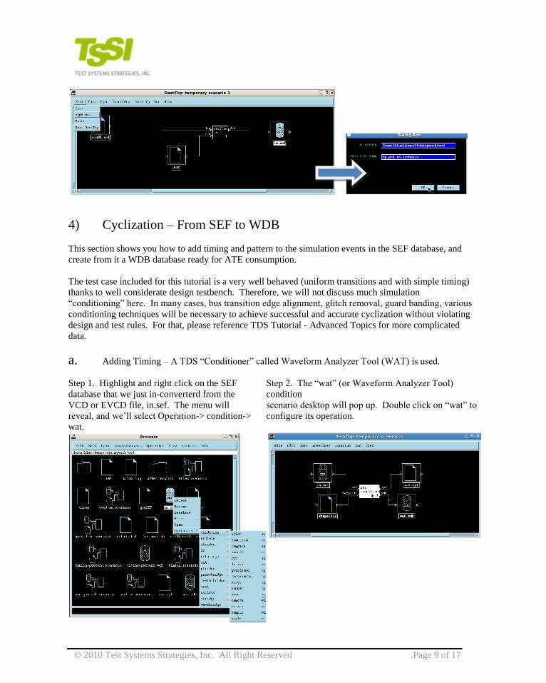
4) Cyclization – From SEF to WDB
This section shows you how to add timing and pattern to the simulation events in the SEF database, and
create from it a WDB database ready for ATE consumption.
The test case included for this tutorial is a very well behaved (uniform transitions and with simple timing)
thanks to well considerate design testbench. Therefore, we will not discuss much simulation
“conditioning” here. In many cases, bus transition edge alignment, glitch removal, guard banding, various
conditioning techniques will be necessary to achieve successful and accurate cyclization without violating
design and test rules. For that, please reference TDS Tutorial - Advanced Topics for more complicated
data.
a. Adding Timing – A TDS “Conditioner” called Waveform Analyzer Tool (WAT) is used.
Step 1. Highlight and right click on the SEF
database that we just in-converterd from the
VCD or EVCD file, in.sef. The menu will
reveal, and we‟ll select Operation-> condition->
wat.
Step 2. The “wat” (or Waveform Analyzer Tool)
condition
scenario desktop will pop up. Double click on “wat” to
configure its operation.
© 2010 Test Systems Strategies, Inc. All Right Reserved .Page 10 of 17
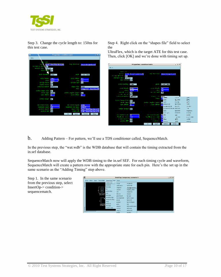
Step 3. Change the cycle length to: 150ns for
this test case.
Step 4. Right click on the “shapes file” field to select
the
UltraFlex, which is the target ATE for this test case.
Then, click [OK] and we‟re done with timing set up.
b. Adding Pattern – For pattern, we‟ll use a TDS conditioner called, SequenceMatch.
In the previous step, the “wat.wdb” is the WDB database that will contain the timing extracted from the
in.sef database.
SequenceMatch now will apply the WDB timing to the in.sef SEF. For each timing cycle and waveform,
SequenceMatch will create a pattern row with the appropriate state for each pin. Here‟s the set up in the
same scenario as the “Adding Timing” step above.
Step 1. In the same scenario
from the previous step, select
InsertOp-> condition->
sequencematch.
© 2010 Test Systems Strategies, Inc. All Right Reserved .Page 11 of 17
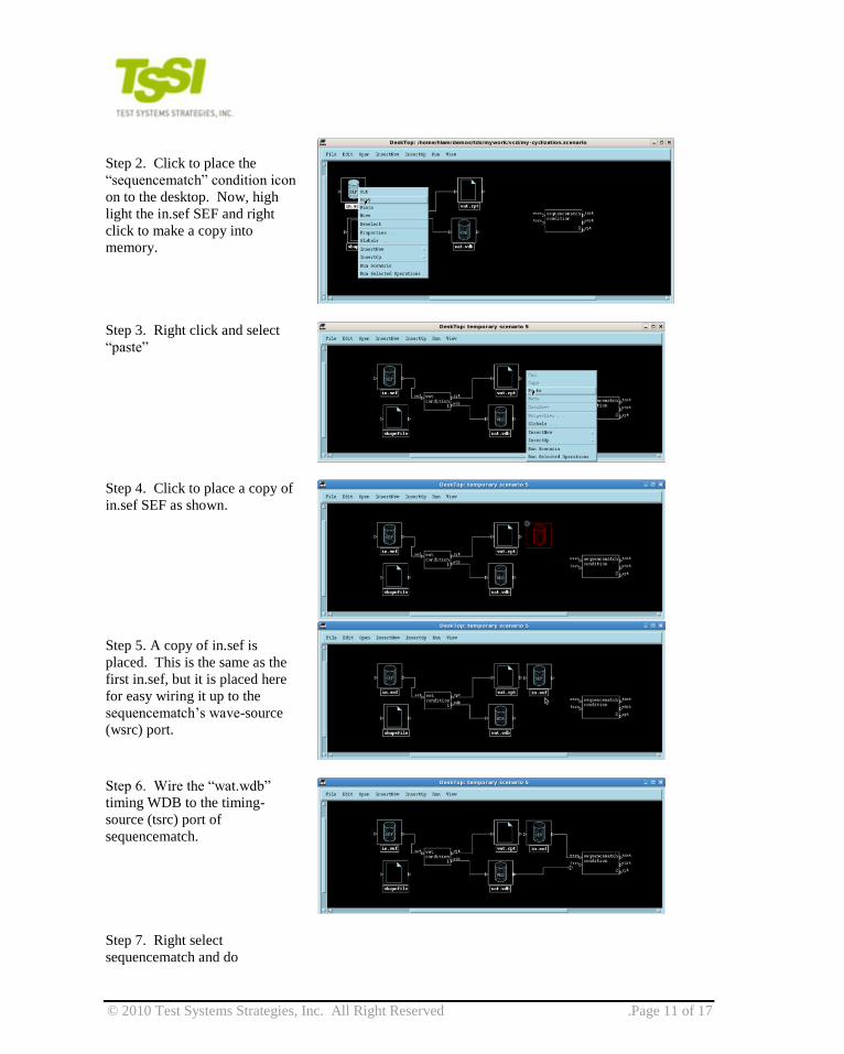
Step 2. Click to place the
“sequencematch” condition icon
on to the desktop. Now, high
light the in.sef SEF and right
click to make a copy into
memory.
Step 3. Right click and select
“paste”
Step 4. Click to place a copy of
in.sef SEF as shown.
Step 5. A copy of in.sef is
placed. This is the same as the
first in.sef, but it is placed here
for easy wiring it up to the
sequencematch‟s wave-source
(wsrc) port.
Step 6. Wire the “wat.wdb”
timing WDB to the timing-
source (tsrc) port of
sequencematch.
Step 7. Right select
sequencematch and do
© 2010 Test Systems Strategies, Inc. All Right Reserved .Page 12 of 17
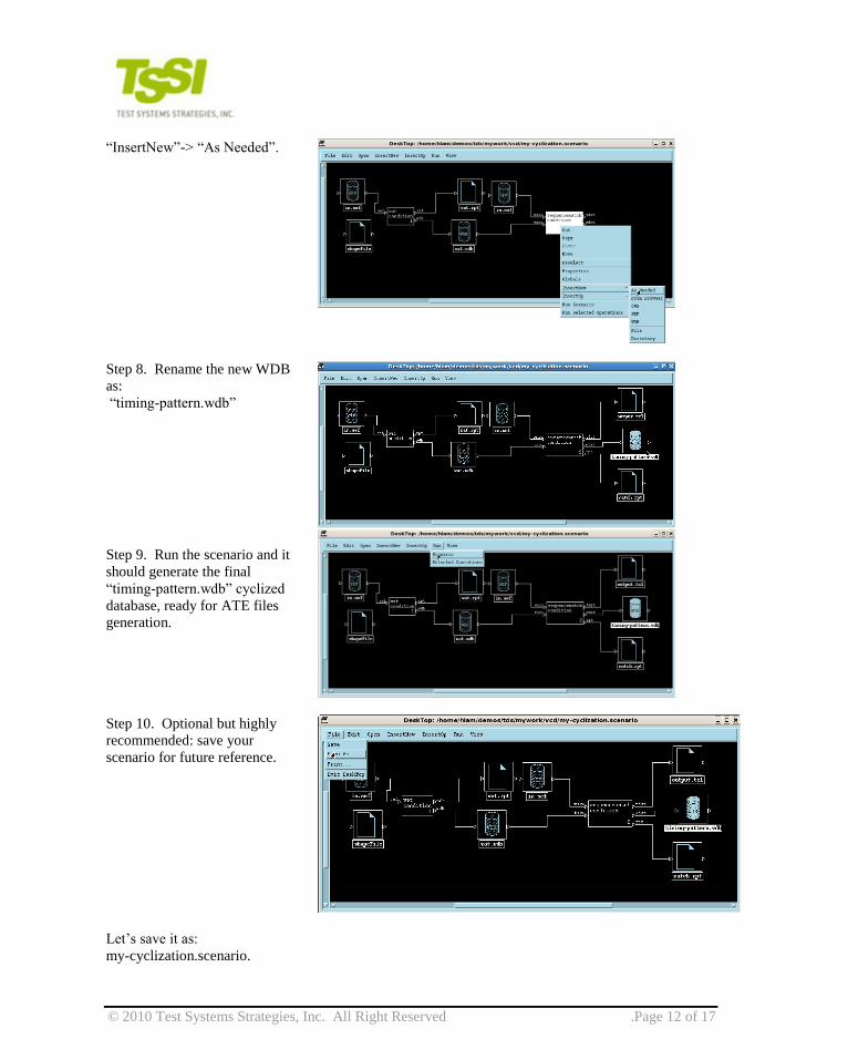
“InsertNew”-> “As Needed”.
Step 8. Rename the new WDB
as:
“timing-pattern.wdb”
Step 9. Run the scenario and it
should generate the final
“timing-pattern.wdb” cyclized
database, ready for ATE files
generation.
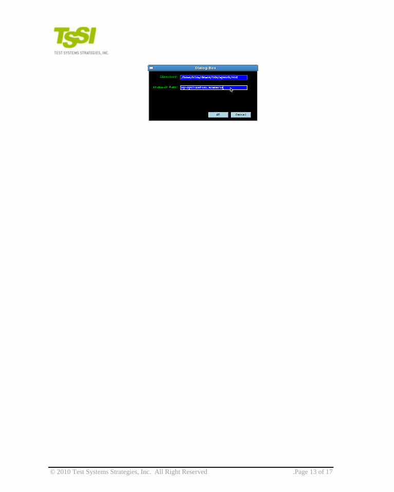
Step 10. Optional but highly
recommended: save your
scenario for future reference.
Let‟s save it as:
my-cyclization.scenario.
© 2010 Test Systems Strategies, Inc. All Right Reserved .Page 13 of 17

© 2010 Test Systems Strategies, Inc. All Right Reserved .Page 14 of 17
5) Out-Convert from a WDB to Teradyne UltraFlex
When a valid cyclized WDB is obtain, whether it was from a WGL, STIL, VCD, EVCD, or any other flow,
it is ready to be converted to a target ATE format. Since in the cyclization, we‟ve already targeted the
Teradyne Ultraflex via the specification of the shape file in the Waveform Analyzer Tool step, we‟ll choose
Teradyne Ultraflex here.
Step 1. Highlight the previous cyclzed WDB,
timing-pattern.wdb; then select Operation->
testerbridge-> ultarflex.
Step 2. When the ultraflex testerbridge scenario
pops up, select run-> scenario and the
testerbridge will generate Ultraflex tester files in
the specifed “./output” directory.
© 2010 Test Systems Strategies, Inc. All Right Reserved .Page 15 of 17
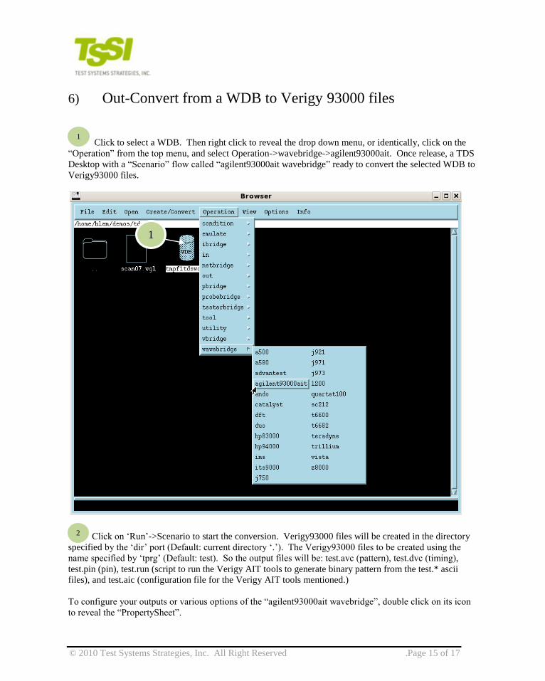
6) Out-Convert from a WDB to Verigy 93000 files
Click to select a WDB. Then right click to reveal the drop down menu, or identically, click on the
“Operation” from the top menu, and select Operation->wavebridge->agilent93000ait. Once release, a TDS
Desktop with a “Scenario” flow called “agilent93000ait wavebridge” ready to convert the selected WDB to
Verigy93000 files.
Click on „Run‟->Scenario to start the conversion. Verigy93000 files will be created in the directory
specified by the „dir‟ port (Default: current directory „.‟). The Verigy93000 files to be created using the
name specified by „tprg‟ (Default: test). So the output files will be: test.avc (pattern), test.dvc (timing),
test.pin (pin), test.run (script to run the Verigy AIT tools to generate binary pattern from the test.* ascii
files), and test.aic (configuration file for the Verigy AIT tools mentioned.)
To configure your outputs or various options of the “agilent93000ait wavebridge”, double click on its icon
to reveal the “PropertySheet”.
1
1
2
© 2010 Test Systems Strategies, Inc. All Right Reserved .Page 16 of 17
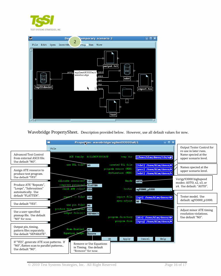
Wavebridge PropertySheet. Description provided below. However, use all default values for now.
2
Advanced Test Control from external ASCII file. Use default “NO”.
Assign ATE resource to produce test program. Use default “YES”.
Produce ATE “Repeats”, “Loops”, “Subroutines” automatically. Use default “FLATTEN”.
Use default “YES”.
Use a user-specified pinmap file. Use default “NO” for now.
Output pin, timing, pattern files separately. Use default “SEPARATE”.
Output Tester Control for re-use in later runs. Name specied at the upper scenario level.
Names specied at the upper scenario level.
Verigy93000 highspeed modes: AUTO, x2, x3, or x4. Use default: “AUTO”.
Tester model. Use default: ag93000_p1000.
Adjust minor ATE timing resolution violations. Use default “NO”.
If “YES”, generate ATE scan patterns. If “NO”, flatten scan to parallel patterns.. Use default “NO”.
Remove or Use Equations in Timing. Use default “Remove” for now.

© 2010 Test Systems Strategies, Inc. All Right Reserved .Page 17 of 17
7) Running and Controlling Scenarios from the Command Line
a. Invocation
All scenarios that have been saved with a name can be invoked from the command line.
For example, in section 3) b, we‟ve created a scenario called, my-vcd-in.scenario. It can be invoked from
the command line as:
$TDSDIR/wavemaker_mt –b my-vcd-in.scenario.
A sample script is available in tds.training/vcd/run_evcd.sh to show one way to invoke several scenarios
to convert an EVCD file to Teradyne UltraFlex format.
b. Setting/Changing Scenario PropertySheet Values from the Command
Line:
$TDSDIR/wavemaker_mt –b my-vcd-in.scenario <operation>.n/parameterName=<new value> <operarion>.n/parameterName=<new value> ...
For example, to run the “my-cyclization.scenario” with a different cycle length than the 150ns, do:
$TDSDIR/wavemaker_mt –b my-cyclization.scenario condition.1/CycleLength=”300ns”
CycleLength is the name of the field inside of the scenario, and they‟re trickier to know the exact name, but
they are all listed in the TDS User Manual.
Contact TSSI
Email: [email protected]
Phone: 1-503-626-8806
Web: www.tessi.com