Embed Size (px)
Citation preview
Defence
29
The application of high pressure water mist as part of a holistic fire fighting systemAbstract
Current accommodation standards consume significant space on board ships. The development of a holistic approach to fire fighting would enable a reduction in the requirement for trained ships crew and in turn in accommodation. This will drive savings in a reduced hull size, propulsion requirements, and reduce the number of people exposed to risk in the event of a fire.
This study aims to explore the use of High Pressure Water Mist (HPWM) to provide ship wide reactive fire fighting by considering its application to a generic area of the Type 26 Frigate in peacetime and battle scenarios. This study also offers a brief discussion of the surrounding issues associated with implementing such a system, including estimated technology readiness levels.
The cost of a ship relates directly to its size, both in the concept phase and in service. Being able to reduce the size of a ship enables savings to be made over an otherwise larger vessel. However, one of the most significant drivers for the size of a ship is the manpower needed to crew it. Current crew living standards consume significant space due to accommodation, stores, black and grey water requirements etc.
Where advancements in technology, particularly navigation and combat management systems, have enabled the number of crew needed to sail the ship to be reduced, these savings are often not realised. The sticking point is the manpower required to fight fires on board, especially in damage and threat situations. Current fire fighting techniques and systems require a certain amount of manpower in order to function. This underlying factor prevents ships crews from being reduced below a minimum level.
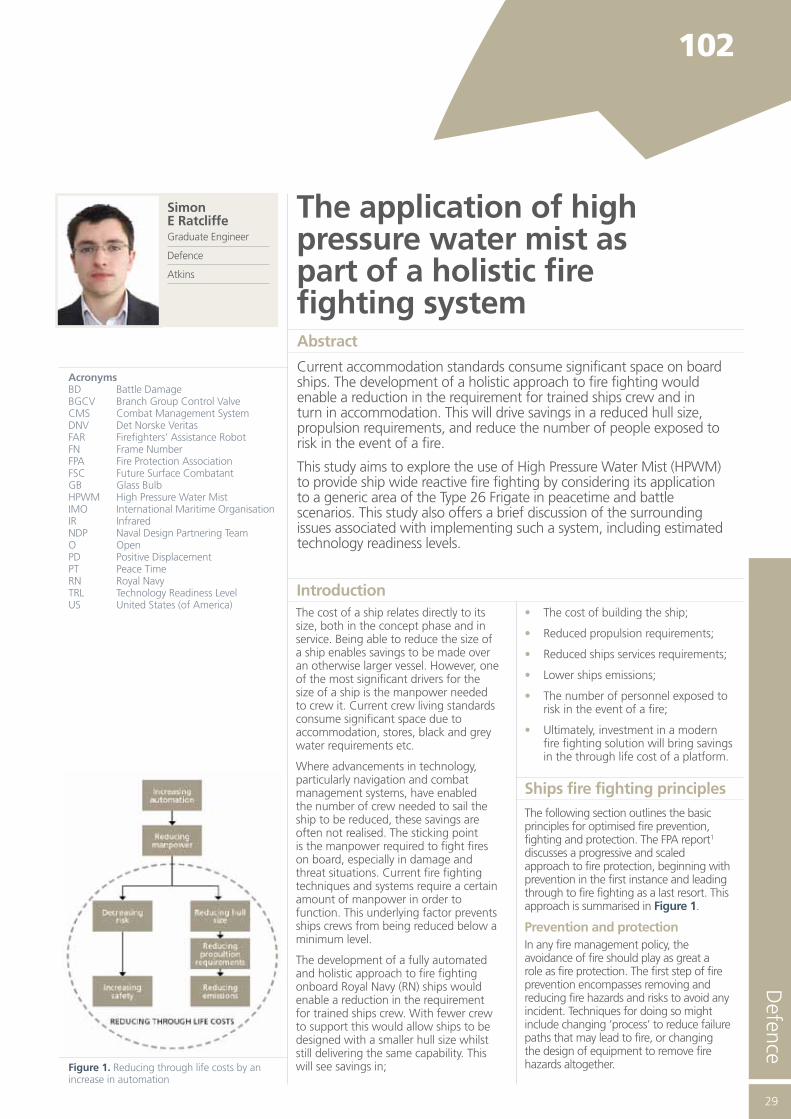
The development of a fully automated and holistic approach to fire fighting onboard Royal Navy (RN) ships would enable a reduction in the requirement for trained ships crew. With fewer crew to support this would allow ships to be designed with a smaller hull size whilst still delivering the same capability. This will see savings in;
• The cost of building the ship;
• Reduced propulsion requirements;
• Reduced ships services requirements;
• Lower ships emissions;
• The number of personnel exposed to risk in the event of a fire;
• Ultimately, investment in a modern fire fighting solution will bring savings in the through life cost of a platform.
Ships fire fighting principlesThe following section outlines the basic principles for optimised fire prevention, fighting and protection. The FPA report1 discusses a progressive and scaled approach to fire protection, beginning with prevention in the first instance and leading through to fire fighting as a last resort. This approach is summarised in Figure 1.
Prevention and protectionIn any fire management policy, the avoidance of fire should play as great a role as fire protection. The first step of fire prevention encompasses removing and reducing fire hazards and risks to avoid any incident. Techniques for doing so might include changing ‘process’ to reduce failure paths that may lead to fire, or changing the design of equipment to remove fire hazards altogether.
Introduction
102
Simon E RatcliffeGraduate Engineer
Defence
Atkins
AcronymsBD Battle DamageBGCV Branch Group Control ValveCMS Combat Management SystemDNV Det Norske VeritasFAR Firefighters’ Assistance RobotFN Frame NumberFPA Fire Protection AssociationFSC Future Surface CombatantGB Glass BulbHPWM High Pressure Water MistIMO International Maritime OrganisationIR InfraredNDP Naval Design Partnering TeamO OpenPD Positive DisplacementPT Peace TimeRN Royal NavyTRL Technology Readiness LevelUS United States (of America)
Figure 1. Reducing through life costs by an increase in automation

30
Fire prevention also includes the detection and prediction of fire scenarios long before the outbreak of fire. Fires and explosions are generally preceded by a series of events that lead step by step to the fire situation. Depending on the nature of these events, there may be opportunities to intervene and detect a fire scenario early. Detecting these events leading up to a fire is often outside the boundary of traditional fire detection systems. For example, monitoring an engine’s vibration, fuel consumption and pressure may provide clues as to whether or not mechanical failure which could lead to fire is imminent.
Damage limitation and responseThe damage and consequence resulting from a fire can be characterised into two areas; the primary damage resulting directly from the fire and its by-products, and the secondary damage and consequences of the implemented fire suppression strategy. The extent of the damage resulting from a fire and its suppression is a function of the scale of the fire and hence the scale of the response. The earlier that fires are detected, prevented and suppressed, the greater the benefits are for reducing both primary and secondary damage. Early detection also allows a better balance between a rapid but high impact response against a measured and proportionate (directed) response causing less overall damage.
Traditionally, ships fire fighting methods are not predictive by nature and, following the failure of first aid fire fighting, accept large amounts of damage as alternative means are readied. The modernising of fire fighting response requires the replacement of the ‘man with an extinguisher’ with automated on the spot alternatives such as equipment control, local suppression and aimed systems designed to reduce the impact of secondary damage.
Redundency and integrity of systemsFire safety systems and the supporting infrastructure generally embody safety factors to ensure availability and effectiveness when required. These factors may include;
• System duplication;
• System over-specification;
• System protection (resource guarantee);
• Manual backup;
• Assigning ‘worst case’ threshold and designing infrastructure to cope with it.
High pressure water mist systems
General descriptionIn suppressing a fire, traditional low-pressure sprinkler and deluge systems often cause significant water damage that can be greater than the damage caused by the fire itself.
HPWM offers equivalent or better fire suppression than traditional systems with minimal water discharge, minimising damage to property and reducing the time and cost of clean-up.
High pressure water is dispersed by fixed nozzles which create an ultra fine mist over the protected area. The mist fights fires in three main ways;
• Cooling – Millions of tiny water droplets produce a very large heat collecting surface and rapidly reduces the temperature of the air in the space;
• Smothering – The vapour displaces the oxygen volume in the fire itself, rather than in the entire space. This means that it does not present an asphyxiation hazard to personnel;
• Attenuation – The mist absorbs radiant heat.
Ultra fine mist has the advantage that it requires very little water and consequently does minimal damage to equipment. If de-ionised water is used HPWM systems can also be applied to live electrical fires. In machinery spaces the major benefit of water mist is that since it is harmless to people, the system can be activated the second a fire is detected, without any need to first evacuate. Nor is there any need to shut off vents or close openings before evacuation, as the water mist will not escape the space, as gases would. This possibility for immediate activation means that the fire damage is kept at a minimum.
Once the fire has been extinguished, the water mist will quickly cool down the space and thus prevent re-ignition.
Flash suppressionA fire protection system designed to provide ‘flashover suppression’ aims to keep air/gas temperatures in compartments too low for materials and fuel sources to ignite. One of the advantages of flashover suppression is that it can be achieved with less water
with a high pressure mist system than a traditional sprinkler extinguishing system. Live fire tests conducted by the US Navy on the ex-USS Shadwell have demonstrated that flashover suppression can be achieved using fewer water mist nozzles in each compartment than would be needed using a conventional marine sprinkler system2.
Pre-emptive actionA networked system of HPWM sprinklers could be used to pre-emptively cool certain spaces. This might be a reaction to developing fire conditions, ie equipment telemetry reporting increased risk, or as a precautionary measure during a fire scenario. For example, water mist could be used to cool an established escape route reducing the chance of it being blocked by fire.
Blast mitigationThe use of water mist has been shown to have benefits for mitigating the effects of blasts on Navy ships. Navier-Stokes simulations performed by Ananth et al3 and the experimental results found by Thomas et al4 suggest that latent heat absorption is the primary mechanism behind water mist explosion suppression in a confined space. The shock front that propagates ahead of the thermal front immediately following a detonation causes the water mist droplets to break up; this increases the heat absorbing surface area and results in an increase in the droplet vaporisation rate. This cools the gasses in the region between the shock and thermal fronts.
The second mechanism by which water mist mitigates blast energy is through momentum absorption. Simulations by Schwer and Kailasanath5 concluded that quasi-static pressures produced by small explosions were suppressed by water mist. The droplets interact with the front as it is reflected multiple times absorbing energy and changes of momentum.
In 2009 the US Naval Research Laboratory conducted a series of detonation experiments designed to establish a link between the mist density conditions of a sprinkler system and its ability to reduce blast impulse in a confined space6. The results of these experiments show that the higher mist density conditions outperformed lower mist concentrations in suppressing blast effects. This shows a significant opportunity for building water mist into a ship’s defensive suite.
System configurationWater mist systems can be configured in various ways;

Defence
31
Thermally activated (Wet pipe) - Wet pipe systems are typically used in accommodation and similar areas where solid materials are the combustible media. When ambient temperature exceeds a given limit, the activation bulb of the sprinkler bursts and water mist is discharged from that particular sprinkler.
Deluge - A deluge system normally has open spray heads with water flow controlled by closed valves. When a valve is opened, water mist is discharged by all spray heads in the section controlled by that valve. Deluge systems are typically used in spaces where fuel fires could occur.
Class A firesClass A, or ‘ordinary combustible’ fires are those started from solid organic material, such as wood, paper, cloth etc. Typically, spaces containing Class A fire hazards are protected by thermally activated sprinklers, ie localised heat sources cause the sprinkler in the immediate vicinity to activate. Class A fires typically spread outwards from a single point, so initially only the closest sprinklers will open, tackling the fire directly. As the fire spreads, more nozzles will open and the water demand from the system will increase.
Class B firesClass B, or flammable liquid fires, are those started from liquid fuels, oils, chemicals etc. Machinery spaces present numerous Class B hazards. Since highly flammable liquids like petroleum can spread quickly and set alight almost instantaneously, it is necessary to cover the entire area with water mist from the offset. In such spaces open nozzle deluge systems are used.
System design and application
Subject area – T26 baseline 2v0For the purpose of this study, an area of T26 Frigate concept design was selected to provide a framework on which to demonstrate the use of HPWM, see Figure 2. The deck area was split into four ‘Fire Zones’ separated by water tight bulkheads.
One fire zone across two decks was isolated for use as a representative area for the application of HPWM.
Frame 71 to Frame 103 on 2 Deck T26 Baseline 2v0 was chosen to act as a single ‘Fire Zone’. This zone represents a typical area on a Surface Combatant. It houses common functions and utility spaces that represent a range of potential fire conditions.
102 The application of high pressure water mist as part of a holistic fire fighting system
Figure 2. Type 26 Frigate concept. Source: http://www.defenseindustrydaily.com/Britains-Future-Frigates-06268/
Figure 3. Fire zone 2, 2 deck arrangement and sprinkler layout
Figure 4. Fire zone 2, 3 deck arrangement and sprinkler layout
32
Commercial water mist system selection
In order to design for and demonstrate the application of a HPWM system in this study, it was necessary for a commercially available HPWM system to be selected for inclusion in the design. In this case the HI-FOG Marine System by Marioff, Finland was chosen on the basis of its pedigree as a marine fire fighting system.
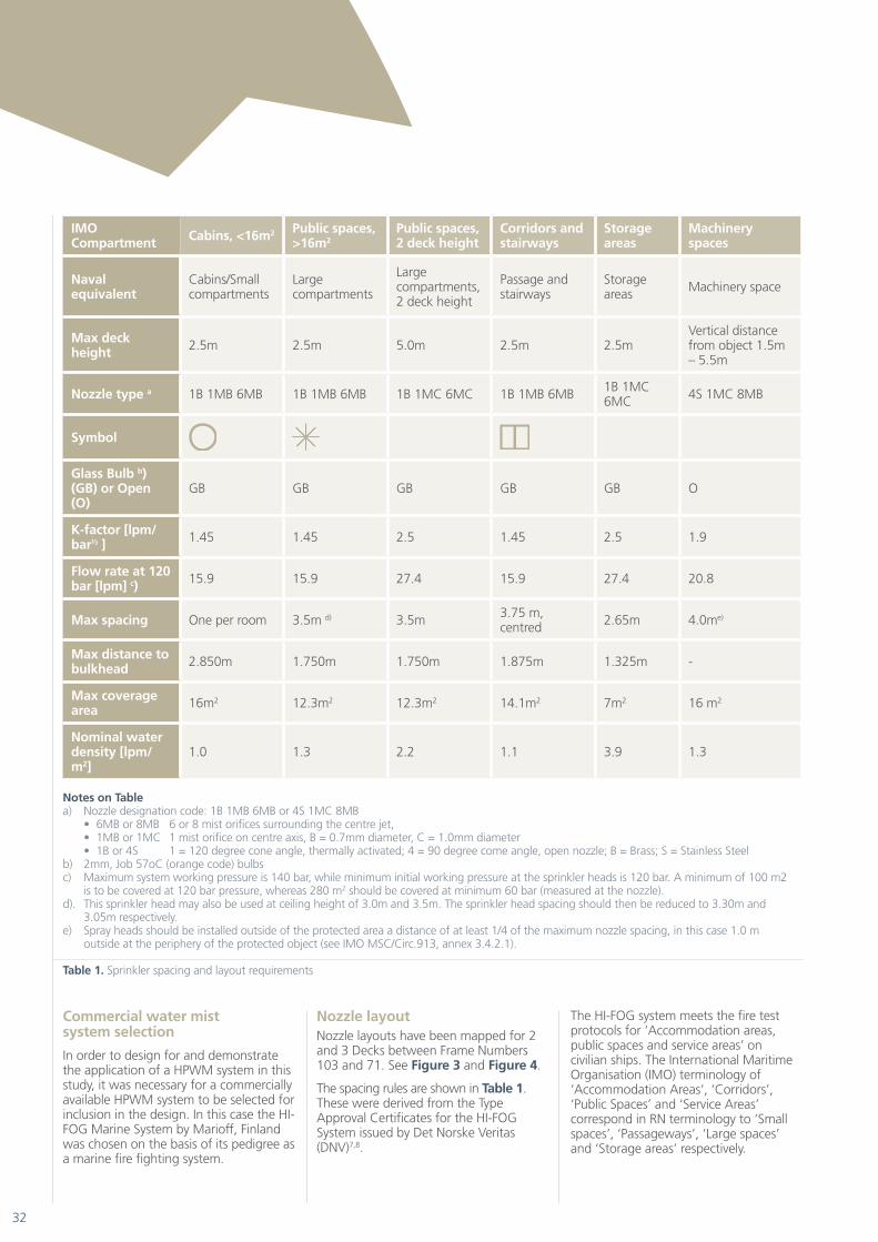
Nozzle layoutNozzle layouts have been mapped for 2 and 3 Decks between Frame Numbers 103 and 71. See Figure 3 and Figure 4.
The spacing rules are shown in Table 1. These were derived from the Type Approval Certificates for the HI-FOG System issued by Det Norske Veritas (DNV)7,8.
The HI-FOG system meets the fire test protocols for ‘Accommodation areas, public spaces and service areas’ on civilian ships. The International Maritime Organisation (IMO) terminology of ‘Accommodation Areas’, ‘Corridors’, ‘Public Spaces’ and ‘Service Areas’ correspond in RN terminology to ‘Small spaces’, ‘Passageways’, ‘Large spaces’ and ‘Storage areas’ respectively.
IMO Compartment Cabins, <16m2 Public spaces,
>16m2Public spaces, 2 deck height
Corridors and stairways
Storage areas
Machinery spaces
Naval equivalent
Cabins/Small compartments
Large compartments
Large compartments, 2 deck height
Passage and stairways
Storage areas Machinery space
Max deck height 2.5m 2.5m 5.0m 2.5m 2.5m
Vertical distance from object 1.5m – 5.5m
Nozzle type a 1B 1MB 6MB 1B 1MB 6MB 1B 1MC 6MC 1B 1MB 6MB 1B 1MC 6MC 4S 1MC 8MB
Symbol
Glass Bulb b) (GB) or Open (O)
GB GB GB GB GB O
K-factor [lpm/bar½ ] 1.45 1.45 2.5 1.45 2.5 1.9
Flow rate at 120 bar [lpm] c) 15.9 15.9 27.4 15.9 27.4 20.8
Max spacing One per room 3.5m d) 3.5m 3.75 m, centred 2.65m 4.0me)
Max distance to bulkhead 2.850m 1.750m 1.750m 1.875m 1.325m -
Max coverage area 16m2 12.3m2 12.3m2 14.1m2 7m2 16 m2
Nominal water density [lpm/m2]
1.0 1.3 2.2 1.1 3.9 1.3
Notes on Tablea) Nozzle designation code: 1B 1MB 6MB or 4S 1MC 8MB
• 6MB or 8MB 6 or 8 mist orifices surrounding the centre jet, • 1MB or 1MC 1 mist orifice on centre axis, B = 0.7mm diameter, C = 1.0mm diameter • 1B or 4S 1 = 120 degree cone angle, thermally activated; 4 = 90 degree come angle, open nozzle; B = Brass; S = Stainless Steel
b) 2mm, Job 57oC (orange code) bulbs c) Maximum system working pressure is 140 bar, while minimum initial working pressure at the sprinkler heads is 120 bar. A minimum of 100 m2
is to be covered at 120 bar pressure, whereas 280 m2 should be covered at minimum 60 bar (measured at the nozzle).d). This sprinkler head may also be used at ceiling height of 3.0m and 3.5m. The sprinkler head spacing should then be reduced to 3.30m and
3.05m respectively.e) Spray heads should be installed outside of the protected area a distance of at least 1/4 of the maximum nozzle spacing, in this case 1.0 m
outside at the periphery of the protected object (see IMO MSC/Circ.913, annex 3.4.2.1).
Table 1. Sprinkler spacing and layout requirements

Defence
33
For the purposes of this paper, both open deluge and closed thermally activated nozzle types are used. It has been assumed that Branch Group Control Valves (BGCV) will control the flow to each branch pipe. This will allow nozzles to be activated remotely without the need for the local temperature being high enough to thermally trigger the bulb. Thus, the system will still maintain the reactive nature of thermally activated bulbs but also allow a central control system to pre-emptively open branch groups to protect spaces in advance of fire or blast situation.
Distribution architecture optionsIn this section, different possible High Pressure Water Main distribution architectures will be discussed. In particular, the way in which they might contribute to enabling a holistic and survivable water mist system capable of intelligent self diagnosis and damage control will be considered. Key factors are the degree of redundancy in pump sources, the number of routes available for water to reach any portion of the piping network, the degree of separation between redundant components and the arrangement of control valves and sprinklers. Other factors that effect survivability are the integrity of the power supply to pumps and valves, communications and logic systems, location, mounting and armouring of risers and valves etc all of which are excluded from this discussion
Three distribution architectures will be considered;
• Centre main distribution;
• Dual main distribution;
• Sectional loop architecture.
Centre mainCentre main architectures consist of a single main running down the centre line on each deck of the ship. Sectional control valves are located at the zone boundaries and at riser connections, which are spaced so to bring water from the pumps on the lower decks to each level. Sprinkler heads are connected in branch groups which in turn are connected to the centre main via a BGCV. If a pipe was to be ruptured between risers on one deck, valves on the mains would close to isolate that length of pipe. Water would still be able to flow to the intact portions of the main on that deck through the adjacent risers. The centre main in this case must be large enough to accommodate the combined flow of all the branch groups.
The level of redundancy in the centre main design is low; the options for re-routing the water around isolated sections is limited and as a result the number of branch groups that can be kept active in the event of damage is low.
Dual mainA step further from the centre main concept is the use of a dual main. This features mains running down both the port and starboard side of each deck with vertical risers spaced at intervals along the length of the ship supplying the mains on each side. Branch group lines are connected to either the port or starboard main via BGCVs. Zonal valves are placed at intervals along the two mains so that damaged sections can be isolated. Any undamaged branch lines within a compartment that are fed from the undamaged side of the ship will still be functional. This architecture can be modified to include crossover mains and valves to create ‘offset loops’.
Sectional loopSectional loop architectures are similar to dual main arrangements in that a high pressure main runs along the port and starboard side of each deck of the ship, with vertical risers placed at regular intervals along the length of the ship, see Figure 5. The network of pipes is separated into ‘loops’ by valves and crossover mains. Each loop is served by its own riser, which can supply that loop with water or any of the loops adjacent to it. Risers alternate between port and starboard sides along the length of the ship in order to minimise vulnerability. Unlike the dual main architecture,
however, crossover mains connect port and starboard mains on the same level, one on either side of each water tight bulkhead.
The advantage of sectional loop architecture is the ability it has to recover from damage with minimal loss of functionality. Valves are placed so that each loop can be supplied in two independent ways;
• With all the supply coming up the riser serving that particular loop;
• The riser can be closed off so that the supply must come from an adjacent loop.
Sectional loop architectures allow for the subdivision of the main network into small cells that can be individually isolated. The greater the number of cells the better the ability to recover from damage while leaving as much of the network operational as possible.
Sectional loop architectures also offer hydraulic advantages in that the number of pathways for water to flow to any one demand point is maximised. A large demand at a particular point will distribute across multiple mains and risers, thus allowing for lower flow rates through the mains, requiring smaller diameter piping9.
It is for these reasons that using a sectional loop architecture offers the greatest potential for providing a flexible and survivable HPWM system. Sectional loop architecture will be considered from here on.
102 The application of high pressure water mist as part of a holistic fire fighting system
Figure 5. Sectional loop architecture

34
Branch group layoutFigure 6 and Figure 7 show the nozzles and branch lines connected to the main on each deck. Typically a branch group connects four nozzles to the main and is controlled by a branch group control valve.
Where possible, branch lines are arranged so that nozzles can provide a curtain of water across the beam of the ship. Each nozzle would be connected to the branch line by a branch vein (not shown), sized to only need to carry the flow for one individual sprinkler, regardless of where it is in the system ie regardless of how many sprinklers are ‘in front’ of it.
Water flow demandsA system configured to provide flashover suppression cover across an entire platform has the advantage that its flow demand grows progressively to match the spread and intensity of the fire. As the fire spreads through the ship, more branch groups can be brought online as needed. For the purpose of this study, the water flow demands will be calculated for two damage scenarios; peace time and battle damage scenarios.
Table 3 compiles the nozzle count and estimated water flow demands for the HPWM system based on the layouts shown in Figure 4 and Figure 5. For simplicity, it has been assumed that each branch group holds four sprinkler heads with a K-factor of 1.45 lpm / bar½, except for the machinery space where a K-factor of 1.9 lpm / bar½ is used.
Pumping strategyThere are several possible approaches for providing the pumping capacity for the HPWM system. Some high level options are discussed in Table 2.
Option BOption B affords 100% redundancy while also separating the two pumping assets. The sizing of both pumps to provide the total design flow rate guards against the loss of a single pump through routine mechanical breakdown and the separation of the units ensures that the risk of losing both through battle damage is greatly reduced.
However, option B may not offer the scalability or design flexibility required when considering much larger or much smaller ships. As the number and size of fire zones increases the demand flow rate will also increase. Sizing a single pump unit to provide 100% of the design flow rate in all circumstances may not be sensible.
Option COption C maintains a reasonable level of redundancy in four pumps each providing a third of the design flow rate. The use of one pump per fire zone ensures that pump units are adequately separated and distributed throughout the ship. Options C offers advantages over Option B in the size and the scalability of the pumps required. Running several smaller pump units rather than relying on large pumps sized to meet the entire demand should
enable savings to be made in running costs and enable a more flexible design. The remainder of this study assumes Option C.
Pump typeSelecting a pump to supply a high pressure water mist system presents a challenging problem. Such a system demands a very high pressure, but also requires the flexibility to vary the flow rate as the demand changes. Potentially, the
Option High level pumping strategy Comments
A
One large pump unit sized to meet the full design flow rate, connected to a distribution main supplying multiple risers
Option A has no redundancy and is not discussed further
B
Two pump units in parallel, one aft of midships, and one forward serving a common distribution main and multiple risers; each pump unit sized to meet full design flow, so that one unit is redundant.
Provides for 100% redundancy and can assume at a reasonable cost for connections, power and filtration. Pump units are adequately separated so that at least one should be functional at all times
C
Four pump units in parallel, one for each fire zone; each pump unit sized for 1/3 of the full design flow, so that three units will meet full design flow with the largest out of service
Provides for redundancy in a way that permits each pump unit to be smaller than arrangement C, such that redundancy can be achieved with three of the four pumps. Can assume that smaller pump units will be cheaper to run
Table 2. High level pumping strategy
Figure 6. General arrangement of 2 deck showing sprinklers, branch groups and water main

Defence
35
pumping system could need to go from providing high pressure fluid at a low flow rate in a single compartment to very high pressure high flow rate fluid across several fire zones.
The high pressures required of the water mist system (up to 150bar) mean that the pumps selected need to be of high quality and high capability. Traditionally, centrifugal pumps are used with sprinkler systems because they allow a constantly varying flow rate to be delivered at with relatively simple equipment. However, at high pressures, multi-stage centrifugal pumps are required. These have the potential to be more complex and require significant maintenance.
More reliable high pressure pumps come in the form of piston type positive displacement (PD) pumps. PD pumps, by nature of their design, deliver a fixed volume of fluid and as such are not best suited to variable demand sprinkler systems. However, PD pumps can be coupled with special design features to match the fixed volume output of the PD pump to a system of variable demand.
PD pumps applied to water mist systemsTo design for the BD3 scenario (Table 3) each pumping unit would need to be sized to provide a flow rate of 381.6 litres/minute.
The use of PD pumps to drive HPWM systems has been demonstrated on the ex-USS Shadwell by the US Naval Research Laboratory9. Their approach is summarised here.
We can assume that in basic terms, each pump unit consists of two smaller pumps, a primary and a secondary pump, driven by a single motor. The two pumps might be connected by a check valve, held closed by the high pressure form the primary pump and preventing flow from the secondary pump entering the system. This excess flow from the secondary pump flow might be bypassed by a suction line via a flow bypass valve and re-circulated to the reservoirs. As long as the system demand is less than or equal to the capacity of the primary pump, the system pressure remains ‘high’. Thus the first nozzles to operate at the early stage of a fire deliver water mist with maximum velocity and flow rate.
102 The application of high pressure water mist as part of a holistic fire fighting system
Scenario Branch groups Nozzles
Flow rate (120bar, K=1.45)
Average branch group 1 4 63.6 Lpm
PT1 – 3 branch groups active in immediate fire area. 3 12 190.8 Lpm
PT2 – 3 branch groups active plus 1 branch group in corridor 4 16 254.4 Lpm
BD1 – Branch groups in adjacent spaces including 4 branch groups immediately above the damage area.
7 28 445.2 Lpm
BD2 – As BD1 but increasing to a further 2 branch groups on the same deck and 4 branch groups above damage area.
13 48 763.2 Lpm
BD3 – As BD2 but including further 2 on deck and 3 above 18 72 1144.8 Lpm
MS1 – machinery space drench system activated (Nozzle type 4S 1MC 8MB, K-factor 1.9)
2 8 166.4 Lpm
BP1 – nozzles in the outer most compartments of the ship open in the vicinity of an expected weapons strike. This may be on one or more decks depending on the accuracy of the prediction.
6 24 381.6
Table 3. Water flow demands
Figure 7. General arrangement of 3 deck showing sprinklers, branch groups and water main

36
As more nozzles open and the volumetric demand of the sprinkler system exceeds the capacity of the first pump, the system pressure will drop. Once it drops to the setting of the secondary pump flow bypass valve, this will allow flow from the secondary pump to enter the system, albeit at a lower pressure. A schematic of this arrangement is shown in Figure 8.
For a large HPWM system, several pump pairs could be assembled in a skid to form one ‘pump unit’. The minimum demand for the system, for example one or two nozzles operating in peacetime conditions could be met with one pump operating. As more nozzles open, the system pressure will drop until it falls below the setting of the next flow bypass valve. That valve then closes and the flow from that pump then enters the system to make up the demand. In this way the pump unit self adjusts to match the demand from the sprinkler system. Figure 9 shows an assembly of pump pairs to form one of four ‘pump units’ sized to meet one third of the maximum expected demand.
Sensors and controlBeing able to detect fires quickly and accurately is key to ensuring a ship’s survivability and protecting life at sea. Early detection allows the ships systems
and crew to deal with the fire and limit its damage. Generally, on most surface ships there is poor integration between sensors and suppression systems, limited use of multiple sensor types and a strong reliance on human input, leading to slow detection and numerous false alarms10. The principle fire detection system on ships is still routine human watch keeping; arguably simple, but slow and potentially dangerous for the personnel involved.
The aim of a fire detection system should be to provide comprehensive, fully integrated, multi criteria fire detection cover across the entire ship, intelligently interfacing with fire suppression systems, fluid control systems and ships crew. Without this advanced functionality, pre-emptively reacting to fire conditions using HPWM systems will be limited. A novel way of thinking about this is to emulate the sensory functions that humans use to detect fire (Table 4).
The basis of an intelligent sensor network would be the employment of multiple sensor types and analysis to ‘diagnose’ whether there is a fire rather than merely detect one of the ‘symptoms’. Multiple sensors working together can provide more accurate clues as to whether a fire has started or not and more importantly if a fire is likely to start. Like the human
crew, the system should be able to make a reasoned judgement as to the fire situation based on all its data. The advantage over the human crew is that the ship can be monitored in all places, 24 hours a day.
In order for the system to correctly match sensor readings to fire scenarios, a database of fire signatures and sensor patterns would need to be established for different types of fire and typical false alarms. The more sensor patterns and fire signatures the system has access to, increased accuracy of diagnosis is achieved. However, given that no two fires are identical, the system would need to include the capacity to ‘learn’.
Network integrationA holistic system will rely on multiple systems ‘talking’ to each other in order to co ordinate the response to a fire or damage situation. The key elements that might be involved are shown in Figure 10. It shows the breakdown of the Fire Control system into two main components; the Sensors and the HPWM system, ie sensing and reacting. Crossovers exist where GB sprinklers both sense and react to fire events. It also shows how the combat management system might feed into the fire and damage control system. Threat
Human faculty System
Optical detection – “Eyes”
• IR cameras
• Machinery monitoring
• Casualty location
• Real-time situational feedback
Electronic “Nose”
• Ionising and photoelectric smoke detectors
• CO and CO2 detectors
• Heat sensors
Acoustic monitoring – “Ears”• Machinery monitoring
• Shock/blast detection
Brain power
• Micro processors
• Intelligent control
• Pattern recognition
• Neural networks
Voice!
• Alarms
• Situational feedback
• Personal address
Table 4. Fire fighting systems approximated to human sensory faculties.
Figure 8. Diagram of a PD pump pair consisting of two PD pumps driven by a single motor
Figure 9. Diagram of an assembly of pump pairs connected in parallel to provide a range of flows

Defence
37
information can be used to coordinate blast suppression response using water mist. A key challenge is the design of a coordinating management suite that can effectively interface with other ships systems and coordinate action. The position of the human operator in the management system will also present interesting questions regarding accountability and autonomy.
The control system will need to digest information regarding the fire itself, the suppression response, the location and movement of personnel, any damage control efforts and the health of the fire fighting infrastructure. An ideal system will be able to react instantly to a fire situation by activating relevant branch groups and then continuing to monitor the progress of that fire and ‘watch’ for new events. New fire situations might come in the form of further sensor readings from multiple sources, a manual activation at an alarm call point or the bursting of a glass bulb sprinkler.
Supporting technologiesThe following section discusses some of the novel technologies that would be necessary to enable a fully integrated HPWM system that provides a pre-emptive fire fighting capability
Smart valvesValves that can autonomously open or close depending on the flow conditions that they ‘see’ are essential to providing a fire fighting system that removes the need for human input and decision making. Positioned at critical points in the distribution main, these motorised
valves incorporate pressure sensors and flow meters to monitor the conditions in the main.
A balance must be achieved between the benefits and the cost of installing smart valves in the distribution mains. The spacing between the valves determines the size of the area that will be non-functional if valves must be closed to isolate a rupture. When considering the sectional loop architecture, the maximum level of control for isolating damaged piping and rerouting flows could be achieved by installing a valve on each end of every pipe connecting two separated grid points. So for a T-intersection this would mean having a valve on all three branches. This strategy would result in a high valve count and, depending on the type of valve used, be prohibitively expensive. An alternative might be to use ‘valve nodes’ at each T-intersection; ie consolidating actuators and logic circuits into one housing capable of operating each valve individually. This would take advantage of the proximity of the valves at each intersecting node in the pipe network and achieve some economies of design.
Heat sensorsHeat sensors will form a key part of an advanced fire detection system. Rising temperature conditions indicate the increased likelihood of a fire. When coupled with other sensor types such as smoke or visual recognition, heat sensors can provide an accurate picture of a developing fire and how it is spreading. This information can be used to coordinate and prioritise the response to the fire. Heat sensing also has the
potential to provide feedback to the control system on the effectiveness of the fire suppression being applied.
Use of infra-red camerasInfra-red (IR) cameras can also be used to spot and identify fires. In particular, they are able to spot fires in hot environments, where heat sensors may give false alarms. IR cameras measure the intensity of the IR radiation emitted from objects and surfaces. Using image recognition software the difference between a flame flare can be distinguished say from the hot casing of an engine. This sort of image processing and software recognition is not completely foolproof, flares and reflexions might give rise for false alarms. IR cameras can, however, provide clear unambiguous information on the situation as it develops by feeding live pictures back to an operator. This allows them to question whether the cause of alarm is false or a real fire and direct actions accordingly.
Technology readiness levelsThis section offers a brief discussion on the maturity of the technology required to implement a holistic fire fighting system. It does not seek to provide a definitive answer with respect to technology readiness levels, but more so a ‘food for thought’ and provides estimates of the technology readiness levels of each solution on a scale of 1 to 10.
HPWM systemHPWM technology is well established. It forms a natural progression from ‘traditional’ low pressure sprinkler systems. HPWM systems are made by a variety of specialist manufacturers and can be found currently in use across a wide range of civilian vessels and increasingly land installations. Military Naval use is known, the US navy investigating its application as early as the year 20009. HPWM systems can be found in small fixed system set ups eg machinery spaces, and also protecting larger spaces providing the primary means of fire fighting. Class Society Certification for passenger and cruise ship applications exists for most systems, including the Marioff products. Estimate at a technology readiness level of 8-9.
Sensors and controlThe sensor technology required to drive a holistic system should be widely available and in use. Smoke detectors, heat detectors, IR cameras etc are all relatively mature technologies. The oil and gas industry are often at the forefront of innovation in this area, using
Fire signature database
Combat management
system
Camera networks
Smart valve feedback
Smoke / heat sensor networks
Telemetry reporting
Pump controller
Valve controller
Reservoir monitoring
Fire and damage control management
system
User interface and command
input
Sensor control system
HPWM control system
Alarm system
Figure 10. Fire and damage control system hierarchy
102 The application of high pressure water mist as part of a holistic fire fighting system
38
fuel mist detection to spot fire situations early and IR cameras to identify fires and false alarms. The processing of the data they gather is where the key technology questions lie. Creating a management system that can ‘learn’ the difference between characteristics of a real fire and a false alarm is not beyond the realms of modern computing power but may require investment in specific examples and programmes to drive forward. Technology readiness level 4 – 7.
Smart valvesSmart valves in various forms are common across the energy and process industries. The drive for greater efficiencies from deep sea drilling operations has demanded large investment from the subsea sector. Schemes have been designed and implemented for use off-shore, for example Unocal, now part of Chevron, installed intelligent pump and valve systems to boost the efficiency of its Monopod platform in the Cook Inlet Basin, Alaska11. The controller technology that powers such valves is where the key development lies – the logic behind the actuated valves. Since their use in high pressure mains to provide automated damage repair and optimisation response is less well documented, valve solutions will be custom built to meet the specific needs of their applications. Technology readiness level 7.
Whole systemThe key to creating a holistic system is linking the different technologies together. Sensor suites combining with suppression systems to fight fires; potential blasts being detected and mitigated against; intelligent controllers spotting false alarms and rerouting around damage will require the system to be greater than the sum of its parts. This will present the greatest challenge. For manpower savings to be realised it will require a change of doctrine, process and attitude, away from current techniques and further towards pre-emptive and instant response. Technology readiness level 4.
ConclusionsThis report raises the issue that current ships fire fighting techniques are old fashioned and slow to act failing initial first aid fire fighting efforts. If ships’ crews are to be reduced on future vessels, attention will need to be paid to developing a holistic and intelligent fire fighting system that can remove the ‘man with an extinguisher’ as far as possible.
This report sees that HPWM is an excellent solution for providing comprehensive cover across a surface ship. It allows for an instant response to a fire situation, in that it is non-toxic, does not require spaces to be sealed and can be deployed in HV and machinery spaces. The mist acts in several ways to fight fire but can also be used to prevent flashovers and pre-emptively cool compartments. Water mist has also been found to offer blast mitigation. Mist systems in outlaying compartments could be activated ahead of a weapon strikes to reduce the potential damage of internal explosions.
In order to provide comprehensive cover however, the entire ship needs to be covered by high pressure sprinkler nozzles that can either be triggered locally by rising temperatures or on command from a control system. It is this ‘total coverage’ element that means personnel are not required in the large numbers that currently operate in fire fighting onboard surface ships. Installing and supplying such a large system presents its own complexities. Possible savings could be made if certain areas of a platform were prioritised for HPWM cover. This could be limited to high risk areas or priority escape routes and passageways for personnel.
A sectional loop architecture was found to provide the most scope for enabling an effective HPWM system, both in terms of hydraulic efficiency and protection against ruptures. The three dimensional grid with multiple flow paths provides hydraulic advantage in that it enables a reduced pumping energy requirement or a reduction in the distribution pipe size.
The use of sectional valves at crossover points either side of each bulkhead offers protection and flexibility in the event of blast damage to any particular section. The subdivision of the network into small ‘cells’ that can be individually isolated, or supplied from alternate routes, offers the advantage for developing a fast recovery from blast damage.
The disadvantage of such a system lies in the expected extra cost in labour, design space and material needed to install the necessary crossover mains, and the number of nozzle heads needed. The requirement of smart valves at each pipe node may also present a significant cost.
PD pumping technology was highlighted as an appropriate means to supply the network. PD pump pairs could be arranged in parallel in a skid to achieve a range of flow demands. Each fire zone should contain its own pump unit and each should be sized to meet a third of the demand. Water would need to be provided from a fresh, de-ionised source and could not be supplemented from the Sea Water Main.
A truly holistic system will require advanced control and management. The integration of smart sensors, a control system and human operators will be vital to ensuring the full implementation of an intelligent fire fighting system. A range of telemetry and joined up sensing processes need to be combined with a sophisticated control system that can ‘diagnose’ fire as well as detect its symptoms. The more automated this detection and diagnosis process is, the greater the potential for saving time taken to respond to a fire and the scale of the response required to control it. Integration with Combat Management System (CMS) offers potential for building in reactive protection.
Aside from the technical challenges this presents, it will also require comprehensive rethinking of how fires and damage control are managed presently and how they are pictured in the future. A full analysis of the costs of such a system would need to be assessed against the savings made in manpower and ships size, also taking into account the reduction in risk to personnel as a result of the system being implemented. Provisionally however, the use of HPWM is recommended for meeting the reduced manning objectives set out by this report. Coupled with smart sensor and control technology it enables a swift and intelligent response to fire across the entire ship with little or no need for ‘the man with an extinguisher’.
Defence
39
102 The application of high pressure water mist as part of a holistic fire fighting system
References1. FIRE PROTECTION AGENCY, ‘NA-FS Firefighting Improvement Initiatives as part of the Future Surface Combatant (FSC) Fire Policy’,
Final Report (Revision 2), Ref. FPA/001020, 17 March 2009.
2. Mawhinney, J.R., DiNenno, P.J., and Williams, F.W., “Water Mist Flashover Suppression and Boundary Cooling System for Integration with DC-ARM: Summary of Testing,” NRL Memorandum Report 8400, September 30 1999.
3. R.Ananth, H.D.Ladouceur, H.D.Willauer, J.P.Farley, F.W.Williams, “Effect of Water Mist on a Confined Blast”, Presented before the Suppression and Detection Research and Applications – A Technical Working Conference (SUPDET 2008), March 2008 Orlando Florida.
4. G.O.Thomas, A.Jones, M.J.Edwards, “Influence of Water Sprays on Explosion Development in Fuel-Air Mixtures”, Combustion Science and Technology, 1991, 80, Pages 47-61
5. D. SCHWER, K. KAILASANATH, ‘Blast Mitigation by Water Mist (3) Mitigation of Confined and Unconfined Blasts, Center for Reactive Flow and Dynamical Systems, Laboratory for Computational Physics and Fluid Dynamics, NRL/MR/6410--06-8976, July 14, 2006
6. Heather D. Willauer, Ramagopal Ananth, John P. Farley, Gerald G. Back, Victor M. Gameiro, Matthew C. Kennedy, John O’Connor Frederick W. Williams, ‘Blast Mitigation Using Water Mist: Test Series II’, Navy Technology Center for Safety and Survivability, Chemistry Division, NRL/MR/6180--09-9182, 12 March 2009.
7. Det Norske Veritas Type Approval Certificate, Certificate number F-18732, 7 August 2008.
8. Det Norske Veritas Type Approval Certificate, Certificate number F-18536, 16 November 2007.
9. JR Mawhinney PJ DiNenno, ‘New Concepts for Design of an Automated Hydraulic Piping Network for a Water mist Fire Suppression System on Navy Ships’, Naval Research Laboratory, Ref NRL/MR/6180-01-8580, September 2001
10. Michelle Peatross and Dr Fred Williams ‘An Overview of Advances in Shipboard Fire Protection’, Hughs Associates Inc
11. Jim Banks ‘Take Control: Smart valves Step Forward’, offshore-technology.com, dated 18 June 2008, viewed


![New Products Air filter medium pressure type [ ] Oil mist ... · New Products CC-771A Air filter medium pressure type Oil mist filter medium pressure type Read the "safety precautions"](https://img.pdfslide.us/doc/110x75/5b5a12c77f8b9a655d8e2c87/new-products-air-filter-medium-pressure-type-oil-mist-new-products-cc-771a.jpg)