Embed Size (px)
Citation preview
Applications & Tools
Answers for industry.
Cover
Sending and Receiving SMS Messagesvia serial CPs and the MD720-3GPRS/GSM Modem
SIMATIC S7-300/400/ET 200S, SINAUT MD 720-3
Application Description February 2013
2Sending and Receiving SMS Messages with MD720-3
V 2.1, ID Number: 25545680
Cop
yrig
htSi
emen
sAG
2011
Allr
ight
sre
serv
ed
Industry Automation and Drive Technologies Service & Support PortalThis document is taken from the Service Portal of Siemens AG, Industry Automa-tion and Drive Technologies. The following link takes you directly to the downloadpage of this document.http://support.automation.siemens.com/WW/view/en/25545680
Caution:The functions and solutions described in this document are restricted to the realiza-tion of the automation task. Please note that networking your plant with other plantcomponents, the company network or the internet, requires appropriate protectionmeasures within the framework of Industrial Security. For further information,please refer to the ID number 50203404.http://support.automation.siemens.com/WW/view/en/50203404.
If you have any questions about this document, please contact us at the followinge-mail address:[email protected]
You can also browse this subject in our Technical Forum at the Service & SupportPortal. Add your questions, suggestions and problems and discuss them with ourlarge forum community:http://www.siemens.de/forum-applications
Sending and Receiving SMS Messages with MD720-3V 2.1, ID Number: 25545680 3
Cop
yrig
htSi
emen
sAG
2011
Allr
ight
sre
serv
ed
s
SIMATICSending and Receiving SMS Mes-sages with MD720-3
Problem 1
Solution 2Functional Mechanismsof this Application 3
Installation 4Commissioning of theApplication 5Operation of the Applica-tion 6
Further Information 7
References 8
History 9
Table of Contents
4Sending and Receiving SMS Messages with MD720-3
V 2.1, ID Number: 25545680
Cop
yrig
htSi
emen
sAG
2011
Allr
ight
sre
serv
ed
Warranty and Liability
Note The application examples are not binding and do not claim to be complete re-garding the circuits shown, equipping and any eventuality. The application ex-amples do not represent customer-specific solutions. They are only intended toprovide support for typical applications. You are responsible for ensuring that thedescribed products are correctly used. These application examples do not re-lieve you of the responsibility of safely and professionally using, installing, oper-ating and servicing equipment. When using these application examples, yourecognize that Siemens cannot be made liable for any damage/claims beyondthe liability clause described. We reserve the right to make changes to theseapplication examples at any time without prior notice. If there are any deviationsbetween the recommendations provided in these application examples and otherSiemens publications – e.g. Catalogs – then the contents of the other documentshave priority.
We do not accept any liability for the information contained in this document.Any claims against us – based on whatever legal reason – resulting from the use ofthe examples, information, programs, engineering and performance data etc. de-scribed in this application example shall be excluded. Such an exclusion shall notapply in the case of mandatory liability, e.g. under the German Product Liability Act(“Produkthaftungsgesetz”), in case of intent, gross negligence, or injury of life, bodyor health, guarantee for the quality of a product, fraudulent concealment of a defi-ciency or breach of a condition which goes to the root of the contract (“wesentlicheVertragspflichten”). However, claims arising from a breach of a condition whichgoes to the root of the contract shall be limited to the foreseeable damage which isintrinsic to the contract, unless caused by intent or gross negligence or based onmandatory liability for injury of life, body or health. The above provisions do not im-ply a change in the burden of proof to your detriment.
It is not permissible to transfer or copy these application examples or excerpts ofthem without first having prior authorization from Siemens Industry Sector in writ-ing.
Table of Contents
Sending and Receiving SMS Messages with MD720-3V 2.1, ID Number: 25545680 5
Cop
yrig
htSi
emen
sAG
2011
Allr
ight
sre
serv
ed
Table of ContentsWarranty and Liability ................................................................................................. 4
1 Problem............................................................................................................... 7
1.1 Overview of the automation problem ................................................... 71.2 Description of the automation problem ................................................ 7
2 Solution............................................................................................................... 8
2.1 Overview of the overall solution ........................................................... 82.2 Description of the core functionality ................................................... 102.2.1 Scenario: “Generating and sending an SMS message” ..................... 102.2.2 Scenario: “Sending an SMS message with attached coefficient” ...... 112.2.3 Scenario: “Receiving and evaluating an SMS order” ......................... 112.2.4 Scenario: “Receiving a remote query of a value” ............................... 122.3 Hardware and software components used......................................... 132.3.1 Hardware for the SIMATIC station ..................................................... 132.3.2 GSM components ............................................................................... 142.3.3 Software components ......................................................................... 142.4 Performance data ............................................................................... 15
3 Functional Mechanisms of this Application ................................................. 17
3.1 Program overview .............................................................................. 173.2 Scenario: “Generating and sending an SMS message” ..................... 193.2.1 Diagram for the “Generating and sending an SMS message”
scenario .............................................................................................. 193.2.2 Program details for the “Generating and sending an SMS
message” scenario ............................................................................. 203.3 Scenario: “Sending an SMS message with attached coefficient” ...... 223.3.1 Diagram for the “Sending an SMS message with attached
coefficient” scenario ........................................................................... 223.3.2 Program details for the “Sending an SMS message with
attached coefficient” scenario ............................................................ 233.4 Scenario: “Receiving and evaluating SMS orders” ............................ 243.4.1 Diagram for the “Evaluating SMS orders” scenario ........................... 243.4.2 Program details for the “Evaluating SMS orders” scenario ................ 253.5 Scenario: “Receiving a remote query of a value” ............................... 263.5.1 Diagram for the “Receiving a remote query of a value” scenario....... 263.5.2 Program details for the “Receiving a remote query of a value”
scenario .............................................................................................. 27
4 Installation ........................................................................................................ 28
4.1 Hardware configuration of the S7 station ........................................... 284.1.1 S7-300 station with CP 340 ................................................................ 284.1.2 S7-300 station with CP 341 ................................................................ 294.1.3 S7-300 station with ET 200S with 1SI module ................................... 304.1.4 S7-400 station with CP 441-2 ............................................................ 314.2 MD720-3 hardware configuration ....................................................... 324.3 Software installation ........................................................................... 32
5 Commissioning of the Application ................................................................ 33
5.1 General preparations .......................................................................... 335.1.1 Installing the application software ...................................................... 335.1.2 Setting the baud rate of the MD720-3 ................................................ 335.1.3 Setting the modem parameters .......................................................... 355.1.4 Configuring the serial CPs.................................................................. 375.2 Downloading the STEP 7 project ....................................................... 41
Table of Contents
6Sending and Receiving SMS Messages with MD720-3
V 2.1, ID Number: 25545680
Cop
yrig
htSi
emen
sAG
2011
Allr
ight
sre
serv
ed
6 Operation of the Application .......................................................................... 43
6.1 Sending an SMS message (scenario 1/scenario 2) ........................... 436.1.1 Generating and sending an SMS message ....................................... 436.1.2 Sending an SMS message with attached coefficient ......................... 456.2 Receiving an SMS message (scenario 3/scenario 4) ........................ 466.2.1 Receiving and evaluating an SMS message...................................... 466.2.2 Remote query of a value .................................................................... 47
7 Further Information ......................................................................................... 50
8 References ....................................................................................................... 52
9 History............................................................................................................... 53
1 Problem1.1 Overview of the automation problem
Sending and Receiving SMS Messages with MD720-3V 2.1, ID Number: 25545680 7
2.C
opyr
ight
Siem
ens
AG20
11Al
lrig
hts
rese
rved
1 ProblemIntroduction
In this application, we will show you how you can implement a simple system forwireless signaling and switching based on SMS messaging.
1.1 Overview of the automation problem
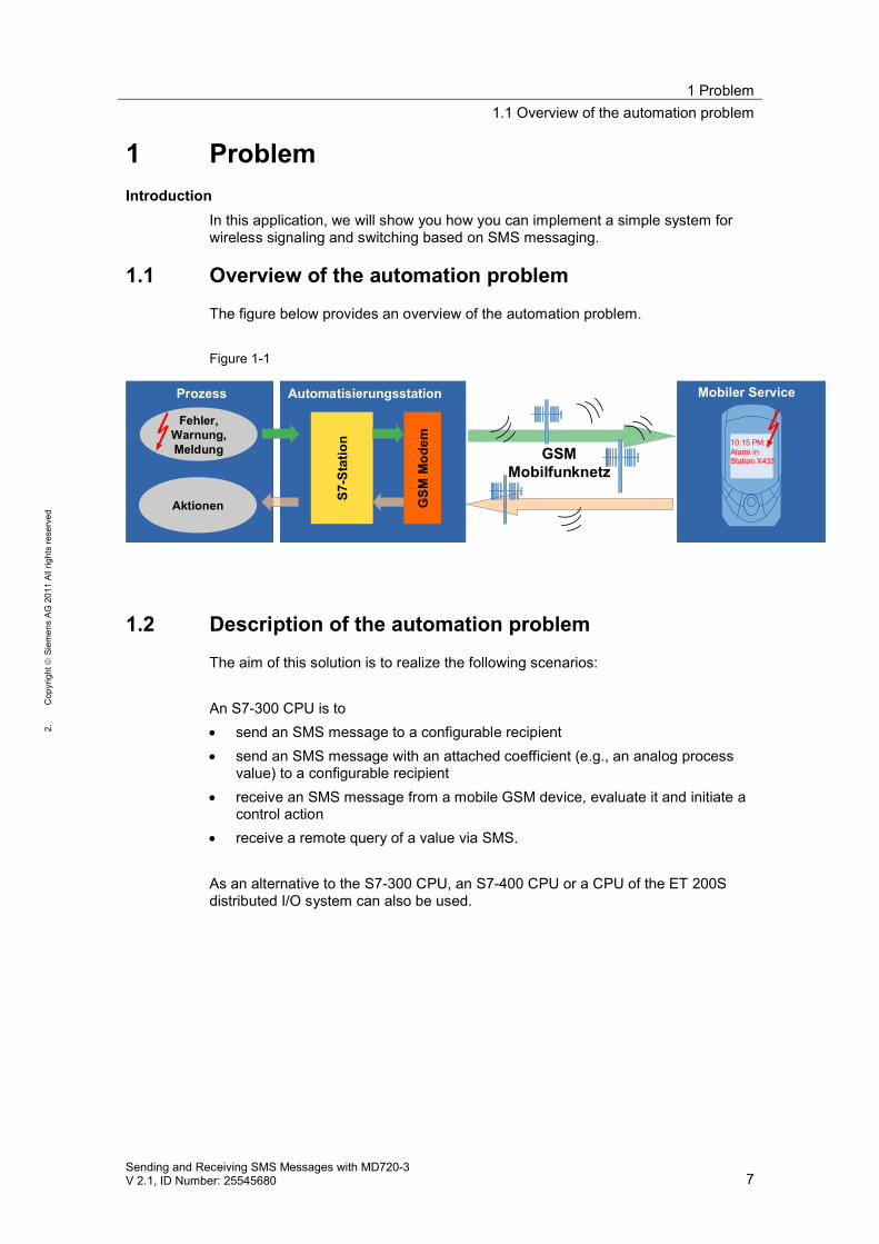
The figure below provides an overview of the automation problem.
Figure 1-1
GSM
Mod
em
S7-S
tatio
n
Automatisierungsstation
Fehler,Warnung,Meldung
Prozess
Aktionen
GSMMobilfunknetz
Mobiler Service
10.15 PM:Alarm inStation X433
1.2 Description of the automation problem
The aim of this solution is to realize the following scenarios:
An S7-300 CPU is to send an SMS message to a configurable recipient send an SMS message with an attached coefficient (e.g., an analog process
value) to a configurable recipient receive an SMS message from a mobile GSM device, evaluate it and initiate a
control action receive a remote query of a value via SMS.
As an alternative to the S7-300 CPU, an S7-400 CPU or a CPU of the ET 200Sdistributed I/O system can also be used.
2 Solution2.1 Overview of the overall solution
8Sending and Receiving SMS Messages with MD720-3
V 2.1, ID Number: 25545680
1.C
opyr
ight
Siem
ens
AG20
11Al
lrig
hts
rese
rved
2 Solution2.1 Overview of the overall solution
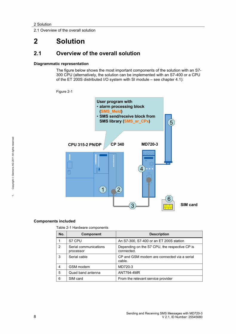
Diagrammatic representationThe figure below shows the most important components of the solution with an S7-300 CPU (alternatively, the solution can be implemented with an S7-400 or a CPUof the ET 200S distributed I/O system with SI module – see chapter 4.1):
Figure 2-1
1 2
4
5
63
CP 340 MD720-3
SIM card
User program with• alarm processing block
(SMS_Meld)• SMS send/receive block from
SMS library (SMS_sr_CPx)
CPU 315-2 PN/DP
Components includedTable 2-1 Hardware components
No. Component Description
1 S7 CPU An S7-300, S7-400 or an ET 200S station2 Serial communications
processorDepending on the S7 CPU, the respective CP isconnected.
3 Serial cable CP and GSM modem are connected via a serialcable.
4 GSM modem MD720-35 Quad band antenna ANT794-4MR6 SIM card From the relevant service provider
2 Solution2.1 Overview of the overall solution
Sending and Receiving SMS Messages with MD720-3V 2.1, ID Number: 25545680 9
2.C
opyr
ight
Siem
ens
AG20
11Al
lrig
hts
rese
rved
Table 2-2 Software components
Block Function Comment
FB “SMS_Meld” Generation of an SMS mes-sage according to a prede-fined logic
Send/receive managementwith SMS library block
Evaluation of a receive SMSmessage
Individual user block inSCL
FB “SMS_sr_CPxxx” Coordinated data exchange be-tween S7 CPU, serial CP andMD720-3
Universal SMS libraryblock in SCL
ScopeThis application does not include the basics of GSM wireless communications. For more information, refer to document \12\ in
the appendix. the LAD/ FBD/ STL/ SCL programming languages.
Basic knowledge of these topics is required.
2 Solution2.2 Description of the core functionality
10Sending and Receiving SMS Messages with MD720-3
V 2.1, ID Number: 25545680
1.C
opyr
ight
Siem
ens
AG20
11Al
lrig
hts
rese
rved
2.2 Description of the core functionality
In this example, the required scenarios are implemented with a user block pro-grammed in SCL (FB “SMS_Meld”) and with the aid of a universal SMS libraryblock (FB “SMS_sr_CPxxx”).
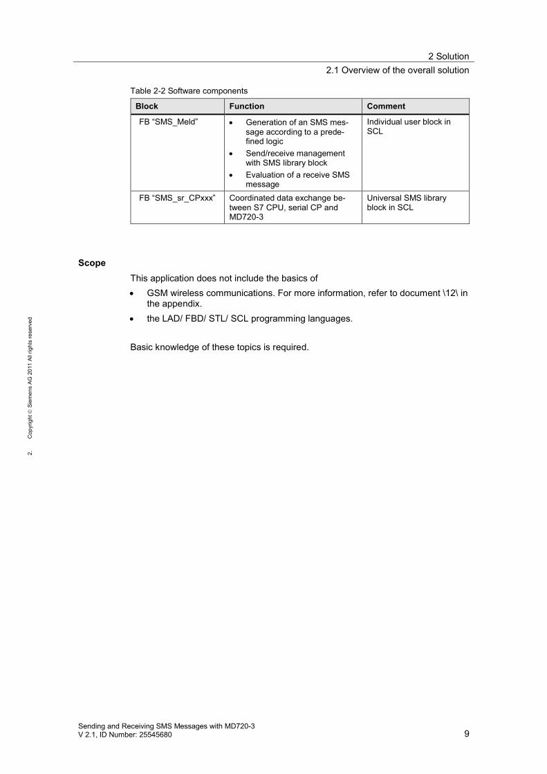
2.2.1 Scenario: “Generating and sending an SMS message”
Figure 2-2
Message_NoSMSmsg
Texts
“Message 1”“Message 2”….….
Tel. no.
“49155123x”“49175345y”….….
Event inthe process
SMS_Meld
Generating an SMS message and sending it to configurable recipients
SMS Generator
Recipients
When the S7 CPU (e.g., via I/O sensors) detects an event in the process, thisevent will be assigned an individually defined message number. In the FB“SMS_Meld” user block, a text and a recipient are assigned to the message num-ber. The FB “SMS_Meld” block coordinates the sending to this recipient.
2 Solution2.2 Description of the core functionality
Sending and Receiving SMS Messages with MD720-3V 2.1, ID Number: 25545680 11
2.C
opyr
ight
Siem
ens
AG20
11Al
lrig
hts
rese
rved
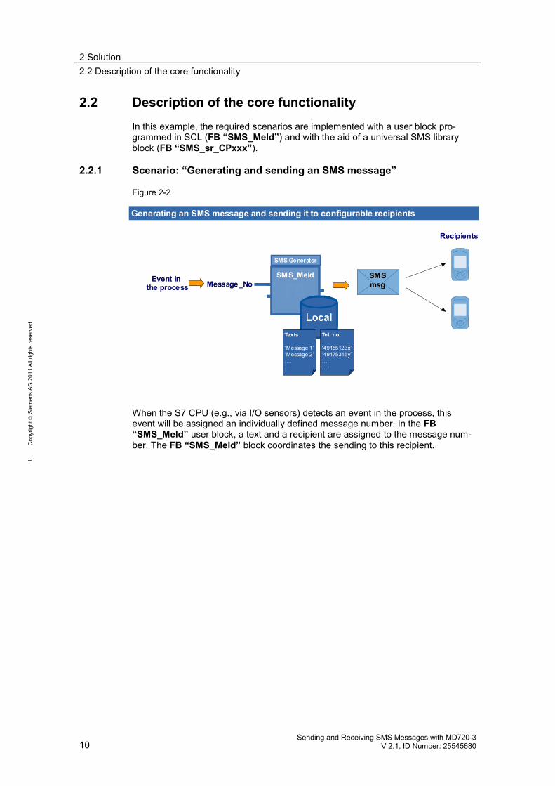
2.2.2 Scenario: “Sending an SMS message with attached coefficient”
Figure 2-3
Message_No SMSmsg
Texte
“Message 1”“Message 2”….….
Tel. no.
“49155123x”“49175345y”….….
Event inthe process
SMS_Meld
Generating an SMS message with attached coefficient and sending it toconfigurable recipients
SMS Generator
Value
Recipients
When the S7 CPU (for example, via I/O sensors) detects an event in the process,this event will be assigned an individually defined message number and any coeffi-cient (e.g., an analog process value). In the FB “SMS_Meld” user block, a text anda recipient are assigned to the message number. The block coordinates the send-ing of the text with the coefficient to the recipient.
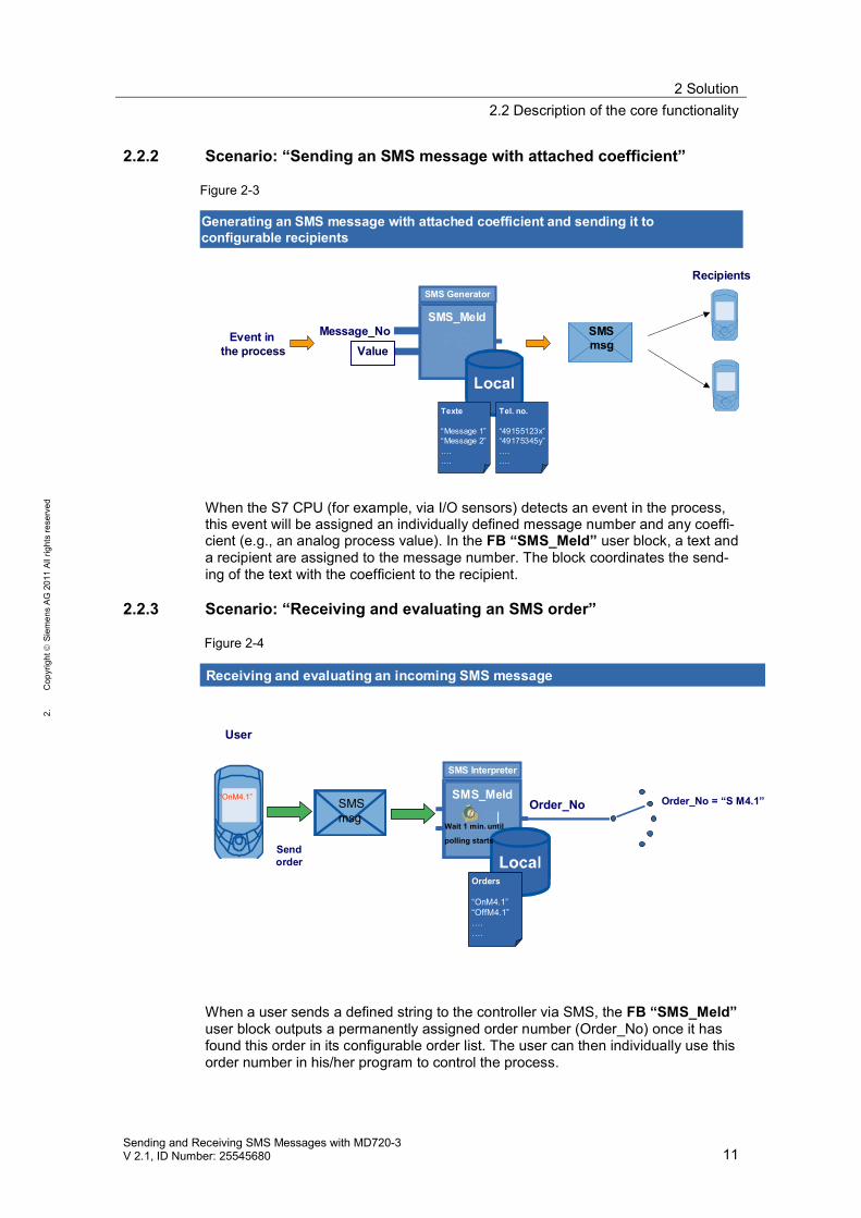
2.2.3 Scenario: “Receiving and evaluating an SMS order”
Figure 2-4
SMSmsg
SMS Interpreter
“OnM4.1” SMS_MeldOrder_No
Sendorder
Order_No = “S M4.1”
Receiving and evaluating an incoming SMS message
User
Orders
“OnM4.1”“OffM4.1”….….
Wait 1 min. until
polling starts
When a user sends a defined string to the controller via SMS, the FB “SMS_Meld”user block outputs a permanently assigned order number (Order_No) once it hasfound this order in its configurable order list. The user can then individually use thisorder number in his/her program to control the process.
2 Solution2.2 Description of the core functionality
12Sending and Receiving SMS Messages with MD720-3
V 2.1, ID Number: 25545680
1.C
opyr
ight
Siem
ens
AG20
11Al
lrig
hts
rese
rved
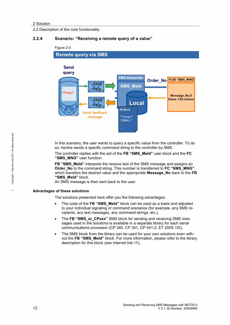
2.2.4 Scenario: “Receiving a remote query of a value”
Figure 2-5
SMSmsg
‘?Temp1’
SMS Interpreter
Orders
“?Temp1”“OffM4.1”….….
SMS_MeldOrder_No
Sendquery
Remote query via SMS
Message_No:5Value: 125 celsius
FC50 “SMS_MNG”
SMSmsg
Send feedbackmessage
In this scenario, the user wants to query a specific value from the controller. To doso, he/she sends a specific command string to the controller by SMS.The controller replies with the aid of the FB “SMS_Meld” user block and the FC“SMS_MNG” user function.FB “SMS_Meld” interprets the receive text of the SMS message and assigns anOrder_No to the command string. This number is transferred to FC “SMS_MNG”,which transfers the desired value and the appropriate Message_No back to the FB“SMS_Meld” block.An SMS message is then sent back to the user.
Advantages of these solutionsThe solutions presented here offer you the following advantages: The code of the FB “SMS_Meld” block can be used as a basis and adjusted
to your individual signaling or command scenarios (for example, any SMS re-cipients, any text messages, any command strings, etc.).
The FB “SMS_sr_CPxxx” SMS block for sending and receiving SMS mes-sages used in the solutions is available in a separate library for each serialcommunications processor (CP 340, CP 341, CP 441-2, ET 200S 1SI).
The SMS block from the library can be used for your own solutions even with-out the FB “SMS_Meld” block. For more information, please refer to the librarydescription for this block (see Internet link \1\).
2 Solution2.3 Hardware and software components used
Sending and Receiving SMS Messages with MD720-3V 2.1, ID Number: 25545680 13
2.C
opyr
ight
Siem
ens
AG20
11Al
lrig
hts
rese
rved
2.3 Hardware and software components used
The application was created with the following components:
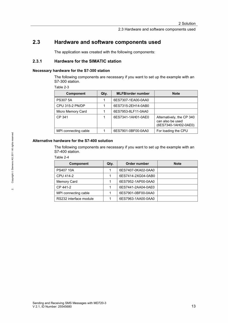
2.3.1 Hardware for the SIMATIC station
Necessary hardware for the S7-300 stationThe following components are necessary if you want to set up the example with anS7-300 station.Table 2-3
Component Qty. MLFB/order number Note
PS307 5A 1 6ES7307-1EA00-0AA0CPU 315-2 PN/DP 1 6ES7315-2EH14-0AB0Micro Memory Card 1 6ES7953-8LF11-0AA0CP 341 1 6ES7341-1AH01-0AE0 Alternatively, the CP 340
can also be used(6ES7340-1AH02-0AE0)
MPI connecting cable 1 6ES7901-0BF00-0AA0 For loading the CPU
Alternative hardware for the S7-400 solutionThe following components are necessary if you want to set up the example with anS7-400 station.Table 2-4
Component Qty. Order number Note
PS407 10A 1 6ES7407-0KA02-0AA0CPU 414-2 1 6ES7414-2XG04-0AB0Memory Card 1 6ES7952-1AP00-0AA0CP 441-2 1 6ES7441-2AA04-0AE0MPI connecting cable 1 6ES7901-0BF00-0AA0RS232 interface module 1 6ES7963-1AA00-0AA0
2 Solution2.3 Hardware and software components used
14Sending and Receiving SMS Messages with MD720-3
V 2.1, ID Number: 25545680
1.C
opyr
ight
Siem
ens
AG20
11Al
lrig
hts
rese
rved
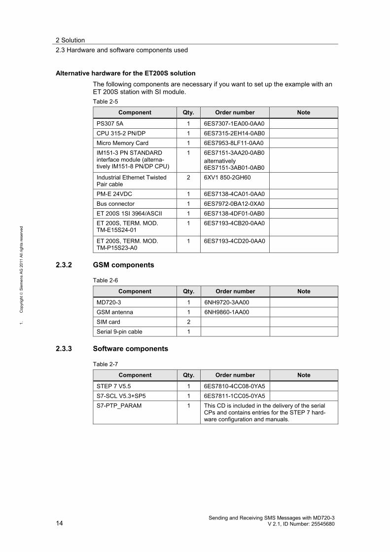
Alternative hardware for the ET200S solutionThe following components are necessary if you want to set up the example with anET 200S station with SI module.Table 2-5
Component Qty. Order number Note
PS307 5A 1 6ES7307-1EA00-0AA0CPU 315-2 PN/DP 1 6ES7315-2EH14-0AB0Micro Memory Card 1 6ES7953-8LF11-0AA0IM151-3 PN STANDARDinterface module (alterna-tively IM151-8 PN/DP CPU)
1 6ES7151-3AA20-0AB0alternatively6ES7151-3AB01-0AB0
Industrial Ethernet TwistedPair cable
2 6XV1 850-2GH60
PM-E 24VDC 1 6ES7138-4CA01-0AA0Bus connector 1 6ES7972-0BA12-0XA0ET 200S 1SI 3964/ASCII 1 6ES7138-4DF01-0AB0ET 200S, TERM. MOD.TM-E15S24-01
1 6ES7193-4CB20-0AA0
ET 200S, TERM. MOD.TM-P15S23-A0
1 6ES7193-4CD20-0AA0
2.3.2 GSM components
Table 2-6
Component Qty. Order number Note
MD720-3 1 6NH9720-3AA00GSM antenna 1 6NH9860-1AA00SIM card 2Serial 9-pin cable 1
2.3.3 Software components
Table 2-7
Component Qty. Order number Note
STEP 7 V5.5 1 6ES7810-4CC08-0YA5S7-SCL V5.3+SP5 1 6ES7811-1CC05-0YA5S7-PTP_PARAM 1 This CD is included in the delivery of the serial
CPs and contains entries for the STEP 7 hard-ware configuration and manuals.
2 Solution2.4 Performance data
Sending and Receiving SMS Messages with MD720-3V 2.1, ID Number: 25545680 15
2.C
opyr
ight
Siem
ens
AG20
11Al
lrig
hts
rese
rved
Sample files and projectsThe following table contains all files and projects that are used in this example.Table 2-8
Component Note
SMS_SR_Library.zip This zip file contains thelibrary blocks.
SMS_Example.zip This zip file contains theuser program.
25545680_Application_SMS_MD720_DOKU_V2_1_en.pdf This document.25545680_Library_SMS_MD720_DOKU_V2_0_en.pdf Library description.
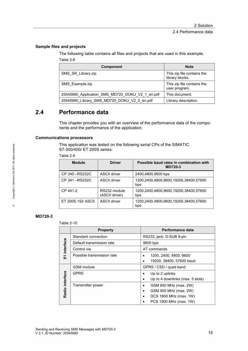
2.4 Performance dataThis chapter provides you with an overview of the performance data of the compo-nents and the performance of the application.
Communications processorsThis application was tested on the following serial CPs of the SIMATICS7-300/400/ ET 200S series:Table 2-9
Module Driver Possible baud rates in combination withMD720-3
CP 340 –RS232C ASCII driver 2400,4800,9600 bpsCP 341 –RS232C ASCII driver 1200,2400,4800,9600,19200,38400,57600
bpsCP 441-2 RS232 module
(ASCII driver)1200,2400,4800,9600,19200,38400,57600bps
ET 200S 1SI/ ASCII ASCII driver 1200,2400,4800,9600,19200,38400,57600bps
MD720-3Table 2-10
Property Performance data
X1in
terf
ace Standard connection RS232, jack; D-SUB 9-pin
Default transmission rate 9600 bpsControl via AT commandsPossible transmission rate 1200, 2400, 4800, 9600
19200, 38400, 57600 baud
Rad
ioin
terf
ace
GSM module GPRS / CSD / quad bandGPRS Up to 2 uplinks
Up to 4 downlinks (max. 5 slots)Transmitter power GSM 850 MHz (max. 2W)
GSM 900 MHz (max. 2W) DCS 1800 MHz (max. 1W) PCS 1900 MHz (max. 1W)
2 Solution2.4 Performance data
16Sending and Receiving SMS Messages with MD720-3
V 2.1, ID Number: 25545680
1.C
opyr
ight
Siem
ens
AG20
11Al
lrig
hts
rese
rved
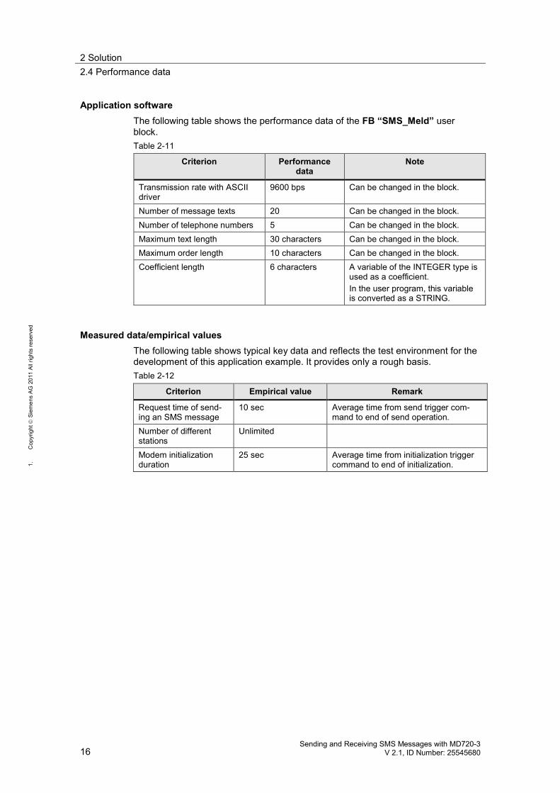
Application softwareThe following table shows the performance data of the FB “SMS_Meld” userblock.Table 2-11
Criterion Performancedata
Note
Transmission rate with ASCIIdriver
9600 bps Can be changed in the block.
Number of message texts 20 Can be changed in the block.Number of telephone numbers 5 Can be changed in the block.Maximum text length 30 characters Can be changed in the block.Maximum order length 10 characters Can be changed in the block.Coefficient length 6 characters A variable of the INTEGER type is
used as a coefficient.In the user program, this variableis converted as a STRING.
Measured data/empirical valuesThe following table shows typical key data and reflects the test environment for thedevelopment of this application example. It provides only a rough basis.Table 2-12
Criterion Empirical value Remark
Request time of send-ing an SMS message
10 sec Average time from send trigger com-mand to end of send operation.
Number of differentstations
Unlimited
Modem initializationduration
25 sec Average time from initialization triggercommand to end of initialization.
3 Functional Mechanisms of this Application3.1 Program overview
Sending and Receiving SMS Messages with MD720-3V 2.1, ID Number: 25545680 17
2.C
opyr
ight
Siem
ens
AG20
11Al
lrig
hts
rese
rved
3 Functional Mechanisms of this ApplicationIntroduction
The following sections provide detailed explanations of the functionalities of the dif-ferent scenarios Generating and sending an SMS message Sending an SMS message with attached coefficient Receiving and evaluating SMS orders and Receiving a remote query of a value.
3.1 Program overview
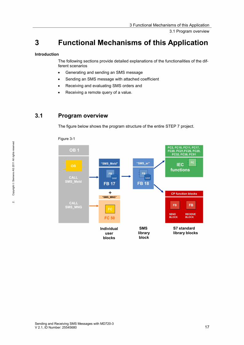
The figure below shows the program structure of the entire STEP 7 project.
Figure 3-1
FB 17
“SMS_Meld”
FB 18
“SMS_sr”
OB 1
OB IECfunctions
FC2, FC10, FC11, FC17,FC20, FC21,FC26, FC29,
FC32, FC38, FC91
CP function blocks
FB FB
SENDBLOCK
RECEIVEBLOCK
Individualuser
blocks
SMSlibraryblock
S7 standardlibrary blocks
“SMS_MNG”
FC
FC 50
+
CALLSMS_Meld
CALLSMS_MNG
3 Functional Mechanisms of this Application3.1 Program overview
18Sending and Receiving SMS Messages with MD720-3
V 2.1, ID Number: 25545680
1.C
opyr
ight
Siem
ens
AG20
11Al
lrig
hts
rese
rved
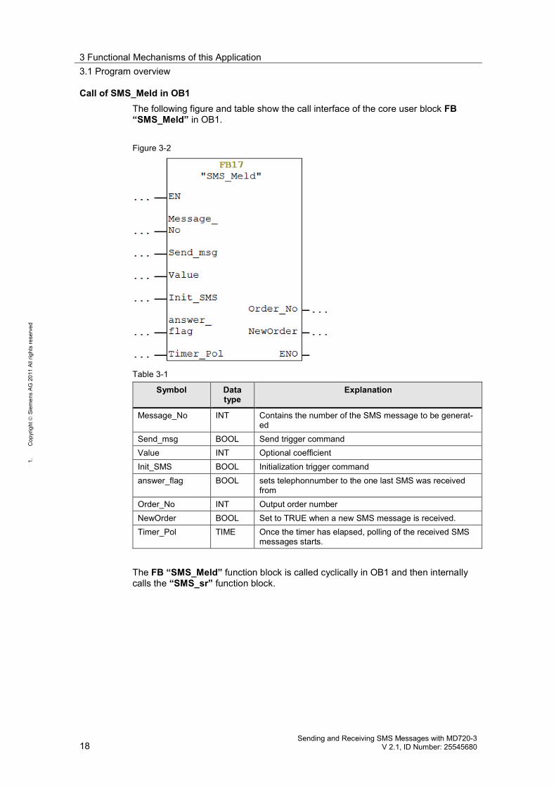
Call of SMS_Meld in OB1The following figure and table show the call interface of the core user block FB“SMS_Meld” in OB1.
Figure 3-2
Table 3-1
Symbol Datatype
Explanation
Message_No INT Contains the number of the SMS message to be generat-ed
Send_msg BOOL Send trigger commandValue INT Optional coefficientInit_SMS BOOL Initialization trigger commandanswer_flag BOOL sets telephonnumber to the one last SMS was received
fromOrder_No INT Output order numberNewOrder BOOL Set to TRUE when a new SMS message is received.Timer_Pol TIME Once the timer has elapsed, polling of the received SMS
messages starts.
The FB “SMS_Meld” function block is called cyclically in OB1 and then internallycalls the “SMS_sr” function block.
3 Functional Mechanisms of this Application3.2 Scenario: “Generating and sending an SMS message”
Sending and Receiving SMS Messages with MD720-3V 2.1, ID Number: 25545680 19
2.C
opyr
ight
Siem
ens
AG20
11Al
lrig
hts
rese
rved
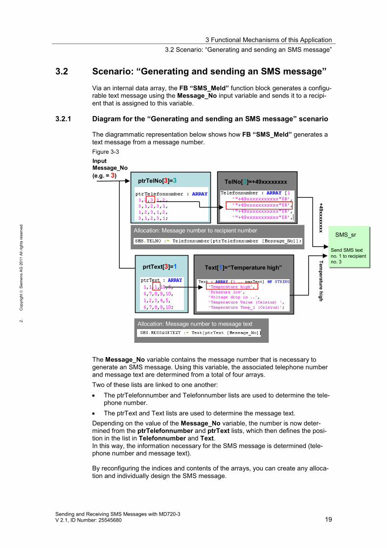
3.2 Scenario: “Generating and sending an SMS message”Via an internal data array, the FB “SMS_Meld” function block generates a configu-rable text message using the Message_No input variable and sends it to a recipi-ent that is assigned to this variable.
3.2.1 Diagram for the “Generating and sending an SMS message” scenario
The diagrammatic representation below shows how FB “SMS_Meld” generates atext message from a message number.Figure 3-3InputMessage_No(e.g. = 3)
SMS_sr
Send SMS textno. 1 to recipientno. 3Tem
peraturehigh
+49xxxxxxxxAllocation: Message number to recipient number
ptrTelNo[3]=3 TelNo[3]=+49xxxxxxxx
Allocation: Message number to message text
prtText[3]=1 Text[1]=“Temperature high”
The Message_No variable contains the message number that is necessary togenerate an SMS message. Using this variable, the associated telephone numberand message text are determined from a total of four arrays.Two of these lists are linked to one another: The ptrTelefonnumber and Telefonnumber lists are used to determine the tele-
phone number. The ptrText and Text lists are used to determine the message text.
Depending on the value of the Message_No variable, the number is now deter-mined from the ptrTelefonnumber and ptrText lists, which then defines the posi-tion in the list in Telefonnumber and Text.In this way, the information necessary for the SMS message is determined (tele-phone number and message text).
By reconfiguring the indices and contents of the arrays, you can create any alloca-tion and individually design the SMS message.
3 Functional Mechanisms of this Application3.2 Scenario: “Generating and sending an SMS message”
20Sending and Receiving SMS Messages with MD720-3
V 2.1, ID Number: 25545680
1.C
opyr
ight
Siem
ens
AG20
11Al
lrig
hts
rese
rved
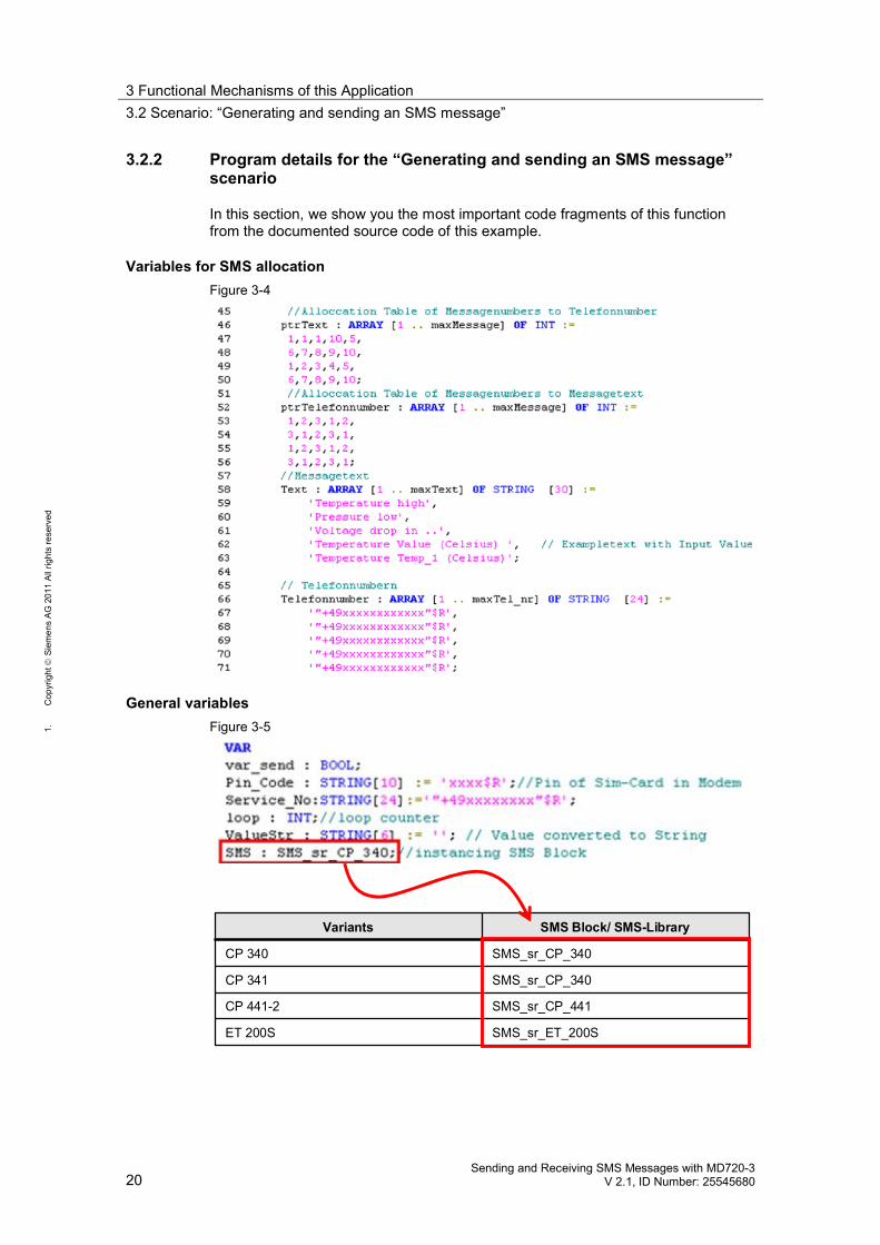
3.2.2 Program details for the “Generating and sending an SMS message”scenario
In this section, we show you the most important code fragments of this functionfrom the documented source code of this example.
Variables for SMS allocationFigure 3-4
General variablesFigure 3-5
SMS_sr_ET_200SET 200S
SMS_sr_CP_441CP 441-2
SMS_sr_CP_340CP 341
SMS_sr_CP_340CP 340
SMS Block/ SMS-LibraryVariants
3 Functional Mechanisms of this Application3.2 Scenario: “Generating and sending an SMS message”
Sending and Receiving SMS Messages with MD720-3V 2.1, ID Number: 25545680 21
2.C
opyr
ight
Siem
ens
AG20
11Al
lrig
hts
rese
rved
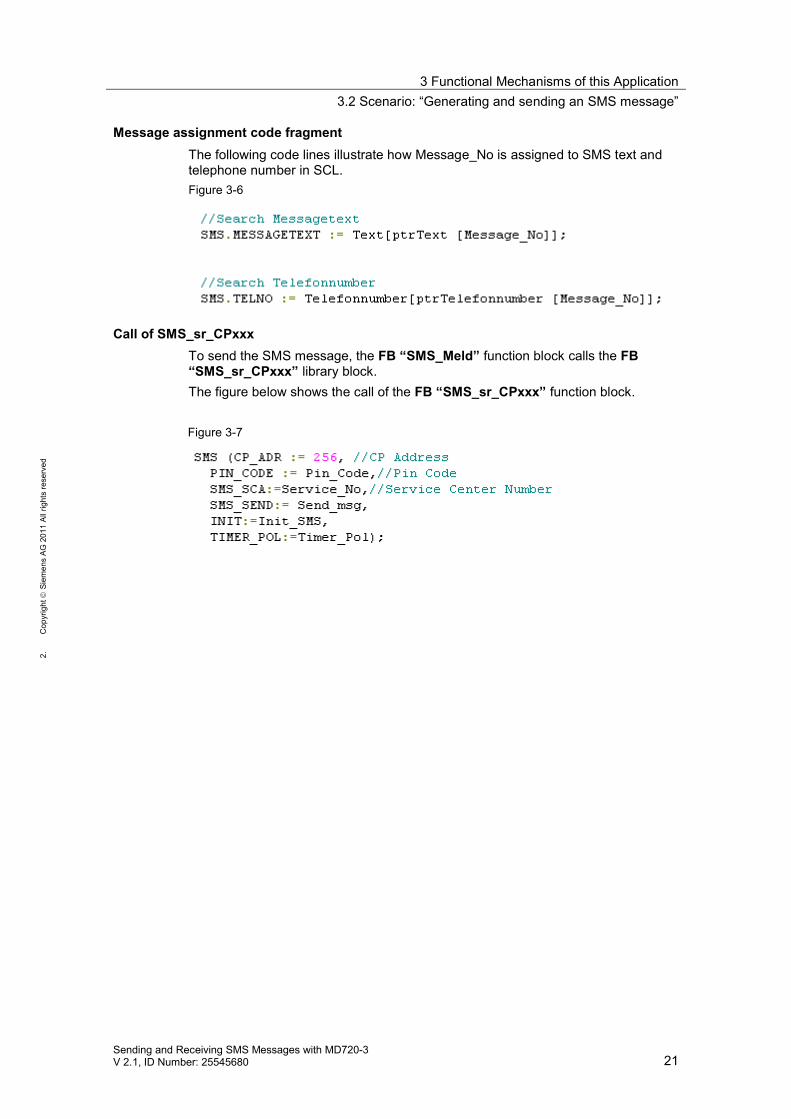
Message assignment code fragmentThe following code lines illustrate how Message_No is assigned to SMS text andtelephone number in SCL.Figure 3-6
Call of SMS_sr_CPxxxTo send the SMS message, the FB “SMS_Meld” function block calls the FB“SMS_sr_CPxxx” library block.The figure below shows the call of the FB “SMS_sr_CPxxx” function block.
Figure 3-7
3 Functional Mechanisms of this Application3.3 Scenario: “Sending an SMS message with attached coefficient”
22Sending and Receiving SMS Messages with MD720-3
V 2.1, ID Number: 25545680
1.C
opyr
ight
Siem
ens
AG20
11Al
lrig
hts
rese
rved
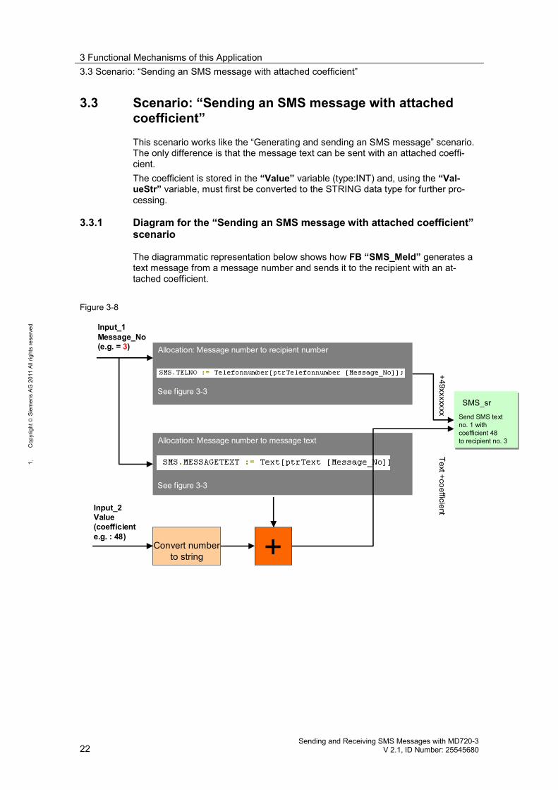
3.3 Scenario: “Sending an SMS message with attachedcoefficient”This scenario works like the “Generating and sending an SMS message” scenario.The only difference is that the message text can be sent with an attached coeffi-cient.The coefficient is stored in the “Value” variable (type:INT) and, using the “Val-ueStr” variable, must first be converted to the STRING data type for further pro-cessing.
3.3.1 Diagram for the “Sending an SMS message with attached coefficient”scenario
The diagrammatic representation below shows how FB “SMS_Meld” generates atext message from a message number and sends it to the recipient with an at-tached coefficient.
Figure 3-8
SMS_sr
Send SMS textno. 1 withcoefficient 48to recipient no. 3
Allocation: Message number to recipient number
Input_2Value(coefficiente.g. : 48)
Convert numberto string
Input_1Message_No(e.g. = 3)
See figure 3-3
Allocation: Message number to message text
See figure 3-3
+
Text+coefficient+49xxxxxxx
3 Functional Mechanisms of this Application3.3 Scenario: “Sending an SMS message with attached coefficient”
Sending and Receiving SMS Messages with MD720-3V 2.1, ID Number: 25545680 23
2.C
opyr
ight
Siem
ens
AG20
11Al
lrig
hts
rese
rved
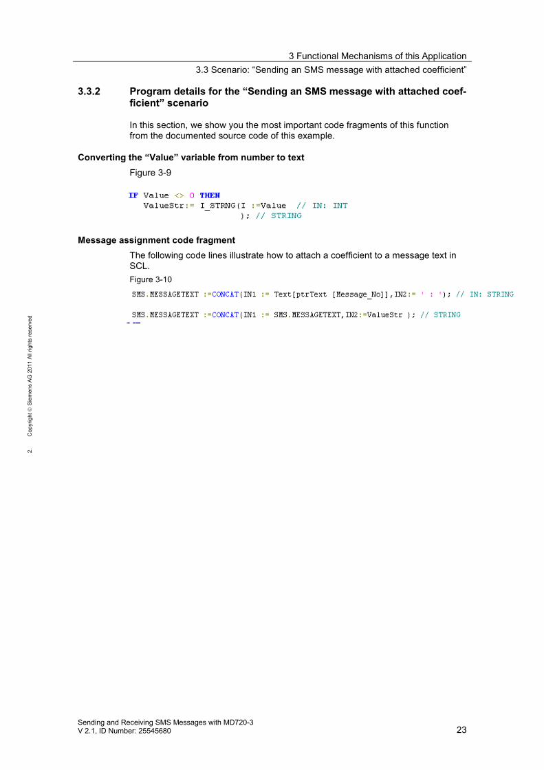
3.3.2 Program details for the “Sending an SMS message with attached coef-ficient” scenario
In this section, we show you the most important code fragments of this functionfrom the documented source code of this example.
Converting the “Value” variable from number to textFigure 3-9
Message assignment code fragmentThe following code lines illustrate how to attach a coefficient to a message text inSCL.Figure 3-10
3 Functional Mechanisms of this Application3.4 Scenario: “Receiving and evaluating SMS orders”
24Sending and Receiving SMS Messages with MD720-3
V 2.1, ID Number: 25545680
1.C
opyr
ight
Siem
ens
AG20
11Al
lrig
hts
rese
rved
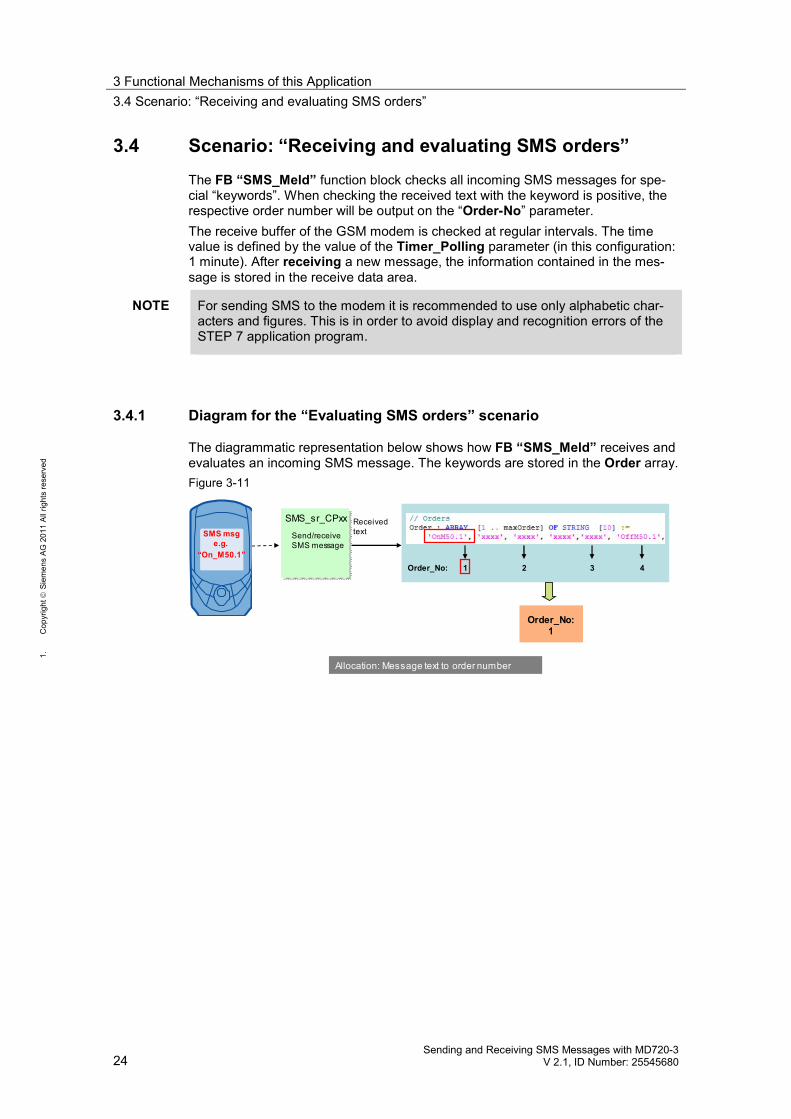
3.4 Scenario: “Receiving and evaluating SMS orders”The FB “SMS_Meld” function block checks all incoming SMS messages for spe-cial “keywords”. When checking the received text with the keyword is positive, therespective order number will be output on the “Order-No” parameter.The receive buffer of the GSM modem is checked at regular intervals. The timevalue is defined by the value of the Timer_Polling parameter (in this configuration:1 minute). After receiving a new message, the information contained in the mes-sage is stored in the receive data area.
NOTE For sending SMS to the modem it is recommended to use only alphabetic char-acters and figures. This is in order to avoid display and recognition errors of theSTEP 7 application program.
3.4.1 Diagram for the “Evaluating SMS orders” scenario
The diagrammatic representation below shows how FB “SMS_Meld” receives andevaluates an incoming SMS message. The keywords are stored in the Order array.Figure 3-11
Send/receiveSMS message
SMS_sr_CPxxSMS msg
e.g.“On_M50.1”
Allocation: Message text to order number
Receivedtext
Order_No:1
Order_No: 1 2 3 4
3 Functional Mechanisms of this Application3.4 Scenario: “Receiving and evaluating SMS orders”
Sending and Receiving SMS Messages with MD720-3V 2.1, ID Number: 25545680 25
2.C
opyr
ight
Siem
ens
AG20
11Al
lrig
hts
rese
rved
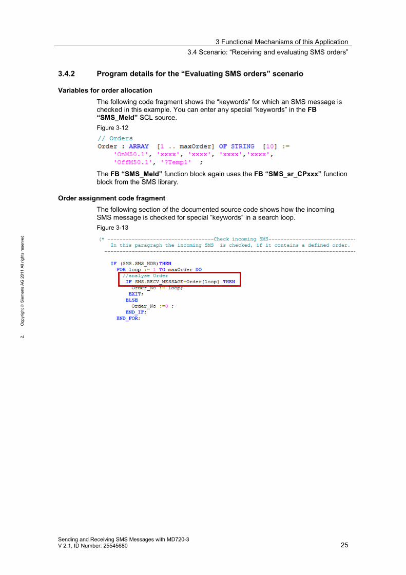
3.4.2 Program details for the “Evaluating SMS orders” scenario
Variables for order allocationThe following code fragment shows the “keywords” for which an SMS message ischecked in this example. You can enter any special “keywords” in the FB“SMS_Meld” SCL source.Figure 3-12
The FB “SMS_Meld” function block again uses the FB “SMS_sr_CPxxx” functionblock from the SMS library.
Order assignment code fragmentThe following section of the documented source code shows how the incomingSMS message is checked for special “keywords” in a search loop.Figure 3-13
3 Functional Mechanisms of this Application3.5 Scenario: “Receiving a remote query of a value”
26Sending and Receiving SMS Messages with MD720-3
V 2.1, ID Number: 25545680
1.C
opyr
ight
Siem
ens
AG20
11Al
lrig
hts
rese
rved
3.5 Scenario: “Receiving a remote query of a value”Using the FB “SMS_Meld” block, SMS messages for querying a value (e.g., theanalog value of a temperature) can be interpreted. An automatic feedback mes-sage is sent with the aid of the FC “SMS_MNG” function.
NOTE For sending SMS to the modem it is recommended to use only alphabetic char-acters and figures. This is in order to avoid display and recognition errors of theSTEP 7 application program.
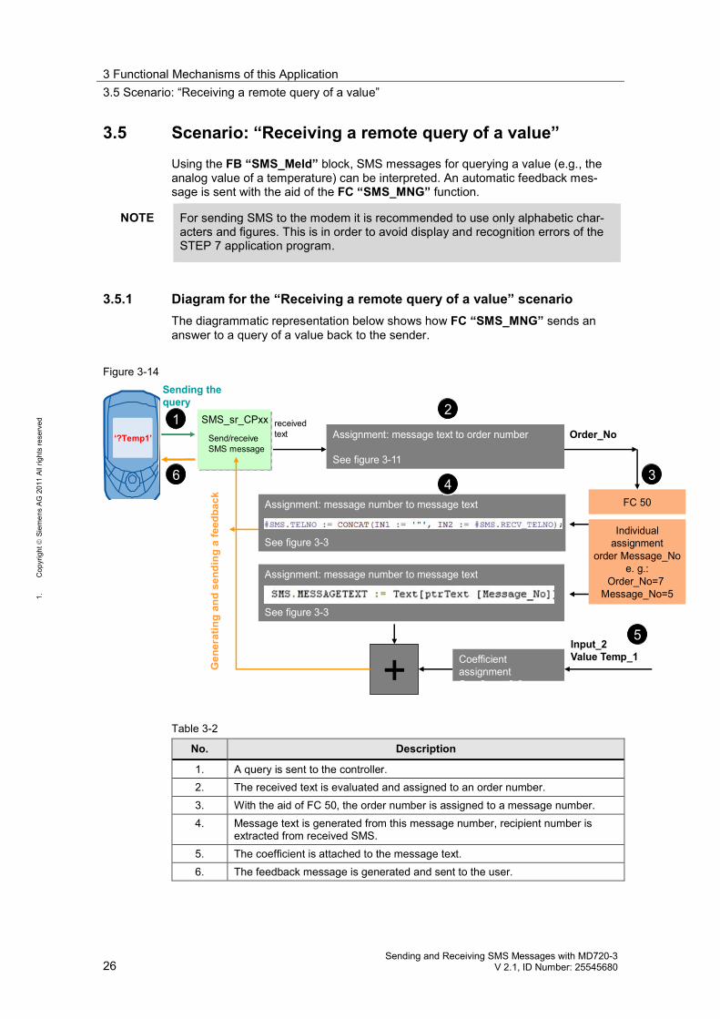
3.5.1 Diagram for the “Receiving a remote query of a value” scenarioThe diagrammatic representation below shows how FC “SMS_MNG” sends ananswer to a query of a value back to the sender.
Figure 3-14
Send/receiveSMS message
SMS_sr_CPxx receivedtext Order_No‘?Temp1’
Sending thequery
Gen
erat
ing
and
send
ing
afe
edba
ck
Assignment: message text to order number
See figure 3-11
Individualassignment
order Message_Noe. g.:
Order_No=7Message_No=5
FC 50Assignment: message number to message text
See figure 3-3
Assignment: message number to message text
See figure 3-3
+Input_2Value Temp_1Coefficient
assignmentSee figure 3-8
1 2
34
5
6
12
6
5
43
Table 3-2
No. Description
1. A query is sent to the controller.2. The received text is evaluated and assigned to an order number.3. With the aid of FC 50, the order number is assigned to a message number.4. Message text is generated from this message number, recipient number is
extracted from received SMS.5. The coefficient is attached to the message text.6. The feedback message is generated and sent to the user.
3 Functional Mechanisms of this Application3.5 Scenario: “Receiving a remote query of a value”
Sending and Receiving SMS Messages with MD720-3V 2.1, ID Number: 25545680 27
2.C
opyr
ight
Siem
ens
AG20
11Al
lrig
hts
rese
rved
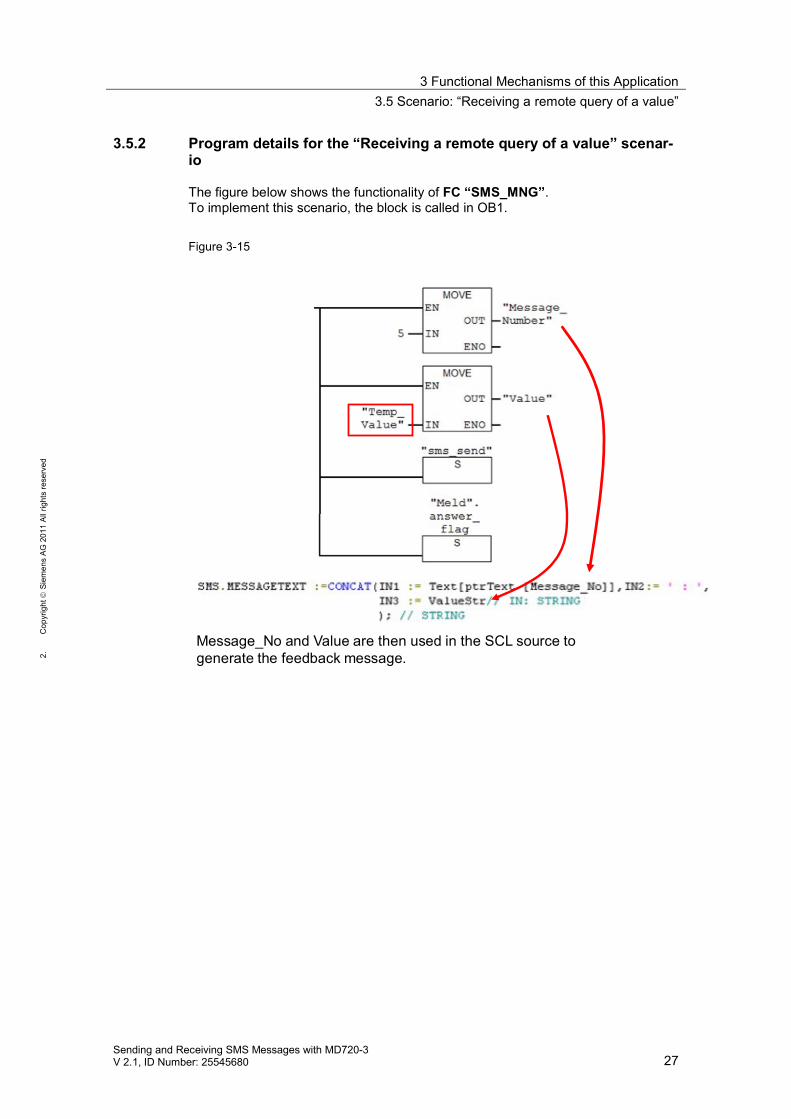
3.5.2 Program details for the “Receiving a remote query of a value” scenar-io
The figure below shows the functionality of FC “SMS_MNG”.To implement this scenario, the block is called in OB1.
Figure 3-15
Message_No and Value are then used in the SCL source togenerate the feedback message.
4 Installation4.1 Hardware configuration of the S7 station
28Sending and Receiving SMS Messages with MD720-3
V 2.1, ID Number: 25545680
1.C
opyr
ight
Siem
ens
AG20
11Al
lrig
hts
rese
rved
4 Installation4.1 Hardware configuration of the S7 station
OverviewThis application example includes the following S7 project variants:Table 4-1
Station Variants/program name
S7-300 station CP_340HW Config and S7 program for variant with CP 340CP_341HW Config and S7 program for variant with CP 341ET 200S _1SIHW Config and S7 program for variant with ET 200S SI module
S7-400 station CP_441-2HW Config and S7 program for variant with CP 441-2
NOTICE The following applies to all project variants:Before you switch on the power supply, complete and check the configura-tion!
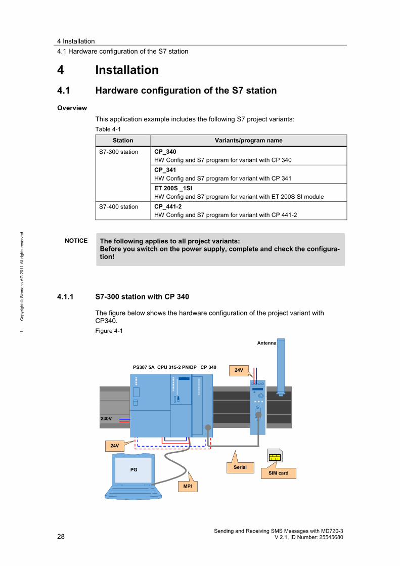
4.1.1 S7-300 station with CP 340
The figure below shows the hardware configuration of the project variant withCP340.Figure 4-1
PS307 5A CPU 315-2 PN/DP CP 340
230V
24V
MPI
24V
Antenna
SerialPG SIM card
4 Installation4.1 Hardware configuration of the S7 station
Sending and Receiving SMS Messages with MD720-3V 2.1, ID Number: 25545680 29
2.C
opyr
ight
Siem
ens
AG20
11Al
lrig
hts
rese
rved
Table 4-2
No. Action Remark
1. Attach the individual modules to a suitable rack. List of components Table 2-32. Use a backplane bus connector to connect CPU and
CP.3. Connect all respective components to a 24 V direct
current source (PS307).Connect the PS307 to the electricity-supply system(230 V AC).
Ensure that the polarity is correct.
4. Connect the MPI of the engineering PG to the MPI ofthe S7 CPU.
5. Connect the serial cable to the CP.
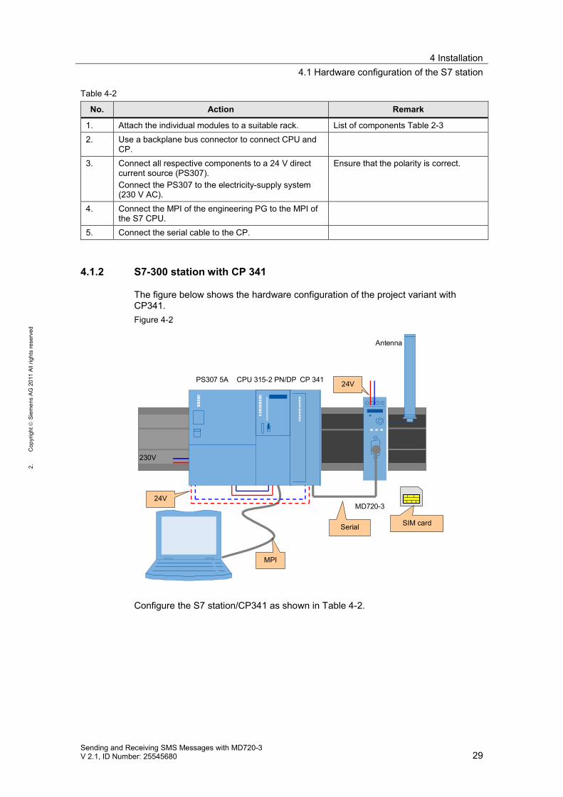
4.1.2 S7-300 station with CP 341
The figure below shows the hardware configuration of the project variant withCP341.Figure 4-2
PS307 5A CPU 315-2 PN/DP CP 341
230V
24V
MPI
Serial
24V
MD720-3
Antenna
SIM card
Configure the S7 station/CP341 as shown in Table 4-2.
4 Installation4.1 Hardware configuration of the S7 station
30Sending and Receiving SMS Messages with MD720-3
V 2.1, ID Number: 25545680
1.C
opyr
ight
Siem
ens
AG20
11Al
lrig
hts
rese
rved
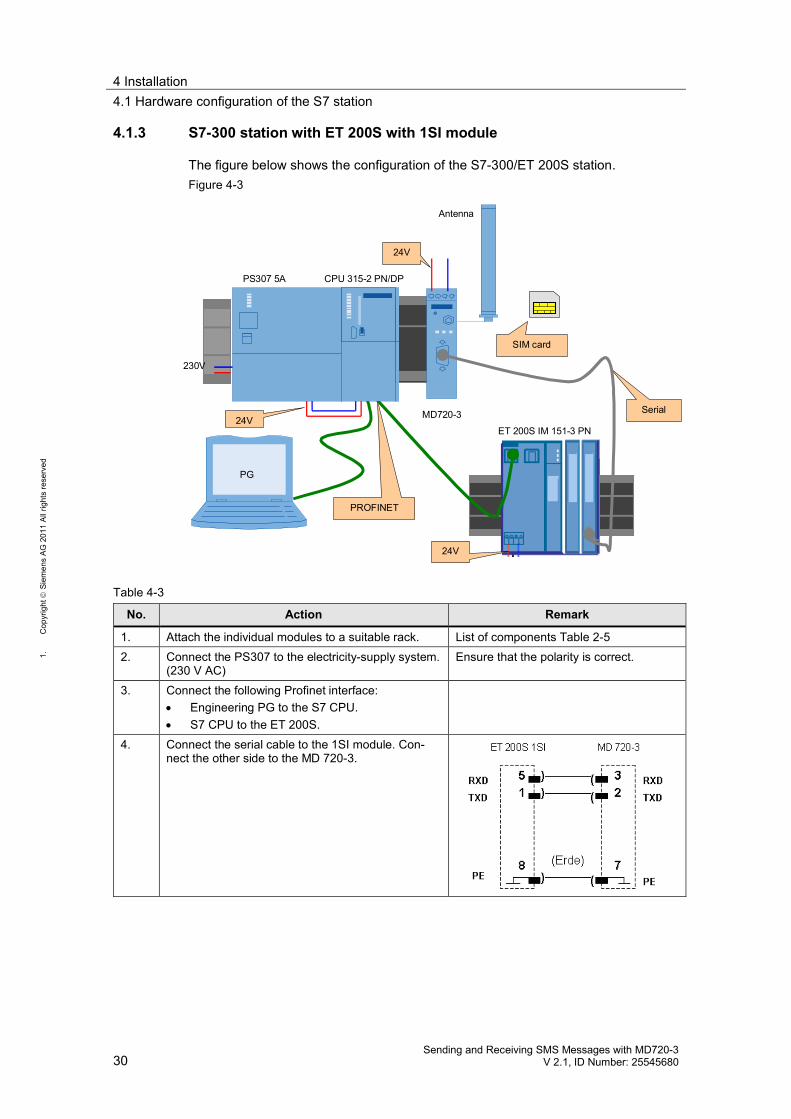
4.1.3 S7-300 station with ET 200S with 1SI module
The figure below shows the configuration of the S7-300/ET 200S station.Figure 4-3
PS307 5A CPU 315-2 PN/DP
ET 200S IM 151-3 PN
230V
24V
PROFINET
Serial
24V
MD720-3
Antenna
SIM card
PG
24V
Table 4-3
No. Action Remark
1. Attach the individual modules to a suitable rack. List of components Table 2-52. Connect the PS307 to the electricity-supply system.
(230 V AC)Ensure that the polarity is correct.
3. Connect the following Profinet interface: Engineering PG to the S7 CPU. S7 CPU to the ET 200S.
4. Connect the serial cable to the 1SI module. Con-nect the other side to the MD 720-3.
4 Installation4.1 Hardware configuration of the S7 station
Sending and Receiving SMS Messages with MD720-3V 2.1, ID Number: 25545680 31
2.C
opyr
ight
Siem
ens
AG20
11Al
lrig
hts
rese
rved
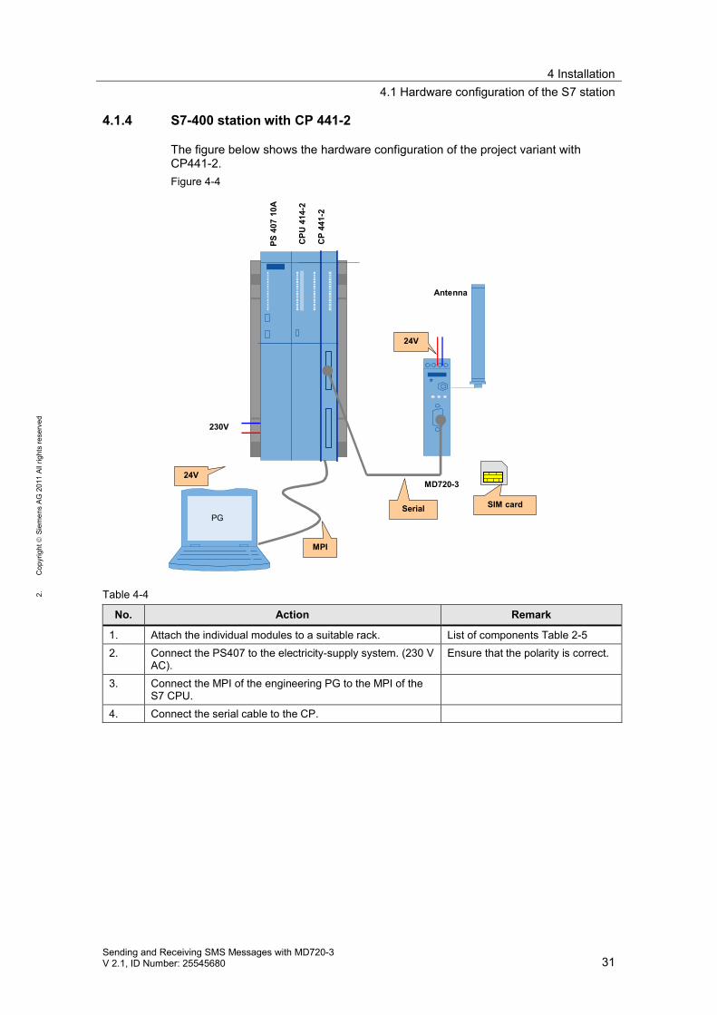
4.1.4 S7-400 station with CP 441-2
The figure below shows the hardware configuration of the project variant withCP441-2.Figure 4-4
PS40
710
A
230V
24V
MPI
Serial
24V
MD720-3
Antenna
SIM card
CPU
414-
2
CP
441-
2
PG
Table 4-4
No. Action Remark
1. Attach the individual modules to a suitable rack. List of components Table 2-52. Connect the PS407 to the electricity-supply system. (230 V
AC).Ensure that the polarity is correct.
3. Connect the MPI of the engineering PG to the MPI of theS7 CPU.
4. Connect the serial cable to the CP.
4 Installation4.2 MD720-3 hardware configuration
32Sending and Receiving SMS Messages with MD720-3
V 2.1, ID Number: 25545680
1.C
opyr
ight
Siem
ens
AG20
11Al
lrig
hts
rese
rved
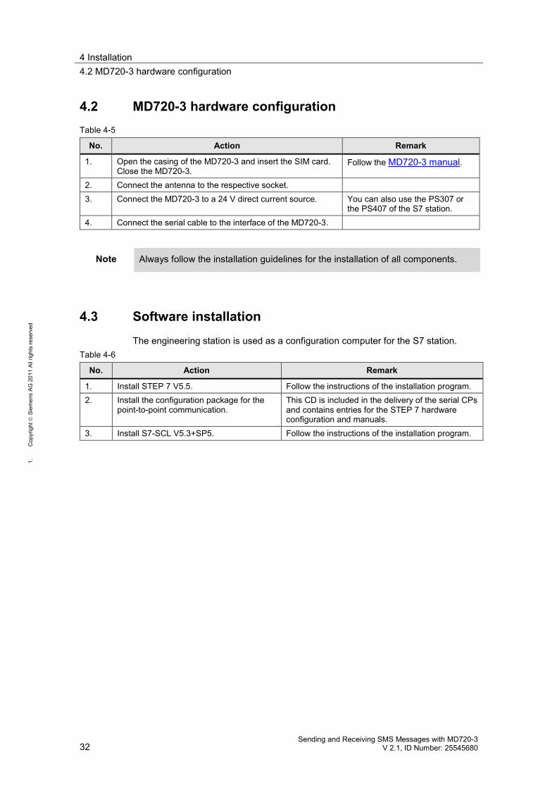
4.2 MD720-3 hardware configurationTable 4-5
No. Action Remark
1. Open the casing of the MD720-3 and insert the SIM card.Close the MD720-3.
Follow the MD720-3 manual.
2. Connect the antenna to the respective socket.3. Connect the MD720-3 to a 24 V direct current source. You can also use the PS307 or
the PS407 of the S7 station.4. Connect the serial cable to the interface of the MD720-3.
Note Always follow the installation guidelines for the installation of all components.
4.3 Software installation
The engineering station is used as a configuration computer for the S7 station.Table 4-6
No. Action Remark
1. Install STEP 7 V5.5. Follow the instructions of the installation program.2. Install the configuration package for the
point-to-point communication.This CD is included in the delivery of the serial CPsand contains entries for the STEP 7 hardwareconfiguration and manuals.
3. Install S7-SCL V5.3+SP5. Follow the instructions of the installation program.
5 Commissioning of the Application5.1 General preparations
Sending and Receiving SMS Messages with MD720-3V 2.1, ID Number: 25545680 33
2.C
opyr
ight
Siem
ens
AG20
11Al
lrig
hts
rese
rved
5 Commissioning of the Application5.1 General preparations
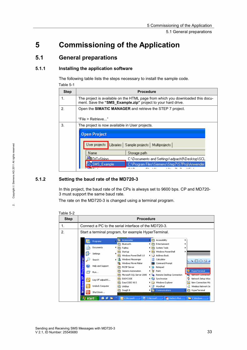
5.1.1 Installing the application software
The following table lists the steps necessary to install the sample code.Table 5-1
Step Procedure
1. The project is available on the HTML page from which you downloaded this docu-ment. Save the “SMS_Example.zip” project to your hard drive.
2. Open the SIMATIC MANAGER and retrieve the STEP 7 project.
“File > Retrieve...”3. The project is now available in User projects.
5.1.2 Setting the baud rate of the MD720-3
In this project, the baud rate of the CPs is always set to 9600 bps. CP and MD720-3 must support the same baud rate.The rate on the MD720-3 is changed using a terminal program.
Table 5-2Step Procedure
1. Connect a PC to the serial interface of the MD720-3.2. Start a terminal program, for example HyperTerminal.
5 Commissioning of the Application5.1 General preparations
34Sending and Receiving SMS Messages with MD720-3
V 2.1, ID Number: 25545680
1.C
opyr
ight
Siem
ens
AG20
11Al
lrig
hts
rese
rved
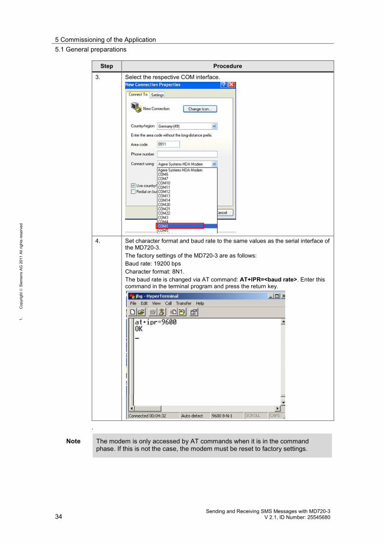
Step Procedure
3. Select the respective COM interface.
4. Set character format and baud rate to the same values as the serial interface ofthe MD720-3.The factory settings of the MD720-3 are as follows:Baud rate: 19200 bpsCharacter format: 8N1.The baud rate is changed via AT command: AT+IPR=<baud rate>. Enter thiscommand in the terminal program and press the return key.
.
Note The modem is only accessed by AT commands when it is in the commandphase. If this is not the case, the modem must be reset to factory settings.
5 Commissioning of the Application5.1 General preparations
Sending and Receiving SMS Messages with MD720-3V 2.1, ID Number: 25545680 35
2.C
opyr
ight
Siem
ens
AG20
11Al
lrig
hts
rese
rved
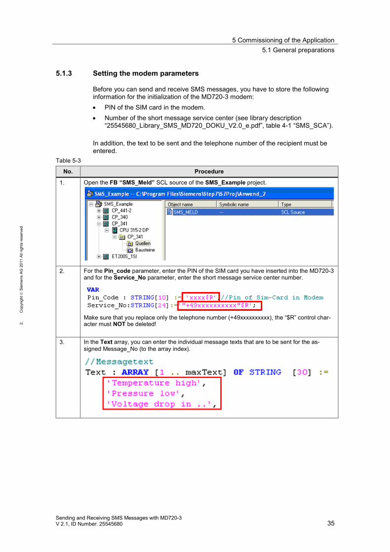
5.1.3 Setting the modem parameters
Before you can send and receive SMS messages, you have to store the followinginformation for the initialization of the MD720-3 modem: PIN of the SIM card in the modem. Number of the short message service center (see library description
“25545680_Library_SMS_MD720_DOKU_V2.0_e.pdf”, table 4-1 “SMS_SCA”).
In addition, the text to be sent and the telephone number of the recipient must beentered.
Table 5-3
No. Procedure
1. Open the FB “SMS_Meld” SCL source of the SMS_Example project.
2. For the Pin_code parameter, enter the PIN of the SIM card you have inserted into the MD720-3and for the Service_No parameter, enter the short message service center number.
Make sure that you replace only the telephone number (+49xxxxxxxxxx), the “$R” control char-acter must NOT be deleted!
3. In the Text array, you can enter the individual message texts that are to be sent for the as-signed Message_No (to the array index).
5 Commissioning of the Application5.1 General preparations
36Sending and Receiving SMS Messages with MD720-3
V 2.1, ID Number: 25545680
1.C
opyr
ight
Siem
ens
AG20
11Al
lrig
hts
rese
rved
No. Procedure
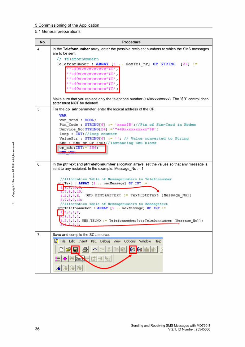
4. In the Telefonnumber array, enter the possible recipient numbers to which the SMS messagesare to be sent.
Make sure that you replace only the telephone number (+49xxxxxxxxxx). The “$R” control char-acter must NOT be deleted!
5. For the cp_adr parameter, enter the logical address of the CP.
6. In the ptrText and ptrTelefonnumber allocation arrays, set the values so that any message issent to any recipient. In the example: Message_No := 1
7. Save and compile the SCL source.
5 Commissioning of the Application5.1 General preparations
Sending and Receiving SMS Messages with MD720-3V 2.1, ID Number: 25545680 37
2.C
opyr
ight
Siem
ens
AG20
11Al
lrig
hts
rese
rved
5.1.4 Configuring the serial CPs
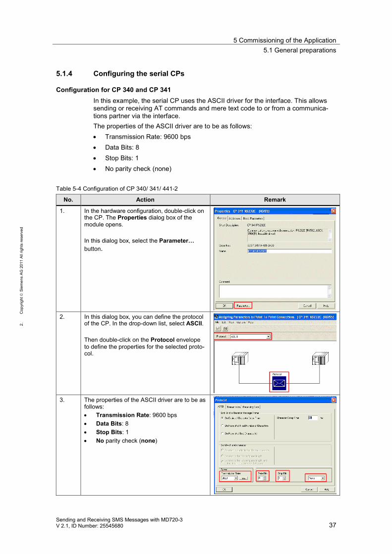
Configuration for CP 340 and CP 341In this example, the serial CP uses the ASCII driver for the interface. This allowssending or receiving AT commands and mere text code to or from a communica-tions partner via the interface.The properties of the ASCII driver are to be as follows: Transmission Rate: 9600 bps Data Bits: 8 Stop Bits: 1 No parity check (none)
Table 5-4 Configuration of CP 340/ 341/ 441-2
No. Action Remark
1. In the hardware configuration, double-click onthe CP. The Properties dialog box of themodule opens.
In this dialog box, select the Parameter…button.
2. In this dialog box, you can define the protocolof the CP. In the drop-down list, select ASCII.
Then double-click on the Protocol envelopeto define the properties for the selected proto-col.
3. The properties of the ASCII driver are to be asfollows:
Transmission Rate: 9600 bpsData Bits: 8Stop Bits: 1No parity check (none)
5 Commissioning of the Application5.1 General preparations
38Sending and Receiving SMS Messages with MD720-3
V 2.1, ID Number: 25545680
1.C
opyr
ight
Siem
ens
AG20
11Al
lrig
hts
rese
rved
No. Action Remark
4. Confirm all dialog boxes with OK.Then recompile the hardware configuration.
“Station > Save and Compile”
Parameterization and configuration for CP 441-2Table 5-5
No. Action Remark
1. CP_441-2 has the RS232 module at interface 1and no module at interface 2. If the interfaceassignment of your CP differs from the one de-scribed above, HW Config must be changedaccordingly.
Communication with a serial CP requires that aconnection be configured in NetPro. For aconfiguring guide for the CP, please refer toTable 5-4 Configuration of CP 340/ 341/ 441-2.
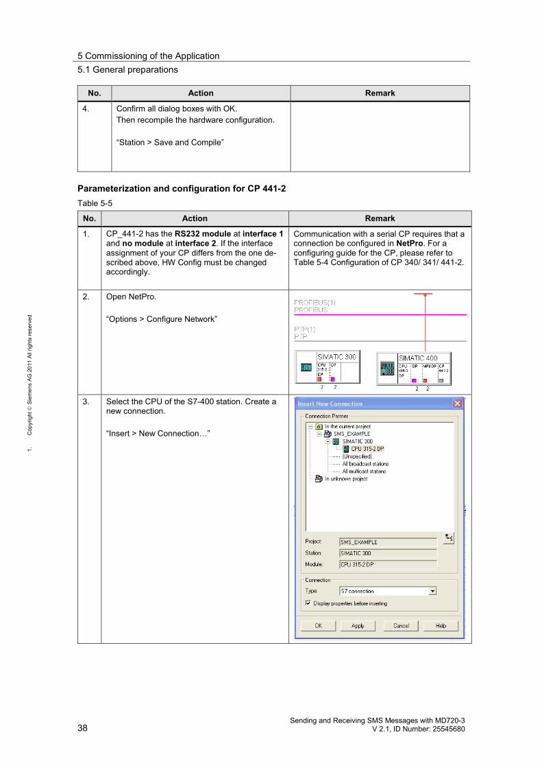
2. Open NetPro.
“Options > Configure Network”
3. Select the CPU of the S7-400 station. Create anew connection.
“Insert > New Connection…”
5 Commissioning of the Application5.1 General preparations
Sending and Receiving SMS Messages with MD720-3V 2.1, ID Number: 25545680 39
2.C
opyr
ight
Siem
ens
AG20
11Al
lrig
hts
rese
rved
No. Action Remark
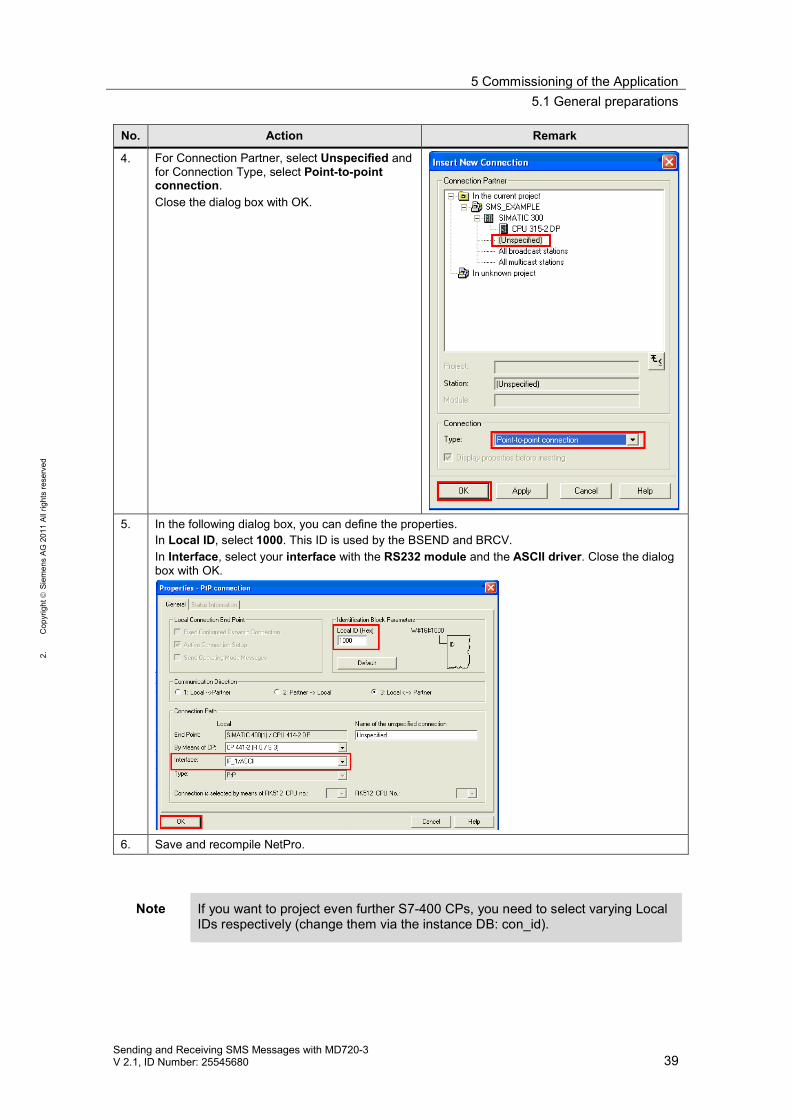
4. For Connection Partner, select Unspecified andfor Connection Type, select Point-to-pointconnection.Close the dialog box with OK.
5. In the following dialog box, you can define the properties.In Local ID, select 1000. This ID is used by the BSEND and BRCV.In Interface, select your interface with the RS232 module and the ASCII driver. Close the dialogbox with OK.
6. Save and recompile NetPro.
Note If you want to project even further S7-400 CPs, you need to select varying LocalIDs respectively (change them via the instance DB: con_id).

5 Commissioning of the Application5.1 General preparations
40Sending and Receiving SMS Messages with MD720-3
V 2.1, ID Number: 25545680
1.C
opyr
ight
Siem
ens
AG20
11Al
lrig
hts
rese
rved
Parameterization and configuration for ET 200S 1SIThe following table shows the necessary settings for the ASCII driver of the ET200S 1SI ASCII serial interface module.
Table 5-6
No. Action
1. In the hardware configuration, double-click on 1 SI ASCII. The Properties dialog box of themodule opens.Click on Parameters…
2. In this dialog box, you can define the properties for the ASCII driver.Transmission Rate: 9600 bpsData Bits: 8Stop Bits: 1No parity check (none)
3. Confirm all dialog boxes with “OK”.Then recompile the hardware configuration.“Station > Save and Compile”
Note When parameterizing the ET 200S distributed I/O, you have to assign a Profinetdevice name to the IM 151-3 PN module.
“HW Config > PLC > Ethernet >…”
IP address of ET 200 S IM151 3 PN -1: 192.168.255.4
5 Commissioning of the Application5.2 Downloading the STEP 7 project
Sending and Receiving SMS Messages with MD720-3V 2.1, ID Number: 25545680 41
2.C
opyr
ight
Siem
ens
AG20
11Al
lrig
hts
rese
rved
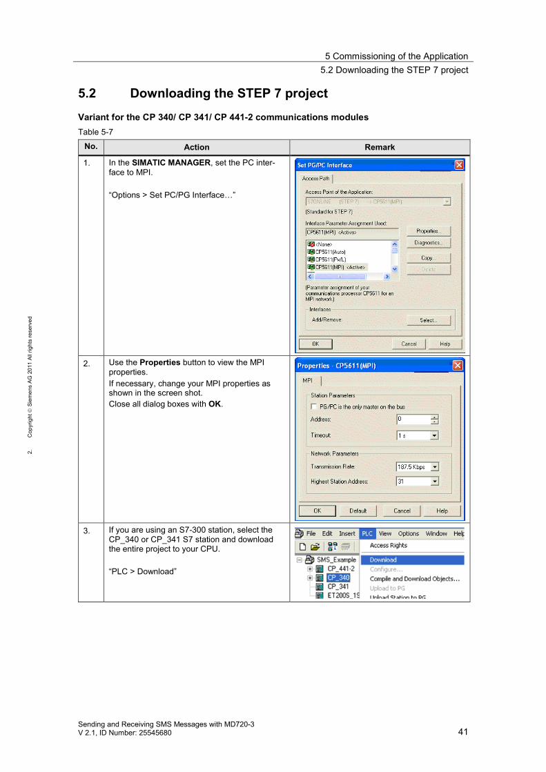
5.2 Downloading the STEP 7 project
Variant for the CP 340/ CP 341/ CP 441-2 communications modulesTable 5-7
No. Action Remark
1. In the SIMATIC MANAGER, set the PC inter-face to MPI.
“Options > Set PC/PG Interface…”
2. Use the Properties button to view the MPIproperties.If necessary, change your MPI properties asshown in the screen shot.Close all dialog boxes with OK.
3. If you are using an S7-300 station, select theCP_340 or CP_341 S7 station and downloadthe entire project to your CPU.
“PLC > Download”
5 Commissioning of the Application5.2 Downloading the STEP 7 project
42Sending and Receiving SMS Messages with MD720-3
V 2.1, ID Number: 25545680
1.C
opyr
ight
Siem
ens
AG20
11Al
lrig
hts
rese
rved
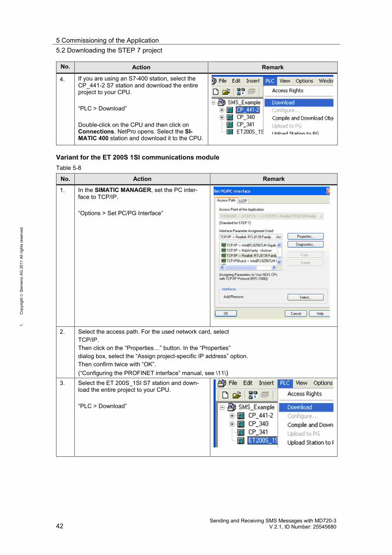
No. Action Remark
4. If you are using an S7-400 station, select theCP_441-2 S7 station and download the entireproject to your CPU.
“PLC > Download”
Double-click on the CPU and then click onConnections. NetPro opens. Select the SI-MATIC 400 station and download it to the CPU.
Variant for the ET 200S 1SI communications moduleTable 5-8
No. Action Remark
1. In the SIMATIC MANAGER, set the PC inter-face to TCP/IP.
“Options > Set PC/PG Interface”
2. Select the access path. For the used network card, selectTCP/IP.Then click on the “Properties…” button. In the “Properties”dialog box, select the “Assign project-specific IP address” option.Then confirm twice with “OK”.(“Configuring the PROFINET interface” manual, see \11\)
3. Select the ET 200S_1SI S7 station and down-load the entire project to your CPU.
“PLC > Download”
6 Operation of the Application6.1 Sending an SMS message (scenario 1/scenario 2)
Sending and Receiving SMS Messages with MD720-3V 2.1, ID Number: 25545680 43
2.C
opyr
ight
Siem
ens
AG20
11Al
lrig
hts
rese
rved
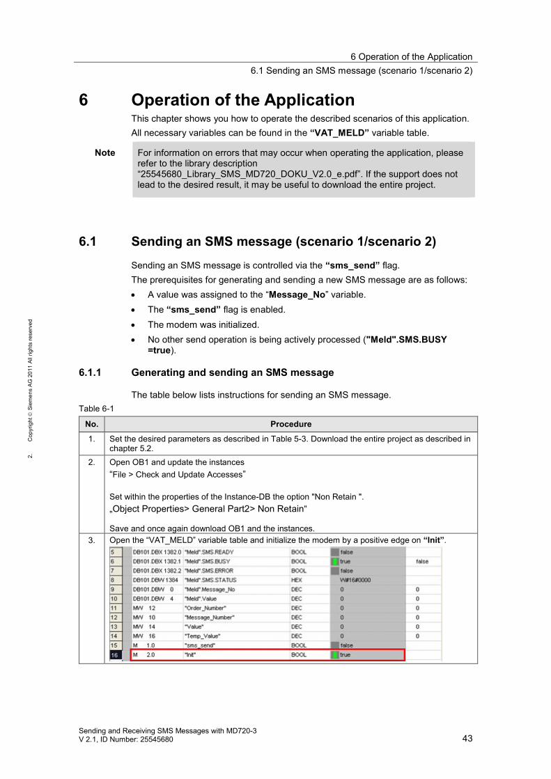
6 Operation of the ApplicationThis chapter shows you how to operate the described scenarios of this application.All necessary variables can be found in the “VAT_MELD” variable table.
Note For information on errors that may occur when operating the application, pleaserefer to the library description“25545680_Library_SMS_MD720_DOKU_V2.0_e.pdf”. If the support does notlead to the desired result, it may be useful to download the entire project.
6.1 Sending an SMS message (scenario 1/scenario 2)
Sending an SMS message is controlled via the “sms_send” flag.The prerequisites for generating and sending a new SMS message are as follows: A value was assigned to the “Message_No” variable. The “sms_send” flag is enabled. The modem was initialized. No other send operation is being actively processed ("Meld".SMS.BUSY
=true).
6.1.1 Generating and sending an SMS message
The table below lists instructions for sending an SMS message.Table 6-1
No. Procedure
1. Set the desired parameters as described in Table 5-3. Download the entire project as described inchapter 5.2.
2. Open OB1 and update the instances“File > Check and Update Accesses”
Set within the properties of the Instance-DB the option "Non Retain ".„Object Properties> General Part2> Non Retain“
Save and once again download OB1 and the instances.3. Open the “VAT_MELD” variable table and initialize the modem by a positive edge on “Init”.
6 Operation of the Application6.1 Sending an SMS message (scenario 1/scenario 2)
44Sending and Receiving SMS Messages with MD720-3
V 2.1, ID Number: 25545680
1.C
opyr
ight
Siem
ens
AG20
11Al
lrig
hts
rese
rved
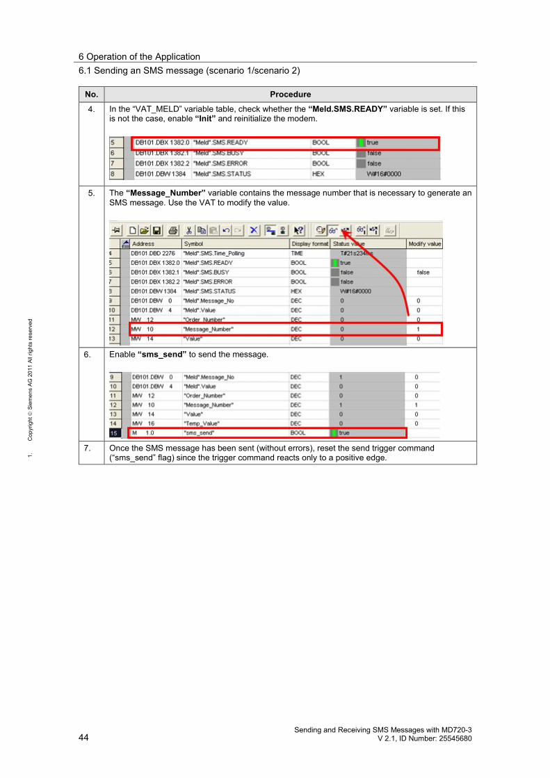
No. Procedure
4. In the “VAT_MELD” variable table, check whether the “Meld.SMS.READY” variable is set. If thisis not the case, enable “Init” and reinitialize the modem.
5. The “Message_Number” variable contains the message number that is necessary to generate anSMS message. Use the VAT to modify the value.
6. Enable “sms_send” to send the message.
7. Once the SMS message has been sent (without errors), reset the send trigger command(“sms_send” flag) since the trigger command reacts only to a positive edge.
6 Operation of the Application6.1 Sending an SMS message (scenario 1/scenario 2)
Sending and Receiving SMS Messages with MD720-3V 2.1, ID Number: 25545680 45
2.C
opyr
ight
Siem
ens
AG20
11Al
lrig
hts
rese
rved
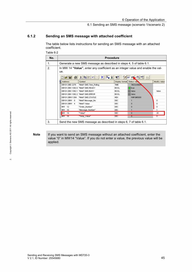
6.1.2 Sending an SMS message with attached coefficient
The table below lists instructions for sending an SMS message with an attachedcoefficient.Table 6-2
No. Procedure
1. Generate a new SMS message as described in steps 4, 5 of table 6.1.2. In MW 14 “Value”, enter any coefficient as an integer value and enable the val-
ue.
3. Send the new SMS message as described in steps 6, 7 of table 6.1.
Note If you want to send an SMS message without an attached coefficient, enter thevalue “0” in MW14 “Value”. If you do not enter a value, the previous value will beapplied.
6 Operation of the Application6.2 Receiving an SMS message (scenario 3/scenario 4)
46Sending and Receiving SMS Messages with MD720-3
V 2.1, ID Number: 25545680
1.C
opyr
ight
Siem
ens
AG20
11Al
lrig
hts
rese
rved
6.2 Receiving an SMS message (scenario 3/scenario 4)
The prerequisites for receiving a new SMS message are as follows: The modem was initialized. The polling timer has elapsed.
CAUTION Do not send an SMS message containing the key word ‘ERROR’ or ‘OK’,since MD720-3 evaluates these words when a faulty behavior occurs dur-ing sending from MD720-3 to the communication module.
NOTE For sending SMS to the modem it is recommended to use only alphabetic char-acters and figures. This is in order to avoid display and recognition errors of theSTEP 7 application program.
6.2.1 Receiving and evaluating an SMS message
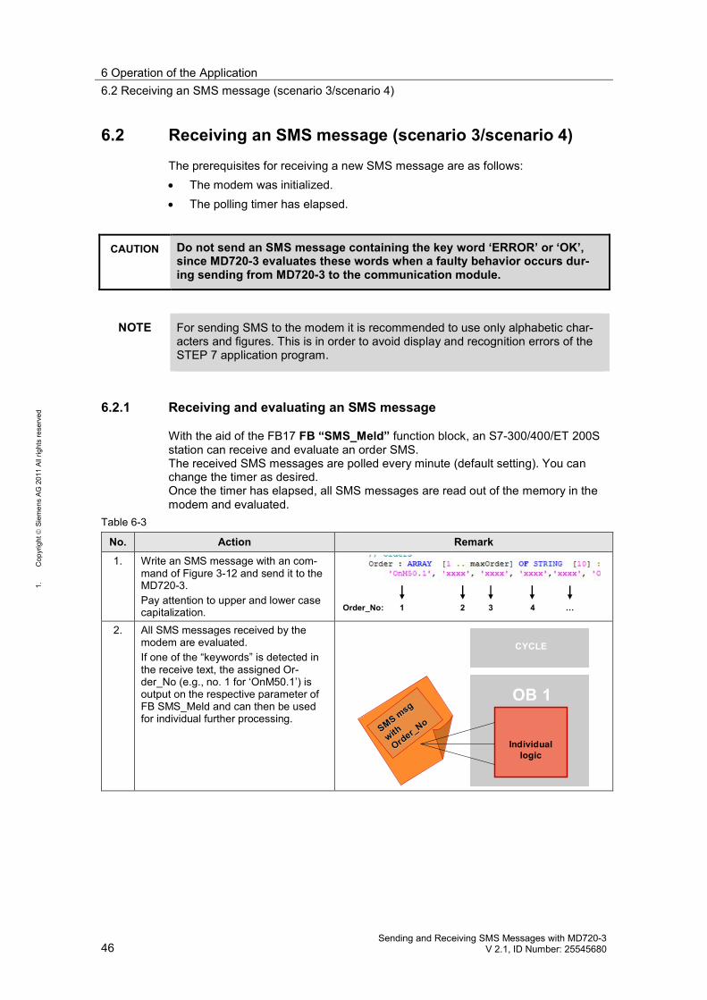
With the aid of the FB17 FB “SMS_Meld” function block, an S7-300/400/ET 200Sstation can receive and evaluate an order SMS.The received SMS messages are polled every minute (default setting). You canchange the timer as desired.Once the timer has elapsed, all SMS messages are read out of the memory in themodem and evaluated.
Table 6-3
No. Action Remark
1. Write an SMS message with an com-mand of Figure 3-12 and send it to theMD720-3.Pay attention to upper and lower casecapitalization. Order_No: 1 2 3 …4
2. All SMS messages received by themodem are evaluated.If one of the “keywords” is detected inthe receive text, the assigned Or-der_No (e.g., no. 1 for ‘OnM50.1’) isoutput on the respective parameter ofFB SMS_Meld and can then be usedfor individual further processing.
CYCLE
OB 1
SMSSMS msg
msg
withwith
Order_No
Order_No
Individuallogic
6 Operation of the Application6.2 Receiving an SMS message (scenario 3/scenario 4)
Sending and Receiving SMS Messages with MD720-3V 2.1, ID Number: 25545680 47
2.C
opyr
ight
Siem
ens
AG20
11Al
lrig
hts
rese
rved
No. Action Remark
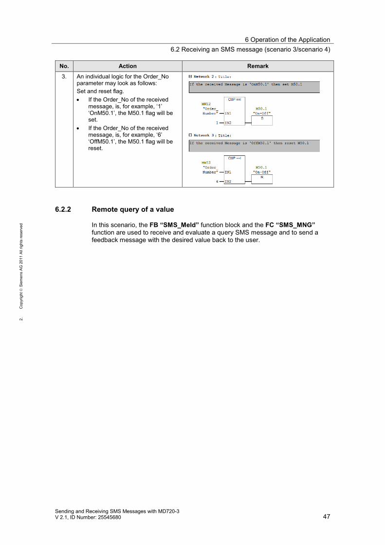
3. An individual logic for the Order_Noparameter may look as follows:Set and reset flag. If the Order_No of the received
message, is, for example, ‘1’‘OnM50.1’, the M50.1 flag will beset.
If the Order_No of the receivedmessage, is, for example, ‘6’‘OffM50.1’, the M50.1 flag will bereset.
6.2.2 Remote query of a value
In this scenario, the FB “SMS_Meld” function block and the FC “SMS_MNG”function are used to receive and evaluate a query SMS message and to send afeedback message with the desired value back to the user.
6 Operation of the Application6.2 Receiving an SMS message (scenario 3/scenario 4)
48Sending and Receiving SMS Messages with MD720-3
V 2.1, ID Number: 25545680
1.C
opyr
ight
Siem
ens
AG20
11Al
lrig
hts
rese
rved
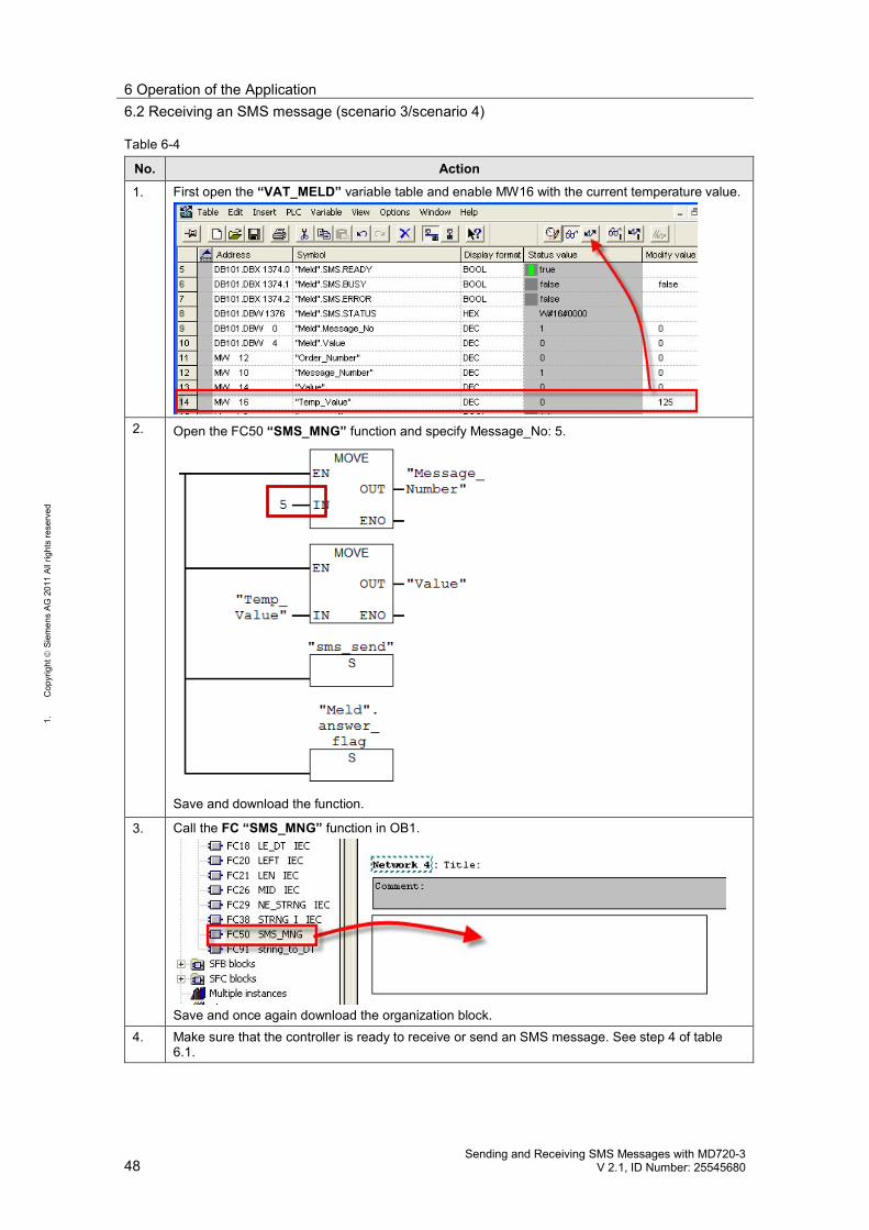
Table 6-4
No. Action
1. First open the “VAT_MELD” variable table and enable MW16 with the current temperature value.
2. Open the FC50 “SMS_MNG” function and specify Message_No: 5.
Save and download the function.
3. Call the FC “SMS_MNG” function in OB1.
Save and once again download the organization block.4. Make sure that the controller is ready to receive or send an SMS message. See step 4 of table
6.1.
6 Operation of the Application6.2 Receiving an SMS message (scenario 3/scenario 4)
Sending and Receiving SMS Messages with MD720-3V 2.1, ID Number: 25545680 49
2.C
opyr
ight
Siem
ens
AG20
11Al
lrig
hts
rese
rved
No. Action
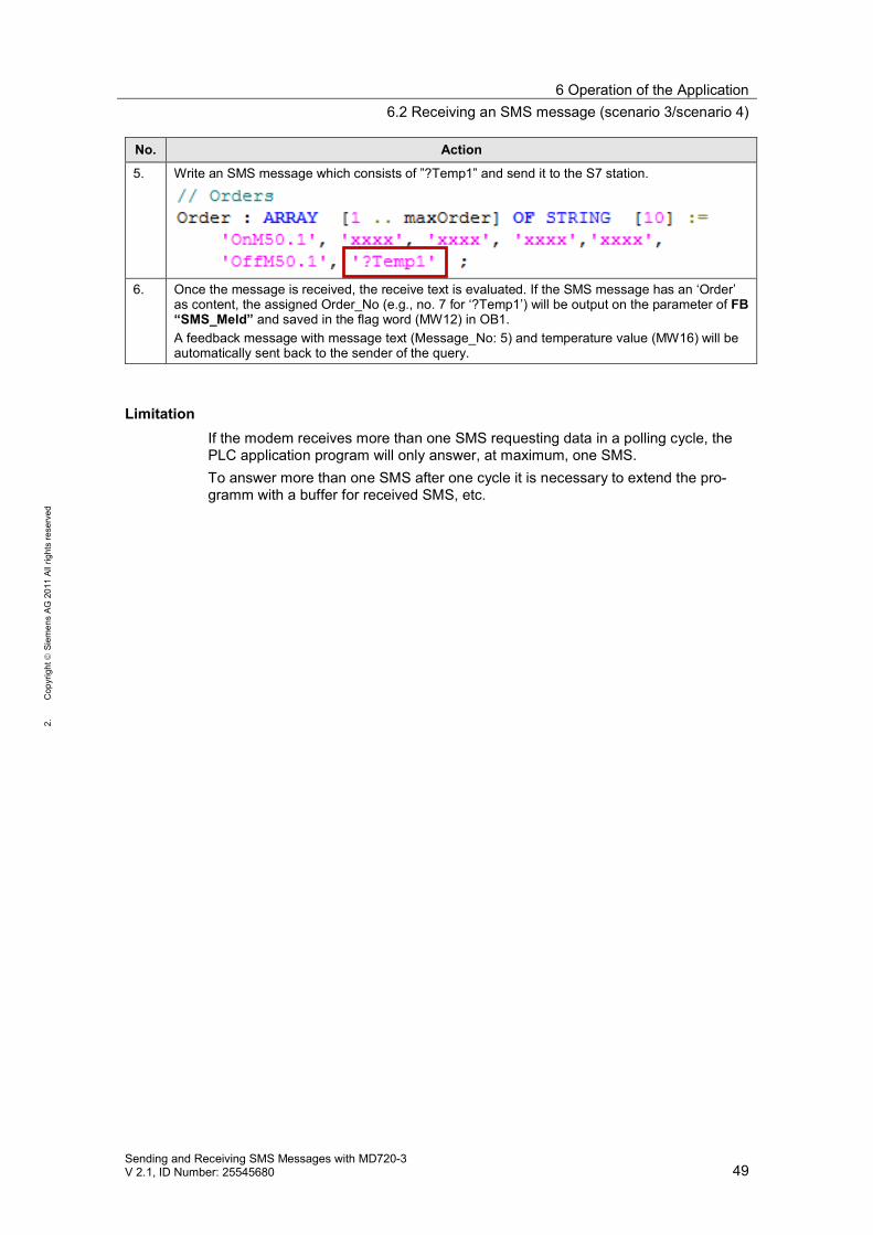
5. Write an SMS message which consists of ”?Temp1” and send it to the S7 station.
6. Once the message is received, the receive text is evaluated. If the SMS message has an ‘Order’as content, the assigned Order_No (e.g., no. 7 for ‘?Temp1’) will be output on the parameter of FB“SMS_Meld” and saved in the flag word (MW12) in OB1.A feedback message with message text (Message_No: 5) and temperature value (MW16) will beautomatically sent back to the sender of the query.
LimitationIf the modem receives more than one SMS requesting data in a polling cycle, thePLC application program will only answer, at maximum, one SMS.To answer more than one SMS after one cycle it is necessary to extend the pro-gramm with a buffer for received SMS, etc.
7 Further Information
50Sending and Receiving SMS Messages with MD720-3
V 2.1, ID Number: 25545680
Cop
yrig
htSi
emen
sAG
2011
Allr
ight
sre
serv
ed
7 Further Information
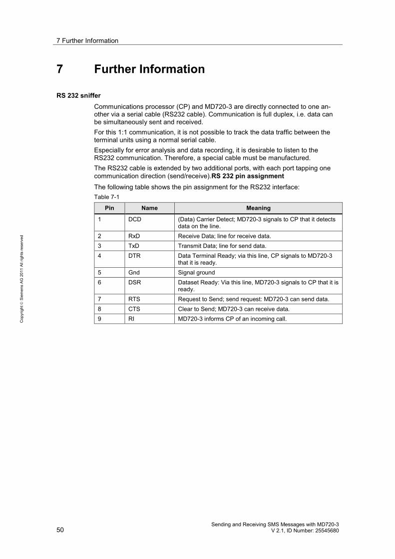
RS 232 snifferCommunications processor (CP) and MD720-3 are directly connected to one an-other via a serial cable (RS232 cable). Communication is full duplex, i.e. data canbe simultaneously sent and received.For this 1:1 communication, it is not possible to track the data traffic between theterminal units using a normal serial cable.Especially for error analysis and data recording, it is desirable to listen to theRS232 communication. Therefore, a special cable must be manufactured.The RS232 cable is extended by two additional ports, with each port tapping onecommunication direction (send/receive).RS 232 pin assignmentThe following table shows the pin assignment for the RS232 interface:Table 7-1
Pin Name Meaning
1 DCD (Data) Carrier Detect; MD720-3 signals to CP that it detectsdata on the line.
2 RxD Receive Data; line for receive data.3 TxD Transmit Data; line for send data.4 DTR Data Terminal Ready; via this line, CP signals to MD720-3
that it is ready.5 Gnd Signal ground6 DSR Dataset Ready: Via this line, MD720-3 signals to CP that it is
ready.7 RTS Request to Send; send request: MD720-3 can send data.8 CTS Clear to Send; MD720-3 can receive data.9 RI MD720-3 informs CP of an incoming call.
7 Further Information
Sending and Receiving SMS Messages with MD720-3V 2.1, ID Number: 25545680 51
Cop
yrig
htSi
emen
sAG
2011
Allr
ight
sre
serv
ed
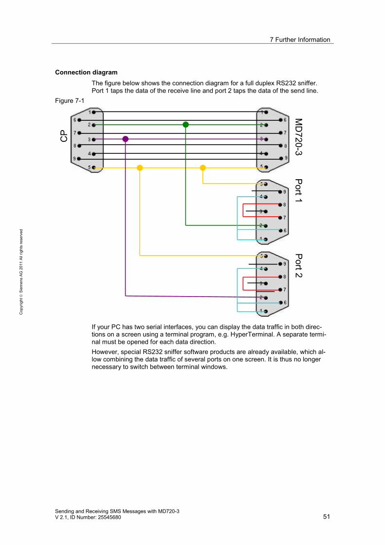
Connection diagramThe figure below shows the connection diagram for a full duplex RS232 sniffer.Port 1 taps the data of the receive line and port 2 taps the data of the send line.
Figure 7-1
CP
MD
720-3Port1
Port2
If your PC has two serial interfaces, you can display the data traffic in both direc-tions on a screen using a terminal program, e.g. HyperTerminal. A separate termi-nal must be opened for each data direction.However, special RS232 sniffer software products are already available, which al-low combining the data traffic of several ports on one screen. It is thus no longernecessary to switch between terminal windows.
8 References
52Sending and Receiving SMS Messages with MD720-3
V 2.1, ID Number: 25545680
Cop
yrig
htSi
emen
sAG
2011
Allr
ight
sre
serv
ed
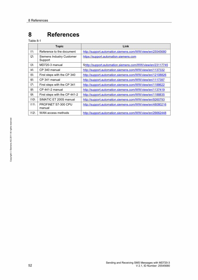
8 ReferencesTable 8-1
Topic Link
\1\ Reference to the document http://support.automation.siemens.com/WW/view/en/25545680\2\ Siemens Industry Customer
Supporthttps://support.automation.siemens.com
\3\ MD720-3 manual 5http://support.automation.siemens.com/WW/view/en/23117745\4\ CP 340 manual http://support.automation.siemens.com/WW/view/en/1137332\5\ First steps with the CP 340 http://support.automation.siemens.com/WW/view/en/12108826\6\ CP 341 manual http://support.automation.siemens.com/WW/view/en/1117397\7\ First steps with the CP 341 http://support.automation.siemens.com/WW/view/en/1188622\8\ CP 441-2 manual http://support.automation.siemens.com/WW/view/en/1137419\9\ First steps with the CP 441-2 http://support.automation.siemens.com/WW/view/en/1188835\10\ SIMATIC ET 200S manual http://support.automation.siemens.com/WW/view/en/9260793\11\ PROFINET S7-300 CPU
manualhttp://support.automation.siemens.com/WW/view/en/48080216
\12\ WAN access methods http://support.automation.siemens.com/WW/view/en/26662448
9 History
Sending and Receiving SMS Messages with MD720-3V 2.1, ID Number: 25545680 53
Cop
yrig
htSi
emen
sAG
2011
Allr
ight
sre
serv
ed
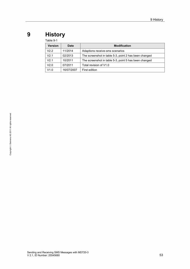
9 HistoryTable 9-1
Version Date Modification
V2.2 11/2014 Adaptions receive-sms scenariosV2.1 02/2013 The screenshot in table 5-3, point 2 has been changedV2.1 10/2011 The screenshot in table 5-3, point 5 has been changedV2.0 07/2011 Total revision of V1.0V1.0 16/07/2007 First edition


![Modem Sinaut MD720-3[1]](https://img.pdfslide.us/doc/110x75/54fe248d4a7959ba458b54a8/modem-sinaut-md720-31.jpg)