Embed Size (px)
Citation preview
SIMATIC ET 200S distributed I/O 2AO I HS analog electronic module (6ES7135-4GB52-0AB0)
______________________________________________________________________
Preface
Properties 1
Parameters 2
Diagnostics 3
Analog value representation 4
Connecting 5
SIMATIC
ET 200S distributed I/O2AO I HS analog electronic module (6ES7135-4GB52-0AB0)
Manual
01/2008 A5E01254126-01
Safety Guidelines Safety Guidelines This manual contains notices you have to observe in order to ensure your personal safety, as well as to prevent damage to property. The notices referring to your personal safety are highlighted in the manual by a safety alert symbol, notices referring only to property damage have no safety alert symbol. These notices shown below are graded according to the degree of danger.
DANGER indicates that death or severe personal injury will result if proper precautions are not taken.
WARNING indicates that death or severe personal injury may result if proper precautions are not taken.
CAUTION with a safety alert symbol, indicates that minor personal injury can result if proper precautions are not taken.
CAUTION without a safety alert symbol, indicates that property damage can result if proper precautions are not taken.
NOTICE indicates that an unintended result or situation can occur if the corresponding information is not taken into account.
If more than one degree of danger is present, the warning notice representing the highest degree of danger will be used. A notice warning of injury to persons with a safety alert symbol may also include a warning relating to property damage.
Qualified Personnel The device/system may only be set up and used in conjunction with this documentation. Commissioning and operation of a device/system may only be performed by qualified personnel. Within the context of the safety notes in this documentation qualified persons are defined as persons who are authorized to commission, ground and label devices, systems and circuits in accordance with established safety practices and standards.
Prescribed Usage Note the following:
WARNING This device may only be used for the applications described in the catalog or the technical description and only in connection with devices or components from other manufacturers which have been approved or recommended by Siemens. Correct, reliable operation of the product requires proper transport, storage, positioning and assembly as well as careful operation and maintenance.
Trademarks All names identified by ® are registered trademarks of the Siemens AG. The remaining trademarks in this publication may be trademarks whose use by third parties for their own purposes could violate the rights of the owner.
Disclaimer of Liability We have reviewed the contents of this publication to ensure consistency with the hardware and software described. Since variance cannot be precluded entirely, we cannot guarantee full consistency. However, the information in this publication is reviewed regularly and any necessary corrections are included in subsequent editions.
Siemens AG Automation and Drives Postfach 48 48 90327 NÜRNBERG GERMANY
A5E01254126-01 02/2008
Copyright © Siemens AG 2008. Technical data subject to change
2AO I HS analog electronic module (6ES7135-4GB52-0AB0) Manual, 01/2008, A5E01254126-01 3
Preface
Preface
Purpose of the manual This manual supplements the ET 200S Distributed I/O System Operating Instructions. General functions for the ET 200S are described in the ET 200S Distributed I/O System Operating Instructions. The information in this document along with the operating instructions enables you to commission the ET 200S.
Basic knowledge requirements To understand these operating instructions you should have general knowledge of automation engineering.
Scope of the manual This manual applies to this ET 200S module. It describes the components that are valid at the time of publication.
Recycling and disposal Thanks to the fact that it is low in contaminants, this ET 200S module is recyclable. For environmentally compliant recycling and disposal of your electronic waste, please contact a company certified for the disposal of electronic waste.
Additional support If you have any questions relating to the products described in these operating instructions, and do not find the answers in this document, please contact your local Siemens representative. http://www.siemens.com/automation/partner The portal to our technical documentation for the various SIMATIC products and systems is available at: http://www.siemens.com/automation/simatic/portal The online catalog and ordering system are available at: http://www.siemens.com/automation/mall
Preface
2AO I HS analog electronic module (6ES7135-4GB52-0AB0) 4 Manual, 01/2008, A5E01254126-01
Training center We offer courses to help you get started with the ET 200S and the SIMATIC S7 automation system. Please contact your regional training center or the central training center in D -90327, Nuremberg, Germany. Phone: +49 (911) 895-3200. http://www.siemens.com/sitrain
Technical Support You can reach technical support for all A&D projects using the support request web form:
http://www.siemens.com/automation/support-request Phone: + 49 180 5050 222 Fax: + 49 180 5050 223 For more information about our technical support, refer to our Web site at http://www.siemens.de/automation/service
Service & Support on the Internet In addition to our documentation services, you can also make use of our comprehensive online knowledge base on the Internet. http://www.siemens.com/automation/service&support There you will find: Our Newsletter, which constantly provides you with the latest information about your
products. The right documentation for you using our Service & Support search engine. The bulletin board, a worldwide knowledge exchange for users and experts. Your local contact for Automation & Drives in our contact database. Information about on-site services, repairs, spare parts. Lots more can be found on our
"Services" pages.
2AO I HS analog electronic module (6ES7135-4GB52-0AB0) Manual, 01/2008, A5E01254126-01 5
Table of contents Preface ...................................................................................................................................................... 3 1 Properties .................................................................................................................................................. 7
1.1 2AO I HS analog electronic module (6ES7135-4GB52-0AB0)......................................................7 2 Parameters .............................................................................................................................................. 13
2.1 Parameters...................................................................................................................................13 3 Diagnostics .............................................................................................................................................. 15
3.1 Diagnostics using LED display.....................................................................................................15 3.2 Error types....................................................................................................................................16
4 Analog value representation .................................................................................................................... 17 4.1 Introduction ..................................................................................................................................17 4.2 Analog value representation for measuring ranges with SIMATIC S7 with 2AO I HF.................17 4.3 Output ranges ..............................................................................................................................18 4.4 Effect on analog value representation .........................................................................................19 4.4.1 Effect of the supply voltage and the operating state on analog output values ............................19 4.4.2 Effect of the value range on the 2AO I HS analog output............................................................20 4.4.3 Effect on the change rate of the output signals ...........................................................................20
5 Connecting .............................................................................................................................................. 21 5.1 Connecting analog outputs ..........................................................................................................21 5.2 Using the shield connection .........................................................................................................21
Index........................................................................................................................................................ 23

Table of contents
2AO I HS analog electronic module (6ES7135-4GB52-0AB0) 6 Manual, 01/2008, A5E01254126-01
2AO I HS analog electronic module (6ES7135-4GB52-0AB0) Manual, 01/2008, A5E01254126-01 7
Properties 11.1 2AO I HS analog electronic module (6ES7135-4GB52-0AB0)
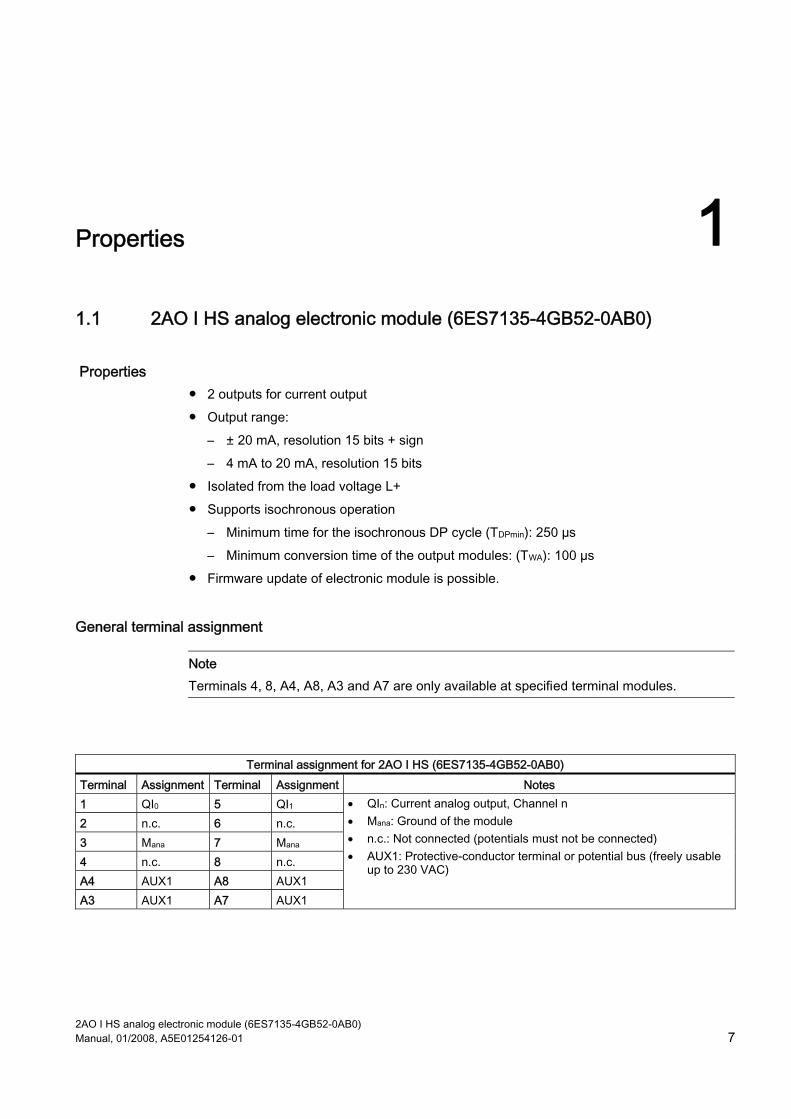
Properties 2 outputs for current output Output range:
– ± 20 mA, resolution 15 bits + sign – 4 mA to 20 mA, resolution 15 bits
Isolated from the load voltage L+ Supports isochronous operation
– Minimum time for the isochronous DP cycle (TDPmin): 250 µs – Minimum conversion time of the output modules: (TWA): 100 µs
Firmware update of electronic module is possible.
General terminal assignment
Note Terminals 4, 8, A4, A8, A3 and A7 are only available at specified terminal modules.
Terminal assignment for 2AO I HS (6ES7135-4GB52-0AB0)
Terminal Assignment Terminal Assignment Notes 1 QI0 5 QI1 2 n.c. 6 n.c. 3 Mana 7 Mana 4 n.c. 8 n.c. A4 AUX1 A8 AUX1 A3 AUX1 A7 AUX1
• QIn: Current analog output, Channel n • Mana: Ground of the module • n.c.: Not connected (potentials must not be connected) • AUX1: Protective-conductor terminal or potential bus (freely usable
up to 230 VAC)
Properties 1.1 2AO I HS analog electronic module (6ES7135-4GB52-0AB0)
2AO I HS analog electronic module (6ES7135-4GB52-0AB0) 8 Manual, 01/2008, A5E01254126-01
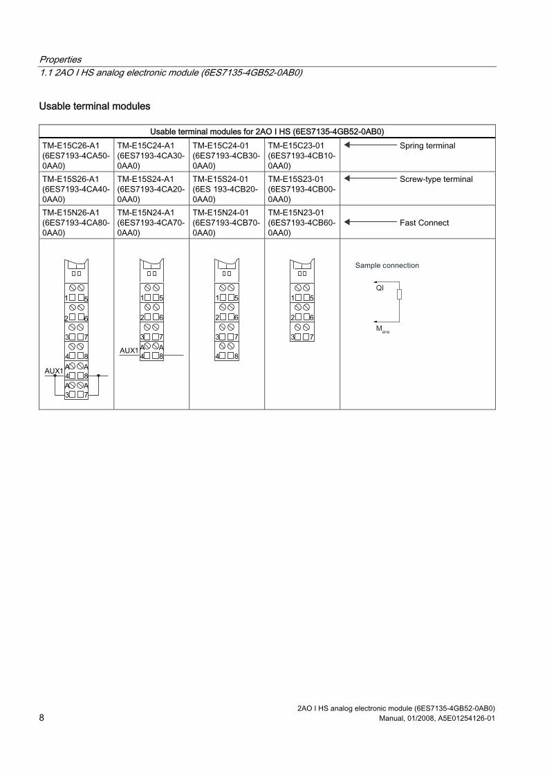
Usable terminal modules
Usable terminal modules for 2AO I HS (6ES7135-4GB52-0AB0) TM-E15C26-A1 (6ES7193-4CA50-0AA0)
TM-E15C24-A1 (6ES7193-4CA30-0AA0)
TM-E15C24-01 (6ES7193-4CB30-0AA0)
TM-E15C23-01 (6ES7193-4CB10-0AA0)
Spring terminal
TM-E15S26-A1 (6ES7193-4CA40-0AA0)
TM-E15S24-A1 (6ES7193-4CA20-0AA0)
TM-E15S24-01 (6ES 193-4CB20-0AA0)
TM-E15S23-01 (6ES7193-4CB00-0AA0)
Screw-type terminal
TM-E15N26-A1 (6ES7193-4CA80-0AA0)
TM-E15N24-A1 (6ES7193-4CA70-0AA0)
TM-E15N24-01 (6ES7193-4CB70-0AA0)
TM-E15N23-01 (6ES7193-4CB60-0AA0)
Fast Connect
Properties 1.1 2AO I HS analog electronic module (6ES7135-4GB52-0AB0)
2AO I HS analog electronic module (6ES7135-4GB52-0AB0) Manual, 01/2008, A5E01254126-01 9
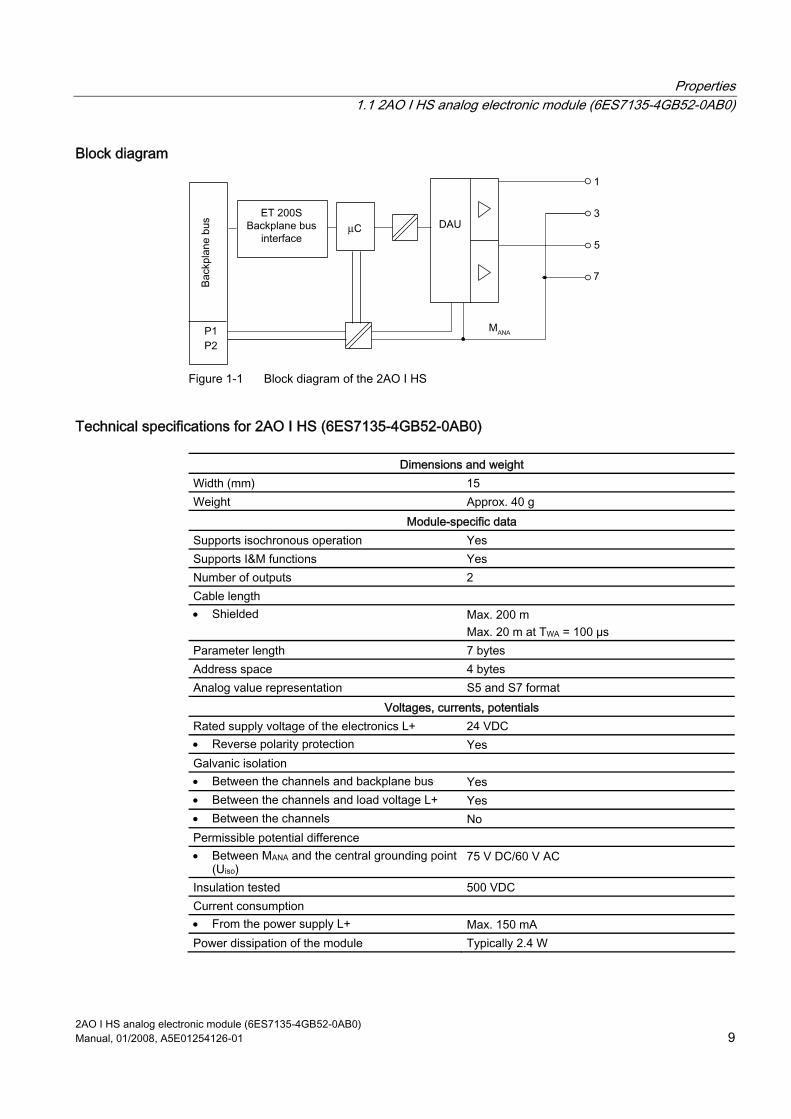
Block diagram
µ
Figure 1-1 Block diagram of the 2AO I HS
Technical specifications for 2AO I HS (6ES7135-4GB52-0AB0)
Dimensions and weight Width (mm) 15 Weight Approx. 40 g
Module-specific data Supports isochronous operation Yes Supports I&M functions Yes Number of outputs 2 Cable length • Shielded Max. 200 m
Max. 20 m at TWA = 100 µs Parameter length 7 bytes Address space 4 bytes Analog value representation S5 and S7 format
Voltages, currents, potentials Rated supply voltage of the electronics L+ 24 VDC • Reverse polarity protection Yes Galvanic isolation • Between the channels and backplane bus Yes • Between the channels and load voltage L+ Yes • Between the channels No Permissible potential difference • Between MANA and the central grounding point
(Uiso) 75 V DC/60 V AC
Insulation tested 500 VDC Current consumption • From the power supply L+ Max. 150 mA Power dissipation of the module Typically 2.4 W
Properties 1.1 2AO I HS analog electronic module (6ES7135-4GB52-0AB0)
2AO I HS analog electronic module (6ES7135-4GB52-0AB0) 10 Manual, 01/2008, A5E01254126-01
Status, interrupts, diagnostics Diagnostics function • Group error display Red "SF" LED • Diagnostic information readable Yes Substitute values can be applied Yes, parameterizable
Analog value generation Resolution (including sign) ±20 mA/15 bits + sign
4 to 20 mA/15 bits Conversion time (per channel) Max. 20 µs Cycle time in ms (per module) 0.25 ms Settling time 1 • For resistive load 0.05 ms • For capacitive load 0.05 ms • For inductive load 0.05 ms
Suppression of interference, limits of error Crosstalk between the outputs < -60 dB Operational limit (in the entire temperature range, with reference to the output range)
± 0,2 % 2
Basic error limit (operational limit at 25°C with reference to output range)
± 0,1 % 3
Temperature error (with reference to the output range)
± 0,01 %/K
Linearity error (with reference to the output range) ± 0.03% (for resistive load) Repeatability (in steady state at 25°C with reference to output range)
± 0,03 %
Transmitter selection data Output range (rated value) ± 20 mA
4 to 20 mA Load impedance (in the rated range of the output)• For current outputs
Max. 500 Ω / 1 mH Max. 0.1 mH for TWA 100 µs
Current output • Open circuit voltage
18 V
Destruction limit against voltages/currents applied from outside
• Voltage at the outputs to MANA Max. 15 V/ 5 hours; 75 V for max. 1 s (sampling ratio 1:20)
• Current Max. 30 mA DC Connection of actuators • Current output two-wire connection Supported 1 At a maximum load of 500 kΩ/ 100 nF and a maximum cable length of 20 m 2 This value applies to loads from 200 Ω to 350 Ω. For loads up to 200 Ω or 350 Ω to 500 Ω, the operational limit is ± 0.4%. 3 This value applies to loads from 200 Ω to 350 Ω. For loads up to 200 Ω or 350 Ω to 500 Ω, the basic error limit is ± 0.3 %.
Properties 1.1 2AO I HS analog electronic module (6ES7135-4GB52-0AB0)
2AO I HS analog electronic module (6ES7135-4GB52-0AB0) Manual, 01/2008, A5E01254126-01 11
Firmware update To add functions and for troubleshooting, it is possible to load firmware updates to the operating system memory of the electronic module using STEP 7 HW Config.
Note When you launch the firmware update, the old firmware is deleted. If the firmware update is interrupted or canceled, the electronic module will no longer be capable of functioning. Restart the firmware update and wait until it has completed successfully.
Note
If the ET 200S is operated in conjunction with an S7-300 CPU with PROFIBUS DP interface or an ET 200S Interface Module IM151-3 PN HIGH SPEED, a station failure of the ET 200S can occur during the firmware update.
I&M functions and firmware update The interface modules identified in the table below (as of order number) can be used to read and write I&M data from the module and for the firmware update.
Interface module as of order number IM151-1 HIGH FEATURE 6ES7151-1BA02-0AB0 IM151-3 PN 6ES7151-3AA22-0AB0 IM151-3 PN HIGH FEATURE 6ES7151-3BA22-0AB0 IM151-3 PN FO 6ES7151-3BB22-0AB0 IM151-7 CPU 6ES7151-7AA20-0AB0

Properties 1.1 2AO I HS analog electronic module (6ES7135-4GB52-0AB0)
2AO I HS analog electronic module (6ES7135-4GB52-0AB0) 12 Manual, 01/2008, A5E01254126-01
2AO I HS analog electronic module (6ES7135-4GB52-0AB0) Manual, 01/2008, A5E01254126-01 13
Parameters 22.1 Parameters
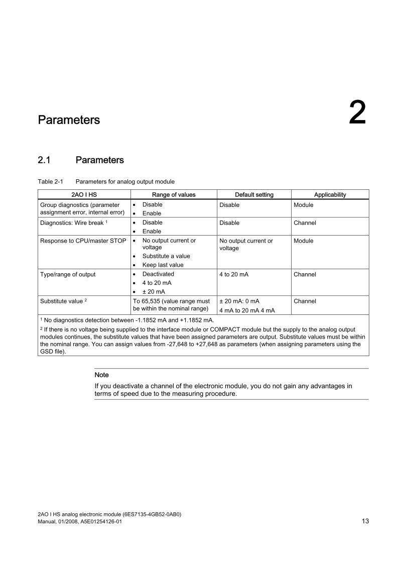
Table 2-1 Parameters for analog output module
2AO I HS Range of values Default setting Applicability Group diagnostics (parameter assignment error, internal error)
• Disable • Enable
Disable Module
Diagnostics: Wire break 1 • Disable • Enable
Disable Channel
Response to CPU/master STOP • No output current or voltage
• Substitute a value • Keep last value
No output current or voltage
Module
Type/range of output • Deactivated • 4 to 20 mA • ± 20 mA
4 to 20 mA Channel
Substitute value 2 To 65,535 (value range must be within the nominal range)
± 20 mA: 0 mA 4 mA to 20 mA 4 mA
Channel
1 No diagnostics detection between -1.1852 mA and +1.1852 mA. 2 If there is no voltage being supplied to the interface module or COMPACT module but the supply to the analog output modules continues, the substitute values that have been assigned parameters are output. Substitute values must be within the nominal range. You can assign values from -27,648 to +27,648 as parameters (when assigning parameters using the GSD file).
Note If you deactivate a channel of the electronic module, you do not gain any advantages in terms of speed due to the measuring procedure.

Parameters 2.1 Parameters
2AO I HS analog electronic module (6ES7135-4GB52-0AB0) 14 Manual, 01/2008, A5E01254126-01
2AO I HS analog electronic module (6ES7135-4GB52-0AB0) Manual, 01/2008, A5E01254126-01 15
Diagnostics 33.1 Diagnostics using LED display
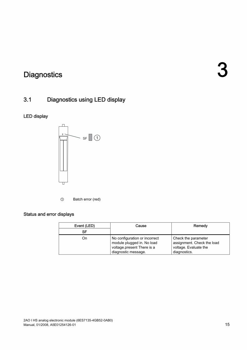
LED display
1
① Batch error (red)
Status and error displays
Event (LED) SF
Cause Remedy
On No configuration or incorrect module plugged in. No load voltage.present There is a diagnostic message.
Check the parameter assignment. Check the load voltage. Evaluate the diagnostics.
Diagnostics 3.2 Error types
2AO I HS analog electronic module (6ES7135-4GB52-0AB0) 16 Manual, 01/2008, A5E01254126-01
3.2 Error types
Analog output module error types
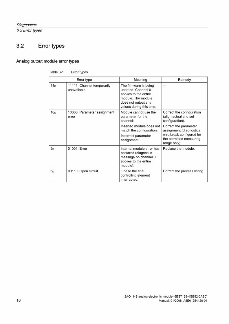
Table 3-1 Error types
Error type Meaning Remedy 31D 11111: Channel temporarily
unavailable The firmware is being updated. Channel 0 applies to the entire module. The module does not output any values during this time.
---
16D 10000: Parameter assignment error
Module cannot use the parameter for the channel: Inserted module does not match the configuration. Incorrect parameter assignment.
Correct the configuration (align actual and set configuration). Correct the parameter assignment (diagnostics wire break configured for the permitted measuring range only).
9D 01001: Error Internal module error has occurred (diagnostic message on channel 0 applies to the entire module).
Replace the module.
6D 00110: Open circuit Line to the final controlling element interrupted.
Correct the process wiring.
2AO I HS analog electronic module (6ES7135-4GB52-0AB0) Manual, 01/2008, A5E01254126-01 17
Analog value representation 44.1 Introduction
Electronic modules with analog outputs With the electronic modules with analog outputs, digital values set by a controller can be converted to a corresponding analog signal (current) in an analog output module and used to control suitable actuators (setpoint input for speed controllers, temperature controllers and similar).
4.2 Analog value representation for measuring ranges with SIMATIC S7 with 2AO I HF
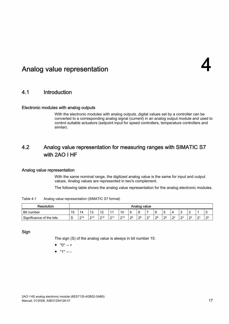
Analog value representation With the same nominal range, the digitized analog value is the same for input and output values. Analog values are represented in two's complement. The following table shows the analog value representation for the analog electronic modules.
Table 4-1 Analog value representation (SIMATIC S7 format)
Resolution Analog value Bit number 15 14 13 12 11 10 9 8 7 6 5 4 3 2 1 0 Significance of the bits S 214 213 212 211 210 29 28 27 26 25 24 23 22 21 20
Sign The sign (S) of the analog value is always in bit number 15: "0" → + "1" → –
Analog value representation 4.3 Output ranges
2AO I HS analog electronic module (6ES7135-4GB52-0AB0) 18 Manual, 01/2008, A5E01254126-01
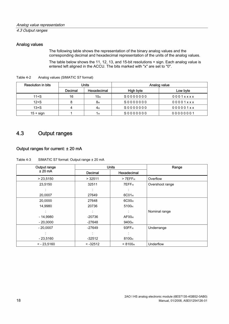
Analog values The following table shows the representation of the binary analog values and the corresponding decimal and hexadecimal representation of the units of the analog values. The table below shows the 11, 12, 13, and 15-bit resolutions + sign. Each analog value is entered left aligned in the ACCU. The bits marked with "x" are set to "0".
Table 4-2 Analog values (SIMATIC S7 format)
Units Analog value Resolution in bits Decimal Hexadecimal High byte Low byte
11+S 16 10H S 0 0 0 0 0 0 0 0 0 0 1 x x x x 12+S 8 8H S 0 0 0 0 0 0 0 0 0 0 0 1 x x x 13+S 4 4H S 0 0 0 0 0 0 0 0 0 0 0 0 1 x x
15 + sign 1 1H S 0 0 0 0 0 0 0 0 0 0 0 0 0 0 1
4.3 Output ranges
Output ranges for current: ± 20 mA
Table 4-3 SIMATIC S7 format: Output range ± 20 mA
Units Output range ± 20 mA Decimal Hexadecimal
Range
> 23,5150 > 32511 > 7EFFH Overflow 23,5150
: 20,0007
32511 :
27649
7EFFH :
6C01H
Overshoot range
20,0000 14,9980
: - 14,9980 - 20,0000
27648 20736
: -20736 -27648
6C00H 5100H
: AF00H 9400H
Nominal range
- 20,0007 :
- 23,5160
-27649 :
-32512
93FFH :
8100H
Underrange
< - 23,5160 < -32512 < 8100H Underflow
Analog value representation 4.4 Effect on analog value representation
2AO I HS analog electronic module (6ES7135-4GB52-0AB0) Manual, 01/2008, A5E01254126-01 19
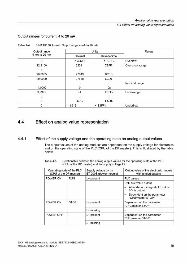
Output ranges for current: 4 to 20 mA
Table 4-4 SIMATIC S7 format: Output range 4 mA to 20 mA
Units Output range 4 mA to 20 mA Decimal Hexadecimal
Range
0 > 32511 > 7EFFH Overflow 22,8100
: 20,0005
32511 :
27649
7EFFH :
6C01H
Overshoot range
20,0000 :
4,0000
27648 : 0
6C00H :
0H
Nominal range
3,9995 : 0
-1 :
-6912
FFFFH :
E500H
Underrange
0 < -6913 < E4FFH Underflow
4.4 Effect on analog value representation
4.4.1 Effect of the supply voltage and the operating state on analog output values The output values of the analog modules are dependent on the supply voltage for electronics and on the operating state of the PLC (CPU of the DP master). This is illustrated by the table below.
Table 4-5 Relationship between the analog output values for the operating state of the PLC (CPU of the DP master) and the supply voltage L+.
Operating state of the PLC (CPU of the DP master)
Supply voltage L+ on ET 200S (power module)
Output value of the electronic module with analog outputs
L+ present PLC values POWER ON RUN Until first value output:
• After startup, a signal of 0 mA or 0 V is output.
• Dependent on the parameter "CPU/master STOP"
L+ present Dependent on the parameter "CPU/master STOP"
POWER ON STOP
L+ missing - L+ present Dependent on the parameter
"CPU/master STOP" POWER OFF -
L+ missing -
Analog value representation 4.4 Effect on analog value representation
2AO I HS analog electronic module (6ES7135-4GB52-0AB0) 20 Manual, 01/2008, A5E01254126-01
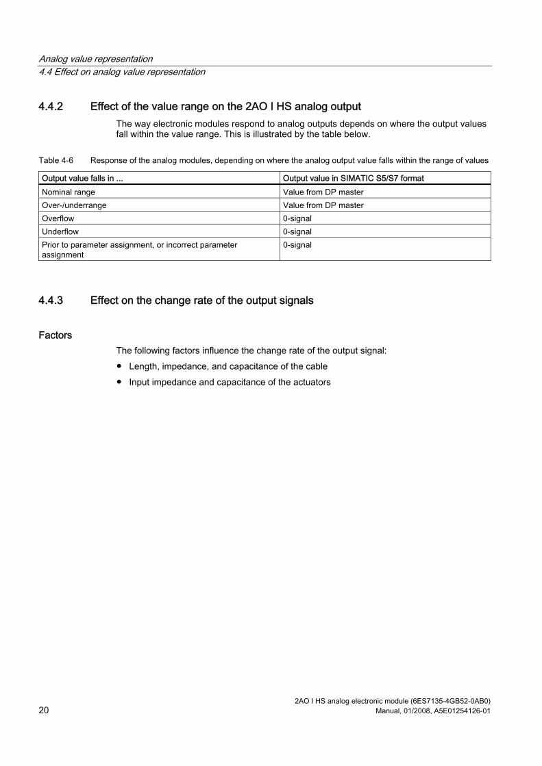
4.4.2 Effect of the value range on the 2AO I HS analog output The way electronic modules respond to analog outputs depends on where the output values fall within the value range. This is illustrated by the table below.
Table 4-6 Response of the analog modules, depending on where the analog output value falls within the range of values
Output value falls in ... Output value in SIMATIC S5/S7 format Nominal range Value from DP master Over-/underrange Value from DP master Overflow 0-signal Underflow 0-signal Prior to parameter assignment, or incorrect parameter assignment
0-signal
4.4.3 Effect on the change rate of the output signals
Factors The following factors influence the change rate of the output signal: Length, impedance, and capacitance of the cable Input impedance and capacitance of the actuators
2AO I HS analog electronic module (6ES7135-4GB52-0AB0) Manual, 01/2008, A5E01254126-01 21
Connecting 55.1 Connecting analog outputs
Introduction This chapter describes the factors to consider when connecting the analog outputs.
Cables for analog signals You should use shielded and twisted-pair cables for the analog signals. This reduces the effect of interference. You should ground the shield of the analog cables at both ends. If there are differences in potential between the cable ends, an equipotential bonding current that may interfere with the analog signals will flow across the shield. In this case, you should only ground the shield at one end of the cable.
Analog output modules In the case of the analog output modules there is generally galvanic isolation Between logic and backplane bus. Between the load voltage and MANA.
Note Ensure that this difference in potential UISO does not exceed the permitted value. If there is a possibility of exceeding the permitted value, establish a connection between terminal MANA and the central grounding point.
5.2 Using the shield connection
Rules To prevent interference we recommend the following with the analog electronic modules: Use shielded wires to the sensors and actuators. Lay out the wire shields on the shield connection. Connect the shield connection with low impedance to the ground bus.

Connecting 5.2 Using the shield connection
2AO I HS analog electronic module (6ES7135-4GB52-0AB0) 22 Manual, 01/2008, A5E01254126-01
2AO I HS analog electronic module (6ES7135-4GB52-0AB0) Manual, 01/2008, A5E01254126-01 23
Index
2 2AO I HF analog electronic module
Block diagram, 9 Properties, 7 Technical specifications, 9 Terminal assignment, 7
A Analog output modules
Error types, 16 Analog output modules in SIMATIC S7 format, 18
B Basic knowledge requirements, 3
C Cables for analog signals, 21
D Disposal, 3
I Internet
Service & Support, 4
L LED display, 15
M Measuring ranges with SIMATIC S7, 17
O Output ranges, 18 Output value, 18
R Recycling, 3 Response of the analog modules, 19
During operation, 19 When faults occur, 19
S Scope
Manual, 3 Service & Support, 4 Shield contact, 21
T Technical Support, 4 Training center, 4

Index
2AO I HS analog electronic module (6ES7135-4GB52-0AB0) 24 Manual, 01/2008, A5E01254126-01