Embed Size (px)
Citation preview
SIMATIC Distributed I/O System ET 200S
________________________________________________________________________________________________________________________________________________________________________
Preface
Description
1
Brief instructions on commissioning ET 200S
2
Application planning
3
Installing
4
Wiring and assembly
5
Commissioning
6
Functions
7
General technical specifications
8
Order numbers
A
Dimensional drawings
B
Leakage resistance
C
Interference-free operation
D
SIMATIC
Distributed I/O System ET 200S
Operating Instructions
08/2008 A5E00515771-06
The following supplement is part of this documentation:
No. Product Information Drawing number Edition
1 Use of subassemblies/modules in a Zone 2 Hazardous Area
A5E00352937-04 05/2008
2 Supplements and corrections A5E02382347-01, 11/2008
Legal information Legal information Warning notice system
This manual contains notices you have to observe in order to ensure your personal safety, as well as to prevent damage to property. The notices referring to your personal safety are highlighted in the manual by a safety alert symbol, notices referring only to property damage have no safety alert symbol. These notices shown below are graded according to the degree of danger.
DANGER indicates that death or severe personal injury will result if proper precautions are not taken.
WARNING indicates that death or severe personal injury may result if proper precautions are not taken.
CAUTION with a safety alert symbol, indicates that minor personal injury can result if proper precautions are not taken.
CAUTION without a safety alert symbol, indicates that property damage can result if proper precautions are not taken.
NOTICE indicates that an unintended result or situation can occur if the corresponding information is not taken into account.
If more than one degree of danger is present, the warning notice representing the highest degree of danger will be used. A notice warning of injury to persons with a safety alert symbol may also include a warning relating to property damage.
Qualified Personnel The device/system may only be set up and used in conjunction with this documentation. Commissioning and operation of a device/system may only be performed by qualified personnel. Within the context of the safety notes in this documentation qualified persons are defined as persons who are authorized to commission, ground and label devices, systems and circuits in accordance with established safety practices and standards.
Proper use of Siemens products Note the following:
WARNING Siemens products may only be used for the applications described in the catalog and in the relevant technical documentation. If products and components from other manufacturers are used, these must be recommended or approved by Siemens. Proper transport, storage, installation, assembly, commissioning, operation and maintenance are required to ensure that the products operate safely and without any problems. The permissible ambient conditions must be adhered to. The information in the relevant documentation must be observed.
Trademarks All names identified by ® are registered trademarks of the Siemens AG. The remaining trademarks in this publication may be trademarks whose use by third parties for their own purposes could violate the rights of the owner.
Disclaimer of Liability We have reviewed the contents of this publication to ensure consistency with the hardware and software described. Since variance cannot be precluded entirely, we cannot guarantee full consistency. However, the information in this publication is reviewed regularly and any necessary corrections are included in subsequent editions.
Siemens AG Industry Sector Postfach 48 48 90026 NÜRNBERG GERMANY
A5E00515771-06 09/2008
Copyright © Siemens AG 2008. Technical data subject to change
ET 200S Operating Instructions, 08/2008, A5E00515771-06 3
Preface
Purpose of the operating instructions The information in these operating instructions is intended to enable you to operate the ET 200S Distributed I/O System: on the PROFIBUS DP as DP Slave as a PROFINET IO device on PROFINET
Required level of knowledge To understand these operating instructions, you should have general experience in the field of automation engineering.
Scope of these operating instructions These operating instructions are valid for the components of the ET 200S Distributed I/O System. These operating instructions contain a description of the components which were valid at the time the manual was published. We reserve the right to enclose a product information bulletin containing up-to-date information regarding new components and new versions of components.
Standards and approvals In Chapter General technical data, you will find information about standards, certificates and approvals (Page 127)
Preface
ET 200S 4 Operating Instructions, 08/2008, A5E00515771-06
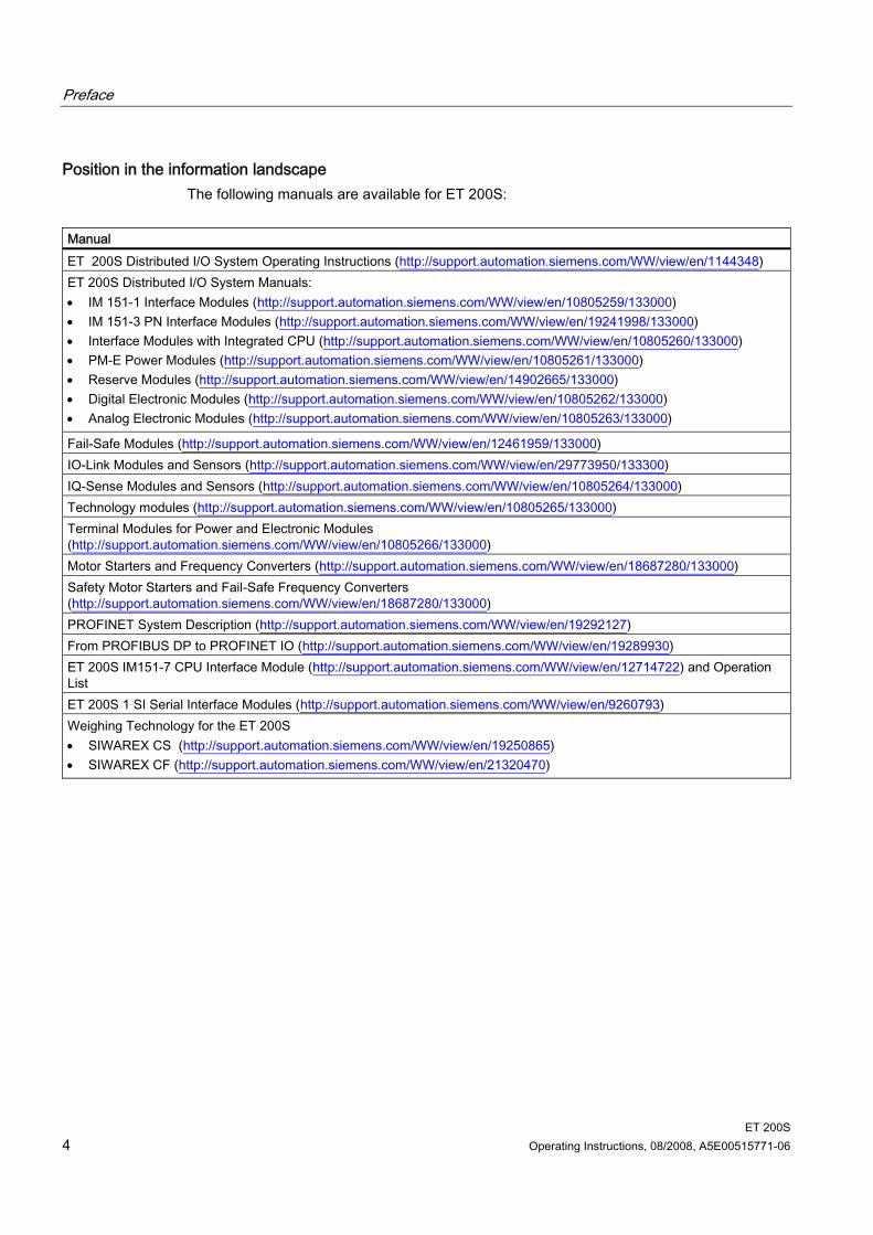
Position in the information landscape The following manuals are available for ET 200S:
Manual ET 200S Distributed I/O System Operating Instructions (http://support.automation.siemens.com/WW/view/en/1144348) ET 200S Distributed I/O System Manuals: • IM 151-1 Interface Modules (http://support.automation.siemens.com/WW/view/en/10805259/133000) • IM 151-3 PN Interface Modules (http://support.automation.siemens.com/WW/view/en/19241998/133000) • Interface Modules with Integrated CPU (http://support.automation.siemens.com/WW/view/en/10805260/133000) • PM-E Power Modules (http://support.automation.siemens.com/WW/view/en/10805261/133000) • Reserve Modules (http://support.automation.siemens.com/WW/view/en/14902665/133000) • Digital Electronic Modules (http://support.automation.siemens.com/WW/view/en/10805262/133000) • Analog Electronic Modules (http://support.automation.siemens.com/WW/view/en/10805263/133000)
Fail-Safe Modules (http://support.automation.siemens.com/WW/view/en/12461959/133000) IO-Link Modules and Sensors (http://support.automation.siemens.com/WW/view/en/29773950/133300) IQ-Sense Modules and Sensors (http://support.automation.siemens.com/WW/view/en/10805264/133000) Technology modules (http://support.automation.siemens.com/WW/view/en/10805265/133000) Terminal Modules for Power and Electronic Modules (http://support.automation.siemens.com/WW/view/en/10805266/133000) Motor Starters and Frequency Converters (http://support.automation.siemens.com/WW/view/en/18687280/133000) Safety Motor Starters and Fail-Safe Frequency Converters (http://support.automation.siemens.com/WW/view/en/18687280/133000) PROFINET System Description (http://support.automation.siemens.com/WW/view/en/19292127) From PROFIBUS DP to PROFINET IO (http://support.automation.siemens.com/WW/view/en/19289930) ET 200S IM151-7 CPU Interface Module (http://support.automation.siemens.com/WW/view/en/12714722) and Operation List ET 200S 1 SI Serial Interface Modules (http://support.automation.siemens.com/WW/view/en/9260793) Weighing Technology for the ET 200S • SIWAREX CS (http://support.automation.siemens.com/WW/view/en/19250865) • SIWAREX CF (http://support.automation.siemens.com/WW/view/en/21320470)
Preface
ET 200S Operating Instructions, 08/2008, A5E00515771-06 5
Guide The operating instructions contain the following guides which provide quick access to the specific information you need: You will find a table of contents and a list of tables and figures in the document at the
beginning of the operating instructions. The chapters contain subheadings that provide an overview of the content of the section. Following the appendix, you will find a glossary in which important technical terms used in
the operating instructions are defined. At the end of the operating instructions, there is a comprehensive index enabling rapid
access to the information you are looking for.
Other manuals In addition to these operating instructions, you also need the manual for your DP master or PROFINET IO Controller and the manuals for the modules you are using.
Recycling and disposal Thanks to the fact that it is low in contaminants, the ET 200S is recyclable. For environmentally compliant recycling and disposal of your electronic waste, please contact a company certified for the disposal of electronic waste.
Information on the Internet You can find information on the Internet on the following topics: Contacts (http://www.siemens.com/automation/partner) for SIMATIC Contacts for SIMATIC NET (http://www.siemens.com/simatic-net) Training (http://www.sitrain.com)
See also Order numbers for ET 200S network components (Page 138) Technical Support, Contacts and Training (http://support.automation.siemens.com/WW/view/en/19293011)

Preface
ET 200S 6 Operating Instructions, 08/2008, A5E00515771-06
ET 200S Operating Instructions, 08/2008, A5E00515771-06 7
Table of contents
Preface ...................................................................................................................................................... 3 1 Description............................................................................................................................................... 11
1.1 What are distributed I/O systems?...............................................................................................11 1.2 What is PROFINET IO? ...............................................................................................................13 1.3 What is the ET 200S distributed I/O system?..............................................................................14
2 Brief instructions on commissioning ET 200S.......................................................................................... 21 2.1 Commissioning on PROFIBUS DP..............................................................................................21 2.1.1 Introduction ..................................................................................................................................21 2.1.2 Install the ET 200S.......................................................................................................................23 2.1.3 Wiring and assembling ET 200S..................................................................................................24 2.1.4 Configuring ET 200S in the SIMATIC manager...........................................................................25 2.1.5 Creating a user program..............................................................................................................26 2.1.6 Switching on ET 200S..................................................................................................................26 2.1.7 Evaluating diagnostic messages..................................................................................................27 2.2 Commissioning on PROFINET IO ...............................................................................................30 2.2.1 Introduction ..................................................................................................................................30 2.2.2 Installing and wiring ET 200S ......................................................................................................32 2.2.3 Configuring ET 200S in the SIMATIC manager...........................................................................34 2.2.4 Assigning device names for the IO device...................................................................................35 2.2.5 Creating a user program..............................................................................................................36 2.2.6 Switching on ET 200S..................................................................................................................36 2.2.7 Evaluating diagnostic messages..................................................................................................37 2.2.8 Evaluating diagnostic messages..................................................................................................38
3 Application planning................................................................................................................................. 41 3.1 Switching on the ET 200S............................................................................................................41 3.2 Use of the ET 200S in a redundant system.................................................................................42 3.3 Limitation of connectable modules/maximum configuration ........................................................43 3.4 Application of power modules ......................................................................................................45 3.4.1 Placing power modules and connecting them to common potential............................................45 3.4.2 Example of a configuration: Terminal modules for power modules.............................................47 3.4.3 Finding the correct power module for an I/O device....................................................................49
Table of contents
ET 200S 8 Operating Instructions, 08/2008, A5E00515771-06
4 Installing .................................................................................................................................................. 51 4.1 Basic principles of installation ..................................................................................................... 51 4.2 Installing the interface module .................................................................................................... 54 4.3 Installing the TM-P and TM-E terminal modules......................................................................... 55 4.4 Installing the terminal modules TM-C for COMPACT modules .................................................. 57 4.5 Installing add-on terminals .......................................................................................................... 59 4.6 Removing/installing pluggable bridges on the additional terminal .............................................. 63 4.7 Replacing the terminal box on the terminal module.................................................................... 64 4.8 Installing the bus terminating module ......................................................................................... 66 4.9 Installing the shield contact ......................................................................................................... 67 4.10 Applying slot number labels and color identification labels......................................................... 69 4.11 Mounting Color Identification Labels for ET 200S and ET 200S COMPACT ............................. 71
5 Wiring and assembly ............................................................................................................................... 73 5.1 General rules and regulations for operating the ET 200S .......................................................... 73 5.2 Operating the ET 200S on a grounded incoming supply ............................................................ 75 5.3 Electrical configuration of the ET 200S....................................................................................... 78 5.4 Wiring the ET 200S ..................................................................................................................... 79 5.4.1 Wiring rules for the ET 200S....................................................................................................... 79 5.4.2 Wiring a terminal module with screw-type terminals................................................................... 79 5.4.3 Wiring a Terminal Module with Spring Terminals ....................................................................... 80 5.4.4 Wiring terminal modules with Fast Connect................................................................................ 81 5.4.5 Wiring terminal modules.............................................................................................................. 84 5.4.6 Wiring an interface module with PROFIBUS DP interface (electrically) ..................................... 87 5.4.7 Wiring an interface module with PROFIBUS DP interface (optically) ......................................... 88 5.4.8 Wiring an interface module with PROFINET IO interface (electrically) ...................................... 92 5.4.9 Wiring the power supply.............................................................................................................. 94 5.5 Plugging and removing electronic modules and COMPACT modules ....................................... 95 5.5.1 Plug and label electronic or COMPACT modules....................................................................... 95 5.5.2 Removing and inserting modules during operation .................................................................... 99
6 Commissioning ...................................................................................................................................... 101 6.1 Safety tests prior to commissioning .......................................................................................... 101 6.2 Commissioning on PROFIBUS DP ........................................................................................... 102 6.2.1 Configuring ET 200S on PROFIBUS DP .................................................................................. 102 6.2.1.1 Basic principles of configuration for the ET 200S on PROFIBUS DP ...................................... 102 6.2.1.2 Combining modules for configuration ....................................................................................... 103 6.2.1.3 Grouping of digital input modules ............................................................................................. 106 6.2.1.4 Grouping of digital output modules ........................................................................................... 107 6.2.1.5 Grouping of motor starters ........................................................................................................ 108 6.2.1.6 Example of a configuration........................................................................................................ 109 6.2.2 Commissioning and startup of ET 200S on PROFIBUS DP..................................................... 111 6.2.2.1 Setting the PROFIBUS Address ............................................................................................... 111 6.2.2.2 Commissioning ET 200S on PROFIBUS DP............................................................................ 113 6.2.2.3 Startup of the ET 200S on PROFIBUS DP............................................................................... 114
Table of contents
ET 200S Operating Instructions, 08/2008, A5E00515771-06 9
6.3 Commissioning on PROFINET IO .............................................................................................115 6.3.1 Configuring the ET 200S on the PROFINET IO ........................................................................115 6.3.2 Assigning device names to the I/O device.................................................................................116 6.3.3 Combing modules for the configuration .....................................................................................118 6.3.4 Commissioning and startup of ET 200S on the PROFINET IO .................................................120
7 Functions ............................................................................................................................................... 123 7.1 Direct data exchange on PROFIBUS DP ..................................................................................123 7.2 Option handling on the PROFIBUS DP .....................................................................................125 7.2.1 Basic principles of option handling on PROFIBUS DP..............................................................125 7.3 Identification data.......................................................................................................................126
8 General technical specifications ............................................................................................................ 127 8.1 Standards and approvals ...........................................................................................................127 8.2 Electromagnetic compatibility ....................................................................................................131 8.3 Transport and storage conditions ..............................................................................................132 8.4 Mechanical and Climatic Ambient Conditions............................................................................133 8.5 Specifications concerning insulation tests, protection class, and rated voltage for ET 200S....135 8.6 Variations in general technical specifications for the ET 200S FC frequency converter ...........136 8.7 Use of ET 200S in a zone 2 potentially explosive environments...............................................136
A Order numbers ...................................................................................................................................... 137 A.1 Order numbers for ET 200S accessories ..................................................................................137 A.2 Order numbers for ET 200S network components ....................................................................138
B Dimensional drawings............................................................................................................................ 139 B.1 Interface modules ......................................................................................................................139 B.2 Terminal module for COMPACT module with COMPACT module inserted..............................141 B.3 Terminal modules with an electronic module inserted...............................................................141 B.4 Terminating module ...................................................................................................................145 B.5 Shield contact.............................................................................................................................146 B.6 Additional terminal .....................................................................................................................146
C Leakage resistance................................................................................................................................ 147 C.1 Establishing the leakage resistance of an ET 200S station.......................................................147
D Interference-free operation .................................................................................................................... 149 D.1 Special Measures for Interference-Free Operation ...................................................................149
Glosary ................................................................................................................................................. 153 Index...................................................................................................................................................... 161

Table of contents
ET 200S 10 Operating Instructions, 08/2008, A5E00515771-06
ET 200S Operating Instructions, 08/2008, A5E00515771-06 11
Description 11.1 What are distributed I/O systems?
Distributed I/O systems When a system is configured the I/Os from and/or to the process are often integrated centrally in the automation system. Circuitry wiring that covers great distances between the I/O and the automation system may become very complex and confusing. Electromagnetic interference can therefore impair reliability. Distributed I/O provides the ideal solution for such systems: The controller CPU is located centrally The I/O systems (inputs and outputs) operate decentrally on-site The high-performance PROFIBUS DP system provides high-speed data transmission for
reliable communication between the controller CPU and the I/O system
What is PROFIBUS DP? PROFIBUS DP is an open bus system according to the standard IEC 61784-1:2002 Ed1 CP 3/1 with the "DP" protocol (DP = Distributed Periphery). Physically, PROFIBUS DP is either an electrical network based on a shielded two-wire line or an optical network based on a fiber-optic cable. The "DP" is a high-speed protocol for cyclic data exchange between the controller CPU and the distributed I/O systems.
What is a DP master and what are DP slaves? The DP master links the controller CPU with the distributed I/O systems. The DP master exchanges data with the distributed I/O systems via PROFIBUS DP. It also monitors the PROFIBUS DP. The distributed I/O systems (= DP slaves) prepare the encoder and actuator data on site in such a way that it can be transmitted via the PROFIBUS DP to the controller CPU.
Which devices can be connected to PROFIBUS DP? PROFIBUS DP supports a wide variety of devices for operation such as DP master or DP slave, provided they operate in compliance with the standard IEC61784-1:2002 Ed1 CP 3/1. These include devices from the following product families: SIMATIC S7/C7 SIMATIC PD/PC SIMATIC HMI (control and monitoring devices OP, OS, TD) Devices from other vendors
Description 1.1 What are distributed I/O systems?
ET 200S 12 Operating Instructions, 08/2008, A5E00515771-06
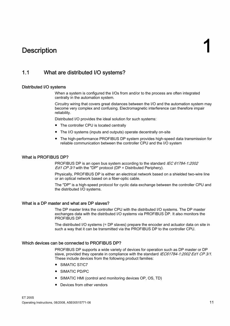
Structure of a PROFIBUS DP network The figure below illustrates a typical PROFIBUS DP network structure. The DP master is integrated in the respective device. For example, the S7-400 is equipped with a PROFIBUS DP interface. The DP slaves are the distributed I/O systems that are linked with the DP masters via the PROFIBUS DP.
Figure 1-1 The typical structure of a PROFIBUS DP network
Description 1.2 What is PROFINET IO?
ET 200S Operating Instructions, 08/2008, A5E00515771-06 13
1.2 What is PROFINET IO?
Definition PROFINET IO is an open transmission system with real-time functionality defined in accordance with the PROFINET standard. This standard defines a manufacturer-independent communication, automation and engineering model. Accessories for wiring the PROFINET components are available in industrial quality. PROFINET does not deploy the hierarchical PROFIBUS master/slave principle.
A provider/consumer principle is used instead. The planning process specifies which modules of an IO device will be subscribed to by an IO controller.
The quantities are extended in accordance with the options offered by the PROFINET IO. Parameter limits are not exceeded during configuration.
The transmission rate is 100 Mbps. The user's configuration interface is generally the same as that on PROFIBUS DP
(configuration in STEP 7 → HW CONFIG).
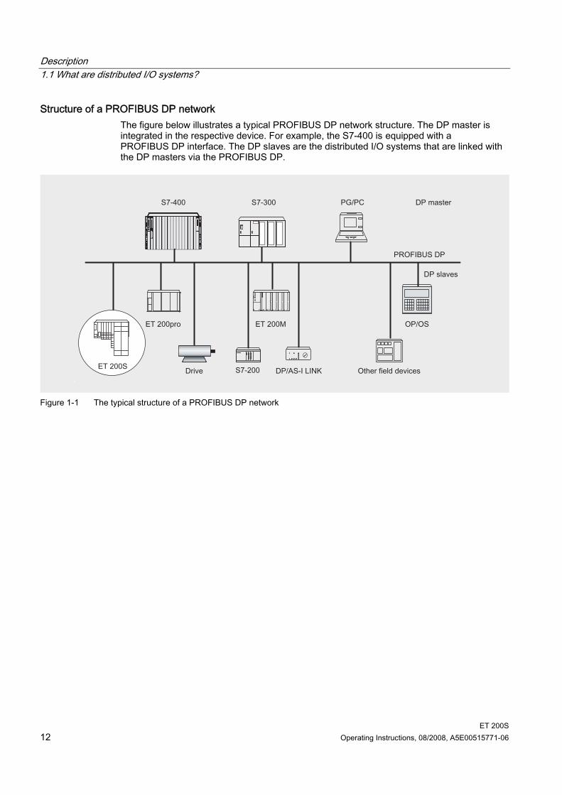
Structure of a PROFINET IO network The figure below illustrates the typical layout of a PROFINET IO network. Existing PROFIBUS slaves can be integrated by using an IE/PB link.
Figure 1-2 Typical structure of a PROFINET IO network
Further information about structuring a PROFINET IO network is available in the PROFINET System Description system manual.
Description 1.3 What is the ET 200S distributed I/O system?
ET 200S 14 Operating Instructions, 08/2008, A5E00515771-06
1.3 What is the ET 200S distributed I/O system?
Definition The ET 200S distributed I/O system is a discretely modular, highly flexible DP slave for connection to process signals on a central controller or a field bus. ET 200S supports field bus types PROFIBUS DP and PROFINET IO. ET 200S has protection class IP 20.
Applications You can connect virtually any number of I/O modules in virtually any combination right next to the interface module that transfers the data to the central controller. You can thus set the focus of your configuration on local requirements. Depending on the interface module, each ET 200S can consist of up to 63 modules - for example, power modules, I/O modules, and motor starters. The fact that motor starters can be integrated (switching and protecting any three-phase load up to 7.5 kW) ensures that the ET 200S can be quickly adapted to suit virtually any process-related use of your machine. The fail-safe modules of the ET 200S ensure the fail-safe reading and output of data to safety category 4 (EN 954-1).
Terminal modules and electronic modules The ET 200S distributed I/O system is Connected to PROFIBUS DP by a cable connector for PROFIBUS DP at the IM151-1 or
IM151-1 COMPACT interface module and Connected to PROFINET IO by a cable connector for PROFINET IO at the IM151-3
interface module. Every ET 200S peripheral system is A DP slave on the PROFIBUS DP, or An IO device on the PROFINET IO.
Description 1.3 What is the ET 200S distributed I/O system?
ET 200S Operating Instructions, 08/2008, A5E00515771-06 15
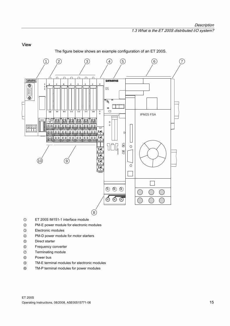
View The figure below shows an example configuration of an ET 200S.
1 2 3 4 5 6 7
8
910
IPM25 FSA
① ET 200S IM151-1 interface module ② PM-E power module for electronic modules ③ Electronic modules ④ PM-D power module for motor starters ⑤ Direct starter ⑥ Frequency converter ⑦ Terminating module ⑧ Power bus ⑨ TM-E terminal modules for electronic modules ⑩ TM-P terminal modules for power modules
Description 1.3 What is the ET 200S distributed I/O system?
ET 200S 16 Operating Instructions, 08/2008, A5E00515771-06
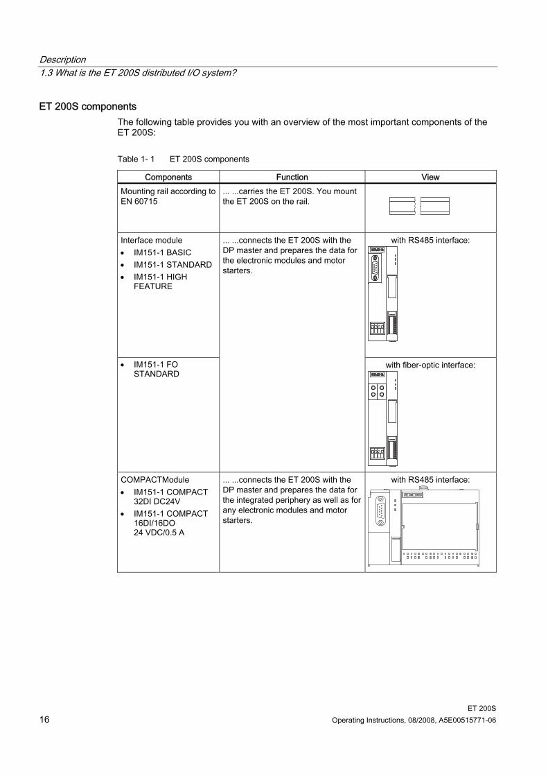
ET 200S components The following table provides you with an overview of the most important components of the ET 200S:
Table 1- 1 ET 200S components
Components Function View Mounting rail according to EN 60715
... ...carries the ET 200S. You mount the ET 200S on the rail.
Interface module • IM151-1 BASIC • IM151-1 STANDARD • IM151-1 HIGH
FEATURE
with RS485 interface:
• IM151-1 FO STANDARD
... ...connects the ET 200S with the DP master and prepares the data for the electronic modules and motor starters.
with fiber-optic interface:
COMPACTModule • IM151-1 COMPACT
32DI DC24V • IM151-1 COMPACT
16DI/16DO 24 VDC/0.5 A
... ...connects the ET 200S with the DP master and prepares the data for the integrated periphery as well as for any electronic modules and motor starters.
with RS485 interface:
Description 1.3 What is the ET 200S distributed I/O system?
ET 200S Operating Instructions, 08/2008, A5E00515771-06 17
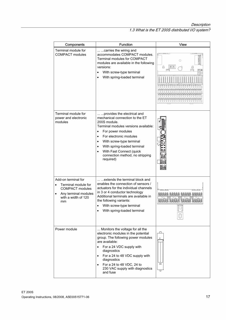
Components Function View Terminal module for COMPACT modules
... ...carries the wiring and accommodates COMPACT modules. Terminal modules for COMPACT modules are available in the following versions: • With screw-type terminal • With spring-loaded terminal
Terminal module for power and electronic modules
... ...provides the electrical and mechanical connection to the ET 200S module. Terminal modules versions available: • For power modules • For electronic modules • With screw-type terminal • With spring-loaded terminal • With Fast Connect (quick
connection method, no stripping required)
Add-on terminal for • Terminal module for
COMPACT modules • Any terminal modules
with a width of 120 mm
... ...extends the terminal block and enables the connection of sensors / actuators for the individual channels in 3 or 4 conductor technology Additional terminals are available in the following variants: • With screw-type terminal • With spring-loaded terminal
Power module ... Monitors the voltage for all the electronic modules in the potential group. The following power modules are available: • For a 24 VDC supply with
diagnostics • For a 24 to 48 VDC supply with
diagnostics • For a 24 to 48 VDC, 24 to
230 VAC supply with diagnostics and fuse
Description 1.3 What is the ET 200S distributed I/O system?
ET 200S 18 Operating Instructions, 08/2008, A5E00515771-06
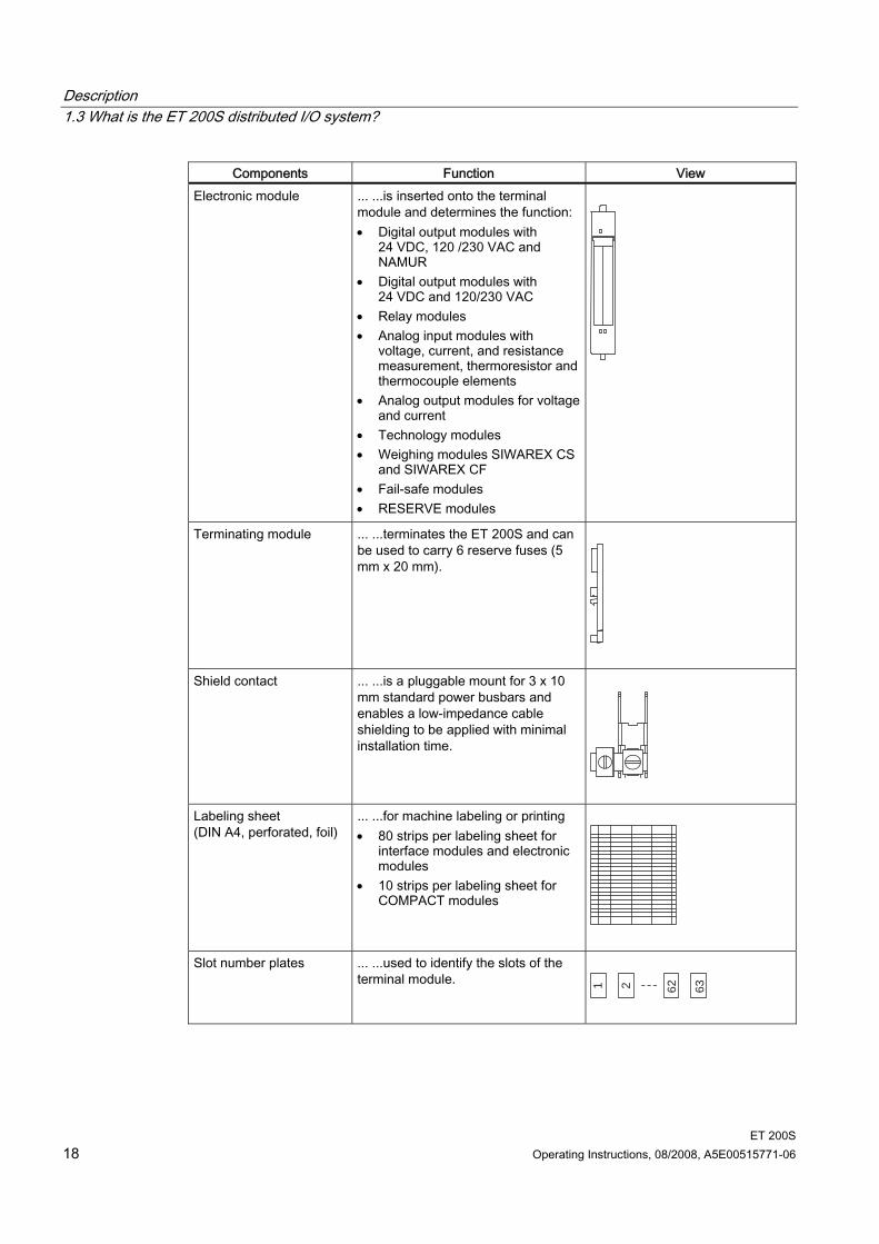
Components Function View Electronic module ... ...is inserted onto the terminal
module and determines the function: • Digital output modules with
24 VDC, 120 /230 VAC and NAMUR
• Digital output modules with 24 VDC and 120/230 VAC
• Relay modules • Analog input modules with
voltage, current, and resistance measurement, thermoresistor and thermocouple elements
• Analog output modules for voltage and current
• Technology modules • Weighing modules SIWAREX CS
and SIWAREX CF • Fail-safe modules • RESERVE modules
Terminating module ... ...terminates the ET 200S and can be used to carry 6 reserve fuses (5 mm x 20 mm).
Shield contact ... ...is a pluggable mount for 3 x 10 mm standard power busbars and enables a low-impedance cable shielding to be applied with minimal installation time.
Labeling sheet (DIN A4, perforated, foil)
... ...for machine labeling or printing • 80 strips per labeling sheet for
interface modules and electronic modules
• 10 strips per labeling sheet for COMPACT modules
Slot number plates ... ...used to identify the slots of the terminal module.
1 2 62 63
Description 1.3 What is the ET 200S distributed I/O system?
ET 200S Operating Instructions, 08/2008, A5E00515771-06 19
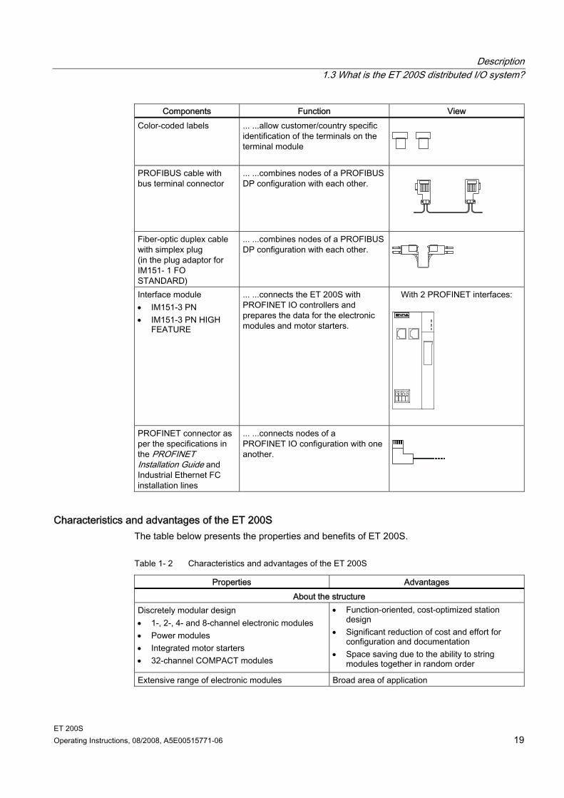
Components Function View Color-coded labels ... ...allow customer/country specific
identification of the terminals on the terminal module
PROFIBUS cable with bus terminal connector
... ...combines nodes of a PROFIBUS DP configuration with each other.
Fiber-optic duplex cable with simplex plug (in the plug adaptor for IM151- 1 FO STANDARD)
... ...combines nodes of a PROFIBUS DP configuration with each other.
Interface module • IM151-3 PN • IM151-3 PN HIGH
FEATURE
... ...connects the ET 200S with PROFINET IO controllers and prepares the data for the electronic modules and motor starters.
With 2 PROFINET interfaces:
PROFINET connector as per the specifications in the PROFINET Installation Guide and Industrial Ethernet FC installation lines
... ...connects nodes of a PROFINET IO configuration with one another.
Characteristics and advantages of the ET 200S The table below presents the properties and benefits of ET 200S.
Table 1- 2 Characteristics and advantages of the ET 200S
Properties Advantages About the structure
Discretely modular design • 1-, 2-, 4- and 8-channel electronic modules • Power modules • Integrated motor starters • 32-channel COMPACT modules
• Function-oriented, cost-optimized station design
• Significant reduction of cost and effort for configuration and documentation
• Space saving due to the ability to string modules together in random order
Extensive range of electronic modules Broad area of application
Description 1.3 What is the ET 200S distributed I/O system?
ET 200S 20 Operating Instructions, 08/2008, A5E00515771-06
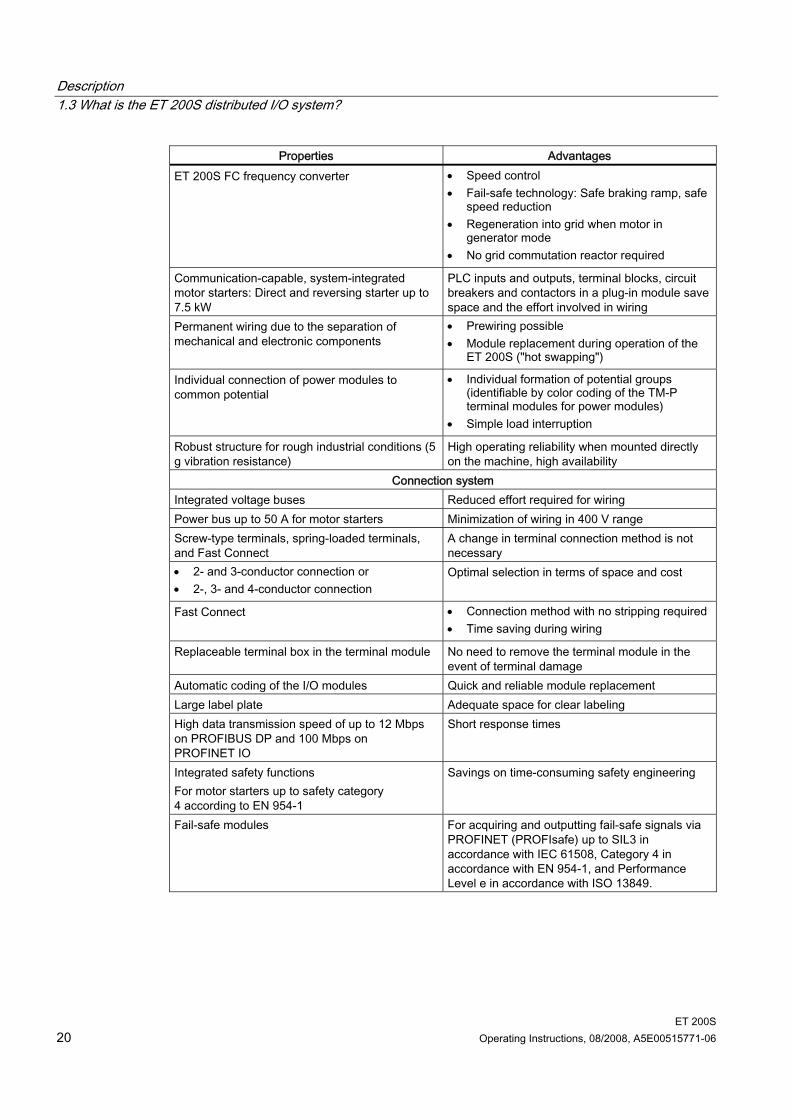
Properties Advantages ET 200S FC frequency converter • Speed control
• Fail-safe technology: Safe braking ramp, safe speed reduction
• Regeneration into grid when motor in generator mode
• No grid commutation reactor required
Communication-capable, system-integrated motor starters: Direct and reversing starter up to 7.5 kW
PLC inputs and outputs, terminal blocks, circuit breakers and contactors in a plug-in module save space and the effort involved in wiring
Permanent wiring due to the separation of mechanical and electronic components
• Prewiring possible • Module replacement during operation of the
ET 200S ("hot swapping")
Individual connection of power modules to common potential
• Individual formation of potential groups (identifiable by color coding of the TM-P terminal modules for power modules)
• Simple load interruption
Robust structure for rough industrial conditions (5 g vibration resistance)
High operating reliability when mounted directly on the machine, high availability
Connection system Integrated voltage buses Reduced effort required for wiring Power bus up to 50 A for motor starters Minimization of wiring in 400 V range Screw-type terminals, spring-loaded terminals, and Fast Connect
A change in terminal connection method is not necessary
• 2- and 3-conductor connection or • 2-, 3- and 4-conductor connection
Optimal selection in terms of space and cost
Fast Connect • Connection method with no stripping required • Time saving during wiring
Replaceable terminal box in the terminal module No need to remove the terminal module in the event of terminal damage
Automatic coding of the I/O modules Quick and reliable module replacement Large label plate Adequate space for clear labeling High data transmission speed of up to 12 Mbps on PROFIBUS DP and 100 Mbps on PROFINET IO
Short response times
Integrated safety functions For motor starters up to safety category 4 according to EN 954-1
Savings on time-consuming safety engineering
Fail-safe modules For acquiring and outputting fail-safe signals via PROFINET (PROFIsafe) up to SIL3 in accordance with IEC 61508, Category 4 in accordance with EN 954-1, and Performance Level e in accordance with ISO 13849.
ET 200S Operating Instructions, 08/2008, A5E00515771-06 21
Brief instructions on commissioning ET 200S 22.1 Commissioning on PROFIBUS DP
2.1.1 Introduction
Introduction The following simple examples will teach you how to commission the ET 200S on the PROFIBUS DP step by step: ET 200S installation and wiring up Configuring ET 200S in the SIMATIC manager Creating a user program Switching on ET 200S Evaluating diagnostic messages:
– Removing and inserting of modules – Switching off the load voltage on the power module – Wire break in the actuator wiring on the digital output module
Requirements You have set up an S7 station consisting of a power supply component and a DP master
(e.g. CPU 315-2 DP). For this example a CPU 315-2 DP is used as the DP master. You can of course use any other DP master (standard IEC 61784-1:2002 Ed1 CP 3/1).
STEP 7 (V5.0 with ServicePack 3 or higher) is installed on your programming device. You know how to work with STEP 7.
The PD must be connected to the DP master.
Brief instructions on commissioning ET 200S 2.1 Commissioning on PROFIBUS DP
ET 200S 22 Operating Instructions, 08/2008, A5E00515771-06
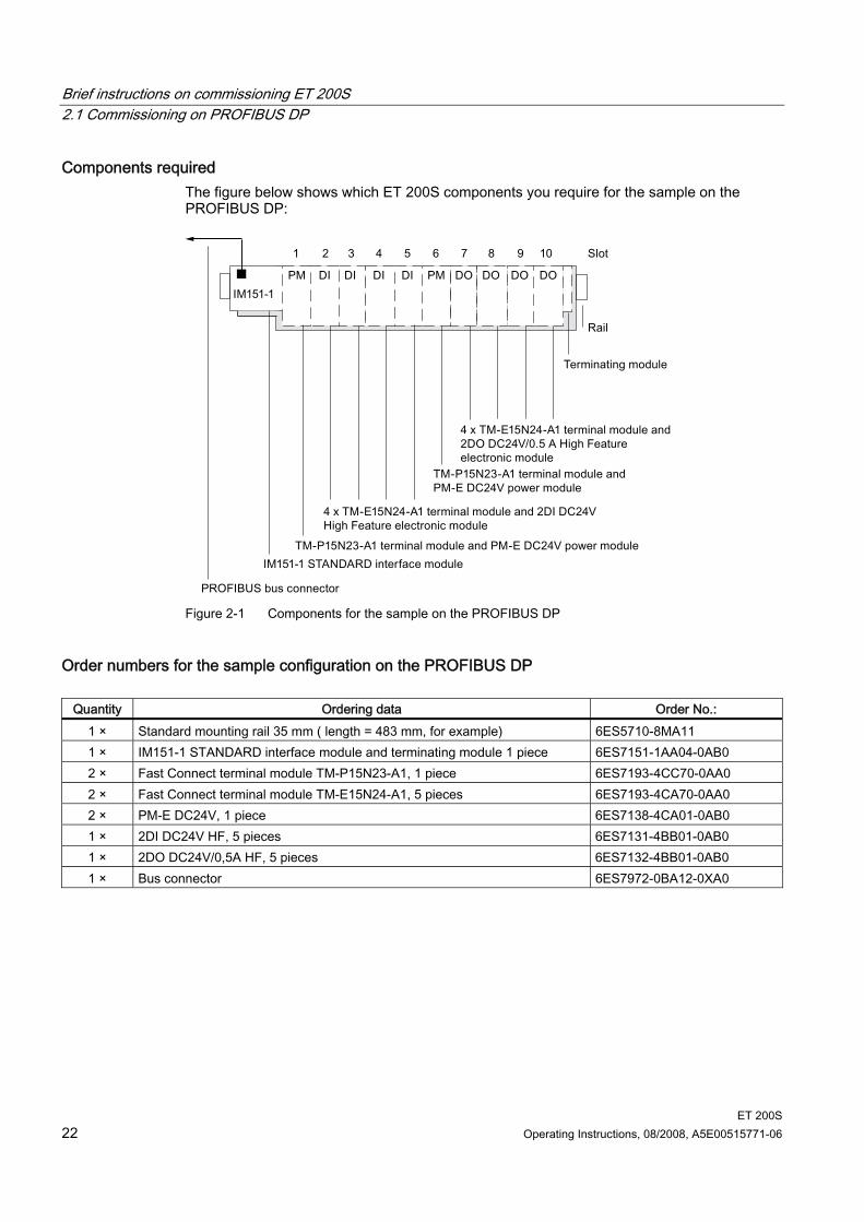
Components required The figure below shows which ET 200S components you require for the sample on the PROFIBUS DP:
Figure 2-1 Components for the sample on the PROFIBUS DP
Order numbers for the sample configuration on the PROFIBUS DP
Quantity Ordering data Order No.: 1 × Standard mounting rail 35 mm ( length = 483 mm, for example) 6ES5710-8MA11 1 × IM151-1 STANDARD interface module and terminating module 1 piece 6ES7151-1AA04-0AB0 2 × Fast Connect terminal module TM-P15N23-A1, 1 piece 6ES7193-4CC70-0AA0 2 × Fast Connect terminal module TM-E15N24-A1, 5 pieces 6ES7193-4CA70-0AA0 2 × PM-E DC24V, 1 piece 6ES7138-4CA01-0AB0 1 × 2DI DC24V HF, 5 pieces 6ES7131-4BB01-0AB0 1 × 2DO DC24V/0,5A HF, 5 pieces 6ES7132-4BB01-0AB0 1 × Bus connector 6ES7972-0BA12-0XA0
Brief instructions on commissioning ET 200S 2.1 Commissioning on PROFIBUS DP
ET 200S Operating Instructions, 08/2008, A5E00515771-06 23
2.1.2 Install the ET 200S
Proceed as follows 1. Install the DIN rail (35 x 7.5 mm or 15 mm) with a length of at least 210 mm on a solid
surface. 2. Mount the various modules onto the rail, starting on the left side (hang in - swivel down -
slide to left.) Follow the following sequence: – Interface module IM151-1 STANDARD – TM-P15N23-A1 terminal module – 4 x TM-E15N24-A1 terminal module – TM-P15N23-A1 terminal module – 4 x TM-E15N24-A1 terminal module – Terminating module
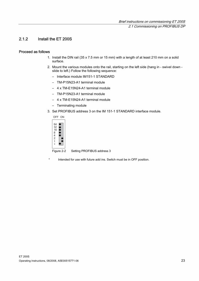
3. Set PROFIBUS address 3 on the IM 151-1 STANDARD interface module.
Figure 2-2 Setting PROFIBUS address 3
* Intended for use with future add ins. Switch must be in OFF position.
Brief instructions on commissioning ET 200S 2.1 Commissioning on PROFIBUS DP
ET 200S 24 Operating Instructions, 08/2008, A5E00515771-06
2.1.3 Wiring and assembling ET 200S
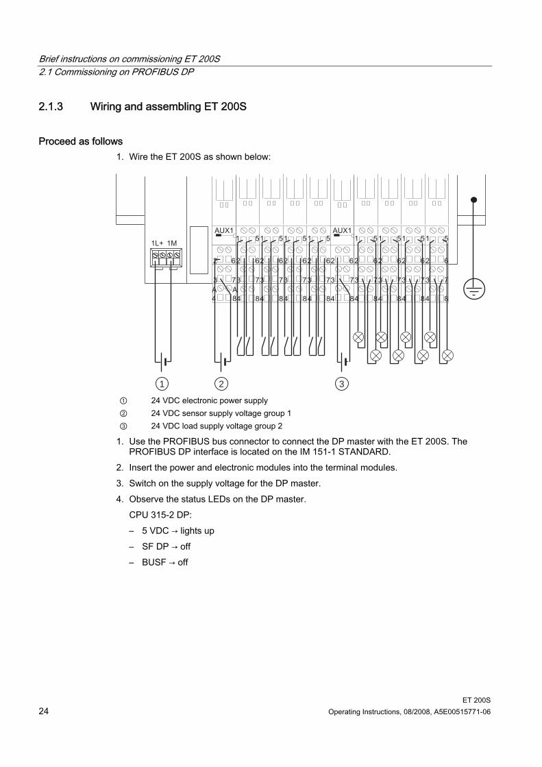
Proceed as follows 1. Wire the ET 200S as shown below:
1 2 3 ① 24 VDC electronic power supply ② 24 VDC sensor supply voltage group 1 ③ 24 VDC load supply voltage group 2
1. Use the PROFIBUS bus connector to connect the DP master with the ET 200S. The PROFIBUS DP interface is located on the IM 151-1 STANDARD.
2. Insert the power and electronic modules into the terminal modules. 3. Switch on the supply voltage for the DP master. 4. Observe the status LEDs on the DP master.
CPU 315-2 DP: – 5 VDC → lights up – SF DP → off – BUSF → off
Brief instructions on commissioning ET 200S 2.1 Commissioning on PROFIBUS DP
ET 200S Operating Instructions, 08/2008, A5E00515771-06 25
2.1.4 Configuring ET 200S in the SIMATIC manager
Proceed as follows 1. Start SIMATIC Manager, and create a new project with a DP master
(e. g., CPU315-2 DP). Create OB 1, OB 82 and OB 122 for the project. 2. Create the PROFIBUS subnet. 3. Connect the PROFIBUS subnet with the DP master in HW Config. 4. Take the ET 200S from the hardware catalog and put it on the PROFIBUS. 5. Set the PROFIBUS address 3 for the ET200S. 6. Drag the individual ET 200S modules from the hardware catalog to the configuration
table. 7. Mark the electronic modules in the configuration table, and click the "Pack addresses"
button.
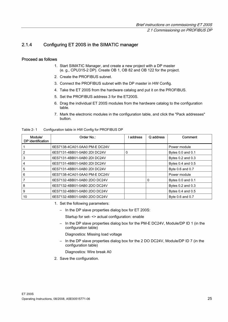
Table 2- 1 Configuration table in HW Config for PROFIBUS DP
Module/ DP identification
Order No.: I address Q address Comment
1 6ES7138-4CA01-0AA0 PM-E DC24V Power module 2 6ES7131-4BB01-0AB0 2DI DC24V 0 Bytes 0.0 and 0.1 3 6ES7131-4BB01-0AB0 2DI DC24V Bytes 0.2 and 0.3 4 6ES7131-4BB01-0AB0 2DI DC24V Bytes 0.4 and 0.5 5 6ES7131-4BB01-0AB0 2DI DC24V Byte 0.6 and 0.7 6 6ES7138-4CA01-0AA0 PM-E DC24V Power module 7 6ES7132-4BB01-0AB0 2DO DC24V 0 Bytes 0.0 and 0.1 8 6ES7132-4BB01-0AB0 2DO DC24V Bytes 0.2 and 0.3 9 6ES7132-4BB01-0AB0 2DO DC24V Bytes 0.4 and 0.5 10 6ES7132-4BB01-0AB0 2DO DC24V Byte 0.6 and 0.7
1. Set the following parameters: – In the DP slave properties dialog box for ET 200S:
Startup for set- <> actual configuration: enable – In the DP slave properties dialog box for the PM-E DC24V, Module/DP ID 1 (in the
configuration table) Diagnostics: Missing load voltage
– In the DP slave properties dialog box for the 2 DO DC24V, Module/DP ID 7 (in the configuration table) Diagnostics: Wire break A0
2. Save the configuration.
Brief instructions on commissioning ET 200S 2.1 Commissioning on PROFIBUS DP
ET 200S 26 Operating Instructions, 08/2008, A5E00515771-06
2.1.5 Creating a user program
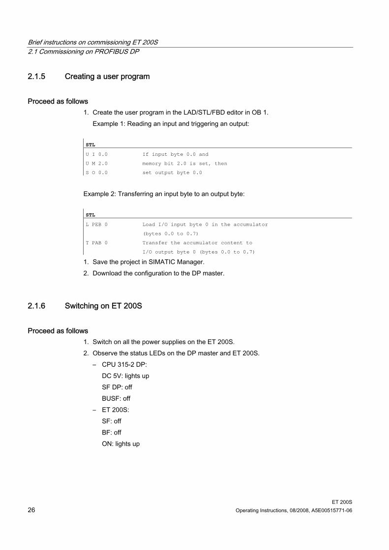
Proceed as follows 1. Create the user program in the LAD/STL/FBD editor in OB 1.
Example 1: Reading an input and triggering an output: STL
U I 0.0 If input byte 0.0 and
U M 2.0 memory bit 2.0 is set, then
S O 0.0 set output byte 0.0
Example 2: Transferring an input byte to an output byte: STL
L PEB 0 Load I/O input byte 0 in the accumulator
(bytes 0.0 to 0.7)
T PAB 0 Transfer the accumulator content to
I/O output byte 0 (bytes 0.0 to 0.7)
1. Save the project in SIMATIC Manager. 2. Download the configuration to the DP master.
2.1.6 Switching on ET 200S
Proceed as follows 1. Switch on all the power supplies on the ET 200S. 2. Observe the status LEDs on the DP master and ET 200S.
– CPU 315-2 DP: DC 5V: lights up SF DP: off BUSF: off
– ET 200S: SF: off BF: off ON: lights up
Brief instructions on commissioning ET 200S 2.1 Commissioning on PROFIBUS DP
ET 200S Operating Instructions, 08/2008, A5E00515771-06 27
2.1.7 Evaluating diagnostic messages
Introduction In this example, you generate diagnostic messages by provoking errors on the ET 200S. In the event of an error, OB 82 is started. You evaluate the start information in OB 82. Tip: Call SFC13 in OB 82, and evaluate the diagnostic frame.
Removing and inserting the 2 DI DC24V HF digital electronic module 1. Remove the 2 DI DC24V HF electronic module from the terminal module during
operation. 2. Observe the status LEDs on the IM 151-1 STANDARD:
– SF: lights up → there is a diagnostic message. – BF: off – ON: lights up Result: The ET 200S continues to run error-free.
3. Evaluate the diagnostic information: Result: – Station status 1 (byte 0): Bit 3 is set → external diagnostics – ID-related diagnostics: Byte 7.1 is set → slot 2 – Module status: bytes 19.2 / 19.3: 11B → no module
4. Reinsert the removed electronic module into the terminal module. Result: – Status LED on the IM 151-1 STANDARD:
SF: off BF: off ON: lights up
– The diagnostic message is deleted.
Brief instructions on commissioning ET 200S 2.1 Commissioning on PROFIBUS DP
ET 200S 28 Operating Instructions, 08/2008, A5E00515771-06
Switching off load voltage on the power module 1. Switch off the load voltage on the PM-E DC24V (slot 1). 2. Monitor the status LEDs.
IM151-1 STANDARD: – SF: lights up Power module: – PWR: off → no load voltage available on the power module – SF: lights up → there is a diagnostic message. I/O modules in the voltage group: – LEDs: light up
3. Evaluate the diagnostics. Result: – Station status 1 (byte 0): Bit 3 is set → external diagnostics – ID-related diagnostics: Byte 7.0 is set → slot 1 – Channel-specific diagnostics:
Bytes 35.0 to 35.5: 000000B → slot 1 Bytes 37.0 to 37.4: 10001B → sensor or load voltage missing
4. Switch on the load voltage back on the power module and re-evaluate the diagnostics. Result: – Status LED on the IM 151-1 STANDARD:
SF: off – Status LEDs on power module:
PWR: on SF: off
– Status LEDs on I/O modules: LEDs: off
– The diagnostic message is deleted.
Brief instructions on commissioning ET 200S 2.1 Commissioning on PROFIBUS DP
ET 200S Operating Instructions, 08/2008, A5E00515771-06 29
Simulating a wire break in the actuator wiring 1. Remove the cable from terminal 1 on the 2DO DC24V/0.5A HF electronic module (slot 7) 2. Monitor the status LEDs:
IM151-1 STANDARD: – SF: lights up Electronic module 2DO DC24V/0.5A HF: – SF: lights up → there is a diagnostic message – 1: off → output is not activated
3. Evaluate the diagnostic information: Result: – Station status 1 (byte 0): Bit 3 is set → external diagnostics – ID-related diagnostics: Byte 7.6 is set → slot 7 – Channel-specific diagnostics:
Bytes 35.0 to 35.5: 000110B → slot 7 Bytes 36.0 to 35.5: 000000B → channel 0 Bytes 37.0 to 37.4: 00110B → wire break
4. Reattach the cable to the actuator in terminal 1 and reevaluate the diagnostics: – Status LED on the IM 151-1 STANDARD:
SF: off – Status LEDs electronic module 2DO DC24V/0.5 A HF:
SF: off 1: off/on
– The diagnostic message is deleted.

Brief instructions on commissioning ET 200S 2.2 Commissioning on PROFINET IO
ET 200S 30 Operating Instructions, 08/2008, A5E00515771-06
2.2 Commissioning on PROFINET IO
2.2.1 Introduction
Introduction The following simple example teaches you step by step how to commission the ET 200S on PROFINET IO: Installing and wiring ET 200S Configuring in HW Config or with the GSDML file Transferring device names to the IO device Integrating into the user program Switching the ET 200S on Evaluating the interrupts and diagnostics:
– Removing and inserting of modules – Switching off the load voltage on the power module – Wire break in the actuator wiring on the digital output module
Requirements You have set up an S7 station consisting of a power supply module and an IO controller
(e.g., CPU 317-2 PN/DP). In this example a CPU 317-2 PN/DP is used as the IO controller with firmware version V2.3 and higher.
STEP 7 V 5.3 + ServicePack 1 or higher is installed on your programming device. You know how to work with STEP 7.
The programming device connected to the PROFINET IO.
Brief instructions on commissioning ET 200S 2.2 Commissioning on PROFINET IO
ET 200S Operating Instructions, 08/2008, A5E00515771-06 31
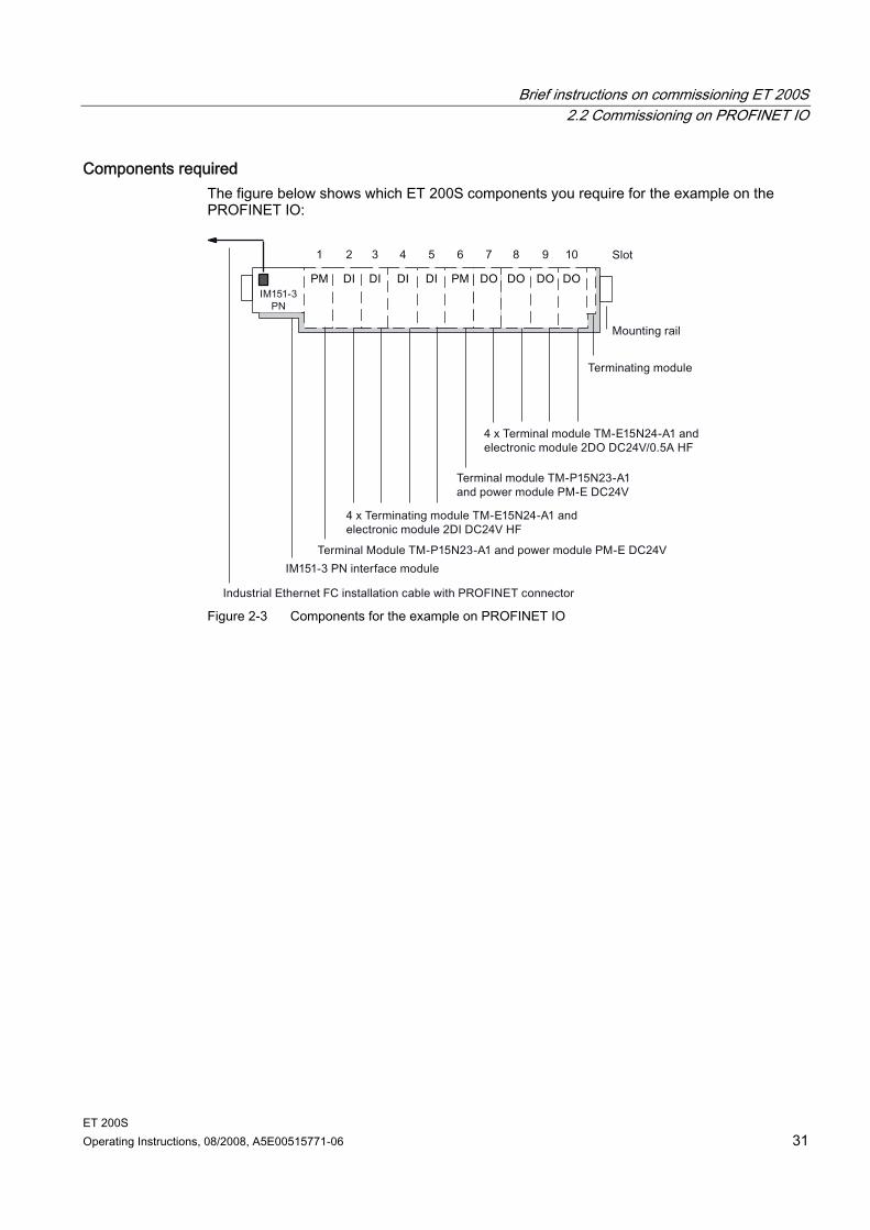
Components required The figure below shows which ET 200S components you require for the example on the PROFINET IO:
Figure 2-3 Components for the example on PROFINET IO
Brief instructions on commissioning ET 200S 2.2 Commissioning on PROFINET IO
ET 200S 32 Operating Instructions, 08/2008, A5E00515771-06
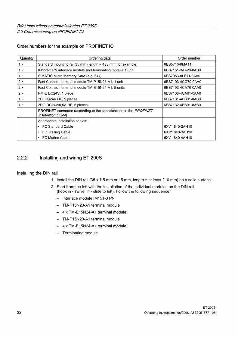
Order numbers for the example on PROFINET IO
Quantity Ordering data Order number 1 × Standard mounting rail 35 mm (length = 483 mm, for example) 6ES5710-8MA11 1 × IM151-3 PN interface module and terminating module,1 unit 6ES7151-3AA20-0AB0 1 × SIMATIC Micro Memory Card (e.g. 64k) 6ES7953-8LF11-0AA0 2 × Fast Connect terminal module TM-P15N23-A1, 1 unit 6ES7193-4CC70-0AA0 2 × Fast Connect terminal module TM-E15N24-A1, 5 units 6ES7193-4CA70-0AA0 2 × PM-E DC24V, 1 piece 6ES7138-4CA01-0AA0 1 × 2DI DC24V HF, 5 pieces 6ES7131-4BB01-0AB0 1 × 2DO DC24V/0,5A HF, 5 pieces 6ES7132-4BB01-0AB0 PROFINET connector (according to the specifications in the PROFINET
Installation Guide)
Appropriate installation cables: • FC Standard Cable • FC Trailing Cable • FC Marine Cable
6XV1 840-2AH10 6XV1 840-3AH10 6XV1 840-4AH10
2.2.2 Installing and wiring ET 200S
Installing the DIN rail 1. Install the DIN rail (35 x 7.5 mm or 15 mm, length = at least 210 mm) on a solid surface. 2. Start from the left with the installation of the individual modules on the DIN rail
(hook in - swivel in - slide to left). Follow the following sequence: – Interface module IM151-3 PN – TM-P15N23-A1 terminal module – 4 x TM-E15N24-A1 terminal module – TM-P15N23-A1 terminal module – 4 x TM-E15N24-A1 terminal module – Terminating module
Brief instructions on commissioning ET 200S 2.2 Commissioning on PROFINET IO
ET 200S Operating Instructions, 08/2008, A5E00515771-06 33
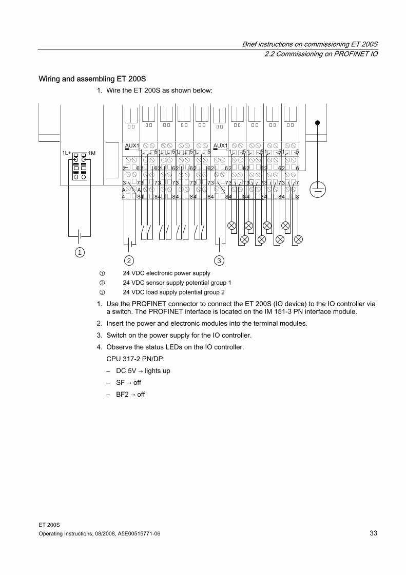
Wiring and assembling ET 200S 1. Wire the ET 200S as shown below:
1 2 3
① 24 VDC electronic power supply ② 24 VDC sensor supply potential group 1 ③ 24 VDC load supply potential group 2
1. Use the PROFINET connector to connect the ET 200S (IO device) to the IO controller via a switch. The PROFINET interface is located on the IM 151-3 PN interface module.
2. Insert the power and electronic modules into the terminal modules. 3. Switch on the power supply for the IO controller. 4. Observe the status LEDs on the IO controller.
CPU 317-2 PN/DP: – DC 5V → lights up – SF → off – BF2 → off
Brief instructions on commissioning ET 200S 2.2 Commissioning on PROFINET IO
ET 200S 34 Operating Instructions, 08/2008, A5E00515771-06
2.2.3 Configuring ET 200S in the SIMATIC manager
Proceed as follows 1. Start SIMATIC Manager and create a new project with an IO controller
(e g., CPU 317-2 PN/DP). For this project, create the OB 1, the OB 82, the OB 83 and the OB 122.
2. Open the "Properties - Ethernet Interface" window in the HW Config and create a subnet e. g. Ethernet (1).
3. Take the IM151-3 PN from the ET 200S catalog of the hardware catalog and insert it on Ethernet(1):PROFINET IO System (100).
4. Drag the individual ET 200S modules from the hardware catalog to the configuration table.
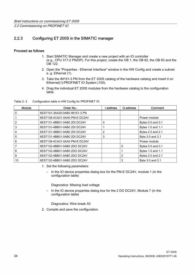
Table 2- 2 Configuration table in HW Config for PROFINET IO
Module Order No.: I address Q address Comment 0 6ES7151-3AA20-0AB0 IM151-3 PN 1 6ES7138-4CA01-0AA0 PM-E DC24V Power module 2 6ES7131-4BB01-0AB0 2DI DC24V 0 Bytes 0.0 and 0.1 3 6ES7131-4BB01-0AB0 2DI DC24V 1 Bytes 1.0 and 1.1 4 6ES7131-4BB01-0AB0 2DI DC24V 2 Bytes 2.0 and 2.1 5 6ES7131-4BB01-0AB0 2DI DC24V 3 Byte 3.0 and 3.1 6 6ES7138-4CA01-0AA0 PM-E DC24V Power module 7 6ES7132-4BB01-0AB0 2DO DC24V 0 Bytes 0.0 and 0.1 8 6ES7132-4BB01-0AB0 2DO DC24V 1 Bytes 1.0 and 1.1 9 6ES7132-4BB01-0AB0 2DO DC24V 2 Bytes 2.0 and 2.1 10 6ES7132-4BB01-0AB0 2DO DC24V 3 Byte 3.0 and 3.1
1. Set the following parameters: – In the IO device properties dialog box for the PM-E DC24V, module 1 (in the
configuration table) Diagnostics: Missing load voltage
– In the IO device properties dialog box for the 2 DO DC24V, Module 7 (in the configuration table) Diagnostics: Wire break A0
2. Compile and save the configuration.
Brief instructions on commissioning ET 200S 2.2 Commissioning on PROFINET IO
ET 200S Operating Instructions, 08/2008, A5E00515771-06 35
2.2.4 Assigning device names for the IO device
Procedure 1. Insert the SIMATIC Micro Memory Card in the IM151-3 PN. 2. Switch on the power supply for the IM151-3 PN. 3. Open the "Properties - IM151-3 PN" window in HW Config and enter the device name for
the IO device there. 4. An online PROFINET connection from the programming device to the IO device via a
switch is required for in order to transfer the name to the IM151-3 PN interface module. The device name is transferred to the IM151-3 PN using "PLC > Ethernet > Assign Device Name". To do so, activate the "Assign name" button in the "Assign device name" window. The device name is stored on the SIMATIC Micro Memory Card in the IM151-3 PN interface module.
Once the name is assigned, it appears in the window. Alternative procedure: Alternatively, you can write directly to a SIMATIC Micro Memory Card using a programming device with an EPROM programming device installed or a PC connected to a SIMATIC USB EPROM programming device and then use the memory card to transfer the device name to the IM151-3 PN. 1. Open the "Properties - IM151-3 PN" window in HW Config and enter the device name for
the IO device there. 2. Insert the required SIMATIC Micro Memory Card into the EPROM programming device. 3. Select the IM151-3 PN in HW Config. 4. Select "Target system > Save device name to memory card" in HW Config. 5. Insert the SIMATIC Micro Memory Card written with the device name in the IM151-3 PN. 6. Switch on the power supply for the IM151-3 PN. The device name is transferred to the IM151-3 PN.
Brief instructions on commissioning ET 200S 2.2 Commissioning on PROFINET IO
ET 200S 36 Operating Instructions, 08/2008, A5E00515771-06
2.2.5 Creating a user program
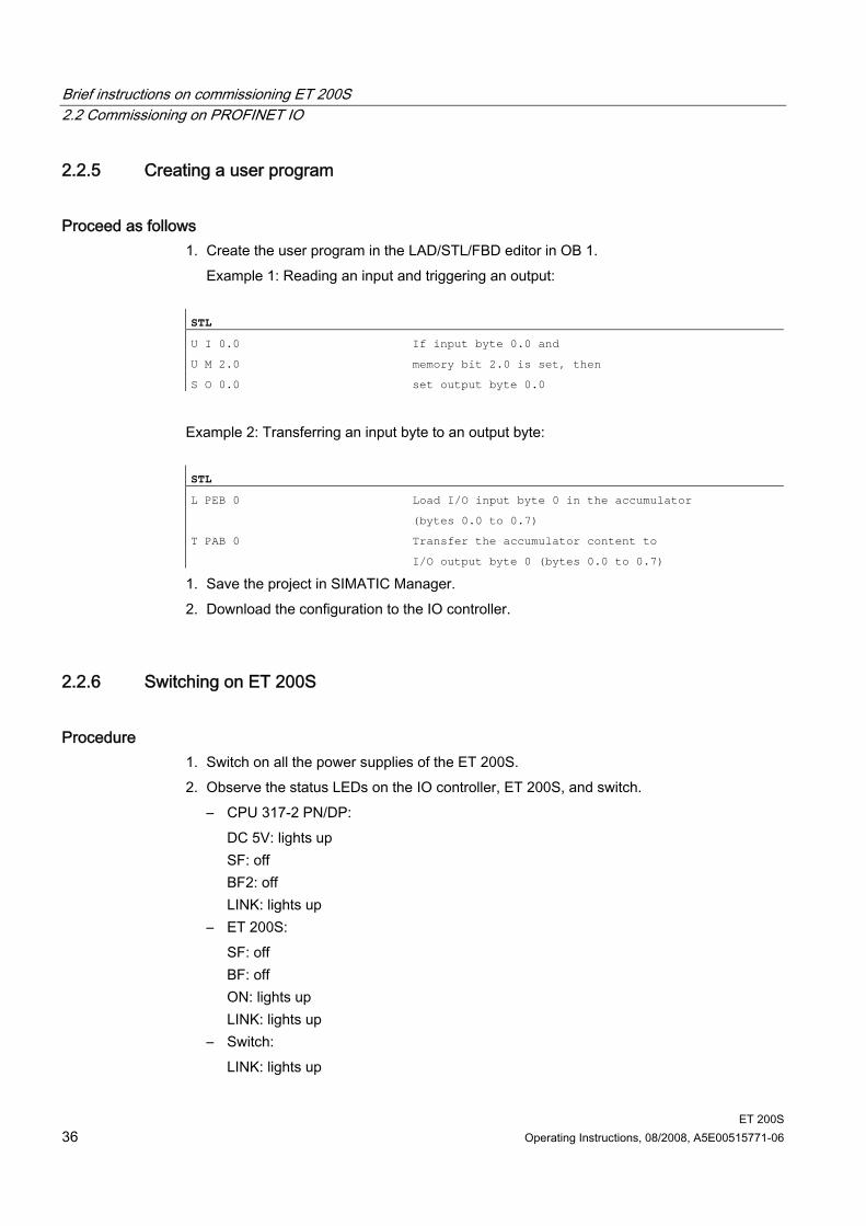
Proceed as follows 1. Create the user program in the LAD/STL/FBD editor in OB 1.
Example 1: Reading an input and triggering an output: STL
U I 0.0 If input byte 0.0 and
U M 2.0 memory bit 2.0 is set, then
S O 0.0 set output byte 0.0
Example 2: Transferring an input byte to an output byte: STL
L PEB 0 Load I/O input byte 0 in the accumulator
(bytes 0.0 to 0.7)
T PAB 0 Transfer the accumulator content to
I/O output byte 0 (bytes 0.0 to 0.7)
1. Save the project in SIMATIC Manager. 2. Download the configuration to the IO controller.
2.2.6 Switching on ET 200S
Procedure 1. Switch on all the power supplies of the ET 200S. 2. Observe the status LEDs on the IO controller, ET 200S, and switch.
– CPU 317-2 PN/DP: DC 5V: lights up SF: off BF2: off LINK: lights up
– ET 200S: SF: off BF: off ON: lights up LINK: lights up
– Switch: LINK: lights up
Brief instructions on commissioning ET 200S 2.2 Commissioning on PROFINET IO
ET 200S Operating Instructions, 08/2008, A5E00515771-06 37
2.2.7 Evaluating diagnostic messages
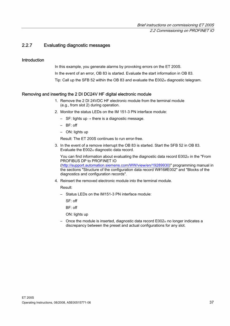
Introduction In this example, you generate alarms by provoking errors on the ET 200S. In the event of an error, OB 83 is started. Evaluate the start information in OB 83. Tip: Call up the SFB 52 within the OB 83 and evaluate the E002H diagnostic telegram.
Removing and inserting the 2 DI DC24V HF digital electronic module 1. Remove the 2 DI 24VDC HF electronic module from the terminal module
(e.g., from slot 2) during operation. 2. Monitor the status LEDs on the IM 151-3 PN interface module:
– SF: lights up → there is a diagnostic message. – BF: off – ON: lights up Result: The ET 200S continues to run error-free.
3. In the event of a remove interrupt the OB 83 is started. Start the SFB 52 in OB 83. Evaluate the E002H diagnostic data record. You can find information about evaluating the diagnostic data record E002H in the "From PROFIBUS DP to PROFINET IO (http://support.automation.siemens.com/WW/view/en/19289930)" programming manual in the sections "Structure of the configuration data record W#16#E002" and "Blocks of the diagnostics and configuration records".
4. Reinsert the removed electronic module into the terminal module. Result: – Status LEDs on the IM151-3 PN interface module:
SF: off BF: off ON: lights up
– Once the module is inserted, diagnostic data record E002H no longer indicates a discrepancy between the preset and actual configurations for any slot.
Brief instructions on commissioning ET 200S 2.2 Commissioning on PROFINET IO
ET 200S 38 Operating Instructions, 08/2008, A5E00515771-06
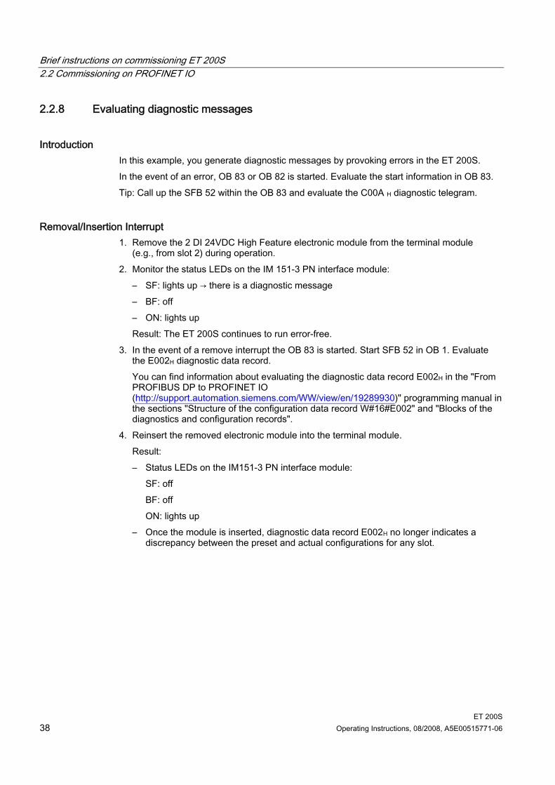
2.2.8 Evaluating diagnostic messages
Introduction In this example, you generate diagnostic messages by provoking errors in the ET 200S. In the event of an error, OB 83 or OB 82 is started. Evaluate the start information in OB 83. Tip: Call up the SFB 52 within the OB 83 and evaluate the C00A H diagnostic telegram.
Removal/Insertion Interrupt 1. Remove the 2 DI 24VDC High Feature electronic module from the terminal module
(e.g., from slot 2) during operation. 2. Monitor the status LEDs on the IM 151-3 PN interface module:
– SF: lights up → there is a diagnostic message – BF: off – ON: lights up Result: The ET 200S continues to run error-free.
3. In the event of a remove interrupt the OB 83 is started. Start SFB 52 in OB 1. Evaluate the E002H diagnostic data record. You can find information about evaluating the diagnostic data record E002H in the "From PROFIBUS DP to PROFINET IO (http://support.automation.siemens.com/WW/view/en/19289930)" programming manual in the sections "Structure of the configuration data record W#16#E002" and "Blocks of the diagnostics and configuration records".
4. Reinsert the removed electronic module into the terminal module. Result: – Status LEDs on the IM151-3 PN interface module:
SF: off BF: off ON: lights up
– Once the module is inserted, diagnostic data record E002H no longer indicates a discrepancy between the preset and actual configurations for any slot.

Brief instructions on commissioning ET 200S 2.2 Commissioning on PROFINET IO
ET 200S Operating Instructions, 08/2008, A5E00515771-06 39
Switching off load voltage on the power module 1. Switch off the load voltage on the PM-E DC24V (slot 1). 2. Monitor the status LEDs.
IM151-3 PN: – SF: lights up Power module: – PWR: off → no load voltage available on the power module – SF: lights up → a diagnostic message is pending. I/O modules in the voltage group: – LEDs: light up
3. Evaluate diagnostic data record C00AH. Tip: Call up the SFB 52 within the OB 1 or OB 82 and evaluate the diagnostic message. You can find information about evaluating the diagnostic data record C00AH in the "From PROFIBUS DP to PROFINET IO (http://support.automation.siemens.com/WW/view/en/19289930)" programming manual in the section "Structure of diagnostics data records".
4. Switch on the load voltage back on the power module and re-evaluate the diagnostics. Result: – Status LEDs on the IM151-3 PN:
SF: off – Status LEDs on power module:
PWR: on SF: off
– Status LEDs on I/O modules: LEDs: off
– The diagnostic message is deleted.

Brief instructions on commissioning ET 200S 2.2 Commissioning on PROFINET IO
ET 200S 40 Operating Instructions, 08/2008, A5E00515771-06
Simulating a wire break in the actuator wiring 1. Remove the cable from terminal 1 on the 2DO DC24V/0.5A HF electronic module (slot 7) 2. Monitor the status LEDs:
IM151-3 PN: – SF: lights up Electronic module 2DO DC24V/0.5A HF: – SF: lights up → there is a diagnostic message – 1: off → output is not activated
3. Evaluate diagnostic data record C00AH. You can find information about evaluating the diagnostic data record C00AH in the "From PROFIBUS DP to PROFINET IO (http://support.automation.siemens.com/WW/view/en/19289930)" programming manual in the section "Structure of diagnostics data records".
4. Reattach the cable to the actuator in terminal 1 and reevaluate the diagnostics: – Status LEDs on the IM151-3 PN:
SF: off – Status LEDs electronic module 2DO DC24V/0.5 A HF:
SF: off 1: off/on
– The diagnostic message is deleted.
ET 200S Operating Instructions, 08/2008, A5E00515771-06 41
Application planning 33.1 Switching on the ET 200S
Simply put your ET 200S together yourself. A configuration tool supports you in doing so. You can find the tool on the Internet (www.siemens.com/et200).
Using power and electronic modules in terminal modules Various signals are available on the terminals depending on which terminal module is selected. For more detailed information, refer to the manual for the specific I/O module. The TM-P and TM-E terminal modules are mixable in the ET 200S configuration.
Usage of COMPACT modules on terminal modules Various signals are available on the terminals depending on which terminal module is selected. For more detailed information, refer to the IM 151-1 COMPACT Modules manual. The terminal module TM-C must always be connected at the start of an ET 200S configuration. Additional terminal modules TM-E or TM-P are to be connected to the right of terminal module TM-C.
Application planning 3.2 Use of the ET 200S in a redundant system
ET 200S 42 Operating Instructions, 08/2008, A5E00515771-06
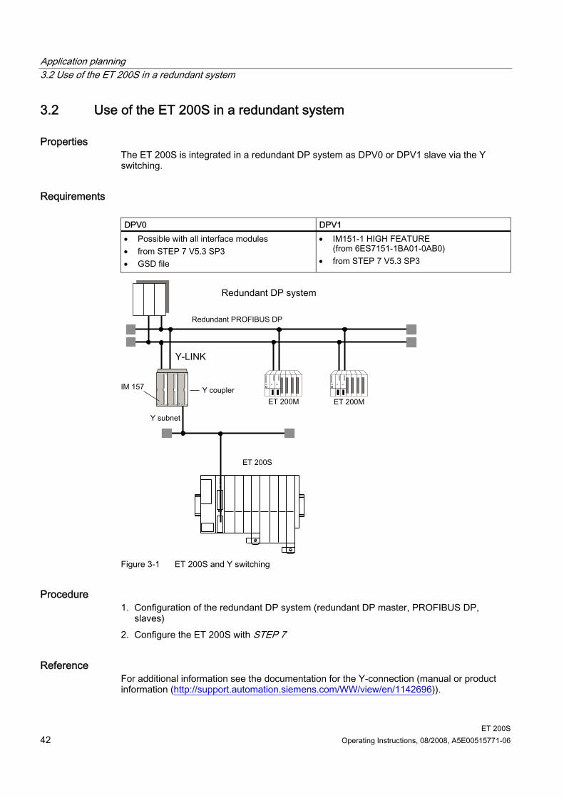
3.2 Use of the ET 200S in a redundant system
Properties The ET 200S is integrated in a redundant DP system as DPV0 or DPV1 slave via the Y switching.
Requirements DPV0 DPV1 • Possible with all interface modules • from STEP 7 V5.3 SP3 • GSD file
• IM151-1 HIGH FEATURE (from 6ES7151-1BA01-0AB0)
• from STEP 7 V5.3 SP3
Figure 3-1 ET 200S and Y switching
Procedure 1. Configuration of the redundant DP system (redundant DP master, PROFIBUS DP,
slaves) 2. Configure the ET 200S with STEP 7
Reference For additional information see the documentation for the Y-connection (manual or product information (http://support.automation.siemens.com/WW/view/en/1142696)).
Application planning 3.3 Limitation of connectable modules/maximum configuration
ET 200S Operating Instructions, 08/2008, A5E00515771-06 43
3.3 Limitation of connectable modules/maximum configuration
Number of modules The following modules are available for the ET 200S: interface modules, power modules, electronic modules, RESERVE modules, technology modules, motor starters, and frequency converters. The number of modules you can insert is dependent on the interface module you are using: Max. 12 modules with:
– IM151-1 BASIC – IM151-1 COMPACT
Max. 63 modules with: – IM151-1 STANDARD – IM151-1 FO STANDARD – IM151-1 HIGH FEATURE – IM151-3 PN – IM151-3 PN FO – IM151-3 PN HIGH FEATURE
Bus length of the ET 200S A maximum bus length of 2 m can be assigned for the ET 200S. Deviations are noted in the properties of the interface modules.
Parameter length For PROFIBUS DP: Depending on the PROFIBUS DP master you are using For PROFINET IO: Not relevant for maximum configuration
Address space For PROFIBUS DP: Depending on the PROFIBUS DP master you are using For PROFINET IO: Not relevant
Application planning 3.3 Limitation of connectable modules/maximum configuration
ET 200S 44 Operating Instructions, 08/2008, A5E00515771-06
Maximum configuration per potential group The number of modules that can be connected depends on the total current of all modules in a potential group. This total current must not exceed the maximum current-carrying capacity of the power modules or COMPACT modules you are using. The total current is governed in large part by the digital output modules.
Table 3- 1 Maximum configuration per potential group
Power modules/ COMPACT modules
Maximum current-carrying capacity
Power Module PM-E DC24V 10 A Power Module PM-E DC24..48V 10 A Power Module PM-E DC24..48V/AC24..230V • For 24 to 56.7 VDC • For 24 to 48/120/230 VAC
10 A 8 A
IM151-1 COMPACT 5 A, for I/O modules connected after the IM151-1 COMPACT
DP master 32-byte diagnostic message frame length You can use the ET 200S with DP masters with a diagnostic frame length of 32 bytes because you can set the length of the diagnostic frame in all the interface modules.
Reference The relevant values can be found in the technical data for the respective modules.
Application planning 3.4 Application of power modules
ET 200S Operating Instructions, 08/2008, A5E00515771-06 45
3.4 Application of power modules
3.4.1 Placing power modules and connecting them to common potential
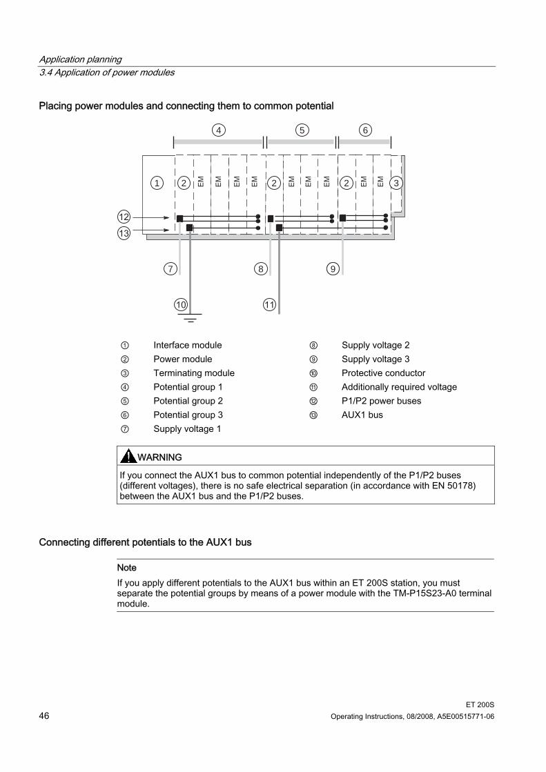
Placing and connecting to common potential You can choose where to position the power modules in the ET 200S. Every TM-P terminal module (for a power module) that you install in the ET 200S opens a new potential group. All sensor and load supplies of the downstream electronic modules are fed from this TM-P terminal module (for a power module). If you place an additional TM-P terminal module after an electronic module/motor starter, you interrupt the potential buses (P1/P2) and simultaneously open a new potential group. This enables sensor and load supplies to be individually connected to common potential.
AUX(iliary) bus (AUX1) A TM-P terminal module (for a power module) allows you to connect additional potential (up to the maximum rated load voltage of the module), which you can apply by means of the AUX(iliary) bus. You can use the AUX(iliary) bus individually: As a protective conductor bar For additionally required voltage The AUX1 bus is laid out as follows: Maximum current-carrying capacity (at 60°C ambient temperature): 10 A Permitted voltage: 230 VAC/DC
Application planning 3.4 Application of power modules
ET 200S 46 Operating Instructions, 08/2008, A5E00515771-06
Placing power modules and connecting them to common potential
77 8 9
4 5 6
32221
① Interface module ⑧ Supply voltage 2 ② Power module ⑨ Supply voltage 3 ③ Terminating module ⑩ Protective conductor ④ Potential group 1 ⑪ Additionally required voltage ⑤ Potential group 2 ⑫ P1/P2 power buses ⑥ Potential group 3 ⑬ AUX1 bus ⑦ Supply voltage 1
WARNING If you connect the AUX1 bus to common potential independently of the P1/P2 buses (different voltages), there is no safe electrical separation (in accordance with EN 50178) between the AUX1 bus and the P1/P2 buses.
Connecting different potentials to the AUX1 bus
Note If you apply different potentials to the AUX1 bus within an ET 200S station, you must separate the potential groups by means of a power module with the TM-P15S23-A0 terminal module.
Application planning 3.4 Application of power modules
ET 200S Operating Instructions, 08/2008, A5E00515771-06 47
3.4.2 Example of a configuration: Terminal modules for power modules
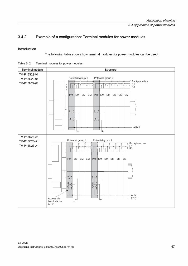
Introduction The following table shows how terminal modules for power modules can be used:
Table 3- 2 Terminal modules for power modules
Terminal module Structure TM-P15S22-01 TM-P15C22-01 TM-P15N22-01
TM-P15S23-A1 TM-P15C23-A1 TM-P15N23-A1
Application planning 3.4 Application of power modules
ET 200S 48 Operating Instructions, 08/2008, A5E00515771-06
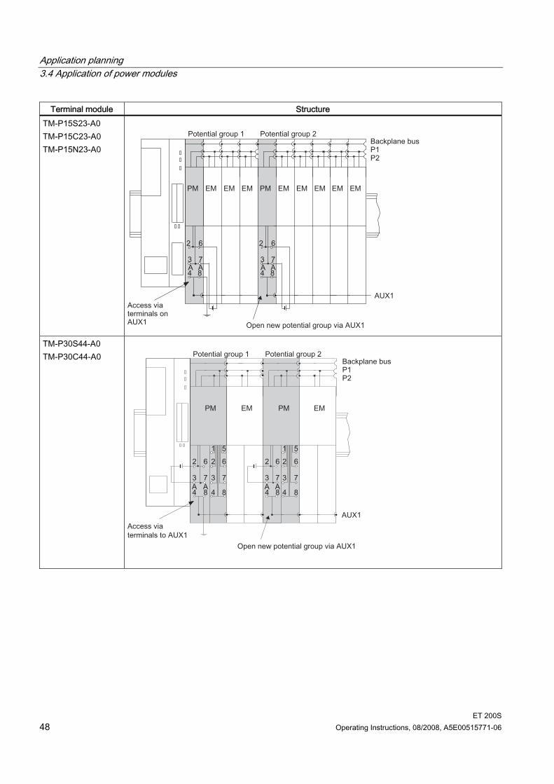
Terminal module Structure TM-P15S23-A0 TM-P15C23-A0 TM-P15N23-A0
TM-P30S44-A0 TM-P30C44-A0
Application planning 3.4 Application of power modules
ET 200S Operating Instructions, 08/2008, A5E00515771-06 49
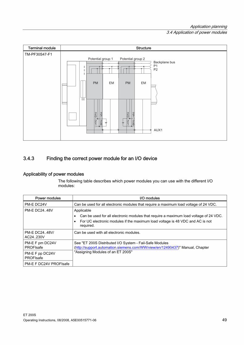
Terminal module Structure TM-PF30S47-F1
3.4.3 Finding the correct power module for an I/O device
Applicability of power modules The following table describes which power modules you can use with the different I/O modules:
Power modules I/O modules
PM-E DC24V Can be used for all electronic modules that require a maximum load voltage of 24 VDC. PM-E DC24..48V Applicable
• Can be used for all electronic modules that require a maximum load voltage of 24 VDC. • For UC electronic modules if the maximum load voltage is 48 VDC and AC is not
required.
PM-E DC24..48V/ AC24..230V
Can be used with all electronic modules.
PM-E F pm DC24V PROFIsafe PM-E F pp DC24V PROFIsafe PM-E F DC24V PROFIsafe
See "ET 200S Distributed I/O System - Fail-Safe Modules (http://support.automation.siemens.com/WW/view/en/12490437)" Manual, Chapter "Assigning Modules of an ET 200S"
Application planning 3.4 Application of power modules
ET 200S 50 Operating Instructions, 08/2008, A5E00515771-06
Power modules I/O modules PM-D For motor starters and frequency converters.
See "ET 200S Motor Starters (http://support.automation.siemens.com/WW/view/en/6008567)" Manual or "Frequency Converter ET 200S FC (http://support.automation.siemens.com/WW/view/en/26291825)" Operating Instructions
PM-D F For fail-safe applications with motor starter or frequency converter. See "ET 200S Motor Starters (http://support.automation.siemens.com/WW/view/en/6008567)" Manual or "Frequency Converter ET 200S FC (http://support.automation.siemens.com/WW/view/en/26291825)" Operating Instructions
ET 200S Operating Instructions, 08/2008, A5E00515771-06 51
Installing 44.1 Basic principles of installation
WARNING Open components Modules of an ET 200S are open components. This means that you may only install the ET 200S in cases, cabinets or electrical plant rooms where they will only be accessible with a key or a tool. Only trained or authorized personnel are allowed access to such cubicles, cabinets or electrical operating rooms.
Simple installation The ET 200S distributed I/O system is designed for simple installation.
Installation rules The ET 200S distributed I/O system starts
– with an interface module or – with a TM-C terminal module with COMPACT module.
A power module comes after the interface module or at the beginning of each potential group.
After a power module come digital, analog, technological, or RESERVE modules. After a COMPACT module, digital, analog, technological, or RESERVE modules may
follow. If necessary, power modules may also be deployed. The ET 200S distributed I/O system ends with the terminating module. The maximum configuration of the distributed I/O system is dependent on the interface
modules being used.
Installation position Preferably, the ET 200S is mounted horizontally on a vertical wall. All other positions are possible, although there are certain restrictions regarding the ambient temperature.
Installing 4.1 Basic principles of installation
ET 200S 52 Operating Instructions, 08/2008, A5E00515771-06
Mounting rail The ET 200S distributed I/O system is installed on a mounting rail according to EN 60715 (35 x 7.5 mm or 35 x 15 mm). Appropriate surface designs are: Steel strip according to Appendix A of EN 60715, or Tinned steel strip. We recommend the following mounting rails for this purpose:
– 6ES5710-8MA11 (length: 483 mm) – 6ES5710-8MA21 (length: 530 mm) – 6ES5710-8MA31 (length: 830 mm) – 6ES5710-8MA41 (length: 2000 mm)
Note If you use mounting rails from other manufacturers, please check whether they have the required properties for your climatic ambient conditions.
Note If the ET 200S distributed IO device is exposed to increased vibrations and shock, we recommend that you screw the mounting rail to the mounting surface at intervals of 200 mm. To prevent the ET 200S distributed I/O system from slipping sideways, we recommend that you apply a mechanical hold-down (e.g. with grounding terminal, 8WA2011-1PH20) at both ends of the device. If you install the rail on grounded, zinc-plated mounting plates, there is no need to ground the rail separately.
Installing 4.1 Basic principles of installation
ET 200S Operating Instructions, 08/2008, A5E00515771-06 53
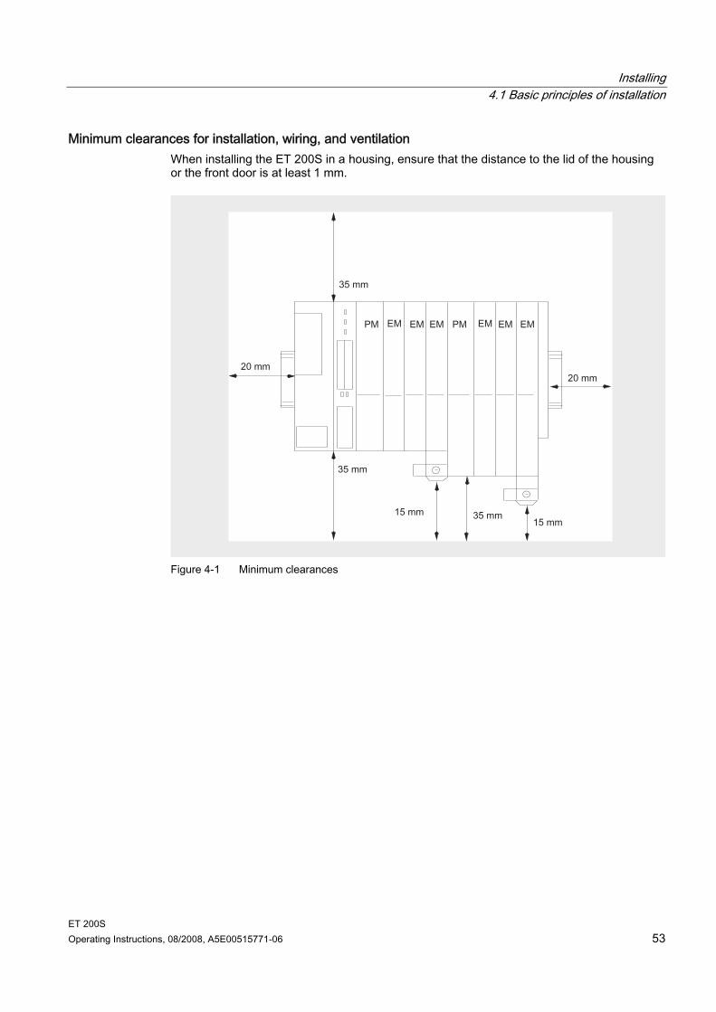
Minimum clearances for installation, wiring, and ventilation When installing the ET 200S in a housing, ensure that the distance to the lid of the housing or the front door is at least 1 mm.
Figure 4-1 Minimum clearances
Installing 4.2 Installing the interface module
ET 200S 54 Operating Instructions, 08/2008, A5E00515771-06
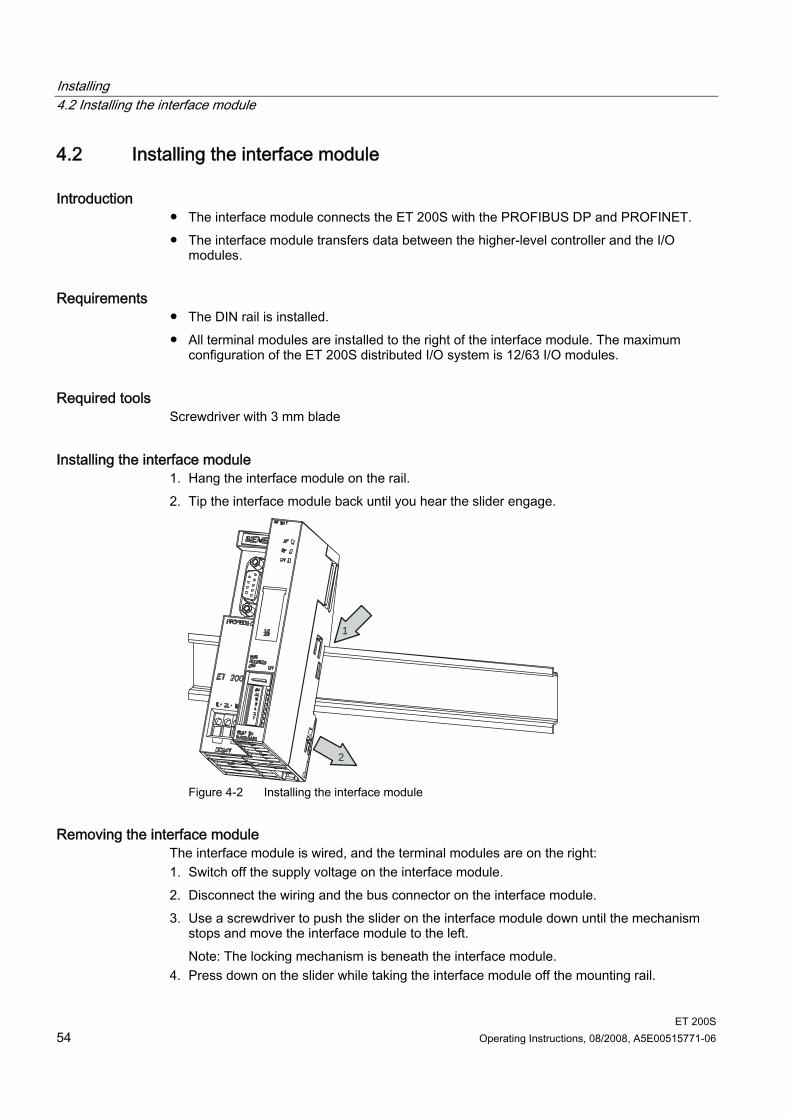
4.2 Installing the interface module
Introduction The interface module connects the ET 200S with the PROFIBUS DP and PROFINET. The interface module transfers data between the higher-level controller and the I/O
modules.
Requirements The DIN rail is installed. All terminal modules are installed to the right of the interface module. The maximum
configuration of the ET 200S distributed I/O system is 12/63 I/O modules.
Required tools Screwdriver with 3 mm blade
Installing the interface module 1. Hang the interface module on the rail. 2. Tip the interface module back until you hear the slider engage.
2
1
Figure 4-2 Installing the interface module
Removing the interface module The interface module is wired, and the terminal modules are on the right: 1. Switch off the supply voltage on the interface module. 2. Disconnect the wiring and the bus connector on the interface module. 3. Use a screwdriver to push the slider on the interface module down until the mechanism
stops and move the interface module to the left. Note: The locking mechanism is beneath the interface module.
4. Press down on the slider while taking the interface module off the mounting rail.
Installing 4.3 Installing the TM-P and TM-E terminal modules
ET 200S Operating Instructions, 08/2008, A5E00515771-06 55
4.3 Installing the TM-P and TM-E terminal modules
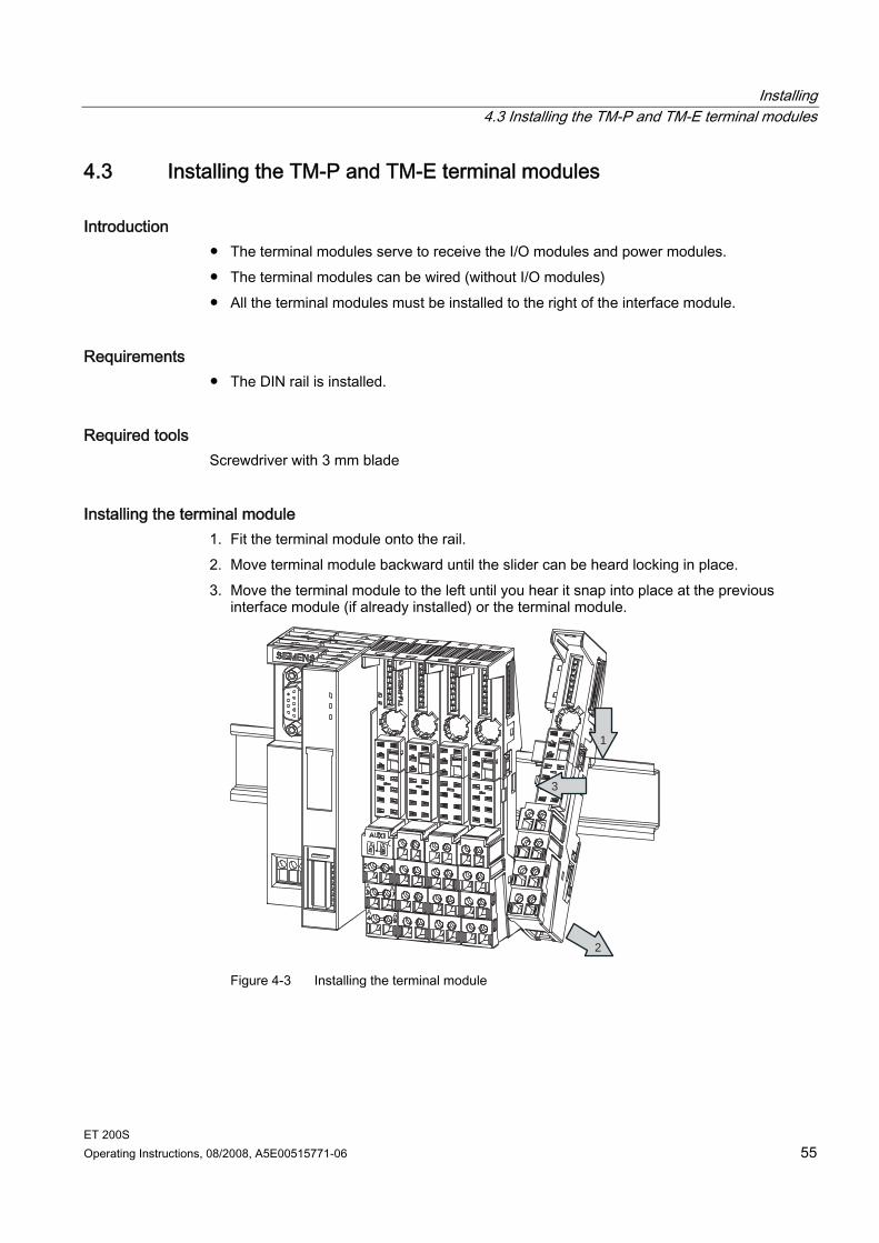
Introduction The terminal modules serve to receive the I/O modules and power modules. The terminal modules can be wired (without I/O modules) All the terminal modules must be installed to the right of the interface module.
Requirements The DIN rail is installed.
Required tools Screwdriver with 3 mm blade
Installing the terminal module 1. Fit the terminal module onto the rail. 2. Move terminal module backward until the slider can be heard locking in place. 3. Move the terminal module to the left until you hear it snap into place at the previous
interface module (if already installed) or the terminal module.
1
2
3
Figure 4-3 Installing the terminal module
Installing 4.3 Installing the TM-P and TM-E terminal modules
ET 200S 56 Operating Instructions, 08/2008, A5E00515771-06
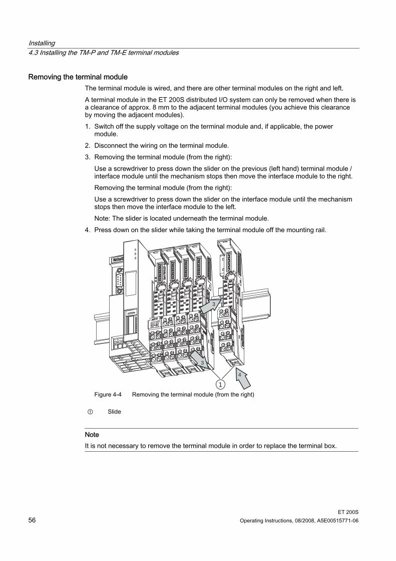
Removing the terminal module The terminal module is wired, and there are other terminal modules on the right and left. A terminal module in the ET 200S distributed I/O system can only be removed when there is a clearance of approx. 8 mm to the adjacent terminal modules (you achieve this clearance by moving the adjacent modules). 1. Switch off the supply voltage on the terminal module and, if applicable, the power
module. 2. Disconnect the wiring on the terminal module. 3. Removing the terminal module (from the right):
Use a screwdriver to press down the slider on the previous (left hand) terminal module / interface module until the mechanism stops then move the interface module to the right. Removing the terminal module (from the right): Use a screwdriver to press down the slider on the interface module until the mechanism stops then move the interface module to the left. Note: The slider is located underneath the terminal module.
4. Press down on the slider while taking the terminal module off the mounting rail.
1
3
4
3
Figure 4-4 Removing the terminal module (from the right)
① Slide
Note It is not necessary to remove the terminal module in order to replace the terminal box.
Installing 4.4 Installing the terminal modules TM-C for COMPACT modules
ET 200S Operating Instructions, 08/2008, A5E00515771-06 57
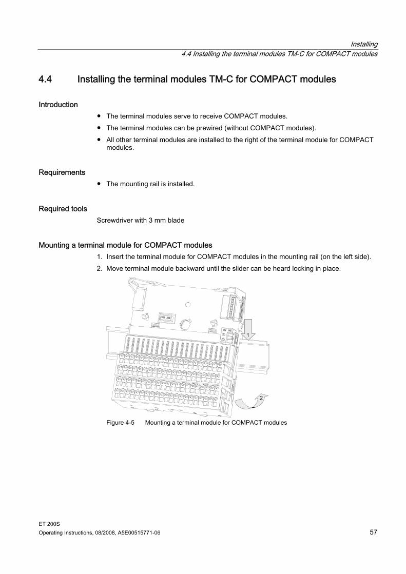
4.4 Installing the terminal modules TM-C for COMPACT modules
Introduction The terminal modules serve to receive COMPACT modules. The terminal modules can be prewired (without COMPACT modules). All other terminal modules are installed to the right of the terminal module for COMPACT
modules.
Requirements The mounting rail is installed.
Required tools Screwdriver with 3 mm blade
Mounting a terminal module for COMPACT modules 1. Insert the terminal module for COMPACT modules in the mounting rail (on the left side). 2. Move terminal module backward until the slider can be heard locking in place.
Figure 4-5 Mounting a terminal module for COMPACT modules
Installing 4.4 Installing the terminal modules TM-C for COMPACT modules
ET 200S 58 Operating Instructions, 08/2008, A5E00515771-06
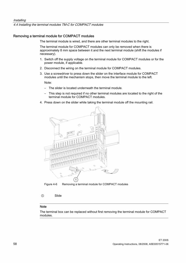
Removing a terminal module for COMPACT modules The terminal module is wired, and there are other terminal modules to the right. The terminal module for COMPACT modules can only be removed when there is approximately 8 mm space between it and the next terminal module (shift the modules if necessary). 1. Switch off the supply voltage on the terminal module for COMPACT modules or for the
power module, if applicable. 2. Disconnect the wiring on the terminal module for COMPACT modules. 3. Use a screwdriver to press down the slider on the interface module for COMPACT
modules until the mechanism stops, then move the terminal module to the left. Note: – The slider is located underneath the terminal module. – This step is not required if no other terminal modules are located to the right of the
terminal module for COMPACT modules. 4. Press down on the slider while taking the terminal module off the mounting rail.
Figure 4-6 Removing a terminal module for COMPACT modules
① Slide
Note The terminal box can be replaced without first removing the terminal module for COMPACT modules.
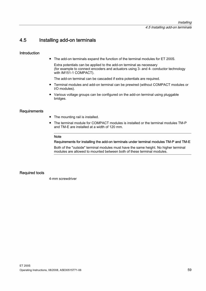
Installing 4.5 Installing add-on terminals
ET 200S Operating Instructions, 08/2008, A5E00515771-06 59
4.5 Installing add-on terminals
Introduction The add-on terminals expand the function of the terminal modules for ET 200S.
Extra potentials can be applied to the add-on terminal as necessary (for example to connect encoders and actuators using 3- and 4- conductor technology with IM151-1 COMPACT). The add-on terminal can be cascaded if extra potentials are required.
Terminal modules and add-on terminal can be prewired (without COMPACT modules or I/O modules).
Various voltage groups can be configured on the add-on terminal using pluggable bridges.
Requirements The mounting rail is installed. The terminal module for COMPACT modules is installed or the terminal modules TM-P
and TM-E are installed at a width of 120 mm.
Note Requirements for installing the add-on terminals under terminal modules TM-P and TM-E Both of the "outside" terminal modules must have the same height. No higher terminal modules are allowed to mounted between both of these terminal modules.
Required tools 4-mm screwdriver
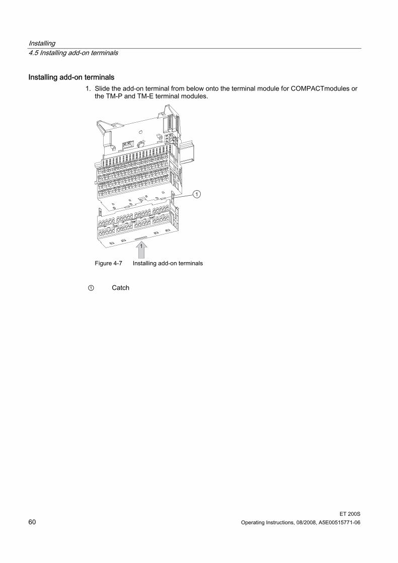
Installing 4.5 Installing add-on terminals
ET 200S 60 Operating Instructions, 08/2008, A5E00515771-06
Installing add-on terminals 1. Slide the add-on terminal from below onto the terminal module for COMPACTmodules or
the TM-P and TM-E terminal modules.
Figure 4-7 Installing add-on terminals
① Catch
Installing 4.5 Installing add-on terminals
ET 200S Operating Instructions, 08/2008, A5E00515771-06 61
If your ET 200S modules are exposed to shocks or vibrations they can be stabilized by using the mounting brackets included in the delivery package. 1. Slide the fixing bracket into the slot in the underside of the additional terminal. 2. Screw the fixing bracket firmly onto the base.
The lower part of the mounting bracket can be broken off and used to fill any gap between the add-on terminal and its base by placement under the bracket (as a spacer).
Figure 4-8 Stabilizing an add-on terminal with fixing bracket
① Mounting brackets ② Spacer
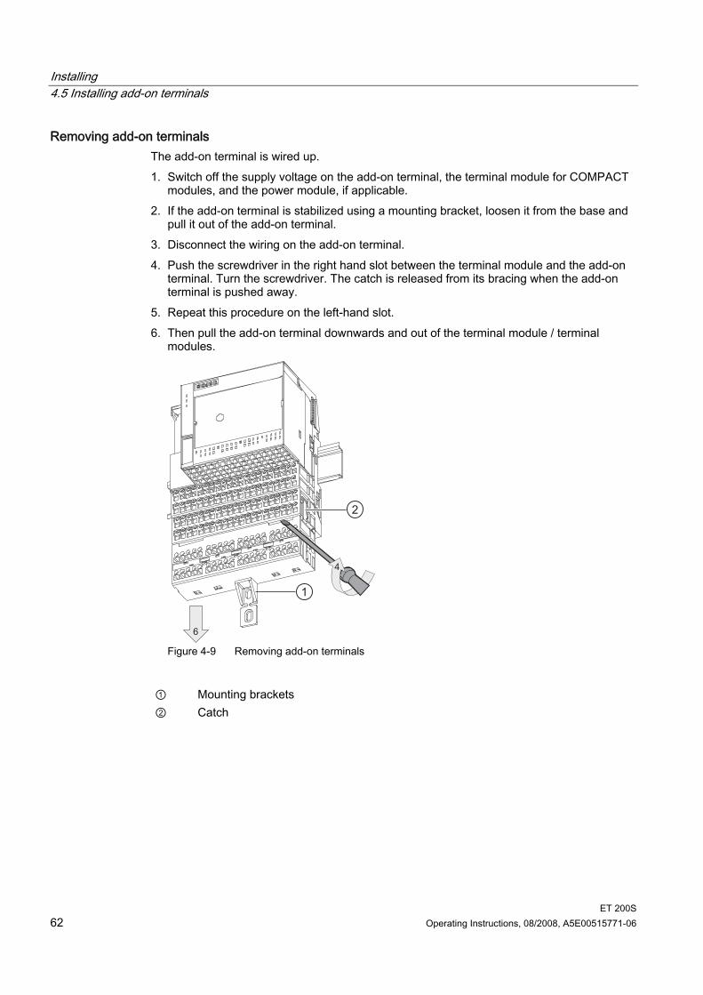
Installing 4.5 Installing add-on terminals
ET 200S 62 Operating Instructions, 08/2008, A5E00515771-06
Removing add-on terminals The add-on terminal is wired up. 1. Switch off the supply voltage on the add-on terminal, the terminal module for COMPACT
modules, and the power module, if applicable. 2. If the add-on terminal is stabilized using a mounting bracket, loosen it from the base and
pull it out of the add-on terminal. 3. Disconnect the wiring on the add-on terminal. 4. Push the screwdriver in the right hand slot between the terminal module and the add-on
terminal. Turn the screwdriver. The catch is released from its bracing when the add-on terminal is pushed away.
5. Repeat this procedure on the left-hand slot. 6. Then pull the add-on terminal downwards and out of the terminal module / terminal
modules.
Figure 4-9 Removing add-on terminals
① Mounting brackets ② Catch
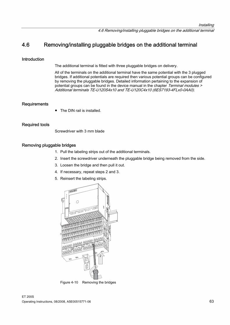
Installing 4.6 Removing/installing pluggable bridges on the additional terminal
ET 200S Operating Instructions, 08/2008, A5E00515771-06 63
4.6 Removing/installing pluggable bridges on the additional terminal
Introduction The additional terminal is fitted with three pluggable bridges on delivery. All of the terminals on the additional terminal have the same potential with the 3 plugged bridges. If additional potentials are required then various potential groups can be configured by removing the pluggable bridges. Detailed information pertaining to the expansion of potential groups can be found in the device manual in the chapter Terminal modules > Additional terminals TE-U120S4x10 and TE-U120C4x10 (6ES7193-4FLx0-0AA0).
Requirements The DIN rail is installed.
Required tools Screwdriver with 3 mm blade
Removing pluggable bridges 1. Pull the labeling strips out of the additional terminals. 2. Insert the screwdriver underneath the pluggable bridge being removed from the side. 3. Loosen the bridge and then pull it out. 4. If necessary, repeat steps 2 and 3. 5. Reinsert the labeling strips.
Figure 4-10 Removing the bridges
Installing 4.7 Replacing the terminal box on the terminal module
ET 200S 64 Operating Instructions, 08/2008, A5E00515771-06
Installing pluggable bridges 1. Pull the labeling strips out of the additional terminals. 2. Insert the pluggable bridge between the potential groups being connected. 3. If necessary, repeat step 2. 4. Reinsert the labeling strips. The inserted bridges can be recognized by their labeling strips.
4.7 Replacing the terminal box on the terminal module
Introduction The terminal box is part of the terminal module. If necessary, you can replace the terminal box. It is not necessary to remove the terminal module.
Requirements The terminal module is installed, wired, and fitted with a COMPACTmodule, power
module, or electronic module.
Required tools Screwdriver with 3 mm blade
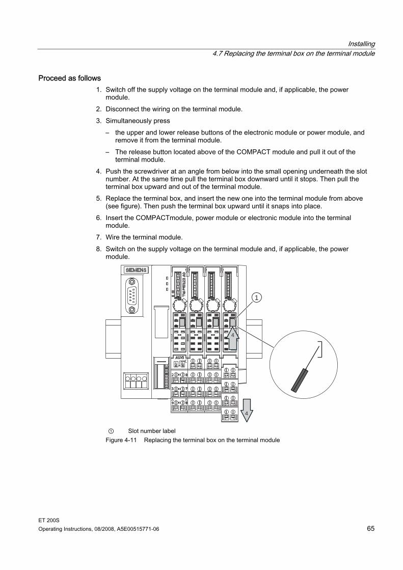
Installing 4.7 Replacing the terminal box on the terminal module
ET 200S Operating Instructions, 08/2008, A5E00515771-06 65
Proceed as follows 1. Switch off the supply voltage on the terminal module and, if applicable, the power
module. 2. Disconnect the wiring on the terminal module. 3. Simultaneously press
– the upper and lower release buttons of the electronic module or power module, and remove it from the terminal module.
– The release button located above of the COMPACT module and pull it out of the terminal module.
4. Push the screwdriver at an angle from below into the small opening underneath the slot number. At the same time pull the terminal box downward until it stops. Then pull the terminal box upward and out of the terminal module.
5. Replace the terminal box, and insert the new one into the terminal module from above (see figure). Then push the terminal box upward until it snaps into place.
6. Insert the COMPACTmodule, power module or electronic module into the terminal module.
7. Wire the terminal module. 8. Switch on the supply voltage on the terminal module and, if applicable, the power
module.
4
4
1
① Slot number label
Figure 4-11 Replacing the terminal box on the terminal module
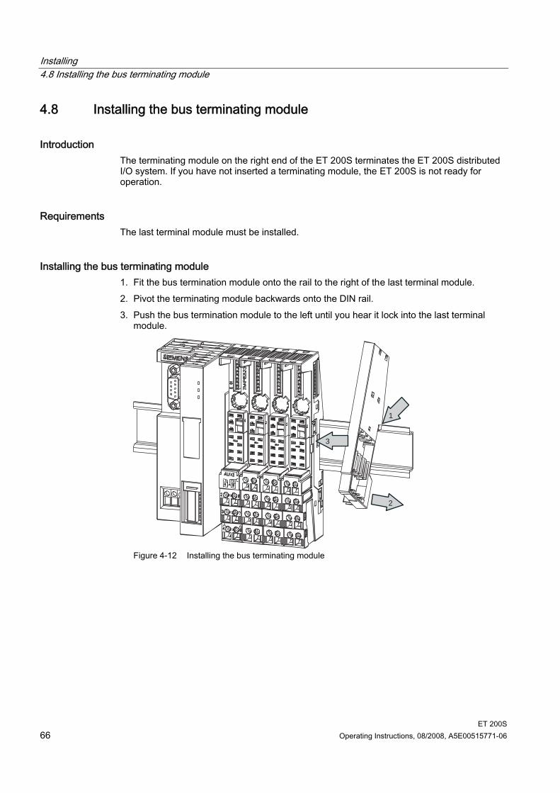
Installing 4.8 Installing the bus terminating module
ET 200S 66 Operating Instructions, 08/2008, A5E00515771-06
4.8 Installing the bus terminating module
Introduction The terminating module on the right end of the ET 200S terminates the ET 200S distributed I/O system. If you have not inserted a terminating module, the ET 200S is not ready for operation.
Requirements The last terminal module must be installed.
Installing the bus terminating module 1. Fit the bus termination module onto the rail to the right of the last terminal module. 2. Pivot the terminating module backwards onto the DIN rail. 3. Push the bus termination module to the left until you hear it lock into the last terminal
module.
1
2
3
Figure 4-12 Installing the bus terminating module
Installing 4.9 Installing the shield contact
ET 200S Operating Instructions, 08/2008, A5E00515771-06 67
Removing the Bus Terminating Module 1. Use a screwdriver to push the slider on the last terminal module down until the
mechanism stops, and move the terminating module to the right. 2. Pivot the terminating module so that it comes off the DIN rail.
Note If • the terminating module of the ET 200S is removed and remounted under voltage, or • the ET 200S backplane bus is interrupted during operation, e. g. at a terminal module,
and then restored to function, the complete power supply of the ET 200S must be switched off and on again in order to achieve a defined station status.
4.9 Installing the shield contact
Introduction You need the shield contact to connect cable shields (for example, analog electronic
modules, 1COUNT 24V/100kHz electronic module and 1SSI electronic module). Fit the shield connection on the terminal module. The shield connection consists of a shield connection element, a power bus (3 x 10 mm),
a shield clamp, and a grounding terminal.
Requirements The terminal modules are installed.
Required tools Screwdriver with 3 mm blade Metal-cutting saw
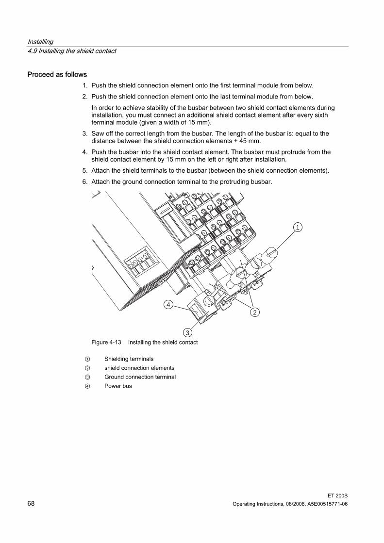
Installing 4.9 Installing the shield contact
ET 200S 68 Operating Instructions, 08/2008, A5E00515771-06
Proceed as follows 1. Push the shield connection element onto the first terminal module from below. 2. Push the shield connection element onto the last terminal module from below.
In order to achieve stability of the busbar between two shield contact elements during installation, you must connect an additional shield contact element after every sixth terminal module (given a width of 15 mm).
3. Saw off the correct length from the busbar. The length of the busbar is: equal to the distance between the shield connection elements + 45 mm.
4. Push the busbar into the shield contact element. The busbar must protrude from the shield contact element by 15 mm on the left or right after installation.
5. Attach the shield terminals to the busbar (between the shield connection elements). 6. Attach the ground connection terminal to the protruding busbar.
1
2
3
4
Figure 4-13 Installing the shield contact
① Shielding terminals ② shield connection elements ③ Ground connection terminal ④ Power bus
Installing 4.10 Applying slot number labels and color identification labels
ET 200S Operating Instructions, 08/2008, A5E00515771-06 69
4.10 Applying slot number labels and color identification labels
Introduction The slot number labels identify the individual I/O modules with a slot (1 to 63). The color identification labels permit individual color coding of the terminals in
accordance with company or national conventions. The color identification labels are available in white, red, blue, brown, yellow, yellow-green, and turquoise. Each terminal on the terminal module can be fitted with a color identification label.
The slot number labels and color identification labels are applied onto the terminal modules. – Position of the slot number plate: below the coding element on the terminal module. – Position of the color-coding plates: directly next to each terminal on the terminal box.
Requirements The terminal modules are installed. You can only fit the slot number labels when no electronics modules are installed. The terminal modules should not be wired when you apply the color identification labels.
Required tools 3 mm screwdriver (for removal only)
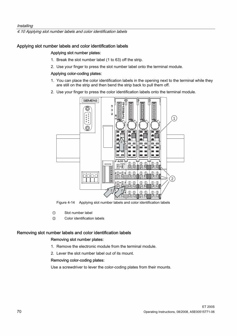
Installing 4.10 Applying slot number labels and color identification labels
ET 200S 70 Operating Instructions, 08/2008, A5E00515771-06
Applying slot number labels and color identification labels Applying slot number plates: 1. Break the slot number label (1 to 63) off the strip. 2. Use your finger to press the slot number label onto the terminal module. Applying color-coding plates: 1. You can place the color identification labels in the opening next to the terminal while they
are still on the strip and then bend the strip back to pull them off. 2. Use your finger to press the color identification labels onto the terminal module.
1
2
2
22
Figure 4-14 Applying slot number labels and color identification labels
① Slot number label ② Color identification labels
Removing slot number labels and color identification labels Removing slot number plates: 1. Remove the electronic module from the terminal module. 2. Lever the slot number label out of its mount. Removing color-coding plates: Use a screwdriver to lever the color-coding plates from their mounts.
Installing 4.11 Mounting Color Identification Labels for ET 200S and ET 200S COMPACT
ET 200S Operating Instructions, 08/2008, A5E00515771-06 71
4.11 Mounting Color Identification Labels for ET 200S and ET 200S COMPACT
Properties Color-coded labels allow terminals to be identified in the colors white, red, blue, yellow,
yellow-green, and turquoise. Color-coded labels can be used at the terminal modules TM-E, TM-P and TM-C of the
ET 200S and ET 200S COMPACT. The packaging unit encompasses 200 color-coded labels (10 star-shaped mounts with 20
piece each).
Introduction You can provide every terminal at a terminal module with a color-coded label. The color-coded labels are mounted on the terminal module. Color-coded labels are positioned directly next to the terminal.
Requirement The terminal module should not be wired in order to make mounting of the color-coded labels easier.
Required tools Screwdriver with 3.5 mm blade
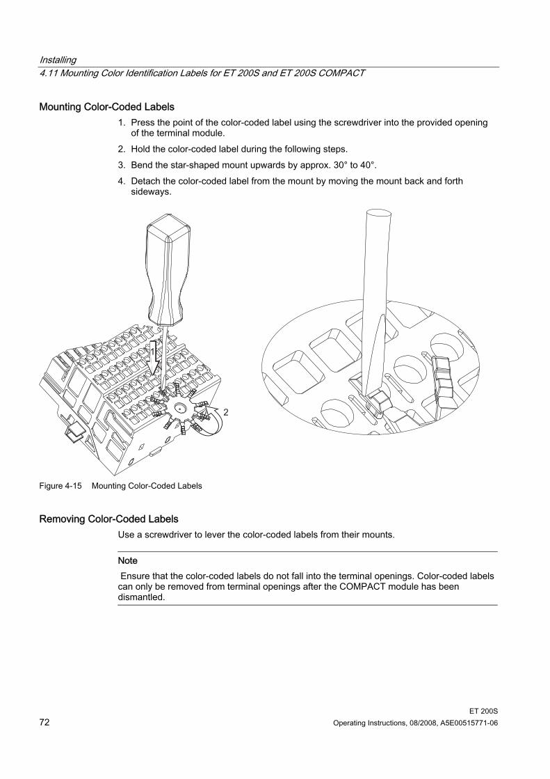
Installing 4.11 Mounting Color Identification Labels for ET 200S and ET 200S COMPACT
ET 200S 72 Operating Instructions, 08/2008, A5E00515771-06
Mounting Color-Coded Labels 1. Press the point of the color-coded label using the screwdriver into the provided opening
of the terminal module. 2. Hold the color-coded label during the following steps. 3. Bend the star-shaped mount upwards by approx. 30° to 40°. 4. Detach the color-coded label from the mount by moving the mount back and forth
sideways.
Figure 4-15 Mounting Color-Coded Labels
Removing Color-Coded Labels Use a screwdriver to lever the color-coded labels from their mounts.
Note Ensure that the color-coded labels do not fall into the terminal openings. Color-coded labels can only be removed from terminal openings after the COMPACT module has been dismantled.
ET 200S Operating Instructions, 08/2008, A5E00515771-06 73
Wiring and assembly 55.1 General rules and regulations for operating the ET 200S
Introduction When operating the ET 200S distributed I/O system as part of a plant or system, special rules and regulations have to be followed depending on the field of application. This chapter provides an overview of the most important rules you must observe when integrating the ET 200S distributed I/O system into a plant or system.
Specific application Please observe the safety and accident prevention regulations applying to specific applications (e.g. machine protection guidelines).
EMERGENCY-STOP devices EMERGENCY-STOP devices according to IEC 204 (coincides with VDE 113) must remain effective during all operating modes of the plant or system.
System Startup after Certain Events The table below shows what you have to observe when restarting a plant after specific events.
If there is ... then ... Start-up following a power drop or failure Startup of the ET 200S follows an interruption of the bus communication
No dangerous operating states may occur. If necessary actuate an EMERGENCY-STOP!
Startup follows unlocking of the emergency stop device
There must not be an uncontrolled or undefined startup.
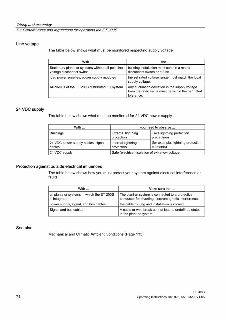
Wiring and assembly 5.1 General rules and regulations for operating the ET 200S
ET 200S 74 Operating Instructions, 08/2008, A5E00515771-06
Line voltage The table below shows what must be monitored respecting supply voltage.
With ... the ... Stationary plants or systems without all-pole line voltage disconnect switch
building installation must contain a mains disconnect switch or a fuse.
load power supplies, power supply modules the set rated voltage range must match the local supply voltage.
All circuits of the ET 200S distributed I/O system Any fluctuation/deviation in the supply voltage from the rated value must be within the permitted tolerance.
24 VDC supply The table below shows what must be monitored for 24 VDC power supply.
With ... you need to observe ... Buildings External lightning
protection 24 VDC power supply cables, signal cables
internal lightning protection
Take lightning protection precautions (for example, lightning protection elements)
24 VDC supply Safe (electrical) isolation of extra-low voltage
Protection against outside electrical influences The table below shows how you must protect your system against electrical interference or faults.
With ... Make sure that ... all plants or systems in which the ET 200S is integrated,
The plant or system is connected to a protective conductor for diverting electromagnetic interference.
power supply, signal, and bus cables the cable routing and installation is correct. Signal and bus cables A cable or wire break cannot lead to undefined states
in the plant or system.
See also Mechanical and Climatic Ambient Conditions (Page 133)
Wiring and assembly 5.2 Operating the ET 200S on a grounded incoming supply
ET 200S Operating Instructions, 08/2008, A5E00515771-06 75
5.2 Operating the ET 200S on a grounded incoming supply
Introduction In this section, you will find information on the overall configuration of an ET 200S distributed I/O system on a grounded incoming supply (TN-S system). The specific subjects discussed are: Disconnecting devices, short-circuit and overload protection to VDE 0100 and VDE 0113 Load voltage supplies and load circuits.
Grounded incoming supply In grounded incoming supplies, the neutral conductor of the supply line is grounded. A single fault between a live conductor and ground or a grounded part of the installation results in tripping of the protective devices.
Safety isolation Safe electrical isolation must be provided for: Modules that require supply with voltages ≤ 60 VDC or ≤ 25 VAC. 24 VDC load circuits
Configuring the ET 200S with ungrounded reference potential As of IM151-1 BASIC (6ES7151-1CA00-0AB0), IM151-1 STANDARD (6ES7151-1AA02-0AB0), IM151-1 FO STANDARD (6ES7151-1AB01-0AB0), IM151-1 HIGH FEATURE (6ES7151-1BA00-0AB0), IM151-3 PN, IM151-3 PN HIGH FEATURE and IM151-1 COMPACT, the ground M of the nominal supply voltage of the IM151-x is connected to the mounting rail (grounding conductor) via an RC combination, thus making a ground-free installation is possible. To divert interference current, the reference potential of the IM151-x is connected internally to the mounting rail (protective conductor) via an RC combination (R = 10 MΩ / C = 22 nF). High-frequency interference currents are thus discharged, and static charge is prevented.
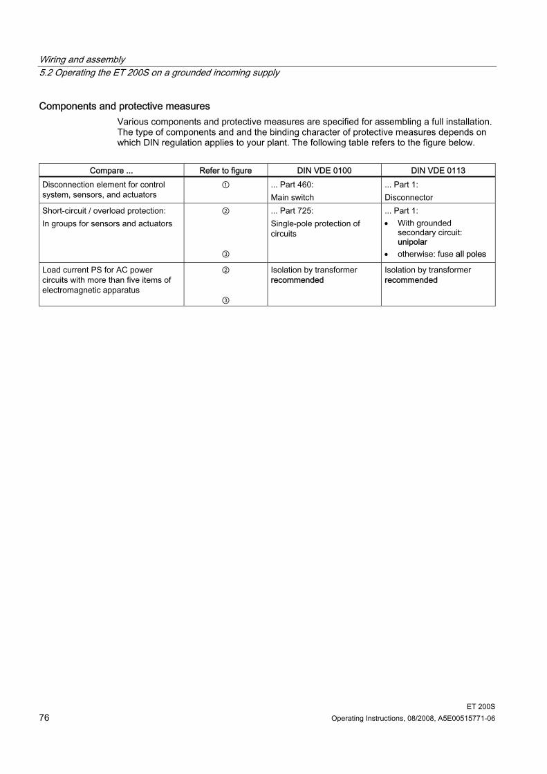
Wiring and assembly 5.2 Operating the ET 200S on a grounded incoming supply
ET 200S 76 Operating Instructions, 08/2008, A5E00515771-06
Components and protective measures Various components and protective measures are specified for assembling a full installation. The type of components and and the binding character of protective measures depends on which DIN regulation applies to your plant. The following table refers to the figure below.
Compare ... Refer to figure DIN VDE 0100 DIN VDE 0113
Disconnection element for control system, sensors, and actuators
① ... Part 460: Main switch
... Part 1: Disconnector
Short-circuit / overload protection: In groups for sensors and actuators
②
③
... Part 725: Single-pole protection of circuits
... Part 1: • With grounded
secondary circuit: unipolar
• otherwise: fuse all poles
Load current PS for AC power circuits with more than five items of electromagnetic apparatus
②
③
Isolation by transformer recommended
Isolation by transformer recommended
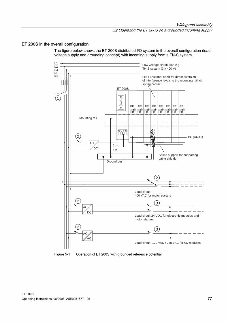
Wiring and assembly 5.2 Operating the ET 200S on a grounded incoming supply
ET 200S Operating Instructions, 08/2008, A5E00515771-06 77
ET 200S in the overall configuration The figure below shows the ET 200S distributed I/O system in the overall configuration (load voltage supply and grounding concept) with incoming supply from a TN-S system.
1
2
2
2
2
3
3
Low voltage distribution e.g.TN-S system (3 x 400 V)
FE: Functional earth for direct diversionof interference levels to the mounting rail via spring contact
Shield support for supportingcable shields
Ground bus
Mounting rail
Load circuit400 VAC for motor starters
Load circuit 24 VDC for electronic modules and motor starters
Load circuit 120 VAC / 230 VAC for AC modules
FE FE FE FE FE FE FE FE
PE (AUX1)
L1 L2 L3 N
AC
DC
PE
AC DC
1L+ 1M
ET 200S
AC AC
Figure 5-1 Operation of ET 200S with grounded reference potential
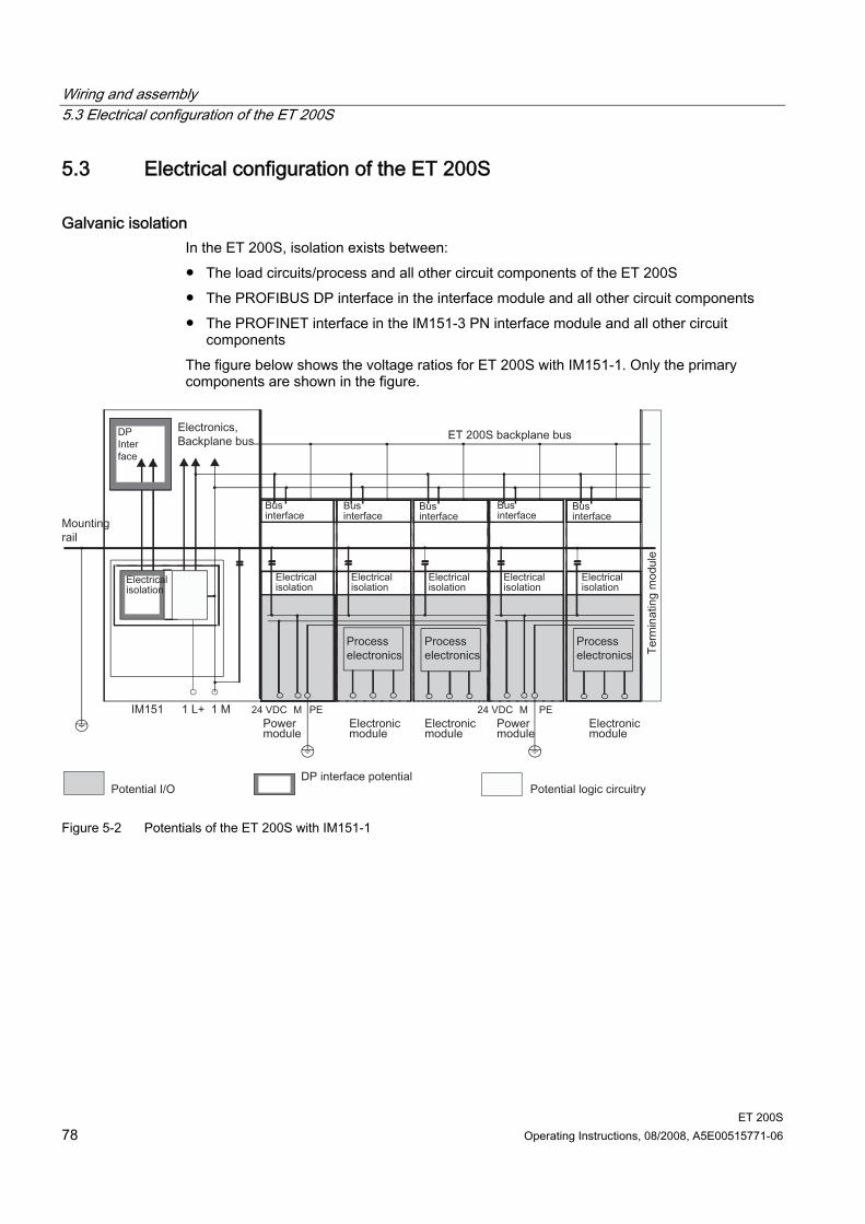
Wiring and assembly 5.3 Electrical configuration of the ET 200S
ET 200S 78 Operating Instructions, 08/2008, A5E00515771-06
5.3 Electrical configuration of the ET 200S
Galvanic isolation In the ET 200S, isolation exists between: The load circuits/process and all other circuit components of the ET 200S The PROFIBUS DP interface in the interface module and all other circuit components The PROFINET interface in the IM151-3 PN interface module and all other circuit
components The figure below shows the voltage ratios for ET 200S with IM151-1. Only the primary components are shown in the figure.
Figure 5-2 Potentials of the ET 200S with IM151-1
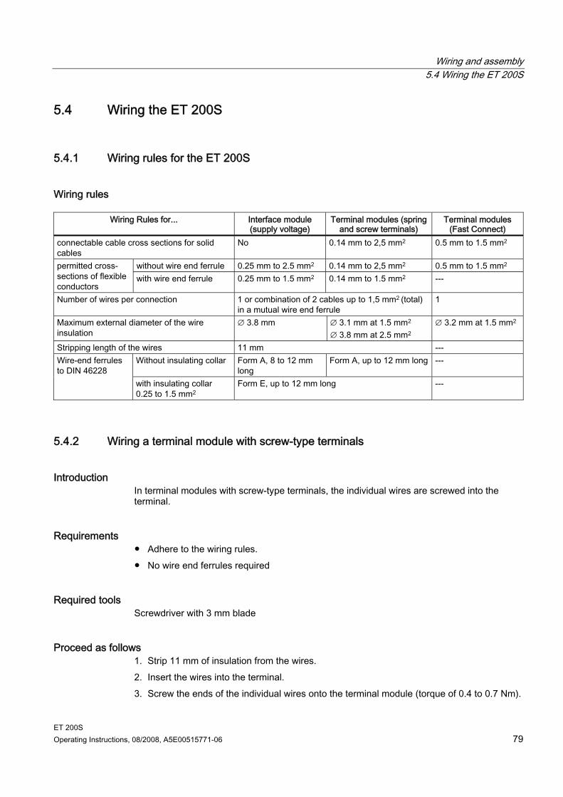
Wiring and assembly 5.4 Wiring the ET 200S
ET 200S Operating Instructions, 08/2008, A5E00515771-06 79
5.4 Wiring the ET 200S
5.4.1 Wiring rules for the ET 200S
Wiring rules
Wiring Rules for... Interface module (supply voltage)
Terminal modules (spring and screw terminals)
Terminal modules (Fast Connect)
connectable cable cross sections for solid cables
No 0.14 mm to 2,5 mm2 0.5 mm to 1.5 mm2
without wire end ferrule 0.25 mm to 2.5 mm2 0.14 mm to 2,5 mm2 0.5 mm to 1.5 mm2 permitted cross-sections of flexible conductors
with wire end ferrule 0.25 mm to 1.5 mm2 0.14 mm to 1.5 mm2 ---
Number of wires per connection 1 or combination of 2 cables up to 1,5 mm2 (total) in a mutual wire end ferrule
1
Maximum external diameter of the wire insulation
∅ 3.8 mm ∅ 3.1 mm at 1.5 mm2 ∅ 3.8 mm at 2.5 mm2
∅ 3.2 mm at 1.5 mm2
Stripping length of the wires 11 mm --- Without insulating collar Form A, 8 to 12 mm
long Form A, up to 12 mm long --- Wire-end ferrules
to DIN 46228 with insulating collar 0.25 to 1.5 mm2
Form E, up to 12 mm long ---
5.4.2 Wiring a terminal module with screw-type terminals
Introduction In terminal modules with screw-type terminals, the individual wires are screwed into the terminal.
Requirements Adhere to the wiring rules. No wire end ferrules required
Required tools Screwdriver with 3 mm blade
Proceed as follows 1. Strip 11 mm of insulation from the wires. 2. Insert the wires into the terminal. 3. Screw the ends of the individual wires onto the terminal module (torque of 0.4 to 0.7 Nm).

Wiring and assembly 5.4 Wiring the ET 200S
ET 200S 80 Operating Instructions, 08/2008, A5E00515771-06
5.4.3 Wiring a Terminal Module with Spring Terminals
Introduction When wiring terminal modules with spring terminals, the wires are secured in the terminal simply by inserting them into the terminal.
Requirements Follow the wiring rules.
Required tools Screwdriver with 3 mm blade
Procedure 1. Strip 11 mm of insulation from the wires. 2. Insert the screwdriver in the upper (round) opening of the terminal. 3. Insert the wire until it stops in the lower (square) opening of the terminal. 4. Release the terminal by pushing the screwdriver into the opening. 5. Push the wire into the released spring terminal, and pull the screwdriver out.
Figure 5-3 Wiring with Spring Terminals
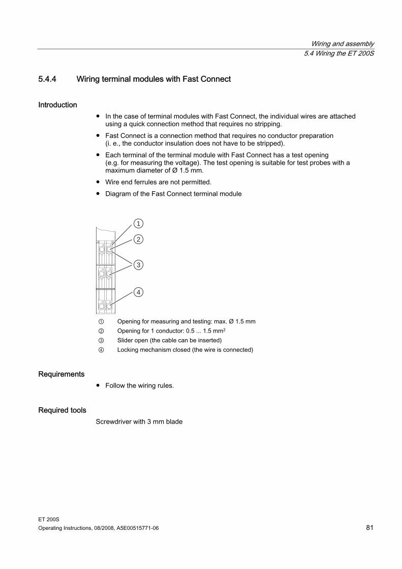
Wiring and assembly 5.4 Wiring the ET 200S
ET 200S Operating Instructions, 08/2008, A5E00515771-06 81
5.4.4 Wiring terminal modules with Fast Connect
Introduction In the case of terminal modules with Fast Connect, the individual wires are attached
using a quick connection method that requires no stripping. Fast Connect is a connection method that requires no conductor preparation
(i. e., the conductor insulation does not have to be stripped). Each terminal of the terminal module with Fast Connect has a test opening
(e.g. for measuring the voltage). The test opening is suitable for test probes with a maximum diameter of Ø 1.5 mm.
Wire end ferrules are not permitted. Diagram of the Fast Connect terminal module
1
2
3
4
① Opening for measuring and testing: max. Ø 1.5 mm ② Opening for 1 conductor: 0.5 ... 1.5 mm2 ③ Slider open (the cable can be inserted) ④ Locking mechanism closed (the wire is connected)
Requirements Follow the wiring rules.
Required tools Screwdriver with 3 mm blade
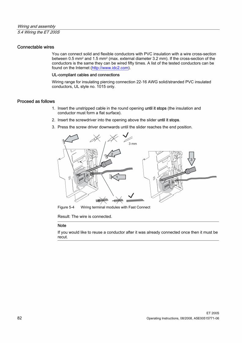
Wiring and assembly 5.4 Wiring the ET 200S
ET 200S 82 Operating Instructions, 08/2008, A5E00515771-06
Connectable wires You can connect solid and flexible conductors with PVC insulation with a wire cross-section between 0.5 mm2 and 1.5 mm2 (max. external diameter 3.2 mm). If the cross-section of the conductors is the same they can be wired fifty times. A list of the tested conductors can be found on the Internet (http://www.idc2.com). UL-compliant cables and connections Wiring range for insulating piercing connection 22-16 AWG solid/stranded PVC insulated conductors, UL style no. 1015 only.
Proceed as follows 1. Insert the unstripped cable in the round opening until it stops (the insulation and
conductor must form a flat surface). 2. Insert the screwdriver into the opening above the slider until it stops. 3. Press the screw driver downwards until the slider reaches the end position.
Figure 5-4 Wiring terminal modules with Fast Connect
Result: The wire is connected.
Note If you would like to reuse a conductor after it was already connected once then it must be recut.
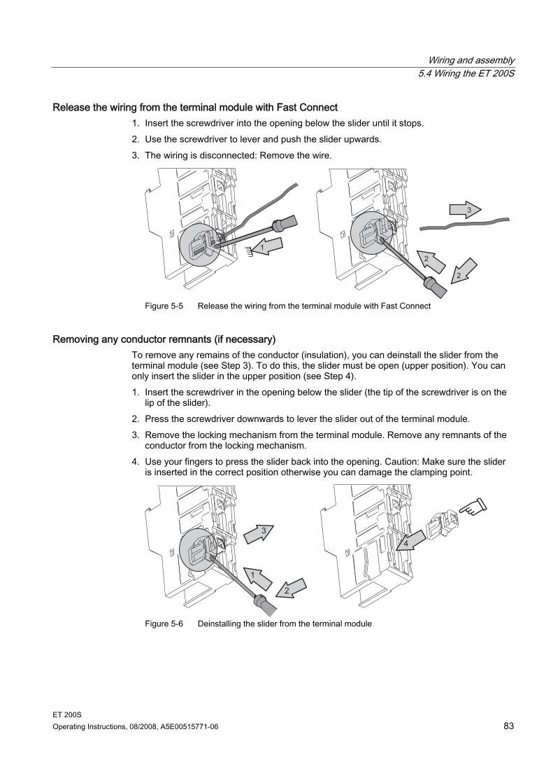
Wiring and assembly 5.4 Wiring the ET 200S
ET 200S Operating Instructions, 08/2008, A5E00515771-06 83
Release the wiring from the terminal module with Fast Connect 1. Insert the screwdriver into the opening below the slider until it stops. 2. Use the screwdriver to lever and push the slider upwards. 3. The wiring is disconnected: Remove the wire.
Figure 5-5 Release the wiring from the terminal module with Fast Connect
Removing any conductor remnants (if necessary) To remove any remains of the conductor (insulation), you can deinstall the slider from the terminal module (see Step 3). To do this, the slider must be open (upper position). You can only insert the slider in the upper position (see Step 4). 1. Insert the screwdriver in the opening below the slider (the tip of the screwdriver is on the
lip of the slider). 2. Press the screwdriver downwards to lever the slider out of the terminal module. 3. Remove the locking mechanism from the terminal module. Remove any remnants of the
conductor from the locking mechanism. 4. Use your fingers to press the slider back into the opening. Caution: Make sure the slider
is inserted in the correct position otherwise you can damage the clamping point.
Figure 5-6 Deinstalling the slider from the terminal module
Wiring and assembly 5.4 Wiring the ET 200S
ET 200S 84 Operating Instructions, 08/2008, A5E00515771-06
5.4.5 Wiring terminal modules
Introduction The ET 200S distributed I/O system incorporates terminal modules for power modules, electronic modules and COMPACT modules: Connect the supply/load voltage for the respective voltage group for the power terminal
modules. Terminal modules for electronic modules connect the ET 200S with the process. With the terminal modules for electronic modules you can connect cable shielding by
means of a shield connection. For terminal modules for COMPACT modules, connect:
– the supply voltage for the interface part – the load voltage for the relevant voltage group – the connections for the integrated peripherals with the process
(with the help of add-on terminals for 3- and 4-conductor technology)
Requirements You must wire the terminal modules with the supply/load voltage switched off at the
power module and the load voltage switched off at the electronic module. Wire terminal modules for COMPACT modules with the supply voltage for the interface
part switched off and the supply/load voltage for the potential groups switched off. Follow the wiring rules.
Required tools Screwdriver with 3 mm blade
Wiring and assembly 5.4 Wiring the ET 200S
ET 200S Operating Instructions, 08/2008, A5E00515771-06 85
Wiring terminal modules for power modules The terminal assignment of the terminal module depends on which power module is inserted. You can find information regarding the terminal and power modules in the ET 200S device manual.
Wiring terminal modules for digital, analog, and technological modules The terminal assignment of the terminal module depends on which electronic module is inserted. You can find information regarding the terminal and electronic modules in the ET 200S device manual. You can find information about technological modules in the Technological Functions manual.
Wiring terminal modules for COMPACT modules The terminal assignment of the terminal module depends on which COMPACT module is inserted. You can find information regarding the terminal and COMPACT modules in the chapter entitled COMPACT- Modules and in the ET 200S device manual.
Connecting the Cable Shielding We recommend that you use the shield connection to connect cable shielding (e.g. in the case of analog electronic modules, the 1COUNT 24V/100kHz electronic module and the 1SSI electronic module.). 1. Remove the insulation material from the area around the shield terminal, and clamp the
cable shield in the shield terminal (above the conductor rail). The shield clamp is suitable for one cable with a maximum diameter of 8 mm or two cables with a maximum diameter of 4 mm each.
2. Tighten the shield terminal (approximately 0.5 Nm) 3. Repeat steps 1 and 2 if you want to connect additional cable shields.
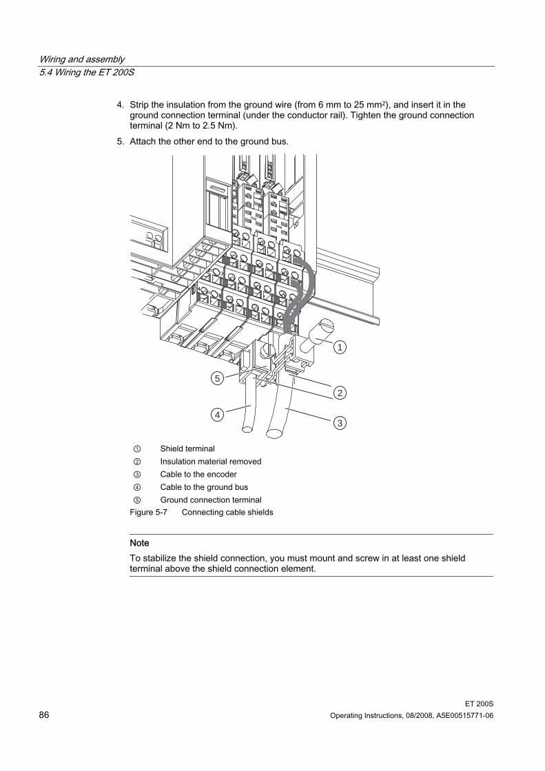
Wiring and assembly 5.4 Wiring the ET 200S
ET 200S 86 Operating Instructions, 08/2008, A5E00515771-06
4. Strip the insulation from the ground wire (from 6 mm to 25 mm2), and insert it in the ground connection terminal (under the conductor rail). Tighten the ground connection terminal (2 Nm to 2.5 Nm).
5. Attach the other end to the ground bus.
1
2
34
5
① Shield terminal ② Insulation material removed ③ Cable to the encoder ④ Cable to the ground bus ⑤ Ground connection terminal
Figure 5-7 Connecting cable shields
Note To stabilize the shield connection, you must mount and screw in at least one shield terminal above the shield connection element.
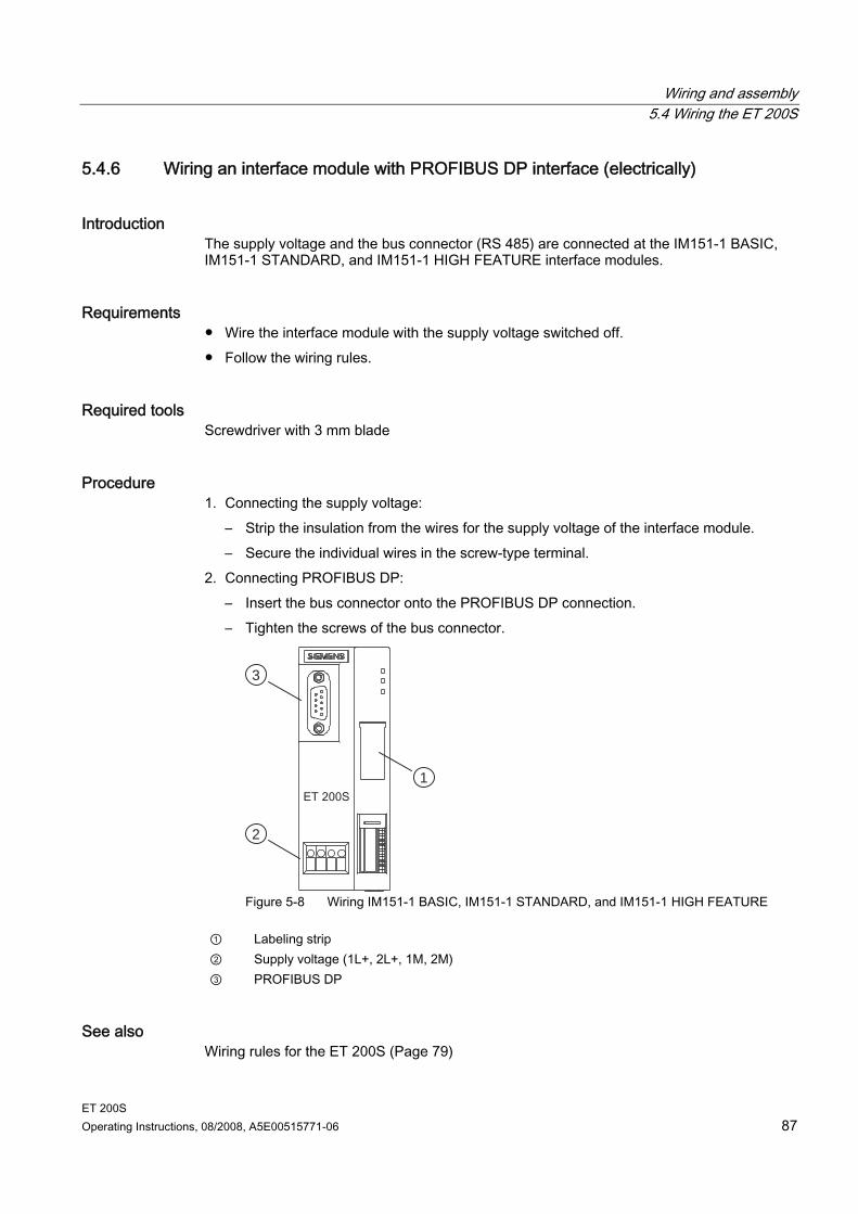
Wiring and assembly 5.4 Wiring the ET 200S
ET 200S Operating Instructions, 08/2008, A5E00515771-06 87
5.4.6 Wiring an interface module with PROFIBUS DP interface (electrically)
Introduction The supply voltage and the bus connector (RS 485) are connected at the IM151-1 BASIC, IM151-1 STANDARD, and IM151-1 HIGH FEATURE interface modules.
Requirements Wire the interface module with the supply voltage switched off. Follow the wiring rules.
Required tools Screwdriver with 3 mm blade
Procedure 1. Connecting the supply voltage:
– Strip the insulation from the wires for the supply voltage of the interface module. – Secure the individual wires in the screw-type terminal.
2. Connecting PROFIBUS DP: – Insert the bus connector onto the PROFIBUS DP connection. – Tighten the screws of the bus connector.
1
2
3
Figure 5-8 Wiring IM151-1 BASIC, IM151-1 STANDARD, and IM151-1 HIGH FEATURE
① Labeling strip ② Supply voltage (1L+, 2L+, 1M, 2M) ③ PROFIBUS DP
See also Wiring rules for the ET 200S (Page 79)
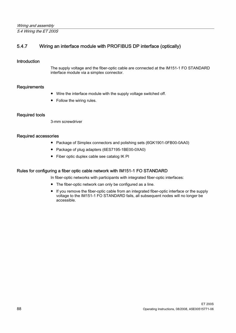
Wiring and assembly 5.4 Wiring the ET 200S
ET 200S 88 Operating Instructions, 08/2008, A5E00515771-06
5.4.7 Wiring an interface module with PROFIBUS DP interface (optically)
Introduction The supply voltage and the fiber-optic cable are connected at the IM151-1 FO STANDARD interface module via a simplex connector.
Requirements Wire the interface module with the supply voltage switched off. Follow the wiring rules.
Required tools 3-mm screwdriver
Required accessories Package of Simplex connectors and polishing sets (6GK1901-0FB00-0AA0) Package of plug adapters (6ES7195-1BE00-0XA0) Fiber optic duplex cable see catalog IK PI
Rules for configuring a fiber optic cable network with IM151-1 FO STANDARD In fiber-optic networks with participants with integrated fiber-optic interfaces: The fiber-optic network can only be configured as a line. If you remove the fiber-optic cable from an integrated fiber-optic interface or the supply
voltage to the IM151-1 FO STANDARD fails, all subsequent nodes will no longer be accessible.
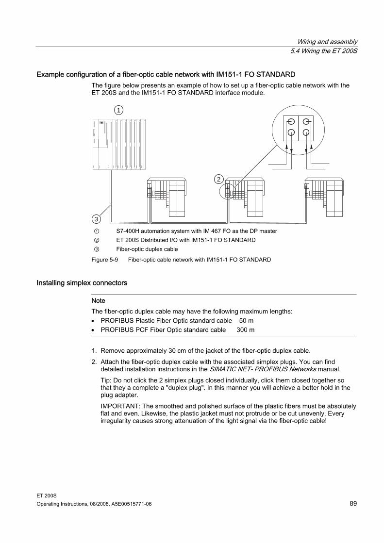
Wiring and assembly 5.4 Wiring the ET 200S
ET 200S Operating Instructions, 08/2008, A5E00515771-06 89
Example configuration of a fiber-optic cable network with IM151-1 FO STANDARD The figure below presents an example of how to set up a fiber-optic cable network with the ET 200S and the IM151-1 FO STANDARD interface module.
1
2
3 ① S7-400H automation system with IM 467 FO as the DP master ② ET 200S Distributed I/O with IM151-1 FO STANDARD ③ Fiber-optic duplex cable
Figure 5-9 Fiber-optic cable network with IM151-1 FO STANDARD
Installing simplex connectors
Note The fiber-optic duplex cable may have the following maximum lengths: • PROFIBUS Plastic Fiber Optic standard cable 50 m • PROFIBUS PCF Fiber Optic standard cable 300 m
1. Remove approximately 30 cm of the jacket of the fiber-optic duplex cable. 2. Attach the fiber-optic duplex cable with the associated simplex plugs. You can find
detailed installation instructions in the SIMATIC NET- PROFIBUS Networks manual. Tip: Do not click the 2 simplex plugs closed individually, click them closed together so that they a complete a "duplex plug". In this manner you will achieve a better hold in the plug adapter. IMPORTANT: The smoothed and polished surface of the plastic fibers must be absolutely flat and even. Likewise, the plastic jacket must not protrude or be cut unevenly. Every irregularity causes strong attenuation of the light signal via the fiber-optic cable!
Wiring and assembly 5.4 Wiring the ET 200S
ET 200S 90 Operating Instructions, 08/2008, A5E00515771-06
3. Place the simplex connectors into the plug adapter for the IM151-1 FO STANDARD interface module and the fiber-optic cable into the designated cable ducts. Snap the plug adapter closed until you can hear clearly that the side panels have engaged. When inserting the plug in the plug adaptor, pay attention to the correct position: Transmitter always up and receiver always down!
1
2
345 ① Plug adapter for IM151-1 FO STANDARD ② Snap the two simplex connectors closed together such that you obtain a "duplex
connector." ③ Tip: Cut the lower wire approx. 10 mm shorter than the upper wire to achieve a better
arrangement of the wiring. ④ Maximum 30 mm bending radius! ⑤ Fiber-optic duplex cable
Bending radius for the fiber-optic cable When placing the fiber-optic duplex core into the plug adapter and routing the cable, be sure not to exceed the permissible bending radius of 30 mm. Refer also to the installation guidelines for fiber-optic cable in the ET 200 Distributed I/O System or SIMATIC NET - PROFIBUS Networks manual.
Reusing fiber-optic cable
Note If you insert previously used fiber-optic cable into the plug adapter, you must shorten both fiber-optic cores by the amount of the curved lengths and reinstall the simplex connectors. This will prevent any attenuation losses caused by re-bent, heavily-stressed portions of the fiber-optic duplex core.
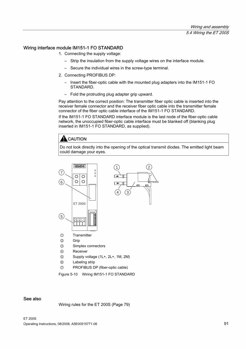
Wiring and assembly 5.4 Wiring the ET 200S
ET 200S Operating Instructions, 08/2008, A5E00515771-06 91
Wiring interface module IM151-1 FO STANDARD 1. Connecting the supply voltage:
– Strip the insulation from the supply voltage wires on the interface module. – Secure the individual wires in the screw-type terminal.
2. Connecting PROFIBUS DP: – Insert the fiber-optic cable with the mounted plug adapters into the IM151-1 FO
STANDARD. – Fold the protruding plug adapter grip upward.
Pay attention to the correct position: The transmitter fiber optic cable is inserted into the receiver female connector and the receiver fiber optic cable into the transmitter female connector of the fiber optic cable interface of the IM151-1 FO STANDARD. If the IM151-1 FO STANDARD interface module is the last node of the fiber-optic cable network, the unoccupied fiber-optic cable interface must be blanked off (blanking plug inserted in IM151-1 FO STANDARD, as supplied).
CAUTION Do not look directly into the opening of the optical transmit diodes. The emitted light beam could damage your eyes.
1 2
34
5
6
7
ET 200S
① Transmitter ② Grip ③ Simplex connectors ④ Receiver ⑤ Supply voltage (1L+, 2L+, 1M, 2M) ⑥ Labeling strip ⑦ PROFIBUS DP (fiber-optic cable)
Figure 5-10 Wiring IM151-1 FO STANDARD
See also Wiring rules for the ET 200S (Page 79)
Wiring and assembly 5.4 Wiring the ET 200S
ET 200S 92 Operating Instructions, 08/2008, A5E00515771-06
5.4.8 Wiring an interface module with PROFINET IO interface (electrically)
Introduction Connect the supply voltage and the bus connectors to the IM151-3 PN interface module.
Requirements Wire the interface module with the supply voltage switched off. Follow the wiring rules.
Note Provide a suitable strain relief for the PROFINET connecting cable.
Note Guideline for setting up modules with PROFINET I/O interfaces You may only operate modules with PROFINET I/O interfaces in LAN networks if all connected nodes are equipped with SELV/PELV power supplies (or have equivalent protection). For linking up to the WAN, a data transfer point is prescribed that guarantees this degree of safety.
Note When using a CPU 315-2 PN/DP or CPU 317-2 PN/DP an industrial-quality switch must be placed directly on the CPU to which the downstream I/O devices must be connected.
Required tools Screwdriver with 3 mm blade Industrial Ethernet Fast Connect stripping tool (6GK1901-1GA00) (stripping tool for
Industrial Ethernet Fast Connect installation cables)
Required accessories PROFINET connector (according to the specifications in the PROFINET Installation
Guide) Industrial Ethernet Fast Connect installation cables
The following are suitable: Fast Connect standard cable 6XV1840-2AH10 Fast Connect trailing cable 6XV1840-3AH10 Fast Connect marine cable 6XV1840-4AH10
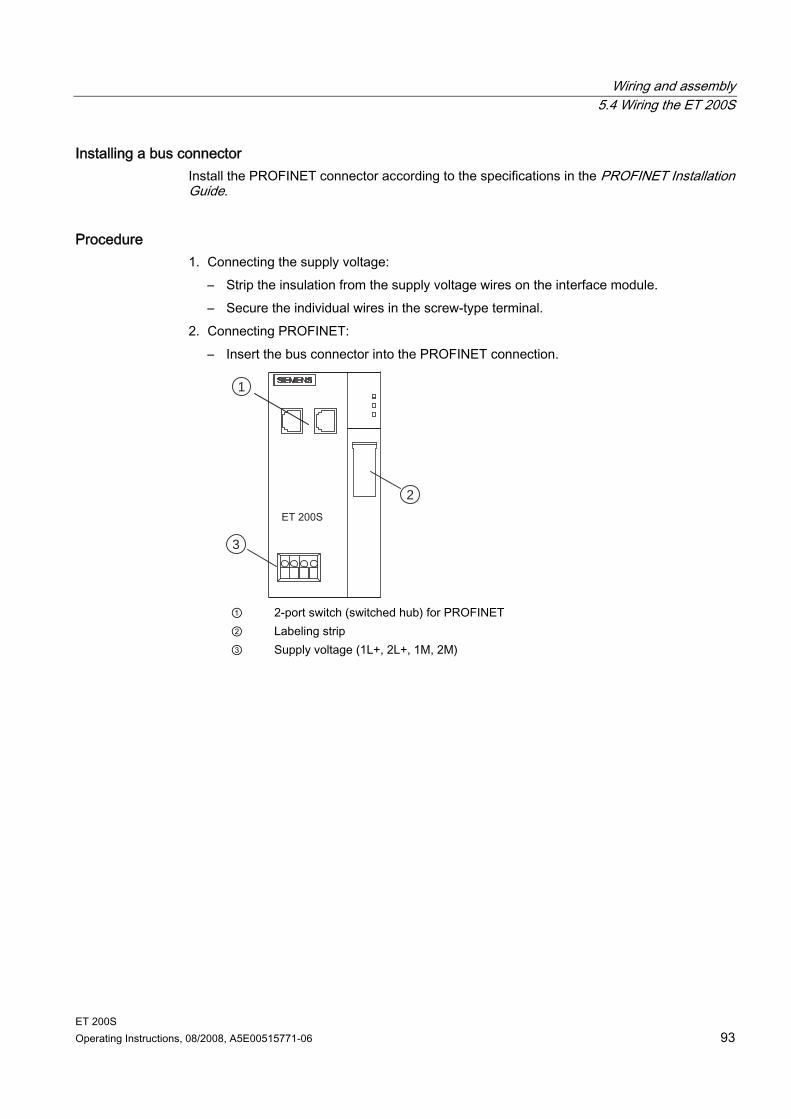
Wiring and assembly 5.4 Wiring the ET 200S
ET 200S Operating Instructions, 08/2008, A5E00515771-06 93
Installing a bus connector Install the PROFINET connector according to the specifications in the PROFINET Installation Guide.
Procedure 1. Connecting the supply voltage:
– Strip the insulation from the supply voltage wires on the interface module. – Secure the individual wires in the screw-type terminal.
2. Connecting PROFINET: – Insert the bus connector into the PROFINET connection.
1
2
3
① 2-port switch (switched hub) for PROFINET ② Labeling strip ③ Supply voltage (1L+, 2L+, 1M, 2M)
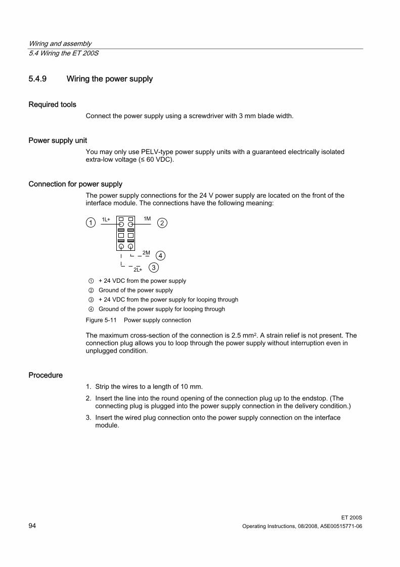
Wiring and assembly 5.4 Wiring the ET 200S
ET 200S 94 Operating Instructions, 08/2008, A5E00515771-06
5.4.9 Wiring the power supply
Required tools Connect the power supply using a screwdriver with 3 mm blade width.
Power supply unit You may only use PELV-type power supply units with a guaranteed electrically isolated extra-low voltage (≤ 60 VDC).
Connection for power supply The power supply connections for the 24 V power supply are located on the front of the interface module. The connections have the following meaning:
① + 24 VDC from the power supply ② Ground of the power supply ③ + 24 VDC from the power supply for looping through ④ Ground of the power supply for looping through
Figure 5-11 Power supply connection
The maximum cross-section of the connection is 2.5 mm2. A strain relief is not present. The connection plug allows you to loop through the power supply without interruption even in unplugged condition.
Procedure 1. Strip the wires to a length of 10 mm. 2. Insert the line into the round opening of the connection plug up to the endstop. (The
connecting plug is plugged into the power supply connection in the delivery condition.) 3. Insert the wired plug connection onto the power supply connection on the interface
module.
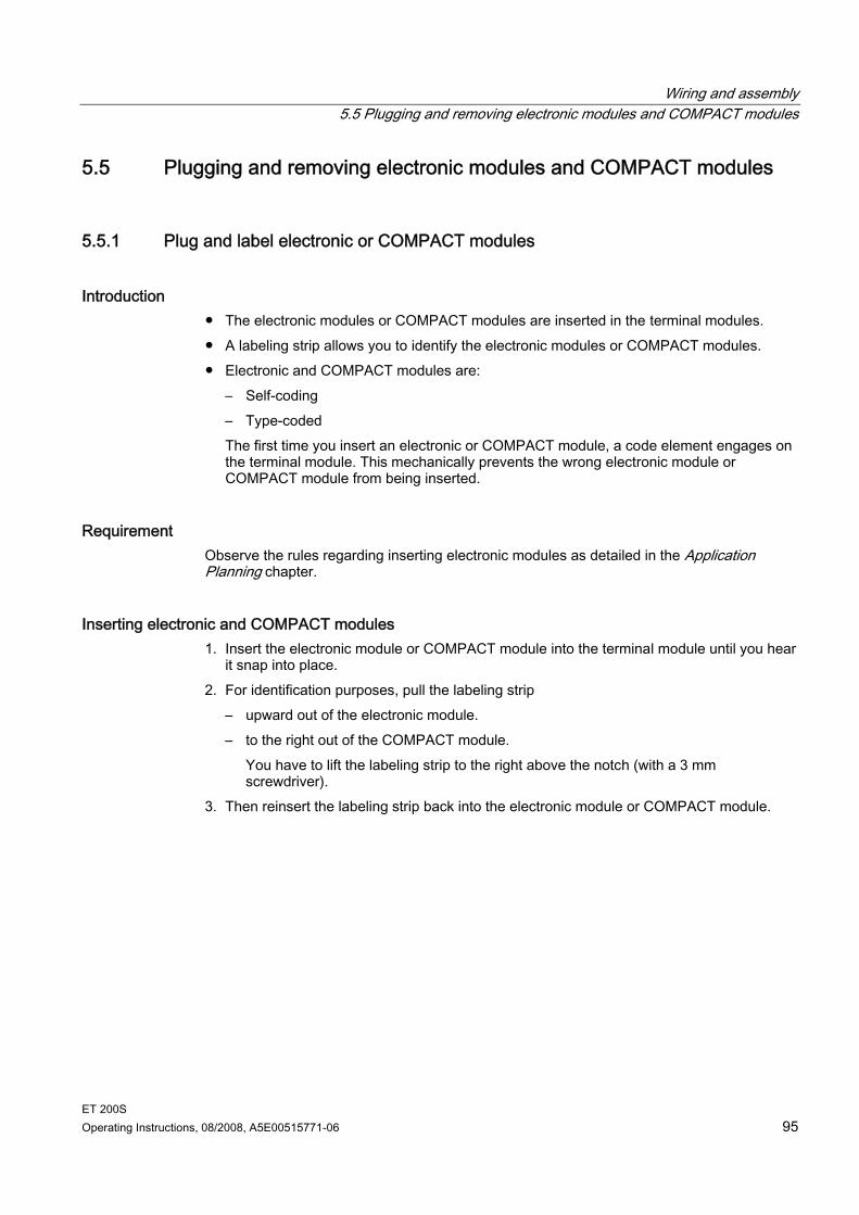
Wiring and assembly 5.5 Plugging and removing electronic modules and COMPACT modules
ET 200S Operating Instructions, 08/2008, A5E00515771-06 95
5.5 Plugging and removing electronic modules and COMPACT modules
5.5.1 Plug and label electronic or COMPACT modules
Introduction The electronic modules or COMPACT modules are inserted in the terminal modules. A labeling strip allows you to identify the electronic modules or COMPACT modules. Electronic and COMPACT modules are:
– Self-coding – Type-coded The first time you insert an electronic or COMPACT module, a code element engages on the terminal module. This mechanically prevents the wrong electronic module or COMPACT module from being inserted.
Requirement Observe the rules regarding inserting electronic modules as detailed in the Application Planning chapter.
Inserting electronic and COMPACT modules 1. Insert the electronic module or COMPACT module into the terminal module until you hear
it snap into place. 2. For identification purposes, pull the labeling strip
– upward out of the electronic module. – to the right out of the COMPACT module.
You have to lift the labeling strip to the right above the notch (with a 3 mm screwdriver).
3. Then reinsert the labeling strip back into the electronic module or COMPACT module.
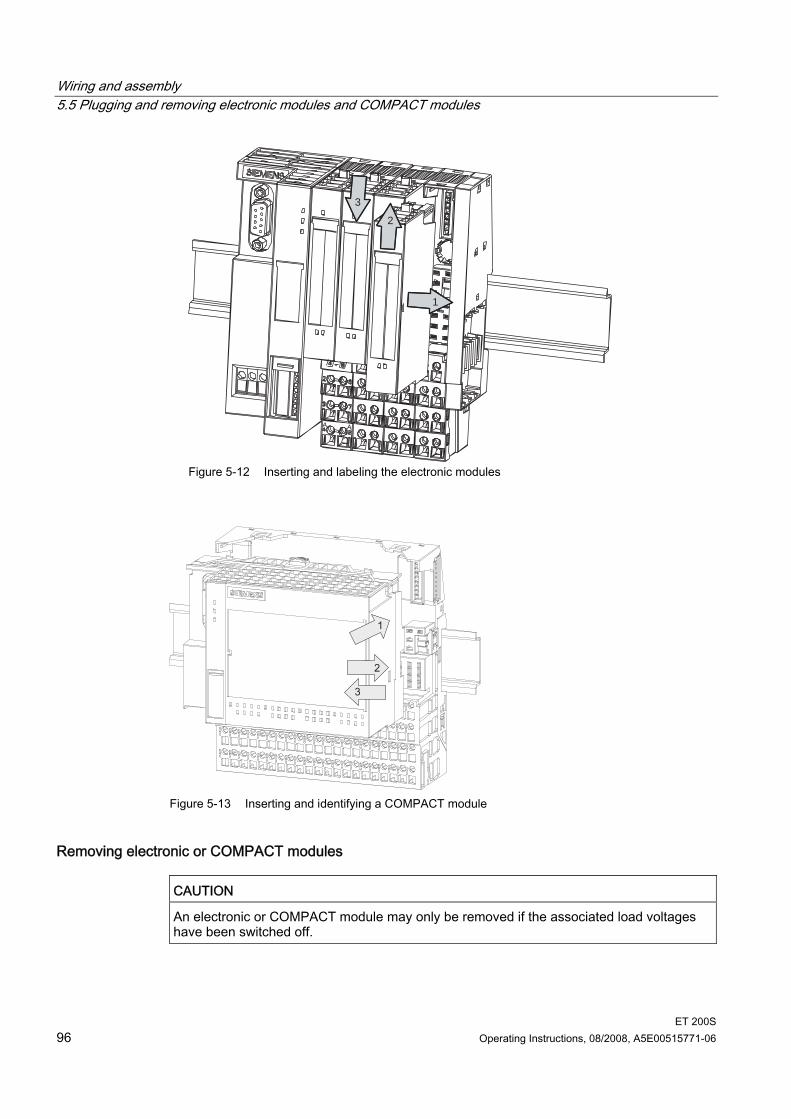
Wiring and assembly 5.5 Plugging and removing electronic modules and COMPACT modules
ET 200S 96 Operating Instructions, 08/2008, A5E00515771-06
2
3
1
Figure 5-12 Inserting and labeling the electronic modules
Figure 5-13 Inserting and identifying a COMPACT module
Removing electronic or COMPACT modules
CAUTION An electronic or COMPACT module may only be removed if the associated load voltages have been switched off.
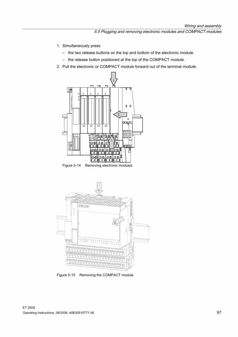
Wiring and assembly 5.5 Plugging and removing electronic modules and COMPACT modules
ET 200S Operating Instructions, 08/2008, A5E00515771-06 97
1. Simultaneously press – the two release buttons on the top and bottom of the electronic module. – the release button positioned at the top of the COMPACT module.
2. Pull the electronic or COMPACT module forward out of the terminal module.
Figure 5-14 Removing electronic modules
Figure 5-15 Removing the COMPACT module
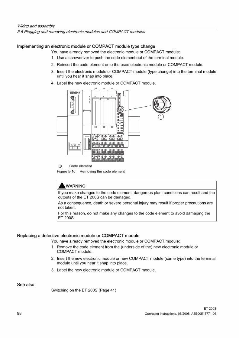
Wiring and assembly 5.5 Plugging and removing electronic modules and COMPACT modules
ET 200S 98 Operating Instructions, 08/2008, A5E00515771-06
Implementing an electronic module or COMPACT module type change You have already removed the electronic module or COMPACT module: 1. Use a screwdriver to push the code element out of the terminal module. 2. Reinsert the code element onto the used electronic module or COMPACT module. 3. Insert the electronic module or COMPACT module (type change) into the terminal module
until you hear it snap into place. 4. Label the new electronic module or COMPACT module.
1
① Code element
Figure 5-16 Removing the code element
WARNING
If you make changes to the code element, dangerous plant conditions can result and the outputs of the ET 200S can be damaged. As a consequence, death or severe personal injury may result if proper precautions are not taken. For this reason, do not make any changes to the code element to avoid damaging the ET 200S.
Replacing a defective electronic module or COMPACT module You have already removed the electronic module or COMPACT module: 1. Remove the code element from the (underside of the) new electronic module or
COMPACT module. 2. Insert the new electronic module or new COMPACT module (same type) into the terminal
module until you hear it snap into place. 3. Label the new electronic module or COMPACT module.
See also Switching on the ET 200S (Page 41)
Wiring and assembly 5.5 Plugging and removing electronic modules and COMPACT modules
ET 200S Operating Instructions, 08/2008, A5E00515771-06 99
5.5.2 Removing and inserting modules during operation
Introduction ET 200S supports the removal and insertion of modules during operation (RUN mode). The ET 200S remains in RUN mode when an electronic module is removed. The protective conductor connections of the ET 200S are not interrupted.
Rules You cannot remove and insert modules during operation unless the corresponding
parameters have been assigned. You can remove and insert modules during operation with IM151-1 BASIC, IM151-1
COMPACT, IM151-1 STANDARD (6ES7151-1AA01-0AB0 or higher), IM151-1 FO STANDARD, IM151-1 HIGH FEATURE, IM151-3 PN and IM151-3 PN HIGH FEATURE.
If one module is missing (gap) and the ET 200S POWER ON is switched, the station will not start up.
The removal and insertion of modules affects the cycle synchronization (constant bus cycle time).
When replacing more than one module, make sure that only one gap occurs.
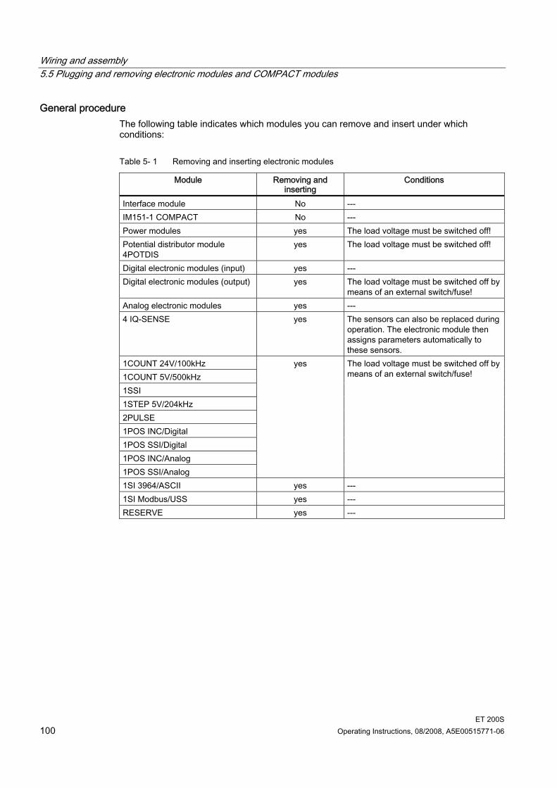
Wiring and assembly 5.5 Plugging and removing electronic modules and COMPACT modules
ET 200S 100 Operating Instructions, 08/2008, A5E00515771-06
General procedure The following table indicates which modules you can remove and insert under which conditions:
Table 5- 1 Removing and inserting electronic modules
Module Removing and inserting
Conditions
Interface module No --- IM151-1 COMPACT No --- Power modules yes The load voltage must be switched off! Potential distributor module 4POTDIS
yes The load voltage must be switched off!
Digital electronic modules (input) yes --- Digital electronic modules (output) yes The load voltage must be switched off by
means of an external switch/fuse! Analog electronic modules yes --- 4 IQ-SENSE yes The sensors can also be replaced during
operation. The electronic module then assigns parameters automatically to these sensors.
1COUNT 24V/100kHz 1COUNT 5V/500kHz 1SSI 1STEP 5V/204kHz 2PULSE 1POS INC/Digital 1POS SSI/Digital 1POS INC/Analog 1POS SSI/Analog
yes The load voltage must be switched off by means of an external switch/fuse!
1SI 3964/ASCII yes --- 1SI Modbus/USS yes --- RESERVE yes ---

ET 200S Operating Instructions, 08/2008, A5E00515771-06 101
Commissioning 66.1 Safety tests prior to commissioning
Performing tests
Note You must ensure the safety of your facility. Before a system undergoes final commissioning, you should perform a complete function test and the necessary safety tests. Incorporate foreseeable errors when planning the tests. In this way, you can avoid exposing your personnel or property to danger during operation.
Commissioning 6.2 Commissioning on PROFIBUS DP
ET 200S 102 Operating Instructions, 08/2008, A5E00515771-06
6.2 Commissioning on PROFIBUS DP
6.2.1 Configuring ET 200S on PROFIBUS DP
6.2.1.1 Basic principles of configuration for the ET 200S on PROFIBUS DP
Introduction Configuration involves configuring and assigning parameters to the ET 200S. Configuration: The systematic arrangement of the different ET 200S modules (setup). Assigning parameters: Defining the ET 200S parameters with the configuration software.
Note The ET 200S is included in the hardware catalog of HW Config: • IM151-1 BASIC: STEP 7 V5.2 and higher • IM151-1 COMPACT: STEP 7 V5.3 with Service Pack 3 or higher +HSP
"ET 200S/COMPACT" • IM151-1 STANDARD: STEP 7 V5.0 with Service Pack 3 or higher • IM151-1 FO STANDARD: STEP 7 V5.1 with Service Pack 1 or higher • IM151-1 HIGH FEATURE: from STEP 7 V5.1 with Service Pack 3 or higher You will not need a GSD file. Advantages: • Simplified summary of the devices (via the "Pack addresses" button in HW Config) • Validity checking of parameters You can find further information about the procedure in the STEP 7 Online Help.
DPV1 operation If you are using IM151-1 STANDARD (6ES7151-1AA04-0AB0 or higher) in DPV1 mode on an S7 CPU that does not support an insert/remove module interrupt, you must not enable the "Operation at preset <> actual configuration" parameter in STEP 7. Otherwise, the removal of a module (module failure) always results in a station failure (OB 86). If it is imperative that you enable "Operation at preset <> actual configuration", you must either select DPV0 mode or configure IM151-1/FO STANDARD using the GSD file (under "Additional field devices - I/O" in the STEP 7 hardware catalog). "Operation at preset <> actual configuration" is then possible even when the insert/remove module interrupt is disabled. However, the S7-CPU does not register an insertion or removal (module failure). You can detect such events only by cyclically reading the diagnostic frame and evaluating the module status.
Commissioning 6.2 Commissioning on PROFIBUS DP
ET 200S Operating Instructions, 08/2008, A5E00515771-06 103
Configuring by means of the GSD file You configure the ET 200S distributed I/O system using the GSD file. The ET 200S is linked as norm slave in your system via the GSD file. You can download the GSD file for ET 200S from the Internet (http://support.automation.siemens.com/WW/view/en/652154):
6.2.1.2 Combining modules for configuration You can only combine digital modules or motor starters with useful data amounting to less than 1 byte.
Introduction The ET 200S has a maximum address area of: IM151-1 BASIC: up to 88 bytes for inputs and 88 bytes for outputs. IM151-1 COMPACT: up to 100 bytes for inputs and 100 bytes for outputs. IM151-1 STANDARD (up to 6ES7151-1AA03-0AB0), IM151-1 FO STANDARD (up to
6ES7151-1AB02-0AB0) up to 128 bytes for inputs and 128 bytes for outputs. IM151-1 STANDARD (from 6ES7151-1AA04-0AB0), IM151-1 HIGH FEATURE: up to
244 bytes for inputs and 244 bytes for outputs. To better utilize the available address space of the DP master and reduce data exchange between the ET 200S and the DP master, you can group several electronic modules/load feeders within one byte in the input or output area of the process image. This is achieved by the systematic arrangement and designation of the ET 200S electronic modules/motor starters. A list of the address space requirements for the individual modules is to be found in the appendix. You can combine the following device types within one byte: Digital input modules Digital output modules Motor starters (direct starters and reversing starters)
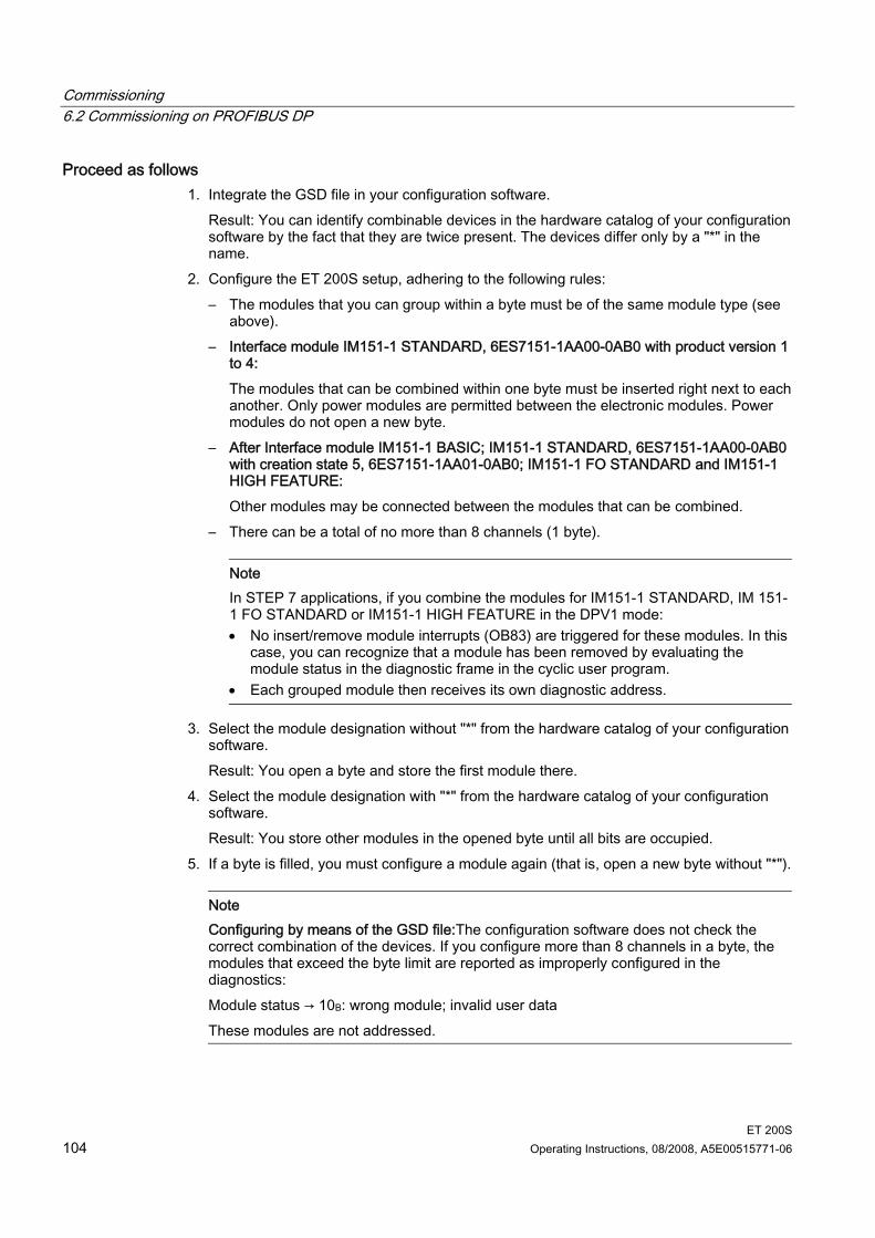
Commissioning 6.2 Commissioning on PROFIBUS DP
ET 200S 104 Operating Instructions, 08/2008, A5E00515771-06
Proceed as follows 1. Integrate the GSD file in your configuration software.
Result: You can identify combinable devices in the hardware catalog of your configuration software by the fact that they are twice present. The devices differ only by a "*" in the name.
2. Configure the ET 200S setup, adhering to the following rules: – The modules that you can group within a byte must be of the same module type (see
above). – Interface module IM151-1 STANDARD, 6ES7151-1AA00-0AB0 with product version 1
to 4: The modules that can be combined within one byte must be inserted right next to each another. Only power modules are permitted between the electronic modules. Power modules do not open a new byte.
– After Interface module IM151-1 BASIC; IM151-1 STANDARD, 6ES7151-1AA00-0AB0 with creation state 5, 6ES7151-1AA01-0AB0; IM151-1 FO STANDARD and IM151-1 HIGH FEATURE: Other modules may be connected between the modules that can be combined.
– There can be a total of no more than 8 channels (1 byte).
Note In STEP 7 applications, if you combine the modules for IM151-1 STANDARD, IM 151-1 FO STANDARD or IM151-1 HIGH FEATURE in the DPV1 mode: • No insert/remove module interrupts (OB83) are triggered for these modules. In this
case, you can recognize that a module has been removed by evaluating the module status in the diagnostic frame in the cyclic user program.
• Each grouped module then receives its own diagnostic address.
3. Select the module designation without "*" from the hardware catalog of your configuration software. Result: You open a byte and store the first module there.
4. Select the module designation with "*" from the hardware catalog of your configuration software. Result: You store other modules in the opened byte until all bits are occupied.
5. If a byte is filled, you must configure a module again (that is, open a new byte without "*").
Note Configuring by means of the GSD file:The configuration software does not check the correct combination of the devices. If you configure more than 8 channels in a byte, the modules that exceed the byte limit are reported as improperly configured in the diagnostics: Module status → 10B: wrong module; invalid user data These modules are not addressed.

Commissioning 6.2 Commissioning on PROFIBUS DP
ET 200S Operating Instructions, 08/2008, A5E00515771-06 105
No grouping If you do not want to group digital input modules, digital output modules, or motor starters within a byte when configuring the ET 200S distributed I/O system, use only those module designations without "*" from the hardware catalog of your configuration software. Each individual electronic module/motor starter will then occupy one byte in the input or output area of the process image.
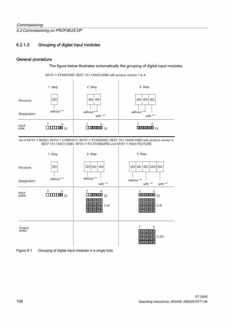
Commissioning 6.2 Commissioning on PROFIBUS DP
ET 200S 106 Operating Instructions, 08/2008, A5E00515771-06
6.2.1.3 Grouping of digital input modules
General procedure The figure below illustrates schematically the grouping of digital input modules.
Figure 6-1 Grouping of digital input modules in a single byte
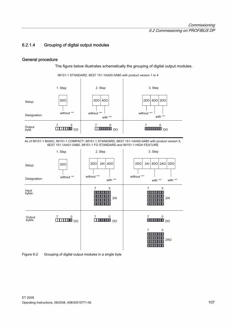
Commissioning 6.2 Commissioning on PROFIBUS DP
ET 200S Operating Instructions, 08/2008, A5E00515771-06 107
6.2.1.4 Grouping of digital output modules
General procedure The figure below illustrates schematically the grouping of digital output modules.
Figure 6-2 Grouping of digital output modules in a single byte
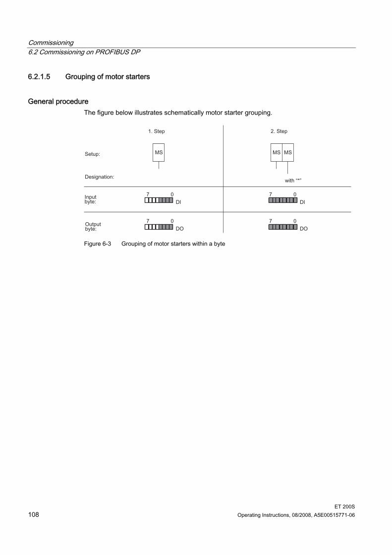
Commissioning 6.2 Commissioning on PROFIBUS DP
ET 200S 108 Operating Instructions, 08/2008, A5E00515771-06
6.2.1.5 Grouping of motor starters
General procedure The figure below illustrates schematically motor starter grouping.
Figure 6-3 Grouping of motor starters within a byte
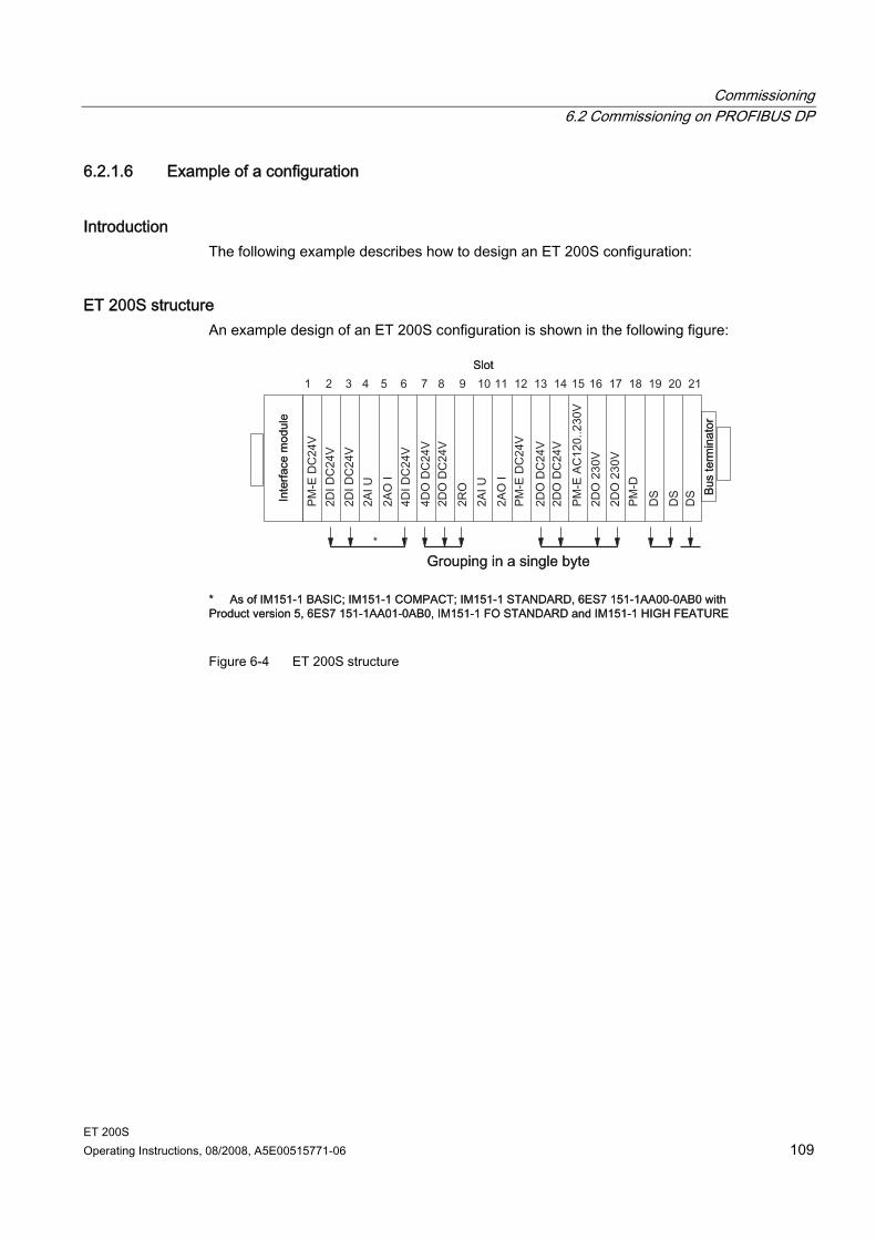
Commissioning 6.2 Commissioning on PROFIBUS DP
ET 200S Operating Instructions, 08/2008, A5E00515771-06 109
6.2.1.6 Example of a configuration
Introduction The following example describes how to design an ET 200S configuration:
ET 200S structure An example design of an ET 200S configuration is shown in the following figure:
Figure 6-4 ET 200S structure
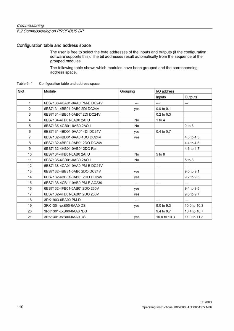
Commissioning 6.2 Commissioning on PROFIBUS DP
ET 200S 110 Operating Instructions, 08/2008, A5E00515771-06
Configuration table and address space The user is free to select the byte addresses of the inputs and outputs (if the configuration software supports this). The bit addresses result automatically from the sequence of the grouped modules. The following table shows which modules have been grouped and the corresponding address space.
Table 6- 1 Configuration table and address space
I/O address Slot Module Grouping Inputs Outputs
1 6ES7138-4CA01-0AA0 PM-E DC24V --- --- --- 2 6ES7131-4BB01-0AB0 2DI DC24V 0.0 to 0.1 3 6ES7131-4BB01-0AB0* 2DI DC24V
yes 0.2 to 0.3
4 6ES7134-4FB01-0AB0 2AI U No 1 to 4 5 6ES7135-4GB01-0AB0 2AO I No 0 to 3 6 6ES7131-4BD01-0AA0* 4DI DC24V yes 0.4 to 0.7 7 6ES7132-4BD01-0AA0 4DO DC24V 4.0 to 4.3 8 6ES7132-4BB01-0AB0* 2DO DC24V 4.4 to 4.5 9 6ES7132-4HB01-0AB0* 2DO Rel.
yes
4.6 to 4.7 10 6ES7134-4FB01-0AB0 2AI U No 5 to 8 11 6ES7135-4GB01-0AB0 2AO I No 5 to 8 12 6ES7138-4CA01-0AA0 PM-E DC24V --- --- --- 13 6ES7132-4BB31-0AB0 2DO DC24V yes 9.0 to 9.1 14 6ES7132-4BB31-0AB0* 2DO DC24V yes 9.2 to 9.3 15 6ES7138-4CB11-0AB0 PM-E AC230 --- --- --- 16 6ES7132-4FB01-0AB0* 2DO 230V yes 9.4 to 9.5 17 6ES7132-4FB01-0AB0* 2DO 230V yes 9.6 to 9.7 18 3RK1903-0BA00 PM-D --- --- --- 19 3RK1301-xxB00-0AA0 DS 9.0 to 9.3 10.0 to 10.3 20 3RK1301-xxB00-0AA0 *DS
yes 9.4 to 9.7 10.4 to 10.7
21 3RK1301-xxB00-0AA0 DS yes 10.0 to 10.3 11.0 to 11.3

Commissioning 6.2 Commissioning on PROFIBUS DP
ET 200S Operating Instructions, 08/2008, A5E00515771-06 111
6.2.2 Commissioning and startup of ET 200S on PROFIBUS DP
6.2.2.1 Setting the PROFIBUS Address
Introduction The PROFIBUS address is used to specify the address of the ET 200S distributed I/O system on PROFIBUS DP. The PROFIBUS DP address for the ET 200S is set on the interface module or COMPACT
module by means of DIP switches. The DIP switches are to be found on the front of the interface module, protected by a sliding window.
Valid PROFIBUS DP addresses are 1 to 125. Each address can be assigned only once on PROFIBUS DP.
Requirements Address setting is not yet assigned on PROFIBUS DP.
Required tools 3-mm screwdriver
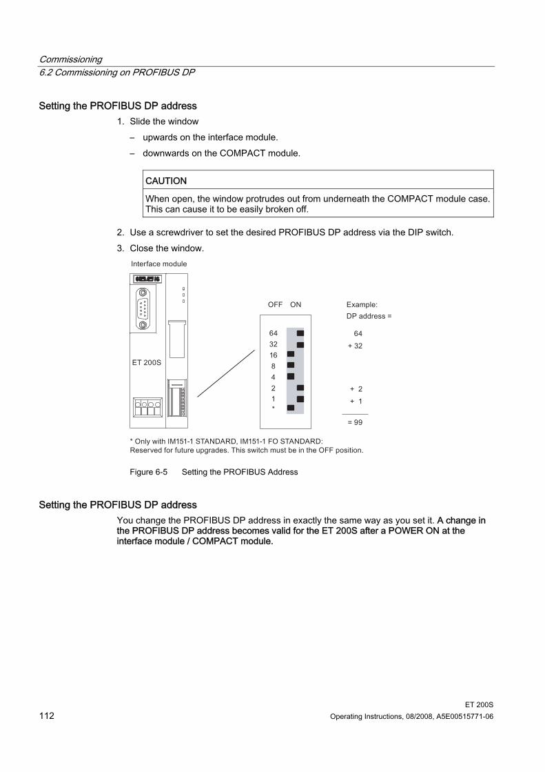
Commissioning 6.2 Commissioning on PROFIBUS DP
ET 200S 112 Operating Instructions, 08/2008, A5E00515771-06
Setting the PROFIBUS DP address 1. Slide the window
– upwards on the interface module. – downwards on the COMPACT module.
CAUTION
When open, the window protrudes out from underneath the COMPACT module case. This can cause it to be easily broken off.
2. Use a screwdriver to set the desired PROFIBUS DP address via the DIP switch. 3. Close the window.
Figure 6-5 Setting the PROFIBUS Address
Setting the PROFIBUS DP address You change the PROFIBUS DP address in exactly the same way as you set it. A change in the PROFIBUS DP address becomes valid for the ET 200S after a POWER ON at the interface module / COMPACT module.
Commissioning 6.2 Commissioning on PROFIBUS DP
ET 200S Operating Instructions, 08/2008, A5E00515771-06 113
6.2.2.2 Commissioning ET 200S on PROFIBUS DP
Software Requirements The table below details the software requirements for commissioning on PROFIBUS DP.
Table 6- 2 Software requirements for commissioning on PROFIBUS DP
Configuration software used
Version Explanations
STEP 7 from Version 5.0 and ServicePack 3
You use HW Config. With Service Pack 3 or higher the ET 200S is included in the hardware catalog.
Configuration software for a different DP master used
You need the GSD file from ET 200S.
Requirements for commissioning The following additional requirements must be satisfied for commissioning the ET 200S on PROFIBUS DP: DP slave installed DP slave wired up DP slave is configured (configured and parameters assigned) Supply voltage for the DP master is switched on (see manual for the DP master) DP master is switched to RUN mode (see manual for the DP master)
Proceed as follows To commission the DP slave, proceed as follows: 1. Switch on the power supply for the DP slave. 2. If necessary, switch on the supply voltage for the load.
See also Basic principles of configuration for the ET 200S on PROFIBUS DP (Page 102) Basic principles of installation (Page 51) Setting the PROFIBUS Address (Page 111) Wiring rules for the ET 200S (Page 79)
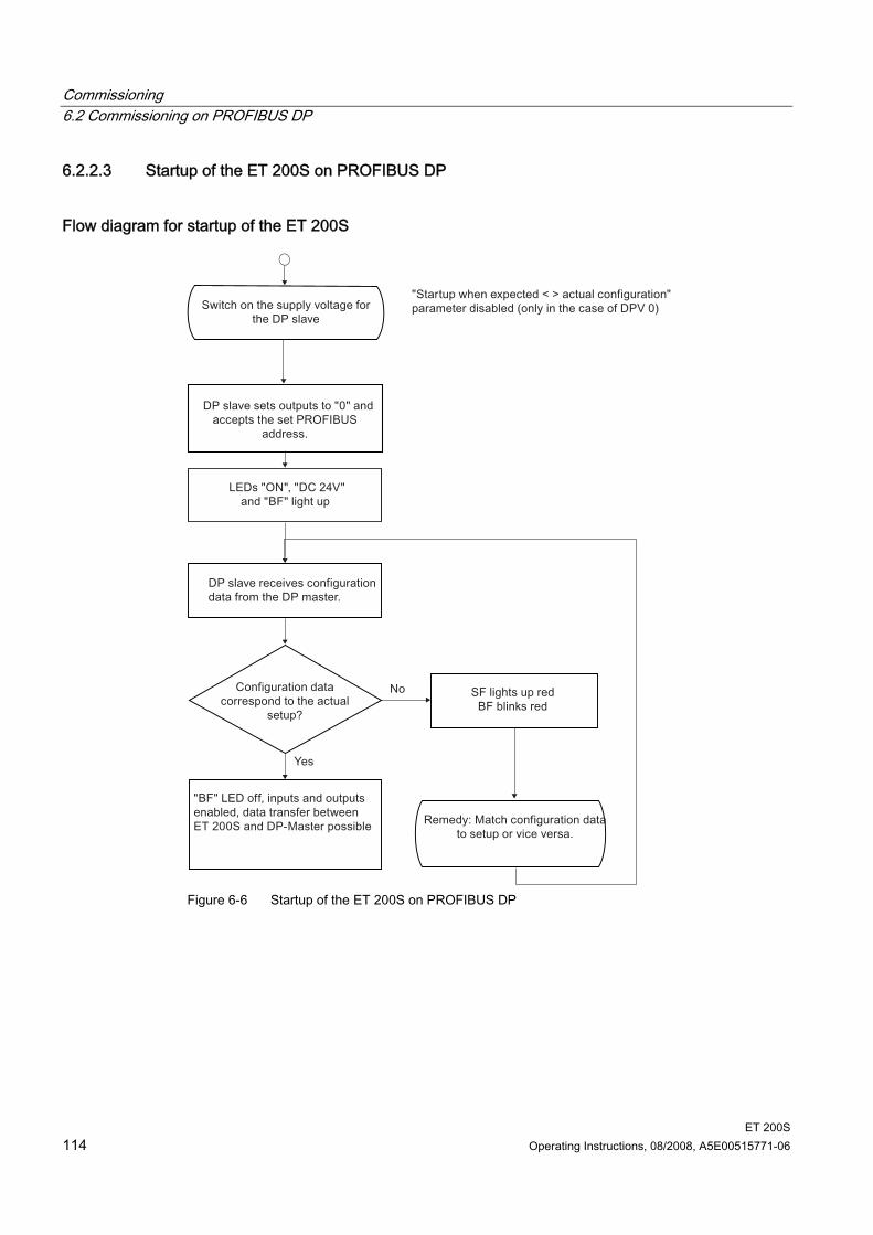
Commissioning 6.2 Commissioning on PROFIBUS DP
ET 200S 114 Operating Instructions, 08/2008, A5E00515771-06
6.2.2.3 Startup of the ET 200S on PROFIBUS DP
Flow diagram for startup of the ET 200S
Figure 6-6 Startup of the ET 200S on PROFIBUS DP
Commissioning 6.3 Commissioning on PROFINET IO
ET 200S Operating Instructions, 08/2008, A5E00515771-06 115
Note All interface modules support the default startup. In other words, configuration using the GSD file or HW Config is not necessary. The following conditions then apply: • Preset parameters are used. • AKF (general identifier format in compliance with the PROFIBUS standard) in the
configuration frame • Grouping (packing) of the electronic modules is not possible without parameterization. • All supply voltages on the power modules must be switched on. • It is not possible to remove or insert modules during operation.
Reference You can find information regarding the parameter assignment of electronic modules in the Device Manual ET 200S in the chapters Digital or Analog electronic Modules in each case under "Parameter for ...".
6.3 Commissioning on PROFINET IO
6.3.1 Configuring the ET 200S on the PROFINET IO
Introduction The interface module IM151-3 requires a unique device name in order to operate at an IO controller (refer to the following chapter). Configuration involves configuring and assigning parameters to the ET 200S. Configuration: The systematic arrangement of the different ET 200S modules (setup). Assigning parameters: Defining the ET 200S parameters with the configuration software.
Note The ET 200S can be operated with STEP 7 V5.3 Service Pack 3 and higher.
GSD file You configure the ET 200S using the GSD file. This file is used to integrate the ET 200S in your system as an IO device. You can download the GSD file for ET 200S from the Internet (http://support.automation.siemens.com/WW/view/en/19699080): The following GSD file is available for the IM151-3 interface module: GSDML-Vx.y-Siemens-ET200S-"Date in yyyymmdd format".xml You can find further information about the procedure in the STEP 7 Online Help.
Commissioning 6.3 Commissioning on PROFINET IO
ET 200S 116 Operating Instructions, 08/2008, A5E00515771-06
6.3.2 Assigning device names to the I/O device
Introduction Each PROFINET IO device is assigned a unique device ID by the manufacturer (MAC address). For configuration and in the user program, each ET 200S IO device is addressed with its device name. For detailed information on addressing in PROFINET IO, refer to the PROFINET System Description.
Requirements IM151-3 Interface Module SIMATIC Micro Memory Card 64k and higher The PD must be online on PROFINET to the IO device to let you assign a device name to
the interface module. The IO device is configured in HW Config and assigned an IP address.
Assigning a device name 1. Insert an empty SIMATIC Micro Memory Card into the module slot on the front of the
IM151-3. 2. Switch on the power supply for the IM151-3 PN. 3. Open the Properties - IM151-3 PN window in the HW Config or Properties - IM151-3 PN
HIGH FEATURE and enter the device name for the IO Device there and confirm with OK. Do not use the device name "noname" (not case-sensitive).
Transferring the device name to the interface module 1. In HW Config select PLC > Ethernet > Assign Device Name. 2. Click the Assign name button in the Assign device name window.
Result The device name is stored on the SIMATIC Micro Memory Card in the IM151-3 interface module.
Commissioning 6.3 Commissioning on PROFINET IO
ET 200S Operating Instructions, 08/2008, A5E00515771-06 117
Alternative procedure Alternatively, you can write directly to a SIMATIC Micro Memory Card using a programming device with an EPROM programming device installed or a PC connected to a SIMATIC USB EPROM programming device and then use the memory card to transfer the device name to the IM151-3 PN. Proceed as described in the online help for HW Config under "Assign device name using a memory card".
Forwarding the device name when the interface module is replaced The device name of the IO device is saved to the SIMATIC Micro Memory Card. To transfer the device name when exchanging the interface module IM151-3, pull the SIMATIC Micro Memory Card out of the "old" IM151-3 and insert it in the "new one". The IO device adopts the device name from the SIMATIC Micro Memory Card after switching the power supply off/on. Then the station is addressable again and functions the same as before the exchange.
Station flash test If you are using multiple IO devices, multiple IO devices are also indicated in the "Assign device name" dialog. In this case, you should compare the MAC address of the device with the indicated MAC address and select the proper IO device. The identification of IO devices in a system is facilitated by a station flash test. The flash test is activated as follows: 1. In the "Assign device name" dialog, select one of the indicated IO devices. 2. Select a flash duration. 3. Click the "Flash on" button. The LINK LED on the selected IO device flashes (open the flaps on the front cover of the IM151-3).
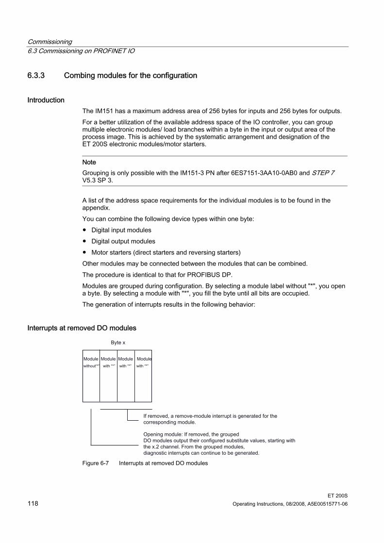
Commissioning 6.3 Commissioning on PROFINET IO
ET 200S 118 Operating Instructions, 08/2008, A5E00515771-06
6.3.3 Combing modules for the configuration
Introduction The IM151 has a maximum address area of 256 bytes for inputs and 256 bytes for outputs. For a better utilization of the available address space of the IO controller, you can group multiple electronic modules/ load branches within a byte in the input or output area of the process image. This is achieved by the systematic arrangement and designation of the ET 200S electronic modules/motor starters.
Note Grouping is only possible with the IM151-3 PN after 6ES7151-3AA10-0AB0 and STEP 7 V5.3 SP 3.
A list of the address space requirements for the individual modules is to be found in the appendix. You can combine the following device types within one byte: Digital input modules Digital output modules Motor starters (direct starters and reversing starters) Other modules may be connected between the modules that can be combined. The procedure is identical to that for PROFIBUS DP. Modules are grouped during configuration. By selecting a module label without "*", you open a byte. By selecting a module with "*", you fill the byte until all bits are occupied. The generation of interrupts results in the following behavior:
Interrupts at removed DO modules
Figure 6-7 Interrupts at removed DO modules
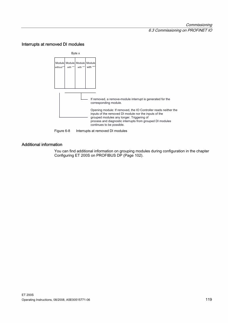
Commissioning 6.3 Commissioning on PROFINET IO
ET 200S Operating Instructions, 08/2008, A5E00515771-06 119
Interrupts at removed DI modules
Figure 6-8 Interrupts at removed DI modules
Additional information You can find additional information on grouping modules during configuration in the chapter Configuring ET 200S on PROFIBUS DP (Page 102).
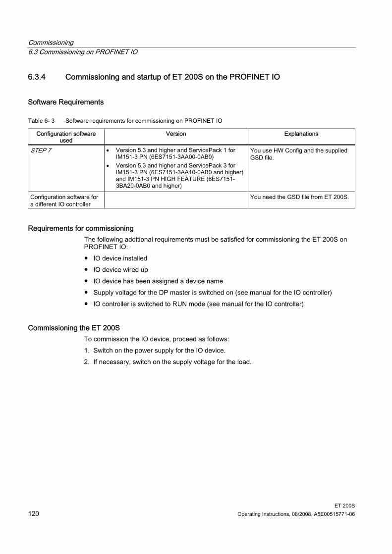
Commissioning 6.3 Commissioning on PROFINET IO
ET 200S 120 Operating Instructions, 08/2008, A5E00515771-06
6.3.4 Commissioning and startup of ET 200S on the PROFINET IO
Software Requirements
Table 6- 3 Software requirements for commissioning on PROFINET IO
Configuration software used
Version Explanations
STEP 7 • Version 5.3 and higher and ServicePack 1 for IM151-3 PN (6ES7151-3AA00-0AB0)
• Version 5.3 and higher and ServicePack 3 for IM151-3 PN (6ES7151-3AA10-0AB0 and higher) and IM151-3 PN HIGH FEATURE (6ES7151-3BA20-0AB0 and higher)
You use HW Config and the supplied GSD file.
Configuration software for a different IO controller
You need the GSD file from ET 200S.
Requirements for commissioning The following additional requirements must be satisfied for commissioning the ET 200S on PROFINET IO: IO device installed IO device wired up IO device has been assigned a device name Supply voltage for the DP master is switched on (see manual for the IO controller) IO controller is switched to RUN mode (see manual for the IO controller)
Commissioning the ET 200S To commission the IO device, proceed as follows: 1. Switch on the power supply for the IO device. 2. If necessary, switch on the supply voltage for the load.
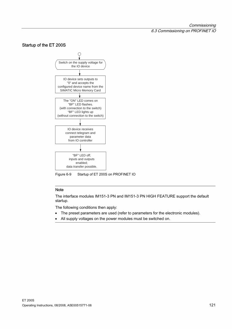
Commissioning 6.3 Commissioning on PROFINET IO
ET 200S Operating Instructions, 08/2008, A5E00515771-06 121
Startup of the ET 200S
Switch on the supply voltage forthe IO device
IO device sets outputs to"0" and accepts the
configured device name from the SIMATIC Micro Memory Card
The "ON" LED comes on "BF" LED flashes.
(with connection to the switch)“BF” LED lights up
(without connection to the switch)
IO device receivesconnect telegram and
parameter datafrom IO controller
"BF" LED off;inputs and outputs
enabled;data transfer possible.
Figure 6-9 Startup of ET 200S on PROFINET IO
Note The interface modules IM151-3 PN and IM151-3 PN HIGH FEATURE support the default startup. The following conditions then apply: • The preset parameters are used (refer to parameters for the electronic modules). • All supply voltages on the power modules must be switched on.

Commissioning 6.3 Commissioning on PROFINET IO
ET 200S 122 Operating Instructions, 08/2008, A5E00515771-06
ET 200S Operating Instructions, 08/2008, A5E00515771-06 123
Functions 77.1 Direct data exchange on PROFIBUS DP
Introduction The ET 200S can be used as the sender (publisher) for the direct exchange of data (cross traffic). Naturally, the DP master used must also support direct data exchange. You will find information on this in the description of the DP master.
General procedure Direct data exchange (cross traffic) is characterized by PROFIBUS DP nodes which "listen" on the bus and know which data a DP slave returns to its DP master. This mechanism allows the "listener" (recipient / subscriber) direct access to modified input data from the remote DP slaves. During configuration in STEP 7 the respective I/O input addresses are used to specify the address space of the recipient where the sender data is stored.
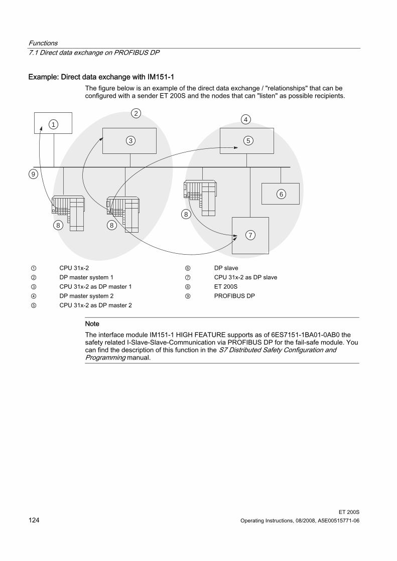
Functions 7.1 Direct data exchange on PROFIBUS DP
ET 200S 124 Operating Instructions, 08/2008, A5E00515771-06
Example: Direct data exchange with IM151-1 The figure below is an example of the direct data exchange / "relationships" that can be configured with a sender ET 200S and the nodes that can "listen" as possible recipients.
1
2
3
4
5
6
7
888
9
① CPU 31x-2 ⑥ DP slave ② DP master system 1 ⑦ CPU 31x-2 as DP slave ③ CPU 31x-2 as DP master 1 ⑧ ET 200S ④ DP master system 2 ⑨ PROFIBUS DP ⑤ CPU 31x-2 as DP master 2
Note The interface module IM151-1 HIGH FEATURE supports as of 6ES7151-1BA01-0AB0 the safety related I-Slave-Slave-Communication via PROFIBUS DP for the fail-safe module. You can find the description of this function in the S7 Distributed Safety Configuration and Programming manual.
Functions 7.2 Option handling on the PROFIBUS DP
ET 200S Operating Instructions, 08/2008, A5E00515771-06 125
7.2 Option handling on the PROFIBUS DP
7.2.1 Basic principles of option handling on PROFIBUS DP
Principle Option handling enables you to set up the ET 200S for future expansions (options). Option handling means that you install, wire, configure, and program the planned maximum configuration of the ET 200S. You can choose between two option handling variants, according to your requirements: Option handling with RESERVE modules Option handling without RESERVE modules The two option handling variants are mutually exclusive.
Option handling with RESERVE modules The optional electronic modules are initially replaced with inexpensive RESERVE modules which are then later exchanged with the planned electronic modules. This means that the ET 200S can be completely prewired ("master cabling") since the RESERVE module is not connected to the terminal module terminals and therefore not to the process. The RESERVE modules for future expansions at the right-hand end of the station do not have to be mounted. In this case, preparatory installation and wiring are possible but not a prerequisite.
Option handling without RESERVE modules With this variant, the use of RESERVE modules is not necessary. The modules are mounted side-by-side without gaps. Preparatory mounting and wiring are not required for the optional electronic modules.
Note Mark the modules in your installation with the slot numbers from your configuration.
Reference Refer to the "Properties" in the manuals for the ET 200S interface modules to find out which interface modules support "Options handling".
Functions 7.3 Identification data
ET 200S 126 Operating Instructions, 08/2008, A5E00515771-06
7.3 Identification data
Definition Identification data are data that are stored in a module for assisting the user in: Checking the system configuration Locating hardware changes in a system Correcting errors in a system Identification data enable modules to be uniquely identified online. STEP 7 shows the identification data in the "Module information - IM 151" and "Properties - DP Slave" tabs.
Reference Refer to the "Properties" in the manuals for the ET 200S interface modules to find out which interface modules support "Identification data".
ET 200S Operating Instructions, 08/2008, A5E00515771-06 127
General technical specifications 88.1 Standards and approvals
Introduction The general technical specifications comprise the standards and test specifications which satisfy the ET 200S distributed I/O system and form the base criteria for testing the ET 200S distributed I/O system.
CE certification The ET 200S distributed I/O system satisfies the requirements and objectives of the following EC directives and satisfies the Harmonized European Standards (EN) for Programmable Logic Controllers which were published in the official pamphlets of the European Community: 73/23/EEC "Electrical Equipment for Use within Fixed Voltage Ranges" (Low-Voltage
Directive) 89/336/EEC "Electromagnetic Compatibility" (EMC guideline) 94/9/EC "Equipment and protective systems intended for use in potentially explosive
environments" (ATEX). The EU conformity declaration certificates are available for the responsible authorities and are kept at the following address: Siemens Aktiengesellschaft Industry Sector IA AS RD ST Type Test P.O. Box 1963 D-92209 Amberg
General technical specifications 8.1 Standards and approvals
ET 200S 128 Operating Instructions, 08/2008, A5E00515771-06
UL approval Underwriters Laboratories Inc. in accordance with UL 508 (Industrial Control Equipment)
CSA approval Canadian Standards Association in accordance with C22.2 No 142 (Process control Equipment) or Underwriters Laboratories Inc. in accordance with UL 508 (Industrial Control Equipment) CSA C22.2 No. 142 (Industrial Control Equipment) or Underwriters Laboratories Inc. according to UL 508 (Industrial Control Equipment) CSA C22.2 No. 142 (Process Control Equipment) UL 1604 (Hazardous Location) CSA-213 (Hazardous Location) APPROVED for use in Class I, Division 2, Group A, B, C, D Tx; Class I, Zone 2, Group IIC Tx The ET 200S motor starters do not possess cULus for HAZ. LOC. certification.
Note The certifications currently valid can be found on the nameplate of the specific module.
General technical specifications 8.1 Standards and approvals
ET 200S Operating Instructions, 08/2008, A5E00515771-06 129
FM approval Factory Mutual Research (FM) according to Approval Standard Class Number 3611, 3600, 3810 APPROVED for use in Class I, Division 2, Group A, B, C, D Tx; Class I, Zone 2, Group IIC Tx The ET 200S motor starters do not possess FM certification. All other modules of the ET 200S are FM certified. acc. to EN 50021 (Electrical apparatus for potentially explosive atmospheres; Type of protection "n")
WARNING Personal injury and property damage can occur. There is a risk of injury or damage if you disconnect any plug-in connections in potentially explosive environments while the ET 200S is in operation. Always de-energize the ET 200S in potentially explosive environments before disconnecting plug-in connections.
WARNING Explosion Hazard Components may no longer qualify for Class I, DIV. 2 if they are substituted.
WARNING This device is only appropriate for use in Class I, Div. 2, Group A, B, C, D, or in non-hazardous areas.
Tick-Mark for Australia The ET 200S distributed I/O system satisfies the requirements of the standard AS/NZS 2064 (Class A).
IEC 61131 The ET 200S distributed I/O system satisfies the requirements and criteria of the standard IEC 61131-2 (Programmable Logic Controllers, Part 2: Equipment Requirements and Tests).
PROFIBUS standard The ET 200S distributed I/O system is based on the IEC 61784-1:2002 Ed1 CP 3/1 standard.
General technical specifications 8.1 Standards and approvals
ET 200S 130 Operating Instructions, 08/2008, A5E00515771-06
Marine type approval Classification organizations: ABS (American Bureau of Shipping) BV (Bureau Veritas) DNV (Det Norske Veritas) GL (Germanischer Lloyd) LRS (Lloyds Register of Shipping) Class NK (Nippon Kaiji Kyokai)
Use in industrial environment SIMATIC products are designed for use in industrial environments.
Table 8- 1 Use in industrial environment
Requirement for Area of application Emitted interference Immunity to noise
Industry EN 61000-6-4 : 2001 EN 61000-6-2 : 2001
Use in residential areas If ET 200S is used in residential areas you must comply with limit class B in accordance with EN 55011 regarding the emission of radio interference. Appropriate measures for achieving the radio interference level required by limit class B are: Installation of the ET 200S in grounded switch cabinets/switch boxes Use of filters in supply lines
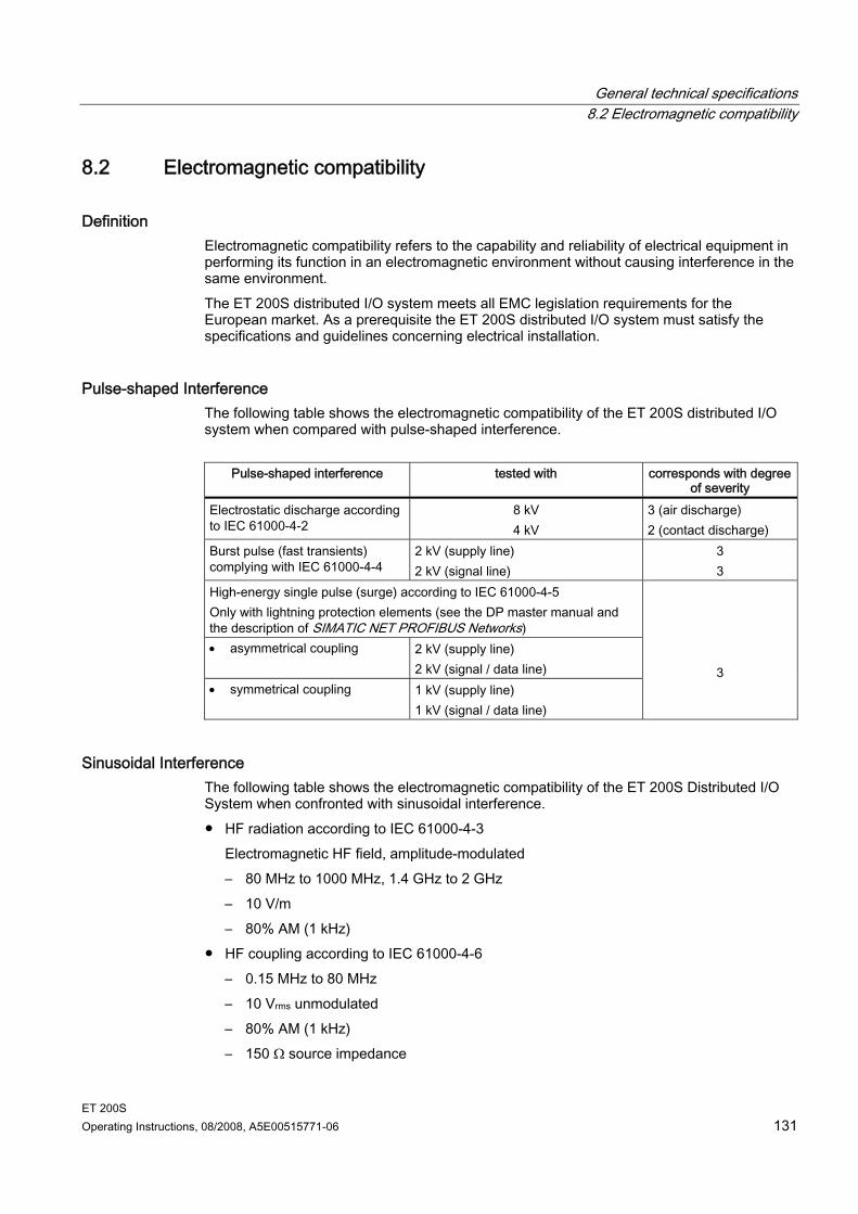
General technical specifications 8.2 Electromagnetic compatibility
ET 200S Operating Instructions, 08/2008, A5E00515771-06 131
8.2 Electromagnetic compatibility
Definition Electromagnetic compatibility refers to the capability and reliability of electrical equipment in performing its function in an electromagnetic environment without causing interference in the same environment. The ET 200S distributed I/O system meets all EMC legislation requirements for the European market. As a prerequisite the ET 200S distributed I/O system must satisfy the specifications and guidelines concerning electrical installation.
Pulse-shaped Interference The following table shows the electromagnetic compatibility of the ET 200S distributed I/O system when compared with pulse-shaped interference.
Pulse-shaped interference tested with corresponds with degree of severity
Electrostatic discharge according to IEC 61000-4-2
8 kV 4 kV
3 (air discharge) 2 (contact discharge)
Burst pulse (fast transients) complying with IEC 61000-4-4
2 kV (supply line) 2 kV (signal line)
3 3
High-energy single pulse (surge) according to IEC 61000-4-5 Only with lightning protection elements (see the DP master manual and the description of SIMATIC NET PROFIBUS Networks) • asymmetrical coupling 2 kV (supply line)
2 kV (signal / data line) • symmetrical coupling 1 kV (supply line)
1 kV (signal / data line)
3
Sinusoidal Interference The following table shows the electromagnetic compatibility of the ET 200S Distributed I/O System when confronted with sinusoidal interference. HF radiation according to IEC 61000-4-3
Electromagnetic HF field, amplitude-modulated – 80 MHz to 1000 MHz, 1.4 GHz to 2 GHz – 10 V/m – 80% AM (1 kHz)
HF coupling according to IEC 61000-4-6 – 0.15 MHz to 80 MHz – 10 Vrms unmodulated – 80% AM (1 kHz) – 150 Ω source impedance
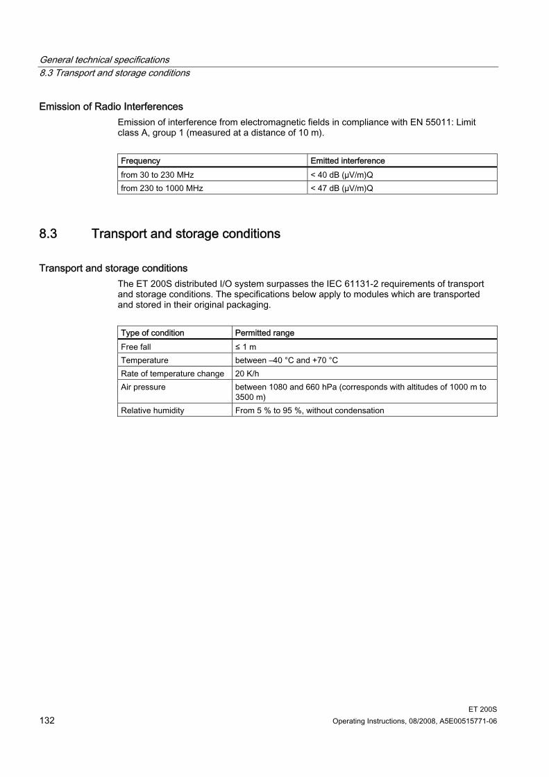
General technical specifications 8.3 Transport and storage conditions
ET 200S 132 Operating Instructions, 08/2008, A5E00515771-06
Emission of Radio Interferences Emission of interference from electromagnetic fields in compliance with EN 55011: Limit class A, group 1 (measured at a distance of 10 m). Frequency Emitted interference from 30 to 230 MHz < 40 dB (µV/m)Q from 230 to 1000 MHz < 47 dB (µV/m)Q
8.3 Transport and storage conditions
Transport and storage conditions The ET 200S distributed I/O system surpasses the IEC 61131-2 requirements of transport and storage conditions. The specifications below apply to modules which are transported and stored in their original packaging. Type of condition Permitted range Free fall ≤ 1 m Temperature between –40 °C and +70 °C Rate of temperature change 20 K/h Air pressure between 1080 and 660 hPa (corresponds with altitudes of 1000 m to
3500 m) Relative humidity From 5 % to 95 %, without condensation
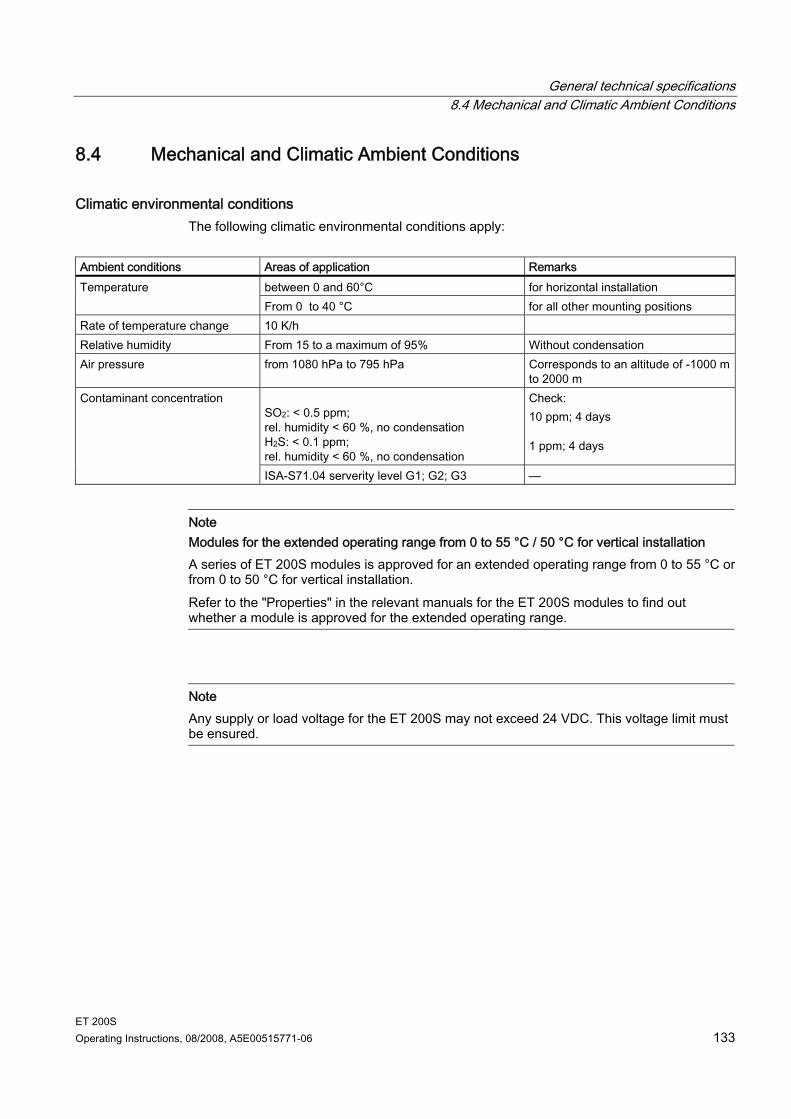
General technical specifications 8.4 Mechanical and Climatic Ambient Conditions
ET 200S Operating Instructions, 08/2008, A5E00515771-06 133
8.4 Mechanical and Climatic Ambient Conditions
Climatic environmental conditions The following climatic environmental conditions apply:
Ambient conditions Areas of application Remarks
between 0 and 60°C for horizontal installation Temperature From 0 to 40 °C for all other mounting positions
Rate of temperature change 10 K/h Relative humidity From 15 to a maximum of 95% Without condensation Air pressure from 1080 hPa to 795 hPa Corresponds to an altitude of -1000 m
to 2000 m SO2: < 0.5 ppm; rel. humidity < 60 %, no condensation H2S: < 0.1 ppm; rel. humidity < 60 %, no condensation
Check: 10 ppm; 4 days 1 ppm; 4 days
Contaminant concentration
ISA-S71.04 serverity level G1; G2; G3 —
Note Modules for the extended operating range from 0 to 55 °C / 50 °C for vertical installation A series of ET 200S modules is approved for an extended operating range from 0 to 55 °C or from 0 to 50 °C for vertical installation. Refer to the "Properties" in the relevant manuals for the ET 200S modules to find out whether a module is approved for the extended operating range.
Note Any supply or load voltage for the ET 200S may not exceed 24 VDC. This voltage limit must be ensured.
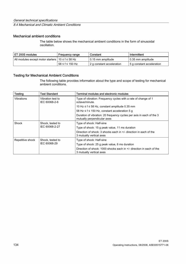
General technical specifications 8.4 Mechanical and Climatic Ambient Conditions
ET 200S 134 Operating Instructions, 08/2008, A5E00515771-06
Mechanical ambient conditions The table below shows the mechanical ambient conditions in the form of sinusoidal oscillation.
ET 200S modules Frequency range Constant Intermittent
10 ≤ f ≤ 58 Hz 0.15 mm amplitude 0.35 mm amplitude All modules except motor starters58 ≤ f ≤ 150 Hz 2 g constant acceleration 5 g constant acceleration
Testing for Mechanical Ambient Conditions The following table provides information about the type and scope of testing for mechanical ambient conditions.
Testing Test Standard Terminal modules and electronic modules Vibrations Vibration test to
IEC 60068-2-6 Type of vibration: Frequency cycles with a rate of change of 1 octave/minute. 10 Hz ≤ f ≤ 58 Hz, constant amplitude 0.35 mm 58 Hz ≤ f ≤ 150 Hz, constant acceleration 5 g Duration of vibration: 20 frequency cycles per axis in each of the 3 mutually perpendicular axes
Shock Shock, tested to IEC 60068-2-27
Type of shock: Half-sine Type of shock: 15 g peak value, 11 ms duration Direction of shock: 3 shocks each in +/- direction in each of the 3 mutually vertical axes
Repetitive shock Shock, tested to IEC 60068-29
Type of shock: Half-sine Type of shock: 25 g peak value, 6 ms duration Direction of shock: 1000 shocks each in +/- direction in each of the 3 mutually vertical axes
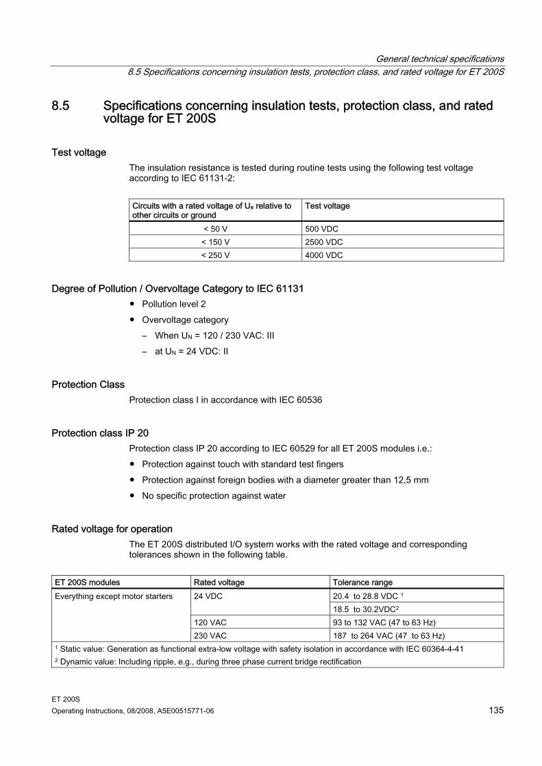
General technical specifications 8.5 Specifications concerning insulation tests, protection class, and rated voltage for ET 200S
ET 200S Operating Instructions, 08/2008, A5E00515771-06 135
8.5 Specifications concerning insulation tests, protection class, and rated voltage for ET 200S
Test voltage The insulation resistance is tested during routine tests using the following test voltage according to IEC 61131-2: Circuits with a rated voltage of Ue relative to other circuits or ground
Test voltage
< 50 V 500 VDC < 150 V 2500 VDC < 250 V 4000 VDC
Degree of Pollution / Overvoltage Category to IEC 61131 Pollution level 2 Overvoltage category
– When UN = 120 / 230 VAC: III – at UN = 24 VDC: II
Protection Class Protection class I in accordance with IEC 60536
Protection class IP 20 Protection class IP 20 according to IEC 60529 for all ET 200S modules i.e.: Protection against touch with standard test fingers Protection against foreign bodies with a diameter greater than 12,5 mm No specific protection against water
Rated voltage for operation The ET 200S distributed I/O system works with the rated voltage and corresponding tolerances shown in the following table.
ET 200S modules Rated voltage Tolerance range
20.4 to 28.8 VDC 1 24 VDC 18.5 to 30.2VDC2
120 VAC 93 to 132 VAC (47 to 63 Hz)
Everything except motor starters
230 VAC 187 to 264 VAC (47 to 63 Hz) 1 Static value: Generation as functional extra-low voltage with safety isolation in accordance with IEC 60364-4-41 2 Dynamic value: Including ripple, e.g., during three phase current bridge rectification
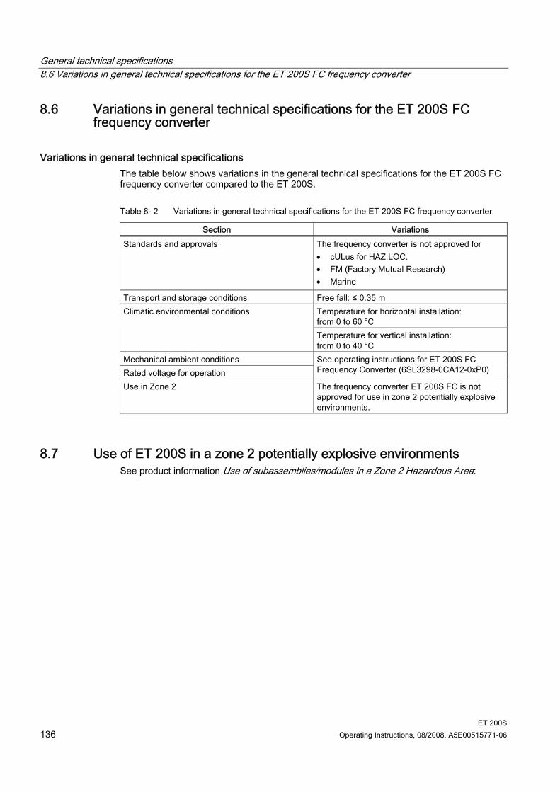
General technical specifications 8.6 Variations in general technical specifications for the ET 200S FC frequency converter
ET 200S 136 Operating Instructions, 08/2008, A5E00515771-06
8.6 Variations in general technical specifications for the ET 200S FC frequency converter
Variations in general technical specifications The table below shows variations in the general technical specifications for the ET 200S FC frequency converter compared to the ET 200S.
Table 8- 2 Variations in general technical specifications for the ET 200S FC frequency converter
Section Variations Standards and approvals The frequency converter is not approved for
• cULus for HAZ.LOC. • FM (Factory Mutual Research) • Marine
Transport and storage conditions Free fall: ≤ 0.35 m Temperature for horizontal installation: from 0 to 60 °C
Climatic environmental conditions
Temperature for vertical installation: from 0 to 40 °C
Mechanical ambient conditions Rated voltage for operation
See operating instructions for ET 200S FC Frequency Converter (6SL3298-0CA12-0xP0)
Use in Zone 2 The frequency converter ET 200S FC is not approved for use in zone 2 potentially explosive environments.
8.7 Use of ET 200S in a zone 2 potentially explosive environments See product information Use of subassemblies/modules in a Zone 2 Hazardous Area:
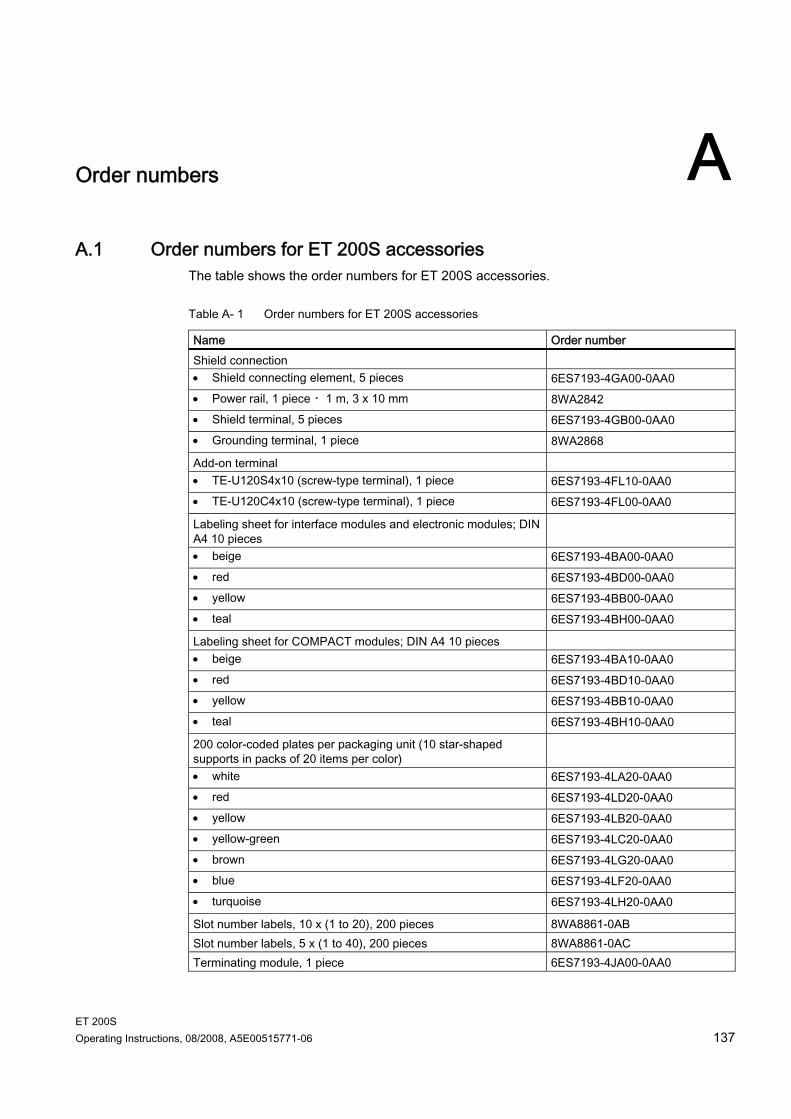
ET 200S Operating Instructions, 08/2008, A5E00515771-06 137
Order numbers AA.1 Order numbers for ET 200S accessories
The table shows the order numbers for ET 200S accessories.
Table A- 1 Order numbers for ET 200S accessories
Name Order number Shield connection • Shield connecting element, 5 pieces 6ES7193-4GA00-0AA0 • Power rail, 1 piece ・1 m, 3 x 10 mm 8WA2842 • Shield terminal, 5 pieces 6ES7193-4GB00-0AA0 • Grounding terminal, 1 piece 8WA2868
Add-on terminal • TE-U120S4x10 (screw-type terminal), 1 piece 6ES7193-4FL10-0AA0 • TE-U120C4x10 (screw-type terminal), 1 piece 6ES7193-4FL00-0AA0
Labeling sheet for interface modules and electronic modules; DIN A4 10 pieces
• beige 6ES7193-4BA00-0AA0 • red 6ES7193-4BD00-0AA0 • yellow 6ES7193-4BB00-0AA0 • teal 6ES7193-4BH00-0AA0
Labeling sheet for COMPACT modules; DIN A4 10 pieces • beige 6ES7193-4BA10-0AA0 • red 6ES7193-4BD10-0AA0 • yellow 6ES7193-4BB10-0AA0 • teal 6ES7193-4BH10-0AA0
200 color-coded plates per packaging unit (10 star-shaped supports in packs of 20 items per color)
• white 6ES7193-4LA20-0AA0 • red 6ES7193-4LD20-0AA0 • yellow 6ES7193-4LB20-0AA0 • yellow-green 6ES7193-4LC20-0AA0 • brown 6ES7193-4LG20-0AA0 • blue 6ES7193-4LF20-0AA0 • turquoise 6ES7193-4LH20-0AA0
Slot number labels, 10 x (1 to 20), 200 pieces 8WA8861-0AB Slot number labels, 5 x (1 to 40), 200 pieces 8WA8861-0AC Terminating module, 1 piece 6ES7193-4JA00-0AA0
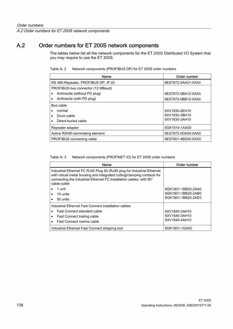
Order numbers A.2 Order numbers for ET 200S network components
ET 200S 138 Operating Instructions, 08/2008, A5E00515771-06
A.2 Order numbers for ET 200S network components The tables below list all the network components for the ET 200S Distributed I/O System that you may require to use the ET 200S.
Table A- 2 Network components (PROFIBUS DP) for ET 200S order numbers
Name Order number RS 485-Repeater, PROFIBUS DP, IP 20 6ES7972-0AA01-0XA0 PROFIBUS bus connector (12 MBaud) • Anthracite (without PD plug) • Anthracite (with PD plug)
6ES7972-0BA12-0XA0 6ES7972-0BB12-0XA0
Bus cable • normal • Drum cable • Direct-buried cable
6XV1830-0EH10 6XV1830-3BH10 6XV1830-3AH10
Repeater adapter 6GK1510-1AA00 Active RS485 terminating element 6ES7972-0DA00-0AA0 PROFIBUS connecting cable 6ES7901-4BD00-0XA0
Table A- 3 Network components (PROFINET IO) for ET 200S order numbers
Name Order number Industrial Ethernet FC RJ45 Plug 90 (RJ45 plug for Industrial Ethernet with robust metal housing and integrated cutting/clamping contacts for connecting the Industrial Ethernet FC installation cables; with 90° cable outlet • 1 unit • 10 units • 50 units
6GK1901-1BB20-2AA0 6GK1901-1BB20-2AB0 6GK1901-1BB20-2AE0
Industrial Ethernet Fast Connect installation cables • Fast Connect standard cable • Fast Connect trailing cable • Fast Connect marine cable
6XV1840-2AH10 6XV1840-3AH10 6XV1840-4AH10
Industrial Ethernet Fast Connect stripping tool 6GK1901-1GA00
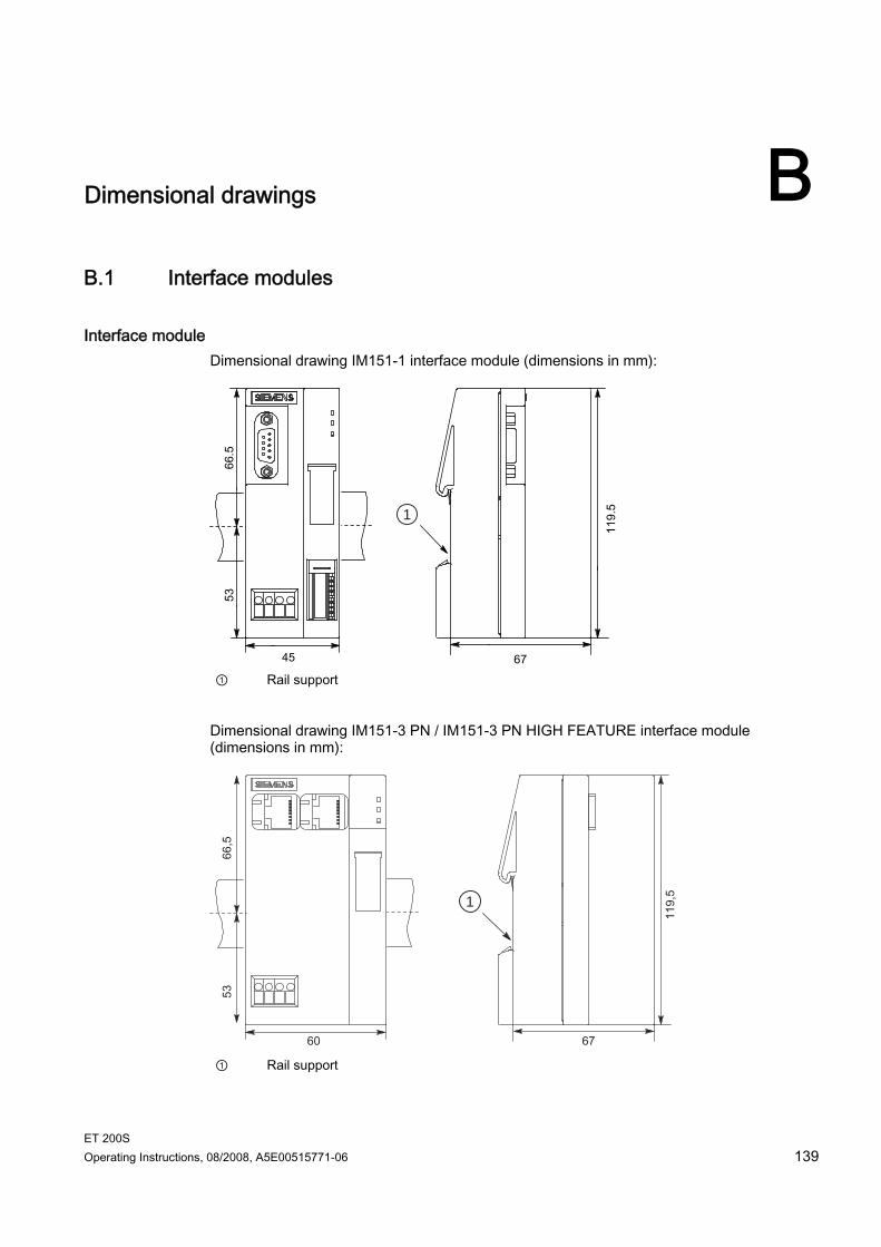
ET 200S Operating Instructions, 08/2008, A5E00515771-06 139
Dimensional drawings BB.1 Interface modules
Interface module Dimensional drawing IM151-1 interface module (dimensions in mm):
1
① Rail support
Dimensional drawing IM151-3 PN / IM151-3 PN HIGH FEATURE interface module (dimensions in mm):
1
① Rail support
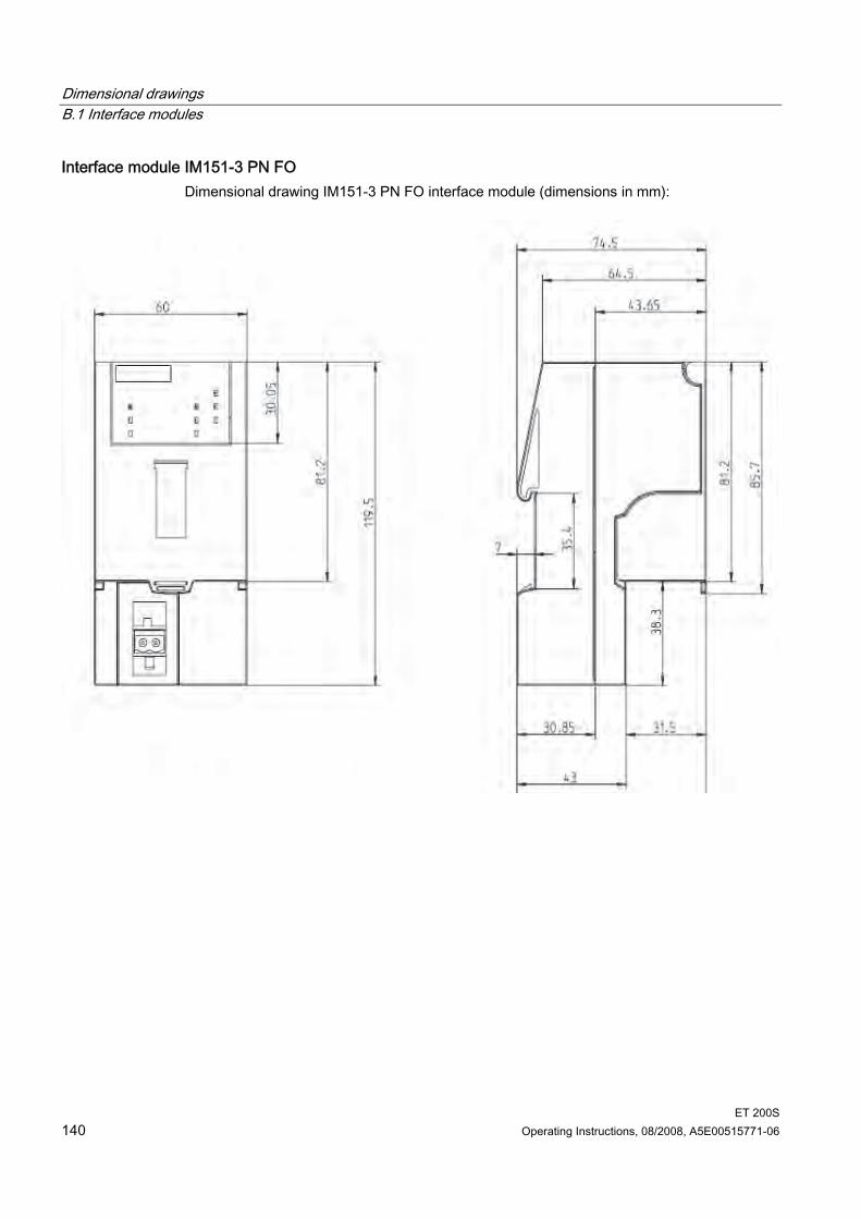
Dimensional drawings B.1 Interface modules
ET 200S 140 Operating Instructions, 08/2008, A5E00515771-06
Interface module IM151-3 PN FO Dimensional drawing IM151-3 PN FO interface module (dimensions in mm):
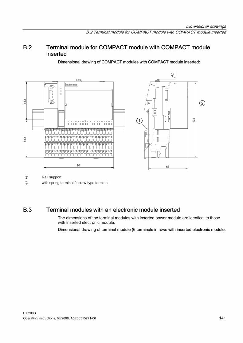
Dimensional drawings B.2 Terminal module for COMPACT module with COMPACT module inserted
ET 200S Operating Instructions, 08/2008, A5E00515771-06 141
B.2 Terminal module for COMPACT module with COMPACT module inserted
Dimensional drawing of COMPACT modules with COMPACT module inserted:
① Rail support ② with spring terminal / screw-type terminal
B.3 Terminal modules with an electronic module inserted The dimensions of the terminal modules with inserted power module are identical to those with inserted electronic module. Dimensional drawing of terminal module (6 terminals in rows with inserted electronic module:
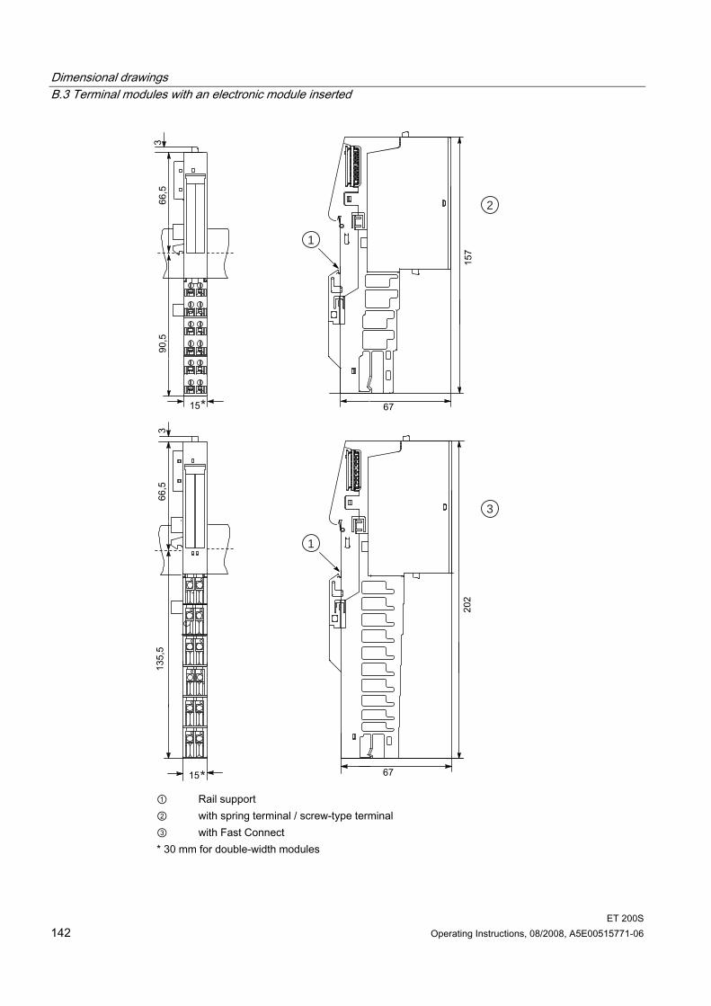
Dimensional drawings B.3 Terminal modules with an electronic module inserted
ET 200S 142 Operating Instructions, 08/2008, A5E00515771-06
2
3
1
1
① Rail support ② with spring terminal / screw-type terminal ③ with Fast Connect * 30 mm for double-width modules
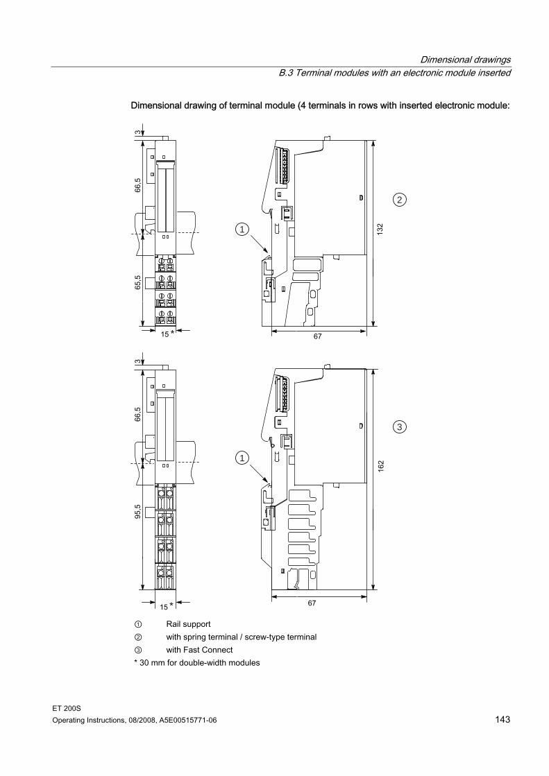
Dimensional drawings B.3 Terminal modules with an electronic module inserted
ET 200S Operating Instructions, 08/2008, A5E00515771-06 143
Dimensional drawing of terminal module (4 terminals in rows with inserted electronic module:
2
3
1
1
① Rail support ② with spring terminal / screw-type terminal ③ with Fast Connect * 30 mm for double-width modules
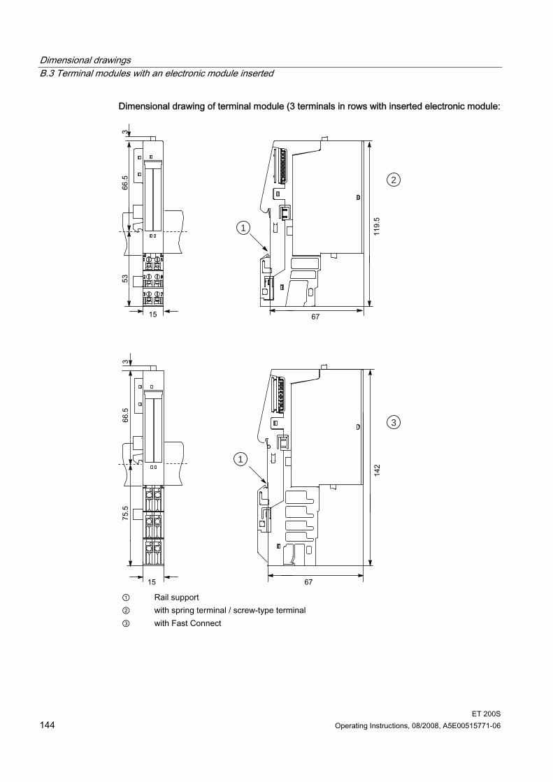
Dimensional drawings B.3 Terminal modules with an electronic module inserted
ET 200S 144 Operating Instructions, 08/2008, A5E00515771-06
Dimensional drawing of terminal module (3 terminals in rows with inserted electronic module:
2
3
1
1
① Rail support ② with spring terminal / screw-type terminal ③ with Fast Connect
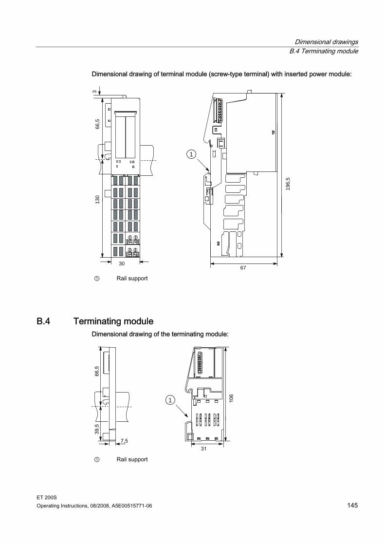
Dimensional drawings B.4 Terminating module
ET 200S Operating Instructions, 08/2008, A5E00515771-06 145
Dimensional drawing of terminal module (screw-type terminal) with inserted power module:
1
130
30
3
67
66,5
196,
5
① Rail support
B.4 Terminating module Dimensional drawing of the terminating module:
1
① Rail support
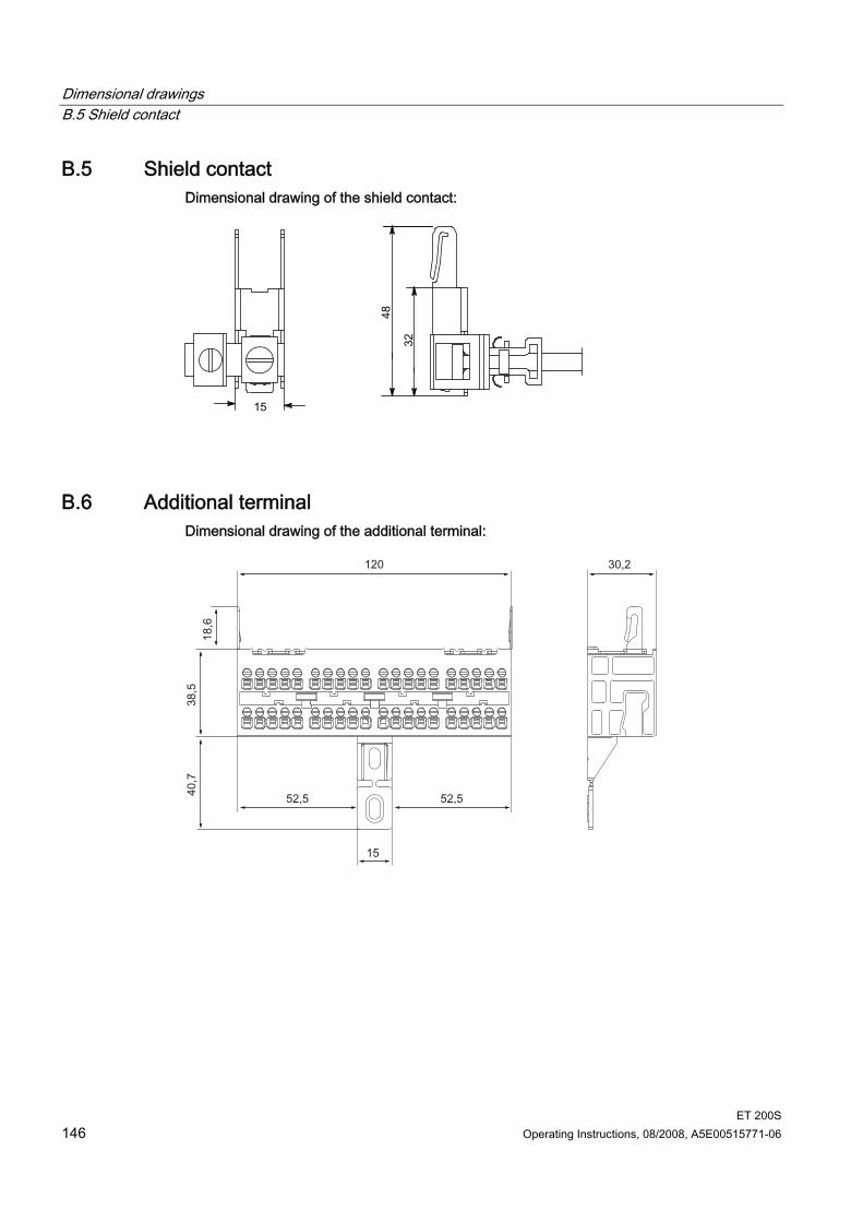
Dimensional drawings B.5 Shield contact
ET 200S 146 Operating Instructions, 08/2008, A5E00515771-06
B.5 Shield contact Dimensional drawing of the shield contact:
B.6 Additional terminal Dimensional drawing of the additional terminal:
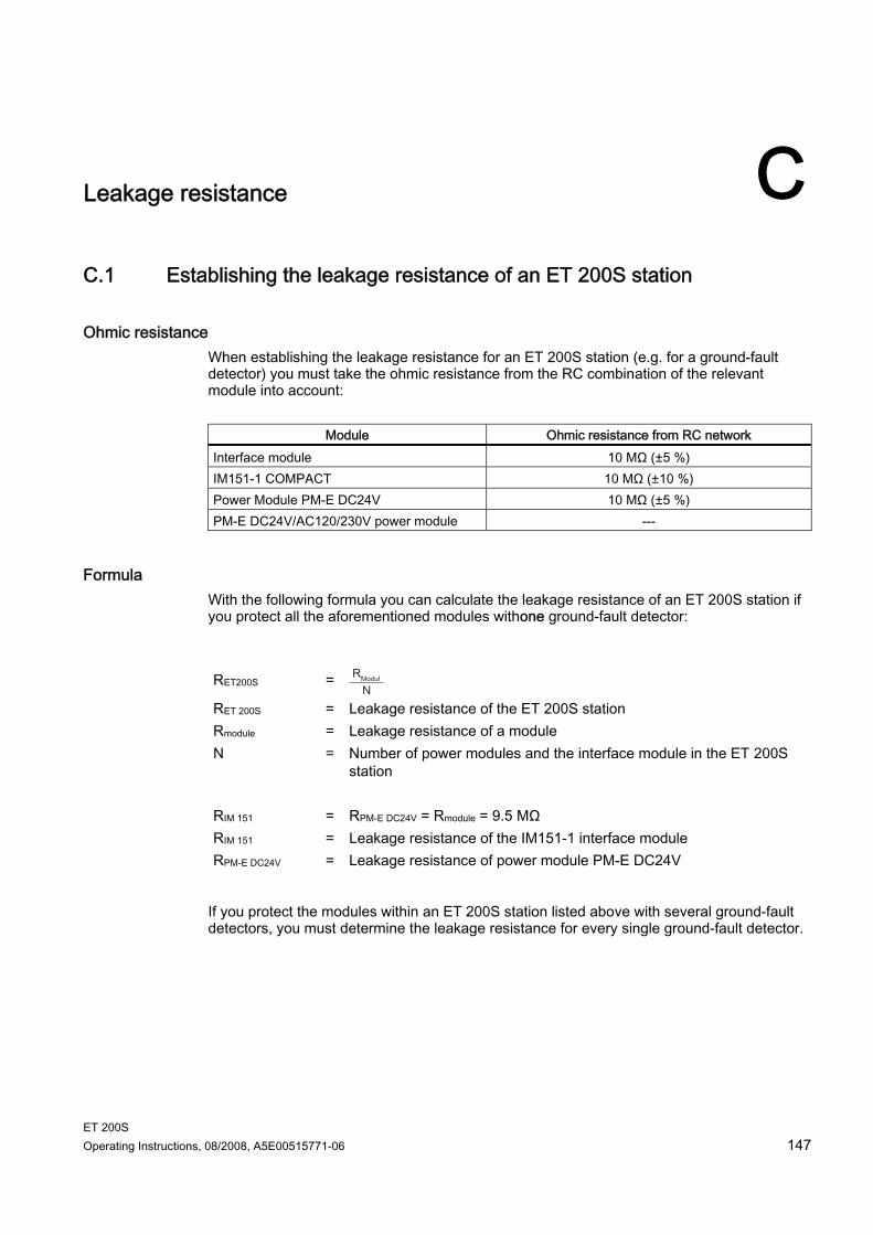
ET 200S Operating Instructions, 08/2008, A5E00515771-06 147
Leakage resistance CC.1 Establishing the leakage resistance of an ET 200S station
Ohmic resistance When establishing the leakage resistance for an ET 200S station (e.g. for a ground-fault detector) you must take the ohmic resistance from the RC combination of the relevant module into account:
Module Ohmic resistance from RC network Interface module 10 MΩ (±5 %) IM151-1 COMPACT 10 MΩ (±10 %) Power Module PM-E DC24V 10 MΩ (±5 %) PM-E DC24V/AC120/230V power module ---
Formula With the following formula you can calculate the leakage resistance of an ET 200S station if you protect all the aforementioned modules withone ground-fault detector: RET200S
=
RET 200S = Leakage resistance of the ET 200S station Rmodule = Leakage resistance of a module N = Number of power modules and the interface module in the ET 200S
station RIM 151 = RPM-E DC24V = Rmodule = 9.5 MΩ RIM 151 = Leakage resistance of the IM151-1 interface module RPM-E DC24V = Leakage resistance of power module PM-E DC24V
If you protect the modules within an ET 200S station listed above with several ground-fault detectors, you must determine the leakage resistance for every single ground-fault detector.
Leakage resistance C.1 Establishing the leakage resistance of an ET 200S station
ET 200S 148 Operating Instructions, 08/2008, A5E00515771-06
Example In the setup of an ET 200S there is one IM151-1 STANDARD and two PM-E DC24V power modules and various input and output modules. The entire ET 200S station is protected by one ground-fault detector:
Figure C-1 Calculation example for the leakage resistance
ET 200S Operating Instructions, 08/2008, A5E00515771-06 149
Interference-free operation DD.1 Special Measures for Interference-Free Operation
Inductive voltages Overvoltage occurs when sources of inductance are switched off. Examples of this are relay coils and contactors.
Integrated overvoltage protection The digital output modules of the ET 200S have an integrated overvoltage protection device.
Additional overvoltage protection Inductance must only be connected to additional overvoltage protective devices in the following cases: If digital output circuits can be switched of by additionally installed contacts
(e. g. relay contacts). If the inductance cannot be controlled by digital output modules. Note: Inquire about how the respective overvoltage protective devices must be dimensioned from your inductance supplier.
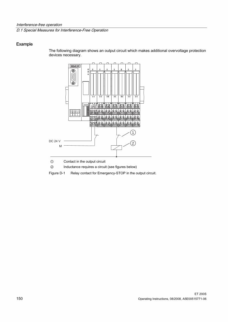
Interference-free operation D.1 Special Measures for Interference-Free Operation
ET 200S 150 Operating Instructions, 08/2008, A5E00515771-06
Example The following diagram shows an output circuit which makes additional overvoltage protection devices necessary.
1
2
① Contact in the output circuit ② Inductance requires a circuit (see figures below)
Figure D-1 Relay contact for Emergency-STOP in the output circuit.
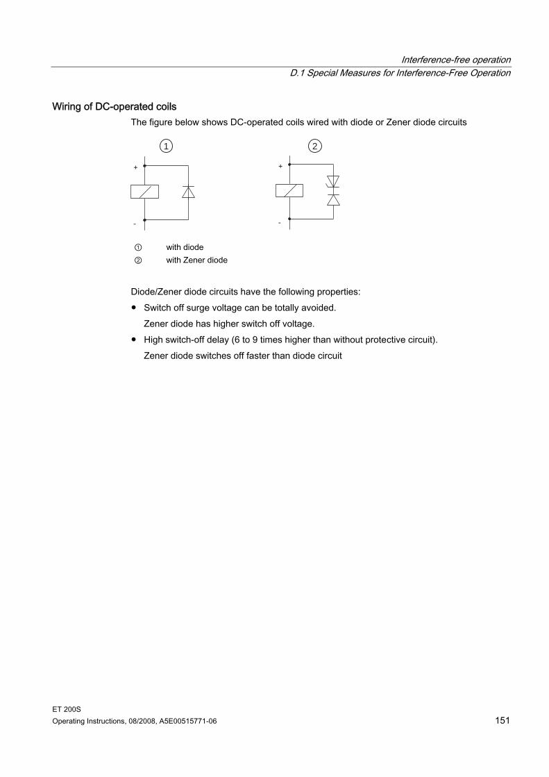
Interference-free operation D.1 Special Measures for Interference-Free Operation
ET 200S Operating Instructions, 08/2008, A5E00515771-06 151
Wiring of DC-operated coils The figure below shows DC-operated coils wired with diode or Zener diode circuits
1 2
① with diode ② with Zener diode
Diode/Zener diode circuits have the following properties: Switch off surge voltage can be totally avoided.
Zener diode has higher switch off voltage. High switch-off delay (6 to 9 times higher than without protective circuit).
Zener diode switches off faster than diode circuit
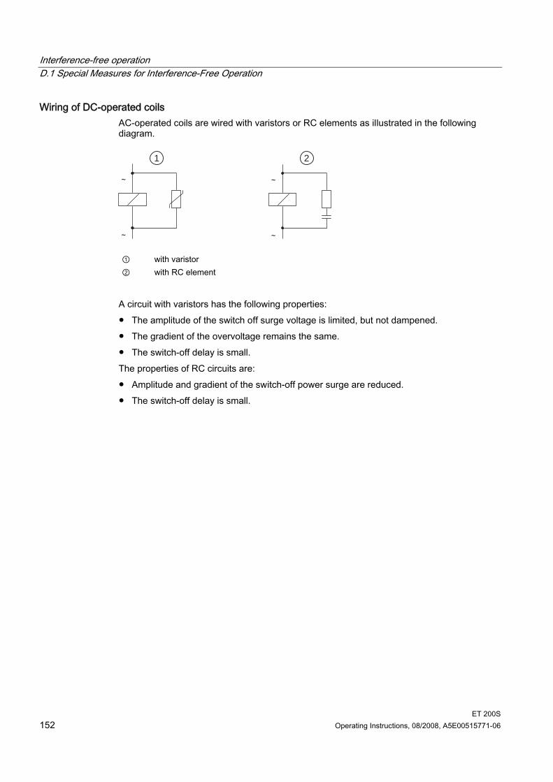
Interference-free operation D.1 Special Measures for Interference-Free Operation
ET 200S 152 Operating Instructions, 08/2008, A5E00515771-06
Wiring of DC-operated coils AC-operated coils are wired with varistors or RC elements as illustrated in the following diagram.
1 2
① with varistor ② with RC element
A circuit with varistors has the following properties: The amplitude of the switch off surge voltage is limited, but not dampened. The gradient of the overvoltage remains the same. The switch-off delay is small. The properties of RC circuits are: Amplitude and gradient of the switch-off power surge are reduced. The switch-off delay is small.
ET 200S Operating Instructions, 08/2008, A5E00515771-06 153
Glossary
Automation system An automation system is a programmable logic controller consisting of at least one CPU, various input and output modules, and operator control and monitoring devices.
AUX1 bus Power modules allow you to connect additional potential (up to 230 VAC), which you can apply by means of the AUX(iliary) bus. You can use the AUX(iliary) bus individually: As a protective conductor bar For additionally required voltage
Backplane bus The backplane bus is a serial data bus via which the IM151-1 interface communicates with the electronic modules/motor starters, supplying them with the required voltage. The connection between the individual modules is established by means of the terminal modules.
Bus A common transfer route connecting all nodes and having two defined ends. In the case of the ET 200, the bus is a two-wire or fiber-optic cable.
Bus connector A physical connection between the bus nodes and the bus line.
Chassis ground Chassis ground refers to all the interconnected inactive parts of a piece of equipment that, even in the event of a fault, cannot carry voltage that is dangerous to the touch.
Configuration The systematic arrangement of the different ET 200S modules (setup).
Connecting to common potential The opening of a new potential group by a power module. This permits the individual grouping of the sensor and load supplies.
Glossary
ET 200S 154 Operating Instructions, 08/2008, A5E00515771-06
Device names Before an IO device can be addressed by an IO controller, it must have a device name. This procedure was selected for PROFINET because names are easier to handle than complex IP addresses. Assignment of a device name for a concrete IO device can be compared with the setting of the PROFIBUS address for a DP slave. An IO device does not have a device name upon delivery. An IO device can only be addressed by an IO controller - i.e., for transferring configuration data (including the IP address) during startup or for user data exchange during cyclic operation - after it has been assigned a device name with the programming device/PC.
Diagnostics Diagnostics involves the identification, localization, classification, display, and further evaluation of errors, faults, and messages. Diagnostics includes monitoring functions that run automatically while the system is in operation. This increases the availability of systems by reducing setup times and downtimes.
Direct starter A direct starter is a → motor starter that switches a motor on or off directly. It consists of a circuit breaker and a contactor.
Distributed IO systems These are input/output units that are not located in the base unit; instead, they are distributed at some distance from the CPU, for example: ET 200M, ET 200X, ET 200L, ET 200S DP/AS-I Link Other DP slaves from either Siemens or other vendors The distributed IO systems are connected to the DP master by means of PROFIBUS DP.
DP master A → master that complies with IEC 61784-1:2002 Ed1 CP 3/1 is known as a DP master.
DP slave A → slave running on the PROFIBUS on the basis of the PROFIBUS DP protocol in accordance with IEC 61784-1:2002 Ed1 CP 3/1 is known as a DP slave.
DP standard The DP standard is the bus protocol of the ET 200 distributed IO system in accordance with IEC 61784-1:2002 Ed1 CP 3/1.
Glossary
ET 200S Operating Instructions, 08/2008, A5E00515771-06 155
Electronic modules Electronic modules provide inputs and outputs for process signals. There are digital and analog electronic modules.
Firmware update Updating of the firmware of the interface module. You should update the interface module to the latest firmware version following (compatible) function-related expansions or performance improvements.
FREEZE This is a control command of the DP master to a group of DP slaves. When a DP slave receives the FREEZE control command, it freezes the current status of the inputs and transfers them cyclically to the DP master. After each subsequent FREEZE control command, the DP slave freezes the status of the inputs again. The input data is not transferred from the DP slave to the DP master again cyclically until the DP master sends the UNFREEZE control command.
Frequency converter The frequency converter implements the smooth controlling of the speed of asynchronous motors. It masters both simple (frequency controlling) as well as more complex driving tasks (vector controlling). It can also be used for torque control.
Ground The conductive mass of earth, the electrical potential of which is equivalent to zero. In the vicinity of grounding electrodes, the potential may not be zero. The term "reference ground" is often used here.
Grounding Grounding means connecting an electrically conductive part to a grounding electrode by means of a grounding system.
GSD file The properties of a PROFINET device are described in a GSD (General Station Descriptor) file that contains all required information for configuration. As with PROFIBUS, you can link a PROFINET device in STEP 7 by means of a GSD file. In PROFINET IO, the GSD file is always in XML format. The structure of the GSD file corresponds to ISO 15734, the worldwide standard for device descriptions. In PROFIBUS, the GSD file is in ASCII format (as defined in IEC 61784-1:2002 Ed1 CP 3/1).
Glossary
ET 200S 156 Operating Instructions, 08/2008, A5E00515771-06
Hot swapping This is the removal and insertion of modules during the operation of the ET 200S.
Isolated In the case of isolated input/output modules, the reference potentials of the control and load circuit are electrically isolated - for example, by means of optical isolators, relays, or transformers. Input/output circuits can be grouped.
MAC address Each PROFINET device has a factory-assigned worldwide unique device identification. This 6-byte device identification is the MAC address. The MAC address consists of: 3-byte manufacturer ID and 3-byte device ID (serial number) As a rule, the MAC address can be read on the front of the device, for example: 08-00-06-6B-80-C0
Master When it has a token, a master can send data to and request data from other nodes (= active participants). Examples of DP masters are the CPU 315-2 DP or the IM308-C.
Motor starter (MS) Motor starter is the generic term for → direct and → reversing starters. The startup and direction of rotation of a motor are determined by motor starters.
Node Device that can send, receive or amplify data via the bus, for example,. DP master, DP slave, RS 485 repeater.
Non-isolated In the case of non-isolated input/output modules, the reference potentials of the control and load circuits are electrically connected.
Parameter assignment Parameter assignment is the transfer of slave parameters from the DP master to the DP slave.
PELV Protective Extra Low Voltage = extra low voltage with safe isolation
Glossary
ET 200S Operating Instructions, 08/2008, A5E00515771-06 157
Power buses (P1/ P2) Two internal buses (P1 and P2) that supply the electronic modules with voltage. The power buses are fed by the power module and connected by means of the terminal modules.
Power modules Power modules monitor the supply voltage for all the electronic modules in the potential group. The supply voltage is fed in by means of the TM-P terminal module.
Prewiring The wiring of the terminal modules before the electronic modules are inserted.
Process image The process image is a component of the system memory of the DP master. The signal states of the input modules are transferred to the process-image input area at the beginning of the cyclic program. At the end of the cyclic program, the values of the process-image output area are transferred to the DP slave as the signal states.
PROFIBUS PROcess FIeld BUS, German process field bus standard specified in IEC 61784-1:2002 Ed1 CP 3/1. It defines functional, electrical, and mechanical properties for a bit-serial field bus system. PROFIBUS is available with the protocols DP (which stands for distributed peripherals, that is, distributed or remote IO), FMS (which stands for field bus message specification), PA (= process automation), or TF (= technological functions).
PROFIBUS address Each bus node must receive a PROFIBUS address to identify it uniquely on the PROFIBUS. The PC/programming device has the PROFIBUS address "0". The PROFIBUS addresses 1 to 125 are permitted for the ET 200S distributed IO system.
PROFINET Within the context of Totally Integrated Automation (TIA), PROFINET is the systematic development of the following systems: PROFIBUS DP, the established field bus and Industrial Ethernet, the communication bus for the cell level Experiences from both systems have been and are being integrated in PROFINET. PROFINET as the Ethernet-based automation standard of PROFIBUS International (formerly PROFIBUS Nutzerorganisation e.V.) defines a cross-vendor communication, automation, and engineering model.
Glossary
ET 200S 158 Operating Instructions, 08/2008, A5E00515771-06
PROFINET device A PROFINET device always has at least one Industrial Ethernet connection. In addition, a PROFINET device can also have a PROFIBUS connection and even act as a master with proxy functionality. In exceptions, a PROFINET device can also have a several PROFIBUS connections (for example CP 5614).
Provider-consumer principle In a PROFINET IO both partners are independent providers in sending data, in contrast to PROFIBUS DP.
Real time Real time means that a system processes external events within a defined time. Determinism means that a system responds in a predictable (deterministic) manner. Both requirements are important for industrial networks. PROFINET satisfies these requirements. Thus, as a deterministic real-time network, PROFINET is designed as follows: The transfer of time-critical data between different stations via a network is guaranteed
within a defined interval of time. To this end, PROFINET has an optimized communication channel for real-time
communication: real time (RT): Real time (RT). The time of transfer can be accurately determined. It is ensured that seamless communication can take place in the same network by means
of other standard protocols, such as industrial communication for programming device/PC.
Reference potential Potential from which the voltages of the circuits involved can be observed and/or measured.
Reversing starter A reversing starter is a → motor starter that determines the direction of rotation of a motor. It consists of a circuit breaker and two contactors.
Segment The bus line between two terminating resistors forms a segment. A segment contains 0 to 32 → bus nodes. Segments can be coupled via RS 485 repeaters.
SELV Safety Extra Low Voltage
Glossary
ET 200S Operating Instructions, 08/2008, A5E00515771-06 159
Slave A slave can only exchange data with a → master when requested by it to do so. By slaves we mean, for example, all DP slaves such as ET 200X, ET 200M, ET 200S, etc.
SNMP SNMP (Simple Network Management Protocol) is the standardized protocol for performing diagnostics and assigning parameters to the Ethernet network infrastructure. In the office setting and in automation engineering, devices from many different vendors support SNMP on the Ethernet. SNMP-based applications can be operated on the same network in parallel to applications with PROFINET. The scope of supported functions depends on the device type. For example, a switch has more functions than a CP 1616.
SSI The positional information is transferred synchronously on the basis of the SSI (synchronous serial interface) protocol. The SSI protocol is used with absolute encoders.
Stationary wiring All the wiring-carrying elements (terminal modules) are mounted on a rail. The power and electronic modules are inserted in the terminal modules.
Switch PROFIBUS is a linear network. The communication nodes are linked by means of a passive cable– the bus. By contrast, the Industrial Ethernet consists of point-to-point connections: each communication node is interconnected directly with one other communication node. If a communication node is linked to several communication nodes, this communication node is connected to the port of an active network component – the switch. Additional communication nodes (including switches) can now be connected to the other ports of the switch. The connection between a communication node and the switch remains a point-to-point connection. A switch also has the task of regenerating and distributing received signals. The switch "learns" the Ethernet address(es) of a connected PROFINET device or additional switches and only forwards those signals that are intended for the connected PROFINET device or switch. A switch has a specific number of ports. You connect at most one PROFINET device or additional switch to each port.
Glossary
ET 200S 160 Operating Instructions, 08/2008, A5E00515771-06
SYNC This is a control command of the DP master to a group of DP slaves. With the SYNC control command the DP master orders the DP slave that the DP slave freeze the states of the outputs to the current value. With the subsequent frames, the DP slave stores the output data, but the statuses of the outputs remain unchanged. After each new SYNC control command, the DP slave sets the outputs that it has stored as output data. The outputs are not cyclically updated again until the DP master sends the UNSYNC control command.
Technological modules Modules that are equipped with technological functions, such as counting pulses, positioning, and controlling stepping motor power units.
Terminal modules Terminal modules implement the electrical and mechanical connection of the I/O modules with the interface module and the terminating module. The inserted I/O module determines the signals at the terminals of the terminal module. Depending on the selected terminal module only certain terminals are available.
Terminating module The ET 200S distributed IO system is completed by the terminating module. If you have not inserted a terminating module, the ET 200S is not ready for operation.
ET 200S Operating Instructions, 08/2008, A5E00515771-06 161
Index
2 24 VDC supply, 74
A Add-on terminal
Installing, 60 removing, 62
Address area, 103, 118 Approval
Standards, 127 Assembly, 67, 68
Shield contact, 67, 68 Assigning a device name, 116 AUX(iliary) bus (AUX1), 45
B Brief instructions on commissioning
ET 200S on PROFINET IO, 30 ET 200S on the PROFIBUS DP, 21
Burst pulses, 131 Bus cable, 16
C CE
Certification, 127 Certification
CE, 127 FM, 129 Marine, 130
Changing the PROFIBUS Address, 112 Climatic environmental conditions, 133 Color-coded labels, 16, 71
Mounting, 72 Removing, 72
Commissioning, 102 PROFIBUS DP, 113 PROFINET IO, 120 Requirements for PROFIBUS DP, 113 Requirements for PROFINET IO, 120
Commissioning the ET 200S on PROFIBUS DP, 113 on PROFINET IO, 120
COMPACT modules, 95, 96, 98 changing type, 98 Exchange, 98 identifying, 95 Mounting, 95 removing, 96
Components and protective measures, 76 Configuration, 102, 115
ET 200S, 102, 115 Configuration examples
Terminal modules for power modules, 47 Connecting cable shields, 85 Connecting PROFIBUS DP, 87, 91 Connecting the supply voltage, 87, 91 Connecting to common potential, 45
D Diagnostics, 102 Digital input modules, 103, 118 Digital output modules, 103, 118 Dimensions
Additional terminal, 146 Shield contact, 146 Terminal module for COMPACT module with COMPACT module inserted, 141 Terminal modules with an electronic module inserted, 141 Terminal modules with inserted power module, 141 Terminating module, 145
Distributed I/O systems, 11 DP master, 11 DP slave, 11
Index
ET 200S 162 Operating Instructions, 08/2008, A5E00515771-06
E Electromagnetic compatibility, 131 Electronic module, 16 Electronic modules, 95, 96, 98, 99
changing type, 98 Exchange, 98 identifying, 95 Mounting, 95 removing, 96 Removing and inserting during operation, 99
Electrostatic discharge, 131 EMC, 131 EMERGENCY-STOP devices, 73 Emission of radio interference, 132 ET 200S, 75, 77, 102, 113, 120
Characteristics and benefits, 19 Configuration, 102, 115 Overall configuration, 77 with grounded reference potential, 75
ET 200S components, 16 ET 200S distributed I/O system
Applications, 14 Definition, 14 Terminal modules and electronic modules, 14 View, 15
ET 200S FC Variations in the technical specifications, 136
Example configuration of a fiber-optic cable network with IM151-1 FO STANDARD, 89 Example of a configuration, 109 Exchange terminal box
on terminal module, 64
F Fiber-optic cable
bending radius, 90 Fiber-optic duplex cable, 16 FM
Certification, 129 Frequency converter
Variations in the technical specifications, 136
G Galvanic isolation, 78 General Rules, 73 General technical specifications, 127 Grounded incoming supply, 75 GSD file, 103, 115 Guide
for the operating instructions, 5
H Heat dissipation, 53
I Identification data, 126 IEC 204, 73 IEC 61131, 129 IEC 61784-1 standard
2002 Ed1 CP 3/1, 11 IM151-1 BASIC interface module, 16 IM151-1 FO STANDARD interface module, 16 IM151-1 HIGH FEATURE interface module, 16 IM151-1 STANDARD interface module, 16 IM151-3 PN interface module, 16 Installation, 54, 66, 69
Color identification labels, 69 Interface module, 54 Slot number plates, 69 Terminating module, 66
Installation position, 51 Installation rules, 51 Installing, 51 Installing the terminal module
TM-C, 57 TM-E, 55 TM-P, 55
Insulation test, 135 Interface module IM151-1 FO STANDARD
Plug adapters, 89
L Label sheet, 16
M Marine
Certification, 130 Mechanical ambient conditions, 134 Minimum clearances, 53 Motor starter, 103, 118 Mounting rail, 16, 52
Index
ET 200S Operating Instructions, 08/2008, A5E00515771-06 163
O Operating instructions
Purpose, 3 Option handling, 125
Properties, 125 Order numbers
ET 200S accessories, 137 Order numbers for sample configuration
on PROFIBUS DP, 22 on PROFINET IO, 32
P Placing and connecting to common potential, 45 Placing power modules and connecting them to common potential, 45 Plug adapters
for IM151-1 FO STANDARD, 89 Pollution level, 135 Potential group, 45 Power module, 16 Power supply, 45
Connecting, 94 PROFIBUS DP, 11
Devices, 11 PROFIBUS DP network
Structure, 12 PROFIBUS standard, 129 PROFINET IO
Network structure, 13 Protection against outside electrical influences, 74 Protection Class, 135 Protection class IP 20, 135 Pulse-shaped Interference, 131
R Rated voltage, 135 Recycling, 5 Redundancy, 42 Regulations, 73 Removing and inserting
Electronic modules, 100 Removing the terminal module
TM-C, 58 TM-E, 56 TM-P, 56
Repetitive shock, 134 Required level of knowledge, 3 Rules for fiber-optic cable network, 88
S Safety isolation, 75 Scope, 3 Self-coding, 95 Setting the PROFIBUS Address, 111 Shield contact, 16 Shock, 134 Simplex connectors
installing, 89 Sinusoidal Interference, 131 Slot number plates, 16 Software Requirements
Commissioning on PROFIBUS DP, 113 Commissioning on PROFINET IO, 120
Specific application, 73 Standards and approvals, 127 Startup, 113, 120 Startup of the ET 200S
on PROFIBUS DP, 114 on PROFINET IO, 121
Storage conditions, 132 System Startup after Certain Events, 73
T Technical specifications
Climatic environmental conditions, 133 Electromagnetic compatibility, 131 mechanical ambient conditions, 133
terminal box on terminal module replace, 64
Terminal module, 16, 79, 80, 81 Wiring with Fast Connect, 81 wiring with screw-type terminals, 79 wiring with spring terminals, 80
Terminal modules, 84 Terminating module, 16 Test voltage, 135 Tick-mark for Australia, 129 Transport conditions, 132 Type-coded, 95
U Use in industrial environment, 130 Use in residential areas, 130
Index
ET 200S 164 Operating Instructions, 08/2008, A5E00515771-06
V Vibrations, 134 Voltage relationships
in the ET 200S with IM151-1, 78
W Wiring, 87, 88, 92
IM151-3 PN interface module, 92 Interface module IM151-1 BASIC, 87 Interface module IM151-1 FO STANDARD, 88 Interface module IM151-1 HIGH FEATURE, 87 Interface module IM151-1 STANDARD, 87
Wiring and assembly, 73 Wiring rules, 79 Wiring terminal modules, 84
for COMPACT modules, 85 for digital, analog, and technological modules, 85 For power modules, 85
Y Y switching, 42
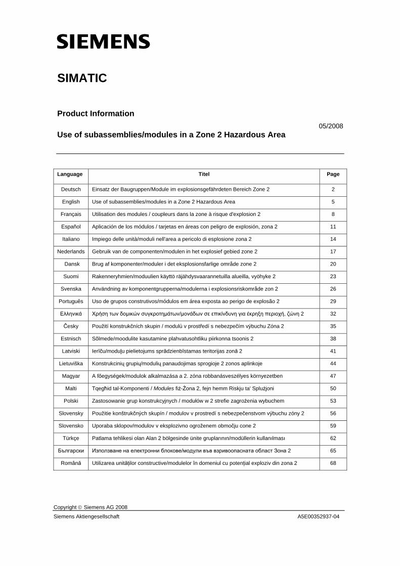
s
Copyright © Siemens AG 2008
Siemens Aktiengesellschaft A5E00352937-04
SIMATIC
Product Information 05/2008
Use of subassemblies/modules in a Zone 2 Hazardous Area
Language Titel Page
Deutsch Einsatz der Baugruppen/Module im explosionsgefährdeten Bereich Zone 2 2
English Use of subassemblies/modules in a Zone 2 Hazardous Area 5
Français Utilisation des modules / coupleurs dans la zone à risque d'explosion 2 8
Español Aplicación de los módulos / tarjetas en áreas con peligro de explosión, zona 2 11
Italiano Impiego delle unità/moduli nell'area a pericolo di esplosione zona 2 14
Nederlands Gebruik van de componenten/modulen in het explosief gebied zone 2 17
Dansk Brug af komponenter/moduler i det eksplosionsfarlige område zone 2 20
Suomi Rakenneryhmien/moduulien käyttö räjähdysvaarannetuilla alueilla, vyöhyke 2 23
Svenska Användning av komponentgrupperna/modulerna i explosionsriskområde zon 2 26
Português Uso de grupos construtivos/módulos em área exposta ao perigo de explosão 2 29
Ελληνικά Χρήση των δομικών συγκροτημάτων/μονάδων σε επικίνδυνη για έκρηξη περιοχή, ζώνη 2 32
Česky Použití konstrukčních skupin / modulů v prostředí s nebezpečím výbuchu Zóna 2 35
Estnisch Sõlmede/moodulite kasutamine plahvatusohtliku piirkonna tsoonis 2 38
Latviski Ierīču/moduļu pielietojums sprādzienbīstamas teritorijas zonā 2 41
Lietuviška Konstrukcinių grupių/modulių panaudojimas sprogioje 2 zonos aplinkoje 44
Magyar A főegységek/modulok alkalmazása a 2. zóna robbanásveszélyes környezetben 47
Malti Tqegħid tal-Komponenti / Modules fiż-Żona 2, fejn hemm Riskju ta' Splużjoni 50
Polski Zastosowanie grup konstrukcyjnych / modułów w 2 strefie zagrożenia wybuchem 53
Slovensky Použitie konštrukčných skupín / modulov v prostredí s nebezpečenstvom výbuchu zóny 2 56
Slovensko Uporaba sklopov/modulov v eksplozivno ogroženem območju cone 2 59
Türkçe Patlama tehlikesi olan Alan 2 bölgesinde ünite gruplarının/modüllerin kullanılması 62
Български Използване на електронни блокове/модули във взривоопасната област Зона 2 65
Română Utilizarea unităţilor constructive/modulelor în domeniul cu potenţial exploziv din zona 2 68
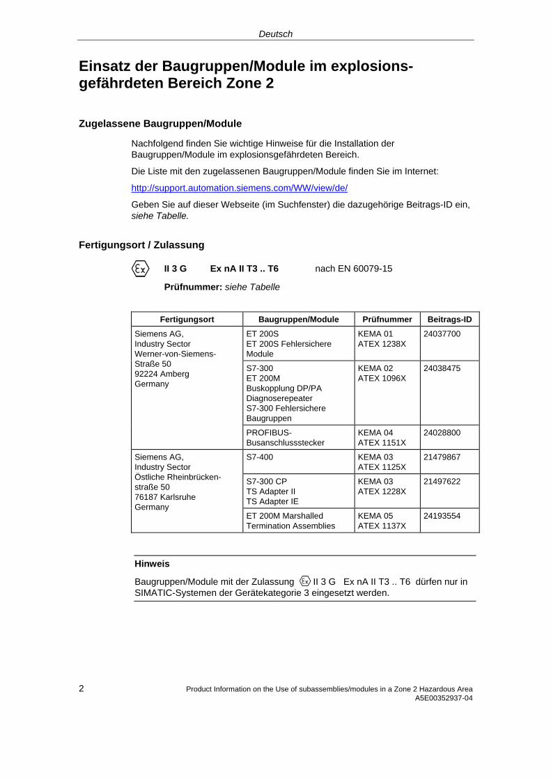
Deutsch
Einsatz der Baugruppen/Module im explosions-gefährdeten Bereich Zone 2
Zugelassene Baugruppen/Module
Nachfolgend finden Sie wichtige Hinweise für die Installation der Baugruppen/Module im explosionsgefährdeten Bereich.
Die Liste mit den zugelassenen Baugruppen/Module finden Sie im Internet:
http://support.automation.siemens.com/WW/view/de/
Geben Sie auf dieser Webseite (im Suchfenster) die dazugehörige Beitrags-ID ein, siehe Tabelle.
Fertigungsort / Zulassung
II 3 G Ex nA II T3 .. T6 nach EN 60079-15
Prüfnummer: siehe Tabelle
Fertigungsort Baugruppen/Module Prüfnummer Beitrags-ID
ET 200S ET 200S Fehlersichere Module
KEMA 01 ATEX 1238X
24037700
S7-300 ET 200M Buskopplung DP/PA Diagnoserepeater S7-300 Fehlersichere Baugruppen
KEMA 02 ATEX 1096X
24038475
Siemens AG, Industry Sector Werner-von-Siemens-Straße 50 92224 Amberg Germany
PROFIBUS-Busanschlussstecker
KEMA 04 ATEX 1151X
24028800
S7-400 KEMA 03 ATEX 1125X
21479867
S7-300 CP TS Adapter II TS Adapter IE
KEMA 03 ATEX 1228X
21497622
Siemens AG, Industry Sector Östliche Rheinbrücken-straße 50 76187 Karlsruhe Germany
ET 200M Marshalled Termination Assemblies
KEMA 05 ATEX 1137X
24193554
Hinweis
Baugruppen/Module mit der Zulassung II 3 G Ex nA II T3 .. T6 dürfen nur in SIMATIC-Systemen der Gerätekategorie 3 eingesetzt werden.
2 Product Information on the Use of subassemblies/modules in a Zone 2 Hazardous Area A5E00352937-04
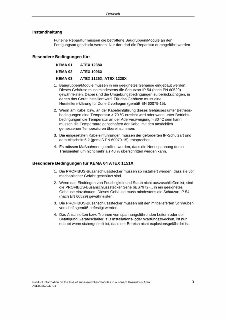
Deutsch
Product Information on the Use of subassemblies/modules in a Zone 2 Hazardous Area 3 A5E00352937-04
Instandhaltung
Für eine Reparatur müssen die betroffene Baugruppen/Module an den Fertigungsort geschickt werden. Nur dort darf die Reparatur durchgeführt werden.
Besondere Bedingungen für:
KEMA 01 ATEX 1238X
KEMA 02 ATEX 1096X
KEMA 03 ATEX 1125X, ATEX 1228X
1. Baugruppen/Module müssen in ein geeignetes Gehäuse eingebaut werden. Dieses Gehäuse muss mindestens die Schutzart IP 54 (nach EN 60529) gewährleisten. Dabei sind die Umgebungsbedingungen zu berücksichtigen, in denen das Gerät installiert wird. Für das Gehäuse muss eine Herstellererklärung für Zone 2 vorliegen (gemäß EN 60079-15).
2. Wenn am Kabel bzw. an der Kabeleinführung dieses Gehäuses unter Betriebs-bedingungen eine Temperatur > 70 °C erreicht wird oder wenn unter Betriebs-bedingungen die Temperatur an der Aderverzweigung > 80 °C sein kann, müssen die Temperatureigenschaften der Kabel mit den tatsächlich gemessenen Temperaturen übereinstimmen.
3. Die eingesetzten Kabeleinführungen müssen der geforderten IP-Schutzart und dem Abschnitt 6.2 (gemäß EN 60079-15) entsprechen.
4. Es müssen Maßnahmen getroffen werden, dass die Nennspannung durch Transienten um nicht mehr als 40 % überschritten werden kann.
Besondere Bedingungen für KEMA 04 ATEX 1151X
1. Die PROFIBUS-Busanschlussstecker müssen so installiert werden, dass sie vor mechanischer Gefahr geschützt sind.
2. Wenn das Eindringen von Feuchtigkeit und Staub nicht auszuschließen ist, sind die PROFIBUS-Busanschlussstecker Serie 6ES7972-... in ein geeignetes Gehäuse einzubauen. Dieses Gehäuse muss mindestens die Schutzart IP 54 (nach EN 60529) gewährleisten.
3. Die PROFIBUS-Busanschlussstecker müssen mit den mitgelieferten Schrauben vorschriftsgemäß befestigt werden.
4. Das Anschließen bzw. Trennen von spannungsführenden Leitern oder der Betätigung Geräteschalter, z.B Installations- oder Wartungszwecken, ist nur erlaubt wenn sichergestellt ist, dass der Bereich nicht explosionsgefährdet ist.
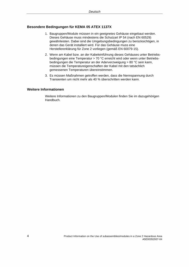
Deutsch
4 Product Information on the Use of subassemblies/modules in a Zone 2 Hazardous Area A5E00352937-04
Besondere Bedingungen für KEMA 05 ATEX 1137X
1. Baugruppen/Module müssen in ein geeignetes Gehäuse eingebaut werden. Dieses Gehäuse muss mindestens die Schutzart IP 54 (nach EN 60529) gewährleisten. Dabei sind die Umgebungsbedingungen zu berücksichtigen, in denen das Gerät installiert wird. Für das Gehäuse muss eine Herstellererklärung für Zone 2 vorliegen (gemäß EN 60079-15).
2. Wenn am Kabel bzw. an der Kabeleinführung dieses Gehäuses unter Betriebs-bedingungen eine Temperatur > 70 °C erreicht wird oder wenn unter Betriebs-bedingungen die Temperatur an der Aderverzweigung > 80 °C sein kann, müssen die Temperatureigenschaften der Kabel mit den tatsächlich gemessenen Temperaturen übereinstimmen.
3. Es müssen Maßnahmen getroffen werden, dass die Nennspannung durch Transienten um nicht mehr als 40 % überschritten werden kann.
Weitere Informationen
Weitere Informationen zu den Baugruppen/Modulen finden Sie im dazugehörigen Handbuch.
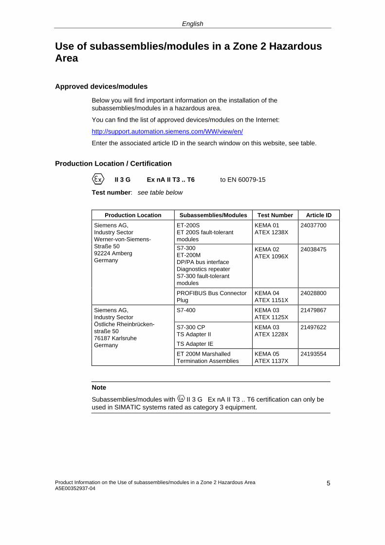
English
Use of subassemblies/modules in a Zone 2 Hazardous Area
Approved devices/modules
Below you will find important information on the installation of the subassemblies/modules in a hazardous area.
You can find the list of approved devices/modules on the Internet:
http://support.automation.siemens.com/WW/view/en/
Enter the associated article ID in the search window on this website, see table.
Production Location / Certification
II 3 G Ex nA II T3 .. T6 to EN 60079-15
Test number: see table below
Production Location Subassemblies/Modules Test Number Article ID
ET-200S ET 200S fault-tolerant modules
KEMA 01 ATEX 1238X
24037700
S7-300 ET-200M DP/PA bus interface Diagnostics repeater S7-300 fault-tolerant modules
KEMA 02 ATEX 1096X
24038475
Siemens AG, Industry Sector Werner-von-Siemens-Straße 50 92224 Amberg Germany
PROFIBUS Bus Connector Plug
KEMA 04 ATEX 1151X
24028800
S7-400 KEMA 03 ATEX 1125X
21479867
S7-300 CP TS Adapter II TS Adapter IE
KEMA 03 ATEX 1228X
21497622
Siemens AG, Industry Sector Östliche Rheinbrücken-straße 50 76187 Karlsruhe Germany
ET 200M Marshalled Termination Assemblies
KEMA 05 ATEX 1137X
24193554
Note
Subassemblies/modules with II 3 G Ex nA II T3 .. T6 certification can only be used in SIMATIC systems rated as category 3 equipment.
Product Information on the Use of subassemblies/modules in a Zone 2 Hazardous Area A5E00352937-04
5
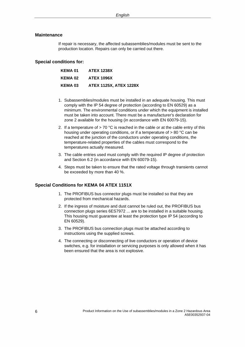
English
Maintenance
If repair is necessary, the affected subassemblies/modules must be sent to the production location. Repairs can only be carried out there.
Special conditions for:
KEMA 01 ATEX 1238X
KEMA 02 ATEX 1096X
KEMA 03 ATEX 1125X, ATEX 1228X
1. Subassemblies/modules must be installed in an adequate housing. This must comply with the IP 54 degree of protection (according to EN 60529) as a minimum. The environmental conditions under which the equipment is installed must be taken into account. There must be a manufacturer's declaration for zone 2 available for the housing (in accordance with EN 60079-15).
2. If a temperature of > 70 °C is reached in the cable or at the cable entry of this housing under operating conditions, or if a temperature of > 80 °C can be reached at the junction of the conductors under operating conditions, the temperature-related properties of the cables must correspond to the temperatures actually measured.
3. The cable entries used must comply with the required IP degree of protection and Section 6.2 (in accordance with EN 60079-15).
4. Steps must be taken to ensure that the rated voltage through transients cannot be exceeded by more than 40 %.
Special Conditions for KEMA 04 ATEX 1151X
1. The PROFIBUS bus connector plugs must be installed so that they are protected from mechanical hazards.
2. If the ingress of moisture and dust cannot be ruled out, the PROFIBUS bus connection plugs series 6ES7972 ... are to be installed in a suitable housing. This housing must guarantee at least the protection type IP 54 (according to EN 60529).
3. The PROFIBUS bus connection plugs must be attached according to instructions using the supplied screws.
4. The connecting or disconnecting of live conductors or operation of device switches, e.g. for installation or servicing purposes is only allowed when it has been ensured that the area is not explosive.
Product Information on the Use of subassemblies/modules in a Zone 2 Hazardous Area A5E00352937-04 6
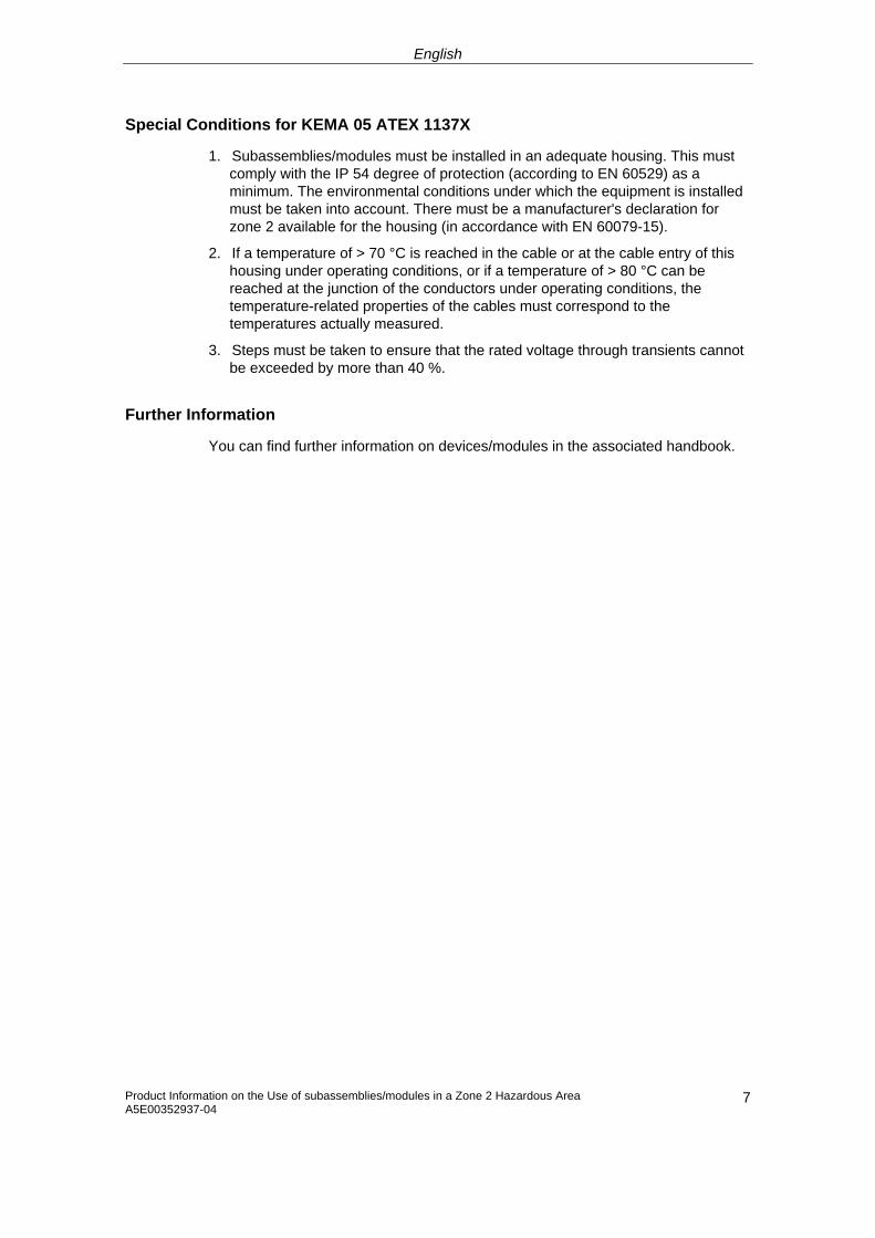
English
Product Information on the Use of subassemblies/modules in a Zone 2 Hazardous Area A5E00352937-04
7
Special Conditions for KEMA 05 ATEX 1137X
1. Subassemblies/modules must be installed in an adequate housing. This must comply with the IP 54 degree of protection (according to EN 60529) as a minimum. The environmental conditions under which the equipment is installed must be taken into account. There must be a manufacturer's declaration for zone 2 available for the housing (in accordance with EN 60079-15).
2. If a temperature of > 70 °C is reached in the cable or at the cable entry of this housing under operating conditions, or if a temperature of > 80 °C can be reached at the junction of the conductors under operating conditions, the temperature-related properties of the cables must correspond to the temperatures actually measured.
3. Steps must be taken to ensure that the rated voltage through transients cannot be exceeded by more than 40 %.
Further Information
You can find further information on devices/modules in the associated handbook.
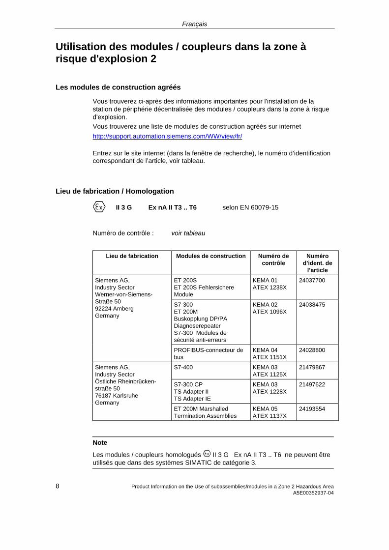
Français
Utilisation des modules / coupleurs dans la zone à risque d'explosion 2
Les modules de construction agréés
Vous trouverez ci-après des informations importantes pour l'installation de la station de périphérie décentralisée des modules / coupleurs dans la zone à risque d'explosion. Vous trouverez une liste de modules de construction agréés sur internet http://support.automation.siemens.com/WW/view/fr/
Entrez sur le site internet (dans la fenêtre de recherche), le numéro d’identification correspondant de l’article, voir tableau.
Lieu de fabrication / Homologation
II 3 G Ex nA II T3 .. T6 selon EN 60079-15
Numéro de contrôle : voir tableau
Lieu de fabrication Modules de construction Numéro de contrôle
Numéro d’ident. de
l’article
ET 200S ET 200S Fehlersichere Module
KEMA 01 ATEX 1238X
24037700
S7-300 ET 200M Buskopplung DP/PA Diagnoserepeater S7-300 Modules de sécurité anti-erreurs
KEMA 02 ATEX 1096X
24038475
Siemens AG, Industry Sector Werner-von-Siemens-Straße 50 92224 Amberg Germany
PROFIBUS-connecteur de bus
KEMA 04 ATEX 1151X
24028800
S7-400 KEMA 03 ATEX 1125X
21479867
S7-300 CP TS Adapter II TS Adapter IE
KEMA 03 ATEX 1228X
21497622
Siemens AG, Industry Sector Östliche Rheinbrücken-straße 50 76187 Karlsruhe Germany
ET 200M Marshalled Termination Assemblies
KEMA 05 ATEX 1137X
24193554
Note
Les modules / coupleurs homologués II 3 G Ex nA II T3 .. T6 ne peuvent être utilisés que dans des systèmes SIMATIC de catégorie 3.
8 Product Information on the Use of subassemblies/modules in a Zone 2 Hazardous Area A5E00352937-04
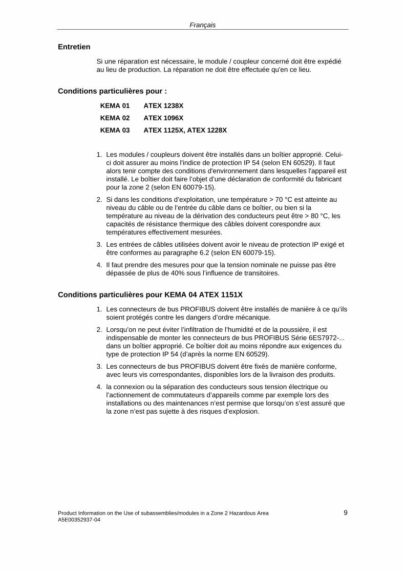
Français
Entretien
Si une réparation est nécessaire, le module / coupleur concerné doit être expédié au lieu de production. La réparation ne doit être effectuée qu'en ce lieu.
Conditions particulières pour :
KEMA 01 ATEX 1238X
KEMA 02 ATEX 1096X
KEMA 03 ATEX 1125X, ATEX 1228X
1. Les modules / coupleurs doivent être installés dans un boîtier approprié. Celui-ci doit assurer au moins l'indice de protection IP 54 (selon EN 60529). Il faut alors tenir compte des conditions d'environnement dans lesquelles l'appareil est installé. Le boîtier doit faire l’objet d’une déclaration de conformité du fabricant pour la zone 2 (selon EN 60079-15).
2. Si dans les conditions d’exploitation, une température > 70 °C est atteinte au niveau du câble ou de l’entrée du câble dans ce boîtier, ou bien si la température au niveau de la dérivation des conducteurs peut être > 80 °C, les capacités de résistance thermique des câbles doivent corespondre aux températures effectivement mesurées.
3. Les entrées de câbles utilisées doivent avoir le niveau de protection IP exigé et être conformes au paragraphe 6.2 (selon EN 60079-15).
4. Il faut prendre des mesures pour que la tension nominale ne puisse pas être dépassée de plus de 40% sous l’influence de transitoires.
Conditions particulières pour KEMA 04 ATEX 1151X
1. Les connecteurs de bus PROFIBUS doivent être installés de manière à ce qu’ils soient protégés contre les dangers d’ordre mécanique.
2. Lorsqu’on ne peut éviter l’infiltration de l’humidité et de la poussière, il est indispensable de monter les connecteurs de bus PROFIBUS Série 6ES7972-... dans un boîtier approprié. Ce boîtier doit au moins répondre aux exigences du type de protection IP 54 (d’après la norme EN 60529).
3. Les connecteurs de bus PROFIBUS doivent être fixés de manière conforme, avec leurs vis correspondantes, disponibles lors de la livraison des produits.
4. la connexion ou la séparation des conducteurs sous tension électrique ou l’actionnement de commutateurs d’appareils comme par exemple lors des installations ou des maintenances n’est permise que lorsqu’on s’est assuré que la zone n’est pas sujette à des risques d’explosion.
9 Product Information on the Use of subassemblies/modules in a Zone 2 Hazardous AreaA5E00352937-04
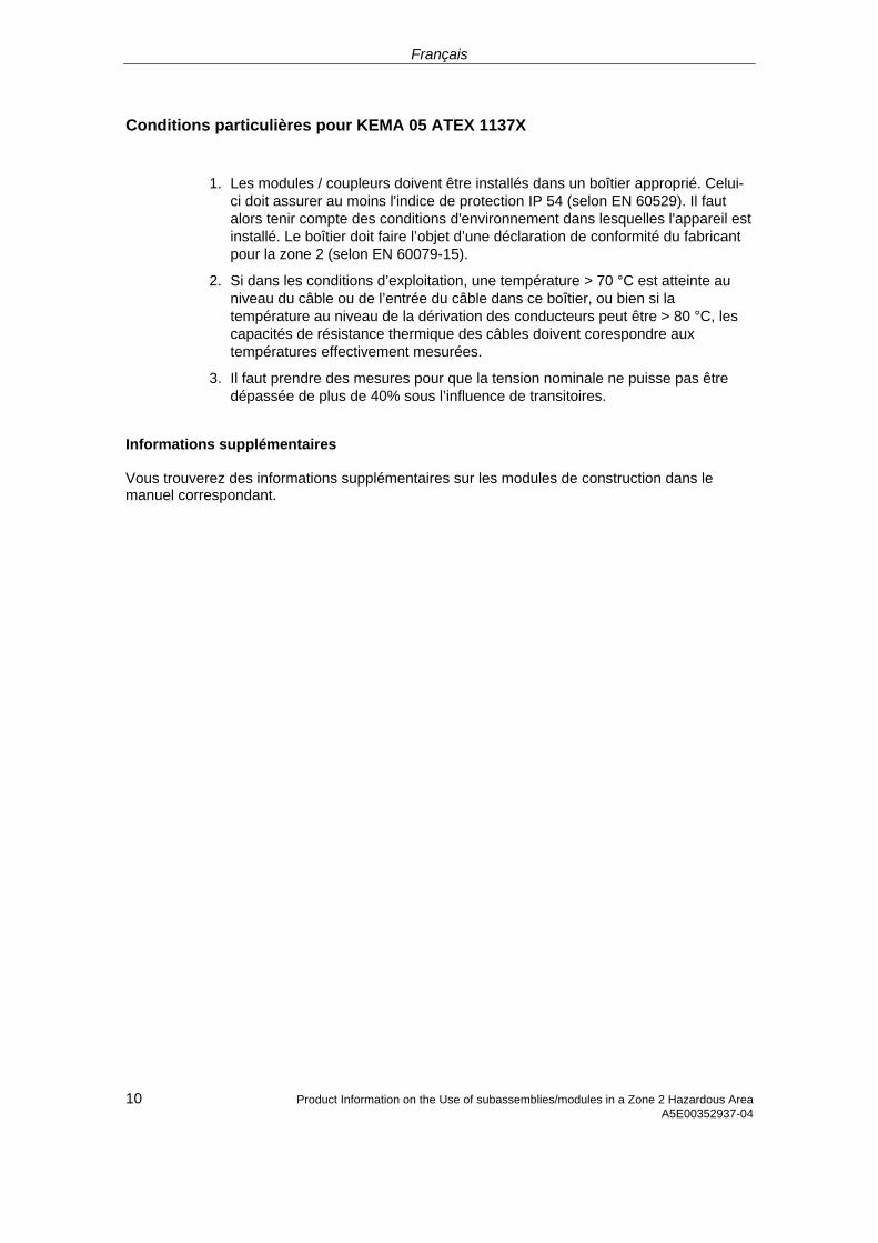
Français
10 Product Information on the Use of subassemblies/modules in a Zone 2 Hazardous Area A5E00352937-04
Conditions particulières pour KEMA 05 ATEX 1137X
1. Les modules / coupleurs doivent être installés dans un boîtier approprié. Celui-ci doit assurer au moins l'indice de protection IP 54 (selon EN 60529). Il faut alors tenir compte des conditions d'environnement dans lesquelles l'appareil est installé. Le boîtier doit faire l’objet d’une déclaration de conformité du fabricant pour la zone 2 (selon EN 60079-15).
2. Si dans les conditions d’exploitation, une température > 70 °C est atteinte au niveau du câble ou de l’entrée du câble dans ce boîtier, ou bien si la température au niveau de la dérivation des conducteurs peut être > 80 °C, les capacités de résistance thermique des câbles doivent corespondre aux températures effectivement mesurées.
3. Il faut prendre des mesures pour que la tension nominale ne puisse pas être dépassée de plus de 40% sous l’influence de transitoires.
Informations supplémentaires Vous trouverez des informations supplémentaires sur les modules de construction dans le manuel correspondant.
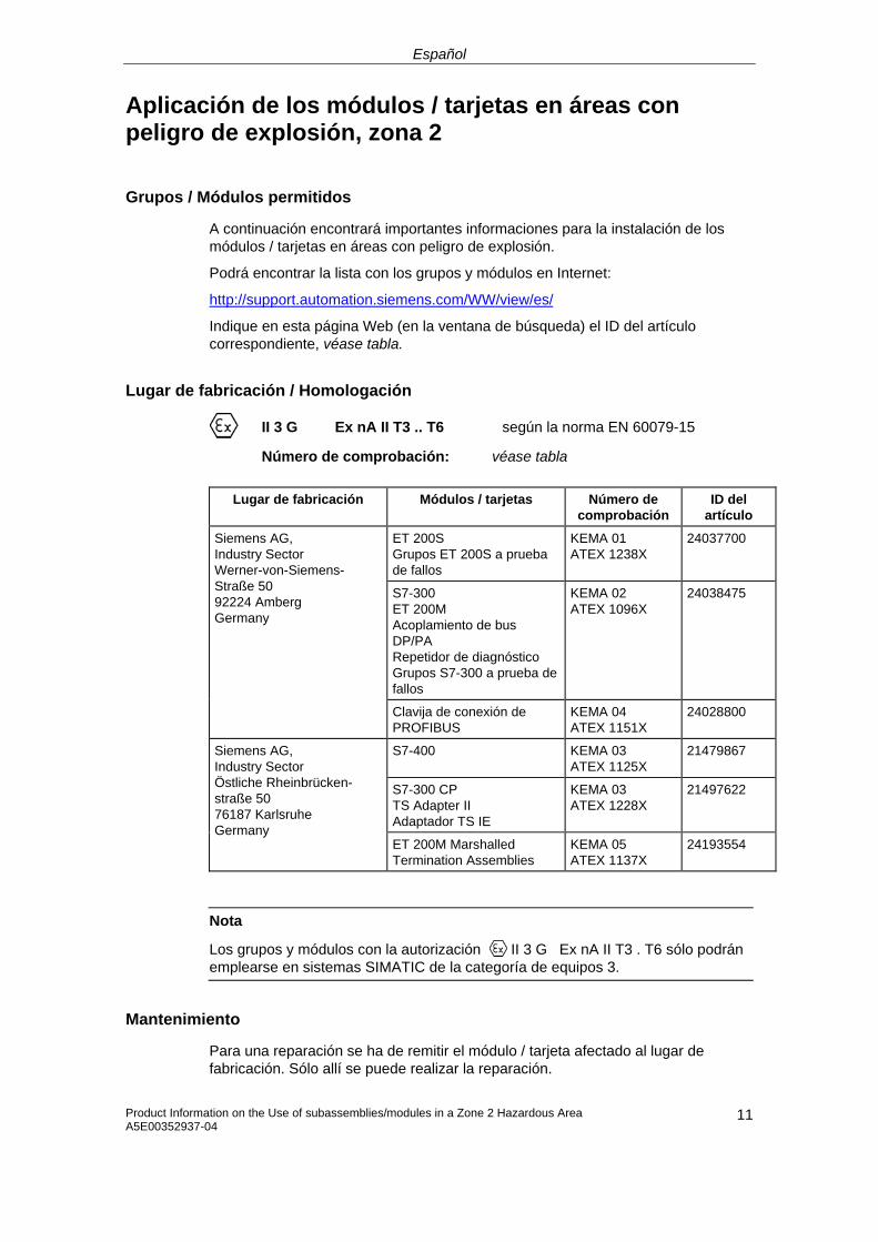
Español
Aplicación de los módulos / tarjetas en áreas con peligro de explosión, zona 2
Grupos / Módulos permitidos
A continuación encontrará importantes informaciones para la instalación de los módulos / tarjetas en áreas con peligro de explosión.
Podrá encontrar la lista con los grupos y módulos en Internet:
http://support.automation.siemens.com/WW/view/es/
Indique en esta página Web (en la ventana de búsqueda) el ID del artículo correspondiente, véase tabla.
Lugar de fabricación / Homologación
II 3 G Ex nA II T3 .. T6 según la norma EN 60079-15
Número de comprobación: véase tabla
Lugar de fabricación Módulos / tarjetas Número de comprobación
ID del artículo
ET 200S Grupos ET 200S a prueba de fallos
KEMA 01 ATEX 1238X
24037700
S7-300 ET 200M Acoplamiento de bus DP/PA Repetidor de diagnóstico Grupos S7-300 a prueba de fallos
KEMA 02 ATEX 1096X
24038475
Siemens AG, Industry Sector Werner-von-Siemens-Straße 50 92224 Amberg Germany
Clavija de conexión de PROFIBUS
KEMA 04 ATEX 1151X
24028800
S7-400 KEMA 03 ATEX 1125X
21479867
S7-300 CP TS Adapter II Adaptador TS IE
KEMA 03 ATEX 1228X
21497622
Siemens AG, Industry Sector Östliche Rheinbrücken- straße 50 76187 Karlsruhe Germany
ET 200M Marshalled Termination Assemblies
KEMA 05 ATEX 1137X
24193554
Nota
Los grupos y módulos con la autorización II 3 G Ex nA II T3 . T6 sólo podrán emplearse en sistemas SIMATIC de la categoría de equipos 3.
Mantenimiento
Para una reparación se ha de remitir el módulo / tarjeta afectado al lugar de fabricación. Sólo allí se puede realizar la reparación.
Product Information on the Use of subassemblies/modules in a Zone 2 Hazardous Area A5E00352937-04
11
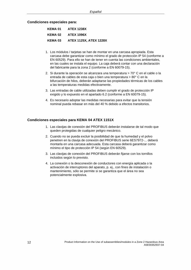
Español
Product Information on the Use of subassemblies/modules in a Zone 2 Hazardous Area A5E00352937-04 12
Condiciones especiales para:
KEMA 01 ATEX 1238X
KEMA 02 ATEX 1096X
KEMA 03 ATEX 1125X, ATEX 1228X
1. Los módulos / tarjetas se han de montar en una carcasa apropiada. Esta carcasa debe garantizar como mínimo el grado de protección IP 54 (conforme a EN 60529). Para ello se han de tener en cuenta las condiciones ambientales, en las cuales se instala el equipo. La caja deberá contar con una declaración del fabricante para la zona 2 (conforme a EN 60079-15).
2. Si durante la operación se alcanzara una temperatura > 70° C en el cable o la entrada de cables de esta caja o bien una temperatura > 80° C en la bifurcación de hilos, deberán adaptarse las propiedades térmicas de los cables a las temperaturas medidas efectivamente.
3. Las entradas de cable utilizadas deben cumplir el grado de protección IP exigido y lo expuesto en el apartado 6.2 (conforme a EN 60079-15).
4. Es necesario adoptar las medidas necesarias para evitar que la tensión nominal pueda rebasar en más del 40 % debido a efectos transitorios.
Condiciones especiales para KEMA 04 ATEX 1151X
1. Las clavijas de conexión del PROFIBUS deberán instalarse de tal modo que queden protegidas de cualquier peligro mecánico.
2. Cuando no se pueda excluir la posibilidad de que la humedad y el polvo penetren en la clavija de conexión del PROFIBUS serie 6ES7972-... deberá montarla en una carcasa adecuada. Esta carcasa deberá garantizar como mínimo el tipo de protección IP 54 (según EN 60529).
3. Las clavijas de conexión del PROFIBUS deberán fijarse con los tornillos incluidos según lo previsto.
4. La conexión o la desconexión de conductores con energía aplicada o la activación de interruptores del aparato, p. ej., con fines de instalación o mantenimiento, sólo se permite si se garantiza que el área no sea potencialmente explosiva.

Español
Condiciones especiales para KEMA 05 ATEX 1137X
1. Los módulos / tarjetas se han de montar en una carcasa apropiada. Esta carcasa debe garantizar como mínimo el grado de protección IP 54 (conforme a EN 60529). Para ello se han de tener en cuenta las condiciones ambientales, en las cuales se instala el equipo. La caja deberá contar con una declaración del fabricante para la zona 2 (conforme a EN 60079-15).
2. Si durante la operación se alcanzara una temperatura > 70° C en el cable o la entrada de cables de esta caja o bien una temperatura > 80° C en la bifurcación de hilos, deberán adaptarse las propiedades térmicas de los cables a las temperaturas medidas efectivamente.
3. Es necesario adoptar las medidas necesarias para evitar que la tensión nominal pueda rebasar en más del 40 % debido a efectos transitorios.
Otras informaciones
Encontrará otras informaciones relativas a los grupos y módulos en el manual correspondiente.
Product Information on the Use of subassemblies/modules in a Zone 2 Hazardous Area A5E00352937-04
13
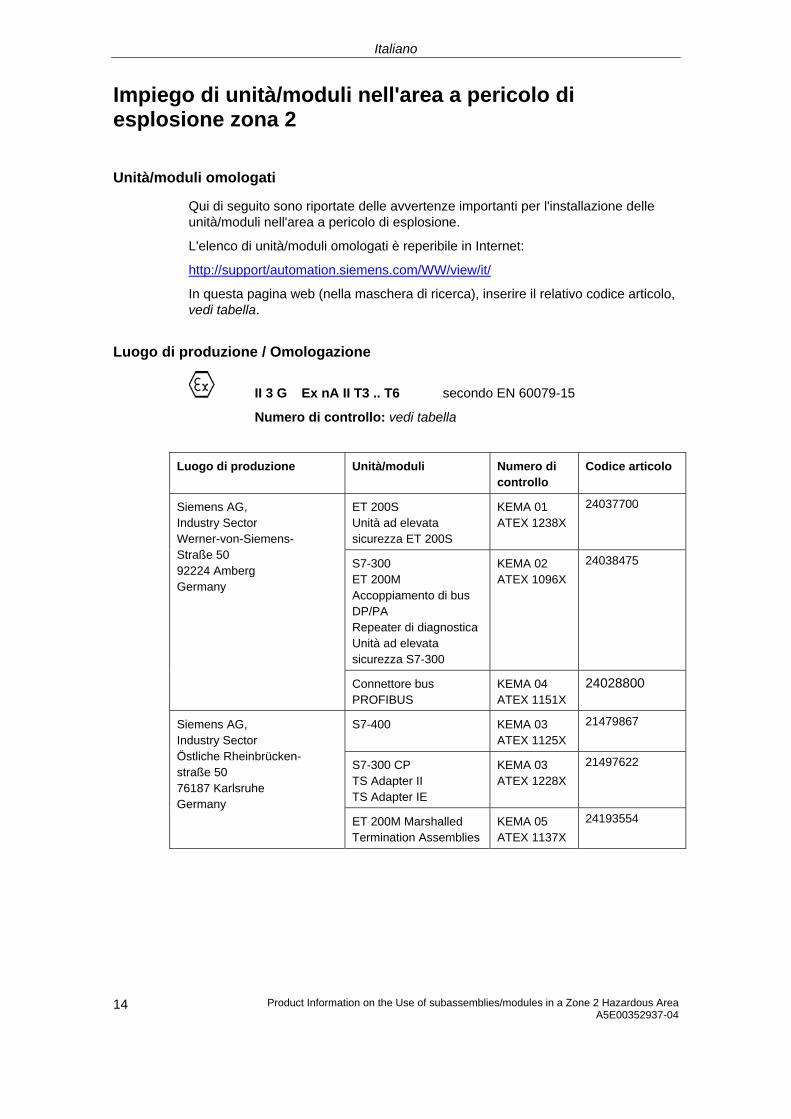
Italiano
Impiego di unità/moduli nell'area a pericolo di esplosione zona 2
Unità/moduli omologati
Qui di seguito sono riportate delle avvertenze importanti per l'installazione delle unità/moduli nell'area a pericolo di esplosione.
L'elenco di unità/moduli omologati è reperibile in Internet:
http://support/automation.siemens.com/WW/view/it/
In questa pagina web (nella maschera di ricerca), inserire il relativo codice articolo, vedi tabella.
Luogo di produzione / Omologazione
II 3 G Ex nA II T3 .. T6 secondo EN 60079-15
Numero di controllo: vedi tabella
Luogo di produzione Unità/moduli Numero di controllo
Codice articolo
ET 200S Unità ad elevata sicurezza ET 200S
KEMA 01 ATEX 1238X
24037700
S7-300 ET 200M Accoppiamento di bus DP/PA Repeater di diagnosticaUnità ad elevata sicurezza S7-300
KEMA 02 ATEX 1096X
24038475
Siemens AG, Industry Sector Werner-von-Siemens- Straße 50 92224 Amberg Germany
Connettore bus PROFIBUS
KEMA 04 ATEX 1151X
24028800
S7-400 KEMA 03 ATEX 1125X
21479867
S7-300 CP TS Adapter II TS Adapter IE
KEMA 03 ATEX 1228X
21497622
Siemens AG, Industry Sector Östliche Rheinbrücken- straße 50 76187 Karlsruhe Germany
ET 200M Marshalled Termination Assemblies
KEMA 05 ATEX 1137X
24193554
Product Information on the Use of subassemblies/modules in a Zone 2 Hazardous Area A5E00352937-04 14
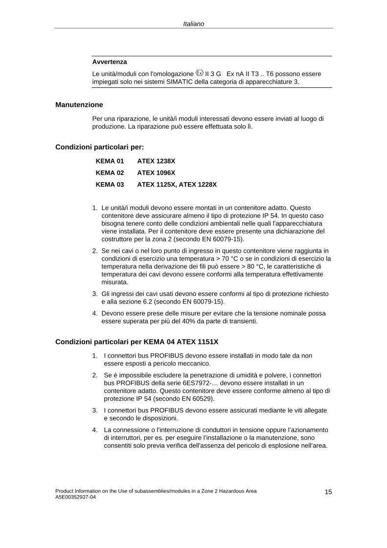
Italiano
Avvertenza
Le unità/moduli con l'omologazione II 3 G Ex nA II T3 .. T6 possono essere impiegati solo nei sistemi SIMATIC della categoria di apparecchiature 3.
Manutenzione
Per una riparazione, le unità/i moduli interessati devono essere inviati al luogo di produzione. La riparazione può essere effettuata solo lì.
Condizioni particolari per:
KEMA 01 ATEX 1238X
KEMA 02 ATEX 1096X
KEMA 03 ATEX 1125X, ATEX 1228X
1. Le unità/i moduli devono essere montati in un contenitore adatto. Questo contenitore deve assicurare almeno il tipo di protezione IP 54. In questo caso bisogna tenere conto delle condizioni ambientali nelle quali l'apparecchiatura viene installata. Per il contenitore deve essere presente una dichiarazione del costruttore per la zona 2 (secondo EN 60079-15).
2. Se nei cavi o nel loro punto di ingresso in questo contenitore viene raggiunta in condizioni di esercizio una temperatura > 70 °C o se in condizioni di esercizio la temperatura nella derivazione dei fili può essere > 80 °C, le caratteristiche di temperatura dei cavi devono essere conformi alla temperatura effettivamente misurata.
3. Gli ingressi dei cavi usati devono essere conformi al tipo di protezione richiesto e alla sezione 6.2 (secondo EN 60079-15).
4. Devono essere prese delle misure per evitare che la tensione nominale possa essere superata per più del 40% da parte di transienti.
Condizioni particolari per KEMA 04 ATEX 1151X
1. I connettori bus PROFIBUS devono essere installati in modo tale da non essere esposti a pericolo meccanico.
2. Se è impossibile escludere la penetrazione di umidità e polvere, i connettori bus PROFIBUS della serie 6ES7972-… devono essere installati in un contenitore adatto. Questo contenitore deve essere conforme almeno al tipo di protezione IP 54 (secondo EN 60529).
3. I connettori bus PROFIBUS devono essere assicurati mediante le viti allegate e secondo le disposizioni.
4. La connessione o l’interruzione di conduttori in tensione oppure l’azionamento di interruttori, per es. per eseguire l’installazione o la manutenzione, sono consentiti solo previa verifica dell'assenza del pericolo di esplosione nell’area.
Product Information on the Use of subassemblies/modules in a Zone 2 Hazardous AreaA5E00352937-04
15
Italiano
Product Information on the Use of subassemblies/modules in a Zone 2 Hazardous Area A5E00352937-04 16
Condizioni particolari per KEMA 05 ATEX 1137X 1. Le unità/i moduli devono essere montati in un contenitore adatto. Questo
contenitore deve assicurare almeno il tipo di protezione IP 54 (secondo EN 60529). In questo caso bisogna tenere conto delle condizioni ambientali nelle quali l'apparecchiatura viene installata. Per il contenitore deve essere presente una dichiarazione del costruttore per la zona 2 (secondo EN 60079-15).
2. Se nei cavi o nel loro punto di ingresso in questo contenitore viene raggiunta in condizioni di esercizio una temperatura > 70 °C o se in condizioni di esercizio la temperatura nella derivazione dei fili può essere > 80 °C, le caratteristiche di temperatura dei cavi devono essere conformi alla temperatura effettivamente misurata.
3. Devono essere prese delle misure per evitare che la tensione nominale possa essere superata per più del 40% da parte di transienti.
Ulteriori informazioni
Ulteriori informazioni relative a unità/moduli sono reperibili nel relativo manuale.
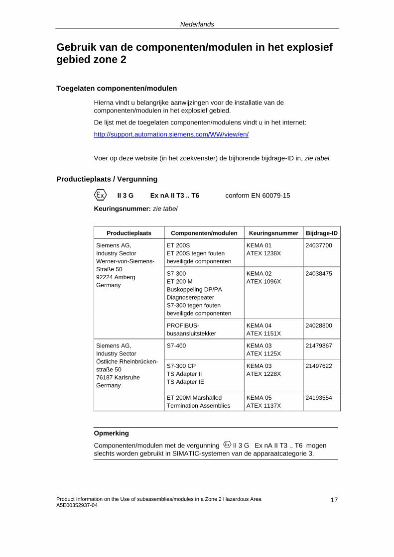
Nederlands
Gebruik van de componenten/modulen in het explosief gebied zone 2
Toegelaten componenten/modulen
Hierna vindt u belangrijke aanwijzingen voor de installatie van de componenten/modulen in het explosief gebied.
De lijst met de toegelaten componenten/modulens vindt u in het internet:
http://support.automation.siemens.com/WW/view/en/
Voer op deze website (in het zoekvenster) de bijhorende bijdrage-ID in, zie tabel.
Productieplaats / Vergunning
II 3 G Ex nA II T3 .. T6 conform EN 60079-15
Keuringsnummer: zie tabel
Productieplaats Componenten/modulen Keuringsnummer Bijdrage-ID
ET 200S ET 200S tegen fouten beveiligde componenten
KEMA 01 ATEX 1238X
24037700 Siemens AG, Industry Sector Werner-von-Siemens-Straße 50 92224 Amberg Germany
S7-300 ET 200 M Buskoppeling DP/PA Diagnoserepeater S7-300 tegen fouten beveiligde componenten
KEMA 02 ATEX 1096X
24038475
PROFIBUS- busaansluitstekker
KEMA 04 ATEX 1151X
24028800
S7-400 KEMA 03 ATEX 1125X
21479867 Siemens AG, Industry Sector Östliche Rheinbrücken-straße 50 76187 Karlsruhe Germany
S7-300 CP TS Adapter II TS Adapter IE
KEMA 03 ATEX 1228X
21497622
ET 200M Marshalled Termination Assemblies
KEMA 05 ATEX 1137X
24193554
Opmerking
Componenten/modulen met de vergunning II 3 G Ex nA II T3 .. T6 mogen slechts worden gebruikt in SIMATIC-systemen van de apparaatcategorie 3.
Product Information on the Use of subassemblies/modules in a Zone 2 Hazardous Area A5E00352937-04
17
Nederlands
Instandhouding
Voor een reparatie moeten de betreffende componenten/modulen naar de plaats van vervaardiging worden gestuurd. Alleen daar mag de reparatie worden uitgevoerd.
Speciale voorwaarden voor:
KEMA 01 ATEX 1238X
KEMA 02 ATEX 1096X
KEMA 03 ATEX 1125X, ATEX 1228X
1. Componenten/modulen moeten worden ingebouwd in een geschikte behuizing. Deze behuizing moet minstens de veiligheidsgraad IP 54 waarborgen. Hierbij dient rekening te worden gehouden met de omgevingsvoorwaarden waarin het apparaat wordt geïnstalleerd. Voor de behuizing dient een verklaring van de fabrikant voor zone 2 te worden ingediend (volgens EN 60079-15).
2. Als aan de kabel of aan de kabelinvoering van deze behuizing onder bedrijfsomstandigheden een temperatuur wordt bereikt > 70 °C of als onder bedrijfsomstandigheden de temperatuur aan de adervertakking > 80 °C kan zijn, moeten de temperatuureigenschappen van de kabel overeenstemmen met de werkelijk gemeten temperaturen.
3. De aangebrachte kabelinvoeringen moeten de vereiste IP-veiligheidsgraad hebben en in overeenstemming zijn met alinea 6.2 (volgens EN 60079-15).
4. Er dienen maatregelen te worden getroffen, zodat de nominale spanning door transiënten met niet meer dan 40 % kan worden overschreden.
Bijzondere voorwaarden voor KEMA 04 ATEX 1151X
1. De PROFIBUS-aansluitstekkers moeten dusdanig worden geïnstalleerd, dat zij tegen mechanisch gevaar beschermd zijn.
2. Als het binnendringen van vocht en stof niet kan worden uitgesloten, dienen de PROFIBUS-busaansluitstekkers van de serie 6ES7972-... in een geschikte behuizing te worden gemonteerd. Deze behuizing moet minstens de veiligheidsgraad IP 54 (volgens EN 60529) waarborgen.
3. De PROFIBUS-busaansluitstekkers moeten met de meegeleverde schroeven zoals voorgeschreven worden bevestigd.
4. Het aansluiten of scheiden van spanningvoerende geleiders of het activeren van apparaatschakelaars, bijv.voor installatie- of onderhoudsdoeleinden, is slechts toegestaan als kan worden gewaarborgd dat het gebied niet explosief is.
Product Information on the Use of subassemblies/modules in a Zone 2 Hazardous Area A5E00352937-04 18
Nederlands
Bijzondere voorwaarden voor KEMA 05 ATEX 1137X
1. Componenten/modulen moeten worden ingebouwd in een geschikte behuizing. Deze behuizing moet minstens de veiligheidsgraad IP 54 waarborgen. Hierbij dient rekening te worden gehouden met de omgevingsvoorwaarden waarin het apparaat wordt geïnstalleerd. Voor de behuizing dient een verklaring van de fabrikant voor zone 2 te worden ingediend (volgens EN 60079-15).
2. Als aan de kabel of aan de kabelinvoering van deze behuizing onder bedrijfsomstandigheden een temperatuur wordt bereikt > 70 °C of als onder bedrijfsomstandigheden de temperatuur aan de adervertakking > 80 °C kan zijn, moeten de temperatuureigenschappen van de kabel overeenstemmen met de werkelijk gemeten temperaturen.
3. Er dienen maatregelen te worden getroffen, zodat de nominale spanning door transiënten met niet meer dan 40 % kan worden overschreden.
Verdere informatie
Verdere informatie over de componenten/modulen vindt u in het bijhorende handboek.
Product Information on the Use of subassemblies/modules in a Zone 2 Hazardous Area A5E00352937-04
19
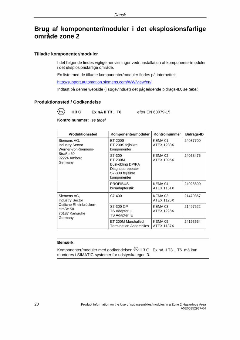
Dansk
Brug af komponenter/moduler i det eksplosionsfarlige område zone 2
Tilladte komponenter/moduler
I det følgende findes vigtige henvisninger vedr. installation af komponenter/moduler i det eksplosionsfarlige område.
En liste med de tilladte komponenter/moduler findes på internettet:
http://support.automation.siemens.com/WW/view/en/
Indtast på denne webside (i søgevinduet) det pågældende bidrags-ID, se tabel.
Produktionssted / Godkendelse
II 3 G Ex nA II T3 .. T6 efter EN 60079-15
Kontrolnummer: se tabel
Produktionssted Komponenter/moduler Kontrolnummer Bidrags-ID
ET 200S ET 200S fejlsikre komponenter
KEMA 01 ATEX 1238X
24037700
S7-300 ET 200M Buskobling DP/PA Diagnoserepeater S7-300 fejlsikre komponenter
KEMA 02 ATEX 1096X
24038475
Siemens AG, Industry Sector Werner-von-Siemens-Straße 50 92224 Amberg Germany
PROFIBUS-busadapterstik
KEMA 04 ATEX 1151X
24028800
S7-400 KEMA 03 ATEX 1125X
21479867
S7-300 CP TS Adapter II TS Adapter IE
KEMA 03 ATEX 1228X
21497622
Siemens AG, Industry Sector Östliche Rheinbrücken- straße 50 76187 Karlsruhe Germany
ET 200M Marshalled Termination Assemblies
KEMA 05 ATEX 1137X
24193554
Bemærk
Komponenter/moduler med godkendelsen II 3 G Ex nA II T3 .. T6 må kun monteres i SIMATIC-systemer for udstyrskategori 3.
20 Product Information on the Use of subassemblies/modules in a Zone 2 Hazardous Area A5E00352937-04
Dansk
Vedligeholdelse
Hvis de pågældende komponenter/moduler skal repareres, bedes De sende dem til produktionsstedet. Reparation må kun udføres der.
Særlige betingelser for:
KEMA 01 ATEX 1238X
KEMA 02 ATEX 1096X
KEMA 03 ATEX 1125X, ATEX 1228X
1. Komponenterne/modulerne skal monteres i et egnet kabinet. Dette kabinet skal mindst kunne sikre beskyttelsesklasse IP 54 (efter EN 60529). I denne forbindelse skal der tages højde for de omgivelsestemperaturer, i hvilke udstyret er installeret. Der skal være udarbejdet en erklæring fra fabrikanten for kabinettet for zone 2 (iht. EN 60079-15).
2. Hvis kablet eller kabelindføringen på dette kabinet når op på en temperatur på > 70 °C under driftsbetingelser eller hvis temperaturen på åreforegreningen kan være > 80 °C under driftsbetingelser, skal kablernes temperaturegenskaber stemme overens med de temperaturer, der rent faktisk måles.
3. De benyttede kabelindføringer skal være i overensstemmelse med den krævede IP-beskyttelsestype og afsnit 6.2 (iht. EN 60079-15).
4. Der skal træffes foranstaltninger, der sørger for, at den nominelle spænding via transienter ikke kan overskrides mere end 40 %.
Særlige betingelser for KEMA 04 ATEX 1151X
1. PROFIBUS-busadapterstik skal installeres således, at de er sikret mod mekanisk fare.
2. Hvis indtrængen af fugtighed og støv ikke kan udelukkes, skal PROFIBUS-busadapterstik serie 6ES7972-... monteres i et egnet kabinet. Dette kabinet skal mindst kunne sikre beskyttelsesklasse IP 54 (efter EN 60529).
3. PROFIBUS-busadapterstik skal fastgøres korrekt med de medleverede skruer.
4. Tilslutning eller afbrydelse af spændingsførende ledere eller betjening af apparatkontakter, f.eks. ved installation eller vedligeholdelse, er kun tilladt, hvis det kan sikres, at området ikke er eksplosionsfarligt.
21 Product Information on the Use of subassemblies/modules in a Zone 2 Hazardous Area A5E00352937-04
Dansk
22 Product Information on the Use of subassemblies/modules in a Zone 2 Hazardous Area A5E00352937-04
Besondere Bedingungen für KEMA 05 ATEX 1137X
1. Komponenterne/modulerne skal monteres i et egnet kabinet. Dette kabinet skal mindst kunne sikre beskyttelsesklasse IP 54 (efter EN 60529). I denne forbindelse skal der tages højde for de omgivelsestemperaturer, i hvilke udstyret er installeret. Der skal være udarbejdet en erklæring fra fabrikanten for kabinettet for zone 2 (iht. EN 60079-15).
2. Hvis kablet eller kabelindføringen på dette kabinet når op på en temperatur på > 70 °C under driftsbetingelser eller hvis temperaturen på åreforegreningen kan være > 80 °C under driftsbetingelser, skal kablernes temperaturegenskaber stemme overens med de temperaturer, der rent faktisk måles.
3. Der skal træffes foranstaltninger, der sørger for, at den nominelle spænding via transienter ikke kan overskrides mere end 40 %.
Yderligere informationer
Yderligere informationer om komponenterne/modulerne findes i den pågældende manual.
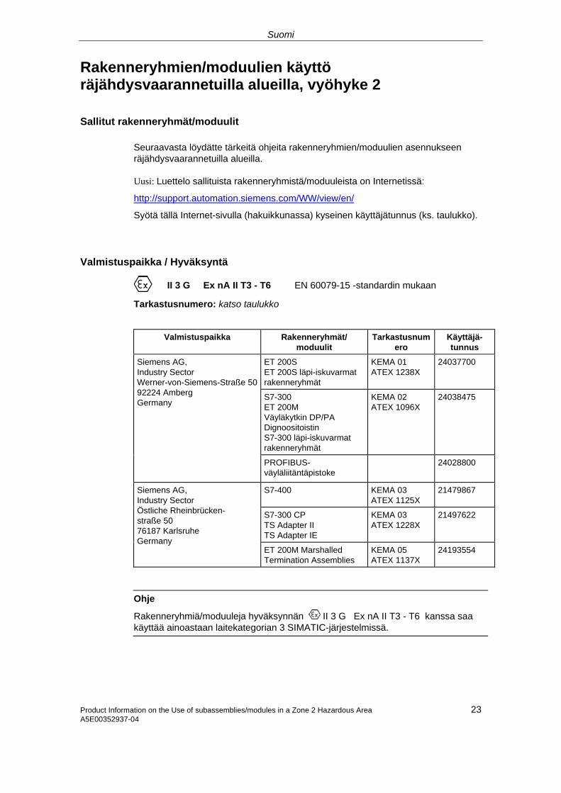
Suomi
Rakenneryhmien/moduulien käyttö räjähdysvaarannetuilla alueilla, vyöhyke 2 Sallitut rakenneryhmät/moduulit
Seuraavasta löydätte tärkeitä ohjeita rakenneryhmien/moduulien asennukseen räjähdysvaarannetuilla alueilla. Uusi: Luettelo sallituista rakenneryhmistä/moduuleista on Internetissä:
http://support.automation.siemens.com/WW/view/en/
Syötä tällä Internet-sivulla (hakuikkunassa) kyseinen käyttäjätunnus (ks. taulukko).
Valmistuspaikka / Hyväksyntä
II 3 G Ex nA II T3 - T6 EN 60079-15 -standardin mukaan
Tarkastusnumero: katso taulukko
Valmistuspaikka Rakenneryhmät/ moduulit
Tarkastusnumero
Käyttäjä-tunnus
ET 200S ET 200S läpi-iskuvarmat rakenneryhmät
KEMA 01 ATEX 1238X
24037700
S7-300 ET 200M Väyläkytkin DP/PA Dignoositoistin S7-300 läpi-iskuvarmat rakenneryhmät
KEMA 02 ATEX 1096X
24038475
Siemens AG, Industry Sector Werner-von-Siemens-Straße 5092224 Amberg Germany
PROFIBUS-väyläliitäntäpistoke
24028800
S7-400 KEMA 03 ATEX 1125X
21479867
S7-300 CP TS Adapter II TS Adapter IE
KEMA 03 ATEX 1228X
21497622
Siemens AG, Industry Sector Östliche Rheinbrücken- straße 50 76187 Karlsruhe Germany
ET 200M Marshalled Termination Assemblies
KEMA 05 ATEX 1137X
24193554
Ohje
Rakenneryhmiä/moduuleja hyväksynnän II 3 G Ex nA II T3 - T6 kanssa saa käyttää ainoastaan laitekategorian 3 SIMATIC-järjestelmissä.
Product Information on the Use of subassemblies/modules in a Zone 2 Hazardous Area A5E00352937-04
23
Suomi
24 Product Information on the Use of subassemblies/modules in a Zone 2 Hazardous Area A5E00352937-04
Kunnossapito
Korjausta varten täytyy kyseinen rakenneryhmä/moduuli lähettää valmistuspaikkaan. Korjaus voidaan suorittaa ainoastaan siellä.
Erityiset vaatimukset:
KEMA 01 ATEX 1238X
KEMA 02 ATEX 1096X
KEMA 03 ATEX 1125X, ATEX 1228X
1. Rakenneryhmät/moduulit täytyy asentaa sopivaan koteloon. Tämän kotelon täytyy olla vähintään kotelointiluokan IP 54 mukaisia. Tällöin on huomioitava ympäristöolosuhteet, johon laite asennetaan. Kotelolle täytyy olla valmistajaselvitys vyöhykettä 2 varten (EN 60079-15 mukaan).
2. Kun johdolla tai tämän kotelon johdon sisäänviennillä saavutetaan > 70 °C lämpötila tai kun käyttöolosuhteissa lämpötila voi piuhajaotuksella olla > 80 °C, täytyy johdon lämpötilaominaisuuksien vastata todellisesti mitattuja lämpötiloja.
3. Käytettyjen johtojen sisäänohjauksien täytyy olla vaaditun IP-kotelointiluokan ja kohdan 6.2 (EN 60079-15 mukaan) mukaisia.
4. Toimenpiteet täytyy suorittaa, ettei nimellisjännite voi transienttien kautta ylittyä enemmän kuin 40 %.
Erityiset vaatimukset rakenneryhmille KEMA 04 ATEX 1151X
1. PROFIBUS-väyläliitäntäpistokkeet on asennettava niin, että ne on suojattu mekaaniselta vaaralta.
2. Mikäli kosteuden ja pölyn pääsyä laitteen sisään ei voida poissulkea, sarjan 6ES7972 PROFIBUS-väyläliitäntäpistokkeet on asennettava sopivaan koteloon. Tämän kotelon on oltava vähintään kotelointiluokan IP 54 (EN 60529) mukainen.
3. PROFIBUS-väyläliitäntäpistokkeet on kiinnitettävä määräysten mukaisesti mukana toimitetuilla ruuveilla.
4. Jännitettä johtavien johdinten liittäminen ja irrottaminen tai laitekytkinten käyttäminen esimerkiksi asennus- tai huoltotarkoituksiin on sallittu ainoastaan silloin, kun on varmistettu, että alue ei ole räjähdysherkkä.
Suomi
Erityiset vaatimukset rakenneryhmille KEMA 05 ATEX 1137X
1. Rakenneryhmät/moduulit täytyy asentaa sopivaan koteloon. Tämän kotelon täytyy olla vähintään kotelointiluokan IP 54 mukaisia. Tällöin on huomioitava ympäristöolosuhteet, johon laite asennetaan. Kotelolle täytyy olla valmistajaselvitys vyöhykettä 2 varten (EN 60079-15 mukaan).
2. Kun johdolla tai tämän kotelon johdon sisäänviennillä saavutetaan > 70 °C lämpötila tai kun käyttöolosuhteissa lämpötila voi piuhajaotuksella olla > 80 °C, täytyy johdon lämpötilaominaisuuksien vastata todellisesti mitattuja lämpötiloja.
3. Toimenpiteet täytyy suorittaa, ettei nimellisjännite voi transienttien kautta ylittyä enemmän kuin 40 %.
Lisätietoja Lisätietoja rakenneryhmistä/moduuleista on asianomaisessa käsikirjassa.
Product Information on the Use of subassemblies/modules in a Zone 2 Hazardous Area A5E00352937-04
25
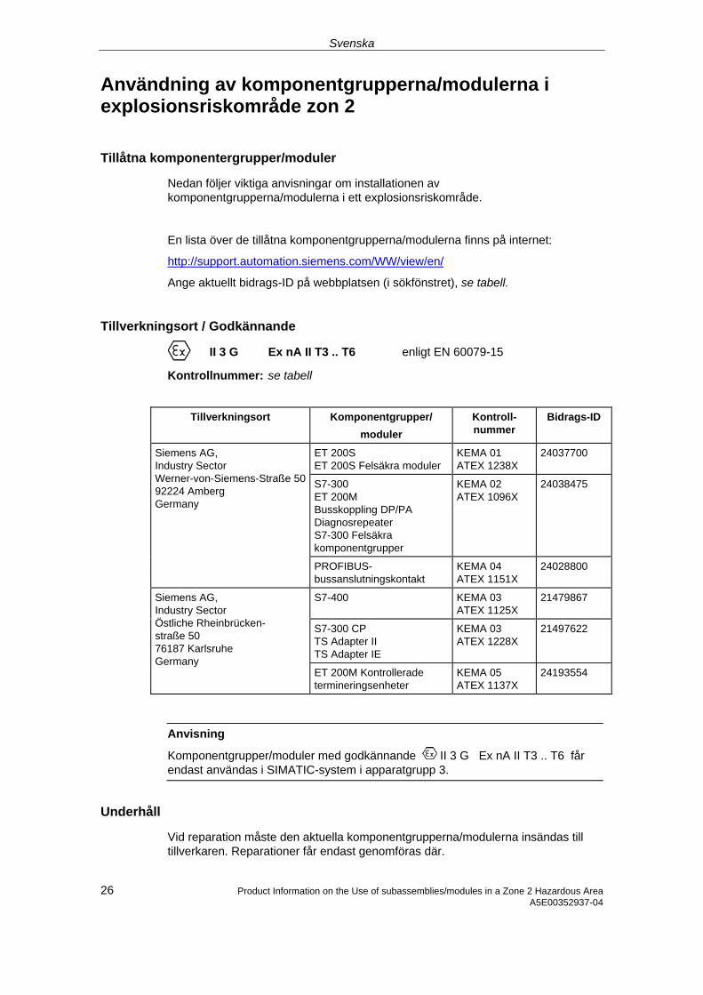
Svenska
Användning av komponentgrupperna/modulerna i explosionsriskområde zon 2
Tillåtna komponentergrupper/moduler
Nedan följer viktiga anvisningar om installationen av komponentgrupperna/modulerna i ett explosionsriskområde.
En lista över de tillåtna komponentgrupperna/modulerna finns på internet:
http://support.automation.siemens.com/WW/view/en/
Ange aktuellt bidrags-ID på webbplatsen (i sökfönstret), se tabell.
Tillverkningsort / Godkännande
II 3 G Ex nA II T3 .. T6 enligt EN 60079-15
Kontrollnummer: se tabell
Tillverkningsort Komponentgrupper/ moduler
Kontroll-nummer
Bidrags-ID
ET 200S ET 200S Felsäkra moduler
KEMA 01 ATEX 1238X
24037700
S7-300 ET 200M Busskoppling DP/PA Diagnosrepeater S7-300 Felsäkra komponentgrupper
KEMA 02 ATEX 1096X
24038475
Siemens AG, Industry Sector Werner-von-Siemens-Straße 5092224 Amberg Germany
PROFIBUS-bussanslutningskontakt
KEMA 04 ATEX 1151X
24028800
S7-400 KEMA 03 ATEX 1125X
21479867
S7-300 CP TS Adapter II TS Adapter IE
KEMA 03 ATEX 1228X
21497622
Siemens AG, Industry Sector Östliche Rheinbrücken- straße 50 76187 Karlsruhe Germany
ET 200M Kontrollerade termineringsenheter
KEMA 05 ATEX 1137X
24193554
Anvisning
Komponentgrupper/moduler med godkännande II 3 G Ex nA II T3 .. T6 får endast användas i SIMATIC-system i apparatgrupp 3.
Underhåll
Vid reparation måste den aktuella komponentgrupperna/modulerna insändas till tillverkaren. Reparationer får endast genomföras där.
26 Product Information on the Use of subassemblies/modules in a Zone 2 Hazardous Area A5E00352937-04

Svenska
Product Information on the Use of subassemblies/modules in a Zone 2 Hazardous Area 27 A5E00352937-04
Särskilda villkor för:
KEMA 01 ATEX 1238X
KEMA 02 ATEX 1096X
KEMA 03 ATEX 1125X, ATEX 1228X
1. Komponentgrupperna/modulerna måste monteras i ett lämpligt hus. Huset måste minst vara av skyddsklass IP 54 (enligt EN 60529). Därvid ska omgivningsvillkoren där enheten installeras beaktas. För kåpan måste en tillverkardeklaration för zon 2 föreligga (enligt EN 60079-15).
2. Om en temperatur på > 70°C uppnås vid husets kabel resp kabelinföring under driftvillkor eller om temperaturen vid trådförgreningen kan vara > 80°C under driftvillkor, måste kabelns temperaturegenskaper överensstämma med den verkligen uppmätta temperaturen.
3. De använda kabelinföringarna måste uppfylla kraven i det krävda IP-skyddsutförandet och i avsnitt 6.2 (enligt EN 60079-15).
4. Åtgärder måste vidtas så, att märkspänningen ej kan överskridas med mer än 40 % genom transienter.
Särskilda villkor för KEMA 04 ATEX 1151X
1. PROFIBUS-bussanslutningskontakten ska installeras så att den är skyddad mot mekaniska faror.
2. Om det inte går att utesluta att fukt och damm kan tränga in ska PROFIBUS-bussanslutningskontakten serie 6ES7972-... monteras i ett lämpligt hus. Huset måste vara av minst skyddsklass IP 54 (enligt EN 60529).
3. PROFIBUS-bussanslutningskontakten måste fästas enligt anvisningarna med de bifogade skruvarna.
4. Anslutning och frånskiljning av spänningsförande ledare eller aktivering av enhetsbrytare vid t.ex. installation eller underhåll får endast utföras om det är säkerställt att det inte föreligger explosionsrisk i området.
Svenska
28 Product Information on the Use of subassemblies/modules in a Zone 2 Hazardous Area A5E00352937-04
Särskilda villkor för KEMA 05 ATEX 1137X
1. Komponentgrupperna/modulerna måste monteras i ett lämpligt hus. Huset måste minst vara av skyddsklass IP 54 (enligt EN 60529). Därvid ska omgivningsvillkoren där enheten installeras beaktas. För kåpan måste en tillverkardeklaration för zon 2 föreligga (enligt EN 60079-15).
2. Om en temperatur på > 70°C uppnås vid husets kabel resp kabelinföring under driftvillkor eller om temperaturen vid trådförgreningen kan vara > 80°C under driftvillkor, måste kabelns temperaturegenskaper överensstämma med den verkligen uppmätta temperaturen.
3. Åtgärder måste vidtas så, att märkspänningen ej kan överskridas med mer än 40 % genom transienter.
Ytterligare information
Ytterligare information om komponentgrupperna/modulerna finns i tillhörande handbok.
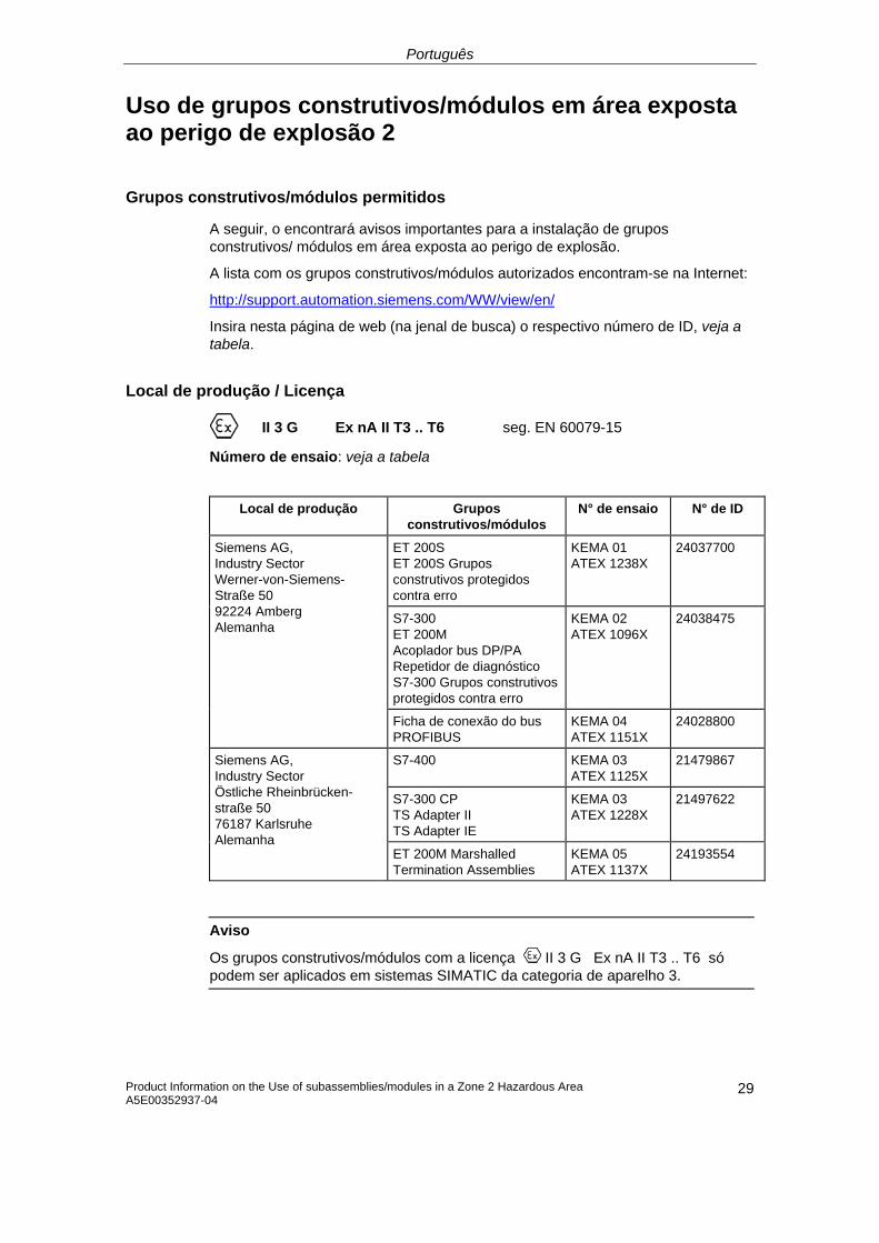
Português
Uso de grupos construtivos/módulos em área exposta ao perigo de explosão 2
Grupos construtivos/módulos permitidos
A seguir, o encontrará avisos importantes para a instalação de grupos construtivos/ módulos em área exposta ao perigo de explosão.
A lista com os grupos construtivos/módulos autorizados encontram-se na Internet:
http://support.automation.siemens.com/WW/view/en/
Insira nesta página de web (na jenal de busca) o respectivo número de ID, veja a tabela.
Local de produção / Licença
II 3 G Ex nA II T3 .. T6 seg. EN 60079-15
Número de ensaio: veja a tabela
Local de produção Grupos construtivos/módulos
N° de ensaio N° de ID
ET 200S ET 200S Grupos construtivos protegidos contra erro
KEMA 01 ATEX 1238X
24037700
S7-300 ET 200M Acoplador bus DP/PA Repetidor de diagnóstico S7-300 Grupos construtivos protegidos contra erro
KEMA 02 ATEX 1096X
24038475
Siemens AG, Industry Sector Werner-von-Siemens-Straße 50 92224 Amberg Alemanha
Ficha de conexão do bus PROFIBUS
KEMA 04 ATEX 1151X
24028800
S7-400 KEMA 03 ATEX 1125X
21479867
S7-300 CP TS Adapter II TS Adapter IE
KEMA 03 ATEX 1228X
21497622
Siemens AG, Industry Sector Östliche Rheinbrücken-straße 50 76187 Karlsruhe Alemanha
ET 200M Marshalled Termination Assemblies
KEMA 05 ATEX 1137X
24193554
Aviso
Os grupos construtivos/módulos com a licença II 3 G Ex nA II T3 .. T6 só podem ser aplicados em sistemas SIMATIC da categoria de aparelho 3.
Product Information on the Use of subassemblies/modules in a Zone 2 Hazardous Area A5E00352937-04
29
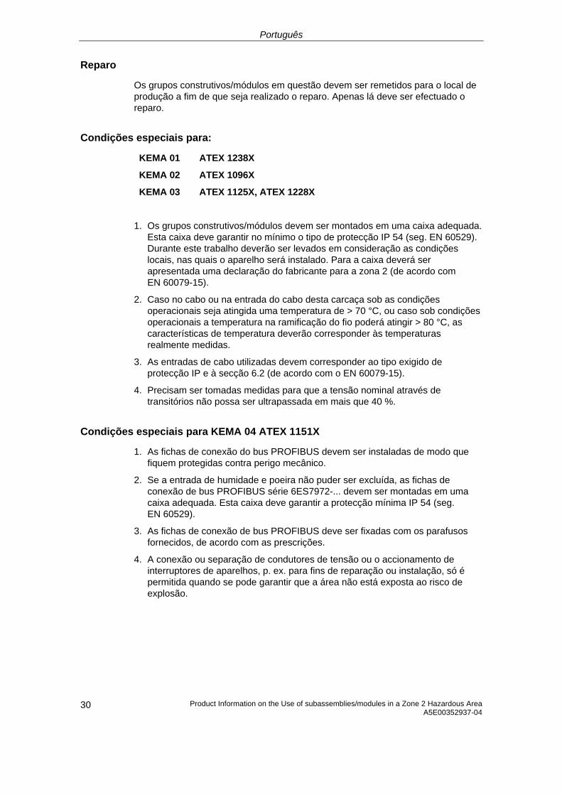
Português
Product Information on the Use of subassemblies/modules in a Zone 2 Hazardous Area A5E00352937-04
30
Reparo
Os grupos construtivos/módulos em questão devem ser remetidos para o local de produção a fim de que seja realizado o reparo. Apenas lá deve ser efectuado o reparo.
Condições especiais para:
KEMA 01 ATEX 1238X
KEMA 02 ATEX 1096X
KEMA 03 ATEX 1125X, ATEX 1228X
1. Os grupos construtivos/módulos devem ser montados em uma caixa adequada. Esta caixa deve garantir no mínimo o tipo de protecção IP 54 (seg. EN 60529). Durante este trabalho deverão ser levados em consideração as condições locais, nas quais o aparelho será instalado. Para a caixa deverá ser apresentada uma declaração do fabricante para a zona 2 (de acordo com EN 60079-15).
2. Caso no cabo ou na entrada do cabo desta carcaça sob as condições operacionais seja atingida uma temperatura de > 70 °C, ou caso sob condições operacionais a temperatura na ramificação do fio poderá atingir > 80 °C, as características de temperatura deverão corresponder às temperaturas realmente medidas.
3. As entradas de cabo utilizadas devem corresponder ao tipo exigido de protecção IP e à secção 6.2 (de acordo com o EN 60079-15).
4. Precisam ser tomadas medidas para que a tensão nominal através de transitórios não possa ser ultrapassada em mais que 40 %.
Condições especiais para KEMA 04 ATEX 1151X
1. As fichas de conexão do bus PROFIBUS devem ser instaladas de modo que fiquem protegidas contra perigo mecânico.
2. Se a entrada de humidade e poeira não puder ser excluída, as fichas de conexão de bus PROFIBUS série 6ES7972-... devem ser montadas em uma caixa adequada. Esta caixa deve garantir a protecção mínima IP 54 (seg. EN 60529).
3. As fichas de conexão de bus PROFIBUS deve ser fixadas com os parafusos fornecidos, de acordo com as prescrições.
4. A conexão ou separação de condutores de tensão ou o accionamento de interruptores de aparelhos, p. ex. para fins de reparação ou instalação, só é permitida quando se pode garantir que a área não está exposta ao risco de explosão.
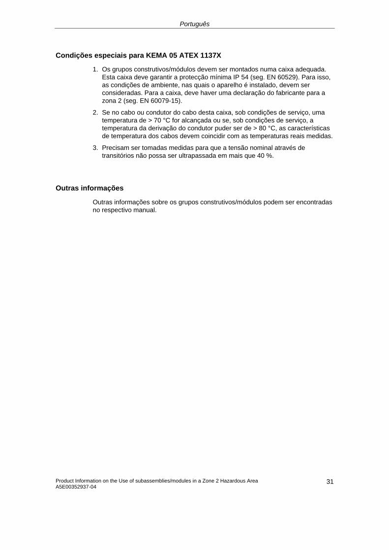
Português
Product Information on the Use of subassemblies/modules in a Zone 2 Hazardous Area A5E00352937-04
31
Condições especiais para KEMA 05 ATEX 1137X
1. Os grupos construtivos/módulos devem ser montados numa caixa adequada. Esta caixa deve garantir a protecção mínima IP 54 (seg. EN 60529). Para isso, as condições de ambiente, nas quais o aparelho é instalado, devem ser consideradas. Para a caixa, deve haver uma declaração do fabricante para a zona 2 (seg. EN 60079-15).
2. Se no cabo ou condutor do cabo desta caixa, sob condições de serviço, uma temperatura de > 70 °C for alcançada ou se, sob condições de serviço, a temperatura da derivação do condutor puder ser de > 80 °C, as características de temperatura dos cabos devem coincidir com as temperaturas reais medidas.
3. Precisam ser tomadas medidas para que a tensão nominal através de transitórios não possa ser ultrapassada em mais que 40 %.
Outras informações
Outras informações sobre os grupos construtivos/módulos podem ser encontradas no respectivo manual.
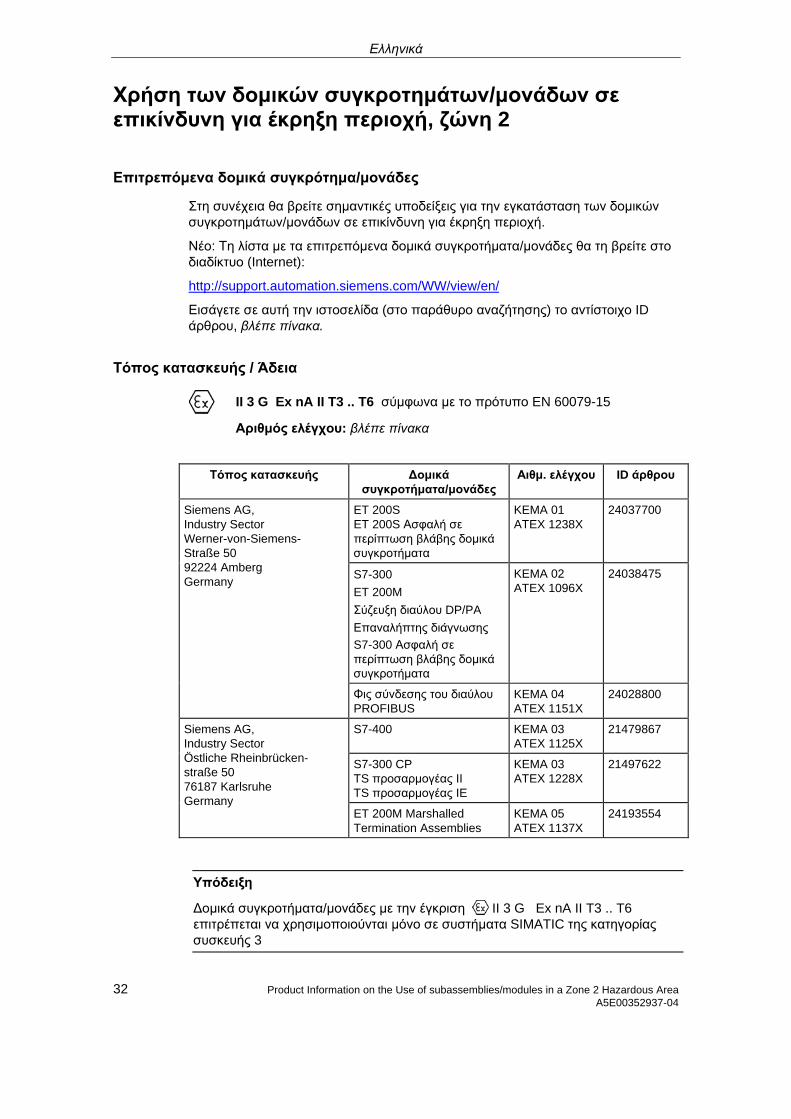
Ελληνικά
Χρήση των δομικών συγκροτημάτων/μονάδων σε επικίνδυνη για έκρηξη περιοχή, ζώνη 2
Επιτρεπόμενα δομικά συγκρότημα/μονάδες
Στη συνέχεια θα βρείτε σημαντικές υποδείξεις για την εγκατάσταση των δομικών συγκροτημάτων/μονάδων σε επικίνδυνη για έκρηξη περιοχή.
Νέο: Τη λίστα με τα επιτρεπόμενα δομικά συγκροτήματα/μονάδες θα τη βρείτε στο διαδίκτυο (Internet):
http://support.automation.siemens.com/WW/view/en/
Εισάγετε σε αυτή την ιστοσελίδα (στο παράθυρο αναζήτησης) το αντίστοιχο ID άρθρου, βλέπε πίνακα.
Τόπος κατασκευής / Άδεια
II 3 G Ex nA II T3 .. T6 σύμφωνα με το πρότυπο EN 60079-15
Αριθμός ελέγχου: βλέπε πίνακα
Τόπος κατασκευής Δομικά συγκροτήματα/μονάδες
Αιθμ. ελέγχου ID άρθρου
ET 200S ET 200S Ασφαλή σε περίπτωση βλάβης δομικά συγκροτήματα
KEMA 01 ATEX 1238X
24037700
S7-300 ET 200M Σύζευξη διαύλου DP/PA Επαναλήπτης διάγνωσης S7-300 Ασφαλή σε περίπτωση βλάβης δομικά συγκροτήματα
KEMA 02 ATEX 1096X
24038475
Siemens AG, Industry Sector Werner-von-Siemens-Straße 50 92224 Amberg Germany
Φις σύνδεσης του διαύλου PROFIBUS
KEMA 04 ATEX 1151X
24028800
S7-400 KEMA 03 ATEX 1125X
21479867
S7-300 CP TS προσαρμογέας II TS προσαρμογέας IE
KEMA 03 ATEX 1228X
21497622
Siemens AG, Industry Sector Östliche Rheinbrücken- straße 50 76187 Karlsruhe Germany
ET 200M Marshalled Termination Assemblies
KEMA 05 ATEX 1137X
24193554
Υπόδειξη
Δομικά συγκροτήματα/μονάδες με την έγκριση II 3 G Ex nA II T3 .. T6 επιτρέπεται να χρησιμοποιούνται μόνο σε συστήματα SIMATIC της κατηγορίας συσκευής 3
32 Product Information on the Use of subassemblies/modules in a Zone 2 Hazardous Area A5E00352937-04
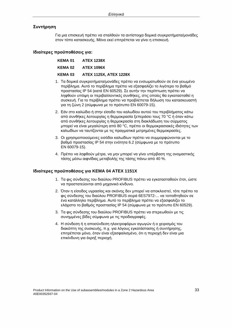
Ελληνικά
Product Information on the Use of subassemblies/modules in a Zone 2 Hazardous Area 33 A5E00352937-04
Συντήρηση
Για μια επισκευή πρέπει να σταλθούν τα αντίστοιχα δομικά συγκροτήματα/μονάδες στον τόπο κατασκευής. Μόνο εκεί επιτρέπεται να γίνει η επισκευή.
Ιδιαίτερες προϋποθέσεις για:
KEMA 01 ATEX 1238X
KEMA 02 ATEX 1096X
KEMA 03 ATEX 1125X, ATEX 1228X
1. Τα δομικά συγκροτήματα/μονάδες πρέπει να ενσωματωθούν σε ένα γειωμένο περίβλημα. Αυτό το περίβλημα πρέπει να εξασφαλίζει το λιγότερο το βαθμό προστασίας IP 54 (κατά EN 60529). Σε αυτήν την περίπτωση πρέπει να ληφθούν υπόψη οι περιβαλλοντικές συνθήκες, στις οποίες θα εγκατασταθεί η συσκευή. Για το περίβλημα πρέπει να προβλέπεται δήλωση του κατασκευαστή για τη ζώνη 2 (σύμφωνα με το πρότυπο EN 60079-15).
2. Εάν στο καλώδιο ή στην είσοδο του καλωδίου αυτού του περιβλήματος κάτω από συνθήκες λειτουργίας η θερμοκρασία ξεπεράσει τους 70 °C ή όταν κάτω από συνθήκες λειτουργίας η θερμοκρασία στη διακλάδωση του σύρματος μπορεί να είναι μεγαλύτερη από 80 °C, πρέπει οι θερμοκρασιακές ιδιότητες των καλωδίων να ταυτίζονται με τις πραγματικά μετρημένες θερμοκρασίες.
3. Οι χρησιμοποιούμενες εισόδοι καλωδίων πρέπει να συμμορφώνονται με το βαθμό προστασίας IP 54 στην ενότητα 6.2 (σύμφωνα με το πρότυπο EN 60079-15).
4. Πρέπει να ληφθούν μέτρα, να μην μπορεί να γίνει υπέρβαση της ονομαστικής τάσης μέσω αιφνίδιας μεταβολής της τάσης πάνω από 40 %.
Ιδιαίτερες προϋποθέσεις για KEMA 04 ATEX 1151X
1. Τα φις σύνδεσης του διαύλου PROFIBUS πρέπει να εγκατασταθούν έτσι, ώστε να προστατεύονται από μηχανικό κίνδυνο.
2. Όταν η είσοδος υγρασίας και σκόνης δεν μπορεί να αποκλειστεί, τότε πρέπει τα φις σύνδεσης του διαύλου PROFIBUS σειρά 6ES7972-... να τοποθτηθούν σε ένα κατάλληλο περίβλημα. Αυτό το περίβλημα πρέπει να εξασφαλίζει το ελάχιστο το βαθμός προστασίας IP 54 (σύμφωνα με το πρότυπο EN 60529).
3. Τα φις σύνδεσης του διαύλου PROFIBUS πρέπει να στερεωθούν με τις συνημμένες βίδες σύμφωνα με τις προδιαγραφές.
4. Η σύνδεση ή η αποσύνδεση ηλεκτροφόρων αγωγών ή ο χειρισμός του διακόπτη της συσκευής, π.χ. για λόγους εγκατάστασης ή συντήρησης, επιτρέπεται μόνο, όταν είναι εξασφαλισμένο, ότι η περιοχή δεν είναι μια επικίνδυνη για έκρηξ περιοχή.
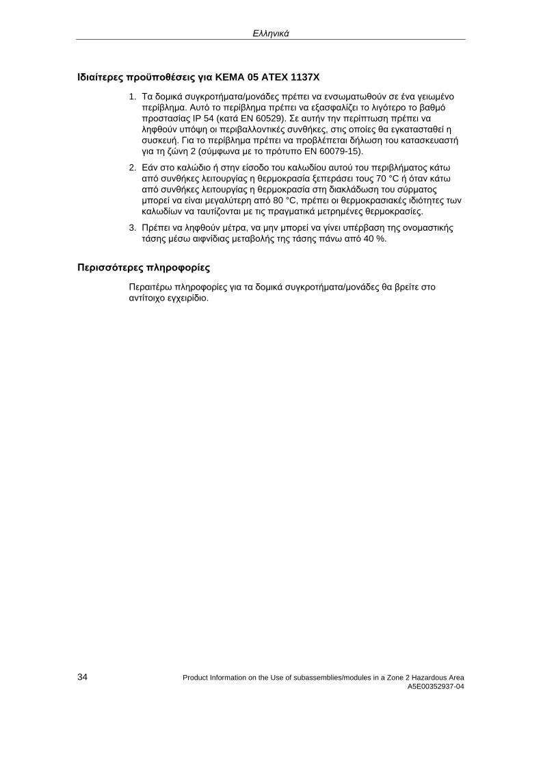
Ελληνικά
34 Product Information on the Use of subassemblies/modules in a Zone 2 Hazardous Area A5E00352937-04
Ιδιαίτερες προϋποθέσεις για KEMA 05 ATEX 1137X
1. Τα δομικά συγκροτήματα/μονάδες πρέπει να ενσωματωθούν σε ένα γειωμένο περίβλημα. Αυτό το περίβλημα πρέπει να εξασφαλίζει το λιγότερο το βαθμό προστασίας IP 54 (κατά EN 60529). Σε αυτήν την περίπτωση πρέπει να ληφθούν υπόψη οι περιβαλλοντικές συνθήκες, στις οποίες θα εγκατασταθεί η συσκευή. Για το περίβλημα πρέπει να προβλέπεται δήλωση του κατασκευαστή για τη ζώνη 2 (σύμφωνα με το πρότυπο EN 60079-15).
2. Εάν στο καλώδιο ή στην είσοδο του καλωδίου αυτού του περιβλήματος κάτω από συνθήκες λειτουργίας η θερμοκρασία ξεπεράσει τους 70 °C ή όταν κάτω από συνθήκες λειτουργίας η θερμοκρασία στη διακλάδωση του σύρματος μπορεί να είναι μεγαλύτερη από 80 °C, πρέπει οι θερμοκρασιακές ιδιότητες των καλωδίων να ταυτίζονται με τις πραγματικά μετρημένες θερμοκρασίες.
3. Πρέπει να ληφθούν μέτρα, να μην μπορεί να γίνει υπέρβαση της ονομαστικής τάσης μέσω αιφνίδιας μεταβολής της τάσης πάνω από 40 %.
Περισσότερες πληροφορίες
Περαιτέρω πληροφορίες για τα δομικά συγκροτήματα/μονάδες θα βρείτε στο αντίτοιχο εγχειρίδιο.
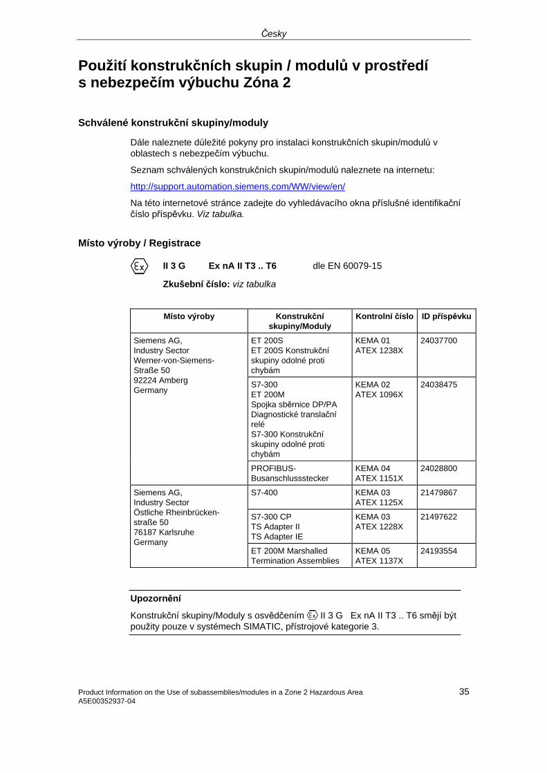
Česky
Použití konstrukčních skupin / modulů v prostředí s nebezpečím výbuchu Zóna 2
Schválené konstrukční skupiny/moduly
Dále naleznete důležité pokyny pro instalaci konstrukčních skupin/modulů v oblastech s nebezpečím výbuchu.
Seznam schválených konstrukčních skupin/modulů naleznete na internetu:
http://support.automation.siemens.com/WW/view/en/
Na této internetové stránce zadejte do vyhledávacího okna příslušné identifikační číslo příspěvku. Viz tabulka.
Místo výroby / Registrace
II 3 G Ex nA II T3 .. T6 dle EN 60079-15
Zkušební číslo: viz tabulka
Místo výroby Konstrukční
skupiny/Moduly Kontrolní číslo ID příspěvku
ET 200S ET 200S Konstrukční skupiny odolné proti chybám
KEMA 01 ATEX 1238X
24037700
S7-300 ET 200M Spojka sběrnice DP/PA Diagnostické translační relé S7-300 Konstrukční skupiny odolné proti chybám
KEMA 02 ATEX 1096X
24038475
Siemens AG, Industry Sector Werner-von-Siemens-Straße 50 92224 Amberg Germany
PROFIBUS-Busanschlussstecker
KEMA 04 ATEX 1151X
24028800
S7-400 KEMA 03 ATEX 1125X
21479867
S7-300 CP TS Adapter II TS Adapter IE
KEMA 03 ATEX 1228X
21497622
Siemens AG, Industry Sector Östliche Rheinbrücken- straße 50 76187 Karlsruhe Germany
ET 200M Marshalled Termination Assemblies
KEMA 05 ATEX 1137X
24193554
Upozornění
Konstrukční skupiny/Moduly s osvědčením II 3 G Ex nA II T3 .. T6 smějí být použity pouze v systémech SIMATIC, přístrojové kategorie 3.
35 Product Information on the Use of subassemblies/modules in a Zone 2 Hazardous AreaA5E00352937-04
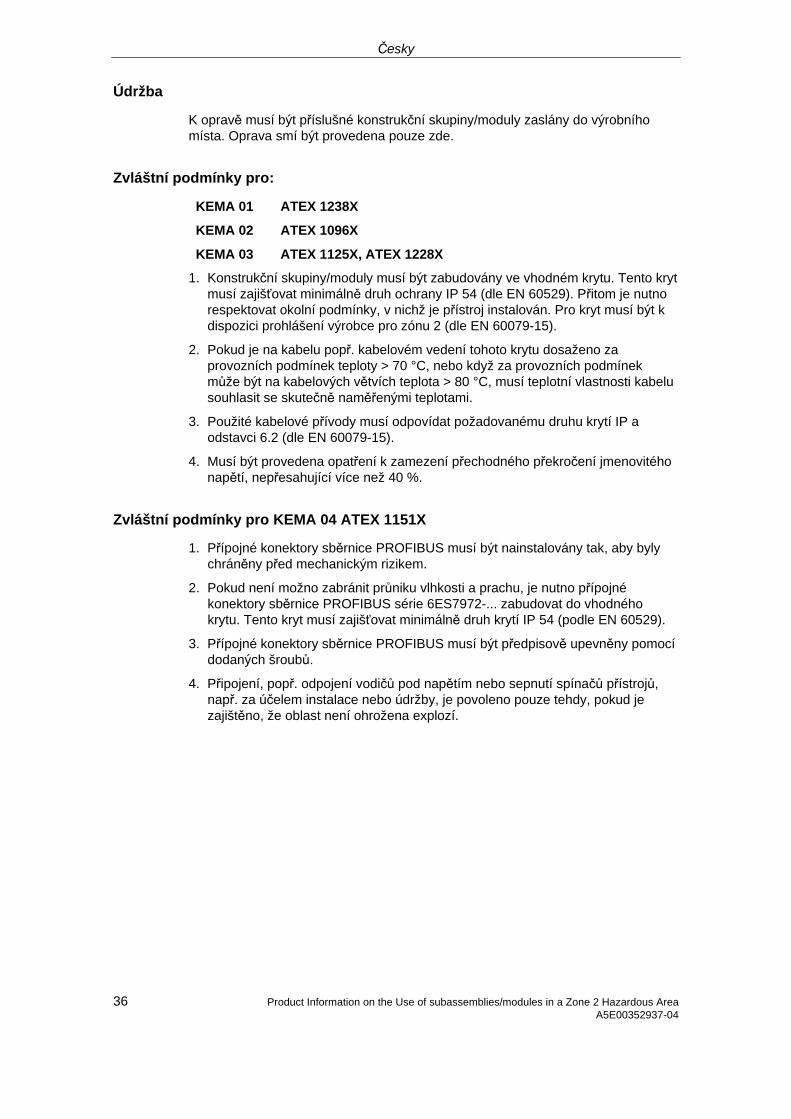
Česky
36 Product Information on the Use of subassemblies/modules in a Zone 2 Hazardous Area A5E00352937-04
Údržba
K opravě musí být příslušné konstrukční skupiny/moduly zaslány do výrobního místa. Oprava smí být provedena pouze zde.
Zvláštní podmínky pro:
KEMA 01 ATEX 1238X
KEMA 02 ATEX 1096X
KEMA 03 ATEX 1125X, ATEX 1228X
1. Konstrukční skupiny/moduly musí být zabudovány ve vhodném krytu. Tento kryt musí zajišťovat minimálně druh ochrany IP 54 (dle EN 60529). Přitom je nutno respektovat okolní podmínky, v nichž je přístroj instalován. Pro kryt musí být k dispozici prohlášení výrobce pro zónu 2 (dle EN 60079-15).
2. Pokud je na kabelu popř. kabelovém vedení tohoto krytu dosaženo za provozních podmínek teploty > 70 °C, nebo když za provozních podmínek může být na kabelových větvích teplota > 80 °C, musí teplotní vlastnosti kabelu souhlasit se skutečně naměřenými teplotami.
3. Použité kabelové přívody musí odpovídat požadovanému druhu krytí IP a odstavci 6.2 (dle EN 60079-15).
4. Musí být provedena opatření k zamezení přechodného překročení jmenovitého napětí, nepřesahující více než 40 %.
Zvláštní podmínky pro KEMA 04 ATEX 1151X
1. Přípojné konektory sběrnice PROFIBUS musí být nainstalovány tak, aby byly chráněny před mechanickým rizikem.
2. Pokud není možno zabránit průniku vlhkosti a prachu, je nutno přípojné konektory sběrnice PROFIBUS série 6ES7972-... zabudovat do vhodného krytu. Tento kryt musí zajišťovat minimálně druh krytí IP 54 (podle EN 60529).
3. Přípojné konektory sběrnice PROFIBUS musí být předpisově upevněny pomocí dodaných šroubů.
4. Připojení, popř. odpojení vodičů pod napětím nebo sepnutí spínačů přístrojů, např. za účelem instalace nebo údržby, je povoleno pouze tehdy, pokud je zajištěno, že oblast není ohrožena explozí.
Česky
Zvláštní podmínky pro KEMA 05 ATEX 1137X
1. Konstrukční skupiny/moduly musí být zabudovány ve vhodném krytu. Tento kryt musí zajišťovat minimálně druh krytí IP 54 (podle EN 60529). Přitom je nutno respektovat okolní podmínky, v nichž je přístroj instalován. Pro kryt musí být k dispozici prohlášení výrobce pro zónu 2 (dle EN 60079-15).
2. Pokud je na kabelu popř. kabelovém vedení tohoto krytu dosaženo za provozních podmínek teploty > 70 °C, nebo když za provozních podmínek může být na kabelových větvích teplota > 80 °C, musí teplotní vlastnosti kabelu souhlasit se skutečně naměřenými teplotami.
3. Musí být provedena opatření k zamezení přechodného překročení jmenovitého napětí, nepřesahující více než 40 %.
Další informace
Další informace ke konstrukčním skupinám/modulům naleznete v příslušné příručce.
37 Product Information on the Use of subassemblies/modules in a Zone 2 Hazardous AreaA5E00352937-04
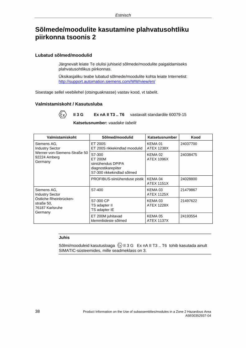
Estnisch
Sõlmede/moodulite kasutamine plahvatusohtliku piirkonna tsoonis 2
Lubatud sõlmed/moodulid
Järgnevalt leiate Te olulisi juhiseid sõlmede/moodulite paigaldamiseks plahvatusohtlikus piirkonnas.
Üksikasjaliku teabe lubatud sõlmede/moodulite kohta leiate Internetist: http://support.automation.siemens.com/WW/view/en/
Sisestage sellel veebilehel (otsinguaknasse) vastav kood, vt tabelit.
Valmistamiskoht / Kasutusluba
II 3 G Ex nA II T3 .. T6 vastavalt standardile 60079-15
Katsetusnumber: vaadake tabelit
Valmistamiskoht Sõlmed/moodulid Katsetusnumber Kood
ET 200S ET 200S rikkekindlad moodulid
KEMA 01 ATEX 1238X
24037700
S7-300 ET 200M siiniühendus DP/PA diagnostikarepiiter S7-300 rikkekindlad sõlmed
KEMA 02 ATEX 1096X
24038475
Siemens AG, Industry Sector Werner-von-Siemens-Straße 50 92224 Amberg Germany
PROFIBUS-siiniühenduse pistik KEMA 04 ATEX 1151X
24028800
S7-400 KEMA 03 ATEX 1125X
21479867
S7-300 CP TS adapter II TS adapter IE
KEMA 03 ATEX 1228X
21497622
Siemens AG, Industry Sector Östliche Rheinbrücken- straße 50, 76187 Karlsruhe Germany
ET 200M juhitavad klemmliideste sõlmed
KEMA 05 ATEX 1137X
24193554
Juhis
Sõlmi/mooduleid kasutusloaga II 3 G Ex nA II T3 .. T6 tohib kasutada ainult SIMATIC-süsteemides, mille seadmeklass on 3.
38 Product Information on the Use of subassemblies/modules in a Zone 2 Hazardous Area A5E00352937-04
Estnisch
Korrashoid
Parandamiseks tuleb sõlmed/moodulid saata valmistamiskohta. Parandustöid tohib teha ainult seal.
Eritingimused
KEMA 01 ATEX 1238X
KEMA 02 ATEX 1096X
KEMA 03 ATEX 1125X, ATEX 1228X
kohta:
1. Sõlmed/moodulid tuleb monteerida sobivasse metallkorpusesse. Korpus peab tagama kaitseastme vähemalt IP 54 (vastavalt standardile EN 60529). Seejuures peab arvesse võtma seadme paigaldamise keskkonna tingimusi. Korpuse jaoks peab tsooni 2 jaoks olema tootja juhis (vastavalt standardile EN 60079-15).
2. Kui selle korpuse kaabli juures või kaabelvaheliku (kaabelsisestuse) juures töötingimustes saavutatakse temperatuur > 70 °C või, kui töötingimustes temperatuur soone hargnemiskoha juures võib olla > 80 °C, peavad kaabli termilised omadused olema vastavuses tegelikult mõõdetud temperatuuridega.
3. Kasutatavad kaabelvahelikud (kaabelsisestused) peavad vastama nõutud IP-kaitseastmele ja osas 6.2 toodud nõuetele (vastavalt standardile EN 60079-15).
4. Peab rakendama abinõusid, et nimipinget üleminekute tõttu ei saaks ületada üle 40 %.
Eritingimused KEMA 04 ATEX 1151X kohta
1. PROFIBUS-siiniühenduse pistik tuleb paigaldada selliselt, et see oleks kaitstud mehaanilise ohu eest.
2. Juhul kui niiskuse ja tolmu sissetungimist ei saa vältida, tuleb 6ES7972-... seeria PROFIBUS-siiniühenduse pistikud paigaldada sobivasse korpusesse. See korpus peab tagama vähemalt kaitseklassile IP 54 (vastavalt standardile EN 60529).
3. PROFIBUS-siiniühenduse pistikud tuleb kinnitada ettenähtud viisil kaasasolevate kruvidega.
4. Pinget juhtivate juhtide ühendamine või eemaldamine või seadme lüliti käivitamine, nt paigaldus- ja hoolduseesmärkidel, on lubatud ainult juhul, kui piirkond ei ole plahvatusohtlik.
39 Product Information on the Use of subassemblies/modules in a Zone 2 Hazardous AreaA5E00352937-04
Estnisch
40 Product Information on the Use of subassemblies/modules in a Zone 2 Hazardous Area A5E00352937-04
Eritingimused KEMA 05 ATEX 1137X kohta
1. Sõlmed/moodulid tuleb monteerida sobivasse metallkorpusesse. Korpus peab tagama kaitseastme vähemalt IP 54 (vastavalt standardile EN 60529). Seejuures peab arvesse võtma seadme paigaldamise keskkonna tingimusi. Korpuse jaoks peab tsooni 2 jaoks olema tootja juhis (vastavalt standardile EN 60079-15).
2. Kui selle korpuse kaabli juures või kaabelvaheliku (kaabelsisestuse) juures töötingimustes saavutatakse temperatuur > 70 °C või, kui töötingimustes temperatuur soone hargnemiskoha juures võib olla > 80 °C, peavad kaabli termilised omadused olema vastavuses tegelikult mõõdetud temperatuuridega.
3. Peab rakendama abinõusid, et nimipinget üleminekute tõttu ei saaks ületada üle 40 %.
Täpsem teave
Täpsemat teavet sõlmede/moodulite kohta leiate kaasasolevast käsiraamatust.
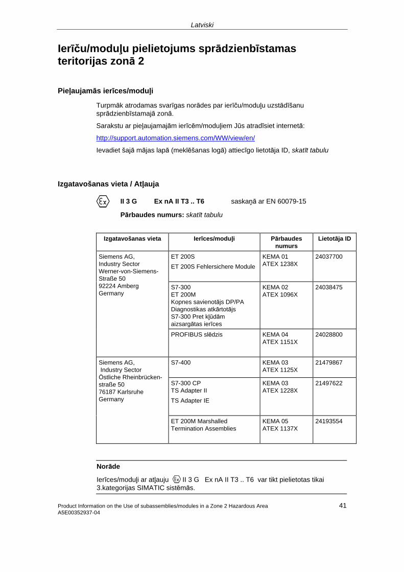
Latviski
Ierīču/moduļu pielietojums sprādzienbīstamas teritorijas zonā 2
Pieļaujamās ierīces/moduļi
Turpmāk atrodamas svarīgas norādes par ierīču/moduļu uzstādīšanu sprādzienbīstamajā zonā.
Sarakstu ar pieļaujamajām ierīcēm/moduļiem Jūs atradīsiet internetā:
http://support.automation.siemens.com/WW/view/en/
Ievadiet šajā mājas lapā (meklēšanas logā) attiecīgo lietotāja ID, skatīt tabulu
Izgatavošanas vieta / Atļauja
II 3 G Ex nA II T3 .. T6 saskaņā ar EN 60079-15
Pārbaudes numurs: skatīt tabulu
Izgatavošanas vieta Ierīces/moduļi Pārbaudes
numurs Lietotāja ID
ET 200S ET 200S Fehlersichere Module
KEMA 01 ATEX 1238X
24037700
S7-300 ET 200M Kopnes savienotājs DP/PA Diagnostikas atkārtotājs S7-300 Pret kļūdām aizsargātas ierīces
KEMA 02 ATEX 1096X
24038475
Siemens AG, Industry Sector Werner-von-Siemens-Straße 50 92224 Amberg Germany
PROFIBUS slēdzis
KEMA 04 ATEX 1151X
24028800
S7-400 KEMA 03 ATEX 1125X
21479867
S7-300 CP TS Adapter II TS Adapter IE
KEMA 03 ATEX 1228X
21497622
Siemens AG, Industry Sector Östliche Rheinbrücken- straße 50 76187 Karlsruhe Germany
ET 200M Marshalled Termination Assemblies
KEMA 05 ATEX 1137X
24193554
Norāde
Ierīces/moduļi ar atļauju II 3 G Ex nA II T3 .. T6 var tikt pielietotas tikai 3.kategorijas SIMATIC sistēmās.
Product Information on the Use of subassemblies/modules in a Zone 2 Hazardous Area 41 A5E00352937-04
Latviski
42 Product Information on the Use of subassemblies/modules in a Zone 2 Hazardous Area A5E00352937-04
Tehniskā apkope
Attiecīgu ierīču/moduļu remontam tie ir jānosūta ražotājam. Remontu drīkst veikt tikai tur.
Īpaši apstākļi priekš
KEMA 01 ATEX 1238X
KEMA 02 ATEX 1096X
KEMA 03 ATEX 1125X, ATEX 1228X
1. Ierīces/moduļi jāiebūvē piemērotā metāla korpusā. Tiem jānodrošina aizsardzības līmenis ne mazāks kā IP 54 (saskaņā ar EN 60529). Turklāt, ierīces uzstādīšanā jāievēro apkārtējas vides apstākļi. Korpusam ir nepieciešams izgatavotāja apliecinājums zonai 2 (saskaņā ar EN 60079-15).
2. Ja uz kabeļa vai šī korpusa kabeļu ievades ekspluatācijas apstākļos tiek sasniegta temperatūra > 70 °C vai ja ekspluatācijas apstākļos uz kabeļa atzariem var būt temperatūra > 80 °C, kabeļu temperatūras īpašībām jāatbilst faktiski nomērītām temperatūrām.
3. Pielietojamām kabeļu ievadēm jāatbilst nepieciešamajam aizsardzības veidam IP un sadaļai 6.2 (saskaņā ar EN 60079-15).
4. Nepieciešams veikt pasākumus, lai pārejas spriegums nepārsniegtu nominālo spriegumu vairāk kā par 40 %.
Īpašie noteikumi KEMA 04 ATEX 1151X 1. PROFIBUS slēdžus ir jāinstalē tā, lai tie būtu aizsargāti no mehāniskām
briesmām
2. Ja nav iespējams izvairīties no šķidrumu un putekļu iekļūšanas, tad PROFIBUS slēdžus no sērijas 6ES7972-... ir jāiebūvē piemērotā korpusā. Šim korpusam ir jāatbalsta vismaz drošības veids IP 54 (pēc E N 60529).
3. PROFIBUS slēdžus ir jāpiestiprina ar komplektā ietilpstošajām skrūvēm.
4. Spriegumu vadošu vadu pieslēgšana vai atslēgšana vai ierīces slēdža lietošana, piemēram, uzstādīšanas vai tehniskās apkopes dēļ, ir atļauta tikai tad, kad ir noskaidrots vai zonā nepastāv eksplodēšanas iespējamība.
Latviski
Product Information on the Use of subassemblies/modules in a Zone 2 Hazardous Area 43 A5E00352937-04
Īpaši noteikumi KEMA 05 ATEX 1137X
1. Ierīces/moduļi ir jāiebūvē piemērotā korpusā. Šiem korpusiem ir jāatbalsta vismaz drošības veids IP 54 (pēc E N 60529). Pie tam ir jāņem vērā apkārtnes faktori, kādā ierīce tiks uzstādīta. Korpusam jāatbilst ražotāja 2. zonas deklarācijai (saskaņā ar EN 60079-15).
2. Ja šī korpusa kabelis, respektīvi, kabeļa ievade darba laikā sasniedz > 70 °C vai, ja darba laikā vadu sazarojums ir sasniedzis > 80 °C, tad kabeļa temperatūras īpašībām ir jāatbilst izmērītajām temperatūrām.
3. Ir jāveic pasākumi, lai nominālais spriegums caur pārejām nepārsniegtu 40%
Papildus informācija Papildus informāciju par ierīcēm/moduļiem Jūs atradīsiet pievienotajā rokasgrāmatā.
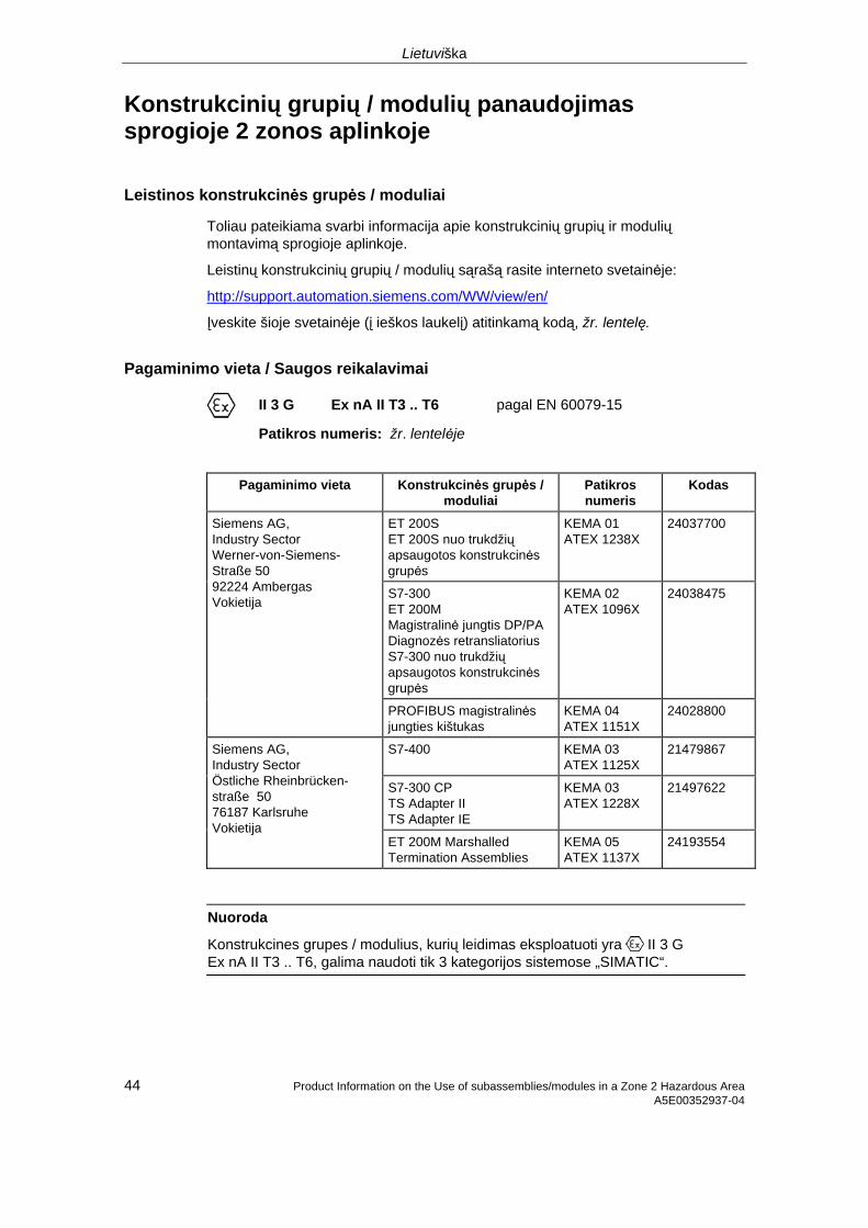
Lietuviška
Konstrukcinių grupių / modulių panaudojimas sprogioje 2 zonos aplinkoje
Leistinos konstrukcinės grupės / moduliai
Toliau pateikiama svarbi informacija apie konstrukcinių grupių ir modulių montavimą sprogioje aplinkoje.
Leistinų konstrukcinių grupių / modulių sąrašą rasite interneto svetainėje:
http://support.automation.siemens.com/WW/view/en/
Įveskite šioje svetainėje (į ieškos laukelį) atitinkamą kodą, žr. lentelę.
Pagaminimo vieta / Saugos reikalavimai
II 3 G Ex nA II T3 .. T6 pagal EN 60079-15
Patikros numeris: žr. lentelėje
Pagaminimo vieta Konstrukcinės grupės /
moduliai Patikros numeris
Kodas
ET 200S ET 200S nuo trukdžių apsaugotos konstrukcinės grupės
KEMA 01 ATEX 1238X
24037700
S7-300 ET 200M Magistralinė jungtis DP/PA Diagnozės retransliatorius S7-300 nuo trukdžių apsaugotos konstrukcinės grupės
KEMA 02 ATEX 1096X
24038475
Siemens AG, Industry Sector Werner-von-Siemens-Straße 50 92224 Ambergas Vokietija
PROFIBUS magistralinės jungties kištukas
KEMA 04 ATEX 1151X
24028800
S7-400 KEMA 03 ATEX 1125X
21479867
S7-300 CP TS Adapter II TS Adapter IE
KEMA 03 ATEX 1228X
21497622
Siemens AG, Industry Sector Östliche Rheinbrücken- straße 50 76187 Karlsruhe Vokietija
ET 200M Marshalled Termination Assemblies
KEMA 05 ATEX 1137X
24193554
Nuoroda
Konstrukcines grupes / modulius, kurių leidimas eksploatuoti yra II 3 G Ex nA II T3 .. T6, galima naudoti tik 3 kategorijos sistemose „SIMATIC“.
44 Product Information on the Use of subassemblies/modules in a Zone 2 Hazardous Area A5E00352937-04
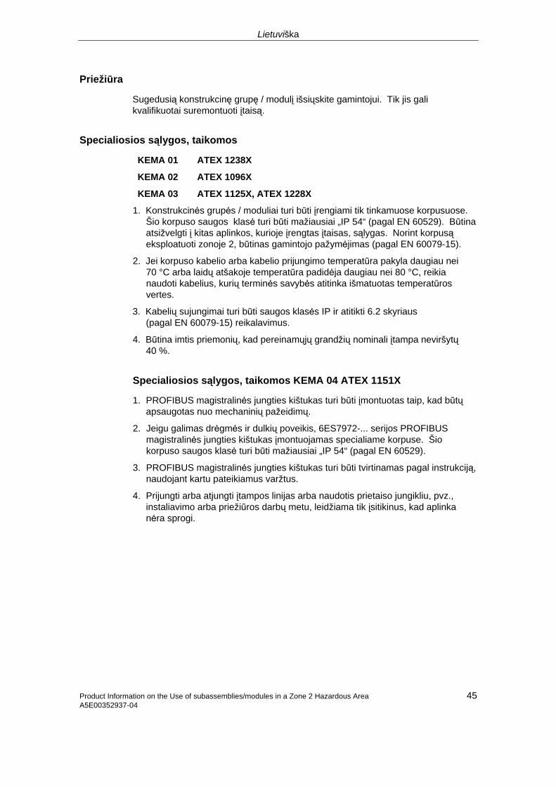
Lietuviška
Product Information on the Use of subassemblies/modules in a Zone 2 Hazardous Area 45 A5E00352937-04
Priežiūra
Sugedusią konstrukcinę grupę / modulį išsiųskite gamintojui. Tik jis gali kvalifikuotai suremontuoti įtaisą.
Specialiosios sąlygos, taikomos
KEMA 01 ATEX 1238X
KEMA 02 ATEX 1096X
KEMA 03 ATEX 1125X, ATEX 1228X
1. Konstrukcinės grupės / moduliai turi būti įrengiami tik tinkamuose korpusuose. Šio korpuso saugos klasė turi būti mažiausiai „IP 54“ (pagal EN 60529). Būtina atsižvelgti į kitas aplinkos, kurioje įrengtas įtaisas, sąlygas. Norint korpusą eksploatuoti zonoje 2, būtinas gamintojo pažymėjimas (pagal EN 60079-15).
2. Jei korpuso kabelio arba kabelio prijungimo temperatūra pakyla daugiau nei 70 °C arba laidų atšakoje temperatūra padidėja daugiau nei 80 °C, reikia naudoti kabelius, kurių terminės savybės atitinka išmatuotas temperatūros vertes.
3. Kabelių sujungimai turi būti saugos klasės IP ir atitikti 6.2 skyriaus (pagal EN 60079-15) reikalavimus.
4. Būtina imtis priemonių, kad pereinamųjų grandžių nominali įtampa neviršytų 40 %.
Specialiosios sąlygos, taikomos KEMA 04 ATEX 1151X
1. PROFIBUS magistralinės jungties kištukas turi būti įmontuotas taip, kad būtų apsaugotas nuo mechaninių pažeidimų.
2. Jeigu galimas drėgmės ir dulkių poveikis, 6ES7972-... serijos PROFIBUS magistralinės jungties kištukas įmontuojamas specialiame korpuse. Šio korpuso saugos klasė turi būti mažiausiai „IP 54“ (pagal EN 60529).
3. PROFIBUS magistralinės jungties kištukas turi būti tvirtinamas pagal instrukciją, naudojant kartu pateikiamus varžtus.
4. Prijungti arba atjungti įtampos linijas arba naudotis prietaiso jungikliu, pvz., instaliavimo arba priežiūros darbų metu, leidžiama tik įsitikinus, kad aplinka nėra sprogi.
Lietuviška
46 Product Information on the Use of subassemblies/modules in a Zone 2 Hazardous Area A5E00352937-04
Specialiosios sąlygos, taikomos KEMA 05 ATEX 1137X
1. Konstrukcinės grupės / moduliai turi būti įrengiami tik tinkamuose korpusuose. Šio korpuso saugos klasė turi būti mažiausiai „IP 54“ (pagal EN 60529). Būtina atsižvelgti į kitas aplinkos, kurioje įrengtas įtaisas, sąlygas. Norint korpusą eksploatuoti zonoje 2, būtinas gamintojo pažymėjimas (pagal EN 60079-15).
2. Jei korpuso kabelio arba kabelio prijungimo temperatūra pakyla daugiau nei 70 °C arba laidų atšakoje temperatūra padidėja daugiau nei 80 °C, reikia naudoti kabelius, kurių terminės savybės atitinka išmatuotas temperatūros vertes.
3. Būtina imtis priemonių, kad pereinamųjų grandžių nominali įtampa neviršytų 40 %.
Papildoma informacija
Papildomos informacijos apie konstrukcines grupes / modulius rasite eksploatacijos vadove.
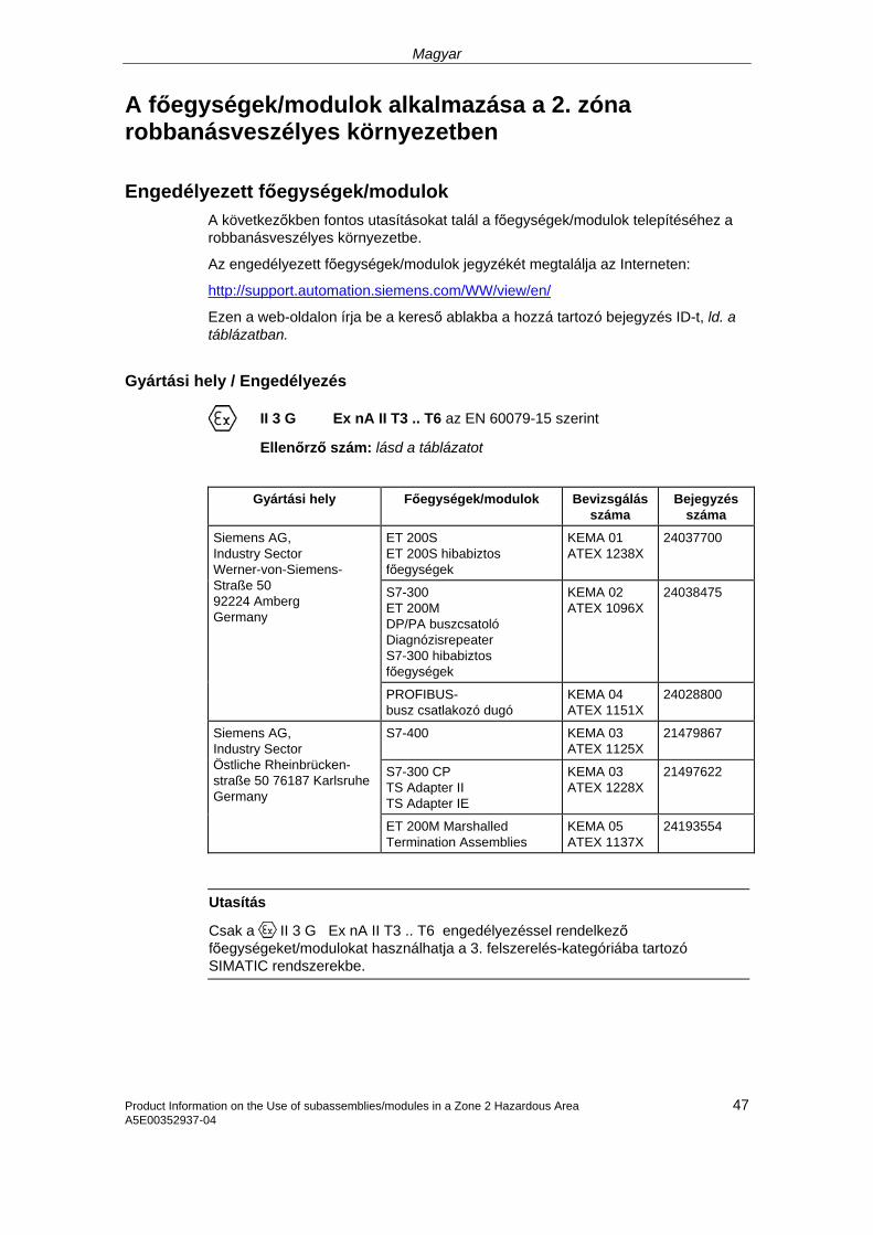
Magyar
A főegységek/modulok alkalmazása a 2. zóna robbanásveszélyes környezetben
Engedélyezett főegységek/modulok A következőkben fontos utasításokat talál a főegységek/modulok telepítéséhez a robbanásveszélyes környezetbe.
Az engedélyezett főegységek/modulok jegyzékét megtalálja az Interneten:
http://support.automation.siemens.com/WW/view/en/
Ezen a web-oldalon írja be a kereső ablakba a hozzá tartozó bejegyzés ID-t, ld. a táblázatban.
Gyártási hely / Engedélyezés
II 3 G Ex nA II T3 .. T6 az EN 60079-15 szerint
Ellenőrző szám: lásd a táblázatot
Gyártási hely Főegységek/modulok Bevizsgálás
száma Bejegyzés
száma ET 200S ET 200S hibabiztos főegységek
KEMA 01 ATEX 1238X
24037700
S7-300 ET 200M DP/PA buszcsatoló Diagnózisrepeater S7-300 hibabiztos főegységek
KEMA 02 ATEX 1096X
24038475
Siemens AG, Industry Sector Werner-von-Siemens-Straße 50 92224 Amberg Germany
PROFIBUS- busz csatlakozó dugó
KEMA 04 ATEX 1151X
24028800
S7-400 KEMA 03 ATEX 1125X
21479867
S7-300 CP TS Adapter II TS Adapter IE
KEMA 03 ATEX 1228X
21497622
Siemens AG, Industry Sector Östliche Rheinbrücken- straße 50 76187 KarlsruheGermany
ET 200M Marshalled Termination Assemblies
KEMA 05 ATEX 1137X
24193554
Utasítás
Csak a II 3 G Ex nA II T3 .. T6 engedélyezéssel rendelkező főegységeket/modulokat használhatja a 3. felszerelés-kategóriába tartozó SIMATIC rendszerekbe.
47 Product Information on the Use of subassemblies/modules in a Zone 2 Hazardous Area A5E00352937-04

Magyar
Product Information on the Use of subassemblies/modules in a Zone 2 Hazardous Area A5E00352937-04 48
Karbantartás
Javításra küldje az érintett főegységeket/modulokat a gyártási helyre. Csak itt hajthatják végre a javítást.
Különleges feltételek a következők számára:
KEMA 01 ATEX 1238X
KEMA 02 ATEX 1096X
KEMA 03 ATEX 1125X, ATEX 1228X
1. A főegységeket/modulokat egy erre alkalmas házba kell beszerelni. Ez a ház rendelkezzen legalább az IP 54 védettségi fokozattal (EN 60529 szerint). Itt figyelembe kell venni azokat a környezeti feltételeket, amelyek a készülék telepítésekor fellépnek. A ház rendelkezzen a 2. zónára vonatkozó gyártói nyilatkozat (az EN 60079-15 szerint).
2. Ha az adott ház kábelén ill. kábelvezetésen üzemi körülmények között a hőmérséklet > 70 °C, vagy ha az üzemi körülmények között az érelágazásokon a hőmérséklet > 80 °C, akkor a kábel hőmérsékleti tulajdonságai egyezzenek meg a ténylegesen mért hőmérsékletekkel.
3. Az alkalmazott kábelvezetések feleljenek meg az előírt IP védettségi fokozatnak és a 6.2. bekezdésnek (EN 60079-15 szerint).
4. Gondoskodjon róla, hogy a tranziensek a névleges feszültséget ne lépjék túl több mint 40 %-al.
Különleges feltételek a KEMA 04 ATEX 1151X-hez
1. A PROFIBUS busz csatlakozó dugót úgy kell beszerelni, hogy mechanikai veszélyeztetéstől védett legyen.
2. Ha por és nedvesség behatolását nem lehet kizárni, a 6ES7972-... sorozatú PROFIBUS busz csatlakozó dugót kell egy alkalmas házba beépíteni. Ez a ház rendelkezzen az IP 54 védettségi fokozattal (EN 60529 szerint).
3. A PROFIBUS busz csatlakozó dugót a vele szállított csavarokkal óvatosan kell rögzíteni.
4. A feszültséget vezető vezetékek bekötése vagy leválasztása, vagy készülék kapcsolók működtetése (pl. szerelési- vagy gondozási célokból) csak akkor szabad, ha biztosították, hogy a terület ne legyen robbanásveszélyes.

Magyar
Különleges feltételek a KEMA 05 ATEX 1137X-hez
1. A főegységeket/modulokat egy erre alkalmas házba kell beszerelni. Ez a ház rendelkezzen legalább az IP 54 védettségi fokozattal (EN 60529 szerint). Itt figyelembe kell venni azokat a környezeti feltételeket, amelyek a készülék telepítésekor fellépnek. A ház rendelkezzen a 2. zónára vonatkozó gyártói nyilatkozat (az EN 60079-15 szerint).
2. Ha a jelen ház kábelén ill. kábelvezetésen üzemi körülmények között a hőmérséklet > 70 °C, vagy ha az üzemi körülmények között az érelágazásokon a hőmérséklet > 80 °C, akkor a kábel hőmérsékleti tulajdonságai legyen azonosak a ténylegesen mért hőmérsékletekkel.
3. Gondoskodjon róla, hogy a tranziensek ne lépjék túl több mint 40 %-al a névleges feszültséget.
További információk
A főegységek/modulokról további információkat talál a hozzá tartozó kézikönyvben.
49 Product Information on the Use of subassemblies/modules in a Zone 2 Hazardous Area A5E00352937-04
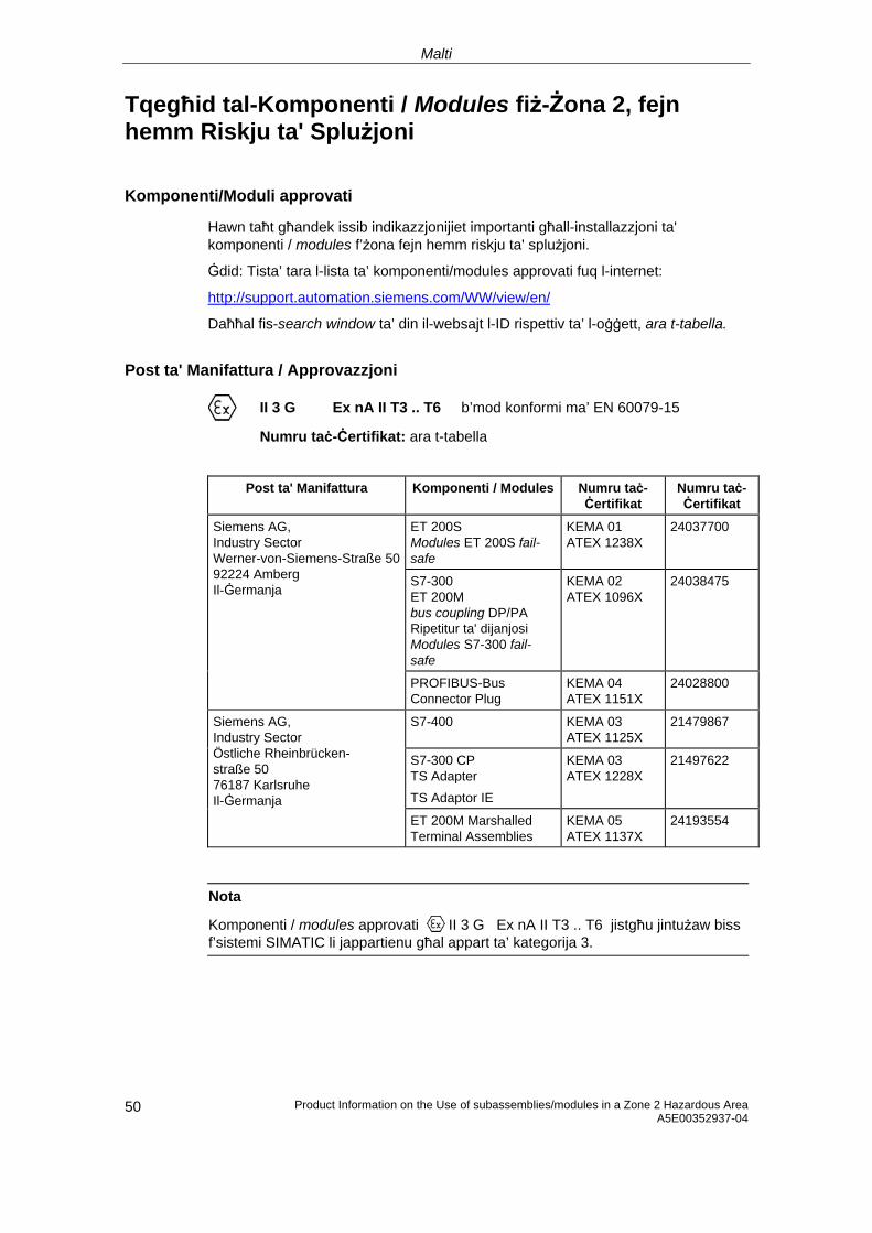
Malti
Tqegħid tal-Komponenti / Modules fiż-Żona 2, fejn hemm Riskju ta' Splużjoni
Komponenti/Moduli approvati
Hawn taħt għandek issib indikazzjonijiet importanti għall-installazzjoni ta' komponenti / modules f’żona fejn hemm riskju ta' splużjoni.
Ġdid: Tista’ tara l-lista ta’ komponenti/modules approvati fuq l-internet:
http://support.automation.siemens.com/WW/view/en/
Daħħal fis-search window ta’ din il-websajt l-ID rispettiv ta’ l-oġġett, ara t-tabella.
Post ta' Manifattura / Approvazzjoni
II 3 G Ex nA II T3 .. T6 b’mod konformi ma’ EN 60079-15
Numru taċ-Ċertifikat: ara t-tabella
Post ta' Manifattura Komponenti / Modules Numru taċ-
Ċertifikat Numru taċ-Ċertifikat
ET 200S Modules ET 200S fail-safe
KEMA 01 ATEX 1238X
24037700
S7-300 ET 200M bus coupling DP/PA Ripetitur ta' dijanjosi Modules S7-300 fail-safe
KEMA 02 ATEX 1096X
24038475
Siemens AG, Industry Sector Werner-von-Siemens-Straße 5092224 Amberg Il-Ġermanja
PROFIBUS-Bus Connector Plug
KEMA 04 ATEX 1151X
24028800
S7-400 KEMA 03 ATEX 1125X
21479867
S7-300 CP TS Adapter TS Adaptor IE
KEMA 03 ATEX 1228X
21497622
Siemens AG, Industry Sector Östliche Rheinbrücken- straße 50 76187 Karlsruhe Il-Ġermanja
ET 200M Marshalled Terminal Assemblies
KEMA 05 ATEX 1137X
24193554
Nota
Komponenti / modules approvati II 3 G Ex nA II T3 .. T6 jistgħu jintużaw biss f’sistemi SIMATIC li jappartienu għal appart ta’ kategorija 3.
Product Information on the Use of subassemblies/modules in a Zone 2 Hazardous Area A5E00352937-04 50
Malti
Manutenzjoni
Fil-każ li jkollhom bżonn tiswija, il-komponenti / modules ikkonċernati għandhom jintbagħtu fil-post ta' manifattura. It-tiswijiet jistgħu jsiru biss f'dan il-post.
Kundizzjonijiet Speċjali għal:
KEMA 01 ATEX 1238X
KEMA 02 ATEX 1096X
KEMA 03 ATEX 1125X, ATEX 1228X
1. Komponenti / modules għandhom jiġu mmontati ġewwa lqugħ addattat. Dan l-ilqugħ għandu jiggarantixxi protezzjoni li tkun mill-inqas tat-tip IP 54 (skond EN 60529). Inti u tagħmel hekk, trid taħseb għall-kundizzjonijiet ambjentali ta' waqt l-installazzjoni ta’ l-apparat. Għall-ilqugħ, irid ikun hemm dikjarazzjoni tal-fabbrikant li tgħid li dan huwa tajjeb għaż-żona 2 (skond EN 60079-15).
2. Jekk fil-kejbil, jew fil-kaxxa mad-daħla għall-kejbil, tintlaħaq temperatura ta' aktar minn 70 °C taħt kundizzjonijiet ta' ħidma, jew jekk fil-post fejn jinfirdu l-wajers jista' jkun hemm temperatura ogħla minn 80 °C, il-kejbil irid ikollu karatteristiċi li jifilħu għal dawn it-temperaturi.
3. Id-daħliet għall-kejbil li jintużaw iridu jikkonformaw mat-tip ta' protezzjoni IP mitluba u mat-taqsima 6.2 (skond EN 60079-15).
4. Iridu jittieħdu miżuri biex il-vultaġġ nominali ma jinqabiżx b'aktar minn 40%.
Kundizzjonijiet speċjali għal KEMA 04 ATEX 1151X
1. Il-plugs tat-tip PROFIBUS-Bus Connector jeħtieġu jiġu installati b’mod li jiżgura protezzjoni kontra kull periklu mekkaniku.
2. Jekk id-dħul ta’ l-umdità jew tat-trab ma jistax jiġi eskluż, jeħtieġu jiġu installati plugs tat-tip PROFIBUS-Bus Connector tan-Numru Serjali 6ES7972-... f’ilqugħ adegwat. Dan l-ilqugħ jeħtieġ jissodisfa l-klassi ta’ protezzjoni IP 54 (b’mod konformi ma’ EN 60529) bħala standard minimu.
3. Il-plugs tat-tip PROFIBUS-Connector jeħtieġu jiġu installati skond l-istruzzjonijiet u bil-viti pprovduti.
4. It-tqabbid u/jew skonnettjar ta’ wajers bil-kurrent fihom u l-użu ta’ swiċċijiet, jiġifieri għal għanijiet ta’ installazzjoni jew manutenzjoni huwa permess biss jekk iż-żona m’hijiex waħda li fiha riskju ta’ splużjoni.
51 Product Information on the Use of subassemblies/modules in a Zone 2 Hazardous Area A5E00352937-04
Malti
Product Information on the Use of subassemblies/modules in a Zone 2 Hazardous Area A5E00352937-04 52
Kundizzjonijiet speċjali għal KEMA 05 ATEX 1137X
1. Komponenti / modules għandhom jiġu mmontati ġewwa lqugħ addattat. Dan l-ilqugħ għandu jiggarantixxi protezzjoni li tkun mill-inqas tat-tip IP 54 (skond EN 60529). Inti u tagħmel hekk, trid taħseb għall-kundizzjonijiet ambjentali ta' waqt l-installazzjoni ta’ l-apparat. Għall-ilqugħ, irid ikun hemm dikjarazzjoni tal-fabbrikant li tgħid li dan huwa tajjeb għaż-żona 2 (skond EN 60079-15).
2. Jekk fil-kejbil, jew fil-kaxxa mad-daħla għall-kejbil, tintlaħaq temperatura ta' aktar minn 70 °C taħt kundizzjonijiet ta' ħidma, jew jekk fil-post fejn jinfirdu l-wajers jista' jkun hemm temperatura ogħla minn 80 °C, il-kejbil irid ikollu karatteristiċi li jifilħu għal dawn it-temperaturi.
3. Iridu jittieħdu miżuri biex il-vultaġġ nominali ma jinqabiżx b'aktar minn 40%.
Aktar informazzjoni
Għal iktar informazzjoni dwar il-komponenti/moduli, jekk jogħġbok irreferi għall-manwal rispettiv.
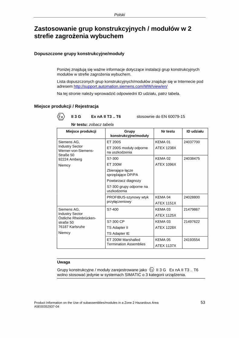
Polski
Zastosowanie grup konstrukcyjnych / modułów w 2 strefie zagrożenia wybuchem
Dopuszczone grupy konstrukcyjne/moduły
Poniżej znajdują się ważne informacje dotyczące instalacji grup konstrukcyjnych modułów w strefie zagrożenia wybuchem.
Lista dopuszczonych grup konstrukcyjnych/modułów znajduje się w Internecie pod adresem http://support.automation.siemens.com/WW/view/en/
Na tej stronie należy wprowadzić odpowiedni ID udziału, patrz tabela.
Miejsce produkcji / Rejestracja
II 3 G Ex nA II T3 .. T6 stosownie do EN 60079-15
Nr testu: zobacz tabela
Miejsce produkcji Grupy konstrukcyjne/moduły
Nr testu ID udziału
ET 200S ET 200S moduły odporne na uszkodzenia
KEMA 01 ATEX 1238X
24037700
S7-300 ET 200M Zbierające łącze sprzężające DP/PA Powtarzacz diagnozy S7-300 grupy odporne na uszkodzenia
KEMA 02 ATEX 1096X
24038475
Siemens AG, Industry Sector Werner-von-Siemens-Straße 50 92224 Amberg Niemcy
PROFIBUS-szynowy wtyk przyłączeniowy
KEMA 04 ATEX 1151X
24028800
S7-400 KEMA 03 ATEX 1125X
21479867
S7-300 CP TS Adapter II TS Adapter IE
KEMA 03 ATEX 1228X
21497622
Siemens AG, Industry Sector Östliche Rheinbrücken- straße 50 76187 Karlsruhe Niemcy
ET 200M Marshalled Termination Assemblies
KEMA 05 ATEX 1137X
24193554
Uwaga
Grupy konstrukcyjne / moduły zarejestrowane jako II 3 G Ex nA II T3 .. T6 wolno stosować jedynie w systemach SIMATIC o 3 kategorii urządzenia.
Product Information on the Use of subassemblies/modules in a Zone 2 Hazardous Area A5E00352937-04
53
Polski
Product Information on the Use of subassemblies/modules in a Zone 2 Hazardous Area A5E00352937-04 54
Konserwacja
W celu naprawy należy odpowiednie grupy konstrukcyjne / moduły przesłać do miejsca produkcji. Jedynie serwis producenta jest upoważniony do dokonywania napraw.
Warunki szczególne dla:
KEMA 01 ATEX 1238X
KEMA 02 ATEX 1096X
KEMA 03 ATEX 1125X, ATEX 1228X
1. Grupy konstrukcyjne / moduły muszą zostać zamontowane do odpowiedniej puszki ochronnej. Puszki muszą spełniać wymagania co najmniej stopnia IP 54 (stosownie do EN 60529). Należy brać pod uwagę warunki otoczenia, w którym urządzenie będzie instalowane. Należy posiadać oświadczenie producenta dopuszczające puszkę do użytku w strefie 2 (stosownie do EN 60079-15).
2. W przypadku, gdyby na przewodzie tej puszki podczas pracy temperatura mogła przekroczyć > 70 °C, lub żyła przewodu mogłaby osiągnąć temperaturę > 80 °C, właściwości cieplne przewodu muszą zostać dobrane do takich wartości.
3. Wszystkie stosowane przewody muszą odpowiadać właściwemu stopniowi ochrony IP oraz warunkom określonym w punkcie 6.2 (stosownie do EN 60079-15).
4. Muszą zostać spełnione takie warunki, aby napięcie miana w przejściach nie mogło przekroczyć więcej niż 40 %.
Warunki szczególne dla KEMA 04 ATEX 1151X
1. Wtyki przyłączeniowe PROFIBUS muszą być zamontowane w sposób chroniący przed uszkodzeniami mechanicznymi.
2. Jeżeli nie można wykluczyć wnikania wilgoci i kurzu wtyki przyłączeniowe PROFIBUS serii 6ES7972… należy zamontować w odpowiedniej puszce. Puszki muszą spełniać wymagania co najmniej stopnia IP 54 (stosownie do EN 60529).
3. Wtyki przyłączeniowe PROFIBUS muszą być unieruchomione zgodnie z przepisami przy pomocy załączonych śrub.
4. Podłączanie lub rozłączanie przewodów będących pod napięciem lub uruchamianie przełączników urządzenia np. do prac instalacyjno - konserwacyjnych jest dozwolone wyłącznie po upewnieniu się, że obszar nie jest zagrożony wybuchem.
Polski
Warunki szczególne dla KEMA 05 ATEX 1137X
1. Grupy konstrukcyjne / moduły muszą zostać zamontowane do odpowiedniej puszki ochronnej. Puszki muszą spełniać wymagania co najmniej stopnia IP 54 (stosownie do EN 60529). Należy brać pod uwagę warunki otoczenia, w którym urządzenie będzie instalowane. Należy posiadać oświadczenie producenta dopuszczające puszkę do użytku w strefie 2 (stosownie do EN 60079-15).
2. W przypadku, gdyby na przewodzie tej puszki podczas pracy temperatura mogła przekroczyć > 70 °C, lub żyła przewodu mogłaby osiągnąć temperaturę > 80 °C, właściwości cieplne przewodu muszą zostać dobrane do takich wartości.
3. Muszą zostać spełnione takie warunki, aby napięcie miana w przejściach nie mogło przekroczyć więcej niż 40 %.
Pozostałe informacje
Pozostałe informacje dotyczące grup konstrukcyjnych/modułów znajdują się w stosownych podręcznikach.
Product Information on the Use of subassemblies/modules in a Zone 2 Hazardous Area A5E00352937-04
55
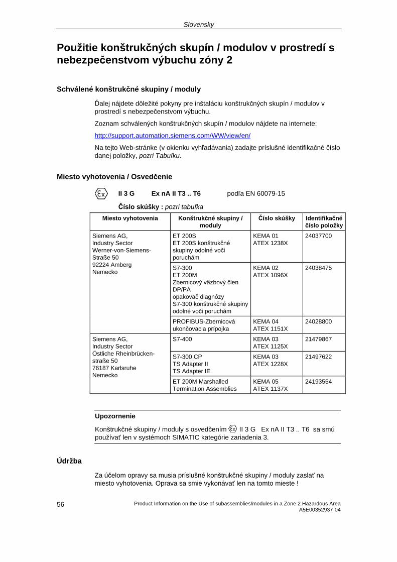
Slovensky
Použitie konštrukčných skupín / modulov v prostredí s nebezpečenstvom výbuchu zóny 2
Schválené konštrukčné skupiny / moduly
Ďalej nájdete dôležité pokyny pre inštaláciu konštrukčných skupín / modulov v prostredí s nebezpečenstvom výbuchu.
Zoznam schválených konštrukčných skupín / modulov nájdete na internete:
http://support.automation.siemens.com/WW/view/en/
Na tejto Web-stránke (v okienku vyhľadávania) zadajte príslušné identifikačné číslo danej položky, pozri Tabuľku.
Miesto vyhotovenia / Osvedčenie
II 3 G Ex nA II T3 .. T6 podľa EN 60079-15
Číslo skúšky : pozri tabuľka
Miesto vyhotovenia Konštrukčné skupiny / moduly
Číslo skúšky Identifikačné číslo položky
ET 200S ET 200S konštrukčné skupiny odolné voči poruchám
KEMA 01 ATEX 1238X
24037700
S7-300 ET 200M Zbernicový väzbový člen DP/PA opakovač diagnózy S7-300 konštrukčné skupiny odolné voči poruchám
KEMA 02 ATEX 1096X
24038475
Siemens AG, Industry Sector Werner-von-Siemens-Straße 50 92224 Amberg Nemecko
PROFIBUS-Zbernicová ukončovacia prípojka
KEMA 04 ATEX 1151X
24028800
S7-400 KEMA 03 ATEX 1125X
21479867
S7-300 CP TS Adapter II TS Adapter IE
KEMA 03 ATEX 1228X
21497622
Siemens AG, Industry Sector Östliche Rheinbrücken- straße 50 76187 Karlsruhe Nemecko
ET 200M Marshalled Termination Assemblies
KEMA 05 ATEX 1137X
24193554
Upozornenie
Konštrukčné skupiny / moduly s osvedčením II 3 G Ex nA II T3 .. T6 sa smú používať len v systémoch SIMATIC kategórie zariadenia 3.
Údržba
Za účelom opravy sa musia príslušné konštrukčné skupiny / moduly zaslať na miesto vyhotovenia. Oprava sa smie vykonávať len na tomto mieste !
Product Information on the Use of subassemblies/modules in a Zone 2 Hazardous Area A5E00352937-04 56
Slovensky
Product Information on the Use of subassemblies/modules in a Zone 2 Hazardous Area 57 A5E00352937-04
Špeciálne podmienky pre:
KEMA 01 ATEX 1238X
KEMA 02 ATEX 1096X
KEMA 03 ATEX 1125X, ATEX 1228X
1. Konštrukčné skupiny / moduly sa musia vmontovať do vhodnej schránky. Táto schránka musí zabezpečovať druh ochrany minimálne IP 54 (podľa EN 60529). Pritom je potrebné zohľadniť podmienky prostredia, do ktorého sa bude zariadenie inštalovať. V prípade puzdra musí existovať vyhlásenie výrobcu pre zónu 2 (podľa EN 60079-15).
2. V prípade, že na kábli, prípadne na káblovom prívode tohto puzdra presiahne teplota pri prevádzkových podmienkach hodnotu > 70 °C, alebo ak na vetve žily môže byť pri prevádzkových podmienkach teplota > 80 °C, musia tepelné vlastnosti kábla vyhovovať skutočne nameraným hodnotám.
3. Všetky použité káblové prívody musia zodpovedať požadovanému druhu ochrany IP a odseku 6.2 (podľa EN 60079-15).
4. Musia sa vykonať také opatrenia, aby sa menovité napätie cez prechody nemohlo prekročiť o viac ako 40 %.
Špeciálne podmienky pre KEMA 04 ATEX 1151X:
1. Zbernicové ukončovacie prípojky musia byť namontované tak, aby boli chránené pred mechanickým poškodením.
2. Ak nie je úplne vylúčený prienik vlhkosti a prachu, zbernicové ukončovacie prípojky PROFIBUS série 6ES7972-... je potrebné zabudovať do vhodnej schránky. Táto schránka musí zabezpečovať druh ochrany minimálne IP 54 (podľa EN 60529).
3. Zbernicové ukončovacie prípojky PROFIBUS musia byť pripevnené s dodanými skrutkami podľa predpisov.
4. Pripojenie resp. odpojenie vodičov pod napätím alebo uvedenie prístrojového spínača do prevádzky, napr. na účely inštalácie alebo údržby je povolené len potom, ako bolo preverené, že v prostredí nehrozí nebezpečenstvo výbuchu.
Slovensky
Product Information on the Use of subassemblies/modules in a Zone 2 Hazardous Area A5E00352937-04 58
Špeciálne podmienky pre KEMA 05 ATEX 1137X
1. Konštrukčné skupiny / moduly sa musia vmontovať do vhodnej schránky. Táto schránka musí zabezpečovať druh ochrany minimálne IP 54 (podľa EN 60529). Pritom je potrebné zohľadniť podmienky prostredia, do ktorého sa bude zariadenie inštalovať. V prípade puzdra musí existovať vyhlásenie výrobcu pre zónu 2 (podľa EN 60079-15).
2. V prípade, že na kábli, prípadne na káblovom prívode tohto puzdra presiahne teplota pri prevádzkových podmienkach hodnotu > 70 °C, alebo ak na vetve žily môže byť pri prevádzkových podmienkach teplota > 80 °C, musia tepelné vlastnosti kábla vyhovovať skutočne nameraným hodnotám.
3. Musia sa vykonať také opatrenia, aby sa menovité napätie cez prechody nemohlo prekročiť o viac ako 40 %.
Ďalšie informácie
Ďalšie o konštrukčných skupinách / moduloch nájdete v príslušnej príručke.
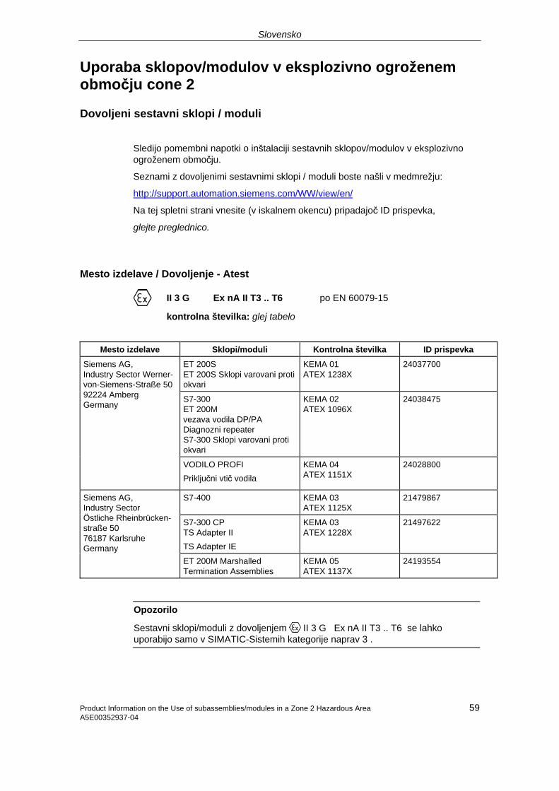
Slovensko
Uporaba sklopov/modulov v eksplozivno ogroženem območju cone 2
Dovoljeni sestavni sklopi / moduli
Sledijo pomembni napotki o inštalaciji sestavnih sklopov/modulov v eksplozivno ogroženem območju.
Seznami z dovoljenimi sestavnimi sklopi / moduli boste našli v medmrežju:
http://support.automation.siemens.com/WW/view/en/
Na tej spletni strani vnesite (v iskalnem okencu) pripadajoč ID prispevka,
glejte preglednico.
Mesto izdelave / Dovoljenje - Atest
II 3 G Ex nA II T3 .. T6 po EN 60079-15
kontrolna številka: glej tabelo
Mesto izdelave Sklopi/moduli Kontrolna številka ID prispevka
ET 200S ET 200S Sklopi varovani proti okvari
KEMA 01 ATEX 1238X
24037700
S7-300 ET 200M vezava vodila DP/PA Diagnozni repeater S7-300 Sklopi varovani proti okvari
KEMA 02 ATEX 1096X
24038475
Siemens AG, Industry Sector Werner-von-Siemens-Straße 5092224 Amberg Germany
VODILO PROFI Priključni vtič vodila
KEMA 04 ATEX 1151X
24028800
S7-400 KEMA 03 ATEX 1125X
21479867
S7-300 CP TS Adapter II TS Adapter IE
KEMA 03 ATEX 1228X
21497622
Siemens AG, Industry Sector Östliche Rheinbrücken- straße 50 76187 Karlsruhe Germany
ET 200M Marshalled Termination Assemblies
KEMA 05 ATEX 1137X
24193554
Opozorilo
Sestavni sklopi/moduli z dovoljenjem II 3 G Ex nA II T3 .. T6 se lahko uporabijo samo v SIMATIC-Sistemih kategorije naprav 3 .
59 Product Information on the Use of subassemblies/modules in a Zone 2 Hazardous Area A5E00352937-04
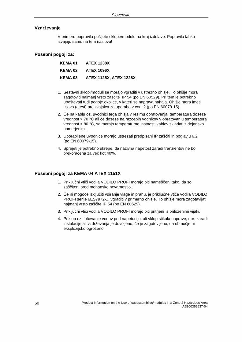
Slovensko
Product Information on the Use of subassemblies/modules in a Zone 2 Hazardous Area A5E00352937-04
60
Vzdrževanje
V primeru popravila pošljete sklope/module na kraj izdelave. Popravila lahko izvajajo samo na tem naslovu!
Posebni pogoji za:
KEMA 01 ATEX 1238X
KEMA 02 ATEX 1096X
KEMA 03 ATEX 1125X, ATEX 1228X
1. Sestavni sklopi/moduli se morajo vgraditi v ustrezno ohišje. To ohišje mora zagotoviti najmanj vrsto zaščite IP 54 (po EN 60529). Pri tem je potrebno upoštevati tudi pogoje okolice, v kateri se naprava nahaja. Ohišje mora imeti izjavo (atest) proizvajalca za uporabo v coni 2 (po EN 60079-15).
2. Če na kablu oz. uvodnici tega ohišja v režimu obratovanja temperatura doseže vrednost > 70 °C ali če doseže na razcepih vodnikov v obratovanju temperatura vrednost > 80 °C, se morajo temperaturne lastnosti kablov skladati z dejansko namerjenimi.
3. Uporabljene uvodnice morajo ustrezati predpisani IP zaščiti in poglavju 6.2 (po EN 60079-15).
4. Sprejeti je potrebno ukrepe, da nazivna napetost zaradi tranzientov ne bo prekoračena za več kot 40%.
Posebni pogoji za KEMA 04 ATEX 1151X
1. Priključni vtiči vodila VODILO PROFI morajo biti nameščeni tako, da so zaščiteni pred mehansko nevarnostjo..
2. Če ni mogoče izključiti vdiranje vlage in prahu, je priključne vtiče vodila VODILO PROFI serije 6ES7972-... vgraditi v primerno ohišje. To ohišje mora zagotavljati najmanj vrsto zaščite IP 54 (po EN 60529).
3. Priključni vtiči vodila VODILO PROFI morajo biti pritrjeni s priloženimi vijaki.
4. Priklop oz. ločevanje vodov pod napetostjo ali vklop stikala naprave, npr. zaradi instalacije ali vzdrževanja je dovoljeno, če je zagotovljeno, da območje ni eksplozijsko ogroženo.
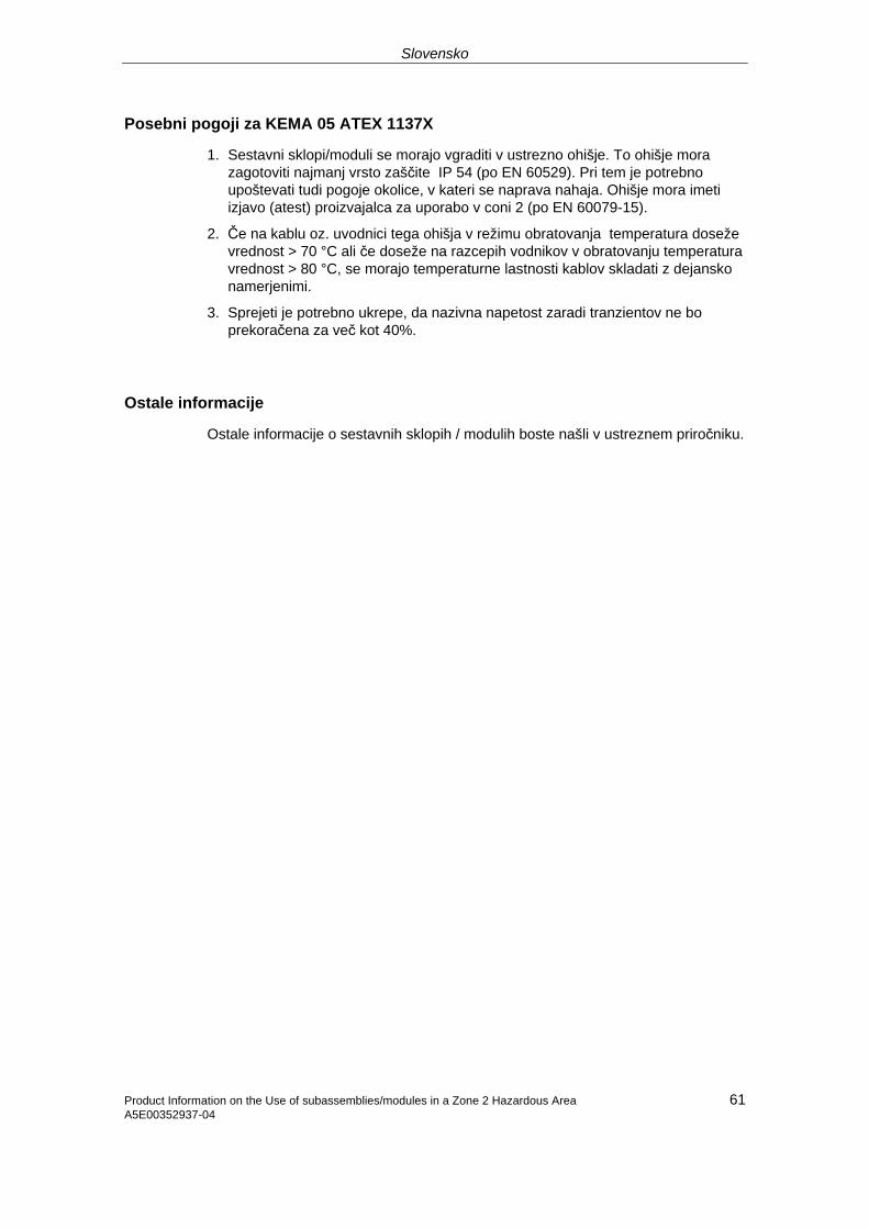
Slovensko
Posebni pogoji za KEMA 05 ATEX 1137X
1. Sestavni sklopi/moduli se morajo vgraditi v ustrezno ohišje. To ohišje mora zagotoviti najmanj vrsto zaščite IP 54 (po EN 60529). Pri tem je potrebno upoštevati tudi pogoje okolice, v kateri se naprava nahaja. Ohišje mora imeti izjavo (atest) proizvajalca za uporabo v coni 2 (po EN 60079-15).
2. Če na kablu oz. uvodnici tega ohišja v režimu obratovanja temperatura doseže vrednost > 70 °C ali če doseže na razcepih vodnikov v obratovanju temperatura vrednost > 80 °C, se morajo temperaturne lastnosti kablov skladati z dejansko namerjenimi.
3. Sprejeti je potrebno ukrepe, da nazivna napetost zaradi tranzientov ne bo prekoračena za več kot 40%.
Ostale informacije
Ostale informacije o sestavnih sklopih / modulih boste našli v ustreznem priročniku.
61 Product Information on the Use of subassemblies/modules in a Zone 2 Hazardous Area A5E00352937-04
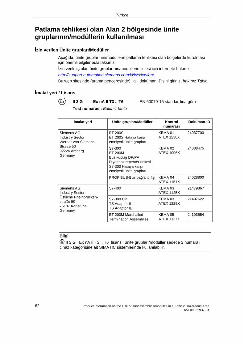
Türkçe
Patlama tehlikesi olan Alan 2 bölgesinde ünite gruplarının/modüllerin kullanılması
İzin verilen Ünite grupları/Modüller Aşağıda, ünite gruplarının/modüllerin patlama tehlikesi olan bölgelerde kurulması için önemli bilgiler bulacaksınız. İzin verilmiş olan ünite gruplarının/modüllerin listesi için internete bakınız: http://support.automation.siemens.com/WW/view/en/ Bu web sitesinde (arama penceresinde) ilgili doküman ID'sini giriniz, bakınız Tablo.
İmalat yeri / Lisans
II 3 G Ex nA II T3 .. T6 EN 60079-15 standardına göre
Test numarası: Bakınız tablo
İmalat yeri Ünite grupları/Modüller Kontrol numarası
Doküman-ID
ET 200S ET 200S Hataya karşı emniyetli ünite grupları
KEMA 01 ATEX 1238X
24037700
S7-300 ET 200M Bus kuplajı DP/PA Diyagnoz repeater ünitesi S7-300 Hataya karşı emniyetli ünite grupları
KEMA 02 ATEX 1096X
24038475
Siemens AG, Industry Sector Werner-von-Siemens-Straße 50 92224 Amberg Germany
PROFIBUS-Bus bağlantı fişi KEMA 04 ATEX 1151X
24028800
S7-400 KEMA 03 ATEX 1125X
21479867
S7-300 CP TS Adaptör II TS Adaptör IE
KEMA 03 ATEX 1228X
21497622
Siemens AG, Industry Sector Östliche Rheinbrücken- straße 50 76187 Karlsruhe Germany
ET 200M Marshalled Termination Assemblies
KEMA 05 ATEX 1137X
24193554
Bilgi II 3 G Ex nA II T3 .. T6 lisanslı ünite grupları/modüller sadece 3 numaralı
cihaz kategorisine ait SIMATIC sistemlerinde kullanılabilir.
62 Product Information on the Use of subassemblies/modules in a Zone 2 Hazardous Area A5E00352937-04
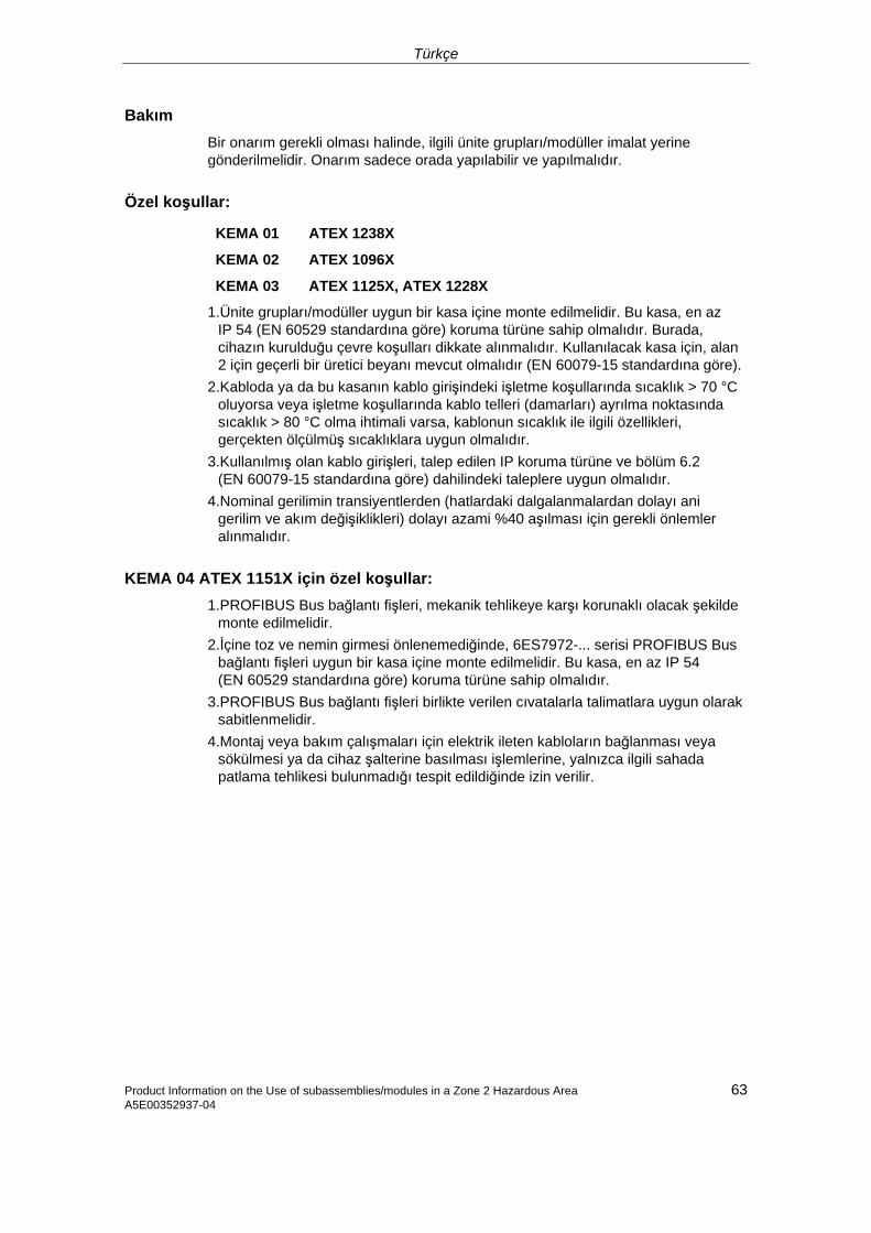
Türkçe
Product Information on the Use of subassemblies/modules in a Zone 2 Hazardous Area 63 A5E00352937-04
Bakım Bir onarım gerekli olması halinde, ilgili ünite grupları/modüller imalat yerine gönderilmelidir. Onarım sadece orada yapılabilir ve yapılmalıdır.
Özel koşullar:
KEMA 01 ATEX 1238X
KEMA 02 ATEX 1096X
KEMA 03 ATEX 1125X, ATEX 1228X
1.Ünite grupları/modüller uygun bir kasa içine monte edilmelidir. Bu kasa, en az IP 54 (EN 60529 standardına göre) koruma türüne sahip olmalıdır. Burada, cihazın kurulduğu çevre koşulları dikkate alınmalıdır. Kullanılacak kasa için, alan 2 için geçerli bir üretici beyanı mevcut olmalıdır (EN 60079-15 standardına göre).
2.Kabloda ya da bu kasanın kablo girişindeki işletme koşullarında sıcaklık > 70 °C oluyorsa veya işletme koşullarında kablo telleri (damarları) ayrılma noktasında sıcaklık > 80 °C olma ihtimali varsa, kablonun sıcaklık ile ilgili özellikleri, gerçekten ölçülmüş sıcaklıklara uygun olmalıdır.
3.Kullanılmış olan kablo girişleri, talep edilen IP koruma türüne ve bölüm 6.2 (EN 60079-15 standardına göre) dahilindeki taleplere uygun olmalıdır.
4.Nominal gerilimin transiyentlerden (hatlardaki dalgalanmalardan dolayı ani gerilim ve akım değişiklikleri) dolayı azami %40 aşılması için gerekli önlemler alınmalıdır.
KEMA 04 ATEX 1151X için özel koşullar: 1.PROFIBUS Bus bağlantı fişleri, mekanik tehlikeye karşı korunaklı olacak şekilde
monte edilmelidir. 2.İçine toz ve nemin girmesi önlenemediğinde, 6ES7972-... serisi PROFIBUS Bus
bağlantı fişleri uygun bir kasa içine monte edilmelidir. Bu kasa, en az IP 54 (EN 60529 standardına göre) koruma türüne sahip olmalıdır.
3.PROFIBUS Bus bağlantı fişleri birlikte verilen cıvatalarla talimatlara uygun olarak sabitlenmelidir.
4.Montaj veya bakım çalışmaları için elektrik ileten kabloların bağlanması veya sökülmesi ya da cihaz şalterine basılması işlemlerine, yalnızca ilgili sahada patlama tehlikesi bulunmadığı tespit edildiğinde izin verilir.
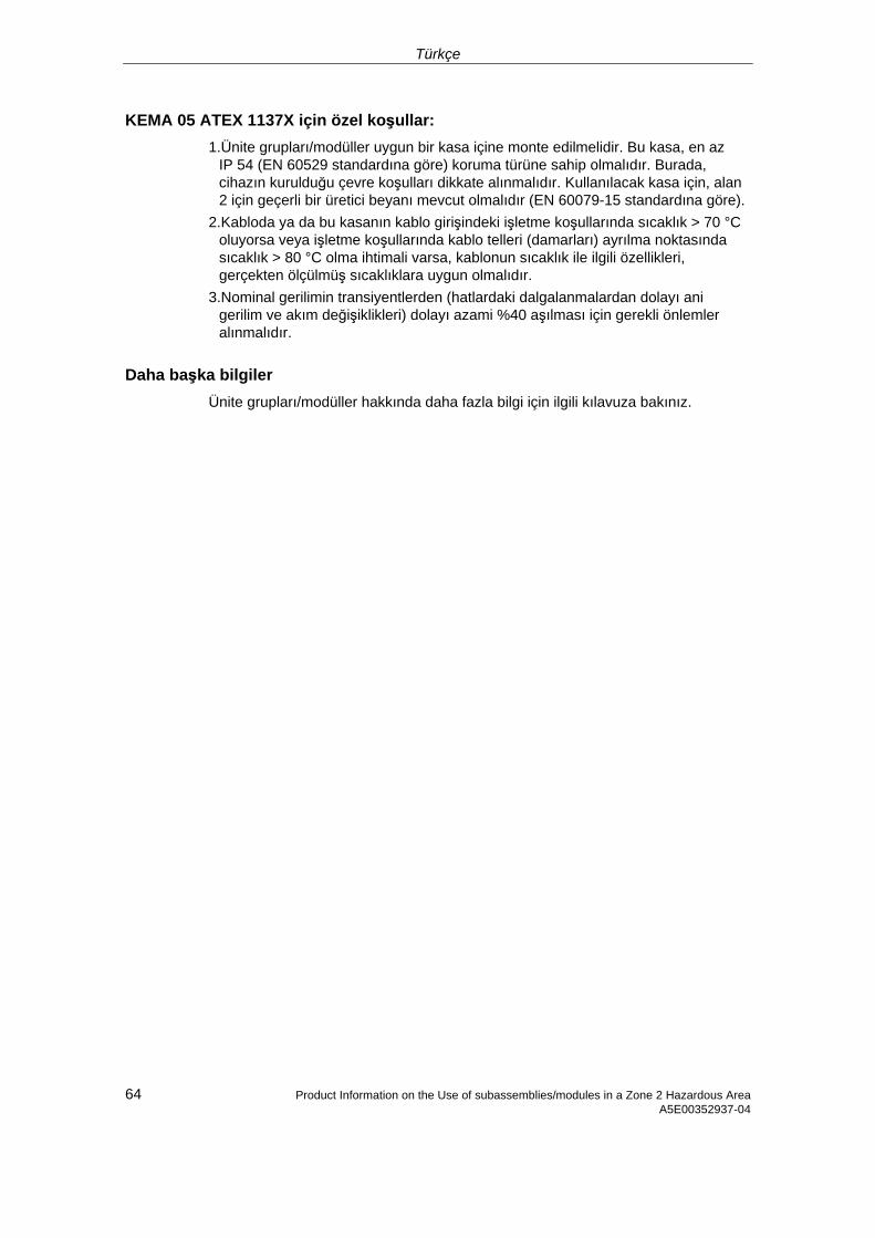
Türkçe
64 Product Information on the Use of subassemblies/modules in a Zone 2 Hazardous Area A5E00352937-04
KEMA 05 ATEX 1137X için özel koşullar: 1.Ünite grupları/modüller uygun bir kasa içine monte edilmelidir. Bu kasa, en az
IP 54 (EN 60529 standardına göre) koruma türüne sahip olmalıdır. Burada, cihazın kurulduğu çevre koşulları dikkate alınmalıdır. Kullanılacak kasa için, alan 2 için geçerli bir üretici beyanı mevcut olmalıdır (EN 60079-15 standardına göre).
2.Kabloda ya da bu kasanın kablo girişindeki işletme koşullarında sıcaklık > 70 °C oluyorsa veya işletme koşullarında kablo telleri (damarları) ayrılma noktasında sıcaklık > 80 °C olma ihtimali varsa, kablonun sıcaklık ile ilgili özellikleri, gerçekten ölçülmüş sıcaklıklara uygun olmalıdır.
3.Nominal gerilimin transiyentlerden (hatlardaki dalgalanmalardan dolayı ani gerilim ve akım değişiklikleri) dolayı azami %40 aşılması için gerekli önlemler alınmalıdır.
Daha başka bilgiler Ünite grupları/modüller hakkında daha fazla bilgi için ilgili kılavuza bakınız.
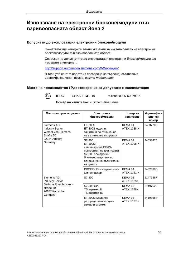
Български
Използване на електронни блокове/модули във взривоопасната област Зона 2
Допуснати до експлоатация електронни блокове/модули
По-нататък ще намерите важни указания за инсталирането на електронни блокове/модули във взривоопасната област.
Списъкът на допуснатите до експлоатация електронни блокове/модули ще намерите в интернет:
http://support.automation.siemens.com/WW/view/en/
В този уеб сайт въведете (в прозореца за търсене) съответния идентификационен номер, вижте таблицата.
Място на производство / Удостоверение за допускане в експлоатация
II 3 G Ex nA II T3 .. T6 съгласно EN 60079-15
Номер на изпитване: вижте таблицата
Място на производство Електронни блокове/модули
Номер на изпитване
Идентификационен номер
ET 200S ET 200S модули, защитени по отношение на възникване на грешки
KEMA 01 ATEX 1238 X
24037700
S7-300 ET 200M шинна връзка DP/PA повторител на диагнозатаS7-300 електронни блокове, защитени по отношение на възникване на грешки
KEMA 02 ATEX 1096 X
24038475
Siemens AG, Industry Sector Werner-von-Siemens-Straße 50 92224 Amberg Germany
PROFIBUS- съединителен шинен щекер
KEMA 04 ATEX 1151 X
24028800
S7-400 KEMA 03 ATEX 1125X
21479867
S7-300 CP TS адаптер II TS адаптер IE
KEMA 03 ATEX 1228X
21497622
Siemens AG, Industry Sector Östliche Rheinbrücken- straße 50 76187 Karlsruhe Germany
ET 200M Модулно разпределени входно-изходни системи
KEMA 05 ATEX 1137 X
24193554
Product Information on the Use of subassemblies/modules in a Zone 2 Hazardous Area 65 A5E00352937-04
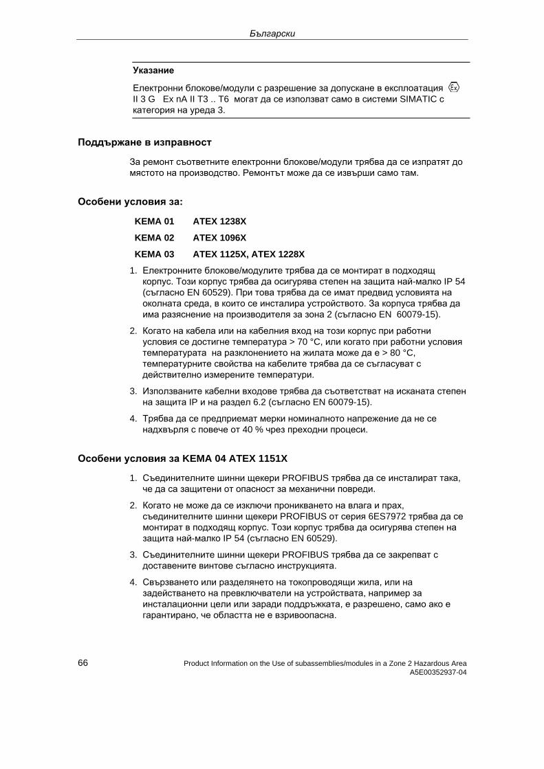
Български
Указание
Електронни блокове/модули с разрешение за допускане в експлоатация II 3 G Ex nA II T3 .. T6 могат да се използват само в системи SIMATIC с категория на уреда 3.
Поддържане в изправност
За ремонт съответните електронни блокове/модули трябва да се изпратят до мястото на производство. Ремонтът може да се извърши само там.
Особени условия за:
KEMA 01 ATEX 1238X
KEMA 02 ATEX 1096X
KEMA 03 ATEX 1125X, ATEX 1228X
1. Електронните блокове/модулите трябва да се монтират в подходящ корпус. Този корпус трябва да осигурява степен на защита най-малко IP 54 (съгласно EN 60529). При това трябва да се имат предвид условията на околната среда, в които се инсталира устройството. За корпуса трябва да има разяснение на производителя за зона 2 (съгласно EN 60079-15).
2. Когато на кабела или на кабелния вход на този корпус при работни условия се достигне температура > 70 °C, или когато при работни условия температурата на разклонението на жилата може да е > 80 °C, температурните свойства на кабелите трябва да се съгласуват с действително измерените температури.
3. Използваните кабелни входове трябва да съответстват на исканата степен на защита IP и на раздел 6.2 (съгласно EN 60079-15).
4. Трябва да се предприемат мерки номиналното напрежение да не се надхвърля с повече от 40 % чрез преходни процеси.
Особени условия за KEMA 04 ATEX 1151X
1. Съединителните шинни щекери PROFIBUS трябва да се инсталират така, че да са защитени от опасност за механични повреди.
2. Когато не може да се изключи проникването на влага и прах, съединителните шинни щекери PROFIBUS от серия 6ES7972 трябва да се монтират в подходящ корпус. Този корпус трябва да осигурява степен на защита най-малко IP 54 (съгласно EN 60529).
3. Съединителните шинни щекери PROFIBUS трябва да се закрепват с доставените винтове съгласно инструкцията.
4. Свързването или разделянето на токопроводящи жила, или на задействането на превключватели на устройствата, например за инсталационни цели или заради поддръжката, е разрешено, само ако е гарантирано, че областта не е взривоопасна.
66 Product Information on the Use of subassemblies/modules in a Zone 2 Hazardous Area A5E00352937-04
Български
Product Information on the Use of subassemblies/modules in a Zone 2 Hazardous Area 67 A5E00352937-04
Особени условия за KEMA 05 ATEX 1137X
1. Електронните блокове/модулите трябва да се монтират в подходящ корпус. Този корпус трябва да осигурява степен на защита най-малко IP 54 (съгласно EN 60529). При това трябва да се имат предвид условията на околната среда, в които се инсталира устройството. За корпуса трябва да има разяснение на производителя за зона 2 (съгласно EN 60079-15).
2. Когато на кабела или на кабелния вход на този корпус при работни условия се достигне температура > 70 °C, или когато при работни условия температурата на разклонението на жилата може да е > 80 °C, температурните свойства на кабелите трябва да се съгласуват с действително измерените температури.
3. Трябва да се предприемат мерки номиналното напрежение да не се надхвърля с повече от 40 % чрез преходни процеси.
Подробна информация
Подробна информация за електронните блокове/модулите ще намерите в съответния справочник.
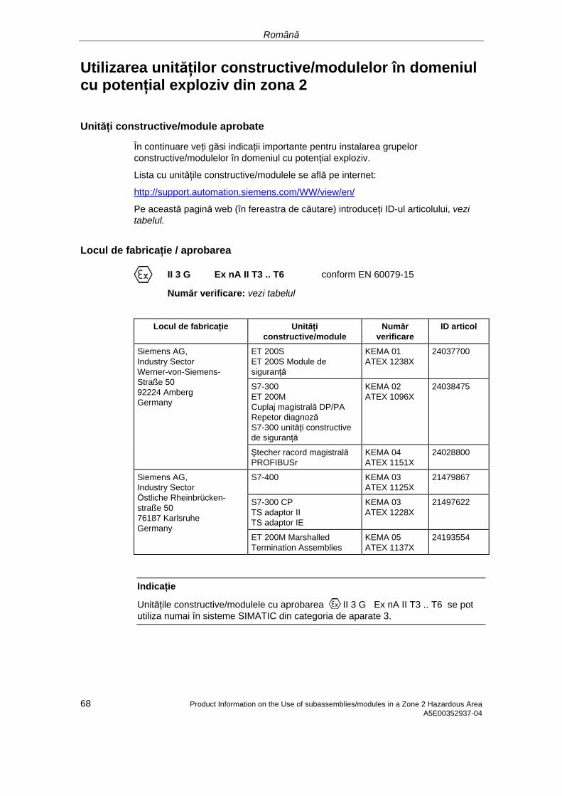
Română
Utilizarea unităţilor constructive/modulelor în domeniul cu potenţial exploziv din zona 2
Unităţi constructive/module aprobate
În continuare veţi găsi indicaţii importante pentru instalarea grupelor constructive/modulelor în domeniul cu potenţial exploziv.
Lista cu unităţile constructive/modulele se află pe internet:
http://support.automation.siemens.com/WW/view/en/
Pe această pagină web (în fereastra de căutare) introduceţi ID-ul articolului, vezi tabelul.
Locul de fabricaţie / aprobarea
II 3 G Ex nA II T3 .. T6 conform EN 60079-15
Număr verificare: vezi tabelul
Locul de fabricaţie Unităţi constructive/module
Număr verificare
ID articol
ET 200S ET 200S Module de siguranţă
KEMA 01 ATEX 1238X
24037700
S7-300 ET 200M Cuplaj magistrală DP/PA Repetor diagnoză S7-300 unităţi constructive de siguranţă
KEMA 02 ATEX 1096X
24038475
Siemens AG, Industry Sector Werner-von-Siemens-Straße 50 92224 Amberg Germany
Ştecher racord magistrală PROFIBUSr
KEMA 04 ATEX 1151X
24028800
S7-400 KEMA 03 ATEX 1125X
21479867
S7-300 CP TS adaptor II TS adaptor IE
KEMA 03 ATEX 1228X
21497622
Siemens AG, Industry Sector Östliche Rheinbrücken- straße 50 76187 Karlsruhe Germany
ET 200M Marshalled Termination Assemblies
KEMA 05 ATEX 1137X
24193554
Indicaţie
Unităţile constructive/modulele cu aprobarea II 3 G Ex nA II T3 .. T6 se pot utiliza numai în sisteme SIMATIC din categoria de aparate 3.
68 Product Information on the Use of subassemblies/modules in a Zone 2 Hazardous Area A5E00352937-04
Română
Product Information on the Use of subassemblies/modules in a Zone 2 Hazardous Area 69 A5E00352937-04
Mentenanţă
Pentru reparaţie, unităţile constructive/modulele respective se vor trimite la locul de fabricaţie. Reparaţia se poate efectua numai acolo.
Condiţii speciale pentru:
KEMA 01 ATEX 1238X
KEMA 02 ATEX 1096X
KEMA 03 ATEX 1125X, ATEX 1228X
1. Unităţile constructive/modulele se vor monta într-o carcasă adecvată. Această carcasă va garanta cel puţin tipul de protecţie IP 54 (conform EN 60529). La aceasta se vor respecta condiţiile de mediu în care se instalează dispozitivul. Pentru carcasă va fi disponibilă declaraţia producătorului pentru zona 2 (conform EN 60079-15).
2. Dacă la cablu, respectiv la intrarea cablului acestei carcase, în condiţii de funcţionare, este atinsă o temperatură > 70 °C sau dacă în condiţii de funcţionare, la derivaţia conductorilor poate fi o temperatură > 80 °C, caracteristicile de temperatură ale cablurilor trebuie să corespundă temperaturilor reale măsurate.
3. Intrările de cablu utilizate vor corespunde tipului de protecţie IP şi secţiunii 6.2 (conform EN 60079-15).
4. Se vor lua măsuri pentru ca tensiunea nominală prin fenomene tranzitorii să nu depăşească mai mult cu 40 %.
Condiţii speciale pentru KEMA 04 ATEX 1151X
1. Ştecherele de conectare pentru magistrală PROFIBUS se vor instala astfel încât să fie protejate contra pericolelor mecanice.
2. Dacă nu se poate evita pătrunderea umezelii şi a prafului, ştecherele de conectare pentru magistrală PROFIBUS, seria 6ES7972-... se vor monta într-o carcasă adecvată. Această carcasă va garanta cel puţin tipul de protecţie IP 54 (conform EN 60529).
3. Ştecherele de conectare pentru magistrală PROFIBUS se vor fixa corespunzător cu şuruburile livrate.
4. Conectarea, resp. separarea firelor conducătoare de tensiune sau la acţionarea comutatorului aparatului, de exemplu în scopuri de instalare sau întreţinere, este permisă numai dacă se garantează că zona nu prezintă potenţial exploziv.
Română
70 Product Information on the Use of subassemblies/modules in a Zone 2 Hazardous Area A5E00352937-04
Condiţii speciale pentru KEMA 05 ATEX 1137X
1. Unităţile constructive/modulele se vor monta într-o carcasă adecvată. Această carcasă va garanta cel puţin tipul de protecţie IP 54 (conform EN 60529). La aceasta se vor respecta condiţiile de mediu în care se instalează dispozitivul. Pentru carcasă va fi disponibilă declaraţia producătorului pentru zona 2 (conform EN 60079-15).
2. Dacă la cablu, respectiv la intrarea cablului acestei carcase, în condiţii de funcţionare, este atinsă o temperatură > 70 °C sau dacă în condiţii de funcţionare, la derivaţia conductorilor poate fi o temperatură > 80 °C, caracteristicile de temperatură ale cablurilor trebuie să corespundă temperaturilor reale măsurate.
3. Se vor lua măsuri pentru ca tensiunea nominală prin fenomene tranzitorii să nu depăşească mai mult cu 40 %.
Informaţii suplimentare
Informaţii suplimentare cu privire la grupele constructive/module se află în manualul aferent.
© Siemens 2008 A5E02382347-01, 11/2008 1
SIMATIC Distributed I/O Product information for the ET 200S Operating Instructions (A5E00515771-06) 08/2008 Product Information
Contents
This product information describes supplements and corrections to the ET 200S Distributed I/O System Operating Instructions, (A5E00515771-06), release 08/2008.
In the chapter: Wiring an interface module with PROFINET IO interface (electrically)
Note Interface modules with PROFINET IO electronic We recommend that you use a strain relief for the PROFINET connecting cable when using an ET 200S system under environmental conditions where it is subject to mechanical vibration or shock. To do this you require a cable tie with a standard width of 2.5 mm or 3.6 mm. Use it to attach the PROFINET connecting cable from right where it exits the PROFINET connector to the cable bracket provided on the Interface module (on the front side directly below the PROFINET IO interface).

Product information for the ET 200S Operating Instructions (A5E00515771-06) 08/2008 2 A5E02382347-01, 11/2008
Siemens AG Industry Sector Postfach 48 48 90026 NÜRNBERG Product information for the ET 200S Operating Instructions (A5E00515771-06) 08/2008 A5E02382347-01, 11/2008