Embed Size (px)
Citation preview

Shrink Disc Type HSD
04
Shrink Disc Type HSD are supplied as standard in six types.
Series 20 Series 21 Series 22 Series 81
Series 23 Series 83
05
Delivery Program Shrink Disc Type HSD
Series 20 For transmission of small torques. Page 06
Series 21 For transmission of medium torques.
Series 22 Standard type for transmission of high torques.
Series 81 As series 22, but with 20 – 30 % higher torques capacity.
Series 23 For transmission of very high torques.
Series 83 As series 23, but with 20 – 30 % higher torques capacity.
Page 08
Page 10
Page 14
Page 16
Page 19
05

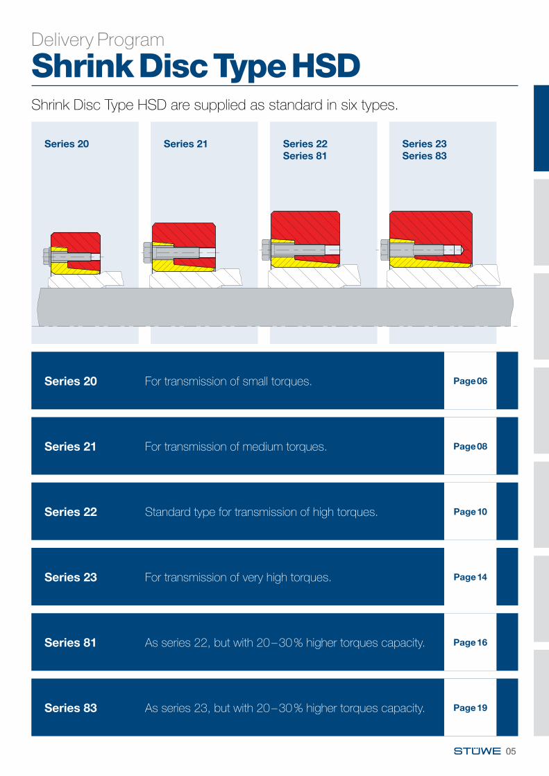
Shrink Disc HSD Series 20
Type d dw Mt Pax Ma B* D l H1 A d1 e kg
mm mm kNm kN Nm mm mm mm mm mm mm HSD 24 - 20 24 20 0,15 15 12 M6 50 11,5 16 38 25 4,2 0,1
21 0,17 1722 0,21 19
HSD 29 - 20 29 25 0,22 18 12 M6 58 12,5 18 44 32 5,5 0,126 0,25 1927 0,29 21
HSD 35 - 20 34 29 0,22 15 12 M6 64 12,5 18 52 38 5,5 0,235 30 0,25 16
32 0,31 19HSD 40 - 20 38 34 0,28 16 12 M6 69 12,2 18 55 43 5,5 0,2
40 35 0,31 1836 0,34 19
HSD 46 - 20 46 38 0,41 22 12 M6 80 13 23 62 49 2,5 0,347 40 0,50 25
42 0,60 28HSD 51 - 20 51 44 0,55 25 12 M6 86 13 23 67 54 2,5 0,4
45 0,60 2747 0,70 30
HSD 56 - 20 55 48 0,57 24 12 M6 90 13 23 72 59 2,5 0,456 50 0,66 2657 52 0,76 29
HSD 61 - 20 61 53 0,68 26 12 M6 96 13 24 76 64 3,5 0,455 0,79 2957 0,90 32
HSD 66 - 20 65 58 0,74 26 12 M6 100 13 24 82 69 3,5 0,566 60 0,85 28
62 0,97 31HSD 73 - 20 70 63 0,94 30 29 M8 115 18 30 94 77 2,7 0,9
72 65 1,07 3373 68 1,29 38
HSD 78 - 20 76 68 1,21 36 29 M8 120 18 30 100 82 2,7 1,078 70 1,36 39
72 1,52 42HSD 83 - 20 81 73 1,24 34 29 M8 125 18 30 104 87 2,7 1,0
83 75 1,38 3777 1,54 40
HSD 88 - 20 86 78 1,47 38 29 M8 130 18 30 110 92 2,7 1,188 80 1,62 40
82 1,78 43HSD 93 - 20 93 83 1,63 39 29 M8 135 18 31 114 97 3,7 1,1
94 85 1,80 4287 1,97 45
HSD 98 - 20 96 88 1,72 39 29 M8 140 18 31 120 102 3,7 1,198 90 1,89 42
92 2,07 45
∅
∅
∅
∅ ∅
∅
l
D
e
A
d H
7/f7
1,1 x l dw H
7/h6
dw ≥
160
H7/
g6 d1
H1
Ra < 3,2µm
Ra < 3,2µm
Code:
Mt maximum transmissible torque of a shrink disc with Pax = 0
Pax maximum transmissible axial load of a shrink disc with Mt = 0
Ma required tightening torque of the tightening bolts (see also “Mounting and Removal Instructions“)
Dimensions H1 and e apply to untightened units.
* Tightening bolts: standard DIN EN ISO 4014/4017 Grade 10.9, alternative DIN EN ISO 4762 Grade 10.9 M16 and upwards with washers: DIN EN ISO 7416
When ordering please state: e. g. HSD 51 - 20 x 51 (Type x Ø d)
06
Type d dw Mt Pax Ma B* D l H1 A d1 e kg
mm mm kNm kN Nm mm mm mm mm mm mmHSD 103 - 20 103 93 2,13 46 29 M8 145 18 31 124 107 3,7 1,2
95 2,31 49 97 2,50 52
HSD 108 - 20 106 98 2,16 44 29 M8 150 18 31 128 112 3,7 1,2108 100 2,34 47
102 2,53 50HSD 115 - 20 112 103 2,34 45 29 M8 160 22 35 134 118 3,7 1,8
115 105 2,54 48108 2,86 53
HSD 120 - 20 118 108 2,82 52 29 M8 164 22 35 140 124 3,7 1,7120 110 3,03 55
113 3,37 60HSD 125 - 20 125 113 2,94 52 29 M8 169 22 35 144 129 3,7 1,7
115 3,16 55118 3,49 59
HSD 130 - 20 130 118 3,15 53 29 M8 174 22 35 150 134 3,7 1,8120 3,37 56123 3,71 60
HSD 135 - 20 135 123 3,57 58 29 M8 179 22 35 154 139 3,7 1,9125 3,81 61128 4,19 66
HSD 140 - 20 138 128 3,93 61 29 M8 184 22 36 160 144 4,7 2,0140 130 4,18 64
132 4,44 67HSD 145 - 20 145 133 4,39 66 29 M8 189 22 36 164 149 4,7 2,0
135 4,65 69137 4,92 72
HSD 150 - 20 150 138 4,89 71 29 M8 194 22 36 170 154 4,7 2,0140 5,16 74142 5,44 77
HSD 160 - 20 160 146 4,86 67 29 M8 204 22 36 180 164 4,7 2,2150 5,39 72152 5,67 75
HSD 170 - 20 166 156 5,20 67 29 M8 214 22 36 190 174 4,7 2,5170 160 5,73 72
162 6,01 74HSD 182 - 20 182 166 7,62 92 29 M8 230 25 41 206 188 4,7 3,0
170 8,35 98172 8,73 101
HSD 192 - 20 189 176 8,35 95 29 M8 240 25 41 216 198 4,7 3,4192 180 9,09 101
182 9,47 104HSD 202 - 20 202 186 8,88 95 29 M8 250 25 41 224 208 4,7 3,3
198 190 9,67 102197 192 10,08 105
HSD 212 - 20 212 196 9,74 99 29 M8 260 25 41 234 218 4,7 3,5200 10,55 106202 10,97 109
HSD 222 - 20 220 206 10,83 105 29 M8 270 25 42 244 228 5,7 3,6222 210 11,66 111
212 12,09 114HSD 232 - 20 230 216 14,40 133 29 M8 280 25 42 254 238 5,7 3,8
232 220 15,35 140222 15,83 143
HSD 242 - 20 242 226 15,27 135 29 M8 290 25 42 264 248 5,7 3,9230 16,22 141232 16,72 144
HSD 252 - 20 252 234 15,98 137 29 M8 300 25 42 274 258 5,7 4,1238 16,94 142240 17,44 145
HSD 262 - 20 262 244 16,84 138 29 M8 310 25 42 286 268 5,7 4,2248 17,80 144250 18,30 146
Series 20
Further sizes on request. Technical changes to be reserved without notice. * Tightening bolts: standard DIN EN ISO 4014/4017 Grade 10.9, alternative DIN EN ISO 4762 Grade 10.9
M16 and upwards with washers: DIN EN ISO 7416 When ordering please state : e. g. HSD 108 - 20 x 106 (Type x Ø d)
07
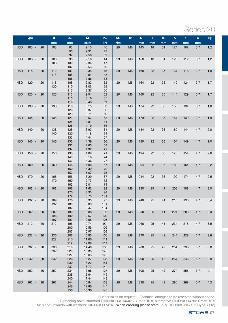
Shrink Disc HSD Series 21
Type d dw Mt Pax Ma B* D l H1 A d1 e kg
mm mm kNm kN Nm mm mm mm mm mm mm
HSD 140 - 21 140 110 16 298 100 M12 215 38 52 164 143 6,5 6
120 20 341
130 25 385
HSD 155 - 21 155 130 26 398 100 M12 245 38 52 184 164 6,5 8
160 135 28 420
140 31 443
HSD 165 - 21 165 135 29 432 160 M14 263 43 58 200 174 6,2 11
170 140 32 456
145 35 480
HSD 175 - 21 175 145 36 497 160 M14 275 43 59 208 184 7,2 12
180 150 39 522
155 42 547
HSD 185 - 21 185 155 50 645 160 M14 290 51 68 220 195 8,2 16
190 160 54 675
165 58 704
HSD 195 - 21 195 165 68 822 160 M14 320 51 68 230 204 8,2 20
200 170 73 855
180 83 922
HSD 220 - 21 220 180 80 892 240 M16 340 55 79 254 227 10 23
190 91 962
200 103 1032
HSD 240 - 21 240 200 103 1026 240 M16 370 55 80 274 246 11 27
210 115 1095
220 128 1165
HSD 260 - 21 260 220 132 1197 240 M16 405 55 80 294 266 11 33
230 146 1271
240 161 1344
HSD 280 - 21 280 230 160 1392 470 M20 430 65 93 320 288 12 43
240 177 1473
250 194 1555
HSD 300 - 21 300 250 191 1529 470 M20 460 65 94 340 307 13 49
260 209 1610
270 228 1691
HSD 320 - 21 320 270 243 1804 470 M20 485 77 106 364 327 13 63
280 265 1894
290 288 1986
∅
∅
∅
∅ ∅
∅
l
D
e
A
d H
7/f7
1,1 x l dw H
7/h6
dw ≥
160
H7/
g6 d1
H1
Ra < 3,2µm
Ra < 3,2µm
Code:
Mt maximum transmissible torque of a shrink disc with Pax = 0
Pax maximum transmissible axial load of a shrink disc with Mt = 0
Ma required tightening torque of the tightening bolts (see also “Mounting and Removal Instructions“)
Dimensions H1 and e apply to untightened units.
* Tightening bolts: standard DIN EN ISO 4014/4017 Grade 10.9, alternative DIN EN ISO 4762 Grade 10.9 M16 and upwards with washers: DIN EN ISO 7416
When ordering please state : e. g. HSD 185 - 21 x 190 (Type x Ø d)
08

Type d dw Mt Pax Ma B* D l H1 A d1 e kg
mm mm kNm kN Nm mm mm mm mm mm mm
HSD 340 - 21 340 280 274 1958 470 M20 520 77 106 384 347 13 73
290 297 2050
300 322 2143
HSD 360 - 21 360 300 356 2373 470 M20 570 89 122 410 367 13 107
310 384 2476
330 443 2686
HSD 390 - 21 390 330 438 2654 470 M20 590 89 123 440 398 14 107
340 469 2759
350 501 2865
HSD 420 - 21 420 350 624 3564 820 M24 630 120 160 470 428 21 163
360 665 3697
370 709 3831
HSD 440 - 21 440 370 778 4203 820 M24 660 132 174 494 448 21 196
380 826 4350
390 877 4497
HSD 460 - 21 460 390 852 4370 820 M24 690 132 174 516 468 21 230
400 903 4514
410 955 4658
HSD 480 - 21 480 410 1086 5298 820 M24 720 152 194 540 488 23 269
420 1147 5461
430 1210 5626
HSD 500 - 21 500 420 1137 5415 820 M24 745 152 197 560 508 24 285
430 1200 5581
450 1331 5914
HSD 530 - 21 530 450 1376 6114 1210 M27 790 166 209 594 540 20 341
460 1446 6287
480 1592 6635
HSD 560 - 21 560 480 1578 6576 1210 M27 830 166 211 626 570 22 373
490 1653 6748
510 1809 7093
HSD 590 - 21 590 510 1873 7344 1210 M27 880 172 219 658 598 197 450
520 1957 7526
540 2131 7891
HSD 620 - 21 620 540 2097 7768 1210 M27 930 172 222 690 630 28 508
550 2186 7948
570 2368 8309
HSD 660 - 21 660 570 2426 8511 1640 M30 990 182 235 734 670 29 609
580 2522 8696
610 2823 9255
HSD 700 - 21 700 610 2772 9088 1640 M30 1040 182 234 774 710 210 661
620 2874 9271
640 3084 9638
HSD 750 - 21 750 640 3104 9700 1640 M30 1100 192 246 826 760 30 764
650 3214 9888
680 3555 10456
HSD 800 - 21 800 680 3443 10128 1640 M30 1150 192 248 876 810 32 805
700 3673 10495
730 4033 11049
Series 21
Further sizes on request. Technical changes to be reserved without notice.
* Tightening bolts: standard DIN EN ISO 4014/4017 Grade 10.9, alternative DIN EN ISO 4762 Grade 10.9 M16 and upwards with washers: DIN EN ISO 7416 When ordering please state : e. g. HSD 660 - 21 x 660 (Type x Ø d)
09
Shrink Disc HSD Series 22
Type d dw Mt Pax Ma B* D l H1 A d1 e kg
mm mm kNm kN Nm mm mm mm mm mm mm
HSD 12 - 22 12 9 0,02 5 12 M6 35 10 16 24 13 2 0,110 0,04 8
HSD 14 - 22 14 11 0,03 6 12 M6 38 10 16 26 15 2 0,112 0,05 9
HSD 16 - 22 16 13 0,07 10 12 M6 41 13,5 20 28 17 2,5 0,114 0,09 13
HSD 18 - 22 18 15 0,08 11 12 M6 44 13,5 20 30 19 2,5 0,116 0,11 14
HSD 20 - 22 20 17 0,15 18 12 M6 47 13,5 20 32 21 2,5 0,118 0,18 20
HSD 24 - 22 24 19 0,16 17 12 M6 50 16 23 36 26 2,5 0,220 0,20 2022 0,28 25
HSD 30 - 22 30 24 0,27 23 12 M6 60 18 26 44 32 3 0,325 0,32 2526 0,36 28
HSD 36 - 22 36 28 0,49 35 29 M8 72 20 29 52 39 3,4 0,538 30 0,61 41
33 0,82 50HSD 44 - 22 44 34 0,69 41 29 M8 80 22 33 61 47 4,7 0,6
40 35 0,77 4436 0,84 47
HSD 50 - 22 50 38 1,10 58 29 M8 90 24 34 68 53 4,4 0,840 1,29 6542 1,50 71
HSD 55 - 22 55 42 1,23 59 29 M8 100 26 36 72 58 4,4 1,145 1,53 6848 1,86 78
HSD 62 - 22 62 48 1,67 70 29 M8 110 26 36 80 66 4,4 1,360 50 1,89 76
52 2,12 81HSD 68 - 22 68 50 1,87 75 29 M8 115 26 36 86 72 4,4 1,3
55 2,45 8960 3,12 104
HSD 75 - 22 75 55 2,33 85 58 M10 138 28 40 100 79 4,6 2,360 3,02 10165 3,80 117
HSD 80 - 22 80 60 3,19 106 58 M10 141 28 40 104 84 4,6 2,365 4,00 12370 4,90 140
* Tightening bolts: standard DIN EN ISO 4014/4017 Grade 10.9, alternative DIN EN ISO 4762 Grade 10.9 M16 and upwards with washers: DIN EN ISO 7416 When ordering please state : e. g. HSD 62 - 22 x 62 (Type x Ø d)
Code:
Mt maximum transmissible torque of a shrink disc with Pax = 0
Pax maximum transmissible axial load of a shrink disc with Mt = 0
Ma required tightening torque of the tightening bolts (see also “Mounting and Removal Instructions“)
Dimensions H1 and e apply to untightened units.
∅
∅
∅
∅ ∅
∅
l
D
e
A
d H
7/f7
1,1 x l dw H
7/h6
dw ≥
160
H7/
g6 d1
H1
Ra < 3,2µm
Ra < 3,2µm
10
Type d dw Mt Pax Ma B* D l H1 A d1 e kg
mm mm kNm kN Nm mm mm mm mm mm mm
HSD 90 - 22 90 65 5,4 166 58 M10 155 30 46 114 94 5,1 3,2 85 70 6,5 187
75 7,8 208HSD 100 - 22 100 70 6,0 171 58 M10 170 34 51 124 104 5,1 4,3
95 75 7,2 192 80 8,5 213
HSD 110 - 22 110 80 10,0 249 100 M12 185 39 59 137 119 5,5 5,8105 85 11,7 275
90 13,6 302HSD 120 - 22 120 85 11,9 280 100 M12 197 42 63 147 124 6,5 6,9
115 90 13,8 307 95 15,9 334
HSD 125 - 22 125 90 14,4 319 100 M12 215 42 63 152 129 6,5 8,7 95 16,5 347100 18,7 375
HSD 135 - 22 135 95 18,1 382 160 M14 230 46 69 165 139 7,2 10,8130 100 20,6 412
110 26,0 473HSD 140 - 22 140 100 19,6 392 160 M14 230 46 70 172 146 8,2 10,3
105 22,1 421115 27,6 481
HSD 155 - 22 155 110 26,5 482 160 M14 263 50 74 186 159 8,7 15,2150 115 29,5 514
125 36,1 578HSD 165 - 22 165 120 37,3 622 240 M16 290 56 85 198 169 9 21,5
160 125 41,2 659135 49,6 734
HSD 175 - 22 175 130 45 692 240 M16 300 56 85 208 179 9 22,5170 135 49 730
145 58 805HSD 185 - 22 185 140 64 916 240 M16 320 71 102 222 191 10 32,7
180 145 70 961155 82 1053
HSD 200 - 22 200 150 80 1073 240 M16 340 71 102 238 206 10 36,3195 155 87 1120190 165 100 1216
HSD 220 - 22 220 160 103 1283 470 M20 370 93 121 270 230 12 53170 119 1395180 136 1509
HSD 240 - 22 240 170 122 1439 470 M20 405 95 124 288 248 12 66180 140 1555200 179 1790
HSD 260 - 22 260 190 163 1715 470 M20 430 105 136 306 268 14 82200 184 1842220 231 2099
HSD 280 - 22 280 210 215 2051 470 M20 460 114 146 328 288 16 103220 240 2186240 295 2458
HSD 300 - 22 300 220 270 2456 820 M24 485 123 158 354 308 16 120230 300 2605250 363 2906
HSD 320 - 22 320 240 301 2511 820 M24 520 125 159 380 328 14 138250 332 2655270 398 2945
HSD 340 - 22 340 250 390 3118 820 M24 570 134 171 402 349 16 189260 427 3283280 506 3617
HSD 350 - 22 350 270 493 3649 820 M24 580 140 177 414 365 16 202280 535 3825290 580 4001
HSD 360 - 22 360 270 496 3676 820 M24 590 140 178 424 369 17 207280 539 3852300 631 4206
HSD 380 - 22 380 290 585 4034 1210 M27 640 146 188 444 388 19 244300 632 4215310 681 4397
Series 22
* Tightening bolts: standard DIN EN ISO 4014/4017 Grade 10.9, alternative DIN EN ISO 4762 Grade 10.9 M16 and upwards with washers: DIN EN ISO 7416 When ordering please state : e. g. HSD 200 - 22 x 195 (Type x Ø d)
11

Type d dw Mt Pax Ma B* D l H1 A d1 e kg
mm mm kNm kN Nm mm mm mm mm mm mm
HSD 390 - 22 390 290 640 4411 1210 M27 645 146 189 454 398 20 249 300 691 4605 320 799 4996
HSD 420 - 22 420 320 742 4640 1210 M27 670 167 210 490 428 20 285 330 797 4829 350 912 5209
HSD 440 - 22 440 340 945 5557 1210 M27 710 174 219 506 448 22 341 350 1009 5764 370 1143 6181
HSD 460 - 22 460 360 1104 6133 1210 M27 745 174 222 534 470 25 386 370 1174 6345 390 1320 6771
HSD 480 - 22 480 380 1300 6843 1640 M30 770 192 239 552 488 22 435 390 1378 7066 410 1541 7516
HSD 500 - 22 500 400 1496 7478 1640 M30 800 192 241 572 509 24 507 410 1581 7711 430 1759 8180
HSD 530 - 22 530 430 1930 8976 1640 M30 845 213 266 606 540 29 589 440 2031 9234 460 2243 9752
HSD 560 - 22 560 450 2097 9318 1640 M30 900 213 264 632 568 27 639 460 2201 9572 480 2420 10081
HSD 590 - 22 590 470 2593 11032 1640 M30 950 230 287 664 598 32 821 480 2715 11314 500 2970 11881
HSD 620 - 22 620 500 2904 11616 1640 M30 960 254 310 706 630 30 872 520 3169 12190 540 3447 12767
HSD 660 - 22 660 530 3329 12562 2210 M33 1020 260 320 748 670 34 1004 550 3614 13140 570 3911 13722
HSD 700 - 22 700 560 3804 13585 2210 M33 1085 260 318 780 710 32 1141 580 4109 14169 600 4427 14756
HSD 750 - 22 750 600 4801 16004 2210 M33 1150 278 344 850 760 38 1346 620 5157 16636 650 5716 17589
HSD 800 - 22 800 640 5620 17562 2210 M33 1230 296 376 900 814 52 1646 660 6012 18219 700 6839 19541
HSD 850 - 22 850 650 5942 18282 2850 M36 1300 315 386 950 860 43 1942 700 6994 19983 730 7669 21011
HSD 900 - 22 900 700 6967 19905 2850 M36 1350 332 413 992 920 51 2142 730 7640 20930 760 8345 21961
HSD 950 - 22 950 750 8295 22121 2850 M36 1400 360 438 1050 970 50 2425 780 9041 23182 820 10088 24606
HSD 1000 - 22 1000 800 9568 23920 2850 M36 1460 380 461 1100 1020 53 2740 830 10380 25013 860 11228 26111
HSD 1050 - 22 1050 850 11241 26449 2850 M36 1520 400 481 1150 1070 53 3078 880 12135 27579 920 13383 29092
HSD 1100 - 22 1100 900 13045 28990 2850 M36 1570 430 511 1200 1120 53 3438 930 14023 30156 960 15038 31328
HSD 1200 - 22 1200 940 12902 27452 2850 M36 1630 460 541 1300 1220 53 35661000 14803 296061050 16493 31415
Series 22
Further sizes on request. Technical changes to be reserved without notice.
* Tightening bolts: standard DIN EN ISO 4014/4017 Grade 10.9, alternative DIN EN ISO 4762 Grade 10.9 M16 and upwards with washers: DIN EN ISO 7416 When ordering please state : e. g. HSD 750 - 22 x 750 (Type x Ø d)
12
Shrink Disc Type HSDCombined with brake disc, economic solution for wind turbine, conveyor etc.
13
Shrink Disc HSD Series 23
Code:
Mt maximum transmissible torque of a shrink disc with Pax = 0
Pax maximum transmissible axial load of a shrink disc with Mt = 0
Ma required tightening torque of the tightening bolts (see also “Mounting and Removal Instructions“)
Dimensions H1 and e apply to untightened units..
Type d dw Mt Pax Ma B* D l H1 A d1 e kg
mm mm kNm kN Nm mm mm mm mm mm mm
HSD 140 - 23 140 100 26 523 240 M16 230 64 89 174 144 10 13135 105 30 562
115 37 641HSD 155 - 23 155 110 36 646 240 M16 263 70 95 194 160 11 19
150 115 40 687125 48 772
HSD 165 - 23 165 120 50 828 240 M16 290 78 102 200 169 10 26160 125 55 877
135 66 977HSD 175 - 23 175 130 61 943 240 M16 300 78 103 210 179 11 27
170 135 67 993145 79 1094
HSD 185 - 23 185 140 89 1269 470 M20 320 92 122 232 189 12 40180 145 96 1330
155 113 1455HSD 200 - 23 200 150 104 1391 470 M20 340 92 125 246 204 15 44
195 155 113 1453165 130 1577
HSD 220 - 23 220 160 127 1591 470 M20 370 117 148 266 224 14 64165 137 1661180 169 1876
HSD 240 - 23 240 170 157 1847 470 M20 405 120 154 286 244 15 81180 180 1996200 230 2300
HSD 260 - 23 260 190 230 2424 470 M20 430 136 171 306 265 17 102200 260 2600220 325 2957
HSD 280 - 23 280 210 306 2918 820 M24 460 148 185 334 285 16 126220 342 3105240 418 3485
HSD 300 - 23 300 230 360 3132 820 M24 485 152 191 354 305 18 141240 398 3314250 437 3498
HSD 320 - 23 320 240 430 3580 820 M24 520 160 199 374 325 18 171250 473 3781270 565 4186
HSD 340 - 23 340 250 551 4407 1210 M27 570 176 219 404 345 19 235260 603 4637280 714 5100
HSD 360 - 23 360 270 671 4969 1210 M27 590 180 224 424 365 20 251280 729 5204300 852 5679
HSD 390 - 23 390 290 850 5860 1210 M27 650 190 238 456 398 24 324300 917 6116320 1061 6633
* Tightening bolts: standard DIN EN ISO 4014/4017 Grade 10.9, alternative DIN EN ISO 4762 Grade 10.9 M16 and upwards with washers: DIN EN ISO 7416 When ordering please state : e. g. HSD 240 - 23 x 240 (Type x Ø d)
∅∅
∅
∅ ∅
∅
l
D
e
A
d H
7/f7
1,1 x l dw H
7/h6
dw ≥
160
H7/
g6 d1
H1
Ra < 3,2µm
Ra < 3,2µm
14
Type d dw Mt Pax Ma B* D l H1 A d1 e kg
mm mm kNm kN Nm mm mm mm mm mm mm
HSD 420 - 23 420 320 1008 6301 1210 M27 670 214 264 486 428 26 372 330 1082 6555 350 1237 7067
HSD 440 - 23 440 340 1218 7166 1640 M30 740 224 278 514 448 24 464 350 1301 7433 370 1475 7972
HSD 460 - 23 460 360 1402 7791 1640 M30 750 226 278 534 468 28 501 370 1491 8062 390 1678 8606
HSD 480 - 23 480 380 1712 9008 1640 M30 760 246 304 552 488 32 592 390 1814 9302 410 2028 9893
HSD 500 - 23 500 400 1993 9963 1640 M30 800 246 303 572 508 31 688 410 2106 10273 430 2342 10895
HSD 530 - 23 530 430 2549 11857 2210 M33 860 276 340 616 538 36 807 440 2683 12196 460 2962 12878
HSD 560 - 23 560 450 2849 12660 2210 M33 900 276 340 646 568 34 937 460 2990 13002 480 3285 13689
HSD 590 - 23 590 470 3310 14084 2210 M33 960 296 366 672 598 40 1082 480 3467 14446 500 3793 15171
HSD 620 - 23 620 500 4069 16276 2210 M33 1020 330 401 706 630 41 1294 510 4251 16672 540 4824 17866
HSD 660 - 23 660 530 4746 17909 2850 M36 1070 330 402 760 670 40 1536 540 4944 18313 570 5566 19530
HSD 700 - 23 700 560 5316 18985 2850 M36 1070 330 413 800 710 45 1702 570 5525 19387 600 6179 20596
HSD 750 - 23 750 600 6326 21086 2850 M36 1170 360 430 850 760 42 1958 620 6794 21917 650 7530 23169
HSD 800 - 23 800 640 7358 22993 2850 M36 1280 360 439 900 810 51 2290 660 7871 23851 700 8952 25576
HSD 850 - 23 850 650 7354 22627 2850 M36 1300 380 469 950 860 58 2342 700 8653 24723 730 9486 25989
HSD 900 - 23 900 700 8455 24156 2850 M36 1350 400 493 1000 915 60 2580 730 9271 25400 760 10127 26649
HSD 950 - 23 950 750 10018 26714 2850 M36 1400 430 525 1050 965 64 2897 780 10917 27993 820 12181 29709
HSD 1000 - 23 1000 800 11388 28470 2850 M36 1450 460 555 1100 1020 66 3231 830 12357 29775 860 13367 31087
HSD 1050 - 23 1050 850 12814 30152 2850 M36 1490 480 579 1150 1070 68 3418 880 13839 31451 920 15269 33194
HSD 1100 - 23 1100 900 14735 32743 2850 M36 1540 510 613 1200 1120 70 3774 930 15844 34073 960 16996 35409
HSD 1200 - 23 1200 940 15404 32775 2850 M36 1630 540 649 1300 1220 76 41871000 17670 353401050 19684 37494
Series 23
Further sizes on request. Technical changes to be reserved without notice.
* Tightening bolts: standard DIN EN ISO 4014/4017 Grade 10.9, alternative DIN EN ISO 4762 Grade 10.9 M16 and upwards with washers: DIN EN ISO 7416 When ordering please state : e. g. HSD 420 - 23 x 420 (Type x Ø d)
15
Shrink Disc HSD Series 81
Type d dw Mt Pax Ma B* D l H1 A d1 e kg
mm mm kNm kN Nm mm mm mm mm mm mm
HSD 50 - 81 50 38 1,5 79 35 M8 90 22 34 68 53 4,4 0,8 40 1,7 87 42 2,0 94
HSD 55 - 81 55 42 1,6 78 35 M8 100 23 36 72 58 4,4 1,1 45 2,0 88 48 2,4 99
HSD 62 - 81 62 48 2,2 92 35 M8 110 23 36 80 66 4,4 1,3 60 50 2,5 98
52 2,7 105HSD 68 - 81 68 50 2,4 94 35 M8 115 23 36 86 72 4,4 1,3
55 3,0 111 60 3,8 128
HSD 75 - 81 75 55 3,7 135 70 M10 138 25 40 100 79 4,6 2,3 60 4,7 156 65 5,8 177
HSD 80 - 81 80 60 4,2 141 70 M10 141 25 41 104 84 5,6 2,3 65 5,2 160 70 6,3 180
HSD 90 - 81 90 65 5,9 182 70 M10 155 30 47 114 94 6,1 3,2 85 70 7,2 204
75 8,5 227HSD 100 - 81 100 70 7,4 213 70 M10 170 39 51 124 104 5,1 4,3
95 75 8,9 236 80 10,4 260
HSD 110 - 81 110 80 12,6 314 121 M12 185 39 60 137 114 6,5 5,8105 85 14,6 345
90 16,9 376HSD 120 - 81 120 85 13,6 320 121 M12 197 42 62 147 124 5,5 6,9
115 90 15,7 349 95 18,0 379
HSD 125 - 81 125 90 16,4 365 121 M12 215 42 63 152 129 6,5 8,7 95 18,8 395100 21,3 425
HSD 135 - 81 135 95 20,3 428 193 M14 230 46 69 165 139 7,2 10,8130 100 23,0 461
110 29,0 527HSD 140 - 81 140 100 23,0 460 193 M14 230 46 70 170 146 8,2 10,3
105 25,9 493115 32,2 561
* Tightening bolts: standard DIN EN ISO 4014/4017 Grade 12.9, alternative DIN EN ISO 4762 Grade 12.9 M16 and upwards with washers: DIN EN ISO 7416 When ordering please state : e. g. HSD 62 - 81 x 60 (Type x Ø d)
Code:
Mt maximum transmissible torque of a shrink disc with Pax = 0
Pax maximum transmissible axial load of a shrink disc with Mt = 0
Ma required tightening torque of the tightening bolts (see also “Mounting and Removal Instructions“)
Dimensions H1 and e apply to untightened units.
∅∅
∅
∅ ∅
∅
l
D
e
A
d H
7/f7
1,1 x l dw H
7/h6
dw ≥
160
H7/
g6 d1
H1
Ra < 3,2µm
Ra < 3,2µm
16
Type d dw Mt Pax Ma B* D l H1 A d1 e kg
mm mm kNm kN Nm mm mm mm mm mm mm
HSD 155 - 81 155 110 31,1 566 193 M14 263 50 74 186 159 8,7 15,2150 115 34,6 602
125 42,1 673HSD 165 - 81 165 120 44,0 734 295 M16 290 56 85 198 169 9,0 21,5
160 125 48,5 776135 58,1 860
HSD 175 - 81 175 130 54 831 295 M16 300 56 86 208 179 10 22,5170 135 59 874
145 70 960HSD 185 - 81 185 140 81 1153 295 M16 320 71 103 222 191 11 32,7
180 145 88 1207155 102 1315
HSD 200 - 81 200 150 96 1280 295 M16 340 71 103 238 206 11 36,3195 155 103 1335190 165 119 1446
HSD 220 - 81 220 160 129 1614 570 M20 370 88 122 270 230 13 53170 149 1751180 170 1888
HSD 240 - 81 240 170 151 1778 570 M20 405 92 125 288 248 13 66180 172 1916200 220 2195
HSD 260 - 81 260 190 212 2234 570 M20 430 103 137 306 268 15 82200 239 2391220 298 2707
HSD 280 - 81 280 210 279 2657 570 M20 460 114 149 328 288 19 103220 311 2823240 379 3158
HSD 300 - 81 300 220 332 3016 900 M24 485 122 158 345 308 16 120230 367 3194250 444 3554
HSD 320 - 81 320 240 404 3371 900 M24 520 122 160 380 328 15 138250 444 3554270 530 3924
HSD 340 - 81 340 250 489 3909 900 M24 570 134 170 402 349 15 189260 534 4109280 632 4511
HSD 360 - 81 360 270 625 4626 900 M24 590 140 178 424 369 17 207280 678 4841300 791 5275
HSD 390 - 81 390 290 780 5377 1310 M27 645 144 190 454 398 21 249300 841 5608320 972 6074
HSD 420 - 81 420 320 969 6055 1310 M27 680 164 210 486 428 22 300330 1038 6292350 1185 6769
HSD 440 - 81 440 340 1212 7129 1310 M27 725 172 222 506 448 25 365350 1293 7386370 1462 7904
HSD 460 - 81 460 360 1397 7759 1310 M27 770 172 225 534 468 28 402370 1484 8020390 1666 8545
HSD 480 - 81 480 380 1658 8729 1800 M30 790 192 243 552 488 26 473390 1756 9006410 1961 9564
HSD 500 - 81 500 400 1888 9441 1800 M30 835 192 244 572 508 27 537410 1994 9727430 2215 10304
Series 81
* Tightening bolts: standard DIN EN ISO 4014/4017 Grade 12.9, alternative DIN EN ISO 4762 Grade 12.9 M16 and upwards with washers: DIN EN ISO 7416 When ordering please state : e. g. HSD 360 - 81 x 360 (Type x Ø d)
17
Type d dw Mt Pax Ma B* D l H1 A d1 e kg
mm mm kNm kN Nm mm mm mm mm mm mm
HSD 530 - 81 530 430 2397 11148 1800 M30 890 213 270 606 538 33 696 440 2521 11461 460 2781 12090
HSD 560 - 81 560 450 2546 11314 1800 M30 920 213 268 632 632 31 725 460 2672 11617 480 2934 12225
HSD 590 - 81 590 470 2969 12634 1800 M30 960 228 288 664 598 33 835 480 3109 12955 500 3400 13600
HSD 620 - 81 620 500 3404 13617 1800 M30 970 254 314 706 630 34 903 520 3713 14281 540 4036 14949
HSD 660 - 81 660 530 4034 15222 2400 M33 1060 260 324 748 670 38 1178 550 4373 15902 570 4726 16584
HSD 700 - 81 700 560 4605 16447 2400 M33 1140 260 321 782 710 35 1345 580 4969 17134 600 5347 17823
HSD 750 - 81 750 600 5806 19354 2400 M33 1205 278 345 848 760 42 1640 620 6231 20099 650 6896 21219
HSD 800 - 81 800 640 6798 21244 2400 M33 1270 296 370 900 810 48 1835 660 7265 22016 700 8249 23569
HSD 850 - 81 850 650 7214 22197 3100 M36 1340 315 392 950 860 49 2154 700 8470 24199 730 9274 25408
HSD 900 - 81 900 700 8453 24152 3100 M36 1400 332 419 1000 915 56 2433 730 9256 25360 760 10098 26573
HSD 950 - 81 950 750 10060 26826 3100 M36 1450 360 444 1050 965 56 2752 780 10949 28076 820 12197 29750
HSD 1000 - 81 1000 800 11614 29034 3100 M36 1510 380 467 1100 1020 56 3099 830 12582 30319 860 13592 31609
HSD 1050 - 81 1050 850 13636 32086 3100 M36 1570 400 487 1150 1070 56 3472 880 14702 33414 920 16189 35193
HSD 1100 - 81 1100 900 15818 35151 3100 M36 1620 430 517 1200 1120 56 3875 930 16983 36523 960 18192 37900
HSD 1200 - 81 1200 940 15680 33361 3100 M36 1670 460 551 1300 1220 60 39531000 17946 358921050 19958 38016
Series 81
Further sizes on request. Technical changes to be reserved without notice.
* Tightening bolts: standard DIN EN ISO 4014/4017 Grade 12.9, alternative DIN EN ISO 4762 Grade 12.9 M16 and upwards with washers: DIN EN ISO 7416
When ordering please state : e. g. HSD 800 - 81 x 800 (Type x Ø d)
18
Type d dw Mt Pax Ma B* D l H1 A d1 e kg
mm mm kNm kN Nm mm mm mm mm mm mm
HSD 140 - 83 140 100 30 608 295 M16 240 60 89 174 144 10 15135 105 34 652
115 43 742HSD 155 - 83 155 110 45 816 295 M16 263 66 95 186 154 11 21
150 115 50 867125 61 970
HSD 165 - 83 165 120 64 1062 295 M16 290 72 103 200 169 11 26160 125 70 1122
135 84 1244HSD 175 - 83 175 130 74 1132 295 M16 300 72 104 210 179 12 27
170 135 80 1191145 95 1309
HSD 185 - 83 185 140 106 1519 570 M20 320 92 124 232 189 13,5 40180 145 115 1592
155 135 1737HSD 200 - 83 200 150 127 1696 570 M20 340 92 124 246 204 13,5 44
195 155 137 1769165 158 1917
HSD 220 - 83 220 160 163 2042 570 M20 370 117 149 266 224 14,5 64165 176 2128180 215 2391
HSD 240 - 83 240 170 209 2459 570 M20 405 122 154 286 244 14,5 81180 238 2647200 303 3029
HSD 260 - 83 260 190 288 3036 570 M20 430 136 173 306 265 18,5 102200 325 3247220 404 3675
HSD 280 - 83 280 210 361 3437 900 M24 460 148 186 334 285 17 126220 402 3654240 491 4092
HSD 300 - 83 300 230 465 4047 900 M24 485 152 189 354 305 18 141240 513 4273250 563 4501
HSD 320 - 83 320 240 510 4250 900 M24 520 160 200 374 325 19 171250 560 4484270 669 4955
HSD 340 - 83 340 250 664 5316 1310 M27 570 176 221 404 345 21 235260 726 5587280 859 6135
HSD 360 - 83 360 270 763 5655 1310 M27 590 180 226 424 365 22 251280 829 5921300 969 6457
HSD 390 - 83 390 290 972 6703 1310 M27 650 190 240 456 398 26 324300 1049 6994320 1213 7580
Shrink Disc HSD Series 83
Code:
Mt maximum transmissible torque of a shrink disc with Pax = 0
Pax maximum transmissible axial load of a shrink disc with Mt = 0
Ma required tightening torque of the tightening bolts (see also “Mounting and Removal Instructions“)
Dimensions H1 and e apply to untightened units.
* Tightening bolts: standard DIN EN ISO 4014/4017 Grade 12.9, alternative DIN EN ISO 4762 Grade 12.9 M16 and upwards with washers: DIN EN ISO 7416 When ordering please state : e. g. HSD 200 - 83 x 195 (Type x Ø d)
∅∅
∅
∅ ∅
∅
l
D
e
A
d H
7/f7
1,1 x l dw H
7/h6
dw ≥
160
H7/
g6 d1
H1
Ra < 3,2µm
Ra < 3,2µm
19

Type d dw Mt Pax Ma B* D l H1 A d1 e kg
mm mm kNm kN Nm mm mm mm mm mm mm
HSD 420 - 83 420 320 1297 8105 1310 M27 690 214 268 486 428 30 409 330 1389 8421 350 1585 9057
HSD 440 - 83 440 340 1585 9323 1800 M30 750 226 280 520 448 30,3 526 350 1690 9659 370 1912 10336
HSD 460 - 83 460 360 1747 9706 1800 M30 760 226 280 534 468 30,3 544 370 1856 10035 390 2086 10697
HSD 480 - 83 480 380 2105 11076 1800 M30 800 246 309 552 488 37,3 642 390 2229 11430 410 2489 12142
HSD 500 - 83 500 400 2552 12762 1800 M30 860 246 306 572 508 34,3 767 410 2695 13147 430 2993 13922
HSD 530 - 83 530 430 3108 14455 2400 M33 890 280 346 616 538 40 899 440 3270 14861 460 3606 15678
HSD 560 - 83 560 450 3452 15341 2400 M33 940 280 348 642 568 40 1002 460 3622 15749 480 3976 16567
HSD 590 - 83 590 470 4027 17138 2400 M33 980 296 367 666 600 41 1155 480 4217 17571 500 4610 18439
HSD 620 - 83 620 500 5040 20160 2400 M33 1020 330 406 706 630 46 1379 510 5263 20641 540 5964 22089
HSD 660 - 83 660 530 5833 22013 3100 M36 1090 334 405 750 670 42,5 1722 540 6075 22501 570 6832 23972
HSD 700 - 83 700 560 6485 23160 3100 M36 1160 334 416 802 710 47,5 1897 570 6738 23642 600 7528 25095
HSD 750 - 83 750 600 7671 25569 3100 M36 1250 370 446 852 760 47,5 2124 620 8234 26562 650 9119 28059
HSD 800 - 83 800 640 9085 28390 3100 M36 1350 360 450 920 810 56 2651 660 9709 29422 700 11024 31497
HSD 850 - 83 850 650 8924 27459 3100 M36 1440 380 469 950 860 60,5 3271 700 10474 29927 730 11467 31416
HSD 900 - 83 900 700 10259 29310 3100 M36 1520 400 493 1000 915 60 3443 730 11233 30774 760 12253 32245
HSD 950 - 83 950 750 12147 32392 3100 M36 1520 430 525 1050 965 66,5 3857 780 13220 33898 820 14726 35917
HSD 1000 - 83 1000 800 13823 34557 3100 M36 1560 460 555 1100 1020 66,5 4201 830 14978 36091 860 16181 37631
HSD 1050 - 83 1050 850 15550 36589 3100 M36 1580 480 579 1150 1070 70,5 4263 880 16771 38116 920 18474 40162
HSD 1100 - 83 1100 900 17871 39712 3100 M36 1630 510 613 1200 1120 74,5 4701 930 19193 41274 960 20564 42842
HSD 1200 - 83 1200 940 18711 39812 3100 M36 1720 540 649 1300 1220 80,5 52241000 21413 428261050 23811 45354
Series 83
Further sizes on request. Technical changes to be reserved without notice.
* Tightening bolts: standard DIN EN ISO 4014/4017 Grade 12.9, alternative DIN EN ISO 4762 Grade 12.9 M16 and upwards with washers: DIN EN ISO 7416 When ordering please state : e. g. HSD 420 - 83 x 420 (Type x Ø d)
20

Torque “Mt“The transmissible torque depends on the coefficient of friction between shaft and hub, the fit clearance and the shaft diameter.
• Coefficient of frictionThe coefficient of friction of dry and grease free surface (steel/steel) ranges from 0.15 to 0.33.
The chart is based on a coefficient of friction (µw) of 0,15!
The coefficient of friction will increase to approximately 0.2 provided that the surfaces are carefully degreased and additionally cleansed by using lime milk. The transmissible torque can thus be increased accordingly.
• Fit clearanceThe torque calculations is based on the maximum clearance (up to 150 mm shaft diameter H7/h6, from 160 mm H7/g6) and the surface roughness.
If the actual fit between shaft and hub is tighter, then the transmissible torque consequently increases and vice versa.
• Shaft diameterThe shaft diameter range for each shrink disc is specified in the chart. The transmis-sible torque can be interpolated with suf-ficient accuracy for shaft diameters which lie between two sizes given in the chart. (Larger shaft diameters can be chosen if hub material permits. The transmissible torque can be extrapolated.)
Axial load “Pax“The maximum transmissible axial load can be determined on the basis of the following equation:
Transmission of torque combined with axial loadIf torsional and axial loads are to be transmitted simultaneously, use the following equation:
Mt“ is the torque reduced by axial load Pax.
Hub materialAs hub material steel, cast steel or nodular cast iron with a yield strength of at least 360 N/mm² can be used.
On assemblies which have to transmit also bending moments (rotating bending) the hub should be of heat-treatable steel like 42CrMo4 or higher quality cast steel or nodular cast iron.
Grey cast iron can be used for assemblies where negligible bending moments occur.
Surface qualityThe surface roughness (Rt) of shaft and hub should be below 16 µm (turning on a lathe is sufficient).
LubricantConical surfaces are greased with a MoS2-lubricant (Combination of bonding coating and paste). The following lubricants (coef-ficient of friction appr. 0.04) are examples of commercially available lubricants:
Lubricant Source
Molykote D 321 R (bonded coating) Dow Corning
Aema-Sol MO 84-K (bonded coating) A.C. Matthes
Molykote G Rapid + (paste) Dow Corning
Aema-Sol M 19 P (paste) A.C. Matthes
The bolts are lubricated with commercially available bolt lubricants (µ=0,1).
Tightening boltsAll units are equipped with commercial available hexagonal bolts DIN EN ISO 4014/4017, quality 10.9 or 12.9.
Technical Specifications
Hub CalculationWhen tensioning the shrink disc multidirectional stresses occur in the hub. Tangential and radial stress can be calculated by using the following equation for the thick-walled pipes (axial stress can be neglected).
Maximum stress occurs on the inner diameter.
2
2
21
22
1
⎟⎠⎞
⎜⎝⎛−
⋅−⎟⎟⎠
⎞⎜⎜⎝
⎛⎟⎠⎞
⎜⎝⎛+
=w
aw
w
td
pd
p
σ
wr p−=σ Die Vergleichsspannung ergibt sich nach der Gestaltänderungsenergiehypothese zu
222 3τσσσσσ +⋅−+= rtrtV Den Wert für die Pressung pw erhält man mit Hilfe des maximal übertragbaren Drehmomentes Mt.
ww
tw
ld
Mp
μπ ⋅⋅⋅⋅
=2
2
w
ww
wa d
dEd
pp⋅
⎟⎟⎠
⎞⎜⎜⎝
⎛⎟⎠⎞
⎜⎝⎛−⋅Δ
+=2
21
2
mit Δdw = Passungsspiel zwischen Welle und Nabe. E = Elastizitätsmodul
pa
pw
�rN
�tN
�tN
N
2
2
21
22
1
⎟⎠⎞
⎜⎝⎛−
⋅−⎟⎟⎠
⎞⎜⎜⎝
⎛⎟⎠⎞
⎜⎝⎛+
=w
aw
w
td
pd
p
σ
wr p−=σ Die Vergleichsspannung ergibt sich nach der Gestaltänderungsenergiehypothese zu
222 3τσσσσσ +⋅−+= rtrtV Den Wert für die Pressung pw erhält man mit Hilfe des maximal übertragbaren Drehmomentes Mt.
ww
tw
ld
Mp
μπ ⋅⋅⋅⋅
=2
2
w
ww
wa d
dEd
pp⋅
⎟⎟⎠
⎞⎜⎜⎝
⎛⎟⎠⎞
⎜⎝⎛−⋅Δ
+=2
21
2
mit Δdw = Passungsspiel zwischen Welle und Nabe. E = Elastizitätsmodul
pa
pw
�rN
�tN
�tN
N
Resultant stress can be calculated on the basis of the following equation:
Pressure pw determined by means of equation (with the maximum transmissible torque Mt).
with
dw = fit clearance between shaft and hub E = modulus of elasticity
Technische Grundlagen Drehmoment "Mt" Das übertragbare Dremoment hängt von dem Reibkoeffizienten zwischen Welle und Nabe, dem Passungsspiel und dem Wellendurchmesser ab.
• Reibwert Der Reibwert für trockene und entfettete Flächen schwankt bei der Paarung Stahl/Stahl zwischen 0,15 und 0,33. Die Tabellenwerte wurden berechnet mit dem Wert µw = 0,15! Bei sorgfältiger Entfettung (Abwaschen mit Lösungsmitteln und zusätzlichem Abwaschen mit Kalkmilch) kann mit höheren Reibwerten - etwa 0,2 - gerechnet werden. Das übertragbare Drehmoment erhöht sich im Verhältnis der Reibwerte.
• Passungsspiele
Die Drehmomentberechnung berücksichtigt das maximale Passungsspiel und die Oberflächenrauhigkeit (bis Wellendurchmesser 150 mm H7/h6, ab 160 mm H7/g6). Ist das tatsächliche Passungsspiel kleiner, vergrößert sich das übertragbare Drehmoment. Umgekehrt verringert sich das übertragbare Drehmoment, wenn das Passungsspiel größer als vorgegeben ist.
• Wellendurchmesser
Der für jede Schrumpfscheibe mögliche Wellendurchmesserbereich ist in den Tabellen angegeben. Wird ein Wellendurchmesser gewählt, der zwischen zwei angegebenen werten liegt, so kann das übertragbare Drehmoment mit genügender Genauigkeit durch Interpolation gefunden werden. (Es können größere Wellendurchmesser als in den Tabellen angegeben gewählt werden, wenn die Qualität des Nabenmaterials dies zulässt. Die übertragbaren Drehmomente können durch Extrapolation gefunden werden.)
Axialkraft "Pax" Die maximal übertragbare Axialkraft kann aus dem maximal übertragbaren Drehmoment berechnet werden:
wListetax d
MP2
,max, ⋅=
Überlagerung von Drehmomenten und Axialkräften Wenn Drehmomente und Axialkräfte gleichzeitig übertragen werden sollen, müssen beide vektoriell addiert werden:
2
2, 2
⎟⎠⎞
⎜⎝⎛ ⋅
−=′′ axwListett
PdMM
Mt" ist das reduzierte übertragbare Drehmoment bei gleichzeitiger Axialkraft Pax. Nabenmaterial Als Nabenmaterial kann Stahl, Stahl- oder Sphäroguss mit einer Streckgrenze von ca. 360 N/mm² oder besser verwendet werden.
2
2
21
22
1
⎟⎠⎞
⎜⎝⎛−
⋅−⎟⎟⎠
⎞⎜⎜⎝
⎛⎟⎠⎞
⎜⎝⎛+
=w
aw
w
td
pd
p
σ
wr p−=σ Die Vergleichsspannung ergibt sich nach der Gestaltänderungsenergiehypothese zu
222 3τσσσσσ +⋅−+= rtrtV Den Wert für die Pressung pw erhält man mit Hilfe des maximal übertragbaren Drehmomentes Mt.
ww
tw
ld
Mp
μπ ⋅⋅⋅⋅
=2
2
w
ww
wa d
dEd
pp⋅
⎟⎟⎠
⎞⎜⎜⎝
⎛⎟⎠⎞
⎜⎝⎛−⋅Δ
+=2
21
2
mit Δdw = Passungsspiel zwischen Welle und Nabe. E = Elastizitätsmodul
pa
pw
�rN
�tN
�tN
2
2
21
22
1
⎟⎠⎞
⎜⎝⎛−
⋅−⎟⎟⎠
⎞⎜⎜⎝
⎛⎟⎠⎞
⎜⎝⎛+
=w
aw
w
td
pd
p
σ
wr p−=σ Die Vergleichsspannung ergibt sich nach der Gestaltänderungsenergiehypothese zu
222 3τσσσσσ +⋅−+= rtrtV Den Wert für die Pressung pw erhält man mit Hilfe des maximal übertragbaren Drehmomentes Mt.
ww
tw
ld
Mp
μπ ⋅⋅⋅⋅
=2
2
w
ww
wa d
dEd
pp⋅
⎟⎟⎠
⎞⎜⎜⎝
⎛⎟⎠⎞
⎜⎝⎛−⋅Δ
+=2
21
2
mit Δdw = Passungsspiel zwischen Welle und Nabe. E = Elastizitätsmodul
pa
pw
�rN
�tN
�tN
N
2
2
21
22
1
⎟⎠⎞
⎜⎝⎛−
⋅−⎟⎟⎠
⎞⎜⎜⎝
⎛⎟⎠⎞
⎜⎝⎛+
=w
aw
w
td
pd
p
σ
wr p−=σ Die Vergleichsspannung ergibt sich nach der Gestaltänderungsenergiehypothese zu
222 3τσσσσσ +⋅−+= rtrtV Den Wert für die Pressung pw erhält man mit Hilfe des maximal übertragbaren Drehmomentes Mt.
ww
tw
ld
Mp
μπ ⋅⋅⋅⋅
=2
2
w
ww
wa d
dEd
pp⋅
⎟⎟⎠
⎞⎜⎜⎝
⎛⎟⎠⎞
⎜⎝⎛−⋅Δ
+=2
21
2
mit Δdw = Passungsspiel zwischen Welle und Nabe. E = Elastizitätsmodul
pa
pw
�rN
�tN
�tN
2
2
21
22
1
⎟⎠⎞
⎜⎝⎛−
⋅−⎟⎟⎠
⎞⎜⎜⎝
⎛⎟⎠⎞
⎜⎝⎛+
=w
aw
w
td
pd
p
σ
wr p−=σ Die Vergleichsspannung ergibt sich nach der Gestaltänderungsenergiehypothese zu
222 3τσσσσσ +⋅−+= rtrtV Den Wert für die Pressung pw erhält man mit Hilfe des maximal übertragbaren Drehmomentes Mt.
ww
tw
ld
Mp
μπ ⋅⋅⋅⋅
=2
2
w
ww
wa d
dEd
pp⋅
⎟⎟⎠
⎞⎜⎜⎝
⎛⎟⎠⎞
⎜⎝⎛−⋅Δ
+=2
21
2
mit Δdw = Passungsspiel zwischen Welle und Nabe. E = Elastizitätsmodul
pa
pw
�rN
�tN
�tN
2
2
1
21
−
⋅−
+
=
σ
−=σ Die Vergleichsspannung ergibt sich nach der Gestaltänderungsenergiehypothese zu
222 3τσσσσσ +⋅−+= Den Wert für die Pressung pw erhält man mit Hilfe des maximal übertragbaren Drehmomentes Mt.
π ⋅⋅⋅⋅
= 2
2
⋅
−⋅
+=2
12
mit ∆dw = Passungsspiel zwischen Welle und Nabe. E = Elastizitätsmodul
pa
pw
σrN
σtN
τtN
2
2
1
21
−
⋅−
+
=
σ
−=σ Die Vergleichsspannung ergibt sich nach der Gestaltänderungsenergiehypothese zu
222 3τσσσσσ +⋅−+= Den Wert für die Pressung pw erhält man mit Hilfe des maximal übertragbaren Drehmomentes Mt.
π ⋅⋅⋅⋅
= 2
2
⋅
−⋅
+=2
12
mit ∆dw = Passungsspiel zwischen Welle und Nabe. E = Elastizitätsmodul
pa
pw
σrN
σtN
τtN
21
Before mounting
Mounting and Removal Instructions for Shrink Disc Type HSD
DismountingThis is similar to mounting.
1. Loosen all tightening bolts, initially not more than a quarter turn per bolt, one after one.
Under no circumstances should the locking bolts be completely removed as this could be dangerous and result in injury.
2. Should the outer ring, when loosening the bolts, not slide automatically from the inner ring, this can be assisted by removing those locking bolts adjacent to the tapped bores provided for jacking purposes and screwing them into these. The jacking procedure must be continued until a complete release of the outer ring is achieved.
3. Dismount shaft or draw off hub. Remove rust which may have formed on the shaft in front of the hub.
4. Remove shrink disc from hub.
Cleaning and lubrication
Dismounted shrink discs do not have to be dismantled and re-lubricated before remounting. The shrink disc has to be cleaned and re-lubricated only if employed in dirty environment.
Use a solid containing lubricant with a high content of MoS2 and a coefficient of friction of μ = 0,04 to lubricate the conical surfaces. Usually a combination of bonded coating and paste is chosen.
The bolts have to be renewed if possible. The bolts are lubricated with commercially availabe bolt lubricants (µ = 0,1).
Lubricant Source
Molykote D 321 R (bonded coating) Dow Corning
Aema-Sol MO 84-K (bonded coating) A.C. Matthes
Molykote G Rapid + (paste) Dow Corning
Aema-Sol M 19 P (paste) A.C. Matthes
Examples:
MountingThe STÜWE shrink discs type HSD are supplied ready to be mounted. Therefore they should not be dis-mantled prior to employing the unit for the first time.
1. Degrease shaft and hub bore. The outer surface of the hub may be greased.
2. Slide shrink disc onto hub.
Do not tighten the tightening bolts before the shaft is mounted.
3. Fit the shaft or slide the hub onto the shaft.
4. Tighten four bolts distributed evenly over the circumference by reduced torque (approx. 50 to 70% of maximum tightening torque).
5. Afterwards tighten all tightening bolts uniformly, one by one, over several revolutions until the outer ring and inner ring are flush. This indicates that the full transmissible torque is achieved.
6. Check each tightening bolt twice for the required tightening torque.
After mounting
grease free
Conical surfaces and bolts are lubricated
22