Embed Size (px)
Citation preview
Dial Technologies Commandsshow port config
DR-836Cisco IOS Dial Technologies Command Reference
78-12091-02
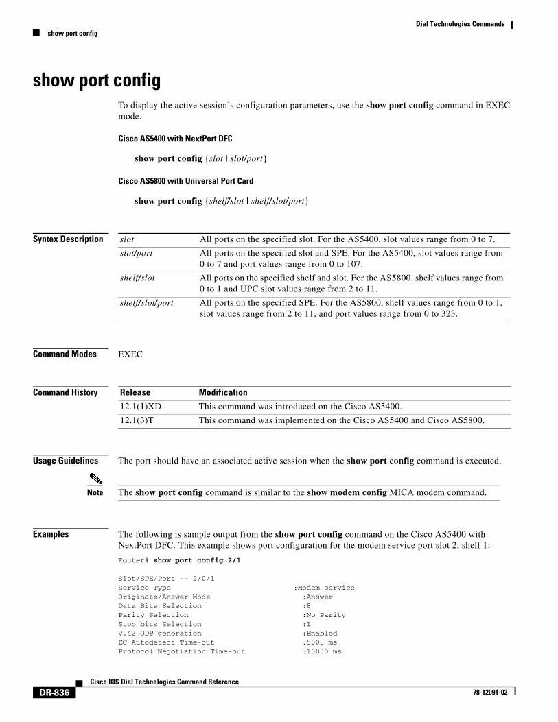
show port configTo display the active session’s configuration parameters, use the show port config command in EXEC mode.
Cisco AS5400 with NextPort DFC
show port config {slot | slot/port}
Cisco AS5800 with Universal Port Card
show port config {shelf/slot | shelf/slot/port}
Syntax Description
Command Modes EXEC
Command History
Usage Guidelines The port should have an associated active session when the show port config command is executed.
Note The show port config command is similar to the show modem config MICA modem command.
Examples The following is sample output from the show port config command on the Cisco AS5400 with NextPort DFC. This example shows port configuration for the modem service port slot 2, shelf 1:
Router# show port config 2/1
Slot/SPE/Port -- 2/0/1 Service Type :Modem service Originate/Answer Mode :Answer Data Bits Selection :8 Parity Selection :No Parity Stop bits Selection :1 V.42 ODP generation :Enabled EC Autodetect Time-out :5000 ms Protocol Negotiation Time-out :10000 ms
slot All ports on the specified slot. For the AS5400, slot values range from 0 to 7.
slot/port All ports on the specified slot and SPE. For the AS5400, slot values range from 0 to 7 and port values range from 0 to 107.
shelf/slot All ports on the specified shelf and slot. For the AS5800, shelf values range from 0 to 1 and UPC slot values range from 2 to 11.
shelf/slot/port All ports on the specified SPE. For the AS5800, shelf values range from 0 to 1, slot values range from 2 to 11, and port values range from 0 to 323.
Release Modification
12.1(1)XD This command was introduced on the Cisco AS5400.
12.1(3)T This command was implemented on the Cisco AS5400 and Cisco AS5800.
Dial Technologies Commandsshow port config
DR-837Cisco IOS Dial Technologies Command Reference
78-12091-02
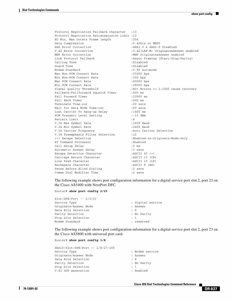
Protocol Negotiation Fallback character :13 Protocol Negotiation Retransmission Limit :12 EC Min, Max Octets Frame length :256 Data Compression :V.42bis or MNP5 ARA Error Correction :ARA1.0 & ARA2.0 Disabled V.42 Error Correction :V.42(LAP-M) Originate&Answer enabled MNP Error Correction :MNP Originate&Answer enabled Link Protocol Fallback :Async Framing (Start/Stop/Parity) Calling Tone :Disabled Guard Tone :Disabled Modem Standard :V.90 Automode Max Non-PCM Connect Rate :33600 bps Min Non-PCM Connect Rate :300 bps Max PCM Connect Rate :60000 bps Min PCM Connect Rate :28000 bps Signal Quality Threshold :Bit Errors >= 1:1000 cause recovery Fallback/Fallforward Squelch Timer :500 ms Fall Forward Timer :10000 ms Fall Back Timer :500 ms Terminate Time-out :20 secs Wait for Data Mode Time-out :60 secs Lost Carrier To Hang-up Delay :1400 ms PCM Transmit Level Setting :-13 dBm Retrain Limit :4 V.34 Max Symbol Rate :3429 Baud V.34 Min Symbol Rate :2400 Baud V.34 Carrier Frequency :Auto Carrier Selection V.34 Preemphasis Filter Selection :11 +++ Escape Detection :Enabled-in-Originate-Mode-Only AT Command Processor :Enabled Call Setup Delay :0 ms Automatic Answer Delay :2 secs Escape Detection Character :ASCII 43 (+) Carriage Return Character :ASCII 13 (CR) Line Feed Character :ASCII 10 (LF) Backspace Character :ASCII 8 (BS) Pause Before Blind Dialing :2 secs Comma Dial Modifier Time :2 secs
The following example shows port configuration information for a digital service port slot 2, port 23 on the Cisco AS5400 with NextPort DFC.
Router# show port config 2/23
Slot/SPE/Port -- 2/3/23 Service Type : Digital service Originate/Answer Mode : Answer Data Bits Selection : 8 Parity Selection : No Parity Stop bits Selection : 1 Modem Standard : reserved
The following example shows port configuration information for a digital service port slot 2, port 23 on the Cisco AS5800 with universal port card.
Router# show port config 1/8
Shelf/Slot/SPE/Port -- 1/8/27/165Service Type : Modem serviceOriginate/Answer Mode : AnswerData Bits Selection : 8Parity Selection : No ParityStop bits Selection : 1V.42 ODP generation : Enabled
Dial Technologies Commandsshow port config
DR-838Cisco IOS Dial Technologies Command Reference
78-12091-02
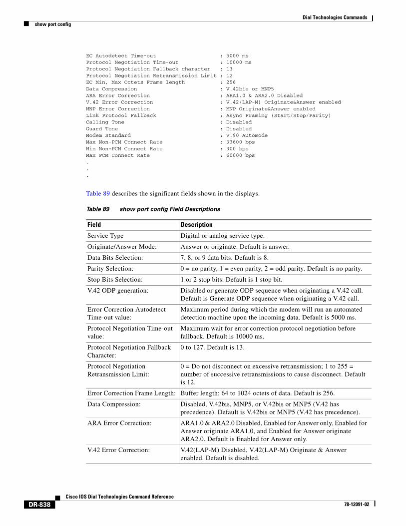
EC Autodetect Time-out : 5000 msProtocol Negotiation Time-out : 10000 msProtocol Negotiation Fallback character : 13Protocol Negotiation Retransmission Limit : 12EC Min, Max Octets Frame length : 256Data Compression : V.42bis or MNP5ARA Error Correction : ARA1.0 & ARA2.0 DisabledV.42 Error Correction : V.42(LAP-M) Originate&Answer enabledMNP Error Correction : MNP Originate&Answer enabledLink Protocol Fallback : Async Framing (Start/Stop/Parity)Calling Tone : DisabledGuard Tone : DisabledModem Standard : V.90 AutomodeMax Non-PCM Connect Rate : 33600 bpsMin Non-PCM Connect Rate : 300 bpsMax PCM Connect Rate : 60000 bps...
Table 89 describes the significant fields shown in the displays.
Table 89 show port config Field Descriptions
Field Description
Service Type Digital or analog service type.
Originate/Answer Mode: Answer or originate. Default is answer.
Data Bits Selection: 7, 8, or 9 data bits. Default is 8.
Parity Selection: 0 = no parity, 1 = even parity, 2 = odd parity. Default is no parity.
Stop Bits Selection: 1 or 2 stop bits. Default is 1 stop bit.
V.42 ODP generation: Disabled or generate ODP sequence when originating a V.42 call. Default is Generate ODP sequence when originating a V.42 call.
Error Correction Autodetect Time-out value:
Maximum period during which the modem will run an automated detection machine upon the incoming data. Default is 5000 ms.
Protocol Negotiation Time-out value:
Maximum wait for error correction protocol negotiation before fallback. Default is 10000 ms.
Protocol Negotiation Fallback Character:
0 to 127. Default is 13.
Protocol Negotiation Retransmission Limit:
0 = Do not disconnect on excessive retransmission; 1 to 255 = number of successive retransmissions to cause disconnect. Default is 12.
Error Correction Frame Length: Buffer length; 64 to 1024 octets of data. Default is 256.
Data Compression: Disabled, V.42bis, MNP5, or V.42bis or MNP5 (V.42 has precedence). Default is V.42bis or MNP5 (V.42 has precedence).
ARA Error Correction: ARA1.0 & ARA2.0 Disabled, Enabled for Answer only, Enabled for Answer originate ARA1.0, and Enabled for Answer originate ARA2.0. Default is Enabled for Answer only.
V.42 Error Correction: V.42(LAP-M) Disabled, V.42(LAP-M) Originate & Answer enabled. Default is disabled.
Dial Technologies Commandsshow port config
DR-839Cisco IOS Dial Technologies Command Reference
78-12091-02
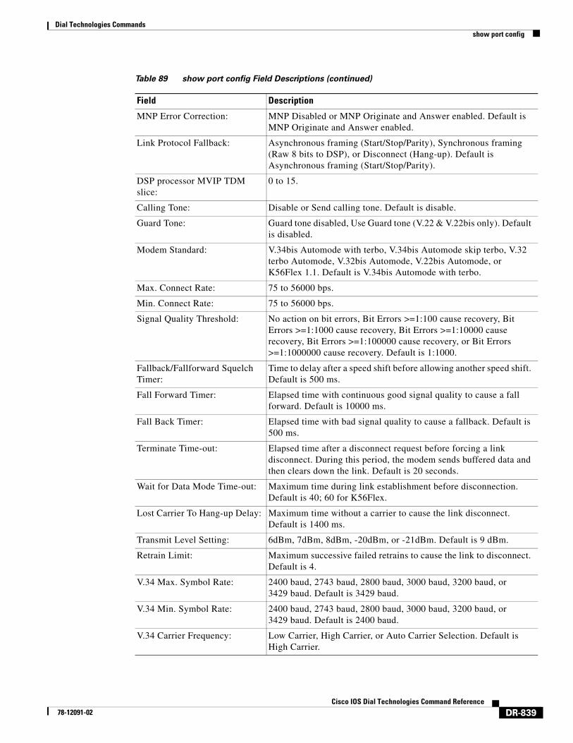
MNP Error Correction: MNP Disabled or MNP Originate and Answer enabled. Default is MNP Originate and Answer enabled.
Link Protocol Fallback: Asynchronous framing (Start/Stop/Parity), Synchronous framing (Raw 8 bits to DSP), or Disconnect (Hang-up). Default is Asynchronous framing (Start/Stop/Parity).
DSP processor MVIP TDM slice:
0 to 15.
Calling Tone: Disable or Send calling tone. Default is disable.
Guard Tone: Guard tone disabled, Use Guard tone (V.22 & V.22bis only). Default is disabled.
Modem Standard: V.34bis Automode with terbo, V.34bis Automode skip terbo, V.32 terbo Automode, V.32bis Automode, V.22bis Automode, or K56Flex 1.1. Default is V.34bis Automode with terbo.
Max. Connect Rate: 75 to 56000 bps.
Min. Connect Rate: 75 to 56000 bps.
Signal Quality Threshold: No action on bit errors, Bit Errors >=1:100 cause recovery, Bit Errors >=1:1000 cause recovery, Bit Errors >=1:10000 cause recovery, Bit Errors >=1:100000 cause recovery, or Bit Errors >=1:1000000 cause recovery. Default is 1:1000.
Fallback/Fallforward Squelch Timer:
Time to delay after a speed shift before allowing another speed shift. Default is 500 ms.
Fall Forward Timer: Elapsed time with continuous good signal quality to cause a fall forward. Default is 10000 ms.
Fall Back Timer: Elapsed time with bad signal quality to cause a fallback. Default is 500 ms.
Terminate Time-out: Elapsed time after a disconnect request before forcing a link disconnect. During this period, the modem sends buffered data and then clears down the link. Default is 20 seconds.
Wait for Data Mode Time-out: Maximum time during link establishment before disconnection. Default is 40; 60 for K56Flex.
Lost Carrier To Hang-up Delay: Maximum time without a carrier to cause the link disconnect. Default is 1400 ms.
Transmit Level Setting: 6dBm, 7dBm, 8dBm, -20dBm, or -21dBm. Default is 9 dBm.
Retrain Limit: Maximum successive failed retrains to cause the link to disconnect. Default is 4.
V.34 Max. Symbol Rate: 2400 baud, 2743 baud, 2800 baud, 3000 baud, 3200 baud, or 3429 baud. Default is 3429 baud.
V.34 Min. Symbol Rate: 2400 baud, 2743 baud, 2800 baud, 3000 baud, 3200 baud, or 3429 baud. Default is 2400 baud.
V.34 Carrier Frequency: Low Carrier, High Carrier, or Auto Carrier Selection. Default is High Carrier.
Table 89 show port config Field Descriptions (continued)
Field Description
Dial Technologies Commandsshow port config
DR-840Cisco IOS Dial Technologies Command Reference
78-12091-02
Related Commands
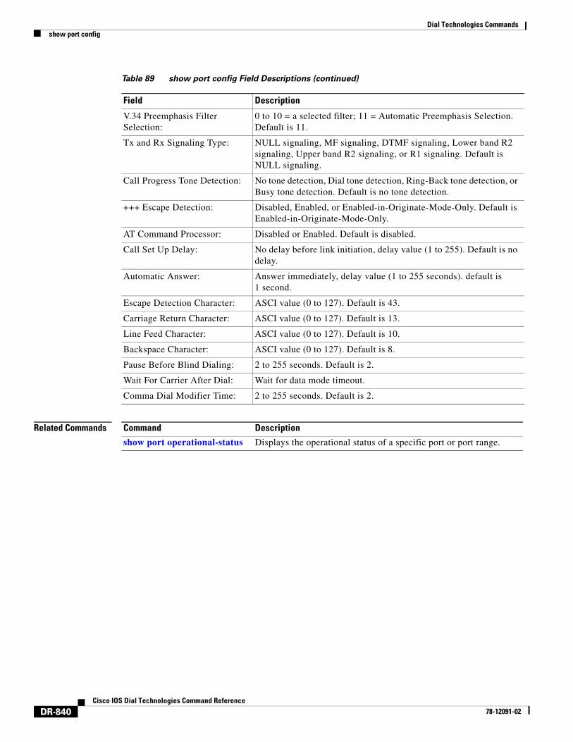
V.34 Preemphasis Filter Selection:
0 to 10 = a selected filter; 11 = Automatic Preemphasis Selection. Default is 11.
Tx and Rx Signaling Type: NULL signaling, MF signaling, DTMF signaling, Lower band R2 signaling, Upper band R2 signaling, or R1 signaling. Default is NULL signaling.
Call Progress Tone Detection: No tone detection, Dial tone detection, Ring-Back tone detection, or Busy tone detection. Default is no tone detection.
+++ Escape Detection: Disabled, Enabled, or Enabled-in-Originate-Mode-Only. Default is Enabled-in-Originate-Mode-Only.
AT Command Processor: Disabled or Enabled. Default is disabled.
Call Set Up Delay: No delay before link initiation, delay value (1 to 255). Default is no delay.
Automatic Answer: Answer immediately, delay value (1 to 255 seconds). default is 1 second.
Escape Detection Character: ASCI value (0 to 127). Default is 43.
Carriage Return Character: ASCI value (0 to 127). Default is 13.
Line Feed Character: ASCI value (0 to 127). Default is 10.
Backspace Character: ASCI value (0 to 127). Default is 8.
Pause Before Blind Dialing: 2 to 255 seconds. Default is 2.
Wait For Carrier After Dial: Wait for data mode timeout.
Comma Dial Modifier Time: 2 to 255 seconds. Default is 2.
Table 89 show port config Field Descriptions (continued)
Field Description
Command Description
show port operational-status Displays the operational status of a specific port or port range.
Dial Technologies Commandsshow port digital log
DR-841Cisco IOS Dial Technologies Command Reference
78-12091-02
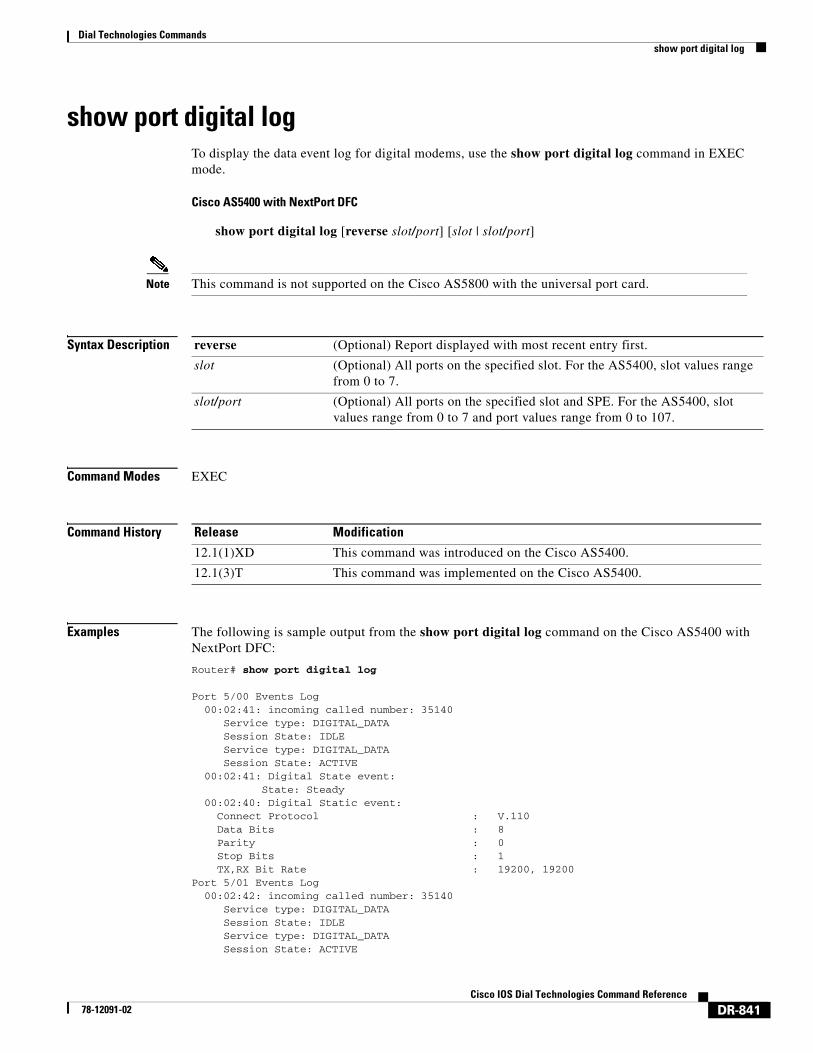
show port digital logTo display the data event log for digital modems, use the show port digital log command in EXEC mode.
Cisco AS5400 with NextPort DFC
show port digital log [reverse slot/port] [slot | slot/port]
Note This command is not supported on the Cisco AS5800 with the universal port card.
Syntax Description
Command Modes EXEC
Command History
Examples The following is sample output from the show port digital log command on the Cisco AS5400 with NextPort DFC:
Router# show port digital log
Port 5/00 Events Log 00:02:41: incoming called number: 35140 Service type: DIGITAL_DATA Session State: IDLE Service type: DIGITAL_DATA Session State: ACTIVE 00:02:41: Digital State event: State: Steady 00:02:40: Digital Static event: Connect Protocol : V.110 Data Bits : 8 Parity : 0 Stop Bits : 1 TX,RX Bit Rate : 19200, 19200 Port 5/01 Events Log 00:02:42: incoming called number: 35140 Service type: DIGITAL_DATA Session State: IDLE Service type: DIGITAL_DATA Session State: ACTIVE
reverse (Optional) Report displayed with most recent entry first.
slot (Optional) All ports on the specified slot. For the AS5400, slot values range from 0 to 7.
slot/port (Optional) All ports on the specified slot and SPE. For the AS5400, slot values range from 0 to 7 and port values range from 0 to 107.
Release Modification
12.1(1)XD This command was introduced on the Cisco AS5400.
12.1(3)T This command was implemented on the Cisco AS5400.
Dial Technologies Commandsshow port digital log
DR-842Cisco IOS Dial Technologies Command Reference
78-12091-02
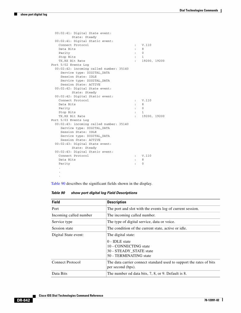
00:02:41: Digital State event: State: Steady 00:02:41: Digital Static event: Connect Protocol : V.110 Data Bits : 8 Parity : 0 Stop Bits : 1 TX,RX Bit Rate : 19200, 19200 Port 5/02 Events Log 00:02:42: incoming called number: 35140 Service type: DIGITAL_DATA Session State: IDLE Service type: DIGITAL_DATA Session State: ACTIVE 00:02:42: Digital State event: State: Steady 00:02:42: Digital Static event: Connect Protocol : V.110 Data Bits : 8 Parity : 0 Stop Bits : 1 TX,RX Bit Rate : 19200, 19200 Port 5/03 Events Log 00:02:43: incoming called number: 35140 Service type: DIGITAL_DATA Session State: IDLE Service type: DIGITAL_DATA Session State: ACTIVE 00:02:43: Digital State event: State: Steady 00:02:43: Digital Static event: Connect Protocol : V.110 Data Bits : 8 Parity : 0
.
.
.
Table 90 describes the significant fields shown in the display.
Table 90 show port digital log Field Descriptions
Field Description
Port The port and slot with the events log of current session.
Incoming called number The incoming called number.
Service type The type of digital service, data or voice.
Session state The condition of the current state, active or idle.
Digital State event: The digital state:
0 - IDLE state10 - CONNECTING state 30 - STEADY_STATE state50 - TERMINATING state
Connect Protocol The data carrier connect standard used to support the rates of bits per second (bps).
Data Bits The number od data bits, 7, 8, or 9. Default is 8.
Dial Technologies Commandsshow port digital log
DR-843Cisco IOS Dial Technologies Command Reference
78-12091-02
Related Commands
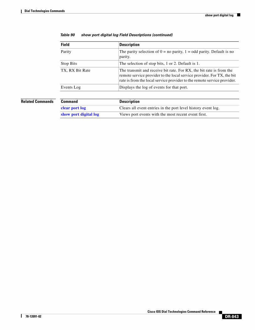
Parity The parity selection of 0 = no parity, 1 = odd parity. Default is no parity.
Stop Bits The selection of stop bits, 1 or 2. Default is 1.
TX, RX Bit Rate The transmit and receive bit rate. For RX, the bit rate is from the remote service provider to the local service provider. For TX, the bit rate is from the local service provider to the remote service provider.
Events Log Displays the log of events for that port.
Table 90 show port digital log Field Descriptions (continued)
Field Description
Command Description
clear port log Clears all event entries in the port level history event log.
show port digital log Views port events with the most recent event first.
Dial Technologies Commandsshow port modem calltracker
DR-844Cisco IOS Dial Technologies Command Reference
78-12091-02
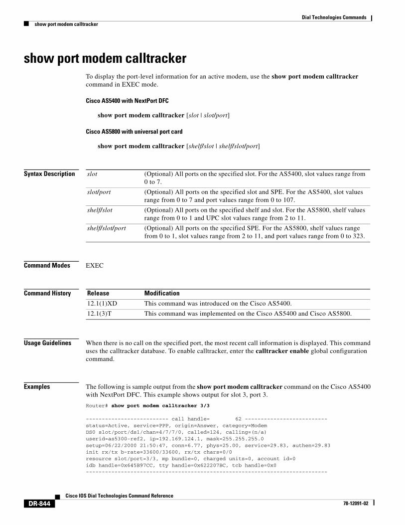
show port modem calltrackerTo display the port-level information for an active modem, use the show port modem calltracker command in EXEC mode.
Cisco AS5400 with NextPort DFC
show port modem calltracker [slot | slot/port]
Cisco AS5800 with universal port card
show port modem calltracker [shelf/slot | shelf/slot/port]
Syntax Description
Command Modes EXEC
Command History
Usage Guidelines When there is no call on the specified port, the most recent call information is displayed. This command uses the calltracker database. To enable calltracker, enter the calltracker enable global configuration command.
Examples The following is sample output from the show port modem calltracker command on the Cisco AS5400 with NextPort DFC. This example shows output for slot 3, port 3.
Router# show port modem calltracker 3/3
-------------------------- call handle= 62 --------------------------status=Active, service=PPP, origin=Answer, category=ModemDS0 slot/port/ds1/chan=4/7/7/0, called=124, calling=(n/a)userid=as5300-ref2, ip=192.169.124.1, mask=255.255.255.0setup=06/22/2000 21:50:47, conn=6.77, phys=25.00, service=29.83, authen=29.83init rx/tx b-rate=33600/33600, rx/tx chars=0/0resource slot/port=3/3, mp bundle=0, charged units=0, account id=0idb handle=0x645B97CC, tty handle=0x622207BC, tcb handle=0x0----------------------------------------------------------------------------
slot (Optional) All ports on the specified slot. For the AS5400, slot values range from 0 to 7.
slot/port (Optional) All ports on the specified slot and SPE. For the AS5400, slot values range from 0 to 7 and port values range from 0 to 107.
shelf/slot (Optional) All ports on the specified shelf and slot. For the AS5800, shelf values range from 0 to 1 and UPC slot values range from 2 to 11.
shelf/slot/port (Optional) All ports on the specified SPE. For the AS5800, shelf values range from 0 to 1, slot values range from 2 to 11, and port values range from 0 to 323.
Release Modification
12.1(1)XD This command was introduced on the Cisco AS5400.
12.1(3)T This command was implemented on the Cisco AS5400 and Cisco AS5800.
Dial Technologies Commandsshow port modem calltracker
DR-845Cisco IOS Dial Technologies Command Reference
78-12091-02
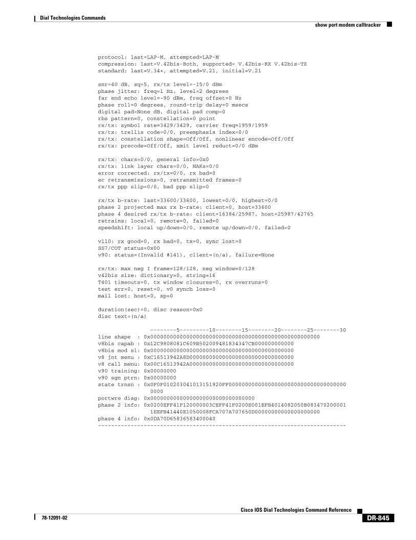
protocol: last=LAP-M, attempted=LAP-Mcompression: last=V.42bis-Both, supported= V.42bis-RX V.42bis-TXstandard: last=V.34+, attempted=V.21, initial=V.21
snr=40 dB, sq=5, rx/tx level=-15/0 dBmphase jitter: freq=1 Hz, level=2 degreesfar end echo level=-90 dBm, freq offset=0 Hzphase roll=0 degrees, round-trip delay=0 msecsdigital pad=None dB, digital pad comp=0rbs pattern=0, constellation=0 pointrx/tx: symbol rate=3429/3429, carrier freq=1959/1959rx/tx: trellis code=0/0, preemphasis index=0/0rx/tx: constellation shape=Off/Off, nonlinear encode=Off/Offrx/tx: precode=Off/Off, xmit level reduct=0/0 dBm
rx/tx: chars=0/0, general info=0x0rx/tx: link layer chars=0/0, NAKs=0/0error corrected: rx/tx=0/0, rx bad=0ec retransmissions=0, retransmitted frames=0rx/tx ppp slip=0/0, bad ppp slip=0
rx/tx b-rate: last=33600/33600, lowest=0/0, highest=0/0phase 2 projected max rx b-rate: client=0, host=33600phase 4 desired rx/tx b-rate: client=16384/25987, host=25987/42765retrains: local=0, remote=0, failed=0speedshift: local up/down=0/0, remote up/down=0/0, failed=0
v110: rx good=0, rx bad=0, tx=0, sync lost=0SS7/COT status=0x00v90: status=(Invalid #141), client=(n/a), failure=None
rx/tx: max neg I frame=128/128, neg window=0/128v42bis size: dictionary=0, string=16T401 timeouts=0, tx window closures=0, rx overruns=0test err=0, reset=0, v0 synch loss=0mail lost: host=0, sp=0
duration(sec)=0, disc reason=0x0disc text=(n/a)
--------5---------10--------15--------20--------25--------30line shape : 0x0000000000000000000000000000000000000000000000000000v8bis capab : 0x12C9808081C609B502009481834347CB000000000000v8bis mod sl: 0x00000000000000000000000000000000000000000000v8 jnt menu : 0xC16513942A8D00000000000000000000000000000000v8 call menu: 0x00C16513942A00000000000000000000000000000000v90 training: 0x00000000v90 sgn ptrn: 0x00000000state trnsn : 0x0F0F010203041013151920FF000000000000000000000000000000000000 0000portwre diag: 0x00000000000000000000000000000000phase 2 info: 0x0200EFF41F120000003CEFF41F0200E001EFB4014082050B083470200001 1EEFB41440E1050008FCA707A707650D00000000000000000000phase 4 info: 0x0DA70D65836583400040----------------------------------------------------------------------------
Dial Technologies Commandsshow port modem log
DR-846Cisco IOS Dial Technologies Command Reference
78-12091-02
show port modem logTo display the events generated by the modem sessions, use the show port modem log command in EXEC mode.
Cisco AS5400 with NextPort DFC
show port modem log [reverse slot/port] [slot | slot/port]
Cisco AS5800 with Universal Port Card
show port modem log [reverse shelf/slot/port] [shelf/slot | shelf/slot/port]
Syntax Description
Command Modes EXEC
Command History
Usage Guidelines The port modem test log displays the results of the SPE diagnostics tests.
Examples The following is sample output for the Cisco AS5400 with NextPort DFC. This example shows the port history event log for slot 5, port 47:
Router# show port modem log 5/47
Port 5/47 Events Log Service type: DATA_FAX_MODEM Service mode: DATA_FAX_MODEM Session State: IDLE 00:02:23: incoming called number: 35160 Service type: DATA_FAX_MODEM Service mode: DATA_FAX_MODEM
reverse (Optional) Displays the modem port history event log with the most recent event first.
slot (Optional) All ports on the specified slot. For the AS5400, slot values range from 0 to 7.
slot/port (Optional) All ports on the specified slot and SPE. For the AS5400, slot values range from 0 to 7 and port values range from 0 to 107.
shelf/slot (Optional) All ports on the specified shelf and slot. For the AS5800, shelf values range from 0 to 1 and UPC slot values range from 2 to 11.
shelf/slot/port (Optional) All ports on the specified SPE. For the AS5800, shelf values range from 0 to 1, slot values range from 2 to 11, and port values range from 0 to 323.
Release Modification
12.1(1)XD This command was introduced on the Cisco AS5400.
12.1(3)T This command was implemented on the Cisco AS5400 and Cisco AS5800.
Dial Technologies Commandsshow port modem log
DR-847Cisco IOS Dial Technologies Command Reference
78-12091-02
Session State: IDLE Service type: DATA_FAX_MODEM Service mode: DATA_FAX_MODEM Session State: ACTIVE 00:02:23: Modem State event: State: Connect 00:02:16: Modem State event: State: Link 00:02:13: Modem State event: State: Train Up 00:02:05: Modem State event: State: EC Negotiating 00:02:05: Modem State event: State: Steady 00:02:05: Modem Static event: Connect Protocol : LAP-M Compression : V.42bis Connected Standard : V.34+ TX,RX Symbol Rate : 3429, 3429 TX,RX Carrier Frequency : 1959, 1959 TX,RX Trellis Coding : 16/16 Frequency Offset : 0 Hz Round Trip Delay : 0 msecs TX,RX Bit Rate : 33600, 33600 Robbed Bit Signalling (RBS) pattern : 0 Digital Pad : None Digital Pad Compensation : None 4 bytes of link info not formatted : 0x00 0x00 0x00 0x00 0x00 00:02:06:Modem Dynamic event: Sq Value : 5 Signal Noise Ratio : 40 dB Receive Level : -12 dBm Phase Jitter Frequency : 0 Hz Phase Jitter Level : 2 degrees Far End Echo Level : -90 dBm Phase Roll : 0 degrees Total Retrains : 0 EC Retransmission Count : 0 Characters transmitted, received : 0, 0 Characters received BAD : 0 PPP/SLIP packets transmitted, received : 0, 0 PPP/SLIP packets received (BAD/ABORTED) : 0 EC packets transmitted, received OK : 0, 0 EC packets (Received BAD/ABORTED) : 0
This following example shows the port history event log with the most recent event first on slot 5, port 40:
Router# show port modem log reverse 5/40
Modem port 5/40 Events Log 00:02:18:Modem Dynamic event: Sq Value : 5 Signal Noise Ratio : 38 dB Receive Level : -12 dBm Phase Jitter Frequency : 0 Hz Phase Jitter Level : 0 degrees Far End Echo Level : 0 dBm Phase Roll : 0 degrees Total Retrains : 0 EC Retransmission Count : 0 Characters transmitted, received : 0, 0 Characters received BAD : 0 PPP/SLIP packets transmitted, received : 0, 0
Dial Technologies Commandsshow port modem log
DR-848Cisco IOS Dial Technologies Command Reference
78-12091-02
PPP/SLIP packets received (BAD/ABORTED) : 0 EC packets transmitted, received OK : 0, 0 EC packets (Received BAD/ABORTED) : 0 00:02:18: Modem Static event: Connect Protocol : LAP-M Compression : V.42bis Connected Standard : V.90 TX,RX Symbol Rate : 8000, 3200 TX,RX Carrier Frequency : 1829, 1829 TX,RX Trellis Coding : 16/16 Frequency Offset : 0 Hz Round Trip Delay : 4 msecs TX,RX Bit Rate : 52000, 28800 Robbed Bit Signalling (RBS) pattern : 255 Digital Pad : None Digital Pad Compensation : Enabled 4 bytes of link info not formatted : 0x00 0x00 0x00 0x00 0x00 00:02:23: Modem State event: State: Steady 00:02:23: Modem State event: State: EC Negotiating 00:02:36: Modem State event: State: Train Up 00:02:39: Modem State event: State: Link 00:02:46: Modem State event: State: Connect 00:02:46: Port State Reached: Service type: DATA_FAX_MODEM Service mode: DATA_FAX_MODEM Session State: ACTIVE 00:02:46: Port State Reached: Service type: DATA_FAX_MODEM Service mode: DATA_FAX_MODEM Session State: IDLE 00:02:47: incoming called number: 6000 00:02:47: incoming caller number: 90002
The following is sample output for the Cisco AS5800 with universal port card. This example shows the port history event log for slot 8, ports 0 to 6:
Router# show port modem log 1/8/0 1/8/6
Port 1/08/00 Events Log 09:09:53: Service Type: DATA_FAX_MODEM 09:09:53: Service Mode: DATA_FAX_MODEM 09:09:53: Session State: FLUSHING 09:09:53: Service Type: DATA_FAX_MODEM 09:09:53: Service Mode: DATA_FAX_MODEM 09:09:53: Session State: IDLE 09:09:53: Modem State event: State: Terminate 09:09:53: Modem End Connect event: Call Timer : 26 secs Disconnect Reason Info : 0x1F00 Type (=0 ): <unknown> Class (=31 ): Requested by host Reason (=0 ): non-specific host disconnect Total Retrains : 0 EC Retransmission Count : 0 Characters transmitted, received : 2633, 485 Characters received BAD : 0 PPP/SLIP packets transmitted, received : 0, 0 PPP/SLIP packets received (BAD/ABORTED) : 0
Dial Technologies Commandsshow port modem log
DR-849Cisco IOS Dial Technologies Command Reference
78-12091-02
EC packets transmitted, received OK : 27, 21 EC packets (Received BAD/ABORTED) : 0 09:09:54:Modem Link Rate event: 09:09:55: Service Type: DATA_FAX_MODEM 09:09:55: Service Mode: DATA_FAX_MODEM 09:09:55: Session State: IDLE 09:09:55: Service Type: DATA_FAX_MODEM 09:09:55: Service Mode: DATA_FAX_MODEM 09:09:55: Session State: ACTIVE 09:09:55: Modem State event: State: Connect 09:09:55: Modem State event: State: Link 09:09:55: Modem State event: State: Train Up 09:09:55: Modem State event: State: EC Negotiating 09:09:55: Modem State event: State: Steady 09:09:55: Modem Static event: Connect Protocol : LAP-M Compression : V.42bis Connected Standard : V.34+ TX,RX Symbol Rate : 3429, 3429 TX,RX Carrier Frequency : 1959, 1959 TX,RX Trellis Coding : 16/16 Frequency Offset : 0 Hz Round Trip Delay : 1 msecs TX,RX Bit Rate : 31200, 28800 Robbed Bit Signalling (RBS) pattern : 0 Digital Pad : None Digital Pad Compensation : None 4 bytes of link info not formatted : 0x00 0x00 0x00 0x00 0x00 09:09:56: Modem Dynamic event: Sq Value : 5 Signal Noise Ratio : 38 dB Receive Level : -15 dBm Phase Jitter Frequency : 13 Hz Phase Jitter Level : 0 degrees Far End Echo Level : -90 dBm Phase Roll : 0 degrees Total Retrains : 0 EC Retransmission Count : 0 Characters transmitted, received : 0, 0 Characters received BAD : 0 PPP/SLIP packets transmitted, received : 0, 0 PPP/SLIP packets received (BAD/ABORTED) : 0 EC packets transmitted, received OK : 0, 0 EC packets (Received BAD/ABORTED) : 0 09:09:58: Service Type: DATA_FAX_MODEM 09:09:58: Service Mode: DATA_FAX_MODEM 09:09:58: Session State: FLUSHING 09:09:58: Service Type: DATA_FAX_MODEM 09:09:58: Service Mode: DATA_FAX_MODEM 09:09:58: Session State: IDLE 09:09:58: Modem State event: State: Terminate
.
.
.
Dial Technologies Commandsshow port modem log
DR-850Cisco IOS Dial Technologies Command Reference
78-12091-02
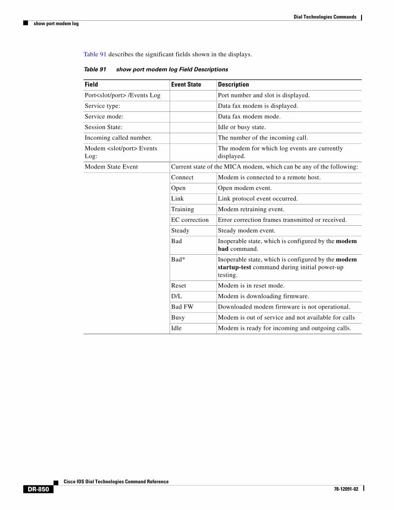
Table 91 describes the significant fields shown in the displays.
Table 91 show port modem log Field Descriptions
Field Event State Description
Port<slot/port> /Events Log Port number and slot is displayed.
Service type: Data fax modem is displayed.
Service mode: Data fax modem mode.
Session State: Idle or busy state.
Incoming called number. The number of the incoming call.
Modem <slot/port> Events Log:
The modem for which log events are currently displayed.
Modem State Event Current state of the MICA modem, which can be any of the following:
Connect Modem is connected to a remote host.
Open Open modem event.
Link Link protocol event occurred.
Training Modem retraining event.
EC correction Error correction frames transmitted or received.
Steady Steady modem event.
Bad Inoperable state, which is configured by the modem bad command.
Bad* Inoperable state, which is configured by the modem startup-test command during initial power-up testing.
Reset Modem is in reset mode.
D/L Modem is downloading firmware.
Bad FW Downloaded modem firmware is not operational.
Busy Modem is out of service and not available for calls
Idle Modem is ready for incoming and outgoing calls.
Dial Technologies Commandsshow port modem log
DR-851Cisco IOS Dial Technologies Command Reference
78-12091-02
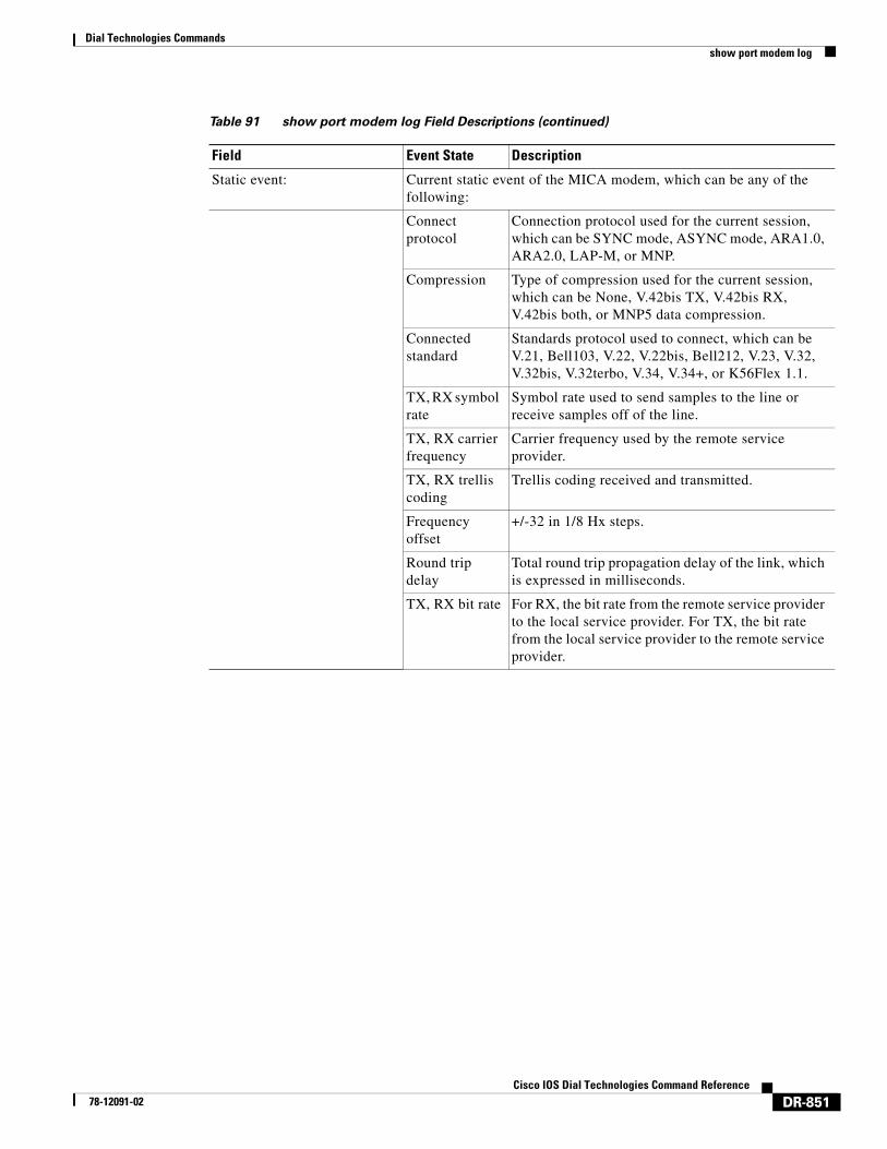
Static event: Current static event of the MICA modem, which can be any of the following:
Connect protocol
Connection protocol used for the current session, which can be SYNC mode, ASYNC mode, ARA1.0, ARA2.0, LAP-M, or MNP.
Compression Type of compression used for the current session, which can be None, V.42bis TX, V.42bis RX, V.42bis both, or MNP5 data compression.
Connected standard
Standards protocol used to connect, which can be V.21, Bell103, V.22, V.22bis, Bell212, V.23, V.32, V.32bis, V.32terbo, V.34, V.34+, or K56Flex 1.1.
TX, RX symbol rate
Symbol rate used to send samples to the line or receive samples off of the line.
TX, RX carrier frequency
Carrier frequency used by the remote service provider.
TX, RX trellis coding
Trellis coding received and transmitted.
Frequency offset
+/-32 in 1/8 Hx steps.
Round trip delay
Total round trip propagation delay of the link, which is expressed in milliseconds.
TX, RX bit rate For RX, the bit rate from the remote service provider to the local service provider. For TX, the bit rate from the local service provider to the remote service provider.
Table 91 show port modem log Field Descriptions (continued)
Field Event State Description
Dial Technologies Commandsshow port modem log
DR-852Cisco IOS Dial Technologies Command Reference
78-12091-02
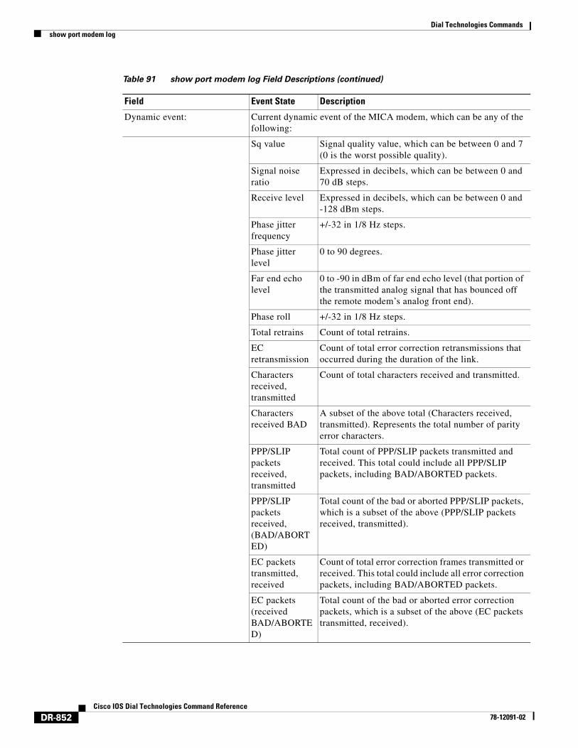
Dynamic event: Current dynamic event of the MICA modem, which can be any of the following:
Sq value Signal quality value, which can be between 0 and 7 (0 is the worst possible quality).
Signal noise ratio
Expressed in decibels, which can be between 0 and 70 dB steps.
Receive level Expressed in decibels, which can be between 0 and -128 dBm steps.
Phase jitter frequency
+/-32 in 1/8 Hz steps.
Phase jitter level
0 to 90 degrees.
Far end echo level
0 to -90 in dBm of far end echo level (that portion of the transmitted analog signal that has bounced off the remote modem’s analog front end).
Phase roll +/-32 in 1/8 Hz steps.
Total retrains Count of total retrains.
EC retransmission
Count of total error correction retransmissions that occurred during the duration of the link.
Characters received, transmitted
Count of total characters received and transmitted.
Characters received BAD
A subset of the above total (Characters received, transmitted). Represents the total number of parity error characters.
PPP/SLIP packets received, transmitted
Total count of PPP/SLIP packets transmitted and received. This total could include all PPP/SLIP packets, including BAD/ABORTED packets.
PPP/SLIP packets received, (BAD/ABORTED)
Total count of the bad or aborted PPP/SLIP packets, which is a subset of the above (PPP/SLIP packets received, transmitted).
EC packets transmitted, received
Count of total error correction frames transmitted or received. This total could include all error correction packets, including BAD/ABORTED packets.
EC packets (received BAD/ABORTED)
Total count of the bad or aborted error correction packets, which is a subset of the above (EC packets transmitted, received).
Table 91 show port modem log Field Descriptions (continued)
Field Event State Description
Dial Technologies Commandsshow port modem log
DR-853Cisco IOS Dial Technologies Command Reference
78-12091-02
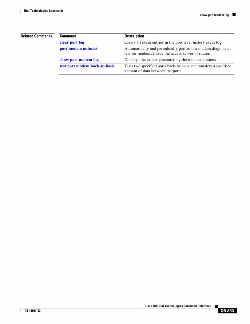
Related Commands Command Description
clear port log Clears all event entries in the port level history event log.
port modem autotest Automatically and periodically performs a modem diagnostics test for modems inside the access server or router.
show port modem log Displays the events generated by the modem sessions.
test port modem back-to-back Tests two specified ports back-to-back and transfers a specified amount of data between the ports.
Dial Technologies Commandsshow port modem test
DR-854Cisco IOS Dial Technologies Command Reference
78-12091-02
show port modem testTo display the modem test log, use the show port modem test command in EXEC mode.
Cisco AS5400 with NextPort DFC
show port modem test [slot | slot/port]
Cisco AS5800 with Universal Port Card
show port modem test [shelf/slot | shelf/slot/port]
Syntax Description
Command Modes EXEC
Command History
Usage Guidelines The port modem test log displays the results of the SPE diagnostics tests.
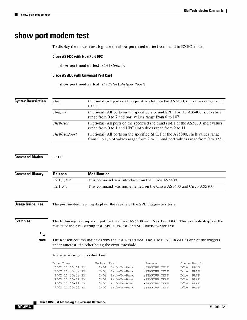
Examples The following is sample output for the Cisco AS5400 with NextPort DFC. This example displays the results of the SPE startup test, SPE auto-test, and SPE back-to-back test.
Note The Reason column indicates why the test was started. The TIME INTERVAL is one of the triggers under autotest, the other being the error threshold.
Router# show port modem test
Date Time Modem Test Reason State Result 3/02 12:00:57 PM 2/01 Back-To-Back :STARTUP TEST Idle PASS 3/02 12:00:57 PM 2/00 Back-To-Back :STARTUP TEST Idle PASS 3/02 12:00:58 PM 2/02 Back-To-Back :STARTUP TEST Idle PASS 3/02 12:00:58 PM 2/03 Back-To-Back :STARTUP TEST Idle PASS 3/02 12:00:58 PM 2/04 Back-To-Back :STARTUP TEST Idle PASS 3/02 12:00:58 PM 2/05 Back-To-Back :STARTUP TEST Idle PASS
slot (Optional) All ports on the specified slot. For the AS5400, slot values range from 0 to 7.
slot/port (Optional) All ports on the specified slot and SPE. For the AS5400, slot values range from 0 to 7 and port values range from 0 to 107.
shelf/slot (Optional) All ports on the specified shelf and slot. For the AS5800, shelf values range from 0 to 1 and UPC slot values range from 2 to 11.
shelf/slot/port (Optional) All ports on the specified SPE. For the AS5800, shelf values range from 0 to 1, slot values range from 2 to 11, and port values range from 0 to 323.
Release Modification
12.1(1)XD This command was introduced on the Cisco AS5400.
12.1(3)T This command was implemented on the Cisco AS5400 and Cisco AS5800.
Dial Technologies Commandsshow port modem test
DR-855Cisco IOS Dial Technologies Command Reference
78-12091-02
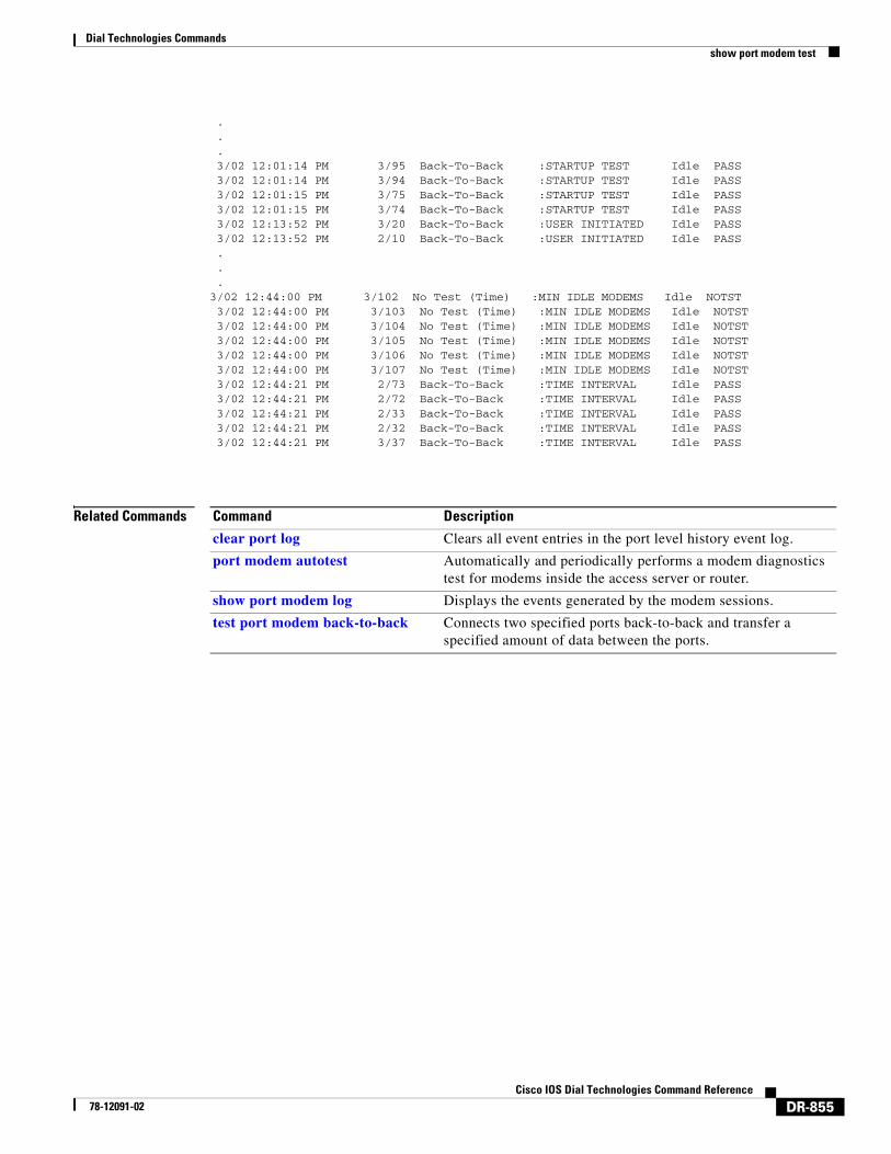
.
.
. 3/02 12:01:14 PM 3/95 Back-To-Back :STARTUP TEST Idle PASS 3/02 12:01:14 PM 3/94 Back-To-Back :STARTUP TEST Idle PASS 3/02 12:01:15 PM 3/75 Back-To-Back :STARTUP TEST Idle PASS 3/02 12:01:15 PM 3/74 Back-To-Back :STARTUP TEST Idle PASS 3/02 12:13:52 PM 3/20 Back-To-Back :USER INITIATED Idle PASS 3/02 12:13:52 PM 2/10 Back-To-Back :USER INITIATED Idle PASS...
3/02 12:44:00 PM 3/102 No Test (Time) :MIN IDLE MODEMS Idle NOTST 3/02 12:44:00 PM 3/103 No Test (Time) :MIN IDLE MODEMS Idle NOTST 3/02 12:44:00 PM 3/104 No Test (Time) :MIN IDLE MODEMS Idle NOTST 3/02 12:44:00 PM 3/105 No Test (Time) :MIN IDLE MODEMS Idle NOTST 3/02 12:44:00 PM 3/106 No Test (Time) :MIN IDLE MODEMS Idle NOTST 3/02 12:44:00 PM 3/107 No Test (Time) :MIN IDLE MODEMS Idle NOTST 3/02 12:44:21 PM 2/73 Back-To-Back :TIME INTERVAL Idle PASS 3/02 12:44:21 PM 2/72 Back-To-Back :TIME INTERVAL Idle PASS 3/02 12:44:21 PM 2/33 Back-To-Back :TIME INTERVAL Idle PASS 3/02 12:44:21 PM 2/32 Back-To-Back :TIME INTERVAL Idle PASS 3/02 12:44:21 PM 3/37 Back-To-Back :TIME INTERVAL Idle PASS
Related Commands Command Description
clear port log Clears all event entries in the port level history event log.
port modem autotest Automatically and periodically performs a modem diagnostics test for modems inside the access server or router.
show port modem log Displays the events generated by the modem sessions.
test port modem back-to-back Connects two specified ports back-to-back and transfer a specified amount of data between the ports.
Dial Technologies Commandsshow port operational-status
DR-856Cisco IOS Dial Technologies Command Reference
78-12091-02
show port operational-statusTo display the active session’s statistics, use the show port operational-status command in EXEC mode.
Cisco AS5400 with NextPort DFC
show port operational-status {slot | slot/port}
Cisco AS5800 with Universal Port Card
show port operational-status {shelf/slot | shelf/slot/port}
Syntax Description
Command Modes EXEC
Command History
Usage Guidelines This command displays the operational status of a specific port or port range. The port should have an associated active modem session when the command is executed.
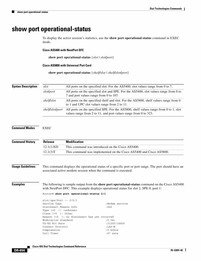
Examples The following is sample output from the show port operational-status command on the Cisco AS5400 with NextPort DFC. This example displays operational status for slot 2, SPE 0, port 1:
Router# show port operational-status 2/1
slot/spe/Port -- 2/0/1 Service Type :Modem service Disconnect Reason Info :0x0 Type (=0 ): <unknown> Class (=0 ): Other Reason (=0 ): no disconnect has yet occurred Modulation Standard :V.34+ TX/RX Bit Rate :31200/14400 Connect Protocol :LAP-M Compression :V.42bis Call Timer :47 secs
slot All ports on the specified slot. For the AS5400, slot values range from 0 to 7.
slot/port All ports on the specified slot and SPE. For the AS5400, slot values range from 0 to 7 and port values range from 0 to 107.
shelf/slot All ports on the specified shelf and slot. For the AS5800, shelf values range from 0 to 1 and UPC slot values range from 2 to 11.
shelf/slot/port All ports on the specified SPE. For the AS5800, shelf values range from 0 to 1, slot values range from 2 to 11, and port values range from 0 to 323.
Release Modification
12.1(1)XD This command was introduced on the Cisco AS5400.
12.1(3)T This command was implemented on the Cisco AS5400 and Cisco AS5800.
Dial Technologies Commandsshow port operational-status
DR-857Cisco IOS Dial Technologies Command Reference
78-12091-02
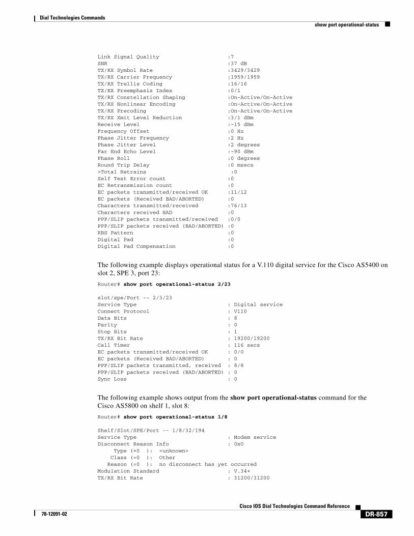
Link Signal Quality :7 SNR :37 dB TX/RX Symbol Rate :3429/3429 TX/RX Carrier Frequency :1959/1959 TX/RX Trellis Coding :16/16 TX/RX Preemphasis Index :0/1 TX/RX Constellation Shaping :On-Active/On-Active TX/RX Nonlinear Encoding :On-Active/On-Active TX/RX Precoding :On-Active/On-Active TX/RX Xmit Level Reduction :3/1 dBm Receive Level :-15 dBm Frequency Offset :0 Hz Phase Jitter Frequency :2 Hz Phase Jitter Level :2 degrees Far End Echo Level :-90 dBm Phase Roll :0 degrees Round Trip Delay :0 msecs >Total Retrains :0 Self Test Error count :0 EC Retransmission count :0 EC packets transmitted/received OK :11/12 EC packets (Received BAD/ABORTED) :0 Characters transmitted/received :76/13 Characters received BAD :0 PPP/SLIP packets transmitted/received :0/0 PPP/SLIP packets received (BAD/ABORTED) :0 RBS Pattern :0 Digital Pad :0 Digital Pad Compensation :0
The following example displays operational status for a V.110 digital service for the Cisco AS5400 on slot 2, SPE 3, port 23:
Router# show port operational-status 2/23
slot/spe/Port -- 2/3/23 Service Type : Digital service Connect Protocol : V110 Data Bits : 8 Parity : 0 Stop Bits : 1 TX/RX Bit Rate : 19200/19200 Call Timer : 116 secs EC packets transmitted/received OK : 0/0 EC packets (Received BAD/ABORTED) : 0 PPP/SLIP packets transmitted, received : 8/8 PPP/SLIP packets received (BAD/ABORTED) : 0 Sync Loss : 0
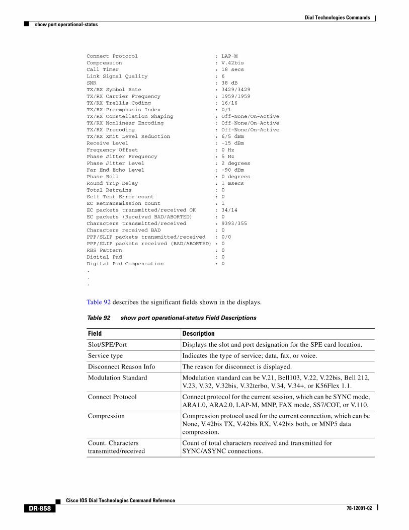
The following example shows output from the show port operational-status command for the Cisco AS5800 on shelf 1, slot 8:
Router# show port operational-status 1/8
Shelf/Slot/SPE/Port -- 1/8/32/194Service Type : Modem serviceDisconnect Reason Info : 0x0 Type (=0 ): <unknown> Class (=0 ): Other Reason (=0 ): no disconnect has yet occurredModulation Standard : V.34+TX/RX Bit Rate : 31200/31200
Dial Technologies Commandsshow port operational-status
DR-858Cisco IOS Dial Technologies Command Reference
78-12091-02
Connect Protocol : LAP-MCompression : V.42bisCall Timer : 18 secsLink Signal Quality : 6SNR : 38 dBTX/RX Symbol Rate : 3429/3429TX/RX Carrier Frequency : 1959/1959TX/RX Trellis Coding : 16/16TX/RX Preemphasis Index : 0/1TX/RX Constellation Shaping : Off-None/On-ActiveTX/RX Nonlinear Encoding : Off-None/On-ActiveTX/RX Precoding : Off-None/On-ActiveTX/RX Xmit Level Reduction : 6/5 dBmReceive Level : -15 dBmFrequency Offset : 0 HzPhase Jitter Frequency : 5 HzPhase Jitter Level : 2 degreesFar End Echo Level : -90 dBmPhase Roll : 0 degreesRound Trip Delay : 1 msecsTotal Retrains : 0Self Test Error count : 0EC Retransmission count : 1EC packets transmitted/received OK : 34/14EC packets (Received BAD/ABORTED) : 0Characters transmitted/received : 9393/355Characters received BAD : 0PPP/SLIP packets transmitted/received : 0/0PPP/SLIP packets received (BAD/ABORTED) : 0RBS Pattern : 0Digital Pad : 0Digital Pad Compensation : 0...
Table 92 describes the significant fields shown in the displays.
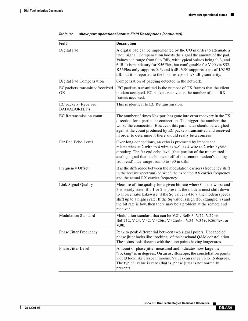
Table 92 show port operational-status Field Descriptions
Field Description
Slot/SPE/Port Displays the slot and port designation for the SPE card location.
Service type Indicates the type of service; data, fax, or voice.
Disconnect Reason Info The reason for disconnect is displayed.
Modulation Standard Modulation standard can be V.21, Bell103, V.22, V.22bis, Bell 212, V.23, V.32, V.32bis, V.32terbo, V.34, V.34+, or K56Flex 1.1.
Connect Protocol Connect protocol for the current session, which can be SYNC mode, ARA1.0, ARA2.0, LAP-M, MNP, FAX mode, SS7/COT, or V.110.
Compression Compression protocol used for the current connection, which can be None, V.42bis TX, V.42bis RX, V.42bis both, or MNP5 data compression.
Count. Characters transmitted/received
Count of total characters received and transmitted for SYNC/ASYNC connections.
Dial Technologies Commandsshow port operational-status
DR-859Cisco IOS Dial Technologies Command Reference
78-12091-02
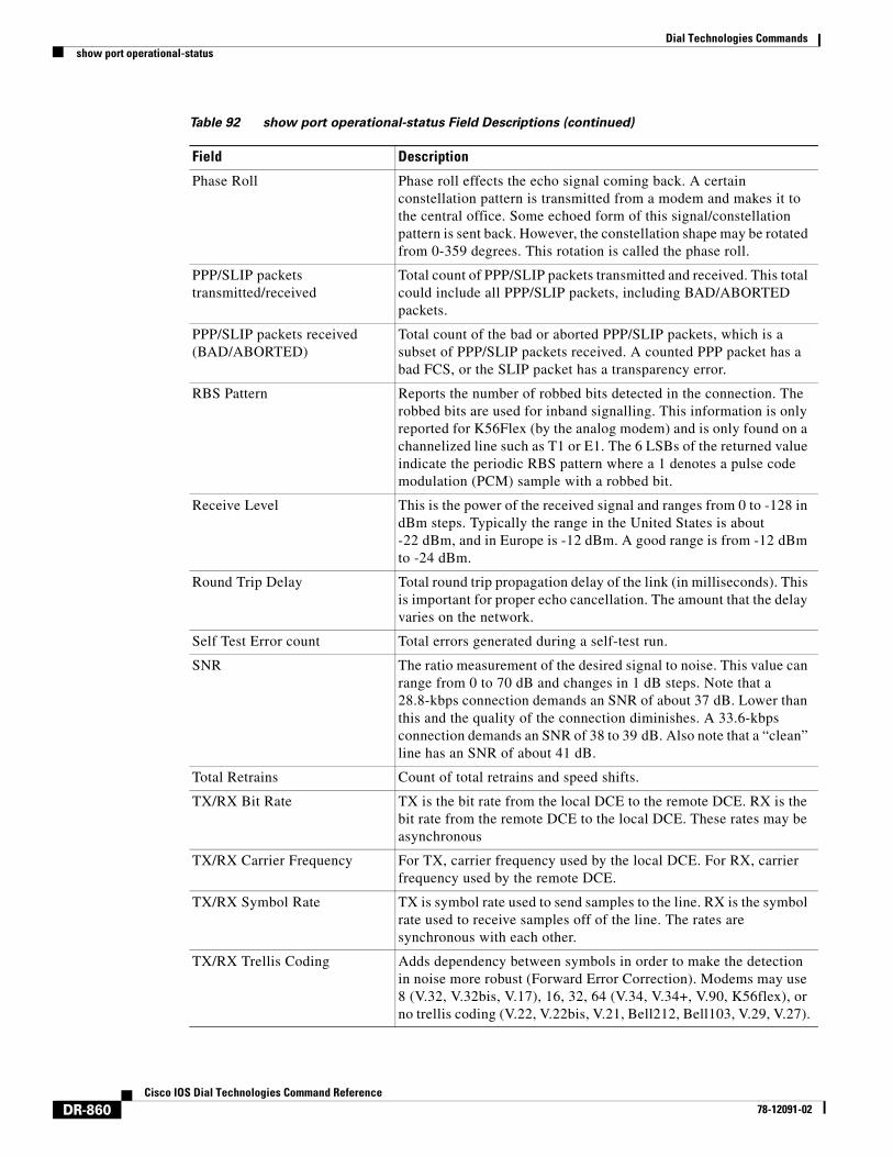
Digital Pad A digital pad can be implemented by the CO in order to attenuate a “hot” signal. Compensation boosts the signal the amount of the pad. Values can range from 0 to 7dB, with typical values being 0, 3, and 6dB. It is mandatory for K56Flex, but configurable for V.90 via S52. K56Flex only supports 0, 3, and 6 dB. V.90 supports steps of 1/8192 dB, but it is reported to the host insteps of 1/8 dB granularity.
Digital Pad Compensation Compensation of padding detected in the network.
EC packets transmitted/received OK
EC packets transmitted is the number of TX frames that the client modem accepted. EC packets received is the number of data RX frames accepted.
EC packets (Received BAD/ABORTED)
This is identical to EC Retransmission.
EC Retransmission count The number of times Nextport has gone into error recovery in the TX direction for a particular connection. The bigger the number, the worse the connection. However, this parameter should be weighed against the count produced by EC packets transmitted and received in order to determine if there should really be a concern.
Far End Echo Level Over long connections, an echo is produced by impedance mismatches at 2 wire to 4 wire as well as 4 wire to 2 wire hybrid circuitry. The far end echo level (that portion of the transmitted analog signal that has bounced off of the remote modem's analog front end) may range from 0 to -90 in dBm.
Frequency Offset It is the difference between the modulation carriers (frequency shift in the receive spectrum) between the expected RX carrier frequency and the actual RX carrier frequency.
Link Signal Quality Measure of line quality for a given bit rate where 0 is the worst and 3 is steady state. If a 1 or 2 is present, the modem must shift down to a lower rate. Likewise, if the Sq value is 4 to 7, the modem speeds shift up to a higher rate. If the Sq value is high (for example, 7) and the bit rate is low, then there may be a problem at the remote end receiver.
Modulation Standard Modulation standard that can be V.21, Bell03, V.22, V.22bis, Bell212, V.23, V.32, V.32bis, V.32terbo, V.34, V.34+, K56Flex, or V.90.
Phase Jitter Frequency Peak to peak differential between two signal points. Uncanceled phase jitter looks like “rocking” of the baseband QAM constellation. The points look like arcs with the outer points having longer arcs.
Phase Jitter Level Amount of phase jitter measured and indicates how large the “rocking” is in degrees. On an oscilloscope, the constellation points would look like crescent moons. Values can range up to 15 degrees. The typical value is zero (that is, phase jitter is not normally present).
Table 92 show port operational-status Field Descriptions (continued)
Field Description
Dial Technologies Commandsshow port operational-status
DR-860Cisco IOS Dial Technologies Command Reference
78-12091-02
Phase Roll Phase roll effects the echo signal coming back. A certain constellation pattern is transmitted from a modem and makes it to the central office. Some echoed form of this signal/constellation pattern is sent back. However, the constellation shape may be rotated from 0-359 degrees. This rotation is called the phase roll.
PPP/SLIP packets transmitted/received
Total count of PPP/SLIP packets transmitted and received. This total could include all PPP/SLIP packets, including BAD/ABORTED packets.
PPP/SLIP packets received (BAD/ABORTED)
Total count of the bad or aborted PPP/SLIP packets, which is a subset of PPP/SLIP packets received. A counted PPP packet has a bad FCS, or the SLIP packet has a transparency error.
RBS Pattern Reports the number of robbed bits detected in the connection. The robbed bits are used for inband signalling. This information is only reported for K56Flex (by the analog modem) and is only found on a channelized line such as T1 or E1. The 6 LSBs of the returned value indicate the periodic RBS pattern where a 1 denotes a pulse code modulation (PCM) sample with a robbed bit.
Receive Level This is the power of the received signal and ranges from 0 to -128 in dBm steps. Typically the range in the United States is about -22 dBm, and in Europe is -12 dBm. A good range is from -12 dBm to -24 dBm.
Round Trip Delay Total round trip propagation delay of the link (in milliseconds). This is important for proper echo cancellation. The amount that the delay varies on the network.
Self Test Error count Total errors generated during a self-test run.
SNR The ratio measurement of the desired signal to noise. This value can range from 0 to 70 dB and changes in 1 dB steps. Note that a 28.8-kbps connection demands an SNR of about 37 dB. Lower than this and the quality of the connection diminishes. A 33.6-kbps connection demands an SNR of 38 to 39 dB. Also note that a “clean” line has an SNR of about 41 dB.
Total Retrains Count of total retrains and speed shifts.
TX/RX Bit Rate TX is the bit rate from the local DCE to the remote DCE. RX is the bit rate from the remote DCE to the local DCE. These rates may be asynchronous
TX/RX Carrier Frequency For TX, carrier frequency used by the local DCE. For RX, carrier frequency used by the remote DCE.
TX/RX Symbol Rate TX is symbol rate used to send samples to the line. RX is the symbol rate used to receive samples off of the line. The rates are synchronous with each other.
TX/RX Trellis Coding Adds dependency between symbols in order to make the detection in noise more robust (Forward Error Correction). Modems may use 8 (V.32, V.32bis, V.17), 16, 32, 64 (V.34, V.34+, V.90, K56flex), or no trellis coding (V.22, V.22bis, V.21, Bell212, Bell103, V.29, V.27).
Table 92 show port operational-status Field Descriptions (continued)
Field Description
Dial Technologies Commandsshow port operational-status
DR-861Cisco IOS Dial Technologies Command Reference
78-12091-02
Related Commands
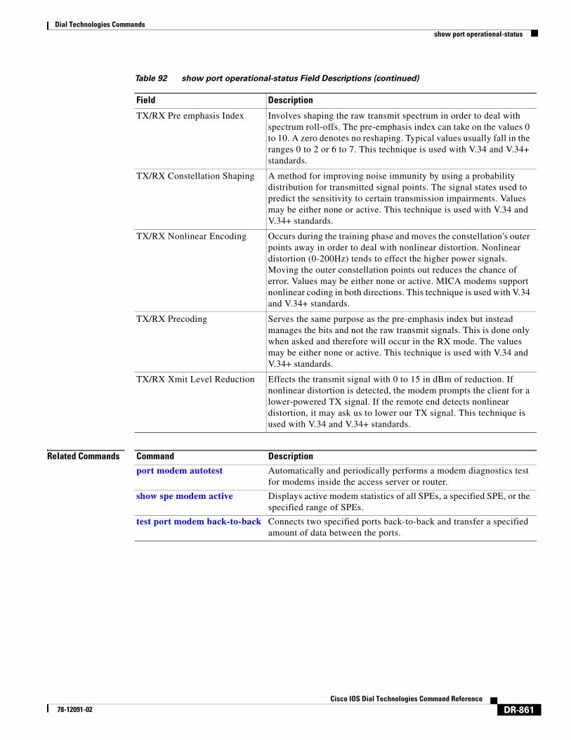
TX/RX Pre emphasis Index Involves shaping the raw transmit spectrum in order to deal with spectrum roll-offs. The pre-emphasis index can take on the values 0 to 10. A zero denotes no reshaping. Typical values usually fall in the ranges 0 to 2 or 6 to 7. This technique is used with V.34 and V.34+ standards.
TX/RX Constellation Shaping A method for improving noise immunity by using a probability distribution for transmitted signal points. The signal states used to predict the sensitivity to certain transmission impairments. Values may be either none or active. This technique is used with V.34 and V.34+ standards.
TX/RX Nonlinear Encoding Occurs during the training phase and moves the constellation's outer points away in order to deal with nonlinear distortion. Nonlinear distortion (0-200Hz) tends to effect the higher power signals. Moving the outer constellation points out reduces the chance of error. Values may be either none or active. MICA modems support nonlinear coding in both directions. This technique is used with V.34 and V.34+ standards.
TX/RX Precoding Serves the same purpose as the pre-emphasis index but instead manages the bits and not the raw transmit signals. This is done only when asked and therefore will occur in the RX mode. The values may be either none or active. This technique is used with V.34 and V.34+ standards.
TX/RX Xmit Level Reduction Effects the transmit signal with 0 to 15 in dBm of reduction. If nonlinear distortion is detected, the modem prompts the client for a lower-powered TX signal. If the remote end detects nonlinear distortion, it may ask us to lower our TX signal. This technique is used with V.34 and V.34+ standards.
Table 92 show port operational-status Field Descriptions (continued)
Field Description
Command Description
port modem autotest Automatically and periodically performs a modem diagnostics test for modems inside the access server or router.
show spe modem active Displays active modem statistics of all SPEs, a specified SPE, or the specified range of SPEs.
test port modem back-to-back Connects two specified ports back-to-back and transfer a specified amount of data between the ports.
Dial Technologies Commandsshow ppp bap
DR-862Cisco IOS Dial Technologies Command Reference
78-12091-02
show ppp bapTo display the configuration settings and run-time status for a multilink bundle, use the show ppp bap command in privileged EXEC mode.
show ppp bap {group [name] | queues}
Syntax Description
Command Modes Privileged EXEC
Command History
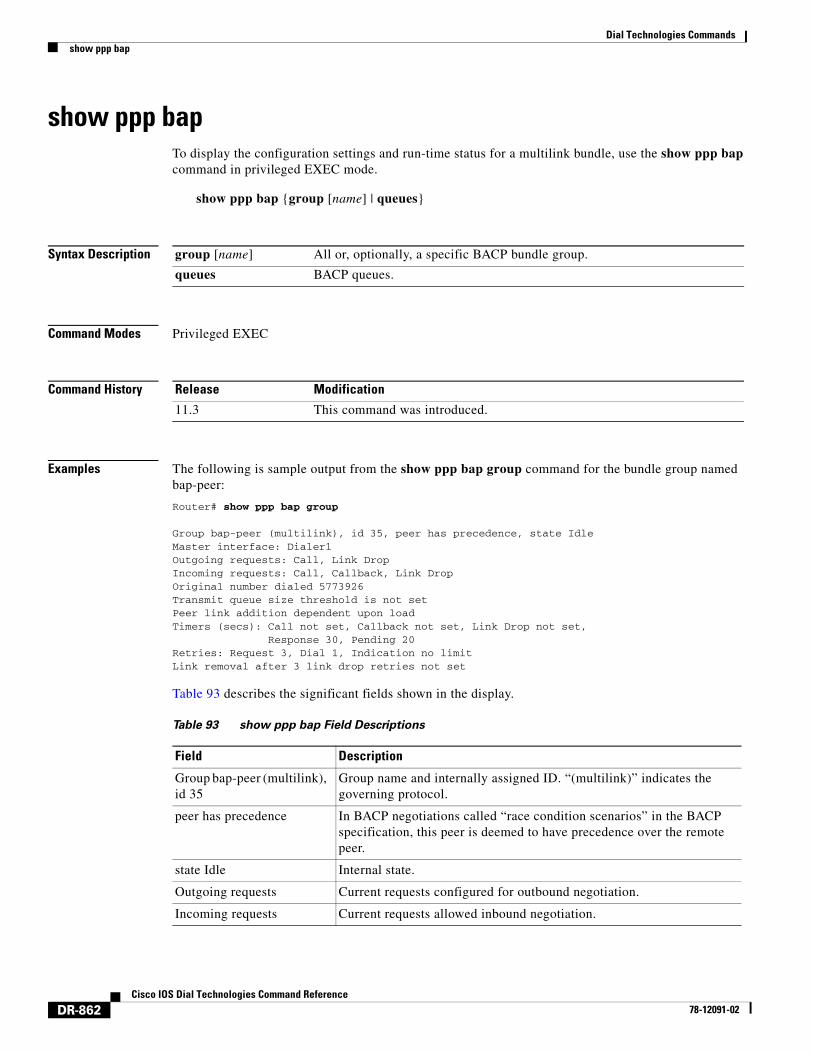
Examples The following is sample output from the show ppp bap group command for the bundle group named bap-peer:
Router# show ppp bap group
Group bap-peer (multilink), id 35, peer has precedence, state IdleMaster interface: Dialer1Outgoing requests: Call, Link DropIncoming requests: Call, Callback, Link DropOriginal number dialed 5773926Transmit queue size threshold is not setPeer link addition dependent upon loadTimers (secs): Call not set, Callback not set, Link Drop not set, Response 30, Pending 20Retries: Request 3, Dial 1, Indication no limitLink removal after 3 link drop retries not set
Table 93 describes the significant fields shown in the display.
group [name] All or, optionally, a specific BACP bundle group.
queues BACP queues.
Release Modification
11.3 This command was introduced.
Table 93 show ppp bap Field Descriptions
Field Description
Group bap-peer (multilink), id 35
Group name and internally assigned ID. “(multilink)” indicates the governing protocol.
peer has precedence In BACP negotiations called “race condition scenarios” in the BACP specification, this peer is deemed to have precedence over the remote peer.
state Idle Internal state.
Outgoing requests Current requests configured for outbound negotiation.
Incoming requests Current requests allowed inbound negotiation.
Dial Technologies Commandsshow ppp bap
DR-863Cisco IOS Dial Technologies Command Reference
78-12091-02
Related Commands
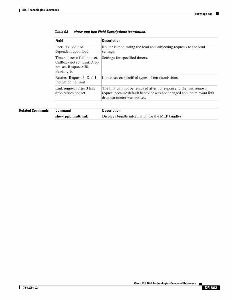
Peer link addition dependent upon load
Router is monitoring the load and subjecting requests to the load settings.
Timers (secs): Call not set, Callback not set, Link Drop not set, Response 30, Pending 20
Settings for specified timers.
Retries: Request 3, Dial 1, Indication no limit
Limits set on specified types of retransmissions.
Link removal after 3 link drop retries not set
The link will not be removed after no response to the link removal request because default behavior was not changed and the relevant link drop parameter was not set.
Table 93 show ppp bap Field Descriptions (continued)
Field Description
Command Description
show ppp multilink Displays bundle information for the MLP bundles.
Dial Technologies Commandsshow ppp mppe
DR-864Cisco IOS Dial Technologies Command Reference
78-12091-02
show ppp mppeTo display Microsoft Point-to-Point Encryption (MPPE) information for an interface, use the show ppp mppe command in privileged EXEC mode.
show ppp mppe {serial | virtual-access} [number]
Syntax Description
Command Modes Privileged EXEC
Command History
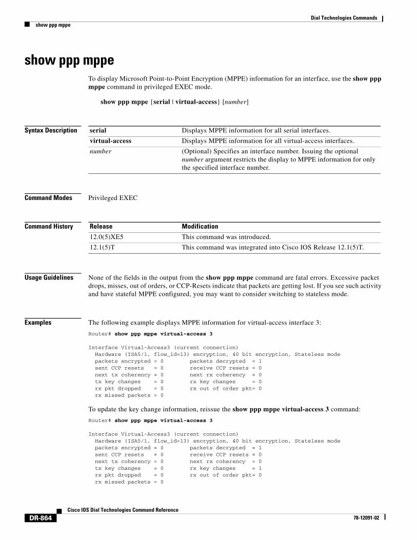
Usage Guidelines None of the fields in the output from the show ppp mppe command are fatal errors. Excessive packet drops, misses, out of orders, or CCP-Resets indicate that packets are getting lost. If you see such activity and have stateful MPPE configured, you may want to consider switching to stateless mode.
Examples The following example displays MPPE information for virtual-access interface 3:
Router# show ppp mppe virtual-access 3
Interface Virtual-Access3 (current connection) Hardware (ISA5/1, flow_id=13) encryption, 40 bit encryption, Stateless mode packets encrypted = 0 packets decrypted = 1 sent CCP resets = 0 receive CCP resets = 0 next tx coherency = 0 next rx coherency = 0 tx key changes = 0 rx key changes = 0 rx pkt dropped = 0 rx out of order pkt= 0 rx missed packets = 0
To update the key change information, reissue the show ppp mppe virtual-access 3 command:
Router# show ppp mppe virtual-access 3
Interface Virtual-Access3 (current connection) Hardware (ISA5/1, flow_id=13) encryption, 40 bit encryption, Stateless mode packets encrypted = 0 packets decrypted = 1 sent CCP resets = 0 receive CCP resets = 0 next tx coherency = 0 next rx coherency = 0 tx key changes = 0 rx key changes = 1 rx pkt dropped = 0 rx out of order pkt= 0 rx missed packets = 0
serial Displays MPPE information for all serial interfaces.
virtual-access Displays MPPE information for all virtual-access interfaces.
number (Optional) Specifies an interface number. Issuing the optional number argument restricts the display to MPPE information for only the specified interface number.
Release Modification
12.0(5)XE5 This command was introduced.
12.1(5)T This command was integrated into Cisco IOS Release 12.1(5)T.
Dial Technologies Commandsshow ppp mppe
DR-865Cisco IOS Dial Technologies Command Reference
78-12091-02
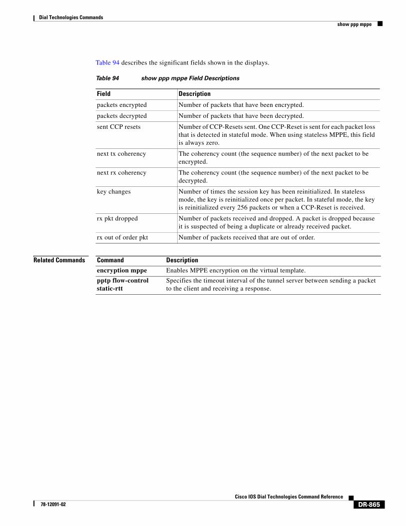
Table 94 describes the significant fields shown in the displays.
Related Commands
Table 94 show ppp mppe Field Descriptions
Field Description
packets encrypted Number of packets that have been encrypted.
packets decrypted Number of packets that have been decrypted.
sent CCP resets Number of CCP-Resets sent. One CCP-Reset is sent for each packet loss that is detected in stateful mode. When using stateless MPPE, this field is always zero.
next tx coherency The coherency count (the sequence number) of the next packet to be encrypted.
next rx coherency The coherency count (the sequence number) of the next packet to be decrypted.
key changes Number of times the session key has been reinitialized. In stateless mode, the key is reinitialized once per packet. In stateful mode, the key is reinitialized every 256 packets or when a CCP-Reset is received.
rx pkt dropped Number of packets received and dropped. A packet is dropped because it is suspected of being a duplicate or already received packet.
rx out of order pkt Number of packets received that are out of order.
Command Description
encryption mppe Enables MPPE encryption on the virtual template.
pptp flow-control static-rtt
Specifies the timeout interval of the tunnel server between sending a packet to the client and receiving a response.
Dial Technologies Commandsshow ppp multilink
DR-866Cisco IOS Dial Technologies Command Reference
78-12091-02
show ppp multilinkTo display bundle information for the Multilink PPP bundles, use the show ppp multilink command in EXEC mode.
show ppp multilink
Syntax Description This command has no arguments or keywords.
Command Modes EXEC
Command History
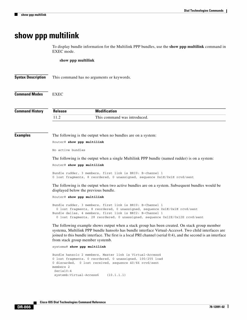
Examples The following is the output when no bundles are on a system:
Router# show ppp multilink
No active bundles
The following is the output when a single Multilink PPP bundle (named rudder) is on a system:
Router# show ppp multilink
Bundle rudder, 3 members, first link is BRI0: B-channel 10 lost fragments, 8 reordered, 0 unassigned, sequence 0x1E/0x1E rcvd/sent
The following is the output when two active bundles are on a system. Subsequent bundles would be displayed below the previous bundle.
Router# show ppp multilink
Bundle rudder, 3 members, first link is BRI0: B-Channel 1 0 lost fragments, 8 reordered, 0 unassigned, sequence 0x1E/0x1E rcvd/sentBundle dallas, 4 members, first link is BRI2: B-Channel 1 0 lost fragments, 28 reordered, 0 unassigned, sequence 0x12E/0x12E rcvd/sent
The following example shows output when a stack group has been created. On stack group member systema, Multilink PPP bundle hansolo has bundle interface Virtual-Access4. Two child interfaces are joined to this bundle interface. The first is a local PRI channel (serial 0:4), and the second is an interface from stack group member systemb.
systema# show ppp multilink
Bundle hansolo 2 members, Master link is Virtual-Access40 lost fragments, 0 reordered, 0 unassigned, 100/255 load0 discarded, 0 lost received, sequence 40/66 rcvd/sentmembers 2 Serial0:4 systemb:Virtual-Access6 (10.1.1.1)
Release Modification
11.2 This command was introduced.
Dial Technologies Commandsshow ppp multilink
DR-867Cisco IOS Dial Technologies Command Reference
78-12091-02
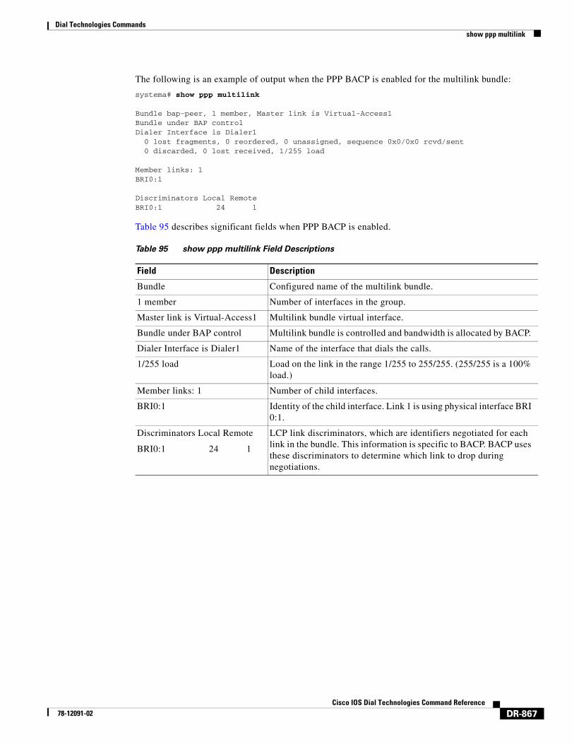
The following is an example of output when the PPP BACP is enabled for the multilink bundle:
systema# show ppp multilink
Bundle bap-peer, 1 member, Master link is Virtual-Access1Bundle under BAP controlDialer Interface is Dialer1 0 lost fragments, 0 reordered, 0 unassigned, sequence 0x0/0x0 rcvd/sent 0 discarded, 0 lost received, 1/255 load Member links: 1BRI0:1 Discriminators Local RemoteBRI0:1 24 1
Table 95 describes significant fields when PPP BACP is enabled.
Table 95 show ppp multilink Field Descriptions
Field Description
Bundle Configured name of the multilink bundle.
1 member Number of interfaces in the group.
Master link is Virtual-Access1 Multilink bundle virtual interface.
Bundle under BAP control Multilink bundle is controlled and bandwidth is allocated by BACP.
Dialer Interface is Dialer1 Name of the interface that dials the calls.
1/255 load Load on the link in the range 1/255 to 255/255. (255/255 is a 100% load.)
Member links: 1 Number of child interfaces.
BRI0:1 Identity of the child interface. Link 1 is using physical interface BRI 0:1.
Discriminators Local Remote
BRI0:1 24 1
LCP link discriminators, which are identifiers negotiated for each link in the bundle. This information is specific to BACP. BACP uses these discriminators to determine which link to drop during negotiations.
Dial Technologies Commandsshow queuing virtual-access
DR-868Cisco IOS Dial Technologies Command Reference
78-12091-02
show queuing virtual-accessTo display information about interleaving, use the show queuing virtual-access command in EXEC mode.
show queuing virtual-access number
Syntax Description
Command Modes EXEC
Command History
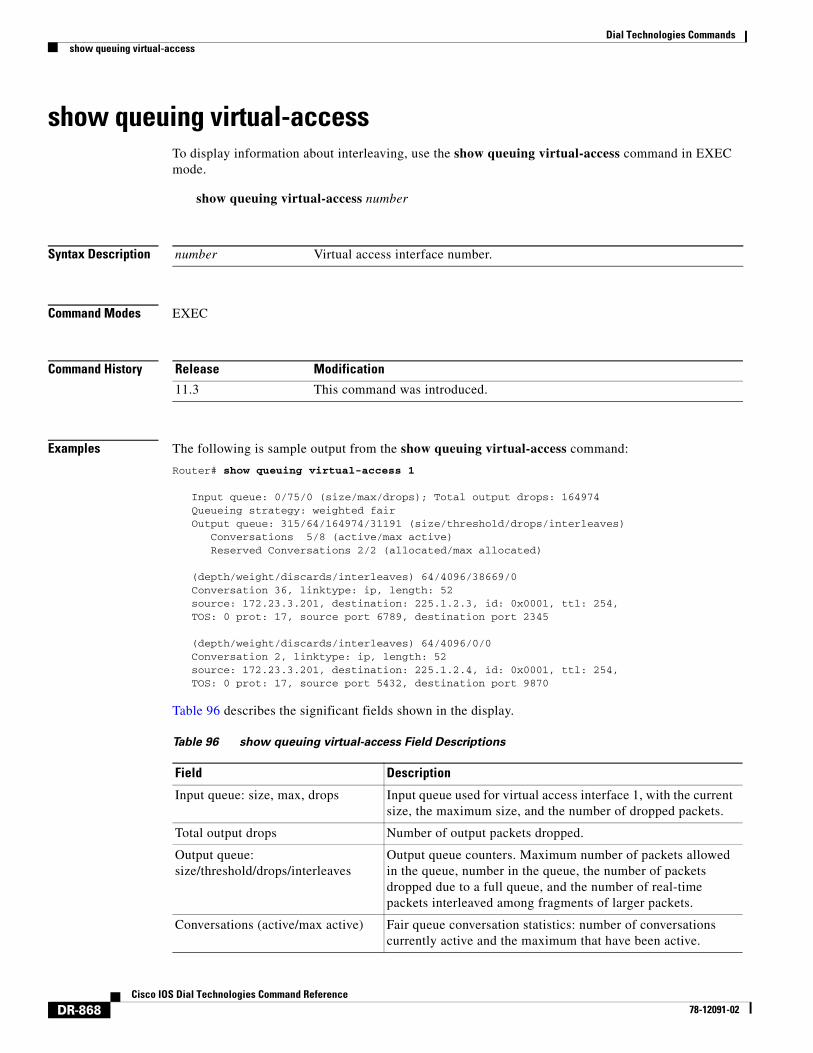
Examples The following is sample output from the show queuing virtual-access command:
Router# show queuing virtual-access 1
Input queue: 0/75/0 (size/max/drops); Total output drops: 164974 Queueing strategy: weighted fair Output queue: 315/64/164974/31191 (size/threshold/drops/interleaves) Conversations 5/8 (active/max active) Reserved Conversations 2/2 (allocated/max allocated) (depth/weight/discards/interleaves) 64/4096/38669/0 Conversation 36, linktype: ip, length: 52 source: 172.23.3.201, destination: 225.1.2.3, id: 0x0001, ttl: 254, TOS: 0 prot: 17, source port 6789, destination port 2345 (depth/weight/discards/interleaves) 64/4096/0/0 Conversation 2, linktype: ip, length: 52 source: 172.23.3.201, destination: 225.1.2.4, id: 0x0001, ttl: 254, TOS: 0 prot: 17, source port 5432, destination port 9870
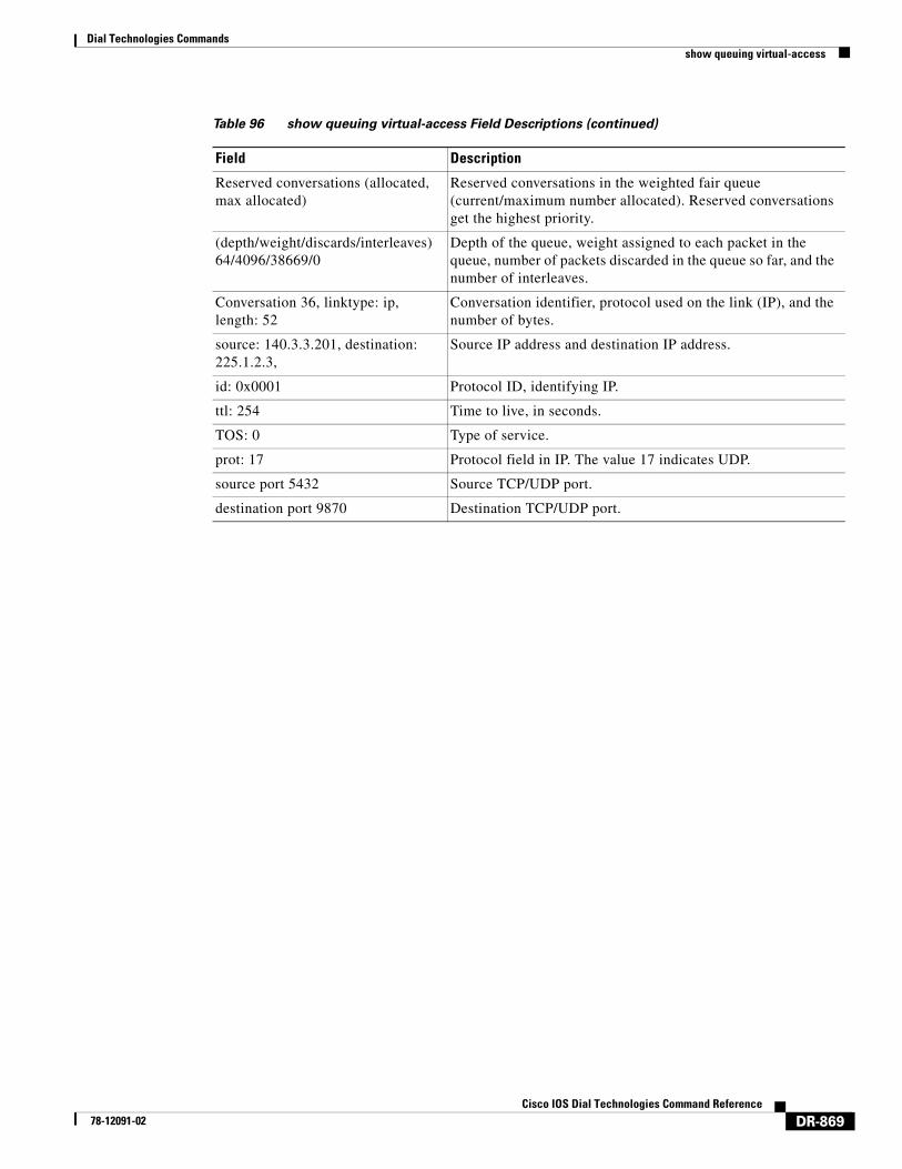
Table 96 describes the significant fields shown in the display.
number Virtual access interface number.
Release Modification
11.3 This command was introduced.
Table 96 show queuing virtual-access Field Descriptions
Field Description
Input queue: size, max, drops Input queue used for virtual access interface 1, with the current size, the maximum size, and the number of dropped packets.
Total output drops Number of output packets dropped.
Output queue: size/threshold/drops/interleaves
Output queue counters. Maximum number of packets allowed in the queue, number in the queue, the number of packets dropped due to a full queue, and the number of real-time packets interleaved among fragments of larger packets.
Conversations (active/max active) Fair queue conversation statistics: number of conversations currently active and the maximum that have been active.
Dial Technologies Commandsshow queuing virtual-access
DR-869Cisco IOS Dial Technologies Command Reference
78-12091-02
Reserved conversations (allocated, max allocated)
Reserved conversations in the weighted fair queue (current/maximum number allocated). Reserved conversations get the highest priority.
(depth/weight/discards/interleaves) 64/4096/38669/0
Depth of the queue, weight assigned to each packet in the queue, number of packets discarded in the queue so far, and the number of interleaves.
Conversation 36, linktype: ip, length: 52
Conversation identifier, protocol used on the link (IP), and the number of bytes.
source: 140.3.3.201, destination: 225.1.2.3,
Source IP address and destination IP address.
id: 0x0001 Protocol ID, identifying IP.
ttl: 254 Time to live, in seconds.
TOS: 0 Type of service.
prot: 17 Protocol field in IP. The value 17 indicates UDP.
source port 5432 Source TCP/UDP port.
destination port 9870 Destination TCP/UDP port.
Table 96 show queuing virtual-access Field Descriptions (continued)
Field Description
Dial Technologies Commandsshow rcapi status
DR-870Cisco IOS Dial Technologies Command Reference
78-12091-02
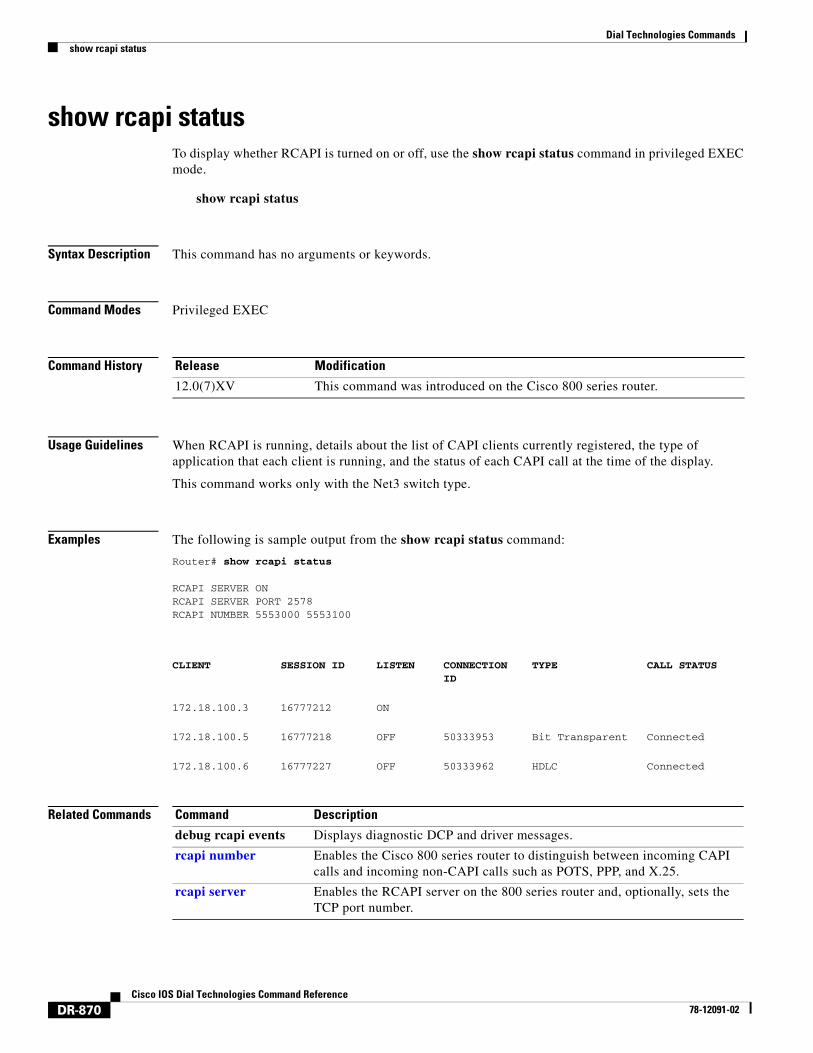
show rcapi statusTo display whether RCAPI is turned on or off, use the show rcapi status command in privileged EXEC mode.
show rcapi status
Syntax Description This command has no arguments or keywords.
Command Modes Privileged EXEC
Command History
Usage Guidelines When RCAPI is running, details about the list of CAPI clients currently registered, the type of application that each client is running, and the status of each CAPI call at the time of the display.
This command works only with the Net3 switch type.
Examples The following is sample output from the show rcapi status command:
Router# show rcapi status
RCAPI SERVER ONRCAPI SERVER PORT 2578RCAPI NUMBER 5553000 5553100
Related Commands
Release Modification
12.0(7)XV This command was introduced on the Cisco 800 series router.
CLIENT SESSION ID LISTEN CONNECTION ID
TYPE CALL STATUS
172.18.100.3 16777212 ON
172.18.100.5 16777218 OFF 50333953 Bit Transparent Connected
172.18.100.6 16777227 OFF 50333962 HDLC Connected
Command Description
debug rcapi events Displays diagnostic DCP and driver messages.
rcapi number Enables the Cisco 800 series router to distinguish between incoming CAPI calls and incoming non-CAPI calls such as POTS, PPP, and X.25.
rcapi server Enables the RCAPI server on the 800 series router and, optionally, sets the TCP port number.
Dial Technologies Commandsshow redundancy
DR-871Cisco IOS Dial Technologies Command Reference
78-12091-02
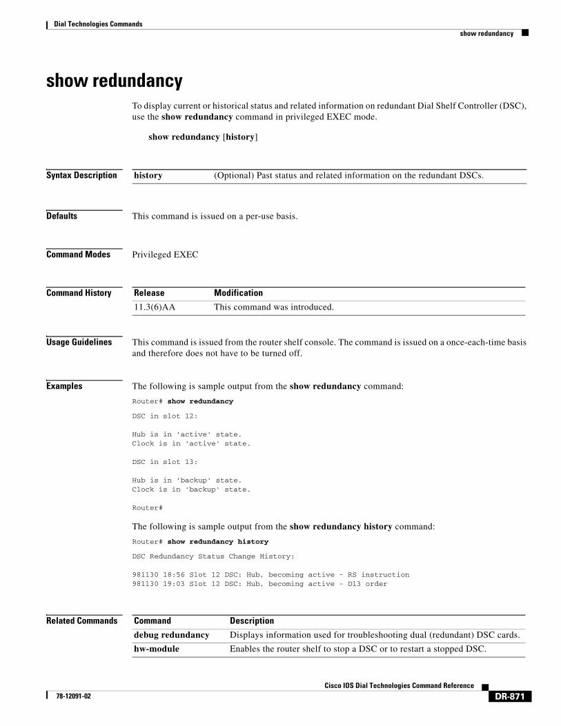
show redundancyTo display current or historical status and related information on redundant Dial Shelf Controller (DSC), use the show redundancy command in privileged EXEC mode.
show redundancy [history]
Syntax Description
Defaults This command is issued on a per-use basis.
Command Modes Privileged EXEC
Command History
Usage Guidelines This command is issued from the router shelf console. The command is issued on a once-each-time basis and therefore does not have to be turned off.
Examples The following is sample output from the show redundancy command:
Router# show redundancy
DSC in slot 12: Hub is in 'active' state.Clock is in 'active' state. DSC in slot 13: Hub is in 'backup' state.Clock is in 'backup' state. Router#
The following is sample output from the show redundancy history command:
Router# show redundancy history
DSC Redundancy Status Change History: 981130 18:56 Slot 12 DSC: Hub, becoming active - RS instruction981130 19:03 Slot 12 DSC: Hub, becoming active - D13 order
Related Commands
history (Optional) Past status and related information on the redundant DSCs.
Release Modification
11.3(6)AA This command was introduced.
Command Description
debug redundancy Displays information used for troubleshooting dual (redundant) DSC cards.
hw-module Enables the router shelf to stop a DSC or to restart a stopped DSC.
Dial Technologies Commandsshow resource-pool call
DR-872Cisco IOS Dial Technologies Command Reference
78-12091-02
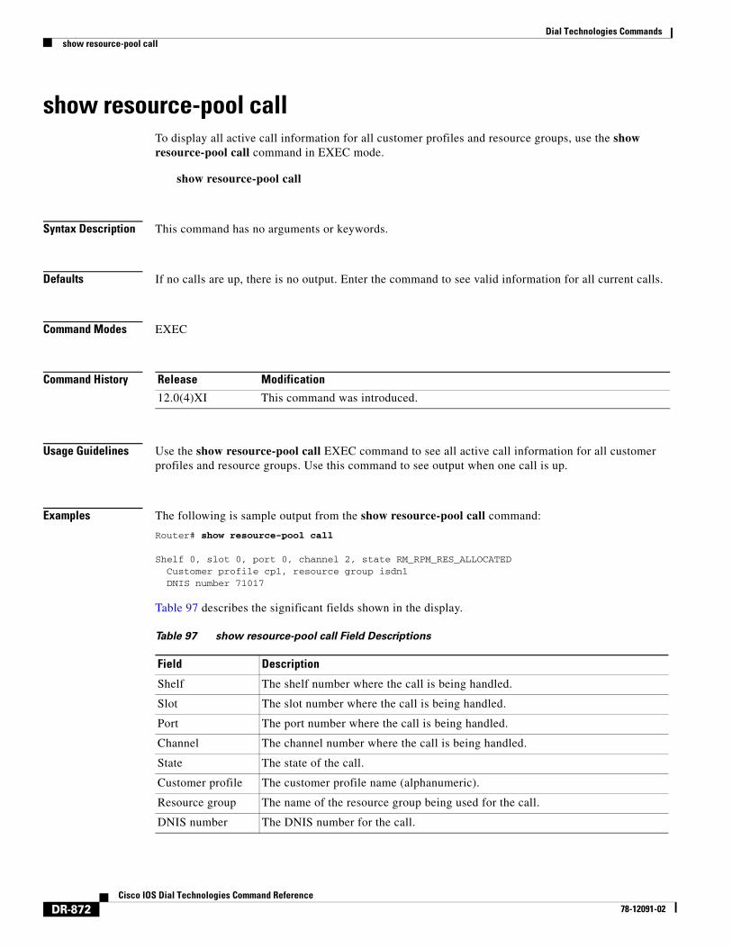
show resource-pool callTo display all active call information for all customer profiles and resource groups, use the show resource-pool call command in EXEC mode.
show resource-pool call
Syntax Description This command has no arguments or keywords.
Defaults If no calls are up, there is no output. Enter the command to see valid information for all current calls.
Command Modes EXEC
Command History
Usage Guidelines Use the show resource-pool call EXEC command to see all active call information for all customer profiles and resource groups. Use this command to see output when one call is up.
Examples The following is sample output from the show resource-pool call command:
Router# show resource-pool call
Shelf 0, slot 0, port 0, channel 2, state RM_RPM_RES_ALLOCATED Customer profile cp1, resource group isdn1 DNIS number 71017
Table 97 describes the significant fields shown in the display.
Release Modification
12.0(4)XI This command was introduced.
Table 97 show resource-pool call Field Descriptions
Field Description
Shelf The shelf number where the call is being handled.
Slot The slot number where the call is being handled.
Port The port number where the call is being handled.
Channel The channel number where the call is being handled.
State The state of the call.
Customer profile The customer profile name (alphanumeric).
Resource group The name of the resource group being used for the call.
DNIS number The DNIS number for the call.
Dial Technologies Commandsshow resource-pool customer
DR-873Cisco IOS Dial Technologies Command Reference
78-12091-02
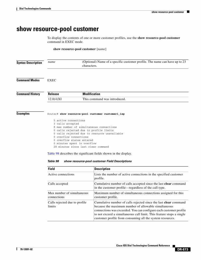
show resource-pool customerTo display the contents of one or more customer profiles, use the show resource-pool customer command in EXEC mode.
show resource-pool customer [name]
Syntax Description
Command Modes EXEC
Command History
Examples Router# show resource-pool customer customer1_isp
5 active connections 3 calls accepted 8 max number of simultaneous connections 0 calls rejected due to profile limits 0 calls rejected due to resource unavailable 0 overflow connections 0 overflow states entered 0 minutes spent in overflow 28 minutes since last clear command
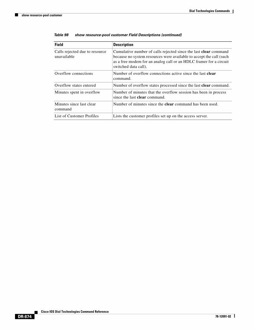
Table 98 describes the significant fields shown in the display.
name (Optional) Name of a specific customer profile. The name can have up to 23 characters.
Release Modification
12.0(4)XI This command was introduced.
Table 98 show resource-pool customer Field Descriptions
Field Description
Active connections Lists the number of active connections in the specified customer profile.
Calls accepted Cumulative number of calls accepted since the last clear command in the customer profile—regardless of the call type.
Max number of simultaneous connections
Maximum number of simultaneous connections assigned for this customer profile.
Calls rejected due to profile limits
Cumulative number of calls rejected since the last clear command because the maximum number of allowable simultaneous connections was exceeded. You can configure each customer profile to not exceed a simultaneous call limit. This feature stops a single customer profile from consuming all the system resources.
Dial Technologies Commandsshow resource-pool customer
DR-874Cisco IOS Dial Technologies Command Reference
78-12091-02
Calls rejected due to resource unavailable
Cumulative number of calls rejected since the last clear command because no system resources were available to accept the call (such as a free modem for an analog call or an HDLC framer for a circuit switched data call).
Overflow connections Number of overflow connections active since the last clear command.
Overflow states entered Number of overflow states processed since the last clear command.
Minutes spent in overflow Number of minutes that the overflow session has been in process since the last clear command.
Minutes since last clear command
Number of minutes since the clear command has been used.
List of Customer Profiles Lists the customer profiles set up on the access server.
Table 98 show resource-pool customer Field Descriptions (continued)
Field Description
Dial Technologies Commandsshow resource-pool discriminator
DR-875Cisco IOS Dial Technologies Command Reference
78-12091-02
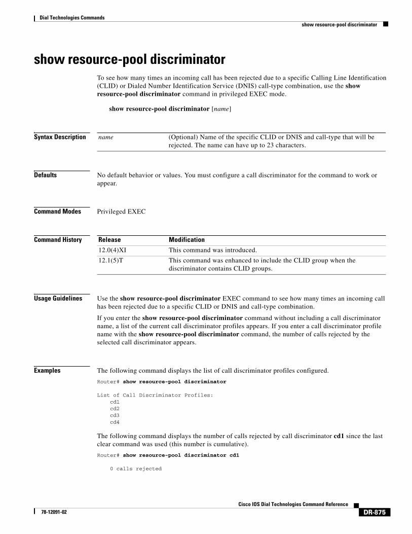
show resource-pool discriminatorTo see how many times an incoming call has been rejected due to a specific Calling Line Identification (CLID) or Dialed Number Identification Service (DNIS) call-type combination, use the show resource-pool discriminator command in privileged EXEC mode.
show resource-pool discriminator [name]
Syntax Description
Defaults No default behavior or values. You must configure a call discriminator for the command to work or appear.
Command Modes Privileged EXEC
Command History
Usage Guidelines Use the show resource-pool discriminator EXEC command to see how many times an incoming call has been rejected due to a specific CLID or DNIS and call-type combination.
If you enter the show resource-pool discriminator command without including a call discriminator name, a list of the current call discriminator profiles appears. If you enter a call discriminator profile name with the show resource-pool discriminator command, the number of calls rejected by the selected call discriminator appears.
Examples The following command displays the list of call discriminator profiles configured.
Router# show resource-pool discriminator
List of Call Discriminator Profiles: cd1 cd2 cd3 cd4
The following command displays the number of calls rejected by call discriminator cd1 since the last clear command was used (this number is cumulative).
Router# show resource-pool discriminator cd1
0 calls rejected
name (Optional) Name of the specific CLID or DNIS and call-type that will be rejected. The name can have up to 23 characters.
Release Modification
12.0(4)XI This command was introduced.
12.1(5)T This command was enhanced to include the CLID group when the discriminator contains CLID groups.
Dial Technologies Commandsshow resource-pool discriminator
DR-876Cisco IOS Dial Technologies Command Reference
78-12091-02
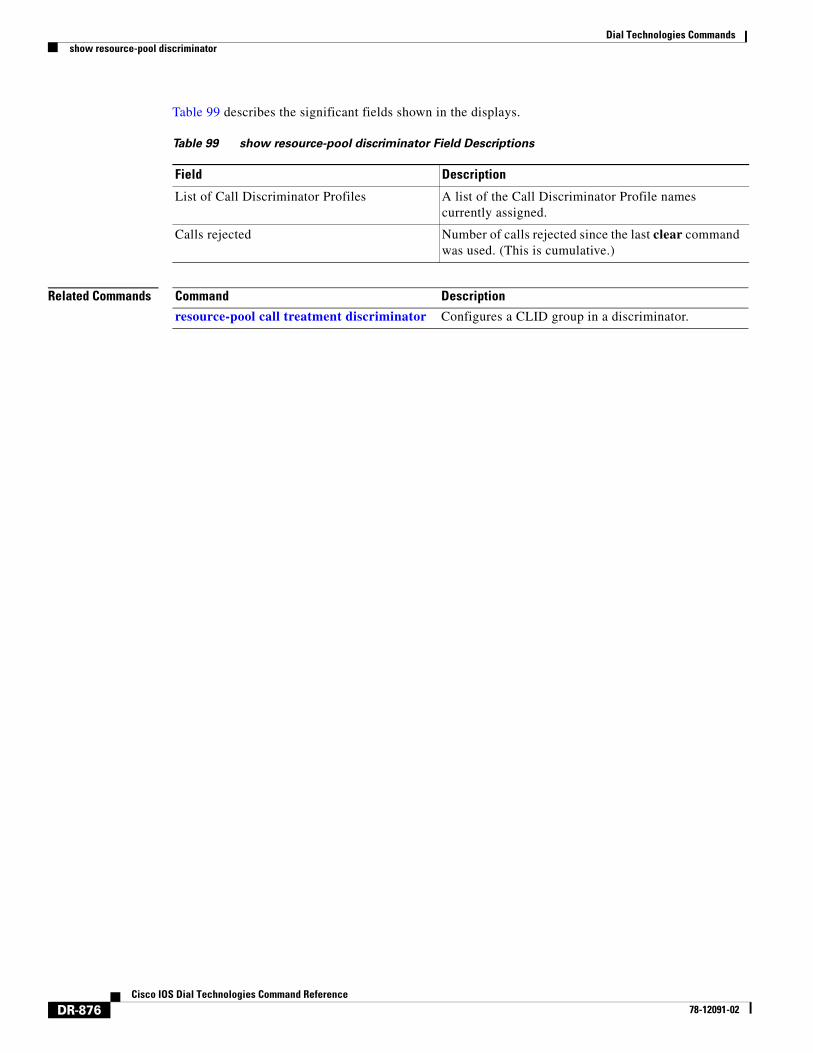
Table 99 describes the significant fields shown in the displays.
Related Commands
Table 99 show resource-pool discriminator Field Descriptions
Field Description
List of Call Discriminator Profiles A list of the Call Discriminator Profile names currently assigned.
Calls rejected Number of calls rejected since the last clear command was used. (This is cumulative.)
Command Description
resource-pool call treatment discriminator Configures a CLID group in a discriminator.
Dial Technologies Commandsshow resource-pool resource
DR-877Cisco IOS Dial Technologies Command Reference
78-12091-02
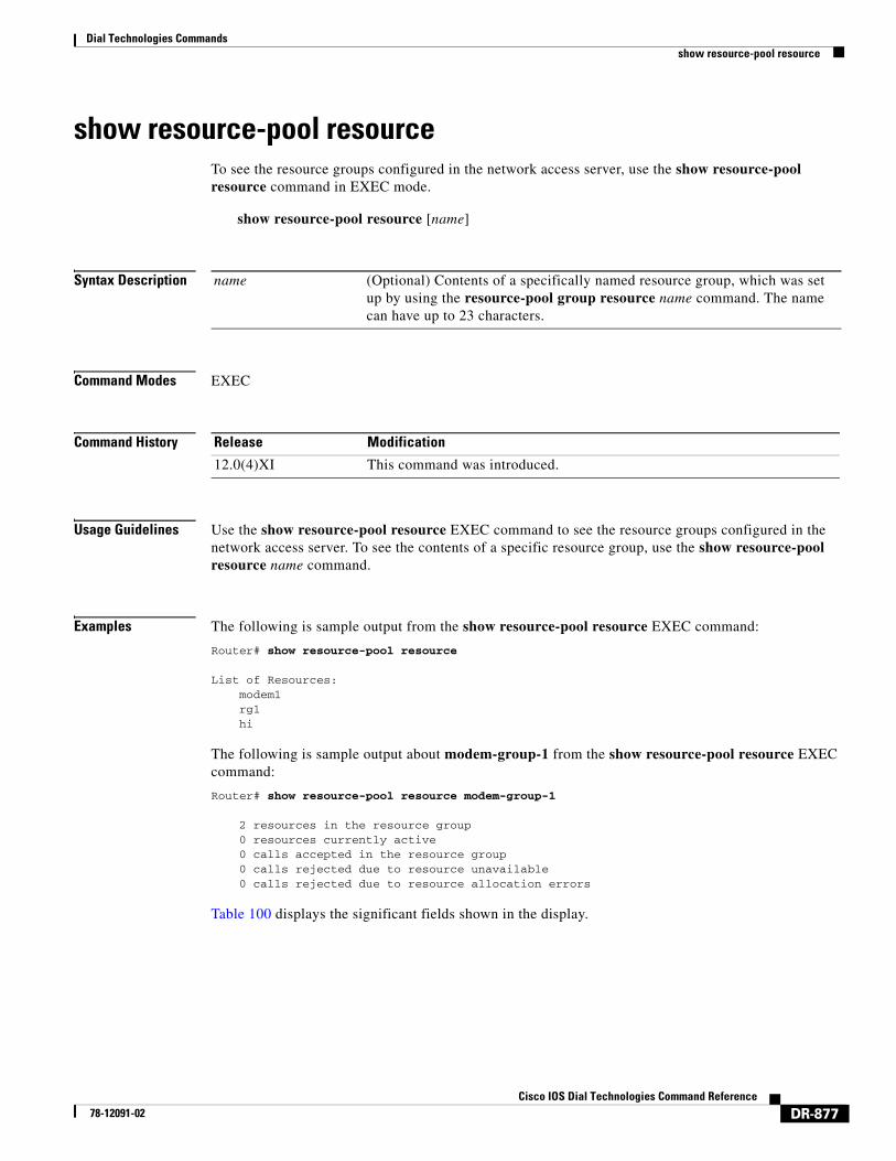
show resource-pool resourceTo see the resource groups configured in the network access server, use the show resource-pool resource command in EXEC mode.
show resource-pool resource [name]
Syntax Description
Command Modes EXEC
Command History
Usage Guidelines Use the show resource-pool resource EXEC command to see the resource groups configured in the network access server. To see the contents of a specific resource group, use the show resource-pool resource name command.
Examples The following is sample output from the show resource-pool resource EXEC command:
Router# show resource-pool resource
List of Resources: modem1 rg1 hi
The following is sample output about modem-group-1 from the show resource-pool resource EXEC command:
Router# show resource-pool resource modem-group-1
2 resources in the resource group 0 resources currently active 0 calls accepted in the resource group 0 calls rejected due to resource unavailable 0 calls rejected due to resource allocation errors
Table 100 displays the significant fields shown in the display.
name (Optional) Contents of a specifically named resource group, which was set up by using the resource-pool group resource name command. The name can have up to 23 characters.
Release Modification
12.0(4)XI This command was introduced.
Dial Technologies Commandsshow resource-pool resource
DR-878Cisco IOS Dial Technologies Command Reference
78-12091-02
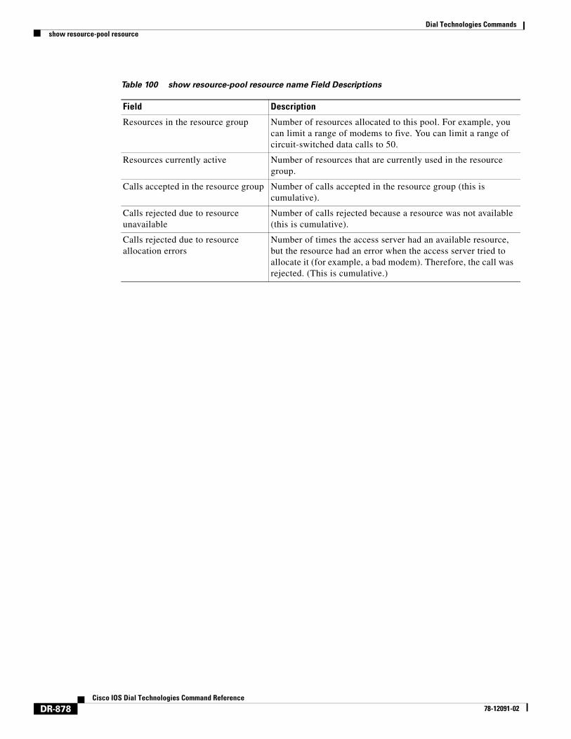
Table 100 show resource-pool resource name Field Descriptions
Field Description
Resources in the resource group Number of resources allocated to this pool. For example, you can limit a range of modems to five. You can limit a range of circuit-switched data calls to 50.
Resources currently active Number of resources that are currently used in the resource group.
Calls accepted in the resource group Number of calls accepted in the resource group (this is cumulative).
Calls rejected due to resource unavailable
Number of calls rejected because a resource was not available (this is cumulative).
Calls rejected due to resource allocation errors
Number of times the access server had an available resource, but the resource had an error when the access server tried to allocate it (for example, a bad modem). Therefore, the call was rejected. (This is cumulative.)
Dial Technologies Commandsshow resource-pool vpdn
DR-879Cisco IOS Dial Technologies Command Reference
78-12091-02
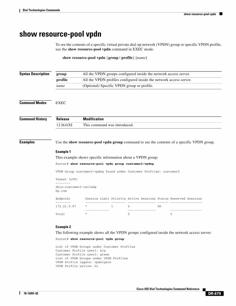
show resource-pool vpdnTo see the contents of a specific virtual private dial-up network (VPDN) group or specific VPDN profile, use the show resource-pool vpdn command in EXEC mode.
show resource-pool vpdn {group | profile} [name]
Syntax Description
Command Modes EXEC
Command History
Examples Use the show resource-pool vpdn group command to see the contents of a specific VPDN group.
Example 1
This example shows specific information about a VPDN group:
Router# show resource-pool vpdn group customer2-vpdng
VPDN Group customer2-vpdng found under Customer Profiles: customer2
Tunnel (LTP)-------- dnis:customer2-calledghp.com
Endpoint Session Limit Priority Active Sessions Status Reserved Sessions-------- ------------- -------- --------------- ------ -----------------172.21.9.97 * 1 0 OK ------------- --------------- -----------------Total * 0 0
Example 2
The following example shows all the VPDN groups configured inside the network access server:
Router# show resource-pool vpdn group
List of VPDN Groups under Customer ProfilesCustomer Profile user1: bigCustomer Profile user2: greenList of VPDN Groups under VPDN ProfilesVPDN Profile lggate: vpdnlgateVPDN Profile yellow: hi
group All the VPDN groups configured inside the network access server.
profile All the VPDN profiles configured inside the network access server.
name (Optional) Specific VPDN group or profile.
Release Modification
12.0(4)XI This command was introduced.
Dial Technologies Commandsshow resource-pool vpdn
DR-880Cisco IOS Dial Technologies Command Reference
78-12091-02
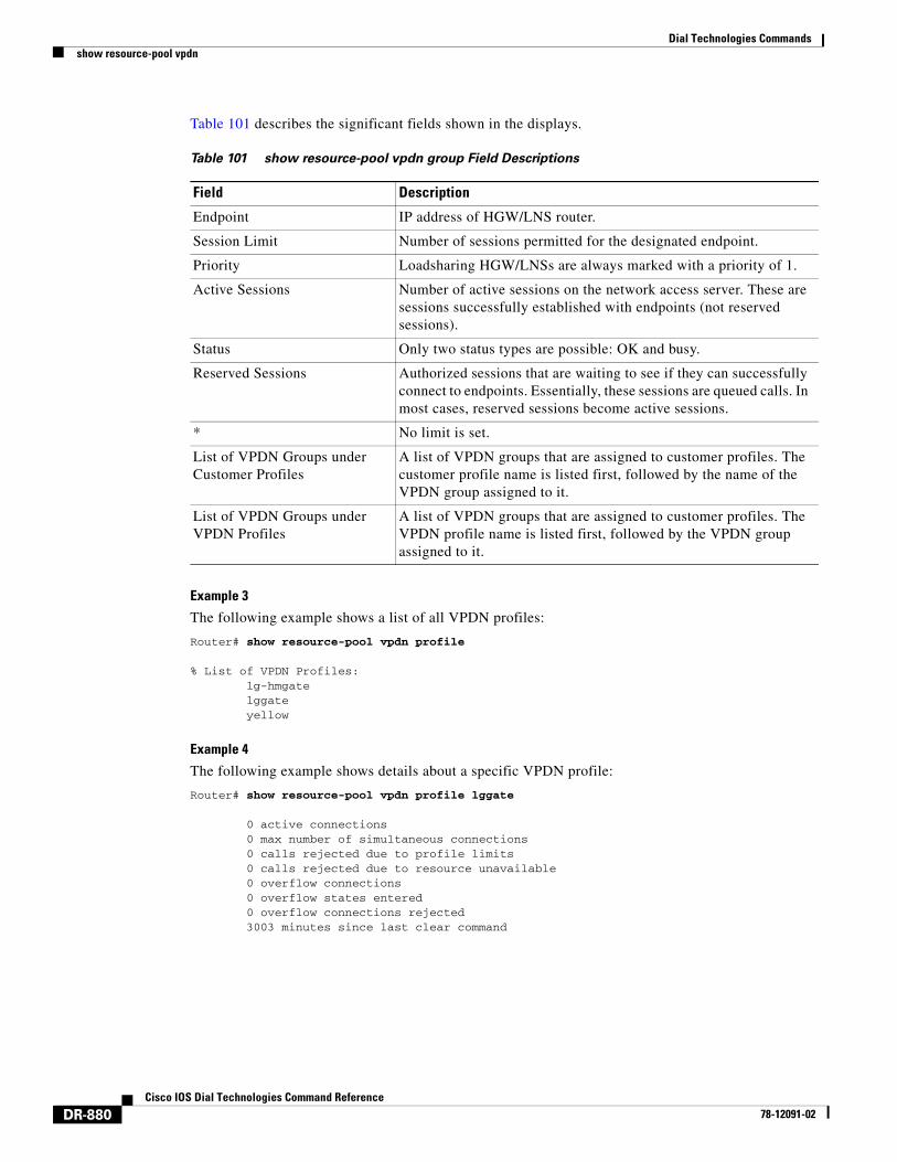
Table 101 describes the significant fields shown in the displays.
Example 3
The following example shows a list of all VPDN profiles:
Router# show resource-pool vpdn profile
% List of VPDN Profiles: lg-hmgate lggate yellow
Example 4
The following example shows details about a specific VPDN profile:
Router# show resource-pool vpdn profile lggate
0 active connections 0 max number of simultaneous connections 0 calls rejected due to profile limits 0 calls rejected due to resource unavailable 0 overflow connections 0 overflow states entered 0 overflow connections rejected 3003 minutes since last clear command
Table 101 show resource-pool vpdn group Field Descriptions
Field Description
Endpoint IP address of HGW/LNS router.
Session Limit Number of sessions permitted for the designated endpoint.
Priority Loadsharing HGW/LNSs are always marked with a priority of 1.
Active Sessions Number of active sessions on the network access server. These are sessions successfully established with endpoints (not reserved sessions).
Status Only two status types are possible: OK and busy.
Reserved Sessions Authorized sessions that are waiting to see if they can successfully connect to endpoints. Essentially, these sessions are queued calls. In most cases, reserved sessions become active sessions.
* No limit is set.
List of VPDN Groups under Customer Profiles
A list of VPDN groups that are assigned to customer profiles. The customer profile name is listed first, followed by the name of the VPDN group assigned to it.
List of VPDN Groups under VPDN Profiles
A list of VPDN groups that are assigned to customer profiles. The VPDN profile name is listed first, followed by the VPDN group assigned to it.
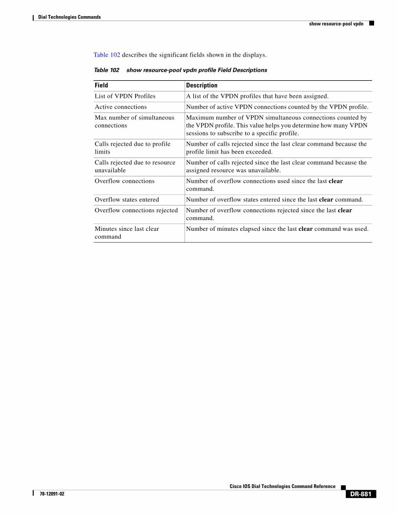
Dial Technologies Commandsshow resource-pool vpdn
DR-881Cisco IOS Dial Technologies Command Reference
78-12091-02
Table 102 describes the significant fields shown in the displays.
Table 102 show resource-pool vpdn profile Field Descriptions
Field Description
List of VPDN Profiles A list of the VPDN profiles that have been assigned.
Active connections Number of active VPDN connections counted by the VPDN profile.
Max number of simultaneous connections
Maximum number of VPDN simultaneous connections counted by the VPDN profile. This value helps you determine how many VPDN sessions to subscribe to a specific profile.
Calls rejected due to profile limits
Number of calls rejected since the last clear command because the profile limit has been exceeded.
Calls rejected due to resource unavailable
Number of calls rejected since the last clear command because the assigned resource was unavailable.
Overflow connections Number of overflow connections used since the last clear command.
Overflow states entered Number of overflow states entered since the last clear command.
Overflow connections rejected Number of overflow connections rejected since the last clear command.
Minutes since last clear command
Number of minutes elapsed since the last clear command was used.