Embed Size (px)
Citation preview
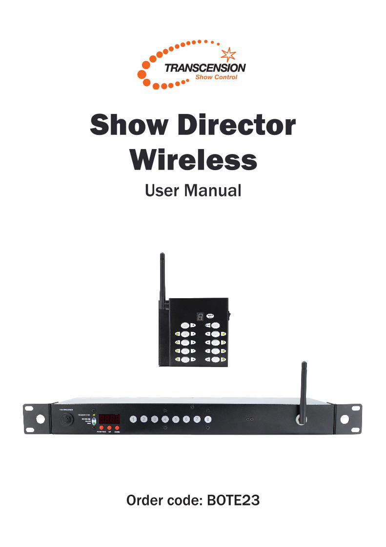
Order code: BOTE23
Show Director Wireless
User Manual

www.prolight.co.uk Show Director Wireless User Manual 2
Safety adviceSafety advice
WARNINGFOR YOUR OWN SAFETY, PLEASE READ THIS USER MANUAL CARE-FULLY BEFORE YOUR INITIAL START-UP!• Beforeyourinitialstart-up,pleasemakesurethatthereisnodamagecausedduringtransportation.
• Shouldtherebeanydamage,consultyourdealeranddonotusetheequipment.
• Tomaintaintheequipmentingoodworkingconditionandtoensuresafeoperation,itisnecessaryfortheusertofollowthesafetyinstructionsandwarningnoteswritteninthismanual.
• Pleasenotethatdamagescausedbyusermodificationstothisequipmentarenotsubjecttowarranty.
IMPORTANT:The manufacturer will not accept liability for any resulting damages caused by the non-observance of this manual or any unauthorised modification to the equipment.
OPERATING DETERMINATIONSIfthisequipmentisoperatedinanyotherway,thanthosedescribedinthismanual,theproductmaysufferdamageandthewarrantybecomesvoid.Incorrectoperationmayleadtodangere.g:short-circuit,burnsandelectricshocksetc.
Donotendangeryourownsafetyandthesafetyofothers!
Incorrectinstallationorusecancauseseriousdamagetopeopleand/orproperty.
CAUTION!KEEP THIS EQUIPMENT AWAY FROM RAIN, MOISTURE AND LIQUIDS
CAUTION! TAKE CARE USING THIS EQUIPMENT!HIGH VOLTAGE-RISK OF ELECTRIC SHOCK!!
• Neverletthepowercablecomeintocontactwithothercables.Handlethepowercableandallmainsvoltageconnectionswithparticularcaution!
• Neverremovewarningorinformativelabelsfromtheunit.
• Donotopentheequipmentanddonotmodifytheunit.
• Donotconnectthisequipmenttoadimmerpack.
• Donotswitchtheequipmentonandoffinshortintervals,asthiswillreducethesystem’slife.
• Onlyusetheequipmentindoors.
• Donotexposetoflammablesources,liquidsorgases.
• Alwaysdisconnectthepowerfromthemainswhenequipmentisnotinuseorbeforecleaning!Onlyhandlethepower-cablebytheplug.Neverpullouttheplugbypullingthepower-cable.
• Makesurethattheavailablemainssupplyvoltageisbetween100~240VAC,50/60Hz.
• Makesurethatthepowercableisnevercrimpedordamaged.Checktheequipmentandthepowercableperiodically.
• Iftheequipmentisdroppedordamaged,disconnectthemainspowersupplyimmediatelyandhaveaqualifiedengineerinspecttheequipmentbeforeoperatingagain.
• Iftheequipmenthasbeenexposedtodrastictemperaturefluctuation(e.g.aftertransportation),donotconnectpowerorswitchitonimmediately.Thearisingcondensationmightdamagetheequipment.Leavetheequipmentswitchedoffuntilithasreachedroomtemperature.
• Ifyourproductfailstofunctioncorrectly,stopuseimmediately.Packtheunitsecurely(preferablyintheoriginalpackingmaterial),andreturnittoyourProLightdealerforservice.
• Onlyusefusesofsametypeandrating.
• Repairs,servicingandpowerconnectionmustonlybecarriedoutbyaqualifiedtechnician.THISUNITCONTAINSNOUSERSERVICEABLEPARTS.
• Thisunitisforprofessionaluseonly-itisnotdesignedfororsuitableforhouseholduse.Theproductmustbeinstalledbyaqualifiedtechnicianinaccordancewithlocalterritoryregulations.Thesafetyoftheinstallationistheresponsibilityoftheinstaller.Thefixturepresentsrisksofsevereinjuryordeathduetofirehazards,electricshockandfalls.
• WARRANTY:Oneyearfromdateofpurchase.

www.prolight.co.uk Show Director Wireless User Manual 3
Product overview & technical specifications
Thishandy19”rackmountableunitfeatureswirelessswitchingforupto8effectsfromoneswitchpack.Theremotecontrolprovidedwiththeunitispoweredbya9VPP3batteryallowingtheusertoruntheirlightshowwirelessly.Multichanneloperationallowsuptoeightswitchpackstobeoperatedfromoneremotecontrolunitallowingupto64channelsofcontrol.Theeffectspowerpackfeaturesawirelessreceivertoacceptthesignalfromtheremotecontrol(on/off)andisfittedwitheightIECoutputs.DMXin/outisalsoprovidedforhardwireapplications.TheShowDirectorWirelessistheidealsolutionformobileentertainers,nightclubs,barsorforanyeventwhereyoudonotwantcablestobeseen.
• 100mwirelessrange(subjecttoidealconditions)
• 2.4GHzoperatingfrequency
• 8Frequencybandsforcontrolofupto8switchpacksfromoneremote
• 9VPP3MN1604batteryoperation
• Relayswitchedoutputsforreliableoperation
• PowerCONinput
• 3-PinXLRinput/output
• 8xIECswitchedoutputs
• 10Aperchannelmaximum,15Aoverloadprotection
Show Director Wireless
Specifications
Powersupply 100~240V,50/60Hz
Totalload 15A
Handheldbatterytype 9VPP3
Switchpackdimensions 44x484x147mm
Handhelddimensions 105x110x35mm
Switchpackweight 1.9kg
Handheldweight 0.6kg
Ordercode BOTE23
www.prolight.co.uk Show Director Wireless User Manual 4
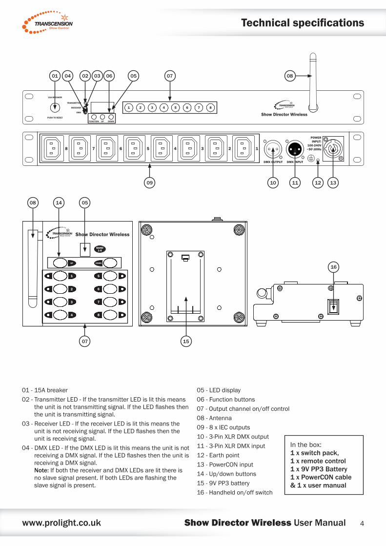
01-15Abreaker
02-TransmitterLED-IfthetransmitterLEDislitthismeanstheunitisnottransmittingsignal.IftheLEDflashesthentheunitistransmittingsignal.
03-ReceiverLED-IfthereceiverLEDislitthismeanstheunitisnotreceivingsignal.IftheLEDflashesthentheunitisreceivingsignal.
04-DMXLED-IftheDMXLEDislitthismeanstheunitisnotreceivingaDMXsignal.IftheLEDflashesthentheunitisreceivingaDMXsignal.Note:IfboththereceiverandDMXLEDsarelitthereisnoslavesignalpresent.IfbothLEDsareflashingtheslavesignalispresent.
05-LEDdisplay
06-Functionbuttons
07-Outputchannelon/offcontrol
08-Antenna
09-8xIECoutputs
10-3-PinXLRDMXoutput
11-3-PinXLRDMXinput
12-Earthpoint
13-PowerCONinput
14-Up/downbuttons
15-9VPP3battery
16-Handheldon/offswitch
Inthebox:1 x switch pack, 1 x remote control 1 x 9V PP3 Battery 1 x PowerCON cable & 1 x user manual
TRANSMITTER
RECEIVER
DMX
FUNCTION
1 2 3 4 5 6 7 8
UP DOWN
15A BREAKER
PUSH TO RESETShow Director Wireless
DMX OUTPUT
12345678
DMX INPUT
POWERINPUT:
100-240V~50\60Hz
09 10 11 12 13
01 05 070602 0304 08
Technical specifications
16
BAND1-8
1 5
UP DOWN
2
3
4
6
7
8
Show Director Wireless
08
07 15
0514

www.prolight.co.uk Show Director Wireless User Manual 5
Operating instructions
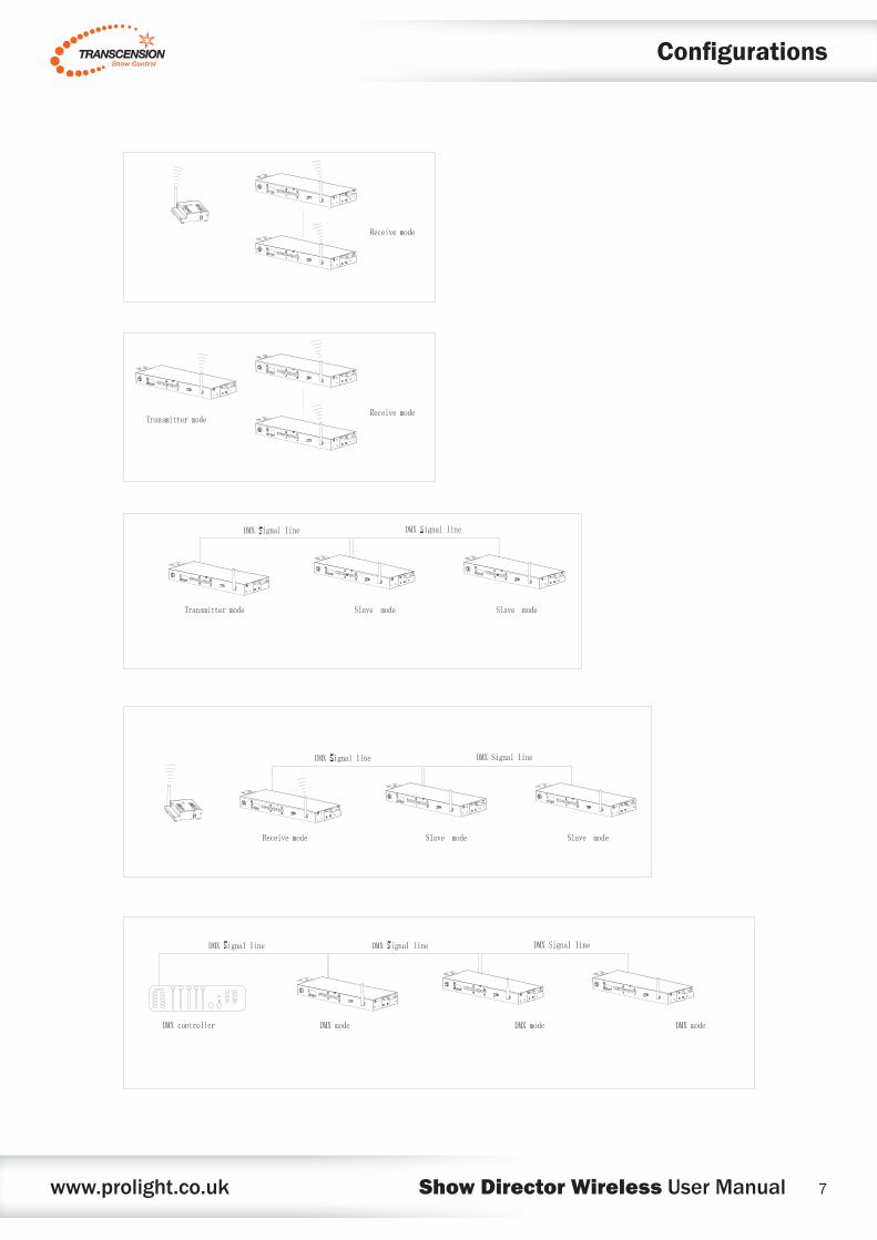
Wireless remote operation:
Thewirelessremotecontrolispoweredfromahighquality9VPP3(MN1604)battery.Thebatterymustbeconnectedbeforecommencingoperation.Donotstoreforlongperiodswithabatteryfittedwhilenotinuse.Thehandheldwirelessremotecontrolcanbeusedtocontroluptoeightswitchpackunits.Todosothefrequencybandmustbechangedonthewirelessremote.Pressandholdthe“UP”or“DOWN”keyfor3secondstochangethefrequencyband.Thewirelessremotewillstoreon/offselectionforeachfrequencybandforglitchfreeoperation.Please note: the frequency band of the switch pack must then also be adjusted to suit.
Whenthewirelessremotecontrollerandpowerpackareonsamefrequencyband,andwithinthewirelessrangetheindicatorwillflashbottomrightofthedisplayonthewirelessremotecontrol.Shouldthewrongfrequencybandbeselectedorthewirelesssignalfailduetointerference/distancetheindicatorwillbelitpermanently.
Toclearthestoredon/offselectionforallfrequencybands,pressandholdboth“UP”and“DOWN”buttons.TheeightoutputindicatorLEDswillflashthreetimestoconfirmthememoryhasbeencleared.
Eachoftheoutputchannelsfeaturesabuttonforon/offcontrolandayellowLEDforstatusindication.TheLEDwillilluminatetoindicatetheoutputchannelisswitchedon.Foraddedcreativitywhenswitchingoutputsonoroff,multipleselectionscanbemadeatthesametime.Forexample,toswitchallchannelsfromofftoonsimplypressbuttons1&8simultaneously.Multipleselectionsmayalsobereversed,forexampleifchannels1,3&5areswitchedonand2,4,6,7&8areoffwhentheuserpressesbuttons1&8simultaneouslythewirelessremotewillswitch1,3&5offandswitchon2,4,6,7&8.
Wireless receiver:
InWirelessReceivemodethepowerpackwillbecontrolledbythewirelessremotecontrol.Usethe“FUNCTION”buttononthefrontpanelofthepowerpacktoselectr000mode.Usethe“UP”and“DOWN”buttonstoselecttherequiredfrequencybandnumber.TheLEDdotunderthe“r”willflashwhenthefrequencybandonthepowerpackandthefrequencybandonthewirelessremotearematched.Inwirelessreceivemodetheon/offbuttonsonthefrontpanelofthepowerpackwillbedisabled.

www.prolight.co.uk Show Director Wireless User Manual 6
Operating instructions
Transmitter mode:
InWirelessTransmittermodethepowerpackwillactasthemasterunitwithdirectcontroloftheoutputchannelsfromthefrontpanelofthepowerpack,theselectionwillthenbereplicatedandtransmittedviathewirelessantennatoallowadditionalpowerpackstobeused.Usethe“UP”and“DOWN”buttonstoselecttherequiredfrequencybandnumber,thismustalsobereplicatedonthecorrespondingpowerpacksettoWirelessReceivemode.
DMX mode:
DMXModeallowsthepowerpacktobecontrolleddirectlyfromanystandardDMXconsolecapableofcontrolling9DMXchannels.Usethe“FUNCTION”buttontoselectDMXmodeonthepowerpack(indicatedbyagreenLED).Usethe“UP”and“DOWN”buttonstoselecttherequiredDMXaddress.
Slave mode:
SlavemodeallowspowerpackstobeconnectedviaDMXcabletootherpowerpacks,increasingthenumberoflighteffectsswitchedon/off.Pressthe“FUNCTION”buttonuntilthedisplayshowsS000thenusethe“UP”and“DOWN”buttonstoselecttherequiredfrequencyband.Themasterunitmustbeselectedtoeither“WirelessReceiver”or“WirelessTransmitter”mode.WhenSlavemodeisactivetheblueReceiverLEDandgreenDMXLEDwillbothilluminate.TheLEDindicatorswillflashtoindicatecorrectDMXsignalisbeingreceived.
DMX channel allocation:
Channel Value Function
CH1000-127 CH1OFF
128-255 CH1ON
CH2000-127 CH2OFF
128-255 CH2ON
CH3000-127 CH3OFF
128-255 CH3ON
CH4000-127 CH4OFF
128-255 CH4ON
CH5000-127 CH5OFF
128-255 CH5ON
CH6000-127 CH6OFF
128-255 CH6ON
CH7000-127 CH7OFF
128-255 CH7ON
CH8000-127 CH8OFF
128-255 CH8ON
CH9000-127 CH1-8OFF
128-255 CH1-8ON
www.prolight.co.uk Show Director Wireless User Manual 7
Configurations

www.prolight.co.uk Show Director Wireless User Manual 8
DMX setup
FurtherDMXcablescanbepurchasedfromallgoodsoundandlightingsuppliersorProLightConceptsdealers.Pleasequote:
CABL10 – 2mCABL11 – 5mCABL12 – 10m
Setting the DMX address:
TheDMXmodeenablestheuseofauniversalDMXcontroller.Eachfixturerequiresa“startaddress”from1-512.Afixturerequiringoneormorechannelsforcontrolbeginstoreadthedataonthechannelindicatedbythestartaddress.Forexample,afixturethatoccupiesoruses7channelsofDMXandwasaddressedtostartonDMXchannel100,wouldreaddatafromchannels:100,101,102,103,104,105and106.Chooseastartaddresssothatthechannelsuseddonotoverlap.E.g.thenextunitinthechainstartsat107.
DMX 512:
DMX(DigitalMultiplex)isauniversalprotocolusedasaformofcommunicationbetweenintelligentfixturesandcontrollers.ADMXcontrollersendsDMXdatainstructionsformthecontrollertothefixture.DMXdataissentasserialdatathattravelsfromfixturetofixtureviatheDATA“IN”andDATA“OUT”XLRterminalslocatedonallDMXfixtures(mostcontrollersonlyhaveadata“out”terminal).
DMX linking:
DMXisalanguageallowingallmakesandmodelsofdifferentmanufacturestobelinkedtogetherandoperatefromasinglecontroller,aslongasallfixturesandthecontrollerareDMXcompliant.ToensureproperDMXdatatransmission,whenusingseveralDMXfixturestrytousetheshortestcablepathpossible.TheorderinwhichfixturesareconnectedinaDMXlinedoesnotinfluencetheDMXaddressing.Forexample;afixtureassignedtoaDMXaddressof1maybeplacedanywhereinaDMXline,atthebeginning,attheend,oranywhereinthemiddle.WhenafixtureisassignedaDMXaddressof1,theDMXcontrollerknowstosendDATAassignedtoaddress1tothatunit,nomatterwhereitislocatedintheDMXchain.
DATA cable (DMX cable) requirements (for DMX operation):
ThisfixturecanbecontrolledviaDMX-512protocol.TheDMXaddressissetonthebackoftheunit.YourunitandyourDMXcontrollerrequireastandard3-pinXLRconnectorfordatainput/output,seeimagebelow.
Also remember that DMX cable must be daisy chained and cannot be split.

www.prolight.co.uk Show Director Wireless User Manual 9
Terminationreducessignaltransmissionproblemsandinterferance.itisalwaysadvisabletoconnectaDMXterminal,(resistance120Ohm1/4W)betweenpin2(DMX-)andpin3(DMX+)ofthelastfixture.
5-pin XLR (socket)Pin 1: GND (screen)Pin 2: Signal (-)Pin 3: Signal (+)Pin 4: N/CPin 5: N/C
3-pin XLR (socket)Pin 1: GND (screen)Pin 2: Signal (-)Pin 3: Signal (+)
3-pin XLR (socket)Pin 1: GND (screen)Pin 2: Signal (-)Pin 3: Signal (+)
5-pin XLR (socket)Pin 1: GND (screen)Pin 2: Signal (-)Pin 3: Signal (+)Pin 4: N/CPin 5: N/C
DMX setup
Notice:
Besuretofollowthediagramsbelowwhenmakingyourowncables.DonotconnectthecablesshieldconductortothegroundlugorallowtheshieldconductortocomeincontactwiththeXLRsoutercasing.Groundingtheshieldcouldcauseashortcircuitanderraticbehaviour.
Special note:
Line termination:
Whenlongerrunsofcableareused,youmayneedtouseaterminatoronthelastunittoavoiderraticbehaviour.
Using a cable terminator will decrease the possibilities of erratic behaviour. (3-pin - Order ref: CABL9O, 5-pin - Order ref: CABL89)
5-pin XLR DMX connectors:
Somemanufacturesuse5-pinXLRconnectorsfordatatransmissioninplaceof3-pin.5-pinXLRfixturesmaybeimplementedina3-pinXLRDMXline.Wheninsertingstandard5-pinXLRconnectorsintoa3-pinlineacableadaptormustbeused.Thediagrambelowdetailsthecorrectcableconversion.

www.prolight.co.uk Show Director Wireless User Manual 10
WEEE notice
Correct Disposal of this Product (Waste Electrical & Electronic Equipment)
(Applicable in the European Union and other European countries with separate collection systems)
Thismarkingshownontheproductoritsliterature,indicatesthatitshouldnotbedisposedofwithotherhouseholdwastesattheendofitsworkinglife.Topreventpossibleharmtotheenvironmentorhumanhealthfromuncontrolledwastedisposal,pleaseseparatethisfromothertypesofwastesandrecycleitresponsiblytopromotethesustainablereuseofmaterialresources.
Householdusersshouldcontacteithertheretailerwheretheypurchasedthisproduct,ortheirlocalgovernmentoffice,fordetailsofwhereandhowtheycantakethisitemforenvironmentallysaferecycling.
Businessusersshouldcontacttheirsupplierandcheckthetermsandconditionsofthepurchasecontract.Thisproductshouldnotbemixedwithothercommercialwastesfordisposal.

www.prolight.co.uk Show Director Wireless User Manual 11

www.prolight.co.uk Show Director Wireless User Manual 12