Embed Size (px)
Citation preview
ShoreTel 12.2Maintenance GuidePart Number 800-1628-01
Document and Software CopyrightsCopyright © 1998-2012 by ShoreTel Inc., Sunnyvale, California, USA. All rights reserved.
Printed in the United States of America. Contents of this publication may not be reproduced or transmitted in any form or by any means, electronic or mechanical, for any purpose, without prior written authorization of ShoreTel, Inc. ShoreTel, Inc. reserves the right to make changes without notice to the specifications and materials contained herein and shall not be responsible for any damage (including consequential) caused by reliance on the materials presented, including, but not limited to typographical, arithmetic or listing errors
TrademarksShoreTel, ShoreTel (and logo), ControlPoint, Brilliantly Simple, Brilliantly Simple Communication, ShoreCare, ShoreGear, ShorePhone, and ShoreWare are registered trademarks of ShoreTel, Inc. in the United States and/or other countries. The ShoreTel logo is a trademark of ShoreTel, Inc. in the United States and/or other countries..
All other copyrights and trademarks herein are the property of their respective owners.
Version InformationMaintenance GuideShoreTel Release 12.2Document Part Number: 800-1539-01Version: MG_GA_12.2_20120118Date: January 18, 2012
Company InformationShoreTel, Inc.960 Stewart DriveSunnyvale, California 94085 USA+1.408.331.3300+1.408.331.3333 (fax)www.shoretel.com
Table of Contents
TABLE OF CONTENTS 3
CHAPTER 1: ABOUT THIS GUIDE 91.1 Conventions Used . . . . . . . . . . . . . . . . . . . . . . . . . . . . . . . . . . . . . . . . . . . . . . . . 9
1.1.1 Syntax Used . . . . . . . . . . . . . . . . . . . . . . . . . . . . . . . . . . . . . . . . . . . . . . . . . . . . . . . . . . . . . 91.2 For More Information . . . . . . . . . . . . . . . . . . . . . . . . . . . . . . . . . . . . . . . . . . . . . 9
CHAPTER 2: SHORETEL ARCHITECTURE 112.1 Overview . . . . . . . . . . . . . . . . . . . . . . . . . . . . . . . . . . . . . . . . . . . . . . . . . . . . . . 11
2.1.1 ShoreTel Servers . . . . . . . . . . . . . . . . . . . . . . . . . . . . . . . . . . . . . . . . . . . . . . . . . . . . . . . . . 122.1.2 ShoreTel Voice Switches. . . . . . . . . . . . . . . . . . . . . . . . . . . . . . . . . . . . . . . . . . . . . . . . . . . 122.1.3 IP Endpoints . . . . . . . . . . . . . . . . . . . . . . . . . . . . . . . . . . . . . . . . . . . . . . . . . . . . . . . . . . . . 132.1.4 ShoreTel Client Applications . . . . . . . . . . . . . . . . . . . . . . . . . . . . . . . . . . . . . . . . . . . . . . . 13
2.2 ShoreTel Distributed IP Voice Architecture . . . . . . . . . . . . . . . . . . . . . . . . . . . 132.2.1 Distributed Applications Platform . . . . . . . . . . . . . . . . . . . . . . . . . . . . . . . . . . . . . . . . . . . 142.2.2 Distributed Call Control. . . . . . . . . . . . . . . . . . . . . . . . . . . . . . . . . . . . . . . . . . . . . . . . . . . 142.2.3 Single System Management . . . . . . . . . . . . . . . . . . . . . . . . . . . . . . . . . . . . . . . . . . . . . . . . 15
2.3 ShoreTel System Communications . . . . . . . . . . . . . . . . . . . . . . . . . . . . . . . . . . 162.3.1 Call Control . . . . . . . . . . . . . . . . . . . . . . . . . . . . . . . . . . . . . . . . . . . . . . . . . . . . . . . . . . . . 162.3.2 Configuration . . . . . . . . . . . . . . . . . . . . . . . . . . . . . . . . . . . . . . . . . . . . . . . . . . . . . . . . . . . 192.3.3 TAPI . . . . . . . . . . . . . . . . . . . . . . . . . . . . . . . . . . . . . . . . . . . . . . . . . . . . . . . . . . . . . . . . . . 202.3.4 Media . . . . . . . . . . . . . . . . . . . . . . . . . . . . . . . . . . . . . . . . . . . . . . . . . . . . . . . . . . . . . . . . . 22
2.4 System Reliability . . . . . . . . . . . . . . . . . . . . . . . . . . . . . . . . . . . . . . . . . . . . . . . 242.4.1 Distributed Switch Control . . . . . . . . . . . . . . . . . . . . . . . . . . . . . . . . . . . . . . . . . . . . . . . . 242.4.2 Distributed Database . . . . . . . . . . . . . . . . . . . . . . . . . . . . . . . . . . . . . . . . . . . . . . . . . . . . . 252.4.3 Embedded IP Phone Display Driver . . . . . . . . . . . . . . . . . . . . . . . . . . . . . . . . . . . . . . . . . . 262.4.4 Public Switched Telephone Network (PSTN) Failover . . . . . . . . . . . . . . . . . . . . . . . . . . . 262.4.5 Distributed CDR . . . . . . . . . . . . . . . . . . . . . . . . . . . . . . . . . . . . . . . . . . . . . . . . . . . . . . . . . 272.4.6 For More Information on System Reliability . . . . . . . . . . . . . . . . . . . . . . . . . . . . . . . . . . . 27
2.5 Call Scenarios . . . . . . . . . . . . . . . . . . . . . . . . . . . . . . . . . . . . . . . . . . . . . . . . . . 272.5.1 On-hook Call from Communicator . . . . . . . . . . . . . . . . . . . . . . . . . . . . . . . . . . . . . . . . . . 272.5.2 Quick Dial Call from Communicator. . . . . . . . . . . . . . . . . . . . . . . . . . . . . . . . . . . . . . . . . 282.5.3 Inbound Call from a Trunk . . . . . . . . . . . . . . . . . . . . . . . . . . . . . . . . . . . . . . . . . . . . . . . . 29
2.6 TCP/IP Ports Used by the ShoreTel System. . . . . . . . . . . . . . . . . . . . . . . . . . . . 292.6.1 ShoreTel Voice Switch and ShoreTel Server Connections . . . . . . . . . . . . . . . . . . . . . . . . . 292.6.2 ShoreTel Voice Switch to ShoreTel Voice Switch Connections . . . . . . . . . . . . . . . . . . . . . 312.6.3 IP Phone to ShoreTel Server Connections . . . . . . . . . . . . . . . . . . . . . . . . . . . . . . . . . . . . . 312.6.4 ShoreTel Server to ShoreTel Server . . . . . . . . . . . . . . . . . . . . . . . . . . . . . . . . . . . . . . . . . . 322.6.5 ShoreTel Server to ShoreTel Director Client . . . . . . . . . . . . . . . . . . . . . . . . . . . . . . . . . . . 332.6.6 ShoreTel Server to ShoreTel Communicator . . . . . . . . . . . . . . . . . . . . . . . . . . . . . . . . . . . 33
CHAPTER 3: SHORETEL SERVERS 353.1 Overview . . . . . . . . . . . . . . . . . . . . . . . . . . . . . . . . . . . . . . . . . . . . . . . . . . . . . . 35
3.1.1 Headquarters Server . . . . . . . . . . . . . . . . . . . . . . . . . . . . . . . . . . . . . . . . . . . . . . . . . . . . . . 353.1.2 Distributed Voice Servers (DVS) . . . . . . . . . . . . . . . . . . . . . . . . . . . . . . . . . . . . . . . . . . . . 35
ShoreTel 12.2 3
Maintenance Guide Table of Contents
3.1.3 Configuration Communications. . . . . . . . . . . . . . . . . . . . . . . . . . . . . . . . . . . . . . . . . . . . . 363.1.4 Call Control Communications . . . . . . . . . . . . . . . . . . . . . . . . . . . . . . . . . . . . . . . . . . . . . . 383.1.5 Media Communications . . . . . . . . . . . . . . . . . . . . . . . . . . . . . . . . . . . . . . . . . . . . . . . . . . . 403.1.6 Integrated Server Applications . . . . . . . . . . . . . . . . . . . . . . . . . . . . . . . . . . . . . . . . . . . . . . 41
3.2 Server Maintenance . . . . . . . . . . . . . . . . . . . . . . . . . . . . . . . . . . . . . . . . . . . . . . 423.2.1 Server Software Upgrades . . . . . . . . . . . . . . . . . . . . . . . . . . . . . . . . . . . . . . . . . . . . . . . . . . 423.2.2 System File Backup. . . . . . . . . . . . . . . . . . . . . . . . . . . . . . . . . . . . . . . . . . . . . . . . . . . . . . . 42
3.3 Diagnostic and Troubleshooting Information . . . . . . . . . . . . . . . . . . . . . . . . . . 433.3.1 Installer Logging. . . . . . . . . . . . . . . . . . . . . . . . . . . . . . . . . . . . . . . . . . . . . . . . . . . . . . . . . 433.3.2 Using Quick Look. . . . . . . . . . . . . . . . . . . . . . . . . . . . . . . . . . . . . . . . . . . . . . . . . . . . . . . . 443.3.3 Using the Event Log . . . . . . . . . . . . . . . . . . . . . . . . . . . . . . . . . . . . . . . . . . . . . . . . . . . . . . 443.3.4 Using the System Logs . . . . . . . . . . . . . . . . . . . . . . . . . . . . . . . . . . . . . . . . . . . . . . . . . . . . 443.3.5 Using the Trunk Test Tool . . . . . . . . . . . . . . . . . . . . . . . . . . . . . . . . . . . . . . . . . . . . . . . . . 513.3.6 Using the cfg Utility . . . . . . . . . . . . . . . . . . . . . . . . . . . . . . . . . . . . . . . . . . . . . . . . . . . . . . 523.3.7 Using Dr. Watson . . . . . . . . . . . . . . . . . . . . . . . . . . . . . . . . . . . . . . . . . . . . . . . . . . . . . . . . 54
3.4 Services (Processes) . . . . . . . . . . . . . . . . . . . . . . . . . . . . . . . . . . . . . . . . . . . . . . 563.5 ShoreTel Server File System . . . . . . . . . . . . . . . . . . . . . . . . . . . . . . . . . . . . . . . 573.6 Registry . . . . . . . . . . . . . . . . . . . . . . . . . . . . . . . . . . . . . . . . . . . . . . . . . . . . . . . 593.7 ShoreTel Release Numbering Scheme . . . . . . . . . . . . . . . . . . . . . . . . . . . . . . . . 59
CHAPTER 4: SHORETEL VOICE SWITCHES 614.1 Overview . . . . . . . . . . . . . . . . . . . . . . . . . . . . . . . . . . . . . . . . . . . . . . . . . . . . . . 614.2 ShoreTel Voice Switch Firmware Upgrades. . . . . . . . . . . . . . . . . . . . . . . . . . . . 62
4.2.1 Using Quick Look to Perform Upgrades . . . . . . . . . . . . . . . . . . . . . . . . . . . . . . . . . . . . . . 624.2.2 Performing a Manual Upgrade . . . . . . . . . . . . . . . . . . . . . . . . . . . . . . . . . . . . . . . . . . . . . . 62
4.3 ShoreTel Voice Switch Boot Options . . . . . . . . . . . . . . . . . . . . . . . . . . . . . . . . . 634.3.1 IP Address from DHCP. . . . . . . . . . . . . . . . . . . . . . . . . . . . . . . . . . . . . . . . . . . . . . . . . . . . 634.3.2 Setting the IP Address with VxWorks . . . . . . . . . . . . . . . . . . . . . . . . . . . . . . . . . . . . . . . . 634.3.3 Accessing ShoreTel Voice Switch CLI on the SoftSwitch. . . . . . . . . . . . . . . . . . . . . . . . . . 654.3.4 Modifying Router Auto-Delete Properties for ICMP Redirects . . . . . . . . . . . . . . . . . . . . . 654.3.5 Using a Telnet Session to Set IP Address and Boot Parameters . . . . . . . . . . . . . . . . . . . . . 664.3.6 Boot Flags . . . . . . . . . . . . . . . . . . . . . . . . . . . . . . . . . . . . . . . . . . . . . . . . . . . . . . . . . . . . . . 68
4.4 ShoreTel Voice Switch Configuration Reset . . . . . . . . . . . . . . . . . . . . . . . . . . . 694.5 ShoreTel Voice Switch Utilities . . . . . . . . . . . . . . . . . . . . . . . . . . . . . . . . . . . . . 69
4.5.1 ipbxctl Utility . . . . . . . . . . . . . . . . . . . . . . . . . . . . . . . . . . . . . . . . . . . . . . . . . . . . . . . . . . . 694.5.2 Burnflash Utility . . . . . . . . . . . . . . . . . . . . . . . . . . . . . . . . . . . . . . . . . . . . . . . . . . . . . . . . . 70
4.6 Diagnostics. . . . . . . . . . . . . . . . . . . . . . . . . . . . . . . . . . . . . . . . . . . . . . . . . . . . . 704.6.1 Switch Trunk Debugging Tools . . . . . . . . . . . . . . . . . . . . . . . . . . . . . . . . . . . . . . . . . . . . . 704.6.2 VxWorks Command Line Interface . . . . . . . . . . . . . . . . . . . . . . . . . . . . . . . . . . . . . . . . . . 714.6.3 Connecting to a ShoreTel Voice Switch . . . . . . . . . . . . . . . . . . . . . . . . . . . . . . . . . . . . . . . 794.6.4 Power over Ethernet Switches . . . . . . . . . . . . . . . . . . . . . . . . . . . . . . . . . . . . . . . . . . . . . . 79
CHAPTER 5: VOICEMAIL MODEL SWITCHES 815.1 Overview . . . . . . . . . . . . . . . . . . . . . . . . . . . . . . . . . . . . . . . . . . . . . . . . . . . . . . 815.2 Utilities . . . . . . . . . . . . . . . . . . . . . . . . . . . . . . . . . . . . . . . . . . . . . . . . . . . . . . . 81
5.2.1 Accessing Voicemail Model Switch Utilities. . . . . . . . . . . . . . . . . . . . . . . . . . . . . . . . . . . . 815.2.2 Switch Utilities . . . . . . . . . . . . . . . . . . . . . . . . . . . . . . . . . . . . . . . . . . . . . . . . . . . . . . . . . . 845.2.3 Server Utilities . . . . . . . . . . . . . . . . . . . . . . . . . . . . . . . . . . . . . . . . . . . . . . . . . . . . . . . . . . 86
5.3 Booting and Restarting V Model Switches . . . . . . . . . . . . . . . . . . . . . . . . . . . . . 875.3.1 Manually Specifying Switch Parameters . . . . . . . . . . . . . . . . . . . . . . . . . . . . . . . . . . . . . . . 885.3.2 Reboot Methods . . . . . . . . . . . . . . . . . . . . . . . . . . . . . . . . . . . . . . . . . . . . . . . . . . . . . . . . . 88
4
Table of Contents Maintenance Guide
5.4 Switch Diagnostics and Repair. . . . . . . . . . . . . . . . . . . . . . . . . . . . . . . . . . . . . . 895.4.1 Switch Trunk Debug Tools. . . . . . . . . . . . . . . . . . . . . . . . . . . . . . . . . . . . . . . . . . . . . . . . . 895.4.2 Creating an tcpdump File. . . . . . . . . . . . . . . . . . . . . . . . . . . . . . . . . . . . . . . . . . . . . . . . . . 905.4.3 Recording Audio from a Switch Port . . . . . . . . . . . . . . . . . . . . . . . . . . . . . . . . . . . . . . . . . 905.4.4 Reformatting the Compact Flash . . . . . . . . . . . . . . . . . . . . . . . . . . . . . . . . . . . . . . . . . . . . 90
5.5 stcli Commands . . . . . . . . . . . . . . . . . . . . . . . . . . . . . . . . . . . . . . . . . . . . . . . . . 915.6 SVCCLI Commands . . . . . . . . . . . . . . . . . . . . . . . . . . . . . . . . . . . . . . . . . . . . . . 925.7 CLI Commands . . . . . . . . . . . . . . . . . . . . . . . . . . . . . . . . . . . . . . . . . . . . . . . . . 985.8 Cfg Utility . . . . . . . . . . . . . . . . . . . . . . . . . . . . . . . . . . . . . . . . . . . . . . . . . . . . 1025.9 UBOOT Commands and Flags . . . . . . . . . . . . . . . . . . . . . . . . . . . . . . . . . . . . . 1035.10 Burnflash . . . . . . . . . . . . . . . . . . . . . . . . . . . . . . . . . . . . . . . . . . . . . . . . . . . . . 1045.11 ipbxctl . . . . . . . . . . . . . . . . . . . . . . . . . . . . . . . . . . . . . . . . . . . . . . . . . . . . . . . 1045.12 regedit Commands . . . . . . . . . . . . . . . . . . . . . . . . . . . . . . . . . . . . . . . . . . . . . . 1055.13 Windows Registry Keys . . . . . . . . . . . . . . . . . . . . . . . . . . . . . . . . . . . . . . . . . . 1055.14 ShoreTel Server File System . . . . . . . . . . . . . . . . . . . . . . . . . . . . . . . . . . . . . . 107
CHAPTER 6: IP ENDPOINTS 1096.1 Overview . . . . . . . . . . . . . . . . . . . . . . . . . . . . . . . . . . . . . . . . . . . . . . . . . . . . . 109
6.1.1 IP Phones . . . . . . . . . . . . . . . . . . . . . . . . . . . . . . . . . . . . . . . . . . . . . . . . . . . . . . . . . . . . . 1096.1.2 Boot Process . . . . . . . . . . . . . . . . . . . . . . . . . . . . . . . . . . . . . . . . . . . . . . . . . . . . . . . . . . . 111
6.2 IP Phone Firmware Upgrades . . . . . . . . . . . . . . . . . . . . . . . . . . . . . . . . . . . . . 1126.3 Diagnostics. . . . . . . . . . . . . . . . . . . . . . . . . . . . . . . . . . . . . . . . . . . . . . . . . . . . 112
6.3.1 Viewing System IP Phones . . . . . . . . . . . . . . . . . . . . . . . . . . . . . . . . . . . . . . . . . . . . . . . . 1126.3.2 On Screen Error Messages . . . . . . . . . . . . . . . . . . . . . . . . . . . . . . . . . . . . . . . . . . . . . . . . 1136.3.3 Diagnostic and Failure Messages . . . . . . . . . . . . . . . . . . . . . . . . . . . . . . . . . . . . . . . . . . . 1136.3.4 Troubleshooting the IP Phone Display. . . . . . . . . . . . . . . . . . . . . . . . . . . . . . . . . . . . . . . 1146.3.5 Manually Configuring the Phones . . . . . . . . . . . . . . . . . . . . . . . . . . . . . . . . . . . . . . . . . . 1166.3.6 Displaying IP Phone Settings . . . . . . . . . . . . . . . . . . . . . . . . . . . . . . . . . . . . . . . . . . . . . . 1176.3.7 Resetting the ShoreTel IP Phone . . . . . . . . . . . . . . . . . . . . . . . . . . . . . . . . . . . . . . . . . . . 117
6.4 Diagnostics & Configuration for ShoreTel IP Phones . . . . . . . . . . . . . . . . . . . 1186.4.1 Boot Configuration Operation . . . . . . . . . . . . . . . . . . . . . . . . . . . . . . . . . . . . . . . . . . . . . 1186.4.2 IP Phone Configuration Files . . . . . . . . . . . . . . . . . . . . . . . . . . . . . . . . . . . . . . . . . . . . . . 1186.4.3 Other Customizable Parameters . . . . . . . . . . . . . . . . . . . . . . . . . . . . . . . . . . . . . . . . . . . . 1236.4.4 DHCP Site Specific Options . . . . . . . . . . . . . . . . . . . . . . . . . . . . . . . . . . . . . . . . . . . . . . . 1246.4.5 PhoneCTL Command Line Tool . . . . . . . . . . . . . . . . . . . . . . . . . . . . . . . . . . . . . . . . . . . 132
6.5 ShoreTel Converged Conference Bridges. . . . . . . . . . . . . . . . . . . . . . . . . . . . . 1366.5.1 SoftPhone . . . . . . . . . . . . . . . . . . . . . . . . . . . . . . . . . . . . . . . . . . . . . . . . . . . . . . . . . . . . . 137
6.6 Dial Tone Behavior. . . . . . . . . . . . . . . . . . . . . . . . . . . . . . . . . . . . . . . . . . . . . . 1376.6.1 Transfer . . . . . . . . . . . . . . . . . . . . . . . . . . . . . . . . . . . . . . . . . . . . . . . . . . . . . . . . . . . . . . 1376.6.2 Park. . . . . . . . . . . . . . . . . . . . . . . . . . . . . . . . . . . . . . . . . . . . . . . . . . . . . . . . . . . . . . . . . . 1386.6.3 Hold (multi-line IP phones: 212k/230/530/560/560g/565/655). . . . . . . . . . . . . . . . . . . . 1386.6.4 Hold (single-line IP phones: 110/115/210) . . . . . . . . . . . . . . . . . . . . . . . . . . . . . . . . . . . 138
CHAPTER 7: SERVICE APPLIANCE 100 (SA-100) 1397.1 Overview . . . . . . . . . . . . . . . . . . . . . . . . . . . . . . . . . . . . . . . . . . . . . . . . . . . . . 1397.2 SA-100 Maintenance . . . . . . . . . . . . . . . . . . . . . . . . . . . . . . . . . . . . . . . . . . . . 139
7.2.1 SA-100 Backup . . . . . . . . . . . . . . . . . . . . . . . . . . . . . . . . . . . . . . . . . . . . . . . . . . . . . . . . . 1397.2.2 Manual Backup . . . . . . . . . . . . . . . . . . . . . . . . . . . . . . . . . . . . . . . . . . . . . . . . . . . . . . . . . 1417.2.3 Restoring the SA-100 Backup . . . . . . . . . . . . . . . . . . . . . . . . . . . . . . . . . . . . . . . . . . . . . . 1427.2.4 Manual Restore . . . . . . . . . . . . . . . . . . . . . . . . . . . . . . . . . . . . . . . . . . . . . . . . . . . . . . . . . 1437.2.5 Backup and Restore FAQ . . . . . . . . . . . . . . . . . . . . . . . . . . . . . . . . . . . . . . . . . . . . . . . . . 144
ShoreTel 12.2 5

Maintenance Guide Table of Contents
7.2.6 Disk Management. . . . . . . . . . . . . . . . . . . . . . . . . . . . . . . . . . . . . . . . . . . . . . . . . . . . . . . 1457.3 Log Files and Processes . . . . . . . . . . . . . . . . . . . . . . . . . . . . . . . . . . . . . . . . . . 148
7.3.1 SA-100 Logging Process . . . . . . . . . . . . . . . . . . . . . . . . . . . . . . . . . . . . . . . . . . . . . . . . . . 1487.3.2 SA-100 Processes and Protocols . . . . . . . . . . . . . . . . . . . . . . . . . . . . . . . . . . . . . . . . . . . . 150
7.4 Log Files. . . . . . . . . . . . . . . . . . . . . . . . . . . . . . . . . . . . . . . . . . . . . . . . . . . . . . 1517.5 SA-100 Utilities . . . . . . . . . . . . . . . . . . . . . . . . . . . . . . . . . . . . . . . . . . . . . . . . 151
7.5.1 Accessing the SA-100 . . . . . . . . . . . . . . . . . . . . . . . . . . . . . . . . . . . . . . . . . . . . . . . . . . . . 1517.5.2 Accessing Utilities from SSH . . . . . . . . . . . . . . . . . . . . . . . . . . . . . . . . . . . . . . . . . . . . . . 151
7.6 Booting and Restarting. . . . . . . . . . . . . . . . . . . . . . . . . . . . . . . . . . . . . . . . . . . 1537.7 Diagnostics and Repair . . . . . . . . . . . . . . . . . . . . . . . . . . . . . . . . . . . . . . . . . . 153
7.7.1 Restore Factory Default . . . . . . . . . . . . . . . . . . . . . . . . . . . . . . . . . . . . . . . . . . . . . . . . . . 1537.8 Reference . . . . . . . . . . . . . . . . . . . . . . . . . . . . . . . . . . . . . . . . . . . . . . . . . . . . . 155
7.8.1 stcli Command Descriptions . . . . . . . . . . . . . . . . . . . . . . . . . . . . . . . . . . . . . . . . . . . . . . 1557.8.2 SVCCLI Command Descriptions . . . . . . . . . . . . . . . . . . . . . . . . . . . . . . . . . . . . . . . . . . . 1557.8.3 CLI . . . . . . . . . . . . . . . . . . . . . . . . . . . . . . . . . . . . . . . . . . . . . . . . . . . . . . . . . . . . . . . . . . 1567.8.4 UBOOT . . . . . . . . . . . . . . . . . . . . . . . . . . . . . . . . . . . . . . . . . . . . . . . . . . . . . . . . . . . . . . . 1567.8.5 Regedit . . . . . . . . . . . . . . . . . . . . . . . . . . . . . . . . . . . . . . . . . . . . . . . . . . . . . . . . . . . . . . . 156
CHAPTER 8: SHORETEL CLIENT APPLICATIONS 1578.1 Overview . . . . . . . . . . . . . . . . . . . . . . . . . . . . . . . . . . . . . . . . . . . . . . . . . . . . . 157
8.1.1 Communicator Application Suite. . . . . . . . . . . . . . . . . . . . . . . . . . . . . . . . . . . . . . . . . . . 1578.1.2 Theory of Operations . . . . . . . . . . . . . . . . . . . . . . . . . . . . . . . . . . . . . . . . . . . . . . . . . . . . 157
8.2 Diagnostics. . . . . . . . . . . . . . . . . . . . . . . . . . . . . . . . . . . . . . . . . . . . . . . . . . . . 1588.2.1 Troubleshooting Login or Startup Problems . . . . . . . . . . . . . . . . . . . . . . . . . . . . . . . . . . 1588.2.2 Troubleshooting Telephony Problems . . . . . . . . . . . . . . . . . . . . . . . . . . . . . . . . . . . . . . . 1618.2.3 Confirming TAPI Operations . . . . . . . . . . . . . . . . . . . . . . . . . . . . . . . . . . . . . . . . . . . . . . 1618.2.4 Troubleshooting Caller ID Problems . . . . . . . . . . . . . . . . . . . . . . . . . . . . . . . . . . . . . . . . 1638.2.5 Troubleshooting Configuration Problems . . . . . . . . . . . . . . . . . . . . . . . . . . . . . . . . . . . . 1648.2.6 Troubleshooting MAPI Contact Import Problems Using SHAdrTst.exe. . . . . . . . . . . . . . . 1648.2.7 Using the History File. . . . . . . . . . . . . . . . . . . . . . . . . . . . . . . . . . . . . . . . . . . . . . . . . . . . 1658.2.8 Using Log Files . . . . . . . . . . . . . . . . . . . . . . . . . . . . . . . . . . . . . . . . . . . . . . . . . . . . . . . . . 165
8.3 Setup Wizard . . . . . . . . . . . . . . . . . . . . . . . . . . . . . . . . . . . . . . . . . . . . . . . . . . 1668.4 Communicator: V-1 Compatibility. . . . . . . . . . . . . . . . . . . . . . . . . . . . . . . . . . 167
8.4.1 Existing Communicator Issues. . . . . . . . . . . . . . . . . . . . . . . . . . . . . . . . . . . . . . . . . . . . . 167
APPENDIX A: EVENT CODES 169A.1 Overview . . . . . . . . . . . . . . . . . . . . . . . . . . . . . . . . . . . . . . . . . . . . . . . . . . . . . 169A.2 Event Types . . . . . . . . . . . . . . . . . . . . . . . . . . . . . . . . . . . . . . . . . . . . . . . . . . . 169A.3 Using the Event Code Tables . . . . . . . . . . . . . . . . . . . . . . . . . . . . . . . . . . . . . . 169
A.3.1 Reading the Event Tables . . . . . . . . . . . . . . . . . . . . . . . . . . . . . . . . . . . . . . . . . . . . . . . . . 169A.3.2 About Severity Levels . . . . . . . . . . . . . . . . . . . . . . . . . . . . . . . . . . . . . . . . . . . . . . . . . . . . 170
A.4 Switches . . . . . . . . . . . . . . . . . . . . . . . . . . . . . . . . . . . . . . . . . . . . . . . . . . . . . . 170A.5 TMS . . . . . . . . . . . . . . . . . . . . . . . . . . . . . . . . . . . . . . . . . . . . . . . . . . . . . . . . . 180A.6 Voice Mail . . . . . . . . . . . . . . . . . . . . . . . . . . . . . . . . . . . . . . . . . . . . . . . . . . . . 190A.7 TDI Media . . . . . . . . . . . . . . . . . . . . . . . . . . . . . . . . . . . . . . . . . . . . . . . . . . . . 196A.8 Event Watch. . . . . . . . . . . . . . . . . . . . . . . . . . . . . . . . . . . . . . . . . . . . . . . . . . . 197A.9 Configuration Administration . . . . . . . . . . . . . . . . . . . . . . . . . . . . . . . . . . . . . 198A.10 Port Mapper . . . . . . . . . . . . . . . . . . . . . . . . . . . . . . . . . . . . . . . . . . . . . . . . . . . 198A.11 Trigger Server . . . . . . . . . . . . . . . . . . . . . . . . . . . . . . . . . . . . . . . . . . . . . . . . . 199A.12 Distributed Routing Service (DRS) . . . . . . . . . . . . . . . . . . . . . . . . . . . . . . . . . 200
6
Table of Contents Maintenance Guide
A.13 Kadota Utility. . . . . . . . . . . . . . . . . . . . . . . . . . . . . . . . . . . . . . . . . . . . . . . . . . 200A.14 Call Accounting . . . . . . . . . . . . . . . . . . . . . . . . . . . . . . . . . . . . . . . . . . . . . . . . 201A.15 Workgroup Server . . . . . . . . . . . . . . . . . . . . . . . . . . . . . . . . . . . . . . . . . . . . . . 201A.16 CSIS . . . . . . . . . . . . . . . . . . . . . . . . . . . . . . . . . . . . . . . . . . . . . . . . . . . . . . . . . 202A.17 IP Phone Console Server (IPCS) . . . . . . . . . . . . . . . . . . . . . . . . . . . . . . . . . . . 203A.18 IP Phone Display Server (IPDS). . . . . . . . . . . . . . . . . . . . . . . . . . . . . . . . . . . . 204
APPENDIX B: DCOM PERMISSIONS 207B.1 Overview . . . . . . . . . . . . . . . . . . . . . . . . . . . . . . . . . . . . . . . . . . . . . . . . . . . . . 207B.2 Editing DCOM Permissions . . . . . . . . . . . . . . . . . . . . . . . . . . . . . . . . . . . . . . . 208
B.2.1 My Computer Properties . . . . . . . . . . . . . . . . . . . . . . . . . . . . . . . . . . . . . . . . . . . . . . . . . 208B.2.2 TriggerServer Properties . . . . . . . . . . . . . . . . . . . . . . . . . . . . . . . . . . . . . . . . . . . . . . . . . . 210B.2.3 Kadota Utilities Properties . . . . . . . . . . . . . . . . . . . . . . . . . . . . . . . . . . . . . . . . . . . . . . . . 213B.2.4 TMSManager2 Properties . . . . . . . . . . . . . . . . . . . . . . . . . . . . . . . . . . . . . . . . . . . . . . . . . 216B.2.5 ZinManager Properties . . . . . . . . . . . . . . . . . . . . . . . . . . . . . . . . . . . . . . . . . . . . . . . . . . . 219
APPENDIX C: DEBUG COMMANDS 221C.1 Overview . . . . . . . . . . . . . . . . . . . . . . . . . . . . . . . . . . . . . . . . . . . . . . . . . . . . . 221
APPENDIX D: SWITCH PORT PINOUTS 223D.1 Switch Model Numbers . . . . . . . . . . . . . . . . . . . . . . . . . . . . . . . . . . . . . . . . . . 223D.2 Switch Models . . . . . . . . . . . . . . . . . . . . . . . . . . . . . . . . . . . . . . . . . . . . . . . . . 223
D.2.1 ShoreGear 1-U Half Width Voice Switches . . . . . . . . . . . . . . . . . . . . . . . . . . . . . . . . . . . 223D.2.2 ShoreGear Voicemail Model Voice Switches . . . . . . . . . . . . . . . . . . . . . . . . . . . . . . . . . . 224D.2.3 ShoreGear 1-U Full Width Voice Switches . . . . . . . . . . . . . . . . . . . . . . . . . . . . . . . . . . . 224D.2.4 ShoreGear IPBX Voice Switches . . . . . . . . . . . . . . . . . . . . . . . . . . . . . . . . . . . . . . . . . . . . 224
D.3 Specifications – SG 1-U Half-Width Switches . . . . . . . . . . . . . . . . . . . . . . . . . 225D.3.1 ShoreGear 90 Voice Switch . . . . . . . . . . . . . . . . . . . . . . . . . . . . . . . . . . . . . . . . . . . . . . . 225D.3.2 ShoreGear 90BRI Voice Switch. . . . . . . . . . . . . . . . . . . . . . . . . . . . . . . . . . . . . . . . . . . . . 227D.3.3 ShoreGear 50 Voice Switch . . . . . . . . . . . . . . . . . . . . . . . . . . . . . . . . . . . . . . . . . . . . . . . 229D.3.4 ShoreGear 30 Voice Switch . . . . . . . . . . . . . . . . . . . . . . . . . . . . . . . . . . . . . . . . . . . . . . . 231D.3.5 ShoreGear 30BRI Voice Switch. . . . . . . . . . . . . . . . . . . . . . . . . . . . . . . . . . . . . . . . . . . . . 233D.3.6 ShoreGear 220T1 Voice Switch . . . . . . . . . . . . . . . . . . . . . . . . . . . . . . . . . . . . . . . . . . . . 235D.3.7 ShoreGear 220T1A Voice Switch . . . . . . . . . . . . . . . . . . . . . . . . . . . . . . . . . . . . . . . . . . . 236D.3.8 ShoreGear-220E1 Voice Switch . . . . . . . . . . . . . . . . . . . . . . . . . . . . . . . . . . . . . . . . . . . . 238D.3.9 ShoreGear T1k Voice Switch . . . . . . . . . . . . . . . . . . . . . . . . . . . . . . . . . . . . . . . . . . . . . . 239D.3.10 ShoreGear E1k Voice Switch . . . . . . . . . . . . . . . . . . . . . . . . . . . . . . . . . . . . . . . . . . . . . . 240
D.4 Specifications – SG Voice Model Switches . . . . . . . . . . . . . . . . . . . . . . . . . . . 241D.4.1 ShoreGear 90V Voice Switch . . . . . . . . . . . . . . . . . . . . . . . . . . . . . . . . . . . . . . . . . . . . . . 241D.4.2 ShoreGear 90BRIV Voice Switch . . . . . . . . . . . . . . . . . . . . . . . . . . . . . . . . . . . . . . . . . . . 243D.4.3 ShoreGear 50V Voice Switch . . . . . . . . . . . . . . . . . . . . . . . . . . . . . . . . . . . . . . . . . . . . . . 245
D.5 Specification – SG 1U Full Width Switches. . . . . . . . . . . . . . . . . . . . . . . . . . . 247D.5.1 ShoreGear 120 Voice Switch . . . . . . . . . . . . . . . . . . . . . . . . . . . . . . . . . . . . . . . . . . . . . . 247D.5.2 ShoreGear 24A Voice Switch . . . . . . . . . . . . . . . . . . . . . . . . . . . . . . . . . . . . . . . . . . . . . . 249D.5.3 ShoreGear 60 Voice Switch . . . . . . . . . . . . . . . . . . . . . . . . . . . . . . . . . . . . . . . . . . . . . . . 251D.5.4 ShoreGear-T1 and ShoreGear E1 Voice Switches . . . . . . . . . . . . . . . . . . . . . . . . . . . . . . 255
D.6 Specification – IPBX Switches . . . . . . . . . . . . . . . . . . . . . . . . . . . . . . . . . . . . . 256D.6.1 IPBX-24 Voice Switch. . . . . . . . . . . . . . . . . . . . . . . . . . . . . . . . . . . . . . . . . . . . . . . . . . . . 256D.6.2 IPBX-T1 and IPBX-E1 Voice Switch. . . . . . . . . . . . . . . . . . . . . . . . . . . . . . . . . . . . . . . . . 258
ShoreTel 12.2 7
Maintenance Guide Table of Contents
GLOSSARY 259A. . . . . . . . . . . . . . . . . . . . . . . . . . . . . . . . . . . . . . . . . . . . . . . . . . . . . . . . . . . . 260B . . . . . . . . . . . . . . . . . . . . . . . . . . . . . . . . . . . . . . . . . . . . . . . . . . . . . . . . . . . . 262C. . . . . . . . . . . . . . . . . . . . . . . . . . . . . . . . . . . . . . . . . . . . . . . . . . . . . . . . . . . . 264D. . . . . . . . . . . . . . . . . . . . . . . . . . . . . . . . . . . . . . . . . . . . . . . . . . . . . . . . . . . . 268E . . . . . . . . . . . . . . . . . . . . . . . . . . . . . . . . . . . . . . . . . . . . . . . . . . . . . . . . . . . . 272F . . . . . . . . . . . . . . . . . . . . . . . . . . . . . . . . . . . . . . . . . . . . . . . . . . . . . . . . . . . . 273G. . . . . . . . . . . . . . . . . . . . . . . . . . . . . . . . . . . . . . . . . . . . . . . . . . . . . . . . . . . . 274H. . . . . . . . . . . . . . . . . . . . . . . . . . . . . . . . . . . . . . . . . . . . . . . . . . . . . . . . . . . . 275I . . . . . . . . . . . . . . . . . . . . . . . . . . . . . . . . . . . . . . . . . . . . . . . . . . . . . . . . . . . . 276L . . . . . . . . . . . . . . . . . . . . . . . . . . . . . . . . . . . . . . . . . . . . . . . . . . . . . . . . . . . . 278M . . . . . . . . . . . . . . . . . . . . . . . . . . . . . . . . . . . . . . . . . . . . . . . . . . . . . . . . . . . 279N. . . . . . . . . . . . . . . . . . . . . . . . . . . . . . . . . . . . . . . . . . . . . . . . . . . . . . . . . . . . 281O. . . . . . . . . . . . . . . . . . . . . . . . . . . . . . . . . . . . . . . . . . . . . . . . . . . . . . . . . . . . 282P . . . . . . . . . . . . . . . . . . . . . . . . . . . . . . . . . . . . . . . . . . . . . . . . . . . . . . . . . . . . 283Q. . . . . . . . . . . . . . . . . . . . . . . . . . . . . . . . . . . . . . . . . . . . . . . . . . . . . . . . . . . . 285R. . . . . . . . . . . . . . . . . . . . . . . . . . . . . . . . . . . . . . . . . . . . . . . . . . . . . . . . . . . . 286S . . . . . . . . . . . . . . . . . . . . . . . . . . . . . . . . . . . . . . . . . . . . . . . . . . . . . . . . . . . . 287T. . . . . . . . . . . . . . . . . . . . . . . . . . . . . . . . . . . . . . . . . . . . . . . . . . . . . . . . . . . . 290U. . . . . . . . . . . . . . . . . . . . . . . . . . . . . . . . . . . . . . . . . . . . . . . . . . . . . . . . . . . . 292V. . . . . . . . . . . . . . . . . . . . . . . . . . . . . . . . . . . . . . . . . . . . . . . . . . . . . . . . . . . . 293W . . . . . . . . . . . . . . . . . . . . . . . . . . . . . . . . . . . . . . . . . . . . . . . . . . . . . . . . . . . 294X. . . . . . . . . . . . . . . . . . . . . . . . . . . . . . . . . . . . . . . . . . . . . . . . . . . . . . . . . . . . 295
8
C H A P T E R 1
About This Guide
The ShoreTel Maintenance Guide describes how to troubleshoot and solve problems that can arise in a highly complex system.
1.1 Conventions Used• Courier font
For code examples and information that you type.
• UPPERCASE WORDS
For keywords related to the ShoreTel system.
• WARNING (alert)
For preventing data loss or equipment damage (if instructions are not followed).
1.1.1 Syntax Used• Italic text
For variable parameters that can change depending on usage.
For document names and path names.
• < > (brackets)
For items supplied by user and variables in event codes.
1.2 For More Information• ShoreTel Planning and Installation Guide
Comprehensive guide to planning and implementing full-featured, enterprise-class VoIP system.
• ShoreTel Administration Guide
Detailed reference guide to administering ShoreTel system.\
ShoreTel 12.2 9

Maintenance Guide Chapter 1: About This Guide
10
C H A P T E R 2
ShoreTel Architecture
2.1 OverviewThe ShoreTel system is a highly distributed, highly reliable voice communication system. A complete ShoreTel system is composed of four fundamental components:
• ShoreTel servers• ShoreTel Voice Switches• IP endpoints such as IP phones• Client applications
The system may also include:
• ShoreTel Conferencing and Instant Messaging Services• ShoreTel Converged Conference Solution• ShoreTel Contact Center Solution
The ShoreTel system’s components interact with each other in a distributed environment. The heart of the architecture is the Telephony Management Service (TMS), which provides overall control for the entire ShoreTel system.
The administrative client, ShoreTel Director, is used to configure and manage the whole system.
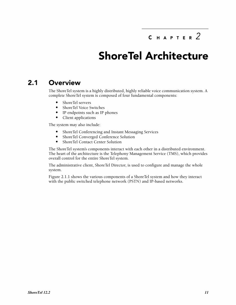
Figure 2.1.1 shows the various components of a ShoreTel system and how they interact with the public switched telephone network (PSTN) and IP-based networks.
ShoreTel 12.2 11
Maintenance Guide Chapter 2: ShoreTel Architecture
Figure 2-1 ShoreTel System
2.1.1 ShoreTel ServersEach ShoreTel system includes a main server called the Headquarters (HQ) server. Systems may optionally include distributed applications servers, called Distributed Voice Servers (DVS). Each server provides a local instance of TMS that supports applications such as voice mail, workgroups and ShoreTel Communicator. Each instance of TMS manages its local SoftSwitch and can be configured to manage ShoreTel Voice Switches as well. The DVS servers continue to rely on the HQ server for configuration changes, but otherwise can operate independently of the HQ server.
2.1.2 ShoreTel Voice SwitchesShoreTel Voice Switches provide physical connectivity for the PSTN and analog phones, and logical connectivity for IP endpoints on a reliable, highly scalable platform for the ShoreTel call control software. The ShoreTel Voice Switches receive their configuration information via TMS.
12
Chapter 2: ShoreTel Architecture Maintenance Guide
2.1.3 IP EndpointsThe ShoreTel system manages calls and applications for three types of IP endpoints: IP phones, SoftPhones, and ShoreTel converged conference bridges. IP endpoints are identified by IP address and can exist anywhere on the network.
2.1.4 ShoreTel Client ApplicationsThe client applications, e.g. Communicator, interact with the TMS using the Telephony Application Programming Interface (TAPI) for call handling and the Client-Server Internet Service (CSIS) interface for data handling. Client applications use CSIS to retrieve and update data through the ZIN Manager (DCOM) interface.
2.1.4.1 ShoreTel CommunicatorCommunicator provides desktop call control as well as voice mail, directory, and call logging features. Microsoft Outlook users can integrate their voicemail, contacts, and calendar with the ShoreTel system.
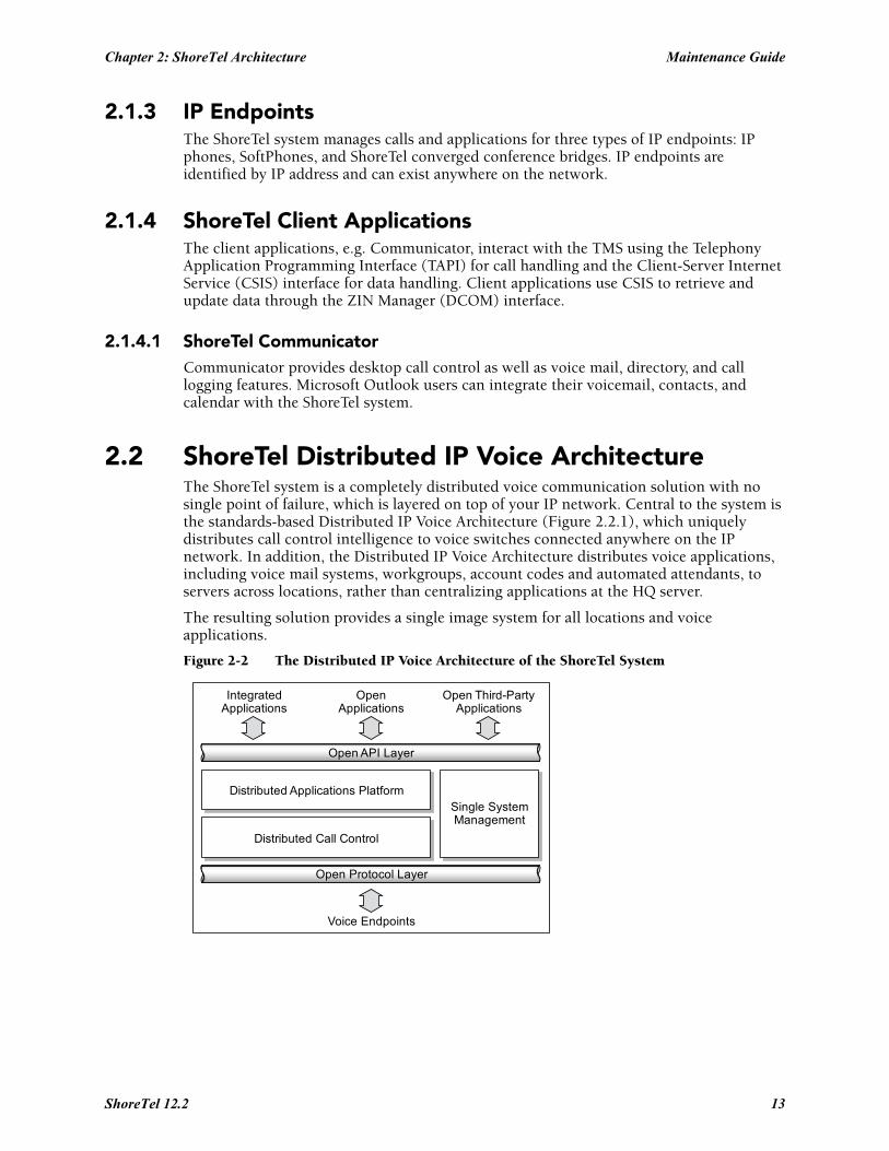
2.2 ShoreTel Distributed IP Voice ArchitectureThe ShoreTel system is a completely distributed voice communication solution with no single point of failure, which is layered on top of your IP network. Central to the system is the standards-based Distributed IP Voice Architecture (Figure 2.2.1), which uniquely distributes call control intelligence to voice switches connected anywhere on the IP network. In addition, the Distributed IP Voice Architecture distributes voice applications, including voice mail systems, workgroups, account codes and automated attendants, to servers across locations, rather than centralizing applications at the HQ server.
The resulting solution provides a single image system for all locations and voice applications.
Figure 2-2 The Distributed IP Voice Architecture of the ShoreTel System
Open API Layer
OpenApplications
Voice Endpoints
IntegratedApplications
Open Third-PartyApplications
Open Protocol Layer
Distributed Applications PlatformSingle SystemManagement
Distributed Call Control
ShoreTel 12.2 13
Maintenance Guide Chapter 2: ShoreTel Architecture
2.2.1 Distributed Applications PlatformThe ShoreTel system's ability to support applications on distributed servers across the enterprise while maintaining a single, cohesive system depends on the ShoreTel Telephony Management Service (TMS) and the ShoreTel Distributed Telephony Application Service (DTAS).
TMS runs on each ShoreTel server and observes all call activity for the SoftSwitch and ShoreTel Voice Switches it manages. DTAS also runs on each ShoreTel DVS server and directs requests to the appropriate TMS.
By installing a DVS at the same site as the users, applications such as voice mail, workgroups and Communicator can run locally, regardless of the network availability to the Headquarters server. In addition, by hosting applications, services, and APIs on multiple ShoreTel servers, the system can scale as necessary by adding ShoreTel servers.
For added local reliability, a working copy of the HQ database can reside on each DVS server in the system in the event contact with HQ is lost.
The ShoreTel TMS/DTAS software exposes a Telephony Application Programming Interface (TAPI) for call control, and a TAPI WAV interface for media playing and recording. These open APIs allow value-added applications to be added to the ShoreTel system to provide voice services.
Even when there are multiple DVS, the ShoreTel system is still managed and behaves as a single image system with complete feature transparency between sites.
2.2.2 Distributed Call ControlDistributed call control is a key concept of the ShoreTel system. Based on the industry-standard SIP protocol, ShoreTel’s distributed call control software runs on every ShoreTel Voice Switch in the ShoreTel system. Each switch call control element manages the call setup and teardown, including features such as transferring, conferencing, and forwarding calls, using call permissions, and call routing for the endpoints that it supports (both analog and IP).
The voice switches communicate on a peer-to-peer basis, eliminating any single point of failure. For instance, if one ShoreTel Voice Switch goes offline, all other ShoreTel Voice Switches continue operating. When the voice switch comes back online, it rejoins the voice network with no impact on system operation. There is no server involved with the basic telephony, so the system delivers levels of availability unmatched by even legacy vendors.
ShoreTel Voice Switches build an internal routing database from the peer-to-peer communication with other switches. Each ShoreTel Voice Switch contains routing information for all endpoints in the system, including information regarding trunk selection for outbound calls (unless Distributed Routing Service is enabled. See Section 2.2.2.1 on page 15.) When a user places a call from any extension, each switch can route the call to the correct ShoreTel Voice Switch based on its internal routing database. Sites can typically support up to 100 ShoreTel Voice Switch voices switches depending on the system configuration.
The heart of the ShoreTel system is the distributed call control software, which runs on the ShoreTel Voice Switches on top of VxWorksTM a real-time operating system, and on the ShoreTel Voice Mail Box switches, which run on top of the LINUX operating system. Each call control element manages the call setup and call teardown, including features such as transfer, conference, forward, call permissions, and call routing.
14
Chapter 2: ShoreTel Architecture Maintenance Guide
2.2.2.1 Distributed Routing ServiceDistributed Routing Service (DRS) allows larger systems to scale beyond 100 switches up to a total of 500 switches (including SoftSwitches). The Distributed Routing Service is optional on systems up to 100 switches, but must be enabled on systems with 100 or more switches.
When Distributed Routing Service is enabled, ShoreTel Voice Switches only exchange routing information with other switches configured in the same site, rather than exchanging information with every switch in the system. Although each ShoreTel Voice Switch only maintains routing information within its site, each ShoreTel server also includes an instance of the Distributed Routing Service, which maintains system-wide routing information. When site-to-site calls are initiated, ShoreTel Voice Switches contact the Distributed Routing Service in order to find the ShoreTel Voice Switch or switches necessary to complete the call.
In a system with more than one ShoreTel server, the ShoreTel Voice Switches may contact an alternate instance of the routing service if the primary instance is unreachable. ShoreTel servers have a hierarchical relationship, with the Headquarters server at the top of the hierarchy. As you add DVS servers to the system using ShoreTel Director, you define the order of the servers in relation to the Headquarters server and the various sites in your system.
Initially, the switches try to contact the nearest instance of the Distributed Routing Service in the hierarchy. If that instance of DRS is unreachable, the switch contacts the instance of DRS at the parent server in the hierarchy as a fallback.
If both instances of DRS are unreachable, the switch makes a best effort to route the call based on its internal routing tables built from communicating with peer ShoreTel Voice Switches at the same site. Additionally, if the call is an external call, the call may be routed out a local trunk even though it may not be the lowest cost. If the call is an internal call, it is redirected to the Backup Auto-Attendant.
2.2.3 Single System Management The ShoreTel system provides a browser-based network management tool called ShoreTel Director that provides a single management interface for all voice services and applications across all locations. Although there are multiple servers and switches to support the services and applications, the ShoreTel system provides a single image system across your entire network.
Integrated management enables a change to propagate dynamically across the system each time a modification is made on the ShoreTel system. When you add a new user to the system, that user automatically receives a dialing plan, voice mail, an extension, a mailbox, an Auto-Attendant profile, and an email reminder to download the desktop software. In addition, the user can be added to a Workgroup, if needed. You add new users and place them in Workgroups from a single management screen.
If ShoreTel Conferencing and Instant Messaging Services are implemented, using the Service Appliance 100 (SA-100), then these services are also fully integrated into the ShoreTel single image management system.
However, the ShoreTel Converged Conference Solution and the ShoreTel Enterprise Contact Center Solution are managed separately with their own management systems.
The ShoreTel system provides automated software distribution for all components on the system. When you add a new ShoreTel Voice Switch to the system, it is automatically upgraded to the current software release by the ShoreTel server. Existing ShoreTel Voice
ShoreTel 12.2 15
Maintenance Guide Chapter 2: ShoreTel Architecture
Switches download the current software when you reboot the switches (see Section 4.2 on page 62). The Headquarters server does not upgrade distributed servers. Distributed servers must be upgraded independently.
When you add a new user to the system, the user receives an email message containing a URL from which desktop call control and unified messaging applications can be downloaded and installed.
For software upgrades at the Headquarters site, you simply install the new software on the ShoreTel servers. Users are notified of the new software release and are automatically prompted to upgrade their software, if an upgrade is mandatory.
The ShoreTel management software also provides a complete suite of maintenance tools that enable you to monitor and change the status of components on the system. The system can be configured with event filters that automatically generate an email message if an error occurs on the system.
2.3 ShoreTel System CommunicationsShoreTel system communications can be divided into four basic communication types:
• Call Control• Configuration• TAPI• Media
The communication streams and the protocols that support them are explained in the following sections.
2.3.1 Call ControlShoreTel uses two protocols to process and manage calls:
• Media Gateway Control Protocol (MGCP)• An enhanced version of Session Initiation Protocol (SIP)
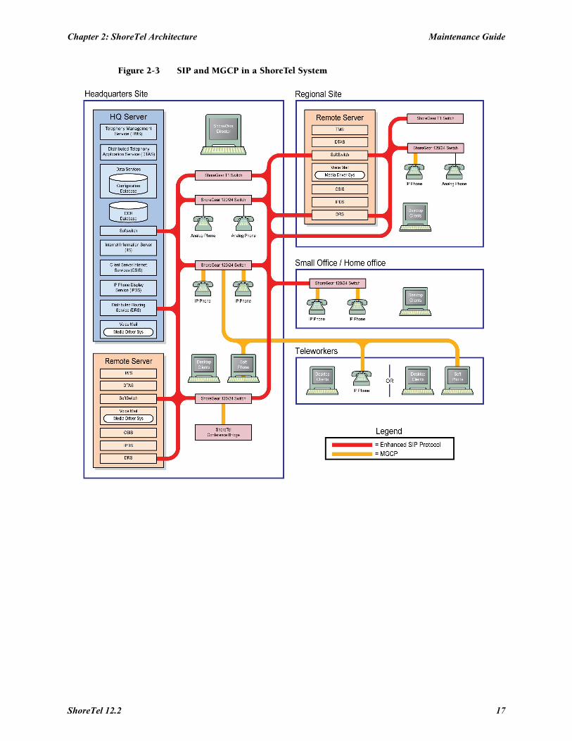
Media Gateway Control Protocol (MGCP) is used between IP phones (and other IP endpoints) and ShoreTel Voice Switches. MGCP manages the setup and teardown of media streams and some basic phone operations.
Figure 2.3.1.1 shows where SIP and MGCP are used in a ShoreTel system.
Call control between ShoreTel switches is based on the emerging Session Initiation Protocol (SIP), an application-layer protocol defined by IETF for voice-over-IP applications. Independent of the packet level, SIP establishes, modifies, or terminates sessions without respect to media content. Because of its extensibility and advanced integration capabilities, SIP is considered the next-generation protocol standard for real-time communications.
16
Chapter 2: ShoreTel Architecture Maintenance Guide
Figure 2-3 SIP and MGCP in a ShoreTel System
ShoreTel 12.2 17
Maintenance Guide Chapter 2: ShoreTel Architecture
2.3.1.1 ShoreTel’s Enhanced SIP Call ControlIn ShoreTel’s implementation of SIP call control, functions are split among the following software modules:
• User Agent• Location Service• Local Call Routing Service• Admission Control Service• Bandwidth Manager
SIP architecture deploys a peer-to-peer model in which endpoints can function either as clients or servers.
User Agents
User agent objects represent call endpoints—an extension or a trunk. Each user agent is addressable by a SIP URL.
For extensions, the URL syntax is:
sip:nnn@ip_addr:5441, where
nnn = extension numberip_addr = ip address5441 = UDP port number used by ShoreTel Call Control
For trunks, the URL syntax is:
sip:TGrp_xxxpyy@ip_addr:5441, where
xxx = trunk group numberyy = port number5441 = UDP port number used by ShoreTel Call Control
In ShoreTel’s call control protocol, user agents representing endpoints on an IP network operate as peers, functioning as clients when initiating requests, and as servers when responding to requests.
Location Service
Endpoint location exchange is performed via ShoreTel’s proprietary Location Service Protocol (LSP). When switches first connect, they exchange all known SIP URLs. Afterwards, only configuration updates are transmitted.
LSP is based on UDP. The service relies on keep-alive pings (sent every 30 seconds) to detect dead switches.
Admission Control Service
Admission Control Service instructs Bandwidth Manager to reserve bandwidth for intersite calls. If a request is successful, updates are sent to Bandwidth Managers running on other switches at the same site.
Bandwidth Manager
A distributed Bandwidth Manager keeps track of intersite bandwidth use. A Bandwidth Manager runs on each ShoreTel Voice Switch.
ShoreTel Voice Switches reserve bandwidth from the Bandwidth Manager via the ShoreTel Bandwidth Reservation Protocol (BRP). Figure 2.3.1.1 shows a hypothetical system with the call control protocols illustrated in simplified form.
18
Chapter 2: ShoreTel Architecture Maintenance Guide
2.3.1.2 Media Gateway Control ProtocolIP phones and other IP endpoints communicate with ShoreTel Voice Switches via MGCP, a device control protocol. The relationship between the switch (call manager) and the phone (gateway) follows a master–slave model.
MGCP, an industry-standard protocol, is used to:
• Deliver information to the IP phone display• Set up and tear down media streams• Report phone events such as key presses, on-hook, and off-hook
Figure 2.3.1.1 shows a hypothetical system with the call control protocols illustrated in simplified form.
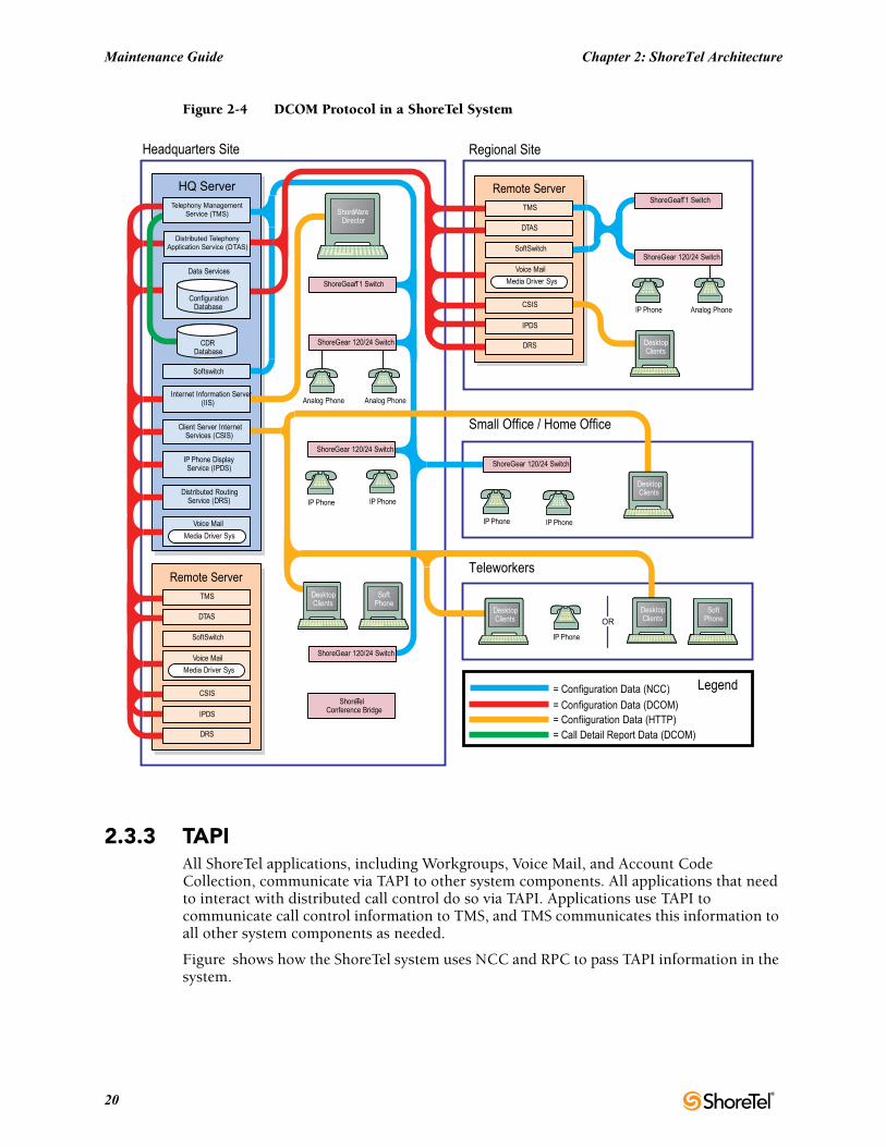
2.3.2 ConfigurationShoreTel maintains a configuration database with all the static and dynamic system configuration data. Any modifications made to the configuration database are broadcast to other system components, such as the server applications and TMS.
The database is accessed and updated via Microsoft’s Distributed Component Object Model (DCOM) protocol. ShoreTel also uses DCOM to send call information to the Call Detail Report (CDR) database, which is in Crystal Reports format.
TMS uses Network Call Control (NCC) to send each switch its configuration information. The ShoreTel Voice Switches that are connected to the network (via LAN/WAN) interact with the TMS using the NCC Client interface.
Figure 2.3.3 shows a hypothetical system with DCOM communication flows.
ShoreTel 12.2 19
Maintenance Guide Chapter 2: ShoreTel Architecture
Figure 2-4 DCOM Protocol in a ShoreTel System
2.3.3 TAPIAll ShoreTel applications, including Workgroups, Voice Mail, and Account Code Collection, communicate via TAPI to other system components. All applications that need to interact with distributed call control do so via TAPI. Applications use TAPI to communicate call control information to TMS, and TMS communicates this information to all other system components as needed.
Figure shows how the ShoreTel system uses NCC and RPC to pass TAPI information in the system.
= Call Detail Report Data (DCOM)= Confiiguration Data (HTTP)= Configuration Data (DCOM)
= Configuration Data (NCC) Legend
Headquarters Site Regional Site
Small Office / Home Office
Teleworkers
ShoreTelConference Bridge
ShoreGear 120/24 Switch
ShoreGearT1 Switch
ShoreGear 120/24 Switch
ShoreGear 120/24 Switch
ShoreGear 120/24 Switch
ShoreGear 120/24 Switch
ShoreGearT1 Switch
SoftPhone
DesktopClientsOR
IP Phone
DesktopClients
DesktopClients
IP PhoneIP Phone
DesktopClients
Analog PhoneIP Phone
SoftPhone
DesktopClients
IP PhoneIP Phone
Analog PhoneAnalog Phone
ShoreWareDirector
DRS
IPDS
CSIS
Voice Mail
Media Driver Sys
SoftSwitch
DTAS
TMS
Remote Server
DRS
IPDS
CSIS
Voice Mail
Media Driver Sys
SoftSwitch
DTAS
TMS
Remote Server
Media Driver Sys
Voice Mail
Distributed RoutingService (DRS)
IP Phone DisplayService (IPDS)
Client Server InternetServices (CSIS)
Internet Information Server(IIS)
Softswitch
CDRDatabase
ConfigurationDatabase
Data Services
Distributed TelephonyApplication Service (DTAS)
Telephony ManagementService (TMS)
HQ Server
20
Chapter 2: ShoreTel Architecture Maintenance Guide
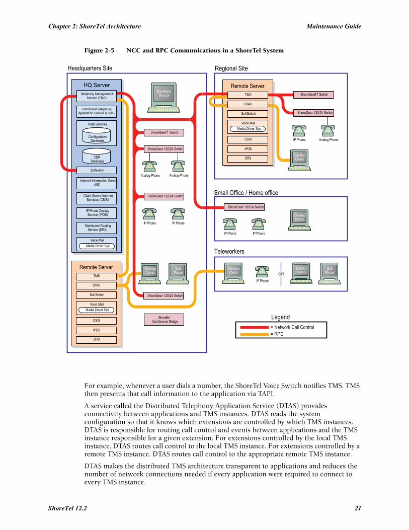
Figure 2-5 NCC and RPC Communications in a ShoreTel System
For example, whenever a user dials a number, the ShoreTel Voice Switch notifies TMS. TMS then presents that call information to the application via TAPI.
A service called the Distributed Telephony Application Service (DTAS) provides connectivity between applications and TMS instances. DTAS reads the system configuration so that it knows which extensions are controlled by which TMS instances. DTAS is responsible for routing call control and events between applications and the TMS instance responsible for a given extension. For extensions controlled by the local TMS instance, DTAS routes call control to the local TMS instance. For extensions controlled by a remote TMS instance. DTAS routes call control to the appropriate remote TMS instance.
DTAS makes the distributed TMS architecture transparent to applications and reduces the number of network connections needed if every application were required to connect to every TMS instance.
= RPC= Network Call Control
Legend
Headquarters Site Regional Site
Small Office / Home office
Teleworkers
ShoreTelConference Bridge
ShoreGear 120/24 Switch
ShoreGearT1 Switch
ShoreGear 120/24 Switch
ShoreGear 120/24 Switch
ShoreGear 120/24 Switch
ShoreGear 120/24 Switch
ShoreGearT1 Switch
SoftPhone
DesktopClientsOR
IP Phone
DesktopClients
DesktopClients
IP PhoneIP Phone
DesktopClients
Analog PhoneIP Phone
SoftPhone
DesktopClients
IP PhoneIP Phone
Analog PhoneAnalog Phone
ShoreWareDirector
DRS
IPDS
CSIS
Voice Mail
Media Driver Sys
SoftSwitch
DTAS
TMS
Remote Server
DRS
IPDS
CSIS
Voice Mail
Media Driver Sys
SoftSwitch
DTAS
TMS
Remote Server
Media Driver Sys
Voice Mail
Distributed RoutingService (DRS)
IP Phone DisplayService (IPDS)
Client Server InternetServices (CSIS)
Internet Information Server(IIS)
Softswitch
CDRDatabase
ConfigurationDatabase
Data Services
Distributed TelephonyApplication Service (DTAS)
Telephony ManagementService (TMS)
HQ Server
ShoreTel 12.2 21
Maintenance Guide Chapter 2: ShoreTel Architecture
Voices switches are assigned to specific TMS servers through ShoreTel Director. Assignment of a voice switch to a TMS server is restricted to TMS servers at its own site, or if there is no TMS server at that site, to the nearest TMS servers in the site hierarchy above.
TAPI requests invoke ShoreTel's Remote TAPI Service Provider, which uses Remote Procedure Calls (RPC) to communicate with TMS. TMS uses Network Call Control to exchange commands and events with ShoreTel Voice Switches so that TMS can present extensions and trunks as TAPI lines to the applications.
2.3.4 Media Media travels through the ShoreTel system using Real-Time Protocol (RTP). After call setup, media flows directly between IP phones via RTP. The ShoreTel Voice Switch is involved only when setting up or tearing down a call(Figure ).
22
Chapter 2: ShoreTel Architecture Maintenance Guide
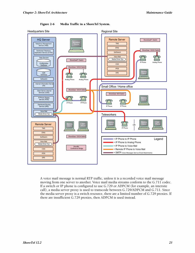
Figure 2-6 Media Traffic in a ShoreTel System.
A voice mail message is normal RTP traffic, unless it is a recorded voice mail message moving from one server to another. Voice mail media streams conform to the G.711 codec. If a switch or IP phone is configured to use G.729 or ADPCM (for example, an intersite call), a media server proxy is used to transcode between G.729/ADPCM and G.711. Since the media server proxy is a switch resource, there are a limited number of G.729 proxies. If there are insufficient G.729 proxies, then ADPCM is used instead.
= SMTP (Voice Messages Sent as Email Attachments)
= Remote IP Phone to Voice Mail
= IP Phone to Voice Mail
= IP Phone to Analog Phone
= IP Phone to IP Phone Legend
Headquarters Site Regional Site
Small Office / Home office
Teleworkers
ShoreTelConference Bridge
ShoreGear 120/24 Switch
ShoreGearT1 Switch
ShoreGear 120/24 Switch
ShoreGear 120/24 Switch
ShoreGear 40/8 Switch
ShoreGear 120/24 Switch
ShoreGearT1 Switch
SoftPhone
DesktopClientsOR
IP Phone
DesktopClients
DesktopClients
IP PhoneIP Phone
DesktopClients
Analog PhoneIP Phone
SoftPhone
DesktopClients
IP PhoneIP Phone
Analog PhoneAnalog Phone
ShoreWareDirector
DRS
IPDS
CSIS
Voice Mail
Media Driver Sys
SoftSwitch
DTAS
TMS
Remote Server
DRS
IPDS
CSIS
Voice Mail
Media Driver Sys
SoftSwitch
DTAS
TMS
Remote Server
Media Driver Sys
Voice Mail
Distributed RoutingService (DRS)
IP Phone DisplayService (IPDS)
Client Server InternetServices (CSIS)
Internet Information Server(IIS)
Softswitch
CDRDatabase
ConfigurationDatabase
Data Services
Distributed TelephonyApplication Service (DTAS)
Telephony ManagementService (TMS)
HQ Server
ShoreTel 12.2 23
Maintenance Guide Chapter 2: ShoreTel Architecture
2.3.4.1 IP Phone to IP PhoneMedia between IP phones or other IP endpoints such as SoftPhones, passes directly point to point.
2.3.4.2 IP Phone to Analog PhoneAnalog phones depend on the ShoreTel Voice Switch to which they are connected. Media from IP endpoints must pass though the ShoreTel Voice Switch supporting the analog phone.
2.3.4.3 Analog Phone to Analog PhoneMedia between analog phones passes though the switches supporting the analog phones.
2.3.4.4 Analog Phone to Voice MailVoice mail media from analog phones passes through the switch supporting the analog phone before going to voice mail via the server’s media driver. When the analog phone is located on the same LAN as the host server, the ShoreTel Voice Switch connects to the server using a G711 ulaw codec. If the analog phone is connected via a WAN, and there are ShoreTel Voice Switch resources available, the ShoreTel Voice Switch uses an inter-site codec (G729 or ADPCM). If ShoreTel Voice Switch resources are not available, the call reverts to the G711 ulaw codec.
2.3.4.5 IP Phone to Voice MailVoice mail media from IP phones and endpoints goes directly to voice mail. IP phones at remote sites without a server send voice mail media to a ShoreTel Voice Switch, which then sends it to voice mail. This is done in order to use G.729 streams for voice mail across the WAN.
2.3.4.6 Voice Mail Between ServersWhen recorded voice mail messages are transferred between servers, they are sent via SMTP.
2.4 System ReliabilitySystem reliability is ensured at several levels, including:
2.4.1 Distributed Switch ControlThe ShoreTel Telephony Management Service (TMS) runs on every ShoreTel Distributed Voice Server (DVS), ensuring switch control even if there a WAN outage between the remote DVS server and the headquarters site. Since multiple servers share the task of switch management, if a server fails, only the extensions it controls may be affected by a disruption in service.
Distributed TMS enables applications to handle calls on the switches at remote sites during a loss of network connectivity between the remote server site and the headquarters site. The co-located TMS provides local control of switches and local control by applications such as the Communicator client and IPDS via TAPI. Applications are able to provide all of the features they normally provide (during full WAN connectivity) for extensions on locally controlled switches. Monitoring and control of extensions on remotely controlled switches without a local DVS are still affected by WAN outages.
24
Chapter 2: ShoreTel Architecture Maintenance Guide
Distributed TMS also reduces the affects of a particular TMS/server outage to just those extensions controlled by that TMS instance.
Overall system scalability is increased with this feature because TMS instances control a subset of the switches in an entire system rather than all the switches in the system. Scalability is also increased because TMS instances handle a subset of Communicator clients rather than all clients in the entire system.
2.4.1.1 WAN OutageDistributed Telephony Application Service (DTAS) is responsible for routing call control and events between applications and the TMS instance responsible for a given extension.
When there is a loss of connectivity between the HQ database and a local DVS, DTAS continues to operate, except that additions and deletions to the configuration database are not seen by local applications. DTAS services involving the local TMS are available. DTAS operations involving remote TMS instances not reachable because of WAN outage are not available.
Telephony operations involving locally controlled phones are available. Monitoring of phones controlled by TMS instances not reachable because of WAN outage are not available.
TMS continues to operate, except that additions and deletions to the configuration database are not been seen by local TMS and are not relayed to telephony clients. Telephony operations involving locally controlled phones are available. If a WAN outage results in the loss of connectivity to one or more switches, telephony operations with those switches is unavailable.
2.4.2 Distributed DatabaseShoreTel now supports a distributed ShoreTel database that allows some actions previously requiring access to the HQ server. Prior to ShoreTel 11, users of ShoreTel Call Manager (now Communicator) were able to change their call handling mode (CHM) only if the HQ server was available. With ShoreTel 11 and later, user changes to their CHM are handled by the local ShoreTel server (if configured appropriately), even if the HQ server is not available.
2.4.2.1 Benefits of a Distributed Database (DDB)
Availability – A remote DVS server with DDB can run without disruption when HQ is down. Additionally, servers running a DDB can be rebooted and can operate properly, even when the HQ server is not available.Scalability – Implementing a DDB on remote DVS servers can reduce the workload on the HQ by handling queries locally, thus reducing the number of queries processed by the HQsystem. The following benefits are also realized by deploying a distributed database:
• ShoreTel Communicator users no longer need access to the HQ server in order to modify their CHM
• No action is normally required by the administrator after the initial configuration is performed. The database on the HQ server acts as the replication master and remote servers are replication slaves.
ShoreTel 12.2 25
Maintenance Guide Chapter 2: ShoreTel Architecture
• Updates from the remote server are automatically sent to the HQ database after it is available. All applications continue working without changes while the HQ system is down, and continue to function as the HQ database is updated.
2.4.3 Embedded IP Phone Display DriverSeveral tasks related to IP phone operation are handled by the switch instead of the server in order to enhance reliability and offer better uptime. Features that are managed by the switch include:
• Phone display• Transferring a call• Conference calls• Placing calls on hold• On-hook dialing• Intercom• Redial• Pickup• Park• Unpark
Some features that require writing to the database depend on the server being both operational and accessible. These features are not handled by the switch but are provided by the servers:
• directory• options• speed dial (due to its reliance on the database)• ability to change call handling modes• wrap up• monitoring extensions on other switches• presence information for user serviced by other switches
2.4.4 Public Switched Telephone Network (PSTN) FailoverUser extensions can be optionally configured to route extension-to extension calls to the public switched telephone network (PSTN) in the event that an IP connection is unavailable. Extension-to-extension calls are those a user makes to another site within a multi-site system, for example, a user in New York calling a co-worker at the company’s San Francisco office.
The IP connection may be unavailable due to lack of bandwidth or connectivity. The PSTN failover option must be explicitly enabled in the user’ Class of Service and bypasses the caller’s call permissions. For systems using Distributed Routing Service (DRS), destinations allowing PSTN failover handling return a contact list with a failover number. When a site does not have connectivity to DRS, users at other sites with DRS connectivity are able to reach the users at that site using PSTN failover (as long as the destination site includes trunks to accept the PSTN calls). This limitation impacts small offices that do not have a local DVS.
26
Chapter 2: ShoreTel Architecture Maintenance Guide
2.4.5 Distributed CDRIn the event of a WAN outage, local CDR data is stored for up to two hours on the managing DVS server. When WAN connectivity is restored, the stored data is forwarded to the Headquarters database. After two hours, the distributed server deletes the data and logs an error to the NT event log.
2.4.6 For More Information on System ReliabilitySee Section 6.1.1.2 on page 109 for more information on failover.
For configuration details about PSTN failover configuration, CDR data, or IP phone configuration, see the ShoreTel Administration Guide.
2.5 Call ScenariosTo understand how the ShoreTel system processes calls, review the following call scenarios and flow charts.
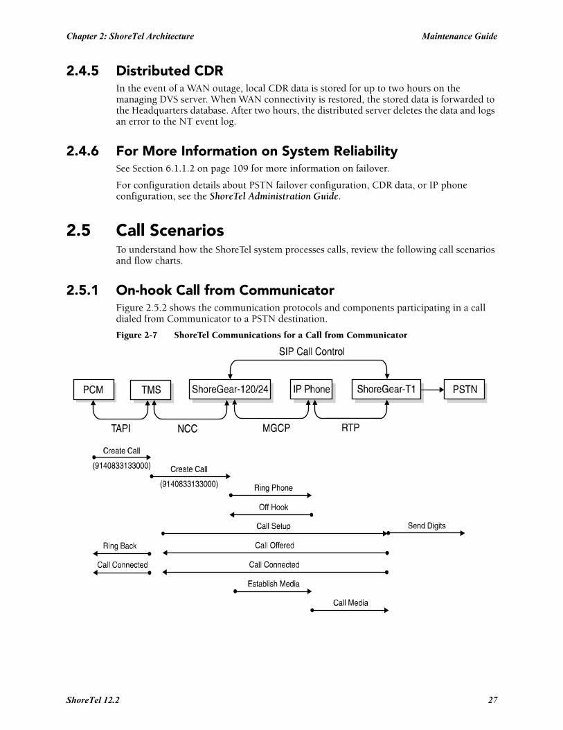
2.5.1 On-hook Call from CommunicatorFigure 2.5.2 shows the communication protocols and components participating in a call dialed from Communicator to a PSTN destination.
Figure 2-7 ShoreTel Communications for a Call from Communicator
ShoreTel 12.2 27
Maintenance Guide Chapter 2: ShoreTel Architecture
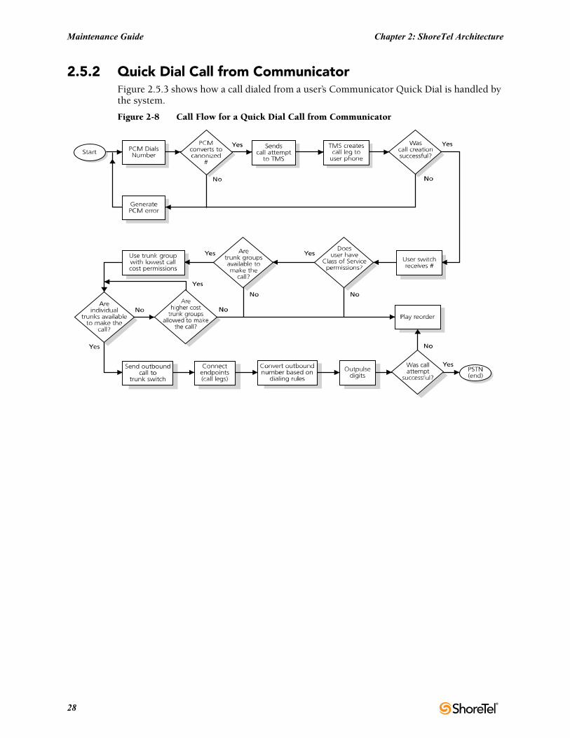
2.5.2 Quick Dial Call from CommunicatorFigure 2.5.3 shows how a call dialed from a user’s Communicator Quick Dial is handled by the system.
Figure 2-8 Call Flow for a Quick Dial Call from Communicator
28
Chapter 2: ShoreTel Architecture Maintenance Guide
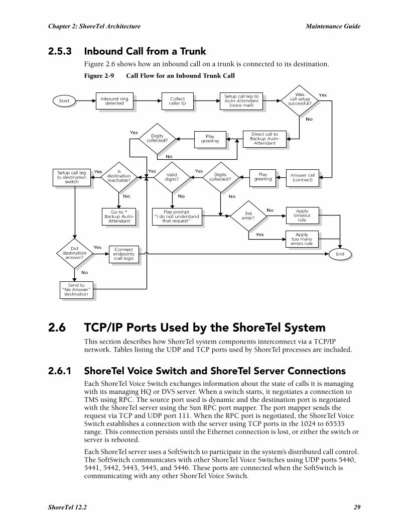
2.5.3 Inbound Call from a TrunkFigure 2.6 shows how an inbound call on a trunk is connected to its destination.
Figure 2-9 Call Flow for an Inbound Trunk Call
2.6 TCP/IP Ports Used by the ShoreTel SystemThis section describes how ShoreTel system components interconnect via a TCP/IP network. Tables listing the UDP and TCP ports used by ShoreTel processes are included.
2.6.1 ShoreTel Voice Switch and ShoreTel Server ConnectionsEach ShoreTel Voice Switch exchanges information about the state of calls it is managing with its managing HQ or DVS server. When a switch starts, it negotiates a connection to TMS using RPC. The source port used is dynamic and the destination port is negotiated with the ShoreTel server using the Sun RPC port mapper. The port mapper sends the request via TCP and UDP port 111. When the RPC port is negotiated, the ShoreTel Voice Switch establishes a connection with the server using TCP ports in the 1024 to 65535 range. This connection persists until the Ethernet connection is lost, or either the switch or server is rebooted.
Each ShoreTel server uses a SoftSwitch to participate in the system’s distributed call control. The SoftSwitch communicates with other ShoreTel Voice Switches using UDP ports 5440, 5441, 5442, 5443, 5445, and 5446. These ports are connected when the SoftSwitch is communicating with any other ShoreTel Voice Switch.
ShoreTel 12.2 29
Maintenance Guide Chapter 2: ShoreTel Architecture
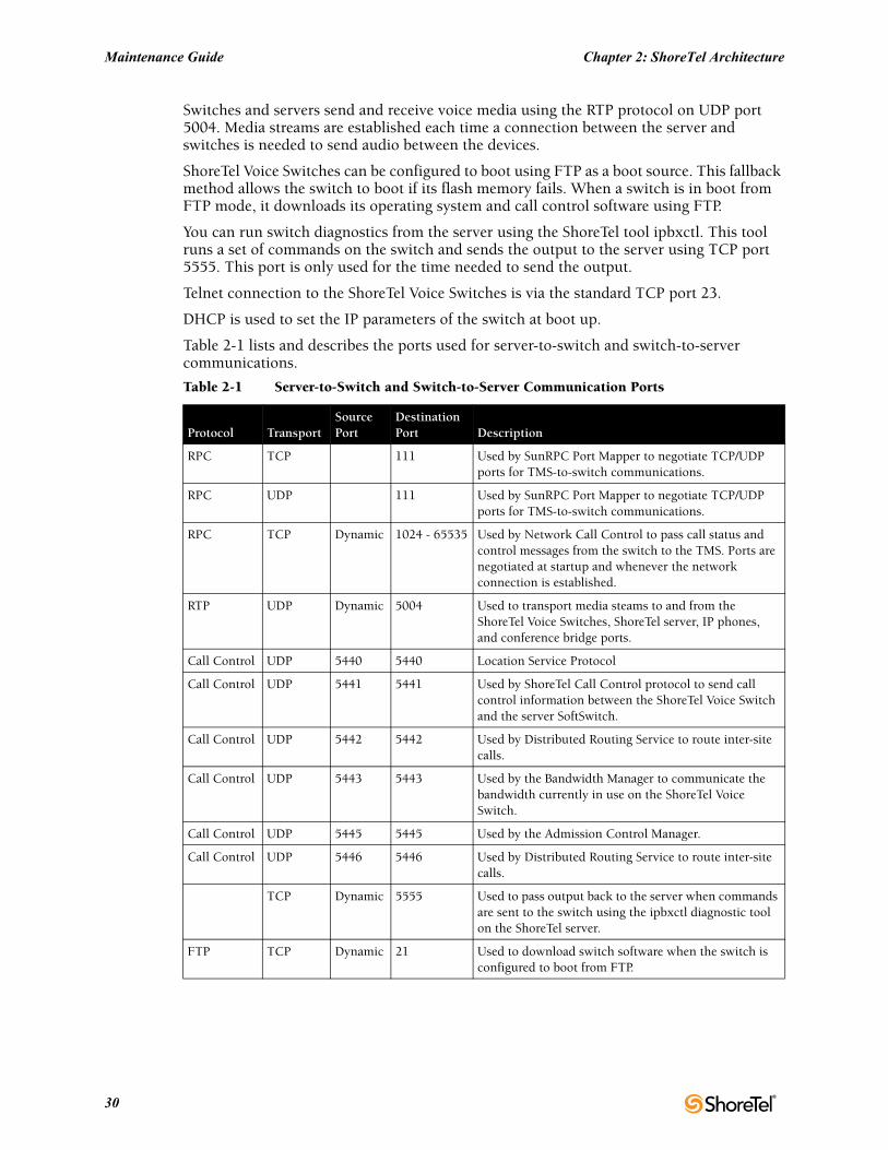
Switches and servers send and receive voice media using the RTP protocol on UDP port 5004. Media streams are established each time a connection between the server and switches is needed to send audio between the devices.
ShoreTel Voice Switches can be configured to boot using FTP as a boot source. This fallback method allows the switch to boot if its flash memory fails. When a switch is in boot from FTP mode, it downloads its operating system and call control software using FTP.
You can run switch diagnostics from the server using the ShoreTel tool ipbxctl. This tool runs a set of commands on the switch and sends the output to the server using TCP port 5555. This port is only used for the time needed to send the output.
Telnet connection to the ShoreTel Voice Switches is via the standard TCP port 23.
DHCP is used to set the IP parameters of the switch at boot up.
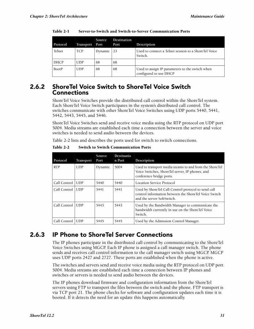
Table 2-1 lists and describes the ports used for server-to-switch and switch-to-server communications.
Table 2-1 Server-to-Switch and Switch-to-Server Communication Ports
Protocol TransportSource Port
Destination Port Description
RPC TCP 111 Used by SunRPC Port Mapper to negotiate TCP/UDP ports for TMS-to-switch communications.
RPC UDP 111 Used by SunRPC Port Mapper to negotiate TCP/UDP ports for TMS-to-switch communications.
RPC TCP Dynamic 1024 - 65535 Used by Network Call Control to pass call status and control messages from the switch to the TMS. Ports are negotiated at startup and whenever the network connection is established.
RTP UDP Dynamic 5004 Used to transport media steams to and from the ShoreTel Voice Switches, ShoreTel server, IP phones, and conference bridge ports.
Call Control UDP 5440 5440 Location Service Protocol
Call Control UDP 5441 5441 Used by ShoreTel Call Control protocol to send call control information between the ShoreTel Voice Switch and the server SoftSwitch.
Call Control UDP 5442 5442 Used by Distributed Routing Service to route inter-site calls.
Call Control UDP 5443 5443 Used by the Bandwidth Manager to communicate the bandwidth currently in use on the ShoreTel Voice Switch.
Call Control UDP 5445 5445 Used by the Admission Control Manager.
Call Control UDP 5446 5446 Used by Distributed Routing Service to route inter-site calls.
TCP Dynamic 5555 Used to pass output back to the server when commands are sent to the switch using the ipbxctl diagnostic tool on the ShoreTel server.
FTP TCP Dynamic 21 Used to download switch software when the switch is configured to boot from FTP.
30
Chapter 2: ShoreTel Architecture Maintenance Guide
2.6.2 ShoreTel Voice Switch to ShoreTel Voice Switch ConnectionsShoreTel Voice Switches provide the distributed call control within the ShoreTel system. Each ShoreTel Voice Switch participates in the system’s distributed call control. The switches communicate with other ShoreTel Voice Switches using UDP ports 5440, 5441, 5442, 5443, 5445, and 5446.
ShoreTel Voice Switches send and receive voice media using the RTP protocol on UDP port 5004. Media streams are established each time a connection between the server and voice switches is needed to send audio between the devices.
Table 2-2 lists and describes the ports used for switch to switch connections.
2.6.3 IP Phone to ShoreTel Server ConnectionsThe IP phones participate in the distributed call control by communicating to the ShoreTel Voice Switches using MGCP. Each IP phone is assigned a call manager switch. The phone sends and receives call control information to the call manager switch using MGCP. MGCP uses UDP ports 2427 and 2727. These ports are established when the phone is active.
The switches and servers send and receive voice media using the RTP protocol on UDP port 5004. Media streams are established each time a connection between IP phones and switches or servers is needed to send audio between the devices.
The IP phones download firmware and configuration information from the ShoreTel servers using FTP to transport the files between the switch and the phone. FTP transport is via TCP port 21. The phone checks for software and configuration updates each time it is booted. If it detects the need for an update this happens automatically.
Telnet TCP Dynamic 23 Used to connect a Telnet session to a ShoreTel Voice Switch.
DHCP UDP 68 68
BootP UDP 68 68 Used to assign IP parameters to the switch when configured to use DHCP
Table 2-2 Switch to Switch Communication Ports
Protocol TransportSource Port
Destination Port Description
RTP UDP Dynamic 5004 Used to transport media steams to and from the ShoreTel Voice Switches, ShoreTel server, IP phones, and conference bridge ports.
Call Control UDP 5440 5440 Location Service Protocol
Call Control UDP 5441 5441 Used by ShoreTel Call Control protocol to send call control information between the ShoreTel Voice Switch and the server SoftSwitch.
Call Control UDP 5443 5443 Used by the Bandwidth Manager to communicate the bandwidth currently in use on the ShoreTel Voice Switch.
Call Control UDP 5445 5445 Used by the Admission Control Manager.
Table 2-1 Server-to-Switch and Switch-to-Server Communication Ports
Protocol TransportSource Port
Destination Port Description
ShoreTel 12.2 31
Maintenance Guide Chapter 2: ShoreTel Architecture
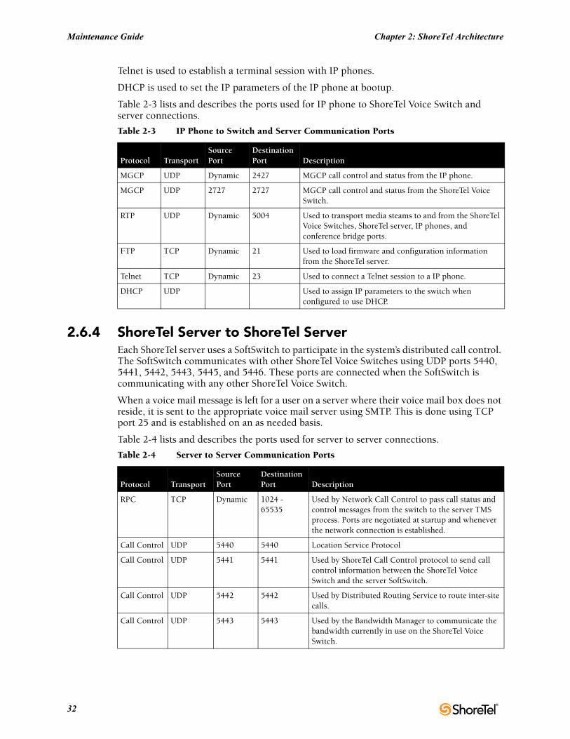
Telnet is used to establish a terminal session with IP phones.
DHCP is used to set the IP parameters of the IP phone at bootup.
Table 2-3 lists and describes the ports used for IP phone to ShoreTel Voice Switch and server connections.
2.6.4 ShoreTel Server to ShoreTel ServerEach ShoreTel server uses a SoftSwitch to participate in the system’s distributed call control. The SoftSwitch communicates with other ShoreTel Voice Switches using UDP ports 5440, 5441, 5442, 5443, 5445, and 5446. These ports are connected when the SoftSwitch is communicating with any other ShoreTel Voice Switch.
When a voice mail message is left for a user on a server where their voice mail box does not reside, it is sent to the appropriate voice mail server using SMTP. This is done using TCP port 25 and is established on an as needed basis.
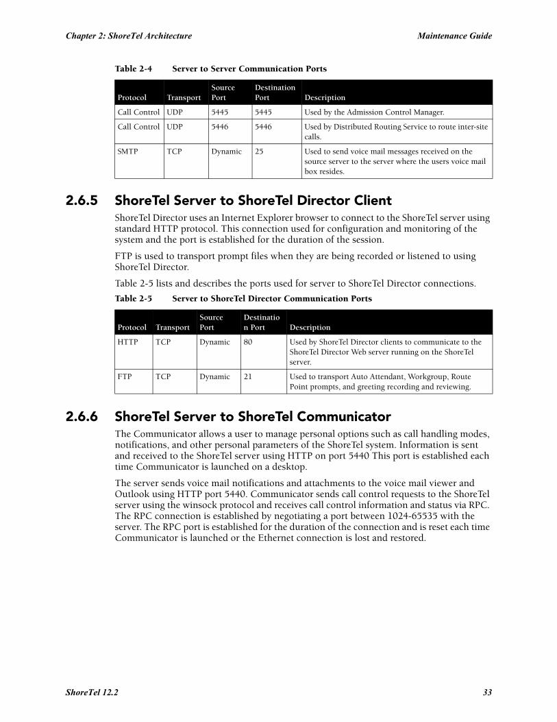
Table 2-4 lists and describes the ports used for server to server connections.
Table 2-3 IP Phone to Switch and Server Communication Ports
Protocol TransportSource Port
Destination Port Description
MGCP UDP Dynamic 2427 MGCP call control and status from the IP phone.
MGCP UDP 2727 2727 MGCP call control and status from the ShoreTel Voice Switch.
RTP UDP Dynamic 5004 Used to transport media steams to and from the ShoreTel Voice Switches, ShoreTel server, IP phones, and conference bridge ports.
FTP TCP Dynamic 21 Used to load firmware and configuration information from the ShoreTel server.
Telnet TCP Dynamic 23 Used to connect a Telnet session to a IP phone.
DHCP UDP Used to assign IP parameters to the switch when configured to use DHCP.
Table 2-4 Server to Server Communication Ports
Protocol TransportSource Port
Destination Port Description
RPC TCP Dynamic 1024 - 65535
Used by Network Call Control to pass call status and control messages from the switch to the server TMS process. Ports are negotiated at startup and whenever the network connection is established.
Call Control UDP 5440 5440 Location Service Protocol
Call Control UDP 5441 5441 Used by ShoreTel Call Control protocol to send call control information between the ShoreTel Voice Switch and the server SoftSwitch.
Call Control UDP 5442 5442 Used by Distributed Routing Service to route inter-site calls.
Call Control UDP 5443 5443 Used by the Bandwidth Manager to communicate the bandwidth currently in use on the ShoreTel Voice Switch.
32
Chapter 2: ShoreTel Architecture Maintenance Guide
2.6.5 ShoreTel Server to ShoreTel Director ClientShoreTel Director uses an Internet Explorer browser to connect to the ShoreTel server using standard HTTP protocol. This connection used for configuration and monitoring of the system and the port is established for the duration of the session.
FTP is used to transport prompt files when they are being recorded or listened to using ShoreTel Director.
Table 2-5 lists and describes the ports used for server to ShoreTel Director connections.
2.6.6 ShoreTel Server to ShoreTel CommunicatorThe Communicator allows a user to manage personal options such as call handling modes, notifications, and other personal parameters of the ShoreTel system. Information is sent and received to the ShoreTel server using HTTP on port 5440 This port is established each time Communicator is launched on a desktop.
The server sends voice mail notifications and attachments to the voice mail viewer and Outlook using HTTP port 5440. Communicator sends call control requests to the ShoreTel server using the winsock protocol and receives call control information and status via RPC. The RPC connection is established by negotiating a port between 1024-65535 with the server. The RPC port is established for the duration of the connection and is reset each time Communicator is launched or the Ethernet connection is lost and restored.
Call Control UDP 5445 5445 Used by the Admission Control Manager.
Call Control UDP 5446 5446 Used by Distributed Routing Service to route inter-site calls.
SMTP TCP Dynamic 25 Used to send voice mail messages received on the source server to the server where the users voice mail box resides.
Table 2-5 Server to ShoreTel Director Communication Ports
Protocol TransportSource Port
Destination Port Description
HTTP TCP Dynamic 80 Used by ShoreTel Director clients to communicate to the ShoreTel Director Web server running on the ShoreTel server.
FTP TCP Dynamic 21 Used to transport Auto Attendant, Workgroup, Route Point prompts, and greeting recording and reviewing.
Table 2-4 Server to Server Communication Ports
Protocol TransportSource Port
Destination Port Description
ShoreTel 12.2 33
Maintenance Guide Chapter 2: ShoreTel Architecture
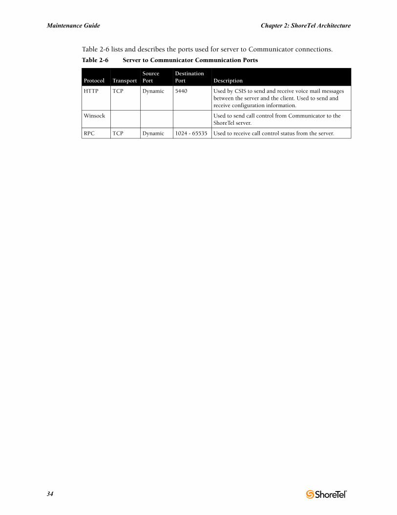
Table 2-6 lists and describes the ports used for server to Communicator connections.
Table 2-6 Server to Communicator Communication Ports
Protocol TransportSource Port
Destination Port Description
HTTP TCP Dynamic 5440 Used by CSIS to send and receive voice mail messages between the server and the client. Used to send and receive configuration information.
Winsock Used to send call control from Communicator to the ShoreTel server.
RPC TCP Dynamic 1024 - 65535 Used to receive call control status from the server.
34
C H A P T E R 3
ShoreTel Servers
3.1 OverviewThe ShoreTel voice over IP telephony solution is a suite of software modules, applications, and services running on a ShoreTel server. Every ShoreTel system includes a main server called the Headquarters server. In a single-site system, the Headquarters server may be the only ShoreTel server. More complex systems may include Distributed Voice Servers (DVS) to add reliability for applications and switches on remote sites or to support distributed applications. The Headquarters server remains the main server and must be available to interact with the DVS servers for full system functionality.
3.1.1 Headquarters ServerThe Headquarters server is the main ShoreTel server and hosts the voice applications platform and the management web site, as well as the integrated voice applications. Typically, the Headquarters ShoreTel server is located at the largest location, containing the majority of users.
The Headquarters server hosts a SoftSwitch that provides extensions for the Auto-Attendant, Workgroups, and virtual users.
3.1.2 Distributed Voice Servers (DVS)The ShoreTel system also supports remote Distributed Voice Servers (DVS). DVS servers provide increased system reliability by distributing key services and applications at remote sites. Each DVS includes an instance of TMS that connects to and manages the local SoftSwitch. The SoftSwitch provides extensions for use by the local Auto-Attendant, Workgroups, and virtual users.
DVS servers can also be configured to support distributed voice applications such voice mail, workgroups, account codes, auto attendant and a distributed database. DVS servers have TAPI access to the local SoftSwitch. The distributed TMS maintains a copy of the configuration database that allows it to provide call control and voice mail service during the outage. Each DVS manages its own SoftSwitch, as well as ShoreTel Voice Switches assigned to it.
Remote DVS are valuable for the following purposes:
• They reduce bandwidth because local users’ calls to voice mail are answered by the local voice mail application and do not pass across the WAN.
• They increase system scale by extending the unified messaging and desktop call control services to additional users of the applications.
• They increase system scale and reliability by providing distributed switch management, call control services, and unified messaging.
ShoreTel 12.2 35
Maintenance Guide Chapter 3: ShoreTel Servers
• They increase system reliability by locating workgroups on other servers and providing a location for backup workgroups to reside if a workgroup’s primary server becomes unavailable.
Call control is provided by HQ and DVS servers even if full network connectivity is unavailable. However, calls to unreachable endpoints cannot be made, and call detail recording requires Headquarters communication. To add reliability to your remote server, consider using redundant network paths to the Headquarters server.
The following sections provide more detail on the communications, services, and applications.
3.1.3 Configuration CommunicationsShoreTel system processes use Microsoft Distributed Component Object Model (DCOM) objects to share information from the configuration database among themselves and to write configuration information to the database. Static configuration parameters are written to the database by ShoreTel Director and system components access the database to read/write current state information. User configuration options are written to the database from Communicator, the telephone interface (voice mail options), Communicator for Web and Communicator for Mac. Director is accessed via a Web browser,
The service ShoreTel-ZIN, running on the Headquarters server, manages these DCOM communications for TMS. There is a single writable instance of the ShoreTel database on the Headquarters server, even if distributed databases are created on DVS servers.
Each ShoreTel service on a distributed server caches its own copy of the configuration database in internal data structures. When a distributed server loses connection to the Headquarters server, changes made to the Headquarters configuration database are no longer received by the distributed server. However, services continue to function with the most recent configuration data until connectivity is restored. When the connection is restored, the distributed server automatically receives and incorporates any changes made to the Headquarters database during the outage.
If a distributed server restarts without a connection to the Headquarters database, then ShoreTel services are started but are not functional. When the network connection is restored, the configuration is retrieved and again cached by each service and services become functional.
ShoreTel client applications, such as Communicator, use CSIS for data handling. The CSIS server communicates with ShoreTel clients via HTTP. ShoreTel Director accesses the configuration database though IIS.
You can use the Component Service Manager to view DCOM objects installed by the ShoreTel software. Component Service Manager is located in the Administrative Tools folder available from the Windows Start menu.
Do not change any permission or security settings for ShoreTel components.
Features accessible from the voice mail phone interface that require write access to the database, such as Extension Assignment and Call Handling Mode changes, are not supported during an outage unless a local distributed database instance is in use.
Figure 3-1 shows how ShoreTel services use Distributed Component Object Model (DCOM) to access the configuration database, and thus maintain the system status.
36
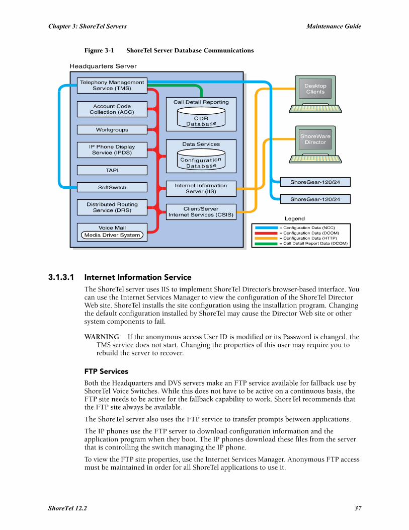
Chapter 3: ShoreTel Servers Maintenance Guide
Figure 3-1 ShoreTel Server Database Communications
3.1.3.1 Internet Information ServiceThe ShoreTel server uses IIS to implement ShoreTel Director’s browser-based interface. You can use the Internet Services Manager to view the configuration of the ShoreTel Director Web site. ShoreTel installs the site configuration using the installation program. Changing the default configuration installed by ShoreTel may cause the Director Web site or other system components to fail.
WARNING If the anonymous access User ID is modified or its Password is changed, the TMS service does not start. Changing the properties of this user may require you to rebuild the server to recover.
FTP Services
Both the Headquarters and DVS servers make an FTP service available for fallback use by ShoreTel Voice Switches. While this does not have to be active on a continuous basis, the FTP site needs to be active for the fallback capability to work. ShoreTel recommends that the FTP site always be available.
The ShoreTel server also uses the FTP service to transfer prompts between applications.
The IP phones use the FTP server to download configuration information and the application program when they boot. The IP phones download these files from the server that is controlling the switch managing the IP phone.
To view the FTP site properties, use the Internet Services Manager. Anonymous FTP access must be maintained in order for all ShoreTel applications to use it.
ShoreTel 12.2 37
Maintenance Guide Chapter 3: ShoreTel Servers
SMTP Services
The ShoreTel software uses SMTP to send email notifications (for example, when new client software is available for installation). The voice mail system uses SMTP to transport composed messages between the distributed servers. SMTP services are also required by the Event Notification feature.
The ShoreTel installer does not make any specific configurations to the SMTP service. The applications deposit outbound email on the server for forwarding elsewhere.
For proper operation of the ShoreTel services, the hosting enterprise must have an email server configured to accept and forward SMTP mail. This is usually the exchange server or primary email server for the company.
Client/Server Internet Services
CSIS is a ShoreTel proprietary protocol that uses HTTP messages to communicate between client PCs and ShoreTel servers. The CSIS protocol communicates configuration updates such as call handling mode settings and Outlook integration. The CSIS client holds open a pending HTTP request in order to receive notifications from the CSIS server. Network devices, such as firewalls and proxies, must not automatically close these pending requests.
3.1.3.2 IP Phone ServicesIP phones in a ShoreTel system rely on two services running on the Headquarters server and distributed servers:
• IP Phone Configuration Service (IPCS)—Runs on all servers.• IP Phone Display Service (IPDS)—Runs on all servers.
The IP Phone Configuration Service (IPCS) manages the IP phone configuration process, including configuration file downloads and the database updates.
IP Phone Display Service (IPDS) controls any actions by the IP phone display not controlled by the device’s firmware or switches.
3.1.3.3 Event WatchEvent Watch monitors the NT Event Log and delivers email notifications of selected events. Event notifications are configured from the Events Filter page in ShoreTel Director. For more information, see the ShoreTel Administration Guide.
3.1.3.4 Call Detail ReportingTMS use DCOM to write call data to the Call Detail Report database. The ShoreTel system tracks all call activity and generates call detail records into a database as well as into a text file on the ShoreTel server. The call detail records are used to generate CDR reports.
For more information on Call Detail Reports, see the ShoreTel Administration Guide.
3.1.4 Call Control CommunicationsThe ShoreTel servers provides call control for server applications and for Distributed Routing Service (DRS).
38
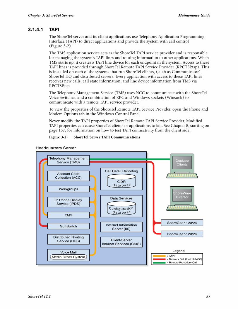
Chapter 3: ShoreTel Servers Maintenance Guide
3.1.4.1 TAPIThe ShoreTel server and its client applications use Telephony Application Programming Interface (TAPI) to direct applications and provide the system with call control (Figure 3-2).
The TMS application service acts as the ShoreTel TAPI service provider and is responsible for managing the system’s TAPI lines and routing information to other applications. When TMS starts up, it creates a TAPI line device for each endpoint in the system. Access to these TAPI lines is provided through ShoreTel Remote TAPI Service Provider (RPCTSP.tsp). This is installed on each of the systems that run ShoreTel clients, (such as Communicator), ShoreTel HQ and distributed servers. Every application with access to these TAPI lines receives new calls, call state information, and line device information from TMS via RPCTSP.tsp.
The Telephony Management Service (TMS) uses NCC to communicate with the ShoreTel Voice Switches, and a combination of RPC and Windows sockets (Winsock) to communicate with a remote TAPI service provider.
To view the properties of the ShoreTel Remote TAPI Service Provider, open the Phone and Modem Options tab in the Windows Control Panel.
Never modify the TAPI properties of ShoreTel Remote TAPI Service Provider. Modified TAPI properties can cause ShoreTel clients or applications to fail. See Chapter 8, starting on page 157, for information on how to test TAPI connectivity from the client side.
Figure 3-2 ShoreTel Server TAPI Communications
ShoreTel 12.2 39
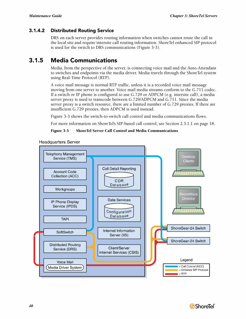
Maintenance Guide Chapter 3: ShoreTel Servers
3.1.4.2 Distributed Routing ServiceDRS on each server provides routing information when switches cannot route the call in the local site and require intersite call routing information. ShoreTel enhanced SIP protocol is used for the switch to DRS communications (Figure 3-3).
3.1.5 Media CommunicationsMedia, from the perspective of the server, is connecting voice mail and the Auto-Attendant to switches and endpoints via the media driver. Media travels through the ShoreTel system using Real-Time Protocol (RTP).
A voice mail message is normal RTP traffic, unless it is a recorded voice mail message moving from one server to another. Voice mail media streams conform to the G.711 codec. If a switch or IP phone is configured to use G.729 or ADPCM (e.g. intersite call), a media server proxy is used to transcode between G.729/ADPCM and G.711. Since the media server proxy is a switch resource, there are a limited number of G.729 proxies. If there are insufficient G.729 proxies, then ADPCM is used instead.
Figure 3-3 shows the switch-to-switch call control and media communications flows.
For more information on ShoreTel’s SIP-based call control, see Section 2.3.1.1 on page 18.
Figure 3-3 ShoreTel Server Call Control and Media Communications
40
Chapter 3: ShoreTel Servers Maintenance Guide
3.1.6 Integrated Server ApplicationsThere are several integrated TAPI applications running on the server. These applications use TAPI to send and receive call control information, and can also manipulate calls. These applications also use ZIN Manager and DCOM to access and update the configuration database.
3.1.6.1 Voice MailVoice mail is a TAPI application that supports 254 simultaneous voice mail or Auto-Attendant connections. The voice mail system uses SMTP to transport composed messages between the distributed servers. Media streams to voice mail use RTP packets to send media.
Voice messages are stored on the server’s hard drive in the VMS MESSAGE subdirectory of the Shoreline Data directory. Voice mail messages are stored as .wav files. To help you calculate storage requirements, one hour of messages requires approximately 30 MB of disk space.
The voice mail application consists of the following services: Port Manager and Mail Server. The Port Manager uses TAPI to interact with TMS. The ShoreTel system also supports linking to legacy voice mail systems using AMIS and SMDI protocols.
Distributed Voice Mail
If the Headquarters server loses network connectivity, the distributed voice mail application allows SoftSwitches on DVS servers to continue handling voice mail calls and access the Auto-Attendant.
During an outage, users can access voice mail only though their phone interface. If users were running Communicator at the time of the outage, they can still compose and play back messages. Users who were not running Communicator at the time of the outage, or who restart Communicator, are not able to access their voice mailboxes until connectivity is restored or unless their managing server includes a distributed database instance.
Voice mail messages to mail boxes hosted at other sites are stored and forwarded when connectivity to the destination voice mail service is restored.
3.1.6.2 WorkgroupsWorkgroups is an integrated Automated Call Distribution (ACD) application. Running on any HQ or DVS server, this TAPI application is responsible for routing and queueing calls directed to ShoreTel workgroups.
In the larger enterprise, there may be small- to medium-sized groups working together as a contact center. The ShoreTel Contact Center Solution is a server-based ACD and reporting package that includes the ability to queue and distribute calls, and provide agent and supervisor functions, as well as deliver reports on the call center activity.
3.1.6.3 Account Code Collection ServiceThe Account Code Collection Service (ACC) is a TAPI application running on any HQ or DVS server. When it is enabled, it allows account codes to be required or optional for outbound calls. When a restricted PSTN call is attempted, and account code collection is enabled, the ShoreTel Voice Switch redirects the call to ACC.
Account Code Collection Service is responsible for:
• Prompting the user for the account code• Collecting and validating the account code
ShoreTel 12.2 41
Maintenance Guide Chapter 3: ShoreTel Servers
• Attaching the account code to the call for reporting purposes• Performing a blind transfer to the external number
If the managing server is down, or ACC is not available, the call is directed to the Backup Auto-Attendant.
TMS provides the following information to ACC:
• Dialed number• User group• Backup Auto-Attendant and correct menu number• Account Code settings for each user group
CSIS exposes a list of account code names and numbers within Communicator clients to facilitate the account selection process for the user.
3.1.6.4 SoftSwitchSoftSwitch is used to host virtual users who are not assigned a physical telephone port on any ShoreTel Voice Switch. The SoftSwitch for each HQ or DVS server hosts all voice mail, Auto-Attendant, and Workgroup extensions as well as route points managed by that server.
There is a major impact to the system when the SoftSwitch is down or having problems. Loss of connectivity to the SoftSwitch makes the voice mail, Auto-Attendant, Workgroups, and route points supported by that SoftSwitch unavailable.
The SoftSwitch receives and transmits information using the same communication paths and protocols as the “hard” switches in the system.
A SoftSwitch is automatically created for every server added to the ShoreTel system. By default, the name of the SoftSwitch is the same as the name of the ShoreTel server hosting the switch, as specified on the Application Server page in ShoreTel Director. For more information on editing the SoftSwitch parameters, see the ShoreTel Administration Guide.
3.2 Server MaintenanceThis section provides information about server software maintenance.
3.2.1 Server Software UpgradesAn installation of the server software refers to the first time the software is installed on a server. This takes place only once and can be done with any version of ShoreTel software.
Server software upgrades take place any time new ShoreTel software is loaded. The Setup program detects the installed software and automatically takes care of converting any system files or databases. In general, you can upgrade any two previous major versions of the ShoreTel software to the current major version.
Upgrading from one minor version to another automatically converts any system files or databases. Minor upgrades typically add incremental features to the software or correct product defects found in previous releases.
3.2.2 System File BackupSee the ShoreTel Administrator Guide for instructions on backing up all essential ShoreTel files, including Workgroup and Auto Attendant prompts, auto attendant, and voicemail files.
42
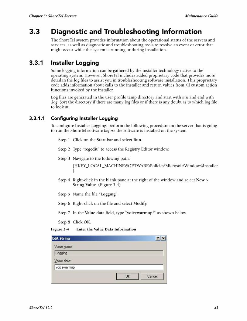
Chapter 3: ShoreTel Servers Maintenance Guide
3.3 Diagnostic and Troubleshooting InformationThe ShoreTel system provides information about the operational status of the servers and services, as well as diagnostic and troubleshooting tools to resolve an event or error that might occur while the system is running or during installation.
3.3.1 Installer LoggingSome logging information can be gathered by the installer technology native to the operating system. However, ShoreTel includes added proprietary code that provides more detail in the log files to assist you in troubleshooting software installation. This proprietary code adds information about calls to the installer and return values from all custom action functions invoked by the installer.
Log files are generated in the user profile temp directory and start with msi and end with .log. Sort the directory if there are many log files or if there is any doubt as to which log file to look at.
3.3.1.1 Configuring Installer Logging To configure Installer Logging, perform the following procedure on the server that is going to run the ShoreTel software before the software is installed on the system.
Step 1 Click on the Start bar and select Run.
Step 2 Type “regedit” to access the Registry Editor window.
Step 3 Navigate to the following path:
[HKEY_LOCAL_MACHINE\SOFTWARE\Policies\Microsoft\Windows\Installer]
Step 4 Right-click in the blank pane at the right of the window and select New > String Value. (Figure 3-4)
Step 5 Name the file “Logging”.
Step 6 Right-click on the file and select Modify.
Step 7 In the Value data field, type “voicewarmup!“ as shown below.
Step 8 Click OK.
Figure 3-4 Enter the Value Data Information
ShoreTel 12.2 43
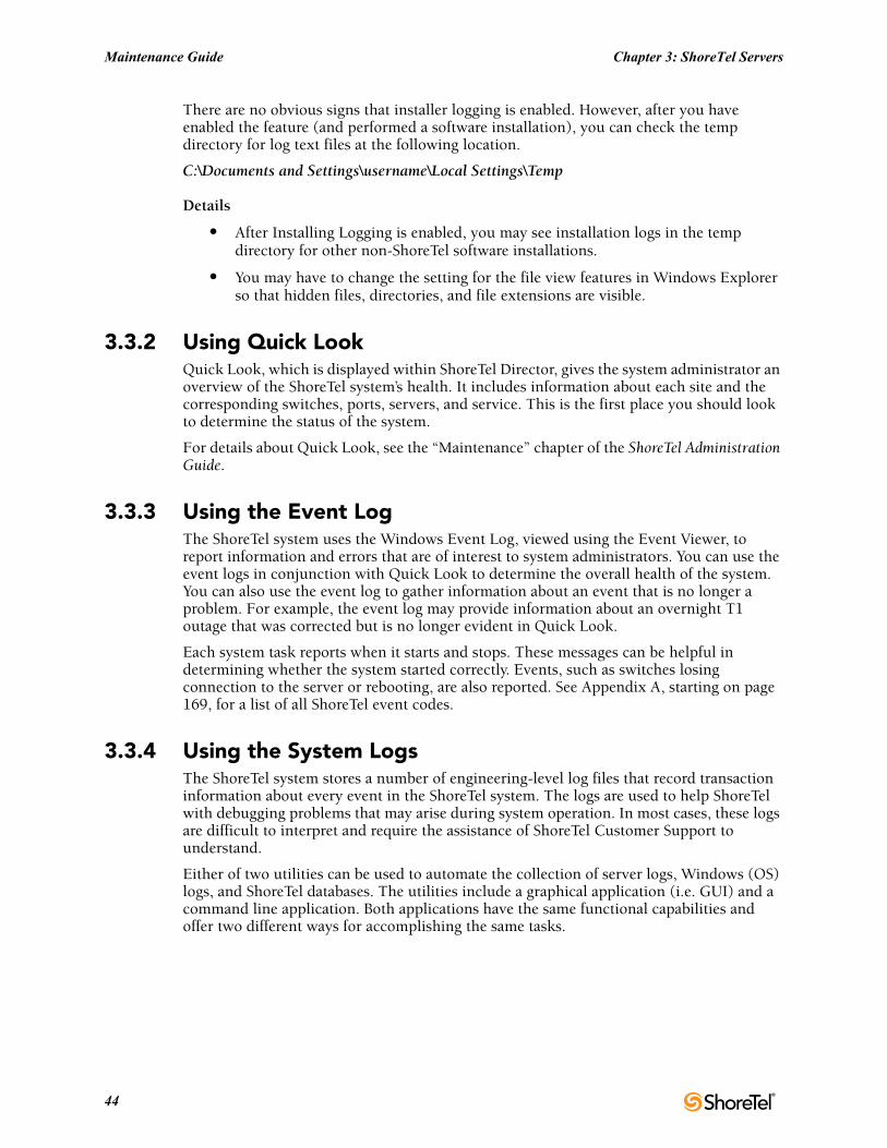
Maintenance Guide Chapter 3: ShoreTel Servers
There are no obvious signs that installer logging is enabled. However, after you have enabled the feature (and performed a software installation), you can check the temp directory for log text files at the following location.
C:\Documents and Settings\username\Local Settings\Temp
Details
• After Installing Logging is enabled, you may see installation logs in the temp directory for other non-ShoreTel software installations.
• You may have to change the setting for the file view features in Windows Explorer so that hidden files, directories, and file extensions are visible.
3.3.2 Using Quick LookQuick Look, which is displayed within ShoreTel Director, gives the system administrator an overview of the ShoreTel system’s health. It includes information about each site and the corresponding switches, ports, servers, and service. This is the first place you should look to determine the status of the system.
For details about Quick Look, see the “Maintenance” chapter of the ShoreTel Administration Guide.
3.3.3 Using the Event Log The ShoreTel system uses the Windows Event Log, viewed using the Event Viewer, to report information and errors that are of interest to system administrators. You can use the event logs in conjunction with Quick Look to determine the overall health of the system. You can also use the event log to gather information about an event that is no longer a problem. For example, the event log may provide information about an overnight T1 outage that was corrected but is no longer evident in Quick Look.
Each system task reports when it starts and stops. These messages can be helpful in determining whether the system started correctly. Events, such as switches losing connection to the server or rebooting, are also reported. See Appendix A, starting on page 169, for a list of all ShoreTel event codes.
3.3.4 Using the System LogsThe ShoreTel system stores a number of engineering-level log files that record transaction information about every event in the ShoreTel system. The logs are used to help ShoreTel with debugging problems that may arise during system operation. In most cases, these logs are difficult to interpret and require the assistance of ShoreTel Customer Support to understand.
Either of two utilities can be used to automate the collection of server logs, Windows (OS) logs, and ShoreTel databases. The utilities include a graphical application (i.e. GUI) and a command line application. Both applications have the same functional capabilities and offer two different ways for accomplishing the same tasks.
44
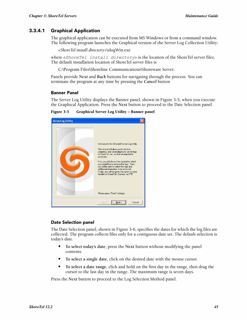
Chapter 3: ShoreTel Servers Maintenance Guide
3.3.4.1 Graphical ApplicationThe graphical application can be executed from MS Windows or from a command window. The following program launches the Graphical version of the Server Log Collection Utility:
<ShoreTel install directory>\slogWin.exe
where <ShoreTel install directory> is the location of the ShoreTel server files. The default installation location of ShoreTel server files is
C:\Program Files\Shoreline Communications\Shoreware Server.
Panels provide Next and Back buttons for navigating through the process. You can terminate the program at any time by pressing the Cancel button
Banner Panel
The Server Log Utility displays the Banner panel, shown in Figure 3-5, when you execute the Graphical Application. Press the Next button to proceed to the Date Selection panel.
Figure 3-5 Graphical Server Log Utility – Banner panel
Date Selection panel
The Date Selection panel, shown in Figure 3-6, specifies the dates for which the log files are collected. The program collects files only for a contiguous date set. The default selection is today’s date.
• To select today’s date, press the Next button without modifying the panel contents.
• To select a single date, click on the desired date with the mouse cursor.
• To select a date range, click and hold on the first day in the range, then drag the cursor to the last day in the range. The maximum range is seven days.
Press the Next button to proceed to the Log Selection Method panel.
ShoreTel 12.2 45
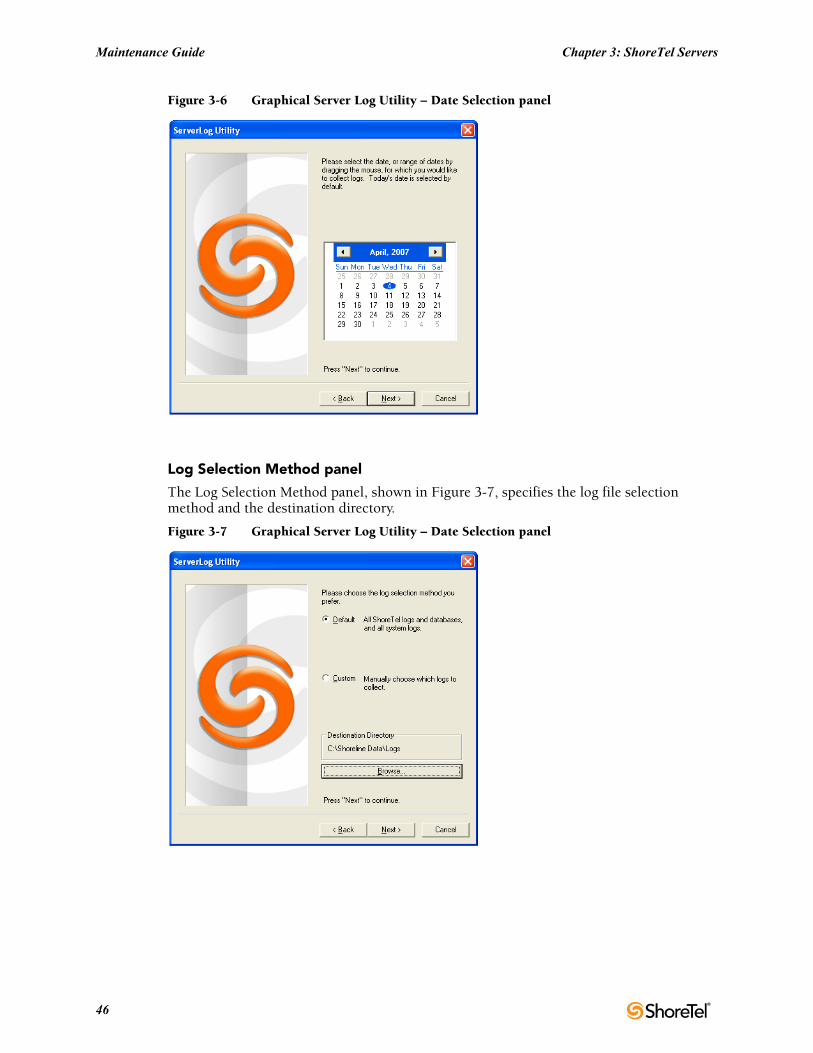
Maintenance Guide Chapter 3: ShoreTel Servers
Figure 3-6 Graphical Server Log Utility – Date Selection panel
Log Selection Method panel
The Log Selection Method panel, shown in Figure 3-7, specifies the log file selection method and the destination directory.
Figure 3-7 Graphical Server Log Utility – Date Selection panel
46
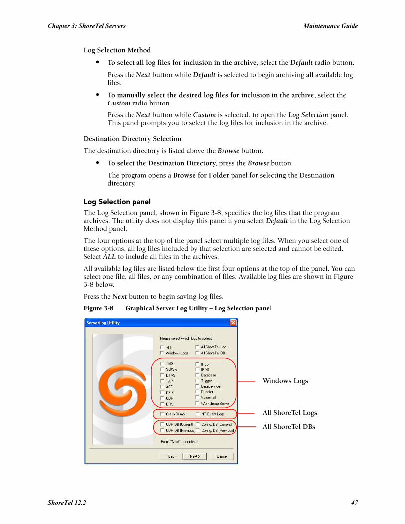
Chapter 3: ShoreTel Servers Maintenance Guide
Log Selection Method
• To select all log files for inclusion in the archive, select the Default radio button.
Press the Next button while Default is selected to begin archiving all available log files.
• To manually select the desired log files for inclusion in the archive, select the Custom radio button.
Press the Next button while Custom is selected, to open the Log Selection panel. This panel prompts you to select the log files for inclusion in the archive.
Destination Directory Selection
The destination directory is listed above the Browse button.
• To select the Destination Directory, press the Browse button
The program opens a Browse for Folder panel for selecting the Destination directory.
Log Selection panel
The Log Selection panel, shown in Figure 3-8, specifies the log files that the program archives. The utility does not display this panel if you select Default in the Log Selection Method panel.
The four options at the top of the panel select multiple log files. When you select one of these options, all log files included by that selection are selected and cannot be edited. Select ALL to include all files in the archives.
All available log files are listed below the first four options at the top of the panel. You can select one file, all files, or any combination of files. Available log files are shown in Figure 3-8 below.
Press the Next button to begin saving log files.
Figure 3-8 Graphical Server Log Utility – Log Selection panel
Windows Logs
All ShoreTel Logs
All ShoreTel DBs
ShoreTel 12.2 47
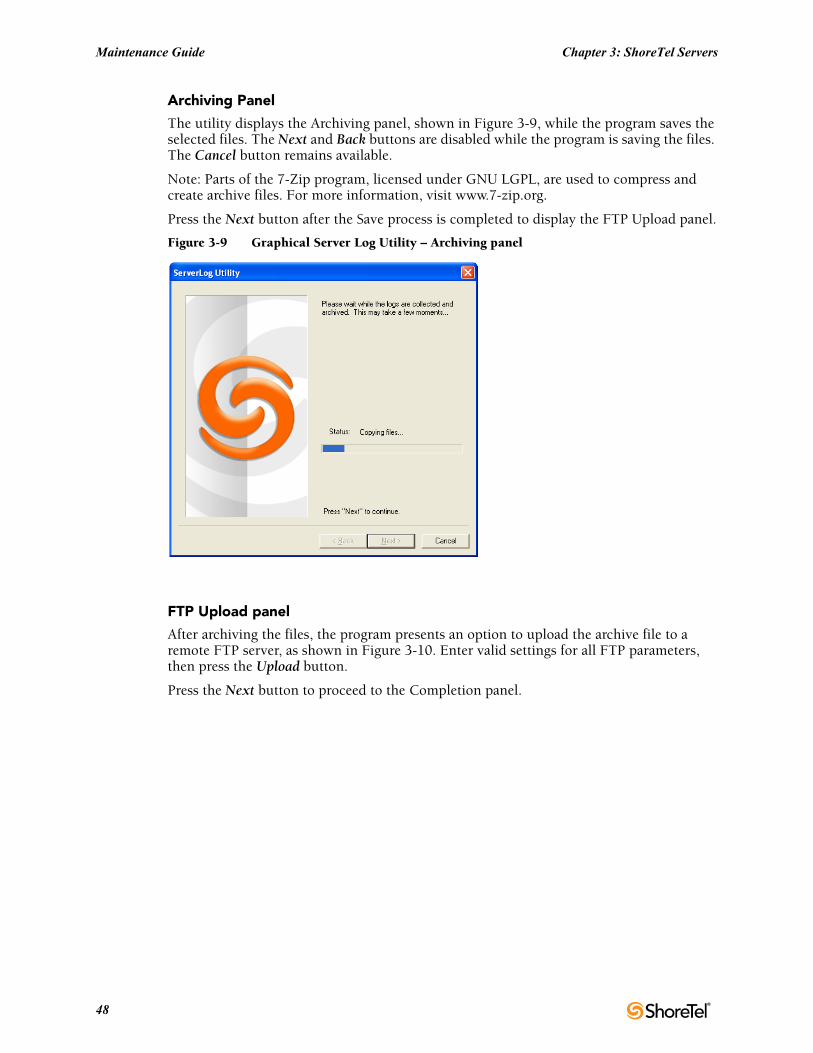
Maintenance Guide Chapter 3: ShoreTel Servers
Archiving Panel
The utility displays the Archiving panel, shown in Figure 3-9, while the program saves the selected files. The Next and Back buttons are disabled while the program is saving the files. The Cancel button remains available.
Note: Parts of the 7-Zip program, licensed under GNU LGPL, are used to compress and create archive files. For more information, visit www.7-zip.org.
Press the Next button after the Save process is completed to display the FTP Upload panel.
Figure 3-9 Graphical Server Log Utility – Archiving panel
FTP Upload panel
After archiving the files, the program presents an option to upload the archive file to a remote FTP server, as shown in Figure 3-10. Enter valid settings for all FTP parameters, then press the Upload button.
Press the Next button to proceed to the Completion panel.
48
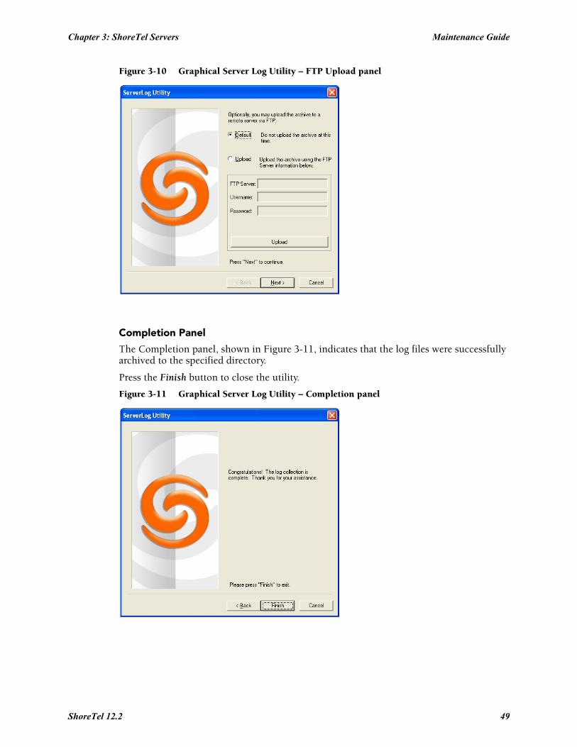
Chapter 3: ShoreTel Servers Maintenance Guide
Figure 3-10 Graphical Server Log Utility – FTP Upload panel
Completion Panel
The Completion panel, shown in Figure 3-11, indicates that the log files were successfully archived to the specified directory.
Press the Finish button to close the utility.
Figure 3-11 Graphical Server Log Utility – Completion panel
ShoreTel 12.2 49
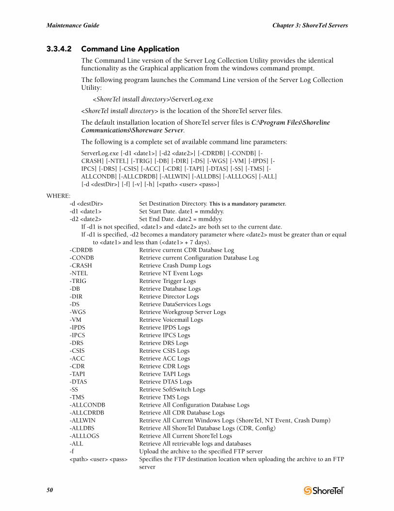
Maintenance Guide Chapter 3: ShoreTel Servers
3.3.4.2 Command Line ApplicationThe Command Line version of the Server Log Collection Utility provides the identical functionality as the Graphical application from the windows command prompt.
The following program launches the Command Line version of the Server Log Collection Utility:
<ShoreTel install directory>\ServerLog.exe
<ShoreTel install directory> is the location of the ShoreTel server files.
The default installation location of ShoreTel server files is C:\Program Files\Shoreline Communications\Shoreware Server.
The following is a complete set of available command line parameters:
ServerLog.exe [-d1 <date1>] [-d2 <date2>] [-CDRDB] [-CONDB] [-CRASH] [-NTEL] [-TRIG] [-DB] [-DIR] [-DS] [-WGS] [-VM] [-IPDS] [-IPCS] [-DRS] [-CSIS] [-ACC] [-CDR] [-TAPI] [-DTAS] [-SS] [-TMS] [-ALLCONDB] [-ALLCDRDB] [-ALLWIN] [-ALLDBS] [-ALLLOGS] [-ALL] [-d <destDir>] [-f] [-v] [-h] [<path> <user> <pass>]
WHERE:-d <destDir> Set Destination Directory. This is a mandatory parameter.-d1 <date1> Set Start Date. date1 = mmddyy.-d2 <date2> Set End Date. date2 = mmddyy.
If -d1 is not specified, <date1> and <date2> are both set to the current date.If -d1 is specified, -d2 becomes a mandatory parameter where <date2> must be greater than or equal
to <date1> and less than (<date1> + 7 days). -CDRDB Retrieve current CDR Database Log-CONDB Retrieve current Configuration Database Log-CRASH Retrieve Crash Dump Logs-NTEL Retrieve NT Event Logs-TRIG Retrieve Trigger Logs-DB Retrieve Database Logs-DIR Retrieve Director Logs-DS Retrieve DataServices Logs-WGS Retrieve Workgroup Server Logs-VM Retrieve Voicemail Logs-IPDS Retrieve IPDS Logs-IPCS Retrieve IPCS Logs-DRS Retrieve DRS Logs-CSIS Retrieve CSIS Logs-ACC Retrieve ACC Logs-CDR Retrieve CDR Logs-TAPI Retrieve TAPI Logs-DTAS Retrieve DTAS Logs-SS Retrieve SoftSwitch Logs-TMS Retrieve TMS Logs-ALLCONDB Retrieve All Configuration Database Logs-ALLCDRDB Retrieve All CDR Database Logs-ALLWIN Retrieve All Current Windows Logs (ShoreTel, NT Event, Crash Dump)-ALLDBS Retrieve All ShoreTel Database Logs (CDR, Config)-ALLLOGS Retrieve All Current ShoreTel Logs-ALL Retrieve All retrievable logs and databases-f Upload the archive to the specified FTP server<path> <user> <pass> Specifies the FTP destination location when uploading the archive to an FTP
server
50
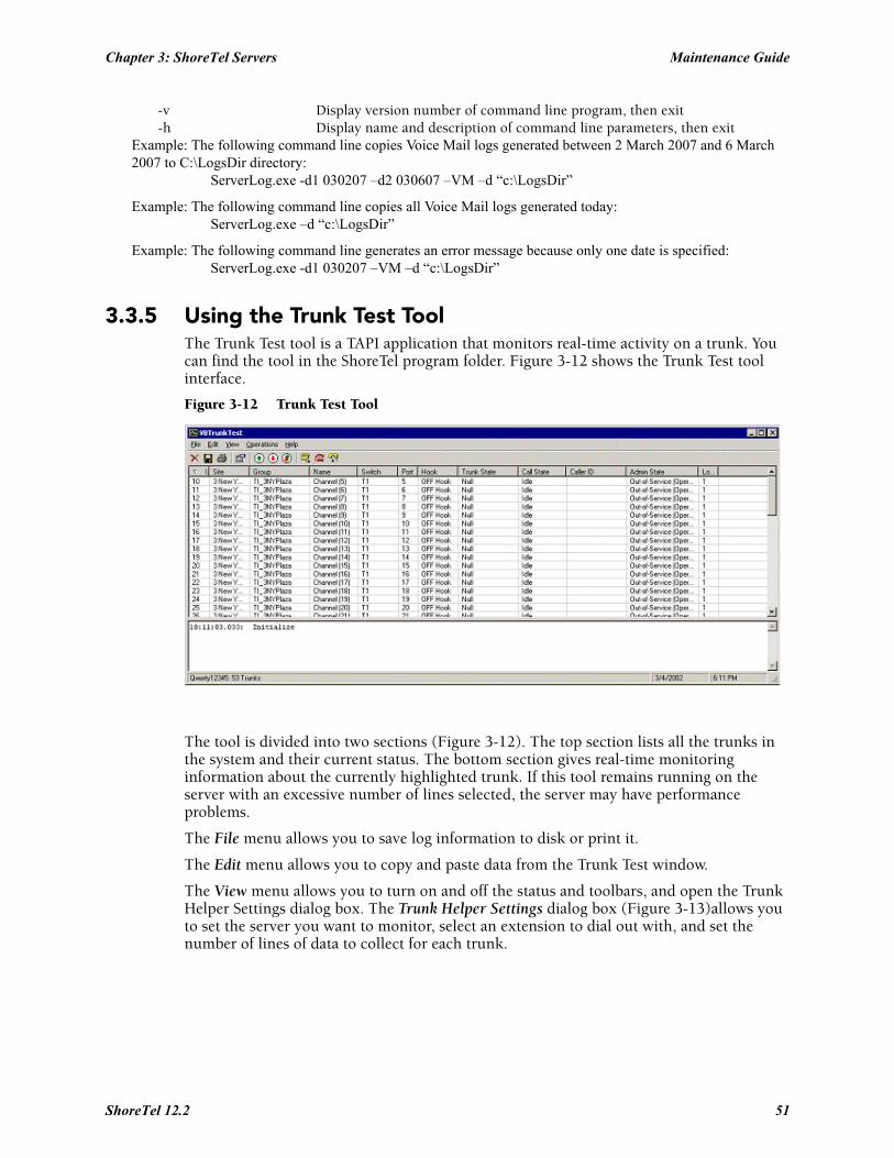
Chapter 3: ShoreTel Servers Maintenance Guide
-v Display version number of command line program, then exit-h Display name and description of command line parameters, then exit
Example: The following command line copies Voice Mail logs generated between 2 March 2007 and 6 March 2007 to C:\LogsDir directory:
ServerLog.exe -d1 030207 –d2 030607 –VM –d “c:\LogsDir”
Example: The following command line copies all Voice Mail logs generated today: ServerLog.exe –d “c:\LogsDir”
Example: The following command line generates an error message because only one date is specified: ServerLog.exe -d1 030207 –VM –d “c:\LogsDir”
3.3.5 Using the Trunk Test ToolThe Trunk Test tool is a TAPI application that monitors real-time activity on a trunk. You can find the tool in the ShoreTel program folder. Figure 3-12 shows the Trunk Test tool interface.
Figure 3-12 Trunk Test Tool
The tool is divided into two sections (Figure 3-12). The top section lists all the trunks in the system and their current status. The bottom section gives real-time monitoring information about the currently highlighted trunk. If this tool remains running on the server with an excessive number of lines selected, the server may have performance problems.
The File menu allows you to save log information to disk or print it.
The Edit menu allows you to copy and paste data from the Trunk Test window.
The View menu allows you to turn on and off the status and toolbars, and open the Trunk Helper Settings dialog box. The Trunk Helper Settings dialog box (Figure 3-13)allows you to set the server you want to monitor, select an extension to dial out with, and set the number of lines of data to collect for each trunk.
ShoreTel 12.2 51
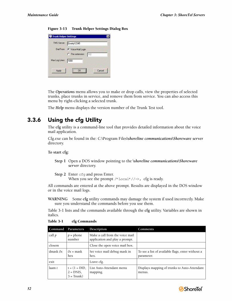
Maintenance Guide Chapter 3: ShoreTel Servers
Figure 3-13 Trunk Helper Settings Dialog Box
The Operations menu allows you to make or drop calls, view the properties of selected trunks, place trunks in service, and remove them from service. You can also access this menu by right-clicking a selected trunk.
The Help menu displays the version number of the Trunk Test tool.
3.3.6 Using the cfg Utility The cfg utility is a command-line tool that provides detailed information about the voice mail application.
Cfg.exe can be found in the: C:\Program Files\shoreline communications\Shoreware server directory.
To start cfg:
Step 1 Open a DOS window pointing to the \shoreline communications\Shoreware server directory.
Step 2 Enter cfg and press Enter. When you see the prompt /*Local*//->, cfg is ready.
All commands are entered at the above prompt. Results are displayed in the DOS window or in the voice mail logs.
WARNING Some cfg utility commands may damage the system if used incorrectly. Make sure you understand the commands before you use them.
Table 3-1 lists and the commands available through the cfg utility. Variables are shown in italics.
Table 3-1 cfg Commands
Command Parameters Description Comments
call p p = phone number
Make a call from the voice mail application and play a prompt.
closem Close the open voice mail box.
dmask 0x 0x = mask hex
Set voice mail debug mask in hex.
To see a list of available flags, enter without a parameter.
exit Leave cfg.
laam t t = (1 = DID, 2 = DNIS, 3 = Trunk)
List Auto-Attendant menu mapping.
Displays mapping of trunks to Auto-Attendant menus.
52
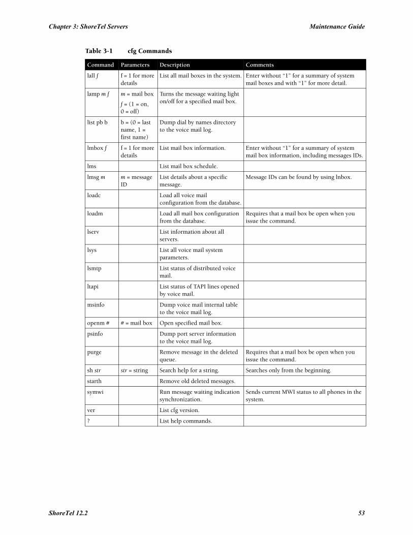
Chapter 3: ShoreTel Servers Maintenance Guide
lall f f = 1 for more details
List all mail boxes in the system. Enter without “1” for a summary of system mail boxes and with “1” for more detail.
lamp m f m = mail box
f = (1 = on,0 = off)
Turns the message waiting light on/off for a specified mail box.
list pb b b = (0 = last name, 1 = first name)
Dump dial by names directory to the voice mail log.
lmbox f f = 1 for more details
List mail box information. Enter without “1” for a summary of system mail box information, including messages IDs.
lms List mail box schedule.
lmsg m m = message ID
List details about a specific message.
Message IDs can be found by using lnbox.
loadc Load all voice mail configuration from the database.
loadm Load all mail box configuration from the database.
Requires that a mail box be open when you issue the command.
lserv List information about all servers.
lsys List all voice mail system parameters.
lsmtp List status of distributed voice mail.
ltapi List status of TAPI lines opened by voice mail.
msinfo Dump voice mail internal table to the voice mail log.
openm # # = mail box Open specified mail box.
psinfo Dump port server information to the voice mail log.
purge Remove message in the deleted queue.
Requires that a mail box be open when you issue the command.
sh str str = string Search help for a string. Searches only from the beginning.
starth Remove old deleted messages.
symwi Run message waiting indication synchronization.
Sends current MWI status to all phones in the system.
ver List cfg version.
? List help commands.
Table 3-1 cfg Commands
Command Parameters Description Comments
ShoreTel 12.2 53
Maintenance Guide Chapter 3: ShoreTel Servers
3.3.7 Using Dr. WatsonDr. Watson is an application debugging program included with the Microsoft Windows operating system. ShoreTel recommends using the Dr. Watson application if you are running on Windows 2003 Server.
Enabling Dr. Watson
Step 1 Open the Control Panel and then double-click System.
Step 2 Click on the Advanced tab.
Step 3 Click on Error Reporting button (Figure 3-14). Disable it, or if you choose to enable it, leave it enabled just for the Windows operating system and leave the Programs checkbox clear.
This must be done whenever a new machine is built or ghosted.
Step 4 Install Dr. Watson from the command line by typing "drwtsn32 -i"
Step 5 Run "drwtsn32" to configure it. A window is opened (similar to the one shown in Figure 3-15).
Step 6 Under Crash Dump Type, select the Mini radio button.
Step 7 Select the Visual notification checkbox. This ensures that you are aware when a dump occurs.
Step 8 Select the Create Crash Dump File checkbox.
Step 9 Optionally, in case the dump file might be overwritten, it may be helpful to enable the following options by selecting the associated checkboxes:
• Dump Symbol Table
• Dump All Thread Contexts
• Append to Existing Log File
Step 10Click OK to store your changes.
To collect Dr. Watson dumps:
• Dumps for a logged in user appear under:C:\Documents and Settings\All Users\Application Data\Microsoft\Dr Watson
• Dumps for services appear under:%systemroot%\PCHEALTH\ERRORREP\UserDumps
54
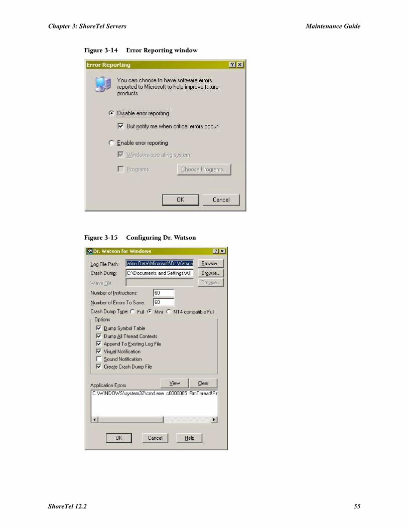
Chapter 3: ShoreTel Servers Maintenance Guide
Figure 3-14 Error Reporting window
Figure 3-15 Configuring Dr. Watson
ShoreTel 12.2 55

Maintenance Guide Chapter 3: ShoreTel Servers
3.4 Services (Processes)The ShoreTel server is made up of multiple processes working together to provide applications that include voice mail, ShoreTel Director, and Workgroups.
Each process runs as a Windows Service, starting automatically when the server starts.
Table 3-2 lists and describes each service and its underlying process. All services run on the Headquarters Server. Services that run on distributed servers are marked in the Dist. Server column.
Table 3-2 Service Descriptions
Service Name Service ID Process DescriptionDist. Server
ShoreTel Call Accounting
ShoreTel-CDR
TMSCDR.exe Records call information (call accounting information, call queuing data, and media stream data) and writes it to the CDR database.
ShoreTel CSIS Server ShoreTel-CSISSVC
CSISSvc.exe Provides ShoreTel clients with an interface to the ShoreTel server.
Manages voice mail notifications to voice mail clients, and is responsible for managing changes made to the database by the clients.
X
ShoreTel Director Utilities
ShoreTel-DirectorUtil
KadotaUtil.exe Provides management capabilities for ShoreTel Director.
Enables Quick Look to control services and browse the Event Log.
X
ShoreTel Event Watch Server
ShoreTel-EventWatch
EventWatch.exe Monitors the NT Event Log and delivers email notifications of selected events.
X
ShoreTel IP Phone Configuration Server
ShoreTel-IPCS
IPCSService.exe Manages the IP phone configuration process, including configuration files and the database updates.
X
ShoreTel IP Phone Display Server
ShoreTel-IPDS
IPDS.exe Controls any actions by the IP phone display not controlled by the device’s firmware or switches.
X
ShoreTel Notification Server
ShoreTel-Notify
TriggerServer.exe Notifies server applications of changes to the ShoreTel configuration.
X
ShoreTel Port Mapper
ShoreTel-Portmap
PortMap.exe Initiates RPC communication connections between the Telephony Management Server (TMS) and ShoreTel Voice Switches.
X
ShoreTel Software Telephony Switch
ShoreTel-SoftSwitch
VTSMain.exe
VTSService.exe
The SoftSwitch hosts call endpoints for voice mail, Workgroup, route points, and other IVR extensions. Virtual users are hosted on the Headquarters SoftSwitch.
X
ShoreTel Distributed Routing Service
ShoreTel-DRS DRS.exe When active, this service provides location information for routing inter-site calls and additional routing information for trunk group selection.
X
ShoreTel Telephony Management Service (TMS)
ShoreTel-TMS
Tms.exe The telephony platform for ShoreTel applications, ShoreTel services, and third-party TAPI applications.
X
ShoreTel Voice Mail Message Server
ShoreTel-MailServ
MailServ.exe Service component of the ShoreTel voice mail system.
X
56
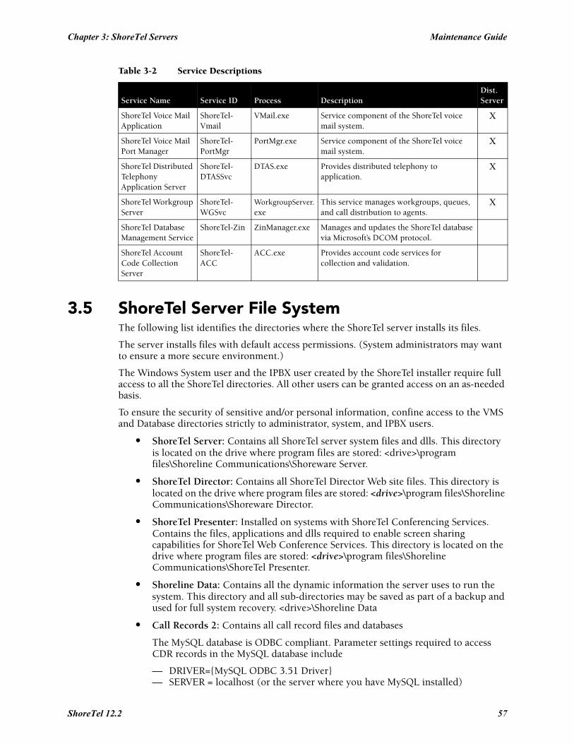
Chapter 3: ShoreTel Servers Maintenance Guide
3.5 ShoreTel Server File System The following list identifies the directories where the ShoreTel server installs its files.
The server installs files with default access permissions. (System administrators may want to ensure a more secure environment.)
The Windows System user and the IPBX user created by the ShoreTel installer require full access to all the ShoreTel directories. All other users can be granted access on an as-needed basis.
To ensure the security of sensitive and/or personal information, confine access to the VMS and Database directories strictly to administrator, system, and IPBX users.
• ShoreTel Server: Contains all ShoreTel server system files and dlls. This directory is located on the drive where program files are stored: <drive>\program files\Shoreline Communications\Shoreware Server.
• ShoreTel Director: Contains all ShoreTel Director Web site files. This directory is located on the drive where program files are stored: <drive>\program files\Shoreline Communications\Shoreware Director.
• ShoreTel Presenter: Installed on systems with ShoreTel Conferencing Services. Contains the files, applications and dlls required to enable screen sharing capabilities for ShoreTel Web Conference Services. This directory is located on the drive where program files are stored: <drive>\program files\Shoreline Communications\ShoreTel Presenter.
• Shoreline Data: Contains all the dynamic information the server uses to run the system. This directory and all sub-directories may be saved as part of a backup and used for full system recovery. <drive>\Shoreline Data
• Call Records 2: Contains all call record files and databases
The MySQL database is ODBC compliant. Parameter settings required to access CDR records in the MySQL database include
— DRIVER={MySQL ODBC 3.51 Driver}— SERVER = localhost (or the server where you have MySQL installed)
ShoreTel Voice Mail Application
ShoreTel-Vmail
VMail.exe Service component of the ShoreTel voice mail system.
X
ShoreTel Voice Mail Port Manager
ShoreTel-PortMgr
PortMgr.exe Service component of the ShoreTel voice mail system.
X
ShoreTel Distributed Telephony Application Server
ShoreTel-DTASSvc
DTAS.exe Provides distributed telephony to application.
X
ShoreTel Workgroup Server
ShoreTel-WGSvc
WorkgroupServer.exe
This service manages workgroups, queues, and call distribution to agents.
X
ShoreTel Database Management Service
ShoreTel-Zin ZinManager.exe Manages and updates the ShoreTel database via Microsoft’s DCOM protocol.
ShoreTel Account Code Collection Server
ShoreTel-ACC
ACC.exe Provides account code services for collection and validation.
Table 3-2 Service Descriptions
Service Name Service ID Process DescriptionDist. Server
ShoreTel 12.2 57
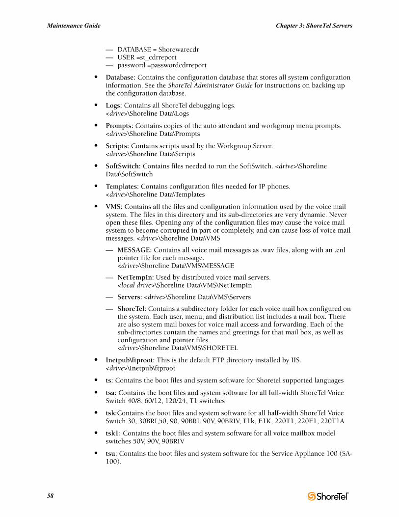
Maintenance Guide Chapter 3: ShoreTel Servers
— DATABASE = Shorewarecdr— USER =st_cdrreport— password =passwordcdrreport
• Database: Contains the configuration database that stores all system configuration information. See the ShoreTel Administrator Guide for instructions on backing up the configuration database.
• Logs: Contains all ShoreTel debugging logs.<drive>\Shoreline Data\Logs
• Prompts: Contains copies of the auto attendant and workgroup menu prompts.<drive>\Shoreline Data\Prompts
• Scripts: Contains scripts used by the Workgroup Server.<drive>\Shoreline Data\Scripts
• SoftSwitch: Contains files needed to run the SoftSwitch. <drive>\Shoreline Data\SoftSwitch
• Templates: Contains configuration files needed for IP phones.<drive>\Shoreline Data\Templates
• VMS: Contains all the files and configuration information used by the voice mail system. The files in this directory and its sub-directories are very dynamic. Never open these files. Opening any of the configuration files may cause the voice mail system to become corrupted in part or completely, and can cause loss of voice mail messages. <drive>\Shoreline Data\VMS
— MESSAGE: Contains all voice mail messages as .wav files, along with an .enl pointer file for each message.<drive>\Shoreline Data\VMS\MESSAGE
— NetTempIn: Used by distributed voice mail servers.<local drive>\Shoreline Data\VMS\NetTempIn
— Servers: <drive>\Shoreline Data\VMS\Servers
— ShoreTel: Contains a subdirectory folder for each voice mail box configured on the system. Each user, menu, and distribution list includes a mail box. There are also system mail boxes for voice mail access and forwarding. Each of the sub-directories contain the names and greetings for that mail box, as well as configuration and pointer files.<drive>\Shoreline Data\VMS\SHORETEL
• Inetpub\ftproot: This is the default FTP directory installed by IIS. <drive>\Inetpub\ftproot
• ts: Contains the boot files and system software for Shoretel supported languages
• tsa: Contains the boot files and system software for all full-width ShoreTel Voice Switch 40/8, 60/12, 120/24, T1 switches
• tsk:Contains the boot files and system software for all half-width ShoreTel Voice Switch 30, 30BRI,50, 90, 90BRI. 90V, 90BRIV, T1k, E1K, 220T1, 220E1, 220T1A
• tsk1: Contains the boot files and system software for all voice mailbox model switches 50V, 90V, 90BRIV
• tsu: Contains the boot files and system software for the Service Appliance 100 (SA-100).
58

Chapter 3: ShoreTel Servers Maintenance Guide
3.6 RegistryThe ShoreTel software uses the Windows registry to store various parameters used by the ShoreTel system. These registry keys can be found in the following registry path:
HKEY_LOCAL_MACHINE\SOFTWARE\Shoreline Teleworks
3.7 ShoreTel Release Numbering SchemeIn the ShoreTel release number schema, the first number is the major build, second is the minor build, the third is the number of the build, and the fourth number is always 0.
The following guidelines are used in the ShoreTel version numbering schema:
• Major = release; minor = update within release; build = build number of the minor/major combo; fourth number = 0
• DVD or Package major.minor.build.0
— Example 8.3.1601.0
• Server major.minor.build.0
— Example 8.3.1601.0
• Remote Server major.minor.build.0
— Example 8.3.1602.0
• Client major.minor.build.0
— Example 8.3.1603.0
• Switch major.minor.build.0
— Example 8.3.1604.0
Patches are software fixes that update a specific version of software and cannot be applied to previous major or minor versions.
ShoreTel 12.2 59

Maintenance Guide Chapter 3: ShoreTel Servers
60
C H A P T E R 4
ShoreTel Voice Switches
4.1 OverviewShoreTel Voice Switches provide physical connectivity for the PSTN and analog phones, and logical connectivity for IP endpoints on a reliable, highly scalable platform for the ShoreTel call control software. The call control software runs on top of VxWorks, a real-time embedded operating system designed specifically for mission-critical applications. For information on Voicemail Box Switches, consult Chapter 5.
The voice switches have flash memory that allows permanent storage of the call control software and configuration information. The voice switches have no moving parts (that is, no hard drive) other than a highly reliable fan. The switches include the necessary DSP technology to enable toll-quality voice with features like echo cancellation, voice compression, and silence suppression.
TMS propagates configuration data from the database to each switch upon reboot of either TMS or the switch. The data sent is a subset of configuration data specific to that switch. TMS also maintains this data by propagating changes to the database to those switches affected by the change. The TMS/Switch configuration interface uses the same Network Call Control protocol that is used for other TMS/switch communication. The NCC protocol is based on Sun RPC. You can obtain the configuration data that TMS sends to any specific switch with a CLI command. For more information, see Section 4.6.2.1 on page 71.
Switches share their switch-specific configuration with other switches in the system using the UDP-based Location Service Protocol (LSP). Switches keep current with other switches by propagating their changes and receiving them from other switches. For information about viewing switch-to-switch communications, see Section 4.6.2.1 on page 71.
The ShoreTel Voice Switches communicate call control information on a peer-to-peer basis. When Distributed Routing Service (DRS) is enabled, switches exchange LSP messages only with other switches at the same site. DRS communicates directly with the database to keep the database configuration current. TMS tells each switch how to find DRS as part of the configuration process described earlier. When DRS is enabled, switches generally give DRS an opportunity to resolve numbers, so that its more complete view of the system can be leveraged to find the best contact. If the switch knows where an intra-site extension is, it does not involve DRS.
For analog phones, the switch detects whether the phone is on or off hook, collects digits from the phone, and (based on digits collected) determines when a call is established. If necessary, the switch communicates with other switches (in some cases this may not be necessary, such as when call is to an endpoint directly on the switch) to establish a call between the appropriate endpoints.
The switch acts as a media gateway for the PSTN and analog phones by encoding the analog voice and transmitting it to the other endpoint over the IP network using RTP. The switch also uses NCC to send events to TMS about digit collection, caller ID, call establishment, and so forth. TMS makes this information available to the server applications. These applications are not necessary for many calls (such as those between
ShoreTel 12.2 61
Maintenance Guide Chapter 4: ShoreTel Voice Switches
two phones or a trunk and a phone, which can be established with only the switches controlling the phones and trunks), but they can enhance the user experience. For example, Communicator can provide information about the call to the user's desktop.
After the call is established, TMS monitors the call and logs call information on the Call Detail Report (CDR) database.
4.2 ShoreTel Voice Switch Firmware UpgradesEach ShoreTel Voice Switch is shipped from the factory with the version of firmware that ShoreTel used to test the system.
When you install a switch, ShoreTel’s TMS service is set up to detect the switch’s firmware version and automatically upgrade your hardware to the latest version. This happens once while the switch still retains the factory-default settings. (You can use the ShoreTel Director Quick Look page to monitor the progress of the upgrade.)
ShoreTel also makes firmware upgrades available via system upgrades and patches.
4.2.1 Using Quick Look to Perform UpgradesYou can use the ShoreTel Director Quick Look page to identify switches that require upgrades. When a switch update is required, QuickLook reports Firmware Update Available or Firmware Version Mismatch.
• Firmware Update Available indicates that a patch is available and an upgrade is required to load the patch. When a switch is in this state, it is fully functional and in communication with TMS and the other switches in the system.
• Firmware Version Mismatch indicates that you must upgrade the switch before it can communicate with the TMS server. A switch with mismatched firmware can communicate with other switches of the same version and manage calls, but cannot support server and client applications.
To upgrade the switch:
Step 1 In ShoreTel Director, open the Maintenance > Quick Look page, and select the Site where the switch is located.
Step 2 Choose Reboot from the Command drop-down list in the switch row.
Upon restart, the switch is automatically upgraded. You can monitor the progress of the upgrade on the Quick Look page.
4.2.2 Performing a Manual Upgrade
To manually upgrade the switch’s firmware:
Step 1 From the server command line, enter the burnflash command in this format:
C:\Program Files\Shoreline Communications\Shoreware Server>burnflash -s <switch IP Address>
62
Chapter 4: ShoreTel Voice Switches Maintenance Guide
4.3 ShoreTel Voice Switch Boot OptionsWhen a ShoreTel Voice Switch boots, it requires an IP address to connect to the network and an application program. ShoreTel Voice Switches are set to use a DHCP server for an IP address and to retrieve the application from the switch’s flash memory.
If a DHCP request receives no response, the switch tries a BootP request as a backup. ShoreTel recommends using static IP parameters configured via the serial port, as this is much more reliable. If DHCP is to be used, ShoreTel strongly recommends using DHCP reservations for each switch so that the DHCP lease is not lost.
If a DHCP server is not available, you can set the IP address manually from the switch’s maintenance port.
The standard method for booting a ShoreTel Voice Switch is to boot from the switch’s flash memory. When a ShoreTel Voice Switch is first powered on, it reads the boot parameters stored on the boot ROM, which instructs the switch to load software from flash memory. When the software starts, it loads its configuration, which is also stored in flash memory.
Booting from FTP is available for instances when you cannot boot the switch from flash memory. When you boot a switch from FTP, the operating system and software load from the FTP site identified in the boot parameters. The loaded configuration is a configuration received from the TMS server.
If the switch fails to load the application from flash and does not have the IP address of the ShoreTel server, you can set the IP address and boot parameters by connecting to the maintenance port and using the configuration menu. The configuration menu allows you to set the IP address of the switch and enter the ShoreTel server (boot host) IP address.
4.3.1 IP Address from DHCP The switch sends requests for an IP address to the DHCP server ten times at increasing intervals. When the switch receives a response from the DHCP server, the boot process begins. If the switch fails to get an IP address from the DHCP server, it uses the last assigned IP address. The switch continues sending IP address requests to the DHCP server.
If the DHCP server sends a conflicting IP address while the switch is using an address from a previous state, the entire system restarts. Use long lease times to prevent to prevent this. ShoreTel recommends either static IP parameters or DHCP reservations.
If the switch does not receive an IP address from the DHCP server and an address is not available from a previous state, the switch continues polling the DHCP server until it receives an address.
4.3.2 Setting the IP Address with VxWorksIf the switch is not configured with an IP address and fails to boot from flash, it cannot download the application and configuration from the FTP server. In this case, you can manually set the IP address and boot parameters from VxWorks accessible from the maintenance port.
Boot parameter changes do not take effect until the switch is rebooted.
This command line interface is not available through Telnet.
To connect to the maintenance port of a ShoreTel Voice Switch:
Step 1 Connect a serial cable between a personal computer and the ShoreTel Voice Switch.
ShoreTel 12.2 63
Maintenance Guide Chapter 4: ShoreTel Voice Switches
Step 2 Use a terminal emulation program such as Tera Term Pro or PuTTY freeware to open a connection to the switch.
Step 3 Apply these values to the terminal settings:
• Speed: 19.2 Kbs• Data bit: 8 bits• Stop bit: 1• Parity: No parity• Flow Control: None
4.3.2.1 The CLI Main MenuThe CLI main menu automatically appears at system startup. You can also invoke the menu at any time by entering a question mark (?).
The following list describes the commands available in the CLI main menu:
• (1) -- Show version: Lists version numbers for firmware and boot ROM in addition to the base version and the CPU board version.
• (2) -- Show system configuration: Displays the switch’s boot and IP configuration.
• (3) -- Change system configuration: Takes you to the system configuration menu where you can set a switch’s boot and IP configuration.
• (4) -- Reboot: Reboots the switch.
• ? -- Help: Enter a ? to print this menu.
To select an option in ShoreTel Voice Switch CLI, enter the number associated with the menu item and press ENTER. To change or set a parameter, select the item you wish to change, then type the parameter number and press Enter.
4.3.2.2 Boot and IP Configuration OptionsWhen you choose Change System Configuration from the CLI main menu, a menu of boot and IP configuration options appears.
• (0) -- Return to previous menu:
• (1) -- Change IP address:
• (2) -- Change IP subnet mask:
• (3) -- Change gateway IP address:
• (4) -- Change server IP address: This is the IP Address the ShoreTel server with the FTP service for the switch.
• (5) -- Change boot method:
• (6) -- Enable/disable DHCP:
• (7) -- Change network speed and duplex mode:
• (P) -- Set/change primary DNS IP address
• (S) -- Set/change secondary DNS IP address
• ? -- Help:
After you have set your IP address and boot options, enter ? to return to the main menu. You must reboot the switch for the new setting to take effect.
64
Chapter 4: ShoreTel Voice Switches Maintenance Guide
4.3.3 Accessing ShoreTel Voice Switch CLI on the SoftSwitchTo run ShoreTel Voice Switch CLI diagnostics on the SoftSwitch, you must create a Telnet session. ShoreTel Voice Switch CLI commands are listed in Section 4.6.2 on page 71.
To start a SoftSwitch Telnet session on the server:
Step 1 Create the following DWORD entry in HKEY_LOCAL_MACHINE\Software\Shoreline Teleworks\SoftSwitch:
TelnetEnabled
Step 2 Set the value to 1.
Step 3 Open a Command Prompt (DOS) window and type:
telnet localhost 2323
In order to Telnet to the SoftSwitch, the Telnet port must be set to 2323. The standard Telnet port is 23.
Step 4 Press ENTER.
No User ID or Password is required. This immediately logs you into the SoftSwitch.
Step 5 Press ENTER a second time to get the SoftSwitch prompt.
The prompt is as follows:
????SHELL: ????SHELL:
Step 6 Enter CLI commands as described in Section 4.6.2 on page 71.
Step 7 End the SoftSwitch Telnet session by typing exit.
Step 8 Press ENTER.
Step 9 Remove the “Telnet Enabled” DWORD from the registry editor by right-clicking on it and selecting Delete.
To start a Telnet session to the SoftSwitch from a different computer, you must specify the IP address of the ShoreTel server and modify the Telnet port to 2323.
All switch commands are available in the SoftSwitch with the exception of the following:
• Any VxWorks-specific commands• msps
4.3.4 Modifying Router Auto-Delete Properties for ICMP Redirects When WAN links fail, ICMP redirect messages are received by the ShoreTel Voice Switches from routers on the network. These ICMP redirect messages notify hosts on the network (i.e. ShoreTel Voice Switches) that an alternate route1 is available and the switch updates its routing table accordingly.
1. The router usually directs the switch to use the default gateway. This gateway can often be a device that is not connected to the remote site.
ShoreTel 12.2 65
Maintenance Guide Chapter 4: ShoreTel Voice Switches
If these messages are not deleted from the switch, the routing table can become cluttered with old, useless, or perhaps inaccurate information. Therefore, the default behavior for ShoreTel Voice Switches is to automatically delete any ICMP redirect messages three minutes after time of receipt.
If desired you can shorten or lengthen this period of time in one-minute increments, or you can disable the automatic deletion of ICMP redirect messages altogether.
To modify the time period for the automatic deletion of ICMP redirect messages, follow the procedure below:
Step 1 Create the following DWORD entry in HKEY_LOCAL_MACHINE\SOFTWARE\Shoreline Teleworks\Telephony Management Server\Settings:
SwitchDebug - “debug_options timeout_icmp_redirect n.”
Step 2 Set the value of n to the desired time period. Note that this must be an integral value and the number represents minutes, not seconds. The value of n can be set to zero (0) to disable the auto deletion of ICMP redirect messages.
When this key is defined in the main server, the switches automatically delete all of their routing table entries after the specified period of time. Note that sampling occurs once per minute, so routes do not disappear exactly 360 seconds later if n is set to 6.
Step 3 Reboot the ShoreTel Voice Switch for these changes to take effect.
4.3.5 Using a Telnet Session to Set IP Address and Boot ParametersYou have the option of setting IP address and boot parameters using the VxWorks bootChange command. To access the bootChange command, you must establish a telnet session to the switch. For information on other commands available from VxWorks, see Section 4.6.2 on page 71.
To set IP address and boot parameters via bootChange:
Step 1 Start the Telnet process with an ipbxctl command entered in this format:
C:\Program Files\Shoreline Communications\ShoreWare Server>ipbxctl -telneton <Switch IP Address>
After the Telnet process is running, open a Telnet session with the switch.
You are prompted for a User ID and Password.
Step 2 For User ID, enter anonymous.
Step 3 For Password, enter ShoreTel (case sensitive). The ShoreTel CLI opens and displays the menu of choices.
Step 4 At the > prompt, enter bootChange.
The boot device parameter appears.
Step 5 Modify parameters by typing values and pressing ENTER [Do not backspace].
When you press ENTER, the next boot parameter appears.
66
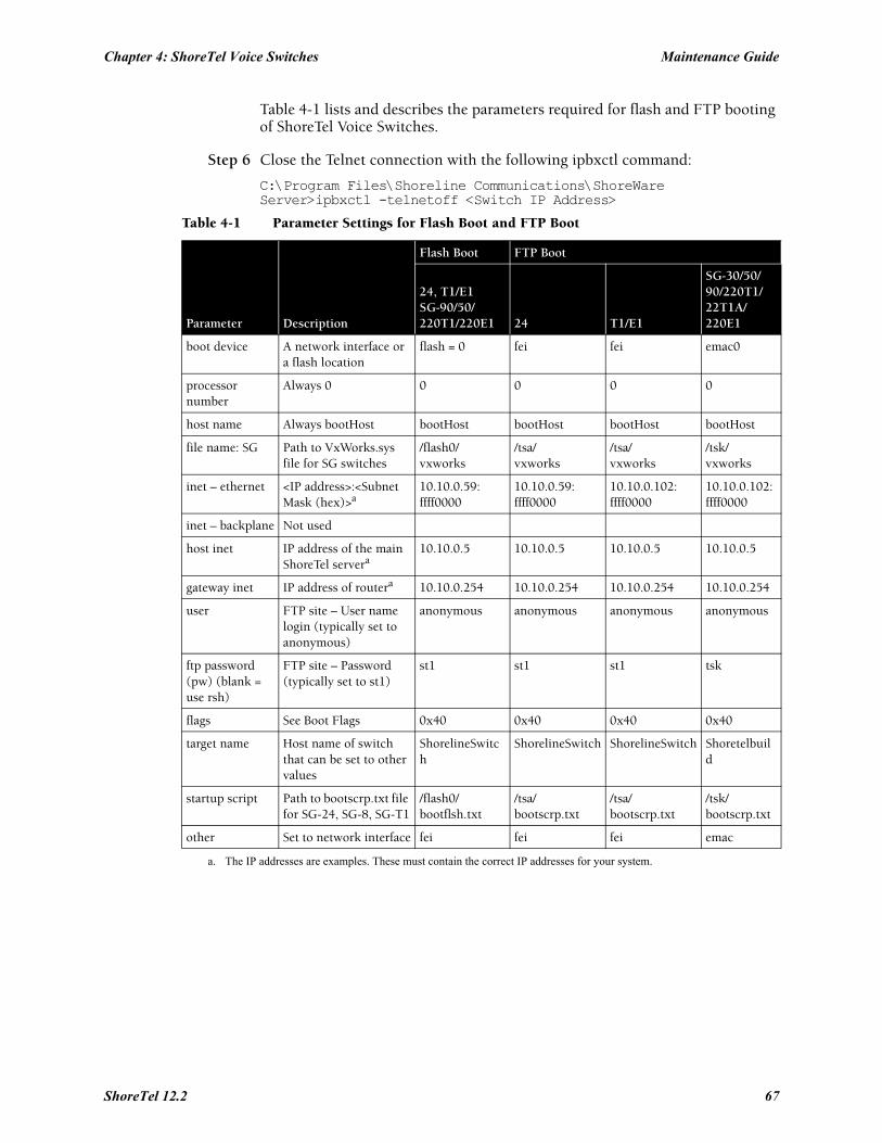
Chapter 4: ShoreTel Voice Switches Maintenance Guide
Table 4-1 lists and describes the parameters required for flash and FTP booting of ShoreTel Voice Switches.
Step 6 Close the Telnet connection with the following ipbxctl command:
C:\Program Files\Shoreline Communications\ShoreWare Server>ipbxctl -telnetoff <Switch IP Address>
Table 4-1 Parameter Settings for Flash Boot and FTP Boot
Parameter Description
Flash Boot FTP Boot
24, T1/E1SG-90/50/220T1/220E1 24 T1/E1
SG-30/50/90/220T1/22T1A/220E1
boot device A network interface or a flash location
flash = 0 fei fei emac0
processor number
Always 0 0 0 0 0
host name Always bootHost bootHost bootHost bootHost bootHost
file name: SG Path to VxWorks.sys file for SG switches
/flash0/vxworks
/tsa/vxworks
/tsa/vxworks
/tsk/vxworks
inet – ethernet <IP address>:<Subnet Mask (hex)>a
10.10.0.59:ffff0000
10.10.0.59:ffff0000
10.10.0.102:ffff0000
10.10.0.102:ffff0000
inet – backplane Not used
host inet IP address of the main ShoreTel servera
a. The IP addresses are examples. These must contain the correct IP addresses for your system.
10.10.0.5 10.10.0.5 10.10.0.5 10.10.0.5
gateway inet IP address of routera 10.10.0.254 10.10.0.254 10.10.0.254 10.10.0.254
user FTP site – User name login (typically set to anonymous)
anonymous anonymous anonymous anonymous
ftp password (pw) (blank = use rsh)
FTP site – Password (typically set to st1)
st1 st1 st1 tsk
flags See Boot Flags 0x40 0x40 0x40 0x40
target name Host name of switch that can be set to other values
ShorelineSwitch
ShorelineSwitch ShorelineSwitch Shoretelbuild
startup script Path to bootscrp.txt file for SG-24, SG-8, SG-T1
/flash0/bootflsh.txt
/tsa/bootscrp.txt
/tsa/bootscrp.txt
/tsk/bootscrp.txt
other Set to network interface fei fei fei emac
ShoreTel 12.2 67
Maintenance Guide Chapter 4: ShoreTel Voice Switches
4.3.6 Boot FlagsThe boot flags allow you to alter how the switch boots up. The hexadecimal values of the flags and their actions are listed in Table 4-2.
You can aggregate flags to perform multiple functions by summing the hex values for the commands. For example, the following command aggregates the flags “0x40 + 0x2000 + 0x40000” and instructs the switch to use DHCP to get boot parameters, disable the ShoreTel shell, and set network speed and duplex mode to 100 Mb HD:
0x42040
4.3.6.1 Setting IP Address and Boot Parameters from the VxWorks Boot MonitorIf you are unable to access the ShoreTel Voice Switch CLI, you can access the same configuration options available with the bootChange command from the switch’s boot monitor.
WARNING Making the incorrect settings in the boot monitor can cause the switch to malfunction.
To access the boot monitor:
Step 1 Connect a serial cable between a personal computer and the ShoreTel Voice Switch.
Step 2 Use a terminal emulation program such as HyperTerminal to open a connection to the switch.
Step 3 Apply these values to the terminal settings:
• Speed: 19.2 kbps• Data bit: 8 bits• Stop bit: 1• Parity: No parity• Flow Control: None
Step 4 Type c at the prompt and press ENTER. You are guided through the options listed in Table 4-1 on page 67.
Table 4-2 Boot Flags
Command Description
0x0 Network speed and duplex mode auto-negotiate.
0x20 Disable login security.
0x40 Use DHCP to get boot parameters.
0x1040 Use bootp to get boot parameters.
0x2000 Disable ShoreTel shell.
0x10000 Network speed and duplex mode 10 Mb full duplex (fixed).
0x20000 Network speed and duplex mode 10 Mb half duplex (fixed).
0x30000 Network speed and duplex mode 100 Mb full duplex (fixed).
0x40000 Network speed and duplex mode 100 Mb half duplex (fixed).
68
Chapter 4: ShoreTel Voice Switches Maintenance Guide
4.4 ShoreTel Voice Switch Configuration ResetEach switch includes a hidden reset button on the front panel that restores the switch to factory default boot settings and requests a new configuration from TMS. To enable the reset, press the button for 5 seconds. This button reboots the ShoreTel Voice Switch.
This completely clears all boot parameters and clears the switch’s configuration.
4.5 ShoreTel Voice Switch UtilitiesThere are two tools available for diagnosing and updating the ShoreTel Voice Switches. The ipbxctl utility allows one to perform diagnostics and Telnet to the switch. You can use the burnflash utility to update the switch to the version of firmware compatible with the ShoreTel server software.
The utilities are available in the ShoreTel Server folder:
C:\Program Files\Shoreline Communications\Shoreware Server
4.5.1 ipbxctl UtilityTable 4-3 lists and describes the commands available using the ipbxctl utility.
For more information on launching the ipbxctl utility, see Section 4.3 on page 63.
4.5.1.1 Password AccessAfter entering the ipbxctl command, the user is prompted to enter a password. After the user enters the correct password, the device permits access to executables that configure or diagnose the switch.
Performing a telnet session on a ShoreTel Voice Switch requires password access to ipbxctl before invoking the teleneton command. After entering the correct password, a user can establish a telnet session during the next minute. At the expiry of this period, existing
Table 4-3 ipbxctl Utility Commands
Command Description
-telneton <Switch IP Address> Enables Telnet connection on the switch.
-reboot <Switch IP Address> Reboots the switch without using ShoreTel Director.
-flash <Switch IP Address> Sets switch to boot from flash memory(allows you to boot without logging in).
-ftp <Switch IP Address> Sets switch to boot from FTP (allows you to do this without logging in).
-diag <Switch IP Address > Sends switch state information. By default, the system puts this information in the same folder where ipbxctl utility is running.
This may be distruptive to normal switch function. Use this command only for diagnostic functions, not for reporting.
-reset Clears all flash memory. Returns switch to factory defaults.
This command is not available from ShoreTel CLI.
-telnetoff <Switch IP Address > Disables Telnet connection on the switch.
-traceroute <target IP Address > Network troubleshooting tool.
For additional information about the parameters that can be used with this command, Table 4-6 on page 78 of this chapter.
ShoreTel 12.2 69
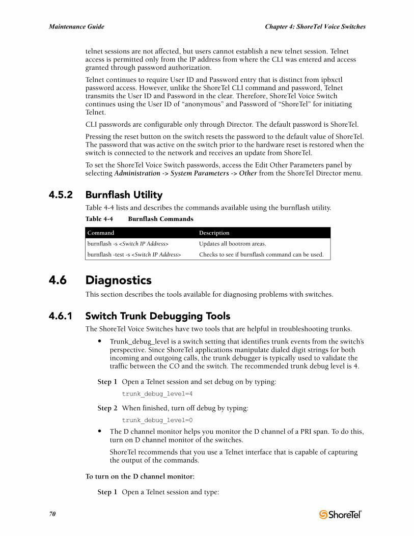
Maintenance Guide Chapter 4: ShoreTel Voice Switches
telnet sessions are not affected, but users cannot establish a new telnet session. Telnet access is permitted only from the IP address from where the CLI was entered and access granted through password authorization.
Telnet continues to require User ID and Password entry that is distinct from ipbxctl password access. However, unlike the ShoreTel CLI command and password, Telnet transmits the User ID and Password in the clear. Therefore, ShoreTel Voice Switch continues using the User ID of “anonymous” and Password of “ShoreTel” for initiating Telnet.
CLI passwords are configurable only through Director. The default password is ShoreTel.
Pressing the reset button on the switch resets the password to the default value of ShoreTel. The password that was active on the switch prior to the hardware reset is restored when the switch is connected to the network and receives an update from ShoreTel.
To set the ShoreTel Voice Switch passwords, access the Edit Other Parameters panel by selecting Administration -> System Parameters -> Other from the ShoreTel Director menu.
4.5.2 Burnflash UtilityTable 4-4 lists and describes the commands available using the burnflash utility.
4.6 DiagnosticsThis section describes the tools available for diagnosing problems with switches.
4.6.1 Switch Trunk Debugging ToolsThe ShoreTel Voice Switches have two tools that are helpful in troubleshooting trunks.
• Trunk_debug_level is a switch setting that identifies trunk events from the switch’s perspective. Since ShoreTel applications manipulate dialed digit strings for both incoming and outgoing calls, the trunk debugger is typically used to validate the traffic between the CO and the switch. The recommended trunk debug level is 4.
Step 1 Open a Telnet session and set debug on by typing:
trunk_debug_level=4
Step 2 When finished, turn off debug by typing:
trunk_debug_level=0
• The D channel monitor helps you monitor the D channel of a PRI span. To do this, turn on D channel monitor of the switches.
ShoreTel recommends that you use a Telnet interface that is capable of capturing the output of the commands.
To turn on the D channel monitor:
Step 1 Open a Telnet session and type:
Table 4-4 Burnflash Commands
Command Description
burnflash -s <Switch IP Address> Updates all bootrom areas.
burnflash -test -s <Switch IP Address> Checks to see if burnflash command can be used.
70
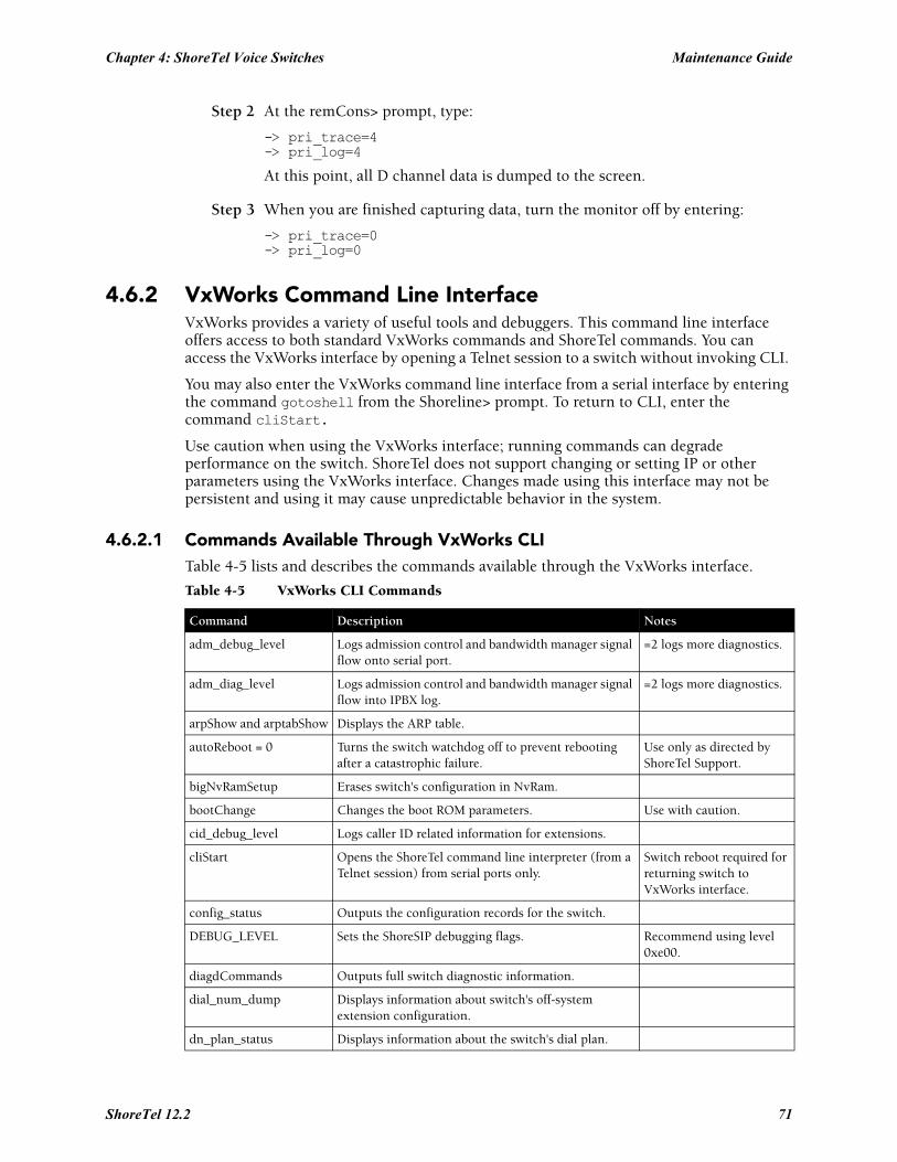
Chapter 4: ShoreTel Voice Switches Maintenance Guide
Step 2 At the remCons> prompt, type:
-> pri_trace=4-> pri_log=4
At this point, all D channel data is dumped to the screen.
Step 3 When you are finished capturing data, turn the monitor off by entering:
-> pri_trace=0-> pri_log=0
4.6.2 VxWorks Command Line InterfaceVxWorks provides a variety of useful tools and debuggers. This command line interface offers access to both standard VxWorks commands and ShoreTel commands. You can access the VxWorks interface by opening a Telnet session to a switch without invoking CLI.
You may also enter the VxWorks command line interface from a serial interface by entering the command gotoshell from the Shoreline> prompt. To return to CLI, enter the command cliStart.
Use caution when using the VxWorks interface; running commands can degrade performance on the switch. ShoreTel does not support changing or setting IP or other parameters using the VxWorks interface. Changes made using this interface may not be persistent and using it may cause unpredictable behavior in the system.
4.6.2.1 Commands Available Through VxWorks CLITable 4-5 lists and describes the commands available through the VxWorks interface.
Table 4-5 VxWorks CLI Commands
Command Description Notes
adm_debug_level Logs admission control and bandwidth manager signal flow onto serial port.
=2 logs more diagnostics.
adm_diag_level Logs admission control and bandwidth manager signal flow into IPBX log.
=2 logs more diagnostics.
arpShow and arptabShow Displays the ARP table.
autoReboot = 0 Turns the switch watchdog off to prevent rebooting after a catastrophic failure.
Use only as directed by ShoreTel Support.
bigNvRamSetup Erases switch's configuration in NvRam.
bootChange Changes the boot ROM parameters. Use with caution.
cid_debug_level Logs caller ID related information for extensions.
cliStart Opens the ShoreTel command line interpreter (from a Telnet session) from serial ports only.
Switch reboot required for returning switch to VxWorks interface.
config_status Outputs the configuration records for the switch.
DEBUG_LEVEL Sets the ShoreSIP debugging flags. Recommend using level 0xe00.
diagdCommands Outputs full switch diagnostic information.
dial_num_dump Displays information about switch's off-system extension configuration.
dn_plan_status Displays information about the switch's dial plan.
ShoreTel 12.2 71
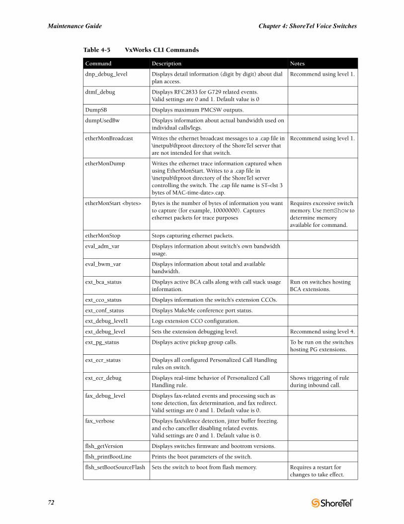
Maintenance Guide Chapter 4: ShoreTel Voice Switches
dnp_debug_level Displays detail information (digit by digit) about dial plan access.
Recommend using level 1.
dtmf_debug Displays RFC2833 for G729 related events.Valid settings are 0 and 1. Default value is 0
DumpSB Displays maximum PMCSW outputs.
dumpUsedBw Displays information about actual bandwidth used on individual calls/legs.
etherMonBroadcast Writes the ethernet broadcast messages to a .cap file in \inetpub\ftproot directory of the ShoreTel server that are not intended for that switch.
Recommend using level 1.
etherMonDump Writes the ethernet trace information captured when using EtherMonStart. Writes to a .cap file in \inetpub\ftproot directory of the ShoreTel server controlling the switch. The .cap file name is ST-<lst 3 bytes of MAC-time-date>.cap.
etherMonStart <bytes> Bytes is the number of bytes of information you want to capture (for example, 10000000). Captures ethernet packets for trace purposes
Requires excessive switch memory. Use memShow to determine memory available for command.
etherMonStop Stops capturing ethernet packets.
eval_adm_var Displays information about switch's own bandwidth usage.
eval_bwm_var Displays information about total and available bandwidth.
ext_bca_status Displays active BCA calls along with call stack usage information.
Run on switches hosting BCA extensions.
ext_cco_status Displays information the switch's extension CCOs.
ext_conf_status Displays MakeMe conference port status.
ext_debug_level1 Logs extension CCO configuration.
ext_debug_level Sets the extension debugging level. Recommend using level 4.
ext_pg_status Displays active pickup group calls. To be run on the switches hosting PG extensions.
ext_ecr_status Displays all configured Personalized Call Handling rules on switch.
ext_ecr_debug Displays real-time behavior of Personalized Call Handling rule.
Shows triggering of rule during inbound call.
fax_debug_level Displays fax-related events and processing such as tone detection, fax determination, and fax redirect.Valid settings are 0 and 1. Default value is 0.
fax_verbose Displays fax/silence detection, jitter buffer freezing. and echo canceller disabling related events.Valid settings are 0 and 1. Default value is 0.
flsh_getVersion Displays switches firmware and bootrom versions.
flsh_printBootLine Prints the boot parameters of the switch.
flsh_setBootSourceFlash Sets the switch to boot from flash memory. Requires a restart for changes to take effect.
Table 4-5 VxWorks CLI Commands
Command Description Notes
72
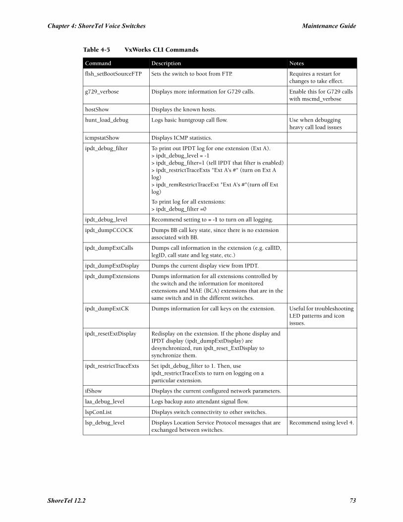
Chapter 4: ShoreTel Voice Switches Maintenance Guide
flsh_setBootSourceFTP Sets the switch to boot from FTP. Requires a restart for changes to take effect.
g729_verbose Displays more information for G729 calls. Enable this for G729 calls with mscmd_verbose
hostShow Displays the known hosts.
hunt_load_debug Logs basic huntgroup call flow. Use when debugging heavy call load issues
icmpstatShow Displays ICMP statistics.
ipdt_debug_filter To print out IPDT log for one extension (Ext A).> ipdt_debug_level = -1> ipdt_debug_filter=1 (tell IPDT that filter is enabled) > ipdt_restrictTraceExts "Ext A's #" (turn on Ext A log)> ipdt_remRestrictTraceExt "Ext A's #"(turn off Ext log)
To print log for all extensions:> ipdt_debug_filter =0
ipdt_debug_level Recommend setting to = -1 to turn on all logging.
ipdt_dumpCCOCK Dumps BB call key state, since there is no extension associated with BB.
ipdt_dumpExtCalls Dumps call information in the extension (e.g. callID, legID, call state and leg state, etc.)
ipdt_dumpExtDisplay Dumps the current display view from IPDT.
ipdt_dumpExtensions Dumps information for all extensions controlled by the switch and the information for monitored extensions and MAE (BCA) extensions that are in the same switch and in the different switches.
ipdt_dumpExtCK Dumps information for call keys on the extension. Useful for troubleshooting LED patterns and icon issues.
ipdt_resetExtDisplay Redisplay on the extension. If the phone display and IPDT display (ipdt_dumpExtDisplay) are desynchronized, run ipdt_reset_ExtDisplay to synchronize them.
ipdt_restrictTraceExts Set ipdt_debug_filter to 1. Then, use ipdt_restrictTraceExts to turn on logging on a particular extension.
ifShow Displays the current configured network parameters.
laa_debug_level Logs backup auto attendant signal flow.
lspConList Displays switch connectivity to other switches.
lsp_debug_level Displays Location Service Protocol messages that are exchanged between switches.
Recommend using level 4.
Table 4-5 VxWorks CLI Commands
Command Description Notes
ShoreTel 12.2 73
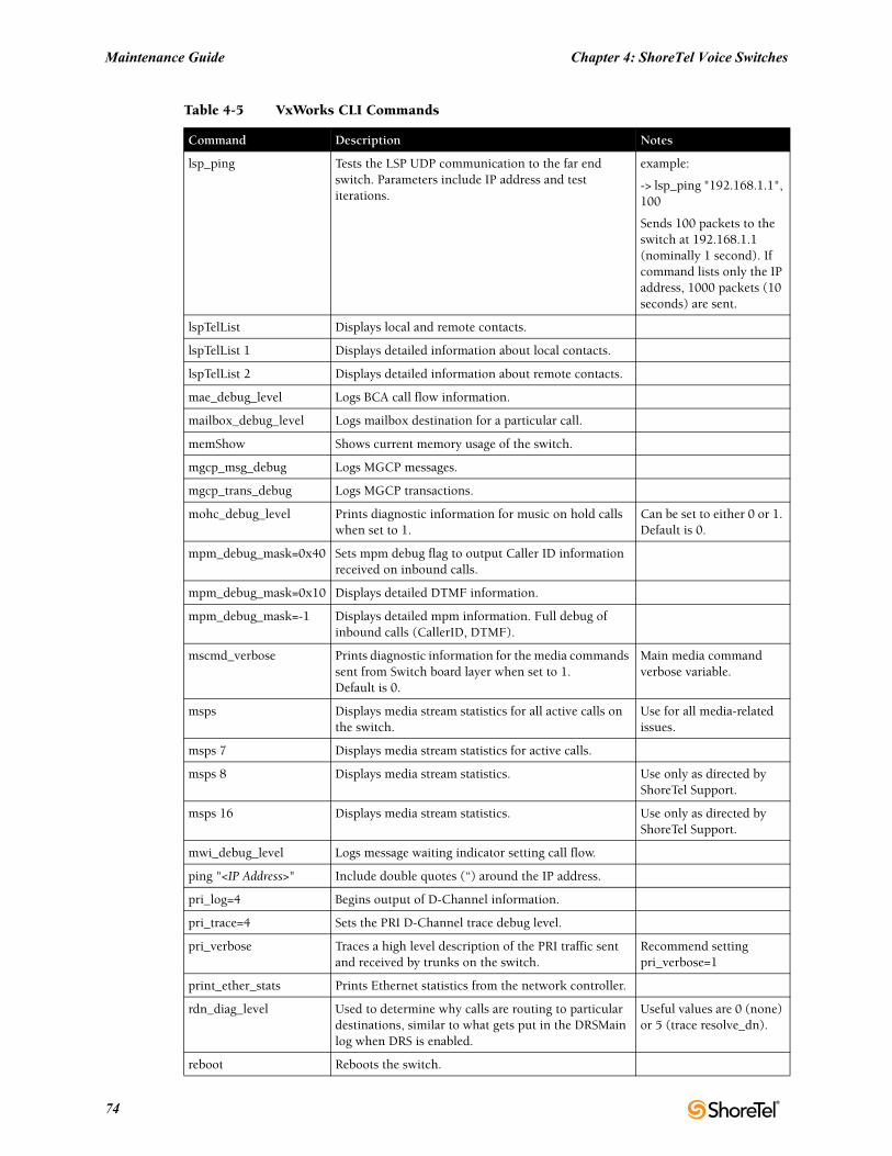
Maintenance Guide Chapter 4: ShoreTel Voice Switches
lsp_ping Tests the LSP UDP communication to the far end switch. Parameters include IP address and test iterations.
example:
-> lsp_ping "192.168.1.1", 100
Sends 100 packets to the switch at 192.168.1.1 (nominally 1 second). If command lists only the IP address, 1000 packets (10 seconds) are sent.
lspTelList Displays local and remote contacts.
lspTelList 1 Displays detailed information about local contacts.
lspTelList 2 Displays detailed information about remote contacts.
mae_debug_level Logs BCA call flow information.
mailbox_debug_level Logs mailbox destination for a particular call.
memShow Shows current memory usage of the switch.
mgcp_msg_debug Logs MGCP messages.
mgcp_trans_debug Logs MGCP transactions.
mohc_debug_level Prints diagnostic information for music on hold calls when set to 1.
Can be set to either 0 or 1. Default is 0.
mpm_debug_mask=0x40 Sets mpm debug flag to output Caller ID information received on inbound calls.
mpm_debug_mask=0x10 Displays detailed DTMF information.
mpm_debug_mask=-1 Displays detailed mpm information. Full debug of inbound calls (CallerID, DTMF).
mscmd_verbose Prints diagnostic information for the media commands sent from Switch board layer when set to 1.Default is 0.
Main media command verbose variable.
msps Displays media stream statistics for all active calls on the switch.
Use for all media-related issues.
msps 7 Displays media stream statistics for active calls.
msps 8 Displays media stream statistics. Use only as directed by ShoreTel Support.
msps 16 Displays media stream statistics. Use only as directed by ShoreTel Support.
mwi_debug_level Logs message waiting indicator setting call flow.
ping "<IP Address>" Include double quotes (“) around the IP address.
pri_log=4 Begins output of D-Channel information.
pri_trace=4 Sets the PRI D-Channel trace debug level.
pri_verbose Traces a high level description of the PRI traffic sent and received by trunks on the switch.
Recommend setting pri_verbose=1
print_ether_stats Prints Ethernet statistics from the network controller.
rdn_diag_level Used to determine why calls are routing to particular destinations, similar to what gets put in the DRSMain log when DRS is enabled.
Useful values are 0 (none) or 5 (trace resolve_dn).
reboot Reboots the switch.
Table 4-5 VxWorks CLI Commands
Command Description Notes
74
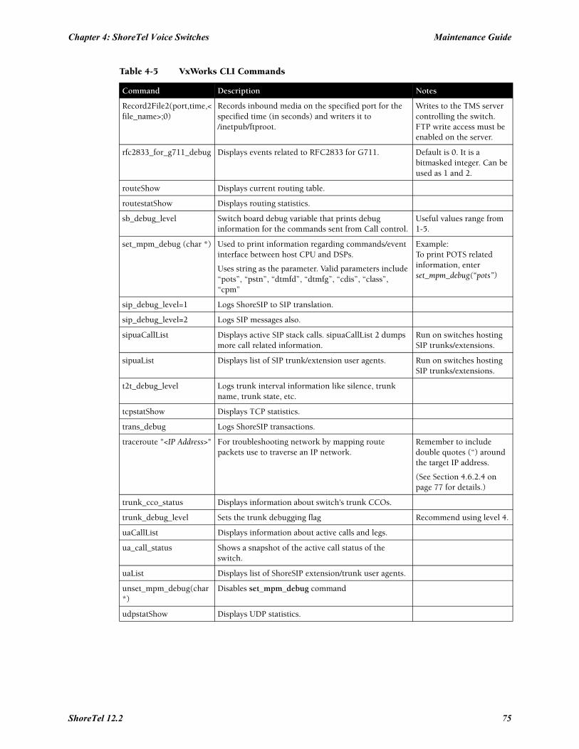
Chapter 4: ShoreTel Voice Switches Maintenance Guide
Record2File2(port,time,<file_name>;0)
Records inbound media on the specified port for the specified time (in seconds) and writers it to /inetpub/ftproot.
Writes to the TMS server controlling the switch. FTP write access must be enabled on the server.
rfc2833_for_g711_debug Displays events related to RFC2833 for G711. Default is 0. It is a bitmasked integer. Can be used as 1 and 2.
routeShow Displays current routing table.
routestatShow Displays routing statistics.
sb_debug_level Switch board debug variable that prints debug information for the commands sent from Call control.
Useful values range from 1-5.
set_mpm_debug (char *) Used to print information regarding commands/event interface between host CPU and DSPs.
Uses string as the parameter. Valid parameters include “pots”, “pstn”, “dtmfd”, “dtmfg”, “cdis”, “class”, “cpm”
Example:To print POTS related information, enterset_mpm_debug(“pots”)
sip_debug_level=1 Logs ShoreSIP to SIP translation.
sip_debug_level=2 Logs SIP messages also.
sipuaCallList Displays active SIP stack calls. sipuaCallList 2 dumps more call related information.
Run on switches hosting SIP trunks/extensions.
sipuaList Displays list of SIP trunk/extension user agents. Run on switches hosting SIP trunks/extensions.
t2t_debug_level Logs trunk interval information like silence, trunk name, trunk state, etc.
tcpstatShow Displays TCP statistics.
trans_debug Logs ShoreSIP transactions.
traceroute "<IP Address>" For troubleshooting network by mapping route packets use to traverse an IP network.
Remember to include double quotes (“) around the target IP address.
(See Section 4.6.2.4 on page 77 for details.)
trunk_cco_status Displays information about switch's trunk CCOs.
trunk_debug_level Sets the trunk debugging flag Recommend using level 4.
uaCallList Displays information about active calls and legs.
ua_call_status Shows a snapshot of the active call status of the switch.
uaList Displays list of ShoreSIP extension/trunk user agents.
unset_mpm_debug(char*)
Disables set_mpm_debug command
udpstatShow Displays UDP statistics.
Table 4-5 VxWorks CLI Commands
Command Description Notes
ShoreTel 12.2 75
Maintenance Guide Chapter 4: ShoreTel Voice Switches
4.6.2.2 Creating an Ethernet Trace File Using a ShoreTel Voice SwitchYou can capture the output of VxWorks “ether” commands from the ShoreTel Voice Switches in an Ethernet Trace file that is stored on the server that is managing that switch. To do so, follow the procedure below:
Step 1 Open a Telnet session and type:
memShow
Run this command to verify that the switch has at least 1 MB of memory to perform the procedure.
Step 2 From the Start menu, navigate to the Control Panel > Administrative Tools and locate the IIS Manager.
Step 3 Right-click on the IIS Manager and select Properties. Then, enable the ability to write to the FTP server by selecting the Write checkbox and clicking OK.
This enables the ability to write to the following directory:C:\Inetpub\ftproot
Step 4 At the command prompt, run the following VxWorks commands. (See Table 4-5 on page 71 for more information about the specific commands.)
etherMonStart 1000000
Do not exceed 6 zeros!
etherMonStatusetherMonBroadcastetherMonDumpetherMonStop
At this point, all data from running these commands is stored in the file _.cap on C:\Inetpub\ftproot
Step 5 When you are finished capturing data, the file can be processed using an Ethernet packet analyzer, such as Ethereal or Wireshark.
4.6.2.3 Recording Audio from a Physical ShoreTel Voice Switch PortYou can capture audio output from a ShoreTel Voice Switch physical port (e.g. trunk port) using VxWorks commands. Audio output is saved on the HQ or DVM server that controls the switch. To do so, follow the procedure below:
Step 1 From the Start menu, navigate to the Control Panel > Administrative Tools and locate the IIS Manager.
Step 2 Right-click on the IIS Manager and select Properties. Then, enable the ability to write to the FTP server by selecting the Write checkbox and clicking OK.
This enables the ability to write to the following directory:C:\Inetpub\ftproot
Step 3 At the command prompt, run the following VxWorks commands. (See Table 4-5 on page 71 for more information about specific VxWorks commands.)
Record2File2 (1, 60, “test”)
Audio data from running this command is stored in the file test_rx.pcm and file test_tx.pcm in C:\Inetpub\ftproot
76
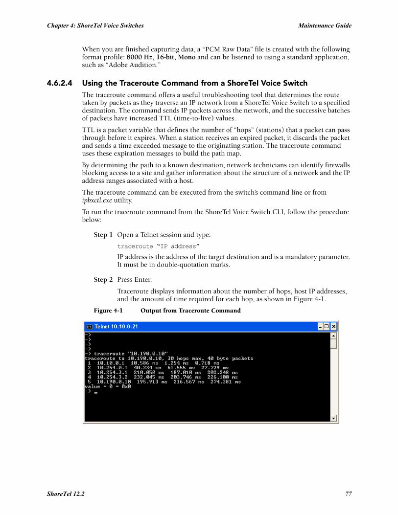
Chapter 4: ShoreTel Voice Switches Maintenance Guide
When you are finished capturing data, a “PCM Raw Data” file is created with the following format profile: 8000 Hz, 16-bit, Mono and can be listened to using a standard application, such as “Adobe Audition.”
4.6.2.4 Using the Traceroute Command from a ShoreTel Voice SwitchThe traceroute command offers a useful troubleshooting tool that determines the route taken by packets as they traverse an IP network from a ShoreTel Voice Switch to a specified destination. The command sends IP packets across the network, and the successive batches of packets have increased TTL (time-to-live) values.
TTL is a packet variable that defines the number of “hops” (stations) that a packet can pass through before it expires. When a station receives an expired packet, it discards the packet and sends a time exceeded message to the originating station. The traceroute command uses these expiration messages to build the path map.
By determining the path to a known destination, network technicians can identify firewalls blocking access to a site and gather information about the structure of a network and the IP address ranges associated with a host.
The traceroute command can be executed from the switch’s command line or from ipbxctl.exe utility.
To run the traceroute command from the ShoreTel Voice Switch CLI, follow the procedure below:
Step 1 Open a Telnet session and type:
traceroute “IP address”
IP address is the address of the target destination and is a mandatory parameter. It must be in double-quotation marks.
Step 2 Press Enter.
Traceroute displays information about the number of hops, host IP addresses, and the amount of time required for each hop, as shown in Figure 4-1.
Figure 4-1 Output from Traceroute Command
ShoreTel 12.2 77
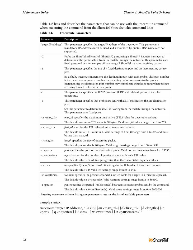
Maintenance Guide Chapter 4: ShoreTel Voice Switches
Table 4-6 lists and describes the parameters that can be use with the traceroute command when executing the command from the ShoreTel Voice Switch’s command line:
Sample syntax:
traceroute "target IP address", "[-CeIS] [-m <max_ttl>] [-f <first_ttl>] [-l <length>] [-p <port>] [-q <nqueries>] [-t <tos>] [-w <waittime>] [-z <pausemsecs>]"
Table 4-6 Traceroute Parameters
Parameter Description
“target IP address” This parameter specifies the target IP address of the traceroute. This parameter is mandatory. IP addresses must be used and surrounded by quotes. DNS names are not supported.
-C Probe on ShoreTel call control (ShoreSIP) port, using a ShoreSIP Request message, to determine if the packets flow from the switch through the network. This parameter uses fixed ports and version compatibility among all ShoreTel switches receiving packets.
-e This parameter specifies the use of a fixed destination port and an incrementing source port.
By default, traceroute increments the destination port with each probe. This port number is then used as a sequence number for matching packet responses to the probes. Incrementing the destination port number may complicate troubleshooting when packets are being filtered or lost at certain ports.
-I This parameter specifies the ICMP protocol. (UDP is the default protocol used for traceroute.)
-S This parameter specifies that probes are sent with a SIP message on the SIP destination port.
Set this parameter to determine if SIP is flowing from the switch through the network. This parameter uses fixed ports.
-m <max_ttl> max_ttl specifies the maximum time to live (TTL) value for traceroute packets.
The default maximum TTL value is 30 bytes. Valid max_ttl values range from 1 to 255.
-f <first_ttl> first_ttl specifies the TTL value of initial traceroute packets.
The default initial TTL value is 1. Valid settings of first_ttl range from 1 to 255 and must be less than max_ttl.
-l <length> length specifies the size of traceroute packet.
The default packet size is 40 bytes. Valid length settings range from 100 to 1992.
-p <port> port specifies the port for the destination probe. Valid port settings range from 1 to 65535.
-q <nqueries> nqueries specifies the number of queries execute with each TTL value.
The default value is 3. All integers greater than 0 are acceptable nqueries values.
-t <tos> tos specifies Type of Server (tos) bit settings in the IP header of traceroute packets.
The default value is 0. Valid tos settings range from 0 to 255.
-w <waittime> waittime specifies the period (seconds) a switch waits for a reply to a traceroute packet.
The default value is 5 (seconds). Valid waittime settings range from 2 to 86400.
-z <pause> pause specifies the period (milliseconds) between successive probes sent by the command.
The default value is 0 (milliseconds). Valid pause settings range from 0 to 3600000.
Entering traceroute without listing any parameters returns the list of available parameters.
78
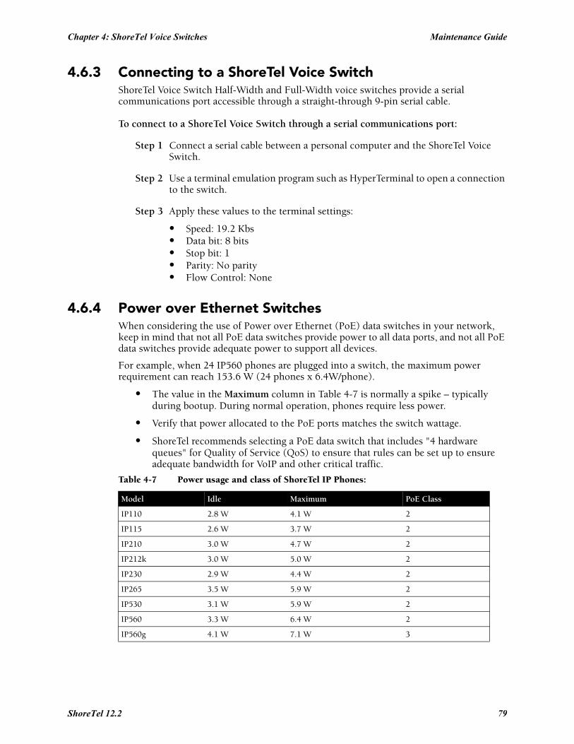
Chapter 4: ShoreTel Voice Switches Maintenance Guide
4.6.3 Connecting to a ShoreTel Voice SwitchShoreTel Voice Switch Half-Width and Full-Width voice switches provide a serial communications port accessible through a straight-through 9-pin serial cable.
To connect to a ShoreTel Voice Switch through a serial communications port:
Step 1 Connect a serial cable between a personal computer and the ShoreTel Voice Switch.
Step 2 Use a terminal emulation program such as HyperTerminal to open a connection to the switch.
Step 3 Apply these values to the terminal settings:
• Speed: 19.2 Kbs• Data bit: 8 bits• Stop bit: 1• Parity: No parity• Flow Control: None
4.6.4 Power over Ethernet SwitchesWhen considering the use of Power over Ethernet (PoE) data switches in your network, keep in mind that not all PoE data switches provide power to all data ports, and not all PoE data switches provide adequate power to support all devices.
For example, when 24 IP560 phones are plugged into a switch, the maximum power requirement can reach 153.6 W (24 phones x 6.4W/phone).
• The value in the Maximum column in Table 4-7 is normally a spike – typically during bootup. During normal operation, phones require less power.
• Verify that power allocated to the PoE ports matches the switch wattage.
• ShoreTel recommends selecting a PoE data switch that includes "4 hardware queues" for Quality of Service (QoS) to ensure that rules can be set up to ensure adequate bandwidth for VoIP and other critical traffic.
Table 4-7 Power usage and class of ShoreTel IP Phones:
Model Idle Maximum PoE Class
IP110 2.8 W 4.1 W 2
IP115 2.6 W 3.7 W 2
IP210 3.0 W 4.7 W 2
IP212k 3.0 W 5.0 W 2
IP230 2.9 W 4.4 W 2
IP265 3.5 W 5.9 W 2
IP530 3.1 W 5.9 W 2
IP560 3.3 W 6.4 W 2
IP560g 4.1 W 7.1 W 3
ShoreTel 12.2 79

Maintenance Guide Chapter 4: ShoreTel Voice Switches
IP565g 4.2 W 6.9 W 3
IP655 5.7 W 9.1 W 3
BB24 2.9 W 11.5 W (with IP560 connected)
3
Table 4-7 Power usage and class of ShoreTel IP Phones:
Model Idle Maximum PoE Class
80
C H A P T E R 5
Voicemail Model Switches
5.1 OverviewVoicemail Model Switches are ShoreTel Voice Switches that provide voicemail services and access to auto attendant menus for extensions hosted by the switch. Voicemail Model (V Model) switches provide local access to voicemail while being controlled by a Distributed server at a different location.
Voicemail Model switches store voicemail in Compact Flash (CF) cards. Auto Attendant menus, greetings, and prompts, are stored in permanent flash memory. Voicemail backup and restore routines are available through Director for protecting voice mail on a regular basis. If a switch is disabled, information on the Compact Flash is retained and can be moved to another switch of the same model.
V Model switches are deployed in the same manner as other ShoreTel Voice Switch 1-U Half Width switches and managed similarly to other switches and servers. Director windows configure switch, voicemail, and server settings. Device status is also monitored through Director maintenance windows.
Three ShoreTel Voice Switches operate as a ShoreTel Voice Switch and a voice mail server:
• ShoreTel Voice Switch 90V• ShoreTel Voice Switch 90BRIV• ShoreTel Voice Switch 50V
5.2 UtilitiesThis section describes the utilities available for voicemail switches, other switches, and servers.
5.2.1 Accessing Voicemail Model Switch UtilitiesShoreTel Voice Switch utilities are accessible through the Maintenance port, an SSH client, or an MS windows program executed from a command prompt on the HQ or a DVS server. The following sections describe utility access methods.
For security purposes, the Switch accepts requests from only CLIs s running on the local host, the controlling DVS, or the HQ server.
5.2.1.1 Accessing Utilities from the Serial PortSwitch utilities and the UBOOT command interface are accessible through the maintenance port located on the faceplate. The state of the switch at the time of Maintenance port access determines the available utility.
• During normal switch operation, the Maintenance port accesses a specified Linux shell.
ShoreTel 12.2 81
Maintenance Guide Chapter 5: Voicemail Model Switches
The default shell is stcli.
• During a switch boot, the Maintenance port accesses UBOOT.
To access ShoreTel Voice Switch utilities through the Maintenance port:
Step 1 Connect a serial cable between a personal computer and the ShoreTel Voice Switch.
Step 2 Use a terminal emulation program to open a connection to the switch.
Step 3 Apply these values to the terminal settings:
• Speed: 19.2 Kbs• Data bit: 8 bits• Stop bit: 1• Parity: No parity• Flow Control: None
Step 4 When opening stcli, enter the account name and password, as normally required by a Linux login.
When opening UBOOT, login credentials are not required.
See Section 5.2.2.2 (stcli) or Section 5.2.2.1 (UBOOT) for descriptions of the utilities accessible through the Maintenance port.
5.2.1.2 Accessing Utilities from SSHShoreTel provides access to several Voicemail Model utilities through a Linux BASH command line. Voicemail Model switches define two accounts:
• Admin: The admin account provides access to selected ShoreTel and Linux utilities, including all Voicemail Model command line interfaces. ShoreTel recommends that user log into the Admin account when accessing Linux utilities.
Logging into the Admin account immediately opens the stcli interface.
• Root: The root account provides access to all ShoreTel and Linux utilities. Restrict access to this account to help prevent potential switch problems.
Logging into the Root account immediately opens a Linux BASH shell.
Access to the Linux BASH command line through an SSH client. Free SSH clients, such as PuTTY, are available through the internet.
To access a Linux BASH Shell account:
Step 1 Open a SSH client access panel.
Figure 5-1 shows the PuTTY Configuration panel.
Step 2 Open the command prompt window by performing the following, as shown in Figure 5-1:
• Enter the IP address of the switch in the Host Name field• Enter 22 in the Port field; SSH client communicates on port 22. • Press the Open button.
82
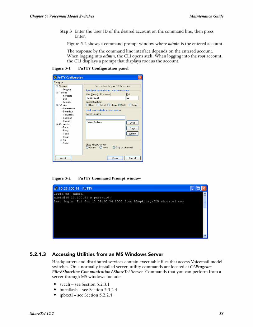
Chapter 5: Voicemail Model Switches Maintenance Guide
Step 3 Enter the User ID of the desired account on the command line, then press Enter.
Figure 5-2 shows a command prompt window where admin is the entered account
The response by the command line interface depends on the entered account. When logging into admin, the CLI opens stcli. When logging into the root account, the CLI displays a prompt that displays root as the account.
Figure 5-1 PuTTY Configuration panel
Figure 5-2 PuTTY Command Prompt window
5.2.1.3 Accessing Utilities from an MS Windows ServerHeadquarters and distributed services contain executable files that access Voicemail model switches. On a normally installed server, utility commands are located at C:\Program Files\Shoreline Communications\ShoreTel Server. Commands that you can perform from a server through MS windows include:
• svccli – see Section 5.2.3.1• burnflash – see Section 5.3.2.4• ipbxctl – see Section 5.2.2.4
ShoreTel 12.2 83
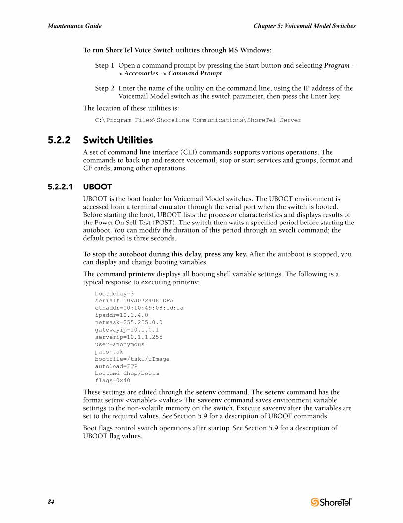
Maintenance Guide Chapter 5: Voicemail Model Switches
To run ShoreTel Voice Switch utilities through MS Windows:
Step 1 Open a command prompt by pressing the Start button and selecting Program -> Accessories -> Command Prompt
Step 2 Enter the name of the utility on the command line, using the IP address of the Voicemail Model switch as the switch parameter, then press the Enter key.
The location of these utilities is:
C:\Program Files\Shoreline Communications\ShoreTel Server
5.2.2 Switch UtilitiesA set of command line interface (CLI) commands supports various operations. The commands to back up and restore voicemail, stop or start services and groups, format and CF cards, among other operations.
5.2.2.1 UBOOTUBOOT is the boot loader for Voicemail Model switches. The UBOOT environment is accessed from a terminal emulator through the serial port when the switch is booted. Before starting the boot, UBOOT lists the processor characteristics and displays results of the Power On Self Test (POST). The switch then waits a specified period before starting the autoboot. You can modify the duration of this period through an svccli command; the default period is three seconds.
To stop the autoboot during this delay, press any key. After the autoboot is stopped, you can display and change booting variables.
The command printenv displays all booting shell variable settings. The following is a typical response to executing printenv:
bootdelay=3serial#=50VJ0724081DFAethaddr=00:10:49:08:1d:faipaddr=10.1.4.0netmask=255.255.0.0gatewayip=10.1.0.1serverip=10.1.1.255user=anonymouspass=tskbootfile=/tskl/uImageautoload=FTPbootcmd=dhcp;bootmflags=0x40
These settings are edited through the setenv command. The setenv command has the format setenv <variable> <value>.The saveenv command saves environment variable settings to the non-volatile memory on the switch. Execute saveenv after the variables are set to the required values. See Section 5.9 for a description of UBOOT commands.
Boot flags control switch operations after startup. See Section 5.9 for a description of UBOOT flag values.
84
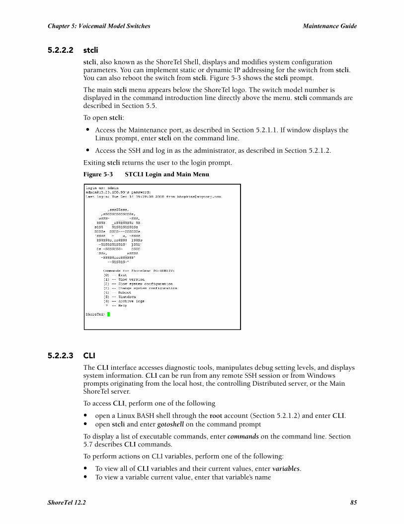
Chapter 5: Voicemail Model Switches Maintenance Guide
5.2.2.2 stclistcli, also known as the ShoreTel Shell, displays and modifies system configuration parameters. You can implement static or dynamic IP addressing for the switch from stcli. You can also reboot the switch from stcli. Figure 5-3 shows the stcli prompt.
The main stcli menu appears below the ShoreTel logo. The switch model number is displayed in the command introduction line directly above the menu. stcli commands are described in Section 5.5.
To open stcli:
• Access the Maintenance port, as described in Section 5.2.1.1. If window displays the Linux prompt, enter stcli on the command line.
• Access the SSH and log in as the administrator, as described in Section 5.2.1.2.
Exiting stcli returns the user to the login prompt.
Figure 5-3 STCLI Login and Main Menu
5.2.2.3 CLIThe CLI interface accesses diagnostic tools, manipulates debug setting levels, and displays system information. CLI can be run from any remote SSH session or from Windows prompts originating from the local host, the controlling Distributed server, or the Main ShoreTel server.
To access CLI, perform one of the following
• open a Linux BASH shell through the root account (Section 5.2.1.2) and enter CLI.• open stcli and enter gotoshell on the command prompt
To display a list of executable commands, enter commands on the command line. Section 5.7 describes CLI commands.
To perform actions on CLI variables, perform one of the following:
• To view all of CLI variables and their current values, enter variables.• To view a variable current value, enter that variable’s name
ShoreTel 12.2 85
Maintenance Guide Chapter 5: Voicemail Model Switches
• To change a variable’s current value, enter the variable name and new value.
To specify the destination of switch trace information, enter the following:
• trace_redirect 0 – send trace information to the Maintenance port.• trace_redirect 1 – send trace information to the current device.
Only trace streams that are sent to the maintenance port can be redirected to an SSH terminal session; this prevent trace stealing from other SSH terminal sessions. All traces can be reverted to the maintenance port, making them accessible to SSH terminals.
To exit CLI,
• Type quit or enter the letter q at the CLI prompt.• Type Ctrl-c if CLI was opened from the Linux BASH shell.
5.2.2.4 ipbxctlipbxctl commands perform switch control and diagnostic tasks, including switch rebooting, clearing flash memory, and running traceroute.
ipbxctl is run as a windows program from the Main Server or the controlling Distributed Server, as described in Section 5.2.1.3
Section 5.11 describes ipbxctl commands.
5.2.2.5 regeditRegedit, a ShoreTel utility that modifies Registry-type data structures in the switch, is accessible through the Root account.
V Model Switches have a Registry similar to Windows Servers. The Registry is a ShoreTel construct, not part of Linux. To edit the Registry, log in as root and run the RegEdit command line tool from the bash shell. RegEdit may be used to set logging levels on applications and set other parameters that change their behavior.
Section 5.12 describes regedit commands.
5.2.3 Server UtilitiesThis section describes utilities available for servers: SVCCLI and cfg.
5.2.3.1 SVCCLIThe svccli commands control low level switch parameter settings and application commands, including Compact Flash storage, switch password, and service control operations. svccli can be run from any remote SSH session or from Windows prompts originating from the local host, the controlling Distributed server, or the Main ShoreTel server.
To access svccli, perform one of the following:
• open a Linux BASH shell through the root account (Section 5.2.1.2) and enter svccli.• Run svccli from the Main Server or a Distributed Server (Section 5.2.1.3).
To display the svccli commands, enter help or ?. Section 5.6 describes svccli commands.
To exit svccli, type Ctrl-c or enter the letter q.
86
Chapter 5: Voicemail Model Switches Maintenance Guide
5.2.3.2 cfg UtilityThe cfg utility is a command-line tool that provides detailed information about the voicemail application.
Cfg.exe can be found in the \shoreline communications\ShoreTel server directory.
To start cfg:
Step 1 Open a DOS window pointing to the \shoreline communications\ShoreTel server directory.
Step 2 Enter cfg and press Enter. When you see the prompt /*Local*//->, cfg is ready.
All commands are entered at the above prompt. Results are displayed in the DOS window or in the voice mail logs.
WARNING Some cfg utility commands may damage the system if used incorrectly. Make sure you understand the commands before you use them.
Section 5.8 lists the commands available through the cfg utility.
5.3 Booting and Restarting V Model SwitchesRebooting and restarting V model switches have different scopes.
• Rebooting a V model switch also reboots the Linux kernel its services.
A reboot takes much longer than a restart.
• Restarting a V model switch only restarts the ShoreTel Voice Switch application layer without restarting the operating system and its services.
On ShoreTel Voice Switches running on VxWorks, rebooting and restarting are identical.
Under certain conditions, initiating a restart reboots the switch. One example is when a switch upgrade is available.
ShoreTel Voice Switch VM switches boot (loads data and programs) from contents of their internal memory. Network parameters, including IP addresses, are required to complete the boot process. Switches obtain these parameters either from a DHCP server or through manual entry. New switches always attempts to access a DHCP server.
Within installations where a DHCP server is not available, switches must be manually configured, including the designation of the IP address and other configuration parameters. For switches not yet placed on a network, this configuration must be performed through the maintenance port. For switches that are on the network, switches can be configured through stcli.
When using DHCP, ShoreTel recommends using DHCP reservations for each switch to ensure that DHCP leases are not lost.
A V model switch can be brought up through a regular boot or by a software upgrade boot. FTP booting is also available for troubleshooting. Switches booted through FTP have limited functionality because internal memory contents are not loaded.
ShoreTel 12.2 87
Maintenance Guide Chapter 5: Voicemail Model Switches
5.3.1 Manually Specifying Switch ParametersV Model switches normally use DHCP to dynamically set the device IP address and specify the addresses of the servers to which it communicates. Switches are set into fixed address mode through CLI instructions.
V model switches require values for the following IP addresses:
1. The IP address and subnet mask of the V model switch
2. The IP address of the server that supervises the switch
3. The gateway IP address of the supervising server if it resides on a different subnet from the V model switch.
4. The IP address of the NTP server. V model switches require valid timestamps to operate; many services, including voicemail, cannot start without NTP access.
The following procedure places the V Model switch into fixed address mode:
Step 1 Access the STCLI command line interface, as described in Section 5.2.2.2 on page 85.
Step 2 Enter “3” on the command line to select Change System Configuration.
The CLI window displays the Change System Configuration options.
Step 3 Enter “6” on the command line to select Enable/Disable DHCP/BOOTP
The CLI window displays the DHCP/BOOT options.
Step 4 Enter “0” on the command line to select Manual Configuration.
Step 5 Change the network parameters as required to support the fixed address from the Change System Configuration entry line.
Step 6 After completing changes to the configuration, type Exit to close the CLI.
Step 7 Reboot the switch.
5.3.2 Reboot MethodsA Shoretel voice switch can be rebooted via a flash boot, a default button, FTP, or burnflash, each of which is described in this section.
5.3.2.1 Flash BootThe standard method for booting a ShoreTel Voice Switch is to boot from the switch’s flash memory. When a ShoreTel Voice Switch is first powered on, it reads the boot parameters stored on the non volatile memory, which instructs the switch to load software from flash memory. When the software starts, it loads its configuration, which is also stored in flash memory.
5.3.2.2 Default ButtonThe Default Button is the small “paperclip” button on the left side of the switch. Pressing this button replaces the two configuration files with their default variants. The Compact Flash is not affected.
88
Chapter 5: Voicemail Model Switches Maintenance Guide
Pressing this button and holding for 10 seconds, in addition to replacing the configuration files, removes all files from the Compact Flash.
5.3.2.3 FTP BootBooting from FTP is available when you cannot boot the switch from internal memory. When booting a switch from FTP, the operating system and software are loaded from the FTP site identified in the boot parameters. The loaded files define a default configuration.
Voicemail services on the switch are disabled after booting from FTP and are restarted only by booting from Flash. After an FTP boot, the switch can perform telephony functions as those available through other ShoreTel Voice Switches. V model switches started with an FTP boot can operate only as a voice switch – (controlling phones, trunks, and call routing.
FTP boot is typically used for troubleshooting and also supports maintenance tasks and the backup and restore facilities.FTP boot supports certain maintenance functions, such as an emergency boot if the flash becomes damaged.
5.3.2.4 BurnflashBurnflash forces a reboot and install new software.
The burnflash command burns a ShoreTel image to the CF card. It unconditionally replaces the resident image while rebooting the system, but it does not destroy any voice mail. The purpose of burning the image to the CF is to enable the switch to boot from solid state memory instead of performing an FTP boot from the server.
If a user created a static configuration for IP addresses and other system parameters through the STCLI (option 3), those parameters must be reconfigured after burnflash runs.
5.4 Switch Diagnostics and RepairThis section describes tools for diagnosing and repairing switch problems.
5.4.1 Switch Trunk Debug ToolsTrunk_debug_level is a switch setting that identifies trunk events from the switch’s perspective. Since ShoreTel applications manipulate dialed digit strings for both incoming and outgoing calls, the trunk debugger is typically used to validate the traffic between the CO and the switch. The recommended trunk debug level is 4.
Step 1 Access the CLI shell, as described in Figure 5.2.2.3.
Step 2 Enter the following command:
trunk_debug_level=4
Step 3 When finished, turn off debug by typing:
trunk_debug_level=0
• The D channel monitor helps you monitor the D channel of a PRI span. To do this, turn on D channel monitor of the switches.
ShoreTel recommends using an SSH interface that is capable of capturing the output of the commands.
ShoreTel 12.2 89
Maintenance Guide Chapter 5: Voicemail Model Switches
5.4.2 Creating an tcpdump FileA tcpdump is a packet sniffer that operates off a command line. ShoreTel can use tcpdump output to debug V model switch issues. Do not create tcpdump files without consulting ShoreTel Technical Assistance.
To create a tcpdump file:
Step 1 Access the CLI shell.
Step 2 Execute the following: tcpdump -C 10 -W 3 -w /var/log/tcpdump.pcap
This step captures ethernet traffic to the switch into ram.
Step 3 After a brief period, press Ctrl-C.
This step terminates the capture and saves the result to
cp /var/log/tcpdump.* /ftproot
Step 4 Submit the files to ShoreTel, as instructed by Technical Assistance.
5.4.3 Recording Audio from a Switch PortYou can capture audio output from a ShoreTel Voice Switch physical port (e.g. trunk port) using a CLI command. Audio output is saved on the HQ or DVM server that controls the switch. To do so, follow the procedure below:
Step 1 From the Start menu, navigate to the Control Panel -> Administrative Tools and locate the IIS Manager.
Step 2 Right-click on the IIS Manager and select Properties. Then, enable the ability to write to the FTP server by selecting the Write checkbox and clicking OK.
This enables the ability to write to the following directory:C:\Inetpub\ftproot
Step 3 At the CLI prompt, run the following command:.
Record2File2 (1, 60, “test”)
Audio data from running this command is stored in the file test_rx.pcm and file test_tx.pcm in C:\Inetpub\ftproot
When you are finished capturing data, a “PCM Raw Data” file is created with the following format profile: 8000 Hz, 16-bit, Mono and can be listened to using a standard application, such as “Adobe Audition.”
5.4.4 Reformatting the Compact FlashThe CF cannot be replaced while the switch is in operation (the Cf cannot be “hot swapped”). You must shut down the switch to remove the card.
To format the compact flash:
Step 1 Open SVCCLI
Step 2 Enter the formatcf on the command line.
The formatcf command does not reformat a properly formatted compact flash. Running the command reboots the switch.
90
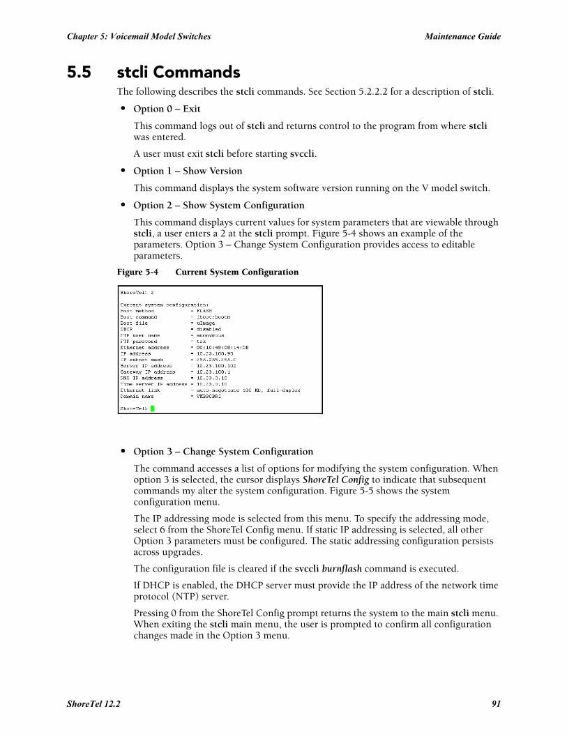
Chapter 5: Voicemail Model Switches Maintenance Guide
5.5 stcli CommandsThe following describes the stcli commands. See Section 5.2.2.2 for a description of stcli.
• Option 0 – Exit
This command logs out of stcli and returns control to the program from where stcli was entered.
A user must exit stcli before starting svccli.
• Option 1 – Show Version
This command displays the system software version running on the V model switch.
• Option 2 – Show System Configuration
This command displays current values for system parameters that are viewable through stcli, a user enters a 2 at the stcli prompt. Figure 5-4 shows an example of the parameters. Option 3 – Change System Configuration provides access to editable parameters.
Figure 5-4 Current System Configuration
• Option 3 – Change System Configuration
The command accesses a list of options for modifying the system configuration. When option 3 is selected, the cursor displays ShoreTel Config to indicate that subsequent commands my alter the system configuration. Figure 5-5 shows the system configuration menu.
The IP addressing mode is selected from this menu. To specify the addressing mode, select 6 from the ShoreTel Config menu. If static IP addressing is selected, all other Option 3 parameters must be configured. The static addressing configuration persists across upgrades.
The configuration file is cleared if the svccli burnflash command is executed.
If DHCP is enabled, the DHCP server must provide the IP address of the network time protocol (NTP) server.
Pressing 0 from the ShoreTel Config prompt returns the system to the main stcli menu. When exiting the stcli main menu, the user is prompted to confirm all configuration changes made in the Option 3 menu.
ShoreTel 12.2 91
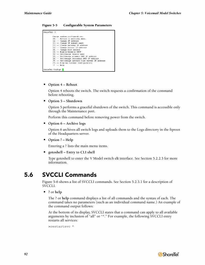
Maintenance Guide Chapter 5: Voicemail Model Switches
Figure 5-5 Configurable System Parameters
• Option 4 – Reboot
Option 4 reboots the switch. The switch requests a confirmation of the command before rebooting.
• Option 5 – Shutdown
Option 5 performs a graceful shutdown of the switch. This command is accessible only through the Maintenance port.
Perform this command before removing power from the switch.
• Option 6 – Archive logs
Option 6 archives all switch logs and uploads them to the Logs directory in the ftproot of the Headquarters server.
• Option ? – Help
Entering a ? lists the main menu items.
• gotoshell – Entry to CLI shell
Type gotoshell to enter the V Model switch cli interface. See Section 5.2.2.3 for more information.
5.6 SVCCLI CommandsFigure 5-6 shows a list of SVCCLI commands. See Section 5.2.3.1 for a description of SVCCLI.
• ? or help
The ? or help command displays a list of all commands and the syntax of each. The command takes no parameters (such as an individual command name.) An example of the command output follows:
At the bottom of its display, SVCCLI states that a command can apply to all available arguments by inclusion of “all” or “*.” For example, the following SVCCLI entry restarts all services:
>restartsvc *
92
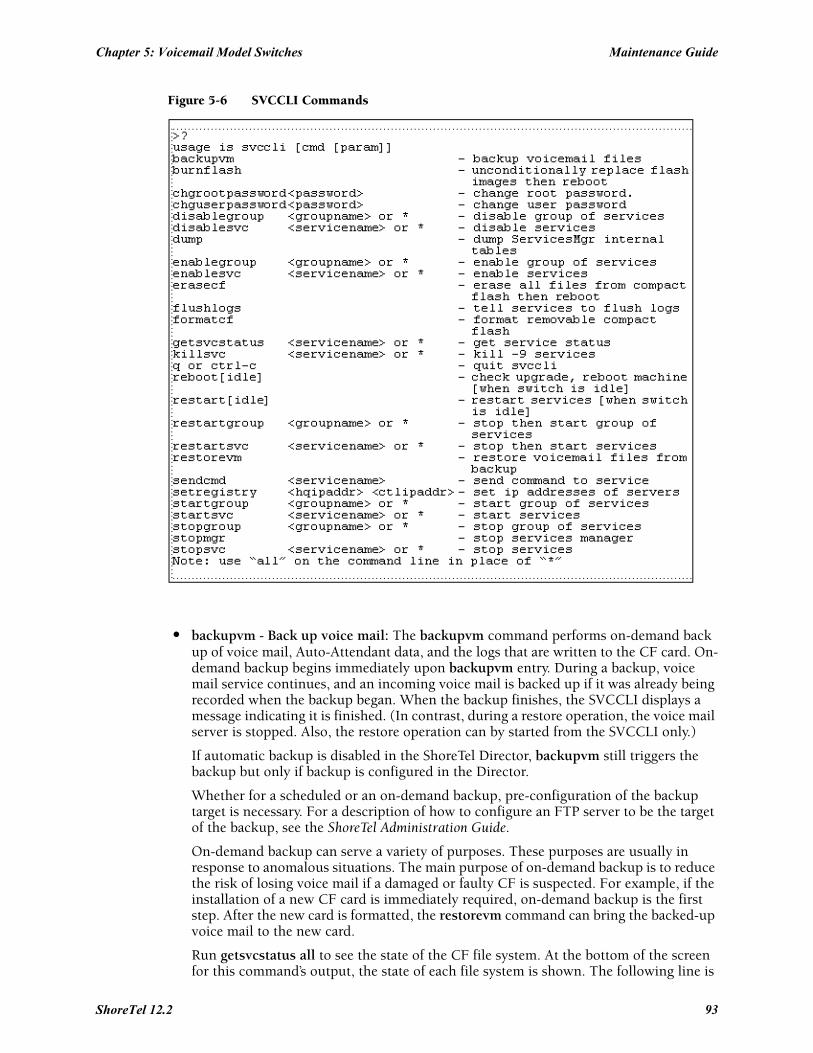
Chapter 5: Voicemail Model Switches Maintenance Guide
Figure 5-6 SVCCLI Commands
• backupvm - Back up voice mail: The backupvm command performs on-demand back up of voice mail, Auto-Attendant data, and the logs that are written to the CF card. On-demand backup begins immediately upon backupvm entry. During a backup, voice mail service continues, and an incoming voice mail is backed up if it was already being recorded when the backup began. When the backup finishes, the SVCCLI displays a message indicating it is finished. (In contrast, during a restore operation, the voice mail server is stopped. Also, the restore operation can by started from the SVCCLI only.)
If automatic backup is disabled in the ShoreTel Director, backupvm still triggers the backup but only if backup is configured in the Director.
Whether for a scheduled or an on-demand backup, pre-configuration of the backup target is necessary. For a description of how to configure an FTP server to be the target of the backup, see the ShoreTel Administration Guide.
On-demand backup can serve a variety of purposes. These purposes are usually in response to anomalous situations. The main purpose of on-demand backup is to reduce the risk of losing voice mail if a damaged or faulty CF is suspected. For example, if the installation of a new CF card is immediately required, on-demand backup is the first step. After the new card is formatted, the restorevm command can bring the backed-up voice mail to the new card.
Run getsvcstatus all to see the state of the CF file system. At the bottom of the screen for this command’s output, the state of each file system is shown. The following line is
ShoreTel 12.2 93
Maintenance Guide Chapter 5: Voicemail Model Switches
from the file system lines of the getsvcstatus output and shows that the CF file system is mounted.
/dev/kcfa1 984871 268663 666163 29% /cf
If the”/cf “is missing, then the CF file system is not mounted, and remedial action is necessary. In this case, not only does voice mail have nowhere to go, but the logs cannot be stored on CF, so the system provides some space in RAM for holding the most important logs.
After backup, the suspect CF card can be removed and tested in another system, and a new card can be installed after voice mail is backed up.
NOTE: You cannot back up voicemail in ShoreTel 9.1 running on Windows Server 2008 using the vmbackup command. You must manually add users with write permission to the FTP folder on the ShoreTel server in order for users to use the vmbackup command.
• burnflash - Burn flash: The burnflash command burns a ShoreTel image to the CF card. It unconditionally replaces the resident image and then reboots the system, but it does not destroy any voice mail. The purpose of burning the image to the CF is to enable the switch to boot from NAND flash memory rather than to do an FTP boot from the server. (FTP boot supports certain maintenance functions, such as an emergency boot, if the flash becomes damaged. Do not use FTP boot to boot the switch. It does not support certain services. For example, an FTP boot does not mount the CF file system, so voice mail does not run after an FTP boot.)
If a user created a static configuration for IP addresses and other system parameters through the STCLI (option 3), those parameters must be reconfigured after burnflash runs.
• chgrootpassword - Change root password: The chgrootpassword command changes the root password for accessing the ShoreTel Voice Switch CLI. Arguments for this command are old and new passwords. This password was created in the Director in the System Parameters –> Other window.
Syntax: chgrootpassword <password>
• chguserpassword - Change user password: The chguserpassword command changes an administrator password for accessing the ShoreTel Voice Switch CLI. Arguments for this command are old and new passwords. This password was created in the Director in the System Parameters –> Other window.
Syntax: chguserpassword <password>
• disablegroup - Disable group: The disablegroup command disables a group of services. Disabling means that one group or all groups of services are suspended but not completely turned off. To enable any disabled groups, use the enablegroup command.
This command is primarily for trouble shooting. During normal operation, if a group of services fails, the system automatically tries to restart the stopped services. However, for troubleshooting purposes, it can be important for the group to remain inactive.
Syntax: disablegroup <group name> * or all
• disablesvc - Disable service: The disableservice command disables one or all services. Disabling means that a service is suspended but not completely turned off. To enable disabled services, use the enableservice command.
94
Chapter 5: Voicemail Model Switches Maintenance Guide
This command is primarily for troubleshooting. During normal operation, if a service fails, the system automatically tries to restart any stopped services. However, for troubleshooting purposes, it can be important for the service(s) to remain inactive.
This status of the service(s) is shown in the output of the getsvcstatus command.
Syntax: disablesvc <service name> * or all
• dump - Dump: Dump sends a dump command to certain services. This command is used by ShoreTel engineering for debug only. Typically, the dump command dumps a service’s internal state to a log file. The dump command does not work on all services.
Syntax: dump <service name>
• enablegroup - Enable a group of services: The enablegroup command enables one or more groups of services after they have been disabled by the disablegroup command. These two commands apply to troubleshooting.
Syntax: enablegroup <group name> * or all
• enablesvc - Enable service: The enablesvc command enables one or more services after they have been disabled by the disablesvc command. These two commands apply to troubleshooting.
Syntax: enablesvc <service name> * or all
• erasecf - Erase CF: The erasecf command completely erases all the contents of a CF card. Back up the CF before using this command. Reasons to erase the CF include, for example:
— To correct suspected memory corruption.
— To erase a CF that is both formatted and mounted. (The formatcf command is not available for a CF card that is formatted and mounted.)
After CF erasure, the system automatically reboots. The reason for rebooting is so that, when the system detects that the CF is empty, the system recreates the file structure and replaces all other voice mails and other needed elements on the CF card.
Syntax: erasecf
• flushlogs - Flush logs: The flushlogs command is a utility that copies certain system logs to the CF card. In normal operation, the system performs very little logging. Only severe problems are logged to files on the V model switch. The logging system is implemented in a memory circular buffer to record the logs (and perform certain tracing tasks.) Each log file includes its own circular buffer. These circular buffers can be forced to a log file by the flushlogs command.
Syntax: flushlogs
• formatcf - Format CF: The formatcf command formats a new CF with the Linux file system format so that Linux recognizes it.
• getsvcstatus - Get service status: The getsvcstatus command displays details about all services on the switch. Regardless of the state of a service, this command displays it. (Therefore, it also shows whether a service even exists.) The command can display a particular service or all services. A service name is case-sensitive, so it must be entered exactly. To see the spelling of a service name, use the all or (*) argument getsvcstatus. Figure 5-7 shows the result of a getsvcstatus all.
Syntax: getsvcstatus <service name> * or all
ShoreTel 12.2 95
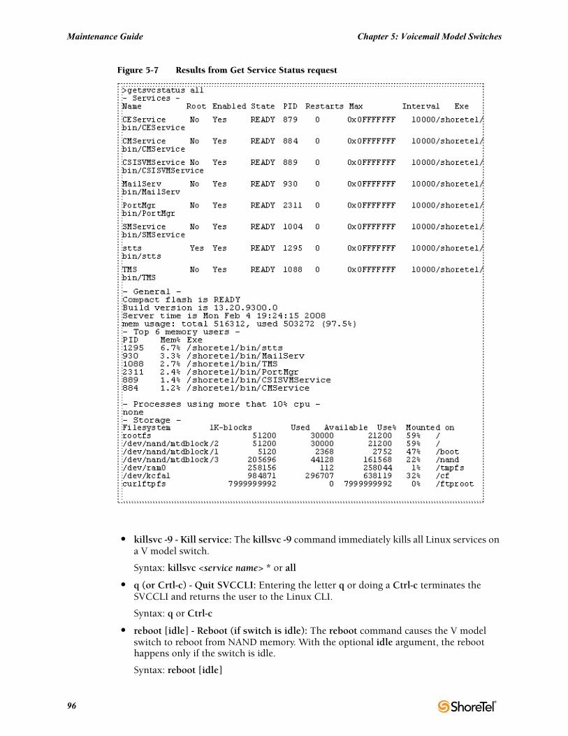
Maintenance Guide Chapter 5: Voicemail Model Switches
Figure 5-7 Results from Get Service Status request
• killsvc -9 - Kill service: The killsvc -9 command immediately kills all Linux services on a V model switch.
Syntax: killsvc <service name> * or all
• q (or Crtl-c) - Quit SVCCLI: Entering the letter q or doing a Ctrl-c terminates the SVCCLI and returns the user to the Linux CLI.
Syntax: q or Ctrl-c
• reboot [idle] - Reboot (if switch is idle): The reboot command causes the V model switch to reboot from NAND memory. With the optional idle argument, the reboot happens only if the switch is idle.
Syntax: reboot [idle]
96
Chapter 5: Voicemail Model Switches Maintenance Guide
Rebooting a V model switch and restarting a V model switch have different scopes. On other ShoreTel Voice Switches, rebooting and restarting are essentially the same. Rebooting a V model switch includes the Linux kernel and everything that a kernel reboot entails. In contrast, restarting a V model switch affects only the application layer.
• restart [idle] - Restart services (if switch is idle): The restart command stops and then re-starts services. The idle option means that the operation waits until the process is idle. For instance, restarting the stts process when idle means waiting for stts not to be handling any calls, stopping stts, and then starting it again. Also, during the course of a restart or a reboot, the switch upgrades, if necessary.
Syntax: restart [idle]
• restorevm - Restore voice mail files: The restorevm command causes the backed up VM, Auto-Attendant, and logs to be restored from the server to the CF card. voice mail operation is unavailable during a restore. This process overwrites whatever is on the CF cards and puts the V model switch in the same state it was in at the time of the backup. The restore operation must be started from the SVCCLI. (The Director provides no option for starting a restore operation.) When the restoration is complete, the SVCCLI posts a message, and the switch is restarted.
NOTE: If ShoreTel 9.1 is installed on a Windows 2008 platform, do not issue the “restorevm” command multiple times. Issuing this command multiple times may result in a “Voice Mail System Unavailable” error.
• sendcmd - Send command: The sendcmd command causes Linux to send a command to a particular service. This command is used by ShoreTel engineers for debug only.
Syntax: sendcmd <service name>
• startgroup - Start group of services: The startgroup command starts a stopped group. This command is the follow up to the stopgroup debug command.
Syntax: startgroup <group name> * or all
• startsvc - Start service: The startsvc command starts one or all services that have been stopped. This command might be able to restart one or more services that have stopped working. It can also be the follow up to the stopsvc debug command.
Syntax: startsvc <service name> * or all
• stopgroup - Stop group of services: The stopgroup command stops one or all service groups. It kills the targeted group’s process.
Syntax: stopgroup <group name> * or all
• stopmgr - Stop services manager: The stopmgr command completely stops the operation of the services manager.
Syntax: stopmgr
• stopsvc - Stop service: The stopsvc command completely stops one or all services. It kills the targeted service’s process.
Syntax: stopsvc <service name> * or all
ShoreTel 12.2 97
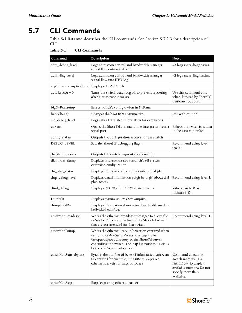
Maintenance Guide Chapter 5: Voicemail Model Switches
5.7 CLI CommandsTable 5-1 lists and describes the CLI commands. See Section 5.2.2.3 for a description of CLI.
Table 5-1 CLI Commands
Command Description Notes
adm_debug_level Logs admission control and bandwidth manager signal flow onto serial port.
=2 logs more diagnostics.
adm_diag_level Logs admission control and bandwidth manager signal flow into IPBX log.
=2 logs more diagnostics.
arpShow and arptabShow Displays the ARP table.
autoReboot = 0 Turns the switch watchdog off to prevent rebooting after a catastrophic failure.
Use this command only when directed by ShoreTel Customer Support.
bigNvRamSetup Erases switch's configuration in NvRam.
bootChange Changes the boot ROM parameters. Use with caution.
cid_debug_level Logs caller ID related information for extensions.
cliStart Opens the ShoreTel command line interpreter from a serial port.
Reboot the switch to return to the Linux interface.
config_status Outputs the configuration records for the switch.
DEBUG_LEVEL Sets the ShoreSIP debugging flags. Recommend using level 0xe00.
diagdCommands Outputs full switch diagnostic information.
dial_num_dump Displays information about switch's off-system extension configuration.
dn_plan_status Displays information about the switch's dial plan.
dnp_debug_level Displays detail information (digit by digit) about dial plan access.
Recommend using level 1.
dtmf_debug Displays RFC2833 for G729 related events. Values can be 0 or 1 (default is 0).
DumpSB Displays maximum PMCSW outputs.
dumpUsedBw Displays information about actual bandwidth used on individual calls/legs.
etherMonBroadcast Writes the ethernet broadcast messages to a .cap file in \inetpub\ftproot directory of the ShoreTel server that are not intended for that switch.
Recommend using level 1.
etherMonDump Writes the ethernet trace information captured when using EtherMonStart. Writes to a .cap file in \inetpub\ftproot directory of the ShoreTel server controlling the switch. The .cap file name is ST-<lst 3 bytes of MAC-time-date>.cap.
etherMonStart <bytes> Bytes is the number of bytes of information you want to capture (for example, 10000000). Captures ethernet packets for trace purposes
Command consumes switch memory. Run memShow to display available memory. Do not specify more than available.
etherMonStop Stops capturing ethernet packets.
98
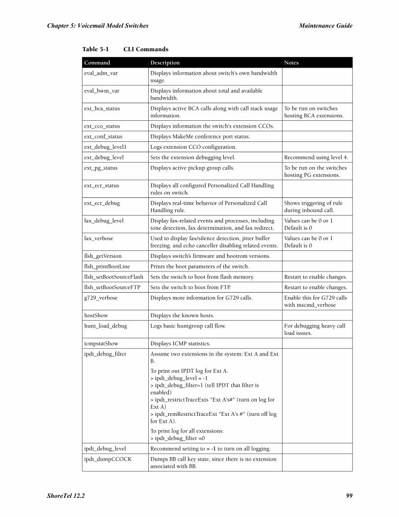
Chapter 5: Voicemail Model Switches Maintenance Guide
eval_adm_var Displays information about switch's own bandwidth usage.
eval_bwm_var Displays information about total and available bandwidth.
ext_bca_status Displays active BCA calls along with call stack usage information.
To be run on switches hosting BCA extensions.
ext_cco_status Displays information the switch's extension CCOs.
ext_conf_status Displays MakeMe conference port status.
ext_debug_level1 Logs extension CCO configuration.
ext_debug_level Sets the extension debugging level. Recommend using level 4.
ext_pg_status Displays active pickup group calls. To be run on the switches hosting PG extensions.
ext_ecr_status Displays all configured Personalized Call Handling rules on switch.
ext_ecr_debug Displays real-time behavior of Personalized Call Handling rule.
Shows triggering of rule during inbound call.
fax_debug_level Display fax-related events and processes, including tone detection, fax determination, and fax redirect.
Values can be 0 or 1 Default is 0
fax_verbose Used to display fax/silence detection, jitter buffer freezing. and echo canceller disabling related events.
Values can be 0 or 1 Default is 0
flsh_getVersion Displays switch’s firmware and bootrom versions.
flsh_printBootLine Prints the boot parameters of the switch.
flsh_setBootSourceFlash Sets the switch to boot from flash memory. Restart to enable changes.
flsh_setBootSourceFTP Sets the switch to boot from FTP. Restart to enable changes.
g729_verbose Displays more information for G729 calls. Enable this for G729 calls with mscmd_verbose
hostShow Displays the known hosts.
hunt_load_debug Logs basic huntgroup call flow. For debugging heavy call load issues.
icmpstatShow Displays ICMP statistics.
ipdt_debug_filter Assume two extensions in the system: Ext A and Ext B.
To print out IPDT log for Ext A.> ipdt_debug_level = -1> ipdt_debug_filter=1 (tell IPDT that filter is enabled) > ipdt_restrictTraceExts "Ext A's#" (turn on log for Ext A)> ipdt_remRestrictTraceExt "Ext A's #" (turn off log for Ext A).
To print log for all extensions:> ipdt_debug_filter =0
ipdt_debug_level Recommend setting to = -1 to turn on all logging.
ipdt_dumpCCOCK Dumps BB call key state, since there is no extension associated with BB.
Table 5-1 CLI Commands
Command Description Notes
ShoreTel 12.2 99
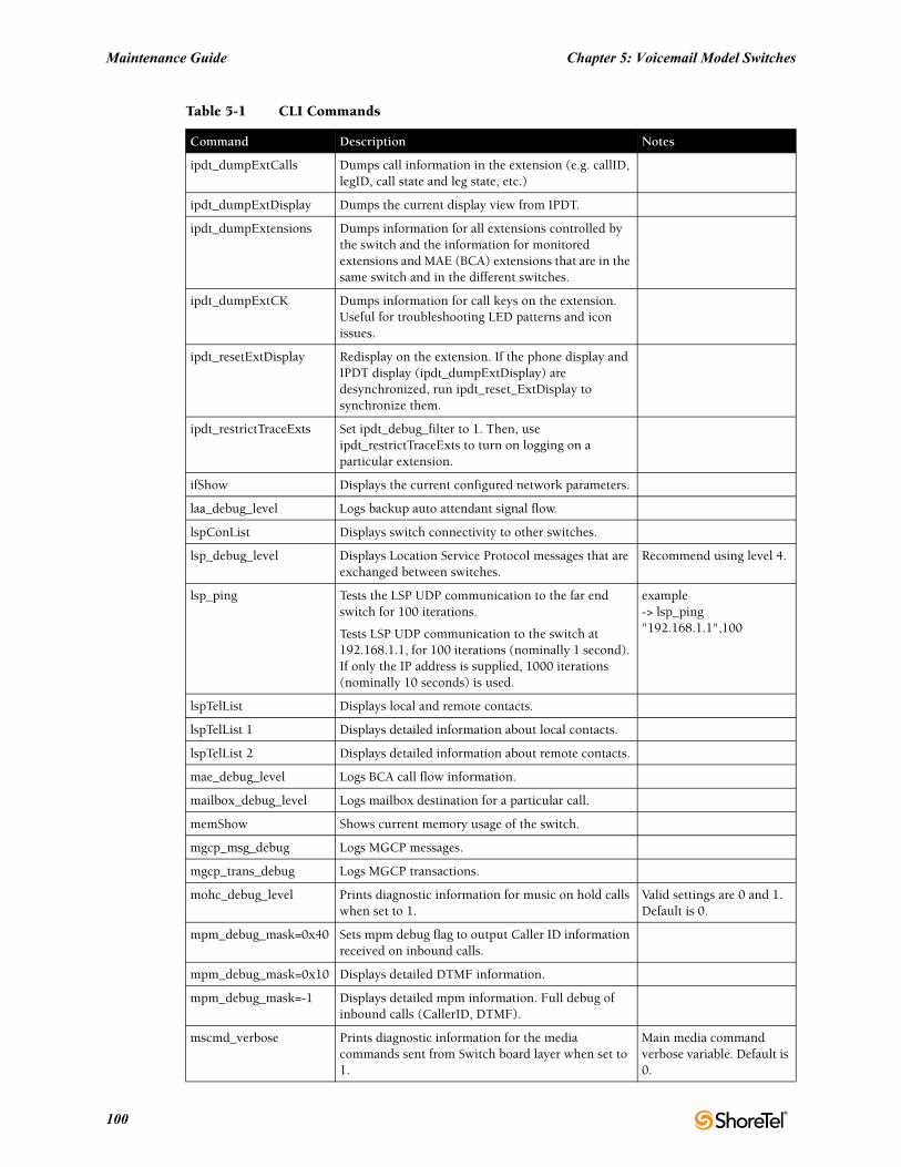
Maintenance Guide Chapter 5: Voicemail Model Switches
ipdt_dumpExtCalls Dumps call information in the extension (e.g. callID, legID, call state and leg state, etc.)
ipdt_dumpExtDisplay Dumps the current display view from IPDT.
ipdt_dumpExtensions Dumps information for all extensions controlled by the switch and the information for monitored extensions and MAE (BCA) extensions that are in the same switch and in the different switches.
ipdt_dumpExtCK Dumps information for call keys on the extension. Useful for troubleshooting LED patterns and icon issues.
ipdt_resetExtDisplay Redisplay on the extension. If the phone display and IPDT display (ipdt_dumpExtDisplay) are desynchronized, run ipdt_reset_ExtDisplay to synchronize them.
ipdt_restrictTraceExts Set ipdt_debug_filter to 1. Then, use ipdt_restrictTraceExts to turn on logging on a particular extension.
ifShow Displays the current configured network parameters.
laa_debug_level Logs backup auto attendant signal flow.
lspConList Displays switch connectivity to other switches.
lsp_debug_level Displays Location Service Protocol messages that are exchanged between switches.
Recommend using level 4.
lsp_ping Tests the LSP UDP communication to the far end switch for 100 iterations.
Tests LSP UDP communication to the switch at 192.168.1.1, for 100 iterations (nominally 1 second). If only the IP address is supplied, 1000 iterations (nominally 10 seconds) is used.
example-> lsp_ping "192.168.1.1",100
lspTelList Displays local and remote contacts.
lspTelList 1 Displays detailed information about local contacts.
lspTelList 2 Displays detailed information about remote contacts.
mae_debug_level Logs BCA call flow information.
mailbox_debug_level Logs mailbox destination for a particular call.
memShow Shows current memory usage of the switch.
mgcp_msg_debug Logs MGCP messages.
mgcp_trans_debug Logs MGCP transactions.
mohc_debug_level Prints diagnostic information for music on hold calls when set to 1.
Valid settings are 0 and 1. Default is 0.
mpm_debug_mask=0x40 Sets mpm debug flag to output Caller ID information received on inbound calls.
mpm_debug_mask=0x10 Displays detailed DTMF information.
mpm_debug_mask=-1 Displays detailed mpm information. Full debug of inbound calls (CallerID, DTMF).
mscmd_verbose Prints diagnostic information for the media commands sent from Switch board layer when set to 1.
Main media command verbose variable. Default is 0.
Table 5-1 CLI Commands
Command Description Notes
100
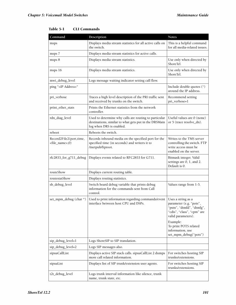
Chapter 5: Voicemail Model Switches Maintenance Guide
msps Displays media stream statistics for all active calls on the switch.
This is a helpful command for all media-related issues.
msps 7 Displays media stream statistics for active calls.
msps 8 Displays media stream statistics. Use only when directed by ShoreTel.
msps 16 Displays media stream statistics. Use only when directed by ShoreTel.
mwi_debug_level Logs message waiting indicator setting call flow.
ping "<IP Address>" Include double quotes (“) around the IP address.
pri_verbose Traces a high level description of the PRI traffic sent and received by trunks on the switch.
Recommend setting pri_verbose=1
print_ether_stats Prints the Ethernet statistics from the network controller.
rdn_diag_level Used to determine why calls are routing to particular destinations, similar to what gets put in the DRSMain log when DRS is enabled.
Useful values are 0 (none) or 5 (trace resolve_dn).
reboot Reboots the switch.
Record2File2(port,time,<file_name>;0)
Records inbound media on the specified port for the specified time (in seconds) and writers it to /inetpub/ftproot.
Writes to the TMS server controlling the switch. FTP write access must be enabled on the server.
rfc2833_for_g711_debug Displays events related to RFC2833 for G711. Bitmask integer. Valid settings are 0, 1, and 2. Default is 0.
routeShow Displays current routing table.
routestatShow Displays routing statistics.
sb_debug_level Switch board debug variable that prints debug information for the commands sent from Call control.
Values range from 1-5.
set_mpm_debug (char *) Used to print information regarding commands/event interface between host CPU and DSPs.
Uses a string as a parameter (e.g. “pots”, “pstn”, “dtmfd”, “dtmfg”, “cdis”, “class”, “cpm” are valid parameters).
Example:To print POTS related information, use set_mpm_debug(“pots”)
sip_debug_level=1 Logs ShoreSIP to SIP translation.
sip_debug_level=2 Logs SIP messages also.
sipuaCallList Displays active SIP stack calls. sipuaCallList 2 dumps more call related information.
For switches hosting SIP trunks/extensions.
sipuaList Displays list of SIP trunk/extension user agents. For switches hosting SIP trunks/extensions.
t2t_debug_level Logs trunk interval information like silence, trunk name, trunk state, etc.
Table 5-1 CLI Commands
Command Description Notes
ShoreTel 12.2 101
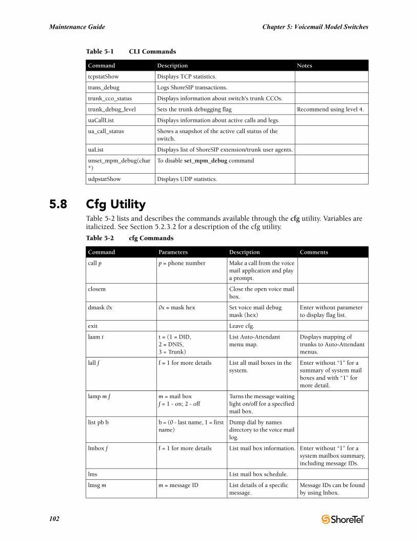
Maintenance Guide Chapter 5: Voicemail Model Switches
5.8 Cfg UtilityTable 5-2 lists and describes the commands available through the cfg utility. Variables are italicized. See Section 5.2.3.2 for a description of the cfg utility.
tcpstatShow Displays TCP statistics.
trans_debug Logs ShoreSIP transactions.
trunk_cco_status Displays information about switch's trunk CCOs.
trunk_debug_level Sets the trunk debugging flag Recommend using level 4.
uaCallList Displays information about active calls and legs.
ua_call_status Shows a snapshot of the active call status of the switch.
uaList Displays list of ShoreSIP extension/trunk user agents.
unset_mpm_debug(char*)
To disable set_mpm_debug command
udpstatShow Displays UDP statistics.
Table 5-2 cfg Commands
Command Parameters Description Comments
call p p = phone number Make a call from the voice mail application and play a prompt.
closem Close the open voice mail box.
dmask 0x 0x = mask hex Set voice mail debug mask (hex)
Enter without parameter to display flag list.
exit Leave cfg.
laam t t = (1 = DID, 2 = DNIS, 3 = Trunk)
List Auto-Attendant menu map.
Displays mapping of trunks to Auto-Attendant menus.
lall f f = 1 for more details List all mail boxes in the system.
Enter without “1” for a summary of system mail boxes and with “1” for more detail.
lamp m f m = mail box f = 1 - on; 2 - off
Turns the message waiting light on/off for a specified mail box.
list pb b b = (0 - last name, 1 = first name)
Dump dial by names directory to the voice mail log.
lmbox f f = 1 for more details List mail box information. Enter without “1” for a system mailbox summary, including message IDs.
lms List mail box schedule.
lmsg m m = message ID List details of a specific message.
Message IDs can be found by using lnbox.
Table 5-1 CLI Commands
Command Description Notes
102
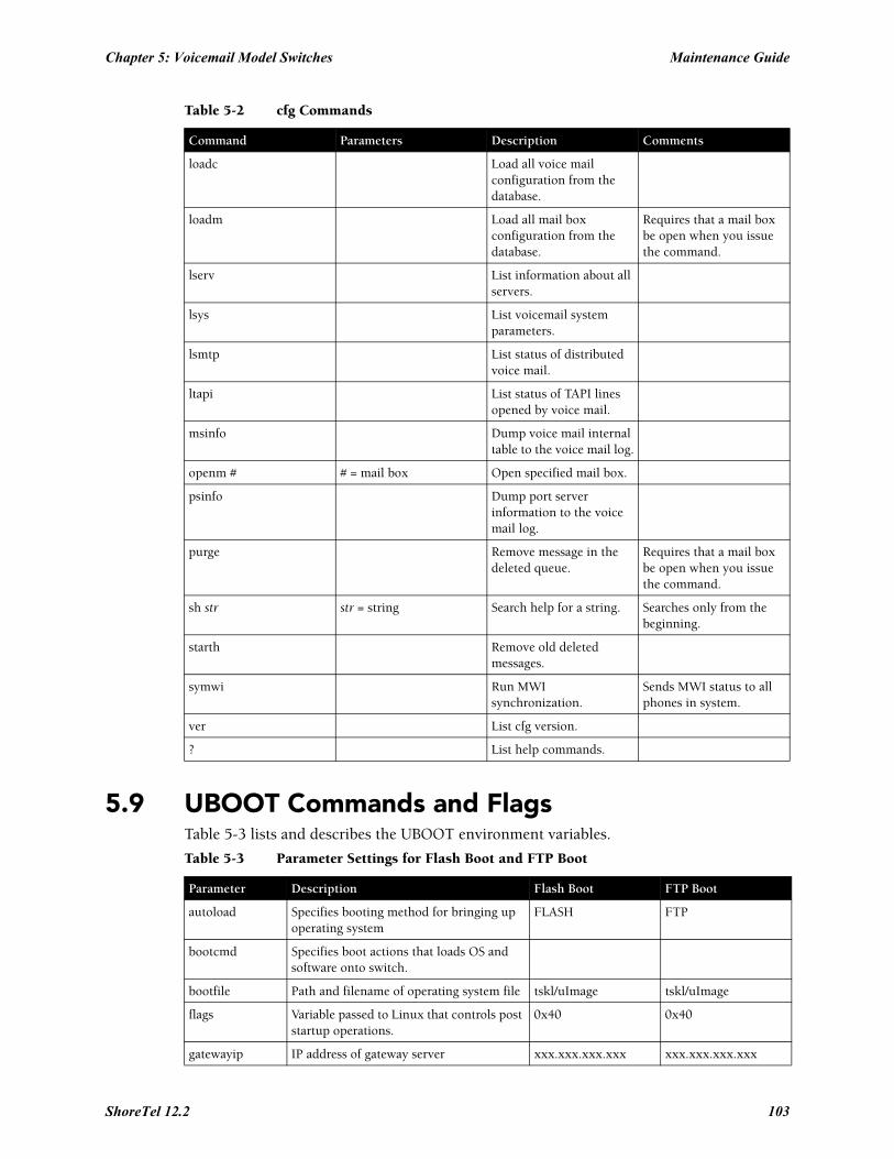
Chapter 5: Voicemail Model Switches Maintenance Guide
5.9 UBOOT Commands and FlagsTable 5-3 lists and describes the UBOOT environment variables.
loadc Load all voice mail configuration from the database.
loadm Load all mail box configuration from the database.
Requires that a mail box be open when you issue the command.
lserv List information about all servers.
lsys List voicemail system parameters.
lsmtp List status of distributed voice mail.
ltapi List status of TAPI lines opened by voice mail.
msinfo Dump voice mail internal table to the voice mail log.
openm # # = mail box Open specified mail box.
psinfo Dump port server information to the voice mail log.
purge Remove message in the deleted queue.
Requires that a mail box be open when you issue the command.
sh str str = string Search help for a string. Searches only from the beginning.
starth Remove old deleted messages.
symwi Run MWI synchronization.
Sends MWI status to all phones in system.
ver List cfg version.
? List help commands.
Table 5-3 Parameter Settings for Flash Boot and FTP Boot
Parameter Description Flash Boot FTP Boot
autoload Specifies booting method for bringing up operating system
FLASH FTP
bootcmd Specifies boot actions that loads OS and software onto switch.
bootfile Path and filename of operating system file tskl/uImage tskl/uImage
flags Variable passed to Linux that controls post startup operations.
0x40 0x40
gatewayip IP address of gateway server xxx.xxx.xxx.xxx xxx.xxx.xxx.xxx
Table 5-2 cfg Commands
Command Parameters Description Comments
ShoreTel 12.2 103
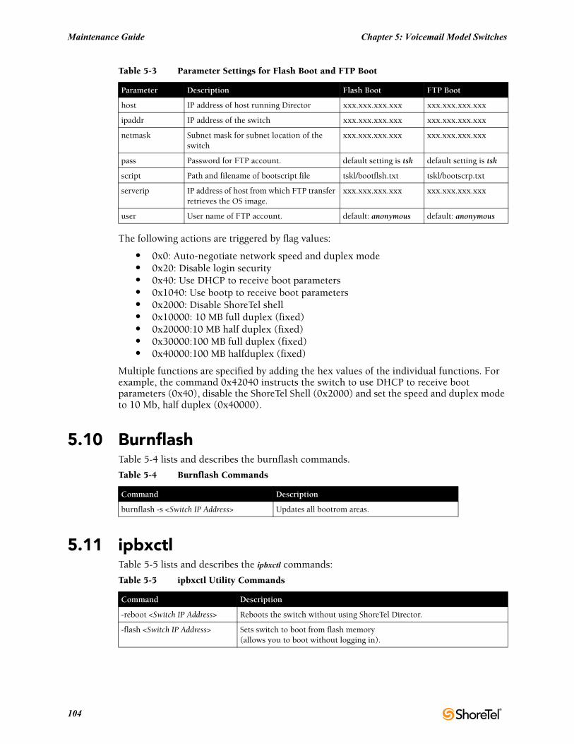
Maintenance Guide Chapter 5: Voicemail Model Switches
The following actions are triggered by flag values:
• 0x0: Auto-negotiate network speed and duplex mode• 0x20: Disable login security• 0x40: Use DHCP to receive boot parameters• 0x1040: Use bootp to receive boot parameters• 0x2000: Disable ShoreTel shell• 0x10000: 10 MB full duplex (fixed)• 0x20000:10 MB half duplex (fixed)• 0x30000:100 MB full duplex (fixed)• 0x40000:100 MB halfduplex (fixed)
Multiple functions are specified by adding the hex values of the individual functions. For example, the command 0x42040 instructs the switch to use DHCP to receive boot parameters (0x40), disable the ShoreTel Shell (0x2000) and set the speed and duplex mode to 10 Mb, half duplex (0x40000).
5.10 BurnflashTable 5-4 lists and describes the burnflash commands.
5.11 ipbxctlTable 5-5 lists and describes the ipbxctl commands:
host IP address of host running Director xxx.xxx.xxx.xxx xxx.xxx.xxx.xxx
ipaddr IP address of the switch xxx.xxx.xxx.xxx xxx.xxx.xxx.xxx
netmask Subnet mask for subnet location of the switch
xxx.xxx.xxx.xxx xxx.xxx.xxx.xxx
pass Password for FTP account. default setting is tsk default setting is tsk
script Path and filename of bootscript file tskl/bootflsh.txt tskl/bootscrp.txt
serverip IP address of host from which FTP transfer retrieves the OS image.
xxx.xxx.xxx.xxx xxx.xxx.xxx.xxx
user User name of FTP account. default: anonymous default: anonymous
Table 5-4 Burnflash Commands
Command Description
burnflash -s <Switch IP Address> Updates all bootrom areas.
Table 5-5 ipbxctl Utility Commands
Command Description
-reboot <Switch IP Address> Reboots the switch without using ShoreTel Director.
-flash <Switch IP Address> Sets switch to boot from flash memory(allows you to boot without logging in).
Table 5-3 Parameter Settings for Flash Boot and FTP Boot
Parameter Description Flash Boot FTP Boot
104
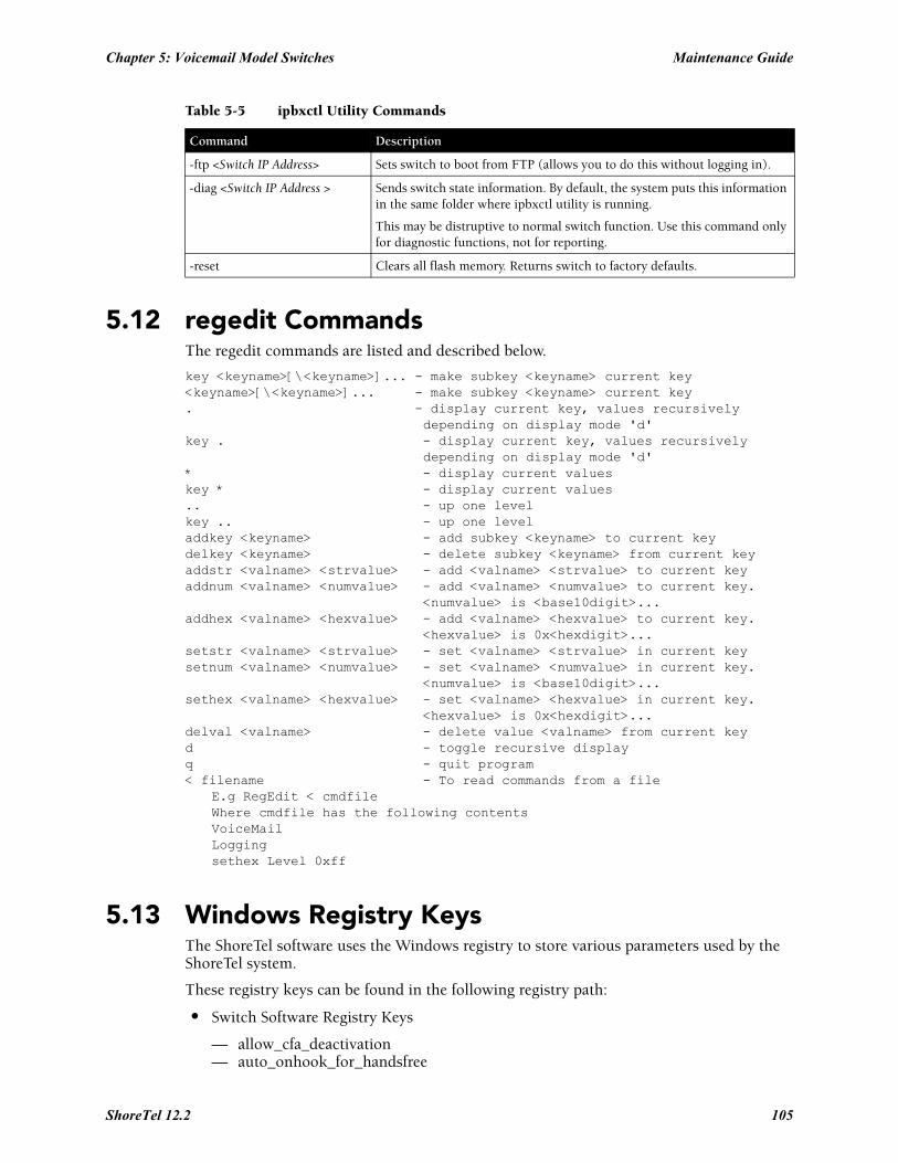
Chapter 5: Voicemail Model Switches Maintenance Guide
5.12 regedit CommandsThe regedit commands are listed and described below.
key <keyname>[\<keyname>]... - make subkey <keyname> current key<keyname>[\<keyname>]... - make subkey <keyname> current key. - display current key, values recursively
depending on display mode 'd'key . - display current key, values recursively
depending on display mode 'd'* - display current valueskey * - display current values.. - up one levelkey .. - up one leveladdkey <keyname> - add subkey <keyname> to current keydelkey <keyname> - delete subkey <keyname> from current keyaddstr <valname> <strvalue> - add <valname> <strvalue> to current keyaddnum <valname> <numvalue> - add <valname> <numvalue> to current key.
<numvalue> is <base10digit>...addhex <valname> <hexvalue> - add <valname> <hexvalue> to current key.
<hexvalue> is 0x<hexdigit>...setstr <valname> <strvalue> - set <valname> <strvalue> in current keysetnum <valname> <numvalue> - set <valname> <numvalue> in current key.
<numvalue> is <base10digit>...sethex <valname> <hexvalue> - set <valname> <hexvalue> in current key.
<hexvalue> is 0x<hexdigit>...delval <valname> - delete value <valname> from current keyd - toggle recursive displayq - quit program< filename - To read commands from a file
E.g RegEdit < cmdfileWhere cmdfile has the following contentsVoiceMailLoggingsethex Level 0xff
5.13 Windows Registry KeysThe ShoreTel software uses the Windows registry to store various parameters used by the ShoreTel system.
These registry keys can be found in the following registry path:
• Switch Software Registry Keys
— allow_cfa_deactivation— auto_onhook_for_handsfree
-ftp <Switch IP Address> Sets switch to boot from FTP (allows you to do this without logging in).
-diag <Switch IP Address > Sends switch state information. By default, the system puts this information in the same folder where ipbxctl utility is running.
This may be distruptive to normal switch function. Use this command only for diagnostic functions, not for reporting.
-reset Clears all flash memory. Returns switch to factory defaults.
Table 5-5 ipbxctl Utility Commands
Command Description
ShoreTel 12.2 105
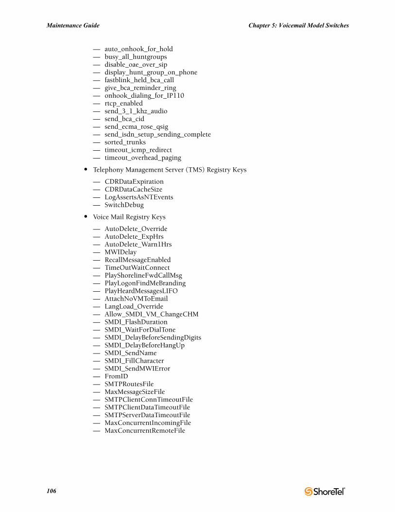
Maintenance Guide Chapter 5: Voicemail Model Switches
— auto_onhook_for_hold— busy_all_huntgroups— disable_oae_over_sip— display_hunt_group_on_phone— fastblink_held_bca_call— give_bca_reminder_ring— onhook_dialing_for_IP110— rtcp_enabled— send_3_1_khz_audio— send_bca_cid— send_ecma_rose_qsig— send_isdn_setup_sending_complete— sorted_trunks— timeout_icmp_redirect— timeout_overhead_paging
• Telephony Management Server (TMS) Registry Keys
— CDRDataExpiration— CDRDataCacheSize— LogAssertsAsNTEvents— SwitchDebug
• Voice Mail Registry Keys
— AutoDelete_Override— AutoDelete_ExpHrs— AutoDelete_Warn1Hrs— MWIDelay— RecallMessageEnabled— TimeOutWaitConnect— PlayShorelineFwdCallMsg— PlayLogonFindMeBranding— PlayHeardMessagesLIFO— AttachNoVMToEmail— LangLoad_Override— Allow_SMDI_VM_ChangeCHM— SMDI_FlashDuration— SMDI_WaitForDialTone— SMDI_DelayBeforeSendingDigits— SMDI_DelayBeforeHangUp— SMDI_SendName— SMDI_FillCharacter— SMDI_SendMWIError— FromID— SMTPRoutesFile— MaxMessageSizeFile— SMTPClientConnTimeoutFile— SMTPClientDataTimeoutFile— SMTPServerDataTimeoutFile— MaxConcurrentIncomingFile— MaxConcurrentRemoteFile
106
Chapter 5: Voicemail Model Switches Maintenance Guide
5.14 ShoreTel Server File SystemThe following list identifies the directories where the ShoreTel server installs its files.
The server installs files with default access permissions. (System administrators may want to ensure a more secure environment.)
The Windows System user and the IPBX user created by the ShoreTel installer require full access to all the ShoreTel directories. All other users can be granted access on an as-needed basis.
To ensure the security of sensitive and/or personal information, confine access to the VMS and Database directories strictly to administrator, system, and IPBX users.
• Shoreline Data: Contains all the dynamic information the server uses to run the system. This directory and all sub-directories may be saved as part of a backup and used for full system recovery. <drive>\Shoreline Data
• Prompts: Contains copies of the auto attendant menu prompts.<drive>\Shoreline Data\Prompts
• VMS: Contains all the files and configuration information used by the voice mail system. The files in this directory and its sub-directories are very dynamic. Never open these files. Opening any of the configuration files may cause the voice mail system to become corrupted in part or completely, and can cause loss of voice mail messages.<drive>\Shoreline Data\VMS
• MESSAGE: Contains all voice mail messages as .wav files, along with an .enl pointer file for each message.<drive>\Shoreline Data\VMS\MESSAGE
ShoreTel 12.2 107

Maintenance Guide Chapter 5: Voicemail Model Switches
108
C H A P T E R 6
IP Endpoints
6.1 OverviewThe ShoreTel system manages calls and applications for three types of IP endpoints: IP phones, SoftPhones, and conference bridges. IP endpoints are identified by IP address and can exist anywhere on the network. All IP endpoints are supported by ShoreTel Voice Switches, which must have sufficient capacity for all the IP endpoints in the system. IP endpoints are configured in the system with ShoreTel Director. For more information on IP endpoints, see the ShoreTel Planning and Installation Guide and ShoreTel Administration Guide.
6.1.1 IP PhonesShoreTel IP phones allow you to deploy your telephony system as an end-to-end IP network without dedicated station wiring. Connecting anywhere on the network, ShoreTel IP phones work with the ShoreTel Communicator client applications or can be used independently, providing an intuitive interface to essential telephone features.
The IP phone controls basic display operations, such as volume level, date and time, and icons. To provide IP telephony in a ShoreTel system, IP phones rely on services, switches, and industry-standard protocols. The following sections describe these dependencies.
6.1.1.1 IP Phone Keep AliveThe ShoreTel Voice Switches that manage IP phones send a heartbeat to their associated IP phones once a minute. If the heartbeat is not acknowledged within approximately four seconds, the switch considers the IP phone to be offline or unavailable. The switch continues to broadcast the heartbeat every minute. Any currently offline IP phone that returns an acknowledgement is considered online and available.
6.1.1.2 IP Phone FailoverIP phones can be optionally configured to send a heartbeat to their ShoreTel Voice Switch every four minutes. If an IP phone cannot communicate with its switch, the phone automatically connects to another switch located at the same site with available configured IP phone resources. For IP phone failover to be effective, the system must be planned with sufficient excess capacity to handle phones from at least one switch during a failover event. For example, if a switch with 20 IP phone ports fails, 20 IP phone ports need to be available elsewhere in the system. For more information, see the IP phone configuration settings in the ShoreTel Administration Guide.
6.1.1.3 ServicesThere are two services running on the ShoreTel HQ and DVS servers that interact with the system’s IP phones: IP Phone Configuration Service (IPCS) and IP Phone Display Service (IPDS).
ShoreTel 12.2 109
Maintenance Guide Chapter 6: IP Endpoints
IPCS
The IP Phone Configuration Service manages the IP phone configuration process, including configuration files and the database updates. Problems with IPCS connectivity can prevent IP phones from booting and prevent phone configuration data from being updated.
IPDS
The IP Phone Display Service handles the remaining functions, such as event handling and feature button functions. It also controls any actions by the IP phone display not controlled by the device’s firmware or switches. Problems with IPDS or TMS connectivity can result in incorrect phone displays and errors in both the hard and soft key functions.
Embedded IP Phone Display Driver
These features are not handled by the switch, but continue to be provided by the server. Control of many of the IP phone features (such as phone display, redial, and call transfers) is now on the server rather than the switch in order to enhance reliability and offer better uptime. Features that require writing to the database (such as directory and speed dial) continue to depend on the server being both operational and accessible.
Date and Time
IP phones depend on an SNTP server to maintain the correct time and date. Without an SNTP server, you can set the phone date and time via a GMT offset.
6.1.1.4 IP Phones and ShoreTel Voice SwitchesIP phones in a ShoreTel system interact with two types of ShoreTel Voice Switches: the configuration switch and the call manager switch. The configuration switches help the IP phones obtain their configuration from the ShoreTel server, which functions as a FTP server for the IP phones. You must have at least one configuration switch and can designate a second configuration switch for reliability.
As part of the configuration information, each IP phone is assigned a ShoreTel Voice Switch that acts as the phone’s call manager to help the IP phone set up and tear down calls.
Configuration Switch(es)
In a DHCP environment, when an IP phone is booted, it receives the IP address of the DHCP and ShoreTel server from the configuration switch. Each system includes at least one configuration switch for this purpose. The IP addresses of these switches are downloaded to the IP phones whenever the IP phones are booted.
If you have configured the IP phones to boot without a DHCP server, you must set the IP address of the configuration switch manually.
These switches communicate with the HQ server to determine which switch manages calls for a particular IP phone. You have the option of assigning two switches to this function, in case one fails. For information on configuration switches, see the ShoreTel Administration Guide.
110
Chapter 6: IP Endpoints Maintenance Guide
Call Manager Switch
The IP phones’ ShoreTel Voice Switch is responsible for actions such as hold, transfer, conference, and park. The call manager module of the ShoreTel Voice Switches handles the Media Gateway Control Protocol (MGCP) information from the IP phones assigned to it. After a call is connected to an endpoint, media streams are independent of the call manager switch.
The ShoreTel Voice Switch communicates call information to other switches in the system using ShoreTel’s enhanced SIP protocol. Every site where IP phones are in use must have a ShoreTel Voice Switch configured to support the number of IP phones at the site.
To configure IP phone support on a ShoreTel Voice Switch, you must reserve ports for IP phone support on the ShoreTel Voice Switch edit page in ShoreTel Director. See the “Configuring Switches” chapter in the ShoreTel Administration Guide for additional information.
6.1.1.5 IP Phone CommunicationsIP phone communications are routed through two protocols: MGCP and RTP (Real-time Protocol).
MGCP
IP phones communicate with ShoreTel Voice Switches via MGCP, a device control protocol. The relationship between the switch (call manager) and the phone (gateway) follows a master–slave model.
MGCP, an industry-standard protocol, is used to:
• Deliver information to the IP phone display• Set up and tear down media streams• Report phone events such as key presses, on hook, and off hook
Media
Media travels through the ShoreTel system using Real-Time Protocol (RTP). After call setup, media flows directly between IP phones via RTP. The ShoreTel Voice Switch is involved only when setting up or tearing down a call.
For more information on MGCP communications, see Section 2.3 on page 16.
For more information on RTP communications, see Section 2.3.4 on page 22.
6.1.2 Boot ProcessShoreTel IP phones are preconfigured by ShoreTel to work in conjunction with your ShoreTel system and your network’s Dynamic Host Configuration Protocol (DHCP) server. After the servers are configured, you simply plug the phones into the network and they are automatically added to your ShoreTel system.
After the IP phone possesses the DHCP and FTP server IP addresses, it downloads the application and configuration files from the FTP server. The IP phone configuration file is modified by ShoreTel Director during IP phone configuration.
If you are not using a DHCP server or it is not currently online, you can set a static IP address and other startup parameters directly at the IP phone. Static IP addresses for IP phones can also be assigned using the IP phone setup menus.
ShoreTel 12.2 111
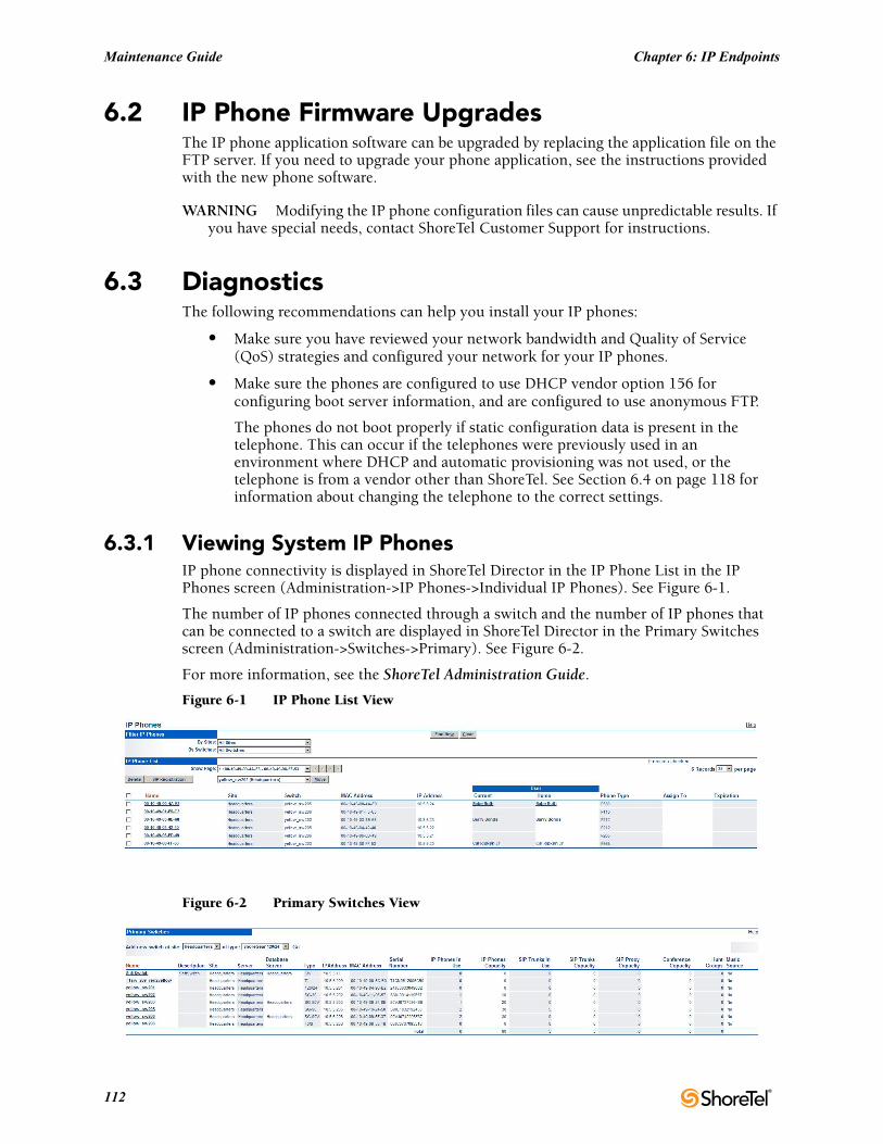
Maintenance Guide Chapter 6: IP Endpoints
6.2 IP Phone Firmware UpgradesThe IP phone application software can be upgraded by replacing the application file on the FTP server. If you need to upgrade your phone application, see the instructions provided with the new phone software.
WARNING Modifying the IP phone configuration files can cause unpredictable results. If you have special needs, contact ShoreTel Customer Support for instructions.
6.3 DiagnosticsThe following recommendations can help you install your IP phones:
• Make sure you have reviewed your network bandwidth and Quality of Service (QoS) strategies and configured your network for your IP phones.
• Make sure the phones are configured to use DHCP vendor option 156 for configuring boot server information, and are configured to use anonymous FTP.
The phones do not boot properly if static configuration data is present in the telephone. This can occur if the telephones were previously used in an environment where DHCP and automatic provisioning was not used, or the telephone is from a vendor other than ShoreTel. See Section 6.4 on page 118 for information about changing the telephone to the correct settings.
6.3.1 Viewing System IP PhonesIP phone connectivity is displayed in ShoreTel Director in the IP Phone List in the IP Phones screen (Administration->IP Phones->Individual IP Phones). See Figure 6-1.
The number of IP phones connected through a switch and the number of IP phones that can be connected to a switch are displayed in ShoreTel Director in the Primary Switches screen (Administration->Switches->Primary). See Figure 6-2.
For more information, see the ShoreTel Administration Guide.
Figure 6-1 IP Phone List View
Figure 6-2 Primary Switches View
112
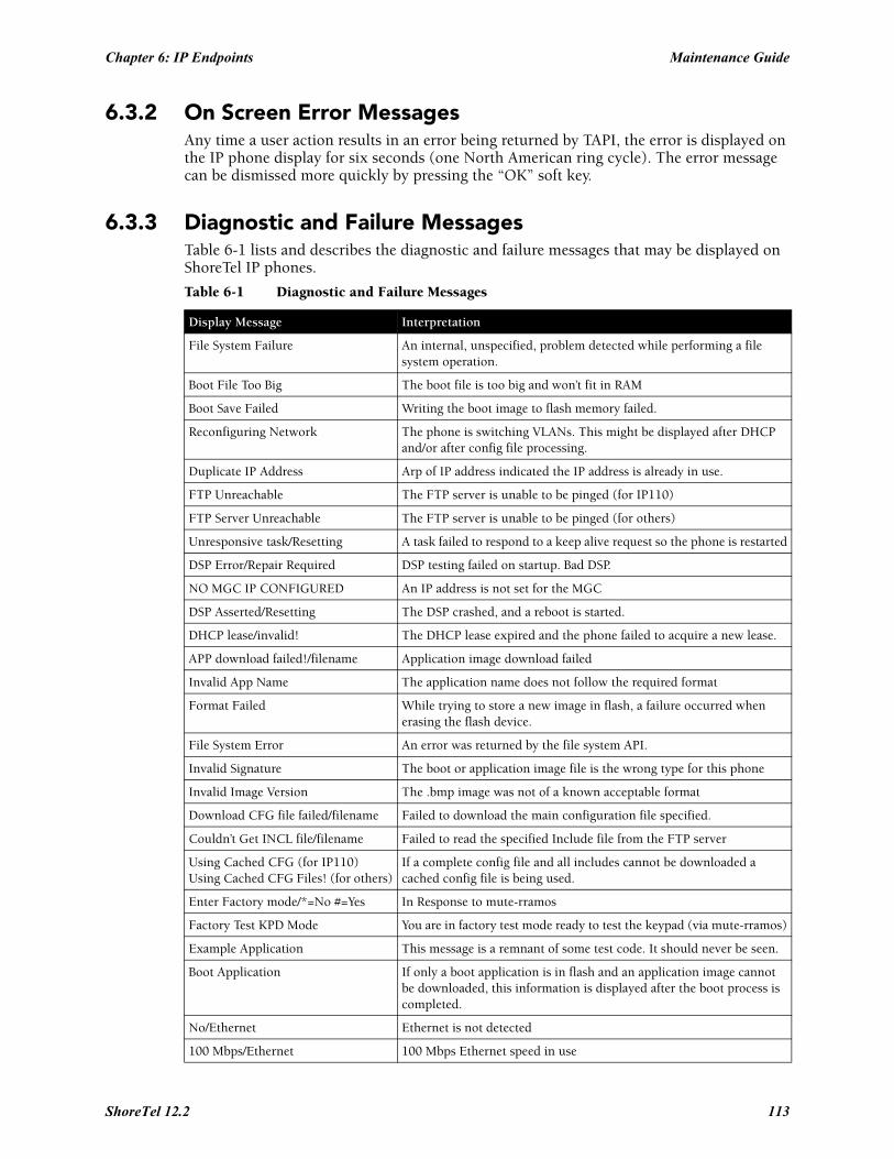
Chapter 6: IP Endpoints Maintenance Guide
6.3.2 On Screen Error MessagesAny time a user action results in an error being returned by TAPI, the error is displayed on the IP phone display for six seconds (one North American ring cycle). The error message can be dismissed more quickly by pressing the “OK” soft key.
6.3.3 Diagnostic and Failure MessagesTable 6-1 lists and describes the diagnostic and failure messages that may be displayed on ShoreTel IP phones.
Table 6-1 Diagnostic and Failure Messages
Display Message Interpretation
File System Failure An internal, unspecified, problem detected while performing a file system operation.
Boot File Too Big The boot file is too big and won’t fit in RAM
Boot Save Failed Writing the boot image to flash memory failed.
Reconfiguring Network The phone is switching VLANs. This might be displayed after DHCP and/or after config file processing.
Duplicate IP Address Arp of IP address indicated the IP address is already in use.
FTP Unreachable The FTP server is unable to be pinged (for IP110)
FTP Server Unreachable The FTP server is unable to be pinged (for others)
Unresponsive task/Resetting A task failed to respond to a keep alive request so the phone is restarted
DSP Error/Repair Required DSP testing failed on startup. Bad DSP.
NO MGC IP CONFIGURED An IP address is not set for the MGC
DSP Asserted/Resetting The DSP crashed, and a reboot is started.
DHCP lease/invalid! The DHCP lease expired and the phone failed to acquire a new lease.
APP download failed!/filename Application image download failed
Invalid App Name The application name does not follow the required format
Format Failed While trying to store a new image in flash, a failure occurred when erasing the flash device.
File System Error An error was returned by the file system API.
Invalid Signature The boot or application image file is the wrong type for this phone
Invalid Image Version The .bmp image was not of a known acceptable format
Download CFG file failed/filename Failed to download the main configuration file specified.
Couldn’t Get INCL file/filename Failed to read the specified Include file from the FTP server
Using Cached CFG (for IP110)Using Cached CFG Files! (for others)
If a complete config file and all includes cannot be downloaded a cached config file is being used.
Enter Factory mode/*=No #=Yes In Response to mute-rramos
Factory Test KPD Mode You are in factory test mode ready to test the keypad (via mute-rramos)
Example Application This message is a remnant of some test code. It should never be seen.
Boot Application If only a boot application is in flash and an application image cannot be downloaded, this information is displayed after the boot process is completed.
No/Ethernet Ethernet is not detected
100 Mbps/Ethernet 100 Mbps Ethernet speed in use
ShoreTel 12.2 113
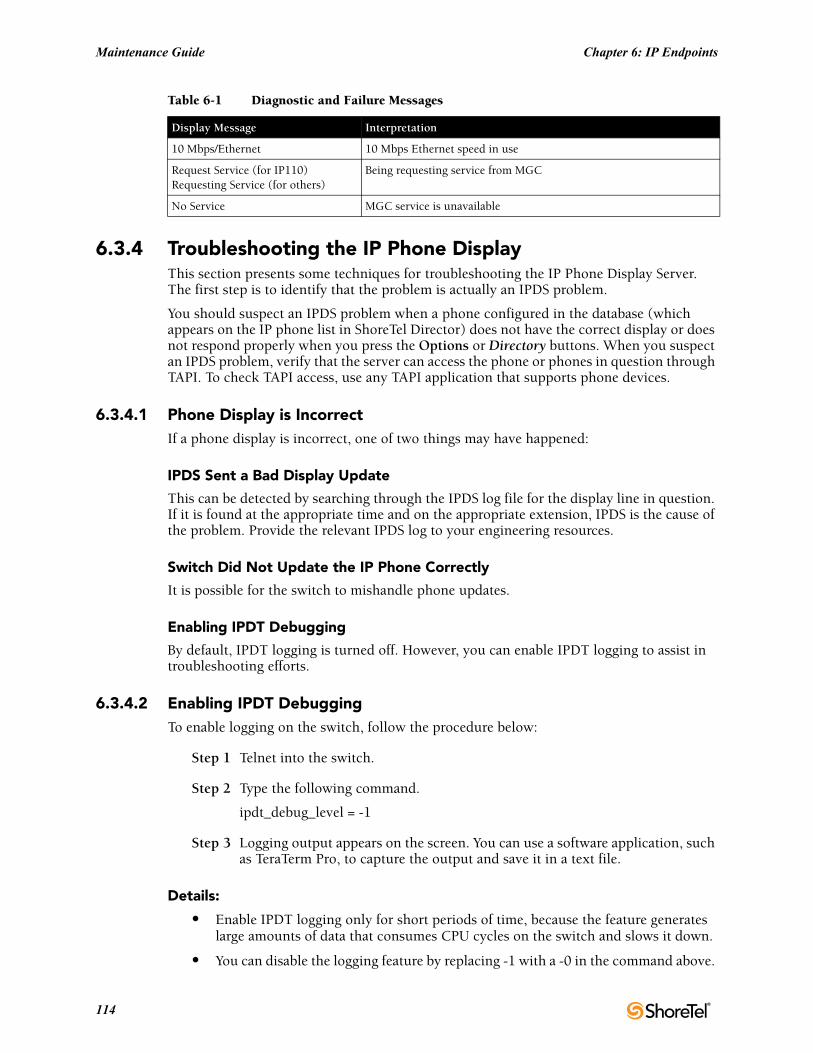
Maintenance Guide Chapter 6: IP Endpoints
6.3.4 Troubleshooting the IP Phone DisplayThis section presents some techniques for troubleshooting the IP Phone Display Server. The first step is to identify that the problem is actually an IPDS problem.
You should suspect an IPDS problem when a phone configured in the database (which appears on the IP phone list in ShoreTel Director) does not have the correct display or does not respond properly when you press the Options or Directory buttons. When you suspect an IPDS problem, verify that the server can access the phone or phones in question through TAPI. To check TAPI access, use any TAPI application that supports phone devices.
6.3.4.1 Phone Display is Incorrect If a phone display is incorrect, one of two things may have happened:
IPDS Sent a Bad Display Update
This can be detected by searching through the IPDS log file for the display line in question. If it is found at the appropriate time and on the appropriate extension, IPDS is the cause of the problem. Provide the relevant IPDS log to your engineering resources.
Switch Did Not Update the IP Phone Correctly
It is possible for the switch to mishandle phone updates.
Enabling IPDT Debugging
By default, IPDT logging is turned off. However, you can enable IPDT logging to assist in troubleshooting efforts.
6.3.4.2 Enabling IPDT DebuggingTo enable logging on the switch, follow the procedure below:
Step 1 Telnet into the switch.
Step 2 Type the following command.
ipdt_debug_level = -1
Step 3 Logging output appears on the screen. You can use a software application, such as TeraTerm Pro, to capture the output and save it in a text file.
Details:
• Enable IPDT logging only for short periods of time, because the feature generates large amounts of data that consumes CPU cycles on the switch and slows it down.
• You can disable the logging feature by replacing -1 with a -0 in the command above.
10 Mbps/Ethernet 10 Mbps Ethernet speed in use
Request Service (for IP110)Requesting Service (for others)
Being requesting service from MGC
No Service MGC service is unavailable
Table 6-1 Diagnostic and Failure Messages
Display Message Interpretation
114
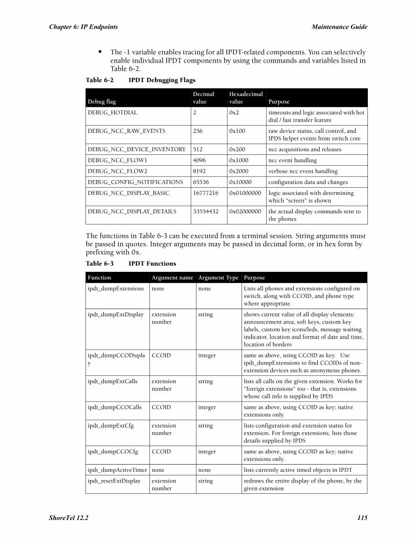
Chapter 6: IP Endpoints Maintenance Guide
• The -1 variable enables tracing for all IPDT-related components. You can selectively enable individual IPDT components by using the commands and variables listed in Table 6-2.
The functions in Table 6-3 can be executed from a terminal session. String arguments must be passed in quotes. Integer arguments may be passed in decimal form, or in hex form by prefixing with 0x.
Table 6-2 IPDT Debugging Flags
Debug flagDecimal value
Hexadecimal value Purpose
DEBUG_HOTDIAL 2 0x2 timeouts and logic associated with hot dial / fast transfer feature
DEBUG_NCC_RAW_EVENTS 256 0x100 raw device status, call control, and IPDS helper events from switch core
DEBUG_NCC_DEVICE_INVENTORY 512 0x200 ncc acquisitions and releases
DEBUG_NCC_FLOW1 4096 0x1000 ncc event handling
DEBUG_NCC_FLOW2 8192 0x2000 verbose ncc event handling
DEBUG_CONFIG_NOTIFICATIONS 65536 0x10000 configuration data and changes
DEBUG_NCC_DISPLAY_BASIC 16777216 0x01000000 logic associated with determining which "screen" is shown
DEBUG_NCC_DISPLAY_DETAILS 33554432 0x02000000 the actual display commands sent to the phones
Table 6-3 IPDT Functions
Function Argument name Argument Type Purpose
ipdt_dumpExtensions none none Lists all phones and extensions configured on switch, along with CCOID, and phone type where appropriate.
ipdt_dumpExtDisplay extension number
string shows current value of all display elements: announcement area, soft keys, custom key labels, custom key icons/leds, message waiting indicator, location and format of date and time, location of borders
ipdt_dumpCCODisplay
CCOID integer same as above, using CCOID as key. Use ipdt_dumpExtensions to find CCOIDs of non-extension devices such as anonymous phones.
ipdt_dumpExtCalls extension number
string lists all calls on the given extension. Works for "foreign extensions" too - that is, extensions whose call info is supplied by IPDS
ipdt_dumpCCOCalls CCOID integer same as above, using CCOID as key; native extensions only.
ipdt_dumpExtCfg extension number
string lists configuration and extension status for extension. For foreign extensions, lists those details supplied by IPDS
ipdt_dumpCCOCfg CCOID integer same as above, using CCOID as key; native extensions only.
ipdt_dumpActiveTimer none none lists currently active timed objects in IPDT
ipdt_resetExtDisplay extension number
string redraws the entire display of the phone, by the given extension
ShoreTel 12.2 115
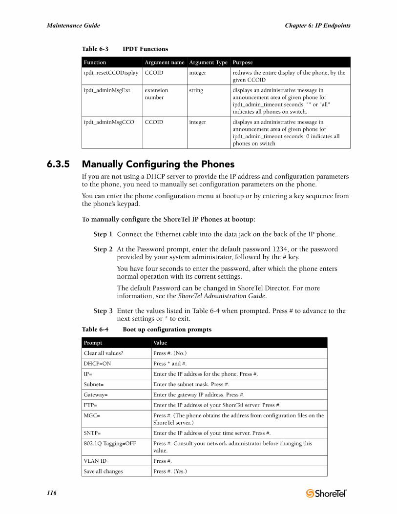
Maintenance Guide Chapter 6: IP Endpoints
6.3.5 Manually Configuring the PhonesIf you are not using a DHCP server to provide the IP address and configuration parameters to the phone, you need to manually set configuration parameters on the phone.
You can enter the phone configuration menu at bootup or by entering a key sequence from the phone’s keypad.
To manually configure the ShoreTel IP Phones at bootup:
Step 1 Connect the Ethernet cable into the data jack on the back of the IP phone.
Step 2 At the Password prompt, enter the default password 1234, or the password provided by your system administrator, followed by the # key.
You have four seconds to enter the password, after which the phone enters normal operation with its current settings.
The default Password can be changed in ShoreTel Director. For more information, see the ShoreTel Administration Guide.
Step 3 Enter the values listed in Table 6-4 when prompted. Press # to advance to the next settings or * to exit.
ipdt_resetCCODisplay CCOID integer redraws the entire display of the phone, by the given CCOID
ipdt_adminMsgExt extension number
string displays an administrative message in announcement area of given phone for ipdt_admin_timeout seconds. "" or "all" indicates all phones on switch.
ipdt_adminMsgCCO CCOID integer displays an administrative message in announcement area of given phone for ipdt_admin_timeout seconds. 0 indicates all phones on switch
Table 6-4 Boot up configuration prompts
Prompt Value
Clear all values? Press #. (No.)
DHCP=ON Press * and #.
IP= Enter the IP address for the phone. Press #.
Subnet= Enter the subnet mask. Press #.
Gateway= Enter the gateway IP address. Press #.
FTP= Enter the IP address of your ShoreTel server. Press #.
MGC= Press #. (The phone obtains the address from configuration files on the ShoreTel server.)
SNTP= Enter the IP address of your time server. Press #.
802.1Q Tagging=OFF Press #. Consult your network administrator before changing this value.
VLAN ID= Press #.
Save all changes Press #. (Yes.)
Table 6-3 IPDT Functions
Function Argument name Argument Type Purpose
116
Chapter 6: IP Endpoints Maintenance Guide
The phone downloads the latest bootROM and firmware from the ShoreTel server and in the process, reboots several times. When the phone displays the date and time, the boot and upgrade process is complete.
To manually configure an operational IP Phone from the keypad:
Step 1 With the phone on hook, press the MUTE key followed by 73887# (SETUP#).
Step 2 At the Password prompt, enter 1234, or the password provided by your system administrator, followed by the # key.
The default Password can be changed in ShoreTel Director. For more information, see the ShoreTel Administration Guide.
Step 3 Enter the values listed in Table 6-4 when prompted. Press # to advance to the next settings or * to exit.
The phone downloads the latest bootROM and firmware from the ShoreTel server and in the process, reboots several times. When the phone displays the date and time, the boot and upgrade process is complete.
6.3.6 Displaying IP Phone SettingsYou can display the phone’s current IP parameters setting by entering a key sequence from the phone’s keypad.
To display the phone’s IP parameter settings:
Step 1 With the phone on hook, press the MUTE key followed by 4636# (INFO#). The phone displays the first two parameters.
Step 2 Press * to advance the display or # to exit. The phone resumes normal operation after the last parameter is displayed.
6.3.7 Resetting the ShoreTel IP Phone
To reset the phone:
Step 1 With the phone on hook, press the MUTE key followed by 73738# (RESET#). The phone reboots.
ShoreTel 12.2 117
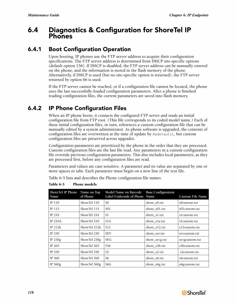
Maintenance Guide Chapter 6: IP Endpoints
6.4 Diagnostics & Configuration for ShoreTel IP Phones
6.4.1 Boot Configuration OperationUpon booting, IP phones use the FTP server address to acquire their configuration specifications. The FTP server address is determined from DHCP site-specific options (default option 156). If DHCP is disabled, the FTP server address can be manually entered on the phone, and the information is stored in the flash memory of the phone. Alternatively, if DHCP is used (but no site-specific option is returned), the FTP server returned by option 66 is used.
If the FTP server cannot be reached, or if a configuration file cannot be located, the phone uses the last successfully-loaded configuration parameters. After a phone is finished reading configuration files, the current parameters are saved into flash memory.
6.4.2 IP Phone Configuration FilesWhen an IP phone boots, it contacts the configured FTP server and reads an initial configuration file from FTP root. (This file corresponds to its coded model name.) Each of these initial configuration files, in turn, references a custom configuration file that can be manually edited by a system administrator. As phone software is upgraded, the contents of configuration files are overwritten at the time of update by Kadotautil, but custom configuration files are preserved across upgrades.
Configuration parameters are prioritized by the phone in the order that they are processed. Custom configuration files are the last file read. Any parameters in a custom configuration file override previous configuration parameters. This also includes local parameters, as they are processed first, before any configuration files are read.
Parameters and values are case sensitive. A parameter and its value are separated by one or more spaces or tabs. Each parameter must begin on a new line of the text file.
Table 6-5 lists and describes the Phone configuration file names.
Table 6-5 Phone models
ShoreTel IP Phone Name
Name on Top of Phone
Model Name on Barcode Label Underside of Phone
Base Configuration Name Custom File Name
IP 110 ShoreTel 110 S0 shore_s0.txt s0custom.txt
IP 115 ShoreTel 115 S01 shore_s01.txt s01custom.txt
IP 210 ShoreTel 210 S1 shore_s1.txt s1custom.txt
IP 210A ShoreTel 210 S1A shore_s1a.txt s1custom.txt
IP 212k ShoreTel 212k S12 shore_s12.txt s12custom.txt
IP 230 ShoreTel 230 SEV shore_sev.txt sevcustom.txt
IP 230g ShoreTel 230g SEG shore_sevg.txt sevgcustom.txt
IP 265 ShoreTel 265 S36 shore_s36.txt s36custom.txt
IP 530 ShoreTel 530 S2 shore_s2.txt s2custom.txt
IP 560 ShoreTel 560 S6 shore_s6.txt s6custom.txt
IP 560g ShoreTel 560g S6G shore_s6g.txt s6gcustom.txt
118
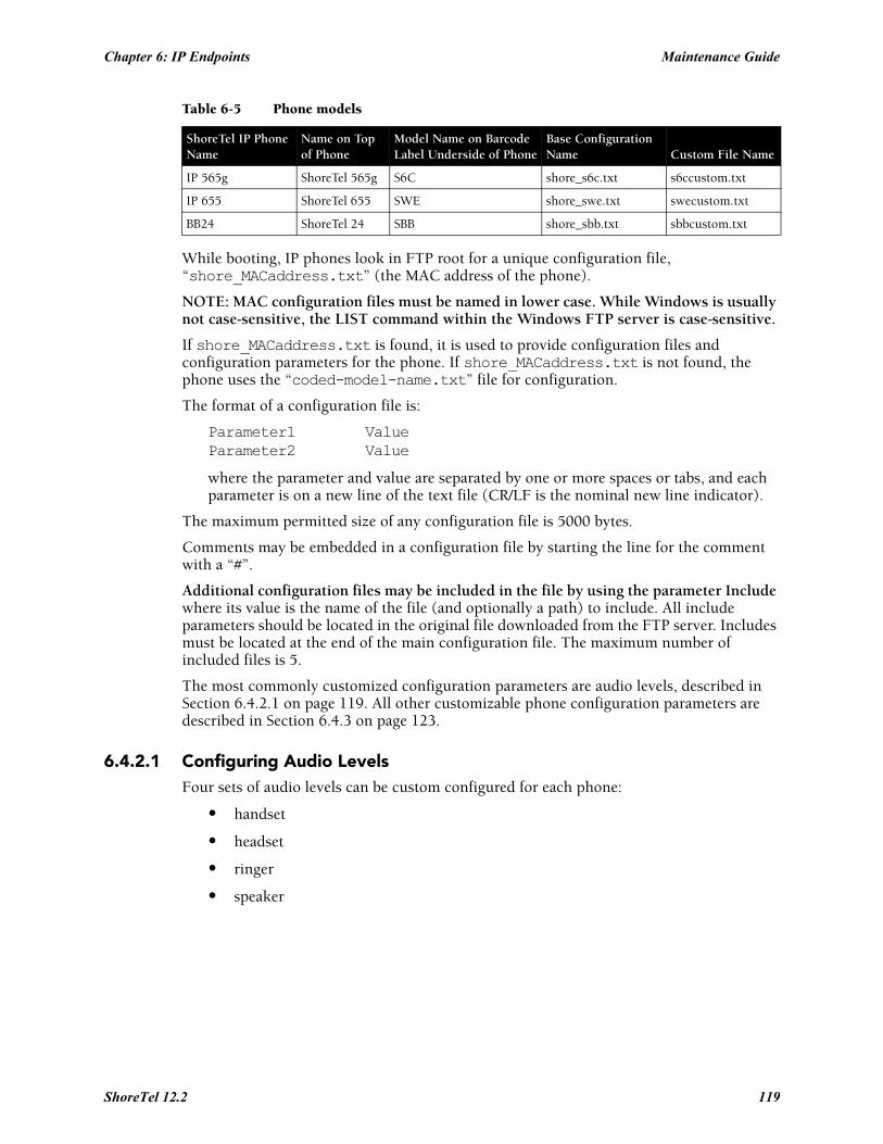
Chapter 6: IP Endpoints Maintenance Guide
While booting, IP phones look in FTP root for a unique configuration file, “shore_MACaddress.txt” (the MAC address of the phone).
NOTE: MAC configuration files must be named in lower case. While Windows is usually not case-sensitive, the LIST command within the Windows FTP server is case-sensitive.
If shore_MACaddress.txt is found, it is used to provide configuration files and configuration parameters for the phone. If shore_MACaddress.txt is not found, the phone uses the “coded-model-name.txt” file for configuration.
The format of a configuration file is:
Parameter1 ValueParameter2 Value
where the parameter and value are separated by one or more spaces or tabs, and each parameter is on a new line of the text file (CR/LF is the nominal new line indicator).
The maximum permitted size of any configuration file is 5000 bytes.
Comments may be embedded in a configuration file by starting the line for the comment with a “#”.
Additional configuration files may be included in the file by using the parameter Include where its value is the name of the file (and optionally a path) to include. All include parameters should be located in the original file downloaded from the FTP server. Includes must be located at the end of the main configuration file. The maximum number of included files is 5.
The most commonly customized configuration parameters are audio levels, described in Section 6.4.2.1 on page 119. All other customizable phone configuration parameters are described in Section 6.4.3 on page 123.
6.4.2.1 Configuring Audio LevelsFour sets of audio levels can be custom configured for each phone:
• handset
• headset
• ringer
• speaker
IP 565g ShoreTel 565g S6C shore_s6c.txt s6ccustom.txt
IP 655 ShoreTel 655 SWE shore_swe.txt swecustom.txt
BB24 ShoreTel 24 SBB shore_sbb.txt sbbcustom.txt
Table 6-5 Phone models
ShoreTel IP Phone Name
Name on Top of Phone
Model Name on Barcode Label Underside of Phone
Base Configuration Name Custom File Name
ShoreTel 12.2 119
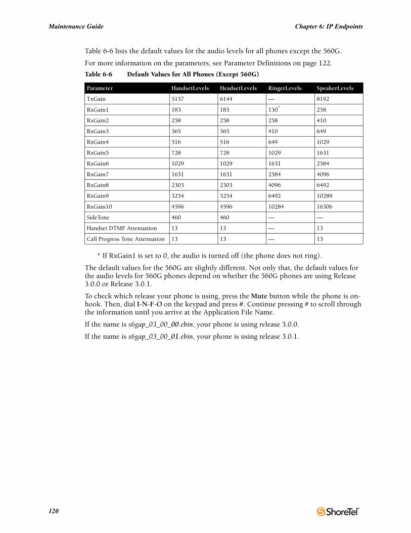
Maintenance Guide Chapter 6: IP Endpoints
Table 6-6 lists the default values for the audio levels for all phones except the 560G.
For more information on the parameters, see Parameter Definitions on page 122.
* If RxGain1 is set to 0, the audio is turned off (the phone does not ring).
The default values for the 560G are slightly different. Not only that, the default values for the audio levels for 560G phones depend on whether the 560G phones are using Release 3.0.0 or Release 3.0.1.
To check which release your phone is using, press the Mute button while the phone is on-hook. Then, dial I-N-F-O on the keypad and press #. Continue pressing # to scroll through the information until you arrive at the Application File Name.
If the name is s6gap_03_00_00.ebin, your phone is using release 3.0.0.
If the name is s6gap_03_00_01.ebin, your phone is using release 3.0.1.
Table 6-6 Default Values for All Phones (Except 560G)
Parameter HandsetLevels HeadsetLevels RingerLevels SpeakerLevels
TxGain 5157 6144 — 8192
RxGain1 183 183 130* 258
RxGain2 258 258 258 410
RxGain3 365 365 410 649
RxGain4 516 516 649 1029
RxGain5 728 728 1029 1631
RxGain6 1029 1029 1631 2584
RxGain7 1631 1631 2584 4096
RxGain8 2303 2303 4096 6492
RxGain9 3254 3254 6492 10289
RxGain10 4596 4596 10284 16306
SideTone 460 460 — —
Handset DTMF Attenuation 13 13 — 13
Call Progress Tone Attenuation 13 13 — 13
120
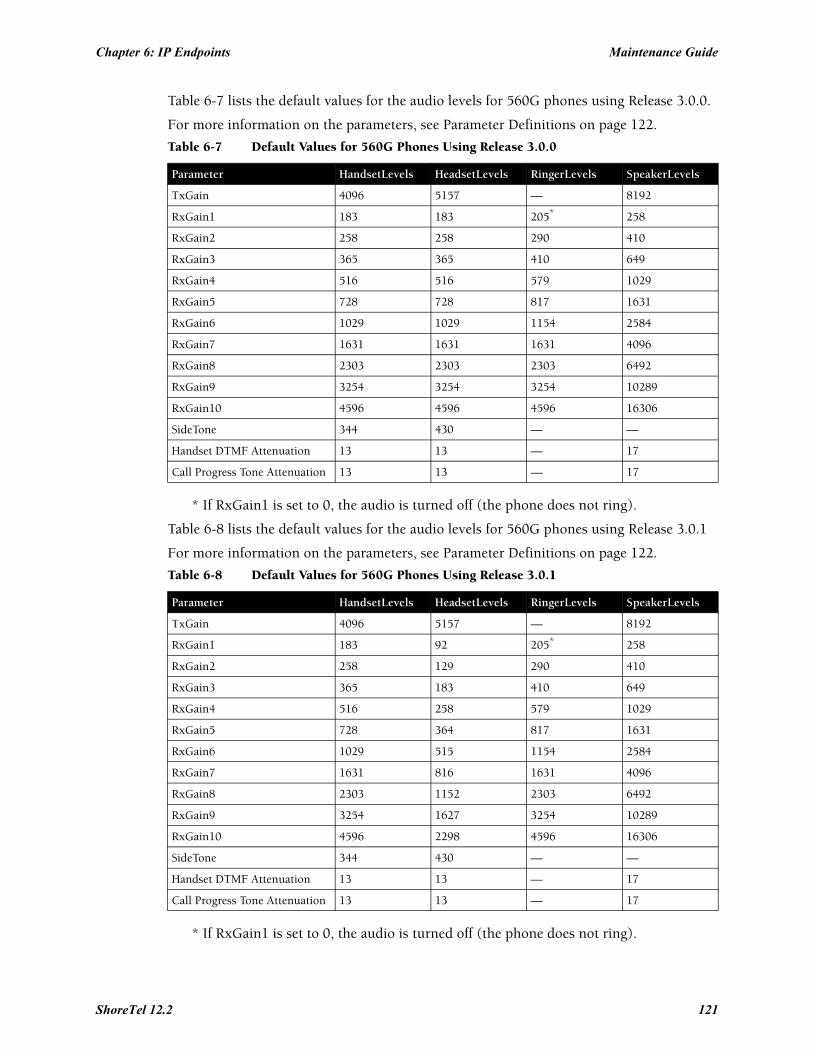
Chapter 6: IP Endpoints Maintenance Guide
Table 6-7 lists the default values for the audio levels for 560G phones using Release 3.0.0.
For more information on the parameters, see Parameter Definitions on page 122.
* If RxGain1 is set to 0, the audio is turned off (the phone does not ring).
Table 6-8 lists the default values for the audio levels for 560G phones using Release 3.0.1
For more information on the parameters, see Parameter Definitions on page 122.
* If RxGain1 is set to 0, the audio is turned off (the phone does not ring).
Table 6-7 Default Values for 560G Phones Using Release 3.0.0
Parameter HandsetLevels HeadsetLevels RingerLevels SpeakerLevels
TxGain 4096 5157 — 8192
RxGain1 183 183 205* 258
RxGain2 258 258 290 410
RxGain3 365 365 410 649
RxGain4 516 516 579 1029
RxGain5 728 728 817 1631
RxGain6 1029 1029 1154 2584
RxGain7 1631 1631 1631 4096
RxGain8 2303 2303 2303 6492
RxGain9 3254 3254 3254 10289
RxGain10 4596 4596 4596 16306
SideTone 344 430 — —
Handset DTMF Attenuation 13 13 — 17
Call Progress Tone Attenuation 13 13 — 17
Table 6-8 Default Values for 560G Phones Using Release 3.0.1
Parameter HandsetLevels HeadsetLevels RingerLevels SpeakerLevels
TxGain 4096 5157 — 8192
RxGain1 183 92 205* 258
RxGain2 258 129 290 410
RxGain3 365 183 410 649
RxGain4 516 258 579 1029
RxGain5 728 364 817 1631
RxGain6 1029 515 1154 2584
RxGain7 1631 816 1631 4096
RxGain8 2303 1152 2303 6492
RxGain9 3254 1627 3254 10289
RxGain10 4596 2298 4596 16306
SideTone 344 430 — —
Handset DTMF Attenuation 13 13 — 17
Call Progress Tone Attenuation 13 13 — 17
ShoreTel 12.2 121
Maintenance Guide Chapter 6: IP Endpoints
Parameter Definitions
The “TxGain” (transmit gain) parameter sets the level of the audio transmitted from the phone onto the network.
The “RxGain” (receive gain) values correspond to each of the 10 volume setting levels shown when the volume on the phone is adjusted. Sometimes, the RxGains are not high enough and need to be customized for an individual system.
“SideTone” is the audio picked up from the microphone and transmitted to the speaker (speakerphone, handset or headset speaker) that provides feedback to the user that the phone is working. SideTone gain is very subjective, and is sometimes lowered and sometimes raised.
DTMF (dual-tone multi-frequency) Attenuation sets the receive DTMF level that the phone user hears.
Call Progress Tone Attenuation sets the level for the various tones played after a call is placed and before audio is connected.
The Plantronics CS50 wireless headset provides its own side tone, plus inserts 20 ms delay between the headset and the phone, which causes some people to say they hear echo when using the Plantronics headset, and in this case headset side tone may need to be reduced. When you speak, Plantronics does reduce the gain on the speaker by -24dB; but when you stop speaking, the gain is turned up, and you can hear the last little bit echoed in your ear.
For example, inserting the following line in "s2custom.txt" or "s6custom.txt" and rebooting the phone increases the headset volume settings 11 dB at the highest setting, which may be required in noisy environments:
HeadsetLevels 6144,183,258,409,649,1028,1630,2899,6491,10288,14333,917,13,13
Inserting the following line reduces the headset side tone by 6 dB, which some CS50 users prefer:
HeadsetLevels 6144,183,258,365,516,728,1029,1631,2303,3254,4596,459,13,13
Minimum gain values are 0 and maximum are 32536. Setting values very high may saturate the speaker and create poor sound quality.
You can change gains on an individual phone by changing the configuration files and then rebooting the phone. Eventually, all phones on the system obtain these values when they reboot.
122
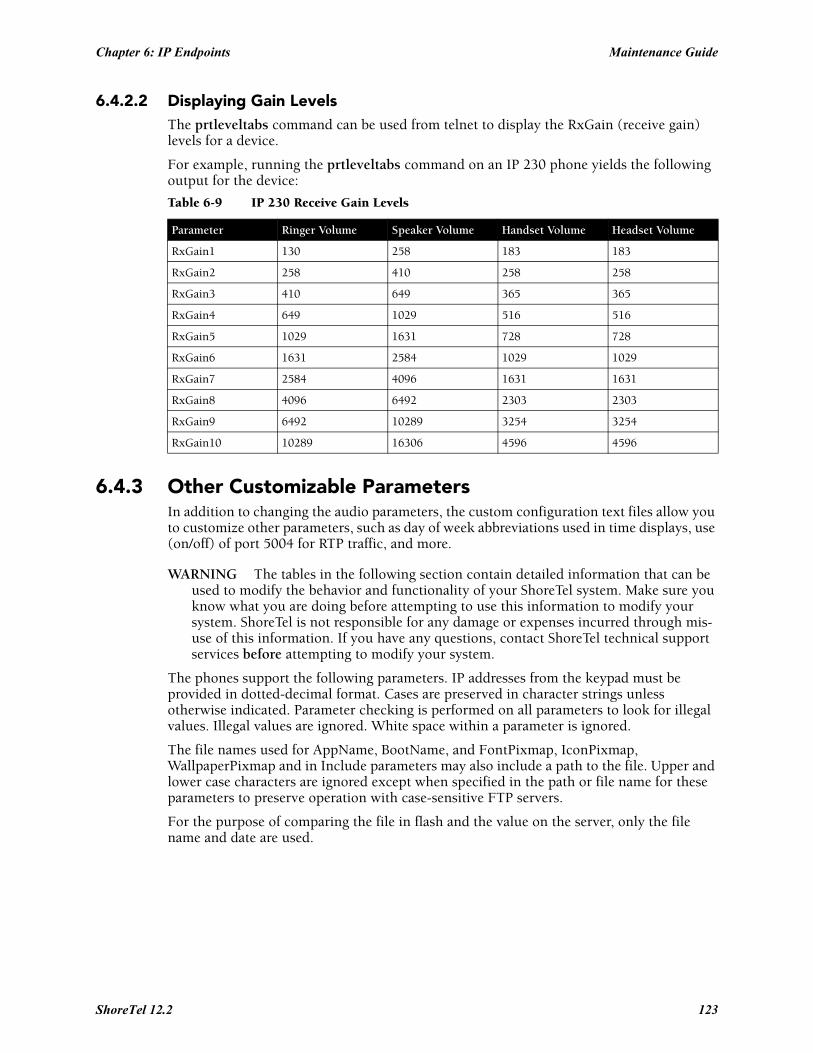
Chapter 6: IP Endpoints Maintenance Guide
6.4.2.2 Displaying Gain LevelsThe prtleveltabs command can be used from telnet to display the RxGain (receive gain) levels for a device.
For example, running the prtleveltabs command on an IP 230 phone yields the following output for the device:
6.4.3 Other Customizable ParametersIn addition to changing the audio parameters, the custom configuration text files allow you to customize other parameters, such as day of week abbreviations used in time displays, use (on/off) of port 5004 for RTP traffic, and more.
WARNING The tables in the following section contain detailed information that can be used to modify the behavior and functionality of your ShoreTel system. Make sure you know what you are doing before attempting to use this information to modify your system. ShoreTel is not responsible for any damage or expenses incurred through mis-use of this information. If you have any questions, contact ShoreTel technical support services before attempting to modify your system.
The phones support the following parameters. IP addresses from the keypad must be provided in dotted-decimal format. Cases are preserved in character strings unless otherwise indicated. Parameter checking is performed on all parameters to look for illegal values. Illegal values are ignored. White space within a parameter is ignored.
The file names used for AppName, BootName, and FontPixmap, IconPixmap, WallpaperPixmap and in Include parameters may also include a path to the file. Upper and lower case characters are ignored except when specified in the path or file name for these parameters to preserve operation with case-sensitive FTP servers.
For the purpose of comparing the file in flash and the value on the server, only the file name and date are used.
Table 6-9 IP 230 Receive Gain Levels
Parameter Ringer Volume Speaker Volume Handset Volume Headset Volume
RxGain1 130 258 183 183
RxGain2 258 410 258 258
RxGain3 410 649 365 365
RxGain4 649 1029 516 516
RxGain5 1029 1631 728 728
RxGain6 1631 2584 1029 1029
RxGain7 2584 4096 1631 1631
RxGain8 4096 6492 2303 2303
RxGain9 6492 10289 3254 3254
RxGain10 10289 16306 4596 4596
ShoreTel 12.2 123
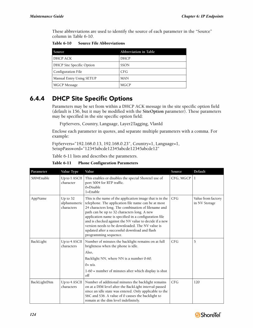
Maintenance Guide Chapter 6: IP Endpoints
These abbreviations are used to identify the source of each parameter in the “Source” column in Table 6-10.
6.4.4 DHCP Site Specific OptionsParameters may be set from within a DHCP ACK message in the site specific option field (default is 156, but it may be modified with the SiteOption parameter). These parameters may be specified in the site specific option field:
FtpServers, Country, Language, Layer2Tagging, VlanId
Enclose each parameter in quotes, and separate multiple parameters with a comma. For example:
FtpServers=”192.168.0.13, 192.168.0.23”, Country=1, Language=1, SetupPassword=”12345abcde12345abcde12345abcde12”
Table 6-11 lists and describes the parameters.
Table 6-10 Source File Abbreviations
Source Abbreviation in Table
DHCP ACK DHCP
DHCP Site Specific Option SSON
Configuration File CFG
Manual Entry Using SETUP MAN
MGCP Message MGCP
Table 6-11 Phone Configuration Parameters
Parameter Value Type Value Source Default
5004Enable Up to 1 ASCII character
This enables or disables the special Shoretel use of port 5004 for RTP traffic.0=Disable1=Enable
CFG, MGCP 1
AppName Up to 32 alphanumeric characters
This is the name of the application image that is in the telephone. The application file name can be at most 24 characters long. The combination of filename and path can be up to 32 characters long. A new application name is specified in a configuration file and is checked against the NV value to decide if a new version needs to be downloaded. The NV value is updated after a successful download and flash programming sequence.
CFG Value from factory in NV Storage
BackLight Up to 4 ASCII characters
Number of minutes the backlight remains on at full brightness when the phone is idle.
Also,
Backlight NN, where NN is a number 0-60.
0= n/a.
1-60 = number of minutes after which display is shut off
CFG 5
BackLightDim Up to 4 ASCII characters
Number of additional minutes the backlight remains on at a DIM level after the BackLight interval passed since an idle state was entered. Only applicable to the S6C and S36. A value of 0 causes the backlight to remain at the dim level indefinitely.
CFG 120
124
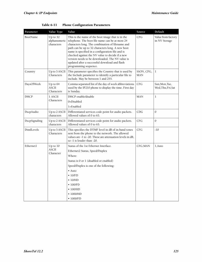
Chapter 6: IP Endpoints Maintenance Guide
BootName Up to 32 alphanumeric characters
This is the name of the boot image that is in the telephone. The boot file name can be at most 24 characters long. The combination of filename and path can be up to 32 characters long. A new boot name is specified in a configuration file and is checked against the NV value to decide if a new version needs to be downloaded. The NV value is updated after a successful download and flash programming sequence.
CFG Value from factory in NV Storage
Country Up to 3 ASCII Characters
This parameter specifies the Country that is used by the Include parameter to identify a particular file to include. May be between 1 and 255.
SSON, CFG, MAN
1
DaysOfWeek Up to 64 ASCII Characters
Comma separated list of the day of week abbreviations used by the IP210 phone to display the time. First day is Sunday.
CFG Sun,Mon,Tue,Wed,Thu,Fri,Sat
DHCP 1 ASCII Characters
DHCP enable/disable
0=Disabled
1=Enabled
MAN 1
DscpAudio Up to 2 ASCII characters
Differentiated services code point for audio packets. Allowed values of 0 to 63.
CDG 0
DscpSignaling Up to 2 ASCII characters
Differentiated services code point for audio packets. Allowed values of 0 to 63.
CFG 0
DtmfLevels Up to 3 ASCII Characters
This specifies the DTMF level in dB of in-band tones sent from the phone to the network. The allowed values are -1 to -20. These are attenuation levels in dB, so -1 is louder than -20.
CFG -10
Ethernet1 Up to 10 ASCII Character
Status of the 1st Ethernet Interface.
Ethernet2 Status, Speed/Duplex
Where:
Status is 0 or 1 (disabled or enabled)
Speed/Duplex is one of the following:
• Auto
• 10/FD
• 10/HD
• 100/FD
• 100/HD
• 1000/HD
• 1000/FD
CFG,MAN 1,Auto
Table 6-11 Phone Configuration Parameters
Parameter Value Type Value Source Default
ShoreTel 12.2 125
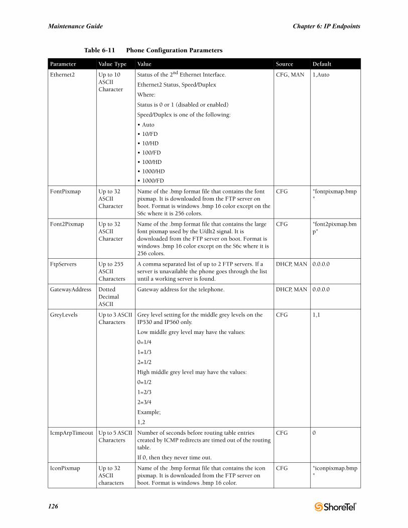
Maintenance Guide Chapter 6: IP Endpoints
Ethernet2 Up to 10 ASCII Character
Status of the 2nd Ethernet Interface.
Ethernet2 Status, Speed/Duplex
Where:
Status is 0 or 1 (disabled or enabled)
Speed/Duplex is one of the following:
• Auto
• 10/FD
• 10/HD
• 100/FD
• 100/HD
• 1000/HD
• 1000/FD
CFG, MAN 1,Auto
FontPixmap Up to 32 ASCII Character
Name of the .bmp format file that contains the font pixmap. It is downloaded from the FTP server on boot. Format is windows .bmp 16 color except on the S6c where it is 256 colors.
CFG "fontpixmap.bmp"
Font2Pixmap Up to 32 ASCII Character
Name of the .bmp format file that contains the large font pixmap used by the U/dlt2 signal. It is downloaded from the FTP server on boot. Format is windows .bmp 16 color except on the S6c where it is 256 colors.
CFG "font2pixmap.bmp"
FtpServers Up to 255 ASCII Characters
A comma separated list of up to 2 FTP servers. If a server is unavailable the phone goes through the list until a working server is found.
DHCP, MAN 0.0.0.0
GatewayAddress Dotted Decimal ASCII
Gateway address for the telephone. DHCP, MAN 0.0.0.0
GreyLevels Up to 3 ASCII Characters
Grey level setting for the middle grey levels on the IP530 and IP560 only.
Low middle grey level may have the values:
0=1/4
1=1/3
2=1/2
High middle grey level may have the values:
0=1/2
1=2/3
2=3/4
Example;
1,2
CFG 1,1
IcmpArpTimeout Up to 5 ASCII Characters
Number of seconds before routing table entries created by ICMP redirects are timed out of the routing table.
If 0, then they never time out.
CFG 0
IconPixmap Up to 32 ASCII characters
Name of the .bmp format file that contains the icon pixmap. It is downloaded from the FTP server on boot. Format is windows .bmp 16 color.
CFG "iconpixmap.bmp"
Table 6-11 Phone Configuration Parameters
Parameter Value Type Value Source Default
126
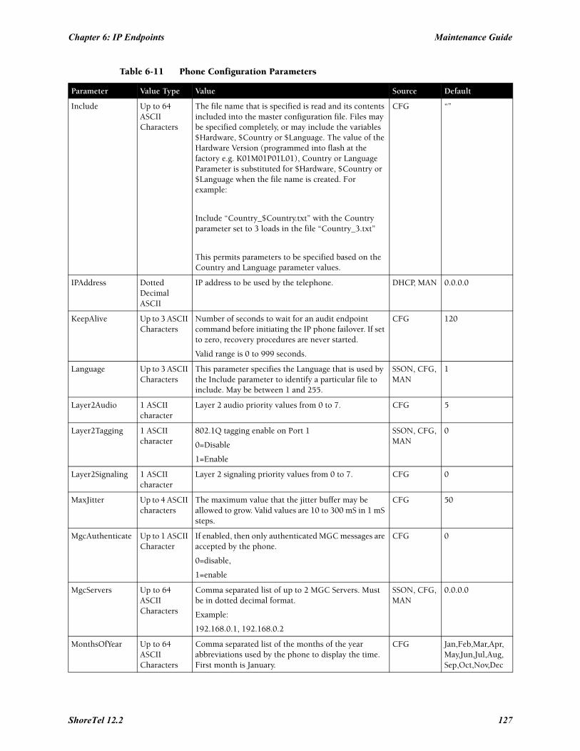
Chapter 6: IP Endpoints Maintenance Guide
Include Up to 64 ASCII Characters
The file name that is specified is read and its contents included into the master configuration file. Files may be specified completely, or may include the variables $Hardware, $Country or $Language. The value of the Hardware Version (programmed into flash at the factory e.g. K01M01P01L01), Country or Language Parameter is substituted for $Hardware, $Country or $Language when the file name is created. For example:
Include “Country_$Country.txt” with the Country parameter set to 3 loads in the file “Country_3.txt”
This permits parameters to be specified based on the Country and Language parameter values.
CFG “”
IPAddress Dotted Decimal ASCII
IP address to be used by the telephone. DHCP, MAN 0.0.0.0
KeepAlive Up to 3 ASCII Characters
Number of seconds to wait for an audit endpoint command before initiating the IP phone failover. If set to zero, recovery procedures are never started.
Valid range is 0 to 999 seconds.
CFG 120
Language Up to 3 ASCII Characters
This parameter specifies the Language that is used by the Include parameter to identify a particular file to include. May be between 1 and 255.
SSON, CFG, MAN
1
Layer2Audio 1 ASCII character
Layer 2 audio priority values from 0 to 7. CFG 5
Layer2Tagging 1 ASCII character
802.1Q tagging enable on Port 1
0=Disable
1=Enable
SSON, CFG, MAN
0
Layer2Signaling 1 ASCII character
Layer 2 signaling priority values from 0 to 7. CFG 0
MaxJitter Up to 4 ASCII characters
The maximum value that the jitter buffer may be allowed to grow. Valid values are 10 to 300 mS in 1 mS steps.
CFG 50
MgcAuthenticate Up to 1 ASCII Character
If enabled, then only authenticated MGC messages are accepted by the phone.
0=disable,
1=enable
CFG 0
MgcServers Up to 64 ASCII Characters
Comma separated list of up to 2 MGC Servers. Must be in dotted decimal format.
Example:
192.168.0.1, 192.168.0.2
SSON, CFG, MAN
0.0.0.0
MonthsOfYear Up to 64 ASCII Characters
Comma separated list of the months of the year abbreviations used by the phone to display the time. First month is January.
CFG Jan,Feb,Mar,Apr,May,Jun,Jul,Aug,Sep,Oct,Nov,Dec
Table 6-11 Phone Configuration Parameters
Parameter Value Type Value Source Default
ShoreTel 12.2 127
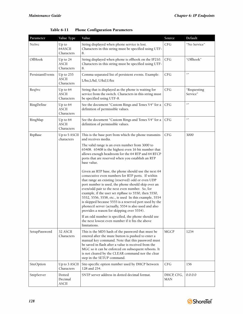
Maintenance Guide Chapter 6: IP Endpoints
NoSvc Up to 64ASCII Characters
String displayed when phone service is lost. Characters in this string must be specified using UTF-8.
CFG “No Service”
OffHook Up to 24 ASCII Characters
String displayed when phone is offhook on the IP210. Characters in this string must be specified using UTF-8.
CFG “Offhook”
PersistantEvents Up to 255 ASCII Characters
Comma separated list of persistent events. Example:
L/hu,L/hd, U/kd,U/ku
CFG “”
ReqSvc Up to 64 ASCII Characters
String that is displayed as the phone is waiting for service from the switch. Characters in this string must be specified using UTF-8.
CFG “Requesting Service”
RingDefine Up to 64 ASCII Characters
See the document "Custom Rings and Tones V4" for a definition of permissible values.
CFG “”
RingMap Up to 64 ASCII Characters
See the document "Custom Rings and Tones V4" for a definition of permissible values.
CFG “”
RtpBase Up to 5 ASCII characters
This is the base port from which the phone transmits and receives media.
The valid range is an even number from 3000 to 65408. 65408 is the highest even 16 bit number that allows enough headroom for the 64 RTP and 64 RTCP ports that are reserved when you establish an RTP base value.
Given an RTP base, the phone should use the next 64 consecutive even numbers for RTP ports. If within that range an existing (reserved) odd or even UDP port number is used, the phone should skip over an even/odd pair to the next even number. So, for example, if the user set rtpBase to 5550, then 5550, 5552, 5556, 5558, etc., is used In this example, 5554 is skipped because 5555 is a reserved port used by the phonectl server (actually, 5554 is also used and also provides a reason for skipping over 5554).
If an odd number is specified, the phone should use the next lowest even number if it fits the above limitations.
CFG 3000
SetupPassword 32 ASCII Characters
This is the MD5 hash of the password that must be entered after the mute button is pushed to enter a manual key command. Note that this password must be saved in flash after a value is received from the MGC so it can be enforced on subsequent reboots. It is not cleared by the CLEAR command nor the clear step in the SETUP command.
MGCP 1234
SiteOption Up to 3 ASCII Characters
Site-specific option number used by DHCP between 128 and 254.
CFG 156
SntpServer Dotted Decimal ASCII
SNTP server address in dotted decimal format. DHCP, CFG, MAN
0.0.0.0
Table 6-11 Phone Configuration Parameters
Parameter Value Type Value Source Default
128
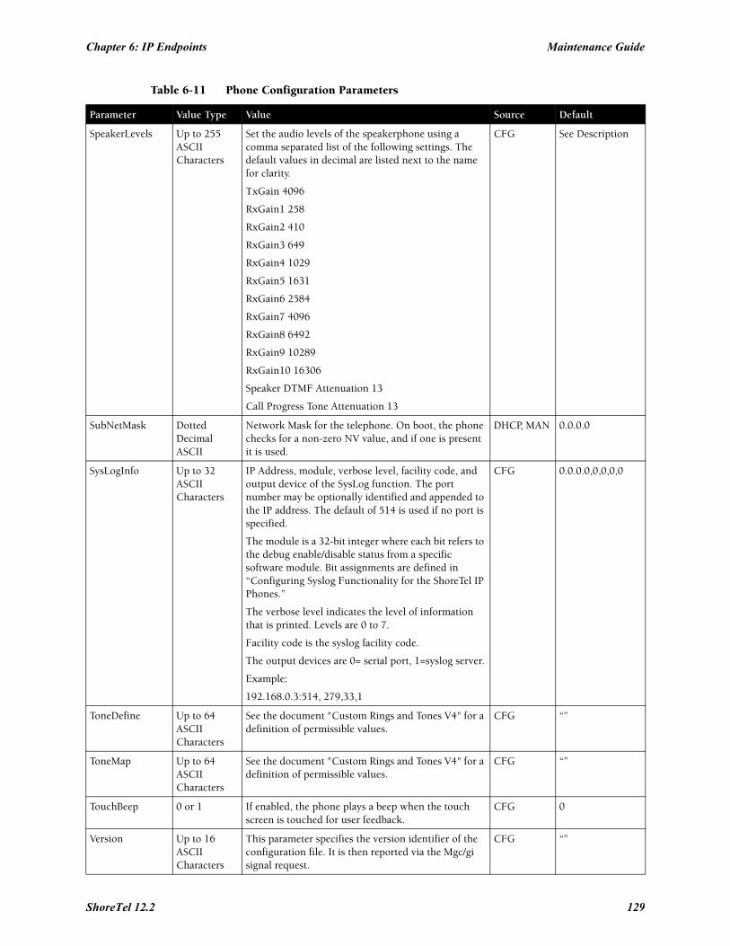
Chapter 6: IP Endpoints Maintenance Guide
SpeakerLevels Up to 255 ASCII Characters
Set the audio levels of the speakerphone using a comma separated list of the following settings. The default values in decimal are listed next to the name for clarity.
TxGain 4096
RxGain1 258
RxGain2 410
RxGain3 649
RxGain4 1029
RxGain5 1631
RxGain6 2584
RxGain7 4096
RxGain8 6492
RxGain9 10289
RxGain10 16306
Speaker DTMF Attenuation 13
Call Progress Tone Attenuation 13
CFG See Description
SubNetMask Dotted Decimal ASCII
Network Mask for the telephone. On boot, the phone checks for a non-zero NV value, and if one is present it is used.
DHCP, MAN 0.0.0.0
SysLogInfo Up to 32 ASCII Characters
IP Address, module, verbose level, facility code, and output device of the SysLog function. The port number may be optionally identified and appended to the IP address. The default of 514 is used if no port is specified.
The module is a 32-bit integer where each bit refers to the debug enable/disable status from a specific software module. Bit assignments are defined in “Configuring Syslog Functionality for the ShoreTel IP Phones.”
The verbose level indicates the level of information that is printed. Levels are 0 to 7.
Facility code is the syslog facility code.
The output devices are 0= serial port, 1=syslog server.
Example:
192.168.0.3:514, 279,33,1
CFG 0.0.0.0,0,0,0,0
ToneDefine Up to 64 ASCII Characters
See the document "Custom Rings and Tones V4" for a definition of permissible values.
CFG “”
ToneMap Up to 64 ASCII Characters
See the document "Custom Rings and Tones V4" for a definition of permissible values.
CFG “”
TouchBeep 0 or 1 If enabled, the phone plays a beep when the touch screen is touched for user feedback.
CFG 0
Version Up to 16 ASCII Characters
This parameter specifies the version identifier of the configuration file. It is then reported via the Mgc/gi signal request.
CFG “”
Table 6-11 Phone Configuration Parameters
Parameter Value Type Value Source Default
ShoreTel 12.2 129
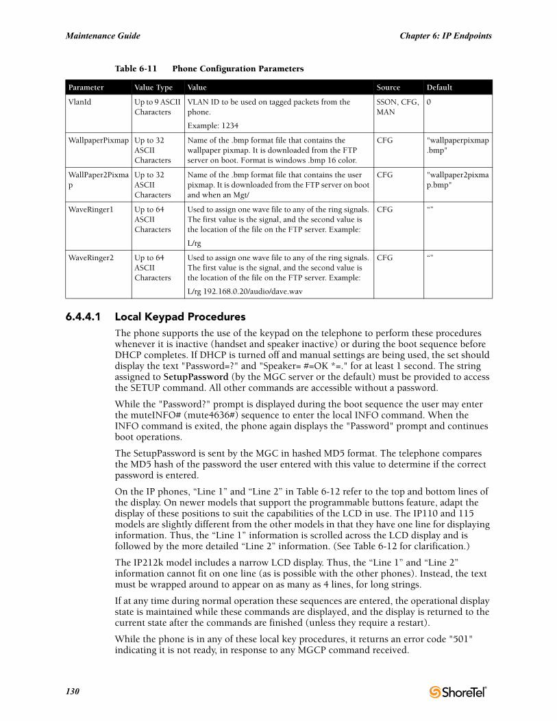
Maintenance Guide Chapter 6: IP Endpoints
6.4.4.1 Local Keypad ProceduresThe phone supports the use of the keypad on the telephone to perform these procedures whenever it is inactive (handset and speaker inactive) or during the boot sequence before DHCP completes. If DHCP is turned off and manual settings are being used, the set should display the text "Password=?" and "Speaker= #=OK *=." for at least 1 second. The string assigned to SetupPassword (by the MGC server or the default) must be provided to access the SETUP command. All other commands are accessible without a password.
While the "Password?" prompt is displayed during the boot sequence the user may enter the muteINFO# (mute4636#) sequence to enter the local INFO command. When the INFO command is exited, the phone again displays the "Password" prompt and continues boot operations.
The SetupPassword is sent by the MGC in hashed MD5 format. The telephone compares the MD5 hash of the password the user entered with this value to determine if the correct password is entered.
On the IP phones, “Line 1” and “Line 2” in Table 6-12 refer to the top and bottom lines of the display. On newer models that support the programmable buttons feature, adapt the display of these positions to suit the capabilities of the LCD in use. The IP110 and 115 models are slightly different from the other models in that they have one line for displaying information. Thus, the “Line 1” information is scrolled across the LCD display and is followed by the more detailed “Line 2” information. (See Table 6-12 for clarification.)
The IP212k model includes a narrow LCD display. Thus, the “Line 1” and “Line 2” information cannot fit on one line (as is possible with the other phones). Instead, the text must be wrapped around to appear on as many as 4 lines, for long strings.
If at any time during normal operation these sequences are entered, the operational display state is maintained while these commands are displayed, and the display is returned to the current state after the commands are finished (unless they require a restart).
While the phone is in any of these local key procedures, it returns an error code "501" indicating it is not ready, in response to any MGCP command received.
VlanId Up to 9 ASCII Characters
VLAN ID to be used on tagged packets from the phone.
Example: 1234
SSON, CFG, MAN
0
WallpaperPixmap Up to 32 ASCII Characters
Name of the .bmp format file that contains the wallpaper pixmap. It is downloaded from the FTP server on boot. Format is windows .bmp 16 color.
CFG "wallpaperpixmap.bmp"
WallPaper2Pixmap
Up to 32 ASCII Characters
Name of the .bmp format file that contains the user pixmap. It is downloaded from the FTP server on boot and when an Mgt/
CFG "wallpaper2pixmap.bmp"
WaveRinger1 Up to 64 ASCII Characters
Used to assign one wave file to any of the ring signals. The first value is the signal, and the second value is the location of the file on the FTP server. Example:
L/rg
CFG “”
WaveRinger2 Up to 64 ASCII Characters
Used to assign one wave file to any of the ring signals. The first value is the signal, and the second value is the location of the file on the FTP server. Example:
L/rg 192.168.0.20/audio/dave.wav
CFG “”
Table 6-11 Phone Configuration Parameters
Parameter Value Type Value Source Default
130
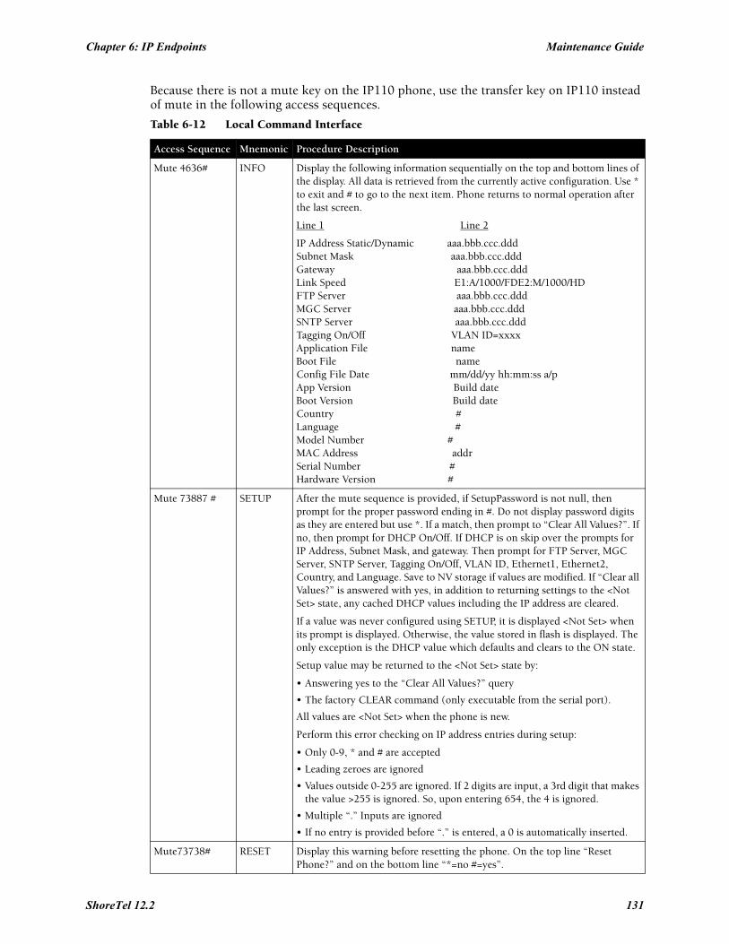
Chapter 6: IP Endpoints Maintenance Guide
Because there is not a mute key on the IP110 phone, use the transfer key on IP110 instead of mute in the following access sequences.
Table 6-12 Local Command Interface
Access Sequence Mnemonic Procedure Description
Mute 4636# INFO Display the following information sequentially on the top and bottom lines of the display. All data is retrieved from the currently active configuration. Use * to exit and # to go to the next item. Phone returns to normal operation after the last screen.
Line 1 Line 2
IP Address Static/Dynamic aaa.bbb.ccc.dddSubnet Mask aaa.bbb.ccc.dddGateway aaa.bbb.ccc.dddLink Speed E1:A/1000/FDE2:M/1000/HDFTP Server aaa.bbb.ccc.dddMGC Server aaa.bbb.ccc.dddSNTP Server aaa.bbb.ccc.dddTagging On/Off VLAN ID=xxxx Application File nameBoot File nameConfig File Date mm/dd/yy hh:mm:ss a/p App Version Build dateBoot Version Build dateCountry #Language #Model Number #MAC Address addrSerial Number #Hardware Version #
Mute 73887 # SETUP After the mute sequence is provided, if SetupPassword is not null, then prompt for the proper password ending in #. Do not display password digits as they are entered but use *. If a match, then prompt to “Clear All Values?”. If no, then prompt for DHCP On/Off. If DHCP is on skip over the prompts for IP Address, Subnet Mask, and gateway. Then prompt for FTP Server, MGC Server, SNTP Server, Tagging On/Off, VLAN ID, Ethernet1, Ethernet2, Country, and Language. Save to NV storage if values are modified. If “Clear all Values?” is answered with yes, in addition to returning settings to the <Not Set> state, any cached DHCP values including the IP address are cleared.
If a value was never configured using SETUP, it is displayed <Not Set> when its prompt is displayed. Otherwise, the value stored in flash is displayed. The only exception is the DHCP value which defaults and clears to the ON state.
Setup value may be returned to the <Not Set> state by:
• Answering yes to the “Clear All Values?” query
• The factory CLEAR command (only executable from the serial port).
All values are <Not Set> when the phone is new.
Perform this error checking on IP address entries during setup:
• Only 0-9, * and # are accepted
• Leading zeroes are ignored
• Values outside 0-255 are ignored. If 2 digits are input, a 3rd digit that makes the value >255 is ignored. So, upon entering 654, the 4 is ignored.
• Multiple “.” Inputs are ignored
• If no entry is provided before “.” is entered, a 0 is automatically inserted.
Mute73738# RESET Display this warning before resetting the phone. On the top line “Reset Phone?” and on the bottom line “*=no #=yes”.
ShoreTel 12.2 131
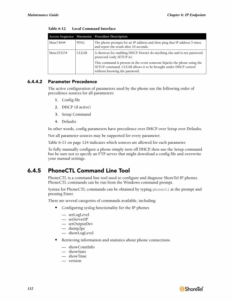
Maintenance Guide Chapter 6: IP Endpoints
6.4.4.2 Parameter PrecedenceThe active configuration of parameters used by the phone use the following order of precedence sources for all parameters:
1. Config file
2. DHCP (if active)
3. Setup Command
4. Defaults
In other words, config parameters have precedence over DHCP over Setup over Defaults.
Not all parameter sources may be supported for every parameter.
Table 6-11 on page 124 indicates which sources are allowed for each parameter.
To fully manually configure a phone simply turn off DHCP, then use the Setup command but be sure not to specify an FTP server that might download a config file and overwrite your manual settings.
6.4.5 PhoneCTL Command Line ToolPhoneCTL is a command line tool used to configure and diagnose ShoreTel IP phones. PhoneCTL commands can be run from the Windows command prompt.
Syntax for PhoneCTL commands can be obtained by typing phonectl at the prompt and pressing Enter.
There are several categories of commands available, including:
• Configuring syslog functionality for the IP phones
— setLogLevel— setServerIP— setOutputDev— dump2pc— showLogLevel
• Retrieving information and statistics about phone connections
— showConnInfo— showStats— showTime— version
Mute7464# PING The phone prompts for an IP address and then ping that IP address 5 times and report the result after 10 seconds.
Mute25327# CLEAR A shortcut for enabling DHCP. Doesn’t do anything else and is not password protected (only SETUP is).
This command is present in the event someone hijacks the phone using the SETUP command. CLEAR allows it to be brought under DHCP control without knowing the password.
Table 6-12 Local Command Interface
Access Sequence Mnemonic Procedure Description
132
Chapter 6: IP Endpoints Maintenance Guide
• Troubleshooting data transfer issues between the phone and the syslog server
— ifShow— arpShow— inetstatShow— ipstatShow— udpstatShow— tcpstatShow— hostShow— routeShow
All commands are case-insensitive.
After the phonectl command, the user is prompted to enter a password.
After the user enters the correct password, the device permits access to executables that configure or diagnose the respective device.
CLI passwords are configurable only through Director.
The default password is ShoreTel.
6.4.5.1 Configuring Syslog Functionality for the ShoreTel IP PhonesSeveral commands are used to set up syslog functionality.
These must be run before any logging messages can be received.
The commands are as follows:
setLogLevel
The setLogLevel command (Table 6-13) sets the logging severity level.
ShoreTel 12.2 133
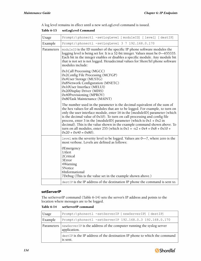
Maintenance Guide Chapter 6: IP Endpoints
A log level remains in effect until a new setLogLevel command is issued.
setServerIP
The setServerIP command (Table 6-14) sets the server’s IP address and points to the location where messages are to be logged.
Table 6-13 setLogLevel Command
Usage Prompt:\phonectl -setLogLevel [moduleID] [level] [destIP]
Example Prompt:\phonectl -setLogLevel 3 7 192.168.0.170
Parameters moduleID is the ID number of the specific IP phone software modules the logging level is being set for. It is a 32-bit integer. Values must be 0—655335. Each bit in the integer enables or disables a specific module. Any module bit that is not set is not logged. Hexadecimal values for ShoreTel phone software modules include:
0x1Call Processing (MGCC)0x2Config File Processing (MCFGP)0x4User Storage (MUSTG)0x8Network Configuration (MNETC)0x10User Interface (MELUI)0x20Display Driver (MDIS)0x40Provisioning (MPROV)0x80Task Maintenance (MAINT)
The number used in the parameter is the decimal equivalent of the sum of the hex values for all modules that are to be logged. For example, to turn on only the user interface module, enter 16 in the [moduleID] parameter (which is the decimal value of 0x10). To turn on call processing and config file process, enter 3 in the [moduleID] parameter (which is 0x1 + 0x2 in decimal). This is the value shown in the example command shown above. To turn on all modules, enter 255 (which is 0x1 + -x2 + 0x4 + 0x8 + 0x10 + 0x20 + 0x40 = 0x80).
level sets the severity level to be logged. Values are 0—7, where zero is the most verbose. Levels are defined as follows:
0Emergency1Alert2Critical3Error4Warning5Notice6Informational7Debug (This is the value set in the example shown above.)
destIP is the IP address of the destination IP phone the command is sent to.
Table 6-14 setServerIP command
Usage Prompt:\phonectl -setServerIP [newServerIP] [destIP]
Example Prompt:\phonectl -setServerIP 192.168.0.3 192.168.0.170
Parameters newServerIP is the address of the computer running the syslog server application.
destIP is the IP address of the destination IP phone to which the command is sent.
134
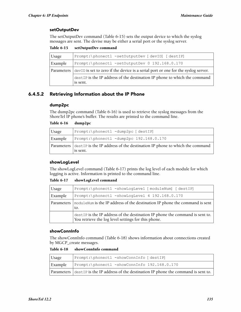
Chapter 6: IP Endpoints Maintenance Guide
setOutputDev
The setOutputDev command (Table 6-15) sets the output device to which the syslog messages are sent. The devise may be either a serial port or the syslog server.
6.4.5.2 Retrieving Information about the IP Phone
dump2pc
The dump2pc command (Table 6-16) is used to retrieve the syslog messages from the ShoreTel IP phone’s buffer. The results are printed to the command line.
showLogLevel
The showLogLevel command (Table 6-17) prints the log level of each module for which logging is active. Information is printed to the command line.
showConnInfo
The showConnInfo command (Table 6-18) shows information about connections created by MGCP_create messages.
Table 6-15 setOutputDev command
Usage Prompt:\phonectl -setOutputDev [devID] [destIP]
Example Prompt:\phonectl -setOutputDev 0 192.168.0.170
Parameters devID is set to zero if the device is a serial port or one for the syslog server.
destIP is the IP address of the destination IP phone to which the command is sent.
Table 6-16 dump2pc
Usage Prompt:\phonectl -dump2pc [destIP]
Example Prompt:\phonectl -dump2pc 192.168.0.170
Parameters destIP is the IP address of the destination IP phone to which the command is sent.
Table 6-17 showLogLevel command
Usage Prompt:\phonectl -showLogLevel [moduleNum] [destIP]
Example Prompt:\phonectl -showLogLevel 4 192.168.0.170
Parameters moduleNum is the IP address of the destination IP phone the command is sent to.
destIP is the IP address of the destination IP phone the command is sent to. You retrieve the log level settings for this phone.
Table 6-18 showConnInfo command
Usage Prompt:\phonectl -showConnInfo [destIP]
Example Prompt:\phonectl -showConnInfo 192.168.0.170
Parameters destIP is the IP address of the destination IP phone the command is sent to.
ShoreTel 12.2 135
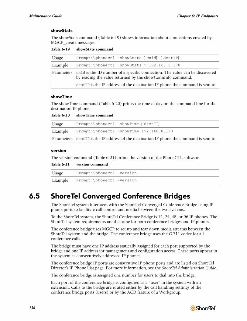
Maintenance Guide Chapter 6: IP Endpoints
showStats
The showStats command (Table 6-19) shows information about connections created by MGCP_create messages.
showTime
The showTime command (Table 6-20) prints the time of day on the command line for the destination IP phone.
version
The version command (Table 6-21) prints the version of the PhoneCTL software.
6.5 ShoreTel Converged Conference BridgesThe ShoreTel system interfaces with the ShoreTel Converged Conference Bridge using IP phone ports to facilitate call control and media between the two systems.
To the ShoreTel system, the ShoreTel Conference Bridge is 12, 24, 48, or 96 IP phones. The ShoreTel system requirements are the same for both conference bridges and IP phones.
The conference bridge uses MGCP to set up and tear down media streams between the ShoreTel system and the bridge. The conference bridge uses the G.711 codec for all conference calls.
The bridge must have one IP address statically assigned for each port supported by the bridge and one IP address for management and configuration access. These ports appear in the system as consecutively addressed IP phones.
The conference bridge IP ports are consecutive IP phone ports and are listed on ShoreTel Director’s IP Phone List page. For more information, see the ShoreTel Administration Guide.
The conference bridge is assigned one number for users to dial into the bridge.
Each port of the conference bridge is configured as a “user” in the system with an extension. Calls to the bridge are routed either by the call handling settings of the conference bridge ports (users) or by the ACD feature of a Workgroup.
Table 6-19 showStats command
Usage Prompt:\phonectl -showStats [cxid] [destIP]
Example Prompt:\phonectl -showStats 5 192.168.0.170
Parameters cxid is the ID number of a specific connection. The value can be discovered by reading the value returned by the showConnInfo command.
destIP is the IP address of the destination IP phone the command is sent to.
Table 6-20 showTime command
Usage Prompt:\phonectl -showTime [destIP]
Example Prompt:\phonectl -showTime 192.168.0.170
Parameters destIP is the IP address of the destination IP phone the command is sent to.
Table 6-21 version command
Usage Prompt:\phonectl -version
Example Prompt:\phonectl -version
136
Chapter 6: IP Endpoints Maintenance Guide
Incorrectly configured call handling can make conference bridge ports unavailable for calls. For reliability, ShoreTel recommends using call handling since it is switch dependant whereas Workgroup call handling is server dependant.
For more information, see the ShoreTel Converged Conference Solution Administration Guide.
6.5.1 SoftPhoneThe ShoreTel SoftPhone can be launched through Communicator. SoftPhone does not support NAT or firewall transversal. Problems with the Headquarters server or network connectivity can prevent the soFTPhone from being loaded.
From a configuration and management standpoint, the SoftPhone appears to be an IP phone with some limitations. User have access to the DTMF keys (0-9, #, *), on hook, off hook, and flash.
The SoftPhone user interface does not have a display, so it does not interact with IPDS. Just like an IP phone, the SoftPhone uses MGCP for call setup and teardown, and RTP for media.
IP phones are uniquely identified by their MAC address. In most cases the SoftPhone is identified by the NIC of the user PC. If a SoftPhone is installed on a PC without a NIC, the SoftPhone generates a fake MAC address that is still unique.
The SoftPhone page contains an ActiveX control that implements the VoIP media support. Because it requires an ActiveX control, the SoftPhone only works on PCs with Internet Explorer and Microsoft Windows. The ActiveX object attempts to reach the switch call manager configured in ShoreTel Director. If the switch call manager is successfully contacted, the SoftPhone buttons are enabled.
When the switch call manager is contacted, ShoreTel Director detects that a new IP phone is being registered. Depending on licensing and IP phone port availability, a new port is automatically created in the configuration database. The SoftPhone then appears in the Individual IP Phones list in ShoreTel Director.
In some situations, Communicator waits for several seconds for a corresponding IP phone port to appear in the configuration database. If this times out, a warning message is displayed in the SoftPhone status bar.
When Communicator is closed, the operation is reversed to return the user to his or her home port
6.6 Dial Tone BehaviorThe following section discusses the dial tone behavior for various call operations.
6.6.1 TransferWhen a user is on a call and hits the transfer button, the phone remains off-hook and plays a dial tone. When the user completes the blind or consultative transfer while on the speakerphone or headset, the phone automatically goes on-hook. Only if a user is on the handset does the phone stay off-hook and play a dial tone. A user using hands-free mode with speaker or headset goes on-hook without a dial tone.
ShoreTel 12.2 137
Maintenance Guide Chapter 6: IP Endpoints
6.6.2 ParkWhen a user is on a call and hits the park button, the phone remains off-hook and plays a dial tone. When a user parks a call while on the speakerphone or headset, the phone automatically goes on-hook. The phone plays dial tone only if the user is on the handset. When using hands-free mode with the speaker or headset, the phone goes on-hook without a dial tone.
6.6.3 Hold (multi-line IP phones: 212k/230/530/560/560g/565/655)When a user on a multi-line IP phone places a call on hold while on the speakerphone or headset, the phone goes on-hook. If the user is on the handset, the phone plays a dial tone. A user using hands-free mode with speaker or headset goes on-hook without a dial tone.
• To retrieve the call, go off-hook by lifting the handset, pushing the speaker button, pushing the headset button, or pushing the call appearance.
• To answer a second incoming call, press the second call appearance.
• To retrieve a second held call, press the second call appearance.
6.6.4 Hold (single-line IP phones: 110/115/210)When a user on a single-line IP phone places a call on hold while on the speakerphone or handset, the phone remains off-hook and plays a dial tone. To retrieve a call, the user can go off-hook by lifting the handset and pushing the speaker button. A user using hands-free mode with speaker or headset goes on-hook without a dial tone.
138
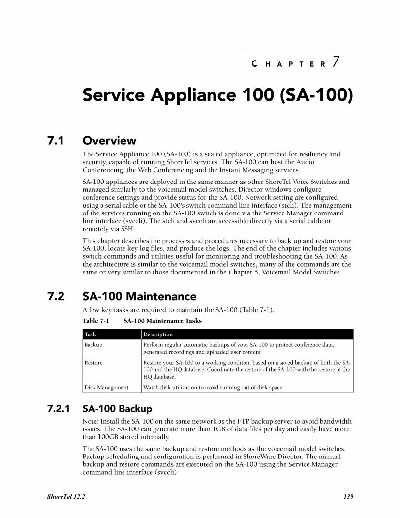
C H A P T E R 7
Service Appliance 100 (SA-100)
7.1 OverviewThe Service Appliance 100 (SA-100) is a sealed appliance, optimized for resiliency and security, capable of running ShoreTel services. The SA-100 can host the Audio Conferencing, the Web Conferencing and the Instant Messaging services.
SA-100 appliances are deployed in the same manner as other ShoreTel Voice Switches and managed similarly to the voicemail model switches. Director windows configure conference settings and provide status for the SA-100. Network setting are configured using a serial cable or the SA-100's switch command line interface (stcli). The management of the services running on the SA-100 switch is done via the Service Manager command line interface (svccli). The stcli and svccli are accessible directly via a serial cable or remotely via SSH.
This chapter describes the processes and procedures necessary to back up and restore your SA-100, locate key log files, and produce the logs. The end of the chapter includes various switch commands and utilities useful for monitoring and troubleshooting the SA-100. As the architecture is similar to the voicemail model switches, many of the commands are the same or very similar to those documented in the Chapter 5, Voicemail Model Switches.
7.2 SA-100 MaintenanceA few key tasks are required to maintain the SA-100 (Table 7-1).
7.2.1 SA-100 BackupNote: Install the SA-100 on the same network as the FTP backup server to avoid bandwidth issues. The SA-100 can generate more than 1GB of data files per day and easily have more than 100GB stored internally.
The SA-100 uses the same backup and restore methods as the voicemail model switches. Backup scheduling and configuration is performed in ShoreWare Director. The manual backup and restore commands are executed on the SA-100 using the Service Manager command line interface (svccli).
Table 7-1 SA-100 Maintenance Tasks
Task Description
Backup Perform regular automatic backups of your SA-100 to protect conference data, generated recordings and uploaded user content
Restore Restore your SA-100 to a working condition based on a saved backup of both the SA-100 and the HQ database. Coordinate the restore of the SA-100 with the restore of the HQ database.
Disk Management Watch disk utilization to avoid running out of disk space
ShoreTel 12.2 139
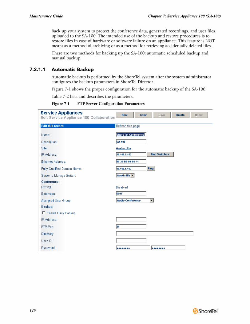
Maintenance Guide Chapter 7: Service Appliance 100 (SA-100)
Back up your system to protect the conference data, generated recordings, and user files uploaded to the SA-100. The intended use of the backup and restore procedures is to restore files in case of hardware or software failure on an appliance. This feature is NOT meant as a method of archiving or as a method for retrieving accidentally deleted files.
There are two methods for backing up the SA-100: automatic scheduled backup and manual backup.
7.2.1.1 Automatic BackupAutomatic backup is performed by the ShoreTel system after the system administrator configures the backup parameters in ShoreTel Director.
Figure 7-1 shows the proper configuration for the automatic backup of the SA-100.
Table 7-2 lists and describes the parameters.
Figure 7-1 FTP Server Configuration Parameters
140
Chapter 7: Service Appliance 100 (SA-100) Maintenance Guide
7.2.2 Manual BackupThe following steps describe the process for manually backing up the SA-100:
Step 1 Access the SA-100 Using either the serial Port or via SSH
Step 2 Start the Service Manager command line interface (svccli)
Step 3 Issue the backupweb command
Note: The manual backup process assumes that you have correctly configured the FTP parameters in ShoreTel Director as specified above in Automatic Backup.
7.2.2.1 Accessing the SA-100 Using the DB9 Serial PortEstablishing the serial console connection requires a DB9 female to DB9 female cable, instead of a DB9 male to DB9 female as in the ShoreTel Voice Switches. A Null-Modem connection (crossover cable) is required, instead of the straight-through cable (extension cable) used on ShoreTel Voice Switches.
Step 1 Connect a serial cable from a desktop/laptop PC to the DB9 serial connector on the rear of the SA-100.
Step 2 Open a terminal emulation program such as Hyper-terminal or Putty and set it for a serial connection using the following parameters:
— Serial Port: COM X (where 'X' is the port number used on your PC)
— Speed: 19200 baud
— Data Bits: 8
— Stop bits: 1
— Parity: None
— Flow control: None
Step 3 After establishing a serial connection, login to the SA-100 environment using 'admin' as the User ID and 'ShoreTel' as the Password.
Table 7-2 FTP Server Parameter
Field Description
Enable Daily Backup Turn on/off automatic backupsr
IP Address The IP address of the FTP Server
FTP Port The FTP port used to access the FTP server.
Note: The FTP port must be set to 21. The SA-100 can only perform backup and restore against a FTP server running on port 21.
Directory The directory on the FTP server where the backup files are stored.
Note: If you are backing up multiple SA-100s, use a separate directory for each SA-100.
User ID The User ID for accessing the FTP server
Password The Password for accessing the FTPserver
ShoreTel 12.2 141
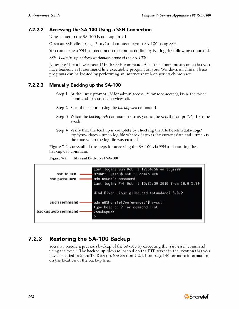
Maintenance Guide Chapter 7: Service Appliance 100 (SA-100)
7.2.2.2 Accessing the SA-100 Using a SSH ConnectionNote: telnet to the SA-100 is not supported.
Open an SSH client (e.g., Putty) and connect to your SA-100 using SSH.
You can create a SSH connection on the command line by issuing the following command:
SSH -l admin <ip address or domain name of the SA-100>
Note: the '-l' is a lower case 'L' in the SSH command. Also, the command assumes that you have loaded a SSH command line executable program on your Windows machine. These programs can be located by performing an internet search on your web browser.
7.2.2.3 Manually Backing up the SA-100
Step 1 At the linux prompt ('$' for admin access; '#' for root access), issue the svccli command to start the services cli.
Step 2 Start the backup using the backupweb command.
Step 3 When the backupweb command returns you to the svccli prompt ('>'). Exit the svccli.
Step 4 Verify that the backup is complete by checking the /cf/shorelinedata/Logs/FtpSync-<date>.<time> log file where <date> is the current date and <time> is the time when the log file was created.
Figure 7-2 shows all of the steps for accessing the SA-100 via SSH and running the backupweb command.
Figure 7-2 Manual Backup of SA-100
7.2.3 Restoring the SA-100 BackupYou may restore a previous backup of the SA-100 by executing the restoreweb command using the svccli. The backed up files are located on the FTP server in the location that you have specified in ShoreTel Director. See Section 7.2.1.1 on page 140 for more information on the location of the backup files.
142
Chapter 7: Service Appliance 100 (SA-100) Maintenance Guide
7.2.3.1 Restore Best Practices
Restore the SA-100 with a restoration of the HQ database from the same day. Since the file pointers are stored in the database in HQ application server, users MUST back up/restore BOTH the HQ database and SA-100(s) altogether to ensure consistency between HQ database and SA-100 file system.
Restoring an SA-100 backup without restoring HQ database taken from the same time as the SA-100 backup may cause the following issues:
• Ghost files - These are the files that exist during the time when the SA-100 backup was made, but have since been removed.
• Wrong metadata files - SA-100 restore overwrites existing files on the SA-100 even if the existing files might be more up to date than the ones in backup.
To ensure the file system on the SA-100 is consistent with HQ database:
• Enable daily backup for SA-100 in Director
• Schedule a windows task to back up the HQ database at the same time as the daily backup
• Restore HQ database from a backup that was created at the same time as the SA-100 backup that is going to be restored
• Restore SA-100 from a backup created at the same time as the HQ database backup
7.2.4 Manual RestoreA manual restore is the only method for restoring the SA-100. Restoring the SA-100 is done using a similar process as the manual backup. The system administrator accesses the SA-100 (through the serial port or via SSH) and executes the restoreweb command from the Service Manager command line interface (svccli).
The following steps describe the process for restoring the SA-100.
7.2.4.1 Accessing the SA-100 Using the DB9 Serial Port or SSHSee sections 7.2.2.1 or 7.2.2.2 for instructions on accessing the SA-100 via a serial cable or via SSH.
Manually restoring the SA-100
Step 1 At the linux prompt ('$' for admin access; '#' for root access), issue the svccli command to start the services cli.
Step 2 Start the restore using the restoreweb command.
Step 3 Wait for the restore to complete. The restore is complete when the restoreweb command returns you to the svccli prompt ('>').
Step 4 Verify that the restore is complete by checking the /cf/shorelinedata/Logs/FtpSync-<date>.<time>.Log file where <date> is the current date and <time> is the time when the log file was created.
Figure 7-3 shows all of the steps for accessing the SA-100 via SSH and running the restoreweb command.
ShoreTel 12.2 143
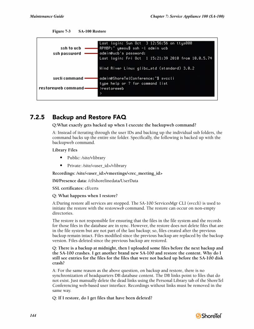
Maintenance Guide Chapter 7: Service Appliance 100 (SA-100)
Figure 7-3 SA-100 Restore
7.2.5 Backup and Restore FAQQ:What exactly gets backed up when I execute the backupweb command?
A: Instead of iterating through the user IDs and backing up the individual sub folders, the command backs up the entire site folder. Specifically, the following is backed up with the backupweb command.
Library Files
• Public: /site/vlibrary
• Private: /site/<user_id>/vlibrary
Recordings: /site/<user_id>/vmeetings/<rec_meeting_id>
IM/Presence data: /cf/shorelinedata/UserData
SSL certificates: cf/certs
Q: What happens when I restore?
A:During restore all services are stopped. The SA-100 ServicesMgr CLI (svccli) is used to initiate the restore with the restoreweb command. The restore can occur on non-empty directories.
The restore is not responsible for ensuring that the files in the file system and the records for those files in the database are in sync. However, the restore does not delete files that are in the file system but are not part of the last backup; so, files created after the previous backup remain intact. Files modified since the previous backup are replaced by the backup version. Files deleted since the previous backup are restored.
Q: There is a backup at midnight, then I uploaded some files before the next backup and the SA-100 crashes. I get another brand new SA-100 and restore the content. Why do I still see entries for the files for the files that were not backed up before the SA-100 disk crash?
A: For the same reason as the above question, on backup and restore, there is no synchronization of headquarters DB database content. The DB links point to files that do not exist. Just manually delete the dead links using the Personal Library tab of the ShoreTel Conferencing web-based user interface. Recordings without links must be removed in the same way.
Q: If I restore, do I get files that have been deleted?
144
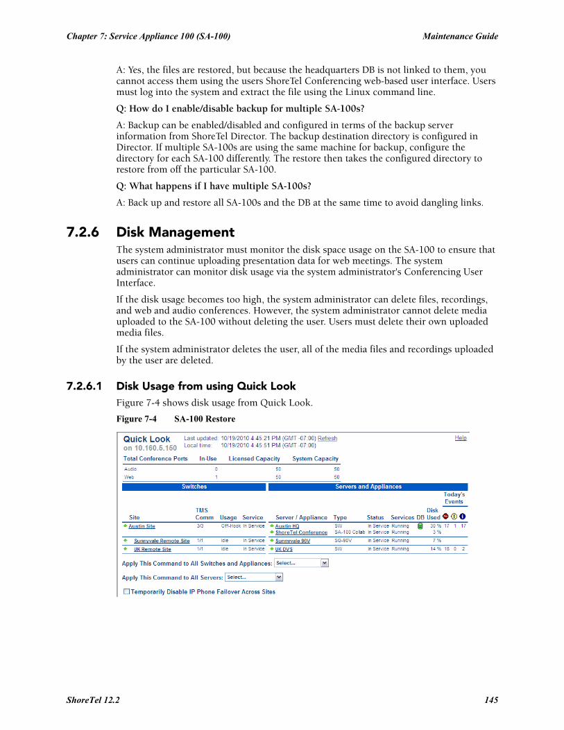
Chapter 7: Service Appliance 100 (SA-100) Maintenance Guide
A: Yes, the files are restored, but because the headquarters DB is not linked to them, you cannot access them using the users ShoreTel Conferencing web-based user interface. Users must log into the system and extract the file using the Linux command line.
Q: How do I enable/disable backup for multiple SA-100s?
A: Backup can be enabled/disabled and configured in terms of the backup server information from ShoreTel Director. The backup destination directory is configured in Director. If multiple SA-100s are using the same machine for backup, configure the directory for each SA-100 differently. The restore then takes the configured directory to restore from off the particular SA-100.
Q: What happens if I have multiple SA-100s?
A: Back up and restore all SA-100s and the DB at the same time to avoid dangling links.
7.2.6 Disk ManagementThe system administrator must monitor the disk space usage on the SA-100 to ensure that users can continue uploading presentation data for web meetings. The system administrator can monitor disk usage via the system administrator's Conferencing User Interface.
If the disk usage becomes too high, the system administrator can delete files, recordings, and web and audio conferences. However, the system administrator cannot delete media uploaded to the SA-100 without deleting the user. Users must delete their own uploaded media files.
If the system administrator deletes the user, all of the media files and recordings uploaded by the user are deleted.
7.2.6.1 Disk Usage from using Quick LookFigure 7-4 shows disk usage from Quick Look.
Figure 7-4 SA-100 Restore
ShoreTel 12.2 145
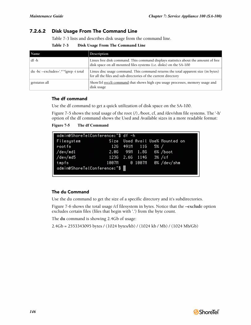
Maintenance Guide Chapter 7: Service Appliance 100 (SA-100)
7.2.6.2 Disk Usage From The Command LineTable 7-3 lists and describes disk usage from the command line.
The df command
Use the df command to get a quick utilization of disk space on the SA-100.
Figure 7-5 shows the total usage of the root (/), /boot, cf, and /dev/shm file systems. The '-h' option of the df command shows the Used and Available sizes in a more readable format:
Figure 7-5 The df Command
The du Command
Use the du command to get the size of a specific directory and it's subdirectories.
Figure 7-6 shows the total usage /cf filesystem in bytes. Notice that the --exclude option excludes certain files (files that begin with '.') from the byte count.
The du command is showing 2.4Gb of usage:
2.4Gb = 2553343095 bytes / (1024 bytes/kb) / (1024 kb / Mb) / (1024 Mb/Gb)
Table 7-3 Disk Usage From The Command Line
Name Description
df -h Linux free disk command. This command displays statistics about the amount of free disk space on all mounted files systems (i.e. disks) on the SA-100
du -bc --excludes=’.*’*|grep -i total Linux disc usage command. This command returns the total apparent size (in bytes) for all the files and sub-directories of the current directory
getstatus all ShoreTel svccli command that shows high cpu usage processes, memory usage and disk usage
146
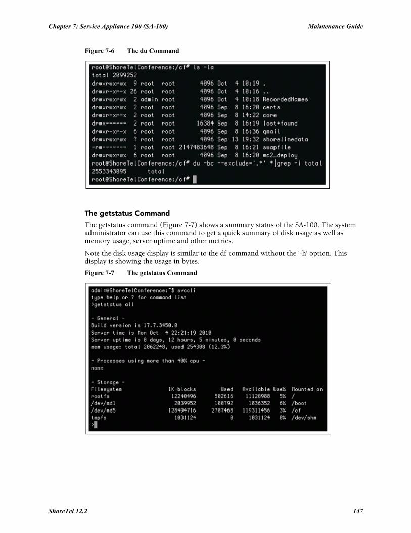
Chapter 7: Service Appliance 100 (SA-100) Maintenance Guide
Figure 7-6 The du Command
The getstatus Command
The getstatus command (Figure 7-7) shows a summary status of the SA-100. The system administrator can use this command to get a quick summary of disk usage as well as memory usage, server uptime and other metrics.
Note the disk usage display is similar to the df command without the '-h' option. This display is showing the usage in bytes.
Figure 7-7 The getstatus Command
ShoreTel 12.2 147
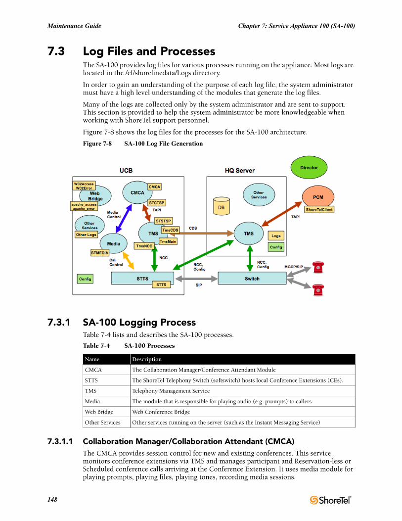
Maintenance Guide Chapter 7: Service Appliance 100 (SA-100)
7.3 Log Files and ProcessesThe SA-100 provides log files for various processes running on the appliance. Most logs are located in the /cf/shorelinedata/Logs directory.
In order to gain an understanding of the purpose of each log file, the system administrator must have a high level understanding of the modules that generate the log files.
Many of the logs are collected only by the system administrator and are sent to support. This section is provided to help the system administrator be more knowledgeable when working with ShoreTel support personnel.
Figure 7-8 shows the log files for the processes for the SA-100 architecture.
Figure 7-8 SA-100 Log File Generation
7.3.1 SA-100 Logging ProcessTable 7-4 lists and describes the SA-100 processes.
7.3.1.1 Collaboration Manager/Collaboration Attendant (CMCA)The CMCA provides session control for new and existing conferences. This service monitors conference extensions via TMS and manages participant and Reservation-less or Scheduled conference calls arriving at the Conference Extension. It uses media module for playing prompts, playing files, playing tones, recording media sessions.
Table 7-4 SA-100 Processes
Name Description
CMCA The Collaboration Manager/Conference Attendant Module
STTS The ShoreTel Telephony Switch (softswitch) hosts local Conference Extensions (CEs).
TMS Telephony Management Service
Media The module that is responsible for playing audio (e.g. prompts) to callers
Web Bridge Web Conference Bridge
Other Services Other services running on the server (such as the Instant Messaging Service)
148
Chapter 7: Service Appliance 100 (SA-100) Maintenance Guide
7.3.1.2 STTS (Softswitch)The STTS process hosts local Conference Extensions (CEs). It is used to create the conference call between users and CMCA, join and end conference calls and provide call signaling during the conference session. The mute/un-mute control, volume control, DTMF, VAD (voice activity detection) commands and events flow through STTS and TMS to the CMCA process.
7.3.1.3 The Media ModuleThe Media module provides media resources (prompts and user audio mixing) for audio conference sessions. The CMCA uses the media module to setup media resources during conference calls.
7.3.1.4 Telephony Management Server (TMS)The Telephony Management Server provides call control for conference sessions. It also manages Participant Lists and provides the Call Detailed Record (CDR) interface for the CMCA.
7.3.1.5 Web Bridge The Web Bridge provides Internet conference viewing and screen and data sharing using Apache (and other) software. It provides a server side interfaces for user conference and SA-100 web conference administration.
The user's interface to web conferences on the SA-100 is a web browser. Windows web browsers use a windows executable program (VPresent.exe) to show the client side interface to the SA-100. Other operating systems use Java and Flash to present the client side interface. The client side interface for all operating systems communicate with an Apache web server, which is a component of the Web Bridge.
7.3.1.6 Other Services There are additional services running on the SA-100. The Instant Messaging (IM) server is included in this category. The list of services running on the SA-100 can be viewed using the svccli interface.
ShoreTel 12.2 149
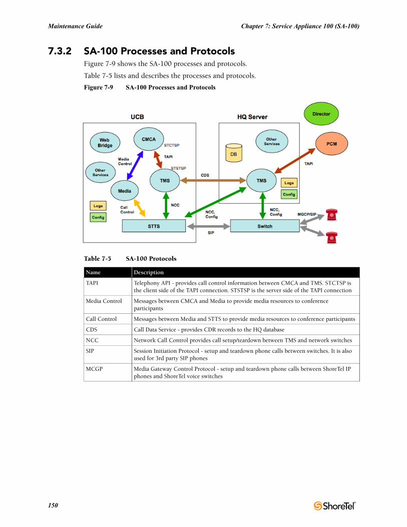
Maintenance Guide Chapter 7: Service Appliance 100 (SA-100)
7.3.2 SA-100 Processes and ProtocolsFigure 7-9 shows the SA-100 processes and protocols.
Table 7-5 lists and describes the processes and protocols.
Figure 7-9 SA-100 Processes and Protocols
Table 7-5 SA-100 Protocols
Name Description
TAPI Telephony API - provides call control information between CMCA and TMS. STCTSP is the client side of the TAPI connection. STSTSP is the server side of the TAPI connection
Media Control Messages between CMCA and Media to provide media resources to conference participants
Call Control Messages between Media and STTS to provide media resources to conference participants
CDS Call Data Service - provides CDR records to the HQ database
NCC Network Call Control provides call setup/teardown between TMS and network switches
SIP Session Initiation Protocol - setup and teardown phone calls between switches. It is also used for 3rd party SIP phones
MCGP Media Gateway Control Protocol - setup and teardown phone calls between ShoreTel IP phones and ShoreTel voice switches
150
Chapter 7: Service Appliance 100 (SA-100) Maintenance Guide
7.4 Log FilesTable 7-6 lists and describes the key log files in the SA-100.
7.5 SA-100 Utilities• UBOOT (page 152)
• stcli (page 152)
• CLI (page 153)
• Regedit (page 153)
7.5.1 Accessing the SA-100The SA-100 uses the same switch architecture as the Voicemail Model Switches. It uses the same access methods are accessible via a serial port of a SSH client. The following sections describe utility access methods.
7.5.2 Accessing Utilities from SSHShoreTel provides access to several Voicemail Model utilities through a Linux BASH command line. Voicemail Model switches define two accounts: admin and root.
Admin: The admin account provides access to selected ShoreTel and Linux utilities, including all Voicemail Model command line interfaces. ShoreTel recommends that user log into the Admin account when accessing Linux utilities.
Unlike the Voicemail Model switches, logging into the Admin account does not open the stcli interface. Logging into the Root account immediately opens a Linux BASH shell. The administrator must issue the stcli command to use the stcli.
Root: The root account provides access to all ShoreTel and Linux utilities. Restrict access to this account to help prevent potential switch problems.
Logging into the Root account immediately opens a Linux BASH shell.
Access to the Linux BASH command line through an SSH client. Free SSH clients, such as PuTTY, are available through the internet.
See section 7.2.2.2, Accessing the SA-100 Using a SSH Connection, for detailed steps on accessing a Linux BASH shell.
Table 7-6 SA-100 Log Files
Name Description
WC2Access and WC2Error logs Access and error log files for web bridge
apache_access and apache_error logs Apache access and error logs when accessing the web bridge
STMEDIA log New media log file for audio mixing. Media are the audio prompts played to audio bridge users
STTS log Softswitch Logs
CMCA log Access and error log files for the SA-100 CMCA process
STCTSP and STSTSP logs TAPI client and server logs for communication between CMCA and TMS
TmsCDS, TmsMain, and TmsNCC logs Telephony Management Server logs
ShoreTel 12.2 151
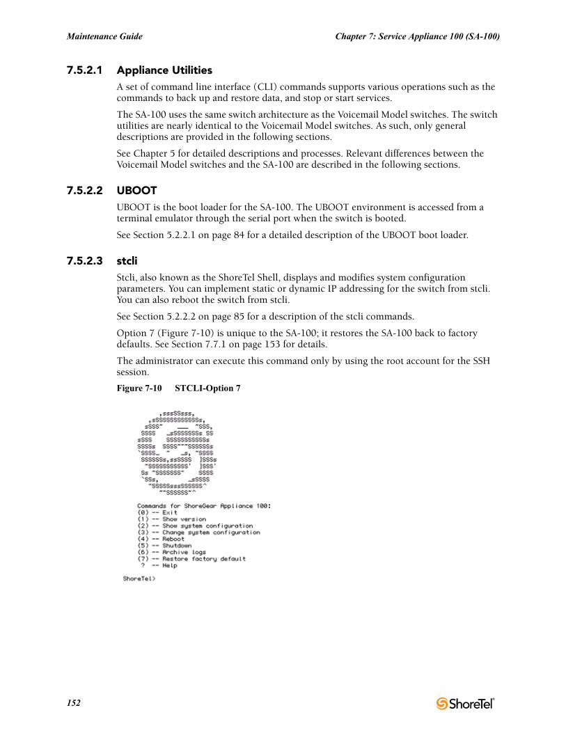
Maintenance Guide Chapter 7: Service Appliance 100 (SA-100)
7.5.2.1 Appliance UtilitiesA set of command line interface (CLI) commands supports various operations such as the commands to back up and restore data, and stop or start services.
The SA-100 uses the same switch architecture as the Voicemail Model switches. The switch utilities are nearly identical to the Voicemail Model switches. As such, only general descriptions are provided in the following sections.
See Chapter 5 for detailed descriptions and processes. Relevant differences between the Voicemail Model switches and the SA-100 are described in the following sections.
7.5.2.2 UBOOTUBOOT is the boot loader for the SA-100. The UBOOT environment is accessed from a terminal emulator through the serial port when the switch is booted.
See Section 5.2.2.1 on page 84 for a detailed description of the UBOOT boot loader.
7.5.2.3 stcliStcli, also known as the ShoreTel Shell, displays and modifies system configuration parameters. You can implement static or dynamic IP addressing for the switch from stcli. You can also reboot the switch from stcli.
See Section 5.2.2.2 on page 85 for a description of the stcli commands.
Option 7 (Figure 7-10) is unique to the SA-100; it restores the SA-100 back to factory defaults. See Section 7.7.1 on page 153 for details.
The administrator can execute this command only by using the root account for the SSH session.
Figure 7-10 STCLI-Option 7
152
Chapter 7: Service Appliance 100 (SA-100) Maintenance Guide
7.5.2.4 CLIThe CLI interface accesses diagnostic tools, manipulates debug setting levels, and displays system information. CLI can be run from any remote SSH session or from Windows prompts originating from the local host, the controlling Distributed server, or the Main ShoreTel server. See section 5.2.2.3, CLI, for a description of the stcli commands.
7.5.2.5 RegeditRegedit, a ShoreTel utility that modifies registry-type data structures in the switch, is accessible through the root account. Voicemail Model Switches have a registry similar to Windows Servers. The Registry is a ShoreTel construct, not part of Linux. To edit the Registry, log in as root and run the RegEdit command line tool from the bash shell. RegEdit may be used to set logging levels on applications and set other parameters that change their behavior. Section 5.5.8 describes regedit commands.
7.6 Booting and RestartingThe SA-100 uses the same switch architecture as the Voicemail Model Switches. See Section 5.3 on page 87 for a detailed description of the booting and restarting process. The SA-100 does not use compact flash. As such, compact flash commands and boot methods do not apply to the SA-100.
7.7 Diagnostics and RepairThe SA-100 uses the same switch architecture as the Voicemail Model Switches. See Section 5.3 on page 87 for a detailed description of the booting and restarting process. The SA-100 does not use compact flash. As such, compact flash commands and boot methods do not apply to the SA-100. Also, the SA-100 does not capture audio output from a switch port.
7.7.1 Restore Factory DefaultIf the SA-100 becomes non-operational due to corruption of the OS or application, it may be possible to restore the appliance to an operational state.
Procedural steps to follow depend upon whether a backup exists for the appliance to be restored, whether HTTPS is being used and whether the SA-100 is in a single appliance installation or one of multiple SA-100s in a distributed system.
Figure 7-11 shows the recovery process for these different situations.
Depending on configuration, various recovery steps may be required:
• Turn off/on HTTPS and uploading of SSL certificates - detailed in the SA-100 Planning, Installation and Administration Guide.
• Configuring an SA-100 with original IP address settings - detailed in the SA-100 Planning, Installation and Administration Guide.
• Installing an SA-100 in Director - detailed in the SA-100 Planning, Installation and Administration Guide.
• Restoring a backup to an SA-100 - detailed in this chapter, section 7.2.3
• Perform Restore to Factory Default - detailed below in section 7.7.1.1
ShoreTel 12.2 153
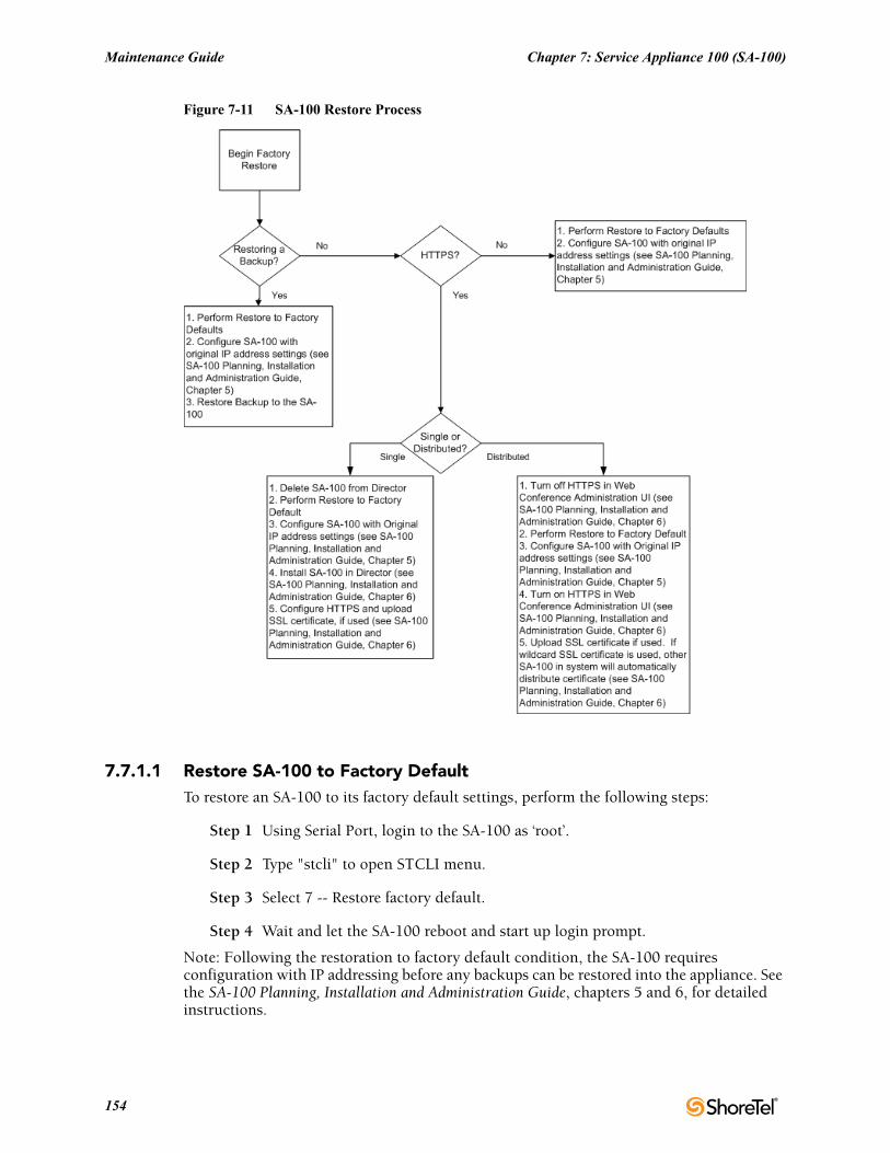
Maintenance Guide Chapter 7: Service Appliance 100 (SA-100)
Figure 7-11 SA-100 Restore Process
7.7.1.1 Restore SA-100 to Factory DefaultTo restore an SA-100 to its factory default settings, perform the following steps:
Step 1 Using Serial Port, login to the SA-100 as ‘root’.
Step 2 Type "stcli" to open STCLI menu.
Step 3 Select 7 -- Restore factory default.
Step 4 Wait and let the SA-100 reboot and start up login prompt.
Note: Following the restoration to factory default condition, the SA-100 requires configuration with IP addressing before any backups can be restored into the appliance. See the SA-100 Planning, Installation and Administration Guide, chapters 5 and 6, for detailed instructions.
154
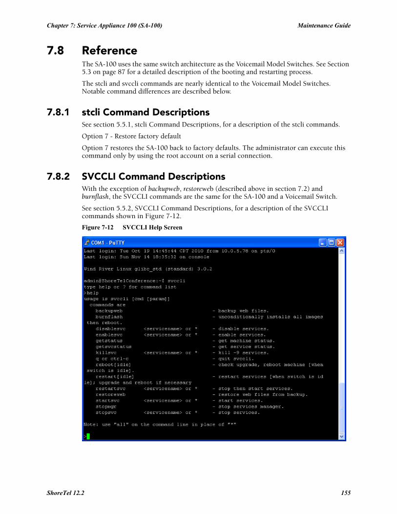
Chapter 7: Service Appliance 100 (SA-100) Maintenance Guide
7.8 ReferenceThe SA-100 uses the same switch architecture as the Voicemail Model Switches. See Section 5.3 on page 87 for a detailed description of the booting and restarting process.
The stcli and svccli commands are nearly identical to the Voicemail Model Switches. Notable command differences are described below.
7.8.1 stcli Command DescriptionsSee section 5.5.1, stcli Command Descriptions, for a description of the stcli commands.
Option 7 - Restore factory default
Option 7 restores the SA-100 back to factory defaults. The administrator can execute this command only by using the root account on a serial connection.
7.8.2 SVCCLI Command DescriptionsWith the exception of backupweb, restoreweb (described above in section 7.2) and burnflash, the SVCCLI commands are the same for the SA-100 and a Voicemail Switch.
See section 5.5.2, SVCCLI Command Descriptions, for a description of the SVCCLI commands shown in Figure 7-12.
Figure 7-12 SVCCLI Help Screen
ShoreTel 12.2 155
Maintenance Guide Chapter 7: Service Appliance 100 (SA-100)
The SA-100 uses the backupweb and restoreweb commands instead of the backupvm and restore commands used on the Voicemail Model Switches.
The burnflash command on the SA-100 installs all images and restarts the appliance. Unlike a Voicemail switch, the SA-100 does not store images in flash memory, however the command is used in the same manner as in a Voicemail switch.
See section 6.3, Backing up the SA-100, and section 6.4, Restoring the SA-100, for a complete more information on backupweb and restoreweb.
7.8.3 CLISee section 5.5.3, CLI, for a detailed description of cli commands.
7.8.4 UBOOTSee section 5.5.4, UBOOT, for a detailed description of UBOOT commands.
7.8.5 RegeditSee section 5.5.8, regedit, for a detailed description of regedit commands.
156
C H A P T E R 8
ShoreTel Client Applications
8.1 OverviewThis chapter provides technical background information about the ShoreTel Communicator application suite.
8.1.1 Communicator Application SuiteThe Communicator suite includes:
• Different functional versions of the Communicator client application: Personal, Professional, Workgroup Agent, Workgroup Supervisor, and Operator.
• Call Monitor software, including the Agent and Queue monitors.
• Viewer applications for Directory, History, and Voice Mail.
• Configure ShoreTel system, a control panel applet for configuring ShoreTel clients.
8.1.2 Theory of OperationsAll Communicator applications are hosted within a single process named ShoreTel.exe.
TAPI objects manage all telephony-related data and tasks for Communicator. Voice mail and database operations require CSIS. Communicator applications use any available service and attempt to degrade gracefully if a requested service is unavailable.
A separate process (PCMMapiRd.exe) is invoked to load Microsoft Outlook contact data into the Communicator’s “white pages.”
Only the Communicator clients and three monitors (Extension, Agent, and Queue) can communicate directly with TAPI. All other applications must use Communicator as a proxy to place calls on their behalf. Applications using Communicator to dial calls are unable to provide feedback when an attempt to place a call fails. (However, notification of call failure does appear in the Communicator application.)
ShoreTel 12.2 157
Maintenance Guide Chapter 8: ShoreTel Client Applications
8.1.2.1 Executable ModulesTable 8-1 lists and describes the top-level executable modules used by Communicator applications.
8.1.2.2 Starting Communicator ApplicationsTo start a Communicator client application, click the Communicator application shortcut that appears on the desktop or Start menu. This starts ShoreTel.exe, opening Communicator and any other applications run by Communicator.
8.2 DiagnosticsIf a Communicator application appears to be malfunctioning, use the following diagnostic guidelines to determine the point of failure.
8.2.1 Troubleshooting Login or Startup ProblemsFor the purpose of this discussion, login problems refer to issues related to CSIS.
The following symptoms may indicate login or startup problems:
• Double-clicking the application shortcut does not bring up the Communicator main window.
• Communicator appears, but no Call Handling Mode icon or Hands free Mode icon is visible on the status bar/application tray. This is the most common symptom of login or startup problems.
• Agent Monitor appears, but fails to list agents.
• Extension Monitor appears and lists extension numbers, but without names.
• Voice Mail Viewer does not appear.
• Control Panel appears, but most fields are grayed out.
• Directory Viewer appears, but shows no data.
Table 8-1 Communicator Executable Modules
Module Description
ShoreTel.exe Launches Communicator application.
(The application shortcut launches this task.)
Sendclientlogs.exe Sends client logs to ShoreTel Customer Support.
PCMMapiRd.exe Reads MAPI contacts and loads them into Communicator.
CSISCMgr.exe Client-side CSIS component.
TAPISRV.exe/SvcHost.exe Microsoft TAPI applications.
Rpctspx.tsp TAPI Service Provider.
158
Chapter 8: ShoreTel Client Applications Maintenance Guide
8.2.1.1 Missing IconsMissing icons often indicate that CSIS was unavailable for user login.
The first time Communicator successfully connects to CSIS, it stores a minimum amount of configuration data in the user’s registry settings, including the user’s current extension number; the values of the system extensions (AA, BAA, VM, VM Login); the values of the paging and night bell extensions for the user’s site; and basic contact information (home country, home area code, and default access code).
This initial data store provides Communicator with enough information to perform high-level tasks that include displaying call information and permitting the user to place and manage calls.
Normally, Communicator locates the cached data and loads it while waiting for login to complete. After login, Communicator updates the configuration information while it runs on the user’s PC.
However, if CSIS is unavailable for login the next time the user starts Communicator (or if the login fails), Communicator uses the cached data until CSIS comes back online and login is successful.
A login problem can prevent Communicator from launching only if the application is not run after installing or upgrading to the latest ShoreTel software release.
8.2.1.2 Login ProblemsIf a Communicator application fails to log in, test the CSIS server to verify that it is running, check the login parameters, and open Windows Task Manager to confirm that no ShoreTel applications are running.
To troubleshoot login issues:
Step 1 Test the CSIS server.
Verify that the CSIS server is running by copying the following URL into your browser’s address field.
(Change SERVERNAME to the name of the CSIS server.)
http://SERVERNAME/CSIS/CSISISAPI.dll/?request?00000000-0000-0000-0000-000000000000;CCSISSvrCONN::ping;
The browser window should display a result similar to this:
10;0x00000000;4;5440
Pay particular notice to the digits that appear after “0x.”
If “x” is followed by a string of zeroes, the CSIS server is running.
If any digits other than zero appear after “x,” you need to troubleshoot the ShoreTel server.
Step 2 Check the login parameters.
Open the Windows Control Panel, and click the Phone and Modem Options.
Click the Advanced tab (Figure 8-1) to display a list of telephony providers.
Choose ShoreTel Remote TAPI Service Provider and click Configure.
The ShoreTel Remote TSP Device tab appears (Figure 8-2).
ShoreTel 12.2 159
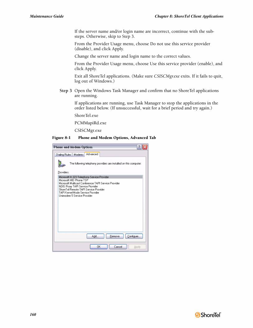
Maintenance Guide Chapter 8: ShoreTel Client Applications
If the server name and/or login name are incorrect, continue with the sub-steps. Otherwise, skip to Step 3.
From the Provider Usage menu, choose Do not use this service provider (disable), and click Apply.
Change the server name and login name to the correct values.
From the Provider Usage menu, choose Use this service provider (enable), and click Apply.
Exit all ShoreTel applications. (Make sure CSISCMgr.exe exits. If it fails to quit, log out of Windows.)
Step 3 Open the Windows Task Manager and confirm that no ShoreTel applications are running.
If applications are running, use Task Manager to stop the applications in the order listed below. (If unsuccessful, wait for a brief period and try again.)
ShoreTel.exe
PCMMapiRd.exe
CSISCMgr.exe
Figure 8-1 Phone and Modem Options, Advanced Tab
160
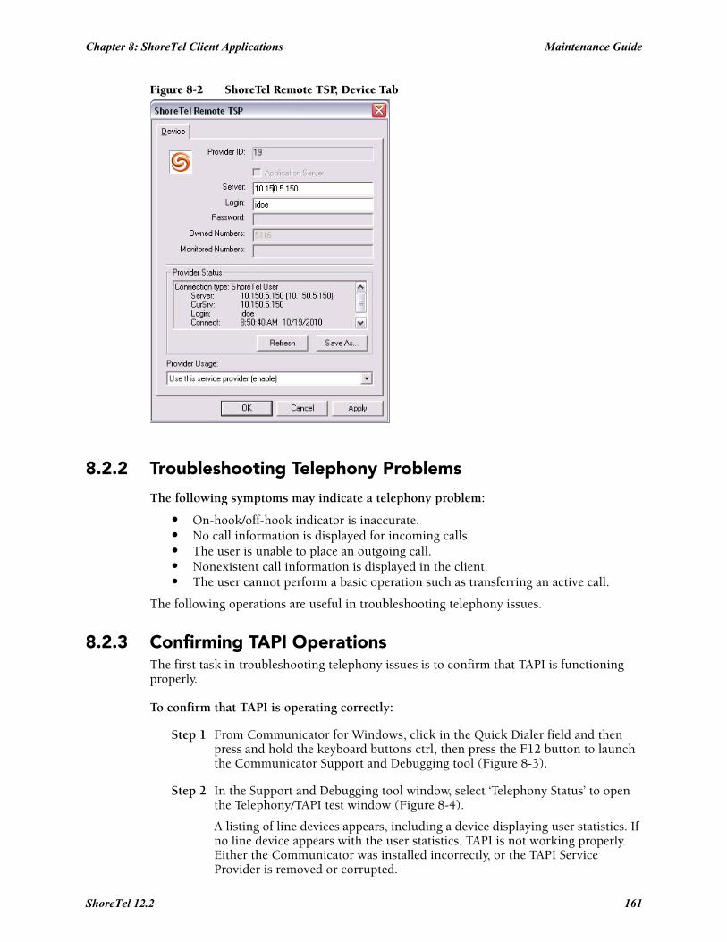
Chapter 8: ShoreTel Client Applications Maintenance Guide
Figure 8-2 ShoreTel Remote TSP, Device Tab
8.2.2 Troubleshooting Telephony Problems
The following symptoms may indicate a telephony problem:
• On-hook/off-hook indicator is inaccurate.• No call information is displayed for incoming calls.• The user is unable to place an outgoing call.• Nonexistent call information is displayed in the client.• The user cannot perform a basic operation such as transferring an active call.
The following operations are useful in troubleshooting telephony issues.
8.2.3 Confirming TAPI OperationsThe first task in troubleshooting telephony issues is to confirm that TAPI is functioning properly.
To confirm that TAPI is operating correctly:
Step 1 From Communicator for Windows, click in the Quick Dialer field and then press and hold the keyboard buttons ctrl, then press the F12 button to launch the Communicator Support and Debugging tool (Figure 8-3).
Step 2 In the Support and Debugging tool window, select ‘Telephony Status’ to open the Telephony/TAPI test window (Figure 8-4).
A listing of line devices appears, including a device displaying user statistics. If no line device appears with the user statistics, TAPI is not working properly. Either the Communicator was installed incorrectly, or the TAPI Service Provider is removed or corrupted.
ShoreTel 12.2 161
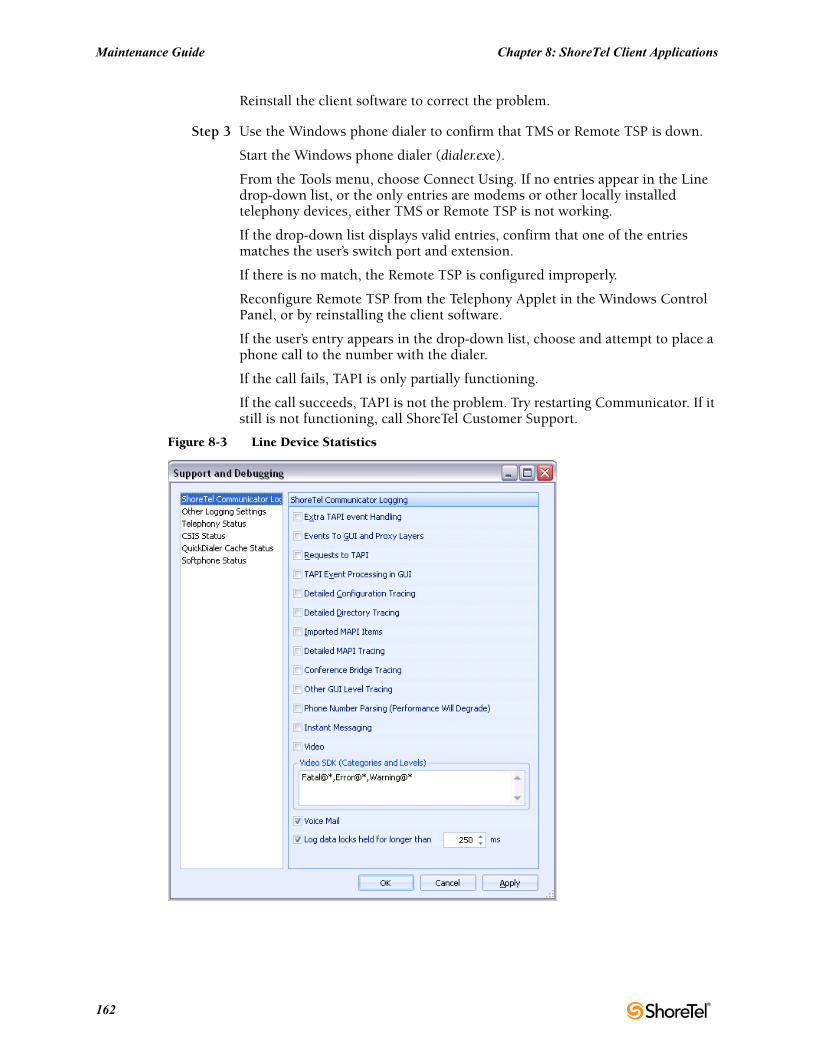
Maintenance Guide Chapter 8: ShoreTel Client Applications
Reinstall the client software to correct the problem.
Step 3 Use the Windows phone dialer to confirm that TMS or Remote TSP is down.
Start the Windows phone dialer (dialer.exe).
From the Tools menu, choose Connect Using. If no entries appear in the Line drop-down list, or the only entries are modems or other locally installed telephony devices, either TMS or Remote TSP is not working.
If the drop-down list displays valid entries, confirm that one of the entries matches the user’s switch port and extension.
If there is no match, the Remote TSP is configured improperly.
Reconfigure Remote TSP from the Telephony Applet in the Windows Control Panel, or by reinstalling the client software.
If the user’s entry appears in the drop-down list, choose and attempt to place a phone call to the number with the dialer.
If the call fails, TAPI is only partially functioning.
If the call succeeds, TAPI is not the problem. Try restarting Communicator. If it still is not functioning, call ShoreTel Customer Support.
Figure 8-3 Line Device Statistics
162
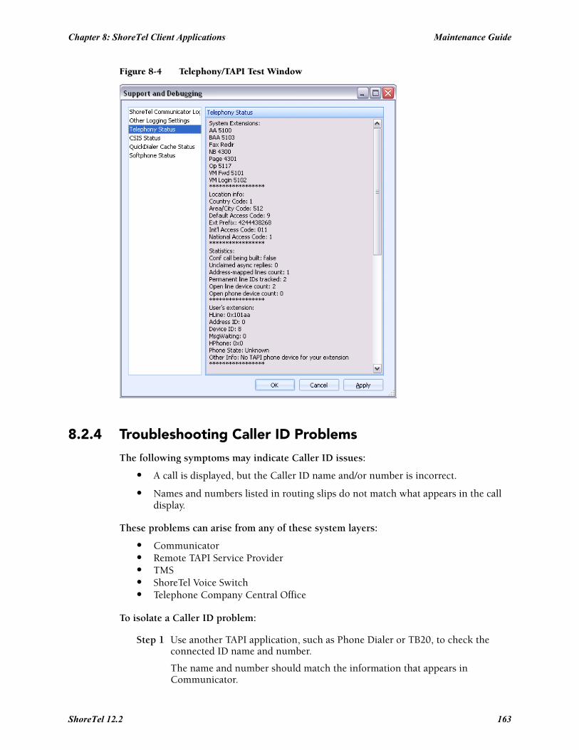
Chapter 8: ShoreTel Client Applications Maintenance Guide
Figure 8-4 Telephony/TAPI Test Window
8.2.4 Troubleshooting Caller ID Problems
The following symptoms may indicate Caller ID issues:
• A call is displayed, but the Caller ID name and/or number is incorrect.
• Names and numbers listed in routing slips do not match what appears in the call display.
These problems can arise from any of these system layers:
• Communicator• Remote TAPI Service Provider• TMS• ShoreTel Voice Switch • Telephone Company Central Office
To isolate a Caller ID problem:
Step 1 Use another TAPI application, such as Phone Dialer or TB20, to check the connected ID name and number.
The name and number should match the information that appears in Communicator.
ShoreTel 12.2 163
Maintenance Guide Chapter 8: ShoreTel Client Applications
If these do not match, it is probable that Communicator detected the number in another application running on the user's machine and applied formatting rules to make the entry unique.
Step 2 Locate the call in question and use the TMSncc log to view the Caller ID information the client sent to the server.
Step 3 Use the trunk debugger to identify what the CO sent to the switch.
8.2.5 Troubleshooting Configuration ProblemsThe following symptoms may indicate configuration issues:
• A Server Unavailable message appears when the user attempts to change his or her call handling or headset mode.
• Unable to use Configure ShoreTel System via Communicator’s Options menu, or unable to access “ShoreTel System” from Windows’ Control Panel.
• Call handling mode or headset mode display on Communicator is inaccurate.
Review Section 8.2.1 on page 158. Most of the diagnostic guidelines in that section apply to configuration problems as well.
To isolate a configuration problem:
Step 1 Confirm that the CSIS server is running by entering the URL provided in the earlier section.
Step 2 If the CSIS server is running, make sure that CSISCMgr.exe is also running on the client PC.
Step 3 If the client process is running, try toggling the hands-free mode on and off, or change the call handling mode.
Step 4 Verify that Communicator is connected to the CSIS server by placing the cursor in the QuickDialer dialog box and pressing CTRL + F12.
You should see a diagnostics dialog that you can use to check the connection.
8.2.6 Troubleshooting MAPI Contact Import Problems Using SHAdrTst.exeYou can isolate MAPI contact import problems by running SHAdrTst.exe (included on the client DVD).
To run SHAdrTst.exe:
Step 1 From a command prompt or DOS window on the client PC, run SHAdrTst.exe, by typing:
SHAdrTst
The command lists what Communicator can import.
164
Chapter 8: ShoreTel Client Applications Maintenance Guide
Table 8-2 lists and describes the available options for SHAdrTst.exe.
8.2.7 Using the History FileWith the ShoreTel 12 Release, all Communicator call history records are now stored on the user’s managing HQ or DVS server in an SQLite file.
When a user accesses their Communicator call history from either the Communicator client, Communicator for Web of Communicator for Mac, this data is recalled from the server-side history records for that user.
The records are stored under the following pathway on the user’s server:
<ShoreTel Data Folder Root>/UserData/<dnuuid>/ with the name "history.sq3".
Each dnuuid corresponds to a particular user.
These are SQLite files and must be opened with the appropriate tools for that format to view the data.
ShoreTel recommends you contact Technical Support for assistance in accessing these files as the call history for individual users can be damaged or lost if not correctly opened.
8.2.8 Using Log FilesAnother critical resource for troubleshooting is the log file where Communicator logs TAPI events, configuration events, and voice mail events, as well as all unexpected errors, exceptions, and warnings.
The main log file is named CC-YYMMDD.HHMMSS.log. CC is literal; YYMMDD represents the year, month, and day of the date when the file was created; and HHMMSS represents the hour, minute, and second of the time the file was created.
Example: The file named CC-081202.120000.log) was created at noon on December 12, 2008.
There are other log files, such as CSIS-YYMMDD.HHMMSS.log, for other processes running on the client.
8.2.8.1 Locating the Log FileYou can find the log file in <app data>\ShoreTel Client\Logs on most Windows machines, or <install dir>\Logs on other platforms. (See Section 8.2.7 on page 165 for examples of pathnames.)
8.2.8.2 Creating Verbose LogsGenerally, only unexpected errors are logged to the error log. You can change this priority from the QuickDialer if you want to create more detailed logs.
Use verbose logging only if a problem is reproducible and ShoreTel Customer Support requires additional information.
Table 8-2 SHAdrTst.exe Options
Command Description
SHAdrTst > filename.txt Transfer the output to a file.
SHAdrTst –debug -stdout Include debugging statements in the output.
SHAdrTst –debug –stdout > filename.txt Include debugging statement in the output file. The output lists all data imported by Communicator.
ShoreTel 12.2 165
Maintenance Guide Chapter 8: ShoreTel Client Applications
To turn on verbose logging:
Step 1 Position the cursor in the QuickDialer window and press CTRL + F12.
Step 2 Check the boxes for preferred types of logging. To ensure you capture as much logging information as possible, check all boxes except phone number parsing.
The resulting logs are voluminous.
Preset Debug Flags
You can preset debug flags by selecting the relevant flag in the Support and Debugging Tool (Ctrl + F12).
8.2.8.3 Collecting LogsTo collect logs to send to ShoreTel Customer Support, use the Senclientlogs.exe utility from the
From Windows Explorer, go to C:\Program Files\Shoreline Communications\ShoreWare Client/SendClientLogs.exe. A wizard guides you through the rest of the process.
8.3 Setup WizardAnother component of the client, the Setup Wizard, continues the configuration of Communicator after installation.
The Setup Wizard appears the first time Communicator runs on any PC. It reappears if a user cancels the Wizard before completing the configuration, or installs Microsoft Outlook at a later date.
The Setup Wizard starts if any of the following conditions are true:
• Any of the following string values are missing from (or blank in) the registry:
— HKEY_CURRENT_USER\Software\Shoreline Teleworks\ShoreTel Client\UserName
— HKEY_CURRENT_USER\Software\Shoreline Teleworks\ShoreTel Client\Server
— HKEY_CURRENT_USER\Software\Shoreline Teleworks\ShoreTel Client\Password
• The following DWORD value is missing from the registry:
— HKEY_CURRENT_USER\Software\Shoreline Teleworks\ShoreTel Client\LoadOutlookPhoneNumbers
• The following values are set to TRUE in the user row of the database USER table:
— MustChangeGUIPassword
— MustChangeTUIPassword
— MustRecordName
• Microsoft Outlook is installed AND Voice Mail Outlook Integration is not installed AND the following DWORD value is missing from the registry, or set to z nonzero value:
— HKEY_CURRENT_USER\Software\Shoreline Teleworks\ShoreTel Client\OfferToInstallOutlookIntegration
166
Chapter 8: ShoreTel Client Applications Maintenance Guide
If any of the specified conditions are TRUE, the Setup Wizard runs, while also setting one or more of the conditions to TRUE and starting the client.
Set the values only after exiting the client from the system tray and terminating all Communicator services.
8.4 Communicator: V-1 CompatibilityCommunicator: V-1 Compatibility functionality logs messages and events to the following log files.
• CSISSvr-XXXXX.Log on server (basic level)
• CSIS-XXXX.Log at C:\Documents and Settings\client's name\Application Data\ShoreTel Client\Logs on client machine.
NOTE: You must enable CSIS Tracing in Communicator.
Here’s an example of a log that is generated, when Communicator starts up. This information is logged on user's machine.
The information of "5804: (5564) 13:35:19.992 PST [CSIS-CONNDLL] CCSISSvrCONN::checkUpgrade for CCARR-755.USER: client version=14.40.6800.0, server version=15.20.3400.0, status=4" is logged to file CSISSvr-XXXX.log.
The information of "3948: (3812) 16:21:08.731 CST [CSIS-CM] CCSISCliCONN::checkUpgrade: client version=14.20.0.0, server version=15.20.3400.0, status=1".
Status Codes generated by Communicator behavior
• status = 0, no upgrade
• status = 1, optional
• status = 2, mandatory
• status = 3, incompatible
• status = 4, not allowed
• status = 5, incompatible server
• status = 6, suggest upgrade
8.4.1 Existing Communicator IssuesWhen warning pop-up windows are displayed that require an upgrade or when a pop-up window is displayed indicating “do not allow upgrade” and the user clicks "Ok" or "Cancel" quickly, the Communicator may not exit properly. The user must wait 1 or 2 seconds before clicking the pop-up warning windows.
ShoreTel 12.2 167

Maintenance Guide Chapter 8: ShoreTel Client Applications
168
A P P E N D I X A
Event Codes
A.1 OverviewThis appendix provides a comprehensive table of ShoreTel event codes. Organized by error type and sorted by event ID numbers, the tables are a valuable resource for troubleshooting events reported by the ShoreTel system.
A.2 Event TypesThe tables list event types according to component functions of the ShoreTel telephony system:
• Switch• TMS• Voice Mail• TDI Media• Event Watch• Configuration Administration• Port Mapper• Trigger Server• Distributed Routing Service (DRS)• Kadota Utility• Call Accounting• Workgroup Server• CSIS• IP Phone Console Server (IPCS)• IP Phone Display Server (IPDS)
A.3 Using the Event Code TablesIn some cases, event codes result from other error conditions that cause related problems.
Always review event codes in the context in which they appear. For example, if event code 171 (internal operating temperature of switch is exceeding acceptable range) appears with code 166 (internal fan failure), you should replace the fan—not the entire switch—to solve the problem.
A.3.1 Reading the Event TablesThe event tables in this appendix provide a structured view of events you may encounter in messages and log files. Each event table entry includes a unique event ID number, a severity level, the event message text, possible causes, and suggested courses of action (if any).
ShoreTel 12.2 169
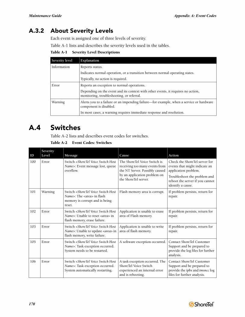
Maintenance Guide Appendix A: Event Codes
A.3.2 About Severity LevelsEach event is assigned one of three levels of severity.
Table A-1 lists and describes the severity levels used in the tables.
A.4 SwitchesTable A-2 lists and describes event codes for switches.
Table A-1 Severity Level Descriptions
Severity level Explanation
Information Reports status.
Indicates normal operation, or a transition between normal operating states.
Typically, no action is required.
Error Reports an exception to normal operations.
Depending on the event and its context with other events, it requires no action, monitoring, troubleshooting, or referral.
Warning Alerts you to a failure or an impending failure—for example, when a service or hardware component is disabled.
In most cases, a warning requires immediate response and resolution.
Table A-2 Event Codes: Switches
IDSeverityLevel Message Cause Action
100 Error Switch <ShoreTel Voice Switch Host Name>: Event message lost, queue overflow.
The ShoreTel Voice Switch is receiving too many events from the NT Server. Possibly caused by an application problem on the ShoreTel server.
Check the ShoreTel server for events that might indicate an application problem.
Troubleshoot the problem and reboot the server if you cannot identify a cause.
101 Warning Switch <ShoreTel Voice Switch Host Name>: The <area> in flash memory is corrupt and is being reset.
Flash memory area is corrupt. If problem persists, return for repair.
102 Error Switch <ShoreTel Voice Switch Host Name>: Unable to reset <area> in flash memory, erase failure.
Application is unable to erase area of Flash memory.
If problem persists, return for repair.
103 Error Switch <ShoreTel Voice Switch Host Name>: Unable to update <area> in flash memory, write failure.
Application is unable to write area of flash memory.
If problem persists, return for repair.
105 Error Switch <ShoreTel Voice Switch Host Name>: Task exception occurred. System needs to be restarted.
A software exception occurred. Contact ShoreTel Customer Support and be prepared to provide the log files for further analysis.
106 Error Switch <ShoreTel Voice Switch Host Name>: Task exception occurred. System automatically restarting.
A task exception occurred. The ShoreTel Voice Switch experienced an internal error and is rebooting.
Contact ShoreTel Customer Support and be prepared to provide the ipbx and tmsncc log files for further analysis.
170
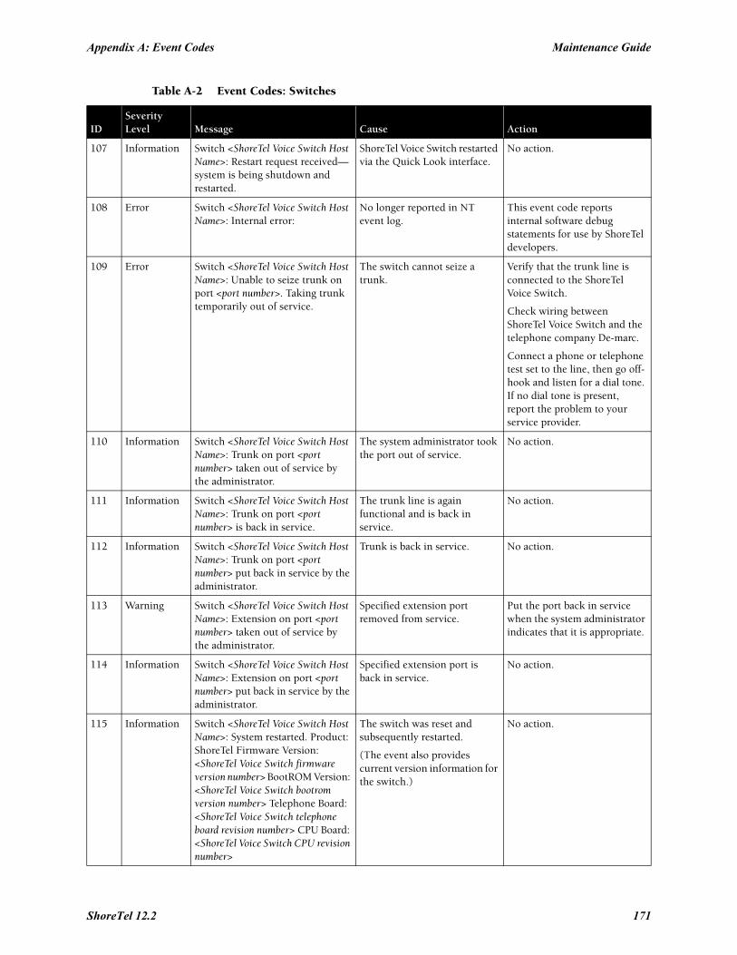
Appendix A: Event Codes Maintenance Guide
107 Information Switch <ShoreTel Voice Switch Host Name>: Restart request received—system is being shutdown and restarted.
ShoreTel Voice Switch restarted via the Quick Look interface.
No action.
108 Error Switch <ShoreTel Voice Switch Host Name>: Internal error:
No longer reported in NT event log.
This event code reports internal software debug statements for use by ShoreTel developers.
109 Error Switch <ShoreTel Voice Switch Host Name>: Unable to seize trunk on port <port number>. Taking trunk temporarily out of service.
The switch cannot seize a trunk.
Verify that the trunk line is connected to the ShoreTel Voice Switch.
Check wiring between ShoreTel Voice Switch and the telephone company De-marc.
Connect a phone or telephone test set to the line, then go off-hook and listen for a dial tone. If no dial tone is present, report the problem to your service provider.
110 Information Switch <ShoreTel Voice Switch Host Name>: Trunk on port <port number> taken out of service by the administrator.
The system administrator took the port out of service.
No action.
111 Information Switch <ShoreTel Voice Switch Host Name>: Trunk on port <port number> is back in service.
The trunk line is again functional and is back in service.
No action.
112 Information Switch <ShoreTel Voice Switch Host Name>: Trunk on port <port number> put back in service by the administrator.
Trunk is back in service. No action.
113 Warning Switch <ShoreTel Voice Switch Host Name>: Extension on port <port number> taken out of service by the administrator.
Specified extension port removed from service.
Put the port back in service when the system administrator indicates that it is appropriate.
114 Information Switch <ShoreTel Voice Switch Host Name>: Extension on port <port number> put back in service by the administrator.
Specified extension port is back in service.
No action.
115 Information Switch <ShoreTel Voice Switch Host Name>: System restarted. Product: ShoreTel Firmware Version: <ShoreTel Voice Switch firmware version number> BootROM Version: <ShoreTel Voice Switch bootrom version number> Telephone Board: <ShoreTel Voice Switch telephone board revision number> CPU Board: <ShoreTel Voice Switch CPU revision number>
The switch was reset and subsequently restarted.
(The event also provides current version information for the switch.)
No action.
Table A-2 Event Codes: Switches
IDSeverityLevel Message Cause Action
ShoreTel 12.2 171
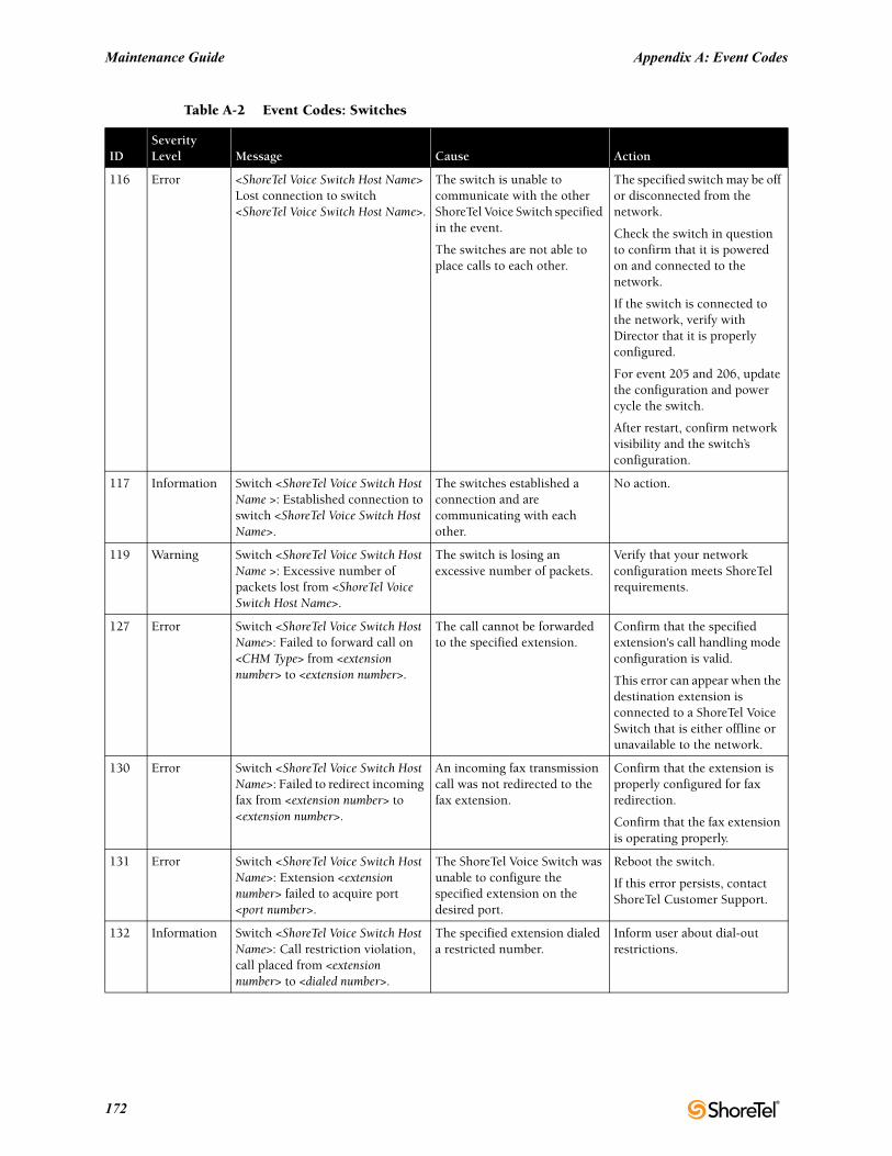
Maintenance Guide Appendix A: Event Codes
116 Error <ShoreTel Voice Switch Host Name> Lost connection to switch <ShoreTel Voice Switch Host Name>.
The switch is unable to communicate with the other ShoreTel Voice Switch specified in the event.
The switches are not able to place calls to each other.
The specified switch may be off or disconnected from the network.
Check the switch in question to confirm that it is powered on and connected to the network.
If the switch is connected to the network, verify with Director that it is properly configured.
For event 205 and 206, update the configuration and power cycle the switch.
After restart, confirm network visibility and the switch’s configuration.
117 Information Switch <ShoreTel Voice Switch Host Name >: Established connection to switch <ShoreTel Voice Switch Host Name>.
The switches established a connection and are communicating with each other.
No action.
119 Warning Switch <ShoreTel Voice Switch Host Name >: Excessive number of packets lost from <ShoreTel Voice Switch Host Name>.
The switch is losing an excessive number of packets.
Verify that your network configuration meets ShoreTel requirements.
127 Error Switch <ShoreTel Voice Switch Host Name>: Failed to forward call on <CHM Type> from <extension number> to <extension number>.
The call cannot be forwarded to the specified extension.
Confirm that the specified extension's call handling mode configuration is valid.
This error can appear when the destination extension is connected to a ShoreTel Voice Switch that is either offline or unavailable to the network.
130 Error Switch <ShoreTel Voice Switch Host Name>: Failed to redirect incoming fax from <extension number> to <extension number>.
An incoming fax transmission call was not redirected to the fax extension.
Confirm that the extension is properly configured for fax redirection.
Confirm that the fax extension is operating properly.
131 Error Switch <ShoreTel Voice Switch Host Name>: Extension <extension number> failed to acquire port <port number>.
The ShoreTel Voice Switch was unable to configure the specified extension on the desired port.
Reboot the switch.
If this error persists, contact ShoreTel Customer Support.
132 Information Switch <ShoreTel Voice Switch Host Name>: Call restriction violation, call placed from <extension number> to <dialed number>.
The specified extension dialed a restricted number.
Inform user about dial-out restrictions.
Table A-2 Event Codes: Switches
IDSeverityLevel Message Cause Action
172
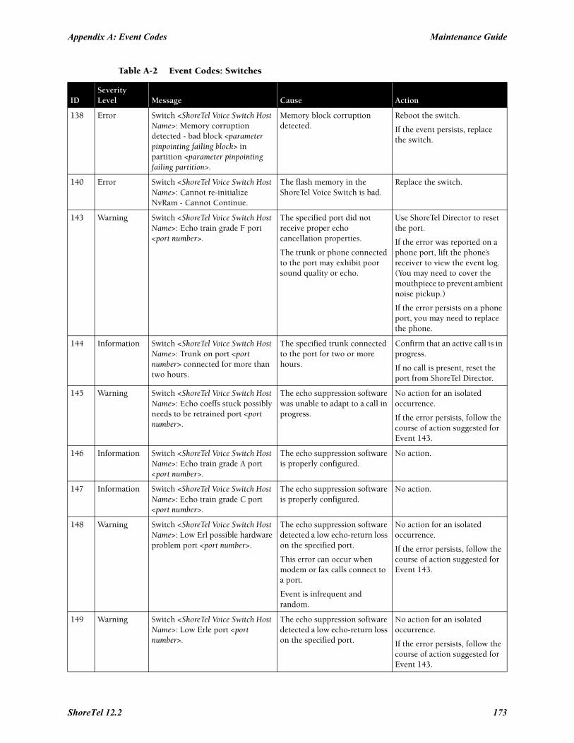
Appendix A: Event Codes Maintenance Guide
138 Error Switch <ShoreTel Voice Switch Host Name>: Memory corruption detected - bad block <parameter pinpointing failing block> in partition <parameter pinpointing failing partition>.
Memory block corruption detected.
Reboot the switch.
If the event persists, replace the switch.
140 Error Switch <ShoreTel Voice Switch Host Name>: Cannot re-initialize NvRam - Cannot Continue.
The flash memory in the ShoreTel Voice Switch is bad.
Replace the switch.
143 Warning Switch <ShoreTel Voice Switch Host Name>: Echo train grade F port <port number>.
The specified port did not receive proper echo cancellation properties.
The trunk or phone connected to the port may exhibit poor sound quality or echo.
Use ShoreTel Director to reset the port.
If the error was reported on a phone port, lift the phone’s receiver to view the event log. (You may need to cover the mouthpiece to prevent ambient noise pickup.)
If the error persists on a phone port, you may need to replace the phone.
144 Information Switch <ShoreTel Voice Switch Host Name>: Trunk on port <port number> connected for more than two hours.
The specified trunk connected to the port for two or more hours.
Confirm that an active call is in progress.
If no call is present, reset the port from ShoreTel Director.
145 Warning Switch <ShoreTel Voice Switch Host Name>: Echo coeffs stuck possibly needs to be retrained port <port number>.
The echo suppression software was unable to adapt to a call in progress.
No action for an isolated occurrence.
If the error persists, follow the course of action suggested for Event 143.
146 Information Switch <ShoreTel Voice Switch Host Name>: Echo train grade A port <port number>.
The echo suppression software is properly configured.
No action.
147 Information Switch <ShoreTel Voice Switch Host Name>: Echo train grade C port <port number>.
The echo suppression software is properly configured.
No action.
148 Warning Switch <ShoreTel Voice Switch Host Name>: Low Erl possible hardware problem port <port number>.
The echo suppression software detected a low echo-return loss on the specified port.
This error can occur when modem or fax calls connect to a port.
Event is infrequent and random.
No action for an isolated occurrence.
If the error persists, follow the course of action suggested for Event 143.
149 Warning Switch <ShoreTel Voice Switch Host Name>: Low Erle port <port number>.
The echo suppression software detected a low echo-return loss on the specified port.
No action for an isolated occurrence.
If the error persists, follow the course of action suggested for Event 143.
Table A-2 Event Codes: Switches
IDSeverityLevel Message Cause Action
ShoreTel 12.2 173
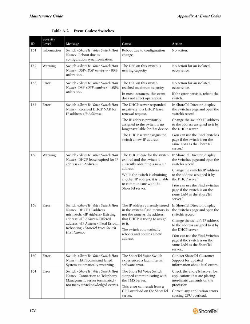
Maintenance Guide Appendix A: Event Codes
151 Information Switch <ShoreTel Voice Switch Host Name>: Reboot due to configuration synchronization.
Reboot due to configuration change.
No action.
152 Warning Switch <ShoreTel Voice Switch Host Name>: DSP< DSP number> - 80% utilization.
The DSP on this switch is nearing capacity.
No action for an isolated occurrence.
153 Error Switch <ShoreTel Voice Switch Host Name>: DSP <DSP number> - 100% utilization.
The DSP on this switch reached maximum capacity.
In most instances, this event does not affect operations.
No action for an isolated occurrence.
If the error persists, reboot the switch.
157 Error Switch <ShoreTel Voice Switch Host Name>: Received DHCP NAK for IP address <IP Address>.
The DHCP server responded negatively to a DHCP lease renewal request.
The IP address previously assigned to the switch is no longer available for that device.
The DHCP server assigns the switch a new IP address.
In ShoreTel Director, display the Switches page and open the switch’s record.
Change the switch’s IP address to the address assigned to it by the DHCP server.
(You can use the Find Switches page if the switch is on the same LAN as the ShoreTel server.)
158 Warning Switch <ShoreTel Voice Switch Host Name>: DHCP lease expired for IP address <IP Address>.
The DHCP lease for the switch expired and the switch is currently obtaining a new IP address.
While the switch is obtaining another IP address, it is unable to communicate with the ShoreTel server.
In ShoreTel Director, display the Switches page and open the switch’s record.
Change the switch’s IP Address to the address assigned it by the DHCP server.
(You can use the Find Switches page if the switch is on the same LAN as the ShoreTel server.)
159 Error Switch <ShoreTel Voice Switch Host Name>: DHCP IP address mismatch: <IP Address> Existing address: <IP Address> Offered address: <IP Address> Fatal Error... Rebooting <ShoreTel Voice Switch Host Name>.
The IP address currently stored in the switch’s flash memory is not the same as the address that DHCP is trying to assign to it.
The switch automatically reboots and obtains a new address.
In ShoreTel Director, display the Switches page and open the switch’s record.
Change the switch’s IP address to the address assigned to it by the DHCP server.
(You can use the Find Switches page if the switch is on the same LAN as the ShoreTel server.)
160 Error Switch <ShoreTel Voice Switch Host Name>: HAPI command failed. System automatically restarting.
The ShoreTel Voice Switch experienced a fatal internal software error.
Contact ShoreTel Customer Support for updated information about fatal errors.
161 Error Switch <ShoreTel Voice Switch Host Name>: Connection to Telephony Management Server terminated - too many unacknowledged events.
The ShoreTel Voice Switch stopped communicating with the TMS Server.
This error can result from a CPU overload on the ShoreTel server.
Check the ShoreTel server for applications that are placing inordinate demands on the processor.
Correct any application errors causing CPU overload.
Table A-2 Event Codes: Switches
IDSeverityLevel Message Cause Action
174
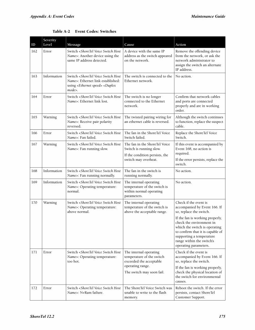
Appendix A: Event Codes Maintenance Guide
162 Error Switch <ShoreTel Voice Switch Host Name>: Another device using the same IP address detected.
A device with the same IP address as the switch appeared on the network.
Remove the offending device from the network, or ask the network administrator to assign the switch an alternate IP address.
163 Information Switch <ShoreTel Voice Switch Host Name>: Ethernet link established: using <Ethernet speed> <Duplex mode>.
The switch is connected to the Ethernet network.
No action.
164 Error Switch <ShoreTel Voice Switch Host Name>: Ethernet link lost.
The switch is no longer connected to the Ethernet network.
Confirm that network cables and ports are connected properly and are in working order.
165 Warning Switch <ShoreTel Voice Switch Host Name>: Receive pair polarity reversed.
The twisted pairing wiring for an ethernet cable is reversed.
Although the switch continues to function, replace the suspect cable.
166 Error Switch <ShoreTel Voice Switch Host Name>: Fan failed.
The fan in the ShoreTel Voice Switch failed.
Replace the ShoreTel Voice Switch.
167 Warning Switch <ShoreTel Voice Switch Host Name>: Fan running slow.
The fan in the ShoreTel Voice Switch is running slow.
If the condition persists, the switch may overheat.
If this event is accompanied by Event 168, no action is required.
If the error persists, replace the switch.
168 Information Switch <ShoreTel Voice Switch Host Name>: Fan running normally.
The fan in the switch is running normally.
No action.
169 Information Switch <ShoreTel Voice Switch Host Name>: Operating temperature: normal.
The internal operating temperature of the switch is within normal operating parameters.
No action.
170 Warning Switch <ShoreTel Voice Switch Host Name>: Operating temperature: above normal.
The internal operating temperature of the switch is above the acceptable range.
Check if the event is accompanied by Event 166. If so, replace the switch.
If the fan is working properly, check the environment in which the switch is operating to confirm that it is capable of supporting a temperature range within the switch’s operating parameters.
171 Error Switch <ShoreTel Voice Switch Host Name>: Operating temperature: too hot.
The internal operating temperature of the switch exceeded the acceptable operating range.
The switch may soon fail.
Check if the event is accompanied by Event 166. If so, replace the switch.
If the fan is working properly, check the physical location of the switch for environmental causes.
172 Error Switch <ShoreTel Voice Switch Host Name>: NvRam failure.
The ShoreTel Voice Switch was unable to write to the flash memory.
Reboot the switch. If the error persists, contact ShoreTel Customer Support.
Table A-2 Event Codes: Switches
IDSeverityLevel Message Cause Action
ShoreTel 12.2 175
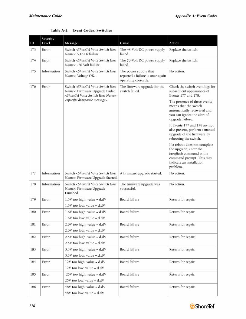
Maintenance Guide Appendix A: Event Codes
173 Error Switch <ShoreTel Voice Switch Host Name>: VTALK failure.
The 48-Volt DC power supply failed.
Replace the switch.
174 Error Switch <ShoreTel Voice Switch Host Name>: -70 Volt failure.
The 70-Volt DC power supply failed.
Replace the switch.
175 Information Switch <ShoreTel Voice Switch Host Name>: Voltage OK.
The power supply that reported a failure is once again operating correctly.
No action.
176 Error Switch <ShoreTel Voice Switch Host Name>: Firmware Upgrade Failed: <ShoreTel Voice Switch Host Name> <specific diagnostic message>.
The firmware upgrade for the switch failed.
Check the switch event logs for subsequent appearances of Events 177 and 178.
The presence of these events means that the switch automatically recovered and you can ignore the alert of upgrade failure.
If Events 177 and 178 are not also present, perform a manual upgrade of the firmware by rebooting the switch.
If a reboot does not complete the upgrade, enter the burnflash command at the command prompt. This may indicate an installation problem.
177 Information Switch <ShoreTel Voice Switch Host Name>: Firmware Upgrade Started.
A firmware upgrade started. No action.
178 Information Switch <ShoreTel Voice Switch Host Name>: Firmware Upgrade Finished
The firmware upgrade was successful.
No action.
179 Error 1.5V too high: value = d.dV
1.5V too low: value = d.dV
Board failure Return for repair.
180 Error 1.6V too high: value = d.dV
1.6V too low: value = d.dV
Board failure Return for repair.
181 Error 2.0V too high: value = d.dV
2.0V too low: value = d.dV
Board failure Return for repair.
182 Error 2.5V too high: value = d.dV
2.5V too low: value = d.dV
Board failure Return for repair.
183 Error 3.3V too high: value = d.dV
3.3V too low: value = d.dV
Board failure Return for repair.
184 Error 12V too high: value = d.dV
12V too low: value = d.dV
Board failure Return for repair.
185 Error 25V too high: value = d.dV
25V too low: value = d.dV
Board failure Return for repair.
186 Error 48V too high: value = d.dV
48V too low: value = d.dV
Board failure Return for repair.
Table A-2 Event Codes: Switches
IDSeverityLevel Message Cause Action
176
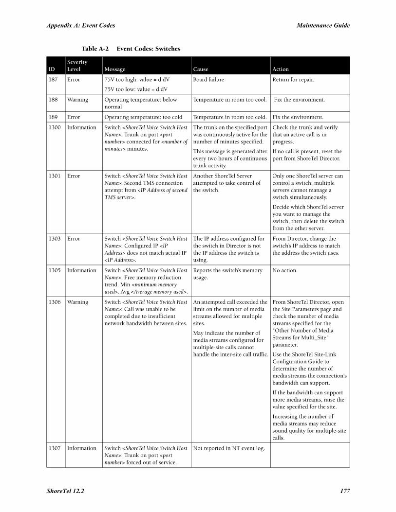
Appendix A: Event Codes Maintenance Guide
187 Error 75V too high: value = d.dV
75V too low: value = d.dV
Board failure Return for repair.
188 Warning Operating temperature: below normal
Temperature in room too cool. Fix the environment.
189 Error Operating temperature: too cold Temperature in room too cold. Fix the environment.
1300 Information Switch <ShoreTel Voice Switch Host Name>: Trunk on port <port number> connected for <number of minutes> minutes.
The trunk on the specified port was continuously active for the number of minutes specified.
This message is generated after every two hours of continuous trunk activity.
Check the trunk and verify that an active call is in progress.
If no call is present, reset the port from ShoreTel Director.
1301 Error Switch <ShoreTel Voice Switch Host Name>: Second TMS connection attempt from <IP Address of second TMS server>.
Another ShoreTel Server attempted to take control of the switch.
Only one ShoreTel server can control a switch; multiple servers cannot manage a switch simultaneously.
Decide which ShoreTel server you want to manage the switch, then delete the switch from the other server.
1303 Error Switch <ShoreTel Voice Switch Host Name>: Configured IP <IP Address> does not match actual IP <IP Address>.
The IP address configured for the switch in Director is not the IP address the switch is using.
From Director, change the switch’s IP address to match the address the switch uses.
1305 Information Switch <ShoreTel Voice Switch Host Name>: Free memory reduction trend. Min <minimum memory used>. Avg <Average memory used>.
Reports the switch’s memory usage.
No action.
1306 Warning Switch <ShoreTel Voice Switch Host Name>: Call was unable to be completed due to insufficient network bandwidth between sites.
An attempted call exceeded the limit on the number of media streams allowed for multiple sites.
May indicate the number of media streams configured for multiple-site calls cannot handle the inter-site call traffic.
From ShoreTel Director, open the Site Parameters page and check the number of media streams specified for the "Other Number of Media Streams for Multi_Site" parameter.
Use the ShoreTel Site-Link Configuration Guide to determine the number of media streams the connection's bandwidth can support.
If the bandwidth can support more media streams, raise the value specified for the site.
Increasing the number of media streams may reduce sound quality for multiple-site calls.
1307 Information Switch <ShoreTel Voice Switch Host Name>: Trunk on port <port number> forced out of service.
Not reported in NT event log.
Table A-2 Event Codes: Switches
IDSeverityLevel Message Cause Action
ShoreTel 12.2 177
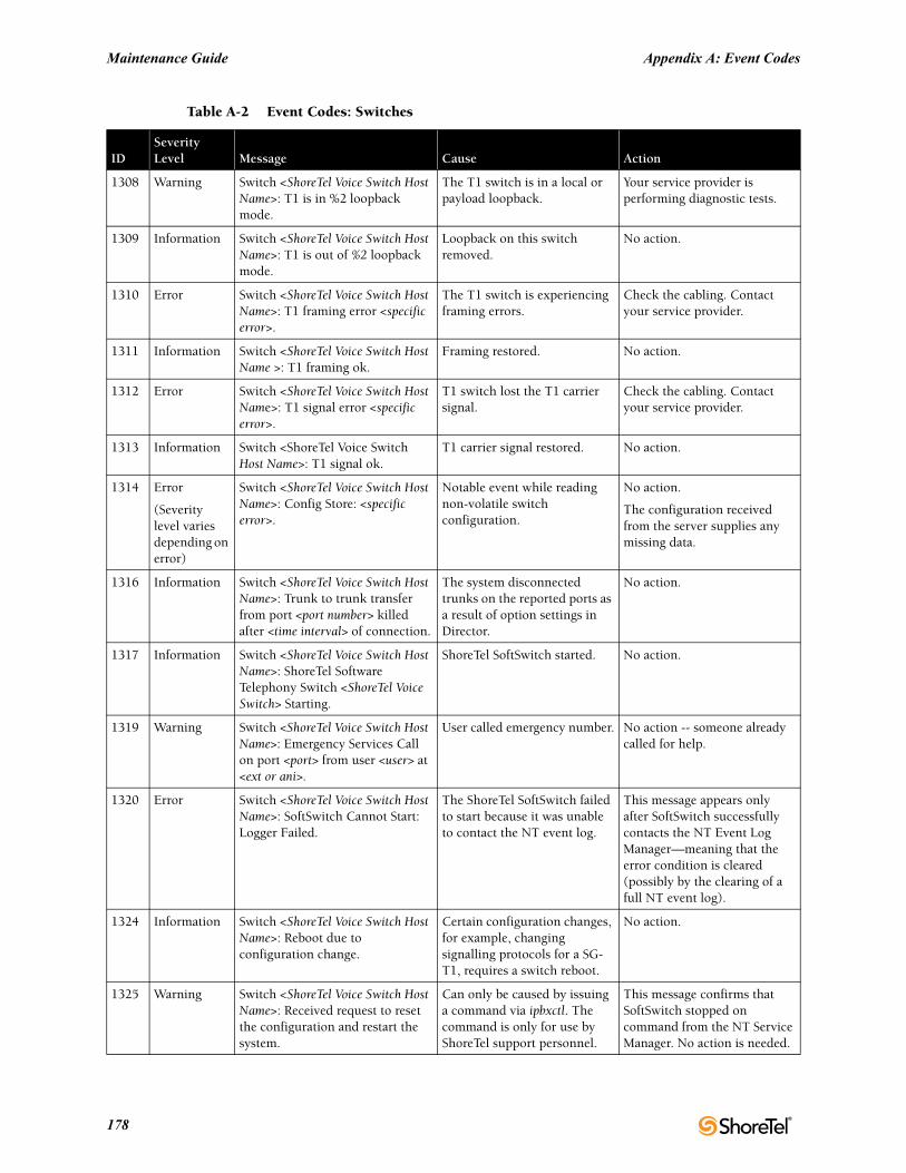
Maintenance Guide Appendix A: Event Codes
1308 Warning Switch <ShoreTel Voice Switch Host Name>: T1 is in %2 loopback mode.
The T1 switch is in a local or payload loopback.
Your service provider is performing diagnostic tests.
1309 Information Switch <ShoreTel Voice Switch Host Name>: T1 is out of %2 loopback mode.
Loopback on this switch removed.
No action.
1310 Error Switch <ShoreTel Voice Switch Host Name>: T1 framing error <specific error>.
The T1 switch is experiencing framing errors.
Check the cabling. Contact your service provider.
1311 Information Switch <ShoreTel Voice Switch Host Name >: T1 framing ok.
Framing restored. No action.
1312 Error Switch <ShoreTel Voice Switch Host Name>: T1 signal error <specific error>.
T1 switch lost the T1 carrier signal.
Check the cabling. Contact your service provider.
1313 Information Switch <ShoreTel Voice Switch Host Name>: T1 signal ok.
T1 carrier signal restored. No action.
1314 Error
(Severity level varies depending on error)
Switch <ShoreTel Voice Switch Host Name>: Config Store: <specific error>.
Notable event while reading non-volatile switch configuration.
No action.
The configuration received from the server supplies any missing data.
1316 Information Switch <ShoreTel Voice Switch Host Name>: Trunk to trunk transfer from port <port number> killed after <time interval> of connection.
The system disconnected trunks on the reported ports as a result of option settings in Director.
No action.
1317 Information Switch <ShoreTel Voice Switch Host Name>: ShoreTel Software Telephony Switch <ShoreTel Voice Switch> Starting.
ShoreTel SoftSwitch started. No action.
1319 Warning Switch <ShoreTel Voice Switch Host Name>: Emergency Services Call on port <port> from user <user> at <ext or ani>.
User called emergency number. No action -- someone already called for help.
1320 Error Switch <ShoreTel Voice Switch Host Name>: SoftSwitch Cannot Start: Logger Failed.
The ShoreTel SoftSwitch failed to start because it was unable to contact the NT event log.
This message appears only after SoftSwitch successfully contacts the NT Event Log Manager—meaning that the error condition is cleared (possibly by the clearing of a full NT event log).
1324 Information Switch <ShoreTel Voice Switch Host Name>: Reboot due to configuration change.
Certain configuration changes, for example, changing signalling protocols for a SG-T1, requires a switch reboot.
No action.
1325 Warning Switch <ShoreTel Voice Switch Host Name>: Received request to reset the configuration and restart the system.
Can only be caused by issuing a command via ipbxctl. The command is only for use by ShoreTel support personnel.
This message confirms that SoftSwitch stopped on command from the NT Service Manager. No action is needed.
Table A-2 Event Codes: Switches
IDSeverityLevel Message Cause Action
178
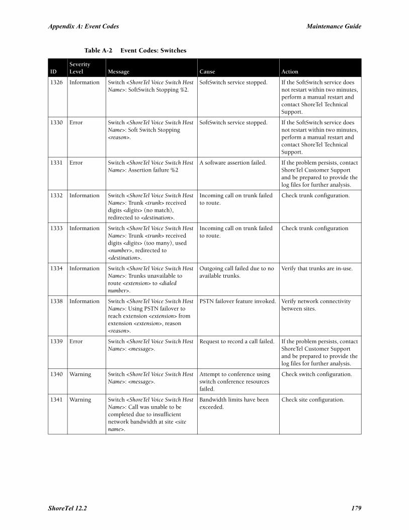
Appendix A: Event Codes Maintenance Guide
1326 Information Switch <ShoreTel Voice Switch Host Name>: SoftSwitch Stopping %2.
SoftSwitch service stopped. If the SoftSwitch service does not restart within two minutes, perform a manual restart and contact ShoreTel Technical Support.
1330 Error Switch <ShoreTel Voice Switch Host Name>: Soft Switch Stopping <reason>.
SoftSwitch service stopped. If the SoftSwitch service does not restart within two minutes, perform a manual restart and contact ShoreTel Technical Support.
1331 Error Switch <ShoreTel Voice Switch Host Name>: Assertion failure %2
A software assertion failed. If the problem persists, contact ShoreTel Customer Support and be prepared to provide the log files for further analysis.
1332 Information Switch <ShoreTel Voice Switch Host Name>: Trunk <trunk> received digits <digits> (no match), redirected to <destination>.
Incoming call on trunk failed to route.
Check trunk configuration.
1333 Information Switch <ShoreTel Voice Switch Host Name>: Trunk <trunk> received digits <digits> (too many), used <number>, redirected to <destination>.
Incoming call on trunk failed to route.
Check trunk configuration
1334 Information Switch <ShoreTel Voice Switch Host Name>: Trunks unavailable to route <extension> to <dialed number>.
Outgoing call failed due to no available trunks.
Verify that trunks are in-use.
1338 Information Switch <ShoreTel Voice Switch Host Name>: Using PSTN failover to reach extension <extension> from extension <extension>, reason <reason>.
PSTN failover feature invoked. Verify network connectivity between sites.
1339 Error Switch <ShoreTel Voice Switch Host Name>: <message>.
Request to record a call failed. If the problem persists, contact ShoreTel Customer Support and be prepared to provide the log files for further analysis.
1340 Warning Switch <ShoreTel Voice Switch Host Name>: <message>.
Attempt to conference using switch conference resources failed.
Check switch configuration.
1341 Warning Switch <ShoreTel Voice Switch Host Name>: Call was unable to be completed due to insufficient network bandwidth at site <site name>.
Bandwidth limits have been exceeded.
Check site configuration.
Table A-2 Event Codes: Switches
IDSeverityLevel Message Cause Action
ShoreTel 12.2 179
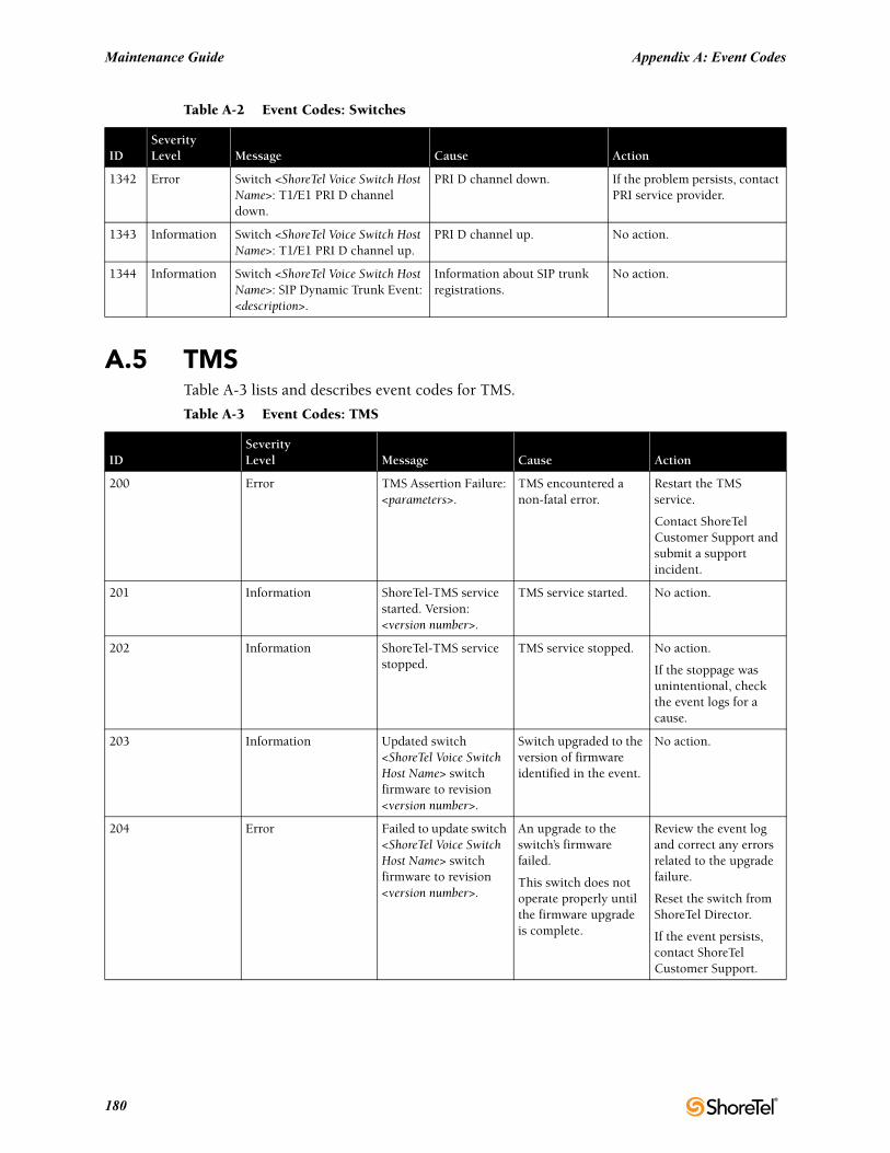
Maintenance Guide Appendix A: Event Codes
A.5 TMSTable A-3 lists and describes event codes for TMS.
1342 Error Switch <ShoreTel Voice Switch Host Name>: T1/E1 PRI D channel down.
PRI D channel down. If the problem persists, contact PRI service provider.
1343 Information Switch <ShoreTel Voice Switch Host Name>: T1/E1 PRI D channel up.
PRI D channel up. No action.
1344 Information Switch <ShoreTel Voice Switch Host Name>: SIP Dynamic Trunk Event: <description>.
Information about SIP trunk registrations.
No action.
Table A-3 Event Codes: TMS
IDSeverityLevel Message Cause Action
200 Error TMS Assertion Failure: <parameters>.
TMS encountered a non-fatal error.
Restart the TMS service.
Contact ShoreTel Customer Support and submit a support incident.
201 Information ShoreTel-TMS service started. Version: <version number>.
TMS service started. No action.
202 Information ShoreTel-TMS service stopped.
TMS service stopped. No action.
If the stoppage was unintentional, check the event logs for a cause.
203 Information Updated switch <ShoreTel Voice Switch Host Name> switch firmware to revision <version number>.
Switch upgraded to the version of firmware identified in the event.
No action.
204 Error Failed to update switch <ShoreTel Voice Switch Host Name> switch firmware to revision <version number>.
An upgrade to the switch’s firmware failed.
This switch does not operate properly until the firmware upgrade is complete.
Review the event log and correct any errors related to the upgrade failure.
Reset the switch from ShoreTel Director.
If the event persists, contact ShoreTel Customer Support.
Table A-2 Event Codes: Switches
IDSeverityLevel Message Cause Action
180
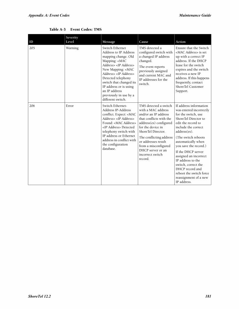
Appendix A: Event Codes Maintenance Guide
205 Warning Switch Ethernet Address to IP Address mapping change. Old Mapping: <MAC Address> <IP Address> New Mapping: <MAC Address> <IP Address> Detected telephony switch that changed its IP address or is using an IP address previously in use by a different switch.
TMS detected a configured switch with a changed IP address changed.
The event reports previously assigned and current MAC and IP addresses for the switch.
Ensure that the Switch <MAC Address> is set up with a correct IP address. If the DHCP lease for the switch expires and the switch receives a new IP address. If this happens frequently, contact ShoreTel Customer Support.
206 Error Switch Ethernet-Address IP-Address conflict. Expect: <MAC Address> <IP Address> Found: <MAC Address> <IP Address> Detected telephony switch with IP address or Ethernet address in conflict with the configuration database.
TMS detected a switch with a MAC address and/or an IP address that conflicts with the address(es) configured for the device in ShoreTel Director.
The conflicting address or addresses result from a misconfigured DHCP server or an incorrect switch record.
If address information was entered incorrectly for the switch, use ShoreTel Director to edit the record to include the correct address(es).
(The switch reboots automatically when you save the record.)
If the DHCP server assigned an incorrect IP address to the switch, correct the DHCP record and reboot the switch force reassignment of a new IP address.
Table A-3 Event Codes: TMS
IDSeverityLevel Message Cause Action
ShoreTel 12.2 181
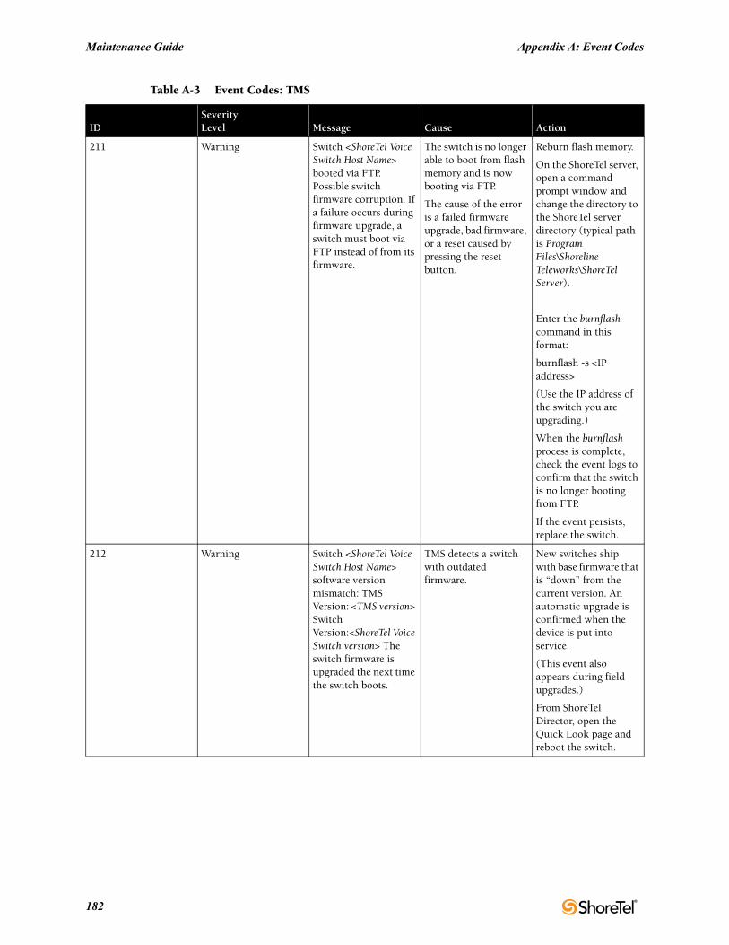
Maintenance Guide Appendix A: Event Codes
211 Warning Switch <ShoreTel Voice Switch Host Name> booted via FTP. Possible switch firmware corruption. If a failure occurs during firmware upgrade, a switch must boot via FTP instead of from its firmware.
The switch is no longer able to boot from flash memory and is now booting via FTP.
The cause of the error is a failed firmware upgrade, bad firmware, or a reset caused by pressing the reset button.
Reburn flash memory.
On the ShoreTel server, open a command prompt window and change the directory to the ShoreTel server directory (typical path is Program Files\Shoreline Teleworks\ShoreTel Server).
Enter the burnflash command in this format:
burnflash -s <IP address>
(Use the IP address of the switch you are upgrading.)
When the burnflash process is complete, check the event logs to confirm that the switch is no longer booting from FTP.
If the event persists, replace the switch.
212 Warning Switch <ShoreTel Voice Switch Host Name> software version mismatch: TMS Version: <TMS version> Switch Version:<ShoreTel Voice Switch version> The switch firmware is upgraded the next time the switch boots.
TMS detects a switch with outdated firmware.
New switches ship with base firmware that is “down” from the current version. An automatic upgrade is confirmed when the device is put into service.
(This event also appears during field upgrades.)
From ShoreTel Director, open the Quick Look page and reboot the switch.
Table A-3 Event Codes: TMS
IDSeverityLevel Message Cause Action
182
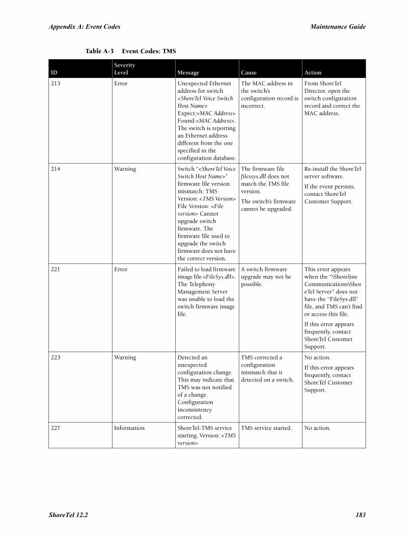
Appendix A: Event Codes Maintenance Guide
213 Error Unexpected Ethernet address for switch <ShoreTel Voice Switch Host Name> Expect:<MAC Address> Found:<MAC Address>. The switch is reporting an Ethernet address different from the one specified in the configuration database.
The MAC address in the switch’s configuration record is incorrect.
From ShoreTel Director, open the switch configuration record and correct the MAC address.
214 Warning Switch “<ShoreTel Voice Switch Host Name>” firmware file version mismatch: TMS Version: <TMS Version> File Version: <File version> Cannot upgrade switch firmware. The firmware file used to upgrade the switch firmware does not have the correct version.
The firmware file filessys.dll does not match the TMS file version.
The switch’s firmware cannot be upgraded.
Re-install the ShoreTel server software.
If the event persists, contact ShoreTel Customer Support.
221 Error Failed to load firmware image file <FileSys.dll>. The Telephony Management Server was unable to load the switch firmware image file.
A switch firmware upgrade may not be possible.
This error appears when the “\Shoreline Communications\ShoreTel Server” does not have the “FileSys.dll” file, and TMS can’t find or access this file.
If this error appears frequently, contact ShoreTel Customer Support.
223 Warning Detected an unexpected configuration change. This may indicate that TMS was not notified of a change. Configuration inconsistency corrected.
TMS corrected a configuration mismatch that it detected on a switch.
No action.
If this error appears frequently, contact ShoreTel Customer Support.
227 Information ShoreTel-TMS service starting. Version: <TMS version>
TMS service started. No action.
Table A-3 Event Codes: TMS
IDSeverityLevel Message Cause Action
ShoreTel 12.2 183
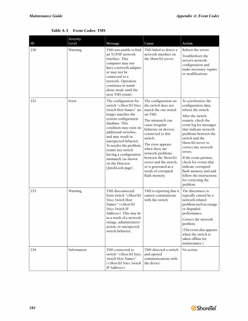
Maintenance Guide Appendix A: Event Codes
230 Warning TMS was unable to find an TCP/IP network interface. This computer may not have a network adapter or may not be connected to a network. Operation continues in stand-alone mode until the next TMS restart.
TMS failed to detect a network interface on the ShoreTel server.
Reboot the server.
Troubleshoot the server’s network configuration and make necessary repairs or modifications.
231 Error The configuration for switch “<ShoreTel Voice Switch Host Name>” no longer matches the system configuration database. This condition may exist on additional switches, and may result in unexpected behavior. To resolve the problem, restart any switch having a configuration mismatch (as shown on the Director-QuickLook page).
The configuration on the switch does not match the one stored on TMS.
The mismatch can cause irregular behavior on devices connected to this switch.
The error appears when there are network problems between the ShoreTel server and the switch, or is generated as a result of corrupted flash memory.
To synchronize the configuration data, reboot the switch.
After the switch restarts, check the event log for messages that indicate network problems between the switch and the ShoreTel server to correct any network errors.
If the event persists, check for events that indicate corrupted flash memory and and follow the instructions for correcting the problem.
233 Warning TMS disconnected from switch “<ShoreTel Voice Switch Host Name>” (<ShoreTel Voice Switch IP Address>). This may be as a result of a network outage, administrative action, or unexpected switch behavior.
TMS is reporting that it cannot communicate with the switch.
The disconnect is typically caused by a network-related problem such as outage or degraded performance.
Correct the network problem.
(The event also appears when the switch is taken offline for maintenance.)
234 Information TMS connected to switch “<ShoreTel Voice Switch Host Name>” (<ShoreTel Voice Switch IP Address>).
TMS detected a switch and opened communications with the device.
No action.
Table A-3 Event Codes: TMS
IDSeverityLevel Message Cause Action
184
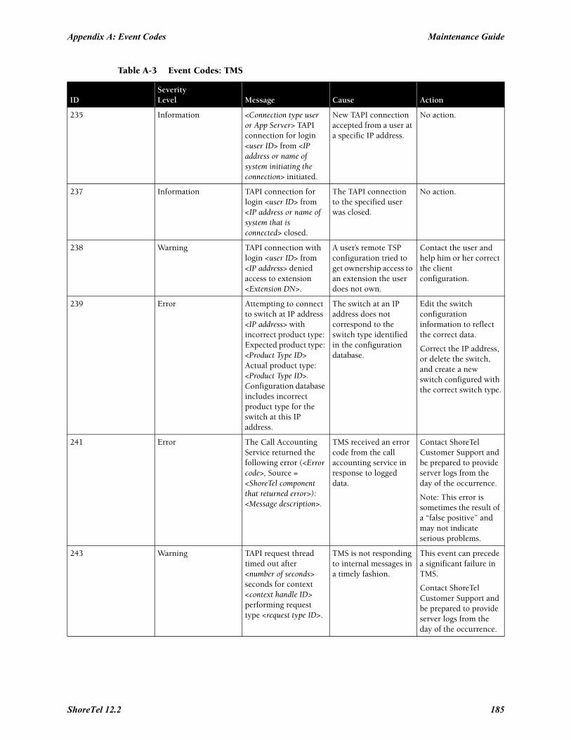
Appendix A: Event Codes Maintenance Guide
235 Information <Connection type user or App Server> TAPI connection for login <user ID> from <IP address or name of system initiating the connection> initiated.
New TAPI connection accepted from a user at a specific IP address.
No action.
237 Information TAPI connection for login <user ID> from <IP address or name of system that is connected> closed.
The TAPI connection to the specified user was closed.
No action.
238 Warning TAPI connection with login <user ID> from <IP address> denied access to extension <Extension DN>.
A user’s remote TSP configuration tried to get ownership access to an extension the user does not own.
Contact the user and help him or her correct the client configuration.
239 Error Attempting to connect to switch at IP address <IP address> with incorrect product type: Expected product type: <Product Type ID> Actual product type: <Product Type ID>. Configuration database includes incorrect product type for the switch at this IP address.
The switch at an IP address does not correspond to the switch type identified in the configuration database.
Edit the switch configuration information to reflect the correct data.
Correct the IP address, or delete the switch, and create a new switch configured with the correct switch type.
241 Error The Call Accounting Service returned the following error (<Error code>, Source = <ShoreTel component that returned error>): <Message description>.
TMS received an error code from the call accounting service in response to logged data.
Contact ShoreTel Customer Support and be prepared to provide server logs from the day of the occurrence.
Note: This error is sometimes the result of a “false positive” and may not indicate serious problems.
243 Warning TAPI request thread timed out after <number of seconds> seconds for context <context handle ID> performing request type <request type ID>.
TMS is not responding to internal messages in a timely fashion.
This event can precede a significant failure in TMS.
Contact ShoreTel Customer Support and be prepared to provide server logs from the day of the occurrence.
Table A-3 Event Codes: TMS
IDSeverityLevel Message Cause Action
ShoreTel 12.2 185
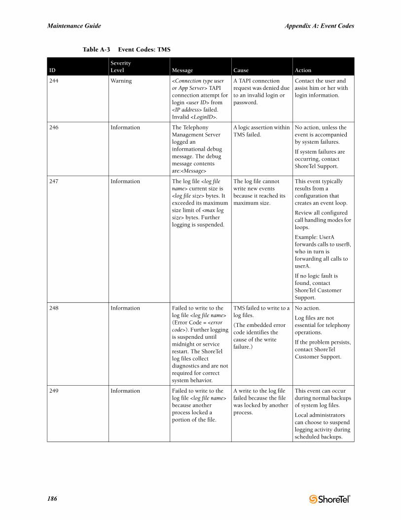
Maintenance Guide Appendix A: Event Codes
244 Warning <Connection type user or App Server> TAPI connection attempt for login <user ID> from <IP address> failed. Invalid <LoginID>.
A TAPI connection request was denied due to an invalid login or password.
Contact the user and assist him or her with login information.
246 Information The Telephony Management Server logged an informational debug message. The debug message contents are:<Message>
A logic assertion within TMS failed.
No action, unless the event is accompanied by system failures.
If system failures are occurring, contact ShoreTel Support.
247 Information The log file <log file name> current size is <log file size> bytes. It exceeded its maximum size limit of <max log size> bytes. Further logging is suspended.
The log file cannot write new events because it reached its maximum size.
This event typically results from a configuration that creates an event loop.
Review all configured call handling modes for loops.
Example: UserA forwards calls to userB, who in turn is forwarding all calls to userA.
If no logic fault is found, contact ShoreTel Customer Support.
248 Information Failed to write to the log file <log file name> (Error Code = <error code>). Further logging is suspended until midnight or service restart. The ShoreTel log files collect diagnostics and are not required for correct system behavior.
TMS failed to write to a log files.
(The embedded error code identifies the cause of the write failure.)
No action.
Log files are not essential for telephony operations.
If the problem persists, contact ShoreTel Customer Support.
249 Information Failed to write to the log file <log file name> because another process locked a portion of the file.
A write to the log file failed because the file was locked by another process.
This event can occur during normal backups of system log files.
Local administrators can choose to suspend logging activity during scheduled backups.
Table A-3 Event Codes: TMS
IDSeverityLevel Message Cause Action
186
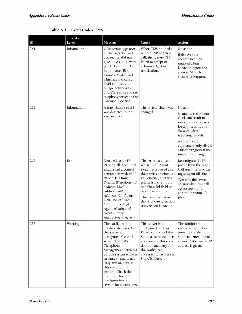
Appendix A: Event Codes Maintenance Guide
251 Information <Connection type user or App Server> TAPI connection did not give NEWCALL event (CallID = <Call ID>, Login: <user ID>, From: <IP address>). This may indicate a TAPI connectivity outage between the ShoreTel server and the telephony server on the machine specified.
When TMS notified a remote TSP of a new call, the remote TSP failed to accept or acknowledge that notification.
No action.
If the event is accompanied by unusual client behavior, report the error to ShoreTel Customer Support.
252 Information A time change of %1 was detected in the system clock.
The system clock was changed.
No action.
Changing the system clock can result in inaccurate call timers for applications and skew call detail reporting records.
A system clock adjustment only affects calls in progress at the time of the change.
253 Error Detected rogue IP Phone Call Agent that established a control connection with an IP Phone. IP Phone Details: IP Address:<IP address> MAC Address:<MAC Address> Call Agent Details:<Call Agent Details> Config’d Agent:<Configured Agent> Rogue Agent:<Rogue Agent>.
This error can occur when a Call Agent switch is replaced and the previous switch is still on-line, or if an IP phone is moved from one ShoreTel IP Phone System to another.
This error can cause the IP phone to exhibit unexpected behavior.
Reconfigure the IP phone from the rogue Call Agent or take the rogue agent off-line.
Typically this event occurs when two call agents attempt to control the same IP phone.
255 Warning The configuration database does not list this server as a configured ShoreTel server. The TMS (Telephony Management Services) on this system remains in standby and is not fully available while this condition is present. Check the ShoreTel Director configuration of servers for correctness.
This server is not configured in ShoreTel Director as one of the ShoreTel servers; or IP addresses on this server do not match any of the configured IP addresses for servers in ShoreTel Director.
The administrator must configure this server correctly in ShoreTel Director and ensure that e correct IP address is given.
Table A-3 Event Codes: TMS
IDSeverityLevel Message Cause Action
ShoreTel 12.2 187
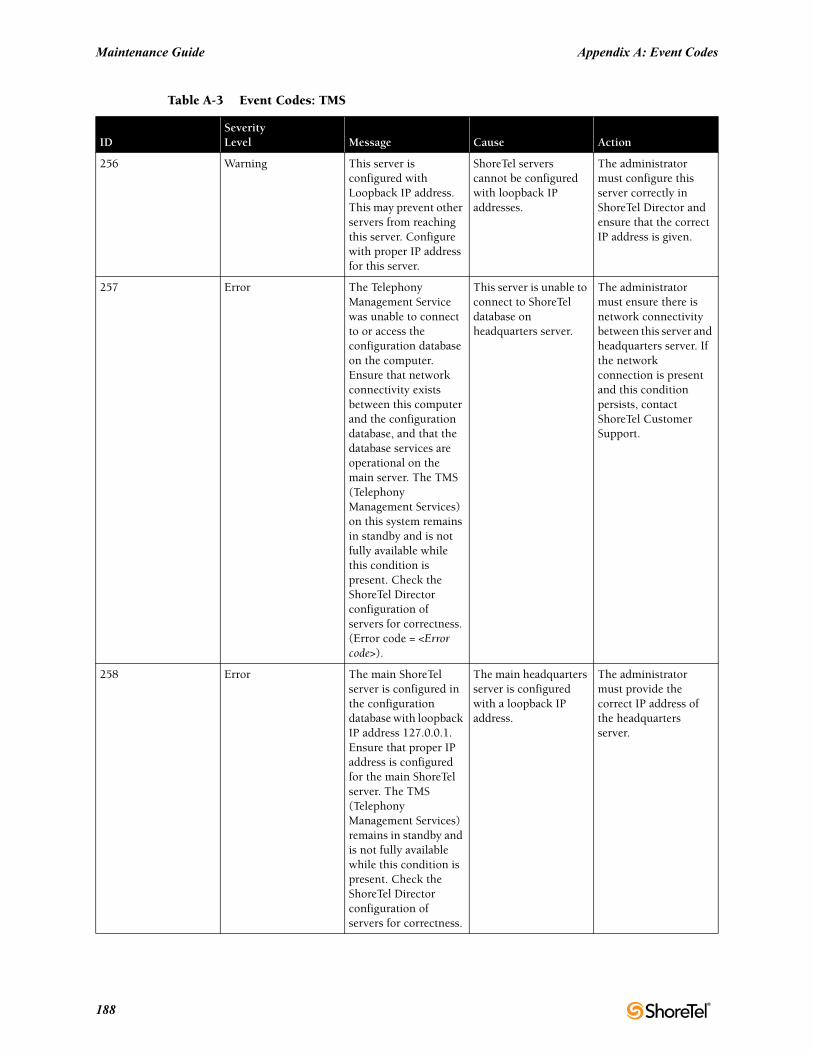
Maintenance Guide Appendix A: Event Codes
256 Warning This server is configured with Loopback IP address. This may prevent other servers from reaching this server. Configure with proper IP address for this server.
ShoreTel servers cannot be configured with loopback IP addresses.
The administrator must configure this server correctly in ShoreTel Director and ensure that the correct IP address is given.
257 Error The Telephony Management Service was unable to connect to or access the configuration database on the computer. Ensure that network connectivity exists between this computer and the configuration database, and that the database services are operational on the main server. The TMS (Telephony Management Services) on this system remains in standby and is not fully available while this condition is present. Check the ShoreTel Director configuration of servers for correctness. (Error code = <Error code>).
This server is unable to connect to ShoreTel database on headquarters server.
The administrator must ensure there is network connectivity between this server and headquarters server. If the network connection is present and this condition persists, contact ShoreTel Customer Support.
258 Error The main ShoreTel server is configured in the configuration database with loopback IP address 127.0.0.1. Ensure that proper IP address is configured for the main ShoreTel server. The TMS (Telephony Management Services) remains in standby and is not fully available while this condition is present. Check the ShoreTel Director configuration of servers for correctness.
The main headquarters server is configured with a loopback IP address.
The administrator must provide the correct IP address of the headquarters server.
Table A-3 Event Codes: TMS
IDSeverityLevel Message Cause Action
188
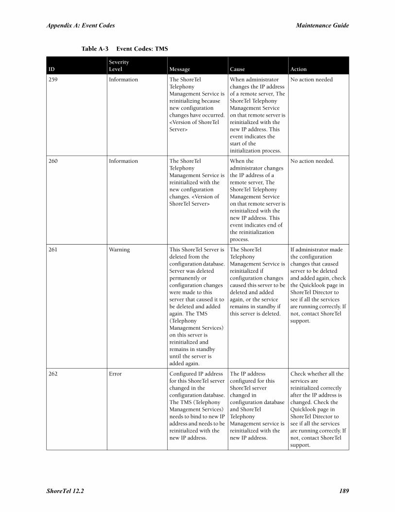
Appendix A: Event Codes Maintenance Guide
259 Information The ShoreTel Telephony Management Service is reinitializing because new configuration changes have occurred. <Version of ShoreTel Server>
When administrator changes the IP address of a remote server, The ShoreTel Telephony Management Service on that remote server is reinitialized with the new IP address. This event indicates the start of the initialization process.
No action needed
260 Information The ShoreTel Telephony Management Service is reinitialized with the new configuration changes. <Version of ShoreTel Server>
When the administrator changes the IP address of a remote server, The ShoreTel Telephony Management Service on that remote server is reinitialized with the new IP address. This event indicates end of the reinitialization process.
No action needed.
261 Warning This ShoreTel Server is deleted from the configuration database. Server was deleted permanently or configuration changes were made to this server that caused it to be deleted and added again. The TMS (Telephony Management Services) on this server is reinitialized and remains in standby until the server is added again.
The ShoreTel Telephony Management Service is reinitialized if configuration changes caused this server to be deleted and added again, or the service remains in standby if this server is deleted.
If administrator made the configuration changes that caused server to be deleted and added again, check the Quicklook page in ShoreTel Director to see if all the services are running correctly. If not, contact ShoreTel support.
262 Error Configured IP address for this ShoreTel server changed in the configuration database. The TMS (Telephony Management Services) needs to bind to new IP address and needs to be reinitialized with the new IP address.
The IP address configured for this ShoreTel server changed in configuration database and ShoreTel Telephony Management service is reinitialized with the new IP address.
Check whether all the services are reinitialized correctly after the IP address is changed. Check the Quicklook page in ShoreTel Director to see if all the services are running correctly. If not, contact ShoreTel support.
Table A-3 Event Codes: TMS
IDSeverityLevel Message Cause Action
ShoreTel 12.2 189
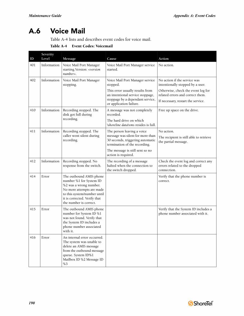
Maintenance Guide Appendix A: Event Codes
A.6 Voice MailTable A-4 lists and describes event codes for voice mail.
Table A-4 Event Codes: Voicemail
IDSeverityLevel Message Cause Action
401 Information Voice Mail Port Manager starting.Version: <version number>.
Voice Mail Port Manager service started.
No action.
402 Information Voice Mail Port Manager stopping.
Voice Mail Port Manager service stopped.
This error usually results from an intentional service stoppage, stoppage by a dependant service, or application failure.
No action if the service was intentionally stopped by a user.
Otherwise, check the event log for related errors and correct them.
If necessary, restart the service.
410 Information Recording stopped. The disk got full during recording.
A message was not completely recorded.
The hard drive on which \shoreline data\vms resides is full.
Free up space on the drive.
411 Information Recording stopped. The caller went silent during recording.
The person leaving a voice message was silent for more than 30 seconds, triggering automatic termination of the recording.
The message is still sent so no action is required.
No action.
The recipient is still able to retrieve the partial message.
412 Information Recording stopped. No response from the switch.
The recording of a message halted when the connection to the switch dropped.
Check the event log and correct any errors related to the dropped connection.
414 Error The outbound AMIS phone number %1 for System ID %2 was a wrong number. No more attempts are made to this system/number until it is corrected. Verify that the number is correct.
Verify that the phone number is correct.
415 Error The outbound AMIS phone number for System ID %1 was not found. Verify that the System ID includes a phone number associated with it.
Verify that the System ID includes a phone number associated with it.
416 Error An internal error occurred. The system was unable to delete an AMIS message from the outbound message queue. System ID%1 Mailbox ID %2 Message ID %3
190
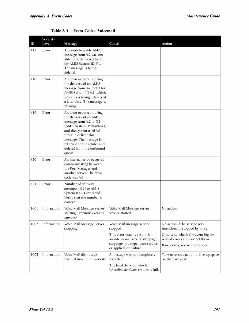
Appendix A: Event Codes Maintenance Guide
417 Error The undeliverable AMIS message from %2 was not able to be delivered to %3 for AMIS System ID %1. The message is being deleted.
418 Error An error occurred during the delivery of an AMIS message from %2 to %3 for AMIS System ID %1, which prevents retrying delivery at a later time. The message is missing.
419 Error An error occurred during the delivery of an AMIS message from %2 to %3 (AMIS System ID:mailbox), and the system tried %1 times to deliver this message. The message is returned to the sender and deleted from the outbound queue.
420 Error An internal error occurred communicating between the Port Manager and another server. The error code was %1.
421 Error Number of delivery attempts (%2) to AMIS System ID %1 exceeded. Verify that the number is correct.
1001 Information Voice Mail Message Server starting. Version: <version number>
Voice Mail Message Server service started.
No action.
1002 Information Voice Mail Message Server stopping.
Voice Mail message service stopped.
This error usually results from an intentional service stoppage, stoppage by a dependant service, or application failure.
No action if the service was intentionally stopped by a user.
Otherwise, check the event log for related errors and correct them.
If necessary, restart the service.
1003 Information Voice Mail disk usage reached maximum capacity.
A message was not completely recorded.
The hard drive on which \shoreline data\vms resides is full.
Take necessary action to free up space on the hard disk.
Table A-4 Event Codes: Voicemail
IDSeverityLevel Message Cause Action
ShoreTel 12.2 191
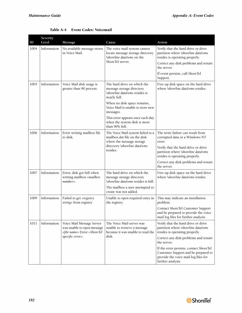
Maintenance Guide Appendix A: Event Codes
1004 Information No available message stores in Voice Mail.
The voice mail system cannot locate message storage directory \shoreline data\vms on the ShoreTel server.
Verify that the hard drive or drive partition where \shoreline data\vms resides is operating properly.
Correct any disk problems and restart the server.
If event persists, call ShoreTel Support.
1005 Information Voice Mail disk usage is greater than 90 percent.
The hard drive on which the message storage directory \shoreline data\vms resides is nearly full.
When no disk space remains, Voice Mail is unable to store new messages.
This error appears once each day when the system disk is more than 90% full.
Free up disk space on the hard drive where \shoreline data\vms resides.
1006 Information Error writing mailbox file to disk.
The Voice Mail system failed to a mailbox.dat file on the disk where the message storage directory \shoreline data\vms resides.
The write failure can result from corrupted data or a Windows NT error.
Verify that the hard drive or drive partition where \shoreline data\vms resides is operating properly.
Correct any disk problems and restart the server.
1007 Information Error, disk got full when writing mailbox <mailbox number>.
The hard drive on which the message storage directory \shoreline data\vms resides is full.
The mailbox a user attempted to create was not added.
Free up disk space on the hard drive where \shoreline data\vms resides.
1009 Information Failed to get <registry string> from registry
Unable to open required entry in the registry.
This may indicate an installation problem.
Contact ShoreTel Customer Support and be prepared to provide the voice mail log files for further analysis.
1011 Information Voice Mail Message Server was unable to open message <file name> Error <ShoreTel specific error>.
The Voice Mail server was unable to retrieve a message because it was unable to read the disk.
Verify that the hard drive or drive partition where \shoreline data\vms resides is operating properly.
Correct any disk problems and restart the server.
If the error persists, contact ShoreTel Customer Support and be prepared to provide the voice mail log files for further analysis.
Table A-4 Event Codes: Voicemail
IDSeverityLevel Message Cause Action
192
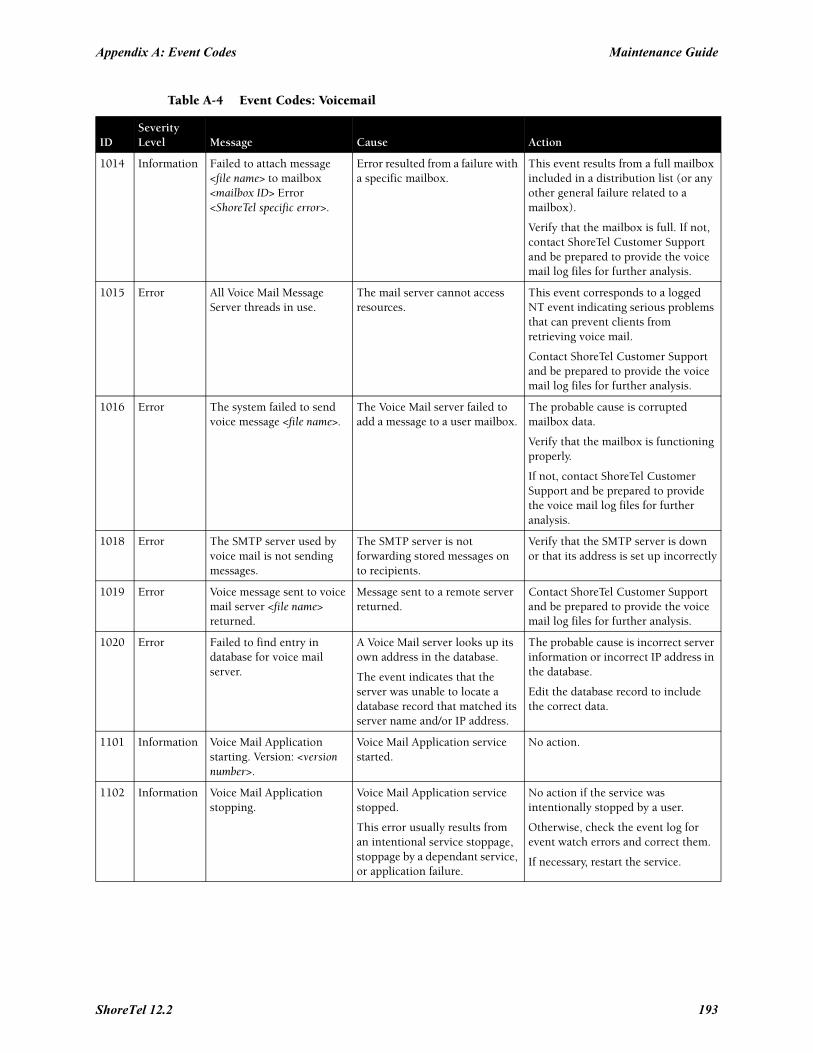
Appendix A: Event Codes Maintenance Guide
1014 Information Failed to attach message <file name> to mailbox <mailbox ID> Error <ShoreTel specific error>.
Error resulted from a failure with a specific mailbox.
This event results from a full mailbox included in a distribution list (or any other general failure related to a mailbox).
Verify that the mailbox is full. If not, contact ShoreTel Customer Support and be prepared to provide the voice mail log files for further analysis.
1015 Error All Voice Mail Message Server threads in use.
The mail server cannot access resources.
This event corresponds to a logged NT event indicating serious problems that can prevent clients from retrieving voice mail.
Contact ShoreTel Customer Support and be prepared to provide the voice mail log files for further analysis.
1016 Error The system failed to send voice message <file name>.
The Voice Mail server failed to add a message to a user mailbox.
The probable cause is corrupted mailbox data.
Verify that the mailbox is functioning properly.
If not, contact ShoreTel Customer Support and be prepared to provide the voice mail log files for further analysis.
1018 Error The SMTP server used by voice mail is not sending messages.
The SMTP server is not forwarding stored messages on to recipients.
Verify that the SMTP server is down or that its address is set up incorrectly
1019 Error Voice message sent to voice mail server <file name> returned.
Message sent to a remote server returned.
Contact ShoreTel Customer Support and be prepared to provide the voice mail log files for further analysis.
1020 Error Failed to find entry in database for voice mail server.
A Voice Mail server looks up its own address in the database.
The event indicates that the server was unable to locate a database record that matched its server name and/or IP address.
The probable cause is incorrect server information or incorrect IP address in the database.
Edit the database record to include the correct data.
1101 Information Voice Mail Application starting. Version: <version number>.
Voice Mail Application service started.
No action.
1102 Information Voice Mail Application stopping.
Voice Mail Application service stopped.
This error usually results from an intentional service stoppage, stoppage by a dependant service, or application failure.
No action if the service was intentionally stopped by a user.
Otherwise, check the event log for event watch errors and correct them.
If necessary, restart the service.
Table A-4 Event Codes: Voicemail
IDSeverityLevel Message Cause Action
ShoreTel 12.2 193
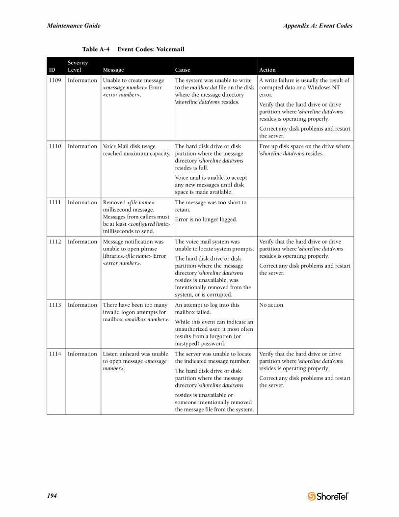
Maintenance Guide Appendix A: Event Codes
1109 Information Unable to create message <message number> Error <error number>.
The system was unable to write to the mailbox.dat file on the disk where the message directory \shoreline data\vms resides.
A write failure is usually the result of corrupted data or a Windows NT error.
Verify that the hard drive or drive partition where \shoreline data\vms resides is operating properly.
Correct any disk problems and restart the server.
1110 Information Voice Mail disk usage reached maximum capacity.
The hard disk drive or disk partition where the message directory \shoreline data\vms resides is full.
Voice mail is unable to accept any new messages until disk space is made available.
Free up disk space on the drive where \shoreline data\vms resides.
1111 Information Removed <file name> millisecond message. Messages from callers must be at least <configured limit> milliseconds to send.
The message was too short to retain.
Error is no longer logged.
1112 Information Message notification was unable to open phrase libraries.<file name> Error <error number>.
The voice mail system was unable to locate system prompts.
The hard disk drive or disk partition where the message directory \shoreline data\vms resides is unavailable, was intentionally removed from the system, or is corrupted.
Verify that the hard drive or drive partition where \shoreline data\vms resides is operating properly.
Correct any disk problems and restart the server.
1113 Information There have been too many invalid logon attempts for mailbox <mailbox number>.
An attempt to log into this mailbox failed.
While this event can indicate an unauthorized user, it most often results from a forgotten (or mistyped) password.
No action.
1114 Information Listen unheard was unable to open message <message number>.
The server was unable to locate the indicated message number.
The hard disk drive or disk partition where the message directory \shoreline data\vms
resides is unavailable or someone intentionally removed the message file from the system.
Verify that the hard drive or drive partition where \shoreline data\vms resides is operating properly.
Correct any disk problems and restart the server.
Table A-4 Event Codes: Voicemail
IDSeverityLevel Message Cause Action
194
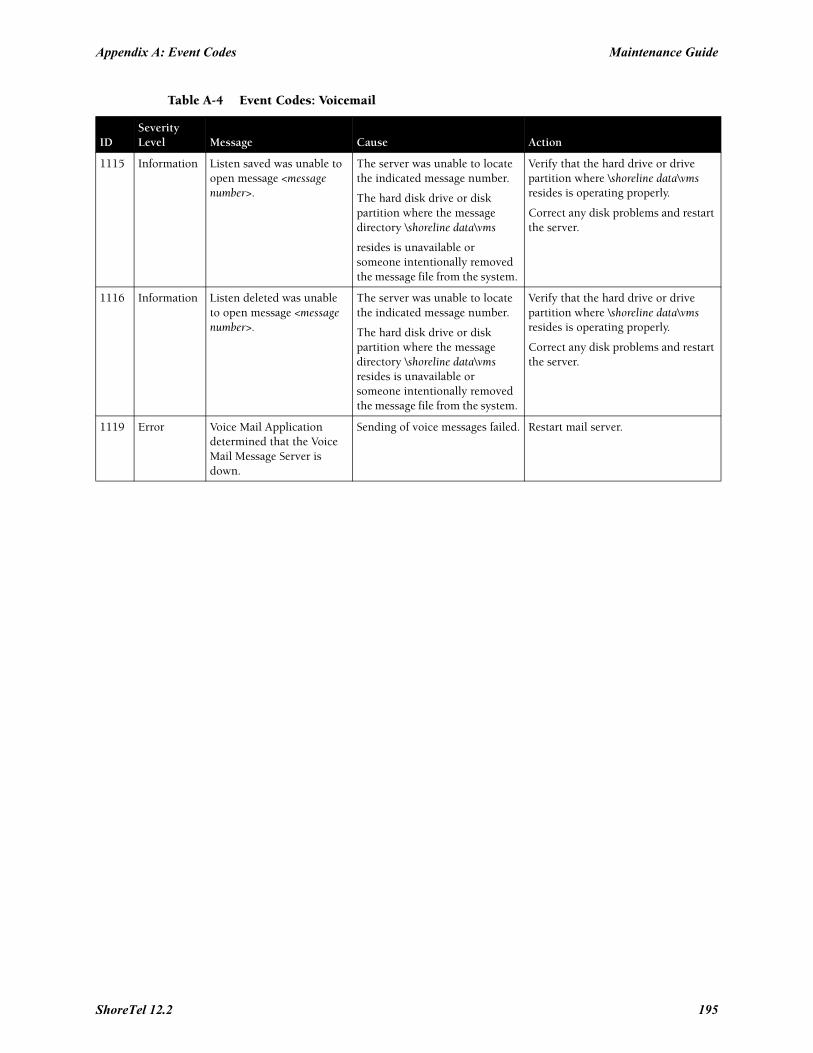
Appendix A: Event Codes Maintenance Guide
1115 Information Listen saved was unable to open message <message number>.
The server was unable to locate the indicated message number.
The hard disk drive or disk partition where the message directory \shoreline data\vms
resides is unavailable or someone intentionally removed the message file from the system.
Verify that the hard drive or drive partition where \shoreline data\vms resides is operating properly.
Correct any disk problems and restart the server.
1116 Information Listen deleted was unable to open message <message number>.
The server was unable to locate the indicated message number.
The hard disk drive or disk partition where the message directory \shoreline data\vms resides is unavailable or someone intentionally removed the message file from the system.
Verify that the hard drive or drive partition where \shoreline data\vms resides is operating properly.
Correct any disk problems and restart the server.
1119 Error Voice Mail Application determined that the Voice Mail Message Server is down.
Sending of voice messages failed. Restart mail server.
Table A-4 Event Codes: Voicemail
IDSeverityLevel Message Cause Action
ShoreTel 12.2 195
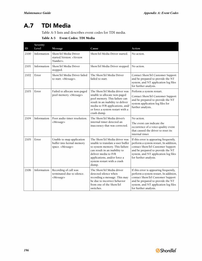
Maintenance Guide Appendix A: Event Codes
A.7 TDI MediaTable A-5 lists and describes event codes for TDI media.
Table A-5 Event Codes: TDI Media
IDSeverityLevel Message Cause Action
2100 Information ShoreTel Media Driver started.Version: <Version Number>.
ShoreTel Media Driver started. No action.
2101 Information ShoreTel Media Driver stopped.
ShoreTel Media Driver stopped. No action.
2102 Error ShoreTel Media Driver failed to start. <Message>.
The ShoreTel Media Driver failed to start.
Contact ShoreTel Customer Support and be prepared to provide the NT system, and NT application log files for further analysis.
2103 Error Failed to allocate non-paged pool memory. <Message>
The ShoreTel Media driver was unable to allocate non-paged pool memory. This failure can result in an inability to deliver media to IVR applications, and/or force a system restart with a crash dump.
Perform a system restart.
Contact ShoreTel Customer Support and be prepared to provide the NT system application log files for further analysis.
2104 Information Poor audio timer resolution. <Message>
The ShoreTel Media driver’s internal timer detected an inaccuracy that was corrected.
No action.
The event can indicate the occurrence of a voice-quality event that caused the driver to reset its internal timer.
2105 Error Unable to map application buffer into kernal memory space. <Message>
The ShoreTel Media driver was unable to translate a user buffer to system memory. This failure can result in an inability to deliver media to IVR applications, and/or force a system restart with a crash dump.
If this error is appearing frequently, perform a system restart, In addition, contact ShoreTel Customer Support and be prepared to provide the NT system, and NT application log files for further analysis.
2106 Information Recording of call was terminated due to silence. <Message>
The ShoreTel Media driver detected silence when recording a message. This may be due to incorrect behavior from one of the ShoreTel switches.
If this error is appearing frequently, perform a system restart, In addition, contact ShoreTel Customer Support and be prepared to provide the NT system, and NT application log files for further analysis.
196
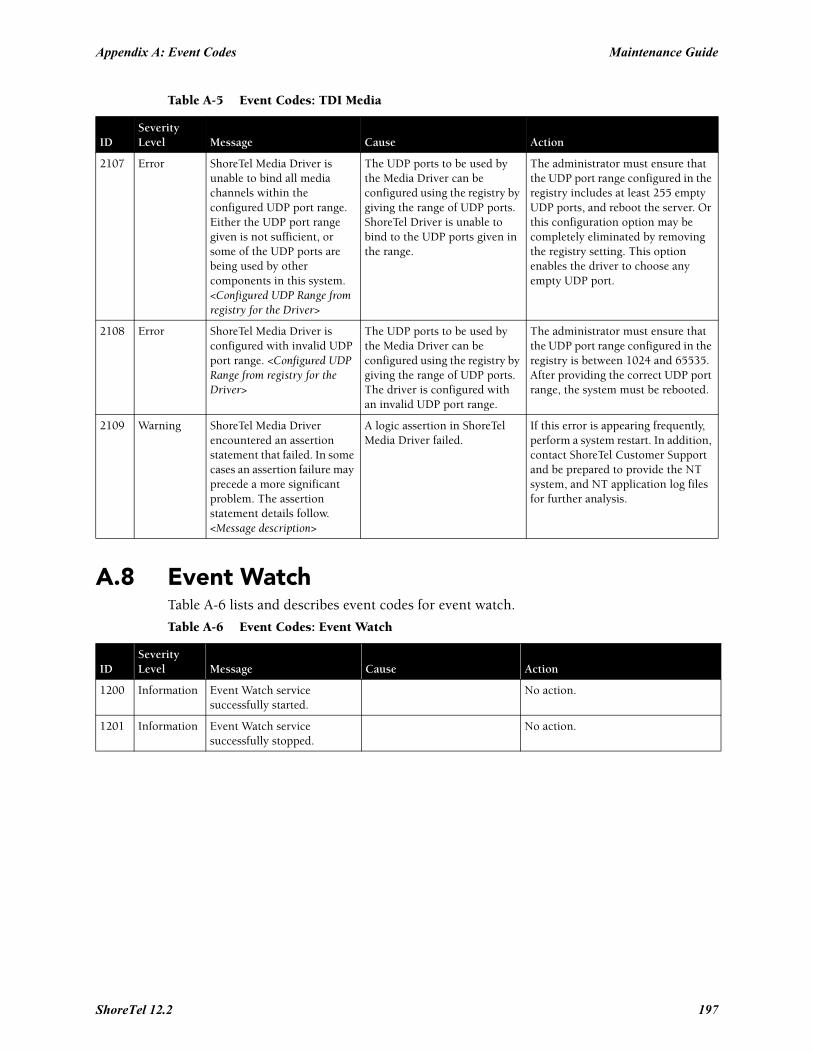
Appendix A: Event Codes Maintenance Guide
A.8 Event WatchTable A-6 lists and describes event codes for event watch.
2107 Error ShoreTel Media Driver is unable to bind all media channels within the configured UDP port range. Either the UDP port range given is not sufficient, or some of the UDP ports are being used by other components in this system. <Configured UDP Range from registry for the Driver>
The UDP ports to be used by the Media Driver can be configured using the registry by giving the range of UDP ports. ShoreTel Driver is unable to bind to the UDP ports given in the range.
The administrator must ensure that the UDP port range configured in the registry includes at least 255 empty UDP ports, and reboot the server. Or this configuration option may be completely eliminated by removing the registry setting. This option enables the driver to choose any empty UDP port.
2108 Error ShoreTel Media Driver is configured with invalid UDP port range. <Configured UDP Range from registry for the Driver>
The UDP ports to be used by the Media Driver can be configured using the registry by giving the range of UDP ports. The driver is configured with an invalid UDP port range.
The administrator must ensure that the UDP port range configured in the registry is between 1024 and 65535. After providing the correct UDP port range, the system must be rebooted.
2109 Warning ShoreTel Media Driver encountered an assertion statement that failed. In some cases an assertion failure may precede a more significant problem. The assertion statement details follow. <Message description>
A logic assertion in ShoreTel Media Driver failed.
If this error is appearing frequently, perform a system restart. In addition, contact ShoreTel Customer Support and be prepared to provide the NT system, and NT application log files for further analysis.
Table A-6 Event Codes: Event Watch
IDSeverityLevel Message Cause Action
1200 Information Event Watch service successfully started.
No action.
1201 Information Event Watch service successfully stopped.
No action.
Table A-5 Event Codes: TDI Media
IDSeverityLevel Message Cause Action
ShoreTel 12.2 197
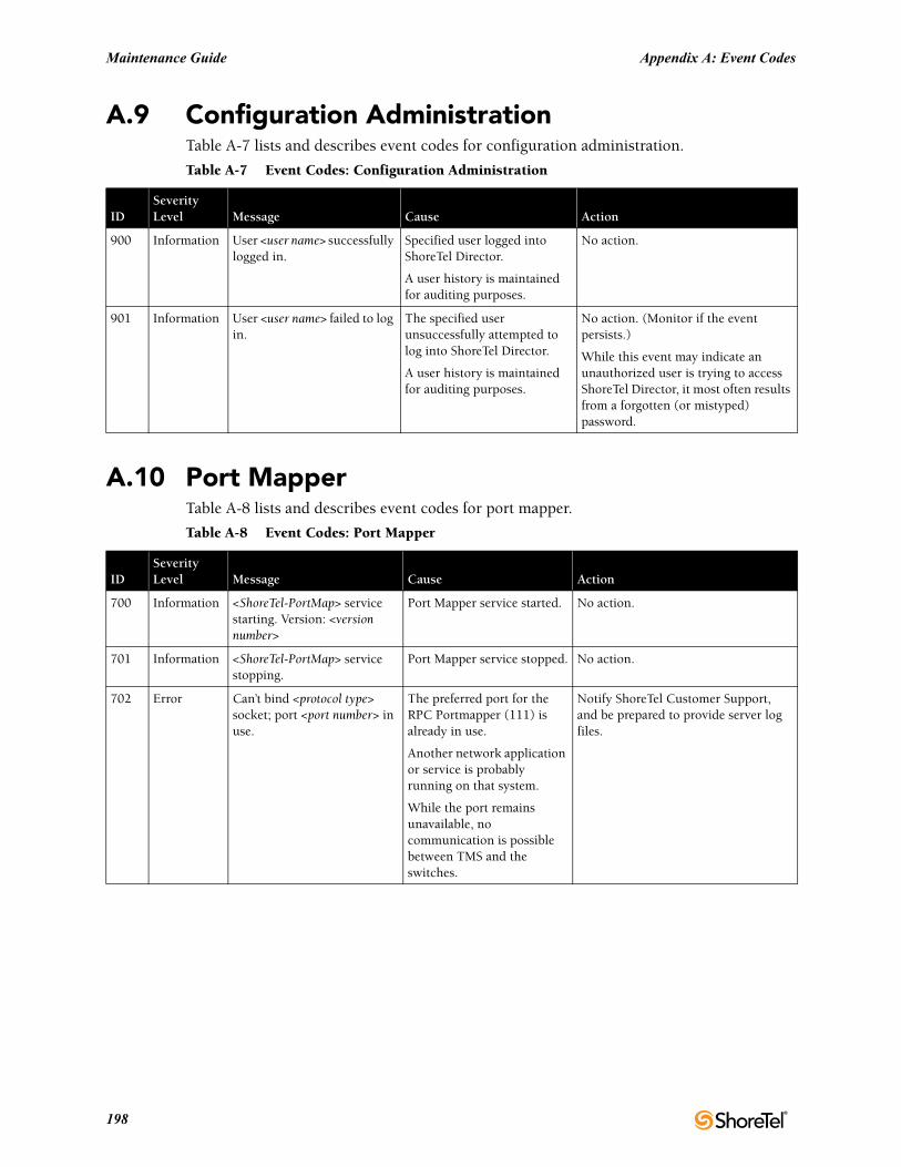
Maintenance Guide Appendix A: Event Codes
A.9 Configuration AdministrationTable A-7 lists and describes event codes for configuration administration.
A.10 Port MapperTable A-8 lists and describes event codes for port mapper.
Table A-7 Event Codes: Configuration Administration
IDSeverityLevel Message Cause Action
900 Information User <user name> successfully logged in.
Specified user logged into ShoreTel Director.
A user history is maintained for auditing purposes.
No action.
901 Information User <user name> failed to log in.
The specified user unsuccessfully attempted to log into ShoreTel Director.
A user history is maintained for auditing purposes.
No action. (Monitor if the event persists.)
While this event may indicate an unauthorized user is trying to access ShoreTel Director, it most often results from a forgotten (or mistyped) password.
Table A-8 Event Codes: Port Mapper
IDSeverityLevel Message Cause Action
700 Information <ShoreTel-PortMap> service starting. Version: <version number>
Port Mapper service started. No action.
701 Information <ShoreTel-PortMap> service stopping.
Port Mapper service stopped. No action.
702 Error Can’t bind <protocol type> socket; port <port number> in use.
The preferred port for the RPC Portmapper (111) is already in use.
Another network application or service is probably running on that system.
While the port remains unavailable, no communication is possible between TMS and the switches.
Notify ShoreTel Customer Support, and be prepared to provide server log files.
198
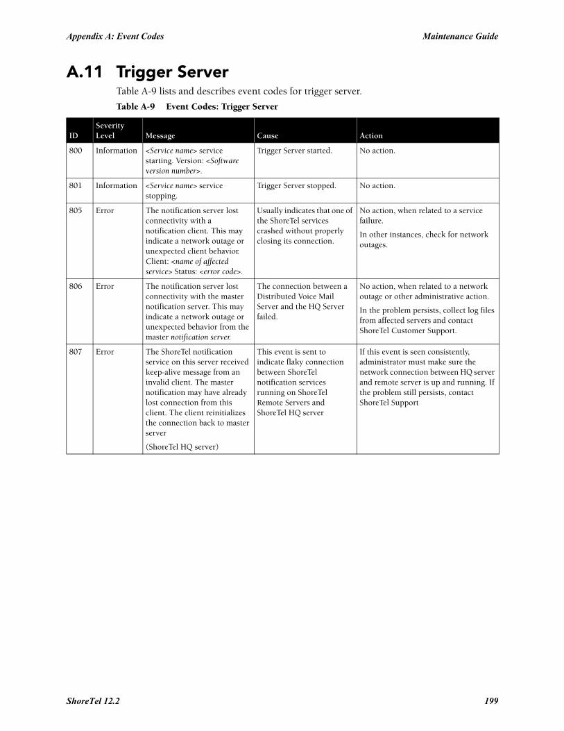
Appendix A: Event Codes Maintenance Guide
A.11 Trigger ServerTable A-9 lists and describes event codes for trigger server.
Table A-9 Event Codes: Trigger Server
IDSeverityLevel Message Cause Action
800 Information <Service name> service starting. Version: <Software version number>.
Trigger Server started. No action.
801 Information <Service name> service stopping.
Trigger Server stopped. No action.
805 Error The notification server lost connectivity with a notification client. This may indicate a network outage or unexpected client behavior. Client: <name of affected service> Status: <error code>.
Usually indicates that one of the ShoreTel services crashed without properly closing its connection.
No action, when related to a service failure.
In other instances, check for network outages.
806 Error The notification server lost connectivity with the master notification server. This may indicate a network outage or unexpected behavior from the master notification server.
The connection between a Distributed Voice Mail Server and the HQ Server failed.
No action, when related to a network outage or other administrative action.
In the problem persists, collect log files from affected servers and contact ShoreTel Customer Support.
807 Error The ShoreTel notification service on this server received keep-alive message from an invalid client. The master notification may have already lost connection from this client. The client reinitializes the connection back to master server
(ShoreTel HQ server)
This event is sent to indicate flaky connection between ShoreTel notification services running on ShoreTel Remote Servers and ShoreTel HQ server
If this event is seen consistently, administrator must make sure the network connection between HQ server and remote server is up and running. If the problem still persists, contact ShoreTel Support
ShoreTel 12.2 199
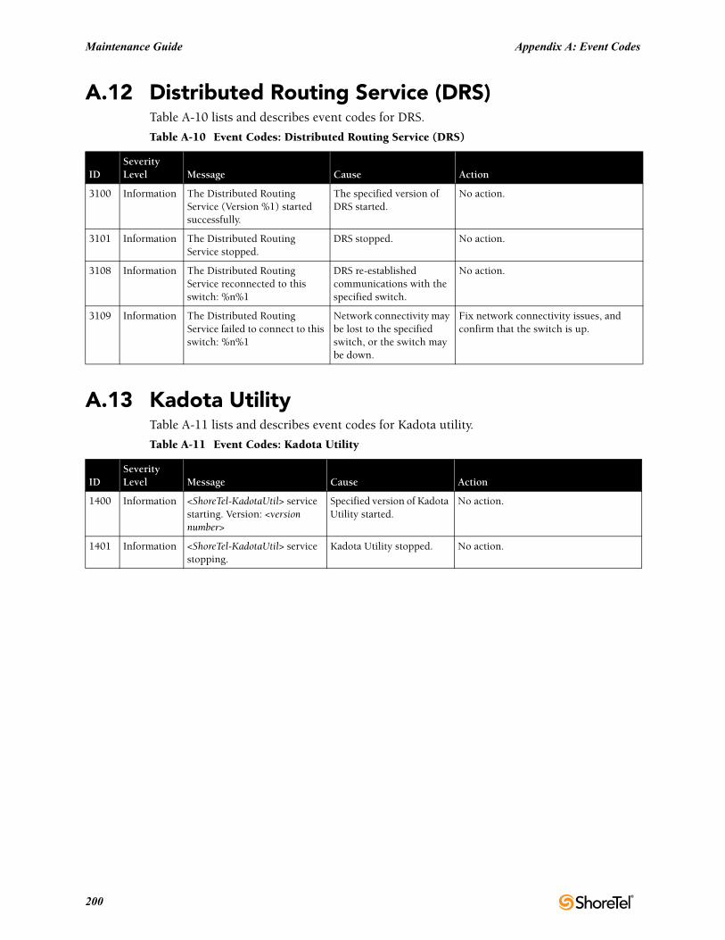
Maintenance Guide Appendix A: Event Codes
A.12 Distributed Routing Service (DRS)Table A-10 lists and describes event codes for DRS.
A.13 Kadota UtilityTable A-11 lists and describes event codes for Kadota utility.
Table A-10 Event Codes: Distributed Routing Service (DRS)
IDSeverityLevel Message Cause Action
3100 Information The Distributed Routing Service (Version %1) started successfully.
The specified version of DRS started.
No action.
3101 Information The Distributed Routing Service stopped.
DRS stopped. No action.
3108 Information The Distributed Routing Service reconnected to this switch: %n%1
DRS re-established communications with the specified switch.
No action.
3109 Information The Distributed Routing Service failed to connect to this switch: %n%1
Network connectivity may be lost to the specified switch, or the switch may be down.
Fix network connectivity issues, and confirm that the switch is up.
Table A-11 Event Codes: Kadota Utility
IDSeverityLevel Message Cause Action
1400 Information <ShoreTel-KadotaUtil> service starting. Version: <version number>
Specified version of Kadota Utility started.
No action.
1401 Information <ShoreTel-KadotaUtil> service stopping.
Kadota Utility stopped. No action.
200
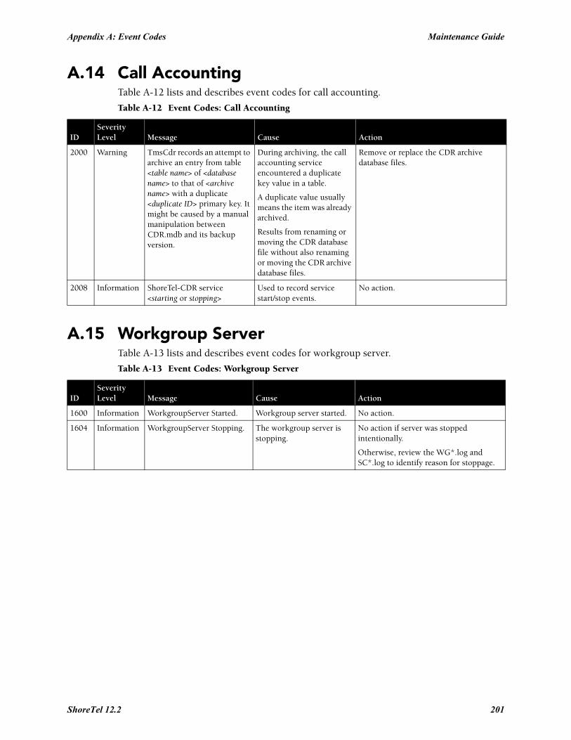
Appendix A: Event Codes Maintenance Guide
A.14 Call AccountingTable A-12 lists and describes event codes for call accounting.
A.15 Workgroup ServerTable A-13 lists and describes event codes for workgroup server.
Table A-12 Event Codes: Call Accounting
IDSeverityLevel Message Cause Action
2000 Warning TmsCdr records an attempt to archive an entry from table <table name> of <database name> to that of <archive name> with a duplicate <duplicate ID> primary key. It might be caused by a manual manipulation between CDR.mdb and its backup version.
During archiving, the call accounting service encountered a duplicate key value in a table.
A duplicate value usually means the item was already archived.
Results from renaming or moving the CDR database file without also renaming or moving the CDR archive database files.
Remove or replace the CDR archive database files.
2008 Information ShoreTel-CDR service <starting or stopping>
Used to record service start/stop events.
No action.
Table A-13 Event Codes: Workgroup Server
IDSeverityLevel Message Cause Action
1600 Information WorkgroupServer Started. Workgroup server started. No action.
1604 Information WorkgroupServer Stopping. The workgroup server is stopping.
No action if server was stopped intentionally.
Otherwise, review the WG*.log and SC*.log to identify reason for stoppage.
ShoreTel 12.2 201
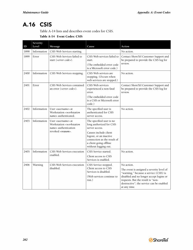
Maintenance Guide Appendix A: Event Codes
A.16 CSISTable A-14 lists and describes event codes for CSIS.
Table A-14 Event Codes: CSIS
IDSeverityLevel Message Cause Action
1898 Information CSIS Web Services starting. No action.
1899 Error CSIS Web Services failed to start (<error code>).
CSIS Web services failed to start.
(The embedded error code is a Microsoft error code.)
Contact ShoreTel Customer Support and be prepared to provide the CSIS log for review.
2400 Information CSIS Web Services stopping. CSIS Web services are stopping. (Occurs when web services are stopped.)
No action.
2401 Error CSIS Web Services contained an error (<error code>).
CSIS Web services experienced a non-fatal error.
(The embedded error code is a CSIS or Microsoft error code.)
Contact ShoreTel Customer Support and be prepared to provide the CSIS log for review.
2402 Information User <username> at Workstation <workstation name> authenticated.
The specified user is authenticated for CSIS server access.
No action.
2403 Information User <username> at Workstation <workstation name> authentication revoked <reason>.
The specified user is no long authorized for CSIS server access.
Causes include client logout, or an inactive connection as the result of a client going offline without logging out.
2405 Information CSIS Web Services execution enabled.
CSIS Service started.
Client access to CSIS Services is enabled.
No action.
2406 Warning CSIS Web Services execution disabled.
CSIS Service stopped. Client access to CSIS Services is disabled.
(Web services continue to run.)
No action.
The event is assigned a severity level of “warning,” because a service (CSIS) is disabled and no longer accept logins or requests. But the result is “non-destructive”; the service can be enabled at any time.
202
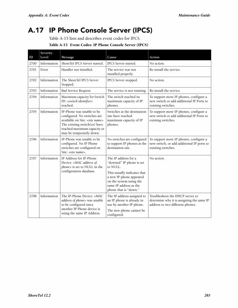
Appendix A: Event Codes Maintenance Guide
A.17 IP Phone Console Server (IPCS)Table A-15 lists and describes event codes for IPCS.
Table A-15 Event Codes: IP Phone Console Server (IPCS)
IDSeverityLevel Message Cause Action
2700 Information ShoreTel IPCS Server started. IPCS Server started. No action.
2701 Error Handler not installed. The service was not installed properly.
Re-install the service.
2702 Information The ShoreTel IPCS Server Stopped.
IPCS Server stopped. No action.
2703 Information Bad Service Request. The service is not running. Re-install the service.
2704 Information Maximum capacity for Switch ID: <switch identifier> reached.
The switch reached its maximum capacity of IP phones.
To support more IP phones, configure a new switch or add additional IP Ports to existing switches.
2705 Information IP-Phone was unable to be configured. No switches are available on Site: <site name> The existing switch(es) have reached maximum capacity or may be temporarily down.
Switches at the destination site have reached maximum capacity of IP phones.
To support more IP phones, configure a new switch or add additional IP Ports to existing switches.
2706 Information IP-Phone was unable to be configured. No IP Phone switches are configured on Site: <site name>.
No switches are configured to support IP phones at the destination site.
To support more IP phones, configure a new switch, or add additional IP ports to existing switches.
2707 Information IP Address for IP-Phone Device: <MAC address of phone> is set to NULL in the configuration database.
The IP address for a “downed” IP phone is set to NULL.
This usually indicates that a new IP phone appeared on the system using the same IP address as the phone that is “down.”
No action.
2708 Information The IP-Phone Device: <MAC address of phone> was unable to be configured since another IP Phone device is using the same IP Address.
The IP address assigned to an IP phone is already in use by another IP phone.
The new phone cannot be configured.
Troubleshoot the DHCP server to determine why it is assigning the same IP address to two different phones.
ShoreTel 12.2 203
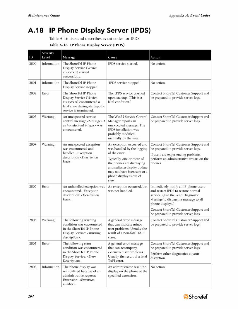
Maintenance Guide Appendix A: Event Codes
A.18 IP Phone Display Server (IPDS)Table A-16 lists and describes event codes for IPDS.
Table A-16 IP Phone Display Server (IPDS)
IDSeverityLevel Message Cause Action
2800 Information The ShoreTel IP Phone Display Service (Version x.x.xxxx.x) started successfully.
IPDS service started. No action.
2801 Information The ShoreTel IP Phone Display Service stopped.
IPDS service stopped. No action.
2802 Error The ShoreTel IP Phone Display Service (Version x.x.xxxx.x) encountered a fatal error during startup; the service is terminated.
The IPDS service crashed upon startup. (This is a fatal condition.)
Contact ShoreTel Customer Support and be prepared to provide server logs.
2803 Warning An unexpected service control message <Message ID as hexadecimal integer> was encountered.
The Win32 Service Control Manager reports an unexpected message. The IPDS installation was probably modified manually by the user.
Contact ShoreTel Customer Support and be prepared to provide server logs.
2804 Warning An unexpected exception was encountered and handled. Exception description <Description here>.
An exception occurred and was handled by the logging of the error.
Typically, one or more of the phones are displaying anomalies; a display update may not have been sent or a phone display is out of sync.
Contact ShoreTel Customer Support and be prepared to provide server logs.
If users are experiencing problems, perform an administrative restart on the phones.
2805 Error An unhandled exception was encountered. Exception description: <Description here>.
An exception occurred, but was not handled.
Immediately notify all IP phone users and restart IPDS to restore normal service. (Use the Send Diagnostic Message to dispatch a message to all phone displays.)
Contact ShoreTel Customer Support and be prepared to provide server logs.
2806 Warning The following warning condition was encountered in the ShoreTel IP Phone Display Service: <Warning description>.
A general error message that can indicate minor user problems. Usually the result of a non-fatal TAPI error.
Contact ShoreTel Customer Support and be prepared to provide server logs.
2807 Error The following error condition was encountered in the ShoreTel IP Phone Display Service: <Error Description>.
A general error message that can accompany extensive user problems. Usually the result of a fatal TAPI error.
Contact ShoreTel Customer Support and be prepared to provide server logs.
Perform other diagnostics at your discretion.
2808 Information The phone display was reinitialized because of an administrative request: Extension: <Extension number>.
An administrator reset the display on the phone at the specified extension.
No action.
204
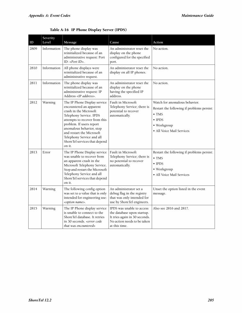
Appendix A: Event Codes Maintenance Guide
2809 Information The phone display was reinitialized because of an administrative request: Port ID: <Port ID>.
An administrator reset the display on the phone configured for the specified port.
No action.
2810 Information All phone displays were reinitialized because of an administrative request.
An administrator reset the display on all IP phones.
No action.
2811 Information The phone display was reinitialized because of an administrative request: IP Address <IP address>.
An administrator reset the display on the phone having the specified IP address.
No action.
2812 Warning The IP Phone Display service encountered an apparent crash in the Microsoft Telephony Service. IPDS attempts to recover from this problem. If users report anomalous behavior, stop and restart the Microsoft Telephony Service and all ShoreTel services that depend on it.
Fault in Microsoft Telephony Service; there is potential to recover automatically.
Watch for anomalous behavior.
Restart the following if problems persist:
• TMS
• IPDS
• Workgroup
• All Voice Mail Services
2813 Error The IP Phone Display service was unable to recover from an apparent crash in the Microsoft Telephony Service. Stop and restart the Microsoft Telephony Service and all ShoreTel services that depend on it.
Fault in Microsoft Telephony Service; there is no potential to recover automatically.
Restart the following if problems persist:
• TMS
• IPDS
• Workgroup
• All Voice Mail Services
2814 Warning The following config option was set to a value that is only intended for engineering use: <option name>.
An administrator set a debug flag in the registry that was only intended for use by ShoreTel engineers.
Unset the option listed in the event message.
2815 Warning The IP Phone display service is unable to connect to the ShoreTel database. It retries in 30 seconds. <error code that was encountered>
IPDS was unable to access the database upon startup. It tries again in 30 seconds. No action needs to be taken at this time.
Also see 2816 and 2817.
Table A-16 IP Phone Display Server (IPDS)
IDSeverityLevel Message Cause Action
ShoreTel 12.2 205
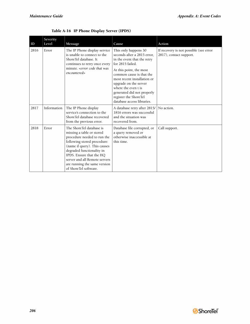
Maintenance Guide Appendix A: Event Codes
2816 Error The IP Phone display service is unable to connect to the ShoreTel database. It continues to retry once every minute. <error code that was encountered>
This only happens 30 seconds after a 2815 error, in the event that the retry for 2815 failed.
At this point, the most common cause is that the most recent installation or upgrade on the server where the even t is generated did not properly register the ShoreTel database access libraries.
If recovery is not possible (see error 2817), contact support.
2817 Information The IP Phone display service’s connection to the ShoreTel database recovered from the previous error.
A database retry after 2815/1816 errors was successful and the situation was recovered from.
No action.
2818 Error The ShoreTel database is missing a table or stored procedure needed to run the following stored procedure: (name if query). This causes degraded functionality in IPDS. Ensure that the HQ server and all Remote servers are running the same version of ShoreTel software.
Database file corrupted, or a query removed or otherwise inaccessible at this time.
Call support.
Table A-16 IP Phone Display Server (IPDS)
IDSeverityLevel Message Cause Action
206
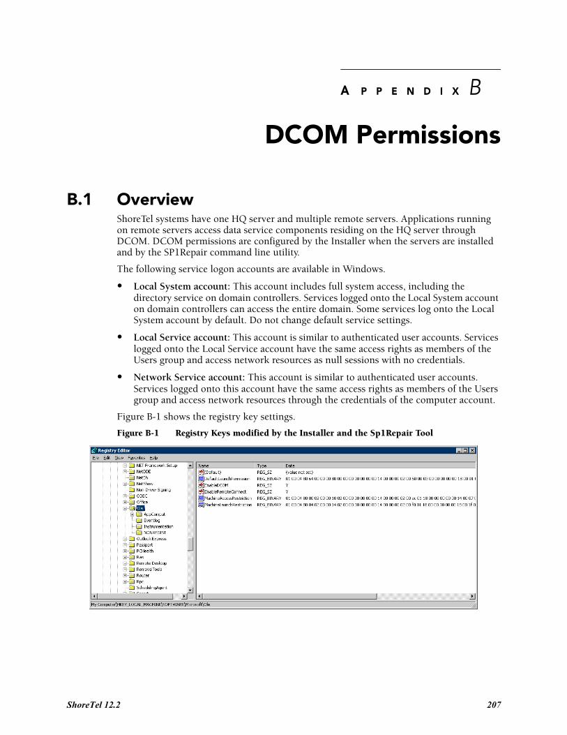
A P P E N D I X B
DCOM Permissions
B.1 OverviewShoreTel systems have one HQ server and multiple remote servers. Applications running on remote servers access data service components residing on the HQ server through DCOM. DCOM permissions are configured by the Installer when the servers are installed and by the SP1Repair command line utility.
The following service logon accounts are available in Windows.
• Local System account: This account includes full system access, including the directory service on domain controllers. Services logged onto the Local System account on domain controllers can access the entire domain. Some services log onto the Local System account by default. Do not change default service settings.
• Local Service account: This account is similar to authenticated user accounts. Services logged onto the Local Service account have the same access rights as members of the Users group and access network resources as null sessions with no credentials.
• Network Service account: This account is similar to authenticated user accounts. Services logged onto this account have the same access rights as members of the Users group and access network resources through the credentials of the computer account.
Figure B-1 shows the registry key settings.
Figure B-1 Registry Keys modified by the Installer and the Sp1Repair Tool
ShoreTel 12.2 207
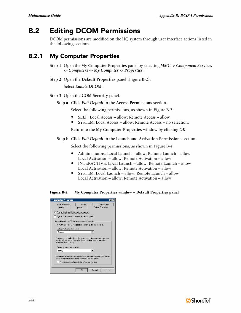
Maintenance Guide Appendix B: DCOM Permissions
B.2 Editing DCOM PermissionsDCOM permissions are modified on the HQ system through user interface actions listed in the following sections.
B.2.1 My Computer PropertiesStep 1 Open the My Computer Properties panel by selecting MMC -> Component Services
-> Computers -> My Computer -> Properties.
Step 2 Open the Default Properties panel (Figure B-2).
Select Enable DCOM.
Step 3 Open the COM Security panel.
Step a Click Edit Default in the Access Permissions section.
Select the following permissions, as shown in Figure B-3:
• SELF: Local Access – allow; Remote Access – allow• SYSTEM: Local Access – allow; Remote Access – no selection.
Return to the My Computer Properties window by clicking OK.
Step b Click Edit Default in the Launch and Activation Permissions section.
Select the following permissions, as shown in Figure B-4:
• Administrators: Local Launch – allow; Remote Launch – allowLocal Activation – allow; Remote Activation – allow
• INTERACTIVE: Local Launch – allow; Remote Launch – allowLocal Activation – allow; Remote Activation – allow
• SYSTEM: Local Launch – allow; Remote Launch – allowLocal Activation – allow; Remote Activation – allow
Figure B-2 My Computer Properties window – Default Properties panel
208
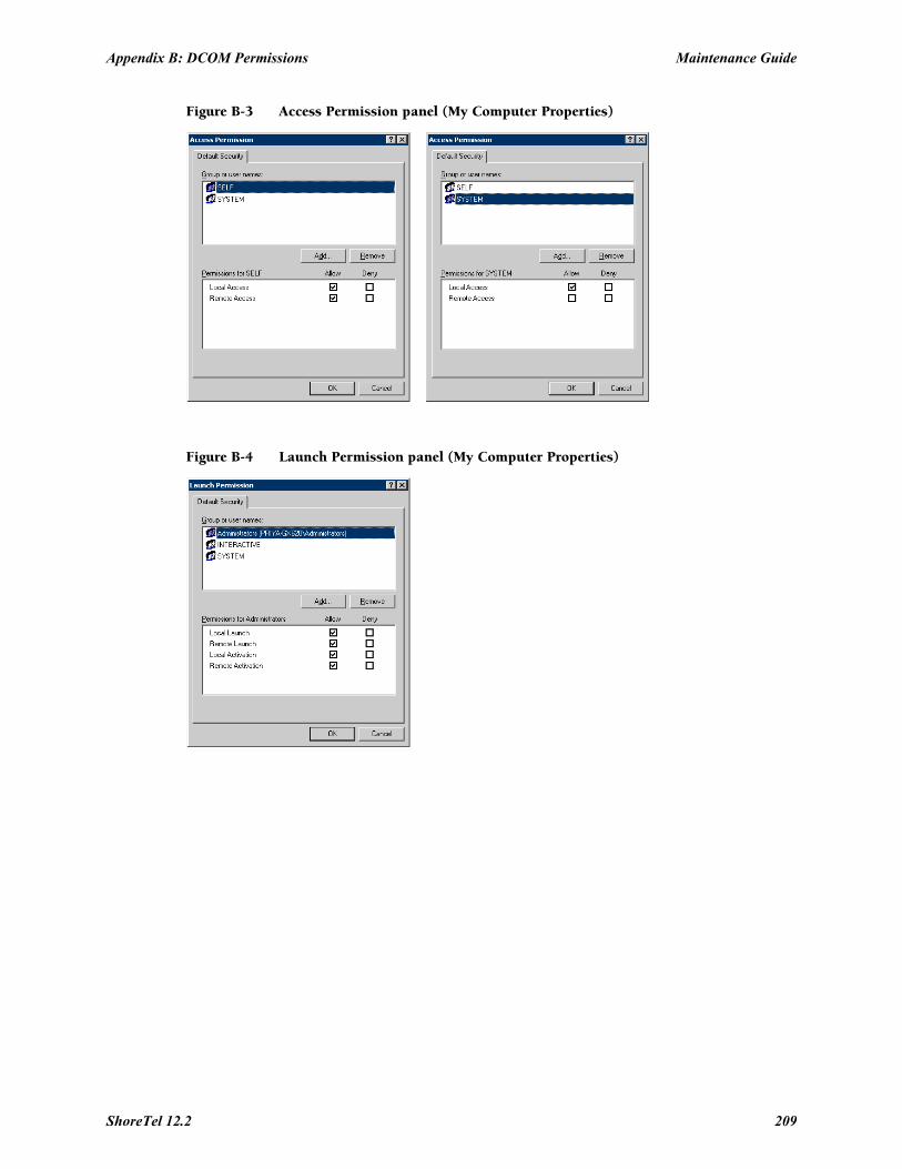
Appendix B: DCOM Permissions Maintenance Guide
Figure B-3 Access Permission panel (My Computer Properties)
Figure B-4 Launch Permission panel (My Computer Properties)
ShoreTel 12.2 209
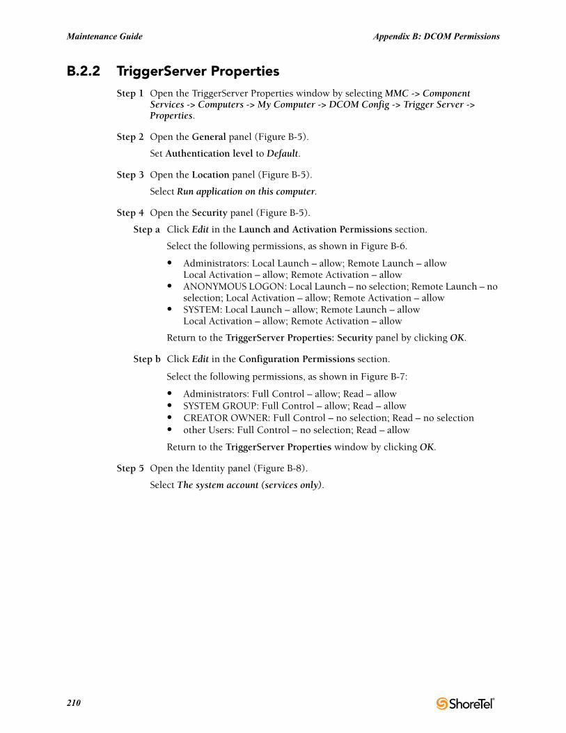
Maintenance Guide Appendix B: DCOM Permissions
B.2.2 TriggerServer PropertiesStep 1 Open the TriggerServer Properties window by selecting MMC -> Component
Services -> Computers -> My Computer -> DCOM Config -> Trigger Server -> Properties.
Step 2 Open the General panel (Figure B-5).
Set Authentication level to Default.
Step 3 Open the Location panel (Figure B-5).
Select Run application on this computer.
Step 4 Open the Security panel (Figure B-5).
Step a Click Edit in the Launch and Activation Permissions section.
Select the following permissions, as shown in Figure B-6.
• Administrators: Local Launch – allow; Remote Launch – allowLocal Activation – allow; Remote Activation – allow
• ANONYMOUS LOGON: Local Launch – no selection; Remote Launch – no selection; Local Activation – allow; Remote Activation – allow
• SYSTEM: Local Launch – allow; Remote Launch – allowLocal Activation – allow; Remote Activation – allow
Return to the TriggerServer Properties: Security panel by clicking OK.
Step b Click Edit in the Configuration Permissions section.
Select the following permissions, as shown in Figure B-7:
• Administrators: Full Control – allow; Read – allow• SYSTEM GROUP: Full Control – allow; Read – allow• CREATOR OWNER: Full Control – no selection; Read – no selection• other Users: Full Control – no selection; Read – allow
Return to the TriggerServer Properties window by clicking OK.
Step 5 Open the Identity panel (Figure B-8).
Select The system account (services only).
210
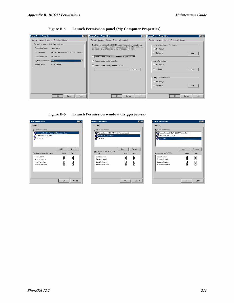
Appendix B: DCOM Permissions Maintenance Guide
Figure B-5 Launch Permission panel (My Computer Properties)
Figure B-6 Launch Permission window (TriggerServer)
ShoreTel 12.2 211
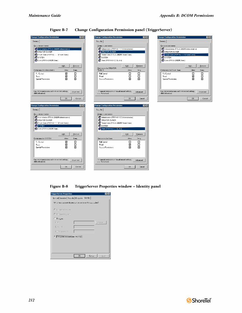
Maintenance Guide Appendix B: DCOM Permissions
Figure B-7 Change Configuration Permission panel (TriggerServer)
Figure B-8 TriggerServer Properties window – Identity panel
212
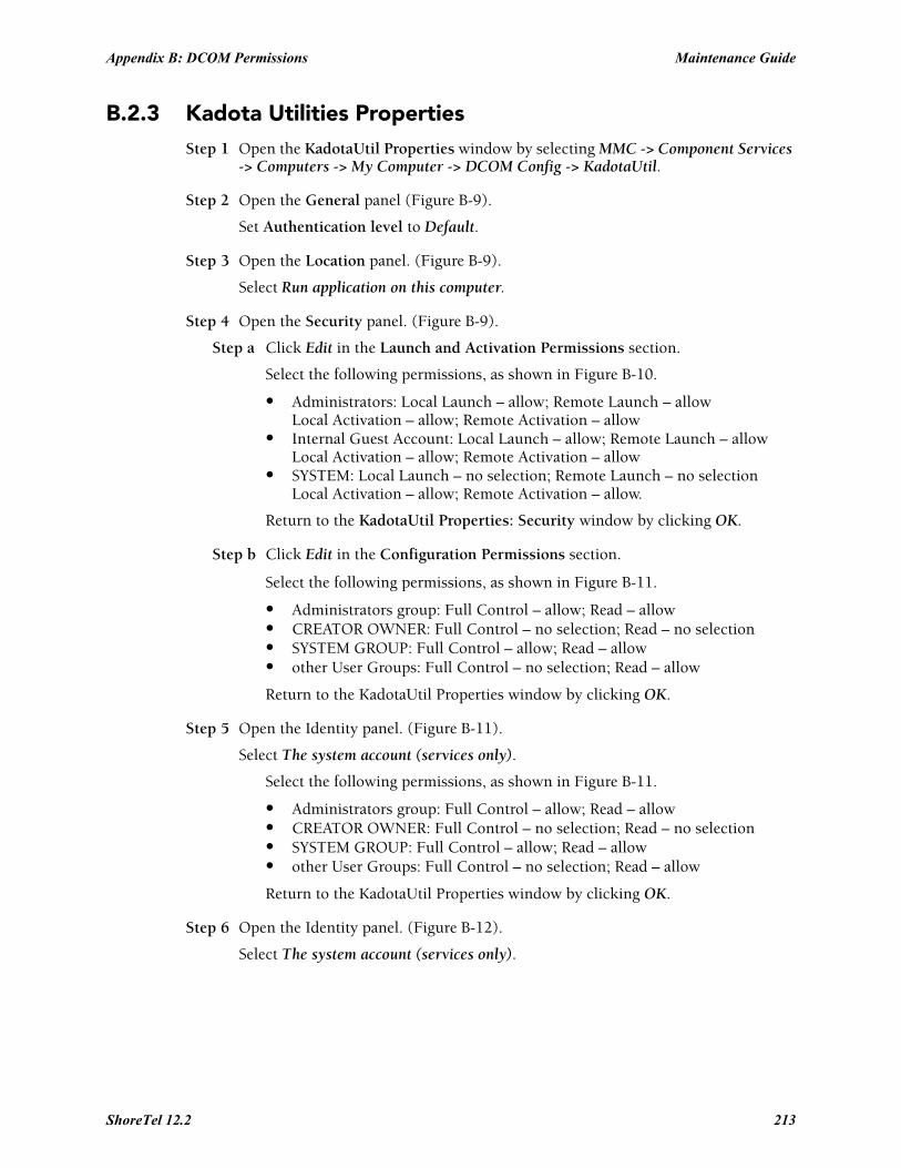
Appendix B: DCOM Permissions Maintenance Guide
B.2.3 Kadota Utilities PropertiesStep 1 Open the KadotaUtil Properties window by selecting MMC -> Component Services
-> Computers -> My Computer -> DCOM Config -> KadotaUtil.
Step 2 Open the General panel (Figure B-9).
Set Authentication level to Default.
Step 3 Open the Location panel. (Figure B-9).
Select Run application on this computer.
Step 4 Open the Security panel. (Figure B-9).
Step a Click Edit in the Launch and Activation Permissions section.
Select the following permissions, as shown in Figure B-10.
• Administrators: Local Launch – allow; Remote Launch – allowLocal Activation – allow; Remote Activation – allow
• Internal Guest Account: Local Launch – allow; Remote Launch – allowLocal Activation – allow; Remote Activation – allow
• SYSTEM: Local Launch – no selection; Remote Launch – no selectionLocal Activation – allow; Remote Activation – allow.
Return to the KadotaUtil Properties: Security window by clicking OK.
Step b Click Edit in the Configuration Permissions section.
Select the following permissions, as shown in Figure B-11.
• Administrators group: Full Control – allow; Read – allow• CREATOR OWNER: Full Control – no selection; Read – no selection• SYSTEM GROUP: Full Control – allow; Read – allow• other User Groups: Full Control – no selection; Read – allow
Return to the KadotaUtil Properties window by clicking OK.
Step 5 Open the Identity panel. (Figure B-11).
Select The system account (services only).
Select the following permissions, as shown in Figure B-11.
• Administrators group: Full Control – allow; Read – allow• CREATOR OWNER: Full Control – no selection; Read – no selection• SYSTEM GROUP: Full Control – allow; Read – allow• other User Groups: Full Control – no selection; Read – allow
Return to the KadotaUtil Properties window by clicking OK.
Step 6 Open the Identity panel. (Figure B-12).
Select The system account (services only).
ShoreTel 12.2 213
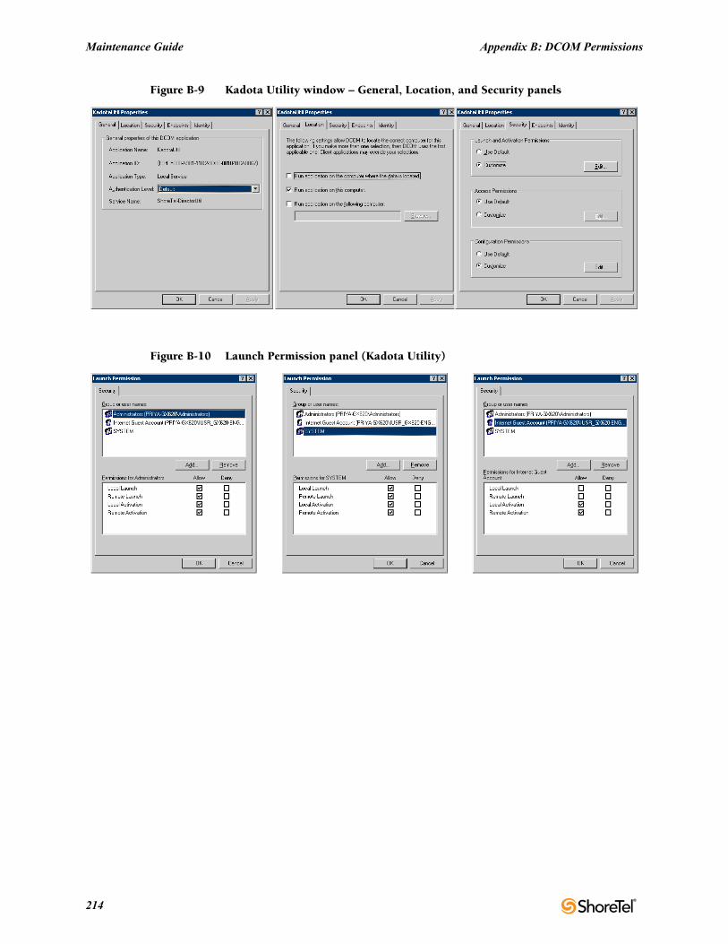
Maintenance Guide Appendix B: DCOM Permissions
Figure B-9 Kadota Utility window – General, Location, and Security panels
Figure B-10 Launch Permission panel (Kadota Utility)
214
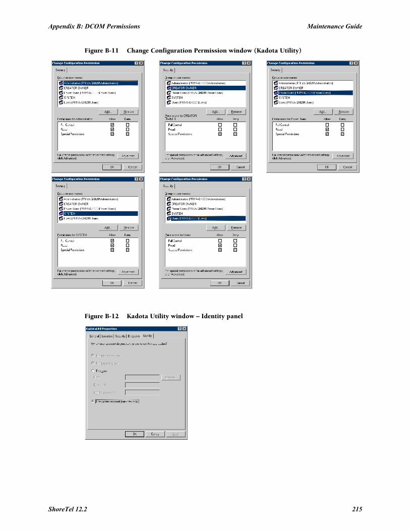
Appendix B: DCOM Permissions Maintenance Guide
Figure B-11 Change Configuration Permission window (Kadota Utility)
Figure B-12 Kadota Utility window – Identity panel
ShoreTel 12.2 215
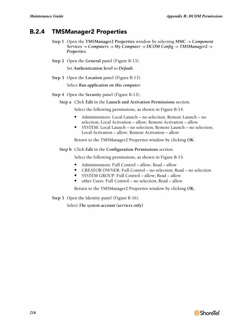
Maintenance Guide Appendix B: DCOM Permissions
B.2.4 TMSManager2 PropertiesStep 1 Open the TMSManager2 Properties window by selecting MMC -> Component
Services -> Computers -> My Computer -> DCOM Config -> TMSManager2 -> Properties.
Step 2 Open the General panel (Figure B-13).
Set Authentication level to Default.
Step 3 Open the Location panel (Figure B-13).
Select Run application on this computer.
Step 4 Open the Security panel (Figure B-13).
Step a Click Edit in the Launch and Activation Permissions section.
Select the following permissions, as shown in Figure B-14.
• Administrators: Local Launch – no selection; Remote Launch – no selection; Local Activation – allow; Remote Activation – allow
• SYSTEM: Local Launch – no selection; Remote Launch – no selection; Local Activation – allow; Remote Activation – allow
Return to the TMSManager2 Properties window by clicking OK.
Step b Click Edit in the Configuration Permissions section.
Select the following permissions, as shown in Figure B-15.
• Administrators: Full Control – allow; Read – allow• CREATOR OWNER: Full Control – no selection; Read – no selection• SYSTEM GROUP: Full Control – allow; Read – allow• other Users: Full Control – no selection; Read – allow
Return to the TMSManager2 Properties window by clicking OK.
Step 5 Open the Identity panel (Figure B-16).
Select The system account (services only)
216
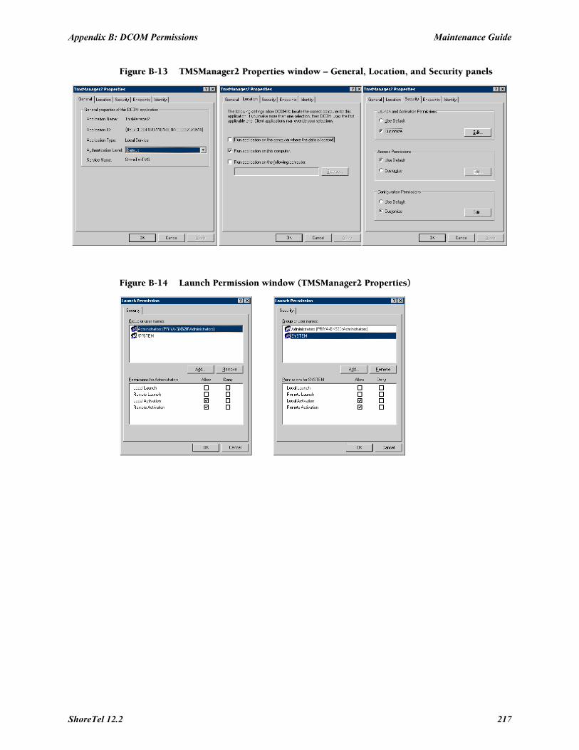
Appendix B: DCOM Permissions Maintenance Guide
Figure B-13 TMSManager2 Properties window – General, Location, and Security panels
Figure B-14 Launch Permission window (TMSManager2 Properties)
ShoreTel 12.2 217
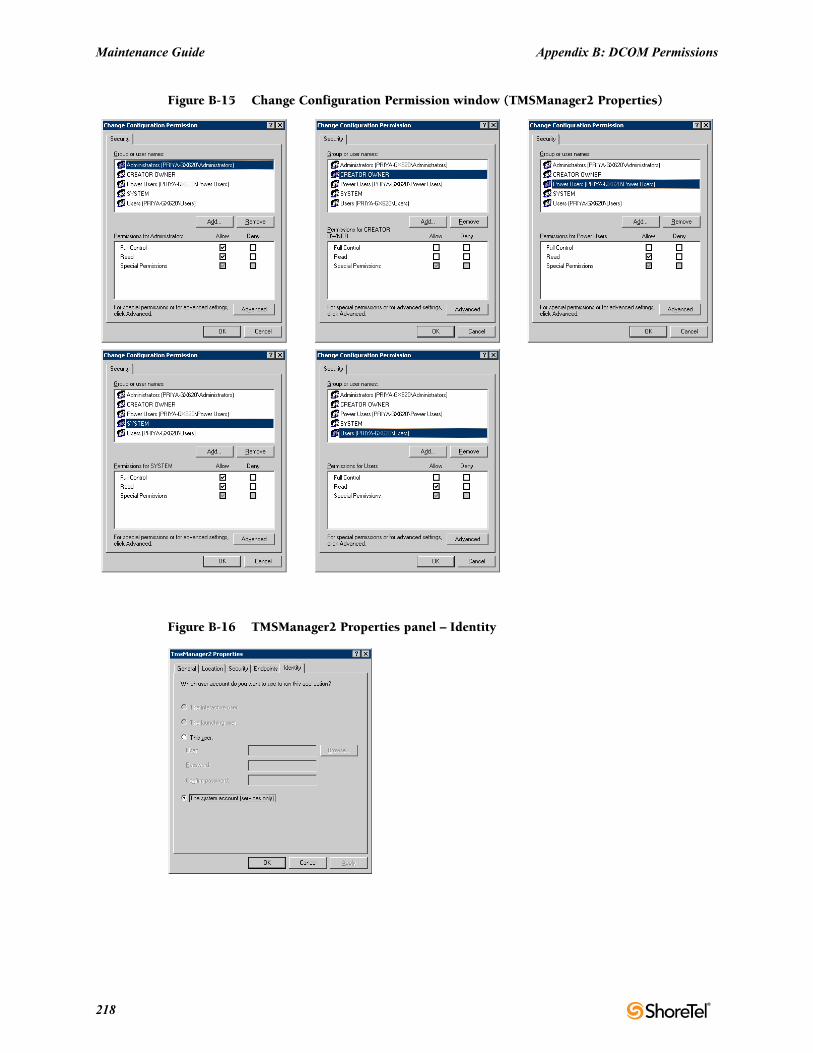
Maintenance Guide Appendix B: DCOM Permissions
Figure B-15 Change Configuration Permission window (TMSManager2 Properties)
Figure B-16 TMSManager2 Properties panel – Identity
218
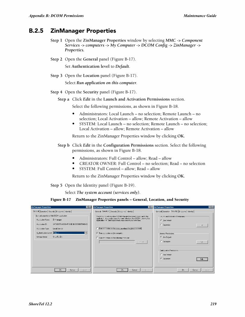
Appendix B: DCOM Permissions Maintenance Guide
B.2.5 ZinManager PropertiesStep 1 Open the ZinManager Properties window by selecting MMC -> Component
Services -> computers -> My Computer -> DCOM Config -> ZinManager -> Properties.
Step 2 Open the General panel (Figure B-17).
Set Authentication level to Default.
Step 3 Open the Location panel (Figure B-17).
Select Run application on this computer.
Step 4 Open the Security panel (Figure B-17).
Step a Click Edit in the Launch and Activation Permissions section.
Select the following permissions, as shown in Figure B-18.
• Administrators: Local Launch – no selection; Remote Launch – no selection; Local Activation – allow; Remote Activation – allow
• SYSTEM: Local Launch – no selection; Remote Launch – no selection; Local Activation – allow; Remote Activation – allow
Return to the ZinManager Properties window by clicking OK.
Step b Click Edit in the Configuration Permissions section. Select the following permissions, as shown in Figure B-18.
• Administrators: Full Control – allow; Read – allow• CREATOR OWNER: Full Control – no selection; Read – no selection• SYSTEM: Full Control – allow; Read – allow
Return to the ZinManager Properties window by clicking OK.
Step 5 Open the Identity panel (Figure B-19).
Select The system account (services only).
Figure B-17 ZinManager Properties panels – General, Location, and Security
ShoreTel 12.2 219

Maintenance Guide Appendix B: DCOM Permissions
Figure B-18 Change Configuration Permission window (ZinManager)
Figure B-19 ZinManager Properties panels – Identity
220

A P P E N D I X C
Debug Commands
C.1 Overview
ShoreTel 12.2 221

Maintenance Guide Appendix C: Debug Commands
222
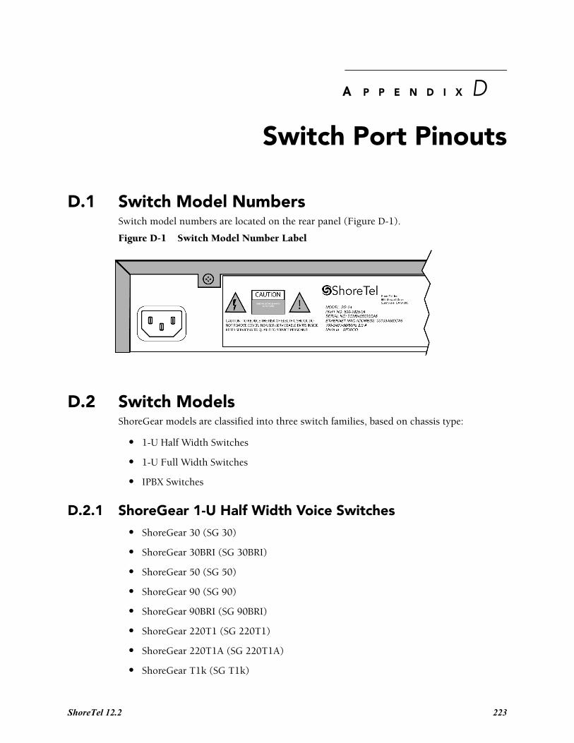
A P P E N D I X D
Switch Port Pinouts
D.1 Switch Model NumbersSwitch model numbers are located on the rear panel (Figure D-1).
Figure D-1 Switch Model Number Label
D.2 Switch ModelsShoreGear models are classified into three switch families, based on chassis type:
• 1-U Half Width Switches
• 1-U Full Width Switches
• IPBX Switches
D.2.1 ShoreGear 1-U Half Width Voice Switches• ShoreGear 30 (SG 30)
• ShoreGear 30BRI (SG 30BRI)
• ShoreGear 50 (SG 50)
• ShoreGear 90 (SG 90)
• ShoreGear 90BRI (SG 90BRI)
• ShoreGear 220T1 (SG 220T1)
• ShoreGear 220T1A (SG 220T1A)
• ShoreGear T1k (SG T1k)
ShoreTel 12.2 223

Maintenance Guide Appendix D: Switch Port Pinouts
• ShoreGear 220E1 (SG 220E1)
• ShoreGear E1k (SG E1k)
D.2.2 ShoreGear Voicemail Model Voice Switches• ShoreGear 90V (SG 90V)
• ShoreGear 50V (SG 50V)
• ShoreGear 90BRIV (SG 90BRIV)
D.2.3 ShoreGear 1-U Full Width Voice Switches• ShoreGear 120 (SG 120) – also referred to as ShoreGear 120/24 (SG 120/24)
• ShoreGear 60 (SG 60) – also referred to as ShoreGear 60/12 (SG 60/12)
• ShoreGear 40 (SG 48) – also referred to as ShoreGear 40/8 (SG 40/8)
• ShoreGear T1 (SG T1)
• ShoreGear E1 (SG E1)
• ShoreGear 24A (SG 24A)
D.2.4 ShoreGear IPBX Voice Switches• ShoreGear 24 (IPBX 24) Voice Switch (2 RU)
• ShoreGear T1 (IPBX T1) Voice Switch (1.5 RU)
• ShoreGear E1 (IPBX E1) Voice Switch (1.5 RU)
224
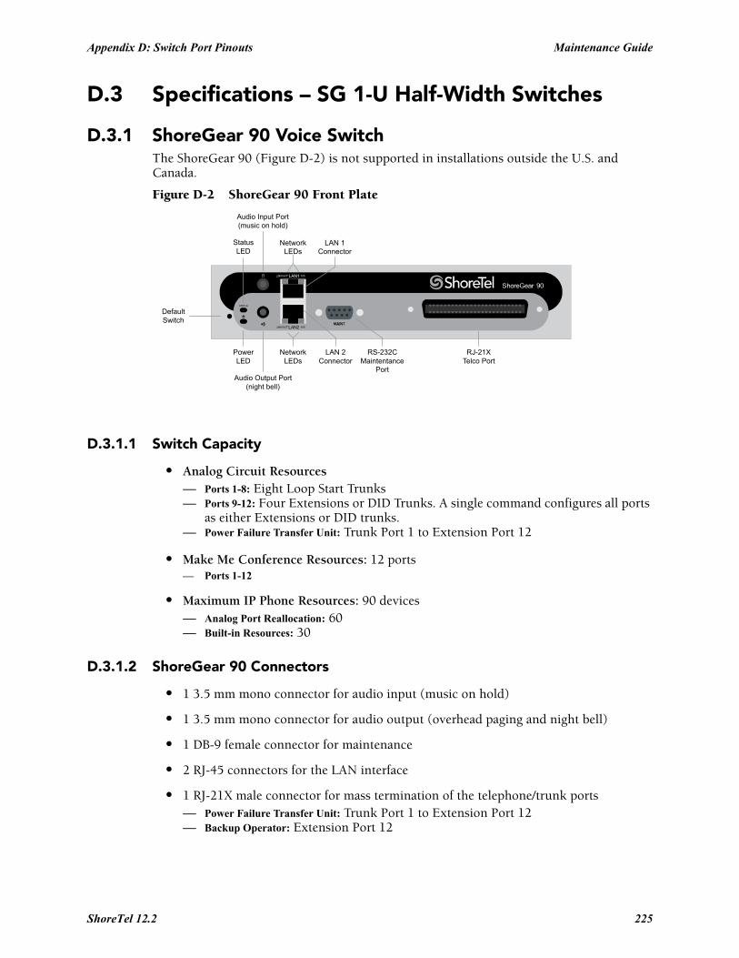
Appendix D: Switch Port Pinouts Maintenance Guide
D.3 Specifications – SG 1-U Half-Width Switches
D.3.1 ShoreGear 90 Voice SwitchThe ShoreGear 90 (Figure D-2) is not supported in installations outside the U.S. and Canada.
Figure D-2 ShoreGear 90 Front Plate
D.3.1.1 Switch Capacity
• Analog Circuit Resources— Ports 1-8: Eight Loop Start Trunks— Ports 9-12: Four Extensions or DID Trunks. A single command configures all ports
as either Extensions or DID trunks.— Power Failure Transfer Unit: Trunk Port 1 to Extension Port 12
• Make Me Conference Resources: 12 ports— Ports 1-12
• Maximum IP Phone Resources: 90 devices— Analog Port Reallocation: 60— Built-in Resources: 30
D.3.1.2 ShoreGear 90 Connectors
• 1 3.5 mm mono connector for audio input (music on hold)
• 1 3.5 mm mono connector for audio output (overhead paging and night bell)
• 1 DB-9 female connector for maintenance
• 2 RJ-45 connectors for the LAN interface
• 1 RJ-21X male connector for mass termination of the telephone/trunk ports— Power Failure Transfer Unit: Trunk Port 1 to Extension Port 12— Backup Operator: Extension Port 12
DefaultSwitch
Audio Output Port(night bell)
PowerLED
NetworkLEDs
LAN 2Connector
RS-232CMaintentance
Port
RJ-21XTelco Port
StatusLED
Audio Input Port(music on hold)
NetworkLEDs
LAN 1Connector
ShoreTel 12.2 225

Maintenance Guide Appendix D: Switch Port Pinouts
ShoreGear 90 RJ-21X Telephone and Trunk Connector
Table D-1 ShoreGear 90 RJ-21X Telephone and Trunk Connector Pins
Port TypeRingPin # Ring Cable Color
TipPin # Tip Cable Color
1 Trunk 1 Blue/White 26 White/Blue
– 2 Orange/White 27 White/Orange
2 Trunk 3 Green/White 28 White/Green
– 4 Brown/White 29 White/Brown
3 Trunk 5 Slate/White 30 White/Slate
– 6 Blue/Red 31 Red/Blue
4 Trunk 7 Orange/Red 32 Red/Orange
– 8 Green/Red 33 Red/Green
5 Trunk 9 Brown/Red 34 Red/Brown
– 10 Slate/Red 35 Red/Slate
6 Trunk 11 Blue/Black 36 Black/Blue
– 12 Orange/Black 37 Black/Orange
7 Trunk 13 Green/Black 38 Black/Green
– 14 Brown/Black 39 Black/Brown
8 Trunk 15 Slate/Black 40 Black/Slate
– 16 Blue/Yellow 41 Yellow/Blue
9 Extension - DID 17 Orange/Yellow 42 Yellow/Orange
– 18 Green/Yellow 43 Yellow/Green
10 Extension - DID 19 Brown/Yellow 44 Yellow/Brown
– 20 Slate/Yellow 45 Yellow/Slate
11 Extension - DID 21 Blue/Violet 46 Violet/Blue
– 22 Orange/Violet 47 Violet/Orange
12 Extension - DID 23 Green/Violet 48 Violet/Green
– 24 Brown/Violet 49 Violet/Brown
– 25 Slate/Violet 50 Violet/Slate
226
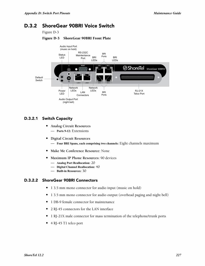
Appendix D: Switch Port Pinouts Maintenance Guide
D.3.2 ShoreGear 90BRI Voice SwitchFigure D-3
Figure D-3 ShoreGear 90BRI Front Plate
D.3.2.1 Switch Capacity
• Analog Circuit Resources— Ports 9-12: Extensions
• Digital Circuit Resources— Four BRI Spans, each comprising two channels: Eight channels maximum
• Make Me Conference Resource: None
• Maximum IP Phone Resources: 90 devices— Analog Port Reallocation: 20— Digital Channel Reallocation: 40— Built-in Resources: 30
D.3.2.2 ShoreGear 90BRI Connectors
• 1 3.5 mm mono connector for audio input (music on hold)
• 1 3.5 mm mono connector for audio output (overhead paging and night bell)
• 1 DB-9 female connector for maintenance
• 2 RJ-45 connectors for the LAN interface
• 1 RJ-21X male connector for mass termination of the telephone/trunk ports
• 4 RJ-45 T1 telco port
DefaultSwitch
Audio Output Port(night bell)
PowerLED
NetworkLEDs
RS-232CMaintentance
Port
RJ-21XTelco Port
StatusLED
Audio Input Port(music on hold)
NetworkLEDs
LANConnectors
BRILEDs
BRILEDs
BRIPorts
BRIPorts
ShoreTel 12.2 227

Maintenance Guide Appendix D: Switch Port Pinouts
ShoreGear 90BRI RJ-21X Telephone and Trunk Connector
Table D-2 ShoreGear 90BRI RJ-21X Telephone and Trunk Connector Pins
Port TypeRingPin # Ring Cable Color
TipPin # Tip Cable Color
– 1 Blue/White 26 White/Blue
– 2 Orange/White 27 White/Orange
– 3 Green/White 28 White/Green
– 4 Brown/White 29 White/Brown
– 5 Slate/White 30 White/Slate
– 6 Blue/Red 31 Red/Blue
– 7 Orange/Red 32 Red/Orange
– 8 Green/Red 33 Red/Green
– 9 Brown/Red 34 Red/Brown
– 10 Slate/Red 35 Red/Slate
– 11 Blue/Black 36 Black/Blue
– 12 Orange/Black 37 Black/Orange
– 13 Green/Black 38 Black/Green
– 14 Brown/Black 39 Black/Brown
– 15 Slate/Black 40 Black/Slate
– 16 Blue/Yellow 41 Yellow/Blue
9 Extension 17 Orange/Yellow 42 Yellow/Orange
– 18 Green/Yellow 43 Yellow/Green
10 Extension 19 Brown/Yellow 44 Yellow/Brown
– 20 Slate/Yellow 45 Yellow/Slate
11 Extension 21 Blue/Violet 46 Violet/Blue
– 22 Orange/Violet 47 Violet/Orange
12 Extension 23 Green/Violet 48 Violet/Green
– 24 Brown/Violet 49 Violet/Brown
– 25 Slate/Violet 50 Violet/Slate
228
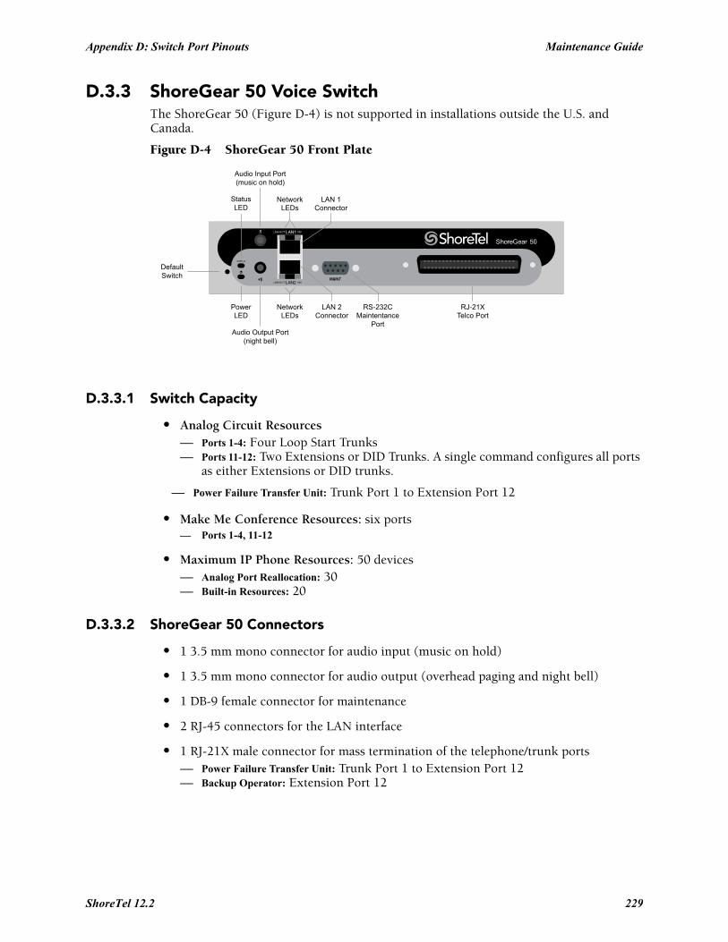
Appendix D: Switch Port Pinouts Maintenance Guide
D.3.3 ShoreGear 50 Voice SwitchThe ShoreGear 50 (Figure D-4) is not supported in installations outside the U.S. and Canada.
Figure D-4 ShoreGear 50 Front Plate
D.3.3.1 Switch Capacity
• Analog Circuit Resources— Ports 1-4: Four Loop Start Trunks— Ports 11-12: Two Extensions or DID Trunks. A single command configures all ports
as either Extensions or DID trunks.
— Power Failure Transfer Unit: Trunk Port 1 to Extension Port 12
• Make Me Conference Resources: six ports— Ports 1-4, 11-12
• Maximum IP Phone Resources: 50 devices— Analog Port Reallocation: 30— Built-in Resources: 20
D.3.3.2 ShoreGear 50 Connectors
• 1 3.5 mm mono connector for audio input (music on hold)
• 1 3.5 mm mono connector for audio output (overhead paging and night bell)
• 1 DB-9 female connector for maintenance
• 2 RJ-45 connectors for the LAN interface
• 1 RJ-21X male connector for mass termination of the telephone/trunk ports— Power Failure Transfer Unit: Trunk Port 1 to Extension Port 12— Backup Operator: Extension Port 12
DefaultSwitch
Audio Output Port(night bell)
PowerLED
NetworkLEDs
LAN 2Connector
RS-232CMaintentance
Port
RJ-21XTelco Port
StatusLED
Audio Input Port(music on hold)
NetworkLEDs
LAN 1Connector
ShoreTel 12.2 229

Maintenance Guide Appendix D: Switch Port Pinouts
ShoreGear 50 RJ-21X Telephone and Trunk Connector
Table D-3 ShoreGear 50 RJ-21X Telephone and Trunk Connector Pins
Port TypeRingPin # Ring Cable Color
TipPin # Tip Cable Color
1 Trunk 1 Blue/White 26 White/Blue
– 2 Orange/White 27 White/Orange
2 Trunk 3 Green/White 28 White/Green
– 4 Brown/White 29 White/Brown
3 Trunk 5 Slate/White 30 White/Slate
– 6 Blue/Red 31 Red/Blue
4 Trunk 7 Orange/Red 32 Red/Orange
– 8 Green/Red 33 Red/Green
– 9 Brown/Red 34 Red/Brown
– 10 Slate/Red 35 Red/Slate
– 11 Blue/Black 36 Black/Blue
– 12 Orange/Black 37 Black/Orange
– 13 Green/Black 38 Black/Green
– 14 Brown/Black 39 Black/Brown
– 15 Slate/Black 40 Black/Slate
– 16 Blue/Yellow 41 Yellow/Blue
9 Extension - DID 17 Orange/Yellow 42 Yellow/Orange
– 18 Green/Yellow 43 Yellow/Green
10 Extension - DID 19 Brown/Yellow 44 Yellow/Brown
– 20 Slate/Yellow 45 Yellow/Slate
11 Extension - DID 21 Blue/Violet 46 Violet/Blue
– 22 Orange/Violet 47 Violet/Orange
12 Extension - DID 23 Green/Violet 48 Violet/Green
– 24 Brown/Violet 49 Violet/Brown
– 25 Slate/Violet 50 Violet/Slate
230
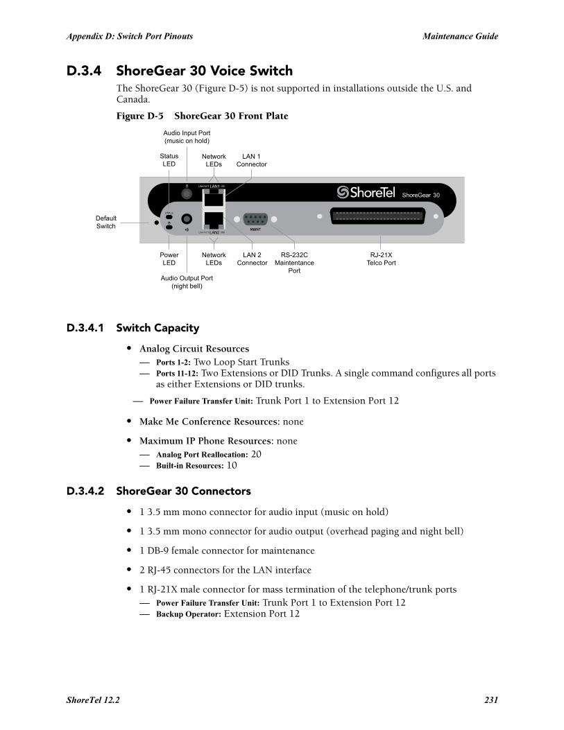
Appendix D: Switch Port Pinouts Maintenance Guide
D.3.4 ShoreGear 30 Voice SwitchThe ShoreGear 30 (Figure D-5) is not supported in installations outside the U.S. and Canada.
Figure D-5 ShoreGear 30 Front Plate
D.3.4.1 Switch Capacity
• Analog Circuit Resources— Ports 1-2: Two Loop Start Trunks— Ports 11-12: Two Extensions or DID Trunks. A single command configures all ports
as either Extensions or DID trunks.
— Power Failure Transfer Unit: Trunk Port 1 to Extension Port 12
• Make Me Conference Resources: none
• Maximum IP Phone Resources: none— Analog Port Reallocation: 20— Built-in Resources: 10
D.3.4.2 ShoreGear 30 Connectors
• 1 3.5 mm mono connector for audio input (music on hold)
• 1 3.5 mm mono connector for audio output (overhead paging and night bell)
• 1 DB-9 female connector for maintenance
• 2 RJ-45 connectors for the LAN interface
• 1 RJ-21X male connector for mass termination of the telephone/trunk ports— Power Failure Transfer Unit: Trunk Port 1 to Extension Port 12— Backup Operator: Extension Port 12
DefaultSwitch
Audio Output Port(night bell)
PowerLED
NetworkLEDs
LAN 2Connector
RS-232CMaintentance
Port
RJ-21XTelco Port
StatusLED
Audio Input Port(music on hold)
NetworkLEDs
LAN 1Connector
ShoreTel 12.2 231

Maintenance Guide Appendix D: Switch Port Pinouts
ShoreGear 30 RJ-21X Telephone and Trunk Connector
Table D-4 ShoreGear 30 RJ-21X Telephone and Trunk Connector Pins
Port TypeRingPin # Ring Cable Color
TipPin # Tip Cable Color
1 Trunk 1 Blue/White 26 White/Blue
– 2 Orange/White 27 White/Orange
2 Trunk 3 Green/White 28 White/Green
– 4 Brown/White 29 White/Brown
– 5 Slate/White 30 White/Slate
– 6 Blue/Red 31 Red/Blue
– 7 Orange/Red 32 Red/Orange
– 8 Green/Red 33 Red/Green
– 9 Brown/Red 34 Red/Brown
– 10 Slate/Red 35 Red/Slate
– 11 Blue/Black 36 Black/Blue
– 12 Orange/Black 37 Black/Orange
– 13 Green/Black 38 Black/Green
– 14 Brown/Black 39 Black/Brown
– 15 Slate/Black 40 Black/Slate
– 16 Blue/Yellow 41 Yellow/Blue
– 17 Orange/Yellow 42 Yellow/Orange
– 18 Green/Yellow 43 Yellow/Green
– 19 Brown/Yellow 44 Yellow/Brown
– 20 Slate/Yellow 45 Yellow/Slate
11 Extension - DID 21 Blue/Violet 46 Violet/Blue
– 22 Orange/Violet 47 Violet/Orange
12 Extension - DID 23 Green/Violet 48 Violet/Green
– 24 Brown/Violet 49 Violet/Brown
– 25 Slate/Violet 50 Violet/Slate
232
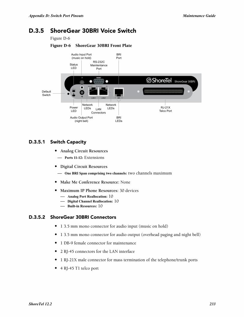
Appendix D: Switch Port Pinouts Maintenance Guide
D.3.5 ShoreGear 30BRI Voice SwitchFigure D-6
Figure D-6 ShoreGear 30BRI Front Plate
D.3.5.1 Switch Capacity
• Analog Circuit Resources
— Ports 11-12: Extensions
• Digital Circuit Resources
— One BRI Span comprising two channels: two channels maximum
• Make Me Conference Resource: None
• Maximum IP Phone Resources: 30 devices— Analog Port Reallocation: 10— Digital Channel Reallocation: 10— Built-in Resources: 10
D.3.5.2 ShoreGear 30BRI Connectors
• 1 3.5 mm mono connector for audio input (music on hold)
• 1 3.5 mm mono connector for audio output (overhead paging and night bell)
• 1 DB-9 female connector for maintenance
• 2 RJ-45 connectors for the LAN interface
• 1 RJ-21X male connector for mass termination of the telephone/trunk ports
• 4 RJ-45 T1 telco port
DefaultSwitch
Audio Output Port(night bell)
PowerLED
NetworkLEDs
RS-232CMaintentance
Port
RJ-21XTelco Port
StatusLED
Audio Input Port(music on hold)
NetworkLEDs LAN
Connectors
BRILEDs
BRIPort
ShoreTel 12.2 233

Maintenance Guide Appendix D: Switch Port Pinouts
ShoreGear 30BRI RJ-21X Telephone and Trunk Connector
Table D-5 ShoreGear 30BRI RJ-21X Telephone and Trunk Connector Pins
Port TypeRingPin # Ring Cable Color
TipPin # Tip Cable Color
– 1 Blue/White 26 White/Blue
– 2 Orange/White 27 White/Orange
– 3 Green/White 28 White/Green
– 4 Brown/White 29 White/Brown
– 5 Slate/White 30 White/Slate
– 6 Blue/Red 31 Red/Blue
– 7 Orange/Red 32 Red/Orange
– 8 Green/Red 33 Red/Green
– 9 Brown/Red 34 Red/Brown
– 10 Slate/Red 35 Red/Slate
– 11 Blue/Black 36 Black/Blue
– 12 Orange/Black 37 Black/Orange
– 13 Green/Black 38 Black/Green
– 14 Brown/Black 39 Black/Brown
– 15 Slate/Black 40 Black/Slate
– 16 Blue/Yellow 41 Yellow/Blue
9 Extension 17 Orange/Yellow 42 Yellow/Orange
– 18 Green/Yellow 43 Yellow/Green
10 Extension 19 Brown/Yellow 44 Yellow/Brown
– 20 Slate/Yellow 45 Yellow/Slate
11 Extension 21 Blue/Violet 46 Violet/Blue
– 22 Orange/Violet 47 Violet/Orange
12 Extension 23 Green/Violet 48 Violet/Green
– 24 Brown/Violet 49 Violet/Brown
– 25 Slate/Violet 50 Violet/Slate
234
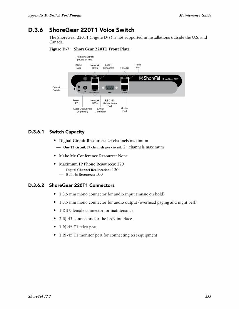
Appendix D: Switch Port Pinouts Maintenance Guide
D.3.6 ShoreGear 220T1 Voice SwitchThe ShoreGear 220T1 (Figure D-7) is not supported in installations outside the U.S. and Canada.
Figure D-7 ShoreGear 220T1 Front Plate
D.3.6.1 Switch Capacity
• Digital Circuit Resources: 24 channels maximum
— One T1 circuit, 24 channels per circuit: 24 channels maximum
• Make Me Conference Resource: None
• Maximum IP Phone Resources: 220— Digital Channel Reallocation: 120— Built-in Resources: 100
D.3.6.2 ShoreGear 220T1 Connectors
• 1 3.5 mm mono connector for audio input (music on hold)
• 1 3.5 mm mono connector for audio output (overhead paging and night bell)
• 1 DB-9 female connector for maintenance
• 2 RJ-45 connectors for the LAN interface
• 1 RJ-45 T1 telco port
• 1 RJ-45 T1 monitor port for connecting test equipment
DefaultSwitch
Audio Output Port(night bell)
PowerLED
NetworkLEDs
LAN 2Connector
RS-232CMaintentance
Port
StatusLED
Audio Input Port(music on hold)
NetworkLEDs
LAN 1Connector T1 LEDs
MonitorPort
TelcoPort
ShoreTel 12.2 235
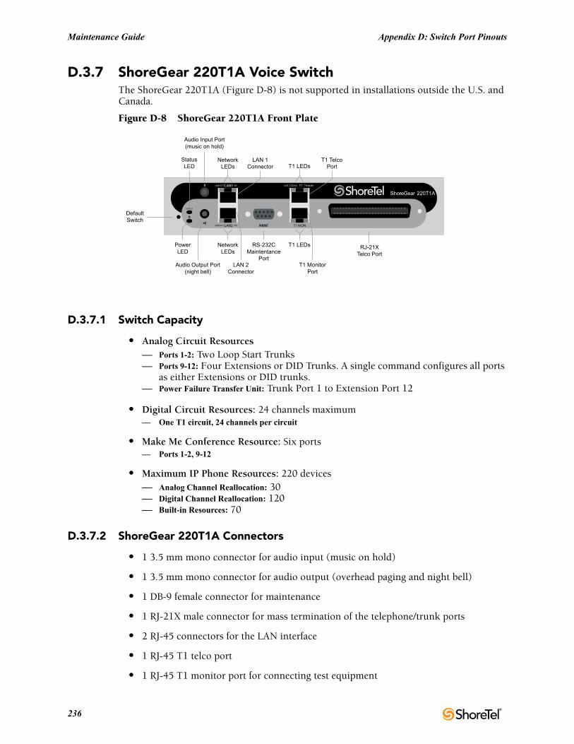
Maintenance Guide Appendix D: Switch Port Pinouts
D.3.7 ShoreGear 220T1A Voice SwitchThe ShoreGear 220T1A (Figure D-8) is not supported in installations outside the U.S. and Canada.
Figure D-8 ShoreGear 220T1A Front Plate
D.3.7.1 Switch Capacity
• Analog Circuit Resources— Ports 1-2: Two Loop Start Trunks— Ports 9-12: Four Extensions or DID Trunks. A single command configures all ports
as either Extensions or DID trunks.— Power Failure Transfer Unit: Trunk Port 1 to Extension Port 12
• Digital Circuit Resources: 24 channels maximum— One T1 circuit, 24 channels per circuit
• Make Me Conference Resource: Six ports— Ports 1-2, 9-12
• Maximum IP Phone Resources: 220 devices— Analog Channel Reallocation: 30— Digital Channel Reallocation: 120— Built-in Resources: 70
D.3.7.2 ShoreGear 220T1A Connectors
• 1 3.5 mm mono connector for audio input (music on hold)
• 1 3.5 mm mono connector for audio output (overhead paging and night bell)
• 1 DB-9 female connector for maintenance
• 1 RJ-21X male connector for mass termination of the telephone/trunk ports
• 2 RJ-45 connectors for the LAN interface
• 1 RJ-45 T1 telco port
• 1 RJ-45 T1 monitor port for connecting test equipment
DefaultSwitch
Audio Output Port(night bell)
PowerLED
NetworkLEDs
LAN 2Connector
RS-232CMaintentance
Port
StatusLED
Audio Input Port(music on hold)
NetworkLEDs
T1 LEDs
T1 LEDsLAN 1
Connector
T1 MonitorPort
T1 TelcoPort
RJ-21XTelco Port
236

Appendix D: Switch Port Pinouts Maintenance Guide
ShoreGear 220T1A RJ-21X Telephone and Trunk Connector
Table D-6 ShoreGear 220T1A RJ-21X Telephone and Trunk Connector Pins
Port TypeRingPin # Ring Cable Color
TipPin # Tip Cable Color
1 Trunk 1 Blue/White 26 White/Blue
– 2 Orange/White 27 White/Orange
2 Trunk 3 Green/White 28 White/Green
– 4 Brown/White 29 White/Brown
– 5 Slate/White 30 White/Slate
– 6 Blue/Red 31 Red/Blue
– 7 Orange/Red 32 Red/Orange
– 8 Green/Red 33 Red/Green
– 9 Brown/Red 34 Red/Brown
– 10 Slate/Red 35 Red/Slate
– 11 Blue/Black 36 Black/Blue
– 12 Orange/Black 37 Black/Orange
– 13 Green/Black 38 Black/Green
– 14 Brown/Black 39 Black/Brown
– 15 Slate/Black 40 Black/Slate
– 16 Blue/Yellow 41 Yellow/Blue
9 Extension 17 Orange/Yellow 42 Yellow/Orange
– 18 Green/Yellow 43 Yellow/Green
10 Extension 19 Brown/Yellow 44 Yellow/Brown
– 20 Slate/Yellow 45 Yellow/Slate
11 Extension 21 Blue/Violet 46 Violet/Blue
– 22 Orange/Violet 47 Violet/Orange
12 Extension 23 Green/Violet 48 Violet/Green
– 24 Brown/Violet 49 Violet/Brown
– 25 Slate/Violet 50 Violet/Slate
ShoreTel 12.2 237
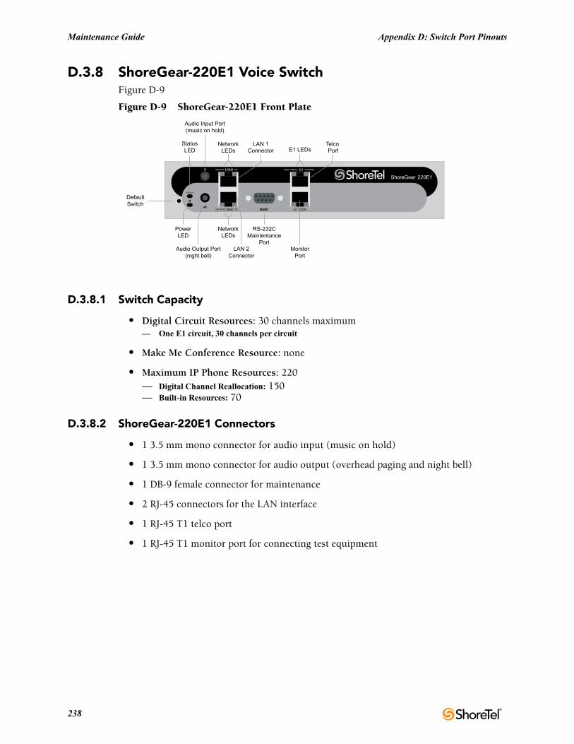
Maintenance Guide Appendix D: Switch Port Pinouts
D.3.8 ShoreGear-220E1 Voice SwitchFigure D-9
Figure D-9 ShoreGear-220E1 Front Plate
D.3.8.1 Switch Capacity
• Digital Circuit Resources: 30 channels maximum— One E1 circuit, 30 channels per circuit
• Make Me Conference Resource: none
• Maximum IP Phone Resources: 220— Digital Channel Reallocation: 150— Built-in Resources: 70
D.3.8.2 ShoreGear-220E1 Connectors
• 1 3.5 mm mono connector for audio input (music on hold)
• 1 3.5 mm mono connector for audio output (overhead paging and night bell)
• 1 DB-9 female connector for maintenance
• 2 RJ-45 connectors for the LAN interface
• 1 RJ-45 T1 telco port
• 1 RJ-45 T1 monitor port for connecting test equipment
DefaultSwitch
Audio Output Port(night bell)
PowerLED
NetworkLEDs
LAN 2Connector
RS-232CMaintentance
Port
StatusLED
Audio Input Port(music on hold)
NetworkLEDs E1 LEDs
LAN 1Connector
MonitorPort
Telco Port
238
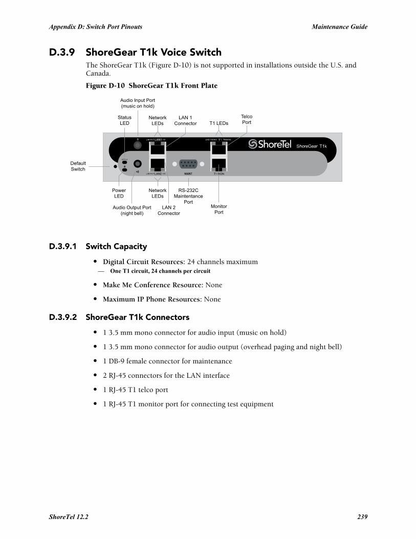
Appendix D: Switch Port Pinouts Maintenance Guide
D.3.9 ShoreGear T1k Voice SwitchThe ShoreGear T1k (Figure D-10) is not supported in installations outside the U.S. and Canada.
Figure D-10 ShoreGear T1k Front Plate
D.3.9.1 Switch Capacity
• Digital Circuit Resources: 24 channels maximum— One T1 circuit, 24 channels per circuit
• Make Me Conference Resource: None
• Maximum IP Phone Resources: None
D.3.9.2 ShoreGear T1k Connectors
• 1 3.5 mm mono connector for audio input (music on hold)
• 1 3.5 mm mono connector for audio output (overhead paging and night bell)
• 1 DB-9 female connector for maintenance
• 2 RJ-45 connectors for the LAN interface
• 1 RJ-45 T1 telco port
• 1 RJ-45 T1 monitor port for connecting test equipment
DefaultSwitch
Audio Output Port(night bell)
PowerLED
NetworkLEDs
LAN 2Connector
RS-232CMaintentance
Port
StatusLED
Audio Input Port(music on hold)
NetworkLEDs
LAN 1Connector T1 LEDs
MonitorPort
TelcoPort
ShoreTel 12.2 239
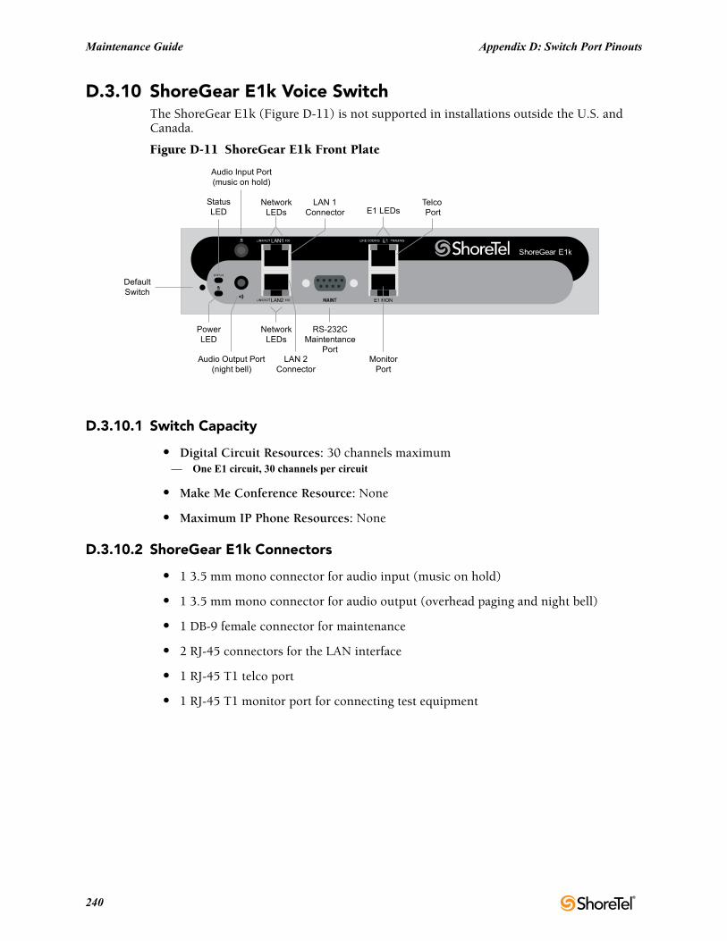
Maintenance Guide Appendix D: Switch Port Pinouts
D.3.10 ShoreGear E1k Voice SwitchThe ShoreGear E1k (Figure D-11) is not supported in installations outside the U.S. and Canada.
Figure D-11 ShoreGear E1k Front Plate
D.3.10.1 Switch Capacity
• Digital Circuit Resources: 30 channels maximum— One E1 circuit, 30 channels per circuit
• Make Me Conference Resource: None
• Maximum IP Phone Resources: None
D.3.10.2 ShoreGear E1k Connectors
• 1 3.5 mm mono connector for audio input (music on hold)
• 1 3.5 mm mono connector for audio output (overhead paging and night bell)
• 1 DB-9 female connector for maintenance
• 2 RJ-45 connectors for the LAN interface
• 1 RJ-45 T1 telco port
• 1 RJ-45 T1 monitor port for connecting test equipment
DefaultSwitch
Audio Output Port(night bell)
PowerLED
NetworkLEDs
LAN 2Connector
RS-232CMaintentance
Port
StatusLED
Audio Input Port(music on hold)
NetworkLEDs E1 LEDs
LAN 1Connector
MonitorPort
Telco Port
240
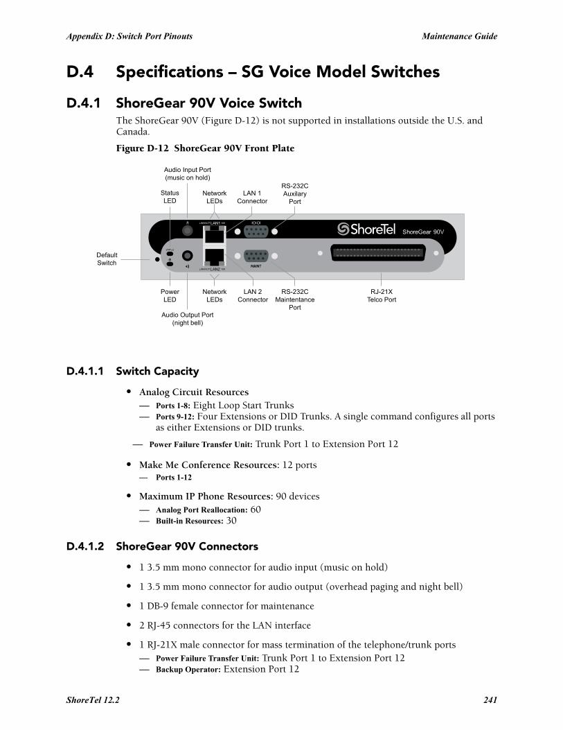
Appendix D: Switch Port Pinouts Maintenance Guide
D.4 Specifications – SG Voice Model Switches
D.4.1 ShoreGear 90V Voice SwitchThe ShoreGear 90V (Figure D-12) is not supported in installations outside the U.S. and Canada.
Figure D-12 ShoreGear 90V Front Plate
D.4.1.1 Switch Capacity
• Analog Circuit Resources— Ports 1-8: Eight Loop Start Trunks— Ports 9-12: Four Extensions or DID Trunks. A single command configures all ports
as either Extensions or DID trunks.
— Power Failure Transfer Unit: Trunk Port 1 to Extension Port 12
• Make Me Conference Resources: 12 ports— Ports 1-12
• Maximum IP Phone Resources: 90 devices— Analog Port Reallocation: 60— Built-in Resources: 30
D.4.1.2 ShoreGear 90V Connectors
• 1 3.5 mm mono connector for audio input (music on hold)
• 1 3.5 mm mono connector for audio output (overhead paging and night bell)
• 1 DB-9 female connector for maintenance
• 2 RJ-45 connectors for the LAN interface
• 1 RJ-21X male connector for mass termination of the telephone/trunk ports— Power Failure Transfer Unit: Trunk Port 1 to Extension Port 12— Backup Operator: Extension Port 12
DefaultSwitch
Audio Output Port(night bell)
PowerLED
NetworkLEDs
LAN 2Connector
RS-232CMaintentance
Port
RJ-21XTelco Port
StatusLED
Audio Input Port(music on hold)
NetworkLEDs
LAN 1Connector
RS-232CAuxilary
Port
ShoreTel 12.2 241

Maintenance Guide Appendix D: Switch Port Pinouts
ShoreGear 90V RJ-21X Telephone and Trunk Connector
Table D-7 ShoreGear 90V RJ-21X Telephone and Trunk Connector Pins
Port TypeRingPin # Ring Cable Color
TipPin # Tip Cable Color
1 Trunk 1 Blue/White 26 White/Blue
– 2 Orange/White 27 White/Orange
2 Trunk 3 Green/White 28 White/Green
– 4 Brown/White 29 White/Brown
3 Trunk 5 Slate/White 30 White/Slate
– 6 Blue/Red 31 Red/Blue
4 Trunk 7 Orange/Red 32 Red/Orange
– 8 Green/Red 33 Red/Green
5 Trunk 9 Brown/Red 34 Red/Brown
– 10 Slate/Red 35 Red/Slate
6 Trunk 11 Blue/Black 36 Black/Blue
– 12 Orange/Black 37 Black/Orange
7 Trunk 13 Green/Black 38 Black/Green
– 14 Brown/Black 39 Black/Brown
8 Trunk 15 Slate/Black 40 Black/Slate
– 16 Blue/Yellow 41 Yellow/Blue
9 Extension - DID 17 Orange/Yellow 42 Yellow/Orange
– 18 Green/Yellow 43 Yellow/Green
10 Extension - DID 19 Brown/Yellow 44 Yellow/Brown
– 20 Slate/Yellow 45 Yellow/Slate
11 Extension - DID 21 Blue/Violet 46 Violet/Blue
– 22 Orange/Violet 47 Violet/Orange
12 Extension - DID 23 Green/Violet 48 Violet/Green
– 24 Brown/Violet 49 Violet/Brown
– 25 Slate/Violet 50 Violet/Slate
242

Appendix D: Switch Port Pinouts Maintenance Guide
D.4.2 ShoreGear 90BRIV Voice SwitchFigure D-13
Figure D-13 ShoreGear 90BRIV Front Plate
D.4.2.1 Switch Capacity
• Analog Circuit Resources— Ports 9-12: Extensions
• Digital Circuit Resources— Four BRI Spans, each comprising two channels: Eight channels maximum
• Make Me Conference Resource: None
• Maximum IP Phone Resources: 90 devices— Analog Port Reallocation: 20— Digital Channel Reallocation: 40— Built-in Resources: 30
D.4.2.2 ShoreGear 90BRIV Connectors
• 1 3.5 mm mono connector for audio input (music on hold)
• 1 3.5 mm mono connector for audio output (overhead paging and night bell)
• 1 DB-9 female connector for maintenance
• 2 RJ-45 connectors for the LAN interface
• 1 RJ-21X male connector for mass termination of the telephone/trunk ports
• 4 RJ-45 T1 telco port
DefaultSwitch
Audio Output Port(night bell)
PowerLED
NetworkLEDs
RS-232CMaintentance
Port
RJ-21XTelco Port
StatusLED
Audio Input Port(music on hold)
NetworkLEDs
LANConnectors
BRILEDs
BRILEDs
BRIPorts
BRIPorts
ShoreTel 12.2 243

Maintenance Guide Appendix D: Switch Port Pinouts
ShoreGear 90BRIV RJ-21X Telephone and Trunk Connector
Table D-8 ShoreGear 90BRIV RJ-21X Telephone and Trunk Connector Pins
Port TypeRingPin # Ring Cable Color
TipPin # Tip Cable Color
– 1 Blue/White 26 White/Blue
– 2 Orange/White 27 White/Orange
– 3 Green/White 28 White/Green
– 4 Brown/White 29 White/Brown
– 5 Slate/White 30 White/Slate
– 6 Blue/Red 31 Red/Blue
– 7 Orange/Red 32 Red/Orange
– 8 Green/Red 33 Red/Green
– 9 Brown/Red 34 Red/Brown
– 10 Slate/Red 35 Red/Slate
– 11 Blue/Black 36 Black/Blue
– 12 Orange/Black 37 Black/Orange
– 13 Green/Black 38 Black/Green
– 14 Brown/Black 39 Black/Brown
– 15 Slate/Black 40 Black/Slate
– 16 Blue/Yellow 41 Yellow/Blue
9 Extension 17 Orange/Yellow 42 Yellow/Orange
– 18 Green/Yellow 43 Yellow/Green
10 Extension 19 Brown/Yellow 44 Yellow/Brown
– 20 Slate/Yellow 45 Yellow/Slate
11 Extension 21 Blue/Violet 46 Violet/Blue
– 22 Orange/Violet 47 Violet/Orange
12 Extension 23 Green/Violet 48 Violet/Green
– 24 Brown/Violet 49 Violet/Brown
– 25 Slate/Violet 50 Violet/Slate
244
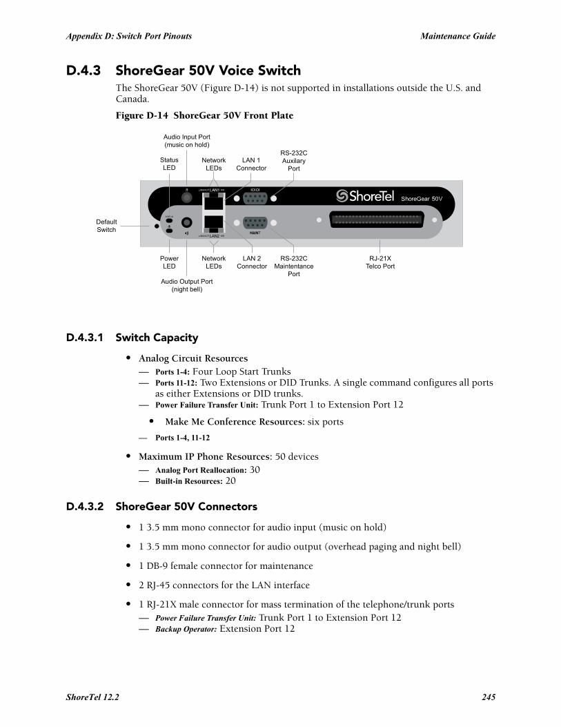
Appendix D: Switch Port Pinouts Maintenance Guide
D.4.3 ShoreGear 50V Voice SwitchThe ShoreGear 50V (Figure D-14) is not supported in installations outside the U.S. and Canada.
Figure D-14 ShoreGear 50V Front Plate
D.4.3.1 Switch Capacity
• Analog Circuit Resources— Ports 1-4: Four Loop Start Trunks— Ports 11-12: Two Extensions or DID Trunks. A single command configures all ports
as either Extensions or DID trunks.— Power Failure Transfer Unit: Trunk Port 1 to Extension Port 12
• Make Me Conference Resources: six ports
— Ports 1-4, 11-12
• Maximum IP Phone Resources: 50 devices— Analog Port Reallocation: 30— Built-in Resources: 20
D.4.3.2 ShoreGear 50V Connectors
• 1 3.5 mm mono connector for audio input (music on hold)
• 1 3.5 mm mono connector for audio output (overhead paging and night bell)
• 1 DB-9 female connector for maintenance
• 2 RJ-45 connectors for the LAN interface
• 1 RJ-21X male connector for mass termination of the telephone/trunk ports— Power Failure Transfer Unit: Trunk Port 1 to Extension Port 12— Backup Operator: Extension Port 12
DefaultSwitch
Audio Output Port(night bell)
PowerLED
NetworkLEDs
LAN 2Connector
RS-232CMaintentance
Port
RJ-21XTelco Port
StatusLED
Audio Input Port(music on hold)
NetworkLEDs
LAN 1Connector
RS-232CAuxilary
Port
ShoreTel 12.2 245

Maintenance Guide Appendix D: Switch Port Pinouts
ShoreGear 50V RJ-21X Telephone and Trunk Connector
Table D-9 ShoreGear 50V RJ-21X Telephone and Trunk Connector Pins
Port TypeRingPin # Ring Cable Color
TipPin # Tip Cable Color
1 Trunk 1 Blue/White 26 White/Blue
– 2 Orange/White 27 White/Orange
2 Trunk 3 Green/White 28 White/Green
– 4 Brown/White 29 White/Brown
3 Trunk 5 Slate/White 30 White/Slate
– 6 Blue/Red 31 Red/Blue
4 Trunk 7 Orange/Red 32 Red/Orange
– 8 Green/Red 33 Red/Green
– 9 Brown/Red 34 Red/Brown
– 10 Slate/Red 35 Red/Slate
– 11 Blue/Black 36 Black/Blue
– 12 Orange/Black 37 Black/Orange
– 13 Green/Black 38 Black/Green
– 14 Brown/Black 39 Black/Brown
– 15 Slate/Black 40 Black/Slate
– 16 Blue/Yellow 41 Yellow/Blue
9 Extension - DID 17 Orange/Yellow 42 Yellow/Orange
– 18 Green/Yellow 43 Yellow/Green
10 Extension - DID 19 Brown/Yellow 44 Yellow/Brown
– 20 Slate/Yellow 45 Yellow/Slate
11 Extension - DID 21 Blue/Violet 46 Violet/Blue
– 22 Orange/Violet 47 Violet/Orange
12 Extension - DID 23 Green/Violet 48 Violet/Green
– 24 Brown/Violet 49 Violet/Brown
– 25 Slate/Violet 50 Violet/Slate
246
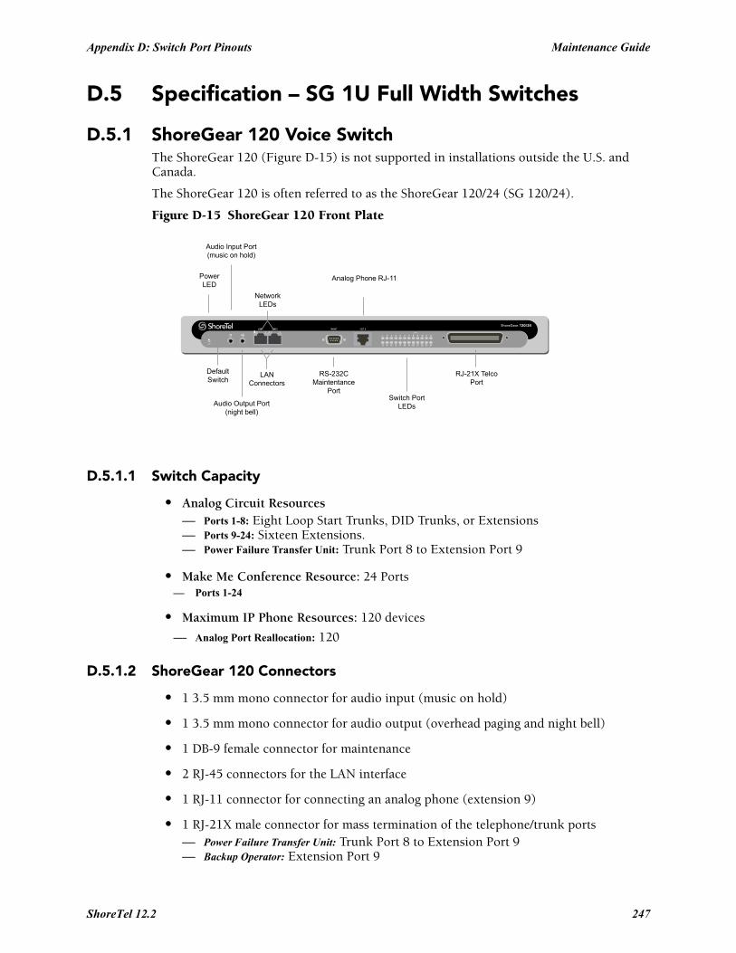
Appendix D: Switch Port Pinouts Maintenance Guide
D.5 Specification – SG 1U Full Width Switches
D.5.1 ShoreGear 120 Voice SwitchThe ShoreGear 120 (Figure D-15) is not supported in installations outside the U.S. and Canada.
The ShoreGear 120 is often referred to as the ShoreGear 120/24 (SG 120/24).
Figure D-15 ShoreGear 120 Front Plate
D.5.1.1 Switch Capacity
• Analog Circuit Resources— Ports 1-8: Eight Loop Start Trunks, DID Trunks, or Extensions— Ports 9-24: Sixteen Extensions.— Power Failure Transfer Unit: Trunk Port 8 to Extension Port 9
• Make Me Conference Resource: 24 Ports— Ports 1-24
• Maximum IP Phone Resources: 120 devices
— Analog Port Reallocation: 120
D.5.1.2 ShoreGear 120 Connectors
• 1 3.5 mm mono connector for audio input (music on hold)
• 1 3.5 mm mono connector for audio output (overhead paging and night bell)
• 1 DB-9 female connector for maintenance
• 2 RJ-45 connectors for the LAN interface
• 1 RJ-11 connector for connecting an analog phone (extension 9)
• 1 RJ-21X male connector for mass termination of the telephone/trunk ports— Power Failure Transfer Unit: Trunk Port 8 to Extension Port 9— Backup Operator: Extension Port 9
ShoreGear-120/24
DefaultSwitch
Audio Output Port(night bell)
PowerLED
RS-232CMaintentance
Port
RJ-21X TelcoPort
Audio Input Port(music on hold)
NetworkLEDs
LANConnectors
Analog Phone RJ-11
Switch PortLEDs
ShoreTel 12.2 247

Maintenance Guide Appendix D: Switch Port Pinouts
ShoreGear 120 RJ-21X Telephone and Trunk Connector
Table D-10 ShoreGear 120 RJ-21X Telephone and Trunk Connector Pins
Port TypeRingPin # Ring Cable Color
TipPin # Tip Cable Color
1 Trunk, DID, Extension 1 Blue/White 26 White/Blue
2 Trunk, DID, Extension 2 Orange/White 27 White/Orange
3 Trunk, DID, Extension 3 Green/White 28 White/Green
4 Trunk, DID, Extension 4 Brown/White 29 White/Brown
5 Trunk, DID, Extension 5 Slate/White 30 White/Slate
6 Trunk, DID, Extension 6 Blue/Red 31 Red/Blue
7 Trunk, DID, Extension 7 Orange/Red 32 Red/Orange
8 Trunk, DID, Extension 8 Green/Red 33 Red/Green
9 Extension 9 Brown/Red 34 Red/Brown
10 Extension 10 Slate/Red 35 Red/Slate
11 Extension 11 Blue/Black 36 Black/Blue
12 Extension 12 Orange/Black 37 Black/Orange
13 Extension 13 Green/Black 38 Black/Green
14 Extension 14 Brown/Black 39 Black/Brown
15 Extension 15 Slate/Black 40 Black/Slate
16 Extension 16 Blue/Yellow 41 Yellow/Blue
17 Extension 17 Orange/Yellow 42 Yellow/Orange
18 Extension 18 Green/Yellow 43 Yellow/Green
19 Extension 19 Brown/Yellow 44 Yellow/Brown
20 Extension 20 Slate/Yellow 45 Yellow/Slate
21 Extension 21 Blue/Violet 46 Violet/Blue
22 Extension 22 Orange/Violet 47 Violet/Orange
23 Extension 23 Green/Violet 48 Violet/Green
24 Extension 24 Brown/Violet 49 Violet/Brown
– 25 Slate/Violet 50 Violet/Slate
248
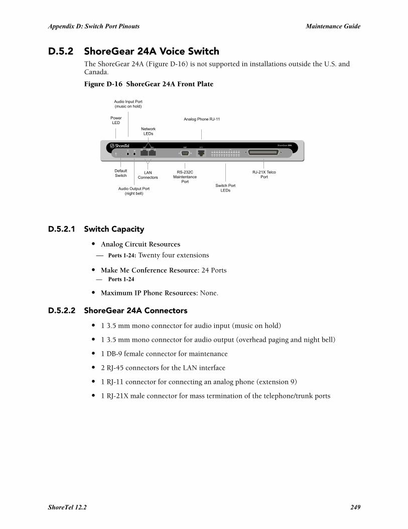
Appendix D: Switch Port Pinouts Maintenance Guide
D.5.2 ShoreGear 24A Voice SwitchThe ShoreGear 24A (Figure D-16) is not supported in installations outside the U.S. and Canada.
Figure D-16 ShoreGear 24A Front Plate
D.5.2.1 Switch Capacity
• Analog Circuit Resources
— Ports 1-24: Twenty four extensions
• Make Me Conference Resource: 24 Ports— Ports 1-24
• Maximum IP Phone Resources: None.
D.5.2.2 ShoreGear 24A Connectors
• 1 3.5 mm mono connector for audio input (music on hold)
• 1 3.5 mm mono connector for audio output (overhead paging and night bell)
• 1 DB-9 female connector for maintenance
• 2 RJ-45 connectors for the LAN interface
• 1 RJ-11 connector for connecting an analog phone (extension 9)
• 1 RJ-21X male connector for mass termination of the telephone/trunk ports
ShoreGear-24A
DefaultSwitch
Audio Output Port(night bell)
PowerLED
RS-232CMaintentance
Port
RJ-21X TelcoPort
Audio Input Port(music on hold)
NetworkLEDs
LANConnectors
Analog Phone RJ-11
Switch PortLEDs
ShoreTel 12.2 249

Maintenance Guide Appendix D: Switch Port Pinouts
ShoreGear 24A RJ-21X Telephone and Trunk Connector
Table D-11 ShoreGear 24A RJ-21X Telephone and Trunk Connector Pins
Port TypeRingPin # Ring Cable Color
TipPin # Tip Cable Color
1 Extension 1 Blue/White 26 White/Blue
2 Extension 2 Orange/White 27 White/Orange
3 Extension 3 Green/White 28 White/Green
4 Extension 4 Brown/White 29 White/Brown
5 Extension 5 Slate/White 30 White/Slate
6 Extension 6 Blue/Red 31 Red/Blue
7 Extension 7 Orange/Red 32 Red/Orange
8 Extension 8 Green/Red 33 Red/Green
9 Extension 9 Brown/Red 34 Red/Brown
10 Extension 10 Slate/Red 35 Red/Slate
11 Extension 11 Blue/Black 36 Black/Blue
12 Extension 12 Orange/Black 37 Black/Orange
13 Extension 13 Green/Black 38 Black/Green
14 Extension 14 Brown/Black 39 Black/Brown
15 Extension 15 Slate/Black 40 Black/Slate
16 Extension 16 Blue/Yellow 41 Yellow/Blue
17 Extension 17 Orange/Yellow 42 Yellow/Orange
18 Extension 18 Green/Yellow 43 Yellow/Green
19 Extension 19 Brown/Yellow 44 Yellow/Brown
20 Extension 20 Slate/Yellow 45 Yellow/Slate
21 Extension 21 Blue/Violet 46 Violet/Blue
22 Extension 22 Orange/Violet 47 Violet/Orange
23 Extension 23 Green/Violet 48 Violet/Green
24 Extension 24 Brown/Violet 49 Violet/Brown
– 25 Slate/Violet 50 Violet/Slate
250
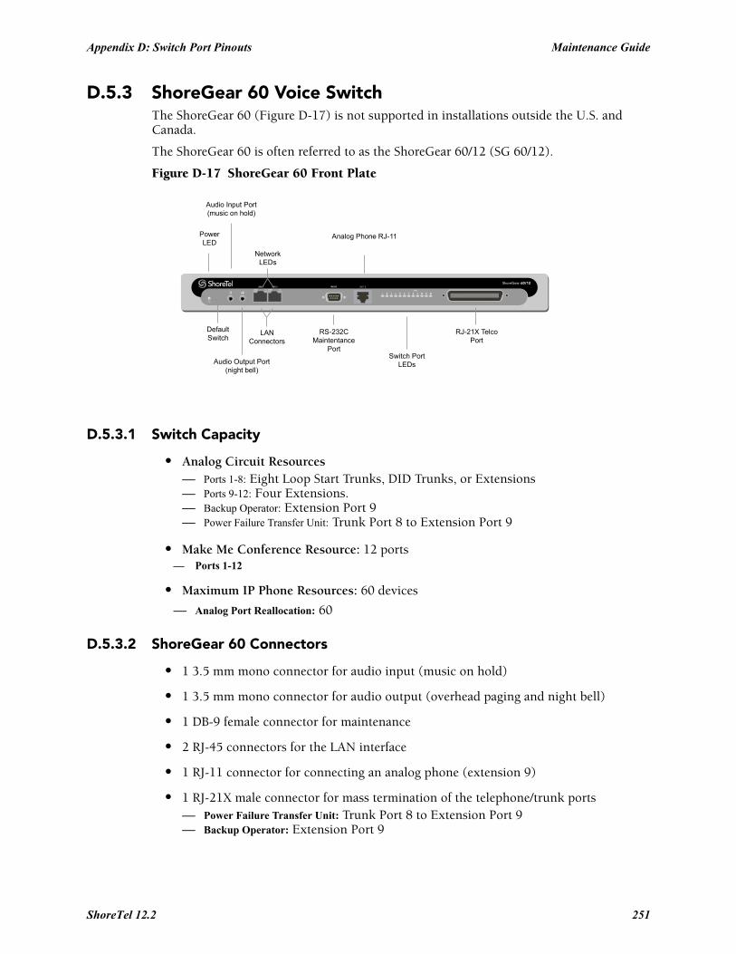
Appendix D: Switch Port Pinouts Maintenance Guide
D.5.3 ShoreGear 60 Voice SwitchThe ShoreGear 60 (Figure D-17) is not supported in installations outside the U.S. and Canada.
The ShoreGear 60 is often referred to as the ShoreGear 60/12 (SG 60/12).
Figure D-17 ShoreGear 60 Front Plate
D.5.3.1 Switch Capacity
• Analog Circuit Resources— Ports 1-8: Eight Loop Start Trunks, DID Trunks, or Extensions— Ports 9-12: Four Extensions.— Backup Operator: Extension Port 9— Power Failure Transfer Unit: Trunk Port 8 to Extension Port 9
• Make Me Conference Resource: 12 ports— Ports 1-12
• Maximum IP Phone Resources: 60 devices
— Analog Port Reallocation: 60
D.5.3.2 ShoreGear 60 Connectors
• 1 3.5 mm mono connector for audio input (music on hold)
• 1 3.5 mm mono connector for audio output (overhead paging and night bell)
• 1 DB-9 female connector for maintenance
• 2 RJ-45 connectors for the LAN interface
• 1 RJ-11 connector for connecting an analog phone (extension 9)
• 1 RJ-21X male connector for mass termination of the telephone/trunk ports— Power Failure Transfer Unit: Trunk Port 8 to Extension Port 9— Backup Operator: Extension Port 9
ShoreGear-60/12
DefaultSwitch
Audio Output Port(night bell)
PowerLED
RS-232CMaintentance
Port
RJ-21X TelcoPort
Audio Input Port(music on hold)
NetworkLEDs
LANConnectors
Analog Phone RJ-11
Switch PortLEDs
ShoreTel 12.2 251

Maintenance Guide Appendix D: Switch Port Pinouts
ShoreGear 60 RJ-21X Telephone and Trunk Connector
Table D-12 ShoreGear 60 RJ-21X Telephone and Trunk Connector Pins
Port TypeRingPin # Ring Cable Color
TipPin # Tip Cable Color
1 Trunk, DID, Extension 1 Blue/White 26 White/Blue
2 Trunk, DID, Extension 2 Orange/White 27 White/Orange
3 Trunk, DID, Extension 3 Green/White 28 White/Green
4 Trunk, DID, Extension 4 Brown/White 29 White/Brown
5 Trunk, DID, Extension 5 Slate/White 30 White/Slate
6 Trunk, DID, Extension 6 Blue/Red 31 Red/Blue
7 Trunk, DID, Extension 7 Orange/Red 32 Red/Orange
8 Trunk, DID, Extension 8 Green/Red 33 Red/Green
9 Extension 9 Brown/Red 34 Red/Brown
10 Extension 10 Slate/Red 35 Red/Slate
11 Extension 11 Blue/Black 36 Black/Blue
12 Extension 12 Orange/Black 37 Black/Orange
– 13 Green/Black 38 Black/Green
– 14 Brown/Black 39 Black/Brown
– 15 Slate/Black 40 Black/Slate
– 16 Blue/Yellow 41 Yellow/Blue
– 17 Orange/Yellow 42 Yellow/Orange
– 18 Green/Yellow 43 Yellow/Green
– 19 Brown/Yellow 44 Yellow/Brown
– 20 Slate/Yellow 45 Yellow/Slate
– 21 Blue/Violet 46 Violet/Blue
– 22 Orange/Violet 47 Violet/Orange
– 23 Green/Violet 48 Violet/Green
– 24 Brown/Violet 49 Violet/Brown
– 25 Slate/Violet 50 Violet/Slate
252
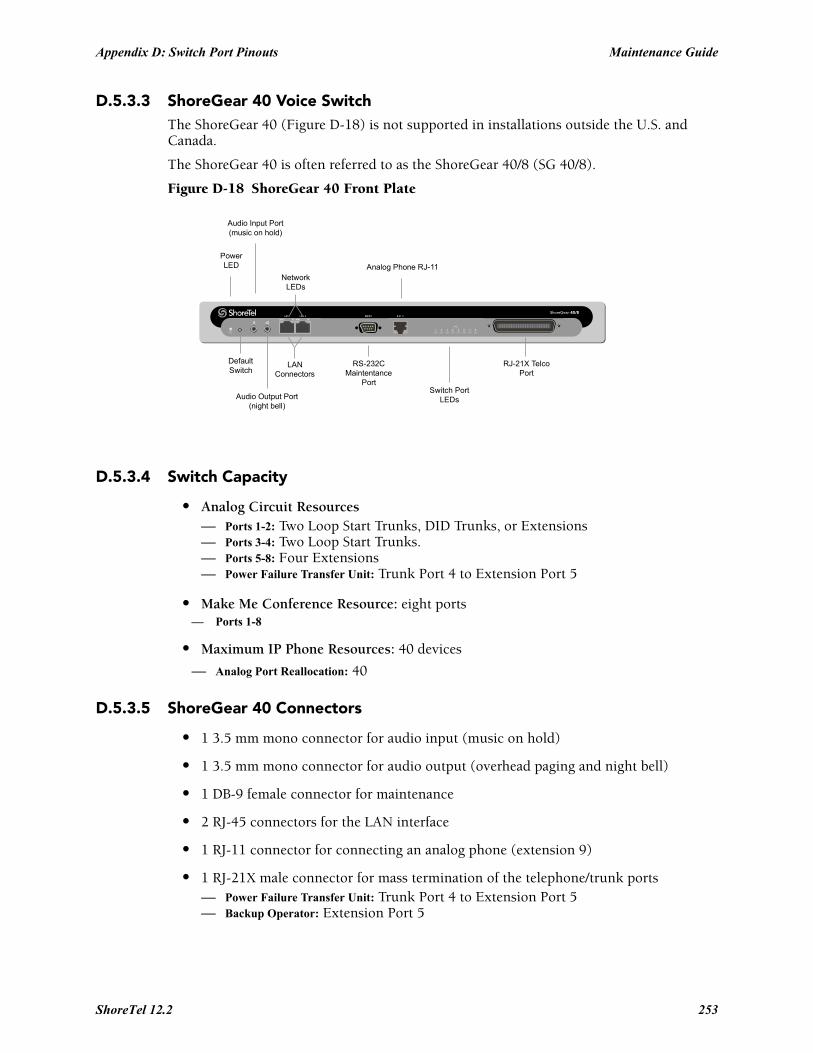
Appendix D: Switch Port Pinouts Maintenance Guide
D.5.3.3 ShoreGear 40 Voice SwitchThe ShoreGear 40 (Figure D-18) is not supported in installations outside the U.S. and Canada.
The ShoreGear 40 is often referred to as the ShoreGear 40/8 (SG 40/8).
Figure D-18 ShoreGear 40 Front Plate
D.5.3.4 Switch Capacity
• Analog Circuit Resources— Ports 1-2: Two Loop Start Trunks, DID Trunks, or Extensions— Ports 3-4: Two Loop Start Trunks.— Ports 5-8: Four Extensions— Power Failure Transfer Unit: Trunk Port 4 to Extension Port 5
• Make Me Conference Resource: eight ports— Ports 1-8
• Maximum IP Phone Resources: 40 devices
— Analog Port Reallocation: 40
D.5.3.5 ShoreGear 40 Connectors
• 1 3.5 mm mono connector for audio input (music on hold)
• 1 3.5 mm mono connector for audio output (overhead paging and night bell)
• 1 DB-9 female connector for maintenance
• 2 RJ-45 connectors for the LAN interface
• 1 RJ-11 connector for connecting an analog phone (extension 9)
• 1 RJ-21X male connector for mass termination of the telephone/trunk ports— Power Failure Transfer Unit: Trunk Port 4 to Extension Port 5— Backup Operator: Extension Port 5
ShoreGear-40/8
DefaultSwitch
Audio Output Port(night bell)
PowerLED
RS-232CMaintentance
Port
RJ-21X TelcoPort
Audio Input Port(music on hold)
NetworkLEDs
LANConnectors
Analog Phone RJ-11
Switch PortLEDs
ShoreTel 12.2 253

Maintenance Guide Appendix D: Switch Port Pinouts
ShoreGear 40 RJ-21X Telephone and Trunk Connector
Table D-13 ShoreGear 40 RJ-21X Telephone and Trunk Connector Pins
Port TypeRingPin # Ring Cable Color
TipPin # Tip Cable Color
– 1 Blue/White 26 White/Blue
– 2 Orange/White 27 White/Orange
– 3 Green/White 28 White/Green
– 4 Brown/White 29 White/Brown
1 Trunk, DID, Extension 5 Slate/White 30 White/Slate
2 Trunk, DID, Extension 6 Blue/Red 31 Red/Blue
3 Trunk 7 Orange/Red 32 Red/Orange
4 Trunk 8 Green/Red 33 Red/Green
5 Extension 9 Brown/Red 34 Red/Brown
6 Extension 10 Slate/Red 35 Red/Slate
7 Extension 11 Blue/Black 36 Black/Blue
8 Extension 12 Orange/Black 37 Black/Orange
– 13 Green/Black 38 Black/Green
– 14 Brown/Black 39 Black/Brown
– 15 Slate/Black 40 Black/Slate
– 16 Blue/Yellow 41 Yellow/Blue
– 17 Orange/Yellow 42 Yellow/Orange
– 18 Green/Yellow 43 Yellow/Green
– 19 Brown/Yellow 44 Yellow/Brown
– 20 Slate/Yellow 45 Yellow/Slate
– 21 Blue/Violet 46 Violet/Blue
– 22 Orange/Violet 47 Violet/Orange
– 23 Green/Violet 48 Violet/Green
– 24 Brown/Violet 49 Violet/Brown
– 25 Slate/Violet 50 Violet/Slate
254
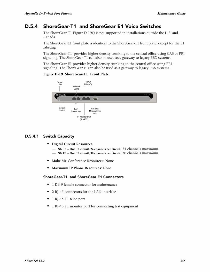
Appendix D: Switch Port Pinouts Maintenance Guide
D.5.4 ShoreGear-T1 and ShoreGear E1 Voice SwitchesThe ShoreGear-T1 Figure D-19() is not supported in installations outside the U.S. and Canada
The ShoreGear E1 front plate is identical to the ShoreGear-T1 front plate, except for the E1 labeling.
The ShoreGear-T1 provides higher-density trunking to the central office using CAS or PRI signaling. The ShoreGear-T1 can also be used as a gateway to legacy PBX systems.
The ShoreGear E1 provides higher-density trunking to the central office using PRI signaling. The ShoreGear E1can also be used as a gateway to legacy PBX systems.
Figure D-19 ShoreGear-T1 Front Plate
D.5.4.1 Switch Capacity
• Digital Circuit Resources— SG T1 – One T1 circuit, 24 channels per circuit: 24 channels maximum.— SG E1 – One T1 circuit, 30 channels per circuit: 30 channels maximum.
• Make Me Conference Resources: None
• Maximum IP Phone Resources: None
ShoreGear-T1 and ShoreGear E1 Connectors
• 1 DB-9 female connector for maintenance
• 2 RJ-45 connectors for the LAN interface
• 1 RJ-45 T1 telco port
• 1 RJ-45 T1 monitor port for connecting test equipment
ShoreGear-T1
DefaultSwitch
PowerLED
RS-232CMaintentance
Port
NetworkLEDs
LANConnectors
T1 Monitor Port(RJ-48C)
T1 Port(RJ-48C)
ShoreTel 12.2 255
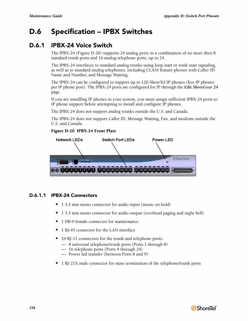
Maintenance Guide Appendix D: Switch Port Pinouts
D.6 Specification – IPBX Switches
D.6.1 IPBX-24 Voice SwitchThe IPBX-24 (Figure D-20) supports 24 analog ports in a combination of no more then 8 standard trunk ports and 16 analog telephone ports, up to 24.
The IPBX-24 interfaces to standard analog trunks using loop start or wink start signaling, as well as to standard analog telephones, including CLASS feature phones with Caller ID Name and Number, and Message Waiting.
The IPBX-24 can be configured to support up to 120 ShoreTel IP phones (five IP phones per IP phone port). The IPBX-24 ports are configured for IP through the Edit ShoreGear 24 page.
If you are installing IP phones in your system, you must assign sufficient IPBX-24 ports to IP phone support before attempting to install and configure IP phones.
The IPBX-24 does not support analog trunks outside the U.S. and Canada.
The IPBX-24 does not support Caller ID, Message Waiting, Fax, and modems outside the U.S. and Canada.
Figure D-20 IPBX-24 Front Plate
D.6.1.1 IPBX-24 Connectors
• 1 3.5 mm mono connector for audio input (music on hold)
• 1 3.5 mm mono connector for audio output (overhead paging and night bell)
• 1 DB-9 female connector for maintenance
• 1 RJ-45 connector for the LAN interface
• 24 RJ-11 connectors for the trunk and telephone ports:— 8 universal telephone/trunk ports (Ports 1 through 8)— 16 telephone ports (Ports 9 through 24)— Power fail transfer (between Ports 8 and 9)
• 1 RJ-21X male connector for mass termination of the telephone/trunk ports
256

Appendix D: Switch Port Pinouts Maintenance Guide
IPBX-24 RJ-21X Telephone and Trunk Connector
Table D-14 IPBX-24 RJ-21X Telephone and Trunk Connector Pins
Port TypeRingPin # Ring Cable Color
TipPin # Tip Cable Color
1 Trunk, DID, Extension 1 Blue/White 26 White/Blue
2 Trunk, DID, Extension 2 Orange/White 27 White/Orange
3 Trunk, DID, Extension 3 Green/White 28 White/Green
4 Trunk, DID, Extension 4 Brown/White 29 White/Brown
5 Trunk, DID, Extension 5 Slate/White 30 White/Slate
6 Trunk, DID, Extension 6 Blue/Red 31 Red/Blue
7 Trunk, DID, Extension 7 Orange/Red 32 Red/Orange
8 Trunk, DID, Extension 8 Green/Red 33 Red/Green
9 Extension 9 Brown/Red 34 Red/Brown
10 Extension 10 Slate/Red 35 Red/Slate
11 Extension 11 Blue/Black 36 Black/Blue
12 Extension 12 Orange/Black 37 Black/Orange
13 Extension 13 Green/Black 38 Black/Green
14 Extension 14 Brown/Black 39 Black/Brown
15 Extension 15 Slate/Black 40 Black/Slate
16 Extension 16 Blue/Yellow 41 Yellow/Blue
17 Extension 17 Orange/Yellow 42 Yellow/Orange
18 Extension 18 Green/Yellow 43 Yellow/Green
19 Extension 19 Brown/Yellow 44 Yellow/Brown
20 Extension 20 Slate/Yellow 45 Yellow/Slate
21 Extension 21 Blue/Violet 46 Violet/Blue
22 Extension 22 Orange/Violet 47 Violet/Orange
23 Extension 23 Green/Violet 48 Violet/Green
24 Extension 24 Brown/Violet 49 Violet/Brown
– 25 Slate/Violet 50 Violet/Slate
ShoreTel 12.2 257
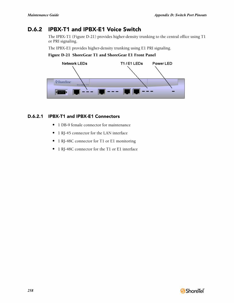
Maintenance Guide Appendix D: Switch Port Pinouts
D.6.2 IPBX-T1 and IPBX-E1 Voice SwitchThe IPBX-T1 (Figure D-21) provides higher-density trunking to the central office using T1 or PRI signaling.
The IPBX-E1 provides higher-density trunking using E1 PRI signaling.
Figure D-21 ShoreGear T1 and ShoreGear E1 Front Panel
D.6.2.1 IPBX-T1 and IPBX-E1 Connectors
• 1 DB-9 female connector for maintenance
• 1 RJ-45 connector for the LAN interface
• 1 RJ-48C connector for T1 or E1 monitoring
• 1 RJ-48C connector for the T1 or E1 interface
258
Glossary
10Base-T
10 Mbps Ethernet over twisted pair copper cable.
100Base-T
100 Mbps Ethernet over twisted pair copper cable.
1000Base-T
1000 Mbps Ethernet over twisted pair copper cable.
10GBase-T
10Gbps over copper cable.
802.1x
A component of IEEE 802.1 group of networking protocols that addresses port-based Network Access Control. It provides an authentication mechanism for devices attaching to a LAN port to either establish a point-to-point connection or prevent the device from accessing the port if authentication fails. 802.1x is based on the Extensible Authentication Protocol (EAP).
ShoreTel 12.2 259
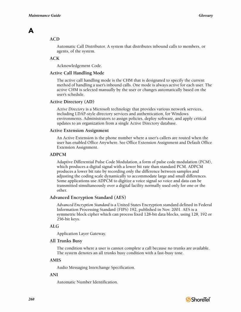
Maintenance Guide Glossary
AACD
Automatic Call Distributor. A system that distributes inbound calls to members, or agents, of the system.
ACK
Acknowledgement Code.
Active Call Handling Mode
The active call handling mode is the CHM that is designated to specify the current method of handling a user’s inbound calls. One mode is always active for each user. The active CHM is selected manually by the user or changes automatically based on the user’s schedule.
Active Directory (AD)
Active Directory is a Microsoft technology that provides various network services, including LDAP-style directory services and authentication, for Windows environments. Administrators to assign policies, deploy software, and apply critical updates to an organization from a single Active Directory database.
Active Extension Assignment
An Active Extension is the phone number where a user's callers are routed when the user has enabled Office Anywhere. See Office Extension Assignment and Default Office Extension Assignment.
ADPCM
Adaptive Differential Pulse Code Modulation, a form of pulse code modulation (PCM), which produces a digital signal with a lower bit rate than standard PCM. ADPCM produces a lower bit rate by recording only the difference between samples and adjusting the coding scale dynamically to accommodate large and small differences. Some applications use ADPCM to digitize a voice signal so voice and data can be transmitted simultaneously over a digital facility normally used only for one or the other.
Advanced Encryption Standard (AES)
Advanced Encryption Standard is a United States Encryption standard defined in Federal Information Processing Standard (FIPS) 192, published in Nov. 2001. AES is a symmetric block cipher which can process fixed 128-bit data blocks, using 128, 192 or 256-bit keys.
ALG
Application Layer Gateway.
All Trunks Busy
The condition where a user is cannot complete a call because no trunks are available. The system denotes an all trunks busy condition with a fast-busy tone.
AMIS
Audio Messaging Interchange Specification.
ANI
Automatic Number Identification.
260
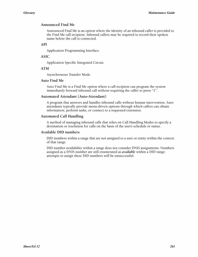
Glossary Maintenance Guide
Announced Find Me
Announced Find Me is an option where the identity of an inbound caller is provided to the Find Me call recipient. Inbound callers may be required to record their spoken name before the call is connected.
API
Application Programming Interface.
ASIC
Application Specific Integrated Circuit.
ATM
Asynchronous Transfer Mode.
Auto Find Me
Auto Find Me is a Find Me option where a call recipient can program the system immediately forward inbound call without requiring the caller to press “1”.
Automated Attendant (Auto-Attendant)
A program that answers and handles inbound calls without human intervention. Auto attendants typically provide menu-driven options through which callers can obtain information, perform tasks, or connect to a requested extension.
Automated Call Handling
A method of managing inbound calls that relies on Call Handling Modes to specify a destination or resolution for calls on the basis of the user’s schedule or status.
Available DID numbers
DID numbers within a range that are not assigned to a user or entity within the context of that range.
DID number availability within a range does not consider DNIS assignments. Numbers assigned as a DNIS number are still enumerated as available within a DID range; attempts to assign these DID numbers will be unsuccessful.
ShoreTel 12 261
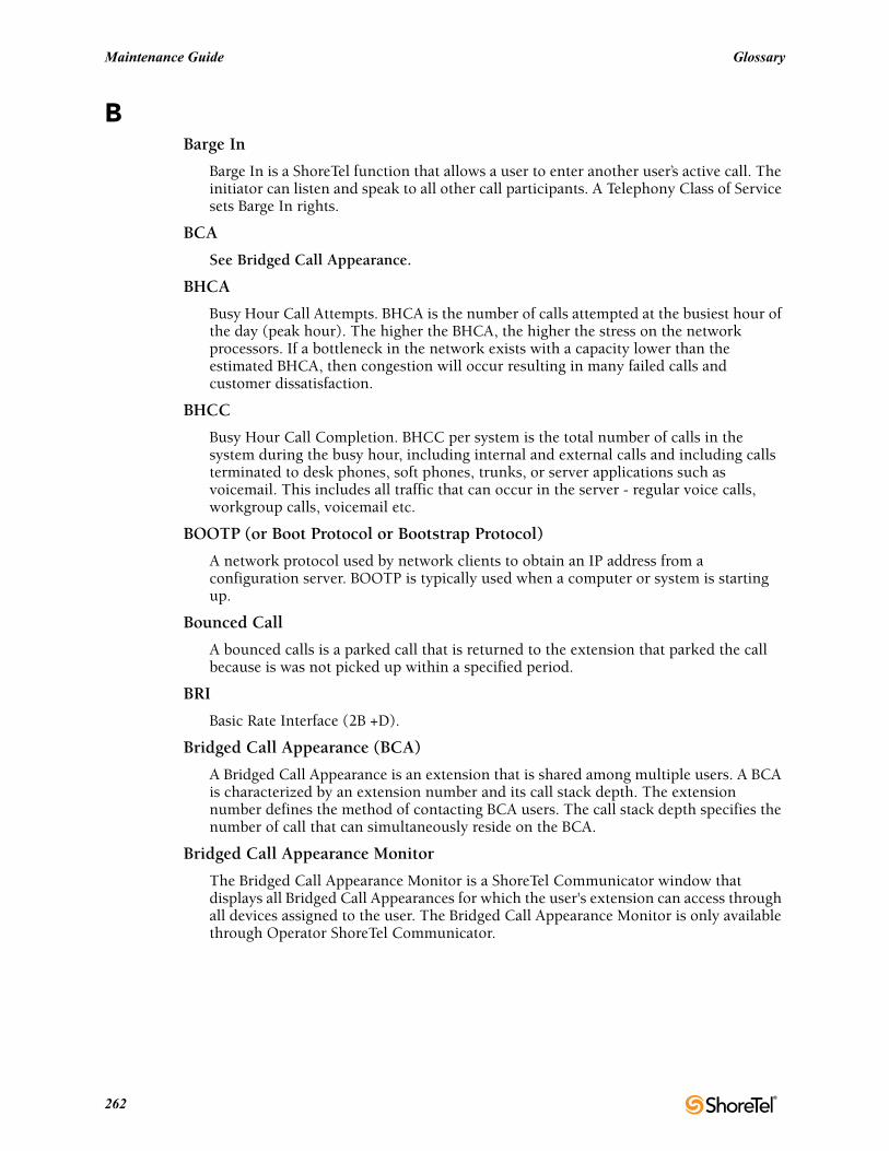
Maintenance Guide Glossary
BBarge In
Barge In is a ShoreTel function that allows a user to enter another user’s active call. The initiator can listen and speak to all other call participants. A Telephony Class of Service sets Barge In rights.
BCA
See Bridged Call Appearance.
BHCA
Busy Hour Call Attempts. BHCA is the number of calls attempted at the busiest hour of the day (peak hour). The higher the BHCA, the higher the stress on the network processors. If a bottleneck in the network exists with a capacity lower than the estimated BHCA, then congestion will occur resulting in many failed calls and customer dissatisfaction.
BHCC
Busy Hour Call Completion. BHCC per system is the total number of calls in the system during the busy hour, including internal and external calls and including calls terminated to desk phones, soft phones, trunks, or server applications such as voicemail. This includes all traffic that can occur in the server - regular voice calls, workgroup calls, voicemail etc.
BOOTP (or Boot Protocol or Bootstrap Protocol)
A network protocol used by network clients to obtain an IP address from a configuration server. BOOTP is typically used when a computer or system is starting up.
Bounced Call
A bounced calls is a parked call that is returned to the extension that parked the call because is was not picked up within a specified period.
BRI
Basic Rate Interface (2B +D).
Bridged Call Appearance (BCA)
A Bridged Call Appearance is an extension that is shared among multiple users. A BCA is characterized by an extension number and its call stack depth. The extension number defines the method of contacting BCA users. The call stack depth specifies the number of call that can simultaneously reside on the BCA.
Bridged Call Appearance Monitor
The Bridged Call Appearance Monitor is a ShoreTel Communicator window that displays all Bridged Call Appearances for which the user's extension can access through all devices assigned to the user. The Bridged Call Appearance Monitor is only available through Operator ShoreTel Communicator.
262
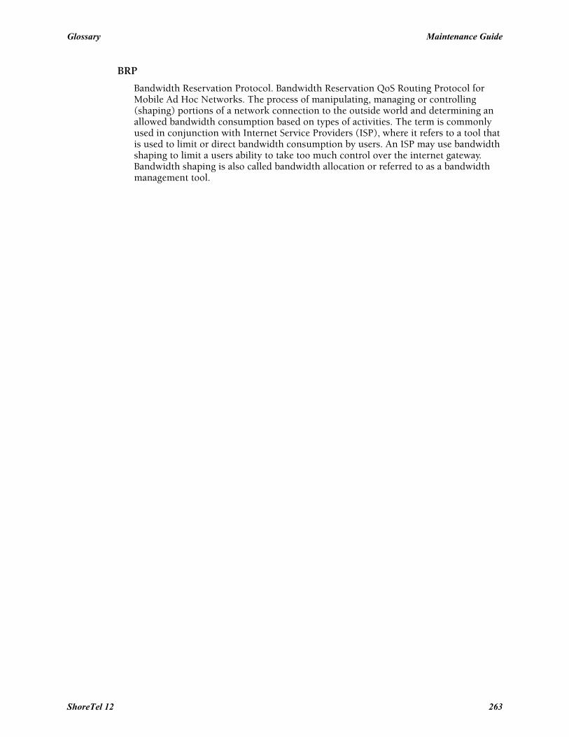
Glossary Maintenance Guide
BRP
Bandwidth Reservation Protocol. Bandwidth Reservation QoS Routing Protocol for Mobile Ad Hoc Networks. The process of manipulating, managing or controlling (shaping) portions of a network connection to the outside world and determining an allowed bandwidth consumption based on types of activities. The term is commonly used in conjunction with Internet Service Providers (ISP), where it refers to a tool that is used to limit or direct bandwidth consumption by users. An ISP may use bandwidth shaping to limit a users ability to take too much control over the internet gateway. Bandwidth shaping is also called bandwidth allocation or referred to as a bandwidth management tool.
ShoreTel 12 263
Maintenance Guide Glossary
CCall Appearance
A VoIP data structure that supports one voice call session.
Call Detail Record (CDR)
A Call Detail Record (CDR) is a data record containing statistics of a call that passed through a pbx or telephone exchange.
Information provided by a CDR includes the number of the originating party, the number of the recipient, the time that the call started, and the duration of the call. ShortTel CDRs contain additional information.
Call Handling
A predetermined method of servicing inbound calls. ShoreTel supports Automated Call Handling and Personalized Call Handling.
Call Handling Mode (CHM)
A call handling mode is a ShoreTel variable that defines a method of handling specified inbound calls. Each user is assigned five call handling modes, one of which is active and determines the user’s current call handling method. See Active Call Handling Mode.
The five call handling modes assigned to each user are named Standard, In a Meeting, Extended Absence, Out of Office, and Custom.
Call Handling Rule
A call handling rule is the base unit of a Call Routing Plan that consists of a condition and action. When a call handling rule is active and the condition is satisfied, the action specifies method by which the ShoreTel system handles the user’s call.
Call History
A set of call records for an end user. Each call history record provides information about one call including type, direction, time, duration, disposition, and identity of the other party. Users view their call history through ShoreTel Communicator or Mobile ShoreTel Communicator.
Call Notification
A set of features that inform the user of the arrival of a new call, such as ringing the telephone or playing a sound on the workstation speakers.
Call Routing
A method of delivering calls to destinations based on a situation or system status. Call routing can also refer to the automatic delivery of an incoming call to a particular extension, such as in DID or dedicated CO lines.
Call Routing Plan
The Call Routing Plan is the Personal Call Handling component that contains of rules that specifies a user’s call handling method. The plan prioritizes a list of enabled Call Handling Rules.
Call Stack
The ShoreTel extension component that manages an entity’s call appearances. The size defines the maximum number of calls – including active and held calls – that an extension can handle simultaneously.
264
Glossary Maintenance Guide
Call Waiting
Usually for single-line telephones, a feature that lets a second call arrive to the line by delivering a call-waiting tone to the user and a ring-back to the caller.
Call Waiting Tone
The tone that is presented to a user with call waiting when a second call arrives.
CallerID
A technique for transmitting the calling party’s telephone number and (optionally) name to equipment enabled to handle this feature; also called CLI in Europe.
Caller’s Emergency Service Identification (CESID)
The extension that a switch sends to a Public Safety Answering Point (PSAP). A CESID identifies the location of callers who require emergency 911 services.
CAT 5e
Category 5e twisted pair cable.
CDMA
Code Division Multiple Access.
CDR
Call Detail Record.
CDR Database
A CDR database contains all CDRs generated by a ShoreTel system over a specified period of time. The CDR database is maintained on the Main Server.
Central Office (CO)
The building where the telephone company’s telephone switching equipment that services the local area is located.
Centrex
A name for advanced telephone services provided by the local telephone company. It usually requires a connection to a special telephone system but provides services such as voice mail and call forwarding.
CERT
Computer Emergency Readiness Team.
CESID
.Caller’s Emergency Service Identification.
CHM
Call Handling Mode.
CIF
Common Intermediate Format.
ShoreTel 12 265
Maintenance Guide Glossary
Class of Service (CoS or COS)
A class of service grants permission to a specified set of features and privileges. Users assigned to a class of service can access the specified features and privileges. ShoreTel defines three types of service classes: telephony features, call permissions, and voice mail permissions.
CLI
Calling Line ID.
CO
Central Office of a telecommunications operator.
CO Line
Trunk.
Codec
Coder/Decoder. A codec is a device or program that encodes and decodes a digital data stream or signal. Codecs encode a data stream or signal for transmission, storage or encryption and decode it for viewing or editing. Codecs are typically used in video conferencing and streaming media applications.
Conference
Three or more parties joined together in a single call, such that each party can hear and be heard by the others.
Coordinate
Location Based Services data point that identifies a specific location in terms of longitude, latitude, and elevation. See Location Based Services.
CoS or COS
Class of Service.
CQM
Call Quality Monitor.
CRM
Customer Relationship Management.
CSIS
Client/Server Internet Services. A ShoreTel proprietary protocol that uses HTTP messages to communicate between client PCs and ShoreTel servers. The CSIS protocol communicates configuration updates such as call handling mode settings and Outlook integration. The CSIS client holds open a pending HTTP request in order to receive notifications from the CSIS server. Network devices such as firewalls and proxies must not automatically close these pending requests.
CSMA/CD
Carrier Sense Multiple Access/Collision Detection.
CSU
Channel Service Unit.
266

Glossary Maintenance Guide
CTI
Computer Telephony Integration.
Current Call Handling Mode
Active Call Handling Mode.
ShoreTel 12 267
Maintenance Guide Glossary
DD4
A T-1 framing scheme.
DBImport
DBImport is a ShoreTel utility that uses the contents of a CSV file to update the ShoreTel user database. DBImport.exe adds, deletes, and modifies user account records based on the CSV file contents.
DCOM
Distributed Component Object Model, an extension of the Component Object Model (COM), which allows COM components to communicate across network boundaries. Traditional COM components can only perform interprocess communication across process boundaries on the same machine. DCOM uses the RPC mechanism to transparently send and receive information between COM components (clients and servers) on the same network.
DECT
Digital Enhanced Cordless Telecommunications.
Default Office Extension Assignment
The Default Office Extension Assignment is the MCM component that can specify the Active Office Extension Assignment when a user places a call or plays a voice message through MCM. See Active Office Extension Assignment and Office Extension Assignment.
DES
Data Encryption Standard.
DHCP
Dynamic Host Configuration Protocol.
Dial Number (DN)
Dial Number – the number dialed by a user.
DID
Direct Inward Dialing.
DID Range
A DID range is a list of consecutive DID numbers assigned to a Trunk Group. Ranges assigned to a trunk group cannot overlap. A DID number can be assigned to multiple trunk groups.
DID (DDI in the U.K.)
Direct Inward Dial.
268
Glossary Maintenance Guide
Differentiated Services
Differentiated Services is a computer networking architecture that specifies a method for managing network traffic and providing Quality of Service (QoS) guarantees on IP networks.
Differentiated Services can provide low-latency, guaranteed service for critical network traffic (voice or video) while providing simple best-effort traffic guarantees to less critical services (web traffic or file transfers).
Differentiated Services Code Point (DSCP)
Differentiated Services Code Point is a 6-bit value, contained in the 8-bit DiffServ/ToS field of the IP packet header, that indicates the data traffic Per-Hop Behavior (PHB).
DiffServ
Differentiated Services.
DMZ
De-militarized Zone.
DN
Dial number.
DNS
Domain Naming System.
DNIS
Dialed Number Identification Service.
DoS
Denial of Service.
DPCM
Differential Pulse Code Modulation.
Dr. Watson
Dr. Watson is an application debugger included with the Microsoft Windows operating system. It is usually named drwatson.exe, drwtsn32.exe or dwwin.exe depending on the version of Windows. It collects error information (symptoms) following the problem. The information obtained and logged by Dr. Watson is the information needed by technical support personnel to diagnose a program error for a computer running Windows. A text file (Drwtsn32.log) is created whenever an error is detected, and can be delivered to support personnel by the method they prefer. A crash dump file can also be created, which is a binary file that a programmer can load into a debugger. Dr. Watson can be made to generate more exacting information for debugging purposes if the appropriate symbol files are installed and the symbol search path (environment variable) is set. When a program error occurs in Windows, the system searches for a program error handler. A program error handler deals with errors as they arise during the running of a program. If the system does not find a program error handler, the system verifies that the program is not currently being debugged and considers the error to be unhandled. The system then processes unhandled errors by looking in the registry for a program error debugger for which Dr. Watson is the default.
ShoreTel 12 269
Maintenance Guide Glossary
DRS
Distributed Routing Service. DRS on each server provides routing information when switches cannot route the call in the local site and require intersite call routing information. A ShoreTel enhanced SIP protocol is used for switch-to-DRS communications.
When DRS is enabled, switches exchange LSP messages only with other switches at the same site. DRS communicates directly with the database to keep the database configuration current. TMS tells each switch how to find DRS. When DRS is enabled, switches generally give DRS an opportunity to resolve numbers, so that its more complete view of the system can be leveraged to find the best contact. If the switch knows where an intra-site extension is, it does not involve DRS.
DSCP
Differentiated Services Code Point.
DSL
Digital Subscriber Line.
DSP
Digital Signal Processor.
DS-0
64 Kbps channel.
DS-1
1.544 Mbps = T-1 = 24 x 64 Kbps channels.
DS-3
44.736 Mbps = T-3 = 28 x T-1s = 672 x 64 Kbps channels.
DSCP
Differentiated Services Code Point.
DSS/BLF
Direct Station Select Busy Lamp Field (Attendant Console).
DTAS
Distributed Telephony Application Service. Provides connectivity between applications and TMS instances. DTAS reads the system configuration so that it knows which extensions are controlled by which TMS instances. DTAS is responsible for routing call control and events between applications and the TMS instance responsible for a given extension. For extensions controlled by the local TMS instance, DTAS routes call control to the local TMS instance. For extensions controlled by a remote TMS instance. DTAS routes call control to the appropriate remote TMS instance. DTAS makes the distributed TMS architecture transparent to applications and reduces the number of network connections needed if every application were required to connect to every TMS instance.
DTMF
Dual Tone Multi Frequency.
270
Glossary Maintenance Guide
Dynamic Host Configuration Protocol (DHCP)
A protocol for downloading network information (such as IP addresses) to client workstations.
Dual-Tone Multi-Frequency (DTMF)
A signalling method used by telephones to send information to an exchange. Pressing a key on the phone's keypad sends two simultaneous tones to the exchange, which are then decoded to determine the pressed key. Also known as Touch Tone.
DVS
Distributed Voice Server. DVS servers provide increased system reliability by distributing key services and applications at remote sites. Each DVS includes an instance of TMS that connects to and manages the local SoftSwitch. The SoftSwitch provides extensions for use by the local Auto-Attendant, Workgroups, and virtual users. DVS servers can also be configured to support distributed voice applications such voice mail, workgroups, account codes, auto attendant and a distributed database. DVS servers have TAPI access to the local SoftSwitch. The distributed TMS maintains a copy of the configuration database that allows it to provide call control and voice mail service during the outage. Each DVS manages its own SoftSwitch, as well as ShoreTel Voice Switches assigned to it.
ShoreTel 12 271
Maintenance Guide Glossary
EE.164
International public telecommunication numbering plan.
ECTF
Enterprise Computer Telephony Forum.
ESF
Extended Super Frame - a T-1 framing scheme.
Explicit Authentication
Explicit Authentication is an LDAP process where an application prompts users for credentials when they log into a network, then verifies those credentials through a call to the LDAP server.
Extension Assignment
Extension Assignment is a ShoreTel user feature that forwards calls to a designated device – either a system IP phone device or a remote telephone connected to the PSTN. Extension Assignment requires administrative authorization.
Extension Monitor
Extension Monitor is a ShoreTel function that provides a user access to another user's extension. In addition to viewing extension activity, the monitoring user can answer calls and perform other actions on calls at that extension. Extension monitoring is facilitated through ShoreTel Communicator and IP Phone Programmable buttons.
272
Glossary Maintenance Guide
FFailback
Failback is the process of restoring a server, system, component, or network to the original, pre-failover state. See failover.
Failover
Failover is the action of automatically transferring operations to a redundant or standby server, system, component, or network to continue normal operation after the base device fails. The failover process initiates without human intervention and typically without warning.
FCC
Federal Communications Commission.
Find Me
Find Me is a call handling feature that allows callers who are routed to a user's voice mailbox to contact the user at alternate devices by pressing “1” while listening to the voice mail greeting. See Auto Find Me and Announced Find Me.
FMC
Fixed Mobile Convergence.
Foreign Exchange Office (FXO)
An FXO interface connects to the public switched telephone network (PSTN) central office and is the interface offered on a standard telephone. An FXO interface is used for trunks, tie lines, or connections to a PSTN CO or PBX that does not support E&M signaling (when local telecommunications authority permits).
Foreign Exchange Station (FXS)
An FXS interface supplies ring, voltage and dial tone for basic telephone equipment, keysets, and PBXs. The FXO interface is useful for off-premises station applications.
FPS
Frames Per Second.
Frequency Shift Key (FSK)
A modulation technique used with low-speed modems; also used with CallerID and message-waiting lamp indicators.
FSK
Frequency Shift Key.
FXO
Foreign Exchange Office.
FXS
Foreign Exchange Station.
ShoreTel 12 273
Maintenance Guide Glossary
GG.711
Pulse code modulation (PCM) of voice frequencies.
G.723.1
Dual rate speech coder for multimedia communications transmitting at 5.3 and 6.3 kbit/s.
G.729a
Coding of speech at 8 Kbps using CS-ACELP.
G.729a (annexe B)
G.729a with silence suppression Ground Start: A way of signaling initiation of a call from a PBX to the CO by briefly grounding one side of a line.
Global Positioning System
The Global Positioning System (GPS) uses a constellation of 24 and 32 satellites that transmit microwave signals to GPS receivers, which they use to determine their current location, the time, and their velocity. GPS usually requires line of sight access between the transmitter and the device.
GPS
Global Positioning System.
GSM
Group System Mobile.
274
Glossary Maintenance Guide
HH.100
ECTF-standard CT bus implementation with PCI.
H.110
ECTF-standard CT bus implementation with Compact PCI.
H.225.0
Call signaling protocols and media stream packetization for packet-based multimedia communication systems.
H.245
Control protocol for multimedia communication.
H.248
ITU equivalent of IETF MEGACO.
H.263
Video Coding Standard.
H.264
Advanced Video Coding Standard.
H.320
Narrow-band visual telephone systems and terminal equipment.
H.323
Packet-based multimedia communications systems.
H.324m
Video conferencing standard for low bit-rate (mobile) connections.
H.450
Generic functional protocol for the support of supplementary services.
Hold (on Hold)
A active call whose conversation is suspended. Calls on hold remain on the user’s.
HTTP
HyperText Transfer Protocol.
ShoreTel 12 275
Maintenance Guide Glossary
IICE
Interactive Connectivity Establishment (Assists with NAT traversal).
IDS
Intrusion Detection System.
IEEE 802.1
Transparent Bridging.
IEEE 802.1d
Spanning Tree Algorithm.
IEEE 802.3
CSMA/CD (Ethernet).
IEEE 802.3ad
Link Aggregation.
IEEE 802.3ae
10-Gbps Ethernet.
IEEE 802.3af
Power over Ethernet.
IEEE 802.11 a,b,g,n
Wireless LAN standards.
IEEE 802.11e
QoS for WiFi.
IEEE 802.16e
Mobile Wimax standard.
IETF
Internet Engineering Task Force.
IIS
Internet Information Server, Microsoft's Web server that runs on Windows NT platforms.
IM
Instant Messaging.
Interactive Voice Recognition.
Instant Messaging (IM)
Instant Messaging is the real-time transmission of text between at least two parties.
Internet Telephony Service Provider (ITSP)
An Internet Telephony Service Provider are vendors that offer Internet data services for making telephone calls.
276
Glossary Maintenance Guide
IP
Internet Protocol.
IPBX
IP PBX.
IPDS
Intelligent Printer Data Stream.
IP Phone Configuration Switch
In each ShoreTel installation, one switch is responsible for assigning, to each IP phone, a switch that performs ShoreTel Communicator activities.
IP Phone Failover
IP Phone Failover is a ShoreTel feature that continues a voice call after the ShoreTel IP Phone loses communication with the its ShoreTel Communicator switch.
When IP Phone Failover is implemented, ShoreTel IP Phones are configured to send a signal to their ShoreTel Voice Switch every four minutes and to expect an acknowledgment from the switch. When a phone does not receive the return signal, it connects to another switch located at the same site.
IP Phone Keep Alive
A signal that voice switches send to the IP phones for which they provide ShoreTel Communicator services. The system considers phones that acknowledge the signal are The signal is also referred to as a heartbeat.
IPS
Intrusion Protection System.
IPSEC
IP Security.
IPT
IP Telephony.
ISDN
Integrated Services Digital Network.
ITU
International Telecommunications Union.
ITSP
Internet Telephony Service Provider.
IVR
Interactive Voice Recognition.
ShoreTel 12 277

Maintenance Guide Glossary
LLBS
Location based service.
LCD
Liquid Crystal Display.
LDAP
See Lightweight Directory Access Protocol.
LDAPExport
LDAPExport is a ShoreTel utility that exports AD directory information to a CSV file, whose contents can be imported to a ShoreTel user database. LDAPExport was introduced in ShoreTel to support AD Integration.
LED
Light Emitting Diode.
Lightweight Directory Access Protocol (LDAP)
Lightweight Directory Access Protocol is an application protocol for querying and modifying directory services running over TCP/IP.
Line
Trunk.
LLDP-MED
An enhancement to the basic LLDP protocol that addresses the discovery of endpoints by networks supporting LLDP.
Location based service
Location based service (LBS) is a component feature that receives data identifying the position of the device in terms of latitude, longitude, and altitude. Data reception methods include GPS access and through Mobile Cell device service transmitters.
MCM location based services does not use altitude to specify the location of the device.
Loop Start
A way of signaling call initiation by creating a loop across the two wires of a telephone pair.
278
Glossary Maintenance Guide
MMAC
Media Access Control (Ethernet).
MAC
Moves, Adds and Changes (Telephony).
MAN
Metropolitan Area Network.
MAPI
Messaging Application Programming Interface. A system built into Microsoft Windows that enables different e-mail applications to work together to distribute mail. As long as both applications are MAPI-enabled, they can share mail messages with each other.
MDMF
Multiple Data Message Format.
MEGACO
Media Gateway Control, also known as H.248 signaling protocol.
Message Notification
A set of features that inform the user that a new message has arrived in his or her voice mailbox, such as lighting the call-waiting lamp, paging the user, or dialing a telephone number.
MGCP
Media Gateway Control Protocol.
MGCP
Media Gateway Control Protocol. A control and signal standard for the conversion of audio signals carried on telephone circuits (PSTN) to data packets carried over the Internet or other packet networks.
MIME
Multipurpose Internet Mail Extensions.
MOH
Music on Hold.
Monitor Extension
Extension monitoring is a ShoreTel feature that permits a user to view another user’s extension status and answer inbound or held calls to that extension.
MOS
Mean Opinion Score.
MPEG
Motion Picture Experts Group.
MPEG-4
Advanced Video Coding Standard.
ShoreTel 12 279
Maintenance Guide Glossary
MPLS
Multi-Protocol Label Switching.
MTBF
Mean Time Between Failures.
Music on Hold (MOH)
Background music heard when callers are put on hold, letting them know they are still connected. Most telephone systems have the ability to connect to any sound-producing device (for example, a radio, a cassette player, or a CD player).
MySQL
MySQL is a relational database management system. It runs as a server providing multi-user access to a number of databases. MySQL is owned and sponsored by a single for-profit firm, the Swedish company MySQL AB, which is a subsidiary of Sun Microsystems. The project's source code is available under terms of the GNU General Public License, as well as under a variety of proprietary agreements.
280

Glossary Maintenance Guide
NNAC
Network Access Control.
NAP
Network Access Protection.
NAT
Network Address Translation.
NIC
Network Interface Card.
NI2
Standard ISDN Signaling scheme.
NM
Nanometer
NTSC
National Television Standards Committee.
ShoreTel 12 281
Maintenance Guide Glossary
OODBC
The Open Database Connectivity specification provides a standard software API method for using database management systems (DBMS). The designers of ODBC aimed to make it independent of programming languages, database systems, and operating systems.
ODBC Connectors
Drivers that provide connectivity to the MySQL server for client programs. There are currently five MySQL Connectors – Connector/ODBC, Connector/NET, Connector/J, Connector/MXJ, Connector/PHP.
Off Hook
The operating state of a communications link in which transmissions are enabled either for network signaling, voice communications, or data communications.
The act of seizing the line or channel is referred to as going off hook.
Off System Extensions
Off System Extensions are ShoreTel extensions that, when dialed, route calls from the trunk group to which they are associated. A ShoreTel system typically uses Off System Extensions to connect with a legacy PBX system.
Office Extension Assignment
An Office Extension Assignment is a phone number to which a user's callers can be routed when the user has enabled Office Anywhere. An OE number can be any system extension or PSTN number that is accessible from the ShoreTel system. Users can define multiple office extensions, of which only one can be active at any time. See Active Office Extension Assignment and Default Office Extension Assignment.
On Hook
The operating state of a telecommunications link in which transmissions are disabled and then end instrument (phone) presents an open circuit to the link. The link is responsive to ringing signals during on-hook conditions.
The act of releasing the line or channel is referred to as going on hook.
Operator
The person who monitors the telephone system and transfers calls to the appropriate extensions.
OUI
Organizationally Unique Identifier.
282
Glossary Maintenance Guide
PP.831
Subjective performance evaluation of network echo cancellers
PABX
Private Automatic Branch Exchange.
PAL
Phase Alternating Line.
Parking a Call
Parking a call places a call on hold on another extension’s.
PBX
Private Branch Exchange.
PCM
Pulse Code Modulation.
Per-Hop Behavior
Per-Hop behaviors define packet forwarding properties associated with a class of traffic. Different PHBs may be defined to offer low-loss, low-latency forwarding properties or best-effort forwarding properties.
Personalized Call Handling
Personalized Call Handling is a ShoreTel feature that defines flexible handling methods for inbound calls. Calls are filtered and managed on the basis caller identity, time or date or receipt, end user status, and caller identity.
Physical Extension
A common internal extension with an assigned physical port and telephone.
PoE
Power over Ethernet.
Presence
Presence is a feature that identifies and distributes the availability of system users and other personal contacts. ShoreTel defines two types of Presence: IM presence and telephony presence.
PRI
Primary Rate Interface.
Private Branch Exchange (PBX)
A term used by telephone companies to indicate equipment that is located on the customer’s premises and that can route telephone calls.
Programmable IP Phone Buttons
Programmable IP Phone buttons is a ShoreTel IP Phone feature that provides access to ShoreTel call management functions. Each button is programmed by the user or administrator to perform a specific function when pushed and contains an LED indicator that displays status of the function.
ShoreTel 12 283

Maintenance Guide Glossary
Programmable ShoreTel Communicator Toolbar Buttons
Programmable Toolbar buttons is a ShoreTel Communicator feature that provides access to ShoreTel call management functions. Each User Interface button is programmed by the administrator to perform a specific function when clicked and contains text that provides status of the function.
PSTN
Public Switched Telephone Network.
Public Switched Telephone Network (PSTN)
Another name for the public telephone network.
284
Glossary Maintenance Guide
QQ.931
ISDN user-network interface layer 3 specification for basic call control
QoS
Quality of Service. A traffic engineering term that refers to resource reservation control by providing different priorities to different applications, users, or data flows to guarantee a performance level for a data flow.
QSIG
Q reference point Signaling.
QuickDial Field
A QuickDial field is a data entry field requesting contact information for a system user, extension, or external contact. Upon the entry of alphanumeric characters, the field expands vertically to display all possible valid entries, filtered by the input. Users fill the field by selecting one of the options with the cursor.
ShoreTel 12 285
Maintenance Guide Glossary
RRAS
Registration Admission Status.
Real-time Transport Control Protocol (RTCP)
Real-time Transport Control Protocol, defined in RFC 3550, is a sister protocol of the Real-time Transport Protocol (RTP) that provides out-of-band control information for an RTP flow. It accompanies RTP in the delivery and packaging of multimedia data, but does not transport any data itself. It is used periodically to transmit control packets to participants in a streaming multimedia session, primarily to provide feedback on the quality of service being provided by RTP media stream.
Real-time Transport Protocol (RTP)
Real-time Transport Protocol defines a standardized packet format for delivering audio and video over the Internet. RTP is described by IETF RFC 3550.
RED
Random Early Detection.
RGB
Red, green, blue.
Ring
Tip and Ring.
Ringback Tone
The audible signal given to the caller by the telephone company (or telephone system) to indicate that the remote telephone is ringing.
Ringdown
A ringdown circuit consists of predefined devices at the circuit endpoints and is configured to ring a recipient device immediately after an initiating device goes off hook. Ringdown calls are completed without dialing or any other signaling other than the initiating device going off hook.
RPC
Remote Procedure Call. A type of protocol that allows a program on one computer to execute a program on a server computer. The client program sends a message to the server with appropriate arguments and the server returns a message containing the results of the program executed.
RSVP-TE
Resource Reservation Protocol - Traffic Engineering.
RTCP
See Real-time Transport Control Protocol.
RTP
See Real-Time Transport Protocol.
286
Glossary Maintenance Guide
SSBC
Session Border Controller.
SCTP
Stream Control Transmission Protocol.
SDH
Synchronous Digital Hierarchy (European Equivalent of SONET).
SDMF
Single Data Message Format.
SDP
Session Description Protocol.
SECAM
Sequential Color Memory.
Secure Real-Time Transport Protocol (SRTP)
Secure Real-Time Transport Protocol defines a profile for providing encryption, message authentication and integrity, and replay protection to RTP data streams.
Session Description Protocol (SDP)
Session Description Protocol is a format for describing streaming media initialization parameters. The IETF published a revised specification as an IETF Proposed Standard as RFC 4566 in July 2006. SDP is intended for describing multimedia communication sessions for the purposes of session announcement, session invitation, and other forms of multimedia session initiation. SDP does not provide the content of the media form itself but simply provides a negotiation between two end points to allow them to agree on a media type and format.
Session Initiated Protocol (SIP)
Session Initiation Protocol is a signalling protocol that is typically used for setting up and tearing down multimedia communication sessions including voice and video calls. SIP also supports video conferencing, streaming multimedia distribution, instant messaging, and presence information.
Shared Call Appearance
Shared Call Appearances is a ShoreTel client feature that establishes common Bridged Call Appearances between a user (executive) and at least one other user (assistant). A Shared Call Appearance is typically established to allow one or more assistants to manage inbound calls and initiate outbound calls for an executive.
ShoreTel Communicator (client application)
ShoreTel Communicator is the ShoreTel client application that manages a user's calls, voicemail, and personal system settings through a graphical user interface.
ShoreTel Communicator (switch)
ShoreTel Communicator is a ShoreGear module that handles MGCP information from the IP phones to which the switch is assigned. This hardware module is not directly related to the ShoreTel Communicator client application.
ShoreTel 12 287
Maintenance Guide Glossary
Silent Monitor
Silent Monitor is a ShoreTel function that allows a user to listen to another user’s call without being heard by any of the call participants. When a call is monitored, external callers may hear a monitor tone; system users are not signaled. A Telephony Class of Service sets Silent Monitoring rights.
SIMPLE
SIP for Instant Messaging and Presence.
Single Sign On (SSO)
Single Sign On (SSO) is an LDAP process where applications automatically authenticate LDAP users that are logged into the network domain through their current network credentials. Such users logged into the network are not prompted to re-enter their credentials.
SIP
Session Initiated Protocol.
SIP Extensions
SIP Extensions are ShoreTel extension provide calling services through SIP devices. By default, ShoreTel extensions support MGCP devices.
SIP Trunk
A SIP trunk is an ITSP service that supports business VoIP sessions to endpoints outside an enterprise network through the connection that accesses the Internet.
Site
A site is a ShoreTel data structure that is identified by a geographic location and characterized by transmission capabilities, device extensions, and other parameters required by ShoreTel devices. Switches, servers, users, and other ShoreTel entities are associated with a site.
SLA
Service Level Agreement.
SMDI
Simplified Message Desk Interface.
SMTP
Simple Mail Transfer Protocol. A protocol for sending e-mail messages between servers. Most e-mail systems that send mail over the Internet use SMTP to send messages from one server to another; the messages can then be retrieved with an e-mail client using either POP or IMAP. In addition, SMTP is generally used to send messages from a mail client to a mail server.
SNA
Systems Network Architecture.
SONET
Synchronous Optical Network.
SRGS
Speech Recognition Grammar Specification.
288
Glossary Maintenance Guide
SRTP
Secure Real-Time Transport Protocol (Secure RTP).
SS7
Signaling System number 7.
SSML
Speech Synthesis Markup Language.
SSO
Single Sign On.
STS
Synchronous Transport Signal.
STUN
Simple Traversal of UDP through NATs.
Stutter Tone
An intermittent dial tone provided by the telephone system (as opposed to the usual constant dial tone); sometimes used to indicate to the user that there are messages in his or her voice mailbox or that a feature (such as call forwarding) is enabled.
SYN
Synchronize Message Flood.
System Database
The ShoreTel system database is the data structure that retains system operational information concerning user accounts, system architecture, switches, servers, sites, and status. Changes made through ShoreTel Director are stored in the system database.
ShoreTel 12 289
Maintenance Guide Glossary
TT-1
A digital transmission link with a capacity of 1.554 Mbps. A T-1 trunk can normally handle 24 voice conversations, each digitized at 64 Kbps. T-1 lines are used for connecting networks across remote distances.
TAPI
Telephony Application Programming Interface,
TCO
Total Cost of Ownership.
TCP/IP
Transmission Control Protocol/Internetworking Protocol. The suite of communications protocols used to connect hosts on the Internet.
TDI
Time Delay Integration (TDI). The Time Delay Integration (TDI) method for blur-free capture of moving images.
TDM
Time Division Multiplexing.
TELCO
Telecommunication service provider.
Telephony Application Programming Interface (TAPI)
A telephony software interface included in Microsoft Windows operating system that supports the incorporation of telephony control by other applications.
TIA 568B
Pin layouts for RJ45 plugs.
Tip and Ring
Telephony terms for the two wires of an ordinary telephone wire. Tip is the ground side (positive) and Ring is the battery side (negative) of the phone circuit.
TLS
Transport Layer Security.
ToS
An eight-bit field in the IP Packet Header, previously referred to as Type of Service, that is used to accommodate applications that require real-time data streaming, as specified by RFC 3168. The ToS fields contains a six-bit Differentiated Services Code Point and a two-bit Explicit Congestion Notification field.
Trunk
Sometimes used synonymously with line or CO line. Traditionally, a trunk from the telephone company connects to a PBX only, and not to a telephone, whereas a line from the telephone company connects to a telephone. For documentation purposes, either term can be used when referring to voice connections from the telephone company.
290

Glossary Maintenance Guide
Trunk Hunt Group
A term sometimes used to indicate a group of telephone lines configured by the telephone company to rotate incoming calls among all the lines in search of the next available one. In this way, a company can give out one main number, and all calls to that number will hunt for the next available line or trunk.
TURN
Traversal Using Relay NAT.
ShoreTel 12 291
Maintenance Guide Glossary
UUAC
User Agent Client.
UC
Unified Communications.
UDP
User Datagram Protocol. A connectionless protocol that runs on top of IP networks. UDP/IP provides very few error recovery services, offering instead a direct way to send and receive datagrams over an IP network. UDP is used primarily for broadcasting messages over a network.
UTP
Unshielded Twisted Pair.
URL
Universal Resource Locator.
Unparking a Call
Unparking a call is the retrieval of a parked call to the extension that parked the call.
292

Glossary Maintenance Guide
VVLAN
Virtual LAN.
VoIP
Voice over IP.
VoiceXML
Voice Extended Markup Language.
VPIM
Voice Profile for Internet Messaging.
VPN
Virtual Private Network.
ShoreTel 12 293
Maintenance Guide Glossary
WWAN
Wide Area Network.
Waypoint
A known location specified by coordinates, associated with a coverage area (radius), and identified by a descriptive label.
WEP
Wired Equivalent Privacy.
WFQ
Weighted Fair Queuing.
Whisper Page
Whisper Page is a ShoreTel client feature that allows a user to interrupt an active call and speak with an internal user. The other call party and the initiator are not connected – they cannot hear or speak with each other. A Telephony Class of Service sets Whisper Page rights.
WiFi
Wireless Frequency.
WIMAX
Worldwide Interoperability for Microwave Access.
Workgroup
Workgroups is a ShoreTel entity that performs ACD functions for inbound calls. Calls are routed to a workgroup through an extension which, in turn, routes them to workgroup agents. Each workgroup is assigned an extension, mailbox, and other parameter settings.
Workstation
A personal computer (PC) or similar computer.
WPA
WiFi Protected Access.
WRED
Weighted Random Early Detection.
294

Glossary Maintenance Guide
XXML
eXtensible Markup Language.
XMPP
Extensible Messaging and Presence Protocol.
ShoreTel 12 295

Maintenance Guide Glossary
296