Embed Size (px)
Citation preview

Document and Software CopyrightsCopyright © 1998-2007 by ShoreTel, Inc., Sunnyvale, California, U.S.A. All rights reserved. Printed in the United States of America. Contents of this publication may not be reproduced or transmitted in any form or by any means, electronic or mechanical, for any purpose, without prior written authorization of ShoreTel, Inc.
ShoreTel, Inc. reserves the right to make changes without notice to the specifications and materials contained herein and shall not be responsible for any damage (including consequential) caused by reliance on the materials presented, including, but not limited to, typographical, arithmetic, or listing errors.
TrademarksShoreTel®, ShoreCare®, ShoreWare®, ShoreGear® and ControlPoint® are registered trademarks of ShoreTel, Inc. in the United States and/or other countries. ShorePhone™ is a trademarks of ShoreTel, Inc. in the United States and/or other countries. All other copyrights and trademarks herein are the property of their respective owners.
PatentsThis product is covered by one or more of the following patents: United States Patent 6,996,059, United States Patent 7,003,091. ShoreTel, Inc. All rights reserved.
Version InformationShoreTel 7.5 Maintenance GuideRevision 1Part Number 800-1031-06Date: August 31, 2007
Company InformationShoreTel, Inc.960 Stewart DriveSunnyvale, California 94085
+1.408.331.3300+1.408.331.3333 fax
www.shoretel.com
i
Contents
CHAPTER 1: INTRODUCTION
Conventions . . . . . . . . . . . . . . . . . . . . . . . . . . . . . . . . . . . . . . . . . . . . . . . . . . . . . . . . . . . . . . . . . . . . . . . . . . . . 1-1Syntax. . . . . . . . . . . . . . . . . . . . . . . . . . . . . . . . . . . . . . . . . . . . . . . . . . . . . . . . . . . . . . . . . . . . . . . . . . . . . . 1-1
For More Information . . . . . . . . . . . . . . . . . . . . . . . . . . . . . . . . . . . . . . . . . . . . . . . . . . . . . . . . . . . . . . . . . . . . . 1-1
CHAPTER 2: SHORETEL ARCHITECTURE
Overview . . . . . . . . . . . . . . . . . . . . . . . . . . . . . . . . . . . . . . . . . . . . . . . . . . . . . . . . . . . . . . . . . . . . . . . . . . . . . . . 2-1ShoreWare Servers. . . . . . . . . . . . . . . . . . . . . . . . . . . . . . . . . . . . . . . . . . . . . . . . . . . . . . . . . . . . . . . . . . . . 2-2ShoreGear Voice Switches . . . . . . . . . . . . . . . . . . . . . . . . . . . . . . . . . . . . . . . . . . . . . . . . . . . . . . . . . . . . . . 2-2IP Endpoints . . . . . . . . . . . . . . . . . . . . . . . . . . . . . . . . . . . . . . . . . . . . . . . . . . . . . . . . . . . . . . . . . . . . . . . . . 2-2ShoreWare Client Applications . . . . . . . . . . . . . . . . . . . . . . . . . . . . . . . . . . . . . . . . . . . . . . . . . . . . . . . . . . 2-3
ShoreTel Distributed IP Voice Architecture. . . . . . . . . . . . . . . . . . . . . . . . . . . . . . . . . . . . . . . . . . . . . . . . . . . . . 2-3Distributed Applications Platform . . . . . . . . . . . . . . . . . . . . . . . . . . . . . . . . . . . . . . . . . . . . . . . . . . . . . . . . 2-4Distributed Call Control . . . . . . . . . . . . . . . . . . . . . . . . . . . . . . . . . . . . . . . . . . . . . . . . . . . . . . . . . . . . . . . . 2-4Single System Management . . . . . . . . . . . . . . . . . . . . . . . . . . . . . . . . . . . . . . . . . . . . . . . . . . . . . . . . . . . . 2-5
ShoreTel System Communications . . . . . . . . . . . . . . . . . . . . . . . . . . . . . . . . . . . . . . . . . . . . . . . . . . . . . . . . . . . 2-6Call Control . . . . . . . . . . . . . . . . . . . . . . . . . . . . . . . . . . . . . . . . . . . . . . . . . . . . . . . . . . . . . . . . . . . . . . . . . 2-6Configuration . . . . . . . . . . . . . . . . . . . . . . . . . . . . . . . . . . . . . . . . . . . . . . . . . . . . . . . . . . . . . . . . . . . . . . . . 2-9TAPI . . . . . . . . . . . . . . . . . . . . . . . . . . . . . . . . . . . . . . . . . . . . . . . . . . . . . . . . . . . . . . . . . . . . . . . . . . . . . . 2-10Media . . . . . . . . . . . . . . . . . . . . . . . . . . . . . . . . . . . . . . . . . . . . . . . . . . . . . . . . . . . . . . . . . . . . . . . . . . . . . 2-12
System Reliability. . . . . . . . . . . . . . . . . . . . . . . . . . . . . . . . . . . . . . . . . . . . . . . . . . . . . . . . . . . . . . . . . . . . . . . . 2-13Distributed Switch Control . . . . . . . . . . . . . . . . . . . . . . . . . . . . . . . . . . . . . . . . . . . . . . . . . . . . . . . . . . . . . 2-13Embedded IP Phone Display Driver. . . . . . . . . . . . . . . . . . . . . . . . . . . . . . . . . . . . . . . . . . . . . . . . . . . . . . 2-14Public Switched Telephone Network (PSTN) Failover . . . . . . . . . . . . . . . . . . . . . . . . . . . . . . . . . . . . . . . . 2-15Distributed CDR . . . . . . . . . . . . . . . . . . . . . . . . . . . . . . . . . . . . . . . . . . . . . . . . . . . . . . . . . . . . . . . . . . . . . 2-15For More Information . . . . . . . . . . . . . . . . . . . . . . . . . . . . . . . . . . . . . . . . . . . . . . . . . . . . . . . . . . . . . . . . . 2-15
Call Scenarios . . . . . . . . . . . . . . . . . . . . . . . . . . . . . . . . . . . . . . . . . . . . . . . . . . . . . . . . . . . . . . . . . . . . . . . . . . 2-15On-hook Call from Personal Call Manager . . . . . . . . . . . . . . . . . . . . . . . . . . . . . . . . . . . . . . . . . . . . . . . . 2-16Quick Dial Call from Personal Call Manager . . . . . . . . . . . . . . . . . . . . . . . . . . . . . . . . . . . . . . . . . . . . . . . 2-17Inbound Call from a Trunk . . . . . . . . . . . . . . . . . . . . . . . . . . . . . . . . . . . . . . . . . . . . . . . . . . . . . . . . . . . . . 2-18
Reference . . . . . . . . . . . . . . . . . . . . . . . . . . . . . . . . . . . . . . . . . . . . . . . . . . . . . . . . . . . . . . . . . . . . . . . . . . . . . 2-18TCP/IP Ports Used by the ShoreTel System . . . . . . . . . . . . . . . . . . . . . . . . . . . . . . . . . . . . . . . . . . . . . . . . 2-18
CHAPTER 3: SHOREWARE SERVERS
Overview . . . . . . . . . . . . . . . . . . . . . . . . . . . . . . . . . . . . . . . . . . . . . . . . . . . . . . . . . . . . . . . . . . . . . . . . . . . . . . . 3-1Headquarters Server . . . . . . . . . . . . . . . . . . . . . . . . . . . . . . . . . . . . . . . . . . . . . . . . . . . . . . . . . . . . . . . . . . 3-1Remote Servers . . . . . . . . . . . . . . . . . . . . . . . . . . . . . . . . . . . . . . . . . . . . . . . . . . . . . . . . . . . . . . . . . . . . . . 3-1Configuration Communications . . . . . . . . . . . . . . . . . . . . . . . . . . . . . . . . . . . . . . . . . . . . . . . . . . . . . . . . . . 3-2Call Control Communications . . . . . . . . . . . . . . . . . . . . . . . . . . . . . . . . . . . . . . . . . . . . . . . . . . . . . . . . . . . 3-5Media Communications . . . . . . . . . . . . . . . . . . . . . . . . . . . . . . . . . . . . . . . . . . . . . . . . . . . . . . . . . . . . . . . . 3-6Integrated Server Applications . . . . . . . . . . . . . . . . . . . . . . . . . . . . . . . . . . . . . . . . . . . . . . . . . . . . . . . . . . 3-7
Maintenance . . . . . . . . . . . . . . . . . . . . . . . . . . . . . . . . . . . . . . . . . . . . . . . . . . . . . . . . . . . . . . . . . . . . . . . . . . . . 3-8Server Software Upgrades . . . . . . . . . . . . . . . . . . . . . . . . . . . . . . . . . . . . . . . . . . . . . . . . . . . . . . . . . . . . . . 3-8Recommended Files to Backup . . . . . . . . . . . . . . . . . . . . . . . . . . . . . . . . . . . . . . . . . . . . . . . . . . . . . . . . . . 3-9
Diagnostic and Troubleshooting Information . . . . . . . . . . . . . . . . . . . . . . . . . . . . . . . . . . . . . . . . . . . . . . . . . . . 3-9Installer Logging . . . . . . . . . . . . . . . . . . . . . . . . . . . . . . . . . . . . . . . . . . . . . . . . . . . . . . . . . . . . . . . . . . . . . 3-9Using Quick Look . . . . . . . . . . . . . . . . . . . . . . . . . . . . . . . . . . . . . . . . . . . . . . . . . . . . . . . . . . . . . . . . . . . . 3-11Using the Event Log. . . . . . . . . . . . . . . . . . . . . . . . . . . . . . . . . . . . . . . . . . . . . . . . . . . . . . . . . . . . . . . . . . 3-11Using the System Logs. . . . . . . . . . . . . . . . . . . . . . . . . . . . . . . . . . . . . . . . . . . . . . . . . . . . . . . . . . . . . . . . 3-11Using the Trunk Test Tool . . . . . . . . . . . . . . . . . . . . . . . . . . . . . . . . . . . . . . . . . . . . . . . . . . . . . . . . . . . . . 3-17Using TapiTest . . . . . . . . . . . . . . . . . . . . . . . . . . . . . . . . . . . . . . . . . . . . . . . . . . . . . . . . . . . . . . . . . . . . . . 3-19Using the cfg Utility . . . . . . . . . . . . . . . . . . . . . . . . . . . . . . . . . . . . . . . . . . . . . . . . . . . . . . . . . . . . . . . . . . 3-20Using Dr. Watson . . . . . . . . . . . . . . . . . . . . . . . . . . . . . . . . . . . . . . . . . . . . . . . . . . . . . . . . . . . . . . . . . . . . 3-22
Reference . . . . . . . . . . . . . . . . . . . . . . . . . . . . . . . . . . . . . . . . . . . . . . . . . . . . . . . . . . . . . . . . . . . . . . . . . . . . . 3-24
ii
Services (Processes) . . . . . . . . . . . . . . . . . . . . . . . . . . . . . . . . . . . . . . . . . . . . . . . . . . . . . . . . . . . . . . . . . . 3-24ShoreWare Server File System . . . . . . . . . . . . . . . . . . . . . . . . . . . . . . . . . . . . . . . . . . . . . . . . . . . . . . . . . . 3-25Registry . . . . . . . . . . . . . . . . . . . . . . . . . . . . . . . . . . . . . . . . . . . . . . . . . . . . . . . . . . . . . . . . . . . . . . . . . . . 3-27ShoreTel Release Numbering Scheme. . . . . . . . . . . . . . . . . . . . . . . . . . . . . . . . . . . . . . . . . . . . . . . . . . . . 3-27
CHAPTER 4: SHOREGEAR SWITCHES
Overview . . . . . . . . . . . . . . . . . . . . . . . . . . . . . . . . . . . . . . . . . . . . . . . . . . . . . . . . . . . . . . . . . . . . . . . . . . . . . . . 4-1Maintenance . . . . . . . . . . . . . . . . . . . . . . . . . . . . . . . . . . . . . . . . . . . . . . . . . . . . . . . . . . . . . . . . . . . . . . . . . . . . 4-2
ShoreGear Firmware Upgrades . . . . . . . . . . . . . . . . . . . . . . . . . . . . . . . . . . . . . . . . . . . . . . . . . . . . . . . . . . 4-2ShoreGear Switch Boot Options . . . . . . . . . . . . . . . . . . . . . . . . . . . . . . . . . . . . . . . . . . . . . . . . . . . . . . . . . 4-3ShoreGear Switch Configuration Reset . . . . . . . . . . . . . . . . . . . . . . . . . . . . . . . . . . . . . . . . . . . . . . . . . . . 4-11ShoreGear Switch Utilities . . . . . . . . . . . . . . . . . . . . . . . . . . . . . . . . . . . . . . . . . . . . . . . . . . . . . . . . . . . . . 4-11
Diagnostics . . . . . . . . . . . . . . . . . . . . . . . . . . . . . . . . . . . . . . . . . . . . . . . . . . . . . . . . . . . . . . . . . . . . . . . . . . . . 4-12LEDs on the ShoreGear Voice Switches. . . . . . . . . . . . . . . . . . . . . . . . . . . . . . . . . . . . . . . . . . . . . . . . . . . 4-12ShoreGear Voice Switch LED Behavior . . . . . . . . . . . . . . . . . . . . . . . . . . . . . . . . . . . . . . . . . . . . . . . . . . . 4-16LEDs on the ShoreGear (IPBX) -24, -12, -TW, -T1, and -E1 Switches. . . . . . . . . . . . . . . . . . . . . . . . . . . . . 4-19ShoreGear (IPBX) -24, -12, -TW, -T1, and -E1 LED Behavior . . . . . . . . . . . . . . . . . . . . . . . . . . . . . . . . . . . . . . . . . . . . . . . . . . . . . . . . . . . . . . . . . . . . . . . 4-20Using the Switch Trunk Debugging Tools . . . . . . . . . . . . . . . . . . . . . . . . . . . . . . . . . . . . . . . . . . . . . . . . . 4-23Using VxWorks Command Line Interface. . . . . . . . . . . . . . . . . . . . . . . . . . . . . . . . . . . . . . . . . . . . . . . . . . 4-24Connecting to a ShoreGear Voice Switch . . . . . . . . . . . . . . . . . . . . . . . . . . . . . . . . . . . . . . . . . . . . . . . . . 4-33
Reference . . . . . . . . . . . . . . . . . . . . . . . . . . . . . . . . . . . . . . . . . . . . . . . . . . . . . . . . . . . . . . . . . . . . . . . . . . . . . 4-33Switch Connectors and Pinouts . . . . . . . . . . . . . . . . . . . . . . . . . . . . . . . . . . . . . . . . . . . . . . . . . . . . . . . . . 4-33ShoreGear Switch Connectors (SG-Models) . . . . . . . . . . . . . . . . . . . . . . . . . . . . . . . . . . . . . . . . . . . . . . . 4-36ShoreGear Switch Connector Pinouts (SG Models) . . . . . . . . . . . . . . . . . . . . . . . . . . . . . . . . . . . . . . . . . . 4-41. . . . . . . . . . . . . . . . . . . . . . . . . . . . . . . . . . . . . . . . . . . . . . . . . . . . . . . . . . . . . . . . . . . . . . . . . . . . . . . . . . 4-473mm Stereo Audio Input Connector for Music on Hold . . . . . . . . . . . . . . . . . . . . . . . . . . . . . . . . . . . . . . 4-543mm Mono Audio Output Connector for Paging/Nightbell . . . . . . . . . . . . . . . . . . . . . . . . . . . . . . . . . . . 4-54ShoreGear IPBX Switch Connectors. . . . . . . . . . . . . . . . . . . . . . . . . . . . . . . . . . . . . . . . . . . . . . . . . . . . . . 4-56ShoreGear IPBX Switch Connector Pinouts . . . . . . . . . . . . . . . . . . . . . . . . . . . . . . . . . . . . . . . . . . . . . . . . 4-59RJ-48C T1 and T1 Monitor Connectors . . . . . . . . . . . . . . . . . . . . . . . . . . . . . . . . . . . . . . . . . . . . . . . . . . . 4-63Power over Ethernet Switches . . . . . . . . . . . . . . . . . . . . . . . . . . . . . . . . . . . . . . . . . . . . . . . . . . . . . . . . . . 4-64
CHAPTER 5: IP ENDPOINTS
Overview . . . . . . . . . . . . . . . . . . . . . . . . . . . . . . . . . . . . . . . . . . . . . . . . . . . . . . . . . . . . . . . . . . . . . . . . . . . . . . . 5-1IP Phones . . . . . . . . . . . . . . . . . . . . . . . . . . . . . . . . . . . . . . . . . . . . . . . . . . . . . . . . . . . . . . . . . . . . . . . . . . . 5-1Boot Process . . . . . . . . . . . . . . . . . . . . . . . . . . . . . . . . . . . . . . . . . . . . . . . . . . . . . . . . . . . . . . . . . . . . . . . . 5-4
Maintenance . . . . . . . . . . . . . . . . . . . . . . . . . . . . . . . . . . . . . . . . . . . . . . . . . . . . . . . . . . . . . . . . . . . . . . . . . . . . 5-4IP Phone Firmware Upgrades. . . . . . . . . . . . . . . . . . . . . . . . . . . . . . . . . . . . . . . . . . . . . . . . . . . . . . . . . . . . 5-4
Diagnostics . . . . . . . . . . . . . . . . . . . . . . . . . . . . . . . . . . . . . . . . . . . . . . . . . . . . . . . . . . . . . . . . . . . . . . . . . . . . . 5-4Viewing System IP Phones . . . . . . . . . . . . . . . . . . . . . . . . . . . . . . . . . . . . . . . . . . . . . . . . . . . . . . . . . . . . . . 5-5Onscreen Error Messages . . . . . . . . . . . . . . . . . . . . . . . . . . . . . . . . . . . . . . . . . . . . . . . . . . . . . . . . . . . . . . 5-5Diagnostic and Failure Messages on IP110/115/212k/230/530/560/560g Phones. . . . . . . . . . . . . . . . . . . 5-5IP100 Phone Troubleshooting . . . . . . . . . . . . . . . . . . . . . . . . . . . . . . . . . . . . . . . . . . . . . . . . . . . . . . . . . . . 5-6Troubleshooting the IP Phone Display. . . . . . . . . . . . . . . . . . . . . . . . . . . . . . . . . . . . . . . . . . . . . . . . . . . . . 5-7Manually Configuring the IP110/115/212k/230/530/560/560g Phones . . . . . . . . . . . . . . . . . . . . . . . . . . 5-10Displaying IP110/115/212k/230/530/560/560g Settings. . . . . . . . . . . . . . . . . . . . . . . . . . . . . . . . . . . . . . 5-11Resetting the IP110/115/212k/230/530/560/560g . . . . . . . . . . . . . . . . . . . . . . . . . . . . . . . . . . . . . . . . . . 5-11
Diagnostics & Config for IP110/115/212k/230/530/560/560g . . . . . . . . . . . . . . . . . . . . . . . . . . . . . . . . . . . . . 5-12Boot Configuration Operation . . . . . . . . . . . . . . . . . . . . . . . . . . . . . . . . . . . . . . . . . . . . . . . . . . . . . . . . . . 5-12IP Phone Configuration Files . . . . . . . . . . . . . . . . . . . . . . . . . . . . . . . . . . . . . . . . . . . . . . . . . . . . . . . . . . . 5-12Other Customizable Parameters . . . . . . . . . . . . . . . . . . . . . . . . . . . . . . . . . . . . . . . . . . . . . . . . . . . . . . . . 5-15DHCP Site Specific Options . . . . . . . . . . . . . . . . . . . . . . . . . . . . . . . . . . . . . . . . . . . . . . . . . . . . . . . . . . . . 5-21PhoneCTL Command Line Tool . . . . . . . . . . . . . . . . . . . . . . . . . . . . . . . . . . . . . . . . . . . . . . . . . . . . . . . . . 5-24
ShoreTel Conference Bridges . . . . . . . . . . . . . . . . . . . . . . . . . . . . . . . . . . . . . . . . . . . . . . . . . . . . . . . . . . . . . . 5-27SoftPhone. . . . . . . . . . . . . . . . . . . . . . . . . . . . . . . . . . . . . . . . . . . . . . . . . . . . . . . . . . . . . . . . . . . . . . . . . . 5-28
Reference . . . . . . . . . . . . . . . . . . . . . . . . . . . . . . . . . . . . . . . . . . . . . . . . . . . . . . . . . . . . . . . . . . . . . . . . . . . . . 5-29Dial Tone Behavior. . . . . . . . . . . . . . . . . . . . . . . . . . . . . . . . . . . . . . . . . . . . . . . . . . . . . . . . . . . . . . . . . . . 5-29Manually Configuring the ShorePhone-IP100 . . . . . . . . . . . . . . . . . . . . . . . . . . . . . . . . . . . . . . . . . . . . . . 5-29Setting IP100 Phone Configuration from the Phone Interface. . . . . . . . . . . . . . . . . . . . . . . . . . . . . . . . . . 5-30
iii
CHAPTER 6: SHORETEL CLIENT APPLICATIONS
Overview . . . . . . . . . . . . . . . . . . . . . . . . . . . . . . . . . . . . . . . . . . . . . . . . . . . . . . . . . . . . . . . . . . . . . . . . . . . . . . . 6-1Call Manager Application Suite . . . . . . . . . . . . . . . . . . . . . . . . . . . . . . . . . . . . . . . . . . . . . . . . . . . . . . . . . . 6-1Theory of Operations . . . . . . . . . . . . . . . . . . . . . . . . . . . . . . . . . . . . . . . . . . . . . . . . . . . . . . . . . . . . . . . . . . 6-1
Diagnostics . . . . . . . . . . . . . . . . . . . . . . . . . . . . . . . . . . . . . . . . . . . . . . . . . . . . . . . . . . . . . . . . . . . . . . . . . . . . . 6-2Troubleshooting Login or Startup Problems . . . . . . . . . . . . . . . . . . . . . . . . . . . . . . . . . . . . . . . . . . . . . . . . 6-2Troubleshooting Telephony Problems. . . . . . . . . . . . . . . . . . . . . . . . . . . . . . . . . . . . . . . . . . . . . . . . . . . . . 6-5Confirming TAPI Operations . . . . . . . . . . . . . . . . . . . . . . . . . . . . . . . . . . . . . . . . . . . . . . . . . . . . . . . . . . . . 6-5Troubleshooting Caller ID Problems . . . . . . . . . . . . . . . . . . . . . . . . . . . . . . . . . . . . . . . . . . . . . . . . . . . . . . 6-7Troubleshooting Configuration Problems . . . . . . . . . . . . . . . . . . . . . . . . . . . . . . . . . . . . . . . . . . . . . . . . . . 6-7Troubleshooting MAPI Contact Import Problems Using SHAdrTst.exe. . . . . . . . . . . . . . . . . . . . . . . . . . . . 6-8Using the History File . . . . . . . . . . . . . . . . . . . . . . . . . . . . . . . . . . . . . . . . . . . . . . . . . . . . . . . . . . . . . . . . . . 6-8Using Log Files. . . . . . . . . . . . . . . . . . . . . . . . . . . . . . . . . . . . . . . . . . . . . . . . . . . . . . . . . . . . . . . . . . . . . . . 6-9
Reference . . . . . . . . . . . . . . . . . . . . . . . . . . . . . . . . . . . . . . . . . . . . . . . . . . . . . . . . . . . . . . . . . . . . . . . . . . . . . . 6-9Call Activity Log File. . . . . . . . . . . . . . . . . . . . . . . . . . . . . . . . . . . . . . . . . . . . . . . . . . . . . . . . . . . . . . . . . . . 6-9Customizing StartCli. . . . . . . . . . . . . . . . . . . . . . . . . . . . . . . . . . . . . . . . . . . . . . . . . . . . . . . . . . . . . . . . . . 6-10The Setup Wizard. . . . . . . . . . . . . . . . . . . . . . . . . . . . . . . . . . . . . . . . . . . . . . . . . . . . . . . . . . . . . . . . . . . . 6-11
APPENDIX A: EVENT CODES
Event Types. . . . . . . . . . . . . . . . . . . . . . . . . . . . . . . . . . . . . . . . . . . . . . . . . . . . . . . . . . . . . . . . . . . . . . . . . . . . . A-1Using the Event Code Tables . . . . . . . . . . . . . . . . . . . . . . . . . . . . . . . . . . . . . . . . . . . . . . . . . . . . . . . . . . . . . . . A-2Switches. . . . . . . . . . . . . . . . . . . . . . . . . . . . . . . . . . . . . . . . . . . . . . . . . . . . . . . . . . . . . . . . . . . . . . . . . . . . . . . . A-3TMS . . . . . . . . . . . . . . . . . . . . . . . . . . . . . . . . . . . . . . . . . . . . . . . . . . . . . . . . . . . . . . . . . . . . . . . . . . . . . . . . . . A-12Voice Mail . . . . . . . . . . . . . . . . . . . . . . . . . . . . . . . . . . . . . . . . . . . . . . . . . . . . . . . . . . . . . . . . . . . . . . . . . . . . . A-18TDI Media . . . . . . . . . . . . . . . . . . . . . . . . . . . . . . . . . . . . . . . . . . . . . . . . . . . . . . . . . . . . . . . . . . . . . . . . . . . . . A-22Event Watch . . . . . . . . . . . . . . . . . . . . . . . . . . . . . . . . . . . . . . . . . . . . . . . . . . . . . . . . . . . . . . . . . . . . . . . . . . . A-24Configuration Administration . . . . . . . . . . . . . . . . . . . . . . . . . . . . . . . . . . . . . . . . . . . . . . . . . . . . . . . . . . . . . . A-24Port Mapper . . . . . . . . . . . . . . . . . . . . . . . . . . . . . . . . . . . . . . . . . . . . . . . . . . . . . . . . . . . . . . . . . . . . . . . . . . . A-24Trigger Server . . . . . . . . . . . . . . . . . . . . . . . . . . . . . . . . . . . . . . . . . . . . . . . . . . . . . . . . . . . . . . . . . . . . . . . . . . A-24Distributed Routing Service (DRS). . . . . . . . . . . . . . . . . . . . . . . . . . . . . . . . . . . . . . . . . . . . . . . . . . . . . . . . . . . A-26Kadota Utility. . . . . . . . . . . . . . . . . . . . . . . . . . . . . . . . . . . . . . . . . . . . . . . . . . . . . . . . . . . . . . . . . . . . . . . . . . . A-26Call Accounting . . . . . . . . . . . . . . . . . . . . . . . . . . . . . . . . . . . . . . . . . . . . . . . . . . . . . . . . . . . . . . . . . . . . . . . . . A-26Workgroup Server . . . . . . . . . . . . . . . . . . . . . . . . . . . . . . . . . . . . . . . . . . . . . . . . . . . . . . . . . . . . . . . . . . . . . . . A-26CSIS . . . . . . . . . . . . . . . . . . . . . . . . . . . . . . . . . . . . . . . . . . . . . . . . . . . . . . . . . . . . . . . . . . . . . . . . . . . . . . . . . . A-27IP Phone Console Server (IPCS). . . . . . . . . . . . . . . . . . . . . . . . . . . . . . . . . . . . . . . . . . . . . . . . . . . . . . . . . . . . . A-27IP Phone Display Server (IPDS) . . . . . . . . . . . . . . . . . . . . . . . . . . . . . . . . . . . . . . . . . . . . . . . . . . . . . . . . . . . . . A-29

iv
ShoreTel 7.5 Maintenance Guide 1 – 1
C H A P T E R 1
Introduction
The ShoreTel 7.5 Maintenance Guide provides a valuable resource for troubleshooting and solving problems that can arise in a highly complex system such as ShoreTel 7.
ConventionsThe guide uses the following text elements to identify special information.
NOTE A note like this presents additional information or sidelights.
WARNING This cautionary note alerts you to situations where you can lose data or damage equipment by failing to follow instructions.
SyntaxThe guide uses these typographic conventions to clarify syntax:
For More InformationIn addition to the ShoreTel 7.5 Maintenance Guide, ShoreTel publishes other documents that can help you solve problems and maintain high system availability, including:
Courier Code examples and information that you type appears in this font.
UPPERCASE Words that appear in uppercase identify keywords related to the ShoreTel 7 system.
Italic Indicates parameters that are variable and can change depending on usage. Also used to identify documents and path names.
< > Brackets surround items that are supplied by a user, or are variables that appear in event codes.

Chapter 1 Introduction
1 – 2 ShoreTel, Inc.
• ShoreTel 7.5 Planning and Installation Guide, a comprehensive guide to planning and implementing a full-featured, enterprise-class VoIP system.
• ShoreTel 7.5 Administration Guide, a detailed reference guide to administering a ShoreTel system.
ShoreTel 7.5 Maintenance Guide 2 – 1
C H A P T E R 2
ShoreTel Architecture
OverviewThe ShoreTel system is a highly distributed, highly reliable voice communication system. A complete ShoreTel system is composed of four fundamental components:
• ShoreWare servers• ShoreGear voice switches• IP endpoints such as IP phones• Client applications
The system may also include:
• ShoreTel Converged Conference Solution• ShoreTel Contact Center Solution
The ShoreTel system’s components interact with each other in a distributed environment. The heart of the architecture is the Telephony Management Service (TMS), which provides overall control for the entire ShoreTel system.
The administrative client, ShoreWare Director, is used to configure and manage the whole system.
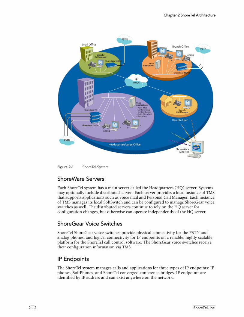
Figure 2-1 shows the various components of a ShoreTel system and how they interact with the public switched telephone network (PSTN) and IP-based networks.
Chapter 2 ShoreTel Architecture
2 – 2 ShoreTel, Inc.
Figure 2-1 ShoreTel System
ShoreWare ServersEach ShoreTel system has a main server called the Headquarters (HQ) server. Systems may optionally include distributed servers.Each server provides a local instance of TMS that supports applications such as voice mail and Personal Call Manager. Each instance of TMS manages its local SoftSwitch and can be configured to manage ShoreGear voice switches as well. The distributed servers continue to rely on the HQ server for configuration changes, but otherwise can operate independently of the HQ server.
ShoreGear Voice SwitchesShoreTel ShoreGear voice switches provide physical connectivity for the PSTN and analog phones, and logical connectivity for IP endpoints on a reliable, highly scalable platform for the ShoreTel call control software. The ShoreGear voice switches receive their configuration information via TMS.
IP EndpointsThe ShoreTel system manages calls and applications for three types of IP endpoints: IP phones, SoftPhones, and ShoreTel converged conference bridges. IP endpoints are identified by IP address and can exist anywhere on the network.
Chapter 2 ShoreTel Architecture
ShoreTel 7.5 Maintenance Guide 2 – 3
ShoreWare Client ApplicationsThe client applications, including Personal Call Manager, Voice Mail Viewer, and Operator client, interact with the TMS using the Telephony Application Programming Interface (TAPI) for call handling and the Client-Server Internet Service (CSIS) interface for data handling. Client applications use CSIS to retrieve and update data through the ZIN Manager (DCOM) interface.
Personal Call Manager
The Personal Call Manager (PCM) provides desktop call control as well as voice mail, directory, and call logging features. Microsoft Outlook users can integrate their voicemail, contacts, and calendar with the ShoreTel 7 system.
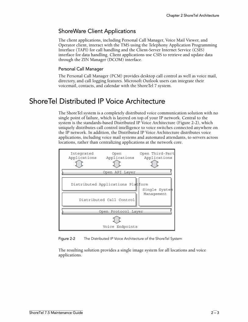
ShoreTel Distributed IP Voice ArchitectureThe ShoreTel system is a completely distributed voice communication solution with no single point of failure, which is layered on top of your IP network. Central to the system is the standards-based Distributed IP Voice Architecture (Figure 2-2), which uniquely distributes call control intelligence to voice switches connected anywhere on the IP network. In addition, the Distributed IP Voice Architecture distributes voice applications, including voice mail systems and automated attendants, to servers across locations, rather than centralizing applications at the network core.
Figure 2-2 The Distributed IP Voice Architecture of the ShoreTel System
The resulting solution provides a single image system for all locations and voice applications.
Open API Layer
OpenApplications
Voice Endpoints
IntegratedApplications
Open Third-PartApplications
Open Protocol Layer
Distributed Applications Platform
Single SystemManagement
Distributed Call Control
Chapter 2 ShoreTel Architecture
2 – 4 ShoreTel, Inc.
Distributed Applications PlatformThe ShoreTel system's ability to support applications on distributed servers across the enterprise while maintaining a single, cohesive system depends on the ShoreWare Telephony Management Service (TMS) and the ShoreWare Distributed Telephony Application Service (DTAS).
TMS runs on each ShoreWare server and observes all call activity for the SoftSwitch and ShoreGear voice switches it manages. DTAS also runs on each ShoreWare server and directs requests to the appropriate TMS. By putting a server at the same site as the users, applications such as voice mail and the Personal Call Manager can run regardless of the network availability to the Headquarters server. In addition, by hosting applications, services, and APIs on multiple ShoreWare servers, the system can scale as necessary by adding ShoreWare servers.
The ShoreWare TMS/DTAS software exposes a Telephony Application Programming Interface (TAPI) for call control, and a TAPI WAV interface for media playing and recording. These open APIs allow value-added applications to be added to the ShoreTel system to provide voice services.
Even when there are multiple application servers, the ShoreTel system is still managed and behaves as a single image system with complete feature transparency between sites.
Distributed Call ControlDistributed call control is a key concept of the ShoreTel system. Based on the industry-standard SIP protocol, ShoreTel’s distributed call control software runs on every ShoreGear voice switch in the ShoreTel system. Each switch call control element manages the call setup and teardown, including features such as transferring, conferencing, and forwarding calls, using call permissions, and call routing for the endpoints that it supports (both analog and IP).
The voice switches communicate on a peer-to-peer basis, eliminating any single point of failure. For instance, if one ShoreGear voice switch goes offline, all other ShoreGear voice switches continue operating. When the voice switch comes back online, it rejoins the voice network with no impact on system operation. There is no server involved with the basic telephony, so the system delivers levels of availability unmatched by even legacy vendors.
ShoreGear switches build an internal routing database from the peer-to-peer communication with other switches. Each ShoreGear switch contains routing information for all endpoints in the system, including information regarding trunk selection for outbound calls (unless Distributed Routing Service has been enabled. See “Distributed Routing Service” on page 2-5.) When a user places a call from any extension, each switch can route the call to the correct ShoreGear switch based on its internal routing database. Sites can typically support up to 60 ShoreGear voices switches depending on the system configuration.
The heart of the ShoreTel 7 system is the distributed call control software, which runs on the ShoreGear voice switches on top of VxWorksTM a real-time operating system. Each call control element manages the call setup and call teardown, including features such as transfer, conference, forward, call permissions, and call routing. The voice switches communicate on a peer-to-peer basis, eliminating any single point of failure. For instance, if one ShoreGear voice switch goes offline, all other ShoreGear voice switches continue operating. When the voice switch comes back online, it rejoins the voice network with no impact on system operation. There is no server involved with the basic telephony, so the system delivers levels of availability unmatched by even legacy vendors.
Chapter 2 ShoreTel Architecture
ShoreTel 7.5 Maintenance Guide 2 – 5
Distributed Routing Service
Distributed Routing Service (DRS) allows larger systems to scale beyond 60 switches up to a total of 500 switches (including SoftSwitches). The Distributed Routing Service is optional on systems up to 60 switches, but must be enabled on systems with 60 or more switches.
When Distributed Routing Service is enabled, ShoreGear switches only exchange routing information with other switches configured in the same site, rather than exchanging information with every switch in the system. Although each ShoreGear switch only maintains routing information within its site, each ShoreWare server also includes an instance of the Distributed Routing Service, which maintains system-wide routing information. When site-to-site calls are initiated, ShoreGear switches contact the Distributed Routing Service in order to find the ShoreGear switch or switches necessary to complete the call.
In a system with more than one ShoreWare server, the ShoreGear switches may contact an alternate instance of the routing service if the primary instance is unreachable. ShoreWare servers have a hierarchical relationship, with the Headquarters server at the top of the hierarchy. As you add servers to the system using ShoreWare Director, you define the order of the servers in relation to the Headquarters server and the various sites in your system. Initially, the switches try to contact the nearest instance of the Distributed Routing Service in the hierarchy. If that instance of DRS is unreachable, the switch contacts the instance of DRS at the parent server in the hierarchy as a fallback. If both instances of DRS are unreachable, the switch makes a best effort to route the call based on its internal routing tables built from communicating with peer ShoreGear switches at the same site.
If the call is an external call, the call may be routed out a local trunk even though it may not be the lowest cost. If the call is an internal call, the call will be redirected to the Backup Auto-Attendant.
Single System Management The ShoreTel system provides a browser-based network management tool called ShoreWare Director that provides a single management interface for all voice services and applications across all locations. Although there are multiple servers and switches to support the services and applications, the ShoreTel system provides a single image system across your entire network.
Integrated management enables a change to propagate dynamically across the system each time a modification is made on the ShoreTel system. When you add a new user to the system, that user automatically receives a dialing plan, voice mail, an extension, a mailbox, an Auto-Attendant profile, and an email reminder to download the desktop software. In addition, the user can be added to a Workgroup, if needed. You add new users and place them in Workgroups from a single management screen.
NOTE The ShoreTel Converged Conference Solution and the ShoreTel Contact Center Solution are managed separately with their own management systems.
The ShoreTel system provides automated software distribution for all components on the system. When you add a new ShoreGear voice switch to the system, it is automatically upgraded to the current software release by the ShoreWare server. Existing ShoreGear voice switches will download the current software when you reboot the switch (see “ShoreGear Firmware Upgrades” on page 4-2). The Headquarters server does not upgrade distributed servers. Distributed servers must be upgraded independently.
Chapter 2 ShoreTel Architecture
2 – 6 ShoreTel, Inc.
When you add a new user to the system, the user receives an email message containing a URL from which desktop call control and unified messaging applications can be downloaded and installed.
For software upgrades at the Headquarters site, you simply install the new software on the ShoreWare servers. Users are notified of the new software release and are automatically prompted to upgrade their software, if an upgrade is mandatory.
The ShoreTel management software also provides a complete suite of maintenance tools that enable you to monitor and change the status of components on the system. The system can be configured with event filters that automatically generate an email message if an error occurs on the system.
ShoreTel System CommunicationsShoreTel system communications can be divided into four basic communication types:
• Call Control• Configuration• TAPI• Media
The communication streams and the protocols that support them are explained in the following sections.
Call ControlShoreTel uses two protocols to process and manage calls:
• Media Gateway Control Protocol (MGCP)• An enhanced version of Session Initiation Protocol (SIP)
Media Gateway Control Protocol (MGCP) is used between IP phones (and other IP endpoints) and ShoreGear switches. MGCP manages the setup and teardown of media streams and some basic phone operations.
Chapter 2 ShoreTel Architecture
ShoreTel 7.5 Maintenance Guide 2 – 7
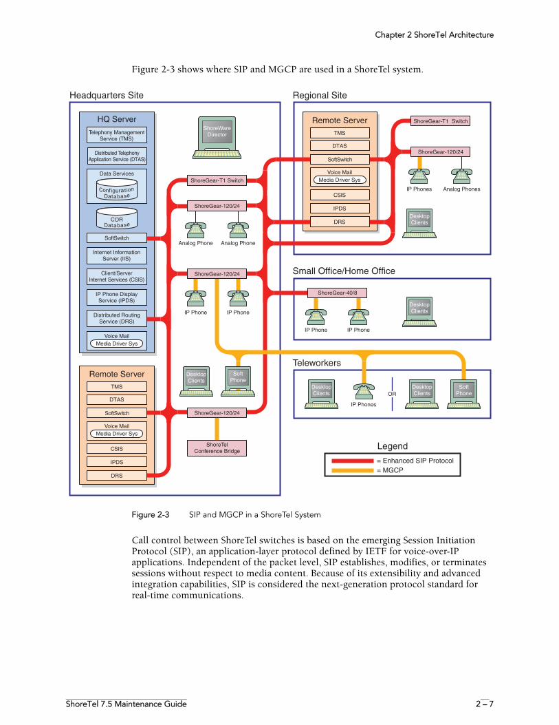
Figure 2-3 shows where SIP and MGCP are used in a ShoreTel system.
Figure 2-3 SIP and MGCP in a ShoreTel System
Call control between ShoreTel switches is based on the emerging Session Initiation Protocol (SIP), an application-layer protocol defined by IETF for voice-over-IP applications. Independent of the packet level, SIP establishes, modifies, or terminates sessions without respect to media content. Because of its extensibility and advanced integration capabilities, SIP is considered the next-generation protocol standard for real-time communications.
OR
CSIS
DRS
IPDS
Voice MailMedia Driver Sys
TMS
DTAS
Remote Server
SoftSwitch
Analog Phone Analog Phone
Internet InformationServer (IIS)
Client/ServerInternet Services (CSIS)
CSIS
DRS
IPDS
ShoreTelConference Bridge
IP Phone DisplayService (IPDS)
Distributed RoutingService (DRS)
Voice MailMedia Driver Sys
Voice MailMedia Driver Sys
ShoreGear-120/24
IP Phone IP Phone
ShoreGear-120/24
ShoreGear-120/24
ShoreGear-T1 Switch
ShoreWareDirector
DesktopClients
Analog PhonesIP Phones
ShoreGear-120/24
IP PhoneIP Phone
ShoreGear-40/8
ShoreGear-T1 Switch
DesktopClients
DesktopClients
SoftPhone
TMS
DTAS
Data Services
HQ Server
Remote Server
Regional Site
Co gi aturfn oi na abt seDa
CDRa abt seDa
Small Office/Home Office
IP Phones
= Enhanced SIP Protocol= MGCP
DesktopClients
DesktopClients
SoftPhone
Teleworkers
Legend
Headquarters Site
Telephony ManagementService (TMS)
Distributed TelephonyApplication Service (DTAS)
SoftSwitch
SoftSwitch
Chapter 2 ShoreTel Architecture
2 – 8 ShoreTel, Inc.
ShoreTel’s Enhanced SIP Call Control
In ShoreTel’s implementation of SIP call control, functions are split among the following software modules:
• User Agent• Location Service• Local Call Routing Service• Admission Control Service• Bandwidth Manager
SIP architecture deploys a peer-to-peer model in which endpoints can function either as clients or servers.
User Agents
User agent objects represent call endpoints—an extension or a trunk. Each user agent is addressable by a SIP URL.
For extensions, the URL syntax is:
For trunks, the URL syntax is:
In ShoreTel’s call control protocol, user agents representing endpoints on an IP network operate as peers, functioning as clients when initiating requests, and as servers when responding to requests.
Location Service
Endpoint location exchange is performed via ShoreTel’s proprietary Location Service Protocol (LSP). When switches first connect, they exchange all known SIP URLs. Afterwards, only configuration updates are transmitted.
LSP is based on UDP. The service relies on keep-alive pings (sent every 30 seconds) to detect dead switches.
Admission Control Service
Admission Control Service instructs Bandwidth Manager to reserve bandwidth for intersite calls. If a request is successful, updates are sent to Bandwidth Managers running on other switches at the same site.
Bandwidth Manager
A distributed Bandwidth Manager keeps track of intersite bandwidth use. A Bandwidth Manager runs on each ShoreGear switch.
ShoreGear switches reserve bandwidth from the Bandwidth Manager via the ShoreTel Bandwidth Reservation Protocol (BRP).
sip:nnn@ip_addr:5441 nnn = extension number
ip_addr = ip address
5441 = UDP port number used by ShoreTel Call Control
sip:TGrp_xxxpyy@ip_addr:5441 xxx = trunk group number
yy = port number
5441 = UDP port number used by ShoreTel Call Control
Chapter 2 ShoreTel Architecture
ShoreTel 7.5 Maintenance Guide 2 – 9
Figure 2-3 shows a hypothetical system with the call control protocols illustrated in simplified form.
Media Gateway Control Protocol
IP phones and other IP endpoints communicate with ShoreGear switches via MGCP, a device control protocol. The relationship between the switch (call manager) and the phone (gateway) follows a master–slave model.
MGCP, an industry-standard protocol, is used to:
• Deliver information to the IP phone display• Set up and tear down media streams• Report phone events such as key presses, on-hook, and off-hook
Figure 2-3 shows a hypothetical system with the call control protocols illustrated in simplified form.
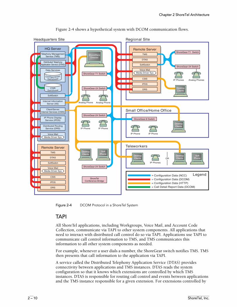
ConfigurationShoreTel maintains a configuration database with all the static and dynamic system configuration data. Any modifications made to the configuration database are broadcast to other system components, such as the server applications and TMS.
The database is accessed and updated via Microsoft’s Distributed Component Object Model (DCOM) protocol. ShoreTel also uses DCOM to send call information to the Call Detail Report (CDR) database, which is in Crystal Reports format.
TMS uses Network Call Control (NCC) to send each switch its configuration information. The ShoreGear switches that are connected to the network (via LAN/WAN) interact with the TMS using the NCC Client interface.
Chapter 2 ShoreTel Architecture
2 – 10 ShoreTel, Inc.
Figure 2-4 shows a hypothetical system with DCOM communication flows.
Figure 2-4 DCOM Protocol in a ShoreTel System
TAPIAll ShoreTel applications, including Workgroups, Voice Mail, and Account Code Collection, communicate via TAPI to other system components. All applications that need to interact with distributed call control do so via TAPI. Applications use TAPI to communicate call control information to TMS, and TMS communicates this information to all other system components as needed.
For example, whenever a user dials a number, the ShoreGear switch notifies TMS. TMS then presents that call information to the application via TAPI.
A service called the Distributed Telephony Application Service (DTAS) provides connectivity between applications and TMS instances. DTAS reads the system configuration so that it knows which extensions are controlled by which TMS instances. DTAS is responsible for routing call control and events between applications and the TMS instance responsible for a given extension. For extensions controlled by
OR
Analog PhoneAnalog Phone
Conference Bridge
IP Phone IP Phone
ShoreGear-24 Switch
ShoreGear-24 Switch
ShoreGear-24 Switch
ShoreGear-T1 Switch
ShoreWareDirector
DesktopClients
Analog PhonesIP Phones
ShoreGear-24 Switch
IP PhoneIP Phone
ShoreGear-8 Switch
ShoreGear-T1 Switch
DesktopClients
SoftPhone
Regional Site
Small Office/Home Office
IP Phones
= Configuration Data (DCOM)
=
= Configuration Data (HTTP)= Call Detail Report Data (DCOM)
DesktopClients
DesktopClients
SoftPhone
Teleworkers
LegendConfiguration Data (NCC)
Headquarters Site
ShoreTelCSIS
DRS
IPDS
Voice MailMedia Driver Sys
TMS
DTAS
Remote Server
SoftSwitch
CSIS
DRS
IPDS
Voice MailMedia Driver Sys
TMS
DTAS
Remote Server
SoftSwitch
Internet InformationServer (IIS)
Client/ServerInternet Services (CSIS)
IP Phone DisplayService (IPDS)
Distributed RoutingService (DRS)
Voice MailMedia Driver Sys
Data Services
HQ Server
Co gi aturfn oi na abt seDa
CDRa abt seDa
Telephony ManagementService (TMS)
Distributed TelephonyApplication Service (DTAS)
SoftSwitch
DesktopClients
Chapter 2 ShoreTel Architecture
ShoreTel 7.5 Maintenance Guide 2 – 11
the local TMS instance, DTAS routes call control to the local TMS instance. For extensions controlled by a remote TMS instance. DTAS routes call control to the appropriate remote TMS instance.
DTAS makes the distributed TMS architecture transparent to applications and reduces the number of network connections that would be needed if every application had to connect to every TMS instance.
Switches are assigned to specific TMS servers through ShoreWare Director. Assignment of a switch to a TMS server is restricted to TMS servers at its own site, or if there is no TMS server at that site, to the nearest TMS servers in the site hierarchy above.
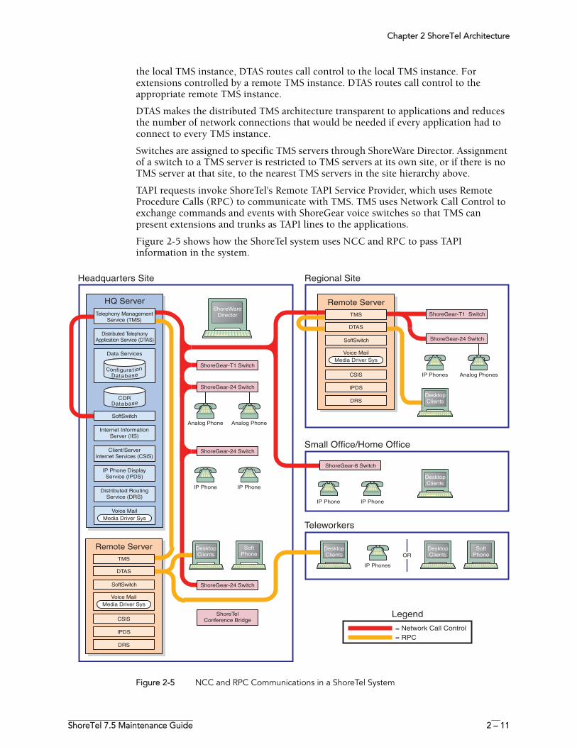
TAPI requests invoke ShoreTel's Remote TAPI Service Provider, which uses Remote Procedure Calls (RPC) to communicate with TMS. TMS uses Network Call Control to exchange commands and events with ShoreGear voice switches so that TMS can present extensions and trunks as TAPI lines to the applications.
Figure 2-5 shows how the ShoreTel system uses NCC and RPC to pass TAPI information in the system.
Figure 2-5 NCC and RPC Communications in a ShoreTel System
OR
Analog Phone Analog Phone
ShoreTelConference Bridge
ShoreGear-24 Switch
IP Phone IP Phone
ShoreGear-24 Switch
ShoreGear-24 Switch
ShoreGear-T1 Switch
ShoreWareDirector
DesktopClients
Analog PhonesIP Phones
ShoreGear-24 Switch
IP PhoneIP Phone
ShoreGear-8 Switch
ShoreGear-T1 Switch
DesktopClients
DesktopClients
SoftPhone
Regional SiteHeadquarters Site
Small Office/Home Office
IP Phones
= Network Call Control= RPC
DesktopClients
DesktopClients
SoftPhone
Teleworkers
Legend
Internet InformationServer (IIS)
Client/ServerInternet Services (CSIS)
IP Phone DisplayService (IPDS)
Distributed RoutingService (DRS)
Voice MailMedia Driver Sys
Data Services
HQ Server
Co gi aturfn oi na abt seDa
CDRa abt seDa
Telephony ManagementService (TMS)
Distributed TelephonyApplication Service (DTAS)
SoftSwitch
CSIS
DRS
IPDS
Voice MailMedia Driver Sys
TMS
DTAS
Remote Server
SoftSwitch
CSIS
DRS
IPDS
Voice MailMedia Driver Sys
TMS
DTAS
Remote Server
SoftSwitch
Chapter 2 ShoreTel Architecture
2 – 12 ShoreTel, Inc.
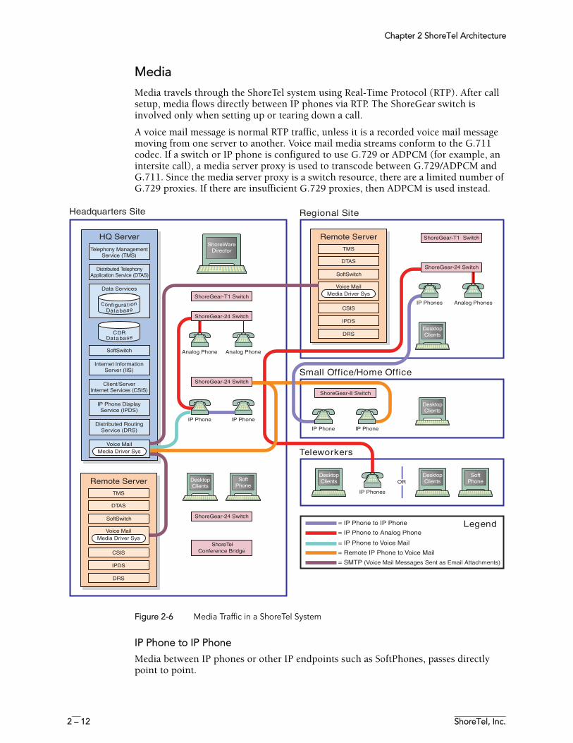
Media Media travels through the ShoreTel system using Real-Time Protocol (RTP). After call setup, media flows directly between IP phones via RTP. The ShoreGear switch is involved only when setting up or tearing down a call.
A voice mail message is normal RTP traffic, unless it is a recorded voice mail message moving from one server to another. Voice mail media streams conform to the G.711 codec. If a switch or IP phone is configured to use G.729 or ADPCM (for example, an intersite call), a media server proxy is used to transcode between G.729/ADPCM and G.711. Since the media server proxy is a switch resource, there are a limited number of G.729 proxies. If there are insufficient G.729 proxies, then ADPCM is used instead.
Figure 2-6 Media Traffic in a ShoreTel System
IP Phone to IP Phone
Media between IP phones or other IP endpoints such as SoftPhones, passes directly point to point.
OR
Analog Phone Analog Phone
Conference Bridge
ShoreGear-24 Switch
IP Phone IP Phone
ShoreGear-24 Switch
ShoreGear-24 Switch
ShoreGear-T1 Switch
ShoreWareDirector
DesktopClients
Analog PhonesIP Phones
ShoreGear-24 Switch
IP PhoneIP Phone
ShoreGear-8 Switch
ShoreGear-T1 Switch
DesktopClients
DesktopClients
SoftPhone
Regional Site
Small Office/Home Office
IP Phones
= IP Phone to IP Phone
= IP Phone to Analog Phone
= IP Phone to Voice Mail
= Remote IP Phone to Voice Mail
= SMTP (Voice Mail Messages Sent as Email Attachments)
DesktopClients
DesktopClients
SoftPhone
Teleworkers
Legend
Headquarters Site
ShoreTel
CSIS
DRS
IPDS
Voice MailMedia Driver Sys
TMS
DTAS
Remote Server
SoftSwitch
CSIS
DRS
IPDS
Voice MailMedia Driver Sys
TMS
DTAS
Remote Server
SoftSwitch
Internet InformationServer (IIS)
Client/ServerInternet Services (CSIS)
IP Phone DisplayService (IPDS)
Distributed RoutingService (DRS)
Voice MailMedia Driver Sys
Data Services
HQ Server
Co gi aturfn oi na abt seDa
CDRa abt seDa
Telephony ManagementService (TMS)
Distributed TelephonyApplication Service (DTAS)
SoftSwitch
Chapter 2 ShoreTel Architecture
ShoreTel 7.5 Maintenance Guide 2 – 13
IP Phone to Analog Phone
Analog phones depend on the ShoreGear switch to which they are connected. Media from IP endpoints must pass though the ShoreGear switch supporting the analog phone.
Analog Phone to Analog Phone
Media between analog phones passes though the switches supporting the analog phones.
Analog Phone to Voice Mail
Voice mail media from analog phones passes through the switch supporting the analog phone before going to voice mail via the server’s media driver. When the analog phone is located on the same LAN as the host server, the ShoreGear voice switch connects to the server using a Mulaw codec. If the analog phone is connected via a WAN, and there are ShoreGear voice switch resources available, the ShoreGear voice switch will use an inter-site codec (G729 or ADPCM). If ShoreGear voice switch resources are not available, the call will revert to the Mulaw codec.
IP Phone to Voice Mail
Voice mail media from IP phones and endpoints goes directly to voice mail. IP phones at remote sites without a server send voice mail media to a ShoreGear switch, which then sends it to voice mail. This is done in order to use G.729 streams for voice mail across the WAN.
Voice Mail Between Servers
When recorded voice mail messages are transferred between servers, they are sent via SMTP.
System ReliabilitySystem reliability is ensured at several levels, including:
Distributed Switch ControlThe ShoreWare Telephony Management Service (TMS) runs on every ShoreWare distributed server, ensuring switch control even if there a WAN outage between the remote server and the headquarters site. Since multiple servers share the task of switch management, if a server fails, only the extensions it controls may be affected by a disruption in service.
Distributed TMS enables applications to handle calls on the switches at remote sites during a loss of network connectivity between the remote server site and the headquarters site. The co-located TMS's provide local control of switches and local control by applications such as the PCM client and IPDS via TAPI. Applications are able to provide all of the features they normally provide (during full WAN connectivity) for extensions on locally controlled switches. Monitoring and control of extensions on remotely controlled switches are still affected by WAN outages.
Distributed TMS also reduces the affects of a particular TMS/server outage to just those extensions controlled by that TMS instance.
Overall system scalability is increased with this feature because TMS instances control a subset of the switches in an entire system rather than all the switches in the system as
Chapter 2 ShoreTel Architecture
2 – 14 ShoreTel, Inc.
in previous releases. Scalability is also increased because TMS instances handle a subset of PCM clients rather than all clients in the entire system.
WAN Outage
Distributed Telephony Application Service (DTAS) is responsible for routing call control and events between applications and the TMS instance responsible for a given extension.
When there is a loss of connectivity with the HQ database, DTAS continues to operate except that additions and deletions to the configuration will not been seen by IPDS. DTAS services involving the local TMS will be available. DTAS operations involving remote TMS instances not reachable because of the WAN outage will not be available.
Telephony operations involving locally controlled phones will be available. Monitoring of phones controlled by TMS's not reachable because of a WAN outage will not be available.
TMS continues to operate except that additions and deletions to the configuration will not been seen by TMS and not relayed to telephony clients. Telephony operations involving locally controlled phones will be available. If a WAN outage results in the loss of connectivity to one or more switches, telephony operations with those switches will be unavailable.
Embedded IP Phone Display DriverSeveral tasks related to IP phone operation (models IP110/115/212k/230/530/560/560g) will be handled by the switch instead of the server. While previous releases placed control of many of the IP phone features at the server, this latest release shifts that control to the switch in order to enhance reliability and offer better uptime. Features that will be affected by this change include:
• Phone display• Transferring a call• Conference calls• Placing calls on hold• On-hook dialing• Intercom• Redial• Pickup• Park• Unpark
Some features that would require writing to the database will continue to depend on the server being both operational and accessible. These features will not be handled by the switch but will continue to be provided by the server. The features that will continue to be provided by the server are:
• directory• options• speed dial (due to its reliance on the database)• ability to change call handling modes• wrap up• monitoring extensions on other switches• presence information for user serviced by other switches
Chapter 2 ShoreTel Architecture
ShoreTel 7.5 Maintenance Guide 2 – 15
No configuration is necessary to enable the new Embedded IP Phone Display Driver behavior. The change in functionality is transparent to the user.
Public Switched Telephone Network (PSTN) FailoverUser extensions can be optionally configured to route extension-to extension calls to the public switched telephone network (PSTN) in the event that an IP connection is unavailable. Extension-to-extension calls are those a user makes to another site within a multi-site system, for example, a user in New York calling a co-worker at the company’s San Francisco office. The IP connection may be unavailable due to lack of bandwidth or connectivity. The PSTN failover option must be explicitly enabled in the user’ Class of Service and bypasses the caller’s call permissions. For systems using Distributed Routing Service (DRS), destinations allowing PSTN failover handling return a contact list with a failover number. When a site does not have connectivity to DRS, users at other sites with DRS connectivity will be able to reach the users at that site using PSTN failover (as long as the destination site has trunks to accept the PSTN calls). This limitation has the biggest impact for small offices that do not have a local ShoreWare server.
Distributed CDRIn the event of a WAN outage, CDR data is stored for up to two hours on the distributed server. When WAN connectivity is restored, the stored data is forwarded to the Headquarters database. After two hours, the distributed server deletes the data and logs an error to the NT event log.
For More InformationAlso refer to Chapter 5 “IP Endpoints” for more information about failover. For configuration details about PSTN failover configuration, CDR data, or IP phone configuration, see the ShoreTel Administration Guide.
Call ScenariosTo understand how the ShoreTel system processes calls, review the following call scenarios and flow charts.
Chapter 2 ShoreTel Architecture
2 – 16 ShoreTel, Inc.
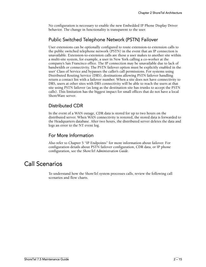
On-hook Call from Personal Call ManagerFigure 2-7 shows the communication protocols and components participating in a call dialed from Personal Call Manager to a PSTN destination.
Figure 2-7 ShoreTel Communications for a Call from Personal Call Manager
Chapter 2 ShoreTel Architecture
ShoreTel 7.5 Maintenance Guide 2 – 17
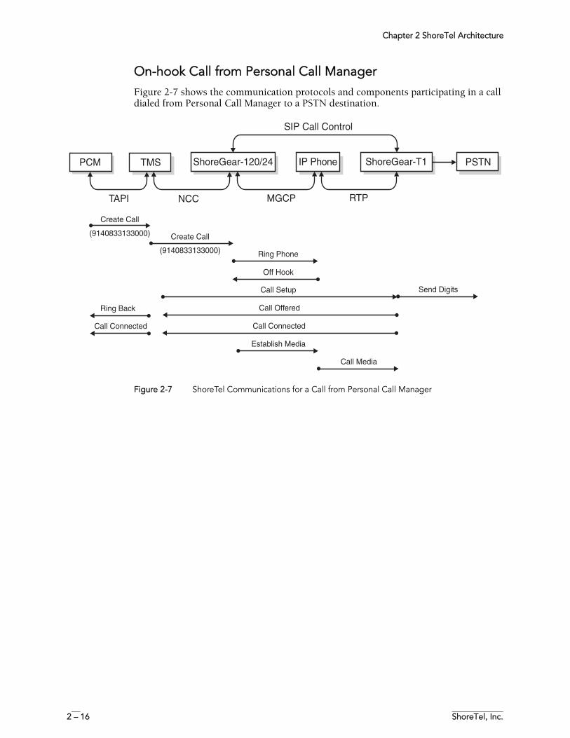
Quick Dial Call from Personal Call ManagerFigure 2-8 shows how a call dialed from a user’s Personal Call Manager Quick Dial is handled by the system.
Figure 2-8 Call Flow for a Quick Dial Call from Personal Call Manager
Chapter 2 ShoreTel Architecture
2 – 18 ShoreTel, Inc.
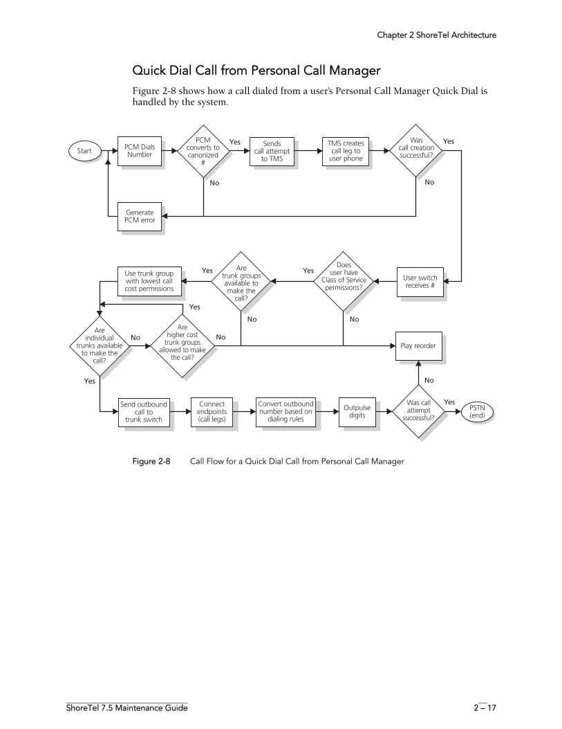
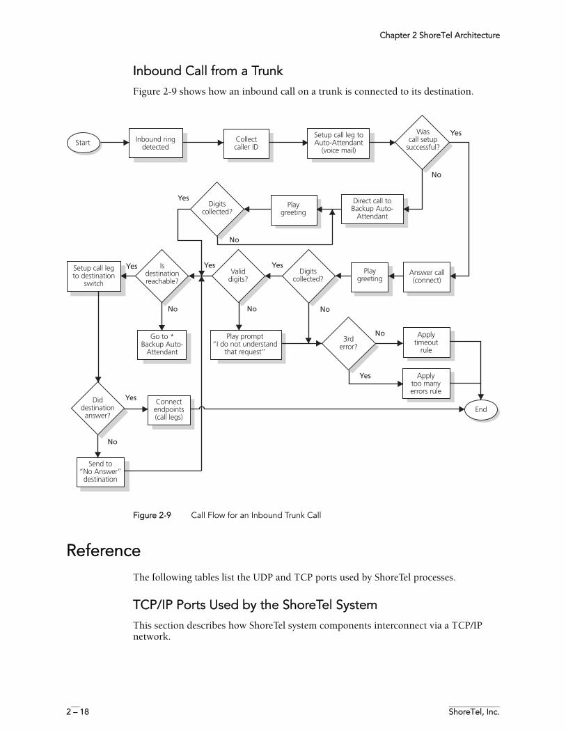
Inbound Call from a TrunkFigure 2-9 shows how an inbound call on a trunk is connected to its destination.
Figure 2-9 Call Flow for an Inbound Trunk Call
ReferenceThe following tables list the UDP and TCP ports used by ShoreTel processes.
TCP/IP Ports Used by the ShoreTel SystemThis section describes how ShoreTel system components interconnect via a TCP/IP network.
Chapter 2 ShoreTel Architecture
ShoreTel 7.5 Maintenance Guide 2 – 19
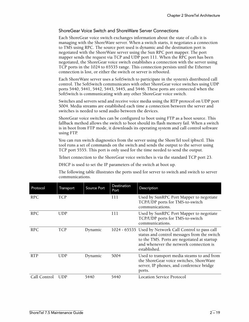
ShoreGear Voice Switch and ShoreWare Server Connections
Each ShoreGear voice switch exchanges information about the state of calls it is managing with the ShoreWare server. When a switch starts, it negotiates a connection to TMS using RPC. The source port used is dynamic and the destination port is negotiated with the ShoreWare server using the Sun RPC port mapper. The port mapper sends the request via TCP and UDP port 111. When the RPC port has been negotiated, the ShoreGear voice switch establishes a connection with the server using TCP ports in the 1024 to 65535 range. This connection persists until the Ethernet connection is lost, or either the switch or server is rebooted.
Each ShoreWare server uses a SoftSwitch to participate in the system’s distributed call control. The SoftSwitch communicates with other ShoreGear voice switches using UDP ports 5440, 5441, 5442, 5443, 5445, and 5446. These ports are connected when the SoftSwitch is communicating with any other ShoreGear voice switch.
Switches and servers send and receive voice media using the RTP protocol on UDP port 5004. Media streams are established each time a connection between the server and switches is needed to send audio between the devices.
ShoreGear voice switches can be configured to boot using FTP as a boot source. This fallback method allows the switch to boot should its flash memory fail. When a switch is in boot from FTP mode, it downloads its operating system and call control software using FTP.
You can run switch diagnostics from the server using the ShoreTel tool ipbxctl. This tool runs a set of commands on the switch and sends the output to the server using TCP port 5555. This port is only used for the time needed to send the output.
Telnet connection to the ShoreGear voice switches is via the standard TCP port 23.
DHCP is used to set the IP parameters of the switch at boot up.
The following table illustrates the ports used for server to switch and switch to server communications.
Protocol Transport Source PortDestination Port
Description
RPC TCP 111 Used by SunRPC Port Mapper to negotiate TCP/UDP ports for TMS-to-switch communications.
RPC UDP 111 Used by SunRPC Port Mapper to negotiate TCP/UDP ports for TMS-to-switch communications.
RPC TCP Dynamic 1024 - 65535 Used by Network Call Control to pass call status and control messages from the switch to the TMS. Ports are negotiated at startup and whenever the network connection is established.
RTP UDP Dynamic 5004 Used to transport media steams to and from the ShoreGear voice switches, ShoreWare server, IP phones, and conference bridge ports.
Call Control UDP 5440 5440 Location Service Protocol
Chapter 2 ShoreTel Architecture
2 – 20 ShoreTel, Inc.
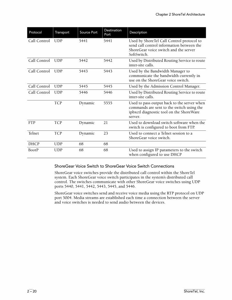
ShoreGear Voice Switch to ShoreGear Voice Switch Connections
ShoreGear voice switches provide the distributed call control within the ShoreTel system. Each ShoreGear voice switch participates in the system’s distributed call control. The switches communicate with other ShoreGear voice switches using UDP ports 5440, 5441, 5442, 5443, 5445, and 5446.
ShoreGear voice switches send and receive voice media using the RTP protocol on UDP port 5004. Media streams are established each time a connection between the server and voice switches is needed to send audio between the devices.
Call Control UDP 5441 5441 Used by ShoreTel Call Control protocol to send call control information between the ShoreGear voice switch and the server SoftSwitch.
Call Control UDP 5442 5442 Used by Distributed Routing Service to route inter-site calls.
Call Control UDP 5443 5443 Used by the Bandwidth Manager to communicate the bandwidth currently in use on the ShoreGear voice switch.
Call Control UDP 5445 5445 Used by the Admission Control Manager.
Call Control UDP 5446 5446 Used by Distributed Routing Service to route inter-site calls.
TCP Dynamic 5555 Used to pass output back to the server when commands are sent to the switch using the ipbxctl diagnostic tool on the ShoreWare server.
FTP TCP Dynamic 21 Used to download switch software when the switch is configured to boot from FTP.
Telnet TCP Dynamic 23 Used to connect a Telnet session to a ShoreGear voice switch.
DHCP UDP 68 68
BootP UDP 68 68 Used to assign IP parameters to the switch when configured to use DHCP
Protocol Transport Source PortDestination Port
Description
Chapter 2 ShoreTel Architecture
ShoreTel 7.5 Maintenance Guide 2 – 21
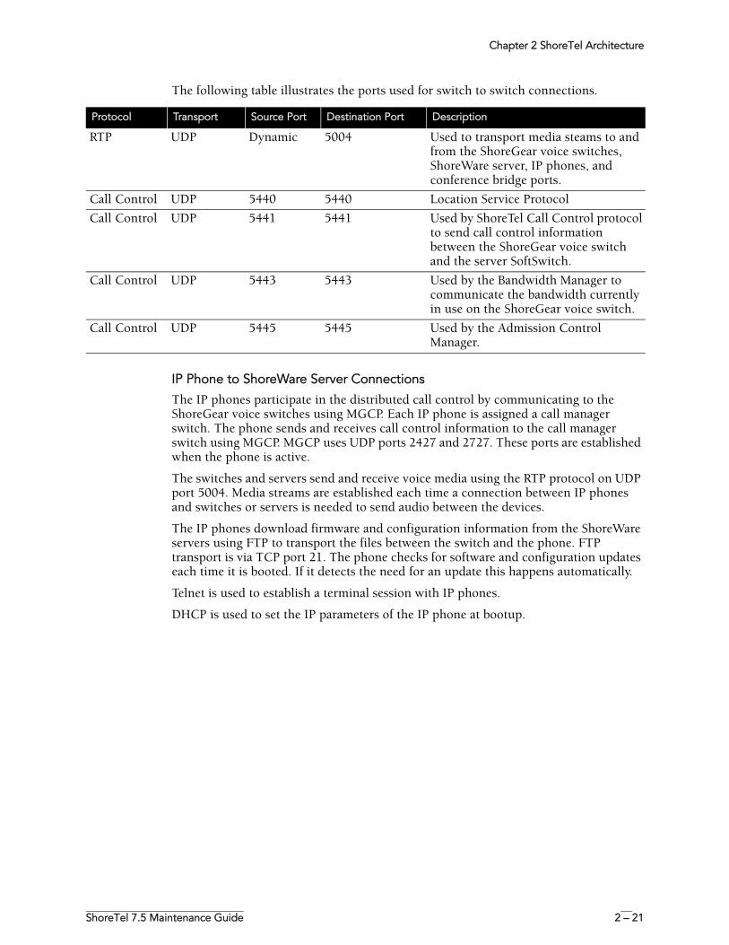
The following table illustrates the ports used for switch to switch connections.
IP Phone to ShoreWare Server Connections
The IP phones participate in the distributed call control by communicating to the ShoreGear voice switches using MGCP. Each IP phone is assigned a call manager switch. The phone sends and receives call control information to the call manager switch using MGCP. MGCP uses UDP ports 2427 and 2727. These ports are established when the phone is active.
The switches and servers send and receive voice media using the RTP protocol on UDP port 5004. Media streams are established each time a connection between IP phones and switches or servers is needed to send audio between the devices.
The IP phones download firmware and configuration information from the ShoreWare servers using FTP to transport the files between the switch and the phone. FTP transport is via TCP port 21. The phone checks for software and configuration updates each time it is booted. If it detects the need for an update this happens automatically.
Telnet is used to establish a terminal session with IP phones.
DHCP is used to set the IP parameters of the IP phone at bootup.
Protocol Transport Source Port Destination Port Description
RTP UDP Dynamic 5004 Used to transport media steams to and from the ShoreGear voice switches, ShoreWare server, IP phones, and conference bridge ports.
Call Control UDP 5440 5440 Location Service Protocol
Call Control UDP 5441 5441 Used by ShoreTel Call Control protocol to send call control information between the ShoreGear voice switch and the server SoftSwitch.
Call Control UDP 5443 5443 Used by the Bandwidth Manager to communicate the bandwidth currently in use on the ShoreGear voice switch.
Call Control UDP 5445 5445 Used by the Admission Control Manager.
Chapter 2 ShoreTel Architecture
2 – 22 ShoreTel, Inc.
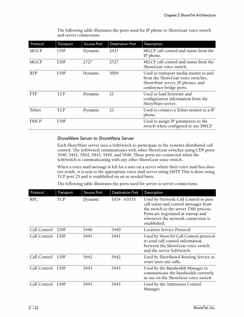
The following table illustrates the ports used for IP phone to ShoreGear voice switch and server connections.
ShoreWare Server to ShoreWare Server
Each ShoreWare server uses a SoftSwitch to participate in the system’s distributed call control. The SoftSwitch communicates with other ShoreGear switches using UDP ports 5440, 5441, 5442, 5443, 5445, and 5446. These ports are connected when the SoftSwitch is communicating with any other ShoreGear voice switch.
When a voice mail message is left for a user on a server where their voice mail box does not reside, it is sent to the appropriate voice mail server using SMTP. This is done using TCP port 25 and is established on an as needed basis.
The following table illustrates the ports used for server to server connections.
Protocol Transport Source Port Destination Port Description
MGCP UDP Dynamic 2427 MGCP call control and status from the IP phone.
MGCP UDP 2727 2727 MGCP call control and status from the ShoreGear voice switch.
RTP UDP Dynamic 5004 Used to transport media steams to and from the ShoreGear voice switches, ShoreWare server, IP phones, and conference bridge ports.
FTP TCP Dynamic 21 Used to load firmware and configuration information from the ShoreWare server.
Telnet TCP Dynamic 23 Used to connect a Telnet session to a IP phone.
DHCP UDP Used to assign IP parameters to the switch when configured to use DHCP.
Protocol Transport Source Port Destination Port Description
RPC TCP Dynamic 1024 - 65535 Used by Network Call Control to pass call status and control messages from the switch to the server TMS process. Ports are negotiated at startup and whenever the network connection is established.
Call Control UDP 5440 5440 Location Service Protocol
Call Control UDP 5441 5441 Used by ShoreTel Call Control protocol to send call control information between the ShoreGear voice switch and the server SoftSwitch.
Call Control UDP 5442 5442 Used by Distributed Routing Service to route inter-site calls.
Call Control UDP 5443 5443 Used by the Bandwidth Manager to communicate the bandwidth currently in use on the ShoreGear voice switch.
Call Control UDP 5445 5445 Used by the Admission Control Manager.
Chapter 2 ShoreTel Architecture
ShoreTel 7.5 Maintenance Guide 2 – 23
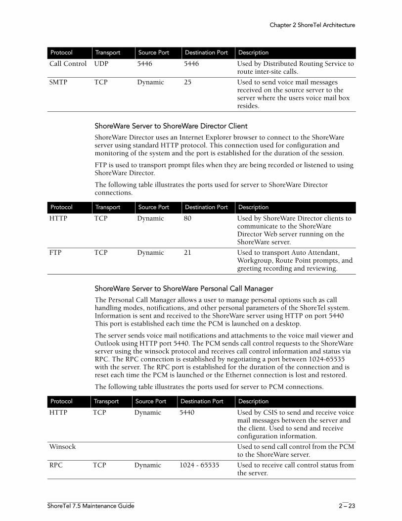
ShoreWare Server to ShoreWare Director Client
ShoreWare Director uses an Internet Explorer browser to connect to the ShoreWare server using standard HTTP protocol. This connection used for configuration and monitoring of the system and the port is established for the duration of the session.
FTP is used to transport prompt files when they are being recorded or listened to using ShoreWare Director.
The following table illustrates the ports used for server to ShoreWare Director connections.
ShoreWare Server to ShoreWare Personal Call Manager
The Personal Call Manager allows a user to manage personal options such as call handling modes, notifications, and other personal parameters of the ShoreTel system. Information is sent and received to the ShoreWare server using HTTP on port 5440 This port is established each time the PCM is launched on a desktop.
The server sends voice mail notifications and attachments to the voice mail viewer and Outlook using HTTP port 5440. The PCM sends call control requests to the ShoreWare server using the winsock protocol and receives call control information and status via RPC. The RPC connection is established by negotiating a port between 1024-65535 with the server. The RPC port is established for the duration of the connection and is reset each time the PCM is launched or the Ethernet connection is lost and restored.
The following table illustrates the ports used for server to PCM connections.
Call Control UDP 5446 5446 Used by Distributed Routing Service to route inter-site calls.
SMTP TCP Dynamic 25 Used to send voice mail messages received on the source server to the server where the users voice mail box resides.
Protocol Transport Source Port Destination Port Description
Protocol Transport Source Port Destination Port Description
HTTP TCP Dynamic 80 Used by ShoreWare Director clients to communicate to the ShoreWare Director Web server running on the ShoreWare server.
FTP TCP Dynamic 21 Used to transport Auto Attendant, Workgroup, Route Point prompts, and greeting recording and reviewing.
Protocol Transport Source Port Destination Port Description
HTTP TCP Dynamic 5440 Used by CSIS to send and receive voice mail messages between the server and the client. Used to send and receive configuration information.
Winsock Used to send call control from the PCM to the ShoreWare server.
RPC TCP Dynamic 1024 - 65535 Used to receive call control status from the server.

Chapter 2 ShoreTel Architecture
2 – 24 ShoreTel, Inc.
ShoreTel 7.5 Maintenance Guide 3 – 1
C H A P T E R 3
ShoreWare Servers
OverviewThe ShoreTel voice over IP telephony solution is a suite of software modules, applications, and services running on a ShoreWare server. Every ShoreTel system has a main server called the Headquarters server. In a single-site system, the Headquarters server may be the only ShoreWare server. More complex systems may include distributed servers to add reliability for applications and switches on remote sites or to support distributed applications. The Headquarters server remains the main server and must be available to interact with the distributed servers for full system functionality.
Headquarters ServerThe Headquarters server is the main ShoreWare server and hosts the voice applications platform and the management Web site, as well as the integrated voice applications. Typically, the Headquarters ShoreWare server is located at the largest location, containing the majority of users.
The Headquarters server hosts a SoftSwitch that provides extensions for the Auto-Attendant, Workgroups, and virtual users.
This version of ShoreTel software was tested and certified on Windows Server 2003 (Enterprise or Standard Editions only) with and without SP1, and Windows Server 2003, Release 2.
Remote ServersThe ShoreTel system also supports remote servers. Remote servers provide increased system reliability by duplicating some key services at remote sites. Each remote server has an instance of TMS that only connects to and manages the SoftSwitch. The SoftSwitch provides extensions for use by the local Auto-Attendant, Workgroups, and virtual users.
ShoreTel remote servers can also be configured to support specific distributed voice applications such voice mail. Remote servers only have TAPI access to the local SoftSwitch. The distributed TMS maintains a copy of the configuration database that
Chapter 3 ShoreWare Servers
3 – 2 ShoreTel, Inc.
allows it to provide call control and voice mail service during the outage. Each remote server manages its own SoftSwitch, as well as ShoreGear switches assigned to it.
Remote servers are valuable for the following purposes:
• They reduce bandwidth because local users’ calls to voice mail are answered by the local voice mail application and do not pass across the WAN.
• They increase system scale by extending the unified messaging and desktop call control services to additional users of the applications.
• They increase system scale and reliability by providing distributed switch management, call control services, and unified messaging.
Call control is provided by Headquarters and remote servers even if full network connectivity is unavailable. However, calls to unreachable endpoints cannot be made, and call detail recording requires Headquarters communication. To add reliability to your remote server, consider using redundant network paths to the Headquarters server.
The following sections provide more detail on the communications, services, and applications.
Configuration CommunicationsShoreTel system processes use Microsoft Distributed Component Object Model (DCOM) objects to share information from the configuration database among themselves and to write configuration information to the database. Static configuration parameters are written to the database by ShoreWare Director and system components access the database to read/write current state information. User configuration options are written to the database from Personal Call Manager, the telephone interface (voice mail options), and Web Access. Director is accessed via a Web browser,
The service ShoreTel-ZIN, running on the Headquarters server, manages these DCOM communications for TMS. There is a single instance of the ShoreWare database on the Headquarters server.
Each ShoreTel service on a distributed server caches its own copy of the configuration database in internal data structures. When a distributed server loses connection to the Headquarters server, changes made to the Headquarters configuration database are no longer received by the distributed server. However, services continue to function with the most recent configuration data until connectivity is restored. When the connection is restored, the distributed server automatically receives and incorporates any changes made to the Headquarters database during the outage.
If a distributed server restarts without a connection to the Headquarters database, then ShoreTel services are started but are not functional. When the network connection is restored, the configuration is retrieved and again cached by each service and services become functional.
ShoreWare client applications, such as Personal Call Manager, use CSIS for data handling. The CSIS server communicates with ShoreWare clients via HTTP. ShoreWare Director accesses the configuration database though IIS.
You can use the Component Service Manager to view DCOM objects installed by the ShoreWare software. Component Service Manager is located in the Administrative Tools folder available from the Windows Start menu.
NOTE Do not change any permission or security settings for ShoreWare components.
Chapter 3 ShoreWare Servers
ShoreTel 7.5 Maintenance Guide 3 – 3
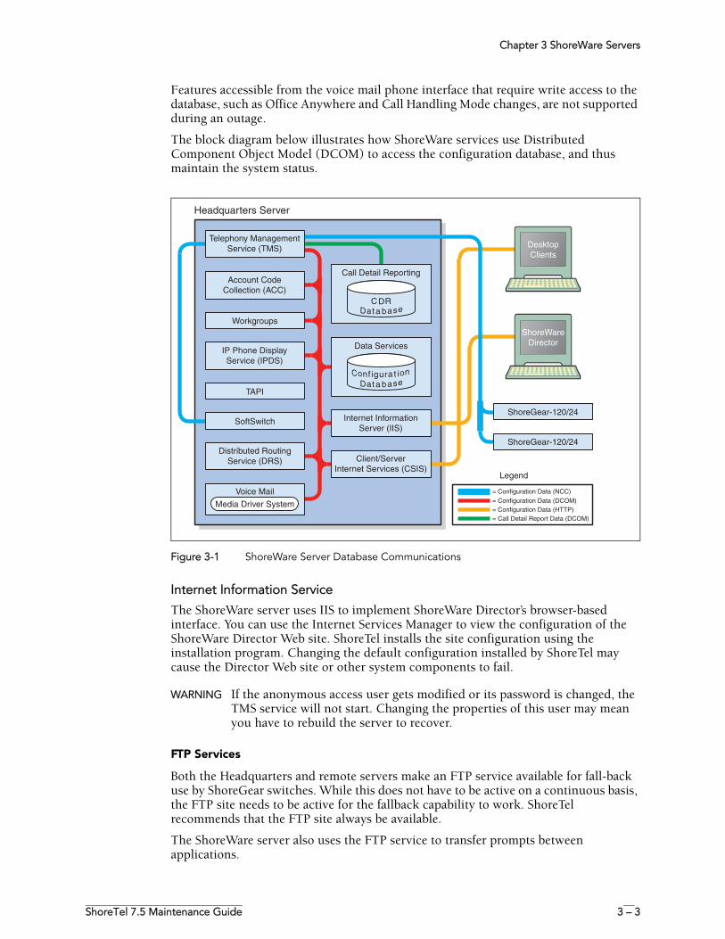
Features accessible from the voice mail phone interface that require write access to the database, such as Office Anywhere and Call Handling Mode changes, are not supported during an outage.
The block diagram below illustrates how ShoreWare services use Distributed Component Object Model (DCOM) to access the configuration database, and thus maintain the system status.
Figure 3-1 ShoreWare Server Database Communications
Internet Information Service
The ShoreWare server uses IIS to implement ShoreWare Director’s browser-based interface. You can use the Internet Services Manager to view the configuration of the ShoreWare Director Web site. ShoreTel installs the site configuration using the installation program. Changing the default configuration installed by ShoreTel may cause the Director Web site or other system components to fail.
WARNING If the anonymous access user gets modified or its password is changed, the TMS service will not start. Changing the properties of this user may mean you have to rebuild the server to recover.
FTP Services
Both the Headquarters and remote servers make an FTP service available for fall-back use by ShoreGear switches. While this does not have to be active on a continuous basis, the FTP site needs to be active for the fallback capability to work. ShoreTel recommends that the FTP site always be available.
The ShoreWare server also uses the FTP service to transfer prompts between applications.
Chapter 3 ShoreWare Servers
3 – 4 ShoreTel, Inc.
The IP phones use the FTP server to download configuration information and the application program when they boot. They will download these files from the server that is controlling the switch managing the IP phone.
To view the FTP site properties, use the Internet Services Manager. Anonymous FTP access must be maintained in order for all ShoreTel applications to use it.
SMTP Services
The ShoreTel software uses SMTP to send email notifications (for example, when new client software is available for installation). The voice mail system uses SMTP to transport composed messages between the distributed servers. SMTP services are also required by the Event Notification feature.
The ShoreTel installer does not make any specific configurations to the SMTP service. The applications deposit outbound email on the server for forwarding elsewhere.
For proper operation of the ShoreTel services, the hosting enterprise must have an email server configured to accept and forward SMTP mail. This is usually the exchange server or primary email server for the company.
Client/Server Internet Services
CSIS is a ShoreTel proprietary protocol that uses HTTP messages to communicate between client PCs and Shoreware servers. The CSIS protocol communicates configuration updates such as call handling mode settings and Outlook integration. The CSIS client holds open a pending HTTP request in order to receive notifications from the CSIS server. Network devices, such as firewalls and proxies, must not automatically close these pending requests.
IP Phone Services
IP phones in a ShoreTel system rely on two services running on the Headquarters server and distributed servers:
• IP Phone Configuration Service (IPCS)—Runs on HQ server only.• IP Phone Display Service (IPDS)—Runs on all servers.
The IP Phone Configuration Service (IPCS) manages the IP phone configuration process, including configuration file downloads and the database updates.
IP Phone Display Service (IPDS) controls any actions by the IP phone display not controlled by the device’s firmware or switches.
Event Watch
Event Watch monitors the NT Event Log and delivers email notifications of selected events. Event notifications are configured from the Events Filter page in ShoreWare Director. For more information, see the ShoreTel Administration Guide.
Call Detail Reporting
TMS use DCOM to write call data to the Call Detail Report database. The ShoreTel system tracks all call activity and generates call detail records into a database as well as into a text file on the ShoreWare server. The call detail records are used to generate CDR reports.
For more information on Call Detail Reports, see the ShoreTel Administration Guide.
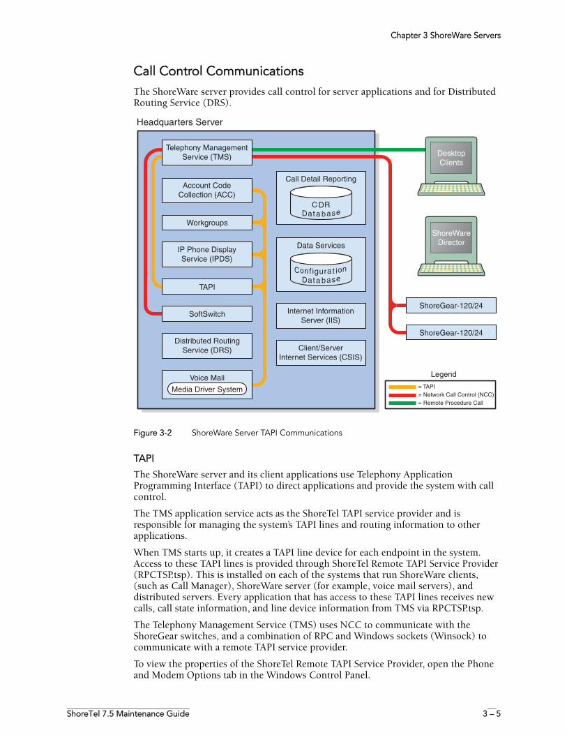
Chapter 3 ShoreWare Servers
ShoreTel 7.5 Maintenance Guide 3 – 5
Call Control CommunicationsThe ShoreWare server provides call control for server applications and for Distributed Routing Service (DRS).
Figure 3-2 ShoreWare Server TAPI Communications
TAPI
The ShoreWare server and its client applications use Telephony Application Programming Interface (TAPI) to direct applications and provide the system with call control.
The TMS application service acts as the ShoreTel TAPI service provider and is responsible for managing the system’s TAPI lines and routing information to other applications.
When TMS starts up, it creates a TAPI line device for each endpoint in the system. Access to these TAPI lines is provided through ShoreTel Remote TAPI Service Provider (RPCTSP.tsp). This is installed on each of the systems that run ShoreWare clients, (such as Call Manager), ShoreWare server (for example, voice mail servers), and distributed servers. Every application that has access to these TAPI lines receives new calls, call state information, and line device information from TMS via RPCTSP.tsp.
The Telephony Management Service (TMS) uses NCC to communicate with the ShoreGear switches, and a combination of RPC and Windows sockets (Winsock) to communicate with a remote TAPI service provider.
To view the properties of the ShoreTel Remote TAPI Service Provider, open the Phone and Modem Options tab in the Windows Control Panel.
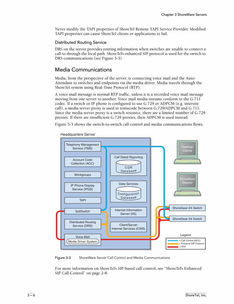
Chapter 3 ShoreWare Servers
3 – 6 ShoreTel, Inc.
Never modify the TAPI properties of ShoreTel Remote TAPI Service Provider. Modified TAPI properties can cause ShoreTel clients or applications to fail.
Distributed Routing Service
DRS on the server provides routing information when switches are unable to connect a call to through the local path. ShoreTel’s enhanced SIP protocol is used for the switch to DRS communications (see Figure 3-3).
Media CommunicationsMedia, from the perspective of the server, is connecting voice mail and the Auto-Attendant to switches and endpoints via the media driver. Media travels through the ShoreTel system using Real-Time Protocol (RTP).
A voice mail message is normal RTP traffic, unless it is a recorded voice mail message moving from one server to another. Voice mail media streams conform to the G.711 codec. If a switch or IP phone is configured to use G.729 or ADPCM (e.g. intersite call), a media server proxy is used to transcode between G.729/ADPCM and G.711. Since the media server proxy is a switch resource, there are a limited number of G.729 proxies. If there are insufficient G.729 proxies, then ADPCM is used instead.
Figure 3-3 shows the switch-to-switch call control and media communications flows.
Figure 3-3 ShoreWare Server Call Control and Media Communications
For more information on ShoreTel’s SIP-based call control, see “ShoreTel’s Enhanced SIP Call Control” on page 2-8.
Chapter 3 ShoreWare Servers
ShoreTel 7.5 Maintenance Guide 3 – 7
Integrated Server ApplicationsThere are several integrated TAPI applications running on the server. These applications use TAPI to send and receive call control information, and can also manipulate calls. These applications also use ZIN Manager and DCOM to access and update the configuration database.
Voice Mail
Voice mail is a TAPI application that supports 254 simultaneous voice mail or Auto-Attendant connections. The voice mail system uses SMTP to transport composed messages between the distributed servers. Media streams to voice mail use RTP packets to send media.
Voice messages are stored on the server’s hard drive in the VMS MESSAGE subdirectory of the Shoreline Data directory. Voice mail messages are stored as .wav files. To help you calculate storage requirements, one hour of messages requires approximately 28.8 MB of disk space.
The voice mail application consists of the following services: Port Manager and Mail Server. The Port Manager uses TAPI to interact with TMS. The ShoreTel system also supports linking to legacy voice mail systems using AMIS and SMDI protocols.
Distributed Voice Mail
Should the Headquarters server lose network connectivity, the distributed voice mail application allows SoftSwitches on distributed ShoreWare servers to continue handling voice mail calls and access the Auto-Attendant.
During an outage, users can only access voice mail though their phone interface. If users were running PCM at the time of the outage, they can still compose and playback messages. Users who were not running PCM at the time of the outage, or who restart PCM, will not be able to access their voice mail boxes until connectivity is restored.
Voice mail messages to mail boxes hosted at other sites will be stored and forwarded when connectivity to the destination voice mail service is restored.
Workgroups
Workgroups is an integrated Automated Call Distribution (ACD) application. Running on the Headquarters server, this TAPI application is responsible for routing and queueing calls directed to ShoreTel workgroups.
In the larger enterprise, there may be small- to medium-sized groups working together as a contact center. The ShoreTel Contact Center Solution is a server-based ACD and reporting package that includes the ability to queue and distribute calls, and provide agent and supervisor functions, as well as deliver reports on the call center activity.
Account Code Collection Service
The Account Code Collection Service (ACC) is a TAPI application running on the Headquarters server. When it is enabled, it allows account codes to be required or optional for outbound calls. When a restricted PSTN call is attempted, and account code collection is enabled, the ShoreGear switch redirects the call to ACC.
Account Code Collection Service is responsible for:
• Prompting the user for the account code• Collecting and validating the account code• Attaching the account code to the call for reporting purposes
Chapter 3 ShoreWare Servers
3 – 8 ShoreTel, Inc.
• Performing a blind transfer to the external number
If the Headquarters server is down, or ACC is not available, the call is directed to the Backup Auto-Attendant.
TMS provides the following information to ACC:
• Dialed number• User group• Backup Auto-Attendant and correct menu number• Account Code settings for each user group
CSIS exposes a list of account code names and numbers within Call Manager clients to facilitate the account selection process for the user.
SoftSwitch
SoftSwitch is used to host virtual users who are not assigned a physical telephone port on any ShoreGear voice switch. The SoftSwitch hosts all voice mail, Auto-Attendant, and Workgroup extensions as well as route points. There is a major impact to the system when the SoftSwitch is down or having problems. Loss of connectivity to the SoftSwitch makes the voice mail, Auto-Attendant, Workgroups, and route points supported by the SoftSwitch unavailable.
The SoftSwitch receives and transmits information using the same communication paths and protocols as the “hard” switches in the system.
A SoftSwitch is automatically created for every server added to the ShoreTel system. By default, the name of the SoftSwitch is the same as the name of the ShoreWare server hosting the switch, as specified on the Application Server page in ShoreWare Director. For more information on editing the SoftSwitch parameters, see the ShoreTel 7 Administration Guide.
Maintenance
Server Software UpgradesAn installation of the server software refers to the first time the software is installed on a server. This takes place only once and can be done with any version of ShoreWare software.
Server software upgrades take place any time new ShoreTel software is loaded. The Setup program detects the installed software and automatically takes care of converting any system files or databases. In general, you can upgrade any two previous major versions of the ShoreTel software to the current major version.
Upgrading from one minor version to another automatically converts any system files or databases. Minor upgrades typically add incremental features to the software or correct product defects found in previous releases.
Chapter 3 ShoreWare Servers
ShoreTel 7.5 Maintenance Guide 3 – 9
Recommended Files to BackupIt is recommended that you save the contents of the Shoreline Data directory and all subdirectories to a safe location before performing any significant offline maintenance, including system upgrades or installing security patches or service packs. Typically, backing up the Shoreline Data directory copies every dynamic file necessary to recover a ShoreTel system.
NOTE You may not want to backup the Shoreline Data\logs directory since this information is not necessary to recover the system and the files are often quite large.
At a minimum, it is recommended that you back up the Shoreline Data\Database\ ShoreWare.mdb file after making database changes. This allows you to recover the entire ShoreTel system with the exception of saved voice mail, personal names and greetings, and menu and workgroup prompts.
Workgroup and Auto-Attendant Prompts
It is recommended that you store a copy of any Workgroup and Auto-Attendant prompts in a safe location, with the .wav files identified by their use. These files are located in the Shoreline Data\Prompts directory in the format user-YYYYMMDD-HHMMSS.wav where user is the name of the ShoreTel extension that was used to record the prompts. YYYYMMDD-HHMMSS is the time the file was saved. ShoreTel recommends renaming the file to reflects its use, for example, MainAAOnHoursprompt.wav.
Voice Mail and Auto-Attendant System Files and Messages
Files located in the VMS directory include voice mail “pointers,” user names, greetings, and current voice mail messages. You may save these files as a backup, but be careful when using them to restore a system. Keep in mind that these files reflect the particular time a backup was made. The voice mail system is a dynamic, transaction-oriented system. Any transactions that occurred after the last backup will be lost.
NOTE The Shoreline Data\VMS directory and subdirectories also include all voice mail greetings for each user.
Diagnostic and Troubleshooting InformationThe ShoreTel system provides information about the operational status of the servers and services, as well as diagnostic and troubleshooting tools to resolve an event or error that might occur while the system is running or during installation.
Installer LoggingSome logging information can be gathered by the installer technology native to the operating system. However, ShoreTel has added proprietary code that provides more detail in the log files to assist you in troubleshooting software installation. This proprietary code adds information about calls to the installer and return values from all custom action functions invoked by the installer.
Log files are generated in the user profile temp directory and start with msi and end with .log. We recommend sorting the directory if there are many log files or if there is any doubt as to which log file to look at.
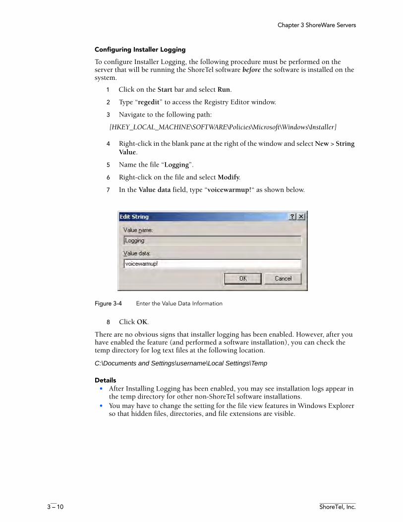
Chapter 3 ShoreWare Servers
3 – 10 ShoreTel, Inc.
Configuring Installer Logging
To configure Installer Logging, the following procedure must be performed on the server that will be running the ShoreTel software before the software is installed on the system.
1 Click on the Start bar and select Run.
2 Type “regedit” to access the Registry Editor window.
3 Navigate to the following path:
[HKEY_LOCAL_MACHINE\SOFTWARE\Policies\Microsoft\Windows\Installer]
4 Right-click in the blank pane at the right of the window and select New > String Value.
5 Name the file “Logging”.
6 Right-click on the file and select Modify.
7 In the Value data field, type “voicewarmup!“ as shown below.
Figure 3-4 Enter the Value Data Information
8 Click OK.
There are no obvious signs that installer logging has been enabled. However, after you have enabled the feature (and performed a software installation), you can check the temp directory for log text files at the following location.
C:\Documents and Settings\username\Local Settings\Temp
Details• After Installing Logging has been enabled, you may see installation logs appear in
the temp directory for other non-ShoreTel software installations.• You may have to change the setting for the file view features in Windows Explorer
so that hidden files, directories, and file extensions are visible.
Chapter 3 ShoreWare Servers
ShoreTel 7.5 Maintenance Guide 3 – 11
Using Quick LookQuick Look, which is available from ShoreWare Director, gives the system administrator an overview of the ShoreTel system’s health. It includes information about each site and the corresponding switches, ports, servers, and service. This is the first place you should look to determine the status of the system.
For details about Quick Look, please see the “Maintenance” chapter of the ShoreTel 7 Administration Guide.
Using the Event Log The ShoreTel system uses the Windows Event Log, viewed using the Event Viewer, to report information and errors that are of interest to system administrators. You can use the event logs in conjunction with Quick Look to determine the overall health of the system. You can also use the event log to gather information about an event that is no longer a problem. For example, the event log may provide information about an overnight T1 outage that was corrected is no longer evident.
Each system task reports when it starts and stops. These messages can be helpful in determining whether the system has started correctly. Events, such as switches losing connection to the server or rebooting, are also reported. See Appendix , Event Codes for a list of all ShoreTel event codes.
Using the System LogsThe ShoreTel system stores a number of engineering-level log files that record transaction information about every event in the ShoreTel system. The logs are used to help ShoreTel with debugging problems that may arise during system operation. In most cases, these logs are difficult to interpret and will require the assistance of ShoreTel Customer Support to understand.
Either of two utilities can be used to automate the collection of server logs, Windows (OS) logs, and ShoreWare databases. The utilities include a graphical application (i.e. GUI) and a command line application. Both applications have the same functional capabilities and offer two different ways for accomplishing the same tasks.
Graphical Application
The graphical application can be executed from MS Windows or from a command window. The following program launches the Graphical version of the Server Log Collection Utility:
<ShoreWare install directory>\slogWin.exe
where <ShoreWare install directory> is the location of the ShoreWare server files. The default installation location of ShoreWare server files is
C:\Program Files\Shoreline Communications\ShoreWare Server.
Panels provide Next and Back buttons for navigating through the process. You can terminate the program at any time by pressing the Cancel button
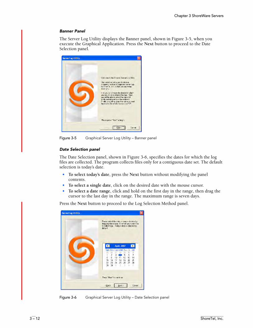
Chapter 3 ShoreWare Servers
3 – 12 ShoreTel, Inc.
Banner Panel
The Server Log Utility displays the Banner panel, shown in Figure 3-5, when you execute the Graphical Application. Press the Next button to proceed to the Date Selection panel.
Figure 3-5 Graphical Server Log Utility – Banner panel
Date Selection panel
The Date Selection panel, shown in Figure 3-6, specifies the dates for which the log files are collected. The program collects files only for a contiguous date set. The default selection is today’s date.
• To select today’s date, press the Next button without modifying the panel contents.
• To select a single date, click on the desired date with the mouse cursor.• To select a date range, click and hold on the first day in the range, then drag the
cursor to the last day in the range. The maximum range is seven days.
Press the Next button to proceed to the Log Selection Method panel.
Figure 3-6 Graphical Server Log Utility – Date Selection panel
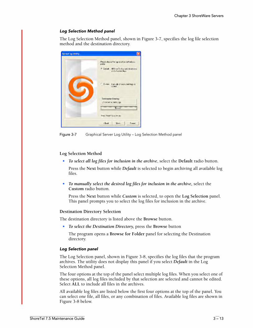
Chapter 3 ShoreWare Servers
ShoreTel 7.5 Maintenance Guide 3 – 13
Log Selection Method panel
The Log Selection Method panel, shown in Figure 3-7, specifies the log file selection method and the destination directory.
Figure 3-7 Graphical Server Log Utility – Log Selection Method panel
Log Selection Method
• To select all log files for inclusion in the archive, select the Default radio button.
Press the Next button while Default is selected to begin archiving all available log files.
• To manually select the desired log files for inclusion in the archive, select the Custom radio button.
Press the Next button while Custom is selected, to open the Log Selection panel. This panel prompts you to select the log files for inclusion in the archive.
Destination Directory Selection
The destination directory is listed above the Browse button.
• To select the Destination Directory, press the Browse button
The program opens a Browse for Folder panel for selecting the Destination directory.
Log Selection panel
The Log Selection panel, shown in Figure 3-8, specifies the log files that the program archives. The utility does not display this panel if you select Default in the Log Selection Method panel.
The four options at the top of the panel select multiple log files. When you select one of these options, all log files included by that selection are selected and cannot be edited. Select ALL to include all files in the archives.
All available log files are listed below the first four options at the top of the panel. You can select one file, all files, or any combination of files. Available log files are shown in Figure 3-8 below.
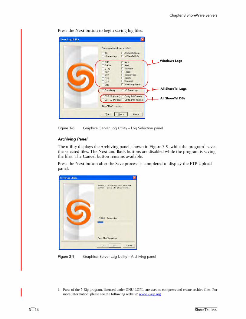
Chapter 3 ShoreWare Servers
3 – 14 ShoreTel, Inc.
Press the Next button to begin saving log files.
Figure 3-8 Graphical Server Log Utility – Log Selection panel
Archiving Panel
The utility displays the Archiving panel, shown in Figure 3-9, while the program1 saves the selected files. The Next and Back buttons are disabled while the program is saving the files. The Cancel button remains available.
Press the Next button after the Save process is completed to display the FTP Upload panel.
Figure 3-9 Graphical Server Log Utility – Archiving panel
1. Parts of the 7-Zip program, licensed under GNU LGPL, are used to compress and create archive files. Formore information, please see the following website: www.7-zip.org
Windows Logs
All ShoreTel Logs
All ShoreTel DBs
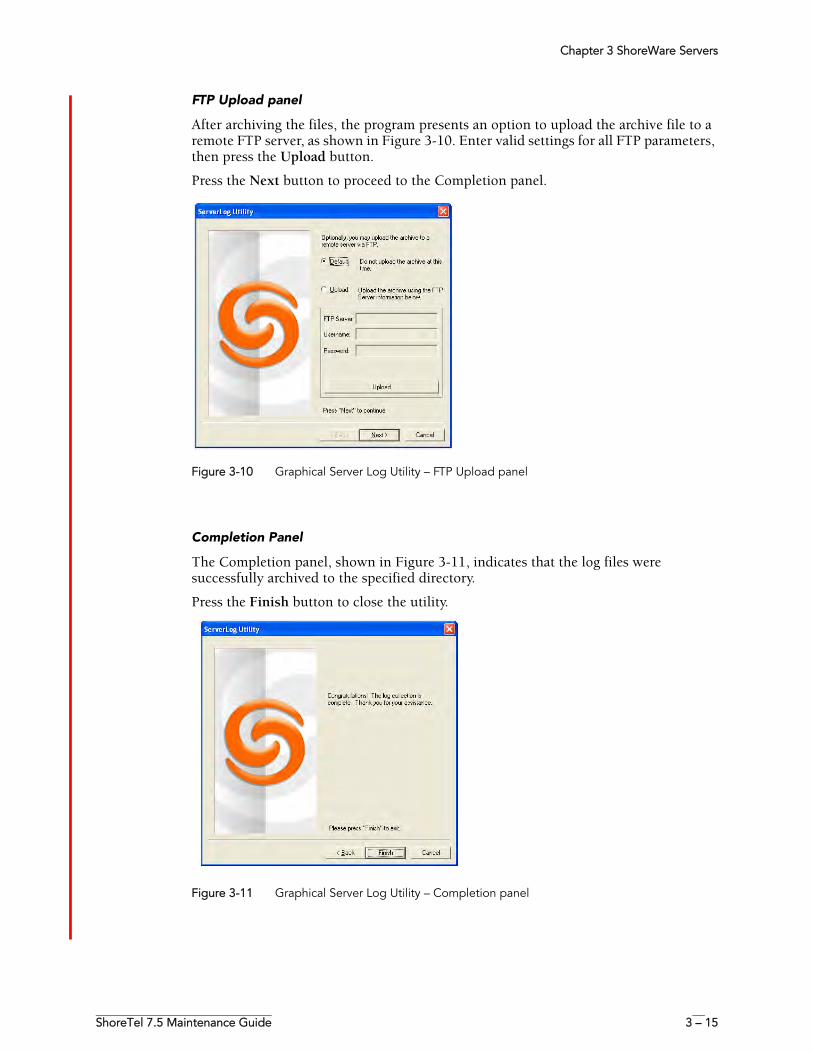
Chapter 3 ShoreWare Servers
ShoreTel 7.5 Maintenance Guide 3 – 15
FTP Upload panel
After archiving the files, the program presents an option to upload the archive file to a remote FTP server, as shown in Figure 3-10. Enter valid settings for all FTP parameters, then press the Upload button.
Press the Next button to proceed to the Completion panel.
Figure 3-10 Graphical Server Log Utility – FTP Upload panel
Completion Panel
The Completion panel, shown in Figure 3-11, indicates that the log files were successfully archived to the specified directory.
Press the Finish button to close the utility.
Figure 3-11 Graphical Server Log Utility – Completion panel
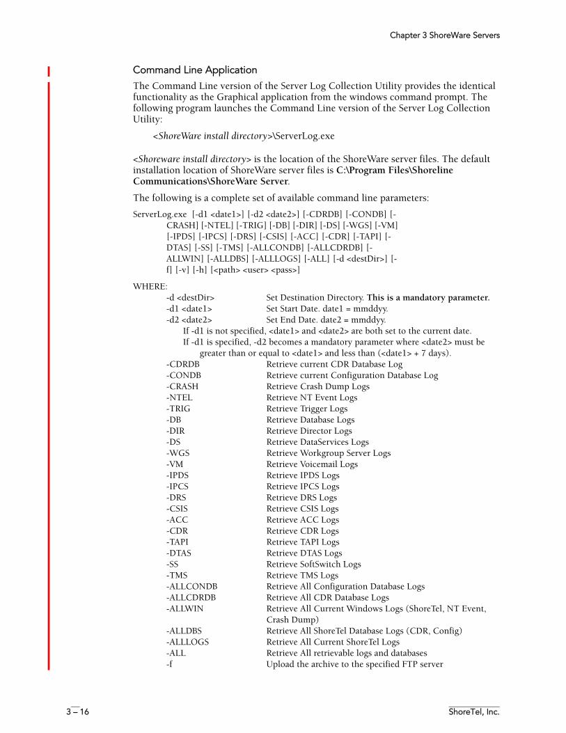
Chapter 3 ShoreWare Servers
3 – 16 ShoreTel, Inc.
Command Line Application
The Command Line version of the Server Log Collection Utility provides the identical functionality as the Graphical application from the windows command prompt. The following program launches the Command Line version of the Server Log Collection Utility:
<ShoreWare install directory>\ServerLog.exe
<Shoreware install directory> is the location of the ShoreWare server files. The default installation location of ShoreWare server files is C:\Program Files\Shoreline Communications\ShoreWare Server.
The following is a complete set of available command line parameters:
ServerLog.exe [-d1 <date1>] [-d2 <date2>] [-CDRDB] [-CONDB] [-CRASH] [-NTEL] [-TRIG] [-DB] [-DIR] [-DS] [-WGS] [-VM] [-IPDS] [-IPCS] [-DRS] [-CSIS] [-ACC] [-CDR] [-TAPI] [-DTAS] [-SS] [-TMS] [-ALLCONDB] [-ALLCDRDB] [-ALLWIN] [-ALLDBS] [-ALLLOGS] [-ALL] [-d <destDir>] [-f] [-v] [-h] [<path> <user> <pass>]
WHERE:-d <destDir> Set Destination Directory. This is a mandatory parameter.-d1 <date1> Set Start Date. date1 = mmddyy.-d2 <date2> Set End Date. date2 = mmddyy.
If -d1 is not specified, <date1> and <date2> are both set to the current date.If -d1 is specified, -d2 becomes a mandatory parameter where <date2> must be
greater than or equal to <date1> and less than (<date1> + 7 days). -CDRDB Retrieve current CDR Database Log-CONDB Retrieve current Configuration Database Log-CRASH Retrieve Crash Dump Logs-NTEL Retrieve NT Event Logs-TRIG Retrieve Trigger Logs-DB Retrieve Database Logs-DIR Retrieve Director Logs-DS Retrieve DataServices Logs-WGS Retrieve Workgroup Server Logs-VM Retrieve Voicemail Logs-IPDS Retrieve IPDS Logs-IPCS Retrieve IPCS Logs-DRS Retrieve DRS Logs-CSIS Retrieve CSIS Logs-ACC Retrieve ACC Logs-CDR Retrieve CDR Logs-TAPI Retrieve TAPI Logs-DTAS Retrieve DTAS Logs-SS Retrieve SoftSwitch Logs-TMS Retrieve TMS Logs-ALLCONDB Retrieve All Configuration Database Logs-ALLCDRDB Retrieve All CDR Database Logs-ALLWIN Retrieve All Current Windows Logs (ShoreTel, NT Event,
Crash Dump)-ALLDBS Retrieve All ShoreTel Database Logs (CDR, Config)-ALLLOGS Retrieve All Current ShoreTel Logs-ALL Retrieve All retrievable logs and databases-f Upload the archive to the specified FTP server
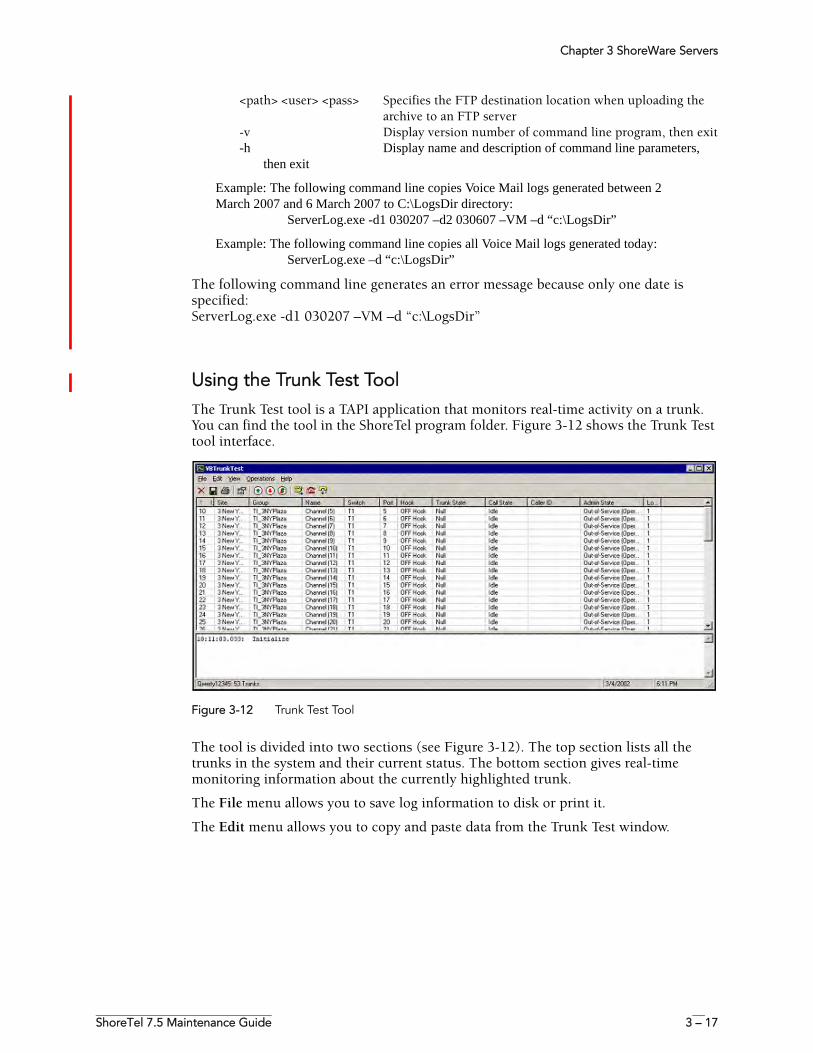
Chapter 3 ShoreWare Servers
ShoreTel 7.5 Maintenance Guide 3 – 17
<path> <user> <pass> Specifies the FTP destination location when uploading the archive to an FTP server
-v Display version number of command line program, then exit-h Display name and description of command line parameters,
then exit
Example: The following command line copies Voice Mail logs generated between 2 March 2007 and 6 March 2007 to C:\LogsDir directory:
ServerLog.exe -d1 030207 –d2 030607 –VM –d “c:\LogsDir”
Example: The following command line copies all Voice Mail logs generated today: ServerLog.exe –d “c:\LogsDir”
The following command line generates an error message because only one date is specified: ServerLog.exe -d1 030207 –VM –d “c:\LogsDir”
Using the Trunk Test ToolThe Trunk Test tool is a TAPI application that monitors real-time activity on a trunk. You can find the tool in the ShoreTel program folder. Figure 3-12 shows the Trunk Test tool interface.
Figure 3-12 Trunk Test Tool
The tool is divided into two sections (see Figure 3-12). The top section lists all the trunks in the system and their current status. The bottom section gives real-time monitoring information about the currently highlighted trunk.
The File menu allows you to save log information to disk or print it.
The Edit menu allows you to copy and paste data from the Trunk Test window.
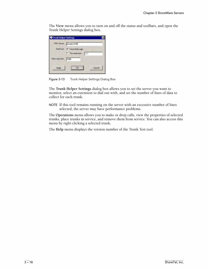
Chapter 3 ShoreWare Servers
3 – 18 ShoreTel, Inc.
The View menu allows you to turn on and off the status and toolbars, and open the Trunk Helper Settings dialog box.
Figure 3-13 Trunk Helper Settings Dialog Box
The Trunk Helper Settings dialog box allows you to set the server you want to monitor, select an extension to dial out with, and set the number of lines of data to collect for each trunk.
NOTE If this tool remains running on the server with an excessive number of lines selected, the server may have performance problems.
The Operations menu allows you to make or drop calls, view the properties of selected trunks, place trunks in service, and remove them from service. You can also access this menu by right-clicking a selected trunk.
The Help menu displays the version number of the Trunk Test tool.
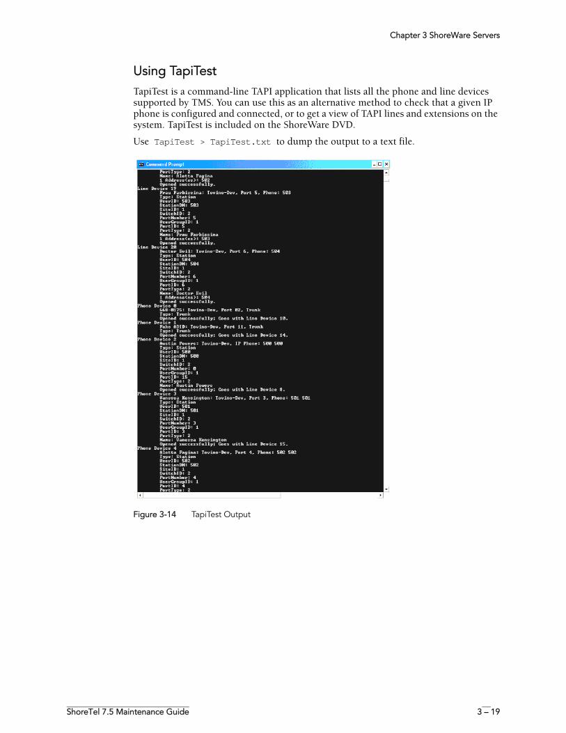
Chapter 3 ShoreWare Servers
ShoreTel 7.5 Maintenance Guide 3 – 19
Using TapiTestTapiTest is a command-line TAPI application that lists all the phone and line devices supported by TMS. You can use this as an alternative method to check that a given IP phone is configured and connected, or to get a view of TAPI lines and extensions on the system. TapiTest is included on the ShoreWare DVD.
Use TapiTest > TapiTest.txt to dump the output to a text file.
Figure 3-14 TapiTest Output
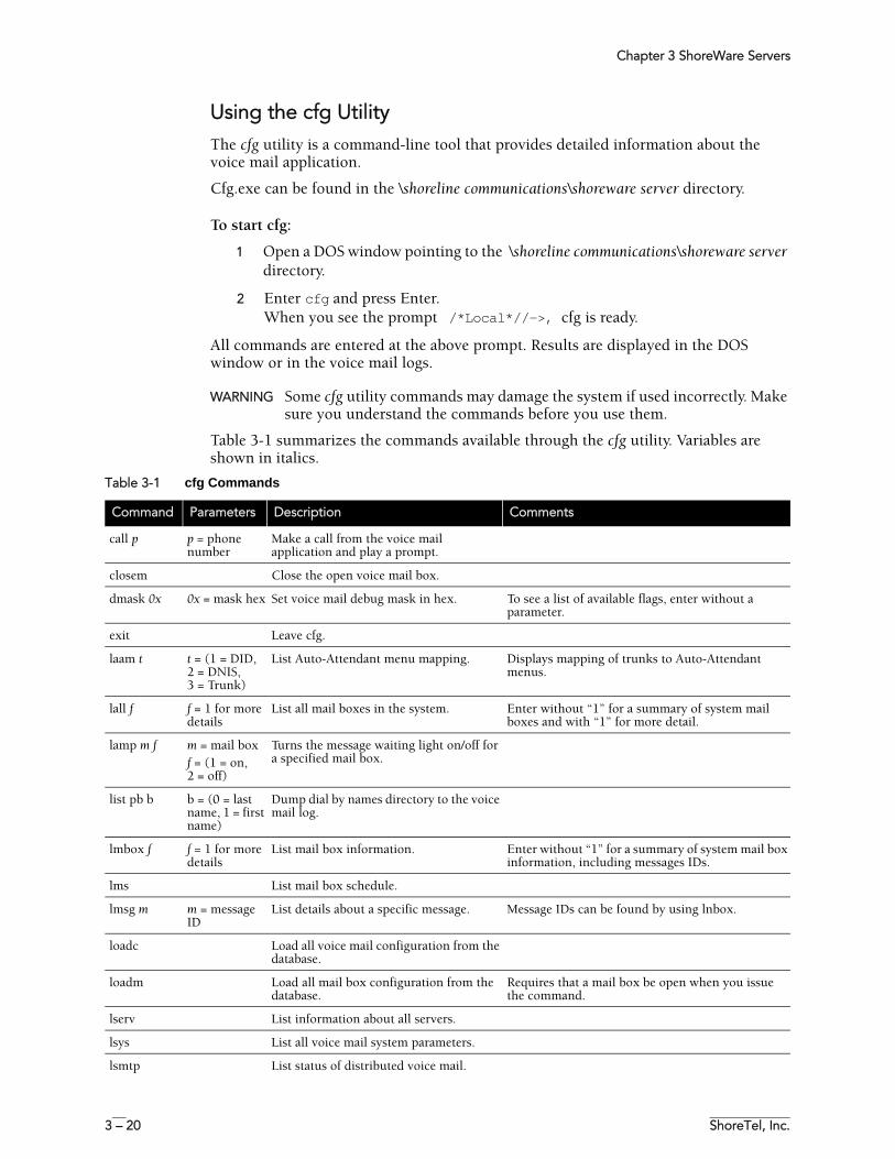
Chapter 3 ShoreWare Servers
3 – 20 ShoreTel, Inc.
Using the cfg Utility The cfg utility is a command-line tool that provides detailed information about the voice mail application.
Cfg.exe can be found in the \shoreline communications\shoreware server directory.
To start cfg:
1 Open a DOS window pointing to the \shoreline communications\shoreware server directory.
2 Enter cfg and press Enter. When you see the prompt /*Local*//->, cfg is ready.
All commands are entered at the above prompt. Results are displayed in the DOS window or in the voice mail logs.
WARNING Some cfg utility commands may damage the system if used incorrectly. Make sure you understand the commands before you use them.
Table 3-1 summarizes the commands available through the cfg utility. Variables are shown in italics.
Table 3-1 cfg Commands
Command Parameters Description Comments
call p p = phone number
Make a call from the voice mail application and play a prompt.
closem Close the open voice mail box.
dmask 0x 0x = mask hex Set voice mail debug mask in hex. To see a list of available flags, enter without a parameter.
exit Leave cfg.
laam t t = (1 = DID, 2 = DNIS, 3 = Trunk)
List Auto-Attendant menu mapping. Displays mapping of trunks to Auto-Attendant menus.
lall f f = 1 for more details
List all mail boxes in the system. Enter without “1” for a summary of system mail boxes and with “1” for more detail.
lamp m f m = mail boxf = (1 = on,2 = off)
Turns the message waiting light on/off for a specified mail box.
list pb b b = (0 = last name, 1 = first name)
Dump dial by names directory to the voice mail log.
lmbox f f = 1 for more details
List mail box information. Enter without “1” for a summary of system mail box information, including messages IDs.
lms List mail box schedule.
lmsg m m = message ID
List details about a specific message. Message IDs can be found by using lnbox.
loadc Load all voice mail configuration from the database.
loadm Load all mail box configuration from the database.
Requires that a mail box be open when you issue the command.
lserv List information about all servers.
lsys List all voice mail system parameters.
lsmtp List status of distributed voice mail.
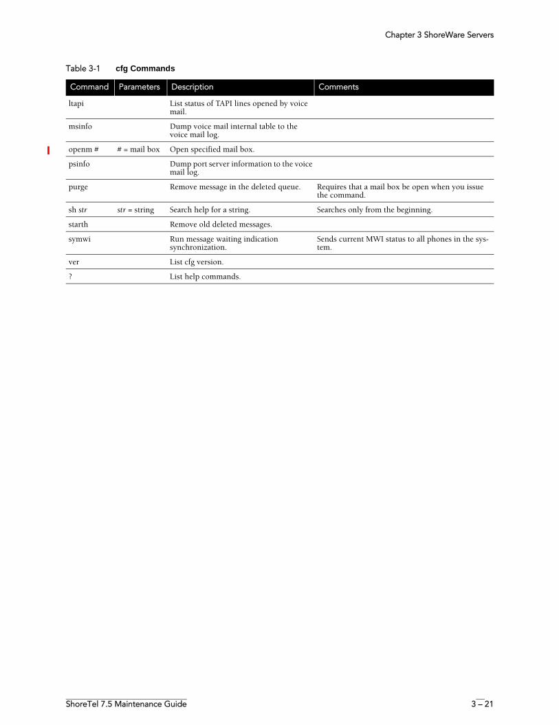
Chapter 3 ShoreWare Servers
ShoreTel 7.5 Maintenance Guide 3 – 21
ltapi List status of TAPI lines opened by voice mail.
msinfo Dump voice mail internal table to the voice mail log.
openm # # = mail box Open specified mail box.
psinfo Dump port server information to the voice mail log.
purge Remove message in the deleted queue. Requires that a mail box be open when you issue the command.
sh str str = string Search help for a string. Searches only from the beginning.
starth Remove old deleted messages.
symwi Run message waiting indication synchronization.
Sends current MWI status to all phones in the sys-tem.
ver List cfg version.
? List help commands.
Table 3-1 cfg Commands
Command Parameters Description Comments
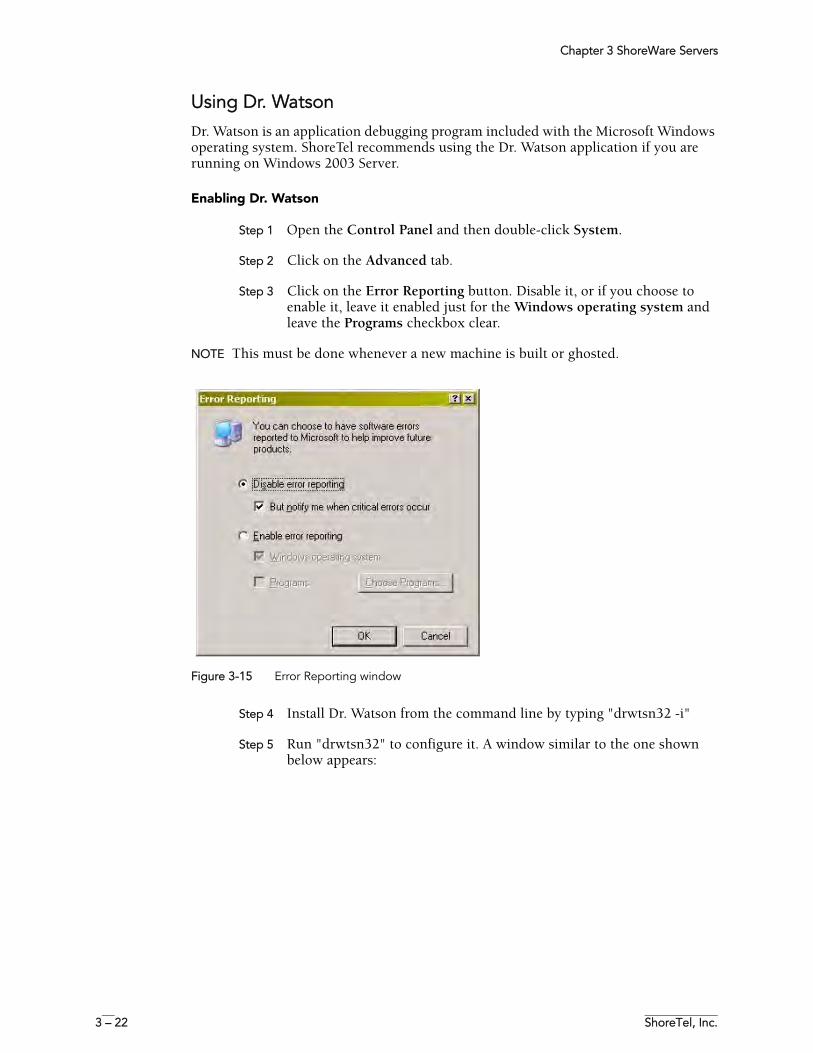
Chapter 3 ShoreWare Servers
3 – 22 ShoreTel, Inc.
Using Dr. WatsonDr. Watson is an application debugging program included with the Microsoft Windows operating system. ShoreTel recommends using the Dr. Watson application if you are running on Windows 2003 Server.
Enabling Dr. Watson
Step 1 Open the Control Panel and then double-click System.
Step 2 Click on the Advanced tab.
Step 3 Click on the Error Reporting button. Disable it, or if you choose to enable it, leave it enabled just for the Windows operating system and leave the Programs checkbox clear.
NOTE This must be done whenever a new machine is built or ghosted.
Figure 3-15 Error Reporting window
Step 4 Install Dr. Watson from the command line by typing "drwtsn32 -i"
Step 5 Run "drwtsn32" to configure it. A window similar to the one shown below appears:
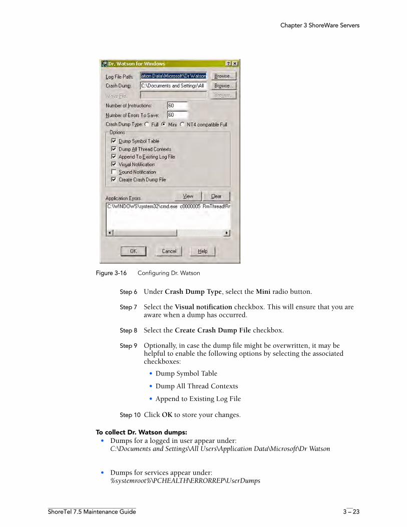
Chapter 3 ShoreWare Servers
ShoreTel 7.5 Maintenance Guide 3 – 23
Figure 3-16 Configuring Dr. Watson
Step 6 Under Crash Dump Type, select the Mini radio button.
Step 7 Select the Visual notification checkbox. This will ensure that you are aware when a dump has occurred.
Step 8 Select the Create Crash Dump File checkbox.
Step 9 Optionally, in case the dump file might be overwritten, it may be helpful to enable the following options by selecting the associated checkboxes:
• Dump Symbol Table
• Dump All Thread Contexts
• Append to Existing Log File
Step 10 Click OK to store your changes.
To collect Dr. Watson dumps:• Dumps for a logged in user appear under:
C:\Documents and Settings\All Users\Application Data\Microsoft\Dr Watson
• Dumps for services appear under:%systemroot%\PCHEALTH\ERRORREP\UserDumps
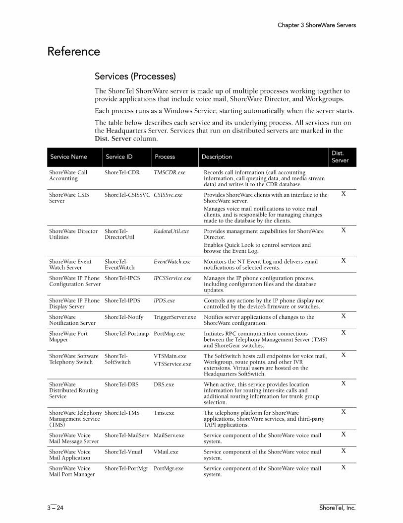
Chapter 3 ShoreWare Servers
3 – 24 ShoreTel, Inc.
Reference
Services (Processes)The ShoreTel ShoreWare server is made up of multiple processes working together to provide applications that include voice mail, ShoreWare Director, and Workgroups.
Each process runs as a Windows Service, starting automatically when the server starts.
The table below describes each service and its underlying process. All services run on the Headquarters Server. Services that run on distributed servers are marked in the Dist. Server column.
Service Name Service ID Process DescriptionDist. Server
ShoreWare Call Accounting
ShoreTel-CDR TMSCDR.exe Records call information (call accounting information, call queuing data, and media stream data) and writes it to the CDR database.
ShoreWare CSIS Server
ShoreTel-CSISSVC CSISSvc.exe Provides ShoreWare clients with an interface to the ShoreWare server. Manages voice mail notifications to voice mail clients, and is responsible for managing changes made to the database by the clients.
X
ShoreWare Director Utilities
ShoreTel-DirectorUtil
KadotaUtil.exe Provides management capabilities for ShoreWare Director. Enables Quick Look to control services and browse the Event Log.
X
ShoreWare Event Watch Server
ShoreTel-EventWatch
EventWatch.exe Monitors the NT Event Log and delivers email notifications of selected events.
X
ShoreWare IP Phone Configuration Server
ShoreTel-IPCS IPCSService.exe Manages the IP phone configuration process, including configuration files and the database updates.
ShoreWare IP Phone Display Server
ShoreTel-IPDS IPDS.exe Controls any actions by the IP phone display not controlled by the device’s firmware or switches.
ShoreWare Notification Server
ShoreTel-Notify TriggerServer.exe Notifies server applications of changes to the ShoreWare configuration.
X
ShoreWare Port Mapper
ShoreTel-Portmap PortMap.exe Initiates RPC communication connections between the Telephony Management Server (TMS) and ShoreGear switches.
X
ShoreWare Software Telephony Switch
ShoreTel-SoftSwitch
VTSMain.exeVTSService.exe
The SoftSwitch hosts call endpoints for voice mail, Workgroup, route points, and other IVR extensions. Virtual users are hosted on the Headquarters SoftSwitch.
X
ShoreWare Distributed Routing Service
ShoreTel-DRS DRS.exe When active, this service provides location information for routing inter-site calls and additional routing information for trunk group selection.
X
ShoreWare Telephony Management Service (TMS)
ShoreTel-TMS Tms.exe The telephony platform for ShoreWare applications, ShoreWare services, and third-party TAPI applications.
X
ShoreWare Voice Mail Message Server
ShoreTel-MailServ MailServ.exe Service component of the ShoreWare voice mail system.
X
ShoreWare Voice Mail Application
ShoreTel-Vmail VMail.exe Service component of the ShoreWare voice mail system.
X
ShoreWare Voice Mail Port Manager
ShoreTel-PortMgr PortMgr.exe Service component of the ShoreWare voice mail system.
X
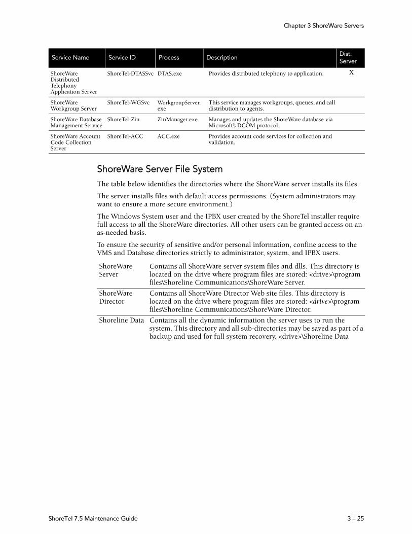
Chapter 3 ShoreWare Servers
ShoreTel 7.5 Maintenance Guide 3 – 25
ShoreWare Server File System The table below identifies the directories where the ShoreWare server installs its files.
The server installs files with default access permissions. (System administrators may want to ensure a more secure environment.)
The Windows System user and the IPBX user created by the ShoreTel installer require full access to all the ShoreWare directories. All other users can be granted access on an as-needed basis.
To ensure the security of sensitive and/or personal information, confine access to the VMS and Database directories strictly to administrator, system, and IPBX users.
ShoreWare Distributed Telephony Application Server
ShoreTel-DTASSvc DTAS.exe Provides distributed telephony to application. X
ShoreWare Workgroup Server
ShoreTel-WGSvc WorkgroupServer.exe
This service manages workgroups, queues, and call distribution to agents.
ShoreWare Database Management Service
ShoreTel-Zin ZinManager.exe Manages and updates the ShoreWare database via Microsoft’s DCOM protocol.
ShoreWare Account Code Collection Server
ShoreTel-ACC ACC.exe Provides account code services for collection and validation.
Service Name Service ID Process DescriptionDist. Server
ShoreWare Server
Contains all ShoreWare server system files and dlls. This directory is located on the drive where program files are stored: <drive>\program files\Shoreline Communications\ShoreWare Server.
ShoreWare Director
Contains all ShoreWare Director Web site files. This directory is located on the drive where program files are stored: <drive>\program files\Shoreline Communications\ShoreWare Director.
Shoreline Data Contains all the dynamic information the server uses to run the system. This directory and all sub-directories may be saved as part of a backup and used for full system recovery. <drive>\Shoreline Data
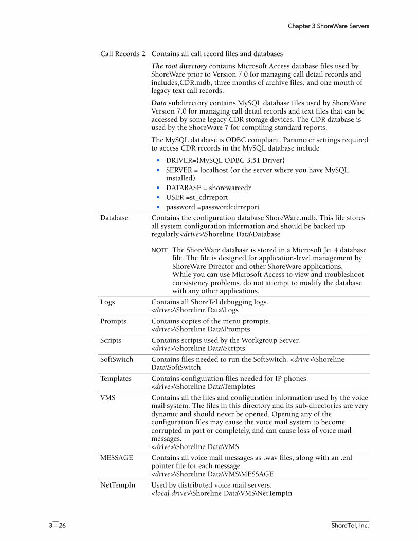
Chapter 3 ShoreWare Servers
3 – 26 ShoreTel, Inc.
Call Records 2 Contains all call record files and databases
The root directory contains Microsoft Access database files used by ShoreWare prior to Version 7.0 for managing call detail records and includes,CDR.mdb, three months of archive files, and one month of legacy text call records.
Data subdirectory contains MySQL database files used by ShoreWare Version 7.0 for managing call detail records and text files that can be accessed by some legacy CDR storage devices. The CDR database is used by the ShoreWare 7 for compiling standard reports.
The MySQL database is ODBC compliant. Parameter settings required to access CDR records in the MySQL database include
• DRIVER={MySQL ODBC 3.51 Driver}• SERVER = localhost (or the server where you have MySQL
installed)• DATABASE = shorewarecdr• USER =st_cdrreport• password =passwordcdrreport
Database Contains the configuration database ShoreWare.mdb. This file stores all system configuration information and should be backed up regularly.<drive>\Shoreline Data\Database
NOTE The ShoreWare database is stored in a Microsoft Jet 4 database file. The file is designed for application-level management by ShoreWare Director and other ShoreWare applications.While you can use Microsoft Access to view and troubleshoot consistency problems, do not attempt to modify the database with any other applications.
Logs Contains all ShoreTel debugging logs.<drive>\Shoreline Data\Logs
Prompts Contains copies of the menu prompts.<drive>\Shoreline Data\Prompts
Scripts Contains scripts used by the Workgroup Server.<drive>\Shoreline Data\Scripts
SoftSwitch Contains files needed to run the SoftSwitch. <drive>\Shoreline Data\SoftSwitch
Templates Contains configuration files needed for IP phones.<drive>\Shoreline Data\Templates
VMS Contains all the files and configuration information used by the voice mail system. The files in this directory and its sub-directories are very dynamic and should never be opened. Opening any of the configuration files may cause the voice mail system to become corrupted in part or completely, and can cause loss of voice mail messages.<drive>\Shoreline Data\VMS
MESSAGE Contains all voice mail messages as .wav files, along with an .enl pointer file for each message.<drive>\Shoreline Data\VMS\MESSAGE
NetTempIn Used by distributed voice mail servers.<local drive>\Shoreline Data\VMS\NetTempIn
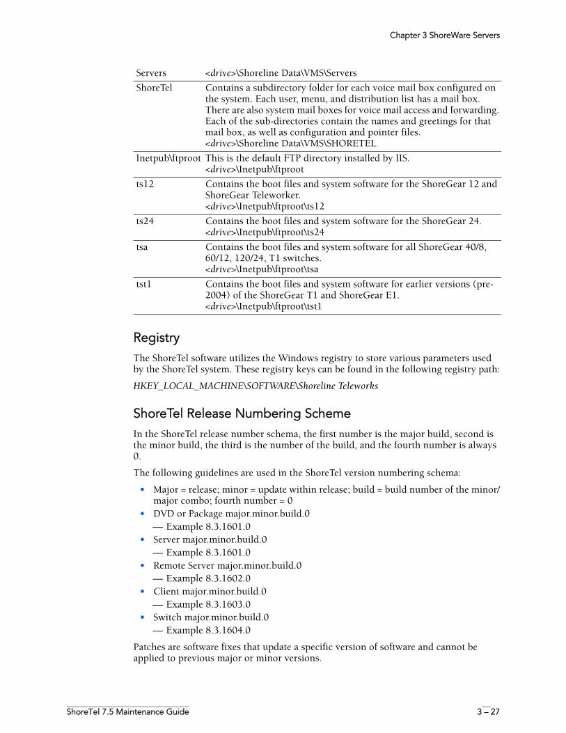
Chapter 3 ShoreWare Servers
ShoreTel 7.5 Maintenance Guide 3 – 27
RegistryThe ShoreTel software utilizes the Windows registry to store various parameters used by the ShoreTel system. These registry keys can be found in the following registry path:
HKEY_LOCAL_MACHINE\SOFTWARE\Shoreline Teleworks
ShoreTel Release Numbering SchemeIn the ShoreTel release number schema, the first number is the major build, second is the minor build, the third is the number of the build, and the fourth number is always 0.
The following guidelines are used in the ShoreTel version numbering schema:
• Major = release; minor = update within release; build = build number of the minor/major combo; fourth number = 0
• DVD or Package major.minor.build.0— Example 8.3.1601.0
• Server major.minor.build.0— Example 8.3.1601.0
• Remote Server major.minor.build.0— Example 8.3.1602.0
• Client major.minor.build.0 — Example 8.3.1603.0
• Switch major.minor.build.0— Example 8.3.1604.0
Patches are software fixes that update a specific version of software and cannot be applied to previous major or minor versions.
Servers <drive>\Shoreline Data\VMS\Servers
ShoreTel Contains a subdirectory folder for each voice mail box configured on the system. Each user, menu, and distribution list has a mail box. There are also system mail boxes for voice mail access and forwarding. Each of the sub-directories contain the names and greetings for that mail box, as well as configuration and pointer files.<drive>\Shoreline Data\VMS\SHORETEL
Inetpub\ftproot This is the default FTP directory installed by IIS. <drive>\Inetpub\ftproot
ts12 Contains the boot files and system software for the ShoreGear 12 and ShoreGear Teleworker.<drive>\Inetpub\ftproot\ts12
ts24 Contains the boot files and system software for the ShoreGear 24.<drive>\Inetpub\ftproot\ts24
tsa Contains the boot files and system software for all ShoreGear 40/8, 60/12, 120/24, T1 switches.<drive>\Inetpub\ftproot\tsa
tst1 Contains the boot files and system software for earlier versions (pre-2004) of the ShoreGear T1 and ShoreGear E1. <drive>\Inetpub\ftproot\tst1

Chapter 3 ShoreWare Servers
3 – 28 ShoreTel, Inc.
ShoreTel 7.5 Maintenance Guide 4 – 1
C H A P T E R 4
ShoreGear Switches
OverviewShoreTel ShoreGear voice switches provide physical connectivity for the PSTN and analog phones, and logical connectivity for IP endpoints on a reliable, highly scalable platform for the ShoreTel call control software. The call control software runs on top of VxWorks, a real-time embedded operating system designed specifically for mission-critical applications.
The voice switches have flash memory that allows permanent storage of the call control software and configuration information. The voice switches have no moving parts (that is, no hard drive) other than a highly reliable fan. The switches include the necessary DSP technology to enable toll-quality voice with features like echo cancellation, voice compression, and silence suppression.
TMS propagates configuration data from the database to each switch upon reboot of either TMS or the switch. The data sent is a subset of configuration data specific to that switch. TMS also maintains this data by propagating changes to the database to those switches affected by the change. The TMS/Switch configuration interface uses the same Network Call Control protocol that is used for other TMS/switch communication. The NCC protocol is based on Sun RPC. You can obtain the configuration data that TMS sends to any specific switch with a CLI command (for more information, see “Commands Available Through VxWorks CLI” on page 4-24).
Switches share their switch-specific configuration with the other switches in the system using the UDP-based Location Service Protocol (LSP). Switches keep up to date with other switches by propagating their own changes and receiving them from other switches. For information about how to view switch-to-switch communications, see “Commands Available Through VxWorks CLI” on page 4-24.
The ShoreGear voice switches communicate call control information on a peer-to-peer basis. When Distributed Routing Service (DRS) is enabled, switches exchange LSP messages only with other switches at the same site. DRS communicates directly with the database to keep the database configuration current. TMS tells each switch how to find DRS as part of the configuration process described earlier. When DRS is enabled, switches generally give DRS an opportunity to resolve numbers, so that its more complete view of the system can be leveraged to find the best contact. If the switch knows where an intra-site extension is, it does not involve DRS.
Chapter 4 ShoreGear Switches
4 – 2 ShoreTel, Inc.
For analog phones, the switch detects whether the phone is on or off hook, collects digits from the phone, and—based on digits collected—determines when a call should be established. If necessary, the switch communicates with other switches (in some cases this may not be necessary, such as when call is to an endpoint directly on the switch) to establish a call between the appropriate endpoints.
The switch acts as a media gateway for the PSTN and analog phones by encoding the analog voice and transmitting it to the other endpoint over the IP network using RTP. The switch also uses NCC to send events to TMS about digit collection, caller ID, call establishment, and so forth. TMS makes this information available to the server applications. These applications are not necessary for many calls (such as those between two phones or a trunk and a phone, which can be established with only the switches controlling the phones and trunks), but they can enhance the user experience. For example, Personal Call Manager can provide information about the call to the user's desktop.
Once the call is established, TMS monitors the call and logs call information on the Call Detail Report (CDR) database.
Maintenance
ShoreGear Firmware UpgradesEach ShoreGear switch is shipped from the factory with the version of firmware that ShoreTel used to test the system.
When you install a switch, ShoreTel’s TMS service is set up to detect the switch’s firmware version and automatically upgrade your hardware to the latest version. This happens once while the switch still retains the factory-default settings. (You can use the ShoreWare Director Quick Look page to monitor the progress of the upgrade.)
NOTE ShoreTel also makes firmware upgrades available via system upgrades and patches.
Using Quick Look to Perform Upgrades
You can use the Shoreware Director Quick Look page to identify switches that require upgrades.
If an update is required for a switch, QuickLook reports either Firmware Update Available or Firmware Version Mismatch.
Firmware Update Available indicates that a patch is available and an upgrade is required to load the patch. When a switch is in this state, it is fully functional and in communication with TMS and the other switches in the system.
Firmware Version Mismatch indicates that you must upgrade the switch before it can communicate with the TMS server. When a switch has mismatched firmware, it can still communicate with other switches of the same version and manage calls, but cannot support server and client applications.
To upgrade the switch:
Step 1 In ShoreWare Director, open the Maintenance > Quick Look page, and select the Site in which the switch is locate. Choose Reboot from the Command drop-down list in the switch row.
Chapter 4 ShoreGear Switches
ShoreTel 7.5 Maintenance Guide 4 – 3
Upon restart, the switch is automatically upgraded. (You can monitor the progress of the upgrade on the Quick Look page.)
Performing a Manual Upgrade
To manually upgrade switch firmware, you need to invoke the burnflash command from the server.
To manually upgrade the switch’s firmware:
Step 1 From the server command line, enter the burnflash command in this format:
C:\Program Files\Shoreline Communications\ShoreWare Server>burnflash -s <switch IP Address>
ShoreGear Switch Boot OptionsWhen a ShoreGear voice switch boots, it requires an IP address to connect to the network and an application program. ShoreGear voice switches are set to use a DHCP server for an IP address and to retrieve the application from the switch’s flash memory.
If a DHCP request receives no response, the switch tries a BootP request as a backup. ShoreTel recommends using static IP parameters configured via the serial port, as this is much more reliable. If DHCP is to be used, ShoreTel strongly recommends using DHCP reservations for each switch so that the DHCP lease will not be lost.
If a DHCP server is not available, you can set the IP address manually from the switch’s maintenance port. The ShoreGear-12 and ShoreGear-Teleworker voice switches can be set to use a static IP configuration via a Telnet session after they have received an IP address via DHCP or BootP.
The standard method for booting a ShoreGear voice switch is to boot from the switch’s flash memory. When a ShoreGear voice switch is first powered on, it reads the boot parameters stored on the boot ROM, which instructs the switch to load software from flash memory. When the software starts, it loads its configuration, which is also stored in flash memory.
Booting from FTP is available for instances when you cannot boot the switch from flash memory. When you boot a switch from FTP, the operating system and software load from the FTP site identified in the boot parameters. The loaded configuration is a configuration received from the TMS server.
If the switch fails to load the application from flash and does not have the IP address of the ShoreWare server, you can set the IP address and boot parameters by connecting to the maintenance port and using the configuration menu. The configuration menu allows you to set the IP address of the switch and enter the ShoreWare server (boot host) IP address.
IP Address from DHCP
The switch sends requests for an IP address to the DHCP server ten times at increasing intervals. If the switch receives a response from the DHCP server, the boot process begins. If the switch fails to get an IP address from the DHCP server, it will use the last assigned IP address, if known. The switch continues to send requests to the DHCP server for an IP address.
In the case of a switch using an IP address from a previous state, if the DHCP sends a conflicting IP address, the entire system will be forced to restart. Use long lease times to
Chapter 4 ShoreGear Switches
4 – 4 ShoreTel, Inc.
help prevent this from happening. ShoreTel recommends either static IP parameters or DHCP reservations.
If the switch does not receive an IP address from the DHCP server and has no IP address available from a previous state, the switch continues to poll the DHCP server until successful.
Setting the IP Address with VxWorks
If the switch has not been configured with an IP address and fails to boot from flash, it will not be able to download the application and configuration from the FTP server. In this case, you can manually set the IP address and boot parameters from VxWorks accessible from the maintenance port.
NOTE Any changes you make to a boot parameter do not take effect until you reboot the switch.
NOTE This command line interface is not available via Telnet.
To connect to the maintenance port of a ShoreGear voice switch:
Step 1 Connect a serial cable between a personal computer and the ShoreGear switch.
Step 2 Use a terminal emulation program such as Tera Term Pro freeware to open a connection to the switch.
Apply these values to the terminal settings:
• Speed: 19.2 Kbs
• Data bit: 8 bits
• Stop bit: 1
• Parity: No parity
• Flow Control: None
The CLI Main Menu
The CLI main menu automatically appears at system startup. You can also invoke the menu at any time by entering a question mark (?).
The following table describes the commands available in the CLI main menu:
To select an option in Shoregear CLI, enter the number associated with the menu item and press ENTER. To change or set a parameter, select the item you wish to change, then type the parameter number and press Enter.
Command Description
(1) -- Show version Lists version numbers for firmware and boot ROM in addition to the base version and the CPU board version.
(2) -- Show system configuration Displays the switch’s boot and IP configuration.
(3) -- Change system configuration Takes you to the system configuration menu where you can set a switch’s boot and IP configuration.
(4) -- Reboot Reboots the switch.
? -- Help Enter a ? to print this menu.
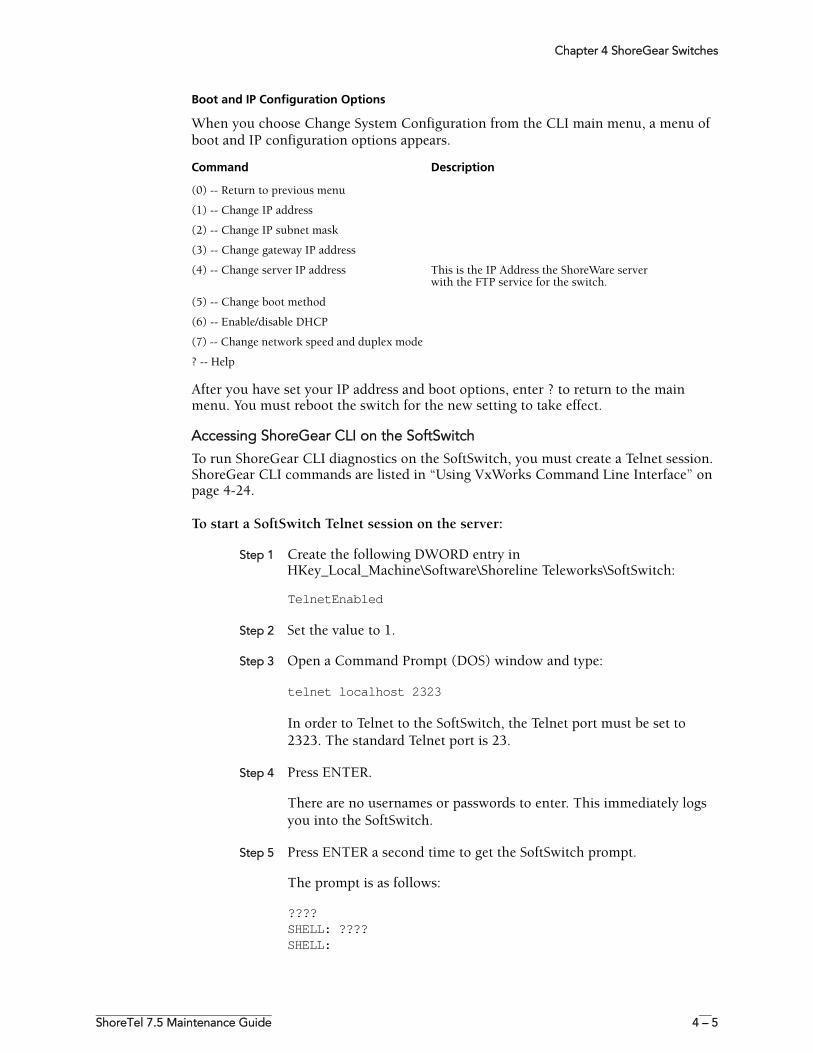
Chapter 4 ShoreGear Switches
ShoreTel 7.5 Maintenance Guide 4 – 5
Boot and IP Configuration Options
When you choose Change System Configuration from the CLI main menu, a menu of boot and IP configuration options appears.
After you have set your IP address and boot options, enter ? to return to the main menu. You must reboot the switch for the new setting to take effect.
Accessing ShoreGear CLI on the SoftSwitch
To run ShoreGear CLI diagnostics on the SoftSwitch, you must create a Telnet session. ShoreGear CLI commands are listed in “Using VxWorks Command Line Interface” on page 4-24.
To start a SoftSwitch Telnet session on the server:
Step 1 Create the following DWORD entry in HKey_Local_Machine\Software\Shoreline Teleworks\SoftSwitch:
TelnetEnabled
Step 2 Set the value to 1.
Step 3 Open a Command Prompt (DOS) window and type:
telnet localhost 2323
In order to Telnet to the SoftSwitch, the Telnet port must be set to 2323. The standard Telnet port is 23.
Step 4 Press ENTER.
There are no usernames or passwords to enter. This immediately logs you into the SoftSwitch.
Step 5 Press ENTER a second time to get the SoftSwitch prompt.
The prompt is as follows:
????SHELL: ????SHELL:
Command Description
(0) -- Return to previous menu
(1) -- Change IP address
(2) -- Change IP subnet mask
(3) -- Change gateway IP address
(4) -- Change server IP address This is the IP Address the ShoreWare server with the FTP service for the switch.
(5) -- Change boot method
(6) -- Enable/disable DHCP
(7) -- Change network speed and duplex mode
? -- Help
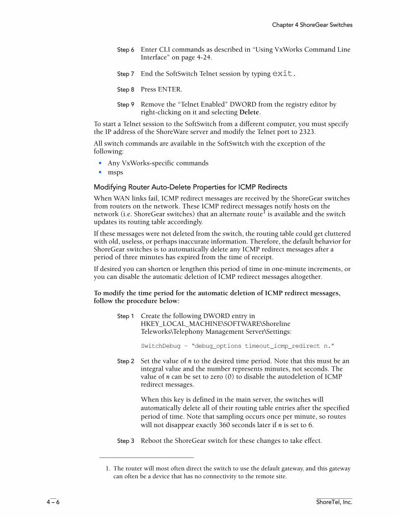
Chapter 4 ShoreGear Switches
4 – 6 ShoreTel, Inc.
Step 6 Enter CLI commands as described in “Using VxWorks Command Line Interface” on page 4-24.
Step 7 End the SoftSwitch Telnet session by typing exit.
Step 8 Press ENTER.
Step 9 Remove the “Telnet Enabled” DWORD from the registry editor by right-clicking on it and selecting Delete.
To start a Telnet session to the SoftSwitch from a different computer, you must specify the IP address of the ShoreWare server and modify the Telnet port to 2323.
All switch commands are available in the SoftSwitch with the exception of the following:
• Any VxWorks-specific commands• msps
Modifying Router Auto-Delete Properties for ICMP Redirects
When WAN links fail, ICMP redirect messages are received by the ShoreGear switches from routers on the network. These ICMP redirect messages notify hosts on the network (i.e. ShoreGear switches) that an alternate route1 is available and the switch updates its routing table accordingly.
If these messages were not deleted from the switch, the routing table could get cluttered with old, useless, or perhaps inaccurate information. Therefore, the default behavior for ShoreGear switches is to automatically delete any ICMP redirect messages after a period of three minutes has expired from the time of receipt.
If desired you can shorten or lengthen this period of time in one-minute increments, or you can disable the automatic deletion of ICMP redirect messages altogether.
To modify the time period for the automatic deletion of ICMP redirect messages, follow the procedure below:
Step 1 Create the following DWORD entry in HKEY_LOCAL_MACHINE\SOFTWARE\Shoreline Teleworks\Telephony Management Server\Settings:
SwitchDebug - “debug_options timeout_icmp_redirect n.”
Step 2 Set the value of n to the desired time period. Note that this must be an integral value and the number represents minutes, not seconds. The value of n can be set to zero (0) to disable the autodeletion of ICMP redirect messages.
When this key is defined in the main server, the switches will automatically delete all of their routing table entries after the specified period of time. Note that sampling occurs once per minute, so routes will not disappear exactly 360 seconds later if n is set to 6.
Step 3 Reboot the ShoreGear switch for these changes to take effect.
1. The router will most often direct the switch to use the default gateway, and this gateway can often be a device that has no connectivity to the remote site.
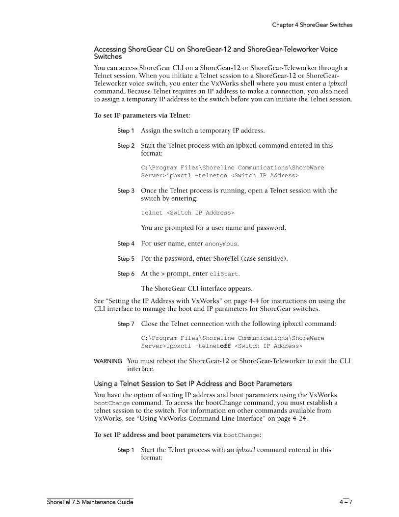
Chapter 4 ShoreGear Switches
ShoreTel 7.5 Maintenance Guide 4 – 7
Accessing ShoreGear CLI on ShoreGear-12 and ShoreGear-Teleworker Voice Switches
You can access ShoreGear CLI on a ShoreGear-12 or ShoreGear-Teleworker through a Telnet session. When you initiate a Telnet session to a ShoreGear-12 or ShoreGear-Teleworker voice switch, you enter the VxWorks shell where you must enter a ipbxctl command. Because Telnet requires an IP address to make a connection, you also need to assign a temporary IP address to the switch before you can initiate the Telnet session.
To set IP parameters via Telnet:
Step 1 Assign the switch a temporary IP address.
Step 2 Start the Telnet process with an ipbxctl command entered in this format:
C:\Program Files\Shoreline Communications\ShoreWare Server>ipbxctl -telneton <Switch IP Address>
Step 3 Once the Telnet process is running, open a Telnet session with the switch by entering:
telnet <Switch IP Address>
You are prompted for a user name and password.
Step 4 For user name, enter anonymous.
Step 5 For the password, enter ShoreTel (case sensitive).
Step 6 At the > prompt, enter cliStart.
The ShoreGear CLI interface appears.
See “Setting the IP Address with VxWorks” on page 4-4 for instructions on using the CLI interface to manage the boot and IP parameters for ShoreGear switches.
Step 7 Close the Telnet connection with the following ipbxctl command:
C:\Program Files\Shoreline Communications\ShoreWare Server>ipbxctl -telnetoff <Switch IP Address>
WARNING You must reboot the ShoreGear-12 or ShoreGear-Teleworker to exit the CLI interface.
Using a Telnet Session to Set IP Address and Boot Parameters
You have the option of setting IP address and boot parameters using the VxWorks bootChange command. To access the bootChange command, you must establish a telnet session to the switch. For information on other commands available from VxWorks, see “Using VxWorks Command Line Interface” on page 4-24.
To set IP address and boot parameters via bootChange:
Step 1 Start the Telnet process with an ipbxctl command entered in this format:
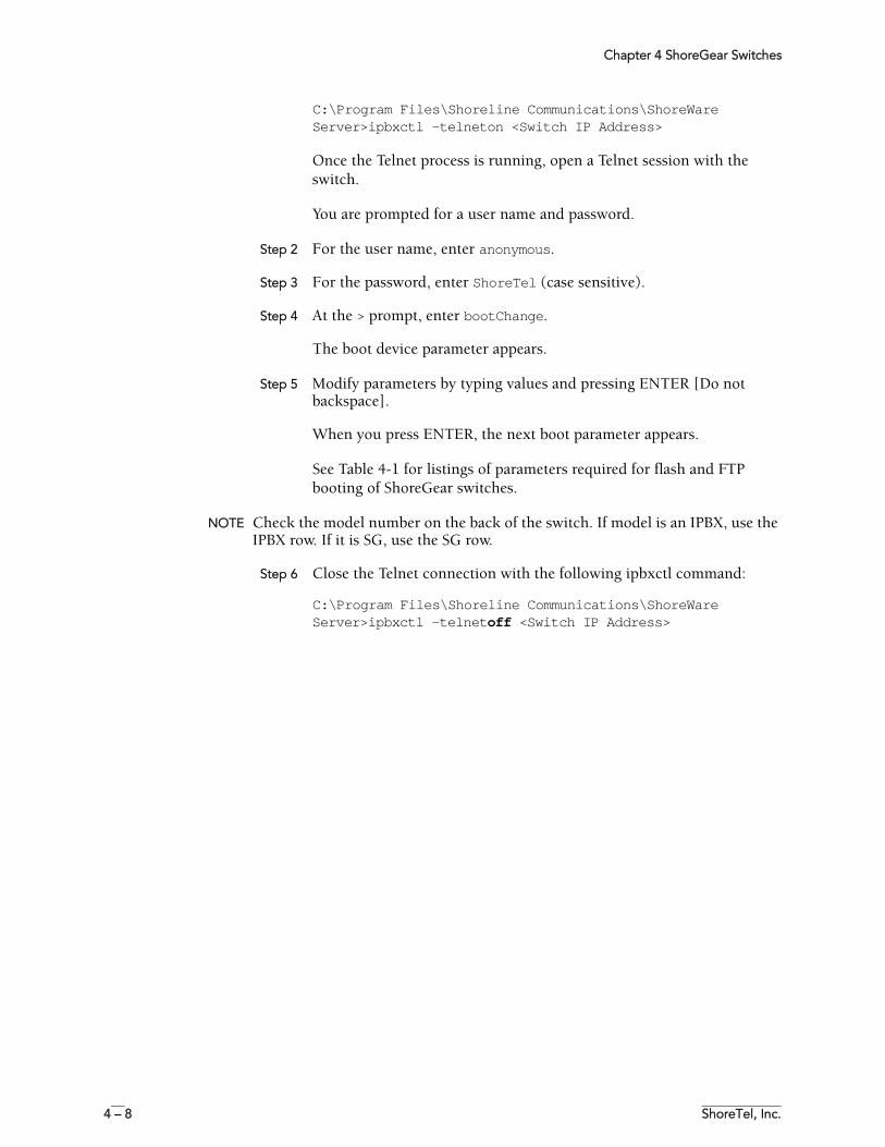
Chapter 4 ShoreGear Switches
4 – 8 ShoreTel, Inc.
C:\Program Files\Shoreline Communications\ShoreWare Server>ipbxctl -telneton <Switch IP Address>
Once the Telnet process is running, open a Telnet session with the switch.
You are prompted for a user name and password.
Step 2 For the user name, enter anonymous.
Step 3 For the password, enter ShoreTel (case sensitive).
Step 4 At the > prompt, enter bootChange.
The boot device parameter appears.
Step 5 Modify parameters by typing values and pressing ENTER [Do not backspace].
When you press ENTER, the next boot parameter appears.
See Table 4-1 for listings of parameters required for flash and FTP booting of ShoreGear switches.
NOTE Check the model number on the back of the switch. If model is an IPBX, use the IPBX row. If it is SG, use the SG row.
Step 6 Close the Telnet connection with the following ipbxctl command:
C:\Program Files\Shoreline Communications\ShoreWare Server>ipbxctl -telnetoff <Switch IP Address>
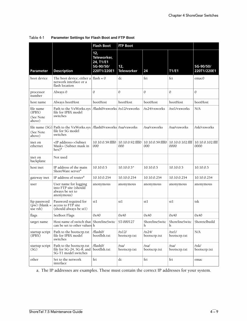
Chapter 4 ShoreGear Switches
ShoreTel 7.5 Maintenance Guide 4 – 9
Table 4-1 Parameter Settings for Flash Boot and FTP Boot
Parameter Description
Flash Boot FTP Boot
12, Teleworker, 24, T1/E1SG-90/50/220T1/220E1
12, Teleworker 24 T1/E1
SG-90/50/220T1/220E1
boot device The boot device; either a network interface or a flash location
flash = 0 dc fei fei emac0
processor number
Always 0 0 0 0 0 0
host name Always bootHost bootHost bootHost bootHost bootHost bootHost
file name (IPBX)(See Note above)
Path to the VxWorks.sys file for IPBX model switches
/flash0/vxworks /ts12/vxworks /ts24/vxworks /tst1/vxworks N/A
file name (SG)(See Note above)
Path to the VxWorks.sys file for SG model switches
/flash0/vxworks /tsa/vxworks /tsa/vxworks /tsa/vxworks /tsk/vxworks
inet on ethernet
<IP address>:<Subnet Mask> (Subnet mask in hex)a
10.10.0.59:ffff0000
10.10.0.92:ffff0000
10.10.0.59:ffff0000
10.10.0.102:ffff0000
10.10.0.102:ffff0000
inet on backplane
Not used
host inet IP address of the main ShoreWare servera
10.10.0.5 10.10.0.5* 10.10.0.5 10.10.0.5 10.10.0.5
gateway inet IP address of routera 10.10.0.254 10.10.0.254 10.10.0.254 10.10.0.254 10.10.0.254
user User name for logging into FTP site (should always be set to anonymous)
anonymous anonymous anonymous anonymous anonymous
ftp password (pw) (blank = use rsh)
Password required for access to FTP site (should always be st1)
st1 st1 st1 st1 tsk
flags SeeBoot Flags 0x40 0x40 0x40 0x40 0x40
target name Host name of switch that can be set to other values
ShorelineSwitch
ST-000127 ShorelineSwitch
ShorelineSwitch
Shoretelbuild
startup script (IPBX)
Path to the bootscrp.txt file for IPBX model switches
/flash0/bootflsh.txt
/ts12/bootscrp.txt
/ts24/bootscrp.txt
/tst1/bootscrp.txt
N/A
startup script (SG)
Path to the bootscrp.txt file for SG-24, SG-8, and SG-T1 model switches
/flash0/bootflsh.txt
/tsa/bootscrp.txt
/tsa/bootscrp.txt
/tsa/bootscrp.txt
/tsk/bootscrp.txt
other Set to the network interface
fei dc fei fei emac
a. The IP addresses are examples. These must contain the correct IP addresses for your system.
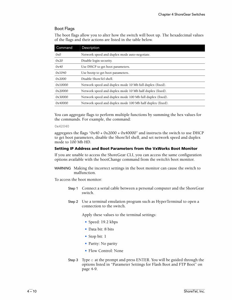
Chapter 4 ShoreGear Switches
4 – 10 ShoreTel, Inc.
Boot Flags
The boot flags allow you to alter how the switch will boot up. The hexadecimal values of the flags and their actions are listed in the table below.
You can aggregate flags to perform multiple functions by summing the hex values for the commands. For example, the command:
0x42040
aggregates the flags “0x40 + 0x2000 + 0x40000” and instructs the switch to use DHCP to get boot parameters, disable the ShoreTel shell, and set network speed and duplex mode to 100 Mb HD.
Setting IP Address and Boot Parameters from the VxWorks Boot Monitor
If you are unable to access the ShoreGear CLI, you can access the same configuration options available with the bootChange command from the switch’s boot monitor.
WARNING Making the incorrect settings in the boot monitor can cause the switch to malfunction.
To access the boot monitor:
Step 1 Connect a serial cable between a personal computer and the ShoreGear switch.
Step 2 Use a terminal emulation program such as HyperTerminal to open a connection to the switch.
Apply these values to the terminal settings:
• Speed: 19.2 kbps
• Data bit: 8 bits
• Stop bit: 1
• Parity: No parity
• Flow Control: None
Step 3 Type c at the prompt and press ENTER. You will be guided through the options listed in “Parameter Settings for Flash Boot and FTP Boot” on page 4-9.
Command Description
0x0 Network speed and duplex mode auto-negotiate.
0x20 Disable login security.
0x40 Use DHCP to get boot parameters.
0x1040 Use bootp to get boot parameters.
0x2000 Disable ShoreTel shell.
0x10000 Network speed and duplex mode 10 Mb full duplex (fixed).
0x20000 Network speed and duplex mode 10 Mb half duplex (fixed).
0x30000 Network speed and duplex mode 100 Mb full duplex (fixed).
0x40000 Network speed and duplex mode 100 Mb half duplex (fixed).
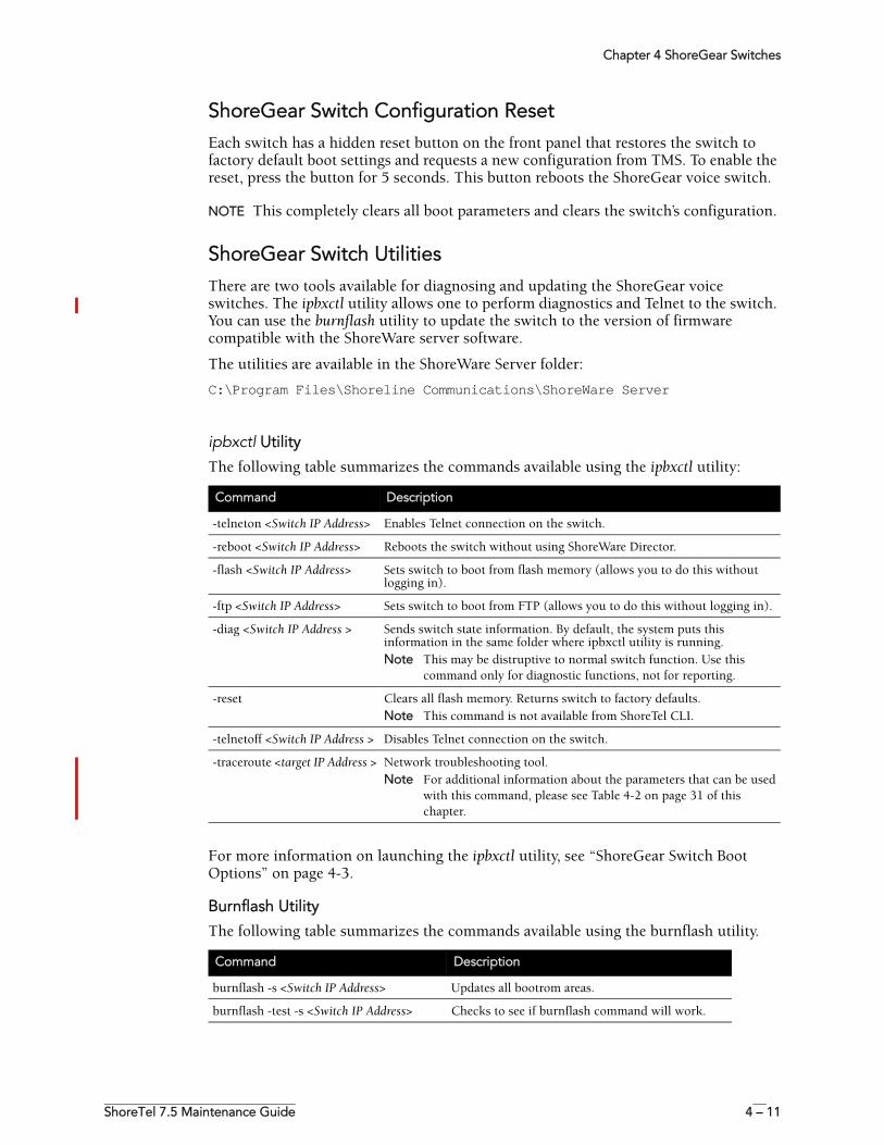
Chapter 4 ShoreGear Switches
ShoreTel 7.5 Maintenance Guide 4 – 11
ShoreGear Switch Configuration ResetEach switch has a hidden reset button on the front panel that restores the switch to factory default boot settings and requests a new configuration from TMS. To enable the reset, press the button for 5 seconds. This button reboots the ShoreGear voice switch.
NOTE This completely clears all boot parameters and clears the switch’s configuration.
ShoreGear Switch UtilitiesThere are two tools available for diagnosing and updating the ShoreGear voice switches. The ipbxctl utility allows one to perform diagnostics and Telnet to the switch. You can use the burnflash utility to update the switch to the version of firmware compatible with the ShoreWare server software.
The utilities are available in the ShoreWare Server folder:
C:\Program Files\Shoreline Communications\ShoreWare Server
ipbxctl Utility
The following table summarizes the commands available using the ipbxctl utility:
For more information on launching the ipbxctl utility, see “ShoreGear Switch Boot Options” on page 4-3.
Burnflash Utility
The following table summarizes the commands available using the burnflash utility.
Command Description
-telneton <Switch IP Address> Enables Telnet connection on the switch.
-reboot <Switch IP Address> Reboots the switch without using ShoreWare Director.
-flash <Switch IP Address> Sets switch to boot from flash memory (allows you to do this without logging in).
-ftp <Switch IP Address> Sets switch to boot from FTP (allows you to do this without logging in).
-diag <Switch IP Address > Sends switch state information. By default, the system puts this information in the same folder where ipbxctl utility is running.Note This may be distruptive to normal switch function. Use this
command only for diagnostic functions, not for reporting.
-reset Clears all flash memory. Returns switch to factory defaults. Note This command is not available from ShoreTel CLI.
-telnetoff <Switch IP Address > Disables Telnet connection on the switch.
-traceroute <target IP Address > Network troubleshooting tool.Note For additional information about the parameters that can be used
with this command, please see Table 4-2 on page 31 of this chapter.
Command Description
burnflash -s <Switch IP Address> Updates all bootrom areas.
burnflash -test -s <Switch IP Address> Checks to see if burnflash command will work.
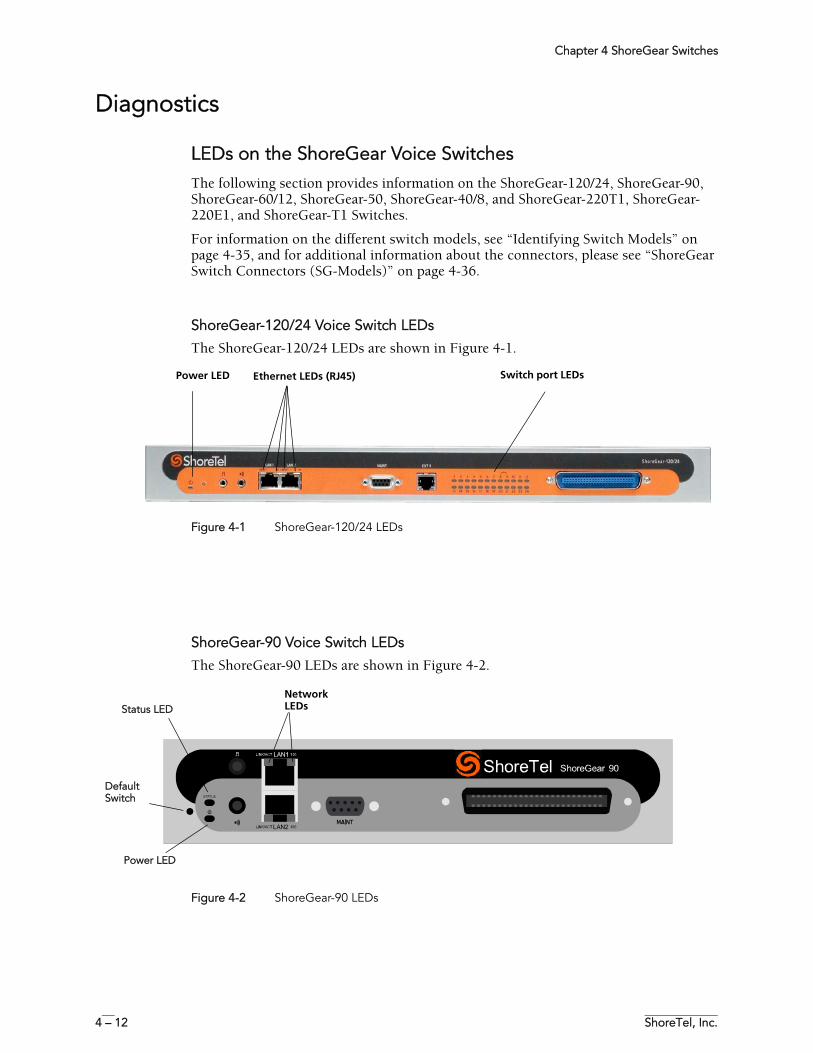
Chapter 4 ShoreGear Switches
4 – 12 ShoreTel, Inc.
Diagnostics
LEDs on the ShoreGear Voice SwitchesThe following section provides information on the ShoreGear-120/24, ShoreGear-90, ShoreGear-60/12, ShoreGear-50, ShoreGear-40/8, and ShoreGear-220T1, ShoreGear-220E1, and ShoreGear-T1 Switches.
For information on the different switch models, see “Identifying Switch Models” on page 4-35, and for additional information about the connectors, please see “ShoreGear Switch Connectors (SG-Models)” on page 4-36.
ShoreGear-120/24 Voice Switch LEDs
The ShoreGear-120/24 LEDs are shown in Figure 4-1.
Figure 4-1 ShoreGear-120/24 LEDs
ShoreGear-90 Voice Switch LEDs
The ShoreGear-90 LEDs are shown in Figure 4-2.
Figure 4-2 ShoreGear-90 LEDs
Switch port LEDsPower LED Ethernet LEDs (RJ45)
Network LEDsStatus LED
Default Switch
Power LED
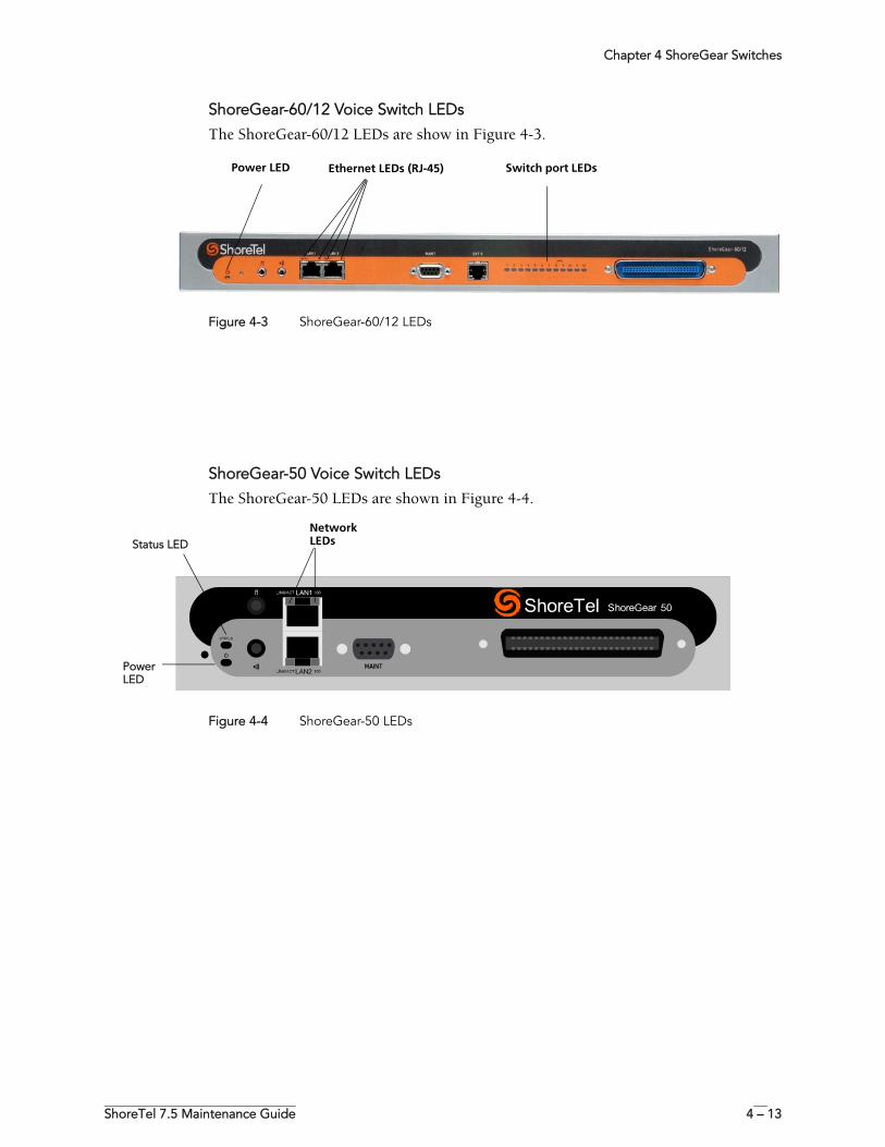
Chapter 4 ShoreGear Switches
ShoreTel 7.5 Maintenance Guide 4 – 13
ShoreGear-60/12 Voice Switch LEDs
The ShoreGear-60/12 LEDs are show in Figure 4-3.
Figure 4-3 ShoreGear-60/12 LEDs
ShoreGear-50 Voice Switch LEDs
The ShoreGear-50 LEDs are shown in Figure 4-4.
Figure 4-4 ShoreGear-50 LEDs
Switch port LEDsPower LED Ethernet LEDs (RJ-45)
Network LEDsStatus LED
Power LED
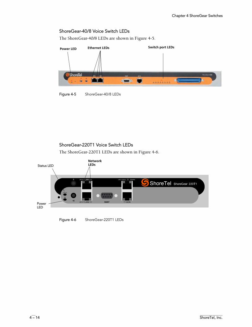
Chapter 4 ShoreGear Switches
4 – 14 ShoreTel, Inc.
ShoreGear-40/8 Voice Switch LEDs
The ShoreGear-40/8 LEDs are shown in Figure 4-5.
Figure 4-5 ShoreGear-40/8 LEDs
ShoreGear-220T1 Voice Switch LEDs
The ShoreGear-220T1 LEDs are shown in Figure 4-6.
Figure 4-6 ShoreGear-220T1 LEDs
Switch port LEDsPower LED Ethernet LEDs
Network LEDsStatus LED
Power LED
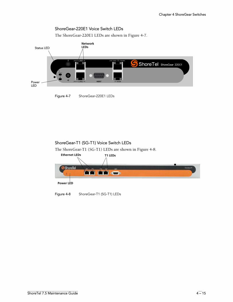
Chapter 4 ShoreGear Switches
ShoreTel 7.5 Maintenance Guide 4 – 15
ShoreGear-220E1 Voice Switch LEDs
The ShoreGear-220E1 LEDs are shown in Figure 4-7.
Figure 4-7 ShoreGear-220E1 LEDs
ShoreGear-T1 (SG-T1) Voice Switch LEDs
The ShoreGear-T1 (SG-T1) LEDs are shown in Figure 4-8.
Figure 4-8 ShoreGear-T1 (SG-T1) LEDs
Network LEDsStatus LED
Power LED
Ethernet LEDs T1 LEDs
Power LED
Chapter 4 ShoreGear Switches
4 – 16 ShoreTel, Inc.
ShoreGear Voice Switch LED BehaviorThis sections describes how to interpret the LED behavior of ShoreGear-120/24, ShoreGear-90, ShoreGear-60/12, ShoreGear-50, ShoreGear-40/8, ShoreGear-220T1, ShoreGear-220E1, and ShoreGear-T1 voice switches.
Power LED
ShoreGear voice switches have one power LED, which indicates the following:
Analog Port LEDs
This section describes how to interpret the switch port LED behavior of the ShoreGear-120/24, ShoreGear-60/12, ShoreGear-40/8, and ShoreGear-T1 voice switches. Note that the ShoreGear-90, ShoreGear-50, ShoreGear-220T1, ShoreGear-220E1 switches do not have analog port LEDs and instead have a single Status LED (see below).
The color of the LED indicates the port function:
• Green when the port is a telephone port. • Yellow when the port is a trunk port.• Off indicates the port is reserved for IP phones, for conferencing, or is
unconfigured.
On The switch is operating normally.
Off The switch has no power.
Flashing 2 flashes—The switch failed its internal self-test. This indicates a hardware failure; replace the unit and submit a Return Material Authorization (RMA) to ShoreTel.
3 flashes—Booting via FTP. Flash memory might be corrupted. Go to the Quick Look page to ensure that the system is running properly.
4 flashes—The IP address is unavailable. DHCP and BOOTP did not respond to the IP address request, and the IP address is not available in nonvolatile memory to continue boot process. The switch will automatically reboot in five seconds and try again. Check the BOOTP/DHCP server and the network configuration to ensure that the voice switch is receiving a valid IP address.
5 flashes—The operating system is not available. The switch is booting from FTP but cannot find the boot files. It automatically reboots in five seconds.
6 flashes—Using a previously stored IP address. A BOOTP/DHCP transaction was attempted, but the BOOTP/DHCP server did not respond. The switch continues to use the IP address stored in nonvolatile memory until it receives a valid response. If the switch receives a response that provides a different IP address, it reboots using the new IP address. If the switch receives a response that matches the IP address stored in nonvolatile memory, it continues operation, and the power LED stops flashing. If the problem persists, check the BOOTP/DHCP server and network configuration.
Chapter 4 ShoreGear Switches
ShoreTel 7.5 Maintenance Guide 4 – 17
The following describes the switch port LED behavior and meaning:
Status LEDs
This section describes how to interpret the Status LED behavior of the ShoreGear-90, ShoreGear-50, ShoreGear-220T1, ShoreGear-220E1 switches (which do not have individual analog port LEDs as with the second-generation switches).
The status LED provides voice switch activity information.
• Off — No ports are assigned• Green — (Steady) No ports are handling active calls• Green — (Flashing-Fast) At least one port is handling an active call.• Yellow — (Steady) No ports are handling active calls and at least one port is out of
service.• Yellow — (Flashing-Slow) The switch is not connected (or has lost connection) to
a ShoreTel server.• Yellow — (Flashing-Fast) At least one port is handling an active call and at least
one port is out of service.
Network LEDs
The network LEDs (LAN1 and LAN2) indicate the speed at which the switch is communicating with the network and whether there is network activity. When you are connecting to both LAN connectors in a redundant network configuration, one network port will be active and the other will be in standby mode. If one LAN link connection fails, the switch automatically changes to the other LAN connection. This section applies to all second- and third-generation switches (i.e. ShoreGear-120/24, ShoreGear-90, ShoreGear-60/12, ShoreGear-50, ShoreGear-40/8, andShoreGear-220T1, ShoreGear-220E1, and ShoreGear-T1 voice switches).
Telephone Port LEDs (Green)
• When on steady, the port is configured as a telephone port and the telephone is idle.
• When flashing with ring cadence, the telephone is ringing.• When flashing slowly, the telephone is off hook.• When flashing fast, the port is in use (call in progress).
Trunk Port LED (Yellow)
When on steady, the port is configured as a trunk port and the trunk is idle.
• When flashing slowly, the trunk is off hook.• When flashing fast, the trunk is in use (call in progress).
Port LED Alternating Green/Yellow
The port is out of service. The LED periodically alternates green/yellow or yellow/green. The color of the LED between alternating colors indicates the port type: green for phone and yellow for trunk.
Off (IP phone or Conference)
When the LED is off, the port is unconfigured or is configured to support IP phones or conferencing.

Chapter 4 ShoreGear Switches
4 – 18 ShoreTel, Inc.
The network LED descriptions are as follows:
ShoreGear-T1 Monitor and Telco LEDs
The Monitor and Telco LEDs indicate line coding, network framing, and loopback status. These LEDs are color coded—green, yellow, and red. The Monitor and Telco LED descriptions follow.
NOTE Telco and Monitor LED alarms and errors are logged as switch events in ShoreWare Director’s event log.
Link/Activity
When lit, this LED indicates that the switch is connected to an Ethernet network.
This LED indicates network activity, as follows:
• When flashing, network activity is detected.• When on (not flashing), heavy network activity is detected.• When off, the switch has no power.
NOTE This LED is not directly related to any particular switch’s individual network activity. For example, if you have three switches that are connected to the same hub, and one switch’s Link/Activity LED shows activity, the other switches will indicate the same.
100M • When green, the switch is connected to a 100BaseT network.• When off, the switch is connected to a 10BaseT network.
Line Coding
This LED indicates line coding status, as follows:
• When green, the line coding signal is good. • When yellow, bipolar violations (BPV) are being received at one
second intervals.• When red, a loss of signal (LOS) has occurred.• When flashing red, loopback is active (local or CO).• When off, the switch has no power.
Framing This LED indicates network framing status, as follows:
• When green, the T1 signal is in frame; the signal is synchronized.• When yellow, a yellow alarm has been received from the CO.• When flashing yellow, the frame-bit error rate has exceeded its limits.• When flashing slow yellow, a small number of frame-bit errors
(10e-6) have occurred; this state will take up to 10 minutes to clear.• When flashing fast yellow, a series of frame-bit errors (10e-3) have
occurred.• When red, the T1 signal is out-of-frame (OOF). The received signal
cannot be framed to the Extended Superframe (ESF) or D4 format.• When flashing red, loopback is active (local or CO).• When off, the switch has no power.
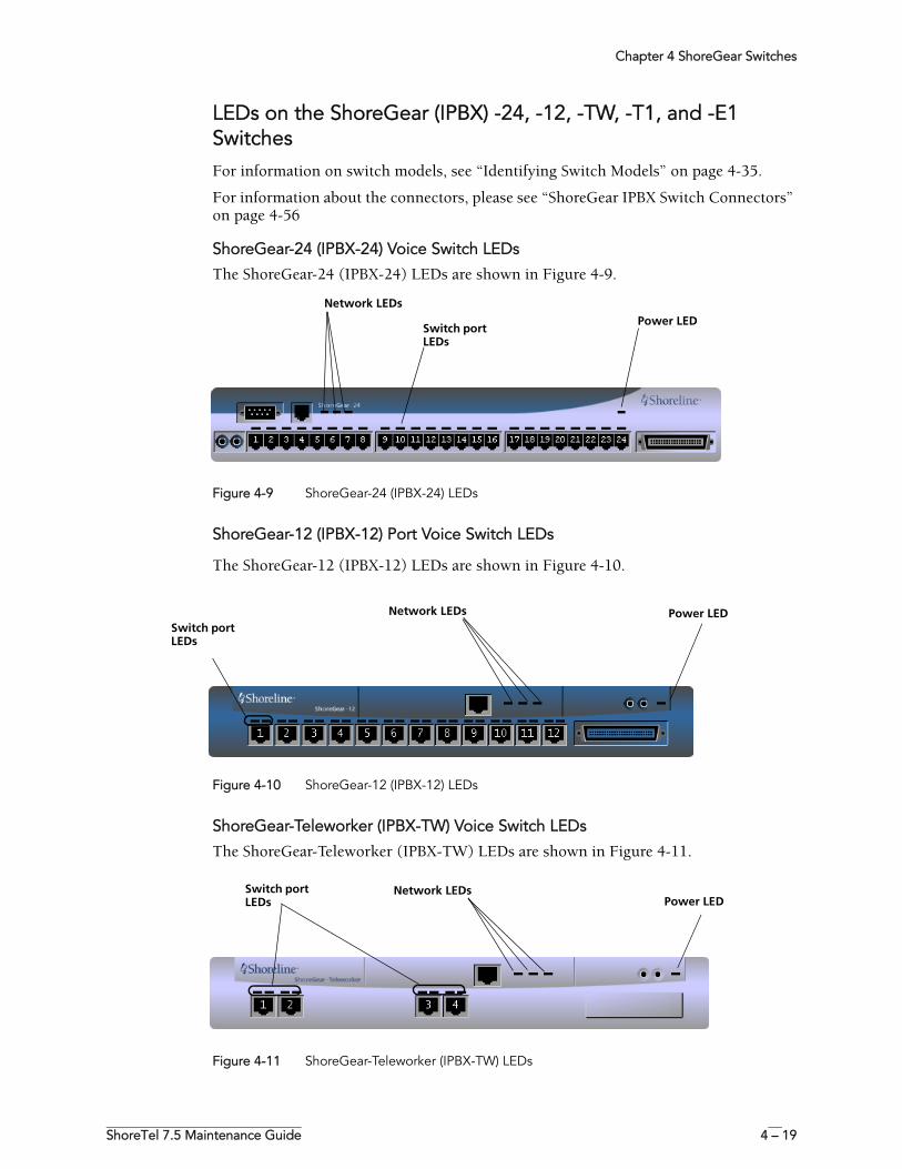
Chapter 4 ShoreGear Switches
ShoreTel 7.5 Maintenance Guide 4 – 19
LEDs on the ShoreGear (IPBX) -24, -12, -TW, -T1, and -E1 SwitchesFor information on switch models, see “Identifying Switch Models” on page 4-35.
For information about the connectors, please see “ShoreGear IPBX Switch Connectors” on page 4-56
ShoreGear-24 (IPBX-24) Voice Switch LEDs
The ShoreGear-24 (IPBX-24) LEDs are shown in Figure 4-9.
Figure 4-9 ShoreGear-24 (IPBX-24) LEDs
ShoreGear-12 (IPBX-12) Port Voice Switch LEDs
The ShoreGear-12 (IPBX-12) LEDs are shown in Figure 4-10.
Figure 4-10 ShoreGear-12 (IPBX-12) LEDs
ShoreGear-Teleworker (IPBX-TW) Voice Switch LEDs
The ShoreGear-Teleworker (IPBX-TW) LEDs are shown in Figure 4-11.
Figure 4-11 ShoreGear-Teleworker (IPBX-TW) LEDs
Switch port LEDs
Power LED
Network LEDs
Network LEDs Power LEDSwitch port LEDs
Network LEDsPower LED
Switch port LEDs
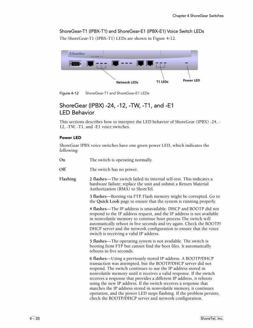
Chapter 4 ShoreGear Switches
4 – 20 ShoreTel, Inc.
ShoreGear-T1 (IPBX-T1) and ShoreGear-E1 (IPBX-E1) Voice Switch LEDs
The ShoreGear-T1 (IPBX-T1) LEDs are shown in Figure 4-12.
Figure 4-12 ShoreGear-T1 and ShoreGear-E1 LEDs
ShoreGear (IPBX) -24, -12, -TW, -T1, and -E1 LED BehaviorThis sections describes how to interpret the LED behavior of ShoreGear (IPBX) -24, -12, -TW, -T1, and -E1 voice switches.
Power LED
ShoreGear IPBX voice switches have one green power LED, which indicates the following:
Network LEDs T1 LEDs Power LED
On The switch is operating normally.
Off The switch has no power.
Flashing 2 flashes—The switch failed its internal self-test. This indicates a hardware failure; replace the unit and submit a Return Material Authorization (RMA) to ShoreTel.
3 flashes—Booting via FTP. Flash memory might be corrupted. Go to the Quick Look page to ensure that the system is running properly.
4 flashes—The IP address is unavailable. DHCP and BOOTP did not respond to the IP address request, and the IP address is not available in nonvolatile memory to continue boot process The switch will automatically reboot in five seconds and try again. Check the BOOTP/DHCP server and the network configuration to ensure that the voice switch is receiving a valid IP address.
5 flashes—The operating system is not available. The switch is booting from FTP but cannot find the boot files. It automatically reboots in five seconds.
6 flashes—Using a previously stored IP address. A BOOTP/DHCP transaction was attempted, but the BOOTP/DHCP server did not respond. The switch continues to use the IP address stored in nonvolatile memory until it receives a valid response. If the switch receives a response that provides a different IP address, it reboots using the new IP address. If the switch receives a response that matches the IP address stored in nonvolatile memory, it continues operation, and the power LED stops flashing. If the problem persists, check the BOOTP/DHCP server and network configuration.
Chapter 4 ShoreGear Switches
ShoreTel 7.5 Maintenance Guide 4 – 21
Switch Port LEDs
ShoreGear IPBX voice switches have telephone/trunk port LEDs. The color of the LED indicates the port function:
• Green when the port is a telephone port. • Yellow when the port is a trunk port.• Off indicates the port is reserved for IP phones or is unconfigured.
The following describes the switch port LED behavior and meaning:
Network LEDs
ShoreGear IPBX voice switches network LEDs indicate the speed at which the switch is communicating with the network and whether there is network activity.
The network LED descriptions are as follows:
Telephone Port LEDs (Green)
• When on steady, the port is configured as a telephone port and the telephone is idle.
• When flashing with ring cadence, the telephone is ringing.• When flashing slowly, the telephone is off hook.• When flashing fast, the port is in use (call in progress).
Trunk Port LED (Yellow)
• When on steady, the port is configured as a trunk port and the trunk is idle.
• When flashing slowly, the trunk is off hook.• When flashing fast, the trunk is in use (call in progress).
Port LED (Red) When on, the port is out of service.
Off (IP phone) When the LED is off, the port is unconfigured or is configured to support IP phones.
Link When lit, the switch is connected to an Ethernet network.
100M When lit, the switch is connected to a 100BaseT network.
When off, the switch is connected to a 10BaseT network.
Traffic This LED indicates network activity, as follows:
• When flashing, network activity is detected.• When on (not flashing), heavy network activity is detected.• When off, network activity is not detected.
NOTE This LED is not directly related to any particular switch’s individual network activity. For example, if you have three switches that are connected to the same hub, and one switch’s Traffic LED shows activity, the other switches will indicate the same.
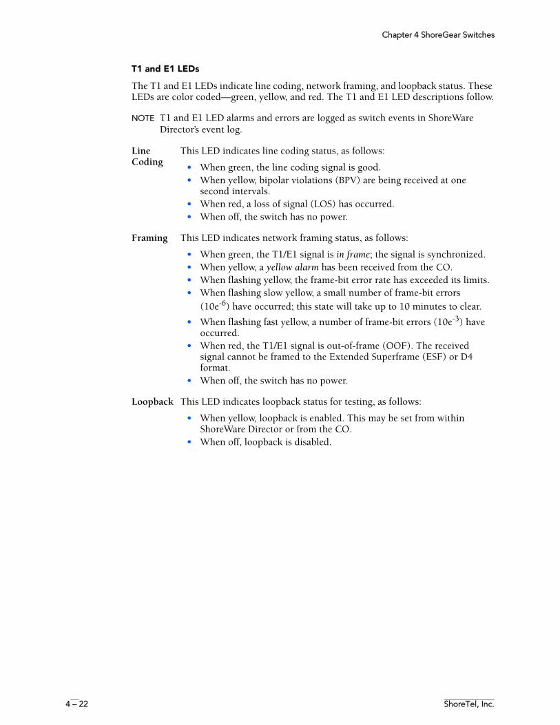
Chapter 4 ShoreGear Switches
4 – 22 ShoreTel, Inc.
T1 and E1 LEDs
The T1 and E1 LEDs indicate line coding, network framing, and loopback status. These LEDs are color coded—green, yellow, and red. The T1 and E1 LED descriptions follow.
NOTE T1 and E1 LED alarms and errors are logged as switch events in ShoreWare Director’s event log.
Line Coding
This LED indicates line coding status, as follows:
• When green, the line coding signal is good. • When yellow, bipolar violations (BPV) are being received at one
second intervals.• When red, a loss of signal (LOS) has occurred.• When off, the switch has no power.
Framing This LED indicates network framing status, as follows:
• When green, the T1/E1 signal is in frame; the signal is synchronized.• When yellow, a yellow alarm has been received from the CO.• When flashing yellow, the frame-bit error rate has exceeded its limits.• When flashing slow yellow, a small number of frame-bit errors
(10e-6) have occurred; this state will take up to 10 minutes to clear.
• When flashing fast yellow, a number of frame-bit errors (10e-3) have occurred.
• When red, the T1/E1 signal is out-of-frame (OOF). The received signal cannot be framed to the Extended Superframe (ESF) or D4 format.
• When off, the switch has no power.
Loopback This LED indicates loopback status for testing, as follows:
• When yellow, loopback is enabled. This may be set from within ShoreWare Director or from the CO.
• When off, loopback is disabled.
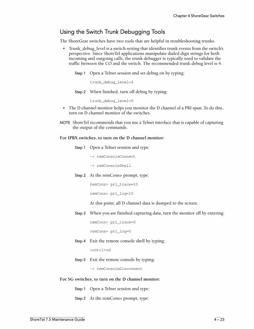
Chapter 4 ShoreGear Switches
ShoreTel 7.5 Maintenance Guide 4 – 23
Using the Switch Trunk Debugging ToolsThe ShoreGear switches have two tools that are helpful in troubleshooting trunks.
• Trunk_debug_level is a switch setting that identifies trunk events from the switch’s perspective. Since ShoreTel applications manipulate dialed digit strings for both incoming and outgoing calls, the trunk debugger is typically used to validate the traffic between the CO and the switch. The recommended trunk debug level is 4.
Step 1 Open a Telnet session and set debug on by typing:
trunk_debug_level=4
Step 2 When finished, turn off debug by typing:
trunk_debug_level=0
• The D channel monitor helps you monitor the D channel of a PRI span. To do this, turn on D channel monitor of the switches.
NOTE ShoreTel recommends that you use a Telnet interface that is capable of capturing the output of the commands.
For IPBX switches, to turn on the D channel monitor:
Step 1 Open a Telnet session and type:
-> remConsoleConnect
-> remConsoleShell
Step 2 At the remCons> prompt, type:
remCons> pri_trace=10
remCons> pri_log=10
At this point, all D channel data is dumped to the screen.
Step 3 When you are finished capturing data, turn the monitor off by entering:
remCons> pri_trace=0
remCons> pri_log=0
Step 4 Exit the remote console shell by typing:
<cntrl>+d
Step 5 Exit the remote console by typing:
-> remConsoleDisconnect
For SG switches, to turn on the D channel monitor:
Step 1 Open a Telnet session and type:
Step 2 At the remCons> prompt, type:
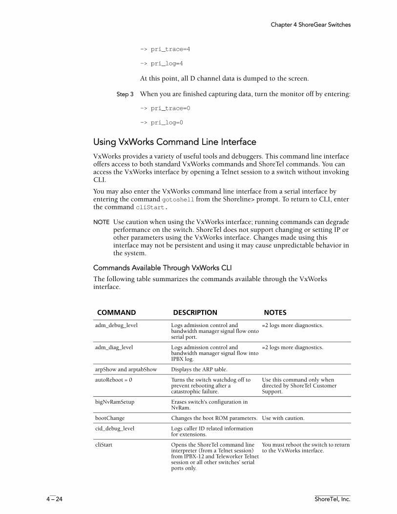
Chapter 4 ShoreGear Switches
4 – 24 ShoreTel, Inc.
-> pri_trace=4
-> pri_log=4
At this point, all D channel data is dumped to the screen.
Step 3 When you are finished capturing data, turn the monitor off by entering:
-> pri_trace=0
-> pri_log=0
Using VxWorks Command Line InterfaceVxWorks provides a variety of useful tools and debuggers. This command line interface offers access to both standard VxWorks commands and ShoreTel commands. You can access the VxWorks interface by opening a Telnet session to a switch without invoking CLI.
You may also enter the VxWorks command line interface from a serial interface by entering the command gotoshell from the Shoreline> prompt. To return to CLI, enter the command cliStart.
NOTE Use caution when using the VxWorks interface; running commands can degrade performance on the switch. ShoreTel does not support changing or setting IP or other parameters using the VxWorks interface. Changes made using this interface may not be persistent and using it may cause unpredictable behavior in the system.
Commands Available Through VxWorks CLI
The following table summarizes the commands available through the VxWorks interface.
COMMAND DESCRIPTION NOTES
adm_debug_level Logs admission control and bandwidth manager signal flow onto serial port.
=2 logs more diagnostics.
adm_diag_level Logs admission control and bandwidth manager signal flow into IPBX log.
=2 logs more diagnostics.
arpShow and arptabShow Displays the ARP table.
autoReboot = 0 Turns the switch watchdog off to prevent rebooting after a catastrophic failure.
Use this command only when directed by ShoreTel Customer Support.
bigNvRamSetup Erases switch's configuration in NvRam.
bootChange Changes the boot ROM parameters. Use with caution.
cid_debug_level Logs caller ID related information for extensions.
cliStart Opens the ShoreTel command line interpreter (from a Telnet session) from IPBX-12 and Teleworker Telnet session or all other switches’ serial ports only.
You must reboot the switch to return to the VxWorks interface.
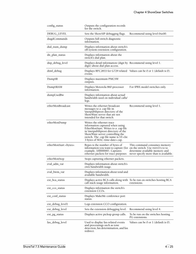
Chapter 4 ShoreGear Switches
ShoreTel 7.5 Maintenance Guide 4 – 25
config_status Outputs the configuration records for the switch.
DEBUG_LEVEL Sets the ShoreSIP debugging flags. Recommend using level 0xe00.
diagdCommands Outputs full switch diagnostic information.
dial_num_dump Displays information about switch's off-system extension configuration.
dn_plan_status Displays information about the switch's dial plan.
dnp_debug_level Displays detail information (digit by digit) about dial plan access.
Recommend using level 1.
dtmf_debug Displays RFC2833 for G729 related events.
Values can be 0 or 1 (default is 0).
DumpSB Displays maximum PMCSW outputs.
DumpSRAM Displays Motorola 860 processor information.
For IPBX model switches only.
dumpUsedBw Displays information about actual bandwidth used on individual calls/legs.
etherMonBroadcast Writes the ethernet broadcast messages to a .cap file in \inetpub\ftproot directory of the ShoreWare server that are not intended for that switch.
Recommend using level 1.
etherMonDump Writes the ethernet trace information captured when using EtherMonStart. Writes to a .cap file in \inetpub\ftproot directory of the ShoreWare server controlling the switch. The .cap file name is ST-<lst 3 bytes of MAC-time-date>.cap.
etherMonStart <bytes> Bypes is the number of bytes of information you want to capture (for example, 10000000). Captures ethernet packets for trace purposes
This command consumes memory on the switch. Use memShow to determine available memory and never specify more than is available.
etherMonStop Stops capturing ethernet packets.
eval_adm_var Displays information about switch's own bandwidth usage.
eval_bwm_var Displays information about total and available bandwidth.
ext_bca_status Displays active BCA calls along with call stack usage information.
To be run on switches hosting BCA extensions.
ext_cco_status Displays information the switch's extension CCOs.
ext_conf_status Displays MakeMe conference port status.
ext_debug_level1 Logs extension CCO configuration.
ext_debug_level Sets the extension debugging level. Recommend using level 4.
ext_pg_status Displays active pickup group calls. To be run on the switches hosting PG extensions.
fax_debug_level Used to display fax-related events and processings such as tone detection, fax determination, and fax redirect.
Values can be 0 or 1 (default is 0).
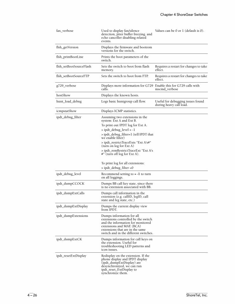
Chapter 4 ShoreGear Switches
4 – 26 ShoreTel, Inc.
fax_verbose Used to display fax/silence detection, jitter buffer freezing. and echo canceller disabling related events.
Values can be 0 or 1 (default is 0).
flsh_getVersion Displays the firmware and bootrom versions for the switch.
flsh_printBootLine Prints the boot parameters of the switch.
flsh_setBootSourceFlash Sets the switch to boot from flash memory.
Requires a restart for changes to take effect.
flsh_setBootSourceFTP Sets the switch to boot from FTP. Requires a restart for changes to take effect.
g729_verbose Displays more information for G729 calls.
Enable this for G729 calls with mscmd_verbose
hostShow Displays the known hosts.
hunt_load_debug Logs basic huntgroup call flow. Useful for debugging issues found during heavy call load.
icmpstatShow Displays ICMP statistics.
ipdt_debug_filter Assuming two extensions in the system: Ext A and Ext B.To print out IPDT log for Ext A.> ipdt_debug_level = -1> ipdt_debug_filter=1 (tell IPDT that we enable filter) > ipdt_restrictTraceExts "Ext A's#" (turn on log for Ext A) > ipdt_remRestrictTraceExt "Ext A's #" (turn off log for Ext A).
To print log for all extensions:> ipdt_debug_filter =0
ipdt_debug_level Recommend setting to = -1 to turn on all loggings.
ipdt_dumpCCOCK Dumps BB call key state, since there is no extension associated with BB.
ipdt_dumpExtCalls Dumps call information in the extension (e.g. callID, legID, call state and leg state, etc.)
ipdt_dumpExtDisplay Dumps the current display view from IPDT.
ipdt_dumpExtensions Dumps information for all extensions controlled by the switch and the information for monitored extensions and MAE (BCA) extensions that are in the same switch and in the different switches.
ipdt_dumpExtCK Dumps information for call keys on the extension. Useful for troubleshooting LED patterns and icon issues.
ipdt_resetExtDisplay Redisplay on the extension. If the phone display and IPDT display (ipdt_dumpExtDisplay) are desynchronized, we can run ipdt_reset_ExtDisplay to synchronize them.
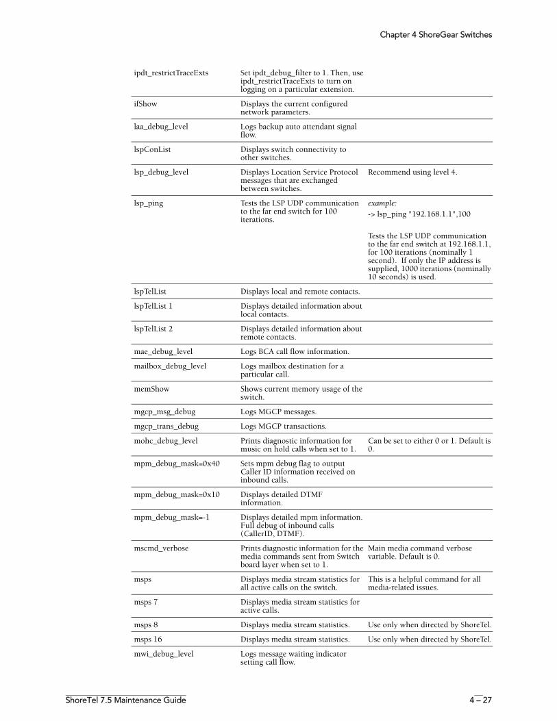
Chapter 4 ShoreGear Switches
ShoreTel 7.5 Maintenance Guide 4 – 27
ipdt_restrictTraceExts Set ipdt_debug_filter to 1. Then, use ipdt_restrictTraceExts to turn on logging on a particular extension.
ifShow Displays the current configured network parameters.
laa_debug_level Logs backup auto attendant signal flow.
lspConList Displays switch connectivity to other switches.
lsp_debug_level Displays Location Service Protocol messages that are exchanged between switches.
Recommend using level 4.
lsp_ping Tests the LSP UDP communication to the far end switch for 100 iterations.
example:-> lsp_ping "192.168.1.1",100
Tests the LSP UDP communication to the far end switch at 192.168.1.1, for 100 iterations (nominally 1 second). If only the IP address is supplied, 1000 iterations (nominally 10 seconds) is used.
lspTelList Displays local and remote contacts.
lspTelList 1 Displays detailed information about local contacts.
lspTelList 2 Displays detailed information about remote contacts.
mae_debug_level Logs BCA call flow information.
mailbox_debug_level Logs mailbox destination for a particular call.
memShow Shows current memory usage of the switch.
mgcp_msg_debug Logs MGCP messages.
mgcp_trans_debug Logs MGCP transactions.
mohc_debug_level Prints diagnostic information for music on hold calls when set to 1.
Can be set to either 0 or 1. Default is 0.
mpm_debug_mask=0x40 Sets mpm debug flag to output Caller ID information received on inbound calls.
mpm_debug_mask=0x10 Displays detailed DTMF information.
mpm_debug_mask=-1 Displays detailed mpm information. Full debug of inbound calls (CallerID, DTMF).
mscmd_verbose Prints diagnostic information for the media commands sent from Switch board layer when set to 1.
Main media command verbose variable. Default is 0.
msps Displays media stream statistics for all active calls on the switch.
This is a helpful command for all media-related issues.
msps 7 Displays media stream statistics for active calls.
msps 8 Displays media stream statistics. Use only when directed by ShoreTel.
msps 16 Displays media stream statistics. Use only when directed by ShoreTel.
mwi_debug_level Logs message waiting indicator setting call flow.
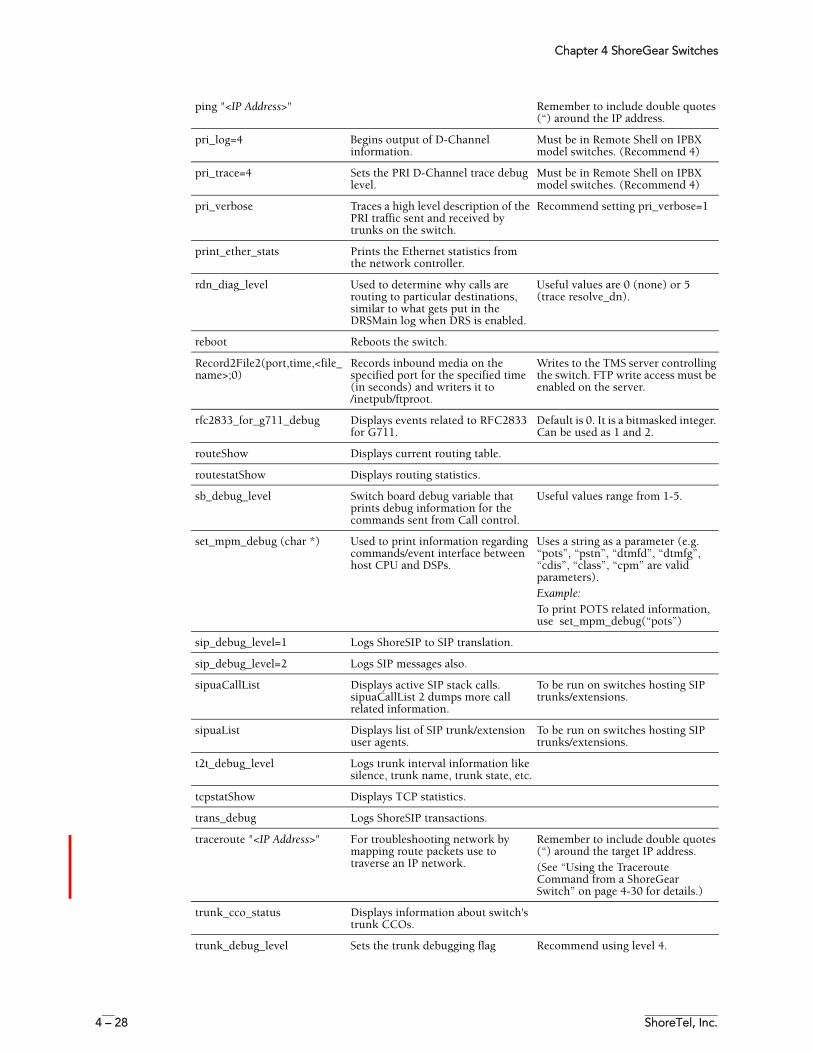
Chapter 4 ShoreGear Switches
4 – 28 ShoreTel, Inc.
ping "<IP Address>" Remember to include double quotes (“) around the IP address.
pri_log=4 Begins output of D-Channel information.
Must be in Remote Shell on IPBX model switches. (Recommend 4)
pri_trace=4 Sets the PRI D-Channel trace debug level.
Must be in Remote Shell on IPBX model switches. (Recommend 4)
pri_verbose Traces a high level description of the PRI traffic sent and received by trunks on the switch.
Recommend setting pri_verbose=1
print_ether_stats Prints the Ethernet statistics from the network controller.
rdn_diag_level Used to determine why calls are routing to particular destinations, similar to what gets put in the DRSMain log when DRS is enabled.
Useful values are 0 (none) or 5 (trace resolve_dn).
reboot Reboots the switch.
Record2File2(port,time,<file_name>;0)
Records inbound media on the specified port for the specified time (in seconds) and writers it to /inetpub/ftproot.
Writes to the TMS server controlling the switch. FTP write access must be enabled on the server.
rfc2833_for_g711_debug Displays events related to RFC2833 for G711.
Default is 0. It is a bitmasked integer. Can be used as 1 and 2.
routeShow Displays current routing table.
routestatShow Displays routing statistics.
sb_debug_level Switch board debug variable that prints debug information for the commands sent from Call control.
Useful values range from 1-5.
set_mpm_debug (char *) Used to print information regarding commands/event interface between host CPU and DSPs.
Uses a string as a parameter (e.g. “pots”, “pstn”, “dtmfd”, “dtmfg”, “cdis”, “class”, “cpm” are valid parameters).Example:To print POTS related information, use set_mpm_debug(“pots”)
sip_debug_level=1 Logs ShoreSIP to SIP translation.
sip_debug_level=2 Logs SIP messages also.
sipuaCallList Displays active SIP stack calls. sipuaCallList 2 dumps more call related information.
To be run on switches hosting SIP trunks/extensions.
sipuaList Displays list of SIP trunk/extension user agents.
To be run on switches hosting SIP trunks/extensions.
t2t_debug_level Logs trunk interval information like silence, trunk name, trunk state, etc.
tcpstatShow Displays TCP statistics.
trans_debug Logs ShoreSIP transactions.
traceroute "<IP Address>" For troubleshooting network by mapping route packets use to traverse an IP network.
Remember to include double quotes (“) around the target IP address.(See “Using the Traceroute Command from a ShoreGear Switch” on page 4-30 for details.)
trunk_cco_status Displays information about switch's trunk CCOs.
trunk_debug_level Sets the trunk debugging flag Recommend using level 4.
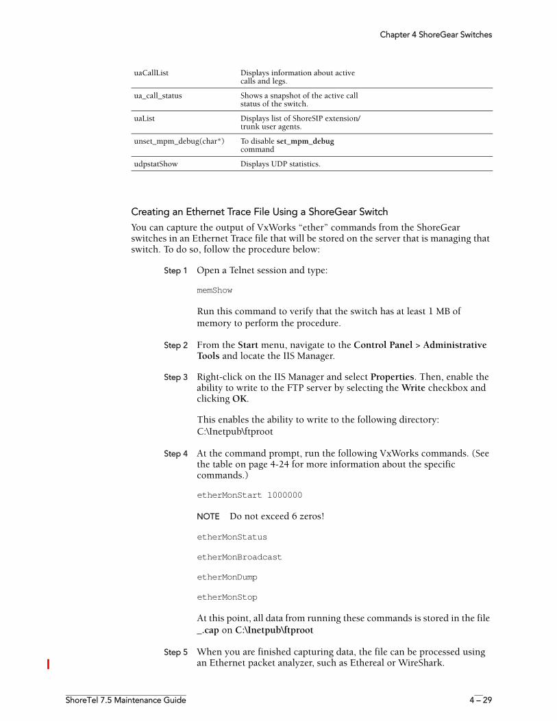
Chapter 4 ShoreGear Switches
ShoreTel 7.5 Maintenance Guide 4 – 29
Creating an Ethernet Trace File Using a ShoreGear Switch
You can capture the output of VxWorks “ether” commands from the ShoreGear switches in an Ethernet Trace file that will be stored on the server that is managing that switch. To do so, follow the procedure below:
Step 1 Open a Telnet session and type:
memShow
Run this command to verify that the switch has at least 1 MB of memory to perform the procedure.
Step 2 From the Start menu, navigate to the Control Panel > Administrative Tools and locate the IIS Manager.
Step 3 Right-click on the IIS Manager and select Properties. Then, enable the ability to write to the FTP server by selecting the Write checkbox and clicking OK.
This enables the ability to write to the following directory:C:\Inetpub\ftproot
Step 4 At the command prompt, run the following VxWorks commands. (See the table on page 4-24 for more information about the specific commands.)
etherMonStart 1000000
NOTE Do not exceed 6 zeros!
etherMonStatus
etherMonBroadcast
etherMonDump
etherMonStop
At this point, all data from running these commands is stored in the file _.cap on C:\Inetpub\ftproot
Step 5 When you are finished capturing data, the file can be processed using an Ethernet packet analyzer, such as Ethereal or WireShark.
uaCallList Displays information about active calls and legs.
ua_call_status Shows a snapshot of the active call status of the switch.
uaList Displays list of ShoreSIP extension/trunk user agents.
unset_mpm_debug(char*) To disable set_mpm_debug command
udpstatShow Displays UDP statistics.
Chapter 4 ShoreGear Switches
4 – 30 ShoreTel, Inc.
Recording Audio from a Physical ShoreGear Switch Port
You can capture audio output from a ShoreGear Switch physical port (e.g. trunk port) using VxWorks commands. Audio output is saved on the HQ or DVM server that controls the switch. To do so, follow the procedure below:
Step 1 From the Start menu, navigate to the Control Panel > Administrative Tools and locate the IIS Manager.
Step 2 Right-click on the IIS Manager and select Properties. Then, enable the ability to write to the FTP server by selecting the Write checkbox and clicking OK.
This enables the ability to write to the following directory:C:\Inetpub\ftproot
Step 3 At the command prompt, run the following VxWorks commands. (See the table on page 4-24 for more information about specific VxWorks commands.)
Record2File2 (1, 60, “test”)
Audio data from running this command is stored in the file test_rx.pcm and file test_tx.pcm in C:\Inetpub\ftproot
When you are finished capturing data, a “PCM Raw Data” file is created with the following format profile: 8000 Hz, 16-bit, Mono and can be listened to using a standard application, such as “Adobe Audition.”
Using the Traceroute Command from a ShoreGear Switch
The traceroute command offers a useful troubleshooting tool that determines the route taken by packets as they traverse an IP network from a ShoreGear switch to a specified destination. The command sends IP packets across the network, and the successive batches of packets have increased TTL (time-to-live) values.
TTL is a packet variable that defines the number of “hops” (stations) that a packet can pass through before it expires. When a station receives a packet that has expired, it discards the packet and sends a time exceeded message to the originating station. The traceroute command uses these expiration messages to build the path map.
By determining the path to a known destination, network technicians can identify firewalls blocking access to a site and gather information about the structure of a network and the IP address ranges associated with a host.
The traceroute command can be executed from the switch’s command line or from ipbxctl.exe utility.
To run the traceroute command from the ShoreGear CLI, follow the procedure below:
Step 1 Open a Telnet session and type:
traceroute “IP address”
NOTE IP address is the address of the target destination and is a mandatory parameter. It must be in double-quotation marks.
Step 2 Press Enter.
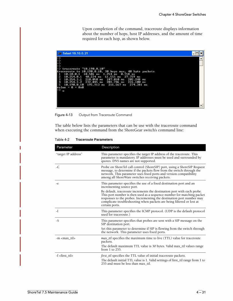
Chapter 4 ShoreGear Switches
ShoreTel 7.5 Maintenance Guide 4 – 31
Upon completion of the command, traceroute displays information about the number of hops, host IP addresses, and the amount of time required for each hop, as shown below.
Figure 4-13 Output from Traceroute Command
The table below lists the parameters that can be use with the traceroute command when executing the command from the ShoreGear switch’s command line:
Table 4-2 Traceroute Parameters
Parameter Description
“target IP address” This parameter specifies the target IP address of the traceroute. This parameter is mandatory. IP addresses must be used and surrounded by quotes. DNS names are not supported.
-C Probe on ShoreTel call control (ShoreSIP) port, using a ShoreSIP Request message, to determine if the packets flow from the switch through the network. This parameter uses fixed ports and version compatibility among all ShoreWare switches receiving packets.
-e This parameter specifies the use of a fixed destination port and an incrementing source port.By default, traceroute increments the destination port with each probe. This port number is then used as a sequence number for matching packet responses to the probes. Incrementing the destination port number may complicate troubleshooting when packets are being filtered or lost at certain ports.
-I This parameter specifies the ICMP protocol. (UDP is the default protocol used for traceroute.)
-S This parameter specifies that probes are sent with a SIP message on the SIP destination port.Set this parameter to determine if SIP is flowing from the switch through the network. This parameter uses fixed ports.
-m <max_ttl> max_ttl specifies the maximum time to live (TTL) value for traceroute packets.The default maximum TTL value is 30 bytes. Valid max_ttl values range from 1 to 255.
-f <first_ttl> first_ttl specifies the TTL value of initial traceroute packets.The default initial TTL value is 1. Valid settings of first_ttl range from 1 to 255 and must be less than max_ttl.
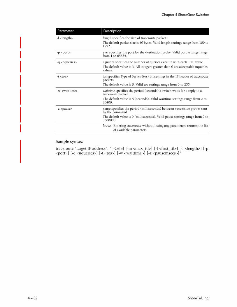
Chapter 4 ShoreGear Switches
4 – 32 ShoreTel, Inc.
Sample syntax:
traceroute "target IP address", "[-CeIS] [-m <max_ttl>] [-f <first_ttl>] [-l <length>] [-p <port>] [-q <nqueries>] [-t <tos>] [-w <waittime>] [-z <pausemsecs>]"
-l <length> length specifies the size of traceroute packet.The default packet size is 40 bytes. Valid length settings range from 100 to 1992.
-p <port> port specifies the port for the destination probe. Valid port settings range from 1 to 65535.
-q <nqueries> nqueries specifies the number of queries execute with each TTL value.The default value is 3. All integers greater than 0 are acceptable nqueries values.
-t <tos> tos specifies Type of Server (tos) bit settings in the IP header of traceroute packets. The default value is 0. Valid tos settings range from 0 to 255.
-w <waittime> waittime specifies the period (seconds) a switch waits for a reply to a traceroute packet.The default value is 5 (seconds). Valid waittime settings range from 2 to 86400.
-z <pause> pause specifies the period (milliseconds) between successive probes sent by the command. The default value is 0 (milliseconds). Valid pause settings range from 0 to 3600000.
Note Entering traceroute without listing any parameters returns the list of available parameters.
Parameter Description
Chapter 4 ShoreGear Switches
ShoreTel 7.5 Maintenance Guide 4 – 33
Connecting to a ShoreGear Voice SwitchThe ShoreGear-120/24, ShoreGear-90, ShoreGear-60/12, ShoreGear-50, ShoreGear-40/8, and ShoreGear-220T1, ShoreGear-220E1, and ShoreGear-T1, and ShoreGear-E1 provide a serial communications port accessible through a straight-through 9-pin serial cable.
NOTE You cannot access ShoreGear CLI on ShoreGear-40/8, ShoreGear-60/12, ShoreGear-120/24, and ShoreGear-T1/E1 switches using Telnet.
To connect to a ShoreGear-120/24, ShoreGear-90, ShoreGear-60/12, ShoreGear-50, ShoreGear-40/8, ShoreGear-220T1, ShoreGear-220E1, or ShoreGear-T1/E1:
Step 1 Connect a serial cable between a personal computer and the ShoreGear switch.
Step 2 Use a terminal emulation program such as HyperTerminal to open a connection to the switch.
Apply these values to the terminal settings:
• Speed: 19.2 Kbs
• Data bit: 8 bits
• Stop bit: 1
• Parity: No parity
• Flow Control: None
Reference
Switch Connectors and PinoutsThis section provides information on the switch connectors and pinouts.
Switch Types
There are three series of ShoreGear voice switches with slight differences in connectors and pinouts.
Your system may include the following third-generation half-width switches:
• ShoreGear-90 Voice Switch (1 U)• ShoreGear-50 Voice Switch (1 U)• ShoreGear-220T1 Voice Switch (1 U)• ShoreGear-220E1 Voice Switch (1 U)
Your system may include the following second-generation switches:
• ShoreGear-120/24 Voice Switch (1 U)• ShoreGear-60/12 Voice Switch (1 U)• ShoreGear-40/8 Voice Switch (1 U)• ShoreGear-T1 Voice Switch (1 U)
You may also have the following first-generation switches in your system:
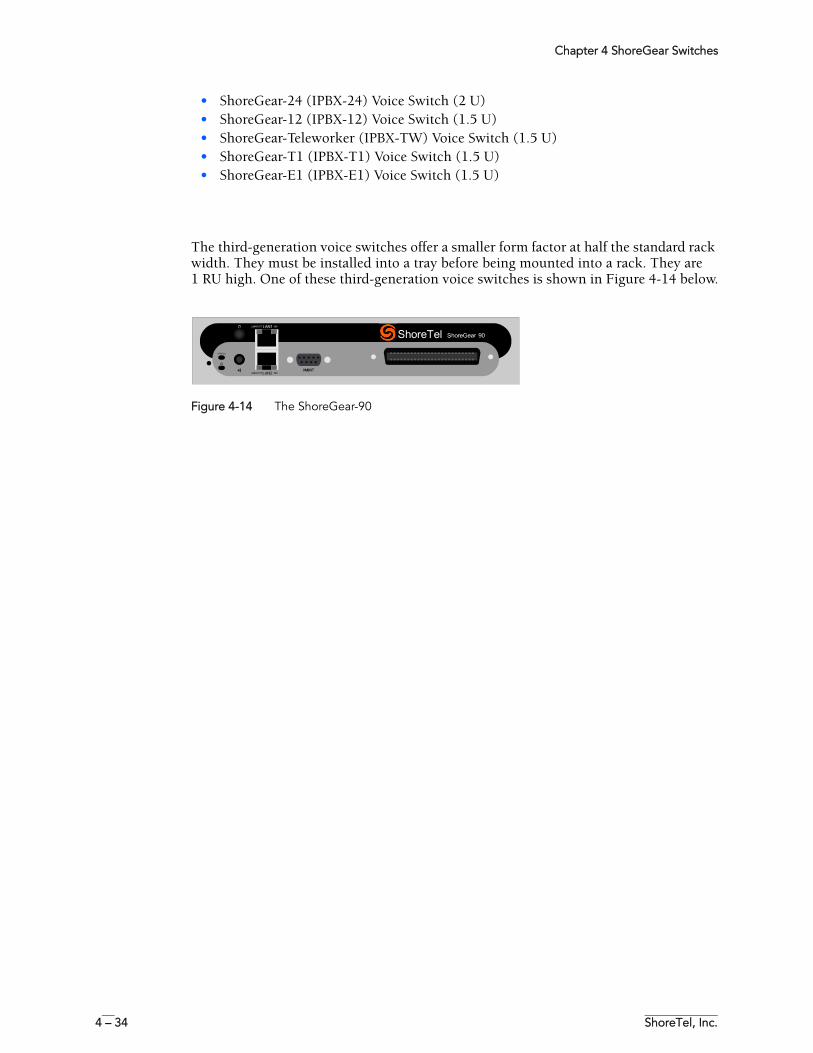
Chapter 4 ShoreGear Switches
4 – 34 ShoreTel, Inc.
• ShoreGear-24 (IPBX-24) Voice Switch (2 U)• ShoreGear-12 (IPBX-12) Voice Switch (1.5 U)• ShoreGear-Teleworker (IPBX-TW) Voice Switch (1.5 U)• ShoreGear-T1 (IPBX-T1) Voice Switch (1.5 U)• ShoreGear-E1 (IPBX-E1) Voice Switch (1.5 U)
The third-generation voice switches offer a smaller form factor at half the standard rack width. They must be installed into a tray before being mounted into a rack. They are1 RU high. One of these third-generation voice switches is shown in Figure 4-14 below.
Figure 4-14 The ShoreGear-90
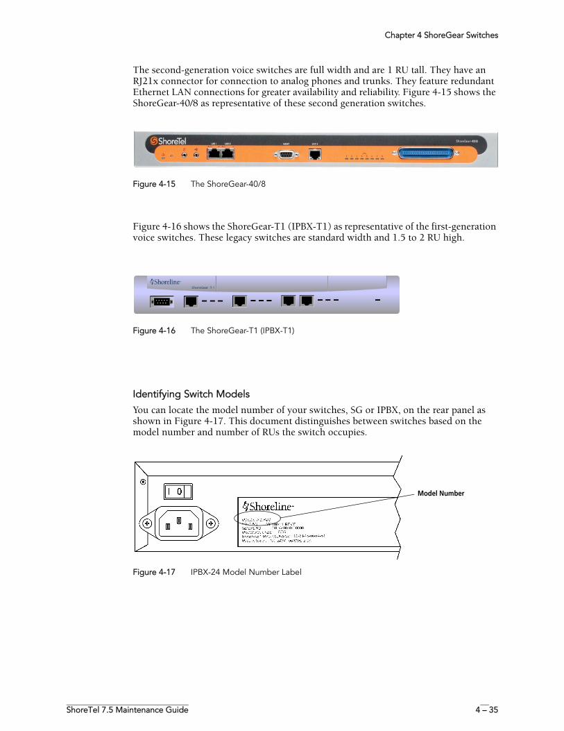
Chapter 4 ShoreGear Switches
ShoreTel 7.5 Maintenance Guide 4 – 35
The second-generation voice switches are full width and are 1 RU tall. They have an RJ21x connector for connection to analog phones and trunks. They feature redundant Ethernet LAN connections for greater availability and reliability. Figure 4-15 shows the ShoreGear-40/8 as representative of these second generation switches.
Figure 4-15 The ShoreGear-40/8
Figure 4-16 shows the ShoreGear-T1 (IPBX-T1) as representative of the first-generation voice switches. These legacy switches are standard width and 1.5 to 2 RU high.
Figure 4-16 The ShoreGear-T1 (IPBX-T1)
Identifying Switch Models
You can locate the model number of your switches, SG or IPBX, on the rear panel as shown in Figure 4-17. This document distinguishes between switches based on the model number and number of RUs the switch occupies.
Figure 4-17 IPBX-24 Model Number Label
Model Number
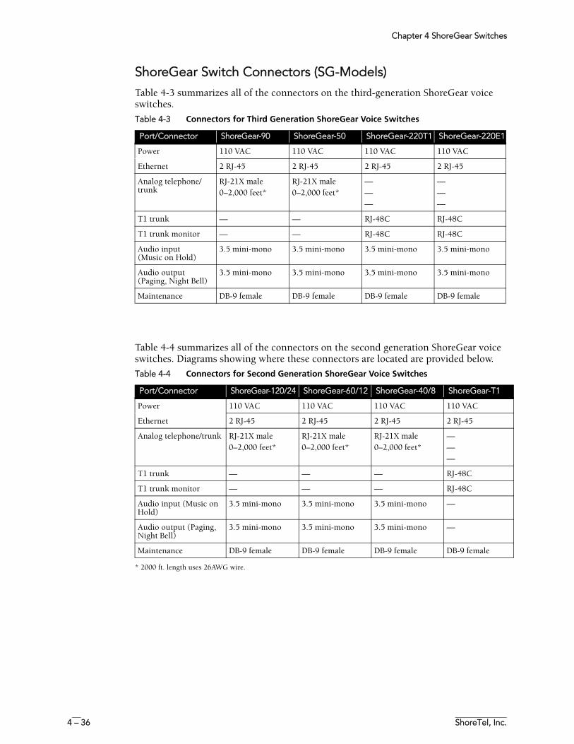
Chapter 4 ShoreGear Switches
4 – 36 ShoreTel, Inc.
ShoreGear Switch Connectors (SG-Models)Table 4-3 summarizes all of the connectors on the third-generation ShoreGear voice switches.
Table 4-4 summarizes all of the connectors on the second generation ShoreGear voice switches. Diagrams showing where these connectors are located are provided below.
* 2000 ft. length uses 26AWG wire.
Table 4-3 Connectors for Third Generation ShoreGear Voice Switches
Port/Connector ShoreGear-90 ShoreGear-50 ShoreGear-220T1 ShoreGear-220E1
Power 110 VAC 110 VAC 110 VAC 110 VAC
Ethernet 2 RJ-45 2 RJ-45 2 RJ-45 2 RJ-45
Analog telephone/trunk
RJ-21X male0–2,000 feet*
RJ-21X male0–2,000 feet*
———
———
T1 trunk — — RJ-48C RJ-48C
T1 trunk monitor — — RJ-48C RJ-48C
Audio input(Music on Hold)
3.5 mini-mono 3.5 mini-mono 3.5 mini-mono 3.5 mini-mono
Audio output(Paging, Night Bell)
3.5 mini-mono 3.5 mini-mono 3.5 mini-mono 3.5 mini-mono
Maintenance DB-9 female DB-9 female DB-9 female DB-9 female
Table 4-4 Connectors for Second Generation ShoreGear Voice Switches
Port/Connector ShoreGear-120/24 ShoreGear-60/12 ShoreGear-40/8 ShoreGear-T1
Power 110 VAC 110 VAC 110 VAC 110 VAC
Ethernet 2 RJ-45 2 RJ-45 2 RJ-45 2 RJ-45
Analog telephone/trunk RJ-21X male0–2,000 feet*
RJ-21X male0–2,000 feet*
RJ-21X male0–2,000 feet*
———
T1 trunk — — — RJ-48C
T1 trunk monitor — — — RJ-48C
Audio input (Music on Hold)
3.5 mini-mono 3.5 mini-mono 3.5 mini-mono —
Audio output (Paging, Night Bell)
3.5 mini-mono 3.5 mini-mono 3.5 mini-mono —
Maintenance DB-9 female DB-9 female DB-9 female DB-9 female
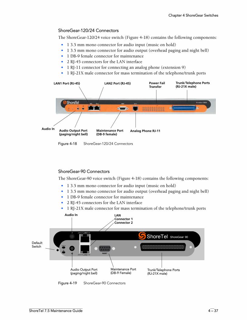
Chapter 4 ShoreGear Switches
ShoreTel 7.5 Maintenance Guide 4 – 37
ShoreGear-120/24 Connectors
The ShoreGear-120/24 voice switch (Figure 4-18) contains the following components:
• 1 3.5 mm mono connector for audio input (music on hold)• 1 3.5 mm mono connector for audio output (overhead paging and night bell)• 1 DB-9 female connector for maintenance • 2 RJ-45 connectors for the LAN interface• 1 RJ-11 connector for connecting an analog phone (extension 9)• 1 RJ-21X male connector for mass termination of the telephone/trunk ports
Figure 4-18 ShoreGear-120/24 Connectors
ShoreGear-90 Connectors
The ShoreGear-90 voice switch (Figure 4-18) contains the following components:
• 1 3.5 mm mono connector for audio input (music on hold)• 1 3.5 mm mono connector for audio output (overhead paging and night bell)• 1 DB-9 female connector for maintenance • 2 RJ-45 connectors for the LAN interface• 1 RJ-21X male connector for mass termination of the telephone/trunk ports
Figure 4-19 ShoreGear-90 Connectors
Audio Output Port(paging/night bell)
Trunk/Telephone Ports (RJ-21X male)
LAN1 Port (RJ-45)
Maintenance Port (DB-9 female)
Power Fail Transfer
LAN2 Port (RJ-45)
Audio InAnalog Phone RJ-11
Trunk/Telephone Ports (RJ-21X male)
Audio Output Port(paging/night bell)
Maintenance Port (DB-9 Female)
Audio In LANConnector 1Connector 2
Default Switch
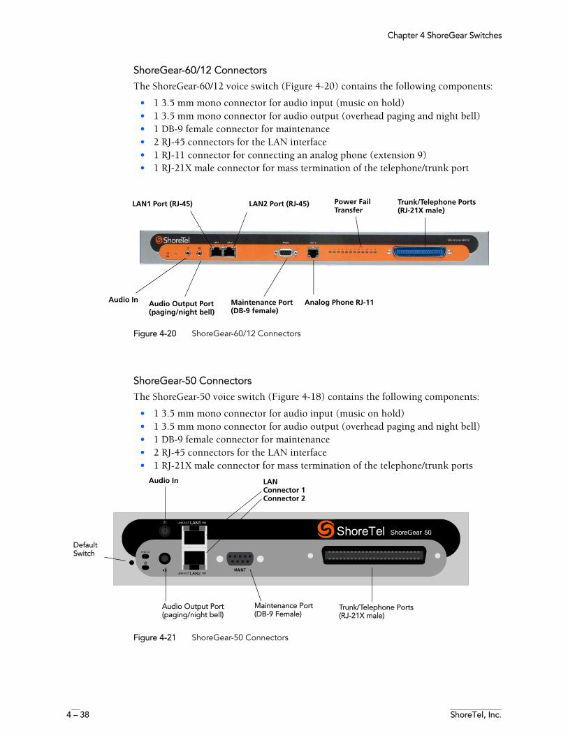
Chapter 4 ShoreGear Switches
4 – 38 ShoreTel, Inc.
ShoreGear-60/12 Connectors
The ShoreGear-60/12 voice switch (Figure 4-20) contains the following components:
• 1 3.5 mm mono connector for audio input (music on hold)• 1 3.5 mm mono connector for audio output (overhead paging and night bell)• 1 DB-9 female connector for maintenance • 2 RJ-45 connectors for the LAN interface• 1 RJ-11 connector for connecting an analog phone (extension 9)• 1 RJ-21X male connector for mass termination of the telephone/trunk port
Figure 4-20 ShoreGear-60/12 Connectors
ShoreGear-50 Connectors
The ShoreGear-50 voice switch (Figure 4-18) contains the following components:
• 1 3.5 mm mono connector for audio input (music on hold)• 1 3.5 mm mono connector for audio output (overhead paging and night bell)• 1 DB-9 female connector for maintenance • 2 RJ-45 connectors for the LAN interface• 1 RJ-21X male connector for mass termination of the telephone/trunk ports
Figure 4-21 ShoreGear-50 Connectors
Trunk/Telephone Ports (RJ-21X male)
LAN1 Port (RJ-45) Power Fail Transfer
LAN2 Port (RJ-45)
Audio Output Port(paging/night bell)
Maintenance Port (DB-9 female)
Audio In Analog Phone RJ-11
Trunk/Telephone Ports (RJ-21X male)
Audio Output Port(paging/night bell)
Maintenance Port (DB-9 Female)
Audio In LANConnector 1Connector 2
Default Switch
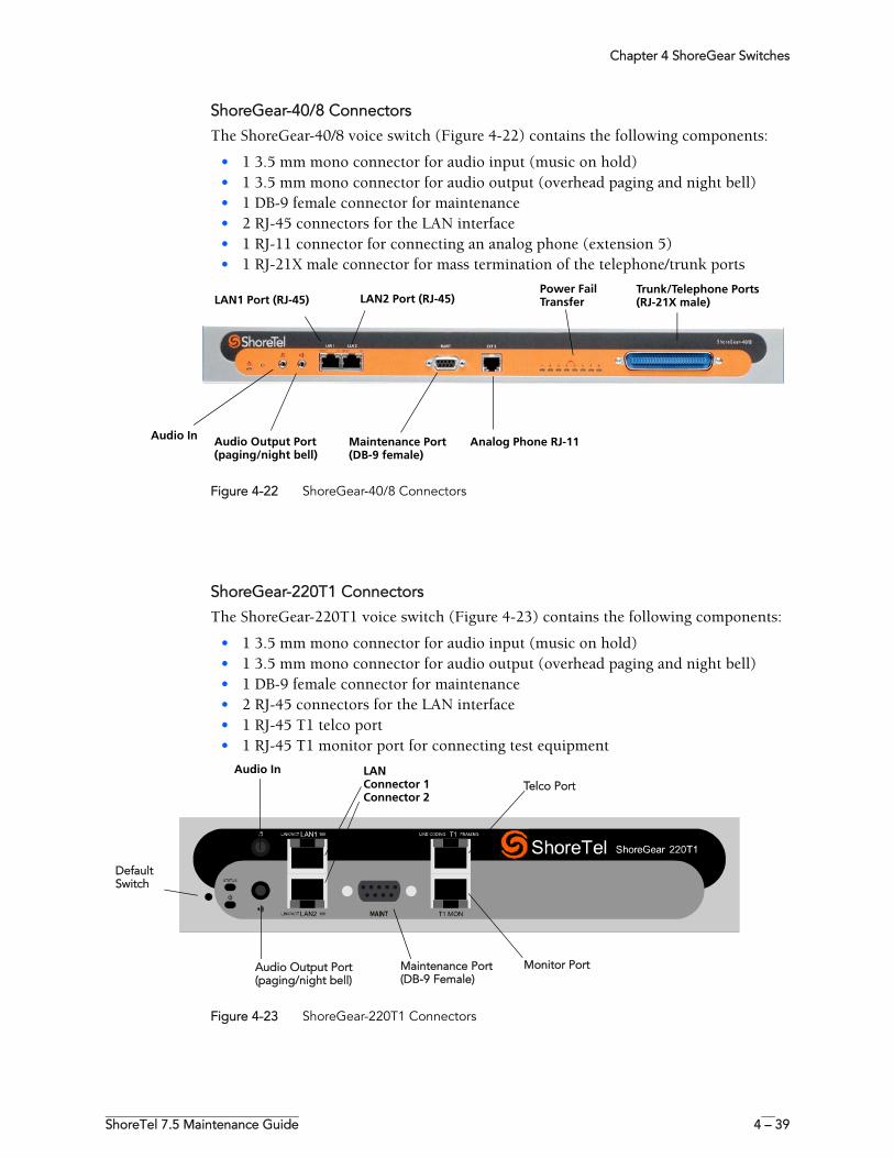
Chapter 4 ShoreGear Switches
ShoreTel 7.5 Maintenance Guide 4 – 39
ShoreGear-40/8 Connectors
The ShoreGear-40/8 voice switch (Figure 4-22) contains the following components:
• 1 3.5 mm mono connector for audio input (music on hold)• 1 3.5 mm mono connector for audio output (overhead paging and night bell)• 1 DB-9 female connector for maintenance• 2 RJ-45 connectors for the LAN interface• 1 RJ-11 connector for connecting an analog phone (extension 5)• 1 RJ-21X male connector for mass termination of the telephone/trunk ports
Figure 4-22 ShoreGear-40/8 Connectors
ShoreGear-220T1 Connectors
The ShoreGear-220T1 voice switch (Figure 4-23) contains the following components:
• 1 3.5 mm mono connector for audio input (music on hold)• 1 3.5 mm mono connector for audio output (overhead paging and night bell)• 1 DB-9 female connector for maintenance • 2 RJ-45 connectors for the LAN interface• 1 RJ-45 T1 telco port • 1 RJ-45 T1 monitor port for connecting test equipment
Figure 4-23 ShoreGear-220T1 Connectors
Audio Output Port(paging/night bell)
Trunk/Telephone Ports (RJ-21X male)LAN1 Port (RJ-45)
Maintenance Port (DB-9 female)
Power Fail TransferLAN2 Port (RJ-45)
Audio In Analog Phone RJ-11
Audio Output Port(paging/night bell)
Maintenance Port (DB-9 Female)
Audio In LANConnector 1Connector 2
Default Switch
Monitor Port
Telco Port
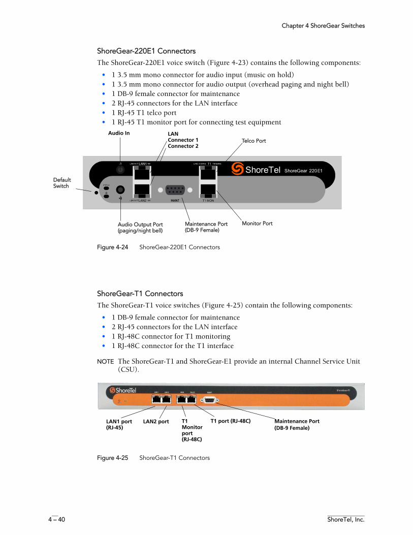
Chapter 4 ShoreGear Switches
4 – 40 ShoreTel, Inc.
ShoreGear-220E1 Connectors
The ShoreGear-220E1 voice switch (Figure 4-23) contains the following components:
• 1 3.5 mm mono connector for audio input (music on hold)• 1 3.5 mm mono connector for audio output (overhead paging and night bell)• 1 DB-9 female connector for maintenance • 2 RJ-45 connectors for the LAN interface• 1 RJ-45 T1 telco port • 1 RJ-45 T1 monitor port for connecting test equipment
Figure 4-24 ShoreGear-220E1 Connectors
ShoreGear-T1 Connectors
The ShoreGear-T1 voice switches (Figure 4-25) contain the following components:
• 1 DB-9 female connector for maintenance • 2 RJ-45 connectors for the LAN interface• 1 RJ-48C connector for T1 monitoring• 1 RJ-48C connector for the T1 interface
NOTE The ShoreGear-T1 and ShoreGear-E1 provide an internal Channel Service Unit (CSU).
Figure 4-25 ShoreGear-T1 Connectors
Audio Output Port(paging/night bell)
Maintenance Port (DB-9 Female)
Audio In LANConnector 1Connector 2
Default Switch
Monitor Port
Telco Port
Maintenance Port (DB-9 Female)
LAN2 port LAN1 port (RJ-45)
T1 port (RJ-48C)T1 Monitor port (RJ-48C)
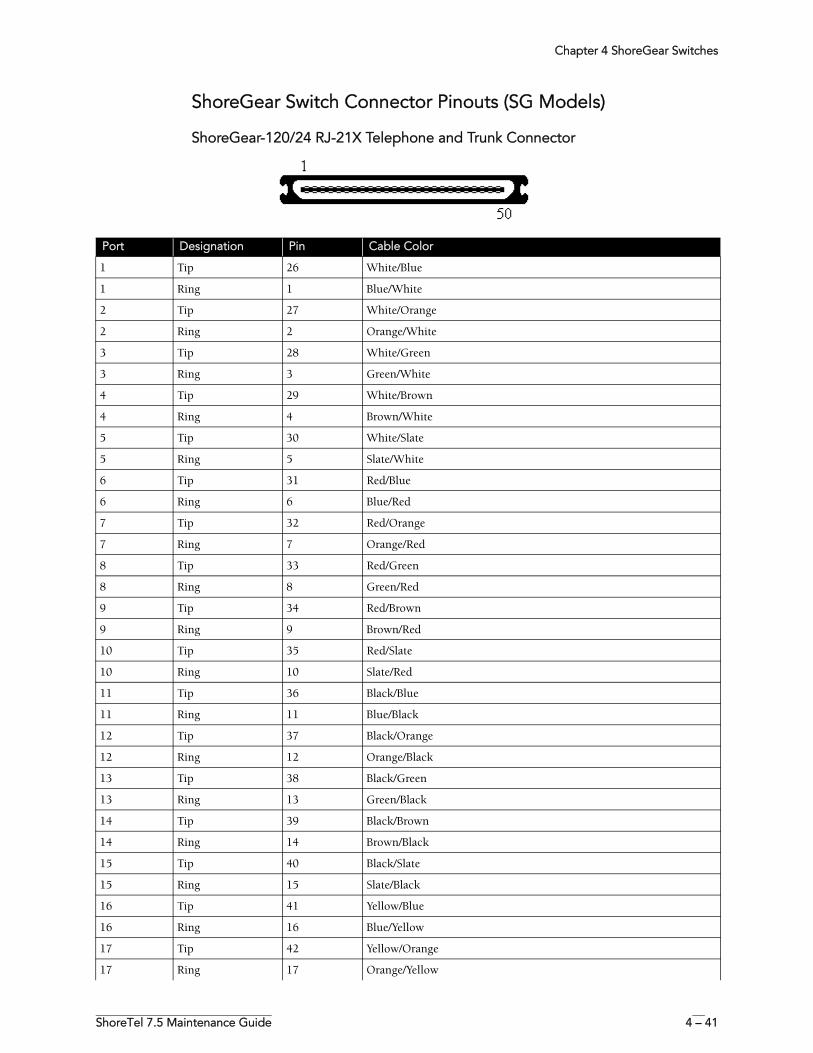
Chapter 4 ShoreGear Switches
ShoreTel 7.5 Maintenance Guide 4 – 41
ShoreGear Switch Connector Pinouts (SG Models)
ShoreGear-120/24 RJ-21X Telephone and Trunk Connector
Port Designation Pin Cable Color
1 Tip 26 White/Blue
1 Ring 1 Blue/White
2 Tip 27 White/Orange
2 Ring 2 Orange/White
3 Tip 28 White/Green
3 Ring 3 Green/White
4 Tip 29 White/Brown
4 Ring 4 Brown/White
5 Tip 30 White/Slate
5 Ring 5 Slate/White
6 Tip 31 Red/Blue
6 Ring 6 Blue/Red
7 Tip 32 Red/Orange
7 Ring 7 Orange/Red
8 Tip 33 Red/Green
8 Ring 8 Green/Red
9 Tip 34 Red/Brown
9 Ring 9 Brown/Red
10 Tip 35 Red/Slate
10 Ring 10 Slate/Red
11 Tip 36 Black/Blue
11 Ring 11 Blue/Black
12 Tip 37 Black/Orange
12 Ring 12 Orange/Black
13 Tip 38 Black/Green
13 Ring 13 Green/Black
14 Tip 39 Black/Brown
14 Ring 14 Brown/Black
15 Tip 40 Black/Slate
15 Ring 15 Slate/Black
16 Tip 41 Yellow/Blue
16 Ring 16 Blue/Yellow
17 Tip 42 Yellow/Orange
17 Ring 17 Orange/Yellow
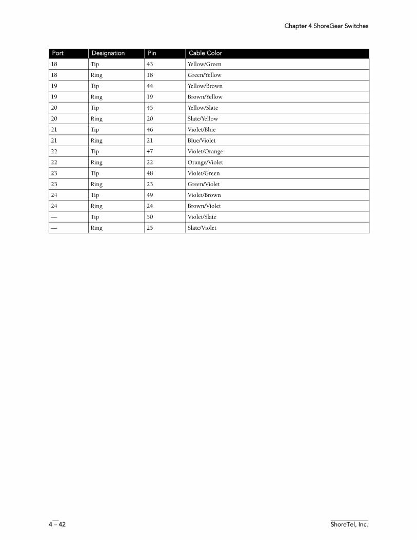
Chapter 4 ShoreGear Switches
4 – 42 ShoreTel, Inc.
18 Tip 43 Yellow/Green
18 Ring 18 Green/Yellow
19 Tip 44 Yellow/Brown
19 Ring 19 Brown/Yellow
20 Tip 45 Yellow/Slate
20 Ring 20 Slate/Yellow
21 Tip 46 Violet/Blue
21 Ring 21 Blue/Violet
22 Tip 47 Violet/Orange
22 Ring 22 Orange/Violet
23 Tip 48 Violet/Green
23 Ring 23 Green/Violet
24 Tip 49 Violet/Brown
24 Ring 24 Brown/Violet
— Tip 50 Violet/Slate
— Ring 25 Slate/Violet
Port Designation Pin Cable Color
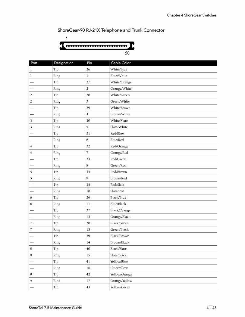
Chapter 4 ShoreGear Switches
ShoreTel 7.5 Maintenance Guide 4 – 43
ShoreGear-90 RJ-21X Telephone and Trunk Connector
Port Designation Pin Cable Color
1 Tip 26 White/Blue
1 Ring 1 Blue/White
— Tip 27 White/Orange
— Ring 2 Orange/White
2 Tip 28 White/Green
2 Ring 3 Green/White
— Tip 29 White/Brown
— Ring 4 Brown/White
3 Tip 30 White/Slate
3 Ring 5 Slate/White
— Tip 31 Red/Blue
— Ring 6 Blue/Red
4 Tip 32 Red/Orange
4 Ring 7 Orange/Red
— Tip 33 Red/Green
— Ring 8 Green/Red
5 Tip 34 Red/Brown
5 Ring 9 Brown/Red
— Tip 35 Red/Slate
— Ring 10 Slate/Red
6 Tip 36 Black/Blue
6 Ring 11 Blue/Black
— Tip 37 Black/Orange
— Ring 12 Orange/Black
7 Tip 38 Black/Green
7 Ring 13 Green/Black
— Tip 39 Black/Brown
— Ring 14 Brown/Black
8 Tip 40 Black/Slate
8 Ring 15 Slate/Black
— Tip 41 Yellow/Blue
— Ring 16 Blue/Yellow
9 Tip 42 Yellow/Orange
9 Ring 17 Orange/Yellow
— Tip 43 Yellow/Green
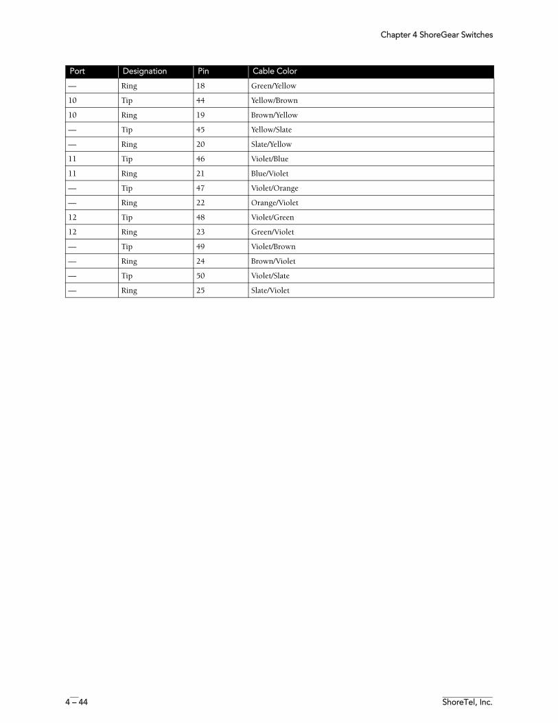
Chapter 4 ShoreGear Switches
4 – 44 ShoreTel, Inc.
— Ring 18 Green/Yellow
10 Tip 44 Yellow/Brown
10 Ring 19 Brown/Yellow
— Tip 45 Yellow/Slate
— Ring 20 Slate/Yellow
11 Tip 46 Violet/Blue
11 Ring 21 Blue/Violet
— Tip 47 Violet/Orange
— Ring 22 Orange/Violet
12 Tip 48 Violet/Green
12 Ring 23 Green/Violet
— Tip 49 Violet/Brown
— Ring 24 Brown/Violet
— Tip 50 Violet/Slate
— Ring 25 Slate/Violet
Port Designation Pin Cable Color
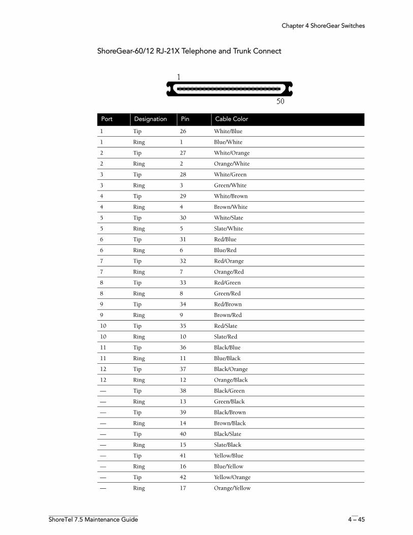
Chapter 4 ShoreGear Switches
ShoreTel 7.5 Maintenance Guide 4 – 45
ShoreGear-60/12 RJ-21X Telephone and Trunk Connect
Port Designation Pin Cable Color
1 Tip 26 White/Blue
1 Ring 1 Blue/White
2 Tip 27 White/Orange
2 Ring 2 Orange/White
3 Tip 28 White/Green
3 Ring 3 Green/White
4 Tip 29 White/Brown
4 Ring 4 Brown/White
5 Tip 30 White/Slate
5 Ring 5 Slate/White
6 Tip 31 Red/Blue
6 Ring 6 Blue/Red
7 Tip 32 Red/Orange
7 Ring 7 Orange/Red
8 Tip 33 Red/Green
8 Ring 8 Green/Red
9 Tip 34 Red/Brown
9 Ring 9 Brown/Red
10 Tip 35 Red/Slate
10 Ring 10 Slate/Red
11 Tip 36 Black/Blue
11 Ring 11 Blue/Black
12 Tip 37 Black/Orange
12 Ring 12 Orange/Black
— Tip 38 Black/Green
— Ring 13 Green/Black
— Tip 39 Black/Brown
— Ring 14 Brown/Black
— Tip 40 Black/Slate
— Ring 15 Slate/Black
— Tip 41 Yellow/Blue
— Ring 16 Blue/Yellow
— Tip 42 Yellow/Orange
— Ring 17 Orange/Yellow
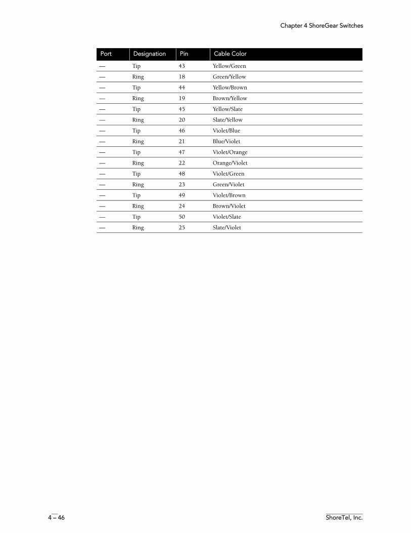
Chapter 4 ShoreGear Switches
4 – 46 ShoreTel, Inc.
— Tip 43 Yellow/Green
— Ring 18 Green/Yellow
— Tip 44 Yellow/Brown
— Ring 19 Brown/Yellow
— Tip 45 Yellow/Slate
— Ring 20 Slate/Yellow
— Tip 46 Violet/Blue
— Ring 21 Blue/Violet
— Tip 47 Violet/Orange
— Ring 22 Orange/Violet
— Tip 48 Violet/Green
— Ring 23 Green/Violet
— Tip 49 Violet/Brown
— Ring 24 Brown/Violet
— Tip 50 Violet/Slate
— Ring 25 Slate/Violet
Port Designation Pin Cable Color
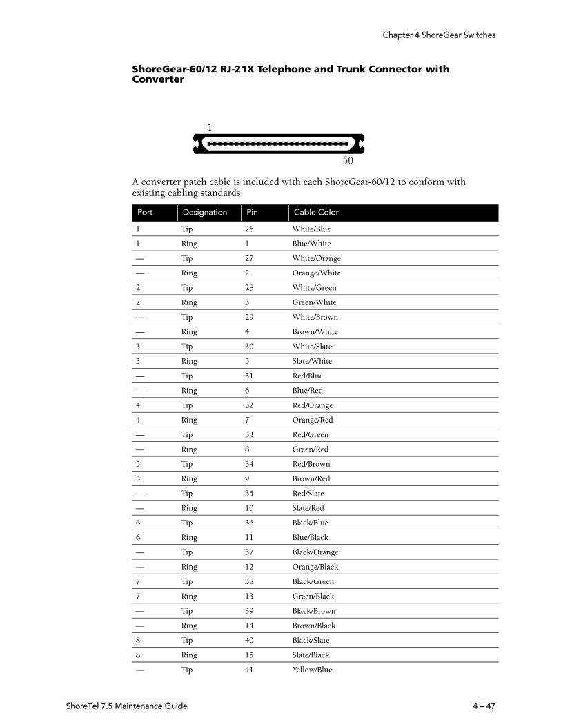
Chapter 4 ShoreGear Switches
ShoreTel 7.5 Maintenance Guide 4 – 47
ShoreGear-60/12 RJ-21X Telephone and Trunk Connector with Converter
A converter patch cable is included with each ShoreGear-60/12 to conform with existing cabling standards.
Port Designation Pin Cable Color
1 Tip 26 White/Blue
1 Ring 1 Blue/White
— Tip 27 White/Orange
— Ring 2 Orange/White
2 Tip 28 White/Green
2 Ring 3 Green/White
— Tip 29 White/Brown
— Ring 4 Brown/White
3 Tip 30 White/Slate
3 Ring 5 Slate/White
— Tip 31 Red/Blue
— Ring 6 Blue/Red
4 Tip 32 Red/Orange
4 Ring 7 Orange/Red
— Tip 33 Red/Green
— Ring 8 Green/Red
5 Tip 34 Red/Brown
5 Ring 9 Brown/Red
— Tip 35 Red/Slate
— Ring 10 Slate/Red
6 Tip 36 Black/Blue
6 Ring 11 Blue/Black
— Tip 37 Black/Orange
— Ring 12 Orange/Black
7 Tip 38 Black/Green
7 Ring 13 Green/Black
— Tip 39 Black/Brown
— Ring 14 Brown/Black
8 Tip 40 Black/Slate
8 Ring 15 Slate/Black
— Tip 41 Yellow/Blue

Chapter 4 ShoreGear Switches
4 – 48 ShoreTel, Inc.
— Ring 16 Blue/Yellow
9 Tip 42 Yellow/Orange
9 Ring 17 Orange/Yellow
— Tip 43 Yellow/Green
— Ring 18 Green/Yellow
10 Tip 44 Yellow/Brown
10 Ring 19 Brown/Yellow
— Tip 45 Yellow/Slate
— Ring 20 Slate/Yellow
11 Tip 46 Violet/Blue
11 Ring 21 Blue/Violet
— Tip 47 Violet/Orange
— Ring 22 Orange/Violet
12 Tip 48 Violet/Green
12 Ring 23 Green/Violet
— Tip 49 Violet/Brown
— Ring 24 Brown/Violet
— Tip 50 Violet/Slate
— Ring 25 Slate/Violet
Port Designation Pin Cable Color

Chapter 4 ShoreGear Switches
ShoreTel 7.5 Maintenance Guide 4 – 49
ShoreGear-50 RJ-21X Telephone and Trunk Connector
Port Designation Pin Cable Color
1 Tip 26 White/Blue
1 Ring 1 Blue/White
— Tip 27 White/Orange
— Ring 2 Orange/White
2 Tip 28 White/Green
2 Ring 3 Green/White
— Tip 29 White/Brown
— Ring 4 Brown/White
3 Tip 30 White/Slate
3 Ring 5 Slate/White
— Tip 31 Red/Blue
— Ring 6 Blue/Red
4 Tip 32 Red/Orange
4 Ring 7 Orange/Red
— Tip 33 Red/Green
— Ring 8 Green/Red
— Tip 34 Red/Brown
— Ring 9 Brown/Red
— Tip 35 Red/Slate
— Ring 10 Slate/Red
— Tip 36 Black/Blue
— Ring 11 Blue/Black
— Tip 37 Black/Orange
— Ring 12 Orange/Black
— Tip 38 Black/Green
— Ring 13 Green/Black
— Tip 39 Black/Brown
— Ring 14 Brown/Black
— Tip 40 Black/Slate
— Ring 15 Slate/Black
— Tip 41 Yellow/Blue
— Ring 16 Blue/Yellow
— Tip 42 Yellow/Orange
— Ring 17 Orange/Yellow
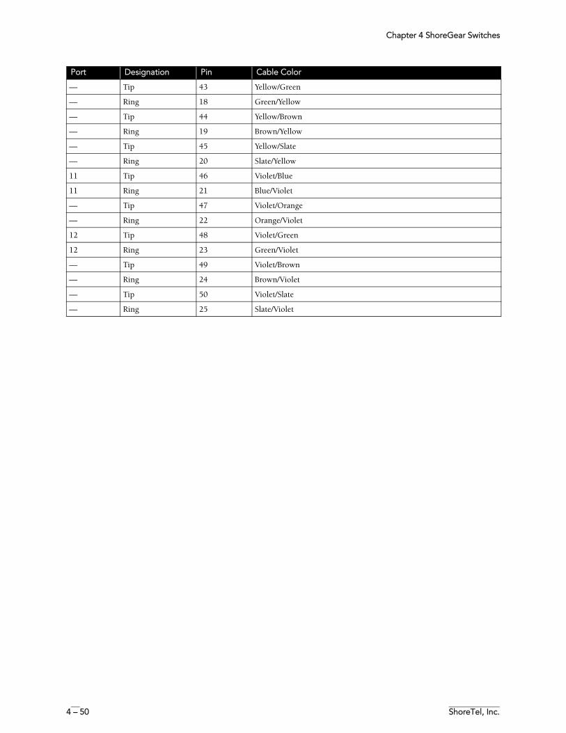
Chapter 4 ShoreGear Switches
4 – 50 ShoreTel, Inc.
— Tip 43 Yellow/Green
— Ring 18 Green/Yellow
— Tip 44 Yellow/Brown
— Ring 19 Brown/Yellow
— Tip 45 Yellow/Slate
— Ring 20 Slate/Yellow
11 Tip 46 Violet/Blue
11 Ring 21 Blue/Violet
— Tip 47 Violet/Orange
— Ring 22 Orange/Violet
12 Tip 48 Violet/Green
12 Ring 23 Green/Violet
— Tip 49 Violet/Brown
— Ring 24 Brown/Violet
— Tip 50 Violet/Slate
— Ring 25 Slate/Violet
Port Designation Pin Cable Color
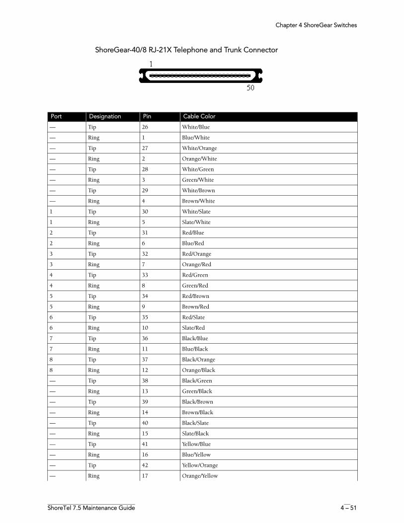
Chapter 4 ShoreGear Switches
ShoreTel 7.5 Maintenance Guide 4 – 51
ShoreGear-40/8 RJ-21X Telephone and Trunk Connector
Port Designation Pin Cable Color
— Tip 26 White/Blue
— Ring 1 Blue/White
— Tip 27 White/Orange
— Ring 2 Orange/White
— Tip 28 White/Green
— Ring 3 Green/White
— Tip 29 White/Brown
— Ring 4 Brown/White
1 Tip 30 White/Slate
1 Ring 5 Slate/White
2 Tip 31 Red/Blue
2 Ring 6 Blue/Red
3 Tip 32 Red/Orange
3 Ring 7 Orange/Red
4 Tip 33 Red/Green
4 Ring 8 Green/Red
5 Tip 34 Red/Brown
5 Ring 9 Brown/Red
6 Tip 35 Red/Slate
6 Ring 10 Slate/Red
7 Tip 36 Black/Blue
7 Ring 11 Blue/Black
8 Tip 37 Black/Orange
8 Ring 12 Orange/Black
— Tip 38 Black/Green
— Ring 13 Green/Black
— Tip 39 Black/Brown
— Ring 14 Brown/Black
— Tip 40 Black/Slate
— Ring 15 Slate/Black
— Tip 41 Yellow/Blue
— Ring 16 Blue/Yellow
— Tip 42 Yellow/Orange
— Ring 17 Orange/Yellow
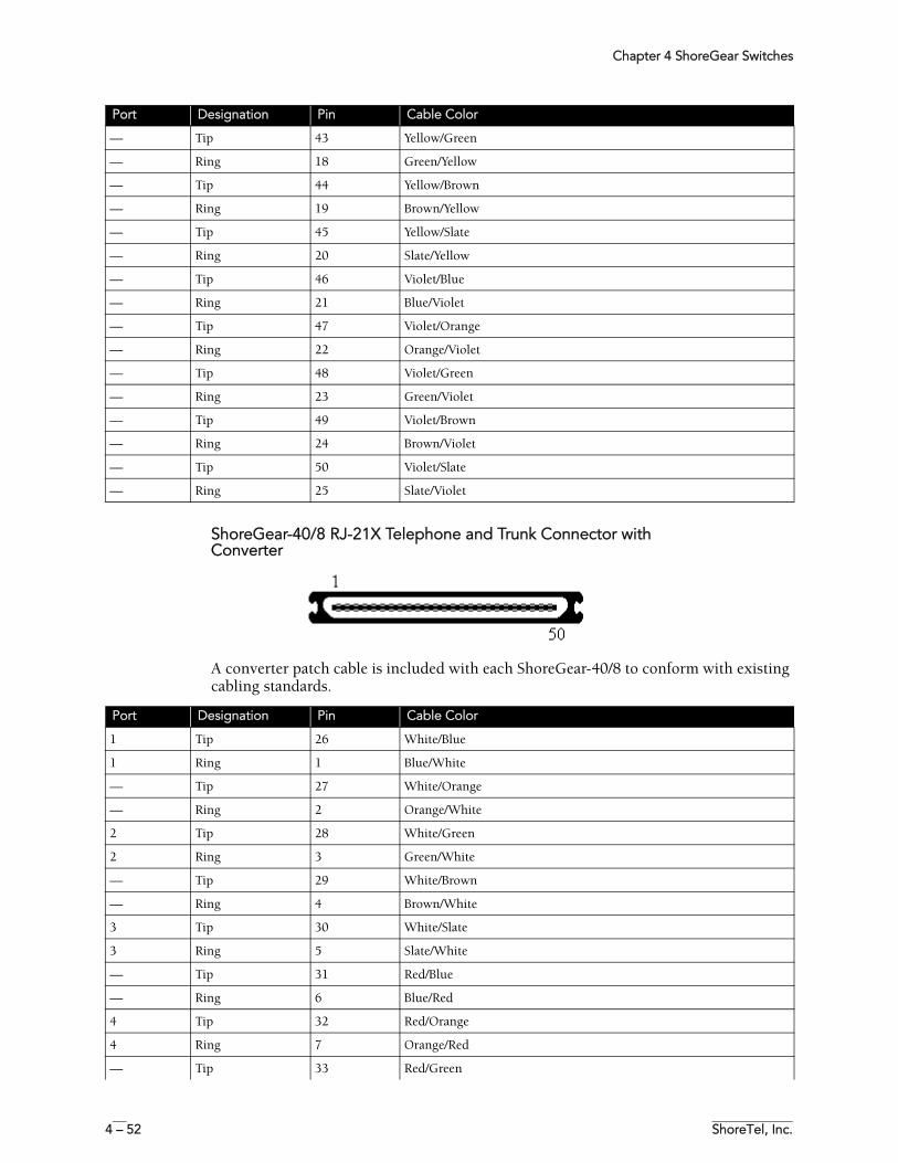
Chapter 4 ShoreGear Switches
4 – 52 ShoreTel, Inc.
ShoreGear-40/8 RJ-21X Telephone and Trunk Connector with Converter
A converter patch cable is included with each ShoreGear-40/8 to conform with existing cabling standards.
— Tip 43 Yellow/Green
— Ring 18 Green/Yellow
— Tip 44 Yellow/Brown
— Ring 19 Brown/Yellow
— Tip 45 Yellow/Slate
— Ring 20 Slate/Yellow
— Tip 46 Violet/Blue
— Ring 21 Blue/Violet
— Tip 47 Violet/Orange
— Ring 22 Orange/Violet
— Tip 48 Violet/Green
— Ring 23 Green/Violet
— Tip 49 Violet/Brown
— Ring 24 Brown/Violet
— Tip 50 Violet/Slate
— Ring 25 Slate/Violet
Port Designation Pin Cable Color
Port Designation Pin Cable Color
1 Tip 26 White/Blue
1 Ring 1 Blue/White
— Tip 27 White/Orange
— Ring 2 Orange/White
2 Tip 28 White/Green
2 Ring 3 Green/White
— Tip 29 White/Brown
— Ring 4 Brown/White
3 Tip 30 White/Slate
3 Ring 5 Slate/White
— Tip 31 Red/Blue
— Ring 6 Blue/Red
4 Tip 32 Red/Orange
4 Ring 7 Orange/Red
— Tip 33 Red/Green

Chapter 4 ShoreGear Switches
ShoreTel 7.5 Maintenance Guide 4 – 53
— Ring 8 Green/Red
5 Tip 34 Red/Brown
5 Ring 9 Brown/Red
— Tip 35 Red/Slate
— Ring 10 Slate/Red
6 Tip 36 Black/Blue
6 Ring 11 Blue/Black
— Tip 37 Black/Orange
— Ring 12 Orange/Black
7 Tip 38 Black/Green
7 Ring 13 Green/Black
— Tip 39 Black/Brown
— Ring 14 Brown/Black
8 Tip 40 Black/Slate
8 Ring 15 Slate/Black
— Tip 41 Yellow/Blue
— Ring 16 Blue/Yellow
— Tip 42 Yellow/Orange
— Ring 17 Orange/Yellow
— Tip 43 Yellow/Green
— Ring 18 Green/Yellow
— Tip 44 Yellow/Brown
— Ring 19 Brown/Yellow
— Tip 45 Yellow/Slate
— Ring 20 Slate/Yellow
— Tip 46 Violet/Blue
— Ring 21 Blue/Violet
— Tip 47 Violet/Orange
— Ring 22 Orange/Violet
— Tip 48 Violet/Green
— Ring 23 Green/Violet
— Tip 49 Violet/Brown
— Ring 24 Brown/Violet
— Tip 50 Violet/Slate
— Ring 25 Slate/Violet
Port Designation Pin Cable Color
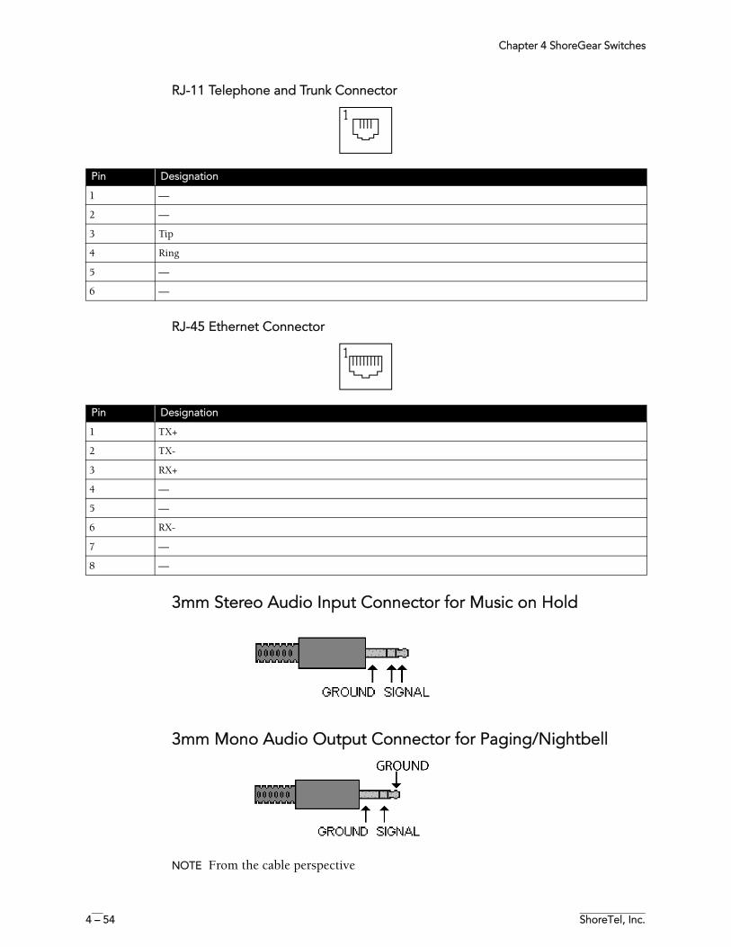
Chapter 4 ShoreGear Switches
4 – 54 ShoreTel, Inc.
RJ-11 Telephone and Trunk Connector
RJ-45 Ethernet Connector
3mm Stereo Audio Input Connector for Music on Hold
3mm Mono Audio Output Connector for Paging/Nightbell
NOTE From the cable perspective
Pin Designation
1 —
2 —
3 Tip
4 Ring
5 —
6 —
Pin Designation
1 TX+
2 TX-
3 RX+
4 —
5 —
6 RX-
7 —
8 —
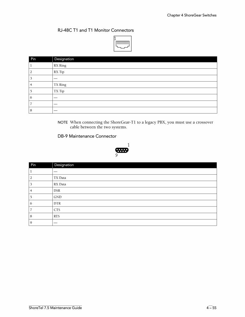
Chapter 4 ShoreGear Switches
ShoreTel 7.5 Maintenance Guide 4 – 55
RJ-48C T1 and T1 Monitor Connectors
NOTE When connecting the ShoreGear-T1 to a legacy PBX, you must use a crossover cable between the two systems.
DB-9 Maintenance Connector
Pin Designation
1 RX Ring
2 RX Tip
3 —
4 TX Ring
5 TX Tip
6 —
7 —
8 —
Pin Designation
1 —
2 TX Data
3 RX Data
4 DSR
5 GND
6 DTR
7 CTS
8 RTS
9 —
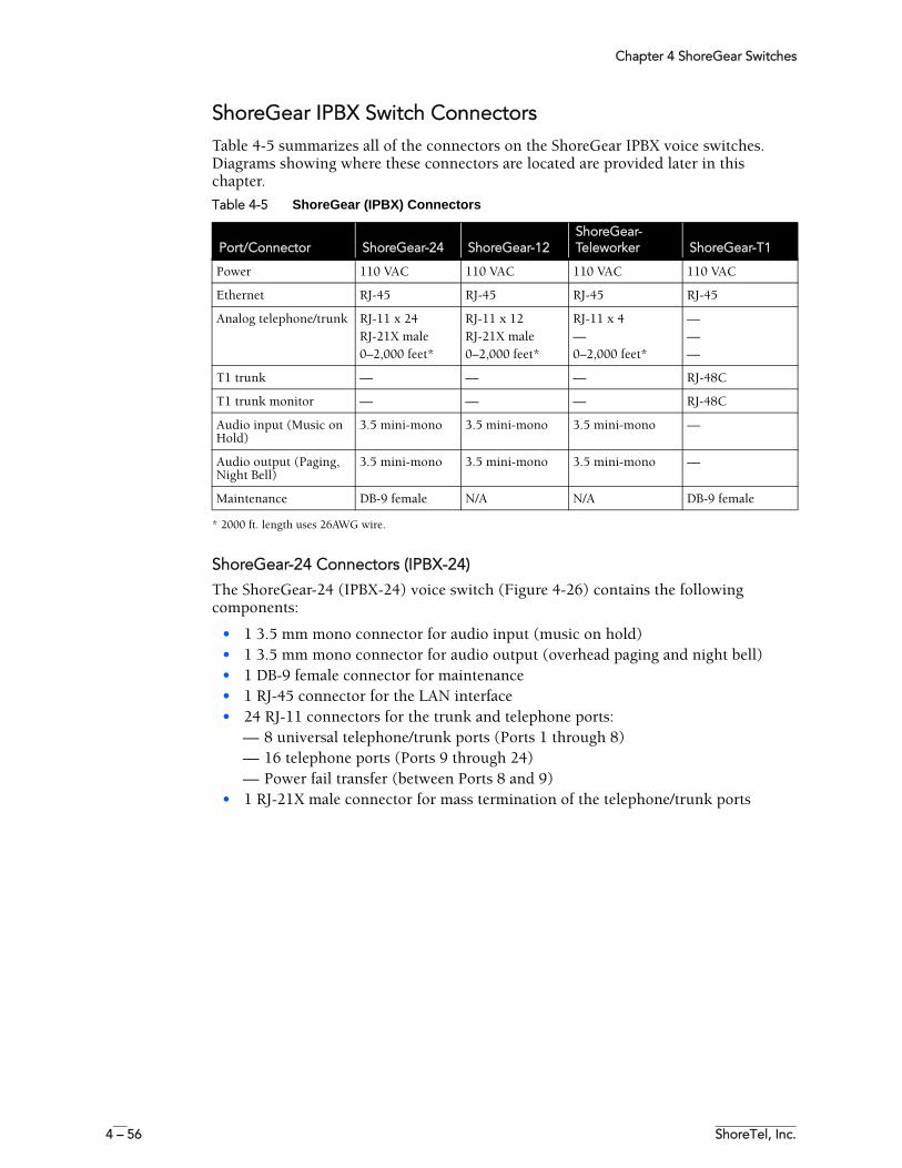
Chapter 4 ShoreGear Switches
4 – 56 ShoreTel, Inc.
ShoreGear IPBX Switch ConnectorsTable 4-5 summarizes all of the connectors on the ShoreGear IPBX voice switches. Diagrams showing where these connectors are located are provided later in this chapter.
* 2000 ft. length uses 26AWG wire.
ShoreGear-24 Connectors (IPBX-24)
The ShoreGear-24 (IPBX-24) voice switch (Figure 4-26) contains the following components:
• 1 3.5 mm mono connector for audio input (music on hold)• 1 3.5 mm mono connector for audio output (overhead paging and night bell)• 1 DB-9 female connector for maintenance • 1 RJ-45 connector for the LAN interface• 24 RJ-11 connectors for the trunk and telephone ports:
— 8 universal telephone/trunk ports (Ports 1 through 8)— 16 telephone ports (Ports 9 through 24)— Power fail transfer (between Ports 8 and 9)
• 1 RJ-21X male connector for mass termination of the telephone/trunk ports
Table 4-5 ShoreGear (IPBX) Connectors
Port/Connector ShoreGear-24 ShoreGear-12ShoreGear-Teleworker ShoreGear-T1
Power 110 VAC 110 VAC 110 VAC 110 VAC
Ethernet RJ-45 RJ-45 RJ-45 RJ-45
Analog telephone/trunk RJ-11 x 24RJ-21X male0–2,000 feet*
RJ-11 x 12RJ-21X male0–2,000 feet*
RJ-11 x 4—0–2,000 feet*
———
T1 trunk — — — RJ-48C
T1 trunk monitor — — — RJ-48C
Audio input (Music on Hold)
3.5 mini-mono 3.5 mini-mono 3.5 mini-mono —
Audio output (Paging, Night Bell)
3.5 mini-mono 3.5 mini-mono 3.5 mini-mono —
Maintenance DB-9 female N/A N/A DB-9 female
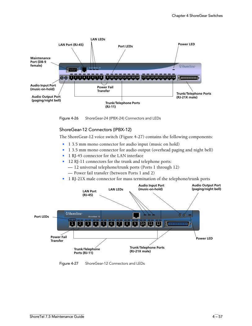
Chapter 4 ShoreGear Switches
ShoreTel 7.5 Maintenance Guide 4 – 57
Figure 4-26 ShoreGear-24 (IPBX-24) Connectors and LEDs
ShoreGear-12 Connectors (IPBX-12)
The ShoreGear-12 voice switch (Figure 4-27) contains the following components:
• 1 3.5 mm mono connector for audio input (music on hold)• 1 3.5 mm mono connector for audio output (overhead paging and night bell)• 1 RJ-45 connector for the LAN interface• 12 RJ-11 connectors for the trunk and telephone ports:
— 12 universal telephone/trunk ports (Ports 1 through 12)— Power fail transfer (between Ports 1 and 2)
• 1 RJ-21X male connector for mass termination of the telephone/trunk ports
Figure 4-27 ShoreGear-12 Connectors and LEDs
Port LEDs
Audio Input Port (music-on-hold)
Audio Output Port(paging/night bell)
Trunk/Telephone Ports (RJ-21X male)
LAN Port (RJ-45) Power LED
Trunk/Telephone Ports (RJ-11)
LAN LEDs
Maintenance Port (DB-9 female)
Power Fail Transfer
Trunk/Telephone Ports (RJ-11)
LAN Port (RJ-45)
Audio Input Port(music-on-hold)
Audio Output Port(paging/night bell)
Trunk/Telephone Ports (RJ-21X male)
LAN LEDs
Power LED
Port LEDs
Power Fail Transfer
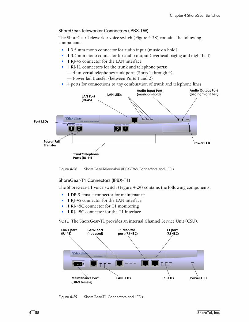
Chapter 4 ShoreGear Switches
4 – 58 ShoreTel, Inc.
ShoreGear-Teleworker Connectors (IPBX-TW)
The ShoreGear-Teleworker voice switch (Figure 4-28) contains the following components:
• 1 3.5 mm mono connector for audio input (music on hold)• 1 3.5 mm mono connector for audio output (overhead paging and night bell)• 1 RJ-45 connector for the LAN interface• 4 RJ-11 connectors for the trunk and telephone ports:
— 4 universal telephone/trunk ports (Ports 1 through 4)— Power fail transfer (between Ports 1 and 2)
• 4 ports for connections to any combination of trunk and telephone lines
Figure 4-28 ShoreGear-Teleworker (IPBX-TW) Connectors and LEDs
ShoreGear-T1 Connectors (IPBX-T1)
The ShoreGear-T1 voice switch (Figure 4-29) contains the following components:
• 1 DB-9 female connector for maintenance • 1 RJ-45 connector for the LAN interface• 1 RJ-48C connector for T1 monitoring• 1 RJ-48C connector for the T1 interface
NOTE The ShoreGear-T1 provides an internal Channel Service Unit (CSU).
Figure 4-29 ShoreGear-T1 Connectors and LEDs
Trunk/Telephone Ports (RJ-11)
LAN Port (RJ-45)
Audio Input Port(music-on-hold)
Audio Output Port(paging/night bell)LAN LEDs
Power LED
Port LEDs
Power Fail Transfer
Maintenance Port (DB-9 female)
LAN2 port (not used)
LAN1 port (RJ-45)
T1 port (RJ-48C)
T1 Monitor port (RJ-48C)
LAN LEDs T1 LEDs Power LED
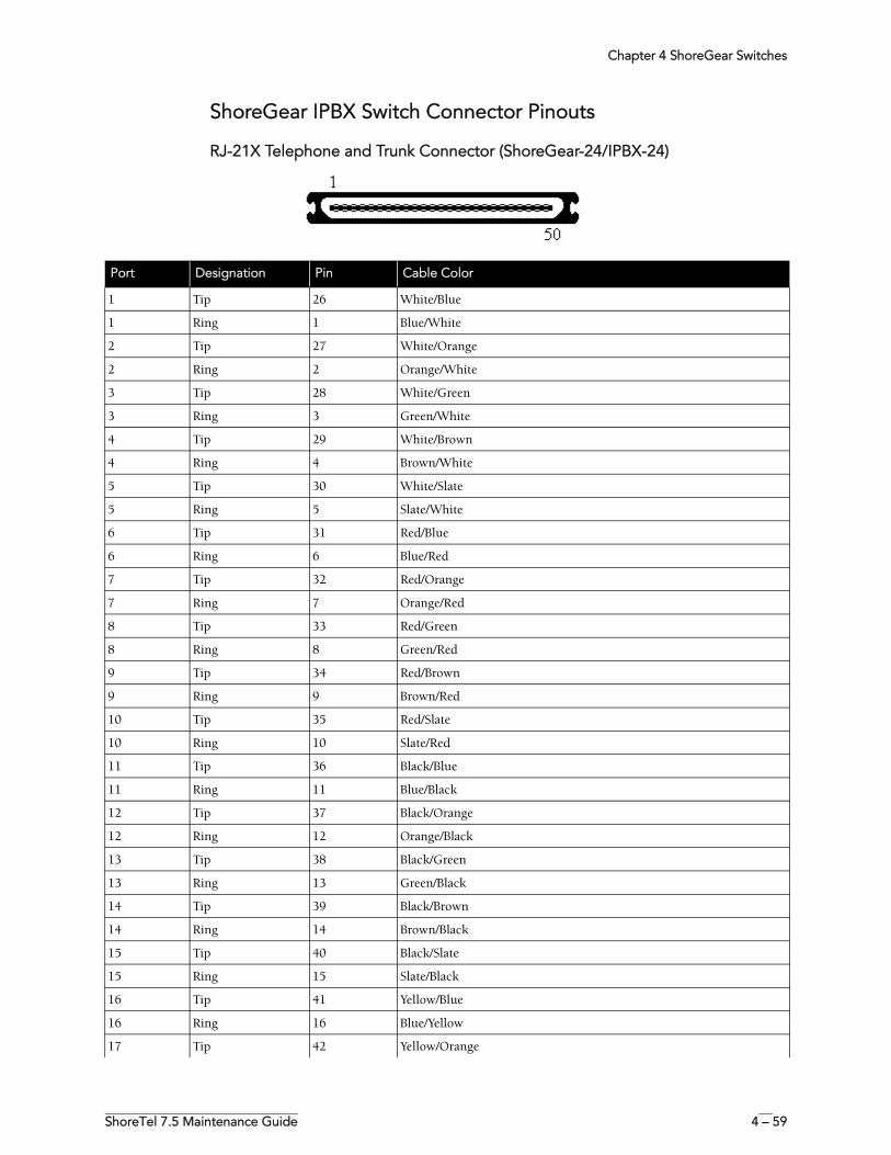
Chapter 4 ShoreGear Switches
ShoreTel 7.5 Maintenance Guide 4 – 59
ShoreGear IPBX Switch Connector Pinouts
RJ-21X Telephone and Trunk Connector (ShoreGear-24/IPBX-24)
Port Designation Pin Cable Color
1 Tip 26 White/Blue
1 Ring 1 Blue/White
2 Tip 27 White/Orange
2 Ring 2 Orange/White
3 Tip 28 White/Green
3 Ring 3 Green/White
4 Tip 29 White/Brown
4 Ring 4 Brown/White
5 Tip 30 White/Slate
5 Ring 5 Slate/White
6 Tip 31 Red/Blue
6 Ring 6 Blue/Red
7 Tip 32 Red/Orange
7 Ring 7 Orange/Red
8 Tip 33 Red/Green
8 Ring 8 Green/Red
9 Tip 34 Red/Brown
9 Ring 9 Brown/Red
10 Tip 35 Red/Slate
10 Ring 10 Slate/Red
11 Tip 36 Black/Blue
11 Ring 11 Blue/Black
12 Tip 37 Black/Orange
12 Ring 12 Orange/Black
13 Tip 38 Black/Green
13 Ring 13 Green/Black
14 Tip 39 Black/Brown
14 Ring 14 Brown/Black
15 Tip 40 Black/Slate
15 Ring 15 Slate/Black
16 Tip 41 Yellow/Blue
16 Ring 16 Blue/Yellow
17 Tip 42 Yellow/Orange
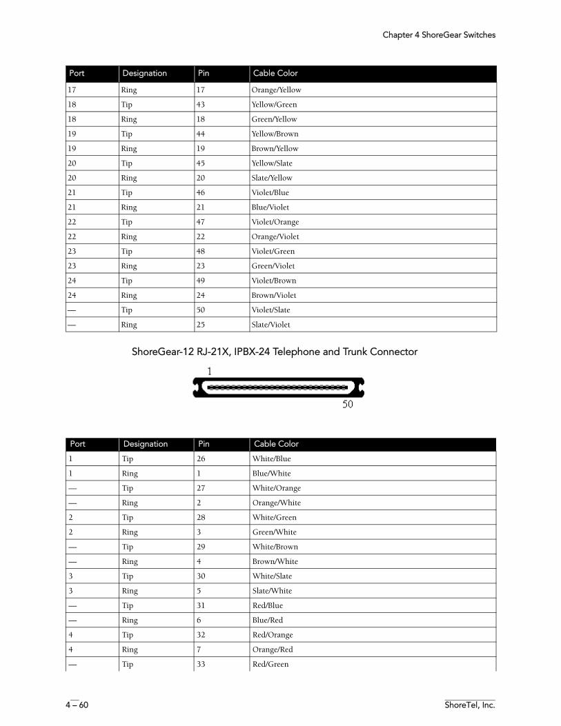
Chapter 4 ShoreGear Switches
4 – 60 ShoreTel, Inc.
ShoreGear-12 RJ-21X, IPBX-24 Telephone and Trunk Connector
17 Ring 17 Orange/Yellow
18 Tip 43 Yellow/Green
18 Ring 18 Green/Yellow
19 Tip 44 Yellow/Brown
19 Ring 19 Brown/Yellow
20 Tip 45 Yellow/Slate
20 Ring 20 Slate/Yellow
21 Tip 46 Violet/Blue
21 Ring 21 Blue/Violet
22 Tip 47 Violet/Orange
22 Ring 22 Orange/Violet
23 Tip 48 Violet/Green
23 Ring 23 Green/Violet
24 Tip 49 Violet/Brown
24 Ring 24 Brown/Violet
— Tip 50 Violet/Slate
— Ring 25 Slate/Violet
Port Designation Pin Cable Color
Port Designation Pin Cable Color
1 Tip 26 White/Blue
1 Ring 1 Blue/White
— Tip 27 White/Orange
— Ring 2 Orange/White
2 Tip 28 White/Green
2 Ring 3 Green/White
— Tip 29 White/Brown
— Ring 4 Brown/White
3 Tip 30 White/Slate
3 Ring 5 Slate/White
— Tip 31 Red/Blue
— Ring 6 Blue/Red
4 Tip 32 Red/Orange
4 Ring 7 Orange/Red
— Tip 33 Red/Green

Chapter 4 ShoreGear Switches
ShoreTel 7.5 Maintenance Guide 4 – 61
— Ring 8 Green/Red
5 Tip 34 Red/Brown
5 Ring 9 Brown/Red
— Tip 35 Red/Slate
— Ring 10 Slate/Red
6 Tip 36 Black/Blue
6 Ring 11 Blue/Black
— Tip 37 Black/Orange
— Ring 12 Orange/Black
7 Tip 38 Black/Green
7 Ring 13 Green/Black
— Tip 39 Black/Brown
— Ring 14 Brown/Black
8 Tip 40 Black/Slate
8 Ring 15 Slate/Black
— Tip 41 Yellow/Blue
— Ring 16 Blue/Yellow
9 Tip 42 Yellow/Orange
9 Ring 17 Orange/Yellow
— Tip 43 Yellow/Green
— Ring 18 Green/Yellow
10 Tip 44 Yellow/Brown
10 Ring 19 Brown/Yellow
— Tip 45 Yellow/Slate
— Ring 20 Slate/Yellow
11 Tip 46 Violet/Blue
11 Ring 21 Blue/Violet
— Tip 47 Violet/Orange
— Ring 22 Orange/Violet
12 Tip 48 Violet/Green
12 Ring 23 Green/Violet
— Tip 49 Violet/Brown
— Ring 24 Brown/Violet
— Tip 50 Violet/Slate
— Ring 25 Slate/Violet
Port Designation Pin Cable Color
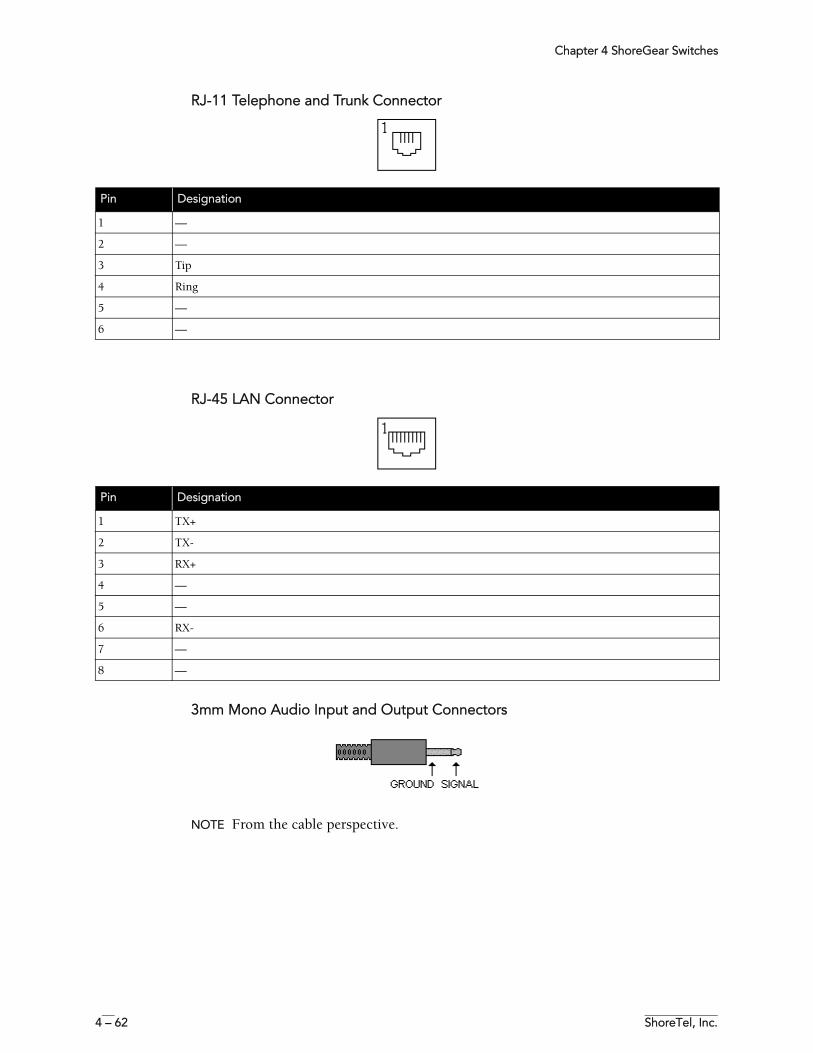
Chapter 4 ShoreGear Switches
4 – 62 ShoreTel, Inc.
RJ-11 Telephone and Trunk Connector
RJ-45 LAN Connector
3mm Mono Audio Input and Output Connectors
NOTE From the cable perspective.
Pin Designation
1 —
2 —
3 Tip
4 Ring
5 —
6 —
Pin Designation
1 TX+
2 TX-
3 RX+
4 —
5 —
6 RX-
7 —
8 —
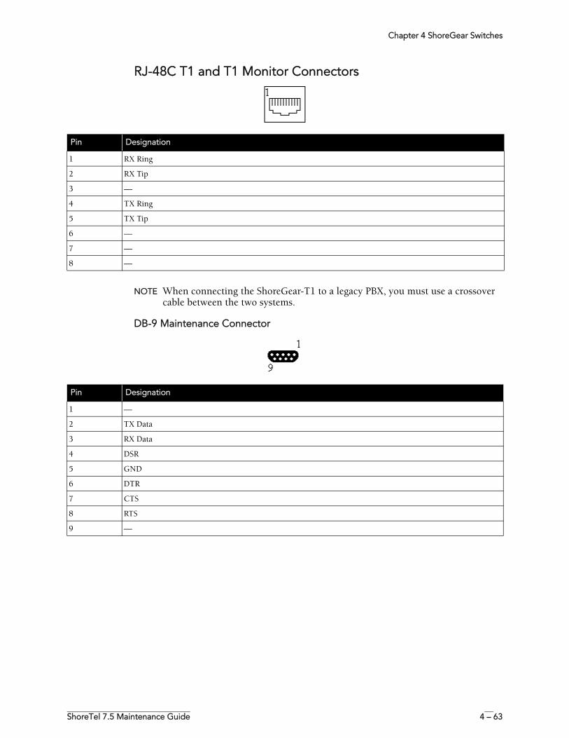
Chapter 4 ShoreGear Switches
ShoreTel 7.5 Maintenance Guide 4 – 63
RJ-48C T1 and T1 Monitor Connectors
NOTE When connecting the ShoreGear-T1 to a legacy PBX, you must use a crossover cable between the two systems.
DB-9 Maintenance Connector
Pin Designation
1 RX Ring
2 RX Tip
3 —
4 TX Ring
5 TX Tip
6 —
7 —
8 —
Pin Designation
1 —
2 TX Data
3 RX Data
4 DSR
5 GND
6 DTR
7 CTS
8 RTS
9 —
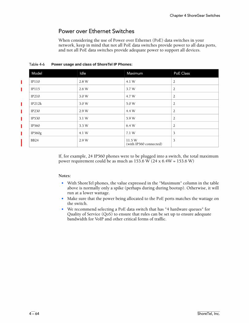
Chapter 4 ShoreGear Switches
4 – 64 ShoreTel, Inc.
Power over Ethernet SwitchesWhen considering the use of Power over Ethernet (PoE) data switches in your network, keep in mind that not all PoE data switches provide power to all data ports, and not all PoE data switches provide adequate power to support all devices.
If, for example, 24 IP560 phones were to be plugged into a switch, the total maximum power requirement could be as much as 153.6 W (24 x 6.4W = 153.6 W)
Notes:
• With ShoreTel phones, the value expressed in the "Maximum" column in the table above is normally only a spike (perhaps during during bootup). Otherwise, it will run at a lower wattage.
• Make sure that the power being allocated to the PoE ports matches the wattage on the switch.
• We recommend selecting a PoE data switch that has "4 hardware queues" for Quality of Service (QoS) to ensure that rules can be set up to ensure adequate bandwidth for VoIP and other critical forms of traffic.
Table 4-6 Power usage and class of ShoreTel IP Phones:
Model Idle Maximum PoE Class
IP110 2.8 W 4.1 W 2
IP115 2.6 W 3.7 W 2
IP210 3.0 W 4.7 W 2
IP212k 3.0 W 5.0 W 2
IP230 2.9 W 4.4 W 2
IP530 3.1 W 5.9 W 2
IP560 3.3 W 6.4 W 2
IP560g 4.1 W 7.1 W 3
BB24 2.9 W 11.5 W(with IP560 connected)
3
ShoreTel 7.5 Maintenance Guide 5 – 1
C H A P T E R 5
IP Endpoints
OverviewThe ShoreTel system manages calls and applications for three types of IP endpoints: IP phones, SoftPhones, and conference bridges. IP endpoints are identified by IP address and can exist anywhere on the network. All IP endpoints are supported by ShoreGear switches, which must have sufficient capacity for all the IP endpoints in the system. IP endpoints are configured in the system with ShoreWare Director. For more information on IP endpoints, see your ShoreTel Planning and Installation Guide and ShoreTel Administration Guide.
IP PhonesShoreTel IP phones allow you to deploy your telephony system as an end-to-end IP network without dedicated station wiring. Connecting anywhere on the network, ShoreTel IP phones work with the ShoreTel Call Manager client applications or can be used independently, providing an intuitive interface to essential telephone features.
The IP phone controls basic display operations, such as volume level, date and time, and icons. To provide IP telephony in a ShoreTel system, IP phones rely on services, switches, and industry-standard protocols. The following sections describe these dependencies.
ShoreTel IP Phones
• ShorePhone-IP100• ShorePhone-IP110• ShorePhone-IP115• ShorePhone-IP210• ShorePhone-IP212k• ShorePhone-IP230• ShorePhone-IP530/560/560g
Chapter 5 IP Endpoints
5 – 2 ShoreTel, Inc.
IP Phone Keep Alive
The ShoreGear-120/24, ShoreGear-60/12, and ShoreGear-40/8 voice switches send a heartbeat to their associated IP phones once a minute. If the heartbeat is not acknowledged within approximately four seconds, the switch considers the IP phone to be offline or unavailable. The switch continues to broadcast the heartbeat every minute. Any currently offline IP phone that returns an acknowledgement is considered online and available.
IP Phone Failover
IP phones can be optionally configured to send a heartbeat to their ShoreGear switch every four minutes. If an IP phone cannot communicate with its switch, the phone automatically connects to another switch located at the same site. For IP phone failover to be effective, the system must be planned with sufficient excess capacity to handle phones from at least one switch during a failover event. For example, if a switch with 20 IP phone ports fails, 20 IP phone ports need to be available elsewhere in the system. For more information, refer to the IP phone configuration settings in the ShoreTel Administration Guide.
Services
There are two services running on the ShoreWare server that interact with the system’s IP phones: IP Phone Configuration Service (IPCS) and IP Phone Display Service (IPDS).
IPCS
The IP Phone Configuration Service manages the IP phone configuration process, including configuration files and the database updates. Problems with IPCS connectivity can prevent IP phones from booting and prevent phone configuration data from being updated.
IPDS
The IP Phone Display Service handles the remaining functions, such as event handling and feature button functions. It also controls any actions by the IP phone display not controlled by the device’s firmware or switches. Problems with IPDS or TMS connectivity can result in incorrect phone displays and errors in both the hard and soft key functions.
Embedded IP Phone Display Driver
These features will not be handled by the switch but will continue to be provided by the server. Control of many of the IP phone features (such as phone display, redial, and call transfers) has been shifted from the server to the switch in order to enhance reliability and offer better uptime. Features that require writing to the database (such as directory and speed dial) will continue to depend on the server being both operational and accessible.
Date and Time
IP phones depend on an SNTP server to maintain the correct time and date. Without an SNTP server, you can set the phone date and time via a GMT offset. For more information, see “Setting IP100 Phone Configuration from the Phone Interface” on page 5-30.
IP Phones and ShoreGear Switches
IP phones in a ShoreTel system interact with two types of ShoreGear switches: the configuration switch and the call manager switch. The configuration switches help the IP phones obtain their configuration from the ShoreWare server, which functions as a
Chapter 5 IP Endpoints
ShoreTel 7.5 Maintenance Guide 5 – 3
FTP server for the IP phones. You must have at least one configuration switch and can designate a second configuration switch for reliability.
As part of the configuration information, each IP phone is assigned a ShoreGear switch that acts as the phone’s call manager to help the IP phone set up and tear down calls.
Configuration Switch(es)
In a DHCP environment, when an IP phone is booted, it receives the IP address of the DHCP and ShoreWare server from the configuration switch. Each system has at least one configuration switch for this purpose. The IP addresses of these switches are downloaded to the IP phones whenever the IP phones are booted.
If you have configured the IP phones to boot without a DHCP server, you must set the IP address of the configuration switch manually. For more information, see “Setting IP100 Phone Configuration from the Phone Interface” on page 5-30.
These switches communicate with the ShoreTel server to determine which switch manages calls for a particular IP phone. You have the option of assigning two switches to this function, in case one fails. For information on configuration switches, see the ShoreTel Administration Guide.
Call Manager Switch
The IP phones’ ShoreGear switch is responsible for actions such hold, transfer, conference, and park. The call manager module of the ShoreGear switches handles the Media Gateway Control Protocol (MGCP) information from the IP phones assigned to it. Once a call has been connected to an endpoint, media streams are independent of the call manager switch.
The ShoreGear switch communicates call information to other switches in the system using ShoreTel’s enhanced SIP protocol. Every site where IP phones are in use must have a ShoreGear voice switch configured to support the number of IP phones at the site.
The ShoreGear voice switches send a heartbeat to the IP phones once a minute. If the heartbeat is not acknowledged within approximately four seconds, the switch considers the IP phone to be offline or unavailable. The voice switches continue to broadcast the heartbeat every minute. Any currently offline IP phone that returns an acknowledgement is considered online and available.
To configure IP phone support on a ShoreGear-120/24, ShoreGear-60/12, or ShoreGear-40/8 voice switch, you must reserve ports for IP phone support on the ShoreGear Switch edit page in ShoreWare Director. See the “Configuring Switches” chapter in the ShoreTel Administration Guide for additional information.
IP Phone Communications
MGCP
IP phones communicate with ShoreGear switches via MGCP, a device control protocol. The relationship between the switch (call manager) and the phone (gateway) follows a master–slave model.
MGCP, an industry-standard protocol, is used to:
• Deliver information to the IP phone display• Set up and tear down media streams• Report phone events such as key presses, on hook, and off hook
Chapter 5 IP Endpoints
5 – 4 ShoreTel, Inc.
Media
Media travels through the ShoreTel system using Real-Time Protocol (RTP). After call setup, media flows directly between IP phones via RTP. The ShoreGear switch is involved only when setting up or tearing down a call.
For more information on MGCP and RTP communications, see “ShoreTel System Communications” on page 2-6.
Boot ProcessShoreTel IP phones are preconfigured by ShoreTel to work in conjunction with your ShoreTel system and your network’s Dynamic Host Configuration Protocol (DHCP) server. Once the servers are configured, you simply plug the phones into the network and they are automatically added to your ShoreTel system.
Once the IP phone has the DHCP and FTP server IP addresses, it downloads the application and configuration files from the FTP server. The IP phone configuration file is modified by ShoreWare Director during IP phone configuration.
If you are not using a DHCP server or it is not currently online, you can set a static IP address and other startup parameters directly at the IP phone. Static IP addresses for IP phones can also be assigned using the IP phone setup menus. For more information, see “Setting IP100 Phone Configuration from the Phone Interface” on page 5-30.
Maintenance
IP Phone Firmware UpgradesThe IP phone application software can be upgraded by replacing the application file on the FTP server. If you need to upgrade your phone application, refer to the instructions provided with the new phone software.
WARNING Modifying the IP phone configuration files can cause unpredictable results. If you have special needs, contact ShoreTel Customer Support for instructions.
DiagnosticsThe following recommendations will help you install your IP phones:
• Make sure you have reviewed your network bandwidth and Quality of Service (QoS) strategies and configured your network for your IP phones.
• Make sure the phones are configured to use DHCP vendor option 155 for configuring boot server information, and are configured to use anonymous FTP.
The phones will not boot properly if static configuration data is present in the telephone. This can occur if the telephones were previously used in an environment where DHCP and automatic provisioning was not used, or the telephone is from a vendor other than ShoreTel. See “Setting IP100 Phone Configuration from the Phone Interface” on page 5-30 and “Diagnostics & Config
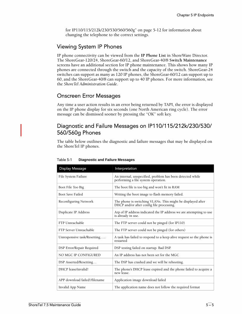
Chapter 5 IP Endpoints
ShoreTel 7.5 Maintenance Guide 5 – 5
for IP110/115/212k/230/530/560/560g” on page 5-12 for information about changing the telephone to the correct settings.
Viewing System IP PhonesIP phone connectivity can be viewed from the IP Phone List in ShoreWare Director. The ShoreGear-120/24, ShoreGear-60/12, and ShoreGear-40/8 Switch Maintenance screens have an additional section for IP phone maintenance. This shows how many IP phones are connected through the switch and the capacity of the switch. ShoreGear-24 switches can support as many as 120 IP phones, the ShoreGear-60/12 can support up to 60, and the ShoreGear-40/8 can support up to 40 IP phones. For more information, see the ShoreTel Administration Guide.
Onscreen Error MessagesAny time a user action results in an error being returned by TAPI, the error is displayed on the IP phone display for six seconds (one North American ring cycle). The error message can be dismissed sooner by pressing the “OK” soft key.
Diagnostic and Failure Messages on IP110/115/212k/230/530/560/560g PhonesThe table below outlines the diagnostic and failure messages that may be displayed on the ShoreTel IP phones.
Table 5-1 Diagnostic and Failure Messages
Display Message Interpretation
File System Failure An internal, unspecified, problem has been detected while performing a file system operation.
Boot File Too Big The boot file is too big and won’t fit in RAM
Boot Save Failed Writing the boot image to flash memory failed.
Reconfiguring Network The phone is switching VLANs. This might be displayed after DHCP and/or after config file processing.
Duplicate IP Address Arp of IP address indicated the IP address we are attempting to use is already in use.
FTP Unreachable The FTP server could not be pinged (for IP110)
FTP Server Unreachable The FTP server could not be pinged (for others)
Unresponsive task/Resetting….. A task has failed to respond to a keep alive request so the phone is restarted
DSP Error/Repair Required DSP testing failed on startup. Bad DSP.
NO MGC IP CONFIGURED An IP address has not been set for the MGC
DSP Asserted/Resetting… The DSP has crashed and we will be rebooting.
DHCP lease/invalid! The phone’s DHCP lease expired and the phone failed to acquire a new lease.
APP download failed!/filename Application image download failed
Invalid App Name The application name does not follow the required format
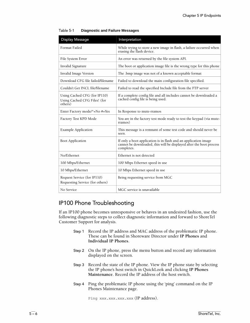
Chapter 5 IP Endpoints
5 – 6 ShoreTel, Inc.
IP100 Phone TroubleshootingIf an IP100 phone becomes unresponsive or behaves in an undesired fashion, use the following diagnostic steps to collect diagnostic information and forward to ShoreTel Customer Support for analysis.
Step 1 Record the IP address and MAC address of the problematic IP phone. These can be found in Shoreware Director under IP Phones and Individual IP Phones.
Step 2 On the IP phone, press the menu button and record any information displayed on the screen.
Step 3 Record the state of the IP phone. View the IP phone state by selecting the IP phone’s host switch in QuickLook and clicking IP Phones Maintenance. Record the IP address of the host switch.
Step 4 Ping the problematic IP phone using the ‘ping’ command on the IP Phones Maintenance page.
Ping xxx.xxx.xxx.xxx (IP address).
Format Failed While trying to store a new image in flash, a failure occurred when erasing the flash device.
File System Error An error was returned by the file system API.
Invalid Signature The boot or application image file is the wrong type for this phone
Invalid Image Version The .bmp image was not of a known acceptable format
Download CFG file failed/filename Failed to download the main configuration file specified.
Couldn’t Get INCL file/filename Failed to read the specified Include file from the FTP server
Using Cached CFG (for IP110)Using Cached CFG Files! (for others)
If a complete config file and all includes cannot be downloaded a cached config file is being used.
Enter Factory mode/*=No #=Yes In Response to mute-rramos
Factory Test KPD Mode You are in the factory test mode ready to test the keypad (via mute-rramos)
Example Application This message is a remnant of some test code and should never be seen.
Boot Application If only a boot application is in flash and an application image cannot be downloaded, this will be displayed after the boot process completes.
No/Ethernet Ethernet is not detected
100 Mbps/Ethernet 100 Mbps Ethernet speed in use
10 Mbps/Ethernet 10 Mbps Ethernet speed in use
Request Service (for IP110)Requesting Service (for others)
Being requesting service from MGC
No Service MGC service is unavailable
Table 5-1 Diagnostic and Failure Messages
Display Message Interpretation
Chapter 5 IP Endpoints
ShoreTel 7.5 Maintenance Guide 5 – 7
If the IP phone returns the following message(s), go to Step 5.
Reply from xxx.xxx.xxx.xxx: bytes=32 time<10ms TTL=64
Step 5 If you do not receive a response to the ping command, collect application and boot logs in the inetpub\ftproot directory, stop here, and send the available information to ShoreTel Customer Support. File naming convention is IP_Phone_MAC-app.log and IP_Phone_MAC-boot.log.
Example: 0004F2003896-app.log
Step 6 On the ShoreWare server, enable a Telnet session to the host switch as follows:
a Open a CMD window and navigate to the Program Files\Shoreline Communications\Shoreware Server directory.
b Type ipbxctl -telneton xxx.xxx.xxx.xxx using the IP address of the host switch and press ENTER.
c Telnet into the host switch using the telnet command. Use the following login name and password:
Login: anonymousPassword: ShoreTel (case sensitive)
d Type ext_cco_status and press ENTER. Capture the returned information.
e Type mgcp_msg_debug=1 and press ENTER to turn on MGCP message trace.
f Type ext_iphone_status and press ENTER. Wait for 5 seconds and capture the returned information. Wait an additional 30 seconds and capture any additional output from the switch.
g Type mgcp_msg_debug=0 to turn off MGCP trace.
Step 7 Restart the IP phone by either unplugging the data cable and reconnecting, or holding down the volume keys, the hold button, and the second soft key directly above the hold button for 5 seconds to initiate a restart of the phone.
Step 8 After the phone completes rebooting, collect the new application and boot logs created for the IP phone (as described above).
Step 9 Forward all the information you recorded to ShoreTel Customer Support for analysis.
Troubleshooting the IP Phone DisplayThis section presents some techniques for troubleshooting the IP Phone Display Server. The first step is to identify that the problem is actually an IPDS problem.
Chapter 5 IP Endpoints
5 – 8 ShoreTel, Inc.
You should suspect an IPDS problem whenever a phone configured in the database (which appears on the IP phone list in ShoreWare Director) does not have the correct display, or doesn’t respond properly when you press the feature buttons. When you suspect an IPDS problem, verify that the server has TAPI access to the phone or phones in question. To check TAPI access, use any TAPI application that supports phone devices such as TapiTest and PhoneMon.
Phone Display is Incorrect
If a phone display is incorrect, one of two things may have happened:
IPDS Sent a Bad Display Update
This can be detected by searching through the IPDS log file for the display line in question. If it is found at the appropriate time and on the appropriate extension, IPDS is the cause of the problem. Provide the relevant IPDS log to your engineering resources.
Switch Did Not Update the IP Phone Correctly
It is possible for the switch to mishandle phone updates.
Administrative Messages
The system administrator may send messages to a single IP phone or to all of them. These messages can alert users of upgrades or downtimes, or simply test the communication channel from IPDS through TMS and the switch to the phones. For details on how to send administrative messages using IPPhoneCfgTool.exe, see “Using the cfg Utility” on page 3-20.
Enabling IPDT Debugging
By default, IPDT logging is turned off. However, you can enable IPDT logging to assist in troubleshooting efforts.
Enabling IPDT Debugging
To enable logging on the switch, follow the procedure below:
Step 1 Telnet into the switch.
Step 2 Type the following command.
ipdt_debug_level = -1
Step 3 Logging output appears on the screen. You can use a software application, such as TeraTerm to capture the output and save it in a text file.
Details:
• IPDT logging should be enabled for short periods of time because the feature generates large amounts of data that consumes CPU cycles on the switch and slow it down.
• You can disable the logging feature by replacing -1 with a 0 in the command above. • The -1 variable enables tracing for all IPDT-related components. You can
selectively enable individual IPDT components by using the commands and variables listed in the table below.
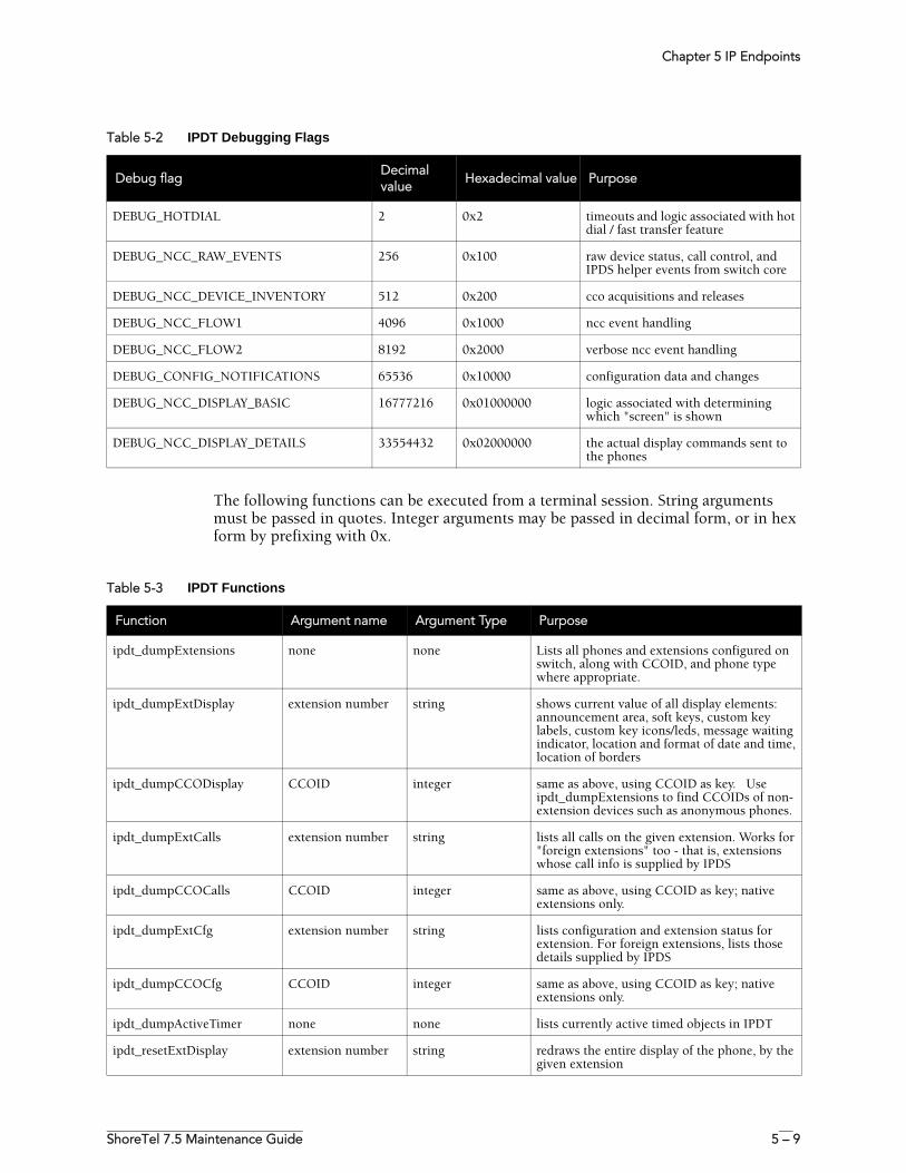
Chapter 5 IP Endpoints
ShoreTel 7.5 Maintenance Guide 5 – 9
The following functions can be executed from a terminal session. String arguments must be passed in quotes. Integer arguments may be passed in decimal form, or in hex form by prefixing with 0x.
Table 5-2 IPDT Debugging Flags
Debug flagDecimal value
Hexadecimal value Purpose
DEBUG_HOTDIAL 2 0x2 timeouts and logic associated with hot dial / fast transfer feature
DEBUG_NCC_RAW_EVENTS 256 0x100 raw device status, call control, and IPDS helper events from switch core
DEBUG_NCC_DEVICE_INVENTORY 512 0x200 cco acquisitions and releases
DEBUG_NCC_FLOW1 4096 0x1000 ncc event handling
DEBUG_NCC_FLOW2 8192 0x2000 verbose ncc event handling
DEBUG_CONFIG_NOTIFICATIONS 65536 0x10000 configuration data and changes
DEBUG_NCC_DISPLAY_BASIC 16777216 0x01000000 logic associated with determining which "screen" is shown
DEBUG_NCC_DISPLAY_DETAILS 33554432 0x02000000 the actual display commands sent to the phones
Table 5-3 IPDT Functions
Function Argument name Argument Type Purpose
ipdt_dumpExtensions none none Lists all phones and extensions configured on switch, along with CCOID, and phone type where appropriate.
ipdt_dumpExtDisplay extension number string shows current value of all display elements: announcement area, soft keys, custom key labels, custom key icons/leds, message waiting indicator, location and format of date and time, location of borders
ipdt_dumpCCODisplay CCOID integer same as above, using CCOID as key. Use ipdt_dumpExtensions to find CCOIDs of non-extension devices such as anonymous phones.
ipdt_dumpExtCalls extension number string lists all calls on the given extension. Works for "foreign extensions" too - that is, extensions whose call info is supplied by IPDS
ipdt_dumpCCOCalls CCOID integer same as above, using CCOID as key; native extensions only.
ipdt_dumpExtCfg extension number string lists configuration and extension status for extension. For foreign extensions, lists those details supplied by IPDS
ipdt_dumpCCOCfg CCOID integer same as above, using CCOID as key; native extensions only.
ipdt_dumpActiveTimer none none lists currently active timed objects in IPDT
ipdt_resetExtDisplay extension number string redraws the entire display of the phone, by the given extension
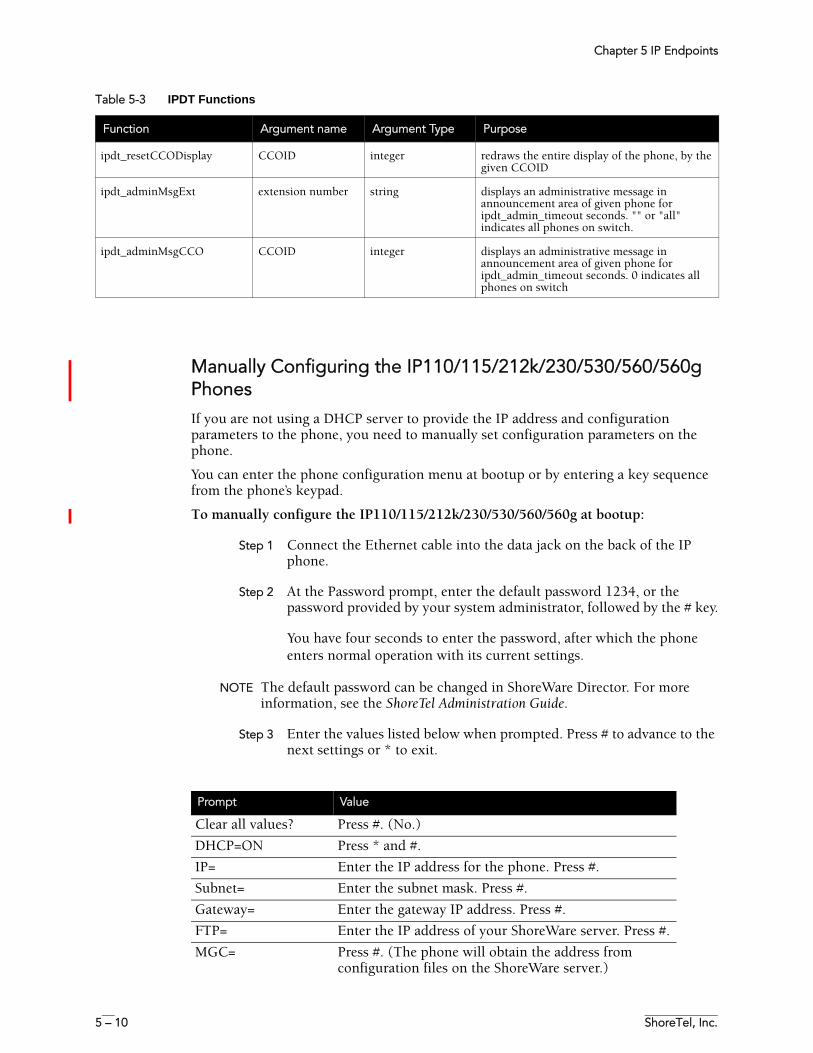
Chapter 5 IP Endpoints
5 – 10 ShoreTel, Inc.
Manually Configuring the IP110/115/212k/230/530/560/560g PhonesIf you are not using a DHCP server to provide the IP address and configuration parameters to the phone, you need to manually set configuration parameters on the phone.
You can enter the phone configuration menu at bootup or by entering a key sequence from the phone’s keypad.
To manually configure the IP110/115/212k/230/530/560/560g at bootup:
Step 1 Connect the Ethernet cable into the data jack on the back of the IP phone.
Step 2 At the Password prompt, enter the default password 1234, or the password provided by your system administrator, followed by the # key.
You have four seconds to enter the password, after which the phone enters normal operation with its current settings.
NOTE The default password can be changed in ShoreWare Director. For more information, see the ShoreTel Administration Guide.
Step 3 Enter the values listed below when prompted. Press # to advance to the next settings or * to exit.
ipdt_resetCCODisplay CCOID integer redraws the entire display of the phone, by the given CCOID
ipdt_adminMsgExt extension number string displays an administrative message in announcement area of given phone for ipdt_admin_timeout seconds. "" or "all" indicates all phones on switch.
ipdt_adminMsgCCO CCOID integer displays an administrative message in announcement area of given phone for ipdt_admin_timeout seconds. 0 indicates all phones on switch
Table 5-3 IPDT Functions
Function Argument name Argument Type Purpose
Prompt Value
Clear all values? Press #. (No.)
DHCP=ON Press * and #.
IP= Enter the IP address for the phone. Press #.
Subnet= Enter the subnet mask. Press #.
Gateway= Enter the gateway IP address. Press #.
FTP= Enter the IP address of your ShoreWare server. Press #.
MGC= Press #. (The phone will obtain the address from configuration files on the ShoreWare server.)
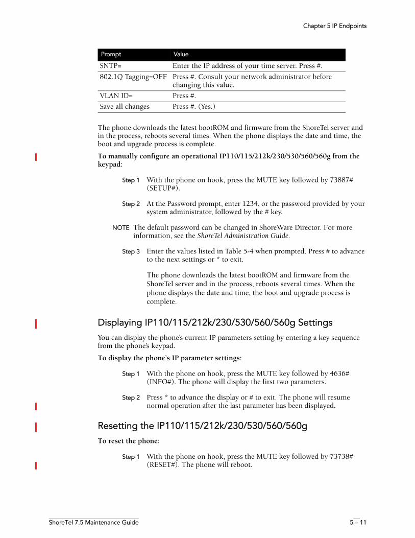
Chapter 5 IP Endpoints
ShoreTel 7.5 Maintenance Guide 5 – 11
The phone downloads the latest bootROM and firmware from the ShoreTel server and in the process, reboots several times. When the phone displays the date and time, the boot and upgrade process is complete.
To manually configure an operational IP110/115/212k/230/530/560/560g from the keypad:
Step 1 With the phone on hook, press the MUTE key followed by 73887# (SETUP#).
Step 2 At the Password prompt, enter 1234, or the password provided by your system administrator, followed by the # key.
NOTE The default password can be changed in ShoreWare Director. For more information, see the ShoreTel Administration Guide.
Step 3 Enter the values listed in Table 5-4 when prompted. Press # to advance to the next settings or * to exit.
The phone downloads the latest bootROM and firmware from the ShoreTel server and in the process, reboots several times. When the phone displays the date and time, the boot and upgrade process is complete.
Displaying IP110/115/212k/230/530/560/560g SettingsYou can display the phone’s current IP parameters setting by entering a key sequence from the phone’s keypad.
To display the phone’s IP parameter settings:
Step 1 With the phone on hook, press the MUTE key followed by 4636# (INFO#). The phone will display the first two parameters.
Step 2 Press * to advance the display or # to exit. The phone will resume normal operation after the last parameter has been displayed.
Resetting the IP110/115/212k/230/530/560/560gTo reset the phone:
Step 1 With the phone on hook, press the MUTE key followed by 73738# (RESET#). The phone will reboot.
SNTP= Enter the IP address of your time server. Press #.
802.1Q Tagging=OFF Press #. Consult your network administrator before changing this value.
VLAN ID= Press #.
Save all changes Press #. (Yes.)
Prompt Value
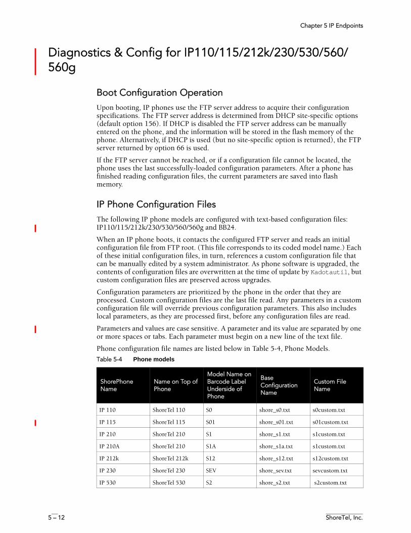
Chapter 5 IP Endpoints
5 – 12 ShoreTel, Inc.
Diagnostics & Config for IP110/115/212k/230/530/560/560g
Boot Configuration OperationUpon booting, IP phones use the FTP server address to acquire their configuration specifications. The FTP server address is determined from DHCP site-specific options (default option 156). If DHCP is disabled the FTP server address can be manually entered on the phone, and the information will be stored in the flash memory of the phone. Alternatively, if DHCP is used (but no site-specific option is returned), the FTP server returned by option 66 is used.
If the FTP server cannot be reached, or if a configuration file cannot be located, the phone uses the last successfully-loaded configuration parameters. After a phone has finished reading configuration files, the current parameters are saved into flash memory.
IP Phone Configuration FilesThe following IP phone models are configured with text-based configuration files: IP110/115/212k/230/530/560/560g and BB24.
When an IP phone boots, it contacts the configured FTP server and reads an initial configuration file from FTP root. (This file corresponds to its coded model name.) Each of these initial configuration files, in turn, references a custom configuration file that can be manually edited by a system administrator. As phone software is upgraded, the contents of configuration files are overwritten at the time of update by Kadotautil, but custom configuration files are preserved across upgrades.
Configuration parameters are prioritized by the phone in the order that they are processed. Custom configuration files are the last file read. Any parameters in a custom configuration file will override previous configuration parameters. This also includes local parameters, as they are processed first, before any configuration files are read.
Parameters and values are case sensitive. A parameter and its value are separated by one or more spaces or tabs. Each parameter must begin on a new line of the text file.
Phone configuration file names are listed below in Table 5-4, Phone Models.
Table 5-4 Phone models
ShorePhone Name
Name on Top of Phone
Model Name on Barcode Label Underside of Phone
Base Configuration Name
Custom File Name
IP 110 ShoreTel 110 S0 shore_s0.txt s0custom.txt
IP 115 ShoreTel 115 S01 shore_s01.txt s01custom.txt
IP 210 ShoreTel 210 S1 shore_s1.txt s1custom.txt
IP 210A ShoreTel 210 S1A shore_s1a.txt s1custom.txt
IP 212k ShoreTel 212k S12 shore_s12.txt s12custom.txt
IP 230 ShoreTel 230 SEV shore_sev.txt sevcustom.txt
IP 530 ShoreTel 530 S2 shore_s2.txt s2custom.txt
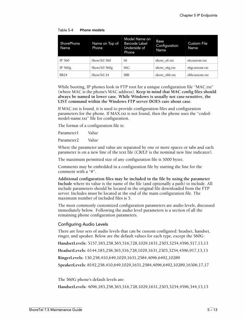
Chapter 5 IP Endpoints
ShoreTel 7.5 Maintenance Guide 5 – 13
While booting, IP phones look in FTP root for a unique configuration file “MAC.txt” (where MAC is the phone’s MAC address). Keep in mind that MAC config files should always be named in lower case. While Windows is usually not case-sensitive, the LIST command within the Windows FTP server DOES care about case.
If MAC.txt is found, it is used to provide configuration files and configuration parameters for the phone. If MAX.txt is not found, then the phone uses the “coded-model-name.txt” file for configuration.
The format of a configuration file is:
Parameter1 Value
Parameter2 Value
Where the parameter and value are separated by one or more spaces or tabs and each parameter is on a new line of the text file (CR/LF is the nominal new line indicator).
The maximum permitted size of any configuration file is 5000 bytes.
Comments may be embedded in a configuration file by starting the line for the comment with a “#”.
Additional configuration files may be included in the file by using the parameter Include where its value is the name of the file (and optionally a path) to include. All include parameters should be located in the original file downloaded from the FTP server. Includes must be located at the end of the main configuration file. The maximum number of included files is 5.
The most commonly customized configuration parameters are audio levels, discussed immediately below. Following the audio level parameters is a section of all the remaining phone configuration parameters.
Configuring Audio Levels
There are four sets of audio levels that can be custom configured: headset, handset, ringer, and speaker. Below are the default values for each type, except the 560G:
HandsetLevels: 5157,183,258,365,516,728,1029,1631,2303,3254,4596,517,13,13
HeadsetLevels: 6144,183,258,365,516,728,1029,1631,2303,3254,4596,917,13,13
RingerLevels: 130,258,410,649,1029,1631,2584,4096,6492,10289
SpeakerLevels: 8192,258,410,649,1029,1631,2584,4096,6492,10289,16306,17,17
The 560G phone's default levels are:
HandsetLevels: 4096,183,258,365,516,728,1029,1631,2303,3254,4596,344,13,13
IP 560 ShoreTel 560 S6 shore_s6.txt s6custom.txt
IP 560g ShoreTel 560g S6G shore_s6g.txt s6gcustom.txt
BB24 ShoreTel 24 SBB shore_sbb.txt sbbcustom.txt
Table 5-4 Phone models
ShorePhone Name
Name on Top of Phone
Model Name on Barcode Label Underside of Phone
Base Configuration Name
Custom File Name
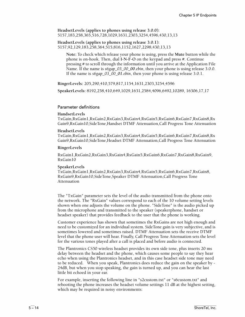
Chapter 5 IP Endpoints
5 – 14 ShoreTel, Inc.
HeadsetLevels (applies to phones using release 3.0.0): 5157,183,258,365,516,728,1029,1631,2303,3254,4596,430,13,13
HeadsetLevels (applies to phones using release 3.0.1): 5157,92,129,183,258,364,515,816,1152,1627,2298,430,13,13
Note: To check which release your phone is using, press the Mute button while the phone is on-hook. Then, dial I-N-F-O on the keypad and press #. Continue pressing # to scroll through the information until you arrive at the Application File Name. If the name is s6gap_03_00_00.ebin, then your phone is using release 3.0.0. If the name is s6gap_03_00_01.ebin, then your phone is using release 3.0.1.
RingerLevels: 205,290,410,579,817,1154,1631,2303,3254,4596
SpeakerLevels: 8192,258,410,649,1029,1631,2584,4096,6492,10289, 16306,17,17
Parameter definitions
HandsetLevels TxGain,RxGain1,RxGain2,RxGain3,RxGain4,RxGain5,RxGain6,RxGain7,RxGain8,RxGain9,RxGain10,SideTone,Handset DTMF Attenuation,Call Progress Tone Attenuation
HeadsetLevels TxGain,RxGain1,RxGain2,RxGain3,RxGain4,RxGain5,RxGain6,RxGain7,RxGain8,RxGain9,RxGain10,SideTone,Headset DTMF Attenuation,Call Progress Tone Attenuation
RingerLevels
RxGain1,RxGain2,RxGain3,RxGain4,RxGain5,RxGain6,RxGain7,RxGain8,RxGain9,RxGain10
SpeakerLevels TxGain,RxGain1,RxGain2,RxGain3,RxGain4,RxGain5,RxGain6,RxGain7,RxGain8,RxGain9,RxGain10,SideTone,Speaker DTMF Attenuation,Call Progress Tone Attenuation
The "TxGain" parameter sets the level of the audio transmitted from the phone onto the network. The "RxGain" values correspond to each of the 10 volume setting levels shown when one adjusts the volume on the phone. "SideTone" is the audio picked up from the microphone and transmitted to the speaker (speakerphone, handset or headset speaker) that provides feedback to the user that the phone is working.
Customer experience has shown that sometimes the RxGains are not high enough and need to be customized for an individual system. SideTone gain is very subjective, and is sometimes lowered and sometimes raised. DTMF Attenuation sets the receive DTMF level that the phone user will hear. Finally, Call Progress Tone Attenuation sets the level for the various tones played after a call is placed and before audio is connected.
The Plantronics CS50 wireless headset provides its own side tone, plus inserts 20 ms delay between the headset and the phone, which causes some people to say they hear echo when using the Plantronics headset, and in this case headset side tone may need to be reduced. When you speak, Plantronics does reduce the gain on the speaker by -24dB, but when you stop speaking, the gain is turned up, and you can hear the last little bit echoed in your ear.
For example, inserting the following line in "s2custom.txt" or "s6custom.txt" and rebooting the phone increases the headset volume settings 11 dB at the highest setting, which may be required in noisy environments:
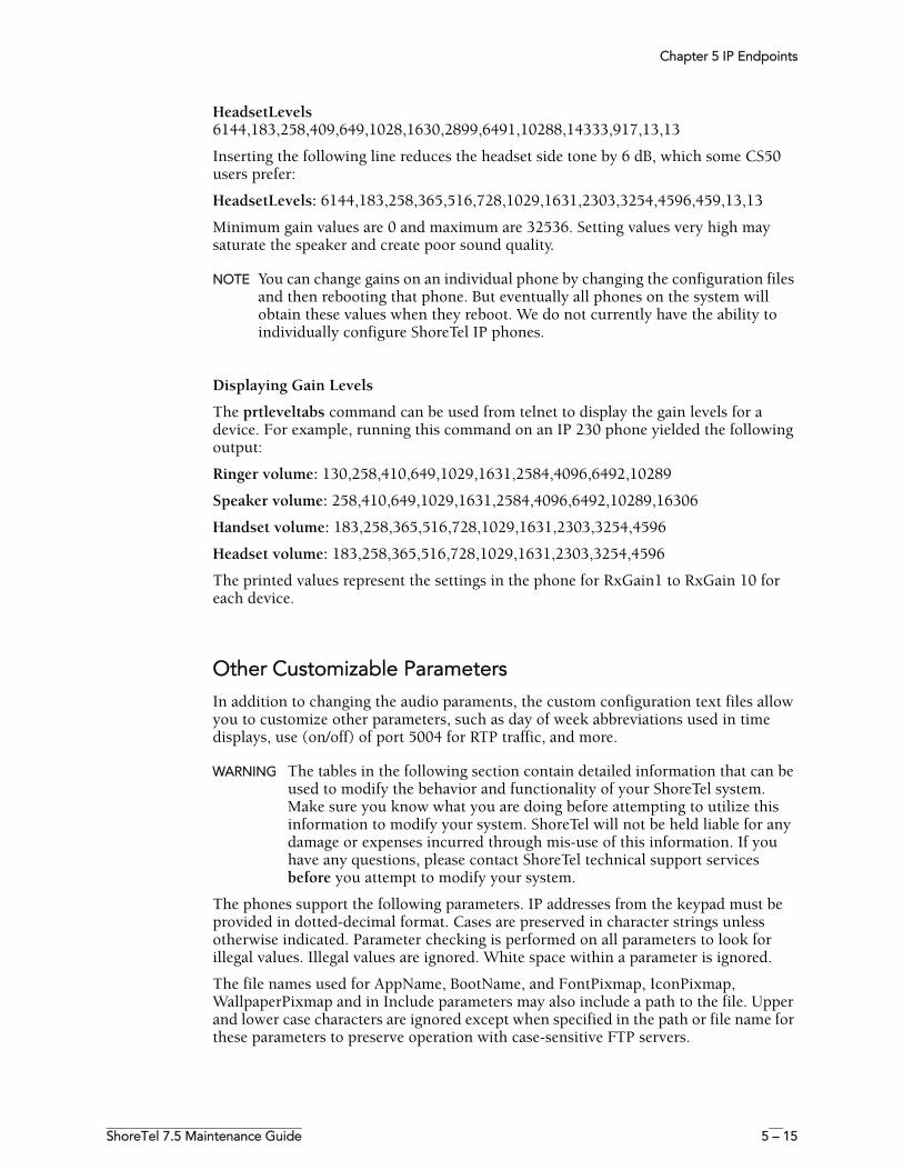
Chapter 5 IP Endpoints
ShoreTel 7.5 Maintenance Guide 5 – 15
HeadsetLevels6144,183,258,409,649,1028,1630,2899,6491,10288,14333,917,13,13
Inserting the following line reduces the headset side tone by 6 dB, which some CS50 users prefer:
HeadsetLevels: 6144,183,258,365,516,728,1029,1631,2303,3254,4596,459,13,13
Minimum gain values are 0 and maximum are 32536. Setting values very high may saturate the speaker and create poor sound quality.
NOTE You can change gains on an individual phone by changing the configuration files and then rebooting that phone. But eventually all phones on the system will obtain these values when they reboot. We do not currently have the ability to individually configure ShoreTel IP phones.
Displaying Gain Levels
The prtleveltabs command can be used from telnet to display the gain levels for a device. For example, running this command on an IP 230 phone yielded the following output:
Ringer volume: 130,258,410,649,1029,1631,2584,4096,6492,10289
Speaker volume: 258,410,649,1029,1631,2584,4096,6492,10289,16306
Handset volume: 183,258,365,516,728,1029,1631,2303,3254,4596
Headset volume: 183,258,365,516,728,1029,1631,2303,3254,4596
The printed values represent the settings in the phone for RxGain1 to RxGain 10 for each device.
Other Customizable ParametersIn addition to changing the audio paraments, the custom configuration text files allow you to customize other parameters, such as day of week abbreviations used in time displays, use (on/off) of port 5004 for RTP traffic, and more.
WARNING The tables in the following section contain detailed information that can be used to modify the behavior and functionality of your ShoreTel system. Make sure you know what you are doing before attempting to utilize this information to modify your system. ShoreTel will not be held liable for any damage or expenses incurred through mis-use of this information. If you have any questions, please contact ShoreTel technical support services before you attempt to modify your system.
The phones support the following parameters. IP addresses from the keypad must be provided in dotted-decimal format. Cases are preserved in character strings unless otherwise indicated. Parameter checking is performed on all parameters to look for illegal values. Illegal values are ignored. White space within a parameter is ignored.
The file names used for AppName, BootName, and FontPixmap, IconPixmap, WallpaperPixmap and in Include parameters may also include a path to the file. Upper and lower case characters are ignored except when specified in the path or file name for these parameters to preserve operation with case-sensitive FTP servers.
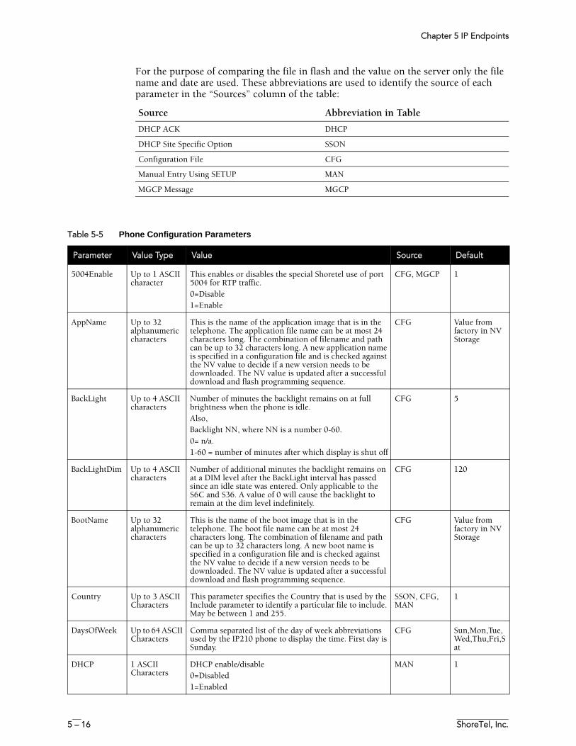
Chapter 5 IP Endpoints
5 – 16 ShoreTel, Inc.
For the purpose of comparing the file in flash and the value on the server only the file name and date are used. These abbreviations are used to identify the source of each parameter in the “Sources” column of the table:
Source Abbreviation in Table
DHCP ACK DHCP
DHCP Site Specific Option SSON
Configuration File CFG
Manual Entry Using SETUP MAN
MGCP Message MGCP
Table 5-5 Phone Configuration Parameters
Parameter Value Type Value Source Default
5004Enable Up to 1 ASCII character
This enables or disables the special Shoretel use of port 5004 for RTP traffic.0=Disable1=Enable
CFG, MGCP 1
AppName Up to 32 alphanumeric characters
This is the name of the application image that is in the telephone. The application file name can be at most 24 characters long. The combination of filename and path can be up to 32 characters long. A new application name is specified in a configuration file and is checked against the NV value to decide if a new version needs to be downloaded. The NV value is updated after a successful download and flash programming sequence.
CFG Value from factory in NV Storage
BackLight Up to 4 ASCII characters
Number of minutes the backlight remains on at full brightness when the phone is idle.Also, Backlight NN, where NN is a number 0-60. 0= n/a. 1-60 = number of minutes after which display is shut off
CFG 5
BackLightDim Up to 4 ASCII characters
Number of additional minutes the backlight remains on at a DIM level after the BackLight interval has passed since an idle state was entered. Only applicable to the S6C and S36. A value of 0 will cause the backlight to remain at the dim level indefinitely.
CFG 120
BootName Up to 32 alphanumeric characters
This is the name of the boot image that is in the telephone. The boot file name can be at most 24 characters long. The combination of filename and path can be up to 32 characters long. A new boot name is specified in a configuration file and is checked against the NV value to decide if a new version needs to be downloaded. The NV value is updated after a successful download and flash programming sequence.
CFG Value from factory in NV Storage
Country Up to 3 ASCII Characters
This parameter specifies the Country that is used by the Include parameter to identify a particular file to include. May be between 1 and 255.
SSON, CFG, MAN
1
DaysOfWeek Up to 64 ASCII Characters
Comma separated list of the day of week abbreviations used by the IP210 phone to display the time. First day is Sunday.
CFG Sun,Mon,Tue,Wed,Thu,Fri,Sat
DHCP 1 ASCII Characters
DHCP enable/disable0=Disabled1=Enabled
MAN 1
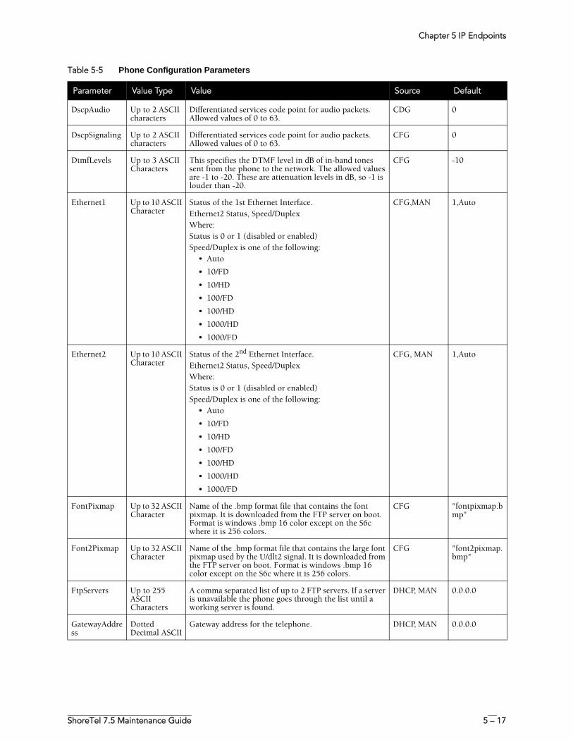
Chapter 5 IP Endpoints
ShoreTel 7.5 Maintenance Guide 5 – 17
DscpAudio Up to 2 ASCII characters
Differentiated services code point for audio packets. Allowed values of 0 to 63.
CDG 0
DscpSignaling Up to 2 ASCII characters
Differentiated services code point for audio packets. Allowed values of 0 to 63.
CFG 0
DtmfLevels Up to 3 ASCII Characters
This specifies the DTMF level in dB of in-band tones sent from the phone to the network. The allowed values are -1 to -20. These are attenuation levels in dB, so -1 is louder than -20.
CFG -10
Ethernet1 Up to 10 ASCII Character
Status of the 1st Ethernet Interface. Ethernet2 Status, Speed/DuplexWhere:Status is 0 or 1 (disabled or enabled)Speed/Duplex is one of the following:
• Auto
• 10/FD
• 10/HD
• 100/FD
• 100/HD
• 1000/HD
• 1000/FD
CFG,MAN 1,Auto
Ethernet2 Up to 10 ASCII Character
Status of the 2nd Ethernet Interface. Ethernet2 Status, Speed/DuplexWhere:Status is 0 or 1 (disabled or enabled)Speed/Duplex is one of the following:
• Auto
• 10/FD
• 10/HD
• 100/FD
• 100/HD
• 1000/HD
• 1000/FD
CFG, MAN 1,Auto
FontPixmap Up to 32 ASCII Character
Name of the .bmp format file that contains the font pixmap. It is downloaded from the FTP server on boot. Format is windows .bmp 16 color except on the S6c where it is 256 colors.
CFG "fontpixmap.bmp"
Font2Pixmap Up to 32 ASCII Character
Name of the .bmp format file that contains the large font pixmap used by the U/dlt2 signal. It is downloaded from the FTP server on boot. Format is windows .bmp 16 color except on the S6c where it is 256 colors.
CFG "font2pixmap.bmp"
FtpServers Up to 255 ASCII Characters
A comma separated list of up to 2 FTP servers. If a server is unavailable the phone goes through the list until a working server is found.
DHCP, MAN 0.0.0.0
GatewayAddress
Dotted Decimal ASCII
Gateway address for the telephone. DHCP, MAN 0.0.0.0
Table 5-5 Phone Configuration Parameters
Parameter Value Type Value Source Default
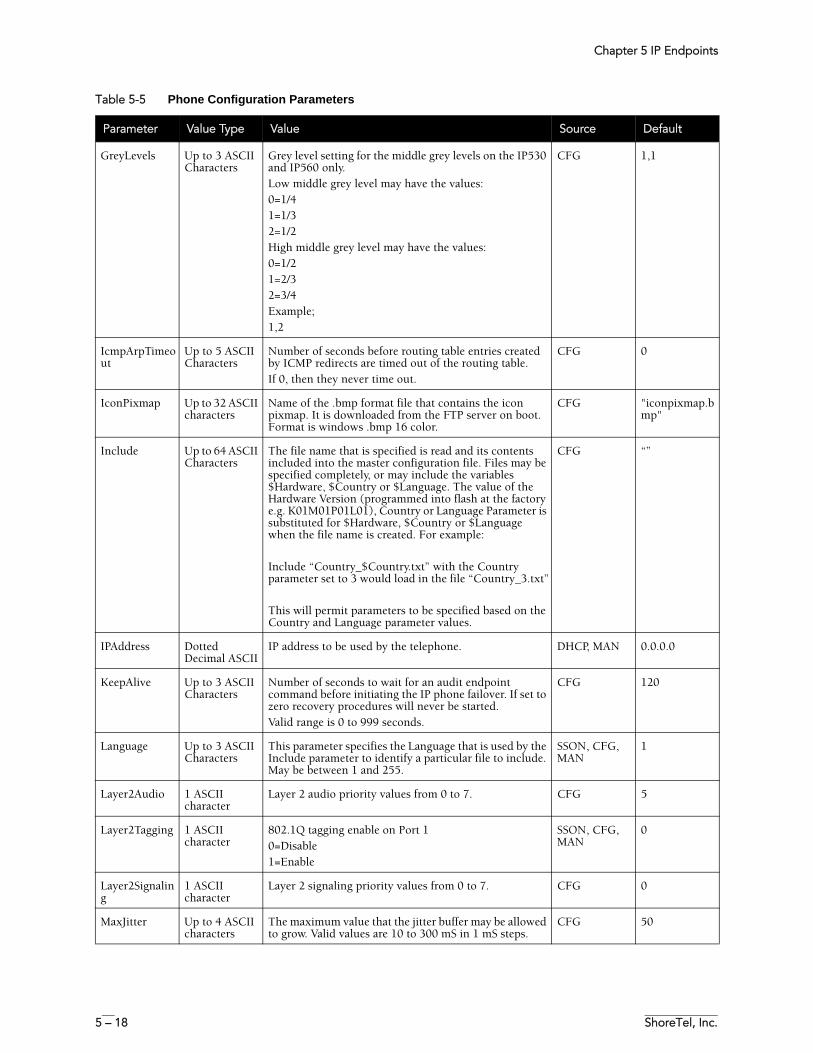
Chapter 5 IP Endpoints
5 – 18 ShoreTel, Inc.
GreyLevels Up to 3 ASCII Characters
Grey level setting for the middle grey levels on the IP530 and IP560 only. Low middle grey level may have the values:0=1/41=1/32=1/2High middle grey level may have the values:0=1/21=2/32=3/4Example;1,2
CFG 1,1
IcmpArpTimeout
Up to 5 ASCII Characters
Number of seconds before routing table entries created by ICMP redirects are timed out of the routing table.If 0, then they never time out.
CFG 0
IconPixmap Up to 32 ASCII characters
Name of the .bmp format file that contains the icon pixmap. It is downloaded from the FTP server on boot. Format is windows .bmp 16 color.
CFG "iconpixmap.bmp"
Include Up to 64 ASCII Characters
The file name that is specified is read and its contents included into the master configuration file. Files may be specified completely, or may include the variables $Hardware, $Country or $Language. The value of the Hardware Version (programmed into flash at the factory e.g. K01M01P01L01), Country or Language Parameter is substituted for $Hardware, $Country or $Language when the file name is created. For example:
Include “Country_$Country.txt” with the Country parameter set to 3 would load in the file “Country_3.txt”
This will permit parameters to be specified based on the Country and Language parameter values.
CFG “”
IPAddress Dotted Decimal ASCII
IP address to be used by the telephone. DHCP, MAN 0.0.0.0
KeepAlive Up to 3 ASCII Characters
Number of seconds to wait for an audit endpoint command before initiating the IP phone failover. If set to zero recovery procedures will never be started.Valid range is 0 to 999 seconds.
CFG 120
Language Up to 3 ASCII Characters
This parameter specifies the Language that is used by the Include parameter to identify a particular file to include. May be between 1 and 255.
SSON, CFG, MAN
1
Layer2Audio 1 ASCII character
Layer 2 audio priority values from 0 to 7. CFG 5
Layer2Tagging 1 ASCII character
802.1Q tagging enable on Port 10=Disable1=Enable
SSON, CFG, MAN
0
Layer2Signaling
1 ASCII character
Layer 2 signaling priority values from 0 to 7. CFG 0
MaxJitter Up to 4 ASCII characters
The maximum value that the jitter buffer may be allowed to grow. Valid values are 10 to 300 mS in 1 mS steps.
CFG 50
Table 5-5 Phone Configuration Parameters
Parameter Value Type Value Source Default
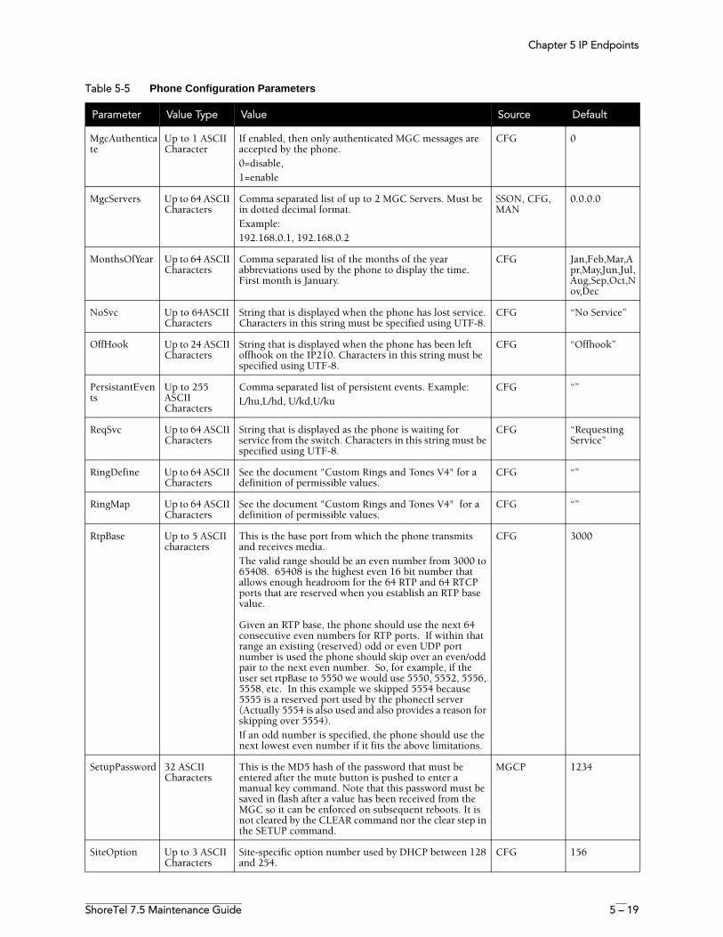
Chapter 5 IP Endpoints
ShoreTel 7.5 Maintenance Guide 5 – 19
MgcAuthenticate
Up to 1 ASCII Character
If enabled, then only authenticated MGC messages are accepted by the phone.0=disable,1=enable
CFG 0
MgcServers Up to 64 ASCII Characters
Comma separated list of up to 2 MGC Servers. Must be in dotted decimal format. Example:192.168.0.1, 192.168.0.2
SSON, CFG, MAN
0.0.0.0
MonthsOfYear Up to 64 ASCII Characters
Comma separated list of the months of the year abbreviations used by the phone to display the time. First month is January.
CFG Jan,Feb,Mar,Apr,May,Jun,Jul,Aug,Sep,Oct,Nov,Dec
NoSvc Up to 64ASCII Characters
String that is displayed when the phone has lost service. Characters in this string must be specified using UTF-8.
CFG “No Service”
OffHook Up to 24 ASCII Characters
String that is displayed when the phone has been left offhook on the IP210. Characters in this string must be specified using UTF-8.
CFG “Offhook”
PersistantEvents
Up to 255 ASCII Characters
Comma separated list of persistent events. Example:L/hu,L/hd, U/kd,U/ku
CFG “”
ReqSvc Up to 64 ASCII Characters
String that is displayed as the phone is waiting for service from the switch. Characters in this string must be specified using UTF-8.
CFG “Requesting Service”
RingDefine Up to 64 ASCII Characters
See the document "Custom Rings and Tones V4" for a definition of permissible values.
CFG “”
RingMap Up to 64 ASCII Characters
See the document "Custom Rings and Tones V4" for a definition of permissible values.
CFG “”
RtpBase Up to 5 ASCII characters
This is the base port from which the phone transmits and receives media.The valid range should be an even number from 3000 to 65408. 65408 is the highest even 16 bit number that allows enough headroom for the 64 RTP and 64 RTCP ports that are reserved when you establish an RTP base value.
Given an RTP base, the phone should use the next 64 consecutive even numbers for RTP ports. If within that range an existing (reserved) odd or even UDP port number is used the phone should skip over an even/odd pair to the next even number. So, for example, if the user set rtpBase to 5550 we would use 5550, 5552, 5556, 5558, etc. In this example we skipped 5554 because 5555 is a reserved port used by the phonectl server (Actually 5554 is also used and also provides a reason for skipping over 5554).If an odd number is specified, the phone should use the next lowest even number if it fits the above limitations.
CFG 3000
SetupPassword 32 ASCII Characters
This is the MD5 hash of the password that must be entered after the mute button is pushed to enter a manual key command. Note that this password must be saved in flash after a value has been received from the MGC so it can be enforced on subsequent reboots. It is not cleared by the CLEAR command nor the clear step in the SETUP command.
MGCP 1234
SiteOption Up to 3 ASCII Characters
Site-specific option number used by DHCP between 128 and 254.
CFG 156
Table 5-5 Phone Configuration Parameters
Parameter Value Type Value Source Default
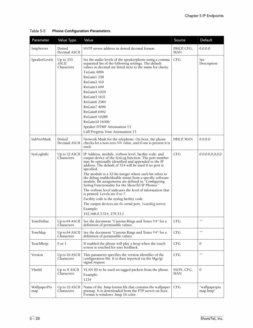
Chapter 5 IP Endpoints
5 – 20 ShoreTel, Inc.
SntpServer Dotted Decimal ASCII
SNTP server address in dotted decimal format. DHCP, CFG, MAN
0.0.0.0
SpeakerLevels Up to 255 ASCII Characters
Set the audio levels of the speakerphone using a comma separated list of the following settings. The default values in decimal are listed next to the name for clarity.TxGain 4096RxGain1 258RxGain2 410RxGain3 649RxGain4 1029RxGain5 1631RxGain6 2584RxGain7 4096RxGain8 6492RxGain9 10289RxGain10 16306Speaker DTMF Attenuation 13Call Progress Tone Attenuation 13
CFG See Description
SubNetMask Dotted Decimal ASCII
Network Mask for the telephone. On boot, the phone checks for a non-zero NV value, and if one is present it is used.
DHCP, MAN 0.0.0.0
SysLogInfo Up to 32 ASCII Characters
IP Address, module, verbose level, facility code, and output device of the SysLog function. The port number may be optionally identified and appended to the IP address. The default of 514 will be used if no port is specified.The module is a 32-bit integer where each bit refers to the debug enable/disable status from a specific software module. Bit assignments are defined in “Configuring Syslog Functionality for the ShoreTel IP Phones.”The verbose level indicates the level of information that is printed. Levels are 0 to 7. Facility code is the syslog facility code.The output devices are 0= serial port, 1=syslog server.Example:192.168.0.3:514, 279,33,1
CFG 0.0.0.0,0,0,0,0
ToneDefine Up to 64 ASCII Characters
See the document "Custom Rings and Tones V4" for a definition of permissible values.
CFG “”
ToneMap Up to 64 ASCII Characters
See the document "Custom Rings and Tones V4" for a definition of permissible values.
CFG “”
TouchBeep 0 or 1 If enabled the phone will play a beep when the touch screen is touched for user feedback.
CFG 0
Version Up to 16 ASCII Characters
This parameter specifies the version identifier of the configuration file. It is then reported via the Mgc/gi signal request.
CFG “”
VlanId Up to 9 ASCII Characters
VLAN ID to be used on tagged packets from the phone.Example:1234
SSON, CFG, MAN
0
WallpaperPixmap
Up to 32 ASCII Characters
Name of the .bmp format file that contains the wallpaper pixmap. It is downloaded from the FTP server on boot. Format is windows .bmp 16 color.
CFG "wallpaperpixmap.bmp"
Table 5-5 Phone Configuration Parameters
Parameter Value Type Value Source Default
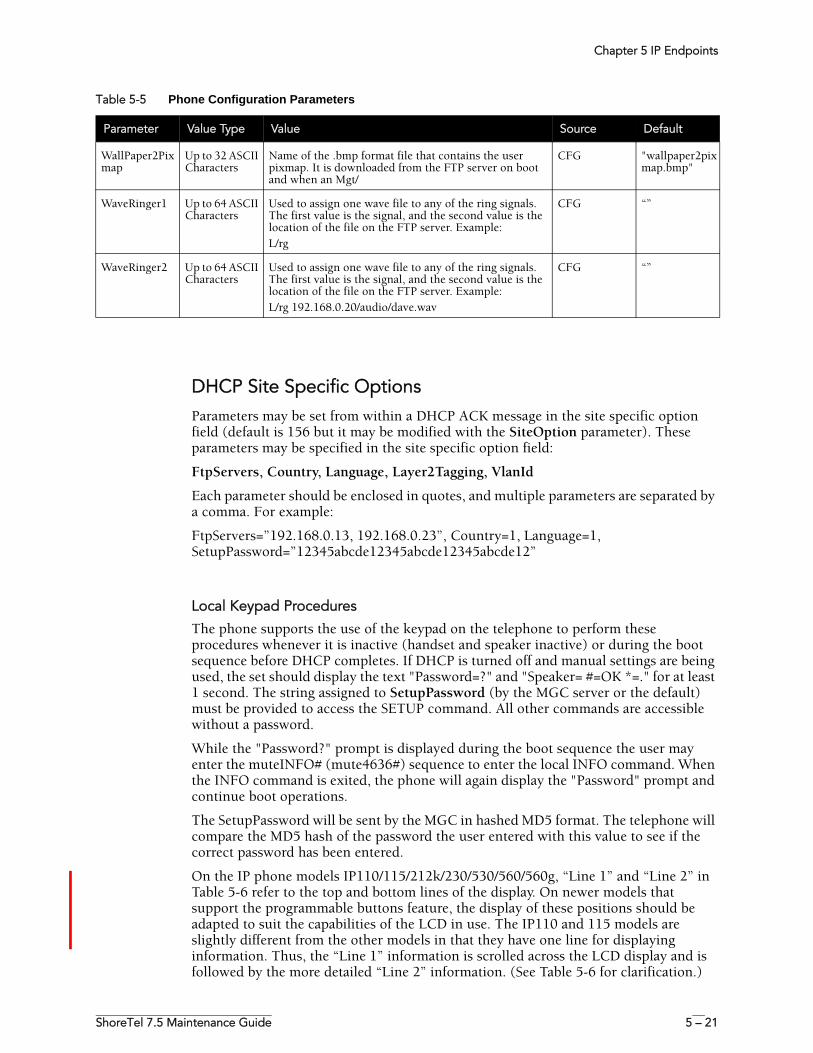
Chapter 5 IP Endpoints
ShoreTel 7.5 Maintenance Guide 5 – 21
DHCP Site Specific OptionsParameters may be set from within a DHCP ACK message in the site specific option field (default is 156 but it may be modified with the SiteOption parameter). These parameters may be specified in the site specific option field:
FtpServers, Country, Language, Layer2Tagging, VlanId
Each parameter should be enclosed in quotes, and multiple parameters are separated by a comma. For example:
FtpServers=”192.168.0.13, 192.168.0.23”, Country=1, Language=1, SetupPassword=”12345abcde12345abcde12345abcde12”
Local Keypad Procedures
The phone supports the use of the keypad on the telephone to perform these procedures whenever it is inactive (handset and speaker inactive) or during the boot sequence before DHCP completes. If DHCP is turned off and manual settings are being used, the set should display the text "Password=?" and "Speaker= #=OK *=." for at least 1 second. The string assigned to SetupPassword (by the MGC server or the default) must be provided to access the SETUP command. All other commands are accessible without a password.
While the "Password?" prompt is displayed during the boot sequence the user may enter the muteINFO# (mute4636#) sequence to enter the local INFO command. When the INFO command is exited, the phone will again display the "Password" prompt and continue boot operations.
The SetupPassword will be sent by the MGC in hashed MD5 format. The telephone will compare the MD5 hash of the password the user entered with this value to see if the correct password has been entered.
On the IP phone models IP110/115/212k/230/530/560/560g, “Line 1” and “Line 2” in Table 5-6 refer to the top and bottom lines of the display. On newer models that support the programmable buttons feature, the display of these positions should be adapted to suit the capabilities of the LCD in use. The IP110 and 115 models are slightly different from the other models in that they have one line for displaying information. Thus, the “Line 1” information is scrolled across the LCD display and is followed by the more detailed “Line 2” information. (See Table 5-6 for clarification.)
WallPaper2Pixmap
Up to 32 ASCII Characters
Name of the .bmp format file that contains the user pixmap. It is downloaded from the FTP server on boot and when an Mgt/
CFG "wallpaper2pixmap.bmp"
WaveRinger1 Up to 64 ASCII Characters
Used to assign one wave file to any of the ring signals. The first value is the signal, and the second value is the location of the file on the FTP server. Example:L/rg
CFG “”
WaveRinger2 Up to 64 ASCII Characters
Used to assign one wave file to any of the ring signals. The first value is the signal, and the second value is the location of the file on the FTP server. Example:L/rg 192.168.0.20/audio/dave.wav
CFG “”
Table 5-5 Phone Configuration Parameters
Parameter Value Type Value Source Default
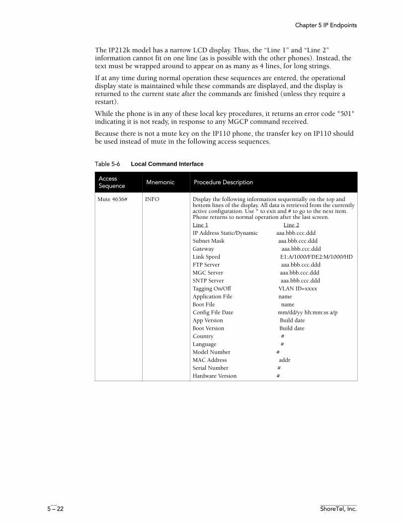
Chapter 5 IP Endpoints
5 – 22 ShoreTel, Inc.
The IP212k model has a narrow LCD display. Thus, the “Line 1” and “Line 2” information cannot fit on one line (as is possible with the other phones). Instead, the text must be wrapped around to appear on as many as 4 lines, for long strings.
If at any time during normal operation these sequences are entered, the operational display state is maintained while these commands are displayed, and the display is returned to the current state after the commands are finished (unless they require a restart).
While the phone is in any of these local key procedures, it returns an error code "501" indicating it is not ready, in response to any MGCP command received.
Because there is not a mute key on the IP110 phone, the transfer key on IP110 should be used instead of mute in the following access sequences.
Table 5-6 Local Command Interface
Access Sequence
Mnemonic Procedure Description
Mute 4636# INFO Display the following information sequentially on the top and bottom lines of the display. All data is retrieved from the currently active configuration. Use * to exit and # to go to the next item. Phone returns to normal operation after the last screen. Line 1 Line 2IP Address Static/Dynamic aaa.bbb.ccc.dddSubnet Mask aaa.bbb.ccc.dddGateway aaa.bbb.ccc.dddLink Speed E1:A/1000/FDE2:M/1000/HDFTP Server aaa.bbb.ccc.dddMGC Server aaa.bbb.ccc.dddSNTP Server aaa.bbb.ccc.dddTagging On/Off VLAN ID=xxxx Application File nameBoot File nameConfig File Date mm/dd/yy hh:mm:ss a/p App Version Build dateBoot Version Build dateCountry #Language #Model Number #MAC Address addrSerial Number #Hardware Version #
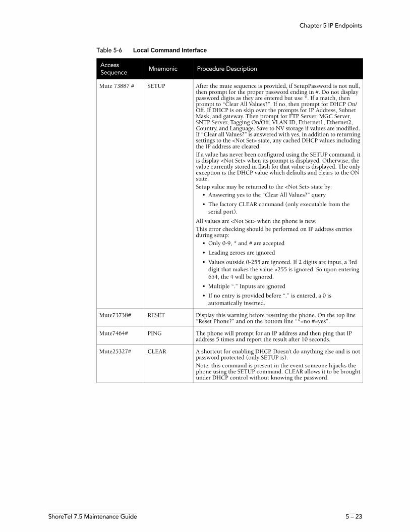
Chapter 5 IP Endpoints
ShoreTel 7.5 Maintenance Guide 5 – 23
Mute 73887 # SETUP After the mute sequence is provided, if SetupPassword is not null, then prompt for the proper password ending in #. Do not display password digits as they are entered but use *. If a match, then prompt to “Clear All Values?”. If no, then prompt for DHCP On/Off. If DHCP is on skip over the prompts for IP Address, Subnet Mask, and gateway. Then prompt for FTP Server, MGC Server, SNTP Server, Tagging On/Off, VLAN ID, Ethernet1, Ethernet2, Country, and Language. Save to NV storage if values are modified. If “Clear all Values?” is answered with yes, in addition to returning settings to the <Not Set> state, any cached DHCP values including the IP address are cleared.If a value has never been configured using the SETUP command, it is display <Not Set> when its prompt is displayed. Otherwise, the value currently stored in flash for that value is displayed. The only exception is the DHCP value which defaults and clears to the ON state.Setup value may be returned to the <Not Set> state by:
• Answering yes to the “Clear All Values?” query
• The factory CLEAR command (only executable from the serial port).
All values are <Not Set> when the phone is new.This error checking should be performed on IP address entries during setup:
• Only 0-9, * and # are accepted
• Leading zeroes are ignored
• Values outside 0-255 are ignored. If 2 digits are input, a 3rd digit that makes the value >255 is ignored. So upon entering 654, the 4 will be ignored.
• Multiple “.” Inputs are ignored
• If no entry is provided before “.” is entered, a 0 is automatically inserted.
Mute73738# RESET Display this warning before resetting the phone. On the top line “Reset Phone?” and on the bottom line “*=no #=yes”.
Mute7464# PING The phone will prompt for an IP address and then ping that IP address 5 times and report the result after 10 seconds.
Mute25327# CLEAR A shortcut for enabling DHCP. Doesn’t do anything else and is not password protected (only SETUP is). Note: this command is present in the event someone hijacks the phone using the SETUP command. CLEAR allows it to be brought under DHCP control without knowing the password.
Table 5-6 Local Command Interface
Access Sequence
Mnemonic Procedure Description
Chapter 5 IP Endpoints
5 – 24 ShoreTel, Inc.
Parameter Precedence
The active configuration of parameters used by the phone use the following order of precedence sources for all parameters:
1 Config file
2 DHCP (if active)
3 Setup Command
4 Defaults
In other words, config parameters have precedence over DHCP over Setup over Defaults.
Note that not all parameter sources may be supported for every parameter. Table 5-5 indicates which sources are allowed for each parameter.
Note that to fully manually configure a phone simply turn off DHCP, then use the Setup command but be sure not to specify an FTP server that might download a config file and overwrite your manual settings.
PhoneCTL Command Line ToolPhoneCTL is a command line tool used to configure and diagnose ShoreTel IP phones. PhoneCTL commands can be run from the Windows command prompt.
Syntax for PhoneCTL commands can be obtained by typing phonectl at the prompt and pressing Enter.
There are several categories of commands available, including:
• Configuring syslog functionality for the IP phones• setLogLevel• setServerIP• setOutputDev• dump2pc• showLogLevel
• Retrieving information and statistics about phone connections• showConnInfo• showStats• showTime• version
• Troubleshooting data transfer issues between the phone and the syslog server• ifShow• arpShow• inetstatShow• ipstatShow• udpstatShow• tcpstatShow• hostShow• routeShow
NOTE All commands are case-insensitive.
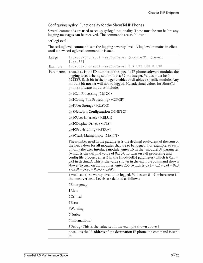
Chapter 5 IP Endpoints
ShoreTel 7.5 Maintenance Guide 5 – 25
Configuring syslog Functionality for the ShoreTel IP Phones
Several commands are used to set up syslog functionality. These must be run before any logging messages can be received. The commands are as follows:
setLogLevel
The setLogLevel command sets the logging severity level. A log level remains in effect until a new setLogLevel command is issued.
Usage Prompt:\phonectl -setLogLevel [moduleID] [level] [destIP]
Example Prompt:\phonectl -setLogLevel 3 7 192.168.0.170
Parameters moduleID is the ID number of the specific IP phone software modules the logging level is being set for. It is a 32-bit integer. Values must be 0—655335. Each bit in the integer enables or disables a specific module. Any module bit not set will not be logged. Hexadecimal values for ShoreTel phone software modules include:
0x1Call Processing (MGCC)
0x2Config File Processing (MCFGP)
0x4User Storage (MUSTG)
0x8Network Configuration (MNETC)
0x10User Interface (MELUI)
0x20Display Driver (MDIS)
0x40Provisioning (MPROV)
0x80Task Maintenance (MAINT)
The number used in the parameter is the decimal equivalent of the sum of the hex values for all modules that are to be logged. For example, to turn on only the user interface module, enter 16 in the [moduleID] parameter (which is the decimal value of 0x10). To turn on call processing and config file process, enter 3 in the [moduleID] parameter (which is 0x1 + 0x2 in decimal). This is the value shown in the example command shown above. To turn on all modules, enter 255 (which is 0x1 + -x2 + 0x4 + 0x8 + 0x10 + 0x20 + 0x40 = 0x80).
level sets the severity level to be logged. Values are 0—7, where zero is the most verbose. Levels are defined as follows:
0Emergency
1Alert
2Critical
3Error
4Warning
5Notice
6Informational
7Debug (This is the value set in the example shown above.)
destIP is the IP address of the destination IP phone the command is sent to.
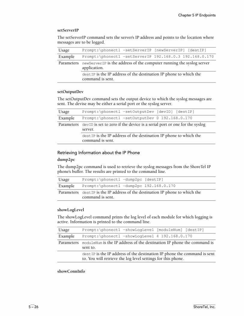
Chapter 5 IP Endpoints
5 – 26 ShoreTel, Inc.
setServerIP
The setServerIP command sets the server’s IP address and points to the location where messages are to be logged.
setOutputDev
The setOutputDev command sets the output device to which the syslog messages are sent. The devise may be either a serial port or the syslog server.
Retrieving Information about the IP Phone
dump2pc
The dump2pc command is used to retrieve the syslog messages from the ShoreTel IP phone’s buffer. The results are printed to the command line.
showLogLevel
The showLogLevel command prints the log level of each module for which logging is active. Information is printed to the command line.
showConnInfo
Usage Prompt:\phonectl -setServerIP [newServerIP] [destIP]
Example Prompt:\phonectl -setServerIP 192.168.0.3 192.168.0.170
Parameters newServerIP is the address of the computer running the syslog server application.
destIP is the IP address of the destination IP phone to which the command is sent.
Usage Prompt:\phonectl -setOutputDev [devID] [destIP]
Example Prompt:\phonectl -setOutputDev 0 192.168.0.170
Parameters devID is set to zero if the device is a serial port or one for the syslog server.
destIP is the IP address of the destination IP phone to which the command is sent.
Usage Prompt:\phonectl -dump2pc [destIP]
Example Prompt:\phonectl -dump2pc 192.168.0.170
Parameters destIP is the IP address of the destination IP phone to which the command is sent.
Usage Prompt:\phonectl -showLogLevel [moduleNum] [destIP]
Example Prompt:\phonectl -showLogLevel 4 192.168.0.170
Parameters moduleNum is the IP address of the destination IP phone the command is sent to.
destIP is the IP address of the destination IP phone the command is sent to. You will retrieve the log level settings for this phone.
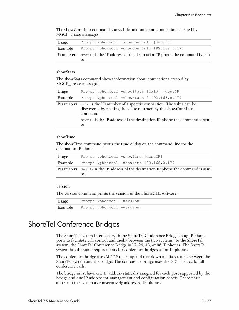
Chapter 5 IP Endpoints
ShoreTel 7.5 Maintenance Guide 5 – 27
The showConnInfo command shows information about connections created by MGCP_create messages.
showStats
The showStats command shows information about connections created by MGCP_create messages.
showTime
The showTime command prints the time of day on the command line for the destination IP phone.
version
The version command prints the version of the PhoneCTL software.
ShoreTel Conference BridgesThe ShoreTel system interfaces with the ShoreTel Conference Bridge using IP phone ports to facilitate call control and media between the two systems. To the ShoreTel system, the ShoreTel Conference Bridge is 12, 24, 48, or 96 IP phones. The ShoreTel system has the same requirements for conference bridges as for IP phones.
The conference bridge uses MGCP to set up and tear down media streams between the ShoreTel system and the bridge. The conference bridge uses the G.711 codec for all conference calls.
The bridge must have one IP address statically assigned for each port supported by the bridge and one IP address for management and configuration access. These ports appear in the system as consecutively addressed IP phones.
Usage Prompt:\phonectl -showConnInfo [destIP]
Example Prompt:\phonectl -showConnInfo 192.168.0.170
Parameters destIP is the IP address of the destination IP phone the command is sent to.
Usage Prompt:\phonectl -showStats [cxid] [destIP]
Example Prompt:\phonectl -showStats 5 192.168.0.170
Parameters cxid is the ID number of a specific connection. The value can be discovered by reading the value returned by the showConnInfo command.
destIP is the IP address of the destination IP phone the command is sent to.
Usage Prompt:\phonectl -showTime [destIP]
Example Prompt:\phonectl -showTime 192.168.0.170
Parameters destIP is the IP address of the destination IP phone the command is sent to.
Usage Prompt:\phonectl -version
Example Prompt:\phonectl -version
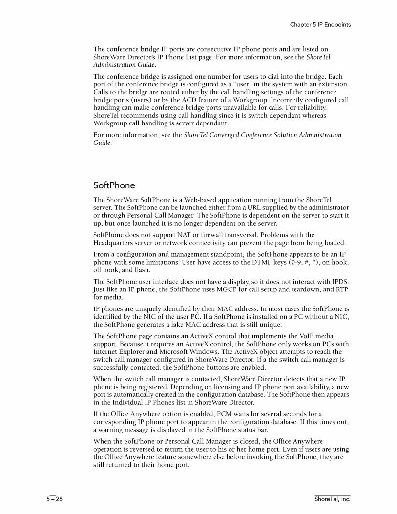
Chapter 5 IP Endpoints
5 – 28 ShoreTel, Inc.
The conference bridge IP ports are consecutive IP phone ports and are listed on ShoreWare Director’s IP Phone List page. For more information, see the ShoreTel Administration Guide.
The conference bridge is assigned one number for users to dial into the bridge. Each port of the conference bridge is configured as a “user” in the system with an extension. Calls to the bridge are routed either by the call handling settings of the conference bridge ports (users) or by the ACD feature of a Workgroup. Incorrectly configured call handling can make conference bridge ports unavailable for calls. For reliability, ShoreTel recommends using call handling since it is switch dependant whereas Workgroup call handling is server dependant.
For more information, see the ShoreTel Converged Conference Solution Administration Guide.
SoftPhoneThe ShoreWare SoftPhone is a Web-based application running from the ShoreTel server. The SoftPhone can be launched either from a URL supplied by the administrator or through Personal Call Manager. The SoftPhone is dependent on the server to start it up, but once launched it is no longer dependent on the server.
SoftPhone does not support NAT or firewall transversal. Problems with the Headquarters server or network connectivity can prevent the page from being loaded.
From a configuration and management standpoint, the SoftPhone appears to be an IP phone with some limitations. User have access to the DTMF keys (0-9, #, *), on hook, off hook, and flash.
The SoftPhone user interface does not have a display, so it does not interact with IPDS. Just like an IP phone, the SoftPhone uses MGCP for call setup and teardown, and RTP for media.
IP phones are uniquely identified by their MAC address. In most cases the SoftPhone is identified by the NIC of the user PC. If a SoftPhone is installed on a PC without a NIC, the SoftPhone generates a fake MAC address that is still unique.
The SoftPhone page contains an ActiveX control that implements the VoIP media support. Because it requires an ActiveX control, the SoftPhone only works on PCs with Internet Explorer and Microsoft Windows. The ActiveX object attempts to reach the switch call manager configured in ShoreWare Director. If a the switch call manager is successfully contacted, the SoftPhone buttons are enabled.
When the switch call manager is contacted, ShoreWare Director detects that a new IP phone is being registered. Depending on licensing and IP phone port availability, a new port is automatically created in the configuration database. The SoftPhone then appears in the Individual IP Phones list in ShoreWare Director.
If the Office Anywhere option is enabled, PCM waits for several seconds for a corresponding IP phone port to appear in the configuration database. If this times out, a warning message is displayed in the SoftPhone status bar.
When the SoftPhone or Personal Call Manager is closed, the Office Anywhere operation is reversed to return the user to his or her home port. Even if users are using the Office Anywhere feature somewhere else before invoking the SoftPhone, they are still returned to their home port.
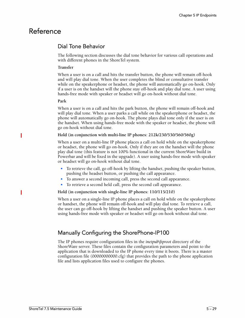
Chapter 5 IP Endpoints
ShoreTel 7.5 Maintenance Guide 5 – 29
Reference
Dial Tone BehaviorThe following section discusses the dial tone behavior for various call operations and with different phones in the ShoreTel system.
Transfer
When a user is on a call and hits the transfer button, the phone will remain off-hook and will play dial tone. When the user completes the blind or consultative transfer while on the speakerphone or headset, the phone will automatically go on-hook. Only if a user is on the handset will the phone stay off-hook and play dial tone. A user using hands-free mode with speaker or headset will go on-hook without dial tone.
Park
When a user is on a call and hits the park button, the phone will remain off-hook and will play dial tone. When a user parks a call while on the speakerphone or headset, the phone will automatically go on-hook. The phone plays dial tone only if the user is on the handset. When using hands-free mode with the speaker or headset, the phone will go on-hook without dial tone.
Hold (in conjunction with multi-line IP phones: 212k/230/530/560/560g)
When a user on a multi-line IP phone places a call on hold while on the speakerphone or headset, the phone will go on-hook. Only if they are on the handset will the phone play dial tone (this feature is not 100% functional in the current ShoreWare build in Powerbar and will be fixed in the upgrade). A user using hands-free mode with speaker or headset will go on-hook without dial tone.
• To retrieve the call, go off-hook by lifting the handset, pushing the speaker button, pushing the headset button, or pushing the call appearance.
• To answer a second incoming call, press the second call appearance.• To retrieve a second held call, press the second call appearance.
Hold (in conjunction with single-line IP phones: 110/115/210)
When a user on a single-line IP phone places a call on hold while on the speakerphone or handset, the phone will remain off-hook and will play dial tone. To retrieve a call, the user can go off-hook by lifting the handset and pushing the speaker button. A user using hands-free mode with speaker or headset will go on-hook without dial tone.
Manually Configuring the ShorePhone-IP100The IP phones require configuration files in the inetpub\ftproot directory of the ShoreWare server. These files contain the configuration parameters and point to the application that is downloaded to the IP phone every time it boots. There is a master configuration file (00000000000.cfg) that provides the path to the phone application file and lists application files used to configure the phones.
Chapter 5 IP Endpoints
5 – 30 ShoreTel, Inc.
Table 5-7 lists the configuration files and their function.
ShoreTel 7 manages the configuration files for the IP phones. ShoreWare Director changes the contents of some configuration files according to the settings you make in Director. If you wish to modify the behavior of the IP phones via the configuration files, contact ShoreTel Customer Support.
Setting IP100 Phone Configuration from the Phone InterfaceIf you are not using a DHCP server, you must set configuration parameters from the IP phone’s setup menu. You can also use the setup menu to set a custom Boot Server Option for the DHCP server and set the phone’s VLAN identifier.
Accessing the Setup Menu
The setup menu is accessible when the IP phone boots. You can enter this menu during a six-second period, after which the phone enters normal operation using the current settings.
Rebooting the IP Phone
There are two ways to reboot the IP phone:
• By reapplying power• By pressing four of the phone’s keys simultaneously
The IP phone reboots whenever power is reapplied. You can accomplish this by disconnecting the power cable momentarily and then reconnecting it.
You can also reboot the IP phone by pressing four keys simultaneously. The four keys (as illustrated in Figure 5-1) are:
• Middle Blank Key• Hold• Volume –• Volume +
Table 5-7 IP Phone Configuration Files
Type Description File Name
Default Master The default master is the global master configuration file. Certain settings in the master configuration file are changed when you configure the system through ShoreWare Director.
000000000000.cfg
Baseline These files contain global parameters that affect the basic operation of the IP phone, including voice codecs, gain, tone, and so on.
ipmid.cfg
Application These files contain global parameters that set the basic mode of the application.
func.cfg
User These files contain parameters that are unique to a particular phone user. Typical parameters include the user name and MAC ID of the IP phone. Each phone has its own customized version of this file identified by user name.
gmx<user>.cfg
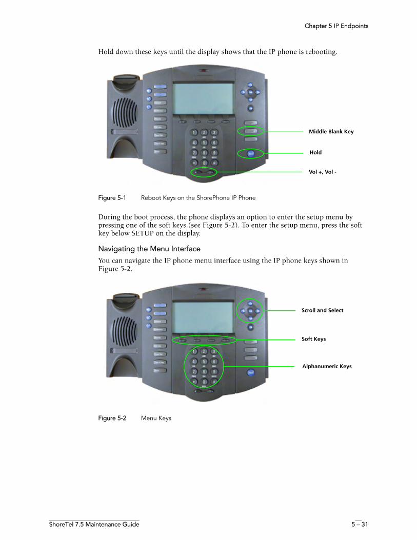
Chapter 5 IP Endpoints
ShoreTel 7.5 Maintenance Guide 5 – 31
Hold down these keys until the display shows that the IP phone is rebooting.
Figure 5-1 Reboot Keys on the ShorePhone IP Phone
During the boot process, the phone displays an option to enter the setup menu by pressing one of the soft keys (see Figure 5-2). To enter the setup menu, press the soft key below SETUP on the display.
Navigating the Menu Interface
You can navigate the IP phone menu interface using the IP phone keys shown in Figure 5-2.
Figure 5-2 Menu Keys
Middle Blank Key
Hold
Vol +, Vol -
Scroll and Select
Soft Keys
Alphanumeric Keys
Chapter 5 IP Endpoints
5 – 32 ShoreTel, Inc.
Table 5-8 explains the functions of these keys.
Menu Options
The IP phone menu interface consists of the main setup menu and two submenus. The submenus set parameters for the Dynamic Host Configuration Protocol (DHCP) server and the ShoreWare server. You can scroll through menu options as described in the preceding section.
Table 5-9 describes the options available from the main menu in the order in which they appear.
Table 5-9 Main Menu Options
Table 5-8 Function of Menu Keys
Key Description
Scroll and Select Use these keys to scroll through menu items and options. For some options, you can use the top and bottom arrow keys to skip to the first or last parameter in a range. The left-arrow key functions as a backspace key.
Soft Keys The function of these keys changes with the current menu. The display shows the function of the active soft keys.
Alphanumeric keys Use these keys and the soft keys to enter numbers and letters, such as for IP addresses and name strings.
Option Name Value Description
DHCP Client Enable or Disable Set to Enable by default. To configure TCP/IP parameters, disable DHCP Client.
DHCP Menu If you are using the setup menu to modify the DHCP Boot Server Option, enter this menu. DHCP Client must be enabled.
Phone IP Address Dotted-decimal IP address
The phone’s IP address.
Subnet Mask Dotted-decimal subnet mask
The phone’s subnet mask.
IP Gateway Dotted-decimal IP address
The phone’s default router.
Server Menu See Table 5-11 for ShoreWare server options.
SNTP Address Dotted-decimal IP address
The SNTP server from which the IP phone obtains the current time (see “Configuring Time Source” on page 5-33).
GMT Offset –12 through +13 The offset from Greenwich Mean Time in half-hour increments.
DNS Server Dotted-decimal IP address
The primary server to which the IP phone directs Domain Name System queries.
DNS Alternate Server Dotted-decimal IP address
The secondary server to which the IP phone directs Domain Name System queries.
DNS Domain Domain name string The IP phone’s domain.
VLAN ID 0 through 4094 The IP phone’s 802.1Q VLAN identifier.
Chapter 5 IP Endpoints
ShoreTel 7.5 Maintenance Guide 5 – 33
Configuring Time Source
The configuration file for the IP100 phone (ip100.cfg), located in the inetpub\ftproot directory of the ShoreWare server. The line that needs to be modified is:
<SNTP tcpIpApp.sntp.daylightSavings.gmtOffset="-28800" tcpIpApp.sntp.daylightSavings.enable="1" tcpIpApp.sntp.daylightSavings.fixedDayEnable="0" tcpIpApp.sntp.daylightSavings.start.month="3" tcpIpApp.sntp.daylightSavings.start.date="8" tcpIpApp.sntp.daylightSavings.start.time="2" tcpIpApp.sntp.daylightSavings.start.dayOfWeek="1" tcpIpApp.sntp.daylightSavings.start.dayOfWeek.lastInMonth="0" tcpIpApp.sntp.daylightSavings.stop.month="11" tcpIpApp.sntp.daylightSavings.stop.date="1" tcpIpApp.sntp.daylightSavings.stop.time="2" tcpIpApp.sntp.daylightSavings.stop.dayOfWeek="1" tcpIpApp.sntp.daylightSavings.stop.dayOfWeek.lastInMonth="0"/>
The gmtOffset parameter represents the number of seconds offset from GMT: “-28800” is for Pacific Standard Time (PST), “-25200” is for Mountain Standard Time (MST), “-21600” is for Central Standard Time (CST), and “-18000” is for Eastern Standard Time (EST).
Configuring with DHCP
When DHCP is used to provide the IP address and configuration parameters to the telephone, the DHCP settings indicate which DHCP option is used to provide the ShoreWare server's address as the telephone's boot server. The settings configured in the telephones must match that of the DHCP server.
Table 5-10 DHCP Menu Options
Option Name Value Description
Timeout 1 through 600 This value is the number of seconds the IP phone waits for secondary DHCP offers before selecting an offer.
Boot Server Default, Custom, Static When set to Default, the IP phone looks for option number 66 (string type) in the response sent from the DHCP server. The DHCP server must be configured to send the boot server address in option 66.When set to Custom, you specify the option number in the Boot Server Option field and the option type in the Boot Server Option Type field. The IP phone looks in the option having this number and type for its boot server.When set to Static, the IP phone uses the boot server configured through the Server menu options. See Table 5-11.
Boot Server Option 128 through 254 When the Boot Server parameter is set to Custom, this parameter specifies the number of the DHCP option in which the IP phone looks for its boot server.
Boot Server Option Type
IP address, string When the Boot Server parameter is set to Custom, this parameter specifies the type of DHCP option in which the IP phone looks for its boot server.
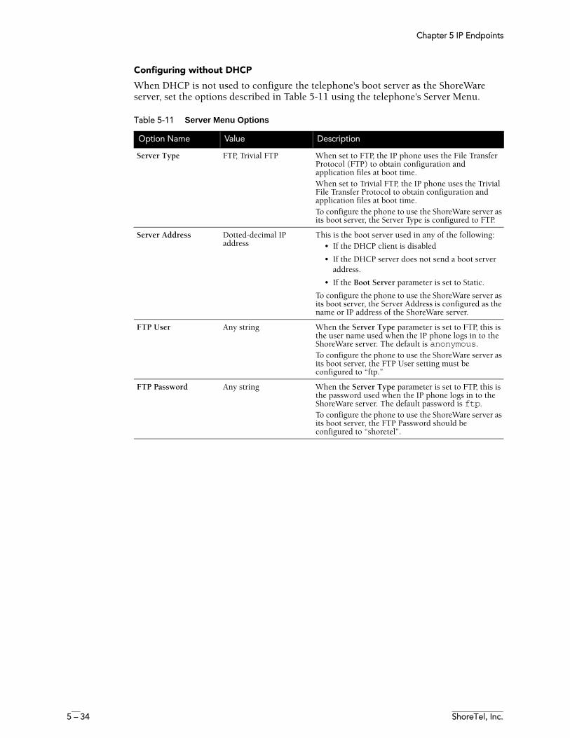
Chapter 5 IP Endpoints
5 – 34 ShoreTel, Inc.
Configuring without DHCP
When DHCP is not used to configure the telephone's boot server as the ShoreWare server, set the options described in Table 5-11 using the telephone's Server Menu.
Table 5-11 Server Menu Options
Option Name Value Description
Server Type FTP, Trivial FTP When set to FTP, the IP phone uses the File Transfer Protocol (FTP) to obtain configuration and application files at boot time.When set to Trivial FTP, the IP phone uses the Trivial File Transfer Protocol to obtain configuration and application files at boot time.To configure the phone to use the ShoreWare server as its boot server, the Server Type is configured to FTP.
Server Address Dotted-decimal IP address
This is the boot server used in any of the following:• If the DHCP client is disabled
• If the DHCP server does not send a boot server address.
• If the Boot Server parameter is set to Static.
To configure the phone to use the ShoreWare server as its boot server, the Server Address is configured as the name or IP address of the ShoreWare server.
FTP User Any string When the Server Type parameter is set to FTP, this is the user name used when the IP phone logs in to the ShoreWare server. The default is anonymous.To configure the phone to use the ShoreWare server as its boot server, the FTP User setting must be configured to “ftp.”
FTP Password Any string When the Server Type parameter is set to FTP, this is the password used when the IP phone logs in to the ShoreWare server. The default password is ftp.To configure the phone to use the ShoreWare server as its boot server, the FTP Password should be configured to “shoretel”.
ShoreTel 7.5 Maintenance Guide 6 – 1
C H A P T E R 6
ShoreTel Client Applications
OverviewThis chapter provides technical background information about the ShoreTel Call Manager application suite.
Call Manager Application SuiteThe Call Manager suite includes:
• Different functional versions of the Call Manager client application: Personal, Advanced, Workgroup Agent, Workgroup Supervisor, and Operator.
• Call Monitor software, including the Agent and Queue monitors.• Viewer applications for Directory, History, and Voice Mail.• Configure ShoreTel system, a control panel applet for configuring Shoreware
clients.
Theory of OperationsAll Call Manager applications are hosted within a single process named STCHost.exe.
TAPI objects manage all telephony-related data and tasks for Call Manager. Voice mail and database operations require CSIS. Call Manager applications use any available service and attempt to degrade gracefully if a requested service is unavailable.
A separate process (STMapiRd.exe) is invoked to load Microsoft Outlook contact data into the Call Manager’s “white pages.”
Only the Call Manager clients and three monitors (Extension, Agent, and Queue) can communicate directly with TAPI. All other applications must use Call Manager as a proxy to place calls on their behalf. Applications using Call Manager to dial calls are unable to provide feedback when an attempt to place a call fails. (However, notification of call failure does appear in the Call Manager application.)
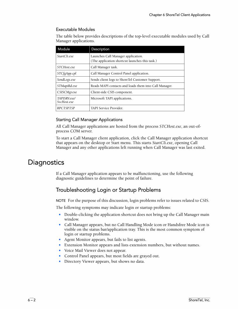
Chapter 6 ShoreTel Client Applications
6 – 2 ShoreTel, Inc.
Executable Modules
The table below provides descriptions of the top-level executable modules used by Call Manager applications.
Starting Call Manager Applications
All Call Manager applications are hosted from the process STCHost.exe, an out-of-process COM server.
To start a Call Manager client application, click the Call Manager application shortcut that appears on the desktop or Start menu. This starts StartCli.exe, opening Call Manager and any other applications left running when Call Manager was last exited.
DiagnosticsIf a Call Manager application appears to be malfunctioning, use the following diagnostic guidelines to determine the point of failure.
Troubleshooting Login or Startup Problems
NOTE For the purpose of this discussion, login problems refer to issues related to CSIS.
The following symptoms may indicate login or startup problems:
• Double-clicking the application shortcut does not bring up the Call Manager main window.
• Call Manager appears, but no Call Handling Mode icon or Handsfree Mode icon is visible on the status bar/application tray. This is the most common symptom of login or startup problems.
• Agent Monitor appears, but fails to list agents.• Extension Monitor appears and lists extension numbers, but without names.• Voice Mail Viewer does not appear.• Control Panel appears, but most fields are grayed out.• Directory Viewer appears, but shows no data.
Module Description
StartCli.exe Launches Call Manager application.(The application shortcut launches this task.)
STCHost.exe Call Manager task.
STCfgApp.cpl Call Manager Control Panel application.
SendLogs.exe Sends client logs to ShoreTel Customer Support.
STMapiRd.exe Reads MAPI contacts and loads them into Call Manager.
CSISCMgr.exe Client-side CSIS component.
TAPISRV.exe/SvcHost.exe
Microsoft TAPI applications.
RPCTSP.TSP TAPI Service Provider.
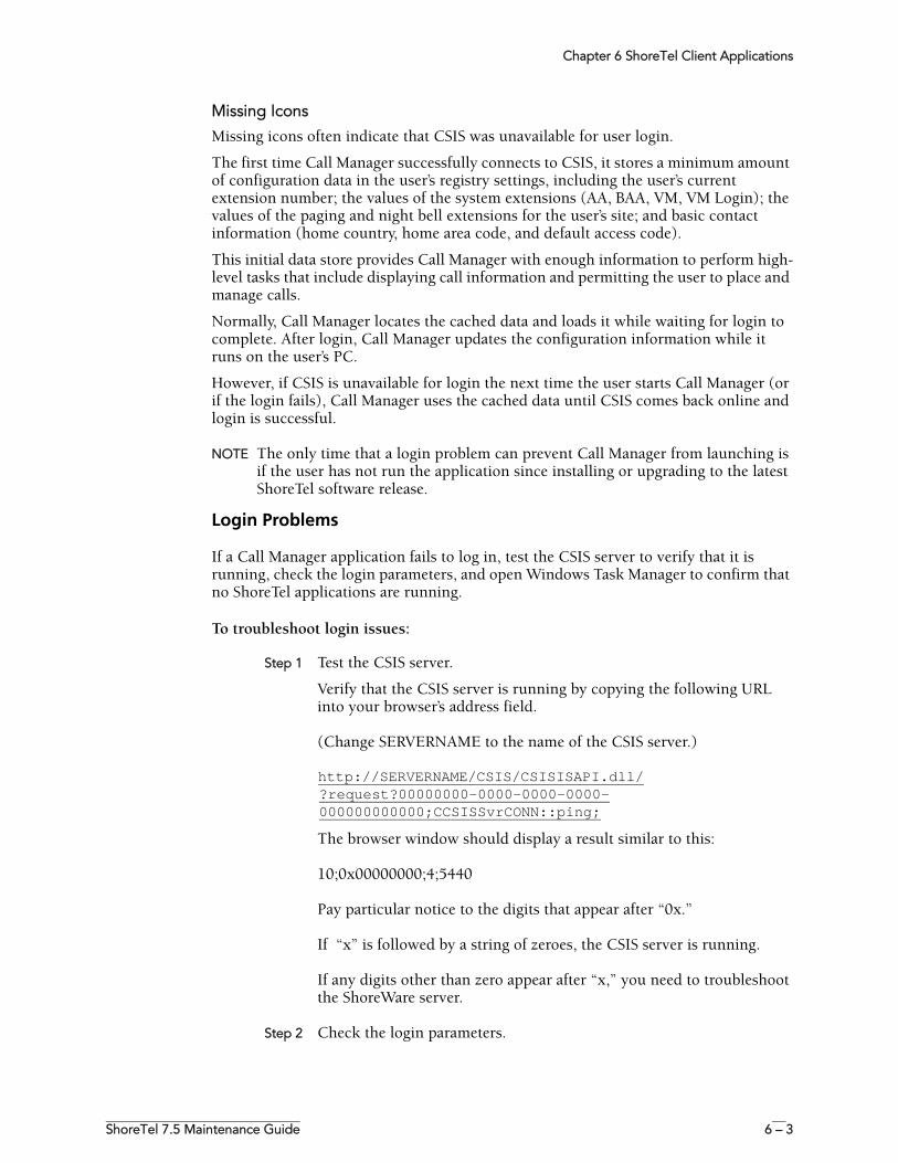
Chapter 6 ShoreTel Client Applications
ShoreTel 7.5 Maintenance Guide 6 – 3
Missing Icons
Missing icons often indicate that CSIS was unavailable for user login.
The first time Call Manager successfully connects to CSIS, it stores a minimum amount of configuration data in the user’s registry settings, including the user’s current extension number; the values of the system extensions (AA, BAA, VM, VM Login); the values of the paging and night bell extensions for the user’s site; and basic contact information (home country, home area code, and default access code).
This initial data store provides Call Manager with enough information to perform high-level tasks that include displaying call information and permitting the user to place and manage calls.
Normally, Call Manager locates the cached data and loads it while waiting for login to complete. After login, Call Manager updates the configuration information while it runs on the user’s PC.
However, if CSIS is unavailable for login the next time the user starts Call Manager (or if the login fails), Call Manager uses the cached data until CSIS comes back online and login is successful.
NOTE The only time that a login problem can prevent Call Manager from launching is if the user has not run the application since installing or upgrading to the latest ShoreTel software release.
Login Problems
If a Call Manager application fails to log in, test the CSIS server to verify that it is running, check the login parameters, and open Windows Task Manager to confirm that no ShoreTel applications are running.
To troubleshoot login issues:
Step 1 Test the CSIS server.
Verify that the CSIS server is running by copying the following URL into your browser’s address field.
(Change SERVERNAME to the name of the CSIS server.)
http://SERVERNAME/CSIS/CSISISAPI.dll/?request?00000000-0000-0000-0000-000000000000;CCSISSvrCONN::ping;
The browser window should display a result similar to this:
10;0x00000000;4;5440
Pay particular notice to the digits that appear after “0x.”
If “x” is followed by a string of zeroes, the CSIS server is running.
If any digits other than zero appear after “x,” you need to troubleshoot the ShoreWare server.
Step 2 Check the login parameters.
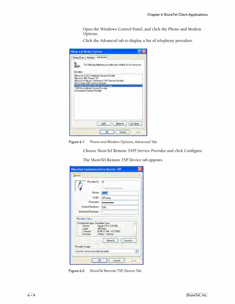
Chapter 6 ShoreTel Client Applications
6 – 4 ShoreTel, Inc.
Open the Windows Control Panel, and click the Phone and Modem Options.
Click the Advanced tab to display a list of telephony providers.
Figure 6-1 Phone and Modem Options, Advanced Tab
Choose ShoreTel Remote TAPI Service Provider and click Configure.
The ShoreTel Remote TSP Device tab appears.
Figure 6-2 ShoreTel Remote TSP, Device Tab
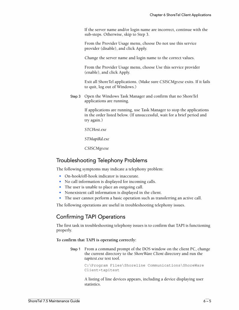
Chapter 6 ShoreTel Client Applications
ShoreTel 7.5 Maintenance Guide 6 – 5
If the server name and/or login name are incorrect, continue with the sub-steps. Otherwise, skip to Step 3.
From the Provider Usage menu, choose Do not use this service provider (disable), and click Apply.
Change the server name and login name to the correct values.
From the Provider Usage menu, choose Use this service provider (enable), and click Apply.
Exit all ShoreTel applications. (Make sure CSISCMgr.exe exits. If it fails to quit, log out of Windows.)
Step 3 Open the Windows Task Manager and confirm that no ShoreTel applications are running.
If applications are running, use Task Manager to stop the applications in the order listed below. (If unsuccessful, wait for a brief period and try again.)
STCHost.exe
STMapiRd.exe
CSISCMgr.exe
Troubleshooting Telephony ProblemsThe following symptoms may indicate a telephony problem:
• On-hook/off-hook indicator is inaccurate.• No call information is displayed for incoming calls.• The user is unable to place an outgoing call.• Nonexistent call information is displayed in the client.• The user cannot perform a basic operation such as transferring an active call.
The following operations are useful in troubleshooting telephony issues.
Confirming TAPI OperationsThe first task in troubleshooting telephony issues is to confirm that TAPI is functioning properly.
To confirm that TAPI is operating correctly:
Step 1 From a command prompt of the DOS window on the client PC, change the current directory to the ShoreWare Client directory and run the tapitest.exe test tool.
C:\Program Files\Shoreline Communications\ShoreWare Client>tapitest
A listing of line devices appears, including a device displaying user statistics.
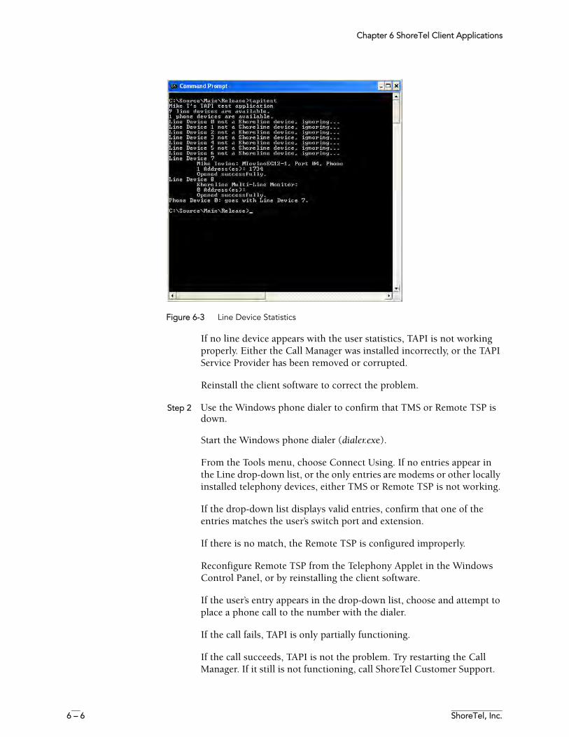
Chapter 6 ShoreTel Client Applications
6 – 6 ShoreTel, Inc.
Figure 6-3 Line Device Statistics
If no line device appears with the user statistics, TAPI is not working properly. Either the Call Manager was installed incorrectly, or the TAPI Service Provider has been removed or corrupted.
Reinstall the client software to correct the problem.
Step 2 Use the Windows phone dialer to confirm that TMS or Remote TSP is down.
Start the Windows phone dialer (dialer.exe).
From the Tools menu, choose Connect Using. If no entries appear in the Line drop-down list, or the only entries are modems or other locally installed telephony devices, either TMS or Remote TSP is not working.
If the drop-down list displays valid entries, confirm that one of the entries matches the user’s switch port and extension.
If there is no match, the Remote TSP is configured improperly.
Reconfigure Remote TSP from the Telephony Applet in the Windows Control Panel, or by reinstalling the client software.
If the user’s entry appears in the drop-down list, choose and attempt to place a phone call to the number with the dialer.
If the call fails, TAPI is only partially functioning.
If the call succeeds, TAPI is not the problem. Try restarting the Call Manager. If it still is not functioning, call ShoreTel Customer Support.
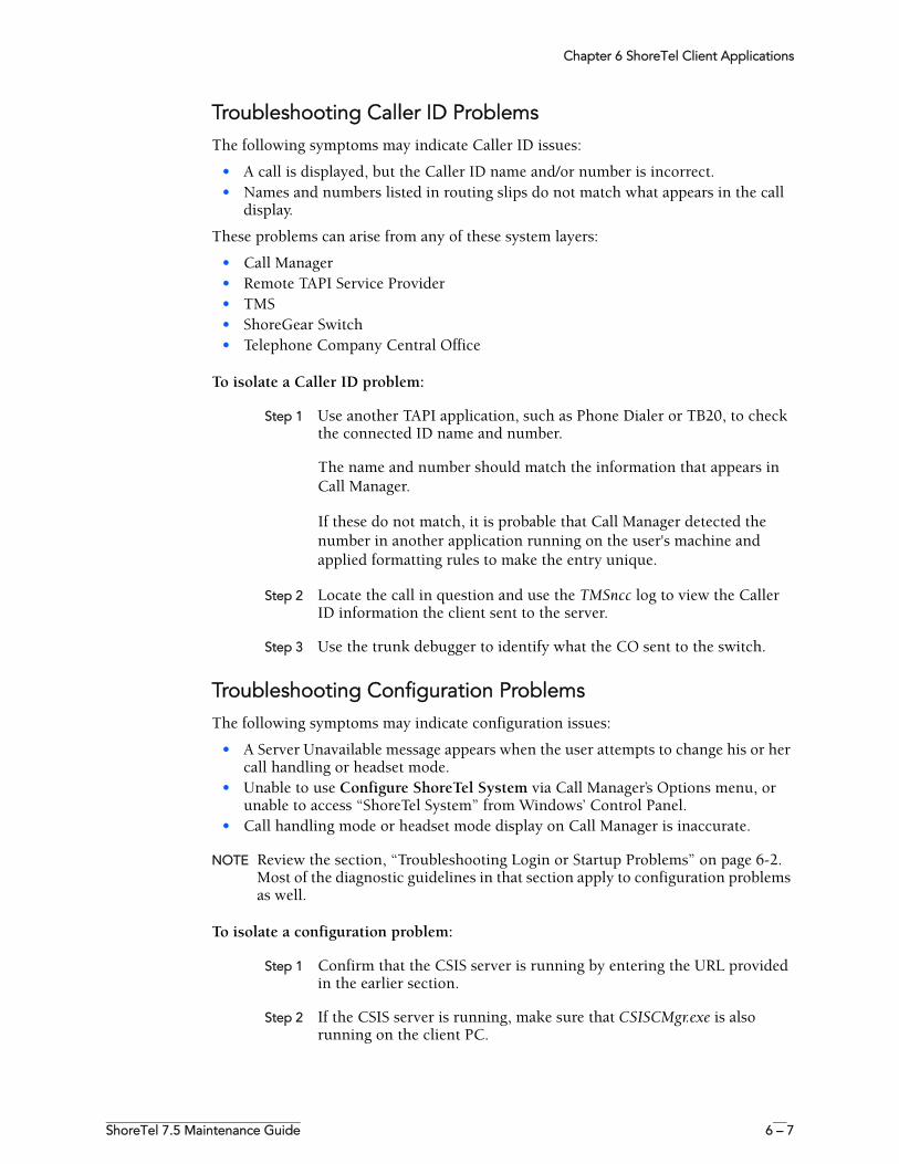
Chapter 6 ShoreTel Client Applications
ShoreTel 7.5 Maintenance Guide 6 – 7
Troubleshooting Caller ID ProblemsThe following symptoms may indicate Caller ID issues:
• A call is displayed, but the Caller ID name and/or number is incorrect.• Names and numbers listed in routing slips do not match what appears in the call
display.
These problems can arise from any of these system layers:
• Call Manager• Remote TAPI Service Provider• TMS• ShoreGear Switch • Telephone Company Central Office
To isolate a Caller ID problem:
Step 1 Use another TAPI application, such as Phone Dialer or TB20, to check the connected ID name and number.
The name and number should match the information that appears in Call Manager.
If these do not match, it is probable that Call Manager detected the number in another application running on the user's machine and applied formatting rules to make the entry unique.
Step 2 Locate the call in question and use the TMSncc log to view the Caller ID information the client sent to the server.
Step 3 Use the trunk debugger to identify what the CO sent to the switch.
Troubleshooting Configuration ProblemsThe following symptoms may indicate configuration issues:
• A Server Unavailable message appears when the user attempts to change his or her call handling or headset mode.
• Unable to use Configure ShoreTel System via Call Manager’s Options menu, or unable to access “ShoreTel System” from Windows’ Control Panel.
• Call handling mode or headset mode display on Call Manager is inaccurate.
NOTE Review the section, “Troubleshooting Login or Startup Problems” on page 6-2. Most of the diagnostic guidelines in that section apply to configuration problems as well.
To isolate a configuration problem:
Step 1 Confirm that the CSIS server is running by entering the URL provided in the earlier section.
Step 2 If the CSIS server is running, make sure that CSISCMgr.exe is also running on the client PC.
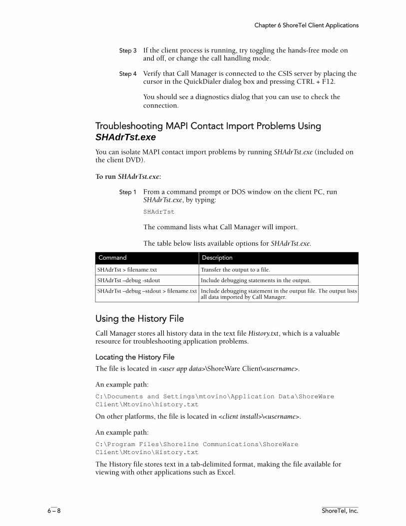
Chapter 6 ShoreTel Client Applications
6 – 8 ShoreTel, Inc.
Step 3 If the client process is running, try toggling the hands-free mode on and off, or change the call handling mode.
Step 4 Verify that Call Manager is connected to the CSIS server by placing the cursor in the QuickDialer dialog box and pressing CTRL + F12.
You should see a diagnostics dialog that you can use to check the connection.
Troubleshooting MAPI Contact Import Problems Using SHAdrTst.exeYou can isolate MAPI contact import problems by running SHAdrTst.exe (included on the client DVD).
To run SHAdrTst.exe:
Step 1 From a command prompt or DOS window on the client PC, run SHAdrTst.exe, by typing:
SHAdrTst
The command lists what Call Manager will import.
The table below lists available options for SHAdrTst.exe.
Using the History FileCall Manager stores all history data in the text file History.txt, which is a valuable resource for troubleshooting application problems.
Locating the History File
The file is located in <user app data>\ShoreWare Client\<username>.
An example path:
C:\Documents and Settings\mtovino\Application Data\ShoreWare Client\Mtovino\history.txt
On other platforms, the file is located in <client install>\<username>.
An example path:
C:\Program Files\Shoreline Communications\ShoreWare Client\Mtovino\History.txt
The History file stores text in a tab-delimited format, making the file available for viewing with other applications such as Excel.
Command Description
SHAdrTst > filename.txt Transfer the output to a file.
SHAdrTst –debug -stdout Include debugging statements in the output.
SHAdrTst –debug –stdout > filename.txt Include debugging statement in the output file. The output lists all data imported by Call Manager.
Chapter 6 ShoreTel Client Applications
ShoreTel 7.5 Maintenance Guide 6 – 9
Using Log FilesAnother critical resource for troubleshooting is the log file where Call Manager logs TAPI events, configuration events, and voice mail events, as well as all unexpected errors, exceptions, and warnings.
The main log file is named CC-MMDDYY.log. CC is literal and MMDDYY is a variable representing the month, day, and year. (For example, CC-061403.log). There are other log files, such as CSIS-MMDDYY.log, for other processes running on the client.
Locating the Log File
You can find the log file in <app data>\ShoreWare Client\Logs on most Windows machines, or <install dir>\Logs on other platforms. (See the section, “Using the History File” on page 6-8” for examples of pathnames.)
Creating Verbose Logs
Generally, only unexpected errors are logged to the error log. You can change this priority from the QuickDialer if you want to create more detailed logs.
NOTE Use verbose logging only if a problem is reproducible and ShoreTel Customer Support requires additional information.
To turn on verbose logging:
Step 1 Position the cursor in the QuickDialer window and press CTRL + F12.
Step 2 Check the boxes for preferred types of logging. To ensure you capture as much logging information as possible, check all boxes except phone number parsing.
The resulting logs are voluminous.
Preset Debug Flags
You can preset debug flags by running STClient –d from the command line instead of Stclient.
Collecting Logs
To collect logs to send to ShoreTel Customer Support, use the SendLogs utility.
From the Start menu, go to Programs/Shoreline Communications/Support/Send Client Logs. A wizard guides you through the rest of the process.
Reference
Call Activity Log FileCall Manager saves all call activity logs to the file history.txt. (When users open the History Viewer application to view a call history, they are displaying log data read from history.txt.)
On servers running Windows XP or Windows 2003, history.txt is stored in the user’s application data directory (ShoreWare Client/<username>). Under Windows 98 and
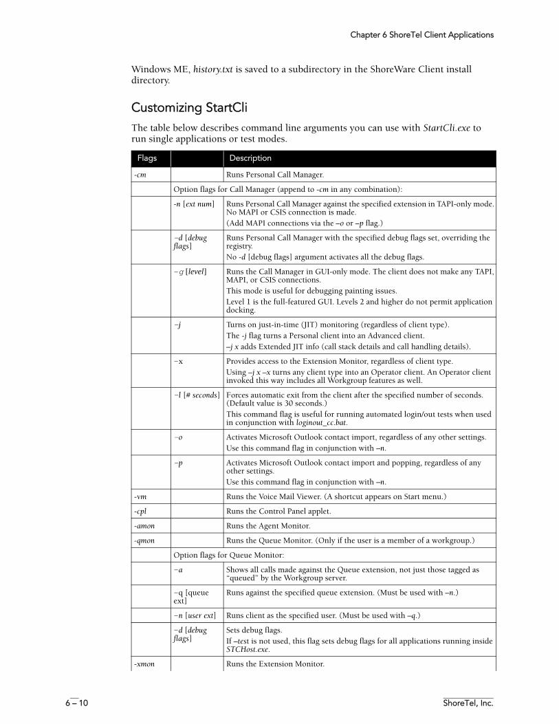
Chapter 6 ShoreTel Client Applications
6 – 10 ShoreTel, Inc.
Windows ME, history.txt is saved to a subdirectory in the ShoreWare Client install directory.
Customizing StartCliThe table below describes command line arguments you can use with StartCli.exe to run single applications or test modes.
Flags Description
-cm Runs Personal Call Manager.
Option flags for Call Manager (append to -cm in any combination):
-n [ext num] Runs Personal Call Manager against the specified extension in TAPI-only mode. No MAPI or CSIS connection is made.(Add MAPI connections via the –o or –p flag.)
–d [debug flags]
Runs Personal Call Manager with the specified debug flags set, overriding the registry. No -d [debug flags] argument activates all the debug flags.
-g [level] Runs the Call Manager in GUI-only mode. The client does not make any TAPI, MAPI, or CSIS connections. This mode is useful for debugging painting issues. Level 1 is the full-featured GUI. Levels 2 and higher do not permit application docking.
–j Turns on just-in-time (JIT) monitoring (regardless of client type). The -j flag turns a Personal client into an Advanced client. –j x adds Extended JIT info (call stack details and call handling details).
–x Provides access to the Extension Monitor, regardless of client type. Using –j x –x turns any client type into an Operator client. An Operator client invoked this way includes all Workgroup features as well.
–l [# seconds] Forces automatic exit from the client after the specified number of seconds. (Default value is 30 seconds.)This command flag is useful for running automated login/out tests when used in conjunction with loginout_cc.bat.
–o Activates Microsoft Outlook contact import, regardless of any other settings. Use this command flag in conjunction with –n.
–p Activates Microsoft Outlook contact import and popping, regardless of any other settings.Use this command flag in conjunction with –n.
-vm Runs the Voice Mail Viewer. (A shortcut appears on Start menu.)
-cpl Runs the Control Panel applet.
-amon Runs the Agent Monitor.
-qmon Runs the Queue Monitor. (Only if the user is a member of a workgroup.)
Option flags for Queue Monitor:
–a Shows all calls made against the Queue extension, not just those tagged as “queued” by the Workgroup server.
–q [queue ext]
Runs against the specified queue extension. (Must be used with –n.)
–n [user ext] Runs client as the specified user. (Must be used with –q.)
–d [debug flags]
Sets debug flags. If –test is not used, this flag sets debug flags for all applications running inside STCHost.exe.
-xmon Runs the Extension Monitor.
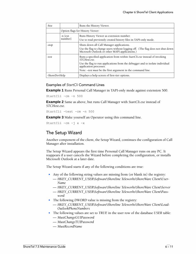
Chapter 6 ShoreTel Client Applications
ShoreTel 7.5 Maintenance Guide 6 – 11
Examples of StartCli Command Lines
Example 1 Runs Personal Call Manager in TAPI-only mode against extension 500.
StartCli -cm -n 500
Example 2 Same as above, but runs Call Manager with StartCli.exe instead of STCHost.exe.
StartCli -test -cm -n 500
Example 3 Make yourself an Operator using this command line.
StartCli –cm –j x –x
The Setup WizardAnother component of the client, the Setup Wizard, continues the configuration of Call Manager after installation.
The Setup Wizard appears the first time Personal Call Manager runs on any PC. It reappears if a user cancels the Wizard before completing the configuration, or installs Microsoft Outlook at a later date.
The Setup Wizard starts if any of the following conditions are true:
• Any of the following string values are missing from (or blank in) the registry:— HKEY_CURRENT_USER\Software\Shoreline Teleworks\ShoreWare Client\User-
Name— HKEY_CURRENT_USER\Software\Shoreline Teleworks\ShoreWare Client\Server— HKEY_CURRENT_USER\Software\Shoreline Teleworks\ShoreWare Client\Pass-
word• The following DWORD value is missing from the registry:
— HKEY_CURRENT_USER\Software\Shoreline Teleworks\ShoreWare Client\Load-OutlookPhoneNumbers
• The following values are set to TRUE in the user row of the database USER table:— MustChangeGUIPassword— MustChangeTUIPassword— MustRecordName
-hist Runs the History Viewer.
Option flags for History Viewer:
-n [ext number]
Runs History Viewer as extension number.Use to read previously created history files in TAPI-only mode.
-stop Shuts down all Call Manager applications.Use the flag to change users without logging off. (The flag does not shut down Microsoft Outlook or other MAPI applications.)
-test Runs a specified application from within StartCli.exe instead of invoking STCHost.exe. Use the flag to run applications from the debugger and to isolate individual application processes.Note: –test must be the first argument in the command line.
-ShoreDevHelp Displays a help screen of first-tier options.
Chapter 6 ShoreTel Client Applications
6 – 12 ShoreTel, Inc.
• Microsoft Outlook is installed AND Voice Mail Outlook Integration is not installed AND the following DWORD value is missing from the registry, or set to z nonzero value:— HKEY_CURRENT_USER\Software\Shoreline Teleworks\ShoreWare Client\OfferTo-
InstallOutlookIntegration
If any of the specified conditions are TRUE, the Setup Wizard runs, while also setting one or more of the conditions to TRUE and starting the client.
NOTE Set the values only after exiting the client from the system tray and terminating STCHost.exe. Otherwise, exiting the client applications may overwrite the settings.
ShoreTel 7.5 Maintenance Guide A – 1
A P P E N D I X A
Event Codes
This appendix provides a comprehensive table of ShoreTel event codes. Organized by error type and sorted by event ID numbers, the tables are a valuable resource for troubleshooting events reported by the ShoreTel system.
Event TypesThe tables list event types according to component functions of the ShoreTel telephony system:
• Switch• TMS• Voice Mail• TDI Media• Event Watch• Configuration Administration• Port Mapper• Trigger Server• Distributed Routing Service (DRS)• Kadota Utility• Call Accounting• Workgroup Server• CSIS• IP Phone Console Server (IPCS)• IP Phone Display Server (IPDS)
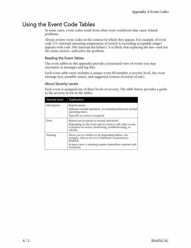
Appendix A Event Codes
A – 2 ShoreTel, Inc.
Using the Event Code TablesIn some cases, event codes result from other error conditions that cause related problems.
Always review event codes in the context in which they appear. For example, if event code 171 (internal operating temperature of switch is exceeding acceptable range) appears with code 166 (internal fan failure), it is likely that replacing the fan—and not the entire switch—will solve the problem.
Reading the Event Tables
The event tables in this appendix provide a structured view of events you may encounter in messages and log files.
Each event table entry includes a unique event ID number, a severity level, the event message text, possible causes, and suggested courses of action (if any).
About Severity Levels
Each event is assigned one of three levels of severity. The table below provides a guide to the severity levels in the tables.
Severity level Explanation
Information Reports status.Indicates normal operation, or a transition between normal operating states. Typically, no action is required.
Error Reports an exception to normal operations. Depending on the event and its context with other events, it requires no action, monitoring, troubleshooting, or referral.
Warning Alerts you to a failure or an impending failure—for example, when a service or hardware component is disabled.In most cases, a warning requires immediate response and resolution.
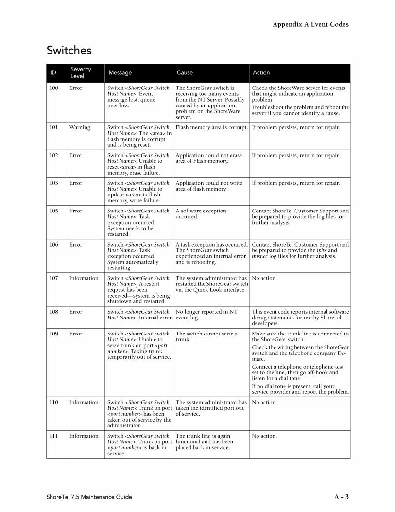
Appendix A Event Codes
ShoreTel 7.5 Maintenance Guide A – 3
Switches
IDSeverityLevel
Message Cause Action
100 Error Switch <ShoreGear Switch Host Name>: Event message lost, queue overflow.
The ShoreGear switch is receiving too many events from the NT Server. Possibly caused by an application problem on the ShoreWare server.
Check the ShoreWare server for events that might indicate an application problem.Troubleshoot the problem and reboot the server if you cannot identify a cause.
101 Warning Switch <ShoreGear Switch Host Name>: The <area> in flash memory is corrupt and is being reset.
Flash memory area is corrupt. If problem persists, return for repair.
102 Error Switch <ShoreGear Switch Host Name>: Unable to reset <area> in flash memory, erase failure.
Application could not erase area of Flash memory.
If problem persists, return for repair.
103 Error Switch <ShoreGear Switch Host Name>: Unable to update <area> in flash memory, write failure.
Application could not write area of flash memory.
If problem persists, return for repair.
105 Error Switch <ShoreGear Switch Host Name>: Task exception occurred. System needs to be restarted.
A software exception occurred.
Contact ShoreTel Customer Support and be prepared to provide the log files for further analysis.
106 Error Switch <ShoreGear Switch Host Name>: Task exception occurred. System automatically restarting.
A task exception has occurred. The ShoreGear switch experienced an internal error and is rebooting.
Contact ShoreTel Customer Support and be prepared to provide the ipbx and tmsncc log files for further analysis.
107 Information Switch <ShoreGear Switch Host Name>: A restart request has been received—system is being shutdown and restarted.
The system administrator has restarted the ShoreGear switch via the Quick Look interface.
No action.
108 Error Switch <ShoreGear Switch Host Name>: Internal error:
No longer reported in NT event log.
This event code reports internal software debug statements for use by ShoreTel developers.
109 Error Switch <ShoreGear Switch Host Name>: Unable to seize trunk on port <port number>. Taking trunk temporarily out of service.
The switch cannot seize a trunk.
Make sure the trunk line is connected to the ShoreGear switch. Check the wiring between the ShoreGear switch and the telephone company De-marc. Connect a telephone or telephone test set to the line, then go off-hook and listen for a dial tone. If no dial tone is present, call your service provider and report the problem.
110 Information Switch <ShoreGear Switch Host Name>: Trunk on port <port number> has been taken out of service by the administrator.
The system administrator has taken the identified port out of service.
No action.
111 Information Switch <ShoreGear Switch Host Name>: Trunk on port <port number> is back in service.
The trunk line is again functional and has been placed back in service.
No action.
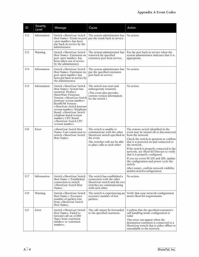
Appendix A Event Codes
A – 4 ShoreTel, Inc.
112 Information Switch <ShoreGear Switch Host Name>: Trunk on port <port number> has been put back in service by the administrator.
The system administrator has put the trunk back in service.
No action.
113 Warning Switch <ShoreGear Switch Host Name>: Extension on port <port number> has been taken out of service by the administrator.
The system administrator has removed the specified extension port from service.
Put the port back in service when the system administrator indicates that it is appropriate.
114 Information Switch <ShoreGear Switch Host Name>: Extension on port <port number> has been put back in service by the administrator.
The system administrator has put the specified extension port back in service.
No action.
115 Information Switch <ShoreGear Switch Host Name>: System has restarted. Product: ShoreWare Firmware Version: <ShoreGear Switch firmware version number> BootROM Version: <ShoreGear Switch bootrom version number> Telephone Board: <ShoreGear Switch telephone board revision number> CPU Board: <ShoreGear Switch CPU revision number>
The switch was reset and subsequently restarted. (The event also provides current version information for the switch.)
No action.
116 Error <ShoreGear Switch Host Name> Lost connection to switch <ShoreGear Switch Host Name>.
The switch is unable to communicate with the other ShoreGear switch specified in the event.The switches will not be able to place calls to each other.
The remote switch identified in the event may be turned off or disconnected from the network. Check the switch in question to confirm that it is powered on and connected to the network. If the switch is properly connected to the network, use ShoreTel Director to verify that it is properly configured. If you see event ID 205 and 206, update the configuration and power cycle the switch. After restart, confirm network visibility and the switch’s configuration.
117 Information Switch <ShoreGear Switch Host Name >: Established connection to switch <ShoreGear Switch Host Name>.
The switch has established a connection with the other ShoreGear switch and the two switches are communicating with each other.
No action.
119 Warning Switch <ShoreGear Switch Host Name >: Excessive number of packets lost from <ShoreGear Switch Host Name>.
The switch is experiencing an excessive number of lost packets.
Verify that your network configuration meets ShoreTel requirements.
127 Error Switch <ShoreGear Switch Host Name>: Failed to forward call on <CHM Type> from <extension number> to <extension number>.
The call cannot be forwarded to the specified extension.
Confirm that the specified extension's call handling mode configuration is valid.This error can appear when the destination extension is connected to a ShoreGear switch that is either offline or unavailable to the network.
IDSeverityLevel
Message Cause Action
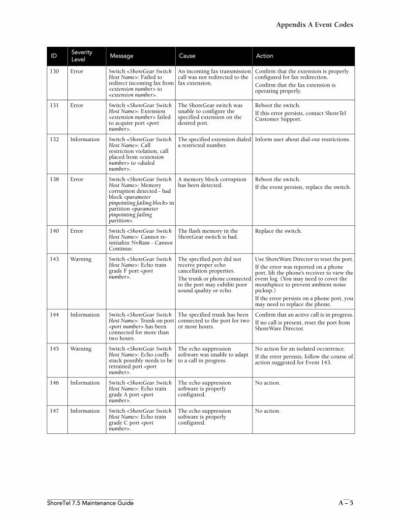
Appendix A Event Codes
ShoreTel 7.5 Maintenance Guide A – 5
130 Error Switch <ShoreGear Switch Host Name>: Failed to redirect incoming fax from <extension number> to <extension number>.
An incoming fax transmission call was not redirected to the fax extension.
Confirm that the extension is properly configured for fax redirection. Confirm that the fax extension is operating properly.
131 Error Switch <ShoreGear Switch Host Name>: Extension <extension number> failed to acquire port <port number>.
The ShoreGear switch was unable to configure the specified extension on the desired port.
Reboot the switch. If this error persists, contact ShoreTel Customer Support.
132 Information Switch <ShoreGear Switch Host Name>: Call restriction violation, call placed from <extension number> to <dialed number>.
The specified extension dialed a restricted number.
Inform user about dial-out restrictions.
138 Error Switch <ShoreGear Switch Host Name>: Memory corruption detected - bad block <parameter pinpointing failing block> in partition <parameter pinpointing failing partition>.
A memory block corruption has been detected.
Reboot the switch. If the event persists, replace the switch.
140 Error Switch <ShoreGear Switch Host Name>: Cannot re-initialize NvRam - Cannot Continue.
The flash memory in the ShoreGear switch is bad.
Replace the switch.
143 Warning Switch <ShoreGear Switch Host Name>: Echo train grade F port <port number>.
The specified port did not receive proper echo cancellation properties. The trunk or phone connected to the port may exhibit poor sound quality or echo.
Use ShoreWare Director to reset the port. If the error was reported on a phone port, lift the phone’s receiver to view the event log. (You may need to cover the mouthpiece to prevent ambient noise pickup.) If the error persists on a phone port, you may need to replace the phone.
144 Information Switch <ShoreGear Switch Host Name>: Trunk on port <port number> has been connected for more than two hours.
The specified trunk has been connected to the port for two or more hours.
Confirm that an active call is in progress. If no call is present, reset the port from ShoreWare Director.
145 Warning Switch <ShoreGear Switch Host Name>: Echo coeffs stuck possibly needs to be retrained port <port number>.
The echo suppression software was unable to adapt to a call in progress.
No action for an isolated occurrence. If the error persists, follow the course of action suggested for Event 143.
146 Information Switch <ShoreGear Switch Host Name>: Echo train grade A port <port number>.
The echo suppression software is properly configured.
No action.
147 Information Switch <ShoreGear Switch Host Name>: Echo train grade C port <port number>.
The echo suppression software is properly configured.
No action.
IDSeverityLevel
Message Cause Action
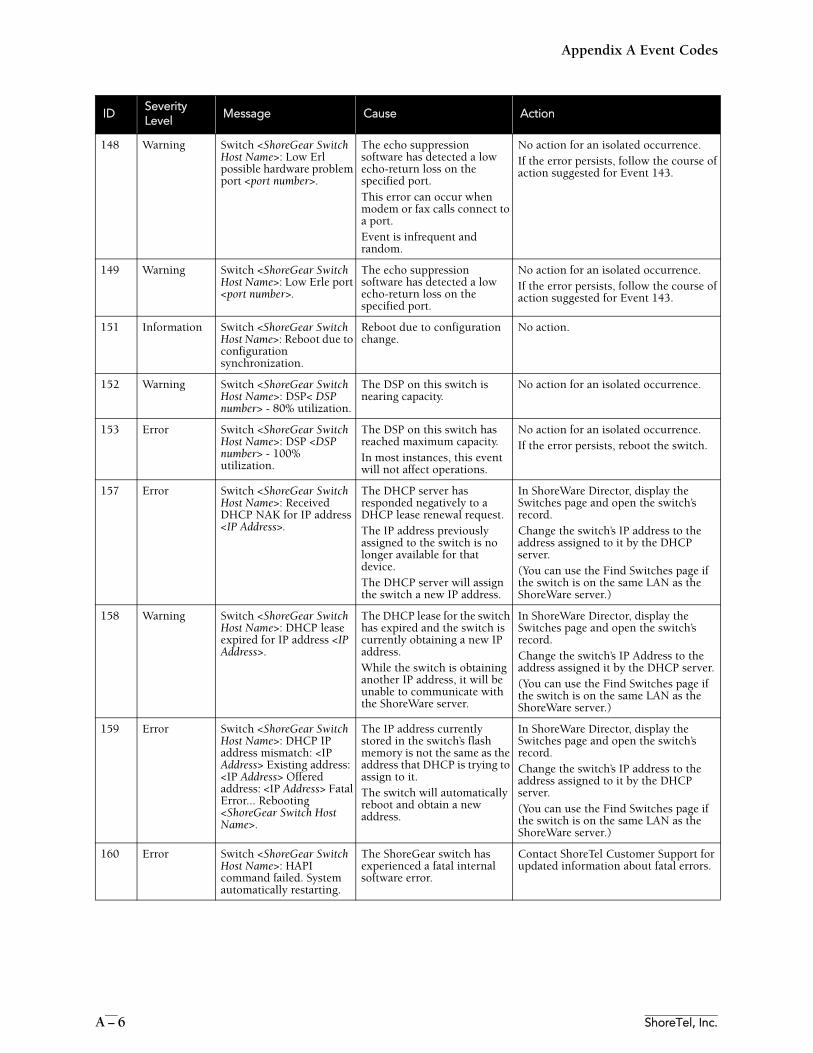
Appendix A Event Codes
A – 6 ShoreTel, Inc.
148 Warning Switch <ShoreGear Switch Host Name>: Low Erl possible hardware problem port <port number>.
The echo suppression software has detected a low echo-return loss on the specified port. This error can occur when modem or fax calls connect to a port. Event is infrequent and random.
No action for an isolated occurrence.If the error persists, follow the course of action suggested for Event 143.
149 Warning Switch <ShoreGear Switch Host Name>: Low Erle port <port number>.
The echo suppression software has detected a low echo-return loss on the specified port.
No action for an isolated occurrence.If the error persists, follow the course of action suggested for Event 143.
151 Information Switch <ShoreGear Switch Host Name>: Reboot due to configuration synchronization.
Reboot due to configuration change.
No action.
152 Warning Switch <ShoreGear Switch Host Name>: DSP< DSP number> - 80% utilization.
The DSP on this switch is nearing capacity.
No action for an isolated occurrence.
153 Error Switch <ShoreGear Switch Host Name>: DSP <DSP number> - 100% utilization.
The DSP on this switch has reached maximum capacity.In most instances, this event will not affect operations.
No action for an isolated occurrence. If the error persists, reboot the switch.
157 Error Switch <ShoreGear Switch Host Name>: Received DHCP NAK for IP address <IP Address>.
The DHCP server has responded negatively to a DHCP lease renewal request. The IP address previously assigned to the switch is no longer available for that device. The DHCP server will assign the switch a new IP address.
In ShoreWare Director, display the Switches page and open the switch’s record. Change the switch’s IP address to the address assigned to it by the DHCP server. (You can use the Find Switches page if the switch is on the same LAN as the ShoreWare server.)
158 Warning Switch <ShoreGear Switch Host Name>: DHCP lease expired for IP address <IP Address>.
The DHCP lease for the switch has expired and the switch is currently obtaining a new IP address.While the switch is obtaining another IP address, it will be unable to communicate with the ShoreWare server.
In ShoreWare Director, display the Switches page and open the switch’s record. Change the switch’s IP Address to the address assigned it by the DHCP server. (You can use the Find Switches page if the switch is on the same LAN as the ShoreWare server.)
159 Error Switch <ShoreGear Switch Host Name>: DHCP IP address mismatch: <IP Address> Existing address: <IP Address> Offered address: <IP Address> Fatal Error... Rebooting <ShoreGear Switch Host Name>.
The IP address currently stored in the switch’s flash memory is not the same as the address that DHCP is trying to assign to it. The switch will automatically reboot and obtain a new address.
In ShoreWare Director, display the Switches page and open the switch’s record. Change the switch’s IP address to the address assigned to it by the DHCP server. (You can use the Find Switches page if the switch is on the same LAN as the ShoreWare server.)
160 Error Switch <ShoreGear Switch Host Name>: HAPI command failed. System automatically restarting.
The ShoreGear switch has experienced a fatal internal software error.
Contact ShoreTel Customer Support for updated information about fatal errors.
IDSeverityLevel
Message Cause Action
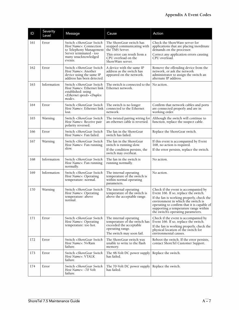
Appendix A Event Codes
ShoreTel 7.5 Maintenance Guide A – 7
161 Error Switch <ShoreGear Switch Host Name>: Connection to Telephony Management Server terminated - too many unacknowledged events.
The ShoreGear switch has stopped communicating with the TMS Server. This error can result from a CPU overload on the ShoreWare server.
Check the ShoreWare server for applications that are placing inordinate demands on the processor.Correct any application errors causing CPU overload.
162 Error Switch <ShoreGear Switch Host Name>: Another device using the same IP address has been detected.
A device with the same IP address as the switch has appeared on the network.
Remove the offending device from the network, or ask the network administrator to assign the switch an alternate IP address.
163 Information Switch <ShoreGear Switch Host Name>: Ethernet link established: using <Ethernet speed> <Duplex mode>.
The switch is connected to the Ethernet network.
No action.
164 Error Switch <ShoreGear Switch Host Name>: Ethernet link lost.
The switch is no longer connected to the Ethernet network.
Confirm that network cables and ports are connected properly and are in working order.
165 Warning Switch <ShoreGear Switch Host Name>: Receive pair polarity reversed.
The twisted pairing wiring for an ethernet cable is reversed.
Although the switch will continue to function, replace the suspect cable.
166 Error Switch <ShoreGear Switch Host Name>: Fan failed.
The fan in the ShoreGear switch has failed.
Replace the ShoreGear switch.
167 Warning Switch <ShoreGear Switch Host Name>: Fan running slow.
The fan in the ShoreGear switch is running slow. If the condition persists, the switch may overheat.
If this event is accompanied by Event 168, no action is required. If the error persists, replace the switch.
168 Information Switch <ShoreGear Switch Host Name>: Fan running normally.
The fan in the switch is running normally.
No action.
169 Information Switch <ShoreGear Switch Host Name>: Operating temperature: normal.
The internal operating temperature of the switch is within normal operating parameters.
No action.
170 Warning Switch <ShoreGear Switch Host Name>: Operating temperature: above normal.
The internal operating temperature of the switch is above the acceptable range.
Check if the event is accompanied by Event 166. If so, replace the switch. If the fan is working properly, check the environment in which the switch is operating to confirm that it is capable of supporting a temperature range within the switch’s operating parameters.
171 Error Switch <ShoreGear Switch Host Name>: Operating temperature: too hot.
The internal operating temperature of the switch has exceeded the acceptable operating range. The switch may soon fail.
Check if the event is accompanied by Event 166. If so, replace the switch. If the fan is working properly, check the physical location of the switch for environmental causes.
172 Error Switch <ShoreGear Switch Host Name>: NvRam failure.
The ShoreGear switch was unable to write to the flash memory.
Reboot the switch. If the error persists, contact ShoreTel Customer Support.
173 Error Switch <ShoreGear Switch Host Name>: VTALK failure.
The 48-Volt DC power supply has failed.
Replace the switch.
174 Error Switch <ShoreGear Switch Host Name>: -70 Volt failure.
The 70-Volt DC power supply has failed.
Replace the switch.
IDSeverityLevel
Message Cause Action
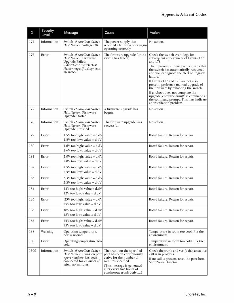
Appendix A Event Codes
A – 8 ShoreTel, Inc.
175 Information Switch <ShoreGear Switch Host Name>: Voltage OK.
The power supply that reported a failure is once again operating correctly.
No action.
176 Error Switch <ShoreGear Switch Host Name>: Firmware Upgrade Failed: <ShoreGear Switch Host Name> <specific diagnostic message>.
The firmware upgrade for the switch has failed.
Check the switch event logs for subsequent appearances of Events 177 and 178.The presence of these events means that the switch has automatically recovered and you can ignore the alert of upgrade failure.If Events 177 and 178 are not also present, perform a manual upgrade of the firmware by rebooting the switch.If a reboot does not complete the upgrade, enter the burnflash command at the command prompt. This may indicate an installation problem.
177 Information Switch <ShoreGear Switch Host Name>: Firmware Upgrade Started.
A firmware upgrade has begun.
No action.
178 Information Switch <ShoreGear Switch Host Name>: Firmware Upgrade Finished
The firmware upgrade was successful.
No action.
179 Error 1.5V too high: value = d.dV1.5V too low: value = d.dV
Board failure. Return for repair.
180 Error 1.6V too high: value = d.dV1.6V too low: value = d.dV
Board failure. Return for repair.
181 Error 2.0V too high: value = d.dV2.0V too low: value = d.dV
Board failure. Return for repair.
182 Error 2.5V too high: value = d.dV2.5V too low: value = d.dV
Board failure. Return for repair.
183 Error 3.3V too high: value = d.dV3.3V too low: value = d.dV
Board failure. Return for repair.
184 Error 12V too high: value = d.dV12V too low: value = d.dV
Board failure. Return for repair.
185 Error 25V too high: value = d.dV25V too low: value = d.dV
Board failure. Return for repair.
186 Error 48V too high: value = d.dV48V too low: value = d.dV
Board failure. Return for repair.
187 Error 75V too high: value = d.dV75V too low: value = d.dV
Board failure. Return for repair.
188 Warning Operating temperature: below normal
Temperature in room too cool. Fix the environment.
189 Error Operating temperature: too cold
Temperature in room too cold. Fix the environment.
1300 Information Switch <ShoreGear Switch Host Name>: Trunk on port <port number> has been connected for <number of minutes> minutes.
The trunk on the specified port has been continuously active for the number of minutes specified. (This message is generated after every two hours of continuous trunk activity.)
Check the trunk and verify that an active call is in progress. If no call is present, reset the port from ShoreWare Director.
IDSeverityLevel
Message Cause Action
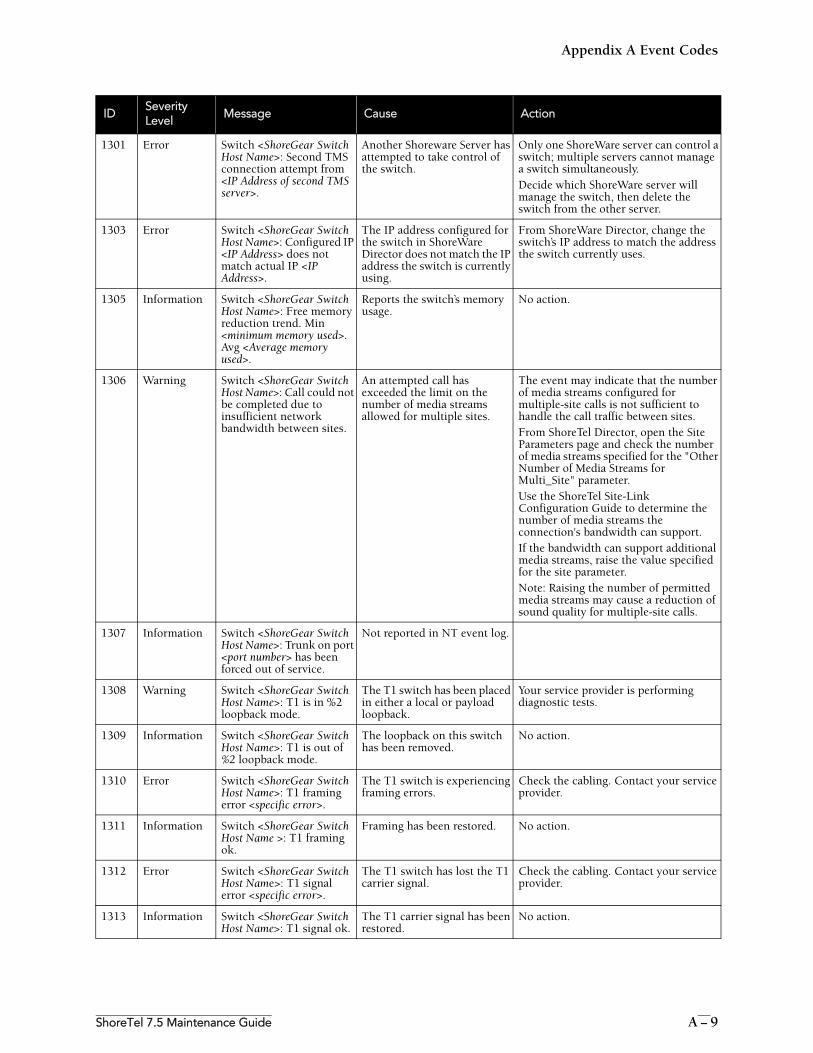
Appendix A Event Codes
ShoreTel 7.5 Maintenance Guide A – 9
1301 Error Switch <ShoreGear Switch Host Name>: Second TMS connection attempt from <IP Address of second TMS server>.
Another Shoreware Server has attempted to take control of the switch.
Only one ShoreWare server can control a switch; multiple servers cannot manage a switch simultaneously. Decide which ShoreWare server will manage the switch, then delete the switch from the other server.
1303 Error Switch <ShoreGear Switch Host Name>: Configured IP <IP Address> does not match actual IP <IP Address>.
The IP address configured for the switch in ShoreWare Director does not match the IP address the switch is currently using.
From ShoreWare Director, change the switch’s IP address to match the address the switch currently uses.
1305 Information Switch <ShoreGear Switch Host Name>: Free memory reduction trend. Min <minimum memory used>. Avg <Average memory used>.
Reports the switch’s memory usage.
No action.
1306 Warning Switch <ShoreGear Switch Host Name>: Call could not be completed due to insufficient network bandwidth between sites.
An attempted call has exceeded the limit on the number of media streams allowed for multiple sites.
The event may indicate that the number of media streams configured for multiple-site calls is not sufficient to handle the call traffic between sites.From ShoreTel Director, open the Site Parameters page and check the number of media streams specified for the "Other Number of Media Streams for Multi_Site" parameter.Use the ShoreTel Site-Link Configuration Guide to determine the number of media streams the connection's bandwidth can support.If the bandwidth can support additional media streams, raise the value specified for the site parameter. Note: Raising the number of permitted media streams may cause a reduction of sound quality for multiple-site calls.
1307 Information Switch <ShoreGear Switch Host Name>: Trunk on port <port number> has been forced out of service.
Not reported in NT event log.
1308 Warning Switch <ShoreGear Switch Host Name>: T1 is in %2 loopback mode.
The T1 switch has been placed in either a local or payload loopback.
Your service provider is performing diagnostic tests.
1309 Information Switch <ShoreGear Switch Host Name>: T1 is out of %2 loopback mode.
The loopback on this switch has been removed.
No action.
1310 Error Switch <ShoreGear Switch Host Name>: T1 framing error <specific error>.
The T1 switch is experiencing framing errors.
Check the cabling. Contact your service provider.
1311 Information Switch <ShoreGear Switch Host Name >: T1 framing ok.
Framing has been restored. No action.
1312 Error Switch <ShoreGear Switch Host Name>: T1 signal error <specific error>.
The T1 switch has lost the T1 carrier signal.
Check the cabling. Contact your service provider.
1313 Information Switch <ShoreGear Switch Host Name>: T1 signal ok.
The T1 carrier signal has been restored.
No action.
IDSeverityLevel
Message Cause Action
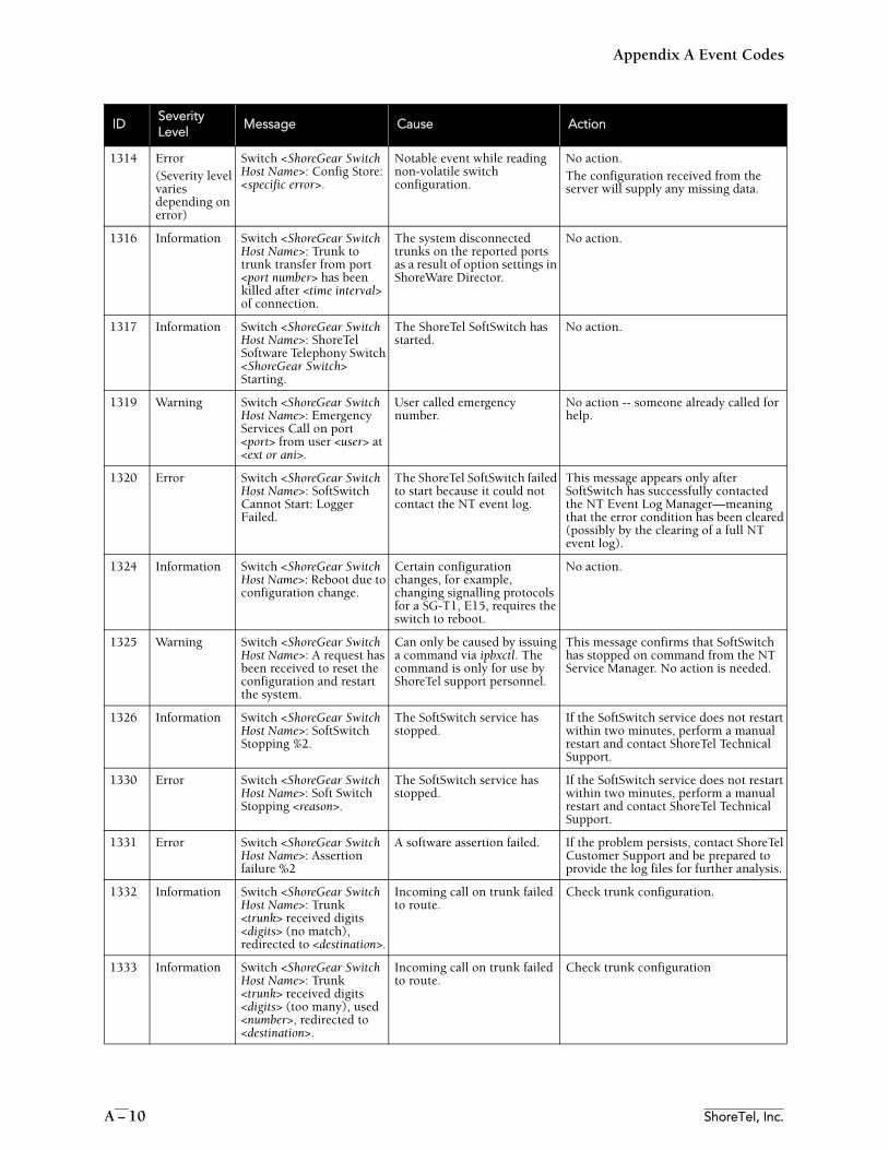
Appendix A Event Codes
A – 10 ShoreTel, Inc.
1314 Error(Severity level varies depending on error)
Switch <ShoreGear Switch Host Name>: Config Store: <specific error>.
Notable event while reading non-volatile switch configuration.
No action.The configuration received from the server will supply any missing data.
1316 Information Switch <ShoreGear Switch Host Name>: Trunk to trunk transfer from port <port number> has been killed after <time interval> of connection.
The system disconnected trunks on the reported ports as a result of option settings in ShoreWare Director.
No action.
1317 Information Switch <ShoreGear Switch Host Name>: ShoreTel Software Telephony Switch <ShoreGear Switch> Starting.
The ShoreTel SoftSwitch has started.
No action.
1319 Warning Switch <ShoreGear Switch Host Name>: Emergency Services Call on port <port> from user <user> at <ext or ani>.
User called emergency number.
No action -- someone already called for help.
1320 Error Switch <ShoreGear Switch Host Name>: SoftSwitch Cannot Start: Logger Failed.
The ShoreTel SoftSwitch failed to start because it could not contact the NT event log.
This message appears only after SoftSwitch has successfully contacted the NT Event Log Manager—meaning that the error condition has been cleared (possibly by the clearing of a full NT event log).
1324 Information Switch <ShoreGear Switch Host Name>: Reboot due to configuration change.
Certain configuration changes, for example, changing signalling protocols for a SG-T1, E15, requires the switch to reboot.
No action.
1325 Warning Switch <ShoreGear Switch Host Name>: A request has been received to reset the configuration and restart the system.
Can only be caused by issuing a command via ipbxctl. The command is only for use by ShoreTel support personnel.
This message confirms that SoftSwitch has stopped on command from the NT Service Manager. No action is needed.
1326 Information Switch <ShoreGear Switch Host Name>: SoftSwitch Stopping %2.
The SoftSwitch service has stopped.
If the SoftSwitch service does not restart within two minutes, perform a manual restart and contact ShoreTel Technical Support.
1330 Error Switch <ShoreGear Switch Host Name>: Soft Switch Stopping <reason>.
The SoftSwitch service has stopped.
If the SoftSwitch service does not restart within two minutes, perform a manual restart and contact ShoreTel Technical Support.
1331 Error Switch <ShoreGear Switch Host Name>: Assertion failure %2
A software assertion failed. If the problem persists, contact ShoreTel Customer Support and be prepared to provide the log files for further analysis.
1332 Information Switch <ShoreGear Switch Host Name>: Trunk <trunk> received digits <digits> (no match), redirected to <destination>.
Incoming call on trunk failed to route.
Check trunk configuration.
1333 Information Switch <ShoreGear Switch Host Name>: Trunk <trunk> received digits <digits> (too many), used <number>, redirected to <destination>.
Incoming call on trunk failed to route.
Check trunk configuration
IDSeverityLevel
Message Cause Action
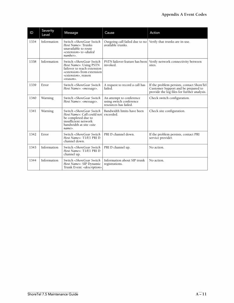
Appendix A Event Codes
ShoreTel 7.5 Maintenance Guide A – 11
1334 Information Switch <ShoreGear Switch Host Name>: Trunks unavailable to route <extension> to <dialed number>.
Outgoing call failed due to no available trunks.
Verify that trunks are in-use.
1338 Information Switch <ShoreGear Switch Host Name>: Using PSTN failover to reach extension <extension> from extension <extension>, reason <reason>.
PSTN failover feature has been invoked.
Verify network connectivity between sites.
1339 Error Switch <ShoreGear Switch Host Name>: <message>.
A request to record a call has failed.
If the problem persists, contact ShoreTel Customer Support and be prepared to provide the log files for further analysis.
1340 Warning Switch <ShoreGear Switch Host Name>: <message>.
An attempt to conference using switch conference resources has failed.
Check switch configuration.
1341 Warning Switch <ShoreGear Switch Host Name>: Call could not be completed due to insufficient network bandwidth at site <site name>.
Bandwidth limits have been exceeded.
Check site configuration.
1342 Error Switch <ShoreGear Switch Host Name>: T1/E1 PRI D channel down.
PRI D channel down. If the problem persists, contact PRI service provider.
1343 Information Switch <ShoreGear Switch Host Name>: T1/E1 PRI D channel up.
PRI D channel up. No action.
1344 Information Switch <ShoreGear Switch Host Name>: SIP Dynamic Trunk Event: <description>.
Information about SIP trunk registrations.
No action.
IDSeverityLevel
Message Cause Action
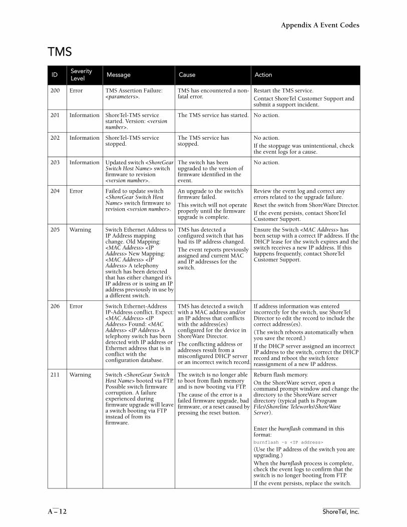
Appendix A Event Codes
A – 12 ShoreTel, Inc.
TMS
IDSeverityLevel
Message Cause Action
200 Error TMS Assertion Failure: <parameters>.
TMS has encountered a non-fatal error.
Restart the TMS service. Contact ShoreTel Customer Support and submit a support incident.
201 Information ShoreTel-TMS service started. Version: <version number>.
The TMS service has started. No action.
202 Information ShoreTel-TMS service stopped.
The TMS service has stopped.
No action. If the stoppage was unintentional, check the event logs for a cause.
203 Information Updated switch <ShoreGear Switch Host Name> switch firmware to revision <version number>.
The switch has been upgraded to the version of firmware identified in the event.
No action.
204 Error Failed to update switch <ShoreGear Switch Host Name> switch firmware to revision <version number>.
An upgrade to the switch’s firmware failed. This switch will not operate properly until the firmware upgrade is complete.
Review the event log and correct any errors related to the upgrade failure.Reset the switch from ShoreWare Director.If the event persists, contact ShoreTel Customer Support.
205 Warning Switch Ethernet Address to IP Address mapping change. Old Mapping: <MAC Address> <IP Address> New Mapping: <MAC Address> <IP Address> A telephony switch has been detected that has either changed it’s IP address or is using an IP address previously in use by a different switch.
TMS has detected a configured switch that has had its IP address changed. The event reports previously assigned and current MAC and IP addresses for the switch.
Ensure the Switch <MAC Address> has been setup with a correct IP address. If the DHCP lease for the switch expires and the switch receives a new IP address. If this happens frequently, contact ShoreTel Customer Support.
206 Error Switch Ethernet-Address IP-Address conflict. Expect: <MAC Address> <IP Address> Found: <MAC Address> <IP Address> A telephony switch has been detected with IP address or Ethernet address that is in conflict with the configuration database.
TMS has detected a switch with a MAC address and/or an IP address that conflicts with the address(es) configured for the device in ShoreWare Director. The conflicting address or addresses result from a misconfigured DHCP server or an incorrect switch record.
If address information was entered incorrectly for the switch, use ShoreTel Director to edit the record to include the correct address(es). (The switch reboots automatically when you save the record.) If the DHCP server assigned an incorrect IP address to the switch, correct the DHCP record and reboot the switch force reassignment of a new IP address.
211 Warning Switch <ShoreGear Switch Host Name> booted via FTP. Possible switch firmware corruption. A failure experienced during firmware upgrade will leave a switch booting via FTP instead of from its firmware.
The switch is no longer able to boot from flash memory and is now booting via FTP. The cause of the error is a failed firmware upgrade, bad firmware, or a reset caused by pressing the reset button.
Reburn flash memory. On the ShoreWare server, open a command prompt window and change the directory to the ShoreWare server directory (typical path is Program Files\Shoreline Teleworks\ShoreWare Server).
Enter the burnflash command in this format: burnflash -s <IP address>
(Use the IP address of the switch you are upgrading.)When the burnflash process is complete, check the event logs to confirm that the switch is no longer booting from FTP. If the event persists, replace the switch.
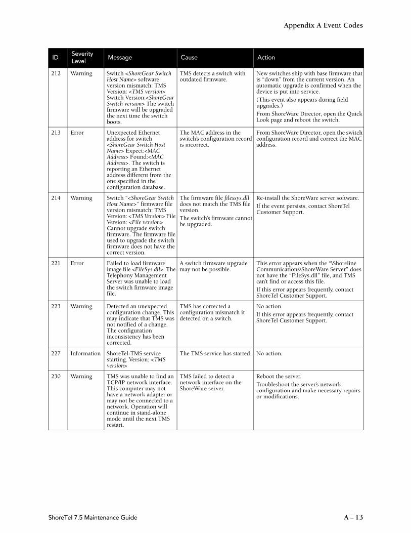
Appendix A Event Codes
ShoreTel 7.5 Maintenance Guide A – 13
212 Warning Switch <ShoreGear Switch Host Name> software version mismatch: TMS Version: <TMS version> Switch Version:<ShoreGear Switch version> The switch firmware will be upgraded the next time the switch boots.
TMS detects a switch with outdated firmware.
New switches ship with base firmware that is “down” from the current version. An automatic upgrade is confirmed when the device is put into service. (This event also appears during field upgrades.)From ShoreWare Director, open the Quick Look page and reboot the switch.
213 Error Unexpected Ethernet address for switch <ShoreGear Switch Host Name> Expect:<MAC Address> Found:<MAC Address>. The switch is reporting an Ethernet address different from the one specified in the configuration database.
The MAC address in the switch’s configuration record is incorrect.
From ShoreWare Director, open the switch configuration record and correct the MAC address.
214 Warning Switch “<ShoreGear Switch Host Name>” firmware file version mismatch: TMS Version: <TMS Version> File Version: <File version> Cannot upgrade switch firmware. The firmware file used to upgrade the switch firmware does not have the correct version.
The firmware file filessys.dll does not match the TMS file version. The switch’s firmware cannot be upgraded.
Re-install the ShoreWare server software. If the event persists, contact ShoreTel Customer Support.
221 Error Failed to load firmware image file <FileSys.dll>. The Telephony Management Server was unable to load the switch firmware image file.
A switch firmware upgrade may not be possible.
This error appears when the “\Shoreline Communications\ShoreWare Server” does not have the “FileSys.dll” file, and TMS can’t find or access this file. If this error appears frequently, contact ShoreTel Customer Support.
223 Warning Detected an unexpected configuration change. This may indicate that TMS was not notified of a change. The configuration inconsistency has been corrected.
TMS has corrected a configuration mismatch it detected on a switch.
No action.If this error appears frequently, contact ShoreTel Customer Support.
227 Information ShoreTel-TMS service starting. Version: <TMS version>
The TMS service has started. No action.
230 Warning TMS was unable to find an TCP/IP network interface. This computer may not have a network adapter or may not be connected to a network. Operation will continue in stand-alone mode until the next TMS restart.
TMS failed to detect a network interface on the ShoreWare server.
Reboot the server. Troubleshoot the server’s network configuration and make necessary repairs or modifications.
IDSeverityLevel
Message Cause Action
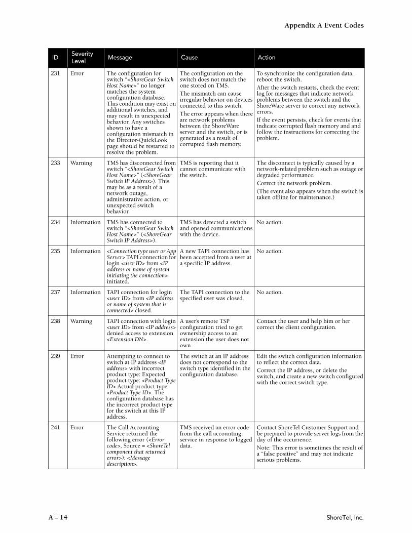
Appendix A Event Codes
A – 14 ShoreTel, Inc.
231 Error The configuration for switch “<ShoreGear Switch Host Name>” no longer matches the system configuration database. This condition may exist on additional switches, and may result in unexpected behavior. Any switches shown to have a configuration mismatch in the Director-QuickLook page should be restarted to resolve the problem.
The configuration on the switch does not match the one stored on TMS. The mismatch can cause irregular behavior on devices connected to this switch. The error appears when there are network problems between the ShoreWare server and the switch, or is generated as a result of corrupted flash memory.
To synchronize the configuration data, reboot the switch. After the switch restarts, check the event log for messages that indicate network problems between the switch and the ShoreWare server to correct any network errors.If the event persists, check for events that indicate corrupted flash memory and and follow the instructions for correcting the problem.
233 Warning TMS has disconnected from switch “<ShoreGear Switch Host Name>” (<ShoreGear Switch IP Address>). This may be as a result of a network outage, administrative action, or unexpected switch behavior.
TMS is reporting that it cannot communicate with the switch.
The disconnect is typically caused by a network-related problem such as outage or degraded performance. Correct the network problem.(The event also appears when the switch is taken offline for maintenance.)
234 Information TMS has connected to switch “<ShoreGear Switch Host Name>” (<ShoreGear Switch IP Address>).
TMS has detected a switch and opened communications with the device.
No action.
235 Information <Connection type user or App Server> TAPI connection for login <user ID> from <IP address or name of system initiating the connection> initiated.
A new TAPI connection has been accepted from a user at a specific IP address.
No action.
237 Information TAPI connection for login <user ID> from <IP address or name of system that is connected> closed.
The TAPI connection to the specified user was closed.
No action.
238 Warning TAPI connection with login <user ID> from <IP address> denied access to extension <Extension DN>.
A user’s remote TSP configuration tried to get ownership access to an extension the user does not own.
Contact the user and help him or her correct the client configuration.
239 Error Attempting to connect to switch at IP address <IP address> with incorrect product type: Expected product type: <Product Type ID> Actual product type: <Product Type ID>. The configuration database has the incorrect product type for the switch at this IP address.
The switch at an IP address does not correspond to the switch type identified in the configuration database.
Edit the switch configuration information to reflect the correct data. Correct the IP address, or delete the switch, and create a new switch configured with the correct switch type.
241 Error The Call Accounting Service returned the following error (<Error code>, Source = <ShoreTel component that returned error>): <Message description>.
TMS received an error code from the call accounting service in response to logged data.
Contact ShoreTel Customer Support and be prepared to provide server logs from the day of the occurrence. Note: This error is sometimes the result of a “false positive” and may not indicate serious problems.
IDSeverityLevel
Message Cause Action
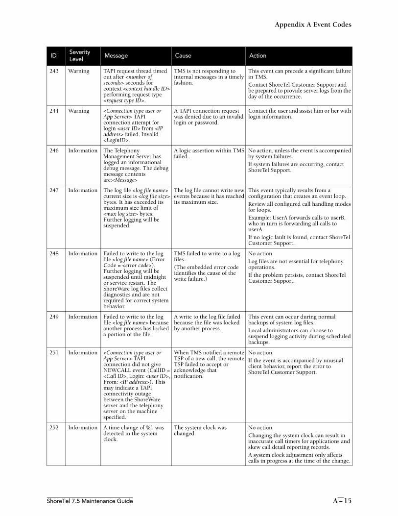
Appendix A Event Codes
ShoreTel 7.5 Maintenance Guide A – 15
243 Warning TAPI request thread timed out after <number of seconds> seconds for context <context handle ID> performing request type <request type ID>.
TMS is not responding to internal messages in a timely fashion.
This event can precede a significant failure in TMS.Contact ShoreTel Customer Support and be prepared to provide server logs from the day of the occurrence.
244 Warning <Connection type user or App Server> TAPI connection attempt for login <user ID> from <IP address> failed. Invalid <LoginID>.
A TAPI connection request was denied due to an invalid login or password.
Contact the user and assist him or her with login information.
246 Information The Telephony Management Server has logged an informational debug message. The debug message contents are:<Message>
A logic assertion within TMS failed.
No action, unless the event is accompanied by system failures.If system failures are occurring, contact ShoreTel Support.
247 Information The log file <log file name> current size is <log file size> bytes. It has exceeded its maximum size limit of <max log size> bytes. Further logging will be suspended.
The log file cannot write new events because it has reached its maximum size.
This event typically results from a configuration that creates an event loop. Review all configured call handling modes for loops. Example: UserA forwards calls to userB, who in turn is forwarding all calls to userA. If no logic fault is found, contact ShoreTel Customer Support.
248 Information Failed to write to the log file <log file name> (Error Code = <error code>). Further logging will be suspended until midnight or service restart. The ShoreWare log files collect diagnostics and are not required for correct system behavior.
TMS failed to write to a log files.(The embedded error code identifies the cause of the write failure.)
No action. Log files are not essential for telephony operations. If the problem persists, contact ShoreTel Customer Support.
249 Information Failed to write to the log file <log file name> because another process has locked a portion of the file.
A write to the log file failed because the file was locked by another process.
This event can occur during normal backups of system log files. Local administrators can choose to suspend logging activity during scheduled backups.
251 Information <Connection type user or App Server> TAPI connection did not give NEWCALL event (CallID = <Call ID>, Login: <user ID>, From: <IP address>). This may indicate a TAPI connectivity outage between the ShoreWare server and the telephony server on the machine specified.
When TMS notified a remote TSP of a new call, the remote TSP failed to accept or acknowledge that notification.
No action.If the event is accompanied by unusual client behavior, report the error to ShoreTel Customer Support.
252 Information A time change of %1 was detected in the system clock.
The system clock was changed.
No action.Changing the system clock can result in inaccurate call timers for applications and skew call detail reporting records. A system clock adjustment only affects calls in progress at the time of the change.
IDSeverityLevel
Message Cause Action
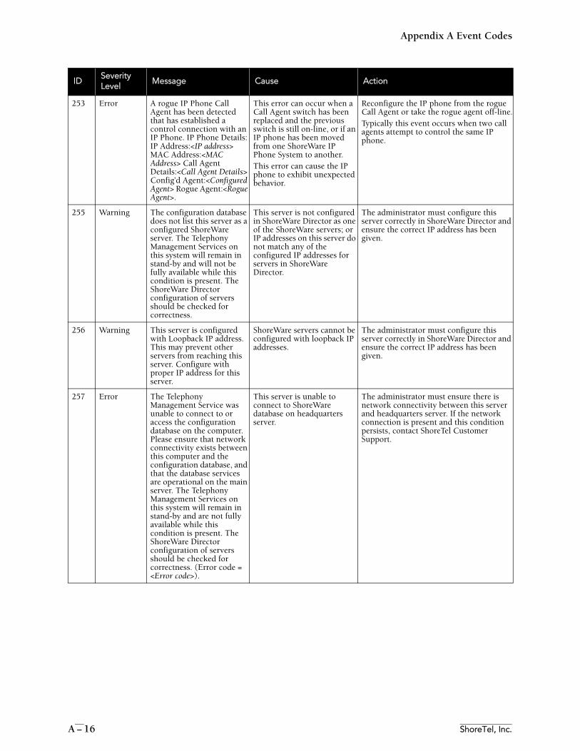
Appendix A Event Codes
A – 16 ShoreTel, Inc.
253 Error A rogue IP Phone Call Agent has been detected that has established a control connection with an IP Phone. IP Phone Details: IP Address:<IP address> MAC Address:<MAC Address> Call Agent Details:<Call Agent Details> Config’d Agent:<Configured Agent> Rogue Agent:<Rogue Agent>.
This error can occur when a Call Agent switch has been replaced and the previous switch is still on-line, or if an IP phone has been moved from one ShoreWare IP Phone System to another. This error can cause the IP phone to exhibit unexpected behavior.
Reconfigure the IP phone from the rogue Call Agent or take the rogue agent off-line.Typically this event occurs when two call agents attempt to control the same IP phone.
255 Warning The configuration database does not list this server as a configured ShoreWare server. The Telephony Management Services on this system will remain in stand-by and will not be fully available while this condition is present. The ShoreWare Director configuration of servers should be checked for correctness.
This server is not configured in ShoreWare Director as one of the ShoreWare servers; or IP addresses on this server do not match any of the configured IP addresses for servers in ShoreWare Director.
The administrator must configure this server correctly in ShoreWare Director and ensure the correct IP address has been given.
256 Warning This server is configured with Loopback IP address. This may prevent other servers from reaching this server. Configure with proper IP address for this server.
ShoreWare servers cannot be configured with loopback IP addresses.
The administrator must configure this server correctly in ShoreWare Director and ensure the correct IP address has been given.
257 Error The Telephony Management Service was unable to connect to or access the configuration database on the computer. Please ensure that network connectivity exists between this computer and the configuration database, and that the database services are operational on the main server. The Telephony Management Services on this system will remain in stand-by and are not fully available while this condition is present. The ShoreWare Director configuration of servers should be checked for correctness. (Error code = <Error code>).
This server is unable to connect to ShoreWare database on headquarters server.
The administrator must ensure there is network connectivity between this server and headquarters server. If the network connection is present and this condition persists, contact ShoreTel Customer Support.
IDSeverityLevel
Message Cause Action
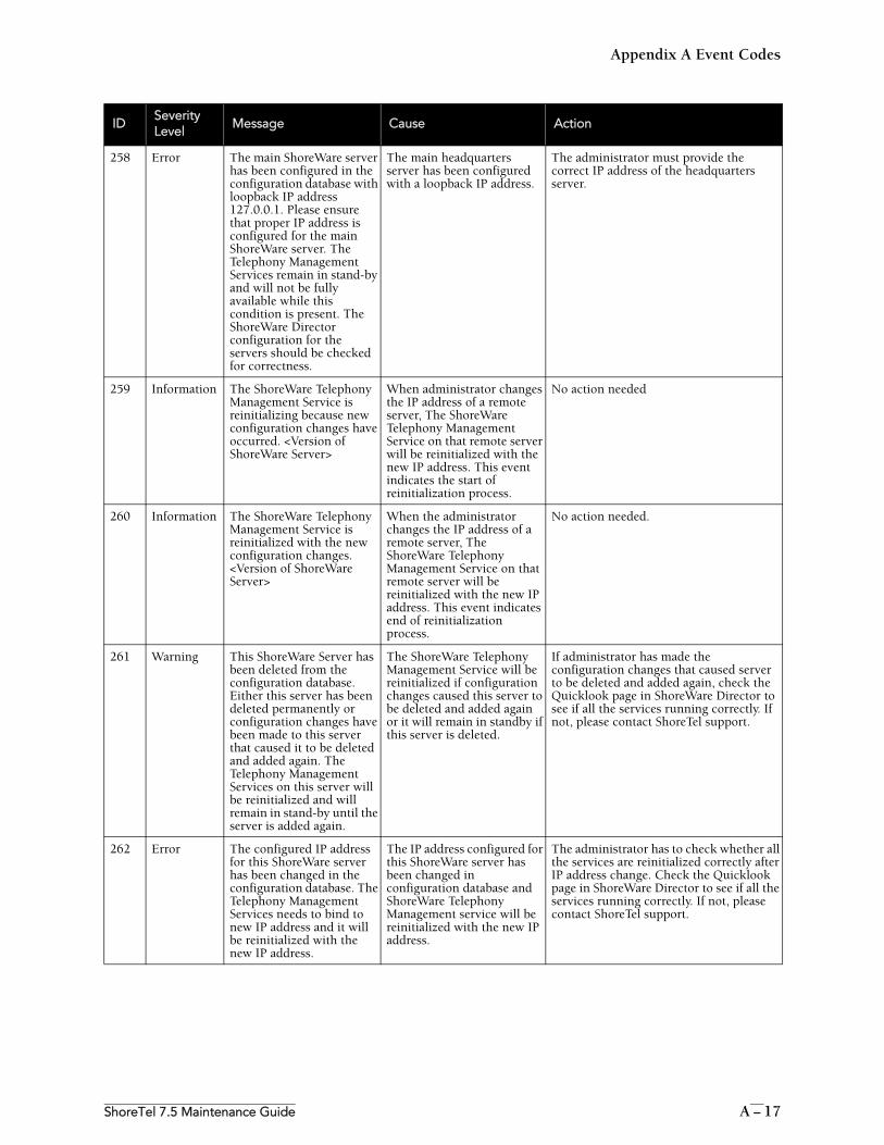
Appendix A Event Codes
ShoreTel 7.5 Maintenance Guide A – 17
258 Error The main ShoreWare server has been configured in the configuration database with loopback IP address 127.0.0.1. Please ensure that proper IP address is configured for the main ShoreWare server. The Telephony Management Services remain in stand-by and will not be fully available while this condition is present. The ShoreWare Director configuration for the servers should be checked for correctness.
The main headquarters server has been configured with a loopback IP address.
The administrator must provide the correct IP address of the headquarters server.
259 Information The ShoreWare Telephony Management Service is reinitializing because new configuration changes have occurred. <Version of ShoreWare Server>
When administrator changes the IP address of a remote server, The ShoreWare Telephony Management Service on that remote server will be reinitialized with the new IP address. This event indicates the start of reinitialization process.
No action needed
260 Information The ShoreWare Telephony Management Service is reinitialized with the new configuration changes. <Version of ShoreWare Server>
When the administrator changes the IP address of a remote server, The ShoreWare Telephony Management Service on that remote server will be reinitialized with the new IP address. This event indicates end of reinitialization process.
No action needed.
261 Warning This ShoreWare Server has been deleted from the configuration database. Either this server has been deleted permanently or configuration changes have been made to this server that caused it to be deleted and added again. The Telephony Management Services on this server will be reinitialized and will remain in stand-by until the server is added again.
The ShoreWare Telephony Management Service will be reinitialized if configuration changes caused this server to be deleted and added again or it will remain in standby if this server is deleted.
If administrator has made the configuration changes that caused server to be deleted and added again, check the Quicklook page in ShoreWare Director to see if all the services running correctly. If not, please contact ShoreTel support.
262 Error The configured IP address for this ShoreWare server has been changed in the configuration database. The Telephony Management Services needs to bind to new IP address and it will be reinitialized with the new IP address.
The IP address configured for this ShoreWare server has been changed in configuration database and ShoreWare Telephony Management service will be reinitialized with the new IP address.
The administrator has to check whether all the services are reinitialized correctly after IP address change. Check the Quicklook page in ShoreWare Director to see if all the services running correctly. If not, please contact ShoreTel support.
IDSeverityLevel
Message Cause Action

Appendix A Event Codes
A – 18 ShoreTel, Inc.
Voice Mail
IDSeverityLevel
Message Cause Action
401 Information Voice Mail Port Manager starting.Version: <version number>.
The Voice Mail Port Manager service has started.
No action.
402 Information Voice Mail Port Manager stopping.
The Voice Mail Port Manager service has stopped. This error usually results from an intentional service stoppage, stoppage by a dependant service, or application failure.
No action if the service was intentionally stopped by a user. Otherwise, check the event log for related errors and correct them.If necessary, restart the service.
410 Information Recording stopped. The disk got full during recording.
A message was not completely recorded. The hard drive on which \shoreline data\vms resides is full.
Free up space on the drive.
411 Information Recording stopped. The caller went silent during recording.
The person leaving a voice message was silent for more than 30 seconds, triggering automatic termination of the recording. The message is still sent so no action is required.
No action. The recipient will still be able to retrieve the partial message.
412 Information Recording stopped. No response from the switch.
The recording of a message halted when the connection to the switch dropped.
Check the event log and correct any errors related to the dropped connection.
414 Error The outbound AMIS phone number %1 for System ID %2 was a wrong number. No more attempts will be made to this system/number until it is corrected. Please verify the number is correct.
Verify that the phone number is correct.
415 Error The outbound AMIS phone number for System ID %1 was not found. Please verify that the System ID has a phone number associated with it.
Verify that the System ID has a phone number associated with it.
416 Error An internal error occurred. The system could not delete an AMIS message from the outbound message queue. System ID%1 Mailbox ID %2 Message ID %3
417 Error The undeliverable AMIS message from %2 could not be delivered to %3 for AMIS System ID %1. The message is being deleted.
418 Error An error occurred during the delivery of an AMIS message from %2 to %3 for AMIS System ID %1, which prevents retrying delivery at a later time. The message has been deleted.
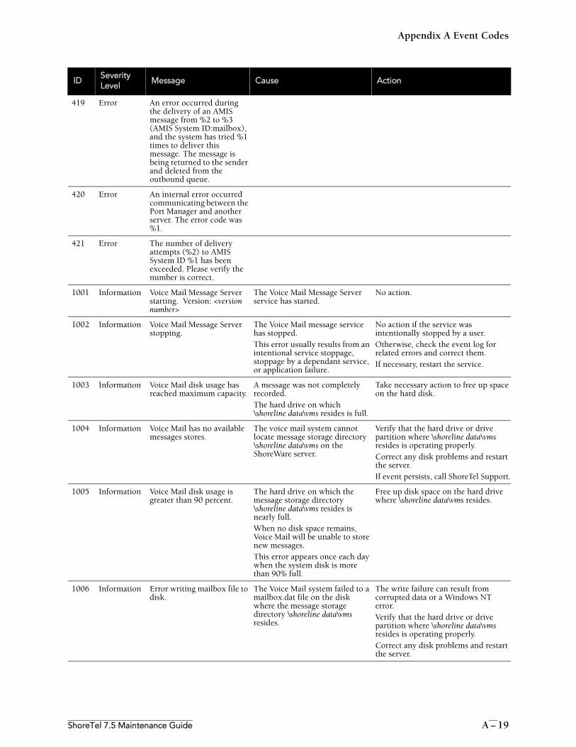
Appendix A Event Codes
ShoreTel 7.5 Maintenance Guide A – 19
419 Error An error occurred during the delivery of an AMIS message from %2 to %3 (AMIS System ID:mailbox), and the system has tried %1 times to deliver this message. The message is being returned to the sender and deleted from the outbound queue.
420 Error An internal error occurred communicating between the Port Manager and another server. The error code was %1.
421 Error The number of delivery attempts (%2) to AMIS System ID %1 has been exceeded. Please verify the number is correct.
1001 Information Voice Mail Message Server starting. Version: <version number>
The Voice Mail Message Server service has started.
No action.
1002 Information Voice Mail Message Server stopping.
The Voice Mail message service has stopped. This error usually results from an intentional service stoppage, stoppage by a dependant service, or application failure.
No action if the service was intentionally stopped by a user. Otherwise, check the event log for related errors and correct them.If necessary, restart the service.
1003 Information Voice Mail disk usage has reached maximum capacity.
A message was not completely recorded. The hard drive on which \shoreline data\vms resides is full.
Take necessary action to free up space on the hard disk.
1004 Information Voice Mail has no available messages stores.
The voice mail system cannot locate message storage directory \shoreline data\vms on the ShoreWare server.
Verify that the hard drive or drive partition where \shoreline data\vms resides is operating properly. Correct any disk problems and restart the server.If event persists, call ShoreTel Support.
1005 Information Voice Mail disk usage is greater than 90 percent.
The hard drive on which the message storage directory \shoreline data\vms resides is nearly full.When no disk space remains, Voice Mail will be unable to store new messages.This error appears once each day when the system disk is more than 90% full.
Free up disk space on the hard drive where \shoreline data\vms resides.
1006 Information Error writing mailbox file to disk.
The Voice Mail system failed to a mailbox.dat file on the disk where the message storage directory \shoreline data\vms resides.
The write failure can result from corrupted data or a Windows NT error.Verify that the hard drive or drive partition where \shoreline data\vms resides is operating properly. Correct any disk problems and restart the server.
IDSeverityLevel
Message Cause Action
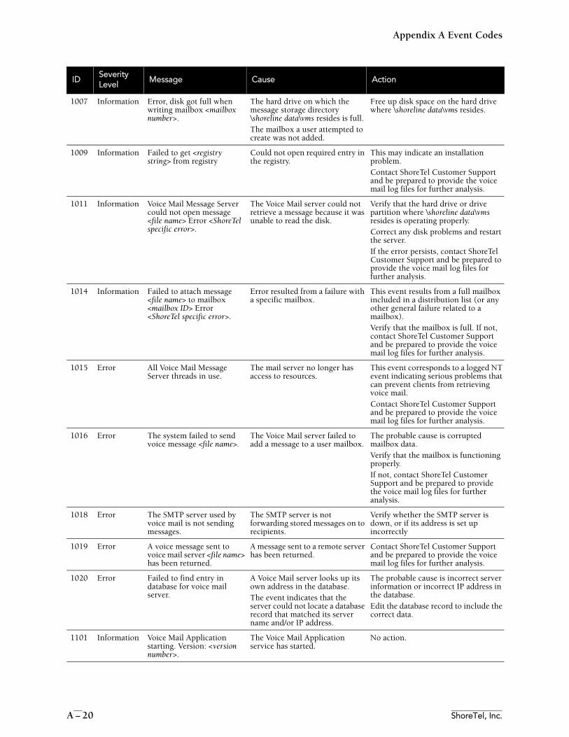
Appendix A Event Codes
A – 20 ShoreTel, Inc.
1007 Information Error, disk got full when writing mailbox <mailbox number>.
The hard drive on which the message storage directory \shoreline data\vms resides is full. The mailbox a user attempted to create was not added.
Free up disk space on the hard drive where \shoreline data\vms resides.
1009 Information Failed to get <registry string> from registry
Could not open required entry in the registry.
This may indicate an installation problem.Contact ShoreTel Customer Support and be prepared to provide the voice mail log files for further analysis.
1011 Information Voice Mail Message Server could not open message <file name> Error <ShoreTel specific error>.
The Voice Mail server could not retrieve a message because it was unable to read the disk.
Verify that the hard drive or drive partition where \shoreline data\vms resides is operating properly. Correct any disk problems and restart the server.If the error persists, contact ShoreTel Customer Support and be prepared to provide the voice mail log files for further analysis.
1014 Information Failed to attach message <file name> to mailbox <mailbox ID> Error <ShoreTel specific error>.
Error resulted from a failure with a specific mailbox.
This event results from a full mailbox included in a distribution list (or any other general failure related to a mailbox).Verify that the mailbox is full. If not, contact ShoreTel Customer Support and be prepared to provide the voice mail log files for further analysis.
1015 Error All Voice Mail Message Server threads in use.
The mail server no longer has access to resources.
This event corresponds to a logged NT event indicating serious problems that can prevent clients from retrieving voice mail. Contact ShoreTel Customer Support and be prepared to provide the voice mail log files for further analysis.
1016 Error The system failed to send voice message <file name>.
The Voice Mail server failed to add a message to a user mailbox.
The probable cause is corrupted mailbox data.Verify that the mailbox is functioning properly. If not, contact ShoreTel Customer Support and be prepared to provide the voice mail log files for further analysis.
1018 Error The SMTP server used by voice mail is not sending messages.
The SMTP server is not forwarding stored messages on to recipients.
Verify whether the SMTP server is down, or if its address is set up incorrectly
1019 Error A voice message sent to voice mail server <file name> has been returned.
A message sent to a remote server has been returned.
Contact ShoreTel Customer Support and be prepared to provide the voice mail log files for further analysis.
1020 Error Failed to find entry in database for voice mail server.
A Voice Mail server looks up its own address in the database. The event indicates that the server could not locate a database record that matched its server name and/or IP address.
The probable cause is incorrect server information or incorrect IP address in the database.Edit the database record to include the correct data.
1101 Information Voice Mail Application starting. Version: <version number>.
The Voice Mail Application service has started.
No action.
IDSeverityLevel
Message Cause Action
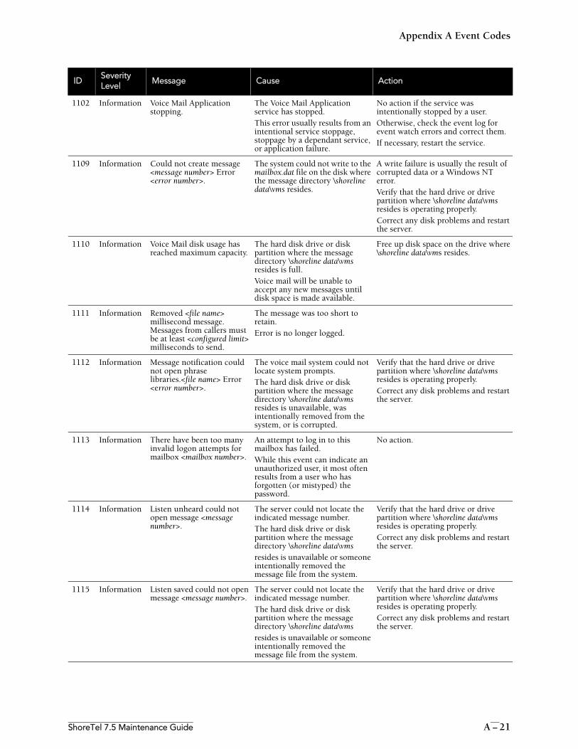
Appendix A Event Codes
ShoreTel 7.5 Maintenance Guide A – 21
1102 Information Voice Mail Application stopping.
The Voice Mail Application service has stopped. This error usually results from an intentional service stoppage, stoppage by a dependant service, or application failure.
No action if the service was intentionally stopped by a user. Otherwise, check the event log for event watch errors and correct them.If necessary, restart the service.
1109 Information Could not create message <message number> Error <error number>.
The system could not write to the mailbox.dat file on the disk where the message directory \shoreline data\vms resides.
A write failure is usually the result of corrupted data or a Windows NT error.Verify that the hard drive or drive partition where \shoreline data\vms resides is operating properly. Correct any disk problems and restart the server.
1110 Information Voice Mail disk usage has reached maximum capacity.
The hard disk drive or disk partition where the message directory \shoreline data\vms resides is full.Voice mail will be unable to accept any new messages until disk space is made available.
Free up disk space on the drive where \shoreline data\vms resides.
1111 Information Removed <file name> millisecond message. Messages from callers must be at least <configured limit> milliseconds to send.
The message was too short to retain. Error is no longer logged.
1112 Information Message notification could not open phrase libraries.<file name> Error <error number>.
The voice mail system could not locate system prompts. The hard disk drive or disk partition where the message directory \shoreline data\vms resides is unavailable, was intentionally removed from the system, or is corrupted.
Verify that the hard drive or drive partition where \shoreline data\vms resides is operating properly. Correct any disk problems and restart the server.
1113 Information There have been too many invalid logon attempts for mailbox <mailbox number>.
An attempt to log in to this mailbox has failed. While this event can indicate an unauthorized user, it most often results from a user who has forgotten (or mistyped) the password.
No action.
1114 Information Listen unheard could not open message <message number>.
The server could not locate the indicated message number. The hard disk drive or disk partition where the message directory \shoreline data\vmsresides is unavailable or someone intentionally removed the message file from the system.
Verify that the hard drive or drive partition where \shoreline data\vms resides is operating properly. Correct any disk problems and restart the server.
1115 Information Listen saved could not open message <message number>.
The server could not locate the indicated message number. The hard disk drive or disk partition where the message directory \shoreline data\vmsresides is unavailable or someone intentionally removed the message file from the system.
Verify that the hard drive or drive partition where \shoreline data\vms resides is operating properly. Correct any disk problems and restart the server.
IDSeverityLevel
Message Cause Action
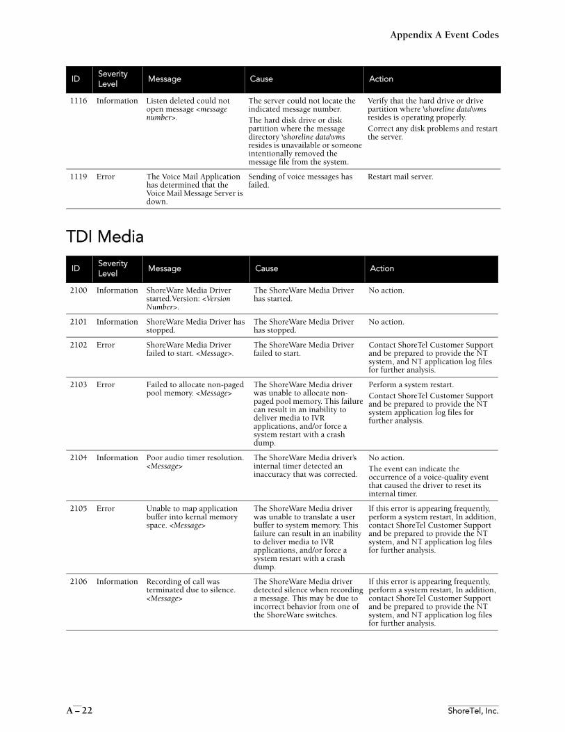
Appendix A Event Codes
A – 22 ShoreTel, Inc.
TDI Media
1116 Information Listen deleted could not open message <message number>.
The server could not locate the indicated message number. The hard disk drive or disk partition where the message directory \shoreline data\vms resides is unavailable or someone intentionally removed the message file from the system.
Verify that the hard drive or drive partition where \shoreline data\vms resides is operating properly. Correct any disk problems and restart the server.
1119 Error The Voice Mail Application has determined that the Voice Mail Message Server is down.
Sending of voice messages has failed.
Restart mail server.
IDSeverityLevel
Message Cause Action
2100 Information ShoreWare Media Driver started.Version: <Version Number>.
The ShoreWare Media Driver has started.
No action.
2101 Information ShoreWare Media Driver has stopped.
The ShoreWare Media Driver has stopped.
No action.
2102 Error ShoreWare Media Driver failed to start. <Message>.
The ShoreWare Media Driver failed to start.
Contact ShoreTel Customer Support and be prepared to provide the NT system, and NT application log files for further analysis.
2103 Error Failed to allocate non-paged pool memory. <Message>
The ShoreWare Media driver was unable to allocate non-paged pool memory. This failure can result in an inability to deliver media to IVR applications, and/or force a system restart with a crash dump.
Perform a system restart.Contact ShoreTel Customer Support and be prepared to provide the NT system application log files for further analysis.
2104 Information Poor audio timer resolution. <Message>
The ShoreWare Media driver’s internal timer detected an inaccuracy that was corrected.
No action.The event can indicate the occurrence of a voice-quality event that caused the driver to reset its internal timer.
2105 Error Unable to map application buffer into kernal memory space. <Message>
The ShoreWare Media driver was unable to translate a user buffer to system memory. This failure can result in an inability to deliver media to IVR applications, and/or force a system restart with a crash dump.
If this error is appearing frequently, perform a system restart, In addition, contact ShoreTel Customer Support and be prepared to provide the NT system, and NT application log files for further analysis.
2106 Information Recording of call was terminated due to silence. <Message>
The ShoreWare Media driver detected silence when recording a message. This may be due to incorrect behavior from one of the ShoreWare switches.
If this error is appearing frequently, perform a system restart, In addition, contact ShoreTel Customer Support and be prepared to provide the NT system, and NT application log files for further analysis.
IDSeverityLevel
Message Cause Action
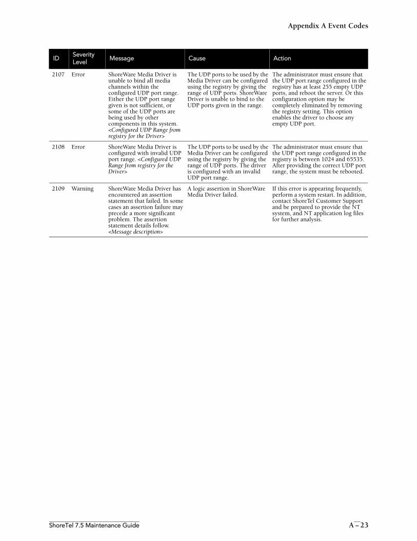
Appendix A Event Codes
ShoreTel 7.5 Maintenance Guide A – 23
2107 Error ShoreWare Media Driver is unable to bind all media channels within the configured UDP port range. Either the UDP port range given is not sufficient, or some of the UDP ports are being used by other components in this system. <Configured UDP Range from registry for the Driver>
The UDP ports to be used by the Media Driver can be configured using the registry by giving the range of UDP ports. ShoreWare Driver is unable to bind to the UDP ports given in the range.
The administrator must ensure that the UDP port range configured in the registry has at least 255 empty UDP ports, and reboot the server. Or this configuration option may be completely eliminated by removing the registry setting. This option enables the driver to choose any empty UDP port.
2108 Error ShoreWare Media Driver is configured with invalid UDP port range. <Configured UDP Range from registry for the Driver>
The UDP ports to be used by the Media Driver can be configured using the registry by giving the range of UDP ports. The driver is configured with an invalid UDP port range.
The administrator must ensure that the UDP port range configured in the registry is between 1024 and 65535. After providing the correct UDP port range, the system must be rebooted.
2109 Warning ShoreWare Media Driver has encountered an assertion statement that failed. In some cases an assertion failure may precede a more significant problem. The assertion statement details follow. <Message description>
A logic assertion in ShoreWare Media Driver failed.
If this error is appearing frequently, perform a system restart. In addition, contact ShoreTel Customer Support and be prepared to provide the NT system, and NT application log files for further analysis.
IDSeverityLevel
Message Cause Action
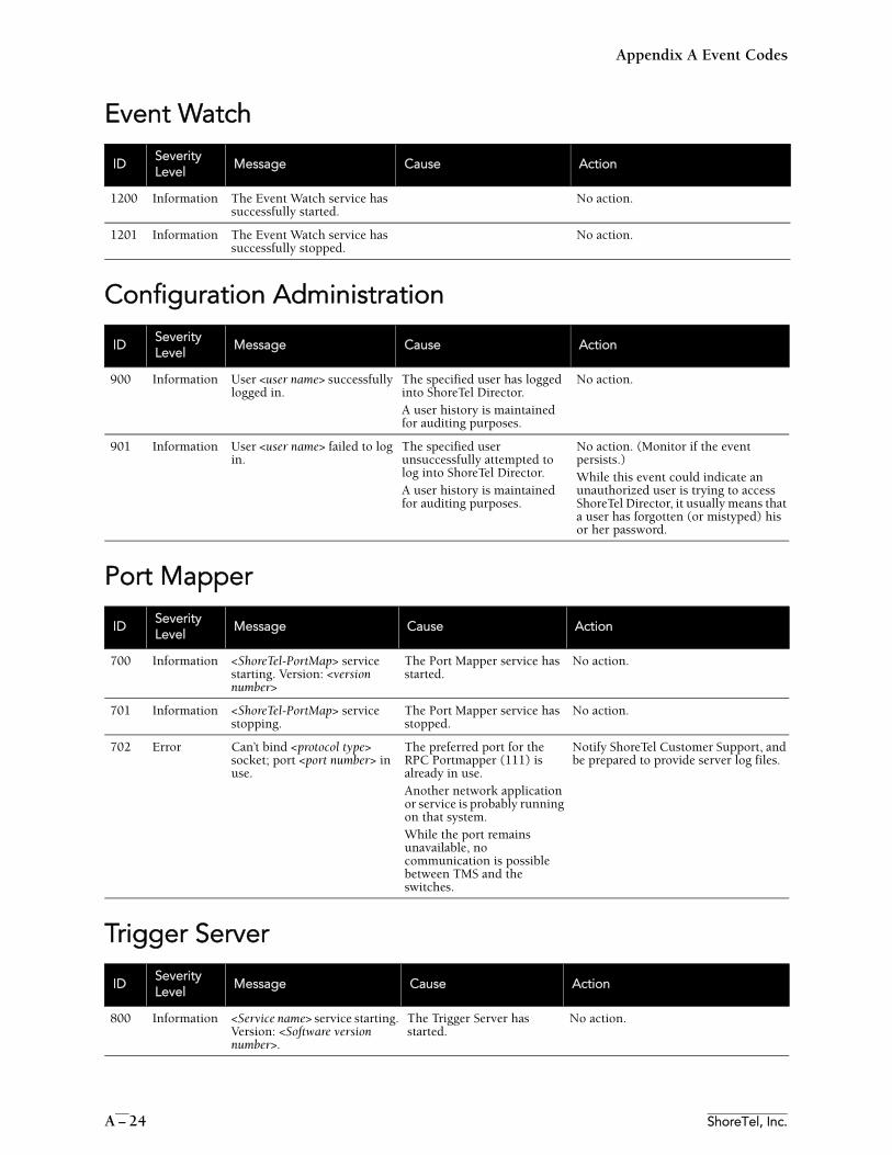
Appendix A Event Codes
A – 24 ShoreTel, Inc.
Event Watch
Configuration Administration
Port Mapper
Trigger Server
IDSeverityLevel
Message Cause Action
1200 Information The Event Watch service has successfully started.
No action.
1201 Information The Event Watch service has successfully stopped.
No action.
IDSeverityLevel
Message Cause Action
900 Information User <user name> successfully logged in.
The specified user has logged into ShoreTel Director.A user history is maintained for auditing purposes.
No action.
901 Information User <user name> failed to log in.
The specified user unsuccessfully attempted to log into ShoreTel Director.A user history is maintained for auditing purposes.
No action. (Monitor if the event persists.)While this event could indicate an unauthorized user is trying to access ShoreTel Director, it usually means that a user has forgotten (or mistyped) his or her password.
IDSeverityLevel
Message Cause Action
700 Information <ShoreTel-PortMap> service starting. Version: <version number>
The Port Mapper service has started.
No action.
701 Information <ShoreTel-PortMap> service stopping.
The Port Mapper service has stopped.
No action.
702 Error Can’t bind <protocol type> socket; port <port number> in use.
The preferred port for the RPC Portmapper (111) is already in use. Another network application or service is probably running on that system.While the port remains unavailable, no communication is possible between TMS and the switches.
Notify ShoreTel Customer Support, and be prepared to provide server log files.
IDSeverityLevel
Message Cause Action
800 Information <Service name> service starting. Version: <Software version number>.
The Trigger Server has started.
No action.
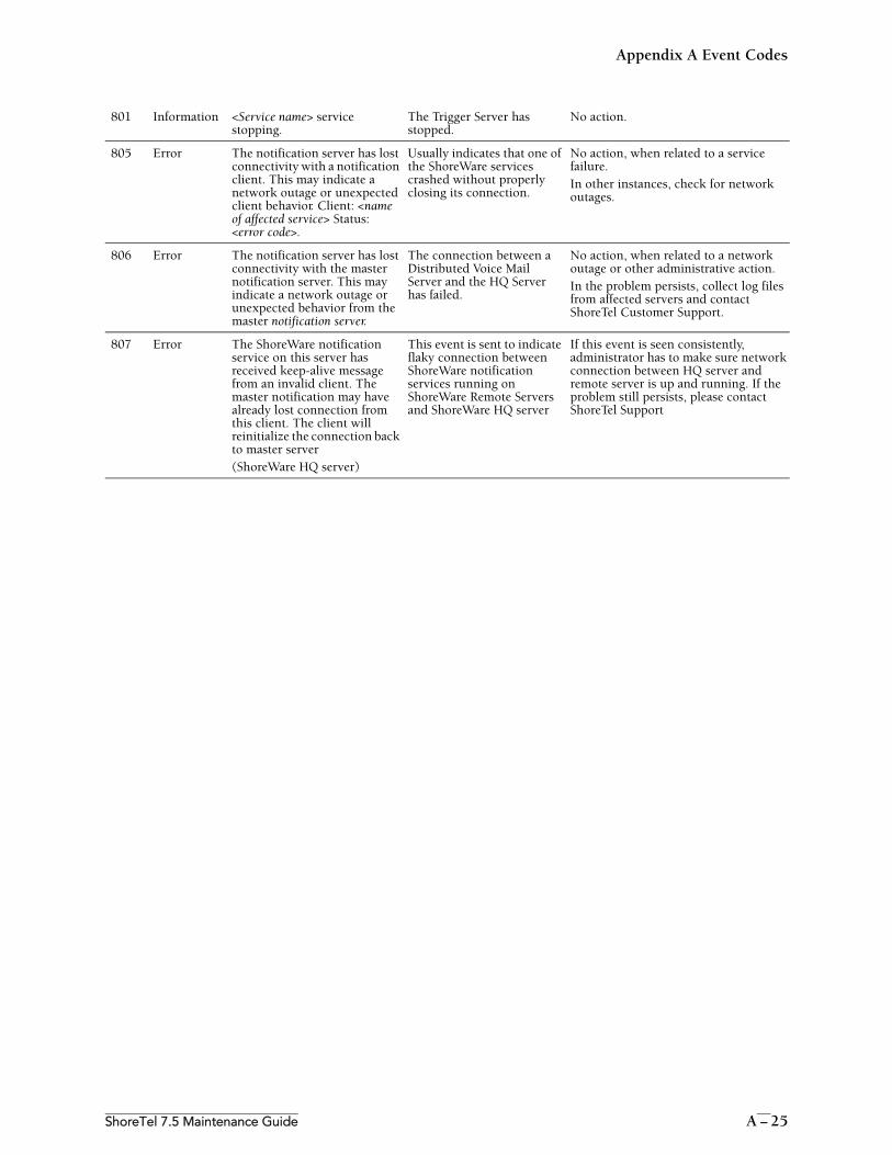
Appendix A Event Codes
ShoreTel 7.5 Maintenance Guide A – 25
801 Information <Service name> service stopping.
The Trigger Server has stopped.
No action.
805 Error The notification server has lost connectivity with a notification client. This may indicate a network outage or unexpected client behavior. Client: <name of affected service> Status: <error code>.
Usually indicates that one of the ShoreWare services crashed without properly closing its connection.
No action, when related to a service failure.In other instances, check for network outages.
806 Error The notification server has lost connectivity with the master notification server. This may indicate a network outage or unexpected behavior from the master notification server.
The connection between a Distributed Voice Mail Server and the HQ Server has failed.
No action, when related to a network outage or other administrative action.In the problem persists, collect log files from affected servers and contact ShoreTel Customer Support.
807 Error The ShoreWare notification service on this server has received keep-alive message from an invalid client. The master notification may have already lost connection from this client. The client will reinitialize the connection back to master server(ShoreWare HQ server)
This event is sent to indicate flaky connection between ShoreWare notification services running on ShoreWare Remote Servers and ShoreWare HQ server
If this event is seen consistently, administrator has to make sure network connection between HQ server and remote server is up and running. If the problem still persists, please contact ShoreTel Support
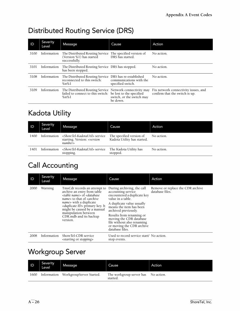
Appendix A Event Codes
A – 26 ShoreTel, Inc.
Distributed Routing Service (DRS)
Kadota Utility
Call Accounting
Workgroup Server
IDSeverityLevel
Message Cause Action
3100 Information The Distributed Routing Service (Version %1) has started successfully.
The specified version of DRS has started.
No action.
3101 Information The Distributed Routing Service has been stopped.
DRS has stopped. No action.
3108 Information The Distributed Routing Service reconnected to this switch: %n%1
DRS has re-established communications with the specified switch.
No action.
3109 Information The Distributed Routing Service failed to connect to this switch: %n%1
Network connectivity may be lost to the specified switch, or the switch may be down.
Fix network connectivity issues, and confirm that the switch is up.
IDSeverityLevel
Message Cause Action
1400 Information <ShoreTel-KadotaUtil> service starting. Version: <version number>
The specified version of Kadota Utility has started.
No action.
1401 Information <ShoreTel-KadotaUtil> service stopping.
The Kadota Utility has stopped.
No action.
IDSeverityLevel
Message Cause Action
2000 Warning TmsCdr records an attempt to archive an entry from table <table name> of <database name> to that of <archive name> with a duplicate <duplicate ID> primary key. It might be caused by a manual manipulation between CDR.mdb and its backup version.
During archiving, the call accounting service encountered a duplicate key value in a table. A duplicate value usually means the item has been archived previously. Results from renaming or moving the CDR database file without also renaming or moving the CDR archive database files.
Remove or replace the CDR archive database files.
2008 Information ShoreTel-CDR service <starting or stopping>
Used to record service start/stop events.
No action.
IDSeverityLevel
Message Cause Action
1600 Information WorkgroupServer Started. The workgroup server has started.
No action.
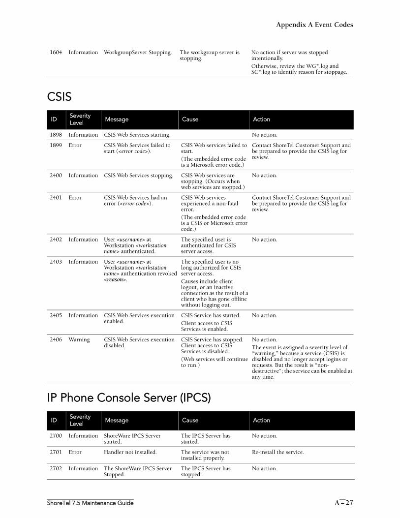
Appendix A Event Codes
ShoreTel 7.5 Maintenance Guide A – 27
CSIS
IP Phone Console Server (IPCS)
1604 Information WorkgroupServer Stopping. The workgroup server is stopping.
No action if server was stopped intentionally.Otherwise, review the WG*.log and SC*.log to identify reason for stoppage.
IDSeverityLevel
Message Cause Action
1898 Information CSIS Web Services starting. No action.
1899 Error CSIS Web Services failed to start (<error code>).
CSIS Web services failed to start. (The embedded error code is a Microsoft error code.)
Contact ShoreTel Customer Support and be prepared to provide the CSIS log for review.
2400 Information CSIS Web Services stopping. CSIS Web services are stopping. (Occurs when web services are stopped.)
No action.
2401 Error CSIS Web Services had an error (<error code>).
CSIS Web services experienced a non-fatal error. (The embedded error code is a CSIS or Microsoft error code.)
Contact ShoreTel Customer Support and be prepared to provide the CSIS log for review.
2402 Information User <username> at Workstation <workstation name> authenticated.
The specified user is authenticated for CSIS server access.
No action.
2403 Information User <username> at Workstation <workstation name> authentication revoked <reason>.
The specified user is no long authorized for CSIS server access. Causes include client logout, or an inactive connection as the result of a client who has gone offline without logging out.
2405 Information CSIS Web Services execution enabled.
CSIS Service has started. Client access to CSIS Services is enabled.
No action.
2406 Warning CSIS Web Services execution disabled.
CSIS Service has stopped. Client access to CSIS Services is disabled. (Web services will continue to run.)
No action. The event is assigned a severity level of “warning,” because a service (CSIS) is disabled and no longer accept logins or requests. But the result is “non-destructive”; the service can be enabled at any time.
IDSeverityLevel
Message Cause Action
2700 Information ShoreWare IPCS Server started.
The IPCS Server has started.
No action.
2701 Error Handler not installed. The service was not installed properly.
Re-install the service.
2702 Information The ShoreWare IPCS Server Stopped.
The IPCS Server has stopped.
No action.
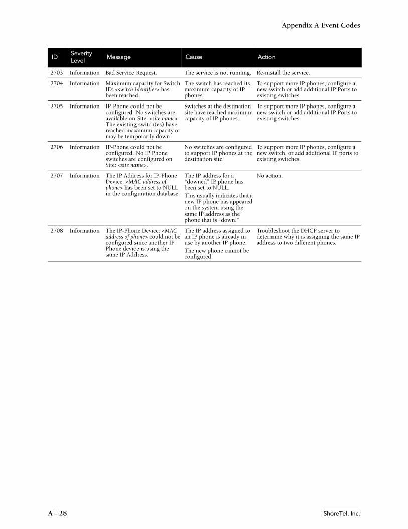
Appendix A Event Codes
A – 28 ShoreTel, Inc.
2703 Information Bad Service Request. The service is not running. Re-install the service.
2704 Information Maximum capacity for Switch ID: <switch identifier> has been reached.
The switch has reached its maximum capacity of IP phones.
To support more IP phones, configure a new switch or add additional IP Ports to existing switches.
2705 Information IP-Phone could not be configured. No switches are available on Site: <site name> The existing switch(es) have reached maximum capacity or may be temporarily down.
Switches at the destination site have reached maximum capacity of IP phones.
To support more IP phones, configure a new switch or add additional IP Ports to existing switches.
2706 Information IP-Phone could not be configured. No IP Phone switches are configured on Site: <site name>.
No switches are configured to support IP phones at the destination site.
To support more IP phones, configure a new switch, or add additional IP ports to existing switches.
2707 Information The IP Address for IP-Phone Device: <MAC address of phone> has been set to NULL in the configuration database.
The IP address for a “downed” IP phone has been set to NULL. This usually indicates that a new IP phone has appeared on the system using the same IP address as the phone that is “down.”
No action.
2708 Information The IP-Phone Device: <MAC address of phone> could not be configured since another IP Phone device is using the same IP Address.
The IP address assigned to an IP phone is already in use by another IP phone. The new phone cannot be configured.
Troubleshoot the DHCP server to determine why it is assigning the same IP address to two different phones.
IDSeverityLevel
Message Cause Action
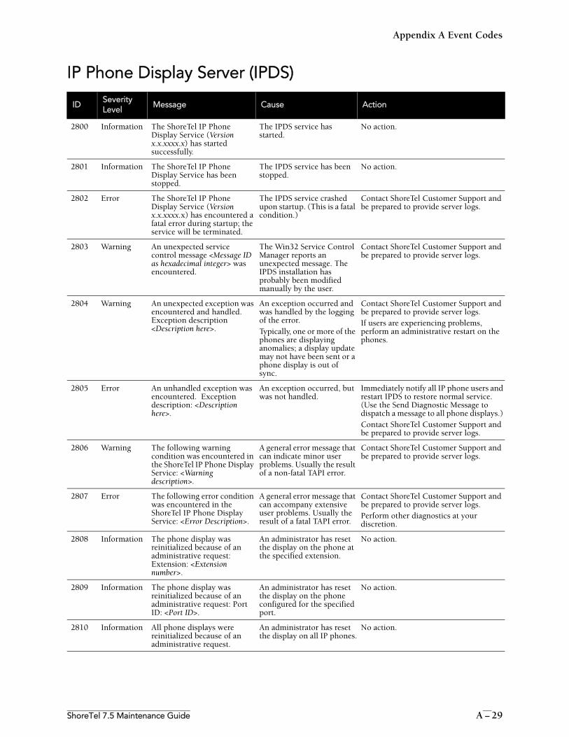
Appendix A Event Codes
ShoreTel 7.5 Maintenance Guide A – 29
IP Phone Display Server (IPDS)
IDSeverityLevel
Message Cause Action
2800 Information The ShoreTel IP Phone Display Service (Version x.x.xxxx.x) has started successfully.
The IPDS service has started.
No action.
2801 Information The ShoreTel IP Phone Display Service has been stopped.
The IPDS service has been stopped.
No action.
2802 Error The ShoreTel IP Phone Display Service (Version x.x.xxxx.x) has encountered a fatal error during startup; the service will be terminated.
The IPDS service crashed upon startup. (This is a fatal condition.)
Contact ShoreTel Customer Support and be prepared to provide server logs.
2803 Warning An unexpected service control message <Message ID as hexadecimal integer> was encountered.
The Win32 Service Control Manager reports an unexpected message. The IPDS installation has probably been modified manually by the user.
Contact ShoreTel Customer Support and be prepared to provide server logs.
2804 Warning An unexpected exception was encountered and handled. Exception description <Description here>.
An exception occurred and was handled by the logging of the error. Typically, one or more of the phones are displaying anomalies; a display update may not have been sent or a phone display is out of sync.
Contact ShoreTel Customer Support and be prepared to provide server logs.If users are experiencing problems, perform an administrative restart on the phones.
2805 Error An unhandled exception was encountered. Exception description: <Description here>.
An exception occurred, but was not handled.
Immediately notify all IP phone users and restart IPDS to restore normal service. (Use the Send Diagnostic Message to dispatch a message to all phone displays.) Contact ShoreTel Customer Support and be prepared to provide server logs.
2806 Warning The following warning condition was encountered in the ShoreTel IP Phone Display Service: <Warning description>.
A general error message that can indicate minor user problems. Usually the result of a non-fatal TAPI error.
Contact ShoreTel Customer Support and be prepared to provide server logs.
2807 Error The following error condition was encountered in the ShoreTel IP Phone Display Service: <Error Description>.
A general error message that can accompany extensive user problems. Usually the result of a fatal TAPI error.
Contact ShoreTel Customer Support and be prepared to provide server logs.Perform other diagnostics at your discretion.
2808 Information The phone display was reinitialized because of an administrative request: Extension: <Extension number>.
An administrator has reset the display on the phone at the specified extension.
No action.
2809 Information The phone display was reinitialized because of an administrative request: Port ID: <Port ID>.
An administrator has reset the display on the phone configured for the specified port.
No action.
2810 Information All phone displays were reinitialized because of an administrative request.
An administrator has reset the display on all IP phones.
No action.
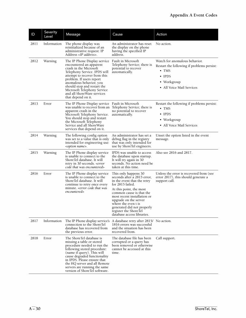
Appendix A Event Codes
A – 30 ShoreTel, Inc.
2811 Information The phone display was reinitialized because of an administrative request: IP Address <IP address>.
An administrator has reset the display on the phone having the specified IP address.
No action.
2812 Warning The IP Phone Display service encountered an apparent crash in the Microsoft Telephony Service. IPDS will attempt to recover from this problem. If users report anomalous behavior, you should stop and restart the Microsoft Telephony Service and all ShoreWare services that depend on it.
Fault in Microsoft Telephony Service; there is potential to recover automatically.
Watch for anomalous behavior. Restart the following if problems persist:
• TMS
• IPDS
• Workgroup
• All Voice Mail Services
2813 Error The IP Phone Display service was unable to recover from an apparent crash in the Microsoft Telephony Service. You should stop and restart the Microsoft Telephony Service and all ShoreWare services that depend on it.
Fault in Microsoft Telephony Service; there is no potential to recover automatically.
Restart the following if problems persist:• TMS
• IPDS
• Workgroup
• All Voice Mail Services
2814 Warning The following config option was set to a value that is only intended for engineering use: <option name>.
An administrator has set a debug flag in the registry that was only intended for use by ShoreTel engineers.
Unset the option listed in the event message.
2815 Warning The IP Phone display service is unable to connect to the ShoreTel database. It will retry in 30 seconds. <error code that was encountered>
IPDS was unable to access the database upon startup. It will try again in 30 seconds. No action need be taken at this time.
Also see 2816 and 2817.
2816 Error The IP Phone display service is unable to connect to the ShoreTel database. It will continue to retry once every minute. <error code that was encountered>
This only happens 30 seconds after a 2815 error, in the event that the retry for 2815 failed. At this point, the most common cause is that the most recent installation or upgrade on the server where the even t is generated did not properly register the ShoreTel database access libraries.
Unless the error is recovered from (see error 2817), this should generate a support call.
2817 Information The IP Phone display service’s connection to the ShoreTel database has recovered from the previous error.
A database retry after 2815/1816 errors was successful and the situation has been recovered from.
No action.
2818 Error The ShoreTel database is missing a table or stored procedure needed to run the following stored procedure: (name if query). This will cause degraded functionality in IPDS. Please ensure that the HQ server and all Remote servers are running the same version of ShoreTel software.
The database file has been corrupted or a query has been removed or otherwise cannot be accessed at this time.
Call support.
IDSeverityLevel
Message Cause Action