Embed Size (px)
Citation preview

www.omega.com e-mail: [email protected]
User’s Guide
DPF75, DPF76 AND DPF78 SERIES
Rate/Totalizer
Shop online at
M1090 /071603

Servicing North America:USA: One Omega Drive, P.O. Box 4047ISO 9001 Certified Stamford CT 06907-0047
TEL: (203) 359-1660 FAX: (203) 359-7700e-mail: [email protected]
Canada: 976 BergarLaval (Quebec) H7L 5A1TEL: (514) 856-6928 FAX: (514) 856-6886e-mail: [email protected]
For immediate technical or application assistance:USA and Canada: Sales Service: 1-800-826-6342 / 1-800-TC-OMEGA®
Customer Service: 1-800-622-2378 / 1-800-622-BEST®
Engineering Service: 1-800-872-9436 / 1-800-USA-WHEN®
TELEX: 996404 EASYLINK: 62968934 CABLE: OMEGA
Mexico: En Espanol: (001) 203-359-7803 e-mail: [email protected]: (001) 203-359-7807 [email protected]
Servicing Europe:Benelux: Postbus 8034, 1180 LA Amstelveen, The Netherlands
TEL: +31 (0)20 3472121 FAX: +31 (0)20 6434643Toll Free in Benelux: 0800 0993344e-mail: [email protected]
Czech Republic: Rudé armády 1868, 733 01 Karviná 8TEL: +420 (0)69 6311899 FAX: +420 (0)69 6311114Toll Free: 0800-1-66342 e-mail: [email protected]
France: 9, rue Denis Papin, 78190 TrappesTEL: +33 (0)130 621 400 FAX: +33 (0)130 699 120Toll Free in France: 0800-4-06342e-mail: [email protected]
Germany/Austria: Daimlerstrasse 26, D-75392 Deckenpfronn, GermanyTEL: +49 (0)7056 9398-0 FAX: +49 (0)7056 9398-29Toll Free in Germany: 0800 639 7678e-mail: [email protected]
United Kingdom: One Omega Drive, River Bend Technology CentreISO 9002 Certified Northbank, Irlam, Manchester
M44 5BD United Kingdom TEL: +44 (0)161 777 6611 FAX: +44 (0)161 777 6622Toll Free in United Kingdom: 0800-488-488e-mail: [email protected]
OMEGAnet® Online Service Internet e-mailwww.omega.com [email protected]
It is the policy of OMEGA to comply with all worldwide safety and EMC/EMI regulations thatapply. OMEGA is constantly pursuing certification of its products to the European New ApproachDirectives. OMEGA will add the CE mark to every appropriate device upon certification.The information contained in this document is believed to be correct, but OMEGA Engineering, Inc. accepts no liability for any errors it contains, and reserves the right to alter specifications without notice.WARNING: These products are not designed for use in, and should not be used for, patient-connected applications.
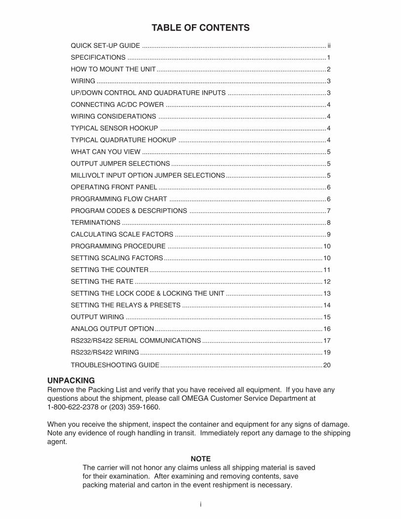
TABLE OF CONTENTS
i
QUICK SET-UP GUIDE ..................................................................................................... ii
SPECIFICATIONS .............................................................................................................1
HOW TO MOUNT THE UNIT .............................................................................................2
WIRING ..............................................................................................................................3
UP/DOWN CONTROL AND QUADRATURE INPUTS ......................................................3
CONNECTING AC/DC POWER ........................................................................................4
WIRING CONSIDERATIONS ............................................................................................4
TYPICAL SENSOR HOOKUP ...........................................................................................4
TYPICAL QUADRATURE HOOKUP .................................................................................4
WHAT CAN YOU VIEW .....................................................................................................5
OUTPUT JUMPER SELECTIONS .....................................................................................5
MILLIVOLT INPUT OPTION JUMPER SELECTIONS.......................................................5
OPERATING FRONT PANEL ............................................................................................6
PROGRAMMING FLOW CHART ......................................................................................6
PROGRAM CODES & DESCRIPTIONS ...........................................................................7
TERMINATIONS ................................................................................................................8
CALCULATING SCALE FACTORS ...................................................................................9
PROGRAMMING PROCEDURE .....................................................................................10
SETTING SCALING FACTORS .......................................................................................10
SETTING THE COUNTER...............................................................................................11
SETTING THE RATE .......................................................................................................12
SETTING THE LOCK CODE & LOCKING THE UNIT .....................................................13
SETTING THE RELAYS & PRESETS .............................................................................14
OUTPUT WIRING ............................................................................................................15
ANALOG OUTPUT OPTION............................................................................................16
RS232/RS422 SERIAL COMMUNICATIONS ..................................................................17
RS232/RS422 WIRING ....................................................................................................19
TROUBLESHOOTING GUIDE .........................................................................................20
UNPACKINGRemove the Packing List and verify that you have received all equipment. If you have anyquestions about the shipment, please call OMEGA Customer Service Department at1-800-622-2378 or (203) 359-1660.
When you receive the shipment, inspect the container and equipment for any signs of damage.Note any evidence of rough handling in transit. Immediately report any damage to the shippingagent.
NOTEThe carrier will not honor any claims unless all shipping material is savedfor their examination. After examining and removing contents, savepacking material and carton in the event reshipment is necessary.
QUICK SET-UP GUIDE
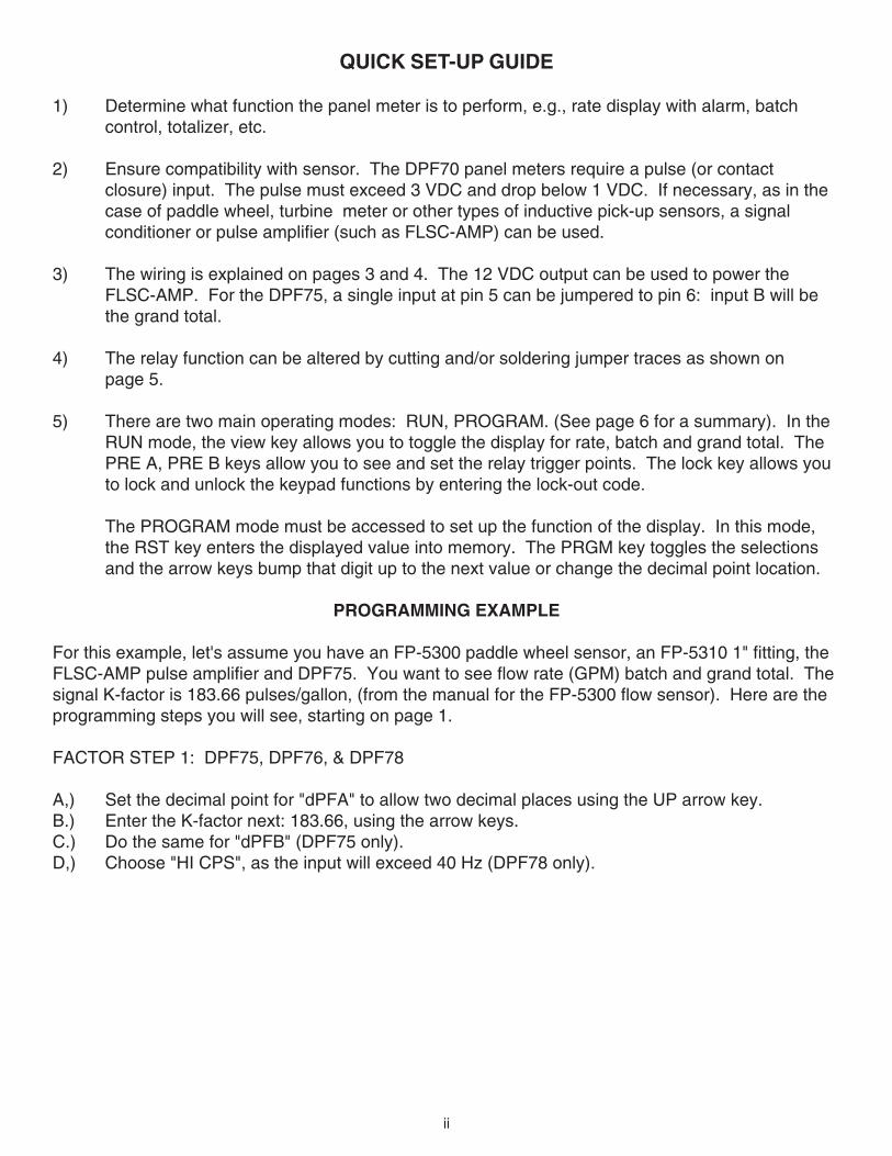
1) Determine what function the panel meter is to perform, e.g., rate display with alarm, batchcontrol, totalizer, etc.
2) Ensure compatibility with sensor. The DPF70 panel meters require a pulse (or contactclosure) input. The pulse must exceed 3 VDC and drop below 1 VDC. If necessary, as in thecase of paddle wheel, turbine meter or other types of inductive pick-up sensors, a signalconditioner or pulse amplifier (such as FLSC-AMP) can be used.
3) The wiring is explained on pages 3 and 4. The 12 VDC output can be used to power theFLSC-AMP. For the DPF75, a single input at pin 5 can be jumpered to pin 6: input B will bethe grand total.
4) The relay function can be altered by cutting and/or soldering jumper traces as shown onpage 5.
5) There are two main operating modes: RUN, PROGRAM. (See page 6 for a summary). In theRUN mode, the view key allows you to toggle the display for rate, batch and grand total. ThePRE A, PRE B keys allow you to see and set the relay trigger points. The lock key allows youto lock and unlock the keypad functions by entering the lock-out code.
The PROGRAM mode must be accessed to set up the function of the display. In this mode,the RST key enters the displayed value into memory. The PRGM key toggles the selectionsand the arrow keys bump that digit up to the next value or change the decimal point location.
PROGRAMMING EXAMPLE
For this example, let's assume you have an FP-5300 paddle wheel sensor, an FP-5310 1" fitting, theFLSC-AMP pulse amplifier and DPF75. You want to see flow rate (GPM) batch and grand total. Thesignal K-factor is 183.66 pulses/gallon, (from the manual for the FP-5300 flow sensor). Here are theprogramming steps you will see, starting on page 1.
FACTOR STEP 1: DPF75, DPF76, & DPF78
A,) Set the decimal point for "dPFA" to allow two decimal places using the UP arrow key.B.) Enter the K-factor next: 183.66, using the arrow keys.C.) Do the same for "dPFB" (DPF75 only).D,) Choose "HI CPS", as the input will exceed 40 Hz (DPF78 only).
ii
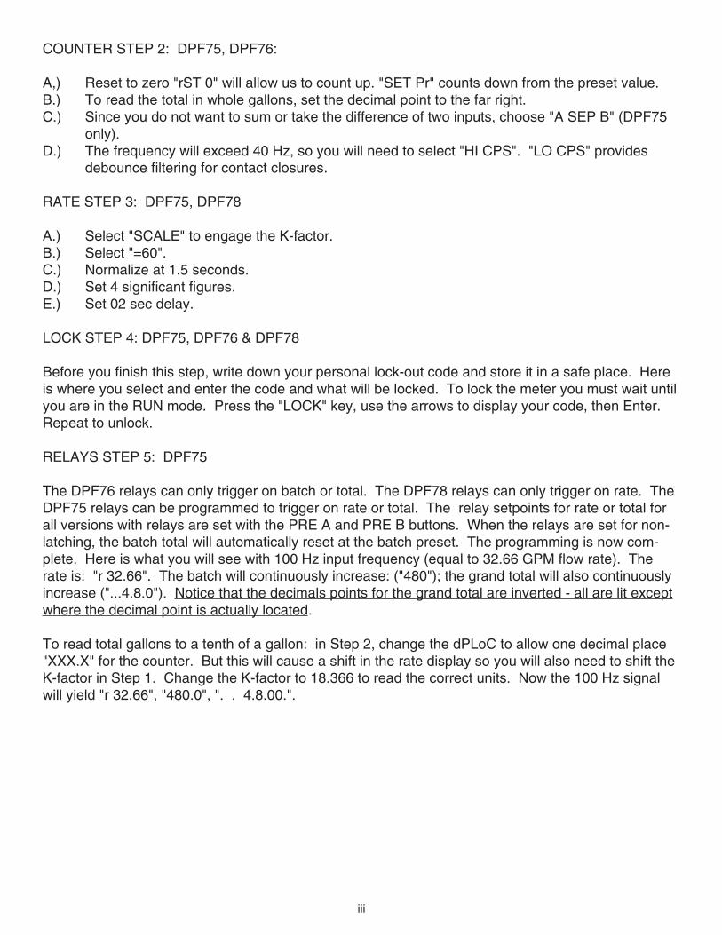
COUNTER STEP 2: DPF75, DPF76:
A,) Reset to zero "rST 0" will allow us to count up. "SET Pr" counts down from the preset value.B.) To read the total in whole gallons, set the decimal point to the far right.C.) Since you do not want to sum or take the difference of two inputs, choose "A SEP B" (DPF75
only).D.) The frequency will exceed 40 Hz, so you will need to select "HI CPS". "LO CPS" provides
debounce filtering for contact closures.
RATE STEP 3: DPF75, DPF78
A.) Select "SCALE" to engage the K-factor.B.) Select "=60".C.) Normalize at 1.5 seconds.D.) Set 4 significant figures.E.) Set 02 sec delay.
LOCK STEP 4: DPF75, DPF76 & DPF78
Before you finish this step, write down your personal lock-out code and store it in a safe place. Hereis where you select and enter the code and what will be locked. To lock the meter you must wait untilyou are in the RUN mode. Press the "LOCK" key, use the arrows to display your code, then Enter.Repeat to unlock.
RELAYS STEP 5: DPF75
The DPF76 relays can only trigger on batch or total. The DPF78 relays can only trigger on rate. TheDPF75 relays can be programmed to trigger on rate or total. The relay setpoints for rate or total forall versions with relays are set with the PRE A and PRE B buttons. When the relays are set for non-latching, the batch total will automatically reset at the batch preset. The programming is now com-plete. Here is what you will see with 100 Hz input frequency (equal to 32.66 GPM flow rate). Therate is: "r 32.66". The batch will continuously increase: ("480"); the grand total will also continuouslyincrease ("...4.8.0"). Notice that the decimals points for the grand total are inverted - all are lit exceptwhere the decimal point is actually located.
To read total gallons to a tenth of a gallon: in Step 2, change the dPLoC to allow one decimal place"XXX.X" for the counter. But this will cause a shift in the rate display so you will also need to shift theK-factor in Step 1. Change the K-factor to 18.366 to read the correct units. Now the 100 Hz signalwill yield "r 32.66", "480.0", ". . 4.8.00.".
iii
1
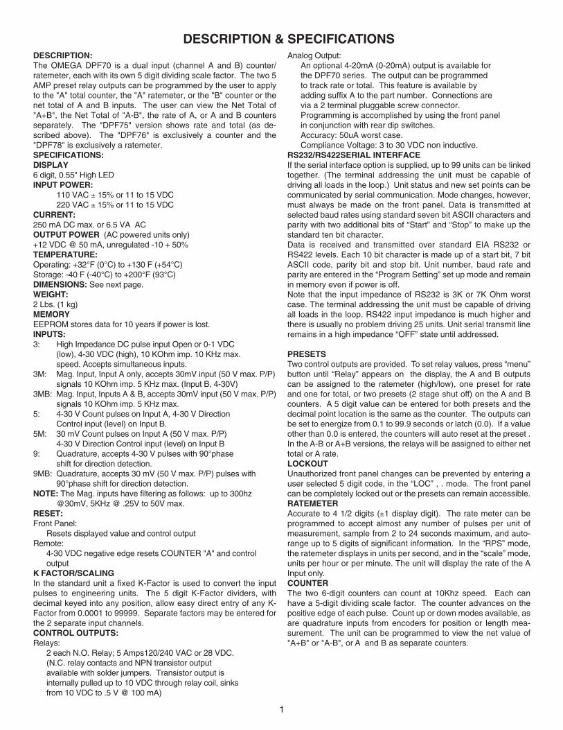
DESCRIPTION & SPECIFICATIONSDESCRIPTION:The OMEGA DPF70 is a dual input (channel A and B) counter/ratemeter, each with its own 5 digit dividing scale factor. The two 5AMP preset relay outputs can be programmed by the user to applyto the "A" total counter, the "A" ratemeter, or the "B" counter or thenet total of A and B inputs. The user can view the Net Total of"A+B", the Net Total of "A-B", the rate of A, or A and B countersseparately. The "DPF75" version shows rate and total (as de-scribed above). The "DPF76" is exclusively a counter and the"DPF78" is exclusively a ratemeter.SPECIFICATIONS:DISPLAY6 digit, 0.55" High LEDINPUT POWER:
110 VAC ± 15% or 11 to 15 VDC220 VAC ± 15% or 11 to 15 VDC
CURRENT:250 mA DC max. or 6.5 VA ACOUTPUT POWER (AC powered units only)+12 VDC @ 50 mA, unregulated -10 + 50%TEMPERATURE:Operating: +32°F (0°C) to +130 F (+54°C)Storage: -40 F (-40°C) to +200°F (93°C)DIMENSIONS: See next page.WEIGHT:2 Lbs. (1 kg)MEMORYEEPROM stores data for 10 years if power is lost.INPUTS:3: High Impedance DC pulse input Open or 0-1 VDC
(low), 4-30 VDC (high), 10 KOhm imp. 10 KHz max.speed. Accepts simultaneous inputs.
3M: Mag. Input, Input A only, accepts 30mV input (50 V max. P/P)signals 10 KOhm imp. 5 KHz max. (Input B, 4-30V)
3MB: Mag. Input, Inputs A & B, accepts 30mV input (50 V max. P/P)signals 10 KOhm imp. 5 KHz max.
5: 4-30 V Count pulses on Input A, 4-30 V DirectionControl input (level) on Input B.
5M: 30 mV Count pulses on Input A (50 V max. P/P)4-30 V Direction Control input (level) on Input B
9: Quadrature, accepts 4-30 V pulses with 90°phaseshift for direction detection.
9MB: Quadrature, accepts 30 mV (50 V max. P/P) pulses with90°phase shift for direction detection.
NOTE: The Mag. inputs have filtering as follows: up to 300hz@30mV, 5KHz @ .25V to 50V max.
RESET:Front Panel:
Resets displayed value and control outputRemote:
4-30 VDC negative edge resets COUNTER "A" and controloutput
K FACTOR/SCALINGIn the standard unit a fixed K-Factor is used to convert the inputpulses to engineering units. The 5 digit K-Factor dividers, withdecimal keyed into any position, allow easy direct entry of any K-Factor from 0.0001 to 99999. Separate factors may be entered forthe 2 separate input channels.CONTROL OUTPUTS:Relays:
2 each N.O. Relay; 5 Amps120/240 VAC or 28 VDC.(N.C. relay contacts and NPN transistor outputavailable with solder jumpers. Transistor output isinternally pulled up to 10 VDC through relay coil, sinksfrom 10 VDC to .5 V @ 100 mA)
Analog Output:An optional 4-20mA (0-20mA) output is available forthe DPF70 series. The output can be programmedto track rate or total. This feature is available byadding suffix A to the part number. Connections arevia a 2 terminal pluggable screw connector.Programming is accomplished by using the front panelin conjunction with rear dip switches.Accuracy: 50uA worst case.Compliance Voltage: 3 to 30 VDC non inductive.
RS232/RS422SERIAL INTERFACEIf the serial interface option is supplied, up to 99 units can be linkedtogether. (The terminal addressing the unit must be capable ofdriving all loads in the loop.) Unit status and new set points can becommunicated by serial communication. Mode changes, however,must always be made on the front panel. Data is transmitted atselected baud rates using standard seven bit ASCII characters andparity with two additional bits of “Start” and “Stop” to make up thestandard ten bit character.Data is received and transmitted over standard EIA RS232 orRS422 levels. Each 10 bit character is made up of a start bit, 7 bitASCII code, parity bit and stop bit. Unit number, baud rate andparity are entered in the “Program Setting” set up mode and remainin memory even if power is off.Note that the input impedance of RS232 is 3K or 7K Ohm worstcase. The terminal addressing the unit must be capable of drivingall loads in the loop. RS422 input impedance is much higher andthere is usually no problem driving 25 units. Unit serial transmit lineremains in a high impedance “OFF” state until addressed.
PRESETSTwo control outputs are provided. To set relay values, press “menu”button until “Relay” appears on the display, the A and B outputscan be assigned to the ratemeter (high/low), one preset for rateand one for total, or two presets (2 stage shut off) on the A and Bcounters. A 5 digit value can be entered for both presets and thedecimal point location is the same as the counter. The outputs canbe set to energize from 0.1 to 99.9 seconds or latch (0.0). If a valueother than 0.0 is entered, the counters will auto reset at the preset .In the A-B or A+B versions, the relays will be assigned to either nettotal or A rate.LOCKOUTUnauthorized front panel changes can be prevented by entering auser selected 5 digit code, in the “LOC” , . mode. The front panelcan be completely locked out or the presets can remain accessible.RATEMETERAccurate to 4 1/2 digits (±1 display digit). The rate meter can beprogrammed to accept almost any number of pulses per unit ofmeasurement, sample from 2 to 24 seconds maximum, and auto-range up to 5 digits of significant information. In the “RPS” mode,the ratemeter displays in units per second, and in the “scale” mode,units per hour or per minute. The unit will display the rate of the AInput only.COUNTERThe two 6-digit counters can count at 10Khz speed. Each canhave a 5-digit dividing scale factor. The counter advances on thepositive edge of each pulse. Count up or down modes available, asare quadrature inputs from encoders for position or length mea-surement. The unit can be programmed to view the net value of"A+B" or "A-B", or A and B as separate counters.
2
HOW TO MOUNT THE UNIT
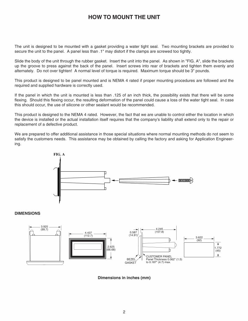
The unit is designed to be mounted with a gasket providing a water tight seal. Two mounting brackets are provided tosecure the unit to the panel. A panel less than .1" may distort if the clamps are screwed too tightly.
Slide the body of the unit through the rubber gasket. Insert the unit into the panel. As shown in "FIG. A", slide the bracketsup the groove to press against the back of the panel. Insert screws into rear of brackets and tighten them evenly andalternately. Do not over tighten! A normal level of torque is required. Maximum torque should be 3" pounds.
This product is designed to be panel mounted and is NEMA 4 rated if proper mounting procedures are followed and therequired and supplied hardware is correctly used.
If the panel in which the unit is mounted is less than .125 of an inch thick, the possibility exists that there will be someflexing. Should this flexing occur, the resulting deformation of the panel could cause a loss of the water tight seal. In casethis should occur, the use of silicone or other sealant would be recommended.
This product is designed to the NEMA 4 rated. However, the fact that we are unable to control either the location in whichthe device is installed or the actual installation itself requires that the company's liability shall extend only to the repair orreplacement of a defective product.
We are prepared to offer additional assistance in those special situations where normal mounting methods do not seem tosatisfy the customers needs. This assistance may be obtained by calling the factory and asking for Application Engineer-ing.
DIMENSIONS
FIG. A
Dimensions in inches (mm)
3.622(92)
1.772(45)
4.437(112.7)
2.625(66.68)
0.587(14.91)
4.245(107.8)
BEZELGASKET
CUSTOMER PANELPanel Thickness 0.062" (1.5)to 0.187" (4.7) max.
3.925(99.7)
3
WIRING
The rear terminal contains 12 screw terminals for connecting #14 to #28 gauge wire.
The unit is controlled by a microprocessor and, therefore, an electrically "noisy" environment could cause operatingproblems. The input power line should not be common to power lines for motors, pumps, contactors, etc.
The unit is designed to be immune from line or RF voltage interference. In some environments voltage spikes of over 100volts, even 1000 volts, can occur. When common to a power line driving motors voltage fluctuations can be extreme andrapid. Lines driving DC or AC solenoids, relays, or actuators can also cause problems.
Four sources of noise can occur:
1) AC power line noise - If the unit cannot be connected to a clean power source, an inductive load suppressing device(MOV as GE # V130LA1 or Resistor Capacitor as Paktron # .2 uf/220 ohm @ 400V) can be installed. Although locatingthe suppressor across the AC supply at the unit should help, best results are obtained by connecting the suppressoracross the leads of the "load" at the device causing the spike.
2) Input line noise -The noise is carried on the input and D.C. ground lines. Make sure the input wires are never run intothe unit in a bundle with power input lines. Also, keep these input lines isolated from inductive lines from devicesdrawing heavy loads. If there is a possibility of electrical noise, we recommend using shielded cable, with the shieldbeing hooked to the D.C. ground terminal on the instrument, and to "earth" at one point in the circuit, preferably at theD.C. ground terminal of the unit.
3) Output lines - The unit has two relay outputs. When these outputs are used to run external relays or solenoids, spikescan be generated upon activation. This noise can spread through the instrument causing operating problems. If thesource is a D.C. operated device, a general purpose diode (IN4004) placed across the solenoid prevents electricalnoise spikes. Connect the cathode (banded side) to the more positive side of the coil. If the source is an A.C. operateddevice, use a MOV or Resistor Capacitor across the coil.
4) 12 VDC output supply - Noise can be generated on the 12 VDC output supply if it is used to drive inductive loads or ifthe current draw exceeds 50 mA. Insure that all inductive loads have a diode (such as IN4004) across the coil and thatthe current does not exceed 50 mA.
UP/DOWN CONTROL AND QUADRATURE INPUTS
QUADRATURE INPUT:When programming the counter section for quadrature input, you must set the unit for A net B and A sub B (see step 2 inprogramming section). This insures proper operation. The rate can only be viewed in one direction. If the unit is aratemeter only (DPF78), connect only one of the quadrature channels to Input A (pin 5).
UP/DOWN CONTROL:When using the up/down control option, Input A (pin 5) is the count input and Input B (pin 6) is the up/down control(direction) input. The counter must be set for A net B and A sub B (see step 2 in programming section).When the direction input is high (4-30VDC) the count inputs will count up, when the direction input is low (open or less than1VDC) the count inputs will count down. The direction input must precede the count input by 1 msec when the unit is set forlow CPS and 1 usec when set for high CPS.
4
CONNECTING AC / DC POWER
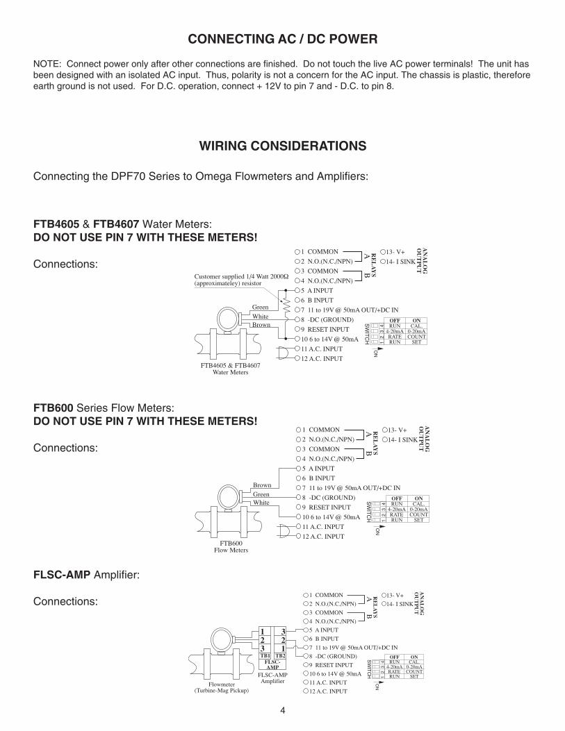
NOTE: Connect power only after other connections are finished. Do not touch the live AC power terminals! The unit hasbeen designed with an isolated AC input. Thus, polarity is not a concern for the AC input. The chassis is plastic, thereforeearth ground is not used. For D.C. operation, connect + 12V to pin 7 and - D.C. to pin 8.
1 COMMON
2 N.O.(N.C./NPN)
3 COMMON
4 N.O.(N.C./NPN)
5 A INPUT
6 B INPUT
7 11 to 19V @ 50mA OUT/+DC IN
8 -DC (GROUND)
9 RESET INPUT
10 6 to 14V @ 50mA
11 A.C. INPUT
12 A.C. INPUT
RE
LA
YS
AB
13- V+
14- I SINK
AN
AL
OG
OU
TP
UT
ONCAL.
0-20mACOUNT
SET
OFFRUN
4-20mARATERUN1
2
3
4
ON
SW
ITC
H
Flowmeter(Turbine-Mag Pickup)
123TB1
321
TB2FLSC-AMP
FLSC-AMPAmplifier
FLSC-AMP Amplifier:
Connections:
FTB600Flow Meters
Brown
1 COMMON
2 N.O.(N.C./NPN)
3 COMMON
4 N.O.(N.C./NPN)
5 A INPUT
6 B INPUT
7 11 to 19V @ 50mA OUT/+DC IN
8 -DC (GROUND)
9 RESET INPUT
10 6 to 14V @ 50mA
11 A.C. INPUT
12 A.C. INPUT
RE
LA
YS
AB
13- V+
14- I SINK
AN
AL
OG
OU
TP
UT
ONCAL.
0-20mACOUNT
SET
OFFRUN
4-20mARATERUN1
2
3
4
ON
SW
ITC
H
GreenWhite
FTB600 Series Flow Meters:DO NOT USE PIN 7 WITH THESE METERS!
Connections:
FTB4605 & FTB4607Water Meters
Green
1 COMMON
2 N.O.(N.C./NPN)
3 COMMON
4 N.O.(N.C./NPN)
5 A INPUT
6 B INPUT
7 11 to 19V @ 50mA OUT/+DC IN
8 -DC (GROUND)
9 RESET INPUT
10 6 to 14V @ 50mA
11 A.C. INPUT
12 A.C. INPUT
RE
LA
YS
AB
13- V+
14- I SINK
AN
AL
OG
OU
TP
UT
ONCAL.
0-20mACOUNT
SET
OFFRUN
4-20mARATERUN1
2
3
4
ON
SW
ITC
H
BrownWhite
Customer supplied 1/4 Watt 2000Ω(approximateley) resistor
FTB4605 & FTB4607 Water Meters:DO NOT USE PIN 7 WITH THESE METERS!
Connections:
WIRING CONSIDERATIONS
Connecting the DPF70 Series to Omega Flowmeters and Amplifiers:
5
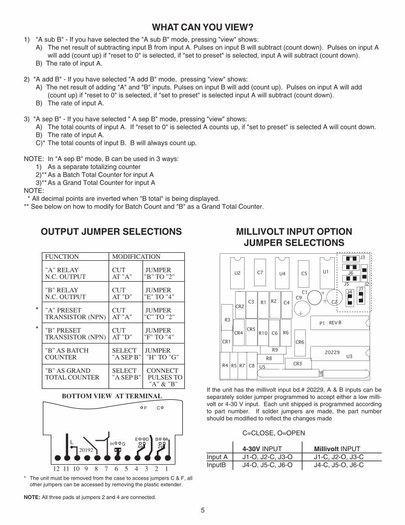
WHAT CAN YOU VIEW?1) "A sub B" - If you have selected the "A sub B" mode, pressing "view" shows:
A) The net result of subtracting input B from input A. Pulses on input B will subtract (count down). Pulses on input Awill add (count up) if "reset to 0" is selected, if "set to preset" is selected, input A will subtract (count down).
B) The rate of input A.
2) "A add B" - If you have selected "A add B" mode, pressing "view" shows:A) The net result of adding "A" and "B" inputs. Pulses on input B will add (count up). Pulses on input A will add
(count up) if "reset to 0" is selected, if "set to preset" is selected input A will subtract (count down).B) The rate of input A.
3) "A sep B" - If you have selected " A sep B" mode, pressing "view" shows:A) The total counts of input A. If "reset to 0" is selected A counts up, if "set to preset" is selected A will count down.B) The rate of input A.C)* The total counts of input B. B will always count up.
NOTE: In "A sep B" mode, B can be used in 3 ways:1) As a separate totalizing counter2)**As a Batch Total Counter for input A3)**As a Grand Total Counter for input A
NOTE: * All decimal points are inverted when "B total" is being displayed.** See below on how to modify for Batch Count and "B" as a Grand Total Counter.
MILLIVOLT INPUT OPTIONJUMPER SELECTIONS
OUTPUT JUMPER SELECTIONS
FUNCTION
"A" RELAYN.C. OUTPUT
"B" RELAYN.C. OUTPUT
"A" PRESETTRANSISTOR (NPN)
"B" PRESETTRANSISTOR (NPN)
"B" AS BATCHCOUNTER
"B" AS GRANDTOTAL COUNTER
MODIFICATION
CUT JUMPERAT "A" "B" TO "2"
CUT JUMPERAT "D" "E" TO "4"
CUT JUMPERAT "A" "C" TO "2"
CUT JUMPERAT "D" "F" TO "4"
SELECT JUMPER"A SEP B" "H" TO "G"
SELECT CONNECT"A SEP B" PULSES TO "A" & "B"
BOTTOM VIEW AT TERMINAL
DEGH
20192
12 11 10 9 8 7 6 5 4 3 2 1
L4
AB
2
F C
J4
J5
J6
J3
J1J2
CR1
R3
C8R7R5R4
U1
CR2
REV
20229
CR6
CR3
U3
P1
R10 R6C6
C7
CR4CR5
C4R2R1C3
C5U2 U4
U6
U5
R8
R9
C1
C2C9
B
If the unit has the millivolt input bd.# 20229, A & B inputs can beseparately solder jumper programmed to accept either a low milli-volt or 4-30 V input. Each unit shipped is programmed accordingto part number. If solder jumpers are made, the part numbershould be modified to reflect the changes made
C=CLOSE, O=OPEN
4-30V INPUT Millivolt INPUTInput A J1-O, J2-C, J3-O J1-C, J2-O, J3-CInputB J4-O, J5-C, J6-O J4-C, J5-O, J6-C
*
*
* The unit must be removed from the case to access jumpers C & F, allother jumpers can be accessed by removing the plastic extender.
NOTE: All three pads at jumpers 2 and 4 are connected.
6
PRGM
FACToR
RUN MODE
DP F A
#####
DP F B
#####
ENTER
ENTER
ENTER
ENTER
ENTER
PRGM
HiCPS
LoCPSPRGM
RUN MODE
ENTER RATE METER(MR2) ONLY
CouNT
ENTER
RST0
SET PRPRGM
ENTER
DPLoC
ENTER
ANET
B
ASEP
BPRGM
ENTERENTER
AADD
B
ASuB
BPRGM
HiCPS
LoCPSPRGM
ENTER
RUN MODE
ENTER
RATE
ENTER
SCALE RPSPRGM
Z3600 Z60PRGM
ENTERENTER
ENTER
RUN MODE
NoR ##
ENTER
FiguR#
ENTER
DLY #
ENTER
LoC
ENTER
LCPRg
LCALLPRGM
ENTER
CoDE
#####
RUN MODE
ENTER
RELAY
AToT PRGM
A ##.#
ENTER ENTER
BToT PRGM
B ##.#
ENTER ENTER
RUN MODE
PRGM PRGM PRGM
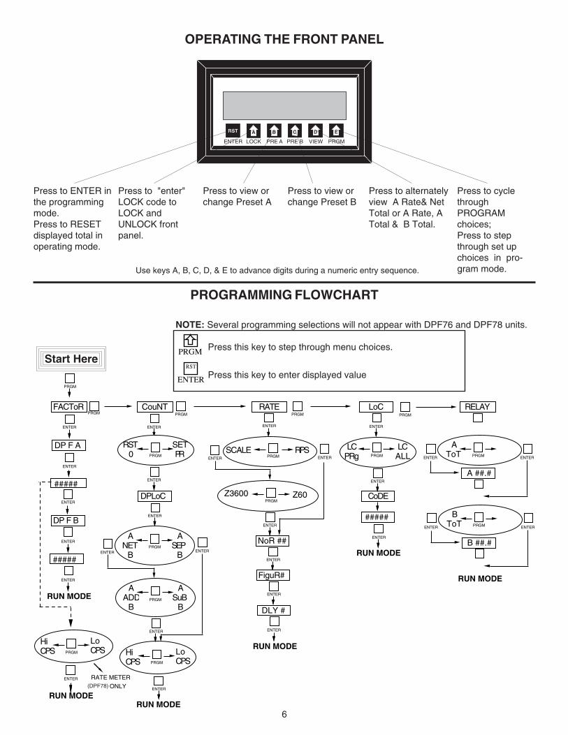
PROGRAMMING FLOWCHART
NOTE: Several programming selections will not appear with DPF76 and DPF78 units.
PRGM Press this key to step through menu choices.
ENTER
RST
Press this key to enter displayed value
Start Here
(DPF78)
OPERATING THE FRONT PANEL
ARST B C D E
ENTER LOCK PRE A PRE B VIEW PRGM
Use keys A, B, C, D, & E to advance digits during a numeric entry sequence.
Press to ENTER inthe programmingmode.Press to RESETdisplayed total inoperating mode.
Press to "enter"LOCK code toLOCK andUNLOCK frontpanel.
Press to view orchange Preset A
Press to view orchange Preset B
Press to alternatelyview A Rate& NetTotal or A Rate, ATotal & B Total.
Press to cyclethroughPROGRAMchoices;Press to stepthrough set upchoices in pro-gram mode.
7
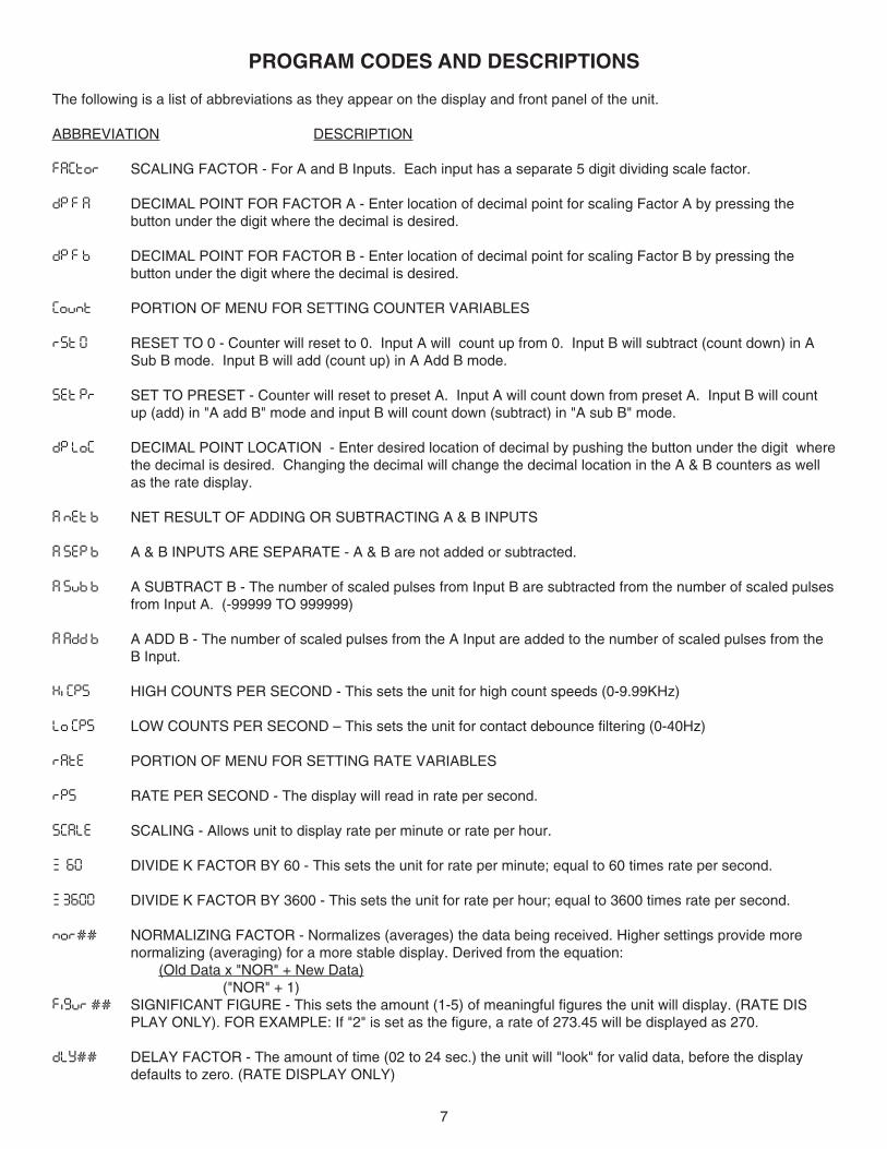
The following is a list of abbreviations as they appear on the display and front panel of the unit.
ABBREVIATION DESCRIPTION
FACTOR SCALING FACTOR - For A and B Inputs. Each input has a separate 5 digit dividing scale factor.
DP F A DECIMAL POINT FOR FACTOR A - Enter location of decimal point for scaling Factor A by pressing thebutton under the digit where the decimal is desired.
DP F B DECIMAL POINT FOR FACTOR B - Enter location of decimal point for scaling Factor B by pressing thebutton under the digit where the decimal is desired.
COUNT PORTION OF MENU FOR SETTING COUNTER VARIABLES
RST 0 RESET TO 0 - Counter will reset to 0. Input A will count up from 0. Input B will subtract (count down) in ASub B mode. Input B will add (count up) in A Add B mode.
SET PR SET TO PRESET - Counter will reset to preset A. Input A will count down from preset A. Input B will countup (add) in "A add B" mode and input B will count down (subtract) in "A sub B" mode.
DP LOC DECIMAL POINT LOCATION - Enter desired location of decimal by pushing the button under the digit wherethe decimal is desired. Changing the decimal will change the decimal location in the A & B counters as wellas the rate display.
A NET B NET RESULT OF ADDING OR SUBTRACTING A & B INPUTS
A SEP B A & B INPUTS ARE SEPARATE - A & B are not added or subtracted.
A SUB B A SUBTRACT B - The number of scaled pulses from Input B are subtracted from the number of scaled pulsesfrom Input A. (-99999 TO 999999)
A ADD B A ADD B - The number of scaled pulses from the A Input are added to the number of scaled pulses from theB Input.
HI CPS HIGH COUNTS PER SECOND - This sets the unit for high count speeds (0-9.99KHz)
LO CPS LOW COUNTS PER SECOND – This sets the unit for contact debounce filtering (0-40Hz)
RATE PORTION OF MENU FOR SETTING RATE VARIABLES
RPS RATE PER SECOND - The display will read in rate per second.
SCALE SCALING - Allows unit to display rate per minute or rate per hour.
Z 60 DIVIDE K FACTOR BY 60 - This sets the unit for rate per minute; equal to 60 times rate per second.
Z 3600 DIVIDE K FACTOR BY 3600 - This sets the unit for rate per hour; equal to 3600 times rate per second.
NOR## NORMALIZING FACTOR - Normalizes (averages) the data being received. Higher settings provide morenormalizing (averaging) for a more stable display. Derived from the equation:
(Old Data x "NOR" + New Data)("NOR" + 1)
FIGUR ## SIGNIFICANT FIGURE - This sets the amount (1-5) of meaningful figures the unit will display. (RATE DISPLAY ONLY). FOR EXAMPLE: If "2" is set as the figure, a rate of 273.45 will be displayed as 270.
DLY## DELAY FACTOR - The amount of time (02 to 24 sec.) the unit will "look" for valid data, before the displaydefaults to zero. (RATE DISPLAY ONLY)
PROGRAM CODES AND DESCRIPTIONS
8
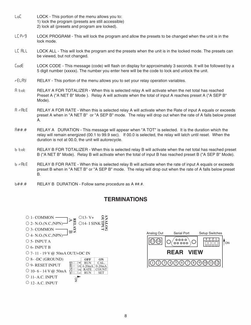
LOC LOCK - This portion of the menu allows you to:1) lock the program (presets are still accessible)2) lock all (presets and program are locked).
LC PRG LOCK PROGRAM - This will lock the program and allow the presets to be changed when the unit is in thelock mode.
LC ALL LOCK ALL - This will lock the program and the presets when the unit is in the locked mode. The presets canbe viewed, but not changed.
CODE LOCK CODE - This message (code) will flash on display for approximately 3 seconds. It will be followed by a5 digit number (xxxxx). The number you enter here will be the code to lock and unlock the unit.
RELAY RELAY - This portion of the menu allows you to set your relay operation variables.
A TOT RELAY A FOR TOTALIZER - When this is selected relay A will activate when the net total has reachedPreset A ("A NET B" Mode ). Relay A will activate when the total of input A reaches preset A ("A SEP B"Mode).
A RATE RELAY A FOR RATE - When this is selected relay A will activate when the Rate of input A equals or exceedspreset A when in "A NET B" or "A SEP B" mode. The relay will drop out when the rate of A falls below presetA.
A##.# RELAY A DURATION - This message will appear when "A TOT" is selected. It is the duration which therelay will remain energized (00.1 to 99.9 sec). If 00.0 is selected, the relay will latch until reset. When theduration is not at 00.0, the unit will autorecycle.
B TOT RELAY B FOR TOTALIZER - When this is selected relay B will activate when the net total has reached presetB ("A NET B" Mode). Relay B will activate when the total of input B has reached preset B ("A SEP B" Mode).
B RATE RELAY B FOR RATE - When this is selected relay B will activate when the rate of input A equals or exceedspreset B when in "A NET B" or "A SEP B" mode. The relay will drop out when the rate of A falls below presetB.
B##.# RELAY B DURATION - Follow same procedure as A ##.#.
TERMINATIONS
1 2 3 4
REAR VIEW
1 2 3 4 5 6 7 8 9 10 11 12
13 14
Analog Out Setup SwitchesSerial Port
ON
RE
LA
YS
AB
13- V+
14- I SINK
AN
AL
OG
OU
TP
UT
ONCAL.
0-20mACOUNT
SET
OFFRUN
4-20mARATERUN1
2
3
4
ON
SW
ITC
H
1- COMMON
2- N.O.(N.C./NPN)
3- COMMON
4- N.O.(N.C./NPN)
5- INPUT A
6- INPUT B
7- 11 - 19 V @ 50mA OUT/+DC IN
8- -DC (GROUND)
9- RESET INPUT
10- 6 - 14 V @ 50mA
11- A.C. INPUT
12- A.C. INPUT
9
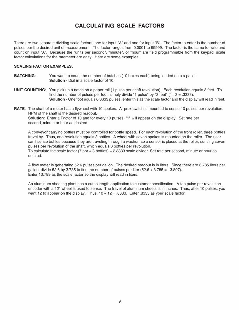
CALCULATING SCALE FACTORS
There are two separate dividing scale factors, one for input "A" and one for input "B". The factor to enter is the number ofpulses per the desired unit of measurement. The factor ranges from 0.0001 to 99999. The factor is the same for rate andcount on input "A". Because the "units per second", "minute", or "hour" are field programmable from the keypad, scalefactor calculations for the ratemeter are easy. Here are some examples:
SCALING FACTOR EXAMPLES:
BATCHING: You want to count the number of batches (10 boxes each) being loaded onto a pallet.Solution - Dial in a scale factor of 10.
UNIT COUNTING: You pick up a notch on a paper roll (1 pulse per shaft revolution). Each revolution equals 3 feet. Tofind the number of pulses per foot, simply divide "1 pulse" by "3 feet" (1÷ 3 = .3333).Solution - One foot equals 0.3333 pulses, enter this as the scale factor and the display will read in feet.
RATE: The shaft of a motor has a flywheel with 10 spokes. A prox switch is mounted to sense 10 pulses per revolution.RPM of the shaft is the desired readout.Solution: Enter a Factor of 10 and for every 10 pulses, "1" will appear on the display. Set rate persecond, minute or hour as desired.
A conveyor carrying bottles must be controlled for bottle speed. For each revolution of the front roller, three bottlestravel by. Thus, one revolution equals 3 bottles. A wheel with seven spokes is mounted on the roller. The usercan't sense bottles because they are traveling through a washer, so a sensor is placed at the roller, sensing sevenpulses per revolution of the shaft, which equals 3 bottles per revolution.To calculate the scale factor (7 ppr ÷ 3 bottles) = 2.3333 scale divider. Set rate per second, minute or hour asdesired.
A flow meter is generating 52.6 pulses per gallon. The desired readout is in liters. Since there are 3.785 liters pergallon, divide 52.6 by 3.785 to find the number of pulses per liter (52.6 ÷ 3.785 = 13.897).Enter 13.789 as the scale factor so the display will read in liters.
An aluminum sheeting plant has a cut to length application to customer specification. A ten pulse per revolutionencoder with a 12" wheel is used to sense. The travel of aluminum sheets is in inches. Thus, after 10 pulses, youwant 12 to appear on the display. Thus, 10 ÷ 12 = .8333. Enter .8333 as your scale factor.
10
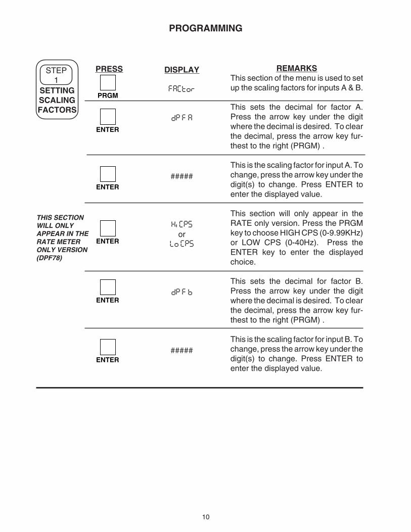
REMARKSThis section of the menu is used to setup the scaling factors for inputs A & B.
This sets the decimal for factor A.Press the arrow key under the digitwhere the decimal is desired. To clearthe decimal, press the arrow key fur-thest to the right (PRGM) .
This is the scaling factor for input A. Tochange, press the arrow key under thedigit(s) to change. Press ENTER toenter the displayed value.
This section will only appear in theRATE only version. Press the PRGMkey to choose HIGH CPS (0-9.99KHz)or LOW CPS (0-40Hz). Press theENTER key to enter the displayedchoice.
This sets the decimal for factor B.Press the arrow key under the digitwhere the decimal is desired. To clearthe decimal, press the arrow key fur-thest to the right (PRGM) .
This is the scaling factor for input B. Tochange, press the arrow key under thedigit(s) to change. Press ENTER toenter the displayed value.
DISPLAY
factor
dp f a
#####
hi cps
orlo cps
dp f b
#####
PRESS
PRGM
ENTER
ENTER
ENTER
ENTER
ENTER
THIS SECTIONWILL ONLYAPPEAR IN THERATE METERONLY VERSION(DPF78)
SETTINGSCALINGFACTORS
STEP1
PROGRAMMING
11
PRESS DISPLAY REMARKS
PRGM
PRGM
ENTER
ENTER
SETTINGTHE
COUNTER
STEP2
DPF75&
DPF76ONLY
factor
count
rst 0
orset pr
dp loc
a net b
ora sep b
a sub b
ora add b
hi cps
orlo cpsENTER
ENTER
ENTER
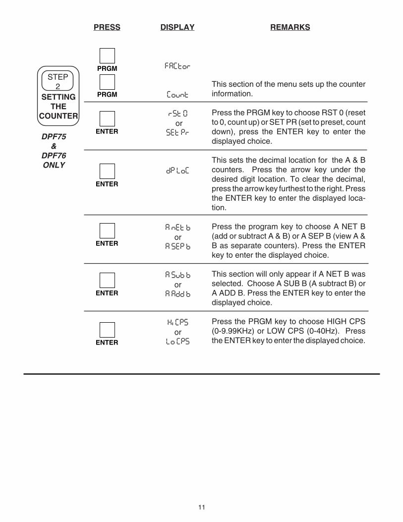
This section of the menu sets up the counterinformation.
Press the PRGM key to choose RST 0 (resetto 0, count up) or SET PR (set to preset, countdown), press the ENTER key to enter thedisplayed choice.
This sets the decimal location for the A & Bcounters. Press the arrow key under thedesired digit location. To clear the decimal,press the arrow key furthest to the right. Pressthe ENTER key to enter the displayed loca-tion.
Press the program key to choose A NET B(add or subtract A & B) or A SEP B (view A &B as separate counters). Press the ENTERkey to enter the displayed choice.
This section will only appear if A NET B wasselected. Choose A SUB B (A subtract B) orA ADD B. Press the ENTER key to enter thedisplayed choice.
Press the PRGM key to choose HIGH CPS(0-9.99KHz) or LOW CPS (0-40Hz). Pressthe ENTER key to enter the displayed choice.
12
ENTER
STEP3
REMARKSPRESS DISPLAY
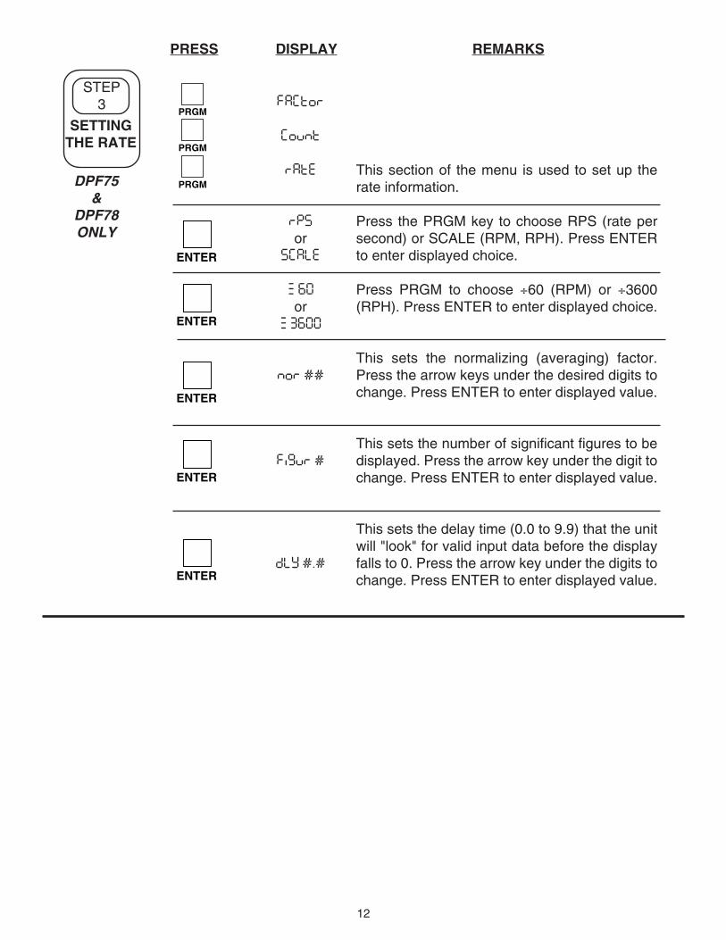
This section of the menu is used to set up therate information.
Press the PRGM key to choose RPS (rate persecond) or SCALE (RPM, RPH). Press ENTERto enter displayed choice.
Press PRGM to choose ÷60 (RPM) or ÷3600(RPH). Press ENTER to enter displayed choice.
This sets the normalizing (averaging) factor.Press the arrow keys under the desired digits tochange. Press ENTER to enter displayed value.
This sets the number of significant figures to bedisplayed. Press the arrow key under the digit tochange. Press ENTER to enter displayed value.
This sets the delay time (0.0 to 9.9) that the unitwill "look" for valid input data before the displayfalls to 0. Press the arrow key under the digits tochange. Press ENTER to enter displayed value.
factor
count
rate
rps
orscale
z 60
orz 3600
nor ##
figur #
dly #.#
ENTER
ENTER
PRGM
PRGM
PRGM
ENTER
ENTER
SETTINGTHE RATE
DPF75&
DPF78ONLY
13
DISPLAY REMARKS
factor
count
rate
loc
LC PG
orLC ALL
CoDE
Flashesfollowed by:
#####
CoDE
Flashesfollowed by:
0
LoC
oruN LoC
PRGM
PRGM
PRGM
PRGM
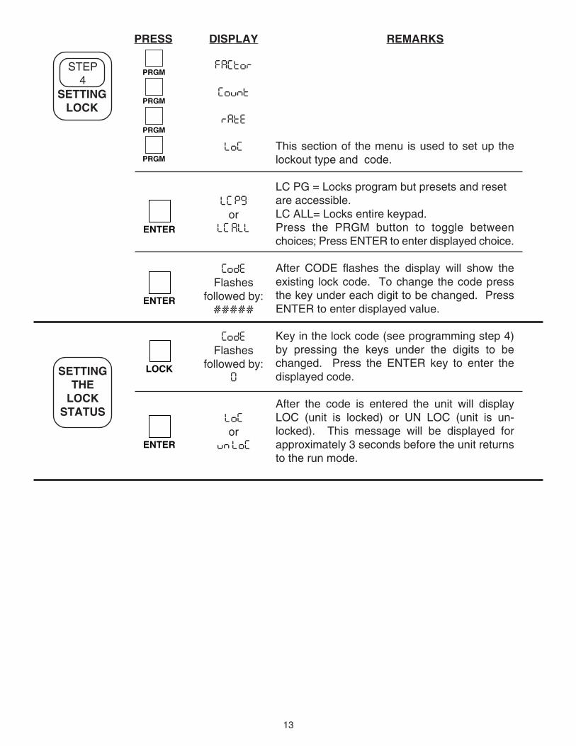
This section of the menu is used to set up thelockout type and code.
LC PG = Locks program but presets and resetare accessible.LC ALL= Locks entire keypad.Press the PRGM button to toggle betweenchoices; Press ENTER to enter displayed choice.
After CODE flashes the display will show theexisting lock code. To change the code pressthe key under each digit to be changed. PressENTER to enter displayed value.
Key in the lock code (see programming step 4)by pressing the keys under the digits to bechanged. Press the ENTER key to enter thedisplayed code.
After the code is entered the unit will displayLOC (unit is locked) or UN LOC (unit is un-locked). This message will be displayed forapproximately 3 seconds before the unit returnsto the run mode.
ENTER
SETTINGTHE
LOCKSTATUS
PRESS
SETTINGLOCK
STEP4
ENTER
LOCK
ENTER
14
REMARKSDISPLAYPRESS
PRGM
PRGM
PRGM
PRGM
PRGM
STEP5
SETTINGTHE
RELAYS
ENTER
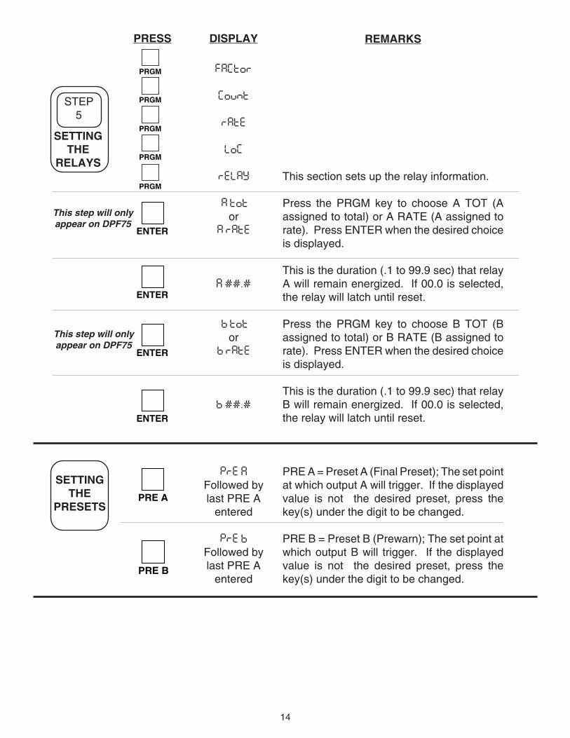
This section sets up the relay information.
Press the PRGM key to choose A TOT (Aassigned to total) or A RATE (A assigned torate). Press ENTER when the desired choiceis displayed.
This is the duration (.1 to 99.9 sec) that relayA will remain energized. If 00.0 is selected,the relay will latch until reset.
Press the PRGM key to choose B TOT (Bassigned to total) or B RATE (B assigned torate). Press ENTER when the desired choiceis displayed.
This is the duration (.1 to 99.9 sec) that relayB will remain energized. If 00.0 is selected,the relay will latch until reset.
PRE A = Preset A (Final Preset); The set pointat which output A will trigger. If the displayedvalue is not the desired preset, press thekey(s) under the digit to be changed.
PRE B = Preset B (Prewarn); The set point atwhich output B will trigger. If the displayedvalue is not the desired preset, press thekey(s) under the digit to be changed.
ENTER
factor
count
rate
loc
relay
a tot
ora rate
A ##.#
b tot
orb rate
b ##.#
PRE A
Followed bylast PRE A
entered
PRE B
Followed bylast PRE A
entered
ENTER
ENTER
SETTINGTHE
PRESETSPRE A
PRE B
This step will onlyappear on DPF75
This step will onlyappear on DPF75
15
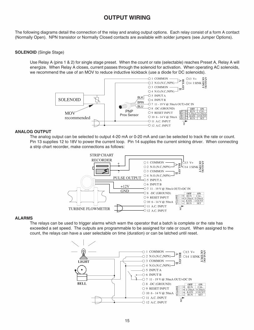
OUTPUT WIRING
The following diagrams detail the connection of the relay and analog output options. Each relay consist of a form A contact(Normally Open). NPN transistor or Normally Closed contacts are available with solder jumpers (see Jumper Options).
SOLENOID (Single Stage)
Use Relay A (pins 1 & 2) for single stage preset. When the count or rate (selectable) reaches Preset A, Relay A willenergize. When Relay A closes, current passes through the solenoid for activation. When operating AC solenoids,we recommend the use of an MOV to reduce inductive kickback (use a diode for DC solenoids).
ANALOG OUTPUTThe analog output can be selected to output 4-20 mA or 0-20 mA and can be selected to track the rate or count.Pin 13 supplies 12 to 18V to power the current loop. Pin 14 supplies the current sinking driver. When connectinga strip chart recorder, make connections as follows:
ALARMSThe relays can be used to trigger alarms which warn the operator that a batch is complete or the rate hasexceeded a set speed. The outputs are programmable to be assigned for rate or count. When assigned to thecount, the relays can have a user selectable on time (duration) or can be latched until reset.
MOV recommended
SOLENOID
PNPProx Sensor
BLK
BRNBLU
1 COMMON
2 N.O.(N.C./NPN)
3 COMMON
4 N.O.(N.C./NPN)
5 INPUT A
6 INPUT B
7 11 - 19 V @ 50mA OUT/+DC IN
8 -DC (GROUND)
9 RESET INPUT
10 6 - 14 V @ 50mA
11 A.C. INPUT
12 A.C. INPUT
RE
LA
YS
AB
13 V+
14 I SINK
AN
AL
OG
OU
TP
UT
ONCAL.
0-20mACOUNT
SET
OFFRUN
4-20mARATERUN1
2
3
4
ON
SW
ITC
H
GND+12V
STRIP CHARTRECORDER
TURBINE FLOWMETER
PULSE OUTPUT
-
+ 1 COMMON
2 N.O.(N.C./NPN)
3 COMMON
4 N.O.(N.C./NPN)
5 INPUT A
6 INPUT B
7 11 - 19 V @ 50mA OUT/+DC IN
8 -DC (GROUND)
9 RESET INPUT
10 6 - 14 V @ 50mA
11 A.C. INPUT
12 A.C. INPUT
RE
LA
YS
AB
13 V+
14 I SINK
AN
AL
OG
OU
TP
UT
ONCAL.
0-20mACOUNT
SET
OFFRUN
4-20mARATERUN1
2
3
4
ON
SW
ITC
H
LIGHT
BELL
1 COMMON
2 N.O.(N.C./NPN)
3 COMMON
4 N.O.(N.C./NPN)
5 INPUT A
6 INPUT B
7 11 - 19 V @ 50mA OUT/+DC IN
8 -DC (GROUND)
9 RESET INPUT
10 6 - 14 V @ 50mA
11 A.C. INPUT
12 A.C. INPUT
RE
LA
YS
AB
13 V+
14 I SINK
AN
AL
OG
OU
TP
UT
ONCAL.
0-20mACOUNT
SET
OFFRUN
4-20mARATERUN1
2
3
4
ON
SW
ITC
H
16
ANALOG OUTPUT OPTION
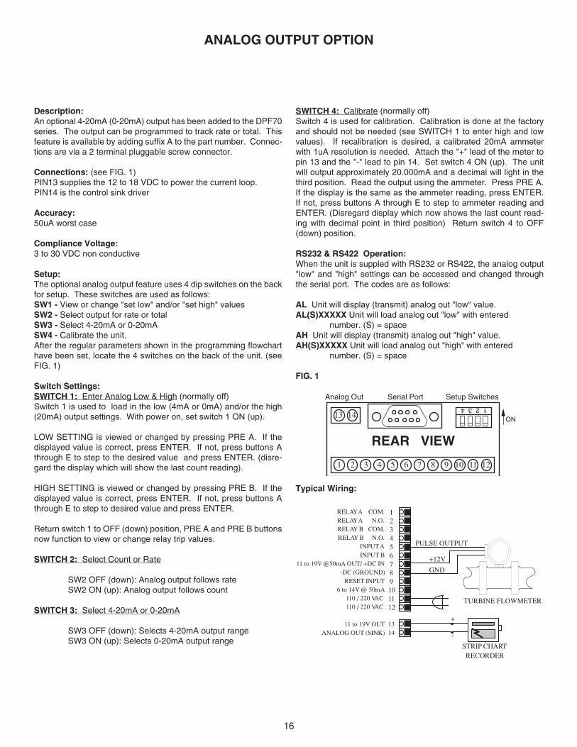
Description:An optional 4-20mA (0-20mA) output has been added to the DPF70series. The output can be programmed to track rate or total. Thisfeature is available by adding suffix A to the part number. Connec-tions are via a 2 terminal pluggable screw connector.
Connections: (see FIG. 1)PIN13 supplies the 12 to 18 VDC to power the current loop.PIN14 is the control sink driver
Accuracy:50uA worst case
Compliance Voltage:3 to 30 VDC non conductive
Setup:The optional analog output feature uses 4 dip switches on the backfor setup. These switches are used as follows:SW1 - View or change "set low" and/or "set high" valuesSW2 - Select output for rate or totalSW3 - Select 4-20mA or 0-20mASW4 - Calibrate the unit.After the regular parameters shown in the programming flowcharthave been set, locate the 4 switches on the back of the unit. (seeFIG. 1)
Switch Settings:SWITCH 1: Enter Analog Low & High (normally off)Switch 1 is used to load in the low (4mA or 0mA) and/or the high(20mA) output settings. With power on, set switch 1 ON (up).
LOW SETTING is viewed or changed by pressing PRE A. If thedisplayed value is correct, press ENTER. If not, press buttons Athrough E to step to the desired value and press ENTER. (disre-gard the display which will show the last count reading).
HIGH SETTING is viewed or changed by pressing PRE B. If thedisplayed value is correct, press ENTER. If not, press buttons Athrough E to step to desired value and press ENTER.
Return switch 1 to OFF (down) position, PRE A and PRE B buttonsnow function to view or change relay trip values.
SWITCH 2: Select Count or Rate
SW2 OFF (down): Analog output follows rateSW2 ON (up): Analog output follows count
SWITCH 3: Select 4-20mA or 0-20mA
SW3 OFF (down): Selects 4-20mA output rangeSW3 ON (up): Selects 0-20mA output range
SWITCH 4: Calibrate (normally off)Switch 4 is used for calibration. Calibration is done at the factoryand should not be needed (see SWITCH 1 to enter high and lowvalues). If recalibration is desired, a calibrated 20mA ammeterwith 1uA resolution is needed. Attach the "+" lead of the meter topin 13 and the "-" lead to pin 14. Set switch 4 ON (up). The unitwill output approximately 20.000mA and a decimal will light in thethird position. Read the output using the ammeter. Press PRE A.If the display is the same as the ammeter reading, press ENTER.If not, press buttons A through E to step to ammeter reading andENTER. (Disregard display which now shows the last count read-ing with decimal point in third position) Return switch 4 to OFF(down) position.
RS232 & RS422 Operation:When the unit is suppled with RS232 or RS422, the analog output"low" and "high" settings can be accessed and changed throughthe serial port. The codes are as follows:
AL Unit will display (transmit) analog out "low" value.AL(S)XXXXX Unit will load analog out "low" with entered
number. (S) = spaceAH Unit will display (transmit) analog out "high" value.AH(S)XXXXX Unit will load analog out "high" with entered
number. (S) = space
FIG. 1
1 2 3 4
REAR VIEW
1 2 3 4 5 6 7 8 9 10 11 12
13 14
Analog Out Setup SwitchesSerial Port
ON
Typical Wiring:
RELAY A COM.RELAY A N.O.RELAY B COM.RELAY B N.O.
INPUT AINPUT B
11 to 19V @50mA OUT/ +DC IN-DC (GROUND)
RESET INPUT6 to 14V @ 50mA
110 / 220 VAC110 / 220 VAC
11 to 19V OUTANALOG OUT (SINK)
GND
+12V
STRIP CHARTRECORDER
-
+
TURBINE FLOWMETER
PULSE OUTPUT
101112
123456789
1314
17
INTERFACE CARD RS 232/422 OPERATION
RS 232/422 SET-UP:All serial communication mode changes must be donethrough serial communications. Mode changes cannot bedone through the front panel. To initialize the unit, place ajumper between pin 7(+12V )[bottom board] and pin 1(init) [DB-9 connector] on initial power up. The unit defaults to: 300baud rate,"MARK" parity and device number 01. To enter theprogram mode you must set your terminal for 300 baud rateand "MARK" parity. Next, type D1(s), (s)= space bar. Theunit will echo back "DEVICE #1:". Now type EP (enterprogram) and a carriage return (ENTER). The unit will echoback "PROGRAM SETTING". You are now in the program-ming mode.
SETUP PROCEDURE:The following sections consist of the communications setupoptions as they appear in the menu. (If you wish to exit theprogram mode, at any time you can hit the "escape key" (HexCode: 1B) and the unit will save the changes made but noteffect the remaining data values.) When each section of thesetup menu is displayed, the current data will appear in the <> signs. If you wish to change the data, type in the numberof the desired choice and press return (ENTER). If you wishto keep the current data, simply press return.
DEVICE NUMBER:Each unit in the hook-up must be assigned it's own devicenumber (1 to 99). Zero is reserved for a dedicated hook-up toonly one terminal, and it's transmit output line remains in an"on" active state. The device number is entered in theprogram mode. The unit will prompt you:DEVICE# <XX>? If XX is the desired device number press return (ENTER), ifnot enter the desired number after the question mark andpress return (ENTER).
BAUD RATE:The baud rate is the speed at which data is transmitted,expressed in bits per second. Baud rates of 300, 600, 1200,2400, 4800 or 9600 are available. When in the baud ratesection of the menu, the unit will list :BAUD RATES:1:300 2:600 3:12004:2400 5:4800 6:9600then prompt you:BAUD RATE <300>?Press return (ENTER) if this is the desired baud rate or enterthe assigned number of one of the six possible baud rates. Ifan invalid baud rate is entered the unit will prompt you tochoose another baud rate. This will occur until a valid baudrate is entered or escape is pressed.
PARITY:Parity is a bit of information that is inserted before the stop bitand is used to help check if the transmission is correct. Whensetting the parity you may select "ODD" (parity bit is logic 0 iftotal number of logic 1's in the first seven data bits is odd),
"EVEN" (parity bit is logic 0 if total number of logic 1's in the firstseven data bits is even), "MARK" (parity bit is always logic 1- High / Mark) or "SPACE" (parity bit is always logic 0 - Low /Space). If a "MARK" parity is chosen, it will appear that twostop bits are used. Use the "MARK" parity with terminals usingparity "OFF" or "NONE". These terminals ignore the parity.The unit does not check the parity but does transmit the paritychosen. When setting the parity, the unit will print:PARITIES:MARK-0 SPACE-1 EVEN-2 ODD-3Then the unit will prompt you:PARITY<MARK>?If this is the desired parity press return (ENTER), if it isn't enterthe number of the desired parity then press return (ENTER).
STROBE LIST:The serial interface card is also equipped with a strobe line.When the strobe line is triggered, a chosen set of data will betransmitted to be displayed or printed. The selections for thedisplay list are entered in the program mode. Enter "1" to addselections to the list and enter "0" to delete selections from thelist. The seven available items for the strobe display list are:(1) Preset A, (2) Preset B, (3) K-Factor A, (4) K-Factor B, (5)Rate of A, (6) Count A, (7) Count B. In the "A net B" modeCount A will display the Net Count and Count B is an invalidcommand and the unit will transmit useless data. Whensetting the strobe list the unit will print :ENTER STROBE LIST:DO NOT DISPLAY-0 DISPLAY-1The unit will prompt you:PRESET A<DISPLAY>?PRESET B<DISPLAY>?K-FACTOR A<DISPLAY>?K-FACTOR B<DISPLAY>?RATE<DISPLAY>?COUNT A<DISPLAY>?COUNT B<DISPLAY>?If the above choices are entered, when the strobe line istriggered (3-30V positive pulse) the unit will transmit:DEVICE# 1:PA XXXXXPB XXXXXKA XXXXXKB XXXXXDR XXXXXXDA XXXXXXDB XXXXXX(SEE COMMANDS BELOW FOR DESCRIPTION OF COM-MAND CODES).Each time the strobe line gets triggered the unit will transmitthis data unless the program mode is entered and the strobelist altered.
After these four items have been entered they will remainunaltered unless the program mode is entered again and thevalues changed. The unit is now set and must be addressedby its device number to come on line again.
18
SERIAL INPUT COMMANDS:To get a unit on line you must address it by its device number.This is done by typing DXX(S), XX= device number. The unitcomes on line and echoes back DEVICE# XX. Insure that"DEVICE# XX:" is received before requests are sent. The unitis now ready to receive a command or string of commandsseparated by a space. A carriage return (enter) will enter thecommands and processing of requests begins. The carriagereturn (Hex Code "D") puts the unit "off line" after data isprocessed.
COMMANDS:EP...........Unit will enter program mode.DA..........Unit will display (transmit) Count A.DB..........Unit will display (transmit) Count B.DR..........Unit will display (transmit) rate A.KA..........Unit will display K-factor A.†*KA(S)XXXXX....Unit will load K-factor Awith entered number.KB..........Unit will display K-factor B†*KB(S)XXXXX....Unit will load K-factor Bwith entered number.PA...........Unit will display Preset A.†PA(S)XXXXX....Unit will load Preset A withentered number.PB...........Unit will display Preset B†PB(S)XXXXX....Unit will load Preset B withentered number.RA..........Counter A will reset†*RA(S)XXXXXX...Unit will set Counter A toentered number.RB..........Counter B will reset.†*RB(S)XXXXXX...Unit will reset Counter B to
entered number.*THE UNIT WILL RECOGNIZE A DECIMAL IF ONE ISPLACED IN ANY OF THESE DATA VALUES.
†THE UNIT WILL ONLY RECOGNIZE THE LAST FIVEDIGITS ENTERED (SIX DIGITS FOR RA & RB).The following is an example of requests and responses:Transmit from terminal Receive from unit
(s)=SpaceD5(s) [Unit #5 Activated] DEVICE# 5:PA(s)12345(s)PA PA 12345 PAKA(s)1576(s)KA KA 1576 KAKB(s)6751(s)KB KB 6751 KBRA(s)RB[RETURN] RA RB(UNIT PRESETS AND A & B K-FACTORS ARE SET ANDBOTH COUNTERS ARE RESET)
1234515766751
SERIAL INTERFACE OPERATION:Data is received and transmitted over standard EIA RS232 orRS422 levels. Each ten bit character is made up of a start bit,seven bit ASCII code, a parity bit and a stop bit. Devicenumber, baud rate, parity and strobe list are entered in theprogram setup mode and will remain in memory even if poweris lost.
The input impedance of RS232 is 3KΩ to 7KΩ worst case. Theterminal addressing the unit must be capable of driving allloads in the loop. The input impedance of RS422 is muchhigher and there should be no problem driving as many as 99units. The transmit line remains in a high impedance "off"state until addressed. Only one unit is to be on line at a time!!!More than one unit on line could damage the unit or destroythe transmitted data.When the unit is active (on line) it will operate in a full duplex,echo back mode, so that data sent from the terminal will betransmitted back for verification. When the unit is "on line",use the proper serial transmit commands to request data orset a new value. Up to 80 characters of data can be linkedtogether and transmitted to the unit in a string as long as thereis a space between the commands. If an error is made, acorrection can be made by back spacing and retyping correctdata before the return (enter) is sent. Once a return (enter) issent, the unit begins processing the data and will transmit therequested data on a non-priority basis over the data transmitline. A keypad entry or incoming data will halt the datacommunication cycle. Therefore, there should be a pauseafter data is requested to insure that all data has beentransmitted before making another request or addressinganother unit. If the unit is not busy, it should not take longerthan 300 msec to process each request. To find the cycle timeto process and transmit a request, calculate the bit transmittime by using this formula: [(1÷ baud rate) x (80) + .005] xnumber of requests made. This time will be extended if theunit must service the front keypad. If transmission has notstarted within two seconds after data is requested, it can beassumed that there is a problem. The unit transmits a carriagereturn and line feed after each data value. Any new commu-nication must be started with DXX(S) (device number andspace).
RS232/RS422 - IBM-PC INTERFACE:The following program is for IBM basic to set up RS232/RS422on serial port (#1) at 300 baud. Run this program afterconnecting the serial interface connections.
10 SCREEN 0,0:WIDTH 80
20 CLS:CLOSE
30 OPEN "COM1:300,n,7,1,CS,DS,CD" AS #1
40 ON ERROR GOTO 110
50 B$=INKEY$
60 IF B$< >"" THEN PRINT #1,B$;
70 IF EOF (1) THEN 50
80 A$=INPUT$ (LOC(1),#1)
90 PRINT A$;
100 GOTO 50
110 RESUME
19
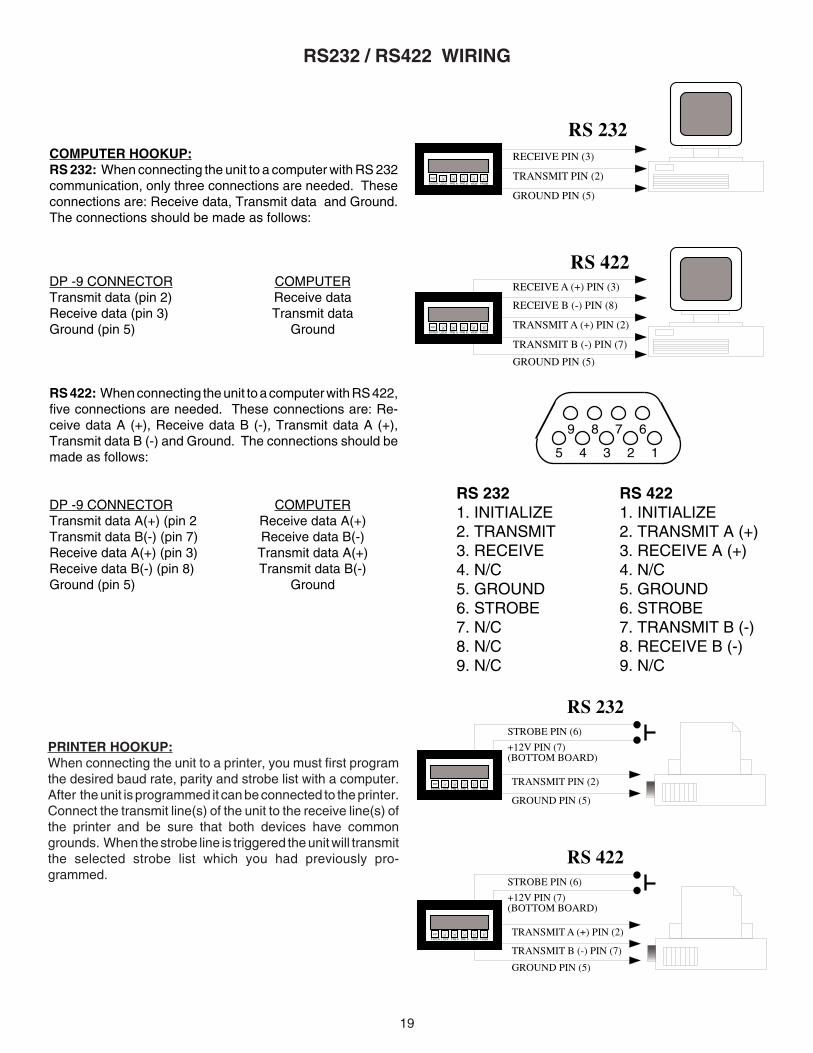
COMPUTER HOOKUP:RS 232: When connecting the unit to a computer with RS 232communication, only three connections are needed. Theseconnections are: Receive data, Transmit data and Ground.The connections should be made as follows:
DP -9 CONNECTOR COMPUTERTransmit data (pin 2) Receive dataReceive data (pin 3) Transmit dataGround (pin 5) Ground
RS 422: When connecting the unit to a computer with RS 422,five connections are needed. These connections are: Re-ceive data A (+), Receive data B (-), Transmit data A (+),Transmit data B (-) and Ground. The connections should bemade as follows:
DP -9 CONNECTOR COMPUTERTransmit data A(+) (pin 2 Receive data A(+)Transmit data B(-) (pin 7) Receive data B(-)Receive data A(+) (pin 3) Transmit data A(+)Receive data B(-) (pin 8) Transmit data B(-)Ground (pin 5) Ground
ARST B C D E
ENTER LOCK PRE A PRE B VIEW PRGM
TRANSMIT A (+) PIN (2)
GROUND PIN (5)
RS 422
TRANSMIT B (-) PIN (7)
STROBE PIN (6)
+12V PIN (7)(BOTTOM BOARD)
ARST B C D E
ENTER LOCK PRE A PRE B VIEW PRGM
TRANSMIT PIN (2)
GROUND PIN (5)
RS 232STROBE PIN (6)
+12V PIN (7)(BOTTOM BOARD)
RS232 / RS422 WIRING
ARST B C D E
ENTER LOCK PRE A PRE B VIEW PRGM
RECEIVE PIN (3)
TRANSMIT PIN (2)
GROUND PIN (5)
RS 232
ARST B C D E
ENTER LOCK PRE A PRE B VIEW PRGM
RECEIVE B (-) PIN (8)
TRANSMIT A (+) PIN (2)
GROUND PIN (5)
RS 422RECEIVE A (+) PIN (3)
TRANSMIT B (-) PIN (7)
12345
6789
RS 2321. INITIALIZE2. TRANSMIT3. RECEIVE4. N/C5. GROUND6. STROBE7. N/C8. N/C9. N/C
RS 4221. INITIALIZE2. TRANSMIT A (+)3. RECEIVE A (+)4. N/C5. GROUND6. STROBE7. TRANSMIT B (-)8. RECEIVE B (-)9. N/C
PRINTER HOOKUP:When connecting the unit to a printer, you must first programthe desired baud rate, parity and strobe list with a computer.After the unit is programmed it can be connected to the printer.Connect the transmit line(s) of the unit to the receive line(s) ofthe printer and be sure that both devices have commongrounds. When the strobe line is triggered the unit will transmitthe selected strobe list which you had previously pro-grammed.
20
PROBLEM SOLUTIONSPOSSIBLE CAUSES
TROUBLESHOOTING GUIDE
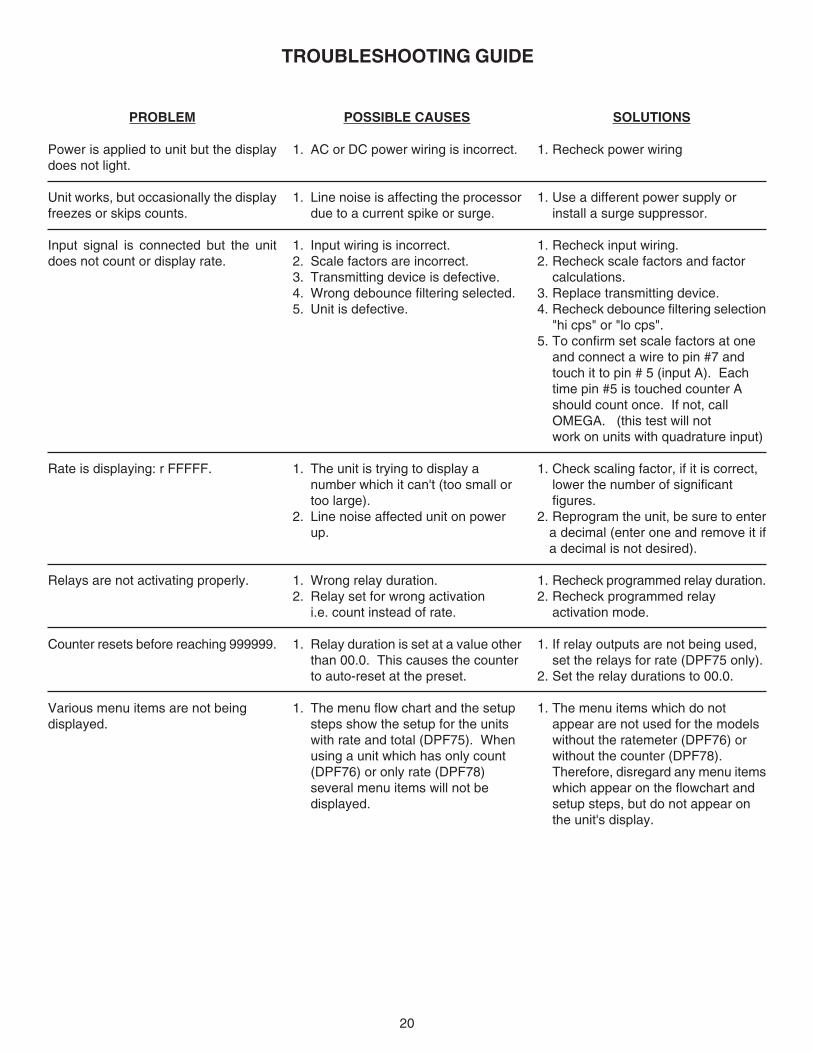
Power is applied to unit but the displaydoes not light.
Unit works, but occasionally the displayfreezes or skips counts.
Input signal is connected but the unitdoes not count or display rate.
Rate is displaying: r FFFFF.
Relays are not activating properly.
Counter resets before reaching 999999.
Various menu items are not beingdisplayed.
1. AC or DC power wiring is incorrect.
1. Line noise is affecting the processordue to a current spike or surge.
1. Input wiring is incorrect.2. Scale factors are incorrect.3. Transmitting device is defective.4. Wrong debounce filtering selected.5. Unit is defective.
1. The unit is trying to display anumber which it can't (too small ortoo large).
2. Line noise affected unit on powerup.
1. Wrong relay duration.2. Relay set for wrong activation
i.e. count instead of rate.
1. Relay duration is set at a value otherthan 00.0. This causes the counterto auto-reset at the preset.
1. The menu flow chart and the setupsteps show the setup for the unitswith rate and total (DPF75). Whenusing a unit which has only count(DPF76) or only rate (DPF78)several menu items will not bedisplayed.
1. Recheck power wiring
1. Use a different power supply orinstall a surge suppressor.
1. Recheck input wiring.2. Recheck scale factors and factor
calculations.3. Replace transmitting device.4. Recheck debounce filtering selection
"hi cps" or "lo cps".5. To confirm set scale factors at one
and connect a wire to pin #7 andtouch it to pin # 5 (input A). Eachtime pin #5 is touched counter Ashould count once. If not, callOMEGA. (this test will notwork on units with quadrature input)
1. Check scaling factor, if it is correct,lower the number of significantfigures.
2. Reprogram the unit, be sure to entera decimal (enter one and remove it ifa decimal is not desired).
1. Recheck programmed relay duration.2. Recheck programmed relay
activation mode.
1. If relay outputs are not being used,set the relays for rate (DPF75 only).
2. Set the relay durations to 00.0.
1. The menu items which do notappear are not used for the modelswithout the ratemeter (DPF76) orwithout the counter (DPF78).Therefore, disregard any menu itemswhich appear on the flowchart andsetup steps, but do not appear onthe unit's display.

21
NOTES

22
NOTES

23
NOTES
WARRANTY/DISCLAIMEROMEGA ENGINEERING, INC. warrants this unit to be free of defects in materials and workmanship for aperiod of 13 months from date of purchase. OMEGA’s WARRANTY adds an additional one (1) monthgrace period to the normal one (1) year product warranty to cover handling and shipping time. Thisensures that OMEGA’s customers receive maximum coverage on each product. If the unit malfunctions, it must be returned to the factory for evaluation. OMEGA’s Customer ServiceDepartment will issue an Authorized Return (AR) number immediately upon phone or written request.Upon examination by OMEGA, if the unit is found to be defective, it will be repaired or replaced at nocharge. OMEGA’s WARRANTY does not apply to defects resulting from any action of the purchaser,including but not limited to mishandling, improper interfacing, operation outside of design limits, improper repair, or unauthorized modification. This WARRANTY is VOID if the unit shows evidence of having been tampered with or shows evidence of having been damaged as a result of excessive corrosion;or current, heat, moisture or vibration; improper specification; misapplication; misuse or other operatingconditions outside of OMEGA’s control. Components which wear are not warranted, including but not limited to contact points, fuses, and triacs.OMEGA is pleased to offer suggestions on the use of its various products. However, OMEGA neither assumes responsibility for any omissions or errors nor assumes liability for anydamages that result from the use of its products in accordance with information provided byOMEGA, either verbal or written. OMEGA warrants only that the parts manufactured by it will beas specified and free of defects. OMEGA MAKES NO OTHER WARRANTIES OR REPRESENTATIONS OF ANY KIND WHATSOEVER, EXPRESS OR IMPLIED, EXCEPT THAT OF TITLE,AND ALL IMPLIED WARRANTIES INCLUDING ANY WARRANTY OF MERCHANTABILITY AND FITNESS FOR A PARTICULAR PURPOSE ARE HEREBY DISCLAIMED. LIMITATION OF LIABILITY: The remedies of purchaser set forth herein are exclusive, and the total liability of OMEGA with respect to this order, whether based on contract, warranty, negligence, indemnification, strict liability or otherwise, shall not exceed the purchase price of the component upon which liability is based. In no event shall OMEGA be liable for consequential, incidental or special damages.CONDITIONS: Equipment sold by OMEGA is not intended to be used, nor shall it be used: (1) as a “BasicComponent” under 10 CFR 21 (NRC), used in or with any nuclear installation or activity; or (2) in medicalapplications or used on humans. Should any Product(s) be used in or with any nuclear installation oractivity, medical application, used on humans, or misused in any way, OMEGA assumes no responsibilityas set forth in our basic WARRANTY/DISCLAIMER language, and, additionally, purchaser will indemnifyOMEGA and hold OMEGA harmless from any liability or damage whatsoever arising out of the use of theProduct(s) in such a manner.
RETURN REQUESTS/INQUIRIESDirect all warranty and repair requests/inquiries to the OMEGA Customer Service Department. BEFORERETURNING ANY PRODUCT(S) TO OMEGA, PURCHASER MUST OBTAIN AN AUTHORIZED RETURN(AR) NUMBER FROM OMEGA’S CUSTOMER SERVICE DEPARTMENT (IN ORDER TO AVOIDPROCESSING DELAYS). The assigned AR number should then be marked on the outside of the returnpackage and on any correspondence.The purchaser is responsible for shipping charges, freight, insurance and proper packaging to preventbreakage in transit.
FOR WARRANTY RETURNS, please have the following information available BEFORE contacting OMEGA:1. Purchase Order number under which the product
was PURCHASED,2. Model and serial number of the product under
warranty, and3. Repair instructions and/or specific problems
relative to the product.
FOR NON-WARRANTY REPAIRS, consult OMEGAfor current repair charges. Have the followinginformation available BEFORE contacting OMEGA:1. Purchase Order number to cover the COST
of the repair,2. Model and serial number of the product, and3. Repair instructions and/or specific problems
relative to the product.
OMEGA’s policy is to make running changes, not model changes, whenever an improvement is possible. This affordsour customers the latest in technology and engineering.OMEGA is a registered trademark of OMEGA ENGINEERING, INC.© Copyright 2002 OMEGA ENGINEERING, INC. All rights reserved. This document may not be copied, photocopied,reproduced, translated, or reduced to any electronic medium or machine-readable form, in whole or in part, without theprior written consent of OMEGA ENGINEERING, INC.

Where Do I Find Everything I Need for Process Measurement and Control?
OMEGA…Of Course!Shop online at www.omega.com
TEMPERATURE Thermocouple, RTD & Thermistor Probes, Connectors, Panels & Assemblies Wire: Thermocouple, RTD & Thermistor Calibrators & Ice Point References Recorders, Controllers & Process Monitors Infrared Pyrometers
PRESSURE, STRAIN AND FORCE Transducers & Strain Gages Load Cells & Pressure Gages Displacement Transducers Instrumentation & Accessories
FLOW/LEVEL Rotameters, Gas Mass Flowmeters & Flow Computers Air Velocity Indicators Turbine/Paddlewheel Systems Totalizers & Batch Controllers
pH/CONDUCTIVITY pH Electrodes, Testers & Accessories Benchtop/Laboratory Meters Controllers, Calibrators, Simulators & Pumps Industrial pH & Conductivity Equipment
DATA ACQUISITION Data Acquisition & Engineering Software Communications-Based Acquisition Systems Plug-in Cards for Apple, IBM & Compatibles Datalogging Systems Recorders, Printers & Plotters
HEATERS Heating Cable Cartridge & Strip Heaters Immersion & Band Heaters Flexible Heaters Laboratory Heaters
ENVIRONMENTALMONITORING AND CONTROL Metering & Control Instrumentation Refractometers Pumps & Tubing Air, Soil & Water Monitors Industrial Water & Wastewater Treatment pH, Conductivity & Dissolved Oxygen Instruments