Embed Size (px)
Citation preview
FLUOstar Omega LUMIstar Omega
POLARstar Omega SPECTROstar Omega
Operating Manual
Revision E
Omega Operating Manual BMG LABTECH
2/25 0415B0001E 2010-07-28
This manual is designed to guide FLUOstar Omega, POLARstar Omega, LUMIstar Omega and SPECTROstar Omega users through the basic hardware features of the instrument.
Although these instructions were carefully written and checked, we cannot accept responsibility for problems encountered when using this manual. Suggestions for improving this manual will be gratefully accepted.
BMG LABTECH reserves the right to change or update this manual at any time. The Revision-Number is stated at the bottom of every page.
For contact information please visit www.bmglabtech.com or send an email to [email protected].
Copyright 2007-2010 BMG LABTECH. All rights reserved. All BMG LABTECH brand and product names are trademarks of
BMG LABTECH. Other brand and product names are trademarks or registered trademarks of their respective holders.
BMG LABTECH Omega Operating Manual
2010-07-28 0415B0001E 3/25
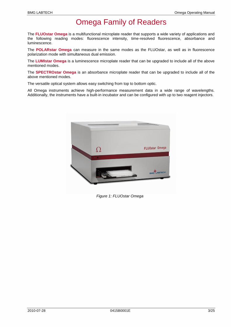
Omega Family of Readers The FLUOstar Omega is a multifunctional microplate reader that supports a wide variety of applications and the following reading modes: fluorescence intensity, time-resolved fluorescence, absorbance and luminescence.
The POLARstar Omega can measure in the same modes as the FLUOstar, as well as in fluorescence polarization mode with simultaneous dual emission.
The LUMIstar Omega is a luminescence microplate reader that can be upgraded to include all of the above mentioned modes.
The SPECTROstar Omega is an absorbance microplate reader that can be upgraded to include all of the above mentioned modes.
The versatile optical system allows easy switching from top to bottom optic.
All Omega instruments achieve high-performance measurement data in a wide range of wavelengths. Additionally, the instruments have a built-in incubator and can be configured with up to two reagent injectors.
Figure 1: FLUOstar Omega
Omega Operating Manual BMG LABTECH
4/25 0415B0001E 2010-07-28
TABLE OF CONTENTS
1 TECHNICAL SPECIFICATIONS 5
2 INSTALLATION 7
2.1 TRANSPORT LOCK 7
2.2 SOFTWARE INSTALLATION 8
2.3 POWER AND COMMUNICATION CONNECTIONS 8
3 INSTRUMENT OVERVIEW 9
4 DESCRIPTION OF COMPONENTS 11
4.1 OPTICS 11
4.2 INSTALLATION AND CHANGING OF OPTICS 11 4.2.1 FLUORESCENCE INTENSITY OPTICS 12 4.2.2 LUMINESCENCE OPTICS 12 4.2.3 FLUORESCENCE POLARIZATION OPTICS 13 4.2.4 DUAL EMISSION OPTICS 13 4.2.5 COMBINATION OPTICS 13 4.2.6 ABSORBANCE OPTICS 14 4.2.7 HIGH DENSITY OPTICS 14 4.2.8 BOTTOM OPTICS 14 4.2.9 ADVANCED OPTIC HEAD FOR TRF / TR-FRET 15FEHLER! VERWEISQUELLE KONNTE NICHT GEFUNDEN
WERDEN.
4.3 FILTERS 19 4.3.1 FILTER CHANGE AND INSTALLATION 19 4.3.2 FLUORESCENCE FILTERS 21 4.3.3 FLUORESCENCE POLARIZATION FILTERS 21 4.3.4 DUAL EMISSION FILTERS 21 4.3.5 ABSORBANCE FILTERS 21 4.3.6 LUMINESCENCE FILTERS 21
4.4 SPACERS 21
4.5 REAGENT INJECTORS 22 4.5.1 USE AND MAINTENANCE OF THE REAGENT INJECTORS 23
5 INSTRUMENT DISINFECTION 24
BMG LABTECH Omega Operating Manual
2010-07-28 0415B0001E 5/25
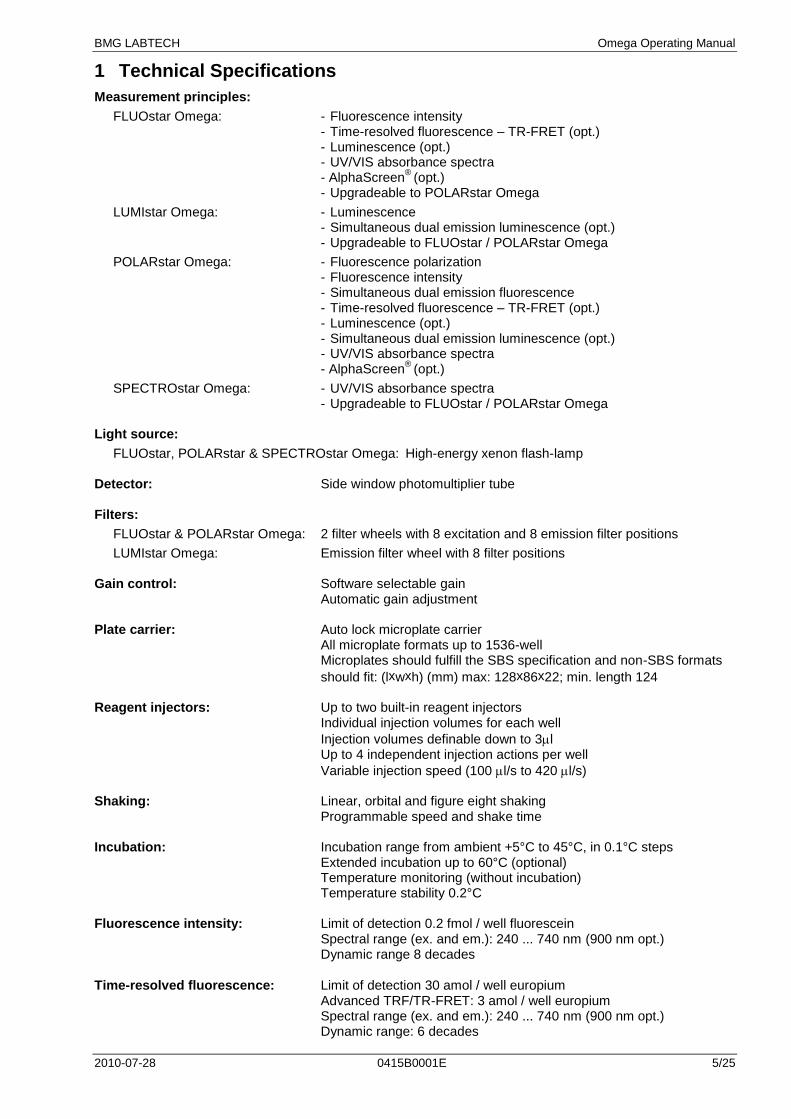
1 Technical Specifications
Measurement principles:
FLUOstar Omega: - Fluorescence intensity - Time-resolved fluorescence – TR-FRET (opt.) - Luminescence (opt.) - UV/VIS absorbance spectra - AlphaScreen
® (opt.)
- Upgradeable to POLARstar Omega
LUMIstar Omega: - Luminescence - Simultaneous dual emission luminescence (opt.) - Upgradeable to FLUOstar / POLARstar Omega
POLARstar Omega: - Fluorescence polarization - Fluorescence intensity - Simultaneous dual emission fluorescence - Time-resolved fluorescence – TR-FRET (opt.) - Luminescence (opt.) - Simultaneous dual emission luminescence (opt.) - UV/VIS absorbance spectra - AlphaScreen
® (opt.)
SPECTROstar Omega: - UV/VIS absorbance spectra - Upgradeable to FLUOstar / POLARstar Omega Light source:
FLUOstar, POLARstar & SPECTROstar Omega: High-energy xenon flash-lamp Detector: Side window photomultiplier tube Filters:
FLUOstar & POLARstar Omega: 2 filter wheels with 8 excitation and 8 emission filter positions
LUMIstar Omega: Emission filter wheel with 8 filter positions Gain control: Software selectable gain Automatic gain adjustment Plate carrier: Auto lock microplate carrier All microplate formats up to 1536-well Microplates should fulfill the SBS specification and non-SBS formats
should fit: (lxwxh) (mm) max: 128x86x22; min. length 124 Reagent injectors: Up to two built-in reagent injectors Individual injection volumes for each well
Injection volumes definable down to 3l Up to 4 independent injection actions per well
Variable injection speed (100 l/s to 420 l/s) Shaking: Linear, orbital and figure eight shaking Programmable speed and shake time Incubation: Incubation range from ambient +5°C to 45°C, in 0.1°C steps Extended incubation up to 60°C (optional) Temperature monitoring (without incubation) Temperature stability 0.2°C Fluorescence intensity: Limit of detection 0.2 fmol / well fluorescein Spectral range (ex. and em.): 240 ... 740 nm (900 nm opt.) Dynamic range 8 decades
Time-resolved fluorescence: Limit of detection 30 amol / well europium Advanced TRF/TR-FRET: 3 amol / well europium Spectral range (ex. and em.): 240 ... 740 nm (900 nm opt.) Dynamic range: 6 decades
Omega Operating Manual BMG LABTECH
6/25 0415B0001E 2010-07-28
Luminescence: Limit of detection 20 amol / well ATP Spectral range 240 ... 740 nm Dynamic range: 9 decades Fluorescence polarization: Limit of detection: <5 mP SD at 1 nM fluorescein Spectral range: (ex. and em.): 380 ... 740 nm (900 nm opt.) Dynamic range: 4 decades Absorbance Spectrometer based: Spectral range 220 ... 850 nm Full spectrum captured in < 1 s/well Selectable spectral resolution: 1 nm, 2 nm, 5 nm, 10 nm OD range: 0 to 4 OD Accuracy: < 1% at 2 OD Precision: < 0.5% at 1 OD and < 0.8% at 2 OD AlphaScreen
®: < 100 amol / well (384)*
Computer interface: USB 2.0, compatible to USB 1.1 Power requirements: 100-240 V, 50/60 Hz Consumption: max. 300 VA Fuses: T5A/250V (use original spare fuses provided by BMG
LABTECH only) Dimensions: Height: 31 cm, width: 44 cm and length 48 cm Weight: 29 kg Ambient conditions: Operating temperature: 15°C to 35°C Storage temperature: -10°C to 50°C Humidity of atmosphere: 20% to 80% Non-condensing Instrument conformity: Over voltage category II; contamination class II; protection class I Robotic capabilities: Stacker for 50 microplates (optional) Limit of detection was calculated according to the IUPAC standard: 3 x (SDblank)/slope * Limit of detection < 100 amol of biotinylated and phosphorylated polypeptide (P-Tyr-100 assay kit, PerkinElmer, #6760620C), measured in white 384 small volume microplates (17 µL/well) AlphaScreen is a registered trademark of PerkinElmer, Inc. Specifications are subject to change without notice.
BMG LABTECH Omega Operating Manual
2010-07-28 0415B0001E 7/25
2 Installation
When unpacking the instrument, please check to ensure that all of the following parts are included:
FLUOstar Omega or LUMIstar Omega or POLARstar Omega or SPECTROstar Omega reader
Control and Data Analysis software (CD ROM in a cover inside this manual)
Manual
Power cord
USB cable
Service box containing: - Allen key (1.5mm)
- 2 extra fuses: 5A/250V for main power 100V-240V
- 4 spacers
- Injector needle cleaner (only with instruments that have reagent injectors)
Call BMG LABTECH immediately if any of these items are missing.
The area designated for the instrument should be free of dust, liquids and acidic vapours. The table's surface should be flat and even. Avoid areas subject to vibrations and direct sunlight. After unpacking and positioning the reader, please do the following steps in the given order:
1 – Release transport lock
2 – Install software
3 – Plug in power and USB connection
Always install the software before plugging in USB connection!
2.1 Transport Lock
When the instrument is shipped or moved to a different location, the transport lock should be in the locked position.
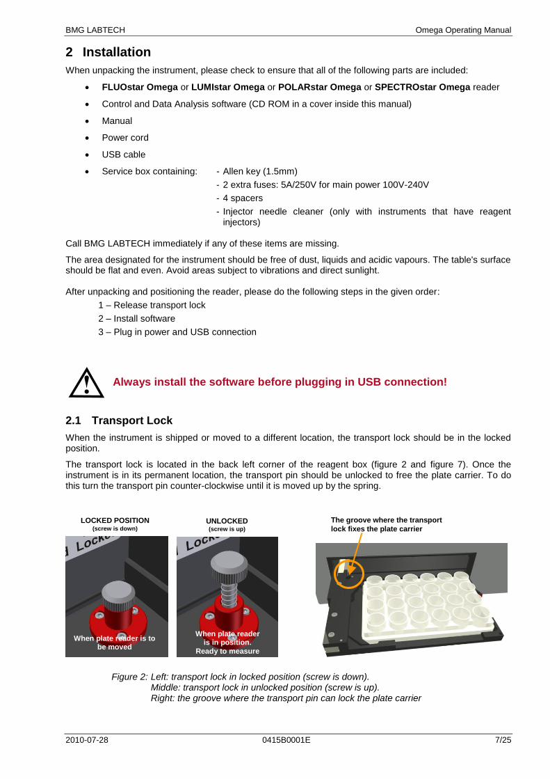
The transport lock is located in the back left corner of the reagent box (figure 2 and figure 7). Once the instrument is in its permanent location, the transport pin should be unlocked to free the plate carrier. To do this turn the transport pin counter-clockwise until it is moved up by the spring.
Figure 2: Left: transport lock in locked position (screw is down).
Middle: transport lock in unlocked position (screw is up). Right: the groove where the transport pin can lock the plate carrier
LOCKED POSITION (screw is down)
UNLOCKED (screw is up)
When plate reader is to be moved
When plate reader is in position.
Ready to measure
The groove where the transport
lock fixes the plate carrier view)
Omega Operating Manual BMG LABTECH
8/25 0415B0001E 2010-07-28
If the instrument needs to be moved to a new location, the plate carrier should be in the locked position otherwise the transport system could be damaged.
Figure 3: Plate In / Plate Out button.
Press and hold the plate in / plate out button for 3 seconds, hereafter the plate carrier will automatically move to its lock position. Once the reader is switched off, the transport pin can be moved down and turned clockwise. The transport pin must be screwed until it tightens. Please tighten it firmly with your fingers. Don‟t use any tools.
The transport system is locked when the transport lock is in its down position and firmly tightened.
2.2 Software Installation
Before connecting the instrument's USB communication cable the software must be installed! Please follow the instructions in the software manual.
2.3 Power and Communication Connections
Power Connection
First check that the power switch on the back of the instrument is in the "Off" position. Inspect the voltage information on the label next to the power switch to ensure that it corresponds to the local main power specifications. Also make sure the power cable is grounded. Hereafter, the power cable can be connected to the instrument.
USB Communication Connection
Connect the USB cable to the FLUOstar Omega (or POLARstar Omega or SPECTROstar or LUMIstar Omega) and to the USB port on the PC. Please connect the reader directly to your PC and do not use a USB-hub.
Only connect a computer that corresponds to EN 60950 and UL 1950 for data processing instruments.
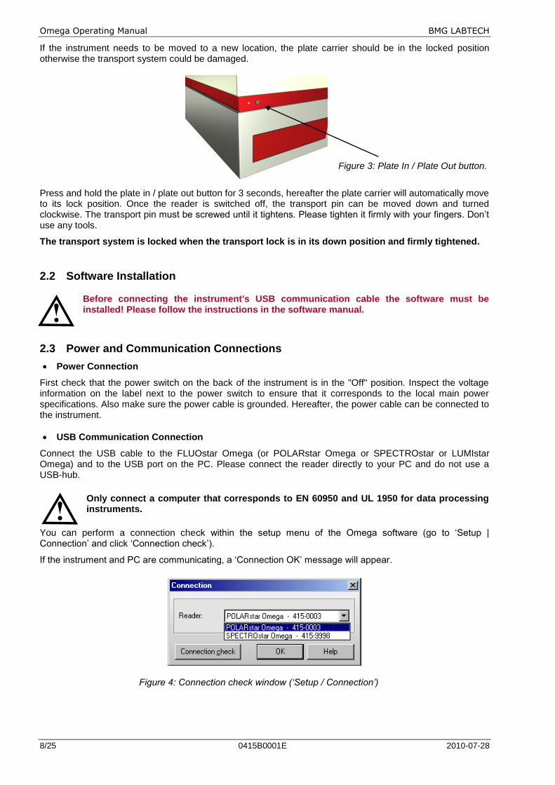
You can perform a connection check within the setup menu of the Omega software (go to „Setup | Connection‟ and click „Connection check‟).
If the instrument and PC are communicating, a „Connection OK‟ message will appear.
Figure 4: Connection check window (‘Setup / Connection’)
BMG LABTECH Omega Operating Manual
2010-07-28 0415B0001E 9/25
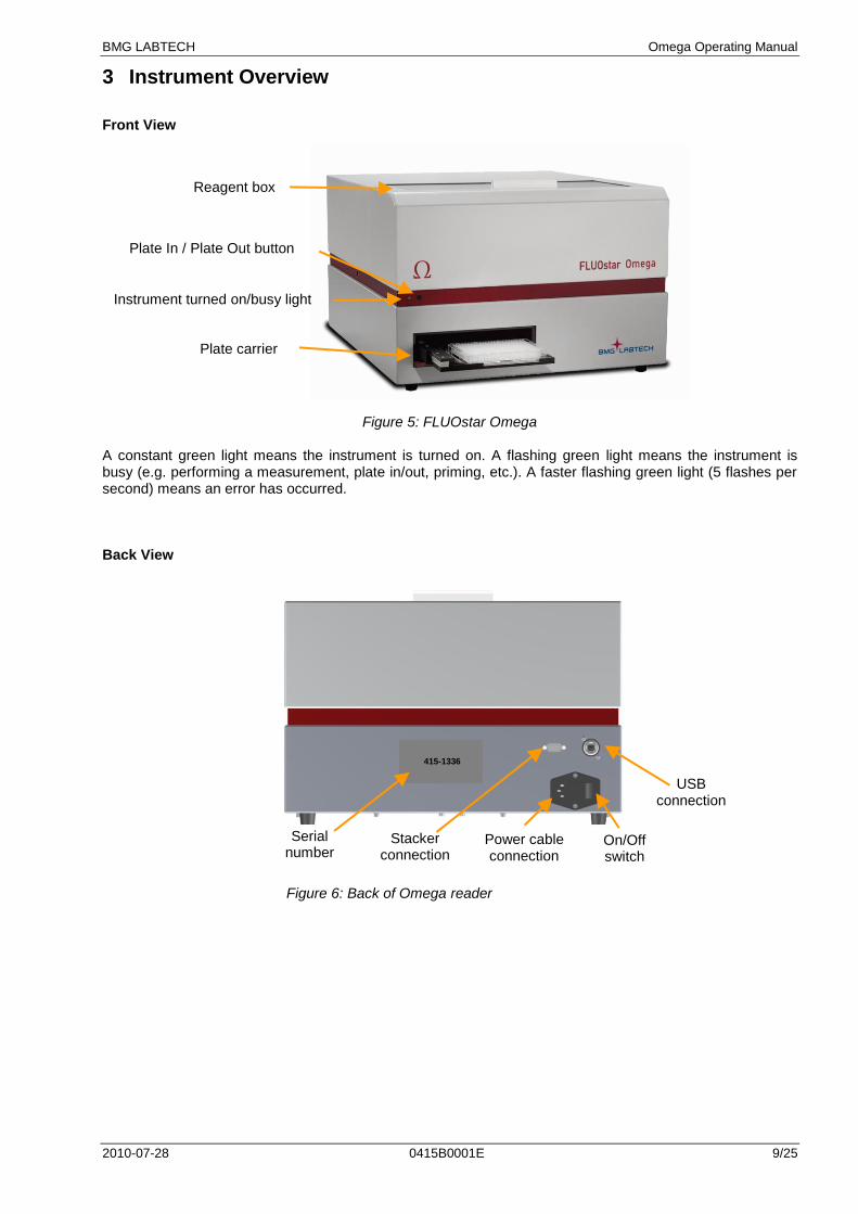
Reagent box
Plate carrier
Plate In / Plate Out button
3 Instrument Overview
Front View
Figure 5: FLUOstar Omega A constant green light means the instrument is turned on. A flashing green light means the instrument is busy (e.g. performing a measurement, plate in/out, priming, etc.). A faster flashing green light (5 flashes per second) means an error has occurred. Back View
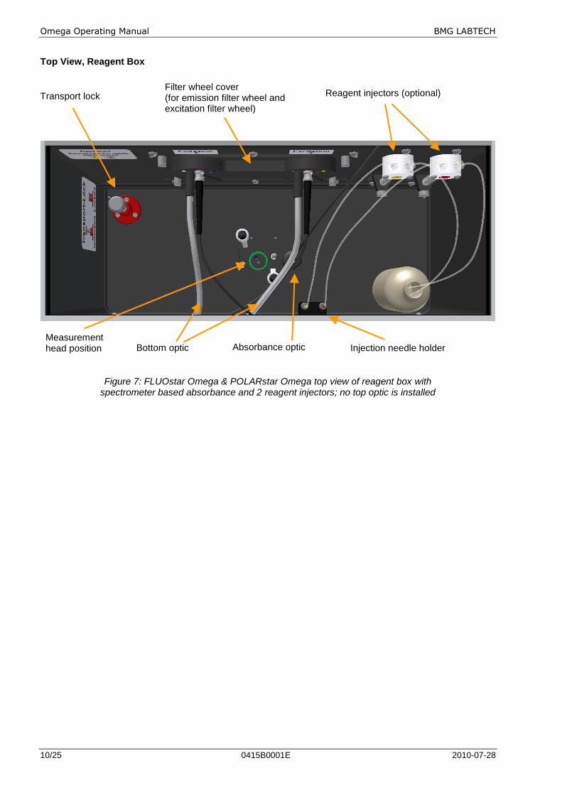
Figure 6: Back of Omega reader
Instrument turned on/busy light
USB connection
Stacker connection
Power cable connection
On/Off switch
Serial number
415-1336
Omega Operating Manual BMG LABTECH
10/25 0415B0001E 2010-07-28
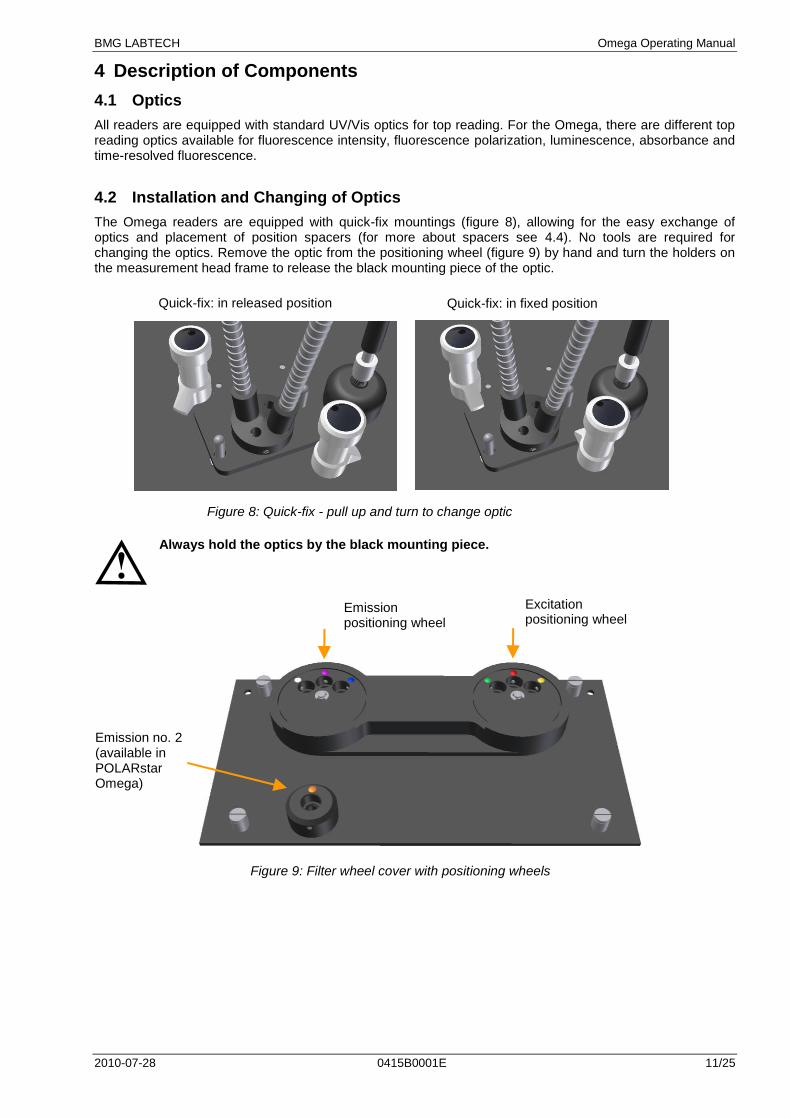
Top View, Reagent Box
Figure 7: FLUOstar Omega & POLARstar Omega top view of reagent box with spectrometer based absorbance and 2 reagent injectors; no top optic is installed
Injection needle holder Measurement head position Bottom optic
Filter wheel cover (for emission filter wheel and excitation filter wheel)
Transport lock Reagent injectors (optional)
Absorbance optic
BMG LABTECH Omega Operating Manual
2010-07-28 0415B0001E 11/25
Emission no. 2 (available in POLARstar Omega)
4 Description of Components
4.1 Optics
All readers are equipped with standard UV/Vis optics for top reading. For the Omega, there are different top reading optics available for fluorescence intensity, fluorescence polarization, luminescence, absorbance and time-resolved fluorescence.
4.2 Installation and Changing of Optics
The Omega readers are equipped with quick-fix mountings (figure 8), allowing for the easy exchange of optics and placement of position spacers (for more about spacers see 4.4). No tools are required for changing the optics. Remove the optic from the positioning wheel (figure 9) by hand and turn the holders on the measurement head frame to release the black mounting piece of the optic.
Figure 8: Quick-fix - pull up and turn to change optic
Always hold the optics by the black mounting piece.
Figure 9: Filter wheel cover with positioning wheels
Quick-fix: in fixed position
Emission positioning wheel
Excitation positioning wheel
Quick-fix: in released position
Omega Operating Manual BMG LABTECH
12/25 0415B0001E 2010-07-28
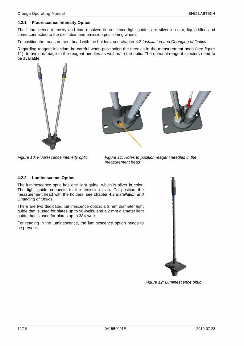
4.2.1 Fluorescence Intensity Optics
The fluorescence intensity and time-resolved fluorescence light guides are silver in color, liquid-filled and come connected to the excitation and emission positioning wheels.
To position the measurement head with the holders, see chapter 4.2 Installation and Changing of Optics.
Regarding reagent injection: be careful when positioning the needles in the measurement head (see figure 11), to avoid damage to the reagent needles as well as to the optic. The optional reagent injectors need to be available.
Figure 10: Fluorescence intensity optic Figure 11: Holes to position reagent needles in the measurement head
4.2.2 Luminescence Optics
The luminescence optic has one light guide, which is silver in color. The light guide connects to the emission side. To position the measurement head with the holders, see chapter 4.2 Installation and Changing of Optics.
There are two dedicated luminescence optics: a 3 mm diameter light guide that is used for plates up to 96-wells, and a 2 mm diameter light guide that is used for plates up to 384-wells.
For reading in the luminescence, the luminescence option needs to be present.
Figure 12: Luminescence optic
BMG LABTECH Omega Operating Manual
2010-07-28 0415B0001E 13/25
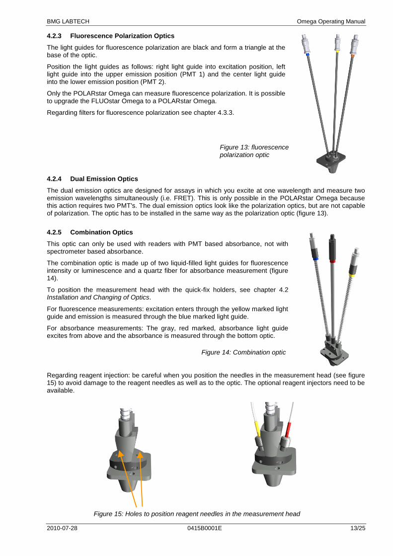
4.2.3 Fluorescence Polarization Optics
The light guides for fluorescence polarization are black and form a triangle at the base of the optic.
Position the light guides as follows: right light guide into excitation position, left light guide into the upper emission position (PMT 1) and the center light guide into the lower emission position (PMT 2).
Only the POLARstar Omega can measure fluorescence polarization. It is possible to upgrade the FLUOstar Omega to a POLARstar Omega.
Regarding filters for fluorescence polarization see chapter 4.3.3.
4.2.4 Dual Emission Optics
The dual emission optics are designed for assays in which you excite at one wavelength and measure two emission wavelengths simultaneously (i.e. FRET). This is only possible in the POLARstar Omega because this action requires two PMT's. The dual emission optics look like the polarization optics, but are not capable of polarization. The optic has to be installed in the same way as the polarization optic (figure 13).
4.2.5 Combination Optics
This optic can only be used with readers with PMT based absorbance, not with spectrometer based absorbance.
The combination optic is made up of two liquid-filled light guides for fluorescence intensity or luminescence and a quartz fiber for absorbance measurement (figure 14).
To position the measurement head with the quick-fix holders, see chapter 4.2 Installation and Changing of Optics.
For fluorescence measurements: excitation enters through the yellow marked light guide and emission is measured through the blue marked light guide.
For absorbance measurements: The gray, red marked, absorbance light guide excites from above and the absorbance is measured through the bottom optic.
Figure 14: Combination optic
Regarding reagent injection: be careful when you position the needles in the measurement head (see figure 15) to avoid damage to the reagent needles as well as to the optic. The optional reagent injectors need to be available.
Figure 15: Holes to position reagent needles in the measurement head
Figure 13: fluorescence polarization optic
Omega Operating Manual BMG LABTECH
14/25 0415B0001E 2010-07-28
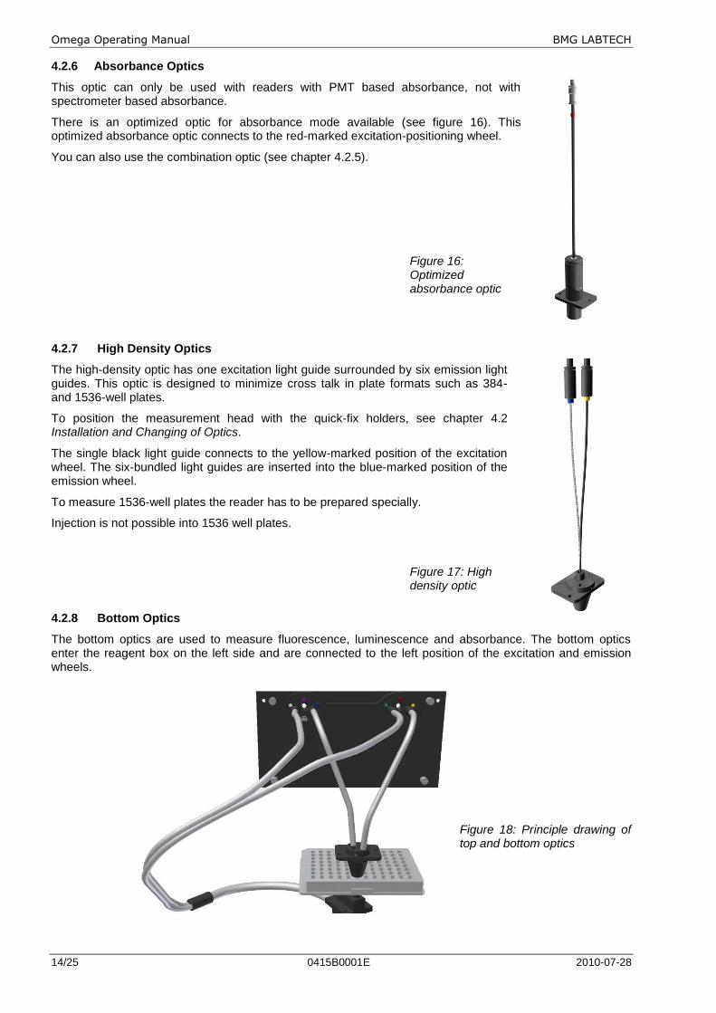
4.2.6 Absorbance Optics
This optic can only be used with readers with PMT based absorbance, not with spectrometer based absorbance.
There is an optimized optic for absorbance mode available (see figure 16). This optimized absorbance optic connects to the red-marked excitation-positioning wheel.
You can also use the combination optic (see chapter 4.2.5).
Figure 16: Optimized absorbance optic
4.2.7 High Density Optics
The high-density optic has one excitation light guide surrounded by six emission light guides. This optic is designed to minimize cross talk in plate formats such as 384- and 1536-well plates.
To position the measurement head with the quick-fix holders, see chapter 4.2 Installation and Changing of Optics.
The single black light guide connects to the yellow-marked position of the excitation wheel. The six-bundled light guides are inserted into the blue-marked position of the emission wheel.
To measure 1536-well plates the reader has to be prepared specially.
Injection is not possible into 1536 well plates.
Figure 17: High density optic
4.2.8 Bottom Optics
The bottom optics are used to measure fluorescence, luminescence and absorbance. The bottom optics enter the reagent box on the left side and are connected to the left position of the excitation and emission wheels.
Figure 18: Principle drawing of top and bottom optics
BMG LABTECH Omega Operating Manual
2010-07-28 0415B0001E 15/25
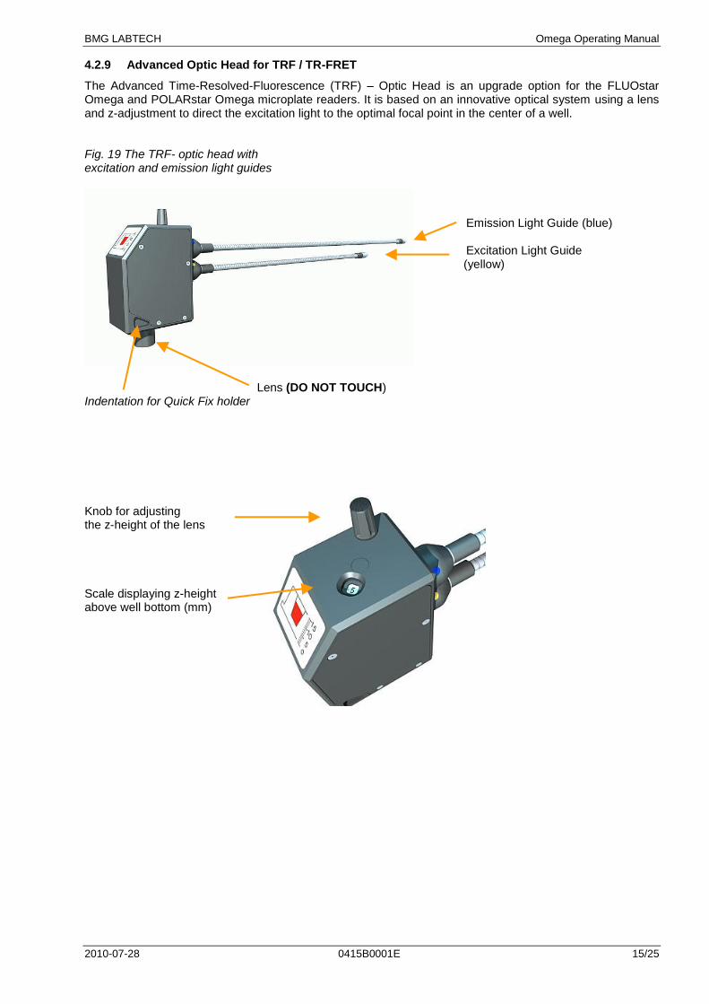
4.2.9 Advanced Optic Head for TRF / TR-FRET
The Advanced Time-Resolved-Fluorescence (TRF) – Optic Head is an upgrade option for the FLUOstar Omega and POLARstar Omega microplate readers. It is based on an innovative optical system using a lens and z-adjustment to direct the excitation light to the optimal focal point in the center of a well. Fig. 19 The TRF- optic head with excitation and emission light guides
Emission Light Guide (blue)
Excitation Light Guide
(yellow)
Lens (DO NOT TOUCH) Indentation for Quick Fix holder Knob for adjusting the z-height of the lens Scale displaying z-height above well bottom (mm)
Omega Operating Manual BMG LABTECH
16/25 0415B0001E 2010-07-28
Installation: NOTES:
1. Before installing the TRF-optic head make sure to install the supplied filters for TRF measurement as described in 4.3.1 “Filter Change and Installation”.
2. Make sure that the firmware of your Omega reader is at least v.1.12. The firmware version can be read by opening the Control software and clicking on the reader icon in the upper right corner. Contact BMG LABTECH in case you need an update of the reader firmware
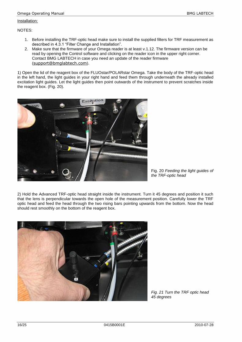
([email protected]). 1) Open the lid of the reagent box of the FLUOstar/POLARstar Omega. Take the body of the TRF-optic head in the left hand, the light guides in your right hand and feed them through underneath the already installed excitation light guides. Let the light guides then point outwards of the instrument to prevent scratches inside the reagent box. (Fig. 20).
Fig. 20 Feeding the light guides of the TRF-optic head
2) Hold the Advanced TRF-optic head straight inside the instrument. Turn it 45 degrees and position it such that the lens is perpendicular towards the open hole of the measurement position. Carefully lower the TRF optic head and feed the head through the two rising bars pointing upwards from the bottom. Now the head should rest smoothly on the bottom of the reagent box.
Fig. 21 Turn the TRF optic head 45 degrees
BMG LABTECH Omega Operating Manual
2010-07-28 0415B0001E 17/25
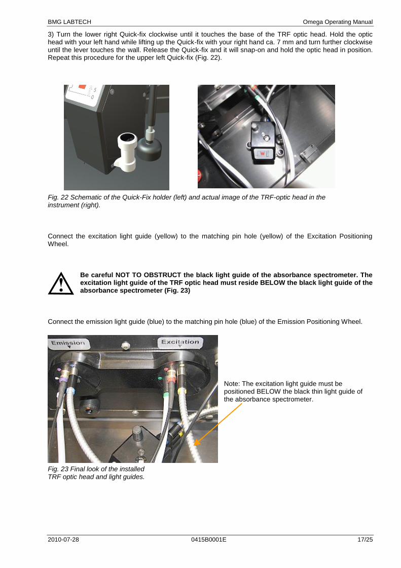
3) Turn the lower right Quick-fix clockwise until it touches the base of the TRF optic head. Hold the optic head with your left hand while lifting up the Quick-fix with your right hand ca. 7 mm and turn further clockwise until the lever touches the wall. Release the Quick-fix and it will snap-on and hold the optic head in position. Repeat this procedure for the upper left Quick-fix (Fig. 22). Fig. 22 Schematic of the Quick-Fix holder (left) and actual image of the TRF-optic head in the instrument (right). Connect the excitation light guide (yellow) to the matching pin hole (yellow) of the Excitation Positioning Wheel.
Be careful NOT TO OBSTRUCT the black light guide of the absorbance spectrometer. The excitation light guide of the TRF optic head must reside BELOW the black light guide of the absorbance spectrometer (Fig. 23)
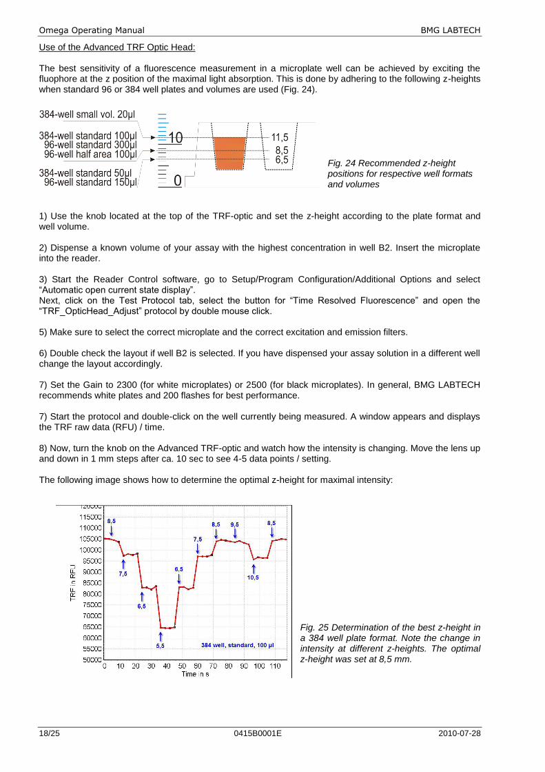
Connect the emission light guide (blue) to the matching pin hole (blue) of the Emission Positioning Wheel.
Note: The excitation light guide must be positioned BELOW the black thin light guide of the absorbance spectrometer.
Fig. 23 Final look of the installed TRF optic head and light guides.
Omega Operating Manual BMG LABTECH
18/25 0415B0001E 2010-07-28
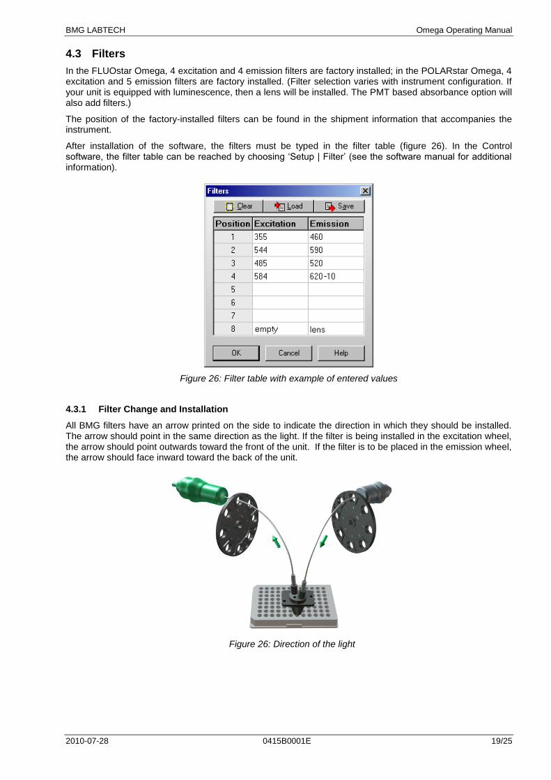
Use of the Advanced TRF Optic Head: The best sensitivity of a fluorescence measurement in a microplate well can be achieved by exciting the fluophore at the z position of the maximal light absorption. This is done by adhering to the following z-heights when standard 96 or 384 well plates and volumes are used (Fig. 24).
Fig. 24 Recommended z-height positions for respective well formats and volumes
1) Use the knob located at the top of the TRF-optic and set the z-height according to the plate format and well volume. 2) Dispense a known volume of your assay with the highest concentration in well B2. Insert the microplate into the reader. 3) Start the Reader Control software, go to Setup/Program Configuration/Additional Options and select “Automatic open current state display”. Next, click on the Test Protocol tab, select the button for “Time Resolved Fluorescence” and open the “TRF_OpticHead_Adjust” protocol by double mouse click. 5) Make sure to select the correct microplate and the correct excitation and emission filters. 6) Double check the layout if well B2 is selected. If you have dispensed your assay solution in a different well change the layout accordingly. 7) Set the Gain to 2300 (for white microplates) or 2500 (for black microplates). In general, BMG LABTECH recommends white plates and 200 flashes for best performance. 7) Start the protocol and double-click on the well currently being measured. A window appears and displays the TRF raw data (RFU) / time. 8) Now, turn the knob on the Advanced TRF-optic and watch how the intensity is changing. Move the lens up and down in 1 mm steps after ca. 10 sec to see 4-5 data points / setting. The following image shows how to determine the optimal z-height for maximal intensity:
Fig. 25 Determination of the best z-height in a 384 well plate format. Note the change in intensity at different z-heights. The optimal z-height was set at 8,5 mm.
BMG LABTECH Omega Operating Manual
2010-07-28 0415B0001E 19/25
4.3 Filters
In the FLUOstar Omega, 4 excitation and 4 emission filters are factory installed; in the POLARstar Omega, 4 excitation and 5 emission filters are factory installed. (Filter selection varies with instrument configuration. If your unit is equipped with luminescence, then a lens will be installed. The PMT based absorbance option will also add filters.)
The position of the factory-installed filters can be found in the shipment information that accompanies the instrument.
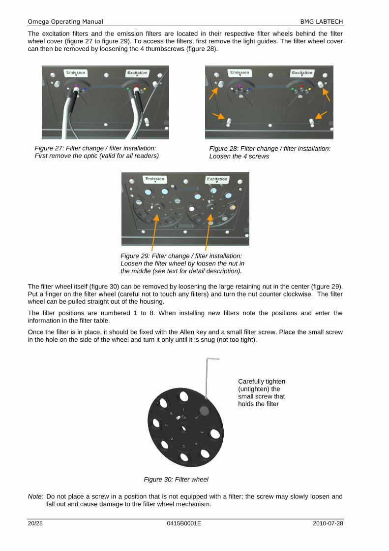
After installation of the software, the filters must be typed in the filter table (figure 26). In the Control software, the filter table can be reached by choosing „Setup | Filter‟ (see the software manual for additional information).
Figure 26: Filter table with example of entered values
4.3.1 Filter Change and Installation
All BMG filters have an arrow printed on the side to indicate the direction in which they should be installed. The arrow should point in the same direction as the light. If the filter is being installed in the excitation wheel, the arrow should point outwards toward the front of the unit. If the filter is to be placed in the emission wheel, the arrow should face inward toward the back of the unit.
Figure 26: Direction of the light
Omega Operating Manual BMG LABTECH
20/25 0415B0001E 2010-07-28
The excitation filters and the emission filters are located in their respective filter wheels behind the filter wheel cover (figure 27 to figure 29). To access the filters, first remove the light guides. The filter wheel cover can then be removed by loosening the 4 thumbscrews (figure 28).
Figure 29: Filter change / filter installation: Loosen the filter wheel by loosen the nut in the middle (see text for detail description).
The filter wheel itself (figure 30) can be removed by loosening the large retaining nut in the center (figure 29). Put a finger on the filter wheel (careful not to touch any filters) and turn the nut counter clockwise. The filter wheel can be pulled straight out of the housing.
The filter positions are numbered 1 to 8. When installing new filters note the positions and enter the information in the filter table.
Once the filter is in place, it should be fixed with the Allen key and a small filter screw. Place the small screw in the hole on the side of the wheel and turn it only until it is snug (not too tight).
Figure 30: Filter wheel
Note: Do not place a screw in a position that is not equipped with a filter; the screw may slowly loosen and
fall out and cause damage to the filter wheel mechanism.
Carefully tighten (untighten) the small screw that holds the filter
Figure 28: Filter change / filter installation: Loosen the 4 screws
Figure 27: Filter change / filter installation: First remove the optic (valid for all readers)
BMG LABTECH Omega Operating Manual
2010-07-28 0415B0001E 21/25
Next to the axle in the center of the housing is a small positioning pin. This pin must fit into one of the holes on the back of the filter wheel. Replace the filter wheel on the axle and push it in position (the axle should stick out 3mm). Turning the filter wheel quickly might help position it correctly. Place the filter wheel nut on the axle and tighten it with your fingers until it is fixed. Spin the wheel again. The filter wheel should move freely and move without vibration. If the wheel seems to drag or wobble, tighten the nut more or remove and reposition the wheel.
Replace the cover and reconnect the light guides.
If the instrument makes a grinding sound it is very likely that the large filter wheel nut in the middle should be tightened better or that a filter screw is loose.
4.3.2 Fluorescence Filters
The fluorescence filters have a bandwidth that varies depending upon the type of fluorescence filter. Filters optimized for specific fluorophores can vary in the bandwidth from around 10 nm to around 30 to 40 nm (measured at ½ height). BMG-10 filters are symmetrical filters that in ½ height have a bandwidth of 10 nm and hence can be used in both the excitation and the emission position.
4.3.3 Fluorescence Polarization Filters
The excitation filters can go in any available position in the excitation wheel. The emission wheel has two filters of the same wavelength for each channel (one for parallel and one for perpendicular). They must be positioned 180° from each other (for example position 3 and position 7 for the 520 filter). The filter configuration can be entered in „Setup | Filters‟.
4.3.4 Dual Emission Filters
As for fluorescence polarization, the excitation filter can be placed in any position on the filter wheel. The emission filters to be used in dual emission measurement must be positioned 180° from each other (emission position 1 pairs with position 5, position 2 pairs with position 6, etc).
4.3.5 Absorbance Filters
Absorbance filters are only needed in readers that use PMT based absorbance. Place the filter (either a BMG-10 or an "Abs" filter) that matches the wavelength of choice in any excitation position. For emission, there are two possibilities:
Empty: Define a filter position as empty so that all the light from the reaction will pass directly through to the PMT ("empty" needs to be typed in).
Use of a filter: If you know the wavelength of the emitting light, you may choose to use a filter to block any stray light. The filter can be used in any emission filter position.
4.3.6 Luminescence Filters
Like for fluorescence filters, the luminescence filters are designed to transmit as much light as possible. The bandwidth varies depending upon the type of assay (filters are optimized to return the best result) and can vary in bandwidth from around 10 nm to around 100 nm (measured at ½ height).
4.4 Spacers
The Omega readers are designed for most microplate formats. The height of some microplates exceeds the space allowed under the optic. The minimum space between the optic and microplate should be 1.5 mm. With 6, 24, 48-well plate formats, it will be necessary to raise the optic using the spacers provided in the service box.
The spacers are metal rectangular pieces with a hole in the center. Each spacer is 2 mm in height. They will be installed between the measurement head and the bottom of the reagent box. The number of spacers used depends on how high the optic needs to be elevated.
Determination of the number of spacers:
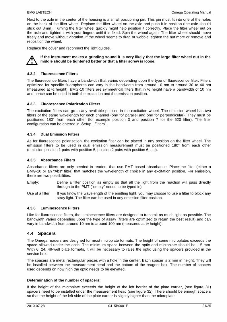
If the height of the microplate exceeds the height of the left border of the plate carrier, (see figure 31) spacers need to be installed under the measurement head (see figure 32). There should be enough spacers so that the height of the left side of the plate carrier is slightly higher than the microplate.
Omega Operating Manual BMG LABTECH
22/25 0415B0001E 2010-07-28
Figure 31: Front view of the plate carrier Installation of spacers:
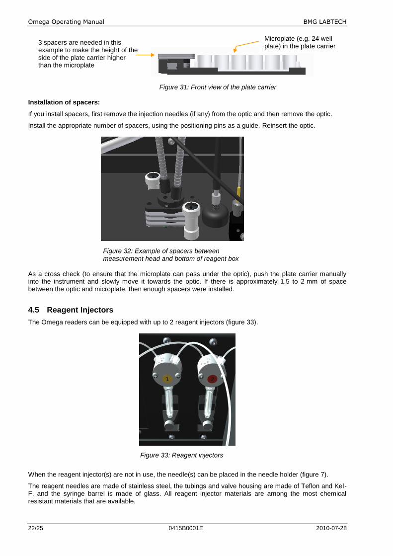
If you install spacers, first remove the injection needles (if any) from the optic and then remove the optic.
Install the appropriate number of spacers, using the positioning pins as a guide. Reinsert the optic.
Figure 32: Example of spacers between measurement head and bottom of reagent box As a cross check (to ensure that the microplate can pass under the optic), push the plate carrier manually into the instrument and slowly move it towards the optic. If there is approximately 1.5 to 2 mm of space between the optic and microplate, then enough spacers were installed.
4.5 Reagent Injectors
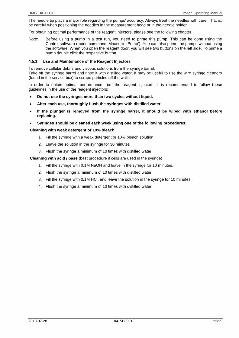
The Omega readers can be equipped with up to 2 reagent injectors (figure 33).
Figure 33: Reagent injectors
When the reagent injector(s) are not in use, the needle(s) can be placed in the needle holder (figure 7).
The reagent needles are made of stainless steel, the tubings and valve housing are made of Teflon and Kel-F, and the syringe barrel is made of glass. All reagent injector materials are among the most chemical resistant materials that are available.
3 spacers are needed in this example to make the height of the side of the plate carrier higher than the microplate
Microplate (e.g. 24 well plate) in the plate carrier
BMG LABTECH Omega Operating Manual
2010-07-28 0415B0001E 23/25
The needle tip plays a major role regarding the pumps' accuracy. Always treat the needles with care. That is, be careful when positioning the needles in the measurement head or in the needle holder.
For obtaining optimal performance of the reagent injectors, please see the following chapter.
Note: Before using a pump in a test run, you need to prime this pump. This can be done using the Control software (menu command „Measure | Prime‟). You can also prime the pumps without using the software. When you open the reagent door, you will see two buttons on the left side. To prime a pump double click the respective button.
4.5.1 Use and Maintenance of the Reagent Injectors
To remove cellular debris and viscous solutions from the syringe barrel: Take off the syringe barrel and rinse it with distilled water. It may be useful to use the wire syringe cleaners (found in the service box) to scrape particles off the walls.
In order to obtain optimal performance from the reagent injectors, it is recommended to follow these guidelines in the use of the reagent injectors:
Do not use the syringes more than two cycles without liquid.
After each use, thoroughly flush the syringes with distilled water.
If the plunger is removed from the syringe barrel, it should be wiped with ethanol before replacing.
Syringes should be cleaned each week using one of the following procedures:
Cleaning with weak detergent or 10% bleach
1. Fill the syringe with a weak detergent or 10% bleach solution
2. Leave the solution in the syringe for 30 minutes
3. Flush the syringe a minimum of 10 times with distilled water
Cleaning with acid / base (best procedure if cells are used in the syringe)
1. Fill the syringe with 0.1M NaOH and leave in the syringe for 10 minutes.
2. Flush the syringe a minimum of 10 times with distilled water.
3. Fill the syringe with 0.1M HCl, and leave the solution in the syringe for 10 minutes.
4. Flush the syringe a minimum of 10 times with distilled water.
Omega Operating Manual BMG LABTECH
24/25 0415B0001E 2010-07-28
5 Instrument Disinfection
Please follow all instructions carefully for a successful disinfection of the FLUOstar, POLARstar, SPECTROstar and LUMIstar Omega.
All parts of the instrument, which have the possibility of contacting patient sera or positive samples, have to be handled as if they are hazardous. For this reason, it is recommended that gloves be worn while maintaining or working with the instrument.
It is very important that the instrument is thoroughly disinfected before maintenance or before removing the instrument from the laboratory. Be sure that the instrument is disinfected before you send it to your distributor or to the manufacturer. For safety reasons, you have to fill out the Disinfection Certificate, or the instrument may not be accepted by the service center or by customs authorities.
Use suitable disinfectants, e.g. Alcohol (70%).
Authorized personnel wearing disposable gloves and protective clothing should only perform the disinfection procedure. The location should be well ventilated.
Disinfection Steps
1. Disconnect the instrument from the main power supply.
2. Remove the USB cable from the connector.
3. Clean all outside surfaces of the instrument carefully with cotton wool, which has been soaked in disinfecting solution.
4. Place the instrument in a large plastic bag along with the cotton wool that has been soaked in disinfecting solution. Ensure that the wool does not touch the instrument.
5. Close and seal the bag.
6. Keep the instrument in the plastic bag for at least 24 hours.
7. After the disinfection time has lapsed, remove the instrument from the plastic bag and clean all outside surfaces of the instrument with cotton wool that has been soaked in alcohol solution.
8. Repeat the procedure for disinfection on any accessories, which will be returned with the instrument.
9. Complete the Disinfection Certificate.

Disinfection Certification
This instrument and its inventory have never been in contact with any dangerous biological material, or if so, the instrument and its inventory have been disinfected according to the instructions of the operating manual of the instrument.
Name: ________________________________________________
Company: ________________________________________________ ________________________________________________ ________________________________________________ ________________________________________________
Date, Signature: ________________________