Embed Size (px)
Citation preview
EN
Italian company established in 1956
QTS®
SELECTION TECHNICAL BOOKLET
SHERPA REVERSIBLEAIR-COOLED HEAT PUMPS

2
SHERPAHEAT PUMPS

3
SHERPAHEAT PUMPS
TABL
E OF
CON
TEN
TSSE
LECT
ION
OF
HEA
T PU
MPS
TRAD
ITIO
NAL
SPL
IT T
ECH
NOL
OGY
STB
MUL
TI-P
URPO
SE S
PLIT
TEC
HNOL
OGY
STB
MON
OBLO
C TE
CHN
OLOG
Y ST
BRA
NGE
ACC
ESSO
RIES
SPEC
IFIC
ATIO
NS
TABLE OF CONTENTS
1 Selection of air-cooled heat pumps ................................................................................ 81.1 Traditional split technology ................................................................................................................. 81.2 Multi-purpose split technology ............................................................................................................ 81.3 Monobloc technology ...........................................................................................................................9
2 Technical booklets .................................................................................................. 102.1 Sherpa - traditional split technology technical booklet .................................................................. 102.1.1 Fundamental characteristics ................................................................................................................. 102.1.2 Control and functions ............................................................................................................................ 112.1.3 The models available and connection of the units ................................................................................ 122.1.4 Technical data .......................................................................................................................................132.1.5 Performance tables ...............................................................................................................................152.1.5.1 Sherpa 7 heating performance .............................................................................................................. 152.1.5.2 Sherpa 7 cooling performance .............................................................................................................. 162.1.5.3 Sherpa 7 performance according to standard UNI/TS 11300-4 ............................................................ 172.1.5.4 Sherpa 11 heating performance ............................................................................................................ 182.1.5.5 Sherpa 11 cooling performance ............................................................................................................ 192.1.5.6 Sherpa 11 performance according to standard UNI/TS 11300-4 .......................................................... 202.1.5.7 Sherpa 13 heating performance ............................................................................................................ 212.1.5.8 Sherpa 13 cooling performance ............................................................................................................ 222.1.5.9 Sherpa 13 performance according to standard UNI/TS 11300-4 .......................................................... 232.1.5.10 Sherpa 13T heating performance ......................................................................................................... 242.1.5.11 Sherpa 13T cooling performance .......................................................................................................... 252.1.5.12 Sherpa 13T performance according to standard UNI/TS 11300-4 ........................................................ 262.1.5.13 Sherpa 16 heating performance ............................................................................................................ 272.1.5.14 Sherpa 16 cooling performance ............................................................................................................ 282.1.5.15 Sherpa 16 performance according to standard UNI/TS 11300-4 .......................................................... 292.1.5.16 Sherpa 16T heating performance ......................................................................................................... 302.1.5.17 Sherpa 16T cooling performance .......................................................................................................... 312.1.5.18 Sherpa 16T performance according to standard UNI/TS 11300-4 ........................................................ 322.1.6 Operating limits .....................................................................................................................................332.1.7 Useful heads of the system ................................................................................................................... 342.1.8 Components ..........................................................................................................................................362.1.8.1 Components of the internal unit ............................................................................................................ 362.1.8.2 Components of the external units ......................................................................................................... 382.1.9 Dimensions and positioning .................................................................................................................. 392.1.9.1 Dimensions of the internal unit .............................................................................................................. 392.1.9.2 Positioning of the internal unit ............................................................................................................... 402.1.9.3 Dimensions of the external units ........................................................................................................... 412.1.9.4 Positioning of the external units ............................................................................................................ 432.1.10 Installation .............................................................................................................................................442.1.10.1 Hydraulic connection .............................................................................................................................452.1.10.2 Refrigerant connection ..........................................................................................................................472.1.10.3 Wiring ....................................................................................................................................................48
4
SHERPAHEAT PUMPS
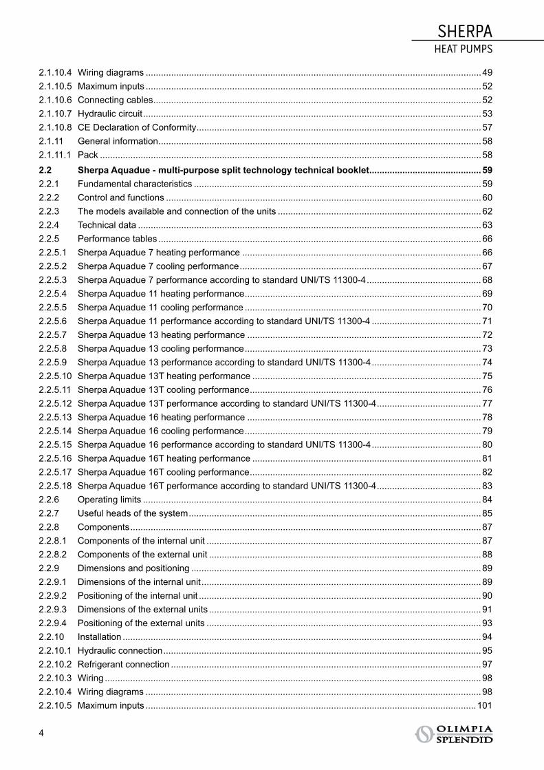
2.1.10.4 Wiring diagrams ....................................................................................................................................492.1.10.5 Maximum inputs ....................................................................................................................................522.1.10.6 Connecting cables .................................................................................................................................522.1.10.7 Hydraulic circuit .....................................................................................................................................532.1.10.8 CE Declaration of Conformity ................................................................................................................ 572.1.11 General information ...............................................................................................................................582.1.11.1 Pack ......................................................................................................................................................58
2.2 Sherpa Aquadue - multi-purpose split technology technical booklet ............................................ 592.2.1 Fundamental characteristics ................................................................................................................. 592.2.2 Control and functions ............................................................................................................................602.2.3 The models available and connection of the units ................................................................................ 622.2.4 Technical data .......................................................................................................................................632.2.5 Performance tables ...............................................................................................................................662.2.5.1 Sherpa Aquadue 7 heating performance .............................................................................................. 662.2.5.2 Sherpa Aquadue 7 cooling performance ............................................................................................... 672.2.5.3 Sherpa Aquadue 7 performance according to standard UNI/TS 11300-4 ............................................. 682.2.5.4 Sherpa Aquadue 11 heating performance ............................................................................................. 692.2.5.5 Sherpa Aquadue 11 cooling performance ............................................................................................. 702.2.5.6 Sherpa Aquadue 11 performance according to standard UNI/TS 11300-4 ........................................... 712.2.5.7 Sherpa Aquadue 13 heating performance ............................................................................................ 722.2.5.8 Sherpa Aquadue 13 cooling performance ............................................................................................. 732.2.5.9 Sherpa Aquadue 13 performance according to standard UNI/TS 11300-4 ........................................... 742.2.5.10 Sherpa Aquadue 13T heating performance .......................................................................................... 752.2.5.11 Sherpa Aquadue 13T cooling performance ........................................................................................... 762.2.5.12 Sherpa Aquadue 13T performance according to standard UNI/TS 11300-4 ......................................... 772.2.5.13 Sherpa Aquadue 16 heating performance ............................................................................................ 782.2.5.14 Sherpa Aquadue 16 cooling performance ............................................................................................. 792.2.5.15 Sherpa Aquadue 16 performance according to standard UNI/TS 11300-4 ........................................... 802.2.5.16 Sherpa Aquadue 16T heating performance .......................................................................................... 812.2.5.17 Sherpa Aquadue 16T cooling performance ........................................................................................... 822.2.5.18 Sherpa Aquadue 16T performance according to standard UNI/TS 11300-4 ......................................... 832.2.6 Operating limits .....................................................................................................................................842.2.7 Useful heads of the system ................................................................................................................... 852.2.8 Components ..........................................................................................................................................872.2.8.1 Components of the internal unit ............................................................................................................ 872.2.8.2 Components of the external unit ........................................................................................................... 882.2.9 Dimensions and positioning .................................................................................................................. 892.2.9.1 Dimensions of the internal unit .............................................................................................................. 892.2.9.2 Positioning of the internal unit ............................................................................................................... 902.2.9.3 Dimensions of the external units ........................................................................................................... 912.2.9.4 Positioning of the external units ............................................................................................................ 932.2.10 Installation .............................................................................................................................................942.2.10.1 Hydraulic connection .............................................................................................................................952.2.10.2 Refrigerant connection ..........................................................................................................................972.2.10.3 Wiring ....................................................................................................................................................982.2.10.4 Wiring diagrams ....................................................................................................................................982.2.10.5 Maximum inputs ..................................................................................................................................101
5
SHERPAHEAT PUMPS
TABL
E OF
CON
TEN
TSSE
LECT
ION
OF
HEA
T PU
MPS
TRAD
ITIO
NAL
SPL
IT T
ECH
NOL
OGY
STB
MUL
TI-P
URPO
SE S
PLIT
TEC
HNOL
OGY
STB
MON
OBLO
C TE
CHN
OLOG
Y ST
BRA
NGE
ACC
ESSO
RIES
SPEC
IFIC
ATIO
NS
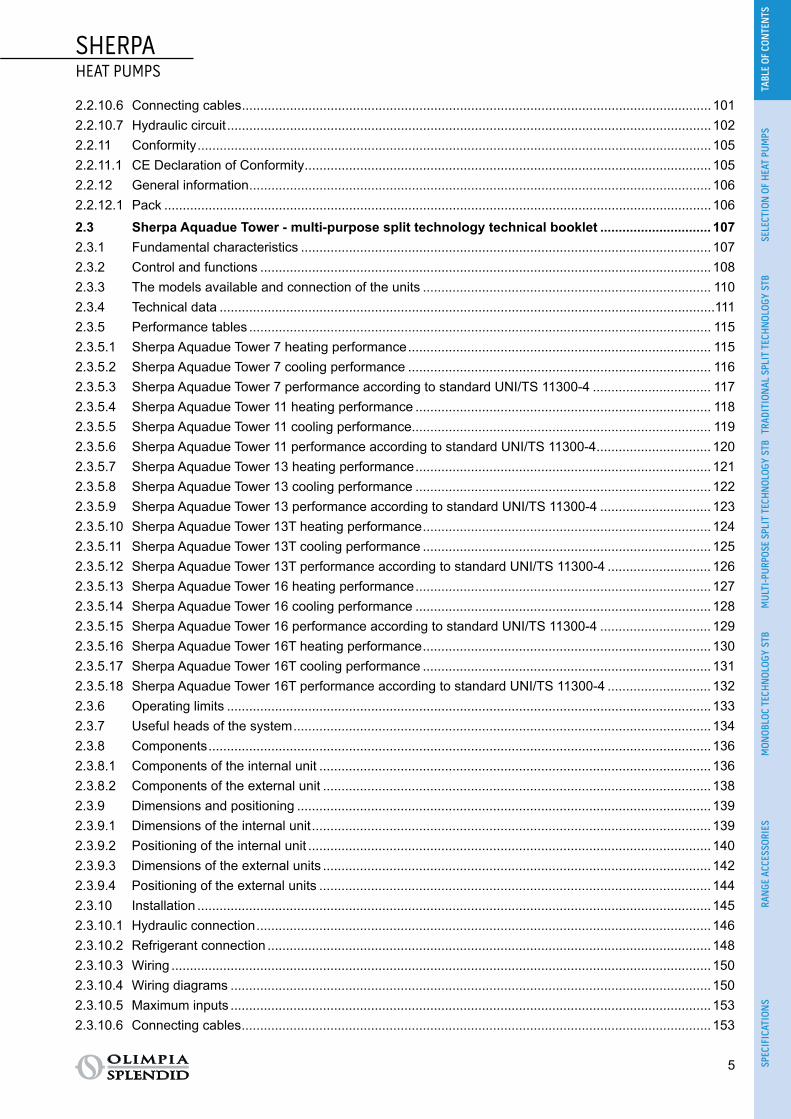
2.2.10.6 Connecting cables ...............................................................................................................................1012.2.10.7 Hydraulic circuit ...................................................................................................................................1022.2.11 Conformity ...........................................................................................................................................1052.2.11.1 CE Declaration of Conformity .............................................................................................................. 1052.2.12 General information .............................................................................................................................1062.2.12.1 Pack ....................................................................................................................................................106
2.3 Sherpa Aquadue Tower - multi-purpose split technology technical booklet .............................. 1072.3.1 Fundamental characteristics ............................................................................................................... 1072.3.2 Control and functions ..........................................................................................................................1082.3.3 The models available and connection of the units .............................................................................. 1102.3.4 Technical data ......................................................................................................................................1112.3.5 Performance tables ............................................................................................................................. 1152.3.5.1 Sherpa Aquadue Tower 7 heating performance .................................................................................. 1152.3.5.2 Sherpa Aquadue Tower 7 cooling performance .................................................................................. 1162.3.5.3 Sherpa Aquadue Tower 7 performance according to standard UNI/TS 11300-4 ................................ 1172.3.5.4 Sherpa Aquadue Tower 11 heating performance ................................................................................ 1182.3.5.5 Sherpa Aquadue Tower 11 cooling performance................................................................................. 1192.3.5.6 Sherpa Aquadue Tower 11 performance according to standard UNI/TS 11300-4 ............................... 1202.3.5.7 Sherpa Aquadue Tower 13 heating performance ................................................................................ 1212.3.5.8 Sherpa Aquadue Tower 13 cooling performance ................................................................................ 1222.3.5.9 Sherpa Aquadue Tower 13 performance according to standard UNI/TS 11300-4 .............................. 1232.3.5.10 Sherpa Aquadue Tower 13T heating performance .............................................................................. 1242.3.5.11 Sherpa Aquadue Tower 13T cooling performance .............................................................................. 1252.3.5.12 Sherpa Aquadue Tower 13T performance according to standard UNI/TS 11300-4 ............................ 1262.3.5.13 Sherpa Aquadue Tower 16 heating performance ................................................................................ 1272.3.5.14 Sherpa Aquadue Tower 16 cooling performance ................................................................................ 1282.3.5.15 Sherpa Aquadue Tower 16 performance according to standard UNI/TS 11300-4 .............................. 1292.3.5.16 Sherpa Aquadue Tower 16T heating performance .............................................................................. 1302.3.5.17 Sherpa Aquadue Tower 16T cooling performance .............................................................................. 1312.3.5.18 Sherpa Aquadue Tower 16T performance according to standard UNI/TS 11300-4 ............................ 1322.3.6 Operating limits ...................................................................................................................................1332.3.7 Useful heads of the system ................................................................................................................. 1342.3.8 Components ........................................................................................................................................1362.3.8.1 Components of the internal unit .......................................................................................................... 1362.3.8.2 Components of the external unit ......................................................................................................... 1382.3.9 Dimensions and positioning ................................................................................................................ 1392.3.9.1 Dimensions of the internal unit ............................................................................................................ 1392.3.9.2 Positioning of the internal unit ............................................................................................................. 1402.3.9.3 Dimensions of the external units ......................................................................................................... 1422.3.9.4 Positioning of the external units .......................................................................................................... 1442.3.10 Installation ...........................................................................................................................................1452.3.10.1 Hydraulic connection ...........................................................................................................................1462.3.10.2 Refrigerant connection ........................................................................................................................1482.3.10.3 Wiring ..................................................................................................................................................1502.3.10.4 Wiring diagrams ..................................................................................................................................1502.3.10.5 Maximum inputs ..................................................................................................................................1532.3.10.6 Connecting cables ...............................................................................................................................153

6
SHERPAHEAT PUMPS
2.3.10.7 Hydraulic circuit ...................................................................................................................................1542.3.11 Conformity ...........................................................................................................................................1572.3.11.1 CE Declaration of Conformity .............................................................................................................. 1572.3.12 General information .............................................................................................................................1582.3.12.1 Pack ....................................................................................................................................................158
2.4 Sherpa Monobloc - monobloc technology technical booklet ....................................................... 1592.4.1 Fundamental characteristics ............................................................................................................... 1592.4.2 Control and functions ..........................................................................................................................1602.4.3 Technical data .....................................................................................................................................1612.4.4 Performance tables .............................................................................................................................1632.4.4.1 Sherpa Monobloc 4 heating performance ........................................................................................... 1632.4.4.2 Sherpa Monobloc 4 cooling performance ........................................................................................... 1642.4.4.3 Sherpa Monobloc 6 heating performance ........................................................................................... 1652.4.4.4 Sherpa Monobloc 6 cooling performance ........................................................................................... 1662.4.4.5 Sherpa Monobloc 8 heating performance ........................................................................................... 1672.4.4.6 Sherpa Monobloc 8 cooling performance ........................................................................................... 1682.4.4.7 Sherpa Monobloc 12 heating performance ......................................................................................... 1692.4.4.8 Sherpa Monobloc 12 cooling performance ......................................................................................... 1702.4.4.9 Sherpa Monobloc 15 heating performance ......................................................................................... 1712.4.4.10 Sherpa Monobloc 15 cooling performance ......................................................................................... 1722.4.4.11 Sherpa Monobloc 12T heating performance ....................................................................................... 1732.4.4.12 Sherpa Monobloc 12T cooling performance ....................................................................................... 1742.4.4.13 Sherpa Monobloc 15T heating performance ....................................................................................... 1752.4.4.14 Sherpa Monobloc 15T cooling performance ....................................................................................... 1762.4.5 Operating limits ...................................................................................................................................1762.4.6 Useful heads of the system ................................................................................................................. 1782.4.7 Components ........................................................................................................................................1792.4.8 Dimensions and positioning ................................................................................................................ 1802.4.8.1 Dimensions .........................................................................................................................................1802.4.8.2 Positioning ...........................................................................................................................................1812.4.9 Installation ...........................................................................................................................................1822.4.9.1 Hydraulic connection ...........................................................................................................................1832.4.9.2 Electrical connection, maximum consumption and connecting cables ............................................... 1852.4.9.3 Wiring diagrams ..................................................................................................................................1872.4.9.4 Hydronic circuit ....................................................................................................................................1882.4.10 Conformity ...........................................................................................................................................1922.4.10.1 CE Declaration of Conformity .............................................................................................................. 1922.4.11 General information .............................................................................................................................1932.4.11.1 Pack ....................................................................................................................................................193
3 Range accessories ................................................................................................ 1943.1 Compatibility of the accessories ..................................................................................................... 1943.2 Description of the accessories ........................................................................................................ 1953.3 Aquadue control ................................................................................................................................1993.3.1 Introduction .........................................................................................................................................1993.3.2 Components ........................................................................................................................................1993.3.3 Functions .............................................................................................................................................199

7
SHERPAHEAT PUMPS
TABL
E OF
CON
TEN
TSSE
LECT
ION
OF
HEA
T PU
MPS
TRAD
ITIO
NAL
SPL
IT T
ECH
NOL
OGY
STB
MUL
TI-P
URPO
SE S
PLIT
TEC
HNOL
OGY
STB
MON
OBLO
C TE
CHN
OLOG
Y ST
BRA
NGE
ACC
ESSO
RIES
SPEC
IFIC
ATIO
NS
3.3.4 Connections .......................................................................................................................................2003.3.5 Unit ......................................................................................................................................................2003.3.6 Smart phone ........................................................................................................................................2003.3.7 Codes and accessories .......................................................................................................................2003.3.8 Setting up of interconnections and components per number of units ................................................. 202
4 Specifications ........................................................................................................ 203
SymbolsBelow are the various symbols used in the technical booklet to draw attention to information of particular impor-tance:
Failure to observe the information and warnings marked with this symbol could lead to damage to the machine or compromise the safety of the personnel.
Failure to observe the information and warnings of an electrical nature marked with this symbol could lead to damage to the machine or compromise the safety of the personnel.

8
SHERPAHEAT PUMPS
1 SELECTION OF AIR-COOLED HEAT PUMPS1.1 TRADITIONAL SPLIT TECHNOLOGY
TRADITIONAL SPLIT REVERSIBLE AIR-COOLED HEAT PUMPpag. 10
• DHW 60°C
• COMFORT AND DHW
• INVERTER TECHNOLOGY
• COP > 4
• ERP energy class*: at 35°C at 55°C
1.2 MULTI-PURPOSE SPLIT TECHNOLOGYMULTI-PURPOSE SPLIT REVERSIBLE AIR-COOLED HEAT PUMP
pag. 59
• DHW 75°C
• ENERGY RECOVERY
• COMFORT AND DHW AT THE SAME TIME
• INVERTER TECHNOLOGY
• COP > 4
• ERP energy class*: at 35°C at 55°C
MULTI-PURPOSE SPLIT REVERSIBLE AIR-WATER HEAT PUMP WITH INTEGRATED 150 L BOILERpag. 107
• DHW 75°C
• ENERGY RECOVERY
• COMFORT AND DHW AT THE SAME TIME
• INVERTER TECHNOLOGY
• HIGH EFFICIENCY INTEGRATED 150 L BOILER
• COP > 4
• ERP energy class*: at 35°C at 55°C at 55°C for DHW

SHERPAHEAT PUMPS
9
TABL
E OF
CON
TEN
TSSE
LECT
ION
OF
HEA
T PU
MPS
TRAD
ITIO
NAL
SPL
IT T
ECH
NOL
OGY
STB
MUL
TI-P
URPO
SE S
PLIT
TEC
HNOL
OGY
STB
MON
OBLO
C TE
CHN
OLOG
Y ST
BRA
NGE
ACC
ESSO
RIES
SPEC
IFIC
ATIO
NS
1.3 MONOBLOC TECHNOLOGYMONOBLOC REVERSIBLE AIR-COOLED HEAT PUMP
(2) pag. 159
• DHW 60°C
• COMFORT AND DHW
• INVERTER TECHNOLOGY
• COP > 4
• ERP energy class*: at 35°C at 55°C
* Depending on the choice of model.

10
SHERPA TECHNICAL BOOKLETHEAT PUMPS
2 TECHNICAL BOOKLETS 2.1 SHERPA - TRADITIONAL SPLIT TECHNOLOGY TECHNICAL BOOKLET
2.1.1 FUNDAMENTAL CHARACTERISTICS ○ Reversible air-water heat pump split system with DC inverter motor. ○ System with two modules: external unit and internal hydronic module. ○ Supplies water for heating DHW at a temperature of up to 60°C. ○ Integrated 3-way valve. ○ Standard two-stage electrical heater elements: can be configured as single or two-stage heater
elements to support the heat pump. ○ Two methods for management of DHW: with water probe in the boiler or with boiler thermostat contact. ○ Complete management of anti-legionella cycles. ○ Configurable climate curves based on the outdoor air temperature: one for cooling and one for heating. ○ Daily timer with night-time mode. ○ Two set-points for cooling, two set-points for heating and one set-point for DHW that can also be
selected with remote contact (ECO). ○ R410A cooling gas.

SHERPA TECHNICAL BOOKLETHEAT PUMPS
11
TABL
E OF
CON
TEN
TSSE
LECT
ION
OF
HEA
T PU
MPS
TRAD
ITIO
NAL
SPL
IT T
ECH
NOL
OGY
STB
MUL
TI-P
URPO
SE S
PLIT
TEC
HNOL
OGY
STB
MON
OBLO
C TE
CHN
OLOG
Y ST
BRA
NGE
ACC
ESSO
RIES
SPEC
IFIC
ATIO
NS
2.1.2 CONTROL AND FUNCTIONS ○ Sherpa can be activated for:
• heating, • cooling, • domestic water production only, • cooling or heating with domestic water.
○ The control can manage one climate curve for heating and another for cooling to vary the water tem-perature of the system in relation to the outdoor weather conditions, adapting the amount of heat to the heating requirements of the building in order to save energy.
○ There is a daily timer with night-time mode that permits up to 20% energy savings.
○ Sherpa offers two methods for the highly flexible management of Domestic Hot Water: • water probe on board the machine;• water probe in the boiler.
○ The probe in the DHW tank also allows Sherpa to manage anti-legionella cycles; when there is an electrical heater element in the DHW tank, the anti-legionella cycle runs without interrupting the heating or cooling cycle of the air-conditioning system.
○ The set-points available are:• two set-points for cooling;• two set-points for heating that can be activated at the button on the Eco control panel or via remote
contacts;• a set-point for defining the temperature of the domestic water.
○ The units have a supporting two-stage heater element: • 1.5kW + 1.5kW on SMALL internal units,• 3 kW + 3 kW on LARGE units. These can be enabled to integrate power for heating, the production of domestic water, and the anti-legionella cycles. Once enabled, the heater elements start automatically the moment the low outdoor air temperature does not allow the heat pump to meet the heating load or when the exter-nal unit malfunctions (back-up function). It is possible to enable just one or both the stages of the electrical heater element according to needs or the electrical power available. This function requires installation of the outdoor air temperature probe kit (optional).
○ The following functions can be remote controlled with free contacts:• switching on/off;• heating/cooling mode;• activation of the second set-point (Eco mode);• activation of night-time mode;• activation of heating of domestic water storage;• enabling/disabling of air conditioning (only production of DHW). The unit may also be connected to a chrono-thermostat or to the chiller/boiler contacts of the elec-tronic controls of the fan coils Bi2 and Bi2+.
○ Sherpa can activate an auxiliary external heat source (e.g. heater) to substitute the heat pump unit, in relation to the outdoor air temperature. This function requires installation of the outdoor air tempera-ture probe kit (optional).
○ The following accessories are available:• Code B0622 - 3-way valve kit for domestic hot water;• Code B0623 - Outdoor air probe kit;• Code B0624 - DHW boiler sensor kit;• Code B0665 - Heating cable kit.
The codes are subject to change; please contact Olimpia Splendid for further information.

12
SHERPA TECHNICAL BOOKLETHEAT PUMPS
2.1.3 THE MODELS AVAILABLE AND CONNECTION OF THE UNITS Below is a table of the models to which the relative external unit is connected (Tab. 1).
SHERPA 7 SHERPA 11 SHERPA 13 SHERPA 13T SHERPA 16 SHERPA 16T
STANDARD internal unit
SMALL599501A
BIG599503A
INTERNAL UNIT with integrated three-way valve
SMALL599505A
BIG599500A
EXTERNAL UNIT
OS-CEBSH24EI OS-CEBCH36EI OS-CEINH48EI OS-CETNH48EI OS-CEINH60EI OS-CETNH60EI
S1 EXTER-NAL UNIT
OS-CESHH24EI OS-CESHH36EI OS-CESHH48EI OS-CESTH48EI OS-CESHH60EI OS-CESTH60EI
The models available and connection of the units Tab. 1
The codes are subject to change; please contact Olimpia Splendid for further information.

SHERPA TECHNICAL BOOKLETHEAT PUMPS
13
TABL
E OF
CON
TEN
TSSE
LECT
ION
OF
HEA
T PU
MPS
TRAD
ITIO
NAL
SPL
IT T
ECH
NOL
OGY
STB
MUL
TI-P
URPO
SE S
PLIT
TEC
HNOL
OGY
STB
MON
OBLO
C TE
CHN
OLOG
Y ST
BRA
NGE
ACC
ESSO
RIES
SPEC
IFIC
ATIO
NS
2.1.4 TECHNICAL DATA Below are tables summarising the technical data (Tab. 2 and Tab. 3).
SHERPA 7
SHERPA11
SHERPA13
SHERPA 13T
SHERPA16
SHERPA 16T
Standard internal unit code 599501A 599501A 599503A 599503A 599503A 599503A
Internal unit with 3-way valve code 599505A 599505A 599500A 599500A 599500A 599500A
External unit code OSCEBSH24EI
OSCEBCH36EI
OSCEINH48EI
OSCETNH48EI
OSCEINH60EI
OSCETNH60EI
S1 external unit code OSCESHH24EI
OSCESHH36EI
OSCESHH48EI
OSCESTH48EI
OSCESHH60EI
OSCESTH60EI
Type of evaporator Brazed-plate Brazed-plate Brazed-plate Brazed-plate Brazed-plate Brazed-plate
Heating capacity (a) kW 6.50 10.50 12.50 12.50 14 16
COP (a) W/W 4.12 4.14 4.12 4.12 4.11 4.11
Heating capacity (b) kW 4.30 7.20 8 8 8.50 9.20
COP (b) W/W 2.60 2.65 2.70 2.70 2.40 2.50
Heating capacity (c) kW 6.50 9.90 12.50 12.50 13.30 14
COP (c) W/W 3.40 3.14 3.21 3.21 3.10 3.10
Heating capacity (d) kW 3.80 6.20 7.20 7.20 8.50 9
COP (d) W/W 2.30 2 2.10 2.10 2.10 2.10
Cooling capacity (e) kW 7.90 11.80 12.30 12.50 13.50 15
EER (e) W/W 4.50 4.40 4 4.10 3.80 4
Cooling capacity (f) kW 5.60 8.10 10.40 10.40 11.30 12.80
EER (f) W/W 3.10 3.08 3 3 2.70 2.80
Energy efficiency class for heating water at 35°C
Energy efficiency class for heating water at 55°C
Sound pressure of internal unit (g) dB(A) 35 35 35 35 35 35
Sound pressure of internal unit dB(A) 41 41 41 41 41 41
Sound pressure of external unit (g) dB(A) 54/55 56/58 60/60 60/60 60/60 60/62
Sound pressure of external unit dB(A) 64/65 66/68 70/70 70/70 70/70 70/72
Notes(a) Heating mode, inlet/outlet water temperature 30°C/35°C, outdoor air temperature 7°C d.b./6°C w.b.(b) Heating mode, inlet/outlet water temperature 30°C/35°C, outdoor air temperature -2°C d.b./-1°C w.b.(c) Heating mode, inlet/outlet water temperature 40°C/45°C, outdoor air temperature 7°C d.b./6°C w.b.(d) Heating mode, inlet/outlet water temperature 40°C/45°C, outdoor air temperature -2°C d.b./-1°C w.b.(e) Cooling mode, inlet/outlet water temperature 23°C/18°C, outdoor air temperature 35°C(f) Cooling mode, inlet/outlet water temperature 12°C/7°C, outdoor air temperature 35°C(g) Sound pressure values measured at a distance of 1 m in semi-anechoic chamber(h) Sound pressure values measured at a distance of 4 m in a free field
Technical data Tab. 2

14
SHERPA TECHNICAL BOOKLETHEAT PUMPS
SHERPA 7
SHERPA11
SHERPA13
SHERPA 13T
SHERPA16
SHERPA 16T
Diameter of connection of liquid line “ 3/8 3/8 3/8 3/8 3/8 3/8
Diameter of connection of gas line “ 5/8 5/8 5/8 5/8 5/8 5/8
Absorption of circulator W 40-130 40-130 40-130 40-130 40-130 40-130
Useful head of system circu-lator kPa 80 82 80 80 78 73
Capacity of expansion vessel l 8 8 8 8 8 8
Power supply of internal unit V/ph/Hz 230/1/50 230/1/50 230/1/50 230/1/50 230/1/50 230/1/50
Maximum absorbed current (a) A 14.10 14.10 27.20 27.20 27.20 27.20
Internal unit maximum ab-sorbed power (a) kW 3.22 3.22 6.22 6.22 6.22 6.22
Additional electrical heater elements for internal unit kW 1,5 + 1,5 1,5 + 1,5 3 + 3 3 + 3 3 + 3 3 + 3
Hydraulic connections of inter-nal unit “ 1 1 1 1 1 1
Power supply of external unit
V/ph/Hz 230/1/50 230/1/50 230/1/50 400/3/50 230/1/50 400/3/50
External unit maximum ab-sorbed current A 13.50 22 28 8.15 28 11.50
Cooling gas (b) R410A R410A R410A R410A R410A R410A
Overall heating potential GWP 2088 2088 2088 2088 2088 2088
Charge of cooling gas of exter-nal unit Kg 2.10 2.75 4.45 4.00 4.45 4.20
Charge of cooling gas of S1 external unit Kg 1.95 3.20 4.00 4.00 4.00 4.30
Water safety valve bar 3 3 3 3 3 3
Expansion vessel pre-charge pressure bar 1.50 1.50 1.50 1.50 1.50 1.50
Notes(a) With heater elements engaged(b) Equipment not hermetically sealed containing fluorinated gases with an equivalent GWP of 2088
Technical data Tab. 3

SHERPA TECHNICAL BOOKLETHEAT PUMPS
15
TABL
E OF
CON
TEN
TSSE
LECT
ION
OF
HEA
T PU
MPS
TRAD
ITIO
NAL
SPL
IT T
ECH
NOL
OGY
STB
MUL
TI-P
URPO
SE S
PLIT
TEC
HNOL
OGY
STB
MON
OBLO
C TE
CHN
OLOG
Y ST
BRA
NGE
ACC
ESSO
RIES
SPEC
IFIC
ATIO
NS
2.1.5 PERFORMANCE TABLES2.1.5.1 SHERPA 7 HEATING PERFORMANCE
Below is a table of the heating performance (Tab. 4) and a table with the correction factors (Tab. 5).
WT °C 35 40 45 50 55 60
OAT °C
PhkW
PekW COP Ph
kWPekW COP Ph
kWPekW COP Ph
kWPekW COP Ph
kWPekW COP Ph
kWPekW COP
-20 3.31 1.72 1.92 3.17 1.75 1.81 2.88 1.80 1.60 2.61 1.86 1.40 - - - - - -
-7 4.21 1.40 3.01 3.79 1.44 2.63 3.51 1.42 2.48 3.30 1.43 2.30 2.85 1.43 2.00 - - -
0 4.85 1.49 3.25 4.50 1.55 2.90 4.05 1.58 2.56 3.88 1.62 2.40 3.35 1.68 2.00 3.10 1.79 1.73
2 5.05 1.50 3.37 4.70 1.57 3.00 4.30 1.65 2.60 4.20 1.68 2.50 3.58 1.70 2.10 3.30 1.83 1.80
7 6.50 1.58 4.12 5.90 1.61 3.66 5.50 1.62 3.40 5.10 1.76 2.90 4.65 1.79 2.60 4.30 1.95 2.20
12 7.71 1.72 4.48 7.20 1.75 4.11 6.79 1.82 3.73 6.00 1.85 3.25 5.60 1.93 2.90 5.20 2.08 2.50
30 8.90 1.94 4.58 8.51 1.98 4.30 7.90 2.01 3.93 7.30 2.05 3.57 6.65 2.15 3.10 - - -
42 9.30 2.04 4.55 8.82 2.10 4.20 8.20 2.14 3.83 7.60 2.19 3.47 7.00 2.33 3.00 - - -
Data declared pursuant to UNI EN 14511
LegendPh Heating power kWPe Absorbed power kWOAT Outdoor air temperatureWT System water flow temperature
Sherpa 7 heating performance Tab. 4
CORRECTION FACTORS
∆t water 3 5 8 10
Heating power correction factor 0.99 1 1.01 1.02
Absorbed power correction factor 1.01 1 0.98 0.96
Correction factors Tab. 5

16
SHERPA TECHNICAL BOOKLETHEAT PUMPS
2.1.5.2 SHERPA 7 COOLING PERFORMANCE
Below are tables of the cooling performance (Tab. 6 and Tab. 7) and a table with the correction factors (Tab. 8).
OAT °C 20 25 30
WT °C PckW
PekW EER Pc
kWPekW EER Pc
kWPekW EER
4 6.1 1.26 4.84 5.80 1.41 4.11 5.57 1.59 3.50
7 6.56 1.28 5.13 6.27 1.43 4.38 5.94 1.61 3.69
10 7.05 1.30 5.42 6.74 1.46 4.62 6.38 1.64 3.89
13 7.64 1.31 5.83 7.31 1.48 4.94 6.92 1.65 4.19
18 8.84 1.35 6.55 8.47 1.51 5.61 8.04 1.70 4.73
Data declared pursuant to UNI EN 14511
LegendPc Cooling power kWPe Absorbed power kWOAT Outdoor air temperatureWT System water flow temperature
Sherpa 7 cooling performance Tab. 6
OAT °C 35 40 46
WT °C PckW
PekW EER Pc
kWPekW EER Pc
kWPekW EER
4 5.25 1.79 2.93 4.90 2.01 2.44 4.60 2.20 2.09
7 5.60 1.81 3.09 5.26 2.03 2.59 4.94 2.25 2.20
10 6.01 1.83 3.28 5.65 2.05 2.76 5.30 2.30 2.30
13 6.35 1.86 3.51 6.13 2.08 2.95 5.72 2.29 2.50
18 7.60 1.90 4.00 7.16 2.13 3.36 6.70 2.33 2.88
Data declared pursuant to UNI EN 14511LegendPc Cooling power kWPe Absorbed power kWOAT Outdoor air temperatureWT System water flow temperature
Sherpa 7 cooling performance Tab. 7
CORRECTION FACTORS
∆t of water different from the nominal value (∆t 5°C) 3 5 8 10
Cooling power correction factor 0.99 1 1.02 1.03
Absorbed power correction factor 0.99 1 1.01 1.02
Correction factors Tab. 8

SHERPA TECHNICAL BOOKLETHEAT PUMPS
17
TABL
E OF
CON
TEN
TSSE
LECT
ION
OF
HEA
T PU
MPS
TRAD
ITIO
NAL
SPL
IT T
ECH
NOL
OGY
STB
MUL
TI-P
URPO
SE S
PLIT
TEC
HNOL
OGY
STB
MON
OBLO
C TE
CHN
OLOG
Y ST
BRA
NGE
ACC
ESSO
RIES
SPEC
IFIC
ATIO
NS
2.1.5.3 SHERPA 7 PERFORMANCE ACCORDING TO STANDARD UNI/TS 11300-4
Below are the tables of performance according to standard UNI/TS 11300-4 (Tab. 9 and Tab. 10).
Water T °C 35 45 55
Outdoor air T °C Heating capacity kW COP Heating capacity kW COP Heating capacity kW COP
-7 4.21 3.01 3.51 2.48 2.85 2.00
2 5.05 3.37 4.30 2.60 3.58 2.10
7 6.50 4.12 5.50 3.40 4.65 2.60
12 7.71 4.48 6.79 3.73 5.60 2.90
Sherpa 7 performance according to standard UNI/TS 11300-4 Tab. 9
WT 35°C A Td-fan B C D
Outdoor air T °C -7 2 7 12
PLR 88% 54% 35% 15%
DC 4.21 5.05 6.50 7.71
COP at Partial Load 3.01 4.14 4.60 4.50
COP at Full Load 3.01 3.37 4.12 4.48
CR 1.00 0.50 0.25 0.09
fCOP 1.00 1.34 1.12 1.00
LegendTU: water flow temperature of the systemPLR: Part load ratioDC: Power at full load and at the temperatures recommended by the manufacturerCOP at Partial Load: COP at CR load and at the temperatures recommended by the manufacturerCOP at Full Load: COP at full load and at the temperatures recommended by the manufacturerCR = capacity control ratio of the heat pumpfCOP = COP correction factor in relation to the CR load ratio
Sherpa 7 performance according to standard UNI/TS 11300-4 Tab. 10

18
SHERPA TECHNICAL BOOKLETHEAT PUMPS
2.1.5.4 SHERPA 11 HEATING PERFORMANCE
Below is a table of the heating performance (Tab. 11) and a table with the correction factors (Tab. 12).
WT °C 35 40 45 50 55 60
OAT °C PhkW
PekW COP Ph
kWPekW COP Ph
kWPekW COP Ph
kWPekW COP Ph
kWPekW COP Ph
kWPekW COP
-20 5.50 3.13 1.75 5.30 3.53 1.50 5.15 3.81 1.35 4.80 4.00 1.20 - - - - - -
-7 6.99 2.64 2.65 6.50 2.71 2.40 6.3 2.86 2.20 5.95 2.98 2.00 5.60 3.01 1.86 - - -
0 7.60 2.63 2.89 7.30 2.70 2.70 7.00 2.89 2.42 6.80 3.02 2.25 6.45 3.19 2.02 6.10 3.30 1.85
2 7.95 2.69 2.95 7.60 2.76 2.75 7.20 2.94 2.45 7.00 3.04 2.30 6.70 3.27 2.05 6.40 3.37 1.90
7 11.00 2.68 4.10 10.10 2.89 3.50 9.90 3.15 3.14 9.40 3.48 2.70 9.10 3.70 2.46 8.20 3.90 2.10
12 12.35 2.81 4.40 11.80 2.95 4.00 11.45 3.28 3.49 11.00 3.55 3.10 10.75 3.83 2.81 10 4.00 2.50
30 14.30 3.18 4.50 13.80 3.29 4.20 13.32 3.42 3.90 13.05 3.66 3.57 12.77 3.93 3.25 - - -
42 14.80 3.22 4.60 14.20 3.34 4.25 13.70 3.51 3.90 13.50 3.70 3.65 13.44 4.07 3.30 - - -
Data declared pursuant to UNI EN 14511
LegendPh Heating power kWPe Absorbed power kWOAT Outdoor air temperatureWT System water flow temperature
Sherpa 11 heating performance Tab. 11
CORRECTION FACTORS
∆t water 3 5 8 10
Heating power correction factor 0.99 1 1.01 1.02
Absorbed power correction factor 1.01 1 0.98 0.96
Correction factors Tab. 12
SHERPA TECHNICAL BOOKLETHEAT PUMPS
19
TABL
E OF
CON
TEN
TSSE
LECT
ION
OF
HEA
T PU
MPS
TRAD
ITIO
NAL
SPL
IT T
ECH
NOL
OGY
STB
MUL
TI-P
URPO
SE S
PLIT
TEC
HNOL
OGY
STB
MON
OBLO
C TE
CHN
OLOG
Y ST
BRA
NGE
ACC
ESSO
RIES
SPEC
IFIC
ATIO
NS
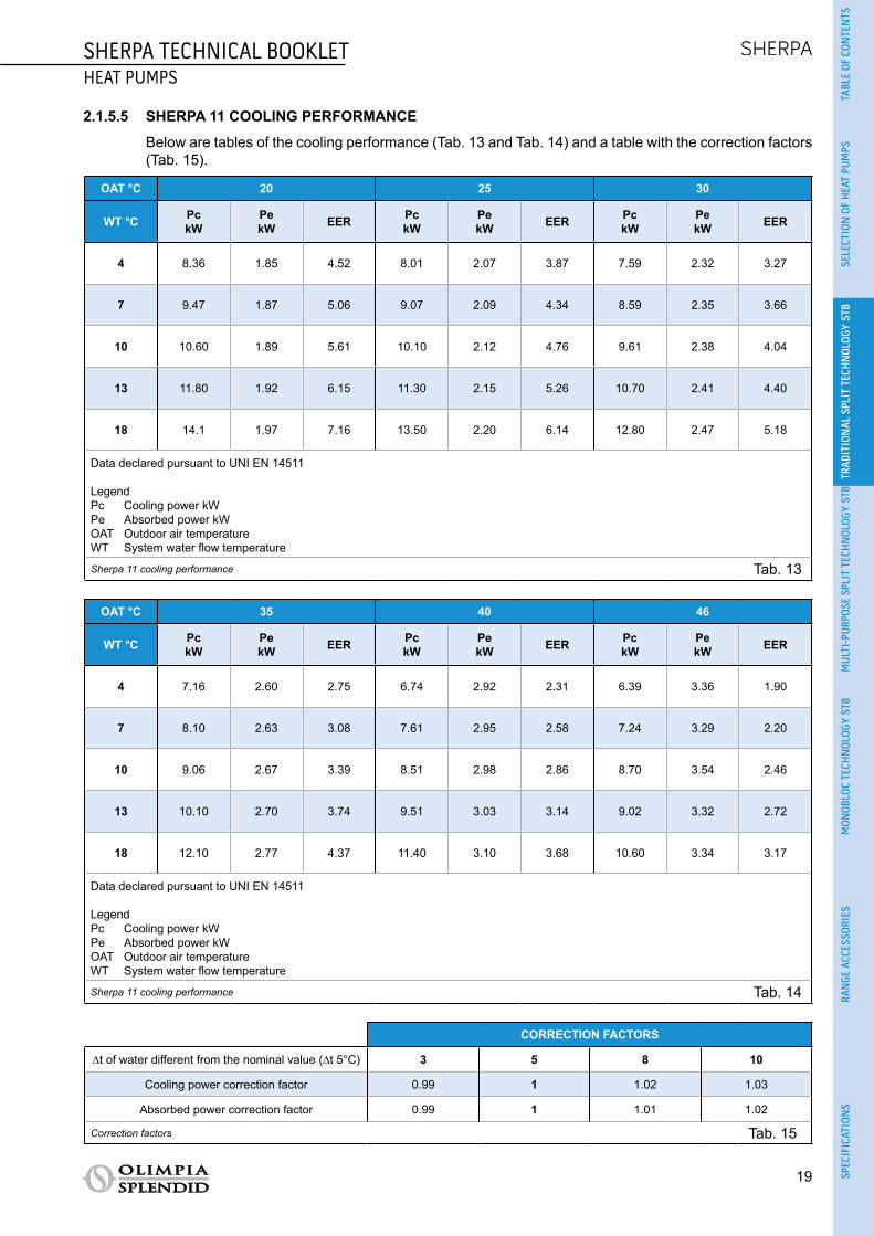
2.1.5.5 SHERPA 11 COOLING PERFORMANCE
Below are tables of the cooling performance (Tab. 13 and Tab. 14) and a table with the correction factors (Tab. 15).
OAT °C 20 25 30
WT °C PckW
PekW EER Pc
kWPekW EER Pc
kWPekW EER
4 8.36 1.85 4.52 8.01 2.07 3.87 7.59 2.32 3.27
7 9.47 1.87 5.06 9.07 2.09 4.34 8.59 2.35 3.66
10 10.60 1.89 5.61 10.10 2.12 4.76 9.61 2.38 4.04
13 11.80 1.92 6.15 11.30 2.15 5.26 10.70 2.41 4.40
18 14.1 1.97 7.16 13.50 2.20 6.14 12.80 2.47 5.18
Data declared pursuant to UNI EN 14511
LegendPc Cooling power kWPe Absorbed power kWOAT Outdoor air temperatureWT System water flow temperature
Sherpa 11 cooling performance Tab. 13
OAT °C 35 40 46
WT °C PckW
PekW EER Pc
kWPekW EER Pc
kWPekW EER
4 7.16 2.60 2.75 6.74 2.92 2.31 6.39 3.36 1.90
7 8.10 2.63 3.08 7.61 2.95 2.58 7.24 3.29 2.20
10 9.06 2.67 3.39 8.51 2.98 2.86 8.70 3.54 2.46
13 10.10 2.70 3.74 9.51 3.03 3.14 9.02 3.32 2.72
18 12.10 2.77 4.37 11.40 3.10 3.68 10.60 3.34 3.17
Data declared pursuant to UNI EN 14511
LegendPc Cooling power kWPe Absorbed power kWOAT Outdoor air temperatureWT System water flow temperature
Sherpa 11 cooling performance Tab. 14
CORRECTION FACTORS
∆t of water different from the nominal value (∆t 5°C) 3 5 8 10
Cooling power correction factor 0.99 1 1.02 1.03
Absorbed power correction factor 0.99 1 1.01 1.02
Correction factors Tab. 15

20
SHERPA TECHNICAL BOOKLETHEAT PUMPS
2.1.5.6 SHERPA 11 PERFORMANCE ACCORDING TO STANDARD UNI/TS 11300-4
Below are the tables of performance according to standard UNI/TS 11300-4 (Tab. 16 and Tab. 17).
Water T °C 35 45 55
Outdoor air T °C Heating capacity kW COP Heating capacity kW COP Heating capacity kW COP
-7 6.99 2.65 6.30 2.20 5.60 1.86
2 7.95 2.95 7.20 2.45 6.70 2.05
7 11.00 4.10 9.90 3.14 9.10 2.46
12 12.35 4.40 11.45 3.49 10.75 2.81
Sherpa 11 performance according to standard UNI/TS 11300-4 Tab. 16
WT 35°C A Td-fan B C D
Outdoor air T °C -7 2 7 12
PLR 88% 54% 35% 15%
DC 6.99 7.95 11.00 12.35
COP at Partial Load 2.50 2.87 4.28 4.45
COP at Full Load 2.65 2.95 4.10 4.40
CR 1.00 0.55 0.26 0.10
fCOP 1.00 0.97 1.03 1.01
LegendTU: water flow temperature of the systemPLR: Part load ratioDC: Power at full load and at the temperatures recommended by the manufacturerCOP at Partial Load: COP at CR load and at the temperatures recommended by the manufacturerCOP at Full Load: COP at full load and at the temperatures recommended by the manufacturerCR = capacity control ratio of the heat pumpfCOP = COP correction factor in relation to the CR load ratio
Sherpa 11 performance according to standard UNI/TS 11300-4 Tab. 17

SHERPA TECHNICAL BOOKLETHEAT PUMPS
21
TABL
E OF
CON
TEN
TSSE
LECT
ION
OF
HEA
T PU
MPS
TRAD
ITIO
NAL
SPL
IT T
ECH
NOL
OGY
STB
MUL
TI-P
URPO
SE S
PLIT
TEC
HNOL
OGY
STB
MON
OBLO
C TE
CHN
OLOG
Y ST
BRA
NGE
ACC
ESSO
RIES
SPEC
IFIC
ATIO
NS
2.1.5.7 SHERPA 13 HEATING PERFORMANCE
Below is a table of the heating performance (Tab. 18) and a table with the correction factors (Tab. 19).
WT °C 35 40 45 50 55 60
OAT °C PhkW
PekW COP Ph
kWPekW COP Ph
kWPekW COP Ph
kWPekW COP Ph
kWPekW COP Ph
kWPekW COP
-20 6.80 2.83 2.40 6.30 2.93 2.15 5.8 2.90 2.00 5.20 2.77 1.88 - - - - - -
-7 7.49 2.94 2.55 7.00 3.04 2.30 6.6 3.07 2.15 6.00 3.00 2.00 5.48 2.99 1.83 - - -
0 7.80 2.97 2.63 7.30 3.04 2.40 7.00 3.18 2.20 6.40 3.12 2.05 5.70 3.00 1.90 5.00 3.13 1.60
2 8.21 2.95 2.78 7.80 3.12 2.50 7.45 3.23 2.31 6.80 3.16 2.15 6.01 2.99 2.01 5.20 3.06 1.70
7 12.50 3.03 4.12 12.10 3.27 3.70 11.80 3.68 3.21 11.00 3.93 2.80 10.61 4.19 2.53 9.8 4.45 2.20
12 13.48 3.06 4.40 12.90 3.23 4.00 12.38 3.48 3.56 11.90 3.72 3.20 11.32 3.89 2.91 10.5 4.12 2.55
30 15.00 3.26 4.6 14.20 3.38 4.20 13.50 3.60 3.75 13.00 3.82 3.40 12.30 4.10 3.00 - - -
42 16.20 3.38 4.8 15.50 3.52 4.40 14.90 3.73 4.00 14.50 3.92 3.70 13.80 4.18 3.30 - - -
Data declared pursuant to UNI EN 14511
LegendPh Heating power kWPe Absorbed power kWOAT Outdoor air temperatureWT System water flow temperature
Sherpa 13 heating performance Tab. 18
CORRECTION FACTORS
∆t water 3 5 8 10
Heating power correction factor 0.99 1 1.01 1.02
Absorbed power correction factor 1.01 1 0.98 0.96
Correction factors Tab. 19

22
SHERPA TECHNICAL BOOKLETHEAT PUMPS
2.1.5.8 SHERPA 13 COOLING PERFORMANCE
Below are tables of the cooling performance (Tab. 20 and Tab. 21) and a table with the correction factors (Tab. 22).
OAT °C 20 25 30
WT °C PckW
PekW EER Pc
kWPekW EER Pc
kWPekW EER
4 11.6 2.44 4.75 11.10 2.73 4.07 10.50 3.06 3.43
7 12.20 2.46 4.96 11.60 2.75 4.22 11.00 3.09 3.56
10 12.70 2.50 5.08 12.20 2.79 4.37 11.50 3.14 3.66
13 13.40 2.53 5.30 12.80 2.84 4.51 12.10 3.17 3.82
18 14.7 2.59 5.68 14.10 2.91 4.85 13.30 3.26 4.08
Data declared pursuant to UNI EN 14511
LegendPc Cooling power kWPe Absorbed power kWOAT Outdoor air temperatureWT System water flow temperature
Sherpa 13 cooling performance Tab. 20
OAT °C 35 40 46
WT °C PckW
PekW EER Pc
kWPekW EER Pc
kWPekW EER
4 9.95 3.43 2.90 9.36 3.85 2.43 8.88 4.25 2.09
7 10.40 3.47 3.00 9.78 3.89 2.51 9.29 4.26 2.18
10 10.90 3.51 3.11 10.20 3.93 2.60 9.68 4.32 2.24
13 11.40 3.58 3.20 10.8 3.99 2.71 10.10 4.39 2.30
18 12.60 3.65 3.45 11.90 4.09 2.91 11.20 4.43 2.53
Data declared pursuant to UNI EN 14511
LegendPc Cooling power kWPe Absorbed power kWOAT Outdoor air temperatureWT System water flow temperature
Sherpa 13 cooling performance Tab. 21
CORRECTION FACTORS
∆t of water different from the nominal value (∆t 5°C) 3 5 8 10
Cooling power correction factor 0.99 1 1.02 1.03
Absorbed power correction factor 0.99 1 1.01 1.02
Correction factors Tab. 22

SHERPA TECHNICAL BOOKLETHEAT PUMPS
23
TABL
E OF
CON
TEN
TSSE
LECT
ION
OF
HEA
T PU
MPS
TRAD
ITIO
NAL
SPL
IT T
ECH
NOL
OGY
STB
MUL
TI-P
URPO
SE S
PLIT
TEC
HNOL
OGY
STB
MON
OBLO
C TE
CHN
OLOG
Y ST
BRA
NGE
ACC
ESSO
RIES
SPEC
IFIC
ATIO
NS
2.1.5.9 SHERPA 13 PERFORMANCE ACCORDING TO STANDARD UNI/TS 11300-4
Below are the tables of performance according to standard UNI/TS 11300-4 (Tab. 23 and Tab. 24).
Water T °C 35 45 55
Outdoor air T °C Heating capacity kW COP Heating capacity kW COP Heating capacity kW COP
-7 7.49 2.55 6.60 2.15 5.48 1.83
2 8.21 2.78 7.45 2.31 6.01 2.01
7 12.50 4.12 11.8 3.21 10.61 2.53
12 13.48 4.40 12.38 3.56 11.32 2.91
Sherpa 13 performance according to standard UNI/TS 11300-4 Tab. 23
WT 35°C A Td-fan B C D
Outdoor air T °C -7 2 7 12
PLR 88% 54% 35% 15%
DC 7.49 8.21 12.50 13.48
COP at Partial Load 2.55 2.91 4.26 4.52
COP at Full Load 2.55 2.78 4.12 4.40
CR 1.00 0.55 0.23 0.10
fCOP 1.00 1.05 1.03 1.03
LegendTU: water flow temperature of the systemPLR: Part load ratioDC: Power at full load and at the temperatures recommended by the manufacturerCOP at Partial Load: COP at CR load and at the temperatures recommended by the manufacturerCOP at Full Load: COP at full load and at the temperatures recommended by the manufacturerCR = capacity control ratio of the heat pumpfCOP = COP correction factor in relation to the CR load ratio
Sherpa 13 performance according to standard UNI/TS 11300-4 Tab. 24

24
SHERPA TECHNICAL BOOKLETHEAT PUMPS
2.1.5.10 SHERPA 13T HEATING PERFORMANCE
Below is a table of the heating performance (Tab. 25) and a table with the correction factors (Tab. 26).
WT °C 35 40 45 50 55 60
OAT °C PhkW
PekW COP Ph
kWPekW COP Ph
kWPekW COP Ph
kWPekW COP Ph
kWPekW COP Ph
kWPekW COP
-20 6.80 2.83 2.40 6.30 2.93 2.15 5.8 2.90 2.00 5.20 2.77 1.88 - - - - - -
-7 7.49 2.94 2.55 7.00 3.04 2.30 6.6 3.07 2.15 6.00 3.00 2.00 5.48 2.99 1.83 - - -
0 7.80 2.97 2.63 7.30 3.04 2.40 7.00 3.18 2.20 6.40 3.12 2.05 5.70 3.00 1.90 5.00 3.13 1.60
2 8.21 2.95 2.78 7.80 3.12 2.50 7.45 3.23 2.31 6.80 3.16 2.15 6.01 2.99 2.01 5.20 3.06 1.70
7 12.50 3.03 4.12 12.10 3.27 3.70 11.80 3.68 3.21 11.00 3.93 2.80 10.61 4.19 2.53 9.8 4.45 2.20
12 13.48 3.06 4.40 12.90 3.23 4.00 12.38 3.48 3.56 11.90 3.72 3.20 11.32 3.89 2.91 10.5 4.12 2.55
30 15.00 3.26 4.6 14.20 3.38 4.20 13.50 3.60 3.75 13.00 3.82 3.40 12.30 4.10 3.00 - - -
42 16.20 3.38 4.8 15.50 3.52 4.40 14.90 3.73 4.00 14.50 3.92 3.70 13.80 4.18 3.30 - - -
Data declared pursuant to UNI EN 14511
LegendPh Heating power kWPe Absorbed power kWOAT Outdoor air temperatureWT System water flow temperature
Sherpa 13T heating performance Tab. 25
CORRECTION FACTORS
∆t water 3 5 8 10
Heating power correction factor 0.99 1 1.01 1.02
Absorbed power correction factor 1.01 1 0.98 0.96
Correction factors Tab. 26
SHERPA TECHNICAL BOOKLETHEAT PUMPS
25
TABL
E OF
CON
TEN
TSSE
LECT
ION
OF
HEA
T PU
MPS
TRAD
ITIO
NAL
SPL
IT T
ECH
NOL
OGY
STB
MUL
TI-P
URPO
SE S
PLIT
TEC
HNOL
OGY
STB
MON
OBLO
C TE
CHN
OLOG
Y ST
BRA
NGE
ACC
ESSO
RIES
SPEC
IFIC
ATIO
NS
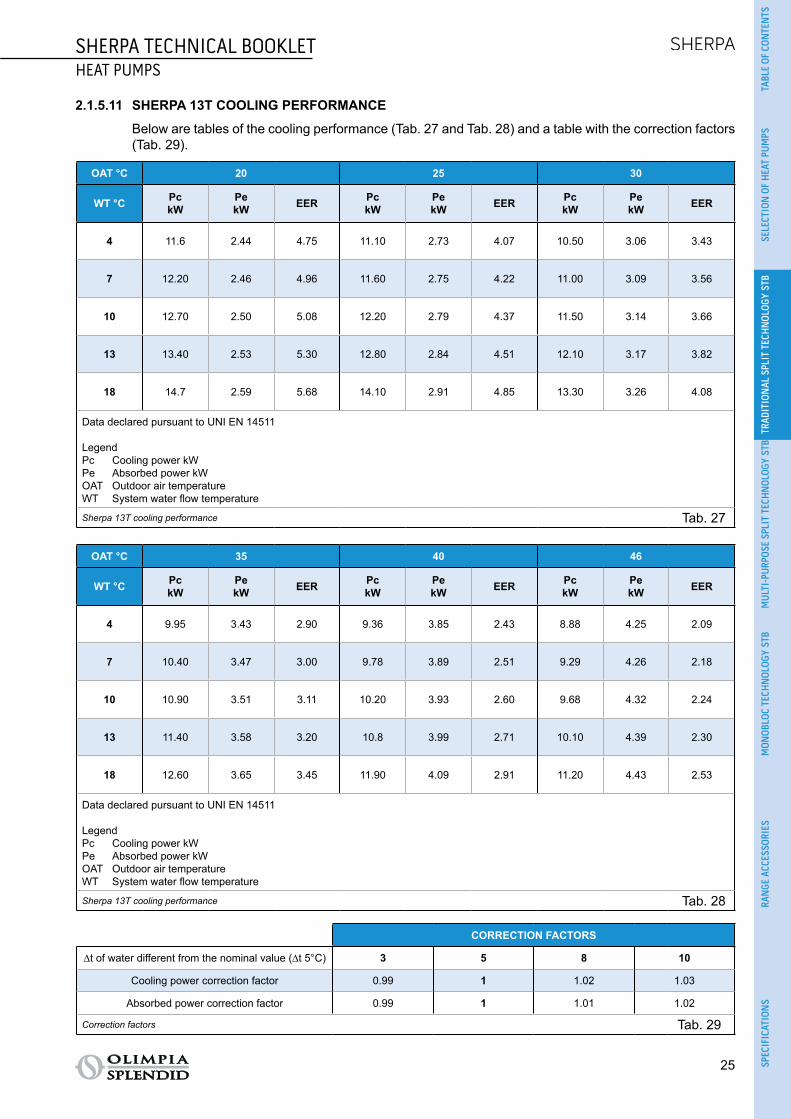
2.1.5.11 SHERPA 13T COOLING PERFORMANCE
Below are tables of the cooling performance (Tab. 27 and Tab. 28) and a table with the correction factors (Tab. 29).
OAT °C 20 25 30
WT °C PckW
PekW EER Pc
kWPekW EER Pc
kWPekW EER
4 11.6 2.44 4.75 11.10 2.73 4.07 10.50 3.06 3.43
7 12.20 2.46 4.96 11.60 2.75 4.22 11.00 3.09 3.56
10 12.70 2.50 5.08 12.20 2.79 4.37 11.50 3.14 3.66
13 13.40 2.53 5.30 12.80 2.84 4.51 12.10 3.17 3.82
18 14.7 2.59 5.68 14.10 2.91 4.85 13.30 3.26 4.08
Data declared pursuant to UNI EN 14511
LegendPc Cooling power kWPe Absorbed power kWOAT Outdoor air temperatureWT System water flow temperature
Sherpa 13T cooling performance Tab. 27
OAT °C 35 40 46
WT °C PckW
PekW EER Pc
kWPekW EER Pc
kWPekW EER
4 9.95 3.43 2.90 9.36 3.85 2.43 8.88 4.25 2.09
7 10.40 3.47 3.00 9.78 3.89 2.51 9.29 4.26 2.18
10 10.90 3.51 3.11 10.20 3.93 2.60 9.68 4.32 2.24
13 11.40 3.58 3.20 10.8 3.99 2.71 10.10 4.39 2.30
18 12.60 3.65 3.45 11.90 4.09 2.91 11.20 4.43 2.53
Data declared pursuant to UNI EN 14511
LegendPc Cooling power kWPe Absorbed power kWOAT Outdoor air temperatureWT System water flow temperature
Sherpa 13T cooling performance Tab. 28
CORRECTION FACTORS
∆t of water different from the nominal value (∆t 5°C) 3 5 8 10
Cooling power correction factor 0.99 1 1.02 1.03
Absorbed power correction factor 0.99 1 1.01 1.02
Correction factors Tab. 29

26
SHERPA TECHNICAL BOOKLETHEAT PUMPS
2.1.5.12 SHERPA 13T PERFORMANCE ACCORDING TO STANDARD UNI/TS 11300-4
Below are the tables of performance according to standard UNI/TS 11300-4 (Tab. 30 and Tab. 31).
Water T °C 35 45 55
Outdoor air T °C Heating capacity kW COP Heating capacity kW COP Heating capacity kW COP
-7 7.49 2.55 6.60 2.15 5.48 1.83
2 8.21 2.78 7.45 2.31 6.01 2.01
7 12.50 4.12 11.8 3.21 10.61 2.53
12 13.48 4.40 12.38 3.56 11.32 2.91
Sherpa 13T performance according to standard UNI/TS 11300-4 Tab. 30
WT 35°C A Td-fan B C D
Outdoor air T °C -7 2 7 12
PLR 88% 54% 35% 15%
DC 7.49 8.21 12.50 13.48
COP at Partial Load 2.55 2.91 4.26 4.52
COP at Full Load 2.55 2.78 4.12 4.40
CR 1.00 0.55 0.23 0.10
fCOP 1.00 1.05 1.03 1.03
LegendTU: water flow temperature of the systemPLR: Part load ratioDC: Power at full load and at the temperatures recommended by the manufacturerCOP at Partial Load: COP at CR load and at the temperatures recommended by the manufacturerCOP at Full Load: COP at full load and at the temperatures recommended by the manufacturerCR = capacity control ratio of the heat pumpfCOP = COP correction factor in relation to the CR load ratio
Sherpa 13T performance according to standard UNI/TS 11300-4 Tab. 31
SHERPA TECHNICAL BOOKLETHEAT PUMPS
27
TABL
E OF
CON
TEN
TSSE
LECT
ION
OF
HEA
T PU
MPS
TRAD
ITIO
NAL
SPL
IT T
ECH
NOL
OGY
STB
MUL
TI-P
URPO
SE S
PLIT
TEC
HNOL
OGY
STB
MON
OBLO
C TE
CHN
OLOG
Y ST
BRA
NGE
ACC
ESSO
RIES
SPEC
IFIC
ATIO
NS
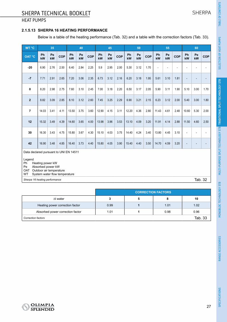
2.1.5.13 SHERPA 16 HEATING PERFORMANCE
Below is a table of the heating performance (Tab. 32) and a table with the correction factors (Tab. 33).
WT °C 35 40 45 50 55 60
OAT °C PhkW
PekW COP Ph
kWPekW COP Ph
kWPekW COP Ph
kWPekW COP Ph
kWPekW COP Ph
kWPekW COP
-20 6.90 2.76 2.50 6.40 2.84 2.25 5.9 2.95 2.00 5.30 3.12 1.70 - - - - - -
-7 7.71 2.91 2.65 7.20 3.06 2.35 6.73 3.12 2.16 6.20 3.18 1.95 5.61 3.10 1.81 - - -
0 8.20 2.98 2.75 7.60 3.10 2.45 7.00 3.18 2.20 6.50 3.17 2.05 5.90 3.11 1.90 5.10 3.00 1.70
2 8.82 3.09 2.85 8.10 3.12 2.60 7.45 3.25 2.29 6.90 3.21 2.15 6.23 3.12 2.00 5.40 3.00 1.80
7 14.03 3.41 4.11 13.50 3.75 3.60 12.90 4.15 3.11 12.20 4.36 2.80 11.43 4.61 2.48 10.60 5.30 2.00
12 15.32 3.49 4.39 14.60 3.65 4.00 13.98 3.96 3.53 13.10 4.09 3.20 11.91 4.14 2.88 11.50 4.60 2.50
30 16.30 3.43 4.75 15.80 3.67 4.30 15.10 4.03 3.75 14.40 4.24 3.40 13.80 4.45 3.10 - - -
42 16.90 3.48 4.85 16.40 3.73 4.40 15.80 4.05 3.90 15.40 4.40 3.50 14.70 4.59 3.20 - - -
Data declared pursuant to UNI EN 14511
LegendPh Heating power kWPe Absorbed power kWOAT Outdoor air temperatureWT System water flow temperature
Sherpa 16 heating performance Tab. 32
CORRECTION FACTORS
∆t water 3 5 8 10
Heating power correction factor 0.99 1 1.01 1.02
Absorbed power correction factor 1.01 1 0.98 0.96
Correction factors Tab. 33

28
SHERPA TECHNICAL BOOKLETHEAT PUMPS
2.1.5.14 SHERPA 16 COOLING PERFORMANCE
Below are tables of the cooling performance (Tab. 34 and Tab. 35) and a table with the correction factors (Tab. 36).
OAT °C 20 25 30
WT °C PckW
PekW EER Pc
kWPekW EER Pc
kWPekW EER
4 12.60 2.93 4.30 12.10 3.30 3.67 11.40 3.69 3.09
7 13.20 2.97 4.44 12.60 3.33 3.78 12.00 3.73 3.22
10 13.90 3.01 4.62 13.30 3.38 3.93 12.60 3.79 3.32
13 14.60 3.06 4.77 14.00 3.42 4.09 13.30 3.84 3.46
18 16.10 3.13 5.14 15.40 3.50 4.40 14.60 3.93 3.72
Data declared pursuant to UNI EN 14511
LegendPc Cooling power kWPe Absorbed power kWOAT Outdoor air temperatureWT System water flow temperature
Sherpa 16 cooling performance Tab. 34
OAT °C 35 40 46
WT °C PckW
PekW EER Pc
kWPekW EER Pc
kWPekW EER
4 10.80 4.14 2.61 10.10 4.63 2.18 9.61 5.06 1.90
7 11.30 4.19 2.70 10.60 4.68 2.26 10.00 5.08 1.97
10 11.90 4.24 2.81 11.10 4.75 2.34 10.50 5.17 2.03
13 12.50 4.31 2.90 11.80 4.82 2.45 11.10 5.23 2.12
18 13.80 4.41 3.13 13.00 4.94 2.83 12.30 5.37 2.29
Data declared pursuant to UNI EN 14511
LegendPc Cooling power kWPe Absorbed power kWOAT Outdoor air temperatureWT System water flow temperature
Sherpa 16 cooling performance Tab. 35
CORRECTION FACTORS
∆t of water different from the nominal value (∆t 5°C) 3 5 8 10
Cooling power correction factor 0.99 1 1.02 1.03
Absorbed power correction factor 0.99 1 1.01 1.02
Correction factors Tab. 36

SHERPA TECHNICAL BOOKLETHEAT PUMPS
29
TABL
E OF
CON
TEN
TSSE
LECT
ION
OF
HEA
T PU
MPS
TRAD
ITIO
NAL
SPL
IT T
ECH
NOL
OGY
STB
MUL
TI-P
URPO
SE S
PLIT
TEC
HNOL
OGY
STB
MON
OBLO
C TE
CHN
OLOG
Y ST
BRA
NGE
ACC
ESSO
RIES
SPEC
IFIC
ATIO
NS
2.1.5.15 SHERPA 16 PERFORMANCE ACCORDING TO STANDARD UNI/TS 11300-4
Below are the tables of performance according to standard UNI/TS 11300-4 (Tab. 37 and Tab. 38).
Water T °C 35 45 55
Outdoor air T °C Heating capacity kW COP Heating capacity kW COP Heating capacity kW COP
-7 7.71 2.65 6.73 2.16 5.61 1.81
2 8.82 2.85 7.45 2.29 6.23 2.00
7 14.03 4.11 12.90 3.11 11.43 2.48
12 15.32 4.39 13.98 3.53 12.20 2.88
Sherpa 16 performance according to standard UNI/TS 11300-4 Tab. 37
WT 35°C A Td-fan B C D
Outdoor air T °C -7 2 7 12
PLR 88% 54% 35% 15%
DC 7.71 8.82 14.03 15.32
COP at Partial Load 2.65 2.91 4.26 4.52
COP at Full Load 2.65 2.85 4.11 4.39
CR 1.00 0.53 0.22 0.09
fCOP 1.00 1.02 1.04 1.03
LegendTU: water flow temperature of the systemPLR: Part load ratioDC: Power at full load and at the temperatures recommended by the manufacturerCOP at Partial Load: COP at CR load and at the temperatures recommended by the manufacturerCOP at Full Load: COP at full load and at the temperatures recommended by the manufacturerCR = capacity control ratio of the heat pumpfCOP = COP correction factor in relation to the CR load ratio
Sherpa 16 performance according to standard UNI/TS 11300-4 Tab. 38

30
SHERPA TECHNICAL BOOKLETHEAT PUMPS
2.1.5.16 SHERPA 16T HEATING PERFORMANCE
Below is a table of the heating performance (Tab. 39) and a table with the correction factors (Tab. 40).
WT °C 35 40 45 50 55 60
OAT °C PhkW
PekW COP Ph
kWPekW COP Ph
kWPekW COP Ph
kWPekW COP Ph
kWPekW COP Ph
kWPekW COP
-20 8.90 3.87 2.30 8.50 4.05 2.10 8.2 4.32 1.90 7.90 4.94 1.60 - - - - - -
-7 9.57 3.75 2.55 9.20 4.00 2.30 9.01 4.33 2.08 8.80 4.89 1.80 8.55 5.03 1.70 - - -
0 10.50 3.89 2.70 10.30 4.20 2.45 10.00 4.65 2.15 9.80 4.90 2.00 9.50 5.28 1.80 8.50 5.48 1.55
2 11.89 4.17 2.85 11.30 4.35 2.60 10.90 4.84 2.25 10.60 5.05 2.10 10.20 5.37 1.90 9.20 5.58 1.65
7 15.96 3.88 4.11 14.90 4.14 3.60 14.04 4.54 3.09 13.30 4.75 2.80 12.5 5.04 2.48 11.2 5.21 2.15
12 18.02 4.11 4.38 17.20 4.41 3.90 16.30 4.87 3.35 15.60 5.03 3.10 14.4 5.20 2.77 13.2 5.50 2.40
30 18.50 4.11 4.5 17.70 4.48 3.95 17.00 4.86 3.50 16.20 5.14 3.15 15.30 5.46 2.80 - - -
42 18.80 4.13 4.55 18.20 4.49 4.05 17.30 4.87 3.55 16.60 5.19 3.20 15.80 5.54 2.85 - - -
Data declared pursuant to UNI EN 14511
LegendPh Heating power kWPe Absorbed power kWOAT Outdoor air temperatureWT System water flow temperature
Sherpa 16T heating performance Tab. 39
CORRECTION FACTORS
∆t water 3 5 8 10
Heating power correction factor 0.99 1 1.01 1.02
Absorbed power correction factor 1.01 1 0.98 0.96
Correction factors Tab. 40

SHERPA TECHNICAL BOOKLETHEAT PUMPS
31
TABL
E OF
CON
TEN
TSSE
LECT
ION
OF
HEA
T PU
MPS
TRAD
ITIO
NAL
SPL
IT T
ECH
NOL
OGY
STB
MUL
TI-P
URPO
SE S
PLIT
TEC
HNOL
OGY
STB
MON
OBLO
C TE
CHN
OLOG
Y ST
BRA
NGE
ACC
ESSO
RIES
SPEC
IFIC
ATIO
NS
2.1.5.17 SHERPA 16T COOLING PERFORMANCE
Below are tables of the cooling performance (Tab. 41 and Tab. 42) and a table with the correction factors (Tab. 43).
OAT °C 20 25 30
WT °C PckW
PekW EER Pc
kWPekW EER Pc
kWPekW EER
4 14.30 3.20 4.47 13.70 3.60 3.81 13.00 4.03 3.23
7 15.00 3.24 4.63 14.30 3.64 3.93 13.96 4.08 3.33
10 15.60 3.29 4.74 14.90 3.69 4.04 14.10 4.14 3.41
13 16.40 3.34 4.91 15.70 3.74 4.20 14.80 4.20 3.52
18 17.90 3.42 5.23 17.10 3.82 4.48 16.20 4.29 3.78
Data declared pursuant to UNI EN 14511
LegendPc Cooling power kWPe Absorbed power kWOAT Outdoor air temperatureWT System water flow temperature
Sherpa 16T cooling performance Tab. 41
OAT °C 35 40 46
WT °C PckW
PekW EER Pc
kWPekW EER Pc
kWPekW EER
4 12.30 4.52 2.72 11.50 5.05 2.28 10.90 5.51 1.98
7 12.80 4.57 2.80 12.00 5.12 2.34 11.40 5.59 2.04
10 13.40 4.63 2.89 12.60 5.19 2.43 11.80 5.65 2.09
13 14.00 4.70 2.98 13.20 5.26 2.51 12.40 5.71 2.17
18 15.30 4.81 3.18 14.40 5.39 2.67 13.60 5.86 2.32
Data declared pursuant to UNI EN 14511
LegendPc Cooling power kWPe Absorbed power kWOAT Outdoor air temperatureWT System water flow temperature
Sherpa 16T cooling performance Tab. 42
CORRECTION FACTORS
∆t of water different from the nominal value (∆t 5°C) 3 5 8 10
Cooling power correction factor 0.99 1 1.02 1.03
Absorbed power correction factor 0.99 1 1.01 1.02
Correction factors Tab. 43

32
SHERPA TECHNICAL BOOKLETHEAT PUMPS
2.1.5.18 SHERPA 16T PERFORMANCE ACCORDING TO STANDARD UNI/TS 11300-4
Below are the tables of performance according to standard UNI/TS 11300-4 (Tab. 44 and Tab. 45).
Water T °C 35 45 55
Outdoor air T °C Heating capacity kW COP Heating capacity kW COP Heating capacity kW COP
-7 9.57 2.55 9.01 2.08 8.55 1.70
2 11.89 2.85 10.90 2.25 10.20 1.90
7 15.96 4.11 14.04 3.09 12.50 2.48
12 18.02 4.38 16.30 3.35 14.40 2.77
Sherpa 16T performance according to standard UNI/TS 11300-4 Tab. 44
WT 35°C A Td-fan B C D
Outdoor air T °C -7 2 7 12
PLR 88% 54% 35% 15%
DC 9.57 11.89 15.96 18.02
COP at Partial Load 2.55 3.09 4.14 4.83
COP at Full Load 2.55 2.85 4.11 4.38
CR 1.00 0.49 0.23 0.09
fCOP 1.00 1.08 1.01 1.10
LegendTU: water flow temperature of the systemPLR: Part load ratioDC: Power at full load and at the temperatures recommended by the manufacturerCOP at Partial Load: COP at CR load and at the temperatures recommended by the manufacturerCOP at Full Load: COP at full load and at the temperatures recommended by the manufacturerCR = capacity control ratio of the heat pumpfCOP = COP correction factor in relation to the CR load ratio
Sherpa 16T performance according to standard UNI/TS 11300-4 Tab. 45

SHERPA TECHNICAL BOOKLETHEAT PUMPS
33
TABL
E OF
CON
TEN
TSSE
LECT
ION
OF
HEA
T PU
MPS
TRAD
ITIO
NAL
SPL
IT T
ECH
NOL
OGY
STB
MUL
TI-P
URPO
SE S
PLIT
TEC
HNOL
OGY
STB
MON
OBLO
C TE
CHN
OLOG
Y ST
BRA
NGE
ACC
ESSO
RIES
SPEC
IFIC
ATIO
NS
2.1.6 OPERATING LIMITS Below are diagrams of the water and outdoor air temperature limits within which the heat pump can run
in cooling (Fig. 1) and heating/production of domestic water (Fig. 2) modes.
15
25
35
45
55
65
-25 -15 -5 5 15 25 35 45
LWT
°C
ODT °C ODT °C
LWT
°C
0
2
4
6
8
10
12
14
16
18
20
-10 0 10 20 30 40 50
TEM
PER
ATU
RE
OF
WAT
ER P
RO
DU
CED
°C
OUTDOOR AIR TEMPERATURE °C
Operating limits in cooling mode Fig. 1
15
25
35
45
55
65
-25 -15 -5 5 15 25 35 45
LWT
°C
ODT °C ODT °C
LWT
°C
0
2
4
6
8
10
12
14
16
18
20
-10 0 10 20 30 40 50TEM
PER
ATU
RE
OF
WAT
ER P
RO
DU
CED
°C
OUTDOOR AIR TEMPERATURE °C
Operating limits in heating mode Fig. 2
The supporting electrical heater elements can be enabled during the functions of heating or production of domestic hot water even outside the operating range of the heat pump.
If the unit is installed in a particularly windy area, wind barriers must be put in place to avoid malfunctioning of the unit.

34
SHERPA TECHNICAL BOOKLETHEAT PUMPS
2.1.7 USEFUL HEADS OF THE SYSTEM The water circulation pump permits the following two types of control:
○ with constant pressure differential. ○ with variable pressure differential.
The pump with permanent magnet wet rotor has an electronic control module with integrated frequency converter. There is a control knob on the module.
SETTINGS USING THE CONTROL KNOB
2
Mode A: Variable differential pressure (Δp-v). The differential-pressure set-point is increased linearly over the permitted volume flow range between ½
H and H (Δp-v graph). The differential pressure generated by the pump is adjusted to the corresponding differential-pressure
set-point.This control mode is especially useful in heating systems with fan coils and radiators, since the flow noise at the thermostatic valves is reduced.
2
Mode B: Constant differential pressure (Δp-c). The differential pressure set-point H is constantly maintained, within the permitted
delivery range, at the programmed set-point up to the maximum characteristic curve (Δp-c graph). This regulation method is recommended for floor mounted heating systems or older heating systems with large pipelines, but also for all other applications that do not have variable characteristic curves, such as for example DHW boiler pumps.
Waterflow[l/s] in nominal conditions
SHERPA 7 SHERPA 11 SHERPA 13 SHERPA 13 T SHERPA 16 SHERPA
16 T
Heating modet.water 30/35°C t.air 7°C d.b./6°C w.b. 0.31 0.50 0.60 0.60 0.67 0.76
Heating modet.water 40/45°C t.air 7°C d.b./6°C w.b. 0.31 0.47 0.60 0.60 0.64 0.67
Heating modet.water 23/18°C t.air 35°C 0.38 0.56 0.59 0.60 0.65 0.72
Heating modet.water 12/7°C t.air 35°C 0.27 0.39 0.50 0.50 0.54 0.61
Sherpa water flow Tab. 46

SHERPA TECHNICAL BOOKLETHEAT PUMPS
35
TABL
E OF
CON
TEN
TSSE
LECT
ION
OF
HEA
T PU
MPS
TRAD
ITIO
NAL
SPL
IT T
ECH
NOL
OGY
STB
MUL
TI-P
URPO
SE S
PLIT
TEC
HNOL
OGY
STB
MON
OBLO
C TE
CHN
OLOG
Y ST
BRA
NGE
ACC
ESSO
RIES
SPEC
IFIC
ATIO
NS
Below are diagrams (Fig. 3) of the available heads, for each speed of the hydraulic circulator, at the hydraulic connections of the internal unit.
A
8
7
6
5
4
3
2
1
80
p/kPa
Q/m3/h
H/m
70
60
50
40
30
20
10
010 2 3 4 6 75
0
∆p-c (constant)
∆p-c
max.
Wilo-Stratos-Para25/1-8,30/1-81-230V-Rp1, Rp1¼
8
7
6
5
4
3
2
1
80
p/kPa
Q/m3/h
H/m
70
60
50
40
30
20
10
010 2 3 4 6 75
0
∆p-v (variable)∆p-c
max.
Wilo-Stratos-Para25/1-8,30/1-81-230V-Rp1, Rp1¼
Q/IgpmP1/W
0 0,4 0,8 1,2 1,6 2,0
0 4 8 12 16 24 2820
Q/m3/h10 2 3 4 6 75
150
100
50
0
Q/l/s
max.
8m 7m 6m 5m 4m 3m 2m
Q/IgpmP1/W
00 .40. 02 .6 0.8
0 2 4 6 108
Q/m3m/h0 0.5 1.0 1.5 2.0 2.5 3.0
40
20
0
Q/l/s
max.
6
5
4
3
2
1
p/kPa
Q/m3m/h
H/m
50
60
40
30
20
10
00
00.5 1.0 1.5 2.0 2.5 3.0
∆p-c
max.
Wilo-Yonos PARA RS15/6, 25/6, 30/61~230V - Rp½, Rp1, Rp1¼
Q/IgpmP1/W
00 .40. 02 .6 0.8
0 2 4 6 108
Q/m3m/h0 0.5 1.0 1.5 2.0 2.5 3.0
40
20
0
Q/l/s
max.
A B
C
B
8
7
6
5
4
3
2
1
80
p/kPa
Q/m3/h
H/m
70
60
50
40
30
20
10
010 2 3 4 6 75
0
∆p-c (constant)
∆p-c
max.
Wilo-Stratos-Para25/1-8,30/1-81-230V-Rp1, Rp1¼
8
7
6
5
4
3
2
1
80
p/kPa
Q/m3/h
H/m
70
60
50
40
30
20
10
010 2 3 4 6 75
0
∆p-v (variable)
∆p-c
max.
Wilo-Stratos-Para25/1-8,30/1-81-230V-Rp1, Rp1¼
Q/IgpmP1/W
0 0,4 0,8 1,2 1,6 2,0
0 4 8 12 16 24 2820
Q/m3/h10 2 3 4 6 75
150
100
50
0
Q/l/s
max.
8m 7m 6m 5m 4m 3m 2m
Q/IgpmP1/W
00 .40. 02 .6 0.8
0 2 4 6 108
Q/m3m/h0 0.5 1.0 1.5 2.0 2.5 3.0
40
20
0
Q/l/s
max.
6
5
4
3
2
1
p/kPa
Q/m3m/h
H/m
50
60
40
30
20
10
00
00.5 1.0 1.5 2.0 2.5 3.0
∆p-c
max.
Wilo-Yonos PARA RS15/6, 25/6, 30/61~230V - Rp½, Rp1, Rp1¼
Q/IgpmP1/W
00 .40. 02 .6 0.8
0 2 4 6 108
Q/m3m/h0 0.5 1.0 1.5 2.0 2.5 3.0
40
20
0
Q/l/s
max.
A B
CHydraulic connection - head Fig. 3
If greater heads are required due to high pressure losses in the system, an inertial vessel or a hydraulic separator and an external idle pump must be added. The system must have a minimum water content required(Tab. 52 and Tab. 53) to ensure good system operation. If it is insufficient, add a storage vessel in order to reach the required content.The water distribution pipes must be suitably insulated with expanded polyethylene or similar materials. The on/off valves, bends and unions must also be suitably insulated. To prevent air locks inside the cir-cuit, insert automatic or manual breather devices at all the points (high pipes, traps etc.) where air may accumulate.

36
SHERPA TECHNICAL BOOKLETHEAT PUMPS
2.1.8 COMPONENTS2.1.8.1 COMPONENTS OF THE INTERNAL UNIT
The internal unit comprises the following main components (see Fig. 4):
STRUCTUREA. Cover: in galvanised sheet steel and painted with oven-dried epoxy powders. All the components can be accessed from the front for ease of installation and maintenance. B. Supporting structure: in high-tensile galvanised sheet steel.
REFRIGERANT CIRCUITC. Refrigerant/water heat exchanger: brazed-plate in AISI 316 sheet steel.
HYDRAULIC CIRCUITD. Flow switchE. Expansion vessel: of eight litres.F. Water inlet.G. Domestic hot water outlet (only for internal unit with integrated 3-way valve).H. System water outlet.I. Water circulation pump.J. Post-heating electrical heater elements collector: two-stage that can be activated with integration of the heat pump or available in the event of the external unit breaking.K. Automatic air breatherL. Three-way valve: integrated on board the machine (only for internal unit with integrated 3-way valve) or to be installed outside the module (optional).
CONTROL AND SAFETYM. Electrical heater elements safety thermostat: with manual reset.N. Pressure gauge.O. Safety valve: 3 bar.P. Electrical heater elements safety thermostat: with automatic reset.
ELECTRIC PANELQ. Electric panel assembly: easy to access and with a circuit breaker for the heater elements and a fuse for the other loads.R. Master switch.S. Control panel: with LED display and icons for viewing and setting all the control parameters during installation, use and maintenance, with Olimpia Splendid logic and direct interaction between the inter-nal module and the external unit with direct capacity demand, and management of work parameters and alarms on the control panel.
INTEGRATED 3-WAY VALVE In order to permit ease of installation, the Sherpa heat pumps are made available in a version with
3-way valve integrated in the internal module for diversion of the flow of water from the system to the DHW tank.

SHERPA TECHNICAL BOOKLETHEAT PUMPS
37
TABL
E OF
CON
TEN
TSSE
LECT
ION
OF
HEA
T PU
MPS
TRAD
ITIO
NAL
SPL
IT T
ECH
NOL
OGY
STB
MUL
TI-P
URPO
SE S
PLIT
TEC
HNOL
OGY
STB
MON
OBLO
C TE
CHN
OLOG
Y ST
BRA
NGE
ACC
ESSO
RIES
SPEC
IFIC
ATIO
NS
F
MB
Q
ARS
GH
L
K
J
P
O
N
I
E
D
C
Components of the internal unit Fig. 4

38
SHERPA TECHNICAL BOOKLETHEAT PUMPS
2.1.8.2 COMPONENTS OF THE EXTERNAL UNITS
The external units comprise the following main components (see Fig. 5): ○ Supporting structure: in galvanised sheet steel and painted with oven-dried epoxy powders. ○ Compressor: with permanent magnet motor (DC Brushless) with inverter for electronic speed control. ○ Electronic expansion valve: for ongoing and precise control of the parameters of the refrigerant
circuit. ○ Large axial fans: for more silent operation. ○ Optimised defrosting cycle: for application of the air-water heat pump. ○ 4-way cycle inversion valve. ○ Heat exchange coil: copper pipes ribbed on the inside and aluminium fins. ○ Electric panel: with control boards and inverter for powering the compressor. ○ Temperature sensors and high pressure switch: for optimal and safe operation at all times.
Components of the external units Fig. 5

SHERPA TECHNICAL BOOKLETHEAT PUMPS
39
TABL
E OF
CON
TEN
TSSE
LECT
ION
OF
HEA
T PU
MPS
TRAD
ITIO
NAL
SPL
IT T
ECH
NOL
OGY
STB
MUL
TI-P
URPO
SE S
PLIT
TEC
HNOL
OGY
STB
MON
OBLO
C TE
CHN
OLOG
Y ST
BRA
NGE
ACC
ESSO
RIES
SPEC
IFIC
ATIO
NS
2.1.9 DIMENSIONS AND POSITIONING2.1.9.1 DIMENSIONS OF THE INTERNAL UNIT
Below is the layout of the internal unit of the heat pump (Fig. 6) and a table summarising the dimensions and weight values (Tab. 47).
B D
C
AA
B D
C
Layout of the internal unit Fig. 6
Ref. Fig. 6 SHERPA7
SHERPA11
SHERPA13
SHERPA 13T
SHERPA16
SHERPA 16T
Internal unit SMALL 599501ASMALL 595505A
BIG 599503ABIG 595500A
A mm 810 810 810 810 810 810
B mm 500 500 500 500 500 500
C mm 280 280 280 280 280 280
D mm 296 296 296 296 296 296
Standard weight kg 36 36 38 38 38 38
Weight of version with 3-way valve kg 38 38 40 40 40 40
Dimensions and weight values of the internal unit Tab. 47

40
SHERPA TECHNICAL BOOKLETHEAT PUMPS
2.1.9.2 POSITIONING OF THE INTERNAL UNIT
The pleasing aesthetics of the internal unit mean that it can be installed in plain sight or, as it is also compact, in a kitchen closet of standard size.
The internal unit must be installed indoors and on a wall with the display at eye level. For the installation layout and fitting of the pipes, please refer to Fig. 7 and use the template provided with
the unit. Leave a clearance at the sides and above of no less than 25 mm so that the covers can be removed for the purpose of routine and special maintenance.
Also prepare:
○ a nearby water drainage point; ○ a compliant power supply; ○ a water supply to fill the hydraulic circuit; ○ a communication cable between internal unit and external unit.
600
960
350
500 296280
25 25
25
65
113
113
140
810
165275
13979
Positioning of the internal unit Fig. 7
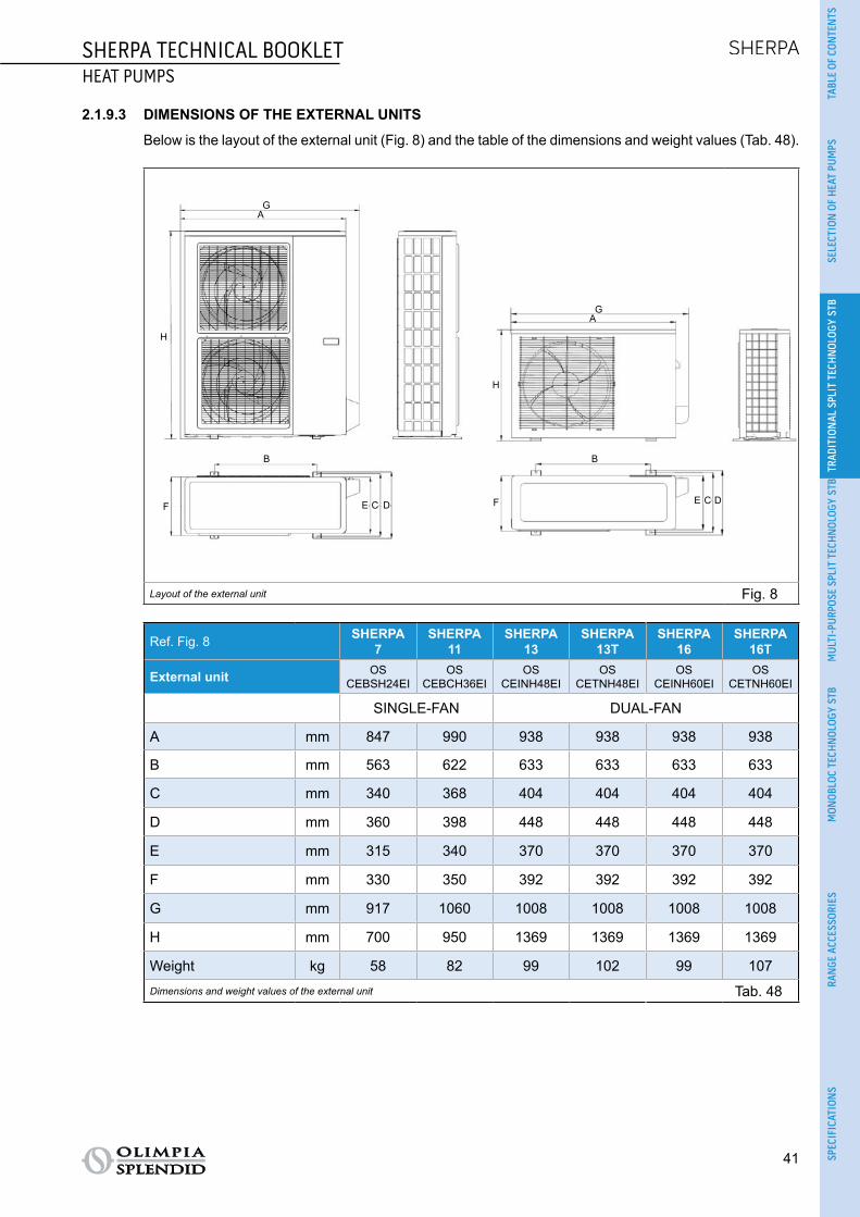
SHERPA TECHNICAL BOOKLETHEAT PUMPS
41
TABL
E OF
CON
TEN
TSSE
LECT
ION
OF
HEA
T PU
MPS
TRAD
ITIO
NAL
SPL
IT T
ECH
NOL
OGY
STB
MUL
TI-P
URPO
SE S
PLIT
TEC
HNOL
OGY
STB
MON
OBLO
C TE
CHN
OLOG
Y ST
BRA
NGE
ACC
ESSO
RIES
SPEC
IFIC
ATIO
NS
2.1.9.3 DIMENSIONS OF THE EXTERNAL UNITS
Below is the layout of the external unit (Fig. 8) and the table of the dimensions and weight values (Tab. 48).
F
B
DCE
AG
H
GA
H
E DC
B
F
Layout of the external unit Fig. 8
Ref. Fig. 8 SHERPA7
SHERPA11
SHERPA13
SHERPA 13T
SHERPA16
SHERPA 16T
External unit OSCEBSH24EI
OSCEBCH36EI
OSCEINH48EI
OSCETNH48EI
OSCEINH60EI
OSCETNH60EI
SINGLE-FAN DUAL-FAN
A mm 847 990 938 938 938 938
B mm 563 622 633 633 633 633
C mm 340 368 404 404 404 404
D mm 360 398 448 448 448 448
E mm 315 340 370 370 370 370
F mm 330 350 392 392 392 392
G mm 917 1060 1008 1008 1008 1008
H mm 700 950 1369 1369 1369 1369
Weight kg 58 82 99 102 99 107Dimensions and weight values of the external unit Tab. 48

42
SHERPA TECHNICAL BOOKLETHEAT PUMPS
Below is the layout of the S1 external unit (Fig. 9) and a table summarising the dimensions and weight values (Tab. 49).
D
F
H
A
E
CD
F
E
C
AB
H
B
Layout of the S1 external unit Fig. 9
Ref. Fig. 9 SHERPA7
SHERPA11
SHERPA13
SHERPA 13T
SHERPA16
SHERPA 16T
OSCESHH24EI
OSCESHH36EI
OSCESHH48EI
OSCESTH48EI
OSCESHH60EI
OSCESTH60EI
SINGLE-FAN DUAL-FAN
A mm 845 946 952 952 952 952
B mm 914 1030 1045 1045 1045 1045
C mm 540 673 634 634 634 634
D mm 363 410 415 415 415 415
E mm 350 403 404 404 404 404
F mm 915 1036 1032 1032 1032 1032
H mm 702 810 1333 1333 1333 1333
Weight kg 49 67 95 108 95 113Dimensions and weight values of the S1 external unit Tab. 49

SHERPA TECHNICAL BOOKLETHEAT PUMPS
43
TABL
E OF
CON
TEN
TSSE
LECT
ION
OF
HEA
T PU
MPS
TRAD
ITIO
NAL
SPL
IT T
ECH
NOL
OGY
STB
MUL
TI-P
URPO
SE S
PLIT
TEC
HNOL
OGY
STB
MON
OBLO
C TE
CHN
OLOG
Y ST
BRA
NGE
ACC
ESSO
RIES
SPEC
IFIC
ATIO
NS
2.1.9.4 POSITIONING OF THE EXTERNAL UNITS
Install the external unit (Fig. 10) on a solid base that is able to support its weight; if installed incompletely or onto an inappropriate base, the unit could cause damage to persons or property, if it should detach from the base.
It is very important that the installation place be chosen with extreme care in order to ensure adequate protection of the device against impact or possible consequential damage. Choose a place that is ade-quately ventilated and in which the outdoor temperature in summer does not exceed 46°C.
Leave sufficient free space around the appliance in order to avoid recirculation and to facilitate maintenance. Prepare a layer of gravel underneath the appliance for drainage of the defrost water.
Leave space underneath the unit to prevent the defrost water from freezing. In normal situations, ensure the base is at least 5 cm off the ground; for use in regions with very cold winters, ensure a space of at least 15 cm on both sides of the unit. When installed in a location with high snow fall, mount the support of the appliance at a height that is above the maximum level of snow.Install the unit so that wind is not blowing across it.
Also prepare: ○ anti-vibration dampers; ○ compliant power supply near the external unit.
600
960
350
> 60 cm
> 60 cm
> 30 cm
> 30 cm
> 30 cm
> 15 cm
Positioning of the external units Fig. 10
The external unit is supplied with a mesh for covering the heat exchange battery; this is envisaged for installations accessible to the public. Fitting the mesh may cause, in the event of high humidity at low temperature (fog) or snow, a build-up of ice on the battery with reduced system performance.

44
SHERPA TECHNICAL BOOKLETHEAT PUMPS
2.1.10 INSTALLATION To ensure successful installation and optimal performance, follow the instructions in the installation, use
and maintenance manual supplied with each unit and accessory. This technical booklet provides general information on installation, dimensional drawings and wiring diagrams.
The installation must be carried out by the dealer or by other qualified personnel; if the installation is not carried out correctly, there may be a risk of water leakage, electric shock or fire.
During assembly and any maintenance operation, observe the precautions in the installation, use and maintenance manuals and on the labels inside the appliances, and take any precautions dictated by common sense and set down by the safety rules at the place of installation.
Always wear protective gloves and goggles when performing maintenance on the parts of the appliances
containing refrigerant. Air-water heat pumps MUST NEVER be installed in rooms where there is inflam-mable gas, explosive gas, a high level of humidity (laundry rooms, greenhouses etc.), or in rooms where there are other machines generating a lot of heat.
It is recommended to use only the components designed specially for the installation provided; the use of different components could cause the leakage of water, electric shock or fire.
Once the installation has been completed, check that there is no leakage of refrigerant (the liquid can produce toxic gas when exposed to flames).
When installing or relocating the system, make sure that there is no substance in the refrigerant circuit other than the refrigerant specified in the technical data (see para. 2.1.4) as the presence of air or other foreign substances in the refrigerant circuit can cause an abnormal increase in pressure or breakage of the system, resulting in damage to property or physical injury.

SHERPA TECHNICAL BOOKLETHEAT PUMPS
45
TABL
E OF
CON
TEN
TSSE
LECT
ION
OF
HEA
T PU
MPS
TRAD
ITIO
NAL
SPL
IT T
ECH
NOL
OGY
STB
MUL
TI-P
URPO
SE S
PLIT
TEC
HNOL
OGY
STB
MON
OBLO
C TE
CHN
OLOG
Y ST
BRA
NGE
ACC
ESSO
RIES
SPEC
IFIC
ATIO
NS
2.1.10.1 HYDRAULIC CONNECTION
The hydraulic connections are located at the bottom of the unit (Fig. 11):A. System water flow.B. Domestic water flow.C. System water inlet.D. Gas line pipe connections.E. Liquid line pipe connections.
The minimum nominal diameter of the hydraulic connection pipes must be 1". In order to allow for maintenance or repair, it is essential that each hydraulic connection is equipped with
the respective manual valves.
A B C D E Hydraulic connection - head Fig. 11
They should be completed by installing:
○ air relief valves at the highest points of the pipes; ○ flexible elastic joints; ○ on/off valves; ○ sieve water filter with 0.4 mm mesh.
The tables below (Tab. 50, Tab. 51, Tab. 52 and Tab. 53) show the essential characteristics of the hydraulic system.
Water content of the pipes Internal diameter External diameter Litres/metre
Copper
12 mm 14 mm 0,11 l/m
14 mm 16 mm 0,15 l/m
16 mm 18 mm 0,20 l/m
20 mm 22 mm 0,31 l/m
25 mm 28 mm 0,49 l/m
32 mm 35 mm 0,80 l/m
Steel
12,7 mm (1/2”) 3/8” Gas 0,13 l/m
16,3 mm (5/8”) 1/2” Gas 0,21 l/m
21,7 mm (7/8”) 3/4” Gas 0,37 l/m
27,4 mm (11/16”) 1” Gas 0,59 l/mHydraulic connection Tab. 50

46
SHERPA TECHNICAL BOOKLETHEAT PUMPS
% Inhibited monoethylene glycol 10% 20% 30% 40%Freezing point (a) -4°C -9°C -15°C -23°C
Correction factors
Capacity 0.996 0.991 0.983 0.975Absorbed power 0.990 0.978 0.964 1.008Load loss 1.003 1.010 1.020 1.033
Notes(a) The temperature values are indicative; always refer to the temperatures stated for the specific product used
Hydraulic connection Tab. 51
Table for calculating the water content of the system
Installed unit..............................................................................
Content of unit (a) l ..............................................................................
Content of pipes (b) l ..............................................................................
Utilities (fan coils, panels, radiators, etc.) (c) l ..............................................................................
Total content (d) l ..............................................................................Notes(a) Consult the technical data table(b) Consult the pipe water content table(c) Consult the manual of the installed utilities(d) The water content of the system must be between the minimum value and the maximum value stated in Tab. 53. The mini-
mum content of the hydraulic circuit must be considered as the volume of water always circulating in the system (i.e. the parts of the system excluded by valves must not be considered). It is possible to increase the maximum content of the system by adding an expansion vessel suited to the water content of the system.
Hydraulic connection Tab. 52
SHERPA 7
SHERPA 11
SHERPA 13
SHERPA 13T
SHERPA 16
SHERPA 16T
Nominal water flow Std l/s 0.31 0.50 0.60 0.60 0.67 0.74
Water content of system
Min l 23 38 45 45 51 58Max (a) l 138 138 138 138 138 138Max (b) l 400 400 400 400 400 400
Operating pressure Max kPa 300 300 300 300 300 300
Filling pressure Min kPa 150 150 150 150 150 150
System height difference Max m 20 20 20 20 20 20
Notes(a) Temperature of water in system 55°C, water content of the system using only the expansion vessel supplied as standard in
the unit(b) Temperature of water in system 35°C, water content of the system using only the expansion vessel supplied as standard in
the unit
Hydraulic connection Tab. 53

SHERPA TECHNICAL BOOKLETHEAT PUMPS
47
TABL
E OF
CON
TEN
TSSE
LECT
ION
OF
HEA
T PU
MPS
TRAD
ITIO
NAL
SPL
IT T
ECH
NOL
OGY
STB
MUL
TI-P
URPO
SE S
PLIT
TEC
HNOL
OGY
STB
MON
OBLO
C TE
CHN
OLOG
Y ST
BRA
NGE
ACC
ESSO
RIES
SPEC
IFIC
ATIO
NS
2.1.10.2 REFRIGERANT CONNECTION
Use only pipes measuring 3/8” and 5/8” in diameter (see para. 2.1.4). The following table (Tab. 54) provides the data needed to define the refrigerant connection between the
internal and external units.
SHERPA7
SHERPA 11
SHERPA 13
SHERPA 13T
SHERPA 16
SHERPA 16T
Internal unit SMALL 599501ASMALL 595505A
BIG 599503ABIG 595500A
External unit OSCEBSH24EI
OSCEBCH36EI
OSCEINH48EI
OSCETNH48EI
OSCEINH60EI
OSCETNH60EI
S1 external unit OSCESHH24EI
OSCESHH36EI
OSCESHH48EI
OSCESTH48EI
OSCESHH60EI
OSCESTH60EI
Maximum length of the connecting pipes m 25 30 50 50 50 50
Limit of elevation difference between the two units if the external unit is positioned higher
m 12 20 25 30 25 30
Limit of elevation difference between the two units if the external unit is positioned lower
m 9 12 20 20 20 20
Additional charge of refrigerant per metre over 5 metres piping
g/m 60 60 60 60 60 60
Refrigerant connection Tab. 54
To set up the refrigerant connection: ○ Connect the internal unit observing the maximum length of the pipes in the table (see Tab. 54). ○ Do not exceed the maximum permissible difference in height when installing the internal and external
units (see Tab. 54). ○ Complete the refrigerant circuit by connecting the internal unit to the external unit (for the connection
points see Fig. 12) and check that the refrigerant circuit is perfectly sealed following the instructions in the installation, use and maintenance manual.
Refrigerant connection between the units Fig. 12

48
SHERPA TECHNICAL BOOKLETHEAT PUMPS
2.1.10.3 WIRING
The electrical connections must be made in compliance with the instructions given in the installation manual and with national standards or procedures governing electrical connections; insufficient capacity or incomplete electrical connections may lead to electric shock or fire.
The power circuits of the internal and external units must be separate; the external unit line must be protected with a thermomagnetic circuit breaker or suitably sized fuses.
The system must be wired in accordance with the regulations in force and properly earthed.
To prevent any risk of electric shock, the master switches must be disconnected before making electrical connections and carrying out maintenance on the appliances.
Before performing any operation, make sure that the electrical power of the internal and external units is switched off.
The supply voltage must be that indicated in the technical data (see para. 2.1.4).

SHERPA TECHNICAL BOOKLETHEAT PUMPS
49
TABL
E OF
CON
TEN
TSSE
LECT
ION
OF
HEA
T PU
MPS
TRAD
ITIO
NAL
SPL
IT T
ECH
NOL
OGY
STB
MUL
TI-P
URPO
SE S
PLIT
TEC
HNOL
OGY
STB
MON
OBLO
C TE
CHN
OLOG
Y ST
BRA
NGE
ACC
ESSO
RIES
SPEC
IFIC
ATIO
NS
2.1.10.4 WIRING DIAGRAMS
The following are diagrams for connecting the electrical cables (Fig. 13, Fig. 14 and Fig. 15)
*For S1 external units, the terminals of the communication cable are marked S1 and S2 instead of P and Q
*
Wiring diagram Fig. 13
T3 temperature sensor for domestic water tank T4 outdoor air temperature sensor N/13 contactor activation for electrical heater element power supply in domestic water tank during an-
ti-legionella cycles (220-240V 50Hz 100W max) 14/15 activation of external heat source e.g.: gas boiler (contact 8A (3A) 250Vac) 16/17 alarm contact (contact 8A (3A) 250Vac) 5/L domestic hot water request (when the domestic hot water tank temperature is set by a dedicated
external control; a closed contact between these terminals activates the domestic hot water request).
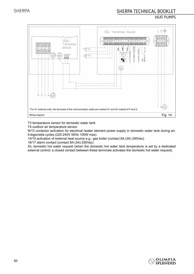
50
SHERPA TECHNICAL BOOKLETHEAT PUMPS
*For S1 external units, the terminals of the communication cable are marked S1 and S2 instead of P and Q
*
Wiring diagram Fig. 14
T3 temperature sensor for domestic water tank T4 outdoor air temperature sensor N/13 contactor activation for electrical heater element power supply in domestic water tank during an-
ti-legionella cycles (220-240V 50Hz 100W max) 14/15 activation of external heat source e.g.: gas boiler (contact 8A (3A) 250Vac) 16/17 alarm contact (contact 8A (3A) 250Vac) 5/L domestic hot water request (when the domestic hot water tank temperature is set by a dedicated
external control; a closed contact between these terminals activates the domestic hot water request).
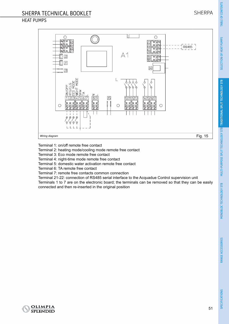
SHERPA TECHNICAL BOOKLETHEAT PUMPS
51
TABL
E OF
CON
TEN
TSSE
LECT
ION
OF
HEA
T PU
MPS
TRAD
ITIO
NAL
SPL
IT T
ECH
NOL
OGY
STB
MUL
TI-P
URPO
SE S
PLIT
TEC
HNOL
OGY
STB
MON
OBLO
C TE
CHN
OLOG
Y ST
BRA
NGE
ACC
ESSO
RIES
SPEC
IFIC
ATIO
NS
Wiring diagram Fig. 15
Terminal 1: on/off remote free contactTerminal 2: heating mode/cooling mode remote free contact Terminal 3: Eco mode remote free contactTerminal 4: night-time mode remote free contactTerminal 5: domestic water activation remote free contactTerminal 6: TA remote free contactTerminal 7: remote free contacts common connectionTerminal 21-22: connection of RS485 serial interface to the Acquadue Control supervision unitTerminals 1 to 7 are on the electronic board; the terminals can be removed so that they can be easily connected and then re-inserted in the original position

52
SHERPA TECHNICAL BOOKLETHEAT PUMPS
2.1.10.5 MAXIMUM INPUTS
The power line of the external unit must be capable of being sectioned from the mains using a thermo-magnetic circuit breaker suitable for the machine input with differential relay, with maximum calibration equal to that stated in national electrical regulations. The internal unit line is already protected by a ther-momagnetic circuit breaker on the electrical heater elements power supply and by a fuse; installation of a differential relay on the power line is recommended.
The following table (Tab. 55) shows the maximum power consumption of the units and protections to be installed on the line of the external unit.
External unit OSCEBSH24EI
OSCEBCH36EI
OSCEINH48EI
OSCETNH48EI
OSCEINH60EI
OSCETNH60EI
S1 external unit OSCESHH24EI
OSCESHH36EI
OSCESHH48EI
OSCESTH48EI
OSCESHH60EI
OSCESTH60EI
Power supply V/ph/Hz
220-240/1/50
220-240/1/50
220-240/1/50
380-415/3+N/50
220-240/1/50
380-415/3+N/50
Maximum absorbed power kW 3.0 4.8 6.0 5.5 6.0 7.5
Maximum absorbed current A 13.5 22 28 8.15 28 11.5
Fuse or circuit breaker
MFA A 25 40 40 25 40 25
Internal unit SMALL 599501ASMALL 595505A
BIG 599503ABIG 595500A
Power supply V/ph/Hz 220-240/1/50 220-240/1/50
Maximum absorbed power with electrical heater elements activated
kW 3.22 3.22 6.22 6.22 6.22 6.22
Maximum absorbed current with electrical heater elements activated
A 14.1 14.1 27.2 27.2 27.2 27.2
Maximum inputs Tab. 55
2.1.10.6 CONNECTING CABLES
Use the specified types of cable for the electrical connections between the internal and external units (see Tab. 56).
External unit OSCEBSH24EI
OSCEBCH36EI
OSCEINH48EI
OSCETNH48EI
OSCEINH60EI
OSCETNH60EI
S1 external unit OSCESHH24EI
OSCESHH36EI
OSCESHH48EI
OSCESTH48EI
OSCESHH60EI
OSCESTH60EI
Power cable H07RN-F 3 G2,5
H07RN-F 3 G4
H07RN-F 3 G4
H07RN-F 5 G2,5
H07RN-F 3 G4
H07RN-F 5 G2,5
Internal unit SMALL 599501ASMALL 595505A
BIG 599503ABIG 595500A
Power cable H05VV 3 x 2.5 mm² H05VV-F 3 x 4 mm²
ODU/IDU communication cable 2 x 0.5 mm² shielded
DHW and outdoor air probe cable H03RN-F 2 G 0.5 / H03VV-F 2 G 0.5
Connecting cables Tab. 56

SHERPA TECHNICAL BOOKLETHEAT PUMPS
53
TABL
E OF
CON
TEN
TSSE
LECT
ION
OF
HEA
T PU
MPS
TRAD
ITIO
NAL
SPL
IT T
ECH
NOL
OGY
STB
MUL
TI-P
URPO
SE S
PLIT
TEC
HNOL
OGY
STB
MON
OBLO
C TE
CHN
OLOG
Y ST
BRA
NGE
ACC
ESSO
RIES
SPEC
IFIC
ATIO
NS
2.1.10.7 HYDRAULIC CIRCUIT
Sherpa Heat Pump, compensating Tank, SLR fan radiator terminals and boiler for the production of DHW.The hydraulic diagram (Fig. 16) is purely indicative.
Y
M
T
T
TT
TT
T
2
Hydraulic circuit Fig. 16 Legend:
C/H
M
T
Y
T
Mesh filter
C/H
M
T
Y
T
On/off valve
C/H
M
T
Y
T
Motorised three-way valve
C/H
M
T
Y
T
Check valve
C/H
M
T
Y
T
Thermostatic mixer
C/H
M
T
Y
T
Thermometer
C/H
M
T
Y
T
Temperature probe
C/H
M
T
Y
T
Automatic air breather
C/H
M
T
Y
T
Expansion vessel
C/H
M
T
Y
T
Circulator

54
SHERPA TECHNICAL BOOKLETHEAT PUMPS
Sherpa Heat Pump, compensating Tank, SL fan radiator terminals, radiant panels and boiler for the pro-duction of DHW.The hydraulic diagram (Fig. 17) is purely indicative.
Y
M
T
T
TT
T
TT
MT
3
Hydraulic circuit Fig. 17
Legend:
C/H
M
T
Y
T
Mesh filter
C/H
M
T
Y
T
On/off valve
C/H
M
T
Y
T
Motorised three-way valve
C/H
M
T
Y
T
Check valve
C/H
M
T
Y
T
Thermostatic mixer
C/H
M
T
Y
T
Thermometer
C/H
M
T
Y
T
Temperature probe
C/H
M
T
Y
T
Automatic air breather
C/H
M
T
Y
T
Expansion vessel
C/H
M
T
Y
T
Circulator

SHERPA TECHNICAL BOOKLETHEAT PUMPS
55
TABL
E OF
CON
TEN
TSSE
LECT
ION
OF
HEA
T PU
MPS
TRAD
ITIO
NAL
SPL
IT T
ECH
NOL
OGY
STB
MUL
TI-P
URPO
SE S
PLIT
TEC
HNOL
OGY
STB
MON
OBLO
C TE
CHN
OLOG
Y ST
BRA
NGE
ACC
ESSO
RIES
SPEC
IFIC
ATIO
NS
Sherpa Heat Pump, outdoor back-up heater, SLR fan radiator terminals and boiler for the production of DHW.The hydraulic diagram (Fig. 18) is purely indicative.
Y
T
T
TT
TT
M
T
C/H
C/H
4
Hydraulic circuit Fig. 18
Legend:
C/H
M
T
Y
T
Mesh filter
C/H
M
T
Y
T
On/off valve
C/H
M
T
Y
T
Motorised three-way valve
C/H
M
T
Y
T
Check valve
C/H
M
T
Y
T
Thermostatic mixer
C/H
M
T
Y
T
Thermometer
C/H
M
T
Y
T
Temperature probe
C/H
M
T
Y
T
Automatic air breather
C/H
M
T
Y
T
Expansion vessel
C/H
M
T
Y
T
Circulator C/H
M
T
Y
T
Summer/winter valve
C/H
M
T
Y
T
Differential by-pass

56
SHERPA TECHNICAL BOOKLETHEAT PUMPS
Sherpa Heat Pump, compensating Tank, SLR fan radiator terminals and boiler for the production of DHW with thermal solar panels.The hydraulic diagram (Fig. 19) is purely indicative.
Y
M
TT
TT
T
1S
T
T
Hydraulic circuit Fig. 19
Legend:
C/H
M
T
Y
T
Mesh filter
C/H
M
T
Y
T
On/off valve
C/H
M
T
Y
T
Motorised three-way valve
C/H
M
T
Y
T
Check valve
C/H
M
T
Y
T
Thermostatic mixer
C/H
M
T
Y
T
Thermometer
C/H
M
T
Y
T
Temperature probe
C/H
M
T
Y
T
Automatic air breather
C/H
M
T
Y
T
Expansion vessel
C/H
M
T
Y
T
Circulator
C/H
M
T
Y
T
Pressure gauge

SHERPA TECHNICAL BOOKLETHEAT PUMPS
57
TABL
E OF
CON
TEN
TSSE
LECT
ION
OF
HEA
T PU
MPS
TRAD
ITIO
NAL
SPL
IT T
ECH
NOL
OGY
STB
MUL
TI-P
URPO
SE S
PLIT
TEC
HNOL
OGY
STB
MON
OBLO
C TE
CHN
OLOG
Y ST
BRA
NGE
ACC
ESSO
RIES
SPEC
IFIC
ATIO
NS
CONFORMITY The Sherpa heat pumps are compliant with the following European directives:
○ LVD 2014/35/EU ○ EMCD 2014/30/EU (electromagnetic compatibility) ○ ECODESIGN 2009/125/EC 813/2013EU 327/2011EU ○ RoHS 2011/65/EC
The Sherpa heat pumps are compliant with the following harmonised European standards: ○ EN14825 ○ EN55014-1 ○ EN55014-2 ○ EN61000-3-2 ○ EN61000-3-3 ○ EN61000-3-11 ○ EN61000-3-12 ○ EN60335-1 ○ EN60335-2-40
2.1.10.8 CE DECLARATION OF CONFORMITY
The CE declaration of conformity is available in the download area on the site www.olimpiasplendid.it (Fig. 20).
Download area Fig. 20

58
SHERPA TECHNICAL BOOKLETHEAT PUMPS
2.1.11 GENERAL INFORMATION2.1.11.1 PACK
The following table summarises the dimensions and weight values of the pack containing the internal unit (Tab. 57).
SHERPA7
SHERPA11
SHERPA13
SHERPA 13T
SHERPA16
SHERPA 16T
Internal unit SMALL 599501ASMALL 595505A
BIG 599503ABIG 595500A
Width cm 56 56 56 56 56 56
Length cm 90 90 90 90 90 90
Height cm 35 35 35 35 35 35
Gross weight kg 40.50 40.50 43.50 43.50 43.50 43.50
Gross weight with 3-way valve kg 42.50 42.50 45.50 45.50 45.50 45.50
Volume m2 1.764 1.764 1.764 1.764 1.764 1.764Pack of internal unit Tab. 57
The following table summarises the dimensions and weight values of the pack containing the external unit (Tab. 58).
External unit OSCEBSH24EI
OSCEBCH36EI
OSCEINH48EI
OSCETNH48EI
OSCEINH60EI
OSCETNH60EI
Width cm 78 106 109.50 109.50 109.50 109.50
Length cm 40 44 49.50 49.50 49.50 49.50
Height cm 96 138 142 142 142 142
Gross weight kg 57 114 112 115 112 120
Volume m³ 0.299 0.643 0.769 0.769 0.769 0.769Pack of external unit Tab. 58
The following table summarises the dimensions and weight values of the pack containing the S1 exter-nal unit (Tab. 59).
S1 external unit OSCESHH24EI
OSCESHH36EI
OSCESHH48EI
OSCESTH48EI
OSCESHH60EI
OSCESTH60EI
Width cm 97 109 109 109 109 109
Length cm 40 50 50 50 50 50
Height cm 77 88 148 148 148 148
Gross weight kg 52 73 108 121 108 126
Volume m³ 0.299 0.480 0.807 0.807 0.807 0.807Pack of S1 external unit Tab. 59

SHERPA AQUADUE TECHNICAL BOOKLETHEAT PUMPS
59
TABL
E OF
CON
TEN
TSSE
LECT
ION
OF
HEA
T PU
MPS
TRAD
ITIO
NAL
SPL
IT T
ECH
NOL
OGY
STB
MUL
TI-P
URPO
SE S
PLIT
TEC
HNOL
OGY
STB
MON
OBLO
C TE
CHN
OLOG
Y ST
BRA
NGE
ACC
ESSO
RIES
SPEC
IFIC
ATIO
NS
2.2 SHERPA AQUADUE - MULTI-PURPOSE SPLIT TECHNOLOGY TECHNICAL BOOKLET
2.2.1 FUNDAMENTAL CHARACTERISTICS ○ Reversible air-water heat pump split system. ○ System with two modules: external unit and internal hydronic module. ○ Supplies technical water for DHW boiler at a temperature of up to 75°C. ○ Availability of DHW at all times: guaranteed by the system with dual refrigerant circuit. ○ Two-stage electrical heater elements as standard: activation of one or two elements to support the
heat pump with simple configuration of the electronic control. Each stage is activated according to the need for heating power in real time, in order to optimise power consumption.
○ A water-water heat pump unit integrated in the internal unit provides hot water at high temperature regardless of outdoor weather conditions for the production of DHW.
○ Anti-legionella cycles can be avoided with use of the high temperature water-to-water heat pump (up to 75°C).
○ Configurable climate curves with the outdoor air temperature probe: two curves available, one for cooling and one for heating.
○ Weekly, DHW, holiday and daily timer with night-time mode. ○ Configurable set-points: two set-points for cooling and three set-points for heating (one of which for
DHW) which can also be selected via remote contact. ○ Refrigerants: R410A* for the reversible circuit for air-conditioning and DHW; R134a** for the high
temperature circuit for the production of DHW at high temperature.
* Equipment not hermetically sealed containing fluorinated gases with an equivalent GWP of 2088. ** Equipment not hermetically sealed containing fluorinated gases with an equivalent GWP of 1430.

60
SHERPA AQUADUE TECHNICAL BOOKLETHEAT PUMPS
2.2.2 CONTROL AND FUNCTIONS ○ Sherpa Aquadue can be activated for:
• heating;• cooling;• domestic water production only;• cooling or heating and the simultaneous production of domestic water at a temperature of up to
75°C.
○ A large colour LCD touch screen facilitates installation, use and maintenance of the appliance with the following: • synoptic window;• graph of the temperature readings of the probes;• diagnostics with the INPUT/OUTPUT states of the control board and alarm log. The control can manage one climate curve for heating and another for cooling to vary the water tem-perature of the system in relation to the outdoor weather conditions.
○ The control can manage one climate curve for heating and another for cooling to vary the water tem-perature of the system in relation to the outdoor weather conditions, adapting the amount of heat to the heating requirements of the building in order to save energy.
○ There is a weekly timer with a max of 8 daily time bands for the modes:• cooling/heating;• ECO function;• night-time function. There is a specific timer for the production of DHW. It is possible to set up to 3 "holiday" periods during which the system is deactivated with the frost protection and pumps anti-locking function active.
○ Sherpa Aquadue permits highly flexible management of the production of Domestic Hot Water with an outdoor boiler in two modes:• with diversion of the flow of hot water from the heating circuit to the DHW circuit up to a maximum
temperature of 60°C with the system running at full capacity;• using the water-water heat pump integrated in the internal unit up to a maximum temperature of
75°C.
○ Sherpa Aquadue is able to manage anti-legionella cycles without interrupting the heating or cooling cycle of the air conditioning system, producing hot water at high temperature using the integrated heat pump circuit.
○ The following are available for both cooling and heating mode:• a "comfort" set-point;• an ECO set-point. The set-points can be selected with the ECO command on the control panel or by closing an appro-priate input on the electronic board (remote contact).
○ The DHW production function can be activated by the temperature sensor in the storage tank or by closing an appropriate input on the electronic board (remote contact).
○ There is a specific set point for the DHW production function, and it is possible to change the main operating parameters of the same function for optimal operation in the various situations of installa-tion.
○ The internal units have a supporting two-stage heater element. These elements, if enabled, can be activated to supplement the power of the system in heating mode or for the production of DHW when low outdoor air temperature does not allow the heat pump to meet the heating load or when the external unit malfunctions (back-up function). It is possible to enable just one or both the stages of the electrical heater element according to needs or on the basis of the electrical power available.

SHERPA AQUADUE TECHNICAL BOOKLETHEAT PUMPS
61
TABL
E OF
CON
TEN
TSSE
LECT
ION
OF
HEA
T PU
MPS
TRAD
ITIO
NAL
SPL
IT T
ECH
NOL
OGY
STB
MUL
TI-P
URPO
SE S
PLIT
TEC
HNOL
OGY
STB
MON
OBLO
C TE
CHN
OLOG
Y ST
BRA
NGE
ACC
ESSO
RIES
SPEC
IFIC
ATIO
NS
○ Sherpa Aquadue can activate an auxiliary external heat source (e.g. heater) to substitute the heat pump unit, in relation to the outdoor air temperature.
○ The following functions can be remote controlled with free contacts:• activation of cooling mode;• activation of heating mode;• activation of the second set-point (Eco mode);• activation of night-time mode;• activation of the heating of domestic water storage;• enabling of air-conditioning.
○ The unit may also be connected to a chrono-thermostat or to the chiller/boiler contacts of the elec-tronic controls of the fan coils Bi2 and Bi2+.
○ The following accessories are available:• Code B0665 - Heating cable kit.
The codes are subject to change; please contact Olimpia Splendid for futher infromation.

62
SHERPA AQUADUE TECHNICAL BOOKLETHEAT PUMPS
2.2.3 THE MODELS AVAILABLE AND CONNECTION OF THE UNITS Below is a table of the models to which the relative external unit is connected (Tab. 60).
SHERPA AQUADUE 7
SHERPA AQUADUE 11
SHERPA AQUADUE 13
SHERPA AQUADUE
13T
SHERPA AQUADUE 16
SHERPA AQUADUE
16T
INTERNAL UNIT
SMALL599510A
BIG599506A
EXTERNAL UNIT
OS-CEBSH24EI OS-CEBCH36EI OS-CEINH48EI OS-CETNH48EI OS-CEINH60EI OS-CETNH60EI
S1 EXTER-NAL UNIT
OS-CESHH24EI OS-CESHH36EI OS-CESHH48EI OS-CESTH48EI OS-CESHH60EI OS-CESTH60EI
The models available and connection of the units Tab. 60
The codes are subject to change; please contact Olimpia Splendid for further information.

SHERPA AQUADUE TECHNICAL BOOKLETHEAT PUMPS
63
TABL
E OF
CON
TEN
TSSE
LECT
ION
OF
HEA
T PU
MPS
TRAD
ITIO
NAL
SPL
IT T
ECH
NOL
OGY
STB
MUL
TI-P
URPO
SE S
PLIT
TEC
HNOL
OGY
STB
MON
OBLO
C TE
CHN
OLOG
Y ST
BRA
NGE
ACC
ESSO
RIES
SPEC
IFIC
ATIO
NS
2.2.4 TECHNICAL DATA Below are tables summarising the technical data (Tab. 61, Tab. 62, Tab. 63 and Tab. 64).
SHERPAAQUADUE
7
SHERPA AQUADUE
11
SHERPA AQUADUE
13
SHERPA AQUADUE
13T
SHERPA AQUADUE
16
SHERPA AQUADUE
16T
Internal unit code 599510A 599510A 599506A 599506A 599506A 599506A
External unit code OSCEBSH24EI
OSCEBCH36EI
OSCEINH48EI
OSCETNH48EI
OSCEINH60EI
OSCETNH60EI
S1 external unit code OSCESHH24EI
OSCESHH36EI
OSCESHH48EI
OSCESTH48EI
OSCESHH60EI
OSCESTH60EI
Type of evaporator Brazed-plate Brazed-plate Brazed-plate Brazed-plate Brazed-plate Brazed-plate
Heating capacity (a) kW 6.50 10.50 12.50 12.50 14 16
COP (a) W/W 4.12 4.14 4.12 4.12 4.11 4.11
Heating capacity (b) kW 4.30 7.20 8 8 8.50 9.20
COP (b) W/W 2.60 2.65 2.70 2.70 2.40 2.50
Heating capacity (c) kW 6.50 9.90 12.50 12.50 13.30 14
COP (c) W/W 3.40 3.14 3.21 3.21 3.10 3.10
Heating capacity (d) kW 3.80 6.20 7.20 7.20 8.50 9
COP (d) W/W 2.30 2 2.10 2.10 2.10 2.10
Cooling capacity (e) kW 7.90 11.80 12.30 12.50 13.50 15
EER (e) W/W 4.50 4.40 4 4.10 3.80 4
Cooling capacity (f) kW 5.60 8.10 10.40 10.40 11.30 12.80
EER (f) W/W 3.10 3.08 3 3 2.70 2.80
Energy efficiency class for heating water at 35°CEnergy efficiency class for heating water at 55°CDHW circuit heating capacity (g) kW 2.15 2.15 2.15 2.15 2.15 2.15
COP (g) W/W 3.12 3.12 3.12 3.12 3.12 3.12
DHW circuit heating capacity (h) kW 1.60 1.60 1.60 1.60 1.60 1.60
COP (h) W/W 2.58 2.58 2.58 2.58 2.58 2.58
Notes(a) Heating mode, inlet/outlet water temperature 30°C/35°C, outdoor air temperature 7°C d.b. / 6°C w.b.(b) Heating mode, inlet/outlet water temperature 30°C/35°C, outdoor air temperature -2°C d.b. / -1°C w.b.(c) Heating mode, inlet/outlet water temperature 40°C/45°C, outdoor air temperature 7°C d.b. / 6°C w.b.(d) Heating mode, inlet/outlet water temperature 40°C/45°C, outdoor air temperature -2°C d.b. / -1°C w.b.(e) Cooling mode, inlet/outlet water temperature 23°C/18°C, outdoor air temperature 35°C(f) Cooling mode, inlet/outlet water temperature 12°C/7°C, outdoor air temperature 35°C(g) Outlet water temperature 55°C / Heating circuit water temperature 35°C(g) Outlet water temperature 55°C / Heating circuit water temperature 12°C
Technical data Tab. 61

64
SHERPA AQUADUE TECHNICAL BOOKLETHEAT PUMPS
SHERPAAQUADUE
7
SHERPA AQUADUE
11
SHERPA AQUADUE
13
SHERPA AQUADUE
13T
SHERPA AQUADUE
16
SHERPA AQUADUE
16T
Sound pressure of internal unit (a) dB(A) 35 35 35 35 35 35
Sound pressure of internal unit dB(A) 41 41 41 41 41 41
Sound power of internal unit in heat. or cool. and DHW mode dB(A) 47 47 47 47 47 47
Sound pressure of external unit (b) dB(A) 54/55 56/58 60/60 60/60 60/60 60/62
Sound pressure of external unit dB(A) 64/65 66/68 70/70 70/70 70/70 70/72
Diameter of refrigerant inlet connection “ 3/8 3/8 3/8 3/8 3/8 3/8
Diameter of refrigerant outlet connection “ 5/8 5/8 5/8 5/8 5/8 5/8
Absorption of DHW circulator W 16-43 16-43 16-43 16-43 16-43 16-43
Absorption of system circulator W 40-130 40-130 40-130 40-130 40-130 40-130
Nominal flow in heating mode l/s 0.31 0.5 0.6 0.6 0.67 0.74
Residual useful head kPa 80 82 80 80 78 73
Capacity of expansion vessel l 8 8 8 8 8 8
Power supply of internal unit V/ph/Hz 230/1/50 230/1/50 230/1/50 230/1/50 230/1/50 230/1/50
Internal unit maximum ab-sorbed current (c) A 13.50 22 28 27.20 27.20 27.20
Internal unit maximum ab-sorbed power (d) kW 3.22 3.22 6.22 6.22 6.22 6.22
Additional electrical heater elements kW 1,5 + 1,5 1,5 + 1,5 3 + 3 3 + 3 3 + 3 3 + 3
Hydraulic connections “ 1 1 1 1 1 1
Power supply of external unit V/ph/Hz 230/1/50 230/1/50 230/1/50 400/3/50 230/1/50 400/3/50
External unit maximum ab-sorbed current A 13.50 22 28 8.15 28 11.50
Cooling gas (system circuit) (e) R410A R410A R410A R410A R410A R410A
Overall heating potential GWP 2088 2088 2088 2088 2088 2088
Charge of cooling gas of exter-nal unit Kg 2.10 2.75 4.45 4.00 4.45 4.20
Charge of cooling gas of S1 external unit Kg 1.95 3.20 4.00 4.00 4.00 4.30
Cooling gas (DHW circuit) (f) R134a R134a R134a R134a R134a R134a
Overall heating potential GWP 1430 1430 1430 1430 1430 1430
Safety valve bar 3 3 3 3 3 3
Pre-charge pressure bar 1.5 1.5 1.5 1.5 1.5 1.5
Notes(a) Sound pressure values measured at a distance of 4 m in a free field(b) Sound pressure values measured at a distance of 1 m in semi-anechoic chamber(c) In heating or cooling mode(d) With heater elements engaged(e) Equipment not hermetically sealed containing fluorinated gases with an equivalent GWP of 2088(f) Equipment hermetically sealed containing fluorinated gases with an equivalent GWP of 1430
Technical data Tab. 62
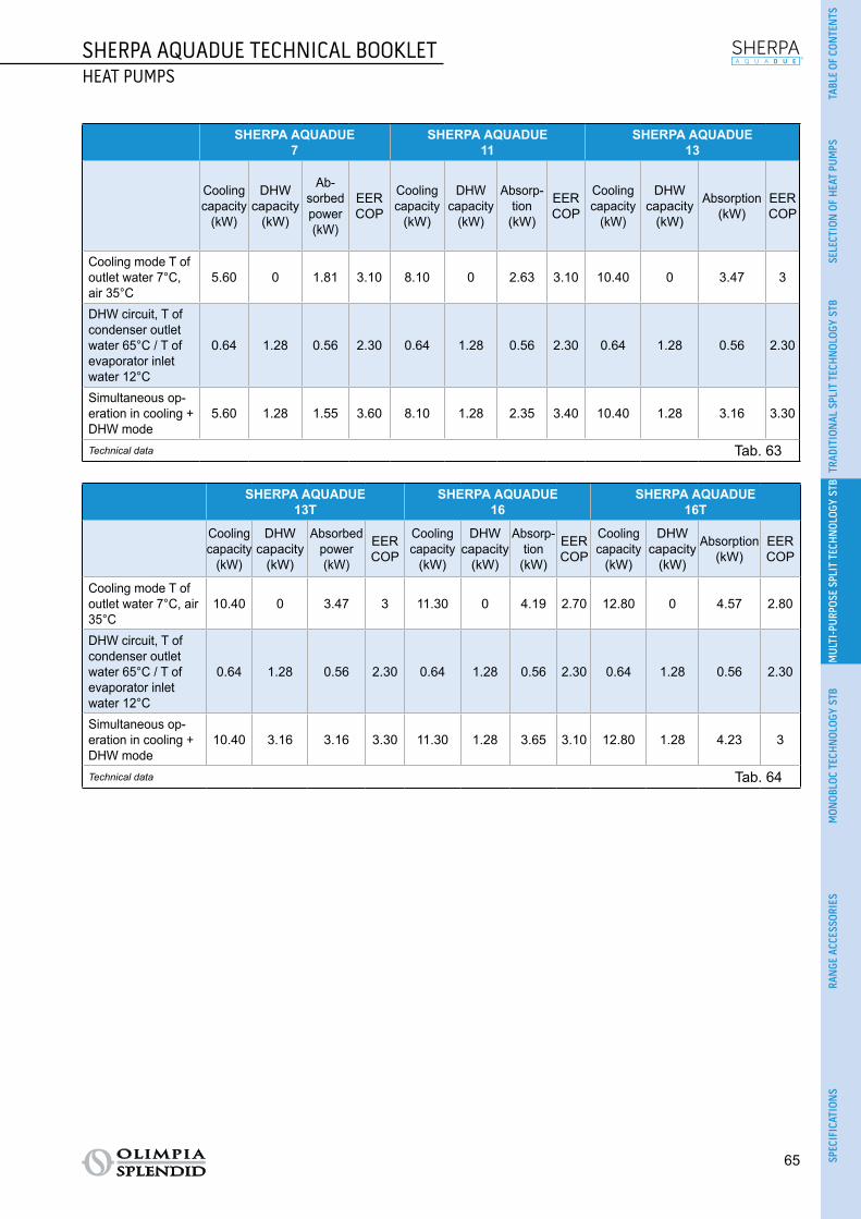
SHERPA AQUADUE TECHNICAL BOOKLETHEAT PUMPS
65
TABL
E OF
CON
TEN
TSSE
LECT
ION
OF
HEA
T PU
MPS
TRAD
ITIO
NAL
SPL
IT T
ECH
NOL
OGY
STB
MUL
TI-P
URPO
SE S
PLIT
TEC
HNOL
OGY
STB
MON
OBLO
C TE
CHN
OLOG
Y ST
BRA
NGE
ACC
ESSO
RIES
SPEC
IFIC
ATIO
NS
SHERPA AQUADUE7
SHERPA AQUADUE11
SHERPA AQUADUE13
Cooling capacity
(kW)
DHWcapacity
(kW)
Ab-sorbed power (kW)
EERCOP
Cooling capacity
(kW)
DHW capacity
(kW)
Absorp-tion
(kW)
EERCOP
Cooling capacity
(kW)
DHWcapacity
(kW)
Absorption(kW)
EERCOP
Cooling mode T of outlet water 7°C, air 35°C
5.60 0 1.81 3.10 8.10 0 2.63 3.10 10.40 0 3.47 3
DHW circuit, T of condenser outlet water 65°C / T of evaporator inlet water 12°C
0.64 1.28 0.56 2.30 0.64 1.28 0.56 2.30 0.64 1.28 0.56 2.30
Simultaneous op-eration in cooling + DHW mode
5.60 1.28 1.55 3.60 8.10 1.28 2.35 3.40 10.40 1.28 3.16 3.30
Technical data Tab. 63
SHERPA AQUADUE13T
SHERPA AQUADUE16
SHERPA AQUADUE16T
Cooling capacity
(kW)
DHWcapacity
(kW)
Absorbed power (kW)
EERCOP
Cooling capacity
(kW)
DHW capacity
(kW)
Absorp-tion
(kW)
EERCOP
Cooling capacity
(kW)
DHWcapacity
(kW)
Absorption(kW)
EERCOP
Cooling mode T of outlet water 7°C, air 35°C
10.40 0 3.47 3 11.30 0 4.19 2.70 12.80 0 4.57 2.80
DHW circuit, T of condenser outlet water 65°C / T of evaporator inlet water 12°C
0.64 1.28 0.56 2.30 0.64 1.28 0.56 2.30 0.64 1.28 0.56 2.30
Simultaneous op-eration in cooling + DHW mode
10.40 3.16 3.16 3.30 11.30 1.28 3.65 3.10 12.80 1.28 4.23 3
Technical data Tab. 64

66
SHERPA AQUADUE TECHNICAL BOOKLETHEAT PUMPS
2.2.5 PERFORMANCE TABLES2.2.5.1 SHERPA AQUADUE 7 HEATING PERFORMANCE
Below is a table of the heating performance (Tab. 65) and a table with the correction factors (Tab. 66).
WT °C 35 40 45 50 55 60
OAT °C
PhkW
PekW COP Ph
kWPekW COP Ph
kWPekW COP Ph
kWPekW COP Ph
kWPekW COP Ph
kWPekW COP
-20 3.31 1.72 1.92 3.17 1.75 1.81 2.88 1.80 1.60 2.61 1.86 1.40 - - - - - -
-7 4.21 1.40 3.01 3.79 1.44 2.63 3.51 1.42 2.48 3.30 1.43 2.30 2.85 1.43 2.00 - - -
0 4.85 1.49 3.25 4.50 1.55 2.90 4.05 1.58 2.56 3.88 1.62 2.40 3.35 1.68 2.00 3.10 1.79 1.73
2 5.05 1.50 3.37 4.70 1.57 3.00 4.30 1.65 2.60 4.20 1.68 2.50 3.58 1.70 2.10 3.30 1.83 1.80
7 6.50 1.58 4.12 5.90 1.61 3.66 5.50 1.62 3.40 5.10 1.76 2.90 4.65 1.79 2.60 4.30 1.95 2.20
12 7.71 1.72 4.48 7.20 1.75 4.11 6.79 1.82 3.73 6.00 1.85 3.25 5.60 1.93 2.90 5.20 2.08 2.50
30 8.90 1.94 4.58 8.51 1.98 4.30 7.90 2.01 3.93 7.30 2.05 3.57 6.65 2.15 3.10 - - -
42 9.30 2.04 4.55 8.82 2.10 4.20 8.20 2.14 3.83 7.60 2.19 3.47 7.00 2.33 3.00 - - -
Data declared pursuant to UNI EN 14511
LegendPh Heating power kWPe Absorbed power kWOAT Outdoor air temperatureWT System water flow temperature
Sherpa Aquadue 7 heating performance Tab. 65
CORRECTION FACTORS
∆t water 3 5 8 10
Heating power correction factor 0.99 1 1.01 1.02
Absorbed power correction factor 1.01 1 0.98 0.96
Correction factors Tab. 66

SHERPA AQUADUE TECHNICAL BOOKLETHEAT PUMPS
67
TABL
E OF
CON
TEN
TSSE
LECT
ION
OF
HEA
T PU
MPS
TRAD
ITIO
NAL
SPL
IT T
ECH
NOL
OGY
STB
MUL
TI-P
URPO
SE S
PLIT
TEC
HNOL
OGY
STB
MON
OBLO
C TE
CHN
OLOG
Y ST
BRA
NGE
ACC
ESSO
RIES
SPEC
IFIC
ATIO
NS
2.2.5.2 SHERPA AQUADUE 7 COOLING PERFORMANCE
Below are tables of the cooling performance (Tab. 67 and Tab. 68) and a table with the correction factors (Tab. 69).
OAT °C 20 25 30
WT °C PckW
PekW EER Pc
kWPekW EER Pc
kWPekW EER
4 6.1 1.26 4.84 5.80 1.41 4.11 5.57 1.59 3.50
7 6.56 1.28 5.13 6.27 1.43 4.38 5.94 1.61 3.69
10 7.05 1.30 5.42 6.74 1.46 4.62 6.38 1.64 3.89
13 7.64 1.31 5.83 7.31 1.48 4.94 6.92 1.65 4.19
18 8.84 1.35 6.55 8.47 1.51 5.61 8.04 1.70 4.73
Data declared pursuant to UNI EN 14511
LegendPc Cooling power kWPe Absorbed power kWOAT Outdoor air temperatureWT System water flow temperature
Sherpa Aquadue 7 cooling performance Tab. 67
OAT °C 35 40 46
WT °C PckW
PekW EER Pc
kWPekW EER Pc
kWPekW EER
4 5.25 1.79 2.93 4.90 2.01 2.44 4.60 2.20 2.09
7 5.60 1.81 3.09 5.26 2.03 2.59 4.94 2.25 2.20
10 6.01 1.83 3.28 5.65 2.05 2.76 5.30 2.30 2.30
13 6.35 1.86 3.51 6.13 2.08 2.95 5.72 2.29 2.50
18 7.60 1.90 4.00 7.16 2.13 3.36 6.70 2.33 2.88
Data declared pursuant to UNI EN 14511
LegendPc Cooling power kWPe Absorbed power kWOAT Outdoor air temperatureWT System water flow temperature
Sherpa Aquadue 7 cooling performance Tab. 68
CORRECTION FACTORS
∆t of water different from the nominal value (∆t 5°C) 3 5 8 10
Cooling power correction factor 0.99 1 1.02 1.03
Absorbed power correction factor 0.99 1 1.01 1.02
Correction factors Tab. 69

68
SHERPA AQUADUE TECHNICAL BOOKLETHEAT PUMPS
2.2.5.3 SHERPA AQUADUE 7 PERFORMANCE ACCORDING TO STANDARD UNI/TS 11300-4
Below are the tables of performance according to standard UNI/TS 11300-4 (Tab. 70 and Tab. 71).
Water T °C 35 45 55
Outdoor air T °C Heating capacity kW COP Heating capacity kW COP Heating capacity kW COP
-7 4.21 3.01 3.51 2.48 2.85 2.00
2 5.05 3.37 4.30 2.60 3.58 2.10
7 6.50 4.12 5.50 3.40 4.65 2.60
12 7.71 4.48 6.79 3.73 5.60 2.90
Sherpa Aquadue 7 performance according to standard UNI/TS 11300-4 Tab. 70
WT 35°C A Td-fan B C D
Outdoor air T °C -7 2 7 12
PLR 88% 54% 35% 15%
DC 4.21 5.05 6.50 7.71
COP at Partial Load 3.01 4.14 4.60 4.50
COP at Full Load 3.01 3.37 4.12 4.48
CR 1.00 0.50 0.25 0.09
fCOP 1.00 1.34 1.12 1.00
LegendTU: water flow temperature of the systemPLR: Part load ratioDC: Power at full load and at the temperatures recommended by the manufacturerCOP at Partial Load: COP at CR load and at the temperatures recommended by the manufacturerCOP at Full Load: COP at full load and at the temperatures recommended by the manufacturerCR = capacity control ratio of the heat pumpfCOP = COP correction factor in relation to the CR load ratio
Sherpa Aquadue 7 performance according to standard UNI/TS 11300-4 Tab. 71

SHERPA AQUADUE TECHNICAL BOOKLETHEAT PUMPS
69
TABL
E OF
CON
TEN
TSSE
LECT
ION
OF
HEA
T PU
MPS
TRAD
ITIO
NAL
SPL
IT T
ECH
NOL
OGY
STB
MUL
TI-P
URPO
SE S
PLIT
TEC
HNOL
OGY
STB
MON
OBLO
C TE
CHN
OLOG
Y ST
BRA
NGE
ACC
ESSO
RIES
SPEC
IFIC
ATIO
NS
2.2.5.4 SHERPA AQUADUE 11 HEATING PERFORMANCE
Below is a table of the heating performance (Tab. 72) and a table with the correction factors (Tab. 73).
WT °C 35 40 45 50 55 60
OAT °C PhkW
PekW COP Ph
kWPekW COP Ph
kWPekW COP Ph
kWPekW COP Ph
kWPekW COP Ph
kWPekW COP
-20 5.50 3.13 1.75 5.30 3.53 1.50 5.15 3.81 1.35 4.80 4.00 1.20 - - - - - -
-7 6.99 2.64 2.65 6.50 2.71 2.40 6.3 2.86 2.20 5.95 2.98 2.00 5.60 3.01 1.86 - - -
0 7.60 2.63 2.89 7.30 2.70 2.70 7.00 2.89 2.42 6.80 3.02 2.25 6.45 3.19 2.02 6.10 3.30 1.85
2 7.95 2.69 2.95 7.60 2.76 2.75 7.20 2.94 2.45 7.00 3.04 2.30 6.70 3.27 2.05 6.40 3.37 1.90
7 11.00 2.68 4.10 10.10 2.89 3.50 9.90 3.15 3.14 9.40 3.48 2.70 9.10 3.70 2.46 8.20 3.90 2.10
12 12.35 2.81 4.40 11.80 2.95 4.00 11.45 3.28 3.49 11.00 3.55 3.10 10.75 3.83 2.81 10 4.00 2.50
30 14.30 3.18 4.50 13.80 3.29 4.20 13.32 3.42 3.90 13.05 3.66 3.57 12.77 3.93 3.25 - - -
42 14.80 3.22 4.60 14.20 3.34 4.25 13.70 3.51 3.90 13.50 3.70 3.65 13.44 4.07 3.30 - - -
Data declared pursuant to UNI EN 14511
LegendPh Heating power kWPe Absorbed power kWOAT Outdoor air temperatureWT System water flow temperature
Sherpa Aquadue 11 heating performance Tab. 72
CORRECTION FACTORS
∆t water 3 5 8 10
Heating power correction factor 0.99 1 1.01 1.02
Absorbed power correction factor 1.01 1 0.98 0.96
Correction factors Tab. 73
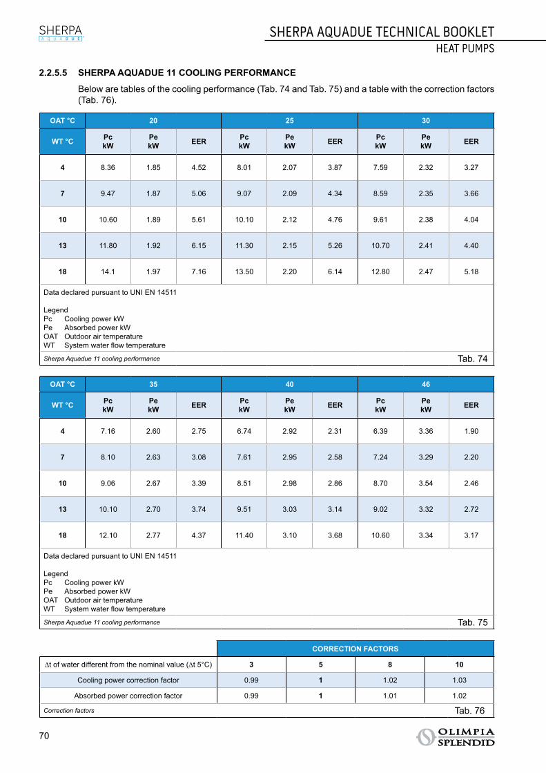
70
SHERPA AQUADUE TECHNICAL BOOKLETHEAT PUMPS
2.2.5.5 SHERPA AQUADUE 11 COOLING PERFORMANCE
Below are tables of the cooling performance (Tab. 74 and Tab. 75) and a table with the correction factors (Tab. 76).
OAT °C 20 25 30
WT °C PckW
PekW EER Pc
kWPekW EER Pc
kWPekW EER
4 8.36 1.85 4.52 8.01 2.07 3.87 7.59 2.32 3.27
7 9.47 1.87 5.06 9.07 2.09 4.34 8.59 2.35 3.66
10 10.60 1.89 5.61 10.10 2.12 4.76 9.61 2.38 4.04
13 11.80 1.92 6.15 11.30 2.15 5.26 10.70 2.41 4.40
18 14.1 1.97 7.16 13.50 2.20 6.14 12.80 2.47 5.18
Data declared pursuant to UNI EN 14511
LegendPc Cooling power kWPe Absorbed power kWOAT Outdoor air temperatureWT System water flow temperature
Sherpa Aquadue 11 cooling performance Tab. 74
OAT °C 35 40 46
WT °C PckW
PekW EER Pc
kWPekW EER Pc
kWPekW EER
4 7.16 2.60 2.75 6.74 2.92 2.31 6.39 3.36 1.90
7 8.10 2.63 3.08 7.61 2.95 2.58 7.24 3.29 2.20
10 9.06 2.67 3.39 8.51 2.98 2.86 8.70 3.54 2.46
13 10.10 2.70 3.74 9.51 3.03 3.14 9.02 3.32 2.72
18 12.10 2.77 4.37 11.40 3.10 3.68 10.60 3.34 3.17
Data declared pursuant to UNI EN 14511
LegendPc Cooling power kWPe Absorbed power kWOAT Outdoor air temperatureWT System water flow temperature
Sherpa Aquadue 11 cooling performance Tab. 75
CORRECTION FACTORS
∆t of water different from the nominal value (∆t 5°C) 3 5 8 10
Cooling power correction factor 0.99 1 1.02 1.03
Absorbed power correction factor 0.99 1 1.01 1.02
Correction factors Tab. 76

SHERPA AQUADUE TECHNICAL BOOKLETHEAT PUMPS
71
TABL
E OF
CON
TEN
TSSE
LECT
ION
OF
HEA
T PU
MPS
TRAD
ITIO
NAL
SPL
IT T
ECH
NOL
OGY
STB
MUL
TI-P
URPO
SE S
PLIT
TEC
HNOL
OGY
STB
MON
OBLO
C TE
CHN
OLOG
Y ST
BRA
NGE
ACC
ESSO
RIES
SPEC
IFIC
ATIO
NS
2.2.5.6 SHERPA AQUADUE 11 PERFORMANCE ACCORDING TO STANDARD UNI/TS 11300-4
Below are the tables of performance according to standard UNI/TS 11300-4 (Tab. 77 and Tab. 78).
Water T °C 35 45 55
Outdoor air T °C Heating capacity kW COP Heating capacity kW COP Heating capacity kW COP
-7 6.99 2.65 6.30 2.20 5.60 1.86
2 7.95 2.95 7.20 2.45 6.70 2.05
7 11.00 4.10 9.90 3.14 9.10 2.46
12 12.35 4.40 11.45 3.49 10.75 2.81
Sherpa Aquadue 11 performance according to standard UNI/TS 11300-4 Tab. 77
WT 35°C A Td-fan B C D
Outdoor air T °C -7 2 7 12
PLR 88% 54% 35% 15%
DC 6.99 7.95 11.00 12.35
COP at Partial Load 2.50 2.87 4.28 4.45
COP at Full Load 2.65 2.95 4.10 4.40
CR 1.00 0.55 0.26 0.10
fCOP 1.00 0.97 1.03 1.01
LegendTU: water flow temperature of the systemPLR: Part load ratioDC: Power at full load and at the temperatures recommended by the manufacturerCOP at Partial Load: COP at CR load and at the temperatures recommended by the manufacturerCOP at Full Load: COP at full load and at the temperatures recommended by the manufacturerCR = capacity control ratio of the heat pumpfCOP = COP correction factor in relation to the CR load ratio
Sherpa Aquadue 11 performance according to standard UNI/TS 11300-4 Tab. 78

72
SHERPA AQUADUE TECHNICAL BOOKLETHEAT PUMPS
2.2.5.7 SHERPA AQUADUE 13 HEATING PERFORMANCE
Below is a table of the heating performance (Tab. 79) and a table with the correction factors (Tab. 80).
WT °C 35 40 45 50 55 60
OAT °C PhkW
PekW COP Ph
kWPekW COP Ph
kWPekW COP Ph
kWPekW COP Ph
kWPekW COP Ph
kWPekW COP
-20 6.80 2.83 2.40 6.30 2.93 2.15 5.8 2.90 2.00 5.20 2.77 1.88 - - - - - -
-7 7.49 2.94 2.55 7.00 3.04 2.30 6.6 3.07 2.15 6.00 3.00 2.00 5.48 2.99 1.83 - - -
0 7.80 2.97 2.63 7.30 3.04 2.40 7.00 3.18 2.20 6.40 3.12 2.05 5.70 3.00 1.90 5.00 3.13 1.60
2 8.21 2.95 2.78 7.80 3.12 2.50 7.45 3.23 2.31 6.80 3.16 2.15 6.01 2.99 2.01 5.20 3.06 1.70
7 12.50 3.03 4.12 12.10 3.27 3.70 11.80 3.68 3.21 11.00 3.93 2.80 10.61 4.19 2.53 9.8 4.45 2.20
12 13.48 3.06 4.40 12.90 3.23 4.00 12.38 3.48 3.56 11.90 3.72 3.20 11.32 3.89 2.91 10.5 4.12 2.55
30 15.00 3.26 4.6 14.20 3.38 4.20 13.50 3.60 3.75 13.00 3.82 3.40 12.30 4.10 3.00 - - -
42 16.20 3.38 4.8 15.50 3.52 4.40 14.90 3.73 4.00 14.50 3.92 3.70 13.80 4.18 3.30 - - -
Data declared pursuant to UNI EN 14511
LegendPh Heating power kWPe Absorbed power kWOAT Outdoor air temperatureWT System water flow temperature
Sherpa Aquadue 13 heating performance Tab. 79
CORRECTION FACTORS
∆t water 3 5 8 10
Heating power correction factor 0.99 1 1.01 1.02
Absorbed power correction factor 1.01 1 0.98 0.96
Correction factors Tab. 80

SHERPA AQUADUE TECHNICAL BOOKLETHEAT PUMPS
73
TABL
E OF
CON
TEN
TSSE
LECT
ION
OF
HEA
T PU
MPS
TRAD
ITIO
NAL
SPL
IT T
ECH
NOL
OGY
STB
MUL
TI-P
URPO
SE S
PLIT
TEC
HNOL
OGY
STB
MON
OBLO
C TE
CHN
OLOG
Y ST
BRA
NGE
ACC
ESSO
RIES
SPEC
IFIC
ATIO
NS
2.2.5.8 SHERPA AQUADUE 13 COOLING PERFORMANCE
Below are tables of the cooling performance (Tab. 81 and Tab. 82) and a table with the correction factors (Tab. 83).
OAT °C 20 25 30
WT °C PckW
PekW EER Pc
kWPekW EER Pc
kWPekW EER
4 11.6 2.44 4.75 11.10 2.73 4.07 10.50 3.06 3.43
7 12.20 2.46 4.96 11.60 2.75 4.22 11.00 3.09 3.56
10 12.70 2.50 5.08 12.20 2.79 4.37 11.50 3.14 3.66
13 13.40 2.53 5.30 12.80 2.84 4.51 12.10 3.17 3.82
18 14.7 2.59 5.68 14.10 2.91 4.85 13.30 3.26 4.08
Data declared pursuant to UNI EN 14511
LegendPc Cooling power kWPe Absorbed power kWOAT Outdoor air temperatureWT System water flow temperature
Sherpa Aquadue 13 cooling performance Tab. 81
OAT °C 35 40 46
WT °C PckW
PekW EER Pc
kWPekW EER Pc
kWPekW EER
4 9.95 3.43 2.90 9.36 3.85 2.43 8.88 4.25 2.09
7 10.40 3.47 3.00 9.78 3.89 2.51 9.29 4.26 2.18
10 10.90 3.51 3.11 10.20 3.93 2.60 9.68 4.32 2.24
13 11.40 3.58 3.20 10.8 3.99 2.71 10.10 4.39 2.30
18 12.60 3.65 3.45 11.90 4.09 2.91 11.20 4.43 2.53
Data declared pursuant to UNI EN 14511
LegendPc Cooling power kWPe Absorbed power kWOAT Outdoor air temperatureWT System water flow temperature
Sherpa Aquadue 13 cooling performance Tab. 82
CORRECTION FACTORS
∆t of water different from the nominal value (∆t 5°C) 3 5 8 10
Cooling power correction factor 0.99 1 1.02 1.03
Absorbed power correction factor 0.99 1 1.01 1.02
Correction factors Tab. 83

74
SHERPA AQUADUE TECHNICAL BOOKLETHEAT PUMPS
2.2.5.9 SHERPA AQUADUE 13 PERFORMANCE ACCORDING TO STANDARD UNI/TS 11300-4
Below are the tables of performance according to standard UNI/TS 11300-4 (Tab. 84 and Tab. 85).
Water T °C 35 45 55
Outdoor air T °C Heating capacity kW COP Heating capacity kW COP Heating capacity kW COP
-7 7.49 2.55 6.60 2.15 5.48 1.83
2 8.21 2.78 7.45 2.31 6.01 2.01
7 12.50 4.12 11.8 3.21 10.61 2.53
12 13.48 4.40 12.38 3.56 11.32 2.91
Sherpa Aquadue 13 performance according to standard UNI/TS 11300-4 Tab. 84
WT 35°C A Td-fan B C D
Outdoor air T °C -7 2 7 12
PLR 88% 54% 35% 15%
DC 7.49 8.21 12.50 13.48
COP at Partial Load 2.55 2.91 4.26 4.52
COP at Full Load 2.55 2.78 4.12 4.40
CR 1.00 0.55 0.23 0.10
fCOP 1.00 1.05 1.03 1.03
LegendTU: water flow temperature of the systemPLR: Part load ratioDC: Power at full load and at the temperatures recommended by the manufacturerCOP at Partial Load: COP at CR load and at the temperatures recommended by the manufacturerCOP at Full Load: COP at full load and at the temperatures recommended by the manufacturerCR = capacity control ratio of the heat pumpfCOP = COP correction factor in relation to the CR load ratio
Sherpa Aquadue 13 performance according to standard UNI/TS 11300-4 Tab. 85

SHERPA AQUADUE TECHNICAL BOOKLETHEAT PUMPS
75
TABL
E OF
CON
TEN
TSSE
LECT
ION
OF
HEA
T PU
MPS
TRAD
ITIO
NAL
SPL
IT T
ECH
NOL
OGY
STB
MUL
TI-P
URPO
SE S
PLIT
TEC
HNOL
OGY
STB
MON
OBLO
C TE
CHN
OLOG
Y ST
BRA
NGE
ACC
ESSO
RIES
SPEC
IFIC
ATIO
NS
2.2.5.10 SHERPA AQUADUE 13T HEATING PERFORMANCE
Below is a table of the heating performance (Tab. 86) and a table with the correction factors (Tab. 87).
WT °C 35 40 45 50 55 60
OAT °C PhkW
PekW COP Ph
kWPekW COP Ph
kWPekW COP Ph
kWPekW COP Ph
kWPekW COP Ph
kWPekW COP
-20 6.80 2.83 2.40 6.30 2.93 2.15 5.8 2.90 2.00 5.20 2.77 1.88 - - - - - -
-7 7.49 2.94 2.55 7.00 3.04 2.30 6.6 3.07 2.15 6.00 3.00 2.00 5.48 2.99 1.83 - - -
0 7.80 2.97 2.63 7.30 3.04 2.40 7.00 3.18 2.20 6.40 3.12 2.05 5.70 3.00 1.90 5.00 3.13 1.60
2 8.21 2.95 2.78 7.80 3.12 2.50 7.45 3.23 2.31 6.80 3.16 2.15 6.01 2.99 2.01 5.20 3.06 1.70
7 12.50 3.03 4.12 12.10 3.27 3.70 11.80 3.68 3.21 11.00 3.93 2.80 10.61 4.19 2.53 9.8 4.45 2.20
12 13.48 3.06 4.40 12.90 3.23 4.00 12.38 3.48 3.56 11.90 3.72 3.20 11.32 3.89 2.91 10.5 4.12 2.55
30 15.00 3.26 4.6 14.20 3.38 4.20 13.50 3.60 3.75 13.00 3.82 3.40 12.30 4.10 3.00 - - -
42 16.20 3.38 4.8 15.50 3.52 4.40 14.90 3.73 4.00 14.50 3.92 3.70 13.80 4.18 3.30 - - -
Data declared pursuant to UNI EN 14511
LegendPh Heating power kWPe Absorbed power kWOAT Outdoor air temperatureWT System water flow temperature
Sherpa Aquadue 13T heating performance Tab. 86
CORRECTION FACTORS
∆t water 3 5 8 10
Heating power correction factor 0.99 1 1.01 1.02
Absorbed power correction factor 1.01 1 0.98 0.96
Correction factors Tab. 87

76
SHERPA AQUADUE TECHNICAL BOOKLETHEAT PUMPS
2.2.5.11 SHERPA AQUADUE 13T COOLING PERFORMANCE
Below are tables of the cooling performance (Tab. 88 and Tab. 89) and a table with the correction factors (Tab. 90).
OAT °C 20 25 30
WT °C PckW
PekW EER Pc
kWPekW EER Pc
kWPekW EER
4 11.6 2.44 4.75 11.10 2.73 4.07 10.50 3.06 3.43
7 12.20 2.46 4.96 11.60 2.75 4.22 11.00 3.09 3.56
10 12.70 2.50 5.08 12.20 2.79 4.37 11.50 3.14 3.66
13 13.40 2.53 5.30 12.80 2.84 4.51 12.10 3.17 3.82
18 14.7 2.59 5.68 14.10 2.91 4.85 13.30 3.26 4.08
Data declared pursuant to UNI EN 14511
LegendPc Cooling power kWPe Absorbed power kWOAT Outdoor air temperatureWT System water flow temperature
Sherpa Aquadue 13T cooling performance Tab. 88
OAT °C 35 40 46
WT °C PckW
PekW EER Pc
kWPekW EER Pc
kWPekW EER
4 9.95 3.43 2.90 9.36 3.85 2.43 8.88 4.25 2.09
7 10.40 3.47 3.00 9.78 3.89 2.51 9.29 4.26 2.18
10 10.90 3.51 3.11 10.20 3.93 2.60 9.68 4.32 2.24
13 11.40 3.58 3.20 10.8 3.99 2.71 10.10 4.39 2.30
18 12.60 3.65 3.45 11.90 4.09 2.91 11.20 4.43 2.53
Data declared pursuant to UNI EN 14511
LegendPc Cooling power kWPe Absorbed power kWOAT Outdoor air temperatureWT System water flow temperature
Sherpa Aquadue 13T cooling performance Tab. 89
CORRECTION FACTORS
∆t of water different from the nominal value (∆t 5°C) 3 5 8 10
Cooling power correction factor 0.99 1 1.02 1.03
Absorbed power correction factor 0.99 1 1.01 1.02
Correction factors Tab. 90

SHERPA AQUADUE TECHNICAL BOOKLETHEAT PUMPS
77
TABL
E OF
CON
TEN
TSSE
LECT
ION
OF
HEA
T PU
MPS
TRAD
ITIO
NAL
SPL
IT T
ECH
NOL
OGY
STB
MUL
TI-P
URPO
SE S
PLIT
TEC
HNOL
OGY
STB
MON
OBLO
C TE
CHN
OLOG
Y ST
BRA
NGE
ACC
ESSO
RIES
SPEC
IFIC
ATIO
NS
2.2.5.12 SHERPA AQUADUE 13T PERFORMANCE ACCORDING TO STANDARD UNI/TS 11300-4
Below are the tables of performance according to standard UNI/TS 11300-4 (Tab. 91 and Tab. 92).
Water T °C 35 45 55
Outdoor air T °C Heating capacity kW COP Heating capacity kW COP Heating capacity kW COP
-7 7.49 2.55 6.60 2.15 5.48 1.83
2 8.21 2.78 7.45 2.31 6.01 2.01
7 12.50 4.12 11.8 3.21 10.61 2.53
12 13.48 4.40 12.38 3.56 11.32 2.91
Sherpa Aquadue 13T performance according to standard UNI/TS 11300-4 Tab. 91
WT 35°C A Td-fan B C D
Outdoor air T °C -7 2 7 12
PLR 88% 54% 35% 15%
DC 7.49 8.21 12.50 13.48
COP at Partial Load 2.55 2.91 4.26 4.52
COP at Full Load 2.55 2.78 4.12 4.40
CR 1.00 0.55 0.23 0.10
fCOP 1.00 1.05 1.03 1.03
LegendTU: water flow temperature of the systemPLR: Part load ratioDC: Power at full load and at the temperatures recommended by the manufacturerCOP at Partial Load: COP at CR load and at the temperatures recommended by the manufacturerCOP at Full Load: COP at full load and at the temperatures recommended by the manufacturerCR = capacity control ratio of the heat pumpfCOP = COP correction factor in relation to the CR load ratio
Sherpa Aquadue 13T performance according to standard UNI/TS 11300-4 Tab. 92

78
SHERPA AQUADUE TECHNICAL BOOKLETHEAT PUMPS
2.2.5.13 SHERPA AQUADUE 16 HEATING PERFORMANCE
Below is a table of the heating performance (Tab. 93) and a table with the correction factors (Tab. 94).
WT °C 35 40 45 50 55 60
OAT °C PhkW
PekW COP Ph
kWPekW COP Ph
kWPekW COP Ph
kWPekW COP Ph
kWPekW COP Ph
kWPekW COP
-20 6.90 2.76 2.50 6.40 2.84 2.25 5.9 2.95 2.00 5.30 3.12 1.70 - - - - - -
-7 7.71 2.91 2.65 7.20 3.06 2.35 6.73 3.12 2.16 6.20 3.18 1.95 5.61 3.10 1.81 - - -
0 8.20 2.98 2.75 7.60 3.10 2.45 7.00 3.18 2.20 6.50 3.17 2.05 5.90 3.11 1.90 5.10 3.00 1.70
2 8.82 3.09 2.85 8.10 3.12 2.60 7.45 3.25 2.29 6.90 3.21 2.15 6.23 3.12 2.00 5.40 3.00 1.80
7 14.03 3.41 4.11 13.50 3.75 3.60 12.90 4.15 3.11 12.20 4.36 2.80 11.43 4.61 2.48 10.60 5.30 2.00
12 15.32 3.49 4.39 14.60 3.65 4.00 13.98 3.96 3.53 13.10 4.09 3.20 11.91 4.14 2.88 11.50 4.60 2.50
30 16.30 3.43 4.75 15.80 3.67 4.30 15.10 4.03 3.75 14.40 4.24 3.40 13.80 4.45 3.10 - - -
42 16.90 3.48 4.85 16.40 3.73 4.40 15.80 4.05 3.90 15.40 4.40 3.50 14.70 4.59 3.20 - - -
Data declared pursuant to UNI EN 14511
LegendPh Heating power kWPe Absorbed power kWOAT Outdoor air temperatureWT System water flow temperature
Sherpa Aquadue 16 heating performance Tab. 93
CORRECTION FACTORS
∆t water 3 5 8 10
Heating power correction factor 0.99 1 1.01 1.02
Absorbed power correction factor 1.01 1 0.98 0.96
Correction factors Tab. 94
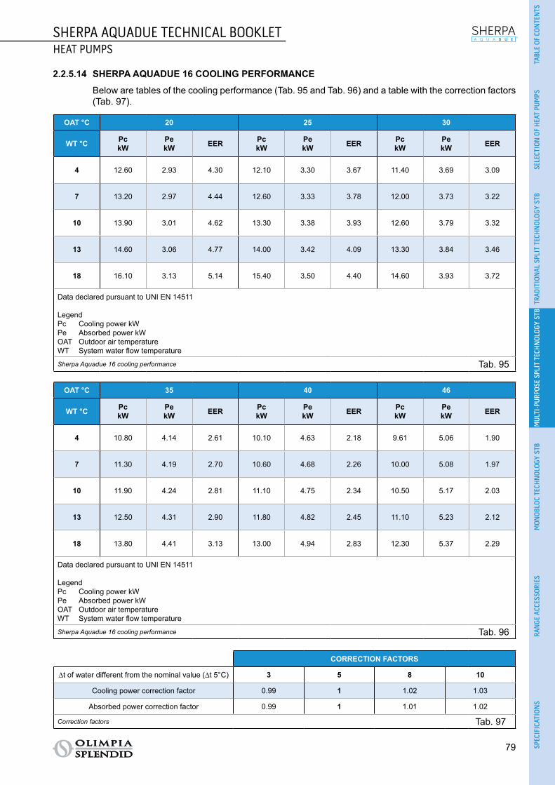
SHERPA AQUADUE TECHNICAL BOOKLETHEAT PUMPS
79
TABL
E OF
CON
TEN
TSSE
LECT
ION
OF
HEA
T PU
MPS
TRAD
ITIO
NAL
SPL
IT T
ECH
NOL
OGY
STB
MUL
TI-P
URPO
SE S
PLIT
TEC
HNOL
OGY
STB
MON
OBLO
C TE
CHN
OLOG
Y ST
BRA
NGE
ACC
ESSO
RIES
SPEC
IFIC
ATIO
NS
2.2.5.14 SHERPA AQUADUE 16 COOLING PERFORMANCE
Below are tables of the cooling performance (Tab. 95 and Tab. 96) and a table with the correction factors (Tab. 97).
OAT °C 20 25 30
WT °C PckW
PekW EER Pc
kWPekW EER Pc
kWPekW EER
4 12.60 2.93 4.30 12.10 3.30 3.67 11.40 3.69 3.09
7 13.20 2.97 4.44 12.60 3.33 3.78 12.00 3.73 3.22
10 13.90 3.01 4.62 13.30 3.38 3.93 12.60 3.79 3.32
13 14.60 3.06 4.77 14.00 3.42 4.09 13.30 3.84 3.46
18 16.10 3.13 5.14 15.40 3.50 4.40 14.60 3.93 3.72
Data declared pursuant to UNI EN 14511
LegendPc Cooling power kWPe Absorbed power kWOAT Outdoor air temperatureWT System water flow temperature
Sherpa Aquadue 16 cooling performance Tab. 95
OAT °C 35 40 46
WT °C PckW
PekW EER Pc
kWPekW EER Pc
kWPekW EER
4 10.80 4.14 2.61 10.10 4.63 2.18 9.61 5.06 1.90
7 11.30 4.19 2.70 10.60 4.68 2.26 10.00 5.08 1.97
10 11.90 4.24 2.81 11.10 4.75 2.34 10.50 5.17 2.03
13 12.50 4.31 2.90 11.80 4.82 2.45 11.10 5.23 2.12
18 13.80 4.41 3.13 13.00 4.94 2.83 12.30 5.37 2.29
Data declared pursuant to UNI EN 14511
LegendPc Cooling power kWPe Absorbed power kWOAT Outdoor air temperatureWT System water flow temperature
Sherpa Aquadue 16 cooling performance Tab. 96
CORRECTION FACTORS
∆t of water different from the nominal value (∆t 5°C) 3 5 8 10
Cooling power correction factor 0.99 1 1.02 1.03
Absorbed power correction factor 0.99 1 1.01 1.02
Correction factors Tab. 97

80
SHERPA AQUADUE TECHNICAL BOOKLETHEAT PUMPS
2.2.5.15 SHERPA AQUADUE 16 PERFORMANCE ACCORDING TO STANDARD UNI/TS 11300-4
Below are the tables of performance according to standard UNI/TS 11300-4 (Tab. 98 and Tab. 99).
Water T °C 35 45 55
Outdoor air T °C Heating capacity kW COP Heating capacity kW COP Heating capacity kW COP
-7 7.71 2.65 6.73 2.16 5.61 1.81
2 8.82 2.85 7.45 2.29 6.23 2.00
7 14.03 4.11 12.90 3.11 11.43 2.48
12 15.32 4.39 13.98 3.53 12.20 2.88
Sherpa Aquadue 16 performance according to standard UNI/TS 11300-4 Tab. 98
WT 35°C A Td-fan B C D
Outdoor air T °C -7 2 7 12
PLR 88% 54% 35% 15%
DC 7.71 8.82 14.03 15.32
COP at Partial Load 2.65 2.91 4.26 4.52
COP at Full Load 2.65 2.85 4.11 4.39
CR 1.00 0.53 0.22 0.09
fCOP 1.00 1.02 1.04 1.03
LegendTU: water flow temperature of the systemPLR: Part load ratioDC: Power at full load and at the temperatures recommended by the manufacturerCOP at Partial Load: COP at CR load and at the temperatures recommended by the manufacturerCOP at Full Load: COP at full load and at the temperatures recommended by the manufacturerCR = capacity control ratio of the heat pumpfCOP = COP correction factor in relation to the CR load ratio
Sherpa Aquadue 16 performance according to standard UNI/TS 11300-4 Tab. 99

SHERPA AQUADUE TECHNICAL BOOKLETHEAT PUMPS
81
TABL
E OF
CON
TEN
TSSE
LECT
ION
OF
HEA
T PU
MPS
TRAD
ITIO
NAL
SPL
IT T
ECH
NOL
OGY
STB
MUL
TI-P
URPO
SE S
PLIT
TEC
HNOL
OGY
STB
MON
OBLO
C TE
CHN
OLOG
Y ST
BRA
NGE
ACC
ESSO
RIES
SPEC
IFIC
ATIO
NS
2.2.5.16 SHERPA AQUADUE 16T HEATING PERFORMANCE
Below is a table of the heating performance (Tab. 100) and a table with the correction factors (Tab. 101).
WT °C 35 40 45 50 55 60
OAT °C PhkW
PekW COP Ph
kWPekW COP Ph
kWPekW COP Ph
kWPekW COP Ph
kWPekW COP Ph
kWPekW COP
-20 8.90 3.87 2.30 8.50 4.05 2.10 8.2 4.32 1.90 7.90 4.94 1.60 - - - - - -
-7 9.57 3.75 2.55 9.20 4.00 2.30 9.01 4.33 2.08 8.80 4.89 1.80 8.55 5.03 1.70 - - -
0 10.50 3.89 2.70 10.30 4.20 2.45 10.00 4.65 2.15 9.80 4.90 2.00 9.50 5.28 1.80 8.50 5.48 1.55
2 11.89 4.17 2.85 11.30 4.35 2.60 10.90 4.84 2.25 10.60 5.05 2.10 10.20 5.37 1.90 9.20 5.58 1.65
7 15.96 3.88 4.11 14.90 4.14 3.60 14.04 4.54 3.09 13.30 4.75 2.80 12.5 5.04 2.48 11.2 5.21 2.15
12 18.02 4.11 4.38 17.20 4.41 3.90 16.30 4.87 3.35 15.60 5.03 3.10 14.4 5.20 2.77 13.2 5.50 2.40
30 18.50 4.11 4.5 17.70 4.48 3.95 17.00 4.86 3.50 16.20 5.14 3.15 15.30 5.46 2.80 - - -
42 18.80 4.13 4.55 18.20 4.49 4.05 17.30 4.87 3.55 16.60 5.19 3.20 15.80 5.54 2.85 - - -
Data declared pursuant to UNI EN 14511
LegendPh Heating power kWPe Absorbed power kWOAT Outdoor air temperatureWT System water flow temperature
Sherpa Aquadue 16T heating performance Tab. 100
CORRECTION FACTORS
∆t water 3 5 8 10
Heating power correction factor 0.99 1 1.01 1.02
Absorbed power correction factor 1.01 1 0.98 0.96
Correction factors Tab. 101

82
SHERPA AQUADUE TECHNICAL BOOKLETHEAT PUMPS
2.2.5.17 SHERPA AQUADUE 16T COOLING PERFORMANCE
Below are tables of the cooling performance (Tab. 102 and Tab. 103) and a table with the correction factors (Tab. 104).
OAT °C 20 25 30
WT °C PckW
PekW EER Pc
kWPekW EER Pc
kWPekW EER
4 14.30 3.20 4.47 13.70 3.60 3.81 13.00 4.03 3.23
7 15.00 3.24 4.63 14.30 3.64 3.93 13.96 4.08 3.33
10 15.60 3.29 4.74 14.90 3.69 4.04 14.10 4.14 3.41
13 16.40 3.34 4.91 15.70 3.74 4.20 14.80 4.20 3.52
18 17.90 3.42 5.23 17.10 3.82 4.48 16.20 4.29 3.78
Data declared pursuant to UNI EN 14511
LegendPc Cooling power kWPe Absorbed power kWOAT Outdoor air temperatureWT System water flow temperature
Sherpa Aquadue 16T cooling performance Tab. 102
OAT °C 35 40 46
WT °C PckW
PekW EER Pc
kWPekW EER Pc
kWPekW EER
4 12.30 4.52 2.72 11.50 5.05 2.28 10.90 5.51 1.98
7 12.80 4.57 2.80 12.00 5.12 2.34 11.40 5.59 2.04
10 13.40 4.63 2.89 12.60 5.19 2.43 11.80 5.65 2.09
13 14.00 4.70 2.98 13.20 5.26 2.51 12.40 5.71 2.17
18 15.30 4.81 3.18 14.40 5.39 2.67 13.60 5.86 2.32
Data declared pursuant to UNI EN 14511
LegendPc Cooling power kWPe Absorbed power kWOAT Outdoor air temperatureWT System water flow temperature
Sherpa Aquadue 16T cooling performance Tab. 103
CORRECTION FACTORS
∆t of water different from the nominal value (∆t 5°C) 3 5 8 10
Cooling power correction factor 0.99 1 1.02 1.03
Absorbed power correction factor 0.99 1 1.01 1.02
Correction factors Tab. 104
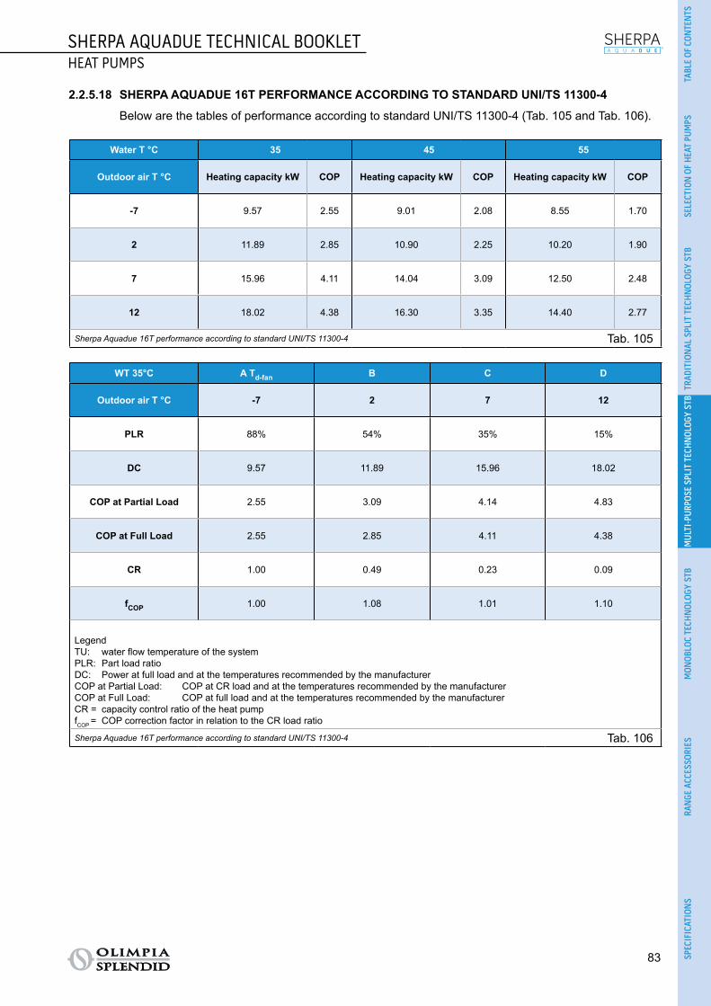
SHERPA AQUADUE TECHNICAL BOOKLETHEAT PUMPS
83
TABL
E OF
CON
TEN
TSSE
LECT
ION
OF
HEA
T PU
MPS
TRAD
ITIO
NAL
SPL
IT T
ECH
NOL
OGY
STB
MUL
TI-P
URPO
SE S
PLIT
TEC
HNOL
OGY
STB
MON
OBLO
C TE
CHN
OLOG
Y ST
BRA
NGE
ACC
ESSO
RIES
SPEC
IFIC
ATIO
NS
2.2.5.18 SHERPA AQUADUE 16T PERFORMANCE ACCORDING TO STANDARD UNI/TS 11300-4
Below are the tables of performance according to standard UNI/TS 11300-4 (Tab. 105 and Tab. 106).
Water T °C 35 45 55
Outdoor air T °C Heating capacity kW COP Heating capacity kW COP Heating capacity kW COP
-7 9.57 2.55 9.01 2.08 8.55 1.70
2 11.89 2.85 10.90 2.25 10.20 1.90
7 15.96 4.11 14.04 3.09 12.50 2.48
12 18.02 4.38 16.30 3.35 14.40 2.77
Sherpa Aquadue 16T performance according to standard UNI/TS 11300-4 Tab. 105
WT 35°C A Td-fan B C D
Outdoor air T °C -7 2 7 12
PLR 88% 54% 35% 15%
DC 9.57 11.89 15.96 18.02
COP at Partial Load 2.55 3.09 4.14 4.83
COP at Full Load 2.55 2.85 4.11 4.38
CR 1.00 0.49 0.23 0.09
fCOP 1.00 1.08 1.01 1.10
LegendTU: water flow temperature of the systemPLR: Part load ratioDC: Power at full load and at the temperatures recommended by the manufacturerCOP at Partial Load: COP at CR load and at the temperatures recommended by the manufacturerCOP at Full Load: COP at full load and at the temperatures recommended by the manufacturerCR = capacity control ratio of the heat pumpfCOP = COP correction factor in relation to the CR load ratio
Sherpa Aquadue 16T performance according to standard UNI/TS 11300-4 Tab. 106

84
SHERPA AQUADUE TECHNICAL BOOKLETHEAT PUMPS
2.2.6 OPERATING LIMITS Below are diagrams of the limits of water temperature (LWT) and outdoor air temperature (OAT) within
which the heat pump can run in cooling (Fig. 21) and heating/production of domestic water (Fig. 22) modes.
10
20
30
40
50
60
70
LWT
°C
10
20
30
40
50
60
70
80
30 20 10 0 10 20 30 40 50
LWT °
ODT °C
ACS/DHW
- - -ODT °C
LWT
°C
0
2
4
6
8
10
12
14
16
18
20
-10 0 10 20 30 40 50
Operating limits in cooling mode Fig. 21
10
20
30
40
50
60
70
LWT
°C
10
20
30
40
50
60
70
80
30 20 10 0 10 20 30 40 50
LWT °
ODT °C
ACS/DHW
- - -ODT °C
LWT
°C0
2
4
6
8
10
12
14
16
18
20
-10 0 10 20 30 40 50
Operating limits in heating mode Fig. 22
The supporting electrical heater elements can be enabled during the functions of heating or production of domestic hot water even outside the operating range of the heat pump.
If the unit is installed in a particularly windy area, wind barriers must be put in place to avoid malfunc-tioning of the unit.

SHERPA AQUADUE TECHNICAL BOOKLETHEAT PUMPS
85
TABL
E OF
CON
TEN
TSSE
LECT
ION
OF
HEA
T PU
MPS
TRAD
ITIO
NAL
SPL
IT T
ECH
NOL
OGY
STB
MUL
TI-P
URPO
SE S
PLIT
TEC
HNOL
OGY
STB
MON
OBLO
C TE
CHN
OLOG
Y ST
BRA
NGE
ACC
ESSO
RIES
SPEC
IFIC
ATIO
NS
2.2.7 USEFUL HEADS OF THE SYSTEM Sherpa Aquadue is equipped with two high efficiency circulation pumps.
The technical water circulation pump permits the following two types of control: ○ With constant pressure differential (mode A). ○ With variable pressure differential (mode B).
The technical water circulation pump of the DHW circuit permits the following two types of control: ○ With constant pressure differential (mode A). ○ Three constant speeds (mode C).
IT is equipped with two high efficiency circulation pumps: the pumps with permanent magnet wet rotor have an electronic control module with integrated frequency converter. There is a control knob on the module.
An LED on the DHW pump indicates the operating status of the pump.All the functions can be set, activated and deactivated at the control knob.
SETTINGS USING THE CONTROL KNOB
2
Mode A: Variable pressure difference (Δp-v) (available for the pump of the air-conditioning circuit and the DHW pump).
The differential-pressure set-point is increased linearly over the permitted volume flow range between ½ H and H (Δp-v graph).
The differential pressure generated by the pump is adjusted to the corresponding differential-pressure set-point.This control mode is especially useful in heating systems with fan coils and radiators, since the flow noise at the thermostatic valves is reduced.
2
Mode B: Constant pressure difference (Δp-c) (available for the pump of the air-conditioning circuit). The differential pressure set-point H is constantly maintained, within the permitted delivery range, at the
programmed set-point up to the maximum characteristic curve (Δp-c graph). This regulation method is recommended for floor mounted heating systems or older heating systems with large pipelines, but also for all other applications that do not have variable characteristic curves, such as for example DHW boiler pumps.
Mode C: Constant speed I, II and III (available for DHW pump). The circulation pump works like a conventional three-speed pump but uses less energy.
Waterflow[l/s] in nominal conditions
SHERPA 7 SHERPA 11 SHERPA 13 SHERPA 13 T SHERPA 16 SHERPA
16 T
Heating modet.water 30/35°C t.air 7°C d.b./6°C w.b. 0.31 0.50 0.60 0.60 0.67 0.76
Heating modet.water 40/45°C t.air 7°C d.b./6°C w.b. 0.31 0.47 0.60 0.60 0.64 0.67
Heating modet.water 23/18°C t.air 35°C 0.38 0.56 0.59 0.60 0.65 0.72
Heating modet.water 12/7°C t.air 35°C 0.27 0.39 0.50 0.50 0.54 0.61
Sherpa water flow Tab. 107

86
SHERPA AQUADUE TECHNICAL BOOKLETHEAT PUMPS
Below are diagrams (Fig. 23) of the available heads, for each speed of the hydraulic circulator, at the hydraulic connections of the internal unit.
A
8
7
6
5
4
3
2
1
80
p/kPa
Q/m3/h
H/m
70
60
50
40
30
20
10
010 2 3 4 6 75
0
∆p-c (constant)
∆p-c
max.
Wilo-Stratos-Para25/1-8,30/1-81-230V-Rp1, Rp1¼
8
7
6
5
4
3
2
1
80
p/kPa
Q/m3/h
H/m
70
60
50
40
30
20
10
010 2 3 4 6 75
0
∆p-v (variable)∆p-c
max.
Wilo-Stratos-Para25/1-8,30/1-81-230V-Rp1, Rp1¼
Q/IgpmP1/W
0 0,4 0,8 1,2 1,6 2,0
0 4 8 12 16 24 2820
Q/m3/h10 2 3 4 6 75
150
100
50
0
Q/l/s
max.
8m 7m 6m 5m 4m 3m 2m
Q/IgpmP1/W
00 .40. 02 .6 0.8
0 2 4 6 108
Q/m3m/h0 0.5 1.0 1.5 2.0 2.5 3.0
40
20
0
Q/l/s
max.
6
5
4
3
2
1
p/kPa
Q/m3m/h
H/m
50
60
40
30
20
10
00
00.5 1.0 1.5 2.0 2.5 3.0
∆p-c
max.
Wilo-Yonos PARA RS15/6, 25/6, 30/61~230V - Rp½, Rp1, Rp1¼
Q/IgpmP1/W
00 .40. 02 .6 0.8
0 2 4 6 108
Q/m3m/h0 0.5 1.0 1.5 2.0 2.5 3.0
40
20
0
Q/l/s
max.
A B
C
B
8
7
6
5
4
3
2
1
80
p/kPa
Q/m3/h
H/m
70
60
50
40
30
20
10
010 2 3 4 6 75
0
∆p-c (constant)
∆p-c
max.
Wilo-Stratos-Para25/1-8,30/1-81-230V-Rp1, Rp1¼
8
7
6
5
4
3
2
1
80
p/kPa
Q/m3/h
H/m
70
60
50
40
30
20
10
010 2 3 4 6 75
0
∆p-v (variable)
∆p-c
max.
Wilo-Stratos-Para25/1-8,30/1-81-230V-Rp1, Rp1¼
Q/IgpmP1/W
0 0,4 0,8 1,2 1,6 2,0
0 4 8 12 16 24 2820
Q/m3/h10 2 3 4 6 75
150
100
50
0
Q/l/s
max.
8m 7m 6m 5m 4m 3m 2m
Q/IgpmP1/W
00 .40. 02 .6 0.8
0 2 4 6 108
Q/m3m/h0 0.5 1.0 1.5 2.0 2.5 3.0
40
20
0
Q/l/s
max.
6
5
4
3
2
1
p/kPa
Q/m3m/h
H/m
50
60
40
30
20
10
00
00.5 1.0 1.5 2.0 2.5 3.0
∆p-c
max.
Wilo-Yonos PARA RS15/6, 25/6, 30/61~230V - Rp½, Rp1, Rp1¼
Q/IgpmP1/W
00 .40. 02 .6 0.8
0 2 4 6 108
Q/m3m/h0 0.5 1.0 1.5 2.0 2.5 3.0
40
20
0
Q/l/s
max.
A B
CC
8
7
6
5
4
3
2
1
80
p/kPa
Q/m3/h
H/m
70
60
50
40
30
20
10
010 2 3 4 6 75
0
∆p-c (constant)
∆p-c
max.
Wilo-Stratos-Para25/1-8,30/1-81-230V-Rp1, Rp1¼
8
7
6
5
4
3
2
1
80
p/kPa
Q/m3/h
H/m
70
60
50
40
30
20
10
010 2 3 4 6 75
0
∆p-v (variable)
∆p-c
max.
Wilo-Stratos-Para25/1-8,30/1-81-230V-Rp1, Rp1¼
Q/IgpmP1/W
0 0,4 0,8 1,2 1,6 2,0
0 4 8 12 16 24 2820
Q/m3/h10 2 3 4 6 75
150
100
50
0
Q/l/s
max.
8m 7m 6m 5m 4m 3m 2m
Q/IgpmP1/W
00 .40. 02 .6 0.8
0 2 4 6 108
Q/m3m/h0 0.5 1.0 1.5 2.0 2.5 3.0
40
20
0
Q/l/s
max.
6
5
4
3
2
1
p/kPa
Q/m3m/h
H/m
50
60
40
30
20
10
00
00.5 1.0 1.5 2.0 2.5 3.0
∆p-c
max.
Wilo-Yonos PARA RS15/6, 25/6, 30/61~230V - Rp½, Rp1, Rp1¼
Q/IgpmP1/W
00 .40. 02 .6 0.8
0 2 4 6 108
Q/m3m/h0 0.5 1.0 1.5 2.0 2.5 3.0
40
20
0
Q/l/s
max.
A B
C
Hydraulic connection - head Fig. 23
If greater heads are required due to high pressure losses in the system, an inertial vessel or a hydraulic sep-arator and an external idle pump must be added. The system must have a minimum water content required to ensure good system operation. If it is insufficient, add a storage vessel in order to reach the required content. The water distribution pipes must be suitably insulated with expanded polyethylene or similar materials. The on/off valves, bends and unions must also be suitably insulated. To prevent air locks inside the cir-cuit, insert automatic or manual breather devices at all the points (high pipes, traps etc.) where air may accumulate.

SHERPA AQUADUE TECHNICAL BOOKLETHEAT PUMPS
87
TABL
E OF
CON
TEN
TSSE
LECT
ION
OF
HEA
T PU
MPS
TRAD
ITIO
NAL
SPL
IT T
ECH
NOL
OGY
STB
MUL
TI-P
URPO
SE S
PLIT
TEC
HNOL
OGY
STB
MON
OBLO
C TE
CHN
OLOG
Y ST
BRA
NGE
ACC
ESSO
RIES
SPEC
IFIC
ATIO
NS
2.2.8 COMPONENTS2.2.8.1 COMPONENTS OF THE INTERNAL UNIT
The internal unit comprises the following main components (see Fig. 24):
STRUCTUREA. Cover: in galvanised sheet steel and painted with oven-dried epoxy powders. All the components can be accessed from the front for ease of installation and maintenance. B. Supporting structure: in high-tensile galvanised sheet steel.
REFRIGERANT CIRCUITC. Refrigerant/water heat exchanger: brazed-plate in AISI 316 sheet steel.
HYDRAULIC CIRCUITD. Flow switches.E. Expansion vessel: of eight litres.F. Expansion valve.G. Compressor.H. Air-conditioning circuit circulation pump.I. DHW circuit circulation pump.J. DHW circuit heat exchangers.K. DHWcircuitevaporatorwaterflowregulator.L. Post-heating electrical heater elements collector: two-stage that can be activated with integration of the heat pump or available in the event of the external unit breaking.M. Automatic relief valves.N. Three-way valve: integrated on board the machine.
CONTROL AND SAFETYO. Water circuit pressure gauge.P. Safety valve: 3 bar.Q. Manual reset safety thermostat.R. Automatic reset safety thermostat.
ELECTRIC PANELS. Electric panel assembly: easy to access and with a circuit breaker for the heater elements and a fuse for the other loads.T. Master switch.U. Touch screen display.

88
SHERPA AQUADUE TECHNICAL BOOKLETHEAT PUMPS
LM
T
U
S
I G
J
B
H
Q
O
NP
L
K
E
C
A
F
C
DR
Components of the internal unit Fig. 24
2.2.8.2 COMPONENTS OF THE EXTERNAL UNIT
The external unit comprises the following main components (see Fig. 25): ○ Supporting structure: in galvanised sheet steel and painted with oven-dried epoxy powders. ○ Compressor: with permanent magnet motor (DC Brushless) with inverter for electronic speed control. ○ Electronic expansion valve: for ongoing and precise control of the parameters of the refrigerant
circuit. ○ Large axial fans: for more silent operation. ○ Optimised defrosting cycle: for application of the air-water heat pump. ○ 4-way cycle inversion valve. ○ Heat exchange coil: copper pipes ribbed on the inside and aluminium fins. ○ Electric panel: with control boards and inverter for powering the compressor. ○ Temperature sensors and high pressure switch: for optimal and safe operation.
Components of the external unit Fig. 25

SHERPA AQUADUE TECHNICAL BOOKLETHEAT PUMPS
89
TABL
E OF
CON
TEN
TSSE
LECT
ION
OF
HEA
T PU
MPS
TRAD
ITIO
NAL
SPL
IT T
ECH
NOL
OGY
STB
MUL
TI-P
URPO
SE S
PLIT
TEC
HNOL
OGY
STB
MON
OBLO
C TE
CHN
OLOG
Y ST
BRA
NGE
ACC
ESSO
RIES
SPEC
IFIC
ATIO
NS
2.2.9 DIMENSIONS AND POSITIONING2.2.9.1 DIMENSIONS OF THE INTERNAL UNIT
Below is the layout of the internal unit of the heat pump (Fig. 26) and a table summarising the dimensions and weight values (Tab. 108).
A
B D
C
Layout of the internal unit Fig. 26
Ref. Fig. 26SHERPA
AQUADUE7
SHERPA AQUADUE
11
SHERPA AQUADUE
13
SHERPA AQUADUE
13T
SHERPA AQUADUE
16
SHERPA AQUADUE
16T
Internal unit SMALL 599510A BIG 599506A
A mm 1116 1116 1116 1116 1116 1116
B mm 500 500 500 500 500 500
C mm 280 280 280 280 280 280
D mm 288 288 288 288 288 288
Standard weight kg 70 70 72 72 72 72Dimensions and weight values of the internal unit Tab. 108

90
SHERPA AQUADUE TECHNICAL BOOKLETHEAT PUMPS
2.2.9.2 POSITIONING OF THE INTERNAL UNIT
The pleasing aesthetics of the internal unit mean that it can be installed in plain view. The internal unit must be installed indoors and on a wall with the display at eye level. For the installation layout and fitting of the pipes, please refer to Fig. 27 and use the template provided
with the unit. Leave a clearance at the sides and above of no less than 25 mm so that the covers can be removed for
the purpose of routine and special maintenance. Also prepare:
○ a nearby water drainage point; ○ a compliant power supply; ○ a water supply to fill the hydraulic circuit; ○ a communication cable between internal unit and external unit.
500288
25
25
184
1116
11565
280
25
180
136
6818 65
105140180
Positioning of the internal unit Fig. 27

SHERPA AQUADUE TECHNICAL BOOKLETHEAT PUMPS
91
TABL
E OF
CON
TEN
TSSE
LECT
ION
OF
HEA
T PU
MPS
TRAD
ITIO
NAL
SPL
IT T
ECH
NOL
OGY
STB
MUL
TI-P
URPO
SE S
PLIT
TEC
HNOL
OGY
STB
MON
OBLO
C TE
CHN
OLOG
Y ST
BRA
NGE
ACC
ESSO
RIES
SPEC
IFIC
ATIO
NS
2.2.9.3 DIMENSIONS OF THE EXTERNAL UNITS
Below is the layout of the external unit (Fig. 28) and a table summarising the dimensions and weight values (Tab. 109).
H
E
B
A
B
G
F
G
CEF
A
DC
H
D
Layout of the external unit Fig. 28
Ref. Fig. 28SHERPA
AQUADUE7
SHERPA AQUADUE
11
SHERPA AQUADUE
13
SHERPA AQUADUE
13T
SHERPA AQUADUE
16
SHERPA AQUADUE
16T
External unit OSCEBSH24EI
OSCEBCH36EI
OSCEINH48EI
OSCETNH48EI
OSCEINH60EI
OSCETNH60EI
SINGLE-FAN DUAL-FAN
A mm 847 990 938 938 938 938
B mm 563 622 633 633 633 633
C mm 340 368 404 404 404 404
D mm 360 398 448 448 448 448
E mm 315 340 370 370 370 370
F mm 330 350 392 392 392 392
G mm 917 1060 1008 1008 1008 1008
H mm 700 950 1369 1369 1369 1369
Weight kg 58 82 99 102 99 107Dimensions and weight values of the external unit Tab. 109

92
SHERPA AQUADUE TECHNICAL BOOKLETHEAT PUMPS
Below is the layout of the S1 external unit (Fig. 29) and a table summarising the dimensions and weight values (Tab. 110).
D E
B
C
F
A
H
E
FB
A
D
C
H
Layout of the S1 external unit Fig. 29
Ref. Fig. 29SHERPA
AQUADUE7
SHERPA AQUADUE
11
SHERPA AQUADUE
13
SHERPA AQUADUE
13T
SHERPA AQUADUE
16
SHERPA AQUADUE
16T
S1 external unit OSCESHH24EI
OSCESHH36EI
OSCESHH48EI
OSCESTH48EI
OSCESHH60EI
OSCESTH60EI
SINGLE-FAN DUAL-FAN
A mm 845 946 952 952 952 952
B mm 914 1030 1045 1045 1045 1045
C mm 540 673 634 634 634 634
D mm 363 410 415 415 415 415
E mm 350 403 404 404 404 404
F mm 915 1036 1032 1032 1032 1032
H mm 702 810 1333 1333 1333 1333
Weight kg 49 67 95 108 95 113Dimensions and weight values of the S1 external unit Tab. 110
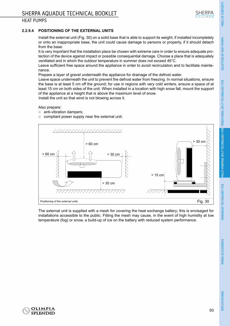
SHERPA AQUADUE TECHNICAL BOOKLETHEAT PUMPS
93
TABL
E OF
CON
TEN
TSSE
LECT
ION
OF
HEA
T PU
MPS
TRAD
ITIO
NAL
SPL
IT T
ECH
NOL
OGY
STB
MUL
TI-P
URPO
SE S
PLIT
TEC
HNOL
OGY
STB
MON
OBLO
C TE
CHN
OLOG
Y ST
BRA
NGE
ACC
ESSO
RIES
SPEC
IFIC
ATIO
NS
2.2.9.4 POSITIONING OF THE EXTERNAL UNITS
Install the external unit (Fig. 30) on a solid base that is able to support its weight; if installed incompletely or onto an inappropriate base, the unit could cause damage to persons or property, if it should detach from the base.
It is very important that the installation place be chosen with extreme care in order to ensure adequate pro-tection of the device against impact or possible consequential damage. Choose a place that is adequately ventilated and in which the outdoor temperature in summer does not exceed 46°C.
Leave sufficient free space around the appliance in order to avoid recirculation and to facilitate mainte-nance.
Prepare a layer of gravel underneath the appliance for drainage of the defrost water.Leave space underneath the unit to prevent the defrost water from freezing. In normal situations, ensure the base is at least 5 cm off the ground; for use in regions with very cold winters, ensure a space of at least 15 cm on both sides of the unit. When installed in a location with high snow fall, mount the support of the appliance at a height that is above the maximum level of snow.Install the unit so that wind is not blowing across it.
Also prepare: ○ anti-vibration dampers; ○ compliant power supply near the external unit.
600
960
350
> 60 cm
> 60 cm
> 30 cm
> 30 cm
> 30 cm
> 15 cm
Positioning of the external units Fig. 30
The external unit is supplied with a mesh for covering the heat exchange battery; this is envisaged for installations accessible to the public. Fitting the mesh may cause, in the event of high humidity at low temperature (fog) or snow, a build-up of ice on the battery with reduced system performance.

94
SHERPA AQUADUE TECHNICAL BOOKLETHEAT PUMPS
2.2.10 INSTALLATION To ensure successful installation and optimal performance, follow the instructions in the installation, use
and maintenance manual supplied with each unit and accessory. This technical booklet provides general information on installation, dimensional drawings and wiring diagrams.
The installation must be carried out by the dealer or by other qualified personnel; if the installation is not carried out correctly, there may be a risk of water leakage, electric shock or fire.
During assembly and any maintenance operation, observe the precautions in the installation, use and maintenance manuals and on the labels inside the appliances, and take any precautions dictated by common sense and set down by the safety rules at the place of installation.
Always wear protective gloves and goggles when performing maintenance on the parts of the appliances
containing refrigerant. Air-water heat pumps MUST NEVER be installed in rooms where there is inflam-mable gas, explosive gas, a high level of humidity (laundry rooms, greenhouses etc.), or in rooms where there are other machines generating a lot of heat.
It is recommended to use only the components designed specially for the installation provided; the use of different components could cause the leakage of water, electric shock or fire.
Once the installation has been completed, check that there is no leakage of refrigerant (the liquid can produce toxic gas when exposed to flames).
When installing or relocating the system, make sure that there is no substance in the refrigerant circuit other than the refrigerant specified in the technical data (see para. 2.2.4) as the presence of air or other foreign substances in the refrigerant circuit can cause an abnormal increase in pressure or breakage of the system, resulting in damage to property or physical injury.

SHERPA AQUADUE TECHNICAL BOOKLETHEAT PUMPS
95
TABL
E OF
CON
TEN
TSSE
LECT
ION
OF
HEA
T PU
MPS
TRAD
ITIO
NAL
SPL
IT T
ECH
NOL
OGY
STB
MUL
TI-P
URPO
SE S
PLIT
TEC
HNOL
OGY
STB
MON
OBLO
C TE
CHN
OLOG
Y ST
BRA
NGE
ACC
ESSO
RIES
SPEC
IFIC
ATIO
NS
2.2.10.1 HYDRAULIC CONNECTION
In Fig. 31 are the positions of the hydraulic connections:A. Water flow.B. Water flow of the domestic hot water tank.C. Water return.D. Water return of the domestic hot water tank.E. Refrigerant pipe connection.F. Refrigerant pipe connection.
CA E F
B
D
Hydraulic connection - head Fig. 31
The hydraulic connections are to be completed by installing: ○ air relief valves at the highest points of the pipes; ○ flexible elastic joints; ○ on/off valves; ○ sieve water filter with 0.4 mm mesh.
The minimum nominal diameter of the hydraulic connection pipes must be 1". In order to allow for maintenance or repair, it is essential that each hydraulic connection is equipped with
the respective manual valves.
The tables below (Tab. 111, Tab. 112, Tab. 113 and Tab. 114) show the essential characteristics of the hydraulic system.
Water content of the pipes Internal diameter External diameter Litres/metre
Copper
12 mm 14 mm 0,11 l/m
14 mm 16 mm 0,15 l/m
16 mm 18 mm 0,20 l/m
20 mm 22 mm 0,31 l/m
25 mm 28 mm 0,49 l/m
32 mm 35 mm 0,80 l/m
Steel
12,7 mm (1/2”) 3/8” Gas 0,13 l/m
16,3 mm (5/8”) 1/2” Gas 0,21 l/m
21,7 mm (7/8”) 3/4” Gas 0,37 l/m
27,4 mm (11/16”) 1” Gas 0,59 l/mHydraulic connection Tab. 111

96
SHERPA AQUADUE TECHNICAL BOOKLETHEAT PUMPS
% Inhibited monoethylene glycol 10% 20% 30% 40%Freezing point (a) -4°C -9°C -15°C -23°C
Correction factors
Capacity 0.996 0.991 0.983 0.975Absorbed power 0.990 0.978 0.964 1.008Load loss 1.003 1.010 1.020 1.033
Notes(a) The temperature values are indicative; always refer to the temperatures stated for the specific product used
Hydraulic connection Tab. 112
Table for calculating the water content of the system
Installed unit..............................................................................
Content of unit (a) l ..............................................................................
Content of pipes (b) l ..............................................................................
Utilities (fan coils, panels, radiators, etc.) (c) l ..............................................................................
Total content (d) l ..............................................................................Notes(a) Consult the technical data table(b) Consult the pipe water content table(c) Consult the manual of the installed utilities(d) The water content of the system must be between the minimum value and the maximum value stated in Tab. 114. The mini-
mum content of the hydraulic circuit must be considered as the volume of water always circulating in the system (i.e. the parts of the system excluded by valves must not be considered). Water must always be allowed to circulate in the heat pump of the circuit of the system. It is possible to increase the maximum content of the system by adding an expansion vessel suited to the water content of the system.
Hydraulic connection Tab. 113
SHERPA AQUADUE
7
SHERPA AQUADUE
11
SHERPA AQUADUE
13
SHERPA AQUADUE
13T
SHERPA AQUADUE
16
SHERPA AQUADUE
16TNominal water flow Std l/s 0.31 0.50 0.60 0.60 0.67 0.74
Water content of system
Min l 23 38 45 45 51 58Max (a) l 138 138 138 138 138 138Max (b) l 400 400 400 400 400 400
Operating pressure Max kPa 300 300 300 300 300 300
Filling pressure Min kPa 150 150 150 150 150 150
System height difference Max m 20 20 20 20 20 20
Notes(a) Temperature of water in system 55°C, water content of the system using only the expansion vessel supplied as standard in
the unit(b) Temperature of water in system 35°C, water content of the system using only the expansion vessel supplied as standard in
the unit
Hydraulic connection Tab. 114

SHERPA AQUADUE TECHNICAL BOOKLETHEAT PUMPS
97
TABL
E OF
CON
TEN
TSSE
LECT
ION
OF
HEA
T PU
MPS
TRAD
ITIO
NAL
SPL
IT T
ECH
NOL
OGY
STB
MUL
TI-P
URPO
SE S
PLIT
TEC
HNOL
OGY
STB
MON
OBLO
C TE
CHN
OLOG
Y ST
BRA
NGE
ACC
ESSO
RIES
SPEC
IFIC
ATIO
NS
2.2.10.2 REFRIGERANT CONNECTION
Use only pipes measuring 3/8” and 5/8” in diameter (see para. 2.1.4). The following table (Tab. 115) provides the data needed to define the refrigerant connection between the
internal and external units.
SHERPA AQUADUE
7
SHERPA AQUADUE
11
SHERPA AQUADUE
13
SHERPA AQUADUE
13T
SHERPA AQUADUE
16
SHERPA AQUADUE
16T
Internal unit SMALL 599510A BIG 599506A
External unit OSCEBSH24EI
OSCEBCH36EI
OSCEINH48EI
OSCETNH48EI
OSCEINH60EI
OSCETNH60EI
S1 external unit OSCESHH24EI
OSCESHH36EI
OSCESHH48EI
OSCESTH48EI
OSCESHH60EI
OSCESTH60EI
Maximum length of the connecting pipes m 25 30 50 50 50 50
Limit of elevation difference between the two units if the external unit is positioned higher
m 12 20 25 30 25 30
Limit of elevation difference between the two units if the external unit is positioned lower
m 9 12 20 20 20 20
Additional charge of refrigerant per metre over 5 metres piping
g/m 60 60 60 60 60 60
Refrigerant connection Tab. 115
To set up the refrigerant connection: ○ Connect the internal unit observing the maximum length of the pipes in the table (see Tab. 115). ○ Do not exceed the maximum permissible difference in height when installing the internal and external
units (see Tab. 115). ○ Complete the refrigerant circuit by connecting the internal unit to the external unit (for the connection
points see Fig. 32) and check that the refrigerant circuit is perfectly sealed following the instructions in the installation, use and maintenance manual.
Refrigerant connection between the units Fig. 32

98
SHERPA AQUADUE TECHNICAL BOOKLETHEAT PUMPS
2.2.10.3 WIRING
The electrical connections must be made in compliance with the instructions given in the installation manual and with national standards or procedures governing electrical connections; insufficient capacity or incomplete electrical connections may lead to electric shock or fire.
The power circuits of the internal and external units must be separate; the external unit line must be protected with a thermomagnetic circuit breaker or suitably sized fuses.
The system must be wired in accordance with the regulations in force and properly earthed.
To prevent any risk of electric shock, the master switches must be disconnected before making electrical connections and carrying out maintenance on the appliances.
Before performing any operation, make sure that the electrical power of the internal and external units is switched off.
The supply voltage must be that indicated in the technical data (see para. 2.1.4).
2.2.10.4 WIRING DIAGRAMS
The following are diagrams for connecting the electrical cables (Fig. 33, Fig. 34 and Fig. 35).
*For S1 external units, the terminals of the communication cable are marked S1 and S2 instead of P and Q
*
Wiring diagram Fig. 33
T3 temperature sensor for domestic water tank T4 outdoor air temperature sensor N/13 contactor activation for electrical heater element power supply in domestic water tank during an-
ti-legionella cycles (220-240V 50Hz 100W max) 14/15 activation of external heat source e.g.: gas boiler (contact 8A (3A) 250Vac) 16/17 alarm contact (contact 8A (3A) 250Vac) 5/L domestic hot water request (when the domestic hot water tank temperature is set by a dedicated
external control; a closed contact between these terminals activates the domestic hot water request).

SHERPA AQUADUE TECHNICAL BOOKLETHEAT PUMPS
99
TABL
E OF
CON
TEN
TSSE
LECT
ION
OF
HEA
T PU
MPS
TRAD
ITIO
NAL
SPL
IT T
ECH
NOL
OGY
STB
MUL
TI-P
URPO
SE S
PLIT
TEC
HNOL
OGY
STB
MON
OBLO
C TE
CHN
OLOG
Y ST
BRA
NGE
ACC
ESSO
RIES
SPEC
IFIC
ATIO
NS
*For S1 external units, the terminals of the communication cable are marked S1 and S2 instead of P and Q
*
Wiring diagram Fig. 34
T3 temperature sensor for domestic water tank T4 outdoor air temperature sensor N/13 contactor activation for electrical heater element power supply in domestic water tank during an-
ti-legionella cycles (220-240V 50Hz 100W max) 14/15 activation of external heat source e.g.: gas boiler (contact 8A (3A) 250Vac) 16/17 alarm contact (contact 8A (3A) 250Vac) 5/L domestic hot water request (when the domestic hot water tank temperature is set by a dedicated
external control; a closed contact between these terminals activates the domestic hot water request).

100
SHERPA AQUADUE TECHNICAL BOOKLETHEAT PUMPS
Wiring diagram Fig. 35
Terminal 1: cooling on/off remote free contactTerminal 2: heating on/off remote free contactTerminal 3: Eco mode remote free contactTerminal 4: night-time mode remote free contactTerminal 5: domestic water activation remote free contactTerminal 6: TA remote free contact for enabling cooling or heating modeTerminal 7: remote free contacts common connectionTerminal 21-22: connection of RS485 serial interface to the Acquadue Control supervision unitTerminals 1 to 7 are on the electronic board; the terminals can be removed so that they can be easily connected and then re-inserted in the original position

SHERPA AQUADUE TECHNICAL BOOKLETHEAT PUMPS
101
TABL
E OF
CON
TEN
TSSE
LECT
ION
OF
HEA
T PU
MPS
TRAD
ITIO
NAL
SPL
IT T
ECH
NOL
OGY
STB
MUL
TI-P
URPO
SE S
PLIT
TEC
HNOL
OGY
STB
MON
OBLO
C TE
CHN
OLOG
Y ST
BRA
NGE
ACC
ESSO
RIES
SPEC
IFIC
ATIO
NS
2.2.10.5 MAXIMUM INPUTS
The power line of the external unit must be capable of being sectioned from the mains using a thermo-magnetic circuit breaker suitable for the machine input with differential relay, with maximum calibration equal to that stated in national electrical regulations. The internal unit line is already protected by a ther-momagnetic circuit breaker on the electrical heater elements power supply and by a fuse; installation of a differential relay on the power line is recommended.
The following table (Tab. 116) shows the maximum power consumption of the units and protections to be installed on the line of the external unit.
External unit OSCEBSH24EI
OSCEBCH36EI
OSCEINH48EI
OSCETNH48EI
OSCEINH60EI
OSCETNH60EI
S1 external unit OSCESHH24EI
OSCESHH36EI
OSCESHH48EI
OSCESTH48EI
OSCESHH60EI
OSCESTH60EI
Power supply V/ph/Hz
220-240/1/50
220-240/1/50
220-240/1/50
380-415/3+N/50
220-240/1/50
380-415/3+N/50
Maximum absorbed power kW 3.0 4.8 6.0 5.5 6.0 7.5
Maximum absorbed current A 13.5 22 28 8.15 28 11.5
Fuse or circuit break-er
MFA A 25 40 40 25 40 25
Internal unit SMALL 599510A BIG 599506A
Power supply V/ph/Hz 220-240/1/50 220-240/1/50
Maximum absorbed power with electrical heater elements activated
kW 4.05 4.05 7.05 7.05 7.05 7.05
Maximum absorbed current with electrical heater elements activated
A 18 18 31 31 31 31
Maximum inputs Tab. 116
2.2.10.6 CONNECTING CABLES
Use the specified types of cable for the electrical connections between the internal and external units (see Tab. 117).
External unit OSCEBSH24EI
OSCEBCH36EI
OSCEINH48EI
OSCETNH48EI
OSCEINH60EI
OSCETNH60EI
S1 external unit OSCESHH24EI
OSCESHH36EI
OSCESHH48EI
OSCESTH48EI
OSCESHH60EI
OSCESTH60EI
Power cable H07RN-F 3 G2,5
H07RN-F 3 G4
H07RN-F 3 G4
H07RN-F 5 G2,5
H07RN-F 3 G4
H07RN-F 5 G2,5
Internal unit SMALL 599510A BIG 599506A
Power cable 3 X H07V-K 4 mm²
ODU/IDU communication cable 2 x 0.5 mm² shielded
DHW and outdoor air probe cable H03RN-F 2 G 0.5 / H03VV-F 2 G 0.5
Connecting cables Tab. 117

102
SHERPA AQUADUE TECHNICAL BOOKLETHEAT PUMPS
2.2.10.7 HYDRAULIC CIRCUIT
Sherpa Aquadue heat pump, SLR fan radiator terminals and boiler for the production of DHW.The hydraulic diagram (Fig. 36) is purely indicative.
T
T
TT
TT
YY
AQUA
DUE
modu
le
C/H
7
T
M
Hydraulic circuit Fig. 36 Legend:
C/H
M
T
Y
T
Mesh filter
C/H
M
T
Y
T
On/off valve
C/H
M
T
Y
T
Motorised three-way valve
C/H
M
T
Y
T
Differential by-pass
C/H
M
T
Y
T
Thermostatic mixer
C/H
M
T
Y
T
Thermometer
C/H
M
T
Y
T
Temperature probe
C/H
M
T
Y
T
Automatic air breather
C/H
M
T
Y
T
Expansion vessel
C/H
M
T
Y
T
Circulator C/H
M
T
Y
T
Summer/winter valve

SHERPA AQUADUE TECHNICAL BOOKLETHEAT PUMPS
103
TABL
E OF
CON
TEN
TSSE
LECT
ION
OF
HEA
T PU
MPS
TRAD
ITIO
NAL
SPL
IT T
ECH
NOL
OGY
STB
MUL
TI-P
URPO
SE S
PLIT
TEC
HNOL
OGY
STB
MON
OBLO
C TE
CHN
OLOG
Y ST
BRA
NGE
ACC
ESSO
RIES
SPEC
IFIC
ATIO
NS
Sherpa Aquadue heat pump, SL fan radiator terminals, radiant panels and boiler for the production of DHW.The hydraulic diagram (Fig. 37) is purely indicative.
T
T
YY
TT
TT
MT
8
T
AQUA
DUE
modu
le
M
Hydraulic circuit Fig. 37
Legend:
C/H
M
T
Y
T
Mesh filter
C/H
M
T
Y
T
On/off valve
C/H
M
T
Y
T
Motorised three-way valve
C/H
M
T
Y
T
Check valve
C/H
M
T
Y
T
Thermostatic mixer
C/H
M
T
Y
T
Thermometer
C/H
M
T
Y
T
Temperature probe
C/H
M
T
Y
T
Automatic air breather
C/H
M
T
Y
T
Expansion vessel
C/H
M
T
Y
T
Circulator C/H
M
T
Y
T
Summer/winter valve
C/H
M
T
Y
T
Differential by-pass

104
SHERPA AQUADUE TECHNICAL BOOKLETHEAT PUMPS
Sherpa Aquadue Heat Pump, compensating Tank, SLR fan radiator terminals and boiler for the production of DHW.The hydraulic diagram (Fig. 38) is purely indicative.
T
T
TT
TT
T
YY
9
AQUA
DUE
mod
ule
M
Hydraulic circuit Fig. 38
Legend:
C/H
M
T
Y
T
Mesh filter
C/H
M
T
Y
T
On/off valve
C/H
M
T
Y
T
Motorised three-way valve
C/H
M
T
Y
T
Check valve
C/H
M
T
Y
T
Thermostatic mixer
C/H
M
T
Y
T
Thermometer
C/H
M
T
Y
T
Temperature probe
C/H
M
T
Y
T
Automatic air breather
C/H
M
T
Y
T
Expansion vessel
C/H
M
T
Y
T
Circulator
C/H
M
T
Y
T
Differential by-pass

SHERPA AQUADUE TECHNICAL BOOKLETHEAT PUMPS
105
TABL
E OF
CON
TEN
TSSE
LECT
ION
OF
HEA
T PU
MPS
TRAD
ITIO
NAL
SPL
IT T
ECH
NOL
OGY
STB
MUL
TI-P
URPO
SE S
PLIT
TEC
HNOL
OGY
STB
MON
OBLO
C TE
CHN
OLOG
Y ST
BRA
NGE
ACC
ESSO
RIES
SPEC
IFIC
ATIO
NS
2.2.11 CONFORMITY The Sherpa Aquadue heat pumps are compliant with the following European directives:
○ LVD 2014/35/EU ○ EMCD 2014/30/EU (electromagnetic compatibility) ○ ECODESIGN 2009/125/EC 813/2013EU 327/2011EU ○ RoHS 2011/65/EC
The Sherpa Aquadue heat pumps are compliant with the following harmonised European standards: ○ EN14825 ○ EN55014-1 ○ EN55014-2 ○ EN61000-3-2 ○ EN61000-3-3 ○ EN61000-3-11 ○ EN61000-3-12 ○ EN60335-1 ○ EN60335-2-40
2.2.11.1 CE DECLARATION OF CONFORMITY
The CE declaration of conformity is available in the download area on the site www.olimpiasplendid.it (Fig. 39).
Download area Fig. 39

106
SHERPA AQUADUE TECHNICAL BOOKLETHEAT PUMPS
2.2.12 GENERAL INFORMATION2.2.12.1 PACK
The following table summarises the dimensions and weight values of the pack containing the internal unit (Tab. 118).
SHERPA AQUADUE
7
SHERPA AQUADUE
11
SHERPA AQUADUE
13
SHERPA AQUADUE
13T
SHERPA AQUADUE
16
SHERPA AQUADUE
16T
Internal unit SMALL 599510A BIG 599506A
Width cm 71 71 71 71 71 71
Length cm 52 52 52 52 52 52
Height cm 136 136 136 136 136 136
Gross weight kg 82 82 82 82 82 82
Volume m2 0.502 0.502 0.502 0.502 0.502 0.502Pack Tab. 118
The following table summarises the dimensions and weight values of the pack containing the external unit (Tab. 119).
External unit OSCEBSH24EI
OSCEBCH36EI
OSCEINH48EI
OSCETNH48EI
OSCEINH60EI
OSCETNH60EI
Width cm 78 106 109.50 109.50 109.50 109.50
Length cm 40 44 49.50 49.50 49.50 49.50
Height cm 96 138 142 142 142 142
Gross weight kg 57 114 112 115 112 120
Volume m³ 0.299 0.643 0.769 0.769 0.769 0.769Pack of external unit Tab. 119
The following table summarises the dimensions and weight values of the pack containing the S1 exter-nal unit (Tab. 120).
S1 external unit OSCESHH24EI
OSCESHH36EI
OSCESHH48EI
OSCESTH48EI
OSCESHH60EI
OSCESTH60EI
Width cm 97 109 109 109 109 109
Length cm 40 50 50 50 50 50
Height cm 77 88 148 148 148 148
Gross weight kg 52 73 108 121 108 126
Volume m³ 0.299 0.480 0.807 0.807 0.807 0.807Pack of S1 external unit Tab. 120

SHERPA AQUADUE TOWER TECHNICAL BOOKLETHEAT PUMPS
107
TABL
E OF
CON
TEN
TSSE
LECT
ION
OF
HEA
T PU
MPS
TRAD
ITIO
NAL
SPL
IT T
ECH
NOL
OGY
STB
MUL
TI-P
URPO
SE S
PLIT
TEC
HNOL
OGY
STB
MON
OBLO
C TE
CHN
OLOG
Y ST
BRA
NGE
ACC
ESSO
RIES
SPEC
IFIC
ATIO
NS
2.3 SHERPA AQUADUE TOWER - MULTI-PURPOSE SPLIT TECHNOLOGY TECHNICAL BOOKLET
2.3.1 FUNDAMENTAL CHARACTERISTICS
○ Reversible air-water heat pump split system. ○ System with two modules: external unit and internal hydronic module. ○ Supplies technical water for DHW boiler at a temperature of up to 75°C in the integrated boiler. ○ Production of technical water for mixed boiler at 40°C up to 3-6 days.* ○ Availability of DHW at all times: guaranteed by the redundancy of the system with dual refrigerant circuit. ○ Two-stage electrical heater elements as standard: activation of one or two elements to support the heat
pump with simple configuration of the electronic control. Each stage is activated according to the need for heating power in real time, in order to optimise power consumption.
○ A water-water heat pump unit integrated in the internal unit provides hot water at high temperature re-gardless of outdoor weather conditions for the production of DHW.
○ Anti-legionella cycles can be avoided with use of the high temperature water-to-water heat pump (up to 75°C).
○ Climate curves with the outdoor air temperature probe: two curves available, one for cooling and one for heating. The climate curves make it possible to vary the water temperature of the system in relation to the outdoor weather conditions, adapting the heating requirements of the building in order to save energy.
○ Weekly, DHW, holiday and daily timer with night-time mode. ○ Configurable set-points: two set-points for cooling and three set-points for heating (one of which for
DHW) which can also be selected via remote contact. ○ Refrigerants: R410A** for the reversible circuit for air-conditioning and R134a*** for the high tempera-
ture circuit for the production of DHW. ○ Integrated high efficiency 150 l boiler.
* Qref 2.1 kWh/day for 150 l tank according to standard EN16147, 2005. ** Equipment not hermetically sealed containing fluorinated gases with an equivalent GWP of 2088. *** Equipment not hermetically sealed containing fluorinated gases with an equivalent GWP of 1430.

108
SHERPA AQUADUE TOWER TECHNICAL BOOKLETHEAT PUMPS
2.3.2 CONTROL AND FUNCTIONS ○ Sherpa Aquadue Tower can be activated for:
• heating;• cooling;• domestic water production only;• cooling or heating and the simultaneous production of domestic water at a temperature of up to
75°C.
○ A large colour LCD touch screen facilitates installation, use and maintenance of the appliance with the following: • synoptic window;• graph of the temperature readings of the probes;• diagnostics with the INPUT/OUTPUT states of the control board and alarm log. The control can manage one climate curve for heating and another for cooling to vary the water tem-perature of the system in relation to the outdoor weather conditions.
○ The control can manage one climate curve for heating and another for cooling to vary the water tem-perature of the system in relation to the outdoor weather conditions, adapting the amount of heat to the heating requirements of the building in order to save energy.
○ There is a weekly timer with a max of 8 daily time bands for the modes:• cooling/heating;• ECO function;• night-time function. There is a specific timer for the production of DHW. It is possible to set up to 3 "holiday" periods during which the system is deactivated with the frost protection and pumps anti-locking function active.
○ Sherpa Aquadue Tower permits highly flexible management of the production of Domestic Hot Water with an outdoor boiler in two modes:• with diversion of the flow of hot water from the heating circuit to the DHW circuit up to a maximum
temperature of 60°C with the system running at full capacity;• using the water-water heat pump integrated in the internal unit up to a maximum temperature of
75°C.
○ Sherpa Aquadue Tower is able to manage anti-legionella cycles without interrupting the heating or cool-ing cycle of the air conditioning system, producing hot water at high temperature using the integrated heat pump circuit.
○ The following are available for both cooling and heating mode:• a "comfort" set-point;• an ECO set-point. The set-points can be selected with the ECO command on the control panel or by closing an appro-priate input on the electronic board (remote contact).
○ The DHW production function can be activated by the temperature sensor in the storage tank or by closing an appropriate input on the electronic board (remote contact).
○ There is a specific set point for the DHW production function, and it is possible to change the main op-erating parameters of the same function for optimal operation in the various situations of installation.
○ The internal units have a supporting two-stage heater element. These elements, if enabled, can be activated to supplement the power of the system in heating mode or for the production of DHW when low outdoor air temperature does not allow the heat pump to meet the heating load or when the external unit malfunctions (back-up function). It is possible to enable just one or both the stages of the electrical heater element according to needs or on the basis of the electrical power available.

SHERPA AQUADUE TOWER TECHNICAL BOOKLETHEAT PUMPS
109
TABL
E OF
CON
TEN
TSSE
LECT
ION
OF
HEA
T PU
MPS
TRAD
ITIO
NAL
SPL
IT T
ECH
NOL
OGY
STB
MUL
TI-P
URPO
SE S
PLIT
TEC
HNOL
OGY
STB
MON
OBLO
C TE
CHN
OLOG
Y ST
BRA
NGE
ACC
ESSO
RIES
SPEC
IFIC
ATIO
NS
○ Sherpa Aquadue Tower can activate an auxiliary external heat source (e.g. heater) to substitute the heat pump unit, in relation to the outdoor air temperature.
○ The following functions can be remote controlled with free contacts:• activation of cooling mode;• activation of heating mode;• activation of the second set-point (Eco mode);• activation of night-time mode;• activation of the heating of domestic water storage;• enabling of air-conditioning.
○ The unit may also be connected to a chrono-thermostat or to the chiller/boiler contacts of the elec-tronic controls of the fan coils Bi2 and Bi2+.
○ The internal unit has a DHW boiler with the following characteristics:• rigid polyurethane coating;• enamelled steel;• sacrificial anode;• drain tap;• probe sump;• fixed point thermostatic mixer for DHW.
○ The following accessories are available:• Code B0665 - Heating cable kit.
.
The codes are subject to change; please contact Olimpia Splendid for further information.

110
SHERPA AQUADUE TOWER TECHNICAL BOOKLETHEAT PUMPS
2.3.3 THE MODELS AVAILABLE AND CONNECTION OF THE UNITS Below is a table of the models to which the relative external unit is connected (Tab. 121).
SHERPAAQUADUE TOWER 7
SHERPAAQUADUE TOWER 11
SHERPAAQUADUE TOWER 13
SHERPAAQUADUE
TOWER 13T
SHERPAAQUADUE TOWER 16
SHERPAAQUADUE
TOWER 16T
STANDARD internal unit
SMALL599513A
BIG599512A
EXTERNAL UNIT
OS-CEBSH24EI OS-CEBCH36EI OS-CEINH48EI OS-CETNH48EI OS-CEINH60EI OS-CETNH60EI
S1 EXTER-NAL UNIT
OS-CESHH24EI OS-CESHH36EI OS-CESHH48EI OS-CESTH48EI OS-CESHH60EI OS-CESTH60EI
The models available and connection of the units Tab. 121
The codes are subject to change; please contact Olimpia Splendid for further information.

SHERPA AQUADUE TOWER TECHNICAL BOOKLETHEAT PUMPS
111
TABL
E OF
CON
TEN
TSSE
LECT
ION
OF
HEA
T PU
MPS
TRAD
ITIO
NAL
SPL
IT T
ECH
NOL
OGY
STB
MUL
TI-P
URPO
SE S
PLIT
TEC
HNOL
OGY
STB
MON
OBLO
C TE
CHN
OLOG
Y ST
BRA
NGE
ACC
ESSO
RIES
SPEC
IFIC
ATIO
NS
2.3.4 TECHNICAL DATA Below are tables summarising the technical data (Tab. 122, Tab. 123, Tab. 124, Tab. 125 and Tab. 126).
SHERPAAQUADUE
TOWER7
SHERPAAQUADUE
TOWER11
SHERPAAQUADUE
TOWER13
SHERPAAQUADUE
TOWER 13T
SHERPAAQUADUE
TOWER16
SHERPAAQUADUE
TOWER 16T
Internal unit code 599513A 599513A 599512A 599512A 599512A 599512A
External unit code OSCEBSH24EI
OSCEBCH36EI
OSCEINH48EI
OSCETNH48EI
OSCEINH60EI
OSCETNH60EI
S1 external unit code OSCESHH24EI
OSCESHH36EI
OSCESHH48EI
OSCESTH48EI
OSCESHH60EI
OSCESTH60EI
Type of evaporator Brazed-plate Brazed-plate Brazed-plate Brazed-plate Brazed-plate Brazed-plate
Heating capacity (a) kW 6.50 10.50 12.50 12.50 14 16
COP (a) W/W 4.10 4.10 4.10 4.10 4.10 4.10
Heating capacity (b) kW 5 8.30 10 10 10.50 12
COP (b) W/W 3.10 3.20 3.10 3.10 2.90 2.90
Heating capacity (c) kW 6.20 9.90 11.60 11.60 13 14.60
COP (c) W/W 3.40 3.20 3.30 3.30 3.20 3
Heating capacity (d) kW 4.80 7.80 9.30 9.30 9.80 10.90
COP (d) W/W 2.50 2.30 2.20 2.20 2.30 2.20
Cooling capacity (e) kW 7.60 12.10 12.60 12.80 13.80 15.30
EER (e) W/W 4 4.40 3.50 3.50 3.10 3.20
Cooling capacity (f) kW 5.60 8.10 10.40 10.40 11.30 12.80
EER (f) W/W 3.10 3.10 3 3 2.70 2.80
Energy efficiency class for heating water at 35°CEnergy efficiency class for heating water at 55°CDHW circuit heating capacity (g) kW 2.15 2.15 2.15 2.15 2.15 2.15
COP (g) W/W 3.12 3.12 3.12 3.12 3.12 3.12
DHW circuit heating capacity (h) kW 1.60 1.60 1.60 1.60 1.60 1.60
COP (h) W/W 2.58 2.58 2.58 2.58 2.58 2.58
Notes(a) Heating mode, inlet/outlet water temperature 30°C/35°C, outdoor air temperature 7°C d.b. / 6°C w.b.(b) Heating mode, inlet/outlet water temperature 30°C/35°C, outdoor air temperature -2°C d.b. / -1°C w.b.(c) Heating mode, inlet/outlet water temperature 40°C/45°C, outdoor air temperature 7°C d.b. / 6°C w.b.(d) Heating mode, inlet/outlet water temperature 40°C/45°C, outdoor air temperature -2°C d.b. / -1°C w.b.(e) Cooling mode, inlet/outlet water temperature 23°C/18°C, outdoor air temperature 35°C(f) Cooling mode, inlet/outlet water temperature 12°C/7°C, outdoor air temperature 35°C(g) Outlet water temperature 55°C / Heating circuit water temperature 35°C(g) Outlet water temperature 55°C / Heating circuit water temperature 12°C
Technical data Tab. 122
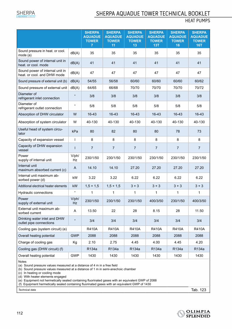
112
SHERPA AQUADUE TOWER TECHNICAL BOOKLETHEAT PUMPS
SHERPAAQUADUE
TOWER7
SHERPAAQUADUE
TOWER11
SHERPAAQUADUE
TOWER13
SHERPAAQUADUE
TOWER 13T
SHERPAAQUADUE
TOWER16
SHERPAAQUADUE
TOWER 16T
Sound pressure in heat. or cool. mode (a) dB(A) 35 35 35 35 35 35
Sound power of internal unit in heat. or cool. mode dB(A) 41 41 41 41 41 41
Sound power of internal unit in heat. or cool. and DHW mode dB(A) 47 47 47 47 47 47
Sound pressure of external unit (b) dB(A) 54/55 56/58 60/60 60/60 60/60 60/62
Sound pressure of external unit dB(A) 64/65 66/68 70/70 70/70 70/70 70/72
Diameter of refrigerant inlet connection “ 3/8 3/8 3/8 3/8 3/8 3/8
Diameter of refrigerant outlet connection “ 5/8 5/8 5/8 5/8 5/8 5/8
Absorption of DHW circulator W 16-43 16-43 16-43 16-43 16-43 16-43
Absorption of system circulator W 40-130 40-130 40-130 40-130 40-130 40-130
Useful head of system circu-lator kPa 80 82 80 80 78 73
Capacity of expansion vessel l 8 8 8 8 8 8
Capacity of DHW expansion vessel l 7 7 7 7 7 7
Power supply of internal unit
V/ph/Hz 230/1/50 230/1/50 230/1/50 230/1/50 230/1/50 230/1/50
Internal unitmaximum absorbed current (c) A 14.10 14.10 27.20 27.20 27.20 27.20
Internal unit maximum ab-sorbed power (d) kW 3.22 3.22 6.22 6.22 6.22 6.22
Additional electrical heater elements kW 1,5 + 1,5 1,5 + 1,5 3 + 3 3 + 3 3 + 3 3 + 3
Hydraulic connections “ 1 1 1 1 1 1
Power supply of external unit
V/ph/Hz 230/1/50 230/1/50 230/1/50 400/3/50 230/1/50 400/3/50
External unit maximum ab-sorbed current A 13.50 22 28 8.15 28 11.50
Drinking water inlet and DHW outlet pipe connections “ 3/4 3/4 3/4 3/4 3/4 3/4
Cooling gas (system circuit) (e) R410A R410A R410A R410A R410A R410A
Overall heating potential GWP 2088 2088 2088 2088 2088 2088
Charge of cooling gas Kg 2.10 2.75 4.45 4.00 4.45 4.20
Cooling gas (DHW circuit) (f) R134a R134a R134a R134a R134a R134a
Overall heating potential GWP 1430 1430 1430 1430 1430 1430
Notes(a) Sound pressure values measured at a distance of 4 m in a free field(b) Sound pressure values measured at a distance of 1 m in semi-anechoic chamber(c) In heating or cooling mode(d) With heater elements engaged(e) Equipment not hermetically sealed containing fluorinated gases with an equivalent GWP of 2088(f) Equipment hermetically sealed containing fluorinated gases with an equivalent GWP of 1430
Technical data Tab. 123

SHERPA AQUADUE TOWER TECHNICAL BOOKLETHEAT PUMPS
113
TABL
E OF
CON
TEN
TSSE
LECT
ION
OF
HEA
T PU
MPS
TRAD
ITIO
NAL
SPL
IT T
ECH
NOL
OGY
STB
MUL
TI-P
URPO
SE S
PLIT
TEC
HNOL
OGY
STB
MON
OBLO
C TE
CHN
OLOG
Y ST
BRA
NGE
ACC
ESSO
RIES
SPEC
IFIC
ATIO
NS
SHERPAAQUADUE
TOWER7
SHERPAAQUADUE
TOWER11
SHERPAAQUADUE
TOWER13
SHERPAAQUADUE
TOWER 13T
SHERPAAQUADUE
TOWER16
SHERPAAQUADUE
TOWER 16T
Volume of boiler l 150 150 150 150 150 150
Material of internal surface of boiler Glazed steel
Heat exchanger in the boiler Steel pipe
Boiler insulation Rigid foam polyurethane
Air-conditioning system safety valve bar 3 3 3 3 3 3
Domestic hot water circuit safety valve bar 6 6 6 6 6 6
Pre-charge pressure bar 1.5 1.5 1.5 1.5 1.5 1.5
Technical data Tab. 124
SHERPA AQUADUE TOWER7
SHERPA AQUADUE TOWER11
SHERPA AQUADUE TOWER13
Cooling capacity
(kW)
DHW capac-
ity(kW)
Absorp-tion
(kW)
EERCOP
Cooling capacity
(kW)
DHW capac-
ity(kW)
Absorp-tion
(kW)
EERCOP
Cooling capacity
(kW)
DHW ca-
pacity(kW)
Absorp-tion
(kW)
EERCOP
Cooling mode T of outlet water 7°C, air 35°C
5.60 0 1.81 3.10 8.10 0 2.63 3.10 10.40 0 3.47 3
DHW circuit, T of condenser outlet water 65°C / T of evaporator inlet water 12°C
0.64 1.28 0.56 2.30 0.64 1.28 0.56 2.30 0.64 1.28 0.56 2.30
Simultaneous op-eration in cooling + DHW mode
5.60 1.28 1.55 3.60 8.10 1.28 2.35 3.40 10.40 1.28 3.16 3.30
Technical data Tab. 125

114
SHERPA AQUADUE TOWER TECHNICAL BOOKLETHEAT PUMPS
SHERPA AQUADUE TOWER13T
SHERPA AQUADUE TOWER16
SHERPA AQUADUE TOWER16T
Cooling capacity
(kW)
DHW ca-
pacity(kW)
Absorp-tion
(kW)
EERCOP
Cooling capacity
(kW)
DHW ca-
pacity(kW)
Absorp-tion
(kW)
EERCOP
Cooling capacity
(kW)
DHW capac-
ity(kW)
Absorp-tion
(kW)
EERCOP
Cooling mode T of outlet water 7°C, air 35°C
10.40 0 3.47 3 11.30 0 4.19 2.70 12.80 0 4.57 2.80
DHW circuit, T of condenser outlet water 65°C / T of evaporator inlet water 12°C
0.64 1.28 0.56 2.30 0.64 1.28 0.56 2.30 0.64 1.28 0.56 2.30
Simultaneous op-eration in cooling + DHW mode
10.40 3.16 3.16 3.30 11.30 1.28 3.65 3.10 12.80 1.28 4.23 3
Technical data Tab. 126

SHERPA AQUADUE TOWER TECHNICAL BOOKLETHEAT PUMPS
115
TABL
E OF
CON
TEN
TSSE
LECT
ION
OF
HEA
T PU
MPS
TRAD
ITIO
NAL
SPL
IT T
ECH
NOL
OGY
STB
MUL
TI-P
URPO
SE S
PLIT
TEC
HNOL
OGY
STB
MON
OBLO
C TE
CHN
OLOG
Y ST
BRA
NGE
ACC
ESSO
RIES
SPEC
IFIC
ATIO
NS
2.3.5 PERFORMANCE TABLES2.3.5.1 SHERPA AQUADUE TOWER 7 HEATING PERFORMANCE
Below is a table of the heating performance (Tab. 127) and a table with the correction factors (Tab. 128).
WT °C 35 40 45 50 55 60
OAT °C
PhkW
PekW COP Ph
kWPekW COP Ph
kWPekW COP Ph
kWPekW COP Ph
kWPekW COP Ph
kWPekW COP
-20 3.31 1.72 1.92 3.17 1.75 1.81 2.88 1.80 1.60 2.61 1.86 1.40 - - - - - -
-7 4.21 1.40 3.01 3.79 1.44 2.63 3.51 1.42 2.48 3.30 1.43 2.30 2.85 1.43 2.00 - - -
0 4.85 1.49 3.25 4.50 1.55 2.90 4.05 1.58 2.56 3.88 1.62 2.40 3.35 1.68 2.00 3.10 1.79 1.73
2 5.05 1.50 3.37 4.70 1.57 3.00 4.30 1.65 2.60 4.20 1.68 2.50 3.58 1.70 2.10 3.30 1.83 1.80
7 6.50 1.58 4.12 5.90 1.61 3.66 5.50 1.62 3.40 5.10 1.76 2.90 4.65 1.79 2.60 4.30 1.95 2.20
12 7.71 1.72 4.48 7.20 1.75 4.11 6.79 1.82 3.73 6.00 1.85 3.25 5.60 1.93 2.90 5.20 2.08 2.50
30 8.90 1.94 4.58 8.51 1.98 4.30 7.90 2.01 3.93 7.30 2.05 3.57 6.65 2.15 3.10 - - -
42 9.30 2.04 4.55 8.82 2.10 4.20 8.20 2.14 3.83 7.60 2.19 3.47 7.00 2.33 3.00 - - -
Data declared pursuant to UNI EN 14511
LegendPh Heating power kWPe Absorbed power kWOAT Outdoor air temperatureWT System water flow temperature
Sherpa Aquadue Tower 7 heating performance Tab. 127
CORRECTION FACTORS
∆t water 3 5 8 10
Heating power correction factor 0.99 1 1.01 1.02
Absorbed power correction factor 1.01 1 0.98 0.96
Correction factors Tab. 128
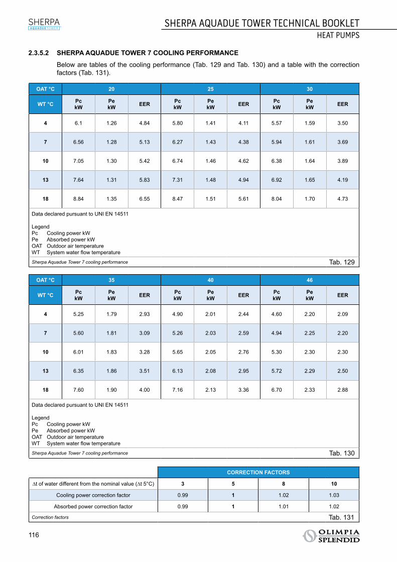
116
SHERPA AQUADUE TOWER TECHNICAL BOOKLETHEAT PUMPS
2.3.5.2 SHERPA AQUADUE TOWER 7 COOLING PERFORMANCE
Below are tables of the cooling performance (Tab. 129 and Tab. 130) and a table with the correction factors (Tab. 131).
OAT °C 20 25 30
WT °C PckW
PekW EER Pc
kWPekW EER Pc
kWPekW EER
4 6.1 1.26 4.84 5.80 1.41 4.11 5.57 1.59 3.50
7 6.56 1.28 5.13 6.27 1.43 4.38 5.94 1.61 3.69
10 7.05 1.30 5.42 6.74 1.46 4.62 6.38 1.64 3.89
13 7.64 1.31 5.83 7.31 1.48 4.94 6.92 1.65 4.19
18 8.84 1.35 6.55 8.47 1.51 5.61 8.04 1.70 4.73
Data declared pursuant to UNI EN 14511
LegendPc Cooling power kWPe Absorbed power kWOAT Outdoor air temperatureWT System water flow temperature
Sherpa Aquadue Tower 7 cooling performance Tab. 129
OAT °C 35 40 46
WT °C PckW
PekW EER Pc
kWPekW EER Pc
kWPekW EER
4 5.25 1.79 2.93 4.90 2.01 2.44 4.60 2.20 2.09
7 5.60 1.81 3.09 5.26 2.03 2.59 4.94 2.25 2.20
10 6.01 1.83 3.28 5.65 2.05 2.76 5.30 2.30 2.30
13 6.35 1.86 3.51 6.13 2.08 2.95 5.72 2.29 2.50
18 7.60 1.90 4.00 7.16 2.13 3.36 6.70 2.33 2.88
Data declared pursuant to UNI EN 14511
LegendPc Cooling power kWPe Absorbed power kWOAT Outdoor air temperatureWT System water flow temperature
Sherpa Aquadue Tower 7 cooling performance Tab. 130
CORRECTION FACTORS
∆t of water different from the nominal value (∆t 5°C) 3 5 8 10
Cooling power correction factor 0.99 1 1.02 1.03
Absorbed power correction factor 0.99 1 1.01 1.02
Correction factors Tab. 131
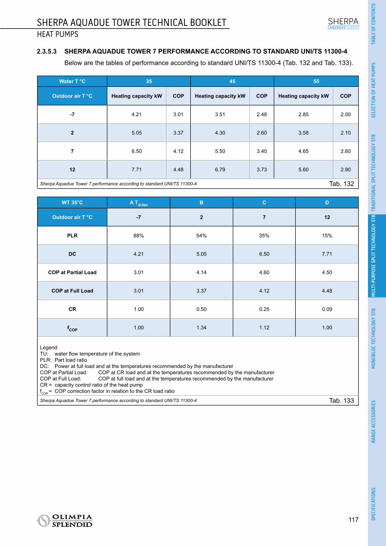
SHERPA AQUADUE TOWER TECHNICAL BOOKLETHEAT PUMPS
117
TABL
E OF
CON
TEN
TSSE
LECT
ION
OF
HEA
T PU
MPS
TRAD
ITIO
NAL
SPL
IT T
ECH
NOL
OGY
STB
MUL
TI-P
URPO
SE S
PLIT
TEC
HNOL
OGY
STB
MON
OBLO
C TE
CHN
OLOG
Y ST
BRA
NGE
ACC
ESSO
RIES
SPEC
IFIC
ATIO
NS
2.3.5.3 SHERPA AQUADUE TOWER 7 PERFORMANCE ACCORDING TO STANDARD UNI/TS 11300-4
Below are the tables of performance according to standard UNI/TS 11300-4 (Tab. 132 and Tab. 133).
Water T °C 35 45 55
Outdoor air T °C Heating capacity kW COP Heating capacity kW COP Heating capacity kW COP
-7 4.21 3.01 3.51 2.48 2.85 2.00
2 5.05 3.37 4.30 2.60 3.58 2.10
7 6.50 4.12 5.50 3.40 4.65 2.60
12 7.71 4.48 6.79 3.73 5.60 2.90
Sherpa Aquadue Tower 7 performance according to standard UNI/TS 11300-4 Tab. 132
WT 35°C A Td-fan B C D
Outdoor air T °C -7 2 7 12
PLR 88% 54% 35% 15%
DC 4.21 5.05 6.50 7.71
COP at Partial Load 3.01 4.14 4.60 4.50
COP at Full Load 3.01 3.37 4.12 4.48
CR 1.00 0.50 0.25 0.09
fCOP 1.00 1.34 1.12 1.00
LegendTU: water flow temperature of the systemPLR: Part load ratioDC: Power at full load and at the temperatures recommended by the manufacturerCOP at Partial Load: COP at CR load and at the temperatures recommended by the manufacturerCOP at Full Load: COP at full load and at the temperatures recommended by the manufacturerCR = capacity control ratio of the heat pumpfCOP = COP correction factor in relation to the CR load ratio
Sherpa Aquadue Tower 7 performance according to standard UNI/TS 11300-4 Tab. 133

118
SHERPA AQUADUE TOWER TECHNICAL BOOKLETHEAT PUMPS
2.3.5.4 SHERPA AQUADUE TOWER 11 HEATING PERFORMANCE
Below is a table of the heating performance (Tab. 134) and a table with the correction factors (Tab. 135).
WT °C 35 40 45 50 55 60
OAT °C PhkW
PekW COP Ph
kWPekW COP Ph
kWPekW COP Ph
kWPekW COP Ph
kWPekW COP Ph
kWPekW COP
-20 5.50 3.13 1.75 5.30 3.53 1.50 5.15 3.81 1.35 4.80 4.00 1.20 - - - - - -
-7 6.99 2.64 2.65 6.50 2.71 2.40 6.3 2.86 2.20 5.95 2.98 2.00 5.60 3.01 1.86 - - -
0 7.60 2.63 2.89 7.30 2.70 2.70 7.00 2.89 2.42 6.80 3.02 2.25 6.45 3.19 2.02 6.10 3.30 1.85
2 7.95 2.69 2.95 7.60 2.76 2.75 7.20 2.94 2.45 7.00 3.04 2.30 6.70 3.27 2.05 6.40 3.37 1.90
7 11.00 2.68 4.10 10.10 2.89 3.50 9.90 3.15 3.14 9.40 3.48 2.70 9.10 3.70 2.46 8.20 3.90 2.10
12 12.35 2.81 4.40 11.80 2.95 4.00 11.45 3.28 3.49 11.00 3.55 3.10 10.75 3.83 2.81 10 4.00 2.50
30 14.30 3.18 4.50 13.80 3.29 4.20 13.32 3.42 3.90 13.05 3.66 3.57 12.77 3.93 3.25 - - -
42 14.80 3.22 4.60 14.20 3.34 4.25 13.70 3.51 3.90 13.50 3.70 3.65 13.44 4.07 3.30 - - -
Data declared pursuant to UNI EN 14511
LegendPh Heating power kWPe Absorbed power kWOAT Outdoor air temperatureWT System water flow temperature
Sherpa Aquadue Tower 11 heating performance Tab. 134
CORRECTION FACTORS
∆t water 3 5 8 10
Heating power correction factor 0.99 1 1.01 1.02
Absorbed power correction factor 1.01 1 0.98 0.96
Correction factors Tab. 135

SHERPA AQUADUE TOWER TECHNICAL BOOKLETHEAT PUMPS
119
TABL
E OF
CON
TEN
TSSE
LECT
ION
OF
HEA
T PU
MPS
TRAD
ITIO
NAL
SPL
IT T
ECH
NOL
OGY
STB
MUL
TI-P
URPO
SE S
PLIT
TEC
HNOL
OGY
STB
MON
OBLO
C TE
CHN
OLOG
Y ST
BRA
NGE
ACC
ESSO
RIES
SPEC
IFIC
ATIO
NS
2.3.5.5 SHERPA AQUADUE TOWER 11 COOLING PERFORMANCE
Below are tables of the cooling performance (Tab. 136 and Tab. 137) and a table with the correction factors (Tab. 138).
OAT °C 20 25 30
WT °C PckW
PekW EER Pc
kWPekW EER Pc
kWPekW EER
4 8.36 1.85 4.52 8.01 2.07 3.87 7.59 2.32 3.27
7 9.47 1.87 5.06 9.07 2.09 4.34 8.59 2.35 3.66
10 10.60 1.89 5.61 10.10 2.12 4.76 9.61 2.38 4.04
13 11.80 1.92 6.15 11.30 2.15 5.26 10.70 2.41 4.40
18 14.1 1.97 7.16 13.50 2.20 6.14 12.80 2.47 5.18
Data declared pursuant to UNI EN 14511
LegendPc Cooling power kWPe Absorbed power kWOAT Outdoor air temperatureWT System water flow temperature
Sherpa Aquadue Tower 11 cooling performance Tab. 136
OAT °C 35 40 46
WT °C PckW
PekW EER Pc
kWPekW EER Pc
kWPekW EER
4 7.16 2.60 2.75 6.74 2.92 2.31 6.39 3.36 1.90
7 8.10 2.63 3.08 7.61 2.95 2.58 7.24 3.29 2.20
10 9.06 2.67 3.39 8.51 2.98 2.86 8.70 3.54 2.46
13 10.10 2.70 3.74 9.51 3.03 3.14 9.02 3.32 2.72
18 12.10 2.77 4.37 11.40 3.10 3.68 10.60 3.34 3.17
Data declared pursuant to UNI EN 14511
LegendPc Cooling power kWPe Absorbed power kWOAT Outdoor air temperatureWT System water flow temperature
Sherpa Aquadue Tower 11 cooling performance Tab. 137
CORRECTION FACTORS
∆t of water different from the nominal value (∆t 5°C) 3 5 8 10
Cooling power correction factor 0.99 1 1.02 1.03
Absorbed power correction factor 0.99 1 1.01 1.02
Correction factors Tab. 138

120
SHERPA AQUADUE TOWER TECHNICAL BOOKLETHEAT PUMPS
2.3.5.6 SHERPA AQUADUE TOWER 11 PERFORMANCE ACCORDING TO STANDARD UNI/TS 11300-4
Below are the tables of performance according to standard UNI/TS 11300-4 (Tab. 139 and Tab. 140).
Water T °C 35 45 55
Outdoor air T °C Heating capacity kW COP Heating capacity kW COP Heating capacity kW COP
-7 6.99 2.65 6.30 2.20 5.60 1.86
2 7.95 2.95 7.20 2.45 6.70 2.05
7 11.00 4.10 9.90 3.14 9.10 2.46
12 12.35 4.40 11.45 3.49 10.75 2.81
Sherpa Aquadue Tower 11 performance according to standard UNI/TS 11300-4 Tab. 139
WT 35°C A Td-fan B C D
Outdoor air T °C -7 2 7 12
PLR 88% 54% 35% 15%
DC 6.99 7.95 11.00 12.35
COP at Partial Load 2.50 2.87 4.28 4.45
COP at Full Load 2.65 2.95 4.10 4.40
CR 1.00 0.55 0.26 0.10
fCOP 1.00 0.97 1.03 1.01
LegendTU: water flow temperature of the systemPLR: Part load ratioDC: Power at full load and at the temperatures recommended by the manufacturerCOP at Partial Load: COP at CR load and at the temperatures recommended by the manufacturerCOP at Full Load: COP at full load and at the temperatures recommended by the manufacturerCR = capacity control ratio of the heat pumpfCOP = COP correction factor in relation to the CR load ratio
Sherpa Aquadue Tower 11 performance according to standard UNI/TS 11300-4 Tab. 140

SHERPA AQUADUE TOWER TECHNICAL BOOKLETHEAT PUMPS
121
TABL
E OF
CON
TEN
TSSE
LECT
ION
OF
HEA
T PU
MPS
TRAD
ITIO
NAL
SPL
IT T
ECH
NOL
OGY
STB
MUL
TI-P
URPO
SE S
PLIT
TEC
HNOL
OGY
STB
MON
OBLO
C TE
CHN
OLOG
Y ST
BRA
NGE
ACC
ESSO
RIES
SPEC
IFIC
ATIO
NS
2.3.5.7 SHERPA AQUADUE TOWER 13 HEATING PERFORMANCE
Below is a table of the heating performance (Tab. 141) and a table with the correction factors (Tab. 142).
WT °C 35 40 45 50 55 60
OAT °C PhkW
PekW COP Ph
kWPekW COP Ph
kWPekW COP Ph
kWPekW COP Ph
kWPekW COP Ph
kWPekW COP
-20 6.80 2.83 2.40 6.30 2.93 2.15 5.8 2.90 2.00 5.20 2.77 1.88 - - - - - -
-7 7.49 2.94 2.55 7.00 3.04 2.30 6.6 3.07 2.15 6.00 3.00 2.00 5.48 2.99 1.83 - - -
0 7.80 2.97 2.63 7.30 3.04 2.40 7.00 3.18 2.20 6.40 3.12 2.05 5.70 3.00 1.90 5.00 3.13 1.60
2 8.21 2.95 2.78 7.80 3.12 2.50 7.45 3.23 2.31 6.80 3.16 2.15 6.01 2.99 2.01 5.20 3.06 1.70
7 12.50 3.03 4.12 12.10 3.27 3.70 11.80 3.68 3.21 11.00 3.93 2.80 10.61 4.19 2.53 9.8 4.45 2.20
12 13.48 3.06 4.40 12.90 3.23 4.00 12.38 3.48 3.56 11.90 3.72 3.20 11.32 3.89 2.91 10.5 4.12 2.55
30 15.00 3.26 4.6 14.20 3.38 4.20 13.50 3.60 3.75 13.00 3.82 3.40 12.30 4.10 3.00 - - -
42 16.20 3.38 4.8 15.50 3.52 4.40 14.90 3.73 4.00 14.50 3.92 3.70 13.80 4.18 3.30 - - -
Data declared pursuant to UNI EN 14511
LegendPh Heating power kWPe Absorbed power kWOAT Outdoor air temperatureWT System water flow temperature
Sherpa Aquadue Tower 13 heating performance Tab. 141
CORRECTION FACTORS
∆t water 3 5 8 10
Heating power correction factor 0.99 1 1.01 1.02
Absorbed power correction factor 1.01 1 0.98 0.96
Correction factors Tab. 142

122
SHERPA AQUADUE TOWER TECHNICAL BOOKLETHEAT PUMPS
2.3.5.8 SHERPA AQUADUE TOWER 13 COOLING PERFORMANCE
Below are tables of the cooling performance (Tab. 143 and Tab. 144) and a table with the correction factors (Tab. 145).
OAT °C 20 25 30
WT °C PckW
PekW EER Pc
kWPekW EER Pc
kWPekW EER
4 11.6 2.44 4.75 11.10 2.73 4.07 10.50 3.06 3.43
7 12.20 2.46 4.96 11.60 2.75 4.22 11.00 3.09 3.56
10 12.70 2.50 5.08 12.20 2.79 4.37 11.50 3.14 3.66
13 13.40 2.53 5.30 12.80 2.84 4.51 12.10 3.17 3.82
18 14.7 2.59 5.68 14.10 2.91 4.85 13.30 3.26 4.08
Data declared pursuant to UNI EN 14511
LegendPc Cooling power kWPe Absorbed power kWOAT Outdoor air temperatureWT System water flow temperature
Sherpa Aquadue Tower 13 cooling performance Tab. 143
OAT °C 35 40 46
WT °C PckW
PekW EER Pc
kWPekW EER Pc
kWPekW EER
4 9.95 3.43 2.90 9.36 3.85 2.43 8.88 4.25 2.09
7 10.40 3.47 3.00 9.78 3.89 2.51 9.29 4.26 2.18
10 10.90 3.51 3.11 10.20 3.93 2.60 9.68 4.32 2.24
13 11.40 3.58 3.20 10.8 3.99 2.71 10.10 4.39 2.30
18 12.60 3.65 3.45 11.90 4.09 2.91 11.20 4.43 2.53
Data declared pursuant to UNI EN 14511
LegendPc Cooling power kWPe Absorbed power kWOAT Outdoor air temperatureWT System water flow temperature
Sherpa Aquadue Tower 13 cooling performance Tab. 144
CORRECTION FACTORS
∆t of water different from the nominal value (∆t 5°C) 3 5 8 10
Cooling power correction factor 0.99 1 1.02 1.03
Absorbed power correction factor 0.99 1 1.01 1.02
Correction factors Tab. 145

SHERPA AQUADUE TOWER TECHNICAL BOOKLETHEAT PUMPS
123
TABL
E OF
CON
TEN
TSSE
LECT
ION
OF
HEA
T PU
MPS
TRAD
ITIO
NAL
SPL
IT T
ECH
NOL
OGY
STB
MUL
TI-P
URPO
SE S
PLIT
TEC
HNOL
OGY
STB
MON
OBLO
C TE
CHN
OLOG
Y ST
BRA
NGE
ACC
ESSO
RIES
SPEC
IFIC
ATIO
NS
2.3.5.9 SHERPA AQUADUE TOWER 13 PERFORMANCE ACCORDING TO STANDARD UNI/TS 11300-4
Below are the tables of performance according to standard UNI/TS 11300-4 (Tab. 146 and Tab. 147).
Water T °C 35 45 55
Outdoor air T °C Heating capacity kW COP Heating capacity kW COP Heating capacity kW COP
-7 7.49 2.55 6.60 2.15 5.48 1.83
2 8.21 2.78 7.45 2.31 6.01 2.01
7 12.50 4.12 11.8 3.21 10.61 2.53
12 13.48 4.40 12.38 3.56 11.32 2.91
Sherpa Aquadue Tower 13 performance according to standard UNI/TS 11300-4 Tab. 146
WT 35°C A Td-fan B C D
Outdoor air T °C -7 2 7 12
PLR 88% 54% 35% 15%
DC 7.49 8.21 12.50 13.48
COP at Partial Load 2.55 2.91 4.26 4.52
COP at Full Load 2.55 2.78 4.12 4.40
CR 1.00 0.55 0.23 0.10
fCOP 1.00 1.05 1.03 1.03
LegendTU: water flow temperature of the systemPLR: Part load ratioDC: Power at full load and at the temperatures recommended by the manufacturerCOP at Partial Load: COP at CR load and at the temperatures recommended by the manufacturerCOP at Full Load: COP at full load and at the temperatures recommended by the manufacturerCR = capacity control ratio of the heat pumpfCOP = COP correction factor in relation to the CR load ratio
Sherpa Aquadue Tower 13 performance according to standard UNI/TS 11300-4 Tab. 147

124
SHERPA AQUADUE TOWER TECHNICAL BOOKLETHEAT PUMPS
2.3.5.10 SHERPA AQUADUE TOWER 13T HEATING PERFORMANCE
Below is a table of the heating performance (Tab. 148) and a table with the correction factors (Tab. 149).
WT °C 35 40 45 50 55 60
OAT °C PhkW
PekW COP Ph
kWPekW COP Ph
kWPekW COP Ph
kWPekW COP Ph
kWPekW COP Ph
kWPekW COP
-20 6.80 2.83 2.40 6.30 2.93 2.15 5.8 2.90 2.00 5.20 2.77 1.88 - - - - - -
-7 7.49 2.94 2.55 7.00 3.04 2.30 6.6 3.07 2.15 6.00 3.00 2.00 5.48 2.99 1.83 - - -
0 7.80 2.97 2.63 7.30 3.04 2.40 7.00 3.18 2.20 6.40 3.12 2.05 5.70 3.00 1.90 5.00 3.13 1.60
2 8.21 2.95 2.78 7.80 3.12 2.50 7.45 3.23 2.31 6.80 3.16 2.15 6.01 2.99 2.01 5.20 3.06 1.70
7 12.50 3.03 4.12 12.10 3.27 3.70 11.80 3.68 3.21 11.00 3.93 2.80 10.61 4.19 2.53 9.8 4.45 2.20
12 13.48 3.06 4.40 12.90 3.23 4.00 12.38 3.48 3.56 11.90 3.72 3.20 11.32 3.89 2.91 10.5 4.12 2.55
30 15.00 3.26 4.6 14.20 3.38 4.20 13.50 3.60 3.75 13.00 3.82 3.40 12.30 4.10 3.00 - - -
42 16.20 3.38 4.8 15.50 3.52 4.40 14.90 3.73 4.00 14.50 3.92 3.70 13.80 4.18 3.30 - - -
Data declared pursuant to UNI EN 14511
LegendPh Heating power kWPe Absorbed power kWOAT Outdoor air temperatureWT System water flow temperature
Sherpa Aquadue Tower 13T heating performance Tab. 148
CORRECTION FACTORS
∆t water 3 5 8 10
Heating power correction factor 0.99 1 1.01 1.02
Absorbed power correction factor 1.01 1 0.98 0.96
Correction factors Tab. 149

SHERPA AQUADUE TOWER TECHNICAL BOOKLETHEAT PUMPS
125
TABL
E OF
CON
TEN
TSSE
LECT
ION
OF
HEA
T PU
MPS
TRAD
ITIO
NAL
SPL
IT T
ECH
NOL
OGY
STB
MUL
TI-P
URPO
SE S
PLIT
TEC
HNOL
OGY
STB
MON
OBLO
C TE
CHN
OLOG
Y ST
BRA
NGE
ACC
ESSO
RIES
SPEC
IFIC
ATIO
NS
2.3.5.11 SHERPA AQUADUE TOWER 13T COOLING PERFORMANCE
Below are tables of the cooling performance (Tab. 150 and Tab. 151) and a table with the correction factors (Tab. 152).
OAT °C 20 25 30
WT °C PckW
PekW EER Pc
kWPekW EER Pc
kWPekW EER
4 11.6 2.44 4.75 11.10 2.73 4.07 10.50 3.06 3.43
7 12.20 2.46 4.96 11.60 2.75 4.22 11.00 3.09 3.56
10 12.70 2.50 5.08 12.20 2.79 4.37 11.50 3.14 3.66
13 13.40 2.53 5.30 12.80 2.84 4.51 12.10 3.17 3.82
18 14.7 2.59 5.68 14.10 2.91 4.85 13.30 3.26 4.08
Data declared pursuant to UNI EN 14511
LegendPc Cooling power kWPe Absorbed power kWOAT Outdoor air temperatureWT System water flow temperature
Sherpa Aquadue Tower 13T cooling performance Tab. 150
OAT °C 35 40 46
WT °C PckW
PekW EER Pc
kWPekW EER Pc
kWPekW EER
4 9.95 3.43 2.90 9.36 3.85 2.43 8.88 4.25 2.09
7 10.40 3.47 3.00 9.78 3.89 2.51 9.29 4.26 2.18
10 10.90 3.51 3.11 10.20 3.93 2.60 9.68 4.32 2.24
13 11.40 3.58 3.20 10.8 3.99 2.71 10.10 4.39 2.30
18 12.60 3.65 3.45 11.90 4.09 2.91 11.20 4.43 2.53
Data declared pursuant to UNI EN 14511
LegendPc Cooling power kWPe Absorbed power kWOAT Outdoor air temperatureWT System water flow temperature
Sherpa Aquadue Tower 13T cooling performance Tab. 151
CORRECTION FACTORS
∆t of water different from the nominal value (∆t 5°C) 3 5 8 10
Cooling power correction factor 0.99 1 1.02 1.03
Absorbed power correction factor 0.99 1 1.01 1.02
Correction factors Tab. 152

126
SHERPA AQUADUE TOWER TECHNICAL BOOKLETHEAT PUMPS
2.3.5.12 SHERPA AQUADUE TOWER 13T PERFORMANCE ACCORDING TO STANDARD UNI/TS 11300-4
Below are the tables of performance according to standard UNI/TS 11300-4 (Tab. 153 and Tab. 154).
Water T °C 35 45 55
Outdoor air T °C Heating capacity kW COP Heating capacity kW COP Heating capacity kW COP
-7 7.49 2.55 6.60 2.15 5.48 1.83
2 8.21 2.78 7.45 2.31 6.01 2.01
7 12.50 4.12 11.8 3.21 10.61 2.53
12 13.48 4.40 12.38 3.56 11.32 2.91
Sherpa Aquadue Tower 13T performance according to standard UNI/TS 11300-4 Tab. 153
WT 35°C A Td-fan B C D
Outdoor air T °C -7 2 7 12
PLR 88% 54% 35% 15%
DC 7.49 8.21 12.50 13.48
COP at Partial Load 2.55 2.91 4.26 4.52
COP at Full Load 2.55 2.78 4.12 4.40
CR 1.00 0.55 0.23 0.10
fCOP 1.00 1.05 1.03 1.03
LegendTU: water flow temperature of the systemPLR: Part load ratioDC: Power at full load and at the temperatures recommended by the manufacturerCOP at Partial Load: COP at CR load and at the temperatures recommended by the manufacturerCOP at Full Load: COP at full load and at the temperatures recommended by the manufacturerCR = capacity control ratio of the heat pumpfCOP = COP correction factor in relation to the CR load ratio
Sherpa Aquadue Tower 13T performance according to standard UNI/TS 11300-4 Tab. 154

SHERPA AQUADUE TOWER TECHNICAL BOOKLETHEAT PUMPS
127
TABL
E OF
CON
TEN
TSSE
LECT
ION
OF
HEA
T PU
MPS
TRAD
ITIO
NAL
SPL
IT T
ECH
NOL
OGY
STB
MUL
TI-P
URPO
SE S
PLIT
TEC
HNOL
OGY
STB
MON
OBLO
C TE
CHN
OLOG
Y ST
BRA
NGE
ACC
ESSO
RIES
SPEC
IFIC
ATIO
NS
2.3.5.13 SHERPA AQUADUE TOWER 16 HEATING PERFORMANCE
Below is a table of the heating performance (Tab. 155) and a table with the correction factors (Tab. 156).
WT °C 35 40 45 50 55 60
OAT °C PhkW
PekW COP Ph
kWPekW COP Ph
kWPekW COP Ph
kWPekW COP Ph
kWPekW COP Ph
kWPekW COP
-20 6.90 2.76 2.50 6.40 2.84 2.25 5.9 2.95 2.00 5.30 3.12 1.70 - - - - - -
-7 7.71 2.91 2.65 7.20 3.06 2.35 6.73 3.12 2.16 6.20 3.18 1.95 5.61 3.10 1.81 - - -
0 8.20 2.98 2.75 7.60 3.10 2.45 7.00 3.18 2.20 6.50 3.17 2.05 5.90 3.11 1.90 5.10 3.00 1.70
2 8.82 3.09 2.85 8.10 3.12 2.60 7.45 3.25 2.29 6.90 3.21 2.15 6.23 3.12 2.00 5.40 3.00 1.80
7 14.03 3.41 4.11 13.50 3.75 3.60 12.90 4.15 3.11 12.20 4.36 2.80 11.43 4.61 2.48 10.60 5.30 2.00
12 15.32 3.49 4.39 14.60 3.65 4.00 13.98 3.96 3.53 13.10 4.09 3.20 11.91 4.14 2.88 11.50 4.60 2.50
30 16.30 3.43 4.75 15.80 3.67 4.30 15.10 4.03 3.75 14.40 4.24 3.40 13.80 4.45 3.10 - - -
42 16.90 3.48 4.85 16.40 3.73 4.40 15.80 4.05 3.90 15.40 4.40 3.50 14.70 4.59 3.20 - - -
Data declared pursuant to UNI EN 14511
LegendPh Heating power kWPe Absorbed power kWOAT Outdoor air temperatureWT System water flow temperature
Sherpa Aquadue Tower 16 heating performance Tab. 155
CORRECTION FACTORS
∆t water 3 5 8 10
Heating power correction factor 0.99 1 1.01 1.02
Absorbed power correction factor 1.01 1 0.98 0.96
Correction factors Tab. 156

128
SHERPA AQUADUE TOWER TECHNICAL BOOKLETHEAT PUMPS
2.3.5.14 SHERPA AQUADUE TOWER 16 COOLING PERFORMANCE
Below are tables of the cooling performance (Tab. 157 and Tab. 158) and a table with the correction factors (Tab. 159).
OAT °C 20 25 30
WT °C PckW
PekW EER Pc
kWPekW EER Pc
kWPekW EER
4 12.60 2.93 4.30 12.10 3.30 3.67 11.40 3.69 3.09
7 13.20 2.97 4.44 12.60 3.33 3.78 12.00 3.73 3.22
10 13.90 3.01 4.62 13.30 3.38 3.93 12.60 3.79 3.32
13 14.60 3.06 4.77 14.00 3.42 4.09 13.30 3.84 3.46
18 16.10 3.13 5.14 15.40 3.50 4.40 14.60 3.93 3.72
Data declared pursuant to UNI EN 14511
LegendPc Cooling power kWPe Absorbed power kWOAT Outdoor air temperatureWT System water flow temperature
Sherpa Aquadue Tower 16 cooling performance Tab. 157
OAT °C 35 40 46
WT °C PckW
PekW EER Pc
kWPekW EER Pc
kWPekW EER
4 10.80 4.14 2.61 10.10 4.63 2.18 9.61 5.06 1.90
7 11.30 4.19 2.70 10.60 4.68 2.26 10.00 5.08 1.97
10 11.90 4.24 2.81 11.10 4.75 2.34 10.50 5.17 2.03
13 12.50 4.31 2.90 11.80 4.82 2.45 11.10 5.23 2.12
18 13.80 4.41 3.13 13.00 4.94 2.83 12.30 5.37 2.29
Data declared pursuant to UNI EN 14511
LegendPc Cooling power kWPe Absorbed power kWOAT Outdoor air temperatureWT System water flow temperature
Sherpa Aquadue Tower 16 cooling performance Tab. 158
CORRECTION FACTORS
∆t of water different from the nominal value (∆t 5°C) 3 5 8 10
Cooling power correction factor 0.99 1 1.02 1.03
Absorbed power correction factor 0.99 1 1.01 1.02
Correction factors Tab. 159

SHERPA AQUADUE TOWER TECHNICAL BOOKLETHEAT PUMPS
129
TABL
E OF
CON
TEN
TSSE
LECT
ION
OF
HEA
T PU
MPS
TRAD
ITIO
NAL
SPL
IT T
ECH
NOL
OGY
STB
MUL
TI-P
URPO
SE S
PLIT
TEC
HNOL
OGY
STB
MON
OBLO
C TE
CHN
OLOG
Y ST
BRA
NGE
ACC
ESSO
RIES
SPEC
IFIC
ATIO
NS
2.3.5.15 SHERPA AQUADUE TOWER 16 PERFORMANCE ACCORDING TO STANDARD UNI/TS 11300-4
Below are the tables of performance according to standard UNI/TS 11300-4 (Tab. 160 and Tab. 161).
Water T °C 35 45 55
Outdoor air T °C Heating capacity kW COP Heating capacity kW COP Heating capacity kW COP
-7 7.71 2.65 6.73 2.16 5.61 1.81
2 8.82 2.85 7.45 2.29 6.23 2.00
7 14.03 4.11 12.90 3.11 11.43 2.48
12 15.32 4.39 13.98 3.53 12.20 2.88
Sherpa Aquadue Tower 16 performance according to standard UNI/TS 11300-4 Tab. 160
WT 35°C A Td-fan B C D
Outdoor air T °C -7 2 7 12
PLR 88% 54% 35% 15%
DC 7.71 8.82 14.03 15.32
COP at Partial Load 2.65 2.91 4.26 4.52
COP at Full Load 2.65 2.85 4.11 4.39
CR 1.00 0.53 0.22 0.09
fCOP 1.00 1.02 1.04 1.03
LegendTU: water flow temperature of the systemPLR: Part load ratioDC: Power at full load and at the temperatures recommended by the manufacturerCOP at Partial Load: COP at CR load and at the temperatures recommended by the manufacturerCOP at Full Load: COP at full load and at the temperatures recommended by the manufacturerCR = capacity control ratio of the heat pumpfCOP = COP correction factor in relation to the CR load ratio
Sherpa Aquadue Tower 16 performance according to standard UNI/TS 11300-4 Tab. 161

130
SHERPA AQUADUE TOWER TECHNICAL BOOKLETHEAT PUMPS
2.3.5.16 SHERPA AQUADUE TOWER 16T HEATING PERFORMANCE
Below is a table of the heating performance (Tab. 162) and a table with the correction factors (Tab. 163).
WT °C 35 40 45 50 55 60
OAT °C PhkW
PekW COP Ph
kWPekW COP Ph
kWPekW COP Ph
kWPekW COP Ph
kWPekW COP Ph
kWPekW COP
-20 8.90 3.87 2.30 8.50 4.05 2.10 8.2 4.32 1.90 7.90 4.94 1.60 - - - - - -
-7 9.57 3.75 2.55 9.20 4.00 2.30 9.01 4.33 2.08 8.80 4.89 1.80 8.55 5.03 1.70 - - -
0 10.50 3.89 2.70 10.30 4.20 2.45 10.00 4.65 2.15 9.80 4.90 2.00 9.50 5.28 1.80 8.50 5.48 1.55
2 11.89 4.17 2.85 11.30 4.35 2.60 10.90 4.84 2.25 10.60 5.05 2.10 10.20 5.37 1.90 9.20 5.58 1.65
7 15.96 3.88 4.11 14.90 4.14 3.60 14.04 4.54 3.09 13.30 4.75 2.80 12.5 5.04 2.48 11.2 5.21 2.15
12 18.02 4.11 4.38 17.20 4.41 3.90 16.30 4.87 3.35 15.60 5.03 3.10 14.4 5.20 2.77 13.2 5.50 2.40
30 18.50 4.11 4.5 17.70 4.48 3.95 17.00 4.86 3.50 16.20 5.14 3.15 15.30 5.46 2.80 - - -
42 18.80 4.13 4.55 18.20 4.49 4.05 17.30 4.87 3.55 16.60 5.19 3.20 15.80 5.54 2.85 - - -
Data declared pursuant to UNI EN 14511
LegendPh Heating power kWPe Absorbed power kWOAT Outdoor air temperatureWT System water flow temperature
Sherpa Aquadue Tower 16T heating performance Tab. 162
CORRECTION FACTORS
∆t water 3 5 8 10
Heating power correction factor 0.99 1 1.01 1.02
Absorbed power correction factor 1.01 1 0.98 0.96
Correction factors Tab. 163

SHERPA AQUADUE TOWER TECHNICAL BOOKLETHEAT PUMPS
131
TABL
E OF
CON
TEN
TSSE
LECT
ION
OF
HEA
T PU
MPS
TRAD
ITIO
NAL
SPL
IT T
ECH
NOL
OGY
STB
MUL
TI-P
URPO
SE S
PLIT
TEC
HNOL
OGY
STB
MON
OBLO
C TE
CHN
OLOG
Y ST
BRA
NGE
ACC
ESSO
RIES
SPEC
IFIC
ATIO
NS
2.3.5.17 SHERPA AQUADUE TOWER 16T COOLING PERFORMANCE
Below are tables of the cooling performance (Tab. 164 and Tab. 165) and a table with the correction factors (Tab. 166).
OAT °C 20 25 30
WT °C PckW
PekW EER Pc
kWPekW EER Pc
kWPekW EER
4 14.30 3.20 4.47 13.70 3.60 3.81 13.00 4.03 3.23
7 15.00 3.24 4.63 14.30 3.64 3.93 13.96 4.08 3.33
10 15.60 3.29 4.74 14.90 3.69 4.04 14.10 4.14 3.41
13 16.40 3.34 4.91 15.70 3.74 4.20 14.80 4.20 3.52
18 17.90 3.42 5.23 17.10 3.82 4.48 16.20 4.29 3.78
Data declared pursuant to UNI EN 14511
LegendPc Cooling power kWPe Absorbed power kWOAT Outdoor air temperatureWT System water flow temperature
Sherpa Aquadue Tower 16T cooling performance Tab. 164
OAT °C 35 40 46
WT °C PckW
PekW EER Pc
kWPekW EER Pc
kWPekW EER
4 12.30 4.52 2.72 11.50 5.05 2.28 10.90 5.51 1.98
7 12.80 4.57 2.80 12.00 5.12 2.34 11.40 5.59 2.04
10 13.40 4.63 2.89 12.60 5.19 2.43 11.80 5.65 2.09
13 14.00 4.70 2.98 13.20 5.26 2.51 12.40 5.71 2.17
18 15.30 4.81 3.18 14.40 5.39 2.67 13.60 5.86 2.32
Data declared pursuant to UNI EN 14511
LegendPc Cooling power kWPe Absorbed power kWOAT Outdoor air temperatureWT System water flow temperature
Sherpa Aquadue Tower 16T cooling performance Tab. 165
CORRECTION FACTORS
∆t of water different from the nominal value (∆t 5°C) 3 5 8 10
Cooling power correction factor 0.99 1 1.02 1.03
Absorbed power correction factor 0.99 1 1.01 1.02
Correction factors Tab. 166
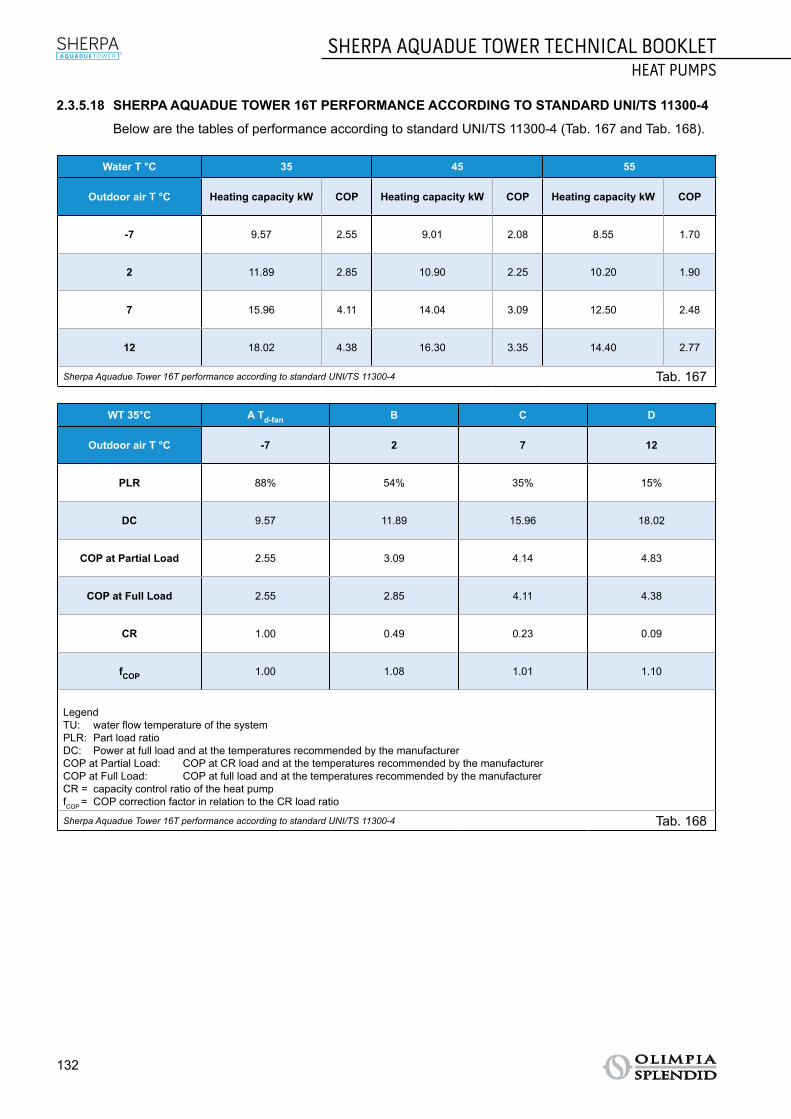
132
SHERPA AQUADUE TOWER TECHNICAL BOOKLETHEAT PUMPS
2.3.5.18 SHERPA AQUADUE TOWER 16T PERFORMANCE ACCORDING TO STANDARD UNI/TS 11300-4
Below are the tables of performance according to standard UNI/TS 11300-4 (Tab. 167 and Tab. 168).
Water T °C 35 45 55
Outdoor air T °C Heating capacity kW COP Heating capacity kW COP Heating capacity kW COP
-7 9.57 2.55 9.01 2.08 8.55 1.70
2 11.89 2.85 10.90 2.25 10.20 1.90
7 15.96 4.11 14.04 3.09 12.50 2.48
12 18.02 4.38 16.30 3.35 14.40 2.77
Sherpa Aquadue Tower 16T performance according to standard UNI/TS 11300-4 Tab. 167
WT 35°C A Td-fan B C D
Outdoor air T °C -7 2 7 12
PLR 88% 54% 35% 15%
DC 9.57 11.89 15.96 18.02
COP at Partial Load 2.55 3.09 4.14 4.83
COP at Full Load 2.55 2.85 4.11 4.38
CR 1.00 0.49 0.23 0.09
fCOP 1.00 1.08 1.01 1.10
LegendTU: water flow temperature of the systemPLR: Part load ratioDC: Power at full load and at the temperatures recommended by the manufacturerCOP at Partial Load: COP at CR load and at the temperatures recommended by the manufacturerCOP at Full Load: COP at full load and at the temperatures recommended by the manufacturerCR = capacity control ratio of the heat pumpfCOP = COP correction factor in relation to the CR load ratio
Sherpa Aquadue Tower 16T performance according to standard UNI/TS 11300-4 Tab. 168

SHERPA AQUADUE TOWER TECHNICAL BOOKLETHEAT PUMPS
133
TABL
E OF
CON
TEN
TSSE
LECT
ION
OF
HEA
T PU
MPS
TRAD
ITIO
NAL
SPL
IT T
ECH
NOL
OGY
STB
MUL
TI-P
URPO
SE S
PLIT
TEC
HNOL
OGY
STB
MON
OBLO
C TE
CHN
OLOG
Y ST
BRA
NGE
ACC
ESSO
RIES
SPEC
IFIC
ATIO
NS
2.3.6 OPERATING LIMITS Below are diagrams of the limits of water temperature (LWT) and outdoor air temperature (OAT) within
which the heat pump can run in cooling (Fig. 40) and heating/production of domestic water (Fig. 41) modes.
10
20
30
40
50
60
70LW
T °C
10
20
30
40
50
60
70
80
30 20 10 0 10 20 30 40 50
LWT °
ODT °C
ACS/DHW
- - -ODT °C
LWT
°C
0
2
4
6
8
10
12
14
16
18
20
-10 0 10 20 30 40 50
Operating limits in cooling mode Fig. 40
10
20
30
40
50
60
70
LWT
°C
10
20
30
40
50
60
70
80
30 20 10 0 10 20 30 40 50
LWT °
ODT °C
ACS/DHW
- - -ODT °C
LWT
°C
0
2
4
6
8
10
12
14
16
18
20
-10 0 10 20 30 40 50
Operating limits in heating mode Fig. 41
The supporting electrical heater elements can be enabled during the functions of heating or production of domestic hot water even outside the operating range of the heat pump.
If the unit is installed in a particularly windy area, wind barriers must be put in place to avoid malfunc-tioning of the unit.

134
SHERPA AQUADUE TOWER TECHNICAL BOOKLETHEAT PUMPS
2.3.7 USEFUL HEADS OF THE SYSTEM Sherpa Aquadue Tower is equipped with two high efficiency circulation pumps.
The technical water circulation pump permits the following two types of control: ○ With constant pressure differential (mode A). ○ With variable pressure differential (mode B).
The technical water circulation pump of the DHW circuit permits two types of control: ○ With constant pressure differential (mode A). ○ Three constant speeds (mode C)
IT is equipped with two high efficiency circulation pumps: the pumps with permanent magnet wet rotor have an electronic control module with integrated frequency converter. There is a control knob on the module.
An LED on the DHW pump indicates the operating status of the pump. All the functions can be set, activated and deactivated at the control knob.
SETTINGS USING THE CONTROL KNOB
2
Mode A: Variable pressure difference (Δp-v) (available for the pump of the air-conditioning circuit and the DHW pump).
The differential-pressure set-point is increased linearly over the permitted volume flow range between ½ H and H (Δp-v graph).
The differential pressure generated by the pump is adjusted to the corresponding differential-pressure set-point.This control mode is especially useful in heating systems with fan coils and radiators, since the flow noise at the thermostatic valves is reduced.
2
Mode B: Constant pressure difference (Δp-c) (available for the pump of the air-conditioning circuit). The differential pressure set-point H is constantly maintained, within the permitted delivery range, at the
programmed set-point up to the maximum characteristic curve (Δp-c graph). This regulation method is recommended for floor mounted heating systems or older heating systems with large pipelines, but also for all other applications that do not have variable characteristic curves, such as for example DHW boiler pumps.
Mode C: Constant speed I, II and III (available for DHW pump). The circulation pump works like a conventional three-speed pump but uses less energy.
Waterflow[l/s] in nominal conditions
SHERPA 7 SHERPA 11 SHERPA 13 SHERPA 13 T SHERPA 16 SHERPA
16 T
Heating modet.water 30/35°C t.air 7°C d.b./6°C w.b. 0.31 0.50 0.60 0.60 0.67 0.76
Heating modet.water 40/45°C t.air 7°C d.b./6°C w.b. 0.31 0.47 0.60 0.60 0.64 0.67
Heating modet.water 23/18°C t.air 35°C 0.38 0.56 0.59 0.60 0.65 0.72
Heating modet.water 12/7°C t.air 35°C 0.27 0.39 0.50 0.50 0.54 0.61
Sherpa water flow Tab. 169

SHERPA AQUADUE TOWER TECHNICAL BOOKLETHEAT PUMPS
135
TABL
E OF
CON
TEN
TSSE
LECT
ION
OF
HEA
T PU
MPS
TRAD
ITIO
NAL
SPL
IT T
ECH
NOL
OGY
STB
MUL
TI-P
URPO
SE S
PLIT
TEC
HNOL
OGY
STB
MON
OBLO
C TE
CHN
OLOG
Y ST
BRA
NGE
ACC
ESSO
RIES
SPEC
IFIC
ATIO
NS
Below are diagrams (Fig. 42) of the available heads, for each speed of the hydraulic circulator, at the hydraulic connections of the internal unit.
A
8
7
6
5
4
3
2
1
80
p/kPa
Q/m3/h
H/m
70
60
50
40
30
20
10
010 2 3 4 6 75
0
∆p-c (constant)
∆p-c
max.
Wilo-Stratos-Para25/1-8,30/1-81-230V-Rp1, Rp1¼
8
7
6
5
4
3
2
1
80
p/kPa
Q/m3/h
H/m
70
60
50
40
30
20
10
010 2 3 4 6 75
0
∆p-v (variable)∆p-c
max.
Wilo-Stratos-Para25/1-8,30/1-81-230V-Rp1, Rp1¼
Q/IgpmP1/W
0 0,4 0,8 1,2 1,6 2,0
0 4 8 12 16 24 2820
Q/m3/h10 2 3 4 6 75
150
100
50
0
Q/l/s
max.
8m 7m 6m 5m 4m 3m 2m
Q/IgpmP1/W
4.00 8.06.02.0
0 2 4 6 108
Q/m3m/h0 0.5 1.0 1.5 2.0 2.5 3.0
40
20
0
Q/l/s
max.
6
5
4
3
2
1
p/kPa
Q/m3m/h
H/m
50
60
40
30
20
10
00
00.5 1.0 1.5 2.0 2.5 3.0
∆p-c
max.
Wilo-Yonos PARA RS15/6, 25/6, 30/61~230V - Rp½, Rp1, Rp1¼
Q/IgpmP1/W
4.00 8.06.02.0
0 2 4 6 108
Q/m3m/h0 0.5 1.0 1.5 2.0 2.5 3.0
40
20
0
Q/l/s
max.
BA
C
B
8
7
6
5
4
3
2
1
80
p/kPa
Q/m3/h
H/m
70
60
50
40
30
20
10
010 2 3 4 6 75
0
∆p-c (constant)
∆p-c
max.
Wilo-Stratos-Para25/1-8,30/1-81-230V-Rp1, Rp1¼
8
7
6
5
4
3
2
1
80
p/kPa
Q/m3/h
H/m
70
60
50
40
30
20
10
010 2 3 4 6 75
0
∆p-v (variable)
∆p-c
max.
Wilo-Stratos-Para25/1-8,30/1-81-230V-Rp1, Rp1¼
Q/IgpmP1/W
0 0,4 0,8 1,2 1,6 2,0
0 4 8 12 16 24 2820
Q/m3/h10 2 3 4 6 75
150
100
50
0
Q/l/s
max.
8m 7m 6m 5m 4m 3m 2m
Q/IgpmP1/W
4.00 8.06.02.0
0 2 4 6 108
Q/m3m/h0 0.5 1.0 1.5 2.0 2.5 3.0
40
20
0
Q/l/s
max.
6
5
4
3
2
1
p/kPa
Q/m3m/h
H/m
50
60
40
30
20
10
00
00.5 1.0 1.5 2.0 2.5 3.0
∆p-c
max.
Wilo-Yonos PARA RS15/6, 25/6, 30/61~230V - Rp½, Rp1, Rp1¼
Q/IgpmP1/W
4.00 8.06.02.0
0 2 4 6 108
Q/m3m/h0 0.5 1.0 1.5 2.0 2.5 3.0
40
20
0
Q/l/s
max.
BA
C C
8
7
6
5
4
3
2
1
80
p/kPa
Q/m3/h
H/m
70
60
50
40
30
20
10
010 2 3 4 6 75
0
∆p-c (constant)
∆p-c
max.
Wilo-Stratos-Para25/1-8,30/1-81-230V-Rp1, Rp1¼
8
7
6
5
4
3
2
1
80
p/kPa
Q/m3/h
H/m
70
60
50
40
30
20
10
010 2 3 4 6 75
0
∆p-v (variable)
∆p-c
max.
Wilo-Stratos-Para25/1-8,30/1-81-230V-Rp1, Rp1¼
Q/IgpmP1/W
0 0,4 0,8 1,2 1,6 2,0
0 4 8 12 16 24 2820
Q/m3/h10 2 3 4 6 75
150
100
50
0
Q/l/s
max.
8m 7m 6m 5m 4m 3m 2m
Q/IgpmP1/W
4.00 8.06.02.0
0 2 4 6 108
Q/m3m/h0 0.5 1.0 1.5 2.0 2.5 3.0
40
20
0
Q/l/s
max.
6
5
4
3
2
1
p/kPa
Q/m3m/h
H/m
50
60
40
30
20
10
00
00.5 1.0 1.5 2.0 2.5 3.0
∆p-c
max.
Wilo-Yonos PARA RS15/6, 25/6, 30/61~230V - Rp½, Rp1, Rp1¼
Q/IgpmP1/W
4.00 8.06.02.0
0 2 4 6 108
Q/m3m/h0 0.5 1.0 1.5 2.0 2.5 3.0
40
20
0
Q/l/s
max.
BA
C
Hydraulic connection - head Fig. 42
If greater heads are required due to high pressure losses in the system, an inertial vessel or a hydraulic separator and an external idle pump must be added. The system must have a minimum water content required to ensure good system operation. If it is insufficient, add a storage vessel in order to reach the required content.The water distribution pipes must be suitably insulated with expanded polyethylene or similar materials. The on/off valves, bends and unions must also be suitably insulated. To prevent air locks inside the circuit, insert automatic or manual breather devices at all the points (high pipes, traps etc.) where air may accumulate.

136
SHERPA AQUADUE TOWER TECHNICAL BOOKLETHEAT PUMPS
2.3.8 COMPONENTS2.3.8.1 COMPONENTS OF THE INTERNAL UNIT
The internal unit comprises the following main components (see Fig. 43):
STRUCTUREA. Cover: in galvanised sheet steel and painted with oven-dried epoxy powders. All the componentscan be accessed from the front for ease of installation and maintenance.B. Supporting structure: in high-tensile galvanised sheet steel.C. Adjustable feet.
HYDRAULIC CIRCUITD. Flow switches.E. Air-conditioning circuit expansion vessel.F. Air-conditioning circuit circulation pump.G. DHWcircuitfillingunit.H. DHW circuit circulation pump.I. DHW water heat exchangers: brazed-plate in AISI 316 sheet steel.J. DHW circuit expansion vessel.K. DHWcircuitevaporatorwaterflowregulator.L. Domestic Hot Water (DHW) tank.M. DHW thermostatic mixer.N. DHW tank drain tap.O. Air-conditioning circuit heat exchanger: brazed-plate in AISI 316 sheet steel.P. Post-heating electrical heater elements collector: two-stage that can be activated with integrationof the heat pump or available in the event of the external unit breaking.Q. Automatic air relief valves.R. Three-way valve: integrated on board the machine.
CONTROL AND SAFETYS. Air-conditioning circuit pressure gauge.T. Safety valve: air-conditioning circuit 3 bar, DHW technical water circuit 6 bar.U. Safety valve: air-conditioning circuit 3 bar.V. Electrical heater elements safety thermostats.W. Tester anode.
ELECTRIC PANELX. Electric panel assembly: easy to access and with a circuit breaker for the heater elements and afuse for the other loads.Y. Master switch.Z. Touch screen display.
COMPONENTS SUPPLIED○ External air sensor kit.

SHERPA AQUADUE TOWER TECHNICAL BOOKLETHEAT PUMPS
137
TABL
E OF
CON
TEN
TSSE
LECT
ION
OF
HEA
T PU
MPS
TRAD
ITIO
NAL
SPL
IT T
ECH
NOL
OGY
STB
MUL
TI-P
URPO
SE S
PLIT
TEC
HNOL
OGY
STB
MON
OBLO
C TE
CHN
OLOG
Y ST
BRA
NGE
ACC
ESSO
RIES
SPEC
IFIC
ATIO
NS
Z
M K
R
F
V
J
V
Q
O
D
W
L
U
T
P
E
Y
X
Q HGS
I
N
A
B
C C
Components of the internal unit Fig. 43

138
SHERPA AQUADUE TOWER TECHNICAL BOOKLETHEAT PUMPS
2.3.8.2 COMPONENTS OF THE EXTERNAL UNIT
The external unit comprises the following main components (see Fig. 44): ○ Supporting structure: in galvanised sheet steel and painted with oven-dried epoxy powders. ○ Compressor: with permanent magnet motor (DC Brushless) with inverter for electronic speed control. ○ Electronic expansion valve: for ongoing and precise control of the parameters of the refrigerant
circuit. ○ Large axial fans: combined with the compressor for more silent operation. ○ Optimised defrosting cycle: for application of the air-water heat pump. ○ 4-way cycle inversion valve. ○ Heat exchange coil: copper pipes ribbed on the inside and aluminium fins. ○ Electric panel: with control boards and inverter for powering the compressor. ○ Temperature sensors and high pressure switch: for optimal and safe operation at all times.
Components of the external unit Fig. 44

SHERPA AQUADUE TOWER TECHNICAL BOOKLETHEAT PUMPS
139
TABL
E OF
CON
TEN
TSSE
LECT
ION
OF
HEA
T PU
MPS
TRAD
ITIO
NAL
SPL
IT T
ECH
NOL
OGY
STB
MUL
TI-P
URPO
SE S
PLIT
TEC
HNOL
OGY
STB
MON
OBLO
C TE
CHN
OLOG
Y ST
BRA
NGE
ACC
ESSO
RIES
SPEC
IFIC
ATIO
NS
2.3.9 DIMENSIONS AND POSITIONING2.3.9.1 DIMENSIONS OF THE INTERNAL UNIT
Below is the layout of the internal unit of the heat pump (Fig. 45) and a table summarising the dimensions and weight values (Tab. 170).
A
B C
Layout of the internal unit Fig. 45
Ref. Fig. 45
SHERPAAQUADUE
TOWER7
SHERPAAQUADUE
TOWER11
SHERPAAQUADUE
TOWER13
SHERPAAQUADUE
TOWER 13T
SHERPAAQUADUE
TOWER16
SHERPAAQUADUE
TOWER 16T
Internal unit SMALL 599513A BIG 599512A
A mm 1980 1980 1980 1980 1980 1980
B mm 600 600 600 600 600 600
C mm 600 600 600 600 600 600
Weight kg 171 171 173 173 173 173
Weight in use kg 183 183 185 185 185 185Dimensions and weight values of the internal unit Tab. 170

140
SHERPA AQUADUE TOWER TECHNICAL BOOKLETHEAT PUMPS
2.3.9.2 POSITIONING OF THE INTERNAL UNIT
Install the internal unit by placing it on the floor in an indoor environment and levelling it at the adjustable feet (ref. A Fig. 46).
A A
Positioning of the internal unit Fig. 46
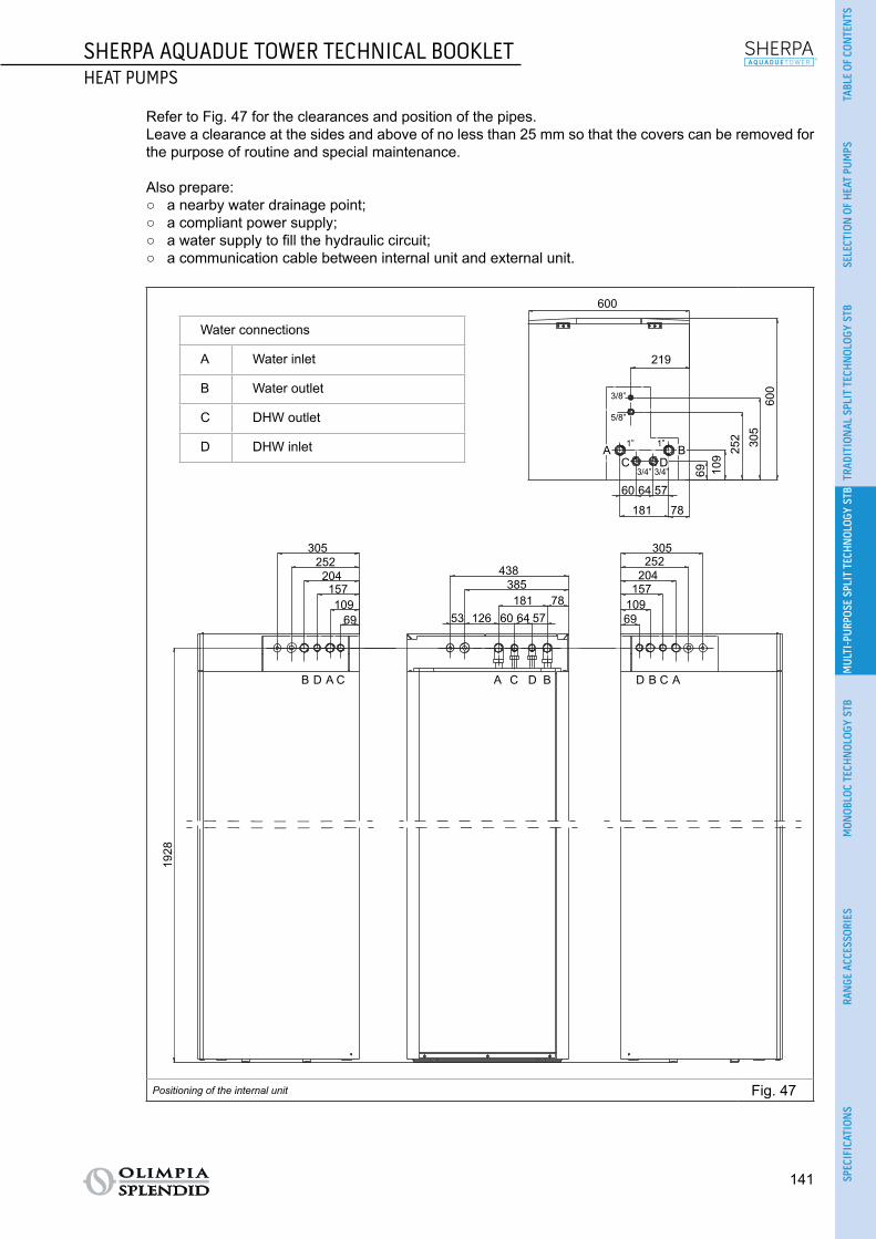
SHERPA AQUADUE TOWER TECHNICAL BOOKLETHEAT PUMPS
141
TABL
E OF
CON
TEN
TSSE
LECT
ION
OF
HEA
T PU
MPS
TRAD
ITIO
NAL
SPL
IT T
ECH
NOL
OGY
STB
MUL
TI-P
URPO
SE S
PLIT
TEC
HNOL
OGY
STB
MON
OBLO
C TE
CHN
OLOG
Y ST
BRA
NGE
ACC
ESSO
RIES
SPEC
IFIC
ATIO
NS
Refer to Fig. 47 for the clearances and position of the pipes. Leave a clearance at the sides and above of no less than 25 mm so that the covers can be removed for
the purpose of routine and special maintenance. Also prepare:
○ a nearby water drainage point; ○ a compliant power supply; ○ a water supply to fill the hydraulic circuit; ○ a communication cable between internal unit and external unit.
Water connections
A Water inlet
B Water outlet
C DHW outlet
D DHW inlet
600
219
181
60 64 573/4”
1”
3/8”
5/8”
1”
3/4”
78
600
305
252
109
69
305 305
438385181 78
53 126 60 64 57
1928
252 252204 204157 157109 109
69 69
B D A C A C D B D B C A
AC D
BB
Positioning of the internal unit Fig. 47

142
SHERPA AQUADUE TOWER TECHNICAL BOOKLETHEAT PUMPS
2.3.9.3 DIMENSIONS OF THE EXTERNAL UNITS
Below is the layout of the external unit (Fig. 48) and a table summarising the dimensions and weight values (Tab. 171).
H
G
F
A
B
DCE
A G
H
B
H
DCE
Layout of the external unit Fig. 48
Ref. Fig. 48
SHERPAAQUADUE
TOWER7
SHERPAAQUADUE
TOWER11
SHERPAAQUADUE
TOWER13
SHERPAAQUADUE
TOWER 13T
SHERPAAQUADUE
TOWER16
SHERPAAQUADUE
TOWER 16T
External unit OSCEBSH24EI
OSCEBCH36EI
OSCEINH48EI
OSCETNH48EI
OSCEINH60EI
OSCETNH60EI
SINGLE-FAN DUAL-FAN
A mm 847 990 938 938 938 938
B mm 563 622 633 633 633 633
C mm 340 368 404 404 404 404
D mm 360 398 448 448 448 448
E mm 315 340 370 370 370 370
F mm 330 350 392 392 392 392
G mm 917 1060 1008 1008 1008 1008
H mm 700 950 1369 1369 1369 1369
Weight kg 58 82 99 102 99 107Dimensions and weight values of the external unit Tab. 171

SHERPA AQUADUE TOWER TECHNICAL BOOKLETHEAT PUMPS
143
TABL
E OF
CON
TEN
TSSE
LECT
ION
OF
HEA
T PU
MPS
TRAD
ITIO
NAL
SPL
IT T
ECH
NOL
OGY
STB
MUL
TI-P
URPO
SE S
PLIT
TEC
HNOL
OGY
STB
MON
OBLO
C TE
CHN
OLOG
Y ST
BRA
NGE
ACC
ESSO
RIES
SPEC
IFIC
ATIO
NS
Below is the layout of the S1 external unit (Fig. 49) and a table summarising the dimensions and weight values (Tab. 172).
E D
C
AC
D
H
B
E
F
F
H
BA
Layout of the S1 external unit Fig. 49
Ref. Fig. 49
SHERPAAQUADUE
TOWER7
SHERPAAQUADUE
TOWER11
SHERPAAQUADUE
TOWER13
SHERPAAQUADUE
TOWER 13T
SHERPAAQUADUE
TOWER16
SHERPAAQUADUE
TOWER 16T
S1 external unit OSCESHH24EI
OSCESHH36EI
OSCESHH48EI
OSCESTH48EI
OSCESHH60EI
OSCESTH60EI
SINGLE-FAN DUAL-FAN
A mm 845 946 952 952 952 952
B mm 914 1030 1045 1045 1045 1045
C mm 540 673 634 634 634 634
D mm 363 410 415 415 415 415
E mm 350 403 404 404 404 404
F mm 915 1036 1032 1032 1032 1032
H mm 702 810 1333 1333 1333 1333
Weight kg 49 67 95 108 95 113Dimensions and weight values of the S1 external unit Tab. 172

144
SHERPA AQUADUE TOWER TECHNICAL BOOKLETHEAT PUMPS
2.3.9.4 POSITIONING OF THE EXTERNAL UNITS
Install the external unit (Fig. 50) on a solid base that is able to support its weight; if installed incompletely or onto an inappropriate base, the unit could cause damage to persons or property, if it should detach from the base.
It is very important that the installation place be chosen with extreme care in order to ensure adequate protection of the device against impact or possible consequential damage. Choose a place that is ade-quately ventilated and in which the outdoor temperature in summer does not exceed 46°C.
Leave sufficient free space around the appliance in order to avoid recirculation and to facilitate mainte-nance.
Prepare a layer of gravel underneath the appliance for drainage of the defrost water.Leave space underneath the unit to prevent the defrost water from freezing. In normal situations, ensure the base is at least 5 cm off the ground; for use in regions with very cold winters, ensure a space of at least 15 cm on both sides of the unit. When installed in a location with high snow fall, mount the support of the appliance at a height that is above the maximum level of snow.Install the unit so that wind is not blowing across it.
Also prepare: ○ anti-vibration dampers; ○ compliant power supply near the external unit.
600
960
350
> 60 cm
> 60 cm
> 30 cm
> 30 cm
> 30 cm
> 15 cm
Positioning of the external units Fig. 50
The external unit is supplied with a mesh for covering the heat exchange battery; this is envisaged for installations accessible to the public. Fitting the mesh may cause, in the event of high humidity at low temperature (fog) or snow, a build-up of ice on the battery with reduced system performance.

SHERPA AQUADUE TOWER TECHNICAL BOOKLETHEAT PUMPS
145
TABL
E OF
CON
TEN
TSSE
LECT
ION
OF
HEA
T PU
MPS
TRAD
ITIO
NAL
SPL
IT T
ECH
NOL
OGY
STB
MUL
TI-P
URPO
SE S
PLIT
TEC
HNOL
OGY
STB
MON
OBLO
C TE
CHN
OLOG
Y ST
BRA
NGE
ACC
ESSO
RIES
SPEC
IFIC
ATIO
NS
2.3.10 INSTALLATION To ensure successful installation and optimal performance, follow the instructions in the installation, use
and maintenance manual supplied with each unit and accessory. This technical booklet provides general information on installation, dimensional drawings and wiring diagrams.
The installation must be carried out by the dealer or by other qualified personnel; if the installation is not carried out correctly, there may be a risk of water leakage, electric shock or fire.
During assembly and any maintenance operation, observe the precautions in the installation, use and maintenance manuals and on the labels inside the appliances, and take any precautions dictated by common sense and set down by the safety rules at the place of installation.
Always wear protective gloves and goggles when performing maintenance on the parts of the appliances
containing refrigerant. Air-water heat pumps MUST NEVER be installed in rooms where there is inflam-mable gas, explosive gas, a high level of humidity (laundry rooms, greenhouses etc.), or in rooms where there are other machines generating a lot of heat.
It is recommended to use only the components designed specially for the installation provided; the use of different components could cause the leakage of water, electric shock or fire.
Once the installation has been completed, check that there is no leakage of refrigerant (the liquid can produce toxic gas when exposed to flames).
When installing or relocating the system, make sure that there is no substance in the refrigerant circuit other than the refrigerant specified in the technical data (see para. 2.3.4) as the presence of air or other foreign substances in the refrigerant circuit can cause an abnormal increase in pressure or breakage of the system, resulting in damage to property or physical injury.

146
SHERPA AQUADUE TOWER TECHNICAL BOOKLETHEAT PUMPS
2.3.10.1 HYDRAULIC CONNECTION
In Fig. 51 are the positions of the hydraulic connections:A. Air-conditioning circuit water flow (1").B. Drinking water inlet (3/4").C. Domestic hot water outlet (3/4").D. Air-conditioning circuit water return (1").E. Refrigerant pipe connection (5/8").F. Refrigerant pipe connection (3/8").
A B E FC D
Hydraulic connection - head Fig. 51
The hydraulic connections are to be completed by installing: ○ air relief valves at the highest points of the pipes; ○ flexible elastic joints; ○ on/off valves; ○ sieve water filter with 0.4 mm mesh.
The minimum nominal diameter of the hydraulic connection pipes must be 1". In order to allow for maintenance or repair, it is essential that each hydraulic connection is equipped with
the respective manual valves.
The tables below (Tab. 173, Tab. 174, Tab. 175 and Tab. 176) show the essential characteristics of the hydraulic system.
Water content of the pipes Internal diameter External diameter Litres/metre
Copper
12 mm 14 mm 0,11 l/m
14 mm 16 mm 0,15 l/m
16 mm 18 mm 0,20 l/m
20 mm 22 mm 0,31 l/m
25 mm 28 mm 0,49 l/m
32 mm 35 mm 0,80 l/m
Steel
12,7 mm (1/2”) 3/8” Gas 0,13 l/m
16,3 mm (5/8”) 1/2” Gas 0,21 l/m
21,7 mm (7/8”) 3/4” Gas 0,37 l/m
27,4 mm (11/16”) 1” Gas 0,59 l/mHydraulic connection Tab. 173

SHERPA AQUADUE TOWER TECHNICAL BOOKLETHEAT PUMPS
147
TABL
E OF
CON
TEN
TSSE
LECT
ION
OF
HEA
T PU
MPS
TRAD
ITIO
NAL
SPL
IT T
ECH
NOL
OGY
STB
MUL
TI-P
URPO
SE S
PLIT
TEC
HNOL
OGY
STB
MON
OBLO
C TE
CHN
OLOG
Y ST
BRA
NGE
ACC
ESSO
RIES
SPEC
IFIC
ATIO
NS
% Inhibited monoethylene glycol 10% 20% 30% 40%Freezing point (a) -4°C -9°C -15°C -23°C
Correction factors
Capacity 0.996 0.991 0.983 0.975Absorbed power 0.990 0.978 0.964 1.008Load loss 1.003 1.010 1.020 1.033
Notes(a) The temperature values are indicative; always refer to the temperatures stated for the specific product used
Hydraulic connection Tab. 174
Table for calculating the water content of the system
Installed unit..............................................................................
Content of unit (a) l ..............................................................................
Content of pipes (b) l ..............................................................................
Utilities (fan coils, panels, radiators, etc.) (c) l ..............................................................................
Total content (d) l ..............................................................................Notes(a) Consult the technical data table(b) Consult the pipe water content table(c) Consult the manual of the installed utilities(d) The water content of the system must be between the minimum value and the maximum value stated in Tab. 176. The mini-
mum content of the hydraulic circuit must be considered as the volume of water always circulating in the system (i.e. the parts of the system excluded by valves must not be considered). Water must always be allowed to circulate in the heat pump of the circuit of the system. It is possible to increase the maximum content of the system by adding an expansion vessel suited to the water content of the system.
Hydraulic connection Tab. 175
SHERPAAQUADUE
TOWER7
SHERPAAQUADUE
TOWER11
SHERPAAQUADUE
TOWER13
SHERPAAQUADUE
TOWER 13T
SHERPAAQUADUE
TOWER16
SHERPAAQUADUE
TOWER 16T
Nominal water flow Std l/s 0.31 0.50 0.60 0.60 0.67 0.74
Water content of system
Min l 23 38 45 45 51 58Max (a) l 138 138 138 138 138 138Max (b) l 400 400 400 400 400 400
Operating pressure Max kPa 300 300 300 300 300 300
Filling pressure Min kPa 150 150 150 150 150 150
System height difference Max m 20 20 20 20 20 20
Notes(a) Temperature of water in system 55°C, water content of the system using only the expansion vessel supplied as standard in
the unit(b) Temperature of water in system 35°C, water content of the system using only the expansion vessel supplied as standard in
the unit
Hydraulic connection Tab. 176

148
SHERPA AQUADUE TOWER TECHNICAL BOOKLETHEAT PUMPS
2.3.10.2 REFRIGERANT CONNECTION
Use only pipes of a diameter meeting the required dimensions (see para. 2.1.4). The following table (Tab. 177) provides the data needed to define the refrigerant connection between the
internal and external units.
Internal unitSHERPA
AQUADUE TOWER
7
SHERPAAQUADUE
TOWER11
SHERPAAQUADUE
TOWER13
SHERPAAQUADUE
TOWER 13T
SHERPAAQUADUE
TOWER16
SHERPAAQUADUE
TOWER 16T
Internal unit SMALL 599513A BIG 599512A
External unit OSCEBSH24EI
OSCEBCH36EI
OSCEINH48EI
OSCETNH48EI
OSCEINH60EI
OSCETNH60EI
S1 external unit OSCESHH24EI
OSCESHH36EI
OSCESHH48EI
OSCESTH48EI
OSCESHH60EI
OSCESTH60EI
Maximum length of the connecting pipes m 25 30 50 50 50 50
Limit of elevation difference between the two units if the external unit is positioned higher
m 12 20 25 30 25 30
Limit of elevation difference between the two units if the external unit is positioned lower
m 9 12 20 20 20 20
Additional charge of re-frigerant per metre over 5 metres piping
g/m 60 60 60 60 60 60
Refrigerant connection Tab. 177
To set up the refrigerant connection: ○ Connect the internal unit observing the maximum length of the pipes in the table (see Tab. 177). ○ Do not exceed the maximum permissible difference in height when installing the internal and external
units (see Tab. 177). ○ Complete the refrigerant circuit by connecting the internal unit to the external unit (for the connection
points see Fig. 52) and check that the refrigerant circuit is perfectly sealed following the instructions in the installation, use and maintenance manual.

SHERPA AQUADUE TOWER TECHNICAL BOOKLETHEAT PUMPS
149
TABL
E OF
CON
TEN
TSSE
LECT
ION
OF
HEA
T PU
MPS
TRAD
ITIO
NAL
SPL
IT T
ECH
NOL
OGY
STB
MUL
TI-P
URPO
SE S
PLIT
TEC
HNOL
OGY
STB
MON
OBLO
C TE
CHN
OLOG
Y ST
BRA
NGE
ACC
ESSO
RIES
SPEC
IFIC
ATIO
NS
Refrigerant connection between the units Fig. 52

150
SHERPA AQUADUE TOWER TECHNICAL BOOKLETHEAT PUMPS
2.3.10.3 WIRING
The electrical connections must be made in compliance with the instructions given in the installation manual and with national standards or procedures governing electrical connections; insufficient capacity or incomplete electrical connections may lead to electric shock or fire.
The power circuits of the internal and external units must be separate; the external unit line must be protected with a thermomagnetic circuit breaker or suitably sized fuses.
The system must be wired in accordance with the regulations in force and properly earthed.
To prevent any risk of electric shock, the master switches must be disconnected before making electrical connections and carrying out maintenance on the appliances.
Before performing any operation, make sure that the electrical power of the internal and external units is switched off.
The supply voltage must be that indicated in the technical data (see para. 2.1.4).
2.3.10.4 WIRING DIAGRAMS
The following are diagrams for connecting the electrical cables (Fig. 53, Fig. 54 and Fig. 55).
*For S1 external units, the terminals of the communication cable are marked S1 and S2 instead of P and Q
*
Wiring diagram Fig. 53
T4 outdoor air temperature sensor N/13 contactor activation for electrical heater element power supply in domestic water tank during anti-le-
gionella cycles (220-240V 50Hz 100W max) 14/15 activation of external heat source e.g.: gas boiler (contact 8A (3A) 250Vac) 16/17 alarm contact (contact 8A (3A) 250Vac) 5/L domestic hot water request (when the domestic hot water tank temperature is set by a dedicated
external control; a closed contact between these terminals activates the domestic hot water request).

SHERPA AQUADUE TOWER TECHNICAL BOOKLETHEAT PUMPS
151
TABL
E OF
CON
TEN
TSSE
LECT
ION
OF
HEA
T PU
MPS
TRAD
ITIO
NAL
SPL
IT T
ECH
NOL
OGY
STB
MUL
TI-P
URPO
SE S
PLIT
TEC
HNOL
OGY
STB
MON
OBLO
C TE
CHN
OLOG
Y ST
BRA
NGE
ACC
ESSO
RIES
SPEC
IFIC
ATIO
NS
*For S1 external units, the terminals of the communication cable are marked S1 and S2 instead of P and Q
*
Wiring diagram Fig. 54
T4 outdoor air temperature sensor N/13 contactor activation for electrical heater element power supply in domestic water tank during an-
ti-legionella cycles (220-240V 50Hz 100W max) 14/15 activation of external heat source e.g.: gas boiler (contact 8A (3A) 250Vac) 16/17 alarm contact (contact 8A (3A) 250Vac) 5/L domestic hot water request (when the domestic hot water tank temperature is set by a dedicated
external control; a closed contact between these terminals activates the domestic hot water request).

152
SHERPA AQUADUE TOWER TECHNICAL BOOKLETHEAT PUMPS
Wiring diagram Fig. 55
Terminal 1: cooling on/off remote free contactTerminal 2: heating on/off remote free contactTerminal 3: Eco mode remote free contactTerminal 4: night-time mode remote free contactTerminal 5: domestic water activation remote free contactTerminal 6: TA remote free contact for enabling cooling or heating modeTerminal 7: remote free contacts common connectionTerminal 21-22: connection of RS485 serial interface to the Acquadue Control supervision unitTerminals 1 to 7 are on the electronic board; the terminals can be removed so that they can be easily connected and then re-inserted in the original position

SHERPA AQUADUE TOWER TECHNICAL BOOKLETHEAT PUMPS
153
TABL
E OF
CON
TEN
TSSE
LECT
ION
OF
HEA
T PU
MPS
TRAD
ITIO
NAL
SPL
IT T
ECH
NOL
OGY
STB
MUL
TI-P
URPO
SE S
PLIT
TEC
HNOL
OGY
STB
MON
OBLO
C TE
CHN
OLOG
Y ST
BRA
NGE
ACC
ESSO
RIES
SPEC
IFIC
ATIO
NS
2.3.10.5 MAXIMUM INPUTS
The power line of the external unit must be capable of being sectioned from the mains using a thermomag-netic circuit breaker suitable for the machine input with differential relay, with maximum calibration equal to that stated in national electrical regulations. The internal unit line is already protected by a thermomagnetic circuit breaker on the electrical heater elements power supply and by a fuse; installation of a differential relay on the power line is recommended.
The following table (Tab. 178) shows the maximum power consumption of the units and protections to be installed on the line of the external unit.
External unit OSCEBSH24EI
OSCEBCH36EI
OSCEINH48EI
OSCETNH48EI
OSCEINH60EI
OSCETNH60EI
S1 external unit OSCESHH24EI
OSCESHH36EI
OSCESHH48EI
OSCESTH48EI
OSCESHH60EI
OSCESTH60EI
Power supply V/ph/Hz
220-240/1/50
220-240/1/50
220-240/1/50
380-415/3+N/50
220-240/1/50
380-415/3+N/50
Maximum absorbed power kW 3.0 4.8 6.0 5.5 6.0 7.5
Maximum absorbed current A 13.5 22 28 8.15 28 11.5
Fuse or circuit break-er
MFA A 25 40 40 25 40 25
Internal unit SMALL 599513A BIG 599512A
Power supply V/ph/Hz 220-240/1/50 220-240/1/50
Maximum absorbed power with electrical heater elements activated
kW 4.05 4.05 7.05 7.05 7.05 7.05
Maximum absorbed current with electrical heater elements activated
A 18 18 31 31 31 31
Maximum inputs Tab. 178
2.3.10.6 CONNECTING CABLES
Use the specified types of cable for the electrical connections between the internal and external units (see Tab. 179).
External unit OSCEBSH24EI
OSCEBCH36EI
OSCEINH48EI
OSCETNH48EI
OSCEINH60EI
OSCETNH60EI
S1 external unit OSCESHH24EI
OSCESHH36EI
OSCESHH48EI
OSCESTH48EI
OSCESHH60EI
OSCESTH60EI
Power cable H07RN-F 3 G2,5
H07RN-F 3 G4
H07RN-F 3 G4
H07RN-F 5 G2,5
H07RN-F 3 G4
H07RN-F 5 G2,5
Internal unit SMALL 599513A BIG 599512A
Power cable 3 X H07V-K 4 mm²
ODU/IDU communication cable 2 x 0.5 mm² shielded
DHW and outdoor air probe cable H03RN-F 2 G 0.5 / H03VV-F 2 G 0.5
Connecting cables Tab. 179

154
SHERPA AQUADUE TOWER TECHNICAL BOOKLETHEAT PUMPS
2.3.10.7 HYDRAULIC CIRCUIT
Sherpa Aquadue Tower heat pump, SLR fan radiator terminals and production of DHW.The hydraulic diagram (Fig. 56) is purely indicative.
TT
TT
T
AQUA
DUE
mod
ule
DOM
ESTI
CHO
T W
ATER
tank
150
L
Y
C/H
11
TY
M
Hydraulic circuit Fig. 56 Legend:
C/H
M
T
Y
T
Mesh filter
C/H
M
T
Y
T
On/off valve
C/H
M
T
Y
T
Motorised three-way valve
C/H
M
T
Y
T
Differential by-pass
C/H
M
T
Y
T
Thermostatic mixer
C/H
M
T
Y
T
Thermometer
C/H
M
T
Y
T
Temperature probe
C/H
M
T
Y
T
Automatic air breather
C/H
M
T
Y
T
Expansion vessel
C/H
M
T
Y
T
Circulator C/H
M
T
Y
T
Summer/winter valve
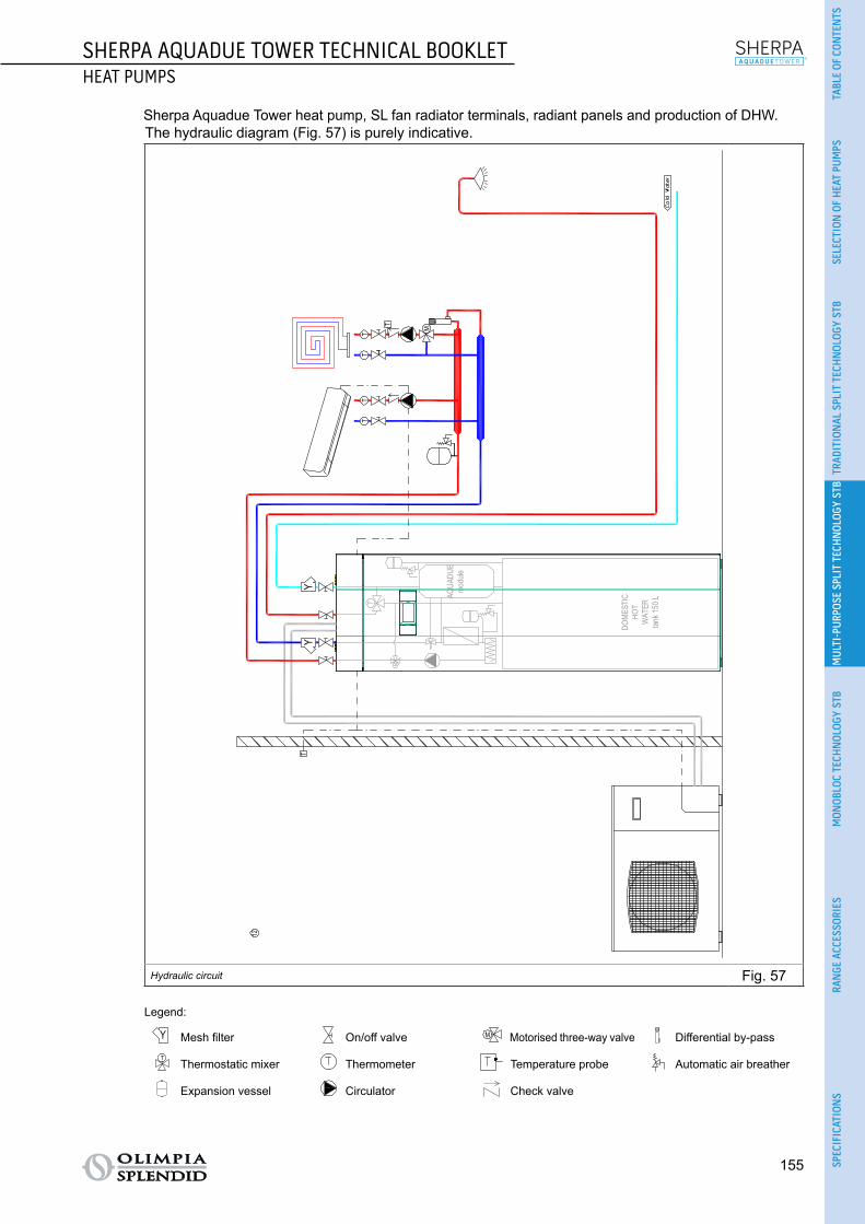
SHERPA AQUADUE TOWER TECHNICAL BOOKLETHEAT PUMPS
155
TABL
E OF
CON
TEN
TSSE
LECT
ION
OF
HEA
T PU
MPS
TRAD
ITIO
NAL
SPL
IT T
ECH
NOL
OGY
STB
MUL
TI-P
URPO
SE S
PLIT
TEC
HNOL
OGY
STB
MON
OBLO
C TE
CHN
OLOG
Y ST
BRA
NGE
ACC
ESSO
RIES
SPEC
IFIC
ATIO
NS
Sherpa Aquadue Tower heat pump, SL fan radiator terminals, radiant panels and production of DHW.The hydraulic diagram (Fig. 57) is purely indicative.
TT
TT
MT
T
AQUA
DUE
modu
le
DOME
STIC
HOT
WAT
ERtan
k 150
L
12
TY
Y
M
Hydraulic circuit Fig. 57
Legend:
C/H
M
T
Y
T
Mesh filter
C/H
M
T
Y
T
On/off valve
C/H
M
T
Y
T
Motorised three-way valve
C/H
M
T
Y
T
Differential by-pass
C/H
M
T
Y
T
Thermostatic mixer
C/H
M
T
Y
T
Thermometer
C/H
M
T
Y
T
Temperature probe
C/H
M
T
Y
T
Automatic air breather
C/H
M
T
Y
T
Expansion vessel
C/H
M
T
Y
T
Circulator
C/H
M
T
Y
T
Check valve

156
SHERPA AQUADUE TOWER TECHNICAL BOOKLETHEAT PUMPS
Sherpa Aquadue Tower heat pump, compensating tank, SLR fan radiator terminals and production of DHW.The hydraulic diagram (Fig. 58) is purely indicative.
TT
TT
T
T
AQUA
DUE
mod
ule
DOM
ESTI
CHO
T W
ATER
tank
150
L
13
YY
M
Hydraulic circuit Fig. 58
Legend:
C/H
M
T
Y
T
Mesh filter
C/H
M
T
Y
T
On/off valve
C/H
M
T
Y
T
Motorised three-way valve
C/H
M
T
Y
T
Check valve
C/H
M
T
Y
T
Thermostatic mixer
C/H
M
T
Y
T
Thermometer
C/H
M
T
Y
T
Temperature probe
C/H
M
T
Y
T
Automatic air breather
C/H
M
T
Y
T
Expansion vessel
C/H
M
T
Y
T
Circulator

SHERPA AQUADUE TOWER TECHNICAL BOOKLETHEAT PUMPS
157
TABL
E OF
CON
TEN
TSSE
LECT
ION
OF
HEA
T PU
MPS
TRAD
ITIO
NAL
SPL
IT T
ECH
NOL
OGY
STB
MUL
TI-P
URPO
SE S
PLIT
TEC
HNOL
OGY
STB
MON
OBLO
C TE
CHN
OLOG
Y ST
BRA
NGE
ACC
ESSO
RIES
SPEC
IFIC
ATIO
NS
2.3.11 CONFORMITY The Sherpa Aquadue Tower heat pumps are compliant with the following European directives:
○ LVD 2014/35/EU ○ EMCD 2014/30/EU (electromagnetic compatibility) ○ ECODESIGN 2009/125/EC 813/2013EU 327/2011EU ○ RoHS 2011/65/EC
The Sherpa Aquadue Tower heat pumps are compliant with the following harmonised European standards: ○ EN14825 ○ EN55014-1 ○ EN55014-2 ○ EN61000-3-2 ○ EN61000-3-3 ○ EN61000-3-11 ○ EN61000-3-12 ○ EN60335-1 ○ EN60335-2-40
2.3.11.1 CE DECLARATION OF CONFORMITY
The CE declaration of conformity is available in the download area on the site www.olimpiasplendid.it (Fig. 59).
Download area Fig. 59
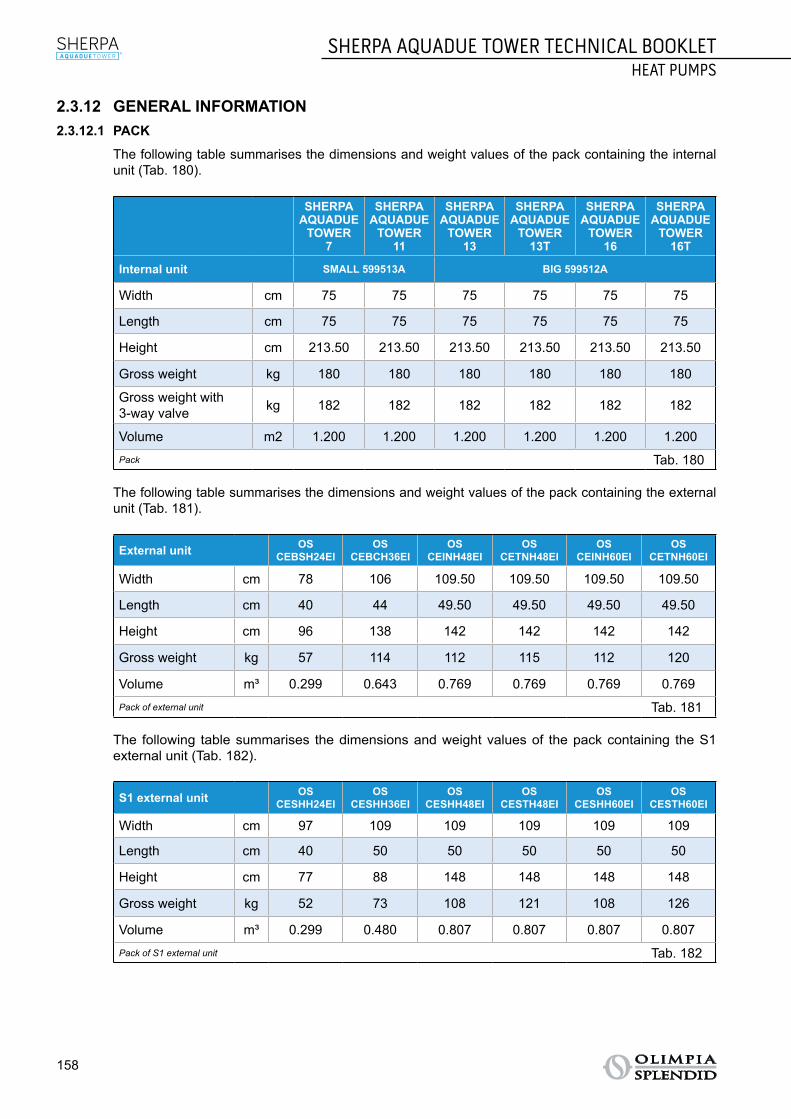
158
SHERPA AQUADUE TOWER TECHNICAL BOOKLETHEAT PUMPS
2.3.12 GENERAL INFORMATION2.3.12.1 PACK
The following table summarises the dimensions and weight values of the pack containing the internal unit (Tab. 180).
SHERPAAQUADUE
TOWER7
SHERPAAQUADUE
TOWER11
SHERPAAQUADUE
TOWER13
SHERPAAQUADUE
TOWER 13T
SHERPAAQUADUE
TOWER16
SHERPAAQUADUE
TOWER 16T
Internal unit SMALL 599513A BIG 599512A
Width cm 75 75 75 75 75 75
Length cm 75 75 75 75 75 75
Height cm 213.50 213.50 213.50 213.50 213.50 213.50
Gross weight kg 180 180 180 180 180 180
Gross weight with 3-way valve kg 182 182 182 182 182 182
Volume m2 1.200 1.200 1.200 1.200 1.200 1.200Pack Tab. 180
The following table summarises the dimensions and weight values of the pack containing the external unit (Tab. 181).
External unit OSCEBSH24EI
OSCEBCH36EI
OSCEINH48EI
OSCETNH48EI
OSCEINH60EI
OSCETNH60EI
Width cm 78 106 109.50 109.50 109.50 109.50
Length cm 40 44 49.50 49.50 49.50 49.50
Height cm 96 138 142 142 142 142
Gross weight kg 57 114 112 115 112 120
Volume m³ 0.299 0.643 0.769 0.769 0.769 0.769Pack of external unit Tab. 181
The following table summarises the dimensions and weight values of the pack containing the S1 external unit (Tab. 182).
S1 external unit OSCESHH24EI
OSCESHH36EI
OSCESHH48EI
OSCESTH48EI
OSCESHH60EI
OSCESTH60EI
Width cm 97 109 109 109 109 109
Length cm 40 50 50 50 50 50
Height cm 77 88 148 148 148 148
Gross weight kg 52 73 108 121 108 126
Volume m³ 0.299 0.480 0.807 0.807 0.807 0.807Pack of S1 external unit Tab. 182

159
SHERPA MONOBLOC TECHNICAL BOOKLETHEAT PUMPS
(2)
TABL
E OF
CON
TEN
TSSE
LECT
ION
OF
HEA
T PU
MPS
TRAD
ITIO
NAL
SPL
IT T
ECH
NOL
OGY
STB
MUL
TI-P
URPO
SE S
PLIT
TEC
HNOL
OGY
STB
MON
OBLO
C TE
CHN
OLOG
Y ST
BRA
NGE
ACC
ESSO
RIES
SPEC
IFIC
ATIO
NS
2.4 SHERPA MONOBLOC - MONOBLOC TECHNOLOGY TECHNICAL BOOKLET
2.4.1 FUNDAMENTAL CHARACTERISTICS ○ Monobloc reversible air-water heat pump unit for outdoor installation. ○ Incorporated hydronic module. ○ Supplies technical water for DHW boiler at a temperature of up to 60°C. ○ Climate curves based on the outdoor air temperature: there are twelve curves for heating and two for
cooling, or customised climate curves can be added. ○ Two set-points can be configured for cooling and two for heating. ○ Frost protection: managed in the software. ○ Daily programmer with night-time mode: night-time mode permits energy savings of up to 20%. ○ Remote control panel for controlling room temperature and humidity. ○ R410A cooling gas.
160
SHERPA MONOBLOC TECHNICAL BOOKLETHEAT PUMPS
(2)
2.4.2 CONTROL AND FUNCTIONS ○ Sherpa Monobloc comes as standard with a wired remote control with large LCD panel that displays
graphical symbols, the settings and temperature values.
○ The control can be used to run Sherpa Monobloc for:• heating, • cooling, • domestic water production.
○ The control has twelve climate curves for heating mode and two for cooling mode. The climate curve makes it possible to vary the water temperature of the system in relation to the outdoor weather con-ditions, adapting the amount of heat to the heating requirements of the building and permitting up to 20% energy savings. It is also possible to create customised climate curves.
○ There are three programming modes that can be selected at the "Touch 'N' Go" buttons under the control LCD panel:• indoor,• outdoor,• night-time.Each of these programming modes has a different reset set-point.
○ Sherpa Monobloc permits the production of hot domestic water with the contact of the thermostat on board the boiler; this function requires installation of the three-way valve kit for domestic hot water (optional).
○ The following functions can be remote controlled with free contacts:• switching on/off,• heating or cooling mode,• activation of the second set-point (Eco mode),• frequency limitation of the compressor,• production of domestic hot water.
○ Sherpa Monobloc can activate an auxiliary external heat source (e.g. heater) to substitute operation of the heat pump unit, in relation to the outdoor air temperature. This function requires installation of the outdoor air temperature probe kit (optional).
○ The following accessories are available:• Code B0622 - Three-way valve kit for domestic hot water,• Code B0623 - Outdoor air temperature probe kit,• Code B0812 - Remote control kit.
The codes are subject to change; please contact Olimpia Splendid for further information.

161
SHERPA MONOBLOC TECHNICAL BOOKLETHEAT PUMPS
(2)
TABL
E OF
CON
TEN
TSSE
LECT
ION
OF
HEA
T PU
MPS
TRAD
ITIO
NAL
SPL
IT T
ECH
NOL
OGY
STB
MUL
TI-P
URPO
SE S
PLIT
TEC
HNOL
OGY
STB
MON
OBLO
C TE
CHN
OLOG
Y ST
BRA
NGE
ACC
ESSO
RIES
SPEC
IFIC
ATIO
NS
2.4.3 TECHNICAL DATA Below are tables summarising the technical data (Tab. 183 and Tab. 184).
SHERPAMONOBLOC
4
SHERPAMONOBLOC
6
SHERPAMONOBLOC
8
SHERPAMONOBLOC
12
SHERPAMONOBLOC
15
SHERPAMONOBLOC
12T
SHERPAMONOBLOC
15T
External unit code 01674 01675 01676 01677 01678 01679 01680
Type of evaporator Brazed-plate
Brazed-plate
Brazed-plate
Brazed-plate
Brazed-plate
Brazed-plate
Brazed-plate
Heating capacity (a) kW 4.07 5.76 7.16 11.86 12.00 12.00 15
COP (a) W/W 4.15 4.28 3.97 3.95 4.09 4.30 4.20
Heating capacity (b) kW 2.80 3.75 4.36 7.83 8.98 7.68 8.49
COP (b) W/W 2.60 2.77 2.81 2.85 2.81 2.82 2.75
Heating capacity (c) kW 3.87 5.76 7.36 12.91 13.96 11.20 14.50
COP (c) W/W 3.26 3.05 3.19 3.03 3.23 3.35 3.30
Heating capacity (d) kW 2.70 3.76 4.45 7.43 8.98 6.23 8.40
COP (d) W/W 2.40 2.31 2.34 2.31 2.34 2.39 2.39
Cooling capacity (e) kW 4.93 7.04 7.84 13.54 16.04 16.00 16.00
EER (e) W/W 4.20 3.70 3.99 3.66 3.85 4.15 3.81
Cooling capacity (f) kW 3.33 4.73 5.84 10.24 13.04 10.20 13.00
EER (f) W/W 3.00 3.00 2.98 2.96 3.00 3.00 2.91
Sound pressure in heating mode (g) dB(A) 42 42 44 47 48 48 48
Sound powerin heating mode (g) dB(A) 62 62 64 67 68 68 68
Sound pressure in cooling mode (h) dB(A) 44 44 45 48 49 49 49
Sound power in cooling mode (h) dB(A) 64 64 65 68 69 69 69
Notes(a) Heating mode, inlet/outlet water temperature 30°C/35°C, outdoor air temperature 7°C d.b. / 6°C w.b.(b) Heating mode, inlet/outlet water temperature 30°C/35°C, outdoor air temperature -4°C d.b. / -2°C w.b.(c) Heating mode, inlet/outlet water temperature 40°C/45°C, outdoor air temperature 7°C d.b. / 6°C w.b.(d) Heating mode, inlet/outlet water temperature 40°C/45°C, outdoor air temperature -4°C d.b. / -2°C w.b.(e) Cooling mode, inlet/outlet water temperature 23°C/18°C, outdoor air temperature 35°C(f) Cooling mode, inlet/outlet water temperature 12°C/7°C, outdoor air temperature 35°C(g) Heating mode: water inlet/outlet temp. of refrigerant-water exchanger at 47°C/55°C, with air entering the refrigerant-air exchanger at
7°C d.b./6°C w.b. (h) Heating mode: water inlet/outlet temp. of evaporator at 12/7°C, air entering the condenser at 35°C
Technical data Tab. 183

162
SHERPA MONOBLOC TECHNICAL BOOKLETHEAT PUMPS
(2)
SHERPAMONOBLOC
4
SHERPAMONOBLOC
6
SHERPAMONOBLOC
8
SHERPAMONOBLOC
12
SHERPAMONOBLOC
15
SHERPAMONOBLOC
12T
SHERPAMONOBLOC
15T
Water circulation pump Variable speed circulator
Residual useful head kPa 65 65 66 76 66 76 66
Capacity of expansion vessel l 2 2 2 3 3 3 3
Power supply V/ph/Hz 230/1/50 230/1/50 230/1/50 230/1/50 230/1/50 400/3/50 400/3/50
Maximum absorbed current(a)
A 9 11 14.50 20.70 22.60 11.10 11.10
Hydraulic connections “ 1 1 1 1 1 1 1
Cooling gas (system circuit) (b) R410A R410A R410A R410A R410A R410A R410A
Overall heating potential GWP 2088 2088 2088 2088 2088 2088 2088
Charge of cooling gas Kg 1.195 1.35 1.81 2.45 3.385 2.45 3.385
Safety valve bar 3 3 3 3 3 3 3
Pre-charge pressure bar 1.5 1.5 1.5 1.5 1.5 1.5 1.5
Energy efficiency class for heating water at 35°CEnergy efficiency class for heating water at 55°CNotes(a) In heating or cooling mode(b) Equipment not hermetically sealed containing fluorinated gases with an equivalent GWP of 2088
Technical data Tab. 184

163
SHERPA MONOBLOC TECHNICAL BOOKLETHEAT PUMPS
(2)
TABL
E OF
CON
TEN
TSSE
LECT
ION
OF
HEA
T PU
MPS
TRAD
ITIO
NAL
SPL
IT T
ECH
NOL
OGY
STB
MUL
TI-P
URPO
SE S
PLIT
TEC
HNOL
OGY
STB
MON
OBLO
C TE
CHN
OLOG
Y ST
BRA
NGE
ACC
ESSO
RIES
SPEC
IFIC
ATIO
NS
2.4.4 PERFORMANCE TABLES2.4.4.1 SHERPA MONOBLOC 4 HEATING PERFORMANCE
Below is a table of the heating performance (Tab. 185).
WT °C 35 45 55 60
OAT °C PhkW COP q
l/sPhkW COP q
l/sPhkW COP q
l/sPhkW COP q
l/s
-20 d.b.-21 w.b. 1.22 1.16 0.058 1.18 1.07 0.056 - - - - - -
-15 d.b.-16 w.b. 2.35 2 0.112 2.28 1.85 0.109 1.17 1.60 0.056 - - -
-7 d.b.-8 w.b. 2.50 2.40 0.119 2.40 2.15 0.115 2.44 1.78 0.117 2.23 1.75 0.107
-3 d.b.-4 w.b. 2.80 2.60 0.134 2.70 2.40 0.129 2.77 1.92 0.132 2.56 1.90 0.122
0 d.b.-1 w.b. 2.90 2.90 0.139 2.80 2.52 0.134 2.99 2.01 0.143 2.76 1.95 0.132
2 d.b.1 w.b. 3.25 3.00 0.155 3 2.64 0.143 3.15 2.13 0.15 2.91 2.08 0.139
7 d.b.6 w.b. 4.07 4.15 0.196 3.87 3.26 0.186 4.10 2.71 0.196 3.83 2.48 0.183
10 d.b.9 w.b. 4.45 4.47 0.213 4.19 3.39 0.200 4.41 2.90 0.211 4.07 2.61 0.195
20 d.b.19 w.b. 5.62 5.45 0.269 5.17 4.02 0.247 5.41 3.44 0.258 4.94 3.07 0.236
Data declared pursuant to UNI EN 14511
LegendPh Heating power kWq Flow of water of the condenserOAT Outdoor air temperatureWT System water flow temperature
Sherpa Monobloc 4 heating performance Tab. 185

164
SHERPA MONOBLOC TECHNICAL BOOKLETHEAT PUMPS
(2)
2.4.4.2 SHERPA MONOBLOC 4 COOLING PERFORMANCE
Below is a table of the cooling performance (Tab. 186).
OAT °C 5 15 25 35 45
WT °C PckW EER q
l/sPckW EER q
l/sPckW EER q
l/sPckW EER q
l/sPckW EER q
l/s
5 1.29 8.31 0.062 1.16 7.21 0.055 3.50 3.55 0.167 3.01 2.70 0.144 2.67 2.09 0.127
7 1.43 9.20 0.068 1.28 7.90 0.061 3.82 3.88 0.182 3.33 3.02 0.158 2.91 2.23 0.139
10 - - - 1.47 8.94 0.07 4.29 4.36 0.205 3.74 3.22 0.179 3.28 2.45 0.157
15 - - - 1.78 10.66 0.085 5.09 5.17 0.243 4.46 3.74 0.213 3.88 2.82 0.186
18 - - - 1.96 11.70 0.094 5.56 5.65 0.266 4.93 4.20 0.234 4.25 3.03 0.203
Data declared pursuant to UNI EN 14511
LegendPc Cooling power kWq Flow of water of the evaporatorOAT Dry bulb outdoor air temperatureWT System water flow temperature
Sherpa Monobloc 4 cooling performance Tab. 186

165
SHERPA MONOBLOC TECHNICAL BOOKLETHEAT PUMPS
(2)
TABL
E OF
CON
TEN
TSSE
LECT
ION
OF
HEA
T PU
MPS
TRAD
ITIO
NAL
SPL
IT T
ECH
NOL
OGY
STB
MUL
TI-P
URPO
SE S
PLIT
TEC
HNOL
OGY
STB
MON
OBLO
C TE
CHN
OLOG
Y ST
BRA
NGE
ACC
ESSO
RIES
SPEC
IFIC
ATIO
NS
2.4.4.3 SHERPA MONOBLOC 6 HEATING PERFORMANCE
Below is a table of the heating performance (Tab. 187).
WT °C 35 45 55 60
OAT °C PhkW COP q
l/sPhkW COP q
l/sPhkW COP q
l/sPhkW COP q
l/s
-20 d.b.-21 w.b. 3 2.06 0.143 1.44 1.82 0.069 - - - - - -
-15 d.b.-16 w.b. 3.20 2.31 0.153 3.20 2.13 0.153 1.58 1.76 0.075 - - -
-7 d.b.-8 w.b. 3.44 2.51 0.164 3.45 2.20 0.165 3.28 1.90 0.157 3.01 1.69 0.144
-3 d.b.-4 w.b. 3.75 2.77 0.179 3.76 2.31 0.180 3.70 2.04 0.177 3.39 1.80 0.162
0 d.b.-1 w.b. 3.99 2.97 0.191 4 2.39 0.191 3.97 2.14 0.19 3.68 1.89 0.176
2 d.b.1 w.b. 4.20 3.07 0.201 4.20 2.51 0.201 4.19 2.26 0.200 3.87 1.99 0.185
7 d.b.6 w.b. 5.76 4.28 0.277 5.76 3.05 0.277 5.40 2.58 0.258 5.00 2.25 0.239
10 d.b.9 w.b. 6.32 4.63 0.302 6.24 3.18 0.298 5.98 2.72 0.286 5.32 2.37 0.254
20 d.b.19 w.b. 7.98 6.07 0.381 7.70 3.77 0.368 6.87 3.23 0.328 6.07 2.79 0.290
Data declared pursuant to UNI EN 14511
LegendPh Heating power kWq Flow of water of the condenserOAT Outdoor air temperatureWT System water flow temperature
Sherpa Monobloc 6 heating performance Tab. 187

166
SHERPA MONOBLOC TECHNICAL BOOKLETHEAT PUMPS
(2)
2.4.4.4 SHERPA MONOBLOC 6 COOLING PERFORMANCE
Below is a table of the cooling performance (Tab. 188).
OAT °C 5 15 25 35 45
WT °C PckW EER q
l/sPckW EER q
l/sPckW EER q
l/sPckW EER q
l/sPckW EER q
l/s
5 1.14 9.36 0.054 1 8.22 0.048 5.16 3.66 0.247 4.28 2.78 0.205 3.78 2.11 0.18
7 1.26 10.14 0.06 1.11 8.91 0.053 5.61 3.88 0.268 4.73 3 0.225 4.15 2.21 0.198
10 1.44 11.32 0.069 1.28 9.95 0.061 6.29 4.19 0.300 5.33 3.10 0.255 4.71 2.35 0.225
15 1.59 14.75 0.076 1.56 11.68 0.074 7.41 4.72 0.354 6.37 3.42 0.304 5.64 2.60 0.270
18 1.75 16.06 0.084 1.72 12.71 0.082 8.08 5.04 0.386 7.04 3.70 0.334 6.20 2.74 0.296
Data declared pursuant to UNI EN 14511
LegendPc Cooling power kWq Flow of water of the evaporatorOAT Dry bulb outdoor air temperatureWT System water flow temperature
Sherpa Monobloc 6 cooling performance Tab. 188

167
SHERPA MONOBLOC TECHNICAL BOOKLETHEAT PUMPS
(2)
TABL
E OF
CON
TEN
TSSE
LECT
ION
OF
HEA
T PU
MPS
TRAD
ITIO
NAL
SPL
IT T
ECH
NOL
OGY
STB
MUL
TI-P
URPO
SE S
PLIT
TEC
HNOL
OGY
STB
MON
OBLO
C TE
CHN
OLOG
Y ST
BRA
NGE
ACC
ESSO
RIES
SPEC
IFIC
ATIO
NS
2.4.4.5 SHERPA MONOBLOC 8 HEATING PERFORMANCE
Below is a table of the heating performance (Tab. 189).
WT °C 35 45 55 60
OAT °C PhkW COP q
l/sPhkW COP q
l/sPhkW COP q
l/sPhkW COP q
l/s
-20 d.b.-21 w.b. 1.76 2.46 0.084 1.27 2 0.061 - - - - - -
-15 d.b.-16 w.b. 3.20 2.47 0.153 3.35 2.11 0.160 0.83 1.88 0.039 - - -
-7 d.b.-8 w.b. 3.76 2.63 0.180 3.85 2.23 0.184 3.60 1.86 0.172 1.83 1.57 0.087
-3 d.b.-4 w.b. 4.36 2.81 0.208 4.45 2.34 0.212 4.23 1.97 0.202 2.06 1.68 0.098
0 d.b.-1 w.b. 4.74 2.94 0.226 4.81 2.42 0.230 4.50 2.08 0.215 2.24 1.76 0.107
2 d.b.1 w.b. 5.12 2.99 0.245 5.15 2.55 0.246 4.86 2.20 0.232 2.35 1.86 0.112
7 d.b.6 w.b. 7.16 3.97 0.344 7.36 3.19 0.354 6.70 2.30 0.32 3.04 2.12 0.145
10 d.b.9 w.b. 7.82 4.26 0.373 8.03 3.44 0.384 7.25 2.87 0.346 3.25 2.26 0.155
20 d.b.19 w.b. 9.87 5.46 0.472 10.02 4.34 0.479 9.05 3.49 0.432 3.95 2.71 0.189
Data declared pursuant to UNI EN 14511
LegendPh Heating power kWq Flow of water of the condenserOAT Outdoor air temperatureWT System water flow temperature
Sherpa Monobloc 8 heating performance Tab. 189

168
SHERPA MONOBLOC TECHNICAL BOOKLETHEAT PUMPS
(2)
2.4.4.6 SHERPA MONOBLOC 8 COOLING PERFORMANCE
Below is a table of the cooling performance (Tab. 190).
OAT °C 5 15 25 35 45
WT °C PckW EER q
l/sPckW EER q
l/sPckW EER q
l/sPckW EER q
l/sPckW EER q
l/s
5 6.16 8.68 0.294 5.60 5.71 0.268 5.05 3.97 0.241 4.50 2.84 0.215 3.91 2.03 0.187
7 6.86 9.01 0.328 6.25 6.10 0.299 5.63 4.23 0.269 5.84 2.98 0.239 4.37 2.17 0.209
10 7.92 9.52 0.378 7.22 6.68 0.345 6.51 4.61 0.311 5.77 3.25 0.276 5.04 2.37 0.241
15 9.68 10.35 0.462 8.83 7.66 0.422 7.98 5.24 0.381 7.04 3.66 0.336 6.17 2.70 0.295
18 10.73 10.86 0.513 9.80 8.24 0.468 8.86 5.62 0.423 7.84 3.99 0.373 0.85 4.62 0.041
Data declared pursuant to UNI EN 14511
LegendPc Cooling power kWq Flow of water of the evaporatorOAT Dry bulb outdoor air temperatureWT System water flow temperature
Sherpa Monobloc 8 cooling performance Tab. 190

169
SHERPA MONOBLOC TECHNICAL BOOKLETHEAT PUMPS
(2)
TABL
E OF
CON
TEN
TSSE
LECT
ION
OF
HEA
T PU
MPS
TRAD
ITIO
NAL
SPL
IT T
ECH
NOL
OGY
STB
MUL
TI-P
URPO
SE S
PLIT
TEC
HNOL
OGY
STB
MON
OBLO
C TE
CHN
OLOG
Y ST
BRA
NGE
ACC
ESSO
RIES
SPEC
IFIC
ATIO
NS
2.4.4.7 SHERPA MONOBLOC 12 HEATING PERFORMANCE
Below is a table of the heating performance (Tab. 191).
WT °C 35 45 55 60
OAT °C PhkW COP q
l/sPhkW COP q
l/sPhkW COP q
l/sPhkW COP q
l/s
-20 d.b.-21 w.b. 3.22 2.08 0.154 3.02 1.96 0.144 - - - - - -
-15 d.b.-16 w.b. 6.44 2.28 0.308 6.04 2.10 0.288 2.87 1.67 0.137 - - -
-7 d.b.-8 w.b. 6.94 2.52 0.332 6.63 2.19 0.317 6.37 1.80 0.304 6.12 1.56 0.293
-3 d.b.-4 w.b. 7.83 2.85 0.374 7.43 2.31 0.355 7.44 1.98 0.355 6.91 1.67 0.330
0 d.b.-1 w.b. 8.50 3 0.406 8.06 2.42 0.385 8.23 2.08 0.393 7.49 1.75 0.358
2 d.b.1 w.b. 8.75 3.11 0.418 8.48 2.61 0.405 8.66 2.20 0.414 7.89 1.85 0.377
7 d.b.6 w.b. 11.86 3.95 0.569 12.91 3.03 0.547 10.27 2.50 0.49 10.19 2.09 0.487
10 d.b.9 w.b. 12.92 4.30 0.617 12.31 3.21 0.588 11.46 2.63 0.547 10.84 2.20 0.518
20 d.b.19 w.b. 16.32 5.63 0.780 15.18 3.80 0.725 13.85 3.08 0.662 11.10 2.56 0.53
Data declared pursuant to UNI EN 14511
LegendPh Heating power kWq Flow of water of the condenserOAT Outdoor air temperatureWT System water flow temperature
Sherpa Monobloc 12 heating performance Tab. 191

170
SHERPA MONOBLOC TECHNICAL BOOKLETHEAT PUMPS
(2)
2.4.4.8 SHERPA MONOBLOC 12 COOLING PERFORMANCE
Below is a table of the cooling performance (Tab. 192).
OAT °C 5 15 25 35 45
WT °C PckW EER q
l/sPckW EER q
l/sPckW EER q
l/sPckW EER q
l/sPckW EER q
l/s
5 14.66 5.94 0.701 11.83 4.94 0.565 10.81 3.69 0.516 9.60 2.78 0.459 8.38 2.02 0.401
7 13.62 7.64 0.651 12.57 5.24 0.600 11.47 3.88 0.548 10.24 2.96 0.487 8.68 2.14 0.415
10 12.05 10.21 0.576 13.67 5.69 0.653 12.46 4.17 0.596 11.10 3.10 0.530 9.14 2.31 0.437
15 7.11 15.10 0.340 15.52 6.44 0.741 14.12 4.66 0.675 12.60 3.42 0.602 9.89 2.59 0.473
18 7.86 17.04 0.375 16.62 6.89 0.794 15.12 4.94 0.722 13.54 3.66 0.645 10.34 2.76 0.494
Data declared pursuant to UNI EN 14511
LegendPc Cooling power kWq Flow of water of the evaporatorOAT Dry bulb outdoor air temperatureWT System water flow temperature
Sherpa Monobloc 12 cooling performance Tab. 192

171
SHERPA MONOBLOC TECHNICAL BOOKLETHEAT PUMPS
(2)
TABL
E OF
CON
TEN
TSSE
LECT
ION
OF
HEA
T PU
MPS
TRAD
ITIO
NAL
SPL
IT T
ECH
NOL
OGY
STB
MUL
TI-P
URPO
SE S
PLIT
TEC
HNOL
OGY
STB
MON
OBLO
C TE
CHN
OLOG
Y ST
BRA
NGE
ACC
ESSO
RIES
SPEC
IFIC
ATIO
NS
2.4.4.9 SHERPA MONOBLOC 15 HEATING PERFORMANCE
Below is a table of the heating performance (Tab. 193).
WT °C 35 45 55 60
OAT °C PhkW COP q
l/sPhkW COP q
l/sPhkW COP q
l/sPhkW COP q
l/s
-20 d.b.-21 w.b. 4.45 1.78 0.213 3 1.70 0.143 - - - - - -
-15 d.b.-16 w.b. 7.42 2.36 0.355 7.05 2.08 0.358 3 1.74 0.143 - - -
-7 d.b.-8 w.b. 7.80 2.50 0.382 7.65 2.20 0.382 7.35 1.85 0.358 6.57 1.64 0.314
-3 d.b.-4 w.b. 8.98 2.81 0.429 8.98 2.34 0.429 7.99 1.98 0.382 6.75 1.76 0.323
0 d.b.-1 w.b. 8.99 3.04 0.464 9.71 2.44 0.464 8.26 2.08 0.395 7.04 1.85 0.336
2 d.b.1 w.b. 9.50 3.10 0.487 9.50 2.60 0.487 8.97 2.20 0.428 7.41 1.95 0.354
7 d.b.6 w.b. 14.46 4.09 0.693 13.96 3.23 0.669 11.66 2.82 0.575 10.03 2.20 0.479
10 d.b.9 w.b. 15.74 4.48 0.752 15.05 3.40 0.719 12.70 2.97 0.607 11.25 2.30 0.537
20 d.b.19 w.b. 19.89 5.87 0.950 18.55 4.03 0.886 15.02 3.52 0.718 11.90 2.48 0.568
Data declared pursuant to UNI EN 14511
LegendPh Heating power kWq Flow of water of the condenserOAT Outdoor air temperatureWT System water flow temperature
Sherpa Monobloc 15 heating performance Tab. 193

172
SHERPA MONOBLOC TECHNICAL BOOKLETHEAT PUMPS
(2)
2.4.4.10 SHERPA MONOBLOC 15 COOLING PERFORMANCE
Below is a table of the cooling performance (Tab. 194).
OAT °C 5 15 25 35 45
WT °C PckW EER q
l/sPckW EER q
l/sPckW EER q
l/sPckW EER q
l/sPckW EER q
l/s
5 19.14 5.13 0.914 15.33 4.69 0.732 14.01 3.58 0.669 12.45 2.75 0.595 9.24 2.20 0.441
7 17.37 7.43 0.83 16.01 5.09 0.765 14.62 3.85 0.698 13.04 2.95 0.621 9.82 2.30 0.469
10 14.72 10.87 0.703 17.04 5.69 0.814 15.54 4.25 0.742 13.82 3.16 0.660 10.70 2.45 0.511
15 6.93 17.50 0.331 18.75 6.70 0.896 17.06 4.93 0.815 15.18 3.56 0.725 12.16 2.70 0.581
18 7.65 20.06 0.365 19.77 7.31 0.945 17.98 5.33 0.859 16.04 3.85 0.764 13.03 2.86 0.623
Data declared pursuant to UNI EN 14511
LegendPc Cooling power kWq Flow of water of the evaporatorOAT Dry bulb outdoor air temperatureWT System water flow temperature
Sherpa Monobloc 15 cooling performance Tab. 194
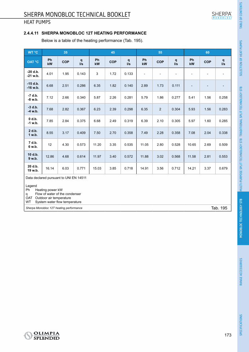
173
SHERPA MONOBLOC TECHNICAL BOOKLETHEAT PUMPS
(2)
TABL
E OF
CON
TEN
TSSE
LECT
ION
OF
HEA
T PU
MPS
TRAD
ITIO
NAL
SPL
IT T
ECH
NOL
OGY
STB
MUL
TI-P
URPO
SE S
PLIT
TEC
HNOL
OGY
STB
MON
OBLO
C TE
CHN
OLOG
Y ST
BRA
NGE
ACC
ESSO
RIES
SPEC
IFIC
ATIO
NS
2.4.4.11 SHERPA MONOBLOC 12T HEATING PERFORMANCE
Below is a table of the heating performance (Tab. 195).
WT °C 35 45 55 60
OAT °C PhkW COP q
l/sPhkW COP q
l/sPhkW COP q
l/sPhkW COP q
l/s
-20 d.b.-21 w.b. 4.01 1.95 0.143 3 1.72 0.133 - - - - - -
-15 d.b.-16 w.b. 6.68 2.51 0.286 6.35 1.82 0.140 2.89 1.73 0.111 - - -
-7 d.b.-8 w.b. 7.12 2.66 0.340 5.87 2.26 0.281 5.79 1.86 0.277 5.41 1.56 0.258
-3 d.b.-4 w.b. 7.68 2.82 0.367 6.23 2.39 0.298 6.35 2 0.304 5.93 1.56 0.283
0 d.b.-1 w.b. 7.85 2.84 0.375 6.68 2.49 0.319 6.39 2.10 0.305 5.97 1.60 0.285
2 d.b.1 w.b. 8.55 3.17 0.409 7.50 2.70 0.358 7.49 2.28 0.358 7.08 2.04 0.338
7 d.b.6 w.b. 12 4.30 0.573 11.20 3.35 0.535 11.05 2.80 0.528 10.65 2.69 0.509
10 d.b.9 w.b. 12.86 4.68 0.614 11.97 3.40 0.572 11.88 3.02 0.568 11.58 2.81 0.553
20 d.b.19 w.b. 16.14 6.03 0.771 15.03 3.85 0.718 14.91 3.56 0.712 14.21 3.37 0.679
Data declared pursuant to UNI EN 14511
LegendPh Heating power kWq Flow of water of the condenserOAT Outdoor air temperatureWT System water flow temperature
Sherpa Monobloc 12T heating performance Tab. 195

174
SHERPA MONOBLOC TECHNICAL BOOKLETHEAT PUMPS
(2)
2.4.4.12 SHERPA MONOBLOC 12T COOLING PERFORMANCE
Below is a table of the cooling performance (Tab. 196).
OAT °C 5 15 25 35 45
WT °C PckW EER q
l/sPckW EER q
l/sPckW EER q
l/sPckW EER q
l/sPckW EER q
l/s
5 13.79 5.96 0.659 11.37 5.19 0.543 10.41 3.72 0.497 9.60 2.79 0.459 8.88 2.38 0.424
7 12.82 8.07 0.613 12.12 5.69 0.579 11.14 4.03 0.532 10.20 3 0.487 9.33 2.56 0.446
10 11.37 11.23 0.543 13.25 6.44 0.633 12.23 4.50 0.584 11.10 3.31 0.530 10 2.84 0.478
15 6.79 17.15 0.324 15.14 7.68 0.723 14.05 5.28 0.671 12.60 3.84 0.602 11.12 3.30 0.531
18 7.49 19.66 0.358 16.26 8.43 0.777 15.15 5.75 0.724 13.50 4.15 0.645 11.80 3.58 0.564
Data declared pursuant to UNI EN 14511
LegendPc Cooling power kWq Flow of water of the evaporatorOAT Dry bulb outdoor air temperatureWT System water flow temperature
Sherpa Monobloc 12T cooling performance Tab. 196

175
SHERPA MONOBLOC TECHNICAL BOOKLETHEAT PUMPS
(2)
TABL
E OF
CON
TEN
TSSE
LECT
ION
OF
HEA
T PU
MPS
TRAD
ITIO
NAL
SPL
IT T
ECH
NOL
OGY
STB
MUL
TI-P
URPO
SE S
PLIT
TEC
HNOL
OGY
STB
MON
OBLO
C TE
CHN
OLOG
Y ST
BRA
NGE
ACC
ESSO
RIES
SPEC
IFIC
ATIO
NS
2.4.4.13 SHERPA MONOBLOC 15T HEATING PERFORMANCE
Below is a table of the heating performance (Tab. 197).
WT °C 35 45 55 60
OAT °C PhkW COP q
l/sPhkW COP q
l/sPhkW COP q
l/sPhkW COP q
l/s
-20 d.b.-21 w.b. 4.45 1.78 0.177 3 1.70 0.133 - - - - - -
-15 d.b.-16 w.b. 7.42 2.45 0.355 7.05 1.80 0.191 3 1.78 0.124 - - -
-7 d.b.-8 w.b. 8 2.60 0.382 8 2.26 0.382 6.49 1.88 0.31 6.66 1.51 0.318
-3 d.b.-4 w.b. 8.49 2.75 0.406 8.40 2.39 0.401 6.90 2.01 0.33 7.30 1.52 0.349
0 d.b.-1 w.b. 8.69 2.77 0.415 8.61 2.49 0.412 7.56 2.11 0.361 7.50 1.56 0.358
2 d.b.1 w.b. 9.50 3.10 0.454 9.30 2.65 0.444 7.96 2.24 0.38 8.53 1.98 0.408
7 d.b.6 w.b. 15 4.20 0.717 14.50 3.30 0.693 12 2.85 0.573 12.80 2.60 0.612
10 d.b.9 w.b. 16.13 4.57 0.771 15.90 3.40 0.760 13.07 3.02 0.624 13.69 2.75 0.654
20 d.b.19 w.b. 20.24 5.89 0.967 18.92 4.03 0.904 15.68 3.58 0.749 16.03 3.29 0.766
Data declared pursuant to UNI EN 14511
LegendPh Heating power kWq Flow of water of the condenserOAT Outdoor air temperatureWT System water flow temperature
Sherpa Monobloc 15T heating performance Tab. 197

176
SHERPA MONOBLOC TECHNICAL BOOKLETHEAT PUMPS
(2)
2.4.4.14 SHERPA MONOBLOC 15T COOLING PERFORMANCE
Below is a table of the cooling performance (Tab. 198).
OAT °C 5 15 25 35 45
WT °C PckW EER q
l/sPckW EER q
l/sPckW EER q
l/sPckW EER q
l/sPckW EER q
l/s
5 19.14 5.13 0.914 15.33 4.69 0.732 14.01 3.58 0.669 12.45 2.75 0.595 9.24 2.20 0.441
7 17.37 7.43 0.83 16.01 5.09 0.765 14.62 3.85 0.698 13 2.91 0.621 9.82 2.30 0.469
10 14.72 10.87 0.703 17.04 5.69 0.814 15.54 4.25 0.742 13.82 3.16 0.66 10.70 2.45 0.511
15 6.93 17.50 0.331 18.75 6.70 0.896 17.06 4.93 0.815 15.18 3.56 0.725 12.16 2.70 0.581
18 7.65 20.06 0.365 19.77 7.31 0.945 17.98 5.33 0.859 16 3.81 0.764 13.03 2.86 0.623
Data declared pursuant to UNI EN 14511
LegendPc Cooling power kWq Flow of water of the evaporatorOAT Dry bulb outdoor air temperatureWT System water flow temperature
Sherpa Monobloc 15T cooling performance Tab. 198
2.4.5 OPERATING LIMITS

177
SHERPA MONOBLOC TECHNICAL BOOKLETHEAT PUMPS
(2)
TABL
E OF
CON
TEN
TSSE
LECT
ION
OF
HEA
T PU
MPS
TRAD
ITIO
NAL
SPL
IT T
ECH
NOL
OGY
STB
MUL
TI-P
URPO
SE S
PLIT
TEC
HNOL
OGY
STB
MON
OBLO
C TE
CHN
OLOG
Y ST
BRA
NGE
ACC
ESSO
RIES
SPEC
IFIC
ATIO
NS
Below are diagrams of the water and outdoor air temperature limits within which the heat pump can run in cooling (Fig. 60) and heating/production of domestic water (Fig. 61) modes.
10
20
30
40
50
60
-25 -20 -15 -10 -5 0 5 10 15 20 25 30 35
0
2
4
6
8
10
12
14
16
18
20
30AWH 006
30AWH 004
-10 0 10 20 30 40 50
70
TEM
PER
ATU
RE
OF
WAT
ER P
RO
DU
CED
°C
OUTDOOR AIR TEMPERATURE °C
Operating limits in cooling mode Fig. 60
10
20
30
40
50
60
-25 -20 -15 -10 -5 0 5 10 15 20 25 30 35
0
2
4
6
8
10
12
14
16
18
20
30AWH 006
30AWH 004
-10 0 10 20 30 40 50
70
TEM
PER
ATU
RE
OF
WAT
ER P
RO
DU
CED
°C
OUTDOOR AIR TEMPERATURE °C
Operating limits in heating mode Fig. 61
If the unit is installed in a particularly windy area, wind barriers must be put in place to avoid malfunc-tioning of the unit.
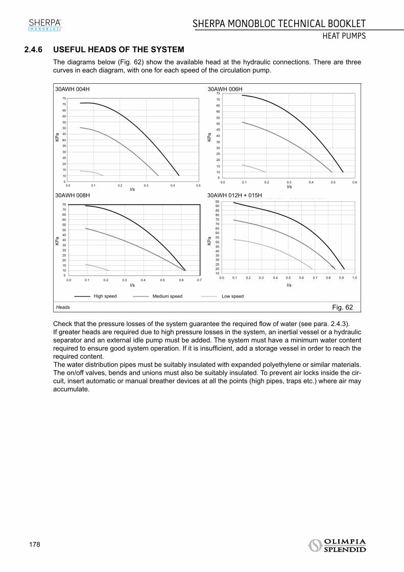
178
SHERPA MONOBLOC TECHNICAL BOOKLETHEAT PUMPS
(2)
2.4.6 USEFUL HEADS OF THE SYSTEM The diagrams below (Fig. 62) show the available head at the hydraulic connections. There are three
curves in each diagram, with one for each speed of the circulation pump.
KP
aK
Pa
KP
aK
Pa
l/s
l/s l/s
l/s
30AWH 012H + 015H30AWH 008H
0
5
10
15
20
25
30
35
40
45
50
55
60
65
70
0,2 0,3 0,4 0,50,10,0A
BB
A0.0 0.1 0.2 0.3 0.4 0.5
5
10
15
20
25
30
35
40
45
50
55
60
65
70
75
0
5
10
15
20
25
30
35
40
45
50
55
60
0 0,1 0,2 0,3 0,4 0,5 0,60.0 0.1 0.2 0.3 0.4 0.5 0.65
10
15
20
25
30
35
40
45
50
55
60
65
70
75
0
5
10
15
20
25
30
35
40
45
50
55
60
0 0 1 0 2 0 3 0 4 0 5 0 6
30AWH008H
0.0 0.1 0.2 0.3 0.4 0.5 0.6 0.75
1015202530354045505560657075
0
10
20
30
40
50
60
70
80
90
0 0,1 0,2 0,3 0,4 0,5 0,6 0,7 0,8 0,9
30AWH012H 30AWH015H
1020253035404550556065707580859095
0.0 0.1 0.2 0.3 0.4 0.5 0.6 0.7 0.8 0.9 1.0
High speed Medium speed Low speed
30AWH 004H 30AWH 006H
Heads Fig. 62
Check that the pressure losses of the system guarantee the required flow of water (see para. 2.4.3). If greater heads are required due to high pressure losses in the system, an inertial vessel or a hydraulic
separator and an external idle pump must be added. The system must have a minimum water content required to ensure good system operation. If it is insufficient, add a storage vessel in order to reach the required content.The water distribution pipes must be suitably insulated with expanded polyethylene or similar materials. The on/off valves, bends and unions must also be suitably insulated. To prevent air locks inside the cir-cuit, insert automatic or manual breather devices at all the points (high pipes, traps etc.) where air may accumulate.

179
SHERPA MONOBLOC TECHNICAL BOOKLETHEAT PUMPS
(2)
TABL
E OF
CON
TEN
TSSE
LECT
ION
OF
HEA
T PU
MPS
TRAD
ITIO
NAL
SPL
IT T
ECH
NOL
OGY
STB
MUL
TI-P
URPO
SE S
PLIT
TEC
HNOL
OGY
STB
MON
OBLO
C TE
CHN
OLOG
Y ST
BRA
NGE
ACC
ESSO
RIES
SPEC
IFIC
ATIO
NS
2.4.7 COMPONENTS The unit comprises the following main components (see Fig. 63):
HYDRONIC MODULEA. Automatic air relief valve.B. Waterflowswitch.C. Safety valve.D. Water temperature sensors.E. Water circulation pump.F. Pump release screw.G. Expansion vessel: 2 or 3 litres.H. Drain cap.
I. Electric panel.J. Plate exchanger.K. Reversible gas circuit: 4-way valve.L. Twin-Rotary Inverter DC Compressor.
14 14
G
A
BI
K J
L
F
C
E
D
H
Components of the internal unit Fig. 63

180
SHERPA MONOBLOC TECHNICAL BOOKLETHEAT PUMPS
(2)
2.4.8 DIMENSIONS AND POSITIONING2.4.8.1 DIMENSIONS
Below is the layout of the heat pump (Fig. 64) and a table summarising the dimensions and weight values (Tab. 199).
A
B
C
A
B
C
Layout of the internal unit Fig. 64
Ref. Fig. 64SHERPA
MONOBLOC 4
SHERPAMONOBLOC
6
SHERPAMONOBLOC
8
SHERPAMONOBLOC
12
SHERPAMONOBLOC
15
SHERPAMONOBLOC
12T
SHERPAMONOBLOC
15T
SINGLE-FAN DUAL-FAN
A mm 908 908 908 908 908 908 908
B mm 350 350 350 350 350 350 350
C mm 821 821 821 1363 1363 1363 1363
Weight kg 57 61 69 104 112 116 116Dimensions and weight values of the internal unit Tab. 199

181
SHERPA MONOBLOC TECHNICAL BOOKLETHEAT PUMPS
(2)
TABL
E OF
CON
TEN
TSSE
LECT
ION
OF
HEA
T PU
MPS
TRAD
ITIO
NAL
SPL
IT T
ECH
NOL
OGY
STB
MUL
TI-P
URPO
SE S
PLIT
TEC
HNOL
OGY
STB
MON
OBLO
C TE
CHN
OLOG
Y ST
BRA
NGE
ACC
ESSO
RIES
SPEC
IFIC
ATIO
NS
2.4.8.2 POSITIONING
Install the unit on a solid base that is able to take its weight; if installed incompletely or on an inappropriate base, the unit could detach itself and cause damage to property or physical injury.
It is very important that the installation place be chosen with extreme care in order to ensure adequate protection of the device against impact or possible consequential damage. Choose a place that is ade-quately ventilated and in which the outdoor temperature in summer does not exceed 46°C.
Leave sufficient clearance around the appliance in order to avoid the recirculation of air and to facilitate maintenance (see Fig. 65).
Prepare a layer of gravel underneath the appliance for drainage of the defrost water.Leave space underneath the unit to prevent the defrost water from freezing. In normal situa-tions, ensure the base is at least 5 cm off the ground; for use in regions with very cold winters, en-sure a space of at least 15 cm on both sides of the unit. When installed in a location with high snow fall, mount the support of the appliance at a height that is above the maximum level of snow. Install the unit so that wind is not blowing across it.
Also prepare: ○ anti-vibration dampers; ○ compliant power supply near the unit.
9
150
150
1000
200
200
1000
1000 1500 2000 200300
300300
300300
300150
1000 1000
1000
500
150
150
300
200
500
Positioning of the external unit Fig. 65
The unit is supplied with a mesh for covering the heat exchange coil; this is envisaged for installations accessible to the public. Fitting the mesh may cause, in the event of high humidity at low temperature (fog) or snow, a build-up of ice on the battery with reduced system performance.

182
SHERPA MONOBLOC TECHNICAL BOOKLETHEAT PUMPS
(2)
2.4.9 INSTALLATION To ensure successful installation and optimal performance, follow the instructions in the installation, use
and maintenance manual supplied with each unit and accessory. This technical booklet provides general information on installation, dimensional drawings and wiring diagrams.
The installation must be carried out by the dealer or by other qualified personnel; if the installation is not carried out correctly, there may be a risk of water leakage, electric shock or fire.
During assembly and any maintenance operation, observe the precautions in the installation, use and maintenance manuals and on the labels inside the appliances, and take any precautions dictated by common sense and set down by the safety rules at the place of installation.
Always wear protective gloves and goggles when performing maintenance on the parts of the appliances
containing refrigerant. Air-water heat pumps MUST NEVER be installed in rooms where there is inflam-mable gas, explosive gas, a high level of humidity (laundry rooms, greenhouses etc.), or in rooms where there are other machines generating a lot of heat.
It is recommended to use only the components designed specially for the installation provided; the use of different components could cause the leakage of water, electric shock or fire.
Once the installation has been completed, check that there is no leakage of refrigerant (the liquid can produce toxic gas when exposed to flames).
When installing or relocating the system, make sure that there is no substance in the refrigerant circuit other than the refrigerant specified in the technical data (see para. 2.4.3) as the presence of air or other foreign substances in the refrigerant circuit can cause an abnormal increase in pressure or breakage of the system, resulting in damage to property or physical injury.
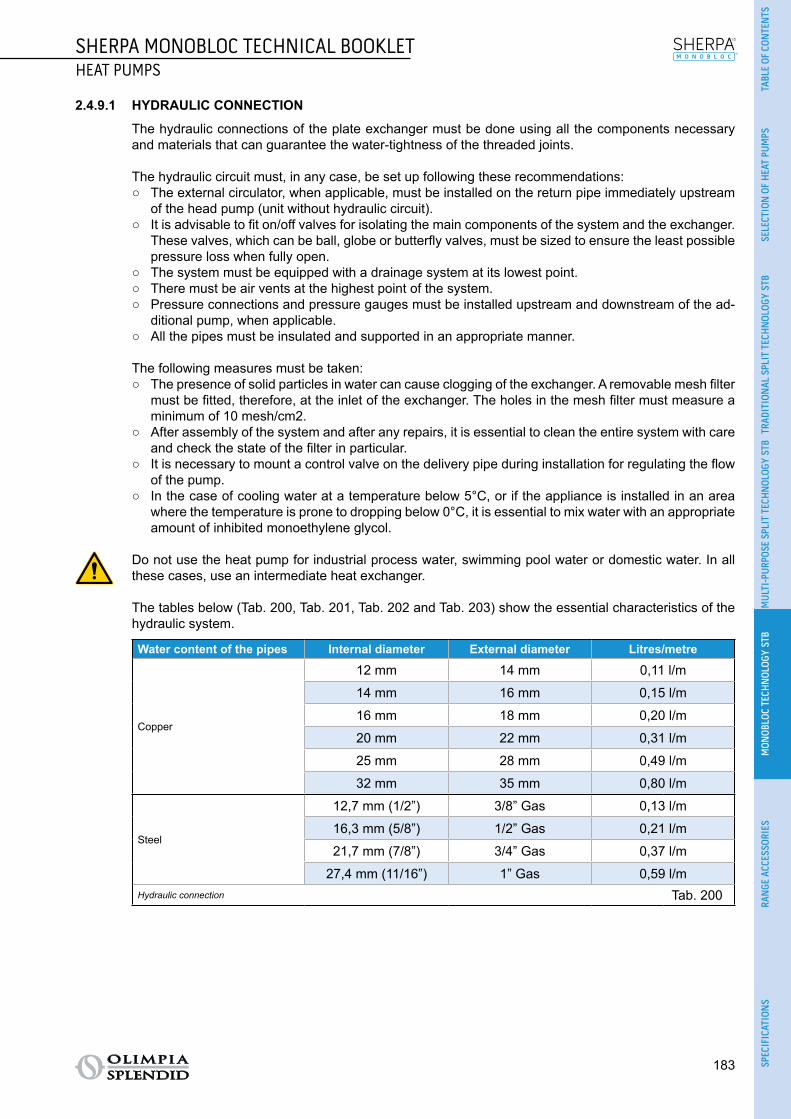
183
SHERPA MONOBLOC TECHNICAL BOOKLETHEAT PUMPS
(2)
TABL
E OF
CON
TEN
TSSE
LECT
ION
OF
HEA
T PU
MPS
TRAD
ITIO
NAL
SPL
IT T
ECH
NOL
OGY
STB
MUL
TI-P
URPO
SE S
PLIT
TEC
HNOL
OGY
STB
MON
OBLO
C TE
CHN
OLOG
Y ST
BRA
NGE
ACC
ESSO
RIES
SPEC
IFIC
ATIO
NS
2.4.9.1 HYDRAULIC CONNECTION
The hydraulic connections of the plate exchanger must be done using all the components necessary and materials that can guarantee the water-tightness of the threaded joints.
The hydraulic circuit must, in any case, be set up following these recommendations: ○ The external circulator, when applicable, must be installed on the return pipe immediately upstream
of the head pump (unit without hydraulic circuit). ○ It is advisable to fit on/off valves for isolating the main components of the system and the exchanger.
These valves, which can be ball, globe or butterfly valves, must be sized to ensure the least possible pressure loss when fully open.
○ The system must be equipped with a drainage system at its lowest point. ○ There must be air vents at the highest point of the system. ○ Pressure connections and pressure gauges must be installed upstream and downstream of the ad-
ditional pump, when applicable. ○ All the pipes must be insulated and supported in an appropriate manner.
The following measures must be taken: ○ The presence of solid particles in water can cause clogging of the exchanger. A removable mesh filter
must be fitted, therefore, at the inlet of the exchanger. The holes in the mesh filter must measure a minimum of 10 mesh/cm2.
○ After assembly of the system and after any repairs, it is essential to clean the entire system with care and check the state of the filter in particular.
○ It is necessary to mount a control valve on the delivery pipe during installation for regulating the flow of the pump.
○ In the case of cooling water at a temperature below 5°C, or if the appliance is installed in an area where the temperature is prone to dropping below 0°C, it is essential to mix water with an appropriate amount of inhibited monoethylene glycol.
Do not use the heat pump for industrial process water, swimming pool water or domestic water. In all these cases, use an intermediate heat exchanger.
The tables below (Tab. 200, Tab. 201, Tab. 202 and Tab. 203) show the essential characteristics of the hydraulic system.
Water content of the pipes Internal diameter External diameter Litres/metre
Copper
12 mm 14 mm 0,11 l/m
14 mm 16 mm 0,15 l/m
16 mm 18 mm 0,20 l/m
20 mm 22 mm 0,31 l/m
25 mm 28 mm 0,49 l/m
32 mm 35 mm 0,80 l/m
Steel
12,7 mm (1/2”) 3/8” Gas 0,13 l/m
16,3 mm (5/8”) 1/2” Gas 0,21 l/m
21,7 mm (7/8”) 3/4” Gas 0,37 l/m
27,4 mm (11/16”) 1” Gas 0,59 l/mHydraulic connection Tab. 200

184
SHERPA MONOBLOC TECHNICAL BOOKLETHEAT PUMPS
(2)
% Inhibited monoethylene glycol 10% 20% 30% 40%Freezing point (a) -4°C -9°C -15°C -23°C
Correction factors
Capacity 0.996 0.991 0.983 0.975Absorbed power 0.990 0.978 0.964 1.008Load loss 1.003 1.010 1.020 1.033
Notes(a) The temperature values are indicative; always refer to the temperatures stated for the specific product used
Hydraulic connection Tab. 201
Table for calculating the water content of the system
Installed unit..............................................................................
Content of unit (a) l ..............................................................................
Content of pipes (b) l ..............................................................................
Utilities (fan coils, panels, radiators, etc.) (c) l ..............................................................................
Total content (d) l ..............................................................................
Notes(a) Consult the technical data table(b) Consult the pipe water content table(c) Consult the manual of the installed utilities(d) The water content of the system must be between the minimum value and the maximum value stated in Tab. 203. The mini-
mum content of the hydraulic circuit must be considered as the volume of water always circulating in the system (i.e. the parts of the system excluded by valves must not be considered). It is possible to increase the maximum content of the system by adding an expansion vessel suited to the water content of the system.
Hydraulic connection Tab. 202
SHERPAMONOBLOC
4
SHERPAMONOBLOC
6
SHERPAMONOBLOC
8
SHERPAMONOBLOC
12
SHERPAMONOBLOC
15
Nominal water flow Std l/s 0.20 0.28 0.33 0.58 0.69
Water content of system
Min l 14 21 28 42 49Max (a) l 30 30 30 50 50Max (b) l 65 65 65 95 95
Operating pressure Max kPa 300 300 300 300 300
Filling pressure Min kPa 120 120 120 120 120
System height difference Max m 20 20 20 20 20Notes(a) Temperature of water in system 55°C, maximum water content of the system using only the expansion vessel supplied as
standard in the unit(b) Temperature of water in system 35°C, maximum water content of the system using only the expansion vessel supplied as
standard in the unit
Hydraulic connection Tab. 203

185
SHERPA MONOBLOC TECHNICAL BOOKLETHEAT PUMPS
(2)
TABL
E OF
CON
TEN
TSSE
LECT
ION
OF
HEA
T PU
MPS
TRAD
ITIO
NAL
SPL
IT T
ECH
NOL
OGY
STB
MUL
TI-P
URPO
SE S
PLIT
TEC
HNOL
OGY
STB
MON
OBLO
C TE
CHN
OLOG
Y ST
BRA
NGE
ACC
ESSO
RIES
SPEC
IFIC
ATIO
NS
2.4.9.2 ELECTRICAL CONNECTION, MAXIMUM CONSUMPTION AND CONNECTING CABLES
The electrical connections must be made in compliance with the instructions given in the installation man-ual and with national standards or procedures governing electrical connections; insufficient capacity or incomplete electrical connections may lead to electric shock or fire.
The system must be wired in accordance with the regulations in force and properly earthed.
To prevent any risk of electric shock, the master switches must be disconnected before making electrical connections and carrying out maintenance on the appliances.
Connect the hydraulic pipes before making the electrical connections, and connect the earth before the cables.
Before performing any operation, make sure that the electrical power of the internal and external units is switched off.
The supply voltage must be that indicated in the technical data (see para. 2.4.3).
Use the specified types of cable for the electrical connections (see Tab. 204).
SHERPAMONOBLOC
4
SHERPAMONOBLOC
6
SHERPAMONOBLOC
8
SHERPAMONOBLOC
12
SHERPAMONOBLOC
15
SHERPAMONOBLOC
12T
SHERPAMONOBLOC
15T
Power supply V-ph-Hz 230-1-50 400-3N-50
ALLOWABLE voltage range V 207-253 376÷424
MAXIMUM ab-sorbed power kW 1.65 2 2.70 3.85 4.20 6.50 6.50
Maximum ab-sorbed current A 9 11 14.50 20.70 22.60 11.10 11.10
Power fusestype gL Type
A 10-Type B
16-Type B
10-Type B
25-Type D
25-Type D
16-Type B
16-Type B
Power cables mm² H07RN-F 3x2.5 H07RN-F 5x2.5
External circula-tion pump maxi-mum current
A 2 2 2 2 2 2 2
Connecting cables Tab. 204
Use H03VV-F 4x0.75 mm² cables to connect the wired control of the B0813 programmable thermostat, and H03VV-F 6x0.75 mm² cables to connect the B0812 wired remote control.
The unit can be controlled and set with: ○ User Interface B0813 wired control. ○ B0812 wired remote control (optional). ○ Switches (not supplied).
Use H03VV-F 4x0.75 mm² cables to connect the wired control of the B0813 programmable thermostat, and H03VV-F 6x0.75 mm² cables to connect the B0812 wired remote control.
Install the wired remote control with reference to the control installation manual. Power supply: select the cable, which must be of the type H07 RN-F. In accordance with the installation
instructions, all the circuit breaker devices must have a contact opening (of 4 mm) to permit total discon-nection in compliance with the conditions for overvoltage category III. In order to avoid risks, the power cable must be replaced only by a Service Technician.

186
SHERPA MONOBLOC TECHNICAL BOOKLETHEAT PUMPS
(2)
For 3Ph units, make sure to apply the ferrite supplied on the power cable to guarantee compliance with the EMC standards (see para. 2.4.9.3).
The Sherpa Monobloc units can pilot a 3-way valve for managing a domestic water storage tank. The operating logic is such that, when a storage tank requires domestic water, the system controls a 3-way valve to direct hot water only to the tank and runs at full capacity to supply water at 60 °C (in accordance with the operating limits).
For operation, connect the 3-way valve to PIN 18, N and 10 of the terminal board (see para. 2.4.9.3). PIN 18 (Line) and N (Neutral) supply power to the valve (1ph ~ 230V, 2A max), while the control signal is available at PIN 10 (1ph ~ 230V, 2A max). If using a valve with spring return, connect only PIN 10 and N.
The DHW request signal must be of the Dry Contact type (quality of the contacts greater than 25mA @ 12V) that closes the circuit between PIN 15 and PIN 13 of the terminal (see para. 2.4.9.3).
The request for domestic water takes priority over the programmed operating mode, whether heating or cooling.

187
SHERPA MONOBLOC TECHNICAL BOOKLETHEAT PUMPS
(2)
TABL
E OF
CON
TEN
TSSE
LECT
ION
OF
HEA
T PU
MPS
TRAD
ITIO
NAL
SPL
IT T
ECH
NOL
OGY
STB
MUL
TI-P
URPO
SE S
PLIT
TEC
HNOL
OGY
STB
MON
OBLO
C TE
CHN
OLOG
Y ST
BRA
NGE
ACC
ESSO
RIES
SPEC
IFIC
ATIO
NS
2.4.9.3 WIRING DIAGRAMS
Below is the diagram for connecting the electrical cables (Fig. 66).
L N L N
L N
N N 18
12
3
3Ph
11
30
1010
40
12-15 3PH15kW 1Ph
L1 L2 L3 N
L N
1Ph
45
9
6
7
Σ �
Σ �Σ �
C W G Y 13 14 15 7 6 3 2 1 8 21 23 2433AW-CS1Remote control
33AW-RC1 (SUI)Remote control
8
10
10 11 12 4 5 16
Wiring diagram Fig. 66
Connection of the switches: S1 OFF (open)/ON (closed) S2 Cooling (open)/heating (closed) S3 Normal (open)/Eco (closed)
Auxiliary connections 1 3-way valve 6 Maximum frequency reduction 2 Alarm or Defrosting/dehumidifier 7 Request for domestic water 3 Trace heater/Additional water circulator 8 External alarm input 4 External heat source/defrosting 9 External temperature sensor (NTC 3k @25°C) 5 Alarm/Signal when room temperature is reached 10 External water circulator

188
SHERPA MONOBLOC TECHNICAL BOOKLETHEAT PUMPS
(2)
2.4.9.4 HYDRONIC CIRCUIT
Sherpa Aquadue Monobloc heat pump, compensating Tank, SLR fan radiator terminals and boiler for the production of DHW.The hydraulic diagram (Fig. 67) is purely indicative.
T
TT
TT
T
YT
M
17
Hydraulic circuit Fig. 67 Legend:
C/H
M
T
Y
T
Mesh filter
C/H
M
T
Y
T
On/off valve
C/H
M
T
Y
T
Motorised three-way valve
C/H
M
T
Y
T
Check valve
C/H
M
T
Y
T
Thermostatic mixer
C/H
M
T
Y
T
Thermometer
C/H
M
T
Y
T
Thermostat
C/H
M
T
Y
T
Automatic air breather
C/H
M
T
Y
T
Expansion vessel
C/H
M
T
Y
T
Circulator
C/H
M
T
Y
T
Pressure gauge
C/H
M
T
Y
T
Frost protection valve
Provide for frost protection on the hydraulic connections of the external unit.Three-way valve and thermostat, accessories required for the production of DHW.

189
SHERPA MONOBLOC TECHNICAL BOOKLETHEAT PUMPS
(2)
TABL
E OF
CON
TEN
TSSE
LECT
ION
OF
HEA
T PU
MPS
TRAD
ITIO
NAL
SPL
IT T
ECH
NOL
OGY
STB
MUL
TI-P
URPO
SE S
PLIT
TEC
HNOL
OGY
STB
MON
OBLO
C TE
CHN
OLOG
Y ST
BRA
NGE
ACC
ESSO
RIES
SPEC
IFIC
ATIO
NS
Sherpa Aquadue Monobloc heat pump, compensating Tank, SL fan radiator terminals, radiant panels and boiler for the production of DHW.The hydraulic diagram (Fig. 68) is purely indicative.
T
TT
TT
MT
T
YT
M
18
Hydraulic circuit Fig. 68 Legend:
C/H
M
T
Y
T
Mesh filter
C/H
M
T
Y
T
On/off valve
C/H
M
T
Y
T
Motorised three-way valve
C/H
M
T
Y
T
Check valve
C/H
M
T
Y
T
Thermostatic mixer
C/H
M
T
Y
T
Thermometer
C/H
M
T
Y
T
Thermostat
C/H
M
T
Y
T
Automatic air breather
C/H
M
T
Y
T
Expansion vessel
C/H
M
T
Y
T
Circulator
C/H
M
T
Y
T
Pressure gauge
C/H
M
T
Y
T
Frost protection valve
C/H
M
T
Y
T
Temperature probe
Provide for frost protection on the hydraulic connections of the external unit.Three-way valve and thermostat, accessories required for the production of DHW.

190
SHERPA MONOBLOC TECHNICAL BOOKLETHEAT PUMPS
(2)
Sherpa Aquadue Monobloc Heat Pump, outdoor back-up heater, SLR fan radiator terminals and boiler for the production of DHW.The hydraulic diagram (Fig. 69) is purely indicative.
T
TT
TT
M
T
YT
C/H
C/H
19
Hydraulic circuit Fig. 69
Legend:
C/H
M
T
Y
T
Mesh filter
C/H
M
T
Y
T
On/off valve
C/H
M
T
Y
T
Motorised three-way valve
C/H
M
T
Y
T
Check valve
C/H
M
T
Y
T
Thermostatic mixer
C/H
M
T
Y
T
Thermometer
C/H
M
T
Y
T
Frost protection valve
C/H
M
T
Y
T
Automatic air breather
C/H
M
T
Y
T
Expansion vessel
C/H
M
T
Y
T
Circulator
C/H
M
T
Y
T
Pressure gauge
C/H
M
T
Y
T
Differential by-passC/H
M
T
Y
T
Summer/winter valve
Provide for frost protection on the hydraulic connections of the external unit.

191
SHERPA MONOBLOC TECHNICAL BOOKLETHEAT PUMPS
(2)
TABL
E OF
CON
TEN
TSSE
LECT
ION
OF
HEA
T PU
MPS
TRAD
ITIO
NAL
SPL
IT T
ECH
NOL
OGY
STB
MUL
TI-P
URPO
SE S
PLIT
TEC
HNOL
OGY
STB
MON
OBLO
C TE
CHN
OLOG
Y ST
BRA
NGE
ACC
ESSO
RIES
SPEC
IFIC
ATIO
NS
Sherpa Aquadue Monobloc Heat Pump, compensating Tank, SLR fan radiator terminals and boiler for the production of DHW with thermal solar panels.The hydraulic diagram (Fig. 70) is purely indicative.
2S
TT
TT
T
YT
M
T
Hydraulic circuit Fig. 70
Legend:
C/H
M
T
Y
T
Mesh filter
C/H
M
T
Y
T
On/off valve
C/H
M
T
Y
T
Motorised three-way valve
C/H
M
T
Y
T
Check valve
C/H
M
T
Y
T
Thermostatic mixer
C/H
M
T
Y
T
Thermometer
C/H
M
T
Y
T
Thermostat
C/H
M
T
Y
T
Automatic air breather
C/H
M
T
Y
T
Expansion vessel
C/H
M
T
Y
T
Circulator
C/H
M
T
Y
T
Pressure gauge
C/H
M
T
Y
T
Frost protection valve
Provide for frost protection on the hydraulic connections of the external unit.Three-way valve and thermostat, accessories required for the production of DHW.
192
SHERPA MONOBLOC TECHNICAL BOOKLETHEAT PUMPS
(2)
2.4.10 CONFORMITY The Sherpa Monobloc heat pumps are compliant with the following European directives:
○ MD 2006/42/CE ○ EMCD 2014/30/EU (electromagnetic compatibility) ○ ECODESIGN 2009/125/EC 813/2013EU 327/2011EU ○ RoHS 2011/65/EC
The Sherpa Monobloc heat pumps are compliant with the following harmonised European standards: ○ EN14825 ○ EN55014-1 ○ EN55014-2 ○ EN61000-3-2 ○ EN61000-3-3 ○ EN61000-3-11 ○ EN61000-3-12 ○ EN60335-1 ○ EN60335-2-40
2.4.10.1 CE DECLARATION OF CONFORMITY
The CE declaration of conformity is available in the download area on the site www.olimpiasplendid.it (Fig. 71).
Download area Fig. 71

193
SHERPA MONOBLOC TECHNICAL BOOKLETHEAT PUMPS
(2)
TABL
E OF
CON
TEN
TSSE
LECT
ION
OF
HEA
T PU
MPS
TRAD
ITIO
NAL
SPL
IT T
ECH
NOL
OGY
STB
MUL
TI-P
URPO
SE S
PLIT
TEC
HNOL
OGY
STB
MON
OBLO
C TE
CHN
OLOG
Y ST
BRA
NGE
ACC
ESSO
RIES
SPEC
IFIC
ATIO
NS
2.4.11 GENERAL INFORMATION2.4.11.1 PACK
The following table summarises the dimensions and weight values of the unit (Tab. 205).
SHERPAMONOBLOC
4
SHERPAMONOBLOC
6
SHERPAMONOBLOC
8
SHERPAMONOBLOC
12
SHERPAMONOBLOC
15
SHERPAMONOBLOC
12T
SHERPAMONOBLOC
15T
SINGLE-FAN DUAL-FAN
Width cm 44 44 44 44 44 44 44
Length cm 97 97 97 97 97 97 97
Height cm 96 96 96 150 150 150 150
Gross weight kg 60 64 72 107 115 119 119
Volume m³ 0.409 0.409 0.409 0.640 0.640 0.640 0.640Pack Tab. 205

194
SHERPAHEAT PUMPS
3 RANGE ACCESSORIES3.1 COMPATIBILITY OF THE ACCESSORIES The following table indicates the compatibility of the various accessories (Tab. 206).
Description Kit code SHERPA SHERPA AQUADUE
SHERPA AQUADUE
TOWER
SHERPA MONOBLOC
CONT
ROL
KITS
AND
ACC
ESSO
RIES Additional remote control B0812 x
Heating cable kit B0665 x x x
3-way valve kit for domestic hot water B0622 x x
Additional outdoor air temperature probe kit B0814 x
Additional outdoor air temperature probe kit B0623 x standard standard
DHW BOILER SENSOR KIT B0624 x standard standard
BO
ILER
S
200 l DHW boiler with single exchanger 01193 x x x
300 l DHW boiler with single exchanger 01194 x x x
500 l DHW boiler with single exchanger 01195 x x x
200 l DHW boiler with dual exchanger 01196 x xx x
300 l DHW boiler with dual exchanger 01197 x xx x
500 l DHW boiler with dual exchanger 01198 x xx x
Flange kit for electrical heater element B0617 x x
2 kW heater element for boiler of up to 300 l B0618 x x
3 kW heater element for boiler of up to 500 l B0666* x x
50 l storage tank puffer 01199 x x x x
100 l storage tank puffer 01200 x x x x
200 l storage tank puffer 01201 x x x x
Notes* Optional to be ordered as kit complete with flangexx Boiler with dual coil: Aquadue technology permits attainment of the renewable energy quota without solar integration.x Puffer: Aquadue technology guarantees uninterruptible power supply to the system and makes installation of the puffer
secondary.
Compatibility of the accessories Tab. 206

SHERPAHEAT PUMPS
195
TABL
E OF
CON
TEN
TSSE
LECT
ION
OF
HEA
T PU
MPS
TRAD
ITIO
NAL
SPL
IT T
ECH
NOL
OGY
STB
MUL
TI-P
URPO
SE S
PLIT
TEC
HNOL
OGY
STB
MON
OBLO
C TE
CHN
OLOG
Y ST
BRA
NGE
ACC
ESSO
RIES
SPEC
IFIC
ATIO
NS
3.2 DESCRIPTION OF THE ACCESSORIES
COD. B0812ADDITIONAL REMOTE CONTROL
○ Functions available ON-OFF ○ Operating mode: heating, cooling and Economy. ○ LEDs: power, Eco, cooling, heating and alarm code.
COD. B0665HEATING CABLE KIT
This prevents the formation of ice at the bottom of the external unit in the case of prolonged operation in particularly aggressive conditions.
COD. B06223-WAY VALVE KIT FOR DOMESTIC HOT WATER
○ Compact dimensions. ○ Control at two points.
36 4343
72
50
32 37 66
32+77
77 13
CharacteristicsRotation time s 30Rotation ° 90Kvs V/ph/Hz 13Power VA 230±10%/1/50Power absorption 5Protection class IIValve connection “ 1Signal at two pointsWeight kg 0.4Casing, class IP41Min/max room temperature °C -5/55

196
SHERPAHEAT PUMPS
COD. B0814ADDITIONAL OUTDOOR AIR TEMPERATURE probe kit
Shielded probe for measuring outdoor air temperature. The probe is for activating the functions for correction of the water set-point in relation to the outdoor tem-perature (climate compensation) and activation of an auxiliary heat generator.(only for Sherpa Monobloc)
COD. B0623ADDITIONAL OUTDOOR AIR TEMPERATURE probe kit
Shielded probe for measuring outdoor air temperature. The probe is for activating the functions for correction of the water set-point in relation to the outdoor tem-perature (climate compensation) and activation of an auxiliary heat generator.(only for Sherpa, standard for Sherpa Aquadue and Sherpa Aquadue Tower)
COD. B0624DHW BOILER SENSOR KIT
Probe for measuring and direct control of the water temperature in the domestic water storage tank. The probe is for activation of the anti-legionella cycles in the domestic water tank.
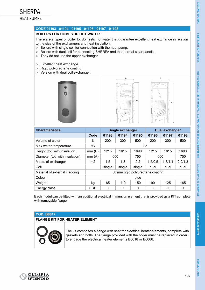
SHERPAHEAT PUMPS
197
TABL
E OF
CON
TEN
TSSE
LECT
ION
OF
HEA
T PU
MPS
TRAD
ITIO
NAL
SPL
IT T
ECH
NOL
OGY
STB
MUL
TI-P
URPO
SE S
PLIT
TEC
HNOL
OGY
STB
MON
OBLO
C TE
CHN
OLOG
Y ST
BRA
NGE
ACC
ESSO
RIES
SPEC
IFIC
ATIO
NS
CODE 01193 - 01194 - 01195 - 01196 - 01197 - 01198BOILERS FOR DOMESTIC HOT WATERThere are 2 types of boiler for domestic hot water that guarantee excellent heat exchange in relation to the size of the exchangers and heat insulation:
○ Boilers with single coil for connection with the heat pump. ○ Boilers with dual coil for connecting SHERPA and the thermal solar panels. ○ They do not use the upper exchanger
○ Excellent heat exchange. ○ Rigid polyurethane coating. ○ Version with dual coil exchanger.
A
B
A
B
Characteristics Single exchanger Dual exchangerCode 01193 01194 01195 01196 01197 01198
Volume of water lt 200 300 500 200 300 500Max water temperature °C 85Height (tot. with insulation) mm (B) 1215 1615 1690 1215 1615 1690Diameter (tot. with insulation) mm (A) 600 750 600 750Meas. of exchanger m2 1.5 1.8 2.2 1,5/0,5 1,8/1,1 2,2/1,3Coil single single single dual dual dualMaterial of external cladding 50 mm rigid polyurethane coatingColour blueWeight kg 85 110 150 90 125 165Energy class ERP C C D C C D
Each model can be fitted with an additional electrical immersion element that is provided as a KIT complete with removable flange.
COD. B0617FLANGE KIT FOR HEATER ELEMENT
The kit comprises a flange with seat for electrical heater elements, complete with gaskets and bolts. The flange provided with the boiler must be replaced in order to engage the electrical heater elements B0618 or B0666.

198
SHERPAHEAT PUMPS
COD. B06182 KW HEATER ELEMENT FOR BOILER OF UP TO 300 L
Immersion electrical heater element in copper, IP 65, with inter-nal adjustable thermostat and temperature limiter.
COD. B06663 KW HEATER ELEMENT FOR BOILER OF UP TO 500 L
Immersion electrical heater element in copper, IP 65, with inter-nal adjustable thermostat and temperature limiter.
COD. 01199 - 01200 - 01201STORAGE TANK PUFFERS
○ These guarantee inertia in the system and help to minimise frequency variation of the inverter compressor.
○ Minimum recommended water content in the system: 3.5 litres per kW of installed power. ○ Tanks in carbon steel with 50 mm thick rigid polyurethane coating and blue sky finish. ○ Maximum water temperature 85°C.
F
A
E
D
C
B
G
F
A
E
D
C
B
G
F
A
E
D
C
B
G
CharacteristicsFigure ref. Code 01199 01200 01201A mm 300 400 450B mm 933 1095 1395C mm 785 935 1200D mm 485 560 705E mm 180 185 215F mm 100 100 105G mm 530 605 750Weight kg 25 34 45Volume of water lt 50 100 200
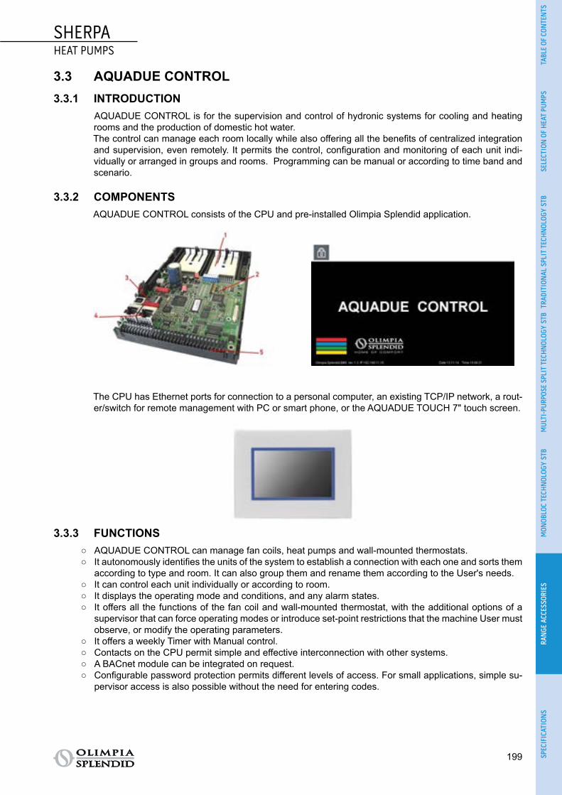
SHERPAHEAT PUMPS
199
TABL
E OF
CON
TEN
TSSE
LECT
ION
OF
HEA
T PU
MPS
TRAD
ITIO
NAL
SPL
IT T
ECH
NOL
OGY
STB
MUL
TI-P
URPO
SE S
PLIT
TEC
HNOL
OGY
STB
MON
OBLO
C TE
CHN
OLOG
Y ST
BRA
NGE
ACC
ESSO
RIES
SPEC
IFIC
ATIO
NS
3.3 AQUADUE CONTROL3.3.1 INTRODUCTION
AQUADUE CONTROL is for the supervision and control of hydronic systems for cooling and heating rooms and the production of domestic hot water.The control can manage each room locally while also offering all the benefits of centralized integration and supervision, even remotely. It permits the control, configuration and monitoring of each unit indi-vidually or arranged in groups and rooms. Programming can be manual or according to time band and scenario.
3.3.2 COMPONENTSAQUADUE CONTROL consists of the CPU and pre-installed Olimpia Splendid application.
The CPU has Ethernet ports for connection to a personal computer, an existing TCP/IP network, a rout-er/switch for remote management with PC or smart phone, or the AQUADUE TOUCH 7" touch screen.
3.3.3 FUNCTIONS ○ AQUADUE CONTROL can manage fan coils, heat pumps and wall-mounted thermostats. ○ It autonomously identifies the units of the system to establish a connection with each one and sorts them
according to type and room. It can also group them and rename them according to the User's needs. ○ It can control each unit individually or according to room. ○ It displays the operating mode and conditions, and any alarm states. ○ It offers all the functions of the fan coil and wall-mounted thermostat, with the additional options of a
supervisor that can force operating modes or introduce set-point restrictions that the machine User must observe, or modify the operating parameters.
○ It offers a weekly Timer with Manual control. ○ Contacts on the CPU permit simple and effective interconnection with other systems. ○ A BACnet module can be integrated on request. ○ Configurable password protection permits different levels of access. For small applications, simple su-
pervisor access is also possible without the need for entering codes.

200
SHERPAHEAT PUMPS
3.3.4 CONNECTIONS All the units, whether fan coils, heat pumps or thermostats, can be connected to the CPU with a common two-core cable for data lines, RS485 interface and MODBUS protocol. Each unit is assigned a unique address to permit identification on the network irrespective of its point of connection.
3.3.5 UNITThe base configuration of AQUADUE CONTROL can manage up to 32 units. The number can be in-creased to 192 with appropriate expansions or, with 5 interconnected CPUs, up to about 1000 units.
The Bi2 and Bi2+ SMART 2- or 4-tube fan coil units can be equipped with the usual B0371 or B0374 type complete control panels instead of additional accessories.The heat pump units can be Sherpa or Aquadue, or both, up to a maximum of ten.The wall-mounted B0736 LCD thermostat can, in turn, manage up to 32 sub-units (equipped with B0372 or B0375 type on-board panels) and increases the total number of units that can be managed ten-fold.
3.3.6 SMART PHONEThere are APPs for iOS and Android that permit access to AQUADUE even on your smart phone.
3.3.7 CODES AND ACCESSORIES
OS code Description
B0738 AQUADUECONTROL SUPERVISION UNIT
B0739 AQUADUECONTROL RS485 SERIAL INTERFACE
B0740 AQUADUECONTROL MODULE FOR RS485 SERIAL INTERFACE
B0742 AQUADUE 7" TOUCH SCREEN
B0743 AQUADUECONTROL RECESSED FRAME
B0744 AQUADUECONTROL 24V POWER SUPPLY UNIT
APP for Android or iOS available in the Google Store

SHERPAHEAT PUMPS
201
TABL
E OF
CON
TEN
TSSE
LECT
ION
OF
HEA
T PU
MPS
TRAD
ITIO
NAL
SPL
IT T
ECH
NOL
OGY
STB
MUL
TI-P
URPO
SE S
PLIT
TEC
HNOL
OGY
STB
MON
OBLO
C TE
CHN
OLOG
Y ST
BRA
NGE
ACC
ESSO
RIES
SPEC
IFIC
ATIO
NS
Number of units of the system Names and numbers of devices required to set up a supervision system
1 < unit < 32 AQUADUECONTROL SUPERVISION UNIT
32 < unit < 64 AQUADUECONTROL RS485 SERIAL INTERFACE
64 < unit < 96 AQUADUECONTROL MODULE FOR RS485 SERIAL INTERFACE
96 < unit < 128 AQUADUE 7" TOUCH SCREEN
128 < unit < 160 AQUADUECONTROL RECESSED FRAME
160 < unit < 192 AQUADUECONTROL 24V POWER SUPPLY UNIT
Up to 384 APP for Android or iOS available in the Google Store
Up to 576 3* (B0738 + B0744 + 2 * B0740 + 3 * B0739)
Up to 768 4* (B0738 + B0744 + 2 * B0740 + 3 * B0739)
Up to 960 5* (B0738 + B0744 + 2 * B0740 + 3 * B0739)

202
SHERPAHEAT PUMPS
3.3.8 SETTING UP OF INTERCONNECTIONS AND COMPONENTS PER NUMBER OF UNITS
Up to 32 units: AQUADUE CONTROL
+ AQUADUE POWER UNIT+ AQUADUE TOUCH
(optional)(router/switch not included)
Up to 64 units: + AQUADUE INTERFACE
Up to 96 units: + AQUADUE MODULE
Up to 128 units: + AQUADUE INTERFACE
Up to 160 units: + AQUADUE MODULE
Up to 192 units: + AQUADUE INTERFACE
Up to 960 units: + 4*AQUADUE CONTROL
(total 5 interconnected CPUs
with their components)
SHERPAHEAT PUMPS
203
TABL
E OF
CON
TEN
TSSE
LECT
ION
OF
HEA
T PU
MPS
TRAD
ITIO
NAL
SPL
IT T
ECH
NOL
OGY
STB
MUL
TI-P
URPO
SE S
PLIT
TEC
HNOL
OGY
STB
MON
OBLO
C TE
CHN
OLOG
Y ST
BRA
NGE
ACC
ESSO
RIES
SPEC
IFIC
ATIO
NS
4 SPECIFICATIONSThespecificationsofeachmodelareavailableinthedownloadareaonthesitewww.olimpiasplendid.it
Download area Fig. 72

[email protected] www.olimpiasplendid.it
OLIMPIA SPLENDID GROUP
Via Industriale 1/325060 Cellatica (BS) - Italy
Via Guido Rossa 1/342044 Gualtieri (RE) - Italy
OLIMPIA SPLENDID FRANCE S.A.R.L.49 bis Avenue de l’EuropeParc de la Malnoue77436 Marnes la ValléePars, France
OLIMPIA SPLENDID IBERICA S.L.Calle Luxemburgo, número 2,28820, CosladaMadrid, Spain
OLIMPIA SPLENDIDAIR CONDITIONING (SHANGHAI) CO., LTD.Room 803, Block C, No. 685Huaxu Rd (North Area of E-LINK WORLD),Qingpu District, 201702Shanghai, China
DTP0854