Embed Size (px)
Citation preview

ETASR - Engineering, Technology & Applied Science Research Vol. 1, �o. 4, 2011, 98-104 98
SHAF for Mitigation of Current Harmonics Using
p-q Method with PI and Fuzzy Controllers
Suresh Mikkili
Ph.D Scholar
NIT Rourkela, India
Anup Kumar Panda
Professor
NIT Rourkela, India
Abstract— Commencing with incandescent light bulb, every load
today creates harmonics. Unfortunately, these loads vary with
respect to their amount of harmonic content and response to
problems caused by harmonics. The issue of harmonics is of great
concern to engineers, building designers and also in industrial
applications because they do not just distort voltage waveforms,
but they can also overheat the building wiring, cause nuisance
tripping, overheat transformer units, and cause random end-user
equipment failures. Thus, power quality has become more and
more serious with each passing day. As a result active power
filters (APF) gain attention due to their excellent harmonic
compensation. But still the performance of the active filter seems
to be in contradiction with different control techniques. The main
objective of this paper is to analyze shunt active filters employing
fuzzy and PI controllers. The active and reactive power method
(p-q) is used for the analysis. Extensive simulations were carried
out; simulations were performed with balance, unbalanced and
non sinusoidal conditions. Simulation results validate the
dynamic behaviour of fuzzy logic controller over pi controller.
Keywords- Harmonic compensation, Shunt Active power filters
(SHAF), p-q control strategy, PI controller, fuzzy controller
I. INTRODUCTION
Instantaneous active and reactive theory (p-q theory) was introduced in 1984 [1]. Since then, many scientists and engineers [2-5] made significant contributions to its modifications in three-phase four-wire circuits and its applications to power electronic equipment. The p-q theory is based on a set of instantaneous powers defined in the time domain. No restrictions are imposed on the voltage and current waveforms, and it can be applied to three phase systems with or without neutral wire for three phase generic voltage and current waveforms. Thus, it is valid not only in the steady state but also in the transient state. The p-q theory needs an additional Phase locked loop (PLL) circuit for synchronization and therefore p-q method is frequency variant.
Eminent issues always arise in three-phase four-wire systems. It is well-known that zero line may be overheated or cause fire disaster as a result of excessive harmonic current that is going through the zero line (even three times that of normal current). Thus, a perfect compensator is necessary to avoid the consequences due to harmonics. Though several control strategies and controllers have been developed, still the
performance of filters is not equivalent under distorted conditions.
Present paper focuses on two controllers (fuzzy and pi) and a filter, employing the instantaneous active and reactive power (p-q) method [6] under different main voltages.
II. SHUNT ACTIVE FILTER CONFIGURATION
To employ APFs in three-phase four-wire systems, two types of configurations are possible; one is a three-leg structure with the neutral conductor being connected to midpoint of dc-link capacitor (Figure 1) and the other one is a four-leg structure, where a fourth leg is provided exclusively for neutral current compensation (Figure 2).
Fig. 1. Three-leg shunt APF with non-linear load.
The four-leg eight-switch APF topology is usually preferred
as many researchers have pointed out this configuration as the
most proficient alternative to be used in shunt APF [7] (Figure
2). The three-leg six-switch split-capacitor configuration of
shunt APF suffers from several shortcomings such as:
(a) Control circuit is somewhat complex
(b) Voltages of the two capacitors of split-capacitor need to
be properly balanced
(c) Large dc-link capacitors are required.

ETASR - Engineering, Technology & Applied Science Research Vol. 1, �o. 4, 2011, 98-104 99
However, this topology is sometimes preferred due to less
switching devices and lower switching losses compared to the
eight-switch topology [8]. The higher order harmonics
generated in the eight switch configuration due to frequent
switching of semiconductor devices can be eliminated by the
use of RC high-pass filter and switching losses occurring in the
VSI can also be minimized by the use of DC-link voltage
regulator. Moreover, the four-leg APF has simple dc-link
voltage controller, requires small dc-link capacitor, and the
control scheme is also quite simple to implement.
Fig. 2. Four-leg shunt APF with non-linear load
III. INSTANTANEOUS ACTIVE AND REACTIVE POWER
CONTROL STRATEGY
The control algorithm block diagram for p–q method [1] is
shown in Figure 3. The three-phase source voltages (vsa, vsb,
vsc) and load currents (iLa, iLb, iLc) in the a–b–c coordinates are
algebraically transformed to the α–β–0 coordinates using
Clarke’s transformation as shown in (1) and (2), followed by
the calculation of the instantaneous active power (p), reactive
power (q) and zero-sequence power (p0) as shown in (3).
V v
V
V v
1 1 1
2 2 20 a
2 1 1= 1 - - vα b3 2 2
β c3 30 -
2 2
(1)
1 1 1
2 2 2i i0 La
2 1 1i = 1 - - iα Lb3 2 2i iβ 3 3 Lc
0 -2 2
(2)
p v 0 0 i0 0 0
p = 0 v v iα αβq i
0 v -v βαβ
(3)
�
ɶ
p p p
q q q
= +
= +
(4)
For reactive and harmonic compensation, the entire reactive
power and ac component of active power are utilized as the reference power. The reference currents in α-β coordinates are calculated by using (5).
�v vi * α βcα - p+ ∆p1=
i * 2 2 v -v -qv +vcβ αβα β
(5)
The additional average power required to compensate for
the losses in VSI due to the switching of semi-conductor
devices is such that, 0 lossp P P∆ = +, where loss
P is the average value of losses occurring in the inverter and is obtained from the voltage regulator. DC-link voltage regulator is designed to give both good compensation and an excellent transient response. The actual DC-link capacitor voltage (Vdc) is compared by a reference value (Vdc*) and the error is processed in a PI controller.
*
*
11 0
2 -ii * 0ca2 1 1 3
i * = - icαcb 3 2 22ii * cβcc 1 1 3
- -2 22
(6)
Appropriate design of PLL allows proper operation under distorted and unbalanced voltage conditions. Controller includes small changes in positive sequence detector as harmonic compensation is mainly concentrated on three phase four wire [9]. In three- phase three wire, va′, vb′, vc′ are used in transformations given by (7). In three phase four wire are modified as vα′, vβ′ and given by (8).
1 0v 'a v 'α2 1 3v ' = -
v 'b 3 2 2 βv 'c 1 3
- -2 2
(7)
ETASR - Engineering, Technology & Applied Science Research Vol. 1, �o. 4, 2011, 98-104 100
lossP
�p
0p
Fig. 3. Reference current extraction with conventional p-q method
α β α
ββ α
v v ip
iq v - v
=
a
α
b
β
c
1 1 v1 V
2 2
3 3V0 -
v2 2
2v
3
=
La
α
Lb
Lc
1 11 - -
2 2
3 30 -
2 2
ii 2
ii 3
iβ
=
*
cα α β c
*cβ β α c
α β
i * v v -P1=
2 2i * v -v qv +v
−
cα
c
1 0i *ca i *1 32i * = cb i *3 2 2i *cc 1 3
- 2 2
β
−
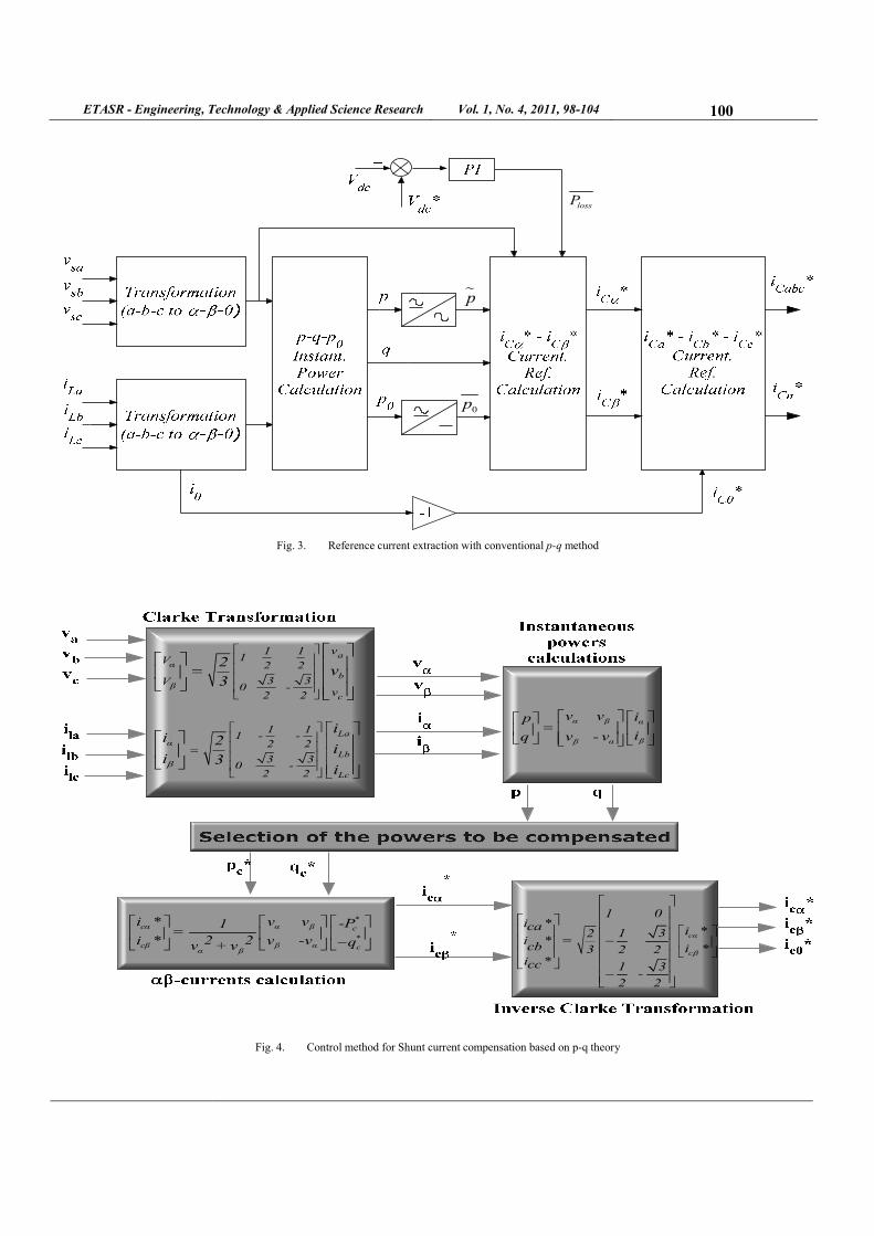
−
Fig. 4. Control method for Shunt current compensation based on p-q theory

ETASR - Engineering, Technology & Applied Science Research Vol. 1, �o. 4, 2011, 98-104 101
i ' -i 'v ' α βα p'1=
v ' 2 2 i ' i ' q'i ' +i 'β αβα β
(8)
IV. CONSTRUCTION OF PI CONTROLLER
Figure 5 shows the internal structure of the control circuit. The control scheme consists of a PI controller, a limiter, and a three phase sine wave generator for reference current generation and generation of switching signals. The peak value of reference currents is estimated by regulating the DC link voltage. The actual capacitor voltage is compared with a set reference value [10].
Fig. 5. Conventional PI Controller
The error signal is then processed through a PI controller, which contributes to zero steady error in tracking the reference current signal. The output of the PI controller is considered as peak value of the supply current (Imax), which is composed of two components: (a) fundamental active power component of load current, and (b) loss component of APF to maintain the average capacitor voltage to a constant value. The peak value of the current (Imax) is multiplied by the unit sine vectors in phase with the respective source voltages to obtain the reference compensating currents. These estimated reference currents (Isa*, Isb*, Isc*) and sensed actual currents (Isa, Isb, Isc ) are compared at a hysteresis band, which gives the error signal for the modulation technique. This error signal decides the operation of the converter switches. In this current control circuit configuration, the source/supply currents Isabc are made to follow the sinusoidal reference current Iabc, within a fixed hysteretic band. The width of hysteresis window determines the source current pattern, its harmonic spectrum and the switching frequency of the devices [11].
The DC link capacitor voltage is kept constant throughout the operating range of the converter. Each phase of the converter is controlled independently. To increase the current of a particular phase, the lower switch of the converter associated with that particular phase is turned on. To decrease the current the upper switch of the respective converter phase is turned on.
V. CONSTRUCTION OF FUZZY CONTROLLER
Figure 6 shows the internal structure of the control circuit. The control scheme consists of a fuzzy controller, a limiter, and
three phase sine wave generator for reference current generation and generation of switching signals. The peak value of reference currents is estimated by regulating the DC link voltage. The actual capacitor voltage is compared with a set reference value. The error signal is then processed through a Fuzzy controller, which contributes to zero steady error in tracking the reference current signal.
Fig. 6. Conventional Fuzzy Controller
A fuzzy controller converts a linguistic control strategy into an automatic control strategy, and fuzzy rules are constructed by expert experience or knowledge database. Firstly, input voltage Vdc and the input reference voltage Vdc-ref have been placed of the angular velocity to be the input variables of the fuzzy logic controller. Then the output variable of the fuzzy logic controller is presented by the control current Imax. To convert these numerical variables into linguistic variables, the following seven fuzzy levels or sets are chosen [12]: NB (negative big), NM (negative medium), NS (negative small), ZE (zero), PS (positive small), PM (positive medium), and PB (positive big) as shown in Figure 7.
The fuzzy controller is characterized as follows:
(i) Seven fuzzy sets for each input and output.
(ii) Fuzzification using continuous universe of discourse.
(iii) Implication using Mamdani's 'min' operator.
(iv) De-fuzzification using the 'centroid' method.
Fuzzification: The process of converting a numerical variable (real number) convert to a linguistic variable (fuzzy number) is called fuzzification.
De-fuzzification:The rules of FLC generate required output in a linguistic variable (Fuzzy Number), according to real world requirements, linguistic variables have to be transformed to crisp output (Real number).
Database: The Database stores the definition of the membership Function required by fuzzifier and defuzzifier.
VI. SIMULATION RESULTS
Figure 8 and Figure 9 illustrates the performance of shunt active power filter under different main voltages. As load is highly inductive, the current is integrated with rich harmonics. Initially, system performance is analyzed with balanced sinusoidal conditions. PI and Fuzzy are good enough in

ETASR - Engineering, Technology & Applied Science Research Vol. 1, �o. 4, 2011, 98-104 102
suppressing harmonics and THD is about 2.85% and 1.27%, but under un-balanced and non-sinusoidal conditions fuzzy shows superior performance over pi controller and THD at this instant with PI are 4.36% and 5.31 %, where as in fuzzy it is about 2.98% and 3.85%. (Figure 10).
VII. CONCLUSION
In the present paper two controllers are developed and verified with three phase four wire system. Even though both controllers are capable to compensate the current harmonics in the 3 phase 4-wire system, it is observed that the fuzzy controller shows more dynamic performance over conventional PI controller. With fuzzy logic and p-q approach a novel shunt active filter can be developed.
TABLE I. SYSTEM PARAMETERS
Fig. 7. Input Vdc Normalized Membership Function.
TABLE II. RULE BASE
3ph 4w Non-Sin p-q with Fuzzy Controller
0.352 0.354 0.356 0.358 0.36 0.362 0.364 0.366 0.368 0.37 0.372-400
-300
-200
-100
0
100
200
300
400
Time (Sec)
So
urc
e V
olt
ag
e
(Vo
lts)
0.352 0.354 0.356 0.358 0.36 0.362 0.364 0.366 0.368 0.37 0.372-150
-100
-50
0
50
100
150
Time (Sec)
So
urc
e C
urr
ent
(A
mp
s)
0.352 0.354 0.356 0.358 0.36 0.362 0.364 0.366 0.368 0.37 0.372-150
-100
-50
0
50
100
150
Time (Sec)
Fil
ter
Cu
rre
nt
(A
mp
s)
0.352 0.354 0.356 0.358 0.36 0.362 0.364 0.366 0.368 0.37 0.3720
200
400
600
800
1000
Time (Sec)
DC
Lin
k V
olt
ag
e (
Vo
lts)
0.352 0.354 0.356 0.358 0.36 0.362 0.364 0.366 0.368 0.37 0.372-40
-30
-20
-10
0
10
20
30
40
Time (Sec)
Lo
ad C
urr
en
t (
Am
ps)
0 10 20 30 40 500
1
2
3
4
5
Harmonic order
THD= 3.85%
Mag
(%
of
Fu
nd
ame
nta
l)
3ph 4w Non-Sin p-q with PI Controller
0.352 0.354 0.356 0.358 0.36 0.362 0.364 0.366 0.368 0.37 0.372-400
-300
-200
-100
0
100
200
300
400
Time (Sec)
So
urc
e V
olt
ag
e
(Vo
lts)
0.352 0.354 0.356 0.358 0.36 0.362 0.364 0.366 0.368 0.37 0.372-150
-100
-50
0
50
100
150
Time (Sec)
So
urc
e C
urr
ent
(A
mp
s)
0.352 0.354 0.356 0.358 0.36 0.362 0.364 0.366 0.368 0.37 0.372-150
-100
-50
0
50
100
150
Time (Sec)
Fil
ter
Cu
rre
nt
(A
mp
s)
0.352 0.354 0.356 0.358 0.36 0.362 0.364 0.366 0.368 0.37 0.3720
200
400
600
800
1000
Time (Sec)
DC
Lin
k V
olt
ag
e
(Vo
lts)
0.352 0.354 0.356 0.358 0.36 0.362 0.364 0.366 0.368 0.37 0.372-40
-30
-20
-10
0
10
20
30
40
Time (Sec)
Lo
ad C
urr
en
t (
Am
ps)
0 10 20 30 40 500
2
4
6
8
10
Harmonic order
THD= 5.31%
Mag
(%
of
Fu
nd
am
en
tal)
(a) (b)
Fig. 8. p-q Control Strategy response Under Bal Non-Sin
with (a) PI controller (b) Fuzzy controller

ETASR - Engineering, Technology & Applied Science Research Vol. 1, �o. 4, 2011, 98-104 103
0.352 0.354 0.356 0.358 0.36 0.362 0.364 0.366 0.368 0.37 0.372-400
-300
-200
-100
0
100
200
300
400
Time (Sec)
So
urc
e V
olt
age
(V
olt
s)
0.352 0.354 0.356 0.358 0.36 0.362 0.364 0.366 0.368 0.37 0.372-150
-100
-50
0
50
100
150
Time (Sec)
So
urc
e C
urr
en
t (
Am
ps)
0.352 0.354 0.356 0.358 0.36 0.362 0.364 0.366 0.368 0.37 0.372-150
-100
-50
0
50
100
150
Time (Amps)
Fil
ter
Cu
rren
t (
Am
ps)
0.352 0.354 0.356 0.358 0.36 0.362 0.364 0.366 0.368 0.37 0.3720
200
400
600
800
1000
Time (Sec)
DC
Lin
k V
olt
ag
e
(Vo
lts)
3ph 4w Bal Sin p-q with PI Controller
0.352 0.354 0.356 0.358 0.36 0.362 0.364 0.366 0.368 0.37 0.372-40
-30
-20
-10
0
10
20
30
40
Time (Sec)
Lo
ad C
urr
ent
(A
mp
s)
0 10 20 30 40 500
0.2
0.4
0.6
0.8
1
Harmonic order
THD= 2.15%
Ma
g (
% o
f F
un
dam
en
tal)
0.352 0.354 0.356 0.358 0.36 0.362 0.364 0.366 0.368 0.37 0.372-400
-300
-200
-100
0
100
200
300
400
Time (Sec)
So
urc
e V
olt
age
(V
olt
s)
0.352 0.354 0.356 0.358 0.36 0.362 0.364 0.366 0.368 0.37 0.372-150
-100
-50
0
50
100
150
Time (Sec)
So
urc
e C
urr
ent
(A
mp
s)
0.352 0.354 0.356 0.358 0.36 0.362 0.364 0.366 0.368 0.37 0.372-150
-100
-50
0
50
100
150
Time (Sec)
Fil
ter
Cu
rre
nt
(A
mp
s)
0.352 0.354 0.356 0.358 0.36 0.362 0.364 0.366 0.368 0.37 0.3720
200
400
600
800
1000
DC
Lin
k V
olt
ag
e
(Vo
lts)
Time (Sec)
3ph 4w Bal Sin p-q with Fuzzy Controller
0.352 0.354 0.356 0.358 0.36 0.362 0.364 0.366 0.368 0.37 0.372-40
-30
-20
-10
0
10
20
30
40
Time (Sec)
Lo
ad C
urr
ent
(A
mp
s)
0 10 20 30 40 500
0.2
0.4
0.6
0.8
1
Harmonic order
THD= 1.27%
Mag
(%
of
Fu
nd
amen
tal)
3ph 4w Un-bal p-q with PI Controller
0.352 0.354 0.356 0.358 0.36 0.362 0.364 0.366 0.368 0.37 0.372-400
-300
-200
-100
0
100
200
300
400
Time (Sec)
So
urc
e V
olt
age
(V
olt
s)
0.352 0.354 0.356 0.358 0.36 0.362 0.364 0.366 0.368 0.37 0.372-150
-100
-50
0
50
100
150
Time (Sec)
So
urc
e C
urr
en
t (
Am
ps)
0.352 0.354 0.356 0.358 0.36 0.362 0.364 0.366 0.368 0.37 0.372-150
-100
-50
0
50
100
150
Time (Sec)
Fil
ter
Cu
rren
t (
Am
ps)
0.352 0.354 0.356 0.358 0.36 0.362 0.364 0.366 0.368 0.37 0.3720
200
400
600
800
1000
Time (Sec)
DC
Lin
k V
olt
age
(V
olt
s)
0.352 0.354 0.356 0.358 0.36 0.362 0.364 0.366 0.368 0.37 0.372-40
-30
-20
-10
0
10
20
30
40
Time (Sec)L
oad
Cu
rren
t (
Am
ps)
0 10 20 30 40 500
1
2
3
4
5
Harmonic order
THD= 4.16%
Mag
(%
of
Fu
nd
ame
nta
l)
3ph 4w Un-bal p-q with Fuzzy Controller
0.352 0.354 0.356 0.358 0.36 0.362 0.364 0.366 0.368 0.37 0.372-400
-300
-200
-100
0
100
200
300
400
Time (Sec)
So
urc
e V
olt
age
(V
olt
s)
0.352 0.354 0.356 0.358 0.36 0.362 0.364 0.366 0.368 0.37 0.372-150
-100
-50
0
50
100
150
Time (Sec)
So
urc
e C
urr
ent
(A
mp
s)
0.352 0.354 0.356 0.358 0.36 0.362 0.364 0.366 0.368 0.37 0.372-150
-100
-50
0
50
100
150
Time (Sec)
Fil
ter
Cu
rren
t (
Am
ps)
0.352 0.354 0.356 0.358 0.36 0.362 0.364 0.366 0.368 0.37 0.3720
200
400
600
800
1000
Time (Sec)
DC
Lin
k V
olt
age
(V
olt
s)
0.352 0.354 0.356 0.358 0.36 0.362 0.364 0.366 0.368 0.37 0.372-40
-30
-20
-10
0
10
20
30
40
Time (Sec)
Lo
ad C
urr
ent
(A
mp
s)
0 10 20 30 40 500
0.2
0.4
0.6
0.8
1
Harmonic order
THD= 2.98%
Mag
(%
of
Fu
nd
am
en
tal)
(a) (b) (c) (d)
Fig. 9. 3ph 4wire Shunt ative filter using p-q Control Strategy response Under
(a)Bal Sin with PI (b) Bal Sin with Fuzzy (c) Un-bal Sin with PI (d) Un-bal Sin with Fuzzy controller

ETASR - Engineering, Technology & Applied Science Research Vol. 1, �o. 4, 2011, 98-104 104
Fig. 10. THD for p-q method with PI and Fuzzy controllers
REFERENCES
[1] H Akagi, H. Kanazawa, Y. Nabae “instantaneous reactive power compensators comprising Switching devices without energy storage components” IEEE Transactions on Industry Applications, Vol. Ia-20, No. 3, pp 625-630, 1984
[2] L. Gyugyi, E. C. Strycula, “Active AC power filters”, IEEE IIAS Annual Meeting, pp. 529-535, 1996
[3] F. Z. Peng, G. W. Ott Jr, D. J Adams, “Harmonic and reactive power compensation based on the generalized instantaneous reactive power theory for three-phase four-wire systems”, IEEE Transactions on Power Electronics, Vol. 13, No. 5, pp. 1174-1181, 1998
[4] M. I. M. Montero, E. R. Cadaval, F. B. Gonzalez, “Comparison of control strategies for shunt active power filters in three-phase fourwire systems”, IEEE Transactions on Power Electronics, Vol. 22, No. 1, pp. 229-236, 2007.
[5] M. Suresh, A. K. Panda, S. Yellasiri, “Fuzzy controller based 3phase 4wire shunt active Filter for mitigation of current harmonics with combined p-q and Id-Iq control strategies”, Journal of Energy and Power Engineering, Vol. 3, No. 1, pp. 43-52, 2011
[6] H. Akagi, E. H. Watanabe, “Instantaneous power theory and applications to power conditioning”, New Jersey. IEEE Press/Wiley-Inter-science ISBN: 978-0-470-10761-4, 2007
[7] V. Soares, P. Verdelho, G. Marques, “Active power filter control circuit based on the instantaneous active and reactive current id –iq method”, IEEE Power Electronics Specialists Conference, Vol. 2, pp. 1096-1101, 1997
[8] M. Aredes, J. Hafner, K. Heumann, “Three-phase four-wire shunt active filter control strategies”, IEEE Transactions on Power Electronics, Vol. 12, No. 2, pp. 311–318, 1997
[9] P. Rodriguez, J. I. Candela, A. Luna, L. Asiminoaei, “Current harmonics cancellation in three-phase four-wire systems by using a four-branch star filtering topology”, IEEE Transactions on Power Electronics, Vol. 24, No. 8, pp. 1939-1950, 2009
[10] P. Salmeron, R. S. Herrera, “Distorted and unbalanced systems compensation within instantaneous reactive power framework”, IEEE Transactions on Power Delivery, Vol. 21, No. 3, pp. 1655-1662, 2006
[11] S. Mikkili, A. K. Panda, "Simulation and RTDS Hardware implementation of SHAF for Mitigation of Current Harmonics with p-q and Id-Iq Control strategies using PI controller", Engineering, Technology & Applied Science Research, Vol. 1, No. 3, pp. 54-62, 2011
[12] S. K. Jain, P. Agrawal, H. O. Gupta, “Fuzzy logic controlled shunt active power filter for power quality improvement” IEEE Proceedings Electric Power Applications, Vol. 149, No. 5, pp. 317–328, 2002
AUTHORS PROFILE
Suresh Mikkili was born in Bapatla, Andhra
Pradesh, India on 5th Aug 1985. He received B.Tech
degree in Electrical and Electronics Engineering
from JNTU University Hyderabad in May 2006 and
Masters (M.Tech) in Electrical Engineering from
N.I.T Rourkela, India in May 2008. He has worked
as a Asst.Prof in Electrical Engineering, S.I.T.E,
T.P.Gudem from June 2008 to Dec-2009 and in
V.K.R & V.N.B Engineering college from Dec-
2009 to July 2010. He is currently pursuing the Ph.D degree in Electrical
Engineering at N.I.T Rourkela, India from July 2010. His main area of
research includes power quality improvement issues, active filters, and soft
computing techniques.
.
Anup Kumar Panda: Born in 1964. He received the B.Tech in Electrical Engineering from Sambalpur University, India in 1987. He received
the M.Tech in Power Electronics and Drives from
Indian Institute of Technology, Kharagpur, India in 1993 and Ph.D. in 2001 from Utkal University.
Join as a faculty in IGIT, Sarang in 1990. Served
there for eleven years and then join National Institute of Technology, Rourkela in January 2001
as an assistant professor and currently continuing
as a Professor in the Department of Electrical Engineering. He has published over forty articles in journals and conferences. He has completed
two MHRD projects and one NaMPET project. Guided two Ph.D. scholars and currently guiding four scholars in the area of Power Electronics &
Drives. His research interest include analysis and design of high frequency
power conversion circuits, power factor correction circuits, power quality improvement in power system and electric drives.