Embed Size (px)
Citation preview
Circuits and Systems, 2016, 7, 779-793 Published Online May 2016 in SciRes. http://www.scirp.org/journal/cs http://dx.doi.org/10.4236/cs.2016.76067
How to cite this paper: Pugazhendiran, P. and Baskaran, J. (2016) Realization of Unified Power Quality Conditioner for Mi-tigating All Voltage Collapse Issues. Circuits and Systems, 7, 779-793. http://dx.doi.org/10.4236/cs.2016.76067
Realization of Unified Power Quality Conditioner for Mitigating All Voltage Collapse Issues Parthasarathy Pugazhendiran1, Jeevarathinam Baskaran2 1Department of Electrical and Electronics Engineering, IFET College of Engineering, Villupuram, India 2Department of Electrical and Electronics Engineering, Adhiparasakthi College of Engineering, Melmaruvathur, India Email: [email protected], [email protected] Received 10 March 2016; accepted 8 May 2016; published 13 May 2016
Copyright © 2016 by authors and Scientific Research Publishing Inc. This work is licensed under the Creative Commons Attribution International License (CC BY). http://creativecommons.org/licenses/by/4.0/
Abstract This paper proposes about a powerful control mechanism of UPQC (Unified Power Quality Condi-tioner) work on voltage source inverter which can effectively compensate source current har-monics and also mitigate all voltage collapse such as dip, swell, voltage unbalances and harmonics. The consolidation of series and parallel active power filters sharing mutual DC bus capacitor forms UPQC. PI (Proportional Integral) controller is mainly used in order to maintain continual DC voltage along with the hysteresis current controller. The parallel and series power filters were de-signed using 3-phase voltage source inverter. The reference signals for shunt and series active power filters were obtained by Synchronous Reference Frame (SRF) theory and Power Reactive (PQ) theory respectively. By using these theories, reference signals were obtained which was fed to the controllers for generating switching pulses for parallel and series active filters. The UPQC dynamic performance is obtained through testing terms like the compensation of voltage, current harmonics and all voltage distortion associated with 3-phase 3-wire power system which is simu-lated using MATLAB-Simulink software.
Keywords Power Quality Conditioner, Voltage Sag (Dip), Voltage Swell, Current Harmonics Mitigation, Power Quality Improvement
1. Introduction Due to increase in use of power electronics devices in industrial area as well as in customer loads which uses
P. Pugazhendiran, J. Baskaran
780
non-linear loads, non-linear loads at utility cause large supply of reactive power which pollutes the source side equipment largely. The main requirement of mitigation equipment is that they should be fast and dynamic re-sponse helps to reduce the source side harmonics. Due to increasing use of non-linear loads, nowadays active filters are replacing the olden days mitigation methods like switching capacitor and thyristor controlled inductor coupled with passive filters [1]-[4]. There are types of active power filters used: parallel active filter eliminates current harmonics and series active filter mitigates all types of voltage issues.
The Unified Power Quality Conditioner (UPQC) is a solution to mitigate current and voltage issues; it is the combined design of shunt and series active power filters coupled through mutual DC linkage capacitor which rejects the instabilities spread from the supply side and the interconnected supplementary loads. In general, the task of UPQC, parallel active filter estimates the reimbursing current harmonics called mitigating current har-monics and helps in VAR generation using the control circuitry [5]-[8]. The series active filters are able to miti-gate all voltage issues. The device used to control the series active power filter analyzes the reference voltage to be inoculated by matching the voltage at terminal against the reference voltage.
From the literature review of various works done so far, describing the balanced or unbalanced source condi-tions by voltage either dip or rise. In this work, different kind of voltage based PQ issues such as sag, swell, transients, interruption and current harmonics are simultaneously mitigated under balanced and unbalanced source conditions as well as linear and non-linear loading conditions.
This article proposes about three-phase three-wire system having voltage source inverter using streamlined control method. The series active filter is maintaining load voltage, dip/swell, harmonics and flickers. The vol-tage on DC capacitor is maintained constant by parallel active filters. UPQC performances are simulated and ve-rified using MATLAB tool.
The Right Shunt type Unified Power Quality Conditioner (UPQC) with voltage source inverter is acted as a filter and its modelling is deliberated in Section 2. The proposed control method based on hysteresis controller for series and parallel active filter is explained in Section 3. A Simulink model and its detailed result and discus-sion of the projected control scheme are described in Section4 for two different source conditions. The conclu-sion of the work is summarized in Section 5.
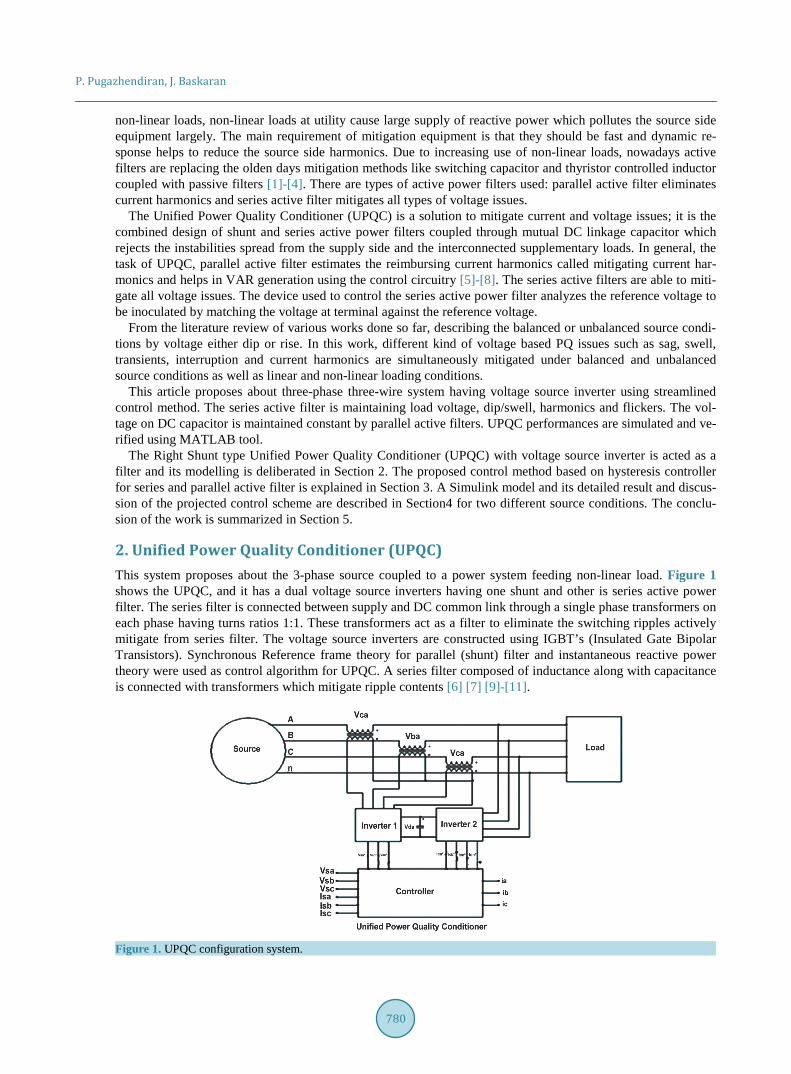
2. Unified Power Quality Conditioner (UPQC) This system proposes about the 3-phase source coupled to a power system feeding non-linear load. Figure 1 shows the UPQC, and it has a dual voltage source inverters having one shunt and other is series active power filter. The series filter is connected between supply and DC common link through a single phase transformers on each phase having turns ratios 1:1. These transformers act as a filter to eliminate the switching ripples actively mitigate from series filter. The voltage source inverters are constructed using IGBT’s (Insulated Gate Bipolar Transistors). Synchronous Reference frame theory for parallel (shunt) filter and instantaneous reactive power theory were used as control algorithm for UPQC. A series filter composed of inductance along with capacitance is connected with transformers which mitigate ripple contents [6] [7] [9]-[11].
Figure 1. UPQC configuration system.
P. Pugazhendiran, J. Baskaran
781
2.1. Voltage Source Inverter From olden days, several inverters have been used due to different applications. Voltage Source inverters have wide applications which include drive control strategy, STATCOM, HVDC transmission, and more important is that the interfacing of renewable energy resources. In Power Quality improvement voltage source topology was widely used in SVC’s, UPQC’s, etc. due fast and dynamic response characteristics [8] [11]. Moreover, in UPQC, voltage source converters certain unbalance DC link voltage due fast short duration operation. The advantages of voltage source inverter are:
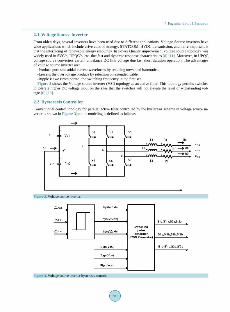
-Produce pure sinusoidal current waveforms by reducing unwanted harmonics. -Lessens the overvoltage produce by refection on extended cable. -Ripple is two times normal the switching frequency in the first set. Figure 2 shows the Voltage source inverter (VSI) topology as an active filter .This topology permits switches
to tolerate higher DC voltage input on the sites that the switches will not elevate the level of withstanding vol-tage [6] [10].
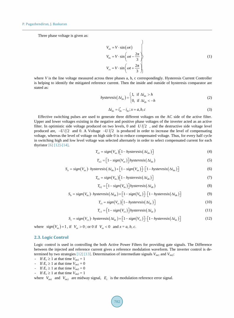
2.2. Hysteresis Controller Conventional control topology for parallel active filter controlled by the hysteresis scheme in voltage source in-verter is shown in Figure 3 and its modeling is defined as follows.
Figure 2. Voltage source inverter.
Figure 3. Voltage source inverter hysteresis control.
P. Pugazhendiran, J. Baskaran
782
Three phase voltage is given as:
( )sin
2πsin3
2πsin3
as
bs
cs
V V t
V V t
V V t
ω
ω
ω
= ⋅ = ⋅ −
= ⋅ +
(1)
where V is the line voltage measured across three phases a, b, c correspondingly. Hysteresis Current Controller is helping to identify the mitigated reference current. Then the inside and outside of hysteresis comparator are stated as:
( )1, if0, if
dxdx
dx
i hhysteresis i
i h∆ >
∆ = ∆ < − (2)
* ; , ,dx dx dxi i i x a b c∆ = − = (3)
Effective switching pulses are used to generate three different voltages on the AC side of the active filter. Upper and lower voltages existing in the negative and positive phase voltages of the inverter acted as an active filter. In optimistic side voltage produced on two levels, 0 and 2U l , and the destructive side voltage level produced are, 2U l− and 0. A Voltage 2U l− is produced in order to increase the level of compensating voltage, whereas the level of voltage on high side 0 is to reduce compensated voltage. Thus, for every half cycle in switching high and low level voltage was selected alternately in order to select compensated current for each thyristor [6] [12]-[14].
( ) ( )1 1a as daT sign V hysteresis i = − ∆ (4)
( ) ( )2 1a as daT sign V hysteresis i = − ∆ (5)
( ) ( ) ( ) ( )1 1a as da as daS sign V hysteresis i sign V hysteresis i = ⋅ ∆ + − ⋅ − ∆ (6)
( ) ( )1 1b bs dbT sign V hysteresis i = − ∆ (7)
( ) ( )2 1b bs dbT sign V hysteresis i = − ∆ (8)
( ) ( ) ( ) ( )1 1b bs db bs dbS sign V hysteresis i sign V hysteresis i = ⋅ ∆ + − ⋅ − ∆ (9)
( ) ( )1 1c cs dcT sign V hysteresis i = − ∆ (10)
( ) ( )2 1c cs dcT sign V hysteresis i = − ∆ (11)
( ) ( ) ( ) ( )1 1c cs dc cs dcS sign V hysteresis i sign V hysteresis i = ⋅ ∆ + − ⋅ − ∆ (12)
where ( ) 1sxsign V = , if 0sxV > ; or 0 if 0sxV < and x = a, b, c.
2.3. Logic Control Logic control is used in controlling the both Active Power Filters for providing gate signals. The Difference between the injected and reference current gives a reference modulation waveform. The inverter control is de-termined by two strategies [12] [13]. Determination of intermediate signals Vim1 and Vim2: - If Ec ≥ 1 at that time Vim1 = 1 - If Ec ≥ 1 at that time Vim1 = 0 - If Ec ≥ 1 at that time Vim2 = 0 - If Ec ≥ 1 at that time Vim2 = 1 where 1imV and 2imV are midway signal, cE is the modulation reference error signal.
P. Pugazhendiran, J. Baskaran
783
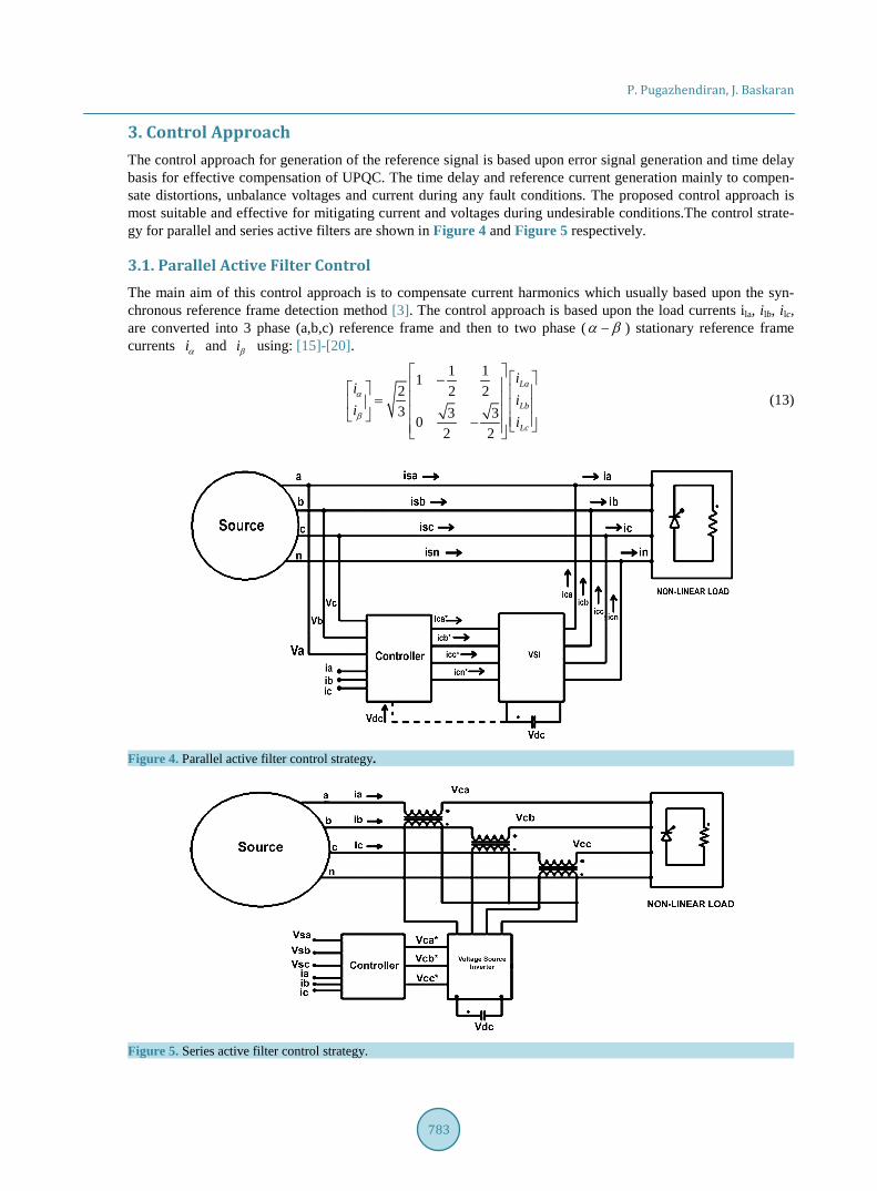
3. Control Approach The control approach for generation of the reference signal is based upon error signal generation and time delay basis for effective compensation of UPQC. The time delay and reference current generation mainly to compen-sate distortions, unbalance voltages and current during any fault conditions. The proposed control approach is most suitable and effective for mitigating current and voltages during undesirable conditions.The control strate-gy for parallel and series active filters are shown in Figure 4 and Figure 5 respectively.
3.1. Parallel Active Filter Control The main aim of this control approach is to compensate current harmonics which usually based upon the syn-chronous reference frame detection method [3]. The control approach is based upon the load currents ila, ilb, ilc, are converted into 3 phase (a,b,c) reference frame and then to two phase (α β− ) stationary reference frame currents iα and iβ using: [15]-[20].
1 112 2 23 3 30
2 2
La
Lb
Lc
ii
ii
i
α
β
− = −
(13)
Figure 4. Parallel active filter control strategy.
Figure 5. Series active filter control strategy.
P. Pugazhendiran, J. Baskaran
784
By means of phase locked loop (PLL), that make possible for generations of ( )cos etθ and ( )sin etθ from phase voltages such as, Vas, Vbs, and Vcs.
The iα and iβ currents obtained from (d-q) reference frame are written as:
( ) ( )( ) ( )
sin coscos sin
d et et
q et et
i ii i
α
β
θ θθ θ
− =
(14)
The id and iq current are transformed into DC components and using a low pass filter harmonic components are obtained:
d d d
q q
i i ii i
+=
(15)
The equation for the reference current iα -ref and iβ -ref as,
( ) ( )( ) ( )
1sin coscos sin
det et
qet et
ii refii ref
α
β
θ θθ θ
−− −
= − (16)
( ) ( )( ) ( )
sin coscos sin
et et d d
et et q
i ref i ii ref iα
β
θ θθ θ
− += − −
(17)
The abc reference frame is given as:
1 0
2 1 33 2 2
1 32 2
a ref
b ref
c ref
ii ref
ii ref
i
α
β
−
−
−
− = − − −
(18)
Finally, the compensation currents are obtained as;
acomp a ref La
bcomp b ref Lb
ccomp c ref Lc
i i i
i i i
i i i
−
−
−
= −
= − = −
(19)
In order to mitigate, initially the inverter losses are reduced and then normalize the DC link voltages using a PI voltage controller [21]. The loop produces an equivalent current given as:
, dc los p DC i DCI k U K U t= ⋅ ∆ + ∆ ⋅∫ (20)
3.2. Series Active Filter Control For generating reference frame for series active filter depending upon the PQ theory, we assume phase voltages are symmetric and distorted: [3] [15] [17] [19]. The Figure 5 shows the series active filter control for generating the filter reference voltage at the time of distortion occurred in the supply voltage.
( )1
1
1
2 sin
2π2 sin3
2π2 sin3
n nn
A
B n nn
C
n nn
U n tUU U n tU
U n t
ω θ
ω θ
ω θ
∞
=
∞
=
∞
=
+
= − + − +
∑
∑
∑
(21)
P. Pugazhendiran, J. Baskaran
785
The Un and nθ are rms voltages and primary phase angle, n is the harmonic order. When n = 1, it means that the fundamental 3-phasesupply voltage;
( )1 1
1 1
1 1
2 sin
2π2 sin3
2π2 sin3
A
B
C
U tUU U tU
U t
ω θ
ω θ
ω θ
+ = − + − +
(22)
Equation (10) is converted into reference frame:
( )
( )
132
1
sin3
sin
A n nn
B
n nCn
U U n tUC U
UU n tU
α
β
ω θ
ω θ
∞
=
∞
=
+ = = +
∑
∑ (23)
32
1 1 2 1 223 0 3 2 3 2
C− −
= −
(24)
The fundamental 3-phase current is framed as:
( )sin2 2πsin3 3
2πsin3
a
b
c
tii ti
t
ω
ω
ω
= − +
(25)
Equation (10) is transformed to (α β− ) reference frame:
( )( )32
sincos
a
b
c
ii t
C ii t
i
α
β
ωω
= = −
(26)
The DC components are obtained by passing P and Q in low pass filter (LPF), then
( )( )
1 1
1 1
cos3
sinUpUq
θθ
=
(27)
From the above equation the transformation is made as: U U i i i UpU U i i i Uq
α β α α β α
β α β β α β
= = − −
(28)
The DC mechanisms of p and q as:
f f f
f f f
U U Ui i ipU U Ui i iq
α β αα α β
β α ββ β α
= = − −
(29)
The fundamental reference frame is given as: 1f
f
U i i pU i i q
α α β
β β α
−
= − (30)
The three-phase fundamental voltages are given as:
P. Pugazhendiran, J. Baskaran
786
( )1 1
23 1 1
1 1
sin
2π2 sin3
2πsin3
Aff
Bff
Cf
U tU
UU C U t
UU
U t
α
β
ω θ
ω θ
ω θ
+ = = − + − +
(31)
23
1 0
1 32 21 32 2
C
= − −
(32)
4. Simulation Results and Discussion 4.1. UPQC Performance for Voltage Compensation for Balanced Source Voltage Here both shunt and series power filters are put into operation at different time instants. Considering nonlinear load for simulation source parameters considered are as follows. Input source voltages: Va = 230 V, Vb = 230 V, Vc = 230 V. The load element and filters with VSC has been built using MATLAB /SIMULINK. The following observations are drawn from the simulation outcomes. The control algorithm provides reactive and harmonic power compensation.
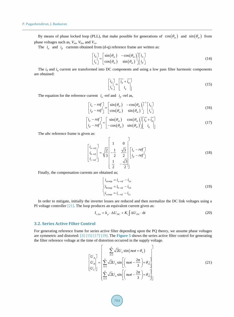
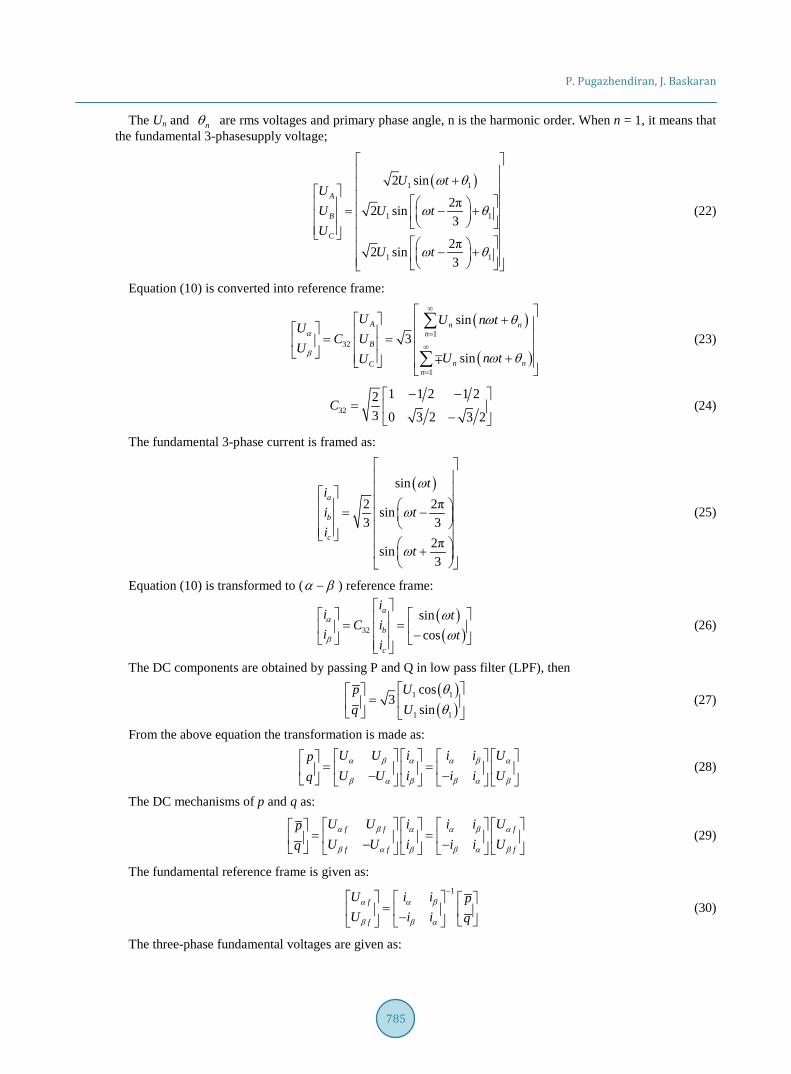
Here balanced source voltage is considered and after compensation balanced source current is prescribed in following results. Figure 6 shows the three phase balanced source voltages which is being supplied to the sys-tem. Figure 7 depicts the three phase error voltage which is generated due to the load connected to UPQC.
At time instant for t = 0 to 0.05 sec system is working without any issues, which does not require any com-pensation and after t = 0.05 voltage dip is introduced, in this time period series filter comes into operation for compensating voltage harmonics. The voltage dip occurs till 0.1 sec, the system is again at normal working con-dition. Then a short time interruption is led which occur from t = 0.14 to 0.15 sec, following the interruption
Figure 6. Three phase balanced source voltage.
Figure 7. Three phase error voltage.
P. Pugazhendiran, J. Baskaran
787
voltage swell is hosted from t = 0.15 to 0.18 sec at that time shunt filter comes into operation for compensating harmonics due rise in voltage, then the system voltage come back to its normal working condition.
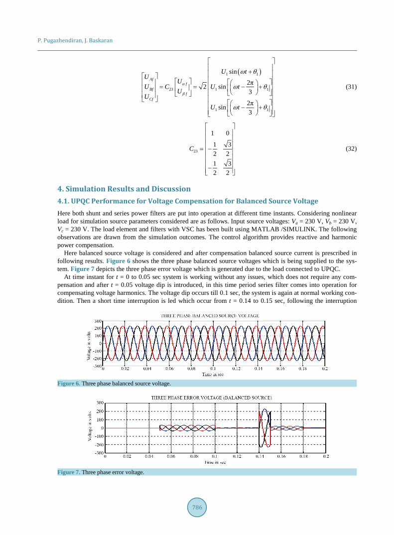
In Figure 8 voltage from t = 0 to 0.05 sec remain zero because of normal operation at time 0.05 sec voltage dip arise the reference voltage generator generates required amount of voltage to compensate dip which occur till 0.1 sec. At t = 0.14 sec there is a small interruption for 0.01 sec so reference voltage generator generates the necessary voltage to maintain source voltage as normal. At t = 0.15 sec there is 10% rise (Vs = 253 volt) in vol-tage till 0.18 sec. So reference voltage generator generates the required voltage in the opposite direction for mi-tigation.
Three phase actual (generated) error voltage which is being added to the system error voltage to obtain the compensated source voltage of 230 volts for an entire operating period, it is shown in Figure 9.
In Figure 8 and Figure 9 there are few overshoots at t = 0.5 secs, t = 0.1 secs, t = 0.14 ecs, t = 0.18 secs re-spectively. This overshoots are due to sudden injection of reference components (voltage/Current) while miti-gating the pq issues like sag, swell and etc., in the respective fault points. The duration of this overshoot exist for few milli or micro seconds. These overshoots can be reduced by selecting suitable values of L and C of the ac-tive filters and its controllers in the proposed UPQC.
The supply current before compensation is non-sinusoidal due to the non-linear load connected to the system which is shown in Figure 10.
Figure 8. Three phase actual error voltage.
Figure 9. Compensated Source voltage after compensation.
Figure 10. Source current before compensation.
P. Pugazhendiran, J. Baskaran
788
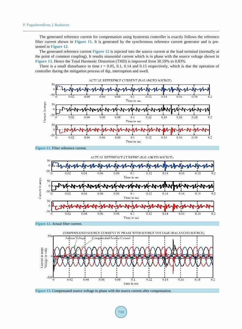
The generated reference current for compensation using hysteresis controller is exactly follows the reference filter current shown in Figure 11. It is generated by the synchronous reference current generator and is pre-sented in Figure 12.
The generated reference current Figure 12 is injected into the source current at the load terminal (normally at the point of common coupling). It results sinusoidal current which is in phase with the source voltage shown in Figure 13. Hence the Total Harmonic Distortion (THD) is improved from 30.59% to 0.83%.
There is a small disturbance in time t = 0.05, 0.1, 0.14 and 0.15 respectively, which is due the operation of controller during the mitigation process of dip, interruption and swell.
Figure 11. Filter reference current.
Figure 12. Actual filter current.
Figure 13. Compensated source voltage in phase with the source current after compensation.
P. Pugazhendiran, J. Baskaran
789
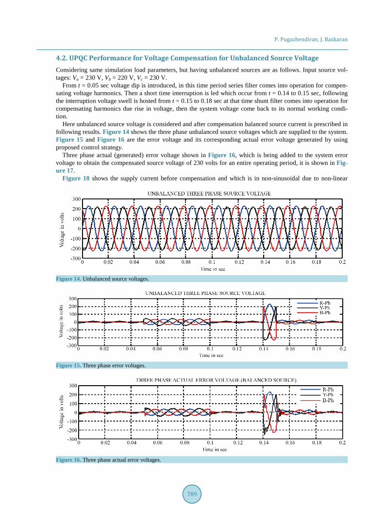
4.2. UPQC Performance for Voltage Compensation for Unbalanced Source Voltage Considering same simulation load parameters, but having unbalanced sources are as follows. Input source vol-tages: Va = 230 V, Vb = 220 V, Vc = 230 V.
From t = 0.05 sec voltage dip is introduced, in this time period series filter comes into operation for compen-sating voltage harmonics. Then a short time interruption is led which occur from t = 0.14 to 0.15 sec, following the interruption voltage swell is hosted from t = 0.15 to 0.18 sec at that time shunt filter comes into operation for compensating harmonics due rise in voltage, then the system voltage come back to its normal working condi-tion.
Here unbalanced source voltage is considered and after compensation balanced source current is prescribed in following results. Figure 14 shows the three phase unbalanced source voltages which are supplied to the system. Figure 15 and Figure 16 are the error voltage and its corresponding actual error voltage generated by using proposed control strategy.
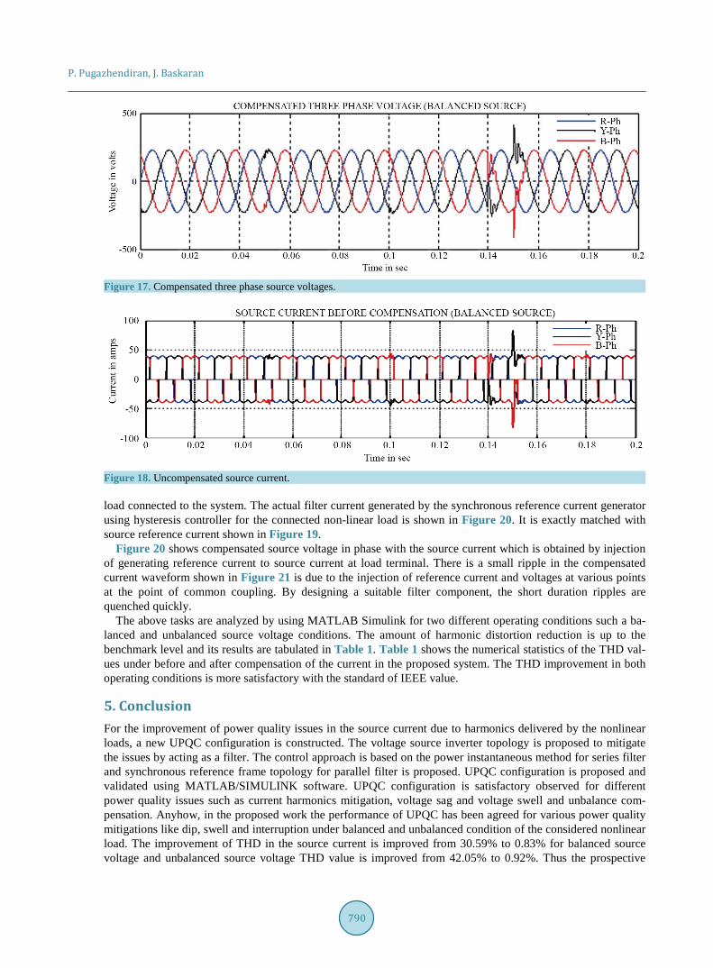
Three phase actual (generated) error voltage shown in Figure 16, which is being added to the system error voltage to obtain the compensated source voltage of 230 volts for an entire operating period, it is shown in Fig-ure 17.
Figure 18 shows the supply current before compensation and which is in non-sinusoidal due to non-linear
Figure 14. Unbalanced source voltages.
Figure 15. Three phase error voltages.
Figure 16. Three phase actual error voltages.
P. Pugazhendiran, J. Baskaran
790
Figure 17. Compensated three phase source voltages.
Figure 18. Uncompensated source current.
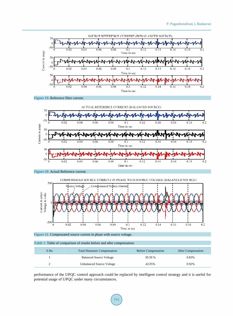
load connected to the system. The actual filter current generated by the synchronous reference current generator using hysteresis controller for the connected non-linear load is shown in Figure 20. It is exactly matched with source reference current shown in Figure 19.
Figure 20 shows compensated source voltage in phase with the source current which is obtained by injection of generating reference current to source current at load terminal. There is a small ripple in the compensated current waveform shown in Figure 21 is due to the injection of reference current and voltages at various points at the point of common coupling. By designing a suitable filter component, the short duration ripples are quenched quickly.
The above tasks are analyzed by using MATLAB Simulink for two different operating conditions such a ba-lanced and unbalanced source voltage conditions. The amount of harmonic distortion reduction is up to the benchmark level and its results are tabulated in Table 1. Table 1 shows the numerical statistics of the THD val-ues under before and after compensation of the current in the proposed system. The THD improvement in both operating conditions is more satisfactory with the standard of IEEE value.
5. Conclusion For the improvement of power quality issues in the source current due to harmonics delivered by the nonlinear loads, a new UPQC configuration is constructed. The voltage source inverter topology is proposed to mitigate the issues by acting as a filter. The control approach is based on the power instantaneous method for series filter and synchronous reference frame topology for parallel filter is proposed. UPQC configuration is proposed and validated using MATLAB/SIMULINK software. UPQC configuration is satisfactory observed for different power quality issues such as current harmonics mitigation, voltage sag and voltage swell and unbalance com-pensation. Anyhow, in the proposed work the performance of UPQC has been agreed for various power quality mitigations like dip, swell and interruption under balanced and unbalanced condition of the considered nonlinear load. The improvement of THD in the source current is improved from 30.59% to 0.83% for balanced source voltage and unbalanced source voltage THD value is improved from 42.05% to 0.92%. Thus the prospective
P. Pugazhendiran, J. Baskaran
791
Figure 19. Reference filter current.
Figure 20. Actual Reference current.
Figure 21. Compensated source current in phase with source voltage.
Table 1. Table of comparison of results before and after compensation.
S.No Total Harmonic Compensation Before Compensation After Compensation
1 Balanced Source Voltage 30.59 % 0.83%
2 Unbalanced Source Voltage 42.05% 0.92%
performance of the UPQC control approach could be replaced by intelligent control strategy and it is useful for potential usage of UPQC under many circumstances.
P. Pugazhendiran, J. Baskaran
792
References [1] JAfonso, J.L., Pinto, J.G. and Gonçalves, H. (2013) Active Power Conditioners to Mitigate Power Quality Problems in
Industrial Facilities.In: Zobaa, A., Ed., Power Quality Issues, Intech, 105-137. [2] Benachaiba, C., Abdelkhalek1, O., Dib, S., Allali, M. and Dib, D. (2010) The Unified Power Quality Conditioner
(UPQC): The Principle, Control and Application. Journal of Scientific Research, 2, 91-94. [3] Akagi, H. and Fujita, H. (1995) A New Power Line Conditioner for Harmonic Compensation in Power Systems. IEEE
Transactions on Power Delivery, 10, 1570-1575. http://dx.doi.org/10.1109/61.400941 [4] Gyugyi, L. (1979) Reactive Power Generation and Control by Thyristor Circuits. IEEE Transactions on Industry Ap-
plications, 15, 521-532. http://dx.doi.org/10.1109/TIA.1979.4503701 [5] Hirve, S., Chatterjee, K., Fernandes, B.G., Imayavaramban, M. and Dwari, S. (2007) PLL-Less Active Power Filter
Based on One-Cycle Control for Compensating Unbalanced Loads in Three-Phase Four-Wire System. IEEE Transac-tions on Power Delivery, 22, 2457-2465. http://dx.doi.org/10.1109/TPWRD.2007.893450
[6] Srikanth, D. and Ganesh, L.B. (2013) Mitigation of Harmonics by Hysteresis Control Technique of VSI Based STATCOM. International Journal of Latest Trends in Engineering and Technology (IJLTET), 2, 146-160.
[7] Fujita, H. and Akagi, H. (1998) The Unified Power Quality Conditioner: The Integration of Series Active Filters and Shunt Active Filters. IEEE Transactions on Power Electronics, 13, 315-322. http://dx.doi.org/10.1109/63.662847
[8] Jagadeesh, K., Prasad, D. and Ramesh, P. (2016) 3-Phase 4-Wire UPQC Topology with Reduced DC-Link Voltage Rating for Power Quality Improvement Using Fuzzy Controller. International Journal of Signal Processing, Image Processing and Pattern Recognition, 9, 135-146. http://dx.doi.org/10.14257/ijsip.2016.9.1.13
[9] Kolhatkar, Y.Y. and Das, S.P. (2007) Experimental Investigation of a Single-Phase UPQC with Minimum VA Loading. IEEE Transactions on Power Delivery, 22, 373-380. http://dx.doi.org/10.1109/TPWRD.2006.881471
[10] Yash, P., Swarup, A. and Singh, B. (2012) A Novel Control Strategy of Three-phase, Four-Wire UPQC for Power Quality Improvement. Journal of Electrical Engineering & Technology, 7, 1-8. http://dx.doi.org/10.5370/JEET.2012.7.1.1
[11] Paduchuri Chandra Babu, SubhransuSekhar Dash, C. Subramani,NavyaTejaswini and Y. Sravan Kumar Reddy (2015) A Fuzzy Logic Controller Based Multi Converter UPQC to Enhance the Power Quality Problems. In: Kamalakannan, C., Suresh, L.P., Dash, S.S. and Panigrahi, B.K., Eds., Power Electronics and Renewable Energy Systems, Lecture Notes in Electrical Engineering, Chapter 46, 453-463, Springer, Chennai.
[12] Lin, B.-R., Huang, C.-H., Yang, T.-Y. and Lee, Y.-C. (2003) Analysis and Implementation of Shunt Active Power Fil-ter with Three-Level PWM Scheme. IEEE Transactions on Power Electronics and Drives, 2, 1580-1585.
[13] Maur´ıcioAredes, J¨urgenH¨afner, and KlemensHeumann (1997) Three-Phase Four-Wire Shunt Active Filter Control Strategies. IEEE Transactions on Power Electronics, 12, 311-318. http://dx.doi.org/10.1109/63.558748
[14] Ghosh, A., Jindal, A.K. and Joshi, A. (2004) A Unified Power Quality Conditioner for Voltage Regulation of Critical Load Bus. Proceedings of IEEE Power Eng. Society General Meeting, Vol. 1, 471-476.
[15] Hamadi, A., Rahmani, S. and Al-Haddad, K. (2007) A Novel Hybrid Series Active Filter for Power Quality Compen-sation. IEEE Power Electronics Specialists Conference, Orlando, 17-21 June 2007, 1099-1104.
[16] Mazumdar, J., Harley, R.G. and Venayagamoorty, G.K. (2008) Synchronous Reference Frame Based Active Filter Current Reference Generation Using Neural Networks. 32nd Annual Conference on IEEE Industrial Electronics, Paris, 6-10 November 2006, 4404-4409.
[17] Salim, C., Benchouia, M.-T. and Goléa, A. (2012) Series Active Power Filter for Harmonic Voltage Compensation Using Two Control Strategies Based on Fuzzy Control Techniques. 4th International Conference on Electrical Engi-neering, ICEE’2012, 7-9 May 2012, Algiers, 370-375.
[18] Kiran, C.N., Dash, S.S. and Latha, S.P. (2011) A Few Aspects of Power Quality Improvement Using Shunt Active Power Filter. International Journal of Scientific & Engineering Research, 2, 1-11.
[19] Senthilnathan, K. and Annapoorani, K.I. (2016) Artificial Neural Network Control Strategy for Multi-Converter Uni-fied Power Quality Conditioner for Power Quality Improvements in 3-Feeder System. International Conference on Ar-tificial Intelligence and Evolutionary Computations in Engineering Systems. Advances in Intelligent Systems and Computing, 394, 1105-1111.
[20] Salim, C., Benchouia, M.-T. and Goléa, A. (2011) Harmonic Currents Compensation Based on Three-Level Shunt Ac-tive Filter Using Fuzzy Logic Current Controller. Journal of Electrical Engineering & Technology KIEE, 6, 595-604.

P. Pugazhendiran, J. Baskaran
793
[21] Zhao, G.P. and Han, M.X. (2015) Design of DC Side Voltage and Compensation Analysis of THD for Shunt Power Quality Controller under System Load of Rectifier with R-L Load. Journal of Electrical Engineering and Technology, 10, 30-40. http://dx.doi.org/10.5370/JEET.2015.10.1.030


![Paper - Marsland€¦ · Web viewUPQC introduced in [10] has the ability to compensate voltage sag and swell, harmonics and reactive power. In fig. 1 the general structure of grid](https://img.pdfslide.us/doc/110x75/5e798075845ed24b5b6eb8f5/paper-web-view-upqc-introduced-in-10-has-the-ability-to-compensate-voltage-sag.jpg)