Embed Size (px)
Citation preview
SETUP GUIDE FOR THE MINIBAY™ and SUPERBAY™
Golf Simulator Screen Systems
www.allsportsystems.com
Page 2 of 40 Rev 6/29/2017
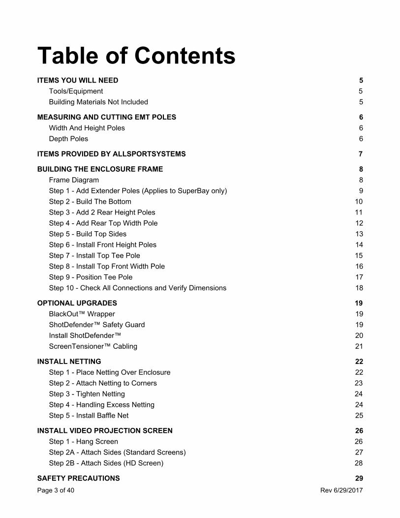
Table of Contents ITEMS YOU WILL NEED 5
Tools/Equipment 5 Building Materials Not Included 5
MEASURING AND CUTTING EMT POLES 6 Width And Height Poles 6 Depth Poles 6
ITEMS PROVIDED BY ALLSPORTSYSTEMS 7
BUILDING THE ENCLOSURE FRAME 8 Frame Diagram 8 Step 1 - Add Extender Poles (Applies to SuperBay only) 9 Step 2 - Build The Bottom 10 Step 3 - Add 2 Rear Height Poles 11 Step 4 - Add Rear Top Width Pole 12 Step 5 - Build Top Sides 13 Step 6 - Install Front Height Poles 14 Step 7 - Install Top Tee Pole 15 Step 8 - Install Top Front Width Pole 16 Step 9 - Position Tee Pole 17 Step 10 - Check All Connections and Verify Dimensions 18
OPTIONAL UPGRADES 19 BlackOut™ Wrapper 19 ShotDefender™ Safety Guard 19 Install ShotDefender™ 20 ScreenTensioner™ Cabling 21
INSTALL NETTING 22 Step 1 - Place Netting Over Enclosure 22 Step 2 - Attach Netting to Corners 23 Step 3 - Tighten Netting 24 Step 4 - Handling Excess Netting 24 Step 5 - Install Baffle Net 25
INSTALL VIDEO PROJECTION SCREEN 26 Step 1 - Hang Screen 26 Step 2A - Attach Sides (Standard Screens) 27 Step 2B - Attach Sides (HD Screen) 28
SAFETY PRECAUTIONS 29 Page 3 of 40 Rev 6/29/2017
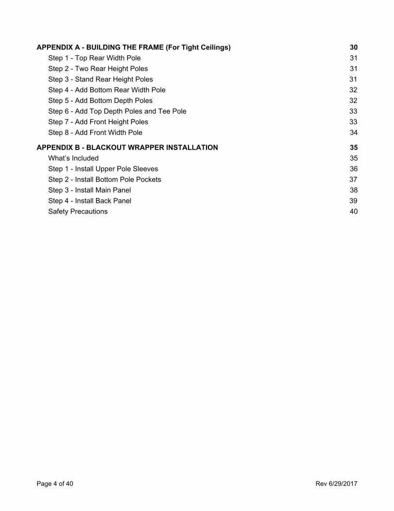
APPENDIX A - BUILDING THE FRAME (For Tight Ceilings) 30 Step 1 - Top Rear Width Pole 31 Step 2 - Two Rear Height Poles 31 Step 3 - Stand Rear Height Poles 31 Step 4 - Add Bottom Rear Width Pole 32 Step 5 - Add Bottom Depth Poles 32 Step 6 - Add Top Depth Poles and Tee Pole 33 Step 7 - Add Front Height Poles 33 Step 8 - Add Front Width Pole 34
APPENDIX B - BLACKOUT WRAPPER INSTALLATION 35 What’s Included 35 Step 1 - Install Upper Pole Sleeves 36 Step 2 - Install Bottom Pole Pockets 37 Step 3 - Install Main Panel 38 Step 4 - Install Back Panel 39 Safety Precautions 40
Page 4 of 40 Rev 6/29/2017
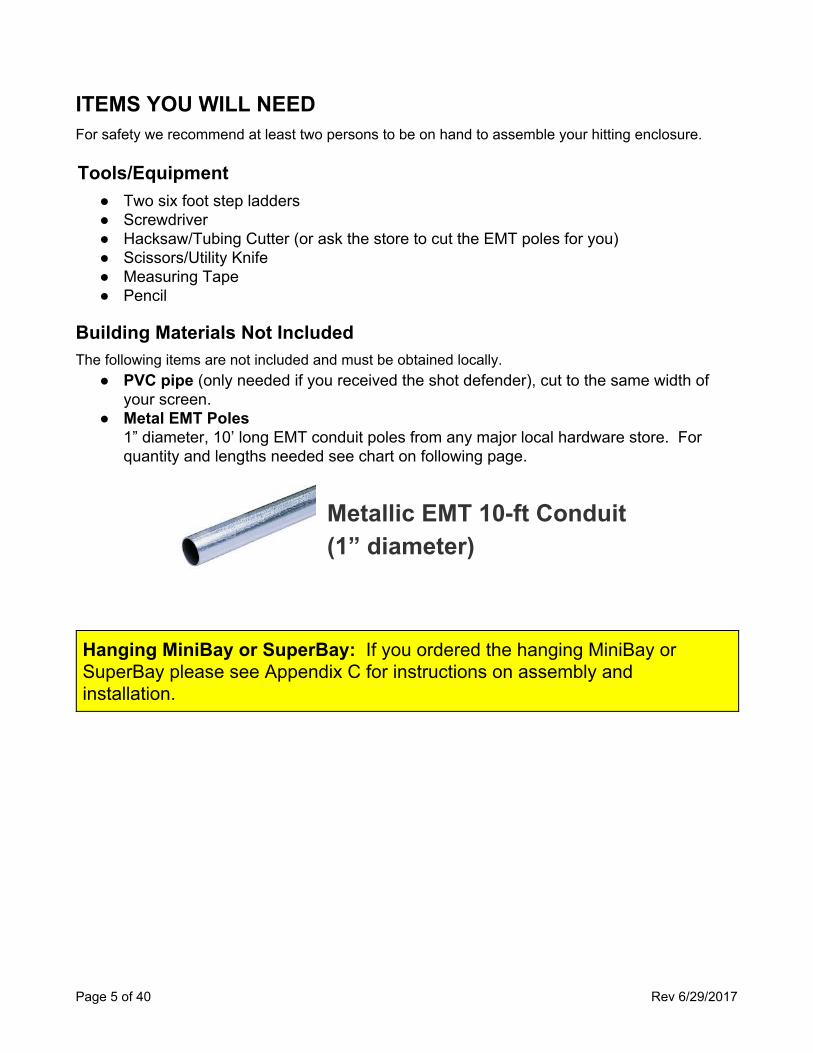
ITEMS YOU WILL NEED For safety we recommend at least two persons to be on hand to assemble your hitting enclosure.
Tools/Equipment ● Two six foot step ladders ● Screwdriver ● Hacksaw/Tubing Cutter (or ask the store to cut the EMT poles for you) ● Scissors/Utility Knife ● Measuring Tape ● Pencil
Building Materials Not Included The following items are not included and must be obtained locally.
● PVC pipe (only needed if you received the shot defender), cut to the same width of your screen.
● Metal EMT Poles 1” diameter, 10’ long EMT conduit poles from any major local hardware store. For quantity and lengths needed see chart on following page.
Metallic EMT 10-ft Conduit (1” diameter)
Hanging MiniBay or SuperBay: If you ordered the hanging MiniBay or SuperBay please see Appendix C for instructions on assembly and installation.
Page 5 of 40 Rev 6/29/2017
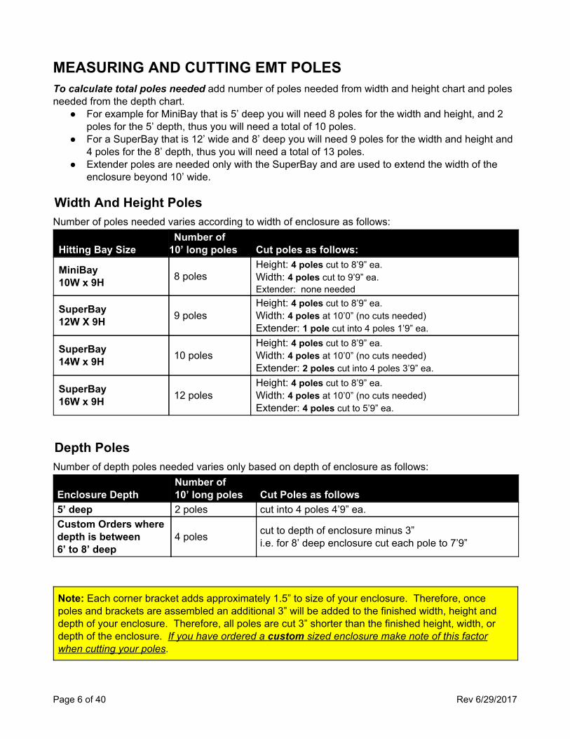
MEASURING AND CUTTING EMT POLES To calculate total poles needed add number of poles needed from width and height chart and poles needed from the depth chart.
● For example for MiniBay that is 5’ deep you will need 8 poles for the width and height, and 2 poles for the 5’ depth, thus you will need a total of 10 poles.
● For a SuperBay that is 12’ wide and 8’ deep you will need 9 poles for the width and height and 4 poles for the 8’ depth, thus you will need a total of 13 poles.
● Extender poles are needed only with the SuperBay and are used to extend the width of the enclosure beyond 10’ wide.
Width And Height Poles Number of poles needed varies according to width of enclosure as follows:
Hitting Bay Size Number of
10’ long poles Cut poles as follows:
MiniBay 10W x 9H 8 poles
Height: 4 poles cut to 8’9” ea. Width: 4 poles cut to 9’9” ea. Extender: none needed
SuperBay 12W X 9H 9 poles
Height: 4 poles cut to 8’9” ea. Width: 4 poles at 10’0” (no cuts needed) Extender: 1 pole cut into 4 poles 1’9” ea.
SuperBay 14W x 9H 10 poles
Height: 4 poles cut to 8’9” ea. Width: 4 poles at 10’0” (no cuts needed) Extender: 2 poles cut into 4 poles 3’9” ea.
SuperBay 16W x 9H 12 poles
Height: 4 poles cut to 8’9” ea. Width: 4 poles at 10’0” (no cuts needed) Extender: 4 poles cut to 5’9” ea.
Depth Poles Number of depth poles needed varies only based on depth of enclosure as follows:
Enclosure Depth Number of 10’ long poles Cut Poles as follows
5’ deep 2 poles cut into 4 poles 4’9” ea. Custom Orders where depth is between 6’ to 8’ deep
4 poles cut to depth of enclosure minus 3” i.e. for 8’ deep enclosure cut each pole to 7’9”
Note: Each corner bracket adds approximately 1.5” to size of your enclosure. Therefore, once poles and brackets are assembled an additional 3” will be added to the finished width, height and depth of your enclosure. Therefore, all poles are cut 3” shorter than the finished height, width, or depth of the enclosure. If you have ordered a custom sized enclosure make note of this factor when cutting your poles.
Page 6 of 40 Rev 6/29/2017
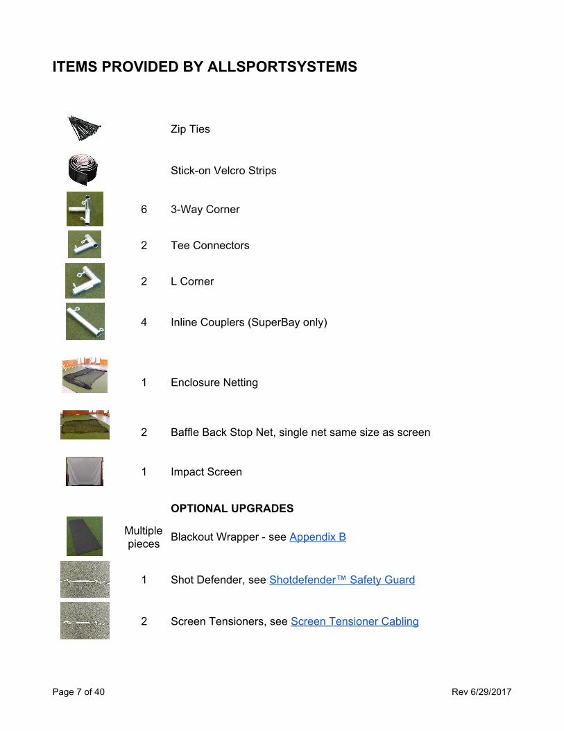
ITEMS PROVIDED BY ALLSPORTSYSTEMS
Zip Ties
Stick-on Velcro Strips
6 3-Way Corner
2 Tee Connectors
2 L Corner
4 Inline Couplers (SuperBay only)
1 Enclosure Netting
2 Baffle Back Stop Net, single net same size as screen
1 Impact Screen
OPTIONAL UPGRADES
Multiple pieces Blackout Wrapper - see Appendix B
1 Shot Defender, see Shotdefender™ Safety Guard
2 Screen Tensioners, see Screen Tensioner Cabling
Page 7 of 40 Rev 6/29/2017
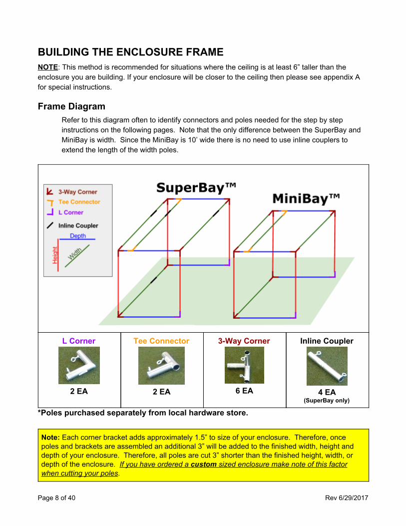
BUILDING THE ENCLOSURE FRAME NOTE: This method is recommended for situations where the ceiling is at least 6” taller than the enclosure you are building. If your enclosure will be closer to the ceiling then please see appendix A for special instructions.
Frame Diagram Refer to this diagram often to identify connectors and poles needed for the step by step instructions on the following pages. Note that the only difference between the SuperBay and MiniBay is width. Since the MiniBay is 10’ wide there is no need to use inline couplers to extend the length of the width poles.
L Corner
2 EA
Tee Connector
2 EA
3-Way Corner
6 EA
Inline Coupler
4 EA
(SuperBay only)
*Poles purchased separately from local hardware store.
Note: Each corner bracket adds approximately 1.5” to size of your enclosure. Therefore, once poles and brackets are assembled an additional 3” will be added to the finished width, height and depth of your enclosure. Therefore, all poles are cut 3” shorter than the finished height, width, or depth of the enclosure. If you have ordered a custom sized enclosure make note of this factor when cutting your poles.
Page 8 of 40 Rev 6/29/2017
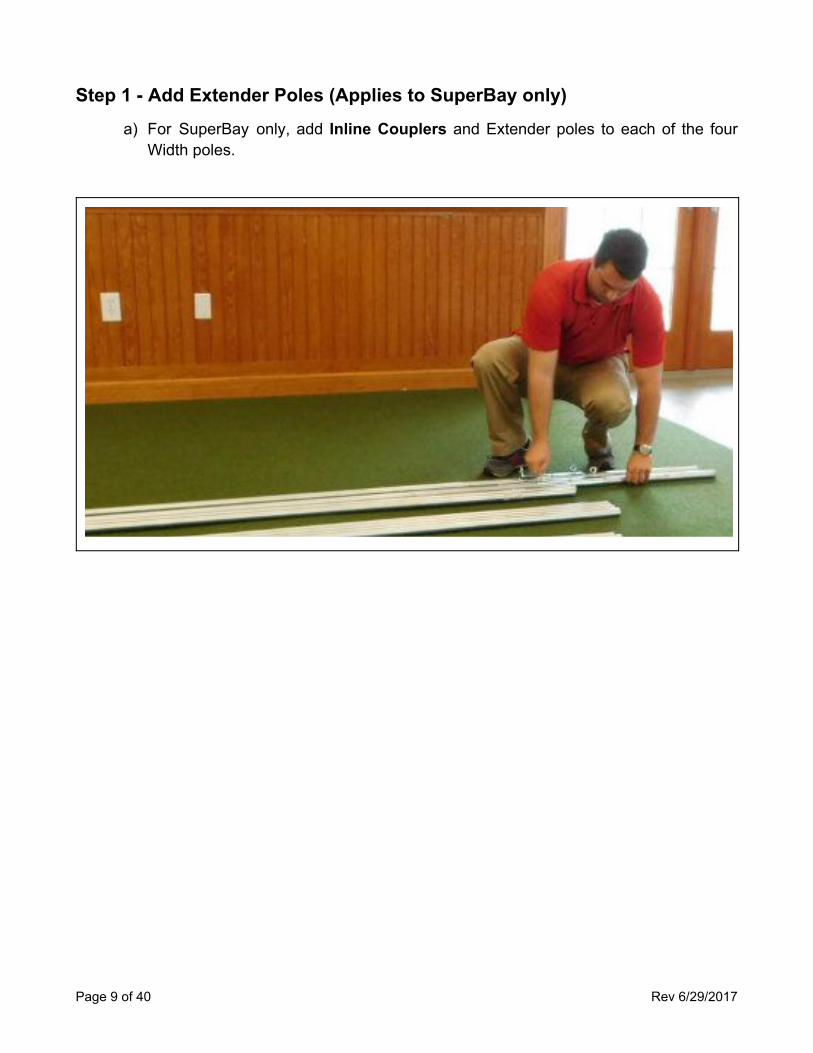
Step 1 - Add Extender Poles (Applies to SuperBay only) a) For SuperBay only, add Inline Couplers and Extender poles to each of the four
Width poles.
Page 9 of 40 Rev 6/29/2017
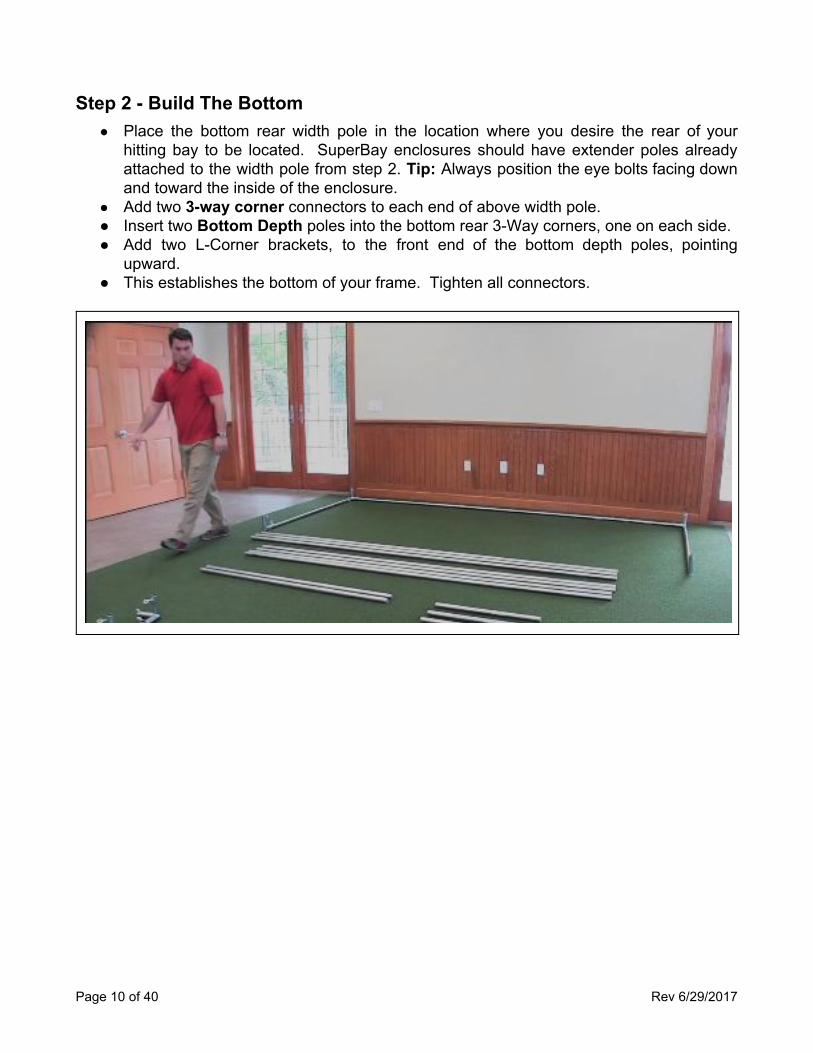
Step 2 - Build The Bottom ● Place the bottom rear width pole in the location where you desire the rear of your
hitting bay to be located. SuperBay enclosures should have extender poles already attached to the width pole from step 2. Tip: Always position the eye bolts facing down and toward the inside of the enclosure.
● Add two 3-way corner connectors to each end of above width pole. ● Insert two Bottom Depth poles into the bottom rear 3-Way corners, one on each side. ● Add two L-Corner brackets, to the front end of the bottom depth poles, pointing
upward. ● This establishes the bottom of your frame. Tighten all connectors.
Page 10 of 40 Rev 6/29/2017
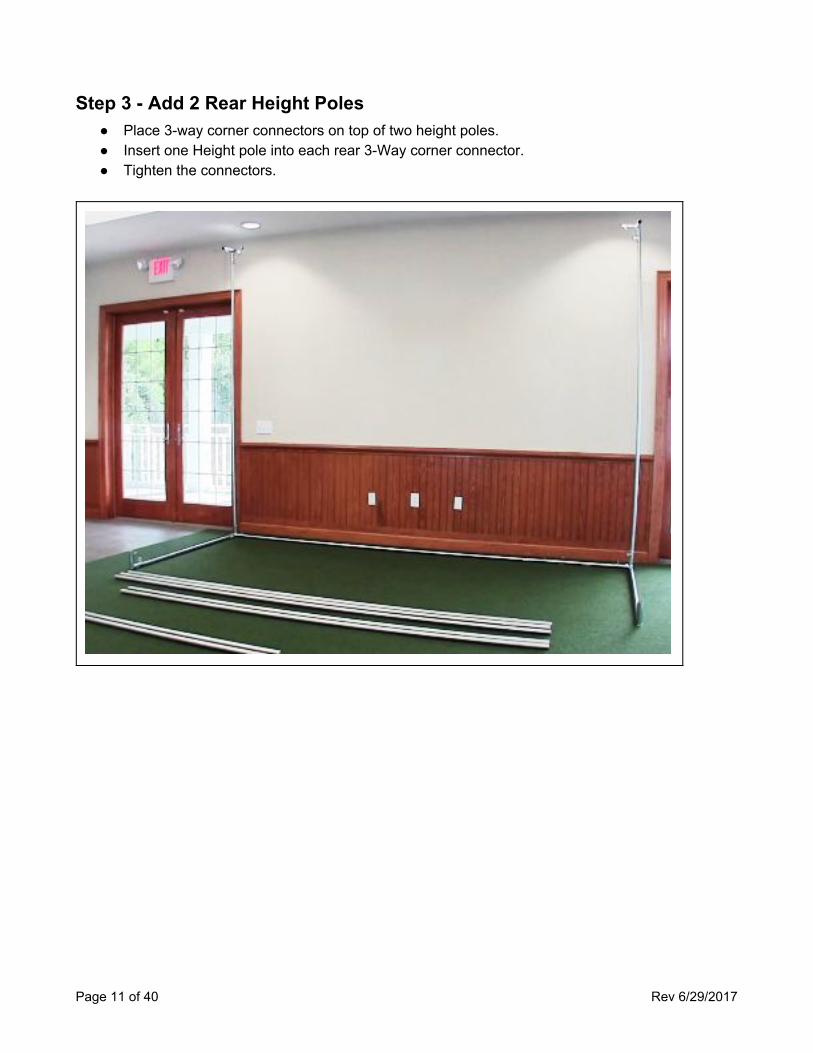
Step 3 - Add 2 Rear Height Poles ● Place 3-way corner connectors on top of two height poles. ● Insert one Height pole into each rear 3-Way corner connector. ● Tighten the connectors.
Page 11 of 40 Rev 6/29/2017
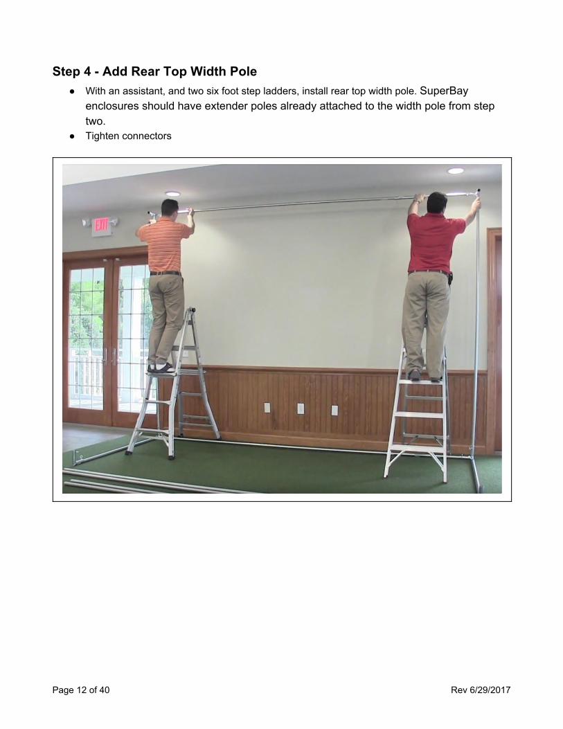
Step 4 - Add Rear Top Width Pole ● With an assistant, and two six foot step ladders, install rear top width pole. SuperBay
enclosures should have extender poles already attached to the width pole from step two.
● Tighten connectors
Page 12 of 40 Rev 6/29/2017
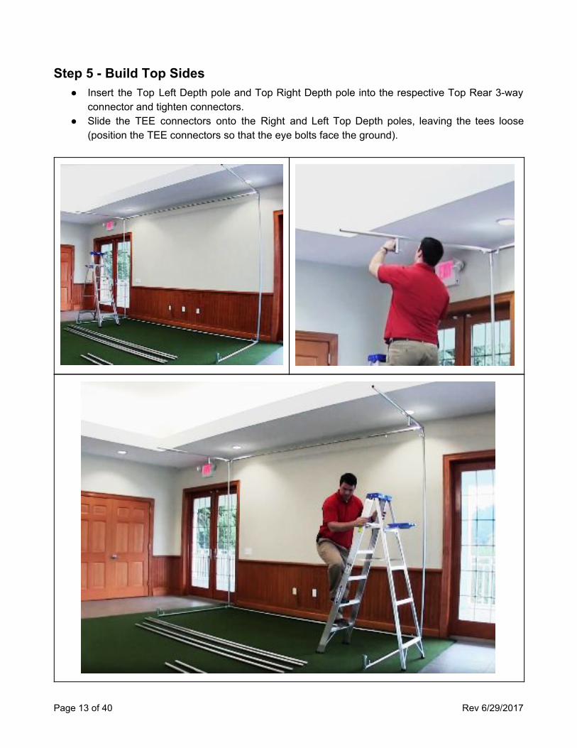
Step 5 - Build Top Sides ● Insert the Top Left Depth pole and Top Right Depth pole into the respective Top Rear 3-way
connector and tighten connectors. ● Slide the TEE connectors onto the Right and Left Top Depth poles, leaving the tees loose
(position the TEE connectors so that the eye bolts face the ground).
Page 13 of 40 Rev 6/29/2017
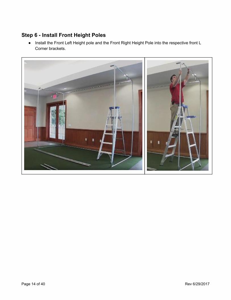
Step 6 - Install Front Height Poles ● Install the Front Left Height pole and the Front Right Height Pole into the respective front L
Corner brackets.
Page 14 of 40 Rev 6/29/2017
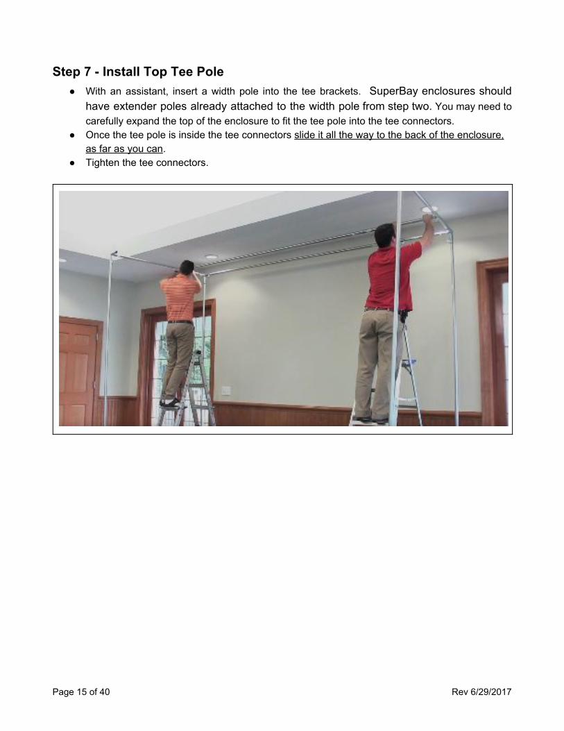
Step 7 - Install Top Tee Pole ● With an assistant, insert a width pole into the tee brackets. SuperBay enclosures should
have extender poles already attached to the width pole from step two. You may need to carefully expand the top of the enclosure to fit the tee pole into the tee connectors.
● Once the tee pole is inside the tee connectors slide it all the way to the back of the enclosure, as far as you can.
● Tighten the tee connectors.
Page 15 of 40 Rev 6/29/2017
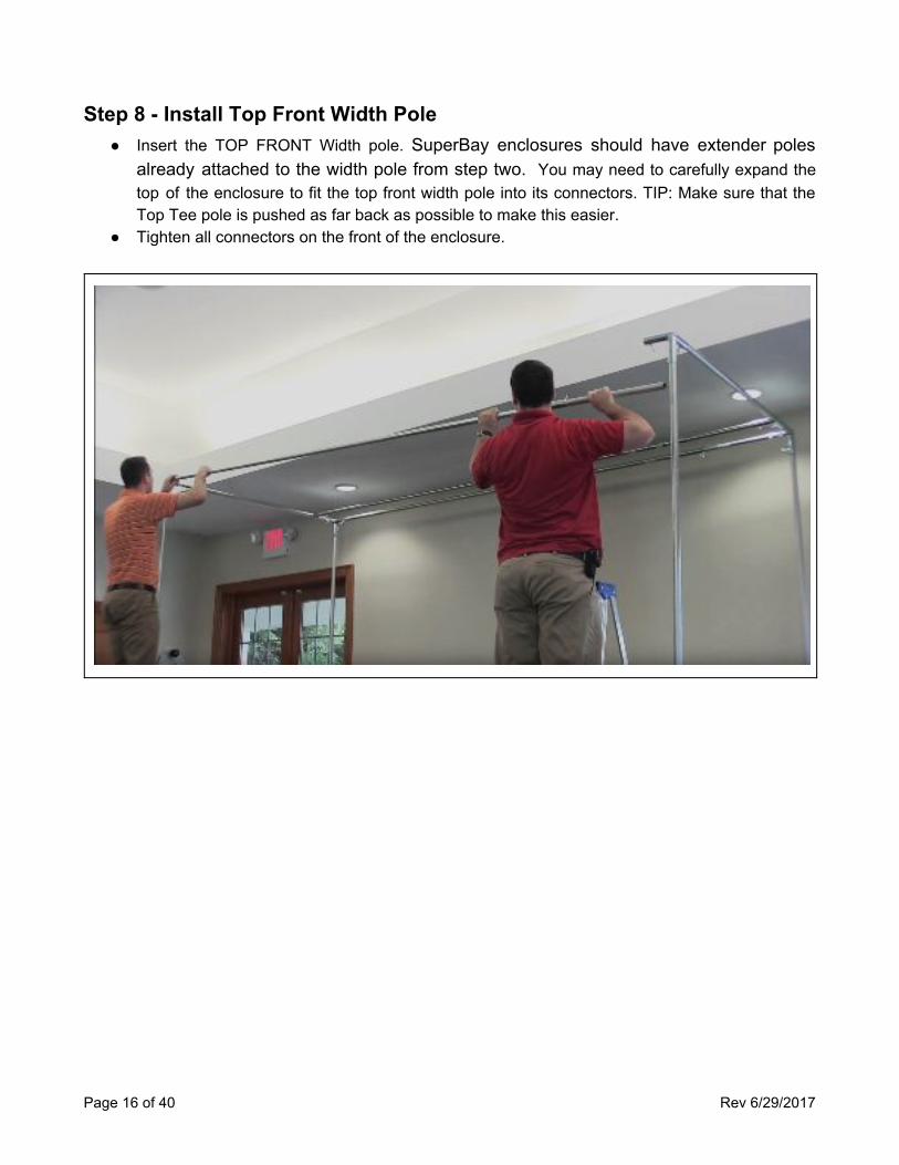
Step 8 - Install Top Front Width Pole ● Insert the TOP FRONT Width pole. SuperBay enclosures should have extender poles
already attached to the width pole from step two. You may need to carefully expand the top of the enclosure to fit the top front width pole into its connectors. TIP: Make sure that the Top Tee pole is pushed as far back as possible to make this easier.
● Tighten all connectors on the front of the enclosure.
Page 16 of 40 Rev 6/29/2017
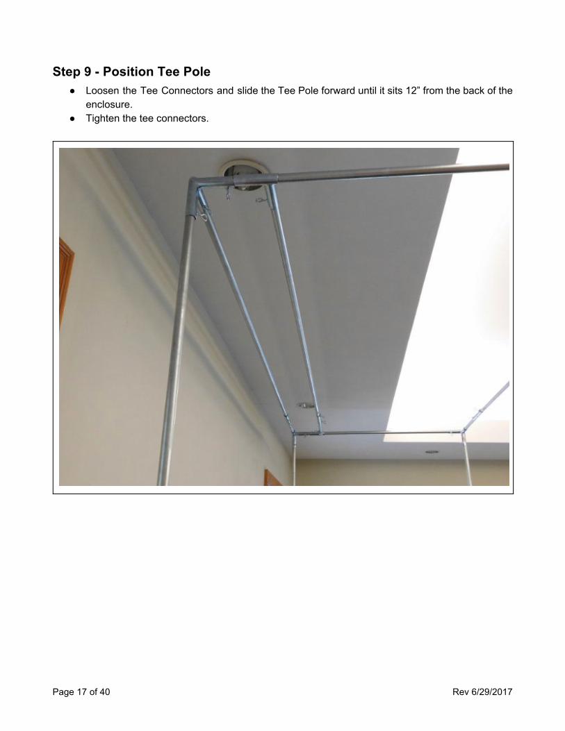
Step 9 - Position Tee Pole ● Loosen the Tee Connectors and slide the Tee Pole forward until it sits 12” from the back of the
enclosure. ● Tighten the tee connectors.
Page 17 of 40 Rev 6/29/2017
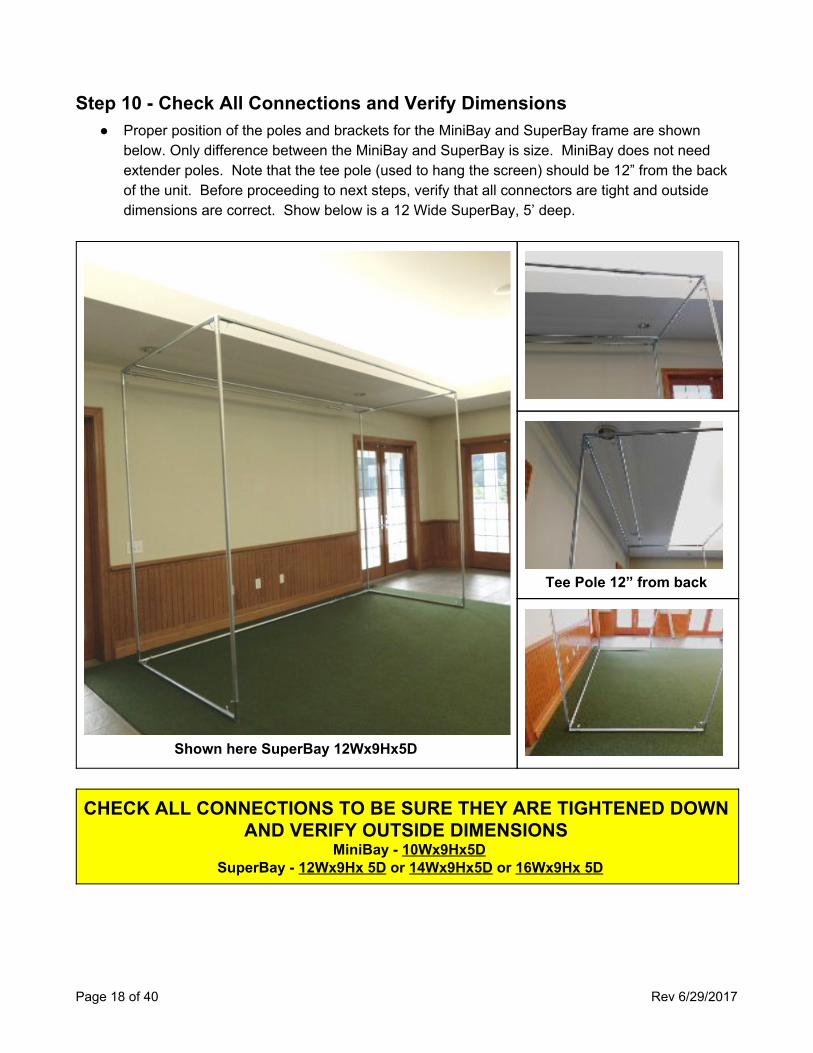
Step 10 - Check All Connections and Verify Dimensions ● Proper position of the poles and brackets for the MiniBay and SuperBay frame are shown
below. Only difference between the MiniBay and SuperBay is size. MiniBay does not need extender poles. Note that the tee pole (used to hang the screen) should be 12” from the back of the unit. Before proceeding to next steps, verify that all connectors are tight and outside dimensions are correct. Show below is a 12 Wide SuperBay, 5’ deep.
Shown here SuperBay 12Wx9Hx5D
Tee Pole 12” from back
CHECK ALL CONNECTIONS TO BE SURE THEY ARE TIGHTENED DOWN AND VERIFY OUTSIDE DIMENSIONS
MiniBay - 10Wx9Hx5D SuperBay - 12Wx9Hx 5D or 14Wx9Hx5D or 16Wx9Hx 5D
Page 18 of 40 Rev 6/29/2017
OPTIONAL UPGRADES
BlackOut™ Wrapper ● This step applies only if you have purchased the BlackOut™ Wrapper upgrade. If so proceed
to Appendix B for instructions regarding pole sleeve installation. After installing pole sleeves return here for next step.
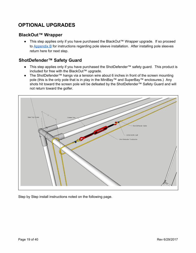
ShotDefender™ Safety Guard ● This step applies only if you have purchased the ShotDefender™ safety guard. This product is
included for free with the BlackOut™ upgrade. ● The ShotDefender™ hangs via a tension wire about 6 inches in front of the screen mounting
pole (this is the only pole that is in play in the MiniBay™ and SuperBay™ enclosures.) Any shots hit toward the screen pole will be defeated by the ShotDefender™ Safety Guard and will not return toward the golfer.
Step by Step install instructions noted on the following page.
Page 19 of 40 Rev 6/29/2017
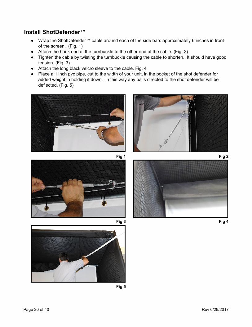
Install ShotDefender™ ● Wrap the ShotDefender™ cable around each of the side bars approximately 6 inches in front
of the screen. (Fig. 1) ● Attach the hook end of the turnbuckle to the other end of the cable. (Fig. 2) ● Tighten the cable by twisting the turnbuckle causing the cable to shorten. It should have good
tension. (Fig. 3) ● Attach the long black velcro sleeve to the cable. Fig. 4 ● Place a 1 inch pvc pipe, cut to the width of your unit, in the pocket of the shot defender for
added weight in holding it down. In this way any balls directed to the shot defender will be deflected. (Fig. 5)
Fig 1 Fig 2
Fig 3 Fig 4
Fig 5
Page 20 of 40 Rev 6/29/2017
ScreenTensioner™ Cabling Note: The ScreenTensioner™ cabling system comes standard with all HD Screen upgrades. When installed your screen will hang flatter and smoother than the standard method of hanging.
● On each side of the enclosure wrap the screen tensioning cabling around the upper and lower depth poles. Cable should be positioned directly against and in front of the tee pole from which the screen will be hung.
● Attach the hook end of the turnbuckle to the other end of the cable. Tighten the cable by twisting the turnbuckle causing the cable to shorten. It should have good tension.
● Next install netting, see installing side and top netting). ○ After installing the netting the screen can be installed as outlined under installing video
projection screen.
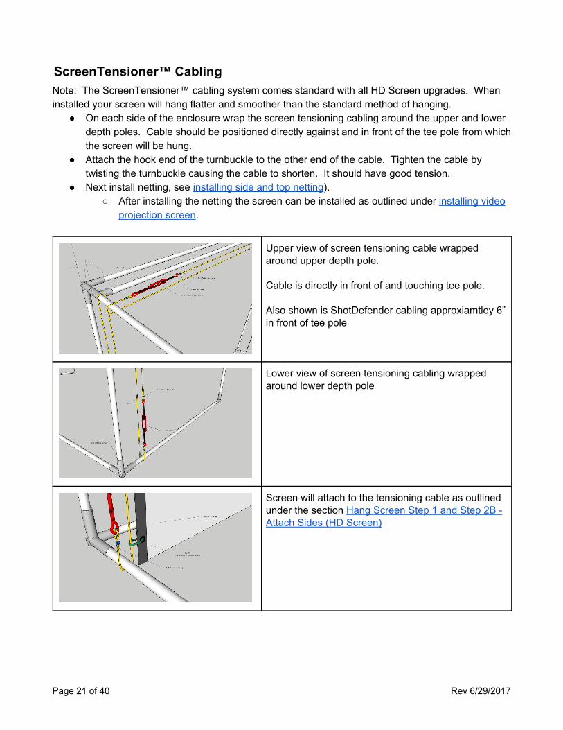
Upper view of screen tensioning cable wrapped around upper depth pole. Cable is directly in front of and touching tee pole. Also shown is ShotDefender cabling approxiamtley 6” in front of tee pole
Lower view of screen tensioning cabling wrapped around lower depth pole
Screen will attach to the tensioning cable as outlined under the section Hang Screen Step 1 and Step 2B - Attach Sides (HD Screen)
Page 21 of 40 Rev 6/29/2017
INSTALL NETTING
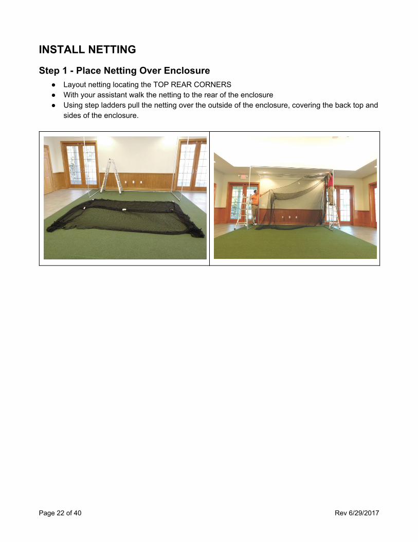
Step 1 - Place Netting Over Enclosure ● Layout netting locating the TOP REAR CORNERS ● With your assistant walk the netting to the rear of the enclosure ● Using step ladders pull the netting over the outside of the enclosure, covering the back top and
sides of the enclosure.
Page 22 of 40 Rev 6/29/2017
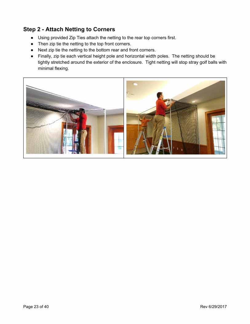
Step 2 - Attach Netting to Corners ● Using provided Zip Ties attach the netting to the rear top corners first. ● Then zip tie the netting to the top front corners. ● Next zip tie the netting to the bottom rear and front corners. ● Finally, zip tie each vertical height pole and horizontal width poles. The netting should be
tightly stretched around the exterior of the enclosure. Tight netting will stop stray golf balls with minimal flexing.
Page 23 of 40 Rev 6/29/2017
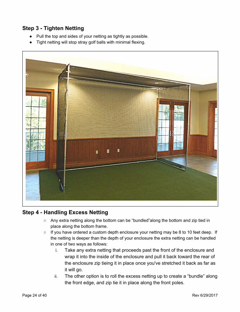
Step 3 - Tighten Netting ● Pull the top and sides of your netting as tightly as possible. ● Tight netting will stop stray golf balls with minimal flexing.
Step 4 - Handling Excess Netting ○ Any extra netting along the bottom can be “bundled”along the bottom and zip tied in
place along the bottom frame. ○ If you have ordered a custom depth enclosure your netting may be 8 to 10 feet deep. If
the netting is deeper than the depth of your enclosure the extra netting can be handled in one of two ways as follows:
i. Take any extra netting that proceeds past the front of the enclosure and wrap it into the inside of the enclosure and pull it back toward the rear of the enclosure zip tieing it in place once you've stretched it back as far as it will go.
ii. The other option is to roll the excess netting up to create a “bundle” along the front edge, and zip tie it in place along the front poles.
Page 24 of 40 Rev 6/29/2017
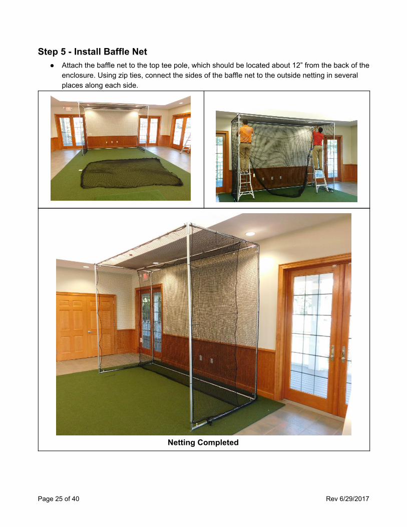
Step 5 - Install Baffle Net ● Attach the baffle net to the top tee pole, which should be located about 12” from the back of the
enclosure. Using zip ties, connect the sides of the baffle net to the outside netting in several places along each side.
Netting Completed
Page 25 of 40 Rev 6/29/2017
INSTALL VIDEO PROJECTION SCREEN
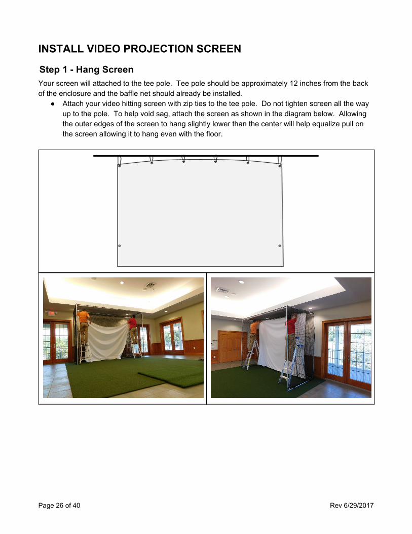
Step 1 - Hang Screen Your screen will attached to the tee pole. Tee pole should be approximately 12 inches from the back of the enclosure and the baffle net should already be installed.
● Attach your video hitting screen with zip ties to the tee pole. Do not tighten screen all the way up to the pole. To help void sag, attach the screen as shown in the diagram below. Allowing the outer edges of the screen to hang slightly lower than the center will help equalize pull on the screen allowing it to hang even with the floor.
Page 26 of 40 Rev 6/29/2017
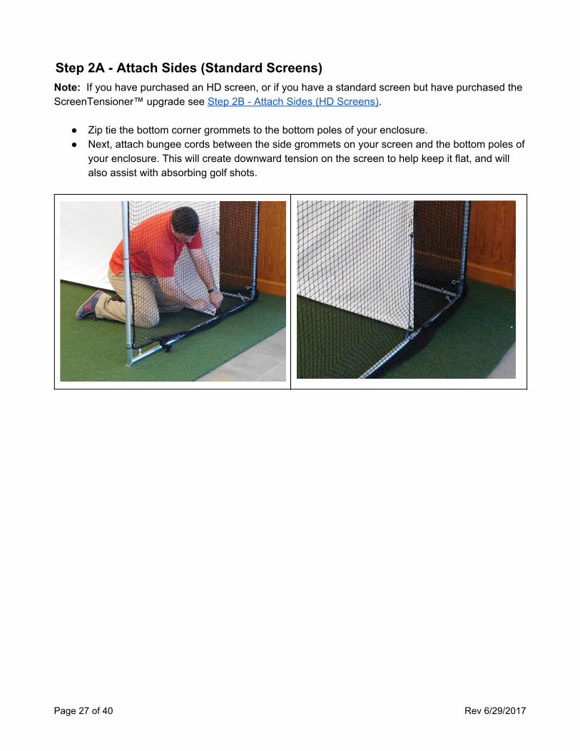
Step 2A - Attach Sides (Standard Screens) Note: If you have purchased an HD screen, or if you have a standard screen but have purchased the ScreenTensioner™ upgrade see Step 2B - Attach Sides (HD Screens).
● Zip tie the bottom corner grommets to the bottom poles of your enclosure. ● Next, attach bungee cords between the side grommets on your screen and the bottom poles of
your enclosure. This will create downward tension on the screen to help keep it flat, and will also assist with absorbing golf shots.
Page 27 of 40 Rev 6/29/2017
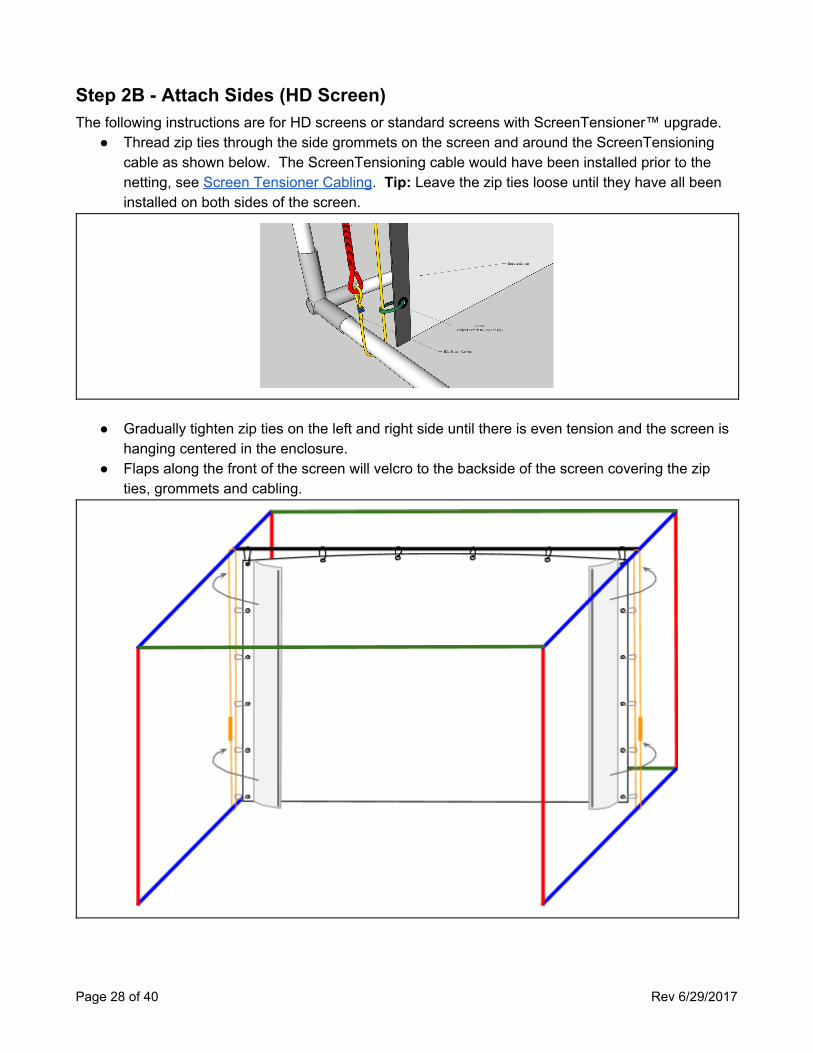
Step 2B - Attach Sides (HD Screen) The following instructions are for HD screens or standard screens with ScreenTensioner™ upgrade.
● Thread zip ties through the side grommets on the screen and around the ScreenTensioning cable as shown below. The ScreenTensioning cable would have been installed prior to the netting, see Screen Tensioner Cabling. Tip: Leave the zip ties loose until they have all been installed on both sides of the screen.
● Gradually tighten zip ties on the left and right side until there is even tension and the screen is
hanging centered in the enclosure. ● Flaps along the front of the screen will velcro to the backside of the screen covering the zip
ties, grommets and cabling.
Page 28 of 40 Rev 6/29/2017
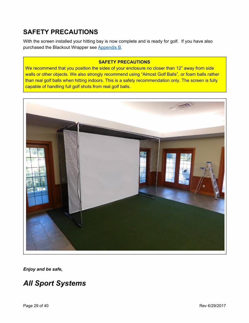
SAFETY PRECAUTIONS With the screen installed your hitting bay is now complete and is ready for golf. If you have also purchased the Blackout Wrapper see Appendix B.
SAFETY PRECAUTIONS We recommend that you position the sides of your enclosure no closer than 12” away from side walls or other objects. We also strongly recommend using “Almost Golf Balls”, or foam balls rather than real golf balls when hitting indoors. This is a safety recommendation only. The screen is fully capable of handling full golf shots from real golf balls.
Enjoy and be safe,
All Sport Systems
Page 29 of 40 Rev 6/29/2017
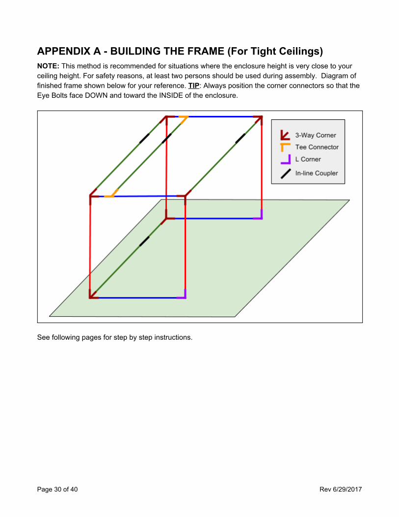
APPENDIX A - BUILDING THE FRAME (For Tight Ceilings) NOTE: This method is recommended for situations where the enclosure height is very close to your ceiling height. For safety reasons, at least two persons should be used during assembly. Diagram of finished frame shown below for your reference. TIP: Always position the corner connectors so that the Eye Bolts face DOWN and toward the INSIDE of the enclosure.
See following pages for step by step instructions.
Page 30 of 40 Rev 6/29/2017
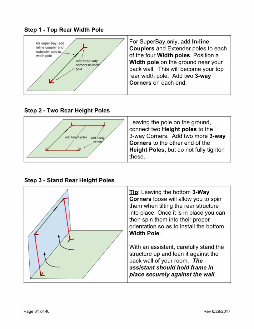
Step 1 - Top Rear Width Pole
For SuperBay only, add In-line Couplers and Extender poles to each of the four Width poles. Position a Width pole on the ground near your back wall. This will become your top rear width pole. Add two 3-way Corners on each end.
Step 2 - Two Rear Height Poles
Leaving the pole on the ground, connect two Height poles to the 3-way Corners. Add two more 3-way Corners to the other end of the Height Poles, but do not fully tighten these.
Step 3 - Stand Rear Height Poles
Tip: Leaving the bottom 3-Way Corners loose will allow you to spin them when tilting the rear structure into place. Once it is in place you can then spin them into their proper orientation so as to install the bottom Width Pole. With an assistant, carefully stand the structure up and lean it against the back wall of your room. The assistant should hold frame in place securely against the wall.
Page 31 of 40 Rev 6/29/2017
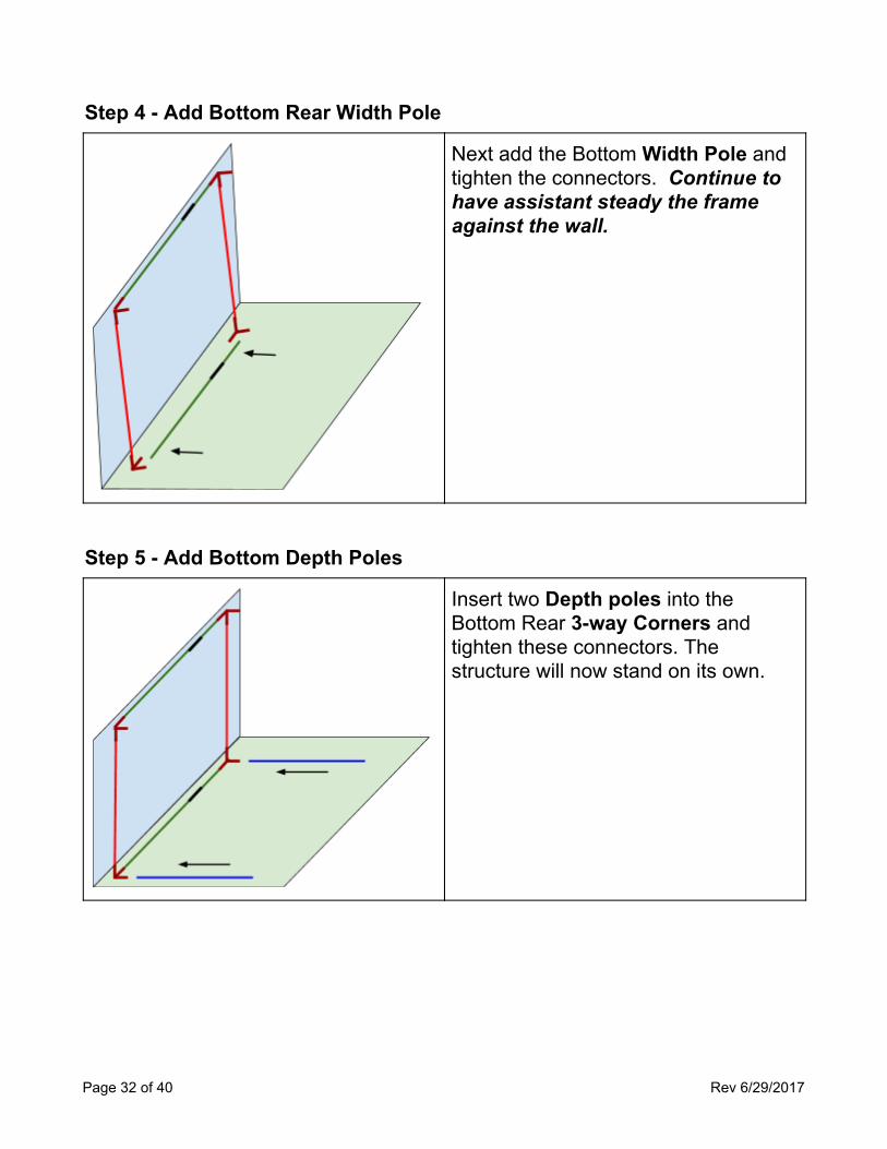
Step 4 - Add Bottom Rear Width Pole
Next add the Bottom Width Pole and tighten the connectors. Continue to have assistant steady the frame against the wall.
Step 5 - Add Bottom Depth Poles
Insert two Depth poles into the Bottom Rear 3-way Corners and tighten these connectors. The structure will now stand on its own.
Page 32 of 40 Rev 6/29/2017
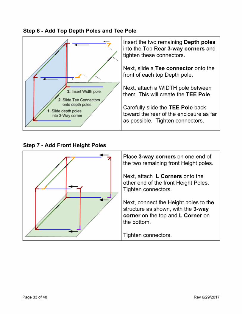
Step 6 - Add Top Depth Poles and Tee Pole
Insert the two remaining Depth poles into the Top Rear 3-way corners and tighten these connectors. Next, slide a Tee connector onto the front of each top Depth pole. Next, attach a WIDTH pole between them. This will create the TEE Pole. Carefully slide the TEE Pole back toward the rear of the enclosure as far as possible. Tighten connectors.
Step 7 - Add Front Height Poles
Place 3-way corners on one end of the two remaining front Height poles. Next, attach L Corners onto the other end of the front Height Poles. Tighten connectors. Next, connect the Height poles to the structure as shown, with the 3-way corner on the top and L Corner on the bottom. Tighten connectors.
Page 33 of 40 Rev 6/29/2017
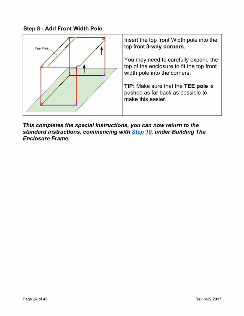
Step 8 - Add Front Width Pole
Insert the top front Width pole into the top front 3-way corners. You may need to carefully expand the top of the enclosure to fit the top front width pole into the corners. TIP: Make sure that the TEE pole is pushed as far back as possible to make this easier.
This completes the special instructions, you can now return to the standard instructions, commencing with Step 10, under Building The Enclosure Frame.
Page 34 of 40 Rev 6/29/2017
APPENDIX B - BLACKOUT WRAPPER INSTALLATION
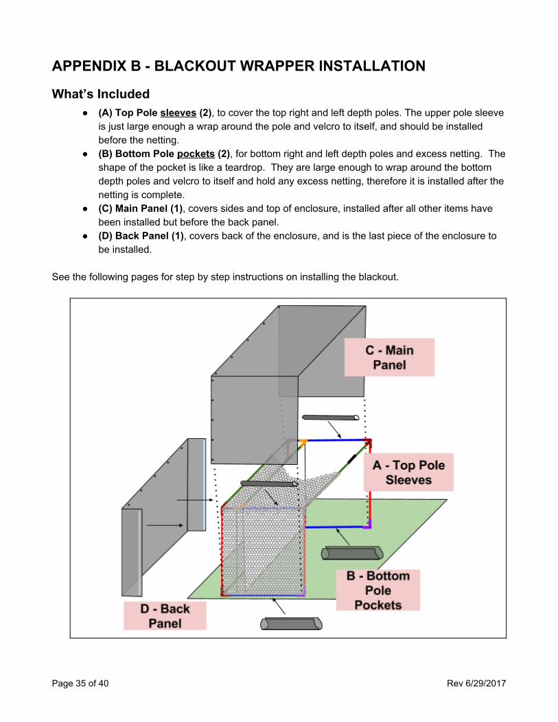
What’s Included ● (A) Top Pole sleeves (2), to cover the top right and left depth poles. The upper pole sleeve
is just large enough a wrap around the pole and velcro to itself, and should be installed before the netting.
● (B) Bottom Pole pockets (2), for bottom right and left depth poles and excess netting. The shape of the pocket is like a teardrop. They are large enough to wrap around the bottom depth poles and velcro to itself and hold any excess netting, therefore it is installed after the netting is complete.
● (C) Main Panel (1), covers sides and top of enclosure, installed after all other items have been installed but before the back panel.
● (D) Back Panel (1), covers back of the enclosure, and is the last piece of the enclosure to be installed.
See the following pages for step by step instructions on installing the blackout.
Page 35 of 40 Rev 6/29/2017
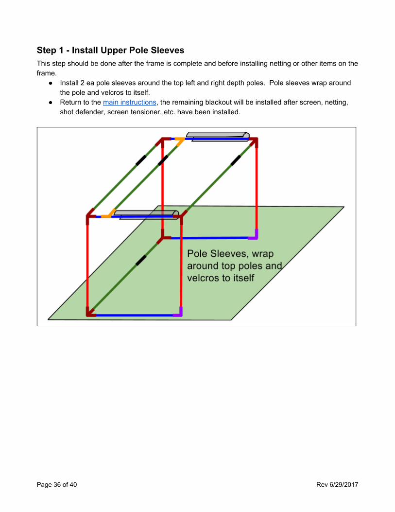
Step 1 - Install Upper Pole Sleeves This step should be done after the frame is complete and before installing netting or other items on the frame.
● Install 2 ea pole sleeves around the top left and right depth poles. Pole sleeves wrap around the pole and velcros to itself.
● Return to the main instructions, the remaining blackout will be installed after screen, netting, shot defender, screen tensioner, etc. have been installed.
Page 36 of 40 Rev 6/29/2017
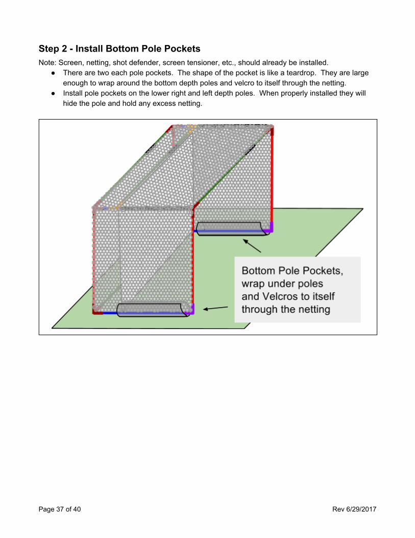
Step 2 - Install Bottom Pole Pockets Note: Screen, netting, shot defender, screen tensioner, etc., should already be installed.
● There are two each pole pockets. The shape of the pocket is like a teardrop. They are large enough to wrap around the bottom depth poles and velcro to itself through the netting.
● Install pole pockets on the lower right and left depth poles. When properly installed they will hide the pole and hold any excess netting.
Page 37 of 40 Rev 6/29/2017
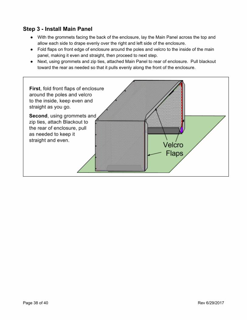
Step 3 - Install Main Panel ● With the grommets facing the back of the enclosure, lay the Main Panel across the top and
allow each side to drape evenly over the right and left side of the enclosure. ● Fold flaps on front edge of enclosure around the poles and velcro to the inside of the main
panel, making it even and straight, then proceed to next step. ● Next, using grommets and zip ties, attached Main Panel to rear of enclosure. Pull blackout
toward the rear as needed so that it pulls evenly along the front of the enclosure.
Page 38 of 40 Rev 6/29/2017
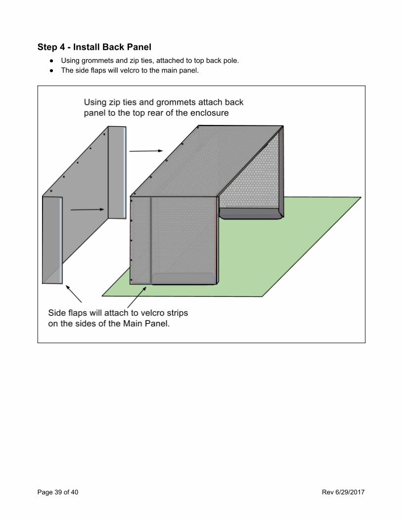
Step 4 - Install Back Panel ● Using grommets and zip ties, attached to top back pole. ● The side flaps will velcro to the main panel.
Page 39 of 40 Rev 6/29/2017
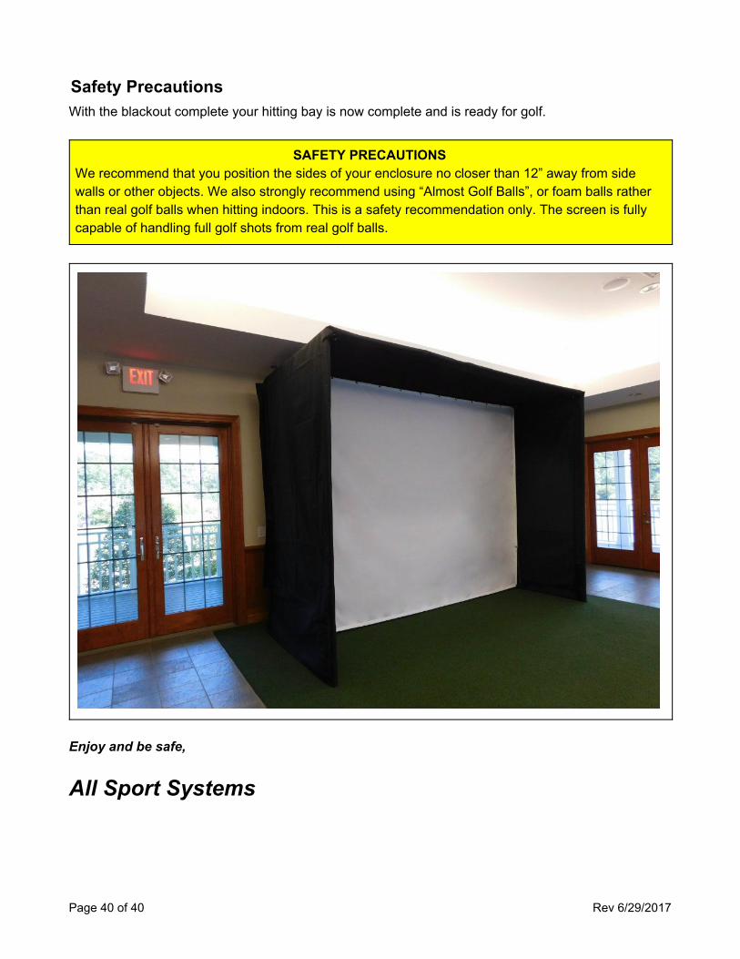
Safety Precautions With the blackout complete your hitting bay is now complete and is ready for golf.
SAFETY PRECAUTIONS We recommend that you position the sides of your enclosure no closer than 12” away from side walls or other objects. We also strongly recommend using “Almost Golf Balls”, or foam balls rather than real golf balls when hitting indoors. This is a safety recommendation only. The screen is fully capable of handling full golf shots from real golf balls.
Enjoy and be safe,
All Sport Systems
Page 40 of 40 Rev 6/29/2017


![Untitled-1 [puran1982.files.wordpress.com]€¦ · ÔÞðMÚtt™tk y™uf ftÞtuo fhðt {txu™e Ëhfth©e™e þiûtrýf ËkMÚtt Au. rðãtÚteo™t ËðtO„e rðftË {txu htßÞ](https://img.pdfslide.us/doc/110x75/5ea1f2de810bf91db0251443/untitled-1-mttatk-yauf-fttuo-fht-txuae-hftheae-itrf.jpg)