Embed Size (px)
Citation preview
PIMG Integra
C H A P T E R 7
Setting Up a Mitel SX-200 Digital PIMG Integration with Cisco Unity ConnectionFor detailed instructions for setting up a Mitel SX-200 digital PIMG integration with Cisco Unity Connection, see the following sections in this chapter:
• Task List to Create Integration with Mitel SX-200 PIMG Phone System, page 7-1
• Requirements, page 7-2
• Programming Mitel SX-200 PIMG Phone System for Integration, page 7-3
• Setting Up the Digital Mitel PIMG Units, page 7-8
• Creating a New Integration with Mitel SX-200 Phone System, page 7-23
Task List to Create Integration with Mitel SX-200 PIMG Phone System
Before doing the following tasks to integrate Unity Connection with the Mitel SX-200 phone system using PIMG units (media gateways), confirm that the Unity Connection server is ready for the integration after completing the server installation, following the tasks in the “Installing Cisco Unity Connection” chapter of the Install, Upgrade, and Maintenance Guide for Cisco Unity Connection, Release 10.x, available at http://www.cisco.com/c/en/us/td/docs/voice_ip_comm/connection/10x/install_upgrade/guide/10xcuciumgx/10xcuciumg010.html.
1. Review the system and equipment requirements to confirm that all phone system and Unity Connection server requirements have been met. See the “Requirements” section on page 7-2.
2. Plan how the voice messaging ports are used by Unity Connection. See the “Planning the Usage of Voice Messaging Ports in Cisco Unity Connection” chapter.
3. Program the Mitel SX-200 phone system and extensions. See the “Programming Mitel SX-200 PIMG Phone System for Integration” section on page 7-3.
4. Set up the PIMG units. See the “Setting Up the Digital Mitel PIMG Units” section on page 7-8.
5. Create the integration. See the “Creating a New Integration with Mitel SX-200 Phone System” section on page 7-23.
6. Test the integration. See the “Testing the Integration” chapter.
7. If this integration is a second or subsequent integration, add the applicable new user templates for the new phone system. See the “Adding New User Templates for Multiple Integrations” chapter.
7-1tion Guide for Cisco Unity Connection Release 10.x
Chapter 7 Setting Up a Mitel SX-200 Digital PIMG Integration with Cisco Unity ConnectionRequirements
RequirementsThe Mitel SX-200 integration supports configurations of the following components:
Phone System• Mitel SX-200.
• Software level Lightware 19 or later.
• A DNI Line MC330 line card to support the two-wire station interface.
• One or more of the applicable PIMG units. For details, see the “Introduction” chapter.
• The voice messaging ports in the phone system connected by digital lines to the ports on the PIMG units.
To simplify troubleshooting, we recommend that you connect the voice messaging ports on the phone system to the ports on the PIMG units in a planned manner. For example, connect the first phone system voice messaging port to the first port on the first PIMG unit, connect the second phone system voice messaging port to the second port on the first PIMG unit, and so on. Alternatively, if you have multiple PIMG units, you can reduce answer times in the event of a PIMG unit failure by connecting the phone system ports to the PIMG units in a round-robin fashion. For example, connect the first phone system voice messaging port to the first port on the first PIMG unit, connect the second phone system voice messaging port to the first port on the second PIMG unit, and so on.
• The PIMG units connected to the same LAN or WAN that Unity Connection is connected to.
• If the PIMG units connect to a WAN, the requirements for the WAN network connections are:
– For G.729a codec formatting, a minimum of 32.76 Kbps guaranteed bandwidth for each voice messaging port.
– For G.711 codec formatting, a minimum of 91.56 Kbps guaranteed bandwidth for each voice messaging port.
– No network devices that implement network address translation (NAT).
– A maximum 200 ms one-way network latency.
Unity Connection Server• Unity Connection installed and ready for the integration after completing the server installation,
following the tasks in the “Installing Cisco Unity Connection” chapter of the Install, Upgrade, and Maintenance Guide for Cisco Unity Connection, Release 10.x, available at http://www.cisco.com/c/en/us/td/docs/voice_ip_comm/connection/10x/install_upgrade/guide/10xcuciumgx/10xcuciumg010.html.
• A license that enables the applicable number of voice messaging ports.
Centralized Voice MessagingUnity Connection supports centralized voice messaging through the phone system, which supports various inter-phone system networking protocols including proprietary protocols such as Avaya DCS, Nortel MCDN, or Siemens CorNet, and standards-based protocols such as QSIG or DPNSS. Note that centralized voice messaging is a function of the phone system and its inter-phone system networking,
7-2PIMG Integration Guide for Cisco Unity Connection Release 10.x
Chapter 7 Setting Up a Mitel SX-200 Digital PIMG Integration with Cisco Unity ConnectionProgramming Mitel SX-200 PIMG Phone System for Integration
not voicemail. Unity Connection supports centralized voice messaging as long as the phone system and its inter-phone system networking are properly configured. For details, see the “Centralized Voice Messaging” section in the “Integrating Cisco Unity Connection 10.x with the Phone System” chapter of the Design Guide for Cisco Unity Connection, Release 10.x, available at http://www.cisco.com/c/en/us/td/docs/voice_ip_comm/connection/10x/design/guide/10xcucdgx/10xcucdg050.html.
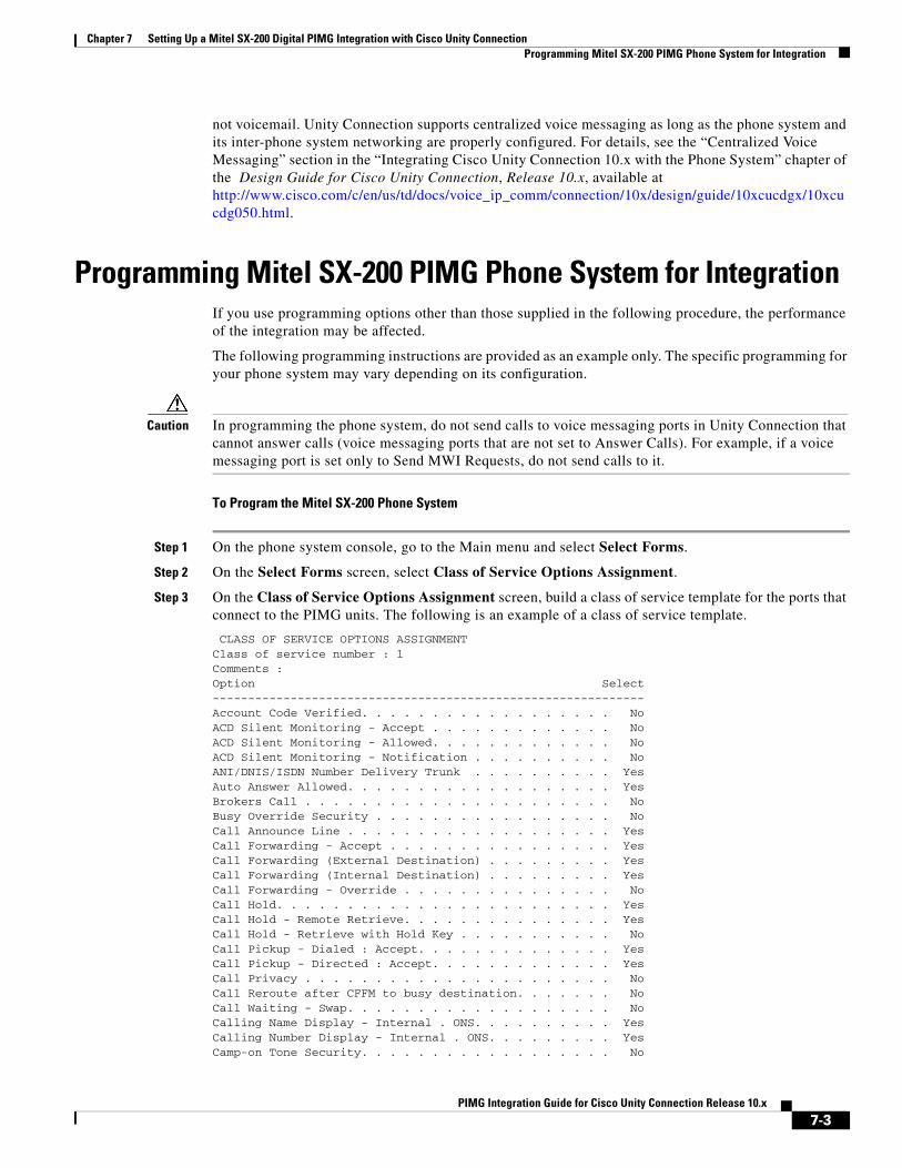
Programming Mitel SX-200 PIMG Phone System for IntegrationIf you use programming options other than those supplied in the following procedure, the performance of the integration may be affected.
The following programming instructions are provided as an example only. The specific programming for your phone system may vary depending on its configuration.
Caution In programming the phone system, do not send calls to voice messaging ports in Unity Connection that cannot answer calls (voice messaging ports that are not set to Answer Calls). For example, if a voice messaging port is set only to Send MWI Requests, do not send calls to it.
To Program the Mitel SX-200 Phone System
Step 1 On the phone system console, go to the Main menu and select Select Forms.
Step 2 On the Select Forms screen, select Class of Service Options Assignment.
Step 3 On the Class of Service Options Assignment screen, build a class of service template for the ports that connect to the PIMG units. The following is an example of a class of service template.
CLASS OF SERVICE OPTIONS ASSIGNMENTClass of service number : 1Comments :Option Select-------------------------------------------------------------Account Code Verified. . . . . . . . . . . . . . . . . . NoACD Silent Monitoring - Accept . . . . . . . . . . . . . NoACD Silent Monitoring - Allowed. . . . . . . . . . . . . NoACD Silent Monitoring - Notification . . . . . . . . . . NoANI/DNIS/ISDN Number Delivery Trunk . . . . . . . . . . YesAuto Answer Allowed. . . . . . . . . . . . . . . . . . . YesBrokers Call . . . . . . . . . . . . . . . . . . . . . . NoBusy Override Security . . . . . . . . . . . . . . . . . NoCall Announce Line . . . . . . . . . . . . . . . . . . . YesCall Forwarding - Accept . . . . . . . . . . . . . . . . YesCall Forwarding (External Destination) . . . . . . . . . YesCall Forwarding (Internal Destination) . . . . . . . . . YesCall Forwarding - Override . . . . . . . . . . . . . . . NoCall Hold. . . . . . . . . . . . . . . . . . . . . . . . YesCall Hold - Remote Retrieve. . . . . . . . . . . . . . . YesCall Hold - Retrieve with Hold Key . . . . . . . . . . . NoCall Pickup - Dialed : Accept. . . . . . . . . . . . . . YesCall Pickup - Directed : Accept. . . . . . . . . . . . . YesCall Privacy . . . . . . . . . . . . . . . . . . . . . . NoCall Reroute after CFFM to busy destination. . . . . . . NoCall Waiting - Swap. . . . . . . . . . . . . . . . . . . NoCalling Name Display - Internal . ONS. . . . . . . . . . YesCalling Number Display - Internal . ONS. . . . . . . . . YesCamp-on Tone Security. . . . . . . . . . . . . . . . . . No
7-3PIMG Integration Guide for Cisco Unity Connection Release 10.x
Chapter 7 Setting Up a Mitel SX-200 Digital PIMG Integration with Cisco Unity ConnectionProgramming Mitel SX-200 PIMG Phone System for Integration
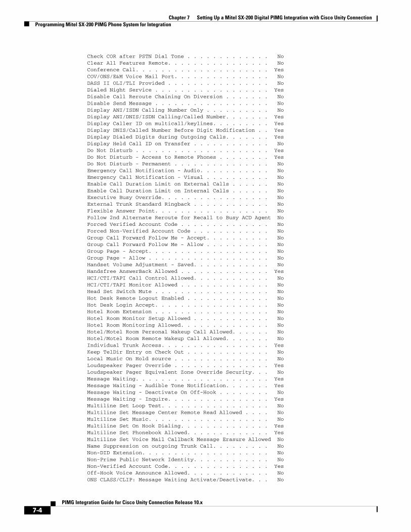
Check COR after PSTN Dial Tone . . . . . . . . . . . . . NoClear All Features Remote. . . . . . . . . . . . . . . . NoConference Call. . . . . . . . . . . . . . . . . . . . . YesCOV/ONS/E&M Voice Mail Port. . . . . . . . . . . . . . . NoDASS II OLI/TLI Provided . . . . . . . . . . . . . . . . NoDialed Night Service . . . . . . . . . . . . . . . . . . YesDisable Call Reroute Chaining On Diversion . . . . . . . NoDisable Send Message . . . . . . . . . . . . . . . . . . NoDisplay ANI/ISDN Calling Number Only . . . . . . . . . . NoDisplay ANI/DNIS/ISDN Calling/Called Number. . . . . . . YesDisplay Caller ID on multicall/keylines. . . . . . . . . YesDisplay DNIS/Called Number Before Digit Modification . . YesDisplay Dialed Digits during Outgoing Calls. . . . . . . YesDisplay Held Call ID on Transfer . . . . . . . . . . . . NoDo Not Disturb . . . . . . . . . . . . . . . . . . . . . YesDo Not Disturb - Access to Remote Phones . . . . . . . . YesDo Not Disturb - Permanent . . . . . . . . . . . . . . . NoEmergency Call Notification - Audio. . . . . . . . . . . NoEmergency Call Notification - Visual . . . . . . . . . . NoEnable Call Duration Limit on External Calls . . . . . . NoEnable Call Duration Limit on Internal Calls . . . . . . NoExecutive Busy Override. . . . . . . . . . . . . . . . . NoExternal Trunk Standard Ringback . . . . . . . . . . . . NoFlexible Answer Point. . . . . . . . . . . . . . . . . . NoFollow 2nd Alternate Reroute for Recall to Busy ACD Agent NoForced Verified Account Code . . . . . . . . . . . . . . NoForced Non-Verified Account Code . . . . . . . . . . . . NoGroup Call Forward Follow Me - Accept. . . . . . . . . . NoGroup Call Forward Follow Me - Allow . . . . . . . . . . NoGroup Page - Accept. . . . . . . . . . . . . . . . . . . NoGroup Page - Allow . . . . . . . . . . . . . . . . . . . NoHandset Volume Adjustment - Saved. . . . . . . . . . . . NoHandsfree AnswerBack Allowed . . . . . . . . . . . . . . YesHCI/CTI/TAPI Call Control Allowed. . . . . . . . . . . . NoHCI/CTI/TAPI Monitor Allowed . . . . . . . . . . . . . . NoHead Set Switch Mute . . . . . . . . . . . . . . . . . . NoHot Desk Remote Logout Enabled . . . . . . . . . . . . . NoHot Desk Login Accept. . . . . . . . . . . . . . . . . . NoHotel Room Extension . . . . . . . . . . . . . . . . . . NoHotel Room Monitor Setup Allowed . . . . . . . . . . . . NoHotel Room Monitoring Allowed. . . . . . . . . . . . . . NoHotel/Motel Room Personal Wakeup Call Allowed. . . . . . NoHotel/Motel Room Remote Wakeup Call Allowed. . . . . . . NoIndividual Trunk Access. . . . . . . . . . . . . . . . . YesKeep TelDir Entry on Check Out . . . . . . . . . . . . . NoLocal Music On Hold source . . . . . . . . . . . . . . . NoLoudspeaker Pager Override . . . . . . . . . . . . . . . YesLoudspeaker Pager Equivalent Zone Override Security. . . NoMessage Waiting. . . . . . . . . . . . . . . . . . . . . YesMessage Waiting - Audible Tone Notification. . . . . . . YesMessage Waiting - Deactivate On Off-Hook . . . . . . . . NoMessage Waiting - Inquire. . . . . . . . . . . . . . . . YesMultiline Set Loop Test. . . . . . . . . . . . . . . . . NoMultiline Set Message Center Remote Read Allowed . . . . NoMultiline Set Music. . . . . . . . . . . . . . . . . . . NoMultiline Set On Hook Dialing. . . . . . . . . . . . . . YesMultiline Set Phonebook Allowed. . . . . . . . . . . . . YesMultiline Set Voice Mail Callback Message Erasure Allowed NoName Suppression on outgoing Trunk Call. . . . . . . . . NoNon-DID Extension. . . . . . . . . . . . . . . . . . . . NoNon-Prime Public Network Identity. . . . . . . . . . . . NoNon-Verified Account Code. . . . . . . . . . . . . . . . YesOff-Hook Voice Announce Allowed. . . . . . . . . . . . . NoONS CLASS/CLIP: Message Waiting Activate/Deactivate. . . No
7-4PIMG Integration Guide for Cisco Unity Connection Release 10.x
Chapter 7 Setting Up a Mitel SX-200 Digital PIMG Integration with Cisco Unity ConnectionProgramming Mitel SX-200 PIMG Phone System for Integration
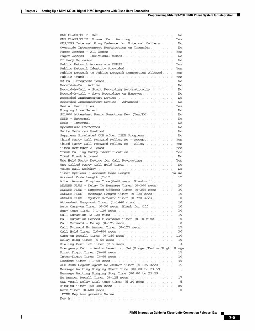
ONS CLASS/CLIP: Set. . . . . . . . . . . . . . . . . . . NoONS CLASS/CLIP: Visual Call Waiting. . . . . . . . . . . YesONS/OPS Internal Ring Cadence for External Callers . . . NoOverride Interconnect Restriction on Transfer. . . . . . NoPager Access - All Zones . . . . . . . . . . . . . . . . YesPager Access - Individual Zones. . . . . . . . . . . . . NoPrivacy Released . . . . . . . . . . . . . . . . . . . . NoPublic Network Access via DPNSS. . . . . . . . . . . . . YesPublic Network Identity Provided . . . . . . . . . . . . YesPublic Network To Public Network Connection Allowed. . . YesPublic Trunk . . . . . . . . . . . . . . . . . . . . . . YesR2 Call Progress Tones . . . . . . . . . . . . . . . . . NoRecord-A-Call Active . . . . . . . . . . . . . . . . . . NoRecord-A-Call - Start Recording Automatically. . . . . . NoRecord-A-Call - Save Recording on Hang-up. . . . . . . . NoRecorded Announcement Device . . . . . . . . . . . . . . NoRecorded Announcement Device - Advanced. . . . . . . . . NoRedial Facilities. . . . . . . . . . . . . . . . . . . . YesRinging Line Select. . . . . . . . . . . . . . . . . . . NoSC1000 Attendant Basic Function Key (Yes/NO) . . . . . . NoSMDR - External. . . . . . . . . . . . . . . . . . . . . NoSMDR - Internal. . . . . . . . . . . . . . . . . . . . . NoSpeak@Ease Preferred . . . . . . . . . . . . . . . . . . NoSuite Services Enabled . . . . . . . . . . . . . . . . . NoSuppress Simulated CCM after ISDN Progress . . . . . . . NoThird Party Call Forward Follow Me - Accept. . . . . . . YesThird Party Call Forward Follow Me - Allow . . . . . . . YesTimed Reminder Allowed . . . . . . . . . . . . . . . . . YesTrunk Calling Party Identification . . . . . . . . . . . YesTrunk Flash Allowed. . . . . . . . . . . . . . . . . . . NoUse Held Party Device for Call Re-routing. . . . . . . . YesUse Called Party Call Hold Timer . . . . . . . . . . . . NoVoice Mail Softkey . . . . . . . . . . . . . . . . . . . NoTimer Options / Account Code Length ValueAccount Code Length (2-12) . . . . . . . . . . . . . . . 12After Answer Display Time(0-60 secs, Blank=off). . . . .ANSWER PLUS - Delay To Message Timer (0-300 secs). . . . 20ANSWER PLUS - Expected Offhook Timer (0-255 secs). . . . 30ANSWER PLUS - Message Length Timer (0-120 secs). . . . . 10ANSWER PLUS - System Reroute Timer (0-720 secs). . . . . 0Attendant Busy-out Timer (1-1440 mins) . . . . . . . . . 10Auto Camp-on Timer (0-30 secs, Blank for Off). . . . . . 10Busy Tone Timer ( 1-120 secs). . . . . . . . . . . . . . 30Call Duration (2-120 mins) . . . . . . . . . . . . . . . 10Call Duration Forced Cleardown Timer (0-10 mins) . . . . 0Call Forward - Delay (0-125 secs). . . . . . . . . . . . 0Call Forward No Answer Timer (0-125 secs). . . . . . . . 15Call Hold Timer (10-600 secs). . . . . . . . . . . . . . 30Camp-on Recall Timer (0-180 secs). . . . . . . . . . . . 110Delay Ring Timer (5-60 secs) . . . . . . . . . . . . . . 10Dialing Conflict Timer (2-5 secs). . . . . . . . . . . . 3Emergency Call - Audio Level for Set(Ringer/Medium/High) RingerFirst Digit Timer (5-60 secs). . . . . . . . . . . . . . 15Inter-Digit Timer (3-60 secs). . . . . . . . . . . . . . 10Lockout Timer ( 1-60 secs) . . . . . . . . . . . . . . . 45ACD 2000 Logout Agent No Answer Timer (0-125 secs) . . . 15Message Waiting Ringing Start Time (00:00 to 23:59). . . :Message Waiting Ringing Stop Time (00:00 to 23:59) . . .No Answer Recall Timer (0-125 secs). . . . . . . . . . . 17ONS VMail-Delay Dial Tone Timer (5-20 secs). . . . . . . 5Ringing Timer (60-300 secs). . . . . . . . . . . . . . . 180Work Timer (0-600 secs). . . . . . . . . . . . . . . . . 0DTMF Key Assignments Value
Key A. . . . . . . . . . . . . . . . . . . . . . . . . .
7-5PIMG Integration Guide for Cisco Unity Connection Release 10.x
Chapter 7 Setting Up a Mitel SX-200 Digital PIMG Integration with Cisco Unity ConnectionProgramming Mitel SX-200 PIMG Phone System for Integration
Key B. . . . . . . . . . . . . . . . . . . . . . . . . .Key C. . . . . . . . . . . . . . . . . . . . . . . . . .Key D. . . . . . . . . . . . . . . . . . . . . . . . . .
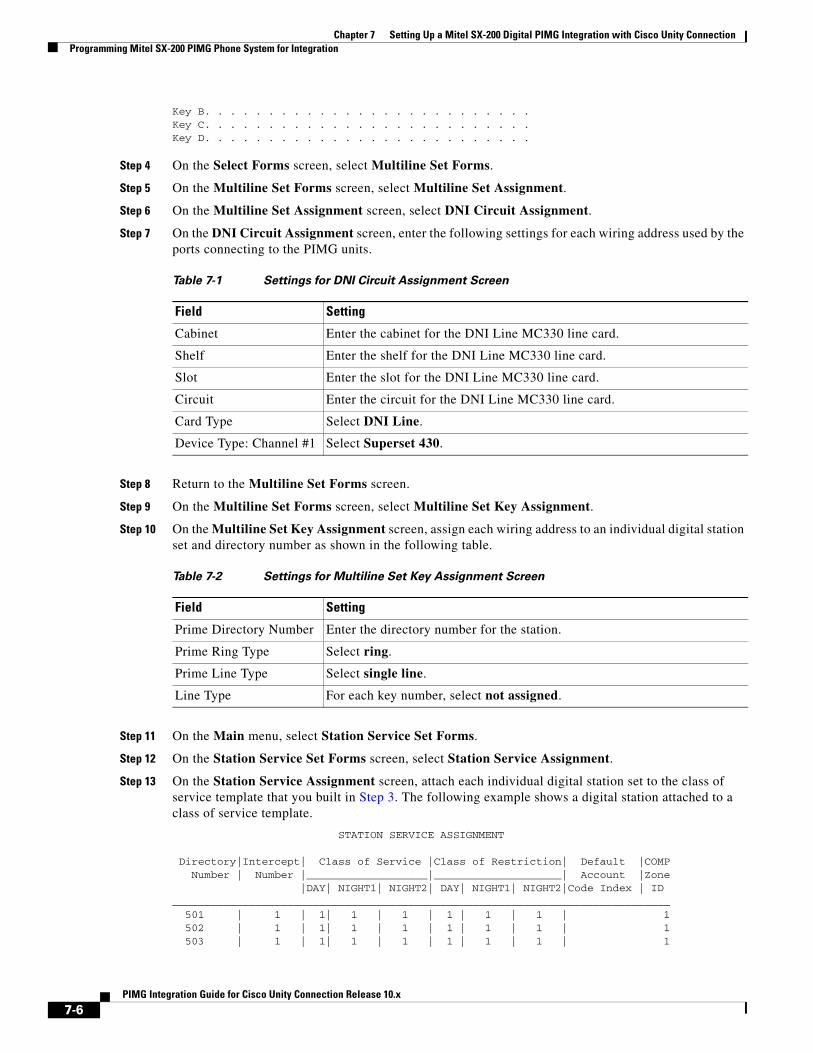
Step 4 On the Select Forms screen, select Multiline Set Forms.
Step 5 On the Multiline Set Forms screen, select Multiline Set Assignment.
Step 6 On the Multiline Set Assignment screen, select DNI Circuit Assignment.
Step 7 On the DNI Circuit Assignment screen, enter the following settings for each wiring address used by the ports connecting to the PIMG units.
Step 8 Return to the Multiline Set Forms screen.
Step 9 On the Multiline Set Forms screen, select Multiline Set Key Assignment.
Step 10 On the Multiline Set Key Assignment screen, assign each wiring address to an individual digital station set and directory number as shown in the following table.
Step 11 On the Main menu, select Station Service Set Forms.
Step 12 On the Station Service Set Forms screen, select Station Service Assignment.
Step 13 On the Station Service Assignment screen, attach each individual digital station set to the class of service template that you built in Step 3. The following example shows a digital station attached to a class of service template.
STATION SERVICE ASSIGNMENT
Directory|Intercept| Class of Service |Class of Restriction| Default |COMPNumber | Number |___________________|____________________| Account |Zone
|DAY| NIGHT1| NIGHT2| DAY| NIGHT1| NIGHT2|Code Index | ID______________________________________________________________________________
501 | 1 | 1| 1 | 1 | 1 | 1 | 1 | 1502 | 1 | 1| 1 | 1 | 1 | 1 | 1 | 1503 | 1 | 1| 1 | 1 | 1 | 1 | 1 | 1
Table 7-1 Settings for DNI Circuit Assignment Screen
Field Setting
Cabinet Enter the cabinet for the DNI Line MC330 line card.
Shelf Enter the shelf for the DNI Line MC330 line card.
Slot Enter the slot for the DNI Line MC330 line card.
Circuit Enter the circuit for the DNI Line MC330 line card.
Card Type Select DNI Line.
Device Type: Channel #1 Select Superset 430.
Table 7-2 Settings for Multiline Set Key Assignment Screen
Field Setting
Prime Directory Number Enter the directory number for the station.
Prime Ring Type Select ring.
Prime Line Type Select single line.
Line Type For each key number, select not assigned.
7-6PIMG Integration Guide for Cisco Unity Connection Release 10.x

Chapter 7 Setting Up a Mitel SX-200 Digital PIMG Integration with Cisco Unity ConnectionProgramming Mitel SX-200 PIMG Phone System for Integration
504 | 1 | 1| 1 | 1 | 1 | 1 | 1 | 1505 | 1 | 1| 1 | 1 | 1 | 1 | 1 | 1506 | 1 | 1| 1 | 1 | 1 | 1 | 1 | 1507 | 1 | 1| 1 | 1 | 1 | 1 | 1 | 1508 | 1 | 1| 1 | 1 | 1 | 1 | 1 | 1
Step 14 On the Main menu, select Group Forms.
Step 15 On the Group Forms screen, select Hunt Group Assignment.
Step 16 On the Hunt Group Assignment screen, enter the following settings to make a hunt group to act as a central inbound route for calls.
Step 17 In the Hunt Group Assignment table of the Hunt Group Assignment screen, assign the directory number for each port connecting to the PIMG units as follows.
Table 7-3 Settings for Hunt Group Assignment Screen
Field Setting
Pilot Number Enter the pilot number for Unity Connection.
Name Enter PIMG hunt group or another name.
Hunt Mode Select the hunt mode that you want to use:
• Circular
• Linear
Group Type Select Voice.
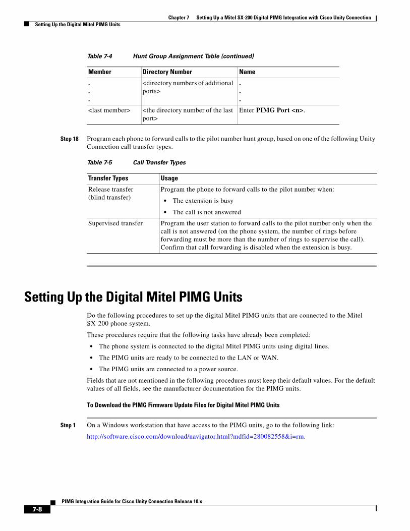
Table 7-4 Hunt Group Assignment Table
Member Directory Number Name
1 <the directory number of the first port>
Enter PIMG Port 1.
2 <the directory number of the second port>
Enter PIMG Port 2.
3 <the directory number of the third port>
Enter PIMG Port 3.
4 <the directory number of the next port>
Enter PIMG Port 4.
5 <the directory number of the next port>
Enter PIMG Port 5.
6 <the directory number of the next port>
Enter PIMG Port 6.
7 <the directory number of the next port>
Enter PIMG Port 7.
8 <the directory number of the next port>
Enter PIMG Port 8.
7-7PIMG Integration Guide for Cisco Unity Connection Release 10.x
Chapter 7 Setting Up a Mitel SX-200 Digital PIMG Integration with Cisco Unity ConnectionSetting Up the Digital Mitel PIMG Units
Step 18 Program each phone to forward calls to the pilot number hunt group, based on one of the following Unity Connection call transfer types.
Setting Up the Digital Mitel PIMG UnitsDo the following procedures to set up the digital Mitel PIMG units that are connected to the Mitel SX-200 phone system.
These procedures require that the following tasks have already been completed:
• The phone system is connected to the digital Mitel PIMG units using digital lines.
• The PIMG units are ready to be connected to the LAN or WAN.
• The PIMG units are connected to a power source.
Fields that are not mentioned in the following procedures must keep their default values. For the default values of all fields, see the manufacturer documentation for the PIMG units.
To Download the PIMG Firmware Update Files for Digital Mitel PIMG Units
Step 1 On a Windows workstation that have access to the PIMG units, go to the following link:
http://software.cisco.com/download/navigator.html?mdfid=280082558&i=rm.
.
.
.
<directory numbers of additional ports>
.
.
.
<last member> <the directory number of the last port>
Enter PIMG Port <n>.
Table 7-5 Call Transfer Types
Transfer Types Usage
Release transfer(blind transfer)
Program the phone to forward calls to the pilot number when:
• The extension is busy
• The call is not answered
Supervised transfer Program the user station to forward calls to the pilot number only when the call is not answered (on the phone system, the number of rings before forwarding must be more than the number of rings to supervise the call). Confirm that call forwarding is disabled when the extension is busy.
Table 7-4 Hunt Group Assignment Table (continued)
Member Directory Number Name
7-8PIMG Integration Guide for Cisco Unity Connection Release 10.x
Chapter 7 Setting Up a Mitel SX-200 Digital PIMG Integration with Cisco Unity ConnectionSetting Up the Digital Mitel PIMG Units
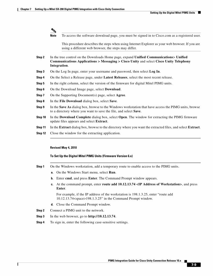
Note To access the software download page, you must be signed in to Cisco.com as a registered user.
This procedure describes the steps when using Internet Explorer as your web browser. If you are using a different web browser, the steps may differ.
Step 2 In the tree control on the Downloads Home page, expand Unified Communications> Unified Communications Applications > Messaging > Cisco Unity and select Cisco Unity Telephony Integration.
Step 3 On the Log In page, enter your username and password, then select Log In.
Step 4 On the Select a Release page, under Latest Releases, select the most recent release.
Step 5 In the right column, select the version of the firmware for digital Mitel PIMG units.
Step 6 On the Download Image page, select Download.
Step 7 On the Supporting Document(s) page, select Agree.
Step 8 In the File Download dialog box, select Save.
Step 9 In the Save As dialog box, browse to the Windows workstation that have access the PIMG units, browse to a directory where you want to save the file, and select Save.
Step 10 In the Download Complete dialog box, select Open. The window for extracting the PIMG firmware update files appears and select Extract.
Step 11 In the Extract dialog box, browse to the directory where you want the extracted files, and select Extract.
Step 12 Close the window for the extracting application.
Revised May 4, 2010
To Set Up the Digital Mitel PIMG Units (Firmware Version 6.x)
Step 1 On the Windows workstation, add a temporary route to enable access to the PIMG units.
a. On the Windows Start menu, select Run.
b. Enter cmd, and press Enter. The Command Prompt window appears.
c. At the command prompt, enter route add 10.12.13.74 <IP Address of Workstation>, and press Enter.
For example, if the IP address of the workstation is 198.1.3.25, enter “route add 10.12.13.74<space>198.1.3.25” in the Command Prompt window.
d. Close the Command Prompt window.
Step 2 Connect a PIMG unit to the network.
Step 3 In the web browser, go to http://10.12.13.74.
Step 4 To sign in, enter the following case-sensitive settings.
7-9PIMG Integration Guide for Cisco Unity Connection Release 10.x
Chapter 7 Setting Up a Mitel SX-200 Digital PIMG Integration with Cisco Unity ConnectionSetting Up the Digital Mitel PIMG Units
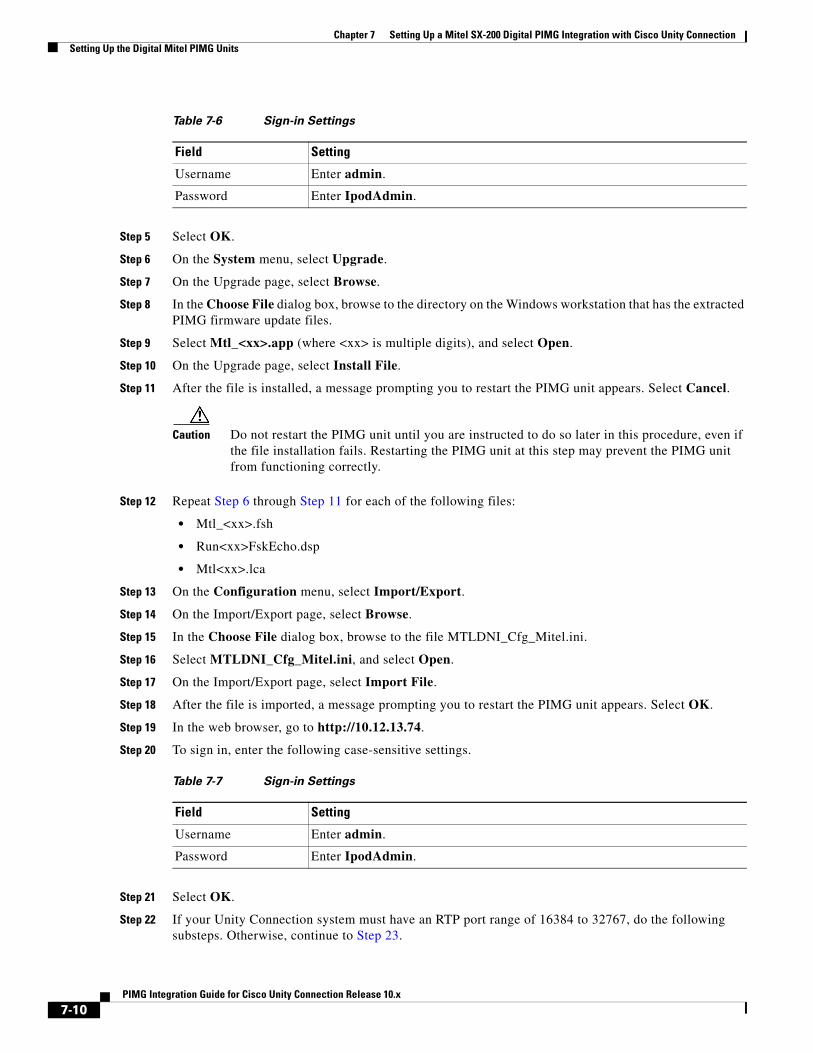
Step 5 Select OK.
Step 6 On the System menu, select Upgrade.
Step 7 On the Upgrade page, select Browse.
Step 8 In the Choose File dialog box, browse to the directory on the Windows workstation that has the extracted PIMG firmware update files.
Step 9 Select Mtl_<xx>.app (where <xx> is multiple digits), and select Open.
Step 10 On the Upgrade page, select Install File.
Step 11 After the file is installed, a message prompting you to restart the PIMG unit appears. Select Cancel.
Caution Do not restart the PIMG unit until you are instructed to do so later in this procedure, even if the file installation fails. Restarting the PIMG unit at this step may prevent the PIMG unit from functioning correctly.
Step 12 Repeat Step 6 through Step 11 for each of the following files:
• Mtl_<xx>.fsh
• Run<xx>FskEcho.dsp
• Mtl<xx>.lca
Step 13 On the Configuration menu, select Import/Export.
Step 14 On the Import/Export page, select Browse.
Step 15 In the Choose File dialog box, browse to the file MTLDNI_Cfg_Mitel.ini.
Step 16 Select MTLDNI_Cfg_Mitel.ini, and select Open.
Step 17 On the Import/Export page, select Import File.
Step 18 After the file is imported, a message prompting you to restart the PIMG unit appears. Select OK.
Step 19 In the web browser, go to http://10.12.13.74.
Step 20 To sign in, enter the following case-sensitive settings.
Step 21 Select OK.
Step 22 If your Unity Connection system must have an RTP port range of 16384 to 32767, do the following substeps. Otherwise, continue to Step 23.
Table 7-6 Sign-in Settings
Field Setting
Username Enter admin.
Password Enter IpodAdmin.
Table 7-7 Sign-in Settings
Field Setting
Username Enter admin.
Password Enter IpodAdmin.
7-10PIMG Integration Guide for Cisco Unity Connection Release 10.x
Chapter 7 Setting Up a Mitel SX-200 Digital PIMG Integration with Cisco Unity ConnectionSetting Up the Digital Mitel PIMG Units
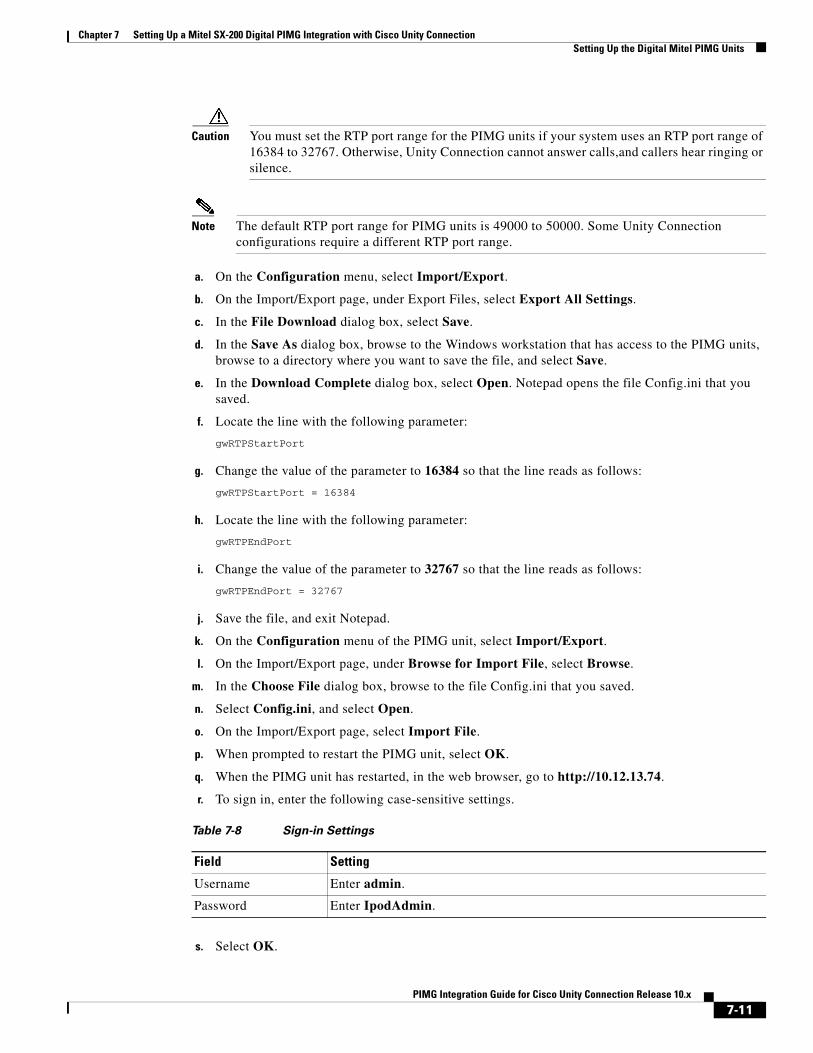
Caution You must set the RTP port range for the PIMG units if your system uses an RTP port range of 16384 to 32767. Otherwise, Unity Connection cannot answer calls,and callers hear ringing or silence.
Note The default RTP port range for PIMG units is 49000 to 50000. Some Unity Connection configurations require a different RTP port range.
a. On the Configuration menu, select Import/Export.
b. On the Import/Export page, under Export Files, select Export All Settings.
c. In the File Download dialog box, select Save.
d. In the Save As dialog box, browse to the Windows workstation that has access to the PIMG units, browse to a directory where you want to save the file, and select Save.
e. In the Download Complete dialog box, select Open. Notepad opens the file Config.ini that you saved.
f. Locate the line with the following parameter:
gwRTPStartPort
g. Change the value of the parameter to 16384 so that the line reads as follows:
gwRTPStartPort = 16384
h. Locate the line with the following parameter:
gwRTPEndPort
i. Change the value of the parameter to 32767 so that the line reads as follows:
gwRTPEndPort = 32767
j. Save the file, and exit Notepad.
k. On the Configuration menu of the PIMG unit, select Import/Export.
l. On the Import/Export page, under Browse for Import File, select Browse.
m. In the Choose File dialog box, browse to the file Config.ini that you saved.
n. Select Config.ini, and select Open.
o. On the Import/Export page, select Import File.
p. When prompted to restart the PIMG unit, select OK.
q. When the PIMG unit has restarted, in the web browser, go to http://10.12.13.74.
r. To sign in, enter the following case-sensitive settings.
s. Select OK.
Table 7-8 Sign-in Settings
Field Setting
Username Enter admin.
Password Enter IpodAdmin.
7-11PIMG Integration Guide for Cisco Unity Connection Release 10.x
Chapter 7 Setting Up a Mitel SX-200 Digital PIMG Integration with Cisco Unity ConnectionSetting Up the Digital Mitel PIMG Units
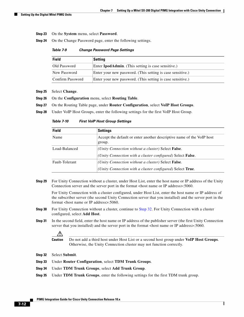
Step 23 On the System menu, select Password.
Step 24 On the Change Password page, enter the following settings.
Step 25 Select Change.
Step 26 On the Configuration menu, select Routing Table.
Step 27 On the Routing Table page, under Router Configuration, select VoIP Host Groups.
Step 28 Under VoIP Host Groups, enter the following settings for the first VoIP Host Group.
Step 29 For Unity Connection without a cluster, under Host List, enter the host name or IP address of the Unity Connection server and the server port in the format <host name or IP address>:5060.
For Unity Connection with a cluster configured, under Host List, enter the host name or IP address of the subscriber server (the second Unity Connection server that you installed) and the server port in the format <host name or IP address>:5060.
Step 30 For Unity Connection without a cluster, continue to Step 32. For Unity Connection with a cluster configured, select Add Host.
Step 31 In the second field, enter the host name or IP address of the publisher server (the first Unity Connection server that you installed) and the server port in the format <host name or IP address>:5060.
Caution Do not add a third host under Host List or a second host group under VoIP Host Groups. Otherwise, the Unity Connection cluster may not function correctly.
Step 32 Select Submit.
Step 33 Under Router Configuration, select TDM Trunk Groups.
Step 34 Under TDM Trunk Groups, select Add Trunk Group.
Step 35 Under TDM Trunk Groups, enter the following settings for the first TDM trunk group.
Table 7-9 Change Password Page Settings
Field Setting
Old Password Enter IpodAdmin. (This setting is case sensitive.)
New Password Enter your new password. (This setting is case sensitive.)
Confirm Password Enter your new password. (This setting is case sensitive.)
Table 7-10 First VoIP Host Group Settings
Field Settings
Name Accept the default or enter another descriptive name of the VoIP host group.
Load-Balanced (Unity Connection without a cluster) Select False.
(Unity Connection with a cluster configured) Select False.
Fault-Tolerant (Unity Connection without a cluster) Select False.
(Unity Connection with a cluster configured) Select True.
7-12PIMG Integration Guide for Cisco Unity Connection Release 10.x
Chapter 7 Setting Up a Mitel SX-200 Digital PIMG Integration with Cisco Unity ConnectionSetting Up the Digital Mitel PIMG Units
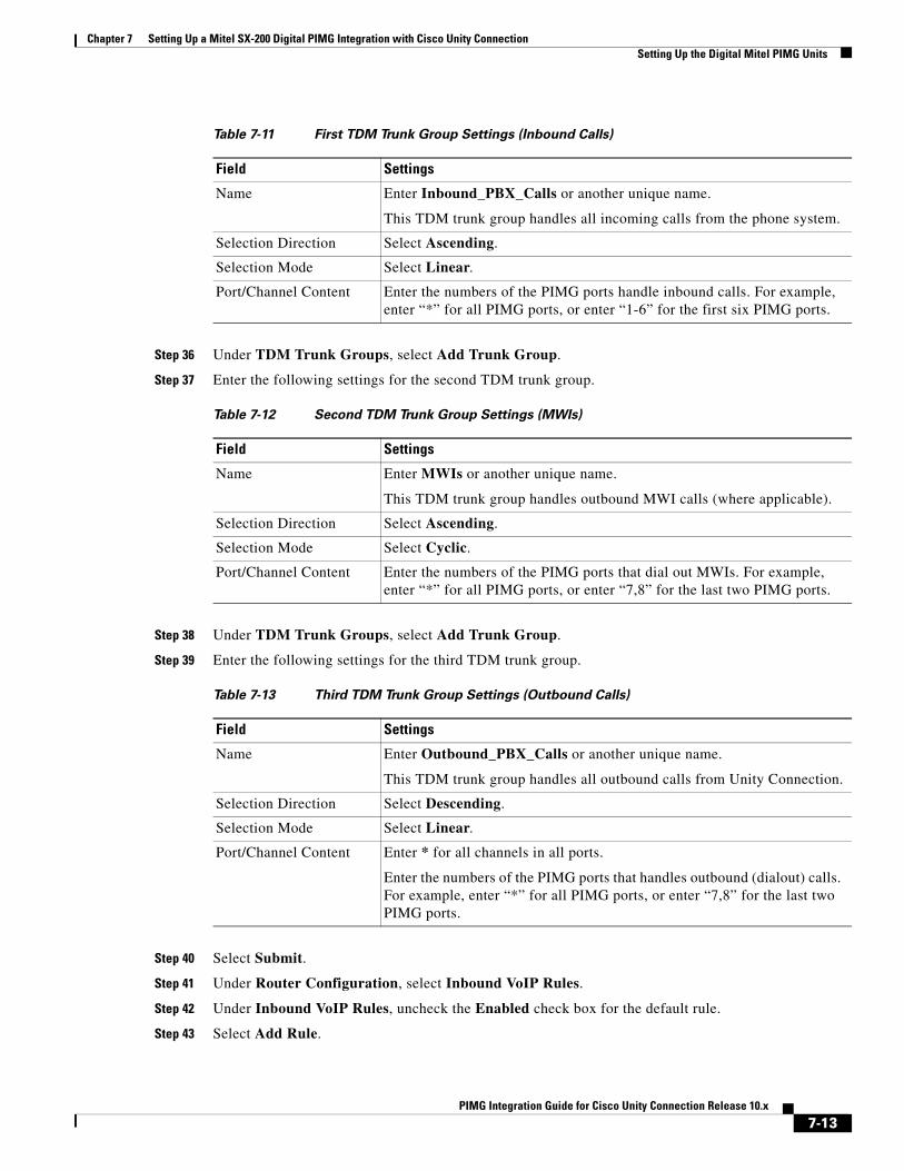
Step 36 Under TDM Trunk Groups, select Add Trunk Group.
Step 37 Enter the following settings for the second TDM trunk group.
Step 38 Under TDM Trunk Groups, select Add Trunk Group.
Step 39 Enter the following settings for the third TDM trunk group.
Step 40 Select Submit.
Step 41 Under Router Configuration, select Inbound VoIP Rules.
Step 42 Under Inbound VoIP Rules, uncheck the Enabled check box for the default rule.
Step 43 Select Add Rule.
Table 7-11 First TDM Trunk Group Settings (Inbound Calls)
Field Settings
Name Enter Inbound_PBX_Calls or another unique name.
This TDM trunk group handles all incoming calls from the phone system.
Selection Direction Select Ascending.
Selection Mode Select Linear.
Port/Channel Content Enter the numbers of the PIMG ports handle inbound calls. For example, enter “*” for all PIMG ports, or enter “1-6” for the first six PIMG ports.
Table 7-12 Second TDM Trunk Group Settings (MWIs)
Field Settings
Name Enter MWIs or another unique name.
This TDM trunk group handles outbound MWI calls (where applicable).
Selection Direction Select Ascending.
Selection Mode Select Cyclic.
Port/Channel Content Enter the numbers of the PIMG ports that dial out MWIs. For example, enter “*” for all PIMG ports, or enter “7,8” for the last two PIMG ports.
Table 7-13 Third TDM Trunk Group Settings (Outbound Calls)
Field Settings
Name Enter Outbound_PBX_Calls or another unique name.
This TDM trunk group handles all outbound calls from Unity Connection.
Selection Direction Select Descending.
Selection Mode Select Linear.
Port/Channel Content Enter * for all channels in all ports.
Enter the numbers of the PIMG ports that handles outbound (dialout) calls. For example, enter “*” for all PIMG ports, or enter “7,8” for the last two PIMG ports.
7-13PIMG Integration Guide for Cisco Unity Connection Release 10.x
Chapter 7 Setting Up a Mitel SX-200 Digital PIMG Integration with Cisco Unity ConnectionSetting Up the Digital Mitel PIMG Units
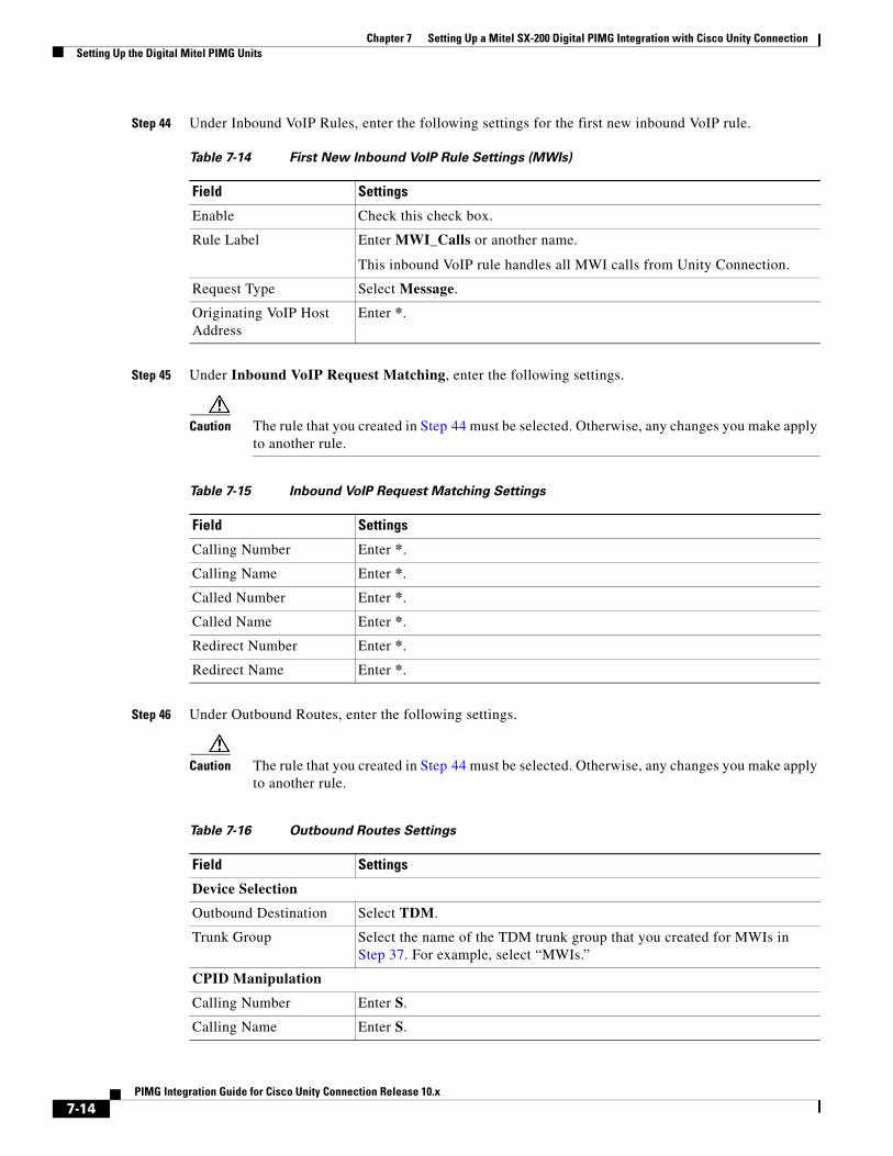
Step 44 Under Inbound VoIP Rules, enter the following settings for the first new inbound VoIP rule.
Step 45 Under Inbound VoIP Request Matching, enter the following settings.
Caution The rule that you created in Step 44 must be selected. Otherwise, any changes you make apply to another rule.
Step 46 Under Outbound Routes, enter the following settings.
Caution The rule that you created in Step 44 must be selected. Otherwise, any changes you make apply to another rule.
Table 7-14 First New Inbound VoIP Rule Settings (MWIs)
Field Settings
Enable Check this check box.
Rule Label Enter MWI_Calls or another name.
This inbound VoIP rule handles all MWI calls from Unity Connection.
Request Type Select Message.
Originating VoIP Host Address
Enter *.
Table 7-15 Inbound VoIP Request Matching Settings
Field Settings
Calling Number Enter *.
Calling Name Enter *.
Called Number Enter *.
Called Name Enter *.
Redirect Number Enter *.
Redirect Name Enter *.
Table 7-16 Outbound Routes Settings
Field Settings
Device Selection
Outbound Destination Select TDM.
Trunk Group Select the name of the TDM trunk group that you created for MWIs in Step 37. For example, select “MWIs.”
CPID Manipulation
Calling Number Enter S.
Calling Name Enter S.
7-14PIMG Integration Guide for Cisco Unity Connection Release 10.x
Chapter 7 Setting Up a Mitel SX-200 Digital PIMG Integration with Cisco Unity ConnectionSetting Up the Digital Mitel PIMG Units
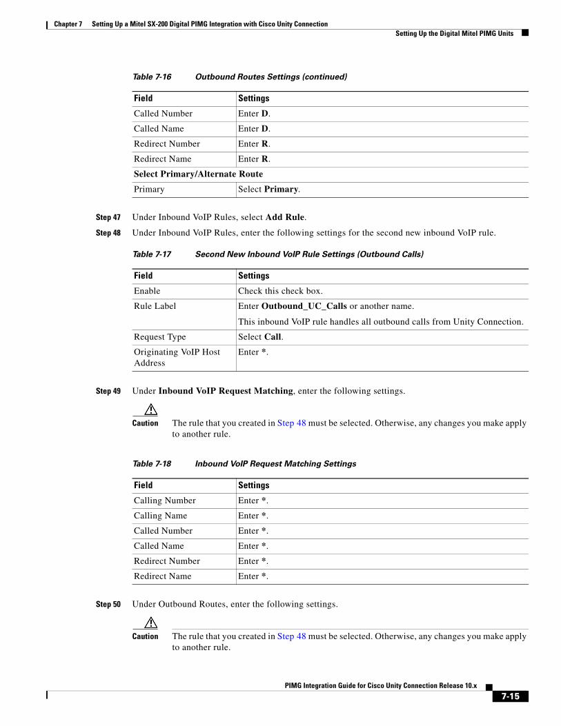
Step 47 Under Inbound VoIP Rules, select Add Rule.
Step 48 Under Inbound VoIP Rules, enter the following settings for the second new inbound VoIP rule.
Step 49 Under Inbound VoIP Request Matching, enter the following settings.
Caution The rule that you created in Step 48 must be selected. Otherwise, any changes you make apply to another rule.
Step 50 Under Outbound Routes, enter the following settings.
Caution The rule that you created in Step 48 must be selected. Otherwise, any changes you make apply to another rule.
Called Number Enter D.
Called Name Enter D.
Redirect Number Enter R.
Redirect Name Enter R.
Select Primary/Alternate Route
Primary Select Primary.
Table 7-17 Second New Inbound VoIP Rule Settings (Outbound Calls)
Field Settings
Enable Check this check box.
Rule Label Enter Outbound_UC_Calls or another name.
This inbound VoIP rule handles all outbound calls from Unity Connection.
Request Type Select Call.
Originating VoIP Host Address
Enter *.
Table 7-16 Outbound Routes Settings (continued)
Field Settings
Table 7-18 Inbound VoIP Request Matching Settings
Field Settings
Calling Number Enter *.
Calling Name Enter *.
Called Number Enter *.
Called Name Enter *.
Redirect Number Enter *.
Redirect Name Enter *.
7-15PIMG Integration Guide for Cisco Unity Connection Release 10.x
Chapter 7 Setting Up a Mitel SX-200 Digital PIMG Integration with Cisco Unity ConnectionSetting Up the Digital Mitel PIMG Units
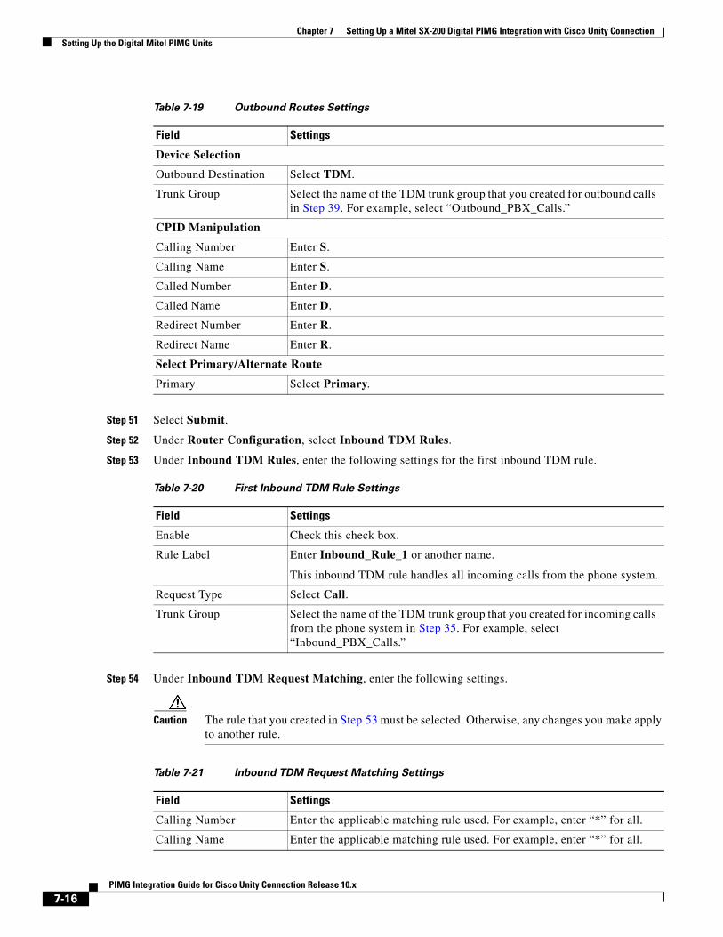
Step 51 Select Submit.
Step 52 Under Router Configuration, select Inbound TDM Rules.
Step 53 Under Inbound TDM Rules, enter the following settings for the first inbound TDM rule.
Step 54 Under Inbound TDM Request Matching, enter the following settings.
Caution The rule that you created in Step 53 must be selected. Otherwise, any changes you make apply to another rule.
Table 7-19 Outbound Routes Settings
Field Settings
Device Selection
Outbound Destination Select TDM.
Trunk Group Select the name of the TDM trunk group that you created for outbound calls in Step 39. For example, select “Outbound_PBX_Calls.”
CPID Manipulation
Calling Number Enter S.
Calling Name Enter S.
Called Number Enter D.
Called Name Enter D.
Redirect Number Enter R.
Redirect Name Enter R.
Select Primary/Alternate Route
Primary Select Primary.
Table 7-20 First Inbound TDM Rule Settings
Field Settings
Enable Check this check box.
Rule Label Enter Inbound_Rule_1 or another name.
This inbound TDM rule handles all incoming calls from the phone system.
Request Type Select Call.
Trunk Group Select the name of the TDM trunk group that you created for incoming calls from the phone system in Step 35. For example, select “Inbound_PBX_Calls.”
Table 7-21 Inbound TDM Request Matching Settings
Field Settings
Calling Number Enter the applicable matching rule used. For example, enter “*” for all.
Calling Name Enter the applicable matching rule used. For example, enter “*” for all.
7-16PIMG Integration Guide for Cisco Unity Connection Release 10.x
Chapter 7 Setting Up a Mitel SX-200 Digital PIMG Integration with Cisco Unity ConnectionSetting Up the Digital Mitel PIMG Units
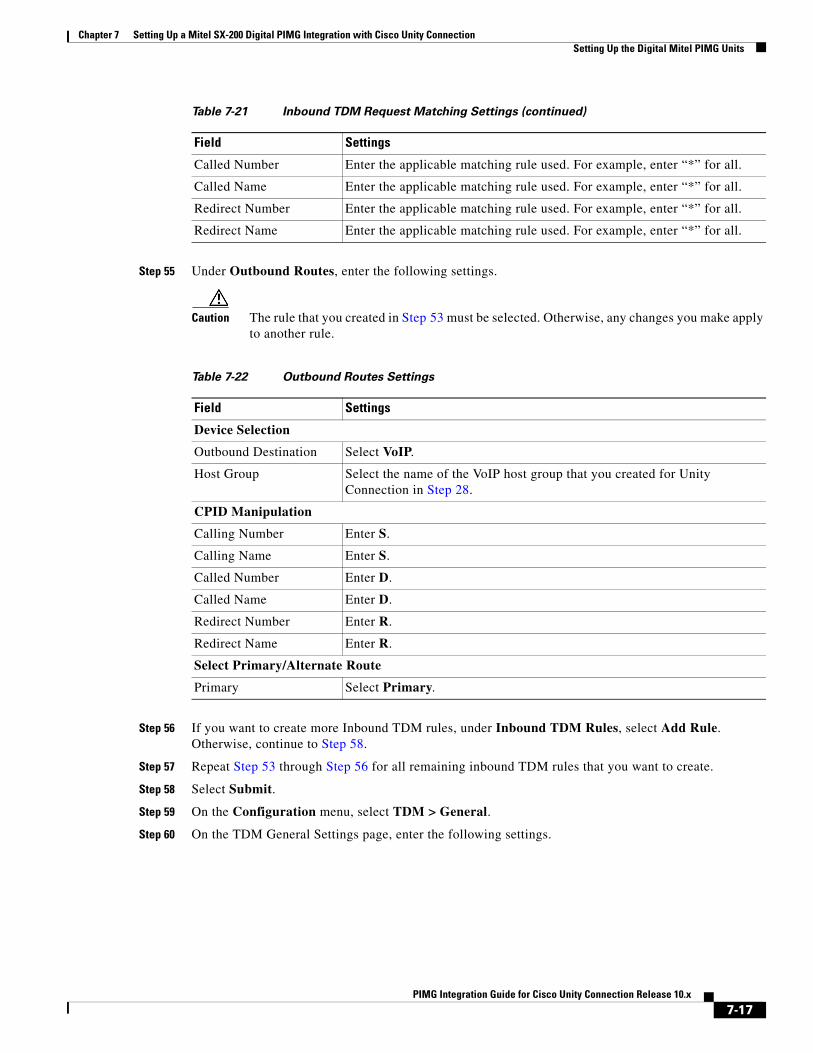
Step 55 Under Outbound Routes, enter the following settings.
Caution The rule that you created in Step 53 must be selected. Otherwise, any changes you make apply to another rule.
Step 56 If you want to create more Inbound TDM rules, under Inbound TDM Rules, select Add Rule. Otherwise, continue to Step 58.
Step 57 Repeat Step 53 through Step 56 for all remaining inbound TDM rules that you want to create.
Step 58 Select Submit.
Step 59 On the Configuration menu, select TDM > General.
Step 60 On the TDM General Settings page, enter the following settings.
Called Number Enter the applicable matching rule used. For example, enter “*” for all.
Called Name Enter the applicable matching rule used. For example, enter “*” for all.
Redirect Number Enter the applicable matching rule used. For example, enter “*” for all.
Redirect Name Enter the applicable matching rule used. For example, enter “*” for all.
Table 7-21 Inbound TDM Request Matching Settings (continued)
Field Settings
Table 7-22 Outbound Routes Settings
Field Settings
Device Selection
Outbound Destination Select VoIP.
Host Group Select the name of the VoIP host group that you created for Unity Connection in Step 28.
CPID Manipulation
Calling Number Enter S.
Calling Name Enter S.
Called Number Enter D.
Called Name Enter D.
Redirect Number Enter R.
Redirect Name Enter R.
Select Primary/Alternate Route
Primary Select Primary.
7-17PIMG Integration Guide for Cisco Unity Connection Release 10.x
Chapter 7 Setting Up a Mitel SX-200 Digital PIMG Integration with Cisco Unity ConnectionSetting Up the Digital Mitel PIMG Units
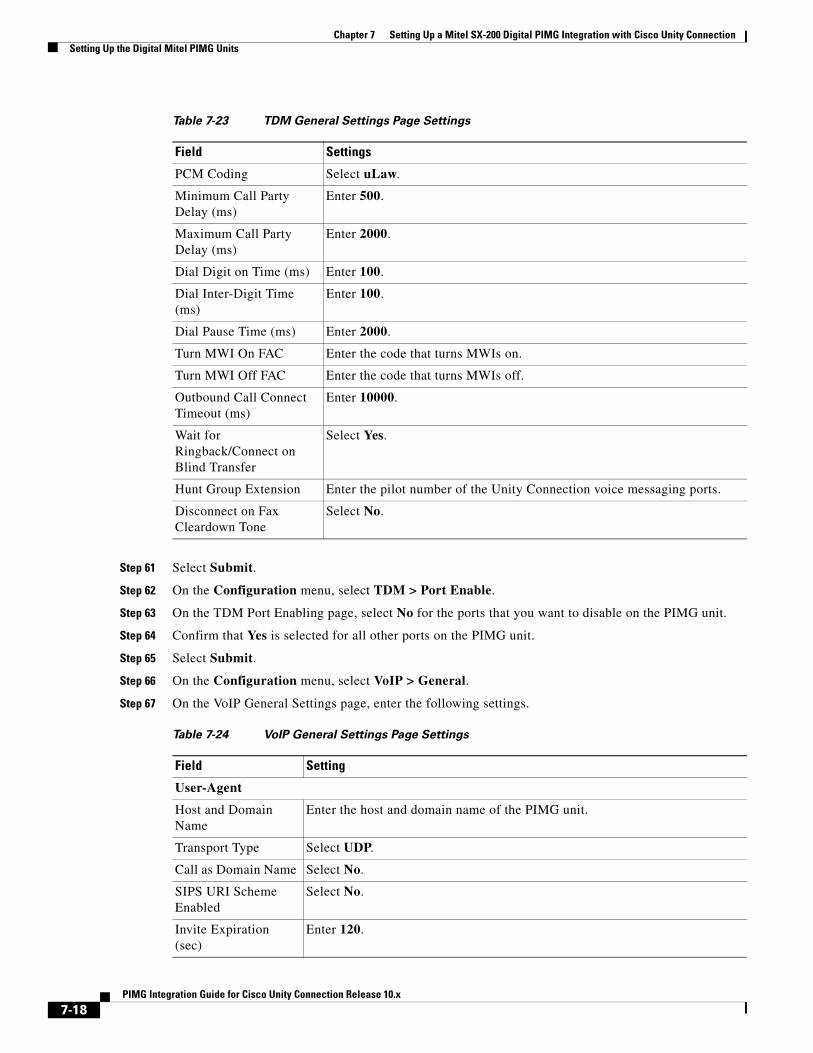
Step 61 Select Submit.
Step 62 On the Configuration menu, select TDM > Port Enable.
Step 63 On the TDM Port Enabling page, select No for the ports that you want to disable on the PIMG unit.
Step 64 Confirm that Yes is selected for all other ports on the PIMG unit.
Step 65 Select Submit.
Step 66 On the Configuration menu, select VoIP > General.
Step 67 On the VoIP General Settings page, enter the following settings.
Table 7-23 TDM General Settings Page Settings
Field Settings
PCM Coding Select uLaw.
Minimum Call Party Delay (ms)
Enter 500.
Maximum Call Party Delay (ms)
Enter 2000.
Dial Digit on Time (ms) Enter 100.
Dial Inter-Digit Time (ms)
Enter 100.
Dial Pause Time (ms) Enter 2000.
Turn MWI On FAC Enter the code that turns MWIs on.
Turn MWI Off FAC Enter the code that turns MWIs off.
Outbound Call Connect Timeout (ms)
Enter 10000.
Wait for Ringback/Connect on Blind Transfer
Select Yes.
Hunt Group Extension Enter the pilot number of the Unity Connection voice messaging ports.
Disconnect on Fax Cleardown Tone
Select No.
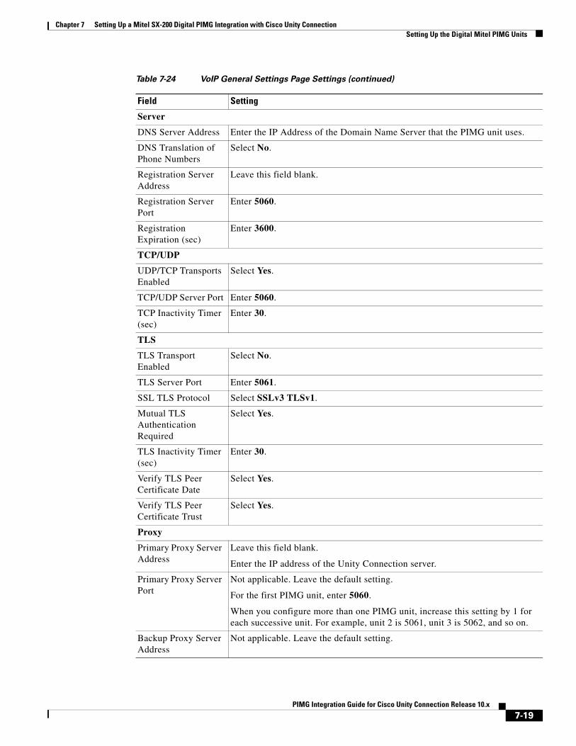
Table 7-24 VoIP General Settings Page Settings
Field Setting
User-Agent
Host and Domain Name
Enter the host and domain name of the PIMG unit.
Transport Type Select UDP.
Call as Domain Name Select No.
SIPS URI Scheme Enabled
Select No.
Invite Expiration (sec)
Enter 120.
7-18PIMG Integration Guide for Cisco Unity Connection Release 10.x
Chapter 7 Setting Up a Mitel SX-200 Digital PIMG Integration with Cisco Unity ConnectionSetting Up the Digital Mitel PIMG Units
Server
DNS Server Address Enter the IP Address of the Domain Name Server that the PIMG unit uses.
DNS Translation of Phone Numbers
Select No.
Registration Server Address
Leave this field blank.
Registration Server Port
Enter 5060.
Registration Expiration (sec)
Enter 3600.
TCP/UDP
UDP/TCP Transports Enabled
Select Yes.
TCP/UDP Server Port Enter 5060.
TCP Inactivity Timer (sec)
Enter 30.
TLS
TLS Transport Enabled
Select No.
TLS Server Port Enter 5061.
SSL TLS Protocol Select SSLv3 TLSv1.
Mutual TLS Authentication Required
Select Yes.
TLS Inactivity Timer (sec)
Enter 30.
Verify TLS Peer Certificate Date
Select Yes.
Verify TLS Peer Certificate Trust
Select Yes.
Proxy
Primary Proxy Server Address
Leave this field blank.
Enter the IP address of the Unity Connection server.
Primary Proxy Server Port
Not applicable. Leave the default setting.
For the first PIMG unit, enter 5060.
When you configure more than one PIMG unit, increase this setting by 1 for each successive unit. For example, unit 2 is 5061, unit 3 is 5062, and so on.
Backup Proxy Server Address
Not applicable. Leave the default setting.
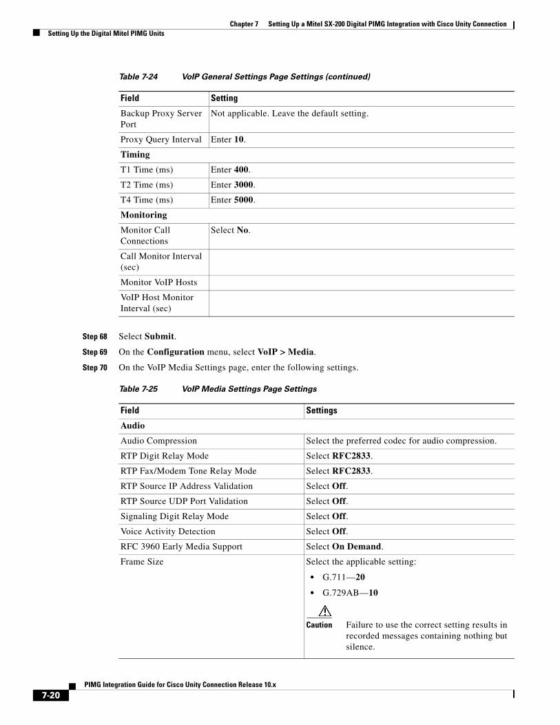
Table 7-24 VoIP General Settings Page Settings (continued)
Field Setting
7-19PIMG Integration Guide for Cisco Unity Connection Release 10.x
Chapter 7 Setting Up a Mitel SX-200 Digital PIMG Integration with Cisco Unity ConnectionSetting Up the Digital Mitel PIMG Units
Step 68 Select Submit.
Step 69 On the Configuration menu, select VoIP > Media.
Step 70 On the VoIP Media Settings page, enter the following settings.
Backup Proxy Server Port
Not applicable. Leave the default setting.
Proxy Query Interval Enter 10.
Timing
T1 Time (ms) Enter 400.
T2 Time (ms) Enter 3000.
T4 Time (ms) Enter 5000.
Monitoring
Monitor Call Connections
Select No.
Call Monitor Interval (sec)
Monitor VoIP Hosts
VoIP Host Monitor Interval (sec)
Table 7-25 VoIP Media Settings Page Settings
Field Settings
Audio
Audio Compression Select the preferred codec for audio compression.
RTP Digit Relay Mode Select RFC2833.
RTP Fax/Modem Tone Relay Mode Select RFC2833.
RTP Source IP Address Validation Select Off.
RTP Source UDP Port Validation Select Off.
Signaling Digit Relay Mode Select Off.
Voice Activity Detection Select Off.
RFC 3960 Early Media Support Select On Demand.
Frame Size Select the applicable setting:
• G.711—20
• G.729AB—10
Caution Failure to use the correct setting results in recorded messages containing nothing but silence.
Table 7-24 VoIP General Settings Page Settings (continued)
Field Setting
7-20PIMG Integration Guide for Cisco Unity Connection Release 10.x
Chapter 7 Setting Up a Mitel SX-200 Digital PIMG Integration with Cisco Unity ConnectionSetting Up the Digital Mitel PIMG Units
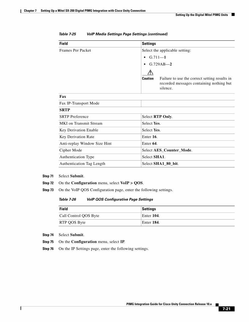
Step 71 Select Submit.
Step 72 On the Configuration menu, select VoIP > QOS.
Step 73 On the VoIP QOS Configuration page, enter the following settings.
Step 74 Select Submit.
Step 75 On the Configuration menu, select IP.
Step 76 On the IP Settings page, enter the following settings.
Frames Per Packet Select the applicable setting:
• G.711—1
• G.729AB—2
Caution Failure to use the correct setting results in recorded messages containing nothing but silence.
Fax
Fax IP-Transport Mode
SRTP
SRTP Preference Select RTP Only.
MKI on Transmit Stream Select Yes.
Key Derivation Enable Select Yes.
Key Derivation Rate Enter 16.
Anti-replay Window Size Hint Enter 64.
Cipher Mode Select AES_Counter_Mode.
Authentication Type Select SHA1.
Authentication Tag Length Select SHA1_80_bit.
Table 7-26 VoIP QOS Configurative Page Settings
Field Settings
Call Control QOS Byte Enter 104.
RTP QOS Byte Enter 184.
Table 7-25 VoIP Media Settings Page Settings (continued)
Field Settings
7-21PIMG Integration Guide for Cisco Unity Connection Release 10.x
Chapter 7 Setting Up a Mitel SX-200 Digital PIMG Integration with Cisco Unity ConnectionSetting Up the Digital Mitel PIMG Units
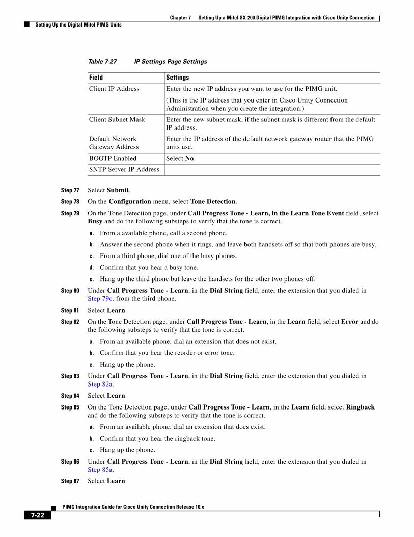
Step 77 Select Submit.
Step 78 On the Configuration menu, select Tone Detection.
Step 79 On the Tone Detection page, under Call Progress Tone - Learn, in the Learn Tone Event field, select Busy and do the following substeps to verify that the tone is correct.
a. From a available phone, call a second phone.
b. Answer the second phone when it rings, and leave both handsets off so that both phones are busy.
c. From a third phone, dial one of the busy phones.
d. Confirm that you hear a busy tone.
e. Hang up the third phone but leave the handsets for the other two phones off.
Step 80 Under Call Progress Tone - Learn, in the Dial String field, enter the extension that you dialed in Step 79c. from the third phone.
Step 81 Select Learn.
Step 82 On the Tone Detection page, under Call Progress Tone - Learn, in the Learn field, select Error and do the following substeps to verify that the tone is correct.
a. From an available phone, dial an extension that does not exist.
b. Confirm that you hear the reorder or error tone.
c. Hang up the phone.
Step 83 Under Call Progress Tone - Learn, in the Dial String field, enter the extension that you dialed in Step 82a.
Step 84 Select Learn.
Step 85 On the Tone Detection page, under Call Progress Tone - Learn, in the Learn field, select Ringback and do the following substeps to verify that the tone is correct.
a. From an available phone, dial an extension that does exist.
b. Confirm that you hear the ringback tone.
c. Hang up the phone.
Step 86 Under Call Progress Tone - Learn, in the Dial String field, enter the extension that you dialed in Step 85a.
Step 87 Select Learn.
Table 7-27 IP Settings Page Settings
Field Settings
Client IP Address Enter the new IP address you want to use for the PIMG unit.
(This is the IP address that you enter in Cisco Unity Connection Administration when you create the integration.)
Client Subnet Mask Enter the new subnet mask, if the subnet mask is different from the default IP address.
Default Network Gateway Address
Enter the IP address of the default network gateway router that the PIMG units use.
BOOTP Enabled Select No.
SNTP Server IP Address
7-22PIMG Integration Guide for Cisco Unity Connection Release 10.x
Chapter 7 Setting Up a Mitel SX-200 Digital PIMG Integration with Cisco Unity ConnectionCreating a New Integration with Mitel SX-200 Phone System
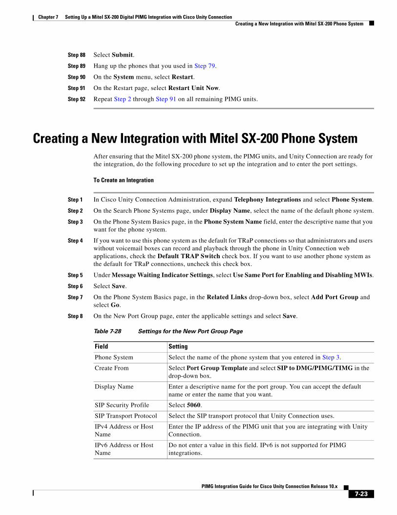
Step 88 Select Submit.
Step 89 Hang up the phones that you used in Step 79.
Step 90 On the System menu, select Restart.
Step 91 On the Restart page, select Restart Unit Now.
Step 92 Repeat Step 2 through Step 91 on all remaining PIMG units.
Creating a New Integration with Mitel SX-200 Phone SystemAfter ensuring that the Mitel SX-200 phone system, the PIMG units, and Unity Connection are ready for the integration, do the following procedure to set up the integration and to enter the port settings.
To Create an Integration
Step 1 In Cisco Unity Connection Administration, expand Telephony Integrations and select Phone System.
Step 2 On the Search Phone Systems page, under Display Name, select the name of the default phone system.
Step 3 On the Phone System Basics page, in the Phone System Name field, enter the descriptive name that you want for the phone system.
Step 4 If you want to use this phone system as the default for TRaP connections so that administrators and users without voicemail boxes can record and playback through the phone in Unity Connection web applications, check the Default TRAP Switch check box. If you want to use another phone system as the default for TRaP connections, uncheck this check box.
Step 5 Under Message Waiting Indicator Settings, select Use Same Port for Enabling and Disabling MWIs.
Step 6 Select Save.
Step 7 On the Phone System Basics page, in the Related Links drop-down box, select Add Port Group and select Go.
Step 8 On the New Port Group page, enter the applicable settings and select Save.
Table 7-28 Settings for the New Port Group Page
Field Setting
Phone System Select the name of the phone system that you entered in Step 3.
Create From Select Port Group Template and select SIP to DMG/PIMG/TIMG in the drop-down box.
Display Name Enter a descriptive name for the port group. You can accept the default name or enter the name that you want.
SIP Security Profile Select 5060.
SIP Transport Protocol Select the SIP transport protocol that Unity Connection uses.
IPv4 Address or Host Name
Enter the IP address of the PIMG unit that you are integrating with Unity Connection.
IPv6 Address or Host Name
Do not enter a value in this field. IPv6 is not supported for PIMG integrations.
7-23PIMG Integration Guide for Cisco Unity Connection Release 10.x
Chapter 7 Setting Up a Mitel SX-200 Digital PIMG Integration with Cisco Unity ConnectionCreating a New Integration with Mitel SX-200 Phone System
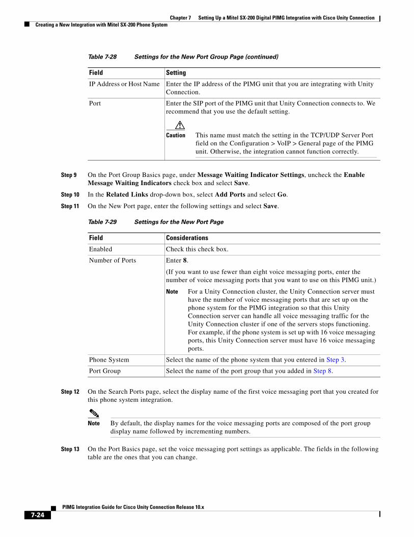
Step 9 On the Port Group Basics page, under Message Waiting Indicator Settings, uncheck the Enable Message Waiting Indicators check box and select Save.
Step 10 In the Related Links drop-down box, select Add Ports and select Go.
Step 11 On the New Port page, enter the following settings and select Save.
Step 12 On the Search Ports page, select the display name of the first voice messaging port that you created for this phone system integration.
Note By default, the display names for the voice messaging ports are composed of the port group display name followed by incrementing numbers.
Step 13 On the Port Basics page, set the voice messaging port settings as applicable. The fields in the following table are the ones that you can change.
IP Address or Host Name Enter the IP address of the PIMG unit that you are integrating with Unity Connection.
Port Enter the SIP port of the PIMG unit that Unity Connection connects to. We recommend that you use the default setting.
Caution This name must match the setting in the TCP/UDP Server Port field on the Configuration > VoIP > General page of the PIMG unit. Otherwise, the integration cannot function correctly.
Table 7-29 Settings for the New Port Page
Field Considerations
Enabled Check this check box.
Number of Ports Enter 8.
(If you want to use fewer than eight voice messaging ports, enter the number of voice messaging ports that you want to use on this PIMG unit.)
Note For a Unity Connection cluster, the Unity Connection server must have the number of voice messaging ports that are set up on the phone system for the PIMG integration so that this Unity Connection server can handle all voice messaging traffic for the Unity Connection cluster if one of the servers stops functioning. For example, if the phone system is set up with 16 voice messaging ports, this Unity Connection server must have 16 voice messaging ports.
Phone System Select the name of the phone system that you entered in Step 3.
Port Group Select the name of the port group that you added in Step 8.
Table 7-28 Settings for the New Port Group Page (continued)
Field Setting
7-24PIMG Integration Guide for Cisco Unity Connection Release 10.x
Chapter 7 Setting Up a Mitel SX-200 Digital PIMG Integration with Cisco Unity ConnectionCreating a New Integration with Mitel SX-200 Phone System
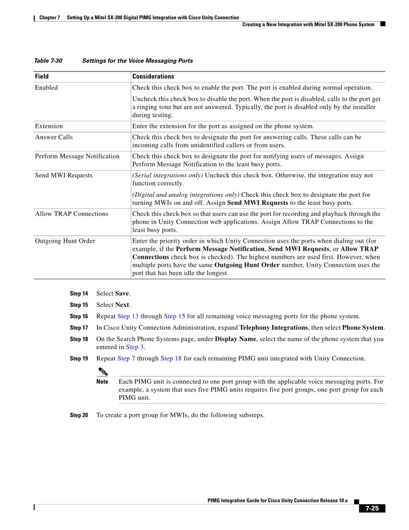
Step 14 Select Save.
Step 15 Select Next.
Step 16 Repeat Step 13 through Step 15 for all remaining voice messaging ports for the phone system.
Step 17 In Cisco Unity Connection Administration, expand Telephony Integrations, then select Phone System.
Step 18 On the Search Phone Systems page, under Display Name, select the name of the phone system that you entered in Step 3.
Step 19 Repeat Step 7 through Step 18 for each remaining PIMG unit integrated with Unity Connection.
Note Each PIMG unit is connected to one port group with the applicable voice messaging ports. For example, a system that uses five PIMG units requires five port groups, one port group for each PIMG unit.
Step 20 To create a port group for MWIs, do the following substeps.
Table 7-30 Settings for the Voice Messaging Ports
Field Considerations
Enabled Check this check box to enable the port. The port is enabled during normal operation.
Uncheck this check box to disable the port. When the port is disabled, calls to the port get a ringing tone but are not answered. Typically, the port is disabled only by the installer during testing.
Extension Enter the extension for the port as assigned on the phone system.
Answer Calls Check this check box to designate the port for answering calls. These calls can be incoming calls from unidentified callers or from users.
Perform Message Notification Check this check box to designate the port for notifying users of messages. Assign Perform Message Notification to the least busy ports.
Send MWI Requests (Serial integrations only) Uncheck this check box. Otherwise, the integration may not function correctly.
(Digital and analog integrations only) Check this check box to designate the port for turning MWIs on and off. Assign Send MWI Requests to the least busy ports.
Allow TRAP Connections Check this check box so that users can use the port for recording and playback through the phone in Unity Connection web applications. Assign Allow TRAP Connections to the least busy ports.
Outgoing Hunt Order Enter the priority order in which Unity Connection uses the ports when dialing out (for example, if the Perform Message Notification, Send MWI Requests, or Allow TRAP Connections check box is checked). The highest numbers are used first. However, when multiple ports have the same Outgoing Hunt Order number, Unity Connection uses the port that has been idle the longest.
7-25PIMG Integration Guide for Cisco Unity Connection Release 10.x
Chapter 7 Setting Up a Mitel SX-200 Digital PIMG Integration with Cisco Unity ConnectionCreating a New Integration with Mitel SX-200 Phone System
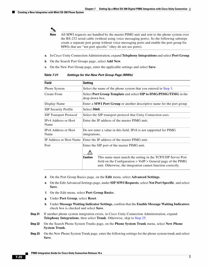
Note All MWI requests are handled by the master PIMG unit and sent to the phone system over the RS-232 serial cable (without using voice messaging ports). So the following substeps create a separate port group without voice messaging ports and enable the port group for MWIs that are “not port specific” (they do not use ports).
a. In Cisco Unity Connection Administration, expand Telephony Integrations and select Port Group.
b. On the Search Port Groups page, select Add New.
c. On the New Port Group page, enter the applicable settings and select Save.
d. On the Port Group Basics page, on the Edit menu, select Advanced Settings.
e. On the Edit Advanced Settings page, under SIP MWI Requests, select Not Port Specific. and select Save.
f. On the Edit menu, select Port Group Basics.
g. Under Port Group, select Reset.
h. Under Message Waiting Indicator Settings, confirm that the Enable Message Waiting Indicators check box is checked and select Save.
Step 21 If another phone system integration exists, in Cisco Unity Connection Administration, expand Telephony Integrations, then select Trunk. Otherwise, skip to Step 25.
Step 22 On the Search Phone System Trunks page, on the Phone System Trunk menu, select New Phone System Trunk.
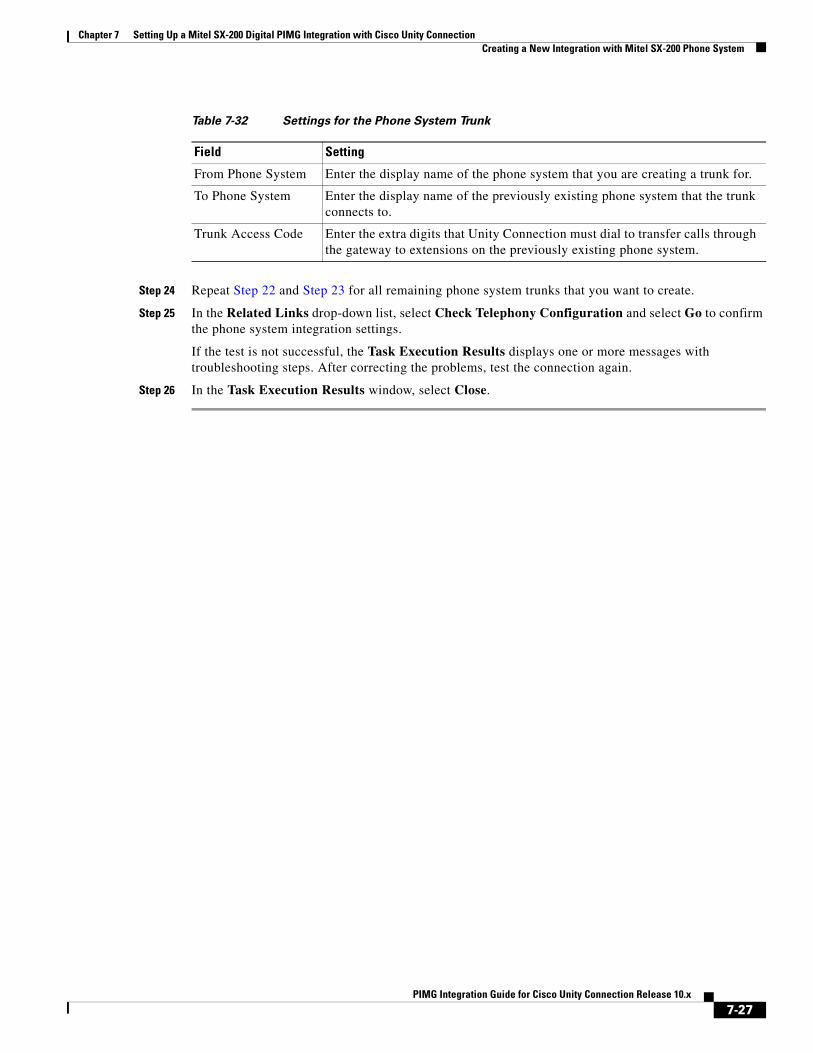
Step 23 On the New Phone System Trunk page, enter the following settings for the phone system trunk and select Save.
Table 7-31 Settings for the New Port Group Page (MWIs)
Field Setting
Phone System Select the name of the phone system that you entered in Step 3.
Create From Select Port Group Template and select SIP to DMG/PIMG/TIMG in the drop-down box.
Display Name Enter a MWI Port Group or another descriptive name for the port group.
SIP Security Profile Select 5060.
SIP Transport Protocol Select the SIP transport protocol that Unity Connection uses.
IPv4 Address or Host Name
Enter the IP address of the master PIMG unit.
IPv6 Address or Host Name
Do not enter a value in this field. IPv6 is not supported for PIMG integrations.
IP Address or Host Name Enter the IP address of the master PIMG unit.
Port Enter the SIP port of the master PIMG unit.
Caution This name must match the setting in the TCP/UDP Server Port field on the Configuration > VoIP > General page of the PIMG unit. Otherwise, the integration cannot function correctly.
7-26PIMG Integration Guide for Cisco Unity Connection Release 10.x
Chapter 7 Setting Up a Mitel SX-200 Digital PIMG Integration with Cisco Unity ConnectionCreating a New Integration with Mitel SX-200 Phone System
Step 24 Repeat Step 22 and Step 23 for all remaining phone system trunks that you want to create.
Step 25 In the Related Links drop-down list, select Check Telephony Configuration and select Go to confirm the phone system integration settings.
If the test is not successful, the Task Execution Results displays one or more messages with troubleshooting steps. After correcting the problems, test the connection again.
Step 26 In the Task Execution Results window, select Close.
Table 7-32 Settings for the Phone System Trunk
Field Setting
From Phone System Enter the display name of the phone system that you are creating a trunk for.
To Phone System Enter the display name of the previously existing phone system that the trunk connects to.
Trunk Access Code Enter the extra digits that Unity Connection must dial to transfer calls through the gateway to extensions on the previously existing phone system.
7-27PIMG Integration Guide for Cisco Unity Connection Release 10.x

Chapter 7 Setting Up a Mitel SX-200 Digital PIMG Integration with Cisco Unity ConnectionCreating a New Integration with Mitel SX-200 Phone System
7-28PIMG Integration Guide for Cisco Unity Connection Release 10.x