Embed Size (px)
Citation preview
PIMG Integration Guide for Cisco Unity ConnectionRelease 9.x Revised June, 2013
Americas HeadquartersCisco Systems, Inc.170 West Tasman DriveSan Jose, CA 95134-1706 USAhttp://www.cisco.comTel: 408 526-4000
800 553-NETS (6387)Fax: 408 527-0883
Text Part Number: OL-20351-01
THE SPECIFICATIONS AND INFORMATION REGARDING THE PRODUCTS IN THIS MANUAL ARE SUBJECT TO CHANGE WITHOUT NOTICE. ALL STATEMENTS, INFORMATION, AND RECOMMENDATIONS IN THIS MANUAL ARE BELIEVED TO BE ACCURATE BUT ARE PRESENTED WITHOUT WARRANTY OF ANY KIND, EXPRESS OR IMPLIED. USERS MUST TAKE FULL RESPONSIBILITY FOR THEIR APPLICATION OF ANY PRODUCTS.
THE SOFTWARE LICENSE AND LIMITED WARRANTY FOR THE ACCOMPANYING PRODUCT ARE SET FORTH IN THE INFORMATION PACKET THAT SHIPPED WITH THE PRODUCT AND ARE INCORPORATED HEREIN BY THIS REFERENCE. IF YOU ARE UNABLE TO LOCATE THE SOFTWARE LICENSE OR LIMITED WARRANTY, CONTACT YOUR CISCO REPRESENTATIVE FOR A COPY.
The Cisco implementation of TCP header compression is an adaptation of a program developed by the University of California, Berkeley (UCB) as part of UCB’s public domain version of the UNIX operating system. All rights reserved. Copyright © 1981, Regents of the University of California.
NOTWITHSTANDING ANY OTHER WARRANTY HEREIN, ALL DOCUMENT FILES AND SOFTWARE OF THESE SUPPLIERS ARE PROVIDED “AS IS” WITH ALL FAULTS. CISCO AND THE ABOVE-NAMED SUPPLIERS DISCLAIM ALL WARRANTIES, EXPRESSED OR IMPLIED, INCLUDING, WITHOUT LIMITATION, THOSE OF MERCHANTABILITY, FITNESS FOR A PARTICULAR PURPOSE AND NONINFRINGEMENT OR ARISING FROM A COURSE OF DEALING, USAGE, OR TRADE PRACTICE.
IN NO EVENT SHALL CISCO OR ITS SUPPLIERS BE LIABLE FOR ANY INDIRECT, SPECIAL, CONSEQUENTIAL, OR INCIDENTAL DAMAGES, INCLUDING, WITHOUT LIMITATION, LOST PROFITS OR LOSS OR DAMAGE TO DATA ARISING OUT OF THE USE OR INABILITY TO USE THIS MANUAL, EVEN IF CISCO OR ITS SUPPLIERS HAVE BEEN ADVISED OF THE POSSIBILITY OF SUCH DAMAGES.
Cisco and the Cisco logo are trademarks or registered trademarks of Cisco and/or its affiliates in the U.S. and other countries. To view a list of Cisco trademarks, go to this URL: www.cisco.com/go/trademarks. Third-party trademarks mentioned are the property of their respective owners. The use of the word partner does not imply a partnership relationship between Cisco and any other company. (1110R)
Any Internet Protocol (IP) addresses used in this document are not intended to be actual addresses. Any examples, command display output, and figures included in the document are shown for illustrative purposes only. Any use of actual IP addresses in illustrative content is unintentional and coincidental.
PIMG Integration Guide for Cisco Unity Connection Release 8.x © 2013 Cisco Systems, Inc. All rights reserved.
OL-20351-01
C O N T E N T S
Preface vii
Audience and Use vii
Documentation Conventions vii
Cisco Unity Connection Documentation viii
Obtaining Documentation and Submitting a Service Request viii
Cisco Product Security Overview viii
C H A P T E R 1 Introduction 1-1
Integration Description 1-1
Digital Integration with Digital PIMG Units 1-2
DTMF Integration with Analog PIMG Units 1-3
Serial (SMDI, MCI, or MD-110) Integration with Analog PIMG Units 1-3
Call Information 1-4
Integration Functionality 1-4
Integrations with Multiple Phone Systems 1-5
C H A P T E R 2 Planning How the Voice Messaging Ports Will Be Used by Cisco Unity Connection 2-1
Introduction: Issues to Consider When Planning Port Setup 2-1
Determining How Many Voice Messaging Ports to Install 2-2
Determining How Many Voice Messaging Ports Will Answer Calls 2-3
Determining How Many Voice Messaging Ports Will Only Dial Out, and Not Answer Calls 2-3
Considerations for a Cisco Unity Connection Cluster 2-3
When Both Cisco Unity Connection Servers Are Functioning Normally 2-4
When Only One Cisco Unity Connection Server Is Functioning 2-4
C H A P T E R 3 Setting Up an Avaya Definity G3 Digital PIMG Integration with Cisco Unity Connection 3-1
Task List to Create an Avaya Definity G3 Integration 3-1
Requirements 3-2
Programming the Avaya Definity G3 Phone System for Integrating with Cisco Unity Connection 3-3
Setting Up the Digital PIMG Units 3-5
Creating a New Integration with the Avaya Definity G3 Phone System 3-18
iiiPIMG Integration Guide for Cisco Unity Connection Release 8.x
Contents
C H A P T E R 4 Setting Up an Avaya Definity ProLogix Digital PIMG Integration with Cisco Unity Connection 4-1
Task List to Create the Integration 4-1
Requirements 4-2
Programming the Avaya Definity ProLogix PIMG Phone System for Integrating with Cisco Unity Connection 4-3
Setting Up the Digital PIMG Units 4-5
Creating a New Integration with the Avaya Definity ProLogix Phone System 4-18
C H A P T E R 5 Setting Up an Avaya S8300/S8500/S8700 Digital PIMG Integration with Cisco Unity Connection 5-1
Task List to Create an Avaya S8300/S8500/S8700 PIMG Integration 5-1
Requirements 5-2
Programming the Avaya S8300/S8500/S8700 PIMG Phone System for Integrating with Cisco Unity Connection 5-3
Setting Up the Digital PIMG Units 5-5
Creating a New Integration with the Avaya S8300/S8500/S8700 Phone System 5-18
C H A P T E R 6 Setting Up a Mitel SX-200 Digital PIMG Integration with Cisco Unity Connection 6-1
Task List to Create the Integration with the Mitel SX-200 PIMG Phone System 6-1
Requirements 6-2
Programming the Mitel SX-200 PIMG Phone System for Integrating with Cisco Unity Connection 6-3
Setting Up the Digital Mitel PIMG Units 6-8
Creating a New Integration with the Mitel SX-200 Phone System 6-22
C H A P T E R 7 Setting Up a Mitel SX-2000 Digital PIMG Integration with Cisco Unity Connection 7-1
Task List to Create the Integration with the Mitel SX-2000 PIMG Phone System 7-1
Requirements 7-2
Programming the Mitel SX-2000 PIMG Phone System for Integrating with Cisco Unity Connection 7-3
Setting Up the Digital Mitel PIMG Units 7-5
Creating a New Integration with the Mitel SX-2000 Phone System 7-18
C H A P T E R 8 Setting Up an NEC NEAX 2400 Digital PIMG Integration with Cisco Unity Connection 8-1
Task List to Create the Integration with the NEC NEAX 2400 PIMG Phone System 8-1
Requirements 8-2
Programming the NEC NEAX 2400 PIMG Phone System for Integrating with Cisco Unity Connection 8-3
Setting Up the Digital PIMG Units 8-5
Creating a New Integration with the NEC NEAX 2400 Phone System 8-19
ivPIMG Integration Guide for Cisco Unity Connection Release 8.x
OL-20351-01
Contents
C H A P T E R 9 Setting Up a Nortel Meridian 1 Digital PIMG Integration with Cisco Unity Connection 9-1
Task List to Create the Integration with a Nortel Meridian 1 PIMG Phone System 9-1
Requirements 9-2
Programming the Nortel Meridian 1 PIMG Phone System for Integrating with Cisco Unity Connection 9-3
Setting Up the Digital PIMG Units 9-10
Creating a New Integration with the Nortel Meridian 1 Phone System 9-24
C H A P T E R 10 Setting Up a Rolm 9751 Digital PIMG Integration with Cisco Unity Connection 10-1
Task List to Create the Integration with a Rolm 9751 PIMG Phone System 10-1
Requirements 10-2
Programming the Rolm 9751 PIMG Phone System for Integrating with Cisco Unity Connection 10-3
Setting Up the Digital Rolm PIMG Units 10-7
Creating a New Integration with the Rolm 9751 Phone System 10-20
C H A P T E R 11 Setting Up a Serial (SMDI, MCI, or MD-110) PIMG Integration with Cisco Unity Connection 11-1
Task List to Create a Serial (SMDI, MCI, or MD-110) PIMG Integration 11-1
Requirements 11-2
Programming the Phone System for a Serial Integration with Cisco Unity Connection 11-3
Setting Up the Analog PIMG Units for a Serial Integration 11-4
Creating a New Integration with the Phone System 11-19
C H A P T E R 12 Setting Up a Siemens Hicom 300 E (European) Analog PIMG Integration with Cisco Unity Connection 12-1
Task List to Create the Integration with a Siemens Hicom 300 E (European) PIMG Phone System 12-1
Requirements 12-2
Programming the Siemens Hicom 300 E (European) PIMG Phone System for Integrating with Cisco Unity Connection 12-3
Setting Up the Analog PIMG Units for a DTMF Integration 12-5
Creating a New Integration with the Siemens Hicom 300 E (European) Phone System 12-19
C H A P T E R 13 Setting Up a Siemens Hicom 300 E (North American) Digital PIMG Integration with Cisco Unity Connection 13-1
Task List to Create the Integration with the Siemens Hicom 300 PIMG Phone System 13-1
Requirements 13-2
Clearing MWIs from a Legacy Voice Messaging System 13-3
Programming the Siemens Hicom 300 E (North American) Phone System for Integrating with Cisco Unity Connection 13-3
vPIMG Integration Guide for Cisco Unity Connection Release 8.x
OL-20351-01
Contents
Setting Up the Digital PIMG Units 13-6
Creating a New Integration with the Siemens Hicom 300 Phone System 13-20
C H A P T E R 14 Testing the Integration 14-1
C H A P T E R 15 Adding New User Templates for Multiple Integrations 15-1
A P P E N D I X A Adding a Secondary Master PIMG Unit A-1
Task List to Add a Secondary Master PIMG Unit A-1
Analog Voice Line Connections for the Master PIMG Units A-1
Requirements A-2
Connections That Use RJ-11 Connectors A-3
Serial Data Cable Connections for the Master PIMG Units A-4
Requirements A-4
Connections for the Serial Data Cables A-4
Configuring the Secondary Master PIMG Unit A-5
A P P E N D I X B Application Note for the Ericsson MD-110 Serial PIMG Integration B-1
Network Topology B-1
Requirements B-2
Programming the Ericsson MD-100 Phone System for the Serial Integration B-2
A P P E N D I X C Application Note for the Nortel SL-100 Serial SMDI TIMG Integration C-1
Network Topology C-1
Requirements C-2
Programming the Nortel SL-100 Phone System for the Serial Integration C-2
A P P E N D I X D Settings for PIMG Firmware Version 5.x D-1
Digital PIMG Settings (Firmware Version 5.x) D-1
Analog PIMG Settings for a DTMF Integration (Firmware Version 5.x) D-6
Analog PIMG Settings for a Serial Integration (Firmware Version 5.x) D-11
Digital Mitel PIMG Settings (Firmware Version 5.x) D-17
Digital Rolm PIMG Settings (Firmware Version 5.x) D-22
I N D E X
viPIMG Integration Guide for Cisco Unity Connection Release 8.x
OL-20351-01
Preface
This Preface contains the following sections:
• Audience and Use, page vii
• Documentation Conventions, page vii
• Cisco Unity Connection Documentation, page viii
• Obtaining Documentation and Submitting a Service Request, page viii
• Cisco Product Security Overview, page viii
Audience and UseThis document provides instructions for setting up an integration between Cisco Unity Connection and supported phone systems, by using PIMG units. For a list of phone systems that are qualified to integrate with Cisco Unity Connection through PIMG units, see the “Introduction” chapter.
Documentation ConventionsThe PIMG Integration Guide for Cisco Unity Connection Release 8.x uses the following conventions.
Table 1 PIMG Integration Guide for Cisco Unity Connection Release 8.x Conventions
Convention Description
boldfaced text Boldfaced text is used for:
• Key and button names. (Example: Select OK.)
• Information that you enter. (Example: Enter Administrator in the User Name box.)
< >
(angle brackets)
Angle brackets are used around parameters for which you supply a value. (Example: In the Command Prompt window, enter ping <IP address>.)
viiPIMG Integration Guide for Cisco Unity Connection Release 8.x
OL-20351-01
Preface
The PIMG Integration Guide for Cisco Unity Connection Release 8.x also uses the following conventions:
Note Means reader take note. Notes contain helpful suggestions or references to material not covered in the document.
Caution Means reader be careful. In this situation, you might do something that could result in equipment damage or loss of data.
Cisco Unity Connection DocumentationFor descriptions and URLs of Cisco Unity Connection documentation on Cisco.com, see the Cisco Unity Documentation Guide. The document is shipped with Cisco Unity Connection and is available at http://www.cisco.com/en/US/products/ps6509/products_documentation_roadmaps_list.html.
Obtaining Documentation and Submitting a Service RequestFor information on obtaining documentation, submitting a service request, and gathering additional information, see the monthly What’s New in Cisco Product Documentation, which also lists all new and revised Cisco technical documentation, at:
http://www.cisco.com/en/US/docs/general/whatsnew/whatsnew.html
Subscribe to the What’s New in Cisco Product Documentation as a Really Simple Syndication (RSS) feed and set content to be delivered directly to your desktop using a reader application. The RSS feeds are a free service and Cisco currently supports RSS Version 2.0.
Cisco Product Security OverviewThis product contains cryptographic features and is subject to United States and local country laws governing import, export, transfer and use. Delivery of Cisco cryptographic products does not imply third-party authority to import, export, distribute or use encryption. Importers, exporters, distributors
-
(hyphen)
Hyphens separate keys that must be pressed simultaneously. (Example: Press Ctrl-Alt-Delete.)
>
(right angle bracket)
A right angle bracket is used to separate selections that you make on menus. (Example: On the Windows Start menu, select Programs > Cisco Unified Serviceability > Real-Time Monitoring Tool.)
In the navigation bar of the Cisco Unity Connection Administration. (Example: In the Cisco Unity Connection Administration, expand System Settings > Advanced.)
Table 1 PIMG Integration Guide for Cisco Unity Connection Release 8.x Conventions
Convention Description
viiiPIMG Integration Guide for Cisco Unity Connection Release 8.x
OL-20351-01

Preface
and users are responsible for compliance with U.S. and local country laws. By using this product you agree to comply with applicable laws and regulations. If you are unable to comply with U.S. and local laws, return this product immediately.
Further information regarding U.S. export regulations can be found at http://www.access.gpo.gov/bis/ear/ear_data.html.
ixPIMG Integration Guide for Cisco Unity Connection Release 8.x
OL-20351-01

Preface
xPIMG Integration Guide for Cisco Unity Connection Release 8.x
OL-20351-01
PIMG IntegrOL-20351-01
C H A P T E R 1
IntroductionSee the following sections in this chapter:
• Integration Description, page 1-1
• Call Information, page 1-4
• Integration Functionality, page 1-4
• Integrations with Multiple Phone Systems, page 1-5
Integration DescriptionCisco Unity Connection supports PIMG integrations with the following phone systems.
Table 1-1 Supported Phone Systems for PIMG Integrations
Phone System Integration Type Supported PIMG Units
Any phone system that provides a serial data link (SMDI, MCI, or MD-110 protocol) to the master PIMG unit
Serial (SMDI, MCI, or MD-110) Analog PIMG units (PIMG80LS or DMG1008LS)
Avaya Definity G3 Digital Digital PIMG units (PIMG80PBXDNI or DMG1008DNI)
Avaya Definity ProLogix Digital Digital PIMG units (PIMG80PBXDNI or DMG1008DNI)
Avaya S8300, Avaya S8500, and Avaya S8700
Digital Digital PIMG units (PIMG80PBXDNI or DMG1008DNI)
Mitel SX-200 Digital Digital Mitel PIMG units (PIMG80MTLPBXDNI or DMG1008MTLDNI)
Mitel SX-2000 Digital Digital Mitel PIMG units (PIMG80MTLPBXDNI or DMG1008MTLDNI)
1-1ation Guide for Cisco Unity Connection Release 8.x
Chapter 1 Introduction Integration Description
See the applicable description for the integration type that your system uses:
• Digital Integration with Digital PIMG Units, page 1-2
• DTMF Integration with Analog PIMG Units, page 1-3
• Serial (SMDI, MCI, or MD-110) Integration with Analog PIMG Units, page 1-3
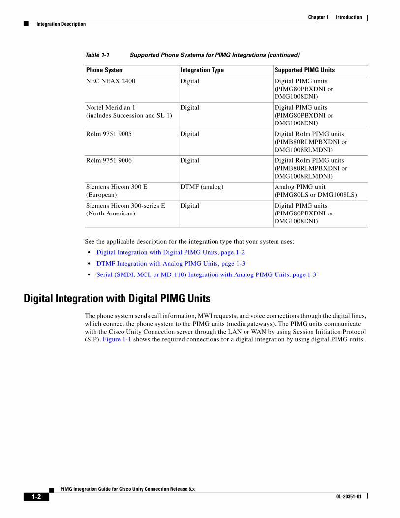
Digital Integration with Digital PIMG UnitsThe phone system sends call information, MWI requests, and voice connections through the digital lines, which connect the phone system to the PIMG units (media gateways). The PIMG units communicate with the Cisco Unity Connection server through the LAN or WAN by using Session Initiation Protocol (SIP). Figure 1-1 shows the required connections for a digital integration by using digital PIMG units.
NEC NEAX 2400 Digital Digital PIMG units (PIMG80PBXDNI or DMG1008DNI)
Nortel Meridian 1 (includes Succession and SL 1)
Digital Digital PIMG units (PIMG80PBXDNI or DMG1008DNI)
Rolm 9751 9005 Digital Digital Rolm PIMG units (PIMB80RLMPBXDNI or DMG1008RLMDNI)
Rolm 9751 9006 Digital Digital Rolm PIMG units (PIMB80RLMPBXDNI or DMG1008RLMDNI)
Siemens Hicom 300 E (European)
DTMF (analog) Analog PIMG unit (PIMG80LS or DMG1008LS)
Siemens Hicom 300-series E (North American)
Digital Digital PIMG units (PIMG80PBXDNI or DMG1008DNI)
Table 1-1 Supported Phone Systems for PIMG Integrations (continued)
Phone System Integration Type Supported PIMG Units
1-2PIMG Integration Guide for Cisco Unity Connection Release 8.x
OL-20351-01
Chapter 1 Introduction Integration Description
Figure 1-1 Connections for a Digital Integration by Using Digital PIMG Units
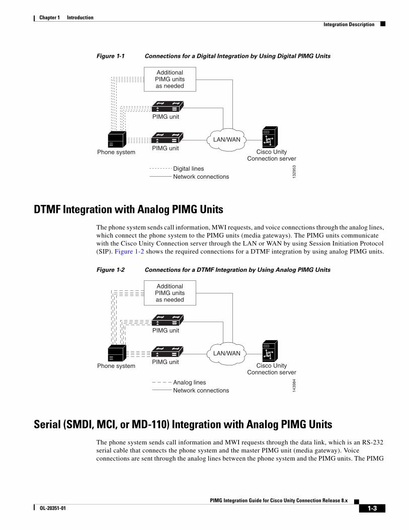
DTMF Integration with Analog PIMG UnitsThe phone system sends call information, MWI requests, and voice connections through the analog lines, which connect the phone system to the PIMG units (media gateways). The PIMG units communicate with the Cisco Unity Connection server through the LAN or WAN by using Session Initiation Protocol (SIP). Figure 1-2 shows the required connections for a DTMF integration by using analog PIMG units.
Figure 1-2 Connections for a DTMF Integration by Using Analog PIMG Units
Serial (SMDI, MCI, or MD-110) Integration with Analog PIMG UnitsThe phone system sends call information and MWI requests through the data link, which is an RS-232 serial cable that connects the phone system and the master PIMG unit (media gateway). Voice connections are sent through the analog lines between the phone system and the PIMG units. The PIMG
Digital linesNetwork connections
Phone system
1329
53
LAN/WANPIMG unit
AdditionalPIMG unitsas needed
PIMG unit
C
Cisco UnityConnection server
Analog linesNetwork connections
Phone system
1439
84
LAN/WANPIMG unit
AdditionalPIMG unitsas needed
PIMG unit
C
Cisco UnityConnection server
1-3PIMG Integration Guide for Cisco Unity Connection Release 8.x
OL-20351-01
Chapter 1 Introduction Call Information
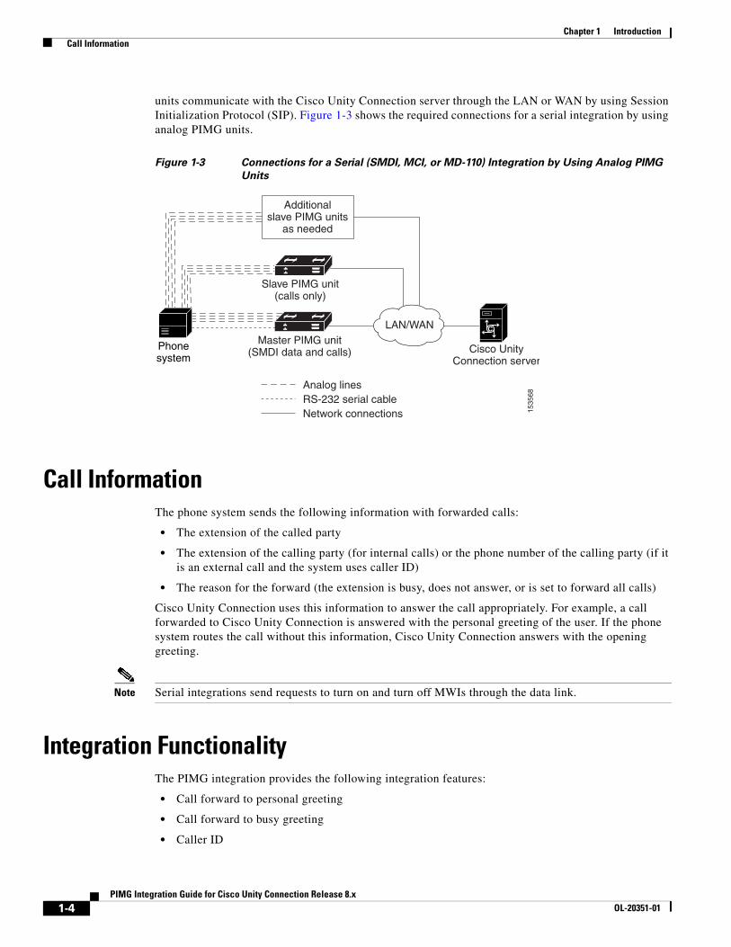
units communicate with the Cisco Unity Connection server through the LAN or WAN by using Session Initialization Protocol (SIP). Figure 1-3 shows the required connections for a serial integration by using analog PIMG units.
Figure 1-3 Connections for a Serial (SMDI, MCI, or MD-110) Integration by Using Analog PIMG
Units
Call InformationThe phone system sends the following information with forwarded calls:
• The extension of the called party
• The extension of the calling party (for internal calls) or the phone number of the calling party (if it is an external call and the system uses caller ID)
• The reason for the forward (the extension is busy, does not answer, or is set to forward all calls)
Cisco Unity Connection uses this information to answer the call appropriately. For example, a call forwarded to Cisco Unity Connection is answered with the personal greeting of the user. If the phone system routes the call without this information, Cisco Unity Connection answers with the opening greeting.
Note Serial integrations send requests to turn on and turn off MWIs through the data link.
Integration FunctionalityThe PIMG integration provides the following integration features:
• Call forward to personal greeting
• Call forward to busy greeting
• Caller ID
Analog linesRS-232 serial cableNetwork connections 15
3568
LAN/WANMaster PIMG unit
(SMDI data and calls)
Additionalslave PIMG units
as needed
Slave PIMG unit(calls only)
C
Cisco UnityConnection server
Phonesystem
1-4PIMG Integration Guide for Cisco Unity Connection Release 8.x
OL-20351-01
Chapter 1 Introduction Integrations with Multiple Phone Systems
• Easy message access (a user can retrieve messages without entering an ID because Cisco Unity Connection identifies the user based on the extension from which the call originated; a password may be required)
• Identified user messaging (Cisco Unity Connection identifies the user who leaves a message during a forwarded internal call, based on the extension from which the call originated)
• Message waiting indication (MWI)
Integrations with Multiple Phone SystemsCisco Unity Connection can be integrated with two or more phone systems at one time. For information on the maximum supported combinations and instructions for integrating Cisco Unity Connection with multiple phone systems, see the Multiple Phone System Integration Guide for Cisco Unity Connection Release 9.x at http://www.cisco.com/en/US/products/ps6509/products_installation_and_configuration_guides_list.html.
1-5PIMG Integration Guide for Cisco Unity Connection Release 8.x
OL-20351-01

Chapter 1 Introduction Integrations with Multiple Phone Systems
1-6PIMG Integration Guide for Cisco Unity Connection Release 8.x
OL-20351-01
PIMG IntegrOL-20351-01
C H A P T E R 2
Planning How the Voice Messaging Ports Will Be Used by Cisco Unity ConnectionRevised June 21, 2013See the following sections in this chapter:
• Introduction: Issues to Consider When Planning Port Setup, page 2-1
• Determining How Many Voice Messaging Ports to Install, page 2-2
• Determining How Many Voice Messaging Ports Will Answer Calls, page 2-3
• Determining How Many Voice Messaging Ports Will Only Dial Out, and Not Answer Calls, page 2-3
• Considerations for a Cisco Unity Connection Cluster, page 2-3
Introduction: Issues to Consider When Planning Port SetupBefore programming the phone system, you need to plan how the voice messaging ports will be used by Cisco Unity Connection. The following considerations will affect the programming for the phone system (for example, setting up the hunt group or call forwarding for the voice messaging ports):
• The number of voice messaging ports installed.
For a Cisco Unity Connection cluster, each Cisco Unity Connection server must have enough ports to handle all voice messaging traffic in case the other server stops functioning.
• The number of voice messaging ports that will answer calls.
• The number of voice messaging ports that will only dial out, for example, to send message notification, to set message waiting indicators (MWIs), and to make telephone record and playback (TRAP) connections.
The following table describes the voice messaging port settings in Cisco Unity Connection that can be set on Telephony Integrations > Port of Cisco Unity Connection Administration.
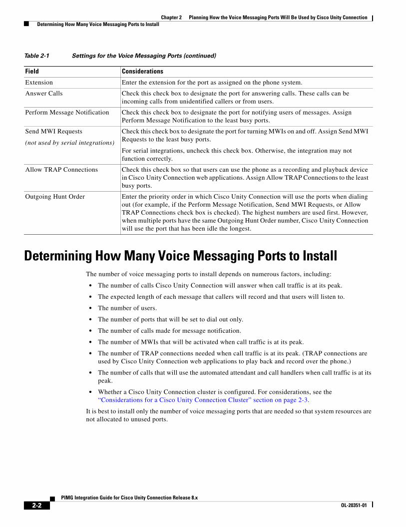
Table 2-1 Settings for the Voice Messaging Ports
Field Considerations
Enabled Check this check box to enable the port. The port is enabled during normal operation.
Uncheck this check box to disable the port. When the port is disabled, calls to the port get a ringing tone but are not answered. Typically, the port is disabled only by the installer during testing.
2-1ation Guide for Cisco Unity Connection Release 8.x
Chapter 2 Planning How the Voice Messaging Ports Will Be Used by Cisco Unity Connection Determining How Many Voice Messaging Ports to Install
Determining How Many Voice Messaging Ports to InstallThe number of voice messaging ports to install depends on numerous factors, including:
• The number of calls Cisco Unity Connection will answer when call traffic is at its peak.
• The expected length of each message that callers will record and that users will listen to.
• The number of users.
• The number of ports that will be set to dial out only.
• The number of calls made for message notification.
• The number of MWIs that will be activated when call traffic is at its peak.
• The number of TRAP connections needed when call traffic is at its peak. (TRAP connections are used by Cisco Unity Connection web applications to play back and record over the phone.)
• The number of calls that will use the automated attendant and call handlers when call traffic is at its peak.
• Whether a Cisco Unity Connection cluster is configured. For considerations, see the “Considerations for a Cisco Unity Connection Cluster” section on page 2-3.
It is best to install only the number of voice messaging ports that are needed so that system resources are not allocated to unused ports.
Extension Enter the extension for the port as assigned on the phone system.
Answer Calls Check this check box to designate the port for answering calls. These calls can be incoming calls from unidentified callers or from users.
Perform Message Notification Check this check box to designate the port for notifying users of messages. Assign Perform Message Notification to the least busy ports.
Send MWI Requests
(not used by serial integrations)
Check this check box to designate the port for turning MWIs on and off. Assign Send MWI Requests to the least busy ports.
For serial integrations, uncheck this check box. Otherwise, the integration may not function correctly.
Allow TRAP Connections Check this check box so that users can use the phone as a recording and playback device in Cisco Unity Connection web applications. Assign Allow TRAP Connections to the least busy ports.
Outgoing Hunt Order Enter the priority order in which Cisco Unity Connection will use the ports when dialing out (for example, if the Perform Message Notification, Send MWI Requests, or Allow TRAP Connections check box is checked). The highest numbers are used first. However, when multiple ports have the same Outgoing Hunt Order number, Cisco Unity Connection will use the port that has been idle the longest.
Table 2-1 Settings for the Voice Messaging Ports (continued)
Field Considerations
2-2PIMG Integration Guide for Cisco Unity Connection Release 8.x
OL-20351-01
Chapter 2 Planning How the Voice Messaging Ports Will Be Used by Cisco Unity Connection Determining How Many Voice Messaging Ports Will Answer Calls
Determining How Many Voice Messaging Ports Will Answer Calls
The calls that the voice messaging ports answer can be incoming calls from unidentified callers or from users. Typically, the voice messaging ports that answer calls are the busiest.
You can set voice messaging ports to both answer calls and to dial out (for example, to send message notifications). However, when the voice messaging ports perform more than one function and are very active (for example, answering many calls), the other functions may be delayed until the voice messaging port is free (for example, message notifications cannot be sent until there are fewer calls to answer). For best performance, dedicate certain voice messaging ports for only answering incoming calls, and dedicate other ports for only dialing out. Separating these port functions eliminates the possibility of a collision, in which an incoming call arrives on a port at the same time that Cisco Unity Connection takes the port off-hook to dial out.
If your system is configured for a Cisco Unity Connection cluster, see the “Considerations for a Cisco Unity Connection Cluster” section on page 2-3.
Determining How Many Voice Messaging Ports Will Only Dial Out, and Not Answer Calls
Ports that will only dial out and will not answer calls can do one or more of the following:
• Notify users by phone, pager, or email of messages that have arrived.
• Turn MWIs on and off for user extensions.
• Make a TRAP connection so that users can use the phone as a recording and playback device in Cisco Unity Connection web applications.
Typically, these voice messaging ports are the least busy ports.
If your system is configured for a Cisco Unity Connection cluster, see the “Considerations for a Cisco Unity Connection Cluster” section on page 2-3.
Caution In programming the phone system, do not send calls to voice messaging ports in Cisco Unity Connection that cannot answer calls (voice messaging ports that are not set to Answer Calls). For example, if a voice messaging port is set only to Send MWI Requests, do not send calls to it.
Considerations for a Cisco Unity Connection ClusterRevised June 21, 2013If your system is configured for a Cisco Unity Connection cluster, consider how the voice messaging ports will be used in different scenarios.
Unlike SCCP/SIP ports, the PIMG ports are shared between the publisher and subscriber as the PIMG ports are not node bound.
Number of ports allowed for SIP/SCCP profile on each node = Port Limit - PIMG Ports.
2-3PIMG Integration Guide for Cisco Unity Connection Release 8.x
OL-20351-01
Chapter 2 Planning How the Voice Messaging Ports Will Be Used by Cisco Unity Connection Considerations for a Cisco Unity Connection Cluster
Note The PIMG port limit has been enforced into the system with respect to the hardware deployed on Cisco Unity Connection server. The number of voice ports supported with Cisco Unity Connection depends upon the Connection platform specifications. For more information, see the “Number of Voice Ports Supported with Connection Platforms” section of the Cisco Unity Connection 9.x Supported Platforms List at http://www.cisco.com/en/US/docs/voice_ip_comm/connection/9x/supported_platforms/9xcucspl.html.
When Both Cisco Unity Connection Servers Are Functioning Normally • The number of ports provisioned on the phone system is the same as the number of voice messaging
ports on each Cisco Unity Connection server.
• The PIMG units are configured to send incoming calls first to the subscriber server, then to the publisher server if no answering ports are available on the subscriber server.
• The PIMG units are configured to balance the voice messaging traffic between the Cisco Unity Connection servers.
• Both Cisco Unity Connection servers are active and handle voice messaging traffic for the system.
• The number of voice messaging ports on each Cisco Unity Connection server must be sufficient to handle all of the voice messaging traffic for the system (answering calls and dialing out) when the other Cisco Unity Connection server stops functioning.
If both Cisco Unity Connection servers must be functioning to handle the voice messaging traffic, the system will not have sufficient capacity when one of the servers stops functioning.
• Each Cisco Unity Connection server must have voice messaging ports that will answer calls and that can dial out (for example, to set MWIs).
When Only One Cisco Unity Connection Server Is Functioning • PIMG units send all calls to the functioning Cisco Unity Connection server.
• The functioning Cisco Unity Connection server receives all voice messaging traffic for the system.
• The number of voice messaging ports that are assigned to the functioning Cisco Unity Connection server must be sufficient to handle all of the voice messaging traffic for the system (answering calls and dialing out).
• The functioning Cisco Unity Connection server must have voice messaging ports that will answer calls and that can dial out (for example, to set MWIs).
If the functioning Cisco Unity Connection server does not have voice messaging ports for answering calls, the system will not be able to answer incoming calls. Similarly, if the functioning Cisco Unity Connection server does not have voice messaging ports for dialing out, the system will not be able to dial out (for example, to set MWIs).
2-4PIMG Integration Guide for Cisco Unity Connection Release 8.x
OL-20351-01
PIMG IntegrOL-20351-01
C H A P T E R 3
Setting Up an Avaya Definity G3 Digital PIMG Integration with Cisco Unity ConnectionFor detailed instructions for setting up an Avaya Definity G3 digital PIMG integration with Cisco Unity Connection, see the following sections in this chapter:
• Task List to Create an Avaya Definity G3 Integration, page 3-1
• Requirements, page 3-2
• Programming the Avaya Definity G3 Phone System for Integrating with Cisco Unity Connection, page 3-3
• Setting Up the Digital PIMG Units, page 3-5
• Creating a New Integration with the Avaya Definity G3 Phone System, page 3-18
Task List to Create an Avaya Definity G3 IntegrationBefore doing the following tasks to integrate Cisco Unity Connection with the Avaya Definity G3 phone system by using PIMG units (media gateways), confirm that the Cisco Unity Connection server is ready for the integration by completing the applicable tasks in the Cisco Unity Connection Installation Guide.
1. Review the system and equipment requirements to confirm that all phone system and Cisco Unity Connection server requirements have been met. See the “Requirements” section on page 3-2.
2. Plan how the voice messaging ports will be used by Cisco Unity Connection. See Chapter 2, “Planning How the Voice Messaging Ports Will Be Used by Cisco Unity Connection.”
3. Program the Avaya Definity G3 phone system and extensions. See the “Programming the Avaya Definity G3 Phone System for Integrating with Cisco Unity Connection” section on page 3-3.
4. Set up the PIMG units. See the “Setting Up the Digital PIMG Units” section on page 3-5.
5. Create the integration. See the “Creating a New Integration with the Avaya Definity G3 Phone System” section on page 3-18.
6. Test the integration. See Chapter 14, “Testing the Integration.”
7. If this integration is a second or subsequent integration, add the applicable new user templates for the new phone system. See Chapter 15, “Adding New User Templates for Multiple Integrations.”
3-1ation Guide for Cisco Unity Connection Release 8.x
Chapter 3 Setting Up an Avaya Definity G3 Digital PIMG Integration with Cisco Unity Connection Requirements
RequirementsThe Avaya Definity G3 integration supports configurations of the following components:
Phone System
• Avaya Definity G33 phone system. The voice messaging ports that connect to the PIMG units must be compatible with the 7434ND, 8434, 8434D, or 8434DX digital phones.
Caution You must use 2-wire line cards for these voice messaging ports. Otherwise, the voice messaging ports will not be compatible with the 7434ND, 8434, 8434D, or 8434DX digital phones.
• Software version 4 or later.
• One or more of the applicable PIMG units. For details, see Chapter 1, “Introduction.”
• The voice messaging ports in the phone system connected by digital lines to the ports on the PIMG units.
To simplify troubleshooting, we recommend that you connect the voice messaging ports on the phone system to the ports on the PIMG units in a planned manner. For example, connect the first phone system voice messaging port to the first port on the first PIMG unit, connect the second phone system voice messaging port to the second port on the first PIMG unit, and so on. Alternatively, if you have multiple PIMG units, you can reduce answer times in the event of a PIMG unit failure by connecting the phone system ports to the PIMG units in a round-robin fashion. For example, connect the first phone system voice messaging port to the first port on the first PIMG unit, connect the second phone system voice messaging port to the first port on the second PIMG unit, and so on.
• The PIMG units connected to the same LAN or WAN that Cisco Unity Connection is connected to.
• If the PIMG units connect to a WAN, the requirements for the WAN network connections are:
– For G.729a codec formatting, a minimum of 32.76 Kbps guaranteed bandwidth for each voice messaging port.
– For G.711 codec formatting, a minimum of 91.56 Kbps guaranteed bandwidth for each voice messaging port.
– No network devices that implement network address translation (NAT).
– A maximum 200 ms one-way network latency.
• The phone system ready for the integration, as described in the documentation for the phone system.
Cisco Unity Connection Server
• Cisco Unity Connection installed and ready for the integration, as described in the Cisco Unity Connection Installation Guide at http://www.cisco.com/en/US/products/ps6509/prod_installation_guides_list.html.
• A license that enables the applicable number of voice messaging ports.
Centralized Voice Messaging
Cisco Unity Connection supports centralized voice messaging through the phone system, which supports various inter-phone system networking protocols including proprietary protocols such as Avaya DCS, Nortel MCDN, or Siemens CorNet, and standards-based protocols such as QSIG or DPNSS. Note that centralized voice messaging is a function of the phone system and its inter-phone system networking, not voicemail. Connection will support centralized voice messaging as long as the phone system and its
3-2PIMG Integration Guide for Cisco Unity Connection Release 8.x
OL-20351-01
Chapter 3 Setting Up an Avaya Definity G3 Digital PIMG Integration with Cisco Unity Connection Programming the Avaya Definity G3 Phone System for Integrating with Cisco Unity Connection
inter-phone system networking are properly configured. For details, see the “Centralized Voice Messaging” section in the “Integrating Cisco Unity Connection with the Phone System” chapter of the Cisco Unity Design Guide Release 8.x at http://www.cisco.com/en/US/docs/voice_ip_comm/connection/8x/design/guide/8xcucdgx.html.
Programming the Avaya Definity G3 Phone System for Integrating with Cisco Unity Connection
The following programming instructions are provided as an example only. The specific programming for your phone system may vary depending on its configuration.
Caution In programming the phone system, do not send calls to voice messaging ports in Cisco Unity Connection that cannot answer calls (voice messaging ports that are not set to Answer Calls). For example, if a voice messaging port is set only to Send MWI Requests, do not send calls to it.
To Program the Avaya Definity G3 Phone System
Step 1 Create a coverage path which contains the PIMG unit hunt group number as the coverage point.
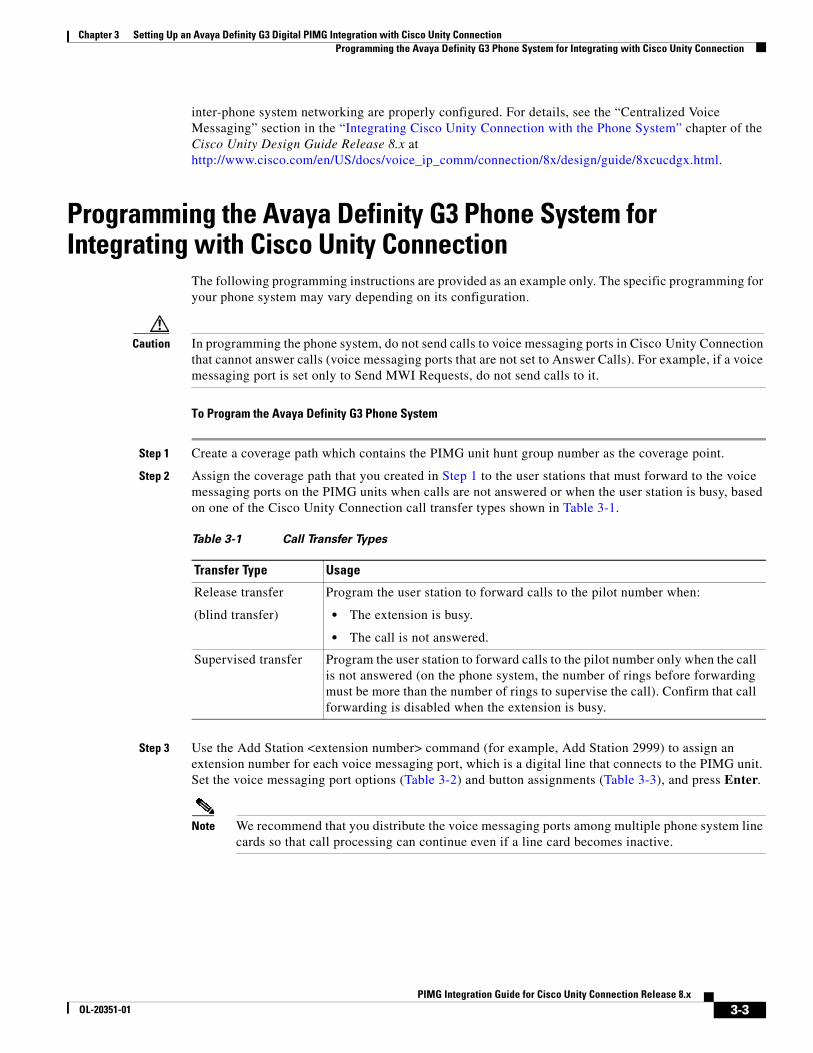
Step 2 Assign the coverage path that you created in Step 1 to the user stations that must forward to the voice messaging ports on the PIMG units when calls are not answered or when the user station is busy, based on one of the Cisco Unity Connection call transfer types shown in Table 3-1.
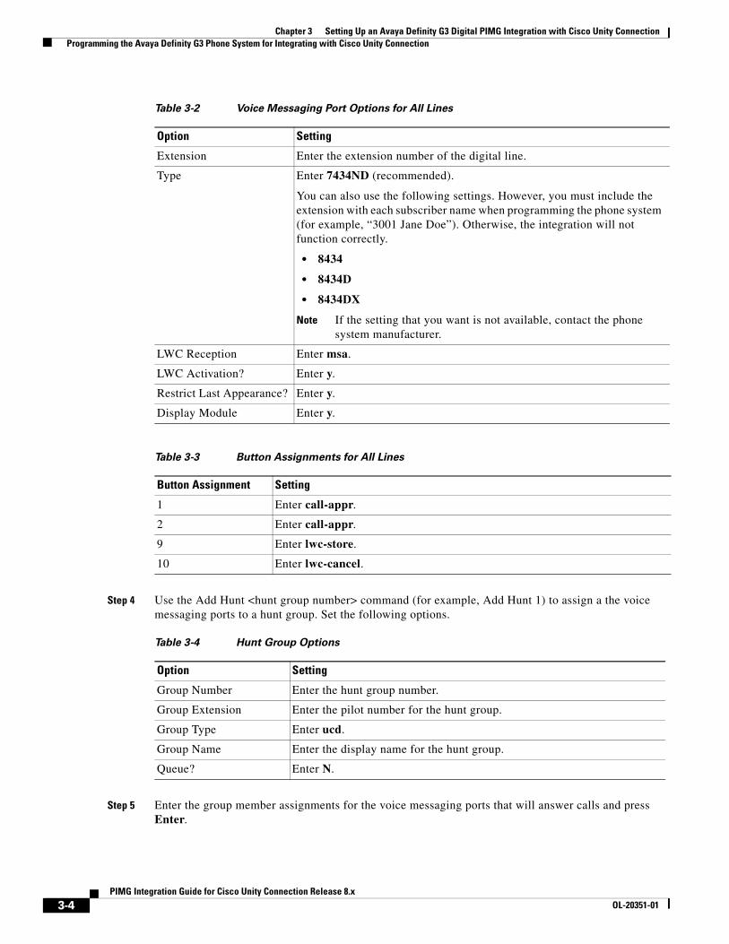
Step 3 Use the Add Station <extension number> command (for example, Add Station 2999) to assign an extension number for each voice messaging port, which is a digital line that connects to the PIMG unit. Set the voice messaging port options (Table 3-2) and button assignments (Table 3-3), and press Enter.
Note We recommend that you distribute the voice messaging ports among multiple phone system line cards so that call processing can continue even if a line card becomes inactive.
Table 3-1 Call Transfer Types
Transfer Type Usage
Release transfer
(blind transfer)
Program the user station to forward calls to the pilot number when:
• The extension is busy.
• The call is not answered.
Supervised transfer Program the user station to forward calls to the pilot number only when the call is not answered (on the phone system, the number of rings before forwarding must be more than the number of rings to supervise the call). Confirm that call forwarding is disabled when the extension is busy.
3-3PIMG Integration Guide for Cisco Unity Connection Release 8.x
OL-20351-01
Chapter 3 Setting Up an Avaya Definity G3 Digital PIMG Integration with Cisco Unity Connection Programming the Avaya Definity G3 Phone System for Integrating with Cisco Unity Connection
Step 4 Use the Add Hunt <hunt group number> command (for example, Add Hunt 1) to assign a the voice messaging ports to a hunt group. Set the following options.
Step 5 Enter the group member assignments for the voice messaging ports that will answer calls and press Enter.
Table 3-2 Voice Messaging Port Options for All Lines
Option Setting
Extension Enter the extension number of the digital line.
Type Enter 7434ND (recommended).
You can also use the following settings. However, you must include the extension with each subscriber name when programming the phone system (for example, “3001 Jane Doe”). Otherwise, the integration will not function correctly.
• 8434
• 8434D
• 8434DX
Note If the setting that you want is not available, contact the phone system manufacturer.
LWC Reception Enter msa.
LWC Activation? Enter y.
Restrict Last Appearance? Enter y.
Display Module Enter y.
Table 3-3 Button Assignments for All Lines
Button Assignment Setting
1 Enter call-appr.
2 Enter call-appr.
9 Enter lwc-store.
10 Enter lwc-cancel.
Table 3-4 Hunt Group Options
Option Setting
Group Number Enter the hunt group number.
Group Extension Enter the pilot number for the hunt group.
Group Type Enter ucd.
Group Name Enter the display name for the hunt group.
Queue? Enter N.
3-4PIMG Integration Guide for Cisco Unity Connection Release 8.x
OL-20351-01
Chapter 3 Setting Up an Avaya Definity G3 Digital PIMG Integration with Cisco Unity Connection Setting Up the Digital PIMG Units
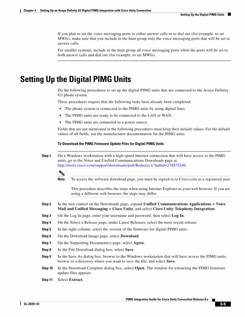
If you plan to set the voice messaging ports to either answer calls or to dial out (for example, to set MWIs), make sure that you include in the hunt group only the voice messaging ports that will be set to answer calls.
For smaller systems, include in the hunt group all voice messaging ports when the ports will be set to both answer calls and dial out (for example, to set MWIs).
Setting Up the Digital PIMG UnitsDo the following procedures to set up the digital PIMG units that are connected to the Avaya Definity G3 phone system.
These procedures require that the following tasks have already been completed:
• The phone system is connected to the PIMG units by using digital lines.
• The PIMG units are ready to be connected to the LAN or WAN.
• The PIMG units are connected to a power source.
Fields that are not mentioned in the following procedures must keep their default values. For the default values of all fields, see the manufacturer documentation for the PIMG units.
To Download the PIMG Firmware Update Files for Digital PIMG Units
Step 1 On a Windows workstation with a high-speed Internet connection that will have access to the PIMG units, go to the Voice and Unified Communications Downloads page at http://tools.cisco.com/support/downloads/pub/Redirect.x?mdfid=278875240.
Note To access the software download page, you must be signed in to Cisco.com as a registered user. This procedure describes the steps when using Internet Explorer as your web browser. If you are using a different web browser, the steps may differ.
Step 2 In the tree control on the Downloads page, expand Unified Communications Applications > Voice Mail and Unified Messaging > Cisco Unity, and select Cisco Unity Telephony Integration.
Step 3 On the Log In page, enter your username and password, then select Log In.
Step 4 On the Select a Release page, under Latest Releases, select the most recent release.
Step 5 In the right column, select the version of the firmware for digital PIMG units.
Step 6 On the Download Image page, select Download.
Step 7 On the Supporting Document(s) page, select Agree.
Step 8 In the File Download dialog box, select Save.
Step 9 In the Save As dialog box, browse to the Windows workstation that will have access the PIMG units, browse to a directory where you want to save the file, and select Save.
Step 10 In the Download Complete dialog box, select Open. The window for extracting the PIMG firmware update files appears.
Step 11 Select Extract.
3-5PIMG Integration Guide for Cisco Unity Connection Release 8.x
OL-20351-01
Chapter 3 Setting Up an Avaya Definity G3 Digital PIMG Integration with Cisco Unity Connection Setting Up the Digital PIMG Units
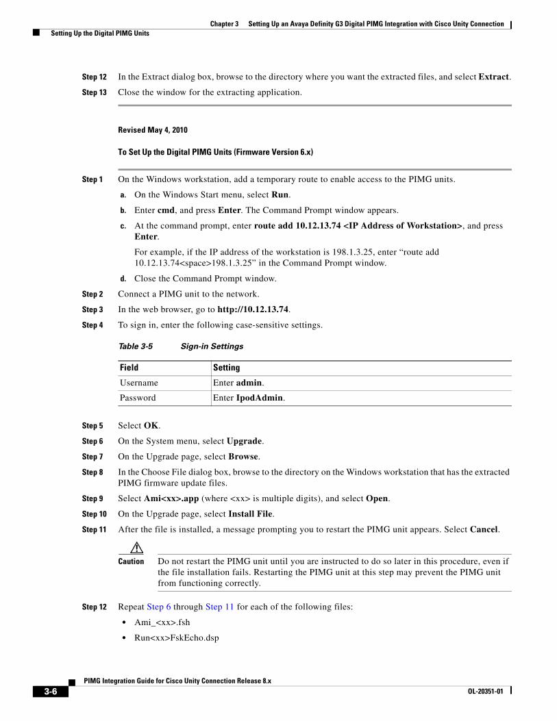
Step 12 In the Extract dialog box, browse to the directory where you want the extracted files, and select Extract.
Step 13 Close the window for the extracting application.
Revised May 4, 2010
To Set Up the Digital PIMG Units (Firmware Version 6.x)
Step 1 On the Windows workstation, add a temporary route to enable access to the PIMG units.
a. On the Windows Start menu, select Run.
b. Enter cmd, and press Enter. The Command Prompt window appears.
c. At the command prompt, enter route add 10.12.13.74 <IP Address of Workstation>, and press Enter.
For example, if the IP address of the workstation is 198.1.3.25, enter “route add 10.12.13.74<space>198.1.3.25” in the Command Prompt window.
d. Close the Command Prompt window.
Step 2 Connect a PIMG unit to the network.
Step 3 In the web browser, go to http://10.12.13.74.
Step 4 To sign in, enter the following case-sensitive settings.
Step 5 Select OK.
Step 6 On the System menu, select Upgrade.
Step 7 On the Upgrade page, select Browse.
Step 8 In the Choose File dialog box, browse to the directory on the Windows workstation that has the extracted PIMG firmware update files.
Step 9 Select Ami<xx>.app (where <xx> is multiple digits), and select Open.
Step 10 On the Upgrade page, select Install File.
Step 11 After the file is installed, a message prompting you to restart the PIMG unit appears. Select Cancel.
Caution Do not restart the PIMG unit until you are instructed to do so later in this procedure, even if the file installation fails. Restarting the PIMG unit at this step may prevent the PIMG unit from functioning correctly.
Step 12 Repeat Step 6 through Step 11 for each of the following files:
• Ami_<xx>.fsh
• Run<xx>FskEcho.dsp
Table 3-5 Sign-in Settings
Field Setting
Username Enter admin.
Password Enter IpodAdmin.
3-6PIMG Integration Guide for Cisco Unity Connection Release 8.x
OL-20351-01
Chapter 3 Setting Up an Avaya Definity G3 Digital PIMG Integration with Cisco Unity Connection Setting Up the Digital PIMG Units
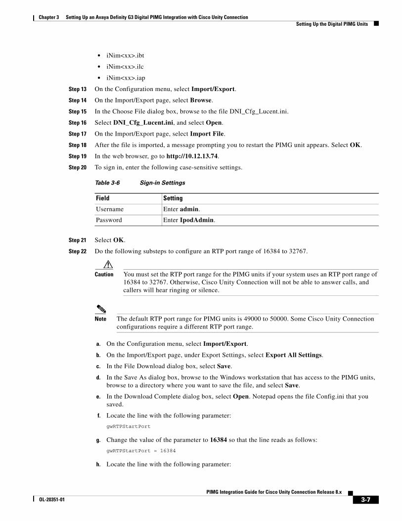
• iNim<xx>.ibt
• iNim<xx>.ilc
• iNim<xx>.iap
Step 13 On the Configuration menu, select Import/Export.
Step 14 On the Import/Export page, select Browse.
Step 15 In the Choose File dialog box, browse to the file DNI_Cfg_Lucent.ini.
Step 16 Select DNI_Cfg_Lucent.ini, and select Open.
Step 17 On the Import/Export page, select Import File.
Step 18 After the file is imported, a message prompting you to restart the PIMG unit appears. Select OK.
Step 19 In the web browser, go to http://10.12.13.74.
Step 20 To sign in, enter the following case-sensitive settings.
Step 21 Select OK.
Step 22 Do the following substeps to configure an RTP port range of 16384 to 32767.
Caution You must set the RTP port range for the PIMG units if your system uses an RTP port range of 16384 to 32767. Otherwise, Cisco Unity Connection will not be able to answer calls, and callers will hear ringing or silence.
Note The default RTP port range for PIMG units is 49000 to 50000. Some Cisco Unity Connection configurations require a different RTP port range.
a. On the Configuration menu, select Import/Export.
b. On the Import/Export page, under Export Settings, select Export All Settings.
c. In the File Download dialog box, select Save.
d. In the Save As dialog box, browse to the Windows workstation that has access to the PIMG units, browse to a directory where you want to save the file, and select Save.
e. In the Download Complete dialog box, select Open. Notepad opens the file Config.ini that you saved.
f. Locate the line with the following parameter:
gwRTPStartPort
g. Change the value of the parameter to 16384 so that the line reads as follows:
gwRTPStartPort = 16384
h. Locate the line with the following parameter:
Table 3-6 Sign-in Settings
Field Setting
Username Enter admin.
Password Enter IpodAdmin.
3-7PIMG Integration Guide for Cisco Unity Connection Release 8.x
OL-20351-01
Chapter 3 Setting Up an Avaya Definity G3 Digital PIMG Integration with Cisco Unity Connection Setting Up the Digital PIMG Units
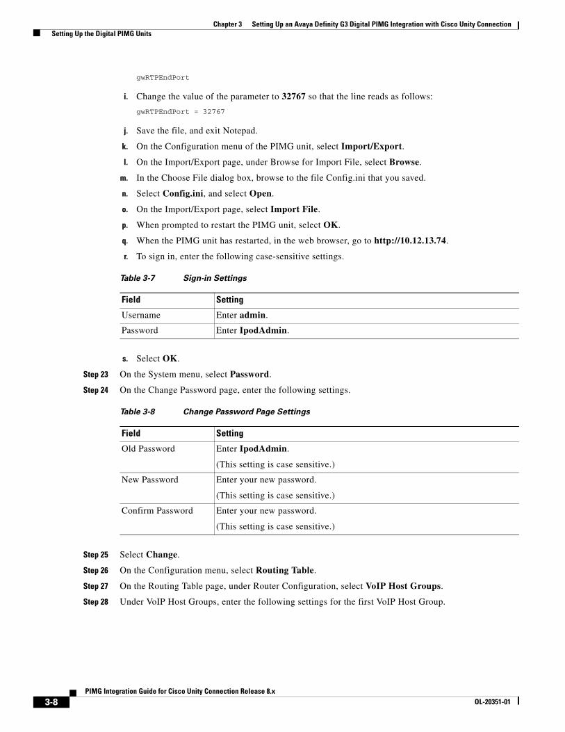
gwRTPEndPort
i. Change the value of the parameter to 32767 so that the line reads as follows:
gwRTPEndPort = 32767
j. Save the file, and exit Notepad.
k. On the Configuration menu of the PIMG unit, select Import/Export.
l. On the Import/Export page, under Browse for Import File, select Browse.
m. In the Choose File dialog box, browse to the file Config.ini that you saved.
n. Select Config.ini, and select Open.
o. On the Import/Export page, select Import File.
p. When prompted to restart the PIMG unit, select OK.
q. When the PIMG unit has restarted, in the web browser, go to http://10.12.13.74.
r. To sign in, enter the following case-sensitive settings.
s. Select OK.
Step 23 On the System menu, select Password.
Step 24 On the Change Password page, enter the following settings.
Step 25 Select Change.
Step 26 On the Configuration menu, select Routing Table.
Step 27 On the Routing Table page, under Router Configuration, select VoIP Host Groups.
Step 28 Under VoIP Host Groups, enter the following settings for the first VoIP Host Group.
Table 3-7 Sign-in Settings
Field Setting
Username Enter admin.
Password Enter IpodAdmin.
Table 3-8 Change Password Page Settings
Field Setting
Old Password Enter IpodAdmin.
(This setting is case sensitive.)
New Password Enter your new password.
(This setting is case sensitive.)
Confirm Password Enter your new password.
(This setting is case sensitive.)
3-8PIMG Integration Guide for Cisco Unity Connection Release 8.x
OL-20351-01

Chapter 3 Setting Up an Avaya Definity G3 Digital PIMG Integration with Cisco Unity Connection Setting Up the Digital PIMG Units
Step 29 For Cisco Unity Connection without a cluster, under Host List, enter the host name or IP address of the Cisco Unity Connection server and the server port in the format <host name or IP address>:5060.
For Cisco Unity Connection with a cluster configured, under Host List, enter the host name or IP address of the subscriber Cisco Unity Connection server (the second Cisco Unity Connection server that you installed) and the server port in the format <host name or IP address>:5060.
Step 30 For Cisco Unity Connection without a cluster, continue to Step 32. For Cisco Unity Connection with a cluster configured, select Add Host.
Step 31 In the second field, enter the host name or IP address of the publisher Cisco Unity Connection server (the first Cisco Unity Connection server that you installed) and the server port in the format <host name or IP address>:5060.
Caution Do not add a third host under Host List or a second host group under VoIP Host Groups. Otherwise, the Cisco Unity Connection cluster may not function correctly.
Step 32 Select Submit.
Step 33 Under Router Configuration, select TDM Trunk Groups.
Step 34 Under TDM Trunk Groups, select Add Trunk Group.
Step 35 Under TDM Trunk Groups, enter the following settings for the first TDM trunk group.
Step 36 Under TDM Trunk Groups, select Add Trunk Group.
Step 37 Enter the following settings for the second TDM trunk group.
Table 3-9 First VoIP Host Group Settings
Field Settings
Name Accept the default or enter another descriptive name of the VoIP host group.
Load-Balanced (Cisco Unity Connection without a cluster) Select False.
(Cisco Unity Connection with a cluster configured) Select False.
Fault-Tolerant (Cisco Unity Connection without a cluster) Select False.
(Cisco Unity Connection with a cluster configured) Select True.
Table 3-10 First TDM Trunk Group Settings (Inbound Calls)
Field Settings
Name Enter Inbound_PBX_Calls or another unique name.
This TDM trunk group will handle all incoming calls from the phone system.
Selection Direction Select Ascending.
Selection Mode Select Linear.
Port/Channel Content Enter the numbers of the PIMG ports that will handle inbound calls. For example, enter “*” for all PIMG ports, or enter “1-6” for the first six PIMG ports.
3-9PIMG Integration Guide for Cisco Unity Connection Release 8.x
OL-20351-01

Chapter 3 Setting Up an Avaya Definity G3 Digital PIMG Integration with Cisco Unity Connection Setting Up the Digital PIMG Units
Step 38 Under TDM Trunk Groups, select Add Trunk Group.
Step 39 Enter the following settings for the third TDM trunk group.
Step 40 Select Submit.
Step 41 Under Router Configuration, select Inbound VoIP Rules.
Step 42 Under Inbound VoIP Rules, uncheck the Enabled check box for the default rule.
Step 43 Select Add Rule.
Step 44 Under Inbound VoIP Rules, enter the following settings for the first new inbound VoIP rule.
Table 3-11 Second TDM Trunk Group Settings (MWIs)
Field Settings
Name Enter MWIs or another unique name.
This TDM trunk group will handle outbound MWI calls (where applicable).
Selection Direction Select Ascending.
Selection Mode Select Cyclic.
Port/Channel Content Enter the numbers of the PIMG ports that will MWIs. For example, enter “*” for all PIMG ports, or enter “7,8” for the last two PIMG ports.
Table 3-12 Third TDM Trunk Group Settings (Outbound Calls)
Field Settings
Name Enter Outbound_PBX_Calls or another unique name.
This TDM trunk group will handle all outbound calls from Cisco Unity Connection.
Selection Direction Select Descending.
Selection Mode Select Linear.
Port/Channel Content Enter * for all channels in all ports.
Enter the numbers of the PIMG ports that will handle outbound (dialout) calls. For example, enter “*” for all PIMG ports, or enter “7,8” for the last two PIMG ports.
Table 3-13 First New Inbound VoIP Rule Settings (MWIs)
Field Settings
Enable Check this check box.
Rule Label Enter MWI_Calls or another name.
This inbound VoIP rule will handle all MWI calls from Cisco Unity Connection.
Request Type Select Message.
Originating VoIP Host Address
Enter *.
3-10PIMG Integration Guide for Cisco Unity Connection Release 8.x
OL-20351-01
Chapter 3 Setting Up an Avaya Definity G3 Digital PIMG Integration with Cisco Unity Connection Setting Up the Digital PIMG Units
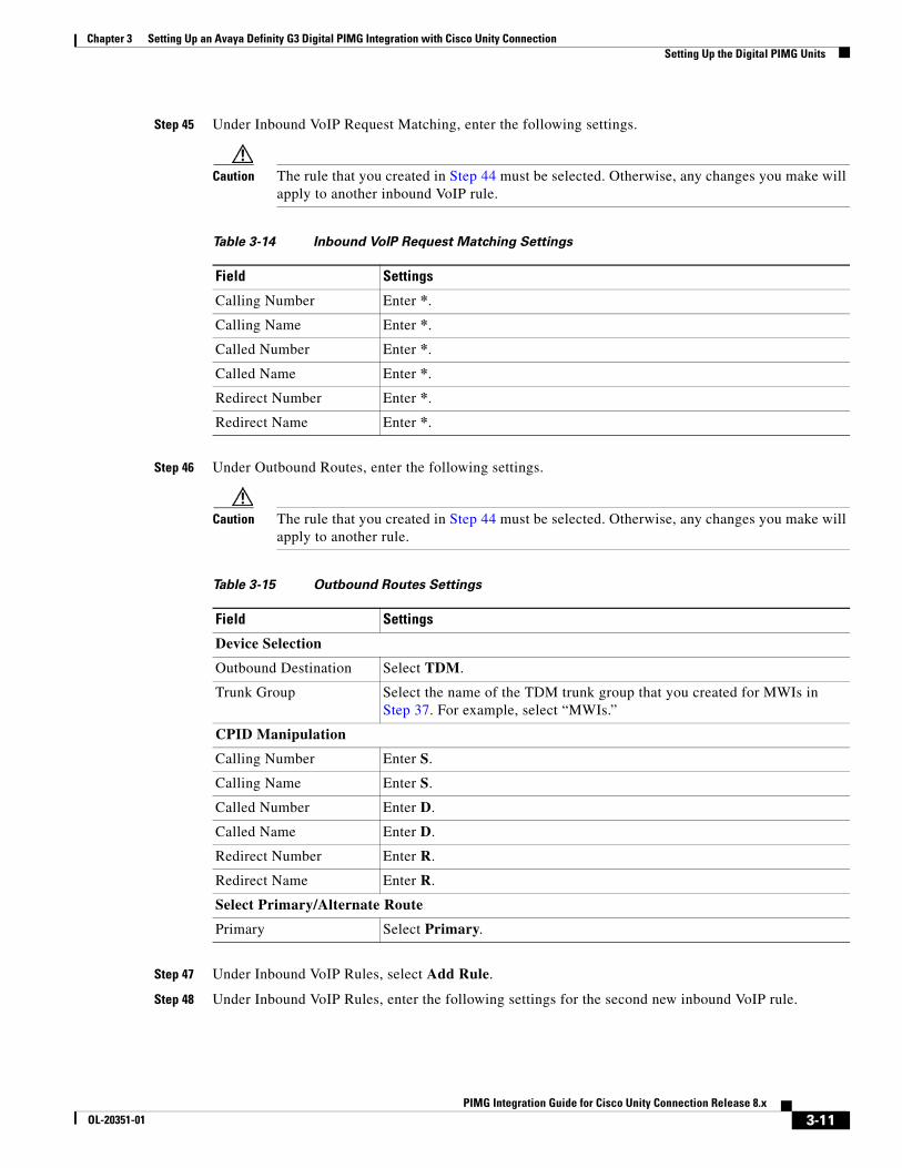
Step 45 Under Inbound VoIP Request Matching, enter the following settings.
Caution The rule that you created in Step 44 must be selected. Otherwise, any changes you make will apply to another inbound VoIP rule.
Step 46 Under Outbound Routes, enter the following settings.
Caution The rule that you created in Step 44 must be selected. Otherwise, any changes you make will apply to another rule.
Step 47 Under Inbound VoIP Rules, select Add Rule.
Step 48 Under Inbound VoIP Rules, enter the following settings for the second new inbound VoIP rule.
Table 3-14 Inbound VoIP Request Matching Settings
Field Settings
Calling Number Enter *.
Calling Name Enter *.
Called Number Enter *.
Called Name Enter *.
Redirect Number Enter *.
Redirect Name Enter *.
Table 3-15 Outbound Routes Settings
Field Settings
Device Selection
Outbound Destination Select TDM.
Trunk Group Select the name of the TDM trunk group that you created for MWIs in Step 37. For example, select “MWIs.”
CPID Manipulation
Calling Number Enter S.
Calling Name Enter S.
Called Number Enter D.
Called Name Enter D.
Redirect Number Enter R.
Redirect Name Enter R.
Select Primary/Alternate Route
Primary Select Primary.
3-11PIMG Integration Guide for Cisco Unity Connection Release 8.x
OL-20351-01

Chapter 3 Setting Up an Avaya Definity G3 Digital PIMG Integration with Cisco Unity Connection Setting Up the Digital PIMG Units
Step 49 Under Inbound VoIP Request Matching, enter the following settings.
Caution The rule that you created in Step 48 must be selected. Otherwise, any changes you make will apply to another rule.
Step 50 Under Outbound Routes, enter the following settings.
Caution The rule that you created in Step 48 must be selected. Otherwise, any changes you make will apply to another rule.
Table 3-16 Second New Inbound VoIP Rule Settings (Outbound Calls)
Field Settings
Enable Check this check box.
Rule Label Enter Outbound_UC_Calls or another name.
This inbound VoIP rule will handle all outbound calls from Cisco Unity Connection.
Request Type Select Call.
Originating VoIP Host Address
Enter *.
Table 3-17 Inbound VoIP Request Matching Settings
Field Settings
Calling Number Enter *.
Calling Name Enter *.
Called Number Enter *.
Called Name Enter *.
Redirect Number Enter *.
Redirect Name Enter *.
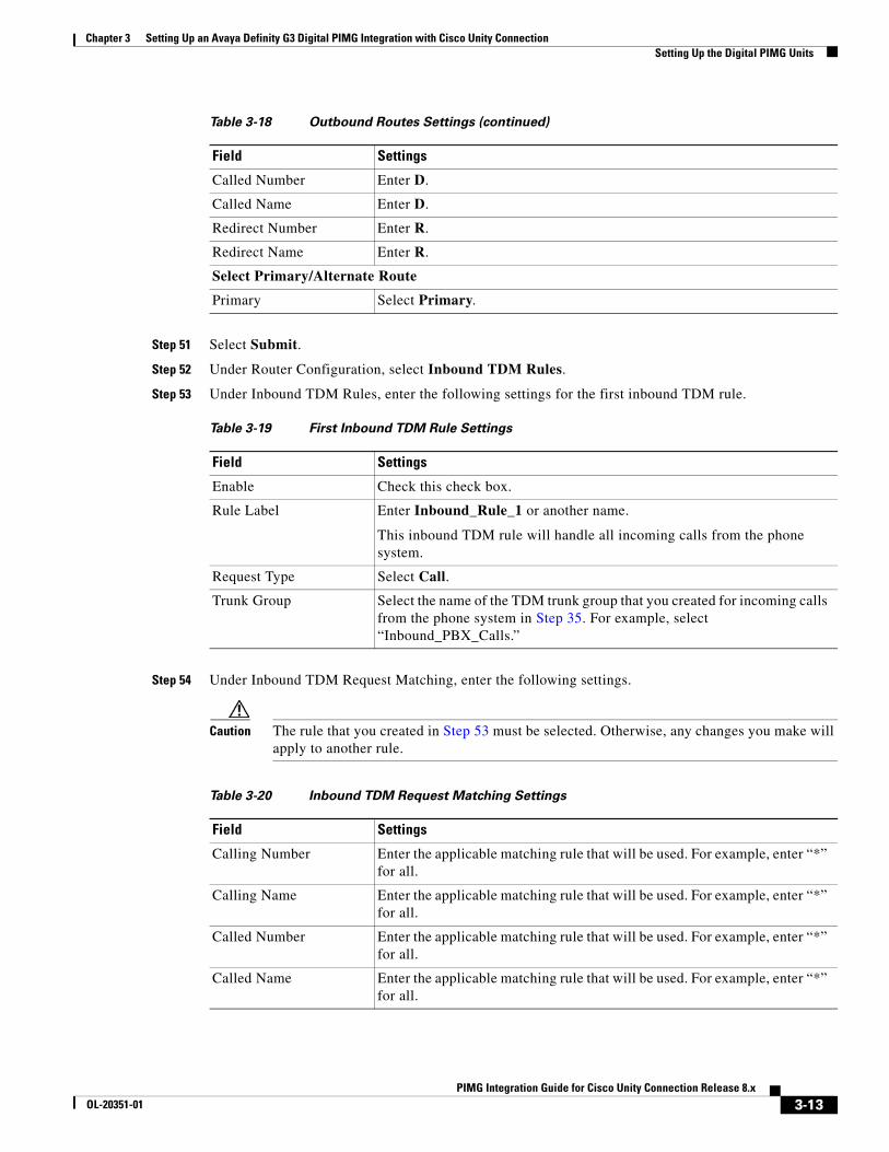
Table 3-18 Outbound Routes Settings
Field Settings
Device Selection
Outbound Destination Select TDM.
Trunk Group Select the name of the TDM trunk group that you created for outbound calls in Step 39. For example, select “Outbound_PBX_Calls.”
CPID Manipulation
Calling Number Enter S.
Calling Name Enter S.
3-12PIMG Integration Guide for Cisco Unity Connection Release 8.x
OL-20351-01
Chapter 3 Setting Up an Avaya Definity G3 Digital PIMG Integration with Cisco Unity Connection Setting Up the Digital PIMG Units
Step 51 Select Submit.
Step 52 Under Router Configuration, select Inbound TDM Rules.
Step 53 Under Inbound TDM Rules, enter the following settings for the first inbound TDM rule.
Step 54 Under Inbound TDM Request Matching, enter the following settings.
Caution The rule that you created in Step 53 must be selected. Otherwise, any changes you make will apply to another rule.
Called Number Enter D.
Called Name Enter D.
Redirect Number Enter R.
Redirect Name Enter R.
Select Primary/Alternate Route
Primary Select Primary.
Table 3-19 First Inbound TDM Rule Settings
Field Settings
Enable Check this check box.
Rule Label Enter Inbound_Rule_1 or another name.
This inbound TDM rule will handle all incoming calls from the phone system.
Request Type Select Call.
Trunk Group Select the name of the TDM trunk group that you created for incoming calls from the phone system in Step 35. For example, select “Inbound_PBX_Calls.”
Table 3-18 Outbound Routes Settings (continued)
Field Settings
Table 3-20 Inbound TDM Request Matching Settings
Field Settings
Calling Number Enter the applicable matching rule that will be used. For example, enter “*” for all.
Calling Name Enter the applicable matching rule that will be used. For example, enter “*” for all.
Called Number Enter the applicable matching rule that will be used. For example, enter “*” for all.
Called Name Enter the applicable matching rule that will be used. For example, enter “*” for all.
3-13PIMG Integration Guide for Cisco Unity Connection Release 8.x
OL-20351-01

Chapter 3 Setting Up an Avaya Definity G3 Digital PIMG Integration with Cisco Unity Connection Setting Up the Digital PIMG Units
Step 55 Under Outbound Routes, enter the following settings.
Caution The rule that you created in Step 53 must be selected. Otherwise, any changes you make will apply to another rule.
Step 56 If you want to create more Inbound TDM rules, under Inbound TDM Rules, select Add Rule. Otherwise, continue to Step 58.
Step 57 Repeat Step 53 through Step 56 for all remaining inbound TDM rules that you want to create.
Step 58 Select Submit.
Step 59 On the Configuration menu, select TDM > Digital.
Step 60 On the Digital Telephony page, in the Telephony Switch Type field, select Lucent.
Step 61 Select Submit.
Step 62 On the Configuration menu, select TDM > General.
Step 63 On the TDM General Settings page, enter the following settings.
Redirect Number Enter the applicable matching rule that will be used. For example, enter “*” for all.
Redirect Name Enter the applicable matching rule that will be used. For example, enter “*” for all.
Table 3-20 Inbound TDM Request Matching Settings (continued)
Field Settings
Table 3-21 Outbound Routes Settings
Field Settings
Device Selection
Outbound Destination Select VoIP.
Host Group Select the name of the VoIP host group that you created for Cisco Unity Connection in Step 28.
CPID Manipulation
Calling Number Enter S.
Calling Name Enter S.
Called Number Enter D.
Called Name Enter D.
Redirect Number Enter R.
Redirect Name Enter R.
Select Primary/Alternate Route
Primary Select Primary.
3-14PIMG Integration Guide for Cisco Unity Connection Release 8.x
OL-20351-01

Chapter 3 Setting Up an Avaya Definity G3 Digital PIMG Integration with Cisco Unity Connection Setting Up the Digital PIMG Units
Step 64 Select Submit.
Step 65 On the Configuration menu, select TDM > Port Enable.
Step 66 On the TDM Port Enabling page, select No for the ports that you want to disable on the PIMG unit.
Step 67 Confirm that Yes is selected for all other ports on the PIMG unit.
Step 68 Select Submit.
Step 69 On the Configuration menu, select VoIP > General.
Step 70 On the VoIP General Settings page, enter the following settings.
Table 3-22 TDM General Settings Page Settings
Field Settings
PCM Coding Select uLaw.
Minimum Call Party Delay (ms)
Enter 500.
Maximum Call Party Delay (ms)
Enter 2000.
Dial Digit on Time (ms) Enter 100.
Dial Inter-Digit Time (ms)
Enter 100.
Dial Pause Time (ms) Enter 2000.
Turn MWI On FAC Leave this field blank.
Turn MWI Off FAC Leave this field blank.
Outbound Call Connect Timeout (ms)
Enter 10000.
Wait for Ringback/Connect on Blind Transfer
Select Yes.
Hunt Group Extension Enter the pilot number of the Cisco Unity Connection voice messaging ports.
Table 3-23 VoIP General Settings Page Settings
Field Setting
User-Agent
Host and Domain Name
Enter the host and domain name of the PIMG unit.
Transport Type Select UDP.
Call as Domain Name Select No.
Invite Expiration (sec)
Enter 120.
Server
DNS Server Address Enter the IP Address of the Domain Name Server that the PIMG unit will use.
3-15PIMG Integration Guide for Cisco Unity Connection Release 8.x
OL-20351-01
Chapter 3 Setting Up an Avaya Definity G3 Digital PIMG Integration with Cisco Unity Connection Setting Up the Digital PIMG Units
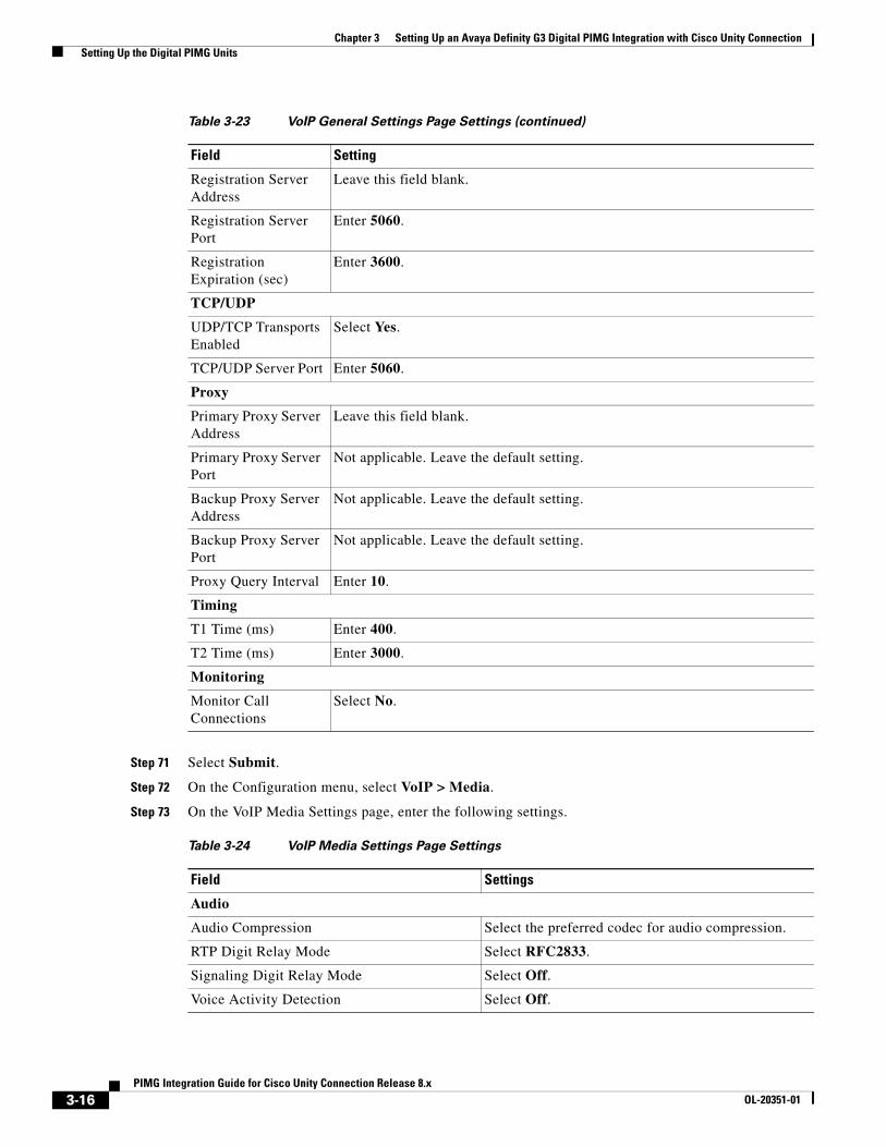
Step 71 Select Submit.
Step 72 On the Configuration menu, select VoIP > Media.
Step 73 On the VoIP Media Settings page, enter the following settings.
Registration Server Address
Leave this field blank.
Registration Server Port
Enter 5060.
Registration Expiration (sec)
Enter 3600.
TCP/UDP
UDP/TCP Transports Enabled
Select Yes.
TCP/UDP Server Port Enter 5060.
Proxy
Primary Proxy Server Address
Leave this field blank.
Primary Proxy Server Port
Not applicable. Leave the default setting.
Backup Proxy Server Address
Not applicable. Leave the default setting.
Backup Proxy Server Port
Not applicable. Leave the default setting.
Proxy Query Interval Enter 10.
Timing
T1 Time (ms) Enter 400.
T2 Time (ms) Enter 3000.
Monitoring
Monitor Call Connections
Select No.
Table 3-24 VoIP Media Settings Page Settings
Field Settings
Audio
Audio Compression Select the preferred codec for audio compression.
RTP Digit Relay Mode Select RFC2833.
Signaling Digit Relay Mode Select Off.
Voice Activity Detection Select Off.
Table 3-23 VoIP General Settings Page Settings (continued)
Field Setting
3-16PIMG Integration Guide for Cisco Unity Connection Release 8.x
OL-20351-01
Chapter 3 Setting Up an Avaya Definity G3 Digital PIMG Integration with Cisco Unity Connection Setting Up the Digital PIMG Units
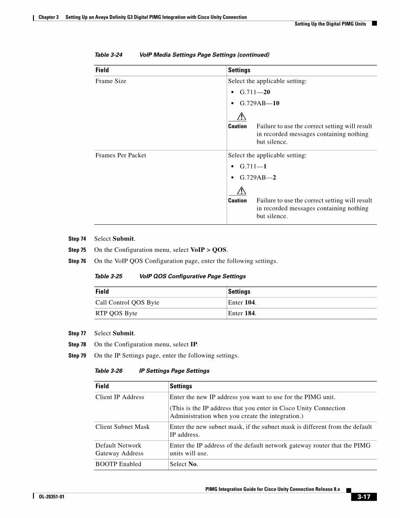
Step 74 Select Submit.
Step 75 On the Configuration menu, select VoIP > QOS.
Step 76 On the VoIP QOS Configuration page, enter the following settings.
Step 77 Select Submit.
Step 78 On the Configuration menu, select IP.
Step 79 On the IP Settings page, enter the following settings.
Frame Size Select the applicable setting:
• G.711—20
• G.729AB—10
Caution Failure to use the correct setting will result in recorded messages containing nothing but silence.
Frames Per Packet Select the applicable setting:
• G.711—1
• G.729AB—2
Caution Failure to use the correct setting will result in recorded messages containing nothing but silence.
Table 3-25 VoIP QOS Configurative Page Settings
Field Settings
Call Control QOS Byte Enter 104.
RTP QOS Byte Enter 184.
Table 3-26 IP Settings Page Settings
Field Settings
Client IP Address Enter the new IP address you want to use for the PIMG unit.
(This is the IP address that you enter in Cisco Unity Connection Administration when you create the integration.)
Client Subnet Mask Enter the new subnet mask, if the subnet mask is different from the default IP address.
Default Network Gateway Address
Enter the IP address of the default network gateway router that the PIMG units will use.
BOOTP Enabled Select No.
Table 3-24 VoIP Media Settings Page Settings (continued)
Field Settings
3-17PIMG Integration Guide for Cisco Unity Connection Release 8.x
OL-20351-01
Chapter 3 Setting Up an Avaya Definity G3 Digital PIMG Integration with Cisco Unity Connection Creating a New Integration with the Avaya Definity G3 Phone System
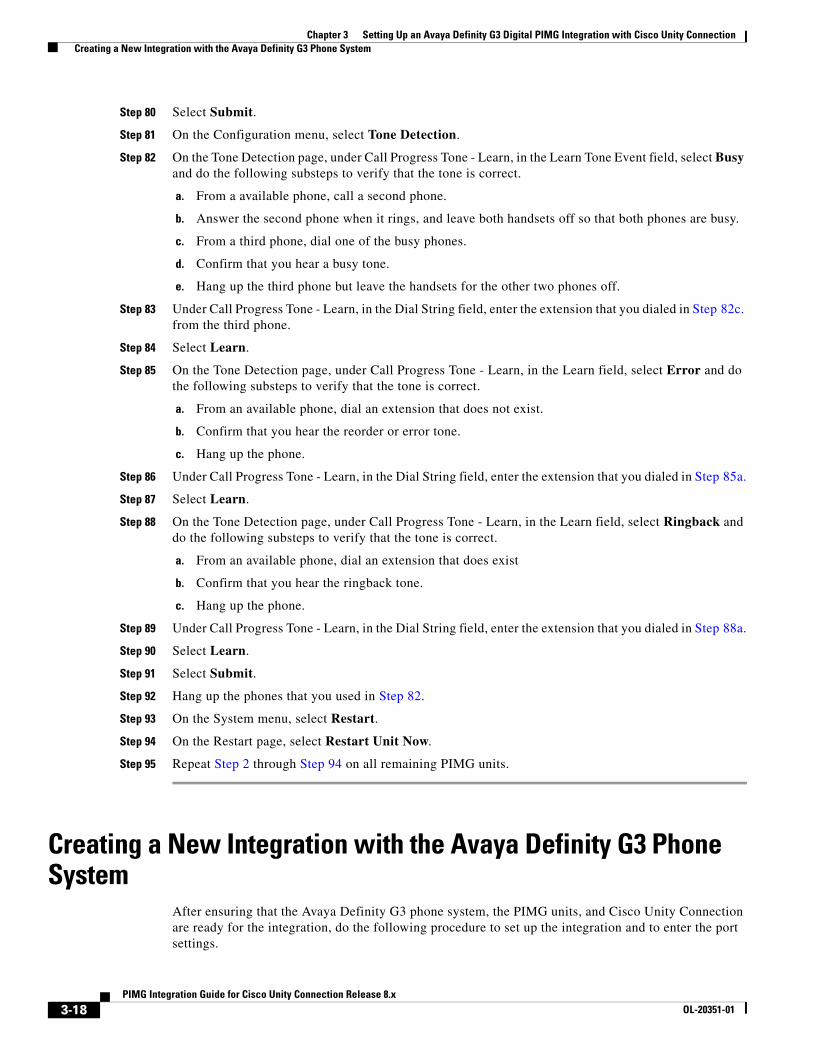
Step 80 Select Submit.
Step 81 On the Configuration menu, select Tone Detection.
Step 82 On the Tone Detection page, under Call Progress Tone - Learn, in the Learn Tone Event field, select Busy and do the following substeps to verify that the tone is correct.
a. From a available phone, call a second phone.
b. Answer the second phone when it rings, and leave both handsets off so that both phones are busy.
c. From a third phone, dial one of the busy phones.
d. Confirm that you hear a busy tone.
e. Hang up the third phone but leave the handsets for the other two phones off.
Step 83 Under Call Progress Tone - Learn, in the Dial String field, enter the extension that you dialed in Step 82c. from the third phone.
Step 84 Select Learn.
Step 85 On the Tone Detection page, under Call Progress Tone - Learn, in the Learn field, select Error and do the following substeps to verify that the tone is correct.
a. From an available phone, dial an extension that does not exist.
b. Confirm that you hear the reorder or error tone.
c. Hang up the phone.
Step 86 Under Call Progress Tone - Learn, in the Dial String field, enter the extension that you dialed in Step 85a.
Step 87 Select Learn.
Step 88 On the Tone Detection page, under Call Progress Tone - Learn, in the Learn field, select Ringback and do the following substeps to verify that the tone is correct.
a. From an available phone, dial an extension that does exist
b. Confirm that you hear the ringback tone.
c. Hang up the phone.
Step 89 Under Call Progress Tone - Learn, in the Dial String field, enter the extension that you dialed in Step 88a.
Step 90 Select Learn.
Step 91 Select Submit.
Step 92 Hang up the phones that you used in Step 82.
Step 93 On the System menu, select Restart.
Step 94 On the Restart page, select Restart Unit Now.
Step 95 Repeat Step 2 through Step 94 on all remaining PIMG units.
Creating a New Integration with the Avaya Definity G3 Phone System
After ensuring that the Avaya Definity G3 phone system, the PIMG units, and Cisco Unity Connection are ready for the integration, do the following procedure to set up the integration and to enter the port settings.
3-18PIMG Integration Guide for Cisco Unity Connection Release 8.x
OL-20351-01
Chapter 3 Setting Up an Avaya Definity G3 Digital PIMG Integration with Cisco Unity Connection Creating a New Integration with the Avaya Definity G3 Phone System
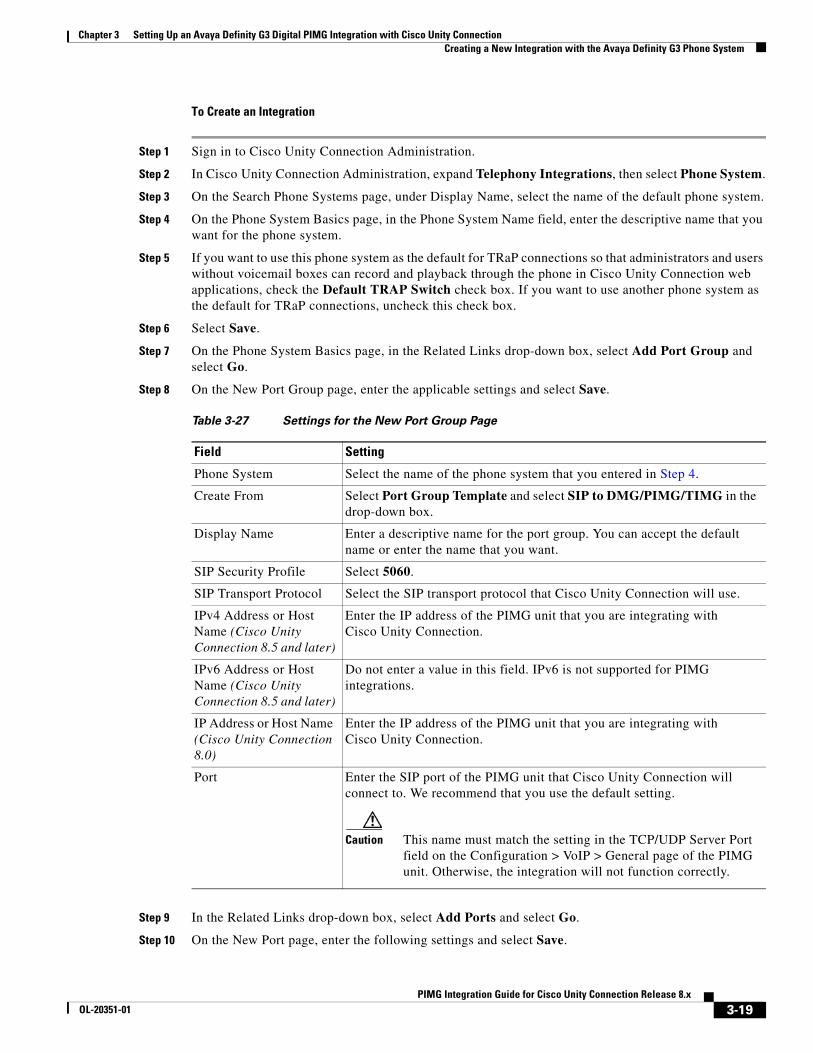
To Create an Integration
Step 1 Sign in to Cisco Unity Connection Administration.
Step 2 In Cisco Unity Connection Administration, expand Telephony Integrations, then select Phone System.
Step 3 On the Search Phone Systems page, under Display Name, select the name of the default phone system.
Step 4 On the Phone System Basics page, in the Phone System Name field, enter the descriptive name that you want for the phone system.
Step 5 If you want to use this phone system as the default for TRaP connections so that administrators and users without voicemail boxes can record and playback through the phone in Cisco Unity Connection web applications, check the Default TRAP Switch check box. If you want to use another phone system as the default for TRaP connections, uncheck this check box.
Step 6 Select Save.
Step 7 On the Phone System Basics page, in the Related Links drop-down box, select Add Port Group and select Go.
Step 8 On the New Port Group page, enter the applicable settings and select Save.
Step 9 In the Related Links drop-down box, select Add Ports and select Go.
Step 10 On the New Port page, enter the following settings and select Save.
Table 3-27 Settings for the New Port Group Page
Field Setting
Phone System Select the name of the phone system that you entered in Step 4.
Create From Select Port Group Template and select SIP to DMG/PIMG/TIMG in the drop-down box.
Display Name Enter a descriptive name for the port group. You can accept the default name or enter the name that you want.
SIP Security Profile Select 5060.
SIP Transport Protocol Select the SIP transport protocol that Cisco Unity Connection will use.
IPv4 Address or Host Name (Cisco Unity Connection 8.5 and later)
Enter the IP address of the PIMG unit that you are integrating with Cisco Unity Connection.
IPv6 Address or Host Name (Cisco Unity Connection 8.5 and later)
Do not enter a value in this field. IPv6 is not supported for PIMG integrations.
IP Address or Host Name (Cisco Unity Connection 8.0)
Enter the IP address of the PIMG unit that you are integrating with Cisco Unity Connection.
Port Enter the SIP port of the PIMG unit that Cisco Unity Connection will connect to. We recommend that you use the default setting.
Caution This name must match the setting in the TCP/UDP Server Port field on the Configuration > VoIP > General page of the PIMG unit. Otherwise, the integration will not function correctly.
3-19PIMG Integration Guide for Cisco Unity Connection Release 8.x
OL-20351-01
Chapter 3 Setting Up an Avaya Definity G3 Digital PIMG Integration with Cisco Unity Connection Creating a New Integration with the Avaya Definity G3 Phone System
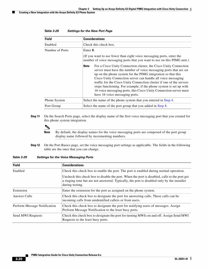
Step 11 On the Search Ports page, select the display name of the first voice messaging port that you created for this phone system integration.
Note By default, the display names for the voice messaging ports are composed of the port group display name followed by incrementing numbers.
Step 12 On the Port Basics page, set the voice messaging port settings as applicable. The fields in the following table are the ones that you can change.
Table 3-28 Settings for the New Port Page
Field Considerations
Enabled Check this check box.
Number of Ports Enter 8.
(If you want to use fewer than eight voice messaging ports, enter the number of voice messaging ports that you want to use on this PIMG unit.)
Note For a Cisco Unity Connection cluster, the Cisco Unity Connection server must have the number of voice messaging ports that are set up on the phone system for the PIMG integration so that this Cisco Unity Connection server can handle all voice messaging traffic for the Cisco Unity Connection cluster if one of the servers stops functioning. For example, if the phone system is set up with 16 voice messaging ports, this Cisco Unity Connection server must have 16 voice messaging ports.
Phone System Select the name of the phone system that you entered in Step 4.
Port Group Select the name of the port group that you added in Step 8.
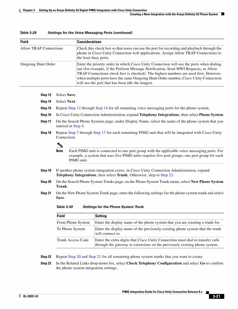
Table 3-29 Settings for the Voice Messaging Ports
Field Considerations
Enabled Check this check box to enable the port. The port is enabled during normal operation.
Uncheck this check box to disable the port. When the port is disabled, calls to the port get a ringing tone but are not answered. Typically, the port is disabled only by the installer during testing.
Extension Enter the extension for the port as assigned on the phone system.
Answer Calls Check this check box to designate the port for answering calls. These calls can be incoming calls from unidentified callers or from users.
Perform Message Notification Check this check box to designate the port for notifying users of messages. Assign Perform Message Notification to the least busy ports.
Send MWI Requests Check this check box to designate the port for turning MWIs on and off. Assign Send MWI Requests to the least busy ports.
3-20PIMG Integration Guide for Cisco Unity Connection Release 8.x
OL-20351-01
Chapter 3 Setting Up an Avaya Definity G3 Digital PIMG Integration with Cisco Unity Connection Creating a New Integration with the Avaya Definity G3 Phone System
Step 13 Select Save.
Step 14 Select Next.
Step 15 Repeat Step 12 through Step 14 for all remaining voice messaging ports for the phone system.
Step 16 In Cisco Unity Connection Administration, expand Telephony Integrations, then select Phone System.
Step 17 On the Search Phone Systems page, under Display Name, select the name of the phone system that you entered in Step 4.
Step 18 Repeat Step 7 through Step 17 for each remaining PIMG unit that will be integrated with Cisco Unity Connection.
Note Each PIMG unit is connected to one port group with the applicable voice messaging ports. For example, a system that uses five PIMG units requires five port groups, one port group for each PIMG unit.
Step 19 If another phone system integration exists, in Cisco Unity Connection Administration, expand Telephony Integrations, then select Trunk. Otherwise, skip to Step 23.
Step 20 On the Search Phone System Trunks page, on the Phone System Trunk menu, select New Phone System Trunk.
Step 21 On the New Phone System Trunk page, enter the following settings for the phone system trunk and select Save.
Step 22 Repeat Step 20 and Step 21 for all remaining phone system trunks that you want to create.
Step 23 In the Related Links drop-down list, select Check Telephony Configuration and select Go to confirm the phone system integration settings.
Allow TRAP Connections Check this check box so that users can use the port for recording and playback through the phone in Cisco Unity Connection web applications. Assign Allow TRAP Connections to the least busy ports.
Outgoing Hunt Order Enter the priority order in which Cisco Unity Connection will use the ports when dialing out (for example, if the Perform Message Notification, Send MWI Requests, or Allow TRAP Connections check box is checked). The highest numbers are used first. However, when multiple ports have the same Outgoing Hunt Order number, Cisco Unity Connection will use the port that has been idle the longest.
Table 3-29 Settings for the Voice Messaging Ports (continued)
Field Considerations
Table 3-30 Settings for the Phone System Trunk
Field Setting
From Phone System Enter the display name of the phone system that you are creating a trunk for.
To Phone System Enter the display name of the previously existing phone system that the trunk will connect to.
Trunk Access Code Enter the extra digits that Cisco Unity Connection must dial to transfer calls through the gateway to extensions on the previously existing phone system.
3-21PIMG Integration Guide for Cisco Unity Connection Release 8.x
OL-20351-01

Chapter 3 Setting Up an Avaya Definity G3 Digital PIMG Integration with Cisco Unity Connection Creating a New Integration with the Avaya Definity G3 Phone System
If the test is not successful, the Task Execution Results displays one or more messages with troubleshooting steps. After correcting the problems, test the connection again.
Step 24 In the Task Execution Results window, select Close.
3-22PIMG Integration Guide for Cisco Unity Connection Release 8.x
OL-20351-01
PIMG IntegrOL-20351-01
C H A P T E R 4
Setting Up an Avaya Definity ProLogix Digital PIMG Integration with Cisco Unity ConnectionFor detailed instructions for setting up an Avaya Definity ProLogix digital PIMG integration with Cisco Unity Connection, see the following sections in this chapter:
• Task List to Create the Integration, page 4-1
• Requirements, page 4-2
• Programming the Avaya Definity ProLogix PIMG Phone System for Integrating with Cisco Unity Connection, page 4-3
• Setting Up the Digital PIMG Units, page 4-5
• Creating a New Integration with the Avaya Definity ProLogix Phone System, page 4-18
Task List to Create the IntegrationBefore doing the following tasks to integrate Cisco Unity Connection with the Avaya Definity ProLogix phone system by using PIMG units (media gateways), confirm that the Cisco Unity Connection server is ready for the integration by completing the applicable tasks in the Cisco Unity Connection Installation Guide.
1. Review the system and equipment requirements to confirm that all phone system and Cisco Unity Connection server requirements have been met. See the “Requirements” section on page 4-2.
2. Plan how the voice messaging ports will be used by Cisco Unity Connection. See Chapter 2, “Planning How the Voice Messaging Ports Will Be Used by Cisco Unity Connection.”
3. Program the Avaya Definity ProLogix phone system and extensions. See the “Programming the Avaya Definity ProLogix PIMG Phone System for Integrating with Cisco Unity Connection” section on page 4-3.
4. Set up the PIMG units. See the “Setting Up the Digital PIMG Units” section on page 4-5.
5. Create the integration. See the “Creating a New Integration with the Avaya Definity ProLogix Phone System” section on page 4-18.
6. Test the integration. See Chapter 14, “Testing the Integration.”
7. If this integration is a second or subsequent integration, add the applicable new user templates for the new phone system. See Chapter 15, “Adding New User Templates for Multiple Integrations.”
4-1ation Guide for Cisco Unity Connection Release 8.x
Chapter 4 Setting Up an Avaya Definity ProLogix Digital PIMG Integration with Cisco Unity Connection Requirements
RequirementsThe Avaya Definity ProLogix integration supports configurations of the following components:
Phone System
• Avaya Definity ProLogix phone system. The voice messaging ports that connect to the PIMG units must be compatible with the 7434ND, 8434, 8434D, or 8434DX digital phones.
Caution You must use 2-wire line cards for these voice messaging ports. Otherwise, the voice messaging ports will not be compatible with the 7434ND, 8434, 8434D, or 8434DX digital phones.
• One or more of the applicable PIMG units. For details, see Chapter 1, “Introduction.”
• The voice messaging ports in the phone system connected by digital lines to the ports on the PIMG units.
To simplify troubleshooting, we recommend that you connect the voice messaging ports on the phone system to the ports on the PIMG units in a planned manner. For example, connect the first phone system voice messaging port to the first port on the first PIMG unit, connect the second phone system voice messaging port to the second port on the first PIMG unit, and so on. Alternatively, if you have multiple PIMG units, you can reduce answer times in the event of a PIMG unit failure by connecting the phone system ports to the PIMG units in a round-robin fashion. For example, connect the first phone system voice messaging port to the first port on the first PIMG unit, connect the second phone system voice messaging port to the first port on the second PIMG unit, and so on.
• The PIMG units connected to the same LAN or WAN that Cisco Unity Connection is connected to.
• If the PIMG units connect to a WAN, the requirements for the WAN network connections are:
– For G.729a codec formatting, a minimum of 32.76 Kbps guaranteed bandwidth for each voice messaging port.
– For G.711 codec formatting, a minimum of 91.56 Kbps guaranteed bandwidth for each voice messaging port.
– No network devices that implement network address translation (NAT).
– A maximum 200 ms one-way network latency.
• The phone system ready for the integration, as described in the documentation for the phone system.
Cisco Unity Connection Server
• Cisco Unity Connection installed and ready for the integration, as described in the Cisco Unity Connection Installation Guide at http://www.cisco.com/en/US/products/ps6509/prod_installation_guides_list.html.
• A license that enables the applicable number of voice messaging ports.
Centralized Voice Messaging
Cisco Unity Connection supports centralized voice messaging through the phone system, which supports various inter-phone system networking protocols including proprietary protocols such as Avaya DCS, Nortel MCDN, or Siemens CorNet, and standards-based protocols such as QSIG or DPNSS. Note that centralized voice messaging is a function of the phone system and its inter-phone system networking, not voicemail. Connection will support centralized voice messaging as long as the phone system and its inter-phone system networking are properly configured. For details, see the “Centralized Voice
4-2PIMG Integration Guide for Cisco Unity Connection Release 8.x
OL-20351-01
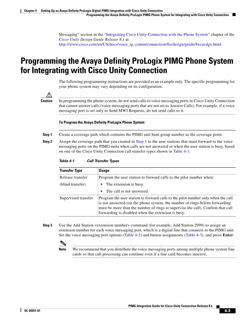
Chapter 4 Setting Up an Avaya Definity ProLogix Digital PIMG Integration with Cisco Unity Connection Programming the Avaya Definity ProLogix PIMG Phone System for Integrating with Cisco Unity Connection
Messaging” section in the “Integrating Cisco Unity Connection with the Phone System” chapter of the Cisco Unity Design Guide Release 8.x at http://www.cisco.com/en/US/docs/voice_ip_comm/connection/8x/design/guide/8xcucdgx.html.
Programming the Avaya Definity ProLogix PIMG Phone System for Integrating with Cisco Unity Connection
The following programming instructions are provided as an example only. The specific programming for your phone system may vary depending on its configuration.
Caution In programming the phone system, do not send calls to voice messaging ports in Cisco Unity Connection that cannot answer calls (voice messaging ports that are not set to Answer Calls). For example, if a voice messaging port is set only to Send MWI Requests, do not send calls to it.
To Program the Avaya Definity ProLogix Phone System
Step 1 Create a coverage path which contains the PIMG unit hunt group number as the coverage point.
Step 2 Assign the coverage path that you created in Step 1 to the user stations that must forward to the voice messaging ports on the PIMG units when calls are not answered or when the user station is busy, based on one of the Cisco Unity Connection call transfer types shown in Table 4-1.
Step 3 Use the Add Station <extension number> command (for example, Add Station 2999) to assign an extension number for each voice messaging port, which is a digital line that connects to the PIMG unit. Set the voice messaging port options (Table 4-2) and button assignments (Table 4-3), and press Enter.
Note We recommend that you distribute the voice messaging ports among multiple phone system line cards so that call processing can continue even if a line card becomes inactive.
Table 4-1 Call Transfer Types
Transfer Type Usage
Release transfer
(blind transfer)
Program the user station to forward calls to the pilot number when:
• The extension is busy.
• The call is not answered.
Supervised transfer Program the user station to forward calls to the pilot number only when the call is not answered (on the phone system, the number of rings before forwarding must be more than the number of rings to supervise the call). Confirm that call forwarding is disabled when the extension is busy.
4-3PIMG Integration Guide for Cisco Unity Connection Release 8.x
OL-20351-01

Chapter 4 Setting Up an Avaya Definity ProLogix Digital PIMG Integration with Cisco Unity Connection Programming the Avaya Definity ProLogix PIMG Phone System for Integrating with Cisco Unity Connection
Step 4 Use the Add Hunt <hunt group number> command (for example, Add Hunt 1) to assign a the voice messaging ports to a hunt group. Set the following options.
Step 5 Enter the group member assignments for the voice messaging ports that will answer calls and press Enter.
Table 4-2 Voice Messaging Port Options for All Lines
Option Setting
Extension Enter the extension number of the digital line.
Type Enter 7434ND (recommended).
You can also use the following settings. However, you must include the extension with each subscriber name when programming the phone system (for example, “3001 Jane Doe”). Otherwise, the integration will not function correctly.
• 8434
• 8434D
• 8434DX
Note If the setting that you want is not available, contact the phone system manufacturer.
LWC Reception Enter msa.
LWC Activation? Enter y.
Restrict Last Appearance? Enter y.
Display Module Enter y.
Table 4-3 Button Assignments for All Lines
Button Assignment Setting
1 Enter call-appr.
2 Enter call-appr.
9 Enter lwc-store.
10 Enter lwc-cancel.
Table 4-4 Hunt Group Options
Option Setting
Group Number Enter the hunt group number.
Group Extension Enter the pilot number for the hunt group.
Group Type Enter ucd.
Group Name Enter the display name for the hunt group.
Queue? Enter N.
4-4PIMG Integration Guide for Cisco Unity Connection Release 8.x
OL-20351-01
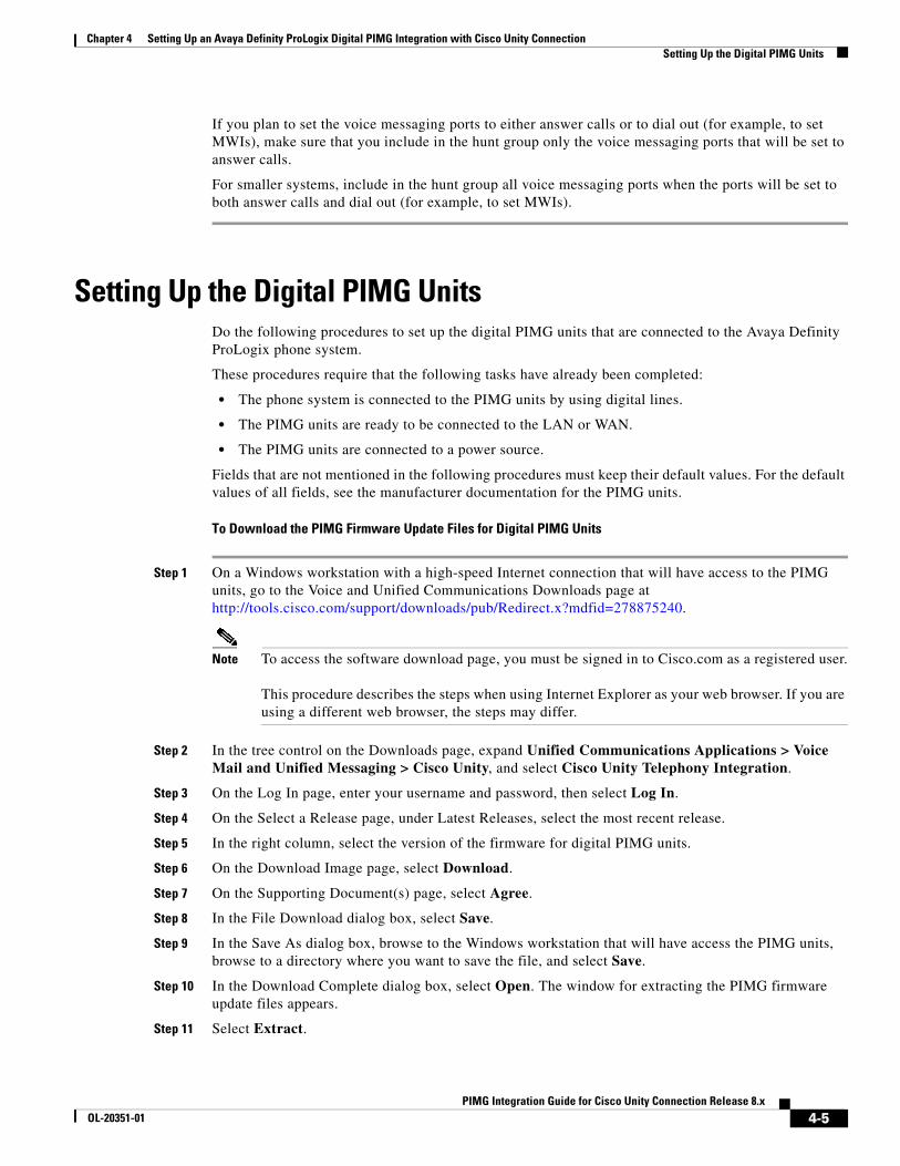
Chapter 4 Setting Up an Avaya Definity ProLogix Digital PIMG Integration with Cisco Unity Connection Setting Up the Digital PIMG Units
If you plan to set the voice messaging ports to either answer calls or to dial out (for example, to set MWIs), make sure that you include in the hunt group only the voice messaging ports that will be set to answer calls.
For smaller systems, include in the hunt group all voice messaging ports when the ports will be set to both answer calls and dial out (for example, to set MWIs).
Setting Up the Digital PIMG UnitsDo the following procedures to set up the digital PIMG units that are connected to the Avaya Definity ProLogix phone system.
These procedures require that the following tasks have already been completed:
• The phone system is connected to the PIMG units by using digital lines.
• The PIMG units are ready to be connected to the LAN or WAN.
• The PIMG units are connected to a power source.
Fields that are not mentioned in the following procedures must keep their default values. For the default values of all fields, see the manufacturer documentation for the PIMG units.
To Download the PIMG Firmware Update Files for Digital PIMG Units
Step 1 On a Windows workstation with a high-speed Internet connection that will have access to the PIMG units, go to the Voice and Unified Communications Downloads page at http://tools.cisco.com/support/downloads/pub/Redirect.x?mdfid=278875240.
Note To access the software download page, you must be signed in to Cisco.com as a registered user. This procedure describes the steps when using Internet Explorer as your web browser. If you are using a different web browser, the steps may differ.
Step 2 In the tree control on the Downloads page, expand Unified Communications Applications > Voice Mail and Unified Messaging > Cisco Unity, and select Cisco Unity Telephony Integration.
Step 3 On the Log In page, enter your username and password, then select Log In.
Step 4 On the Select a Release page, under Latest Releases, select the most recent release.
Step 5 In the right column, select the version of the firmware for digital PIMG units.
Step 6 On the Download Image page, select Download.
Step 7 On the Supporting Document(s) page, select Agree.
Step 8 In the File Download dialog box, select Save.
Step 9 In the Save As dialog box, browse to the Windows workstation that will have access the PIMG units, browse to a directory where you want to save the file, and select Save.
Step 10 In the Download Complete dialog box, select Open. The window for extracting the PIMG firmware update files appears.
Step 11 Select Extract.
4-5PIMG Integration Guide for Cisco Unity Connection Release 8.x
OL-20351-01
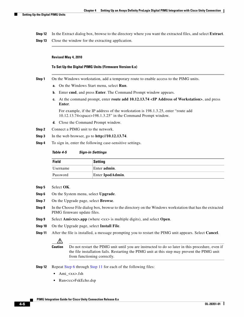
Chapter 4 Setting Up an Avaya Definity ProLogix Digital PIMG Integration with Cisco Unity Connection Setting Up the Digital PIMG Units
Step 12 In the Extract dialog box, browse to the directory where you want the extracted files, and select Extract.
Step 13 Close the window for the extracting application.
Revised May 4, 2010
To Set Up the Digital PIMG Units (Firmware Version 6.x)
Step 1 On the Windows workstation, add a temporary route to enable access to the PIMG units.
a. On the Windows Start menu, select Run.
b. Enter cmd, and press Enter. The Command Prompt window appears.
c. At the command prompt, enter route add 10.12.13.74 <IP Address of Workstation>, and press Enter.
For example, if the IP address of the workstation is 198.1.3.25, enter “route add 10.12.13.74<space>198.1.3.25” in the Command Prompt window.
d. Close the Command Prompt window.
Step 2 Connect a PIMG unit to the network.
Step 3 In the web browser, go to http://10.12.13.74.
Step 4 To sign in, enter the following case-sensitive settings.
Step 5 Select OK.
Step 6 On the System menu, select Upgrade.
Step 7 On the Upgrade page, select Browse.
Step 8 In the Choose File dialog box, browse to the directory on the Windows workstation that has the extracted PIMG firmware update files.
Step 9 Select Ami<xx>.app (where <xx> is multiple digits), and select Open.
Step 10 On the Upgrade page, select Install File.
Step 11 After the file is installed, a message prompting you to restart the PIMG unit appears. Select Cancel.
Caution Do not restart the PIMG unit until you are instructed to do so later in this procedure, even if the file installation fails. Restarting the PIMG unit at this step may prevent the PIMG unit from functioning correctly.
Step 12 Repeat Step 6 through Step 11 for each of the following files:
• Ami_<xx>.fsh
• Run<xx>FskEcho.dsp
Table 4-5 Sign-in Settings
Field Setting
Username Enter admin.
Password Enter IpodAdmin.
4-6PIMG Integration Guide for Cisco Unity Connection Release 8.x
OL-20351-01
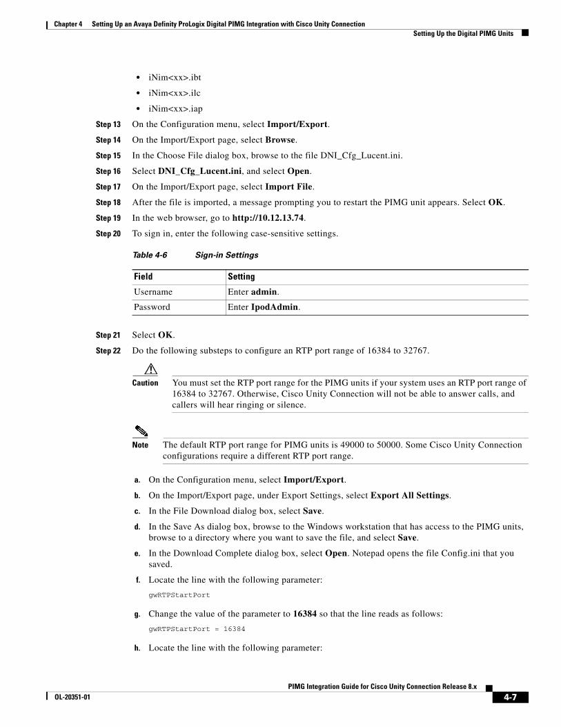
Chapter 4 Setting Up an Avaya Definity ProLogix Digital PIMG Integration with Cisco Unity Connection Setting Up the Digital PIMG Units
• iNim<xx>.ibt
• iNim<xx>.ilc
• iNim<xx>.iap
Step 13 On the Configuration menu, select Import/Export.
Step 14 On the Import/Export page, select Browse.
Step 15 In the Choose File dialog box, browse to the file DNI_Cfg_Lucent.ini.
Step 16 Select DNI_Cfg_Lucent.ini, and select Open.
Step 17 On the Import/Export page, select Import File.
Step 18 After the file is imported, a message prompting you to restart the PIMG unit appears. Select OK.
Step 19 In the web browser, go to http://10.12.13.74.
Step 20 To sign in, enter the following case-sensitive settings.
Step 21 Select OK.
Step 22 Do the following substeps to configure an RTP port range of 16384 to 32767.
Caution You must set the RTP port range for the PIMG units if your system uses an RTP port range of 16384 to 32767. Otherwise, Cisco Unity Connection will not be able to answer calls, and callers will hear ringing or silence.
Note The default RTP port range for PIMG units is 49000 to 50000. Some Cisco Unity Connection configurations require a different RTP port range.
a. On the Configuration menu, select Import/Export.
b. On the Import/Export page, under Export Settings, select Export All Settings.
c. In the File Download dialog box, select Save.
d. In the Save As dialog box, browse to the Windows workstation that has access to the PIMG units, browse to a directory where you want to save the file, and select Save.
e. In the Download Complete dialog box, select Open. Notepad opens the file Config.ini that you saved.
f. Locate the line with the following parameter:
gwRTPStartPort
g. Change the value of the parameter to 16384 so that the line reads as follows:
gwRTPStartPort = 16384
h. Locate the line with the following parameter:
Table 4-6 Sign-in Settings
Field Setting
Username Enter admin.
Password Enter IpodAdmin.
4-7PIMG Integration Guide for Cisco Unity Connection Release 8.x
OL-20351-01
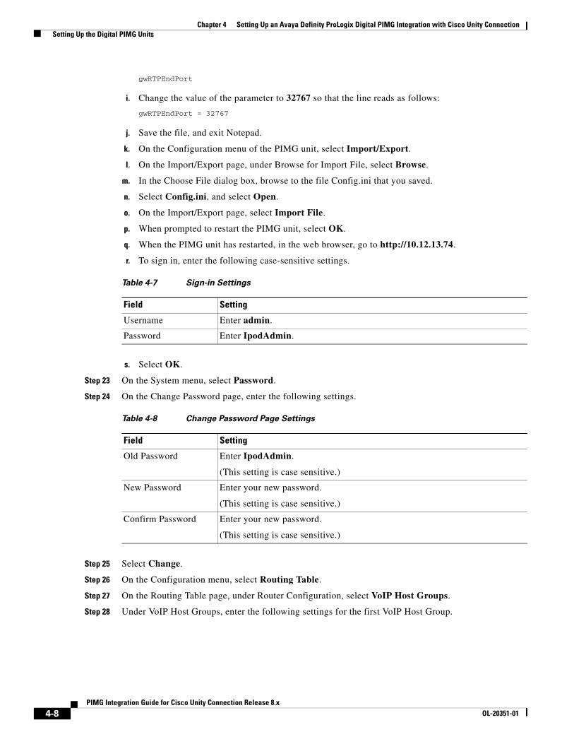
Chapter 4 Setting Up an Avaya Definity ProLogix Digital PIMG Integration with Cisco Unity Connection Setting Up the Digital PIMG Units
gwRTPEndPort
i. Change the value of the parameter to 32767 so that the line reads as follows:
gwRTPEndPort = 32767
j. Save the file, and exit Notepad.
k. On the Configuration menu of the PIMG unit, select Import/Export.
l. On the Import/Export page, under Browse for Import File, select Browse.
m. In the Choose File dialog box, browse to the file Config.ini that you saved.
n. Select Config.ini, and select Open.
o. On the Import/Export page, select Import File.
p. When prompted to restart the PIMG unit, select OK.
q. When the PIMG unit has restarted, in the web browser, go to http://10.12.13.74.
r. To sign in, enter the following case-sensitive settings.
s. Select OK.
Step 23 On the System menu, select Password.
Step 24 On the Change Password page, enter the following settings.
Step 25 Select Change.
Step 26 On the Configuration menu, select Routing Table.
Step 27 On the Routing Table page, under Router Configuration, select VoIP Host Groups.
Step 28 Under VoIP Host Groups, enter the following settings for the first VoIP Host Group.
Table 4-7 Sign-in Settings
Field Setting
Username Enter admin.
Password Enter IpodAdmin.
Table 4-8 Change Password Page Settings
Field Setting
Old Password Enter IpodAdmin.
(This setting is case sensitive.)
New Password Enter your new password.
(This setting is case sensitive.)
Confirm Password Enter your new password.
(This setting is case sensitive.)
4-8PIMG Integration Guide for Cisco Unity Connection Release 8.x
OL-20351-01
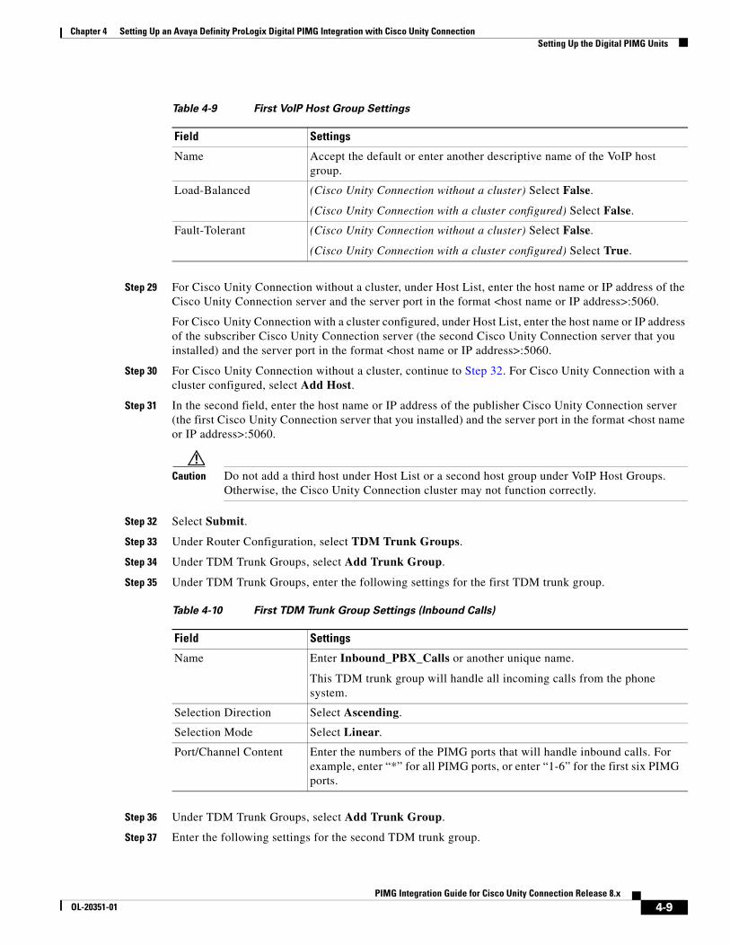
Chapter 4 Setting Up an Avaya Definity ProLogix Digital PIMG Integration with Cisco Unity Connection Setting Up the Digital PIMG Units
Step 29 For Cisco Unity Connection without a cluster, under Host List, enter the host name or IP address of the Cisco Unity Connection server and the server port in the format <host name or IP address>:5060.
For Cisco Unity Connection with a cluster configured, under Host List, enter the host name or IP address of the subscriber Cisco Unity Connection server (the second Cisco Unity Connection server that you installed) and the server port in the format <host name or IP address>:5060.
Step 30 For Cisco Unity Connection without a cluster, continue to Step 32. For Cisco Unity Connection with a cluster configured, select Add Host.
Step 31 In the second field, enter the host name or IP address of the publisher Cisco Unity Connection server (the first Cisco Unity Connection server that you installed) and the server port in the format <host name or IP address>:5060.
Caution Do not add a third host under Host List or a second host group under VoIP Host Groups. Otherwise, the Cisco Unity Connection cluster may not function correctly.
Step 32 Select Submit.
Step 33 Under Router Configuration, select TDM Trunk Groups.
Step 34 Under TDM Trunk Groups, select Add Trunk Group.
Step 35 Under TDM Trunk Groups, enter the following settings for the first TDM trunk group.
Step 36 Under TDM Trunk Groups, select Add Trunk Group.
Step 37 Enter the following settings for the second TDM trunk group.
Table 4-9 First VoIP Host Group Settings
Field Settings
Name Accept the default or enter another descriptive name of the VoIP host group.
Load-Balanced (Cisco Unity Connection without a cluster) Select False.
(Cisco Unity Connection with a cluster configured) Select False.
Fault-Tolerant (Cisco Unity Connection without a cluster) Select False.
(Cisco Unity Connection with a cluster configured) Select True.
Table 4-10 First TDM Trunk Group Settings (Inbound Calls)
Field Settings
Name Enter Inbound_PBX_Calls or another unique name.
This TDM trunk group will handle all incoming calls from the phone system.
Selection Direction Select Ascending.
Selection Mode Select Linear.
Port/Channel Content Enter the numbers of the PIMG ports that will handle inbound calls. For example, enter “*” for all PIMG ports, or enter “1-6” for the first six PIMG ports.
4-9PIMG Integration Guide for Cisco Unity Connection Release 8.x
OL-20351-01
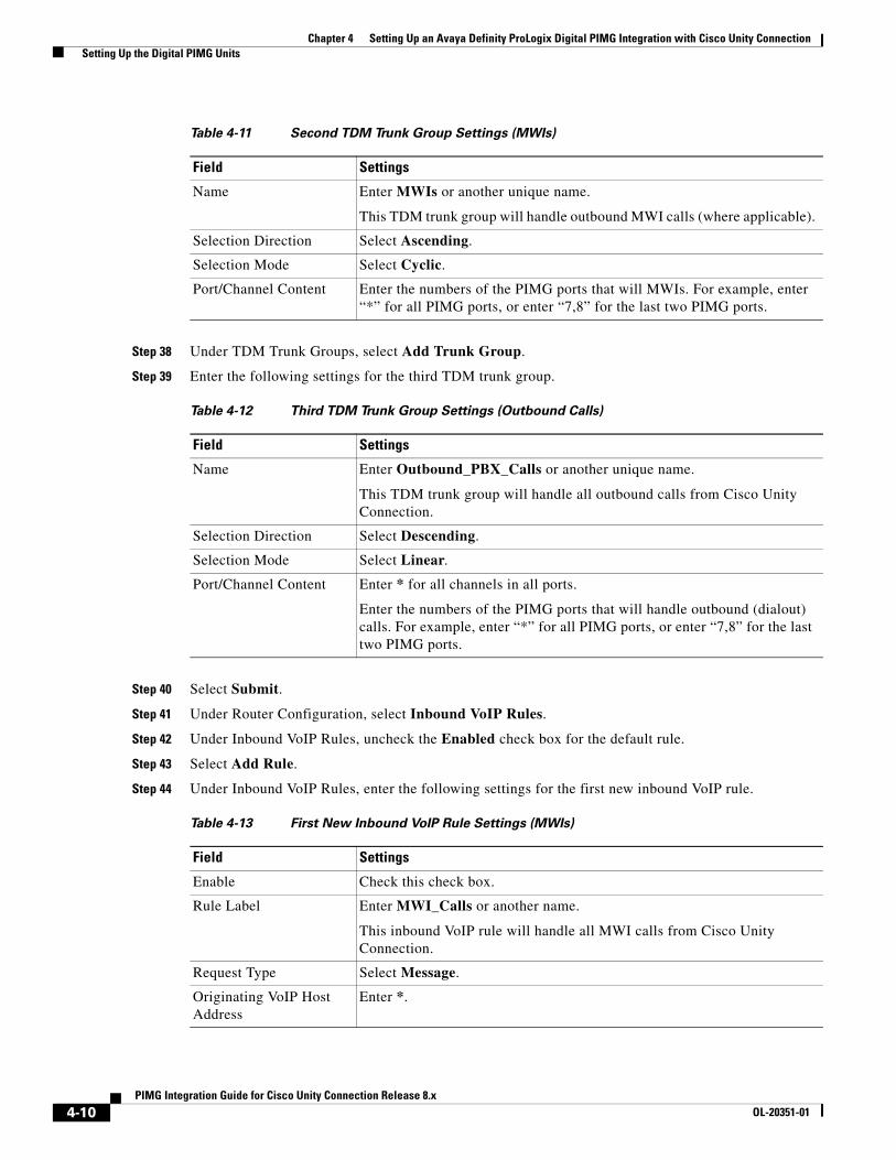
Chapter 4 Setting Up an Avaya Definity ProLogix Digital PIMG Integration with Cisco Unity Connection Setting Up the Digital PIMG Units
Step 38 Under TDM Trunk Groups, select Add Trunk Group.
Step 39 Enter the following settings for the third TDM trunk group.
Step 40 Select Submit.
Step 41 Under Router Configuration, select Inbound VoIP Rules.
Step 42 Under Inbound VoIP Rules, uncheck the Enabled check box for the default rule.
Step 43 Select Add Rule.
Step 44 Under Inbound VoIP Rules, enter the following settings for the first new inbound VoIP rule.
Table 4-11 Second TDM Trunk Group Settings (MWIs)
Field Settings
Name Enter MWIs or another unique name.
This TDM trunk group will handle outbound MWI calls (where applicable).
Selection Direction Select Ascending.
Selection Mode Select Cyclic.
Port/Channel Content Enter the numbers of the PIMG ports that will MWIs. For example, enter “*” for all PIMG ports, or enter “7,8” for the last two PIMG ports.
Table 4-12 Third TDM Trunk Group Settings (Outbound Calls)
Field Settings
Name Enter Outbound_PBX_Calls or another unique name.
This TDM trunk group will handle all outbound calls from Cisco Unity Connection.
Selection Direction Select Descending.
Selection Mode Select Linear.
Port/Channel Content Enter * for all channels in all ports.
Enter the numbers of the PIMG ports that will handle outbound (dialout) calls. For example, enter “*” for all PIMG ports, or enter “7,8” for the last two PIMG ports.
Table 4-13 First New Inbound VoIP Rule Settings (MWIs)
Field Settings
Enable Check this check box.
Rule Label Enter MWI_Calls or another name.
This inbound VoIP rule will handle all MWI calls from Cisco Unity Connection.
Request Type Select Message.
Originating VoIP Host Address
Enter *.
4-10PIMG Integration Guide for Cisco Unity Connection Release 8.x
OL-20351-01

Chapter 4 Setting Up an Avaya Definity ProLogix Digital PIMG Integration with Cisco Unity Connection Setting Up the Digital PIMG Units
Step 45 Under Inbound VoIP Request Matching, enter the following settings.
Caution The rule that you created in Step 44 must be selected. Otherwise, any changes you make will apply to another inbound VoIP rule.
Step 46 Under Outbound Routes, enter the following settings.
Caution The rule that you created in Step 44 must be selected. Otherwise, any changes you make will apply to another rule.
Step 47 Under Inbound VoIP Rules, select Add Rule.
Step 48 Under Inbound VoIP Rules, enter the following settings for the second new inbound VoIP rule.
Table 4-14 Inbound VoIP Request Matching Settings
Field Settings
Calling Number Enter *.
Calling Name Enter *.
Called Number Enter *.
Called Name Enter *.
Redirect Number Enter *.
Redirect Name Enter *.
Table 4-15 Outbound Routes Settings
Field Settings
Device Selection
Outbound Destination Select TDM.
Trunk Group Select the name of the TDM trunk group that you created for MWIs in Step 37. For example, select “MWIs.”
CPID Manipulation
Calling Number Enter S.
Calling Name Enter S.
Called Number Enter D.
Called Name Enter D.
Redirect Number Enter R.
Redirect Name Enter R.
Select Primary/Alternate Route
Primary Select Primary.
4-11PIMG Integration Guide for Cisco Unity Connection Release 8.x
OL-20351-01

Chapter 4 Setting Up an Avaya Definity ProLogix Digital PIMG Integration with Cisco Unity Connection Setting Up the Digital PIMG Units
Step 49 Under Inbound VoIP Request Matching, enter the following settings.
Caution The rule that you created in Step 48 must be selected. Otherwise, any changes you make will apply to another rule.
Step 50 Under Outbound Routes, enter the following settings.
Caution The rule that you created in Step 48 must be selected. Otherwise, any changes you make will apply to another rule.
Table 4-16 Second New Inbound VoIP Rule Settings (Outbound Calls)
Field Settings
Enable Check this check box.
Rule Label Enter Outbound_UC_Calls or another name.
This inbound VoIP rule will handle all outbound calls from Cisco Unity Connection.
Request Type Select Call.
Originating VoIP Host Address
Enter *.
Table 4-17 Inbound VoIP Request Matching Settings
Field Settings
Calling Number Enter *.
Calling Name Enter *.
Called Number Enter *.
Called Name Enter *.
Redirect Number Enter *.
Redirect Name Enter *.
Table 4-18 Outbound Routes Settings
Field Settings
Device Selection
Outbound Destination Select TDM.
Trunk Group Select the name of the TDM trunk group that you created for outbound calls in Step 39. For example, select “Outbound_PBX_Calls.”
CPID Manipulation
Calling Number Enter S.
Calling Name Enter S.
4-12PIMG Integration Guide for Cisco Unity Connection Release 8.x
OL-20351-01
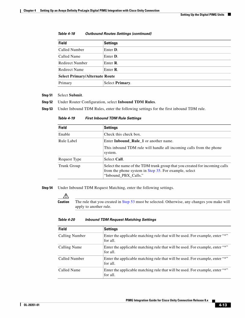
Chapter 4 Setting Up an Avaya Definity ProLogix Digital PIMG Integration with Cisco Unity Connection Setting Up the Digital PIMG Units
Step 51 Select Submit.
Step 52 Under Router Configuration, select Inbound TDM Rules.
Step 53 Under Inbound TDM Rules, enter the following settings for the first inbound TDM rule.
Step 54 Under Inbound TDM Request Matching, enter the following settings.
Caution The rule that you created in Step 53 must be selected. Otherwise, any changes you make will apply to another rule.
Called Number Enter D.
Called Name Enter D.
Redirect Number Enter R.
Redirect Name Enter R.
Select Primary/Alternate Route
Primary Select Primary.
Table 4-19 First Inbound TDM Rule Settings
Field Settings
Enable Check this check box.
Rule Label Enter Inbound_Rule_1 or another name.
This inbound TDM rule will handle all incoming calls from the phone system.
Request Type Select Call.
Trunk Group Select the name of the TDM trunk group that you created for incoming calls from the phone system in Step 35. For example, select “Inbound_PBX_Calls.”
Table 4-18 Outbound Routes Settings (continued)
Field Settings
Table 4-20 Inbound TDM Request Matching Settings
Field Settings
Calling Number Enter the applicable matching rule that will be used. For example, enter “*” for all.
Calling Name Enter the applicable matching rule that will be used. For example, enter “*” for all.
Called Number Enter the applicable matching rule that will be used. For example, enter “*” for all.
Called Name Enter the applicable matching rule that will be used. For example, enter “*” for all.
4-13PIMG Integration Guide for Cisco Unity Connection Release 8.x
OL-20351-01
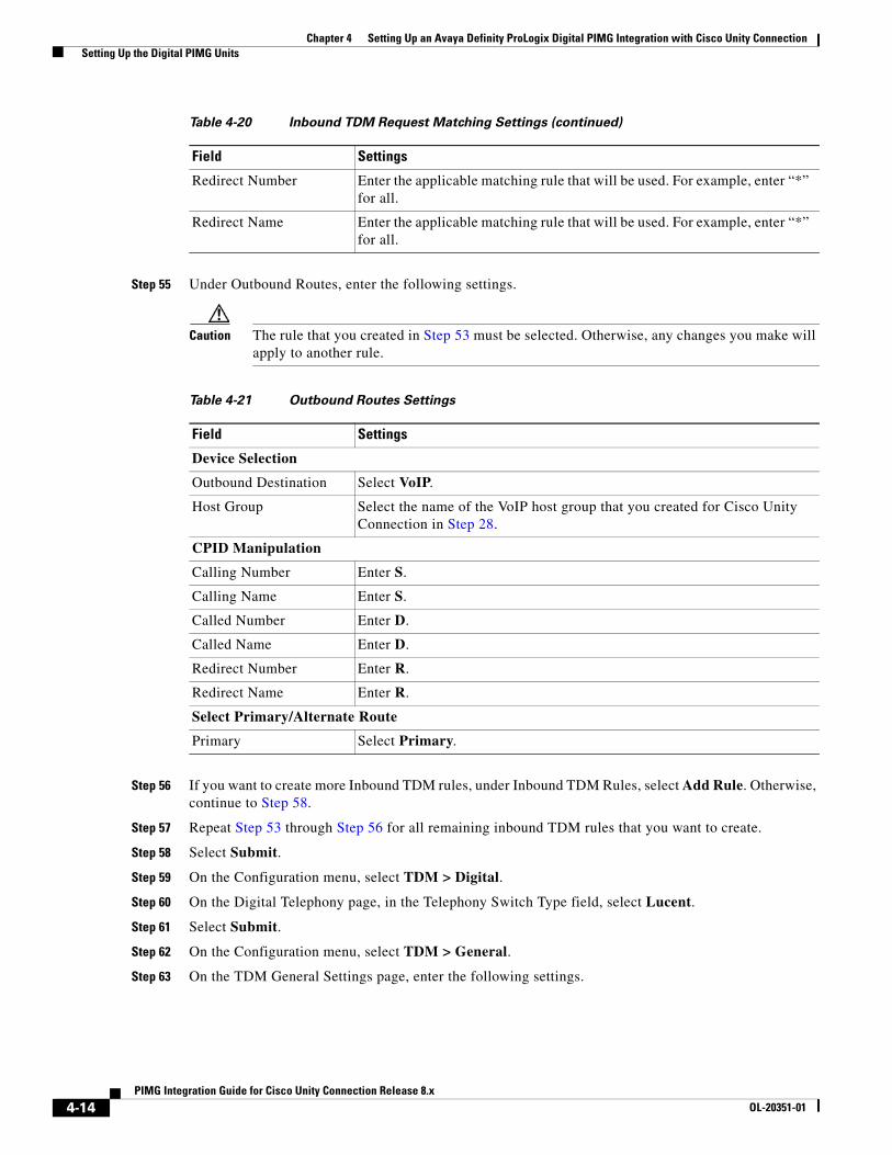
Chapter 4 Setting Up an Avaya Definity ProLogix Digital PIMG Integration with Cisco Unity Connection Setting Up the Digital PIMG Units
Step 55 Under Outbound Routes, enter the following settings.
Caution The rule that you created in Step 53 must be selected. Otherwise, any changes you make will apply to another rule.
Step 56 If you want to create more Inbound TDM rules, under Inbound TDM Rules, select Add Rule. Otherwise, continue to Step 58.
Step 57 Repeat Step 53 through Step 56 for all remaining inbound TDM rules that you want to create.
Step 58 Select Submit.
Step 59 On the Configuration menu, select TDM > Digital.
Step 60 On the Digital Telephony page, in the Telephony Switch Type field, select Lucent.
Step 61 Select Submit.
Step 62 On the Configuration menu, select TDM > General.
Step 63 On the TDM General Settings page, enter the following settings.
Redirect Number Enter the applicable matching rule that will be used. For example, enter “*” for all.
Redirect Name Enter the applicable matching rule that will be used. For example, enter “*” for all.
Table 4-20 Inbound TDM Request Matching Settings (continued)
Field Settings
Table 4-21 Outbound Routes Settings
Field Settings
Device Selection
Outbound Destination Select VoIP.
Host Group Select the name of the VoIP host group that you created for Cisco Unity Connection in Step 28.
CPID Manipulation
Calling Number Enter S.
Calling Name Enter S.
Called Number Enter D.
Called Name Enter D.
Redirect Number Enter R.
Redirect Name Enter R.
Select Primary/Alternate Route
Primary Select Primary.
4-14PIMG Integration Guide for Cisco Unity Connection Release 8.x
OL-20351-01
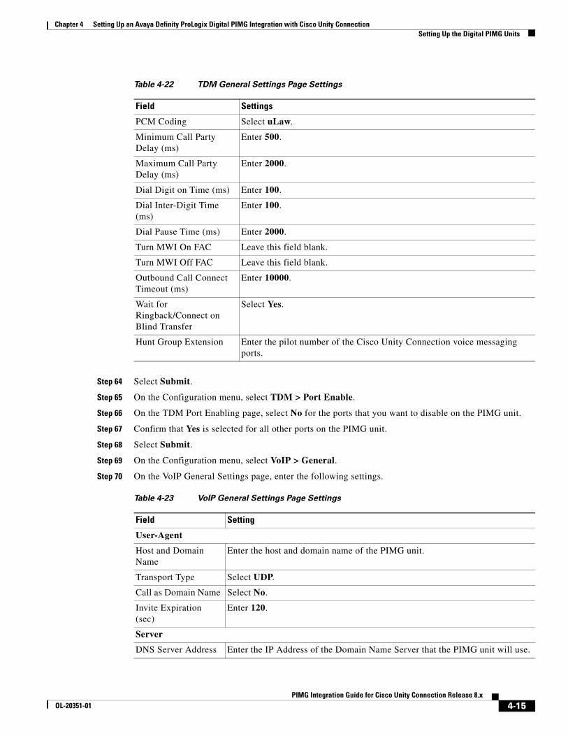
Chapter 4 Setting Up an Avaya Definity ProLogix Digital PIMG Integration with Cisco Unity Connection Setting Up the Digital PIMG Units
Step 64 Select Submit.
Step 65 On the Configuration menu, select TDM > Port Enable.
Step 66 On the TDM Port Enabling page, select No for the ports that you want to disable on the PIMG unit.
Step 67 Confirm that Yes is selected for all other ports on the PIMG unit.
Step 68 Select Submit.
Step 69 On the Configuration menu, select VoIP > General.
Step 70 On the VoIP General Settings page, enter the following settings.
Table 4-22 TDM General Settings Page Settings
Field Settings
PCM Coding Select uLaw.
Minimum Call Party Delay (ms)
Enter 500.
Maximum Call Party Delay (ms)
Enter 2000.
Dial Digit on Time (ms) Enter 100.
Dial Inter-Digit Time (ms)
Enter 100.
Dial Pause Time (ms) Enter 2000.
Turn MWI On FAC Leave this field blank.
Turn MWI Off FAC Leave this field blank.
Outbound Call Connect Timeout (ms)
Enter 10000.
Wait for Ringback/Connect on Blind Transfer
Select Yes.
Hunt Group Extension Enter the pilot number of the Cisco Unity Connection voice messaging ports.
Table 4-23 VoIP General Settings Page Settings
Field Setting
User-Agent
Host and Domain Name
Enter the host and domain name of the PIMG unit.
Transport Type Select UDP.
Call as Domain Name Select No.
Invite Expiration (sec)
Enter 120.
Server
DNS Server Address Enter the IP Address of the Domain Name Server that the PIMG unit will use.
4-15PIMG Integration Guide for Cisco Unity Connection Release 8.x
OL-20351-01

Chapter 4 Setting Up an Avaya Definity ProLogix Digital PIMG Integration with Cisco Unity Connection Setting Up the Digital PIMG Units
Step 71 Select Submit.
Step 72 On the Configuration menu, select VoIP > Media.
Step 73 On the VoIP Media Settings page, enter the following settings.
Registration Server Address
Leave this field blank.
Registration Server Port
Enter 5060.
Registration Expiration (sec)
Enter 3600.
TCP/UDP
UDP/TCP Transports Enabled
Select Yes.
TCP/UDP Server Port Enter 5060.
Proxy
Primary Proxy Server Address
Leave this field blank.
Primary Proxy Server Port
Not applicable. Leave the default setting.
Backup Proxy Server Address
Not applicable. Leave the default setting.
Backup Proxy Server Port
Not applicable. Leave the default setting.
Proxy Query Interval Enter 10.
Timing
T1 Time (ms) Enter 400.
T2 Time (ms) Enter 3000.
Monitoring
Monitor Call Connections
Select No.
Table 4-24 VoIP Media Settings Page Settings
Field Settings
Audio
Audio Compression Select the preferred codec for audio compression.
RTP Digit Relay Mode Select RFC2833.
Signaling Digit Relay Mode Select Off.
Voice Activity Detection Select Off.
Table 4-23 VoIP General Settings Page Settings (continued)
Field Setting
4-16PIMG Integration Guide for Cisco Unity Connection Release 8.x
OL-20351-01
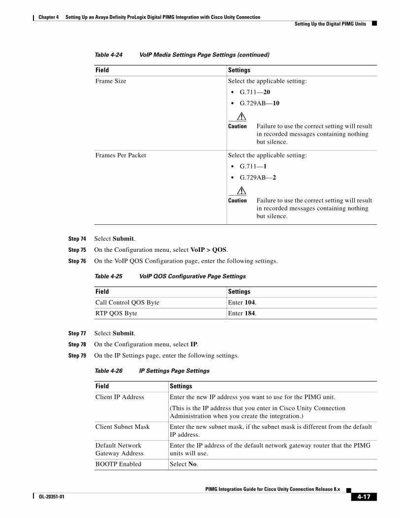
Chapter 4 Setting Up an Avaya Definity ProLogix Digital PIMG Integration with Cisco Unity Connection Setting Up the Digital PIMG Units
Step 74 Select Submit.
Step 75 On the Configuration menu, select VoIP > QOS.
Step 76 On the VoIP QOS Configuration page, enter the following settings.
Step 77 Select Submit.
Step 78 On the Configuration menu, select IP.
Step 79 On the IP Settings page, enter the following settings.
Frame Size Select the applicable setting:
• G.711—20
• G.729AB—10
Caution Failure to use the correct setting will result in recorded messages containing nothing but silence.
Frames Per Packet Select the applicable setting:
• G.711—1
• G.729AB—2
Caution Failure to use the correct setting will result in recorded messages containing nothing but silence.
Table 4-25 VoIP QOS Configurative Page Settings
Field Settings
Call Control QOS Byte Enter 104.
RTP QOS Byte Enter 184.
Table 4-26 IP Settings Page Settings
Field Settings
Client IP Address Enter the new IP address you want to use for the PIMG unit.
(This is the IP address that you enter in Cisco Unity Connection Administration when you create the integration.)
Client Subnet Mask Enter the new subnet mask, if the subnet mask is different from the default IP address.
Default Network Gateway Address
Enter the IP address of the default network gateway router that the PIMG units will use.
BOOTP Enabled Select No.
Table 4-24 VoIP Media Settings Page Settings (continued)
Field Settings
4-17PIMG Integration Guide for Cisco Unity Connection Release 8.x
OL-20351-01
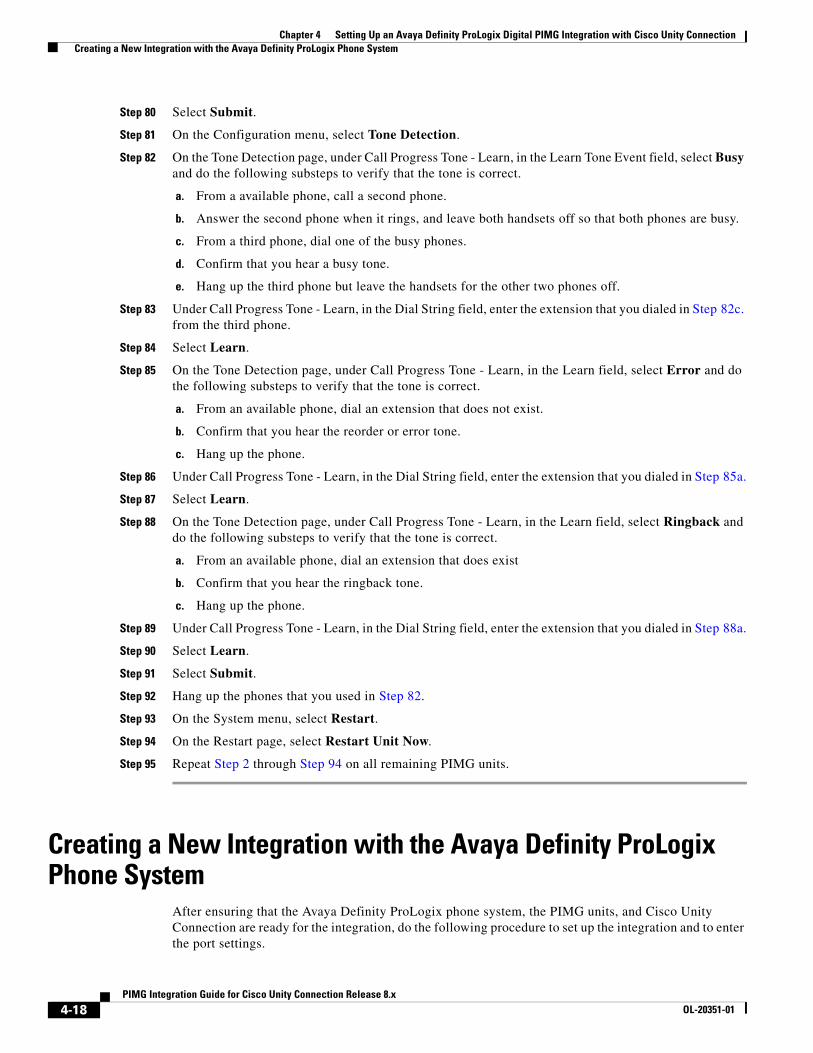
Chapter 4 Setting Up an Avaya Definity ProLogix Digital PIMG Integration with Cisco Unity Connection Creating a New Integration with the Avaya Definity ProLogix Phone System
Step 80 Select Submit.
Step 81 On the Configuration menu, select Tone Detection.
Step 82 On the Tone Detection page, under Call Progress Tone - Learn, in the Learn Tone Event field, select Busy and do the following substeps to verify that the tone is correct.
a. From a available phone, call a second phone.
b. Answer the second phone when it rings, and leave both handsets off so that both phones are busy.
c. From a third phone, dial one of the busy phones.
d. Confirm that you hear a busy tone.
e. Hang up the third phone but leave the handsets for the other two phones off.
Step 83 Under Call Progress Tone - Learn, in the Dial String field, enter the extension that you dialed in Step 82c. from the third phone.
Step 84 Select Learn.
Step 85 On the Tone Detection page, under Call Progress Tone - Learn, in the Learn field, select Error and do the following substeps to verify that the tone is correct.
a. From an available phone, dial an extension that does not exist.
b. Confirm that you hear the reorder or error tone.
c. Hang up the phone.
Step 86 Under Call Progress Tone - Learn, in the Dial String field, enter the extension that you dialed in Step 85a.
Step 87 Select Learn.
Step 88 On the Tone Detection page, under Call Progress Tone - Learn, in the Learn field, select Ringback and do the following substeps to verify that the tone is correct.
a. From an available phone, dial an extension that does exist
b. Confirm that you hear the ringback tone.
c. Hang up the phone.
Step 89 Under Call Progress Tone - Learn, in the Dial String field, enter the extension that you dialed in Step 88a.
Step 90 Select Learn.
Step 91 Select Submit.
Step 92 Hang up the phones that you used in Step 82.
Step 93 On the System menu, select Restart.
Step 94 On the Restart page, select Restart Unit Now.
Step 95 Repeat Step 2 through Step 94 on all remaining PIMG units.
Creating a New Integration with the Avaya Definity ProLogix Phone System
After ensuring that the Avaya Definity ProLogix phone system, the PIMG units, and Cisco Unity Connection are ready for the integration, do the following procedure to set up the integration and to enter the port settings.
4-18PIMG Integration Guide for Cisco Unity Connection Release 8.x
OL-20351-01

Chapter 4 Setting Up an Avaya Definity ProLogix Digital PIMG Integration with Cisco Unity Connection Creating a New Integration with the Avaya Definity ProLogix Phone System
To Create an Integration
Step 1 Sign in to Cisco Unity Connection Administration.
Step 2 In Cisco Unity Connection Administration, expand Telephony Integrations, then select Phone System.
Step 3 On the Search Phone Systems page, under Display Name, select the name of the default phone system.
Step 4 On the Phone System Basics page, in the Phone System Name field, enter the descriptive name that you want for the phone system.
Step 5 If you want to use this phone system as the default for TRaP connections so that administrators and users without voicemail boxes can record and playback through the phone in Cisco Unity Connection web applications, check the Default TRAP Switch check box. If you want to use another phone system as the default for TRaP connections, uncheck this check box.
Step 6 Select Save.
Step 7 On the Phone System Basics page, in the Related Links drop-down box, select Add Port Group and select Go.
Step 8 On the New Port Group page, enter the applicable settings and select Save.
Step 9 In the Related Links drop-down box, select Add Ports and select Go.
Step 10 On the New Port page, enter the following settings and select Save.
Table 4-27 Settings for the New Port Group Page
Field Setting
Phone System Select the name of the phone system that you entered in Step 4.
Create From Select Port Group Template and select SIP to DMG/PIMG/TIMG in the drop-down box.
Display Name Enter a descriptive name for the port group. You can accept the default name or enter the name that you want.
SIP Security Profile Select 5060.
SIP Transport Protocol Select the SIP transport protocol that Cisco Unity Connection will use.
IPv4 Address or Host Name (Cisco Unity Connection 8.5 and later)
Enter the IP address of the PIMG unit that you are integrating with Cisco Unity Connection.
IPv6 Address or Host Name (Cisco Unity Connection 8.5 and later)
Do not enter a value in this field. IPv6 is not supported for PIMG integrations.
IP Address or Host Name (Cisco Unity Connection 8.0)
Enter the IP address of the PIMG unit that you are integrating with Cisco Unity Connection.
Port Enter the SIP port of the PIMG unit that Cisco Unity Connection will connect to. We recommend that you use the default setting.
Caution This name must match the setting in the TCP/UDP Server Port field on the Configuration > VoIP > General page of the PIMG unit. Otherwise, the integration will not function correctly.
4-19PIMG Integration Guide for Cisco Unity Connection Release 8.x
OL-20351-01
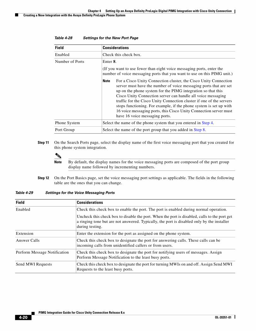
Chapter 4 Setting Up an Avaya Definity ProLogix Digital PIMG Integration with Cisco Unity Connection Creating a New Integration with the Avaya Definity ProLogix Phone System
Step 11 On the Search Ports page, select the display name of the first voice messaging port that you created for this phone system integration.
Note By default, the display names for the voice messaging ports are composed of the port group display name followed by incrementing numbers.
Step 12 On the Port Basics page, set the voice messaging port settings as applicable. The fields in the following table are the ones that you can change.
Table 4-28 Settings for the New Port Page
Field Considerations
Enabled Check this check box.
Number of Ports Enter 8.
(If you want to use fewer than eight voice messaging ports, enter the number of voice messaging ports that you want to use on this PIMG unit.)
Note For a Cisco Unity Connection cluster, the Cisco Unity Connection server must have the number of voice messaging ports that are set up on the phone system for the PIMG integration so that this Cisco Unity Connection server can handle all voice messaging traffic for the Cisco Unity Connection cluster if one of the servers stops functioning. For example, if the phone system is set up with 16 voice messaging ports, this Cisco Unity Connection server must have 16 voice messaging ports.
Phone System Select the name of the phone system that you entered in Step 4.
Port Group Select the name of the port group that you added in Step 8.
Table 4-29 Settings for the Voice Messaging Ports
Field Considerations
Enabled Check this check box to enable the port. The port is enabled during normal operation.
Uncheck this check box to disable the port. When the port is disabled, calls to the port get a ringing tone but are not answered. Typically, the port is disabled only by the installer during testing.
Extension Enter the extension for the port as assigned on the phone system.
Answer Calls Check this check box to designate the port for answering calls. These calls can be incoming calls from unidentified callers or from users.
Perform Message Notification Check this check box to designate the port for notifying users of messages. Assign Perform Message Notification to the least busy ports.
Send MWI Requests Check this check box to designate the port for turning MWIs on and off. Assign Send MWI Requests to the least busy ports.
4-20PIMG Integration Guide for Cisco Unity Connection Release 8.x
OL-20351-01
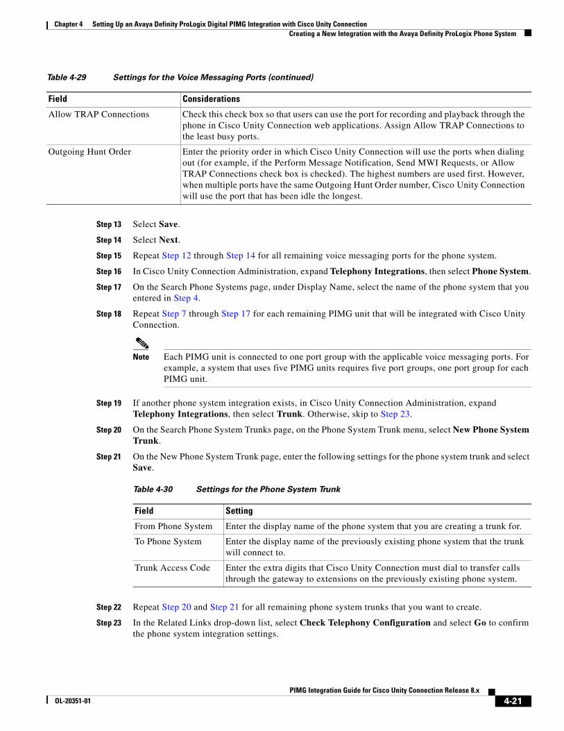
Chapter 4 Setting Up an Avaya Definity ProLogix Digital PIMG Integration with Cisco Unity Connection Creating a New Integration with the Avaya Definity ProLogix Phone System
Step 13 Select Save.
Step 14 Select Next.
Step 15 Repeat Step 12 through Step 14 for all remaining voice messaging ports for the phone system.
Step 16 In Cisco Unity Connection Administration, expand Telephony Integrations, then select Phone System.
Step 17 On the Search Phone Systems page, under Display Name, select the name of the phone system that you entered in Step 4.
Step 18 Repeat Step 7 through Step 17 for each remaining PIMG unit that will be integrated with Cisco Unity Connection.
Note Each PIMG unit is connected to one port group with the applicable voice messaging ports. For example, a system that uses five PIMG units requires five port groups, one port group for each PIMG unit.
Step 19 If another phone system integration exists, in Cisco Unity Connection Administration, expand Telephony Integrations, then select Trunk. Otherwise, skip to Step 23.
Step 20 On the Search Phone System Trunks page, on the Phone System Trunk menu, select New Phone System Trunk.
Step 21 On the New Phone System Trunk page, enter the following settings for the phone system trunk and select Save.
Step 22 Repeat Step 20 and Step 21 for all remaining phone system trunks that you want to create.
Step 23 In the Related Links drop-down list, select Check Telephony Configuration and select Go to confirm the phone system integration settings.
Allow TRAP Connections Check this check box so that users can use the port for recording and playback through the phone in Cisco Unity Connection web applications. Assign Allow TRAP Connections to the least busy ports.
Outgoing Hunt Order Enter the priority order in which Cisco Unity Connection will use the ports when dialing out (for example, if the Perform Message Notification, Send MWI Requests, or Allow TRAP Connections check box is checked). The highest numbers are used first. However, when multiple ports have the same Outgoing Hunt Order number, Cisco Unity Connection will use the port that has been idle the longest.
Table 4-29 Settings for the Voice Messaging Ports (continued)
Field Considerations
Table 4-30 Settings for the Phone System Trunk
Field Setting
From Phone System Enter the display name of the phone system that you are creating a trunk for.
To Phone System Enter the display name of the previously existing phone system that the trunk will connect to.
Trunk Access Code Enter the extra digits that Cisco Unity Connection must dial to transfer calls through the gateway to extensions on the previously existing phone system.
4-21PIMG Integration Guide for Cisco Unity Connection Release 8.x
OL-20351-01

Chapter 4 Setting Up an Avaya Definity ProLogix Digital PIMG Integration with Cisco Unity Connection Creating a New Integration with the Avaya Definity ProLogix Phone System
If the test is not successful, the Task Execution Results displays one or more messages with troubleshooting steps. After correcting the problems, test the connection again.
Step 24 In the Task Execution Results window, select Close.
4-22PIMG Integration Guide for Cisco Unity Connection Release 8.x
OL-20351-01
PIMG IntegrOL-20351-01
C H A P T E R 5
Setting Up an Avaya S8300/S8500/S8700 Digital PIMG Integration with Cisco Unity ConnectionFor detailed instructions for setting up an Avaya S8300/S8500/S8700 digital PIMG integration with Cisco Unity Connection, see the following sections in this chapter:
• Task List to Create an Avaya S8300/S8500/S8700 PIMG Integration, page 5-1
• Requirements, page 5-2
• Programming the Avaya S8300/S8500/S8700 PIMG Phone System for Integrating with Cisco Unity Connection, page 5-3
• Setting Up the Digital PIMG Units, page 5-5
• Creating a New Integration with the Avaya S8300/S8500/S8700 Phone System, page 5-18
Task List to Create an Avaya S8300/S8500/S8700 PIMG Integration
Before doing the following tasks to integrate Cisco Unity Connection with the Avaya S8300/S8500/S8700 phone system by using PIMG units (media gateways), confirm that the Cisco Unity Connection server is ready for the integration by completing the applicable tasks in the Cisco Unity Connection Installation Guide.
1. Review the system and equipment requirements to confirm that all phone system and Cisco Unity Connection server requirements have been met. See the “Requirements” section on page 5-2.
2. Plan how the voice messaging ports will be used by Cisco Unity Connection. See Chapter 2, “Planning How the Voice Messaging Ports Will Be Used by Cisco Unity Connection.”
3. Program the Avaya S8300/S8500/S8700 phone system and extensions. See the “Programming the Avaya S8300/S8500/S8700 PIMG Phone System for Integrating with Cisco Unity Connection” section on page 5-3.
4. Set up the PIMG units. See the “Setting Up the Digital PIMG Units” section on page 5-5.
5. Create the integration. See the “Creating a New Integration with the Avaya S8300/S8500/S8700 Phone System” section on page 5-18.
6. Test the integration. See Chapter 14, “Testing the Integration.”
7. If this integration is a second or subsequent integration, add the applicable new user templates for the new phone system. See Chapter 15, “Adding New User Templates for Multiple Integrations.”
5-1ation Guide for Cisco Unity Connection Release 8.x
Chapter 5 Setting Up an Avaya S8300/S8500/S8700 Digital PIMG Integration with Cisco Unity Connection Requirements
RequirementsThe Avaya S8300/S8500/S8700 integration supports configurations of the following components:
Phone System
• An Avaya S8300, Avaya S8500, or Avaya S8700 phone system. The voice messaging ports that connect to the PIMG units must be compatible with the 7434ND, 8434, 8434D, or 8434DX digital phones.
Caution You must use 2-wire line cards for these voice messaging ports. Otherwise, the voice messaging ports will not be compatible with the 7434ND, 8434, 8434D, or 8434DX digital phones.
• Software version Communication Manager 2.0.
• One or more of the applicable PIMG units. For details, see Chapter 1, “Introduction.”
• The voice messaging ports in the phone system connected by digital lines to the ports on the PIMG units.
To simplify troubleshooting, we recommend that you connect the voice messaging ports on the phone system to the ports on the PIMG units in a planned manner. For example, connect the first phone system voice messaging port to the first port on the first PIMG unit, connect the second phone system voice messaging port to the second port on the first PIMG unit, and so on. Alternatively, if you have multiple PIMG units, you can reduce answer times in the event of a PIMG unit failure by connecting the phone system ports to the PIMG units in a round-robin fashion. For example, connect the first phone system voice messaging port to the first port on the first PIMG unit, connect the second phone system voice messaging port to the first port on the second PIMG unit, and so on.
• The PIMG units connected to the same LAN or WAN that Cisco Unity Connection is connected to.
• If the PIMG units connect to a WAN, the requirements for the WAN network connections are:
– For G.729a codec formatting, a minimum of 32.76 Kbps guaranteed bandwidth for each voice messaging port.
– For G.711 codec formatting, a minimum of 91.56 Kbps guaranteed bandwidth for each voice messaging port.
– No network devices that implement network address translation (NAT).
– A maximum 200 ms one-way network latency.
• The phone system ready for the integration, as described in the documentation for the phone system.
Cisco Unity Connection Server
• Cisco Unity Connection installed and ready for the integration, as described in the Cisco Unity Connection Installation Guide at http://www.cisco.com/en/US/products/ps6509/prod_installation_guides_list.html.
• A license that enables the applicable number of voice messaging ports.
Centralized Voice Messaging
Cisco Unity Connection supports centralized voice messaging through the phone system, which supports various inter-phone system networking protocols including proprietary protocols such as Avaya DCS, Nortel MCDN, or Siemens CorNet, and standards-based protocols such as QSIG or DPNSS. Note that centralized voice messaging is a function of the phone system and its inter-phone system networking,
5-2PIMG Integration Guide for Cisco Unity Connection Release 8.x
OL-20351-01
Chapter 5 Setting Up an Avaya S8300/S8500/S8700 Digital PIMG Integration with Cisco Unity Connection Programming the Avaya S8300/S8500/S8700 PIMG Phone System for Integrating with Cisco Unity Connection
not voicemail. Connection will support centralized voice messaging as long as the phone system and its inter-phone system networking are properly configured. For details, see the “Centralized Voice Messaging” section in the “Integrating Cisco Unity Connection with the Phone System” chapter of the Cisco Unity Design Guide Release 8.x at http://www.cisco.com/en/US/docs/voice_ip_comm/connection/8x/design/guide/8xcucdgx.html.
Programming the Avaya S8300/S8500/S8700 PIMG Phone System for Integrating with Cisco Unity Connection
The following programming instructions are provided as an example only. The specific programming for your phone system may vary depending on its configuration.
Caution In programming the phone system, do not send calls to voice messaging ports in Cisco Unity Connection that cannot answer calls (voice messaging ports that are not set to Answer Calls). For example, if a voice messaging port is set only to Send MWI Requests, do not send calls to it.
To Program the Avaya S8300/S8500/S8700Phone System
Step 1 Create a coverage path which contains the PIMG unit hunt group number as the coverage point.
Step 2 Assign the coverage path that you created in Step 1 to the user stations that must forward to the voice messaging ports on the PIMG units when calls are not answered or when the user station is busy, based on one of the Cisco Unity Connection call transfer types shown in Table 5-1.
Step 3 Use the Add Station <extension number> command (for example, Add Station 2999) to assign an extension number for each voice messaging port, which is a digital line that connects to the PIMG unit. Set the voice messaging port options (Table 5-2) and button assignments (Table 5-3), and press Enter.
Note We recommend that you distribute the voice messaging ports among multiple phone system line cards so that call processing can continue even if a line card becomes inactive.
Table 5-1 Call Transfer Types
Transfer Type Usage
Release transfer
(blind transfer)
Program the user station to forward calls to the pilot number when:
• The extension is busy.
• The call is not answered.
Supervised transfer Program the user station to forward calls to the pilot number only when the call is not answered (on the phone system, the number of rings before forwarding must be more than the number of rings to supervise the call). Confirm that call forwarding is disabled when the extension is busy.
5-3PIMG Integration Guide for Cisco Unity Connection Release 8.x
OL-20351-01
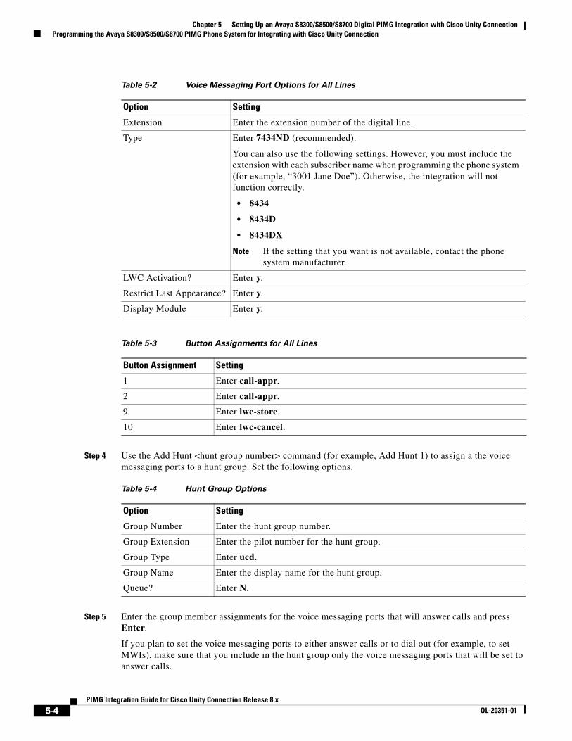
Chapter 5 Setting Up an Avaya S8300/S8500/S8700 Digital PIMG Integration with Cisco Unity Connection Programming the Avaya S8300/S8500/S8700 PIMG Phone System for Integrating with Cisco Unity Connection
Step 4 Use the Add Hunt <hunt group number> command (for example, Add Hunt 1) to assign a the voice messaging ports to a hunt group. Set the following options.
Step 5 Enter the group member assignments for the voice messaging ports that will answer calls and press Enter.
If you plan to set the voice messaging ports to either answer calls or to dial out (for example, to set MWIs), make sure that you include in the hunt group only the voice messaging ports that will be set to answer calls.
Table 5-2 Voice Messaging Port Options for All Lines
Option Setting
Extension Enter the extension number of the digital line.
Type Enter 7434ND (recommended).
You can also use the following settings. However, you must include the extension with each subscriber name when programming the phone system (for example, “3001 Jane Doe”). Otherwise, the integration will not function correctly.
• 8434
• 8434D
• 8434DX
Note If the setting that you want is not available, contact the phone system manufacturer.
LWC Activation? Enter y.
Restrict Last Appearance? Enter y.
Display Module Enter y.
Table 5-3 Button Assignments for All Lines
Button Assignment Setting
1 Enter call-appr.
2 Enter call-appr.
9 Enter lwc-store.
10 Enter lwc-cancel.
Table 5-4 Hunt Group Options
Option Setting
Group Number Enter the hunt group number.
Group Extension Enter the pilot number for the hunt group.
Group Type Enter ucd.
Group Name Enter the display name for the hunt group.
Queue? Enter N.
5-4PIMG Integration Guide for Cisco Unity Connection Release 8.x
OL-20351-01
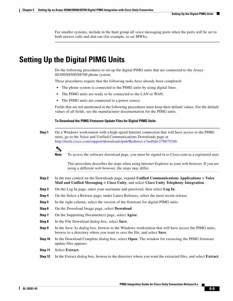
Chapter 5 Setting Up an Avaya S8300/S8500/S8700 Digital PIMG Integration with Cisco Unity Connection Setting Up the Digital PIMG Units
For smaller systems, include in the hunt group all voice messaging ports when the ports will be set to both answer calls and dial out (for example, to set MWIs).
Setting Up the Digital PIMG UnitsDo the following procedures to set up the digital PIMG units that are connected to the Avaya S8300/S8500/S8700 phone system.
These procedures require that the following tasks have already been completed:
• The phone system is connected to the PIMG units by using digital lines.
• The PIMG units are ready to be connected to the LAN or WAN.
• The PIMG units are connected to a power source.
Fields that are not mentioned in the following procedures must keep their default values. For the default values of all fields, see the manufacturer documentation for the PIMG units.
To Download the PIMG Firmware Update Files for Digital PIMG Units
Step 1 On a Windows workstation with a high-speed Internet connection that will have access to the PIMG units, go to the Voice and Unified Communications Downloads page at http://tools.cisco.com/support/downloads/pub/Redirect.x?mdfid=278875240.
Note To access the software download page, you must be signed in to Cisco.com as a registered user. This procedure describes the steps when using Internet Explorer as your web browser. If you are using a different web browser, the steps may differ.
Step 2 In the tree control on the Downloads page, expand Unified Communications Applications > Voice Mail and Unified Messaging > Cisco Unity, and select Cisco Unity Telephony Integration.
Step 3 On the Log In page, enter your username and password, then select Log In.
Step 4 On the Select a Release page, under Latest Releases, select the most recent release.
Step 5 In the right column, select the version of the firmware for digital PIMG units.
Step 6 On the Download Image page, select Download.
Step 7 On the Supporting Document(s) page, select Agree.
Step 8 In the File Download dialog box, select Save.
Step 9 In the Save As dialog box, browse to the Windows workstation that will have access the PIMG units, browse to a directory where you want to save the file, and select Save.
Step 10 In the Download Complete dialog box, select Open. The window for extracting the PIMG firmware update files appears.
Step 11 Select Extract.
Step 12 In the Extract dialog box, browse to the directory where you want the extracted files, and select Extract.
5-5PIMG Integration Guide for Cisco Unity Connection Release 8.x
OL-20351-01
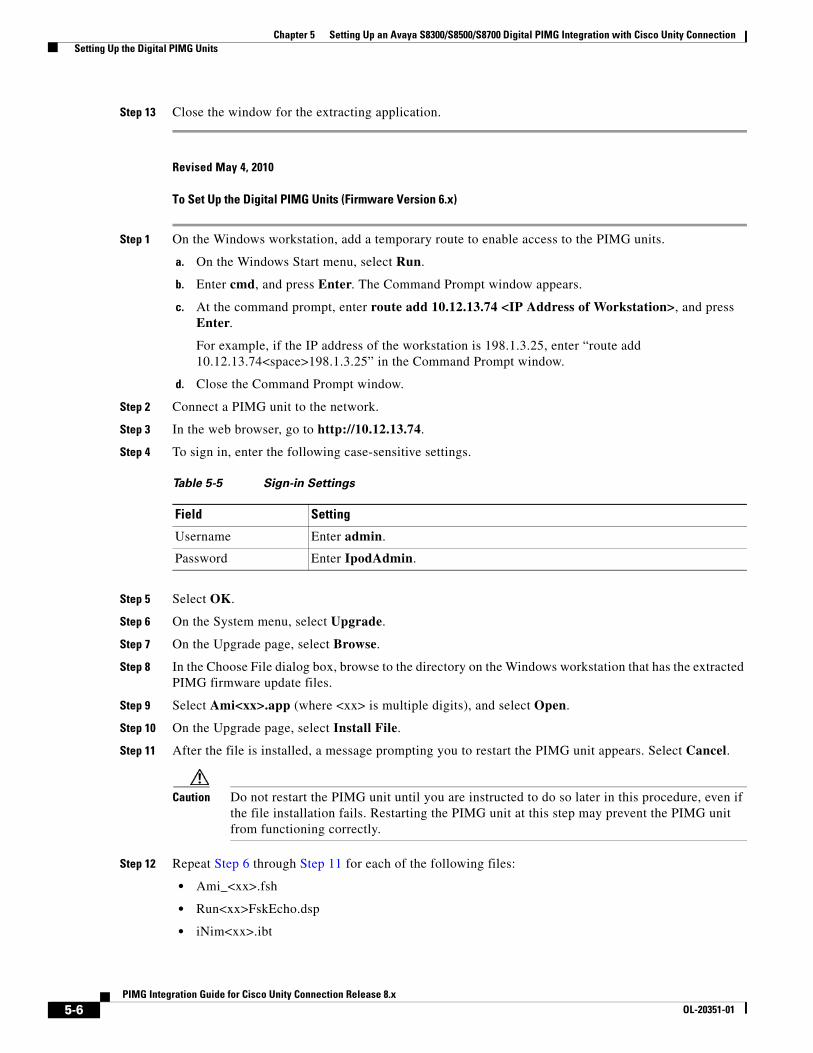
Chapter 5 Setting Up an Avaya S8300/S8500/S8700 Digital PIMG Integration with Cisco Unity Connection Setting Up the Digital PIMG Units
Step 13 Close the window for the extracting application.
Revised May 4, 2010
To Set Up the Digital PIMG Units (Firmware Version 6.x)
Step 1 On the Windows workstation, add a temporary route to enable access to the PIMG units.
a. On the Windows Start menu, select Run.
b. Enter cmd, and press Enter. The Command Prompt window appears.
c. At the command prompt, enter route add 10.12.13.74 <IP Address of Workstation>, and press Enter.
For example, if the IP address of the workstation is 198.1.3.25, enter “route add 10.12.13.74<space>198.1.3.25” in the Command Prompt window.
d. Close the Command Prompt window.
Step 2 Connect a PIMG unit to the network.
Step 3 In the web browser, go to http://10.12.13.74.
Step 4 To sign in, enter the following case-sensitive settings.
Step 5 Select OK.
Step 6 On the System menu, select Upgrade.
Step 7 On the Upgrade page, select Browse.
Step 8 In the Choose File dialog box, browse to the directory on the Windows workstation that has the extracted PIMG firmware update files.
Step 9 Select Ami<xx>.app (where <xx> is multiple digits), and select Open.
Step 10 On the Upgrade page, select Install File.
Step 11 After the file is installed, a message prompting you to restart the PIMG unit appears. Select Cancel.
Caution Do not restart the PIMG unit until you are instructed to do so later in this procedure, even if the file installation fails. Restarting the PIMG unit at this step may prevent the PIMG unit from functioning correctly.
Step 12 Repeat Step 6 through Step 11 for each of the following files:
• Ami_<xx>.fsh
• Run<xx>FskEcho.dsp
• iNim<xx>.ibt
Table 5-5 Sign-in Settings
Field Setting
Username Enter admin.
Password Enter IpodAdmin.
5-6PIMG Integration Guide for Cisco Unity Connection Release 8.x
OL-20351-01
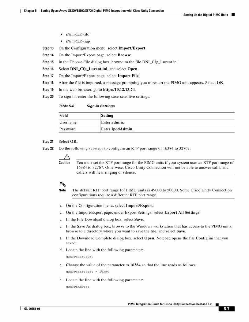
Chapter 5 Setting Up an Avaya S8300/S8500/S8700 Digital PIMG Integration with Cisco Unity Connection Setting Up the Digital PIMG Units
• iNim<xx>.ilc
• iNim<xx>.iap
Step 13 On the Configuration menu, select Import/Export.
Step 14 On the Import/Export page, select Browse.
Step 15 In the Choose File dialog box, browse to the file DNI_Cfg_Lucent.ini.
Step 16 Select DNI_Cfg_Lucent.ini, and select Open.
Step 17 On the Import/Export page, select Import File.
Step 18 After the file is imported, a message prompting you to restart the PIMG unit appears. Select OK.
Step 19 In the web browser, go to http://10.12.13.74.
Step 20 To sign in, enter the following case-sensitive settings.
Step 21 Select OK.
Step 22 Do the following substeps to configure an RTP port range of 16384 to 32767.
Caution You must set the RTP port range for the PIMG units if your system uses an RTP port range of 16384 to 32767. Otherwise, Cisco Unity Connection will not be able to answer calls, and callers will hear ringing or silence.
Note The default RTP port range for PIMG units is 49000 to 50000. Some Cisco Unity Connection configurations require a different RTP port range.
a. On the Configuration menu, select Import/Export.
b. On the Import/Export page, under Export Settings, select Export All Settings.
c. In the File Download dialog box, select Save.
d. In the Save As dialog box, browse to the Windows workstation that has access to the PIMG units, browse to a directory where you want to save the file, and select Save.
e. In the Download Complete dialog box, select Open. Notepad opens the file Config.ini that you saved.
f. Locate the line with the following parameter:
gwRTPStartPort
g. Change the value of the parameter to 16384 so that the line reads as follows:
gwRTPStartPort = 16384
h. Locate the line with the following parameter:
gwRTPEndPort
Table 5-6 Sign-in Settings
Field Setting
Username Enter admin.
Password Enter IpodAdmin.
5-7PIMG Integration Guide for Cisco Unity Connection Release 8.x
OL-20351-01
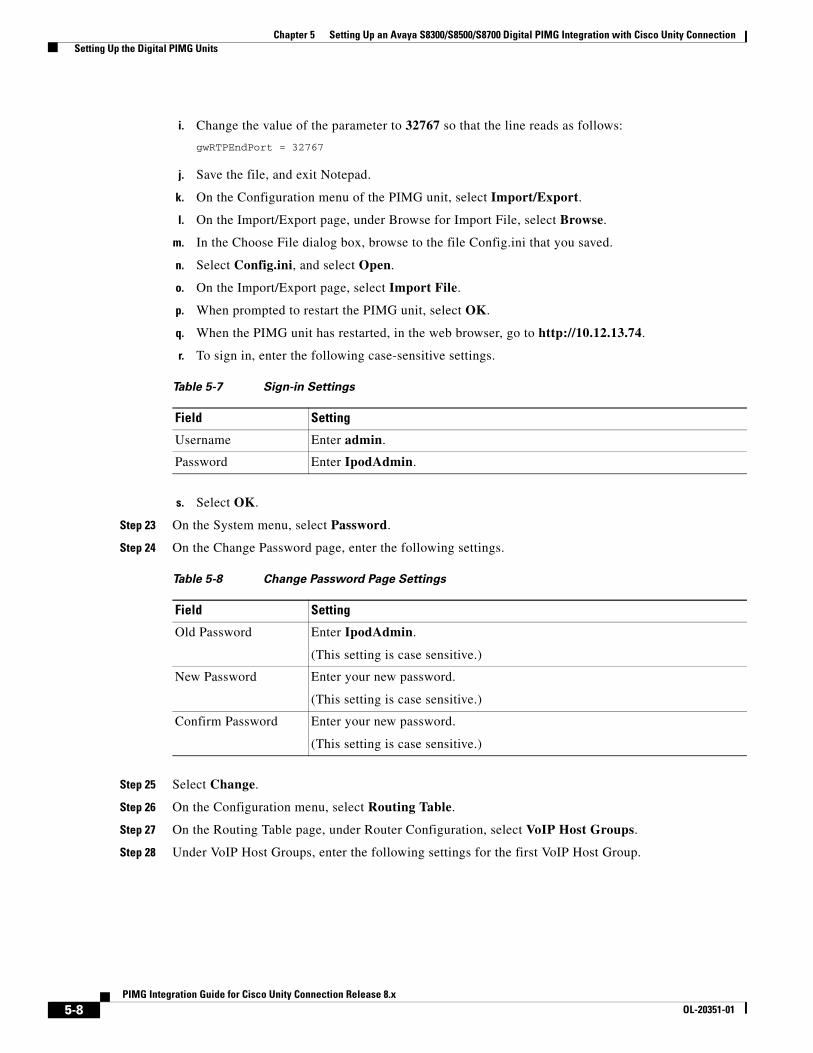
Chapter 5 Setting Up an Avaya S8300/S8500/S8700 Digital PIMG Integration with Cisco Unity Connection Setting Up the Digital PIMG Units
i. Change the value of the parameter to 32767 so that the line reads as follows:
gwRTPEndPort = 32767
j. Save the file, and exit Notepad.
k. On the Configuration menu of the PIMG unit, select Import/Export.
l. On the Import/Export page, under Browse for Import File, select Browse.
m. In the Choose File dialog box, browse to the file Config.ini that you saved.
n. Select Config.ini, and select Open.
o. On the Import/Export page, select Import File.
p. When prompted to restart the PIMG unit, select OK.
q. When the PIMG unit has restarted, in the web browser, go to http://10.12.13.74.
r. To sign in, enter the following case-sensitive settings.
s. Select OK.
Step 23 On the System menu, select Password.
Step 24 On the Change Password page, enter the following settings.
Step 25 Select Change.
Step 26 On the Configuration menu, select Routing Table.
Step 27 On the Routing Table page, under Router Configuration, select VoIP Host Groups.
Step 28 Under VoIP Host Groups, enter the following settings for the first VoIP Host Group.
Table 5-7 Sign-in Settings
Field Setting
Username Enter admin.
Password Enter IpodAdmin.
Table 5-8 Change Password Page Settings
Field Setting
Old Password Enter IpodAdmin.
(This setting is case sensitive.)
New Password Enter your new password.
(This setting is case sensitive.)
Confirm Password Enter your new password.
(This setting is case sensitive.)
5-8PIMG Integration Guide for Cisco Unity Connection Release 8.x
OL-20351-01
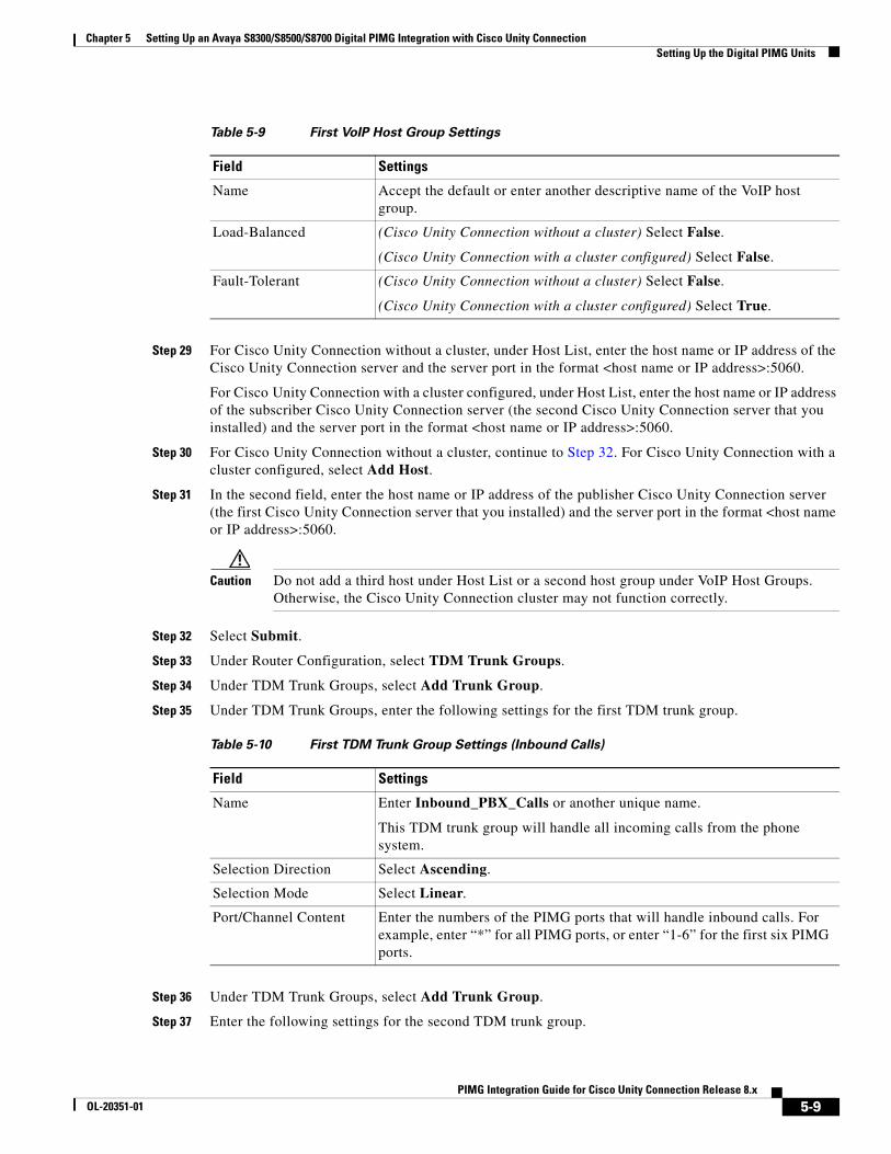
Chapter 5 Setting Up an Avaya S8300/S8500/S8700 Digital PIMG Integration with Cisco Unity Connection Setting Up the Digital PIMG Units
Step 29 For Cisco Unity Connection without a cluster, under Host List, enter the host name or IP address of the Cisco Unity Connection server and the server port in the format <host name or IP address>:5060.
For Cisco Unity Connection with a cluster configured, under Host List, enter the host name or IP address of the subscriber Cisco Unity Connection server (the second Cisco Unity Connection server that you installed) and the server port in the format <host name or IP address>:5060.
Step 30 For Cisco Unity Connection without a cluster, continue to Step 32. For Cisco Unity Connection with a cluster configured, select Add Host.
Step 31 In the second field, enter the host name or IP address of the publisher Cisco Unity Connection server (the first Cisco Unity Connection server that you installed) and the server port in the format <host name or IP address>:5060.
Caution Do not add a third host under Host List or a second host group under VoIP Host Groups. Otherwise, the Cisco Unity Connection cluster may not function correctly.
Step 32 Select Submit.
Step 33 Under Router Configuration, select TDM Trunk Groups.
Step 34 Under TDM Trunk Groups, select Add Trunk Group.
Step 35 Under TDM Trunk Groups, enter the following settings for the first TDM trunk group.
Step 36 Under TDM Trunk Groups, select Add Trunk Group.
Step 37 Enter the following settings for the second TDM trunk group.
Table 5-9 First VoIP Host Group Settings
Field Settings
Name Accept the default or enter another descriptive name of the VoIP host group.
Load-Balanced (Cisco Unity Connection without a cluster) Select False.
(Cisco Unity Connection with a cluster configured) Select False.
Fault-Tolerant (Cisco Unity Connection without a cluster) Select False.
(Cisco Unity Connection with a cluster configured) Select True.
Table 5-10 First TDM Trunk Group Settings (Inbound Calls)
Field Settings
Name Enter Inbound_PBX_Calls or another unique name.
This TDM trunk group will handle all incoming calls from the phone system.
Selection Direction Select Ascending.
Selection Mode Select Linear.
Port/Channel Content Enter the numbers of the PIMG ports that will handle inbound calls. For example, enter “*” for all PIMG ports, or enter “1-6” for the first six PIMG ports.
5-9PIMG Integration Guide for Cisco Unity Connection Release 8.x
OL-20351-01
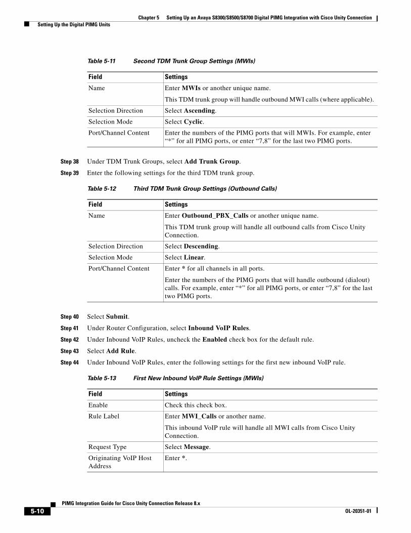
Chapter 5 Setting Up an Avaya S8300/S8500/S8700 Digital PIMG Integration with Cisco Unity Connection Setting Up the Digital PIMG Units
Step 38 Under TDM Trunk Groups, select Add Trunk Group.
Step 39 Enter the following settings for the third TDM trunk group.
Step 40 Select Submit.
Step 41 Under Router Configuration, select Inbound VoIP Rules.
Step 42 Under Inbound VoIP Rules, uncheck the Enabled check box for the default rule.
Step 43 Select Add Rule.
Step 44 Under Inbound VoIP Rules, enter the following settings for the first new inbound VoIP rule.
Table 5-11 Second TDM Trunk Group Settings (MWIs)
Field Settings
Name Enter MWIs or another unique name.
This TDM trunk group will handle outbound MWI calls (where applicable).
Selection Direction Select Ascending.
Selection Mode Select Cyclic.
Port/Channel Content Enter the numbers of the PIMG ports that will MWIs. For example, enter “*” for all PIMG ports, or enter “7,8” for the last two PIMG ports.
Table 5-12 Third TDM Trunk Group Settings (Outbound Calls)
Field Settings
Name Enter Outbound_PBX_Calls or another unique name.
This TDM trunk group will handle all outbound calls from Cisco Unity Connection.
Selection Direction Select Descending.
Selection Mode Select Linear.
Port/Channel Content Enter * for all channels in all ports.
Enter the numbers of the PIMG ports that will handle outbound (dialout) calls. For example, enter “*” for all PIMG ports, or enter “7,8” for the last two PIMG ports.
Table 5-13 First New Inbound VoIP Rule Settings (MWIs)
Field Settings
Enable Check this check box.
Rule Label Enter MWI_Calls or another name.
This inbound VoIP rule will handle all MWI calls from Cisco Unity Connection.
Request Type Select Message.
Originating VoIP Host Address
Enter *.
5-10PIMG Integration Guide for Cisco Unity Connection Release 8.x
OL-20351-01

Chapter 5 Setting Up an Avaya S8300/S8500/S8700 Digital PIMG Integration with Cisco Unity Connection Setting Up the Digital PIMG Units
Step 45 Under Inbound VoIP Request Matching, enter the following settings.
Caution The rule that you created in Step 44 must be selected. Otherwise, any changes you make will apply to another inbound VoIP rule.
Step 46 Under Outbound Routes, enter the following settings.
Caution The rule that you created in Step 44 must be selected. Otherwise, any changes you make will apply to another rule.
Step 47 Under Inbound VoIP Rules, select Add Rule.
Step 48 Under Inbound VoIP Rules, enter the following settings for the second new inbound VoIP rule.
Table 5-14 Inbound VoIP Request Matching Settings
Field Settings
Calling Number Enter *.
Calling Name Enter *.
Called Number Enter *.
Called Name Enter *.
Redirect Number Enter *.
Redirect Name Enter *.
Table 5-15 Outbound Routes Settings
Field Settings
Device Selection
Outbound Destination Select TDM.
Trunk Group Select the name of the TDM trunk group that you created for MWIs in Step 37. For example, select “MWIs.”
CPID Manipulation
Calling Number Enter S.
Calling Name Enter S.
Called Number Enter D.
Called Name Enter D.
Redirect Number Enter R.
Redirect Name Enter R.
Select Primary/Alternate Route
Primary Select Primary.
5-11PIMG Integration Guide for Cisco Unity Connection Release 8.x
OL-20351-01
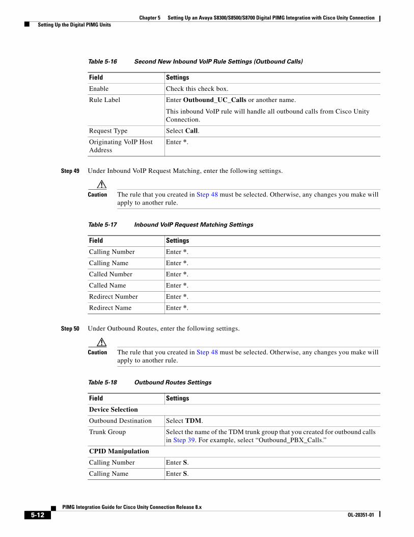
Chapter 5 Setting Up an Avaya S8300/S8500/S8700 Digital PIMG Integration with Cisco Unity Connection Setting Up the Digital PIMG Units
Step 49 Under Inbound VoIP Request Matching, enter the following settings.
Caution The rule that you created in Step 48 must be selected. Otherwise, any changes you make will apply to another rule.
Step 50 Under Outbound Routes, enter the following settings.
Caution The rule that you created in Step 48 must be selected. Otherwise, any changes you make will apply to another rule.
Table 5-16 Second New Inbound VoIP Rule Settings (Outbound Calls)
Field Settings
Enable Check this check box.
Rule Label Enter Outbound_UC_Calls or another name.
This inbound VoIP rule will handle all outbound calls from Cisco Unity Connection.
Request Type Select Call.
Originating VoIP Host Address
Enter *.
Table 5-17 Inbound VoIP Request Matching Settings
Field Settings
Calling Number Enter *.
Calling Name Enter *.
Called Number Enter *.
Called Name Enter *.
Redirect Number Enter *.
Redirect Name Enter *.
Table 5-18 Outbound Routes Settings
Field Settings
Device Selection
Outbound Destination Select TDM.
Trunk Group Select the name of the TDM trunk group that you created for outbound calls in Step 39. For example, select “Outbound_PBX_Calls.”
CPID Manipulation
Calling Number Enter S.
Calling Name Enter S.
5-12PIMG Integration Guide for Cisco Unity Connection Release 8.x
OL-20351-01
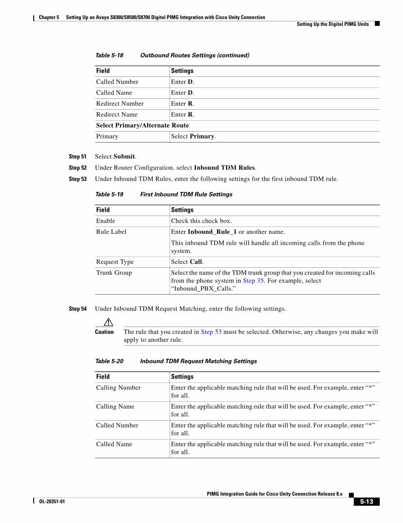
Chapter 5 Setting Up an Avaya S8300/S8500/S8700 Digital PIMG Integration with Cisco Unity Connection Setting Up the Digital PIMG Units
Step 51 Select Submit.
Step 52 Under Router Configuration, select Inbound TDM Rules.
Step 53 Under Inbound TDM Rules, enter the following settings for the first inbound TDM rule.
Step 54 Under Inbound TDM Request Matching, enter the following settings.
Caution The rule that you created in Step 53 must be selected. Otherwise, any changes you make will apply to another rule.
Called Number Enter D.
Called Name Enter D.
Redirect Number Enter R.
Redirect Name Enter R.
Select Primary/Alternate Route
Primary Select Primary.
Table 5-19 First Inbound TDM Rule Settings
Field Settings
Enable Check this check box.
Rule Label Enter Inbound_Rule_1 or another name.
This inbound TDM rule will handle all incoming calls from the phone system.
Request Type Select Call.
Trunk Group Select the name of the TDM trunk group that you created for incoming calls from the phone system in Step 35. For example, select “Inbound_PBX_Calls.”
Table 5-18 Outbound Routes Settings (continued)
Field Settings
Table 5-20 Inbound TDM Request Matching Settings
Field Settings
Calling Number Enter the applicable matching rule that will be used. For example, enter “*” for all.
Calling Name Enter the applicable matching rule that will be used. For example, enter “*” for all.
Called Number Enter the applicable matching rule that will be used. For example, enter “*” for all.
Called Name Enter the applicable matching rule that will be used. For example, enter “*” for all.
5-13PIMG Integration Guide for Cisco Unity Connection Release 8.x
OL-20351-01

Chapter 5 Setting Up an Avaya S8300/S8500/S8700 Digital PIMG Integration with Cisco Unity Connection Setting Up the Digital PIMG Units
Step 55 Under Outbound Routes, enter the following settings.
Caution The rule that you created in Step 53 must be selected. Otherwise, any changes you make will apply to another rule.
Step 56 If you want to create more Inbound TDM rules, under Inbound TDM Rules, select Add Rule. Otherwise, continue to Step 58.
Step 57 Repeat Step 53 through Step 56 for all remaining inbound TDM rules that you want to create.
Step 58 Select Submit.
Step 59 On the Configuration menu, select TDM > Digital.
Step 60 On the Digital Telephony page, in the Telephony Switch Type field, select Lucent.
Step 61 Select Submit.
Step 62 On the Configuration menu, select TDM > General.
Step 63 On the TDM General Settings page, enter the following settings.
Redirect Number Enter the applicable matching rule that will be used. For example, enter “*” for all.
Redirect Name Enter the applicable matching rule that will be used. For example, enter “*” for all.
Table 5-20 Inbound TDM Request Matching Settings (continued)
Field Settings
Table 5-21 Outbound Routes Settings
Field Settings
Device Selection
Outbound Destination Select VoIP.
Host Group Select the name of the VoIP host group that you created for Cisco Unity Connection in Step 28.
CPID Manipulation
Calling Number Enter S.
Calling Name Enter S.
Called Number Enter D.
Called Name Enter D.
Redirect Number Enter R.
Redirect Name Enter R.
Select Primary/Alternate Route
Primary Select Primary.
5-14PIMG Integration Guide for Cisco Unity Connection Release 8.x
OL-20351-01
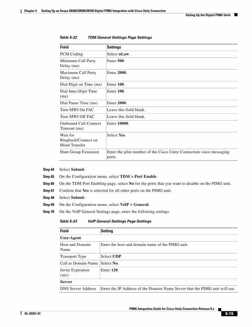
Chapter 5 Setting Up an Avaya S8300/S8500/S8700 Digital PIMG Integration with Cisco Unity Connection Setting Up the Digital PIMG Units
Step 64 Select Submit.
Step 65 On the Configuration menu, select TDM > Port Enable.
Step 66 On the TDM Port Enabling page, select No for the ports that you want to disable on the PIMG unit.
Step 67 Confirm that Yes is selected for all other ports on the PIMG unit.
Step 68 Select Submit.
Step 69 On the Configuration menu, select VoIP > General.
Step 70 On the VoIP General Settings page, enter the following settings.
Table 5-22 TDM General Settings Page Settings
Field Settings
PCM Coding Select uLaw.
Minimum Call Party Delay (ms)
Enter 500.
Maximum Call Party Delay (ms)
Enter 2000.
Dial Digit on Time (ms) Enter 100.
Dial Inter-Digit Time (ms)
Enter 100.
Dial Pause Time (ms) Enter 2000.
Turn MWI On FAC Leave this field blank.
Turn MWI Off FAC Leave this field blank.
Outbound Call Connect Timeout (ms)
Enter 10000.
Wait for Ringback/Connect on Blind Transfer
Select Yes.
Hunt Group Extension Enter the pilot number of the Cisco Unity Connection voice messaging ports.
Table 5-23 VoIP General Settings Page Settings
Field Setting
User-Agent
Host and Domain Name
Enter the host and domain name of the PIMG unit.
Transport Type Select UDP.
Call as Domain Name Select No.
Invite Expiration (sec)
Enter 120.
Server
DNS Server Address Enter the IP Address of the Domain Name Server that the PIMG unit will use.
5-15PIMG Integration Guide for Cisco Unity Connection Release 8.x
OL-20351-01
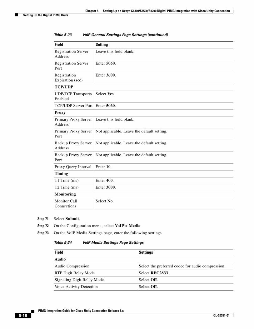
Chapter 5 Setting Up an Avaya S8300/S8500/S8700 Digital PIMG Integration with Cisco Unity Connection Setting Up the Digital PIMG Units
Step 71 Select Submit.
Step 72 On the Configuration menu, select VoIP > Media.
Step 73 On the VoIP Media Settings page, enter the following settings.
Registration Server Address
Leave this field blank.
Registration Server Port
Enter 5060.
Registration Expiration (sec)
Enter 3600.
TCP/UDP
UDP/TCP Transports Enabled
Select Yes.
TCP/UDP Server Port Enter 5060.
Proxy
Primary Proxy Server Address
Leave this field blank.
Primary Proxy Server Port
Not applicable. Leave the default setting.
Backup Proxy Server Address
Not applicable. Leave the default setting.
Backup Proxy Server Port
Not applicable. Leave the default setting.
Proxy Query Interval Enter 10.
Timing
T1 Time (ms) Enter 400.
T2 Time (ms) Enter 3000.
Monitoring
Monitor Call Connections
Select No.
Table 5-24 VoIP Media Settings Page Settings
Field Settings
Audio
Audio Compression Select the preferred codec for audio compression.
RTP Digit Relay Mode Select RFC2833.
Signaling Digit Relay Mode Select Off.
Voice Activity Detection Select Off.
Table 5-23 VoIP General Settings Page Settings (continued)
Field Setting
5-16PIMG Integration Guide for Cisco Unity Connection Release 8.x
OL-20351-01

Chapter 5 Setting Up an Avaya S8300/S8500/S8700 Digital PIMG Integration with Cisco Unity Connection Setting Up the Digital PIMG Units
Step 74 Select Submit.
Step 75 On the Configuration menu, select VoIP > QOS.
Step 76 On the VoIP QOS Configuration page, enter the following settings.
Step 77 Select Submit.
Step 78 On the Configuration menu, select IP.
Step 79 On the IP Settings page, enter the following settings.
Frame Size Select the applicable setting:
• G.711—20
• G.729AB—10
Caution Failure to use the correct setting will result in recorded messages containing nothing but silence.
Frames Per Packet Select the applicable setting:
• G.711—1
• G.729AB—2
Caution Failure to use the correct setting will result in recorded messages containing nothing but silence.
Table 5-25 VoIP QOS Configurative Page Settings
Field Settings
Call Control QOS Byte Enter 104.
RTP QOS Byte Enter 184.
Table 5-26 IP Settings Page Settings
Field Settings
Client IP Address Enter the new IP address you want to use for the PIMG unit.
(This is the IP address that you enter in Cisco Unity Connection Administration when you create the integration.)
Client Subnet Mask Enter the new subnet mask, if the subnet mask is different from the default IP address.
Default Network Gateway Address
Enter the IP address of the default network gateway router that the PIMG units will use.
BOOTP Enabled Select No.
Table 5-24 VoIP Media Settings Page Settings (continued)
Field Settings
5-17PIMG Integration Guide for Cisco Unity Connection Release 8.x
OL-20351-01

Chapter 5 Setting Up an Avaya S8300/S8500/S8700 Digital PIMG Integration with Cisco Unity Connection Creating a New Integration with the Avaya S8300/S8500/S8700 Phone System
Step 80 Select Submit.
Step 81 On the Configuration menu, select Tone Detection.
Step 82 On the Tone Detection page, under Call Progress Tone - Learn, in the Learn Tone Event field, select Busy and do the following substeps to verify that the tone is correct.
a. From a available phone, call a second phone.
b. Answer the second phone when it rings, and leave both handsets off so that both phones are busy.
c. From a third phone, dial one of the busy phones.
d. Confirm that you hear a busy tone.
e. Hang up the third phone but leave the handsets for the other two phones off.
Step 83 Under Call Progress Tone - Learn, in the Dial String field, enter the extension that you dialed in Step 82c. from the third phone.
Step 84 Select Learn.
Step 85 On the Tone Detection page, under Call Progress Tone - Learn, in the Learn field, select Error and do the following substeps to verify that the tone is correct.
a. From an available phone, dial an extension that does not exist.
b. Confirm that you hear the reorder or error tone.
c. Hang up the phone.
Step 86 Under Call Progress Tone - Learn, in the Dial String field, enter the extension that you dialed in Step 85a.
Step 87 Select Learn.
Step 88 On the Tone Detection page, under Call Progress Tone - Learn, in the Learn field, select Ringback and do the following substeps to verify that the tone is correct.
a. From an available phone, dial an extension that does exist
b. Confirm that you hear the ringback tone.
c. Hang up the phone.
Step 89 Under Call Progress Tone - Learn, in the Dial String field, enter the extension that you dialed in Step 88a.
Step 90 Select Learn.
Step 91 Select Submit.
Step 92 Hang up the phones that you used in Step 82.
Step 93 On the System menu, select Restart.
Step 94 On the Restart page, select Restart Unit Now.
Step 95 Repeat Step 2 through Step 94 on all remaining PIMG units.
Creating a New Integration with the Avaya S8300/S8500/S8700 Phone System
After ensuring that the Avaya S8300/S8500/S8700 phone system, the PIMG units, and Cisco Unity Connection are ready for the integration, do the following procedure to set up the integration and to enter the port settings.
5-18PIMG Integration Guide for Cisco Unity Connection Release 8.x
OL-20351-01
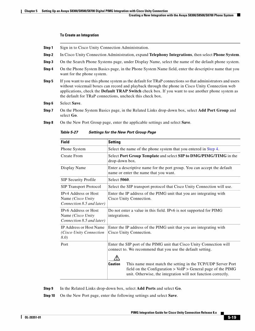
Chapter 5 Setting Up an Avaya S8300/S8500/S8700 Digital PIMG Integration with Cisco Unity Connection Creating a New Integration with the Avaya S8300/S8500/S8700 Phone System
To Create an Integration
Step 1 Sign in to Cisco Unity Connection Administration.
Step 2 In Cisco Unity Connection Administration, expand Telephony Integrations, then select Phone System.
Step 3 On the Search Phone Systems page, under Display Name, select the name of the default phone system.
Step 4 On the Phone System Basics page, in the Phone System Name field, enter the descriptive name that you want for the phone system.
Step 5 If you want to use this phone system as the default for TRaP connections so that administrators and users without voicemail boxes can record and playback through the phone in Cisco Unity Connection web applications, check the Default TRAP Switch check box. If you want to use another phone system as the default for TRaP connections, uncheck this check box.
Step 6 Select Save.
Step 7 On the Phone System Basics page, in the Related Links drop-down box, select Add Port Group and select Go.
Step 8 On the New Port Group page, enter the applicable settings and select Save.
Step 9 In the Related Links drop-down box, select Add Ports and select Go.
Step 10 On the New Port page, enter the following settings and select Save.
Table 5-27 Settings for the New Port Group Page
Field Setting
Phone System Select the name of the phone system that you entered in Step 4.
Create From Select Port Group Template and select SIP to DMG/PIMG/TIMG in the drop-down box.
Display Name Enter a descriptive name for the port group. You can accept the default name or enter the name that you want.
SIP Security Profile Select 5060.
SIP Transport Protocol Select the SIP transport protocol that Cisco Unity Connection will use.
IPv4 Address or Host Name (Cisco Unity Connection 8.5 and later)
Enter the IP address of the PIMG unit that you are integrating with Cisco Unity Connection.
IPv6 Address or Host Name (Cisco Unity Connection 8.5 and later)
Do not enter a value in this field. IPv6 is not supported for PIMG integrations.
IP Address or Host Name (Cisco Unity Connection 8.0)
Enter the IP address of the PIMG unit that you are integrating with Cisco Unity Connection.
Port Enter the SIP port of the PIMG unit that Cisco Unity Connection will connect to. We recommend that you use the default setting.
Caution This name must match the setting in the TCP/UDP Server Port field on the Configuration > VoIP > General page of the PIMG unit. Otherwise, the integration will not function correctly.
5-19PIMG Integration Guide for Cisco Unity Connection Release 8.x
OL-20351-01
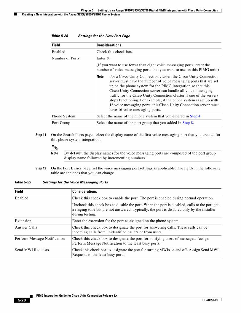
Chapter 5 Setting Up an Avaya S8300/S8500/S8700 Digital PIMG Integration with Cisco Unity Connection Creating a New Integration with the Avaya S8300/S8500/S8700 Phone System
Step 11 On the Search Ports page, select the display name of the first voice messaging port that you created for this phone system integration.
Note By default, the display names for the voice messaging ports are composed of the port group display name followed by incrementing numbers.
Step 12 On the Port Basics page, set the voice messaging port settings as applicable. The fields in the following table are the ones that you can change.
Table 5-28 Settings for the New Port Page
Field Considerations
Enabled Check this check box.
Number of Ports Enter 8.
(If you want to use fewer than eight voice messaging ports, enter the number of voice messaging ports that you want to use on this PIMG unit.)
Note For a Cisco Unity Connection cluster, the Cisco Unity Connection server must have the number of voice messaging ports that are set up on the phone system for the PIMG integration so that this Cisco Unity Connection server can handle all voice messaging traffic for the Cisco Unity Connection cluster if one of the servers stops functioning. For example, if the phone system is set up with 16 voice messaging ports, this Cisco Unity Connection server must have 16 voice messaging ports.
Phone System Select the name of the phone system that you entered in Step 4.
Port Group Select the name of the port group that you added in Step 8.
Table 5-29 Settings for the Voice Messaging Ports
Field Considerations
Enabled Check this check box to enable the port. The port is enabled during normal operation.
Uncheck this check box to disable the port. When the port is disabled, calls to the port get a ringing tone but are not answered. Typically, the port is disabled only by the installer during testing.
Extension Enter the extension for the port as assigned on the phone system.
Answer Calls Check this check box to designate the port for answering calls. These calls can be incoming calls from unidentified callers or from users.
Perform Message Notification Check this check box to designate the port for notifying users of messages. Assign Perform Message Notification to the least busy ports.
Send MWI Requests Check this check box to designate the port for turning MWIs on and off. Assign Send MWI Requests to the least busy ports.
5-20PIMG Integration Guide for Cisco Unity Connection Release 8.x
OL-20351-01
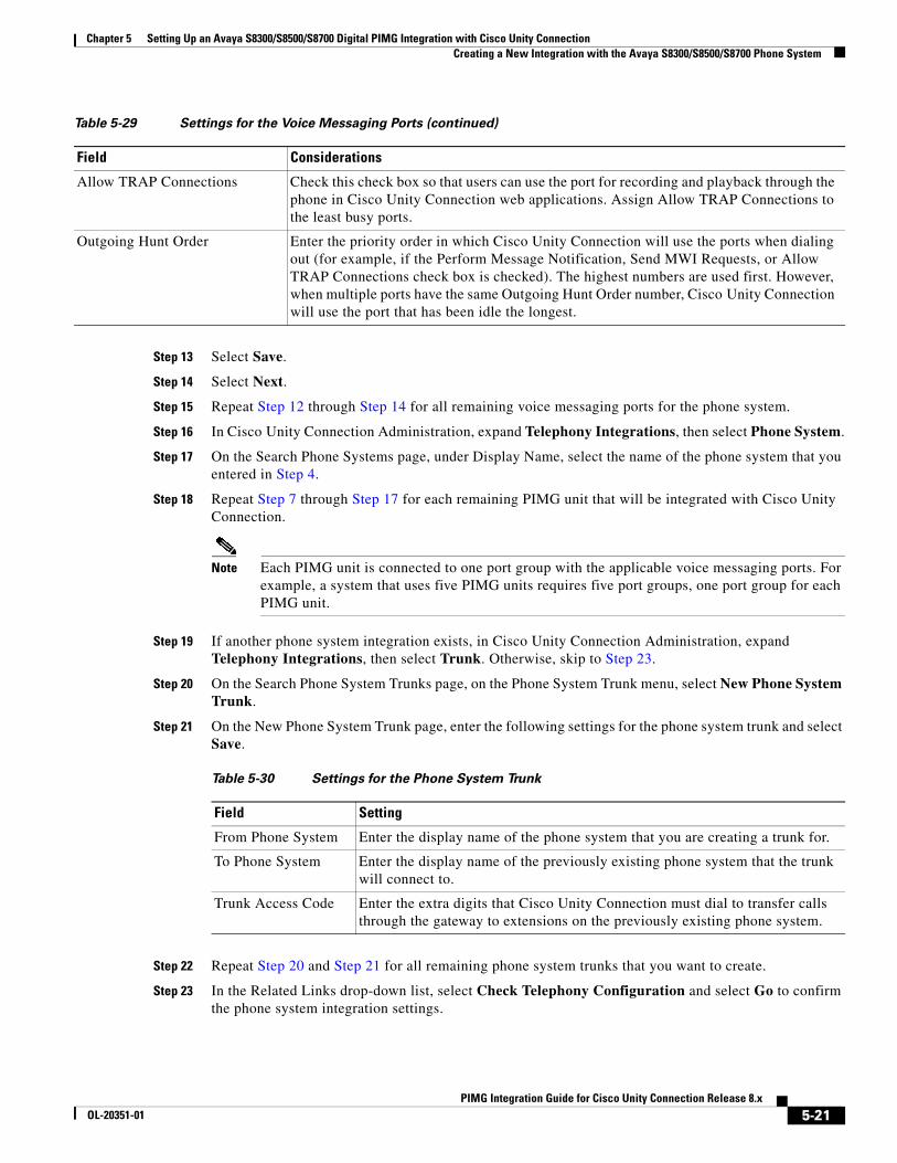
Chapter 5 Setting Up an Avaya S8300/S8500/S8700 Digital PIMG Integration with Cisco Unity Connection Creating a New Integration with the Avaya S8300/S8500/S8700 Phone System
Step 13 Select Save.
Step 14 Select Next.
Step 15 Repeat Step 12 through Step 14 for all remaining voice messaging ports for the phone system.
Step 16 In Cisco Unity Connection Administration, expand Telephony Integrations, then select Phone System.
Step 17 On the Search Phone Systems page, under Display Name, select the name of the phone system that you entered in Step 4.
Step 18 Repeat Step 7 through Step 17 for each remaining PIMG unit that will be integrated with Cisco Unity Connection.
Note Each PIMG unit is connected to one port group with the applicable voice messaging ports. For example, a system that uses five PIMG units requires five port groups, one port group for each PIMG unit.
Step 19 If another phone system integration exists, in Cisco Unity Connection Administration, expand Telephony Integrations, then select Trunk. Otherwise, skip to Step 23.
Step 20 On the Search Phone System Trunks page, on the Phone System Trunk menu, select New Phone System Trunk.
Step 21 On the New Phone System Trunk page, enter the following settings for the phone system trunk and select Save.
Step 22 Repeat Step 20 and Step 21 for all remaining phone system trunks that you want to create.
Step 23 In the Related Links drop-down list, select Check Telephony Configuration and select Go to confirm the phone system integration settings.
Allow TRAP Connections Check this check box so that users can use the port for recording and playback through the phone in Cisco Unity Connection web applications. Assign Allow TRAP Connections to the least busy ports.
Outgoing Hunt Order Enter the priority order in which Cisco Unity Connection will use the ports when dialing out (for example, if the Perform Message Notification, Send MWI Requests, or Allow TRAP Connections check box is checked). The highest numbers are used first. However, when multiple ports have the same Outgoing Hunt Order number, Cisco Unity Connection will use the port that has been idle the longest.
Table 5-29 Settings for the Voice Messaging Ports (continued)
Field Considerations
Table 5-30 Settings for the Phone System Trunk
Field Setting
From Phone System Enter the display name of the phone system that you are creating a trunk for.
To Phone System Enter the display name of the previously existing phone system that the trunk will connect to.
Trunk Access Code Enter the extra digits that Cisco Unity Connection must dial to transfer calls through the gateway to extensions on the previously existing phone system.
5-21PIMG Integration Guide for Cisco Unity Connection Release 8.x
OL-20351-01

Chapter 5 Setting Up an Avaya S8300/S8500/S8700 Digital PIMG Integration with Cisco Unity Connection Creating a New Integration with the Avaya S8300/S8500/S8700 Phone System
If the test is not successful, the Task Execution Results displays one or more messages with troubleshooting steps. After correcting the problems, test the connection again.
Step 24 In the Task Execution Results window, select Close.
5-22PIMG Integration Guide for Cisco Unity Connection Release 8.x
OL-20351-01
PIMG IntegrOL-20351-01
C H A P T E R 6
Setting Up a Mitel SX-200 Digital PIMG Integration with Cisco Unity ConnectionFor detailed instructions for setting up a Mitel SX-200 digital PIMG integration with Cisco Unity Connection, see the following sections in this chapter:
• Task List to Create the Integration with the Mitel SX-200 PIMG Phone System, page 6-1
• Requirements, page 6-2
• Programming the Mitel SX-200 PIMG Phone System for Integrating with Cisco Unity Connection, page 6-3
• Setting Up the Digital Mitel PIMG Units, page 6-8
• Creating a New Integration with the Mitel SX-200 Phone System, page 6-22
Task List to Create the Integration with the Mitel SX-200 PIMG Phone System
Before doing the following tasks to integrate Cisco Unity Connection with the Mitel SX-200 phone system by using PIMG units (media gateways), confirm that the Cisco Unity Connection server is ready for the integration by completing the applicable tasks in the Cisco Unity Connection Installation Guide.
1. Review the system and equipment requirements to confirm that all phone system and Cisco Unity Connection server requirements have been met. See the “Requirements” section on page 6-2.
2. Plan how the voice messaging ports will be used by Cisco Unity Connection. See Chapter 2, “Planning How the Voice Messaging Ports Will Be Used by Cisco Unity Connection.”
3. Program the Mitel SX-200 phone system and extensions. See the “Programming the Mitel SX-200 PIMG Phone System for Integrating with Cisco Unity Connection” section on page 6-3.
4. Set up the PIMG units. See the “Setting Up the Digital Mitel PIMG Units” section on page 6-8.
5. Create the integration. See the “Creating a New Integration with the Mitel SX-200 Phone System” section on page 6-22.
6. Test the integration. See Chapter 14, “Testing the Integration.”
7. If this integration is a second or subsequent integration, add the applicable new user templates for the new phone system. See Chapter 15, “Adding New User Templates for Multiple Integrations.”
6-1ation Guide for Cisco Unity Connection Release 8.x
Chapter 6 Setting Up a Mitel SX-200 Digital PIMG Integration with Cisco Unity Connection Requirements
RequirementsThe Mitel SX-200 integration supports configurations of the following components:
Phone System
• Mitel SX-200.
• Software level Lightware 19 or later.
• A DNI Line MC330 line card to support the two-wire station interface.
• One or more of the applicable PIMG units. For details, see Chapter 1, “Introduction.”
• The voice messaging ports in the phone system connected by digital lines to the ports on the PIMG units.
To simplify troubleshooting, we recommend that you connect the voice messaging ports on the phone system to the ports on the PIMG units in a planned manner. For example, connect the first phone system voice messaging port to the first port on the first PIMG unit, connect the second phone system voice messaging port to the second port on the first PIMG unit, and so on. Alternatively, if you have multiple PIMG units, you can reduce answer times in the event of a PIMG unit failure by connecting the phone system ports to the PIMG units in a round-robin fashion. For example, connect the first phone system voice messaging port to the first port on the first PIMG unit, connect the second phone system voice messaging port to the first port on the second PIMG unit, and so on.
• The PIMG units connected to the same LAN or WAN that Cisco Unity Connection is connected to.
• If the PIMG units connect to a WAN, the requirements for the WAN network connections are:
– For G.729a codec formatting, a minimum of 32.76 Kbps guaranteed bandwidth for each voice messaging port.
– For G.711 codec formatting, a minimum of 91.56 Kbps guaranteed bandwidth for each voice messaging port.
– No network devices that implement network address translation (NAT).
– A maximum 200 ms one-way network latency.
• The phone system ready for the integration, as described in the documentation for the phone system.
Cisco Unity Connection Server
• Cisco Unity Connection installed and ready for the integration, as described in the Cisco Unity Connection Installation Guide at http://www.cisco.com/en/US/products/ps6509/prod_installation_guides_list.html.
• A license that enables the applicable number of voice messaging ports.
Centralized Voice Messaging
Cisco Unity Connection supports centralized voice messaging through the phone system, which supports various inter-phone system networking protocols including proprietary protocols such as Avaya DCS, Nortel MCDN, or Siemens CorNet, and standards-based protocols such as QSIG or DPNSS. Note that centralized voice messaging is a function of the phone system and its inter-phone system networking, not voicemail. Connection will support centralized voice messaging as long as the phone system and its inter-phone system networking are properly configured. For details, see the “Centralized Voice Messaging” section in the “Integrating Cisco Unity Connection with the Phone System” chapter of the Cisco Unity Design Guide Release 8.x at http://www.cisco.com/en/US/docs/voice_ip_comm/connection/8x/design/guide/8xcucdgx.html.
6-2PIMG Integration Guide for Cisco Unity Connection Release 8.x
OL-20351-01
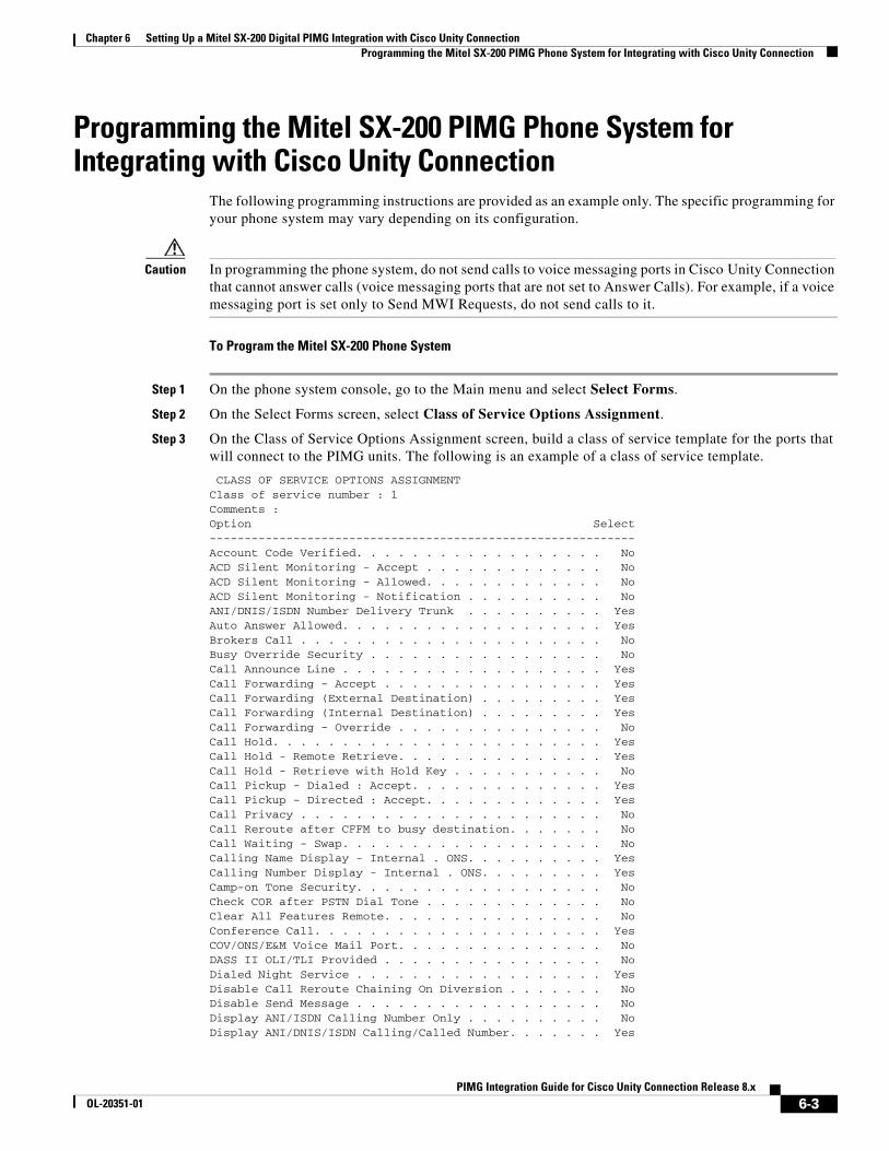
Chapter 6 Setting Up a Mitel SX-200 Digital PIMG Integration with Cisco Unity Connection Programming the Mitel SX-200 PIMG Phone System for Integrating with Cisco Unity Connection
Programming the Mitel SX-200 PIMG Phone System for Integrating with Cisco Unity Connection
The following programming instructions are provided as an example only. The specific programming for your phone system may vary depending on its configuration.
Caution In programming the phone system, do not send calls to voice messaging ports in Cisco Unity Connection that cannot answer calls (voice messaging ports that are not set to Answer Calls). For example, if a voice messaging port is set only to Send MWI Requests, do not send calls to it.
To Program the Mitel SX-200 Phone System
Step 1 On the phone system console, go to the Main menu and select Select Forms.
Step 2 On the Select Forms screen, select Class of Service Options Assignment.
Step 3 On the Class of Service Options Assignment screen, build a class of service template for the ports that will connect to the PIMG units. The following is an example of a class of service template.
CLASS OF SERVICE OPTIONS ASSIGNMENTClass of service number : 1Comments :Option Select-------------------------------------------------------------Account Code Verified. . . . . . . . . . . . . . . . . . NoACD Silent Monitoring - Accept . . . . . . . . . . . . . NoACD Silent Monitoring - Allowed. . . . . . . . . . . . . NoACD Silent Monitoring - Notification . . . . . . . . . . NoANI/DNIS/ISDN Number Delivery Trunk . . . . . . . . . . YesAuto Answer Allowed. . . . . . . . . . . . . . . . . . . YesBrokers Call . . . . . . . . . . . . . . . . . . . . . . NoBusy Override Security . . . . . . . . . . . . . . . . . NoCall Announce Line . . . . . . . . . . . . . . . . . . . YesCall Forwarding - Accept . . . . . . . . . . . . . . . . YesCall Forwarding (External Destination) . . . . . . . . . YesCall Forwarding (Internal Destination) . . . . . . . . . YesCall Forwarding - Override . . . . . . . . . . . . . . . NoCall Hold. . . . . . . . . . . . . . . . . . . . . . . . YesCall Hold - Remote Retrieve. . . . . . . . . . . . . . . YesCall Hold - Retrieve with Hold Key . . . . . . . . . . . NoCall Pickup - Dialed : Accept. . . . . . . . . . . . . . YesCall Pickup - Directed : Accept. . . . . . . . . . . . . YesCall Privacy . . . . . . . . . . . . . . . . . . . . . . NoCall Reroute after CFFM to busy destination. . . . . . . NoCall Waiting - Swap. . . . . . . . . . . . . . . . . . . NoCalling Name Display - Internal . ONS. . . . . . . . . . YesCalling Number Display - Internal . ONS. . . . . . . . . YesCamp-on Tone Security. . . . . . . . . . . . . . . . . . NoCheck COR after PSTN Dial Tone . . . . . . . . . . . . . NoClear All Features Remote. . . . . . . . . . . . . . . . NoConference Call. . . . . . . . . . . . . . . . . . . . . YesCOV/ONS/E&M Voice Mail Port. . . . . . . . . . . . . . . NoDASS II OLI/TLI Provided . . . . . . . . . . . . . . . . NoDialed Night Service . . . . . . . . . . . . . . . . . . YesDisable Call Reroute Chaining On Diversion . . . . . . . NoDisable Send Message . . . . . . . . . . . . . . . . . . NoDisplay ANI/ISDN Calling Number Only . . . . . . . . . . NoDisplay ANI/DNIS/ISDN Calling/Called Number. . . . . . . Yes
6-3PIMG Integration Guide for Cisco Unity Connection Release 8.x
OL-20351-01
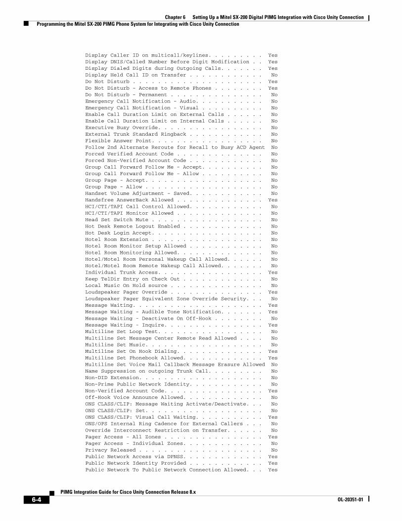
Chapter 6 Setting Up a Mitel SX-200 Digital PIMG Integration with Cisco Unity Connection Programming the Mitel SX-200 PIMG Phone System for Integrating with Cisco Unity Connection
Display Caller ID on multicall/keylines. . . . . . . . . YesDisplay DNIS/Called Number Before Digit Modification . . YesDisplay Dialed Digits during Outgoing Calls. . . . . . . YesDisplay Held Call ID on Transfer . . . . . . . . . . . . NoDo Not Disturb . . . . . . . . . . . . . . . . . . . . . YesDo Not Disturb - Access to Remote Phones . . . . . . . . YesDo Not Disturb - Permanent . . . . . . . . . . . . . . . NoEmergency Call Notification - Audio. . . . . . . . . . . NoEmergency Call Notification - Visual . . . . . . . . . . NoEnable Call Duration Limit on External Calls . . . . . . NoEnable Call Duration Limit on Internal Calls . . . . . . NoExecutive Busy Override. . . . . . . . . . . . . . . . . NoExternal Trunk Standard Ringback . . . . . . . . . . . . NoFlexible Answer Point. . . . . . . . . . . . . . . . . . NoFollow 2nd Alternate Reroute for Recall to Busy ACD Agent NoForced Verified Account Code . . . . . . . . . . . . . . NoForced Non-Verified Account Code . . . . . . . . . . . . NoGroup Call Forward Follow Me - Accept. . . . . . . . . . NoGroup Call Forward Follow Me - Allow . . . . . . . . . . NoGroup Page - Accept. . . . . . . . . . . . . . . . . . . NoGroup Page - Allow . . . . . . . . . . . . . . . . . . . NoHandset Volume Adjustment - Saved. . . . . . . . . . . . NoHandsfree AnswerBack Allowed . . . . . . . . . . . . . . YesHCI/CTI/TAPI Call Control Allowed. . . . . . . . . . . . NoHCI/CTI/TAPI Monitor Allowed . . . . . . . . . . . . . . NoHead Set Switch Mute . . . . . . . . . . . . . . . . . . NoHot Desk Remote Logout Enabled . . . . . . . . . . . . . NoHot Desk Login Accept. . . . . . . . . . . . . . . . . . NoHotel Room Extension . . . . . . . . . . . . . . . . . . NoHotel Room Monitor Setup Allowed . . . . . . . . . . . . NoHotel Room Monitoring Allowed. . . . . . . . . . . . . . NoHotel/Motel Room Personal Wakeup Call Allowed. . . . . . NoHotel/Motel Room Remote Wakeup Call Allowed. . . . . . . NoIndividual Trunk Access. . . . . . . . . . . . . . . . . YesKeep TelDir Entry on Check Out . . . . . . . . . . . . . NoLocal Music On Hold source . . . . . . . . . . . . . . . NoLoudspeaker Pager Override . . . . . . . . . . . . . . . YesLoudspeaker Pager Equivalent Zone Override Security. . . NoMessage Waiting. . . . . . . . . . . . . . . . . . . . . YesMessage Waiting - Audible Tone Notification. . . . . . . YesMessage Waiting - Deactivate On Off-Hook . . . . . . . . NoMessage Waiting - Inquire. . . . . . . . . . . . . . . . YesMultiline Set Loop Test. . . . . . . . . . . . . . . . . NoMultiline Set Message Center Remote Read Allowed . . . . NoMultiline Set Music. . . . . . . . . . . . . . . . . . . NoMultiline Set On Hook Dialing. . . . . . . . . . . . . . YesMultiline Set Phonebook Allowed. . . . . . . . . . . . . YesMultiline Set Voice Mail Callback Message Erasure Allowed NoName Suppression on outgoing Trunk Call. . . . . . . . . NoNon-DID Extension. . . . . . . . . . . . . . . . . . . . NoNon-Prime Public Network Identity. . . . . . . . . . . . NoNon-Verified Account Code. . . . . . . . . . . . . . . . YesOff-Hook Voice Announce Allowed. . . . . . . . . . . . . NoONS CLASS/CLIP: Message Waiting Activate/Deactivate. . . NoONS CLASS/CLIP: Set. . . . . . . . . . . . . . . . . . . NoONS CLASS/CLIP: Visual Call Waiting. . . . . . . . . . . YesONS/OPS Internal Ring Cadence for External Callers . . . NoOverride Interconnect Restriction on Transfer. . . . . . NoPager Access - All Zones . . . . . . . . . . . . . . . . YesPager Access - Individual Zones. . . . . . . . . . . . . NoPrivacy Released . . . . . . . . . . . . . . . . . . . . NoPublic Network Access via DPNSS. . . . . . . . . . . . . YesPublic Network Identity Provided . . . . . . . . . . . . YesPublic Network To Public Network Connection Allowed. . . Yes
6-4PIMG Integration Guide for Cisco Unity Connection Release 8.x
OL-20351-01
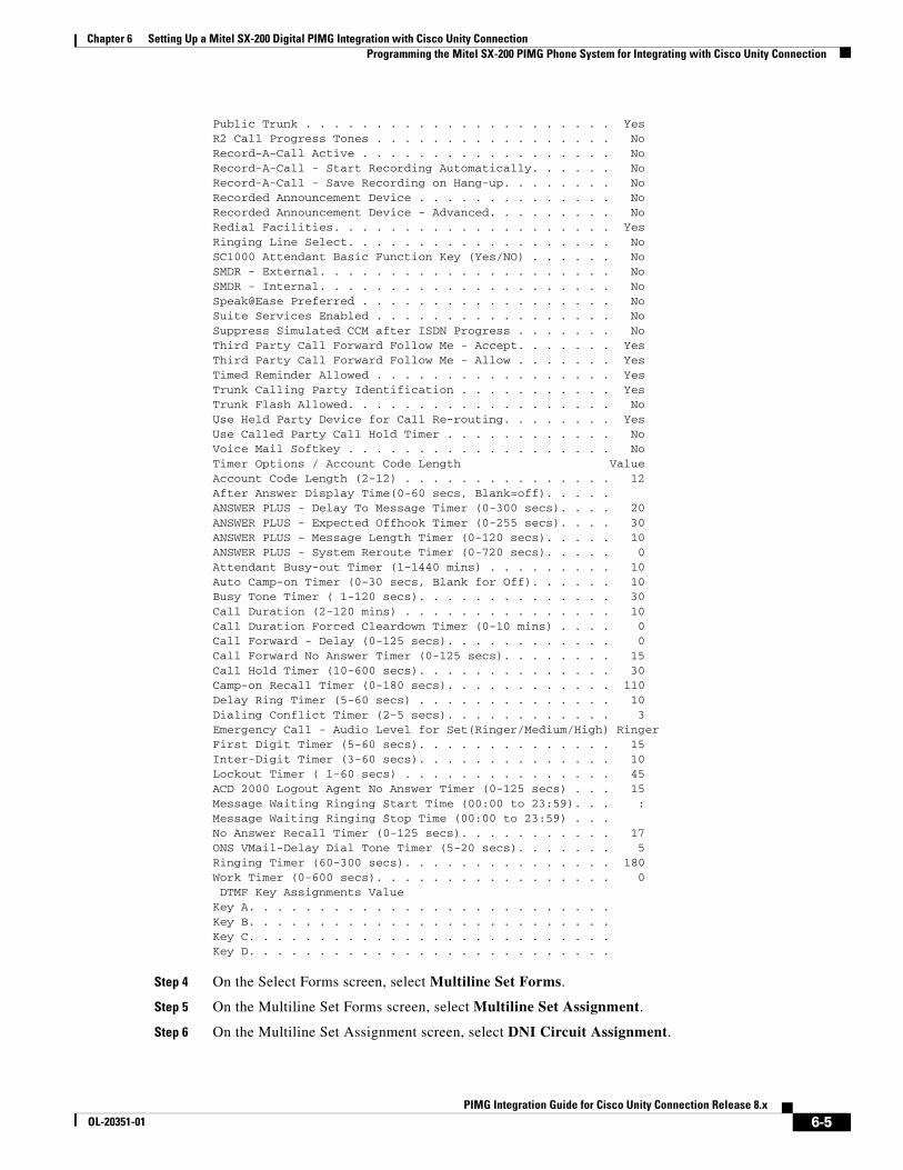
Chapter 6 Setting Up a Mitel SX-200 Digital PIMG Integration with Cisco Unity Connection Programming the Mitel SX-200 PIMG Phone System for Integrating with Cisco Unity Connection
Public Trunk . . . . . . . . . . . . . . . . . . . . . . YesR2 Call Progress Tones . . . . . . . . . . . . . . . . . NoRecord-A-Call Active . . . . . . . . . . . . . . . . . . NoRecord-A-Call - Start Recording Automatically. . . . . . NoRecord-A-Call - Save Recording on Hang-up. . . . . . . . NoRecorded Announcement Device . . . . . . . . . . . . . . NoRecorded Announcement Device - Advanced. . . . . . . . . NoRedial Facilities. . . . . . . . . . . . . . . . . . . . YesRinging Line Select. . . . . . . . . . . . . . . . . . . NoSC1000 Attendant Basic Function Key (Yes/NO) . . . . . . NoSMDR - External. . . . . . . . . . . . . . . . . . . . . NoSMDR - Internal. . . . . . . . . . . . . . . . . . . . . NoSpeak@Ease Preferred . . . . . . . . . . . . . . . . . . NoSuite Services Enabled . . . . . . . . . . . . . . . . . NoSuppress Simulated CCM after ISDN Progress . . . . . . . NoThird Party Call Forward Follow Me - Accept. . . . . . . YesThird Party Call Forward Follow Me - Allow . . . . . . . YesTimed Reminder Allowed . . . . . . . . . . . . . . . . . YesTrunk Calling Party Identification . . . . . . . . . . . YesTrunk Flash Allowed. . . . . . . . . . . . . . . . . . . NoUse Held Party Device for Call Re-routing. . . . . . . . YesUse Called Party Call Hold Timer . . . . . . . . . . . . NoVoice Mail Softkey . . . . . . . . . . . . . . . . . . . NoTimer Options / Account Code Length ValueAccount Code Length (2-12) . . . . . . . . . . . . . . . 12After Answer Display Time(0-60 secs, Blank=off). . . . . ANSWER PLUS - Delay To Message Timer (0-300 secs). . . . 20ANSWER PLUS - Expected Offhook Timer (0-255 secs). . . . 30ANSWER PLUS - Message Length Timer (0-120 secs). . . . . 10ANSWER PLUS - System Reroute Timer (0-720 secs). . . . . 0Attendant Busy-out Timer (1-1440 mins) . . . . . . . . . 10Auto Camp-on Timer (0-30 secs, Blank for Off). . . . . . 10Busy Tone Timer ( 1-120 secs). . . . . . . . . . . . . . 30Call Duration (2-120 mins) . . . . . . . . . . . . . . . 10Call Duration Forced Cleardown Timer (0-10 mins) . . . . 0Call Forward - Delay (0-125 secs). . . . . . . . . . . . 0Call Forward No Answer Timer (0-125 secs). . . . . . . . 15Call Hold Timer (10-600 secs). . . . . . . . . . . . . . 30Camp-on Recall Timer (0-180 secs). . . . . . . . . . . . 110Delay Ring Timer (5-60 secs) . . . . . . . . . . . . . . 10Dialing Conflict Timer (2-5 secs). . . . . . . . . . . . 3Emergency Call - Audio Level for Set(Ringer/Medium/High) RingerFirst Digit Timer (5-60 secs). . . . . . . . . . . . . . 15Inter-Digit Timer (3-60 secs). . . . . . . . . . . . . . 10Lockout Timer ( 1-60 secs) . . . . . . . . . . . . . . . 45ACD 2000 Logout Agent No Answer Timer (0-125 secs) . . . 15Message Waiting Ringing Start Time (00:00 to 23:59). . . :Message Waiting Ringing Stop Time (00:00 to 23:59) . . . No Answer Recall Timer (0-125 secs). . . . . . . . . . . 17ONS VMail-Delay Dial Tone Timer (5-20 secs). . . . . . . 5Ringing Timer (60-300 secs). . . . . . . . . . . . . . . 180Work Timer (0-600 secs). . . . . . . . . . . . . . . . . 0 DTMF Key Assignments ValueKey A. . . . . . . . . . . . . . . . . . . . . . . . . . Key B. . . . . . . . . . . . . . . . . . . . . . . . . . Key C. . . . . . . . . . . . . . . . . . . . . . . . . . Key D. . . . . . . . . . . . . . . . . . . . . . . . . .
Step 4 On the Select Forms screen, select Multiline Set Forms.
Step 5 On the Multiline Set Forms screen, select Multiline Set Assignment.
Step 6 On the Multiline Set Assignment screen, select DNI Circuit Assignment.
6-5PIMG Integration Guide for Cisco Unity Connection Release 8.x
OL-20351-01
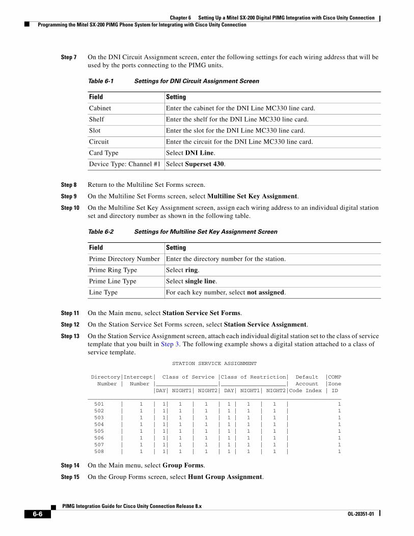
Chapter 6 Setting Up a Mitel SX-200 Digital PIMG Integration with Cisco Unity Connection Programming the Mitel SX-200 PIMG Phone System for Integrating with Cisco Unity Connection
Step 7 On the DNI Circuit Assignment screen, enter the following settings for each wiring address that will be used by the ports connecting to the PIMG units.
Step 8 Return to the Multiline Set Forms screen.
Step 9 On the Multiline Set Forms screen, select Multiline Set Key Assignment.
Step 10 On the Multiline Set Key Assignment screen, assign each wiring address to an individual digital station set and directory number as shown in the following table.
Step 11 On the Main menu, select Station Service Set Forms.
Step 12 On the Station Service Set Forms screen, select Station Service Assignment.
Step 13 On the Station Service Assignment screen, attach each individual digital station set to the class of service template that you built in Step 3. The following example shows a digital station attached to a class of service template.
STATION SERVICE ASSIGNMENT
Directory|Intercept| Class of Service |Class of Restriction| Default |COMP Number | Number |___________________|____________________| Account |Zone |DAY| NIGHT1| NIGHT2| DAY| NIGHT1| NIGHT2|Code Index | ID______________________________________________________________________________ 501 | 1 | 1| 1 | 1 | 1 | 1 | 1 | 1 502 | 1 | 1| 1 | 1 | 1 | 1 | 1 | 1 503 | 1 | 1| 1 | 1 | 1 | 1 | 1 | 1 504 | 1 | 1| 1 | 1 | 1 | 1 | 1 | 1 505 | 1 | 1| 1 | 1 | 1 | 1 | 1 | 1 506 | 1 | 1| 1 | 1 | 1 | 1 | 1 | 1 507 | 1 | 1| 1 | 1 | 1 | 1 | 1 | 1 508 | 1 | 1| 1 | 1 | 1 | 1 | 1 | 1
Step 14 On the Main menu, select Group Forms.
Step 15 On the Group Forms screen, select Hunt Group Assignment.
Table 6-1 Settings for DNI Circuit Assignment Screen
Field Setting
Cabinet Enter the cabinet for the DNI Line MC330 line card.
Shelf Enter the shelf for the DNI Line MC330 line card.
Slot Enter the slot for the DNI Line MC330 line card.
Circuit Enter the circuit for the DNI Line MC330 line card.
Card Type Select DNI Line.
Device Type: Channel #1 Select Superset 430.
Table 6-2 Settings for Multiline Set Key Assignment Screen
Field Setting
Prime Directory Number Enter the directory number for the station.
Prime Ring Type Select ring.
Prime Line Type Select single line.
Line Type For each key number, select not assigned.
6-6PIMG Integration Guide for Cisco Unity Connection Release 8.x
OL-20351-01
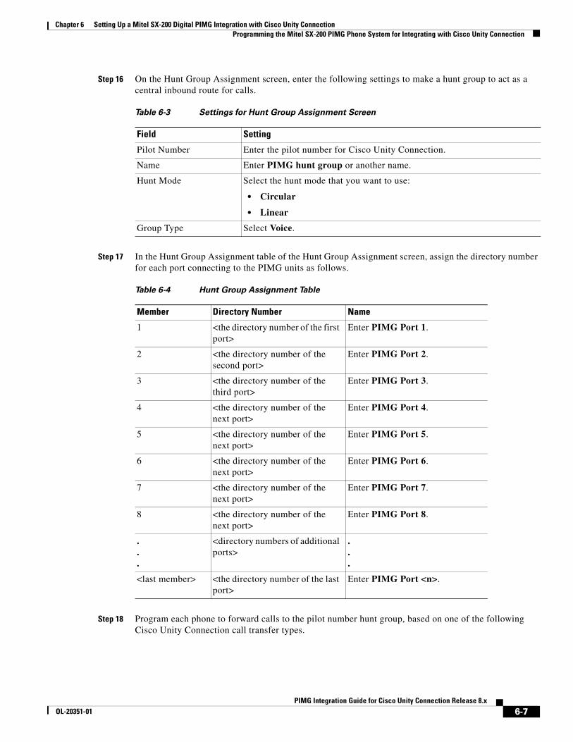
Chapter 6 Setting Up a Mitel SX-200 Digital PIMG Integration with Cisco Unity Connection Programming the Mitel SX-200 PIMG Phone System for Integrating with Cisco Unity Connection
Step 16 On the Hunt Group Assignment screen, enter the following settings to make a hunt group to act as a central inbound route for calls.
Step 17 In the Hunt Group Assignment table of the Hunt Group Assignment screen, assign the directory number for each port connecting to the PIMG units as follows.
Step 18 Program each phone to forward calls to the pilot number hunt group, based on one of the following Cisco Unity Connection call transfer types.
Table 6-3 Settings for Hunt Group Assignment Screen
Field Setting
Pilot Number Enter the pilot number for Cisco Unity Connection.
Name Enter PIMG hunt group or another name.
Hunt Mode Select the hunt mode that you want to use:
• Circular
• Linear
Group Type Select Voice.
Table 6-4 Hunt Group Assignment Table
Member Directory Number Name
1 <the directory number of the first port>
Enter PIMG Port 1.
2 <the directory number of the second port>
Enter PIMG Port 2.
3 <the directory number of the third port>
Enter PIMG Port 3.
4 <the directory number of the next port>
Enter PIMG Port 4.
5 <the directory number of the next port>
Enter PIMG Port 5.
6 <the directory number of the next port>
Enter PIMG Port 6.
7 <the directory number of the next port>
Enter PIMG Port 7.
8 <the directory number of the next port>
Enter PIMG Port 8.
.
.
.
<directory numbers of additional ports>
.
.
.
<last member> <the directory number of the last port>
Enter PIMG Port <n>.
6-7PIMG Integration Guide for Cisco Unity Connection Release 8.x
OL-20351-01
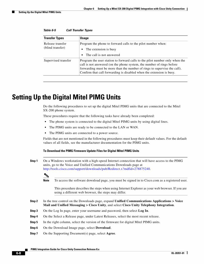
Chapter 6 Setting Up a Mitel SX-200 Digital PIMG Integration with Cisco Unity Connection Setting Up the Digital Mitel PIMG Units
Setting Up the Digital Mitel PIMG UnitsDo the following procedures to set up the digital Mitel PIMG units that are connected to the Mitel SX-200 phone system.
These procedures require that the following tasks have already been completed:
• The phone system is connected to the digital Mitel PIMG units by using digital lines.
• The PIMG units are ready to be connected to the LAN or WAN.
• The PIMG units are connected to a power source.
Fields that are not mentioned in the following procedures must keep their default values. For the default values of all fields, see the manufacturer documentation for the PIMG units.
To Download the PIMG Firmware Update Files for Digital Mitel PIMG Units
Step 1 On a Windows workstation with a high-speed Internet connection that will have access to the PIMG units, go to the Voice and Unified Communications Downloads page at http://tools.cisco.com/support/downloads/pub/Redirect.x?mdfid=278875240.
Note To access the software download page, you must be signed in to Cisco.com as a registered user. This procedure describes the steps when using Internet Explorer as your web browser. If you are using a different web browser, the steps may differ.
Step 2 In the tree control on the Downloads page, expand Unified Communications Applications > Voice Mail and Unified Messaging > Cisco Unity, and select Cisco Unity Telephony Integration.
Step 3 On the Log In page, enter your username and password, then select Log In.
Step 4 On the Select a Release page, under Latest Releases, select the most recent release.
Step 5 In the right column, select the version of the firmware for digital Mitel PIMG units.
Step 6 On the Download Image page, select Download.
Step 7 On the Supporting Document(s) page, select Agree.
Table 6-5 Call Transfer Types
Transfer Types Usage
Release transfer (blind transfer)
Program the phone to forward calls to the pilot number when:
• The extension is busy
• The call is not answered
Supervised transfer Program the user station to forward calls to the pilot number only when the call is not answered (on the phone system, the number of rings before forwarding must be more than the number of rings to supervise the call). Confirm that call forwarding is disabled when the extension is busy.
6-8PIMG Integration Guide for Cisco Unity Connection Release 8.x
OL-20351-01
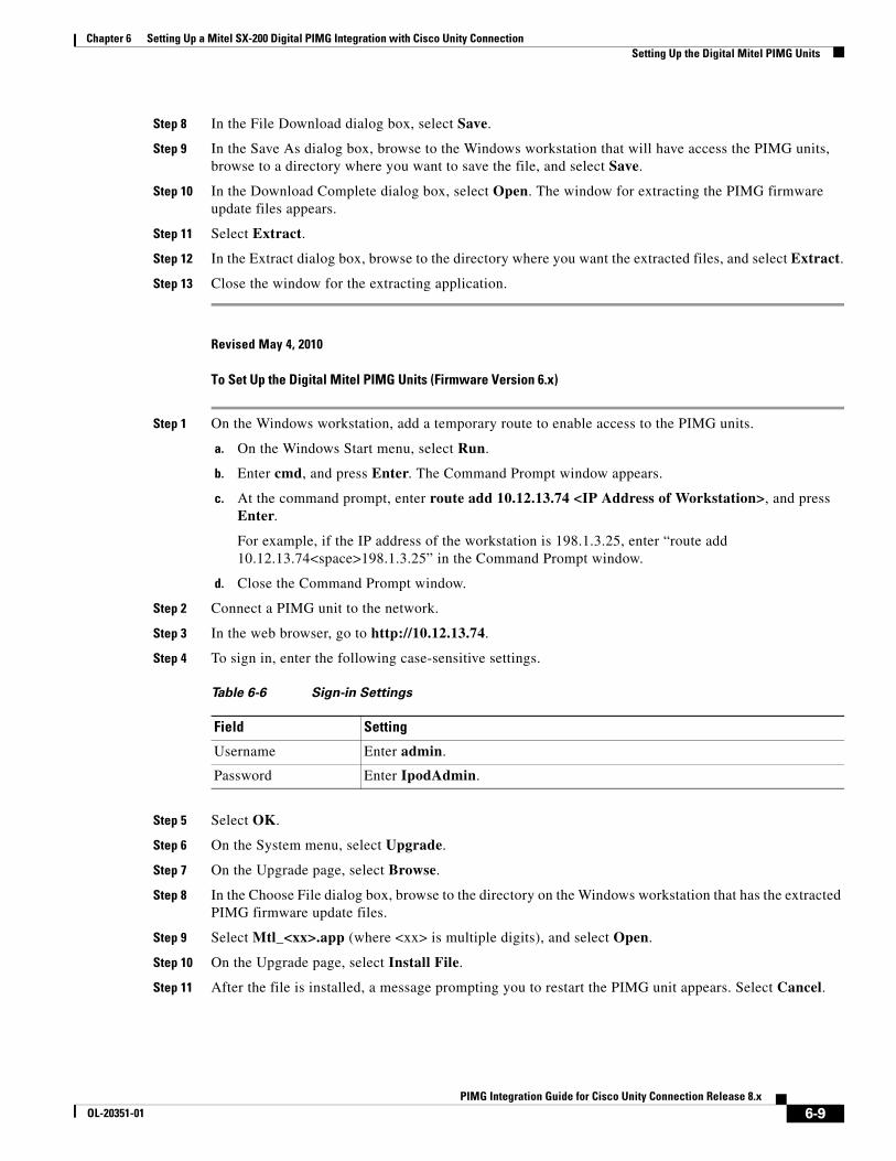
Chapter 6 Setting Up a Mitel SX-200 Digital PIMG Integration with Cisco Unity Connection Setting Up the Digital Mitel PIMG Units
Step 8 In the File Download dialog box, select Save.
Step 9 In the Save As dialog box, browse to the Windows workstation that will have access the PIMG units, browse to a directory where you want to save the file, and select Save.
Step 10 In the Download Complete dialog box, select Open. The window for extracting the PIMG firmware update files appears.
Step 11 Select Extract.
Step 12 In the Extract dialog box, browse to the directory where you want the extracted files, and select Extract.
Step 13 Close the window for the extracting application.
Revised May 4, 2010
To Set Up the Digital Mitel PIMG Units (Firmware Version 6.x)
Step 1 On the Windows workstation, add a temporary route to enable access to the PIMG units.
a. On the Windows Start menu, select Run.
b. Enter cmd, and press Enter. The Command Prompt window appears.
c. At the command prompt, enter route add 10.12.13.74 <IP Address of Workstation>, and press Enter.
For example, if the IP address of the workstation is 198.1.3.25, enter “route add 10.12.13.74<space>198.1.3.25” in the Command Prompt window.
d. Close the Command Prompt window.
Step 2 Connect a PIMG unit to the network.
Step 3 In the web browser, go to http://10.12.13.74.
Step 4 To sign in, enter the following case-sensitive settings.
Step 5 Select OK.
Step 6 On the System menu, select Upgrade.
Step 7 On the Upgrade page, select Browse.
Step 8 In the Choose File dialog box, browse to the directory on the Windows workstation that has the extracted PIMG firmware update files.
Step 9 Select Mtl_<xx>.app (where <xx> is multiple digits), and select Open.
Step 10 On the Upgrade page, select Install File.
Step 11 After the file is installed, a message prompting you to restart the PIMG unit appears. Select Cancel.
Table 6-6 Sign-in Settings
Field Setting
Username Enter admin.
Password Enter IpodAdmin.
6-9PIMG Integration Guide for Cisco Unity Connection Release 8.x
OL-20351-01
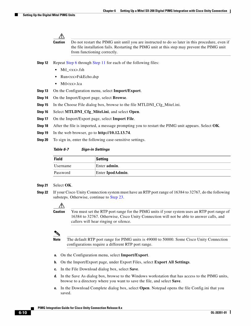
Chapter 6 Setting Up a Mitel SX-200 Digital PIMG Integration with Cisco Unity Connection Setting Up the Digital Mitel PIMG Units
Caution Do not restart the PIMG unit until you are instructed to do so later in this procedure, even if the file installation fails. Restarting the PIMG unit at this step may prevent the PIMG unit from functioning correctly.
Step 12 Repeat Step 6 through Step 11 for each of the following files:
• Mtl_<xx>.fsh
• Run<xx>FskEcho.dsp
• Mtl<xx>.lca
Step 13 On the Configuration menu, select Import/Export.
Step 14 On the Import/Export page, select Browse.
Step 15 In the Choose File dialog box, browse to the file MTLDNI_Cfg_Mitel.ini.
Step 16 Select MTLDNI_Cfg_Mitel.ini, and select Open.
Step 17 On the Import/Export page, select Import File.
Step 18 After the file is imported, a message prompting you to restart the PIMG unit appears. Select OK.
Step 19 In the web browser, go to http://10.12.13.74.
Step 20 To sign in, enter the following case-sensitive settings.
Step 21 Select OK.
Step 22 If your Cisco Unity Connection system must have an RTP port range of 16384 to 32767, do the following substeps. Otherwise, continue to Step 23.
Caution You must set the RTP port range for the PIMG units if your system uses an RTP port range of 16384 to 32767. Otherwise, Cisco Unity Connection will not be able to answer calls, and callers will hear ringing or silence.
Note The default RTP port range for PIMG units is 49000 to 50000. Some Cisco Unity Connection configurations require a different RTP port range.
a. On the Configuration menu, select Import/Export.
b. On the Import/Export page, under Export Files, select Export All Settings.
c. In the File Download dialog box, select Save.
d. In the Save As dialog box, browse to the Windows workstation that has access to the PIMG units, browse to a directory where you want to save the file, and select Save.
e. In the Download Complete dialog box, select Open. Notepad opens the file Config.ini that you saved.
Table 6-7 Sign-in Settings
Field Setting
Username Enter admin.
Password Enter IpodAdmin.
6-10PIMG Integration Guide for Cisco Unity Connection Release 8.x
OL-20351-01
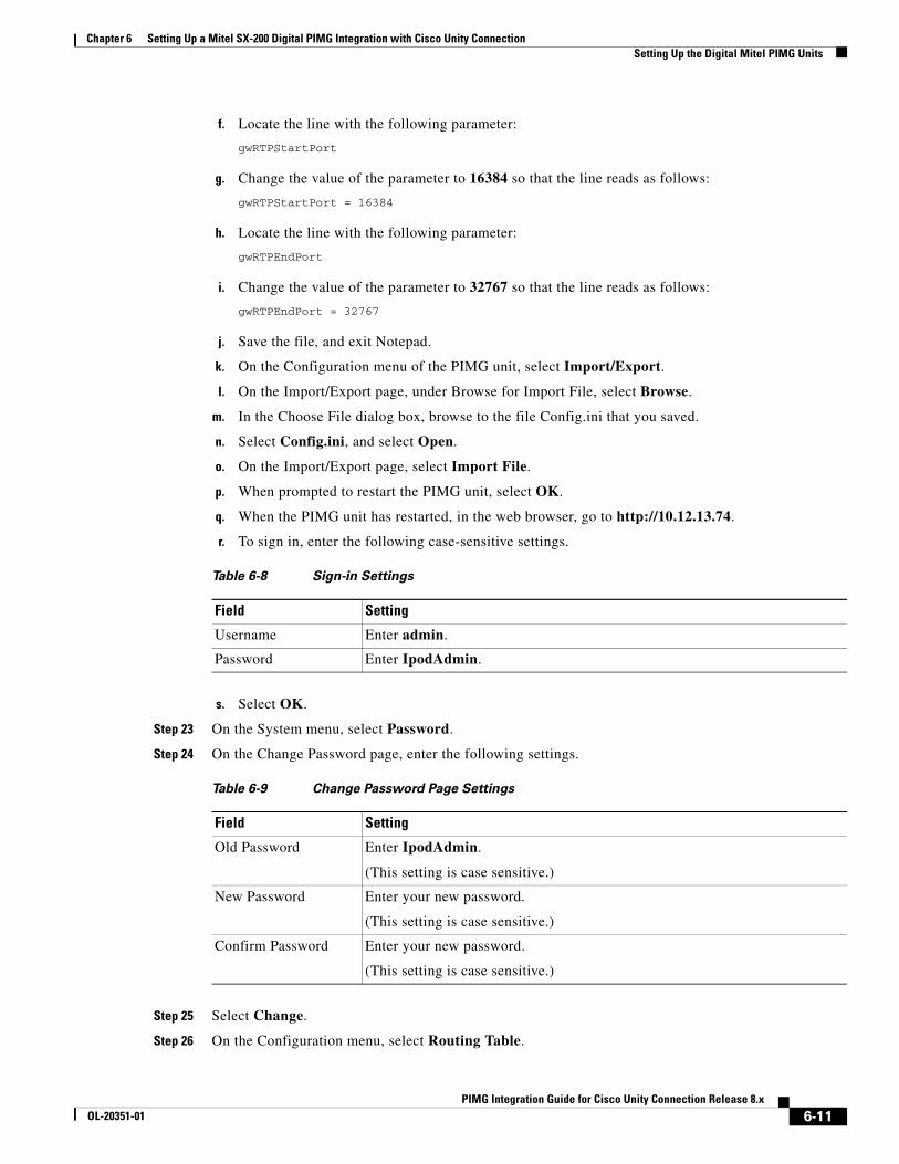
Chapter 6 Setting Up a Mitel SX-200 Digital PIMG Integration with Cisco Unity Connection Setting Up the Digital Mitel PIMG Units
f. Locate the line with the following parameter:
gwRTPStartPort
g. Change the value of the parameter to 16384 so that the line reads as follows:
gwRTPStartPort = 16384
h. Locate the line with the following parameter:
gwRTPEndPort
i. Change the value of the parameter to 32767 so that the line reads as follows:
gwRTPEndPort = 32767
j. Save the file, and exit Notepad.
k. On the Configuration menu of the PIMG unit, select Import/Export.
l. On the Import/Export page, under Browse for Import File, select Browse.
m. In the Choose File dialog box, browse to the file Config.ini that you saved.
n. Select Config.ini, and select Open.
o. On the Import/Export page, select Import File.
p. When prompted to restart the PIMG unit, select OK.
q. When the PIMG unit has restarted, in the web browser, go to http://10.12.13.74.
r. To sign in, enter the following case-sensitive settings.
s. Select OK.
Step 23 On the System menu, select Password.
Step 24 On the Change Password page, enter the following settings.
Step 25 Select Change.
Step 26 On the Configuration menu, select Routing Table.
Table 6-8 Sign-in Settings
Field Setting
Username Enter admin.
Password Enter IpodAdmin.
Table 6-9 Change Password Page Settings
Field Setting
Old Password Enter IpodAdmin.
(This setting is case sensitive.)
New Password Enter your new password.
(This setting is case sensitive.)
Confirm Password Enter your new password.
(This setting is case sensitive.)
6-11PIMG Integration Guide for Cisco Unity Connection Release 8.x
OL-20351-01
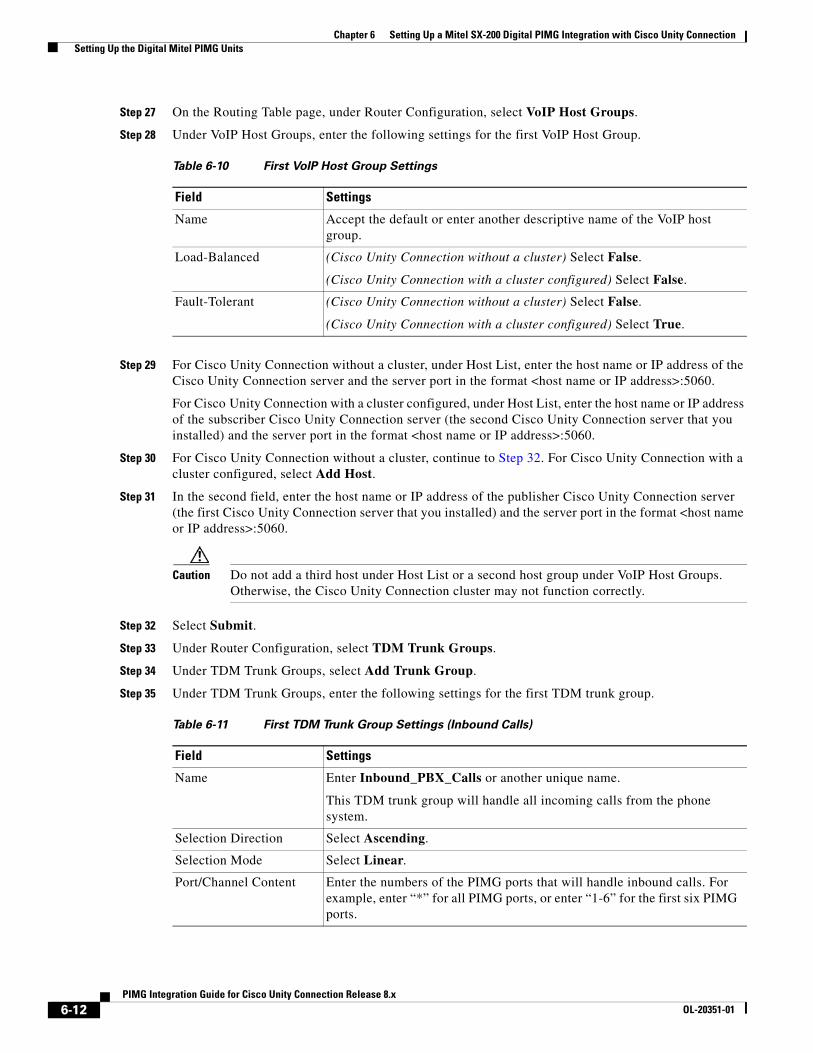
Chapter 6 Setting Up a Mitel SX-200 Digital PIMG Integration with Cisco Unity Connection Setting Up the Digital Mitel PIMG Units
Step 27 On the Routing Table page, under Router Configuration, select VoIP Host Groups.
Step 28 Under VoIP Host Groups, enter the following settings for the first VoIP Host Group.
Step 29 For Cisco Unity Connection without a cluster, under Host List, enter the host name or IP address of the Cisco Unity Connection server and the server port in the format <host name or IP address>:5060.
For Cisco Unity Connection with a cluster configured, under Host List, enter the host name or IP address of the subscriber Cisco Unity Connection server (the second Cisco Unity Connection server that you installed) and the server port in the format <host name or IP address>:5060.
Step 30 For Cisco Unity Connection without a cluster, continue to Step 32. For Cisco Unity Connection with a cluster configured, select Add Host.
Step 31 In the second field, enter the host name or IP address of the publisher Cisco Unity Connection server (the first Cisco Unity Connection server that you installed) and the server port in the format <host name or IP address>:5060.
Caution Do not add a third host under Host List or a second host group under VoIP Host Groups. Otherwise, the Cisco Unity Connection cluster may not function correctly.
Step 32 Select Submit.
Step 33 Under Router Configuration, select TDM Trunk Groups.
Step 34 Under TDM Trunk Groups, select Add Trunk Group.
Step 35 Under TDM Trunk Groups, enter the following settings for the first TDM trunk group.
Table 6-10 First VoIP Host Group Settings
Field Settings
Name Accept the default or enter another descriptive name of the VoIP host group.
Load-Balanced (Cisco Unity Connection without a cluster) Select False.
(Cisco Unity Connection with a cluster configured) Select False.
Fault-Tolerant (Cisco Unity Connection without a cluster) Select False.
(Cisco Unity Connection with a cluster configured) Select True.
Table 6-11 First TDM Trunk Group Settings (Inbound Calls)
Field Settings
Name Enter Inbound_PBX_Calls or another unique name.
This TDM trunk group will handle all incoming calls from the phone system.
Selection Direction Select Ascending.
Selection Mode Select Linear.
Port/Channel Content Enter the numbers of the PIMG ports that will handle inbound calls. For example, enter “*” for all PIMG ports, or enter “1-6” for the first six PIMG ports.
6-12PIMG Integration Guide for Cisco Unity Connection Release 8.x
OL-20351-01
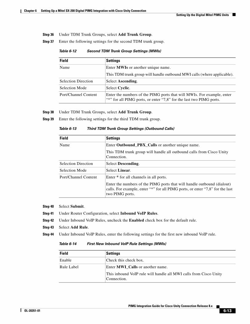
Chapter 6 Setting Up a Mitel SX-200 Digital PIMG Integration with Cisco Unity Connection Setting Up the Digital Mitel PIMG Units
Step 36 Under TDM Trunk Groups, select Add Trunk Group.
Step 37 Enter the following settings for the second TDM trunk group.
Step 38 Under TDM Trunk Groups, select Add Trunk Group.
Step 39 Enter the following settings for the third TDM trunk group.
Step 40 Select Submit.
Step 41 Under Router Configuration, select Inbound VoIP Rules.
Step 42 Under Inbound VoIP Rules, uncheck the Enabled check box for the default rule.
Step 43 Select Add Rule.
Step 44 Under Inbound VoIP Rules, enter the following settings for the first new inbound VoIP rule.
Table 6-12 Second TDM Trunk Group Settings (MWIs)
Field Settings
Name Enter MWIs or another unique name.
This TDM trunk group will handle outbound MWI calls (where applicable).
Selection Direction Select Ascending.
Selection Mode Select Cyclic.
Port/Channel Content Enter the numbers of the PIMG ports that will MWIs. For example, enter “*” for all PIMG ports, or enter “7,8” for the last two PIMG ports.
Table 6-13 Third TDM Trunk Group Settings (Outbound Calls)
Field Settings
Name Enter Outbound_PBX_Calls or another unique name.
This TDM trunk group will handle all outbound calls from Cisco Unity Connection.
Selection Direction Select Descending.
Selection Mode Select Linear.
Port/Channel Content Enter * for all channels in all ports.
Enter the numbers of the PIMG ports that will handle outbound (dialout) calls. For example, enter “*” for all PIMG ports, or enter “7,8” for the last two PIMG ports.
Table 6-14 First New Inbound VoIP Rule Settings (MWIs)
Field Settings
Enable Check this check box.
Rule Label Enter MWI_Calls or another name.
This inbound VoIP rule will handle all MWI calls from Cisco Unity Connection.
6-13PIMG Integration Guide for Cisco Unity Connection Release 8.x
OL-20351-01
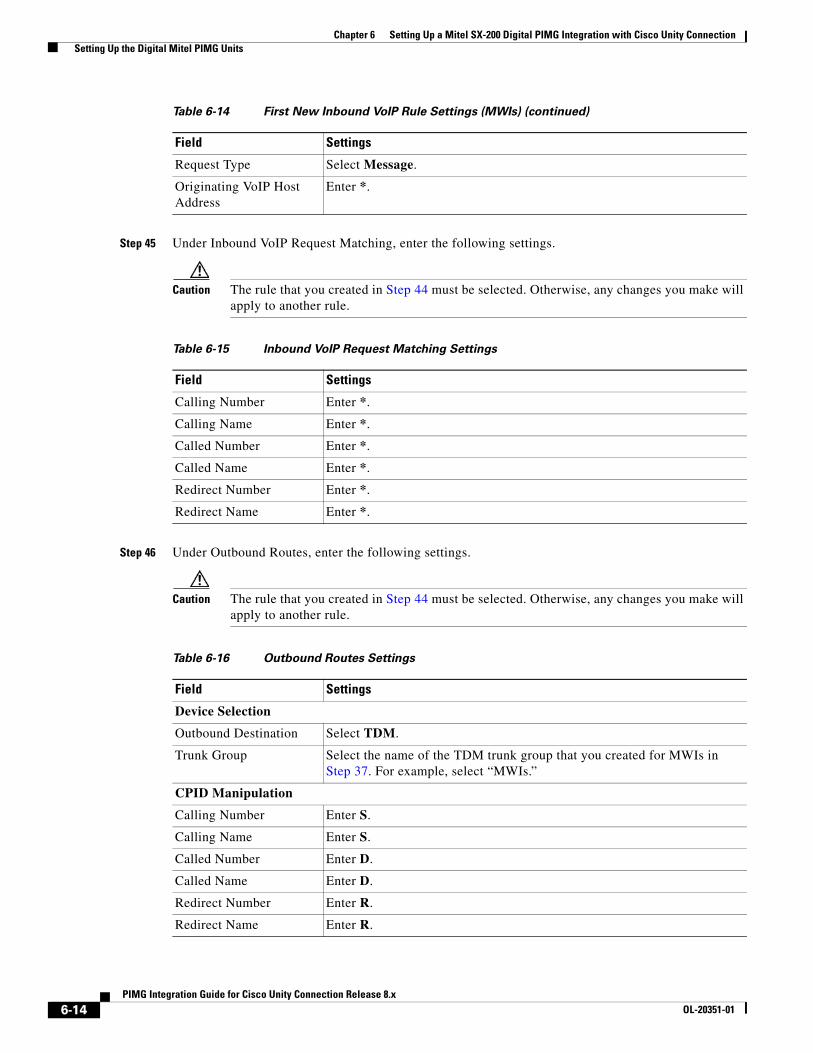
Chapter 6 Setting Up a Mitel SX-200 Digital PIMG Integration with Cisco Unity Connection Setting Up the Digital Mitel PIMG Units
Step 45 Under Inbound VoIP Request Matching, enter the following settings.
Caution The rule that you created in Step 44 must be selected. Otherwise, any changes you make will apply to another rule.
Step 46 Under Outbound Routes, enter the following settings.
Caution The rule that you created in Step 44 must be selected. Otherwise, any changes you make will apply to another rule.
Request Type Select Message.
Originating VoIP Host Address
Enter *.
Table 6-14 First New Inbound VoIP Rule Settings (MWIs) (continued)
Field Settings
Table 6-15 Inbound VoIP Request Matching Settings
Field Settings
Calling Number Enter *.
Calling Name Enter *.
Called Number Enter *.
Called Name Enter *.
Redirect Number Enter *.
Redirect Name Enter *.
Table 6-16 Outbound Routes Settings
Field Settings
Device Selection
Outbound Destination Select TDM.
Trunk Group Select the name of the TDM trunk group that you created for MWIs in Step 37. For example, select “MWIs.”
CPID Manipulation
Calling Number Enter S.
Calling Name Enter S.
Called Number Enter D.
Called Name Enter D.
Redirect Number Enter R.
Redirect Name Enter R.
6-14PIMG Integration Guide for Cisco Unity Connection Release 8.x
OL-20351-01
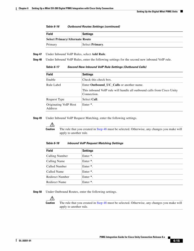
Chapter 6 Setting Up a Mitel SX-200 Digital PIMG Integration with Cisco Unity Connection Setting Up the Digital Mitel PIMG Units
Step 47 Under Inbound VoIP Rules, select Add Rule.
Step 48 Under Inbound VoIP Rules, enter the following settings for the second new inbound VoIP rule.
Step 49 Under Inbound VoIP Request Matching, enter the following settings.
Caution The rule that you created in Step 48 must be selected. Otherwise, any changes you make will apply to another rule.
Step 50 Under Outbound Routes, enter the following settings.
Caution The rule that you created in Step 48 must be selected. Otherwise, any changes you make will apply to another rule.
Select Primary/Alternate Route
Primary Select Primary.
Table 6-17 Second New Inbound VoIP Rule Settings (Outbound Calls)
Field Settings
Enable Check this check box.
Rule Label Enter Outbound_UC_Calls or another name.
This inbound VoIP rule will handle all outbound calls from Cisco Unity Connection.
Request Type Select Call.
Originating VoIP Host Address
Enter *.
Table 6-16 Outbound Routes Settings (continued)
Field Settings
Table 6-18 Inbound VoIP Request Matching Settings
Field Settings
Calling Number Enter *.
Calling Name Enter *.
Called Number Enter *.
Called Name Enter *.
Redirect Number Enter *.
Redirect Name Enter *.
6-15PIMG Integration Guide for Cisco Unity Connection Release 8.x
OL-20351-01
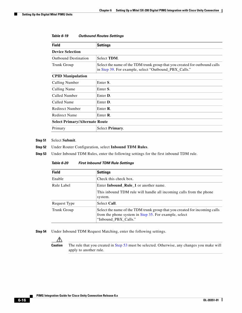
Chapter 6 Setting Up a Mitel SX-200 Digital PIMG Integration with Cisco Unity Connection Setting Up the Digital Mitel PIMG Units
Step 51 Select Submit.
Step 52 Under Router Configuration, select Inbound TDM Rules.
Step 53 Under Inbound TDM Rules, enter the following settings for the first inbound TDM rule.
Step 54 Under Inbound TDM Request Matching, enter the following settings.
Caution The rule that you created in Step 53 must be selected. Otherwise, any changes you make will apply to another rule.
Table 6-19 Outbound Routes Settings
Field Settings
Device Selection
Outbound Destination Select TDM.
Trunk Group Select the name of the TDM trunk group that you created for outbound calls in Step 39. For example, select “Outbound_PBX_Calls.”
CPID Manipulation
Calling Number Enter S.
Calling Name Enter S.
Called Number Enter D.
Called Name Enter D.
Redirect Number Enter R.
Redirect Name Enter R.
Select Primary/Alternate Route
Primary Select Primary.
Table 6-20 First Inbound TDM Rule Settings
Field Settings
Enable Check this check box.
Rule Label Enter Inbound_Rule_1 or another name.
This inbound TDM rule will handle all incoming calls from the phone system.
Request Type Select Call.
Trunk Group Select the name of the TDM trunk group that you created for incoming calls from the phone system in Step 35. For example, select “Inbound_PBX_Calls.”
6-16PIMG Integration Guide for Cisco Unity Connection Release 8.x
OL-20351-01
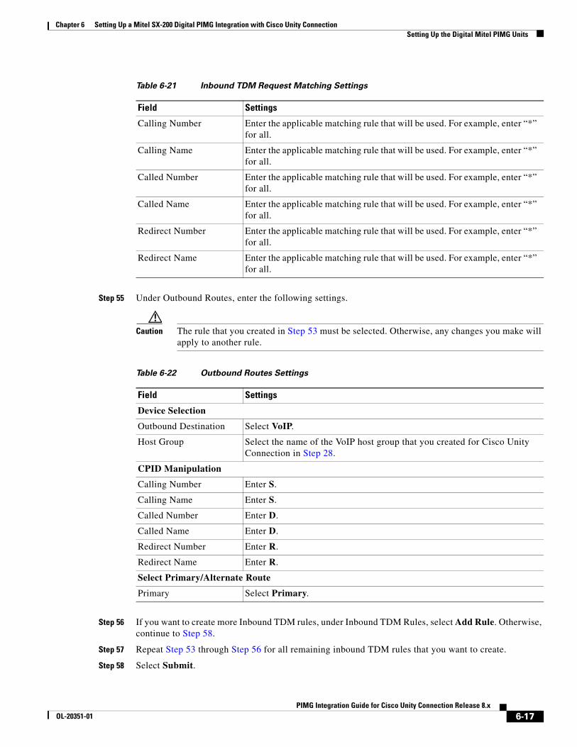
Chapter 6 Setting Up a Mitel SX-200 Digital PIMG Integration with Cisco Unity Connection Setting Up the Digital Mitel PIMG Units
Step 55 Under Outbound Routes, enter the following settings.
Caution The rule that you created in Step 53 must be selected. Otherwise, any changes you make will apply to another rule.
Step 56 If you want to create more Inbound TDM rules, under Inbound TDM Rules, select Add Rule. Otherwise, continue to Step 58.
Step 57 Repeat Step 53 through Step 56 for all remaining inbound TDM rules that you want to create.
Step 58 Select Submit.
Table 6-21 Inbound TDM Request Matching Settings
Field Settings
Calling Number Enter the applicable matching rule that will be used. For example, enter “*” for all.
Calling Name Enter the applicable matching rule that will be used. For example, enter “*” for all.
Called Number Enter the applicable matching rule that will be used. For example, enter “*” for all.
Called Name Enter the applicable matching rule that will be used. For example, enter “*” for all.
Redirect Number Enter the applicable matching rule that will be used. For example, enter “*” for all.
Redirect Name Enter the applicable matching rule that will be used. For example, enter “*” for all.
Table 6-22 Outbound Routes Settings
Field Settings
Device Selection
Outbound Destination Select VoIP.
Host Group Select the name of the VoIP host group that you created for Cisco Unity Connection in Step 28.
CPID Manipulation
Calling Number Enter S.
Calling Name Enter S.
Called Number Enter D.
Called Name Enter D.
Redirect Number Enter R.
Redirect Name Enter R.
Select Primary/Alternate Route
Primary Select Primary.
6-17PIMG Integration Guide for Cisco Unity Connection Release 8.x
OL-20351-01
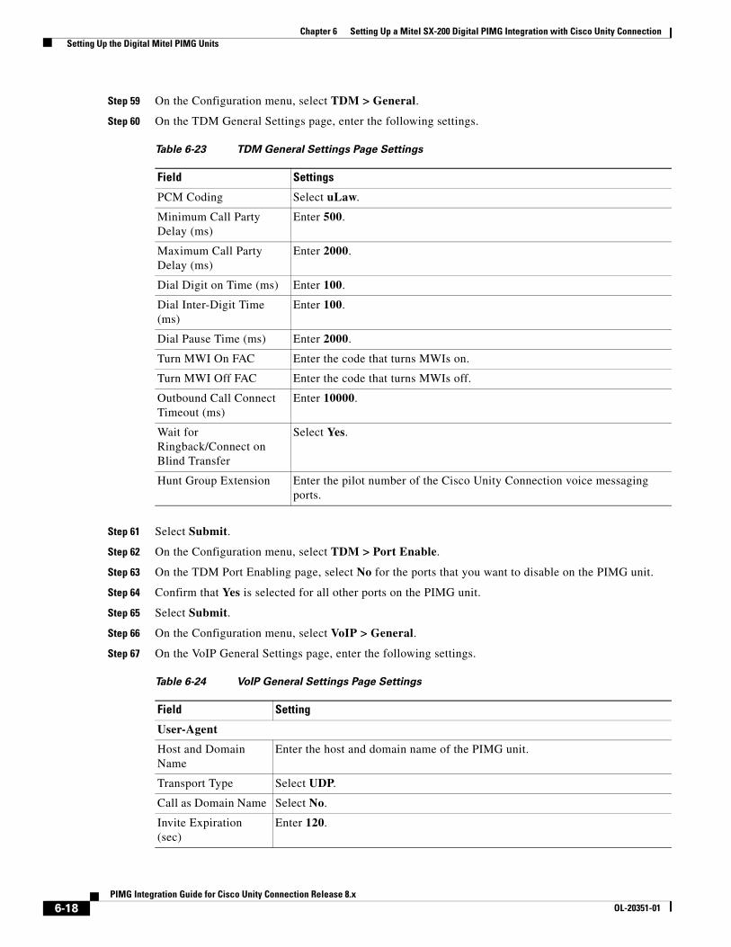
Chapter 6 Setting Up a Mitel SX-200 Digital PIMG Integration with Cisco Unity Connection Setting Up the Digital Mitel PIMG Units
Step 59 On the Configuration menu, select TDM > General.
Step 60 On the TDM General Settings page, enter the following settings.
Step 61 Select Submit.
Step 62 On the Configuration menu, select TDM > Port Enable.
Step 63 On the TDM Port Enabling page, select No for the ports that you want to disable on the PIMG unit.
Step 64 Confirm that Yes is selected for all other ports on the PIMG unit.
Step 65 Select Submit.
Step 66 On the Configuration menu, select VoIP > General.
Step 67 On the VoIP General Settings page, enter the following settings.
Table 6-23 TDM General Settings Page Settings
Field Settings
PCM Coding Select uLaw.
Minimum Call Party Delay (ms)
Enter 500.
Maximum Call Party Delay (ms)
Enter 2000.
Dial Digit on Time (ms) Enter 100.
Dial Inter-Digit Time (ms)
Enter 100.
Dial Pause Time (ms) Enter 2000.
Turn MWI On FAC Enter the code that turns MWIs on.
Turn MWI Off FAC Enter the code that turns MWIs off.
Outbound Call Connect Timeout (ms)
Enter 10000.
Wait for Ringback/Connect on Blind Transfer
Select Yes.
Hunt Group Extension Enter the pilot number of the Cisco Unity Connection voice messaging ports.
Table 6-24 VoIP General Settings Page Settings
Field Setting
User-Agent
Host and Domain Name
Enter the host and domain name of the PIMG unit.
Transport Type Select UDP.
Call as Domain Name Select No.
Invite Expiration (sec)
Enter 120.
6-18PIMG Integration Guide for Cisco Unity Connection Release 8.x
OL-20351-01
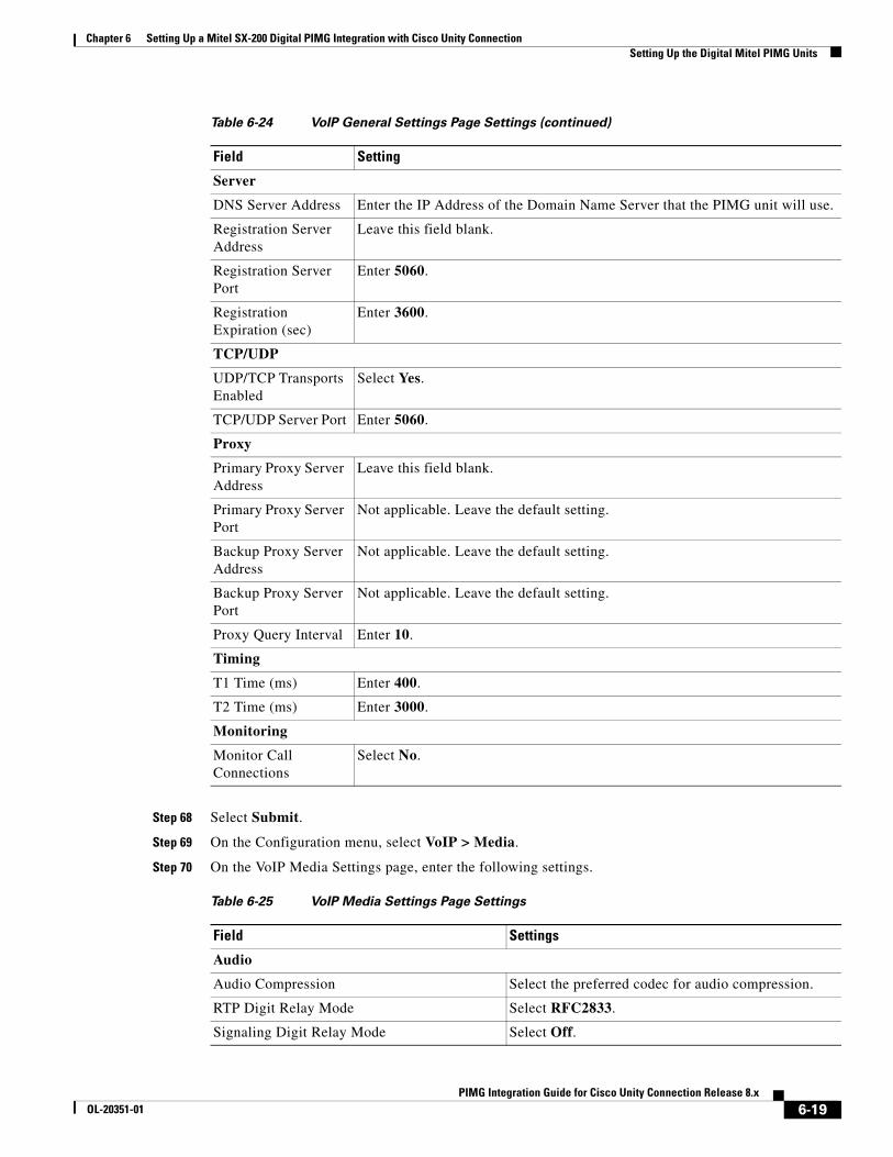
Chapter 6 Setting Up a Mitel SX-200 Digital PIMG Integration with Cisco Unity Connection Setting Up the Digital Mitel PIMG Units
Step 68 Select Submit.
Step 69 On the Configuration menu, select VoIP > Media.
Step 70 On the VoIP Media Settings page, enter the following settings.
Server
DNS Server Address Enter the IP Address of the Domain Name Server that the PIMG unit will use.
Registration Server Address
Leave this field blank.
Registration Server Port
Enter 5060.
Registration Expiration (sec)
Enter 3600.
TCP/UDP
UDP/TCP Transports Enabled
Select Yes.
TCP/UDP Server Port Enter 5060.
Proxy
Primary Proxy Server Address
Leave this field blank.
Primary Proxy Server Port
Not applicable. Leave the default setting.
Backup Proxy Server Address
Not applicable. Leave the default setting.
Backup Proxy Server Port
Not applicable. Leave the default setting.
Proxy Query Interval Enter 10.
Timing
T1 Time (ms) Enter 400.
T2 Time (ms) Enter 3000.
Monitoring
Monitor Call Connections
Select No.
Table 6-25 VoIP Media Settings Page Settings
Field Settings
Audio
Audio Compression Select the preferred codec for audio compression.
RTP Digit Relay Mode Select RFC2833.
Signaling Digit Relay Mode Select Off.
Table 6-24 VoIP General Settings Page Settings (continued)
Field Setting
6-19PIMG Integration Guide for Cisco Unity Connection Release 8.x
OL-20351-01
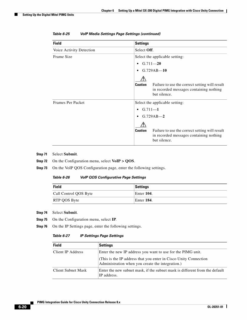
Chapter 6 Setting Up a Mitel SX-200 Digital PIMG Integration with Cisco Unity Connection Setting Up the Digital Mitel PIMG Units
Step 71 Select Submit.
Step 72 On the Configuration menu, select VoIP > QOS.
Step 73 On the VoIP QOS Configuration page, enter the following settings.
Step 74 Select Submit.
Step 75 On the Configuration menu, select IP.
Step 76 On the IP Settings page, enter the following settings.
Voice Activity Detection Select Off.
Frame Size Select the applicable setting:
• G.711—20
• G.729AB—10
Caution Failure to use the correct setting will result in recorded messages containing nothing but silence.
Frames Per Packet Select the applicable setting:
• G.711—1
• G.729AB—2
Caution Failure to use the correct setting will result in recorded messages containing nothing but silence.
Table 6-26 VoIP QOS Configurative Page Settings
Field Settings
Call Control QOS Byte Enter 104.
RTP QOS Byte Enter 184.
Table 6-27 IP Settings Page Settings
Field Settings
Client IP Address Enter the new IP address you want to use for the PIMG unit.
(This is the IP address that you enter in Cisco Unity Connection Administration when you create the integration.)
Client Subnet Mask Enter the new subnet mask, if the subnet mask is different from the default IP address.
Table 6-25 VoIP Media Settings Page Settings (continued)
Field Settings
6-20PIMG Integration Guide for Cisco Unity Connection Release 8.x
OL-20351-01
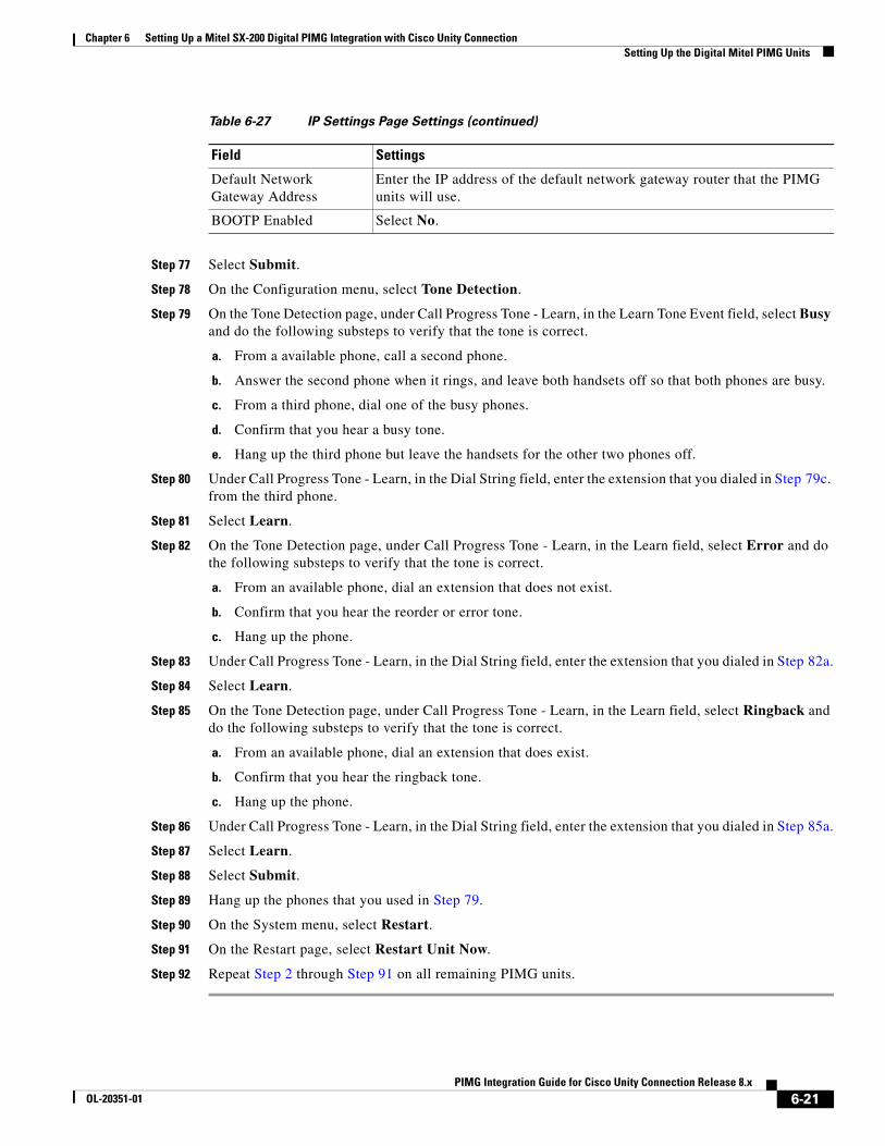
Chapter 6 Setting Up a Mitel SX-200 Digital PIMG Integration with Cisco Unity Connection Setting Up the Digital Mitel PIMG Units
Step 77 Select Submit.
Step 78 On the Configuration menu, select Tone Detection.
Step 79 On the Tone Detection page, under Call Progress Tone - Learn, in the Learn Tone Event field, select Busy and do the following substeps to verify that the tone is correct.
a. From a available phone, call a second phone.
b. Answer the second phone when it rings, and leave both handsets off so that both phones are busy.
c. From a third phone, dial one of the busy phones.
d. Confirm that you hear a busy tone.
e. Hang up the third phone but leave the handsets for the other two phones off.
Step 80 Under Call Progress Tone - Learn, in the Dial String field, enter the extension that you dialed in Step 79c. from the third phone.
Step 81 Select Learn.
Step 82 On the Tone Detection page, under Call Progress Tone - Learn, in the Learn field, select Error and do the following substeps to verify that the tone is correct.
a. From an available phone, dial an extension that does not exist.
b. Confirm that you hear the reorder or error tone.
c. Hang up the phone.
Step 83 Under Call Progress Tone - Learn, in the Dial String field, enter the extension that you dialed in Step 82a.
Step 84 Select Learn.
Step 85 On the Tone Detection page, under Call Progress Tone - Learn, in the Learn field, select Ringback and do the following substeps to verify that the tone is correct.
a. From an available phone, dial an extension that does exist.
b. Confirm that you hear the ringback tone.
c. Hang up the phone.
Step 86 Under Call Progress Tone - Learn, in the Dial String field, enter the extension that you dialed in Step 85a.
Step 87 Select Learn.
Step 88 Select Submit.
Step 89 Hang up the phones that you used in Step 79.
Step 90 On the System menu, select Restart.
Step 91 On the Restart page, select Restart Unit Now.
Step 92 Repeat Step 2 through Step 91 on all remaining PIMG units.
Default Network Gateway Address
Enter the IP address of the default network gateway router that the PIMG units will use.
BOOTP Enabled Select No.
Table 6-27 IP Settings Page Settings (continued)
Field Settings
6-21PIMG Integration Guide for Cisco Unity Connection Release 8.x
OL-20351-01
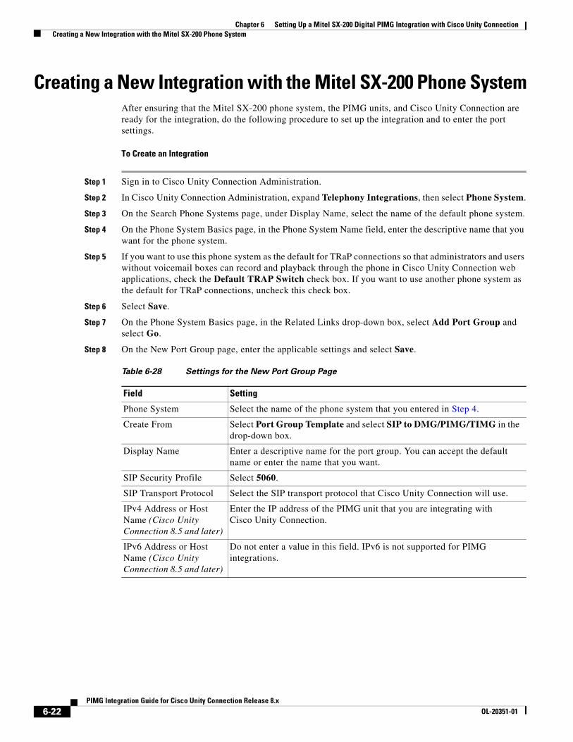
Chapter 6 Setting Up a Mitel SX-200 Digital PIMG Integration with Cisco Unity Connection Creating a New Integration with the Mitel SX-200 Phone System
Creating a New Integration with the Mitel SX-200 Phone SystemAfter ensuring that the Mitel SX-200 phone system, the PIMG units, and Cisco Unity Connection are ready for the integration, do the following procedure to set up the integration and to enter the port settings.
To Create an Integration
Step 1 Sign in to Cisco Unity Connection Administration.
Step 2 In Cisco Unity Connection Administration, expand Telephony Integrations, then select Phone System.
Step 3 On the Search Phone Systems page, under Display Name, select the name of the default phone system.
Step 4 On the Phone System Basics page, in the Phone System Name field, enter the descriptive name that you want for the phone system.
Step 5 If you want to use this phone system as the default for TRaP connections so that administrators and users without voicemail boxes can record and playback through the phone in Cisco Unity Connection web applications, check the Default TRAP Switch check box. If you want to use another phone system as the default for TRaP connections, uncheck this check box.
Step 6 Select Save.
Step 7 On the Phone System Basics page, in the Related Links drop-down box, select Add Port Group and select Go.
Step 8 On the New Port Group page, enter the applicable settings and select Save.
Table 6-28 Settings for the New Port Group Page
Field Setting
Phone System Select the name of the phone system that you entered in Step 4.
Create From Select Port Group Template and select SIP to DMG/PIMG/TIMG in the drop-down box.
Display Name Enter a descriptive name for the port group. You can accept the default name or enter the name that you want.
SIP Security Profile Select 5060.
SIP Transport Protocol Select the SIP transport protocol that Cisco Unity Connection will use.
IPv4 Address or Host Name (Cisco Unity Connection 8.5 and later)
Enter the IP address of the PIMG unit that you are integrating with Cisco Unity Connection.
IPv6 Address or Host Name (Cisco Unity Connection 8.5 and later)
Do not enter a value in this field. IPv6 is not supported for PIMG integrations.
6-22PIMG Integration Guide for Cisco Unity Connection Release 8.x
OL-20351-01
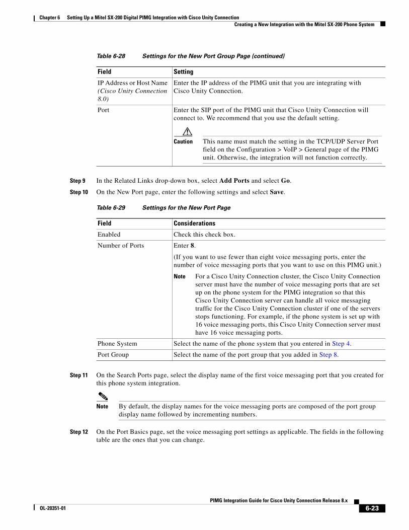
Chapter 6 Setting Up a Mitel SX-200 Digital PIMG Integration with Cisco Unity Connection Creating a New Integration with the Mitel SX-200 Phone System
Step 9 In the Related Links drop-down box, select Add Ports and select Go.
Step 10 On the New Port page, enter the following settings and select Save.
Step 11 On the Search Ports page, select the display name of the first voice messaging port that you created for this phone system integration.
Note By default, the display names for the voice messaging ports are composed of the port group display name followed by incrementing numbers.
Step 12 On the Port Basics page, set the voice messaging port settings as applicable. The fields in the following table are the ones that you can change.
IP Address or Host Name (Cisco Unity Connection 8.0)
Enter the IP address of the PIMG unit that you are integrating with Cisco Unity Connection.
Port Enter the SIP port of the PIMG unit that Cisco Unity Connection will connect to. We recommend that you use the default setting.
Caution This name must match the setting in the TCP/UDP Server Port field on the Configuration > VoIP > General page of the PIMG unit. Otherwise, the integration will not function correctly.
Table 6-29 Settings for the New Port Page
Field Considerations
Enabled Check this check box.
Number of Ports Enter 8.
(If you want to use fewer than eight voice messaging ports, enter the number of voice messaging ports that you want to use on this PIMG unit.)
Note For a Cisco Unity Connection cluster, the Cisco Unity Connection server must have the number of voice messaging ports that are set up on the phone system for the PIMG integration so that this Cisco Unity Connection server can handle all voice messaging traffic for the Cisco Unity Connection cluster if one of the servers stops functioning. For example, if the phone system is set up with 16 voice messaging ports, this Cisco Unity Connection server must have 16 voice messaging ports.
Phone System Select the name of the phone system that you entered in Step 4.
Port Group Select the name of the port group that you added in Step 8.
Table 6-28 Settings for the New Port Group Page (continued)
Field Setting
6-23PIMG Integration Guide for Cisco Unity Connection Release 8.x
OL-20351-01
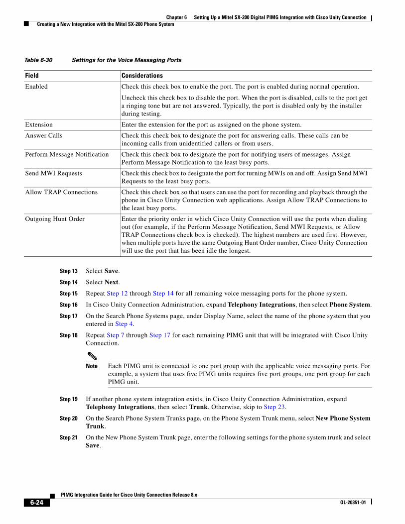
Chapter 6 Setting Up a Mitel SX-200 Digital PIMG Integration with Cisco Unity Connection Creating a New Integration with the Mitel SX-200 Phone System
Step 13 Select Save.
Step 14 Select Next.
Step 15 Repeat Step 12 through Step 14 for all remaining voice messaging ports for the phone system.
Step 16 In Cisco Unity Connection Administration, expand Telephony Integrations, then select Phone System.
Step 17 On the Search Phone Systems page, under Display Name, select the name of the phone system that you entered in Step 4.
Step 18 Repeat Step 7 through Step 17 for each remaining PIMG unit that will be integrated with Cisco Unity Connection.
Note Each PIMG unit is connected to one port group with the applicable voice messaging ports. For example, a system that uses five PIMG units requires five port groups, one port group for each PIMG unit.
Step 19 If another phone system integration exists, in Cisco Unity Connection Administration, expand Telephony Integrations, then select Trunk. Otherwise, skip to Step 23.
Step 20 On the Search Phone System Trunks page, on the Phone System Trunk menu, select New Phone System Trunk.
Step 21 On the New Phone System Trunk page, enter the following settings for the phone system trunk and select Save.
Table 6-30 Settings for the Voice Messaging Ports
Field Considerations
Enabled Check this check box to enable the port. The port is enabled during normal operation.
Uncheck this check box to disable the port. When the port is disabled, calls to the port get a ringing tone but are not answered. Typically, the port is disabled only by the installer during testing.
Extension Enter the extension for the port as assigned on the phone system.
Answer Calls Check this check box to designate the port for answering calls. These calls can be incoming calls from unidentified callers or from users.
Perform Message Notification Check this check box to designate the port for notifying users of messages. Assign Perform Message Notification to the least busy ports.
Send MWI Requests Check this check box to designate the port for turning MWIs on and off. Assign Send MWI Requests to the least busy ports.
Allow TRAP Connections Check this check box so that users can use the port for recording and playback through the phone in Cisco Unity Connection web applications. Assign Allow TRAP Connections to the least busy ports.
Outgoing Hunt Order Enter the priority order in which Cisco Unity Connection will use the ports when dialing out (for example, if the Perform Message Notification, Send MWI Requests, or Allow TRAP Connections check box is checked). The highest numbers are used first. However, when multiple ports have the same Outgoing Hunt Order number, Cisco Unity Connection will use the port that has been idle the longest.
6-24PIMG Integration Guide for Cisco Unity Connection Release 8.x
OL-20351-01
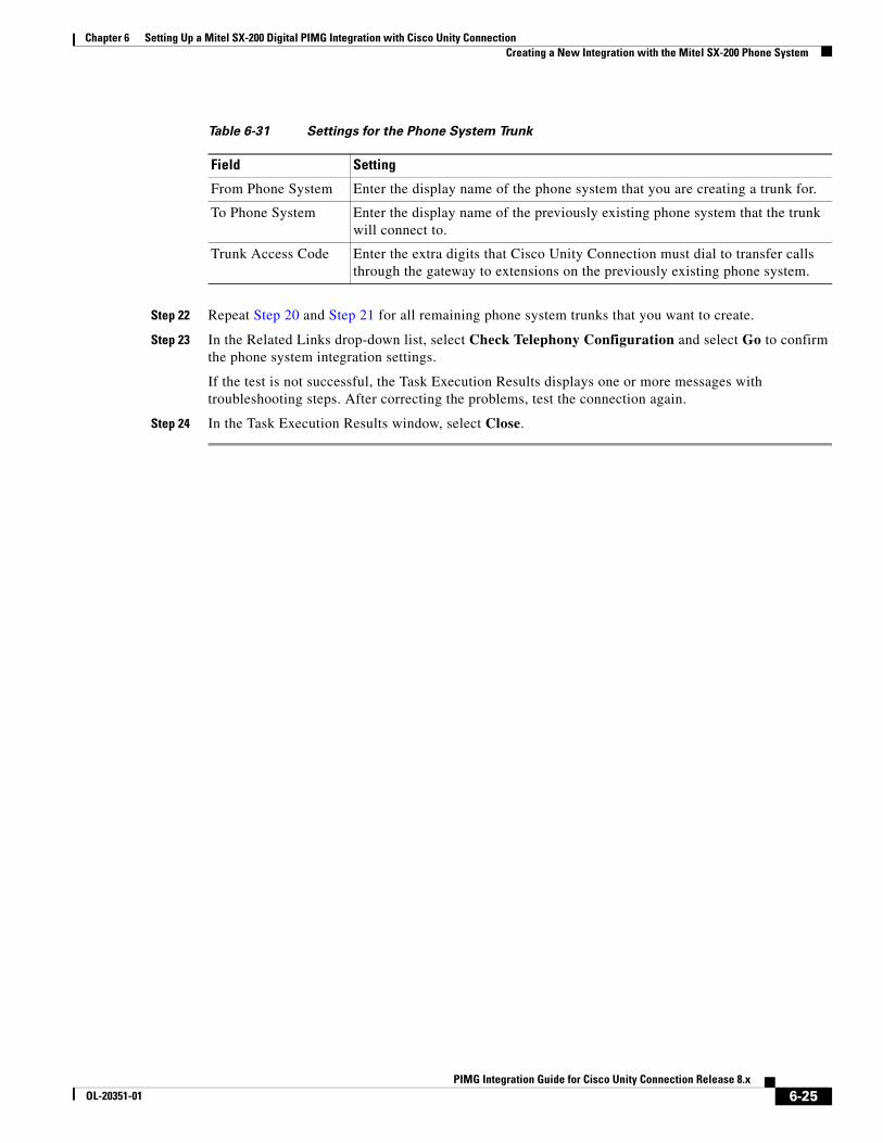
Chapter 6 Setting Up a Mitel SX-200 Digital PIMG Integration with Cisco Unity Connection Creating a New Integration with the Mitel SX-200 Phone System
Step 22 Repeat Step 20 and Step 21 for all remaining phone system trunks that you want to create.
Step 23 In the Related Links drop-down list, select Check Telephony Configuration and select Go to confirm the phone system integration settings.
If the test is not successful, the Task Execution Results displays one or more messages with troubleshooting steps. After correcting the problems, test the connection again.
Step 24 In the Task Execution Results window, select Close.
Table 6-31 Settings for the Phone System Trunk
Field Setting
From Phone System Enter the display name of the phone system that you are creating a trunk for.
To Phone System Enter the display name of the previously existing phone system that the trunk will connect to.
Trunk Access Code Enter the extra digits that Cisco Unity Connection must dial to transfer calls through the gateway to extensions on the previously existing phone system.
6-25PIMG Integration Guide for Cisco Unity Connection Release 8.x
OL-20351-01

Chapter 6 Setting Up a Mitel SX-200 Digital PIMG Integration with Cisco Unity Connection Creating a New Integration with the Mitel SX-200 Phone System
6-26PIMG Integration Guide for Cisco Unity Connection Release 8.x
OL-20351-01

PIMG IntegrOL-20351-01
C H A P T E R 7
Setting Up a Mitel SX-2000 Digital PIMG Integration with Cisco Unity ConnectionFor detailed instructions for setting up a Mitel SX-2000 digital PIMG integration with Cisco Unity Connection, see the following sections in this chapter:
• Task List to Create the Integration with the Mitel SX-2000 PIMG Phone System, page 7-1
• Requirements, page 7-2
• Programming the Mitel SX-2000 PIMG Phone System for Integrating with Cisco Unity Connection, page 7-3
• Setting Up the Digital Mitel PIMG Units, page 7-5
• Creating a New Integration with the Mitel SX-2000 Phone System, page 7-18
Task List to Create the Integration with the Mitel SX-2000 PIMG Phone System
Before doing the following tasks to integrate Cisco Unity Connection with the Mitel SX-2000 phone system by using PIMG units (media gateways), confirm that the Cisco Unity Connection server is ready for the integration by completing the applicable tasks in the Cisco Unity Connection Installation Guide.
1. Review the system and equipment requirements to confirm that all phone system and Cisco Unity Connection server requirements have been met. See the “Requirements” section on page 7-2.
2. Plan how the voice messaging ports will be used by Cisco Unity Connection. See Chapter 2, “Planning How the Voice Messaging Ports Will Be Used by Cisco Unity Connection.”
3. Program the Mitel SX-2000 phone system and extensions. See the “Programming the Mitel SX-2000 PIMG Phone System for Integrating with Cisco Unity Connection” section on page 7-3.
4. Set up the PIMG units. See the “Setting Up the Digital Mitel PIMG Units” section on page 7-5.
5. Create the integration. See the “Creating a New Integration with the Mitel SX-2000 Phone System” section on page 7-18.
6. Test the integration. See Chapter 14, “Testing the Integration.”
7. If this integration is a second or subsequent integration, add the applicable new user templates for the new phone system. See Chapter 15, “Adding New User Templates for Multiple Integrations.”
7-1ation Guide for Cisco Unity Connection Release 8.x
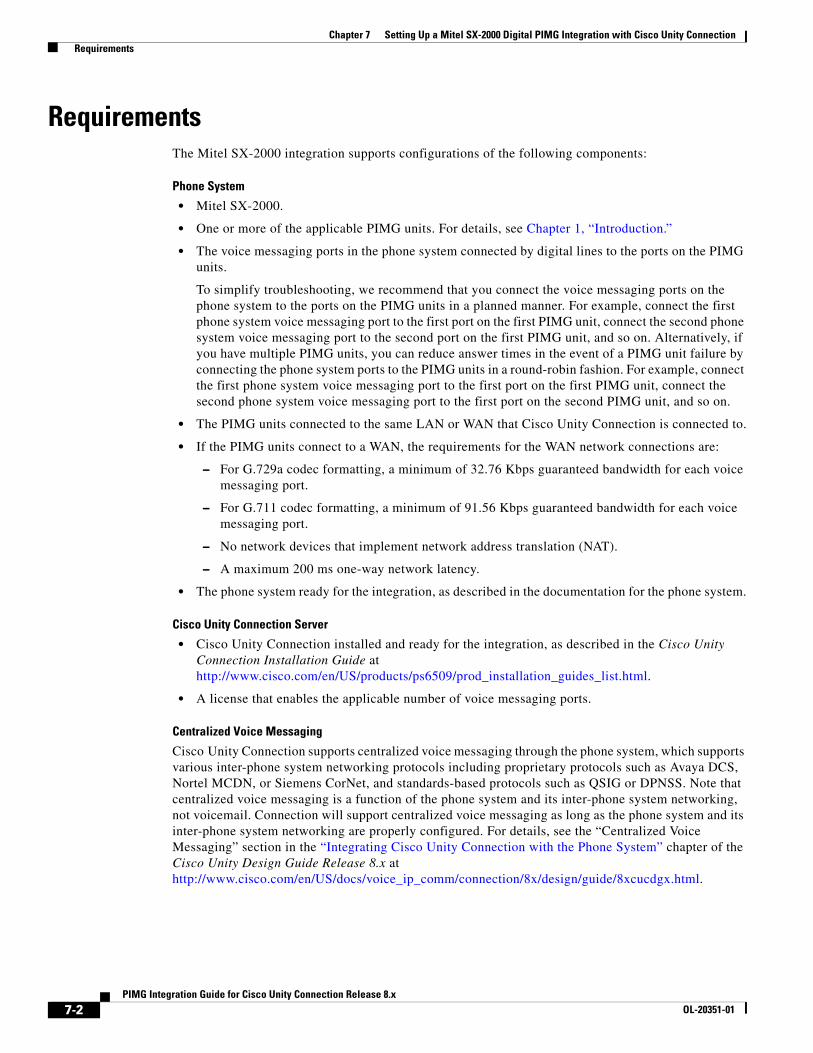
Chapter 7 Setting Up a Mitel SX-2000 Digital PIMG Integration with Cisco Unity Connection Requirements
RequirementsThe Mitel SX-2000 integration supports configurations of the following components:
Phone System
• Mitel SX-2000.
• One or more of the applicable PIMG units. For details, see Chapter 1, “Introduction.”
• The voice messaging ports in the phone system connected by digital lines to the ports on the PIMG units.
To simplify troubleshooting, we recommend that you connect the voice messaging ports on the phone system to the ports on the PIMG units in a planned manner. For example, connect the first phone system voice messaging port to the first port on the first PIMG unit, connect the second phone system voice messaging port to the second port on the first PIMG unit, and so on. Alternatively, if you have multiple PIMG units, you can reduce answer times in the event of a PIMG unit failure by connecting the phone system ports to the PIMG units in a round-robin fashion. For example, connect the first phone system voice messaging port to the first port on the first PIMG unit, connect the second phone system voice messaging port to the first port on the second PIMG unit, and so on.
• The PIMG units connected to the same LAN or WAN that Cisco Unity Connection is connected to.
• If the PIMG units connect to a WAN, the requirements for the WAN network connections are:
– For G.729a codec formatting, a minimum of 32.76 Kbps guaranteed bandwidth for each voice messaging port.
– For G.711 codec formatting, a minimum of 91.56 Kbps guaranteed bandwidth for each voice messaging port.
– No network devices that implement network address translation (NAT).
– A maximum 200 ms one-way network latency.
• The phone system ready for the integration, as described in the documentation for the phone system.
Cisco Unity Connection Server
• Cisco Unity Connection installed and ready for the integration, as described in the Cisco Unity Connection Installation Guide at http://www.cisco.com/en/US/products/ps6509/prod_installation_guides_list.html.
• A license that enables the applicable number of voice messaging ports.
Centralized Voice Messaging
Cisco Unity Connection supports centralized voice messaging through the phone system, which supports various inter-phone system networking protocols including proprietary protocols such as Avaya DCS, Nortel MCDN, or Siemens CorNet, and standards-based protocols such as QSIG or DPNSS. Note that centralized voice messaging is a function of the phone system and its inter-phone system networking, not voicemail. Connection will support centralized voice messaging as long as the phone system and its inter-phone system networking are properly configured. For details, see the “Centralized Voice Messaging” section in the “Integrating Cisco Unity Connection with the Phone System” chapter of the Cisco Unity Design Guide Release 8.x at http://www.cisco.com/en/US/docs/voice_ip_comm/connection/8x/design/guide/8xcucdgx.html.
7-2PIMG Integration Guide for Cisco Unity Connection Release 8.x
OL-20351-01
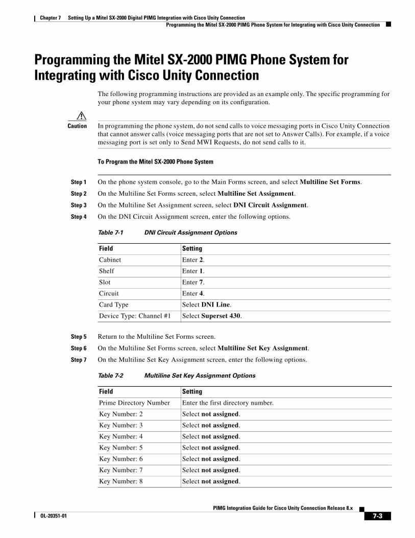
Chapter 7 Setting Up a Mitel SX-2000 Digital PIMG Integration with Cisco Unity Connection Programming the Mitel SX-2000 PIMG Phone System for Integrating with Cisco Unity Connection
Programming the Mitel SX-2000 PIMG Phone System for Integrating with Cisco Unity Connection
The following programming instructions are provided as an example only. The specific programming for your phone system may vary depending on its configuration.
Caution In programming the phone system, do not send calls to voice messaging ports in Cisco Unity Connection that cannot answer calls (voice messaging ports that are not set to Answer Calls). For example, if a voice messaging port is set only to Send MWI Requests, do not send calls to it.
To Program the Mitel SX-2000 Phone System
Step 1 On the phone system console, go to the Main Forms screen, and select Multiline Set Forms.
Step 2 On the Multiline Set Forms screen, select Multiline Set Assignment.
Step 3 On the Multiline Set Assignment screen, select DNI Circuit Assignment.
Step 4 On the DNI Circuit Assignment screen, enter the following options.
Step 5 Return to the Multiline Set Forms screen.
Step 6 On the Multiline Set Forms screen, select Multiline Set Key Assignment.
Step 7 On the Multiline Set Key Assignment screen, enter the following options.
Table 7-1 DNI Circuit Assignment Options
Field Setting
Cabinet Enter 2.
Shelf Enter 1.
Slot Enter 7.
Circuit Enter 4.
Card Type Select DNI Line.
Device Type: Channel #1 Select Superset 430.
Table 7-2 Multiline Set Key Assignment Options
Field Setting
Prime Directory Number Enter the first directory number.
Key Number: 2 Select not assigned.
Key Number: 3 Select not assigned.
Key Number: 4 Select not assigned.
Key Number: 5 Select not assigned.
Key Number: 6 Select not assigned.
Key Number: 7 Select not assigned.
Key Number: 8 Select not assigned.
7-3PIMG Integration Guide for Cisco Unity Connection Release 8.x
OL-20351-01
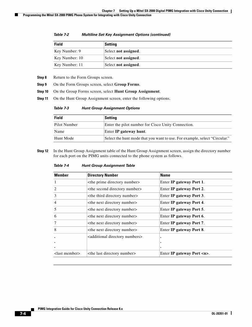
Chapter 7 Setting Up a Mitel SX-2000 Digital PIMG Integration with Cisco Unity Connection Programming the Mitel SX-2000 PIMG Phone System for Integrating with Cisco Unity Connection
Step 8 Return to the Form Groups screen.
Step 9 On the Form Groups screen, select Group Forms.
Step 10 On the Group Forms screen, select Hunt Group Assignment.
Step 11 On the Hunt Group Assignment screen, enter the following options.
Step 12 In the Hunt Group Assignment table of the Hunt Group Assignment screen, assign the directory number for each port on the PIMG units connected to the phone system as follows.
Key Number: 9 Select not assigned.
Key Number: 10 Select not assigned.
Key Number: 11 Select not assigned.
Table 7-3 Hunt Group Assignment Options
Field Setting
Pilot Number Enter the pilot number for Cisco Unity Connection.
Name Enter IP gateway hunt.
Hunt Mode Select the hunt mode that you want to use. For example, select “Circular.”
Table 7-4 Hunt Group Assignment Table
Member Directory Number Name
1 <the prime directory number> Enter IP gateway Port 1.
2 <the second directory number> Enter IP gateway Port 2.
3 <the third directory number> Enter IP gateway Port 3.
4 <the next directory number> Enter IP gateway Port 4.
5 <the next directory number> Enter IP gateway Port 5.
6 <the next directory number> Enter IP gateway Port 6.
7 <the next directory number> Enter IP gateway Port 7.
8 <the next directory number> Enter IP gateway Port 8.
.
.
.
<additional directory numbers> . . .
<last member> <the last directory number> Enter IP gateway Port <n>.
Table 7-2 Multiline Set Key Assignment Options (continued)
Field Setting
7-4PIMG Integration Guide for Cisco Unity Connection Release 8.x
OL-20351-01
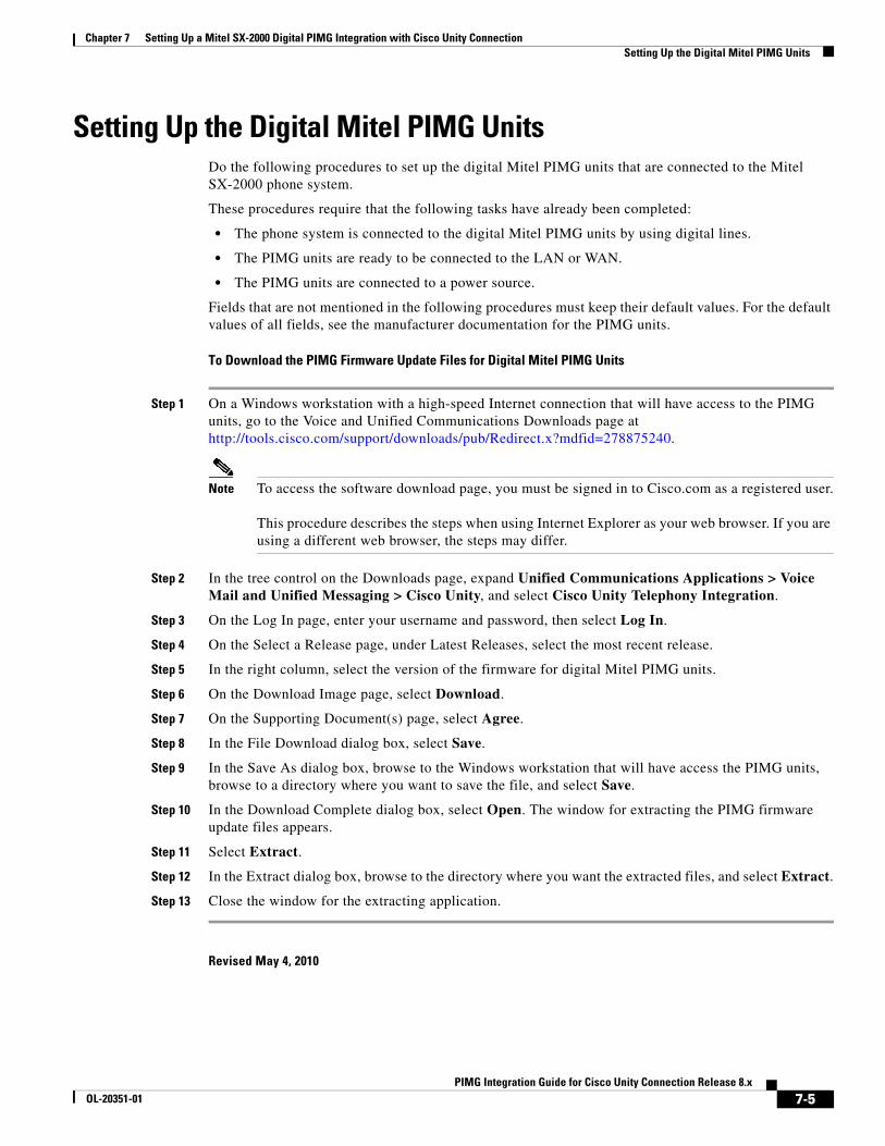
Chapter 7 Setting Up a Mitel SX-2000 Digital PIMG Integration with Cisco Unity Connection Setting Up the Digital Mitel PIMG Units
Setting Up the Digital Mitel PIMG UnitsDo the following procedures to set up the digital Mitel PIMG units that are connected to the Mitel SX-2000 phone system.
These procedures require that the following tasks have already been completed:
• The phone system is connected to the digital Mitel PIMG units by using digital lines.
• The PIMG units are ready to be connected to the LAN or WAN.
• The PIMG units are connected to a power source.
Fields that are not mentioned in the following procedures must keep their default values. For the default values of all fields, see the manufacturer documentation for the PIMG units.
To Download the PIMG Firmware Update Files for Digital Mitel PIMG Units
Step 1 On a Windows workstation with a high-speed Internet connection that will have access to the PIMG units, go to the Voice and Unified Communications Downloads page at http://tools.cisco.com/support/downloads/pub/Redirect.x?mdfid=278875240.
Note To access the software download page, you must be signed in to Cisco.com as a registered user. This procedure describes the steps when using Internet Explorer as your web browser. If you are using a different web browser, the steps may differ.
Step 2 In the tree control on the Downloads page, expand Unified Communications Applications > Voice Mail and Unified Messaging > Cisco Unity, and select Cisco Unity Telephony Integration.
Step 3 On the Log In page, enter your username and password, then select Log In.
Step 4 On the Select a Release page, under Latest Releases, select the most recent release.
Step 5 In the right column, select the version of the firmware for digital Mitel PIMG units.
Step 6 On the Download Image page, select Download.
Step 7 On the Supporting Document(s) page, select Agree.
Step 8 In the File Download dialog box, select Save.
Step 9 In the Save As dialog box, browse to the Windows workstation that will have access the PIMG units, browse to a directory where you want to save the file, and select Save.
Step 10 In the Download Complete dialog box, select Open. The window for extracting the PIMG firmware update files appears.
Step 11 Select Extract.
Step 12 In the Extract dialog box, browse to the directory where you want the extracted files, and select Extract.
Step 13 Close the window for the extracting application.
Revised May 4, 2010
7-5PIMG Integration Guide for Cisco Unity Connection Release 8.x
OL-20351-01
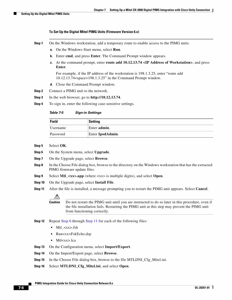
Chapter 7 Setting Up a Mitel SX-2000 Digital PIMG Integration with Cisco Unity Connection Setting Up the Digital Mitel PIMG Units
To Set Up the Digital Mitel PIMG Units (Firmware Version 6.x)
Step 1 On the Windows workstation, add a temporary route to enable access to the PIMG units.
a. On the Windows Start menu, select Run.
b. Enter cmd, and press Enter. The Command Prompt window appears.
c. At the command prompt, enter route add 10.12.13.74 <IP Address of Workstation>, and press Enter.
For example, if the IP address of the workstation is 198.1.3.25, enter “route add 10.12.13.74<space>198.1.3.25” in the Command Prompt window.
d. Close the Command Prompt window.
Step 2 Connect a PIMG unit to the network.
Step 3 In the web browser, go to http://10.12.13.74.
Step 4 To sign in, enter the following case-sensitive settings.
Step 5 Select OK.
Step 6 On the System menu, select Upgrade.
Step 7 On the Upgrade page, select Browse.
Step 8 In the Choose File dialog box, browse to the directory on the Windows workstation that has the extracted PIMG firmware update files.
Step 9 Select Mtl_<xx>.app (where <xx> is multiple digits), and select Open.
Step 10 On the Upgrade page, select Install File.
Step 11 After the file is installed, a message prompting you to restart the PIMG unit appears. Select Cancel.
Caution Do not restart the PIMG unit until you are instructed to do so later in this procedure, even if the file installation fails. Restarting the PIMG unit at this step may prevent the PIMG unit from functioning correctly.
Step 12 Repeat Step 6 through Step 11 for each of the following files:
• Mtl_<xx>.fsh
• Run<xx>FskEcho.dsp
• Mtl<xx>.lca
Step 13 On the Configuration menu, select Import/Export.
Step 14 On the Import/Export page, select Browse.
Step 15 In the Choose File dialog box, browse to the file MTLDNI_Cfg_Mitel.ini.
Step 16 Select MTLDNI_Cfg_Mitel.ini, and select Open.
Table 7-5 Sign-in Settings
Field Setting
Username Enter admin.
Password Enter IpodAdmin.
7-6PIMG Integration Guide for Cisco Unity Connection Release 8.x
OL-20351-01
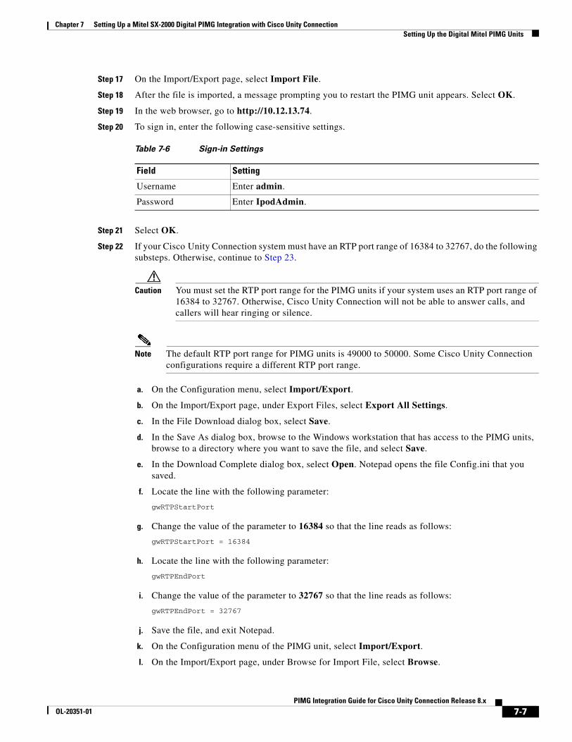
Chapter 7 Setting Up a Mitel SX-2000 Digital PIMG Integration with Cisco Unity Connection Setting Up the Digital Mitel PIMG Units
Step 17 On the Import/Export page, select Import File.
Step 18 After the file is imported, a message prompting you to restart the PIMG unit appears. Select OK.
Step 19 In the web browser, go to http://10.12.13.74.
Step 20 To sign in, enter the following case-sensitive settings.
Step 21 Select OK.
Step 22 If your Cisco Unity Connection system must have an RTP port range of 16384 to 32767, do the following substeps. Otherwise, continue to Step 23.
Caution You must set the RTP port range for the PIMG units if your system uses an RTP port range of 16384 to 32767. Otherwise, Cisco Unity Connection will not be able to answer calls, and callers will hear ringing or silence.
Note The default RTP port range for PIMG units is 49000 to 50000. Some Cisco Unity Connection configurations require a different RTP port range.
a. On the Configuration menu, select Import/Export.
b. On the Import/Export page, under Export Files, select Export All Settings.
c. In the File Download dialog box, select Save.
d. In the Save As dialog box, browse to the Windows workstation that has access to the PIMG units, browse to a directory where you want to save the file, and select Save.
e. In the Download Complete dialog box, select Open. Notepad opens the file Config.ini that you saved.
f. Locate the line with the following parameter:
gwRTPStartPort
g. Change the value of the parameter to 16384 so that the line reads as follows:
gwRTPStartPort = 16384
h. Locate the line with the following parameter:
gwRTPEndPort
i. Change the value of the parameter to 32767 so that the line reads as follows:
gwRTPEndPort = 32767
j. Save the file, and exit Notepad.
k. On the Configuration menu of the PIMG unit, select Import/Export.
l. On the Import/Export page, under Browse for Import File, select Browse.
Table 7-6 Sign-in Settings
Field Setting
Username Enter admin.
Password Enter IpodAdmin.
7-7PIMG Integration Guide for Cisco Unity Connection Release 8.x
OL-20351-01
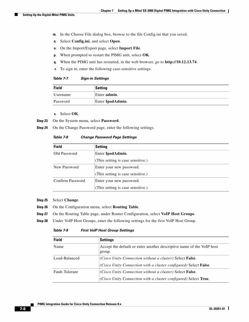
Chapter 7 Setting Up a Mitel SX-2000 Digital PIMG Integration with Cisco Unity Connection Setting Up the Digital Mitel PIMG Units
m. In the Choose File dialog box, browse to the file Config.ini that you saved.
n. Select Config.ini, and select Open.
o. On the Import/Export page, select Import File.
p. When prompted to restart the PIMG unit, select OK.
q. When the PIMG unit has restarted, in the web browser, go to http://10.12.13.74.
r. To sign in, enter the following case-sensitive settings.
s. Select OK.
Step 23 On the System menu, select Password.
Step 24 On the Change Password page, enter the following settings.
Step 25 Select Change.
Step 26 On the Configuration menu, select Routing Table.
Step 27 On the Routing Table page, under Router Configuration, select VoIP Host Groups.
Step 28 Under VoIP Host Groups, enter the following settings for the first VoIP Host Group.
Table 7-7 Sign-in Settings
Field Setting
Username Enter admin.
Password Enter IpodAdmin.
Table 7-8 Change Password Page Settings
Field Setting
Old Password Enter IpodAdmin.
(This setting is case sensitive.)
New Password Enter your new password.
(This setting is case sensitive.)
Confirm Password Enter your new password.
(This setting is case sensitive.)
Table 7-9 First VoIP Host Group Settings
Field Settings
Name Accept the default or enter another descriptive name of the VoIP host group.
Load-Balanced (Cisco Unity Connection without a cluster) Select False.
(Cisco Unity Connection with a cluster configured) Select False.
Fault-Tolerant (Cisco Unity Connection without a cluster) Select False.
(Cisco Unity Connection with a cluster configured) Select True.
7-8PIMG Integration Guide for Cisco Unity Connection Release 8.x
OL-20351-01

Chapter 7 Setting Up a Mitel SX-2000 Digital PIMG Integration with Cisco Unity Connection Setting Up the Digital Mitel PIMG Units
Step 29 For Cisco Unity Connection without a cluster, under Host List, enter the host name or IP address of the Cisco Unity Connection server and the server port in the format <host name or IP address>:5060.
For Cisco Unity Connection with a cluster configured, under Host List, enter the host name or IP address of the subscriber Cisco Unity Connection server (the second Cisco Unity Connection server that you installed) and the server port in the format <host name or IP address>:5060.
Step 30 For Cisco Unity Connection without a cluster, continue to Step 32. For Cisco Unity Connection with a cluster configured, select Add Host.
Step 31 In the second field, enter the host name or IP address of the publisher Cisco Unity Connection server (the first Cisco Unity Connection server that you installed) and the server port in the format <host name or IP address>:5060.
Caution Do not add a third host under Host List or a second host group under VoIP Host Groups. Otherwise, the Cisco Unity Connection cluster may not function correctly.
Step 32 Select Submit.
Step 33 Under Router Configuration, select TDM Trunk Groups.
Step 34 Under TDM Trunk Groups, select Add Trunk Group.
Step 35 Under TDM Trunk Groups, enter the following settings for the first TDM trunk group.
Step 36 Under TDM Trunk Groups, select Add Trunk Group.
Step 37 Enter the following settings for the second TDM trunk group.
Table 7-10 First TDM Trunk Group Settings (Inbound Calls)
Field Settings
Name Enter Inbound_PBX_Calls or another unique name.
This TDM trunk group will handle all incoming calls from the phone system.
Selection Direction Select Ascending.
Selection Mode Select Linear.
Port/Channel Content Enter the numbers of the PIMG ports that will handle inbound calls. For example, enter “*” for all PIMG ports, or enter “1-6” for the first six PIMG ports.
Table 7-11 Second TDM Trunk Group Settings (MWIs)
Field Settings
Name Enter MWIs or another unique name.
This TDM trunk group will handle outbound MWI calls (where applicable).
Selection Direction Select Ascending.
Selection Mode Select Cyclic.
Port/Channel Content Enter the numbers of the PIMG ports that will MWIs. For example, enter “*” for all PIMG ports, or enter “7,8” for the last two PIMG ports.
7-9PIMG Integration Guide for Cisco Unity Connection Release 8.x
OL-20351-01
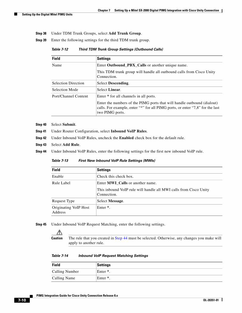
Chapter 7 Setting Up a Mitel SX-2000 Digital PIMG Integration with Cisco Unity Connection Setting Up the Digital Mitel PIMG Units
Step 38 Under TDM Trunk Groups, select Add Trunk Group.
Step 39 Enter the following settings for the third TDM trunk group.
Step 40 Select Submit.
Step 41 Under Router Configuration, select Inbound VoIP Rules.
Step 42 Under Inbound VoIP Rules, uncheck the Enabled check box for the default rule.
Step 43 Select Add Rule.
Step 44 Under Inbound VoIP Rules, enter the following settings for the first new inbound VoIP rule.
Step 45 Under Inbound VoIP Request Matching, enter the following settings.
Caution The rule that you created in Step 44 must be selected. Otherwise, any changes you make will apply to another rule.
Table 7-12 Third TDM Trunk Group Settings (Outbound Calls)
Field Settings
Name Enter Outbound_PBX_Calls or another unique name.
This TDM trunk group will handle all outbound calls from Cisco Unity Connection.
Selection Direction Select Descending.
Selection Mode Select Linear.
Port/Channel Content Enter * for all channels in all ports.
Enter the numbers of the PIMG ports that will handle outbound (dialout) calls. For example, enter “*” for all PIMG ports, or enter “7,8” for the last two PIMG ports.
Table 7-13 First New Inbound VoIP Rule Settings (MWIs)
Field Settings
Enable Check this check box.
Rule Label Enter MWI_Calls or another name.
This inbound VoIP rule will handle all MWI calls from Cisco Unity Connection.
Request Type Select Message.
Originating VoIP Host Address
Enter *.
Table 7-14 Inbound VoIP Request Matching Settings
Field Settings
Calling Number Enter *.
Calling Name Enter *.
7-10PIMG Integration Guide for Cisco Unity Connection Release 8.x
OL-20351-01
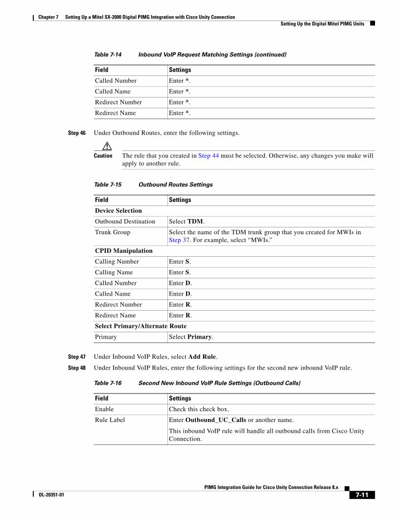
Chapter 7 Setting Up a Mitel SX-2000 Digital PIMG Integration with Cisco Unity Connection Setting Up the Digital Mitel PIMG Units
Step 46 Under Outbound Routes, enter the following settings.
Caution The rule that you created in Step 44 must be selected. Otherwise, any changes you make will apply to another rule.
Step 47 Under Inbound VoIP Rules, select Add Rule.
Step 48 Under Inbound VoIP Rules, enter the following settings for the second new inbound VoIP rule.
Called Number Enter *.
Called Name Enter *.
Redirect Number Enter *.
Redirect Name Enter *.
Table 7-14 Inbound VoIP Request Matching Settings (continued)
Field Settings
Table 7-15 Outbound Routes Settings
Field Settings
Device Selection
Outbound Destination Select TDM.
Trunk Group Select the name of the TDM trunk group that you created for MWIs in Step 37. For example, select “MWIs.”
CPID Manipulation
Calling Number Enter S.
Calling Name Enter S.
Called Number Enter D.
Called Name Enter D.
Redirect Number Enter R.
Redirect Name Enter R.
Select Primary/Alternate Route
Primary Select Primary.
Table 7-16 Second New Inbound VoIP Rule Settings (Outbound Calls)
Field Settings
Enable Check this check box.
Rule Label Enter Outbound_UC_Calls or another name.
This inbound VoIP rule will handle all outbound calls from Cisco Unity Connection.
7-11PIMG Integration Guide for Cisco Unity Connection Release 8.x
OL-20351-01

Chapter 7 Setting Up a Mitel SX-2000 Digital PIMG Integration with Cisco Unity Connection Setting Up the Digital Mitel PIMG Units
Step 49 Under Inbound VoIP Request Matching, enter the following settings.
Caution The rule that you created in Step 48 must be selected. Otherwise, any changes you make will apply to another rule.
Step 50 Under Outbound Routes, enter the following settings.
Caution The rule that you created in Step 48 must be selected. Otherwise, any changes you make will apply to another rule.
Request Type Select Call.
Originating VoIP Host Address
Enter *.
Table 7-16 Second New Inbound VoIP Rule Settings (Outbound Calls) (continued)
Field Settings
Table 7-17 Inbound VoIP Request Matching Settings
Field Settings
Calling Number Enter *.
Calling Name Enter *.
Called Number Enter *.
Called Name Enter *.
Redirect Number Enter *.
Redirect Name Enter *.
Table 7-18 Outbound Routes Settings
Field Settings
Device Selection
Outbound Destination Select TDM.
Trunk Group Select the name of the TDM trunk group that you created for outbound calls in Step 39. For example, select “Outbound_PBX_Calls.”
CPID Manipulation
Calling Number Enter S.
Calling Name Enter S.
Called Number Enter D.
Called Name Enter D.
Redirect Number Enter R.
Redirect Name Enter R.
7-12PIMG Integration Guide for Cisco Unity Connection Release 8.x
OL-20351-01
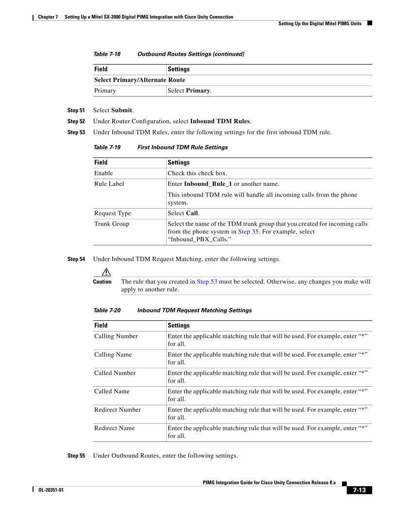
Chapter 7 Setting Up a Mitel SX-2000 Digital PIMG Integration with Cisco Unity Connection Setting Up the Digital Mitel PIMG Units
Step 51 Select Submit.
Step 52 Under Router Configuration, select Inbound TDM Rules.
Step 53 Under Inbound TDM Rules, enter the following settings for the first inbound TDM rule.
Step 54 Under Inbound TDM Request Matching, enter the following settings.
Caution The rule that you created in Step 53 must be selected. Otherwise, any changes you make will apply to another rule.
Step 55 Under Outbound Routes, enter the following settings.
Select Primary/Alternate Route
Primary Select Primary.
Table 7-19 First Inbound TDM Rule Settings
Field Settings
Enable Check this check box.
Rule Label Enter Inbound_Rule_1 or another name.
This inbound TDM rule will handle all incoming calls from the phone system.
Request Type Select Call.
Trunk Group Select the name of the TDM trunk group that you created for incoming calls from the phone system in Step 35. For example, select “Inbound_PBX_Calls.”
Table 7-18 Outbound Routes Settings (continued)
Field Settings
Table 7-20 Inbound TDM Request Matching Settings
Field Settings
Calling Number Enter the applicable matching rule that will be used. For example, enter “*” for all.
Calling Name Enter the applicable matching rule that will be used. For example, enter “*” for all.
Called Number Enter the applicable matching rule that will be used. For example, enter “*” for all.
Called Name Enter the applicable matching rule that will be used. For example, enter “*” for all.
Redirect Number Enter the applicable matching rule that will be used. For example, enter “*” for all.
Redirect Name Enter the applicable matching rule that will be used. For example, enter “*” for all.
7-13PIMG Integration Guide for Cisco Unity Connection Release 8.x
OL-20351-01
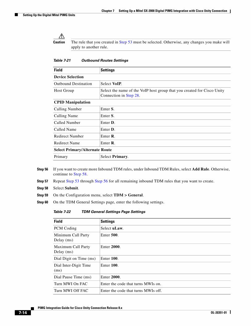
Chapter 7 Setting Up a Mitel SX-2000 Digital PIMG Integration with Cisco Unity Connection Setting Up the Digital Mitel PIMG Units
Caution The rule that you created in Step 53 must be selected. Otherwise, any changes you make will apply to another rule.
Step 56 If you want to create more Inbound TDM rules, under Inbound TDM Rules, select Add Rule. Otherwise, continue to Step 58.
Step 57 Repeat Step 53 through Step 56 for all remaining inbound TDM rules that you want to create.
Step 58 Select Submit.
Step 59 On the Configuration menu, select TDM > General.
Step 60 On the TDM General Settings page, enter the following settings.
Table 7-21 Outbound Routes Settings
Field Settings
Device Selection
Outbound Destination Select VoIP.
Host Group Select the name of the VoIP host group that you created for Cisco Unity Connection in Step 28.
CPID Manipulation
Calling Number Enter S.
Calling Name Enter S.
Called Number Enter D.
Called Name Enter D.
Redirect Number Enter R.
Redirect Name Enter R.
Select Primary/Alternate Route
Primary Select Primary.
Table 7-22 TDM General Settings Page Settings
Field Settings
PCM Coding Select uLaw.
Minimum Call Party Delay (ms)
Enter 500.
Maximum Call Party Delay (ms)
Enter 2000.
Dial Digit on Time (ms) Enter 100.
Dial Inter-Digit Time (ms)
Enter 100.
Dial Pause Time (ms) Enter 2000.
Turn MWI On FAC Enter the code that turns MWIs on.
Turn MWI Off FAC Enter the code that turns MWIs off.
7-14PIMG Integration Guide for Cisco Unity Connection Release 8.x
OL-20351-01
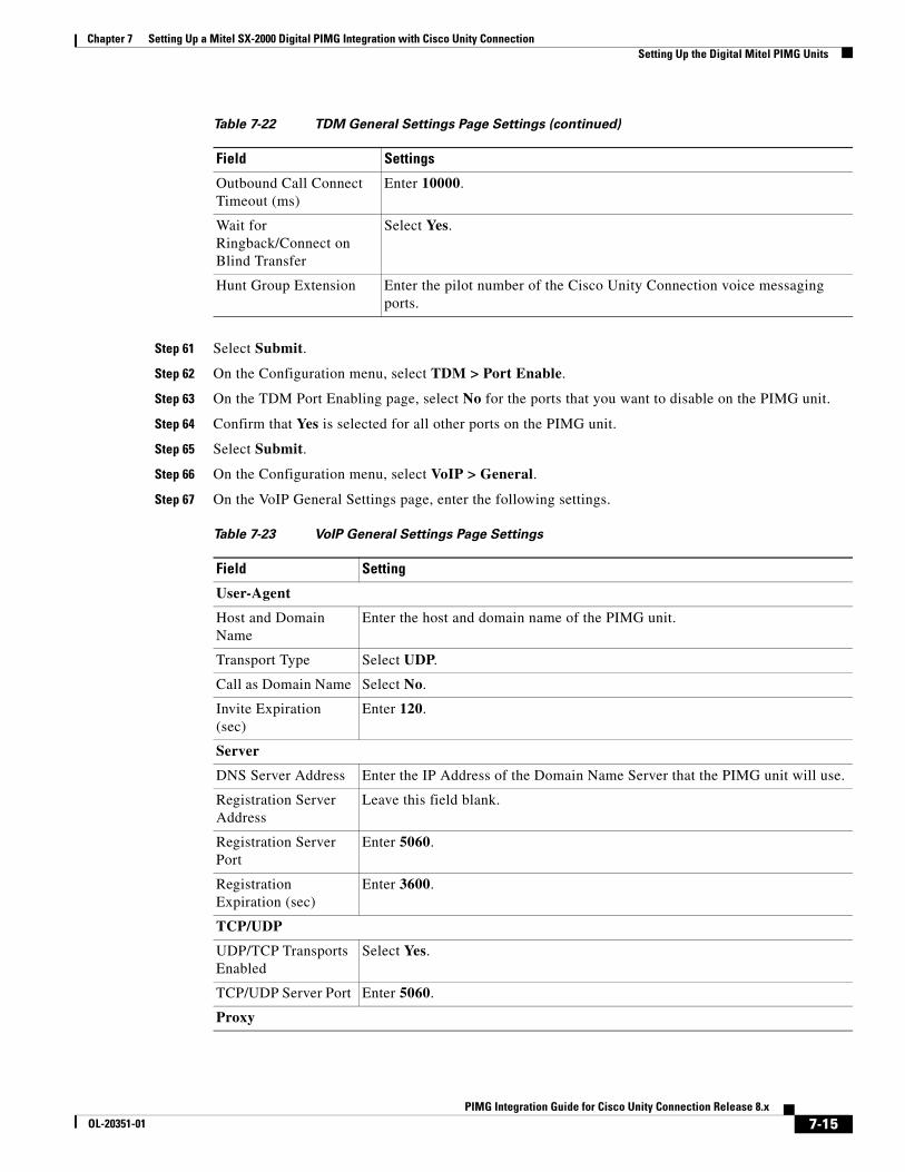
Chapter 7 Setting Up a Mitel SX-2000 Digital PIMG Integration with Cisco Unity Connection Setting Up the Digital Mitel PIMG Units
Step 61 Select Submit.
Step 62 On the Configuration menu, select TDM > Port Enable.
Step 63 On the TDM Port Enabling page, select No for the ports that you want to disable on the PIMG unit.
Step 64 Confirm that Yes is selected for all other ports on the PIMG unit.
Step 65 Select Submit.
Step 66 On the Configuration menu, select VoIP > General.
Step 67 On the VoIP General Settings page, enter the following settings.
Outbound Call Connect Timeout (ms)
Enter 10000.
Wait for Ringback/Connect on Blind Transfer
Select Yes.
Hunt Group Extension Enter the pilot number of the Cisco Unity Connection voice messaging ports.
Table 7-23 VoIP General Settings Page Settings
Field Setting
User-Agent
Host and Domain Name
Enter the host and domain name of the PIMG unit.
Transport Type Select UDP.
Call as Domain Name Select No.
Invite Expiration (sec)
Enter 120.
Server
DNS Server Address Enter the IP Address of the Domain Name Server that the PIMG unit will use.
Registration Server Address
Leave this field blank.
Registration Server Port
Enter 5060.
Registration Expiration (sec)
Enter 3600.
TCP/UDP
UDP/TCP Transports Enabled
Select Yes.
TCP/UDP Server Port Enter 5060.
Proxy
Table 7-22 TDM General Settings Page Settings (continued)
Field Settings
7-15PIMG Integration Guide for Cisco Unity Connection Release 8.x
OL-20351-01
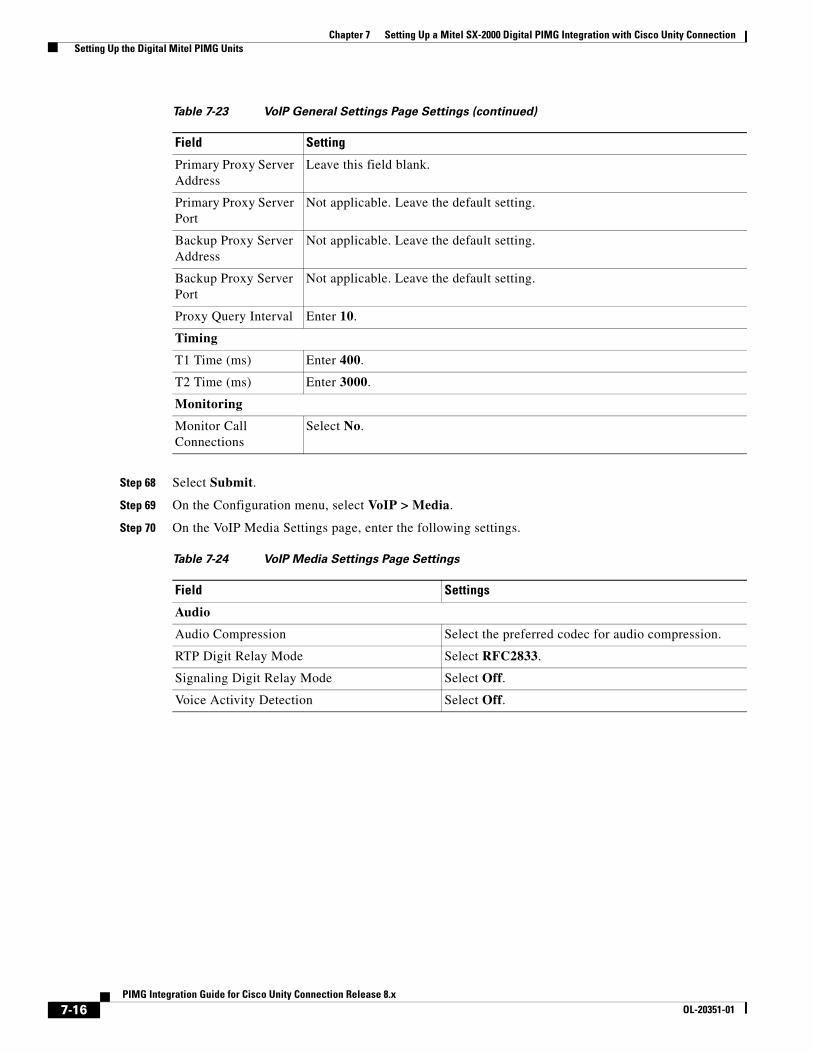
Chapter 7 Setting Up a Mitel SX-2000 Digital PIMG Integration with Cisco Unity Connection Setting Up the Digital Mitel PIMG Units
Step 68 Select Submit.
Step 69 On the Configuration menu, select VoIP > Media.
Step 70 On the VoIP Media Settings page, enter the following settings.
Primary Proxy Server Address
Leave this field blank.
Primary Proxy Server Port
Not applicable. Leave the default setting.
Backup Proxy Server Address
Not applicable. Leave the default setting.
Backup Proxy Server Port
Not applicable. Leave the default setting.
Proxy Query Interval Enter 10.
Timing
T1 Time (ms) Enter 400.
T2 Time (ms) Enter 3000.
Monitoring
Monitor Call Connections
Select No.
Table 7-24 VoIP Media Settings Page Settings
Field Settings
Audio
Audio Compression Select the preferred codec for audio compression.
RTP Digit Relay Mode Select RFC2833.
Signaling Digit Relay Mode Select Off.
Voice Activity Detection Select Off.
Table 7-23 VoIP General Settings Page Settings (continued)
Field Setting
7-16PIMG Integration Guide for Cisco Unity Connection Release 8.x
OL-20351-01

Chapter 7 Setting Up a Mitel SX-2000 Digital PIMG Integration with Cisco Unity Connection Setting Up the Digital Mitel PIMG Units
Step 71 Select Submit.
Step 72 On the Configuration menu, select VoIP > QOS.
Step 73 On the VoIP QOS Configuration page, enter the following settings.
Step 74 Select Submit.
Step 75 On the Configuration menu, select IP.
Step 76 On the IP Settings page, enter the following settings.
Frame Size Select the applicable setting:
• G.711—20
• G.729AB—10
Caution Failure to use the correct setting will result in recorded messages containing nothing but silence.
Frames Per Packet Select the applicable setting:
• G.711—1
• G.729AB—2
Caution Failure to use the correct setting will result in recorded messages containing nothing but silence.
Table 7-25 VoIP QOS Configurative Page Settings
Field Settings
Call Control QOS Byte Enter 104.
RTP QOS Byte Enter 184.
Table 7-26 IP Settings Page Settings
Field Settings
Client IP Address Enter the new IP address you want to use for the PIMG unit.
(This is the IP address that you enter in Cisco Unity Connection Administration when you create the integration.)
Client Subnet Mask Enter the new subnet mask, if the subnet mask is different from the default IP address.
Default Network Gateway Address
Enter the IP address of the default network gateway router that the PIMG units will use.
BOOTP Enabled Select No.
Table 7-24 VoIP Media Settings Page Settings (continued)
Field Settings
7-17PIMG Integration Guide for Cisco Unity Connection Release 8.x
OL-20351-01
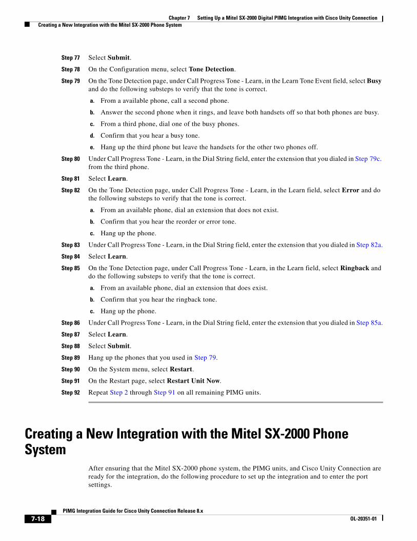
Chapter 7 Setting Up a Mitel SX-2000 Digital PIMG Integration with Cisco Unity Connection Creating a New Integration with the Mitel SX-2000 Phone System
Step 77 Select Submit.
Step 78 On the Configuration menu, select Tone Detection.
Step 79 On the Tone Detection page, under Call Progress Tone - Learn, in the Learn Tone Event field, select Busy and do the following substeps to verify that the tone is correct.
a. From a available phone, call a second phone.
b. Answer the second phone when it rings, and leave both handsets off so that both phones are busy.
c. From a third phone, dial one of the busy phones.
d. Confirm that you hear a busy tone.
e. Hang up the third phone but leave the handsets for the other two phones off.
Step 80 Under Call Progress Tone - Learn, in the Dial String field, enter the extension that you dialed in Step 79c. from the third phone.
Step 81 Select Learn.
Step 82 On the Tone Detection page, under Call Progress Tone - Learn, in the Learn field, select Error and do the following substeps to verify that the tone is correct.
a. From an available phone, dial an extension that does not exist.
b. Confirm that you hear the reorder or error tone.
c. Hang up the phone.
Step 83 Under Call Progress Tone - Learn, in the Dial String field, enter the extension that you dialed in Step 82a.
Step 84 Select Learn.
Step 85 On the Tone Detection page, under Call Progress Tone - Learn, in the Learn field, select Ringback and do the following substeps to verify that the tone is correct.
a. From an available phone, dial an extension that does exist.
b. Confirm that you hear the ringback tone.
c. Hang up the phone.
Step 86 Under Call Progress Tone - Learn, in the Dial String field, enter the extension that you dialed in Step 85a.
Step 87 Select Learn.
Step 88 Select Submit.
Step 89 Hang up the phones that you used in Step 79.
Step 90 On the System menu, select Restart.
Step 91 On the Restart page, select Restart Unit Now.
Step 92 Repeat Step 2 through Step 91 on all remaining PIMG units.
Creating a New Integration with the Mitel SX-2000 Phone System
After ensuring that the Mitel SX-2000 phone system, the PIMG units, and Cisco Unity Connection are ready for the integration, do the following procedure to set up the integration and to enter the port settings.
7-18PIMG Integration Guide for Cisco Unity Connection Release 8.x
OL-20351-01

Chapter 7 Setting Up a Mitel SX-2000 Digital PIMG Integration with Cisco Unity Connection Creating a New Integration with the Mitel SX-2000 Phone System
To Create an Integration
Step 1 Sign in to Cisco Unity Connection Administration.
Step 2 In Cisco Unity Connection Administration, expand Telephony Integrations, then select Phone System.
Step 3 On the Search Phone Systems page, under Display Name, select the name of the default phone system.
Step 4 On the Phone System Basics page, in the Phone System Name field, enter the descriptive name that you want for the phone system.
Step 5 If you want to use this phone system as the default for TRaP connections so that administrators and users without voicemail boxes can record and playback through the phone in Cisco Unity Connection web applications, check the Default TRAP Switch check box. If you want to use another phone system as the default for TRaP connections, uncheck this check box.
Step 6 Select Save.
Step 7 On the Phone System Basics page, in the Related Links drop-down box, select Add Port Group and select Go.
Step 8 On the New Port Group page, enter the applicable settings and select Save.
Step 9 In the Related Links drop-down box, select Add Ports and select Go.
Step 10 On the New Port page, enter the following settings and select Save.
Table 7-27 Settings for the New Port Group Page
Field Setting
Phone System Select the name of the phone system that you entered in Step 4.
Create From Select Port Group Template and select SIP to DMG/PIMG/TIMG in the drop-down box.
Display Name Enter a descriptive name for the port group. You can accept the default name or enter the name that you want.
SIP Security Profile Select 5060.
SIP Transport Protocol Select the SIP transport protocol that Cisco Unity Connection will use.
IPv4 Address or Host Name (Cisco Unity Connection 8.5 and later)
Enter the IP address of the PIMG unit that you are integrating with Cisco Unity Connection.
IPv6 Address or Host Name (Cisco Unity Connection 8.5 and later)
Do not enter a value in this field. IPv6 is not supported for PIMG integrations.
IP Address or Host Name (Cisco Unity Connection 8.0)
Enter the IP address of the PIMG unit that you are integrating with Cisco Unity Connection.
Port Enter the SIP port of the PIMG unit that Cisco Unity Connection will connect to. We recommend that you use the default setting.
Caution This name must match the setting in the TCP/UDP Server Port field on the Configuration > VoIP > General page of the PIMG unit. Otherwise, the integration will not function correctly.
7-19PIMG Integration Guide for Cisco Unity Connection Release 8.x
OL-20351-01
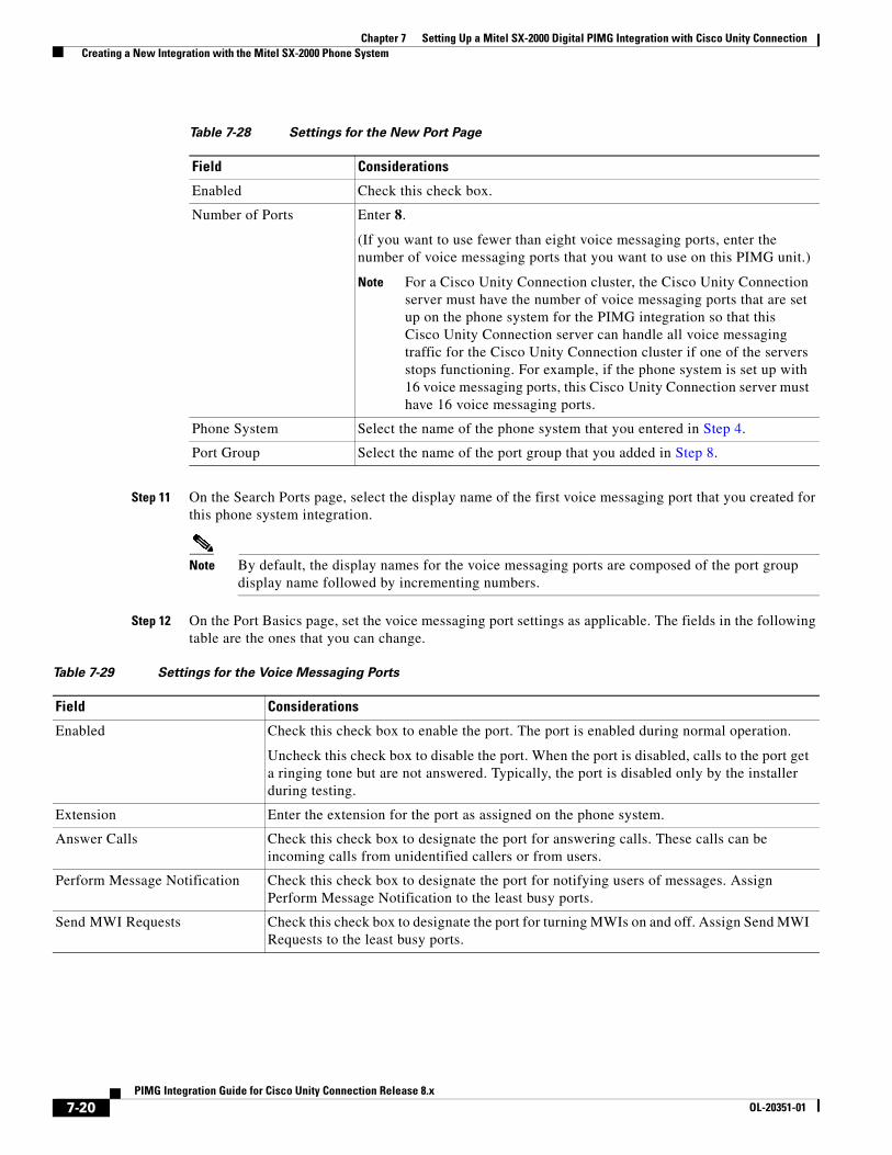
Chapter 7 Setting Up a Mitel SX-2000 Digital PIMG Integration with Cisco Unity Connection Creating a New Integration with the Mitel SX-2000 Phone System
Step 11 On the Search Ports page, select the display name of the first voice messaging port that you created for this phone system integration.
Note By default, the display names for the voice messaging ports are composed of the port group display name followed by incrementing numbers.
Step 12 On the Port Basics page, set the voice messaging port settings as applicable. The fields in the following table are the ones that you can change.
Table 7-28 Settings for the New Port Page
Field Considerations
Enabled Check this check box.
Number of Ports Enter 8.
(If you want to use fewer than eight voice messaging ports, enter the number of voice messaging ports that you want to use on this PIMG unit.)
Note For a Cisco Unity Connection cluster, the Cisco Unity Connection server must have the number of voice messaging ports that are set up on the phone system for the PIMG integration so that this Cisco Unity Connection server can handle all voice messaging traffic for the Cisco Unity Connection cluster if one of the servers stops functioning. For example, if the phone system is set up with 16 voice messaging ports, this Cisco Unity Connection server must have 16 voice messaging ports.
Phone System Select the name of the phone system that you entered in Step 4.
Port Group Select the name of the port group that you added in Step 8.
Table 7-29 Settings for the Voice Messaging Ports
Field Considerations
Enabled Check this check box to enable the port. The port is enabled during normal operation.
Uncheck this check box to disable the port. When the port is disabled, calls to the port get a ringing tone but are not answered. Typically, the port is disabled only by the installer during testing.
Extension Enter the extension for the port as assigned on the phone system.
Answer Calls Check this check box to designate the port for answering calls. These calls can be incoming calls from unidentified callers or from users.
Perform Message Notification Check this check box to designate the port for notifying users of messages. Assign Perform Message Notification to the least busy ports.
Send MWI Requests Check this check box to designate the port for turning MWIs on and off. Assign Send MWI Requests to the least busy ports.
7-20PIMG Integration Guide for Cisco Unity Connection Release 8.x
OL-20351-01
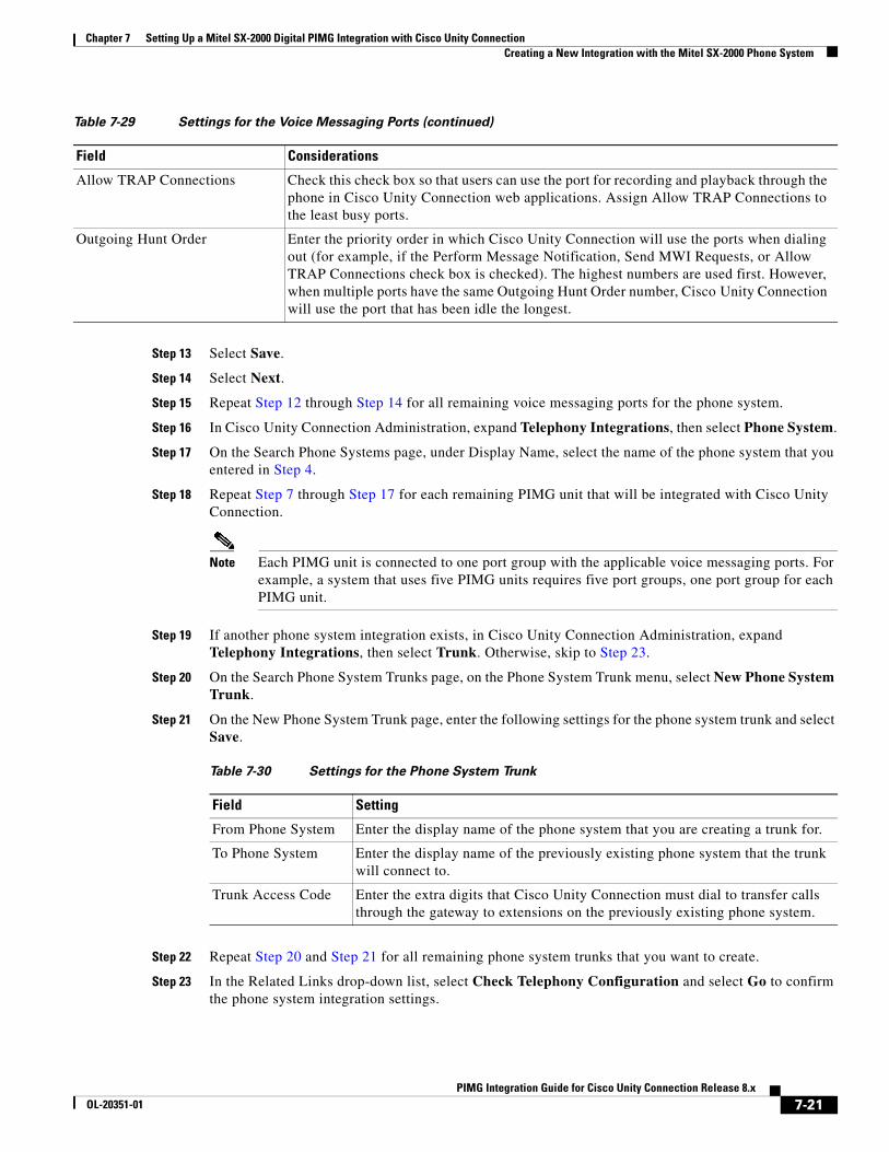
Chapter 7 Setting Up a Mitel SX-2000 Digital PIMG Integration with Cisco Unity Connection Creating a New Integration with the Mitel SX-2000 Phone System
Step 13 Select Save.
Step 14 Select Next.
Step 15 Repeat Step 12 through Step 14 for all remaining voice messaging ports for the phone system.
Step 16 In Cisco Unity Connection Administration, expand Telephony Integrations, then select Phone System.
Step 17 On the Search Phone Systems page, under Display Name, select the name of the phone system that you entered in Step 4.
Step 18 Repeat Step 7 through Step 17 for each remaining PIMG unit that will be integrated with Cisco Unity Connection.
Note Each PIMG unit is connected to one port group with the applicable voice messaging ports. For example, a system that uses five PIMG units requires five port groups, one port group for each PIMG unit.
Step 19 If another phone system integration exists, in Cisco Unity Connection Administration, expand Telephony Integrations, then select Trunk. Otherwise, skip to Step 23.
Step 20 On the Search Phone System Trunks page, on the Phone System Trunk menu, select New Phone System Trunk.
Step 21 On the New Phone System Trunk page, enter the following settings for the phone system trunk and select Save.
Step 22 Repeat Step 20 and Step 21 for all remaining phone system trunks that you want to create.
Step 23 In the Related Links drop-down list, select Check Telephony Configuration and select Go to confirm the phone system integration settings.
Allow TRAP Connections Check this check box so that users can use the port for recording and playback through the phone in Cisco Unity Connection web applications. Assign Allow TRAP Connections to the least busy ports.
Outgoing Hunt Order Enter the priority order in which Cisco Unity Connection will use the ports when dialing out (for example, if the Perform Message Notification, Send MWI Requests, or Allow TRAP Connections check box is checked). The highest numbers are used first. However, when multiple ports have the same Outgoing Hunt Order number, Cisco Unity Connection will use the port that has been idle the longest.
Table 7-29 Settings for the Voice Messaging Ports (continued)
Field Considerations
Table 7-30 Settings for the Phone System Trunk
Field Setting
From Phone System Enter the display name of the phone system that you are creating a trunk for.
To Phone System Enter the display name of the previously existing phone system that the trunk will connect to.
Trunk Access Code Enter the extra digits that Cisco Unity Connection must dial to transfer calls through the gateway to extensions on the previously existing phone system.
7-21PIMG Integration Guide for Cisco Unity Connection Release 8.x
OL-20351-01

Chapter 7 Setting Up a Mitel SX-2000 Digital PIMG Integration with Cisco Unity Connection Creating a New Integration with the Mitel SX-2000 Phone System
If the test is not successful, the Task Execution Results displays one or more messages with troubleshooting steps. After correcting the problems, test the connection again.
Step 24 In the Task Execution Results window, select Close.
7-22PIMG Integration Guide for Cisco Unity Connection Release 8.x
OL-20351-01
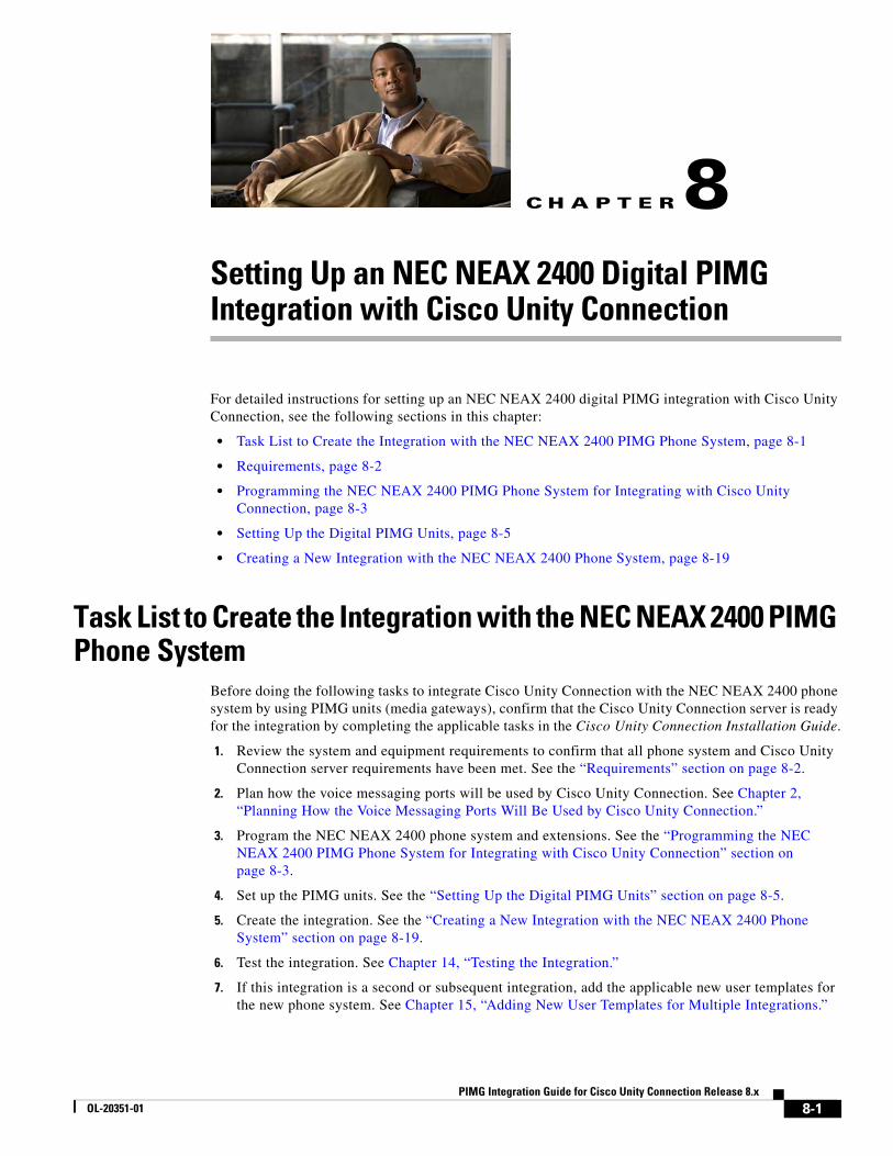
PIMG IntegrOL-20351-01
C H A P T E R 8
Setting Up an NEC NEAX 2400 Digital PIMG Integration with Cisco Unity ConnectionFor detailed instructions for setting up an NEC NEAX 2400 digital PIMG integration with Cisco Unity Connection, see the following sections in this chapter:
• Task List to Create the Integration with the NEC NEAX 2400 PIMG Phone System, page 8-1
• Requirements, page 8-2
• Programming the NEC NEAX 2400 PIMG Phone System for Integrating with Cisco Unity Connection, page 8-3
• Setting Up the Digital PIMG Units, page 8-5
• Creating a New Integration with the NEC NEAX 2400 Phone System, page 8-19
Task List to Create the Integration with the NEC NEAX 2400 PIMG Phone System
Before doing the following tasks to integrate Cisco Unity Connection with the NEC NEAX 2400 phone system by using PIMG units (media gateways), confirm that the Cisco Unity Connection server is ready for the integration by completing the applicable tasks in the Cisco Unity Connection Installation Guide.
1. Review the system and equipment requirements to confirm that all phone system and Cisco Unity Connection server requirements have been met. See the “Requirements” section on page 8-2.
2. Plan how the voice messaging ports will be used by Cisco Unity Connection. See Chapter 2, “Planning How the Voice Messaging Ports Will Be Used by Cisco Unity Connection.”
3. Program the NEC NEAX 2400 phone system and extensions. See the “Programming the NEC NEAX 2400 PIMG Phone System for Integrating with Cisco Unity Connection” section on page 8-3.
4. Set up the PIMG units. See the “Setting Up the Digital PIMG Units” section on page 8-5.
5. Create the integration. See the “Creating a New Integration with the NEC NEAX 2400 Phone System” section on page 8-19.
6. Test the integration. See Chapter 14, “Testing the Integration.”
7. If this integration is a second or subsequent integration, add the applicable new user templates for the new phone system. See Chapter 15, “Adding New User Templates for Multiple Integrations.”
8-1ation Guide for Cisco Unity Connection Release 8.x
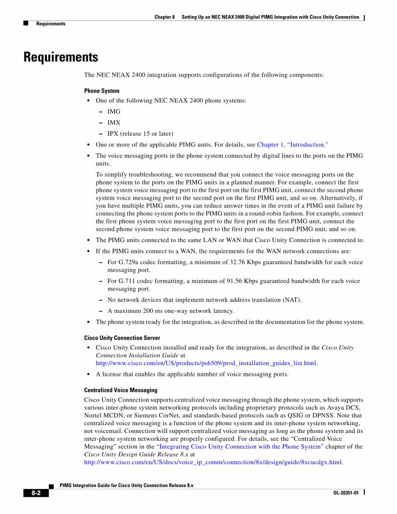
Chapter 8 Setting Up an NEC NEAX 2400 Digital PIMG Integration with Cisco Unity Connection Requirements
RequirementsThe NEC NEAX 2400 integration supports configurations of the following components:
Phone System
• One of the following NEC NEAX 2400 phone systems:
– IMG
– IMX
– IPX (release 15 or later)
• One or more of the applicable PIMG units. For details, see Chapter 1, “Introduction.”
• The voice messaging ports in the phone system connected by digital lines to the ports on the PIMG units.
To simplify troubleshooting, we recommend that you connect the voice messaging ports on the phone system to the ports on the PIMG units in a planned manner. For example, connect the first phone system voice messaging port to the first port on the first PIMG unit, connect the second phone system voice messaging port to the second port on the first PIMG unit, and so on. Alternatively, if you have multiple PIMG units, you can reduce answer times in the event of a PIMG unit failure by connecting the phone system ports to the PIMG units in a round-robin fashion. For example, connect the first phone system voice messaging port to the first port on the first PIMG unit, connect the second phone system voice messaging port to the first port on the second PIMG unit, and so on.
• The PIMG units connected to the same LAN or WAN that Cisco Unity Connection is connected to.
• If the PIMG units connect to a WAN, the requirements for the WAN network connections are:
– For G.729a codec formatting, a minimum of 32.76 Kbps guaranteed bandwidth for each voice messaging port.
– For G.711 codec formatting, a minimum of 91.56 Kbps guaranteed bandwidth for each voice messaging port.
– No network devices that implement network address translation (NAT).
– A maximum 200 ms one-way network latency.
• The phone system ready for the integration, as described in the documentation for the phone system.
Cisco Unity Connection Server
• Cisco Unity Connection installed and ready for the integration, as described in the Cisco Unity Connection Installation Guide at http://www.cisco.com/en/US/products/ps6509/prod_installation_guides_list.html.
• A license that enables the applicable number of voice messaging ports.
Centralized Voice Messaging
Cisco Unity Connection supports centralized voice messaging through the phone system, which supports various inter-phone system networking protocols including proprietary protocols such as Avaya DCS, Nortel MCDN, or Siemens CorNet, and standards-based protocols such as QSIG or DPNSS. Note that centralized voice messaging is a function of the phone system and its inter-phone system networking, not voicemail. Connection will support centralized voice messaging as long as the phone system and its inter-phone system networking are properly configured. For details, see the “Centralized Voice Messaging” section in the “Integrating Cisco Unity Connection with the Phone System” chapter of the Cisco Unity Design Guide Release 8.x at http://www.cisco.com/en/US/docs/voice_ip_comm/connection/8x/design/guide/8xcucdgx.html.
8-2PIMG Integration Guide for Cisco Unity Connection Release 8.x
OL-20351-01
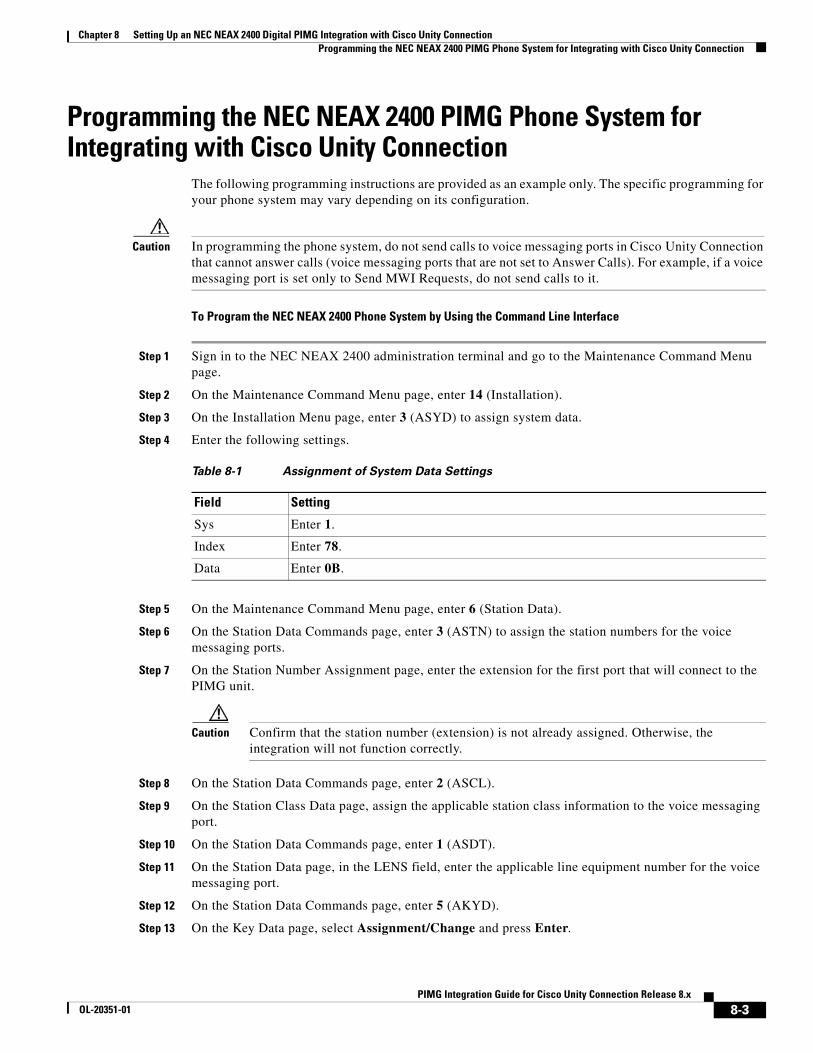
Chapter 8 Setting Up an NEC NEAX 2400 Digital PIMG Integration with Cisco Unity Connection Programming the NEC NEAX 2400 PIMG Phone System for Integrating with Cisco Unity Connection
Programming the NEC NEAX 2400 PIMG Phone System for Integrating with Cisco Unity Connection
The following programming instructions are provided as an example only. The specific programming for your phone system may vary depending on its configuration.
Caution In programming the phone system, do not send calls to voice messaging ports in Cisco Unity Connection that cannot answer calls (voice messaging ports that are not set to Answer Calls). For example, if a voice messaging port is set only to Send MWI Requests, do not send calls to it.
To Program the NEC NEAX 2400 Phone System by Using the Command Line Interface
Step 1 Sign in to the NEC NEAX 2400 administration terminal and go to the Maintenance Command Menu page.
Step 2 On the Maintenance Command Menu page, enter 14 (Installation).
Step 3 On the Installation Menu page, enter 3 (ASYD) to assign system data.
Step 4 Enter the following settings.
Step 5 On the Maintenance Command Menu page, enter 6 (Station Data).
Step 6 On the Station Data Commands page, enter 3 (ASTN) to assign the station numbers for the voice messaging ports.
Step 7 On the Station Number Assignment page, enter the extension for the first port that will connect to the PIMG unit.
Caution Confirm that the station number (extension) is not already assigned. Otherwise, the integration will not function correctly.
Step 8 On the Station Data Commands page, enter 2 (ASCL).
Step 9 On the Station Class Data page, assign the applicable station class information to the voice messaging port.
Step 10 On the Station Data Commands page, enter 1 (ASDT).
Step 11 On the Station Data page, in the LENS field, enter the applicable line equipment number for the voice messaging port.
Step 12 On the Station Data Commands page, enter 5 (AKYD).
Step 13 On the Key Data page, select Assignment/Change and press Enter.
Table 8-1 Assignment of System Data Settings
Field Setting
Sys Enter 1.
Index Enter 78.
Data Enter 0B.
8-3PIMG Integration Guide for Cisco Unity Connection Release 8.x
OL-20351-01
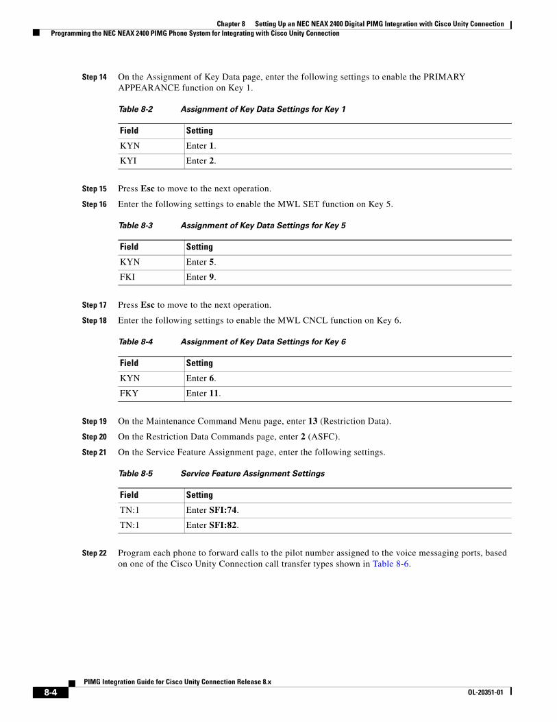
Chapter 8 Setting Up an NEC NEAX 2400 Digital PIMG Integration with Cisco Unity Connection Programming the NEC NEAX 2400 PIMG Phone System for Integrating with Cisco Unity Connection
Step 14 On the Assignment of Key Data page, enter the following settings to enable the PRIMARY APPEARANCE function on Key 1.
Step 15 Press Esc to move to the next operation.
Step 16 Enter the following settings to enable the MWL SET function on Key 5.
Step 17 Press Esc to move to the next operation.
Step 18 Enter the following settings to enable the MWL CNCL function on Key 6.
Step 19 On the Maintenance Command Menu page, enter 13 (Restriction Data).
Step 20 On the Restriction Data Commands page, enter 2 (ASFC).
Step 21 On the Service Feature Assignment page, enter the following settings.
Step 22 Program each phone to forward calls to the pilot number assigned to the voice messaging ports, based on one of the Cisco Unity Connection call transfer types shown in Table 8-6.
Table 8-2 Assignment of Key Data Settings for Key 1
Field Setting
KYN Enter 1.
KYI Enter 2.
Table 8-3 Assignment of Key Data Settings for Key 5
Field Setting
KYN Enter 5.
FKI Enter 9.
Table 8-4 Assignment of Key Data Settings for Key 6
Field Setting
KYN Enter 6.
FKY Enter 11.
Table 8-5 Service Feature Assignment Settings
Field Setting
TN:1 Enter SFI:74.
TN:1 Enter SFI:82.
8-4PIMG Integration Guide for Cisco Unity Connection Release 8.x
OL-20351-01
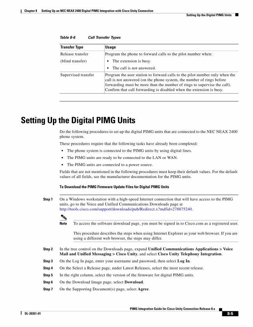
Chapter 8 Setting Up an NEC NEAX 2400 Digital PIMG Integration with Cisco Unity Connection Setting Up the Digital PIMG Units
Setting Up the Digital PIMG UnitsDo the following procedures to set up the digital PIMG units that are connected to the NEC NEAX 2400 phone system.
These procedures require that the following tasks have already been completed:
• The phone system is connected to the PIMG units by using digital lines.
• The PIMG units are ready to be connected to the LAN or WAN.
• The PIMG units are connected to a power source.
Fields that are not mentioned in the following procedures must keep their default values. For the default values of all fields, see the manufacturer documentation for the PIMG units.
To Download the PIMG Firmware Update Files for Digital PIMG Units
Step 1 On a Windows workstation with a high-speed Internet connection that will have access to the PIMG units, go to the Voice and Unified Communications Downloads page at http://tools.cisco.com/support/downloads/pub/Redirect.x?mdfid=278875240.
Note To access the software download page, you must be signed in to Cisco.com as a registered user. This procedure describes the steps when using Internet Explorer as your web browser. If you are using a different web browser, the steps may differ.
Step 2 In the tree control on the Downloads page, expand Unified Communications Applications > Voice Mail and Unified Messaging > Cisco Unity, and select Cisco Unity Telephony Integration.
Step 3 On the Log In page, enter your username and password, then select Log In.
Step 4 On the Select a Release page, under Latest Releases, select the most recent release.
Step 5 In the right column, select the version of the firmware for digital PIMG units.
Step 6 On the Download Image page, select Download.
Step 7 On the Supporting Document(s) page, select Agree.
Table 8-6 Call Transfer Types
Transfer Type Usage
Release transfer
(blind transfer)
Program the phone to forward calls to the pilot number when:
• The extension is busy.
• The call is not answered.
Supervised transfer Program the user station to forward calls to the pilot number only when the call is not answered (on the phone system, the number of rings before forwarding must be more than the number of rings to supervise the call). Confirm that call forwarding is disabled when the extension is busy.
8-5PIMG Integration Guide for Cisco Unity Connection Release 8.x
OL-20351-01
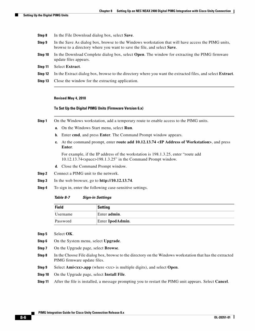
Chapter 8 Setting Up an NEC NEAX 2400 Digital PIMG Integration with Cisco Unity Connection Setting Up the Digital PIMG Units
Step 8 In the File Download dialog box, select Save.
Step 9 In the Save As dialog box, browse to the Windows workstation that will have access the PIMG units, browse to a directory where you want to save the file, and select Save.
Step 10 In the Download Complete dialog box, select Open. The window for extracting the PIMG firmware update files appears.
Step 11 Select Extract.
Step 12 In the Extract dialog box, browse to the directory where you want the extracted files, and select Extract.
Step 13 Close the window for the extracting application.
Revised May 4, 2010
To Set Up the Digital PIMG Units (Firmware Version 6.x)
Step 1 On the Windows workstation, add a temporary route to enable access to the PIMG units.
a. On the Windows Start menu, select Run.
b. Enter cmd, and press Enter. The Command Prompt window appears.
c. At the command prompt, enter route add 10.12.13.74 <IP Address of Workstation>, and press Enter.
For example, if the IP address of the workstation is 198.1.3.25, enter “route add 10.12.13.74<space>198.1.3.25” in the Command Prompt window.
d. Close the Command Prompt window.
Step 2 Connect a PIMG unit to the network.
Step 3 In the web browser, go to http://10.12.13.74.
Step 4 To sign in, enter the following case-sensitive settings.
Step 5 Select OK.
Step 6 On the System menu, select Upgrade.
Step 7 On the Upgrade page, select Browse.
Step 8 In the Choose File dialog box, browse to the directory on the Windows workstation that has the extracted PIMG firmware update files.
Step 9 Select Ami<xx>.app (where <xx> is multiple digits), and select Open.
Step 10 On the Upgrade page, select Install File.
Step 11 After the file is installed, a message prompting you to restart the PIMG unit appears. Select Cancel.
Table 8-7 Sign-in Settings
Field Setting
Username Enter admin.
Password Enter IpodAdmin.
8-6PIMG Integration Guide for Cisco Unity Connection Release 8.x
OL-20351-01
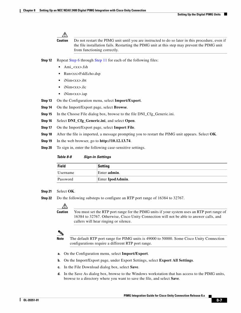
Chapter 8 Setting Up an NEC NEAX 2400 Digital PIMG Integration with Cisco Unity Connection Setting Up the Digital PIMG Units
Caution Do not restart the PIMG unit until you are instructed to do so later in this procedure, even if the file installation fails. Restarting the PIMG unit at this step may prevent the PIMG unit from functioning correctly.
Step 12 Repeat Step 6 through Step 11 for each of the following files:
• Ami_<xx>.fsh
• Run<xx>FskEcho.dsp
• iNim<xx>.ibt
• iNim<xx>.ilc
• iNim<xx>.iap
Step 13 On the Configuration menu, select Import/Export.
Step 14 On the Import/Export page, select Browse.
Step 15 In the Choose File dialog box, browse to the file DNI_Cfg_Generic.ini.
Step 16 Select DNI_Cfg_Generic.ini, and select Open.
Step 17 On the Import/Export page, select Import File.
Step 18 After the file is imported, a message prompting you to restart the PIMG unit appears. Select OK.
Step 19 In the web browser, go to http://10.12.13.74.
Step 20 To sign in, enter the following case-sensitive settings.
Step 21 Select OK.
Step 22 Do the following substeps to configure an RTP port range of 16384 to 32767.
Caution You must set the RTP port range for the PIMG units if your system uses an RTP port range of 16384 to 32767. Otherwise, Cisco Unity Connection will not be able to answer calls, and callers will hear ringing or silence.
Note The default RTP port range for PIMG units is 49000 to 50000. Some Cisco Unity Connection configurations require a different RTP port range.
a. On the Configuration menu, select Import/Export.
b. On the Import/Export page, under Export Settings, select Export All Settings.
c. In the File Download dialog box, select Save.
d. In the Save As dialog box, browse to the Windows workstation that has access to the PIMG units, browse to a directory where you want to save the file, and select Save.
Table 8-8 Sign-in Settings
Field Setting
Username Enter admin.
Password Enter IpodAdmin.
8-7PIMG Integration Guide for Cisco Unity Connection Release 8.x
OL-20351-01
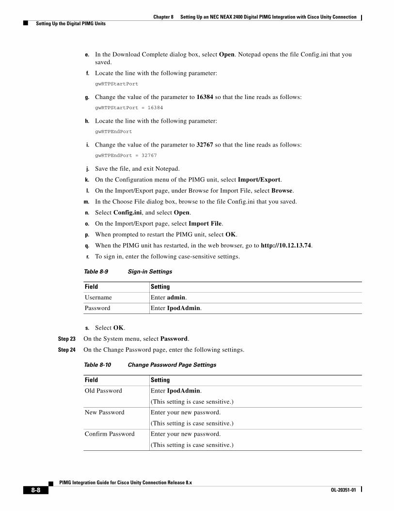
Chapter 8 Setting Up an NEC NEAX 2400 Digital PIMG Integration with Cisco Unity Connection Setting Up the Digital PIMG Units
e. In the Download Complete dialog box, select Open. Notepad opens the file Config.ini that you saved.
f. Locate the line with the following parameter:
gwRTPStartPort
g. Change the value of the parameter to 16384 so that the line reads as follows:
gwRTPStartPort = 16384
h. Locate the line with the following parameter:
gwRTPEndPort
i. Change the value of the parameter to 32767 so that the line reads as follows:
gwRTPEndPort = 32767
j. Save the file, and exit Notepad.
k. On the Configuration menu of the PIMG unit, select Import/Export.
l. On the Import/Export page, under Browse for Import File, select Browse.
m. In the Choose File dialog box, browse to the file Config.ini that you saved.
n. Select Config.ini, and select Open.
o. On the Import/Export page, select Import File.
p. When prompted to restart the PIMG unit, select OK.
q. When the PIMG unit has restarted, in the web browser, go to http://10.12.13.74.
r. To sign in, enter the following case-sensitive settings.
s. Select OK.
Step 23 On the System menu, select Password.
Step 24 On the Change Password page, enter the following settings.
Table 8-9 Sign-in Settings
Field Setting
Username Enter admin.
Password Enter IpodAdmin.
Table 8-10 Change Password Page Settings
Field Setting
Old Password Enter IpodAdmin.
(This setting is case sensitive.)
New Password Enter your new password.
(This setting is case sensitive.)
Confirm Password Enter your new password.
(This setting is case sensitive.)
8-8PIMG Integration Guide for Cisco Unity Connection Release 8.x
OL-20351-01
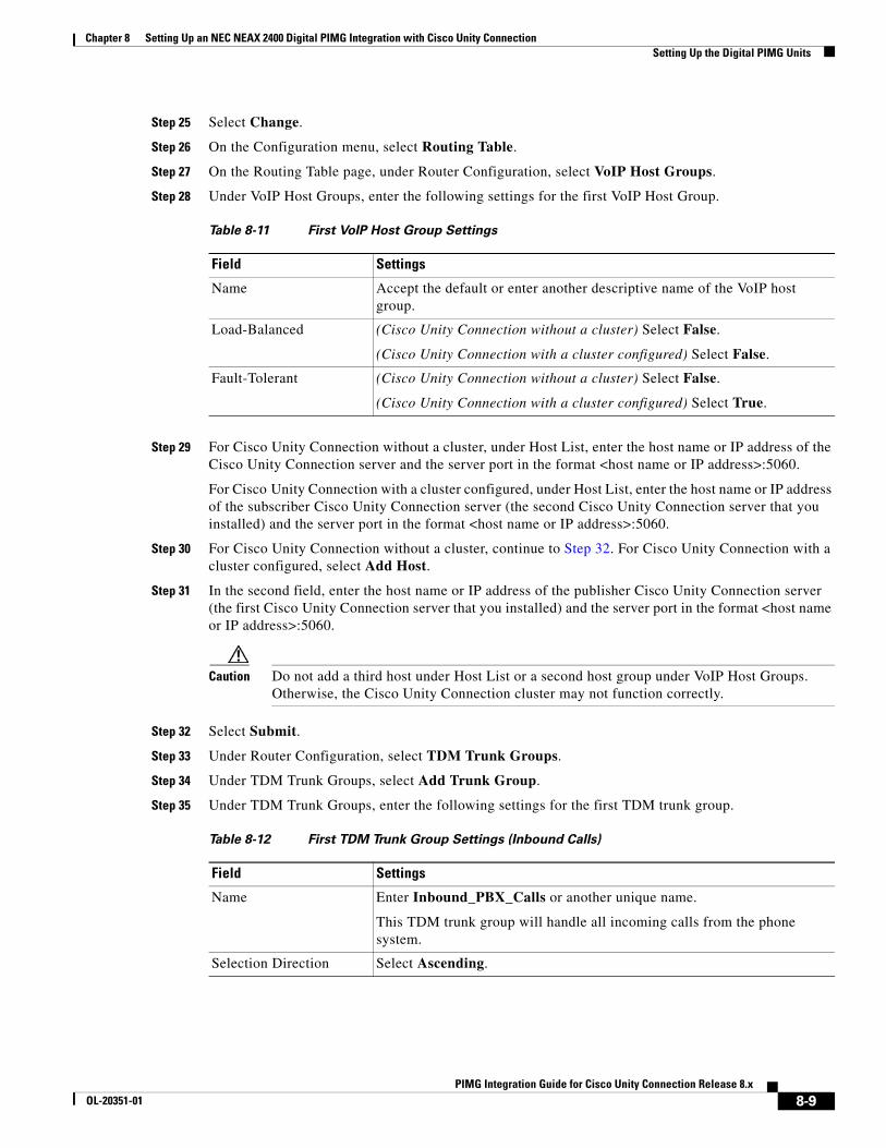
Chapter 8 Setting Up an NEC NEAX 2400 Digital PIMG Integration with Cisco Unity Connection Setting Up the Digital PIMG Units
Step 25 Select Change.
Step 26 On the Configuration menu, select Routing Table.
Step 27 On the Routing Table page, under Router Configuration, select VoIP Host Groups.
Step 28 Under VoIP Host Groups, enter the following settings for the first VoIP Host Group.
Step 29 For Cisco Unity Connection without a cluster, under Host List, enter the host name or IP address of the Cisco Unity Connection server and the server port in the format <host name or IP address>:5060.
For Cisco Unity Connection with a cluster configured, under Host List, enter the host name or IP address of the subscriber Cisco Unity Connection server (the second Cisco Unity Connection server that you installed) and the server port in the format <host name or IP address>:5060.
Step 30 For Cisco Unity Connection without a cluster, continue to Step 32. For Cisco Unity Connection with a cluster configured, select Add Host.
Step 31 In the second field, enter the host name or IP address of the publisher Cisco Unity Connection server (the first Cisco Unity Connection server that you installed) and the server port in the format <host name or IP address>:5060.
Caution Do not add a third host under Host List or a second host group under VoIP Host Groups. Otherwise, the Cisco Unity Connection cluster may not function correctly.
Step 32 Select Submit.
Step 33 Under Router Configuration, select TDM Trunk Groups.
Step 34 Under TDM Trunk Groups, select Add Trunk Group.
Step 35 Under TDM Trunk Groups, enter the following settings for the first TDM trunk group.
Table 8-11 First VoIP Host Group Settings
Field Settings
Name Accept the default or enter another descriptive name of the VoIP host group.
Load-Balanced (Cisco Unity Connection without a cluster) Select False.
(Cisco Unity Connection with a cluster configured) Select False.
Fault-Tolerant (Cisco Unity Connection without a cluster) Select False.
(Cisco Unity Connection with a cluster configured) Select True.
Table 8-12 First TDM Trunk Group Settings (Inbound Calls)
Field Settings
Name Enter Inbound_PBX_Calls or another unique name.
This TDM trunk group will handle all incoming calls from the phone system.
Selection Direction Select Ascending.
8-9PIMG Integration Guide for Cisco Unity Connection Release 8.x
OL-20351-01
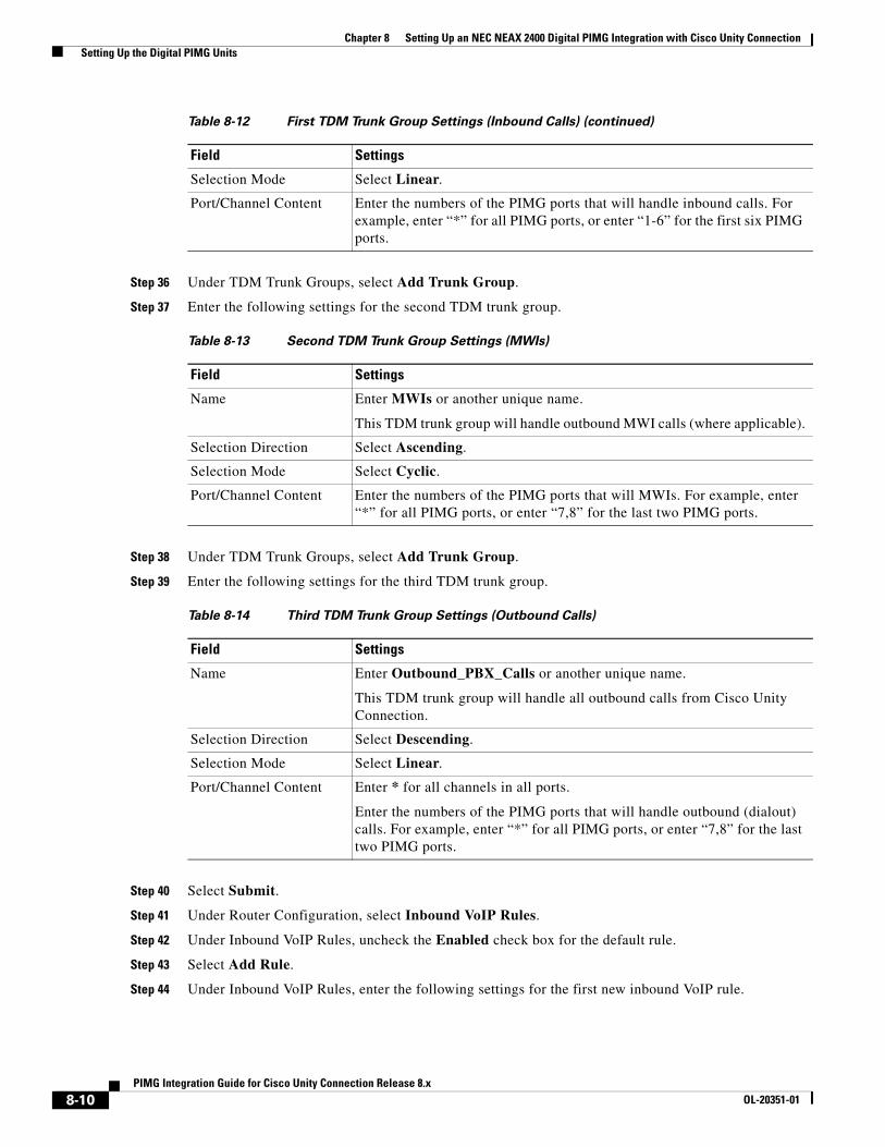
Chapter 8 Setting Up an NEC NEAX 2400 Digital PIMG Integration with Cisco Unity Connection Setting Up the Digital PIMG Units
Step 36 Under TDM Trunk Groups, select Add Trunk Group.
Step 37 Enter the following settings for the second TDM trunk group.
Step 38 Under TDM Trunk Groups, select Add Trunk Group.
Step 39 Enter the following settings for the third TDM trunk group.
Step 40 Select Submit.
Step 41 Under Router Configuration, select Inbound VoIP Rules.
Step 42 Under Inbound VoIP Rules, uncheck the Enabled check box for the default rule.
Step 43 Select Add Rule.
Step 44 Under Inbound VoIP Rules, enter the following settings for the first new inbound VoIP rule.
Selection Mode Select Linear.
Port/Channel Content Enter the numbers of the PIMG ports that will handle inbound calls. For example, enter “*” for all PIMG ports, or enter “1-6” for the first six PIMG ports.
Table 8-13 Second TDM Trunk Group Settings (MWIs)
Field Settings
Name Enter MWIs or another unique name.
This TDM trunk group will handle outbound MWI calls (where applicable).
Selection Direction Select Ascending.
Selection Mode Select Cyclic.
Port/Channel Content Enter the numbers of the PIMG ports that will MWIs. For example, enter “*” for all PIMG ports, or enter “7,8” for the last two PIMG ports.
Table 8-14 Third TDM Trunk Group Settings (Outbound Calls)
Field Settings
Name Enter Outbound_PBX_Calls or another unique name.
This TDM trunk group will handle all outbound calls from Cisco Unity Connection.
Selection Direction Select Descending.
Selection Mode Select Linear.
Port/Channel Content Enter * for all channels in all ports.
Enter the numbers of the PIMG ports that will handle outbound (dialout) calls. For example, enter “*” for all PIMG ports, or enter “7,8” for the last two PIMG ports.
Table 8-12 First TDM Trunk Group Settings (Inbound Calls) (continued)
Field Settings
8-10PIMG Integration Guide for Cisco Unity Connection Release 8.x
OL-20351-01
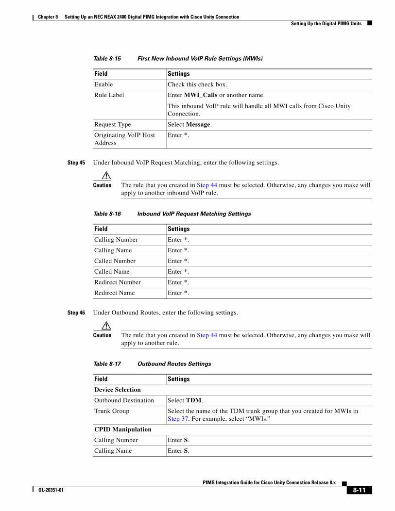
Chapter 8 Setting Up an NEC NEAX 2400 Digital PIMG Integration with Cisco Unity Connection Setting Up the Digital PIMG Units
Step 45 Under Inbound VoIP Request Matching, enter the following settings.
Caution The rule that you created in Step 44 must be selected. Otherwise, any changes you make will apply to another inbound VoIP rule.
Step 46 Under Outbound Routes, enter the following settings.
Caution The rule that you created in Step 44 must be selected. Otherwise, any changes you make will apply to another rule.
Table 8-15 First New Inbound VoIP Rule Settings (MWIs)
Field Settings
Enable Check this check box.
Rule Label Enter MWI_Calls or another name.
This inbound VoIP rule will handle all MWI calls from Cisco Unity Connection.
Request Type Select Message.
Originating VoIP Host Address
Enter *.
Table 8-16 Inbound VoIP Request Matching Settings
Field Settings
Calling Number Enter *.
Calling Name Enter *.
Called Number Enter *.
Called Name Enter *.
Redirect Number Enter *.
Redirect Name Enter *.
Table 8-17 Outbound Routes Settings
Field Settings
Device Selection
Outbound Destination Select TDM.
Trunk Group Select the name of the TDM trunk group that you created for MWIs in Step 37. For example, select “MWIs.”
CPID Manipulation
Calling Number Enter S.
Calling Name Enter S.
8-11PIMG Integration Guide for Cisco Unity Connection Release 8.x
OL-20351-01
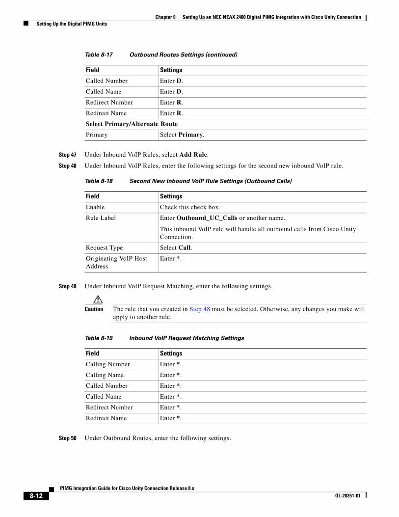
Chapter 8 Setting Up an NEC NEAX 2400 Digital PIMG Integration with Cisco Unity Connection Setting Up the Digital PIMG Units
Step 47 Under Inbound VoIP Rules, select Add Rule.
Step 48 Under Inbound VoIP Rules, enter the following settings for the second new inbound VoIP rule.
Step 49 Under Inbound VoIP Request Matching, enter the following settings.
Caution The rule that you created in Step 48 must be selected. Otherwise, any changes you make will apply to another rule.
Step 50 Under Outbound Routes, enter the following settings.
Called Number Enter D.
Called Name Enter D.
Redirect Number Enter R.
Redirect Name Enter R.
Select Primary/Alternate Route
Primary Select Primary.
Table 8-18 Second New Inbound VoIP Rule Settings (Outbound Calls)
Field Settings
Enable Check this check box.
Rule Label Enter Outbound_UC_Calls or another name.
This inbound VoIP rule will handle all outbound calls from Cisco Unity Connection.
Request Type Select Call.
Originating VoIP Host Address
Enter *.
Table 8-17 Outbound Routes Settings (continued)
Field Settings
Table 8-19 Inbound VoIP Request Matching Settings
Field Settings
Calling Number Enter *.
Calling Name Enter *.
Called Number Enter *.
Called Name Enter *.
Redirect Number Enter *.
Redirect Name Enter *.
8-12PIMG Integration Guide for Cisco Unity Connection Release 8.x
OL-20351-01
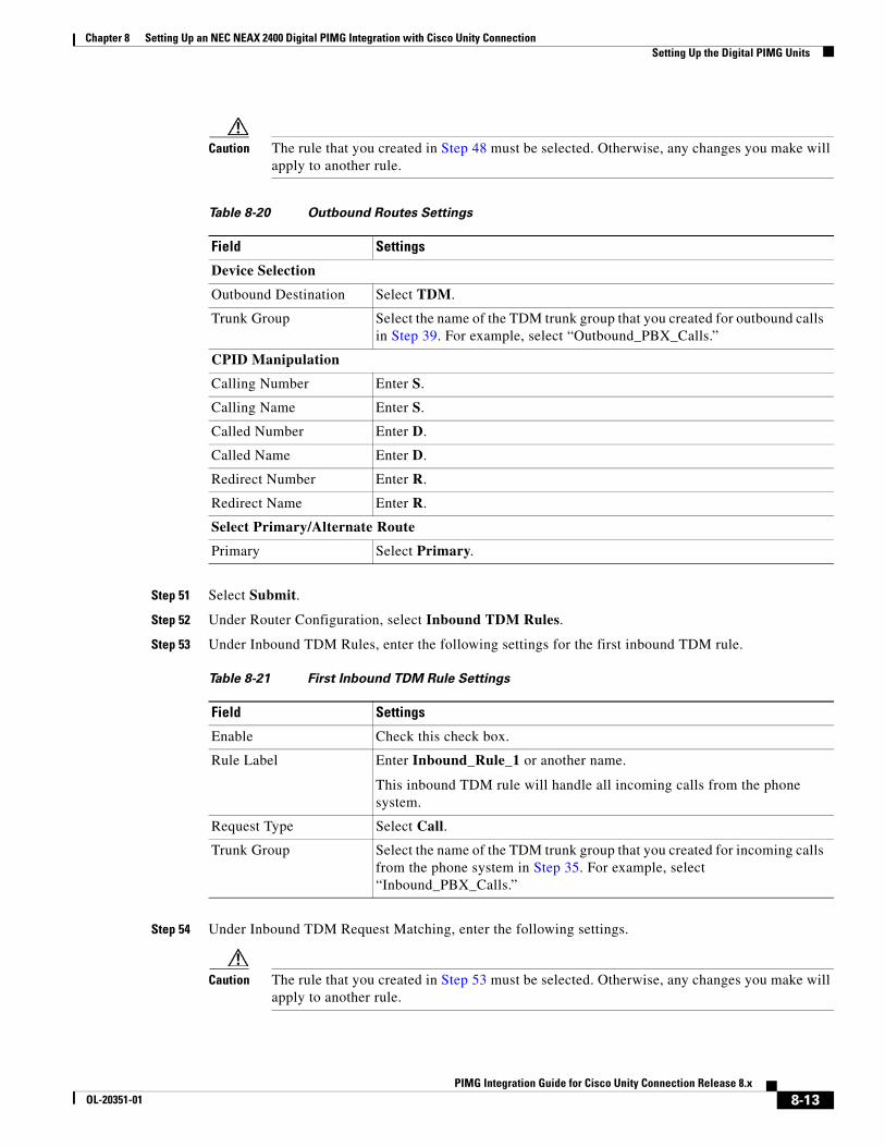
Chapter 8 Setting Up an NEC NEAX 2400 Digital PIMG Integration with Cisco Unity Connection Setting Up the Digital PIMG Units
Caution The rule that you created in Step 48 must be selected. Otherwise, any changes you make will apply to another rule.
Step 51 Select Submit.
Step 52 Under Router Configuration, select Inbound TDM Rules.
Step 53 Under Inbound TDM Rules, enter the following settings for the first inbound TDM rule.
Step 54 Under Inbound TDM Request Matching, enter the following settings.
Caution The rule that you created in Step 53 must be selected. Otherwise, any changes you make will apply to another rule.
Table 8-20 Outbound Routes Settings
Field Settings
Device Selection
Outbound Destination Select TDM.
Trunk Group Select the name of the TDM trunk group that you created for outbound calls in Step 39. For example, select “Outbound_PBX_Calls.”
CPID Manipulation
Calling Number Enter S.
Calling Name Enter S.
Called Number Enter D.
Called Name Enter D.
Redirect Number Enter R.
Redirect Name Enter R.
Select Primary/Alternate Route
Primary Select Primary.
Table 8-21 First Inbound TDM Rule Settings
Field Settings
Enable Check this check box.
Rule Label Enter Inbound_Rule_1 or another name.
This inbound TDM rule will handle all incoming calls from the phone system.
Request Type Select Call.
Trunk Group Select the name of the TDM trunk group that you created for incoming calls from the phone system in Step 35. For example, select “Inbound_PBX_Calls.”
8-13PIMG Integration Guide for Cisco Unity Connection Release 8.x
OL-20351-01
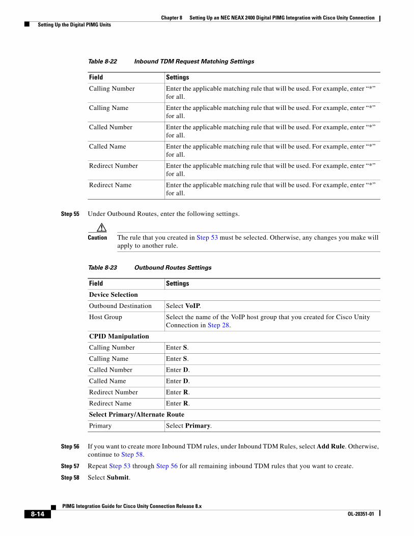
Chapter 8 Setting Up an NEC NEAX 2400 Digital PIMG Integration with Cisco Unity Connection Setting Up the Digital PIMG Units
Step 55 Under Outbound Routes, enter the following settings.
Caution The rule that you created in Step 53 must be selected. Otherwise, any changes you make will apply to another rule.
Step 56 If you want to create more Inbound TDM rules, under Inbound TDM Rules, select Add Rule. Otherwise, continue to Step 58.
Step 57 Repeat Step 53 through Step 56 for all remaining inbound TDM rules that you want to create.
Step 58 Select Submit.
Table 8-22 Inbound TDM Request Matching Settings
Field Settings
Calling Number Enter the applicable matching rule that will be used. For example, enter “*” for all.
Calling Name Enter the applicable matching rule that will be used. For example, enter “*” for all.
Called Number Enter the applicable matching rule that will be used. For example, enter “*” for all.
Called Name Enter the applicable matching rule that will be used. For example, enter “*” for all.
Redirect Number Enter the applicable matching rule that will be used. For example, enter “*” for all.
Redirect Name Enter the applicable matching rule that will be used. For example, enter “*” for all.
Table 8-23 Outbound Routes Settings
Field Settings
Device Selection
Outbound Destination Select VoIP.
Host Group Select the name of the VoIP host group that you created for Cisco Unity Connection in Step 28.
CPID Manipulation
Calling Number Enter S.
Calling Name Enter S.
Called Number Enter D.
Called Name Enter D.
Redirect Number Enter R.
Redirect Name Enter R.
Select Primary/Alternate Route
Primary Select Primary.
8-14PIMG Integration Guide for Cisco Unity Connection Release 8.x
OL-20351-01
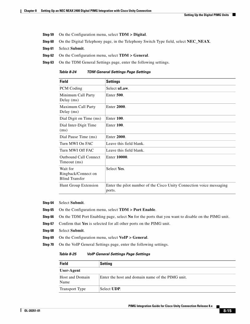
Chapter 8 Setting Up an NEC NEAX 2400 Digital PIMG Integration with Cisco Unity Connection Setting Up the Digital PIMG Units
Step 59 On the Configuration menu, select TDM > Digital.
Step 60 On the Digital Telephony page, in the Telephony Switch Type field, select NEC_NEAX.
Step 61 Select Submit.
Step 62 On the Configuration menu, select TDM > General.
Step 63 On the TDM General Settings page, enter the following settings.
Step 64 Select Submit.
Step 65 On the Configuration menu, select TDM > Port Enable.
Step 66 On the TDM Port Enabling page, select No for the ports that you want to disable on the PIMG unit.
Step 67 Confirm that Yes is selected for all other ports on the PIMG unit.
Step 68 Select Submit.
Step 69 On the Configuration menu, select VoIP > General.
Step 70 On the VoIP General Settings page, enter the following settings.
Table 8-24 TDM General Settings Page Settings
Field Settings
PCM Coding Select uLaw.
Minimum Call Party Delay (ms)
Enter 500.
Maximum Call Party Delay (ms)
Enter 2000.
Dial Digit on Time (ms) Enter 100.
Dial Inter-Digit Time (ms)
Enter 100.
Dial Pause Time (ms) Enter 2000.
Turn MWI On FAC Leave this field blank.
Turn MWI Off FAC Leave this field blank.
Outbound Call Connect Timeout (ms)
Enter 10000.
Wait for Ringback/Connect on Blind Transfer
Select Yes.
Hunt Group Extension Enter the pilot number of the Cisco Unity Connection voice messaging ports.
Table 8-25 VoIP General Settings Page Settings
Field Setting
User-Agent
Host and Domain Name
Enter the host and domain name of the PIMG unit.
Transport Type Select UDP.
8-15PIMG Integration Guide for Cisco Unity Connection Release 8.x
OL-20351-01
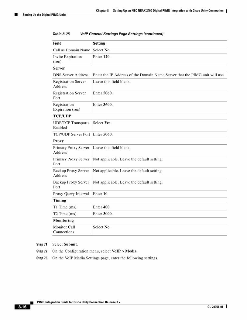
Chapter 8 Setting Up an NEC NEAX 2400 Digital PIMG Integration with Cisco Unity Connection Setting Up the Digital PIMG Units
Step 71 Select Submit.
Step 72 On the Configuration menu, select VoIP > Media.
Step 73 On the VoIP Media Settings page, enter the following settings.
Call as Domain Name Select No.
Invite Expiration (sec)
Enter 120.
Server
DNS Server Address Enter the IP Address of the Domain Name Server that the PIMG unit will use.
Registration Server Address
Leave this field blank.
Registration Server Port
Enter 5060.
Registration Expiration (sec)
Enter 3600.
TCP/UDP
UDP/TCP Transports Enabled
Select Yes.
TCP/UDP Server Port Enter 5060.
Proxy
Primary Proxy Server Address
Leave this field blank.
Primary Proxy Server Port
Not applicable. Leave the default setting.
Backup Proxy Server Address
Not applicable. Leave the default setting.
Backup Proxy Server Port
Not applicable. Leave the default setting.
Proxy Query Interval Enter 10.
Timing
T1 Time (ms) Enter 400.
T2 Time (ms) Enter 3000.
Monitoring
Monitor Call Connections
Select No.
Table 8-25 VoIP General Settings Page Settings (continued)
Field Setting
8-16PIMG Integration Guide for Cisco Unity Connection Release 8.x
OL-20351-01
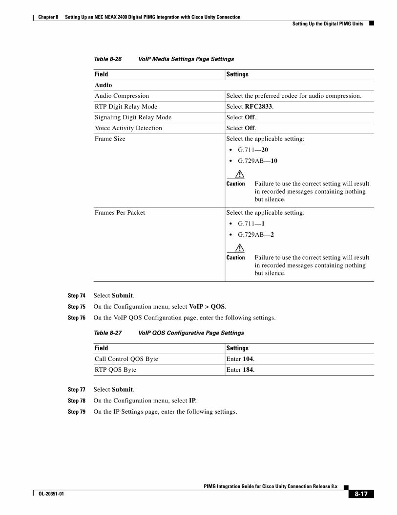
Chapter 8 Setting Up an NEC NEAX 2400 Digital PIMG Integration with Cisco Unity Connection Setting Up the Digital PIMG Units
Step 74 Select Submit.
Step 75 On the Configuration menu, select VoIP > QOS.
Step 76 On the VoIP QOS Configuration page, enter the following settings.
Step 77 Select Submit.
Step 78 On the Configuration menu, select IP.
Step 79 On the IP Settings page, enter the following settings.
Table 8-26 VoIP Media Settings Page Settings
Field Settings
Audio
Audio Compression Select the preferred codec for audio compression.
RTP Digit Relay Mode Select RFC2833.
Signaling Digit Relay Mode Select Off.
Voice Activity Detection Select Off.
Frame Size Select the applicable setting:
• G.711—20
• G.729AB—10
Caution Failure to use the correct setting will result in recorded messages containing nothing but silence.
Frames Per Packet Select the applicable setting:
• G.711—1
• G.729AB—2
Caution Failure to use the correct setting will result in recorded messages containing nothing but silence.
Table 8-27 VoIP QOS Configurative Page Settings
Field Settings
Call Control QOS Byte Enter 104.
RTP QOS Byte Enter 184.
8-17PIMG Integration Guide for Cisco Unity Connection Release 8.x
OL-20351-01
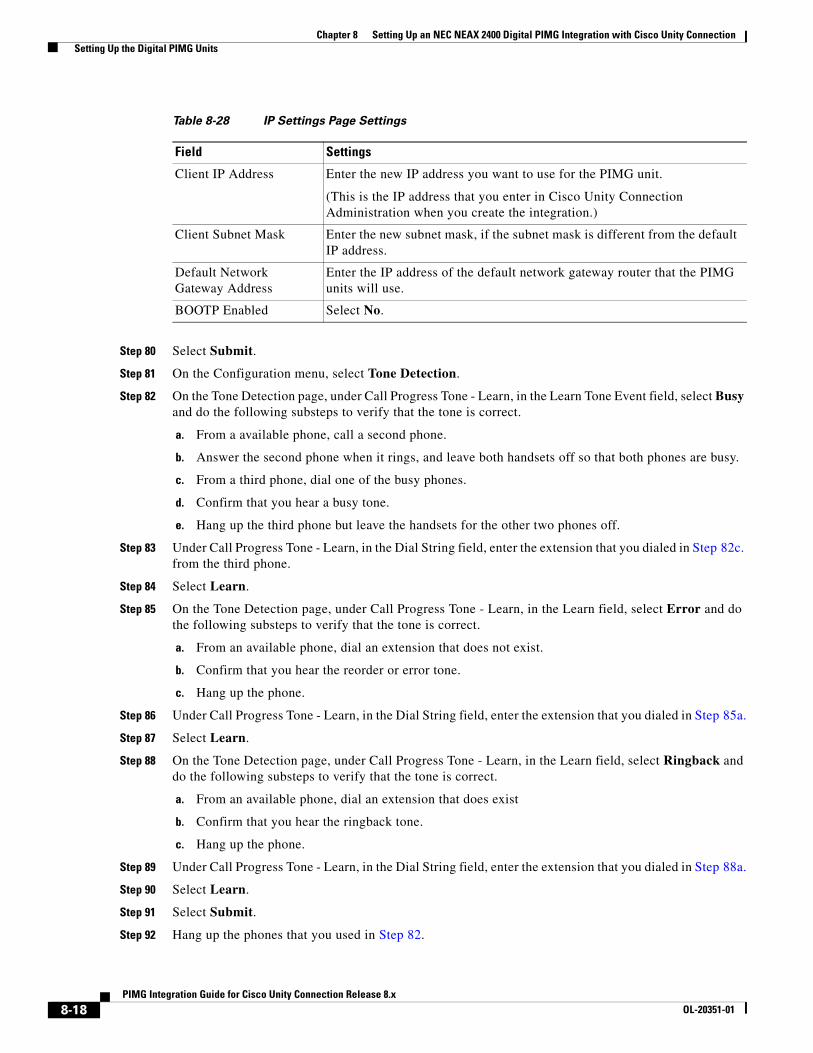
Chapter 8 Setting Up an NEC NEAX 2400 Digital PIMG Integration with Cisco Unity Connection Setting Up the Digital PIMG Units
Step 80 Select Submit.
Step 81 On the Configuration menu, select Tone Detection.
Step 82 On the Tone Detection page, under Call Progress Tone - Learn, in the Learn Tone Event field, select Busy and do the following substeps to verify that the tone is correct.
a. From a available phone, call a second phone.
b. Answer the second phone when it rings, and leave both handsets off so that both phones are busy.
c. From a third phone, dial one of the busy phones.
d. Confirm that you hear a busy tone.
e. Hang up the third phone but leave the handsets for the other two phones off.
Step 83 Under Call Progress Tone - Learn, in the Dial String field, enter the extension that you dialed in Step 82c. from the third phone.
Step 84 Select Learn.
Step 85 On the Tone Detection page, under Call Progress Tone - Learn, in the Learn field, select Error and do the following substeps to verify that the tone is correct.
a. From an available phone, dial an extension that does not exist.
b. Confirm that you hear the reorder or error tone.
c. Hang up the phone.
Step 86 Under Call Progress Tone - Learn, in the Dial String field, enter the extension that you dialed in Step 85a.
Step 87 Select Learn.
Step 88 On the Tone Detection page, under Call Progress Tone - Learn, in the Learn field, select Ringback and do the following substeps to verify that the tone is correct.
a. From an available phone, dial an extension that does exist
b. Confirm that you hear the ringback tone.
c. Hang up the phone.
Step 89 Under Call Progress Tone - Learn, in the Dial String field, enter the extension that you dialed in Step 88a.
Step 90 Select Learn.
Step 91 Select Submit.
Step 92 Hang up the phones that you used in Step 82.
Table 8-28 IP Settings Page Settings
Field Settings
Client IP Address Enter the new IP address you want to use for the PIMG unit.
(This is the IP address that you enter in Cisco Unity Connection Administration when you create the integration.)
Client Subnet Mask Enter the new subnet mask, if the subnet mask is different from the default IP address.
Default Network Gateway Address
Enter the IP address of the default network gateway router that the PIMG units will use.
BOOTP Enabled Select No.
8-18PIMG Integration Guide for Cisco Unity Connection Release 8.x
OL-20351-01
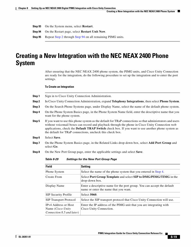
Chapter 8 Setting Up an NEC NEAX 2400 Digital PIMG Integration with Cisco Unity Connection Creating a New Integration with the NEC NEAX 2400 Phone System
Step 93 On the System menu, select Restart.
Step 94 On the Restart page, select Restart Unit Now.
Step 95 Repeat Step 2 through Step 94 on all remaining PIMG units.
Creating a New Integration with the NEC NEAX 2400 Phone System
After ensuring that the NEC NEAX 2400 phone system, the PIMG units, and Cisco Unity Connection are ready for the integration, do the following procedure to set up the integration and to enter the port settings.
To Create an Integration
Step 1 Sign in to Cisco Unity Connection Administration.
Step 2 In Cisco Unity Connection Administration, expand Telephony Integrations, then select Phone System.
Step 3 On the Search Phone Systems page, under Display Name, select the name of the default phone system.
Step 4 On the Phone System Basics page, in the Phone System Name field, enter the descriptive name that you want for the phone system.
Step 5 If you want to use this phone system as the default for TRaP connections so that administrators and users without voicemail boxes can record and playback through the phone in Cisco Unity Connection web applications, check the Default TRAP Switch check box. If you want to use another phone system as the default for TRaP connections, uncheck this check box.
Step 6 Select Save.
Step 7 On the Phone System Basics page, in the Related Links drop-down box, select Add Port Group and select Go.
Step 8 On the New Port Group page, enter the applicable settings and select Save.
Table 8-29 Settings for the New Port Group Page
Field Setting
Phone System Select the name of the phone system that you entered in Step 4.
Create From Select Port Group Template and select SIP to DMG/PIMG/TIMG in the drop-down box.
Display Name Enter a descriptive name for the port group. You can accept the default name or enter the name that you want.
SIP Security Profile Select 5060.
SIP Transport Protocol Select the SIP transport protocol that Cisco Unity Connection will use.
IPv4 Address or Host Name (Cisco Unity Connection 8.5 and later)
Enter the IP address of the PIMG unit that you are integrating with Cisco Unity Connection.
8-19PIMG Integration Guide for Cisco Unity Connection Release 8.x
OL-20351-01
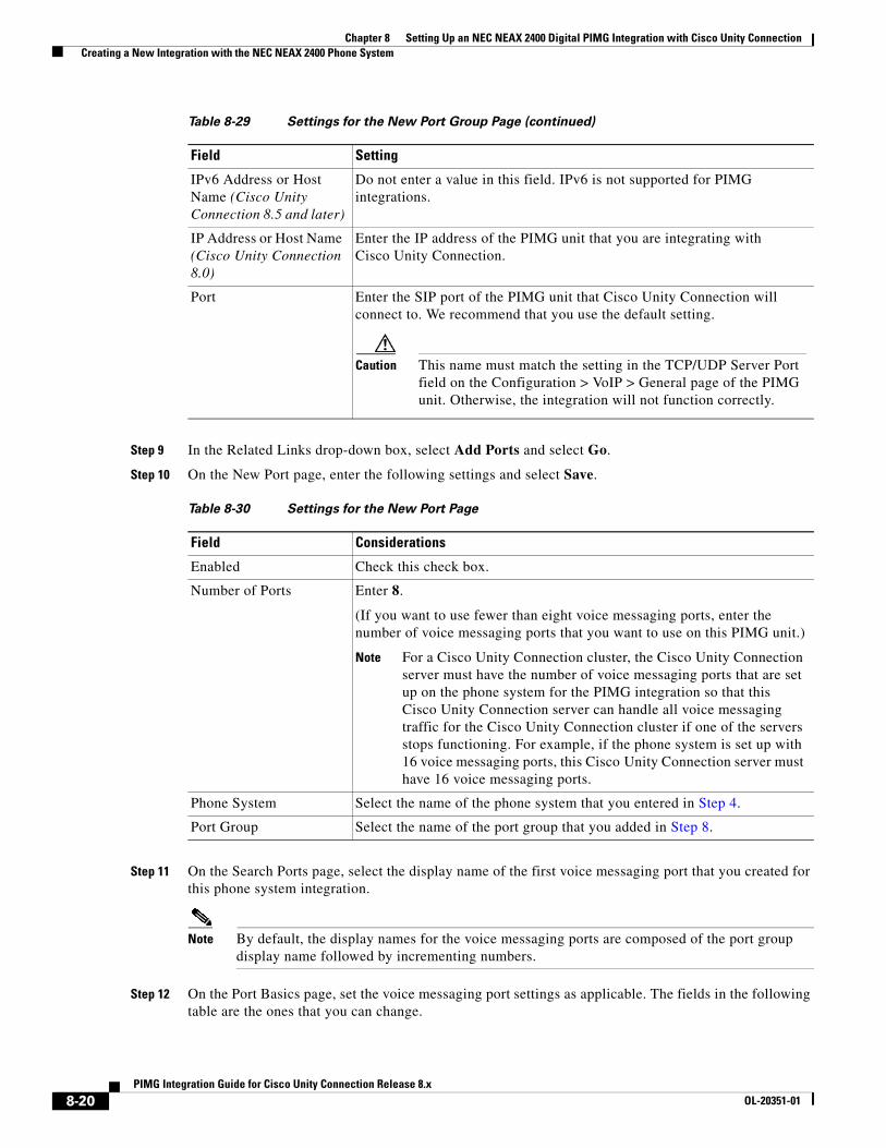
Chapter 8 Setting Up an NEC NEAX 2400 Digital PIMG Integration with Cisco Unity Connection Creating a New Integration with the NEC NEAX 2400 Phone System
Step 9 In the Related Links drop-down box, select Add Ports and select Go.
Step 10 On the New Port page, enter the following settings and select Save.
Step 11 On the Search Ports page, select the display name of the first voice messaging port that you created for this phone system integration.
Note By default, the display names for the voice messaging ports are composed of the port group display name followed by incrementing numbers.
Step 12 On the Port Basics page, set the voice messaging port settings as applicable. The fields in the following table are the ones that you can change.
IPv6 Address or Host Name (Cisco Unity Connection 8.5 and later)
Do not enter a value in this field. IPv6 is not supported for PIMG integrations.
IP Address or Host Name (Cisco Unity Connection 8.0)
Enter the IP address of the PIMG unit that you are integrating with Cisco Unity Connection.
Port Enter the SIP port of the PIMG unit that Cisco Unity Connection will connect to. We recommend that you use the default setting.
Caution This name must match the setting in the TCP/UDP Server Port field on the Configuration > VoIP > General page of the PIMG unit. Otherwise, the integration will not function correctly.
Table 8-30 Settings for the New Port Page
Field Considerations
Enabled Check this check box.
Number of Ports Enter 8.
(If you want to use fewer than eight voice messaging ports, enter the number of voice messaging ports that you want to use on this PIMG unit.)
Note For a Cisco Unity Connection cluster, the Cisco Unity Connection server must have the number of voice messaging ports that are set up on the phone system for the PIMG integration so that this Cisco Unity Connection server can handle all voice messaging traffic for the Cisco Unity Connection cluster if one of the servers stops functioning. For example, if the phone system is set up with 16 voice messaging ports, this Cisco Unity Connection server must have 16 voice messaging ports.
Phone System Select the name of the phone system that you entered in Step 4.
Port Group Select the name of the port group that you added in Step 8.
Table 8-29 Settings for the New Port Group Page (continued)
Field Setting
8-20PIMG Integration Guide for Cisco Unity Connection Release 8.x
OL-20351-01
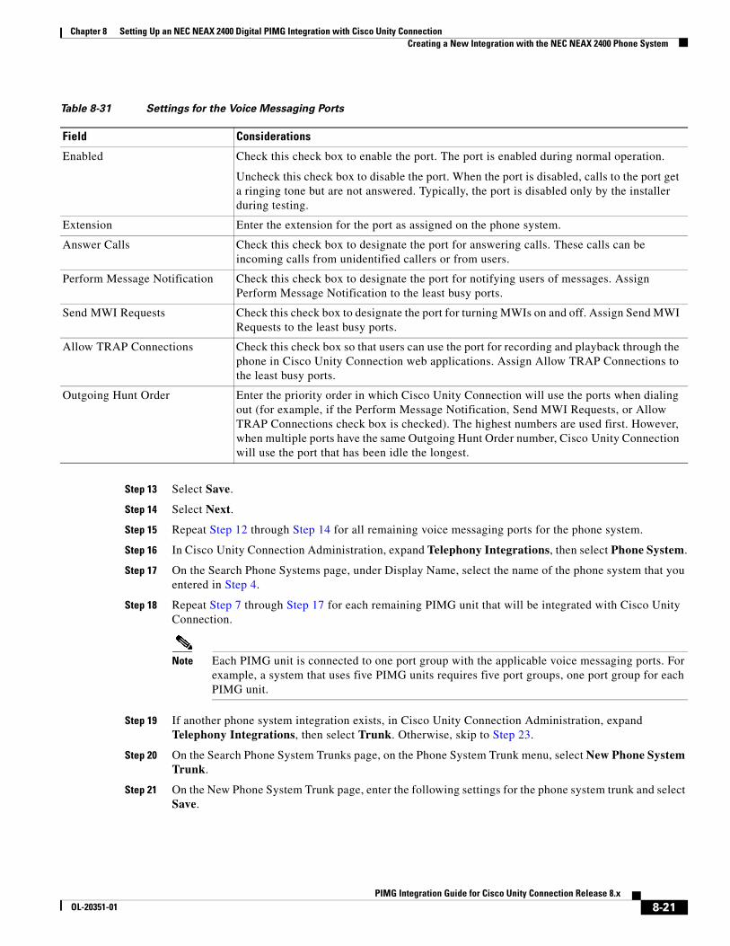
Chapter 8 Setting Up an NEC NEAX 2400 Digital PIMG Integration with Cisco Unity Connection Creating a New Integration with the NEC NEAX 2400 Phone System
Step 13 Select Save.
Step 14 Select Next.
Step 15 Repeat Step 12 through Step 14 for all remaining voice messaging ports for the phone system.
Step 16 In Cisco Unity Connection Administration, expand Telephony Integrations, then select Phone System.
Step 17 On the Search Phone Systems page, under Display Name, select the name of the phone system that you entered in Step 4.
Step 18 Repeat Step 7 through Step 17 for each remaining PIMG unit that will be integrated with Cisco Unity Connection.
Note Each PIMG unit is connected to one port group with the applicable voice messaging ports. For example, a system that uses five PIMG units requires five port groups, one port group for each PIMG unit.
Step 19 If another phone system integration exists, in Cisco Unity Connection Administration, expand Telephony Integrations, then select Trunk. Otherwise, skip to Step 23.
Step 20 On the Search Phone System Trunks page, on the Phone System Trunk menu, select New Phone System Trunk.
Step 21 On the New Phone System Trunk page, enter the following settings for the phone system trunk and select Save.
Table 8-31 Settings for the Voice Messaging Ports
Field Considerations
Enabled Check this check box to enable the port. The port is enabled during normal operation.
Uncheck this check box to disable the port. When the port is disabled, calls to the port get a ringing tone but are not answered. Typically, the port is disabled only by the installer during testing.
Extension Enter the extension for the port as assigned on the phone system.
Answer Calls Check this check box to designate the port for answering calls. These calls can be incoming calls from unidentified callers or from users.
Perform Message Notification Check this check box to designate the port for notifying users of messages. Assign Perform Message Notification to the least busy ports.
Send MWI Requests Check this check box to designate the port for turning MWIs on and off. Assign Send MWI Requests to the least busy ports.
Allow TRAP Connections Check this check box so that users can use the port for recording and playback through the phone in Cisco Unity Connection web applications. Assign Allow TRAP Connections to the least busy ports.
Outgoing Hunt Order Enter the priority order in which Cisco Unity Connection will use the ports when dialing out (for example, if the Perform Message Notification, Send MWI Requests, or Allow TRAP Connections check box is checked). The highest numbers are used first. However, when multiple ports have the same Outgoing Hunt Order number, Cisco Unity Connection will use the port that has been idle the longest.
8-21PIMG Integration Guide for Cisco Unity Connection Release 8.x
OL-20351-01
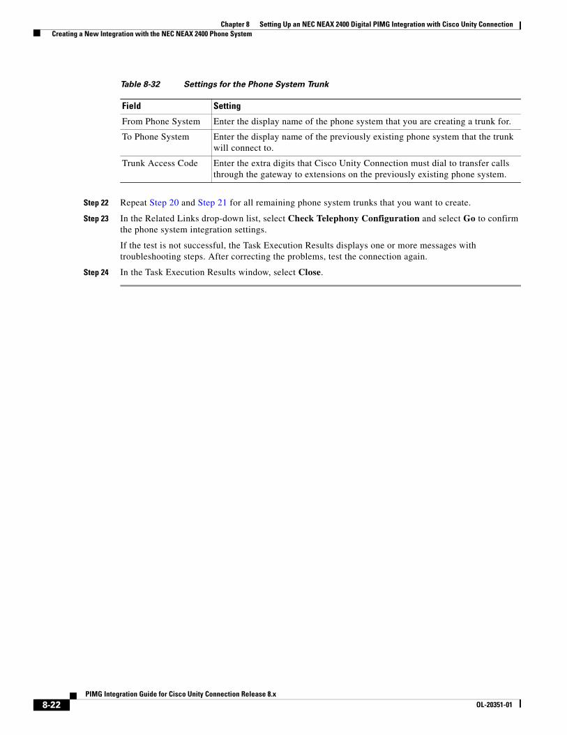
Chapter 8 Setting Up an NEC NEAX 2400 Digital PIMG Integration with Cisco Unity Connection Creating a New Integration with the NEC NEAX 2400 Phone System
Step 22 Repeat Step 20 and Step 21 for all remaining phone system trunks that you want to create.
Step 23 In the Related Links drop-down list, select Check Telephony Configuration and select Go to confirm the phone system integration settings.
If the test is not successful, the Task Execution Results displays one or more messages with troubleshooting steps. After correcting the problems, test the connection again.
Step 24 In the Task Execution Results window, select Close.
Table 8-32 Settings for the Phone System Trunk
Field Setting
From Phone System Enter the display name of the phone system that you are creating a trunk for.
To Phone System Enter the display name of the previously existing phone system that the trunk will connect to.
Trunk Access Code Enter the extra digits that Cisco Unity Connection must dial to transfer calls through the gateway to extensions on the previously existing phone system.
8-22PIMG Integration Guide for Cisco Unity Connection Release 8.x
OL-20351-01
PIMG IntegrOL-20351-01
C H A P T E R 9
Setting Up a Nortel Meridian 1 Digital PIMG Integration with Cisco Unity ConnectionFor detailed instructions for setting up a Nortel Meridian 1 digital PIMG integration with Cisco Unity Connection, see the following sections in this chapter:
• Task List to Create the Integration with a Nortel Meridian 1 PIMG Phone System, page 9-1
• Requirements, page 9-2
• Programming the Nortel Meridian 1 PIMG Phone System for Integrating with Cisco Unity Connection, page 9-3
• Setting Up the Digital PIMG Units, page 9-10
• Creating a New Integration with the Nortel Meridian 1 Phone System, page 9-24
Task List to Create the Integration with a Nortel Meridian 1 PIMG Phone System
Before doing the following tasks to integrate Cisco Unity Connection with the Nortel Meridian 1 phone system by using PIMG units (media gateways), confirm that the Cisco Unity Connection server is ready for the integration by completing the applicable tasks in the Cisco Unity Connection Installation Guide.
1. Review the system and equipment requirements to confirm that all phone system and Cisco Unity Connection server requirements have been met. See the “Requirements” section on page 9-2.
2. Plan how the voice messaging ports will be used by Cisco Unity Connection. See Chapter 2, “Planning How the Voice Messaging Ports Will Be Used by Cisco Unity Connection.”
3. Program the Nortel Meridian 1 phone system and extensions. See the “Programming the Nortel Meridian 1 PIMG Phone System for Integrating with Cisco Unity Connection” section on page 9-3.
4. Set up the PIMG units. See the “Setting Up the Digital PIMG Units” section on page 9-10.
5. Create the integration. See the “Creating a New Integration with the Nortel Meridian 1 Phone System” section on page 9-24.
6. Test the integration. See Chapter 14, “Testing the Integration.”
7. If this integration is a second or subsequent integration, add the applicable new user templates for the new phone system. See Chapter 15, “Adding New User Templates for Multiple Integrations.”
9-1ation Guide for Cisco Unity Connection Release 8.x
Chapter 9 Setting Up a Nortel Meridian 1 Digital PIMG Integration with Cisco Unity Connection Requirements
RequirementsThe Nortel Meridian 1 PIMG integration supports configurations of the following components:
Phone System
• One of the following models:
– Nortel Meridian 1 phone system (Option 11, 21, 51, 61, 71, or 81), software release 17 or later.
– Nortel Succession (CS 1000) phone system, software release 3.0 or later.
– The Nortel SL 1 phone system, when upgraded to Meridian 1 so that it is compatible with the M2616 digital phone.
• The following software option packages installed:
– Package 19, Digit Display Software (DDSP)
– Package 46, Message Waiting Center (MWC)
• One or more digital lines that are compatible with the M2616 digital phone for connecting to the PIMG units.
• One or more of the applicable PIMG units. For details, see Chapter 1, “Introduction.”
• The voice messaging ports in the phone system connected by digital lines to the ports on the PIMG units.
To simplify troubleshooting, we recommend that you connect the voice messaging ports on the phone system to the ports on the PIMG units in a planned manner. For example, connect the first phone system voice messaging port to the first port on the first PIMG unit, connect the second phone system voice messaging port to the second port on the first PIMG unit, and so on. Alternatively, if you have multiple PIMG units, you can reduce answer times in the event of a PIMG unit failure by connecting the phone system ports to the PIMG units in a round-robin fashion. For example, connect the first phone system voice messaging port to the first port on the first PIMG unit, connect the second phone system voice messaging port to the first port on the second PIMG unit, and so on.
• The PIMG units connected to the same LAN or WAN that Cisco Unity Connection is connected to.
• If the PIMG units connect to a WAN, the requirements for the WAN network connections are:
– For G.729a codec formatting, a minimum of 32.76 Kbps guaranteed bandwidth for each voice messaging port.
– For G.711 codec formatting, a minimum of 91.56 Kbps guaranteed bandwidth for each voice messaging port.
– No network devices that implement network address translation (NAT).
– A maximum 200 ms one-way network latency.
• The phone system ready for the integration, as described in the documentation for the phone system.
Cisco Unity Connection Server
• Cisco Unity Connection installed and ready for the integration, as described in the Cisco Unity Connection Installation Guide at http://www.cisco.com/en/US/products/ps6509/prod_installation_guides_list.html.
• A license that enables the applicable number of voice messaging ports.
9-2PIMG Integration Guide for Cisco Unity Connection Release 8.x
OL-20351-01
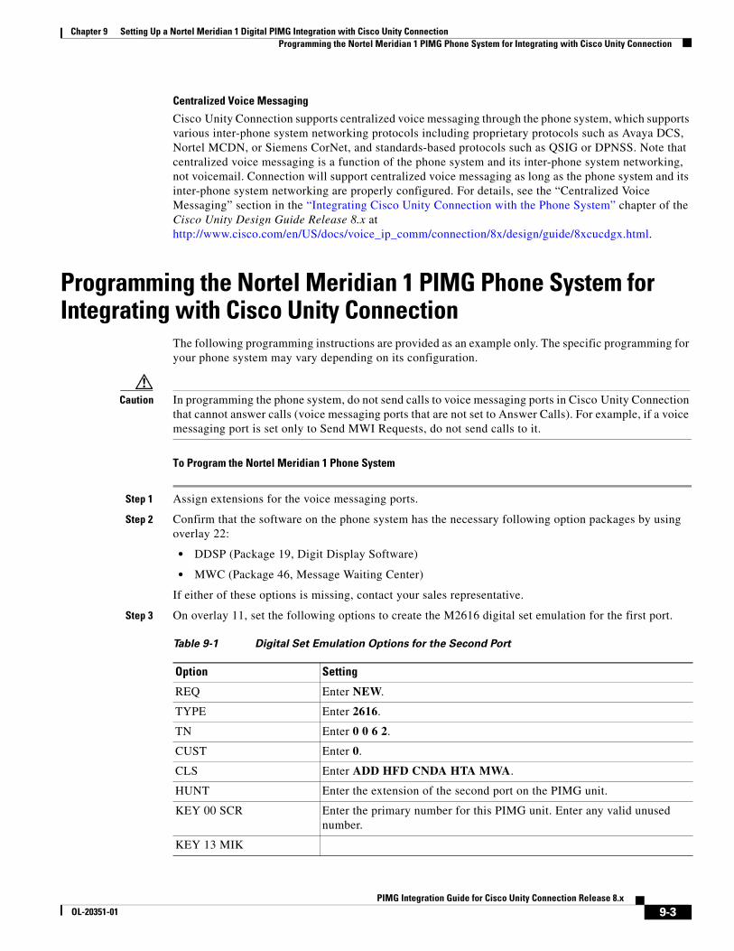
Chapter 9 Setting Up a Nortel Meridian 1 Digital PIMG Integration with Cisco Unity Connection Programming the Nortel Meridian 1 PIMG Phone System for Integrating with Cisco Unity Connection
Centralized Voice Messaging
Cisco Unity Connection supports centralized voice messaging through the phone system, which supports various inter-phone system networking protocols including proprietary protocols such as Avaya DCS, Nortel MCDN, or Siemens CorNet, and standards-based protocols such as QSIG or DPNSS. Note that centralized voice messaging is a function of the phone system and its inter-phone system networking, not voicemail. Connection will support centralized voice messaging as long as the phone system and its inter-phone system networking are properly configured. For details, see the “Centralized Voice Messaging” section in the “Integrating Cisco Unity Connection with the Phone System” chapter of the Cisco Unity Design Guide Release 8.x at http://www.cisco.com/en/US/docs/voice_ip_comm/connection/8x/design/guide/8xcucdgx.html.
Programming the Nortel Meridian 1 PIMG Phone System for Integrating with Cisco Unity Connection
The following programming instructions are provided as an example only. The specific programming for your phone system may vary depending on its configuration.
Caution In programming the phone system, do not send calls to voice messaging ports in Cisco Unity Connection that cannot answer calls (voice messaging ports that are not set to Answer Calls). For example, if a voice messaging port is set only to Send MWI Requests, do not send calls to it.
To Program the Nortel Meridian 1 Phone System
Step 1 Assign extensions for the voice messaging ports.
Step 2 Confirm that the software on the phone system has the necessary following option packages by using overlay 22:
• DDSP (Package 19, Digit Display Software)
• MWC (Package 46, Message Waiting Center)
If either of these options is missing, contact your sales representative.
Step 3 On overlay 11, set the following options to create the M2616 digital set emulation for the first port.
Table 9-1 Digital Set Emulation Options for the Second Port
Option Setting
REQ Enter NEW.
TYPE Enter 2616.
TN Enter 0 0 6 2.
CUST Enter 0.
CLS Enter ADD HFD CNDA HTA MWA.
HUNT Enter the extension of the second port on the PIMG unit.
KEY 00 SCR Enter the primary number for this PIMG unit. Enter any valid unused number.
KEY 13 MIK
9-3PIMG Integration Guide for Cisco Unity Connection Release 8.x
OL-20351-01
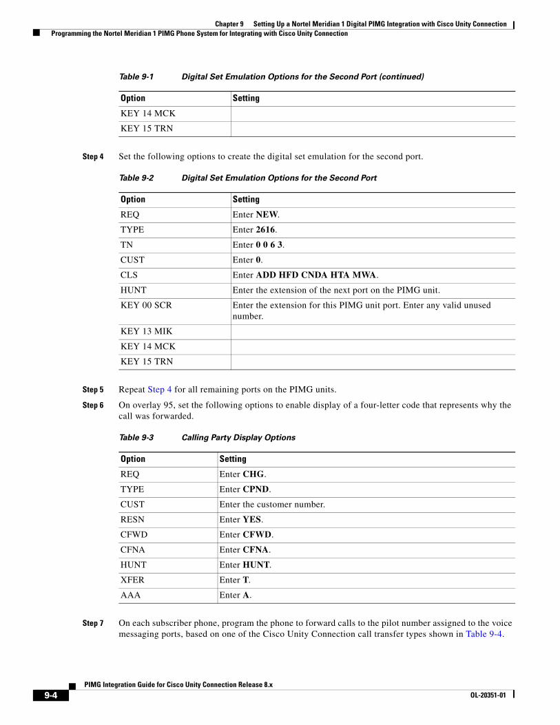
Chapter 9 Setting Up a Nortel Meridian 1 Digital PIMG Integration with Cisco Unity Connection Programming the Nortel Meridian 1 PIMG Phone System for Integrating with Cisco Unity Connection
Step 4 Set the following options to create the digital set emulation for the second port.
Step 5 Repeat Step 4 for all remaining ports on the PIMG units.
Step 6 On overlay 95, set the following options to enable display of a four-letter code that represents why the call was forwarded.
Step 7 On each subscriber phone, program the phone to forward calls to the pilot number assigned to the voice messaging ports, based on one of the Cisco Unity Connection call transfer types shown in Table 9-4.
KEY 14 MCK
KEY 15 TRN
Table 9-2 Digital Set Emulation Options for the Second Port
Option Setting
REQ Enter NEW.
TYPE Enter 2616.
TN Enter 0 0 6 3.
CUST Enter 0.
CLS Enter ADD HFD CNDA HTA MWA.
HUNT Enter the extension of the next port on the PIMG unit.
KEY 00 SCR Enter the extension for this PIMG unit port. Enter any valid unused number.
KEY 13 MIK
KEY 14 MCK
KEY 15 TRN
Table 9-3 Calling Party Display Options
Option Setting
REQ Enter CHG.
TYPE Enter CPND.
CUST Enter the customer number.
RESN Enter YES.
CFWD Enter CFWD.
CFNA Enter CFNA.
HUNT Enter HUNT.
XFER Enter T.
AAA Enter A.
Table 9-1 Digital Set Emulation Options for the Second Port (continued)
Option Setting
9-4PIMG Integration Guide for Cisco Unity Connection Release 8.x
OL-20351-01
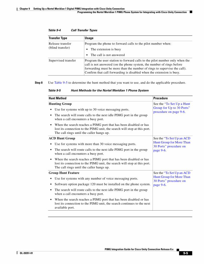
Chapter 9 Setting Up a Nortel Meridian 1 Digital PIMG Integration with Cisco Unity Connection Programming the Nortel Meridian 1 PIMG Phone System for Integrating with Cisco Unity Connection
Step 8 Use Table 9-5 to determine the hunt method that you want to use, and do the applicable procedure.
Table 9-4 Call Transfer Types
Transfer Type Usage
Release transfer (blind transfer)
Program the phone to forward calls to the pilot number when:
• The extension is busy
• The call is not answered
Supervised transfer Program the user station to forward calls to the pilot number only when the call is not answered (on the phone system, the number of rings before forwarding must be more than the number of rings to supervise the call). Confirm that call forwarding is disabled when the extension is busy.
Table 9-5 Hunt Methods for the Nortel Meridian 1 Phone System
Hunt Method Procedure
Hunting Group
• Use for systems with up to 30 voice messaging ports.
• The search will route calls to the next idle PIMG port in the group when a call encounters a busy port.
• When the search reaches a PIMG port that has been disabled or has lost its connection to the PIMG unit, the search will stop at this port. The call rings until the caller hangs up.
See the “To Set Up a Hunt Group for Up to 30 Ports” procedure on page 9-6.
ACD Hunt Group
• Use for systems with more than 30 voice messaging ports.
• The search will route calls to the next idle PIMG port in the group when a call encounters a busy port.
• When the search reaches a PIMG port that has been disabled or has lost its connection to the PIMG unit, the search will stop at this port. The call rings until the caller hangs up.
See the “To Set Up an ACD Hunt Group for More Than 30 Ports” procedure on page 9-6.
Group Hunt Feature
• Use for systems with any number of voice messaging ports.
• Software option package 120 must be installed on the phone system.
• The search will route calls to the next idle PIMG port in the group when a call encounters a busy port.
• When the search reaches a PIMG port that has been disabled or has lost its connection to the PIMG unit, the search continues to the next available port.
See the “To Set Up an ACD Hunt Group for More Than 30 Ports” procedure on page 9-6.
9-5PIMG Integration Guide for Cisco Unity Connection Release 8.x
OL-20351-01
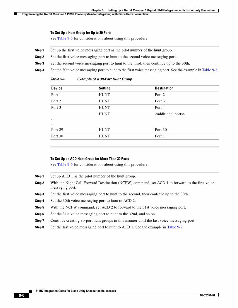
Chapter 9 Setting Up a Nortel Meridian 1 Digital PIMG Integration with Cisco Unity Connection Programming the Nortel Meridian 1 PIMG Phone System for Integrating with Cisco Unity Connection
To Set Up a Hunt Group for Up to 30 Ports
See Table 9-5 for considerations about using this procedure.
Step 1 Set up the first voice messaging port as the pilot number of the hunt group.
Step 2 Set the first voice messaging port to hunt to the second voice messaging port.
Step 3 Set the second voice messaging port to hunt to the third, then continue up to the 30th.
Step 4 Set the 30th voice messaging port to hunt to the first voice messaging port. See the example in Table 9-6.
To Set Up an ACD Hunt Group for More Than 30 Ports
See Table 9-5 for considerations about using this procedure.
Step 1 Set up ACD 1 as the pilot number of the hunt group.
Step 2 With the Night Call Forward Destination (NCFW) command, set ACD 1 to forward to the first voice messaging port.
Step 3 Set the first voice messaging port to hunt to the second, then continue up to the 30th.
Step 4 Set the 30th voice messaging port to hunt to ACD 2.
Step 5 With the NCFW command, set ACD 2 to forward to the 31st voice messaging port.
Step 6 Set the 31st voice messaging port to hunt to the 32nd, and so on.
Step 7 Continue creating 30-port hunt groups in this manner until the last voice messaging port.
Step 8 Set the last voice messaging port to hunt to ACD 1. See the example in Table 9-7.
Table 9-6 Example of a 30-Port Hunt Group
Device Setting Destination
Port 1 HUNT Port 2
Port 2 HUNT Port 3
Port 3 HUNT Port 4
.
.
.
HUNT <additional ports>
Port 29 HUNT Port 30
Port 30 HUNT Port 1
9-6PIMG Integration Guide for Cisco Unity Connection Release 8.x
OL-20351-01
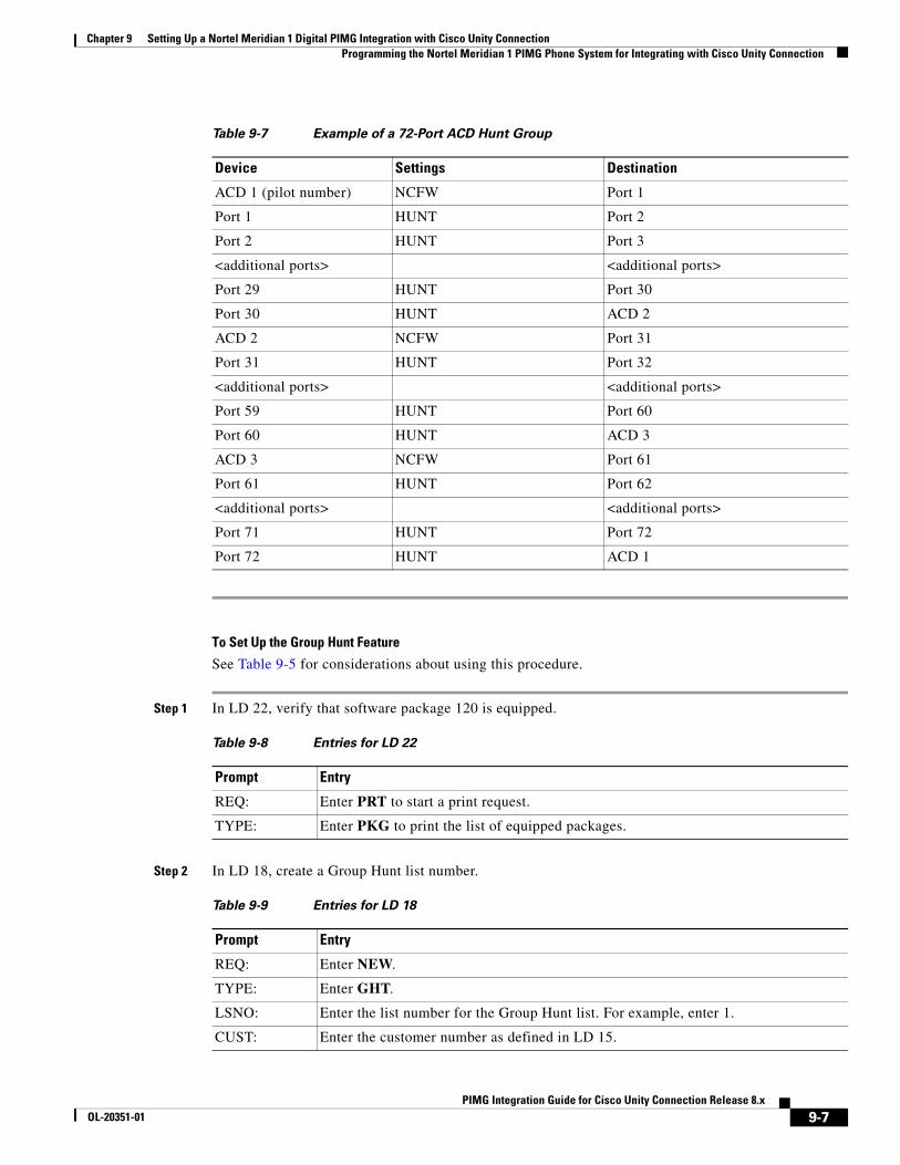
Chapter 9 Setting Up a Nortel Meridian 1 Digital PIMG Integration with Cisco Unity Connection Programming the Nortel Meridian 1 PIMG Phone System for Integrating with Cisco Unity Connection
To Set Up the Group Hunt Feature
See Table 9-5 for considerations about using this procedure.
Step 1 In LD 22, verify that software package 120 is equipped.
Step 2 In LD 18, create a Group Hunt list number.
Table 9-7 Example of a 72-Port ACD Hunt Group
Device Settings Destination
ACD 1 (pilot number) NCFW Port 1
Port 1 HUNT Port 2
Port 2 HUNT Port 3
<additional ports> <additional ports>
Port 29 HUNT Port 30
Port 30 HUNT ACD 2
ACD 2 NCFW Port 31
Port 31 HUNT Port 32
<additional ports> <additional ports>
Port 59 HUNT Port 60
Port 60 HUNT ACD 3
ACD 3 NCFW Port 61
Port 61 HUNT Port 62
<additional ports> <additional ports>
Port 71 HUNT Port 72
Port 72 HUNT ACD 1
Table 9-8 Entries for LD 22
Prompt Entry
REQ: Enter PRT to start a print request.
TYPE: Enter PKG to print the list of equipped packages.
Table 9-9 Entries for LD 18
Prompt Entry
REQ: Enter NEW.
TYPE: Enter GHT.
LSNO: Enter the list number for the Group Hunt list. For example, enter 1.
CUST: Enter the customer number as defined in LD 15.
9-7PIMG Integration Guide for Cisco Unity Connection Release 8.x
OL-20351-01
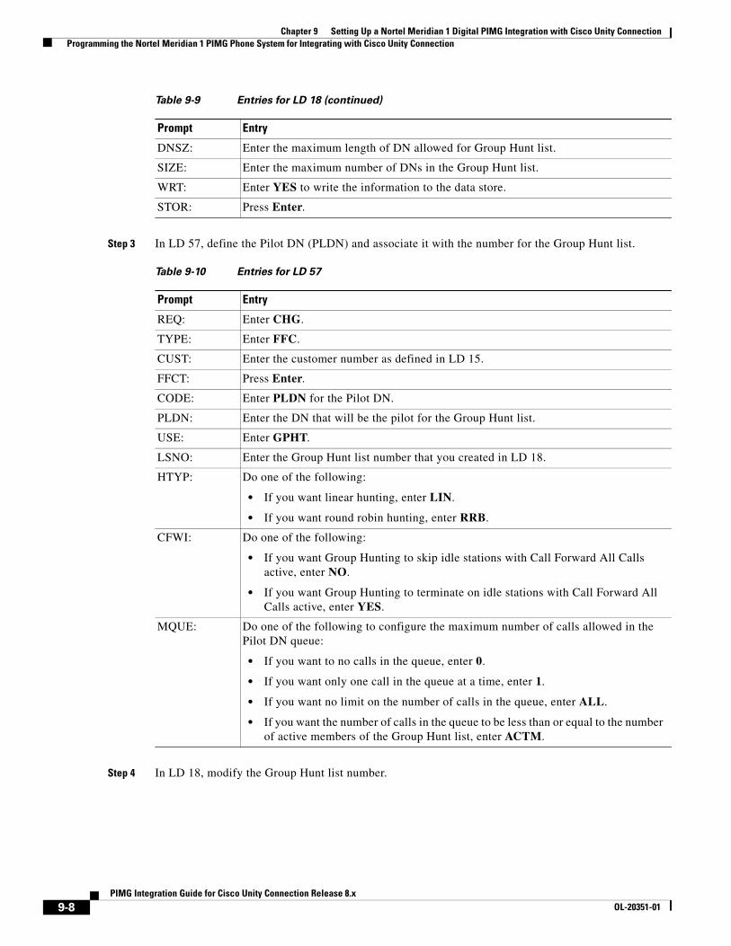
Chapter 9 Setting Up a Nortel Meridian 1 Digital PIMG Integration with Cisco Unity Connection Programming the Nortel Meridian 1 PIMG Phone System for Integrating with Cisco Unity Connection
Step 3 In LD 57, define the Pilot DN (PLDN) and associate it with the number for the Group Hunt list.
Step 4 In LD 18, modify the Group Hunt list number.
DNSZ: Enter the maximum length of DN allowed for Group Hunt list.
SIZE: Enter the maximum number of DNs in the Group Hunt list.
WRT: Enter YES to write the information to the data store.
STOR: Press Enter.
Table 9-10 Entries for LD 57
Prompt Entry
REQ: Enter CHG.
TYPE: Enter FFC.
CUST: Enter the customer number as defined in LD 15.
FFCT: Press Enter.
CODE: Enter PLDN for the Pilot DN.
PLDN: Enter the DN that will be the pilot for the Group Hunt list.
USE: Enter GPHT.
LSNO: Enter the Group Hunt list number that you created in LD 18.
HTYP: Do one of the following:
• If you want linear hunting, enter LIN.
• If you want round robin hunting, enter RRB.
CFWI: Do one of the following:
• If you want Group Hunting to skip idle stations with Call Forward All Calls active, enter NO.
• If you want Group Hunting to terminate on idle stations with Call Forward All Calls active, enter YES.
MQUE: Do one of the following to configure the maximum number of calls allowed in the Pilot DN queue:
• If you want to no calls in the queue, enter 0.
• If you want only one call in the queue at a time, enter 1.
• If you want no limit on the number of calls in the queue, enter ALL.
• If you want the number of calls in the queue to be less than or equal to the number of active members of the Group Hunt list, enter ACTM.
Table 9-9 Entries for LD 18 (continued)
Prompt Entry
9-8PIMG Integration Guide for Cisco Unity Connection Release 8.x
OL-20351-01
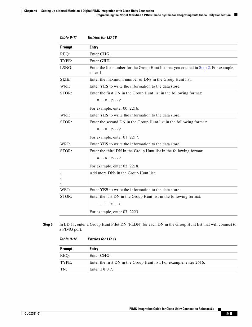
Chapter 9 Setting Up a Nortel Meridian 1 Digital PIMG Integration with Cisco Unity Connection Programming the Nortel Meridian 1 PIMG Phone System for Integrating with Cisco Unity Connection
Step 5 In LD 11, enter a Group Hunt Pilot DN (PLDN) for each DN in the Group Hunt list that will connect to a PIMG port.
Table 9-11 Entries for LD 18
Prompt Entry
REQ: Enter CHG.
TYPE: Enter GHT.
LSNO: Enter the list number for the Group Hunt list that you created in Step 2. For example, enter 1.
SIZE: Enter the maximum number of DNs in the Group Hunt list.
WRT: Enter YES to write the information to the data store.
STOR: Enter the first DN in the Group Hunt list in the following format:
x...x y...y
For example, enter 00 2216.
WRT: Enter YES to write the information to the data store.
STOR: Enter the second DN in the Group Hunt list in the following format:
x...x y...y
For example, enter 01 2217.
WRT: Enter YES to write the information to the data store.
STOR: Enter the third DN in the Group Hunt list in the following format:
x...x y...y
For example, enter 02 2218.
.
.
.
Add more DNs in the Group Hunt list.
WRT: Enter YES to write the information to the data store.
STOR: Enter the last DN in the Group Hunt list in the following format:
x...x y...y
For example, enter 07 2223.
Table 9-12 Entries for LD 11
Prompt Entry
REQ: Enter CHG.
TYPE: Enter the first DN in the Group Hunt list. For example, enter 2616.
TN: Enter 1 0 0 7.
9-9PIMG Integration Guide for Cisco Unity Connection Release 8.x
OL-20351-01
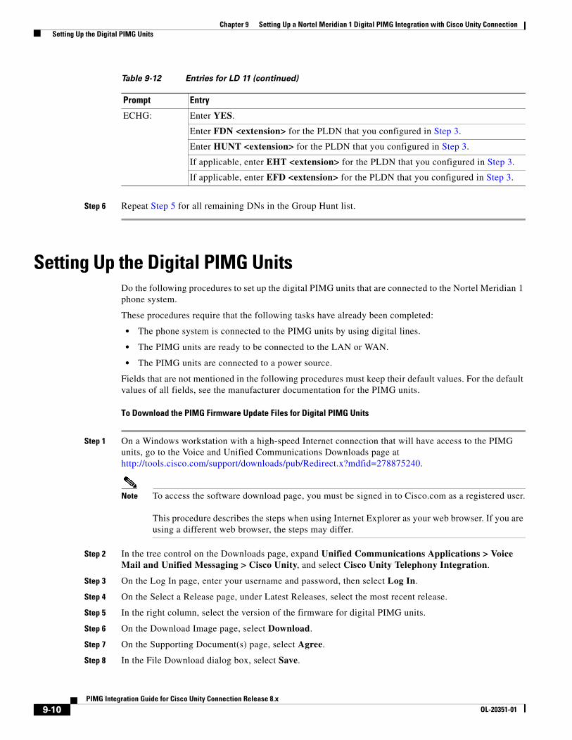
Chapter 9 Setting Up a Nortel Meridian 1 Digital PIMG Integration with Cisco Unity Connection Setting Up the Digital PIMG Units
Step 6 Repeat Step 5 for all remaining DNs in the Group Hunt list.
Setting Up the Digital PIMG UnitsDo the following procedures to set up the digital PIMG units that are connected to the Nortel Meridian 1 phone system.
These procedures require that the following tasks have already been completed:
• The phone system is connected to the PIMG units by using digital lines.
• The PIMG units are ready to be connected to the LAN or WAN.
• The PIMG units are connected to a power source.
Fields that are not mentioned in the following procedures must keep their default values. For the default values of all fields, see the manufacturer documentation for the PIMG units.
To Download the PIMG Firmware Update Files for Digital PIMG Units
Step 1 On a Windows workstation with a high-speed Internet connection that will have access to the PIMG units, go to the Voice and Unified Communications Downloads page at http://tools.cisco.com/support/downloads/pub/Redirect.x?mdfid=278875240.
Note To access the software download page, you must be signed in to Cisco.com as a registered user. This procedure describes the steps when using Internet Explorer as your web browser. If you are using a different web browser, the steps may differ.
Step 2 In the tree control on the Downloads page, expand Unified Communications Applications > Voice Mail and Unified Messaging > Cisco Unity, and select Cisco Unity Telephony Integration.
Step 3 On the Log In page, enter your username and password, then select Log In.
Step 4 On the Select a Release page, under Latest Releases, select the most recent release.
Step 5 In the right column, select the version of the firmware for digital PIMG units.
Step 6 On the Download Image page, select Download.
Step 7 On the Supporting Document(s) page, select Agree.
Step 8 In the File Download dialog box, select Save.
ECHG: Enter YES.
Enter FDN <extension> for the PLDN that you configured in Step 3.
Enter HUNT <extension> for the PLDN that you configured in Step 3.
If applicable, enter EHT <extension> for the PLDN that you configured in Step 3.
If applicable, enter EFD <extension> for the PLDN that you configured in Step 3.
Table 9-12 Entries for LD 11 (continued)
Prompt Entry
9-10PIMG Integration Guide for Cisco Unity Connection Release 8.x
OL-20351-01
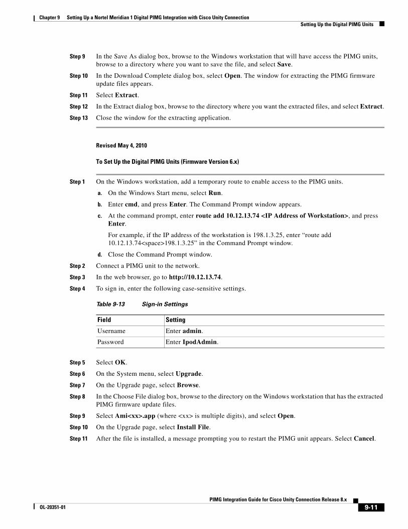
Chapter 9 Setting Up a Nortel Meridian 1 Digital PIMG Integration with Cisco Unity Connection Setting Up the Digital PIMG Units
Step 9 In the Save As dialog box, browse to the Windows workstation that will have access the PIMG units, browse to a directory where you want to save the file, and select Save.
Step 10 In the Download Complete dialog box, select Open. The window for extracting the PIMG firmware update files appears.
Step 11 Select Extract.
Step 12 In the Extract dialog box, browse to the directory where you want the extracted files, and select Extract.
Step 13 Close the window for the extracting application.
Revised May 4, 2010
To Set Up the Digital PIMG Units (Firmware Version 6.x)
Step 1 On the Windows workstation, add a temporary route to enable access to the PIMG units.
a. On the Windows Start menu, select Run.
b. Enter cmd, and press Enter. The Command Prompt window appears.
c. At the command prompt, enter route add 10.12.13.74 <IP Address of Workstation>, and press Enter.
For example, if the IP address of the workstation is 198.1.3.25, enter “route add 10.12.13.74<space>198.1.3.25” in the Command Prompt window.
d. Close the Command Prompt window.
Step 2 Connect a PIMG unit to the network.
Step 3 In the web browser, go to http://10.12.13.74.
Step 4 To sign in, enter the following case-sensitive settings.
Step 5 Select OK.
Step 6 On the System menu, select Upgrade.
Step 7 On the Upgrade page, select Browse.
Step 8 In the Choose File dialog box, browse to the directory on the Windows workstation that has the extracted PIMG firmware update files.
Step 9 Select Ami<xx>.app (where <xx> is multiple digits), and select Open.
Step 10 On the Upgrade page, select Install File.
Step 11 After the file is installed, a message prompting you to restart the PIMG unit appears. Select Cancel.
Table 9-13 Sign-in Settings
Field Setting
Username Enter admin.
Password Enter IpodAdmin.
9-11PIMG Integration Guide for Cisco Unity Connection Release 8.x
OL-20351-01
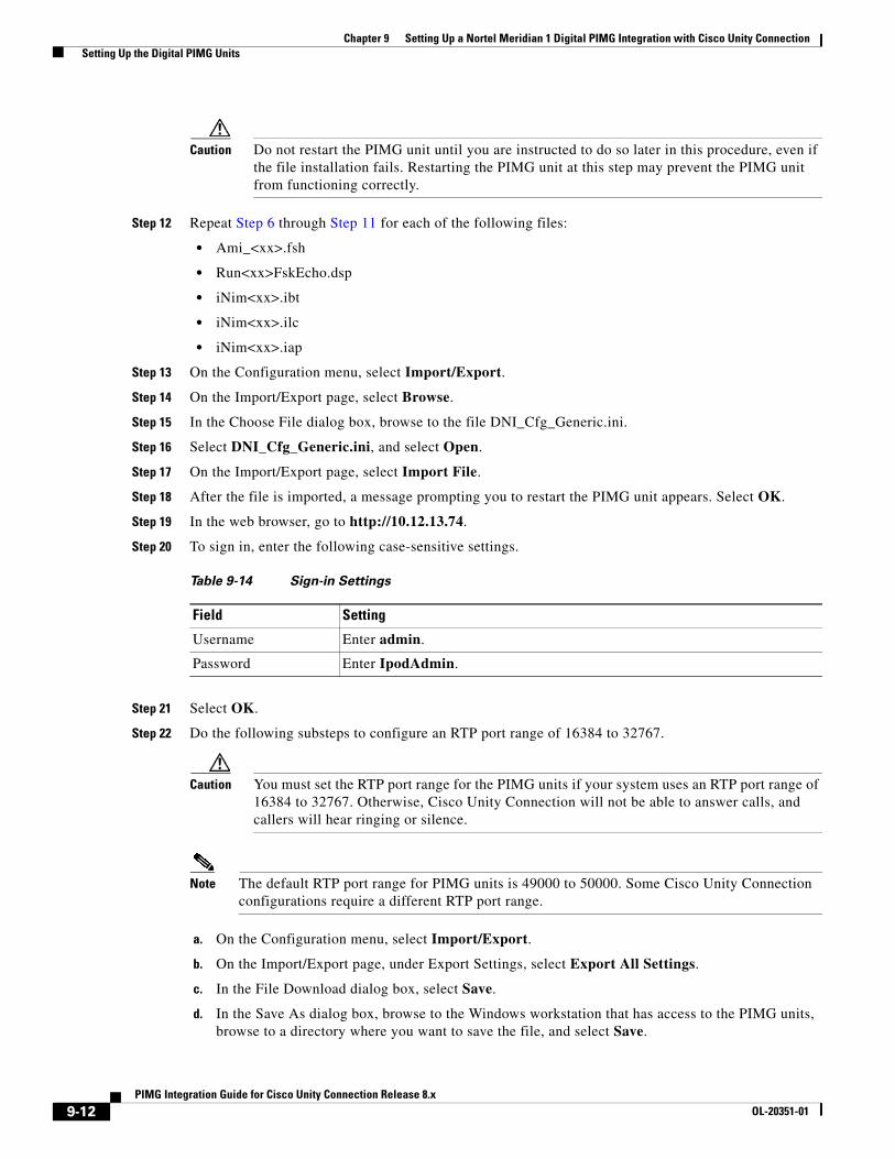
Chapter 9 Setting Up a Nortel Meridian 1 Digital PIMG Integration with Cisco Unity Connection Setting Up the Digital PIMG Units
Caution Do not restart the PIMG unit until you are instructed to do so later in this procedure, even if the file installation fails. Restarting the PIMG unit at this step may prevent the PIMG unit from functioning correctly.
Step 12 Repeat Step 6 through Step 11 for each of the following files:
• Ami_<xx>.fsh
• Run<xx>FskEcho.dsp
• iNim<xx>.ibt
• iNim<xx>.ilc
• iNim<xx>.iap
Step 13 On the Configuration menu, select Import/Export.
Step 14 On the Import/Export page, select Browse.
Step 15 In the Choose File dialog box, browse to the file DNI_Cfg_Generic.ini.
Step 16 Select DNI_Cfg_Generic.ini, and select Open.
Step 17 On the Import/Export page, select Import File.
Step 18 After the file is imported, a message prompting you to restart the PIMG unit appears. Select OK.
Step 19 In the web browser, go to http://10.12.13.74.
Step 20 To sign in, enter the following case-sensitive settings.
Step 21 Select OK.
Step 22 Do the following substeps to configure an RTP port range of 16384 to 32767.
Caution You must set the RTP port range for the PIMG units if your system uses an RTP port range of 16384 to 32767. Otherwise, Cisco Unity Connection will not be able to answer calls, and callers will hear ringing or silence.
Note The default RTP port range for PIMG units is 49000 to 50000. Some Cisco Unity Connection configurations require a different RTP port range.
a. On the Configuration menu, select Import/Export.
b. On the Import/Export page, under Export Settings, select Export All Settings.
c. In the File Download dialog box, select Save.
d. In the Save As dialog box, browse to the Windows workstation that has access to the PIMG units, browse to a directory where you want to save the file, and select Save.
Table 9-14 Sign-in Settings
Field Setting
Username Enter admin.
Password Enter IpodAdmin.
9-12PIMG Integration Guide for Cisco Unity Connection Release 8.x
OL-20351-01
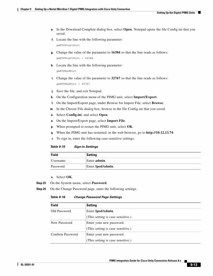
Chapter 9 Setting Up a Nortel Meridian 1 Digital PIMG Integration with Cisco Unity Connection Setting Up the Digital PIMG Units
e. In the Download Complete dialog box, select Open. Notepad opens the file Config.ini that you saved.
f. Locate the line with the following parameter:
gwRTPStartPort
g. Change the value of the parameter to 16384 so that the line reads as follows:
gwRTPStartPort = 16384
h. Locate the line with the following parameter:
gwRTPEndPort
i. Change the value of the parameter to 32767 so that the line reads as follows:
gwRTPEndPort = 32767
j. Save the file, and exit Notepad.
k. On the Configuration menu of the PIMG unit, select Import/Export.
l. On the Import/Export page, under Browse for Import File, select Browse.
m. In the Choose File dialog box, browse to the file Config.ini that you saved.
n. Select Config.ini, and select Open.
o. On the Import/Export page, select Import File.
p. When prompted to restart the PIMG unit, select OK.
q. When the PIMG unit has restarted, in the web browser, go to http://10.12.13.74.
r. To sign in, enter the following case-sensitive settings.
s. Select OK.
Step 23 On the System menu, select Password.
Step 24 On the Change Password page, enter the following settings.
Table 9-15 Sign-in Settings
Field Setting
Username Enter admin.
Password Enter IpodAdmin.
Table 9-16 Change Password Page Settings
Field Setting
Old Password Enter IpodAdmin.
(This setting is case sensitive.)
New Password Enter your new password.
(This setting is case sensitive.)
Confirm Password Enter your new password.
(This setting is case sensitive.)
9-13PIMG Integration Guide for Cisco Unity Connection Release 8.x
OL-20351-01
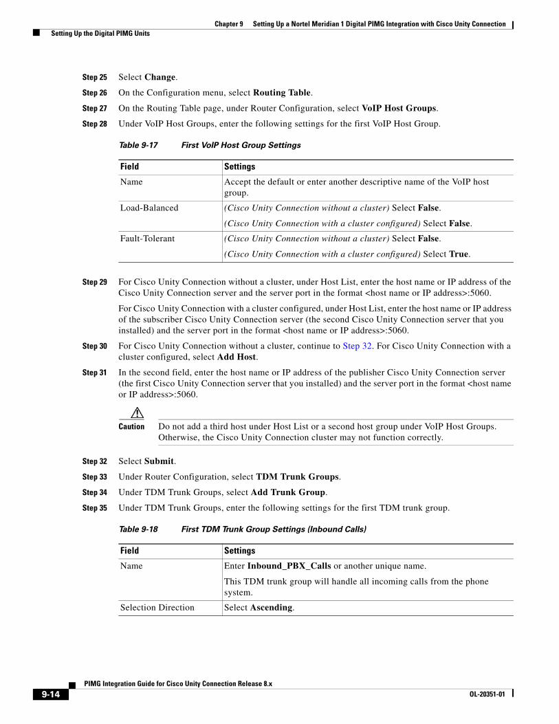
Chapter 9 Setting Up a Nortel Meridian 1 Digital PIMG Integration with Cisco Unity Connection Setting Up the Digital PIMG Units
Step 25 Select Change.
Step 26 On the Configuration menu, select Routing Table.
Step 27 On the Routing Table page, under Router Configuration, select VoIP Host Groups.
Step 28 Under VoIP Host Groups, enter the following settings for the first VoIP Host Group.
Step 29 For Cisco Unity Connection without a cluster, under Host List, enter the host name or IP address of the Cisco Unity Connection server and the server port in the format <host name or IP address>:5060.
For Cisco Unity Connection with a cluster configured, under Host List, enter the host name or IP address of the subscriber Cisco Unity Connection server (the second Cisco Unity Connection server that you installed) and the server port in the format <host name or IP address>:5060.
Step 30 For Cisco Unity Connection without a cluster, continue to Step 32. For Cisco Unity Connection with a cluster configured, select Add Host.
Step 31 In the second field, enter the host name or IP address of the publisher Cisco Unity Connection server (the first Cisco Unity Connection server that you installed) and the server port in the format <host name or IP address>:5060.
Caution Do not add a third host under Host List or a second host group under VoIP Host Groups. Otherwise, the Cisco Unity Connection cluster may not function correctly.
Step 32 Select Submit.
Step 33 Under Router Configuration, select TDM Trunk Groups.
Step 34 Under TDM Trunk Groups, select Add Trunk Group.
Step 35 Under TDM Trunk Groups, enter the following settings for the first TDM trunk group.
Table 9-17 First VoIP Host Group Settings
Field Settings
Name Accept the default or enter another descriptive name of the VoIP host group.
Load-Balanced (Cisco Unity Connection without a cluster) Select False.
(Cisco Unity Connection with a cluster configured) Select False.
Fault-Tolerant (Cisco Unity Connection without a cluster) Select False.
(Cisco Unity Connection with a cluster configured) Select True.
Table 9-18 First TDM Trunk Group Settings (Inbound Calls)
Field Settings
Name Enter Inbound_PBX_Calls or another unique name.
This TDM trunk group will handle all incoming calls from the phone system.
Selection Direction Select Ascending.
9-14PIMG Integration Guide for Cisco Unity Connection Release 8.x
OL-20351-01
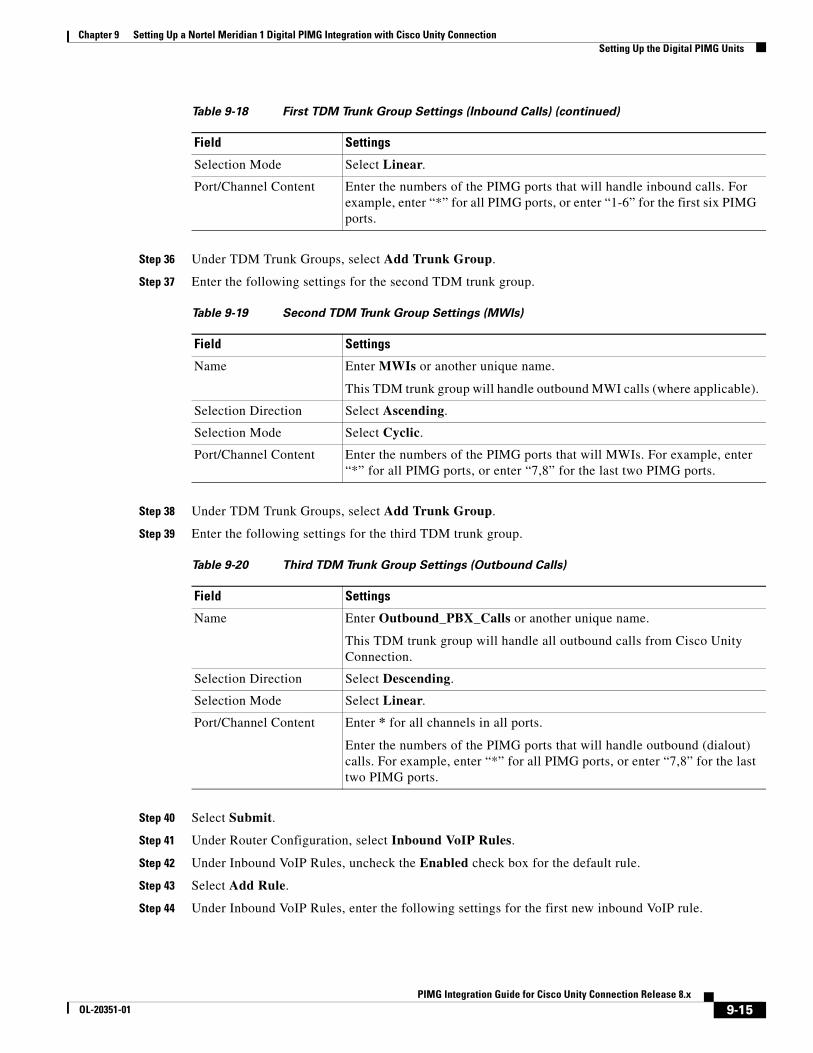
Chapter 9 Setting Up a Nortel Meridian 1 Digital PIMG Integration with Cisco Unity Connection Setting Up the Digital PIMG Units
Step 36 Under TDM Trunk Groups, select Add Trunk Group.
Step 37 Enter the following settings for the second TDM trunk group.
Step 38 Under TDM Trunk Groups, select Add Trunk Group.
Step 39 Enter the following settings for the third TDM trunk group.
Step 40 Select Submit.
Step 41 Under Router Configuration, select Inbound VoIP Rules.
Step 42 Under Inbound VoIP Rules, uncheck the Enabled check box for the default rule.
Step 43 Select Add Rule.
Step 44 Under Inbound VoIP Rules, enter the following settings for the first new inbound VoIP rule.
Selection Mode Select Linear.
Port/Channel Content Enter the numbers of the PIMG ports that will handle inbound calls. For example, enter “*” for all PIMG ports, or enter “1-6” for the first six PIMG ports.
Table 9-19 Second TDM Trunk Group Settings (MWIs)
Field Settings
Name Enter MWIs or another unique name.
This TDM trunk group will handle outbound MWI calls (where applicable).
Selection Direction Select Ascending.
Selection Mode Select Cyclic.
Port/Channel Content Enter the numbers of the PIMG ports that will MWIs. For example, enter “*” for all PIMG ports, or enter “7,8” for the last two PIMG ports.
Table 9-20 Third TDM Trunk Group Settings (Outbound Calls)
Field Settings
Name Enter Outbound_PBX_Calls or another unique name.
This TDM trunk group will handle all outbound calls from Cisco Unity Connection.
Selection Direction Select Descending.
Selection Mode Select Linear.
Port/Channel Content Enter * for all channels in all ports.
Enter the numbers of the PIMG ports that will handle outbound (dialout) calls. For example, enter “*” for all PIMG ports, or enter “7,8” for the last two PIMG ports.
Table 9-18 First TDM Trunk Group Settings (Inbound Calls) (continued)
Field Settings
9-15PIMG Integration Guide for Cisco Unity Connection Release 8.x
OL-20351-01
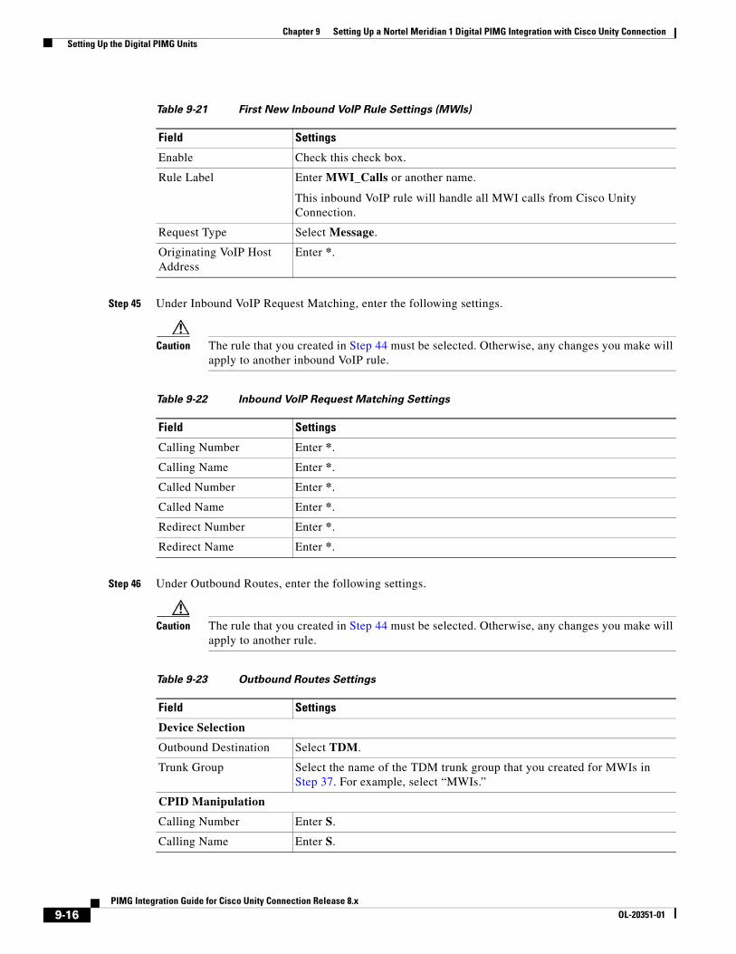
Chapter 9 Setting Up a Nortel Meridian 1 Digital PIMG Integration with Cisco Unity Connection Setting Up the Digital PIMG Units
Step 45 Under Inbound VoIP Request Matching, enter the following settings.
Caution The rule that you created in Step 44 must be selected. Otherwise, any changes you make will apply to another inbound VoIP rule.
Step 46 Under Outbound Routes, enter the following settings.
Caution The rule that you created in Step 44 must be selected. Otherwise, any changes you make will apply to another rule.
Table 9-21 First New Inbound VoIP Rule Settings (MWIs)
Field Settings
Enable Check this check box.
Rule Label Enter MWI_Calls or another name.
This inbound VoIP rule will handle all MWI calls from Cisco Unity Connection.
Request Type Select Message.
Originating VoIP Host Address
Enter *.
Table 9-22 Inbound VoIP Request Matching Settings
Field Settings
Calling Number Enter *.
Calling Name Enter *.
Called Number Enter *.
Called Name Enter *.
Redirect Number Enter *.
Redirect Name Enter *.
Table 9-23 Outbound Routes Settings
Field Settings
Device Selection
Outbound Destination Select TDM.
Trunk Group Select the name of the TDM trunk group that you created for MWIs in Step 37. For example, select “MWIs.”
CPID Manipulation
Calling Number Enter S.
Calling Name Enter S.
9-16PIMG Integration Guide for Cisco Unity Connection Release 8.x
OL-20351-01
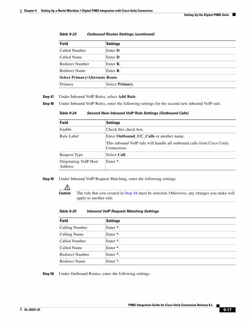
Chapter 9 Setting Up a Nortel Meridian 1 Digital PIMG Integration with Cisco Unity Connection Setting Up the Digital PIMG Units
Step 47 Under Inbound VoIP Rules, select Add Rule.
Step 48 Under Inbound VoIP Rules, enter the following settings for the second new inbound VoIP rule.
Step 49 Under Inbound VoIP Request Matching, enter the following settings.
Caution The rule that you created in Step 48 must be selected. Otherwise, any changes you make will apply to another rule.
Step 50 Under Outbound Routes, enter the following settings.
Called Number Enter D.
Called Name Enter D.
Redirect Number Enter R.
Redirect Name Enter R.
Select Primary/Alternate Route
Primary Select Primary.
Table 9-24 Second New Inbound VoIP Rule Settings (Outbound Calls)
Field Settings
Enable Check this check box.
Rule Label Enter Outbound_UC_Calls or another name.
This inbound VoIP rule will handle all outbound calls from Cisco Unity Connection.
Request Type Select Call.
Originating VoIP Host Address
Enter *.
Table 9-23 Outbound Routes Settings (continued)
Field Settings
Table 9-25 Inbound VoIP Request Matching Settings
Field Settings
Calling Number Enter *.
Calling Name Enter *.
Called Number Enter *.
Called Name Enter *.
Redirect Number Enter *.
Redirect Name Enter *.
9-17PIMG Integration Guide for Cisco Unity Connection Release 8.x
OL-20351-01
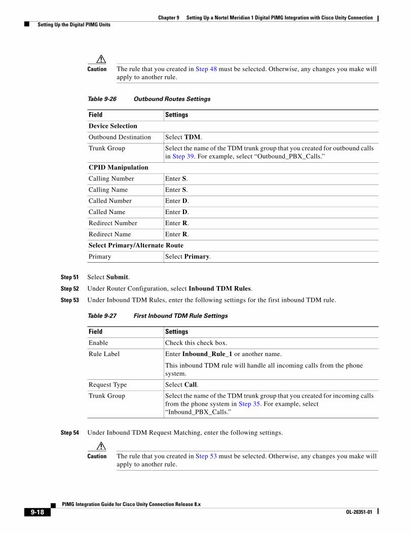
Chapter 9 Setting Up a Nortel Meridian 1 Digital PIMG Integration with Cisco Unity Connection Setting Up the Digital PIMG Units
Caution The rule that you created in Step 48 must be selected. Otherwise, any changes you make will apply to another rule.
Step 51 Select Submit.
Step 52 Under Router Configuration, select Inbound TDM Rules.
Step 53 Under Inbound TDM Rules, enter the following settings for the first inbound TDM rule.
Step 54 Under Inbound TDM Request Matching, enter the following settings.
Caution The rule that you created in Step 53 must be selected. Otherwise, any changes you make will apply to another rule.
Table 9-26 Outbound Routes Settings
Field Settings
Device Selection
Outbound Destination Select TDM.
Trunk Group Select the name of the TDM trunk group that you created for outbound calls in Step 39. For example, select “Outbound_PBX_Calls.”
CPID Manipulation
Calling Number Enter S.
Calling Name Enter S.
Called Number Enter D.
Called Name Enter D.
Redirect Number Enter R.
Redirect Name Enter R.
Select Primary/Alternate Route
Primary Select Primary.
Table 9-27 First Inbound TDM Rule Settings
Field Settings
Enable Check this check box.
Rule Label Enter Inbound_Rule_1 or another name.
This inbound TDM rule will handle all incoming calls from the phone system.
Request Type Select Call.
Trunk Group Select the name of the TDM trunk group that you created for incoming calls from the phone system in Step 35. For example, select “Inbound_PBX_Calls.”
9-18PIMG Integration Guide for Cisco Unity Connection Release 8.x
OL-20351-01
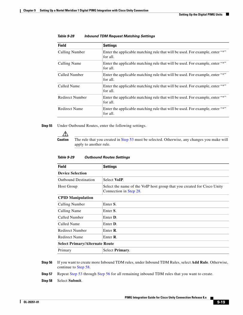
Chapter 9 Setting Up a Nortel Meridian 1 Digital PIMG Integration with Cisco Unity Connection Setting Up the Digital PIMG Units
Step 55 Under Outbound Routes, enter the following settings.
Caution The rule that you created in Step 53 must be selected. Otherwise, any changes you make will apply to another rule.
Step 56 If you want to create more Inbound TDM rules, under Inbound TDM Rules, select Add Rule. Otherwise, continue to Step 58.
Step 57 Repeat Step 53 through Step 56 for all remaining inbound TDM rules that you want to create.
Step 58 Select Submit.
Table 9-28 Inbound TDM Request Matching Settings
Field Settings
Calling Number Enter the applicable matching rule that will be used. For example, enter “*” for all.
Calling Name Enter the applicable matching rule that will be used. For example, enter “*” for all.
Called Number Enter the applicable matching rule that will be used. For example, enter “*” for all.
Called Name Enter the applicable matching rule that will be used. For example, enter “*” for all.
Redirect Number Enter the applicable matching rule that will be used. For example, enter “*” for all.
Redirect Name Enter the applicable matching rule that will be used. For example, enter “*” for all.
Table 9-29 Outbound Routes Settings
Field Settings
Device Selection
Outbound Destination Select VoIP.
Host Group Select the name of the VoIP host group that you created for Cisco Unity Connection in Step 28.
CPID Manipulation
Calling Number Enter S.
Calling Name Enter S.
Called Number Enter D.
Called Name Enter D.
Redirect Number Enter R.
Redirect Name Enter R.
Select Primary/Alternate Route
Primary Select Primary.
9-19PIMG Integration Guide for Cisco Unity Connection Release 8.x
OL-20351-01
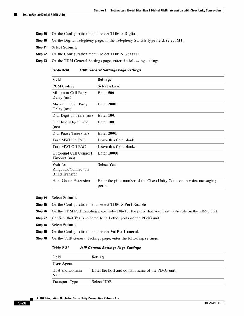
Chapter 9 Setting Up a Nortel Meridian 1 Digital PIMG Integration with Cisco Unity Connection Setting Up the Digital PIMG Units
Step 59 On the Configuration menu, select TDM > Digital.
Step 60 On the Digital Telephony page, in the Telephony Switch Type field, select M1.
Step 61 Select Submit.
Step 62 On the Configuration menu, select TDM > General.
Step 63 On the TDM General Settings page, enter the following settings.
Step 64 Select Submit.
Step 65 On the Configuration menu, select TDM > Port Enable.
Step 66 On the TDM Port Enabling page, select No for the ports that you want to disable on the PIMG unit.
Step 67 Confirm that Yes is selected for all other ports on the PIMG unit.
Step 68 Select Submit.
Step 69 On the Configuration menu, select VoIP > General.
Step 70 On the VoIP General Settings page, enter the following settings.
Table 9-30 TDM General Settings Page Settings
Field Settings
PCM Coding Select uLaw.
Minimum Call Party Delay (ms)
Enter 500.
Maximum Call Party Delay (ms)
Enter 2000.
Dial Digit on Time (ms) Enter 100.
Dial Inter-Digit Time (ms)
Enter 100.
Dial Pause Time (ms) Enter 2000.
Turn MWI On FAC Leave this field blank.
Turn MWI Off FAC Leave this field blank.
Outbound Call Connect Timeout (ms)
Enter 10000.
Wait for Ringback/Connect on Blind Transfer
Select Yes.
Hunt Group Extension Enter the pilot number of the Cisco Unity Connection voice messaging ports.
Table 9-31 VoIP General Settings Page Settings
Field Setting
User-Agent
Host and Domain Name
Enter the host and domain name of the PIMG unit.
Transport Type Select UDP.
9-20PIMG Integration Guide for Cisco Unity Connection Release 8.x
OL-20351-01
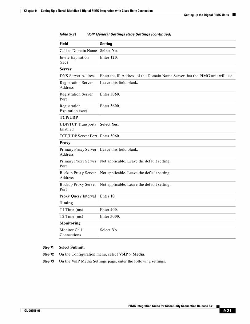
Chapter 9 Setting Up a Nortel Meridian 1 Digital PIMG Integration with Cisco Unity Connection Setting Up the Digital PIMG Units
Step 71 Select Submit.
Step 72 On the Configuration menu, select VoIP > Media.
Step 73 On the VoIP Media Settings page, enter the following settings.
Call as Domain Name Select No.
Invite Expiration (sec)
Enter 120.
Server
DNS Server Address Enter the IP Address of the Domain Name Server that the PIMG unit will use.
Registration Server Address
Leave this field blank.
Registration Server Port
Enter 5060.
Registration Expiration (sec)
Enter 3600.
TCP/UDP
UDP/TCP Transports Enabled
Select Yes.
TCP/UDP Server Port Enter 5060.
Proxy
Primary Proxy Server Address
Leave this field blank.
Primary Proxy Server Port
Not applicable. Leave the default setting.
Backup Proxy Server Address
Not applicable. Leave the default setting.
Backup Proxy Server Port
Not applicable. Leave the default setting.
Proxy Query Interval Enter 10.
Timing
T1 Time (ms) Enter 400.
T2 Time (ms) Enter 3000.
Monitoring
Monitor Call Connections
Select No.
Table 9-31 VoIP General Settings Page Settings (continued)
Field Setting
9-21PIMG Integration Guide for Cisco Unity Connection Release 8.x
OL-20351-01
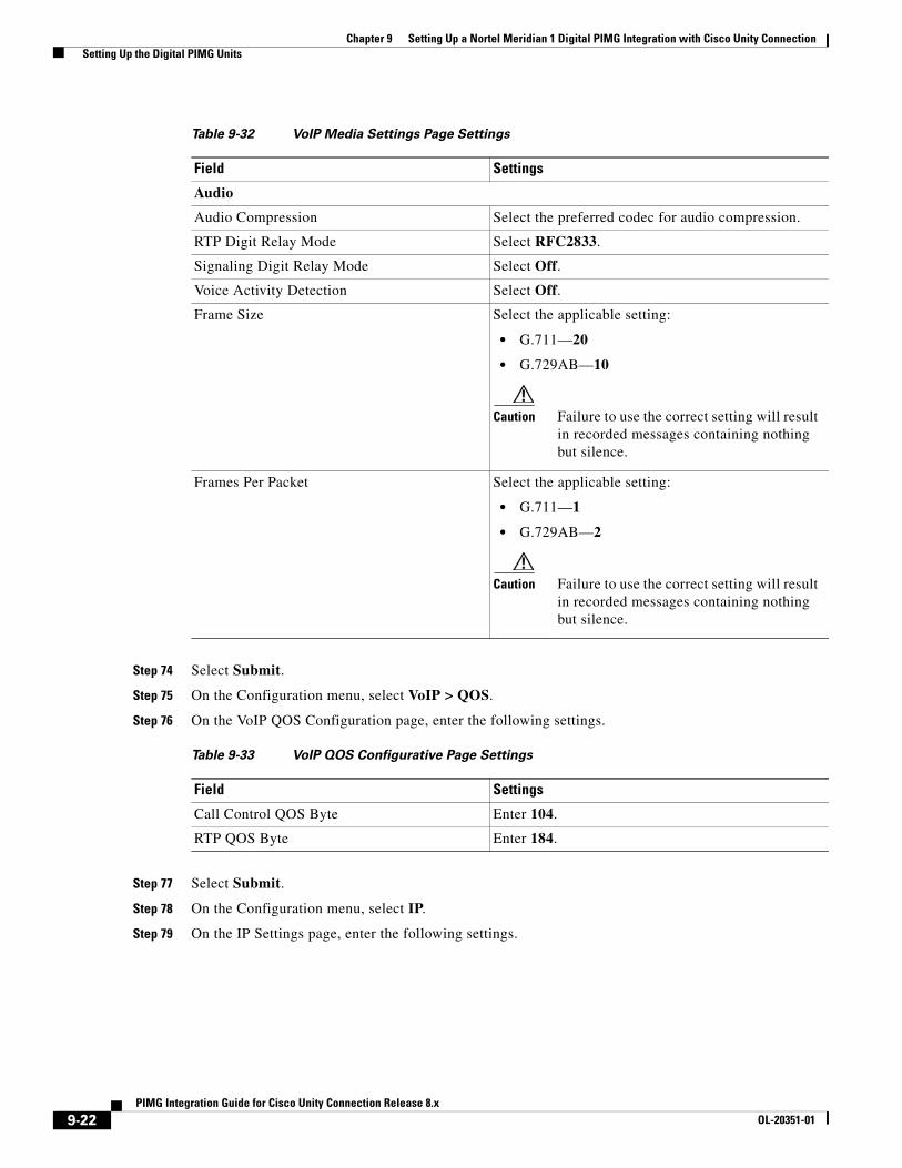
Chapter 9 Setting Up a Nortel Meridian 1 Digital PIMG Integration with Cisco Unity Connection Setting Up the Digital PIMG Units
Step 74 Select Submit.
Step 75 On the Configuration menu, select VoIP > QOS.
Step 76 On the VoIP QOS Configuration page, enter the following settings.
Step 77 Select Submit.
Step 78 On the Configuration menu, select IP.
Step 79 On the IP Settings page, enter the following settings.
Table 9-32 VoIP Media Settings Page Settings
Field Settings
Audio
Audio Compression Select the preferred codec for audio compression.
RTP Digit Relay Mode Select RFC2833.
Signaling Digit Relay Mode Select Off.
Voice Activity Detection Select Off.
Frame Size Select the applicable setting:
• G.711—20
• G.729AB—10
Caution Failure to use the correct setting will result in recorded messages containing nothing but silence.
Frames Per Packet Select the applicable setting:
• G.711—1
• G.729AB—2
Caution Failure to use the correct setting will result in recorded messages containing nothing but silence.
Table 9-33 VoIP QOS Configurative Page Settings
Field Settings
Call Control QOS Byte Enter 104.
RTP QOS Byte Enter 184.
9-22PIMG Integration Guide for Cisco Unity Connection Release 8.x
OL-20351-01
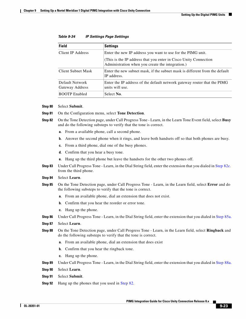
Chapter 9 Setting Up a Nortel Meridian 1 Digital PIMG Integration with Cisco Unity Connection Setting Up the Digital PIMG Units
Step 80 Select Submit.
Step 81 On the Configuration menu, select Tone Detection.
Step 82 On the Tone Detection page, under Call Progress Tone - Learn, in the Learn Tone Event field, select Busy and do the following substeps to verify that the tone is correct.
a. From a available phone, call a second phone.
b. Answer the second phone when it rings, and leave both handsets off so that both phones are busy.
c. From a third phone, dial one of the busy phones.
d. Confirm that you hear a busy tone.
e. Hang up the third phone but leave the handsets for the other two phones off.
Step 83 Under Call Progress Tone - Learn, in the Dial String field, enter the extension that you dialed in Step 82c. from the third phone.
Step 84 Select Learn.
Step 85 On the Tone Detection page, under Call Progress Tone - Learn, in the Learn field, select Error and do the following substeps to verify that the tone is correct.
a. From an available phone, dial an extension that does not exist.
b. Confirm that you hear the reorder or error tone.
c. Hang up the phone.
Step 86 Under Call Progress Tone - Learn, in the Dial String field, enter the extension that you dialed in Step 85a.
Step 87 Select Learn.
Step 88 On the Tone Detection page, under Call Progress Tone - Learn, in the Learn field, select Ringback and do the following substeps to verify that the tone is correct.
a. From an available phone, dial an extension that does exist
b. Confirm that you hear the ringback tone.
c. Hang up the phone.
Step 89 Under Call Progress Tone - Learn, in the Dial String field, enter the extension that you dialed in Step 88a.
Step 90 Select Learn.
Step 91 Select Submit.
Step 92 Hang up the phones that you used in Step 82.
Table 9-34 IP Settings Page Settings
Field Settings
Client IP Address Enter the new IP address you want to use for the PIMG unit.
(This is the IP address that you enter in Cisco Unity Connection Administration when you create the integration.)
Client Subnet Mask Enter the new subnet mask, if the subnet mask is different from the default IP address.
Default Network Gateway Address
Enter the IP address of the default network gateway router that the PIMG units will use.
BOOTP Enabled Select No.
9-23PIMG Integration Guide for Cisco Unity Connection Release 8.x
OL-20351-01
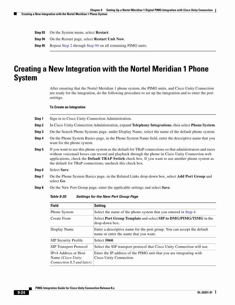
Chapter 9 Setting Up a Nortel Meridian 1 Digital PIMG Integration with Cisco Unity Connection Creating a New Integration with the Nortel Meridian 1 Phone System
Step 93 On the System menu, select Restart.
Step 94 On the Restart page, select Restart Unit Now.
Step 95 Repeat Step 2 through Step 94 on all remaining PIMG units.
Creating a New Integration with the Nortel Meridian 1 Phone System
After ensuring that the Nortel Meridian 1 phone system, the PIMG units, and Cisco Unity Connection are ready for the integration, do the following procedure to set up the integration and to enter the port settings.
To Create an Integration
Step 1 Sign in to Cisco Unity Connection Administration.
Step 2 In Cisco Unity Connection Administration, expand Telephony Integrations, then select Phone System.
Step 3 On the Search Phone Systems page, under Display Name, select the name of the default phone system.
Step 4 On the Phone System Basics page, in the Phone System Name field, enter the descriptive name that you want for the phone system.
Step 5 If you want to use this phone system as the default for TRaP connections so that administrators and users without voicemail boxes can record and playback through the phone in Cisco Unity Connection web applications, check the Default TRAP Switch check box. If you want to use another phone system as the default for TRaP connections, uncheck this check box.
Step 6 Select Save.
Step 7 On the Phone System Basics page, in the Related Links drop-down box, select Add Port Group and select Go.
Step 8 On the New Port Group page, enter the applicable settings and select Save.
Table 9-35 Settings for the New Port Group Page
Field Setting
Phone System Select the name of the phone system that you entered in Step 4.
Create From Select Port Group Template and select SIP to DMG/PIMG/TIMG in the drop-down box.
Display Name Enter a descriptive name for the port group. You can accept the default name or enter the name that you want.
SIP Security Profile Select 5060.
SIP Transport Protocol Select the SIP transport protocol that Cisco Unity Connection will use.
IPv4 Address or Host Name (Cisco Unity Connection 8.5 and later)
Enter the IP address of the PIMG unit that you are integrating with Cisco Unity Connection.
9-24PIMG Integration Guide for Cisco Unity Connection Release 8.x
OL-20351-01
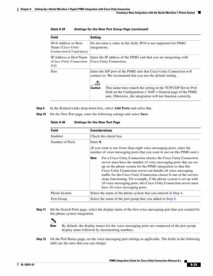
Chapter 9 Setting Up a Nortel Meridian 1 Digital PIMG Integration with Cisco Unity Connection Creating a New Integration with the Nortel Meridian 1 Phone System
Step 9 In the Related Links drop-down box, select Add Ports and select Go.
Step 10 On the New Port page, enter the following settings and select Save.
Step 11 On the Search Ports page, select the display name of the first voice messaging port that you created for this phone system integration.
Note By default, the display names for the voice messaging ports are composed of the port group display name followed by incrementing numbers.
Step 12 On the Port Basics page, set the voice messaging port settings as applicable. The fields in the following table are the ones that you can change.
IPv6 Address or Host Name (Cisco Unity Connection 8.5 and later)
Do not enter a value in this field. IPv6 is not supported for PIMG integrations.
IP Address or Host Name (Cisco Unity Connection 8.0)
Enter the IP address of the PIMG unit that you are integrating with Cisco Unity Connection.
Port Enter the SIP port of the PIMG unit that Cisco Unity Connection will connect to. We recommend that you use the default setting.
Caution This name must match the setting in the TCP/UDP Server Port field on the Configuration > VoIP > General page of the PIMG unit. Otherwise, the integration will not function correctly.
Table 9-36 Settings for the New Port Page
Field Considerations
Enabled Check this check box.
Number of Ports Enter 8.
(If you want to use fewer than eight voice messaging ports, enter the number of voice messaging ports that you want to use on this PIMG unit.)
Note For a Cisco Unity Connection cluster, the Cisco Unity Connection server must have the number of voice messaging ports that are set up on the phone system for the PIMG integration so that this Cisco Unity Connection server can handle all voice messaging traffic for the Cisco Unity Connection cluster if one of the servers stops functioning. For example, if the phone system is set up with 16 voice messaging ports, this Cisco Unity Connection server must have 16 voice messaging ports.
Phone System Select the name of the phone system that you entered in Step 4.
Port Group Select the name of the port group that you added in Step 8.
Table 9-35 Settings for the New Port Group Page (continued)
Field Setting
9-25PIMG Integration Guide for Cisco Unity Connection Release 8.x
OL-20351-01
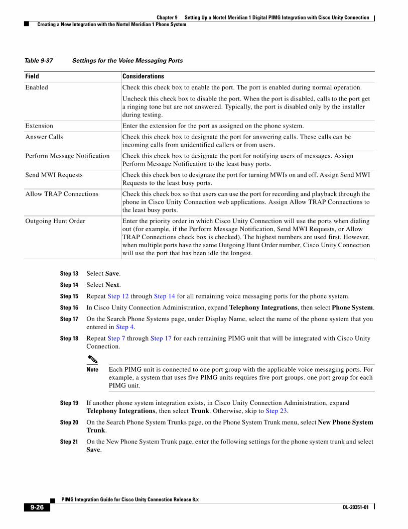
Chapter 9 Setting Up a Nortel Meridian 1 Digital PIMG Integration with Cisco Unity Connection Creating a New Integration with the Nortel Meridian 1 Phone System
Step 13 Select Save.
Step 14 Select Next.
Step 15 Repeat Step 12 through Step 14 for all remaining voice messaging ports for the phone system.
Step 16 In Cisco Unity Connection Administration, expand Telephony Integrations, then select Phone System.
Step 17 On the Search Phone Systems page, under Display Name, select the name of the phone system that you entered in Step 4.
Step 18 Repeat Step 7 through Step 17 for each remaining PIMG unit that will be integrated with Cisco Unity Connection.
Note Each PIMG unit is connected to one port group with the applicable voice messaging ports. For example, a system that uses five PIMG units requires five port groups, one port group for each PIMG unit.
Step 19 If another phone system integration exists, in Cisco Unity Connection Administration, expand Telephony Integrations, then select Trunk. Otherwise, skip to Step 23.
Step 20 On the Search Phone System Trunks page, on the Phone System Trunk menu, select New Phone System Trunk.
Step 21 On the New Phone System Trunk page, enter the following settings for the phone system trunk and select Save.
Table 9-37 Settings for the Voice Messaging Ports
Field Considerations
Enabled Check this check box to enable the port. The port is enabled during normal operation.
Uncheck this check box to disable the port. When the port is disabled, calls to the port get a ringing tone but are not answered. Typically, the port is disabled only by the installer during testing.
Extension Enter the extension for the port as assigned on the phone system.
Answer Calls Check this check box to designate the port for answering calls. These calls can be incoming calls from unidentified callers or from users.
Perform Message Notification Check this check box to designate the port for notifying users of messages. Assign Perform Message Notification to the least busy ports.
Send MWI Requests Check this check box to designate the port for turning MWIs on and off. Assign Send MWI Requests to the least busy ports.
Allow TRAP Connections Check this check box so that users can use the port for recording and playback through the phone in Cisco Unity Connection web applications. Assign Allow TRAP Connections to the least busy ports.
Outgoing Hunt Order Enter the priority order in which Cisco Unity Connection will use the ports when dialing out (for example, if the Perform Message Notification, Send MWI Requests, or Allow TRAP Connections check box is checked). The highest numbers are used first. However, when multiple ports have the same Outgoing Hunt Order number, Cisco Unity Connection will use the port that has been idle the longest.
9-26PIMG Integration Guide for Cisco Unity Connection Release 8.x
OL-20351-01
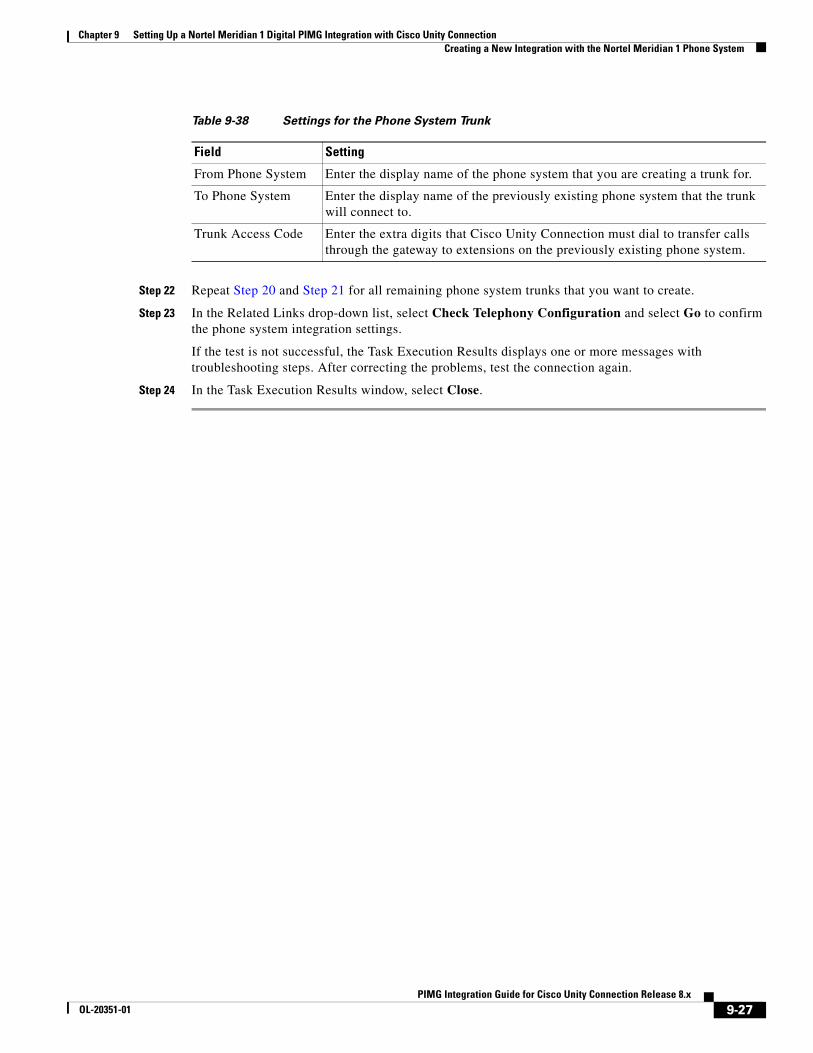
Chapter 9 Setting Up a Nortel Meridian 1 Digital PIMG Integration with Cisco Unity Connection Creating a New Integration with the Nortel Meridian 1 Phone System
Step 22 Repeat Step 20 and Step 21 for all remaining phone system trunks that you want to create.
Step 23 In the Related Links drop-down list, select Check Telephony Configuration and select Go to confirm the phone system integration settings.
If the test is not successful, the Task Execution Results displays one or more messages with troubleshooting steps. After correcting the problems, test the connection again.
Step 24 In the Task Execution Results window, select Close.
Table 9-38 Settings for the Phone System Trunk
Field Setting
From Phone System Enter the display name of the phone system that you are creating a trunk for.
To Phone System Enter the display name of the previously existing phone system that the trunk will connect to.
Trunk Access Code Enter the extra digits that Cisco Unity Connection must dial to transfer calls through the gateway to extensions on the previously existing phone system.
9-27PIMG Integration Guide for Cisco Unity Connection Release 8.x
OL-20351-01

Chapter 9 Setting Up a Nortel Meridian 1 Digital PIMG Integration with Cisco Unity Connection Creating a New Integration with the Nortel Meridian 1 Phone System
9-28PIMG Integration Guide for Cisco Unity Connection Release 8.x
OL-20351-01
PIMG IntegrOL-20351-01
C H A P T E R 10
Setting Up a Rolm 9751 Digital PIMG Integration with Cisco Unity ConnectionFor detailed instructions for setting up a Rolm 9751 digital PIMG integration with Cisco Unity Connection, see the following sections in this chapter:
• Task List to Create the Integration with a Rolm 9751 PIMG Phone System, page 10-1
• Requirements, page 10-2
• Programming the Rolm 9751 PIMG Phone System for Integrating with Cisco Unity Connection, page 10-3
• Setting Up the Digital Rolm PIMG Units, page 10-7
• Creating a New Integration with the Rolm 9751 Phone System, page 10-20
Task List to Create the Integration with a Rolm 9751 PIMG Phone System
Before doing the following tasks to integrate Cisco Unity Connection with the Rolm 9751 phone system by using PIMG units (media gateways), confirm that the Cisco Unity Connection server is ready for the integration by completing the applicable tasks in the Cisco Unity Connection Installation Guide.
1. Review the system and equipment requirements to confirm that all phone system and Cisco Unity Connection server requirements have been met. See the “Requirements” section on page 10-2.
2. Plan how the voice messaging ports will be used by Cisco Unity Connection. See Chapter 2, “Planning How the Voice Messaging Ports Will Be Used by Cisco Unity Connection.”
3. Program the Rolm 9751 phone system and extensions. See the “Programming the Rolm 9751 PIMG Phone System for Integrating with Cisco Unity Connection” section on page 10-3.
4. Set up the PIMG units. See the “Setting Up the Digital Rolm PIMG Units” section on page 10-7.
5. Create the integration. See the “Creating a New Integration with the Rolm 9751 Phone System” section on page 10-20.
6. Test the integration. See Chapter 14, “Testing the Integration.”
7. If this integration is a second or subsequent integration, add the applicable new user templates for the new phone system. See Chapter 15, “Adding New User Templates for Multiple Integrations.”
10-1ation Guide for Cisco Unity Connection Release 8.x
Chapter 10 Setting Up a Rolm 9751 Digital PIMG Integration with Cisco Unity Connection Requirements
RequirementsThe Rolm 9751 integration supports configurations of the following components:
Phone System
• Rolm 9751 phone system with ROLMphone digital phones.
• One of the following software releases:
– 9005.
– 9006.
• (Software release 9005 only) RolmLink Interface (RLI) card.
• (Software release 9006 only) SLMR-type line card.
• One or more of the applicable PIMG units. For details, see Chapter 1, “Introduction.”
• The voice messaging ports in the phone system connected by digital lines to the ports on the PIMG units.
To simplify troubleshooting, we recommend that you connect the voice messaging ports on the phone system to the ports on the PIMG units in a planned manner. For example, connect the first phone system voice messaging port to the first port on the first PIMG unit, connect the second phone system voice messaging port to the second port on the first PIMG unit, and so on. Alternatively, if you have multiple PIMG units, you can reduce answer times in the event of a PIMG unit failure by connecting the phone system ports to the PIMG units in a round-robin fashion. For example, connect the first phone system voice messaging port to the first port on the first PIMG unit, connect the second phone system voice messaging port to the first port on the second PIMG unit, and so on.
• The PIMG units connected to the same LAN or WAN that Cisco Unity Connection is connected to.
• If the PIMG units connect to a WAN, the requirements for the WAN network connections are:
– For G.729a codec formatting, a minimum of 32.76 Kbps guaranteed bandwidth for each voice messaging port.
– For G.711 codec formatting, a minimum of 91.56 Kbps guaranteed bandwidth for each voice messaging port.
– No network devices that implement network address translation (NAT).
– A maximum 200 ms one-way network latency.
• The phone system ready for the integration, as described in the documentation for the phone system.
Cisco Unity Connection Server
• Cisco Unity Connection installed and ready for the integration, as described in the Cisco Unity Connection Installation Guide at http://www.cisco.com/en/US/products/ps6509/prod_installation_guides_list.html.
• A license that enables the applicable number of voice messaging ports.
Centralized Voice Messaging
Cisco Unity Connection supports centralized voice messaging through the phone system, which supports various inter-phone system networking protocols including proprietary protocols such as Avaya DCS, Nortel MCDN, or Siemens CorNet, and standards-based protocols such as QSIG or DPNSS. Note that centralized voice messaging is a function of the phone system and its inter-phone system networking, not voicemail. Connection will support centralized voice messaging as long as the phone system and its inter-phone system networking are properly configured. For details, see the “Centralized Voice
10-2PIMG Integration Guide for Cisco Unity Connection Release 8.x
OL-20351-01
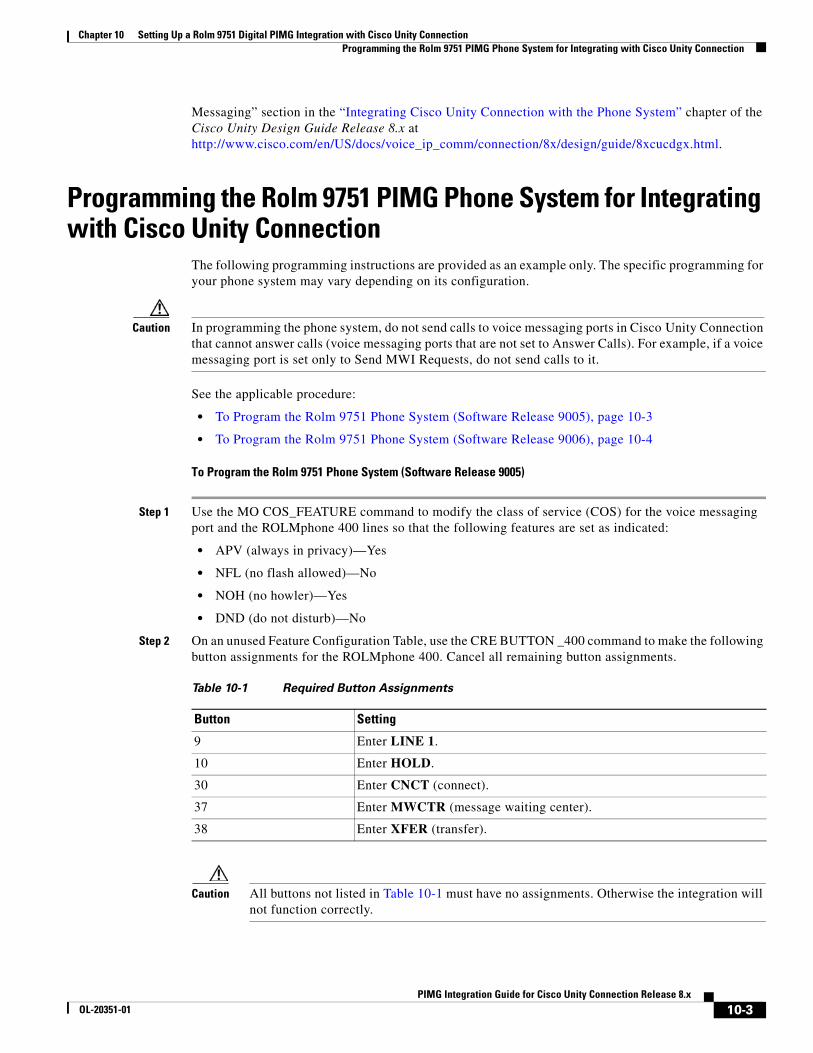
Chapter 10 Setting Up a Rolm 9751 Digital PIMG Integration with Cisco Unity Connection Programming the Rolm 9751 PIMG Phone System for Integrating with Cisco Unity Connection
Messaging” section in the “Integrating Cisco Unity Connection with the Phone System” chapter of the Cisco Unity Design Guide Release 8.x at http://www.cisco.com/en/US/docs/voice_ip_comm/connection/8x/design/guide/8xcucdgx.html.
Programming the Rolm 9751 PIMG Phone System for Integrating with Cisco Unity Connection
The following programming instructions are provided as an example only. The specific programming for your phone system may vary depending on its configuration.
Caution In programming the phone system, do not send calls to voice messaging ports in Cisco Unity Connection that cannot answer calls (voice messaging ports that are not set to Answer Calls). For example, if a voice messaging port is set only to Send MWI Requests, do not send calls to it.
See the applicable procedure:
• To Program the Rolm 9751 Phone System (Software Release 9005), page 10-3
• To Program the Rolm 9751 Phone System (Software Release 9006), page 10-4
To Program the Rolm 9751 Phone System (Software Release 9005)
Step 1 Use the MO COS_FEATURE command to modify the class of service (COS) for the voice messaging port and the ROLMphone 400 lines so that the following features are set as indicated:
• APV (always in privacy)—Yes
• NFL (no flash allowed)—No
• NOH (no howler)—Yes
• DND (do not disturb)—No
Step 2 On an unused Feature Configuration Table, use the CRE BUTTON _400 command to make the following button assignments for the ROLMphone 400. Cancel all remaining button assignments.
Caution All buttons not listed in Table 10-1 must have no assignments. Otherwise the integration will not function correctly.
Table 10-1 Required Button Assignments
Button Setting
9 Enter LINE 1.
10 Enter HOLD.
30 Enter CNCT (connect).
37 Enter MWCTR (message waiting center).
38 Enter XFER (transfer).
10-3PIMG Integration Guide for Cisco Unity Connection Release 8.x
OL-20351-01
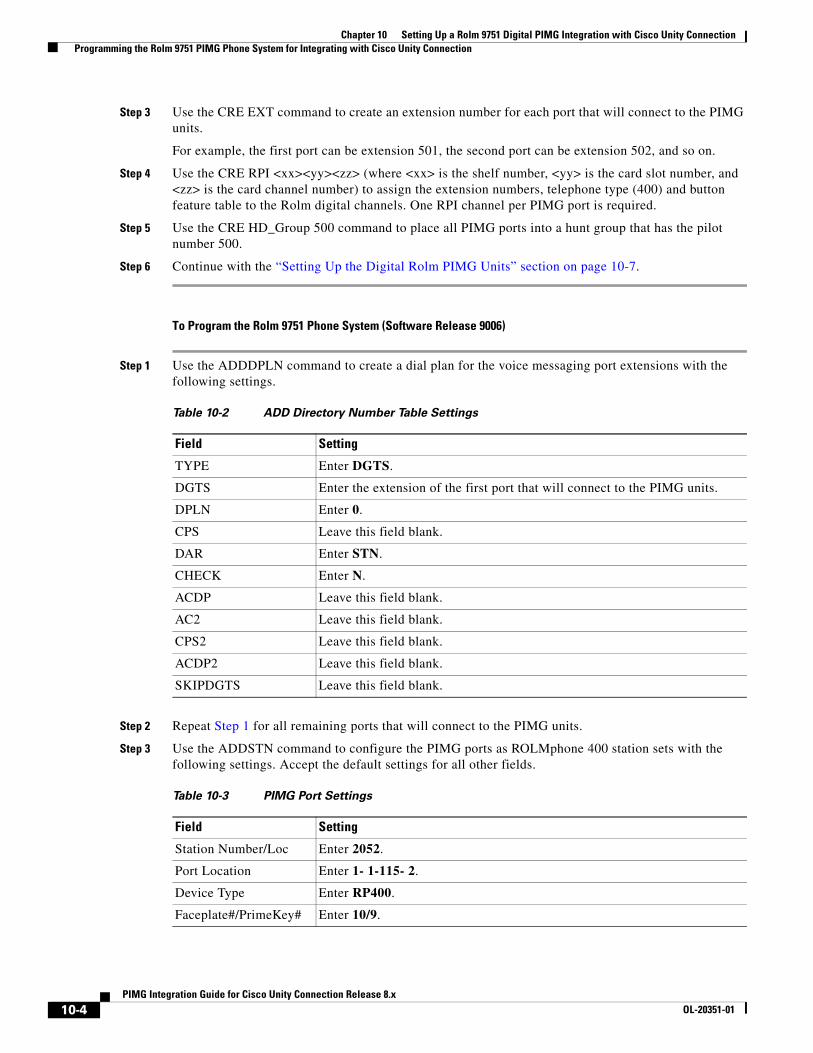
Chapter 10 Setting Up a Rolm 9751 Digital PIMG Integration with Cisco Unity Connection Programming the Rolm 9751 PIMG Phone System for Integrating with Cisco Unity Connection
Step 3 Use the CRE EXT command to create an extension number for each port that will connect to the PIMG units.
For example, the first port can be extension 501, the second port can be extension 502, and so on.
Step 4 Use the CRE RPI <xx><yy><zz> (where <xx> is the shelf number, <yy> is the card slot number, and <zz> is the card channel number) to assign the extension numbers, telephone type (400) and button feature table to the Rolm digital channels. One RPI channel per PIMG port is required.
Step 5 Use the CRE HD_Group 500 command to place all PIMG ports into a hunt group that has the pilot number 500.
Step 6 Continue with the “Setting Up the Digital Rolm PIMG Units” section on page 10-7.
To Program the Rolm 9751 Phone System (Software Release 9006)
Step 1 Use the ADDDPLN command to create a dial plan for the voice messaging port extensions with the following settings.
Step 2 Repeat Step 1 for all remaining ports that will connect to the PIMG units.
Step 3 Use the ADDSTN command to configure the PIMG ports as ROLMphone 400 station sets with the following settings. Accept the default settings for all other fields.
Table 10-2 ADD Directory Number Table Settings
Field Setting
TYPE Enter DGTS.
DGTS Enter the extension of the first port that will connect to the PIMG units.
DPLN Enter 0.
CPS Leave this field blank.
DAR Enter STN.
CHECK Enter N.
ACDP Leave this field blank.
AC2 Leave this field blank.
CPS2 Leave this field blank.
ACDP2 Leave this field blank.
SKIPDGTS Leave this field blank.
Table 10-3 PIMG Port Settings
Field Setting
Station Number/Loc Enter 2052.
Port Location Enter 1- 1-115- 2.
Device Type Enter RP400.
Faceplate#/PrimeKey# Enter 10/9.
10-4PIMG Integration Guide for Cisco Unity Connection Release 8.x
OL-20351-01
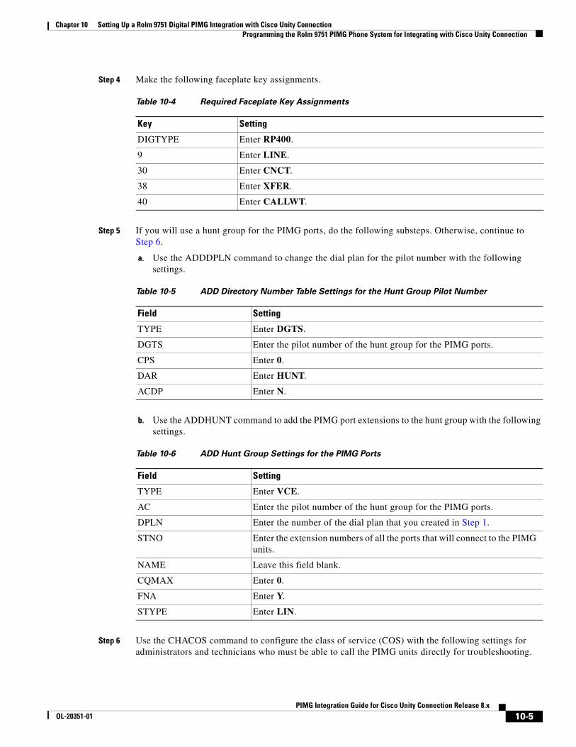
Chapter 10 Setting Up a Rolm 9751 Digital PIMG Integration with Cisco Unity Connection Programming the Rolm 9751 PIMG Phone System for Integrating with Cisco Unity Connection
Step 4 Make the following faceplate key assignments.
Step 5 If you will use a hunt group for the PIMG ports, do the following substeps. Otherwise, continue to Step 6.
a. Use the ADDDPLN command to change the dial plan for the pilot number with the following settings.
b. Use the ADDHUNT command to add the PIMG port extensions to the hunt group with the following settings.
Step 6 Use the CHACOS command to configure the class of service (COS) with the following settings for administrators and technicians who must be able to call the PIMG units directly for troubleshooting.
Table 10-4 Required Faceplate Key Assignments
Key Setting
DIGTYPE Enter RP400.
9 Enter LINE.
30 Enter CNCT.
38 Enter XFER.
40 Enter CALLWT.
Table 10-5 ADD Directory Number Table Settings for the Hunt Group Pilot Number
Field Setting
TYPE Enter DGTS.
DGTS Enter the pilot number of the hunt group for the PIMG ports.
CPS Enter 0.
DAR Enter HUNT.
ACDP Enter N.
Table 10-6 ADD Hunt Group Settings for the PIMG Ports
Field Setting
TYPE Enter VCE.
AC Enter the pilot number of the hunt group for the PIMG ports.
DPLN Enter the number of the dial plan that you created in Step 1.
STNO Enter the extension numbers of all the ports that will connect to the PIMG units.
NAME Leave this field blank.
CQMAX Enter 0.
FNA Enter Y.
STYPE Enter LIN.
10-5PIMG Integration Guide for Cisco Unity Connection Release 8.x
OL-20351-01
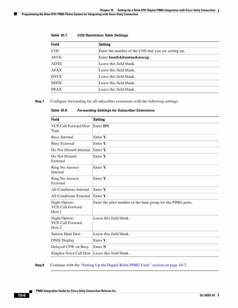
Chapter 10 Setting Up a Rolm 9751 Digital PIMG Integration with Cisco Unity Connection Programming the Rolm 9751 PIMG Phone System for Integrating with Cisco Unity Connection
Step 7 Configure forwarding for all subscriber extensions with the following settings.
Step 8 Continue with the “Setting Up the Digital Rolm PIMG Units” section on page 10-7.
Table 10-7 COS Restriction Table Settings
Field Setting
COS Enter the number of the COS that you are setting up.
AVCE Enter huntb&huntna&mscap.
ADTE Leave this field blank.
AFAX Leave this field blank.
DVCE Leave this field blank.
DDTE Leave this field blank.
DFAX Leave this field blank.
Table 10-8 Forwarding Settings for Subscriber Extensions
Field Setting
VCE Call Forward Dest Type
Enter DN.
Busy Internal Enter Y.
Busy External Enter Y.
Do Not Disturb Internal Enter Y.
Do Not Disturb External
Enter Y.
Ring No Answer Internal
Enter Y.
Ring No Answer External
Enter Y.
All Conditions Internal Enter Y.
All Conditions External Enter Y.
Night Option: VCE Call Forward Dest 1
Enter the pilot number of the hunt group for the PIMG ports.
Night Option: VCE Call Forward Dest 2
Leave this field blank.
Station Hunt Dest Leave this field blank.
DNIS Display Enter Y.
Delayed CFW on Busy Enter N.
Simplex Voice Call Dest Leave this field blank.
10-6PIMG Integration Guide for Cisco Unity Connection Release 8.x
OL-20351-01
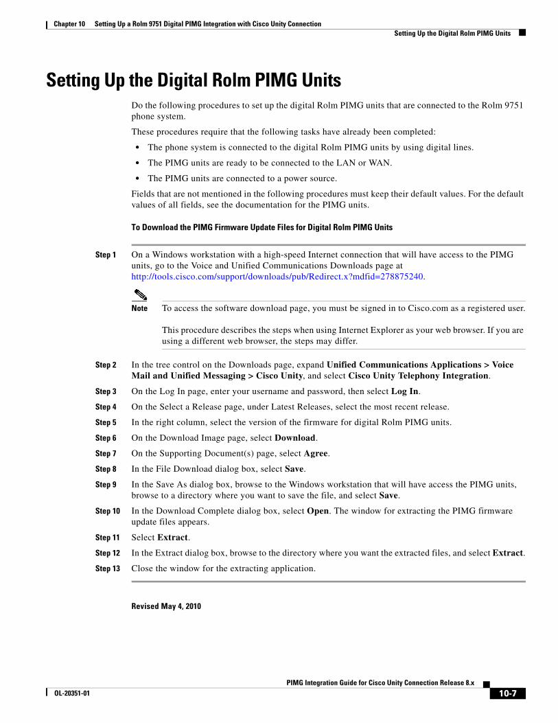
Chapter 10 Setting Up a Rolm 9751 Digital PIMG Integration with Cisco Unity Connection Setting Up the Digital Rolm PIMG Units
Setting Up the Digital Rolm PIMG UnitsDo the following procedures to set up the digital Rolm PIMG units that are connected to the Rolm 9751 phone system.
These procedures require that the following tasks have already been completed:
• The phone system is connected to the digital Rolm PIMG units by using digital lines.
• The PIMG units are ready to be connected to the LAN or WAN.
• The PIMG units are connected to a power source.
Fields that are not mentioned in the following procedures must keep their default values. For the default values of all fields, see the documentation for the PIMG units.
To Download the PIMG Firmware Update Files for Digital Rolm PIMG Units
Step 1 On a Windows workstation with a high-speed Internet connection that will have access to the PIMG units, go to the Voice and Unified Communications Downloads page at http://tools.cisco.com/support/downloads/pub/Redirect.x?mdfid=278875240.
Note To access the software download page, you must be signed in to Cisco.com as a registered user. This procedure describes the steps when using Internet Explorer as your web browser. If you are using a different web browser, the steps may differ.
Step 2 In the tree control on the Downloads page, expand Unified Communications Applications > Voice Mail and Unified Messaging > Cisco Unity, and select Cisco Unity Telephony Integration.
Step 3 On the Log In page, enter your username and password, then select Log In.
Step 4 On the Select a Release page, under Latest Releases, select the most recent release.
Step 5 In the right column, select the version of the firmware for digital Rolm PIMG units.
Step 6 On the Download Image page, select Download.
Step 7 On the Supporting Document(s) page, select Agree.
Step 8 In the File Download dialog box, select Save.
Step 9 In the Save As dialog box, browse to the Windows workstation that will have access the PIMG units, browse to a directory where you want to save the file, and select Save.
Step 10 In the Download Complete dialog box, select Open. The window for extracting the PIMG firmware update files appears.
Step 11 Select Extract.
Step 12 In the Extract dialog box, browse to the directory where you want the extracted files, and select Extract.
Step 13 Close the window for the extracting application.
Revised May 4, 2010
10-7PIMG Integration Guide for Cisco Unity Connection Release 8.x
OL-20351-01

Chapter 10 Setting Up a Rolm 9751 Digital PIMG Integration with Cisco Unity Connection Setting Up the Digital Rolm PIMG Units
To Set Up the Digital Rolm PIMG Units (Firmware Version 6.x)
Step 1 On the Windows workstation, add a temporary route to enable access to the PIMG units.
a. On the Windows Start menu, select Run.
b. Enter cmd, and press Enter. The Command Prompt window appears.
c. At the command prompt, enter route add 10.12.13.74 <IP Address of Workstation>, and press Enter.
For example, if the IP address of the workstation is 198.1.3.25, enter “route add 10.12.13.74<space>198.1.3.25” in the Command Prompt window.
d. Close the Command Prompt window.
Step 2 Connect a PIMG unit to the network.
Step 3 In the web browser, go to http://10.12.13.74.
Step 4 To sign in, enter the following case-sensitive settings.
Step 5 Select OK.
Step 6 On the System menu, select Upgrade.
Step 7 On the Upgrade page, select Browse.
Step 8 In the Choose File dialog box, browse to the directory on the Windows workstation that has the extracted PIMG firmware update files.
Step 9 Select Mtl_<xx>.app (where <xx> is multiple digits), and select Open.
Step 10 On the Upgrade page, select Install File.
Step 11 After the file is installed, a message prompting you to restart the PIMG unit appears. Select Cancel.
Caution Do not restart the PIMG unit until you are instructed to do so later in this procedure, even if the file installation fails. Restarting the PIMG unit at this step may prevent the PIMG unit from functioning correctly.
Step 12 Repeat Step 6 through Step 11 for each of the following files (where <xx> is multiple digits):
• Mtl_<xx>.fsh
• Run<xx>FskEcho.dsp
• Mtl<xx>.lca
Step 13 On the Configuration menu, select Import/Export.
Step 14 On the Import/Export page, select Browse.
Step 15 In the Choose File dialog box, browse to the file RLMDNI_Cfg_Rolm.ini.
Step 16 Select RLMDNI_Cfg_Rolm.ini, and select Open.
Table 10-9 Sign-in Settings
Field Setting
Username Enter admin.
Password Enter IpodAdmin.
10-8PIMG Integration Guide for Cisco Unity Connection Release 8.x
OL-20351-01
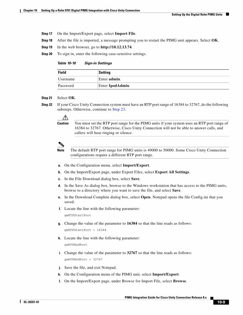
Chapter 10 Setting Up a Rolm 9751 Digital PIMG Integration with Cisco Unity Connection Setting Up the Digital Rolm PIMG Units
Step 17 On the Import/Export page, select Import File.
Step 18 After the file is imported, a message prompting you to restart the PIMG unit appears. Select OK.
Step 19 In the web browser, go to http://10.12.13.74.
Step 20 To sign in, enter the following case-sensitive settings.
Step 21 Select OK.
Step 22 If your Cisco Unity Connection system must have an RTP port range of 16384 to 32767, do the following substeps. Otherwise, continue to Step 23.
Caution You must set the RTP port range for the PIMG units if your system uses an RTP port range of 16384 to 32767. Otherwise, Cisco Unity Connection will not be able to answer calls, and callers will hear ringing or silence.
Note The default RTP port range for PIMG units is 49000 to 50000. Some Cisco Unity Connection configurations require a different RTP port range.
a. On the Configuration menu, select Import/Export.
b. On the Import/Export page, under Export Files, select Export All Settings.
c. In the File Download dialog box, select Save.
d. In the Save As dialog box, browse to the Windows workstation that has access to the PIMG units, browse to a directory where you want to save the file, and select Save.
e. In the Download Complete dialog box, select Open. Notepad opens the file Config.ini that you saved.
f. Locate the line with the following parameter:
gwRTPStartPort
g. Change the value of the parameter to 16384 so that the line reads as follows:
gwRTPStartPort = 16384
h. Locate the line with the following parameter:
gwRTPEndPort
i. Change the value of the parameter to 32767 so that the line reads as follows:
gwRTPEndPort = 32767
j. Save the file, and exit Notepad.
k. On the Configuration menu of the PIMG unit, select Import/Export.
l. On the Import/Export page, under Browse for Import File, select Browse.
Table 10-10 Sign-in Settings
Field Setting
Username Enter admin.
Password Enter IpodAdmin.
10-9PIMG Integration Guide for Cisco Unity Connection Release 8.x
OL-20351-01

Chapter 10 Setting Up a Rolm 9751 Digital PIMG Integration with Cisco Unity Connection Setting Up the Digital Rolm PIMG Units
m. In the Choose File dialog box, browse to the file Config.ini that you saved.
n. Select Config.ini, and select Open.
o. On the Import/Export page, select Import File.
p. When prompted to restart the PIMG unit, select OK.
q. When the PIMG unit has restarted, in the web browser, go to http://10.12.13.74.
r. To sign in, enter the following case-sensitive settings.
s. Select OK.
Step 23 On the System menu, select Password.
Step 24 On the Change Password page, enter the following settings.
Step 25 Select Change.
Step 26 On the Configuration menu, select Routing Table.
Step 27 On the Routing Table page, under Router Configuration, select VoIP Host Groups.
Step 28 Under VoIP Host Groups, enter the following settings for the first VoIP Host Group.
Table 10-11 Sign-in Settings
Field Setting
Username Enter admin.
Password Enter IpodAdmin.
Table 10-12 Change Password Page Settings
Field Setting
Old Password Enter IpodAdmin.
(This setting is case sensitive.)
New Password Enter your new password.
(This setting is case sensitive.)
Confirm Password Enter your new password.
(This setting is case sensitive.)
Table 10-13 First VoIP Host Group Settings
Field Settings
Name Accept the default or enter another descriptive name of the VoIP host group.
Load-Balanced (Cisco Unity Connection without a cluster) Select False.
(Cisco Unity Connection with a cluster configured) Select False.
Fault-Tolerant (Cisco Unity Connection without a cluster) Select False.
(Cisco Unity Connection with a cluster configured) Select True.
10-10PIMG Integration Guide for Cisco Unity Connection Release 8.x
OL-20351-01
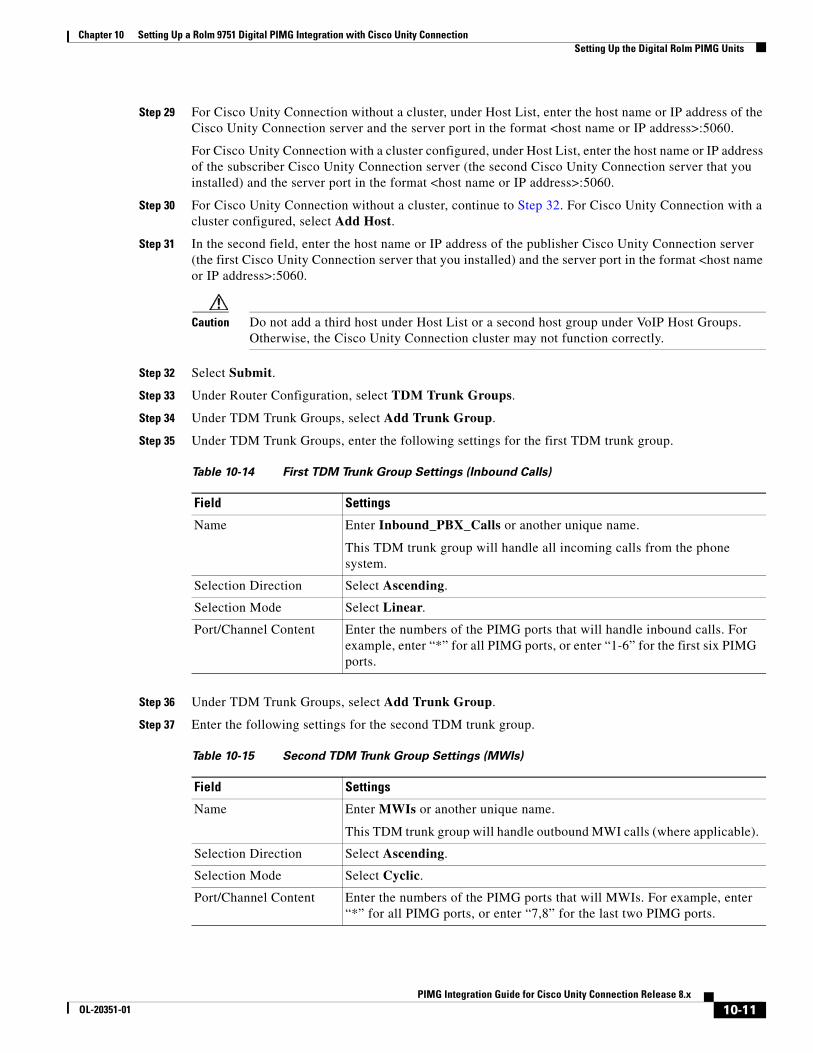
Chapter 10 Setting Up a Rolm 9751 Digital PIMG Integration with Cisco Unity Connection Setting Up the Digital Rolm PIMG Units
Step 29 For Cisco Unity Connection without a cluster, under Host List, enter the host name or IP address of the Cisco Unity Connection server and the server port in the format <host name or IP address>:5060.
For Cisco Unity Connection with a cluster configured, under Host List, enter the host name or IP address of the subscriber Cisco Unity Connection server (the second Cisco Unity Connection server that you installed) and the server port in the format <host name or IP address>:5060.
Step 30 For Cisco Unity Connection without a cluster, continue to Step 32. For Cisco Unity Connection with a cluster configured, select Add Host.
Step 31 In the second field, enter the host name or IP address of the publisher Cisco Unity Connection server (the first Cisco Unity Connection server that you installed) and the server port in the format <host name or IP address>:5060.
Caution Do not add a third host under Host List or a second host group under VoIP Host Groups. Otherwise, the Cisco Unity Connection cluster may not function correctly.
Step 32 Select Submit.
Step 33 Under Router Configuration, select TDM Trunk Groups.
Step 34 Under TDM Trunk Groups, select Add Trunk Group.
Step 35 Under TDM Trunk Groups, enter the following settings for the first TDM trunk group.
Step 36 Under TDM Trunk Groups, select Add Trunk Group.
Step 37 Enter the following settings for the second TDM trunk group.
Table 10-14 First TDM Trunk Group Settings (Inbound Calls)
Field Settings
Name Enter Inbound_PBX_Calls or another unique name.
This TDM trunk group will handle all incoming calls from the phone system.
Selection Direction Select Ascending.
Selection Mode Select Linear.
Port/Channel Content Enter the numbers of the PIMG ports that will handle inbound calls. For example, enter “*” for all PIMG ports, or enter “1-6” for the first six PIMG ports.
Table 10-15 Second TDM Trunk Group Settings (MWIs)
Field Settings
Name Enter MWIs or another unique name.
This TDM trunk group will handle outbound MWI calls (where applicable).
Selection Direction Select Ascending.
Selection Mode Select Cyclic.
Port/Channel Content Enter the numbers of the PIMG ports that will MWIs. For example, enter “*” for all PIMG ports, or enter “7,8” for the last two PIMG ports.
10-11PIMG Integration Guide for Cisco Unity Connection Release 8.x
OL-20351-01

Chapter 10 Setting Up a Rolm 9751 Digital PIMG Integration with Cisco Unity Connection Setting Up the Digital Rolm PIMG Units
Step 38 Under TDM Trunk Groups, select Add Trunk Group.
Step 39 Enter the following settings for the third TDM trunk group.
Step 40 Select Submit.
Step 41 Under Router Configuration, select Inbound VoIP Rules.
Step 42 Under Inbound VoIP Rules, uncheck the Enabled check box for the default rule.
Step 43 Select Add Rule.
Step 44 Under Inbound VoIP Rules, enter the following settings for the first new inbound VoIP rule.
Step 45 Under Inbound VoIP Request Matching, enter the following settings.
Caution The rule that you created in Step 44 must be selected. Otherwise, any changes you make will apply to another rule.
Table 10-16 Third TDM Trunk Group Settings (Outbound Calls)
Field Settings
Name Enter Outbound_PBX_Calls or another unique name.
This TDM trunk group will handle all outbound calls from Cisco Unity Connection.
Selection Direction Select Descending.
Selection Mode Select Linear.
Port/Channel Content Enter * for all channels in all ports.
Enter the numbers of the PIMG ports that will handle outbound (dialout) calls. For example, enter “*” for all PIMG ports, or enter “7,8” for the last two PIMG ports.
Table 10-17 First New Inbound VoIP Rule Settings (MWIs)
Field Settings
Enable Check this check box.
Rule Label Enter MWI_Calls or another name.
This inbound VoIP rule will handle all MWI calls from Cisco Unity Connection.
Request Type Select Message.
Originating VoIP Host Address
Enter *.
Table 10-18 Inbound VoIP Request Matching Settings
Field Settings
Calling Number Enter *.
Calling Name Enter *.
10-12PIMG Integration Guide for Cisco Unity Connection Release 8.x
OL-20351-01

Chapter 10 Setting Up a Rolm 9751 Digital PIMG Integration with Cisco Unity Connection Setting Up the Digital Rolm PIMG Units
Step 46 Under Outbound Routes, enter the following settings.
Caution The rule that you created in Step 44 must be selected. Otherwise, any changes you make will apply to another rule.
Step 47 Under Inbound VoIP Rules, select Add Rule.
Step 48 Under Inbound VoIP Rules, enter the following settings for the second new inbound VoIP rule.
Called Number Enter *.
Called Name Enter *.
Redirect Number Enter *.
Redirect Name Enter *.
Table 10-18 Inbound VoIP Request Matching Settings (continued)
Field Settings
Table 10-19 Outbound Routes Settings
Field Settings
Device Selection
Outbound Destination Select TDM.
Trunk Group Select the name of the TDM trunk group that you created for MWIs in Step 37. For example, select “MWIs.
CPID Manipulation
Calling Number Enter S.
Calling Name Enter S.
Called Number Enter D.
Called Name Enter D.
Redirect Number Enter R.
Redirect Name Enter R.
Select Primary/Alternate Route
Primary Select Primary.
Table 10-20 Second New Inbound VoIP Rule Settings (Outbound Calls)
Field Settings
Enable Check this check box.
Rule Label Enter Outbound_UC_Calls or another name.
This inbound VoIP rule will handle all outbound calls from Cisco Unity Connection.
10-13PIMG Integration Guide for Cisco Unity Connection Release 8.x
OL-20351-01
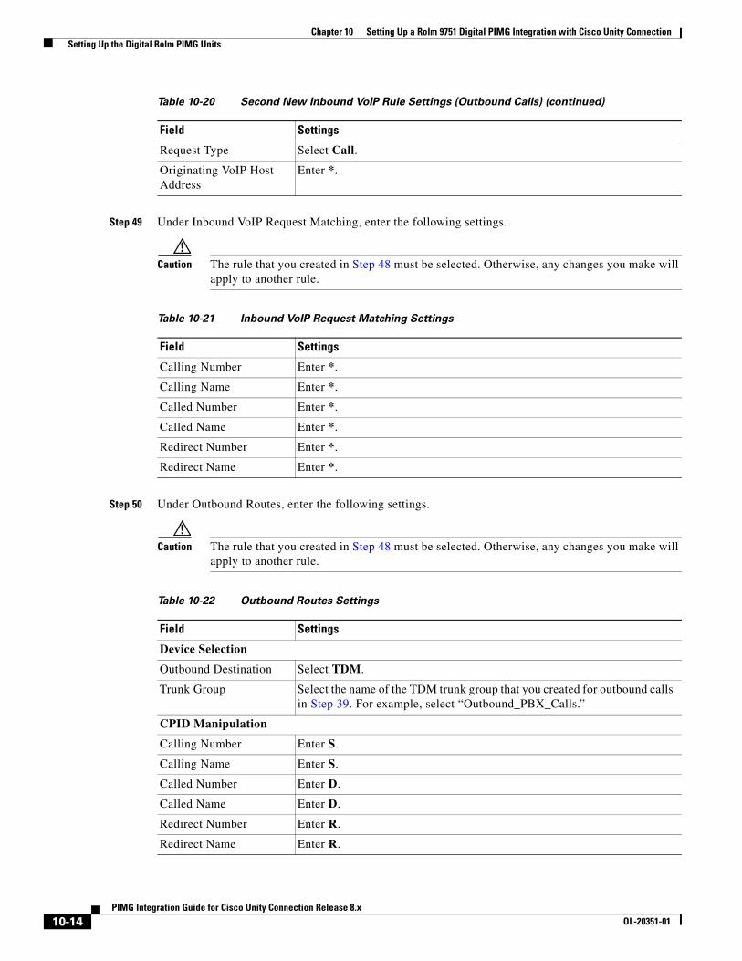
Chapter 10 Setting Up a Rolm 9751 Digital PIMG Integration with Cisco Unity Connection Setting Up the Digital Rolm PIMG Units
Step 49 Under Inbound VoIP Request Matching, enter the following settings.
Caution The rule that you created in Step 48 must be selected. Otherwise, any changes you make will apply to another rule.
Step 50 Under Outbound Routes, enter the following settings.
Caution The rule that you created in Step 48 must be selected. Otherwise, any changes you make will apply to another rule.
Request Type Select Call.
Originating VoIP Host Address
Enter *.
Table 10-20 Second New Inbound VoIP Rule Settings (Outbound Calls) (continued)
Field Settings
Table 10-21 Inbound VoIP Request Matching Settings
Field Settings
Calling Number Enter *.
Calling Name Enter *.
Called Number Enter *.
Called Name Enter *.
Redirect Number Enter *.
Redirect Name Enter *.
Table 10-22 Outbound Routes Settings
Field Settings
Device Selection
Outbound Destination Select TDM.
Trunk Group Select the name of the TDM trunk group that you created for outbound calls in Step 39. For example, select “Outbound_PBX_Calls.”
CPID Manipulation
Calling Number Enter S.
Calling Name Enter S.
Called Number Enter D.
Called Name Enter D.
Redirect Number Enter R.
Redirect Name Enter R.
10-14PIMG Integration Guide for Cisco Unity Connection Release 8.x
OL-20351-01
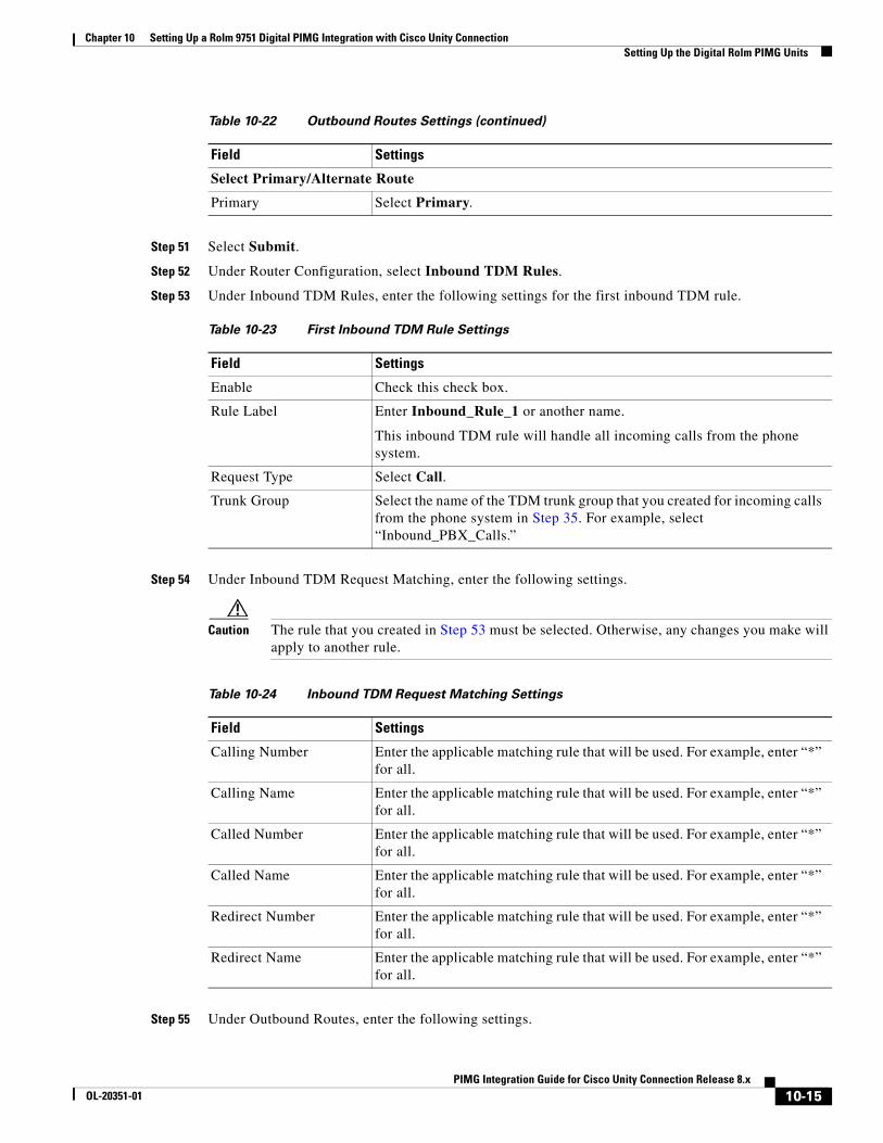
Chapter 10 Setting Up a Rolm 9751 Digital PIMG Integration with Cisco Unity Connection Setting Up the Digital Rolm PIMG Units
Step 51 Select Submit.
Step 52 Under Router Configuration, select Inbound TDM Rules.
Step 53 Under Inbound TDM Rules, enter the following settings for the first inbound TDM rule.
Step 54 Under Inbound TDM Request Matching, enter the following settings.
Caution The rule that you created in Step 53 must be selected. Otherwise, any changes you make will apply to another rule.
Step 55 Under Outbound Routes, enter the following settings.
Select Primary/Alternate Route
Primary Select Primary.
Table 10-23 First Inbound TDM Rule Settings
Field Settings
Enable Check this check box.
Rule Label Enter Inbound_Rule_1 or another name.
This inbound TDM rule will handle all incoming calls from the phone system.
Request Type Select Call.
Trunk Group Select the name of the TDM trunk group that you created for incoming calls from the phone system in Step 35. For example, select “Inbound_PBX_Calls.”
Table 10-22 Outbound Routes Settings (continued)
Field Settings
Table 10-24 Inbound TDM Request Matching Settings
Field Settings
Calling Number Enter the applicable matching rule that will be used. For example, enter “*” for all.
Calling Name Enter the applicable matching rule that will be used. For example, enter “*” for all.
Called Number Enter the applicable matching rule that will be used. For example, enter “*” for all.
Called Name Enter the applicable matching rule that will be used. For example, enter “*” for all.
Redirect Number Enter the applicable matching rule that will be used. For example, enter “*” for all.
Redirect Name Enter the applicable matching rule that will be used. For example, enter “*” for all.
10-15PIMG Integration Guide for Cisco Unity Connection Release 8.x
OL-20351-01
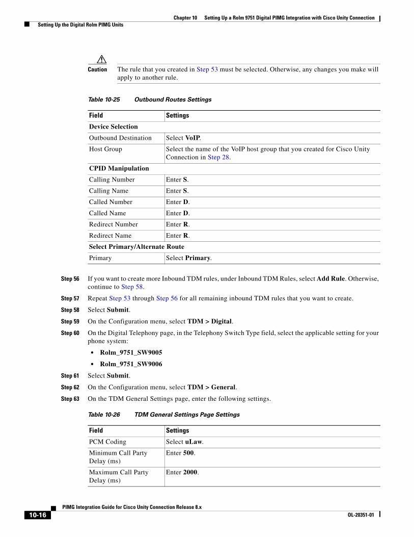
Chapter 10 Setting Up a Rolm 9751 Digital PIMG Integration with Cisco Unity Connection Setting Up the Digital Rolm PIMG Units
Caution The rule that you created in Step 53 must be selected. Otherwise, any changes you make will apply to another rule.
Step 56 If you want to create more Inbound TDM rules, under Inbound TDM Rules, select Add Rule. Otherwise, continue to Step 58.
Step 57 Repeat Step 53 through Step 56 for all remaining inbound TDM rules that you want to create.
Step 58 Select Submit.
Step 59 On the Configuration menu, select TDM > Digital.
Step 60 On the Digital Telephony page, in the Telephony Switch Type field, select the applicable setting for your phone system:
• Rolm_9751_SW9005
• Rolm_9751_SW9006
Step 61 Select Submit.
Step 62 On the Configuration menu, select TDM > General.
Step 63 On the TDM General Settings page, enter the following settings.
Table 10-25 Outbound Routes Settings
Field Settings
Device Selection
Outbound Destination Select VoIP.
Host Group Select the name of the VoIP host group that you created for Cisco Unity Connection in Step 28.
CPID Manipulation
Calling Number Enter S.
Calling Name Enter S.
Called Number Enter D.
Called Name Enter D.
Redirect Number Enter R.
Redirect Name Enter R.
Select Primary/Alternate Route
Primary Select Primary.
Table 10-26 TDM General Settings Page Settings
Field Settings
PCM Coding Select uLaw.
Minimum Call Party Delay (ms)
Enter 500.
Maximum Call Party Delay (ms)
Enter 2000.
10-16PIMG Integration Guide for Cisco Unity Connection Release 8.x
OL-20351-01
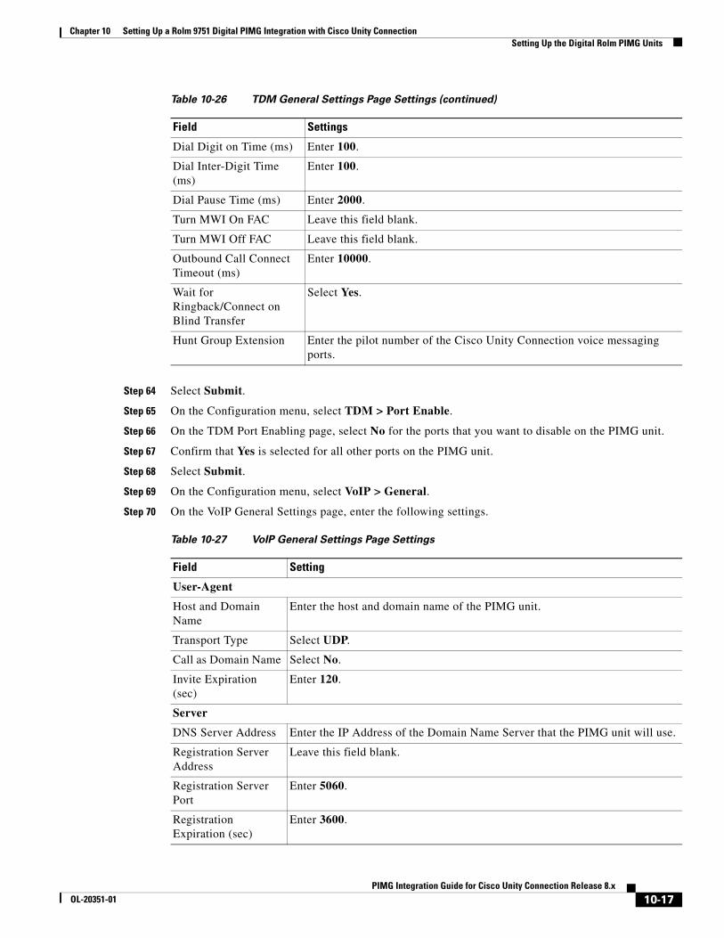
Chapter 10 Setting Up a Rolm 9751 Digital PIMG Integration with Cisco Unity Connection Setting Up the Digital Rolm PIMG Units
Step 64 Select Submit.
Step 65 On the Configuration menu, select TDM > Port Enable.
Step 66 On the TDM Port Enabling page, select No for the ports that you want to disable on the PIMG unit.
Step 67 Confirm that Yes is selected for all other ports on the PIMG unit.
Step 68 Select Submit.
Step 69 On the Configuration menu, select VoIP > General.
Step 70 On the VoIP General Settings page, enter the following settings.
Dial Digit on Time (ms) Enter 100.
Dial Inter-Digit Time (ms)
Enter 100.
Dial Pause Time (ms) Enter 2000.
Turn MWI On FAC Leave this field blank.
Turn MWI Off FAC Leave this field blank.
Outbound Call Connect Timeout (ms)
Enter 10000.
Wait for Ringback/Connect on Blind Transfer
Select Yes.
Hunt Group Extension Enter the pilot number of the Cisco Unity Connection voice messaging ports.
Table 10-27 VoIP General Settings Page Settings
Field Setting
User-Agent
Host and Domain Name
Enter the host and domain name of the PIMG unit.
Transport Type Select UDP.
Call as Domain Name Select No.
Invite Expiration (sec)
Enter 120.
Server
DNS Server Address Enter the IP Address of the Domain Name Server that the PIMG unit will use.
Registration Server Address
Leave this field blank.
Registration Server Port
Enter 5060.
Registration Expiration (sec)
Enter 3600.
Table 10-26 TDM General Settings Page Settings (continued)
Field Settings
10-17PIMG Integration Guide for Cisco Unity Connection Release 8.x
OL-20351-01
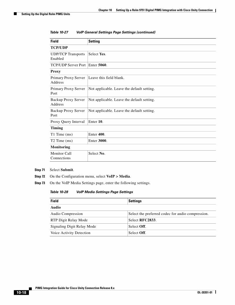
Chapter 10 Setting Up a Rolm 9751 Digital PIMG Integration with Cisco Unity Connection Setting Up the Digital Rolm PIMG Units
Step 71 Select Submit.
Step 72 On the Configuration menu, select VoIP > Media.
Step 73 On the VoIP Media Settings page, enter the following settings.
TCP/UDP
UDP/TCP Transports Enabled
Select Yes.
TCP/UDP Server Port Enter 5060.
Proxy
Primary Proxy Server Address
Leave this field blank.
Primary Proxy Server Port
Not applicable. Leave the default setting.
Backup Proxy Server Address
Not applicable. Leave the default setting.
Backup Proxy Server Port
Not applicable. Leave the default setting.
Proxy Query Interval Enter 10.
Timing
T1 Time (ms) Enter 400.
T2 Time (ms) Enter 3000.
Monitoring
Monitor Call Connections
Select No.
Table 10-28 VoIP Media Settings Page Settings
Field Settings
Audio
Audio Compression Select the preferred codec for audio compression.
RTP Digit Relay Mode Select RFC2833.
Signaling Digit Relay Mode Select Off.
Voice Activity Detection Select Off.
Table 10-27 VoIP General Settings Page Settings (continued)
Field Setting
10-18PIMG Integration Guide for Cisco Unity Connection Release 8.x
OL-20351-01

Chapter 10 Setting Up a Rolm 9751 Digital PIMG Integration with Cisco Unity Connection Setting Up the Digital Rolm PIMG Units
Step 74 Select Submit.
Step 75 On the Configuration menu, select VoIP > QOS.
Step 76 On the VoIP QOS Configuration page, enter the following settings.
Step 77 Select Submit.
Step 78 On the Configuration menu, select IP.
Step 79 On the IP Settings page, enter the following settings.
Frame Size Select the applicable setting:
• G.711—20
• G.729AB—10
Caution Failure to use the correct setting will result in recorded messages containing nothing but silence.
Frames Per Packet Select the applicable setting:
• G.711—1
• G.729AB—2
Caution Failure to use the correct setting will result in recorded messages containing nothing but silence.
Table 10-29 VoIP QOS Configurative Page Settings
Field Settings
Call Control QOS Byte Enter 104.
RTP QOS Byte Enter 184.
Table 10-30 IP Settings Page Settings
Field Settings
Client IP Address Enter the new IP address you want to use for the PIMG unit.
(This is the IP address that you enter in Cisco Unity Connection Administration when you create the integration.)
Client Subnet Mask Enter the new subnet mask, if the subnet mask is different from the default IP address.
Default Network Gateway Address
Enter the IP address of the default network gateway router that the PIMG units will use.
BOOTP Enabled Select No.
Table 10-28 VoIP Media Settings Page Settings (continued)
Field Settings
10-19PIMG Integration Guide for Cisco Unity Connection Release 8.x
OL-20351-01
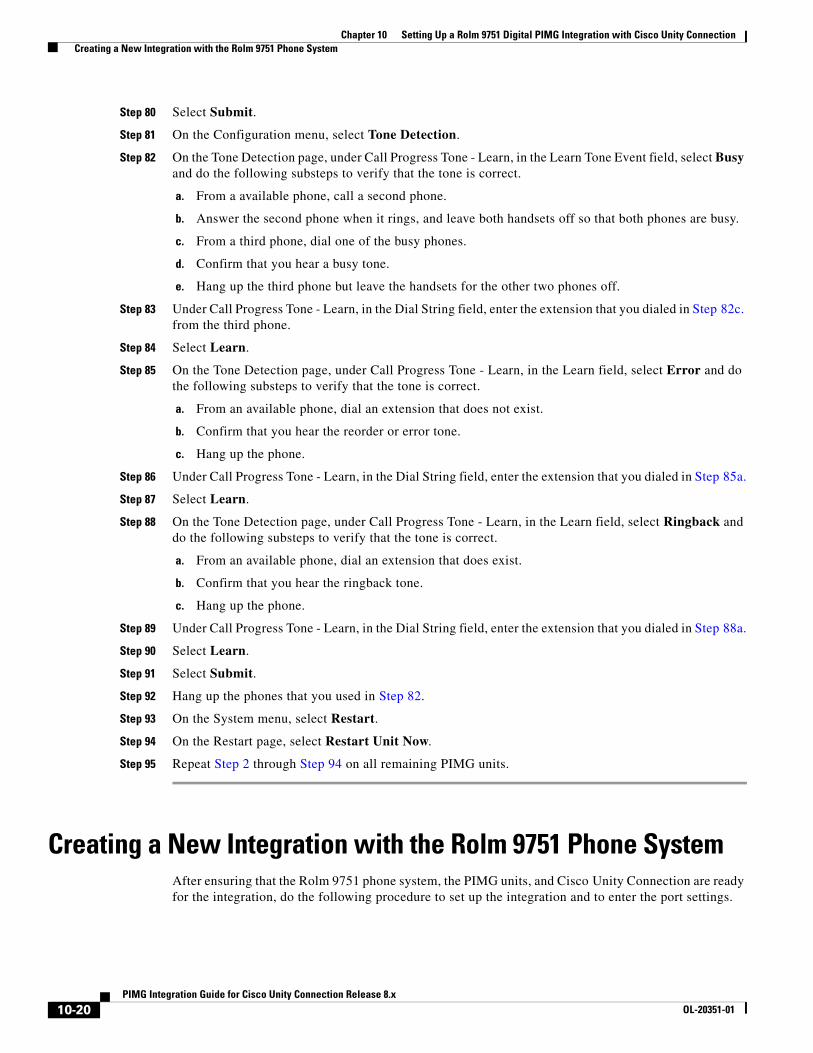
Chapter 10 Setting Up a Rolm 9751 Digital PIMG Integration with Cisco Unity Connection Creating a New Integration with the Rolm 9751 Phone System
Step 80 Select Submit.
Step 81 On the Configuration menu, select Tone Detection.
Step 82 On the Tone Detection page, under Call Progress Tone - Learn, in the Learn Tone Event field, select Busy and do the following substeps to verify that the tone is correct.
a. From a available phone, call a second phone.
b. Answer the second phone when it rings, and leave both handsets off so that both phones are busy.
c. From a third phone, dial one of the busy phones.
d. Confirm that you hear a busy tone.
e. Hang up the third phone but leave the handsets for the other two phones off.
Step 83 Under Call Progress Tone - Learn, in the Dial String field, enter the extension that you dialed in Step 82c. from the third phone.
Step 84 Select Learn.
Step 85 On the Tone Detection page, under Call Progress Tone - Learn, in the Learn field, select Error and do the following substeps to verify that the tone is correct.
a. From an available phone, dial an extension that does not exist.
b. Confirm that you hear the reorder or error tone.
c. Hang up the phone.
Step 86 Under Call Progress Tone - Learn, in the Dial String field, enter the extension that you dialed in Step 85a.
Step 87 Select Learn.
Step 88 On the Tone Detection page, under Call Progress Tone - Learn, in the Learn field, select Ringback and do the following substeps to verify that the tone is correct.
a. From an available phone, dial an extension that does exist.
b. Confirm that you hear the ringback tone.
c. Hang up the phone.
Step 89 Under Call Progress Tone - Learn, in the Dial String field, enter the extension that you dialed in Step 88a.
Step 90 Select Learn.
Step 91 Select Submit.
Step 92 Hang up the phones that you used in Step 82.
Step 93 On the System menu, select Restart.
Step 94 On the Restart page, select Restart Unit Now.
Step 95 Repeat Step 2 through Step 94 on all remaining PIMG units.
Creating a New Integration with the Rolm 9751 Phone SystemAfter ensuring that the Rolm 9751 phone system, the PIMG units, and Cisco Unity Connection are ready for the integration, do the following procedure to set up the integration and to enter the port settings.
10-20PIMG Integration Guide for Cisco Unity Connection Release 8.x
OL-20351-01
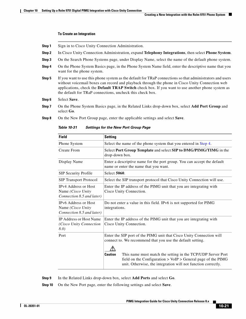
Chapter 10 Setting Up a Rolm 9751 Digital PIMG Integration with Cisco Unity Connection Creating a New Integration with the Rolm 9751 Phone System
To Create an Integration
Step 1 Sign in to Cisco Unity Connection Administration.
Step 2 In Cisco Unity Connection Administration, expand Telephony Integrations, then select Phone System.
Step 3 On the Search Phone Systems page, under Display Name, select the name of the default phone system.
Step 4 On the Phone System Basics page, in the Phone System Name field, enter the descriptive name that you want for the phone system.
Step 5 If you want to use this phone system as the default for TRaP connections so that administrators and users without voicemail boxes can record and playback through the phone in Cisco Unity Connection web applications, check the Default TRAP Switch check box. If you want to use another phone system as the default for TRaP connections, uncheck this check box.
Step 6 Select Save.
Step 7 On the Phone System Basics page, in the Related Links drop-down box, select Add Port Group and select Go.
Step 8 On the New Port Group page, enter the applicable settings and select Save.
Step 9 In the Related Links drop-down box, select Add Ports and select Go.
Step 10 On the New Port page, enter the following settings and select Save.
Table 10-31 Settings for the New Port Group Page
Field Setting
Phone System Select the name of the phone system that you entered in Step 4.
Create From Select Port Group Template and select SIP to DMG/PIMG/TIMG in the drop-down box.
Display Name Enter a descriptive name for the port group. You can accept the default name or enter the name that you want.
SIP Security Profile Select 5060.
SIP Transport Protocol Select the SIP transport protocol that Cisco Unity Connection will use.
IPv4 Address or Host Name (Cisco Unity Connection 8.5 and later)
Enter the IP address of the PIMG unit that you are integrating with Cisco Unity Connection.
IPv6 Address or Host Name (Cisco Unity Connection 8.5 and later)
Do not enter a value in this field. IPv6 is not supported for PIMG integrations.
IP Address or Host Name (Cisco Unity Connection 8.0)
Enter the IP address of the PIMG unit that you are integrating with Cisco Unity Connection.
Port Enter the SIP port of the PIMG unit that Cisco Unity Connection will connect to. We recommend that you use the default setting.
Caution This name must match the setting in the TCP/UDP Server Port field on the Configuration > VoIP > General page of the PIMG unit. Otherwise, the integration will not function correctly.
10-21PIMG Integration Guide for Cisco Unity Connection Release 8.x
OL-20351-01

Chapter 10 Setting Up a Rolm 9751 Digital PIMG Integration with Cisco Unity Connection Creating a New Integration with the Rolm 9751 Phone System
Step 11 On the Search Ports page, select the display name of the first voice messaging port that you created for this phone system integration.
Note By default, the display names for the voice messaging ports are composed of the port group display name followed by incrementing numbers.
Step 12 On the Port Basics page, set the voice messaging port settings as applicable. The fields in the following table are the ones that you can change.
Table 10-32 Settings for the New Port Page
Field Considerations
Enabled Check this check box.
Number of Ports Enter 8.
(If you want to use fewer than eight voice messaging ports, enter the number of voice messaging ports that you want to use on this PIMG unit.)
Note For a Cisco Unity Connection cluster, the Cisco Unity Connection server must have the number of voice messaging ports that are set up on the phone system for the PIMG integration so that this Cisco Unity Connection server can handle all voice messaging traffic for the Cisco Unity Connection cluster if one of the servers stops functioning. For example, if the phone system is set up with 16 voice messaging ports, this Cisco Unity Connection server must have 16 voice messaging ports.
Phone System Select the name of the phone system that you entered in Step 4.
Port Group Select the name of the port group that you added in Step 8.
Table 10-33 Settings for the Voice Messaging Ports
Field Considerations
Enabled Check this check box to enable the port. The port is enabled during normal operation.
Uncheck this check box to disable the port. When the port is disabled, calls to the port get a ringing tone but are not answered. Typically, the port is disabled only by the installer during testing.
Extension Enter the extension for the port as assigned on the phone system.
Answer Calls Check this check box to designate the port for answering calls. These calls can be incoming calls from unidentified callers or from users.
Perform Message Notification Check this check box to designate the port for notifying users of messages. Assign Perform Message Notification to the least busy ports.
Send MWI Requests Check this check box to designate the port for turning MWIs on and off. Assign Send MWI Requests to the least busy ports.
10-22PIMG Integration Guide for Cisco Unity Connection Release 8.x
OL-20351-01
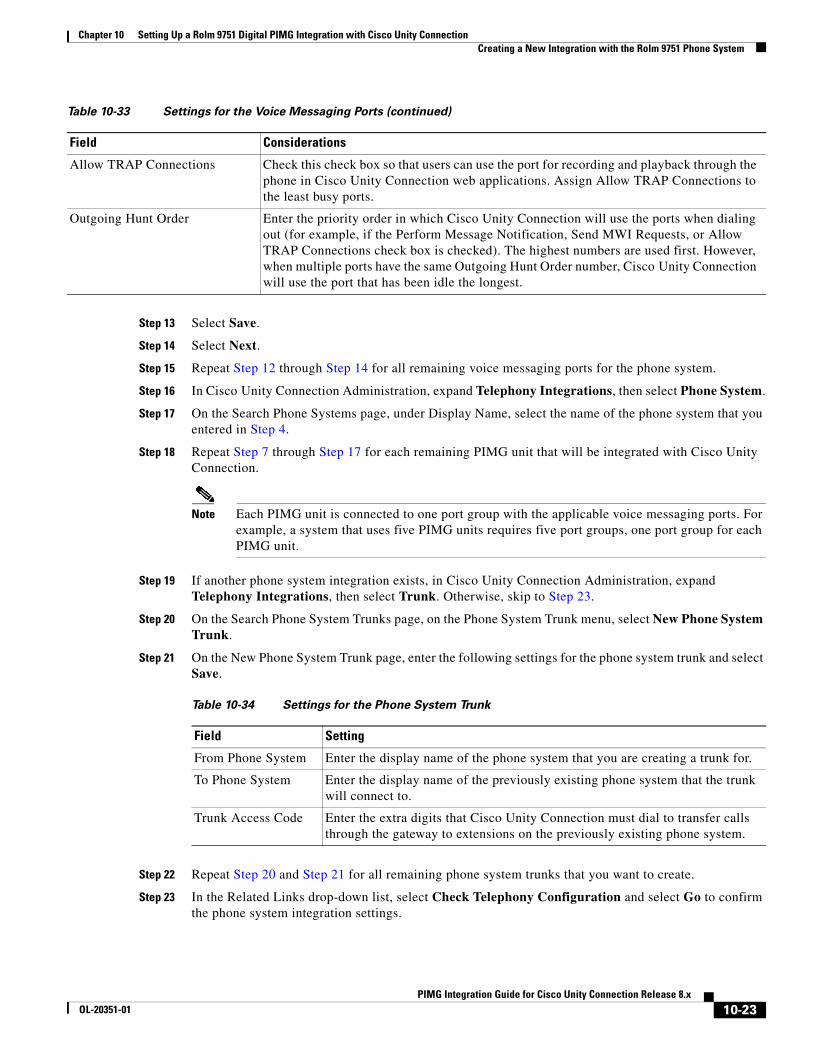
Chapter 10 Setting Up a Rolm 9751 Digital PIMG Integration with Cisco Unity Connection Creating a New Integration with the Rolm 9751 Phone System
Step 13 Select Save.
Step 14 Select Next.
Step 15 Repeat Step 12 through Step 14 for all remaining voice messaging ports for the phone system.
Step 16 In Cisco Unity Connection Administration, expand Telephony Integrations, then select Phone System.
Step 17 On the Search Phone Systems page, under Display Name, select the name of the phone system that you entered in Step 4.
Step 18 Repeat Step 7 through Step 17 for each remaining PIMG unit that will be integrated with Cisco Unity Connection.
Note Each PIMG unit is connected to one port group with the applicable voice messaging ports. For example, a system that uses five PIMG units requires five port groups, one port group for each PIMG unit.
Step 19 If another phone system integration exists, in Cisco Unity Connection Administration, expand Telephony Integrations, then select Trunk. Otherwise, skip to Step 23.
Step 20 On the Search Phone System Trunks page, on the Phone System Trunk menu, select New Phone System Trunk.
Step 21 On the New Phone System Trunk page, enter the following settings for the phone system trunk and select Save.
Step 22 Repeat Step 20 and Step 21 for all remaining phone system trunks that you want to create.
Step 23 In the Related Links drop-down list, select Check Telephony Configuration and select Go to confirm the phone system integration settings.
Allow TRAP Connections Check this check box so that users can use the port for recording and playback through the phone in Cisco Unity Connection web applications. Assign Allow TRAP Connections to the least busy ports.
Outgoing Hunt Order Enter the priority order in which Cisco Unity Connection will use the ports when dialing out (for example, if the Perform Message Notification, Send MWI Requests, or Allow TRAP Connections check box is checked). The highest numbers are used first. However, when multiple ports have the same Outgoing Hunt Order number, Cisco Unity Connection will use the port that has been idle the longest.
Table 10-33 Settings for the Voice Messaging Ports (continued)
Field Considerations
Table 10-34 Settings for the Phone System Trunk
Field Setting
From Phone System Enter the display name of the phone system that you are creating a trunk for.
To Phone System Enter the display name of the previously existing phone system that the trunk will connect to.
Trunk Access Code Enter the extra digits that Cisco Unity Connection must dial to transfer calls through the gateway to extensions on the previously existing phone system.
10-23PIMG Integration Guide for Cisco Unity Connection Release 8.x
OL-20351-01

Chapter 10 Setting Up a Rolm 9751 Digital PIMG Integration with Cisco Unity Connection Creating a New Integration with the Rolm 9751 Phone System
If the test is not successful, the Task Execution Results displays one or more messages with troubleshooting steps. After correcting the problems, test the connection again.
Step 24 In the Task Execution Results window, select Close.
10-24PIMG Integration Guide for Cisco Unity Connection Release 8.x
OL-20351-01
PIMG IntegrOL-20351-01
C H A P T E R 11
Setting Up a Serial (SMDI, MCI, or MD-110) PIMG Integration with Cisco Unity ConnectionFor detailed instructions for setting up a serial (SMDI, MCI, or MD-110) PIMG integration with Cisco Unity Connection, see the following sections in this chapter:
• Task List to Create a Serial (SMDI, MCI, or MD-110) PIMG Integration, page 11-1
• Requirements, page 11-2
• Programming the Phone System for a Serial Integration with Cisco Unity Connection, page 11-3
• Setting Up the Analog PIMG Units for a Serial Integration, page 11-4
• Creating a New Integration with the Phone System, page 11-19
Task List to Create a Serial (SMDI, MCI, or MD-110) PIMG Integration
Before doing the following tasks to integrate Cisco Unity Connection with the phone system by using PIMG units (media gateways), confirm that the Cisco Unity Connection server is ready for the integration by completing the applicable tasks in the Cisco Unity Connection Installation Guide.
1. Review the system and equipment requirements to confirm that all phone system and Cisco Unity Connection server requirements have been met. See the “Requirements” section on page 11-2.
2. Plan how the voice messaging ports will be used by Cisco Unity Connection. See Chapter 2, “Planning How the Voice Messaging Ports Will Be Used by Cisco Unity Connection.”
3. Program the phone system and extensions. See the “Programming the Phone System for a Serial Integration with Cisco Unity Connection” section on page 11-3.
4. Set up the PIMG units. See the “Setting Up the Analog PIMG Units for a Serial Integration” section on page 11-4.
5. Create the integration. See the “Creating a New Integration with the Phone System” section on page 11-19.
6. Test the integration. See Chapter 14, “Testing the Integration.”
7. If this integration is a second or subsequent integration, add the applicable new user templates for the new phone system. See Chapter 15, “Adding New User Templates for Multiple Integrations.”
11-1ation Guide for Cisco Unity Connection Release 8.x
Chapter 11 Setting Up a Serial (SMDI, MCI, or MD-110) PIMG Integration with Cisco Unity Connection Requirements
RequirementsThe serial (SMDI, MCI, or MD-110) PIMG integration supports configurations of the following components:
Phone System
• A phone system that supports the SMDI, MCI, or MD-110 serial protocols.
• For a Centrex phone system only:
– A Centrex service SMDI package, with one SMDI 4-wire private data link connected to the external modem.
– A type 202T or 212A external modem, set to 1200 baud.
• One or more of the applicable PIMG units. For details, see Chapter 1, “Introduction.”
• The serial data port on the phone system connected to the serial port on the master PIMG unit through an RS-232 serial cable (which is available from Cisco).
Specifications for the serial cable are in Connecting PBX-IP Media Gateway (PIMG) to the Serial Port of a PBX at http://www.dialogic.com/support/helpweb/mg/tn117.htm.
We recommend that the serial cable have the following construction:
– A maximum of 50 feet (15.24 m) in length
– 24 AWG stranded conductors
– Low capacitance—for example, no more than 12 pF/ft (39.4 pF/m) between conductors
– At least 65 percent braided shield over aluminized polymer sleeve around conductors
– UL-recognized overall cable jacket insulation with low dielectric constant
– Braided shield fully terminated to and enclosed by a metal connector backshell
– Gold-plated connector contacts
• The voice messaging ports in the phone system connected by analog lines to the ports on the PIMG units.
We recommend that you connect the voice messaging ports on the phone system to the ports on the PIMG units in a planned manner to simplify troubleshooting. For example, the first phone system voice messaging port connects to the first port on the first PIMG unit, the second phone system voice messaging port connects to the second port on the first PIMG unit, and so on.
• The PIMG units connected to the same LAN or WAN that Cisco Unity Connection is connected to.
• If the PIMG units connect to a WAN, the requirements for the WAN network connections are:
– For G.729a codec formatting, a minimum of 32.76 Kbps guaranteed bandwidth for each voice messaging port.
– For G.711 codec formatting, a minimum of 91.56 Kbps guaranteed bandwidth for each voice messaging port.
– No network devices that implement network address translation (NAT).
– A maximum 200 ms one-way network latency.
• The phone system ready for the integration, as described in the documentation for the phone system.
11-2PIMG Integration Guide for Cisco Unity Connection Release 8.x
OL-20351-01
Chapter 11 Setting Up a Serial (SMDI, MCI, or MD-110) PIMG Integration with Cisco Unity Connection Programming the Phone System for a Serial Integration with Cisco Unity Connection
Cisco Unity Connection Server
• Cisco Unity Connection installed and ready for the integration, as described in the Cisco Unity Connection Installation Guide at http://www.cisco.com/en/US/products/ps6509/prod_installation_guides_list.html.
• A license that enables the applicable number of voice messaging ports.
Centralized Voice Messaging
Cisco Unity Connection supports centralized voice messaging through the phone system, which supports various inter-phone system networking protocols including proprietary protocols such as Avaya DCS, Nortel MCDN, or Siemens CorNet, and standards-based protocols such as QSIG or DPNSS. Note that centralized voice messaging is a function of the phone system and its inter-phone system networking, not voicemail. Connection will support centralized voice messaging as long as the phone system and its inter-phone system networking are properly configured. For details, see the “Centralized Voice Messaging” section in the “Integrating Cisco Unity Connection with the Phone System” chapter of the Cisco Unity Design Guide Release 8.x at http://www.cisco.com/en/US/docs/voice_ip_comm/connection/8x/design/guide/8xcucdgx.html.
Programming the Phone System for a Serial Integration with Cisco Unity Connection
If you use programming options other than those supplied in the following procedure, the performance of the integration may be affected.
Caution In programming the phone system, do not send calls to voice messaging ports in Cisco Unity Connection that cannot answer calls (voice messaging ports that are not set to Answer Calls). For example, if a voice messaging port is set only to Perform Message Notification, do not send calls to it.
Instruct the phone system technician to set up the phone system in the manner as directed in the following procedure.
To Program the Phone System for a Serial Integration with Cisco Unity Connection
Step 1 Program the analog lines connecting to the voice messaging ports on the PIMG units as a multiline hunt group.
Make sure that the phone system sends calls only to Cisco Unity Connection voice ports that are set to Answer Calls. Calls sent to a voice port not set to Answer Calls cannot be answered by Cisco Unity Connection and may cause other problems.
Step 2 Enable hookflash transfer capability on each analog line that connects to the voice messaging ports on the PIMG units.
Step 3 Enable caller ID (via SMDI, MCI, or MD-110) on each subscriber extension.
Step 4 For each subscriber extension, set the call forwarding options to the following:
• Unrestricted source
• Forward when the extension is not answered
11-3PIMG Integration Guide for Cisco Unity Connection Release 8.x
OL-20351-01
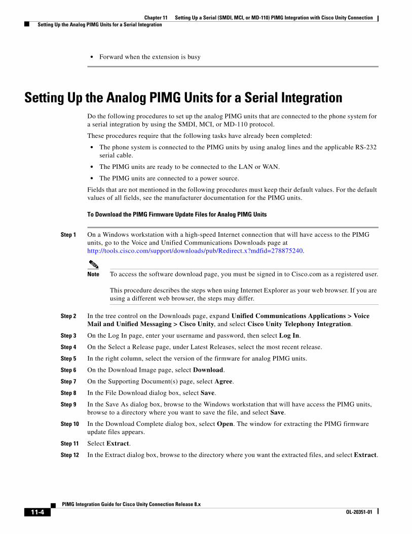
Chapter 11 Setting Up a Serial (SMDI, MCI, or MD-110) PIMG Integration with Cisco Unity Connection Setting Up the Analog PIMG Units for a Serial Integration
• Forward when the extension is busy
Setting Up the Analog PIMG Units for a Serial IntegrationDo the following procedures to set up the analog PIMG units that are connected to the phone system for a serial integration by using the SMDI, MCI, or MD-110 protocol.
These procedures require that the following tasks have already been completed:
• The phone system is connected to the PIMG units by using analog lines and the applicable RS-232 serial cable.
• The PIMG units are ready to be connected to the LAN or WAN.
• The PIMG units are connected to a power source.
Fields that are not mentioned in the following procedures must keep their default values. For the default values of all fields, see the manufacturer documentation for the PIMG units.
To Download the PIMG Firmware Update Files for Analog PIMG Units
Step 1 On a Windows workstation with a high-speed Internet connection that will have access to the PIMG units, go to the Voice and Unified Communications Downloads page at http://tools.cisco.com/support/downloads/pub/Redirect.x?mdfid=278875240.
Note To access the software download page, you must be signed in to Cisco.com as a registered user. This procedure describes the steps when using Internet Explorer as your web browser. If you are using a different web browser, the steps may differ.
Step 2 In the tree control on the Downloads page, expand Unified Communications Applications > Voice Mail and Unified Messaging > Cisco Unity, and select Cisco Unity Telephony Integration.
Step 3 On the Log In page, enter your username and password, then select Log In.
Step 4 On the Select a Release page, under Latest Releases, select the most recent release.
Step 5 In the right column, select the version of the firmware for analog PIMG units.
Step 6 On the Download Image page, select Download.
Step 7 On the Supporting Document(s) page, select Agree.
Step 8 In the File Download dialog box, select Save.
Step 9 In the Save As dialog box, browse to the Windows workstation that will have access the PIMG units, browse to a directory where you want to save the file, and select Save.
Step 10 In the Download Complete dialog box, select Open. The window for extracting the PIMG firmware update files appears.
Step 11 Select Extract.
Step 12 In the Extract dialog box, browse to the directory where you want the extracted files, and select Extract.
11-4PIMG Integration Guide for Cisco Unity Connection Release 8.x
OL-20351-01
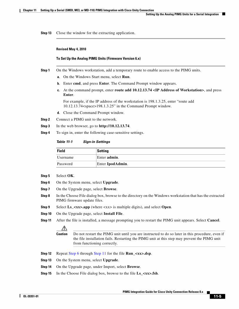
Chapter 11 Setting Up a Serial (SMDI, MCI, or MD-110) PIMG Integration with Cisco Unity Connection Setting Up the Analog PIMG Units for a Serial Integration
Step 13 Close the window for the extracting application.
Revised May 4, 2010
To Set Up the Analog PIMG Units (Firmware Version 6.x)
Step 1 On the Windows workstation, add a temporary route to enable access to the PIMG units.
a. On the Windows Start menu, select Run.
b. Enter cmd, and press Enter. The Command Prompt window appears.
c. At the command prompt, enter route add 10.12.13.74 <IP Address of Workstation>, and press Enter.
For example, if the IP address of the workstation is 198.1.3.25, enter “route add 10.12.13.74<space>198.1.3.25” in the Command Prompt window.
d. Close the Command Prompt window.
Step 2 Connect a PIMG unit to the network.
Step 3 In the web browser, go to http://10.12.13.74.
Step 4 To sign in, enter the following case-sensitive settings.
Step 5 Select OK.
Step 6 On the System menu, select Upgrade.
Step 7 On the Upgrade page, select Browse.
Step 8 In the Choose File dialog box, browse to the directory on the Windows workstation that has the extracted PIMG firmware update files.
Step 9 Select Ls_<xx>.app (where <xx> is multiple digits), and select Open.
Step 10 On the Upgrade page, select Install File.
Step 11 After the file is installed, a message prompting you to restart the PIMG unit appears. Select Cancel.
Caution Do not restart the PIMG unit until you are instructed to do so later in this procedure, even if the file installation fails. Restarting the PIMG unit at this step may prevent the PIMG unit from functioning correctly.
Step 12 Repeat Step 6 through Step 11 for the file Run_<xx>.dsp.
Step 13 On the System menu, select Upgrade.
Step 14 On the Upgrade page, under Import, select Browse.
Step 15 In the Choose File dialog box, browse to the file Ls_<xx>.fsh.
Table 11-1 Sign-in Settings
Field Setting
Username Enter admin.
Password Enter IpodAdmin.
11-5PIMG Integration Guide for Cisco Unity Connection Release 8.x
OL-20351-01
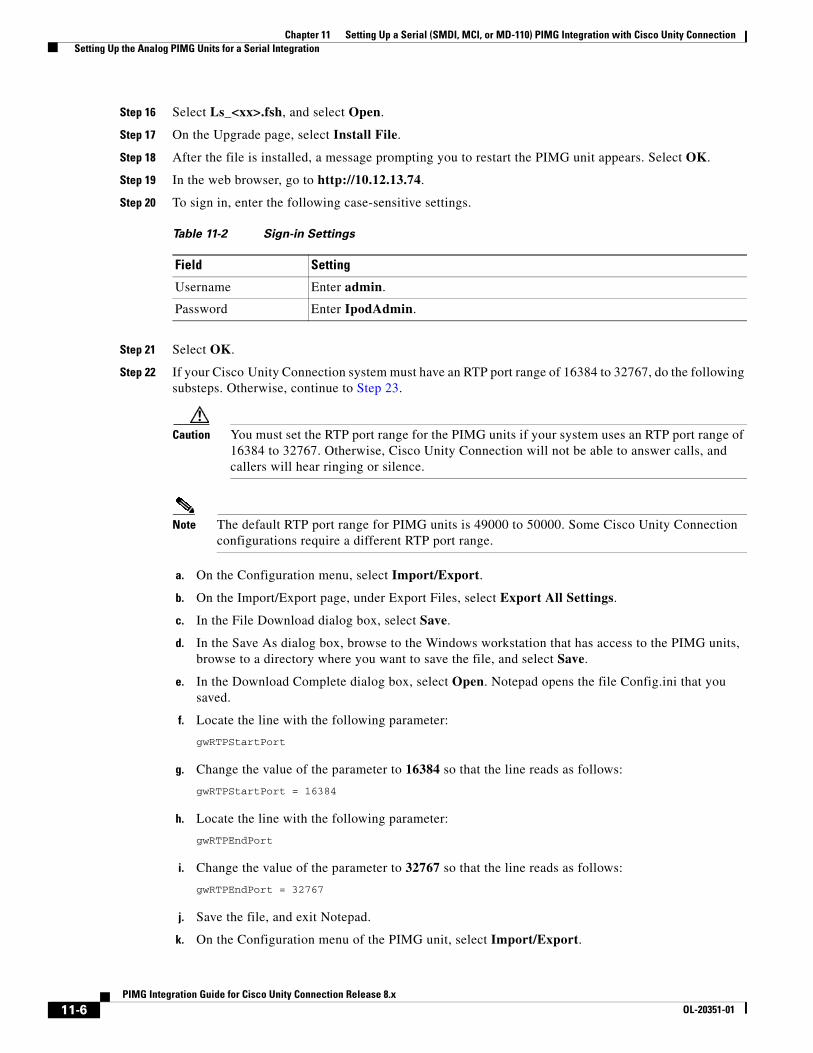
Chapter 11 Setting Up a Serial (SMDI, MCI, or MD-110) PIMG Integration with Cisco Unity Connection Setting Up the Analog PIMG Units for a Serial Integration
Step 16 Select Ls_<xx>.fsh, and select Open.
Step 17 On the Upgrade page, select Install File.
Step 18 After the file is installed, a message prompting you to restart the PIMG unit appears. Select OK.
Step 19 In the web browser, go to http://10.12.13.74.
Step 20 To sign in, enter the following case-sensitive settings.
Step 21 Select OK.
Step 22 If your Cisco Unity Connection system must have an RTP port range of 16384 to 32767, do the following substeps. Otherwise, continue to Step 23.
Caution You must set the RTP port range for the PIMG units if your system uses an RTP port range of 16384 to 32767. Otherwise, Cisco Unity Connection will not be able to answer calls, and callers will hear ringing or silence.
Note The default RTP port range for PIMG units is 49000 to 50000. Some Cisco Unity Connection configurations require a different RTP port range.
a. On the Configuration menu, select Import/Export.
b. On the Import/Export page, under Export Files, select Export All Settings.
c. In the File Download dialog box, select Save.
d. In the Save As dialog box, browse to the Windows workstation that has access to the PIMG units, browse to a directory where you want to save the file, and select Save.
e. In the Download Complete dialog box, select Open. Notepad opens the file Config.ini that you saved.
f. Locate the line with the following parameter:
gwRTPStartPort
g. Change the value of the parameter to 16384 so that the line reads as follows:
gwRTPStartPort = 16384
h. Locate the line with the following parameter:
gwRTPEndPort
i. Change the value of the parameter to 32767 so that the line reads as follows:
gwRTPEndPort = 32767
j. Save the file, and exit Notepad.
k. On the Configuration menu of the PIMG unit, select Import/Export.
Table 11-2 Sign-in Settings
Field Setting
Username Enter admin.
Password Enter IpodAdmin.
11-6PIMG Integration Guide for Cisco Unity Connection Release 8.x
OL-20351-01
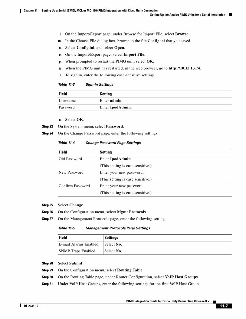
Chapter 11 Setting Up a Serial (SMDI, MCI, or MD-110) PIMG Integration with Cisco Unity Connection Setting Up the Analog PIMG Units for a Serial Integration
l. On the Import/Export page, under Browse for Import File, select Browse.
m. In the Choose File dialog box, browse to the file Config.ini that you saved.
n. Select Config.ini, and select Open.
o. On the Import/Export page, select Import File.
p. When prompted to restart the PIMG unit, select OK.
q. When the PIMG unit has restarted, in the web browser, go to http://10.12.13.74.
r. To sign in, enter the following case-sensitive settings.
s. Select OK.
Step 23 On the System menu, select Password.
Step 24 On the Change Password page, enter the following settings.
Step 25 Select Change.
Step 26 On the Configuration menu, select Mgmt Protocols.
Step 27 On the Management Protocols page, enter the following settings.
Step 28 Select Submit.
Step 29 On the Configuration menu, select Routing Table.
Step 30 On the Routing Table page, under Router Configuration, select VoIP Host Groups.
Step 31 Under VoIP Host Groups, enter the following settings for the first VoIP Host Group.
Table 11-3 Sign-in Settings
Field Setting
Username Enter admin.
Password Enter IpodAdmin.
Table 11-4 Change Password Page Settings
Field Setting
Old Password Enter IpodAdmin.
(This setting is case sensitive.)
New Password Enter your new password.
(This setting is case sensitive.)
Confirm Password Enter your new password.
(This setting is case sensitive.)
Table 11-5 Management Protocols Page Settings
Field Settings
E-mail Alarms Enabled Select No.
SNMP Traps Enabled Select No.
11-7PIMG Integration Guide for Cisco Unity Connection Release 8.x
OL-20351-01
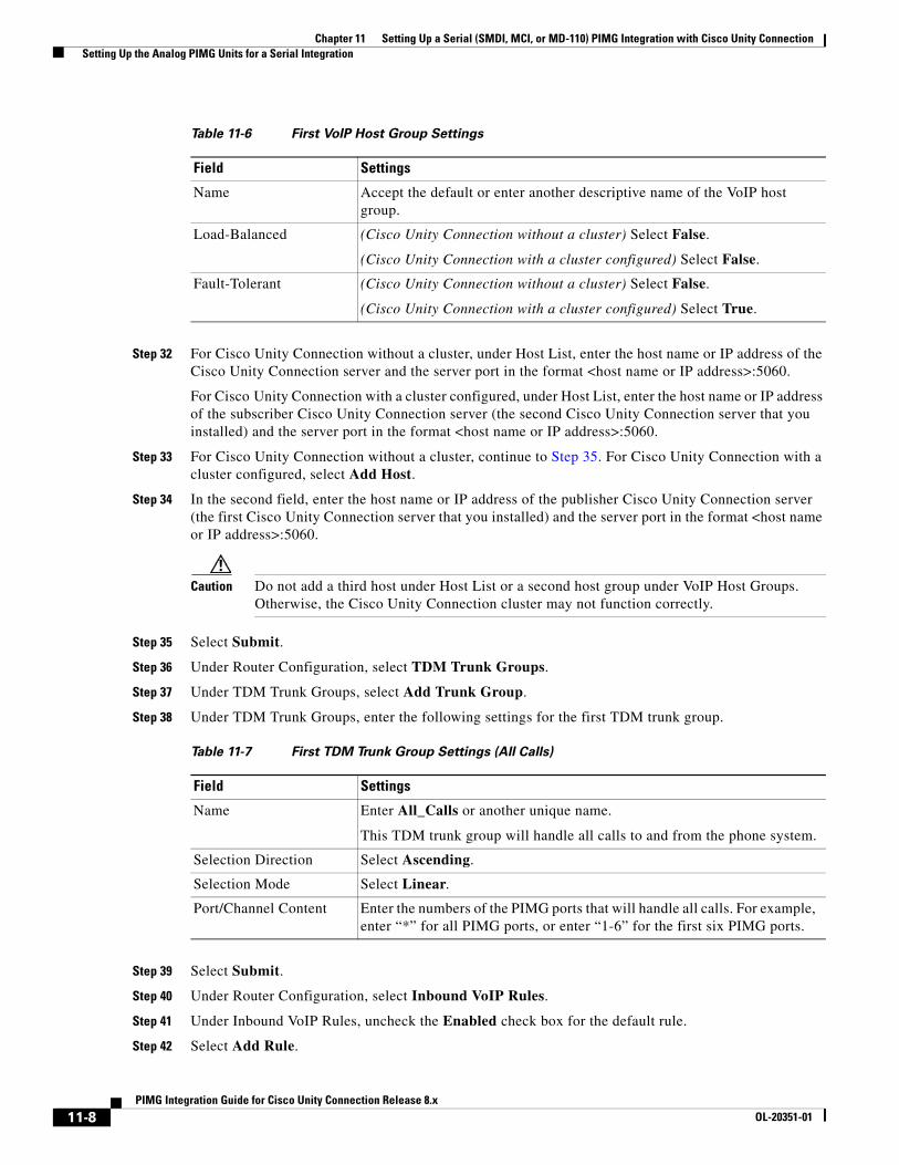
Chapter 11 Setting Up a Serial (SMDI, MCI, or MD-110) PIMG Integration with Cisco Unity Connection Setting Up the Analog PIMG Units for a Serial Integration
Step 32 For Cisco Unity Connection without a cluster, under Host List, enter the host name or IP address of the Cisco Unity Connection server and the server port in the format <host name or IP address>:5060.
For Cisco Unity Connection with a cluster configured, under Host List, enter the host name or IP address of the subscriber Cisco Unity Connection server (the second Cisco Unity Connection server that you installed) and the server port in the format <host name or IP address>:5060.
Step 33 For Cisco Unity Connection without a cluster, continue to Step 35. For Cisco Unity Connection with a cluster configured, select Add Host.
Step 34 In the second field, enter the host name or IP address of the publisher Cisco Unity Connection server (the first Cisco Unity Connection server that you installed) and the server port in the format <host name or IP address>:5060.
Caution Do not add a third host under Host List or a second host group under VoIP Host Groups. Otherwise, the Cisco Unity Connection cluster may not function correctly.
Step 35 Select Submit.
Step 36 Under Router Configuration, select TDM Trunk Groups.
Step 37 Under TDM Trunk Groups, select Add Trunk Group.
Step 38 Under TDM Trunk Groups, enter the following settings for the first TDM trunk group.
Step 39 Select Submit.
Step 40 Under Router Configuration, select Inbound VoIP Rules.
Step 41 Under Inbound VoIP Rules, uncheck the Enabled check box for the default rule.
Step 42 Select Add Rule.
Table 11-6 First VoIP Host Group Settings
Field Settings
Name Accept the default or enter another descriptive name of the VoIP host group.
Load-Balanced (Cisco Unity Connection without a cluster) Select False.
(Cisco Unity Connection with a cluster configured) Select False.
Fault-Tolerant (Cisco Unity Connection without a cluster) Select False.
(Cisco Unity Connection with a cluster configured) Select True.
Table 11-7 First TDM Trunk Group Settings (All Calls)
Field Settings
Name Enter All_Calls or another unique name.
This TDM trunk group will handle all calls to and from the phone system.
Selection Direction Select Ascending.
Selection Mode Select Linear.
Port/Channel Content Enter the numbers of the PIMG ports that will handle all calls. For example, enter “*” for all PIMG ports, or enter “1-6” for the first six PIMG ports.
11-8PIMG Integration Guide for Cisco Unity Connection Release 8.x
OL-20351-01
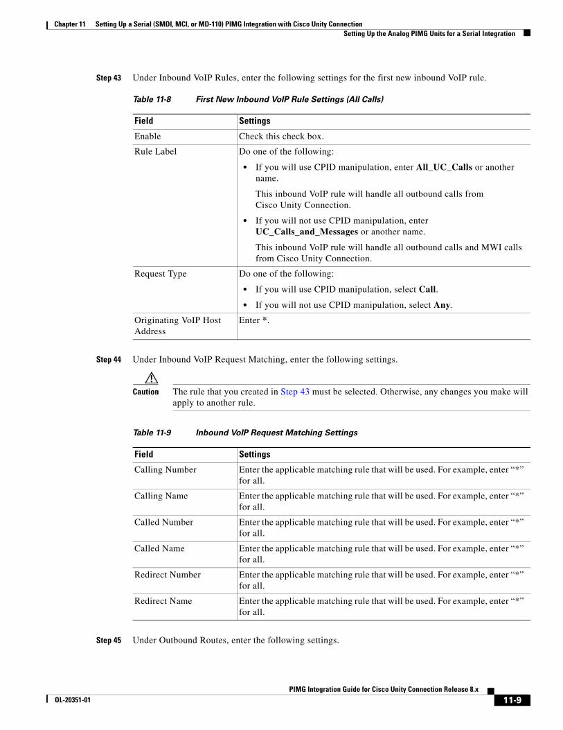
Chapter 11 Setting Up a Serial (SMDI, MCI, or MD-110) PIMG Integration with Cisco Unity Connection Setting Up the Analog PIMG Units for a Serial Integration
Step 43 Under Inbound VoIP Rules, enter the following settings for the first new inbound VoIP rule.
Step 44 Under Inbound VoIP Request Matching, enter the following settings.
Caution The rule that you created in Step 43 must be selected. Otherwise, any changes you make will apply to another rule.
Step 45 Under Outbound Routes, enter the following settings.
Table 11-8 First New Inbound VoIP Rule Settings (All Calls)
Field Settings
Enable Check this check box.
Rule Label Do one of the following:
• If you will use CPID manipulation, enter All_UC_Calls or another name.
This inbound VoIP rule will handle all outbound calls from Cisco Unity Connection.
• If you will not use CPID manipulation, enter UC_Calls_and_Messages or another name.
This inbound VoIP rule will handle all outbound calls and MWI calls from Cisco Unity Connection.
Request Type Do one of the following:
• If you will use CPID manipulation, select Call.
• If you will not use CPID manipulation, select Any.
Originating VoIP Host Address
Enter *.
Table 11-9 Inbound VoIP Request Matching Settings
Field Settings
Calling Number Enter the applicable matching rule that will be used. For example, enter “*” for all.
Calling Name Enter the applicable matching rule that will be used. For example, enter “*” for all.
Called Number Enter the applicable matching rule that will be used. For example, enter “*” for all.
Called Name Enter the applicable matching rule that will be used. For example, enter “*” for all.
Redirect Number Enter the applicable matching rule that will be used. For example, enter “*” for all.
Redirect Name Enter the applicable matching rule that will be used. For example, enter “*” for all.
11-9PIMG Integration Guide for Cisco Unity Connection Release 8.x
OL-20351-01
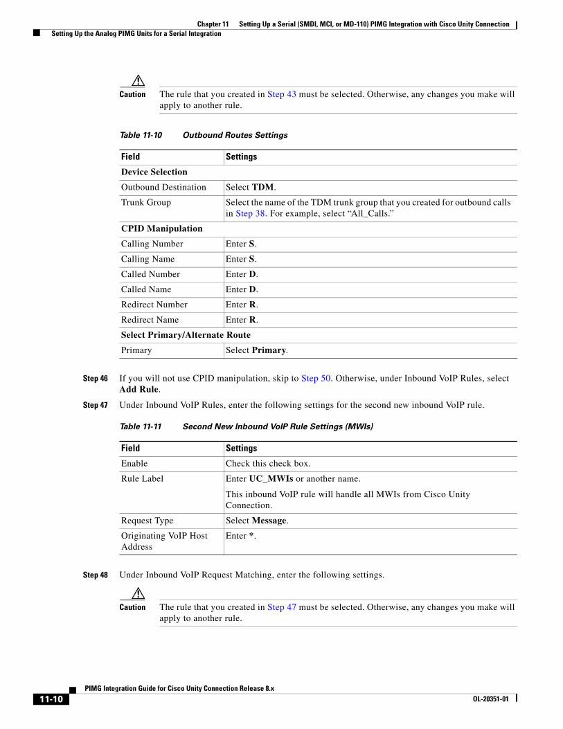
Chapter 11 Setting Up a Serial (SMDI, MCI, or MD-110) PIMG Integration with Cisco Unity Connection Setting Up the Analog PIMG Units for a Serial Integration
Caution The rule that you created in Step 43 must be selected. Otherwise, any changes you make will apply to another rule.
Step 46 If you will not use CPID manipulation, skip to Step 50. Otherwise, under Inbound VoIP Rules, select Add Rule.
Step 47 Under Inbound VoIP Rules, enter the following settings for the second new inbound VoIP rule.
Step 48 Under Inbound VoIP Request Matching, enter the following settings.
Caution The rule that you created in Step 47 must be selected. Otherwise, any changes you make will apply to another rule.
Table 11-10 Outbound Routes Settings
Field Settings
Device Selection
Outbound Destination Select TDM.
Trunk Group Select the name of the TDM trunk group that you created for outbound calls in Step 38. For example, select “All_Calls.”
CPID Manipulation
Calling Number Enter S.
Calling Name Enter S.
Called Number Enter D.
Called Name Enter D.
Redirect Number Enter R.
Redirect Name Enter R.
Select Primary/Alternate Route
Primary Select Primary.
Table 11-11 Second New Inbound VoIP Rule Settings (MWIs)
Field Settings
Enable Check this check box.
Rule Label Enter UC_MWIs or another name.
This inbound VoIP rule will handle all MWIs from Cisco Unity Connection.
Request Type Select Message.
Originating VoIP Host Address
Enter *.
11-10PIMG Integration Guide for Cisco Unity Connection Release 8.x
OL-20351-01
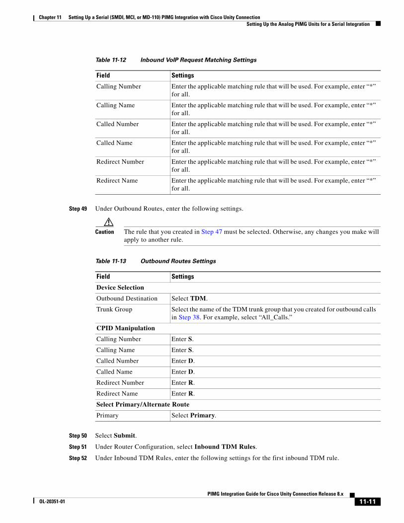
Chapter 11 Setting Up a Serial (SMDI, MCI, or MD-110) PIMG Integration with Cisco Unity Connection Setting Up the Analog PIMG Units for a Serial Integration
Step 49 Under Outbound Routes, enter the following settings.
Caution The rule that you created in Step 47 must be selected. Otherwise, any changes you make will apply to another rule.
Step 50 Select Submit.
Step 51 Under Router Configuration, select Inbound TDM Rules.
Step 52 Under Inbound TDM Rules, enter the following settings for the first inbound TDM rule.
Table 11-12 Inbound VoIP Request Matching Settings
Field Settings
Calling Number Enter the applicable matching rule that will be used. For example, enter “*” for all.
Calling Name Enter the applicable matching rule that will be used. For example, enter “*” for all.
Called Number Enter the applicable matching rule that will be used. For example, enter “*” for all.
Called Name Enter the applicable matching rule that will be used. For example, enter “*” for all.
Redirect Number Enter the applicable matching rule that will be used. For example, enter “*” for all.
Redirect Name Enter the applicable matching rule that will be used. For example, enter “*” for all.
Table 11-13 Outbound Routes Settings
Field Settings
Device Selection
Outbound Destination Select TDM.
Trunk Group Select the name of the TDM trunk group that you created for outbound calls in Step 38. For example, select “All_Calls.”
CPID Manipulation
Calling Number Enter S.
Calling Name Enter S.
Called Number Enter D.
Called Name Enter D.
Redirect Number Enter R.
Redirect Name Enter R.
Select Primary/Alternate Route
Primary Select Primary.
11-11PIMG Integration Guide for Cisco Unity Connection Release 8.x
OL-20351-01
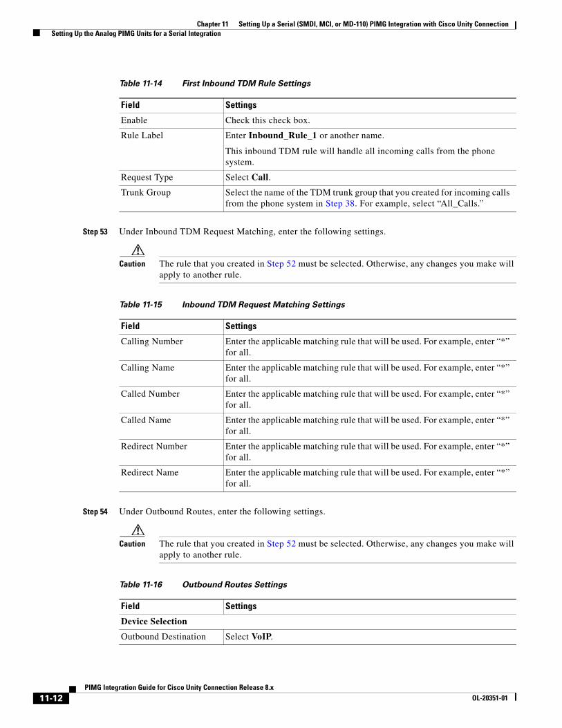
Chapter 11 Setting Up a Serial (SMDI, MCI, or MD-110) PIMG Integration with Cisco Unity Connection Setting Up the Analog PIMG Units for a Serial Integration
Step 53 Under Inbound TDM Request Matching, enter the following settings.
Caution The rule that you created in Step 52 must be selected. Otherwise, any changes you make will apply to another rule.
Step 54 Under Outbound Routes, enter the following settings.
Caution The rule that you created in Step 52 must be selected. Otherwise, any changes you make will apply to another rule.
Table 11-14 First Inbound TDM Rule Settings
Field Settings
Enable Check this check box.
Rule Label Enter Inbound_Rule_1 or another name.
This inbound TDM rule will handle all incoming calls from the phone system.
Request Type Select Call.
Trunk Group Select the name of the TDM trunk group that you created for incoming calls from the phone system in Step 38. For example, select “All_Calls.”
Table 11-15 Inbound TDM Request Matching Settings
Field Settings
Calling Number Enter the applicable matching rule that will be used. For example, enter “*” for all.
Calling Name Enter the applicable matching rule that will be used. For example, enter “*” for all.
Called Number Enter the applicable matching rule that will be used. For example, enter “*” for all.
Called Name Enter the applicable matching rule that will be used. For example, enter “*” for all.
Redirect Number Enter the applicable matching rule that will be used. For example, enter “*” for all.
Redirect Name Enter the applicable matching rule that will be used. For example, enter “*” for all.
Table 11-16 Outbound Routes Settings
Field Settings
Device Selection
Outbound Destination Select VoIP.
11-12PIMG Integration Guide for Cisco Unity Connection Release 8.x
OL-20351-01
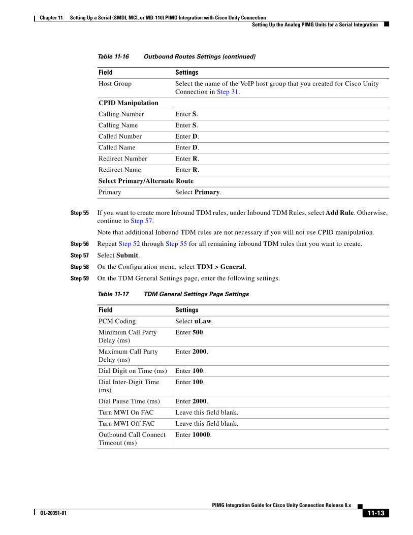
Chapter 11 Setting Up a Serial (SMDI, MCI, or MD-110) PIMG Integration with Cisco Unity Connection Setting Up the Analog PIMG Units for a Serial Integration
Step 55 If you want to create more Inbound TDM rules, under Inbound TDM Rules, select Add Rule. Otherwise, continue to Step 57.
Note that additional Inbound TDM rules are not necessary if you will not use CPID manipulation.
Step 56 Repeat Step 52 through Step 55 for all remaining inbound TDM rules that you want to create.
Step 57 Select Submit.
Step 58 On the Configuration menu, select TDM > General.
Step 59 On the TDM General Settings page, enter the following settings.
Host Group Select the name of the VoIP host group that you created for Cisco Unity Connection in Step 31.
CPID Manipulation
Calling Number Enter S.
Calling Name Enter S.
Called Number Enter D.
Called Name Enter D.
Redirect Number Enter R.
Redirect Name Enter R.
Select Primary/Alternate Route
Primary Select Primary.
Table 11-16 Outbound Routes Settings (continued)
Field Settings
Table 11-17 TDM General Settings Page Settings
Field Settings
PCM Coding Select uLaw.
Minimum Call Party Delay (ms)
Enter 500.
Maximum Call Party Delay (ms)
Enter 2000.
Dial Digit on Time (ms) Enter 100.
Dial Inter-Digit Time (ms)
Enter 100.
Dial Pause Time (ms) Enter 2000.
Turn MWI On FAC Leave this field blank.
Turn MWI Off FAC Leave this field blank.
Outbound Call Connect Timeout (ms)
Enter 10000.
11-13PIMG Integration Guide for Cisco Unity Connection Release 8.x
OL-20351-01
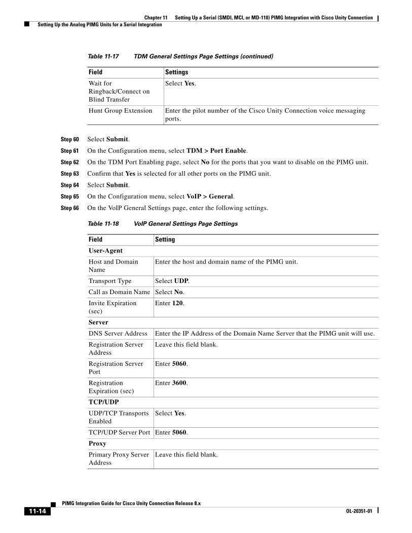
Chapter 11 Setting Up a Serial (SMDI, MCI, or MD-110) PIMG Integration with Cisco Unity Connection Setting Up the Analog PIMG Units for a Serial Integration
Step 60 Select Submit.
Step 61 On the Configuration menu, select TDM > Port Enable.
Step 62 On the TDM Port Enabling page, select No for the ports that you want to disable on the PIMG unit.
Step 63 Confirm that Yes is selected for all other ports on the PIMG unit.
Step 64 Select Submit.
Step 65 On the Configuration menu, select VoIP > General.
Step 66 On the VoIP General Settings page, enter the following settings.
Wait for Ringback/Connect on Blind Transfer
Select Yes.
Hunt Group Extension Enter the pilot number of the Cisco Unity Connection voice messaging ports.
Table 11-18 VoIP General Settings Page Settings
Field Setting
User-Agent
Host and Domain Name
Enter the host and domain name of the PIMG unit.
Transport Type Select UDP.
Call as Domain Name Select No.
Invite Expiration (sec)
Enter 120.
Server
DNS Server Address Enter the IP Address of the Domain Name Server that the PIMG unit will use.
Registration Server Address
Leave this field blank.
Registration Server Port
Enter 5060.
Registration Expiration (sec)
Enter 3600.
TCP/UDP
UDP/TCP Transports Enabled
Select Yes.
TCP/UDP Server Port Enter 5060.
Proxy
Primary Proxy Server Address
Leave this field blank.
Table 11-17 TDM General Settings Page Settings (continued)
Field Settings
11-14PIMG Integration Guide for Cisco Unity Connection Release 8.x
OL-20351-01
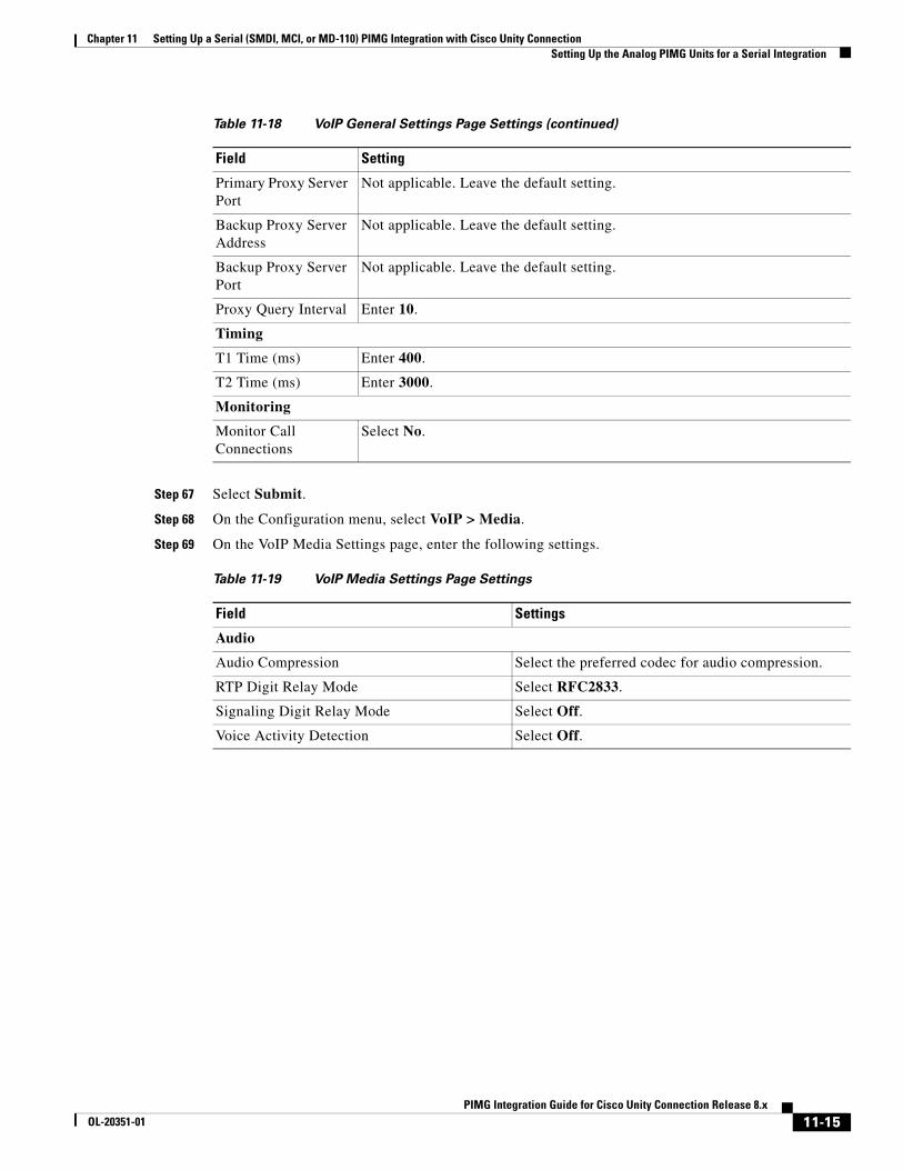
Chapter 11 Setting Up a Serial (SMDI, MCI, or MD-110) PIMG Integration with Cisco Unity Connection Setting Up the Analog PIMG Units for a Serial Integration
Step 67 Select Submit.
Step 68 On the Configuration menu, select VoIP > Media.
Step 69 On the VoIP Media Settings page, enter the following settings.
Primary Proxy Server Port
Not applicable. Leave the default setting.
Backup Proxy Server Address
Not applicable. Leave the default setting.
Backup Proxy Server Port
Not applicable. Leave the default setting.
Proxy Query Interval Enter 10.
Timing
T1 Time (ms) Enter 400.
T2 Time (ms) Enter 3000.
Monitoring
Monitor Call Connections
Select No.
Table 11-19 VoIP Media Settings Page Settings
Field Settings
Audio
Audio Compression Select the preferred codec for audio compression.
RTP Digit Relay Mode Select RFC2833.
Signaling Digit Relay Mode Select Off.
Voice Activity Detection Select Off.
Table 11-18 VoIP General Settings Page Settings (continued)
Field Setting
11-15PIMG Integration Guide for Cisco Unity Connection Release 8.x
OL-20351-01
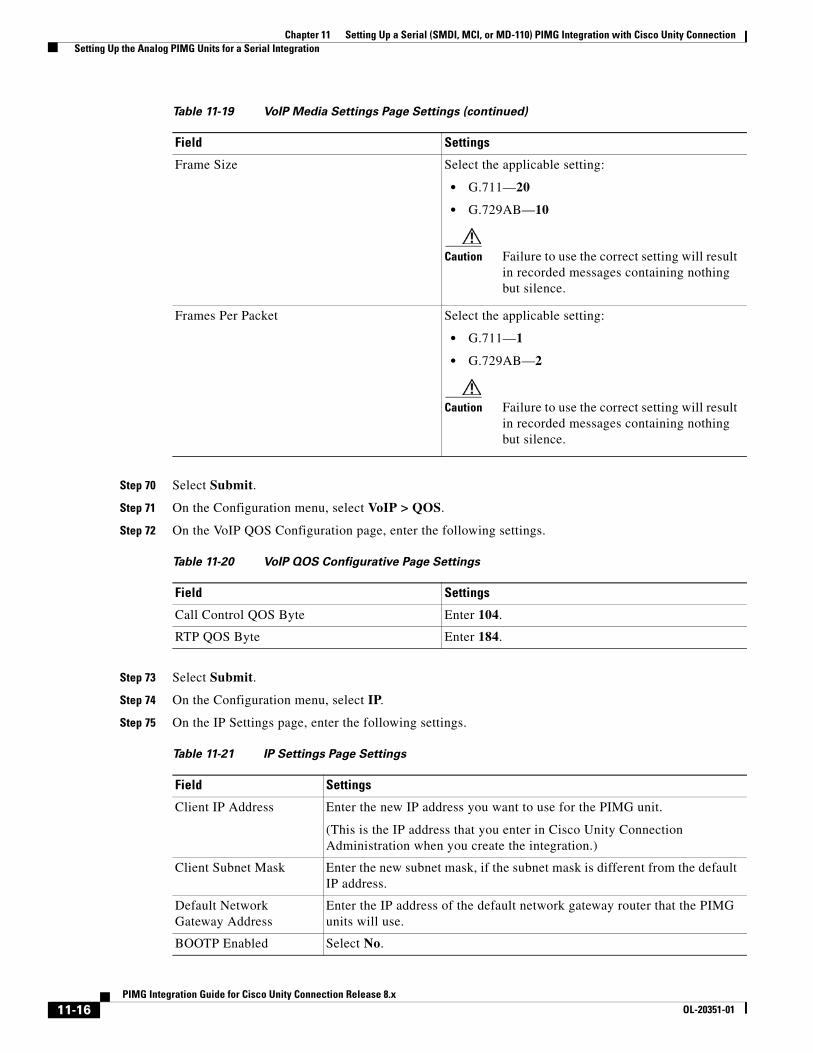
Chapter 11 Setting Up a Serial (SMDI, MCI, or MD-110) PIMG Integration with Cisco Unity Connection Setting Up the Analog PIMG Units for a Serial Integration
Step 70 Select Submit.
Step 71 On the Configuration menu, select VoIP > QOS.
Step 72 On the VoIP QOS Configuration page, enter the following settings.
Step 73 Select Submit.
Step 74 On the Configuration menu, select IP.
Step 75 On the IP Settings page, enter the following settings.
Frame Size Select the applicable setting:
• G.711—20
• G.729AB—10
Caution Failure to use the correct setting will result in recorded messages containing nothing but silence.
Frames Per Packet Select the applicable setting:
• G.711—1
• G.729AB—2
Caution Failure to use the correct setting will result in recorded messages containing nothing but silence.
Table 11-20 VoIP QOS Configurative Page Settings
Field Settings
Call Control QOS Byte Enter 104.
RTP QOS Byte Enter 184.
Table 11-21 IP Settings Page Settings
Field Settings
Client IP Address Enter the new IP address you want to use for the PIMG unit.
(This is the IP address that you enter in Cisco Unity Connection Administration when you create the integration.)
Client Subnet Mask Enter the new subnet mask, if the subnet mask is different from the default IP address.
Default Network Gateway Address
Enter the IP address of the default network gateway router that the PIMG units will use.
BOOTP Enabled Select No.
Table 11-19 VoIP Media Settings Page Settings (continued)
Field Settings
11-16PIMG Integration Guide for Cisco Unity Connection Release 8.x
OL-20351-01
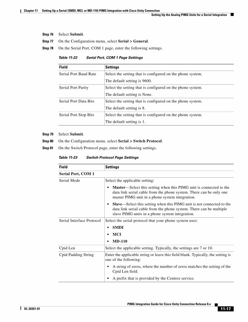
Chapter 11 Setting Up a Serial (SMDI, MCI, or MD-110) PIMG Integration with Cisco Unity Connection Setting Up the Analog PIMG Units for a Serial Integration
Step 76 Select Submit.
Step 77 On the Configuration menu, select Serial > General.
Step 78 On the Serial Port, COM 1 page, enter the following settings.
Step 79 Select Submit.
Step 80 On the Configuration menu, select Serial > Switch Protocol.
Step 81 On the Switch Protocol page, enter the following settings.
Table 11-22 Serial Port, COM 1 Page Settings
Field Settings
Serial Port Baud Rate Select the setting that is configured on the phone system.
The default setting is 9600.
Serial Port Parity Select the setting that is configured on the phone system.
The default setting is None.
Serial Port Data Bits Select the setting that is configured on the phone system.
The default setting is 8.
Serial Port Stop Bits Select the setting that is configured on the phone system.
The default setting is 1.
Table 11-23 Switch Protocol Page Settings
Field Settings
Serial Port, COM 1
Serial Mode Select the applicable setting:
• Master—Select this setting when this PIMG unit is connected to the data link serial cable from the phone system. There can be only one master PIMG unit in a phone system integration.
• Slave—Select this setting when this PIMG unit is not connected to the data link serial cable from the phone system. There can be multiple slave PIMG units in a phone system integration.
Serial Interface Protocol Select the serial protocol that your phone system uses:
• SMDI
• MCI
• MD-110
Cpid Len Select the applicable setting. Typically, the settings are 7 or 10.
Cpid Padding String Enter the applicable string or leave this field blank. Typically, the setting is one of the following:
• A string of zeros, where the number of zeros matches the setting of the Cpid Len field.
• A prefix that is provided by the Centrex service.
11-17PIMG Integration Guide for Cisco Unity Connection Release 8.x
OL-20351-01
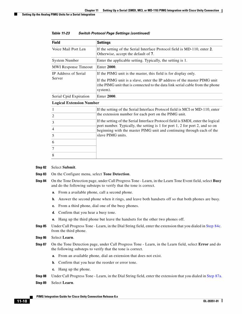
Chapter 11 Setting Up a Serial (SMDI, MCI, or MD-110) PIMG Integration with Cisco Unity Connection Setting Up the Analog PIMG Units for a Serial Integration
Step 82 Select Submit.
Step 83 On the Configure menu, select Tone Detection.
Step 84 On the Tone Detection page, under Call Progress Tone - Learn, in the Learn Tone Event field, select Busy and do the following substeps to verify that the tone is correct.
a. From a available phone, call a second phone.
b. Answer the second phone when it rings, and leave both handsets off so that both phones are busy.
c. From a third phone, dial one of the busy phones.
d. Confirm that you hear a busy tone.
e. Hang up the third phone but leave the handsets for the other two phones off.
Step 85 Under Call Progress Tone - Learn, in the Dial String field, enter the extension that you dialed in Step 84c. from the third phone.
Step 86 Select Learn.
Step 87 On the Tone Detection page, under Call Progress Tone - Learn, in the Learn field, select Error and do the following substeps to verify that the tone is correct.
a. From an available phone, dial an extension that does not exist.
b. Confirm that you hear the reorder or error tone.
c. Hang up the phone.
Step 88 Under Call Progress Tone - Learn, in the Dial String field, enter the extension that you dialed in Step 87a.
Step 89 Select Learn.
Voice Mail Port Len If the setting of the Serial Interface Protocol field is MD-110, enter 2. Otherwise, accept the default of 7.
System Number Enter the applicable setting. Typically, the setting is 1.
MWI Response Timeout Enter 2000.
IP Address of Serial Server
If the PIMG unit is the master, this field is for display only.
If the PIMG unit is a slave, enter the IP address of the master PIMG unit (the PIMG unit that is connected to the data link serial cable from the phone system).
Serial Cpid Expiration Enter 2000.
Logical Extension Number
1 If the setting of the Serial Interface Protocol field is MCI or MD-110, enter the extension number for each port on the PIMG unit.
If the setting of the Serial Interface Protocol field is SMDI, enter the logical port number. Typically, the setting is 1 for port 1, 2 for port 2, and so on beginning with the master PIMG unit and continuing through each of the slave PIMG units.
2
3
4
5
6
7
8
Table 11-23 Switch Protocol Page Settings (continued)
Field Settings
11-18PIMG Integration Guide for Cisco Unity Connection Release 8.x
OL-20351-01
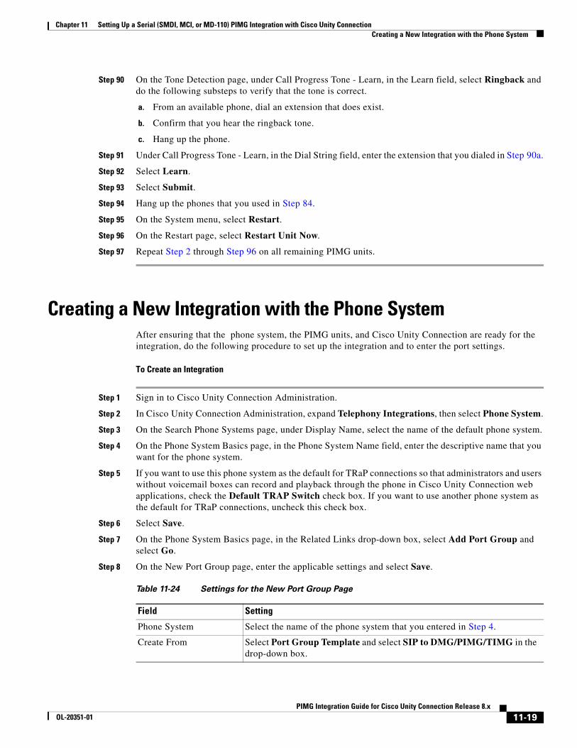
Chapter 11 Setting Up a Serial (SMDI, MCI, or MD-110) PIMG Integration with Cisco Unity Connection Creating a New Integration with the Phone System
Step 90 On the Tone Detection page, under Call Progress Tone - Learn, in the Learn field, select Ringback and do the following substeps to verify that the tone is correct.
a. From an available phone, dial an extension that does exist.
b. Confirm that you hear the ringback tone.
c. Hang up the phone.
Step 91 Under Call Progress Tone - Learn, in the Dial String field, enter the extension that you dialed in Step 90a.
Step 92 Select Learn.
Step 93 Select Submit.
Step 94 Hang up the phones that you used in Step 84.
Step 95 On the System menu, select Restart.
Step 96 On the Restart page, select Restart Unit Now.
Step 97 Repeat Step 2 through Step 96 on all remaining PIMG units.
Creating a New Integration with the Phone SystemAfter ensuring that the phone system, the PIMG units, and Cisco Unity Connection are ready for the integration, do the following procedure to set up the integration and to enter the port settings.
To Create an Integration
Step 1 Sign in to Cisco Unity Connection Administration.
Step 2 In Cisco Unity Connection Administration, expand Telephony Integrations, then select Phone System.
Step 3 On the Search Phone Systems page, under Display Name, select the name of the default phone system.
Step 4 On the Phone System Basics page, in the Phone System Name field, enter the descriptive name that you want for the phone system.
Step 5 If you want to use this phone system as the default for TRaP connections so that administrators and users without voicemail boxes can record and playback through the phone in Cisco Unity Connection web applications, check the Default TRAP Switch check box. If you want to use another phone system as the default for TRaP connections, uncheck this check box.
Step 6 Select Save.
Step 7 On the Phone System Basics page, in the Related Links drop-down box, select Add Port Group and select Go.
Step 8 On the New Port Group page, enter the applicable settings and select Save.
Table 11-24 Settings for the New Port Group Page
Field Setting
Phone System Select the name of the phone system that you entered in Step 4.
Create From Select Port Group Template and select SIP to DMG/PIMG/TIMG in the drop-down box.
11-19PIMG Integration Guide for Cisco Unity Connection Release 8.x
OL-20351-01
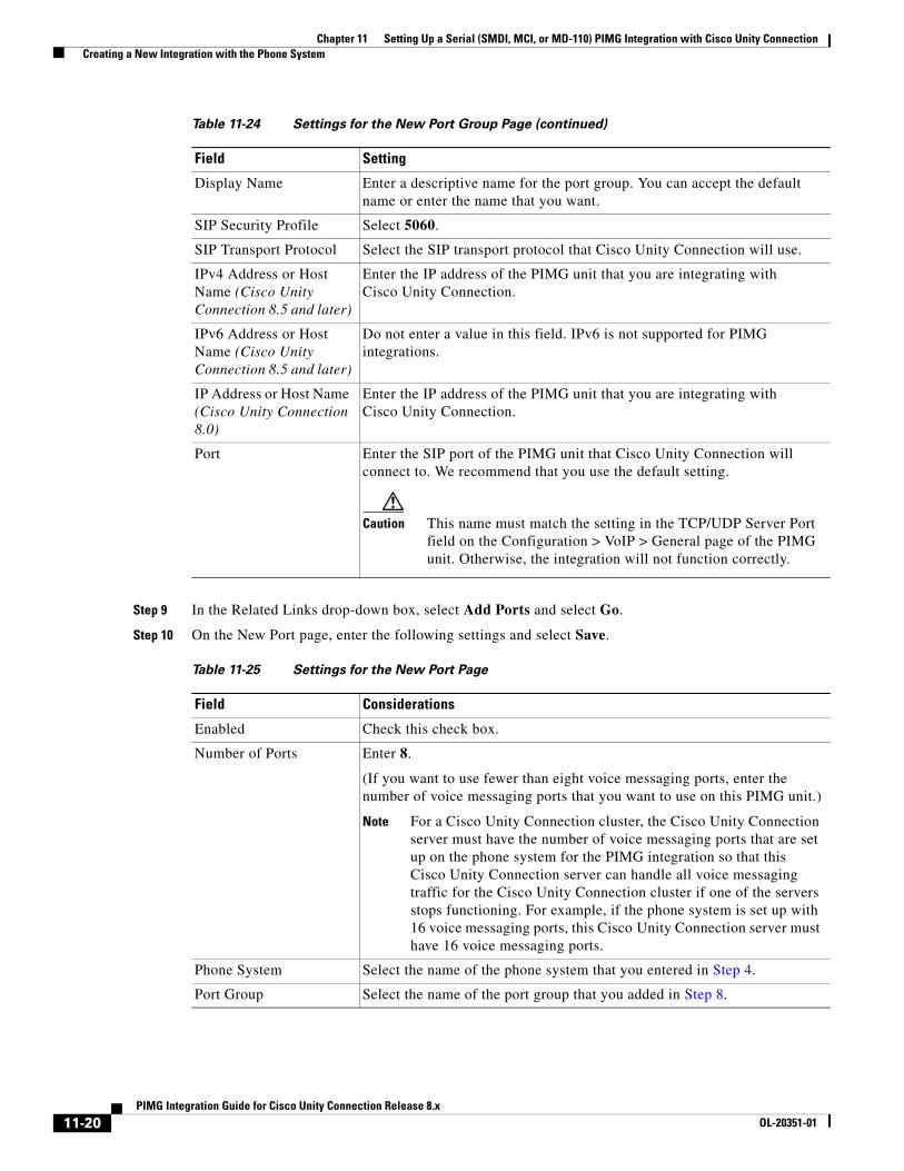
Chapter 11 Setting Up a Serial (SMDI, MCI, or MD-110) PIMG Integration with Cisco Unity Connection Creating a New Integration with the Phone System
Step 9 In the Related Links drop-down box, select Add Ports and select Go.
Step 10 On the New Port page, enter the following settings and select Save.
Display Name Enter a descriptive name for the port group. You can accept the default name or enter the name that you want.
SIP Security Profile Select 5060.
SIP Transport Protocol Select the SIP transport protocol that Cisco Unity Connection will use.
IPv4 Address or Host Name (Cisco Unity Connection 8.5 and later)
Enter the IP address of the PIMG unit that you are integrating with Cisco Unity Connection.
IPv6 Address or Host Name (Cisco Unity Connection 8.5 and later)
Do not enter a value in this field. IPv6 is not supported for PIMG integrations.
IP Address or Host Name (Cisco Unity Connection 8.0)
Enter the IP address of the PIMG unit that you are integrating with Cisco Unity Connection.
Port Enter the SIP port of the PIMG unit that Cisco Unity Connection will connect to. We recommend that you use the default setting.
Caution This name must match the setting in the TCP/UDP Server Port field on the Configuration > VoIP > General page of the PIMG unit. Otherwise, the integration will not function correctly.
Table 11-25 Settings for the New Port Page
Field Considerations
Enabled Check this check box.
Number of Ports Enter 8.
(If you want to use fewer than eight voice messaging ports, enter the number of voice messaging ports that you want to use on this PIMG unit.)
Note For a Cisco Unity Connection cluster, the Cisco Unity Connection server must have the number of voice messaging ports that are set up on the phone system for the PIMG integration so that this Cisco Unity Connection server can handle all voice messaging traffic for the Cisco Unity Connection cluster if one of the servers stops functioning. For example, if the phone system is set up with 16 voice messaging ports, this Cisco Unity Connection server must have 16 voice messaging ports.
Phone System Select the name of the phone system that you entered in Step 4.
Port Group Select the name of the port group that you added in Step 8.
Table 11-24 Settings for the New Port Group Page (continued)
Field Setting
11-20PIMG Integration Guide for Cisco Unity Connection Release 8.x
OL-20351-01
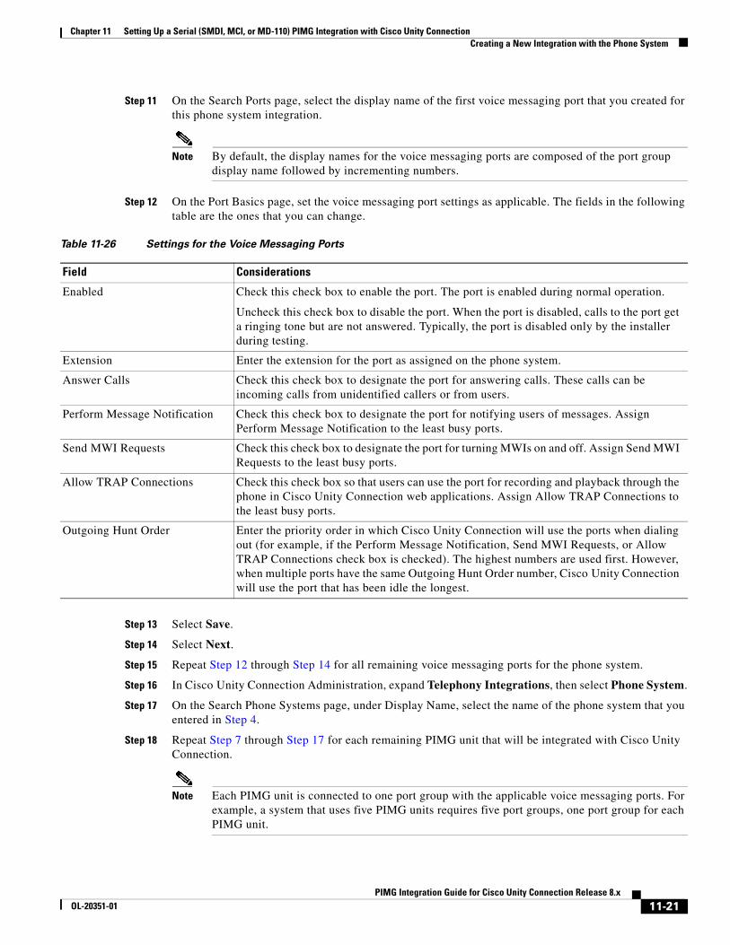
Chapter 11 Setting Up a Serial (SMDI, MCI, or MD-110) PIMG Integration with Cisco Unity Connection Creating a New Integration with the Phone System
Step 11 On the Search Ports page, select the display name of the first voice messaging port that you created for this phone system integration.
Note By default, the display names for the voice messaging ports are composed of the port group display name followed by incrementing numbers.
Step 12 On the Port Basics page, set the voice messaging port settings as applicable. The fields in the following table are the ones that you can change.
Step 13 Select Save.
Step 14 Select Next.
Step 15 Repeat Step 12 through Step 14 for all remaining voice messaging ports for the phone system.
Step 16 In Cisco Unity Connection Administration, expand Telephony Integrations, then select Phone System.
Step 17 On the Search Phone Systems page, under Display Name, select the name of the phone system that you entered in Step 4.
Step 18 Repeat Step 7 through Step 17 for each remaining PIMG unit that will be integrated with Cisco Unity Connection.
Note Each PIMG unit is connected to one port group with the applicable voice messaging ports. For example, a system that uses five PIMG units requires five port groups, one port group for each PIMG unit.
Table 11-26 Settings for the Voice Messaging Ports
Field Considerations
Enabled Check this check box to enable the port. The port is enabled during normal operation.
Uncheck this check box to disable the port. When the port is disabled, calls to the port get a ringing tone but are not answered. Typically, the port is disabled only by the installer during testing.
Extension Enter the extension for the port as assigned on the phone system.
Answer Calls Check this check box to designate the port for answering calls. These calls can be incoming calls from unidentified callers or from users.
Perform Message Notification Check this check box to designate the port for notifying users of messages. Assign Perform Message Notification to the least busy ports.
Send MWI Requests Check this check box to designate the port for turning MWIs on and off. Assign Send MWI Requests to the least busy ports.
Allow TRAP Connections Check this check box so that users can use the port for recording and playback through the phone in Cisco Unity Connection web applications. Assign Allow TRAP Connections to the least busy ports.
Outgoing Hunt Order Enter the priority order in which Cisco Unity Connection will use the ports when dialing out (for example, if the Perform Message Notification, Send MWI Requests, or Allow TRAP Connections check box is checked). The highest numbers are used first. However, when multiple ports have the same Outgoing Hunt Order number, Cisco Unity Connection will use the port that has been idle the longest.
11-21PIMG Integration Guide for Cisco Unity Connection Release 8.x
OL-20351-01
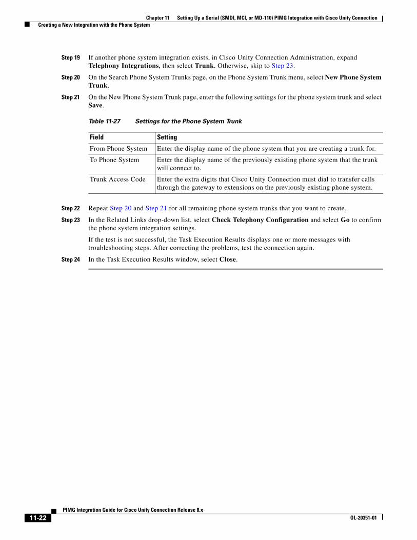
Chapter 11 Setting Up a Serial (SMDI, MCI, or MD-110) PIMG Integration with Cisco Unity Connection Creating a New Integration with the Phone System
Step 19 If another phone system integration exists, in Cisco Unity Connection Administration, expand Telephony Integrations, then select Trunk. Otherwise, skip to Step 23.
Step 20 On the Search Phone System Trunks page, on the Phone System Trunk menu, select New Phone System Trunk.
Step 21 On the New Phone System Trunk page, enter the following settings for the phone system trunk and select Save.
Step 22 Repeat Step 20 and Step 21 for all remaining phone system trunks that you want to create.
Step 23 In the Related Links drop-down list, select Check Telephony Configuration and select Go to confirm the phone system integration settings.
If the test is not successful, the Task Execution Results displays one or more messages with troubleshooting steps. After correcting the problems, test the connection again.
Step 24 In the Task Execution Results window, select Close.
Table 11-27 Settings for the Phone System Trunk
Field Setting
From Phone System Enter the display name of the phone system that you are creating a trunk for.
To Phone System Enter the display name of the previously existing phone system that the trunk will connect to.
Trunk Access Code Enter the extra digits that Cisco Unity Connection must dial to transfer calls through the gateway to extensions on the previously existing phone system.
11-22PIMG Integration Guide for Cisco Unity Connection Release 8.x
OL-20351-01
PIMG IntegrOL-20351-01
C H A P T E R 12
Setting Up a Siemens Hicom 300 E (European) Analog PIMG Integration with Cisco Unity ConnectionFor detailed instructions for setting up a Siemens Hicom 300 E (European) analog PIMG integration with Cisco Unity Connection, see the following sections in this chapter:
• Task List to Create the Integration with a Siemens Hicom 300 E (European) PIMG Phone System, page 12-1
• Requirements, page 12-2
• Programming the Siemens Hicom 300 E (European) PIMG Phone System for Integrating with Cisco Unity Connection, page 12-3
• Setting Up the Analog PIMG Units for a DTMF Integration, page 12-5
• Creating a New Integration with the Siemens Hicom 300 E (European) Phone System, page 12-19
Task List to Create the Integration with a Siemens Hicom 300 E (European) PIMG Phone System
Before doing the following tasks to integrate Cisco Unity Connection with the Siemens Hicom 300 E (European) phone system by using PIMG units (media gateways), confirm that the Cisco Unity Connection server is ready for the integration by completing the applicable tasks in the Cisco Unity Connection Installation Guide.
1. Review the system and equipment requirements to confirm that all phone system and Cisco Unity Connection server requirements have been met. See the “Requirements” section on page 12-2.
2. Plan how the voice messaging ports will be used by Cisco Unity Connection. See Chapter 2, “Planning How the Voice Messaging Ports Will Be Used by Cisco Unity Connection.”
3. Program the Siemens Hicom 300 E (European) phone system and extensions. See the “Programming the Siemens Hicom 300 E (European) PIMG Phone System for Integrating with Cisco Unity Connection” section on page 12-3.
4. Set up the PIMG units. See the “Setting Up the Analog PIMG Units for a DTMF Integration” section on page 12-5.
5. Create the integration. See the “Creating a New Integration with the Siemens Hicom 300 E (European) Phone System” section on page 12-19.
12-1ation Guide for Cisco Unity Connection Release 8.x
Chapter 12 Setting Up a Siemens Hicom 300 E (European) Analog PIMG Integration with Cisco Unity Connection Requirements
6. Test the integration. See Chapter 14, “Testing the Integration.”
7. If this integration is a second or subsequent integration, add the applicable new user templates for the new phone system. See Chapter 15, “Adding New User Templates for Multiple Integrations.”
RequirementsThe Siemens Hicom 300 E (European) integration supports configurations of the following components:
Phone System
• Siemens Hicom 300 E (European) phone system.
• Software version 3.0, release 0.17 or later.
• One or more of the applicable PIMG units. For details, see Chapter 1, “Introduction.”
• The voice messaging ports in the phone system connected by analog lines to the ports on the PIMG units.
To simplify troubleshooting, we recommend that you connect the voice messaging ports on the phone system to the ports on the PIMG units in a planned manner. For example, connect the first phone system voice messaging port to the first port on the first PIMG unit, connect the second phone system voice messaging port to the second port on the first PIMG unit, and so on. Alternatively, if you have multiple PIMG units, you can reduce answer times in the event of a PIMG unit failure by connecting the phone system ports to the PIMG units in a round-robin fashion. For example, connect the first phone system voice messaging port to the first port on the first PIMG unit, connect the second phone system voice messaging port to the first port on the second PIMG unit, and so on.
• The PIMG units connected to the same LAN or WAN that Cisco Unity Connection is connected to.
• If the PIMG units connect to a WAN, the requirements for the WAN network connections are:
– For G.729a codec formatting, a minimum of 32.76 Kbps guaranteed bandwidth for each voice messaging port.
– For G.711 codec formatting, a minimum of 91.56 Kbps guaranteed bandwidth for each voice messaging port.
– No network devices that implement network address translation (NAT).
– A maximum 200 ms one-way network latency.
• The phone system ready for the integration, as described in the documentation for the phone system.
Cisco Unity Connection Server
• Cisco Unity Connection installed and ready for the integration, as described in the Cisco Unity Connection Installation Guide at http://www.cisco.com/en/US/products/ps6509/prod_installation_guides_list.html.
• A license that enables the applicable number of voice messaging ports.
Centralized Voice Messaging
Cisco Unity Connection supports centralized voice messaging through the phone system, which supports various inter-phone system networking protocols including proprietary protocols such as Avaya DCS, Nortel MCDN, or Siemens CorNet, and standards-based protocols such as QSIG or DPNSS. Note that centralized voice messaging is a function of the phone system and its inter-phone system networking, not voicemail. Connection will support centralized voice messaging as long as the phone system and its inter-phone system networking are properly configured. For details, see the “Centralized Voice
12-2PIMG Integration Guide for Cisco Unity Connection Release 8.x
OL-20351-01
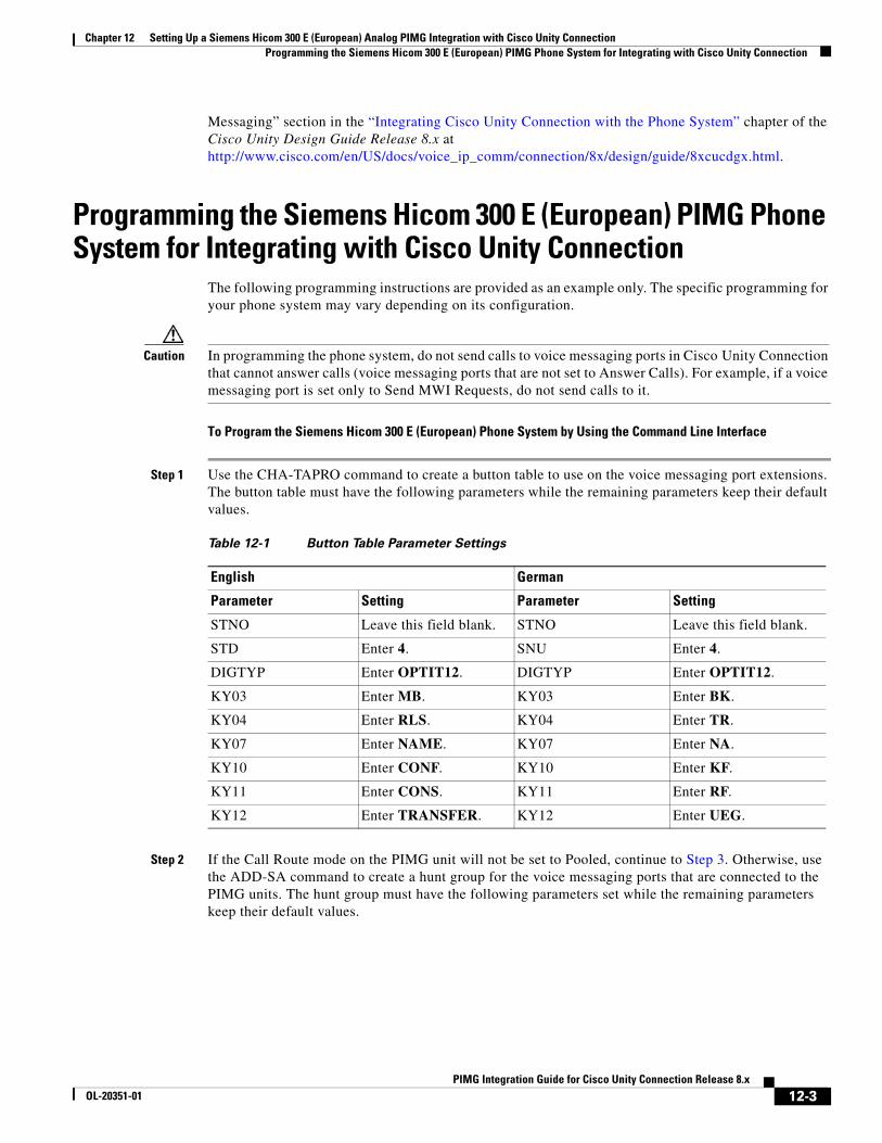
Chapter 12 Setting Up a Siemens Hicom 300 E (European) Analog PIMG Integration with Cisco Unity Connection Programming the Siemens Hicom 300 E (European) PIMG Phone System for Integrating with Cisco Unity Connection
Messaging” section in the “Integrating Cisco Unity Connection with the Phone System” chapter of the Cisco Unity Design Guide Release 8.x at http://www.cisco.com/en/US/docs/voice_ip_comm/connection/8x/design/guide/8xcucdgx.html.
Programming the Siemens Hicom 300 E (European) PIMG Phone System for Integrating with Cisco Unity Connection
The following programming instructions are provided as an example only. The specific programming for your phone system may vary depending on its configuration.
Caution In programming the phone system, do not send calls to voice messaging ports in Cisco Unity Connection that cannot answer calls (voice messaging ports that are not set to Answer Calls). For example, if a voice messaging port is set only to Send MWI Requests, do not send calls to it.
To Program the Siemens Hicom 300 E (European) Phone System by Using the Command Line Interface
Step 1 Use the CHA-TAPRO command to create a button table to use on the voice messaging port extensions. The button table must have the following parameters while the remaining parameters keep their default values.
Step 2 If the Call Route mode on the PIMG unit will not be set to Pooled, continue to Step 3. Otherwise, use the ADD-SA command to create a hunt group for the voice messaging ports that are connected to the PIMG units. The hunt group must have the following parameters set while the remaining parameters keep their default values.
Table 12-1 Button Table Parameter Settings
English German
Parameter Setting Parameter Setting
STNO Leave this field blank. STNO Leave this field blank.
STD Enter 4. SNU Enter 4.
DIGTYP Enter OPTIT12. DIGTYP Enter OPTIT12.
KY03 Enter MB. KY03 Enter BK.
KY04 Enter RLS. KY04 Enter TR.
KY07 Enter NAME. KY07 Enter NA.
KY10 Enter CONF. KY10 Enter KF.
KY11 Enter CONS. KY11 Enter RF.
KY12 Enter TRANSFER. KY12 Enter UEG.
12-3PIMG Integration Guide for Cisco Unity Connection Release 8.x
OL-20351-01
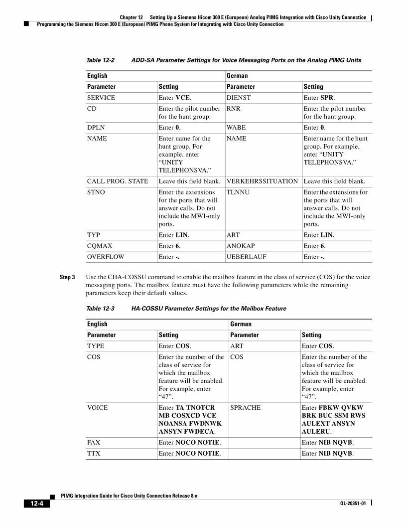
Chapter 12 Setting Up a Siemens Hicom 300 E (European) Analog PIMG Integration with Cisco Unity Connection Programming the Siemens Hicom 300 E (European) PIMG Phone System for Integrating with Cisco Unity Connection
Step 3 Use the CHA-COSSU command to enable the mailbox feature in the class of service (COS) for the voice messaging ports. The mailbox feature must have the following parameters while the remaining parameters keep their default values.
Table 12-2 ADD-SA Parameter Settings for Voice Messaging Ports on the Analog PIMG Units
English German
Parameter Setting Parameter Setting
SERVICE Enter VCE. DIENST Enter SPR.
CD Enter the pilot number for the hunt group.
RNR Enter the pilot number for the hunt group.
DPLN Enter 0. WABE Enter 0.
NAME Enter name for the hunt group. For example, enter “UNITY TELEPHONSVA.”
NAME Enter name for the hunt group. For example, enter “UNITY TELEPHONSVA.”
CALL PROG. STATE Leave this field blank. VERKEHRSSITUATION Leave this field blank.
STNO Enter the extensions for the ports that will answer calls. Do not include the MWI-only ports.
TLNNU Enter the extensions for the ports that will answer calls. Do not include the MWI-only ports.
TYP Enter LIN. ART Enter LIN.
CQMAX Enter 6. ANOKAP Enter 6.
OVERFLOW Enter -. UEBERLAUF Enter -.
Table 12-3 HA-COSSU Parameter Settings for the Mailbox Feature
English German
Parameter Setting Parameter Setting
TYPE Enter COS. ART Enter COS.
COS Enter the number of the class of service for which the mailbox feature will be enabled. For example, enter “47”.
COS Enter the number of the class of service for which the mailbox feature will be enabled. For example, enter “47”.
VOICE Enter TA TNOTCR MB COSXCD VCE NOANSA FWDNWK ANSYN FWDECA.
SPRACHE Enter FBKW QVKW BRK BUC SSM RWS AULEXT ANSYN AULERU.
FAX Enter NOCO NOTIE. Enter NIB NQVB.
TTX Enter NOCO NOTIE. Enter NIB NQVB.
12-4PIMG Integration Guide for Cisco Unity Connection Release 8.x
OL-20351-01
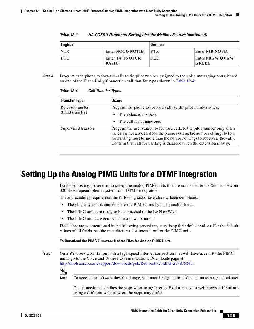
Chapter 12 Setting Up a Siemens Hicom 300 E (European) Analog PIMG Integration with Cisco Unity Connection Setting Up the Analog PIMG Units for a DTMF Integration
Step 4 Program each phone to forward calls to the pilot number assigned to the voice messaging ports, based on one of the Cisco Unity Connection call transfer types shown in Table 12-4.
Setting Up the Analog PIMG Units for a DTMF IntegrationDo the following procedures to set up the analog PIMG units that are connected to the Siemens Hicom 300 E (European) phone system for a DTMF integration.
These procedures require that the following tasks have already been completed:
• The phone system is connected to the PIMG units by using analog lines.
• The PIMG units are ready to be connected to the LAN or WAN.
• The PIMG units are connected to a power source.
Fields that are not mentioned in the following procedures must keep their default values. For the default values of all fields, see the manufacturer documentation for the PIMG units.
To Download the PIMG Firmware Update Files for Analog PIMG Units
Step 1 On a Windows workstation with a high-speed Internet connection that will have access to the PIMG units, go to the Voice and Unified Communications Downloads page at http://tools.cisco.com/support/downloads/pub/Redirect.x?mdfid=278875240.
Note To access the software download page, you must be signed in to Cisco.com as a registered user. This procedure describes the steps when using Internet Explorer as your web browser. If you are using a different web browser, the steps may differ.
VTX Enter NOCO NOTIE. BTX Enter NIB NQVB.
DTE Enter TA TNOTCR BASIC.
DEE Enter FBKW QVKW GRUBE.
Table 12-4 Call Transfer Types
Transfer Type Usage
Release transfer (blind transfer)
Program the phone to forward calls to the pilot number when:
• The extension is busy.
• The call is not answered.
Supervised transfer Program the user station to forward calls to the pilot number only when the call is not answered (on the phone system, the number of rings before forwarding must be more than the number of rings to supervise the call). Confirm that call forwarding is disabled when the extension is busy.
Table 12-3 HA-COSSU Parameter Settings for the Mailbox Feature (continued)
English German
12-5PIMG Integration Guide for Cisco Unity Connection Release 8.x
OL-20351-01
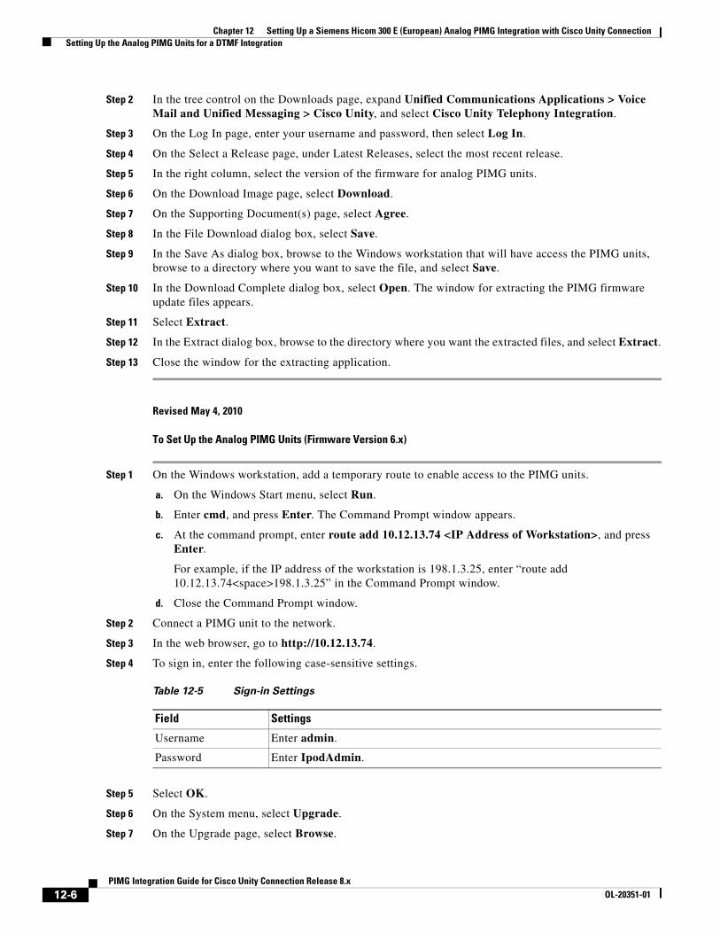
Chapter 12 Setting Up a Siemens Hicom 300 E (European) Analog PIMG Integration with Cisco Unity Connection Setting Up the Analog PIMG Units for a DTMF Integration
Step 2 In the tree control on the Downloads page, expand Unified Communications Applications > Voice Mail and Unified Messaging > Cisco Unity, and select Cisco Unity Telephony Integration.
Step 3 On the Log In page, enter your username and password, then select Log In.
Step 4 On the Select a Release page, under Latest Releases, select the most recent release.
Step 5 In the right column, select the version of the firmware for analog PIMG units.
Step 6 On the Download Image page, select Download.
Step 7 On the Supporting Document(s) page, select Agree.
Step 8 In the File Download dialog box, select Save.
Step 9 In the Save As dialog box, browse to the Windows workstation that will have access the PIMG units, browse to a directory where you want to save the file, and select Save.
Step 10 In the Download Complete dialog box, select Open. The window for extracting the PIMG firmware update files appears.
Step 11 Select Extract.
Step 12 In the Extract dialog box, browse to the directory where you want the extracted files, and select Extract.
Step 13 Close the window for the extracting application.
Revised May 4, 2010
To Set Up the Analog PIMG Units (Firmware Version 6.x)
Step 1 On the Windows workstation, add a temporary route to enable access to the PIMG units.
a. On the Windows Start menu, select Run.
b. Enter cmd, and press Enter. The Command Prompt window appears.
c. At the command prompt, enter route add 10.12.13.74 <IP Address of Workstation>, and press Enter.
For example, if the IP address of the workstation is 198.1.3.25, enter “route add 10.12.13.74<space>198.1.3.25” in the Command Prompt window.
d. Close the Command Prompt window.
Step 2 Connect a PIMG unit to the network.
Step 3 In the web browser, go to http://10.12.13.74.
Step 4 To sign in, enter the following case-sensitive settings.
Step 5 Select OK.
Step 6 On the System menu, select Upgrade.
Step 7 On the Upgrade page, select Browse.
Table 12-5 Sign-in Settings
Field Settings
Username Enter admin.
Password Enter IpodAdmin.
12-6PIMG Integration Guide for Cisco Unity Connection Release 8.x
OL-20351-01
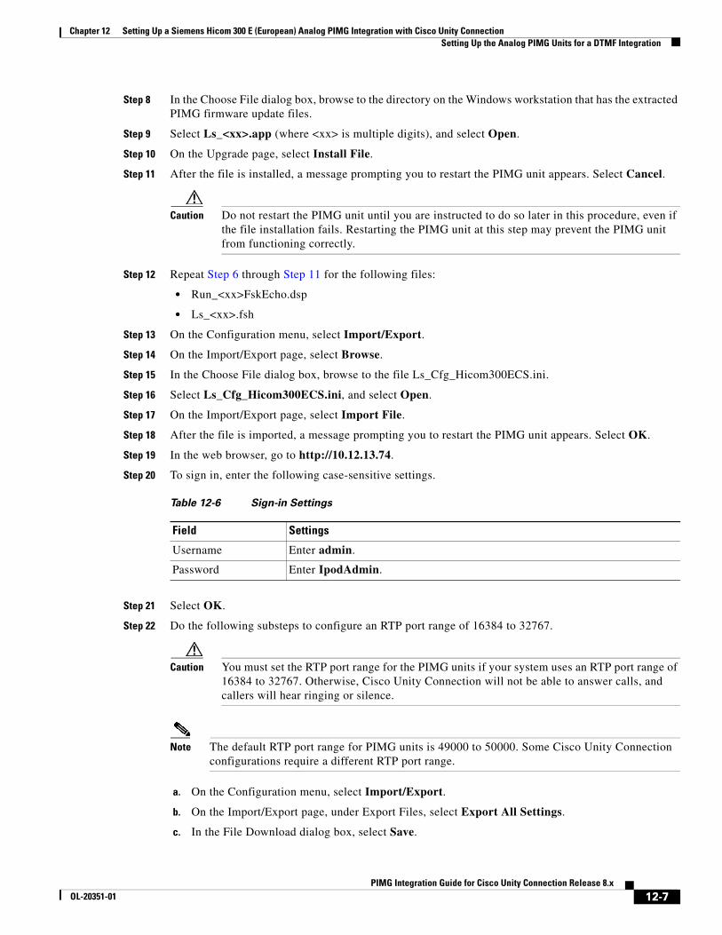
Chapter 12 Setting Up a Siemens Hicom 300 E (European) Analog PIMG Integration with Cisco Unity Connection Setting Up the Analog PIMG Units for a DTMF Integration
Step 8 In the Choose File dialog box, browse to the directory on the Windows workstation that has the extracted PIMG firmware update files.
Step 9 Select Ls_<xx>.app (where <xx> is multiple digits), and select Open.
Step 10 On the Upgrade page, select Install File.
Step 11 After the file is installed, a message prompting you to restart the PIMG unit appears. Select Cancel.
Caution Do not restart the PIMG unit until you are instructed to do so later in this procedure, even if the file installation fails. Restarting the PIMG unit at this step may prevent the PIMG unit from functioning correctly.
Step 12 Repeat Step 6 through Step 11 for the following files:
• Run_<xx>FskEcho.dsp
• Ls_<xx>.fsh
Step 13 On the Configuration menu, select Import/Export.
Step 14 On the Import/Export page, select Browse.
Step 15 In the Choose File dialog box, browse to the file Ls_Cfg_Hicom300ECS.ini.
Step 16 Select Ls_Cfg_Hicom300ECS.ini, and select Open.
Step 17 On the Import/Export page, select Import File.
Step 18 After the file is imported, a message prompting you to restart the PIMG unit appears. Select OK.
Step 19 In the web browser, go to http://10.12.13.74.
Step 20 To sign in, enter the following case-sensitive settings.
Step 21 Select OK.
Step 22 Do the following substeps to configure an RTP port range of 16384 to 32767.
Caution You must set the RTP port range for the PIMG units if your system uses an RTP port range of 16384 to 32767. Otherwise, Cisco Unity Connection will not be able to answer calls, and callers will hear ringing or silence.
Note The default RTP port range for PIMG units is 49000 to 50000. Some Cisco Unity Connection configurations require a different RTP port range.
a. On the Configuration menu, select Import/Export.
b. On the Import/Export page, under Export Files, select Export All Settings.
c. In the File Download dialog box, select Save.
Table 12-6 Sign-in Settings
Field Settings
Username Enter admin.
Password Enter IpodAdmin.
12-7PIMG Integration Guide for Cisco Unity Connection Release 8.x
OL-20351-01
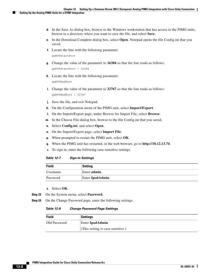
Chapter 12 Setting Up a Siemens Hicom 300 E (European) Analog PIMG Integration with Cisco Unity Connection Setting Up the Analog PIMG Units for a DTMF Integration
d. In the Save As dialog box, browse to the Windows workstation that has access to the PIMG units, browse to a directory where you want to save the file, and select Save.
e. In the Download Complete dialog box, select Open. Notepad opens the file Config.ini that you saved.
f. Locate the line with the following parameter:
gwRTPStartPort
g. Change the value of the parameter to 16384 so that the line reads as follows:
gwRTPStartPort = 16384
h. Locate the line with the following parameter:
gwRTPEndPort
i. Change the value of the parameter to 32767 so that the line reads as follows:
gwRTPEndPort = 32767
j. Save the file, and exit Notepad.
k. On the Configuration menu of the PIMG unit, select Import/Export.
l. On the Import/Export page, under Browse for Import File, select Browse.
m. In the Choose File dialog box, browse to the file Config.ini that you saved.
n. Select Config.ini, and select Open.
o. On the Import/Export page, select Import File.
p. When prompted to restart the PIMG unit, select OK.
q. When the PIMG unit has restarted, in the web browser, go to http://10.12.13.74.
r. To sign in, enter the following case-sensitive settings.
s. Select OK.
Step 23 On the System menu, select Password.
Step 24 On the Change Password page, enter the following settings.
Table 12-7 Sign-in Settings
Field Setting
Username Enter admin.
Password Enter IpodAdmin.
Table 12-8 Change Password Page Settings
Field Settings
Old Password Enter IpodAdmin.
(This setting is case sensitive.)
12-8PIMG Integration Guide for Cisco Unity Connection Release 8.x
OL-20351-01
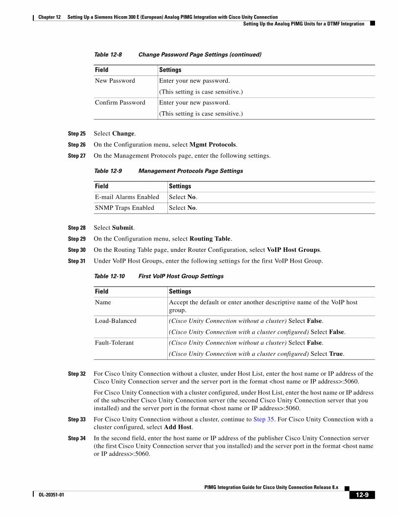
Chapter 12 Setting Up a Siemens Hicom 300 E (European) Analog PIMG Integration with Cisco Unity Connection Setting Up the Analog PIMG Units for a DTMF Integration
Step 25 Select Change.
Step 26 On the Configuration menu, select Mgmt Protocols.
Step 27 On the Management Protocols page, enter the following settings.
Step 28 Select Submit.
Step 29 On the Configuration menu, select Routing Table.
Step 30 On the Routing Table page, under Router Configuration, select VoIP Host Groups.
Step 31 Under VoIP Host Groups, enter the following settings for the first VoIP Host Group.
Step 32 For Cisco Unity Connection without a cluster, under Host List, enter the host name or IP address of the Cisco Unity Connection server and the server port in the format <host name or IP address>:5060.
For Cisco Unity Connection with a cluster configured, under Host List, enter the host name or IP address of the subscriber Cisco Unity Connection server (the second Cisco Unity Connection server that you installed) and the server port in the format <host name or IP address>:5060.
Step 33 For Cisco Unity Connection without a cluster, continue to Step 35. For Cisco Unity Connection with a cluster configured, select Add Host.
Step 34 In the second field, enter the host name or IP address of the publisher Cisco Unity Connection server (the first Cisco Unity Connection server that you installed) and the server port in the format <host name or IP address>:5060.
New Password Enter your new password.
(This setting is case sensitive.)
Confirm Password Enter your new password.
(This setting is case sensitive.)
Table 12-9 Management Protocols Page Settings
Field Settings
E-mail Alarms Enabled Select No.
SNMP Traps Enabled Select No.
Table 12-10 First VoIP Host Group Settings
Field Settings
Name Accept the default or enter another descriptive name of the VoIP host group.
Load-Balanced (Cisco Unity Connection without a cluster) Select False.
(Cisco Unity Connection with a cluster configured) Select False.
Fault-Tolerant (Cisco Unity Connection without a cluster) Select False.
(Cisco Unity Connection with a cluster configured) Select True.
Table 12-8 Change Password Page Settings (continued)
Field Settings
12-9PIMG Integration Guide for Cisco Unity Connection Release 8.x
OL-20351-01
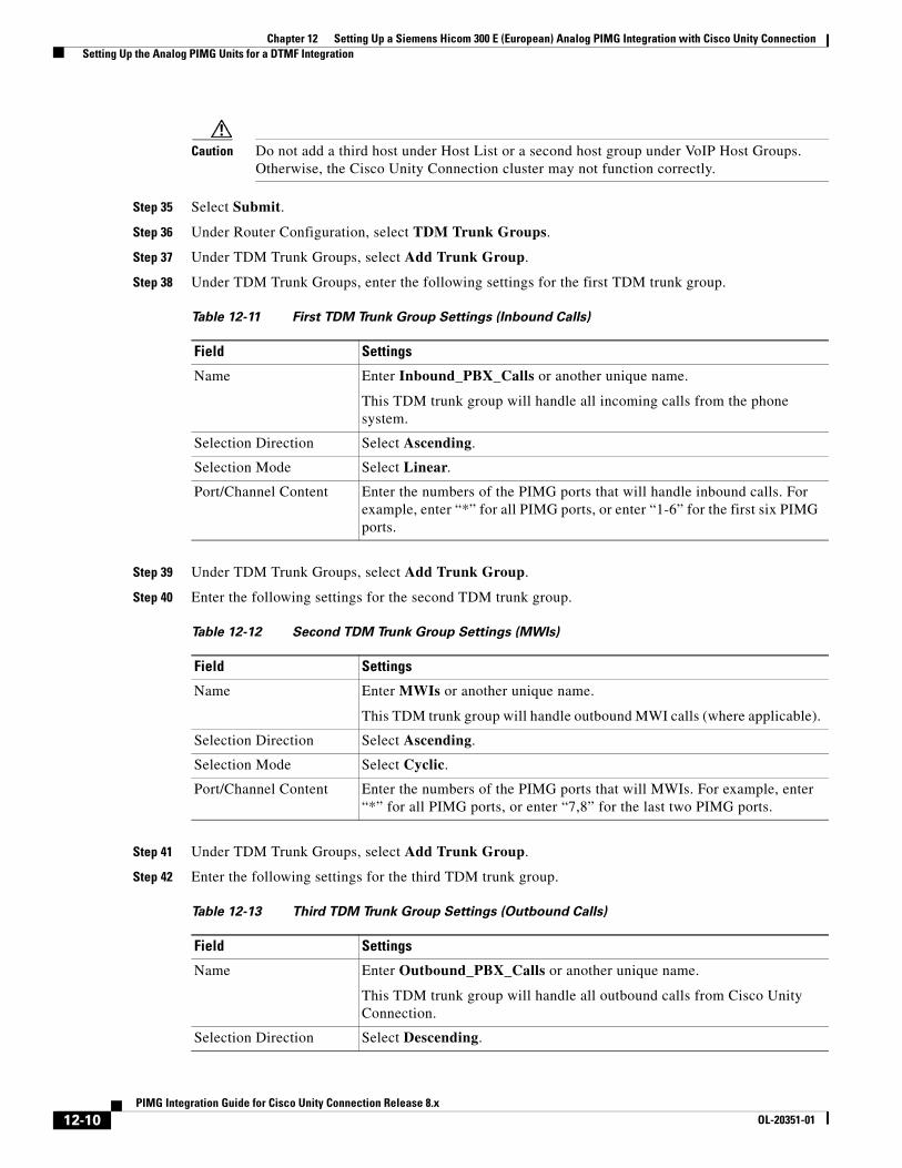
Chapter 12 Setting Up a Siemens Hicom 300 E (European) Analog PIMG Integration with Cisco Unity Connection Setting Up the Analog PIMG Units for a DTMF Integration
Caution Do not add a third host under Host List or a second host group under VoIP Host Groups. Otherwise, the Cisco Unity Connection cluster may not function correctly.
Step 35 Select Submit.
Step 36 Under Router Configuration, select TDM Trunk Groups.
Step 37 Under TDM Trunk Groups, select Add Trunk Group.
Step 38 Under TDM Trunk Groups, enter the following settings for the first TDM trunk group.
Step 39 Under TDM Trunk Groups, select Add Trunk Group.
Step 40 Enter the following settings for the second TDM trunk group.
Step 41 Under TDM Trunk Groups, select Add Trunk Group.
Step 42 Enter the following settings for the third TDM trunk group.
Table 12-11 First TDM Trunk Group Settings (Inbound Calls)
Field Settings
Name Enter Inbound_PBX_Calls or another unique name.
This TDM trunk group will handle all incoming calls from the phone system.
Selection Direction Select Ascending.
Selection Mode Select Linear.
Port/Channel Content Enter the numbers of the PIMG ports that will handle inbound calls. For example, enter “*” for all PIMG ports, or enter “1-6” for the first six PIMG ports.
Table 12-12 Second TDM Trunk Group Settings (MWIs)
Field Settings
Name Enter MWIs or another unique name.
This TDM trunk group will handle outbound MWI calls (where applicable).
Selection Direction Select Ascending.
Selection Mode Select Cyclic.
Port/Channel Content Enter the numbers of the PIMG ports that will MWIs. For example, enter “*” for all PIMG ports, or enter “7,8” for the last two PIMG ports.
Table 12-13 Third TDM Trunk Group Settings (Outbound Calls)
Field Settings
Name Enter Outbound_PBX_Calls or another unique name.
This TDM trunk group will handle all outbound calls from Cisco Unity Connection.
Selection Direction Select Descending.
12-10PIMG Integration Guide for Cisco Unity Connection Release 8.x
OL-20351-01
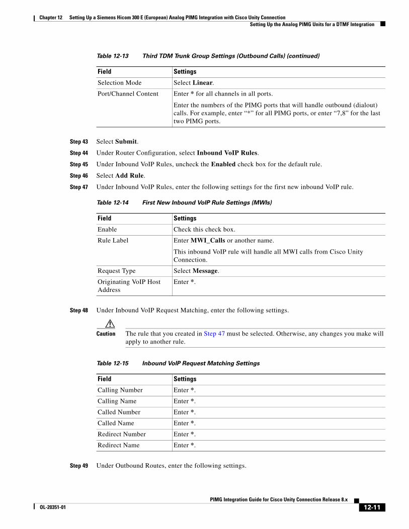
Chapter 12 Setting Up a Siemens Hicom 300 E (European) Analog PIMG Integration with Cisco Unity Connection Setting Up the Analog PIMG Units for a DTMF Integration
Step 43 Select Submit.
Step 44 Under Router Configuration, select Inbound VoIP Rules.
Step 45 Under Inbound VoIP Rules, uncheck the Enabled check box for the default rule.
Step 46 Select Add Rule.
Step 47 Under Inbound VoIP Rules, enter the following settings for the first new inbound VoIP rule.
Step 48 Under Inbound VoIP Request Matching, enter the following settings.
Caution The rule that you created in Step 47 must be selected. Otherwise, any changes you make will apply to another rule.
Step 49 Under Outbound Routes, enter the following settings.
Selection Mode Select Linear.
Port/Channel Content Enter * for all channels in all ports.
Enter the numbers of the PIMG ports that will handle outbound (dialout) calls. For example, enter “*” for all PIMG ports, or enter “7,8” for the last two PIMG ports.
Table 12-14 First New Inbound VoIP Rule Settings (MWIs)
Field Settings
Enable Check this check box.
Rule Label Enter MWI_Calls or another name.
This inbound VoIP rule will handle all MWI calls from Cisco Unity Connection.
Request Type Select Message.
Originating VoIP Host Address
Enter *.
Table 12-13 Third TDM Trunk Group Settings (Outbound Calls) (continued)
Field Settings
Table 12-15 Inbound VoIP Request Matching Settings
Field Settings
Calling Number Enter *.
Calling Name Enter *.
Called Number Enter *.
Called Name Enter *.
Redirect Number Enter *.
Redirect Name Enter *.
12-11PIMG Integration Guide for Cisco Unity Connection Release 8.x
OL-20351-01
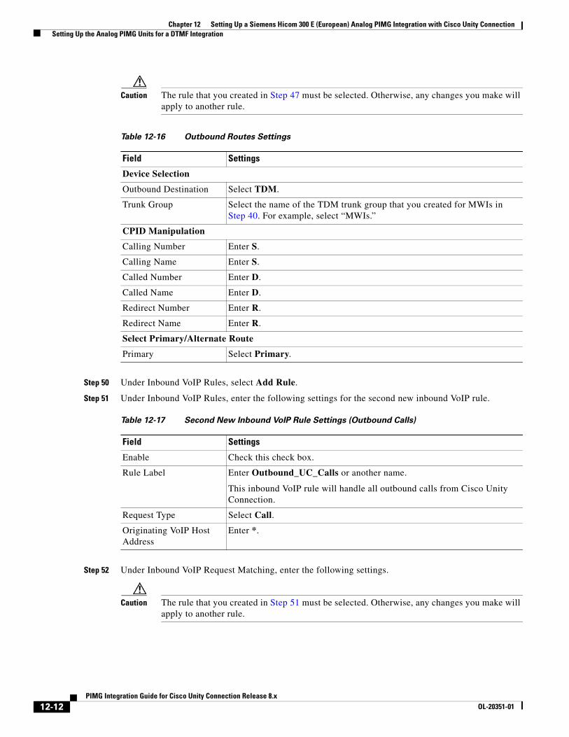
Chapter 12 Setting Up a Siemens Hicom 300 E (European) Analog PIMG Integration with Cisco Unity Connection Setting Up the Analog PIMG Units for a DTMF Integration
Caution The rule that you created in Step 47 must be selected. Otherwise, any changes you make will apply to another rule.
Step 50 Under Inbound VoIP Rules, select Add Rule.
Step 51 Under Inbound VoIP Rules, enter the following settings for the second new inbound VoIP rule.
Step 52 Under Inbound VoIP Request Matching, enter the following settings.
Caution The rule that you created in Step 51 must be selected. Otherwise, any changes you make will apply to another rule.
Table 12-16 Outbound Routes Settings
Field Settings
Device Selection
Outbound Destination Select TDM.
Trunk Group Select the name of the TDM trunk group that you created for MWIs in Step 40. For example, select “MWIs.”
CPID Manipulation
Calling Number Enter S.
Calling Name Enter S.
Called Number Enter D.
Called Name Enter D.
Redirect Number Enter R.
Redirect Name Enter R.
Select Primary/Alternate Route
Primary Select Primary.
Table 12-17 Second New Inbound VoIP Rule Settings (Outbound Calls)
Field Settings
Enable Check this check box.
Rule Label Enter Outbound_UC_Calls or another name.
This inbound VoIP rule will handle all outbound calls from Cisco Unity Connection.
Request Type Select Call.
Originating VoIP Host Address
Enter *.
12-12PIMG Integration Guide for Cisco Unity Connection Release 8.x
OL-20351-01
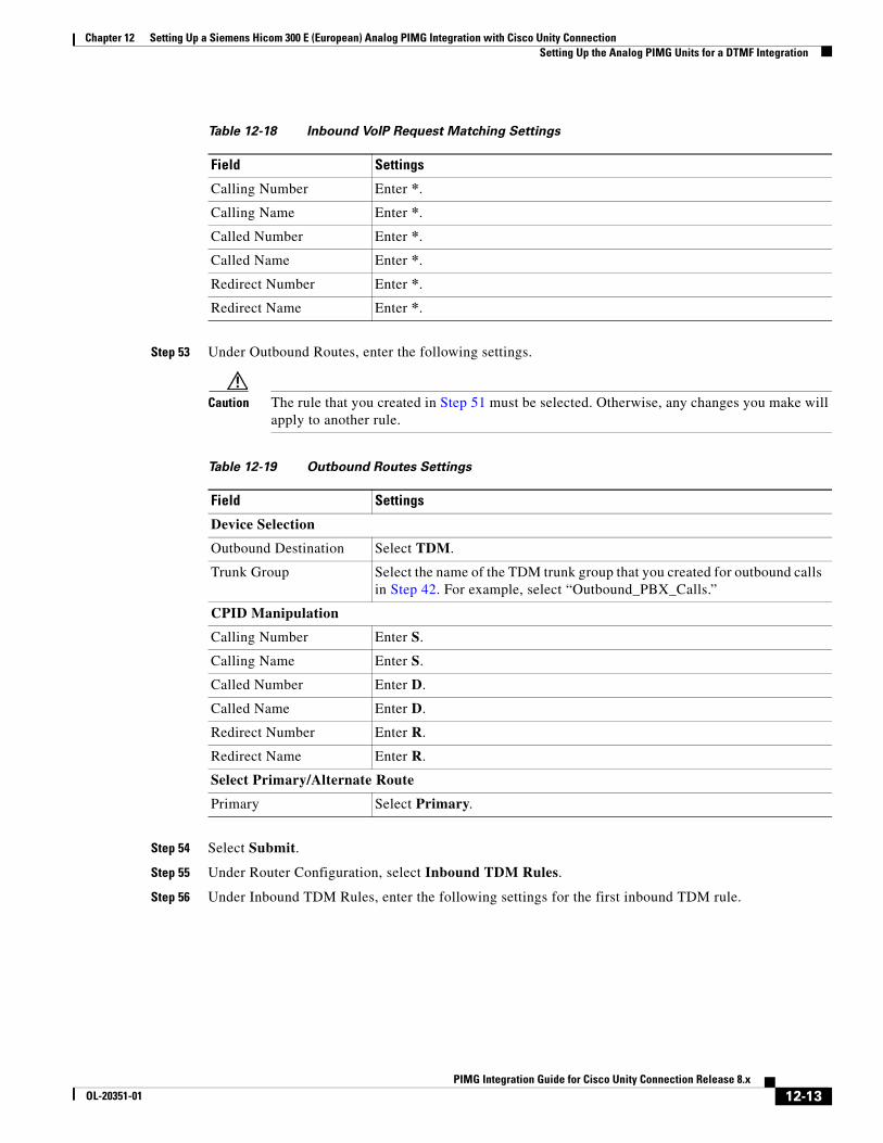
Chapter 12 Setting Up a Siemens Hicom 300 E (European) Analog PIMG Integration with Cisco Unity Connection Setting Up the Analog PIMG Units for a DTMF Integration
Step 53 Under Outbound Routes, enter the following settings.
Caution The rule that you created in Step 51 must be selected. Otherwise, any changes you make will apply to another rule.
Step 54 Select Submit.
Step 55 Under Router Configuration, select Inbound TDM Rules.
Step 56 Under Inbound TDM Rules, enter the following settings for the first inbound TDM rule.
Table 12-18 Inbound VoIP Request Matching Settings
Field Settings
Calling Number Enter *.
Calling Name Enter *.
Called Number Enter *.
Called Name Enter *.
Redirect Number Enter *.
Redirect Name Enter *.
Table 12-19 Outbound Routes Settings
Field Settings
Device Selection
Outbound Destination Select TDM.
Trunk Group Select the name of the TDM trunk group that you created for outbound calls in Step 42. For example, select “Outbound_PBX_Calls.”
CPID Manipulation
Calling Number Enter S.
Calling Name Enter S.
Called Number Enter D.
Called Name Enter D.
Redirect Number Enter R.
Redirect Name Enter R.
Select Primary/Alternate Route
Primary Select Primary.
12-13PIMG Integration Guide for Cisco Unity Connection Release 8.x
OL-20351-01
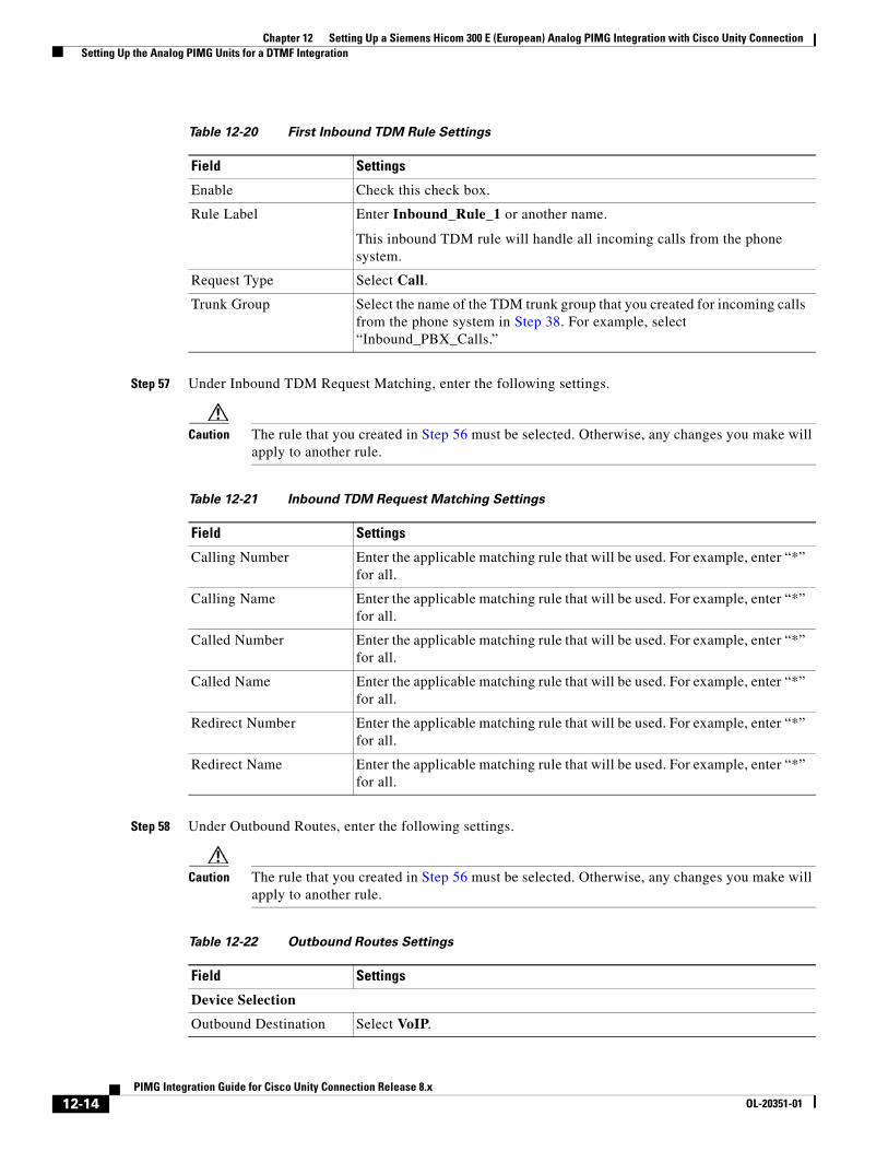
Chapter 12 Setting Up a Siemens Hicom 300 E (European) Analog PIMG Integration with Cisco Unity Connection Setting Up the Analog PIMG Units for a DTMF Integration
Step 57 Under Inbound TDM Request Matching, enter the following settings.
Caution The rule that you created in Step 56 must be selected. Otherwise, any changes you make will apply to another rule.
Step 58 Under Outbound Routes, enter the following settings.
Caution The rule that you created in Step 56 must be selected. Otherwise, any changes you make will apply to another rule.
Table 12-20 First Inbound TDM Rule Settings
Field Settings
Enable Check this check box.
Rule Label Enter Inbound_Rule_1 or another name.
This inbound TDM rule will handle all incoming calls from the phone system.
Request Type Select Call.
Trunk Group Select the name of the TDM trunk group that you created for incoming calls from the phone system in Step 38. For example, select “Inbound_PBX_Calls.”
Table 12-21 Inbound TDM Request Matching Settings
Field Settings
Calling Number Enter the applicable matching rule that will be used. For example, enter “*” for all.
Calling Name Enter the applicable matching rule that will be used. For example, enter “*” for all.
Called Number Enter the applicable matching rule that will be used. For example, enter “*” for all.
Called Name Enter the applicable matching rule that will be used. For example, enter “*” for all.
Redirect Number Enter the applicable matching rule that will be used. For example, enter “*” for all.
Redirect Name Enter the applicable matching rule that will be used. For example, enter “*” for all.
Table 12-22 Outbound Routes Settings
Field Settings
Device Selection
Outbound Destination Select VoIP.
12-14PIMG Integration Guide for Cisco Unity Connection Release 8.x
OL-20351-01
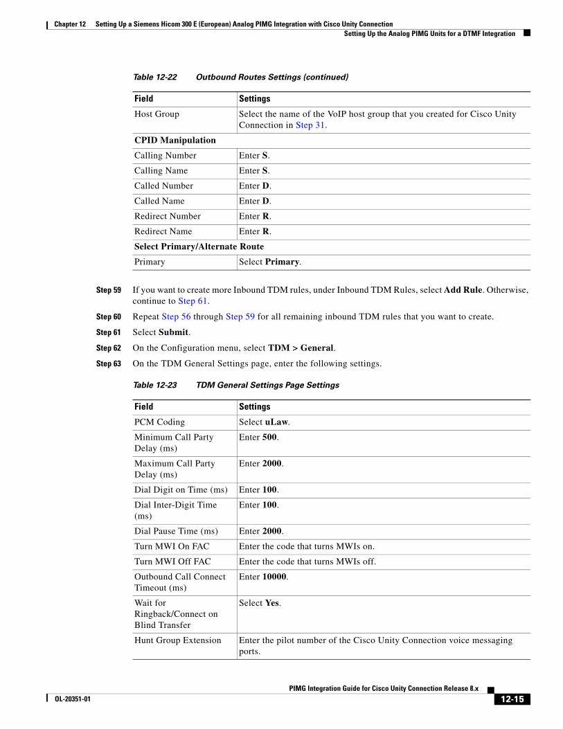
Chapter 12 Setting Up a Siemens Hicom 300 E (European) Analog PIMG Integration with Cisco Unity Connection Setting Up the Analog PIMG Units for a DTMF Integration
Step 59 If you want to create more Inbound TDM rules, under Inbound TDM Rules, select Add Rule. Otherwise, continue to Step 61.
Step 60 Repeat Step 56 through Step 59 for all remaining inbound TDM rules that you want to create.
Step 61 Select Submit.
Step 62 On the Configuration menu, select TDM > General.
Step 63 On the TDM General Settings page, enter the following settings.
Host Group Select the name of the VoIP host group that you created for Cisco Unity Connection in Step 31.
CPID Manipulation
Calling Number Enter S.
Calling Name Enter S.
Called Number Enter D.
Called Name Enter D.
Redirect Number Enter R.
Redirect Name Enter R.
Select Primary/Alternate Route
Primary Select Primary.
Table 12-23 TDM General Settings Page Settings
Field Settings
PCM Coding Select uLaw.
Minimum Call Party Delay (ms)
Enter 500.
Maximum Call Party Delay (ms)
Enter 2000.
Dial Digit on Time (ms) Enter 100.
Dial Inter-Digit Time (ms)
Enter 100.
Dial Pause Time (ms) Enter 2000.
Turn MWI On FAC Enter the code that turns MWIs on.
Turn MWI Off FAC Enter the code that turns MWIs off.
Outbound Call Connect Timeout (ms)
Enter 10000.
Wait for Ringback/Connect on Blind Transfer
Select Yes.
Hunt Group Extension Enter the pilot number of the Cisco Unity Connection voice messaging ports.
Table 12-22 Outbound Routes Settings (continued)
Field Settings
12-15PIMG Integration Guide for Cisco Unity Connection Release 8.x
OL-20351-01
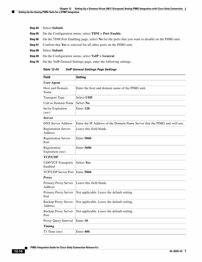
Chapter 12 Setting Up a Siemens Hicom 300 E (European) Analog PIMG Integration with Cisco Unity Connection Setting Up the Analog PIMG Units for a DTMF Integration
Step 64 Select Submit.
Step 65 On the Configuration menu, select TDM > Port Enable.
Step 66 On the TDM Port Enabling page, select No for the ports that you want to disable on the PIMG unit.
Step 67 Confirm that Yes is selected for all other ports on the PIMG unit.
Step 68 Select Submit.
Step 69 On the Configuration menu, select VoIP > General.
Step 70 On the VoIP General Settings page, enter the following settings.
Table 12-24 VoIP General Settings Page Settings
Field Setting
User-Agent
Host and Domain Name
Enter the host and domain name of the PIMG unit.
Transport Type Select UDP.
Call as Domain Name Select No.
Invite Expiration (sec)
Enter 120.
Server
DNS Server Address Enter the IP Address of the Domain Name Server that the PIMG unit will use.
Registration Server Address
Leave this field blank.
Registration Server Port
Enter 5060.
Registration Expiration (sec)
Enter 3600.
TCP/UDP
UDP/TCP Transports Enabled
Select Yes.
TCP/UDP Server Port Enter 5060.
Proxy
Primary Proxy Server Address
Leave this field blank.
Primary Proxy Server Port
Not applicable. Leave the default setting.
Backup Proxy Server Address
Not applicable. Leave the default setting.
Backup Proxy Server Port
Not applicable. Leave the default setting.
Proxy Query Interval Enter 10.
Timing
T1 Time (ms) Enter 400.
12-16PIMG Integration Guide for Cisco Unity Connection Release 8.x
OL-20351-01
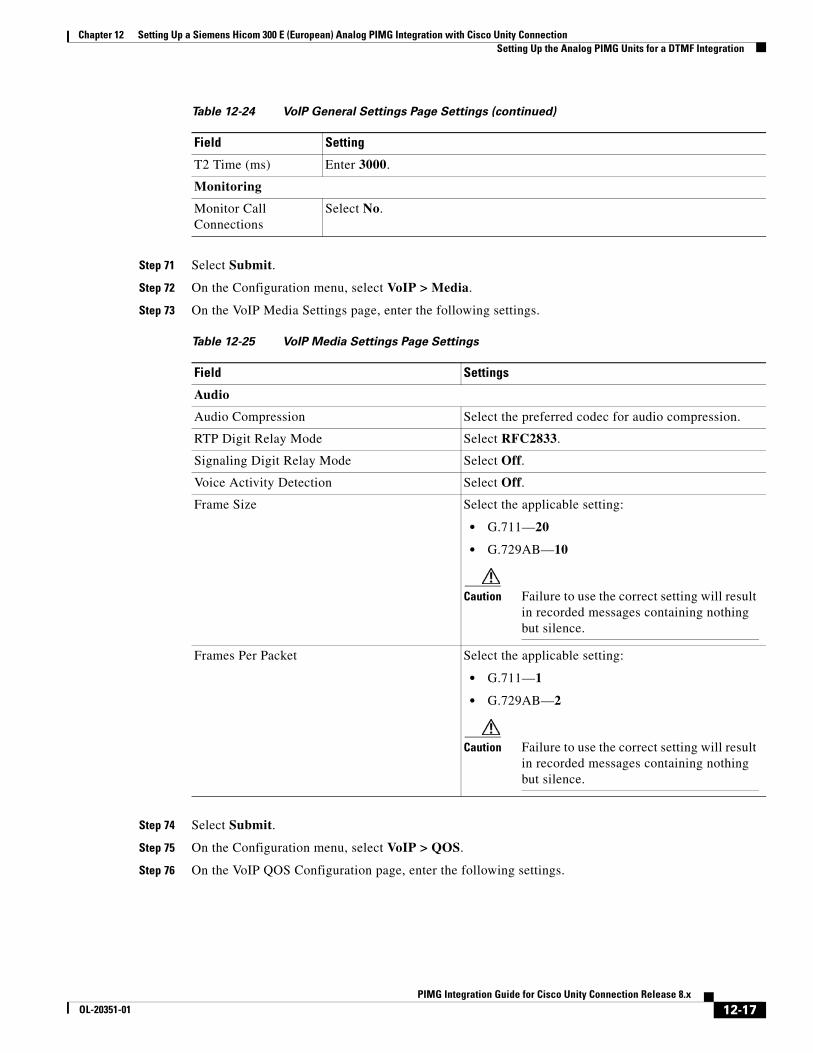
Chapter 12 Setting Up a Siemens Hicom 300 E (European) Analog PIMG Integration with Cisco Unity Connection Setting Up the Analog PIMG Units for a DTMF Integration
Step 71 Select Submit.
Step 72 On the Configuration menu, select VoIP > Media.
Step 73 On the VoIP Media Settings page, enter the following settings.
Step 74 Select Submit.
Step 75 On the Configuration menu, select VoIP > QOS.
Step 76 On the VoIP QOS Configuration page, enter the following settings.
T2 Time (ms) Enter 3000.
Monitoring
Monitor Call Connections
Select No.
Table 12-25 VoIP Media Settings Page Settings
Field Settings
Audio
Audio Compression Select the preferred codec for audio compression.
RTP Digit Relay Mode Select RFC2833.
Signaling Digit Relay Mode Select Off.
Voice Activity Detection Select Off.
Frame Size Select the applicable setting:
• G.711—20
• G.729AB—10
Caution Failure to use the correct setting will result in recorded messages containing nothing but silence.
Frames Per Packet Select the applicable setting:
• G.711—1
• G.729AB—2
Caution Failure to use the correct setting will result in recorded messages containing nothing but silence.
Table 12-24 VoIP General Settings Page Settings (continued)
Field Setting
12-17PIMG Integration Guide for Cisco Unity Connection Release 8.x
OL-20351-01
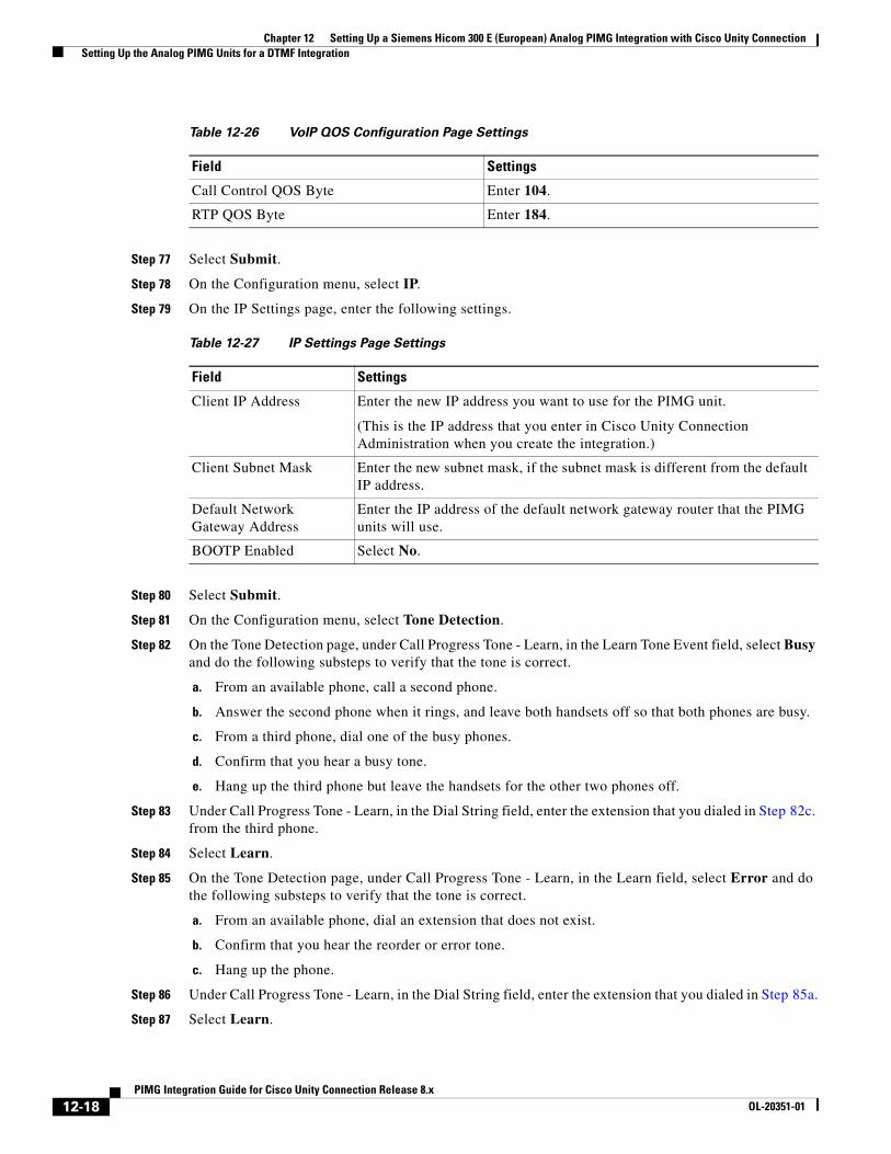
Chapter 12 Setting Up a Siemens Hicom 300 E (European) Analog PIMG Integration with Cisco Unity Connection Setting Up the Analog PIMG Units for a DTMF Integration
Step 77 Select Submit.
Step 78 On the Configuration menu, select IP.
Step 79 On the IP Settings page, enter the following settings.
Step 80 Select Submit.
Step 81 On the Configuration menu, select Tone Detection.
Step 82 On the Tone Detection page, under Call Progress Tone - Learn, in the Learn Tone Event field, select Busy and do the following substeps to verify that the tone is correct.
a. From an available phone, call a second phone.
b. Answer the second phone when it rings, and leave both handsets off so that both phones are busy.
c. From a third phone, dial one of the busy phones.
d. Confirm that you hear a busy tone.
e. Hang up the third phone but leave the handsets for the other two phones off.
Step 83 Under Call Progress Tone - Learn, in the Dial String field, enter the extension that you dialed in Step 82c. from the third phone.
Step 84 Select Learn.
Step 85 On the Tone Detection page, under Call Progress Tone - Learn, in the Learn field, select Error and do the following substeps to verify that the tone is correct.
a. From an available phone, dial an extension that does not exist.
b. Confirm that you hear the reorder or error tone.
c. Hang up the phone.
Step 86 Under Call Progress Tone - Learn, in the Dial String field, enter the extension that you dialed in Step 85a.
Step 87 Select Learn.
Table 12-26 VoIP QOS Configuration Page Settings
Field Settings
Call Control QOS Byte Enter 104.
RTP QOS Byte Enter 184.
Table 12-27 IP Settings Page Settings
Field Settings
Client IP Address Enter the new IP address you want to use for the PIMG unit.
(This is the IP address that you enter in Cisco Unity Connection Administration when you create the integration.)
Client Subnet Mask Enter the new subnet mask, if the subnet mask is different from the default IP address.
Default Network Gateway Address
Enter the IP address of the default network gateway router that the PIMG units will use.
BOOTP Enabled Select No.
12-18PIMG Integration Guide for Cisco Unity Connection Release 8.x
OL-20351-01
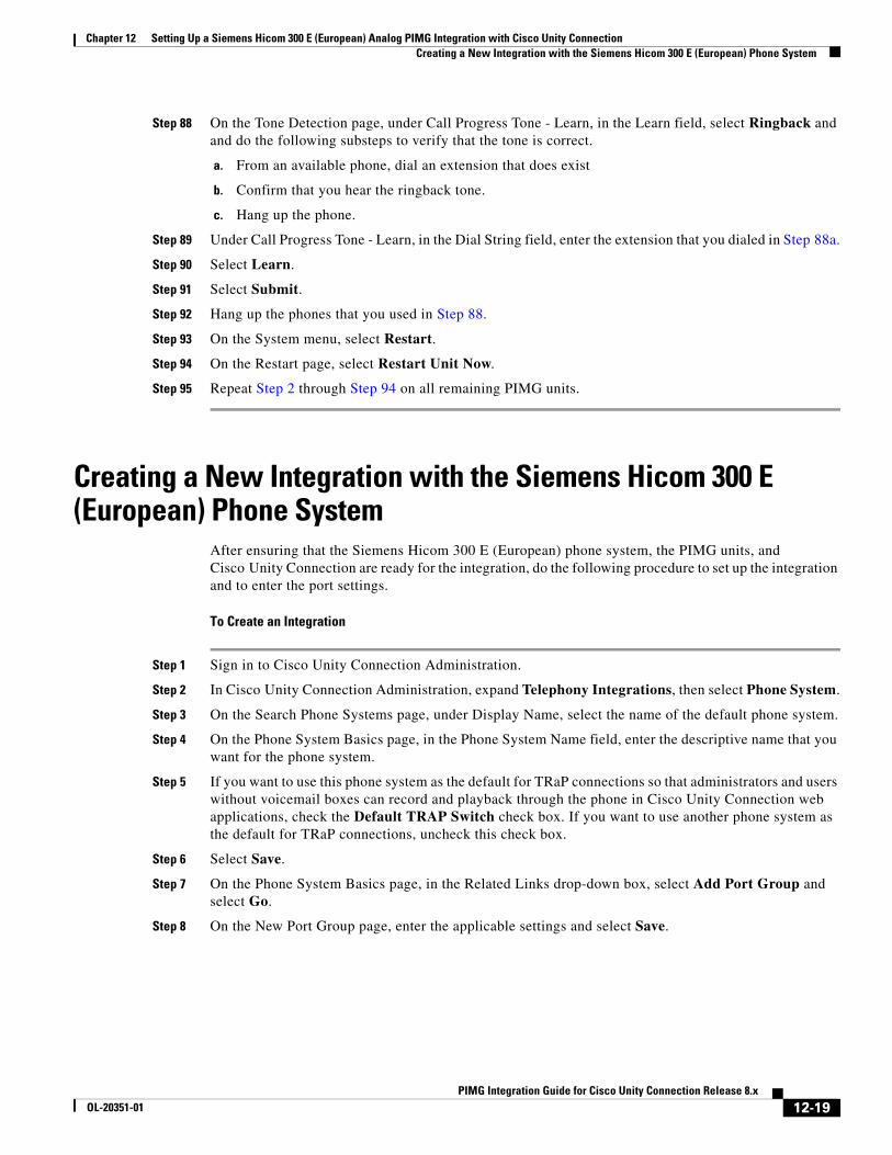
Chapter 12 Setting Up a Siemens Hicom 300 E (European) Analog PIMG Integration with Cisco Unity Connection Creating a New Integration with the Siemens Hicom 300 E (European) Phone System
Step 88 On the Tone Detection page, under Call Progress Tone - Learn, in the Learn field, select Ringback and and do the following substeps to verify that the tone is correct.
a. From an available phone, dial an extension that does exist
b. Confirm that you hear the ringback tone.
c. Hang up the phone.
Step 89 Under Call Progress Tone - Learn, in the Dial String field, enter the extension that you dialed in Step 88a.
Step 90 Select Learn.
Step 91 Select Submit.
Step 92 Hang up the phones that you used in Step 88.
Step 93 On the System menu, select Restart.
Step 94 On the Restart page, select Restart Unit Now.
Step 95 Repeat Step 2 through Step 94 on all remaining PIMG units.
Creating a New Integration with the Siemens Hicom 300 E (European) Phone System
After ensuring that the Siemens Hicom 300 E (European) phone system, the PIMG units, and Cisco Unity Connection are ready for the integration, do the following procedure to set up the integration and to enter the port settings.
To Create an Integration
Step 1 Sign in to Cisco Unity Connection Administration.
Step 2 In Cisco Unity Connection Administration, expand Telephony Integrations, then select Phone System.
Step 3 On the Search Phone Systems page, under Display Name, select the name of the default phone system.
Step 4 On the Phone System Basics page, in the Phone System Name field, enter the descriptive name that you want for the phone system.
Step 5 If you want to use this phone system as the default for TRaP connections so that administrators and users without voicemail boxes can record and playback through the phone in Cisco Unity Connection web applications, check the Default TRAP Switch check box. If you want to use another phone system as the default for TRaP connections, uncheck this check box.
Step 6 Select Save.
Step 7 On the Phone System Basics page, in the Related Links drop-down box, select Add Port Group and select Go.
Step 8 On the New Port Group page, enter the applicable settings and select Save.
12-19PIMG Integration Guide for Cisco Unity Connection Release 8.x
OL-20351-01
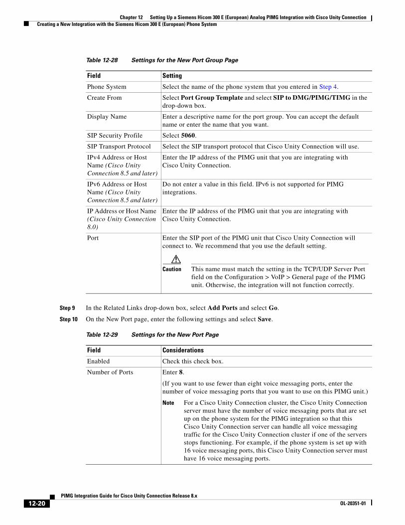
Chapter 12 Setting Up a Siemens Hicom 300 E (European) Analog PIMG Integration with Cisco Unity Connection Creating a New Integration with the Siemens Hicom 300 E (European) Phone System
Step 9 In the Related Links drop-down box, select Add Ports and select Go.
Step 10 On the New Port page, enter the following settings and select Save.
Table 12-28 Settings for the New Port Group Page
Field Setting
Phone System Select the name of the phone system that you entered in Step 4.
Create From Select Port Group Template and select SIP to DMG/PIMG/TIMG in the drop-down box.
Display Name Enter a descriptive name for the port group. You can accept the default name or enter the name that you want.
SIP Security Profile Select 5060.
SIP Transport Protocol Select the SIP transport protocol that Cisco Unity Connection will use.
IPv4 Address or Host Name (Cisco Unity Connection 8.5 and later)
Enter the IP address of the PIMG unit that you are integrating with Cisco Unity Connection.
IPv6 Address or Host Name (Cisco Unity Connection 8.5 and later)
Do not enter a value in this field. IPv6 is not supported for PIMG integrations.
IP Address or Host Name (Cisco Unity Connection 8.0)
Enter the IP address of the PIMG unit that you are integrating with Cisco Unity Connection.
Port Enter the SIP port of the PIMG unit that Cisco Unity Connection will connect to. We recommend that you use the default setting.
Caution This name must match the setting in the TCP/UDP Server Port field on the Configuration > VoIP > General page of the PIMG unit. Otherwise, the integration will not function correctly.
Table 12-29 Settings for the New Port Page
Field Considerations
Enabled Check this check box.
Number of Ports Enter 8.
(If you want to use fewer than eight voice messaging ports, enter the number of voice messaging ports that you want to use on this PIMG unit.)
Note For a Cisco Unity Connection cluster, the Cisco Unity Connection server must have the number of voice messaging ports that are set up on the phone system for the PIMG integration so that this Cisco Unity Connection server can handle all voice messaging traffic for the Cisco Unity Connection cluster if one of the servers stops functioning. For example, if the phone system is set up with 16 voice messaging ports, this Cisco Unity Connection server must have 16 voice messaging ports.
12-20PIMG Integration Guide for Cisco Unity Connection Release 8.x
OL-20351-01
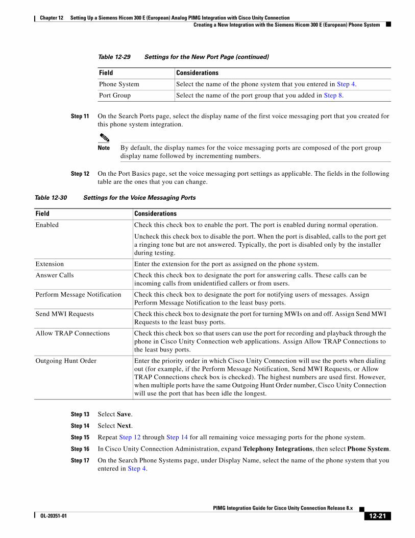
Chapter 12 Setting Up a Siemens Hicom 300 E (European) Analog PIMG Integration with Cisco Unity Connection Creating a New Integration with the Siemens Hicom 300 E (European) Phone System
Step 11 On the Search Ports page, select the display name of the first voice messaging port that you created for this phone system integration.
Note By default, the display names for the voice messaging ports are composed of the port group display name followed by incrementing numbers.
Step 12 On the Port Basics page, set the voice messaging port settings as applicable. The fields in the following table are the ones that you can change.
Step 13 Select Save.
Step 14 Select Next.
Step 15 Repeat Step 12 through Step 14 for all remaining voice messaging ports for the phone system.
Step 16 In Cisco Unity Connection Administration, expand Telephony Integrations, then select Phone System.
Step 17 On the Search Phone Systems page, under Display Name, select the name of the phone system that you entered in Step 4.
Phone System Select the name of the phone system that you entered in Step 4.
Port Group Select the name of the port group that you added in Step 8.
Table 12-29 Settings for the New Port Page (continued)
Field Considerations
Table 12-30 Settings for the Voice Messaging Ports
Field Considerations
Enabled Check this check box to enable the port. The port is enabled during normal operation.
Uncheck this check box to disable the port. When the port is disabled, calls to the port get a ringing tone but are not answered. Typically, the port is disabled only by the installer during testing.
Extension Enter the extension for the port as assigned on the phone system.
Answer Calls Check this check box to designate the port for answering calls. These calls can be incoming calls from unidentified callers or from users.
Perform Message Notification Check this check box to designate the port for notifying users of messages. Assign Perform Message Notification to the least busy ports.
Send MWI Requests Check this check box to designate the port for turning MWIs on and off. Assign Send MWI Requests to the least busy ports.
Allow TRAP Connections Check this check box so that users can use the port for recording and playback through the phone in Cisco Unity Connection web applications. Assign Allow TRAP Connections to the least busy ports.
Outgoing Hunt Order Enter the priority order in which Cisco Unity Connection will use the ports when dialing out (for example, if the Perform Message Notification, Send MWI Requests, or Allow TRAP Connections check box is checked). The highest numbers are used first. However, when multiple ports have the same Outgoing Hunt Order number, Cisco Unity Connection will use the port that has been idle the longest.
12-21PIMG Integration Guide for Cisco Unity Connection Release 8.x
OL-20351-01
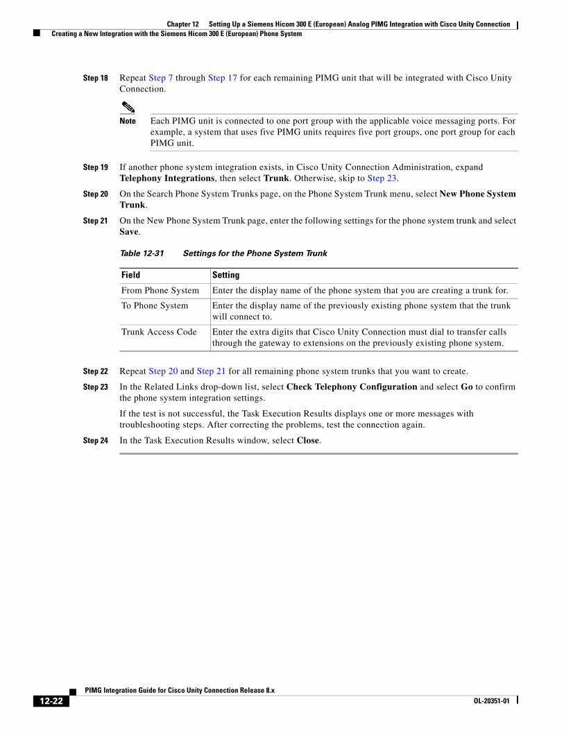
Chapter 12 Setting Up a Siemens Hicom 300 E (European) Analog PIMG Integration with Cisco Unity Connection Creating a New Integration with the Siemens Hicom 300 E (European) Phone System
Step 18 Repeat Step 7 through Step 17 for each remaining PIMG unit that will be integrated with Cisco Unity Connection.
Note Each PIMG unit is connected to one port group with the applicable voice messaging ports. For example, a system that uses five PIMG units requires five port groups, one port group for each PIMG unit.
Step 19 If another phone system integration exists, in Cisco Unity Connection Administration, expand Telephony Integrations, then select Trunk. Otherwise, skip to Step 23.
Step 20 On the Search Phone System Trunks page, on the Phone System Trunk menu, select New Phone System Trunk.
Step 21 On the New Phone System Trunk page, enter the following settings for the phone system trunk and select Save.
Step 22 Repeat Step 20 and Step 21 for all remaining phone system trunks that you want to create.
Step 23 In the Related Links drop-down list, select Check Telephony Configuration and select Go to confirm the phone system integration settings.
If the test is not successful, the Task Execution Results displays one or more messages with troubleshooting steps. After correcting the problems, test the connection again.
Step 24 In the Task Execution Results window, select Close.
Table 12-31 Settings for the Phone System Trunk
Field Setting
From Phone System Enter the display name of the phone system that you are creating a trunk for.
To Phone System Enter the display name of the previously existing phone system that the trunk will connect to.
Trunk Access Code Enter the extra digits that Cisco Unity Connection must dial to transfer calls through the gateway to extensions on the previously existing phone system.
12-22PIMG Integration Guide for Cisco Unity Connection Release 8.x
OL-20351-01
PIMG IntegrOL-20351-01
C H A P T E R 13
Setting Up a Siemens Hicom 300 E (North American) Digital PIMG Integration with Cisco Unity ConnectionFor detailed instructions for setting up a Siemens Hicom 300-series E (North American) digital PIMG integration with Cisco Unity Connection, see the following sections in this chapter:
• Task List to Create the Integration with the Siemens Hicom 300 PIMG Phone System, page 13-1
• Requirements, page 13-2
• Clearing MWIs from a Legacy Voice Messaging System, page 13-3
• Programming the Siemens Hicom 300 E (North American) Phone System for Integrating with Cisco Unity Connection, page 13-3
• Setting Up the Digital PIMG Units, page 13-6
• Creating a New Integration with the Siemens Hicom 300 Phone System, page 13-20
Task List to Create the Integration with the Siemens Hicom 300 PIMG Phone System
Before doing the following tasks to integrate Cisco Unity Connection with the Siemens Hicom 300-series E (North American) phone system by using PIMG units (media gateways), confirm that the Cisco Unity Connection server is ready for the integration by completing the applicable tasks in the Cisco Unity Connection Installation Guide.
1. Review the system and equipment requirements to confirm that all phone system and Cisco Unity Connection server requirements have been met. See the “Requirements” section on page 13-2.
2. Plan how the voice messaging ports will be used by Cisco Unity Connection. See Chapter 2, “Planning How the Voice Messaging Ports Will Be Used by Cisco Unity Connection.”
3. If you have a legacy voice messaging system, clear the MWIs for users who are migrating to Cisco Unity Connection. See the “Clearing MWIs from a Legacy Voice Messaging System” section on page 13-3.
4. Program the Siemens Hicom 300 phone system and extensions. See the “Programming the Siemens Hicom 300 E (North American) Phone System for Integrating with Cisco Unity Connection” section on page 13-3.
5. Set up the PIMG units. See the “Setting Up the Digital PIMG Units” section on page 13-6.
13-1ation Guide for Cisco Unity Connection Release 8.x
Chapter 13 Setting Up a Siemens Hicom 300 E (North American) Digital PIMG Integration with Cisco Unity Requirements
6. Create the integration. See the “Creating a New Integration with the Siemens Hicom 300 Phone System” section on page 13-20.
7. Test the integration. See Chapter 14, “Testing the Integration.”
8. If this integration is a second or subsequent integration, add the applicable new user templates for the new phone system. See Chapter 15, “Adding New User Templates for Multiple Integrations.”
RequirementsThe Siemens Hicom 300 integration supports configurations of the following components:
Phone System
• Siemens Hicom 300-series E CS (North American) phone system.
• Software version 9006.4 or later.
• SLMO line cards installed for connecting to the PIMG units.
• One or more of the applicable PIMG units. For details, see Chapter 1, “Introduction.”
• The voice messaging ports in the phone system connected by digital lines to the ports on the PIMG units.
To simplify troubleshooting, we recommend that you connect the voice messaging ports on the phone system to the ports on the PIMG units in a planned manner. For example, connect the first phone system voice messaging port to the first port on the first PIMG unit, connect the second phone system voice messaging port to the second port on the first PIMG unit, and so on. Alternatively, if you have multiple PIMG units, you can reduce answer times in the event of a PIMG unit failure by connecting the phone system ports to the PIMG units in a round-robin fashion. For example, connect the first phone system voice messaging port to the first port on the first PIMG unit, connect the second phone system voice messaging port to the first port on the second PIMG unit, and so on.
• The PIMG units connected to the same LAN or WAN that Cisco Unity Connection is connected to.
• If the PIMG units connect to a WAN, the requirements for the WAN network connections are:
– For G.729a codec formatting, a minimum of 32.76 Kbps guaranteed bandwidth for each voice messaging port.
– For G.711 codec formatting, a minimum of 91.56 Kbps guaranteed bandwidth for each voice messaging port.
– No network devices that implement network address translation (NAT).
– A maximum 200 ms one-way network latency.
• The phone system ready for the integration, as described in the documentation for the phone system.
Cisco Unity Connection Server
• Cisco Unity Connection installed and ready for the integration, as described in the Cisco Unity Connection Installation Guide at http://www.cisco.com/en/US/products/ps6509/prod_installation_guides_list.html.
• A license that enables the applicable number of voice messaging ports.
13-2PIMG Integration Guide for Cisco Unity Connection Release 8.x
OL-20351-01
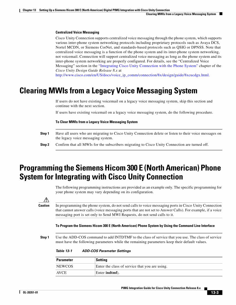
Chapter 13 Setting Up a Siemens Hicom 300 E (North American) Digital PIMG Integration with Cisco Unity Connection Clearing MWIs from a Legacy Voice Messaging System
Centralized Voice Messaging
Cisco Unity Connection supports centralized voice messaging through the phone system, which supports various inter-phone system networking protocols including proprietary protocols such as Avaya DCS, Nortel MCDN, or Siemens CorNet, and standards-based protocols such as QSIG or DPNSS. Note that centralized voice messaging is a function of the phone system and its inter-phone system networking, not voicemail. Connection will support centralized voice messaging as long as the phone system and its inter-phone system networking are properly configured. For details, see the “Centralized Voice Messaging” section in the “Integrating Cisco Unity Connection with the Phone System” chapter of the Cisco Unity Design Guide Release 8.x at http://www.cisco.com/en/US/docs/voice_ip_comm/connection/8x/design/guide/8xcucdgx.html.
Clearing MWIs from a Legacy Voice Messaging SystemIf users do not have existing voicemail on a legacy voice messaging system, skip this section and continue with the next section.
If users have existing voicemail on a legacy voice messaging system, do the following procedure.
To Clear MWIs from a Legacy Voice Messaging System
Step 1 Have all users who are migrating to Cisco Unity Connection delete or listen to their voice messages on the legacy voice messaging system.
Step 2 Confirm that all MWIs for the subscribers migrating to Cisco Unity Connection are turned off.
Programming the Siemens Hicom 300 E (North American) Phone System for Integrating with Cisco Unity Connection
The following programming instructions are provided as an example only. The specific programming for your phone system may vary depending on its configuration.
Caution In programming the phone system, do not send calls to voice messaging ports in Cisco Unity Connection that cannot answer calls (voice messaging ports that are not set to Answer Calls). For example, if a voice messaging port is set only to Send MWI Requests, do not send calls to it.
To Program the Siemens Hicom 300 E (North American) Phone System by Using the Command Line Interface
Step 1 Use the ADD-COS command to add INTDTMF to the class of service that you use. The class of service must have the following parameters while the remaining parameters keep their default values.
Table 13-1 ADD-COS Parameter Settings
Parameter Setting
NEWCOS Enter the class of service that you are using.
AVCE Enter indtmf;.
13-3PIMG Integration Guide for Cisco Unity Connection Release 8.x
OL-20351-01
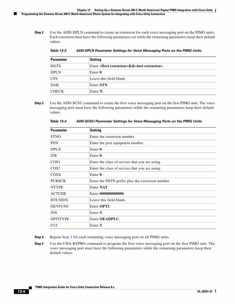
Chapter 13 Setting Up a Siemens Hicom 300 E (North American) Digital PIMG Integration with Cisco Unity Programming the Siemens Hicom 300 E (North American) Phone System for Integrating with Cisco Unity Connection
Step 2 Use the ADD-DPLN command to create an extension for each voice messaging port on the PIMG units. Each extension must have the following parameters set while the remaining parameters keep their default values.
Step 3 Use the ADD-SCSU command to create the first voice messaging port on the first PIMG unit. The voice messaging port must have the following parameters while the remaining parameters keep their default values.
Step 4 Repeat Step 3 for each remaining voice messaging port on all PIMG units.
Step 5 Use the CHA-KEPRO command to program the first voice messaging port on the first PIMG unit. The voice messaging port must have the following parameters while the remaining parameters keep their default values.
Table 13-2 ADD-DPLN Parameter Settings for Voice Messaging Ports on the PIMG Units
Parameter Setting
DGTS Enter <first extension>&&<last extension>.
DPLN Enter 0.
CPS Leave this field blank.
DAR Enter STN.
CHECK Enter N.
Table 13-3 ADD-SCSU Parameter Settings for Voice Messaging Ports on the PIMG Units
Parameter Setting
STNO Enter the extension number.
PEN Enter the port equipment number.
DPLN Enter 0.
ITR Enter 0.
COS1 Enter the class of service that you are using.
COS2 Enter the class of service that you are using.
COSX Enter 0.
PUBSCR Enter the PSTN prefix plus the extension number.
NTYPE Enter NAT.
ACTCDE Enter 000000000000.
HTLNIDX Leave this field blank.
DEVFUNC Enter OPTI.
INS Enter Y.
OPTITYPE Enter OEADPLC.
CUI Enter Y.
13-4PIMG Integration Guide for Cisco Unity Connection Release 8.x
OL-20351-01
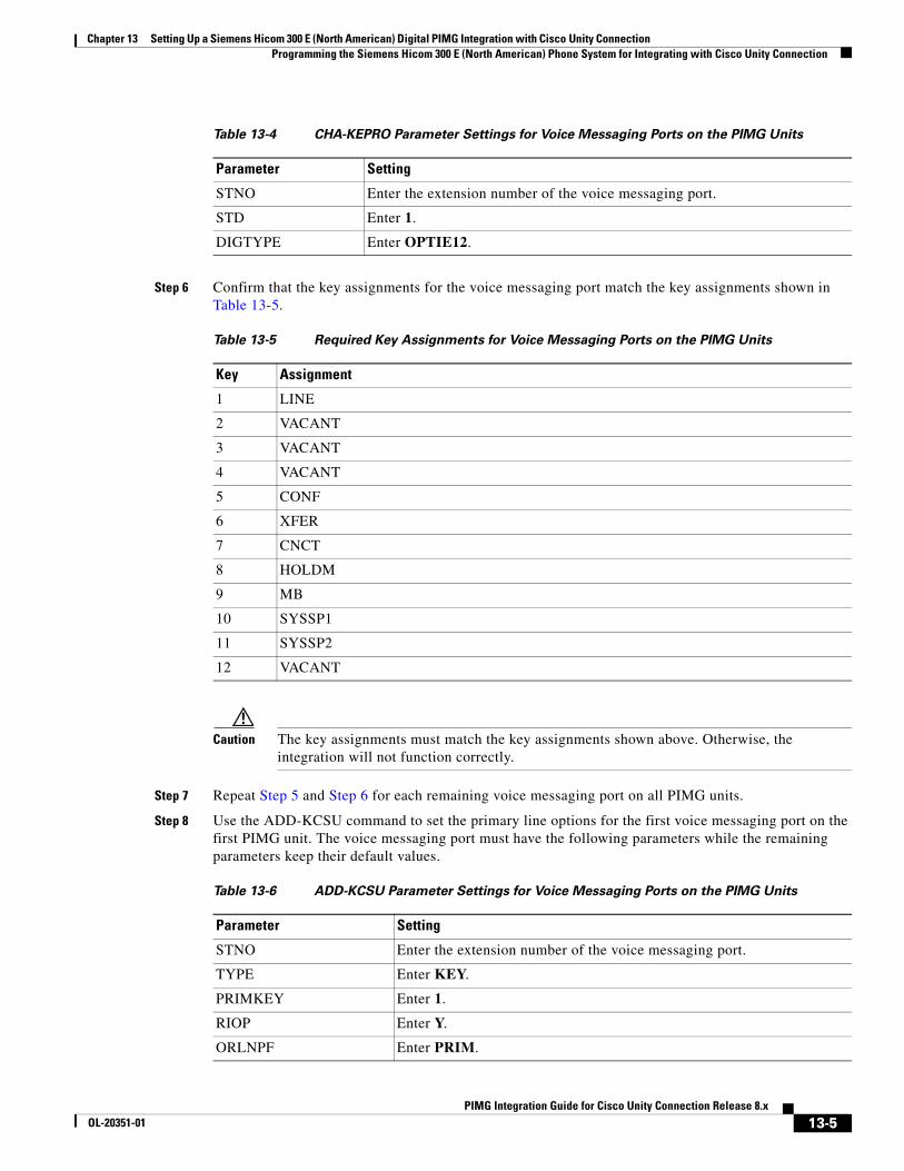
Chapter 13 Setting Up a Siemens Hicom 300 E (North American) Digital PIMG Integration with Cisco Unity Connection Programming the Siemens Hicom 300 E (North American) Phone System for Integrating with Cisco Unity Connection
Step 6 Confirm that the key assignments for the voice messaging port match the key assignments shown in Table 13-5.
Caution The key assignments must match the key assignments shown above. Otherwise, the integration will not function correctly.
Step 7 Repeat Step 5 and Step 6 for each remaining voice messaging port on all PIMG units.
Step 8 Use the ADD-KCSU command to set the primary line options for the first voice messaging port on the first PIMG unit. The voice messaging port must have the following parameters while the remaining parameters keep their default values.
Table 13-4 CHA-KEPRO Parameter Settings for Voice Messaging Ports on the PIMG Units
Parameter Setting
STNO Enter the extension number of the voice messaging port.
STD Enter 1.
DIGTYPE Enter OPTIE12.
Table 13-5 Required Key Assignments for Voice Messaging Ports on the PIMG Units
Key Assignment
1 LINE
2 VACANT
3 VACANT
4 VACANT
5 CONF
6 XFER
7 CNCT
8 HOLDM
9 MB
10 SYSSP1
11 SYSSP2
12 VACANT
Table 13-6 ADD-KCSU Parameter Settings for Voice Messaging Ports on the PIMG Units
Parameter Setting
STNO Enter the extension number of the voice messaging port.
TYPE Enter KEY.
PRIMKEY Enter 1.
RIOP Enter Y.
ORLNPF Enter PRIM.
13-5PIMG Integration Guide for Cisco Unity Connection Release 8.x
OL-20351-01
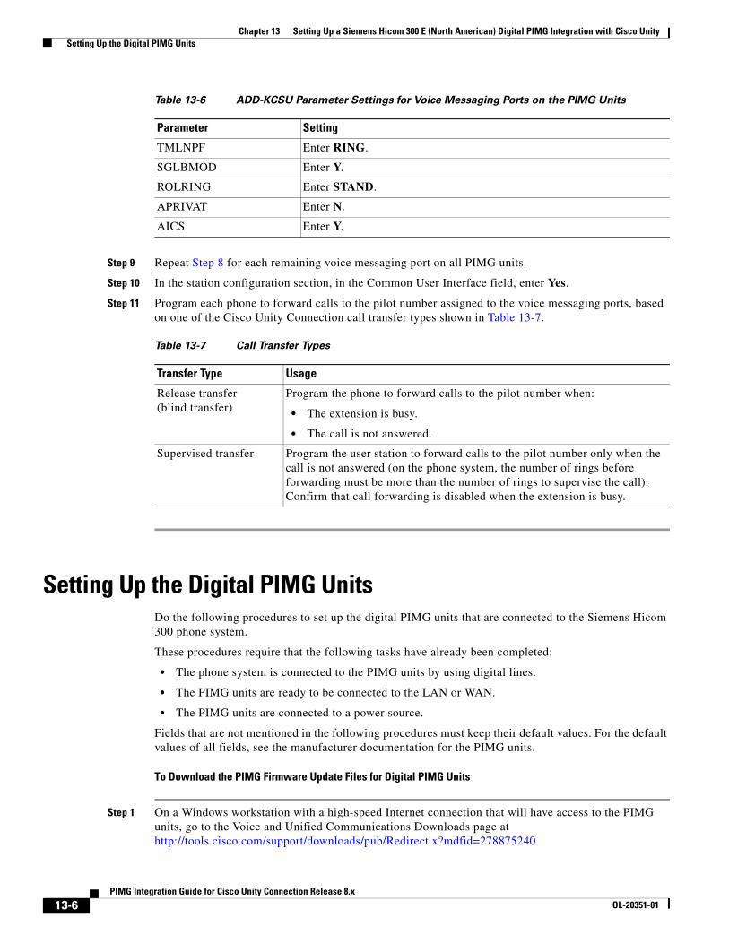
Chapter 13 Setting Up a Siemens Hicom 300 E (North American) Digital PIMG Integration with Cisco Unity Setting Up the Digital PIMG Units
Step 9 Repeat Step 8 for each remaining voice messaging port on all PIMG units.
Step 10 In the station configuration section, in the Common User Interface field, enter Yes.
Step 11 Program each phone to forward calls to the pilot number assigned to the voice messaging ports, based on one of the Cisco Unity Connection call transfer types shown in Table 13-7.
Setting Up the Digital PIMG UnitsDo the following procedures to set up the digital PIMG units that are connected to the Siemens Hicom 300 phone system.
These procedures require that the following tasks have already been completed:
• The phone system is connected to the PIMG units by using digital lines.
• The PIMG units are ready to be connected to the LAN or WAN.
• The PIMG units are connected to a power source.
Fields that are not mentioned in the following procedures must keep their default values. For the default values of all fields, see the manufacturer documentation for the PIMG units.
To Download the PIMG Firmware Update Files for Digital PIMG Units
Step 1 On a Windows workstation with a high-speed Internet connection that will have access to the PIMG units, go to the Voice and Unified Communications Downloads page at http://tools.cisco.com/support/downloads/pub/Redirect.x?mdfid=278875240.
TMLNPF Enter RING.
SGLBMOD Enter Y.
ROLRING Enter STAND.
APRIVAT Enter N.
AICS Enter Y.
Table 13-7 Call Transfer Types
Transfer Type Usage
Release transfer (blind transfer)
Program the phone to forward calls to the pilot number when:
• The extension is busy.
• The call is not answered.
Supervised transfer Program the user station to forward calls to the pilot number only when the call is not answered (on the phone system, the number of rings before forwarding must be more than the number of rings to supervise the call). Confirm that call forwarding is disabled when the extension is busy.
Table 13-6 ADD-KCSU Parameter Settings for Voice Messaging Ports on the PIMG Units
Parameter Setting
13-6PIMG Integration Guide for Cisco Unity Connection Release 8.x
OL-20351-01
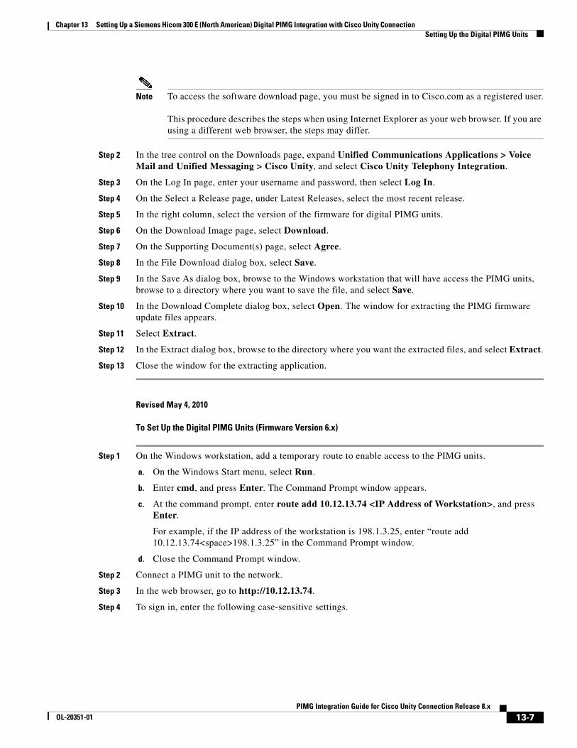
Chapter 13 Setting Up a Siemens Hicom 300 E (North American) Digital PIMG Integration with Cisco Unity Connection Setting Up the Digital PIMG Units
Note To access the software download page, you must be signed in to Cisco.com as a registered user. This procedure describes the steps when using Internet Explorer as your web browser. If you are using a different web browser, the steps may differ.
Step 2 In the tree control on the Downloads page, expand Unified Communications Applications > Voice Mail and Unified Messaging > Cisco Unity, and select Cisco Unity Telephony Integration.
Step 3 On the Log In page, enter your username and password, then select Log In.
Step 4 On the Select a Release page, under Latest Releases, select the most recent release.
Step 5 In the right column, select the version of the firmware for digital PIMG units.
Step 6 On the Download Image page, select Download.
Step 7 On the Supporting Document(s) page, select Agree.
Step 8 In the File Download dialog box, select Save.
Step 9 In the Save As dialog box, browse to the Windows workstation that will have access the PIMG units, browse to a directory where you want to save the file, and select Save.
Step 10 In the Download Complete dialog box, select Open. The window for extracting the PIMG firmware update files appears.
Step 11 Select Extract.
Step 12 In the Extract dialog box, browse to the directory where you want the extracted files, and select Extract.
Step 13 Close the window for the extracting application.
Revised May 4, 2010
To Set Up the Digital PIMG Units (Firmware Version 6.x)
Step 1 On the Windows workstation, add a temporary route to enable access to the PIMG units.
a. On the Windows Start menu, select Run.
b. Enter cmd, and press Enter. The Command Prompt window appears.
c. At the command prompt, enter route add 10.12.13.74 <IP Address of Workstation>, and press Enter.
For example, if the IP address of the workstation is 198.1.3.25, enter “route add 10.12.13.74<space>198.1.3.25” in the Command Prompt window.
d. Close the Command Prompt window.
Step 2 Connect a PIMG unit to the network.
Step 3 In the web browser, go to http://10.12.13.74.
Step 4 To sign in, enter the following case-sensitive settings.
13-7PIMG Integration Guide for Cisco Unity Connection Release 8.x
OL-20351-01
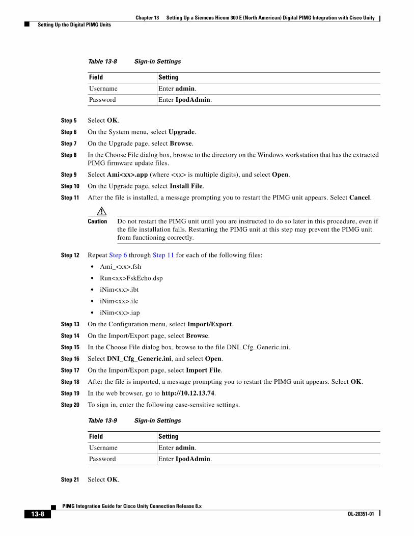
Chapter 13 Setting Up a Siemens Hicom 300 E (North American) Digital PIMG Integration with Cisco Unity Setting Up the Digital PIMG Units
Step 5 Select OK.
Step 6 On the System menu, select Upgrade.
Step 7 On the Upgrade page, select Browse.
Step 8 In the Choose File dialog box, browse to the directory on the Windows workstation that has the extracted PIMG firmware update files.
Step 9 Select Ami<xx>.app (where <xx> is multiple digits), and select Open.
Step 10 On the Upgrade page, select Install File.
Step 11 After the file is installed, a message prompting you to restart the PIMG unit appears. Select Cancel.
Caution Do not restart the PIMG unit until you are instructed to do so later in this procedure, even if the file installation fails. Restarting the PIMG unit at this step may prevent the PIMG unit from functioning correctly.
Step 12 Repeat Step 6 through Step 11 for each of the following files:
• Ami_<xx>.fsh
• Run<xx>FskEcho.dsp
• iNim<xx>.ibt
• iNim<xx>.ilc
• iNim<xx>.iap
Step 13 On the Configuration menu, select Import/Export.
Step 14 On the Import/Export page, select Browse.
Step 15 In the Choose File dialog box, browse to the file DNI_Cfg_Generic.ini.
Step 16 Select DNI_Cfg_Generic.ini, and select Open.
Step 17 On the Import/Export page, select Import File.
Step 18 After the file is imported, a message prompting you to restart the PIMG unit appears. Select OK.
Step 19 In the web browser, go to http://10.12.13.74.
Step 20 To sign in, enter the following case-sensitive settings.
Step 21 Select OK.
Table 13-8 Sign-in Settings
Field Setting
Username Enter admin.
Password Enter IpodAdmin.
Table 13-9 Sign-in Settings
Field Setting
Username Enter admin.
Password Enter IpodAdmin.
13-8PIMG Integration Guide for Cisco Unity Connection Release 8.x
OL-20351-01
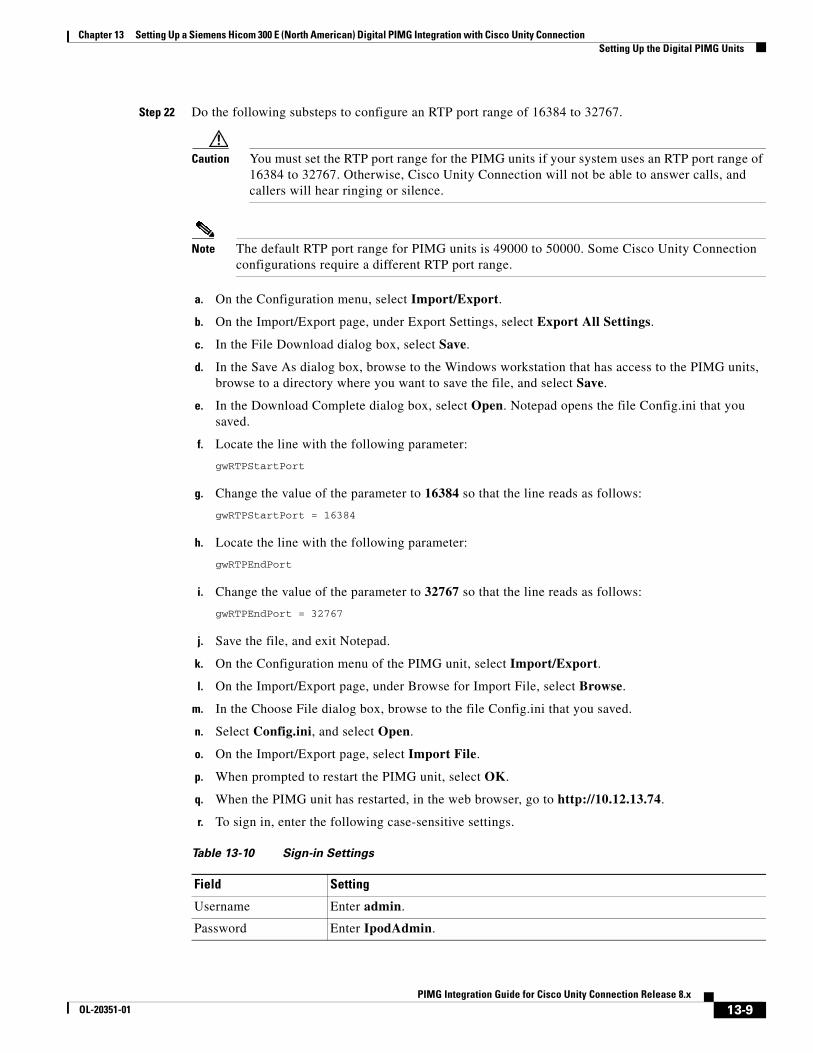
Chapter 13 Setting Up a Siemens Hicom 300 E (North American) Digital PIMG Integration with Cisco Unity Connection Setting Up the Digital PIMG Units
Step 22 Do the following substeps to configure an RTP port range of 16384 to 32767.
Caution You must set the RTP port range for the PIMG units if your system uses an RTP port range of 16384 to 32767. Otherwise, Cisco Unity Connection will not be able to answer calls, and callers will hear ringing or silence.
Note The default RTP port range for PIMG units is 49000 to 50000. Some Cisco Unity Connection configurations require a different RTP port range.
a. On the Configuration menu, select Import/Export.
b. On the Import/Export page, under Export Settings, select Export All Settings.
c. In the File Download dialog box, select Save.
d. In the Save As dialog box, browse to the Windows workstation that has access to the PIMG units, browse to a directory where you want to save the file, and select Save.
e. In the Download Complete dialog box, select Open. Notepad opens the file Config.ini that you saved.
f. Locate the line with the following parameter:
gwRTPStartPort
g. Change the value of the parameter to 16384 so that the line reads as follows:
gwRTPStartPort = 16384
h. Locate the line with the following parameter:
gwRTPEndPort
i. Change the value of the parameter to 32767 so that the line reads as follows:
gwRTPEndPort = 32767
j. Save the file, and exit Notepad.
k. On the Configuration menu of the PIMG unit, select Import/Export.
l. On the Import/Export page, under Browse for Import File, select Browse.
m. In the Choose File dialog box, browse to the file Config.ini that you saved.
n. Select Config.ini, and select Open.
o. On the Import/Export page, select Import File.
p. When prompted to restart the PIMG unit, select OK.
q. When the PIMG unit has restarted, in the web browser, go to http://10.12.13.74.
r. To sign in, enter the following case-sensitive settings.
Table 13-10 Sign-in Settings
Field Setting
Username Enter admin.
Password Enter IpodAdmin.
13-9PIMG Integration Guide for Cisco Unity Connection Release 8.x
OL-20351-01
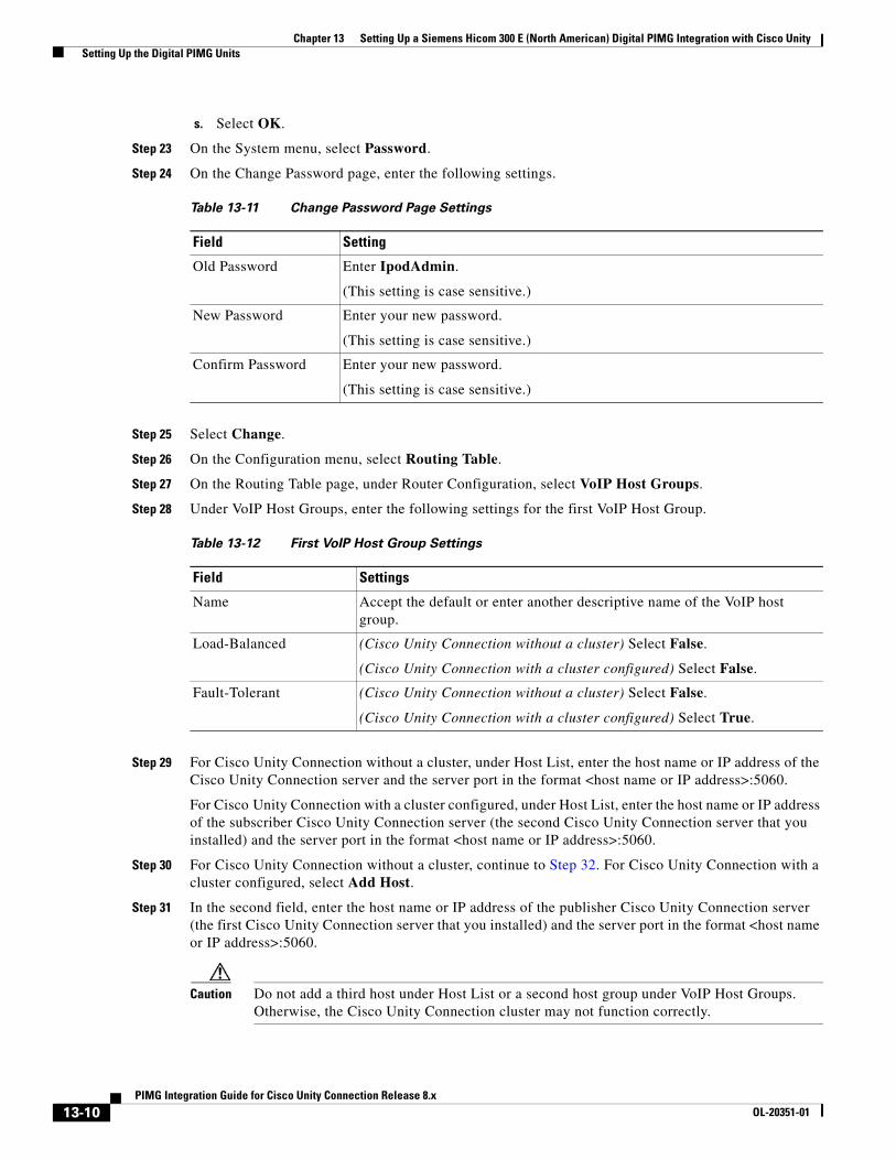
Chapter 13 Setting Up a Siemens Hicom 300 E (North American) Digital PIMG Integration with Cisco Unity Setting Up the Digital PIMG Units
s. Select OK.
Step 23 On the System menu, select Password.
Step 24 On the Change Password page, enter the following settings.
Step 25 Select Change.
Step 26 On the Configuration menu, select Routing Table.
Step 27 On the Routing Table page, under Router Configuration, select VoIP Host Groups.
Step 28 Under VoIP Host Groups, enter the following settings for the first VoIP Host Group.
Step 29 For Cisco Unity Connection without a cluster, under Host List, enter the host name or IP address of the Cisco Unity Connection server and the server port in the format <host name or IP address>:5060.
For Cisco Unity Connection with a cluster configured, under Host List, enter the host name or IP address of the subscriber Cisco Unity Connection server (the second Cisco Unity Connection server that you installed) and the server port in the format <host name or IP address>:5060.
Step 30 For Cisco Unity Connection without a cluster, continue to Step 32. For Cisco Unity Connection with a cluster configured, select Add Host.
Step 31 In the second field, enter the host name or IP address of the publisher Cisco Unity Connection server (the first Cisco Unity Connection server that you installed) and the server port in the format <host name or IP address>:5060.
Caution Do not add a third host under Host List or a second host group under VoIP Host Groups. Otherwise, the Cisco Unity Connection cluster may not function correctly.
Table 13-11 Change Password Page Settings
Field Setting
Old Password Enter IpodAdmin.
(This setting is case sensitive.)
New Password Enter your new password.
(This setting is case sensitive.)
Confirm Password Enter your new password.
(This setting is case sensitive.)
Table 13-12 First VoIP Host Group Settings
Field Settings
Name Accept the default or enter another descriptive name of the VoIP host group.
Load-Balanced (Cisco Unity Connection without a cluster) Select False.
(Cisco Unity Connection with a cluster configured) Select False.
Fault-Tolerant (Cisco Unity Connection without a cluster) Select False.
(Cisco Unity Connection with a cluster configured) Select True.
13-10PIMG Integration Guide for Cisco Unity Connection Release 8.x
OL-20351-01
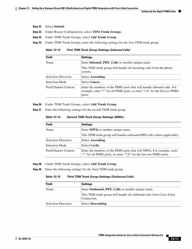
Chapter 13 Setting Up a Siemens Hicom 300 E (North American) Digital PIMG Integration with Cisco Unity Connection Setting Up the Digital PIMG Units
Step 32 Select Submit.
Step 33 Under Router Configuration, select TDM Trunk Groups.
Step 34 Under TDM Trunk Groups, select Add Trunk Group.
Step 35 Under TDM Trunk Groups, enter the following settings for the first TDM trunk group.
Step 36 Under TDM Trunk Groups, select Add Trunk Group.
Step 37 Enter the following settings for the second TDM trunk group.
Step 38 Under TDM Trunk Groups, select Add Trunk Group.
Step 39 Enter the following settings for the third TDM trunk group.
Table 13-13 First TDM Trunk Group Settings (Inbound Calls)
Field Settings
Name Enter Inbound_PBX_Calls or another unique name.
This TDM trunk group will handle all incoming calls from the phone system.
Selection Direction Select Ascending.
Selection Mode Select Linear.
Port/Channel Content Enter the numbers of the PIMG ports that will handle inbound calls. For example, enter “*” for all PIMG ports, or enter “1-6” for the first six PIMG ports.
Table 13-14 Second TDM Trunk Group Settings (MWIs)
Field Settings
Name Enter MWIs or another unique name.
This TDM trunk group will handle outbound MWI calls (where applicable).
Selection Direction Select Ascending.
Selection Mode Select Cyclic.
Port/Channel Content Enter the numbers of the PIMG ports that will MWIs. For example, enter “*” for all PIMG ports, or enter “7,8” for the last two PIMG ports.
Table 13-15 Third TDM Trunk Group Settings (Outbound Calls)
Field Settings
Name Enter Outbound_PBX_Calls or another unique name.
This TDM trunk group will handle all outbound calls from Cisco Unity Connection.
Selection Direction Select Descending.
13-11PIMG Integration Guide for Cisco Unity Connection Release 8.x
OL-20351-01
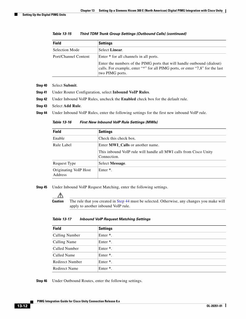
Chapter 13 Setting Up a Siemens Hicom 300 E (North American) Digital PIMG Integration with Cisco Unity Setting Up the Digital PIMG Units
Step 40 Select Submit.
Step 41 Under Router Configuration, select Inbound VoIP Rules.
Step 42 Under Inbound VoIP Rules, uncheck the Enabled check box for the default rule.
Step 43 Select Add Rule.
Step 44 Under Inbound VoIP Rules, enter the following settings for the first new inbound VoIP rule.
Step 45 Under Inbound VoIP Request Matching, enter the following settings.
Caution The rule that you created in Step 44 must be selected. Otherwise, any changes you make will apply to another inbound VoIP rule.
Step 46 Under Outbound Routes, enter the following settings.
Selection Mode Select Linear.
Port/Channel Content Enter * for all channels in all ports.
Enter the numbers of the PIMG ports that will handle outbound (dialout) calls. For example, enter “*” for all PIMG ports, or enter “7,8” for the last two PIMG ports.
Table 13-16 First New Inbound VoIP Rule Settings (MWIs)
Field Settings
Enable Check this check box.
Rule Label Enter MWI_Calls or another name.
This inbound VoIP rule will handle all MWI calls from Cisco Unity Connection.
Request Type Select Message.
Originating VoIP Host Address
Enter *.
Table 13-15 Third TDM Trunk Group Settings (Outbound Calls) (continued)
Field Settings
Table 13-17 Inbound VoIP Request Matching Settings
Field Settings
Calling Number Enter *.
Calling Name Enter *.
Called Number Enter *.
Called Name Enter *.
Redirect Number Enter *.
Redirect Name Enter *.
13-12PIMG Integration Guide for Cisco Unity Connection Release 8.x
OL-20351-01
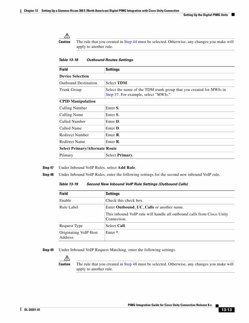
Chapter 13 Setting Up a Siemens Hicom 300 E (North American) Digital PIMG Integration with Cisco Unity Connection Setting Up the Digital PIMG Units
Caution The rule that you created in Step 44 must be selected. Otherwise, any changes you make will apply to another rule.
Step 47 Under Inbound VoIP Rules, select Add Rule.
Step 48 Under Inbound VoIP Rules, enter the following settings for the second new inbound VoIP rule.
Step 49 Under Inbound VoIP Request Matching, enter the following settings.
Caution The rule that you created in Step 48 must be selected. Otherwise, any changes you make will apply to another rule.
Table 13-18 Outbound Routes Settings
Field Settings
Device Selection
Outbound Destination Select TDM.
Trunk Group Select the name of the TDM trunk group that you created for MWIs in Step 37. For example, select “MWIs.”
CPID Manipulation
Calling Number Enter S.
Calling Name Enter S.
Called Number Enter D.
Called Name Enter D.
Redirect Number Enter R.
Redirect Name Enter R.
Select Primary/Alternate Route
Primary Select Primary.
Table 13-19 Second New Inbound VoIP Rule Settings (Outbound Calls)
Field Settings
Enable Check this check box.
Rule Label Enter Outbound_UC_Calls or another name.
This inbound VoIP rule will handle all outbound calls from Cisco Unity Connection.
Request Type Select Call.
Originating VoIP Host Address
Enter *.
13-13PIMG Integration Guide for Cisco Unity Connection Release 8.x
OL-20351-01
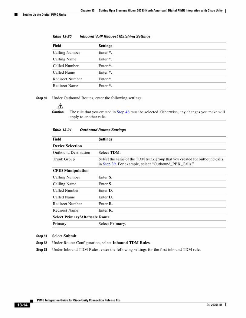
Chapter 13 Setting Up a Siemens Hicom 300 E (North American) Digital PIMG Integration with Cisco Unity Setting Up the Digital PIMG Units
Step 50 Under Outbound Routes, enter the following settings.
Caution The rule that you created in Step 48 must be selected. Otherwise, any changes you make will apply to another rule.
Step 51 Select Submit.
Step 52 Under Router Configuration, select Inbound TDM Rules.
Step 53 Under Inbound TDM Rules, enter the following settings for the first inbound TDM rule.
Table 13-20 Inbound VoIP Request Matching Settings
Field Settings
Calling Number Enter *.
Calling Name Enter *.
Called Number Enter *.
Called Name Enter *.
Redirect Number Enter *.
Redirect Name Enter *.
Table 13-21 Outbound Routes Settings
Field Settings
Device Selection
Outbound Destination Select TDM.
Trunk Group Select the name of the TDM trunk group that you created for outbound calls in Step 39. For example, select “Outbound_PBX_Calls.”
CPID Manipulation
Calling Number Enter S.
Calling Name Enter S.
Called Number Enter D.
Called Name Enter D.
Redirect Number Enter R.
Redirect Name Enter R.
Select Primary/Alternate Route
Primary Select Primary.
13-14PIMG Integration Guide for Cisco Unity Connection Release 8.x
OL-20351-01
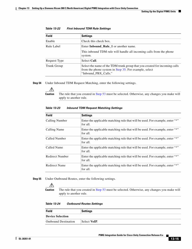
Chapter 13 Setting Up a Siemens Hicom 300 E (North American) Digital PIMG Integration with Cisco Unity Connection Setting Up the Digital PIMG Units
Step 54 Under Inbound TDM Request Matching, enter the following settings.
Caution The rule that you created in Step 53 must be selected. Otherwise, any changes you make will apply to another rule.
Step 55 Under Outbound Routes, enter the following settings.
Caution The rule that you created in Step 53 must be selected. Otherwise, any changes you make will apply to another rule.
Table 13-22 First Inbound TDM Rule Settings
Field Settings
Enable Check this check box.
Rule Label Enter Inbound_Rule_1 or another name.
This inbound TDM rule will handle all incoming calls from the phone system.
Request Type Select Call.
Trunk Group Select the name of the TDM trunk group that you created for incoming calls from the phone system in Step 35. For example, select “Inbound_PBX_Calls.”
Table 13-23 Inbound TDM Request Matching Settings
Field Settings
Calling Number Enter the applicable matching rule that will be used. For example, enter “*” for all.
Calling Name Enter the applicable matching rule that will be used. For example, enter “*” for all.
Called Number Enter the applicable matching rule that will be used. For example, enter “*” for all.
Called Name Enter the applicable matching rule that will be used. For example, enter “*” for all.
Redirect Number Enter the applicable matching rule that will be used. For example, enter “*” for all.
Redirect Name Enter the applicable matching rule that will be used. For example, enter “*” for all.
Table 13-24 Outbound Routes Settings
Field Settings
Device Selection
Outbound Destination Select VoIP.
13-15PIMG Integration Guide for Cisco Unity Connection Release 8.x
OL-20351-01
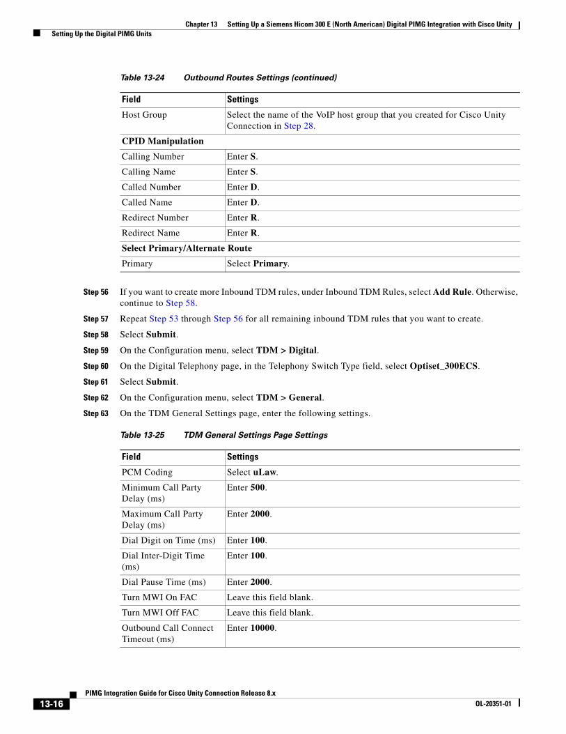
Chapter 13 Setting Up a Siemens Hicom 300 E (North American) Digital PIMG Integration with Cisco Unity Setting Up the Digital PIMG Units
Step 56 If you want to create more Inbound TDM rules, under Inbound TDM Rules, select Add Rule. Otherwise, continue to Step 58.
Step 57 Repeat Step 53 through Step 56 for all remaining inbound TDM rules that you want to create.
Step 58 Select Submit.
Step 59 On the Configuration menu, select TDM > Digital.
Step 60 On the Digital Telephony page, in the Telephony Switch Type field, select Optiset_300ECS.
Step 61 Select Submit.
Step 62 On the Configuration menu, select TDM > General.
Step 63 On the TDM General Settings page, enter the following settings.
Host Group Select the name of the VoIP host group that you created for Cisco Unity Connection in Step 28.
CPID Manipulation
Calling Number Enter S.
Calling Name Enter S.
Called Number Enter D.
Called Name Enter D.
Redirect Number Enter R.
Redirect Name Enter R.
Select Primary/Alternate Route
Primary Select Primary.
Table 13-25 TDM General Settings Page Settings
Field Settings
PCM Coding Select uLaw.
Minimum Call Party Delay (ms)
Enter 500.
Maximum Call Party Delay (ms)
Enter 2000.
Dial Digit on Time (ms) Enter 100.
Dial Inter-Digit Time (ms)
Enter 100.
Dial Pause Time (ms) Enter 2000.
Turn MWI On FAC Leave this field blank.
Turn MWI Off FAC Leave this field blank.
Outbound Call Connect Timeout (ms)
Enter 10000.
Table 13-24 Outbound Routes Settings (continued)
Field Settings
13-16PIMG Integration Guide for Cisco Unity Connection Release 8.x
OL-20351-01
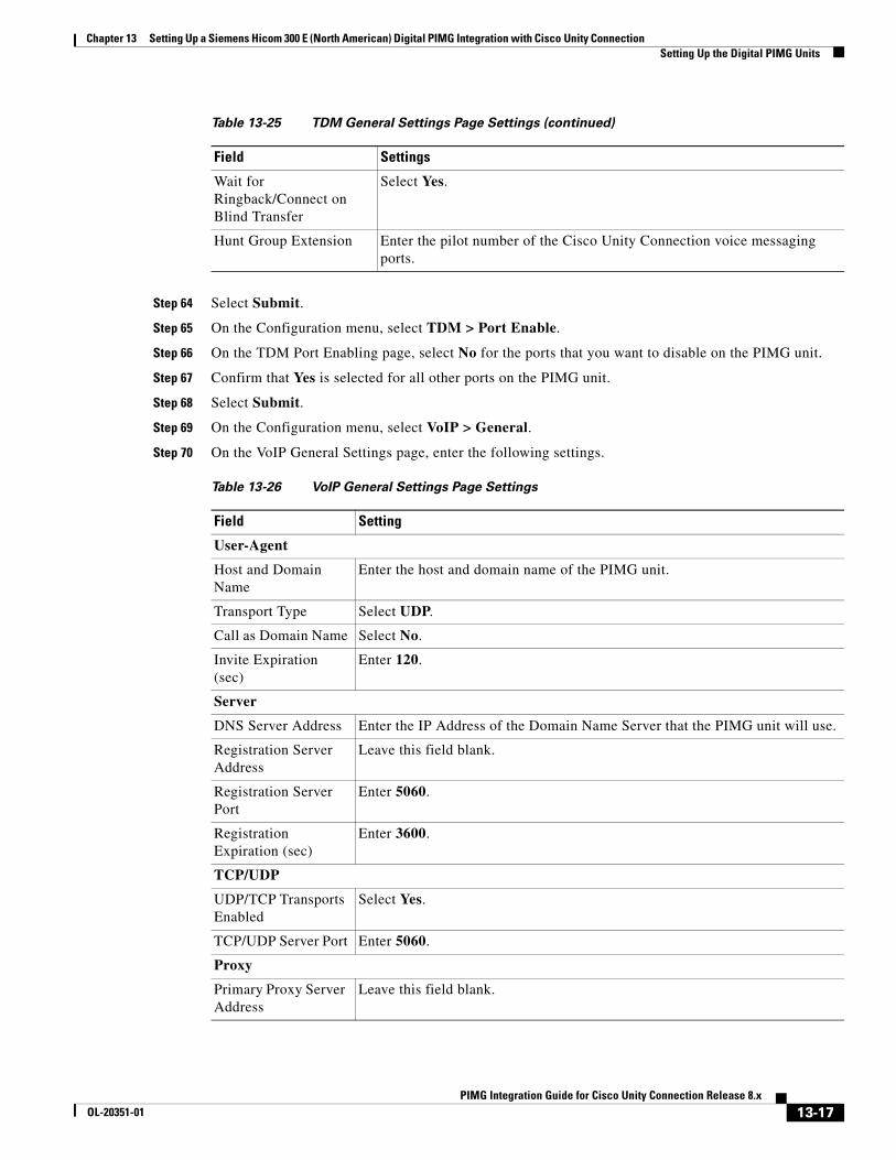
Chapter 13 Setting Up a Siemens Hicom 300 E (North American) Digital PIMG Integration with Cisco Unity Connection Setting Up the Digital PIMG Units
Step 64 Select Submit.
Step 65 On the Configuration menu, select TDM > Port Enable.
Step 66 On the TDM Port Enabling page, select No for the ports that you want to disable on the PIMG unit.
Step 67 Confirm that Yes is selected for all other ports on the PIMG unit.
Step 68 Select Submit.
Step 69 On the Configuration menu, select VoIP > General.
Step 70 On the VoIP General Settings page, enter the following settings.
Wait for Ringback/Connect on Blind Transfer
Select Yes.
Hunt Group Extension Enter the pilot number of the Cisco Unity Connection voice messaging ports.
Table 13-26 VoIP General Settings Page Settings
Field Setting
User-Agent
Host and Domain Name
Enter the host and domain name of the PIMG unit.
Transport Type Select UDP.
Call as Domain Name Select No.
Invite Expiration (sec)
Enter 120.
Server
DNS Server Address Enter the IP Address of the Domain Name Server that the PIMG unit will use.
Registration Server Address
Leave this field blank.
Registration Server Port
Enter 5060.
Registration Expiration (sec)
Enter 3600.
TCP/UDP
UDP/TCP Transports Enabled
Select Yes.
TCP/UDP Server Port Enter 5060.
Proxy
Primary Proxy Server Address
Leave this field blank.
Table 13-25 TDM General Settings Page Settings (continued)
Field Settings
13-17PIMG Integration Guide for Cisco Unity Connection Release 8.x
OL-20351-01
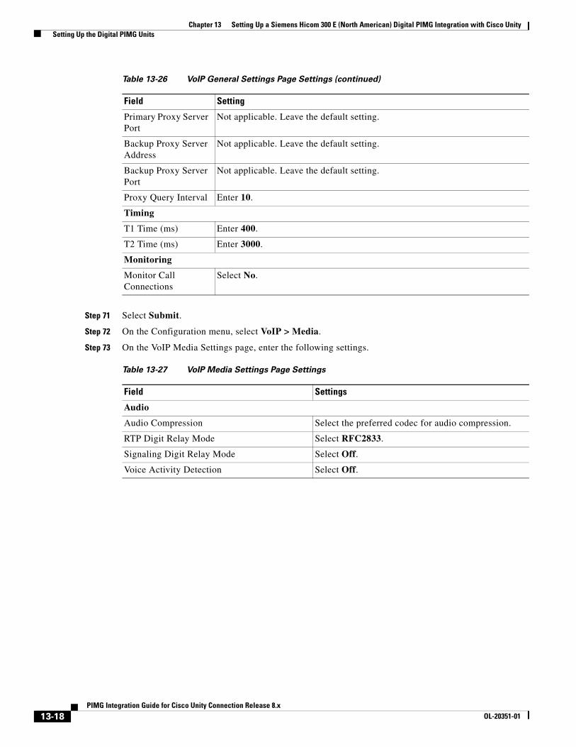
Chapter 13 Setting Up a Siemens Hicom 300 E (North American) Digital PIMG Integration with Cisco Unity Setting Up the Digital PIMG Units
Step 71 Select Submit.
Step 72 On the Configuration menu, select VoIP > Media.
Step 73 On the VoIP Media Settings page, enter the following settings.
Primary Proxy Server Port
Not applicable. Leave the default setting.
Backup Proxy Server Address
Not applicable. Leave the default setting.
Backup Proxy Server Port
Not applicable. Leave the default setting.
Proxy Query Interval Enter 10.
Timing
T1 Time (ms) Enter 400.
T2 Time (ms) Enter 3000.
Monitoring
Monitor Call Connections
Select No.
Table 13-27 VoIP Media Settings Page Settings
Field Settings
Audio
Audio Compression Select the preferred codec for audio compression.
RTP Digit Relay Mode Select RFC2833.
Signaling Digit Relay Mode Select Off.
Voice Activity Detection Select Off.
Table 13-26 VoIP General Settings Page Settings (continued)
Field Setting
13-18PIMG Integration Guide for Cisco Unity Connection Release 8.x
OL-20351-01
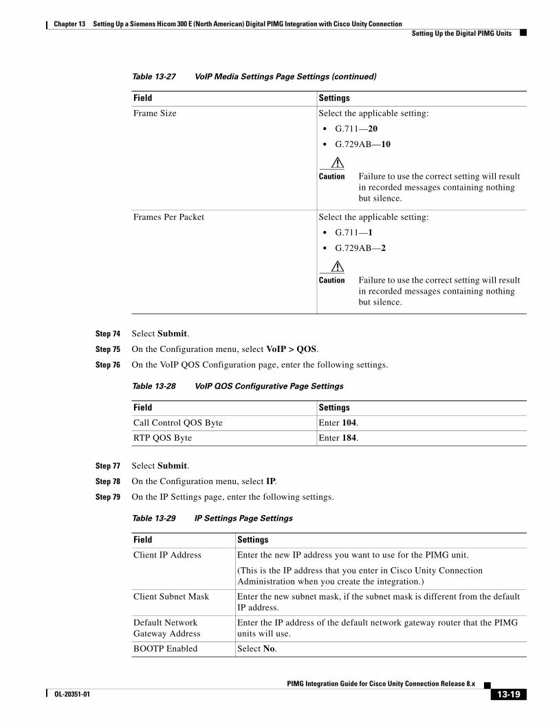
Chapter 13 Setting Up a Siemens Hicom 300 E (North American) Digital PIMG Integration with Cisco Unity Connection Setting Up the Digital PIMG Units
Step 74 Select Submit.
Step 75 On the Configuration menu, select VoIP > QOS.
Step 76 On the VoIP QOS Configuration page, enter the following settings.
Step 77 Select Submit.
Step 78 On the Configuration menu, select IP.
Step 79 On the IP Settings page, enter the following settings.
Frame Size Select the applicable setting:
• G.711—20
• G.729AB—10
Caution Failure to use the correct setting will result in recorded messages containing nothing but silence.
Frames Per Packet Select the applicable setting:
• G.711—1
• G.729AB—2
Caution Failure to use the correct setting will result in recorded messages containing nothing but silence.
Table 13-28 VoIP QOS Configurative Page Settings
Field Settings
Call Control QOS Byte Enter 104.
RTP QOS Byte Enter 184.
Table 13-29 IP Settings Page Settings
Field Settings
Client IP Address Enter the new IP address you want to use for the PIMG unit.
(This is the IP address that you enter in Cisco Unity Connection Administration when you create the integration.)
Client Subnet Mask Enter the new subnet mask, if the subnet mask is different from the default IP address.
Default Network Gateway Address
Enter the IP address of the default network gateway router that the PIMG units will use.
BOOTP Enabled Select No.
Table 13-27 VoIP Media Settings Page Settings (continued)
Field Settings
13-19PIMG Integration Guide for Cisco Unity Connection Release 8.x
OL-20351-01

Chapter 13 Setting Up a Siemens Hicom 300 E (North American) Digital PIMG Integration with Cisco Unity Creating a New Integration with the Siemens Hicom 300 Phone System
Step 80 Select Submit.
Step 81 On the Configuration menu, select Tone Detection.
Step 82 On the Tone Detection page, under Call Progress Tone - Learn, in the Learn Tone Event field, select Busy and do the following substeps to verify that the tone is correct.
a. From a available phone, call a second phone.
b. Answer the second phone when it rings, and leave both handsets off so that both phones are busy.
c. From a third phone, dial one of the busy phones.
d. Confirm that you hear a busy tone.
e. Hang up the third phone but leave the handsets for the other two phones off.
Step 83 Under Call Progress Tone - Learn, in the Dial String field, enter the extension that you dialed in Step 82c. from the third phone.
Step 84 Select Learn.
Step 85 On the Tone Detection page, under Call Progress Tone - Learn, in the Learn field, select Error and do the following substeps to verify that the tone is correct.
a. From an available phone, dial an extension that does not exist.
b. Confirm that you hear the reorder or error tone.
c. Hang up the phone.
Step 86 Under Call Progress Tone - Learn, in the Dial String field, enter the extension that you dialed in Step 85a.
Step 87 Select Learn.
Step 88 On the Tone Detection page, under Call Progress Tone - Learn, in the Learn field, select Ringback and do the following substeps to verify that the tone is correct.
a. From an available phone, dial an extension that does exist
b. Confirm that you hear the ringback tone.
c. Hang up the phone.
Step 89 Under Call Progress Tone - Learn, in the Dial String field, enter the extension that you dialed in Step 88a.
Step 90 Select Learn.
Step 91 Select Submit.
Step 92 Hang up the phones that you used in Step 82.
Step 93 On the System menu, select Restart.
Step 94 On the Restart page, select Restart Unit Now.
Step 95 Repeat Step 2 through Step 94 on all remaining PIMG units.
Creating a New Integration with the Siemens Hicom 300 Phone System
After ensuring that the Siemens Hicom 300 phone system, the PIMG units, and Cisco Unity Connection are ready for the integration, do the following procedure to set up the integration and to enter the port settings.
13-20PIMG Integration Guide for Cisco Unity Connection Release 8.x
OL-20351-01
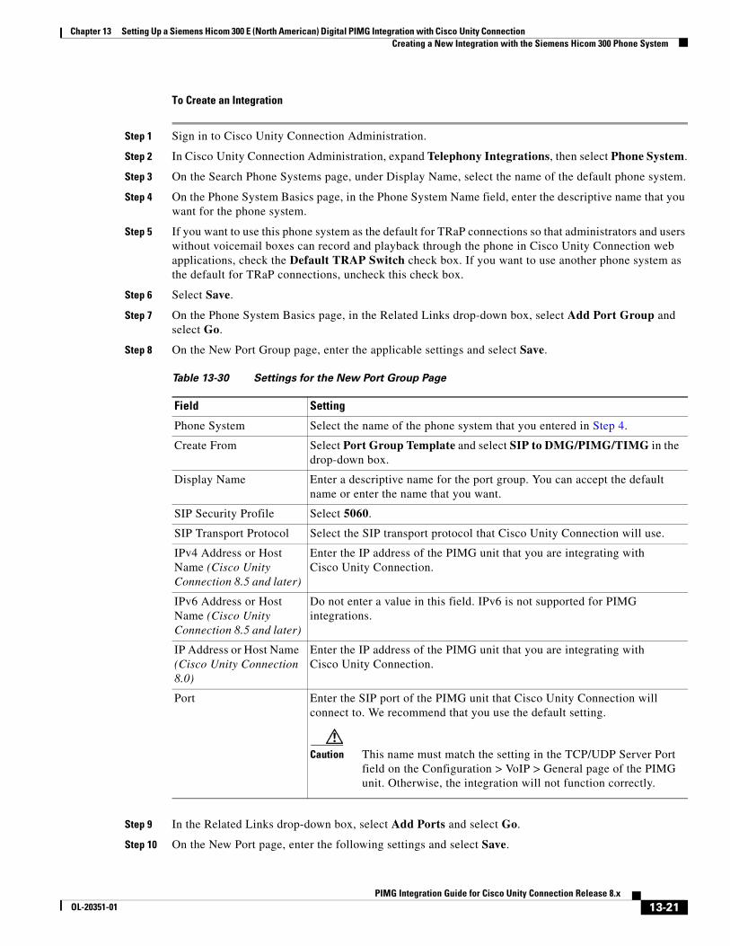
Chapter 13 Setting Up a Siemens Hicom 300 E (North American) Digital PIMG Integration with Cisco Unity Connection Creating a New Integration with the Siemens Hicom 300 Phone System
To Create an Integration
Step 1 Sign in to Cisco Unity Connection Administration.
Step 2 In Cisco Unity Connection Administration, expand Telephony Integrations, then select Phone System.
Step 3 On the Search Phone Systems page, under Display Name, select the name of the default phone system.
Step 4 On the Phone System Basics page, in the Phone System Name field, enter the descriptive name that you want for the phone system.
Step 5 If you want to use this phone system as the default for TRaP connections so that administrators and users without voicemail boxes can record and playback through the phone in Cisco Unity Connection web applications, check the Default TRAP Switch check box. If you want to use another phone system as the default for TRaP connections, uncheck this check box.
Step 6 Select Save.
Step 7 On the Phone System Basics page, in the Related Links drop-down box, select Add Port Group and select Go.
Step 8 On the New Port Group page, enter the applicable settings and select Save.
Step 9 In the Related Links drop-down box, select Add Ports and select Go.
Step 10 On the New Port page, enter the following settings and select Save.
Table 13-30 Settings for the New Port Group Page
Field Setting
Phone System Select the name of the phone system that you entered in Step 4.
Create From Select Port Group Template and select SIP to DMG/PIMG/TIMG in the drop-down box.
Display Name Enter a descriptive name for the port group. You can accept the default name or enter the name that you want.
SIP Security Profile Select 5060.
SIP Transport Protocol Select the SIP transport protocol that Cisco Unity Connection will use.
IPv4 Address or Host Name (Cisco Unity Connection 8.5 and later)
Enter the IP address of the PIMG unit that you are integrating with Cisco Unity Connection.
IPv6 Address or Host Name (Cisco Unity Connection 8.5 and later)
Do not enter a value in this field. IPv6 is not supported for PIMG integrations.
IP Address or Host Name (Cisco Unity Connection 8.0)
Enter the IP address of the PIMG unit that you are integrating with Cisco Unity Connection.
Port Enter the SIP port of the PIMG unit that Cisco Unity Connection will connect to. We recommend that you use the default setting.
Caution This name must match the setting in the TCP/UDP Server Port field on the Configuration > VoIP > General page of the PIMG unit. Otherwise, the integration will not function correctly.
13-21PIMG Integration Guide for Cisco Unity Connection Release 8.x
OL-20351-01
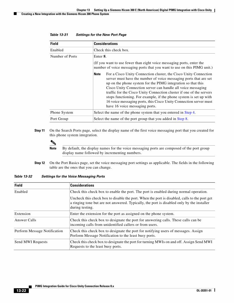
Chapter 13 Setting Up a Siemens Hicom 300 E (North American) Digital PIMG Integration with Cisco Unity Creating a New Integration with the Siemens Hicom 300 Phone System
Step 11 On the Search Ports page, select the display name of the first voice messaging port that you created for this phone system integration.
Note By default, the display names for the voice messaging ports are composed of the port group display name followed by incrementing numbers.
Step 12 On the Port Basics page, set the voice messaging port settings as applicable. The fields in the following table are the ones that you can change.
Table 13-31 Settings for the New Port Page
Field Considerations
Enabled Check this check box.
Number of Ports Enter 8.
(If you want to use fewer than eight voice messaging ports, enter the number of voice messaging ports that you want to use on this PIMG unit.)
Note For a Cisco Unity Connection cluster, the Cisco Unity Connection server must have the number of voice messaging ports that are set up on the phone system for the PIMG integration so that this Cisco Unity Connection server can handle all voice messaging traffic for the Cisco Unity Connection cluster if one of the servers stops functioning. For example, if the phone system is set up with 16 voice messaging ports, this Cisco Unity Connection server must have 16 voice messaging ports.
Phone System Select the name of the phone system that you entered in Step 4.
Port Group Select the name of the port group that you added in Step 8.
Table 13-32 Settings for the Voice Messaging Ports
Field Considerations
Enabled Check this check box to enable the port. The port is enabled during normal operation.
Uncheck this check box to disable the port. When the port is disabled, calls to the port get a ringing tone but are not answered. Typically, the port is disabled only by the installer during testing.
Extension Enter the extension for the port as assigned on the phone system.
Answer Calls Check this check box to designate the port for answering calls. These calls can be incoming calls from unidentified callers or from users.
Perform Message Notification Check this check box to designate the port for notifying users of messages. Assign Perform Message Notification to the least busy ports.
Send MWI Requests Check this check box to designate the port for turning MWIs on and off. Assign Send MWI Requests to the least busy ports.
13-22PIMG Integration Guide for Cisco Unity Connection Release 8.x
OL-20351-01
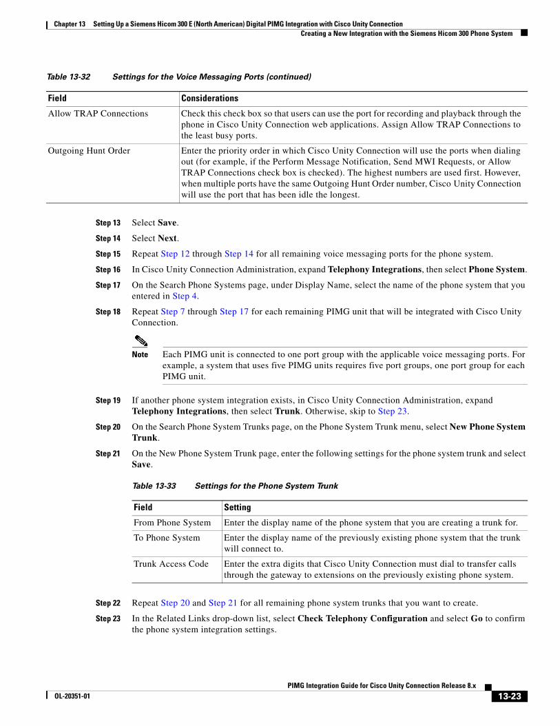
Chapter 13 Setting Up a Siemens Hicom 300 E (North American) Digital PIMG Integration with Cisco Unity Connection Creating a New Integration with the Siemens Hicom 300 Phone System
Step 13 Select Save.
Step 14 Select Next.
Step 15 Repeat Step 12 through Step 14 for all remaining voice messaging ports for the phone system.
Step 16 In Cisco Unity Connection Administration, expand Telephony Integrations, then select Phone System.
Step 17 On the Search Phone Systems page, under Display Name, select the name of the phone system that you entered in Step 4.
Step 18 Repeat Step 7 through Step 17 for each remaining PIMG unit that will be integrated with Cisco Unity Connection.
Note Each PIMG unit is connected to one port group with the applicable voice messaging ports. For example, a system that uses five PIMG units requires five port groups, one port group for each PIMG unit.
Step 19 If another phone system integration exists, in Cisco Unity Connection Administration, expand Telephony Integrations, then select Trunk. Otherwise, skip to Step 23.
Step 20 On the Search Phone System Trunks page, on the Phone System Trunk menu, select New Phone System Trunk.
Step 21 On the New Phone System Trunk page, enter the following settings for the phone system trunk and select Save.
Step 22 Repeat Step 20 and Step 21 for all remaining phone system trunks that you want to create.
Step 23 In the Related Links drop-down list, select Check Telephony Configuration and select Go to confirm the phone system integration settings.
Allow TRAP Connections Check this check box so that users can use the port for recording and playback through the phone in Cisco Unity Connection web applications. Assign Allow TRAP Connections to the least busy ports.
Outgoing Hunt Order Enter the priority order in which Cisco Unity Connection will use the ports when dialing out (for example, if the Perform Message Notification, Send MWI Requests, or Allow TRAP Connections check box is checked). The highest numbers are used first. However, when multiple ports have the same Outgoing Hunt Order number, Cisco Unity Connection will use the port that has been idle the longest.
Table 13-32 Settings for the Voice Messaging Ports (continued)
Field Considerations
Table 13-33 Settings for the Phone System Trunk
Field Setting
From Phone System Enter the display name of the phone system that you are creating a trunk for.
To Phone System Enter the display name of the previously existing phone system that the trunk will connect to.
Trunk Access Code Enter the extra digits that Cisco Unity Connection must dial to transfer calls through the gateway to extensions on the previously existing phone system.
13-23PIMG Integration Guide for Cisco Unity Connection Release 8.x
OL-20351-01

Chapter 13 Setting Up a Siemens Hicom 300 E (North American) Digital PIMG Integration with Cisco Unity Creating a New Integration with the Siemens Hicom 300 Phone System
If the test is not successful, the Task Execution Results displays one or more messages with troubleshooting steps. After correcting the problems, test the connection again.
Step 24 In the Task Execution Results window, select Close.
13-24PIMG Integration Guide for Cisco Unity Connection Release 8.x
OL-20351-01
PIMG IntegrOL-20351-01
C H A P T E R 14
Testing the IntegrationTo test whether Cisco Unity Connection and the phone system are integrated correctly, do the following procedures in the order listed.
If any of the steps indicate a failure, see the following documentation as applicable:
• The installation guide for the phone system.
• Cisco Unity Troubleshooting Guide Release 9.x, available at http://www.cisco.com/en/US/docs/voice_ip_comm/connection/9x/troubleshooting/guide/9xcuctsgx.html.
• The setup information earlier in this guide.
To Set Up the Test Configuration
Step 1 Set up two test extensions (Phone 1 and Phone 2) on the same phone system that Cisco Unity Connection is connected to.
Step 2 Set Phone 1 to forward calls to the Cisco Unity Connection pilot number when calls are not answered.
Caution The phone system must forward calls to the Cisco Unity Connection pilot number in no fewer than four rings. Otherwise, the test may fail.
Step 3 In Cisco Unity Connection Administration, expand Users, then select Users.
Step 4 On the Search Users page, select the display name of a user to use for testing. The extension for this user must be the extension for Phone 1.
Step 5 On the Edit User Basics page, uncheck the Set for Self-enrollment at Next Login check box.
Step 6 In the Voice Name field, record a recorded name for the test user.
Step 7 Select Save.
Step 8 On the Edit menu, select Message Waiting Indicators.
Step 9 On the Message Waiting Indicators page, select the message waiting indicator. If no message waiting indication is in the table, select Add New.
Step 10 On the Edit Message Waiting Indicator page, enter the following settings.
14-1ation Guide for Cisco Unity Connection Release 8.x
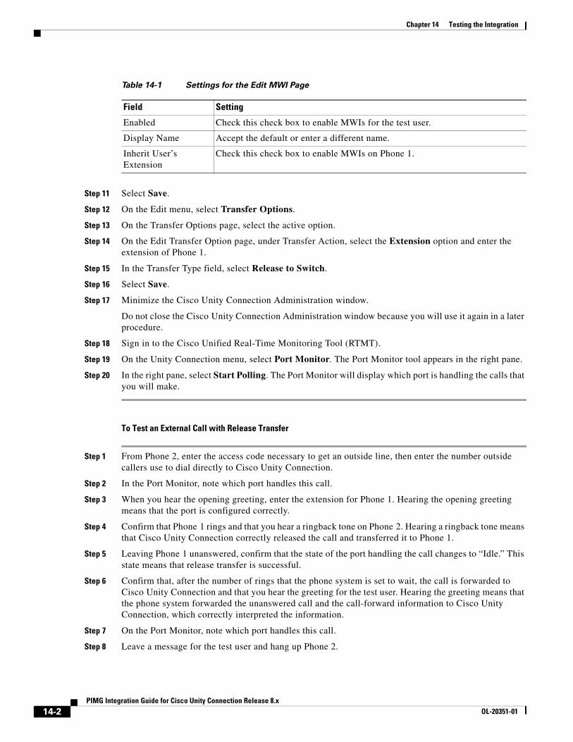
Chapter 14 Testing the Integration
Step 11 Select Save.
Step 12 On the Edit menu, select Transfer Options.
Step 13 On the Transfer Options page, select the active option.
Step 14 On the Edit Transfer Option page, under Transfer Action, select the Extension option and enter the extension of Phone 1.
Step 15 In the Transfer Type field, select Release to Switch.
Step 16 Select Save.
Step 17 Minimize the Cisco Unity Connection Administration window.
Do not close the Cisco Unity Connection Administration window because you will use it again in a later procedure.
Step 18 Sign in to the Cisco Unified Real-Time Monitoring Tool (RTMT).
Step 19 On the Unity Connection menu, select Port Monitor. The Port Monitor tool appears in the right pane.
Step 20 In the right pane, select Start Polling. The Port Monitor will display which port is handling the calls that you will make.
To Test an External Call with Release Transfer
Step 1 From Phone 2, enter the access code necessary to get an outside line, then enter the number outside callers use to dial directly to Cisco Unity Connection.
Step 2 In the Port Monitor, note which port handles this call.
Step 3 When you hear the opening greeting, enter the extension for Phone 1. Hearing the opening greeting means that the port is configured correctly.
Step 4 Confirm that Phone 1 rings and that you hear a ringback tone on Phone 2. Hearing a ringback tone means that Cisco Unity Connection correctly released the call and transferred it to Phone 1.
Step 5 Leaving Phone 1 unanswered, confirm that the state of the port handling the call changes to “Idle.” This state means that release transfer is successful.
Step 6 Confirm that, after the number of rings that the phone system is set to wait, the call is forwarded to Cisco Unity Connection and that you hear the greeting for the test user. Hearing the greeting means that the phone system forwarded the unanswered call and the call-forward information to Cisco Unity Connection, which correctly interpreted the information.
Step 7 On the Port Monitor, note which port handles this call.
Step 8 Leave a message for the test user and hang up Phone 2.
Table 14-1 Settings for the Edit MWI Page
Field Setting
Enabled Check this check box to enable MWIs for the test user.
Display Name Accept the default or enter a different name.
Inherit User’s Extension
Check this check box to enable MWIs on Phone 1.
14-2PIMG Integration Guide for Cisco Unity Connection Release 8.x
OL-20351-01
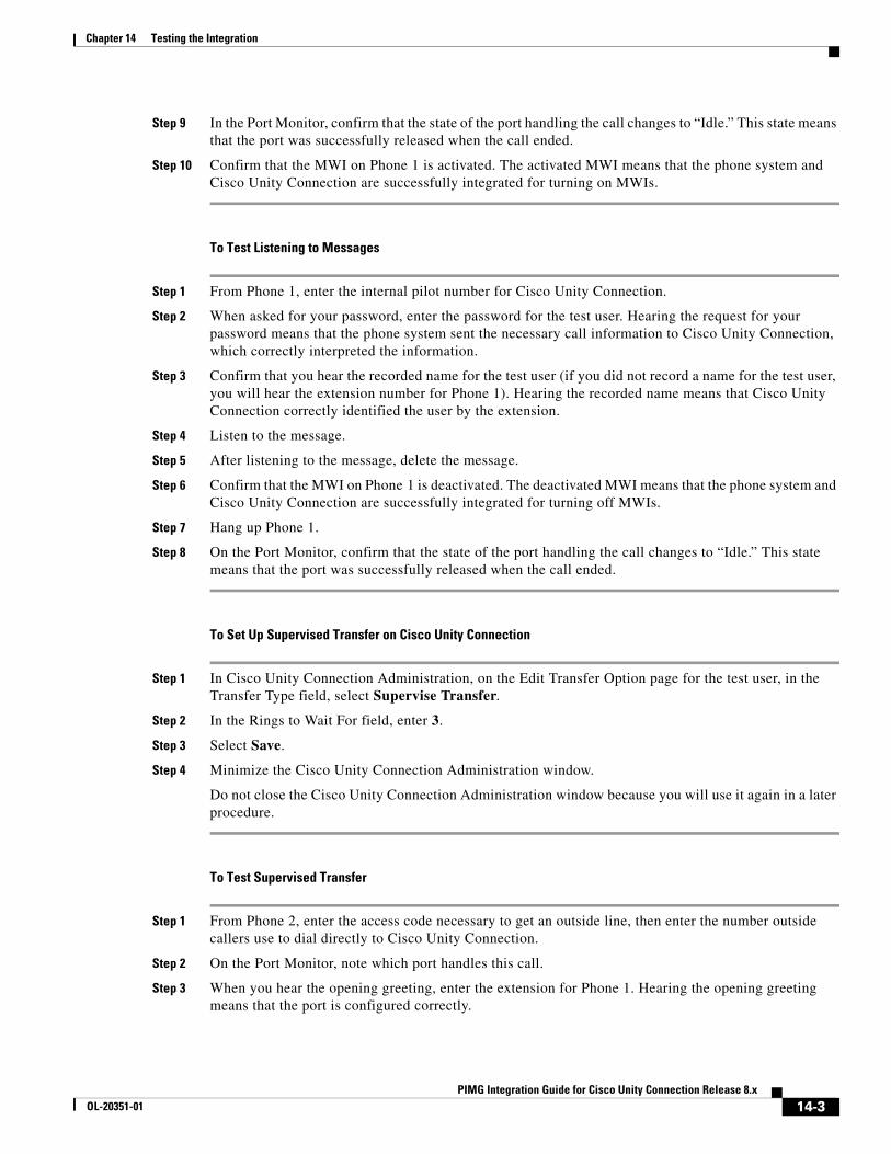
Chapter 14 Testing the Integration
Step 9 In the Port Monitor, confirm that the state of the port handling the call changes to “Idle.” This state means that the port was successfully released when the call ended.
Step 10 Confirm that the MWI on Phone 1 is activated. The activated MWI means that the phone system and Cisco Unity Connection are successfully integrated for turning on MWIs.
To Test Listening to Messages
Step 1 From Phone 1, enter the internal pilot number for Cisco Unity Connection.
Step 2 When asked for your password, enter the password for the test user. Hearing the request for your password means that the phone system sent the necessary call information to Cisco Unity Connection, which correctly interpreted the information.
Step 3 Confirm that you hear the recorded name for the test user (if you did not record a name for the test user, you will hear the extension number for Phone 1). Hearing the recorded name means that Cisco Unity Connection correctly identified the user by the extension.
Step 4 Listen to the message.
Step 5 After listening to the message, delete the message.
Step 6 Confirm that the MWI on Phone 1 is deactivated. The deactivated MWI means that the phone system and Cisco Unity Connection are successfully integrated for turning off MWIs.
Step 7 Hang up Phone 1.
Step 8 On the Port Monitor, confirm that the state of the port handling the call changes to “Idle.” This state means that the port was successfully released when the call ended.
To Set Up Supervised Transfer on Cisco Unity Connection
Step 1 In Cisco Unity Connection Administration, on the Edit Transfer Option page for the test user, in the Transfer Type field, select Supervise Transfer.
Step 2 In the Rings to Wait For field, enter 3.
Step 3 Select Save.
Step 4 Minimize the Cisco Unity Connection Administration window.
Do not close the Cisco Unity Connection Administration window because you will use it again in a later procedure.
To Test Supervised Transfer
Step 1 From Phone 2, enter the access code necessary to get an outside line, then enter the number outside callers use to dial directly to Cisco Unity Connection.
Step 2 On the Port Monitor, note which port handles this call.
Step 3 When you hear the opening greeting, enter the extension for Phone 1. Hearing the opening greeting means that the port is configured correctly.
14-3PIMG Integration Guide for Cisco Unity Connection Release 8.x
OL-20351-01
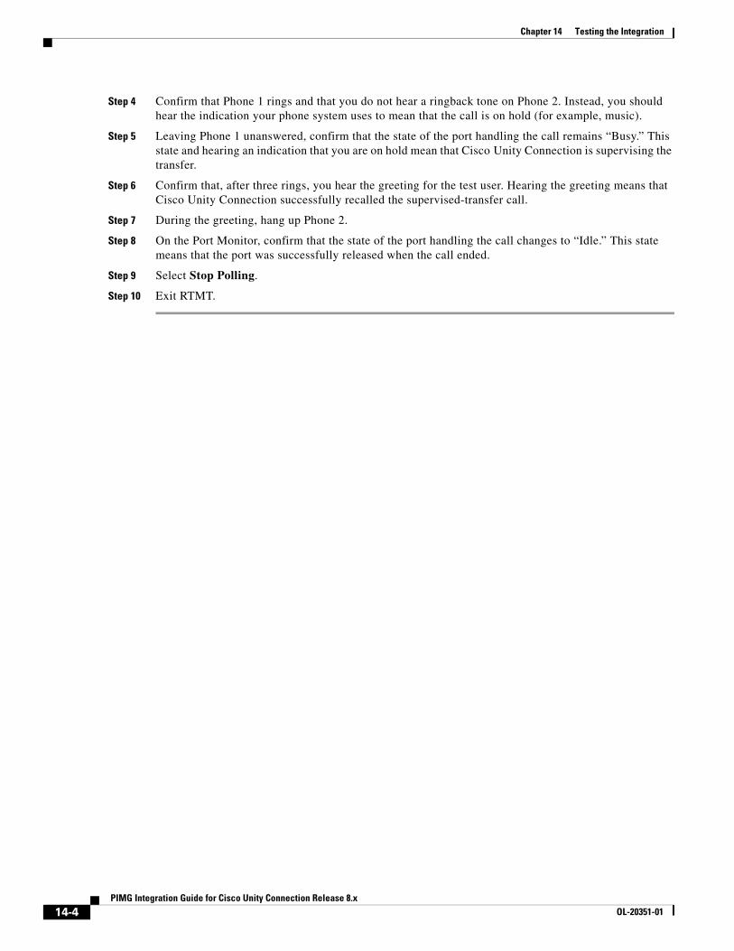
Chapter 14 Testing the Integration
Step 4 Confirm that Phone 1 rings and that you do not hear a ringback tone on Phone 2. Instead, you should hear the indication your phone system uses to mean that the call is on hold (for example, music).
Step 5 Leaving Phone 1 unanswered, confirm that the state of the port handling the call remains “Busy.” This state and hearing an indication that you are on hold mean that Cisco Unity Connection is supervising the transfer.
Step 6 Confirm that, after three rings, you hear the greeting for the test user. Hearing the greeting means that Cisco Unity Connection successfully recalled the supervised-transfer call.
Step 7 During the greeting, hang up Phone 2.
Step 8 On the Port Monitor, confirm that the state of the port handling the call changes to “Idle.” This state means that the port was successfully released when the call ended.
Step 9 Select Stop Polling.
Step 10 Exit RTMT.
14-4PIMG Integration Guide for Cisco Unity Connection Release 8.x
OL-20351-01
PIMG IntegrOL-20351-01
C H A P T E R 15
Adding New User Templates for Multiple IntegrationsWhen you create the first phone system integration, this first phone system is automatically selected in the default user template. The users that you add after creating this phone system integration will be assigned to this phone system by default.
However, for each additional phone system integration that you create, you must add the applicable new user templates that will assign users to the new phone system. You must add the new templates before you add new users who will be assigned to the new phone system.
For details on adding new user templates, or on selecting a user template when adding a new user, see the “Adding, Modifying, or Deleting a User Template in Cisco Unity Connection 9.x” and the “Preparing to Add User Accounts in Cisco Unity Connection 9.x” chapters of the User Moves, Adds, and Changes Guide for Cisco Unity Connection Release 9.x. The guide is available at http://www.cisco.com/en/US/docs/voice_ip_comm/connection/9x/user_mac/guide/9xcucmacx.html.
15-1ation Guide for Cisco Unity Connection Release 8.x

Chapter 15 Adding New User Templates for Multiple Integrations
15-2PIMG Integration Guide for Cisco Unity Connection Release 8.x
OL-20351-01
PIMG Integration GOL-20351-01
A
P P E N D I X A Adding a Secondary Master PIMG UnitBecause the master PIMG unit processes all call information and MWI requests for the system, the integration will lose important functionality if the master PIMG unit stops working. If you want to minimize this risk, you can add a secondary master PIMG unit to process call information and MWI requests when the primary master PIMG unit is no longer functioning.
During normal operation, the primary master PIMG unit is connected to power and is functioning, while the secondary master PIMG unit is not connected to power and is not functioning. To activate the secondary master PIMG unit, you must disconnect power to the primary master PIMG unit, then connect power to the secondary master PIMG unit.
The following task list describes the process for adding a secondary master PIMG unit.
Task List to Add a Secondary Master PIMG UnitUse the following task list to add a secondary master PIMG unit.
1. Set up the analog voice line connections to the master PIMG units. See the “Analog Voice Line Connections for the Master PIMG Units” section on page A-1.
2. Set up the serial data cable connections to the master PIMG units. See the “Serial Data Cable Connections for the Master PIMG Units” section on page A-4.
3. Configure the secondary master PIMG unit. See the “Configuring the Secondary Master PIMG Unit” section on page A-5.
Analog Voice Line Connections for the Master PIMG UnitsCircuit-switched phone systems typically have 25-pair or 32-pair cables to provide analog voice connections. It is common that the cable is broken into individual lines that may attach to a punchdown cross-connect block (for example, 66-Type), or the cable may terminate with RJ-11 or RJ-14 connectors to accept analog voice lines.
A punchdown cross-connect block or line splitters may be used to split the analog lines. It is possible to use these devices in combination to manage and split the lines.
A-1uide for Cisco Unity Connection Release 8.x
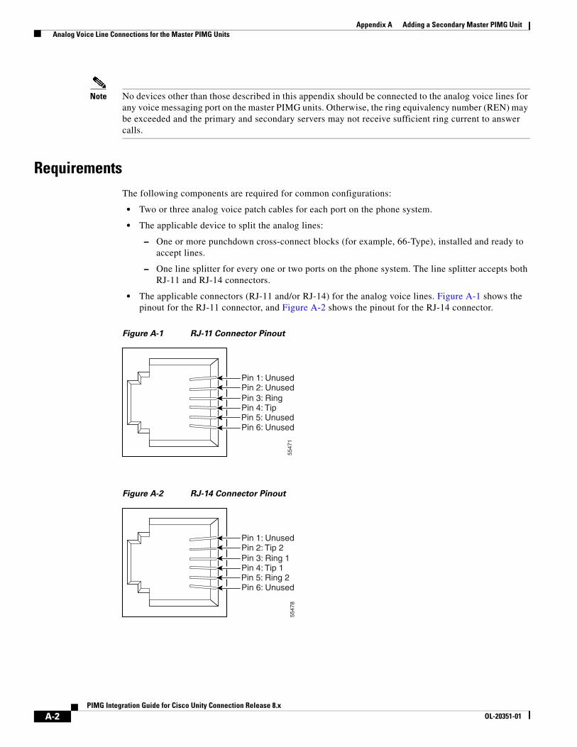
Appendix A Adding a Secondary Master PIMG Unit Analog Voice Line Connections for the Master PIMG Units
Note No devices other than those described in this appendix should be connected to the analog voice lines for any voice messaging port on the master PIMG units. Otherwise, the ring equivalency number (REN) may be exceeded and the primary and secondary servers may not receive sufficient ring current to answer calls.
RequirementsThe following components are required for common configurations:
• Two or three analog voice patch cables for each port on the phone system.
• The applicable device to split the analog lines:
– One or more punchdown cross-connect blocks (for example, 66-Type), installed and ready to accept lines.
– One line splitter for every one or two ports on the phone system. The line splitter accepts both RJ-11 and RJ-14 connectors.
• The applicable connectors (RJ-11 and/or RJ-14) for the analog voice lines. Figure A-1 shows the pinout for the RJ-11 connector, and Figure A-2 shows the pinout for the RJ-14 connector.
Figure A-1 RJ-11 Connector Pinout
Figure A-2 RJ-14 Connector Pinout
5547
1
Pin 1: UnusedPin 2: UnusedPin 3: RingPin 4: TipPin 5: UnusedPin 6: Unused
5547
8
Pin 1: UnusedPin 2: Tip 2Pin 3: Ring 1Pin 4: Tip 1Pin 5: Ring 2Pin 6: Unused
A-2PIMG Integration Guide for Cisco Unity Connection Release 8.x
OL-20351-01
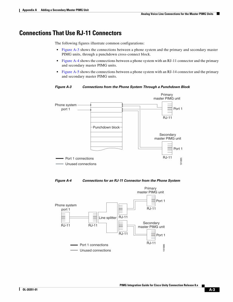
Appendix A Adding a Secondary Master PIMG Unit Analog Voice Line Connections for the Master PIMG Units
Connections That Use RJ-11 ConnectorsThe following figures illustrate common configurations:
• Figure A-3 shows the connections between a phone system and the primary and secondary master PIMG units, through a punchdown cross-connect block.
• Figure A-4 shows the connections between a phone system with an RJ-11 connector and the primary and secondary master PIMG units.
• Figure A-5 shows the connections between a phone system with an RJ-14 connector and the primary and secondary master PIMG units.
Figure A-3 Connections from the Phone System Through a Punchdown Block
Figure A-4 Connections for an RJ-11 Connector from the Phone System
Phone systemport 1
Primarymaster PIMG unit
Secondarymaster PIMG unit
Port 1
Port 1
RJ-11
RJ-11Port 1 connections
Unused connections 1918
85
Punchdown block
Phone systemport 1
Port 1
Port 1
RJ-11
RJ-11Port 1 connections
Unused connections 1918
86
RJ-11
Line splitter
RJ-11
RJ-11
RJ-11
Primarymaster PIMG unit
Secondarymaster PIMG unit
A-3PIMG Integration Guide for Cisco Unity Connection Release 8.x
OL-20351-01
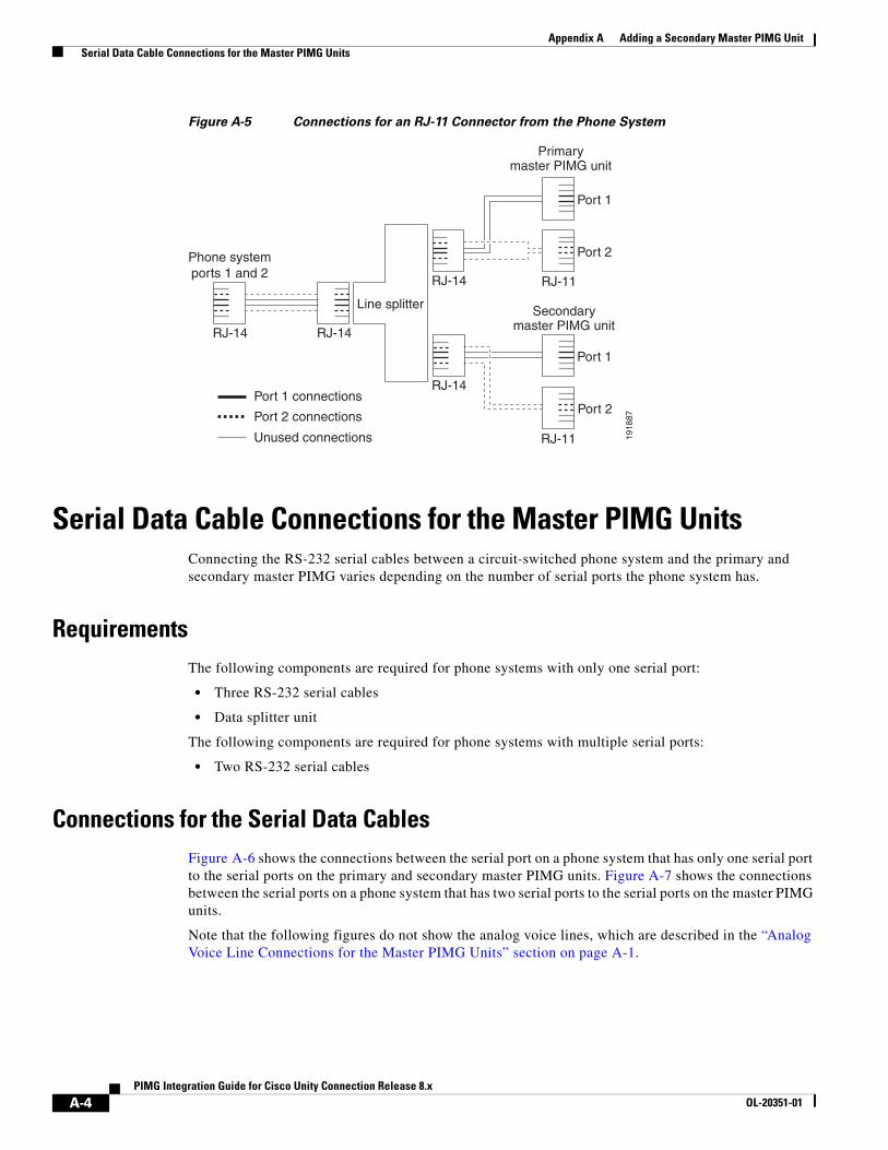
Appendix A Adding a Secondary Master PIMG Unit Serial Data Cable Connections for the Master PIMG Units
Figure A-5 Connections for an RJ-11 Connector from the Phone System
Serial Data Cable Connections for the Master PIMG UnitsConnecting the RS-232 serial cables between a circuit-switched phone system and the primary and secondary master PIMG varies depending on the number of serial ports the phone system has.
RequirementsThe following components are required for phone systems with only one serial port:
• Three RS-232 serial cables
• Data splitter unit
The following components are required for phone systems with multiple serial ports:
• Two RS-232 serial cables
Connections for the Serial Data CablesFigure A-6 shows the connections between the serial port on a phone system that has only one serial port to the serial ports on the primary and secondary master PIMG units. Figure A-7 shows the connections between the serial ports on a phone system that has two serial ports to the serial ports on the master PIMG units.
Note that the following figures do not show the analog voice lines, which are described in the “Analog Voice Line Connections for the Master PIMG Units” section on page A-1.
Phone systemports 1 and 2
Port 1
Port 2
RJ-14
RJ-11
Port 2 connections
Unused connections 1918
87
RJ-14
Line splitter
Port 1 connections
Port 2
RJ-11
Port 1
RJ-14
RJ-14
Primarymaster PIMG unit
Secondarymaster PIMG unit
A-4PIMG Integration Guide for Cisco Unity Connection Release 8.x
OL-20351-01
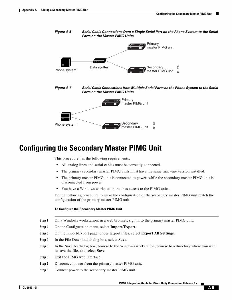
Appendix A Adding a Secondary Master PIMG Unit Configuring the Secondary Master PIMG Unit
Figure A-6 Serial Cable Connections from a Single Serial Port on the Phone System to the Serial
Ports on the Master PIMG Units
Figure A-7 Serial Cable Connections from Multiple Serial Ports on the Phone System to the Serial
Ports on the Master PIMG Units
Configuring the Secondary Master PIMG UnitThis procedure has the following requirements:
• All analog lines and serial cables must be correctly connected.
• The primary secondary master PIMG units must have the same firmware version installed.
• The primary master PIMG unit is connected to power, while the secondary master PIMG unit is disconnected from power.
• You have a Windows workstation that has access to the PIMG units.
Do the following procedure to make the configuration of the secondary master PIMG unit match the configuration of the primary master PIMG unit.
To Configure the Secondary Master PIMG Unit
Step 1 On a Windows workstation, in a web browser, sign in to the primary master PIMG unit.
Step 2 On the Configuration menu, select Import/Export.
Step 3 On the Import/Export page, under Export Files, select Export All Settings.
Step 4 In the File Download dialog box, select Save.
Step 5 In the Save As dialog box, browse to the Windows workstation, browse to a directory where you want to save the file, and select Save.
Step 6 Exit the PIMG web interface.
Step 7 Disconnect power from the primary master PIMG unit.
Step 8 Connect power to the secondary master PIMG unit.
1918
88Data splitterPhone system
Primarymaster PIMG unit
Secondarymaster PIMG unit
1918
89Phone system
Primarymaster PIMG unit
Secondarymaster PIMG unit
A-5PIMG Integration Guide for Cisco Unity Connection Release 8.x
OL-20351-01
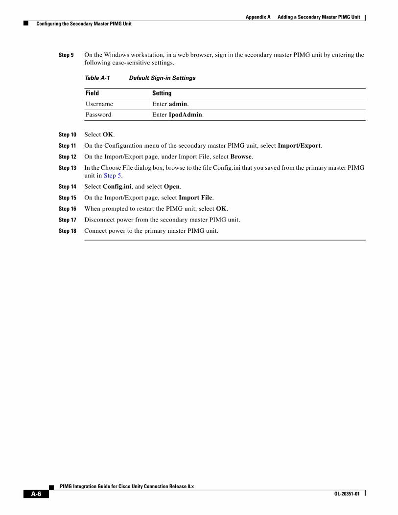
Appendix A Adding a Secondary Master PIMG Unit Configuring the Secondary Master PIMG Unit
Step 9 On the Windows workstation, in a web browser, sign in the secondary master PIMG unit by entering the following case-sensitive settings.
Step 10 Select OK.
Step 11 On the Configuration menu of the secondary master PIMG unit, select Import/Export.
Step 12 On the Import/Export page, under Import File, select Browse.
Step 13 In the Choose File dialog box, browse to the file Config.ini that you saved from the primary master PIMG unit in Step 5.
Step 14 Select Config.ini, and select Open.
Step 15 On the Import/Export page, select Import File.
Step 16 When prompted to restart the PIMG unit, select OK.
Step 17 Disconnect power from the secondary master PIMG unit.
Step 18 Connect power to the primary master PIMG unit.
Table A-1 Default Sign-in Settings
Field Setting
Username Enter admin.
Password Enter IpodAdmin.
A-6PIMG Integration Guide for Cisco Unity Connection Release 8.x
OL-20351-01
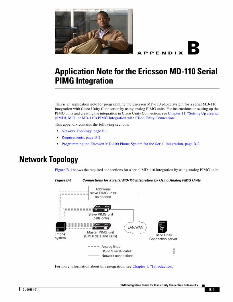
PIMG Integration GOL-20351-01
A
P P E N D I X B Application Note for the Ericsson MD-110 Serial PIMG IntegrationThis is an application note for programming the Ericsson MD-110 phone system for a serial MD-110 integration with Cisco Unity Connection by using analog PIMG units. For instructions on setting up the PIMG units and creating the integration in Cisco Unity Connection, see Chapter 11, “Setting Up a Serial (SMDI, MCI, or MD-110) PIMG Integration with Cisco Unity Connection.”
This appendix contains the following sections:
• Network Topology, page B-1
• Requirements, page B-2
• Programming the Ericsson MD-100 Phone System for the Serial Integration, page B-2
Network TopologyFigure B-1 shows the required connections for a serial MD-110 integration by using analog PIMG units.
Figure B-1 Connections for a Serial MD-110 Integration by Using Analog PIMG Units
For more information about this integration, see Chapter 1, “Introduction.”
Analog linesRS-232 serial cableNetwork connections 15
3568
LAN/WANMaster PIMG unit
(SMDI data and calls)
Additionalslave PIMG units
as needed
Slave PIMG unit(calls only)
C
Cisco UnityConnection server
Phonesystem
B-1uide for Cisco Unity Connection Release 8.x
Appendix B Application Note for the Ericsson MD-110 Serial PIMG Integration Requirements
RequirementsThe Ericsson MD-110 phone system met the following requirements:
• The Ericsson MD-110 phone system.
• Software level BC6 or later.
Programming the Ericsson MD-100 Phone System for the Serial Integration
The following programming instructions are provided as an example of a functioning integration. The specific programming for your phone system may vary depending on its configuration.
Caution In programming the phone system, do not send calls to voice messaging ports in Cisco Unity Connection that cannot answer calls (voice messaging ports that are not set to Answer Calls). For example, if a voice messaging port is set only to Perform Message Notification, do not send calls to it.
Example of Programming for the Ericsson MD-110 Phone System in a Serial Integration
1. Check the software version on the phone system and the country variant that is configured. This information may be useful for troubleshooting problems with the integration. For example:
<cadap; ==> Check the software version and Country variantCALENDAR DATA
IDENTITY=ACM1VERSION=CXP1010101/4/TSWSP02/R3A ==> 01 == Standard Application
2. Configure the analog extensions for the voice messaging ports similarly to the following example:
<excap:dir=1063&1064; ==> print analog extensionEXTENSION CATEGORY FIELDS
DIR TRAF SERV CDIV ROC TRM ADC BSEC1063 00151515 0201120600 000151000 000001 0 010001701 01064 00151515 0201120600 000151000 000001 0 010001701 0
3. Configure the hunt group number for the voice messaging ports on the PIMG units similarly to the following example:
<vmpop:grp=all; ==> print VM HuntGroup numberVOICE MAIL GROUP DATAGRP IFCIND4500 1
4. Associate the voice messaging port extensions with the hunt group number similarly to the following example:
<vmpop:dir=all; ==> print VM port DN associated with the HuntGroup numberVOICE MAIL PORT DATADIR PORT IFCIND1063 1063 11064 1064 1
5. Configure the voice mail function information similarly to the following:
B-2PIMG Integration Guide for Cisco Unity Connection Release 8.x
OL-20351-01

Appendix B Application Note for the Ericsson MD-110 Serial PIMG Integration Programming the Ericsson MD-100 Phone System for the Serial Integration
<vmfup:ifcind=1; ==> print VM function informationVOICE MAIL FUNCTION DATAIFCIND VMF POFMT1 EXTN3 4
6. Configure the I/O device interface for voice mail similarly to the following:
<ioddp; ==> print I/O Device interfaceI/O DEVICE DATANODE IODEV/SUBFS BPOS/EQU I/O-BUS TYPE/USAGE STATUS AUTHSYSN V-MAIL 001-0-60-3 - OUT IN SERVICE
7. Configure the I/O device function for voice mail similarly to the following example:
<iofdp; ==> print I/O Device FunctionI/O FUNCTIONS DEFINITIONIODEV TRD NDC CALLS WAIT DELAY SUPERV-MAIL BOTH 2 30 5 YES
8. Configure the serial connection parameters for voice mail similarly to the following example:
<ioifp; ==> print I/O Device serial interface parameters VMI/O INTERFACE CHARACTERISTICSIODEV IFACE BAUDR WORDL PARITY STPBIT PROCSYSTERMINAL V24 ALL 8 NONE 1 ECHOV-MAIL V24 9600 8 NONE 1 ECHO
9. Configure MWIs to be sent over the serial cable similarly to the following example:
<icmwp:sid=1; ==> print MWI ext using on serial interfaceINFORMATION COMPUTER MESSAGE WAITING DATASID DTXT KFCN DIG1 4500 MWC 4500
10. Configure the filler information similarly to the following example:
<ICFUP:ifcind=1; ==> print the filler informationINFORMATION COMPUTER COMMON FUNCTIONS DATA
MESSAGE WAITING FUNCTIONALITY IS ALL
INFORMATION COMPUTER EQUIPMENT DATA
IFCIND IODEV EQU RATE DFMT UPDFCN PARITY CCHECK1 V-MAIL 4 YES FILLER=48 ICEXG=NONE USER=NONE
11. Configure the hookflash timer similarly to the following example:
<aspap:parnum=253; ==> print Hookflash timerAPPLICATION SYSTEM PARAMETERSPARNUM PARVAL 253 110
12. Configure the on-hook timer similarly to the following example:
<aspap:parnum=252; ==> print On-hook timerAPPLICATION SYSTEM PARAMETERSPARNUM PARVAL 252 225
B-3PIMG Integration Guide for Cisco Unity Connection Release 8.x
OL-20351-01

Appendix B Application Note for the Ericsson MD-110 Serial PIMG Integration Programming the Ericsson MD-100 Phone System for the Serial Integration
B-4PIMG Integration Guide for Cisco Unity Connection Release 8.x
OL-20351-01
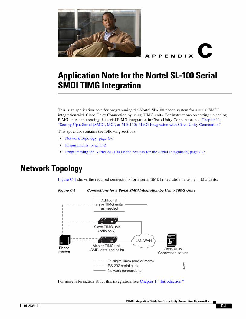
PIMG Integration GOL-20351-01
A
P P E N D I X C Application Note for the Nortel SL-100 Serial SMDI TIMG IntegrationThis is an application note for programming the Nortel SL-100 phone system for a serial SMDI integration with Cisco Unity Connection by using TIMG units. For instructions on setting up analog PIMG units and creating the serial PIMG integration in Cisco Unity Connection, see Chapter 11, “Setting Up a Serial (SMDI, MCI, or MD-110) PIMG Integration with Cisco Unity Connection.”
This appendix contains the following sections:
• Network Topology, page C-1
• Requirements, page C-2
• Programming the Nortel SL-100 Phone System for the Serial Integration, page C-2
Network TopologyFigure C-1 shows the required connections for a serial SMDI integration by using TIMG units.
Figure C-1 Connections for a Serial SMDI Integration by Using TIMG Units
For more information about this integration, see Chapter 1, “Introduction.”
T1 digital lines (one or more)RS-232 serial cableNetwork connections 19
0677
LAN/WANMaster TIMG unit
(SMDI data and calls)
Additionalslave TIMG units
as needed
Slave TIMG unit(calls only)
C
Cisco UnityConnection server
Phonesystem
C-1uide for Cisco Unity Connection Release 8.x
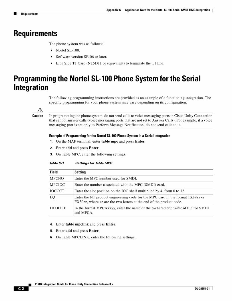
Appendix C Application Note for the Nortel SL-100 Serial SMDI TIMG Integration Requirements
RequirementsThe phone system was as follows:
• Nortel SL-100.
• Software version SE-06 or later.
• Line Side T1 Card (NT5D11 or equivalent) to terminate the T1 line.
Programming the Nortel SL-100 Phone System for the Serial Integration
The following programming instructions are provided as an example of a functioning integration. The specific programming for your phone system may vary depending on its configuration.
Caution In programming the phone system, do not send calls to voice messaging ports in Cisco Unity Connection that cannot answer calls (voice messaging ports that are not set to Answer Calls). For example, if a voice messaging port is set only to Perform Message Notification, do not send calls to it.
Example of Programming for the Nortel SL-100 Phone System in a Serial Integration
1. On the MAP terminal, enter table mpc and press Enter.
2. Enter add and press Enter.
3. On Table MPC, enter the following settings.
4. Enter table mpclink and press Enter.
5. Enter add and press Enter.
6. On Table MPCLINK, enter the following settings.
Table C-1 Settings for Table MPC
Field Setting
MPCNO Enter the MPC number used for SMDI.
MPCIOC Enter the number associated with the MPC (SMDI) card.
IOCCCT Enter the slot position on the IOC shelf multiplied by 4, from 0 to 32.
EQ Enter the NT product engineering code for the MPC card in the format 1X89zz or FX30zz, where zz are the two letters at the end of the product code.
DLDFILE In the format MPCAxxyy, enter the name of the 8-character download file for SMDI and MPCA.
C-2PIMG Integration Guide for Cisco Unity Connection Release 8.x
OL-20351-01
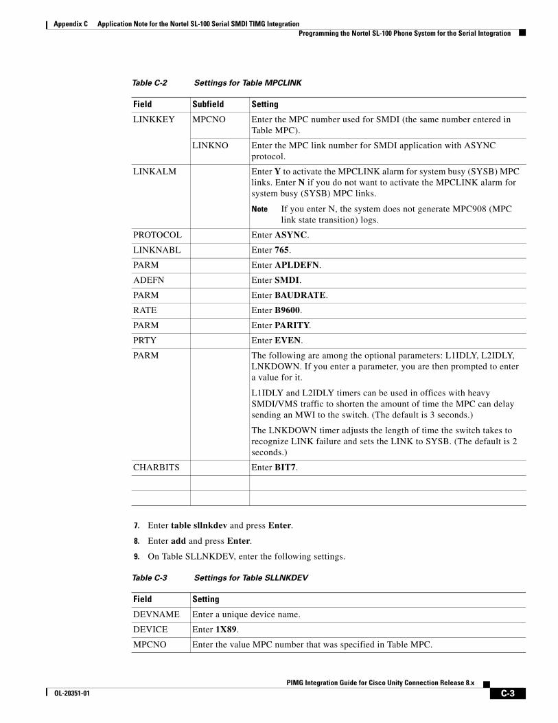
Appendix C Application Note for the Nortel SL-100 Serial SMDI TIMG Integration Programming the Nortel SL-100 Phone System for the Serial Integration
7. Enter table sllnkdev and press Enter.
8. Enter add and press Enter.
9. On Table SLLNKDEV, enter the following settings.
Table C-2 Settings for Table MPCLINK
Field Subfield Setting
LINKKEY MPCNO Enter the MPC number used for SMDI (the same number entered in Table MPC).
LINKNO Enter the MPC link number for SMDI application with ASYNC protocol.
LINKALM Enter Y to activate the MPCLINK alarm for system busy (SYSB) MPC links. Enter N if you do not want to activate the MPCLINK alarm for system busy (SYSB) MPC links.
Note If you enter N, the system does not generate MPC908 (MPC link state transition) logs.
PROTOCOL Enter ASYNC.
LINKNABL Enter 765.
PARM Enter APLDEFN.
ADEFN Enter SMDI.
PARM Enter BAUDRATE.
RATE Enter B9600.
PARM Enter PARITY.
PRTY Enter EVEN.
PARM The following are among the optional parameters: L1IDLY, L2IDLY, LNKDOWN. If you enter a parameter, you are then prompted to enter a value for it.
L1IDLY and L2IDLY timers can be used in offices with heavy SMDI/VMS traffic to shorten the amount of time the MPC can delay sending an MWI to the switch. (The default is 3 seconds.)
The LNKDOWN timer adjusts the length of time the switch takes to recognize LINK failure and sets the LINK to SYSB. (The default is 2 seconds.)
CHARBITS Enter BIT7.
Table C-3 Settings for Table SLLNKDEV
Field Setting
DEVNAME Enter a unique device name.
DEVICE Enter 1X89.
MPCNO Enter the value MPC number that was specified in Table MPC.
C-3PIMG Integration Guide for Cisco Unity Connection Release 8.x
OL-20351-01
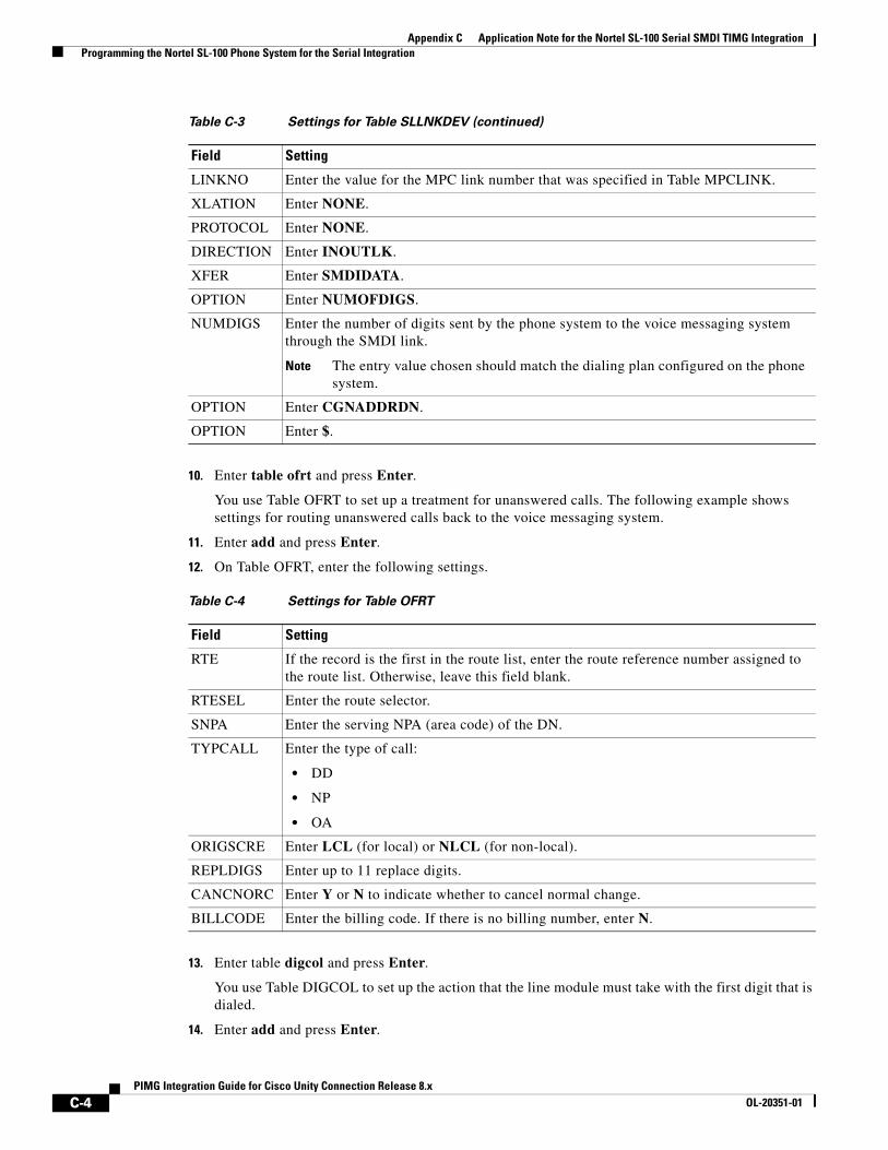
Appendix C Application Note for the Nortel SL-100 Serial SMDI TIMG Integration Programming the Nortel SL-100 Phone System for the Serial Integration
10. Enter table ofrt and press Enter.
You use Table OFRT to set up a treatment for unanswered calls. The following example shows settings for routing unanswered calls back to the voice messaging system.
11. Enter add and press Enter.
12. On Table OFRT, enter the following settings.
13. Enter table digcol and press Enter.
You use Table DIGCOL to set up the action that the line module must take with the first digit that is dialed.
14. Enter add and press Enter.
LINKNO Enter the value for the MPC link number that was specified in Table MPCLINK.
XLATION Enter NONE.
PROTOCOL Enter NONE.
DIRECTION Enter INOUTLK.
XFER Enter SMDIDATA.
OPTION Enter NUMOFDIGS.
NUMDIGS Enter the number of digits sent by the phone system to the voice messaging system through the SMDI link.
Note The entry value chosen should match the dialing plan configured on the phone system.
OPTION Enter CGNADDRDN.
OPTION Enter $.
Table C-3 Settings for Table SLLNKDEV (continued)
Field Setting
Table C-4 Settings for Table OFRT
Field Setting
RTE If the record is the first in the route list, enter the route reference number assigned to the route list. Otherwise, leave this field blank.
RTESEL Enter the route selector.
SNPA Enter the serving NPA (area code) of the DN.
TYPCALL Enter the type of call:
• DD
• NP
• OA
ORIGSCRE Enter LCL (for local) or NLCL (for non-local).
REPLDIGS Enter up to 11 replace digits.
CANCNORC Enter Y or N to indicate whether to cancel normal change.
BILLCODE Enter the billing code. If there is no billing number, enter N.
C-4PIMG Integration Guide for Cisco Unity Connection Release 8.x
OL-20351-01
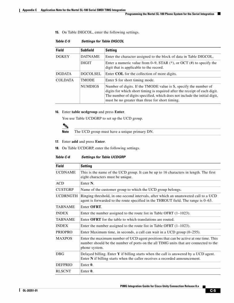
Appendix C Application Note for the Nortel SL-100 Serial SMDI TIMG Integration Programming the Nortel SL-100 Phone System for the Serial Integration
15. On Table DIGCOL, enter the following settings.
16. Enter table ucdgroup and press Enter.
You use Table UCDGRP to set up the UCD group.
Note The UCD group must have a unique primary DN.
17. Enter add and press Enter.
18. On Table UCDGRP, enter the following settings.
Table C-5 Settings for Table DIGCOL
Field Subfield Setting
DGKEY DATNAME Enter the character assigned to the block of data in Table DIGCOL.
DIGIT Enter a numeric value from 0–9, STAR (*), or OCT (#) to specify the digit that is applicable to the record.
DGDATA DGCOLSEL Enter COL for the collection of more digits.
COLDATA TMODE Enter S for short timing mode.
NUMDIGS Number of digits. If the TMODE value is S, specify the number of digits for which short timing is required after the receipt of each digit. The number of digits specified, which does not include the initial digit, must be no greater than three for short timing.
Table C-6 Settings for Table UCDGRP
Field Setting
UCDNAME This is the name of the UCD group. It can be up to 16 characters in length. The first eight characters must be unique.
ACD Enter N.
CUSTGRP Name of the customer group to which the UCD group belongs.
UCDRNGTH Ringing threshold, in one-second intervals, after which an unanswered call to a UCD agent is forwarded to the route specified in the THROUT field. The range is 0–63.
TABNAME Enter OFRT.
INDEX Enter the number assigned to the route list in Table OFRT (1–1023).
TABNAME Enter OFRT for the table to which translations are routed.
INDEX Enter the number assigned to the route list in Table OFRT (1–1023).
PRIOPRO Enter Maximum time, in seconds, a call can wait in a UCD group (0–255).
MAXPOS Enter the maximum number of UCD agent positions that can be active at one time. This number should be the number of ports on the all TIMG units that are connected to the phone system.
DBG Delayed billing. Enter Y if billing starts when the call is answered by a UCD agent. Enter N if billing starts when the caller receives a recorded announcement.
DEFPRIO Enter 0.
RLSCNT Enter 0.
C-5PIMG Integration Guide for Cisco Unity Connection Release 8.x
OL-20351-01
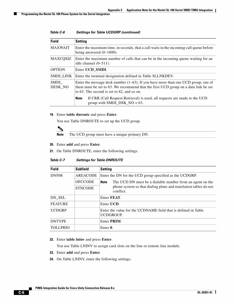
Appendix C Application Note for the Nortel SL-100 Serial SMDI TIMG Integration Programming the Nortel SL-100 Phone System for the Serial Integration
19. Enter table dnroute and press Enter.
You use Table DNROUTE to set up the UCD group.
Note The UCD group must have a unique primary DN.
20. Enter add and press Enter.
21. On Table DNROUTE, enter the following settings.
22. Enter table lninv and press Enter.
You use Table LNINV to assign card slots on the line or remote line module.
23. Enter add and press Enter.
24. On Table LNINV, enter the following settings.
MAXWAIT Enter the maximum time, in seconds, that a call waits in the incoming call queue before being answered (0–1800).
MAXCQSIZ Enter the maximum number of calls that can be in the incoming queue waiting for an idle channel (0–511).
OPTION Enter UCD_SMDI.
SMDI_LINK Enter the terminal designation defined in Table SLLNKDEV.
SMDI_ DESK_NO
Enter the message desk number (1–63). If you have more than one UCD group, one of them must be set to 63. We recommend that the first UCD group on a data link be set to 63. The second is set to 62, and so on.
Note If CRR (Call Request Retrieval) is used, all requests are made to the UCD group with SMDI_DSK_NO = 63.
Table C-6 Settings for Table UCDGRP (continued)
Field Setting
Table C-7 Settings for Table DNROUTE
Field Subfield Setting
DNNM AREACODE Enter the DN for the UCD group specified as the UCDGRP.
Note The UCD DN must be a dialable number from an agent on the phone system so that dialing plans and translation tables do not conflict.
OFCCODE
STNCODE
DN_SEL Enter FEAT.
FEATURE Enter UCD.
UCDGRP Enter the value for the UCDNAME field that is defined in Table UCDGROUP.
DNTYPE Enter PRIM.
TOLLPRIO Enter 0.
C-6PIMG Integration Guide for Cisco Unity Connection Release 8.x
OL-20351-01
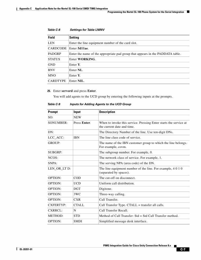
Appendix C Application Note for the Nortel SL-100 Serial SMDI TIMG Integration Programming the Nortel SL-100 Phone System for the Serial Integration
25. Enter servord and press Enter.
You will add agents to the UCD group by entering the following inputs at the prompts.
Table C-8 Settings for Table LNINV
Field Setting
LEN Enter the line equipment number of the card slot.
CARDCODE Enter 5d11ae.
PADGRP Enter the name of the appropriate pad group that appears in the PADDATA table.
STATUS Enter WORKING.
GND Enter Y.
BNV Enter NL.
MNO Enter Y.
CARDTYPE Enter NIL.
Table C-9 Inputs for Adding Agents to the UCD Group
Prompt Input Description
SO: NEW
SONUMBER: Press Enter. When to invoke this service. Pressing Enter starts the service at the current date and time.
DN: The Directory Number of the line. Use ten-digit DNs.
LCC_ACC: IBN The line class code of service.
GROUP: The name of the IBN customer group to which the line belongs. For example, covm.
SUBGRP: The subgroup number. For example, 0.
NCOS: The network class of service. For example, 1.
SNPA: The serving NPA (area code) of the DN.
LEN_OR_LT D: The line equipment number of the line. For example, 4 0 1 0 (separated by spaces).
OPTION: COD The cut-off on disconnect.
OPTION: UCD Uniform call distribution.
OPTION: DGT Digitone.
OPTION: 3WC Three-way calling.
OPTION: CXR Call Transfer.
CXFERTYP: CTALL Call Transfer Type. CTALL = transfer all calls.
CXRRCL: N Call Transfer Recall.
METHOD: STD Method of Call Transfer: Std = Std Call Transfer method.
OPTION: SMDI Simplified message desk interface.
C-7PIMG Integration Guide for Cisco Unity Connection Release 8.x
OL-20351-01
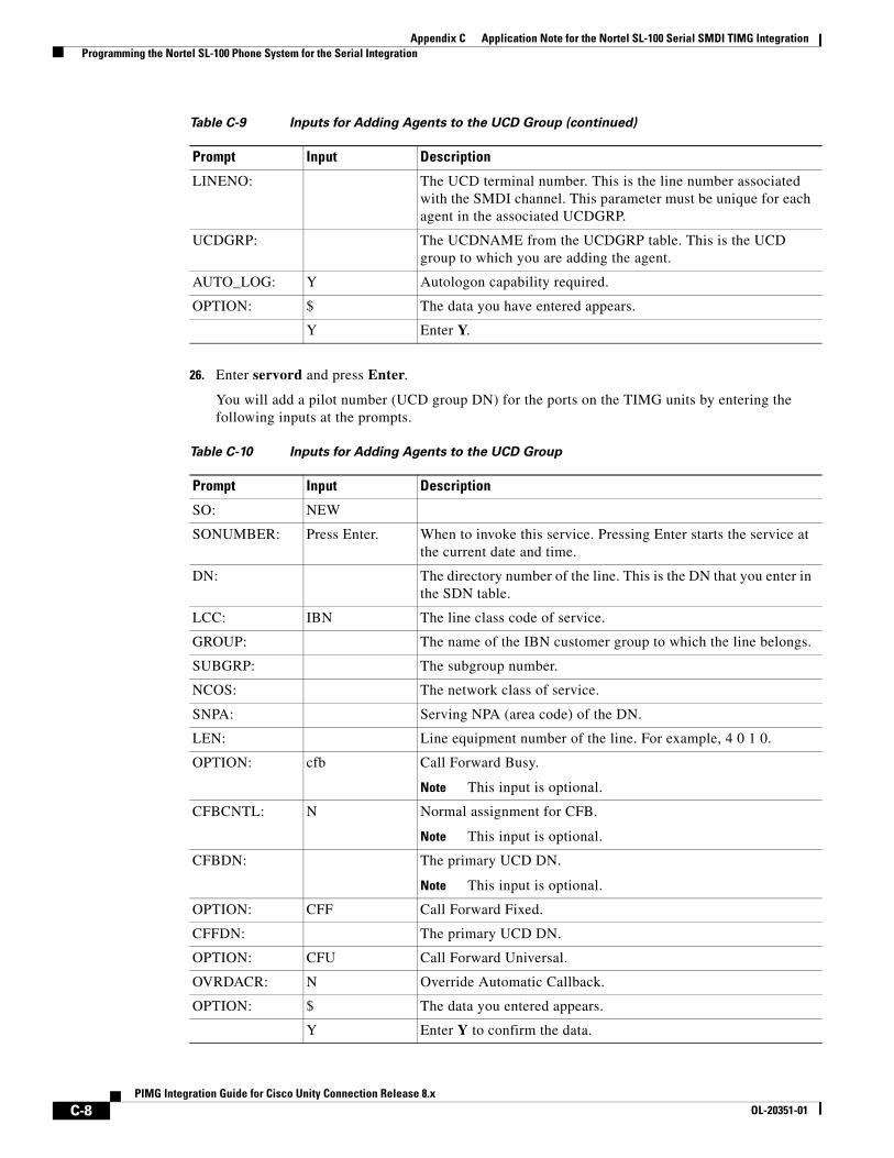
Appendix C Application Note for the Nortel SL-100 Serial SMDI TIMG Integration Programming the Nortel SL-100 Phone System for the Serial Integration
26. Enter servord and press Enter.
You will add a pilot number (UCD group DN) for the ports on the TIMG units by entering the following inputs at the prompts.
LINENO: The UCD terminal number. This is the line number associated with the SMDI channel. This parameter must be unique for each agent in the associated UCDGRP.
UCDGRP: The UCDNAME from the UCDGRP table. This is the UCD group to which you are adding the agent.
AUTO_LOG: Y Autologon capability required.
OPTION: $ The data you have entered appears.
Y Enter Y.
Table C-9 Inputs for Adding Agents to the UCD Group (continued)
Prompt Input Description
Table C-10 Inputs for Adding Agents to the UCD Group
Prompt Input Description
SO: NEW
SONUMBER: Press Enter. When to invoke this service. Pressing Enter starts the service at the current date and time.
DN: The directory number of the line. This is the DN that you enter in the SDN table.
LCC: IBN The line class code of service.
GROUP: The name of the IBN customer group to which the line belongs.
SUBGRP: The subgroup number.
NCOS: The network class of service.
SNPA: Serving NPA (area code) of the DN.
LEN: Line equipment number of the line. For example, 4 0 1 0.
OPTION: cfb Call Forward Busy.
Note This input is optional.
CFBCNTL: N Normal assignment for CFB.
Note This input is optional.
CFBDN: The primary UCD DN.
Note This input is optional.
OPTION: CFF Call Forward Fixed.
CFFDN: The primary UCD DN.
OPTION: CFU Call Forward Universal.
OVRDACR: N Override Automatic Callback.
OPTION: $ The data you entered appears.
Y Enter Y to confirm the data.
C-8PIMG Integration Guide for Cisco Unity Connection Release 8.x
OL-20351-01
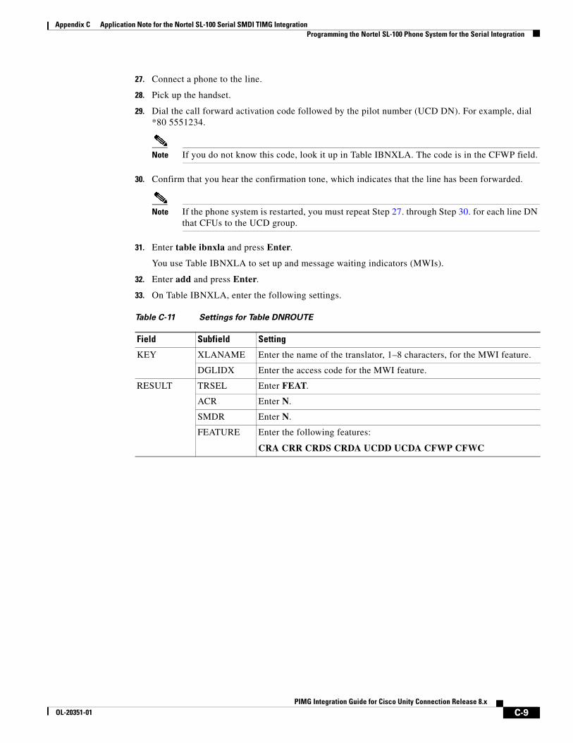
Appendix C Application Note for the Nortel SL-100 Serial SMDI TIMG Integration Programming the Nortel SL-100 Phone System for the Serial Integration
27. Connect a phone to the line.
28. Pick up the handset.
29. Dial the call forward activation code followed by the pilot number (UCD DN). For example, dial *80 5551234.
Note If you do not know this code, look it up in Table IBNXLA. The code is in the CFWP field.
30. Confirm that you hear the confirmation tone, which indicates that the line has been forwarded.
Note If the phone system is restarted, you must repeat Step 27. through Step 30. for each line DN that CFUs to the UCD group.
31. Enter table ibnxla and press Enter.
You use Table IBNXLA to set up and message waiting indicators (MWIs).
32. Enter add and press Enter.
33. On Table IBNXLA, enter the following settings.
Table C-11 Settings for Table DNROUTE
Field Subfield Setting
KEY XLANAME Enter the name of the translator, 1–8 characters, for the MWI feature.
DGLIDX Enter the access code for the MWI feature.
RESULT TRSEL Enter FEAT.
ACR Enter N.
SMDR Enter N.
FEATURE Enter the following features:
CRA CRR CRDS CRDA UCDD UCDA CFWP CFWC
C-9PIMG Integration Guide for Cisco Unity Connection Release 8.x
OL-20351-01

Appendix C Application Note for the Nortel SL-100 Serial SMDI TIMG Integration Programming the Nortel SL-100 Phone System for the Serial Integration
C-10PIMG Integration Guide for Cisco Unity Connection Release 8.x
OL-20351-01
PIMG Integration GOL-20351-01
A
P P E N D I X D Settings for PIMG Firmware Version 5.xThe following sections provide the PIMG settings when firmware version 5.x is installed on the PIMG units:
• Digital PIMG Settings (Firmware Version 5.x), page D-1
• Analog PIMG Settings for a DTMF Integration (Firmware Version 5.x), page D-6
• Analog PIMG Settings for a Serial Integration (Firmware Version 5.x), page D-11
• Digital Mitel PIMG Settings (Firmware Version 5.x), page D-17
• Digital Rolm PIMG Settings (Firmware Version 5.x), page D-22
Note We recommend that you upgrade your PIMG units to the most recent version that is available at http://tools.cisco.com/support/downloads/pub/Redirect.x?mdfid=278875240. For instructions on downloading and installing the most recent PIMG firmware, see the chapter for your phone system integration in this guide.
Digital PIMG Settings (Firmware Version 5.x)To Set Up the Digital PIMG Units
Step 1 On a Windows workstation, sign in to a PIMG unit.
Step 2 On the Configure menu, select System.
Step 3 On the System page, enter the following settings.
Table D-1 System Page Settings
Field Setting
Operating Mode Select SIP.
D-1uide for Cisco Unity Connection Release 8.x
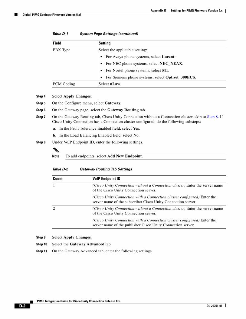
Appendix D Settings for PIMG Firmware Version 5.x Digital PIMG Settings (Firmware Version 5.x)
Step 4 Select Apply Changes.
Step 5 On the Configure menu, select Gateway.
Step 6 On the Gateway page, select the Gateway Routing tab.
Step 7 On the Gateway Routing tab, Cisco Unity Connection without a Connection cluster, skip to Step 8. If Cisco Unity Connection has a Connection cluster configured, do the following substeps:
a. In the Fault Tolerance Enabled field, select Yes.
b. In the Load Balancing Enabled field, select No.
Step 8 Under VoIP Endpoint ID, enter the following settings.
Note To add endpoints, select Add New Endpoint.
Step 9 Select Apply Changes.
Step 10 Select the Gateway Advanced tab.
Step 11 On the Gateway Advanced tab, enter the following settings.
PBX Type Select the applicable setting:
• For Avaya phone systems, select Lucent.
• For NEC phone systems, select NEC_NEAX.
• For Nortel phone systems, select M1.
• For Siemens phone systems, select Optiset_300ECS.
PCM Coding Select uLaw.
Table D-1 System Page Settings (continued)
Field Setting
Table D-2 Gateway Routing Tab Settings
Count VoIP Endpoint ID
1 (Cisco Unity Connection without a Connection cluster) Enter the server name of the Cisco Unity Connection server.
(Cisco Unity Connection with a Connection cluster configured) Enter the server name of the subscriber Cisco Unity Connection server.
2 (Cisco Unity Connection without a Connection cluster) Enter the server name of the Cisco Unity Connection server.
(Cisco Unity Connection with a Connection cluster configured) Enter the server name of the publisher Cisco Unity Connection server.
D-2PIMG Integration Guide for Cisco Unity Connection Release 8.x
OL-20351-01
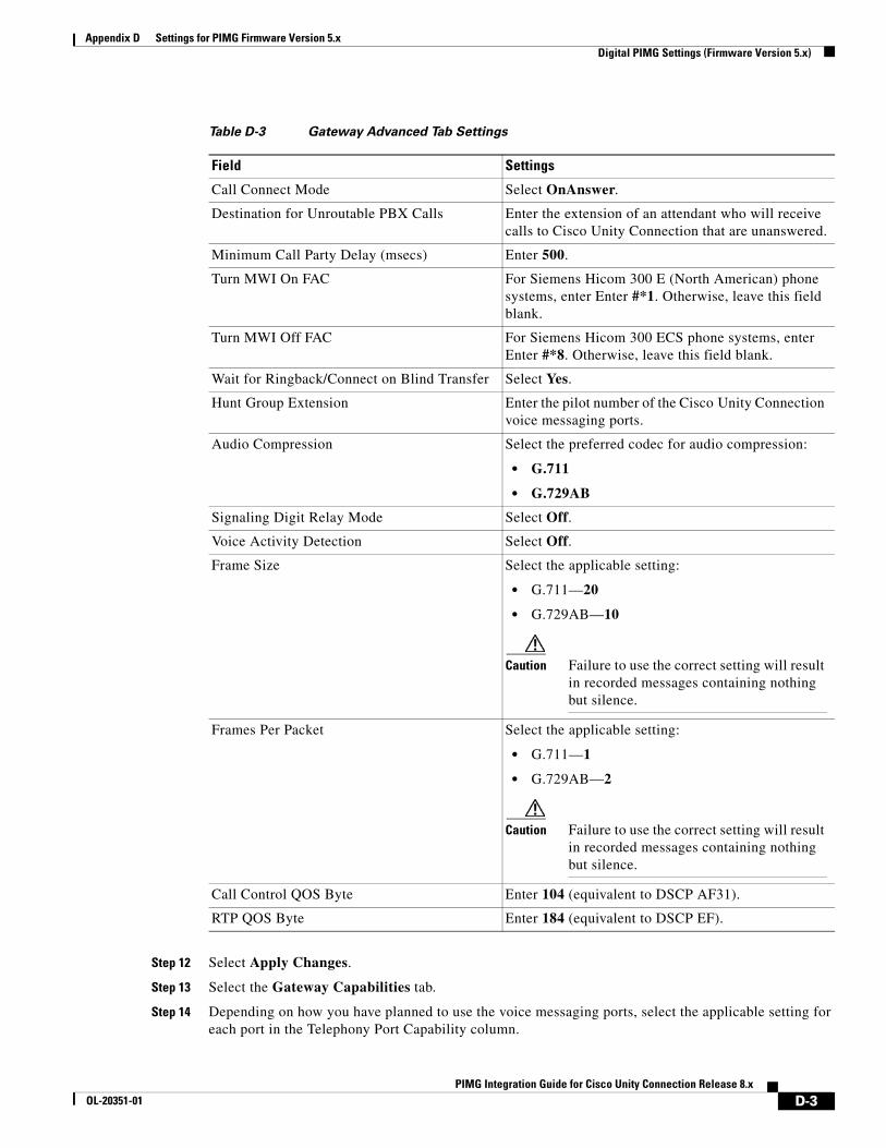
Appendix D Settings for PIMG Firmware Version 5.x Digital PIMG Settings (Firmware Version 5.x)
Step 12 Select Apply Changes.
Step 13 Select the Gateway Capabilities tab.
Step 14 Depending on how you have planned to use the voice messaging ports, select the applicable setting for each port in the Telephony Port Capability column.
Table D-3 Gateway Advanced Tab Settings
Field Settings
Call Connect Mode Select OnAnswer.
Destination for Unroutable PBX Calls Enter the extension of an attendant who will receive calls to Cisco Unity Connection that are unanswered.
Minimum Call Party Delay (msecs) Enter 500.
Turn MWI On FAC For Siemens Hicom 300 E (North American) phone systems, enter Enter #*1. Otherwise, leave this field blank.
Turn MWI Off FAC For Siemens Hicom 300 ECS phone systems, enter Enter #*8. Otherwise, leave this field blank.
Wait for Ringback/Connect on Blind Transfer Select Yes.
Hunt Group Extension Enter the pilot number of the Cisco Unity Connection voice messaging ports.
Audio Compression Select the preferred codec for audio compression:
• G.711
• G.729AB
Signaling Digit Relay Mode Select Off.
Voice Activity Detection Select Off.
Frame Size Select the applicable setting:
• G.711—20
• G.729AB—10
Caution Failure to use the correct setting will result in recorded messages containing nothing but silence.
Frames Per Packet Select the applicable setting:
• G.711—1
• G.729AB—2
Caution Failure to use the correct setting will result in recorded messages containing nothing but silence.
Call Control QOS Byte Enter 104 (equivalent to DSCP AF31).
RTP QOS Byte Enter 184 (equivalent to DSCP EF).
D-3PIMG Integration Guide for Cisco Unity Connection Release 8.x
OL-20351-01
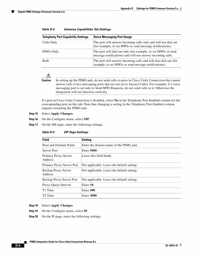
Appendix D Settings for PIMG Firmware Version 5.x Digital PIMG Settings (Firmware Version 5.x)
Caution In setting up the PIMG unit, do not send calls to ports in Cisco Unity Connection that cannot answer calls (voice messaging ports that are not set to Answer Calls). For example, if a voice messaging port is set only to Send MWI Requests, do not send calls to it. Otherwise the integration will not function correctly.
If a port in Cisco Unity Connection is disabled, select No in the Telephony Port Enabled column for the corresponding port on this tab. Note that changing a setting in the Telephony Port Enabled column requires restarting the PIMG unit.
Step 15 Select Apply Changes.
Step 16 On the Configure menu, select SIP.
Step 17 On the SIP page, enter the following settings.
Step 18 Select Apply Changes.
Step 19 On the Configure menu, select IP.
Step 20 On the IP page, enter the following settings.
Table D-4 Gateway Capabilities Tab Settings
Telephony Port Capability Settings Voice Messaging Port Usage
Calls-Only The port will answer incoming calls only and will not dial out (for example, to set MWIs or send message notifications).
MWIs-Only The port will dial out only (for example, to set MWIs or send message notifications) and will not answer incoming calls.
Both The port will answer incoming calls and will also dial out (for example, to set MWIs or send message notifications).
Table D-5 SIP Page Settings
Field Setting
Host and Domain Name Enter the domain name of the PIMG unit.
Server Port Enter 5060.
Primary Proxy Server Address
Leave this field blank.
Primary Proxy Server Port Not applicable. Leave the default setting.
Backup Proxy Server Address
Not applicable. Leave the default setting.
Backup Proxy Server Port Not applicable. Leave the default setting.
Proxy Query Interval Enter 10.
T1 Time Enter 400.
T2 Time Enter 3000.
D-4PIMG Integration Guide for Cisco Unity Connection Release 8.x
OL-20351-01
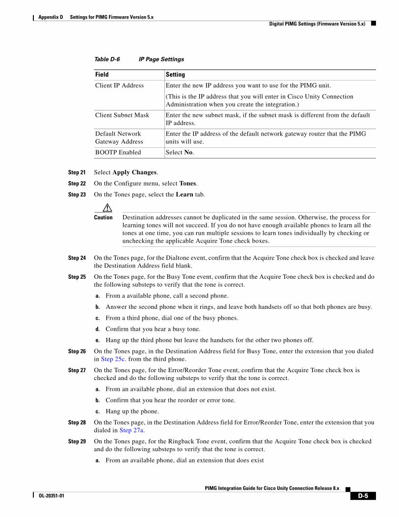
Appendix D Settings for PIMG Firmware Version 5.x Digital PIMG Settings (Firmware Version 5.x)
Step 21 Select Apply Changes.
Step 22 On the Configure menu, select Tones.
Step 23 On the Tones page, select the Learn tab.
Caution Destination addresses cannot be duplicated in the same session. Otherwise, the process for learning tones will not succeed. If you do not have enough available phones to learn all the tones at one time, you can run multiple sessions to learn tones individually by checking or unchecking the applicable Acquire Tone check boxes.
Step 24 On the Tones page, for the Dialtone event, confirm that the Acquire Tone check box is checked and leave the Destination Address field blank.
Step 25 On the Tones page, for the Busy Tone event, confirm that the Acquire Tone check box is checked and do the following substeps to verify that the tone is correct.
a. From a available phone, call a second phone.
b. Answer the second phone when it rings, and leave both handsets off so that both phones are busy.
c. From a third phone, dial one of the busy phones.
d. Confirm that you hear a busy tone.
e. Hang up the third phone but leave the handsets for the other two phones off.
Step 26 On the Tones page, in the Destination Address field for Busy Tone, enter the extension that you dialed in Step 25c. from the third phone.
Step 27 On the Tones page, for the Error/Reorder Tone event, confirm that the Acquire Tone check box is checked and do the following substeps to verify that the tone is correct.
a. From an available phone, dial an extension that does not exist.
b. Confirm that you hear the reorder or error tone.
c. Hang up the phone.
Step 28 On the Tones page, in the Destination Address field for Error/Reorder Tone, enter the extension that you dialed in Step 27a.
Step 29 On the Tones page, for the Ringback Tone event, confirm that the Acquire Tone check box is checked and do the following substeps to verify that the tone is correct.
a. From an available phone, dial an extension that does exist
Table D-6 IP Page Settings
Field Setting
Client IP Address Enter the new IP address you want to use for the PIMG unit.
(This is the IP address that you will enter in Cisco Unity Connection Administration when you create the integration.)
Client Subnet Mask Enter the new subnet mask, if the subnet mask is different from the default IP address.
Default Network Gateway Address
Enter the IP address of the default network gateway router that the PIMG units will use.
BOOTP Enabled Select No.
D-5PIMG Integration Guide for Cisco Unity Connection Release 8.x
OL-20351-01
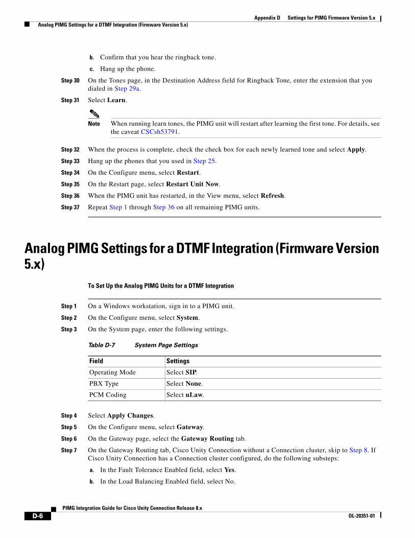
Appendix D Settings for PIMG Firmware Version 5.x Analog PIMG Settings for a DTMF Integration (Firmware Version 5.x)
b. Confirm that you hear the ringback tone.
c. Hang up the phone.
Step 30 On the Tones page, in the Destination Address field for Ringback Tone, enter the extension that you dialed in Step 29a.
Step 31 Select Learn.
Note When running learn tones, the PIMG unit will restart after learning the first tone. For details, see the caveat CSCsh53791.
Step 32 When the process is complete, check the check box for each newly learned tone and select Apply.
Step 33 Hang up the phones that you used in Step 25.
Step 34 On the Configure menu, select Restart.
Step 35 On the Restart page, select Restart Unit Now.
Step 36 When the PIMG unit has restarted, in the View menu, select Refresh.
Step 37 Repeat Step 1 through Step 36 on all remaining PIMG units.
Analog PIMG Settings for a DTMF Integration (Firmware Version 5.x)
To Set Up the Analog PIMG Units for a DTMF Integration
Step 1 On a Windows workstation, sign in to a PIMG unit.
Step 2 On the Configure menu, select System.
Step 3 On the System page, enter the following settings.
Step 4 Select Apply Changes.
Step 5 On the Configure menu, select Gateway.
Step 6 On the Gateway page, select the Gateway Routing tab.
Step 7 On the Gateway Routing tab, Cisco Unity Connection without a Connection cluster, skip to Step 8. If Cisco Unity Connection has a Connection cluster configured, do the following substeps:
a. In the Fault Tolerance Enabled field, select Yes.
b. In the Load Balancing Enabled field, select No.
Table D-7 System Page Settings
Field Settings
Operating Mode Select SIP.
PBX Type Select None.
PCM Coding Select uLaw.
D-6PIMG Integration Guide for Cisco Unity Connection Release 8.x
OL-20351-01
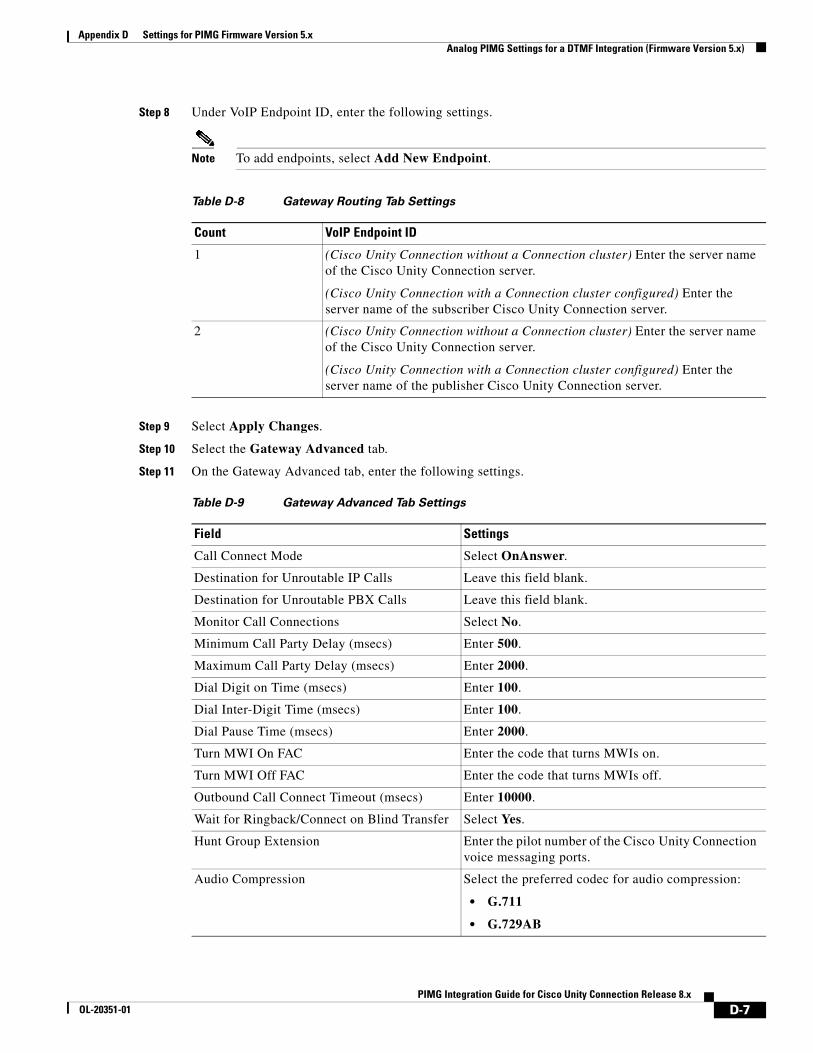
Appendix D Settings for PIMG Firmware Version 5.x Analog PIMG Settings for a DTMF Integration (Firmware Version 5.x)
Step 8 Under VoIP Endpoint ID, enter the following settings.
Note To add endpoints, select Add New Endpoint.
Step 9 Select Apply Changes.
Step 10 Select the Gateway Advanced tab.
Step 11 On the Gateway Advanced tab, enter the following settings.
Table D-8 Gateway Routing Tab Settings
Count VoIP Endpoint ID
1 (Cisco Unity Connection without a Connection cluster) Enter the server name of the Cisco Unity Connection server.
(Cisco Unity Connection with a Connection cluster configured) Enter the server name of the subscriber Cisco Unity Connection server.
2 (Cisco Unity Connection without a Connection cluster) Enter the server name of the Cisco Unity Connection server.
(Cisco Unity Connection with a Connection cluster configured) Enter the server name of the publisher Cisco Unity Connection server.
Table D-9 Gateway Advanced Tab Settings
Field Settings
Call Connect Mode Select OnAnswer.
Destination for Unroutable IP Calls Leave this field blank.
Destination for Unroutable PBX Calls Leave this field blank.
Monitor Call Connections Select No.
Minimum Call Party Delay (msecs) Enter 500.
Maximum Call Party Delay (msecs) Enter 2000.
Dial Digit on Time (msecs) Enter 100.
Dial Inter-Digit Time (msecs) Enter 100.
Dial Pause Time (msecs) Enter 2000.
Turn MWI On FAC Enter the code that turns MWIs on.
Turn MWI Off FAC Enter the code that turns MWIs off.
Outbound Call Connect Timeout (msecs) Enter 10000.
Wait for Ringback/Connect on Blind Transfer Select Yes.
Hunt Group Extension Enter the pilot number of the Cisco Unity Connection voice messaging ports.
Audio Compression Select the preferred codec for audio compression:
• G.711
• G.729AB
D-7PIMG Integration Guide for Cisco Unity Connection Release 8.x
OL-20351-01
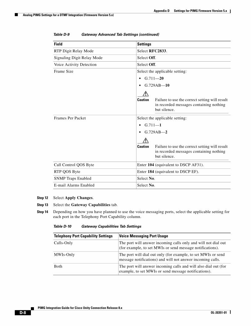
Appendix D Settings for PIMG Firmware Version 5.x Analog PIMG Settings for a DTMF Integration (Firmware Version 5.x)
Step 12 Select Apply Changes.
Step 13 Select the Gateway Capabilities tab.
Step 14 Depending on how you have planned to use the voice messaging ports, select the applicable setting for each port in the Telephony Port Capability column.
RTP Digit Relay Mode Select RFC2833.
Signaling Digit Relay Mode Select Off.
Voice Activity Detection Select Off.
Frame Size Select the applicable setting:
• G.711—20
• G.729AB—10
Caution Failure to use the correct setting will result in recorded messages containing nothing but silence.
Frames Per Packet Select the applicable setting:
• G.711—1
• G.729AB—2
Caution Failure to use the correct setting will result in recorded messages containing nothing but silence.
Call Control QOS Byte Enter 104 (equivalent to DSCP AF31).
RTP QOS Byte Enter 184 (equivalent to DSCP EF).
SNMP Traps Enabled Select No.
E-mail Alarms Enabled Select No.
Table D-10 Gateway Capabilities Tab Settings
Telephony Port Capability Settings Voice Messaging Port Usage
Calls-Only The port will answer incoming calls only and will not dial out (for example, to set MWIs or send message notifications).
MWIs-Only The port will dial out only (for example, to set MWIs or send message notifications) and will not answer incoming calls.
Both The port will answer incoming calls and will also dial out (for example, to set MWIs or send message notifications).
Table D-9 Gateway Advanced Tab Settings (continued)
Field Settings
D-8PIMG Integration Guide for Cisco Unity Connection Release 8.x
OL-20351-01
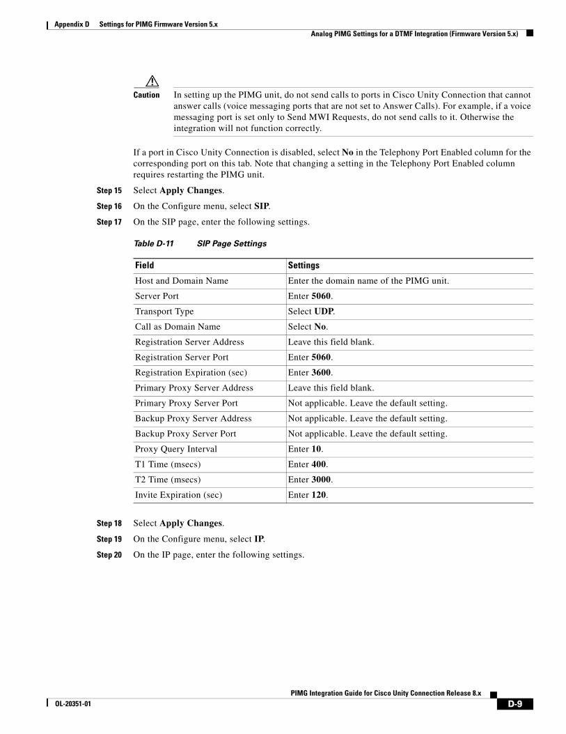
Appendix D Settings for PIMG Firmware Version 5.x Analog PIMG Settings for a DTMF Integration (Firmware Version 5.x)
Caution In setting up the PIMG unit, do not send calls to ports in Cisco Unity Connection that cannot answer calls (voice messaging ports that are not set to Answer Calls). For example, if a voice messaging port is set only to Send MWI Requests, do not send calls to it. Otherwise the integration will not function correctly.
If a port in Cisco Unity Connection is disabled, select No in the Telephony Port Enabled column for the corresponding port on this tab. Note that changing a setting in the Telephony Port Enabled column requires restarting the PIMG unit.
Step 15 Select Apply Changes.
Step 16 On the Configure menu, select SIP.
Step 17 On the SIP page, enter the following settings.
Step 18 Select Apply Changes.
Step 19 On the Configure menu, select IP.
Step 20 On the IP page, enter the following settings.
Table D-11 SIP Page Settings
Field Settings
Host and Domain Name Enter the domain name of the PIMG unit.
Server Port Enter 5060.
Transport Type Select UDP.
Call as Domain Name Select No.
Registration Server Address Leave this field blank.
Registration Server Port Enter 5060.
Registration Expiration (sec) Enter 3600.
Primary Proxy Server Address Leave this field blank.
Primary Proxy Server Port Not applicable. Leave the default setting.
Backup Proxy Server Address Not applicable. Leave the default setting.
Backup Proxy Server Port Not applicable. Leave the default setting.
Proxy Query Interval Enter 10.
T1 Time (msecs) Enter 400.
T2 Time (msecs) Enter 3000.
Invite Expiration (sec) Enter 120.
D-9PIMG Integration Guide for Cisco Unity Connection Release 8.x
OL-20351-01
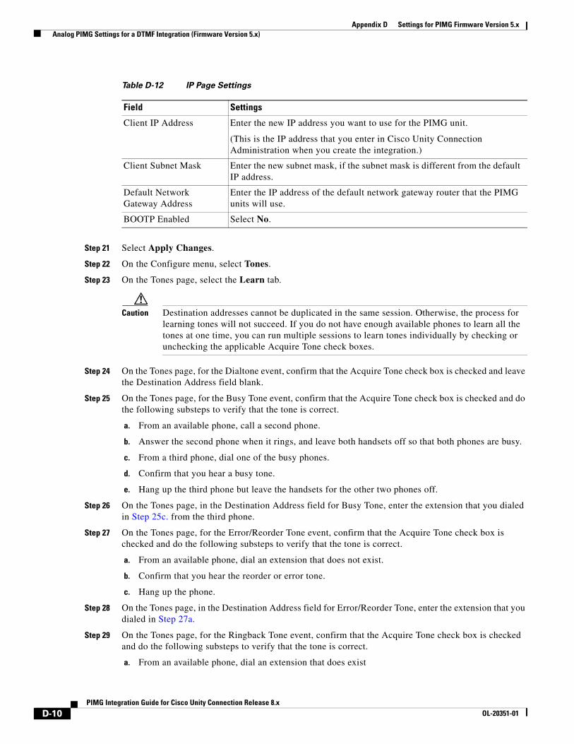
Appendix D Settings for PIMG Firmware Version 5.x Analog PIMG Settings for a DTMF Integration (Firmware Version 5.x)
Step 21 Select Apply Changes.
Step 22 On the Configure menu, select Tones.
Step 23 On the Tones page, select the Learn tab.
Caution Destination addresses cannot be duplicated in the same session. Otherwise, the process for learning tones will not succeed. If you do not have enough available phones to learn all the tones at one time, you can run multiple sessions to learn tones individually by checking or unchecking the applicable Acquire Tone check boxes.
Step 24 On the Tones page, for the Dialtone event, confirm that the Acquire Tone check box is checked and leave the Destination Address field blank.
Step 25 On the Tones page, for the Busy Tone event, confirm that the Acquire Tone check box is checked and do the following substeps to verify that the tone is correct.
a. From an available phone, call a second phone.
b. Answer the second phone when it rings, and leave both handsets off so that both phones are busy.
c. From a third phone, dial one of the busy phones.
d. Confirm that you hear a busy tone.
e. Hang up the third phone but leave the handsets for the other two phones off.
Step 26 On the Tones page, in the Destination Address field for Busy Tone, enter the extension that you dialed in Step 25c. from the third phone.
Step 27 On the Tones page, for the Error/Reorder Tone event, confirm that the Acquire Tone check box is checked and do the following substeps to verify that the tone is correct.
a. From an available phone, dial an extension that does not exist.
b. Confirm that you hear the reorder or error tone.
c. Hang up the phone.
Step 28 On the Tones page, in the Destination Address field for Error/Reorder Tone, enter the extension that you dialed in Step 27a.
Step 29 On the Tones page, for the Ringback Tone event, confirm that the Acquire Tone check box is checked and do the following substeps to verify that the tone is correct.
a. From an available phone, dial an extension that does exist
Table D-12 IP Page Settings
Field Settings
Client IP Address Enter the new IP address you want to use for the PIMG unit.
(This is the IP address that you enter in Cisco Unity Connection Administration when you create the integration.)
Client Subnet Mask Enter the new subnet mask, if the subnet mask is different from the default IP address.
Default Network Gateway Address
Enter the IP address of the default network gateway router that the PIMG units will use.
BOOTP Enabled Select No.
D-10PIMG Integration Guide for Cisco Unity Connection Release 8.x
OL-20351-01
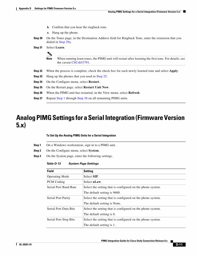
Appendix D Settings for PIMG Firmware Version 5.x Analog PIMG Settings for a Serial Integration (Firmware Version 5.x)
b. Confirm that you hear the ringback tone.
c. Hang up the phone.
Step 30 On the Tones page, in the Destination Address field for Ringback Tone, enter the extension that you dialed in Step 29a.
Step 31 Select Learn.
Note When running learn tones, the PIMG unit will restart after learning the first tone. For details, see the caveat CSCsh53791.
Step 32 When the process is complete, check the check box for each newly learned tone and select Apply.
Step 33 Hang up the phones that you used in Step 25.
Step 34 On the Configure menu, select Restart.
Step 35 On the Restart page, select Restart Unit Now.
Step 36 When the PIMG unit has restarted, in the View menu, select Refresh.
Step 37 Repeat Step 1 through Step 36 on all remaining PIMG units.
Analog PIMG Settings for a Serial Integration (Firmware Version 5.x)
To Set Up the Analog PIMG Units for a Serial Integration
Step 1 On a Windows workstation, sign in to a PIMG unit.
Step 2 On the Configure menu, select System.
Step 3 On the System page, enter the following settings.
Table D-13 System Page Settings
Field Setting
Operating Mode Select SIP.
PCM Coding Select uLaw.
Serial Port Baud Rate Select the setting that is configured on the phone system.
The default setting is 9600.
Serial Port Parity Select the setting that is configured on the phone system.
The default setting is None.
Serial Port Data Bits Select the setting that is configured on the phone system.
The default setting is 8.
Serial Port Stop Bits Select the setting that is configured on the phone system.
The default setting is 1.
D-11PIMG Integration Guide for Cisco Unity Connection Release 8.x
OL-20351-01
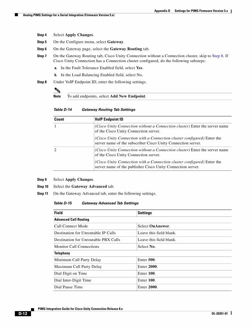
Appendix D Settings for PIMG Firmware Version 5.x Analog PIMG Settings for a Serial Integration (Firmware Version 5.x)
Step 4 Select Apply Changes.
Step 5 On the Configure menu, select Gateway.
Step 6 On the Gateway page, select the Gateway Routing tab.
Step 7 On the Gateway Routing tab, Cisco Unity Connection without a Connection cluster, skip to Step 8. If Cisco Unity Connection has a Connection cluster configured, do the following substeps:
a. In the Fault Tolerance Enabled field, select Yes.
b. In the Load Balancing Enabled field, select No.
Step 8 Under VoIP Endpoint ID, enter the following settings.
Note To add endpoints, select Add New Endpoint.
Step 9 Select Apply Changes.
Step 10 Select the Gateway Advanced tab.
Step 11 On the Gateway Advanced tab, enter the following settings.
Table D-14 Gateway Routing Tab Settings
Count VoIP Endpoint ID
1 (Cisco Unity Connection without a Connection cluster) Enter the server name of the Cisco Unity Connection server.
(Cisco Unity Connection with a Connection cluster configured) Enter the server name of the subscriber Cisco Unity Connection server.
2 (Cisco Unity Connection without a Connection cluster) Enter the server name of the Cisco Unity Connection server.
(Cisco Unity Connection with a Connection cluster configured) Enter the server name of the publisher Cisco Unity Connection server.
Table D-15 Gateway Advanced Tab Settings
Field Settings
Advanced Call Routing
Call Connect Mode Select OnAnswer.
Destination for Unroutable IP Calls Leave this field blank.
Destination for Unroutable PBX Calls Leave this field blank.
Monitor Call Connections Select No.
Telephony
Minimum Call Party Delay Enter 500.
Maximum Call Party Delay Enter 2000.
Dial Digit on Time Enter 100.
Dial Inter-Digit Time Enter 100.
Dial Pause Time Enter 2000.
D-12PIMG Integration Guide for Cisco Unity Connection Release 8.x
OL-20351-01
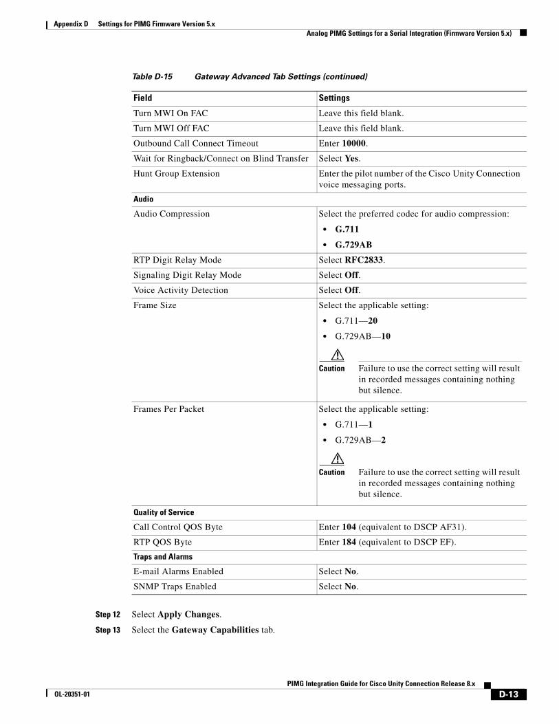
Appendix D Settings for PIMG Firmware Version 5.x Analog PIMG Settings for a Serial Integration (Firmware Version 5.x)
Step 12 Select Apply Changes.
Step 13 Select the Gateway Capabilities tab.
Turn MWI On FAC Leave this field blank.
Turn MWI Off FAC Leave this field blank.
Outbound Call Connect Timeout Enter 10000.
Wait for Ringback/Connect on Blind Transfer Select Yes.
Hunt Group Extension Enter the pilot number of the Cisco Unity Connection voice messaging ports.
Audio
Audio Compression Select the preferred codec for audio compression:
• G.711
• G.729AB
RTP Digit Relay Mode Select RFC2833.
Signaling Digit Relay Mode Select Off.
Voice Activity Detection Select Off.
Frame Size Select the applicable setting:
• G.711—20
• G.729AB—10
Caution Failure to use the correct setting will result in recorded messages containing nothing but silence.
Frames Per Packet Select the applicable setting:
• G.711—1
• G.729AB—2
Caution Failure to use the correct setting will result in recorded messages containing nothing but silence.
Quality of Service
Call Control QOS Byte Enter 104 (equivalent to DSCP AF31).
RTP QOS Byte Enter 184 (equivalent to DSCP EF).
Traps and Alarms
E-mail Alarms Enabled Select No.
SNMP Traps Enabled Select No.
Table D-15 Gateway Advanced Tab Settings (continued)
Field Settings
D-13PIMG Integration Guide for Cisco Unity Connection Release 8.x
OL-20351-01
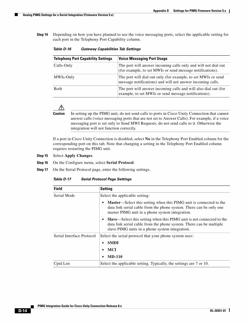
Appendix D Settings for PIMG Firmware Version 5.x Analog PIMG Settings for a Serial Integration (Firmware Version 5.x)
Step 14 Depending on how you have planned to use the voice messaging ports, select the applicable setting for each port in the Telephony Port Capability column.
Caution In setting up the PIMG unit, do not send calls to ports in Cisco Unity Connection that cannot answer calls (voice messaging ports that are not set to Answer Calls). For example, if a voice messaging port is set only to Send MWI Requests, do not send calls to it. Otherwise the integration will not function correctly.
If a port in Cisco Unity Connection is disabled, select No in the Telephony Port Enabled column for the corresponding port on this tab. Note that changing a setting in the Telephony Port Enabled column requires restarting the PIMG unit.
Step 15 Select Apply Changes.
Step 16 On the Configure menu, select Serial Protocol.
Step 17 On the Serial Protocol page, enter the following settings.
Table D-16 Gateway Capabilities Tab Settings
Telephony Port Capability Settings Voice Messaging Port Usage
Calls-Only The port will answer incoming calls only and will not dial out (for example, to set MWIs or send message notifications).
MWIs-Only The port will dial out only (for example, to set MWIs or send message notifications) and will not answer incoming calls.
Both The port will answer incoming calls and will also dial out (for example, to set MWIs or send message notifications).
Table D-17 Serial Protocol Page Settings
Field Setting
Serial Mode Select the applicable setting:
• Master—Select this setting when this PIMG unit is connected to the data link serial cable from the phone system. There can be only one master PIMG unit in a phone system integration.
• Slave—Select this setting when this PIMG unit is not connected to the data link serial cable from the phone system. There can be multiple slave PIMG units in a phone system integration.
Serial Interface Protocol Select the serial protocol that your phone system uses:
• SMDI
• MCI
• MD-110
Cpid Len Select the applicable setting. Typically, the settings are 7 or 10.
D-14PIMG Integration Guide for Cisco Unity Connection Release 8.x
OL-20351-01
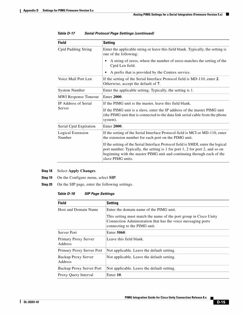
Appendix D Settings for PIMG Firmware Version 5.x Analog PIMG Settings for a Serial Integration (Firmware Version 5.x)
Step 18 Select Apply Changes.
Step 19 On the Configure menu, select SIP.
Step 20 On the SIP page, enter the following settings.
Cpid Padding String Enter the applicable string or leave this field blank. Typically, the setting is one of the following:
• A string of zeros, where the number of zeros matches the setting of the Cpid Len field.
• A prefix that is provided by the Centrex service.
Voice Mail Port Len If the setting of the Serial Interface Protocol field is MD-110, enter 2. Otherwise, accept the default of 7.
System Number Enter the applicable setting. Typically, the setting is 1.
MWI Response Timeout Enter 2000.
IP Address of Serial Server
If the PIMG unit is the master, leave this field blank.
If the PIMG unit is a slave, enter the IP address of the master PIMG unit (the PIMG unit that is connected to the data link serial cable from the phone system).
Serial Cpid Expiration Enter 2000.
Logical Extension Number
If the setting of the Serial Interface Protocol field is MCI or MD-110, enter the extension number for each port on the PIMG unit.
If the setting of the Serial Interface Protocol field is SMDI, enter the logical port number. Typically, the setting is 1 for port 1, 2 for port 2, and so on beginning with the master PIMG unit and continuing through each of the slave PIMG units.
Table D-18 SIP Page Settings
Field Setting
Host and Domain Name Enter the domain name of the PIMG unit.
This setting must match the name of the port group in Cisco Unity Connection Administration that has the voice messaging ports connecting to the PIMG unit.
Server Port Enter 5060.
Primary Proxy Server Address
Leave this field blank.
Primary Proxy Server Port Not applicable. Leave the default setting.
Backup Proxy Server Address
Not applicable. Leave the default setting.
Backup Proxy Server Port Not applicable. Leave the default setting.
Proxy Query Interval Enter 10.
Table D-17 Serial Protocol Page Settings (continued)
Field Setting
D-15PIMG Integration Guide for Cisco Unity Connection Release 8.x
OL-20351-01
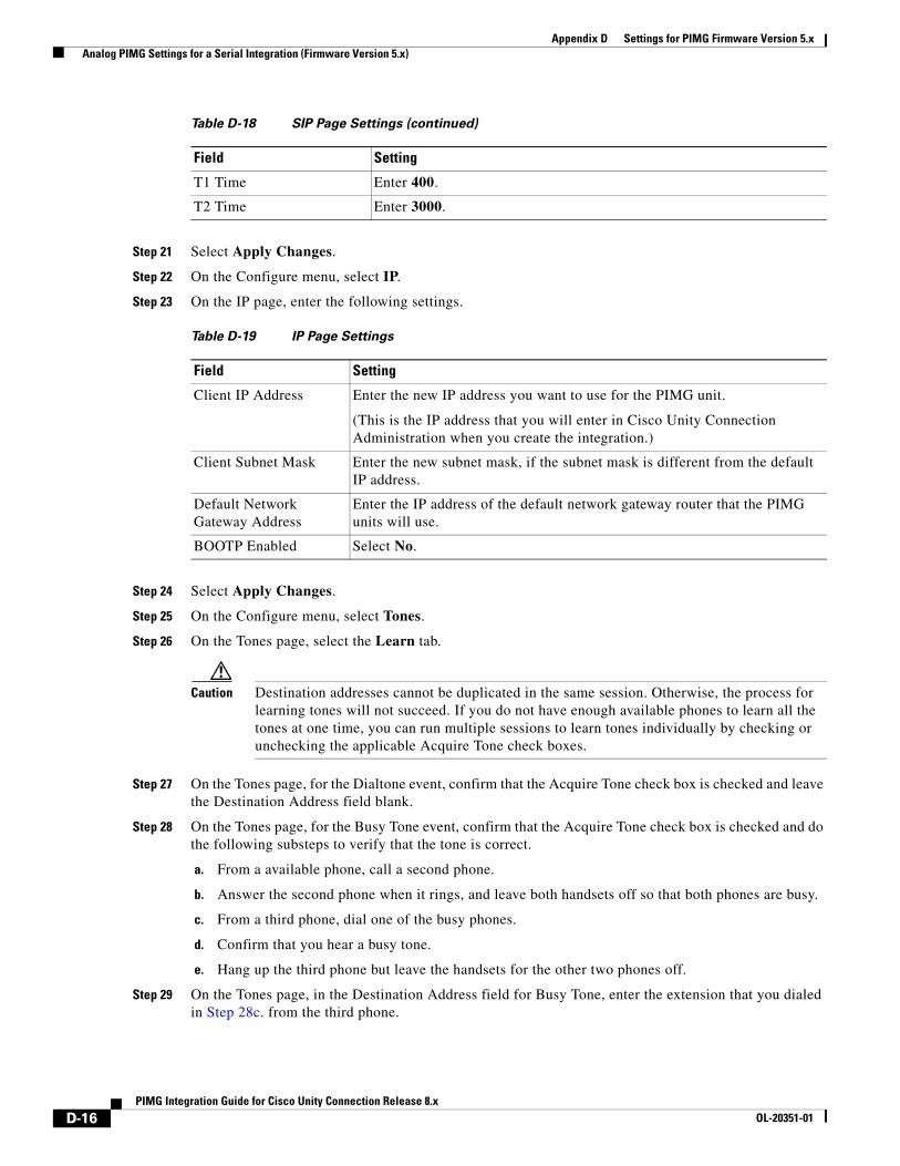
Appendix D Settings for PIMG Firmware Version 5.x Analog PIMG Settings for a Serial Integration (Firmware Version 5.x)
Step 21 Select Apply Changes.
Step 22 On the Configure menu, select IP.
Step 23 On the IP page, enter the following settings.
Step 24 Select Apply Changes.
Step 25 On the Configure menu, select Tones.
Step 26 On the Tones page, select the Learn tab.
Caution Destination addresses cannot be duplicated in the same session. Otherwise, the process for learning tones will not succeed. If you do not have enough available phones to learn all the tones at one time, you can run multiple sessions to learn tones individually by checking or unchecking the applicable Acquire Tone check boxes.
Step 27 On the Tones page, for the Dialtone event, confirm that the Acquire Tone check box is checked and leave the Destination Address field blank.
Step 28 On the Tones page, for the Busy Tone event, confirm that the Acquire Tone check box is checked and do the following substeps to verify that the tone is correct.
a. From a available phone, call a second phone.
b. Answer the second phone when it rings, and leave both handsets off so that both phones are busy.
c. From a third phone, dial one of the busy phones.
d. Confirm that you hear a busy tone.
e. Hang up the third phone but leave the handsets for the other two phones off.
Step 29 On the Tones page, in the Destination Address field for Busy Tone, enter the extension that you dialed in Step 28c. from the third phone.
T1 Time Enter 400.
T2 Time Enter 3000.
Table D-19 IP Page Settings
Field Setting
Client IP Address Enter the new IP address you want to use for the PIMG unit.
(This is the IP address that you will enter in Cisco Unity Connection Administration when you create the integration.)
Client Subnet Mask Enter the new subnet mask, if the subnet mask is different from the default IP address.
Default Network Gateway Address
Enter the IP address of the default network gateway router that the PIMG units will use.
BOOTP Enabled Select No.
Table D-18 SIP Page Settings (continued)
Field Setting
D-16PIMG Integration Guide for Cisco Unity Connection Release 8.x
OL-20351-01
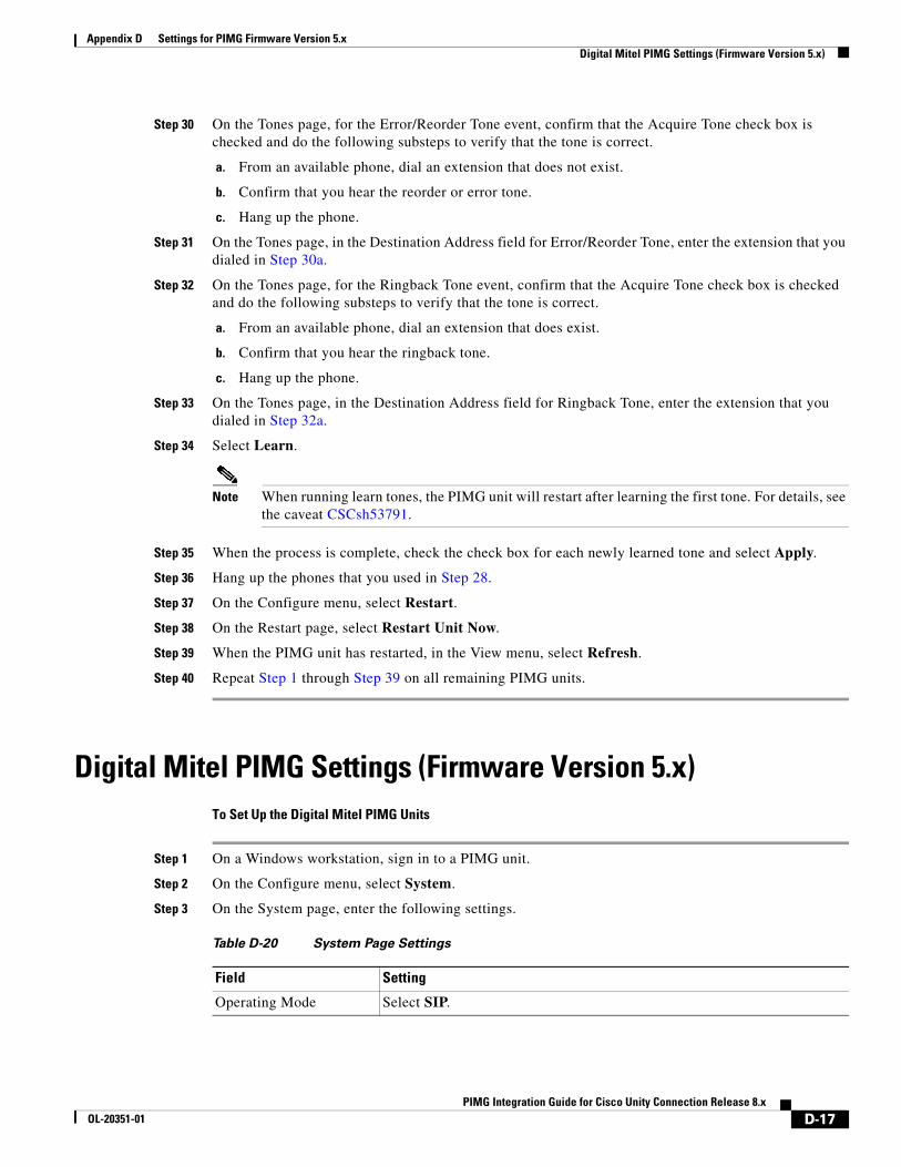
Appendix D Settings for PIMG Firmware Version 5.x Digital Mitel PIMG Settings (Firmware Version 5.x)
Step 30 On the Tones page, for the Error/Reorder Tone event, confirm that the Acquire Tone check box is checked and do the following substeps to verify that the tone is correct.
a. From an available phone, dial an extension that does not exist.
b. Confirm that you hear the reorder or error tone.
c. Hang up the phone.
Step 31 On the Tones page, in the Destination Address field for Error/Reorder Tone, enter the extension that you dialed in Step 30a.
Step 32 On the Tones page, for the Ringback Tone event, confirm that the Acquire Tone check box is checked and do the following substeps to verify that the tone is correct.
a. From an available phone, dial an extension that does exist.
b. Confirm that you hear the ringback tone.
c. Hang up the phone.
Step 33 On the Tones page, in the Destination Address field for Ringback Tone, enter the extension that you dialed in Step 32a.
Step 34 Select Learn.
Note When running learn tones, the PIMG unit will restart after learning the first tone. For details, see the caveat CSCsh53791.
Step 35 When the process is complete, check the check box for each newly learned tone and select Apply.
Step 36 Hang up the phones that you used in Step 28.
Step 37 On the Configure menu, select Restart.
Step 38 On the Restart page, select Restart Unit Now.
Step 39 When the PIMG unit has restarted, in the View menu, select Refresh.
Step 40 Repeat Step 1 through Step 39 on all remaining PIMG units.
Digital Mitel PIMG Settings (Firmware Version 5.x)To Set Up the Digital Mitel PIMG Units
Step 1 On a Windows workstation, sign in to a PIMG unit.
Step 2 On the Configure menu, select System.
Step 3 On the System page, enter the following settings.
Table D-20 System Page Settings
Field Setting
Operating Mode Select SIP.
D-17PIMG Integration Guide for Cisco Unity Connection Release 8.x
OL-20351-01
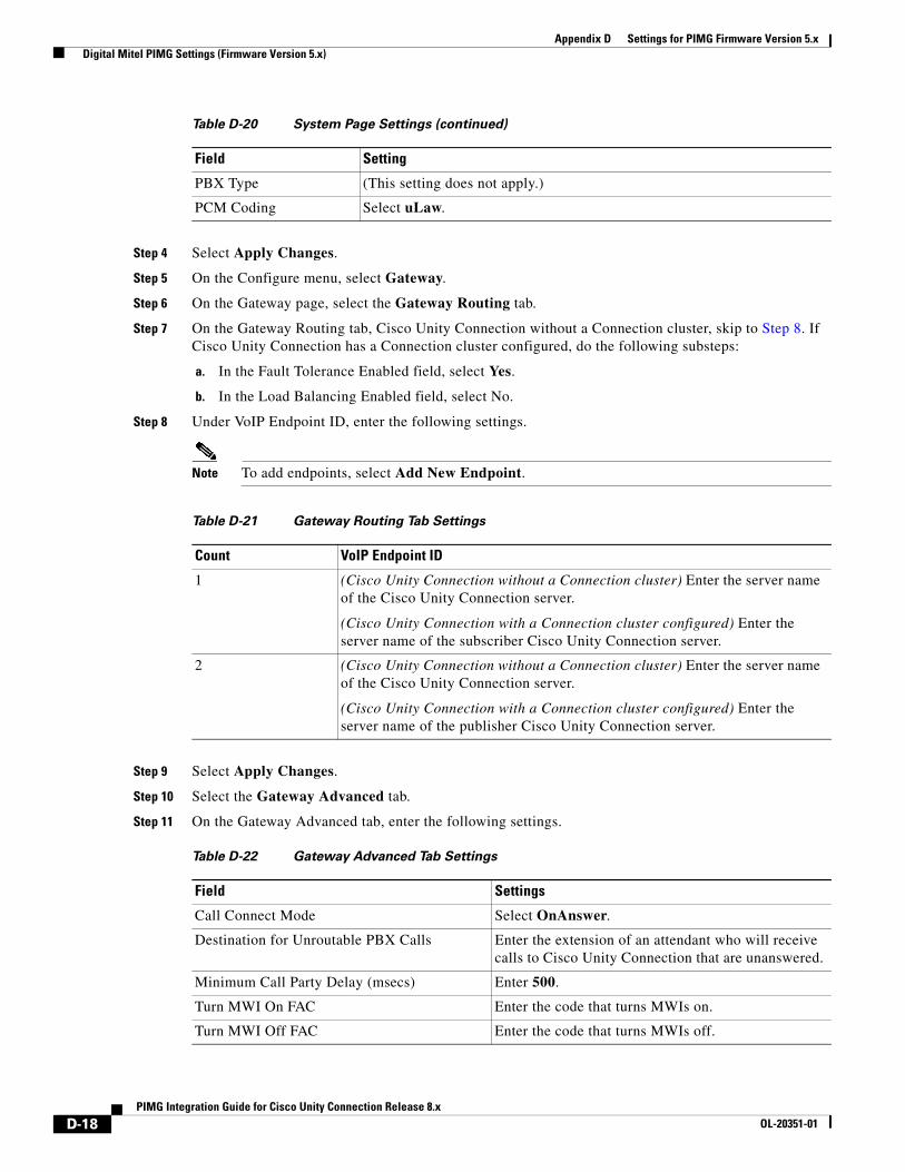
Appendix D Settings for PIMG Firmware Version 5.x Digital Mitel PIMG Settings (Firmware Version 5.x)
Step 4 Select Apply Changes.
Step 5 On the Configure menu, select Gateway.
Step 6 On the Gateway page, select the Gateway Routing tab.
Step 7 On the Gateway Routing tab, Cisco Unity Connection without a Connection cluster, skip to Step 8. If Cisco Unity Connection has a Connection cluster configured, do the following substeps:
a. In the Fault Tolerance Enabled field, select Yes.
b. In the Load Balancing Enabled field, select No.
Step 8 Under VoIP Endpoint ID, enter the following settings.
Note To add endpoints, select Add New Endpoint.
Step 9 Select Apply Changes.
Step 10 Select the Gateway Advanced tab.
Step 11 On the Gateway Advanced tab, enter the following settings.
PBX Type (This setting does not apply.)
PCM Coding Select uLaw.
Table D-20 System Page Settings (continued)
Field Setting
Table D-21 Gateway Routing Tab Settings
Count VoIP Endpoint ID
1 (Cisco Unity Connection without a Connection cluster) Enter the server name of the Cisco Unity Connection server.
(Cisco Unity Connection with a Connection cluster configured) Enter the server name of the subscriber Cisco Unity Connection server.
2 (Cisco Unity Connection without a Connection cluster) Enter the server name of the Cisco Unity Connection server.
(Cisco Unity Connection with a Connection cluster configured) Enter the server name of the publisher Cisco Unity Connection server.
Table D-22 Gateway Advanced Tab Settings
Field Settings
Call Connect Mode Select OnAnswer.
Destination for Unroutable PBX Calls Enter the extension of an attendant who will receive calls to Cisco Unity Connection that are unanswered.
Minimum Call Party Delay (msecs) Enter 500.
Turn MWI On FAC Enter the code that turns MWIs on.
Turn MWI Off FAC Enter the code that turns MWIs off.
D-18PIMG Integration Guide for Cisco Unity Connection Release 8.x
OL-20351-01
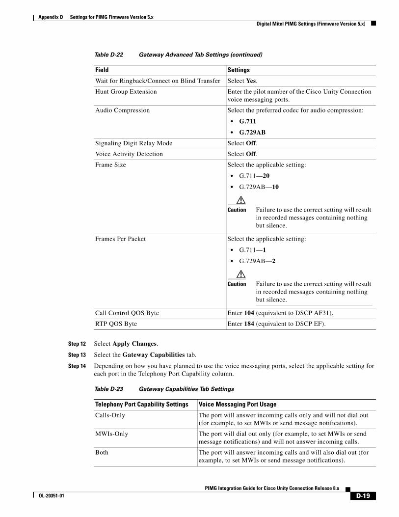
Appendix D Settings for PIMG Firmware Version 5.x Digital Mitel PIMG Settings (Firmware Version 5.x)
Step 12 Select Apply Changes.
Step 13 Select the Gateway Capabilities tab.
Step 14 Depending on how you have planned to use the voice messaging ports, select the applicable setting for each port in the Telephony Port Capability column.
Wait for Ringback/Connect on Blind Transfer Select Yes.
Hunt Group Extension Enter the pilot number of the Cisco Unity Connection voice messaging ports.
Audio Compression Select the preferred codec for audio compression:
• G.711
• G.729AB
Signaling Digit Relay Mode Select Off.
Voice Activity Detection Select Off.
Frame Size Select the applicable setting:
• G.711—20
• G.729AB—10
Caution Failure to use the correct setting will result in recorded messages containing nothing but silence.
Frames Per Packet Select the applicable setting:
• G.711—1
• G.729AB—2
Caution Failure to use the correct setting will result in recorded messages containing nothing but silence.
Call Control QOS Byte Enter 104 (equivalent to DSCP AF31).
RTP QOS Byte Enter 184 (equivalent to DSCP EF).
Table D-23 Gateway Capabilities Tab Settings
Telephony Port Capability Settings Voice Messaging Port Usage
Calls-Only The port will answer incoming calls only and will not dial out (for example, to set MWIs or send message notifications).
MWIs-Only The port will dial out only (for example, to set MWIs or send message notifications) and will not answer incoming calls.
Both The port will answer incoming calls and will also dial out (for example, to set MWIs or send message notifications).
Table D-22 Gateway Advanced Tab Settings (continued)
Field Settings
D-19PIMG Integration Guide for Cisco Unity Connection Release 8.x
OL-20351-01
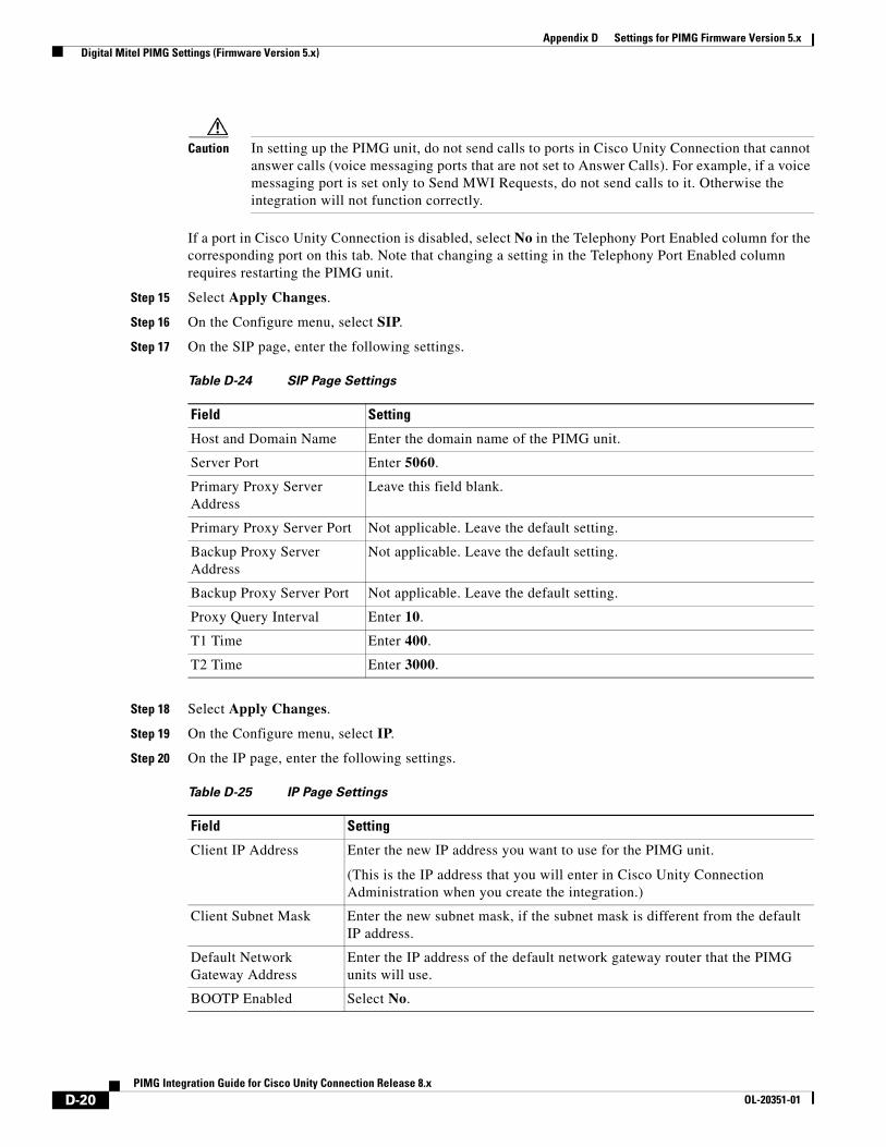
Appendix D Settings for PIMG Firmware Version 5.x Digital Mitel PIMG Settings (Firmware Version 5.x)
Caution In setting up the PIMG unit, do not send calls to ports in Cisco Unity Connection that cannot answer calls (voice messaging ports that are not set to Answer Calls). For example, if a voice messaging port is set only to Send MWI Requests, do not send calls to it. Otherwise the integration will not function correctly.
If a port in Cisco Unity Connection is disabled, select No in the Telephony Port Enabled column for the corresponding port on this tab. Note that changing a setting in the Telephony Port Enabled column requires restarting the PIMG unit.
Step 15 Select Apply Changes.
Step 16 On the Configure menu, select SIP.
Step 17 On the SIP page, enter the following settings.
Step 18 Select Apply Changes.
Step 19 On the Configure menu, select IP.
Step 20 On the IP page, enter the following settings.
Table D-24 SIP Page Settings
Field Setting
Host and Domain Name Enter the domain name of the PIMG unit.
Server Port Enter 5060.
Primary Proxy Server Address
Leave this field blank.
Primary Proxy Server Port Not applicable. Leave the default setting.
Backup Proxy Server Address
Not applicable. Leave the default setting.
Backup Proxy Server Port Not applicable. Leave the default setting.
Proxy Query Interval Enter 10.
T1 Time Enter 400.
T2 Time Enter 3000.
Table D-25 IP Page Settings
Field Setting
Client IP Address Enter the new IP address you want to use for the PIMG unit.
(This is the IP address that you will enter in Cisco Unity Connection Administration when you create the integration.)
Client Subnet Mask Enter the new subnet mask, if the subnet mask is different from the default IP address.
Default Network Gateway Address
Enter the IP address of the default network gateway router that the PIMG units will use.
BOOTP Enabled Select No.
D-20PIMG Integration Guide for Cisco Unity Connection Release 8.x
OL-20351-01
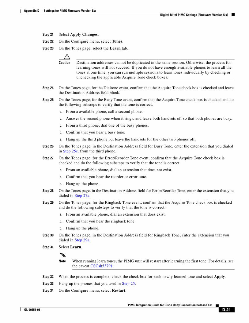
Appendix D Settings for PIMG Firmware Version 5.x Digital Mitel PIMG Settings (Firmware Version 5.x)
Step 21 Select Apply Changes.
Step 22 On the Configure menu, select Tones.
Step 23 On the Tones page, select the Learn tab.
Caution Destination addresses cannot be duplicated in the same session. Otherwise, the process for learning tones will not succeed. If you do not have enough available phones to learn all the tones at one time, you can run multiple sessions to learn tones individually by checking or unchecking the applicable Acquire Tone check boxes.
Step 24 On the Tones page, for the Dialtone event, confirm that the Acquire Tone check box is checked and leave the Destination Address field blank.
Step 25 On the Tones page, for the Busy Tone event, confirm that the Acquire Tone check box is checked and do the following substeps to verify that the tone is correct.
a. From a available phone, call a second phone.
b. Answer the second phone when it rings, and leave both handsets off so that both phones are busy.
c. From a third phone, dial one of the busy phones.
d. Confirm that you hear a busy tone.
e. Hang up the third phone but leave the handsets for the other two phones off.
Step 26 On the Tones page, in the Destination Address field for Busy Tone, enter the extension that you dialed in Step 25c. from the third phone.
Step 27 On the Tones page, for the Error/Reorder Tone event, confirm that the Acquire Tone check box is checked and do the following substeps to verify that the tone is correct.
a. From an available phone, dial an extension that does not exist.
b. Confirm that you hear the reorder or error tone.
c. Hang up the phone.
Step 28 On the Tones page, in the Destination Address field for Error/Reorder Tone, enter the extension that you dialed in Step 27a.
Step 29 On the Tones page, for the Ringback Tone event, confirm that the Acquire Tone check box is checked and do the following substeps to verify that the tone is correct.
a. From an available phone, dial an extension that does exist.
b. Confirm that you hear the ringback tone.
c. Hang up the phone.
Step 30 On the Tones page, in the Destination Address field for Ringback Tone, enter the extension that you dialed in Step 29a.
Step 31 Select Learn.
Note When running learn tones, the PIMG unit will restart after learning the first tone. For details, see the caveat CSCsh53791.
Step 32 When the process is complete, check the check box for each newly learned tone and select Apply.
Step 33 Hang up the phones that you used in Step 25.
Step 34 On the Configure menu, select Restart.
D-21PIMG Integration Guide for Cisco Unity Connection Release 8.x
OL-20351-01
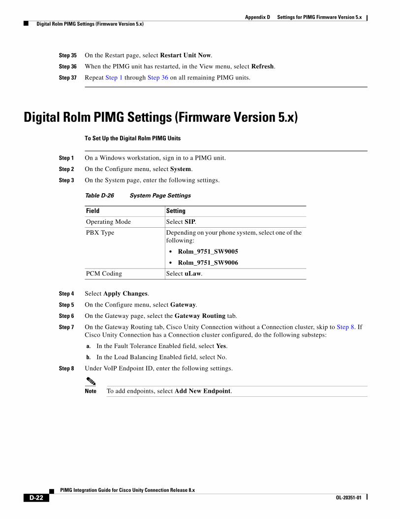
Appendix D Settings for PIMG Firmware Version 5.x Digital Rolm PIMG Settings (Firmware Version 5.x)
Step 35 On the Restart page, select Restart Unit Now.
Step 36 When the PIMG unit has restarted, in the View menu, select Refresh.
Step 37 Repeat Step 1 through Step 36 on all remaining PIMG units.
Digital Rolm PIMG Settings (Firmware Version 5.x)To Set Up the Digital Rolm PIMG Units
Step 1 On a Windows workstation, sign in to a PIMG unit.
Step 2 On the Configure menu, select System.
Step 3 On the System page, enter the following settings.
Step 4 Select Apply Changes.
Step 5 On the Configure menu, select Gateway.
Step 6 On the Gateway page, select the Gateway Routing tab.
Step 7 On the Gateway Routing tab, Cisco Unity Connection without a Connection cluster, skip to Step 8. If Cisco Unity Connection has a Connection cluster configured, do the following substeps:
a. In the Fault Tolerance Enabled field, select Yes.
b. In the Load Balancing Enabled field, select No.
Step 8 Under VoIP Endpoint ID, enter the following settings.
Note To add endpoints, select Add New Endpoint.
Table D-26 System Page Settings
Field Setting
Operating Mode Select SIP.
PBX Type Depending on your phone system, select one of the following:
• Rolm_9751_SW9005
• Rolm_9751_SW9006
PCM Coding Select uLaw.
D-22PIMG Integration Guide for Cisco Unity Connection Release 8.x
OL-20351-01
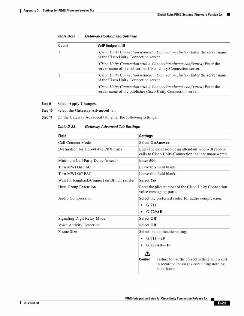
Appendix D Settings for PIMG Firmware Version 5.x Digital Rolm PIMG Settings (Firmware Version 5.x)
Step 9 Select Apply Changes.
Step 10 Select the Gateway Advanced tab.
Step 11 On the Gateway Advanced tab, enter the following settings.
Table D-27 Gateway Routing Tab Settings
Count VoIP Endpoint ID
1 (Cisco Unity Connection without a Connection cluster) Enter the server name of the Cisco Unity Connection server.
(Cisco Unity Connection with a Connection cluster configured) Enter the server name of the subscriber Cisco Unity Connection server.
2 (Cisco Unity Connection without a Connection cluster) Enter the server name of the Cisco Unity Connection server.
(Cisco Unity Connection with a Connection cluster configured) Enter the server name of the publisher Cisco Unity Connection server.
Table D-28 Gateway Advanced Tab Settings
Field Settings
Call Connect Mode Select OnAnswer.
Destination for Unroutable PBX Calls Enter the extension of an attendant who will receive calls to Cisco Unity Connection that are unanswered.
Minimum Call Party Delay (msecs) Enter 500.
Turn MWI On FAC Leave this field blank.
Turn MWI Off FAC Leave this field blank.
Wait for Ringback/Connect on Blind Transfer Select Yes.
Hunt Group Extension Enter the pilot number of the Cisco Unity Connection voice messaging ports.
Audio Compression Select the preferred codec for audio compression:
• G.711
• G.729AB
Signaling Digit Relay Mode Select Off.
Voice Activity Detection Select Off.
Frame Size Select the applicable setting:
• G.711—20
• G.729AB—10
Caution Failure to use the correct setting will result in recorded messages containing nothing but silence.
D-23PIMG Integration Guide for Cisco Unity Connection Release 8.x
OL-20351-01
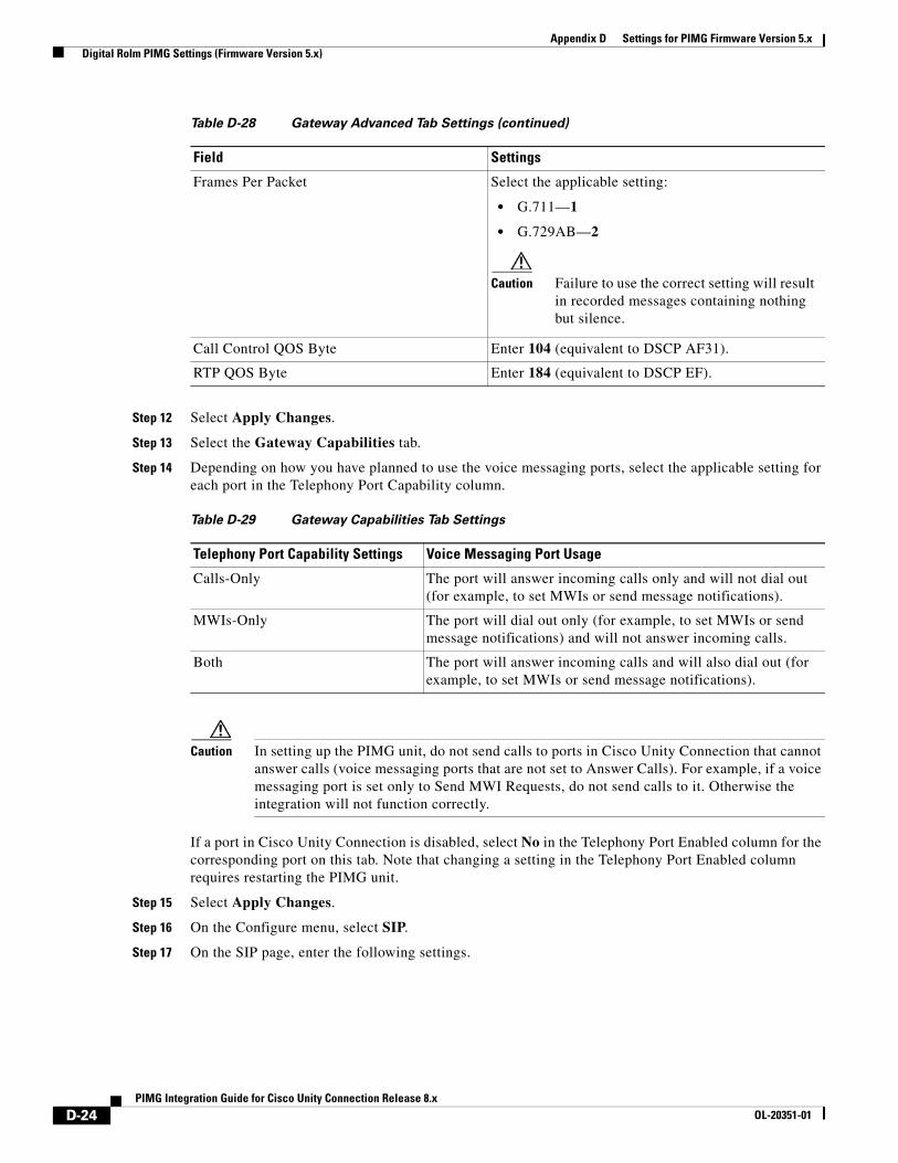
Appendix D Settings for PIMG Firmware Version 5.x Digital Rolm PIMG Settings (Firmware Version 5.x)
Step 12 Select Apply Changes.
Step 13 Select the Gateway Capabilities tab.
Step 14 Depending on how you have planned to use the voice messaging ports, select the applicable setting for each port in the Telephony Port Capability column.
Caution In setting up the PIMG unit, do not send calls to ports in Cisco Unity Connection that cannot answer calls (voice messaging ports that are not set to Answer Calls). For example, if a voice messaging port is set only to Send MWI Requests, do not send calls to it. Otherwise the integration will not function correctly.
If a port in Cisco Unity Connection is disabled, select No in the Telephony Port Enabled column for the corresponding port on this tab. Note that changing a setting in the Telephony Port Enabled column requires restarting the PIMG unit.
Step 15 Select Apply Changes.
Step 16 On the Configure menu, select SIP.
Step 17 On the SIP page, enter the following settings.
Frames Per Packet Select the applicable setting:
• G.711—1
• G.729AB—2
Caution Failure to use the correct setting will result in recorded messages containing nothing but silence.
Call Control QOS Byte Enter 104 (equivalent to DSCP AF31).
RTP QOS Byte Enter 184 (equivalent to DSCP EF).
Table D-29 Gateway Capabilities Tab Settings
Telephony Port Capability Settings Voice Messaging Port Usage
Calls-Only The port will answer incoming calls only and will not dial out (for example, to set MWIs or send message notifications).
MWIs-Only The port will dial out only (for example, to set MWIs or send message notifications) and will not answer incoming calls.
Both The port will answer incoming calls and will also dial out (for example, to set MWIs or send message notifications).
Table D-28 Gateway Advanced Tab Settings (continued)
Field Settings
D-24PIMG Integration Guide for Cisco Unity Connection Release 8.x
OL-20351-01
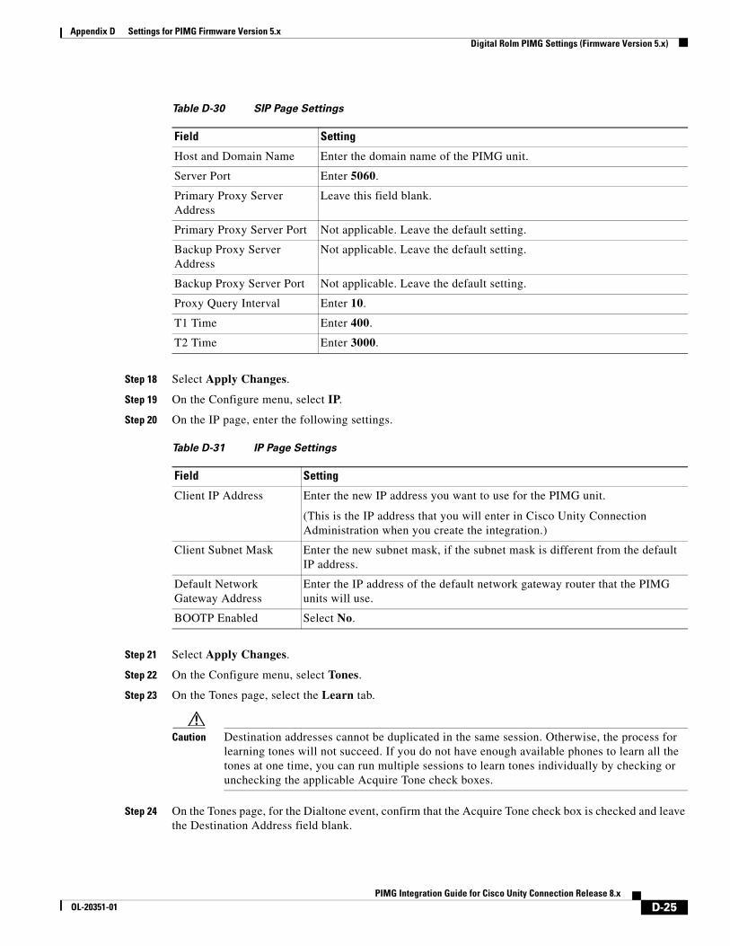
Appendix D Settings for PIMG Firmware Version 5.x Digital Rolm PIMG Settings (Firmware Version 5.x)
Step 18 Select Apply Changes.
Step 19 On the Configure menu, select IP.
Step 20 On the IP page, enter the following settings.
Step 21 Select Apply Changes.
Step 22 On the Configure menu, select Tones.
Step 23 On the Tones page, select the Learn tab.
Caution Destination addresses cannot be duplicated in the same session. Otherwise, the process for learning tones will not succeed. If you do not have enough available phones to learn all the tones at one time, you can run multiple sessions to learn tones individually by checking or unchecking the applicable Acquire Tone check boxes.
Step 24 On the Tones page, for the Dialtone event, confirm that the Acquire Tone check box is checked and leave the Destination Address field blank.
Table D-30 SIP Page Settings
Field Setting
Host and Domain Name Enter the domain name of the PIMG unit.
Server Port Enter 5060.
Primary Proxy Server Address
Leave this field blank.
Primary Proxy Server Port Not applicable. Leave the default setting.
Backup Proxy Server Address
Not applicable. Leave the default setting.
Backup Proxy Server Port Not applicable. Leave the default setting.
Proxy Query Interval Enter 10.
T1 Time Enter 400.
T2 Time Enter 3000.
Table D-31 IP Page Settings
Field Setting
Client IP Address Enter the new IP address you want to use for the PIMG unit.
(This is the IP address that you will enter in Cisco Unity Connection Administration when you create the integration.)
Client Subnet Mask Enter the new subnet mask, if the subnet mask is different from the default IP address.
Default Network Gateway Address
Enter the IP address of the default network gateway router that the PIMG units will use.
BOOTP Enabled Select No.
D-25PIMG Integration Guide for Cisco Unity Connection Release 8.x
OL-20351-01
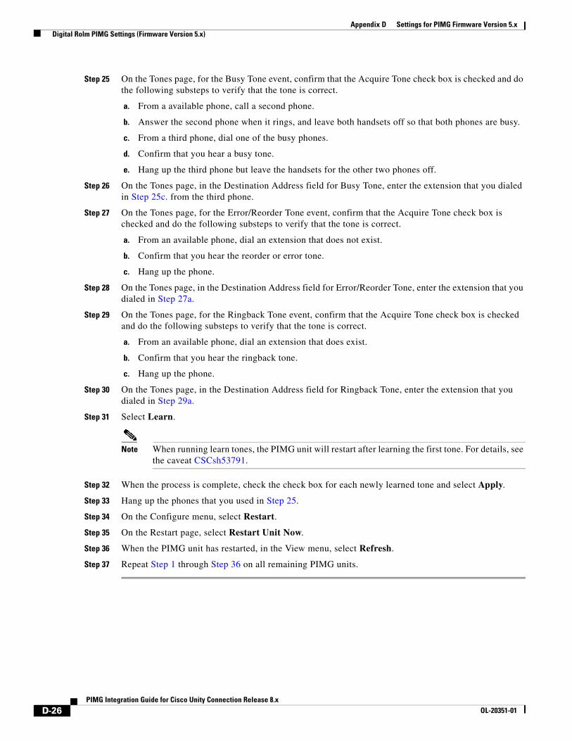
Appendix D Settings for PIMG Firmware Version 5.x Digital Rolm PIMG Settings (Firmware Version 5.x)
Step 25 On the Tones page, for the Busy Tone event, confirm that the Acquire Tone check box is checked and do the following substeps to verify that the tone is correct.
a. From a available phone, call a second phone.
b. Answer the second phone when it rings, and leave both handsets off so that both phones are busy.
c. From a third phone, dial one of the busy phones.
d. Confirm that you hear a busy tone.
e. Hang up the third phone but leave the handsets for the other two phones off.
Step 26 On the Tones page, in the Destination Address field for Busy Tone, enter the extension that you dialed in Step 25c. from the third phone.
Step 27 On the Tones page, for the Error/Reorder Tone event, confirm that the Acquire Tone check box is checked and do the following substeps to verify that the tone is correct.
a. From an available phone, dial an extension that does not exist.
b. Confirm that you hear the reorder or error tone.
c. Hang up the phone.
Step 28 On the Tones page, in the Destination Address field for Error/Reorder Tone, enter the extension that you dialed in Step 27a.
Step 29 On the Tones page, for the Ringback Tone event, confirm that the Acquire Tone check box is checked and do the following substeps to verify that the tone is correct.
a. From an available phone, dial an extension that does exist.
b. Confirm that you hear the ringback tone.
c. Hang up the phone.
Step 30 On the Tones page, in the Destination Address field for Ringback Tone, enter the extension that you dialed in Step 29a.
Step 31 Select Learn.
Note When running learn tones, the PIMG unit will restart after learning the first tone. For details, see the caveat CSCsh53791.
Step 32 When the process is complete, check the check box for each newly learned tone and select Apply.
Step 33 Hang up the phones that you used in Step 25.
Step 34 On the Configure menu, select Restart.
Step 35 On the Restart page, select Restart Unit Now.
Step 36 When the PIMG unit has restarted, in the View menu, select Refresh.
Step 37 Repeat Step 1 through Step 36 on all remaining PIMG units.
D-26PIMG Integration Guide for Cisco Unity Connection Release 8.x
OL-20351-01
PIMG IntegrOL-20351-01
I N D E X
A
Allow TRAP Connections (port setting) 2-2
analog (DTMF) integration
connections 1-3
description 1-3
Answer Calls (port setting) 2-2
application note
Ericsson MD-110 B-1
Nortel SL-100 C-1
Avaya Definity G3
creating a new integration 3-18
phone system programming instructions 3-3
PIMG unit setup instructions 3-5
requirements 3-2
task list, creating an integration 3-1
Avaya Definity ProLogix
creating a new integration 4-18
phone system programming instructions 4-3
PIMG unit setup instructions 4-5
requirements 4-2
task list, creating an integration 4-1
Avaya S8300/S8500/S8700
creating a new integration 5-18
phone system programming instructions 5-3
PIMG unit setup instructions 5-5
requirements 5-2
task list, creating an integration 5-1
C
call information 1-4
connections
analog voice lines to secondary master PIMG unit A-1
required for digital integration 1-2
required for DTMF (analog) integration 1-3
required for serial (SMDI, MCI, or MD-110) integration 1-3
serial cables to secondary master PIMG unit A-4
D
digital integration
connections 1-2
description 1-2
DTMF (analog) integration
connections 1-3
description 1-3
E
Enabled (port setting) 2-1
Extension (port setting) 2-2
F
features provided by integration 1-4
firmware version 5.x, PIMG settings D-1
forwarded calls, information sent by phone system 1-4
M
master PIMG unit, adding a secondary master PIMG unit A-1
MD-110, application note B-1
Mitel SX-200
IN-1ation Guide for Cisco Unity Connection Release 8.x
Index
creating a new integration 6-22
phone system programming instructions 6-3
PIMG unit setup instructions 6-8
requirements 6-2
task list, creating an integration 6-1
Mitel SX-2000
creating a new integration 7-18
phone system programming instructions 7-3
PIMG unit setup instructions 7-5
requirements 7-2
task list, creating an integration 7-1
multiple integrations 1-5
N
NEC NEAX 2400
creating a new integration 8-19
phone system programming instructions 8-3
PIMG unit setup instructions 8-5
requirements 8-2
task list, creating an integration 8-1
Nortel Meridian 1
creating a new integration 9-24
phone system programming instructions 9-3
PIMG unit setup instructions 9-10
requirements 9-2
task list, creating an integration 9-1
O
Outgoing Hunt Order (port setting) 2-2
P
Perform Message Notification (port setting) 2-2
phone systems, supported 1-1
PIMG integrations, supported phone systems 1-1
PIMG settings for firmware version 5.x D-1
IN-2PIMG Integration Guide for Cisco Unity Connection Release 8.x
ports
considerations for Cisco Unity Connection cluster 2-3
planning how many will answer calls 2-3
planning how many will dial out 2-3
planning number to install 2-2
planning setup 2-1
settings 2-1
R
redundant master PIMG unit, adding A-1
Rolm 9751
creating a new integration 10-20
phone system programming instructions 10-3
PIMG unit setup instructions 10-7
requirements 10-2
task list, creating an integration 10-1
S
secondary master PIMG unit
adding A-1
analog voice line connections to A-1
configuring A-5
serial data cable connections to A-4
Send MWI Requests (port setting) 2-2
serial (SMDI, MCI, or MD-110) integration
connections 1-3
creating a new integration 11-19
description 1-3
Ericsson MD-110, application note B-1
Nortel SL-100, application note C-1
phone system programming instructions 11-3
PIMG unit setup instructions 11-4
requirements 11-2
task list 11-1
Siemens Hicom 300 E (European)
creating a new integration 12-19
OL-20351-01
Index
phone system programming instructions 12-3
PIMG unit setup instructions 12-5
requirements 12-2
task list, creating an integration 12-1
Siemens Hicom 300 E (North American)
clearing MWIs from legacy system 13-3
creating a new integration 13-20
phone system programming instructions 13-3
PIMG unit setup instructions 13-6
requirements 13-2
task list, creating an integration 13-1
SMDI, application note C-1
supported phone systems 1-1
T
testing
setting up supervised transfer 14-3
setting up test configuration 14-1
testing an external call with release transfer 14-2
testing supervised transfer 14-3
testing the functionality for listening to messages 14-3
V
voice messaging ports, settings 2-1
PIMOL-20351-01
IN-3G Integration Guide for Cisco Unity Connection Release 8.x

Index
IN-4PIMG Integration Guide for Cisco Unity Connection Release 8.x
OL-20351-01


![[Step-by-Step] Cisco Unity Connection SCCP …Step-by-Step] Cisco Unity Connection SCCP Integration with CUCM Cisco Call Manager The optional Cisco Unity Connection server, available](https://img.pdfslide.us/doc/110x75/5ae0402c7f8b9a1c248cf868/step-by-step-cisco-unity-connection-sccp-step-by-step-cisco-unity-connection.jpg)