Embed Size (px)
Citation preview
C o m m e r c i a l V e h i c l e S y s t e m s
S e r v i c e M a n u a l Spring Brake Actuators for Air Disc Brakes
Description/Function
Service instructions
Service kits
Testing
DisclaimerThe information contained in this document is intended for the exclusive use of trained persons within the commercial vehicle industry, and must not be passed on to any third party. All recommendations regarding products and their servicing or usage are with reference to Knorr-Bremse products and should not be considered applicable to products from other manufacturers.
This information does not purport to be all-inclusive and no responsibility is assumed as a result of its use. We cannot accept any liability nor offer any guarantee regarding data accuracy, completeness or timeliness. The information does not represent any guarantee or ensured characteristics of the Products or Systems described. No liability can be accepted based on the information, its use, recommendations or advice provided. In no event may we be held liable for any damage or loss except in the case of wilful intent or gross negligence on our part, or if any mandatory legal provisions apply.
Any legal disputes arising from the use of this information shall be subject to German law.
Note: If service work is carried out on the vehicle, it is the responsibility of the workshop to ensure the vehicle is fully tested and in full functional order before the vehicle is returned into service. Knorr-Bremse accepts no liability for problems caused as a result of appropriate tests not being carried out.
This disclaimer is an English translation of a German text, which should be referred to for all legal purposes.
Revision Details
Rev. 000 September 2014 New document
Rev. 001 September 2015 Torque on page 8 changed from 50 Nm to 45 Nm.
3
Contents
Safety and Environment Guidelines 4
1 General Information 6
1.1 Voss 230/232 System Connections . . . . . . . . . . . . . . . 6
1.2 Service Intervals . . . . . . . . . . . . . . . . . . . . . 6
2 Basic Principles 7
2.1 Application . . . . . . . . . . . . . . . . . . . . . . . 7
2.2 Function . . . . . . . . . . . . . . . . . . . . . . . 7
3 Components 9
3.1 Exploded View . . . . . . . . . . . . . . . . . . . . . . 9
4 Removal from the vehicle of the Spring Brake Actuator 10
5 Disassembly of the Service Brake Portion 12
6 Service Kits 12
7 Assembly of the Service Brake Portion 16
8 Refitting the Spring Brake Actuator to the vehicle 20
9 Testing 21
9.1 Functional and leakage test . . . . . . . . . . . . . . . . . . 21
4
Safety and Environment Guidelines
Note: The safety advice listed below is applicable to general service and diagnostic work on braking systems. Also observe any recommendations from the axle or vehicle manufacturer concerning towing, jacking-up and securing the vehicle.
CAUTION: KNORR-BREMSE IS NOT LIABLE FOR ANY INJURIES OR DAMAGES CAUSED BY IMPROPER USE OF SPECIFIED SERVICE KITS AND/OR SERVICE TOOLS. FURTHERMORE, MISUSE OF TOOLS OR INCORRECT INSTALLATION OR APPLICATION OF SERVICE KITS MAY RESULT IN DAMAGE OR POTENTIALLY UNSAFE VEHICLE OPERATIONS. IN THIS CASE, KNORR-BREMSE DOES NOT HAVE ANY WARRANTY OBLIGATIONS.
Before and whilst working on or around compressed air systems and devices, the following precautions should be observed, along with the many hazard notes contained throughout the document:
1 Always wear safety glasses when working with air pressure.
2 Never exceed the vehicle manufacturer’s recommended air pressures.
3 Never look into air jets or direct them at anyone.
4 Never connect or disconnect a hose or line containing pressure; it may whip as air escapes.
5 When removing or servicing a product, ensure all pressure related to the specific system it is contained in has been depleted to 0 bar. Be aware that if the vehicle is equipped with an air dryer system, it can also contain air pressure along with its purge reservoir, if fitted, even after pressure has been drained from the other reservoirs.
6 If it is necessary to drain the air pressure from reservoirs, etc., keep away from brake actuator push rods and levers since they may move as system pressure drops. On vehicles fitted with air suspension, it is advised when undertaking such work, to support the chassis from sudden lowering and therefore prevent any possibility of being trapped between the chassis and axle or ground.
7 Park the vehicle on a level surface, apply the parking brakes, and always chock the wheels as depleting vehicle air system pressure may cause the vehicle to roll.
8 When working under or around the vehicle, and particularly when working in the engine compartment, the engine should be shut off and the battery disconnected. Where circumstances require that the engine be running, EXTREME CAUTION should be taken to prevent personal injury resulting from contact with moving, rotating, leaking, heated or electrically charged components. Additionally, it is advisable to place a clear sign on or near the steering wheel advising that there is work in progress on the vehicle.
9 When working on vehicles equipped with air suspension, to guard against injury due to unexpected downward movement of the chassis caused by sudden pressure loss in the suspension system, ensure that the vehicle chassis is mechanically supported with a ‘prop’ between the chassis and the axle or between the chassis and the ground.
10 Examine all pipework for signs of kinks, dents, abrasion, drying out or overheating. Be aware that kinks in pipework may result in air pressure being trapped in the pipework and associated equipment. Replacement hardware, tubing, hose, fittings, etc. must be of equivalent size, type and strength as original equipment and be designed specifically for such applications and systems. Check the attachment of all pipework; it should be installed so that it cannot abrade or be subjected to excessive heat.
11 Components with stripped threads or damaged/corroded parts must be replaced completely. Do not attempt repairs requiring machining or welding unless specifically stated and approved by the vehicle or component manufacturer.
12 Never attempt to install, remove, disassemble or assemble a device until you have read and thoroughly understood the recommended procedures. Some units contain powerful springs and injury can result if not properly dismantled and reassembled. Use only the correct tools and observe all precautions pertaining to use of those tools.
13 Before removing any device note its position and the connections of all pipework so that the replacement/serviced device can be properly installed. Ensure that adequate support or assistance is provided for the removal/installation of heavy items.
14 Use only genuine replacement parts, components and kits as supplied by Knorr-Bremse or the vehicle manufacturer. Only use the recommended tools as specified in related Knorr-Bremse instructions.
15 The serviced or replaced product must be checked for correct function and effectiveness.
16 If products have been dismantled, serviced or replaced, whose performance could affect braking performance or system behaviour, this should be checked on a roller dynamometer. Bear in mind that a lower performance may be experienced during the bedding-in phase if new brake pads/linings and/or brake discs/drums have been fitted.
17 The use of impact screwdrivers or impact wrenches in conjunction with Knorr-Bremse service tools for air disc brakes is not permitted. The service tools are not designed for such use. It is likely that the tools or the vehicle will be damaged and there is a serious risk of injury – see Caution above.
18 Do not use compressed air to clean the disc brake. Avoid air contamination of brake dust.
19 Prior to returning the vehicle to service, make certain that all components and the complete brake systems are leak free and restored to their proper operating condition.
Safety and Environment Guidelines
5
Safety and Environment Guidelines
Welding
To avoid damage to electronic components when carrying out electrical welding, the following precautions should be observed:
1 In all cases, before starting any electrical welding, remove all connections from any electronic control units or modules, noting their position and the order in which they are removed.
2 When re-inserting the electrical connectors (in reverse order) it is essential that they are fitted to their correct assigned position - if necessary this must be checked by PC Diagnostics.
Disposal of Waste Equipment by Business Users in the European UnionThis symbol on the product, packaging or in user instructions, indicates that this product must not be disposed of with other general waste. Instead, it is your responsibility to dispose of the waste electrical and electronic parts of this product by handing them over to a company or organisation authorised for the recycling of waste electrical and electronic equipment. For more information about arrange-ments for waste equipment disposal please contact your Knorr-Bremse distributor or local Knorr-Bremse representative.
6
1General Information
1.1 Voss 230/232 System Connections
1 General Information
Disconnections and reconnections of VOSS quick connect system must be done according to the VOSS assembly instructions (available in web site www.voss.de)
1.2 Service Intervals
In addition to legally required periodic vehicle inspections, it is recommended that simple routine inspections of a general nature are carried out to maintain the braking system at a high level of functionality. These simple routine inspections, including a visual check of the spring brake to verify that there is no damage or unexpected wear, should be:
(1) the weekly checking for excess water in the reservoirs by operation of the reservoir drain valves
and
(2) the 6 monthly / (50,000 km) checking of the complete braking system for excessive air leakage during a maximum pressure foot brake application with the vehicle stationary and the parking brake released.
This inspection has to be done especially for vehicles which are used in severe environments (very high or low temperatures, high humidity, presence of aggressive substances or fluids …) or submitted to frequent braking (buses, garbage trucks, urban distribution …)
These inspections are carried out as preventive maintenance so as to minimize the possibility of a vehicle breakdown. The service interval can also be influenced by the positioning of the device on the vehicle and the service intervals are based on the assumption that each device is positioned such it cannot be inadvertently abused or that external rubber boots/seals are not exposed to abnormal influences.
The Service Brake Portion of a Spring Brake can be serviced using a genuine Knorr-Bremse service kit. In general Knorr-Bremse service kits contain all of the components that can deteriorate with use, such as rubber parts (O-rings, special seals, bonded inlet/exhaust valves, exhaust flaps ...), plastic and metal parts (filter elements,springs ...), fasteners and the correct grease. The range of kits is designed to enable each device to be serviced in part or completely. Knorr-Bremse service kits are only designed for use with genuine Knorr-Bremse assemblies and are only to be used in the manner detailed in these service instructions.
After servicing, the assembly must also be checked in accordance with vehicle manufacturer’s instructions to ensure correct operation before the vehicle is placed back in service.
Important note: The Spring Portion of a Spring Brake must not be disassembled for safety reasons as it contains a compressed high power spring.
7
2
3
e b
1 a
7 52
16 18d
21
19
c
26
Basic Principles
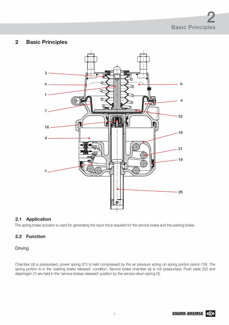
2.1 ApplicationThe spring brake actuator is used for generating the input force required for the service brake and the parking brake.
2 Basic Principles
2.2 Function
Driving
Chamber (d) is pressurised, power spring (21) is held compressed by the air pressure acting on spring portion piston (18). The spring portion is in the ‘parking brake released’ condition. Service brake chamber (a) is not pressurised. Push plate (52) and diaphragm (7) are held in the ‘service brakes released’ position by the service return spring (3).
8
2Basic Principles
Braking with the foot brake valve (service brake)
When air pressure is introduced into service chamber (a) the diaphragm (7) moves the push plate (52) outwards with a force proportional to its effective area and the pressure applied. The push rod (1) transfers this force to the foundation brake via the lever of the disc brake caliper. When the pressure is reduced or removed, the return spring (3) moves the push plate (52) and the diaphragm (7) back to the ‘service brake released’ position. As the diaphragm moves forward, any water or other contamination is expelled through the vent hole (e). This also allows for equalization of any pressure between non-pressure chamber (b) and atmosphere caused by air displaced by the diaphragm.
Braking with the hand brake valve (parking brake)
When the pressure in spring pressure chamber (d) is exhausted, the spring portion piston (18) is pushed forward by the power spring (21). The end of spring portion piston (18) pushes diaphragm (7), push plate (52) and push rod (1) outwards. The force of the power spring (21) is transferred to the foundation brake via the lever of the disc brake caliper. When pressure is reapplied to spring pressure chamber (d) spring portion piston (18) compresses power spring (21) and allows push plate (52) and diaphragm (7) to be returned to the brakes released position by return spring (3). The equalization of pressure in the spring chamber (c) is carried-out via the breather valve (16) in the piston tube (f).
Breather valve
Pressure equalization is carried out between spring chamber (c) and atmosphere via port 11 and the upstream equipment (e.g. foot brake valve) in order to protect the spring chamber (c) from dirt and humidity deposits. Breather valve (16) is designed so that it remains open while the service brake is not applied. Only when actuating the service brake (pressure at port 11), breather valve (16) is closed in order to prevent pressure build-up in the spring chamber (c).
Note: When the parking brake is applied and pressure is applied very slowly at port 11, it is possible that a venting noise becomes audible. This effect is not to be considered as leakage since it does not occur when the spring brake actuator section is charged or when the service brake is actuated in the normal way.
Mechanical release of the parking brake
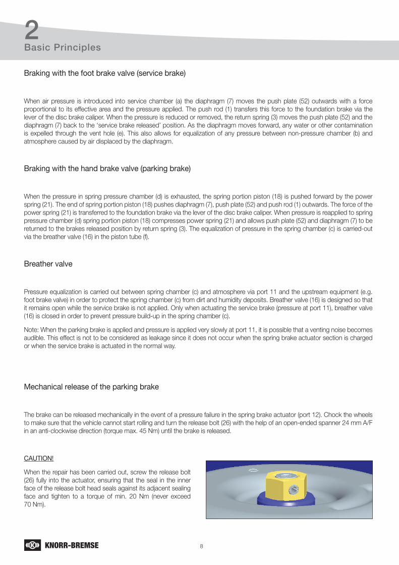
The brake can be released mechanically in the event of a pressure failure in the spring brake actuator (port 12). Chock the wheels to make sure that the vehicle cannot start rolling and turn the release bolt (26) with the help of an open-ended spanner 24 mm A/F in an anti-clockwise direction (torque max. 45 Nm) until the brake is released.
CAUTION!
When the repair has been carried out, screw the release bolt (26) fully into the actuator, ensuring that the seal in the inner face of the release bolt head seals against its adjacent sealing face and tighten to a torque of min. 20 Nm (never exceed 70 Nm).
9
3
6
7●52
70●
1
3●●
20●●
4
11●
54●
10●53●●●
2617
Components
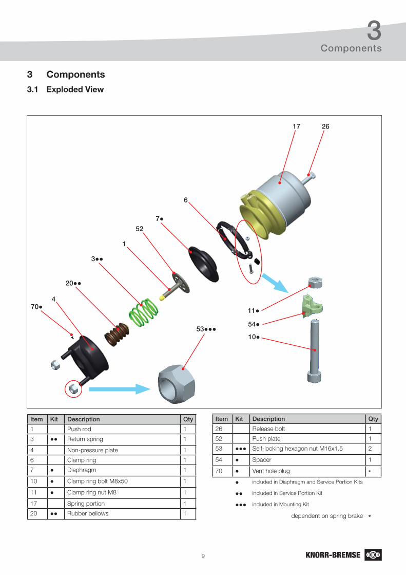
3.1 Exploded View
3 Components
Item Kit Description Qty
1 Push rod 1
3 ●● Return spring 1
4 Non-pressure plate 1
6 Clamp ring 1
7 ● Diaphragm 1
10 ● Clamp ring bolt M8x50 1
11 ● Clamp ring nut M8 1
17 Spring portion 1
20 ●● Rubber bellows 1
Item Kit Description Qty
26 Release bolt 1
52 Push plate 1
53 ●●● Self-locking hexagon nut M16x1.5 2
54 ● Spacer 1
70 ● Vent hole plug *
● included in Diaphragm and Service Portion Kits
●● included in Service Portion Kit
●●● included in Mounting Kit
dependent on spring brake *
10
4
6
4
53
2617
Removal of the Spring Brake Actuator from the Vehicle
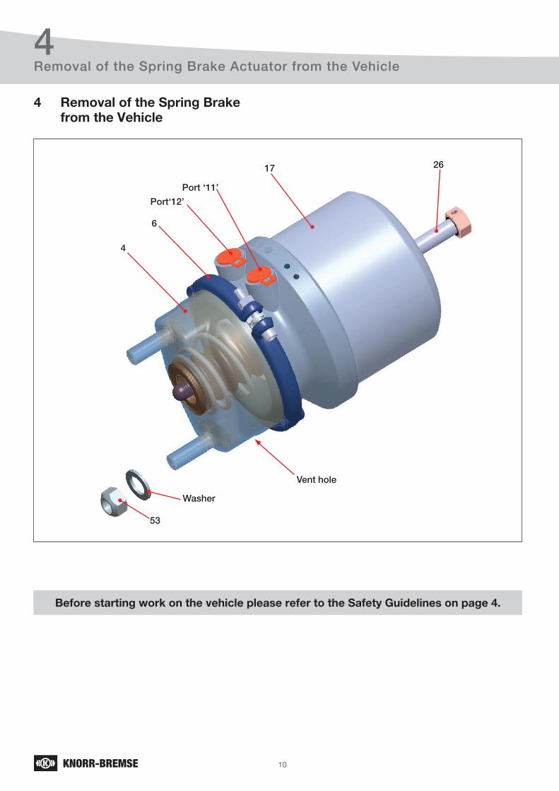
4 Removal of the Spring Brake from the Vehicle
Before starting work on the vehicle please refer to the Safety Guidelines on page 4.
Vent hole
Washer
Port‘12’
Port ‘11’
11
4
≈8 mm
Removal of the Spring Brake Actuator from the Vehicle
Do not use an impact wrench.
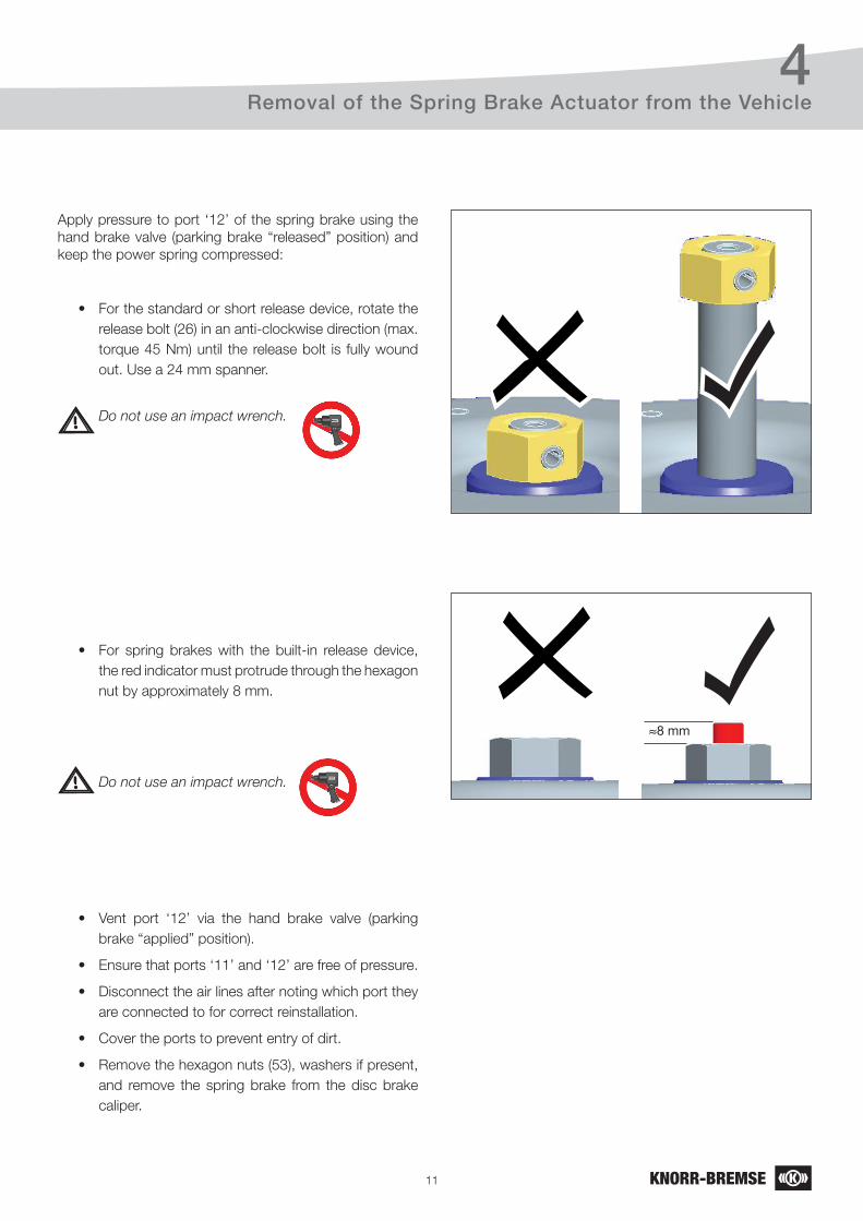
Apply pressure to port ‘12’ of the spring brake using the hand brake valve (parking brake “released” position) and keep the power spring compressed:
• For the standard or short release device, rotate the release bolt (26) in an anti-clockwise direction (max. torque 45 Nm) until the release bolt is fully wound out. Use a 24 mm spanner.
Do not use an impact wrench.
• For spring brakes with the built-in release device, the red indicator must protrude through the hexagon nut by approximately 8 mm.
• Vent port ‘12’ via the hand brake valve (parking brake “applied” position).
• Ensure that ports ‘11’ and ‘12’ are free of pressure.
• Disconnect the air lines after noting which port they are connected to for correct reinstallation.
• Cover the ports to prevent entry of dirt.
• Remove the hexagon nuts (53), washers if present, and remove the spring brake from the disc brake caliper.
12
5
6
7
52
70
1
3
20
4
11
54
1053
2617
Disassembly of the Service Brake Portion
Service Brake
Portion
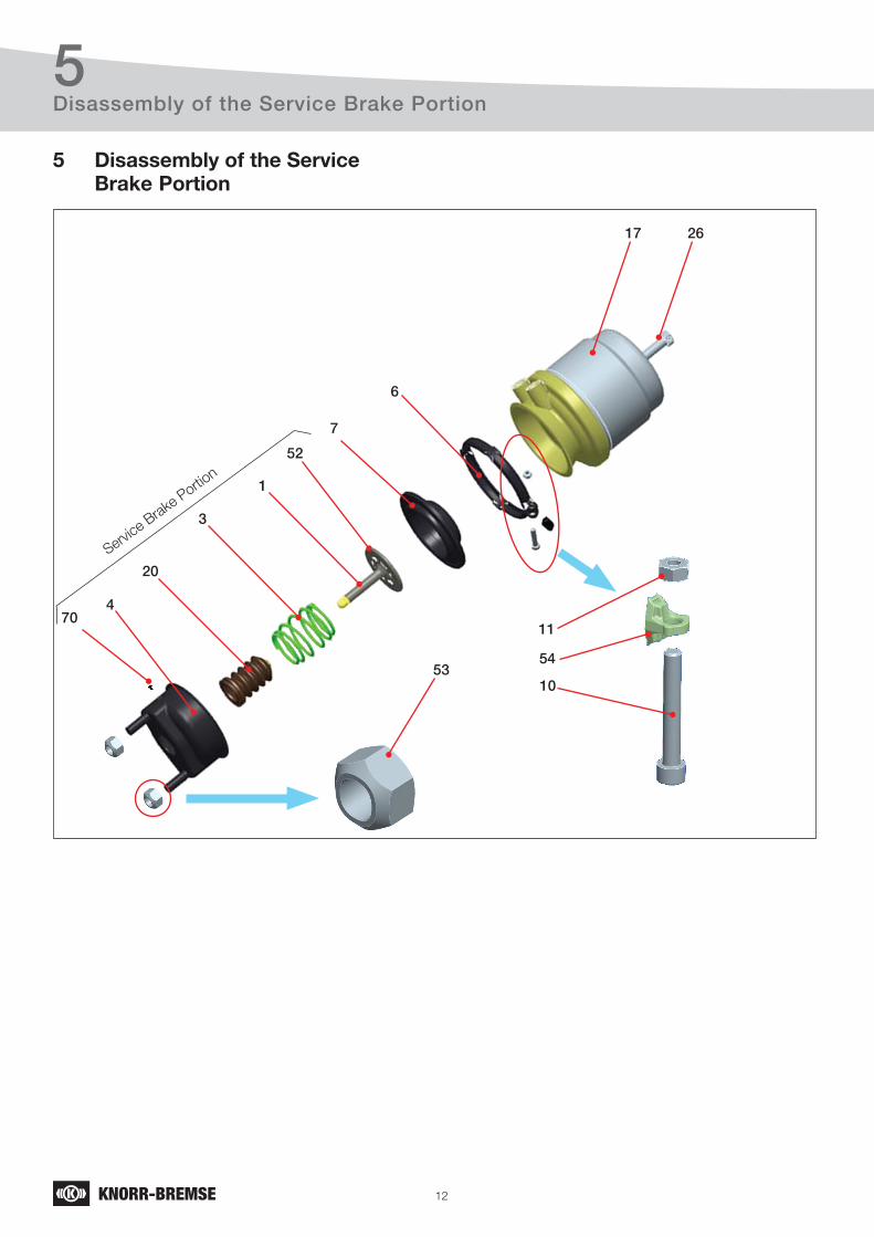
5 Disassembly of the Service Brake Portion
13
5Disassembly of the Service Brake Portion
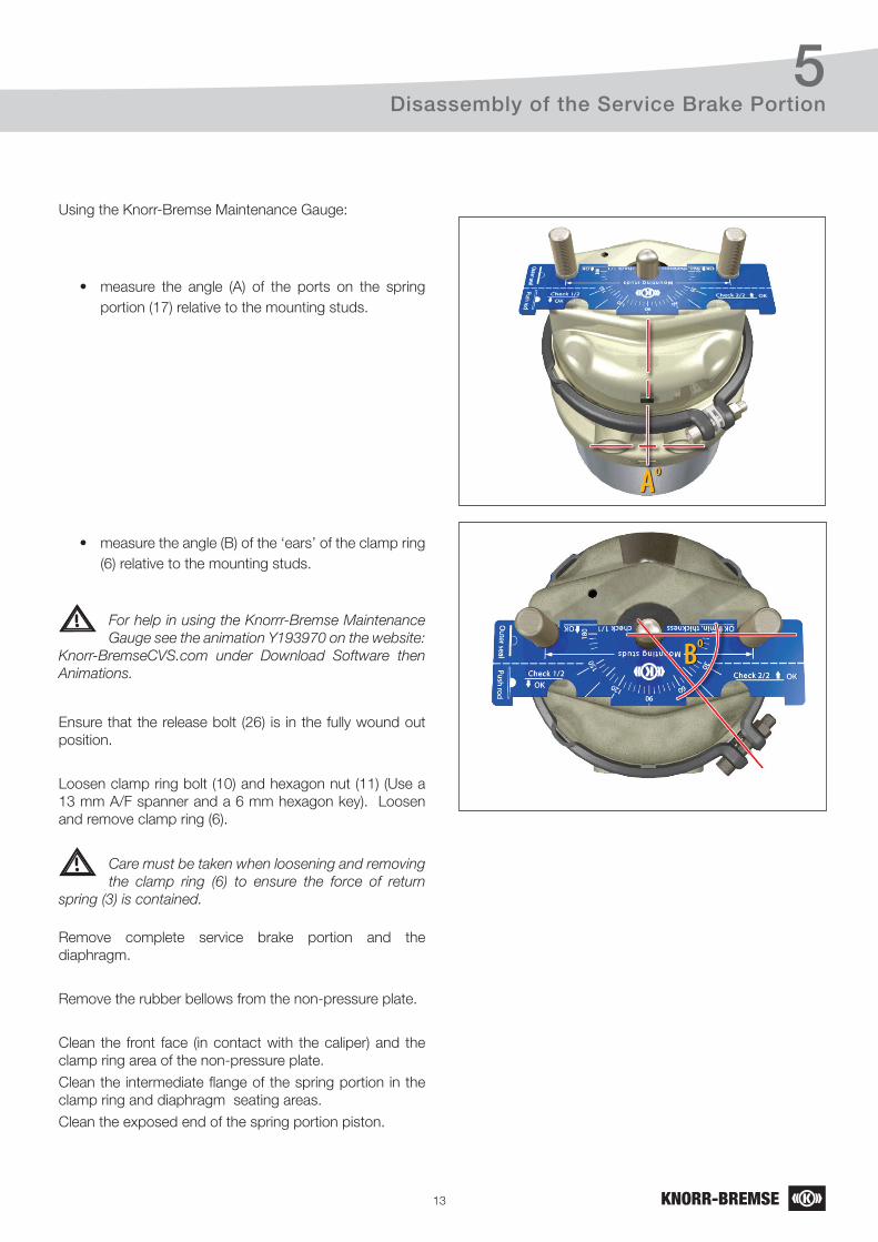
Using the Knorr-Bremse Maintenance Gauge:
• measure the angle (A) of the ports on the spring portion (17) relative to the mounting studs.
• measure the angle (B) of the ‘ears’ of the clamp ring (6) relative to the mounting studs.
Ensure that the release bolt (26) is in the fully wound out position.
Loosen clamp ring bolt (10) and hexagon nut (11) (Use a 13 mm A/F spanner and a 6 mm hexagon key). Loosen and remove clamp ring (6).
Remove complete service brake portion and the diaphragm.
Remove the rubber bellows from the non-pressure plate.
Clean the front face (in contact with the caliper) and the clamp ring area of the non-pressure plate.
Clean the intermediate flange of the spring portion in the clamp ring and diaphragm seating areas.
Clean the exposed end of the spring portion piston.
Care must be taken when loosening and removing the clamp ring (6) to ensure the force of return spring (3) is contained.
For help in using the Knorrr-Bremse Maintenance Gauge see the animation Y193970 on the website: Knorr-BremseCVS.com under Download Software then Animations.
14
6
6
7●52
70●
1
3●●
20●●
4
11●
54●
10●53●●●
17
Service Kits
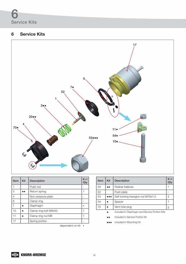
Item Kit Description K i t Qty
1 Push rod -
3 ●● Return spring 1
4 Non-pressure plate -
6 Clamp ring -
7 ● Diaphragm *
10 ● Clamp ring bolt M8x50 1
11 ● Clamp ring nut M8 1
17 Spring portion -
dependent on kit *
Item Kit Description K i t Qty
20 ●● Rubber bellows 1
52 Push plate -
53 ●●● Self-locking hexagon nut M16x1.5 2
54 ● Spacer 1
70 ● Vent hole plug 5
● included in Diaphragm and Service Portion Kits
●● included in Service Portion Kit
●●● included in Mounting Kit
6 Service Kits
15
6Service Kits
Through our continuous improvement process from 2004 a design change was phased in to improve the service portion of the spring brake.
The Diaphragm Kit can be used on all NG3 (BS9...) spring brakes but, when servicing spring brakes manufactured before the changeover date, using the Diaphragm Kit only certain components, such as the Diaphragm, will be usable.
The Service Portion Kit contains the service return spring and suits the majority of actuators in service. This kit is not suitable for all applications due to different return spring forces. The use of a nonconforming spring could have serious impacts on the braking behaviour. This would be critical also in terms of vehicle homologation!
Some Diaphragm and Service Portion Kits contain more than one diaphragm to enable them to cover a range of type sizes. When using these service kits ensure that the same type and size of diaphragm as that removed is fitted.
The Mounting Kit can be used on all NG3 (BS9...) spring brakes.
Go to the Product Search section of the website Knorr-BremseCVS.com, enter the spring brake part number or type number and click on ‘Service Parts’ for details of the Service Portion Kit for a particular spring brake. Also see Document Y195286 (available for download from the Document Download section of the website Knorr-BremseCVS.com) for details of the Service Portion Kits applications.
Go to the Product Search section of the website Knorr-BremseCVS.com, enter the spring brake part number or type number and click on ‘Service Parts’ for details of the Diaphragm Kit for a particular spring brake.
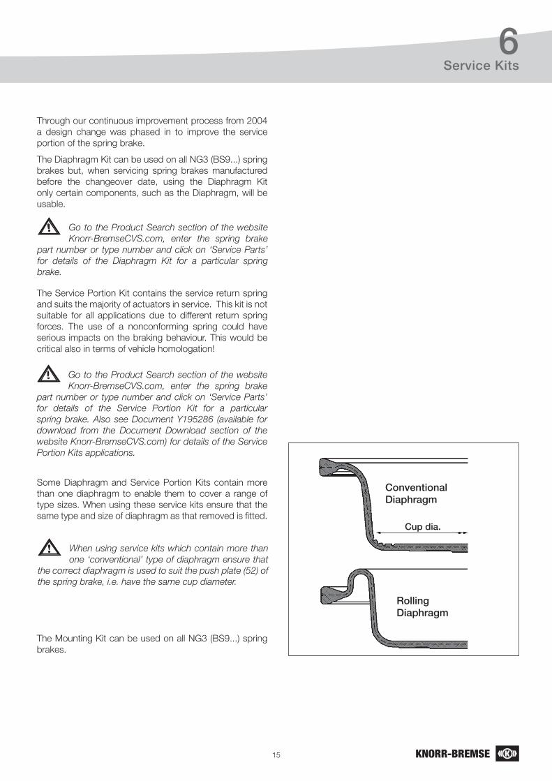
When using service kits which contain more than one ‘conventional’ type of diaphragm ensure that the correct diaphragm is used to suit the push plate (52) of the spring brake, i.e. have the same cup diameter.
ConventionalDiaphragm
RollingDiaphragm
Cup dia
16
7Assembly of the Service Brake Portion
7 Assembly of the Service Brake Portion
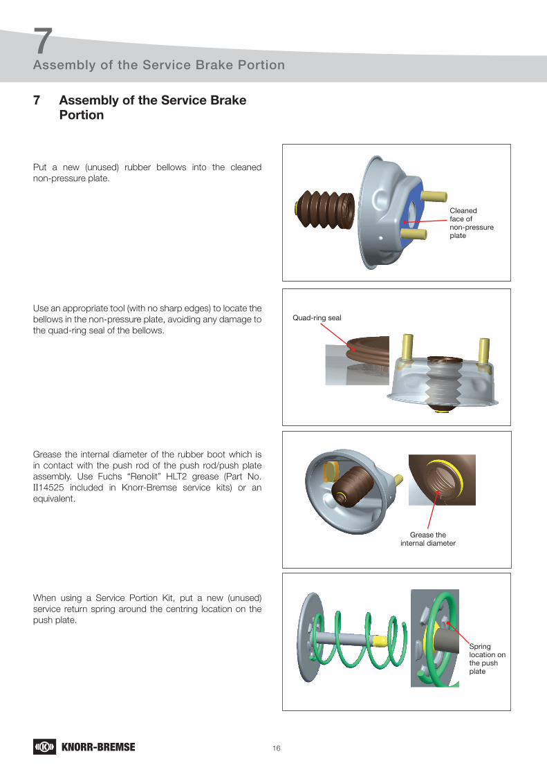
Put a new (unused) rubber bellows into the cleaned non-pressure plate.
Use an appropriate tool (with no sharp edges) to locate the bellows in the non-pressure plate, avoiding any damage to the quad-ring seal of the bellows.
Grease the internal diameter of the rubber boot which is in contact with the push rod of the push rod/push plate assembly. Use Fuchs “Renolit” HLT2 grease (Part No. II14525 included in Knorr-Bremse service kits) or an equivalent.
When using a Service Portion Kit, put a new (unused) service return spring around the centring location on the push plate.
Cleaned face of non-pressure plate
Quad-ring seal
Grease the internal diameter
Spring location on the push plate
17
7Assembly of the Service Brake Portion
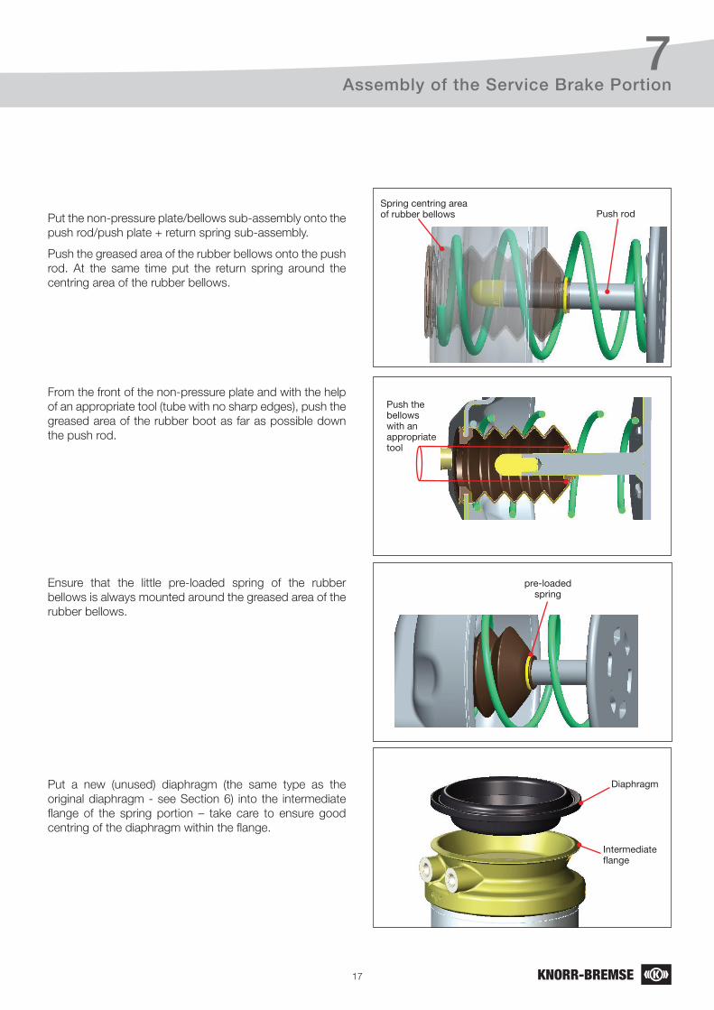
Put the non-pressure plate/bellows sub-assembly onto the push rod/push plate + return spring sub-assembly.
Push the greased area of the rubber bellows onto the push rod. At the same time put the return spring around the centring area of the rubber bellows.
From the front of the non-pressure plate and with the help of an appropriate tool (tube with no sharp edges), push the greased area of the rubber boot as far as possible down the push rod.
Ensure that the little pre-loaded spring of the rubber bellows is always mounted around the greased area of the rubber bellows.
Put a new (unused) diaphragm (the same type as the original diaphragm - see Section 6) into the intermediate flange of the spring portion – take care to ensure good centring of the diaphragm within the flange.
Push rod
Push the bellows with an appropriate tool
pre-loaded spring
Diaphragm
Spring centring area of rubber bellows
Intermediate flange
18
7Assembly of the Service Brake Portion
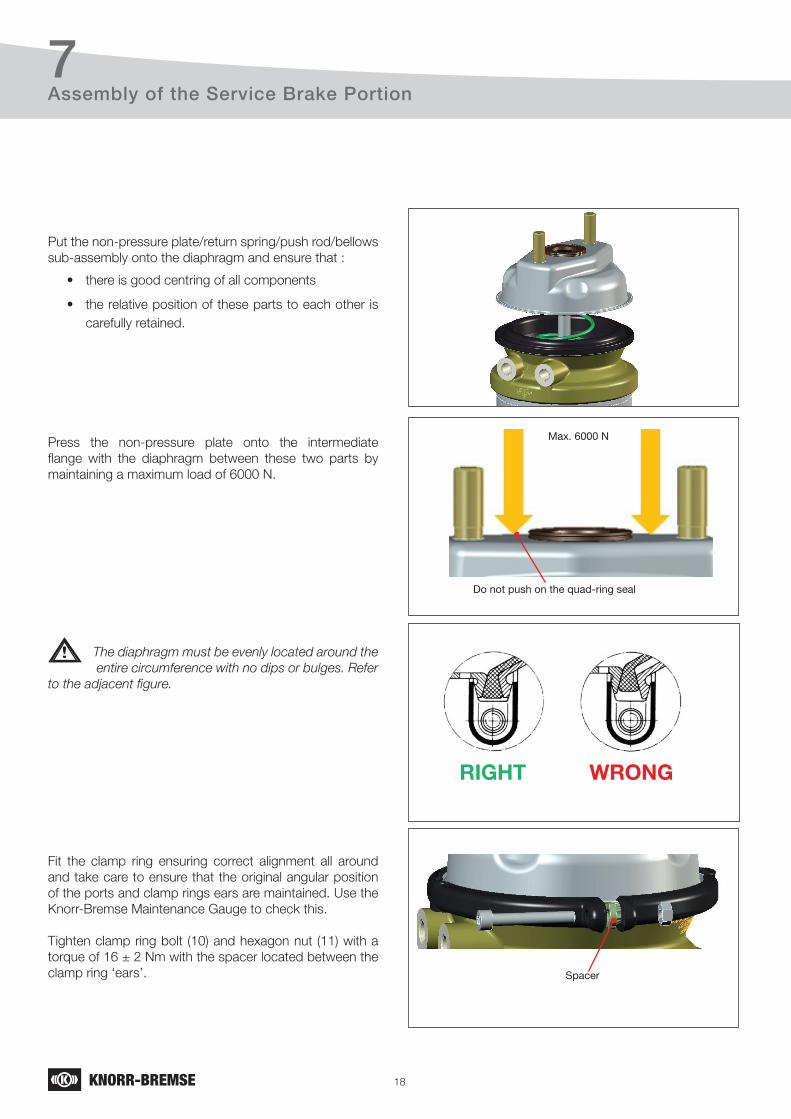
Put the non-pressure plate/return spring/push rod/bellows sub-assembly onto the diaphragm and ensure that :
• there is good centring of all components
• the relative position of these parts to each other is carefully retained.
Press the non-pressure plate onto the intermediate flange with the diaphragm between these two parts by maintaining a maximum load of 6000 N.
Fit the clamp ring ensuring correct alignment all around and take care to ensure that the original angular position of the ports and clamp rings ears are maintained. Use the Knorr-Bremse Maintenance Gauge to check this.
Tighten clamp ring bolt (10) and hexagon nut (11) with a torque of 16 ± 2 Nm with the spacer located between the clamp ring ‘ears’.
Do not push on the quad-ring seal
Spacer
Max. 6000 N
The diaphragm must be evenly located around the entire circumference with no dips or bulges. Refer to the adjacent figure.
RIGHT WRONG
19
7Assembly of the Service Brake Portion
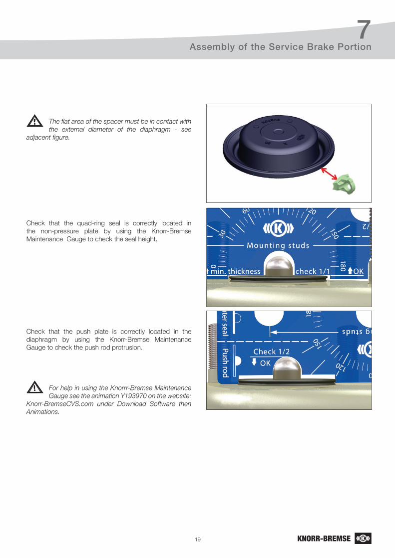
The flat area of the spacer must be in contact with the external diameter of the diaphragm - see adjacent figure.
Check that the quad-ring seal is correctly located in the non-pressure plate by using the Knorr-Bremse Maintenance Gauge to check the seal height.
Check that the push plate is correctly located in the diaphragm by using the Knorr-Bremse Maintenance Gauge to check the push rod protrusion.
For help in using the Knorrr-Bremse Maintenance Gauge see the animation Y193970 on the website: Knorr-BremseCVS.com under Download Software then Animations.
20
8Refitting the Spring Brake Actuator to the Vehicle
8 Refitting the Spring Brake Actuator to the Vehicle
Prepare the caliper to receive the spring brake actuator according to the Service Manual C16352 (for SB6/SB7 Air Disc Brakes), Y006471 (for SN6/SN7 Air Disc Brakes), Y015044 (for SN5 Air Disc Brakes) or Y173241 (for ST7 Air Disc Brakes).
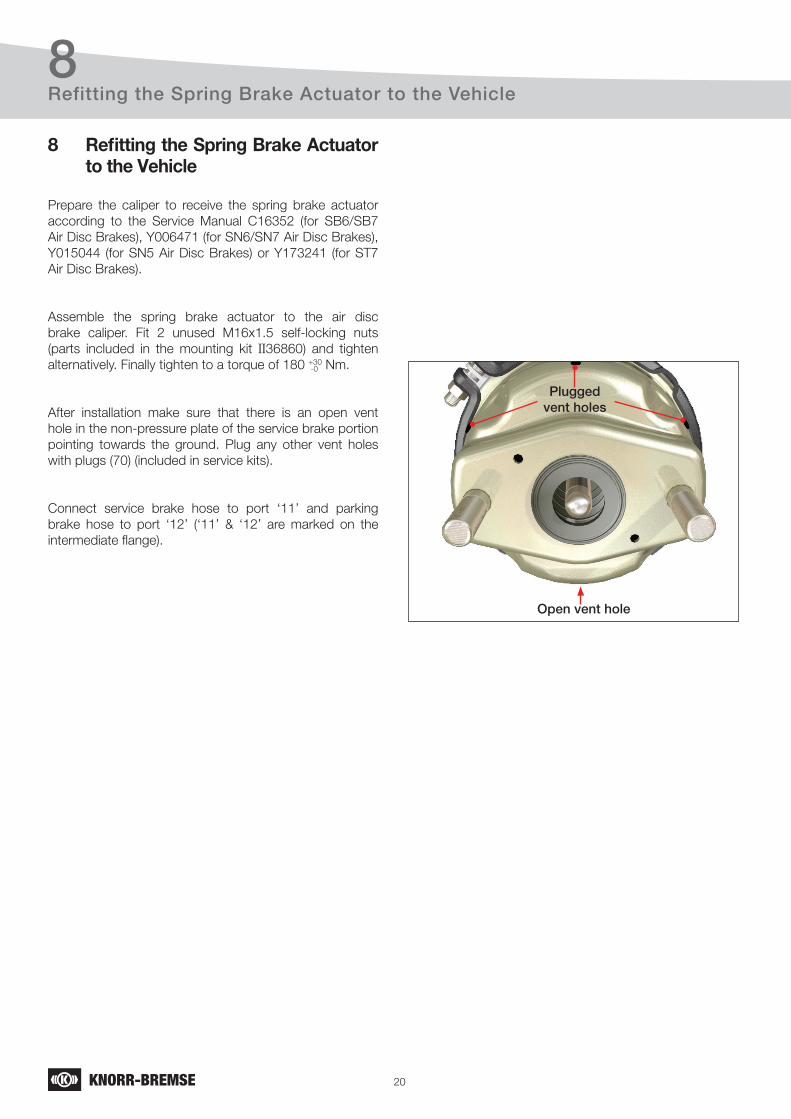
Assemble the spring brake actuator to the air disc brake caliper. Fit 2 unused M16x1.5 self-locking nuts (parts included in the mounting kit II36860) and tighten alternatively. Finally tighten to a torque of 180 +30 Nm.
After installation make sure that there is an open vent hole in the non-pressure plate of the service brake portion pointing towards the ground. Plug any other vent holes with plugs (70) (included in service kits).
Connect service brake hose to port ‘11’ and parking brake hose to port ‘12’ (‘11’ & ‘12’ are marked on the intermediate flange).
-0
Plugged vent holes
Open vent hole
21
9Testing
9 Testing
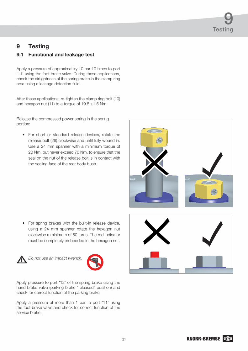
Apply a pressure of approximately 10 bar 10 times to port ‘11’ using the foot brake valve. During these applications, check the airtightness of the spring brake in the clamp ring area using a leakage detection fluid.
After these applications, re-tighten the clamp ring bolt (10) and hexagon nut (11) to a torque of 19.5 ±1.5 Nm.
Release the compressed power spring in the spring portion:
• For short or standard release devices, rotate the release bolt (26) clockwise and until fully wound in. Use a 24 mm spanner with a minimum torque of 20 Nm, but never exceed 70 Nm, to ensure that the seal on the nut of the release bolt is in contact with the sealing face of the rear body bush.
• For spring brakes with the built-in release device, using a 24 mm spanner rotate the hexagon nut clockwise a minimum of 50 turns. The red indicator must be completely embedded in the hexagon nut.
Apply pressure to port ‘12’ of the spring brake using the hand brake valve (parking brake “released” position) and check for correct function of the parking brake.
Apply a pressure of more than 1 bar to port ‘11’ using the foot brake valve and check for correct function of the service brake.
9.1 Functional and leakage test
Do not use an impact wrench.

22
Notes

Notes
Knorr-Bremse Group
Europe – Africa
Austria Knorr-Bremse GmbHSysteme für NutzfahrzeugeMödling Tel: +43 2236 409-2436Fax: +43 2236 409-2434
BelgiumKnorr-Bremse Benelux B.V.B.A.Heist-op-den-BergTel: +32 1525 7900Fax: +32 1524 9240
Czech RepublicKnorr-Bremse Systémy prouzitková vozidla, CR, s.r.o.LiberecTel: +420 482 363-611Fax: +420 482 363-711
France Knorr-BremseSystèmes pour Véhicules Utilitaires FranceLisieux CedexTel: +33 2 3132 1200Fax: +33 2 3132 1303
Germany Hasse & Wrede GmbH Berlin Tel: +49 30 9392-3101Fax: +49 30 7009-0811
Germany Knorr-Bremse Systeme für Nutzfahrzeuge GmbH Berlin Tel: +49 180 223-7637 Fax: +49 30 9392-3426
HungaryKnorr-Bremse Fékrendszerek Kft.Kecskemét Tel: +36 76 511 100Fax: +36 76 481 100
ItalyKnorr-Bremse Sistemi per Autoveicoli Commerciali S.p.A.Arcore Tel: +39 039 6075-1Fax: +39 039 6075-435
Netherlands Knorr-Bremse Benelux B.V.B.A.Mydrecht Tel: +31 297 239-330Fax: +31 297 239-339
PolandKnorr-Bremse Polska SfN Sp. z o.o.WarsawTel: +48 22 887-3870Fax: +48 22 531-4170
Russia Knorr-Bremse Systems for Commercial Vehicles LLCNizhniy NovgorodTel: +7 8312 57-6661Fax: +7 8312 57-6791
Russia Knorr-BremseSystems for Commercial Vehicles LLCMoscowTel: +7 495 234-4995Fax: +7 495 234-4996
South Africa Knorr-Bremse S.A. Pty. Ltd. Kempton Park Tel: +27 11 961-7800Fax: +27 11 975-8249
SpainBost Ibérica, S.L.Irun (Guipuzcoa) Tel: +34 902 100-569Fax: +34 943 614-063
Sweden Knorr-BremseSystem for Tunga Fordon ABLundTel: +46 46 440 0105Fax: +46 46 148971
SwitzerlandKnorr-BremseSysteme für Nutzfahrzeuge GmbHBassersdorf Tel: +41 44 888 77-55Fax: +41 44 888 77-50
Turkey Knorr-BremseTicari Araç Fren Sistemleri Tic. Ltd. Şti.İstanbulTel: +90 212 293-4742Fax: +90 212 293-4743
United Kingdom Knorr-Bremse Systems for Commercial Vehicles Ltd.BristolTel: +44 117 9846-100Fax: +44 117 9846-101
America
Brazil Knorr-BremseSistemas para Veículos Comerciais Brasil Ltda.São Paulo Tel: +55 11 4593 4000Fax: +55 11 4593 4698
USA Bendix Commercial Vehicle Systems LLC Elyria, OH Tel: +1 440 329-9100Fax: +1 440 329-9105
Asia – Australia
AustraliaKnorr-Bremse Australia Pty. Ltd. Granville NSWTel: +61 2 8863-6500Fax: +61 2 8863-6510
China Knorr-Bremse Brake Equipment (Shanghai) Co. Ltd. ShanghaiTel: +86 21 3858-5800Fax: +86 21 3858-5900
China Knorr-Bremse Asia Pacific (Holding) LimitedCommercial Vehicle Systems DivisionHong Kong Tel: +852 3657-9800Fax: +852 3657-9901
India Knorr-BremseSystems for Commercial Vehicles India Private Ltd.PuneTel: +91 20 6674-6800Fax: +91 20 6674-6899
Japan Knorr-Bremse Commercial Vehicle Systems Japan Ltd.SaitamaTel: +81 49 273-9155Fax: +81 49 282-8601
Korea Knorr-Bremse Korea Ltd. Truck Brake DivisionSeoul Tel: +82 2 2273-1182Fax: +82 2 2273-1184
Head Office
Knorr-Bremse Systeme für Nutzfahrzeuge GmbH Moosacher Strasse 80 80809 Munich Germany Tel: +49 89 3547-0 Fax: +49 89 3547-2767www.knorr-bremseCVS.com
C o m m e r c i a l V e h i c l e S y s t e m s
The i
nfor
mati
on co
ntain
ed he
rein i
s sub
ject t
o alte
ration
with
out n
otice
and t
heref
ore m
ay no
t be t
he la
test r
eleas
e. Ple
ase c
heck
our w
ebsit
e www
.knor
r-brem
seCV
S.com
for t
he la
test u
pdate
or co
ntac
t you
r loca
l Kno
rr-Br
emse
repr
esen
tative
. The
figur
ative
m
ark “K
” and
the t
radem
arks K
NORR
and K
NORR
-BRE
MSE
are r
egist
ered i
n the
nam
e of K
norr-
Brem
se AG
. Add
itiona
l term
s and
cond
itions
apply
; plea
se re
fer to
our w
ebsit
e kno
rr-br
emse
CVS.c
om fo
r full
Disc
laim
er.
Note:
If se
rvice
wor
k is c
arried
out o
n a ve
hicle
base
d on i
nfor
mati
on pr
ovide
d here
in, it
is th
e res
pons
ibilit
y of t
he w
orks
hop t
o ens
ure t
he ve
hicle
is fu
lly te
sted a
nd in
full f
uncti
onal
order
befor
e the
vehic
le is
retur
ned i
nto s
ervic
e. Kn
orr-B
remse
acce
pts n
o lia
bility
for p
roblem
s cau
sed a
s a re
sult o
f app
ropria
te tes
ts no
t bein
g carr
ied ou
t.
Copy
right
© Kn
orr-B
remse
AG -
all rig
hts r
eser
ved,
includ
ing in
dustr
ial pr
oper
ty rig
hts a
pplic
ation
s. Kn
orr-B
remse
AG re
tains
any p
ower
of dis
posa
l, suc
h as f
or co
pying
and t
ransfe
rring
Doc. No. Y175639 (EN - Rev. 001)September 2015